lantronix XPICOW 802.11b/g/n Wireless Module User Manual Midas BP UG
lantronix 802.11b/g/n Wireless Module Midas BP UG
UserManual.wiki
>
lantronix
>
XPICOW User Manual
>
User Manual.pdf
Contents
1.
User Manual.pdf
2.
User Manual rev.pdf
User Manual.pdf
Navigation menu
Upload a User Manual
Namespaces
Wiki Guide
HTML
PDF
Info
Views
User Manual
Discussion / Help
Navigation
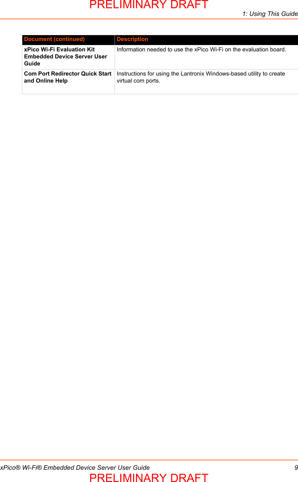
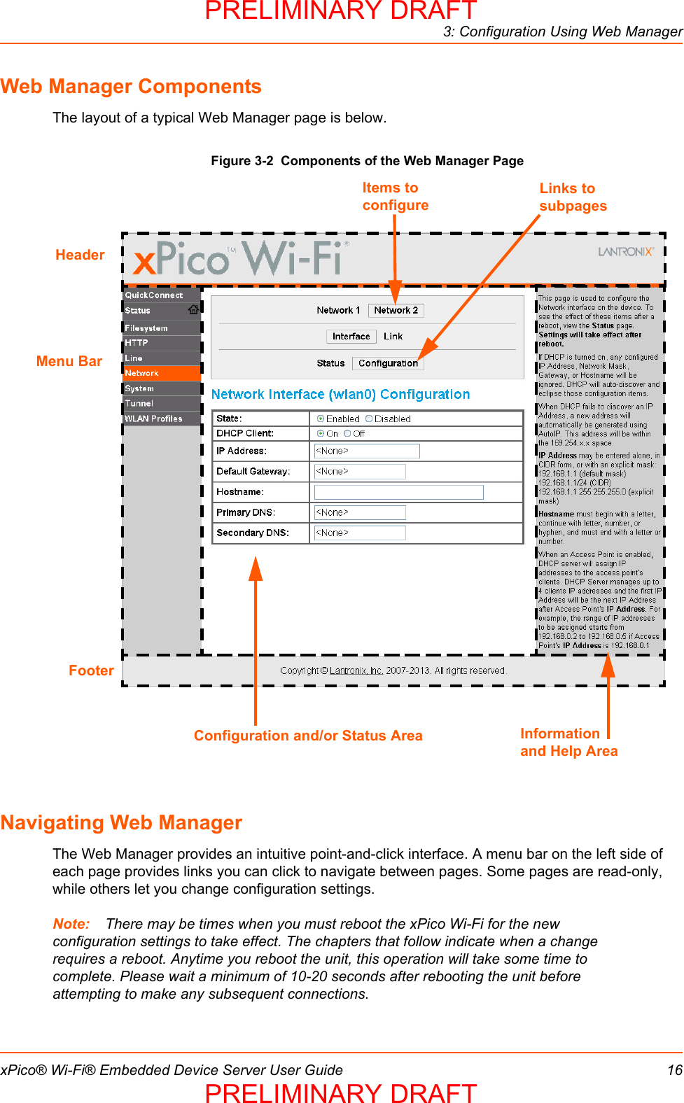
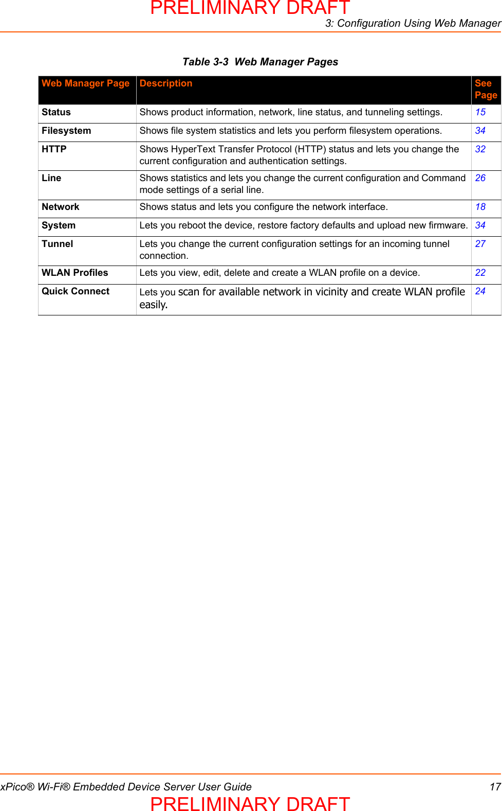
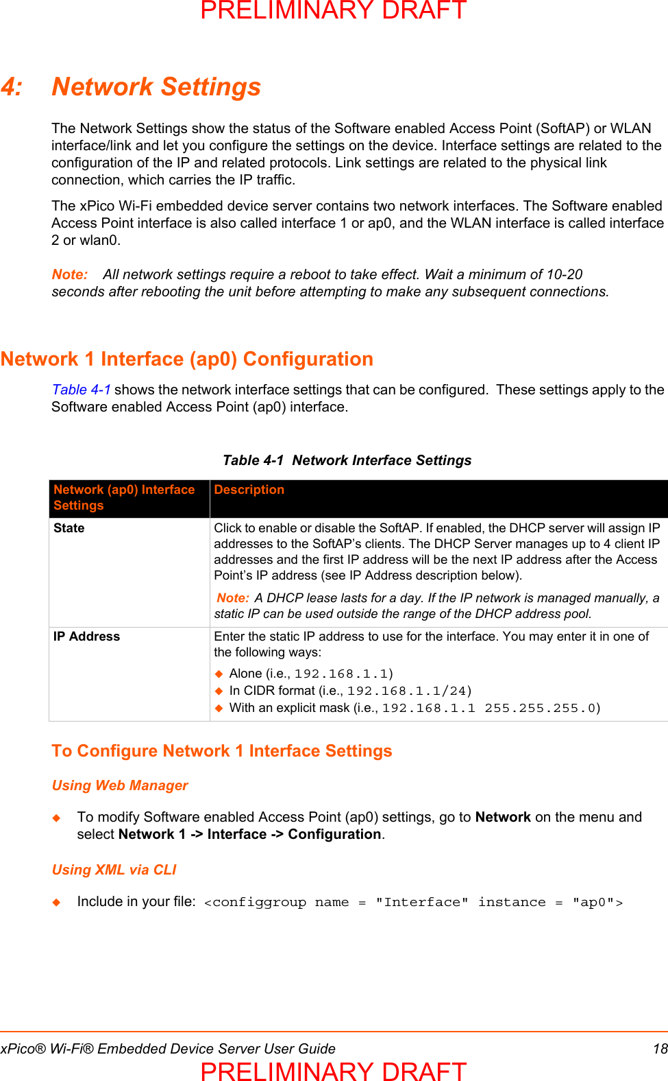
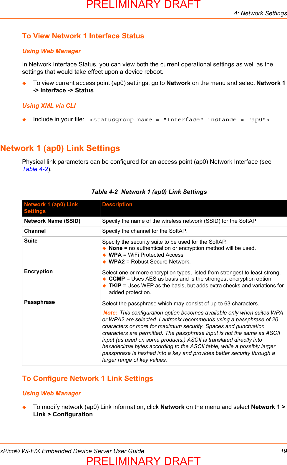
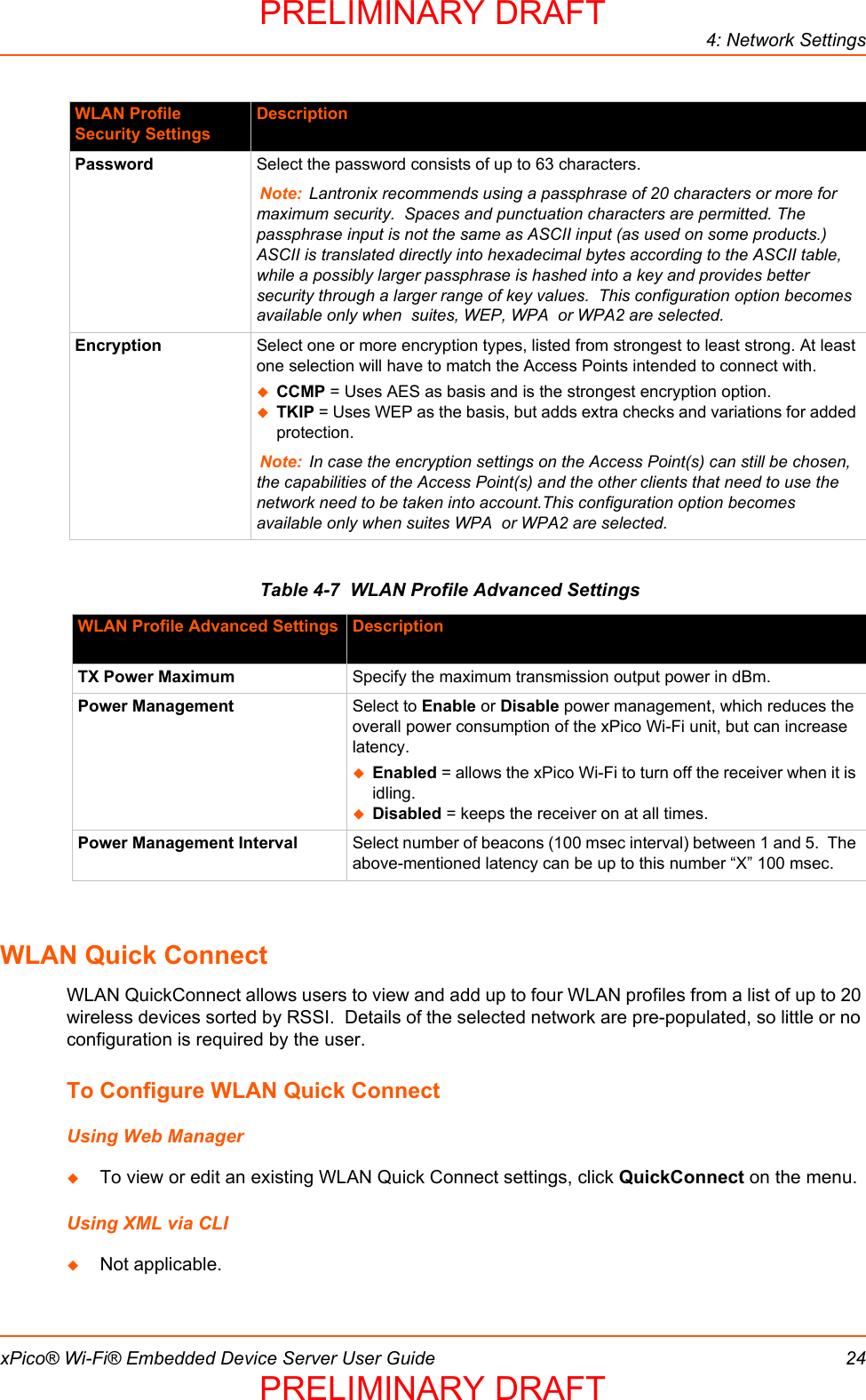
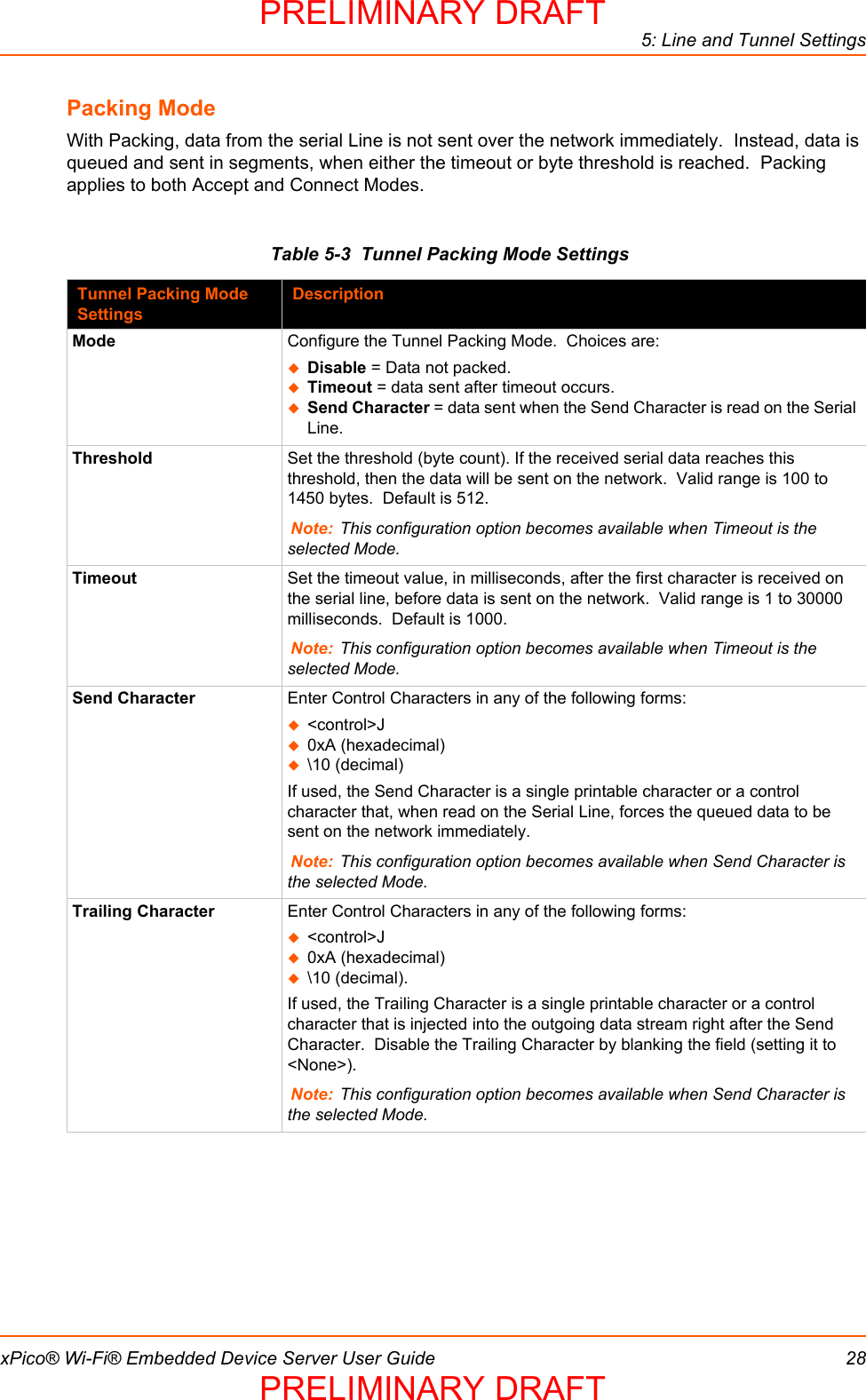
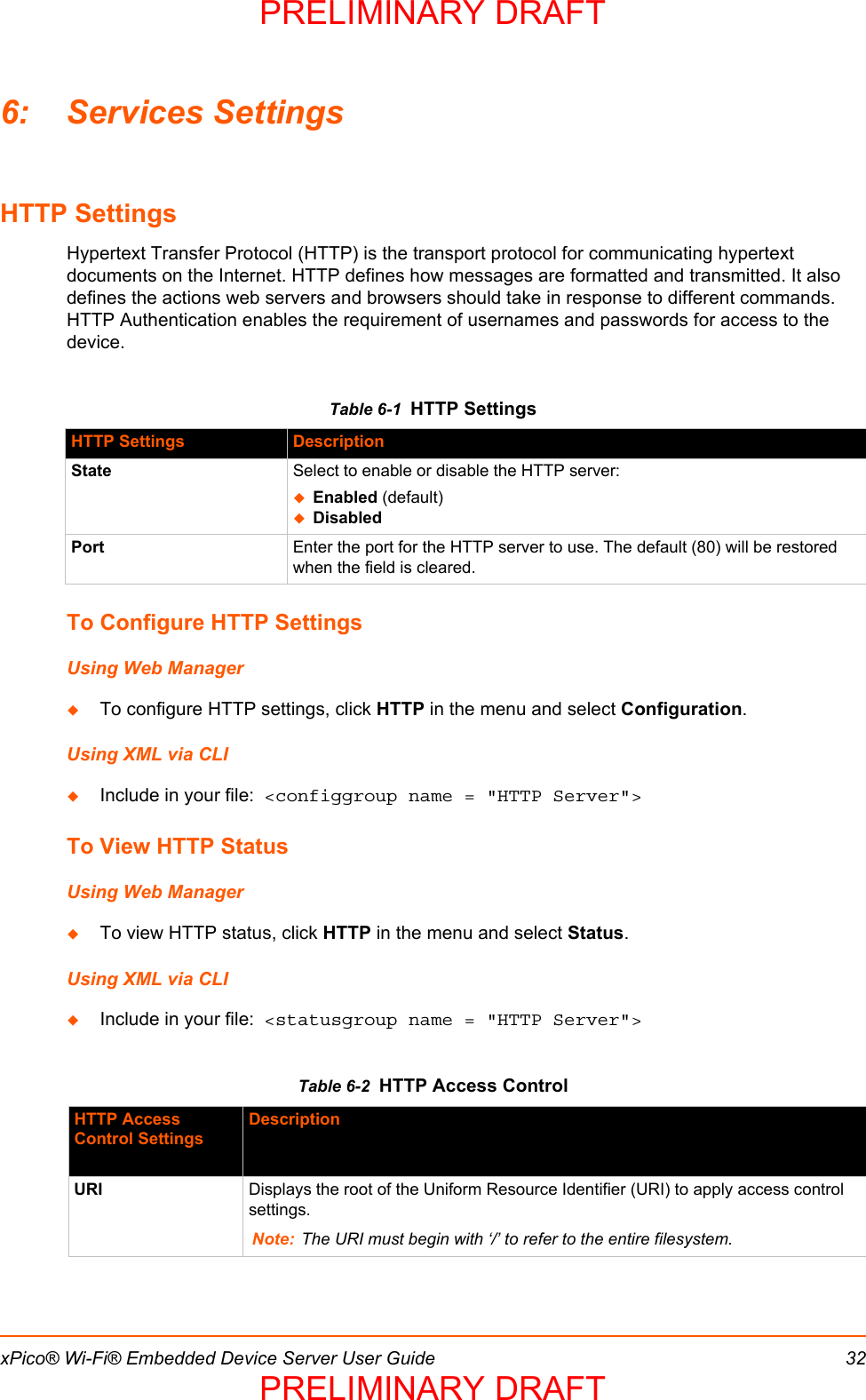
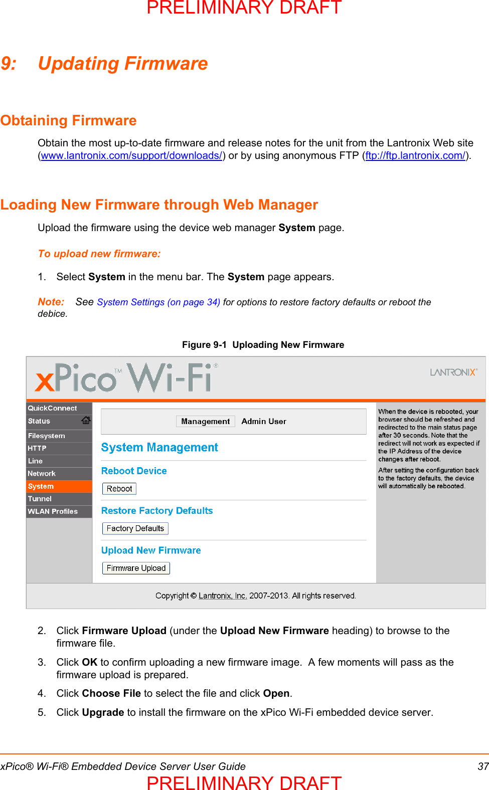
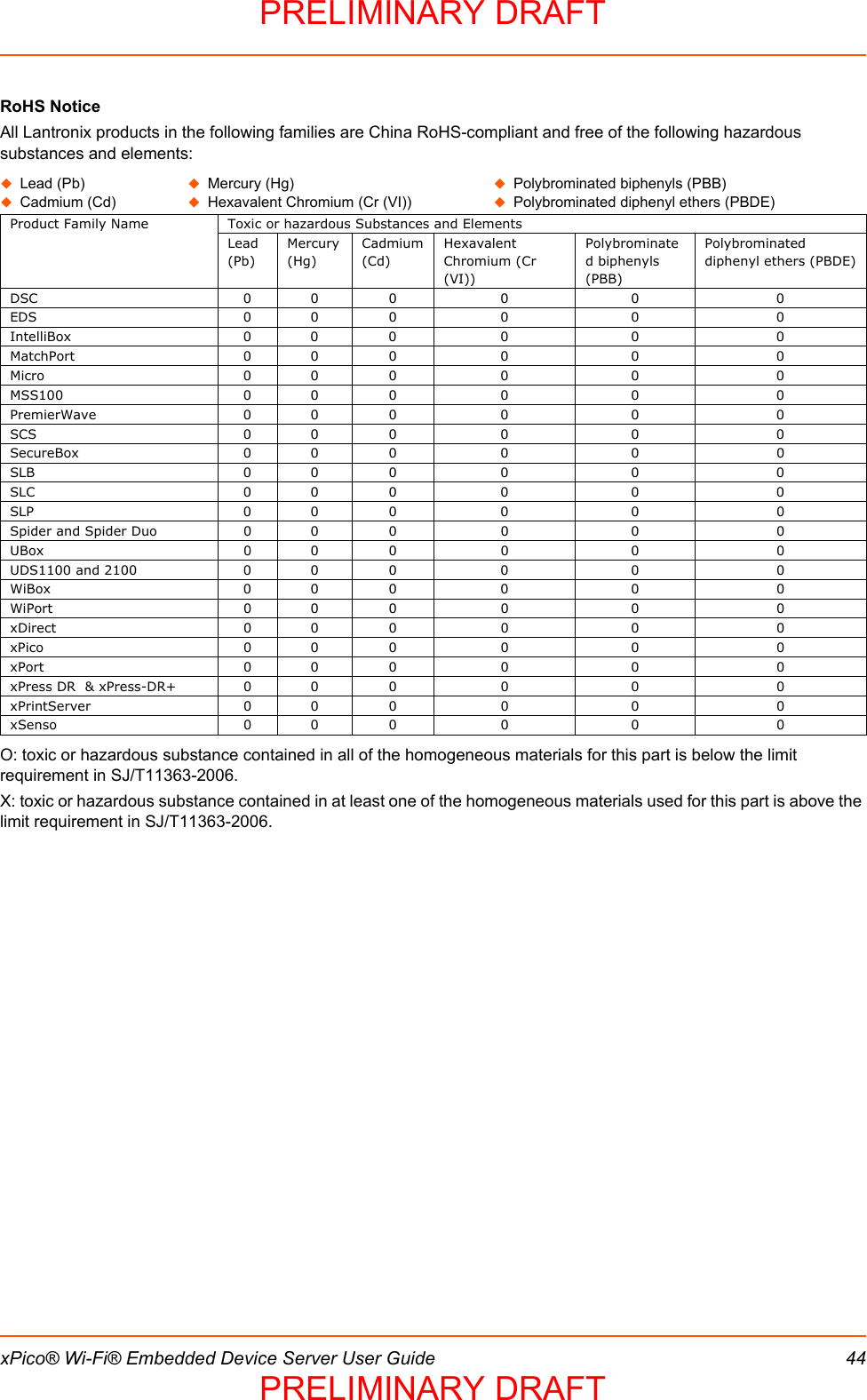
![xPico® Wi-Fi® Embedded Device Server User Guide 102: IntroductionThis chapter summarizes the basic information and features of the xPico Wi-Fi embedded device server. It provides an overview of key features and describes suitable applications. Key FeaturesWireless LAN Interface:IEEE 802.11 b/g and IEEE 802.11n (single stream)WLAN interface (2.4 GHz only)IEEE 802.11 d/h/i/j/k/w/ru.FL connector for external antennaSerial Interface:Two Serial CMOS Ports (3.3V, 5V tolerant)11200 to 921.6KbpsFlow control: XON/XOFF, RTS/CTS (Line 1 only)Lantronix tunneling applicationHost Interface:Dual Serial Port, SPI, USB2.0 (device)8 GPIONetwork Protocols: TCP/IP, UDP/IP, DHCP Server (software-enabled Access Point interface), ARP, ICMP, DHCP Client (WLAN interface), Auto-IP, DNSNetworking Capabilities: Soft Access Point with DHCP ServerRoaming: continually tracks Wi-Fi signal strength within range, resulting in smooth and automatic transition between access points without delay.QuickConnect: Dynamic Profiles facilitate easy and rapid connections to access pointsManagement and Control:Web ServerCLI (Serial Monitor Port) XML Configuration Import and Export (XCR, XML Status Export [XSR])Field upgradable firmware (OTA)Security:IEEE 802.11i Support – WPA-Personal, WPA2-Personal256-bit AES Encryption1. For xPico Wi-Fi 5V tolerant pins, in order to sustain a voltage higher than Vcc+0.3, the internal pull up/pull down resistors must be disabled.PRELIMINARY DRAFTPRELIMINARY DRAFT](https://usermanual.wiki/lantronix/XPICOW.User-Manual-pdf/User-Guide-2021913-Page-10.png)