lantronix XSDRWLSG DRIG WIRELESS DEVICE SERVER User Manual XPress DR User Guide
lantronix DRIG WIRELESS DEVICE SERVER XPress DR User Guide
UserManual.wiki
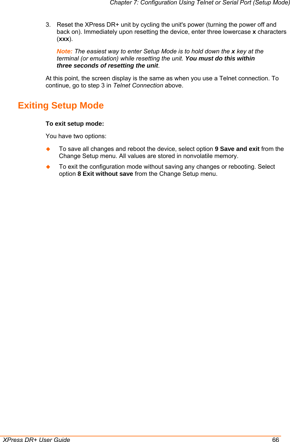
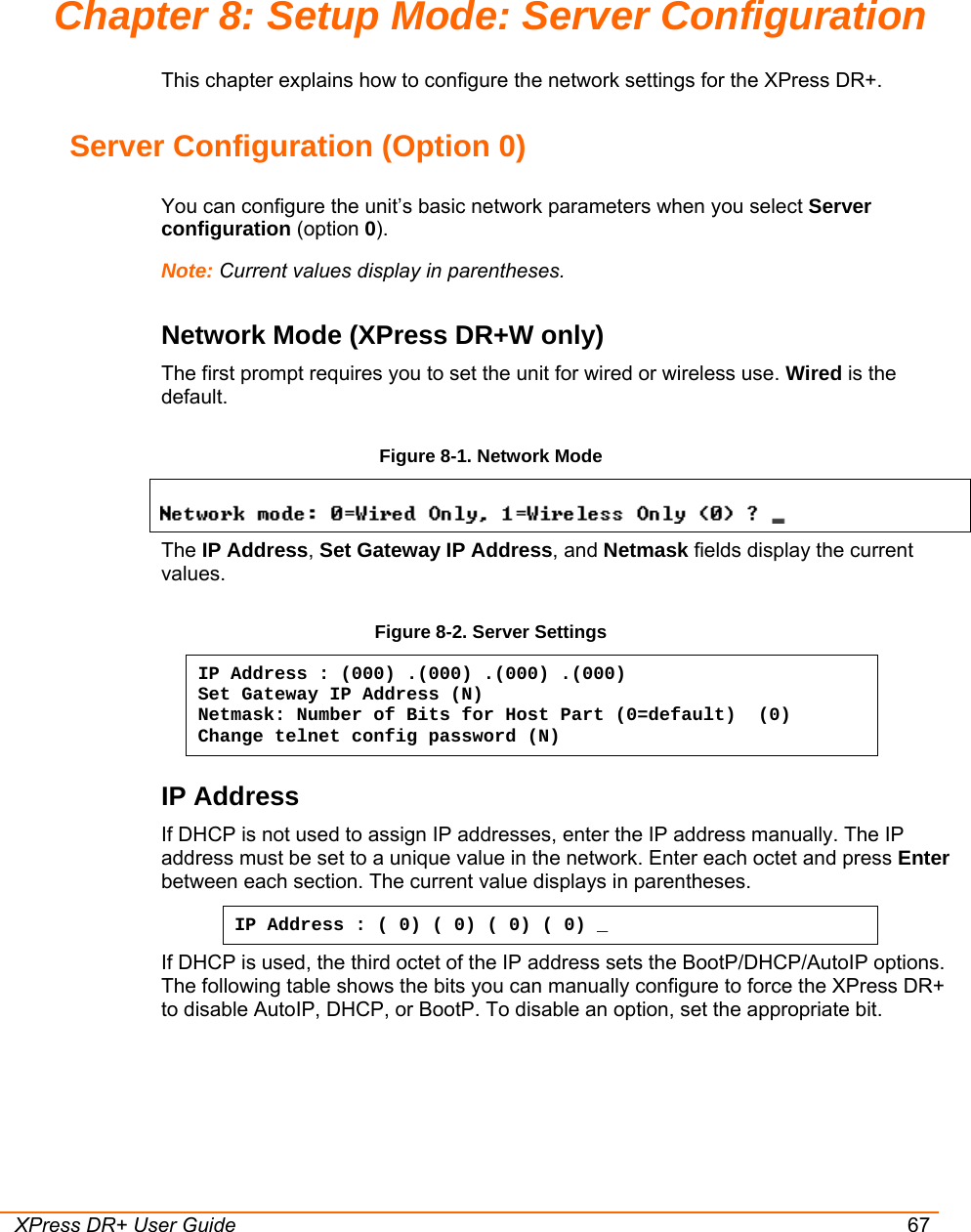
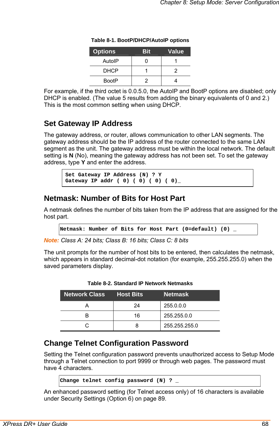
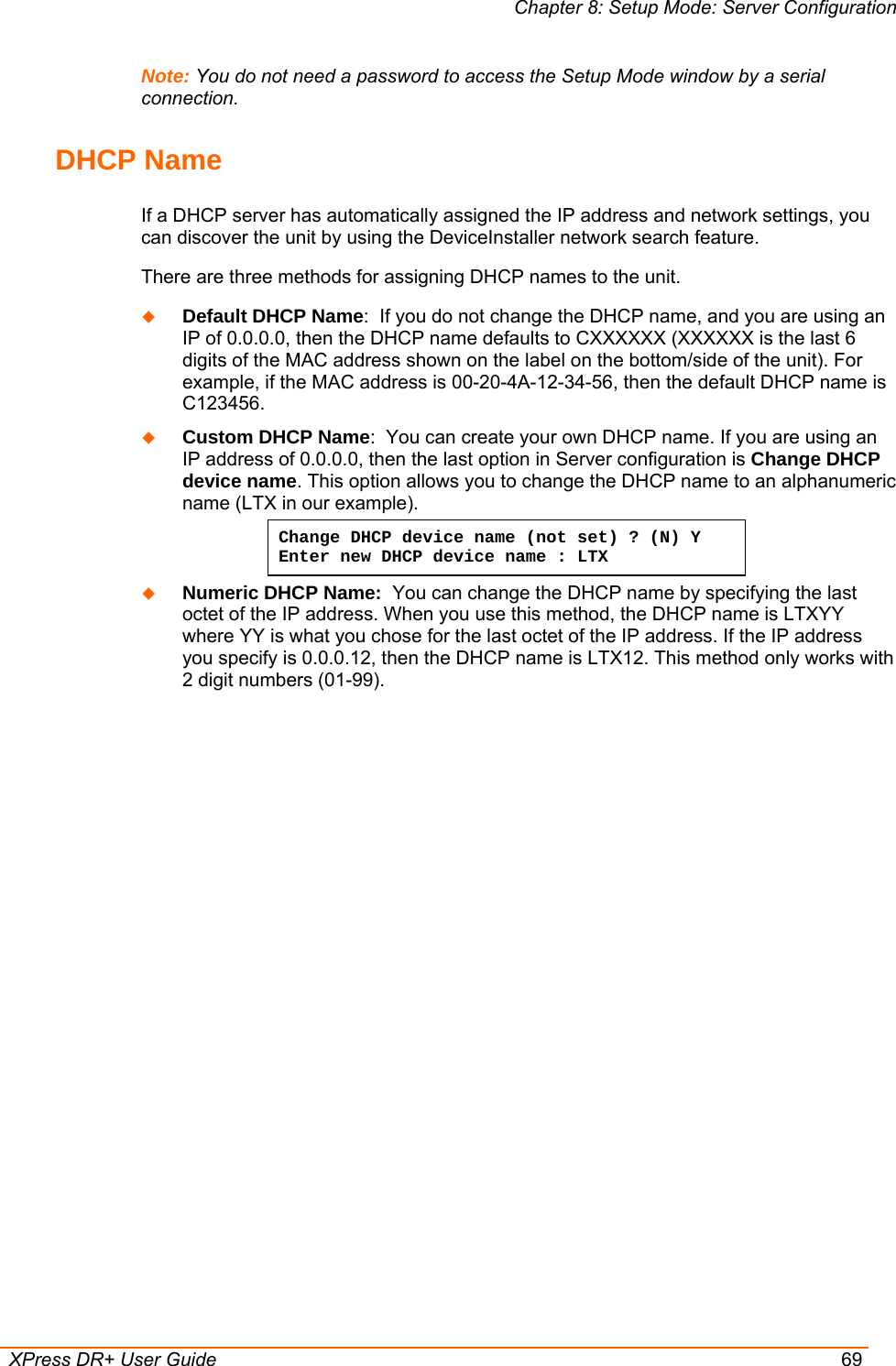
>
lantronix
>
XSDRWLSG User Manual
users manual
Navigation menu
Upload a User Manual
Namespaces
Wiki Guide
HTML
PDF
Info
Views
User Manual
Discussion / Help
Navigation
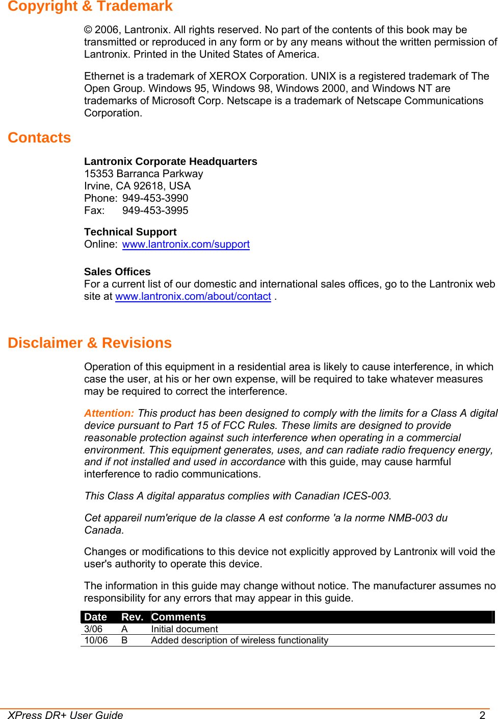
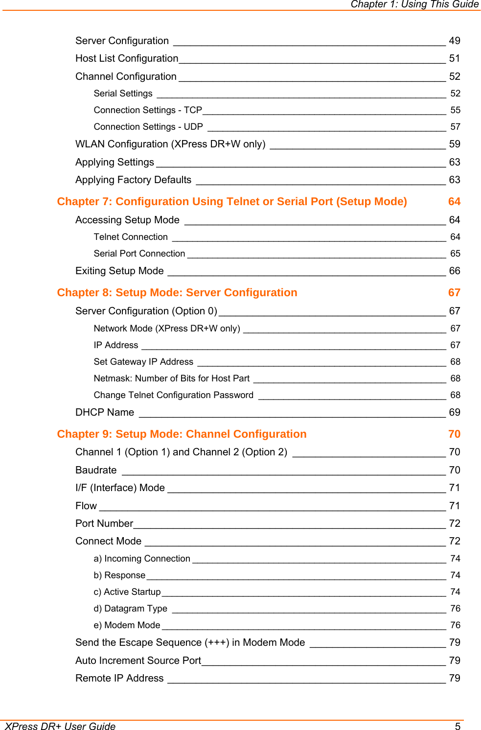
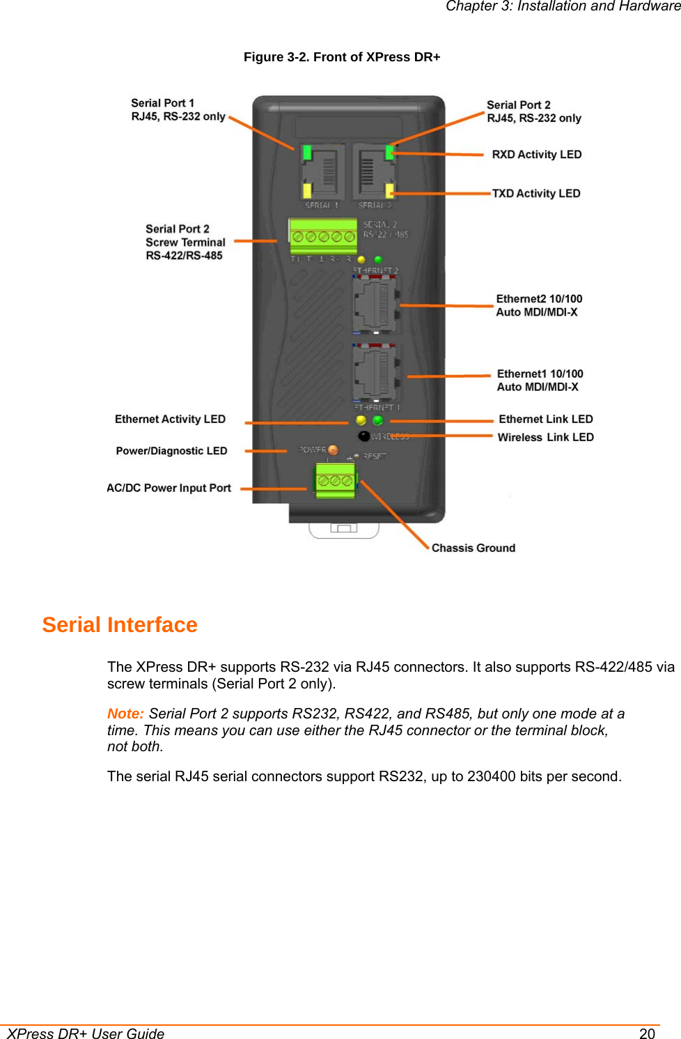
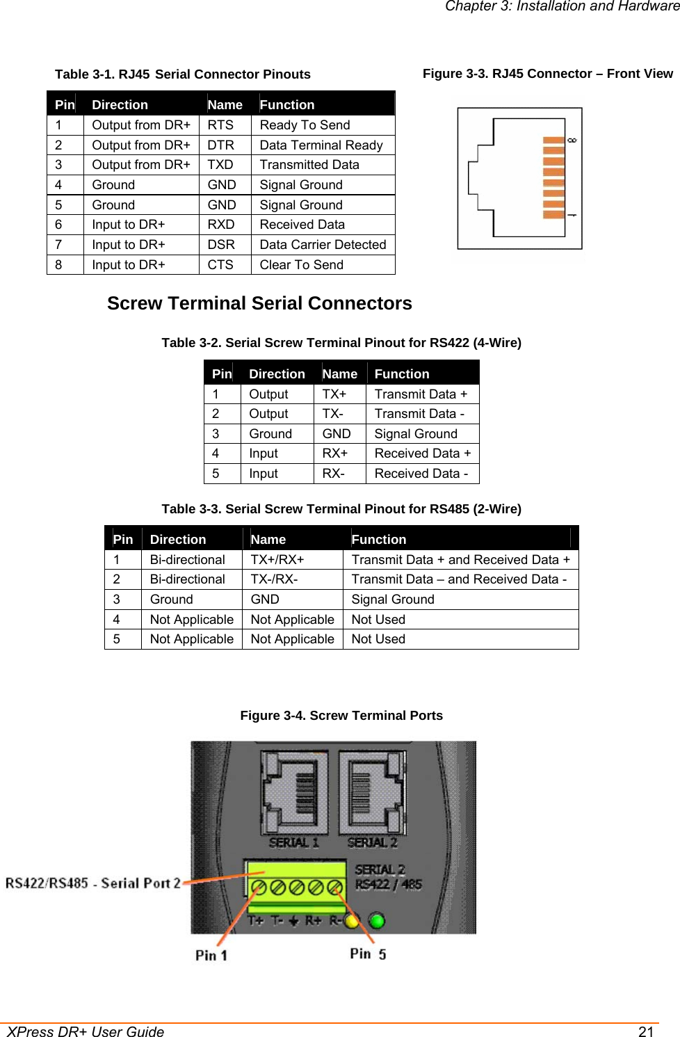
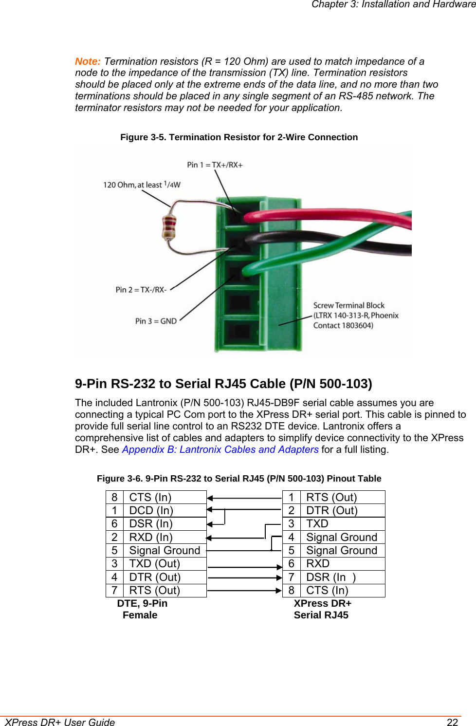
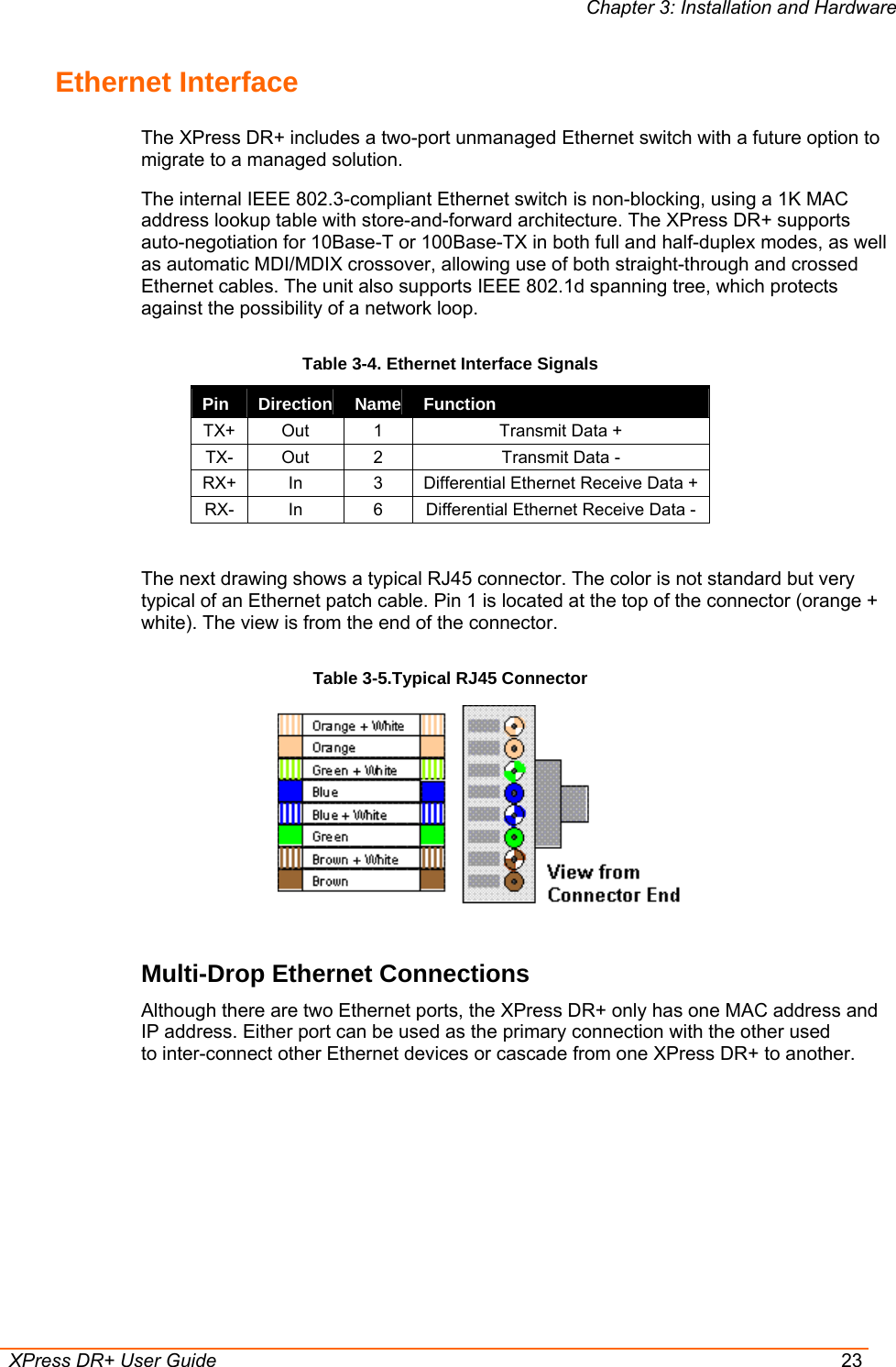
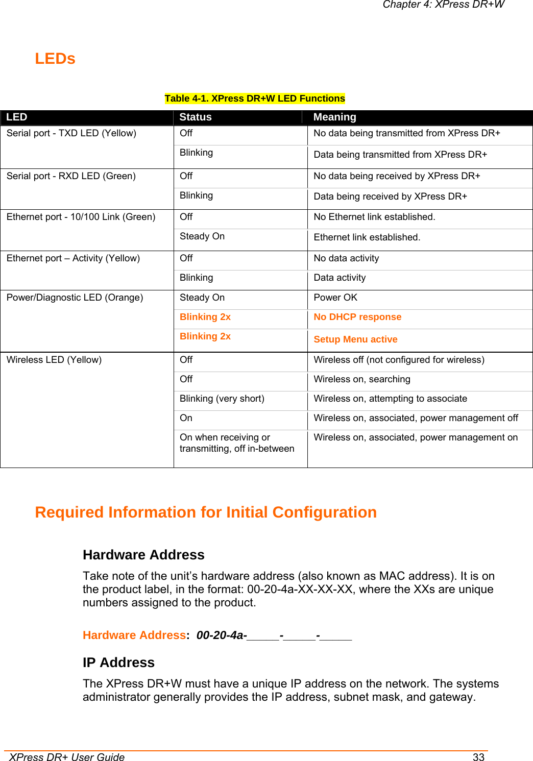
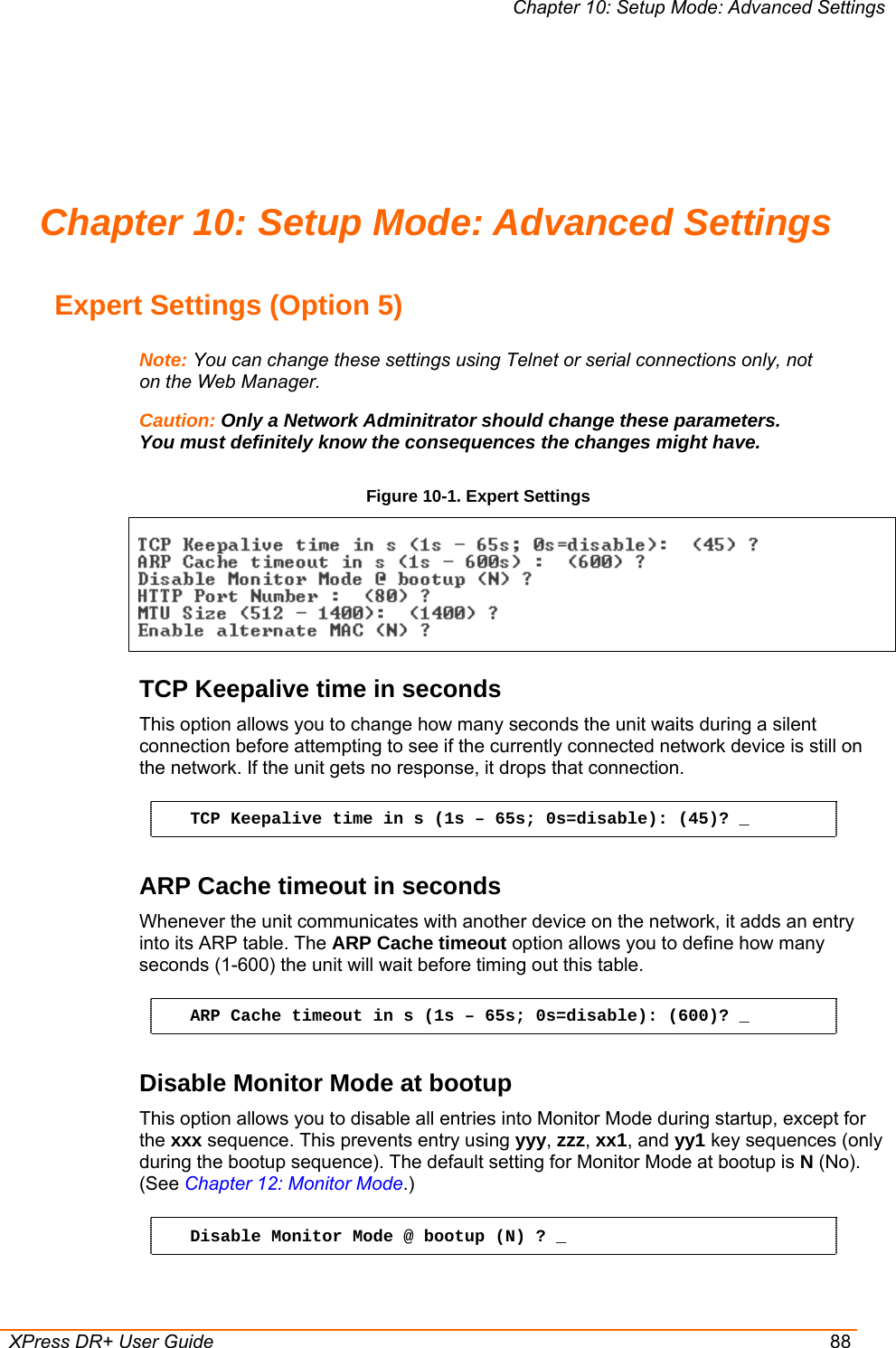
![Chapter 4: XPress DR+W XPress DR+ User Guide 36 A netmask defines the number of bits taken from the IP address that are assigned for the host part. Netmask: Number of Bits for Host Part (0=default) (0) _ Note: Class A: 24 bits; Class B: 16 bits; Class C: 8 bits The unit prompts for the number of host bits to be entered, then calculates the netmask, which appears in standard decimal-dot notation (for example, 255.255.255.0) when the saved parameters display. Table 4-3. Standard IP Network Netmasks Network Class Host Bits Netmask A 24 255.0.0.0 B 16 255.255.0.0 C 8 255.255.255.0 Change Telnet Configuration Password Setting the Telnet configuration password prevents unauthorized access to Setup Mode through a Telnet connection to port 9999 or through web pages. The password must have 4 characters. Change telnet config password (N) ? _ An enhanced password setting (for Telnet access only) of 16 characters is available under Security Settings (Option 6) on page 89. Note: You do not need a password to access the Setup Mode window by a serial connection. Change DHCP Device Name: Change the DHCP name if the network is DHCP-enabled. Change DHCP device name (not set) ? (N) N Enter new DHCP device name : WLAN Configuration (Option 4) Without adequate protection, a wireless LAN is susceptible to access by unauthorized users. For that reason, XPress DR+W features the WPA security standard, based on IEEE802.11i and IEEE802.1X. WEP is provided for backwards compatibility and interaction with older devices. Note: Due to regulations, the country-specific setting has been removed from the setup menu and Web Manager. We provide a separate utility for changing the Country/Zone setting. The utility is called SetZone and is included in the XPress DR+W package. It is also available for download from the Lantronix web site. The syntax is SetZone <IP address> [<zone abbreviation>]](https://usermanual.wiki/lantronix/XSDRWLSG/User-Guide-718916-Page-36.png)
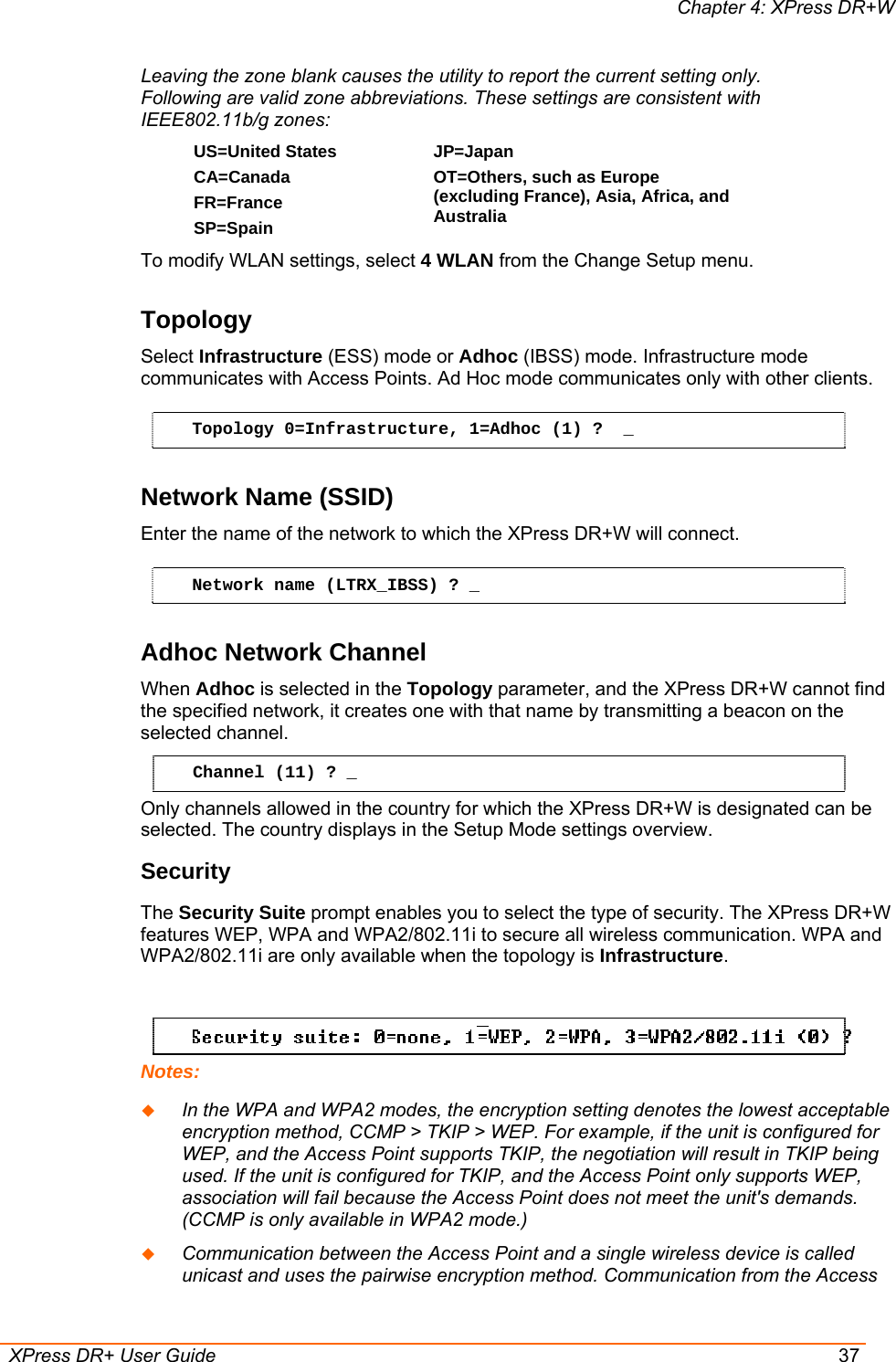
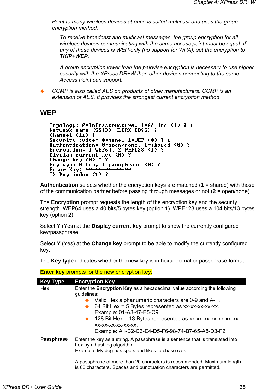
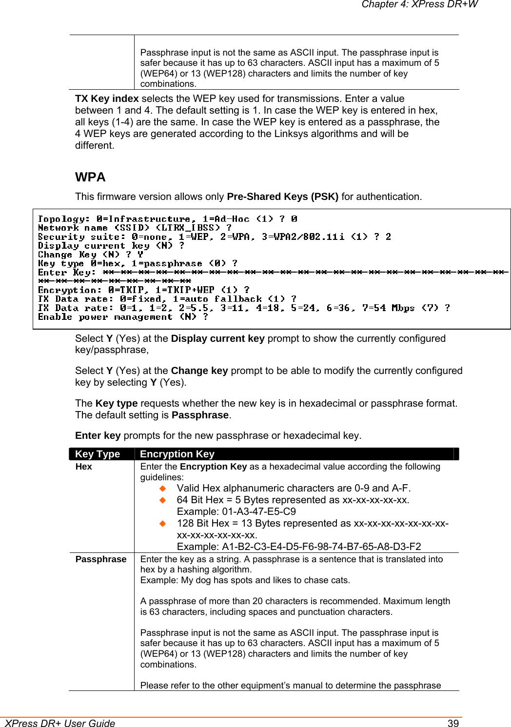
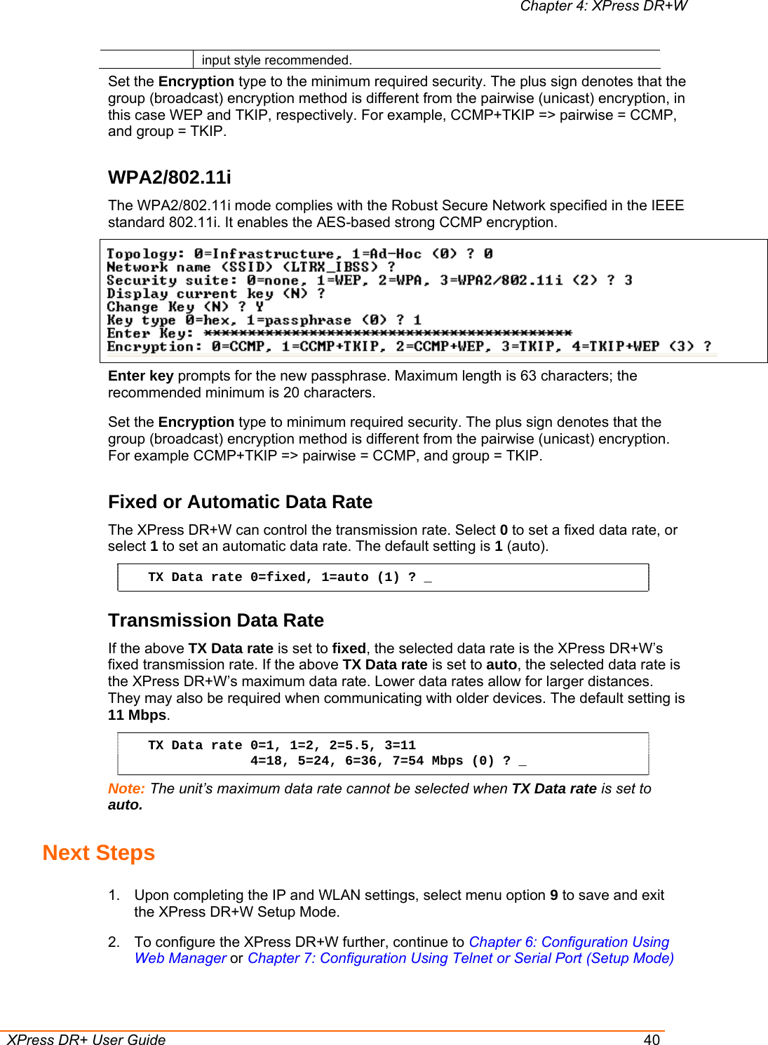
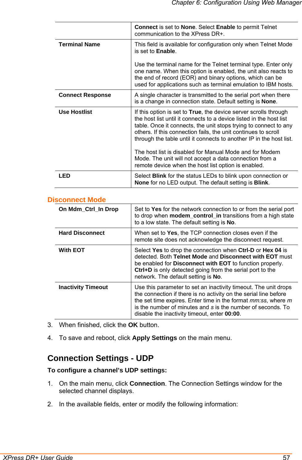
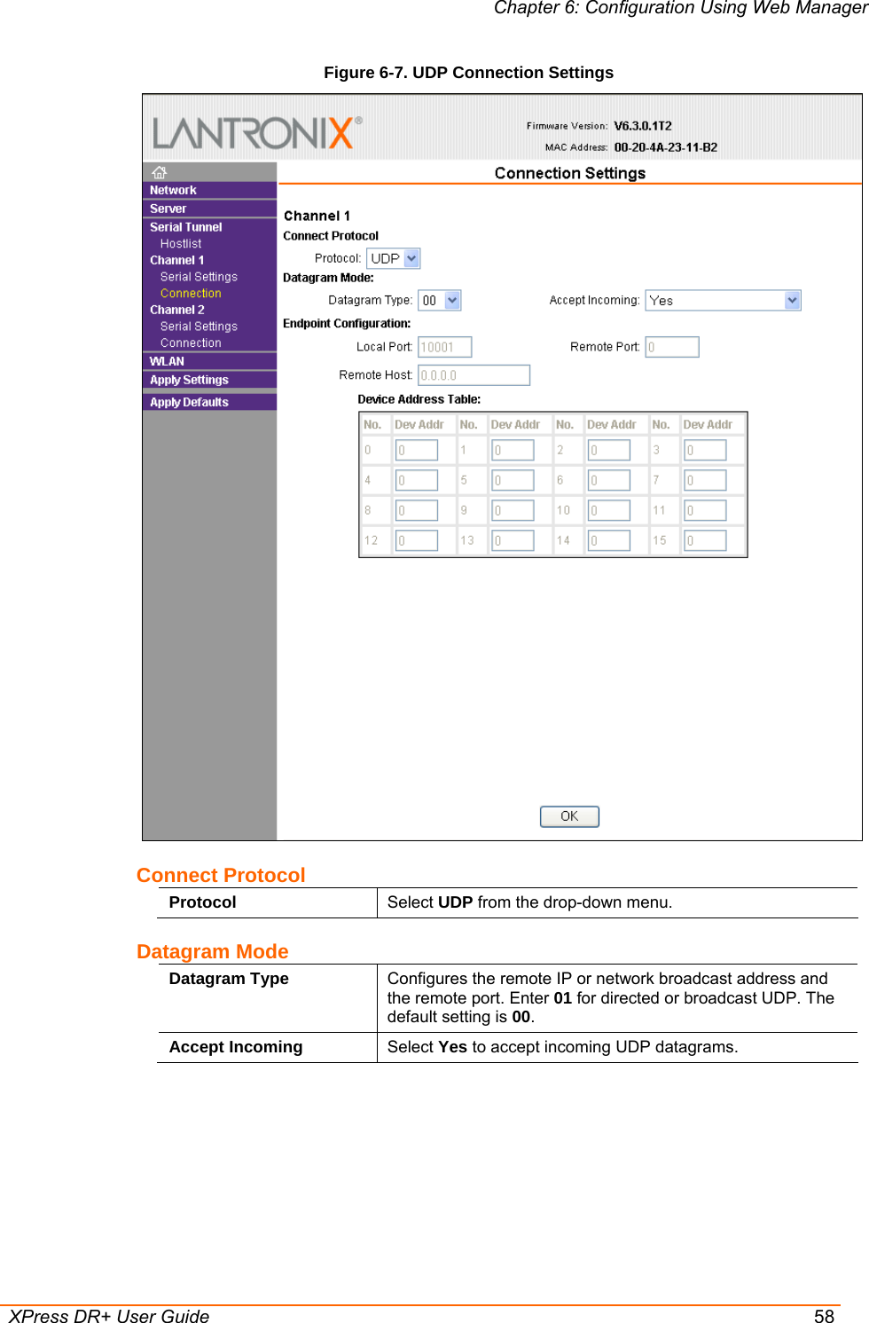
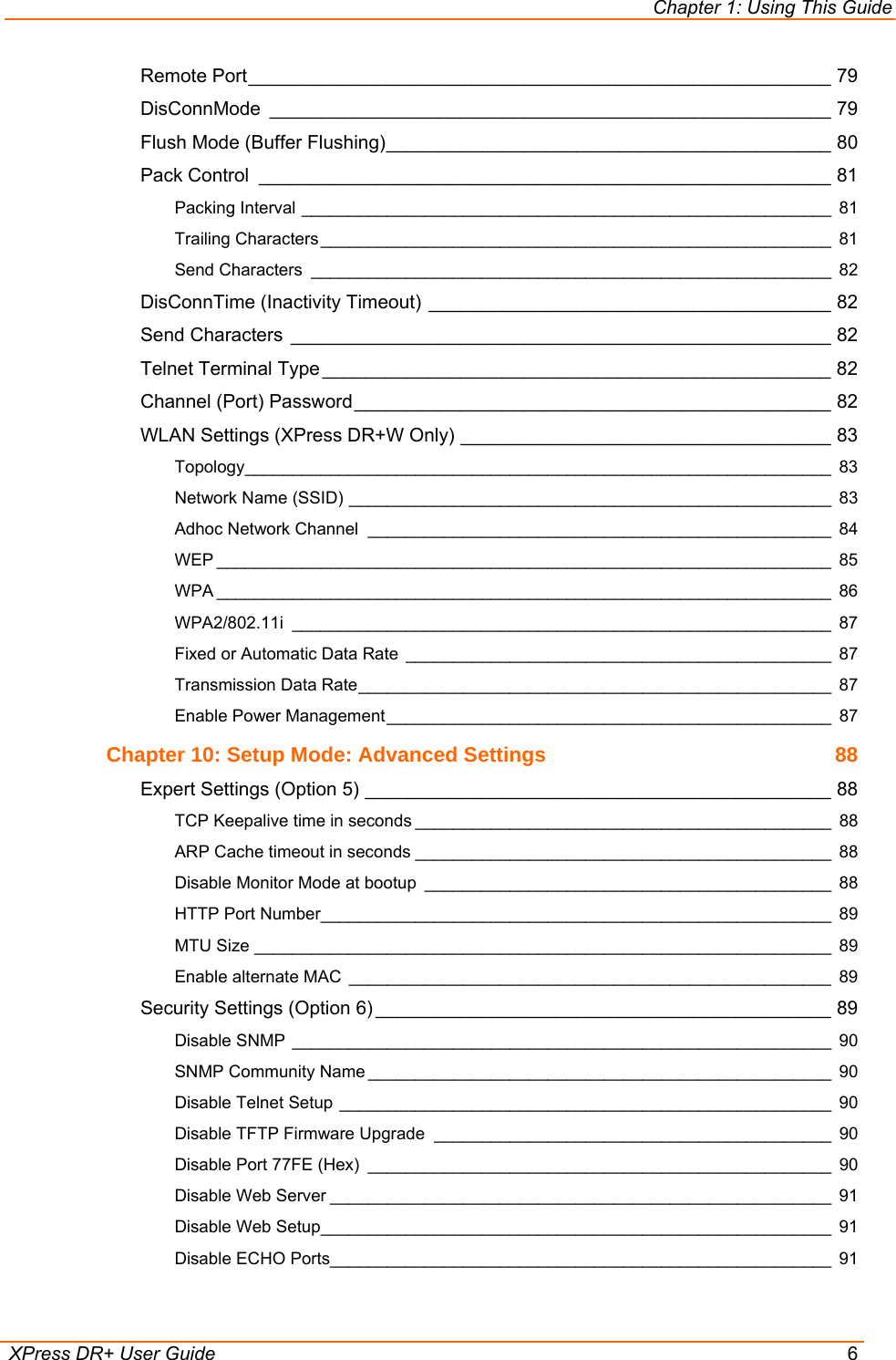
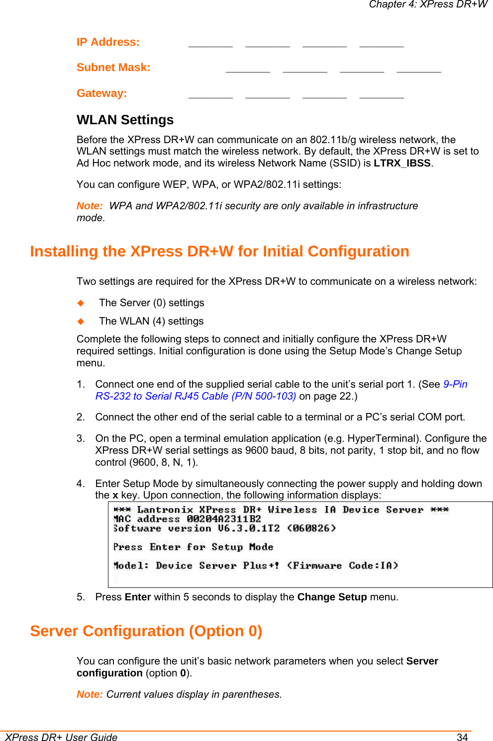
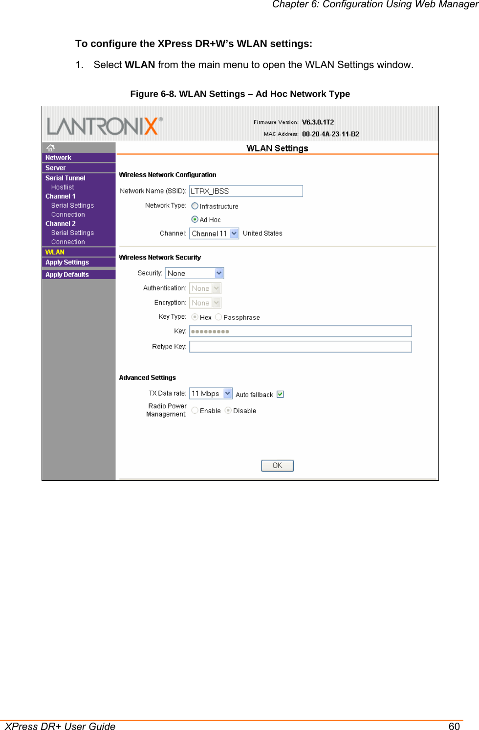
![Chapter 6: Configuration Using Web Manager XPress DR+ User Guide 59 Endpoint Configuration Local Port Enter the local port number. Remote Port Enter the port number of the remote device. Remote Host Enter the IP address of the remote device. Device Address Table The table is enabled when Datagram Type is set to FD. Enter values between 1 and 255 to identify units on the local network of device servers. Note: Lantronix Tech Support supports Datagram type 01. Datagram Type FD is for OEM use. 3. When finished, click the OK button. 4. To save and reboot, click Apply Settings on the main menu. WLAN Configuration (XPress DR+W only) Once you have initially configured the wireless unit's network and WLAN settings, you can modify them in Web Manager. For information on initial configuration, see Chapter 4: XPress DR+W. Without adequate protection, a wireless LAN is susceptible to access by unauthorized users. The XPress DR+W WLAN Settings menu permits the following actions: Configuration of the wireless network profile available for activation Configuration of the wireless network security settings Configuration of advanced settings such as radio power management Note: Due to regulations, the country-specific setting has been removed from the setup menu and Web Manager. However, we provide a separate utility for changing the Country/Zone setting. The utility is called SetZone and is included on the XPress DR+W CD. It is also available for download from the Lantronix web site. The syntax is SetZone <IP address> [<zone abbreviation>] Leaving the zone blank causes the utility to report the current setting only. Following are valid zone abbreviations. These settings are consistent with IEEE802.11b/g zones: US=United States CA=Canada FR=France SP=Spain JP=Japan OT=Others, such as Europe (excluding France), Asia, Africa, and Australia](https://usermanual.wiki/lantronix/XSDRWLSG/User-Guide-718916-Page-59.png)
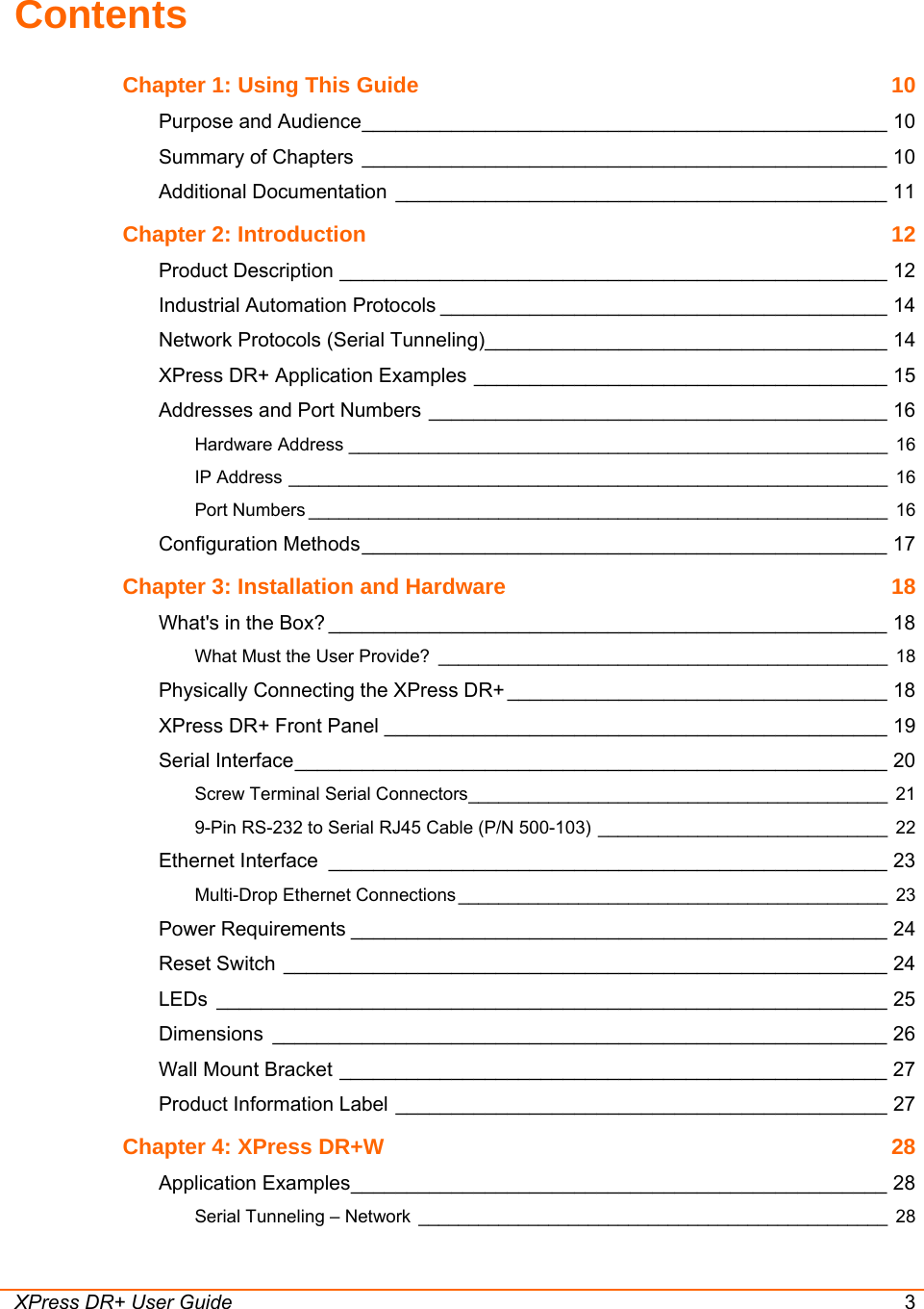
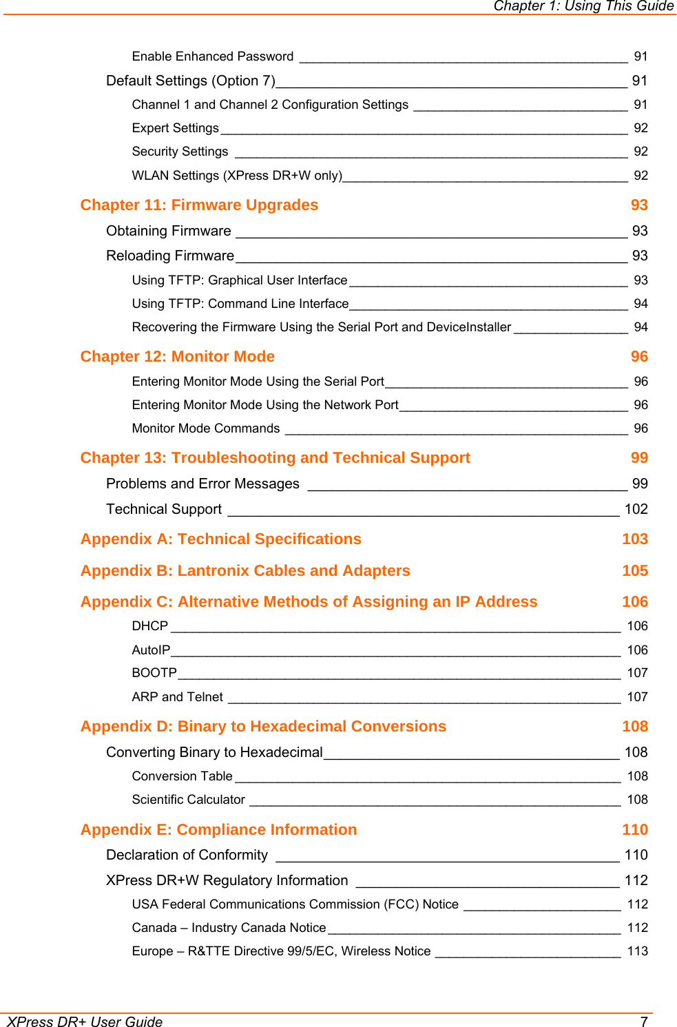
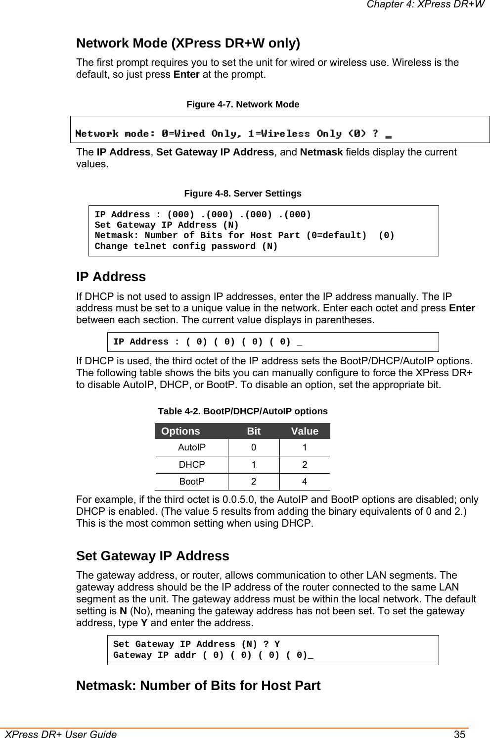
![Chapter 9: Setup Mode: Channel Configuration XPress DR+ User Guide 83 WLAN Settings (XPress DR+W Only) Note: To use DeviceInstaller for communication to an XPress DR+W over a wireless network, you must first configure the network and WLAN settings using a serial connection. See Chapter 4:XPress DR+W. Before the XPress DR+W can communicate on an 802.11b/g wireless network, the WLAN settings must match the wireless network. By default, the XPress DR+W is set to Ad Hoc network mode, and its wireless Network Name (SSID) is LTRX_IBSS. Note: Due to regulations, the country-specific setting has been removed from the setup menu and Web Manager. We provide a separate utility for changing the Country/Zone setting. The utility is called SetZone and is included in the XPress DR+W package. It is also available for download from the Lantronix web site (www.lantronix.com). The syntax is SetZone <IP address> [<zone abbreviation>] Leaving the zone blank causes the utility to report the current setting only. Following are valid zone abbreviations. These settings are consistent with IEEE802.11b/g zones: US=United States CA=Canada FR=France SP=Spain JP=Japan OT=Others, such as Europe (excluding France), Asia, Africa, and Australia Without adequate protection, a wireless LAN is susceptible to access by unauthorized users. As such, XPress DR+W features the WPA security standard, based on IEEE802.11i and IEEE802.1X. WEP is provided for backwards compatibility and interaction with older devices. To modify WLAN settings, select 4 WLAN from the Change Setup menu. Topology Select Infrastructure (ESS) mode or Adhoc (IBSS) mode. Infrastructure mode communicates with Access Points. Ad Hoc mode communicates only with other clients. Topology 0=Infrastructure, 1=Adhoc (0) ? _ Network Name (SSID) Enter the name of the network to which the XPress DR+W will connect. Network name (LTRX_IBSS) ? _](https://usermanual.wiki/lantronix/XSDRWLSG/User-Guide-718916-Page-83.png)