L-ACOUSTICS A15i 15 Inch 2-Way Passive Subwoofer Owner's Manual
File info: application/pdf · 159 pages · 18.14MB
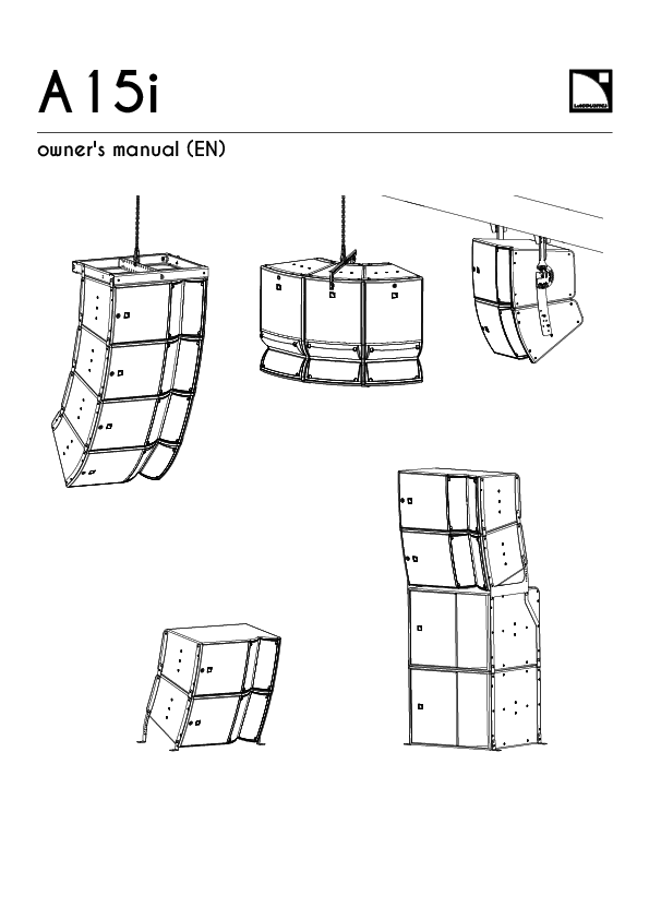
A15i owner's manual
A15i owner's manual - L-Acoustics
Refer to the LA2Xi / LA4X / LA8 / LA12X owner's manual for operating instructions. Cables speaker cable. 2.5 mm2 cable. Speaker cable used to connect enclosures ...
Download
A15i Focus - L-Acoustics
Full PDF Document

If the inline viewer fails, it will open the original document in compatibility mode automatically. You can also open the file directly.
Extracted Text
A15i
owner's manual (EN)

Document reference: A15i owner's manual (EN) version 2.1 Distribution date: May 25, 2021 � 2021 L-Acoustics. All rights reserved. No part of this publication may be reproduced or transmitted in any form or by any means without the express written consent of the publisher.

Contents
Safety................................................................................................................................................................ 5 Instructions................................................................................................................................................5
Introduction........................................................................................................................................................ 7 A15i family.............................................................................................................................................. 7 How to use this manual............................................................................................................................ 8
System components.............................................................................................................................................9 Loudspeaker cables................................................................................................................................. 10 Rigging elements.....................................................................................................................................11 Rigging plates...............................................................................................................................12
Electro-acoustical description.............................................................................................................................. 14 Adjustable ns........................................................................................................................................ 14 Directivity............................................................................................................................................... 17 Symmetrical congurations....................................................................................................................... 20 Preset description.................................................................................................................................... 21 Connectors............................................................................................................................................. 22
Rigging system description.................................................................................................................................23 A15i system rigging................................................................................................................................23 Enclosures.............................................................................................................................................. 24 A15i Wide/Focus......................................................................................................................... 24 KS21i...........................................................................................................................................26 Rigging elements for own arrays............................................................................................................ 28 A15i-BUMP................................................................................................................................... 28 M-BARi......................................................................................................................................... 29 A15i-RIGBAR................................................................................................................................ 30 A15i-LIFT...................................................................................................................................... 32 Rigging elements for other congurations.................................................................................................. 35 A-U15i......................................................................................................................................... 35 Ai-FIXBRACKET / A15i-TILTBRACKET............................................................................................... 37 A15i-TILT.......................................................................................................................................39 Front screens.......................................................................................................................................... 40
Mechanical safety.............................................................................................................................................43
Loudspeaker congurations................................................................................................................................ 46 A15i Wide/Focus line source.................................................................................................................. 46 With low-frequency element........................................................................................................... 47
3

A15i Wide/Focus line source element...................................................................................................... 48 With low-frequency element........................................................................................................... 48
Inspection and preventive maintenance............................................................................................................... 50 How to do preventive maintenance.......................................................................................................... 50 Rigging part inspection........................................................................................................................... 51 Mechanical system overview....................................................................................................................51 Acoustical check..................................................................................................................................... 55
Rigging procedures...........................................................................................................................................59 General principles...................................................................................................................................59 Tools...................................................................................................................................................... 62 Flying.....................................................................................................................................................63 Flying a vertical array with A15i-BUMP.......................................................................................... 63 Flying a vertical array with A15i-RIGBAR........................................................................................ 75 Adding a pullback with A15i-RIGBAR............................................................................................. 77 Flying a radial array with A15i-LIFT................................................................................................79 Wall-mounting or ceiling-mounting............................................................................................................ 84 Mounting an assembly with A-U15i................................................................................................ 84 Mounting an assembly on a ceiling with A15i-TILTBRACKET.............................................................. 90 Stacking................................................................................................................................................. 95 Stacking A15i Wide/Focus on KS21i with A15i-TILT........................................................................ 95 Stacking A15i Wide/Focus with A15i-TILTBRACKET........................................................................101 Securing a screen................................................................................................................................. 104
Connection to LA amplied controllers.............................................................................................................. 107 Cabling schemes...................................................................................................................................107 Cabling................................................................................................................................................109
Corrective maintenance................................................................................................................................... 113 A15i Focus.......................................................................................................................................... 113 A15i Wide.......................................................................................................................................... 121 KS21i.................................................................................................................................................. 129
Specications................................................................................................................................................. 134
APPENDIX A: Authorized congurations with A15i-LIFT...................................................................................... 151
APPENDIX B: Congurations with A-U15i......................................................................................................... 153
APPENDIX C: Recommendation for speaker cables............................................................................................ 156
APPENDIX D: Specications for custom rigging systems......................................................................................157
4

Safety
Safety
Instructions
Inspect the system before any deployment. Perform safety related checks and inspections before any deployment. Perform preventive maintenance at least once a year. Refer to the preventive maintenance section for a list of actions and their periodicity. Insufcient upkeep of the product can void the warranty. If any safety issue is detected during inspection, do not use the product before performing corrective maintenance. Check for issues. A rigging system part or fastener is missing or loose. A rigging system part exhibits: bends, breaks, broken parts, corrosion, cracks, cracks in welded joints, deformation, denting, wear, holes. A safety cue or label is missing. Never incorporate equipment or accessories not approved by L-Acoustics. Read all the related PRODUCT INFORMATION documents shipped with the products before exploiting the system.
Do not store the product on an unstable cart, stand, tripod, bracket, or table.
Beware of sound levels. Do not stay within close proximity of loudspeakers in operation. Loudspeaker systems are capable of producing very high sound pressure levels (SPL) which can instantaneously lead to permanent hearing damage to performers, production crew and audience members. Hearing damage can also occur at moderate level with prolonged exposure to sound. Check the applicable laws and regulations relating to maximum sound levels and exposure times. Work with qualied personnel for rigging the system Installation should only be carried out by qualied personnel that are familiar with the rigging techniques and safety recommendations outlined in this manual. Ensure personnel health and safety During installation and set-up personnel must wear protective headgear and footwear at all times. Under no circumstances is personnel allowed to climb on a loudspeaker assembly. Respect the Working Load Limit (WLL) of third party equipment. L-Acoustics is not responsible for any rigging equipment and accessories provided by third party manufacturers. Verify that the Working Load Limit (WLL) of the suspension points, chain hoists and all additional hardware rigging accessories is respected. Respect the maximum congurations and the recommended safety precautions. For safety issue, respect the maximum congurations outlined in this manual. To check the conformity of any conguration in regards with the safety precautions recommended by L-Acoustics, model the system in Soundvision and refer to the warnings in Mechanical Data section. Be cautious when ying a loudspeaker conguration. Before installing/raising the product, check each individual element to make sure that it is securely fastened to the adjacent element. Always verify that no one is standing underneath the product when it is being installed/raised. Never leave the product unattended during the installation process. As a general rule, L-Acoustics recommends the use of secondary safety at all times. Be cautious when ground-stacking a loudspeaker array. Do not stack the loudspeaker array on unstable ground or surface. If the array is stacked on a structure, platform, or stage, always check that the latter can support the total weight of the array. As a general rule, L-Acoustics recommends the use of safety straps at all times.

A15i owner's manual (EN) version 2.1

5

Safety
Risk of falling objects Verify that no unattached items remain on the product or assembly. Risk of tipping Remove all rigging accessories before transporting a product or an assembly. Take into account the wind effects on dynamic load. When a loudspeaker assembly is deployed in an open air environment, wind can produce dynamic stress to the rigging components and suspension points. If the wind force exceeds 6 bft (Beaufort scale), lower down and/or secure the product or the assembly.
Intended use This system is intended for use by trained personnel for professional applications.
As part of a continuous evolution of techniques and standards, L-Acoustics reserves the right to change the specications of its products and the content of its documents without prior notice. Check www.l-acoustics.com on a regular basis to download the latest document and software updates.
Long term exposure to extreme conditions may damage the product. For more information, refer to the Products weather protection document, available on the website.
Read the maintenance section of this document before servicing the product.
Contact L-Acoustics for advanced maintenance. Any unauthorized maintenance operation will void the product warranty.
This marking indicates that this product should not be disposed of with other household waste throughout the EU. To prevent possible harm to the environment or human health from uncontrolled waste disposal, recycle it responsibly to promote the sustainable reuse of material resources. To return your used device, please use the return and collection systems or contact the retailer where the product was purchased. They can take this product for environmentally safe recycling.

6

A15i owner's manual (EN) version 2.1

Introduction
Introduction
A15i family
Part of the A Series, A15i is a medium throw product line designed for installation applications up to 45 m. The highly multifunctional family includes A15i Focus and A15i Wide, passive 15'' systems with distinct coverage patterns. A15i products can be own or stacked in combinations to form vertical or horizontal line sources or used individually as congurable directivity point sources. A15i can adapt to virtually any audience geometry with two enclosure coverage options (10� or 30�), Panex for user adjustable waveguide directivity (70�, 110� or 90� asymmetrical) and a range of accessories for vertical or horizontal deployment. A15i deployment requires a single preset that is optimized to provide amazing plug-and-play performance for both A15i models regardless of Panex conguration. Performance can be further enhanced with L-Acoustics software optimization tools. A15i provides the low frequency contour of a large concert system. The dedicated KS21i subwoofer can be groundstacked or own with A15i products to reinforce contour and extend bandwidth to 29 Hz. The discreet yet powerful A15i is an ideal solution for integration applications that require aesthetics and concert level performance for venues large and small.

A15i owner's manual (EN) version 2.1

7

Introduction
How to use this manual
The A15i owner's manual is intended for all actors involved in the system design, implementation, preventive and corrective maintenance of the A15i system. It must be used as follows:
1. Read the technical description for an overview of all system elements, their features, and their compatibilities. � Electro-acoustical description (p.14) � Rigging system description (p.23)
2. Prepare the system conguration. Consider the mechanical limits and the available acoustical congurations. � Mechanical safety (p.43) � Loudspeaker congurations (p.46)
3. Before rigging the system, perform mandatory inspections and functional checks. � Inspection and preventive maintenance (p.50)
4. To deploy the system, follow the step-by-step rigging instructions and refer to the cabling schemes. � Rigging procedures (p.59) � Connection to LA amplied controllers (p.107)
The Corrective maintenance (p.113) section contains the operations authorized for the end user. Performing another operation exposes to hazardous situations. For advanced maintenance, contact your L-Acoustics representative.
As part of a continuous evolution of techniques and standards, L-Acoustics reserves the right to change the specications of its products and the content of its document without prior notice. Please check www.l-acoustics.com on a regular basis to download the latest document and software updates.
Contact information
For information on advanced corrective maintenance: � contact your Certied Provider or your L-Acoustics representative � for Certied Providers, contact the L-Acoustics customer service: customer.service@l-acoustics.com
Symbols
The following symbols are used in this document: This symbol indicates a potential risk of harm to an individual or damage to the product. It can also notify the user about instructions that must be strictly followed to ensure safe installation or operation of the product.
This symbol noties the user about instructions that must be strictly followed to ensure proper installation or operation of the product.
This symbol noties the user about complementary information or optional instructions.

8

A15i owner's manual (EN) version 2.1

System components

System components

Loudspeaker enclosures

A15i Focus A15i Wide KS21i

2-way passive constant curvature WST� 10� enclosure: 15" LF + 3" HF diaphragm (installation version)
2-way passive constant curvature WST� 30� enclosure: 15" LF + 3" HF diaphragm (installation version)
High power compact subwoofer: 1 x 21" (installation version)

Powering and driving system

LA2Xi / LA4X / LA8 / Amplied controller with DSP, preset library and networking capabilities LA12X

Refer to the LA2Xi / LA4X / LA8 / LA12X owner's manual for operating instructions.

Cables speaker cable
custom 2-point speakON cable

2.5 mm2 cable Speaker cable used to connect enclosures in parallel. Adapt the cable length to the installation. 2-point speakON cable (2.5 mm2 gauge) to bare wire cable
This cable needs to be custom made.

Information about the connection of the enclosures to the LA amplied controllers is given in this document. Refer to the LA2Xi / LA4X / LA8 / LA12X owner's manual for detailed instructions about the whole cabling scheme, including modulation cables and network.
Rigging elements

Ai-FIXBRACKET

Fastening bracket for A15i, A10i and KS21i

A15i-TILTBRACKET Fastening bracket with angles for A15i

A15i-TILT

Rigging element with angles for A15i above or under KS21i

KS21i-LINK

Rigging plates for KS21i

KS21i-ENDLINK

End rigging plates for KS21i

KS21i-SLINK

Rear rigging plates for A15i and A10i onto or under KS21i

KS21i-ENDSLINK

End rear rigging plates for A15i and A10i onto or under KS21i

A15iFOCUS-LINK

Rigging plates for A15i Focus

A15iWIDE-LINK

Rigging plates for A15i Wide

A15iWIDE-ENDLINK End rigging plates for A15i Wide

A15iFOCUS-ENDLINK End rigging plates for A15i Focus

A15i-ULINK

Rigging plates for ying two A15i with A-U15i

A15iKS21i-ULINK

Rigging plates for ying A15i under KS21i with A-U15i

KS21i-ULINK

Rigging plates for ying two KS21i with A-U15i

A15i-BUMP

Flying frame for vertical deployment of A15i and KS21i

A15i-LIFT

Rigging element for horizontal deployment of A15i

A15i-RIGBAR

Rigging bar and pullback for A15i and KS21i

A15i owner's manual (EN) version 2.1

9

System components

A-U15i CLAMP250 M-BARi

U-bracket for A15i and KS21i Clamp certied for 250 kg Extension bar for rigging frame (installation version)

Transportation accessories

A15iFOCUS-SCREEN Acoustically transparent front screen for A15i Focus

A15iWIDE-SCREEN Acoustically transparent front screen for A15i Wide

A15iFOCUS-SCREEN- Acoustically transparent front screen for A15i Focus with A15i-LIFT LIFT

A15iWIDE-SCREEN- Acoustically transparent front screen for A15i Wide with A15i-LIFT LIFT

KS21i-SCREEN

Acoustically transparent front screen for KS21i

Software applications

Soundvision

3D acoustical and mechanical modeling software

LA Network Manager Software for remote control and monitoring of amplied controllers

Refer to the Soundvision help. Refer to the LA Network Manager help.

Loudspeaker cables

+

+ 2.5 mm2 cable

+ -
2-point speakON cable (2.5 mm2 gauge)
to bare wire cable This cable needs to be custom made.

10

A15i owner's manual (EN) version 2.1

Rigging elements

System components

CLAMP250

A15i-BUMP

M-BARi

A15i-RIGBAR

A15i-LIFT

A-U15i

A15iFOCUS-SCREEN

A15iWIDE-SCREEN

A15iFOCUSSCREEN-LIFT

A15iWIDESCREEN-LIFT

KS21i-SCREEN

A15i owner's manual (EN) version 2.1

11

System components
Rigging plates
On enclosure

x2

x2

A15iFOCUS-LINK
Rigging plates for A15i Focus

x2

x2

A15iFOCUS-ENDLINK
End rigging plates for A15i Focus

x2

x2

A15iWIDE-LINK
Rigging plates for A15i Wide

x2

x2

A15iWIDE-ENDLINK
End rigging plates for A15i Wide

x2

x2

KS21i-LINK
Rigging plates for KS21i

x4
KS21iENDLINK
End rigging plates for KS21i

x2

x2

KS21i-SLINK
Rigging plates for A15i under KS21i

x2

x2

KS21i-ENDSLINK
End rigging plates for A15i under KS21i

x4

x2

x2

AiFIXBRACKET
Fastening brackets for A15i, A10i and KS21i

A15i-TILTBRACKET
Fastening brackets with angles for A15i

12

A15i owner's manual (EN) version 2.1

Inter-enclosure

System components

x2

x2

x2

KS21i-ULINK A15iKS21i-ULINK A15i-ULINK

Rigging plates for ying two KS21i
with A-U15i

Rigging plates for ying A15i under KS21i with A-U15i

Rigging plates for ying two A15i with A-U15i

x2
A15i-TILT Rigging elements with angles for A15i above or under KS21i

A15i owner's manual (EN) version 2.1

13

Electro-acoustical description
Electro-acoustical description
Adjustable ns
A15i Focus and A15i Wide feature L-Fins to adjust the waveguide directivity to one of four settings: 110� / 70� symmetric or 90� asymmetric (35�/55� or 55�/35�). The same [A15] preset drives all directivity settings of both enclosures.
Within a line source, combine A15i Focus and A15i Wide with custom directivity settings to improve SPL mapping and throw capability. 110� setting

55�

55�

14

A15i owner's manual (EN) version 2.1

70� setting Setting the ns in the 35� position offers an additional 2 dB on-axis (> 2 kHz).

Electro-acoustical description

35�

35�

90� settings Setting the ns in the 90� position offers an additional 1 dB on-axis (> 2 kHz).

35� 55�

55�

35�

55� 35�

A15i owner's manual (EN) version 2.1

15

Electro-acoustical description
Mixed settings

35� 55�

35� 55�

16

A15i owner's manual (EN) version 2.1

Electro-acoustical description

Directivity

A15i Focus

A15i Focus generates an enclosure directivity pattern of 10� and a waveguide directivity pattern of 70� / 110� symmetric or 90� asymmetric (-6 dB) depending on the ns settings.

Angle (�)

90 80 70 60 50 40 30 20 10
0 -10 -20 -30 -40 -50 -60 -70 -80 -90
1001 00010 000

Frequency (Hz)

Dispersion angle diagram of one upright A15i Focus, using lines of equal sound pressure at -3 dB, -6 dB, -12 dB.

Angle (�)

180 160 140 120 100
80 60 40 20
0 -20 -40 -60 -80 -100 -120 -140 -160 -180
1001 00010 000

Frequency (Hz)

Dispersion angle diagram of one A15i Focus with 110� ns setting, using lines of equal sound pressure at -3 dB, -6 dB, -12 dB.

A15i owner's manual (EN) version 2.1

17

Electro-acoustical description

Angle (�)

180 160 140 120 100
80 60 40 20
0 -20 -40 -60 -80 -100 -120 -140 -160 -180
1001 00010 000

Frequency (Hz)

Dispersion angle diagram of one A15i Focus with 70� ns setting, using lines of equal sound pressure at -3 dB, -6 dB, -12 dB.

18

A15i owner's manual (EN) version 2.1

Electro-acoustical description

A15i Wide

A15i Wide generates an enclosure directivity pattern of 30� and a waveguide directivity pattern of 70� / 110� symmetric or 90� asymmetric (-6 dB) depending on the ns settings.

Angle (�)

90 80 70 60 50 40 30 20 10
0 -10 -20 -30 -40 -50 -60 -70 -80 -90
1001 00010 000

Frequency (Hz)

Dispersion angle diagram of one upright A15i Wide, using lines of equal sound pressure at -3 dB, -6 dB, -12 dB.

Angle (�)

180 160 140 120 100
80 60 40 20
0 -20 -40 -60 -80 -100 -120 -140 -160 -180
1001 00010 000

Frequency (Hz)

Dispersion angle diagram of one A15i Wide with 110� ns setting, using lines of equal sound pressure at -3 dB, -6 dB, -12 dB.

A15i owner's manual (EN) version 2.1

19

Electro-acoustical description

Angle (�)

180 160 140 120 100
80 60 40 20
0 -20 -40 -60 -80 -100 -120 -140 -160 -180
1001 00010 000

Frequency (Hz)

Dispersion angle diagram of one A15i Wide with 70� ns setting, using lines of equal sound pressure at -3 dB, -6 dB, -12 dB.

Symmetrical congurations
The A15i rigging system is designed to enable a completely symmetrical setup for stereo applications.

20

A15i owner's manual (EN) version 2.1

Electro-acoustical description

Preset description

[A15]

outputs OUT 1 OUT 2 OUT 3 OUT 4

channels PA PA PA PA

routing IN A IN A IN A IN A

gain 0 dB 0 dB 0 dB 0 dB

[A15_FI]

outputs OUT 1 OUT 2 OUT 3 OUT 4

channels PA PA PA PA

routing IN A IN A IN B IN B

gain 0 dB 0 dB 0 dB 0 dB

[KS21_60]

outputs OUT 1 OUT 2 OUT 3 OUT 4

channels SB SB SB SB

routing IN A IN A IN A IN A

gain 0 dB 0 dB 0 dB 0 dB

[KS21_60_C] [KS21_60_Cx]

loudspeaker elements SR SB SB SB

outputs OUT 1 OUT 2 OUT 3 OUT 4

channels SR SB SB SB

routing IN A

delay 0 ms 0 ms 0 ms 0 ms

polarity + + + +

mute ON ON ON ON

delay 0 ms 0 ms 0 ms 0 ms

polarity + + + +

mute ON ON ON ON

delay 0 ms 0 ms 0 ms 0 ms

polarity + + + +

mute ON ON ON ON

gain 0 dB

delay 0 ms

polarity +

mute ON ON ON ON

A15i owner's manual (EN) version 2.1

21

Electro-acoustical description

Connectors
Each set of terminal block connectors (+ and -) can be used interchangeably as IN or LINK connector.

A15i FOCUS

Weight: 33 kg / 73 lb
SAFE USE: 8 A15i WIDE/FOCUS in vertical array or 3 A15i WIDE/FOCUS in horizontal array
FOR OTHER CONFIGURATIONS, CHECK MECHANICAL SAFETY WITH SOUNDVISION SOFTWARE. USE ONLY WITH L-ACOUSTICS AMPLIFIED CONTROLLERS.

1+ = IN + 1 = IN
Znom. = 8

1 1+ 1 1+

Read manual and safety instructions before use

Made in France European Community

A15i WIDE

Weight: 29 kg / 64 lb
SAFE USE: 8 A15i WIDE/FOCUS in vertical array or 3 A15i WIDE/FOCUS in horizontal array
FOR OTHER CONFIGURATIONS, CHECK MECHANICAL SAFETY WITH SOUNDVISION SOFTWARE. USE ONLY WITH L-ACOUSTICS AMPLIFIED CONTROLLERS.

1+ = IN + 1 = IN
Znom. = 8

1 1+ 1 1+

Read manual and safety instructions before use

Made in France European Community

A15i Focus
1 � 4-point terminal block with push-in connection

A15i Wide
1 � 4-point terminal block with push-in connection

Internal pinout for L-Acoustics 2-way passive enclosures

terminal block points

IN +

IN -

Transducer connectors

+

-

KS21i 1 � 4-point terminal block with push-in connection

Internal pinout for L-Acoustics subwoofers

terminal block points Transducer connectors

IN + LF +

22

IN LF -
A15i owner's manual (EN) version 2.1

Rigging system description
Rigging system description
A15i system rigging
The A15i system is the installation version of the A15 system and features a simplied rigging system to optimize visual impact. The enclosures are assembled together with rigging plates and rigging accessories suited for installation. Like the A15 system, the enclosures can be deployed in vertical or horizontal arrays. Multiple rigging kits are available depending on the desired conguration (refer to Rigging plates (p.12)).

The logo on the enclosure front can be rotated to adapt to every conguration.

A15i owner's manual (EN) version 2.1

23

Rigging system description

Enclosures

A15i Wide/Focus

A15i Wide/Focus is compatible with two types of rigging plate kits:

� standard rigging plates (A15iFOCUS-LINK / A15iWIDE-LINK)

� end rigging plates (A15iFOCUS-ENDLINK / A15iWIDE-ENDLINK)

A15iFOCUS-LINK can be used to add an inter-element angle of 5� between two A15i Focus.

A15i Wide/Focus feature on each side:

� Four M6 inserts for own congurations with a rigging frame or stacked congurations.

� Three M8 inserts for wallmounting or ceiling-mounting with a bracket.

� Two M6 inserts for securing a screen.

The inserts are tted with placeholder screws.
24

A15i owner's manual (EN) version 2.1

Rigging screws Only use the rigging screws provided by L-Acoustics. Do not use the placeholder screws for rigging.

Rigging system description

Always put the placeholder screws back in place to avoid leaks. A15i Wide/Focus feature two lodgings to create radial arrays with A15i-LIFT (p.32).

A DIN580-compatible M8 threaded insert is available to implement a secondary safety.

A15i owner's manual (EN) version 2.1

25

Rigging system description
Four M6 inserts are available at the back of A15i Wide/Focus for compatible rigging accessories. 75 mm / 3 in

127 mm / 5 in

KS21i
KS21i is compatible with four types of rigging plate kits: � standard rigging plates
(KS21i-LINK)

� S-shaped standard rigging plates (KS21i-SLINK)

� end rigging plates (KS21i-ENDLINK)

� S-shaped end rigging plates (KS21i-ENDSLINK)

26

A15i owner's manual (EN) version 2.1

Rigging system description
S-shaped rigging plates are used to transition from a KS21i array to a A15i Wide/Focus array.

KS21i features 18 inserts on each side:

� 12 M6 inserts for own congurations with a rigging frame.

� Two M8 inserts for wall-mounting or ceiling-mounting with a bracket.

� Four M6 inserts for securing a screen in standard or cardioid conguration.

The inserts are tted with placeholder screws. Rigging screws Only use the rigging screws provided by L-Acoustics. Do not use the placeholder screws for rigging.
Always put the placeholder screws back in place to avoid leaks.

A15i owner's manual (EN) version 2.1

27

Rigging system description
Rigging elements for own arrays A15i-BUMP
A15i-BUMP is a reversible rigging frame for ying vertical arrays of A15i Wide/Focus or KS21i.
A15i-BUMP is secured to the array with four M6x18 rigging screws and M6 nuts (provided).

Multiple pickup points are available for site angle adjustments: 16 pickup points on each side, one front pickup point (F), and one rear pickup point (R). They are compatible with �12 mm shackles WLL 1 t (two provided) and CLAMP250.

1 2 3 4 5 6 7 8 9 10 11 12 13 14 15 16

F

R

FRONT

1 2 3 4 5 6 7 8 9 10 11 12 13 14 15 16

28

A15i owner's manual (EN) version 2.1

Rigging system description
A15i-BUMP can be used as the main lifting accessory for ying vertical arrays of A15i Wide/Focus and KS21i with one or two lifting points.

M-BARi
The M-BARi extension bar can be secured on A15i-BUMP to extend the site angle capability of A15i Wide/Focus and KS21i arrays. It can be used as a front or rear extension. M-BARi is secured to the rigging frame with two rigging axes, nuts, and safety pins.
rigging axes

A15i owner's manual (EN) version 2.1

29

Rigging system description
Seventeen pickup points are available. They are compatible with �19 mm shackles WLL 3.25 t (two provided). 0 1 2 3 4 5 6 7 8 9 10 11 12 13 14 15 16
A15i-RIGBAR
A15i-RIGBAR is a rigging bar for pullback congurations.
Secured at the bottom of the array, A15i-RIGBAR can be used as a pullback either with A15i-BUMP or with another A15iRIGBAR as the main lifting accessory.

30

A15i owner's manual (EN) version 2.1

Rigging system description
When used at the top of the array as the main lifting accessory, A15i-RIGBAR can be secured at the front for an initial positive site angle.
A15i-RIGBAR is secured to the enclosure with two M6x40 screws (provided).

A15i owner's manual (EN) version 2.1

31

Rigging system description
The pickup points are compatible with �12 mm shackles WLL 1 t (two provided) and CLAMP250. When using A15i-RIGBAR as the main lifting accessory, always implement a secondary safety using available holes.
One pickup point pickup point safety points
Two pickup points safety point pickup points
A15i-LIFT
A15i-LIFT is a rigging element designed to y a radial array of up to three A15i Wide/Focus. A15i-LIFT features two studs that match the lodgings at the front and rear of the enclosure.
studs

32

A15i owner's manual (EN) version 2.1

Rigging system description
Additional safety with A15i-LIFT On each enclosure on which A15i-LIFT is secured, secure a DIN580 eye bolt to the dedicated insert to implement a secondary safety. Use a shackle and a steel wire rope. Make sure the steel rope is as tensed as possible without bearing the load.
A scalable radial array of A15i Wide/Focus can be created using multiple A15i-LIFT. A15i-LIFT quantity and position Use one A15i-LIFT for up to three enclosures in the array. Do not leave more than two adjacent enclosures unsupported. Refer to APPENDIX A: Authorized congurations with A15i-LIFT (p.151).
Risk of tilting When using a single motor or a bridle, make sure the array is symmetrical. When using a third-party bridle, make sure the angle between the two chains does not exceed 60�.

A15i owner's manual (EN) version 2.1

33

Rigging system description
Seventeen holes are available for site angle adjustment. They are compatible with �12 mm shackles WLL 1 t (two provided) and CLAMP250.
A15i-LIFT pickup point Select the same pickup point on each A15i-LIFT within an array of up to 6 enclosures. For larger arrays, refer to Radial arrays of 7 enclosures and more (p.152).
FRONT 1 2 3 4 5 6 7 8 9 10 11 12 13 14 15 16 17
A15iFOCUS-SCREEN-LIFT and A15iWIDE-SCREEN-LIFT are dedicated screens for A15i Wide/Focus enclosures on which A15i-LIFT is secured.

34

A15i owner's manual (EN) version 2.1

Rigging system description
Rigging elements for other congurations A-U15i
A-U15i is a U-bracket for mounting A15i Wide/Focus or KS21i on a ceiling, a wall, or a truss.

In combination with A15i-ULINK, A15iKS21i-ULINK, or KS21i-ULINK, A-U15i can be used to mount or y vertical arrays of two A15i Wide/Focus or KS21i.

Do not use rigging plates other than A15i-ULINK / A15iKS21i-ULINK / KS21i-ULINK between two enclosures mounted on A-U15i.

A15i owner's manual (EN) version 2.1

35

Rigging system description
A-U15i is secured to each side of the enclosure by two M8 screws: the central screw and the angulation screw.
central screw angulation screw Position the central screw in the bottom insert to reduce space between the enclosure and the ceiling.
angulation screw central screw The angle can be set between -30� and +30� in 5� or 10� steps. Refer to the label to position the angulation screw. See APPENDIX B: Congurations with A-U15i (p.153) for a list of authorized congurations.

A-U15i
Weight: 4.9 kg / 11 lb WLL: 110 kg / 243 lb
SAFE USE: 2 enclosures in vertical deployment or 1 enclosure in horizontal deployment.
FOR OTHER CONFIGURATIONS, CHECK MECHANICAL SAFETY WITH SOUNDVISION SOFTWARE.

Read manual and safety instructions before use
Made in France European Community

A-U15i must be secured to the supporting xture with four M10 screws or a truss clamp. Fasteners for wall-mounting or ceiling-mounting Select screw length and anchors applicable to the wall or ceiling properties.

36

A15i owner's manual (EN) version 2.1

Rigging system description
Ai-FIXBRACKET / A15i-TILTBRACKET
Ai-FIXBRACKET is a set of four fastening brackets for A15i Wide/Focus and KS21i. The enclosure is secured to AiFIXBRACKET using the slotted hole.
Secure Ai-FIXBRACKET at the bottom of an array to improve stability.

A15i-TILTBRACKET is a set of four fastening brackets with site angle adjustment for a stack of up to four A15i Wide/ Focus. The enclosure is secured to A15i-TILTBRACKET using the round hole.

A15i owner's manual (EN) version 2.1

37

Rigging system description
Secure A15i-TILTBRACKET at the bottom of an array of up to two A15i Wide/Focus to adjust the site angle.
The angle can be set between 0� and -25� in 2.5� steps. -25� -22.5� -20� -17.5� -15� -12.5� -10� -7.5� -5� -2.5� 0�
Ai-FIXBRACKET and A15i-TILTBRACKET can also be used to mount up to two A15i Wide/Focus or KS21i under the ceiling.

Ai-FIXBRACKET and A15i-TILTBRACKET must be secured to the supporting xture with four M10 screws. Fasteners for wall-mounting or ceiling-mounting Select screw length and anchors applicable to the wall or ceiling properties.

38

A15i owner's manual (EN) version 2.1

Rigging system description
A15i-TILT
A15i-TILT is a site angle adjustment accessory for linking KS21i and A15i Wide/Focus in a stacked or own array.

The inter-element angle can be set between 0� and -25� in 2.5� steps.
-25� -22.5� -20� -17.5� -15� -12.5� -10� -7.5� -5� -2.5� 0�
To know the site angle of the rst enclosure secured on A15i-TILT, refer to Realized site angles (with A15i-TILT at the rear) (p.96).

A15i owner's manual (EN) version 2.1

39

Rigging system description
Front screens
The A15i system features ve acoustically transparent front screens suitable for every conguration.

The screens are secured on top of the rigging plates with four M6 rigging screws:
� Two M6x20 screws on the ns side (A15i Wide/Focus) or vent side (KS21i). � Two M6x35 screws for A15i Wide/Focus or two M6x55 screws for KS21i on the grill side. These two screws are
secured in place of the grill screws.
Risk of damaging the ns When securing a screen to A15i Wide/Focus, make sure to use M6x20 screws on the ns side.

40

A15i owner's manual (EN) version 2.1

Rigging system description
The screws of the grill and the placeholder screws on the ns side can be removed through the rigging plates. The screens are equipped with tabs to hold the grill in place when securing the screen on the enclosure.

A15i owner's manual (EN) version 2.1

41

Rigging system description
KS21i-SCREEN can be secured to the back of KS21i when used in cardioid conguration. The cable(s) can be passed through a cutout on the screen side.
A15iFOCUS-SCREEN-LIFT and A15iWIDE-SCREEN-LIFT are dedicated screens for A15i Wide/Focus own in radial congurations. The screens are designed to t on an A15i Wide/Focus enclosure assembled with A15i-LIFT.

42

A15i owner's manual (EN) version 2.1

Mechanical safety

Mechanical safety

Flown congurations
The A15i rigging system complies with 2006/42/EC: Machinery Directive. It has been designed following the guidelines of BGV-C1.
2006/42/EC: Machinery Directive species a safety factor of 4 against the rupture. The own deployments described in this manual achieve a safety factor of 4 or more.
Refer to Soundvision for the safety factor of a specic deployment.
The safe limit gives the maximum number of elements for which the safety factor is compliant with the 2006/42/ EC: Machinery Directive, within the use dened in this manual and regardless of the other deployment parameters (site angles, inter-element angles, etc.).
The maximum limit gives the maximum number of elements for which the safety factor can be compliant with the 2006/42/EC: Machinery Directive, when the other deployment parameters provide the best mechanical conditions.
For mixed arrays refer to your Soundvision model.
A15i Wide/Focus

conguration Vertical array
Radial array Wall-mounted (horizontal) Wall-mounted (vertical) Ceiling-mounted

rigging accessory A15i-BUMP + rigging plates + M-BARi (optional) A15i-RIGBAR x2 + rigging plates A-U15i A-U15i + A15i-ULINK 1 � A15i-LIFT 2 � A15i-LIFT 3 � A15i-LIFT A-U15i A-U15i + A15i-ULINK A-U15i
A-U15i + A15i-ULINK or Ai-FIXBRACKET/A15i-TILTBRACKET + rigging plates

maximum / safe limit 8 4 1 2
1 or 3 2, 4, 5 or 6
7, 8 or 9 1 2 1
2

KS21i

conguration
Vertical array
Wall-mounted (horizontal) Wall-mounted (vertical) Ceiling-mounted

rigging accessory A15i-BUMP + rigging plates A15i-RIGBAR x2 + rigging plates A-U15i A-U15i + KS21i-ULINK A-U15i A-U15i + KS21i-ULINK A-U15i
A-U15i + KS21i-ULINK or Ai-FIXBRACKET + rigging plates

safe limit 8

maximum limit 16
4 1 2 1 2 1
2

A15i owner's manual (EN) version 2.1

43

Mechanical safety

A15i Wide/Focus under KS21i

conguration

rigging accessory

Wall-mounted (horizontal)

A-U15i + A15iKS21i-ULINK

Ceiling-mounted

A-U15i + A15iKS21i-ULINK or Ai-FIXBRACKET + rigging plates

maximum / safe limit 1 KS21i
1 A15i Wide/Focus
1 KS21i 1 A15i Wide/Focus

Other congurations For other congurations, respect the recommended maximum limit for optimal stability. A15i Wide/Focus

conguration
Stacked vertical array
Stacked vertical array with angle adjustment

rigging accessory Ai-FIXBRACKET + rigging plates A15i-TILTBRACKET + rigging plates

maximum / safe limit 4 4

KS21i

conguration
Stacked vertical array with or without Ai-FIXBRACKET

rigging accessory Ai-FIXBRACKET (optional) + rigging plates

maximum / safe limit 4

A15i Wide/Focus on KS21i

conguration Stacked on subwoofer

rigging accessory Ai-FIXBRACKET + rigging plates

maximum / safe limit 4 KS21i
4 A15i Wide/Focus

Stacked on subwoofer with angle adjustment

Ai-FIXBRACKET + A15i-TILT + rigging plates

4 KS21i 4 A15i Wide/Focus

44

A15i owner's manual (EN) version 2.1

Mechanical safety
Assessing mechanical safety
Mechanical safety of the rigging system Before any installation, always model the system in Soundvision and check the Mechanical Data section for any stress warning or stability warning.
In order to assess the actual safety of any array conguration before implementation, refer to the following warnings:
Rated working load limit (WLL) is not enough The rated WLL is an indication of the element resistance to tensile stress. For complex mechanical systems such as loudspeaker arrays, WLLs cannot be used per se to determine the maximum number of enclosures within an array or to assess the safety of a specic array conguration.
Maximum pullback angle If a pullback accessory is available, the pullback angle must not exceed a 90� negative site angle.
Mechanical modeling with Soundvision The working load applied to each linking point, along with the corresponding safety factor, will depend on numerous variables linked to the composition of the array (type and number of enclosures, splay angles) and the implementation of the ying or stacking structure (number and location of ying points, site angle). This cannot be determined without the complex mechanical modeling and calculation offered by Soundvision.
Assessing the safety with Soundvision The overall safety factor of a specic mechanical conguration always corresponds to the lowest safety factor among all the linking points. Always model the system conguration with the Soundvision software and check the Mechanical Data section to identify the weakest link and its corresponding working load. By default, a stress warning will appear when the mechanical safety goes beyond the recommended safety level.
Safety of ground-stacked arrays in Soundvision For ground-stacked arrays, a distinct stability warning is implemented in Soundvision. It indicates a tipping hazard when the array is not secured to the ground, stage or platform. It is the user's responsibility to secure the array and to ignore the warning.
Additional safety for own arrays When ying an array, use available holes to implement a secondary safety.
Considerations must be given to unusual conditions Soundvision calculations are based on usual environmental conditions. A higher safety factor is recommended with factors such as extreme high or low temperatures, strong wind, prolonged exposition to salt water, etc. Always consult a rigging specialist to adopt safety practices adapted to such a situation.

A15i owner's manual (EN) version 2.1

45

Loudspeaker congurations
Loudspeaker congurations
A15i Wide/Focus line source
In this conguration the system operates over the nominal bandwidth of the enclosures. The [A15] preset delivers a reference frequency response in medium throw applications. The A15i Wide/Focus enclosures are driven by the LA2Xi / LA4X / LA8 / LA12X amplied controllers.

Preset Frequency range (-10 dB)

[A15] 41 Hz - 20 kHz (A15i Focus) 42 Hz - 20 kHz (A15i Wide)

46

A15i owner's manual (EN) version 2.1

Loudspeaker congurations

A15i Wide/Focus line source with low-frequency element

In this conguration, the bandwidth of the A15i system is extended down to 29 Hz and the LF contour is reinforced. The [KS21_60] preset provides KS21i with an upper frequency limit at 60 Hz. The A15i Wide/Focus and KS21i enclosures are driven by the LA2Xi / LA4X / LA8 / LA12X amplied controllers.

3 A15i Wide/Focus : 2 KS21i reinforced contour

1 A15i Wide/Focus : 1 KS21i reinforced contour + 3 dB at 55 Hz

max 2.8 m / 9.2 ft

Enclosure Preset Recommended ratio Frequency range (-10 dB)

A15i Wide/Focus [A15] 1 A15i Wide/Focus : 1 KS21i 29 Hz - 20 kHz

KS21i [KS21_60]

Use [xxxx_xx_C] or [xxxx_xx_Cx] on a reversed subwoofer in a cardioid conguration The cardioid conguration consists in reversing 1 element in an array of 4 subwoofers. Refer to the subwoofer owner's manual and to the Cardioid congurations technical bulletin.
Grouping subwoofers Place the subwoofer enclosures side by side. If not possible, the maximum distance between two adjacent acoustic centers must be 2.8 m or 1.7 m if the upper frequency limit of the subwoofer system is at 60 Hz or 100 Hz, respectively.
Delay values Do not forget to add the pre-alignment and geometric delays depending on the conguration.
Pre-alignment delays

presets

pre-alignment delay values and polarity settings

[A15] or [A15_FI] + [KS21_60]

A15 Wide/Focus = 3.5 ms

KS21 = 0 ms

[A15] or [A15_FI] + [KS21_60_C] A15 Wide/Focus = 9 ms

KS21 = 0 ms

A15i owner's manual (EN) version 2.1

47

Loudspeaker congurations

presets [A15] or [A15_FI] + [KS21_60_Cx]

pre-alignment delay values and polarity settings

A15 Wide/Focus = 8 ms

KS21 = 0 ms

A15i Wide/Focus line source element
A single A15i Wide/Focus can be used as a line source element. In this conguration, the system operates over the nominal bandwidth of the enclosure. The [A15_FI] preset delivers a reference frequency response in short throw applications. The A15i Wide/Focus enclosures are driven by the LA2Xi / LA4X / LA8 / LA12X amplied controllers.

Preset Frequency range (-10 dB)

[A15_FI] 42 Hz - 20 kHz (A15i Focus) 43 Hz - 20 kHz (A15i Wide)

A15i Wide/Focus line source element with low-frequency element
With a complementary subwoofer, the system is extended in the low end and the LF contour is reinforced. The [A15_FI] preset delivers a reference frequency response in short throw applications. The [KS21_60] preset provides KS21i with an upper frequency limit at 60 Hz. The A15i Wide/Focus and KS21i enclosures are driven by the LA2Xi / LA4X / LA8 / LA12X amplied controllers.

Enclosure Preset Recommended ratio Frequency range (-10 dB)

A15i Wide/Focus [A15_FI] 1 A15i Wide/Focus : 1 KS21i 29 Hz - 20 kHz

KS21i [KS21_60]

Use [xxxx_xx_C] or [xxxx_xx_Cx] on a reversed subwoofer in a cardioid conguration The cardioid conguration consists in reversing 1 element in an array of 4 subwoofers. Refer to the subwoofer owner's manual and to the Cardioid congurations technical bulletin.
Grouping subwoofers Place the subwoofer enclosures side by side. If not possible, the maximum distance between two adjacent acoustic centers must be 2.8 m or 1.7 m if the upper frequency limit of the subwoofer system is at 60 Hz or 100 Hz, respectively.

48

A15i owner's manual (EN) version 2.1

Loudspeaker congurations

Delay values Do not forget to add the pre-alignment and geometric delays depending on the conguration.
Pre-alignment delays

presets

pre-alignment delay values and polarity settings

[A15] or [A15_FI] + [KS21_60]

A15 Wide/Focus = 3.5 ms

KS21 = 0 ms

[A15] or [A15_FI] + [KS21_60_C] [A15] or [A15_FI] + [KS21_60_Cx]

A15 Wide/Focus = 9 ms A15 Wide/Focus = 8 ms

KS21 = 0 ms KS21 = 0 ms

A15i owner's manual (EN) version 2.1

49

Inspection and preventive maintenance
Inspection and preventive maintenance
How to do preventive maintenance
Inspect the system after any corrective maintenance operation. Perform preventive maintenance at least once a year. Refer to the maintenance manuals for advanced maintenance. Rigging and hardware Perform the Rigging part inspection (p.51) on each rigging part. Use the Mechanical system overview (p.51) to identify critical parts of the system. If any parts are damaged, contact your L-Acoustics representative for further instructions. Acoustics Perform the Enclosure check (p.55). Perform the Listening test (p.57) to detect any degradation in sound quality. If necessary, refer to the Corrective maintenance (p.113) section for speaker repair kits and maintenance instructions.

50

A15i owner's manual (EN) version 2.1

Inspection and preventive maintenance

Rigging part inspection
About this task
The term "rigging part" comprises: � lifting accessories such as clamps and shackles � rigging accessories such as rigging frames, rigging interfaces, and brackets � fasteners used for assembling two products together such as ball-locking pins, rigging axes, and safety pins � rigging plates mounted on enclosures � screens mounted on enclosures
This inspection procedure covers only L-Acoustics products. To inspect other products that are part of the lifting chain, refer to the manufacturer's instructions.
Prerequisite
Perform the inspection in a well-lit environment.
Procedure
1. Check that the rigging part is present. 2. Check for:
� corrosion � wear and cracks � bends and dents � holes � missing safety cues � missing identication labels � missing or loose fasteners
Replacing screws If a screw is loose, remove and replace it. Always use the new screws provided in the repair kit. If no new screw is available, add blue threadlocker before reusing the screw. Do not apply more than the indicated torque. 3. Check the geometry of the part to identify critical deformations.
What to do next
If a problem is detected, perform the authorized maintenance operations or contact your L-Acoustics representative.

Mechanical system overview
Critical parts of the lifting chains are highlighted.

The

indicates a visual inspection.

Perform the Rigging part inspection (p.51) on critical parts.

Replacing screws If a screw is loose, remove and replace it. Always use the new screws provided in the repair kit. If no new screw is available, add blue threadlocker before reusing the screw. Do not apply more than the indicated torque.

A15i owner's manual (EN) version 2.1

51

Inspection and preventive maintenance
A15i Wide/Focus and KS21i array with A15i-BUMP and M-BARi

shackle axis end is ush with the shackle
nuts are secured and tightened

rigging axes are secured with nuts and safety pins

Rigging part inspection (p.51)

Rigging part inspection (p.51)

52

A15i owner's manual (EN) version 2.1

A15i Wide/Focus array with A15i-LIFT
shackle axis end is ush with the shackle
the studs are not bent Rigging part inspection
(p.51)

Inspection and preventive maintenance
rigging axes are secured with nuts and safety pins the front and rear inserts are not damaged

A15i Wide/Focus ceiling-mounted with A-U15i
the supporting screws are tightened

A15i owner's manual (EN) version 2.1

Rigging part inspection (p.51)
53

Inspection and preventive maintenance
A15i Wide/Focus ceiling-mounted with Ai-FIXBRACKET

the supporting screws are tightened
A15i Wide/Focus stacked on KS21i

Rigging part inspection (p.51) Rigging part inspection (p.51)

the plates are not bent

the xing brackets are present and tightened to the ground

54

A15i owner's manual (EN) version 2.1

Inspection and preventive maintenance

Acoustical check
Enclosure check
This feature is available on: LA4X LA12X
ENCLOSURE CHECK measures impedance at the reference frequencies for the connected loudspeaker family. The measured impedance is compared to the expected range allowing for fast detection of loudspeakers presenting circuit continuity issues.
The results can be used for preliminary diagnosis but cannot replace a comprehensive quality control.
Prerequisite
ENCLOSURE CHECK measurements can only be reliable if the following requirements are met:
Environment and temperature: � Ambient temperature must be comprised between 0 �C / 32 �F and 40 �C / 104 �F. Ideal temperature is 20 �C / 68 �F. � Enclosures must be at room temperature. If warm from a recent high level use or recently moved from a cold environment, let the loudspeakers reach room temperature before starting.
Enclosures: � Enclosures must be included in the embedded factory preset library. � Enclosures must be in nominal operating conditions: � Remove covers or dollies obstructing the loudspeakers or the vents. � Check for obvious physical damage or air leak: visually inspect the grill, gasket, cabinet, and connector plate for loose, missing or damaged parts.
Connection: � Use only 10 m / 30 ft 4 mm� / AWG 11 speaker cables. � Do not connect enclosures in parallel.
Amplied controllers: � LA4X must run at least rmware version 1.1.0. � LA4X load sensors must be calibrated. Refer to the Load Sensor Calibration Tool technical bulletin for more information. � LA4X must warm up for at least 10 minutes after power up. Do not power off, reboot or switch to standby mode to avoid resetting the countdown. � Load a preset corresponding to the connected loudspeaker's family. Presets from the user memories may be used on condition they are made of presets supported in the embedded factory preset library.
Procedure
1. Power up the amplied controller. Let LA4X warm up for at least 10 minutes. 2. Connect the loudspeaker enclosures to the amplied controller. 3. Load a preset from or built from the embedded library corresponding to the connected loudspeaker family. 4. On the amplied controller, use the encoder wheel to select MONITORING & INFO. Press the OK key or the
encoder wheel to validate. 5. Use the encoder wheel to select ENCLOSURE CHECK.
Beware of sound levels. Although the sound pressure levels generated for the ENCLOSURE CHECK are moderate, do not stay within close proximity of the loudspeakers and consider wearing ear protection. 6. Press the OK key or the encoder wheel to launch the ENCLOSURE CHECK.
The amplied controller generates short sinusoidal signals simultaneously for each connected output.
The amplied controller displays the results for each output.

A15i owner's manual (EN) version 2.1

55

Inspection and preventive maintenance

7. Depending on the displayed results, follow the instructions in the table.

result OK

interpretation measured impedance is within expected range

instructions enclosure is in working order electrically

?

unsupported preset family

only supported enclosures should be tested

NC Not Connected

if cables are connected:
a. inspect the cables and connections b. go to step 8 (p.56)

NOK UNDEF

measured impedance is not within expected range measured impedance is undened

a. check that all the prerequisites are met, in particular that the loaded preset corresponds to the connected speaker's family
b. inspect the cables and connections
c. go to step 8 (p.56)

8. Under NC, NOK and UNDEF results, press and hold the corresponding OUT key.
The amplied controller displays: � the tested frequencies, � information on the measured impedance: � OPEN for open circuit (found in NC results), � SHORT for short circuit (found in NOK results), or � a percentage of variation from the expected range (found in NOK and UNDEF results) � the number of operational transducers out of the total
Low variations from the expected range are acceptable: displayed percentage can be different from 0 and all transducers considered operational.

56

A15i owner's manual (EN) version 2.1

Inspection and preventive maintenance

Listening test

enclosure A15i Focus A15i Wide KS21i

preset [A15] [A15] [KS21_100]

usable bandwidth 41 Hz - 20 kHz 42 Hz - 20 kHz 31 Hz - 100 Hz

Procedure
1. Load the preset on an LA2Xi / LA4X / LA8 / LA12X amplied controller. 2. Connect a sinus generator to the amplied controller.
Risk of hearing damage Set a low sound level to start and use ear protection to adjust before testing. 3. Scan the bandwidth focusing on the usable range. The sound should remain pure and free of unwanted noise.
Troubleshooting for LF speakers
One or more LF speaker produces distorted, buzzing, rubbing, clicking, mufed or weak sound.
Possible causes
� The screws are not tightened with the appropriate torque. � There is an air leak in the gasket. � There is dust on the cone. � The cone is damaged. � The surround is torn or delaminated. � The voice coil or the spider is damaged.
Procedure
1. Perform the speaker disassembly procedure. 2. Visually inspect the cables and the connectors. 3. Visually inspect the speaker cone, the voice coil and the spider.
If any damage is visible, replace the speaker. 4. Carefully clean the speaker with a dry cloth. 5. Perform the reassembly procedure.
Replace the speaker gasket and the screws. Apply the recommended torque. 6. Repeat the listening test. If the problem persists, replace the speaker.

A15i owner's manual (EN) version 2.1

57

Inspection and preventive maintenance
Troubleshooting for HF drivers
One or more HF driver produces high-frequency harmonic distortions, strange vibrations or weak sound.
Possible causes
� There are foreign particles on the air gap. � The diaphragm is not centered correctly. � The screws used for reassembly are too loose. � The diaphragm is damaged. � The number of shims is wrong.
Procedure
1. Perform the diaphragm disassembly procedure. 2. Visually inspect the diaphragm and the voice coil.
If any damage is visible, replace the diaphragm. 3. Clean the air gap thoroughly.
Use double-face adhesive tape to remove any particles. 4. Perform the diaphragm reassembly procedure.
Pay close attention to the number of shims and the position of the diaphragm. Apply the recommended torque. 5. Repeat the listening test.
If a buzzing sound is still audible, it might be necessary to add an extra shim on the air gap.
If the problem persists, replace the driver.

58

A15i owner's manual (EN) version 2.1

Rigging procedures
Rigging procedures
General principles
Because of the highly-modular nature of the rigging system, not all possible congurations are described in the rigging procedures. This introduction provides general principles applicable for all congurations. References For information on radial congurations with A15i-LIFT, refer to APPENDIX A: Authorized congurations with A15i-LIFT (p.151). For information on wall-mounted or ceiling-mounted congurations with A-U15i, refer to APPENDIX B: Congurations with A-U15i (p.153). To know the site angle of the rst enclosure secured on A15i-TILT, refer to Realized site angles (with A15i-TILT at the rear) (p.96). Securing rigging plates on an enclosure
� Follow the curvature of the front of the enclosure when securing the rigging plates.
� Make sure that the inserts for the screens are accessible.

Driving screws Do not fully tighten the screws unless otherwise instructed. Follow the indicated torque when tightening a screw.

A15i owner's manual (EN) version 2.1

59

Rigging procedures
Securing rigging plates between two enclosures � Always secure standard rigging plates with the linking section upwards.
� After securing an enclosure to another enclosure, tighten all the screws on the supporting enclosure.
5 N.m T30

60

A15i owner's manual (EN) version 2.1

Rigging procedures
� In an A15i Wide/Focus array, make sure that the ns are on the same side. Additionally, in a KS21i / A15i Wide/ Focus mixed array, make sure that the ns of A15i Wide/Focus are on the same side as the vents of KS21i.

Screws � Always remove the relevant placeholder screws before securing the rigging plates.

� Do not use placeholder screws for rigging purposes.

A15i owner's manual (EN) version 2.1

61

Rigging procedures
Stacked congurations Fastening brackets Always secure a stacked array to the ground using Ai-FIXBRACKET / A15i-TILTBRACKET to ensure stability of the array.

Tools

Before performing rigging procedures on this product, make sure all the tools listed are available. References are given for FACOM� products in this table. Other manufacturers can be used.

Name Set of 6-point 1/4" sockets electric screwdriver with torque selector Torque screwdriver (2 - 10 N.m) 10 mm wrench

Reference RL.NANO1 / R.360NANO -
A.404 -

Distributor FACOM -
FACOM -

62

A15i owner's manual (EN) version 2.1

Flying Flying a vertical array with A15i-BUMP

Type of deployment Rigging accessories
Additional accessories Min number of operators Rigging plates

own array A15i-BUMP A15i Wide/Focus / KS21i rigging plates 2 x �12 mm shackle WLL 1 t (provided) M-BARi (optional) A15i-TILT (optional) M6x18 rigging screws (provided) M6 nuts (provided) T30 Torx bit 3

Rigging procedures

x2

x2

A15iFOCUS-LINK
Rigging plates for A15i Focus

x2

x2

A15iWIDE-LINK
Rigging plates for A15i Wide

x2

x2

KS21i-LINK
Rigging plates for KS21i

x2

x2

KS21i-SLINK
Rigging plates for A15i under KS21i

Risk of falling objects Verify that no unattached items remain on the product or assembly.
Secondary safety Use available holes on the rigging accessories to implement a secondary safety.
Flying hybrid arrays The KS21i subwoofers must always be on top of the array. Refer to Soundvision for maximum congurations.
Array orientation Under A15i-BUMP, the enclosure HF section can be oriented both ways. Under KS21i, the HF section is on the same side as the subwoofer vent.

A15i owner's manual (EN) version 2.1

63

Rigging procedures
A15i Wide/Focus array Procedure 1. Prepare the A15i Wide/Focus enclosures by removing the placeholder screws and securing rigging plates on both
sides.
2. Secure A15i-BUMP on top of A15i Wide/Focus. Optionally, secure an M-BARi on A15i-BUMP to extend the site angle capability. Use the provided rigging axes.

3. Select the pick-up point and raise the array.

1 2 3 4 5 6 7 8 9 10 11 12 13 14 15 16

F

R

FRONT

1 2 3 4 5 6 7 8 9 10 11 12 13 14 15 16

64

A15i owner's manual (EN) version 2.1

Rigging procedures

4. Secure the additional A15i Wide/Focus under the array:

a)

This step requires three operators.

Hold the enclosure at the bottom until the rigging plates are secured.

Lift the rear of the new A15i Wide/Focus and secure it to the array by pre-tightening a rigging screw on both sides.

A15i Focus site angle adjustment A15iFOCUS-LINK can be used to add an inter-element angle of 5� between two A15i Focus.

b) Remove the rigging screws at the bottom front on both sides of the supporting enclosure. c) Link the enclosures at the front with rigging screws.

d) Tighten all the screws on the supporting enclosure. Apply a torque of 5 N.m.

A15i owner's manual (EN) version 2.1

65

Rigging procedures
e) Repeat the procedure until the A15i Wide/Focus array is completed.
5. Check that all the screws are secured and tightened (5 N.m torque) and raise the array. What to do next Securing a screen (p.104)

66

A15i owner's manual (EN) version 2.1

Rigging procedures
KS21i and A15i Wide/Focus array Procedure 1. Prepare the enclosures by removing the placeholder screws and securing rigging plates on both sides.

KS21i

A15i Wide/Focus

Linking KS21i to A15i Wide/Focus Use KS21i-SLINK instead of KS21i-LINK for the last KS21i in a KS21i / A15i Wide/Focus hybrid array.

2. Secure A15i-BUMP on top of KS21i.

A15i owner's manual (EN) version 2.1

67

Rigging procedures

3. Select the pick-up point and raise the array.

1 2 3 4 5 6 7 8 9 10 11 12 13 14 15 16

F

R

FRONT

1 2 3 4 5 6 7 8 9 10 11 12 13 14 15 16

4. Secure an additional KS21i under the array:

a)

This step requires three operators.

Hold the enclosure at the bottom until the rigging plates are secured.

Lift the rear of the new KS21i and secure it to the array by pre-tightening a rigging screw on both sides.

b) Remove the rigging screws at the bottom front on both sides of the supporting KS21i.

68

A15i owner's manual (EN) version 2.1

c) Link the KS21i enclosures at the front with rigging screws.

Rigging procedures

d) Tighten all the screws on the supporting KS21i.
Apply a torque of 5 N.m. e) Repeat the procedure until the KS21i array is completed.

A15i owner's manual (EN) version 2.1

69

Rigging procedures
5. For a KS21i / A15i Wide/Focus hybrid array, secure additional A15i Wide/Focus (refer to A15i Wide/Focus array (p.64), from step 4 (p.65)). For a hybrid array using A15i-TILT, refer to KS21i / A15i Wide/Focus array with A15i-TILT (p.71).

6. Check that all the screws are secured and tightened (5 N.m torque) and raise the array. What to do next Securing a screen (p.104)

70

A15i owner's manual (EN) version 2.1

KS21i / A15i Wide/Focus array with A15i-TILT Procedure 1. Prepare a KS21i array as described in KS21i and A15i Wide/Focus array (p.67).

Rigging procedures

2. Secure A15i-TILT at the bottom of the array.
3. Prepare the rst A15i Wide/Focus by removing the placeholder screws and securing end rigging plates on both sides.

A15i owner's manual (EN) version 2.1

71

Rigging procedures
4. Secure the rst A15i Wide/Focus to A15i-TILT: a) Secure the front of the enclosure to A15i-TILT.
b) Lift the rear of the enclosure and secure it to A15i-TILT at the desired angle.
5. Prepare additional A15i Wide/Focus by removing the placeholder screws and securing rigging plates on both sides.

72

A15i owner's manual (EN) version 2.1

Rigging procedures
6. Secure the additional A15i Wide/Focus under the array: a) Remove the rigging screws at the bottom rear on both sides of the supporting A15i Wide/Focus.

b)

This step requires three operators.

Hold the enclosure at the bottom until the rigging plates are secured.

Lift the rear of the new A15i Wide/Focus and secure it to the array by pre-tightening a rigging screw on both sides.

A15i Focus site angle adjustment A15iFOCUS-LINK can be used to add an inter-element angle of 5� between two A15i Focus.

c) Remove the rigging screws at the bottom front on both sides of the top A15i Wide/Focus.

A15i owner's manual (EN) version 2.1

73

Rigging procedures
d) Link the A15i Wide/Focus enclosures at the front with rigging screws.
e) Tighten all the screws on the supporting A15i Wide/Focus. Apply a torque of 5 N.m.
f) Repeat the procedure until the A15i Wide/Focus array is completed.

7. Check that all the screws are secured and tightened (5 N.m torque) and raise the array. What to do next Securing a screen (p.104)

74

A15i owner's manual (EN) version 2.1

Flying a vertical array with A15i-RIGBAR

Type of deployment Rigging accessories
Additional accessories Min number of operators Rigging plates

own array A15i-RIGBAR A15i Wide/Focus / KS21i rigging plates 2 x �12 mm shackle WLL 1 t (provided) M6x18 rigging screws (provided) T30 Torx bit 3

Rigging procedures

x2

x2

A15iFOCUS-LINK
Rigging plates for A15i Focus

x2

x2

A15iFOCUS-ENDLINK
End rigging plates for A15i Focus

x2

x2

A15iWIDE-LINK
Rigging plates for A15i Wide

x2

x2

A15iWIDE-ENDLINK
End rigging plates for A15i Wide

x2

x2

KS21i-LINK
Rigging plates for KS21i

x4
KS21iENDLINK
End rigging plates for KS21i

x2

x2

KS21i-SLINK
Rigging plates for A15i under KS21i

x2

x2

KS21i-ENDSLINK
End rigging plates for A15i under KS21i

Risk of falling objects Verify that no unattached items remain on the product or assembly.
Secondary safety Use available holes on the rigging accessories to implement a secondary safety.
Flying hybrid arrays The KS21i subwoofers must always be on top of the array. Refer to Soundvision for maximum congurations.

A15i owner's manual (EN) version 2.1

75

Rigging procedures
Assembly Procedure 1. Prepare the rst enclosure by removing the placeholder screws and securing rigging plates on both sides.

A15i Wide/Focus 2. Secure A15i-RIGBAR at the rear of the enclosure.

KS21i

Secure A15i-RIGBAR at the front for a positive initial site angle.

A15i Wide/Focus

KS21i

3. Select the pick-up point and raise the array. 4. Follow the relevant procedure in Flying a vertical array with A15i-BUMP (p.63) from step 4 to the end.

What to do next

Adding a pullback with A15i-RIGBAR (p.77)

76

A15i owner's manual (EN) version 2.1

Rigging procedures

Adding a pullback with A15i-RIGBAR

Type of deployment Rigging accessories Additional accessories
Min number of operators

own array with pullback A15i-RIGBAR 1 x �12 mm shackle WLL 1 t (provided) M6x40 screws (provided) M6x18 rigging screws (provided) T30 Torx bit 1

Risk of falling objects Verify that no unattached items remain on the product or assembly. Secondary safety Use available holes on the rigging accessories to implement a secondary safety.
Assembly
Procedure
1. Prepare a vertical array as described in Flying a vertical array with A15i-BUMP (p.63) or Flying a vertical array with A15i-RIGBAR (p.75).
2. Raise the array until the bottom enclosure is accessible. 3. Remove the bottom screw from the rear rigging plates on each side.

4. Secure A15i-RIGBAR at the rear of the enclosure with M6�40 Torx screws. Apply a torque of 5 N.m.

A15i owner's manual (EN) version 2.1

77

Rigging procedures
5. Secure a shackle to A15i-RIGBAR and lift it with an additional motor.

78

A15i owner's manual (EN) version 2.1

Flying a radial array with A15i-LIFT

Type of deployment Rigging accessories
Additional accessories Min number of operators Rigging plates

own radial array A15i Wide/Focus rigging plates one A15i-LIFT for three enclosures LA-SLING2T or a bridle (optional) �12 mm shackles WLL 1 t (provided) M6x18 rigging screws (provided) T30 Torx bit 2

Rigging procedures

x2

x2

A15iFOCUS-LINK
Rigging plates for A15i Focus

x2

x2

A15iFOCUS-ENDLINK
End rigging plates for A15i Focus

x2

x2

A15iWIDE-LINK
Rigging plates for A15i Wide

x2

x2

A15iWIDE-ENDLINK
End rigging plates for A15i Wide

Risk of falling objects Verify that no unattached items remain on the product or assembly.
Additional safety with A15i-LIFT On each enclosure on which A15i-LIFT is secured, secure a DIN580 eye bolt to the dedicated insert to implement a secondary safety. Use a shackle and a steel wire rope. Make sure the steel rope is as tensed as possible without bearing the load.

A15i owner's manual (EN) version 2.1

79

Rigging procedures
A15i-LIFT quantity and position Use one A15i-LIFT for up to three enclosures in the array. Do not leave more than two adjacent enclosures unsupported. Refer to APPENDIX A: Authorized congurations with A15i-LIFT (p.151).
Risk of tilting When using a single motor or a bridle, make sure the array is symmetrical. Assembly Procedure 1. Place the enclosures (logo on top) at the lifting location.

80

A15i owner's manual (EN) version 2.1

Rigging procedures
2. Remove the placeholder screws and connect the enclosures at the top using the rigging plates. End links Start by using end rigging plates on the leftmost or rightmost enclosure of the array, then proceed towards the other side. Do not add inter-element angle with A15iFOCUS-LINK in radial congurations. Do not tighten the screws until all rigging plates are secured. end rigging plates
3. Tighten all the screws on the rigging plates. Apply a torque of 5 N.m.
4. Secure the A15i-LIFT bars on the array. a) Disconnect the rigging axis at the rear of A15i-LIFT.

A15i owner's manual (EN) version 2.1

81

Rigging procedures
b) Insert the stub at the front of the enclosure.
c) Insert the stub at the rear and secure the rigging axis.

5. On each A15i-LIFT, secure a shackle to the desired pickup point.
A15i-LIFT pickup point Select the same pickup point on each A15i-LIFT within an array of up to 6 enclosures. For larger arrays, refer to Radial arrays of 7 enclosures and more (p.152). 6. Raise the array until the bottom of the array is easily accessible.

82

A15i owner's manual (EN) version 2.1

Rigging procedures
For this operation, do not stand under the array. 7. Secure the enclosures at the bottom using the dedicated rigging plates.
End links Start by using end rigging plates on the leftmost or rightmost enclosure of the array, then proceed towards the other side. Do not tighten the screws until all rigging plates are secured.
end rigging plates
8. Tighten all the screws on the rigging plates (5 N.m torque). What to do next Securing a screen (p.104)

A15i owner's manual (EN) version 2.1

83

Rigging procedures

Wall-mounting or ceiling-mounting Mounting an assembly with A-U15i

Type of deployment Rigging accessories Additional accessories
Min number of operators Rigging plates

ceiling-mounting, wall-mounting A-U15i U-bracket rigging plates M8x35 rigging screws (provided) 4 x M10 screws and anchors T40 Torx bits 3

x2

x2

x2

A15i-ULINK A15iKS21i-ULINK KS21i-ULINK

Rigging plates for ying two A15i with A-U15i

Rigging plates for ying A15i under KS21i with A-U15i

Rigging plates for ying two KS21i
with A-U15i

Additional safety for own arrays When ying an array, use available holes to implement a secondary safety.
The procedure is shown with A-U15i in horizontal position. The same procedure applies for all congurations with A-U15i. Refer to APPENDIX B: Congurations with A-U15i (p.153).
Resistance value of anchoring points

Conguration A-U15i in horizontal position, with 1 enclosure Wall-mounted A-U15i in horizontal position, with 2 enclosures A-U15i in vertical position, with 1 enclosure Ceiling-mounted

Tensile load 275 daN 375 daN 40 daN 150 daN

Shear load 65 daN 75 daN 30 daN --

84

A15i owner's manual (EN) version 2.1

Assembly Procedure
Fasteners for wall-mounting or ceiling-mounting Select screw length and anchors applicable to the wall or ceiling properties. 1. Mount A-U15i on the ceiling or on the wall using four M10 screws.
When using a U-bracket horizontally, make sure the hooks are oriented upwards.
781 mm / 30.7 in

Rigging procedures

� M10 (x4)

120 mm / 4.7 in

2. Remove the placeholder screws at the center of each side of the enclosure:

KS21i

A15i Wide/Focus

Remove the two screws.

Remove the central and top screws or the central and bottom screws, depending on the desired conguration (refer to APPENDIX B: Congurations with A-U15i (p.153)).

3. Using the screws provided with A-U15i, drive a screw on both sides. Approximately 10 mm (0.4 in) of the thread must be visible.

10 mm / 0.4 in

10 mm / 0.4 in

KS21i

A15i Wide/Focus

Alternatively, drive the screw in the bottom insert for a conguration with the enclosure closer to the ceiling.

A15i owner's manual (EN) version 2.1

85

Rigging procedures
4. Mount the enclosure on A-U15i. This step requires two operators. Hold the enclosure at the bottom on each side.
5. Set the angle: For a single enclosure: a. Rotate the enclosure to align the second insert with the selected site angle.

b. Drive a screw on both sides.
c. Tighten all the screws. Apply a torque of 7 N.m.
86

A15i owner's manual (EN) version 2.1

Rigging procedures
For a two-enclosure assembly: This conguration limits the site angle. Refer to APPENDIX B: Congurations with A-U15i (p.153) for a list of possible site angles for each enclosure.
a. Slide the A15i-ULINK / A15iKS21i-ULINK / KS21i-ULINK rigging plates between A-U15i and the enclosure, with the hooks facing front.
b. Rotate the enclosure and the rigging plates to align the second insert and the rigging plates with the selected site angle.

For a an array of two A15i Wide/Focus, make sure to use the correct hole on A15i-ULINK.

A15i Wide/Focus under A15i Focus
A15i owner's manual (EN) version 2.1

A15i Wide/Focus under A15i Wide
87

Rigging procedures
c. Drive a screw on both sides.

d. Tighten all the screws. Apply a torque of 7 N.m.
6. Prepare a new enclosure.
KS21i
Remove the two placeholder screws at the center of each side of the enclosure.

A15i Wide/Focus
Remove the central and top placeholder screws at the center of each side of the enclosure.

88

A15i owner's manual (EN) version 2.1

7. Secure the enclosure to the U-bracket rigging plates. Apply a torque of 7 N.m.

Top Bottom

A15i Focus

A15i Wide

Rigging procedures
KS21i

A15i Focus

A15i-ULINK

A15i-ULINK

A15iKS21i-ULINK

A15i Wide

A15i-ULINK

A15i-ULINK

A15iKS21i-ULINK

KS21i

Not allowed

Not allowed

KS21i-ULINK
If the two enclosures are misaligned at the front, loosen the screws on the U-rigging plates and realign the two enclosures, then re-tighten the screws. What to do next Securing a screen (p.104)

A15i owner's manual (EN) version 2.1

89

Rigging procedures

Mounting an assembly on a ceiling with A15i-TILTBRACKET

Type of deployment Rigging accessories Additional accessories
Min number of operators Rigging plates

ceiling-mounting A15i-TILTBRACKET A15i Wide/Focus rigging plates M6x18 rigging screws (provided) 4 x M10 screws and anchors T30 Torx bits 3

x2

x2

A15iFOCUS-LINK
Rigging plates for A15i Focus

x2

x2

A15iFOCUS-ENDLINK
End rigging plates for A15i Focus

x2

x2

A15iWIDE-LINK
Rigging plates for A15i Wide

x2

x2

A15iWIDE-ENDLINK
End rigging plates for A15i Wide

x2

x2

KS21i-LINK
Rigging plates for KS21i

x4

x2

x2

KS21iENDLINK
End rigging plates for KS21i

A15i-TILTBRACKET
Fastening brackets with angles for A15i

Ai-FIXBRACKET / A15i-TILTBRACKET in ceiling-mounted conguration In a ceiling-mounted conguration, the array applies a force of 60 daN on the anchoring points.

90

A15i owner's manual (EN) version 2.1

Realized site angles (with A15i-TILTBRACKET at the rear)

selected angle on A15i-
TILTBRACKET 25� 22.5� 20� 17.5� 15� 12.5� 10� 7.5� 5� 2.5� 0�

realized site angle

A15i Focus

A15i Wide

20� 17.5� 15� 12.5� 10� 7.5�
5� 2.5� 0� -2.5
-5

10� 7.5� 5� 2.5� 0� -2.5� -5� -7.5� -10� -12.5� -15�

Assembly Procedure 1. Secure A15i-TILTBRACKET to the ceiling using M10 screws.
Fasteners for wall-mounting or ceiling-mounting Select screw length and anchors applicable to the wall or ceiling properties.
829 mm / 32.6 in

Rigging procedures

409 mm / 16 in

2. Prepare an enclosure by removing the placeholder screws and securing end rigging plates on both sides.

A15i owner's manual (EN) version 2.1

91

Rigging procedures
3. Secure the front of the enclosure to Ai-FIXBRACKET.
4. Lift the rear of the enclosure and secure it to A15i-TILTBRACKET at the desired angle.

0� 2.5� 5� 7.5� 10� 12.5� 15� 17.5� 20� 22.5� 25�
5. Tighten the screws on A15i-TILTBRACKET (5 N.m torque).

92

A15i owner's manual (EN) version 2.1

6. Prepare a new enclosure by removing the placeholder screws and securing rigging plates.

Rigging procedures

7. Remove the bottom screws of the supporting enclosure.
8. Link the two enclosures at the rear by pre-tightening a rigging screw on both sides. This step requires three operators. Hold the enclosure at the bottom until the rigging plates are secured. A15i Focus site angle adjustment A15iFOCUS-LINK can be used to add an inter-element angle of 5� between two A15i Focus.

A15i owner's manual (EN) version 2.1

93

Rigging procedures
9. Link the two enclosures at the front by pre-tightening a rigging screw on both sides.
10. Check that all the screws are secured and tightened (5 N.m torque).
What to do next Securing a screen (p.104)

94

A15i owner's manual (EN) version 2.1

Stacking Stacking A15i Wide/Focus on KS21i with A15i-TILT

Type of deployment Rigging accessories
Additional accessories
Min number of operators Rigging plates

stacked array A15i Wide/Focus / KS21i rigging plates Ai-FIXBRACKET A15i-TILT M6x18 rigging screws (provided) 4 x M10 screws and anchors T30 Torx bits 2

Rigging procedures

x2

x2

KS21i-LINK
Rigging plates for KS21i

x2

x2

KS21i-ENDSLINK
End rigging plates for A15i under KS21i

x2

x2

A15iFOCUS-LINK
Rigging plates for A15i Focus

x2

x2

A15iFOCUS-ENDLINK
End rigging plates for A15i Focus

x2

x2

A15iWIDE-LINK
Rigging plates for A15i Wide

x2

x2

A15iWIDE-ENDLINK
End rigging plates for A15i Wide

x2
A15i-TILT Rigging elements with angles for A15i above or under KS21i

Risk of falling objects Verify that no unattached items remain on the product or assembly.
Fastening brackets Always secure a stacked array to the ground using Ai-FIXBRACKET / A15i-TILTBRACKET to ensure stability of the array.

A15i owner's manual (EN) version 2.1

95

Rigging procedures

Ai-FIXBRACKET / A15i-TILTBRACKET in stacked conguration In a stacked conguration, the array applies a force of 110 daN on the anchoring points.
Do not use A15i-TILT between two A15i Wide/Focus.

Realized site angles (with A15i-TILT at the rear)

selected angle on A15i-TILT
-25� -22.5� -20� -17.5� -15� -12.5� -10� -7.5�
-5� -2.5�
0�

realized site angle

A15i Focus

A15i Wide

-20�

-10�

-17.5�

-7.5�

-15�

-5�

-12.5�

-2.5�

-10�

0�

-7.5�

2.5�

-5�

5�

-2.5�

7.5�

0�

10�

2.5

12.5�

5

15�

96

A15i owner's manual (EN) version 2.1

Rigging procedures
Assembly Procedure 1. Prepare a KS21i by removing the placeholder screws and securing rigging plates on both sides.
2. Secure Ai-FIXBRACKET to the ground using M10 screws. Fasteners for wall-mounting or ceiling-mounting Select screw length and anchors applicable to the wall or ceiling properties. 828 mm / 32.6 in
3. Secure KS21i to Ai-FIXBRACKET.

542 mm / 21 in

A15i owner's manual (EN) version 2.1

97

Rigging procedures
4. Secure up to three additional KS21i on top of the rst one. For the last KS21i, use KS21i-ENDSLINK and secure A15i-TILT on top.

Tighten all the screws on the previous enclosure after securing each new enclosure. 5. Prepare a A15i Wide/Focus by removing the placeholder screws and securing rigging plates on both sides.

98

A15i owner's manual (EN) version 2.1

6. Secure the front of A15i Wide/Focus on top of the array.

Rigging procedures

7. Secure the rear of the enclosure to A15i-TILT at the selected angle. Risk of crushing injury Keep ngers away from the contact area between A15i-TILT and the enclosure.

-25� -22.5� -20� -17.5� -15� -12.5� -10� -7.5� -5�
-2.5� 0�

A15i owner's manual (EN) version 2.1

99

Rigging procedures
8. Secure up to three additional A15i Wide/Focus on top of the rst one. For the last A15i Wide/Focus, use A15iFOCUS-ENDLINK / A15iWIDE-LINK.
What to do next Securing a screen (p.104)

100

A15i owner's manual (EN) version 2.1

Stacking A15i Wide/Focus with A15i-TILTBRACKET

Type of deployment Rigging accessories Additional accessories
Min number of operators Rigging plates

stacked assembly A15i Wide/Focus rigging plates A15i-TILTBRACKET M6x18 rigging screws (provided) 4 x M10 screws and anchors T30 Torx bits 2

Rigging procedures

x2

x2

A15iFOCUS-LINK
Rigging plates for A15i Focus

x2

x2

A15iFOCUS-ENDLINK
End rigging plates for A15i Focus

x2

x2

A15iWIDE-LINK
Rigging plates for A15i Wide

x2

x2

A15iWIDE-ENDLINK
End rigging plates for A15i Wide

x2

x2

A15i-TILTBRACKET
Fastening brackets with angles for A15i

Ai-FIXBRACKET / A15i-TILTBRACKET in stacked conguration In a stacked conguration, the array applies a force of 110 daN on the anchoring points.

A15i owner's manual (EN) version 2.1

101

Rigging procedures
Assembly Procedure 1. Prepare a A15i Wide/Focus by removing the placeholder screws and securing rigging plates on both sides.
2. Secure A15i-TILTBRACKET to the ground using M10 screws. Fasteners for wall-mounting or ceiling-mounting Select screw length and anchors applicable to the wall or ceiling properties. 829 mm / 32.6 in
3. Secure the front of A15i Wide/Focus to the front brackets by pre-tightening a screw in the top hole of the front brackets.

409 mm / 16 in

102

A15i owner's manual (EN) version 2.1

4. Secure the rear of the enclosure to A15i-TILTBRACKET at the desired angle.

Rigging procedures
-25� -22.5� -20� -17.5� -15� -12.5� -10� -7.5� -5� -2.5� 0�

5. Tighten the screws on A15i-TILTBRACKET.
6. Prepare a new A15i Wide/Focus enclosure by removing the placeholder screws and securing end rigging plates on both sides.

7. Secure the enclosure on top of the assembly.

What to do next Securing a screen (p.104)

A15i owner's manual (EN) version 2.1

103

Rigging procedures

Securing a screen

Accessory Additional accessories
Min number of operators

A15iFOCUS-SCREEN / A15iWIDE-SCREEN / A15iFOCUS-SCREEN-LIFT / A15iWIDE-SCREEN-LIFT / KS21i-SCREEN 2 x M6x20 screws (provided) 2 x M6x35 screws (for A15i Wide/Focus, provided) 2 x M6x55 screws (for KS21i, provided) 4 x self-sticking washers (for congurations with a U-bracket, provided) T30 Torx bit 1

Assembly
Prerequisite

Secure the screens on the enclosures after the array is fully assembled.

About this task
In radial congurations, use A15iFOCUS-SCREEN-LIFT/A15iWIDE-SCREEN-LIFT for enclosures on which A15i-LIFT is secured.

104

A15i owner's manual (EN) version 2.1

Procedure 1. Remove the placeholder screws on the ns side and the grill screws from the inserts.

Rigging procedures

2. Secure the screen using the provided rigging screws. Apply a torque of 5 N.m. Risk of damaging the ns When securing a screen to A15i Wide/Focus, make sure to use M6x20 screws on the ns side.

A15i owner's manual (EN) version 2.1

105

Rigging procedures
For congurations with A-U15i, stick the provided washers to the screen before securing it on the enclosure.
Risk of bending screen xing tabs Always use the self-sticking washers for securing screens when there are no rigging plates on the enclosure. If KS21i is reversed (cardioid conguration), connect the cables to the enclosure before securing KS21iSCREEN. Pass the cables through the cutout on the screen side. See Connection to LA amplied controllers (p.107) for cabling instructions.

106

A15i owner's manual (EN) version 2.1

Connection to LA amplied controllers

Connection to LA amplied controllers

Enclosure drive capacity per amplied controller

Make sure the total number of connected enclosures does not exceed the maximum number of enclosures per controller (refer to the footnotes).

A15i Wide/Focus KS21i

LA2Xi

LA4X

LA8

LA12X

per output */ total per output */ total per output */ total per output */ total

1 / 4 (SE), 1 / 2 (BTL)

1 / 4

2 / 8

3 / 12

1 / 4 (SE), 1 / 2 (BTL)

1 / 4

2 / 6**

2 / 8

Cabling schemes
For A15i Wide/Focus / KS21i (LA2Xi) Refer to the cabling schemes to connect the enclosures to different types of output congurations.
Refer to the LA2Xi owner's manual for more information on output congurations.

Terminal block output (SE)

4- 4+ 3- 3+

2-

2+ 1-

2.5 mm� cables

-

1+

+

-

+

Terminal block output (BTL)

4-

4+

3-

3+

2-

2.5 mm� cables

-

2+

+

1-

-

1+

+

* For passive loudspeakers, the value corresponds to the number of enclosures in parallel on the output. For active loudspeakers, the value corresponds to the number of sections in parallel on the output.
** LA8 can drive up to two KS21 or KS21i per output, but no more than six per controller at high level.

A15i owner's manual (EN) version 2.1

107

Connection to LA amplied controllers

For A15i Wide/Focus / KS21i (LA4X / LA8 / LA12X) Refer to the cabling schemes to connect the enclosures to different types of output congurations.

One-channel speakON output

custom cable 2.5 mm� cable

1- 1+ +
+

1+/1-

Two-channel speakON output

custom cable

2.5 mm� cable

1- 1+ +
+

1+/12+/2-

2.5 mm� cable

2- 2+ +
+

108

A15i owner's manual (EN) version 2.1

Connection to LA amplied controllers

Cabling

Accessory Screws and fasteners Tools
Min number of operators

connector sealing plate (provided) 4 x M5x16 screws (provided) torque screwdriver T25 Torx bit small tool or at screwdriver (3 mm or less) 1

Assembly
Prerequisite
Refer to: � APPENDIX C: Recommendation for speaker cables (p.156) � Cabling schemes (p.107)
About this task
The connector sealing plates have two cable glands: one for the input cable and one for the cable connecting to the next enclosure in parallel. The second cable gland is equipped with a protective plug. This procedure describes how to connect the input cable to the enclosure. If the enclosure must be connected in parallel, remove the protective plug from the second cable gland and proceed identically for both cables.
Procedure
1. On the connector sealing plate, remove the sealing nut from the cable gland.

A15i owner's manual (EN) version 2.1

109

Connection to LA amplied controllers
2. Insert the cable through the sealing nut and the cable gland.

3. Strip the wires of the cable.

30 mm 10 mm

2 x 2.5 mm cable

110

A15i owner's manual (EN) version 2.1

Refer to the cable manufacturer documentation for the wire color code. 4. Push the wires into the terminals.
If necessary, use a small tool in the hole next to the terminal to unlock it.

Connection to LA amplied controllers

5. Secure the connector sealing plate to the connector plate.

3 N.m
T25

A15i owner's manual (EN) version 2.1

111

Connection to LA amplied controllers
6. Tighten the sealing nut.
What to do next To remove the cables use the small tool to unlock the terminals and pull on the wires.

112

A15i owner's manual (EN) version 2.1

Corrective maintenance
Corrective maintenance
A15i Focus Introduction
This section contains the following maintenance procedures: � Grill (p.114) � Fin (p.115) � LF speaker (p.116) � Connector plate (p.117) � HF driver (p.118) � HF diaphragm (p.119)
For advanced maintenance, contact your L-Acoustics representative.
Exploded view
In order to operate, follow the order outlined here. Each assembly refers to the corresponding Disassembly/Reassembly (D/R) procedure and the necessary repair kit.
GRILL

LF SPEAKER G03547

FIN

CONNECTOR PLATE

HF DIAPHRAGM G03545

HF DRIVER G03546

A15i owner's manual (EN) version 2.1

113

Corrective maintenance
Disassembly and reassembly procedures
D/R - Grill Tools
� torque screwdriver � T30 Torx bit Repair kit G03547 KR loudspeaker 15'' A15i
�2 S221 M6�35 Torx Exploded view
For safety reasons, always use the new screws and spare parts provided in the KR. If no new screws are available, use blue threadlocker.
x2
T30

114

A15i owner's manual (EN) version 2.1

D/R - Fin Tools
� torque screwdriver � T30 Torx bit � at plastic tool Repair kit
G03547
KR loudspeaker 15'' A15i

Corrective maintenance

�5 S100143 M6�25 Torx

Prerequisite

Grill removed.

See Grill (p.114).

Exploded view
For safety reasons, always use the new screws and spare parts provided in the KR. If no new screws are available, use blue threadlocker.

Use a at tool made of smooth plastic to avoid scratching the ns.

With the at tool, unhook the n clips one by one.

3 N.m

x5
1

2

T30

A15i owner's manual (EN) version 2.1

115

Corrective maintenance
D/R - LF speaker Tools
� torque screwdriver � T30 Torx bit Repair kit G03547 KR loudspeaker 15'' A15i

�1 17873 15" LF speaker - 8  (with gasket)

�8 S247 M6�35 Torx

Prerequisite

Grill removed. Fin removed.

See Grill (p.114). See Fin (p.115).

Exploded view
For safety reasons, always use the new screws and spare parts provided in the KR. If no new screws are available, use blue threadlocker.

5 N.m
x8

T30

What to do next Perform the Acoustical check (p.55) procedures.
116

A15i owner's manual (EN) version 2.1

D/R - Connector plate
Tools
� torque screwdriver � T25 Torx bit � at tool Repair kits
G03546 - KR compression driver 3" A15i or G03545 - KR diaphragm 3" A15i

Corrective maintenance

�6 S100086 M5�16 Torx
Exploded view For safety reasons, always use the new screws and spare parts provided in the KR. If no new screws are available, use blue threadlocker.
Gradually tighten the screws following a star pattern.
Use a at tool as a lever to remove the connector plate. Position the connector plate with the connectors towards the middle of the enclosure.

3 N.m
x6

T25

A15i owner's manual (EN) version 2.1

117

Corrective maintenance
D/R - HF driver Tools
� torque screwdriver � T30 Torx bit Repair kit G03546 * KR compression driver 3" A15i

�1 D101593 3" HF driver assembly - 8

�2 S100094 M6�20 Torx

* The screws and fasteners are also provided in the G03545 (KR diaphragm 3" A15i).

Prerequisite

Connector plate removed.

See Connector plate (p.117).

Exploded view
For safety reasons, always use the new screws and spare parts provided in the KR. If no new screws are available, use blue threadlocker. Carefully disconnect the cables before removing the driver assembly. Use the positive (red) connector as a reference point to position the driver assembly.

5 N.m

x2

T30

118

A15i owner's manual (EN) version 2.1

D/R - HF diaphragm
Tools
� torque screwdriver � T20 Torx bit � 3 mm hex bit � compressed air blower Consumables
� double face adhesive tape Repair kit
G03545
KR diaphragm 3" A15i

Corrective maintenance

�1 17581 diaphragm assembly (with 2 shims)
Prerequisite
Connector plate removed. HF driver removed from the cabinet. The driver is placed on a at surface in a dust-free environment.

�4 S100082 M4�14 hex
See Connector plate (p.117). See HF driver (p.118).

Disassembly
Procedure
1. Remove the four screws securing the cover. Use the T20 Torx bit.
2. Remove the cover. 3. Carefully remove the diaphragm. 4. If there are shims on the dome, carefully remove them.
Take note of how many and what kind of shims are present.

A15i owner's manual (EN) version 2.1

119

Corrective maintenance
Reassembly About this task
For safety reasons, always use the new screws and spare parts provided in the KR.
Procedure 1. Clean the dome and the air gap.
Make sure the air gap is perfectly clean before reassembly. Use a blower or double face adhesive to remove any particle. 2. Place the same kind and number of shims that were initially present. 3. Carefully place the diaphragm, using the positive (red) connector as reference point. 4. Position the cover and turn it to align it with the screw holes. Gradually tighten the screws following a star pattern. 5. Secure the cover using four S100082 screws. Use the 3 mm hex bit. Set the torque to 3.5 Nm. What to do next Perform the Acoustical check (p.55) procedures.

120

A15i owner's manual (EN) version 2.1

Corrective maintenance
A15i Wide Introduction
This section contains the following maintenance procedures: � Grill (p.122) � Fin (p.123) � LF speaker (p.124) � Connector plate (p.125) � HF driver (p.126) � HF diaphragm (p.127)
For advanced maintenance, contact your L-Acoustics representative.
Exploded view
In order to operate, follow the order outlined here. Each assembly refers to the corresponding Disassembly/Reassembly (D/R) procedure and the necessary repair kit.
GRILL

LF SPEAKER G03547

FIN CONNECTOR PLATE

HF DIAPHRAGM G03545

HF DRIVER G03546

A15i owner's manual (EN) version 2.1

121

Corrective maintenance
Disassembly and reassembly procedures
D/R - Grill Tools
� torque screwdriver � T30 Torx bit Repair kit G03547 KR loudspeaker 15'' A15i
�2 S221 M6�35 Torx Exploded view
For safety reasons, always use the new screws and spare parts provided in the KR. If no new screws are available, use blue threadlocker.
x2
T30

122

A15i owner's manual (EN) version 2.1

D/R - Fin Tools
� torque screwdriver � T30 Torx bit � at plastic tool Repair kit
G03547
KR loudspeaker 15'' A15i

Corrective maintenance

�5 S100143 M6�25 Torx

Prerequisite

Grill removed.

See Grill (p.122).

Exploded view
For safety reasons, always use the new screws and spare parts provided in the KR. If no new screws are available, use blue threadlocker.

Use a at tool made of smooth plastic to avoid scratching the ns.

With the at tool, unhook the n clips one by one.

3 N.m

1

x5

2
T30

A15i owner's manual (EN) version 2.1

123

Corrective maintenance
D/R - LF speaker Tools
� torque screwdriver � T30 Torx bit Repair kit G03547 KR loudspeaker 15'' A15i

�1 17873 15" LF speaker - 8  (with gasket)

�8 S247 M6�35 Torx

Prerequisite

Grill removed. Fin removed.

See Grill (p.122). See Fin (p.123).

Exploded view
For safety reasons, always use the new screws and spare parts provided in the KR. If no new screws are available, use blue threadlocker.

5 N.m
x8
T30

What to do next Perform the Acoustical check (p.55) procedures.
124

A15i owner's manual (EN) version 2.1

D/R - Connector plate
Tools
� torque screwdriver � T25 Torx bit � at tool Repair kits
G03546 - KR compression driver 3" A15i or G03545 - KR diaphragm 3" A15i

Corrective maintenance

�6 S100086 M5�16 Torx
Exploded view For safety reasons, always use the new screws and spare parts provided in the KR. If no new screws are available, use blue threadlocker.
Gradually tighten the screws following a star pattern.
Use a at tool as a lever to remove the connector plate. Position the connector plate with the connectors towards the middle of the enclosure.

3 N.m
x6

T25

A15i owner's manual (EN) version 2.1

125

Corrective maintenance
D/R - HF driver Tools
� torque screwdriver � T30 Torx bit Repair kit G03546 * KR compression driver 3" A15i

�1 D101593 3" HF driver assembly - 8

�2 S100094 M6�20 Torx

* The screws and fasteners are also provided in the G03545 (KR diaphragm 3" A15i).

Prerequisite

Connector plate removed.

See Connector plate (p.125).

Exploded view
For safety reasons, always use the new screws and spare parts provided in the KR. If no new screws are available, use blue threadlocker. Carefully disconnect the cables before removing the driver assembly. Use the positive (red) connector as a reference point to position the driver assembly.

5 N.m

x2

T30

126

A15i owner's manual (EN) version 2.1

D/R - HF diaphragm
Tools
� torque screwdriver � T20 Torx bit � 3 mm hex bit � compressed air blower Consumables
� double face adhesive tape Repair kit
G03545
KR diaphragm 3" A15i

Corrective maintenance

�1 17581 diaphragm assembly (with 2 shims)
Prerequisite
Connector plate removed. HF driver removed from the cabinet. The driver is placed on a at surface in a dust-free environment.

�4 S100082 M4�14 hex
See Connector plate (p.125). See HF driver (p.126).

Disassembly
Procedure
1. Remove the four screws securing the cover. Use the T20 Torx bit.
2. Remove the cover. 3. Carefully remove the diaphragm. 4. If there are shims on the dome, carefully remove them.
Take note of how many and what kind of shims are present.

A15i owner's manual (EN) version 2.1

127

Corrective maintenance
Reassembly About this task
For safety reasons, always use the new screws and spare parts provided in the KR.
Procedure 1. Clean the dome and the air gap.
Make sure the air gap is perfectly clean before reassembly. Use a blower or double face adhesive to remove any particle. 2. Place the same kind and number of shims that were initially present. 3. Carefully place the diaphragm, using the positive (red) connector as reference point. 4. Position the cover and turn it to align it with the screw holes. Gradually tighten the screws following a star pattern. 5. Secure the cover using four S100082 screws. Use the 3 mm hex bit. Set the torque to 3.5 Nm. What to do next Perform the Acoustical check (p.55) procedures.

128

A15i owner's manual (EN) version 2.1

Corrective maintenance
KS21i Introduction
This section contains the following maintenance procedures: � Grill (p.130) � Fixing bars (p.131) � LF speaker (p.132)
For advanced maintenance, contact your L-Acoustics representative.
KS21i exploded view
In order to operate, follow the order outlined here. Each assembly refers to the corresponding Disassembly/Reassembly (D/R) procedure and the necessary repair kit.
GRILL
FIXING BARS
LF SPEAKER G03543

A15i owner's manual (EN) version 2.1

129

Corrective maintenance
Disassembly and reassembly procedures
D/R - Grill Tools
� torque screwdriver � T30 Torx bit Repair kit G03543 KR loudspeaker 21" KS21i
�2 S221 M6�35 Torx Exploded view
For safety reasons, always use the new screws and spare parts provided in the KR. If no new screws are available, use blue threadlocker.
3 N.m
x2
T30

130

A15i owner's manual (EN) version 2.1

D/R - Fixing bars Tools
� torque screwdriver � T30 Torx bit Repair kit G03543 KR loudspeaker 21" KS21i

Corrective maintenance

�2 S253 M6 � 55 Torx

Prerequisite

Grill removed.

See Grill (p.130).

Exploded view
For safety reasons, always use the new screws and spare parts provided in the KR. If no new screws are available, use blue threadlocker. Slide the xing bars under the vent panel to attach them to the studs, then secure them with the screws.

5 N.m

x2

T30

A15i owner's manual (EN) version 2.1

131

Corrective maintenance
D/R - LF speaker Tools
� torque screwdriver � T30 Torx bit Repair kit G03543 KR loudspeaker 21" KS21i

17945 21" LF speaker - 8

�1

�4

102157

21" speaker gasket

Prerequisite

Grill removed.

See Grill (p.130).

Exploded views
For safety reasons, always use the new screws and spare parts provided in the KR. If no new screws are available, use blue threadlocker. Tilt the speaker to remove it from the cabinet. Carefully disconnect the cables.
5 N.m

�6 S247 M6�35 Torx

x6

T30

132

A15i owner's manual (EN) version 2.1

If the speaker gasket is damaged, remove and replace it.

Corrective maintenance

A15i owner's manual (EN) version 2.1

133

Specications

Specications

A15i Focus specications

Description Usable bandwidth (-10 dB) Maximum SPL 1 Nominal directivity (-6 dB) Transducers Acoustical load Nominal impedance Connectors Rigging and handling
Weight (net) Cabinet Front Finish
IP

2-way passive constant curvature WST� 10� enclosure: 15" LF + 3" HF diaphragm (installation version), amplied by LA2Xi / LA4X / LA8 / LA12X 41 Hz - 20 kHz ([A15]) 144 dB ([A15]) with LA2Xi (bridge mode) / LA4X / LA8 / LA12X 139 dB ([A15]) with LA2Xi enclosure: 10� L-Fins: 70� / 110� symmetric or 90� asymmetric (-6 dB) LF: 1 � 15" cone driver HF: 1 � 3" diaphragm compression driver, neodymium LF: bass-reex, L-Vents HF: DOSC waveguide, L-Fins 8  1 � 4-point terminal block with push-in connection external rigging kits M6 inserts for rigging plates M8 inserts for A-U15i 4 M6 inserts for rigging accessory 1 DIN580-compatible M8 threaded insert 32 kg / 71 lb premium grade Baltic beech and birch plywood coated steel grill acoustically neutral 3D fabric dark grey brown Pantone 426 C pure white RAL 9010 custom RAL code on special order IP55

1 Peak level measured at 1 m under free eld conditions using pink noise with crest factor 4 (preset specied in brackets).

134

A15i owner's manual (EN) version 2.1

A15i Focus dimensions
752 mm / 29.6 in

Specications

345 mm / 13.6 in

427 mm / 16.8 in

522 mm / 20.6 in

516 mm / 20.3 in 490 mm / 19.3 in

A15i owner's manual (EN) version 2.1

135

Specications

A15i Wide specications

Description Usable bandwidth (-10 dB) Maximum SPL 1 Nominal directivity (-6 dB) Transducers Acoustical load Nominal impedance Connectors Rigging and handling
Weight (net) Cabinet Front Finish
IP

2-way passive constant curvature WST� 30� enclosure: 15" LF + 3" HF diaphragm (installation version), amplied by LA2Xi / LA4X / LA8 / LA12X 42 Hz - 20 kHz ([A15]) 141 dB ([A15]) with LA2Xi (bridge mode) / LA4X / LA8 / LA12X 136 dB ([A15]) with LA2Xi enclosure: 30� L-Fins: 70� / 110� symmetric or 90� asymmetric (-6 dB) LF: 1 � 15" cone driver HF: 1 � 3" diaphragm compression driver, neodymium LF: bass-reex, L-Vents HF: DOSC waveguide, L-Fins 8  1 � 4-point terminal block with push-in connection external rigging kits M6 inserts for rigging plates M8 inserts for A-U15i 4 M6 inserts for rigging accessory 1 DIN580-compatible M8 threaded insert 29 kg / 64 lb premium grade Baltic beech and birch plywood coated steel grill acoustically neutral 3D fabric dark grey brown Pantone 426 C pure white RAL 9010 custom RAL code on special order IP55

1 Peak level measured at 1 m under free eld conditions using pink noise with crest factor 4 (preset specied in brackets).

136

A15i owner's manual (EN) version 2.1

A15i Wide dimensions
752 mm / 29.6 in

Specications

180 mm / 7.1 in

424 mm / 16.7 in

523 mm / 20.6 in

521 mm / 20.5 in 494 mm / 19.4 in

A15i owner's manual (EN) version 2.1

137

Specications

KS21i specications

Description Low frequency limit (-10 dB) Maximum SPL 1
Nominal directivity (-6 dB) Transducers Acoustical load Nominal impedance Connectors Rigging and handling
Weight (net) Cabinet Front
Finish
IP

High power compact subwoofer: 1 x 21" (installation version), amplied by LA2Xi / LA4X / LA8 / LA12X 31 Hz ([KS21_100]) 138 dB ([KS21_100]) with LA2Xi (bridge mode) / LA4X / LA8 / LA12X 131 dB ([KS21_100]) with LA2Xi standard or cardioid conguration 1 � 21" neodymium cone driver bass-reex, L-Vents 8  1 � 4-point terminal block with push-in connection external rigging kits M6 inserts for rigging plates M8 inserts for A-U15i 1 DIN580-compatible M8 threaded insert 46 kg / 101 lb premium grade Baltic beech and birch plywood coated steel grill acoustically neutral 3D fabric dark grey brown Pantone 426 C pure white RAL 9010 custom RAL code on special order IP55

1 Peak level at 1 m under half space conditions using pink noise with crest factor 4 (preset specied in brackets).

138

A15i owner's manual (EN) version 2.1

KS21i dimensions
752 mm / 29.6 in

602 mm / 23.7 in

Specications

569 mm / 22.4 in

629 mm / 24.8 in

A15i owner's manual (EN) version 2.1

139

Specications

A-U15i specications

Description Weight (net) Material

U-bracket for A15i and KS21i 4.9 kg / 11 lb high grade steel with anti-corrosion coating

A-U15i dimensions
150 mm / 5.9 in

823 mm / 32.4 in

461 mm / 18.1 in

135 mm / 5.3 in

140

A15i owner's manual (EN) version 2.1

A15i-BUMP specications

Description Weight (net) Material

Flying frame for vertical deployment of A15i and KS21i 16 kg / 35 lb high grade steel with anti-corrosion coating

A15i-BUMP dimensions

656 mm / 25.8 in

758 mm / 29.8 in

600 mm / 23.6 in

Specications

77 mm / 3 in

A15i owner's manual (EN) version 2.1

141

Specications

A15i-RIGBAR specications

Description Weight (net) Material

Rigging bar and pullback for A15i and KS21i 5.6 kg / 12 lb high grade steel with anti-corrosion coating

A15i-RIGBAR dimensions
789 mm / 31.1 in

50 mm / 2 in

810 mm / 31.9 in

291 mm / 11.5 in

142

A15i owner's manual (EN) version 2.1

139 mm / 5.5 in

A15i-LIFT specications

Description Weight (net) Material

Rigging element for horizontal deployment of A15i 2.4 kg / 5.3 lb high grade steel with anti-corrosion coating

A15i-LIFT dimensions

50 mm / 2 in

629 mm / 24.8 in

25 mm / 1 in

CLAMP250 specications

Description Weight (net) Material

Clamp certied for 250 kg 1.8 kg / 4 lb high grade steel with anti-corrosion coating

CLAMP250 dimensions

167 mm / 6.6 in

103 mm / 4.1 in

Specications

227 mm / 8.9 in

A15i owner's manual (EN) version 2.1

143

60 mm / 2.4 in

Specications

M-BARi specications

Description Weight (net) Material

Extension bar for rigging frame (installation version) 5 kg / 11 lb high grade steel with anti-corrosion coating

M-BARi dimensions

954 mm / 37.6 in

112 mm / 4.4 in

Ai-FIXBRACKET specications

Description Weight (net) Material

Fastening bracket for A15i, A10i and KS21i 0.45 kg / 1 lb high grade steel with anti-corrosion coating

Ai-FIXBRACKET dimensions

35 mm / 1.4 in

60 mm / 2.4 in

� 6.9 mm / 0.27 in 6.9 mm / 0.27 in

� 11.5 mm / 0.45 in

75 mm / 3 in

144

A15i owner's manual (EN) version 2.1

A15i-TILTBRACKET specications

Description Weight (net) Material

Fastening bracket with angles for A15i 0.85 kg / 1.9 lb high grade steel with anti-corrosion coating

A15i-TILTBRACKET dimensions

75 mm / 3 in

Specications
60 mm / 2.4 in

35 mm / 1.4 in

60 mm / 2.4 in

� 6.9 mm / 0.27 in 6.9 mm / 0.27 in

� 11.5 mm / 0.45 in

� 6.9 mm / 0.27 in � 11.5 mm / 0.45 in

75 mm / 3 in 250 mm / 9.8 in

A15i owner's manual (EN) version 2.1

145

Specications

A15iFOCUS-SCREEN specications

Description Weight (net) Materials

Acoustically transparent front screen for A15i Focus 2.9 kg / 6.4 lb steel with anti-corrosion coating acoustically neutral 3D fabric

A15iFOCUS-SCREEN dimensions
771 mm / 30.4 in

113 mm / 4.4 in

428 mm / 16.9 in

146

A15i owner's manual (EN) version 2.1

A15iWIDE-SCREEN specications

Description Weight (net) Materials

Acoustically transparent front screen for A15i Wide 2.9 kg / 6.4 lb steel with anti-corrosion coating acoustically neutral 3D fabric

A15iWIDE-SCREEN dimensions
771 mm / 30.4 in

119 mm / 4.7 in

Specications

446 mm / 17.6 in

A15i owner's manual (EN) version 2.1

147

Specications

KS21i-SCREEN specications

Description Weight (net) Materials

Acoustically transparent front screen for KS21i 3.1 kg / 6.8 lb steel with anti-corrosion coating acoustically neutral 3D fabric

KS21i-SCREEN dimensions
771 mm / 30.4 in

110 mm / 4.3 in

569 mm / 22.4 in

148

A15i owner's manual (EN) version 2.1

A15iFOCUS-SCREEN-LIFT specications

Description Weight (net) Materials

Acoustically transparent front screen for A15i Focus with A15i-LIFT 2.9 kg / 6.4 lb steel with anti-corrosion coating acoustically neutral 3D fabric

A15iFOCUS-SCREEN-LIFT dimensions
771 mm / 30.4 in

113 mm / 4.4 in

Specications

428 mm / 16.9 in

A15i owner's manual (EN) version 2.1

149

Specications

A15iWIDE-SCREEN-LIFT specications

Description Weight (net) Materials

Acoustically transparent front screen for A15i Wide with A15i-LIFT 3 kg / 6.6 lb steel with anti-corrosion coating acoustically neutral 3D fabric

A15iWIDE-SCREEN-LIFT dimensions
771 mm / 30.4 in

119 mm / 4.7 in

446 mm / 17.6 in

150

A15i owner's manual (EN) version 2.1

Authorized congurations with A15i-LIFT
Authorized congurations with A15i-LIFT
Safety instructions Additional safety with A15i-LIFT On each enclosure on which A15i-LIFT is secured, secure a DIN580 eye bolt to the dedicated insert to implement a secondary safety. Use a shackle and a steel wire rope. Make sure the steel rope is as tensed as possible without bearing the load.
A15i-LIFT quantity and position Use one A15i-LIFT for up to three enclosures in the array. Do not leave more than two adjacent enclosures unsupported. Refer to APPENDIX A: Authorized congurations with A15i-LIFT (p.151).
A15i-LIFT pickup point Select the same pickup point on each A15i-LIFT within an array of up to 6 enclosures. For larger arrays, refer to Radial arrays of 7 enclosures and more (p.152). Risk of tilting When using a single motor or a bridle, make sure the array is symmetrical. When using a third-party bridle, make sure the angle between the two chains does not exceed 60�. Hybrid congurations Either A15i Wide, A15i Focus or a combination of both can be used as illustrated.

A15i owner's manual (EN) version 2.1

151

Authorized congurations with A15i-LIFT
Radial arrays of 1 to 6 enclosures
Refer to the illustrations to distribute the A15i-LIFT bars on the array.

1 enclosure : 2 enclosures :

1 A15i-LIFT

2 A15i-LIFT

3 enclosures : 1 A15i-LIFT

4 enclosures : 2 A15i-LIFT

5 enclosures : 2 A15i-LIFT

6 enclosures : 2 A15i-LIFT

Radial arrays of 7 enclosures and more
Refer to the illustrations to distribute the A15i-LIFT bars on the array. In radial arrays of 7 enclosures and more, make sure the site angle is 0�. Position the pickup points so that the center of gravity is in the middle of the array.

7 enclosures : 3 A15i-LIFT

8 enclosures : 4 A15i-LIFT

9 enclosures : 3 A15i-LIFT

Array setup information

type

number of enclosures

7

A15i Focus

8

9

7

A15i Wide

8

9

number of motors
3 2 (2 bridles)
3 3 2 (2 bridles) 3

pickup point for 0� site angle
-- 8 -- -- 13 --

152

A15i owner's manual (EN) version 2.1

Congurations with A-U15i

Congurations with A-U15i
A15i Wide/Focus
Inserts for U-bracket

A B C

conguration

number of reference coverage resolution

enclosures

axis

1

0� (site) -30� / +30�

5�

holes used on enclosure

B+C (for -30� to +30� in 10� steps)

A+B (for -25� to +25� in 10� steps)

2

0� (site) -30� / +30�

10�

B+C

1

0� (site) -25� / +25�

10�

B+C

1

-90� (site) -30� / +30�

10�

B+C

1

0� (site) -30� / +30�

10�

B+C

Refer to

2

0� (site)

coverage table

10�

B+C

(p.155)

A15i owner's manual (EN) version 2.1

153

Congurations with A-U15i

conguration

number of reference coverage resolution

enclosures

axis

holes used on enclosure

B+C (for -30� A+B (for -25�

1

0� (azimuth) -30� / +30�

10�

to +30� in

to +25� in

10� steps)

10� steps)

KS21i
Inserts for U-bracket
A B

Both holes are used in every conguration.

conguration

number of reference

enclosures

axis

coverage

resolution holes used on enclosure

1

0� (site)

-30� / +30�

10�

A+B

1

0� (site)

-5� / +5�

10�

A+B (center screw)

1

-90� (site)

-20� / +20�

10�

A+B

154

A15i owner's manual (EN) version 2.1

conguration

number of reference

enclosures

axis

1

0� (site)

2

0� (site)

coverage
0� / +20� (wall)* -20� / +20� (pillar)
Refer to coverage table (p.155)

Congurations with A-U15i

resolution holes used on enclosure

10�

A+B

10�

A+B

0� / +20� (wall)*

1

0� (azimuth)

-20� / +20� (pillar)

10�

(-30� to +30�) A+B

* The cables and connectors at the back of KS21i limit the range of possible site or azimuth angles when the assembly is wall-mounted.

Coverage for a 2-enclosure array mounted with A-U15i

Conguration (top/bottom) Resolution

A15i Focus / A15i Focus

10�

A15i Focus / A15i Wide

10�

A15i Wide / A15i Focus

10�

A15i Wide / A15i Wide

10�

KS21i / A15i Focus

10�

KS21i / A15i Wide

10�

KS21i / KS21i

10�

Coverage (wall) 0� / +30� -10� / +30� 10�** / +30� 0� / +30� 0� / +20� 0� / +20� 0�

Coverage (pillar) -20� / +30� -20� / +30� -10� / +30� -10� / +30� -20� / +20� -20� / +20� -20� / +20�

** For a site angle of 0� on a wall, mount A-U15i on a wedge.

A15i owner's manual (EN) version 2.1

155

Recommendation for speaker cables

Recommendation for speaker cables

Follow the recommended maximum length for loudspeaker cables to ensure minimal SPL attenuation.
Cable quality and resistance Only use high-quality fully insulated speaker cables made of stranded copper wire. Use cables with a gauge offering low resistance per unit length and keep the cables as short as possible.
The table below provides the recommended maximum length for loudspeaker cables depending on the cable gauge and on the impedance load connected to the amplier.

cable gauge

recommended maximum length

mm 2 2.5 4 6

SWG 15 13 11

AWG 13 11 9

8  load

m

ft

30

100

50

160

74

240

4  load

m

ft

15

50

25

80

37

120

2.7  load

m

ft

10

33

17

53

25

80

Use the more detailed L-Acoustics calculation tool to evaluate cable length and gauge based on the type and number of enclosures connected. The calculation tool is available on our website:
https://www.l-acoustics.com/en/installation/tools/

156

A15i owner's manual (EN) version 2.1

Specications for custom rigging systems

Specications for custom rigging systems

Dimensions 752 + 3 mm / 29.6 + 0.12 in

709.9 mm / 27.95 in

4 mm / 0.16 in

1196.1 mm / 47.09 in

352.5 mm / 13.88 in

289.3 mm / 11.39 in 76 mm / 3 in
360.6 mm / 14.20 in 140.8 mm / 5.54 in

407.4 mm / 16.04 in

395.1 mm / 15.56 in

A15i Focus

A15i Wide

A15i owner's manual (EN) version 2.1

157

Specications for custom rigging systems
751.6 + 3 mm / 29.6 + 0.12 in

542 mm / 21.3 in

505.4 mm / 19.9 in

4 mm / 0.16 in

276 mm / 10.9 in

76 mm / 3 in

409 mm / 16.1 in
KS21i
Screws
� The grade and threaded length of screws used on the enclosures depend on the design of the metal sheets on the array.
� Recommended screws for a 3 mm thickness metal sheet: M6x18. Risk of damaging the ns if the length is not respected Adapt the length of the screws according to the thickness of the sheet.
� Prevent screws from loosening (threadlocker, spring washer...).
Threaded inserts
� Ultimate Tensile Strength: 1160 N � Ultimate Shear Strength: 5370 N � Recommended torque: 5 N.m for M6 inserts, 7 N.m for M8 inserts

158

A15i owner's manual (EN) version 2.1

L-Acoustics
13 rue Levacher Cintrat - 91460 Marcoussis - France +33 1 69 63 69 63 - info@l-acoustics.com www.l-acoustics.com