resideo CBU140 Compact Booster Unit - Single Pump To Ensure The quality of potable water According To EN1717 Instructio…
OBJ DOKU-5571-001
Braukmann CBU140 - Resideo
safety instruction itself - the text of the safety instruction must be read entirely! 1.2 General safetyinstructions ; This manual contains basic instructions which are to be observed in trans- port, assembly, start-up,…
CBU140 - Resideo
1.8 Safety instructions for the operator/operating personnel . ... This instruction manual is a part of the compact booster unit and has to be.
manual. • Instructions that are directly attached to the system have to be observed and must be kept completely legible. This applies for exampleto: - Safety instructions - Arrow for rotation direction - Connection labe…
Full PDF Document

If the inline viewer fails, it will open the original document in compatibility mode automatically. You can also open the file directly.
Extracted Text
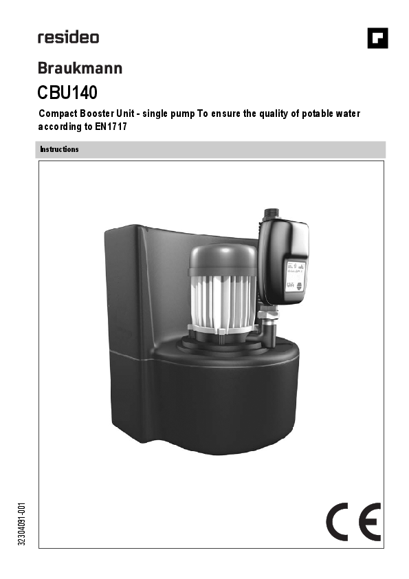
Braukmann
CBU140
Compact Booster Unit - single pump To ensure the quality of potable water according to EN1717
Instructions

32304091-001

GB

Contents
1. Safety Guidelines............................................................................ 3 1.1 Safety instructions in this manual ...................................................... 3 1.2 General safety instructions................................................................ 3 1.3 Further safety regulations.................................................................. 3 1.4 Unauthorised operation types............................................................ 3 1.5 Residual dangers in handling the compact booster unit ...................... 4
1.5.1 Mechanical residual dangers.................................................... 4 1.5.2 Residual dangers pertaining to fluids ........................................ 4 1.5.3 Residual electrical hazards ...................................................... 4 1.5.4 Residual biological hazards...................................................... 4 1.5.5 Residual chemical hazards ...................................................... 4 1.5.6 Consequences and dangers that result from not
observing the manual .............................................................. 5 1.6 Basic Safety Measures ..................................................................... 5
1.6.1 Keep information available....................................................... 5 1.6.2 For environmental protection.................................................... 5 1.6.3 Modifications to the compact booster unit ................................. 5 1.7 Duty of due care of the operator ........................................................ 5 1.8 Safety instructions for the operator/operating personnel ..................... 5 1.9 Safety instructions for maintenance, inspections and assembly work .. 5 1.10Requirements for operating personnel............................................... 5 1.10.1Operating personnel................................................................ 5 1.11Personal safety equipment................................................................ 5
2. General information........................................................................ 6 2.1 Conformity with the following norms .................................................. 6 2.2 Warranty and liability......................................................................... 6 2.3 Storage and perfect condition.............................................................6 2.4 Illustrations ....................................................................................... 6 2.5 Symbols ........................................................................................... 6 2.6 Other applicable documents.............................................................. 6 2.7 Glossary........................................................................................... 6
3. Description...................................................................................... 7 3.1 Pump Output .................................................................................... 7 3.2 Backfeed for 3/4" pipes ..................................................................... 7 3.3 Noise expectancy values................................................................... 7 3.4 Authorised environmental conditions ................................................. 7 3.5 Type label......................................................................................... 7 3.6 Version............................................................................................. 8 3.7 Overview .......................................................................................... 8
3.7.1 Installation type ....................................................................... 8 3.8 Intended use..................................................................................... 8 3.9 Non-intended use ............................................................................. 8 3.10Options ............................................................................................ 8
4. Function.......................................................................................... 8 4.1 Construction dimensions ................................................................... 8
5. Shipping.......................................................................................... 9 5.1 Check condition upon delivery........................................................... 9 5.2 Transportation .................................................................................. 9
6. Assembly ........................................................................................ 9 6.1 General safety instructions................................................................ 9 6.2 Installation according to EN1717 ....................................................... 9 6.3 Inspection before assembly............................................................. 10
6.3.1 Installation site....................................................................... 10 6.4 Installing the compact booster unit................................................... 10 6.5 Installing the pipelines......................................................................10
6.5.1 Water connection....................................................................10 6.5.2 Pressure connection...............................................................10 6.5.3 Connecting the overflow .........................................................10 6.6 Electrical connection........................................................................10 6.6.1 Safety instructions ................................................................. 10 6.7 Verification of the waterflow............................................................. 10
7.

Start-up.......................................................................................... 11 7.1 Safety instructions for start-up.......................................................... 11 7.2 Start-up requirements ...................................................................... 11 7.3 Fill up and vent the pump and tank................................................... 11 7.4 Switching the system on .................................................................. 11 7.5 Function check ................................................................................ 11
7.5.1 Checking the protection against dry running ............................ 11 7.6 Start-up checklist............................................................................. 11
8. Operation....................................................................................... 11
9. Maintenance .................................................................................. 12 9.1 Safety instructions for maintenance.................................................. 12 9.2 Overview of inspection tasks............................................................12 9.3 Inspection ....................................................................................... 12
9.3.1 Check protection against dry running ...................................... 12 9.3.2 Check pressure hoses............................................................ 12 9.3.3 Check pump control ............................................................... 12 9.3.4 Check floating ring seal leakage ............................................. 12 9.3.5 Check preload pressure of membrane pressure
expansion vessel.................................................................... 12 9.4 Maintenance ................................................................................... 12
10. Troubleshooting............................................................................ 13 10.1Measures for elimination of pressure surges..................................... 13
10.1.1Enlargement of the inlet line ................................................... 13 10.1.2Setting pressure reducing valve.............................................. 13 10.1.3Throttle pressure surge .......................................................... 13 10.1.4Membrane pressure expansion vessel.................................... 13
11. Shut-down, disassembly, restart .................................................. 14 11.1Shutting down the compact booster unit........................................... 14 11.2Restarting the compact booster unit ................................................. 14
12. Storage .......................................................................................... 14 12.1Short-term storage .......................................................................... 14 12.2Storage/Preservation....................................................................... 14 12.3Storage conditions........................................................................... 14
13. Disposal.........................................................................................14
14. Spare Parts .................................................................................... 14
15. Start-up protocol ........................................................................... 15
16. Declaration of no objection........................................................... 16
17. Proof of Maintenance .................................................................... 17

2

Translation of original - EN1H-1377GE23 R1020

GB

1. Safety Guidelines
1.1 Safety instructions in this manual
Danger Places with this sign signify that death, severe bodily injury or significant property damage will occur if the appropriate precautionary measures are not followed! Warning Places with this sign signify that death, severe bodily injury or significant property damage may occur if the appropriate precautionary measures are not followed! Caution Places with this sign signify that small bodily injury or slight property damage may occur if the appropriate precautionary measures are not followed!
Places with this sign provide technical information and tips on usage that damage to the machine must be avoided.This symbol is not a safety indication. Places with this sign provide information about possible hazards to the environment
Please notice that a safety symbol never can replace the text of the safety instruction itself - the text of the safety instruction must be read entirely!

1.2 General safety instructions This manual contains basic instructions which are to be observed in transport, assembly, start-up, operation, maintenance, shut-down, storage and waste disposal. The following safety instructions have to be observed while operating the compact booster unit: � When using the compact booster unit, the data, operation and usage
conditions specifically authorised in the technical data sheet and the operating manual have to be observed. � Never exceed the permissible limits pertaining to pressure, temperature, etc. as stated in the documentation. � Observe all safety instructions as well as the operating instructions of the manual. � Instructions that are directly attached to the system have to be observed and must be kept completely legible. This applies for example to: - Safety instructions - Arrow for rotation direction - Connection labels - Type label � Before assembly and start-up, the manual has to be read by the operator as well as by the responsible technical/operating personnel and has to be stored at the site of the compact booster unit at all times. � Installation and maintenance work may only be performed by authorised specialist personnel with the appropriate tools. � The technical condition of the compact booster unit has to be checked regularly (at least once a year) by the operating company. � The local safety and accident regulations have to be observed when operating the compact booster unit. � The general technical rules must be observed when planning the usage and operating the device. � Modification of the compact booster unit is not permitted and leads to the loss of warranty. � After an interruption of the electrical or fluid supply, a defined or controlled re-run of the process must be ensured. � The operator is responsible for complying with local regulations that are not covered by the manual.
1.3 Further safety regulations Besides the safety instructions presented in this manual and its intended use, the following safety regulations are valid: � Accident prevention regulations, safety and operating regulations � Safety regulations for handling hazardous substances � Applicable standards and laws
1.4 Unauthorised operation types The limits that are stated in the documentation have to always be complied with. The delivered system is only guaranteed to operate reliably when it is used as intended.

EN1H-1377GE23 R1020 - Translation of original

3

GB

1.5 Residual dangers in handling the compact booster unit Danger and adverse effects may result from use of the compact booster unit � for the body and life of the operator or third person � for the compact booster unit itself � to other property. The basis for safe and error-free operation of the compact booster unit is knowledge of the instructions for safety and operation in this manual.
1.5.1 Mechanical residual dangers During normal operation, no danger is threatened from mechanical components.
1.5.2 Residual dangers pertaining to fluids During normal operation, no danger is threatened by hydraulic components. Hazards might result solely under the following conditions.

Danger area

Type of hazard

Reduction of hazard

Pipelines

Injury through high pressure

Clear pipelines of pressure and medium prior to assembly, maintenance, shut-down!

1.5.3 Residual electrical hazards During normal operation, no danger results from the electrical equipment of the compact booster unit. Hazards might result solely under the following conditions.

Danger area

Type of hazard

Reduction of hazard

Injury from cables

Danger to life ! Electric shock of 230/400V from electric voltage

Connect up protective earth system!
Always switch off power supply and secure against switching on again during maintenance and servicing work!

Comply with the valid accident prevention and safety regulations for electrical devices!

Electrostatically endangered components / subassemblies

The device contains electronic componental elements that react Comply with requirements according to EN 100 015 - 1,

sensitively to electrostatic discharge (ESD). Contact with electro- in order to minimise or avoid damage through shock-type

statically charged persons or objects endangers these compo- electrostatic discharge!

nental elements. Worst case scenario: they will be immediately Do not touch electronic componental elements when the

destroyed or fail after start-up.

power supply is on!

1.5.4 Residual biological hazards During normal operation, no biological danger results from the compact booster unit. Hazards might result solely under the following conditions.

Danger area

Type of hazard

Buffer tank

Danger of microbial contamination

Reduction of hazard Clean the buffer tank regularly!

1.5.5 Residual chemical hazards During normal operation, no chemical danger results from the compact booster unit. Hazards might result solely under the following conditions.

Danger area

Type of hazard

Reduction of hazard

Use of detergents

Danger through contact with or breathing in dangerous fluids, ga- Wear personal safety equipment!

ses, fumes, vapours or dust

Pay attention to the safety specifications sheet of deter-

gent manufacturers!

4

Translation of original - EN1H-1377GE23 R1020

GB

1.5.6 Consequences and dangers that result from not observing the manual
� Not observing this manual will lead to loss of the warranty and make damage claims invalid.
� Failure to observe the manual can lead, for example, to the following dangers: - Hazard to persons caused by electrical, thermal, mechanical, and chemical influences - Loss of important product functions - Failure to perform required maintenance and service measures - Environmental hazard caused by leakage of hazardous substances
1.6 Basic Safety Measures
1.6.1 Keep information available This manual has to be stored. It has to be ensured that all persons who operate the compact booster unit have access to the manual at all times.
1.6.2 For environmental protection
When operating or servicing the compact booster unit, the regulations concerning waste avoidance and the proper recycling or disposal of waste must be observed. Particular attention must be paid that materials and agents dangerous to the groundwater such as fats, oils, coolants, solvent-based liquid detergents, etc. do not pollute the ground or access the sewage system. These materials must be caught in suitable tanks, stored, transported and properly disposed of.
1.6.3 Modifications to the compact booster unit When using externally procured parts, there is no guarantee that these are designed and constructed to tolerate demands made upon them or whether they comply with safety regulations. For safety reasons, no unauthorised modifications may be made to the compact booster unit. Parts and special equipment not delivered by Resideo are also not authorised by Resideo for use.
1.7 Duty of due care of the operator This compact booster unit was designed and constructed according to a risk assessment and after careful selection of the harmonised standards that apply, as well as according to further technical specifications. It thus complies with best practice and guarantees the highest safety standard. This level of safety can only be attained during operational practice if all required safety measures have been taken. It is the duty of care of the operator of the compact booster unit to plan these measures and enforce their implementation. In particular, the operator must ensure that � the compact booster unit is only operated as intended � the compact booster unit is only operated in perfect workingcondition. � the manual has to be kept legible at all times and stored on-site with the
compact booster unit. � the compact booster unit is assembled, commissioned, maintained, and
shut down solely by sufficiently qualified and authorised personnel. � this personnel is regularly instructed on all relevant questions of work
safety and environmental protection, and has also read and understood the manual and particularly the safety instructions it contains. � none of the safety and warning signs attached to the compact booster unit are removed and all remain legible. � a hazard assessment (according to the Safety at Work Act � 5) is conducted to detect further hazards that may arise from the particular working conditions on-site where the compact booster unit is operated. � all further information and safety instructions which arise from the hazard assessment process shall be summarised in operating instructions (according to the work equipment regulation � 6). � the drain output lines are sufficiently dimensioned

1.8 Safety instructions for the operator/operating personnel � Eliminate hazards caused by electrical energy (for details refer to the
country specific regulations and/or local power supplycompanies).
1.9 Safety instructions for maintenance, inspections and assembly work
� Alterations or modifications of the system are only permitted with the consent of the manufacturer.
� Use only original parts or parts authorised by the manufacturer. � Use of parts other than those authorised may lead to loss of liability for
any damage they may cause. � Perform service on the system only when the machine is off. � The pump housing has to be at ambient temperature. � The pump housing has to be depressurised and empty. � The procedures described in the manual for shutting down the system
have to be observed under all circumstances. � Reinstall safety equipment and protective devices and activate them
again immediately after work on the system has been completed. Before starting up again, observe the start-up checklist. � Keep unauthorised persons (e.g. children) away from the system.
1.10 Requirements for operating personnel
1.10.1 Operating personnel This compact booster system may only be asembled, started, maintained, and shut down by persons who have been trained, instructed and authorised to do so. In some cases, training can be arranged by the manufacturer if asked by the operator. Training or personnel to operate system may only be conducted under the supervision of specialised technicians. The relevant authorisations of the personnel are to be specified by the operating company in the form of an operating instruction. Over and above this, special qualifications are required for the following tasks: � Only electricians may perform work on electrical equipment. � Assembly, maintenance, servicing and repair work may only be
performed by qualified, specialist personnel The basic regulations on work safety and accident prevention are to be observed.
1.10.1.1 Qualified personnel Qualified personnel are persons who on account of their training, experience and instruction also their knowledge of the relevant norms, regulations, accident prevention regulations and operating conditions, including those persons responsible for the safety of the system, have been authorised to perform the relevant and required tasks, meanwhile being able to recognise and avoid dangers. This includes required knowledge of First Aid measures and the local ambulance services and facilities.
1.11 Personal safety equipment No personal safety equipment is required to operate the compact booster unit.

EN1H-1377GE23 R1020 - Translation of original

5

GB

2. General information
The manual is a part of the series and the versions as mentioned on the title page. The manual describes the safe and proper use in all modes of operation. The type label indicates the series and size, the most important operating data and the order number. The factory number/serial number describes the identifies the system uniquely and serves this purpose for all further business transactions. In order to maintain the warranty, in the event of damage immediately contact the nearest Resideo service centre.
2.1 Conformity with the following norms Pump unit: Machinery Directive 2006/42/EG Pump unit: EMC Directive 2004/108/EG Frequency inverter: EMC Directive 2004/108/EG Frequency inverter: Low voltage directive 2006/95/EG
2.2 Warranty and liability As a matter of principle, the general sales and delivery terms of the Honeywell Company apply. Warranty and liability claims for injury to persons and damage to property are ruled out if they arise from one or more of the following causes. � Non-intended use of the compact booster unit � Improper assembly, start-up, operation and maintenance of the compact
booster unit � Failure to comply with the instructions in the manual concerning transport,
storage, assembly, start-up, operation, maintenance, and service of the compact booster unit � Unauthorised constructional modifications of the compact booster unit � Improperly performed repairs � Catastrophes through effect of a foreign object or force majeure
2.3 Storage and perfect condition This instruction manual is a part of the compact booster unit and has to be complete and accessible at all times. Any instruction or page that is missing has to be replaced immediately.
2.4 Illustrations The illustrations used are examples of one possible version of the compact booster unit and might differ in individual cases from the actual compact booster unit version.

2.5 Symbols 1. Start of a task description 2. Next work step
- Result of an action � List of several options  Reference to other documents
Pictogram Danger classification  Danger source  Consequence of non-compliance  Avoidance
2.6 Other applicable documents  Operating manuals, circuit diagram and further documentation of auxilia-
ry equipment and integrated machine parts  Product data sheet CBU140  Operating instructions of the operating company  Data sheets  Declaration of Conformity
2.7 Glossary EN 1717 European standard that specifies technical regulations for potable water installations. Noise expectancy values The expected noise emission, stated here as sound pressure level (SPL) in dB(A). Certificate of no objection A certificate of no objection is a declaration that the system has been cleaned properly so that parts that have been in contact with medium are not dangerous for health and environment.

6

Translation of original - EN1H-1377GE23 R1020

GB

3. Description
Fully automatic, ready-for-connection compact booster unit consisting of a single pump unit and a supply container for hygienic separation of drinking water and liquids of category 5 (agricultural businesses, slaughter houses, biological laboratories, sub-surface sprinkling systems) according to EN 1717. The system has a mechanical floating valve in the inlet and can be switched on and off as required. The compact construction allows for installation in narrow supply rooms. The system comes ready to plug in and is equipped with a pump control and additionally a pressure gauge. A membrane-based pressure expansion vessel, included in delivery, must be installed in the pressure lines and serves to reduce the frequency of operation. The compact booster unit is a separation of systems as a means to protect drinking water from being contaminated by liquids of category 5 according to EN 1717.
The compact booster unit is a separation of systems as a means to protect drinking water from being contaminated by liquids of category 5 according to EN 1717.

Pump medium

Drinking water

Without aggressive, abrasive and solid components

Flow rate

up to 4m3/h, 1.1 l/s

Pumping head

up to 43 m

Operating pressure

max. 6 bar Pre- and pumping pressure must not exceed 6bar.

Switch-on pressure pumps 2.5 bar

System pressure pd

max. 6 bar

Prepressure pumps pbefore max. 1 bar

Prepressure drinking water max. 4 bar backfeed

max. amount of drinking water approx. 1 l/s backfeed at 4bar

Medium temperature

max. 35 �C

Supply voltage

230 V AC � 10 %, 50 Hz

Power consumption in stand- 2.5 - 3 W by mode

Drive

Single-phase, a.c. motor 230V, with built-in

circuit protector

Direct online starting

Thermal class F

Protective class

IP44

Weight CBU without water filled with water

approx. 22 kg approx. 35 kg

Weight Membrane pressure expansion vessel without water filled with water

approx. 2,4 kg approx. 5 kg

3.1 Pump Output
Pump head [m] 50

40

30

20

10

0 0

1,0

2,0

3,0

4,0 Q [m3/h]

0

0,5

3.2 Backfeed for 3/4" pipes
Inlet pressure [bar] 5

1,0

Q [l/s]

Output

4

3

2

1

0

0

1

2

2,7 3

4

Backfeed [m3/h]

3.3 Noise expectancy values Noise levels based on the systems pumping data result in nearly 55 dB(A).

3.4 Authorised environmental conditions

Ambient temperature 5�C ...40�C

Relative air humidity

max. 50% r.h.

3.5 Type label

1 Series 2 Frequency 3 Serial number 4 Power output 5 max. feed rate

6 Rated voltage 7 max. pumping head 8 max. power input 9 Protection class

Key for the serial number

Calendar year

2009 2010 2011 2012 2013

1st half-year

S-U S-W S-Y S-A S-C

2nd half-year

S-V S-X S-Z S-B S-D

EN1H-1377GE23 R1020 - Translation of original

7

GB

3.6 Version Plug-in ready compact booster unit, consisting of: � self-priming multi-stage centrifugal pump � monitoring and control unit for the centrifugal pump � system control � backfeed tank with integrated drinking water backfeed via mechanical
floating valve and free outlet according to EN 1717 � fastening set for wall mounting, consisting of screws, wall plugs and
mounting bracket � flexible expansion joint connection PN10 with DVGW-/T�V approval and
10-year guarantee for the pressure side as well as the drinking water connection (length approx. 30/50 cm) � Membrane pressure expansion vessel � Installation manual with mounting template
3.7 Overview In an angular tank designed for wall mounting there is a multi-stage highpressure pump. The high-pressure pump is connected via bent tube to an inlet, which leads to the supply tank.
1 54
6

2

7

3

3.9 Non-intended use The compact booster unit is not designed for operation outside. Temperature, light and moisture can lead to malfunctions and damaging devices. � Do not operate the compact booster unit outside. � Operate the compact booster unit only as intended. � Do not fill aggressive or flammable medium into the medium lines of the
system. � No mechanical stress on housings (e.g. by depositing objects or as a
step).
� Do not perform any external modifications on the device housing. Do not paint housing parts and screws!
� Do not disassemble the compact booster unit more than is necessary for purposes of installation and maintenance.

3.10 Options CBU140-25A-043

Connection size DN25, Pumping head 43 m

4. Function
The self-priming system draws in the pumping medium from an angular tank via the inlet. In this tank there is a water supply of approx. 13 Litre, which is automatically filled and refilled from the drinking water network via floating valve. The pump is turned on and off automatically when a consumer is opened.
For monitoring there is a pump control in the pressure lines of the system, which turns the pump on when the pressure drops below approx. 2.5 bar (factory setting). When the consumer is closed, the pump is then turned off with a delay of approx. 10 seconds. This device simultaneously protects the pump from dry running. A check valve in the pump control prevents backflow. The pressure is read from a built-in pressure gauge.

4.1 Construction dimensions CBU

200mm free space for service in both directions

56

410

28

R 1

Figure 1: CBU140 Structure

1 Pump control 2 Pump 3 Inlet tank 4 Drinking water connection

5 Pressure delivery 6 Tank 7 Vent valve

3.7.1 Installation type � Fixed installation

3.8 Intended use The compact booster unit may only be operated in such areas as described in the other applicable documents. Non-intended operation of the compact booster unit can result in danger to persons, systems, the surroundings and the environment.
� Operate the compact booster unit only if it is in perfect working condition. � Do not operate the compact booster unit if it is only partially assembled. � The compact booster unit may only be used to pump the medium as
described in the documentation of the respective version. � Never operate the compact booster unit without pump medium. � Observe the values for minimum pumping rates (avoiding damage
because of overheating, storage damage, ...). � Observe the values for maximum pumping rates (to avoid damage due to
overheating, floating ring seal damage, cavitation damage, storage damage, ...). � Do not throttle the input of the compact booster unit (to avoid cavitation damage). � Other modes of operations, if not mentioned in the documentation, have to be coordinated with the manufacturer.

168
Membrane pressure expansion vessel
206

425

290

R

90 DN 70 discharge pipe

56

8

Translation of original - EN1H-1377GE23 R1020

GB

5. Shipping
5.1 Check condition upon delivery 1. Check the contents of each package for damage upon delivery. 2. In the case of transport damage estimate the extent, document the
damage and notify Resideo immediately in writing.
5.2 Transportation
Danger
 The system falls off of the pallet  Danger of being crushed by system!  Position the system vertically during transport  Never get the system tangled in electrical lines.  Observe the local safety regulations.  Observe the weight and mass centre.  Only use appropriate and authorised means of transportation, for example fork lift or hand lift.
Warning
 Installation on non-level and non-structural installation sites  Personal and property damage!  Ensure sufficient compressive strength according to class C12/ 15 for concrete in the exposition class X0 according to EN 2061. The installation site has to be solid, level and horizontal. Observe the weight information.
The compact booster unit is attached to wooden rails and wrapped in foil for transport and temporary storage. All connection interfaces have protective lids.
The system is on a small wooden pallet under the telescope box. Accessories are packed in the same box - see the box label. Two carrier handles for transport are in the box. 1. To unpack, cut the packaging straps. 2. Take the accessories and the extra padding out of the box. 3. Lift the box upwards.
- The system stands alone on the wooden pallet. 4. Check the contents of the package for completeness. 5. Check the system for transport damage. 6. Select the appropriate means of transport. 7. Transporting the system to the installation site.

6. Assembly

6.1 General safety instructions

Danger
 Danger of injury from electric voltage. Highshockcurrentsandburnsfrom directandindirectcontactwith live parts.  Turn off the power supply before assembling the compact booster unit and secure it from being turned on.
 Faulty mains connection  Damage to the electricity network, short circuit!  The electrical system must conform with the installation regulations according to VDE 100 (i.e. grounded electrical sockets). The electrical network must be equipped with a residual current device for max. 30mA.
 Non- or erroneously-connected cables Malfunctions, which endanger the safety of operating personnel. Work on electrical equipment may only be performed by specialist electric technicians.
 Improperly connected wiring and lines (e.g. too small bend radius)  Smouldering and fires from cables. Work on electrical equipment may only be performed by specialist electric technicians.
 Live cable ends and components Make sure the protective earth system is connected throughout.

Warning
 The compact booster unit is not designed for operation outside.  Temperature, light and moisture influences can lead tomalfunctions and damage todevices.  Do not use the compact booster unit outside.
 Danger through improper installation  Personal and property damage!  Performance of tasks only by qualified personnel (see section 1.10.1.1).

Caution
 Damaged or improperly installed compact booster unit.  Malfunctions  Do not damage the compact booster unit and only install it if it is clean and fully functional.  Install the compact booster unit according to the described instructions.  Install free of voltage and of bending moments.
 Connecting cable overly bent  Defective system due to improper load on the system  Reduction of service life!  Install connecting cable with zero potential. No load is allowed to be put on either the connections or the system.
 Drinking water backfeed of max. 4bar exceeded  Defective system due to improper load  Install pressure reducing valve ahead of the system to ensure that not more than 4bar prepressure is fed from the drinking water network.

6.2 Installation according to EN1717 Accomodate the compact booster unit in a technical centre or in a frost-free, well ventilated, lockable room that is not used for anything else. Hazardous gases should never enter the installation room. A sufficiently dimensioned dewatering connection (drain connection or similar) is required (observe EN 12056).

Usable volume tank

Dewatering capacity

13 l

5,4 m3/h

Table 6: Usable volume/dewatering capacity

Do not operate the compact booster unit near living rooms and bedrooms.

EN1H-1377GE23 R1020 - Translation of original

9

GB

185

6.3 Inspection before assembly Check the following points prior toinstallation: � According to specifications on the type label, the system is suitable for the
electric supply network. � The medium to be pumped corresponds to the permissible pumping
media � The above-mentioned safety instructions have been observed. � The installation room is dry, frost-free and well-ventilated. 6.3.1 Installation site
Ideally select an outer wall for mounting. The wall must be able to take 4 wall plugs � 10mm and carry the weight of the system (approx. 35 kg when filled with water).
6.4 Installing the compact booster unit Make allowance for space for operating and maintenance tasks.
1. Remove the packaging before installing the system. 2. Mark the 4 mounting points using the drilling template included.

6.5.3 Connecting the overflow
Caution
 Overflow not connected  Danger of flooding the installation room! Lead the overflow line to a drain with adequate dewatering capacity (connection DN70).
An overflow for free drain as prescribed by EN 1717 is implemented, and has a nominal width of 70mm for this system. This overflow becomes effective when the drinking water backfeed leaks and the water exceeds the maximal overflow point.
The absence of backwater prevention due to the wastewater system leads to the loss of DVGW-approval! If the systems overflow funnel is missing, the system must be connected to the wastewater system with an overflow siphon found in the accessories. In doing so, it must be ensured that the overflow siphon is not firmly connected to the system and that the installation is performed according to DIN 1986-100, EN 1717. With a secure connection to the wastewater system, we recommend the installation of a siphon to avoid unpleasant odour. 1. Connect the overflow.
6.6 Electrical connection
6.6.1 Safety instructions

476
3. Drill holes (4 x �10mm). 4. Insert suitable, proper sized dowels.
- wall plugs included only for mounting in concrete and full brick walls. 5. Mount and adjust both of the lower fixing attachments. 6. Set the system in both of the lower fixing attachments. 7. Mount upper fixing attachments.
6.5 Installing the pipelines

Danger
 Danger of injury from electric voltage. Highshockcurrentsandburnsfromdirect andindirectcontactwith live parts.  Turn off the power supply before assembling the compact booster unit and secure it from being turned on.
 Faulty mains connection  Damage to the electricity network, short circuit!  The electrical system must conform with the installation regulations according to VDE 100 (i.e. grounded electrical sockets). The electrical network must be equipped with a residual current device for max. 30mA.
 Non- or erroneously-connected cables  Malfunctions, which endanger the safety of operating personnel. Work on electrical equipment may only be performed by specialist electric technicians.
 Improperly connected wiring and lines (e.g. too small bend radius)  Smouldering and fires from cables. Work on electrical equipment may only be performed by specialist electric technicians.
 Live cable ends and components Make sure the protective earth system is connected throughout.
The installation of a motor protection device is recommended.

Install connecting cable with zero potential. No load is allowed to be put on either the connections or the system. Install pressure reducing valve ahead of the system to ensure that not more than 4bar prepressure is fed from the drinking water network. It is recommended to install a stop valve and an external filter.
6.5.1 Water connection 1. Attach inlet connection R 3/4" with flexible pressure hose to the drinking
water line. 2. Fill angular tank with water. 3. Open drinking water line.
- After opening the drinking water line, the tank is automatically filled.
6.5.2 Pressure connection Avoid overly bending the flexible connecting pipe, as this reduces the service life and puts an improper load on the connections. To avoid frequently pump activation for small withdrawal amounts, install membrane pressure expansion vessel downstream of the CBU. A membrane pressure expansion vessel is included in scope of delivery. It is recommended to install a stop valve.
1. Install membrane pressure expansion vessel in consumption water line. Set pre-pressure to 3,2 - 3,4 bar. For filling use nitrogen only!
2. Connect the system to the consumption water line using the flexible pressure hose.

1. Compare the mains voltage with the specifications on the type label. 2. Insert mains plug in the electrical socket.
6.7 Verification of the waterflow The water shortage monitor must not be activated at maximal withdrawal. Should the water shortage monitor nevertheless be activated, then the pressure side must be throttled. For maximum withdrawal and backfeed amounts see chapter description.

10

Translation of original - EN1H-1377GE23 R1020

GB

7. Start-up
Performance of tasks only by qualified personnel (see section 1.10.1.1).
7.1 Safety instructions for start-up
Warning
 Danger from improper operation.  Malfunctions  Before starting, the manual has to be read by the operator as well as by the responsible technical/operating personnel and has to be stored at the site of the compact booster unit at all times.  Adhere to local safety and accident regulations when starting the compact booster unit.
 Damaged or improperly installed compact booster unit.  Malfunctions  Check the compact booster unit for obvious signs of damage; eliminate any defects immediately or alert the supervising personnel. The compact booster unit may only be operated in perfect working order.
Inform yourself sufficiently about � the equipment of the compact booster unit � the functionality of the compact booster unit � the close surroundings of the compact booster unit � the measures to be taken in an emergency
7.2 Start-up requirements
Caution
 Dry running pump  Damage to the pump/system!  Ensure that there is no water shortage.
Before start-up of the compact booster unit, the following points have to be ensured: � The compact booster unit has to be connected to all protective equipment
according to the regulations. � The relevant VDE and country-specific regulations have to be adhered to
and fulfilled. � Connection of the drinking water backfeed is connected to the drinking
water network. � The systems electrical connections have been made according to regula-
tions.
7.3 Fill up and vent the pump and tank 1. Set the operating mode switch to drinking water backfeed for approx. 15
seconds. - The system tank is filled automatically. 2. Open the air bleed valve with a screwdriver or a square spanner. 3. Wait until water leaves the air bleed valve. - When water leaves the air bleed valve, the system has beenvented. 4. Close air bleed valve. 5. Open a consumer. 6. Turn the pump briefly on.
7.4 Switching the system on The system is automatically turned on, when the mains plug is inserted.
7.5 Function check The system is set up, installed, connected and started according to specifications. 7.5.1 Checking the protection against dry running 1. Close the suction-side inlet.
- The system is continuously monitored for dry running by the pump control. If not enough pump medium is fed into the system (the flow stalls), the pump control shuts down after 10 to 15 seconds. By pressing the Reset-key, the follow-up time can be reactivated.

7.6 Start-up checklist Work steps

finished

1

Read instructions.

2

Check the voltage supply and compare with the values

on the type label.

3

Check the mechanical connection to the water supply

system. Tighten the flanges and the screws.

4

Fill and ventilate the compact booster unit from the input

side.

5

Check the refilling.

6

Check protection against dry running

7

Check the operating mode

8

Circumstances regarding the system that are not the

same as stated in our documentation or ordering data,

have to be noted in the start-up protocol.

9

Fill out the start-up protocol with the operator and show

the operator how the machine functions.

8. Operation
The pump is turned on automatically when a consumer is opened. The pump is functioning. If all consumers are closed, then the pump shuts down automatically. In case of water shortage, the integrated protection against dry running shuts the pump down automatically. The red light comes on in case of water shortage or malfunction. With the Reset-key, the malfunction message can be reset. As long as the Reset-key is pressed, the control unit is in manual operation mode.

EN1H-1377GE23 R1020 - Translation of original

11

GB

9. Maintenance

Maintenance should be performed by Resideo technical staff. � If necessary contact the service department at Resideo.
Performance of tasks only by qualified personnel (see section 1.10.1.1).
9.1 Safety instructions for maintenance

Danger
 Danger of injury from electric voltage. Highshockcurrentsandburnsfrom direct andindirectcontactwith live parts.  Turn off the power supply before maintaining the compact booster unit and secure it from being turned on.

Warning
 Unqualified persons working on the compact booster unit  Danger of injury!  Only let specially qualified personnel perfom repair and maintenance work.

Caution
 Inappropriately maintained compact booster unit  The proper function of the compact booster unit can no longer be ensured!  Maintain the compact booster unit regularly.

 Always observe the safety regualations and instructions.  Observe the instructions for working on the pumps.

In case of damage, please contact our service department. By setting up a maintenance schedule, the required maintenance to avoid expensive repairs and achieve fault-free and reliable functioning of the compact buster unit is held to a minimum.

9.2 Overview of inspection tasks

Interval

Operation

semi-yearly

Check pump control

Check protection against dry running

Check pressure hoses

Check floating ring seal

9.3 Inspection To ensure that the compact booster unit can be operated reliably, the required inspections have to be conducted on time.
9.3.1 Check protection against dry running Interval: semi-yearly
1. Close off drinking water backfeed. 2. Activate a consumer to pump the supply tank empty.
- When the supply tank is empty, the pump control has to shut the pump down within 10 - 15 seconds. A restart occurs only after pressing the Reset-key.
9.3.2 Check pressure hoses Interval: semi-yearly
1. Check pressure hoses for leaks and damage to the metal braiding. - The hoses are to be replaced in case of leaks or severe damage to the metallic sheath.
9.3.3 Check pump control Interval: semi-yearly
1. Open consumer. 2. Ensure that all consumers are closed. 3. The pump must shut down after approx. 10 - 15 seconds after all consu-
mers are closed. 9.3.4 Check floating ring seal leakage
Interval: semi-yearly
Slight wear of the floating ring seal is unavoidable and is accelerated by abrasive particles in the pumping medium. 1. Check for leakage in the area between motor and pump housing. 2. In case of leakage the floating ring seal must be replaced. - The replacement should be performed by Resideo technical staff. 9.3.5 Check preload pressure of membrane pressure expan-
sion vessel Interval: semi-yearly
1. Remove protection cap. 2. Check preload pressure. If neccessary, set to 3.2 - 3.4 bar.
9.4 Maintenance Maintenance should be performed by Resideo technical staff.

12

Translation of original - EN1H-1377GE23 R1020

GB

10. Troubleshooting

During the warranty period consult the manufacturer before performing maintenance work on the system (only work that is required for start-up and maintenance).
Our customer service department is at your service. Failure to comply will lead to loss of any liablity claims.

Errors

Possible cause

Elimination

by

Pump is running but does not suck

Pump is not full

Fill pump

User

Tank inlet closed

Open tank inlet

User

Pump turns frequently on and off

Leaky consumer

Seal consumer

User

Pump is running, feed rate or pressure are not Pump draws in air sufficient

Suction line check

User

Pump shuts down during operation andindica- Power outage or undervoltage

Check power supply

tes malfunction

Thermo switch has triggered due to overhea- Check that pump moves freely

ting

User Service

ELCB (earth leakage circuit breaker) has trig- Have insulating resistance checked by a trai- Service

gered

ned electrician

System does not turn on

Pump control indicates malfunction

Press Reset-key or disconnect mains voltage User

System does not turn off

Foreign particles in pump control

Clean pump control and replace if necessary Service

System is too loud

Pump lies against the safety screws

Adjust pump by hand, so that the pump is not User lying against the screws

Tank overflows

Contamination in valve

Eliminate dirt/limescale in valve and replace Service floater if necessary

10.1 Measures for elimination of pressure surges
10.1.1 Enlargement of the inlet line According to DIN 1988, Part 3, for amounts > 0.5l/s a minimal pipe inner diameter of 20mm is to be selected.
10.1.2 Setting pressure reducing valve If static pressure of 5bar can be read on the pressure gauge and the pressure drops to 2.5bar when the valve is opened, then the static pressure must be lowered by 1bar. Pressure surges occur by pressure differences larger than 2bar.
10.1.3 Throttle pressure surge If a stop valve or pressure reducing valve is installed in the drinking water line upstream of the system, then it has to be throttled until the pressure surge disappears. The disadvantage of this method is the small feed amounts. It must be checked, whether the feed amount is sufficient for normal use. The water shortage monitor, however, must not be activated at maximal withdrawal. Should the water shortage monitor nevertheless be activated, then the downstream side must be throttled as well.
10.1.4 Membrane pressure expansion vessel Install an 8l - membrane pressure expansion vessel in the line ahead of the system inlet. With this container, severe pressure drops from thin lines are diminished and surges are contained without throttling the amount.

13

Translation of original - EN1H-1377GE23 R1020

GB

11. Shut-down, disassembly, restart
11.1 Shutting down the compact booster unit

Danger
 Danger of injury from electric voltage. Highshockcurrentsandburnsfrom direct andindirectcontactwith live parts.  Turn off the power supply before shut down the compact booster unit and secure it from being turned on.
1. Disconnect system from the electric power supply and secure against being started.
2. Dismantle the system properly. 3. Close drinking water inlet and pressure line. 4. Rinse the system properly. 5. Let system drain.
11.2 Restarting the compact booster unit Please note the procedures in chapter 7.
12. Storage

12.1 Short-term storage Short-term storage is possible without further preparation under the specified environmental conditions.
12.2 Storage/Preservation

Caution
 Damage during storage caused by frost, humidity, dirt, UV radiation or pests  Corrosion/Contamination of the system!  Protect the system against frost, do not store outside.

Caution
 Damp, dirty or damaged openings and junctions Danger of leaks anddamagingthesystem!  Uncover openings in the system only during installation.

12.3 Storage conditions

Storage location

closed room, dry and dust-free

Ambient temperature 5�C to 40�C

Relative air humidity max. 50% r.h.

13. Disposal
It is imperative to observe the laws and regulations on waste disposal B of materials that are detrimental to the environment.
Such materials include old oils, coolants, paint, plastics and chemicals. If in doubt, consult the manufacturer. 1. Disassembly of the system. - Collect grease and lubricants during disassembly. 2. Separate the pump materials for example according to: - Metal - Plastic - Electronic junk - Grease and lubricants 3. Dispose according to local regualtions or have them disposed of according to regulations.
14. Spare Parts
1 2
Compact Booster Unit / single pump CBU140 (from 2013 onwards)

No. Description 1 Float valve (complete) 2 Pump incl. set of seal elements 3 Pump drive 4 Seal set

Part No. 18040893-CBU 18041119-CBU 18041125-CBU 18040824-CBU

14

Translation of original - EN1H-1377GE23 R1020

GB

15. Start-up protocol
The following Resideo Compact Booster Unit was commissioned today by the signatories, authorised the Resideo customer service staff, and this protocol was written.
1 Compact booster unit

Series

......................................................................................

Size

......................................................................................

Serial number

......................................................................................

Order number

......................................................................................

2 Customer/Operating site Customer Name Address

Operating site ...................................................................................... ...................................................................................... ...................................................................................... ...................................................................................... ...................................................................................... ......................................................................................

3 operating data refer to circuit diagram for additional data

Switch-on pressure

pE bar ......................................................................................

Monitoring the precharge pressure

pbefore - x ......................................................................................

Setting value for the precharge pressureswitch

Switch-off pressure

pA bar ......................................................................................

Precharge pressure

pbefore ...................................................................................... bar

Precharge pressure tank

pbefore ...................................................................................... bar

4 Important notes According to the DVGW Process Sheet W 314, the company operating the system is obligated to inform the water distribution company responsible about the commissioning of the system. If the system is additionally operated with group III/IV pressure vessels according to the regulation for such vessels, then the T�V has to be informed as well.

The operating company or their customer hereby confirms being fully trained in operation and maintenance of the compact booster unit. The circuit diagrams and instructions were also delivered.

Defects determined during start-up Defect 1

Scheduled elimination .............................................................................

......................................................................................................................................................

.............................................................................

...................................................................................................................................................... ......................................................................................................................................................

............................................................................. .............................................................................

Name of Resideo customer

......................................................................................................................................................

City

......................................................................................................................................................

EN1H-1377GE23 R1020 - Translation of original

15

Name of supplier and contractor ............................................................................. Date .............................................................................

GB
16. Declaration of no objection

Type Order number/Order item number3) Delivery date Range of application Pumped medium3)

................................................................................................................................................................. ................................................................................................................................................................. ................................................................................................................................................................. .................................................................................................................................................................

Make a check mark if applicable3):


radioactive


explosive

corrosive

poisonous


hazardous to health

Reasons for the return3) Notes:


biohazard

flammable

harmless

................................................................................................................................................................. ................................................................................................................................................................. .................................................................................................................................................................

The system/the accessories has to be carefully emptied and cleaned on the exterior as well as the interior. No special safety precautions are required for further handling. The following safety precautions regarding rinsing medium, residual fluids and their disposal are required:
.................................................................................................................................................................
.................................................................................................................................................................

We ensure that the above information is correct and complete and delivery will be made according to statutory requirements.

......................................................................... City, date and signature

......................................................................... Address

......................................................................... Company stamp

16

Translation of original - EN1H-1377GE23 R1020

GB
17. Proof of Maintenance

Resideo

74821 Mosbach Germany

Compact booster unit

This compact booster unit is subject to the standards for drinking water and guidelines for maintenance therein. The unit has to be maintained regularly by qualified personnel and the results have to be documented.
This compact booster unit is subject to the standards for drinking water and guidelines for maintenance therein. The unit has to be maintained regularly by qualified personnel and the results have to be documented.

Date

Operating company

Name

Signature

EN1H-1377GE23 R1020 - Translation of original

17

www.resideo.com

Ademco 1 GmbH Hardhofweg 40 74821 Mosbach Phone: +49 1801 466 388 info.de@resideo.com homecomfort.resideo.com

@2020 Resideo Technologies, Inc. All rights reserved. This product is manufactured by Resideo Technologies, Inc and its affiliates.