File info: application/pdf · 152 pages · 80.26MB
Document preview and download links are below.
Extracted Text
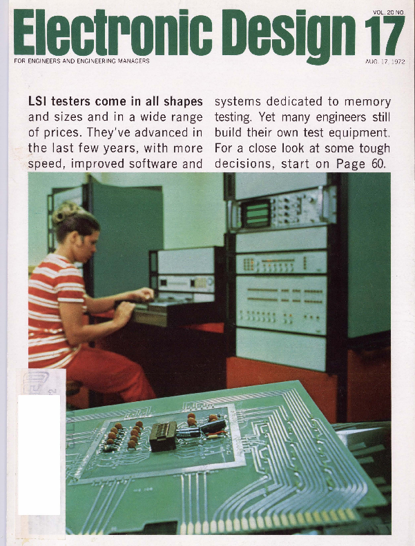
LSI testers come in all shapes
and sizes and in a wide range of prices. They've advanced in ~he last few years, with more speed, improved software and

systems dedicated to memory testing. Yet many engineers still build their own test equipment. For a close look at some tough decisions, start on Page 60.

new networks
We' re ready now to handle your " odd jobs". Complete thick film facilities for design and production of DIP, SIP in volume. Chips. Hybrids. LED metallization a specialty.
exceptional wirewounds
Still the greatest resistor for your high power, tight tolerance needs. Models to 5000 watts-even higher in water-cooled versions. Nation's best source for nonstandard resistors ... send for brochure on " specials".

Send for free comprehensive resistor reference guide, listing industry's widest range
of film styles and functions.

Check our new line of trigger transformers. Printed circuit and bobbin type styles for low-cost trigger source isolation in full and half wave SCA power control circuits.

special fast reply form

Clip and Mail tor fast reply

Send information on :
D Thick Film Networks D High Power Wirewounds D Non-Standard Resistors

D Low Profile Trimmers D Film Resistor D Edgeboard Connectors Reference Guide D Connectors for Liquid D Trigger Transformers
Crystal applications

CITY_ _ _ _ _ _ _ _ _STATc....-_ _ _ _ _ _ _ _ _ _ZIP_ _ _ _ _ __

The smallest PDP-11 just got bigger.

Bigger in performance. Not in price. Or size. It's a power package that's designed to shake up the competition.
We've given the 11/ 05 a real time clock. We've replaced the standard 1.2 usec memory with one that's 0.9 usec fast. And added our PDP-11 multi-level automatic priority interrupt. So now you can spend less time writing programs and more time out selling

your systems. Now the 11/ 05 will do your job, any job,
better, more efficiently than ever before. You can even use it for disc-based systems. But the 11/ 05 still goes for the same,
easy-to-take $4,795 per. Including 4K core. Or $3,070 in quantities of 100. For which you still get the same UNIBUS TM
architecture, direct memory access, hardware stacking, vectored interrupts, automatic power fail protection and all the other

features that have made the PDP-11 the best-selling 16-bit computer on the market.
We've already sold a lot of ll/ 05's. And we're going to sell a lot more. Because now the 11/ 05 is an even bigger bargain. Digital Equipment Corporation, Maynard, Mass . 01754. (617) 897-5111. European headquarters: 81, route de !'Aire, 1211 Geneva 26. Tel.: 42 79 50.

INFORMATION RETRIEVAL NUMBER 2

POP tS A REGISTERED TRADEMARK OF DIGITAL EQUIPMENT CORPORATIO N

MAN-MADE DURABILITY

l.
T0-5 Relay

The diamond is one of the most durable of earth's elements. Man can make it into a jewel or use it

as an industrial tool. It remains

durable to the end. The

"diamond" of the

electro-mechanical relay world is

the Teledyne T0-5 . This accolade

has been earned. The family of

tiny Teledyne T0-5 general

purpose Relays continues to

withstand the critical

requirements of long life,

phenomenal reliability, and

all-around hard use. These relays

remain the standard for

industrial, scientific, and

aerospace applications

throughout the world.

Durability and dependability are

hallmarks of Teledyne Relays

and its products. You can be

assured of this same high quality

from our newly developed family

of advanced Solid State relays.

Teledyne products are

constructed to last.

Send us your requirements.

3155 West El Segundo Boulevard Hawthorne, California 90250 Telephone (213) 679-2205

..,~

TELEDYNE RELAYS

INFORMATION RETRIEVAL NUMBER 3

2

ELCCTRON IC 01.:SJGN 17. Augu~ l 17. 1972

~l~~lronic Design J~l

NEWS
27 News Scope 30 Space shuttle will largely employ off-the-shelf electronics
but will also feature unique tailoring of new technologies. 34 Capacitive strain gage operates at 1750 F. 36 Electronic systems to pace the 1972 Summer Olympics.
A real-time computer system will permit many innovations. 40 Anyone for armchair tennis? Try it soon on your TV screen. 52 Technology Abroad 55 Washington Report

TECHNOLOGY
60 Focus on MSl/LSI Testers: A special report on the effect that highdensity microcircuitry is exerting on the design of IC test equipment.
72 Use ECL 10,000 layout rules to help solve PC-board interconnect problems . You may find you don't need large ground planes or complete transmission lines.
80 Ring map minimizes logic circuit. The technique, a modification of the Karnaugh map, detects EXCLUSIVE-OR functions or their complements at a glance.
84 Try building a pulse generator if you need one for testing logic circuits. Its performance is adequate for routine tests. The parts cost? About $30.
88 To design products that others build engineers must anticipate the builder's problems. But the bonus is often a better product.
94 Ideas for Design
100 Design Decisions

PRODUCTS

103 ICs & Semiconductors: 8, 12-bit registers advance a/d converter designs.

104 ICs & Semiconductors: Hybrid ladder switch cuts cost for precision designs.

110 Data Processing: Static tab-card reader handles hole misalignment with brush contacts.

116 Components

126 Packaging & Materials

119 Instrumentation

128 Microwaves & Lasers

124 Modules & Subassemblies

Departments

59 Editorial: Manage your own career before it's too late

7

Across the Desk

137 Bulletin Board

130 Evaluation Samples

140 Advertisers' Index

130 Design Aids 131 Application Notes

142 Product Index 142 Information Retrieval Cara

132 New Literature

Cover: Photo by Horst Osterwinter, Courtesy of Teradyne Inc.

ELECTRONIC DESIGN is published biweekly by Hayden Publishing Company, Inc., 50 Essex St. Rochelle Park, N. J . 07662. James S. Mulholland , Jr. , President. Printed at Brown Printing Co., Inc., Waseca, Minn. Controlled circulation postage paid at Waseca, Minn., and New York, N. Y., postage pendln&: Rochelle Park, N. J. Copy.
right � 1972. Hayden Publishing Company, Inc. 84,392 copies this Issue.

ELECTRONIC DESIGN 17. Au gust 17 , 1972

3

Our PT times with accurate solid state circuitry... switches with rugged relays. It's the best of both worlds. And it's available now from authorized P&B distributors.

A pretty face? Yes, indeed. But you get more, much more in our new PT Series panel mount time delay. For example: � Solid state precision plus hard-
contact electrical isolation. � 10-ampere switching capacity. � Eight dial-adjustable timing
ranges ... from 0.1 to 300 seconds. � Choice of three timing modes: delay on operate, delay on release, delay on operate with both timed and instantaneous contacts.

� The accuracy, dependability and longevity associated only with solid state circuitry.
Standard models, stocked by leading electronic parts distributors, are available for 24 and 120 volts AC or 12, 24, 48, and 110 volts DC operation . They have a 3-inch diameter Lexan housing designed to be interchangable with most mechanical timers.
Timing function lights on the face of the PT are available options. A red light indicates timing is being performed and a white light shows tim-

MOUNTING DIMENSIONS

SUGGESTED PANEL CUTOUT

ing has been completed . These lights are available on 110 VDC and 120 VAC models.
The dial is calibrated in seconds and is accurate to within 10% of the full scale. Repeatability is �1 % . Typical release time is 45 milliseconds. DC models have polarity protection and AC models withstand transients up to 1000 volts .
Modern in appearance and concept, the panel-mount PT adjustable time delay can add new precision and reliability to your equipment economically.
For full information , call your local P&B representative or write Potter & Brumfield Division of AMF Incorporated, Princeton, Indiana 47670. Telephone 812 385-5251. In Europe, AMF International Limited , Oxford , Oxon, England or S.p.A. Milan , Italy.

J 01!5 MAX

PLASTIC SKI RT
ANO KNOB

NOTE TWO HOl..ES,
M OUNTING SERV ICING OPTION H OLES TA. PPED FOR 9 32 SCRE W S

Potter & Brumfield

P&B makes more of more kinds of time delay relays than anybody in the business.

Anybody.

INFORMATION RETRIEVAL NUMBER 4

Publisher
Peter Coley

How to Design Your

Power Supply for $83

You get the complete schematic diagram, and parts list with operating and in stallation instructi ons when you spend $83 for an Abbott l\!odcl " R" power supply. Two years in development, this model represents the latest state of the art in power modul e des ign . It features close regulation ( �0.05%), low ripple ( 0.02%), au tom atic short circuit and complimentary ovcrvoltage protection and continuous operation in a 160�F ambient .
Abbott Engineers followed specific design criteria in engineering these modules. First, th e electrical design was carefu ll y engineered to insure that all components operate well within th eir limits, under "worst case" operating conditions. Second, th e th erm al design, including case constru ction, was carefu ll y made to insure that the maximum temperature limits of all components arc never C'Wceded. Then the size and weight of these modules were controlled to a minimum, without sacrificing reliability. Finally th ese units were thoroughly t ested to ~11ak c certain th at all design and performance specifications were met.
So, you can build your own power supply using our schema tic diagram if you want to-but we think we can build it more

reliably and for less cost, simply because we ha\�e been doing it for ten years. Put our power supply in your system first and try it . Examine its performance. \ Ve think you will he pleasantly surprised at the quality, adherence to specifications, and the reliability you find in the Abbott \lode! "R".
Any output voltage from .5 to 100 volts DC with currPnt from 0.1.5 to 20 amperes is ava ilable. Many of the popular voltages are carried in stock for immediate delivery . Please call us for attracti ve O.E.1\l. discount prices.
Abbott also manufactures 3,000 other models of power suppli es with output voltages from 5.0 to 3,650 volts DC and with output currents from 2 milliamperes to 20 amperes. They arc all listed with prices in the new Abbott catalog w ith various inputs:
60 ~to DC, Hermetically Sea1ed
1
400 ~to DC, Regulated
28 VDC to DC, Regulated
28 voe to 400 ~. 1<? or 3� 24 voe to 60 f:tt, 1�

Please see pages 618 to 632 of your 1971 -72 EEM (ELECTRONIC ENGINEERS MASTER Catalog) for complete information an Abbott modul es.
Send for our new 56 page FREE catalog.

abbott transistor

Editors
Editorial Offices 50 Essex St. Rochelle Park , N.J. 07662 (201) 843-0550 TWX: 710-990 5071 Cable: Haydenpubs Rochellepark
Editor: George Rostky
Managing Editors: Ralph Dobriner Michael Elphick
Associate Editors: Jules H. Gilder Richard Lee Goldberg Morris Grossman John F. Mason Stanley Runyon Edward A. Terrero Richard L. Turmail
Contributing Editor: Peter N. Budzilovich
Editorial Field Offices
East Jim McDermott, Eastern Editor P.O . Box 272 Easthampton, Mass. 01027 (413) 527 -3632
West David N. Kaye Senior Western Editor 2930 West Imperial Highway Inglewood , Calif. 90303 (213) 757-0183
Washington Michael Blake 922 24th St., N.W. # 718 Washington, D.C. 20037 (202) 338 -0700
Editorial Production
Marjorie A. Duffy
Art
Art Director, William Kelly Richard Luce Anth ony J . Fischetto
Production
Manager, Dollie S. Viebig Helen De Polo Maxine Correal Anne Molfetas
Circulation
Manager, Nancy L. Merritt Ron Deramo

LABORATORIES,
5200 W. Jefferson Blvd./ Los Angeles 90016 (213) 936-8185

NCORPORATED
1224 Anderson Ave ./ Fort Lee, N.J. 07024 (201) 224-6900

INFORMATION RETRIEVAL NUMBER 5
6

Information Retrieval
Peggy Long
ELECTRONIC D ESIGN 17, August 17, 1972

(across the desk)

Reader critiques us: 2 passes, 1 failure
In the past few years ELECTRONIC DESIGN has become one of my primary sources of new products and techniques in electrical engineering. The articles published have been, on the whole, very good because they allow one to understand a new concept or to use an old idea in a better way. It is my opinion that an article that describes a design technique should be written so that the reader can duplicate the work described and, if necessary, be referred to additional sources of information. Most of the articles you publish are welldesigned, self-contained units that attain this goal. The May 25, 1972 issue contains three major articles on technology. Two of them are complete units; the third article is, to me, an irritation.
Ralph D. Taylor, in his article on CAD ("Speed Computer-Aided Design," p. 54 ) spends three pages on generalities, and when he finally talks about an application of his method, there is only one-half page on it. From his explanation, it was impossible to figure out how he had obtained his results. First, there was no real statement of the problem, except in generalities; the active filter specifications were omitted, when they are of prime importance in showing how the method works. Second, none of the necessary equations-again, except as generalities-was shown. Third, a flow chart and an idea of a method for picking the variables was not given. A FORTRAN program was printed; however, it is not complete enough to run, nor is it either self-explanatory or complete enough to give any idea where the results come from.

In some articles, related to CAD there has been a tendency to omit a complete example in the use of the method. By this I mean starting with the specifications for the circuit and ending with the completed design. When a program is printed, but its complete use is not given, the entire article is devalued. If it is not possible to print a more complete explanation, would it be possible to make one available to interested engineers?
Kittredge D. S eely Materials Research Laboratory Pennsylvania State University University Park, Pa. 16802
Ed. note: Any reader is free to get in touch with the authors of articles in this magazine. For that reason we try to give complete mailing addresses with the authors' names.

A foolproof method to convert temperature

If you can never remember

whether to add 32 or subtract 32

(and whether to do it before or

after multiplying) when converting

from degrees centigrade to degrees

Fahrenheit or vice versa, try this

technique: Add 40, multiply, sub-

tract 40. This procedures works m

both directions as follows:
F = (C x 9/ 5) + 32
F + 40 = (C x 9/ 5) + 32 + 40 F + 40 = (C x 9/ 5) + 72
= But 9/ 5 (40 ) 72
.". F + 40 = (C + 40 ) 9/ 5

or

= ( F

C + 40 ) 9/ 5 - 40

and, conversely
C = ( F + 40) 5 / 9 - 40

Thus, whichever conversion is de-

sired, the same number is added

{continued on p. 10 )

Electronic Design welcomes the opinions of its readers on the issues raised in t~e magazine's editorial columns. Address letters to Managing Editor, Elec-
tronic Design, 50 Essex St. Rochelle Park, N. J. 07662. Try to keep letters
under 200 words. Letters must be signed. Names will be withheld on request.

ELECTRO IC DESIGN 17 , August 17, 1972

INFORMATION RETRIEVAL NUMBER 6 ...

7261 SL 7263 7264 7265
Giga-Trim� (gigahertz-trimmers) are tiny variable capacitors which provide a beautifully straight forward technique to fine tune RF hybrid circuits and MIC's into proper behavior. They replace time consuming cut-and-try adjustment techniques and trimming by interchange of fixed capacitors. Applications include impedance matching of GHz transistor circuits, series or shunt "gap-trimming" of microstrips, external tweaking of cavities, and fine tuning of crystal oscillators.
MANUFACTURING CORPORATION
BOONTON, NEW JERSEY 07005 201 I 334-2676

For see-through protection, encapsulate with this clear, resilient silicone resin . Self-extinguishing, it guards against humidity, heat, cold , radiation , thermal shock and vibration . Information retrieval number 221 .

For added safety, specify this flame-retardant, pourable silicone elastomer. Uses for this low-cost packaging material include coating, potting and encapsulating. Information retrieval number 222.

For excellent adhesion to corrosion-prone metals such as copper, use this new noncorrosive, one-part Dow Corning sealant. Cure mechanism produces no exothermic heat or acetic acid. Information retrieval number 223.

For protection against moisture, dirt, ozone, radiation and many solvents and chemicals , select this conformal coating . It flows on easily and cures at room temperature to a tough silicone rubber with excellent dielectric properties. Information retrieval number 224.

Silicones are unusual in the number of ways they protect. They resist change in hostile environments where other materials are unstable. They have excellent dielectric properties. With the electronic industry's concentration on higher performance and smaller components, the application areas where only silicone materials

can ensure design integrity have increased dramatically. Here are some of the newest examples. Many others are described in our Silicone Electronic Materials brochure available from your Dow Corning distributor. His name appears on the following page. Or write Dept. A-2202, Midland, Michigan 48640.

Electrical/electronic materials from
DOW CORNING
eu.p�aa.t.f!ii4+

Silicones add durability to Ominimite* transducer. This magnetostrictive device converts electrical energy into sound for ultrasonic cleaning systems. It is insulated with Dow Corning silicones. Bendix Instruments and Life Support Division uses coil forms fabricated from a Dow Corning silicone resin bonded glass laminate. Finished coils are dipped in Dow Corning� 997 varnish and baked. Silicones help add the physical and electrical stability required for long-term performance. Information retrieval number 226.
�rM, Bendix Corporation

Silicones for cooling high-density modules. More efficient cooling of electronic modules is possible with this suggested assembly design. A silicone-fluid-filled coolant tube dissipates heat transferred to it from dowel pins mated to holes in the module assembly. Further conduction is facilitated by a layer of Dow Corning�
heat-sink compound between a lightweight cold plate and module base. Silicone fluids have excellent heattransfer properties and maintain constant viscosity over a wide temperature range. The heat-sink com-
.~ pound has high
thermal conductivity and low bleed properties for long-term coupling. Information retrieval number 225.

RANGE CHANGE

Extralytic� Aluminum 'lytic Capacitors give you !!fended temperature r.gnge without sacrifice in life or leakage current.

Type 601 D Tubular Case
-SSC to +105C
Superior performance over entire temperature range, unlike conventional 'lytics that do not operate satisfactorily at low temperatures. High volumetric efficiency, long shelf life, low leakage current. Withstand high ripple current. Write for Engineering Bulletin 3456A or;
CIRCLE 882 ON READER SERVICE CARO.

Type 6020 Cylindrical Case
-ssc to +ssc
Power supply fil ter capacitors specifically designed for maximum efficiency. Offer the power supply design engineer the lowest ESR and the highest ripple current capability per ca se size available today for long, trouble-free life . Write fo r Engineering Bulletin 3457 or;
CIRCLE 883 ON READER SERVICE CARD.

ACROSS THE DESK
( continued from p. 7)
and subtracted in both cases. If you remember t hat positive Fahrenheit numbers are bigger than the corresponding centigrade number-for example, water boi ls at 212 F or 100 C-then you can remember to mult iply centigrade by t he large fraction (9/5) to get Fahrenheit and multiply Fahrenheit by t he small fraction (5/ 9 ) to get centigrade.
James M. Wrenn �Hewlett Packard Automatic Measurement Div. 395 Page Mill Rd. Palo Alto, Calif. 94306
You'd sm�ile, too

MORE FROM SPRAGUE .�. THE BROAD-LINE PRODUCER OF ELECTRONIC PARTS

HALL EFFECT SWITCH ICs. Actuated magnetically, not mechanically or op� tically. Hall generator trigger circuit and signal amplification circuit on single sili� con chip. Reliable (no moving parts). Easy interfacing with DTL/TTL/MOS logic. High speed. Low cost. Write for Engineering Bulletin 27,402A or;
CIRCLE 884 ON READER SERVICE CARD.

U.L. LISTED FILTERS. Series JX5000 for EDP equipment and general-purpose use. Rated 125/250 VAC, 0 -60 Hz, 1 thru 50 amps. 60 db @ 150 kHz, 80 db from .5 MHz thru 1 GHz. Special desi gns and rectangular multi -circuit units also available. Write for Engineering Bulletin 8210 or;
CIRCLE 885 ON READER SERVICE CARD.

TYPE 430P METFILM � 'E' CAPACITORS. BLUE JACKET� RESISTORS. Vitreous�

High -Voltage metallized polyester-film enamel power wirewound. Unique all -

capacitors designed for voltage multi - welded end -cap construction elim inates

plier circuits used in electrostatic cop� moisture paths along leads, anchors

I iers, TV power supplies, etc. Working leads securely to re sistor body. Expan�

voltages from 4,000 to

sion coefficients of vit�

15,000 V. Capacitance ..- - - - - - - - - - - . reou s enamel, ceram ic

is stable with time,

body, and end caps

temperature, voltage.

are closely m atched.

Write for Engineering

Write for Engi neering

Bulletin 2445.1 or;

Bulletin 7410E or;

CIRCLE 886 ON

CIRCLE 887 ON

READER SERVICE CARD.

1 READER SERVICE CARD.

TECHNICAL LITERATURE SERVICE, SPRAGUE ELECTRIC CO., 347 MARSHALL ST., NORTH ADAMS, MASS. 01247

... if you were t he world's fastest comparator. That's what Jim Giles, Director of Linear Engineering, fe lt when he designed the Advanced Micro Devices Am685. The device has a 7.5-ns maximum prop delay ( measured with a 100-mV step and 5-mV overdrive).
Interested?
CIRCLE NO. 315

Less$, but not so quick

Intel has changed two significant

specs on the product featured in

the article, "1024-bit Si-fuse bi-

polar pROM guarantees 45-ns ac-

cess time," which appeared in ED

12, June 8, 1972, p. 90. The 100-up

price has been lowered from $55

to $39, allow ing Intel to beat Har-

ris and Monolithic Memories at

$55 and Intersil at $45 . But the

maximum access time has gone

from 45 ns to 70 ns.

That's still quicker than Inter-

sil's 80 ns, but it's slower than

Monolithic Memories' 60 ns. It

can't properly be compared with

Harris' 50 ns, which is a typical

-not maximum-figure.

For more information from:

Intel

CIRCLE NO . 316

Intersil

CIRCLE NO . 3 17

Harris

CIRCLE NO . 318

Monolithic Memories CIRCLE NO 319

10

ELECTRONIC DESIGN 17, August 17, 1972

Econo on�bo prog
uite

mi� ng.

Our DIP switch, in fact. A brand-new device that lets you program your IC's right on their boards. Without the labor costs, nuisance and excessive space requ ired by jumper wires or bracket-mounted toggle switches.
Now all you need for fast, reliable programming is a pencil and a logic diagram. Rocker buttons operate positively but easily with the touch of a pencil. And they're legibly marked to show " on " and " off" positions.
New, low-profile DIP switches take up no more room on the board than a standard DIP. And can be reflowed into plated through-holes or plugged into our

DIP headers. Gold-over-nickel plating on phosphorbronze contacts assures reliable operation in the milliamp " dry-circuit" range .
These DIP switches are available with any number of poles you want, from 4 to 10. Most popular to date are the 7-pole and 8-pole versions which correspond , respectively, to 14-lead and 16-lt.....d standard DIP's.
For more information on really economical on-board programming with DIP switches, write to: AMP Incorporated, Industrial Division, Harrisburg, Pa. 17105.

ANIP INCORPORATED
Manufacturing and direct sales facilities worl dwide: Barcelona , Brussels , Buenos Aires, Frankfurt, London , Mexico Ci ty, Pans, Puerto Rico, Sao Paulo, s'Hertogenbosch (Holland). Sydney, Stockholm, Tokyo, Toronto, Tunn , Vienna.
191 PLEASE SEND LITERATURE-!MMEDIATE INTEREST .
192 PLEASE SEND LITERATURE-POSSIBLE FUTURE INTEREST .

Carbon and Graphite Products

I I
ElectroMechanical Components
Hard and Soft Ferrites
The items shown are produced by Stackpole's Carbon Division, Electronic Components Division, Magnet Division and Stackpole Components Company.

We make a lot of things at Stackpole. Components by the millions. Materials by the ton. But what really makes us different is our philosophy.
Stackpole believes in producing the best possible product, for the lowest practical price, delivered on time and backed by service. Simple? Sure. Perhaps even old-fashioned. But true. And certainly no small task.
Ours is a manufacturing technology. A capability to produce. In volume. To your specific needs.
For sixty-five years, Stackpole has served virtually every industry. To many, we are the known, respected leader. Others in emerging technologies are coming to know the special skills, imagination, experience and quality uniquely Stackpole.
Value. It's determined in performance. For products and companies alike. Let us be a part of your production team.
Stackpole Carbon Company, St. Marys, Pennsylvania 15857.

Announcing the rediscovery
of the relay.

In an age when most people think solid state is the only way to go, some designers have rediscovered the good old electro-mechanical relay. They found relays still can't be beat when it comes to certain jobs. And when they're dealing with tight fisted cost control committees. Maybe you can save some effort and expense by rediscovering the relay whenever you need these things:
1. Simple logic:
Relays let you combine both power switching and logic functions economically. Memory can usually be retained, even after a power loss. And you don't need special power supplies or noise suppression techniques.
2. Easy troubleshooting:
Most relay failures (and they do occur occasionally) can be identified visually. You can see what's wrong. And fix it easily.
3. Heat resistance:
A relay shrugs off a short dose of overheating. Give a solid state device the same treatment while it's functioning near capacity and it's ruined forever. The amount of heat a solid state device can take is usually dependent on the heat sink used. It can take up all the room you expected to save with solid state in the first place. And finding the right heat sink design can become very involved.
4. Electrical isolation:
Relays have a natural isolation between input

circuits, between output circuits, and between output and input control circuits. You can't get that with junction type semiconductors.
5. High insulation resistance: Open relay contacts have an insignificant amount of leakage (1010 ohms or more). Semiconductors can't match this. And, their leakage rates vary greatly with temperature changes.
6. Wide operating power range: Relays work with operating power anywhere from milliwatts to watts. And they usually don't require regulated power. Semiconductors do.
7. Transient voltage immunity: Transient voltage doesn't bother a relay. But high voltage, short duration transients can be sure death to semiconductors.
8. Forgiveness: Relays give you a little margin of safety should you want to change your mind. Maybe you find you need more contacts, or uncover a timing problem, or discover a need for absolute inputoutput isolation. You can change your circuit design a lot easier with relays.
If your project or product needs any of these things, just ask our salesman to help you rediscover relays. GTE Automatic Electric, Industrial Sales Division, Northlake, Illinois 60164.

(Cj i #t AUTDmATIC ELECTRIC
INFORMATION RETRIEVAL NUMBER 9

ACROSS THE DESK
(continued from p. 10)
Let George do it? How about the others?
I notice that your solicitation for letters states that the opinion of readers should be restricted to the issues raised in the editorial columns, so that you can easily decide to not print this on a legal basis. The reference is to the section on your editor, George Rostky (ED 10, May 11, 1972).
The whole write-up comes off as though George is the only man on the staff worthy of mention. Can you find any other editor's name mentioned? The only place I could find one was in a well-buried caption. I assume that George approved the section, and if this is true, is he the tyrant that is portrayed? Is he really a self-appointed combination of Ralph Nader and UL? Does he stop all articles that are "interesting"?
It would have been OK to send the write-up to your advertisers, but I think you made a mistake to print it for your readers.
Burt B ernhold Project Engin~ er Bell & Howell Consumer Products Group 7100 McCormick Rd. Chicago, Ill. 60645 Ed Note: The "George Rostky" write-up in the May 11 issue used the man simply as an embodiment of the magazine. It pointed out that an editorial tea~ot one ma1'1ris responsible for ELECTRONIC DESIGN. It has always been that way amd always will be. We're genuinely sorry if we didn't convey that message adequately.
Readers find morals in morality advice
A number of Grummanites were glad to see Stanley Runyon's editorial "If you Want to be a Pro, Try Morality and Guts" (ED 11, May 25, 1972, p. 47 ) . Had we not given every single relay used in
16

each of the lunar modules a 100 % incoming X-ray "videocon" inspection, there is little doubt that Grumman's record for moon landings would have suffered. We have found all manner of crud, solder balls, unwelded brackets, loose extra seal plugs, etc., in relays submitted by manufacurers as "highly reliable" Mil Spec types.
We are also glad to see George Rostky's editorials and articles on specmanship from time to time. Keep it up.
Naturally we take a dim view of counterfeit relays that end up in flight-safety circuits, or of manufacturers who permit relays to be used on 115-V circuits when they know full well those relays can fail catastrophically once their relay cases are grounded, as they should be to protect personnel from electrical shock.
Another area of concern is the program manager who wants to meet calendar dates, whether design and parts are satisfactory or not.
E.U. Thomas Grumman Aerospace Corp. Dept. 482 Plant 35 Bethpage, N.Y.. 11714
I find bitterly amusing the sentence in your editorial, "If engineers want to earn the much-deserved respect of management, they'll stop worrying about their jobs. . . ." And now I apparently have not earned the respect of management, because I am out of a job.
I previously worked in engineering evaluation for a large, scientific mail-order house. The quality, reliability or value of an item was seldom the answer. What was desired were descriptive words to sell the item-without complete dishonesty-and an assurance that the item would not result in too many returns. Or that it would get through the mail to the customer in one piece. And if at first you couldn't succeed in this, try, try again.
"Out-of-spec" devices? How about the thousands of items being sold that have no specs. And no morality even enters into the selling of them!
Ed Schempp Barrington, N.J.

New

too!

The new F.E.T. HA-2000 combines with the Harris HA-2520 and HA-2620 high performance op amps to provide two additional new F.E.T. Input devices:

HA-2050/2055 High Slew Rate F.E.T. Input Op Amp

High slew rate

120/ �S

Fast settling time

400 ns

Wide power ban.dwidth 20 MHz

High input impedance 1012 Ohms

Ultra-low bias current 1 pA

Operates inverting or non-inverting

Supplied T0-99 pkgs.

Input offset 100-999

HA-2050

voltage

units

- 55� C to + 125� C 15mV $19.25

HA-2050A - 55� C to + 125� C ?mV $24.00

HA-2055 0�Cto + 75� C

30mV $11.75

HA-2055A 0� Cto + 75� C

?mV $13.40

HA-2060/2065 Wideband F.E.T. Input Op Amp

Widepower bandwidth 600 KHz

Gain bandwidth product 100 MHz

High input impedance 1012 Ohms

Low bias current

1 pA

High slew rate

35 V/�S

Operates inverting or non-inverting

Supplied T0-99 pkgs.

Input offset 100-999

HA-2060

voltage

units

- 55 �C to + 125� C 15mV $15.40

HA-2060A - 55� C to + 125� C ?mV $19.90

HA-2065 0� Cto + 75� C

15mV $10.20

HA-2065A 0�Cto t 75� C

7mV $11.85

HJ
HARRIS
SEMICONDUCTOR
A DIVISION OF HARRIS - INTERTYPE CORPORATION
P.O. Box 883, Melbourne, Florida 32901 (305) 727-5430
INFORMATION RETRIEVAL NUMBER 91
ELECTRONI C DESI GN 17, August 17 , 1972

Our new F.E.T. input preamp offers more design features and application possibilities than any alternative device.

The HA-2000 is universal. A monolithic unity gain differential amplifier stage with junction F.E.T. inputs and bipolar transistor
outputs, it can be combined with any op amp, comparator, and most linear circuit functions without
compromising the features of these devices.
As a result, the HA-2000 offers almost limitless possibilities for

low-input current, high source impedance applications such as buffers for op amps and comparators. In addition , because of its compatibility with so many other components, the device permits the user great flexibility in systems design at optimum prices . Find out about our new " universal " F. E.T. preamp. See your Harris distributor or representative.

Features:

Converts any op amp or comparator to F.E.T. input
Input bias current 1 pA

Input resistance 1012 Ohms

Slew rate

100 Volts/�Sec.

Bandwidth

flat to 10 MHz and - 10dbat100MHz

Supplied T0-99 pkgs.

HA-2000

Input offset vol tage

100.999 units

- 55�C to + 125� C 12mV $ 6.50

HA-2000A - 55� C to + 125�C 5mV $10.95

HA-2005 0�Cto + 75� C

25mV $ 4.35

HA-2005A 0�Cto + 75� C

5mV $ 5.95

For information on other new F.E.T. Op Amps incorporating the HA-2000, see the adjacent column.

Ell

HARRIS

SEMICONDUCTOR
A DIVISION OF HARRIS - IN TERT YPE CORPORATION

P.O. Box 883, Melbourne, Florida 32901 (305) 727-5430

~ii~~l~e~~;vJ~~~i~:f~~tO:~~~Ali~~=~i~~r1..i.R~~~~~~~2:;1=~~~;.,~:~~~ti:"go~:,;i:~~~~~~t~:n~~~~&~~~~~~.~:":rt~~d ~~~~o~~~c.:

HAR (202) 337-491 4 FLORIDA: Hollywood-Schweber; Melbourne-HAR (305) 727.5430 IWNOIS: Chicago-Semi.Specs, Schweber; Palos Heights-HAR (312) 597�7510 INDIANA: Indianapolis-Semi.Specs

MARYLAND: Rockvi lle-Schweber MASSACHUSElTS: Lexington-R&D; Waltham-Schweber; W.llesley-HAR (617) 237�5430 MICHIGAN: Detroit-Semi.Specs MINNESOTA: Minneapolis-Semi.Specs

(215) (21 4)231� MISSOURI: Kansas City-Semi.Specs; St. Louis-Semi-8pecs NEW MEXICO: Albuquerque-W.atherford NEW YORK: Melville-HAR (516) 249-4500; Syracuse-HAR (315) 463-3373; Rochester-Schweber;

W.stbury-Schweber OHIO: Beachwood-Schweber; Dayton-Semi.Specs PENNSYLVANIA: Pittsburgh-Semi.Specs; Wayne- HAR

68Hi680 TEXAS: Dallas-W.alherford, Semi-Specs, HAR

9031 WASHINGTON: Seattle-Liberty, W.atherford.

LEGEND FOR HARRIS SALES OFFICES & DISTRIBUTORS: Harris Semiconductor (HAR); Elmar Electronics (Elmar); Harvey/ R&D Electronics (R&D); Liberty Electronics (Liberty); Schweber Electronics (Schweber); Semiconductor Specialists, Inc. (Semi.Specs); A. V. W.atherford Co. (W.atherford); W.stern Radio (W.stern).

INFORMATION RETRIEVAL NUMBER 10

ELECTRON IC D ESIGN 17 , August 17, 1972

17

Line drivers and
MOTOROLA LINE DRIVERS

<10Mtk
<6000'
TTL
6rnA
YES
YES :tSV

<10MHz < 10,000'
TTL 1211\A
YES YES �SY

<10MHz
TTL :t20mA
YES NO :t 5V

<2.6MHz

TTL IOmA

NO

NO �9V SATISFIES EIASTANOARO RS�232

SIMPLE SLEW�RATE

}

CONTROL

<10MHz <5000' MECL
BmA

< 10MHz <5000'
TTL
8mA

YES

YES

NO

NO

:t 5 v

:t 5V

COMMON-MODE INPUT RANGE � 3.5V

COMMON-MODE OUTPUT RANGE } -3V/+9V

MOTOROLA LINE RECEIVERS

1 MHz
<500'
TTL
YES NO �6V TWO STANDARD TTL GATES TWO UNCOMMITTED HIGH VOLTAGE NPN TRANSISTORS

1 MHz <500'
TTL
YES NO �5V POSITIVE " AND" DRIVER OUTPUT TRANSISTORS INTERNALLY CONNECTED

25MVMAX 25MAX
VES TTL ACTIVE
PULL.UP :t5V

25MVMAX 25MAX
YES TTL OPEN COLL.ECTOR
�&V

DIODE PROTECTED INPUT STAGE HIGH COMMON-MOOE REJECTION RATIO HIGH OC NOISE MARGINS

50MVMAX 20MAX NO MECL
+5 V,-5.2 V

50MVMAX 30MAX NO
TTL OPEN COLLECTOR
:t5V

60MV MAX 37 NSEC
NO TTL-ACTIVE
PULL-UP �5V

:t 3.5 V COMMON-MODE INPUT RANGE HIGH INPU.T IMPEDANCE

ADJUSTABLE FROM-3V T0+3V
SO MAX
...&v SATISFIES EIA ~~~ARO, BUILT�IN HYSTERESIS

18

ELECTRONIC DESIGN 17 , August 17. 1972

� Supply variation immunity � Diode protected inputs � New design

receivers step ahead.

Line driver and receiver design advances don't come along every day. Now, in three simultaneous strides, two Motorola twisted-pair_ line drivers offer more than the types they replace, so do two receivers, and a brand new driver is introduced to serve a previously unmet need.
Output sink current is independent of positive and negative supply fluctuations, allowing immunity to supply variations over their entire operating range. Thus the MC55/75109 and 110 are superior to the line drivers they replace. Step one.
MC55/75107 and 108 are superior to the receiver types they replace because diode protection on all input stages preserves data transmitted during power down periods of a particular receiver in

party line applications. Step two. Step three. The MC75113. A
brand new push pull driver designed for high speed data transmission systems using balanced terminated lines. The first one specifically created for party line operation. Output sink current (typ) is 20 mA. Output common-mode voltage range is � 3 V.
FOR PRICE WATCHERS
MC55107l 4.80 MC55109l 5.15 MC75107l 3.20 MC75109l 3.35 MC75107P 2.65 MC75109P 2.80 MC55108l -4.80 MC55110l 5.15 MC75108l 3.20 MC75110l 3.35 MC75108P 2.65 MC75110P 2.80 MC75113l 3.10
In late 1969 we introduced the industry's first twisted pair line driver and receiver family, the MC1580 series. Hundreds of thousands of Motorola line drivers and receivers have been delivered since we introduced the industry's first

EIA RS232C drivers and receivers, the MC1488 and MC1489. And our new developments are only the latest steps in Motorola's continu-� ing effort to meet the expanding needs of a dynamic industry.
These new devices are among the many in Motorola's broad line of linear interface circuits available now from Motorola distributors and sales offices. Since you probably want more information before you buy than the selection guide on the opposite page provides, circle the reader service number or write to Motorola Semiconductor Products Inc., Box 20912, Phoenix, AZ. 85036. We'll also send a copy of our handy new Linear IC Pocket Cross Reference as long as the supply lasts.

/tllOTOROLA LINEAR
- Serving a greater range of analog designs

INFORMATION RETRIEVAL NUMBER 11

ELECTRONIC D ES IG 17 , August 17 , 1972

19

EA1500 N-CHANNEL Si GATE TAKES ON BIPOLAR.
There's a lot of noise these days about RAMs and new super, bipolar processes. Well, we'd like to challenge all those bipolar claims. In fact, you can too. All one needs to do is pick up the data sheets and compare. You may have heard or read that MOS is slower than bipolar. The fact is that the EA1500 N-channel silicon gate 1K RAM has an access time of 85nsec- worst case, including voltage variation, over the 0� to 70�C temperature range. Our "fair" competition also specs their 1K bipolar RAM at 85nsec-but at a nominal voltage and a junction temperature of 25�C!
OK , let's just assume it's a standoff in speed. In power dissipation, the EA1500 with a maximum, worst case, guaranteed .220mW/bit wins right out. The 93415 draws .684mW/bit at 75�C case temperature. That would take a whole bunch of air conditioning if you 're going to use more than one. Then, of course, there's price. The EA1500 sells for about one-third less than the 93415. That's 2.4�/bit vs. 6.8� per bit in 100 up quantities. Just add up your bits and add up your savings. Finally, when you come to EA, you can get it. Because we don't tout it until we got it.

electronic arrays, inc.
501 ELLIS STREET MOUNTAIN VIEW, CALIFORNIA 94040 (415) 964-4321 TWX : 910-379-6985
WE GOT'EM

THE GREAT RAM

CHALLENGE:

N�CHANNEL

VS.
20

BIPOLAR.

INFORMATION RETRIEVAL NUMBER 12

INFORMATION RETRIEVAL NUMBER 13 ...

Nytronics Standard Inductor Part Number

New High Reliability Qualification

(advertisement )
New bi-polar power-dac* solves five major system problems in automatic test equipment
�TM
A new programmable power source from the John Fluke Company solves several big system problems. Appropriately called a Power-DAG, the Models 4250A and 4265A provide up to + 65 volts at 1 amp, with a 100 micro-second settling time to 0.01�/o accuracy. A full complement of options provide needed flexibility in both price and performance.

1. Parallel or series operation - just like batteries
Have you ever needed just a little more current or voltage to test a new device? (Probably this slight extra capability is only needed for a very few tests.) With the 4200 Series Power-DAC, you can double, triple or quadruple your current or voltage capability by a simple parallel or series connection with external relays. No special hardware or software protection features are required. With several Power-DACs in your system you have both single unit control and unlimited power configuration at the discretion of the programmer.

Model 4265A
than 20 microseconds, the crossover time being a function of the load. The larger the overload, the faster the transition. This fast crossover capability minimizes the energy transients to the circuits under test.

2. AC or DC outputs provide versatility
In addition to the standard internal de reference, an external reference option allows any external ac or de signal to be used as the reference for the bi-polar D-to-A ladder network. The Power-DAC can perform many different functions within the test system. Operate it as a programmable amplifier, attenuator or multiplying DAC for either ac or de signals up to 30

4. Programming glitch reduction
A unique track-and-hold technique during the programming interval reduces the peak glitch and transient excursions to less than 50 mv in the 16 volt range, and less than 100 mv in the 65 volt range. Transitions from computer generated waveforms or incremental slewing operations take place smoothly.

kHz. Amplitude of fixed level function generators and special purpose signal �sources can be precisely controlled from microvolt levels up to 50v rms at 0.7

5. Isolation and guarding reduces noise and ground loops

amp rms. By accurately controlling the level of the

Digital and analog portions of the 4200s are sepa-

external reference, programming resolution can be

rated by a metal guard to eliminate both ground loops

varied from 1 millivolt to several microvolts. Either and digital noise which severely affect the system per-

the internal or external reference is selected by a

formance of conventional power supplies and D-to-A

1-bit control line. The 100 �sec settling time includes

converters. With the isolated control logic option,

polarity change, range change and selecting either impedance between the digital control logic and the

the internal or external reference.

analog circuits is 109 ohms in parallel with 3 pico-

farads. This isolation provides significant rejection

3. Fast programmable current limiting protects circuits under test
Standard models provide a gross 1.2 amp current limit as an overload protection feature. One option provides a programmable current limit in two ranges,

of system noise on the analog output. Up to 1000 volts of common mode voltage can be applied between chassis ground and the guard terminal without harming the instrument, or causing severe common mode errors.

100 ma and 1 amp. Each range is programmable in 10 percent steps, yielding 10 ma or 100 ma resolution.

Prices and options

When the overload occurs, transition from the con-

For $1295, the basic 4250A and 4265A are equipped

stant voltage mode to the current mode requires less with direct coupled control logic and blank front pan. - - - - - - - - - - - - - - - - - - - - - - - - - - - - - - - - - - el. The isolated control logic

option which also contains a

i OUTPUT #1 0 to � 65 voe l OUTPUT #2 0 to � 1 Amp i AC OUTPUT #1 0 to + 50V rms l AC OUTPUT #2 0 to � 0.7 Arms
PARALLEL OUTPUT, 0 to � 65 voe, 2 Amps
SERIES OUTPUT, 0 to � 130 voe, 1 Amp

memory register for storing the program command is $300. The external reference, programmable current limit and front panel digital display options are priced at $200 each.

SUPERIMPOSED OUTPUT, AC ON DC

Delivery is 30 days. For com-

plete specifications on all 4200

01G1TAL INPUT

Series Power-DA Cs, write

The 4200 Series POWER-DACs provide a wide range of automatic test system capa-

Fluke, P.O. Box 7428, Seattle,

'b-ili- ty.-W~ith-th-e -eq'ui- pm'en-t - sh- ow- n - ab- ov- e. -no-te-th- e - dif~ fer-en-t t-yp- es'of'o- utp-ut-o- bta-in- ab- le.----' WA 98133 �

!FLUKE! �

INFORMATION RETRIEVAL NUMBER 14

22

INFORMATION RETRIEVAL NUMBER 15 ...

But until then , only Licon can build and sell patented double-break Butterfly�switching.
(Type 16 switch Butterfly mechanism shown twice its actual size.)

Why are Licon patented double-break Butterfl switches better? Because they give a degree of reliability you simply can 't get in single-break switches. It's inherent in the design. There are other advantages, too. A higher current rating than comparablysized single-break switches. Twocircuit control with one switch. High shock and vibration resistance. And Licon 's exclusive Butterfly wiping action which resists contact welding ... minimizes mechanical bounce to increase electrical life. And there' s a

versatile variety of low-cost Butterfly
switches available immediately. In subminiature switches, our Type 16 SPDT series offers a wide choice of terminal styles. With our Type 26 DPDT series you can control up to four isolated circuits. Type 36 3PDT series controls multi pole circuits. Or try our subsubminiature Type 18 SPDT series which packs super reliability into super small volume. All these switches are snap action. All meet MIL specs. And all offer choice of contact arrangements, case and contact

materials. Check them out with your Licon distributor or representative. Or call or write for a Licon Switch Catalog. Licon, Division Illinois Tool Works Inc., 6615 W. Irving Park Road, Chicago, Illinois 60634. Phone (312) 2824040. TWX 910221-0275.

DMLICON

The Innovating Electronic Group of ITW... LICON � ELECTRO MATERIALS � PAKTRON

INTRODUCING 54C/ 74C. CMOS, SIMPLIFIED.

If you've been designing with 54/74 series TTL (standard or low-power) and would now like to design with CMOS, we've greatly eased the procedure.
Our new MM54C and MM74C devices are functionally equivalent to and pin-andpower-supply-compatible with standard and low-power 54/74. Noise immunity is typically 45% ofsupply voltage (which can be anywhere from 3 to 15 volts).And power dissipation is typically 10 nanowatts per gate. All this with the kind of functions you've come to know and love with 54/74 TTL.
In addition to our new full temperature range MM54C/74C series and our intermediate temperature range MM64C series,we are also second-sourcing many of the other popular CMOS devices on the market.
For full particulars on CMOS, National style, simply call us at (408) 732-5000.

Or drop us a line. National Semiconductor Corporation, 2900 Semiconductor Drive, Santa Clara, California 95051.

CMOS, NATIONAL STYLE

Part Number

Function

Availability

MM74C00/ MM64C00/ MM54COO MM74C02/ MM64C02/ MM54C02 MM74C04/ MM64C04/ MM54C04 MM74Cl0/ MM64C 10/ MM54Cl0 MM74C20/ MM64C20/ MM54C20

Quad 2-input NANO Gate Quad 2-input NOR Gate Hex Inverter Triple 3-input NANO Gate Dual 4-input NANO Gate

Now Now November Now Now

MM74C74/ MM64C74/ MM54C74

Dual " D" Flip-Flop

Now

MM74C73/ MM64C73/ MM54C73

Dual J-K Master-Slave Flip-Flop

October

MM74C76/ MM64C76/ MM54C76

Dual J-K Master-Slave Flip-Flop

October

MM74Cl07/ MM64Cl07/ MM54Cl07 Dual J-K Master-Slave Flip-Flop

October

MM74C95/ MM64C95/ MM54C95 MM74Cl60/ MM64Cl60/ MM54Cl60 MM74Cl61 / MM64Cl61 / MM54Cl61

4-Bit Parallel-In / ParallelOut Shift Register
Synchronous Decade Counter
Synchronous 4-Blt Binary Counter

December November November

MM74Cl62/ MM64Cl62 / MM54Cl62 MM74C163/ MM64C163/ MM54C163 MM74Cl95/ MM64C195/ MM54C195 MM74Cl 73 / MM64Cl 73 / MM54Cl 73 MM74C151 / MM64Cl51/ MM54Cl51

Fully Synchronous Decade Counter
Fully Synchronous 4-Bit Binary Counter
4-Bit Parallel-Access Shift Registers
Quad latch
8-Bit Data Selections/ MUX with Strobe

November November November December December

MM74Cl57/ MM64Cl57/ MM54C157 Quad 2 line to 1 line MUX February

MM74C42/ MM64C42/ MM54C42

BCD-to-Dec imal Decoder December

MM74Cl54/ MM64C154/ MM54C154 4 to 16 line Decoder Demultiplexer

January

MM74Cl92/ MM64C192/ MM54Cl92 MM74C193/ MM64C 193/ MM54C 193

Synchronous Up/ Down Decade Counter
Synchronous Up/ Down 4-Bit Binary Counter

February February

MM74Cl64/ MM64C164/ MM54C164 8-Bit Parallel-Out Shift Register

January

MM74Cl65/ MM64C165/ MM54C165 MM74Cl23/ MM64C123/ MM54C123

Para ll el-Load 8-B lt Shift Register
Retriggerable Monostable Multivibrator

February January

MM74C200/ MM64C200/ MM54C200 MM4601A/ MM5601A MM4602A/ MM5602A MM4609A/ MM5609A MM4610A/ MM5610A MM4611A/ MM5611A MM4612A/ MM5612A MM4613A/ MM5613A MM4623A/ MM5623A

256 Bit RAM Quad 2-input NOR Gate Dual 4-input NOR Gate Hex Inverter Buffer Hex Non-inverter Buffer Quad 2-lnput NANO Gate Dual 4-input NANO Gate Dual " D" F.lip-Flop Triple 3-input NANO Gate

2nd Qrtr 1973 Now Now Now Now Now Now Now Now

NATIONAL

INFORMATION RETRIEVAL NUMBER 16

24

INFORMATION RETRIEVAL NUMBER 17 ....

Last year, nobody could offer you any of these

From Paktron, the one U.S. company that keeps making news in film capacitor development and manufacturing automation advances. Metalized Film Capacitors for use in voltage multiplier circuits to replace and outperform more expensive ceramic disc capaci tors. New Paktron� Metalized Polypropylene Capacitors tor high voltage/ high current application - up to 1200 volts. Molded Polyester Capacitors

designed for PC board use in the widest possible capacitance range and popular voltage ratings. Micromatic� Type PP Polypropylene Capacitors for specialized applications in the instrumentation and telecommunications industries. Wrap and Fill Capacitors that combine polycarbonate type performance with metalized type stability and miniaturization. For details on any of these - plus a long

line of standardized film capacitorswrite to the domestic leader in film capacitors: Paktron, Division Illinois Tool Works Inc., 1321 Leslie Ave., Alexandria, Va. 22301. Phone (703) 548-4400. TWX 710-832-9811.

DBPAKTRON
The Innovating Electronic Group of ITW�.. PAKTRON � LICON � ELECTRO MATERIALS

No ceramic capacitor should be permitted to enter this world
with abirth defect.

Because Union Carbide now has manufacturing process that gives

a way to manufacture reliability predictable, uniform results. With

into KEMET� ceramics, rather than new formulation techniques that

just test it in.

provide the smallest possible

This all started when we examined particle size and eliminate

ceramic capacitors that had failed contamination. With a continuous-

at the tender age of 10 or 20

belt casting system for controlled

thousand hours. Even after they'd density and quality. With

passed the burn-in, temperature

automated equipment for electrode

cycling, and testing requirements of printing and lamination to insure

Mil-C-39014.

precision assembly. With the

We found that the failures were exclusive KEMET "Solder-Guard"

not wear-out mechanisms, but

process to prevent end-metallizing

were process irregularities common problems.

to popular manufacturing tech-

�With all that, KEMET ceramic

niques. Such as minute dielectric capacitors are now the most reliable

faults, microscopic contaminates, ones you can get.

slight misalignment of electrodes,

If you use any ceramic capacitor

and silver leaching or migration. up to 3.3 microfarads, specify

All revealed themselves as potential reliable KEMET ceramics.

problems affecting long-term

Write us for complete informa-

reliability.

tion at Box 5928, Greenville, S.C.

So we developed a high-speed 29606. Telephone (803) 963-7421.

�

COMPONENTS DEPARTMENT

SUPPORT HEALTHY CAPACITORS. WITH A CHECK.

Avai lable through your KEMET distributor.

INFORMATION RETRIEVAL NUMBER 18

26

ELECTRON IC D ESIGN 17, August 17, 1972

(news scope)
AUGUST 17, 1972
Nuclear communications proposed as competitive

TRONIC DESIGN. "Our exh ibitors feel that one national conference a year serves their marketing needs better. The meetings were too regional, and it was too expensive for the engineer to attend two meetings a year."
The first of the annual meetings will open next June 4 in New York City's Coliseum. The association hopes it will halt declines in attendance and exhibit ors.

An unusual communications system that promises to be competitive with present microwave and satellite links has been developed by Dr. Richard C. Arnold of the Atomic Energy Commission.
Dr Arnold, a researcher at the Argonne National Laboratory in Illinois, says that the system uses atomic particles known as muons to transmit information. Because they have a large mass and lack strong nuclear interactions, muons -unlike electromagnetic wavescan penetrate solid objects, such as steel or other dense substances.
A beam of muons is produced by a particle accelerator. The beam is modulated by control of the rf power to the accelerator. On the receiving end, the beam is detected by at least two scintillation counters. Multiple counters are used to reduce background interference. The received signal is then processed and read out on some display device. In Dr. Arnold's work, a strip chart recorder was used.
The muon communication system, he says, has a maximum range of about 500 miles. While operation is generally line-of-sight, Arnold points out that it is possible to use the magnetic field of the earth to bend the muon beam.
The bandwidth of such a system has a practical upper limit of about 1 GHz, although this is only possible in cases where the radiation emitted by the beam will not affect the environment.
According to the AEC researcher, the cost of a muon communication system would be competitive with microwave and satellite systems. He estimates that a 500-mile muon system would cost between $10-million and $20-million. A system of microwave relay towers covering the same distance would cost about $10-million, while a satellite system, including ground stations,

Pulse pattern transmitted by muon
communication system is d isplayed on a ch art recorder.
would cost about $18-million, Dr. Arnold says.
He sees the muon system as the first step toward an even more sophisticated system-a neutrino system. Using neutrinos, he explains, there would be no radiation problems. In addition neutrinos are capable of penetrating the earth, so that point-to-point communications between any two sites on earth would be possible. A neutrino communication system, however, is still a long way off, Dr. Arnold admits.
Computer makers opt for one show a year
When the doors close Dec. 7 on the Fall Joint Computer Conference in Anaheim, Calif., it will mark the end of twice-a-year computer conferences sponsored by the American Federation of Information Processing Societies. Beginning in 1973, there will be a single meeting called the National Computer Conference and Exposition.
"We're moving to one conference a year instead of two for a number of reasons," Caroline Enos, public relations for AFIPS, told ELEC-

Solar-oell wristwatch planned for sale in '73
By combining solar energy with quartz-crystal accuracy, Uranus E lectronics, Inc., is developing a LED wristwatch that it says will surmount the power-supply problems associated with LED displays. The solar watch is to be introduced by the New Rochelle, N.Y., company in early 1973. It will use a solar cell to recharge and thus prolong battery life.
To be called the LED~cp, the solar watch will have the same electronics, except for the solar cell, as a watch Uranus has just put on the market. The latter consists of a quartz crystal that oscillates at 30,720 kHz and drives a CMOS LSI circuit that was developed for Uranus by Hughes Aircraft. The chip is fabricated by ion implantation and has outputs for the hour, minute, second, date and a.m. or p.m. Two 1.5-V batteries, each rated at 200 mA-hours, supply enough power to turn on the LED display 25 times a day for a year. The batteries are made by Union Carbide, RCA, Mallory, Gou ld and Rayovac and can be easily replaced. Because of the absence of moving parts, accuracy under normal usage is guaranteed to a 1 minute a year.
The watch avai lable now is being marketed by E lgin, Crotin, Zales and various department stores and discount houses.
G-rowth of 8% a year forecast for electronics
Sales in the electronics industry should grow on the average about 8% a year over the next eight years, while employment increases at about 2% a year, according to

ELECTRONIC DESIGN 17 ' August 17 ' 1972

27

a report just released by the Institute of Electrical and Electronics Engineers.
Entitled "Econpmic Conditions in the U.S. Electrical, Electronics and Related Industries-An Assessment," the forecast contains the results of a study conducted by a committee of top industrialists. It includes information on engineering employment, growth in the industry, Government expenditures and international and financial considerations.
Areas where the committee expects rapid growth through 1980 include nonmilitary transportation electronics and process and industrial controls, both with a 12% annual increase; computers, peripherals and memories, up 11 % a year, and test, measuring, scientific and medical instruments, also with an 11 % annual increase. Semiconductors and communications equipment, except for radio and TV, are expected to grow by 9% a year.
The report, published in two parts, is available from the IEEE, 345 East 47th Street, New York City, at $6 for members and $12 for nonmembers.
U.S. investigates perils in medical equipment
Increasing concern over hazards associated with medical equipment has prompted the Federal Food and Drug Administration to commission a study of the situation.
The study is being conducted by the Emergency Care and Research Institute of Philadelphia. According to Dr. Joel J. Nobel, director of the institute, typical hazards that are being investigated include death due to electric shock from patient-monitoring equipment, inhibition of pacemakers by radiation from microwave ovens and operational problems with heart defibrillators. The data are to be analyzed to see if any patterns emerge.
New opportunities seen for antisub engineers
Prospects for design engineers with experience in antisubmarine warfare work look good. Accord-

ing to Frost & Sullivan, a marketresearch consultant based in New York, the ASW market should rise from its current $2.5-billion a year to $4.5-billion by 1975.
The sharpest increase in requirements will be for big fixed surveillance equipment for the Navy, such as that used in the Caesar program -an array o.f hydrophones planted on the floor of the Atlantic Ocean to listen for intruder submarines and ships. The market for these devices should grow steadily to "several billions of dollars by the early 1980s," the report states.
Spending for ASW aircraft, missiles and tactical equipment, which amounted to $283-million in 1971, should hit $1,003,000,000 by 1975, according to Frost & Sullivan, and shipbuilding and conversion, which totaled $1,143,000,000 in 1971, will require $2.1-billion in 1975.
The 1973 budget also sets aside $628-million for 42 carrier-based ASW S-3 aircraft,
Nova minis to be shown at Peking trade fair
Data General Corp. of Southboro, Mass., has announced that its Nova minicomputer series will be the only computers on display at a Canadia "solo fair" in Peking Aug. 21 to Sept. 2. These Novas were built by Datagen of Canada, Ltd., Data General's Canadian subsidiary.
The company also reports that it has delivered its 3000th mini, a Nova 1200, to Action Communica-
News Briefs
The Federal Aviation Administration has awarded a contract to the Norden Div. of United Aircraft, Norwalk, Conn., to develop a prototype color display for airtraffic control systems. Replacing present black-and-white displays with color equipment, it is felt, would simplify a controller's task in sorting and tracking aircraft.
America's $5.5-billion electronic components manufacturing industry has rebounded strongly after a year-long decline, according to statistics from the U.S. Dept. of Commerce. Estimated shipments of selected components rose near-

tions Sytems of Dallas. The computer will control communications in the Detroit headquarters of the Fruehauf Corp., a manufacturer of freight trailers. The Nova 1200 is part of a message switching/storeand-forward system that handles the flow of data and messages throughout Fruehauf's 167 sales offices, regional headquarters and plant sites.
Virtual storage added to IBM's 370 computer
International Business Machines Corp. is offering virtual storage capability for the first time in any standard data-processing machine.
IBM has offered virtual storage before in a special-purpose computer, and RCA planned to provide it in a system before the company got out of the commercial computer business.
IBM's new machines are models 158 and 168 of the 370 series. Virtual storage means extending the capacity of a core memory by adding a disc. Information then flows from the disc to the core, giving the operator the impression that he is dealing only with a core. The disc, in a sense, becomes part of the core memory.
IBM's new models use advanced semiconductor components that provide it with a main memory that is eight times denser than any previously announced by IBM. The company is also offering four new programming systems one of which is available for shipment.
ly 6% in the fourth quarter o.f 1971, and preliminary figures indicate an even greater upswing in the first and second quarters of 1972.
Interested in industrial robots? Complete data on some 140 of the robots manufactured in Japan, Europe and the U.S. are contained in a 176-page report published by International Fluidics Services Ltd., Felmersham, Bedford, England. (Price: $35.) An industrial robot is defined as an automatically controlled handling device that can be reprogrammed for different work cycles.

28

ELECTRONIC DESIGN 17, August 17, 1972

If you buy transistors, find out what you're buying.
Data doesn1 cost that much anymore.

Maybe the basic go/no-go type of transistor tester is all you really need. Fine. We can sell you the best there is, for as little as $12,500.
But know this. The computeroperated system that cost maybe $50,000 last time you looked is now yours for $29,000.
What can computer control give you?
Data. Measured values and lot summary statistics. In hard copy.
Fast setup. Test programs that automatically flow into memory at the flick of a switch.
Multiplexing. Testing different types of transistors

at different stations, simultaneously.
The system that gives you all this is our T241, the most widely accepted, thoroughly field-proven system of its kind. More than 150 T241 s are at work the world over, most of them on production lines. Now we have packaged an incoming-inspection version of the T241, complete with special software. Program writing couldn't be easier. In T241 talk, lcso is ICBO. HFE is HFE. � Like all Teradyne test equipment, the T241 carries a 10-year warranty and is built to work without worry at least that long. And it costs only $29,000. Learn more. Write Teradyne, 183 Essex St.,
Boston, Mass. 02111.
In Europe: Teradyne Europe S.A., 11 bis, rue Roquepine,
75 Paris ae, France.
Tel. 265 72 62.
~J.ai~~',t!!

INFORMATION RETRIEVAL NUMBER 19

ELECTRONIC DESIGN 17, August 17 , 1972

29

(news)
Down-to-earth avionics planned for a versatile space shuttle

The thousands of design engineers who will work on the space shuttle over the next few years face a number of conflicting avionics requirements. The nation's fourthgeneration spacecraft will be a hybrid-part spacecraft, part aircraft -but NASA is demanding guaranteed performance with the use mainly of off-the-shelf hardware.
Among the tough design requirements are these:
� The costs must be low and the reliability higher than that for the Apollo spacecraft.
� Today's technology must be used, yet 40% of the shuttle's functions have never been required before.
� The shuttle must perform reliably with a minimum of aid from the ground for up to 500 flights, and it must be able to accommodate the evolution of new avionics.
How this all will be done was outlined to ELECTRONIC DESIGN by David Levine, assistant chief engineer of North American Rockwell in Downey, Calif., prime contractor for the shuttle.
"We're not looking for break-
John F. Mason
Associate Editor
30

throughs or innovations in technology for the shuttle," Levine said, "but because of the unique tasks the vehicle must perform, 40% of the avionics must be tailormade.
"But we're going to use today's technology. We want components that we can count on without large duty-cycle reliability tests or mission-life tests. The shuttle can't afford the costs for these."
Wanted: Mature components only
"We'll use more ICs than we did in Apollo, because we're 10 years farther along. And today ICs are proven; they're mature, known quantities, which is what we want throughout the system.
"Our computers will use MSI and to some extent LSI. We're not going to develop new LSI components, but we are certainly going to take advantage of those that are available."
Unique problems for the shuttle include tasks that must be performed by the flight-control system, some of the antennas and their interfaces with subsystems, and the input-output devices for the computers.
"The guidance and control computer," Levine said," must interface not only with the radio navigation aids, with Tacan and ILS, but also

with the automatic, augmented flight-control system and the dataprocessing system. It must drive both the aerodynamic flight controls as well as the engine gimbal actuators for the main engine on the orbitor. And it must drive the orbit-maneuvering-system engine as well."
Combining a spacecraft with an aircraft calls for using as many proven systems for each as possible. North American studied equipment in commercial and military aircraft and in spacecraft and decided to use a mixture of the most reliable. This eliminated the need to design new equipment. But would there be a need for repackaging? Some of the equipment was built to operate in a vacuum and was cooled by cold-plate techniques. Electronics used in aircraft, or spacecraft crew quarters, was designed to operate in atmosphere and was cooled by air. North American's solution was to provide each system with the kind of cooling it originally used, regardless of the fact that in the shuttle all would be housed in atmosphere.
"We're going to have air blowers working at all times under pressure in isolated avionics bays for equipment that depends on air cooling," Levine explained. "The rest will get cold plates."
The space shuttle's reliability will not depend on the most expensive components-although they won't necessarily be cheap. It will depend on redundancy.

ELECTRONIC D ESIGN 17, August 17, 1972

Getting together in the computer industry costs less than youtj e:xped.

Something new in connectors gives you something new in economy for interconnections between peripherals and to mainframes. It's our new AMPLIMATE* connector, which uses gold-plated, phosphor bronze, crimptype hermaphroditic contacts, with three-point contact to assure high performance.
You save on material because of the AMPLIMATE connector's economical price. You save on labor costs, too.

Because you can use our high-speed automated terminated machines instead of manual methods. And you have fewer parts to put together because of our onepiece connector housing construction. No need for heatshrink sleeves; egg-crated cavities in the housing give you the insulation you need.
And lest we forget, the AMPLIMATE connector not only mates with itself, but also with a 48-position hermaphroditic connector widely used in the computer industry.
Get the facts on getting together, by writing : AMP Incorporated, Industrial Division, Harrisburg, Pa. 17105.
AMP INCORPORATED
Manufacturing and direct sa les facilities worldwide: Barcelona, Brussels, Buenos Aires, Frankfurt, London, Mexico City , Pans , Puerto Rico, Sao Paulo, s'Hertogenbosch (Holland), Sydney, Stockholm, Tokyo ,Toronto, Turin, Vienna.

201 PLEASE SEND LITERATURE-IMMEDIATE INTEREST. 202 PLEASE SEND LITERATURE-POSSIBLE FUTURE INTEREST.

* Trademark of AMP Incorporated.

ELECTRONIC DESIGN 17 , Aug�st 17 , 1972

31

The main consideration in choosing components, Levine said, is that they be "mature" rather than developmental; that they have no fundamental problems; and that "we know that a component is on the plateau of its MTBF and not on the wrong end of the bathtub curve." The ideal component won't be too new, nor will it be nearing its replacement stage.
The safety and mission success of the shuttle will depend on triple redundance.
"In some cases Apollo would have to be aborted if one component failed," noted Levine, who worked on Apollo before going to the shuttle program. "Generally, with the shuttle, we're thinking of three ways to get there. If one component fails, we can still carry out the mission. If a second fails, we can get home. The chances of the third failing are astronomical."
Redundancy even extends to separating the electronics into three individual bays.
Built-in test equipment will be standard, and by means of CRT displays, it will alert the crew to failures. And while repairs won't be made in flight, the crew will use the data for rerouting circuits to get the job done. And for reporting to the ground crew.
Some of the components will be radiation-resistant, but most won't, Levine said. NASA's proposal requires only that they be hardened eventually.
"A few might be hardened initially," the North American engi-

Space Tug, controlled by radio, pulls a satellite payload out of the space shuttle's cargo bay.
neer said, "in inaccessible places, so that later on the whole subsystem won't have to be redesigned. And we would probably choose equipment-such as the computers -in which provisions were already made for making such a change without trouble.
"When you look at weight and power requirements for a big central computer-things that are easily measured-you can develop a fine case for a centralized system. But you must also look at the problems of time-phasing the tremendous number and variety of functions the computer must handle. These range from the early horizontal flight tests to specific payload-oriented operational missions. We decided that from the standpoint of management and risk, decentralization was the way to go."
North American chose two families of computers: six minicomputers dedicated to subsystems and

three larger computers. The big ones, which are triple redundant, will handle guidance and control tasks. The minis will handle such jobs as high traffic interfaces between crew members' CRTs and the big computers, "much like the system used in Apollo." They will also take care of the payload-handling functions and the checkout and continual status of equipment"which will provide more autonomy than we had with Apollo," Levine noted.
By using a mass memory, each minicomputer will be able to handle more than one function, as well as provide some redundancy in data processing.
While Apollo's primary guidance was from the ground, with its onboard systems considered secondary, the shuttle's set-up will be the opposite. An on-board optical-inertial system will be its principle means of guidance from blast-off to orbit to return.
A multitude of communications links will be required to keep the shuttle in contact with the space station, the ground and the research and application modules it launches after achieving orbit. Links will also be needed to allow the crew and passengers to communicate with one another.
What this calls for, Levine indicated, is S band for voice, TV and telemetry, C band for a radar altimeter, L band for a Tacan system and ATC network, vhf for voice, and uhf and vhf for instrument landings. � �

The space shuttle: Big enough for 4 to 10 people

Looking somewhat like a DC-9 jetliner, the manned space shuttle will be about 120 feet long, with swept wings measuring 80 feet. It will contain a cargo bay approximately 60 feet long and 15 feet in diameter. Carrying a payload of 65,000 pounds, it will be capable of a 115-statute-mile orbit.
The orbiting portion of the shuttle will be manned by a crew of two and equipped to carry two passengers. With special modules in the payload bay, it

will be able to carry six more passengers.
The manned craft will lift. up from earth on the back of a 175-foot booster. At an altitude of 25 miles, the booster's solid rockets will fall into the ocean, to be recovered for reuse. The orbiter and its propellant tank will continue into a low earth orbit, where the propellant tank will be jettisoned.
An auxiliary vehicle under study is the Space Tug, a reusable propulsive vehicle that

would be transported to earth orbit in the shuttle's cargo bay. From there the tug could propel satellites from the shuttle's low earth orbit to a high-altitude orbit. After completing its mission, the tug would return to the shuttle.
The development costs for the shuttle through 1978 will be $5.15-billion, NASA estimates. Ground facilities are expected to cost $300-million. And each additional orbiter should cost $250million.

32

ELECTRONIC DESIGN 17, August 17, 1972

" SCO TCH FLEX " IS A REG I STE R ED TRADEMARK OF 3 M CO .

Build assembly cost savings into your electronics package with " Scotchflex" flat
cable and connectors . These fast, simple systems make simultaneous multiple
connections in seconds without stripping or soldering. Equipment investment is minimal ;
there's no need for special training. The inexpensive assembly press, shown above,
crimps connections tightly, operates easily and assures error free wiring .
Reliability is built in, too , with " Scotchflex" interconnects. Inside of connector bodies,
un ique U-contacts strip through flat cable insulation, grip each conductor for dependable gas-tight connections.

" Scotchflex" offers you design freedom , with a wide choice of cable and connectors . From off-the-shelf stock you can choose : 14 to SO-conductor cables. Connectors to interface with standard DIP sockets, wrap posts on standard grid patterns, printed circu it boards. Headers for de-pluggable connecti on between cable jumpers and PCB. Custom assemblies are also available on request.
For more information , wri te Dept. EAH-1 , 3M Center, St. Paul , Minn . 55101 .
3m ''Scotchflex''� Your ~ms approach camPANY to Ciftilitry.

INFORMATION RETRIEVAL NUMBER 20

EL ECTRONI C D ESIGN 17, A ugust 17, 1972

33

Capacitive strain gage operates at 1750F

Most strain gages are unuseable above 1200 F and, in fact, begin to deteriorate at about 850 F.
Larry Gillette, senior staff engineer at Hughes Aircraft Co.'s Space Systems Div., E l Segundo, Calif., has developed a capacitive str ain gage t hat operates at 1750 F and, he says, may be useful at temperatures as high as 2000 F.
The gage consists of a square TD nickel-ch rome frame, 0.354 inch on
As positive or negative strain is applied across the strain axis of 'the gage, the capacitor plates either expand apart or contract together. Al though the plates are initially in a state of mild compression , they can still compress further together due to the crushability of the Mi ca .

a side, containing four Inconel capacitor plates separated by 0.005inch-thick Mica dielectric slabs. The capacitor sits in a state of mild compression.
A strain across either diagonal axis of the gage causes the capacitor plates to either separate or compress, depending upon whether t he strain is an expansion or a contraction. T he gage length is 0.5 in. measured along t he diagonal axis .
CAPACITOR \EXPLODED VI EW)
STRAIN FRAME (TD- NICKEL CH ROM El
STRAIN AXIS

The gage has a mass of 1.0 gram and a nominal capacitance of about 10 pF.
Gage factors of greater than 25 are possible. Gage factor is defined as the ratio of the percent change in capacitance to the percent change in gage length.
Maximum strain that can be measured at 1750 Fis 1500 �,in / in. Maximum drift at 1750 F is less than 250 �,i n / in / hour.
Research on the strain gage was funded by the Air Force Flight Dynamics Laboratory at Wright-Patterson Air Force Base in Ohio. It was originally designed for the Phoenix missi le program but was never used. It is now intended for such applications as space vehicle stress analysis, atomic reactor monitoring and turbine engine monitoring.
Gillette notes that major problems in developing the gage included find ing materials that wou ld not deteriorate at 1750 F and getting a cable that could be used to get electrical signals to and from t he Inconel leads attached to the gage.
Maser Rex Hi Temp Wire Co. of Monrovia, Calif., supplied the cable. It has a 0.020-in stainless steel center conductor insulated with quartz fiber and shielded with braided 304 stainless steel. � �

Air abrasion cuts ICs with a soft touch

A process that uses the cutting action of an air abrasive to separate beam-lead integrated circuits on a si licon slice h as been developed by Bell-Northern Research m Ottawa, Canada.
The experimenlal technique is said to provide strong chips without breaking any of the delicate interleaved beam-lead connections .
34

IC wafers cut with new techniqu e

The standard technique of beamlead IC separation involves "lapping," or trimming the slice prior to etching through the back to separate the circuits. The new method coats the back of the slice with a soft metal, defines the separation pattern and then air-abrades channels close to the surface before the final separation etching. � �
INFORMATION RETRIEVAL NUMBER 21 ...

Every systems designer who 's looking for a powerful , versatile computer for the lowest possible price should take a closer look at our byte-sized NAKED MINI 8. Start by comparing its capability. It does everything a 16-bit machine can do except fast arithmetic (or inflate the price of your product). In byte-oriented applications like intelligent batch terminals, source data entry and data communications , the NAKED MINI 8 provides a potent capability that is unmatched by other 8, 12, and most 16-bit machines .

Priced at $1,450, in 200 OEM quantities, the NAKED MINI 8 represents the industry 's lowest cost high-performance minicomputer. So think about it. Capability and price. They 're two good reasons you should ask about the computer that's also a
component. Write 18651 Von Karman, Irvine, Calif. 92664 TWX 910-595-1767 (7 14) 833-8830
COMPUTER AUTOMATION, INC.
~he NAKED MINI company

Electronic systems to pace the 1972 Summer Olympics

New records will be set at the 20th Summer Olympic Games in Germany, not only by the contestants but also by the electronics industry.
For the first time in Olympics competition, a computer system will record the results of events in real time as they take place from Aug. 26 through Sept. 10 at 31 sites in Germany. In addition the games will be covered by the largest television linkup ever attempted anywhere.
A big advantage of the computer setup is that it will provide a final statistical summary of all events on the closing day of the Olympic Games. Previously several months have been needed to assemble a final summary from handwritten
.i udges' scores.
Planned and coordinated by Siemens of Munich, West Germany, the electronics for the games will include the following:
� A computer center in the Olympic Stadium in Munich, where most of the events will be held.
� The largest disc memory of sporting-event statistics in the world.
� Computer-controlled, animated scoreboards that will use megawatts of power for operation.
� A television center in Munich that will permit the transmission of up to 13 different programs and 60 commentaries in as many as 45 languages.
Simultaneous coverage planned
The real-time computer system was designed by Siemens to ensure that 4000 journalists, thousands of visitors and millions of TV viewers receive up-to-the minute news of
Jim McDermott Eastern Editor

Two giant, computer-controlled displays, designed by Conrac Corp., have been installed in the Olympic Stadium in Munich, the principal site of the Summer Olympic Games. These boards use up to 1.26 MW for operation.

events as they unfold at the 31 Olympic sites between Munich and Kiel. As many as 15 sports events will be under way simultaneously.
In the service for the last year, the computer center has three Siemens 4004 / 45 computers, each with a core storage of .256 kilobytes. Additional storage is provided by four magnetic drums, 12 magnetic tape units and 15 disc stores.
One computer will handle message switching and two-way communication over data networks during the Olympic Games. The networks will have input/ output devices at the 31 competition sites.
The data received from the Olympic sites will be processed by the second computer, which has. access to more than 6000 results of former sporting events, including

every Olympic event since 1896. The 1972 Summer Olympic results, and any comparison with former records that might be desired, will be flashed on scoreboards for spectators and relayed directly to news and television reporters over their closed-circuit network.
The third 4004/ 45 computer will be on stand-by status.
For events taking place in Olympic Stadium in Munich, a Seimens 301 satellite computer will receive inputs from data keyboards placed by the various judges' positions on the field. Contest results will be sent to the computer the moment the judges make their decisions. In some cases-as in swimming events, where the swimmer's hand closes a switch at the finish line-the data will be entered automati-

36

ELECTRONIC DESIGN 17, August 17, 1972

Press here to save on lighted pushbutton switches.

buys all the switch you need.
Oak's Series 300 gives you good looks and a small price-tag in lighted pushbutton switches. Plenty of switching performance for most jobs, without paying a premium. Even the Series 300 Split-Legend/4 Lamp Switch is less than $1 .60 (normal latch, 2P2T, glass alkyd insulation, no engraving, less lamps.)
� ���--... . --- ~ .
Three versions with switching up to 4P2T.
Choose from single, dual, or four lamp display as well as non-lighted type. One to twelve station , momentary, interlock, alternate action, or any combination available on the same switch bank. Lockout feature available for all types . Power Module 3A125VAC. Lighted indicators are identical in size and appearance , but without switching.

Built to take it.
Series 300 is built for reliable performance and long life. Applications galore -bank terminals, calculators, and copy equipment.
Gang them up by the dozen.
Order up to 12 switching stations on a single channel, any switching mix, with convenient panel-mounting studs. Color selection: white, lunar white, yellow, amber, orange, red, green, blue. Choose silk-screened , hot-stamped, or engraved-and-filled legends. Splitlegend switches can be specified with any two, three, or four colors on insertable legend plates.

Modular design.
Single-legend/single-lamp, split-legend I 4-lamp, and single-legend I redundant lamp switches have snap-on lamp holders. Plus replaceable legend plates, lens caps, and button assemblies. Frontpanel relamping, too, without special tools on all types.
Write for our Series 300 Brochure

ttAI~ l1uh1stri~s l11c.
SWITCH DIVISION / cRYSTAL LAKE, ILL1No1s 60014
TELEPHONE: 815 � 459 � 5000 � TWX: 910 � 6 3 4�3353 � TELEX : 72 � 2447

INFORMATION RETRIEVAL NUMBER 22

EL ECTRO NI C D ESIGN 17. Au gust 17 , 1972

37

Sporting-event results from 31 Olympic competition sites will be transmitted by wire to a computer center in Munich's Olympic Stadium. The computers will sort the data and distribute and display them.

timing, has 1160 bulbs. For Olympic sites other than the
stadium-such as at the rowing area in Feldmoching and the canoe races in Augsburg-Conrac will supply a third display that is trailer mounted.
Smaller scoreboards will be placed at other areas. Most of these scoreboards, as well as the two big boards at Olympic Stadium, will receive their information from the computer center in the stadium.
Data for the major scoreboards will be received at two control rooms in tape form and in a special format of 34-character lines. After each item of information has been checked by control-room personnel, it will be fed by way of a 200-character-per-second tape readed to a minicomputer that controls the individual scoreboard lamps.

cally in the computer. The computer center will send
out the results simultaneously to the 31 Olympic sites for viewing on scoreboards and TV screens.
In addition the main computers

Each main scoreboard in the Olympic Stadium has a display area of 24,000 25-W light bulbs. Alongside it is a smaller, auxiliary board with 1160 lamps.
Fabricated by Elektron GmbH, a

TV center to serve a billion
Over a billion television viewers throughout the world are expected to see some portion of the 1972 Summer Olympics. The production

will also update the memory containing the 6000 results of former sports events. This random-access memory has a list type of organization. An advantage of this organization is that only simple search

West German subsidiary of the Conrac Corp., New York City, these displays use technology developed by Conrac for installations in the U.S., including the Oakland Stadium in California and the recently

center to accommodate them was developed by Siemens and representatives of Deutsches Olympiazentrum Radio Television, a combine of German TV and radio broadcasters.

equations need be used. The data completed Texas Stadium in Dallas.

The center has a master control

are maintained on multiple-spindle

The display area of the large room and a switching center with

discs with two standby magnetic- board is 100 lamps high by 240 90 TV monitors. Pictures from

card memories. Altogether the lamps long. Each lamp is indi- 130 field cameras and reports by

memory contains about 150,000 vidually controlled by a computer, 380 commentators will be fed to

data words, enough to fill over four million punched cards. It has in-

so that characters of various size, as well as symbols and animated

the switching room. A total of 84 videotape units

(

formation on 15,000 athletes, offi- pictures can be shown (see photo). will record every event, to provide

cials, trainers and team officials, as

The smaller board, which will be an electronic archive of the 20th

well as on all the rules of the 196 used as a digital clock for event Summer Olympics. Ampex Corp.,

events for this year's Olympics.

Redwood City, Calif., is providing

The public will be able to access

the majority of the videotape re-

this data bank through 72 infor-

corders as well as six instant re-

mation stations placed at strategic

play disc recorders for slow-motion

points. Each station will have a

and stop-action coverage.

data terminal to display the an-

In addition the American Broad-

swers to queries. The data bank

casting Company of the U.S., NHK

wi ll be queried by a hostess at a

of Japan, the British Broadcasting

keyboard, and 50 of the terminals

Co. and the Canadian Broadcasting

will have printers for hard copy.

Co. will have their own studios

Spectators at Olympic Stadium

for recording and editing.

will be able to follow the progress

Deutsches Olympiazentrum

of events by watching the first

Radio Television estimates that

fully computer-controlled score-

1200 hours of action will be re-

boards to be used both in Olympic competition and in Europe. Two of

corded-about 85 % on TV tape and Lhe balance on film. More than 1000

these 90-by-30 foot, computerdriven displays have been installed, one at each end of the stadium.

TV signals from the Olympic Games will be beamed around the world from this new earth-station antenna.

reels of magnetic video tape (nearly 1000 miles long ) will be required, according to Ampex. � �

38

ELECTRONIC DESIGN 17, August 17 , 1972

Bourns LOW-COST FAMILY was designed specifically to fill the requirements of cost-conscious �industrial users - so were the prices! Imagine how they reduce on large production-run quantities. As a bonus, you get Bourns TRIMPOT potentiometer quality, reliability and performance.
AVAILABILITY All models shown are stocked in depth RIGHT NOW, so delivery is off-the-shelf from the factory or your local Bourns distributor. Complete data on all models of the LOW-COST FAMILY is available upon request. Just write, or call, your local Bourns Sales office, representative, or distributor.
'1000-piece price Model 3389, U.S. dollars , F.0.B. , U.S.A.

~- Model

~~;

3305
wirewound

Model
3006

, . cermet

I1 1

:>. ,.. ;~" �

'f' ,v 3s�oo0s;"~ 1~ -so1

';:;;:;>' t ,,

I

~
Psoo~ 69ro
q

Model
3389
cermet

~
Model
3329
cermet

'2 "'o'tJ'lZs-1\

3299

3C07P-1-102
f 0>199 lK

l~ J,~'.

Ill 1
Model

'I
' I
Model

�llf Model

3007

3299

3345

wirewound

cermet

wirewound

BOURNS, INC., TRIMPOT PRODUCTS DIVISION � 1200 COLUMBIA AVE., RIVERSIDE, CALIF. 92507

INFORMATION RETRIEVAL NUMBER 23

ELECTRONIC DESIGN 17, August 17, 1972

39

Anyone for armchair tennis? Try it soon on your TV screen

When television programs get boring, viewers will be able to generate their own excitement, starting this fall, by converting the TV screen into an electronic game board. They'll be able to play simulated tennis, roulette, and 10 other games.
A game simulator that connects to the vhf antenna terminals of the TV Ret is being placed on the market by the Magnavox Co., Fort Wayne, Ind. Called Odyssey, it is comprised of three basic units: a master control, which contains most of the electronics, and two player

control boxes, with which the contestants move lighted squares or other symbols around on the TV screen.
Odyssey will come with a set of 12 printed-circuit game program cards. To play a game, the contestants insert the appropriate game card into a slot in the master control unit. They then choose a corresponding transparent overlay that is taped to the TV screen. Suitable for screens 18 inches and larger, the overlay turns the screen into a game board or playing field, depending on which particu lar

An electronic game simulator that connects to the TV set antenna, by the Magnavox Co., permits TV viewers to play a dozen games of skill or chance. Figures on the screen are manipulated by the contestants.

game is chosen. For example, when the "tennis"
card is inserted, a fixed vertical bar, or "net," appears on the screen, dividing it into two equal parts, as shown in the photo. At the same time, two squares of light appear, one on each side of the net. These represent the "players."
The players can be moved up, down, or sideways by rotating a large knob on the side of the operator's unit.
The "ball"- a third, smaller square of light-appears from a player's square when a button on top of the control boxes is pushed.
The ball is bounced back and forth between two players as the contestants manipulate their control boxes. When a player intercepts the ball, it is returned automatically to the other side of the net. If the player fails to intercept the ball, it continues on off the screen, and must be served again.
To provide a curved trajectory, or "english,'' on the ball, a second, smaller knob is included on the side of the control box.
The speed with which the ball bounces back and fo1�th is controlled by a knob on the master control unit.
According to John Silvey, director of consumer product engineering at Magnavox, the master control unit electronics produces the TV rf carrier for either channel 3 or 4, to which the set must be tuned. In addition, horizontal and vertical sync signals are generated in this same unit.
From these sync signals, video pulses are produced that can be advanced or restarted, with respect to the raster sweep, by the controls on the operator's unit. This has the effect of moving the images around on the screen. � �

40

ELECTRONIC DESIGN 17' August 17' 1972

"71tfflEA/UREmenT aJI innovations from Hewlett-Packard
AUGUST edition

- m ~1:,,d/
~
HEWLETT' PACKARD MEASUREMENT NEWS

New multimeters with multi-innovations
A new multimeter that tests itself and a new low-cost "clam-shell" DMM that can be several meters in one have joined HP's growing line of solid-state LED instruments.
The 3490A multimeter performs its own diagnostics and troubleshooting. Automatic self-testing checks the meter's readiness, reduces your calibration time, reduces the required verification standards, and lets you quickly isolate possible troubles from the front panel.
The 3470A digital measuring system is really five compact modules that snap together. In seconds, a digital voltmeter converts to a multimeter, to a batteryoperated field instrument, or to a digitizer with BCD output.
(For both stories, please turn to page 3.)

Compact OEM peripherals for mass storage

~..,
I The 7900 disc drive (top) and 7970 tape transport (underneath) are compact, flexible peripheral memories.
Besides data products and computer systems, HP has developed high-quality disc, tape and card peripherals for original equipment manufacturers. Now, OEMs can select the storage capacity, speed and 1/0 hardware that they need to complement their own systems.
The 7900A disc drive is an ultrafast, random-access, moving-head dual-disc memory. The compact design is ideal for small and mediumsized computers. Average seek time

is less than 30 ms; and the data capacity is five million bytes on-line (with unlimited shelf storage). A new single-cartridge version, 7901A, is now available for low-cost, randomaccess data base applications. Both disc drives are fully compatible.
For a versatile, compact tape drive, consider the 7970 family. There are over 200 configurationsfrom 9-track PE and 7/9-track NRZI to a single unit that reads multipledensity 7- and 9-track NRZI as well as 9-track PE tapes.
For card input, the 2761A-07 optical mark reader handles punched and marked cards at the rate of 200-250/min. Reading time is 190 ms/card. For more information on these OEM products, check Ton the HP Reply Card.
The 2761A-07 optical mark reader

All you ever wanted to know about de power supplies

How can ground loops in multiple loops be avoided? What's the difference between a constant voltage/constant current and a constant voltage/current limit power supply? How do you measure power supply performance? Questions like these are answered in the 138-page DC Power Supply Handbook (AN-90A).
Choosing the right power supply for your application is easier, too, with HP's DC Power Supply Selection Guide. Both general and special-purpose power supplies are listed by voltage and current in tabular form. This 40-page booklet also contains performance data,

operating features, and outline drawings with dimensions. If you would like copies, check 0 and Pon the HP Reply Card.

New microwave test set for production, lab, field
In a typical production test application, the 8755L large screen display shows forward- and return-loss response of components.
Our new 8755 series frequency response test set gives you accurate swept displays of characteristics from 100 MHz to 18 GHz. Use it for those basic insertion gain/loss and return loss (VSWR) measurements. The 8755 features high sensitivity (-50 dBm) , high resolution (better than 0.05 dB), and a full 60 dB dynamic range with only 10 mW of RF drive, which means it's compatible with your solid-state microwave sweeper (e.g., HP 8620 series).
Production testing and incoming inspections are accurate and easy with the 8755 test set. Fewer controls mean simpler operation. Outstanding stability means less recalibration and greater confidence in results. This broadband test set is ideal for testing active and passive circuits, coax and waveguide. It's also immensely useful in the lab.
Because the solid-state system is rugged and compact, it's a natural for field tests of antennas and cables. The detectors can be placed as far as 200 feet away from the test set.
A typical system consists of analyzer, detectors, modulator, and HP 180 series scope display and costs approximately $3200. For details, check Mon the HP Reply Card.

HEWLETT' PACKARD MEASUREMENT NEWS

New HP self-testing DMM improves reliability

Now, HP introduces a new concept in digital multimeters: selftesting. The 3490A multimeter provides 5 ranges of de measurement (0.1 V to-1000 V), 4 ranges of ac measurement (1.0 V to 1000 V, 20 Hz
to 250 kHz), 6 ohms ranges (100 n
to 10 megohms), and the exclusive self-test function . For readability and reliability, the five-digit display uses HP light-emitting diodes.
Measurement capability is unsurpassed . The 3490A uses a dual slope integrating technique and is fully guarded, providing excellent noise immunity at 5 readings/ sec. on all de ran ges. It detects average ac

and displays rms at the rate of 1 reading/ sec. All six resistance ranges provide true 4-wire ohms measuring. Maximum current through the unknown is 1 ma, and there is built-in over-voltage protection in case you inadvertently apply a high voltage to the ohms terminals.
There are 16 front-panel tests, each of which interrogates an

With self-testing ,

the 3490

is calibrated

jiiilli�l!!!!!L

and any

ready for measuring

task.

internal parameter and displays the results. You merely compare the readout with the proper values on an instruction card. Logic tests, ratio amplifier offset, reference voltagethe multimeter checks them faster than you can .
Price: $16SO Fo r more inform atio n, check Eon th e HP Reply Card.

Diverse uses for compact strip-chart recorder
Smoke stack monitoring, soil anal ys is for mineral content, oceanographic research , and auto mo bile exhaust emission teststhey all use a 680 strip-chart recorder to graph final output. Since 1961 , this compact recorder has proven itself hi ghly accurate in specialized industrial applications as w ell as in general laboratory use.
With a 5-inch (12 cm) writing width , the recorder has multi-range input, multi-speed chart transport, full-range zero set, electric pen lift, and full -tilting chart magazine. You can choose standard (English) or metric scalin g, and electric writing is optional.
This popular recorder also has a popular price : only $900. Fo r d etails, c heck H o n th e HP Repl y Card.
The "tried and true" 680 recorder weighs only 11 lbs. (5 kg) and fits into a rack mounting space 7 inches (178 mm) high.

New 'clam-shell' DMM can be several meters

More than just a multimeter or a de voltmeter, the new 3470 measuring system features versatile snaptogether modules that you can configure in minutes. The same system can be a bench instrument in the lab and, five minutes later, a test device in the field . And it couldn ' t be easier :
� Start' with the four-digit solid-state display. � Snap it on top of the multimeter module and it' s a digital multimeter with 4 full digits plus 100% overranging. It has 4 ac and de ranges from 1Vto1000 V full scale and 6 ohms ranges from 10on to 10 megohms. � Or, snap the display and de section together for a de voltmeter from 1Vto1000 V full scale. De accuracy is � 0.03 % of reading +0.01 % of range on all four ranges. � For portability, merely add a battery module between the display and the bottom section. Immediately, your system converts to 6 hours of continuous measuring on rechargeable batteries. � Need BCD output? Simply take out the battery and insert the BCD module for the center section. Non isolated BCD output can be used

to drive printers and other devices. It's as economical as it is easy. Modules start at $150.
For pri ces and full d etails, c heck D o n th e HP Repl y Card.

0, , ! \'.

~ ,,

�

Ai �

"

I

~� I
. "

~
��� 0

" '

.

' ,.

G) -v

r

I

HEWLETT' PACKARD MEA SUREMENT NEWS

More precision and power in four new de supplies

A 6115A precision power supply is used to calibrate the de voltmeter section of an HP multimeter
If you need a low-cost calibrator, a systems reference supply, or a high-performance lab supply, consider one of HP's four new precision power supplies.
These new 40-watt supplies feature output voltage accuracy of 0.025% plus 1 mV, with 5-minute cold-start warmup. Two supplies (6114A and 6115A) use four-digit pushbutton switches for fast and accurate voltage setting, with a fifth-digit vernier

providing 200 �.V resolution . The other two supplies (6104A and 6105A) are designed for applications where the supply is programmed remotely.
Models 6104A and 6114A provide 0-20 Vat 0-2 A and 20-40 Vat 0-1 A. Models 6105A and 6115A provide 0-50 Vat 0-0.8 A and 50-100 Vat 0-0.4 A. These supplies also feature constant voltage/constant current operation, front-panel mode indicator, built-in overvoltage protection, high speed, and remote programming capability. In addition, there are full voltage and current metering and auto-tracking, series, or parallel operation.
Prices: 6104A, $440 ; 6105A, $455; 6114A, $525 ; and 6115A, $540. For power suppl y specifi ca tio ns, check I on the HP Repl y Card.

Get microwave design data quickly, accurately

To save hours of work while producing more ac~urate and thorough microwave designs, you need the 8410S network analyzer. In minutes, this complete system measures key network parameters, such as: phase, gain, attenuation, impedance, return loss, reflection coefficient, ands-parameters. You can quickly characterize active and passive components-even stripline devices-from 110 MHz to 40 GHz. The system has > 60 dB dynamic �range with 0.1 dB resolution and 360� phase range with 0.1� resolution .
Even a taxing chore like characterizing microwave transistors can be done quickly and effectively, using our precise yet simple transistor fixtures, pushbuttoncontrolled test sets, and bright CRT
With this stripline test fixture, merely drop in a stripline microwave device or
transistor and let the 84108 do the work.

display of results . Many system functions are readily programmable to further speed the measurement process.
Full systems start at $11 ,745. To learn more about solving toug h microwave mea surem ents, ch eck K on the HP Reply Card.

HP videotapes make inexpensive, individual, on-the-job service training a reality.
HP videotapes: a better way to learn
When planning a training program - for beginners or for experienced staffers-consider HP's library of quality videotapes. This new medium offers: � More information in less time. � Higher retention, even higher than with live lectures. � Convenience. Your "instructor" is available anytime, anywhere. � Flexibility. You can organize seminars for 100 people or view the tape alone for refresher purposes. � Economy. For just the initial cost, you use a videotape over and over. Executives and engineers don't have to interrupt projects to teach a seminar.
The HP library covers three categories: tutorial, "how to use," and service/ maintenance tapes. Our most popular tutorial series is Practica l Transistors, a 15-program course for electronic service technicians. The " how to" topics range from How to Use HP In strum ents to BASIC Programming. Service/ maintenance tapes cover many areas from adjusting oscilloscopes to servicing computers. Tape format is usually EIAJ half-inch, but other formats are available including cassette. You can also order Sony cameras, video recorders and monitors from HP.
Fo r a complete index and price list, c heck U o n th e HP Repl y Card.

HEWLETT' PACKARD MEASUREMENT NEWS

New instrument calibration system A scope for all seasons

reduces costly overhead

(or any environment)

Calibrating a sweep-time plug-In for a scope, the operator reads the CRT instructions, changes ranges with one hand and answers "done" with the keyboard in the right hand.
Now, there is a way to calibrate today's proliferation of complex instruments, to beat spiraling labor costs, to reduce training costs, and yet to increase efficiency-all without raising the operating budget. How? With an HP 9550A automatic instrument calibration system.
Whether you calibrate HP instruments or others, this automated system covers oscilloscopes, plug-ins, voltmeters, multimeters, test oscillators, amplifiers, DVMs, and low-frequency generators. The system calibrates to manufacturer's recommendations and for the instrument's intended use.
HP has developed almost 50 application programs for calibration. You can adapt or convert these to other workloads by modifying the program. Should you need to write a special program from scratch, the system language is ATS-BASIC, a conversational language that any skilled technician can easily learn .
The calibration system uses a 16K core and a mass memory disc for flexible information storage and fast access. This combination makes it easier to convert programs and parameters, as well as being more

economical. (Saving two minutes on each calibration by having fast access is worth about $10,000 each year.)
HP quality instruments and reliable hardware provide a precise calibration-quality stimulus, de to 1300 MHz.
The 9550A system optimizes man-machine capabilities. An HP 2100 computer handles programming and switching the stimulus, pacing test sequences, measuring_and data keeping. The operator makes connections, adjustments, and control checks and decides whether anomalies are within tolerance or if he should rerun a certain test sequence. For the past year and a half, we've used the 9550A instrument calibration system on our own instruments at the HP Customer Service Center.
Because the 9550A is a modular system, you can also add digital test units or programmable scopes to handle other lab applications. Instrument calibration systems range from $125,000 to $175,000.
To lea rn mo re, check Non th e HP Reply Card.

You probably won't use your oscilloscope under water, but it's reassuring to know that an HP portable scope (1700B, Option 300) operates in virtually any environment. This 35-MHz scope is dustproof, weatherproof, shockproof, and with slight modifications, waterproof. You get laboratory quality and accuracy even when external conditions are less than perfect.
Take the rugged case; fill it with a weight equivalent to the scope; raise it 30 inches off the ground, then drop it onto concrete 14 times-it's still watertight. Use the scope on shipboard without concern about corrosive salt spray. Send it up in an airplane; .the scope operates between
-40� and +ss 0 c at altitudes up to
10,000 feet. The 1700B, Option 300 is � reliable in a chemical plant, refinery or dusty environment; contaminants won't get inside the instrument. The key to environment-resistance is low power consumption and low heat buildup which eliminates the need for vent holes in the case.
An optional internal battery pack enables the scope to operate anywhere without ac or de power lines. Yet you get laboratory qualities such as 10 ns risetime, 10 ns/ div sweep speed, and 10 mV/ div minimum deflection factor.
Price: $2600 Interested? Just check 8 on the HP Reply Card.
Should you accidentally drop your scope overboard, don't worry. It floats.

HEWLETT'PACKARD MEASUREMENT NEWS

Smo.iclirdo-vwaaluvee,sswoeliedp-setraste

New storage scopes show nanosecond transients

Choose from our family of mainframes, RF plug-ins and modules ...

---

-- ~

- .. ~ - ~ �

-I -

�.. � �.. � ..,""::""_

~@ �"'>
~
... for a high-value solid-state sweeper only 5 inches (12 cm) high .

High performance and attractive pricing are two features of the HP 3620 series solid-state sweepers. And there's a wide selection so you can choose the configuration that best suits your needs.

Start with the mainframe. The economical 8620B has start-stop and .6.F sweeps, stable CW and versatile modulation. The more sophisticated 8620A provides remarkable latitude in operating modes, exceptional frequency resolution, plus remote programming capability.
For flexible RF covera~e, there are new wideband VHF/UHF plug-ins (3-350 MHz and 10-1300 MHz) plus microwave units extending to 18 GHz. For most frequency ranges, you can choose either single-band plug-ins or get multiband operation by combining RF modules in a single drawer (e.g., 0.1-6.5 GHz or 5.9-12.4 GHz).
All versions give you high sweep linearity, accurate frequency calibration , low residual FM, low spurious content-and a low price. The 8620A mainframe costs $1,450; the 8620B, $975; and RF units range from $1,375 to $2,950. For details, check Lon the HP Reply Card.

Two new x-y recorders designed for the lab

Two new general-purpose x-y recorders will withstand all sorts of abuse and rough handling and still give you laboratory quality, speed and accuracy. Both the 7044A and 7045A are contained by a rugged aluminum mainframe which eliminates the need for critical
Both the 7044A (pictured here) and 7045A boast an accuracy of � 0.1 % of full scale.

mechanical adjustments, yet provides desired durability.
The 7044A operates at medium speed with a slewing speed of 20 inches/sec. The faster 7045A has a slewing speed of 30 in/sec. and acceleration of 3000 in/sec2 on the y axis and 2000 in/sec2 on the x axis. Input ranges for both instruments are from 0.5 mV/in. to 10 V/in.; input resistance is one megohm on all ranges.
Both recorders use a servoactuated ink pen. The writing area is 10by15 in . (25 by 38 cm) which means you simply use 11by17 in. or standard European A3 size paper. Metric calibration is available with either recorder at no extra charge.
Prices: $1350 for the 7044A; $1675 for the 7045A.

Now, you can view fast rise, low rep-rate or single-shot signals without having to photograph them. The HP 184 A/B oscilloscopes combine fast writing speed and new storage surface processing to produce a bright display of hard-to-capture signals.
Storage writing speed is greater than 400 cm/�.,s. The FAST mode automatically switches the CRT display to a high-writing speed, reduced scan and maintains a fully calibrated display. The reduced graticule is superimposed on the center of the normal graticule. This lets you see signals such as a 16-bit computer word directly, without using a camera. With storage, you can retain the display for 5 minutes from FAST mode or over 30 minutes from the standard mode.
In variable persistence mode, match persistence to the signal speed. Thus, a slowly-moving dot becomes a complete trace and meaningful waveform for study.
Several plug-ins complement these new scopes and let you tailor sweep, bandwidth and sensitivity to specialized applications. The cabinet style 184A costs $2200; rack style 184B, $2275.
For more on these new storage scopes, check A on the HP Reply Card.
A single-shot TTL digital word with a 10 ns noise pulse shows up readily on the 184 display.

For more on these new x-y recorders; just check Jon the HP Reply Card.

HEWLETT'PACKARD MEASUREMENT NEWS

Microwave measurements-quickly and reliably

For the mos t accurate, reliable frequency measurements of CW si gnals in the shortest time, the heterodyne converter is unsurpassed . For equal resolution, counter gate time is up to 500 times shorter than with a transfer oscillator. Now, there are four easy-to-use plug-in converters (up to 18 GHz) for HP 5245, 5246 and 5248 counters.
Tuning is easy. Just dial upwards in frequency until the level meter needle indicates " tuned," then add

the dial and counter readings for your answer. Constant bandwidth cavities ensure that tuning is consi stent over the entire range . HP converters give the most reliable answers-there are no spurious responses.
Converter prices are as follows : (50-512 MHz) $675 ; (0.15-3 GHz) $925 ; (3-12.4 GHz) $2,200; and (8-18 GHz) $2,300. Fo r more information , c heck Q on th e HP Reply Card.

comPonenT

The heterodyne converter provides rapid, reliable resolution of CW and heavily-modulated signals.

New Schottky ring quad double-balanced mixer
Its small size makes the ring quad ideal for microstrip applications.
This monolithic array of Schottky diodes features wideband operation to 2 GHz, tight diode match and temperature tracking, low conversion loss, and a compact mechanical package. Tyriical characteri stics are: 4 dB conversion loss at 1 GHz and VF of 0.4 Vat IF=1 mA.
Designed for high-volume low-cost applications, these devices provide diode circuit functions in double-balanced mixers, AM mo dulators, pulse modulators, phase detectors and low-power limiters requiring wideband operation and sm all size. The 5082-2830 ring quads are available from stock.
Price: $3 .90 each in 1K quantity. For d etails, check G o n th e HP Repl y Card.

Low-cost Pl N diodes for industrial electronics
HP's expanded series of PIN diodes cover the frequency spectrum from RF to above 1 GHz. Types 5082-3080 and 5082-3081 are ideally suited for con stant impedance EGC circuits in bi -directional CATV trunk and line extender amplifiers, where operation with extremely low distortion down to frequencies of 5 GHz is required.
The 1N5 767 is a general-purpose PIN diode for low-cost switching, attenuating, and modulating. A minimum effective carrier lifetime of 1 �.s extends the useful frequency range below 10 MHz. The 5082-3077, with minimum effective carrier lifetime of 100 ns, has similar applications in the UHF frequency band.
Prices in quantities of 1000: 5082- 3077, $1 .80 each; 5082-3080, $1 .65 each ; 5082-3081, $1.80 each ; and 1N5767, $1.95 each .
Fo r da ta shee ts and A pplica ti o n No te 936, check Son th e HP Repl y Ca rd .

Two component kits for engineers, designers
Two popular kits are available so that you can try HP components in your design or development project. The 5082-0050 Schottky diode kit features 24 diodes (8 each of 3 different types) together with supporting literature. Price : $8.40.
The 5082-0051 communications kit contains a transistor and several PIN and Schottky diodes for amplifiers, AGC and mixer/ detector applications . It's a $34 value for $19.40.
To find o ut how to ge t yo ur kit,
chec k Fon th e HP Repl y Card.

Diode fits military specifications

Now, Schottky diode type 1N5711

qualifies to military specification

MIL-S-19500/ 444. This specification

applies to both JAN and JAN TX

devices. Stock to four weeks delivery.

Prices:

JAN 1 N5711 JAN TX 1 N5711

1-99 $1.95

$6 .95

100-999 1.45

5.95

To lea rn m o re, c heck C o n th e HP

Repl y Card.

HEWLETT' PACKARD MEASUREMENT NEWS

New logic probe and logic pulser aid IC troubleshooting

At last, you can inject logic pulses between TTL and DTL gates without unsoldering or trace cutting. Simply touch the new 10526T logic pulser to any in-circuit node, press the pulse button, and a 300-nanosecond pulse is "stuffed" into inputs and outputs. If the node is high, it is pulsed low instantaneously; if low, it goes highall automatically. The ability to source or sink up to 1 amp, typically, ensures a pulse into even the hardiest loads.
Another addition to the IC troubleshooting line is the new three-state 10525T logic probe. Besides detecting TTL highs and lows, the new probe detects bad levels and open circuits. Single pulses as narrow as 10 ns and pulse trains to 50 MHz rep rate are also indicated. (No wonder so many engineers and technicians reach first for their logic probe when digital troubleshooting.)
Combine the unique stimulation capabilities of the logic pulser with the response monitors-the logic probe and the 10528A logic clip. The pulser injects pulses into logic gates; the probe monitors the output. Shorts to ground or Vee are detectable with the pulser and probe. (Opens are detected by the probe itself.) Attach

Together the pulser and probe form an IC logic stimulus-response test set that's only the size of two pens.

the logic clip to flip-flops, counters, decoders, shift registers, and other MSI chips; then monitor exact operation 14or16 pins at a time with the pulser providing clock, reset, clear or transfer pulses.
You can buy these three troubleshooters separately or all together in a convenient low-cost kit. The 10525T logic probe and 10526T pulser cost $95 each; the 10528A logic clip, $125. The 5015T troubleshooting kit contains all three for only $285 .
For more information, check R o n the HP Reply Card.

The 501 ST logic troubleshooting kit packs complete stimulus/response capability into a single package . .. at a 10% discount.

HEWLETTi!IJ PACKARD
Measurement, Analysis, Computation

East-W 120 Century Road , Paramus, N.J. 07652, Ph. (201) 265-5000.
South-P.O . Box 2834, Atlanta , Ga. 30328, Ph . (404) 436-6181.
Midwest-5500 Howard Street, Skokie, 111. 60076, Ph. (312) 677-0400.
Wesl-3939 Lankersh im Boulevard , North Hollywood , Calif. 91604, Ph . (213) 877-1282.
Europe- Post Offi ce Box 85, CH-1217 Meyrin 2, Geneva, Switzerland, Ph . (022) 41 54 00.
Canada-275 Hymus Boulevard , Pointe Claire , Quebec, Canada, Ph. (518) 561-6520.
Japan-Ohashi Building, 59-1 , Yoyogi 1-chrome, Shibuya-ku , Tokyo 151 , Japan , Ph . 03-370-2281 / 92 .
00244

A 1111ounci11g
a wave of power.

Low-energy versions.

Powerversion .

Our newest miniature basic is a snap-action switch capable of handling power loads.
This addition to the SV line uses the same "Rolling Wave" spring principle as our lowenergy SV. So it provides maximum assurance for a reliable switching function.
There's a 3 amp version (25 grams max. operating force) and a 5 amp version (40 grams max. operating force). Both UL and CSA listed for 125/250 VAC. Both offering benefits needed to meet today's demanding applications.
Like high overtravel. This allows more latitude in interfacing with other components.
And small size. Since the switches are a mere 0.25" wide, more can fit in a small space and are ideal for gang mounting.
And easy installation. Combination quickconnect/solder terminals exit at the bottom
to simplify wiri~g .
And design freedom. Among other things, there's a choice of end orcenterplungers and optional integral levers. Also, lower operating force versions are available for your special applications.
Call your MICRO SWITCH Branch Office or Authorized Distributor (Yellow �Pages, "Switches, Electric"). Or write. Whichever you decide, more power to you.

MICRO SWITCH makes your ideas work.

MICRO SWITCH products are available worldwide through Honeywell Internati onal.

ELECTRONIC D ESIGN 17 , August 17, 1972

INFORMATION RETRIEVAL NUMBER 24

MICRO SWITCH
FREEPORT . ILLINOIS 6 1 032
A DIVISION OF HONEYWELL
51

technology abroad

THE
LONG
LINE OF
ECC
LOW AND HIGH CURRENT
TRIACS

World's leading Triac producer offers
fast delivery, electrical isolation and a variety of packages.

LOW CURRENT TRIACS

THERMOTAB� and THERMOPAK*; Swedge and
T0-3; o/a" Hex Stud, and T0-5 Metal and Plastic

Packages

�trademark of ECC

lr(RMSI 0.8 � 16 amps

lgt 1, 11 1 3, 10, 25, 50 ma max; with or w/o internal trigger

lrsM 20 � 150 amps

VoROM 200 � 800 volts

For more information, circle No. 238

HIGH CURRENT TRIACS
3A" Press-Fit, Stud and T0-3 Packages

lr(RMSI 25 � 40 amps lgt 1, 111 50 -100 ma max lrsM 230 � 300 amps VoROM 200 � 800 volts min For more information, circle No. 239

All packages are electrically isolated except T0-5 Metal Can . ECC triacs feature heavily glass passivated junctions for high reliability.

Contact your nearest ECC Sales Representative or Authorized Distributor for pricing and technical information.

ECC
CORPORATION
P.O. Box 669 � Euless, Texas 76039 817 /267-2601

52

Crowded terrestrial commercial television relays may be supplemented with a geostationary satellite relay system in Germany by late 1978. The project-under investigation jointly by Dornier, AEG-Telefunken and Erno Raumfahrttechnik-would add three to five channels to the present three-channel system. The new channels would be transmitted at 400 W from the satellite. Power would be supplied by solar cells with an area of 75 m2 � Home receivers would be fitted with Schottky-barrier diode mixers in a new frequency converter. Paraboloid-receiving antennas of 80cm diameter would also be required.
CIRCLE NO. 441
Electrolytic capacitor manufacturing techniques have been adapted in the production of a watch-sized nuclear battery by the Swiss Watchmakers Association and the Swedish National Atomic Energy Board. The new device consists of a metal sandwich of thin aluminum foil, an aluminum oxide dielectric and either titanium tritide or lithium tritide. The tritium decays radioactively, giving off beta particles that migrate to the aluminum foil as electrons and produce a voltage. The battery is a few cubic millimeters in volume. The device typically produces 10-9 W I cm2 at about 10 V.
CIRCLE NO. 442
Atmospheric attenuation of less than 8 dB/km for a C02, 5-W laser telephony system operating over 5.4 km is claimed by Siemens of West Germany. The system-still in prototype form in Munich-incorporates Cassegrainian t e 1escopes at the receiving and transmitting ends to collect and collimate the 10.5-,um beam. The primary concave mirror is 35 cm in diameter, while the convex

secondary is 3.2 cm across. The laser beam is modulated by transmission through a GaAs crystal. At the receiver the beam is converted to electrical signals by a germanium photodetector.
CIRCLE NO. 443
Doppler sonars for docking oil tankers and large freighters will be installed on ships of the French merchant marine in the next few months. The sonars, developed by Thomson CSF of France, measure a ship's speed to an accuracy of 0.01 knot and can sense speeds as low as 0.05 knot. The sonic measuring system is based on the transmission of ultrasonic waves from the forward and aft parts of the ship's hull and the reflection of waves from either the sea bed or stable layers of the ocean. The doppler system can transmit signals to a radar display, thus indicating the true motion of the ship. Or the information can be processed by a computer to provide anticollision data.
CIRCLE NO. 444
A solid-state converter that displays CRT images from acoustic transducer outputs is being constructed by researchers at Britain's Portsmouth Polytechnic. Objects to be viewed are immersed in water before being illuminated with 1-MHz sonic waves. The diffracted waves are then focused onto an acousto-electric image converter, formed by a matrix of piezoelectric elements that are scanned by FET gating circuits. At present the matrix is 10-by-10 elements, but a 100-by100 element unit is under development. The matrix element may be manufactured with integrated-circuit technology. Pictures produced with this system compare favorably with those produced with more complex electron- beam scanned converters.
CIRCLE NO . 445

ELECTRONIC DESIGN 17, August 17, 1972

Centralab Trimmer Resistors ... in line with your design requirements

Write Centralab for Bulletin
'No. 1284PR3

HIGH WATIAGE STABLE CERAMIC-----SUBSTRATE
WITH OR WITHOUT KNOB

POSITIVE ADJUSTMENT
CARBON OR CERMET
RESISTORS

SOLDER-DIPPED LEADS (TAB OR WIRE)

SINGLE OR MULTIPLE SECTIONS

Ceralllic-just one reason they're better!

The ceramic substrates of Centralab trimmer resistors-in both carbon and cermet-give them performance unmatched by phenolics. They're conservatively rated at double the wattage capability! You get higher wattage in a smaller space. They'll withstand higher operating temperatures. At 70 � C they accept a full wattage load and derate to
zero at temperatures of 105 � C
for carbon and 125 � C for cermet. Ceramic bases give you dimen-
sional stability you can depend on -they won't shrink. They eliminate the problem of flux migration during flow soldering, too, so you can forget catastrophic failures often encountered with conventional trimmers. And-whether
E L ECTRON IC D ES IGN 17, A ugust 17, 1972

you specify wire leads or one of three tab styles, all are solderdipped for ease of installation.
Another reason for selecting Centralab trimmer resistors is their smooth, positive adjustment. Their design eliminates the erratic, "slip-stick" effect in setting.
The seven series of Centralab trimmer resistors come in sizes from %"to %" , single or multiple sections, in ratings from 1/20 to 3/4 watt, TC as low as 150 PPM, competitively priced with phenolics. They give you more of what you're looking for in a trimmer. If you need more reasons or specifications see EEM, 1972-73 Edition, or write Centralab Electromechanical Sales.
INFORMATION RETRIEVAL NUMBER 25

GET CENTRALAB THE "IN" LINE FOR YOUR DESIGN Hybrid Microcircuits Pushbutton & Rotary Switches Capacitors Potentiometers Technical Ceramics Ceramic Packages Semiconductor Devices Trimmer Resistors
CENTRALAB
Electron ics Divisi on GLOBE-UNION INC. 5757 NORTH GREEN BAY AVENUE MILWAUKEE, WISCONSIN 53201
53

Now there's an easy way to make major revisions in power supplies. It's no big deal. Powercubc's new CirkitblockTM modules make even major changes easy and you know the cost before you make the change.
You can use off-the-shelf Cirkitblock modules to put together instrumentation power supplies covering most required voltage and current ratings, with substantial reductions in size and weight.

Cirkitblock modules provide high efficiency conversion and low thermal rise. They are ruggedly constructed, completely self-contained, simple to install. Each basic type- pre-regulator, power generator, or output module-is packaged in a 1" x 1" x 2" building block.
Send for your Cirkitblock power supply design chart. It can bring even your biggest power supply problem down to size.

here's a little something � ��. � ::.~ to'_light the pain of
� constant power supply changes

take one or two or three...

CORPORATION
2 14 C A LVARY S T R EET, W ALTH AM , M ASS . 02154 C6 17l 924- 1758
SUBSIDIARY OF UNITRODE CORPORATION

INFORMATION RETRIEVAL NUMBER 26

54

ELECTRONIC DESIGN 17 , August 17, 1972

washington report

Michael H.. Blake, Jr. Washington Bureau

Employment a big factor in shuttle decision
North American Rockwell's $2.6-billion contract to build the nation's first space shuttle will create job openings for approximately 8800 employees over the next three years at the company's Space Div. in Downey, Calif. Nearly 3000 of the jobs will go to engineers. The contract will boost the Space Div.'s present employment rolls of 6200 to 15,000 during the program's peak in 1975.
Employment elsewhere will be increased by North American's plan to award as many as 10,000 subcontracts to companies employing a total of 160,000 people. NASA officials estimate that the entire space-shuttle program, includin.g two remaining major contracts still to be awarded, will create about 24,000 new jobs, approximately half of them in California.
Although denied officially by NASA and the Administration, the choice of North American Rockwell was heavily influenced by the White House, sources in the capital report. About a month before the final decision, they say, the Administration asked each of the four aerospace-company candidates to provide a state-by-state breakdown of how the shuttle jobs would be allocated. The aim apparently was to favor areas with pockets of high unemployment.

Raytheon silent on charges it was bailed out
Raytheon Corp. has declined to answer publicly allegations by Rep. Jack Brooks (D-Tex.) that the Federal Aviation Administration "bailed out" the company at the expense of the taxpayer by buying "unacceptable" air-traffic-control display equipment. Brooks is chairman of the House Government Activities Subcommittee, which over the years has investigated alleged mismanagement in Government purchases.
Brooks charges that the FAA paid Raytheon $1.5-million for ATC display units that failed to meet Government specifications. In January, 1967, the Texas Democrat contends, Raytheon received a $44-million fixed-price contract for production of the display unit of an ATC system, and it has yet to provide a completely acceptable production model.
In Lexington, Mass., John Severence, spokesman for Raytheon in the Corporate Public Relations Dept., told ELECTRONIC DESIGN: "We're not being charged with anything. FAA is. So we really have no comment."
An FAA spokesman admitted that there had been problems with the Raytheon equipment but said that changing air-traffic-control regulations in the past four years had forced the agency to request design modifications. He said that three of the displays had been delivered with one undergoing tests on a "conditional acceptance" basis at the Los Angeles

ELl:.CTRO IC DESIGN 17, August 17 ' 1972

55

air-traffic-control center, a second under test at the FAA National Aviation Facilities Experimental Center, Atlantic City, N.J., and the third in use for air-traffic-controller training at the FAA Academy in Oklahoma City.

Trade Imbalance worries U.S. and Japan
In moves to head off what could turn out to be a trade war, U.S. and Japanese officials are pressing their negotiations to reduce both the heavy imbalance in U.S.-Japanese import-export trade and the accompanying pressures for import barriers being demanded by U.S. manufacturers. Japan last year exported $3.2-billion more in goods to this country than it imported from the U.S., and estimates are that the figure could reach $4-billion this year.
Both countries are deeply concerned. Prime Minister Kakuei Tanaka has announced that Japan will attempt to close the trade imbalance by at least $1-billion.
In a related development the U.S. Export-Import Bank has authorized two direct loans, totaling approximately $110.9-million, to the Tokyo Electric Power Co. and the Japan Atomic Power Co. This will help them buy U.S. equipment, materials and services for two new 1100-MW nuclear power plants. The total purchase comes to $246-million. General Electric will be the major equipment supplier for both projects, and the GE Technical Services Co. will supply the technical services for one of the plants.

AT&T, Comsat assail FCC domestic-satellite decision
American Telephone and Telegraph and the Communications Satellite Corp. have urged the Federal Communications Commission to reconsider its recent decision restricting their activities with domestic communications satellites. The decision ruled that all qualified applicants could provide domestic-satellite services so long as they demonstrated financial and technical qualifications and showed that their service was in the public interest. AT&T and Comsat, however, were saddled with limitations. AT&T, under the ruling, can use satellites initially only for telephone and Defense Dept. Autovon (Automatic Voice Network) operations within the continental U.S. In addition a joint Comsat/ AT&T proposal under which Comsat would provide services solely for AT&T was rejected.
AT&T says that although it is in "substantial agreement" with man~' of the FCC's conclusions, the limitations placed on its domestic operation" will create a "protective umbrella" under which domestic-satellite applicants seeking to provide "specialized services" will be sheltered from competition. The phone company also urged, as did Comsat, reconsideration of the joint AT&T/ Comsat project.

Capital Capsules: The Senate has approved two Navy programs whose futures were
in doubt. It authorized $299-million for a nuclear-powered carrier and $926-million for the Trident missile-launching submarine.... U.S. exports of industrial process instruments exceeded $160-million in 1971, up 1.5 % from the 1970 figure.

56

ELECTRONIC DESIGN 17, August 17, 1972

THE TEKTRONIX S-3260

AUTOMATED TEST SYSTEM

...//;e resultofy8[Jft ofsystems e~e1181Jt8. ..

THE S-3260 WILL TEST:
� MOS and Bipolar Shift Registers � Random Access Memories � Read-Only Memories � MOS and Bipolar Random Logic Arrays � Circuit Boards � Modules � Subsystems

S-3260 FEATURES:
� Advanced Test Fixturing-Nanosecond Response Characteristics � 128 Active Pins- 64 Input, 64 Output
� Functional Tests- 20-MHz Data Rate; Force, Compare, Mask and Store @ 20 MHz; Individual Drive and Compare Levels at Each Pin ; Programmable Loads.
� Parametric (DC) Tests-Functional Preconditioning, Differential Voltage Measurements; Kelvin Connections; Force V, Measure I; Force I, Measure V.
� Dynamic (Timing) Tests-One Shot Time Measurements; Functional Preconditioning; Dual, Strobed Comparators; Active or Passive Loads.
� Go-No-Go or Analytical Tests
� Interactive Program Writing
� Device-Oriented Source Language � Graphical Test Result Displays
� Data Logging and Data Reduction with Computer Graphics Displays
� Optional Hard Copy Output
� Modify Tests and Data Logging Options at Run Time

Your TEKTRONIX Field Engineer can arrange a discussion with a
Systems Specialist. Call him or write Tektronix, Inc., P. 0 . Box
� 500-A, Beaverton, Oregon 97005. T E K T R O N I X@
committed to technical excellence

INFORMATION RETRIEVAL NUMBER 27

FOR DEMONSTRATION , CIRCLE 123

E L ECTRON IC D ESIGN 17, A ugust 17 , 1972

57

to build a better
VHF/UHFFET mi�xer:

uSIG

I. f.
fl

:t: ..r-11--~.--~~--....-~~--'\/w-~-+-----<>~DD20V

Try our U310 junction PET in this balanced mixer and make your own performance comparison. Our results are below. The inherent square-law transfer characteristic of the PET ensures high intermodulation intercept and signal desensitization. The grounded-gate connection is most stable, while source injection of both the signal and local oscillator make easy impedance matching into the FETs. Also, the balanced configuration reduces l.o. radiation from the signal port and suppresses the generation of even harmonics (which helps reduce intermodulation).

How do you select an optimum JFET for a mixer? Low gate capacitance is needed for wide bandwidth - the Siliconix U310
typically has Cgs = 4.5 pF and C gd = 1.9 pF.
Useful conversion gain comes from high transconductance. Our U310 has typical g rs = 14,000 �. mhos. Dynamic range is bracketed by the lowest drain current for an acceptable noise figure and the maximum drain current - typically I nss = 40 mA for the U310. For an optimum balance, matched pairs are available.

50-250 MHz Mixer Performance Comparison

Characteristic

JFET

Schottky

Intermodulation Intercept Point

+32dBm

+28dBm

Dynamic Range

100 dB

100 dB

Desensitization Level (the level for an unwanted signal when the desired signal first experiences compression)

+8.5 dBm

+3 dBm

Conversion Gain

+3 dB*

-6dB

Single-sideband Noise Figure

6.5 dB

6.5 dB

t Estimated � Conservative minimum

Bipolar + 12 dBmt
80 dBt + 1 dBmt
+18 dB 6.0 dB

There's a lot more to this, so
write for data
and get the complete story on VHF/ UHF mixing and the Siliconix U310. Applications Engineering: (408) 246-8905

Siliconix incorporated
2201 Laurelwood Road, Santa Clara, California 95054

58

ELECTRON IC D ESIGN 17, Au gust 17 , 1972

(editorial)
Manage your own career
before it's too late
The business recession of the past couple� of years has taught us all an important lesson: Good engineers can lose their jobs along with the others-if they happen to be working for the wrong company at the wrong time. A layoff is no longer something that happens to the other guy.
During the boom years we got careless. We concentrated on doing a good engineering job and stopped worrying about the big picture. We assumed that while we were taking care of the engineering, others were taking care of the marketing, finance, management and everything else that's needed to run a successful corporation. But somebody dropped the ball, and many of us lost our jobs.
In a sense, therefore, all of us have to become managers. Of course,
it's not likely that many of us will be invited to manage the corporations we work for. But one thing we can all do is to manage our own careers. By this, I mean we should work where we want to work anp not where others want us to work.
We should evaluate the companies we intend to work for, just as they evaluate the people they intend to hire. Probably none of us would buy stock in a company that we knew to be poorly managed, or that concentrated its efforts in a declining market, or that was dependent on a single,' unreliable customer. Yet too many of us, out of sheer inertia, continue to _work for sucb companies long after the warning signals start flashing.
If you don't like your job, the time to look for a better one is now-while business is expanding and while you have a job. As we found out during the recession, it's difficult to land any sort of job when you're out of work and business is contracting.
But, conversely, if you enjoy your present job and believe in the company's future, then stay with it. Why switch jobs just because some other company is offering a few bucks more? Career planning is one thing, job hopping is something else.
MICHAEL ELPHICK
Managing Editor

EL ECTRONIC D ESIGN 17 ' August 17 ' 1972

59

MSI / LSI circuitry is changing the approach to IC testing. And changing with it is the test equipment to check, analyze and characterize MSI/LSI devices and systems.
The changes are taking account of the fact that LSI is becoming increasingly synonymous with MOS technology, which has its own set of test requirements. MOS memories are particularly in-
volved; last year they accounted for about 10 %
of the estimated $103-million LSI market. LSI is also becoming associated with digital
subsystems-cl/ a and a/ d converters, calculators, counters and other devices-on one or two chips. These are mostly custom devices, and they require test concepts that differ from those for SSI and MSI.
Moreover the explosion of IC processes, device types and configurations complicates the problem for both tester makers and tester users. Questions like these are stirring controversy: Exactly what is a pure MSI/ LSI tester? Should it handle all device technologies? Should it be a dedicated or universal machine? Should it be computer-controlled or pattern-generator-controlled? For that matter, what is LSI itself?
Wading through the specifications of available testers requires the mind of a Bobby Fischer. Direct comparisons are almost impossible to make. Mistakes, however, are easy to make when you consider not only the voluminous specifications that the prospective buyer faces but also the proliferation of manufacturers, each offering many types of equipment.
Fred Van Veen, who has written extensivelY. about testers and is now director of corporate relations for Teradyne, says: "The biggest mistake an engineer can make in reading test-system specs is to take them on faith. This is especially
Stanley Runyon Associate Editor
60

Semiconductor Test Systems' Venture II, a dedicated semiconductor-memory tester, has a microprogrammed controller and an English-language entry console .
true in MOS clock-rate testing, where specs are often too hard to verify."
However, faith is what many manufacturers pitch to sell their product. "Too many tester manufacturers," asserts Clyde J. Davis, president of Datatron, "have based their whole sales strategy on creating a mystique around their tester and then playing the role of a messiah who will pull them through if only they will have faith."
The baffling speed race
The road to tester selection is bugged with traps for the unsuspecting. And nowhere is this
ELECTRONIC DESIGN 17, August 17, 1972

An example of the newer machines is Western Digital's Spartan 770 MOS/ LSI tester. It uses a bipolar, microprogrammable RAM instead of the ubiquitous minicomputer of other systems.

Representative of the production-oriented large-scale test systems is the J277 computerized MOS system, manufactured by Teradyne. Its features include multiplexed
more true than in the related areas of speed, throughput and dynamic testing.
Speed, more than any other machine parameter, is the spec that is most discussed-and the hardest to pin down and define in solid terms. Thus you have clock rates, data rates, real-time rates, time per test, four-phase clock rates and other time-related parameters, all of which may mean different things to different people.
Performing truth-table tests at a 20-MHz data rate sounds fabulous at first-until you notice the pauses in the data stream that occur when data are stripped from the computer and serialized to achieve this rate.
ELECTRONIC D ES IGN 17. August 17 , 1972

test stations, datalogging of de and time-related parameters, generation of distribution curves, on-line editing, a 10-MHz clock rate and 0 .1-ns timing resolution.
And 24-MHz clock rates are breathtakinguntil you take a closer look and find out that this rate is specified on a pulse-to-pulse basis with multiphase clocks.
Another term that pinpoints the need to separate fact from fantasy is device data rate. This is used to specify real-time address generation when dummy, or blank, cycles are inserted in a test program to make up for hardware deficiencies.
More speed is desired, of course, to increase throughput, and throughput is the key to profits. But throughput is another evasive parameter, resisting attempts at quantification because of its
61

dependence on such factors as the types and order of tests, the use of multiplexing and the characteristics of the handling equipment. In fact, the complexity of determining throughput has led one company, Fairchild Systems Technology, to use a computer simulation to evaluate this parameter.
But more speed does not necessarily buy greater throughput and lower testing cost. David E. McGreenery, applications manager of Macrodata, says : "The complexity of the device means that the rules to determine speed/ performance vs cost have changed considerably."
In LSI testing the speed discussion takes on new, and more subtle, arguments. While it-seems that greater speeds are needed to test the thousands of elements on a single LSI chip within a reasonable time (usually 1 to 3 seconds), a closer look reveals that it is impossible in many cases to check all possible pin combinations functionally.
For example, 240 tests are needed to check all combinations of a 40-pin device. Even at a million tests per second, over 300 hours would be required to run all the tests. If you have a 64-pin device, better cancel your appointments for the next 500,000 years.
The solution? Worst-case and other critical tests. Or, as recommended by James Fischer, national sales manager of Computest, "Prayer is
-
Macrodata's answer to obsolescence is the MD-150, a tester that features independent modules that can be replaced as necessary to update the system.
62

very helpful." This may be good advice, since there is little agreement among device makers, tester makers and users as to worst-case patterns. To compound the problem, worst-case can vary from process to process, geometry to geometr:y: and manufacturer to manufacturer.
The relatively long time needed to check even a limited number of pins also tarnishes the argument for high-speed handlers that operate with multiplexed stations. This configuration arose in the days when the device test time for standard DTL and TTL was short compared with handling time.
Of course, the spec sheets don't tell you� what tradeoffs you have to make to get the maximum advertised speeds. Questions that should be asked are: Do I get the maximum accuracy at the fastest speed? What patterns and what tests can be run at this speed? What happens when I add handlers or time-shared stations to the basic system? Must I switch the device to different sockets for different tests? And do I have to change tapes in the middle of a test to vary mY, programming?
Down time, the anathema of test engineers, is another item that is rarely mentioned. Computercontrolled testers that use sophisticated software are particularly subject to down time, since complicated programs need debugging, and debugging may mean temporary loss of the system. Also, on a time-shared system, when the computer goes down, all stations go along. Further, some testers need periodic calibration; to a user, calibration is synonymous with down time.
While superspeeds hold the limelight, it's easy to forget that the slowest test frequency may also be important. For dynamic MOS, clock-rate testing also refers to the minimum rep rate (keep-alive time), which can be as low as a few hertz in some cases.
Other tradeoffs that must be made include functional vs parametric vs dynamic capabilities. Often these are tied in with the level of testingthat is, with the device, PC board or system level.
In the functional testing of a digital IC, you check the truth table of a device by applying a pattern of ONEs and ZEROs to the input and comparing the outputs with those expected from the truth table. MOS circuits are usually checked functionally at their maximum and minimum repetition rates, referred to as clock-rate testing. Since functional testing of LSI involves an enormous number of tests, the highest machine speed is used-but at the expense of accuracy.
Parametric testing refers to the measurement of voltages, currents or time-related characteristics of an IC. In de parametric testing the inputs are held constant until the outputs stabilize.
ELECTRONIC D ESIGN 17, Augu st 17 , 1972

In ac, pulse or dynamic parametric testing, such properties as propagation delay, rise time and fall time are measured.

Dynamic testing-do you really need it?
Dynamic testing~in which a device's timerelated characteristics are checked either by comparison or measuring and recording-is another area in which the issues are not clear-cut. Controversy probably occurs here because dynamic tests are the most difficult and expensive to perform. If you really need them, be prepared to pay; the price of a tester skyrockets when dynamic capability is added.
According to PRD Electronics, manufacturer of the Cast 950 digital test system, the increased complexity in design required to support dynamic testing places the tester out of reach of most customers in today's market. Dynamic testing, PRD believes, is a must only when the device must be exercised at rated speed to evaluate performance.
Adar Associates agrees. Dynamic testing is essential, the company says, if it is defined as testing the device under maximum expected operating conditions, including access time, but not if it is defined as measuring rise and fall times.
However, other manufacturers disagree. Computest, for example, states that dynamic testing is a necessity but not a cure-all. As complexity increases, the need for dynamic testing goes up twice as fast. A semiconductor device with 5000 to 6000 interconnected devices may have only 20 or so that communicate with the outside world. Dynamic functional verification is the only surefire way of locating bad parts.
To avoid the complexity and expense of dynamic tests, many engineers check a device at de and then attempt to project the ac performance from the results. This, too, iS controversial. Here are some proa and cons :
From the Alma Corp : Dynamic testing of such pulse parameters as propagation delays, rise and fall times, data rates and cycle times is very costly. There was much talk of 100 % dynamic testing of oipolars a few years ago, but in the face of a 15-cent gate price and an increase in device speeds to 50 MHz, who would spend the money trying to measure TTL propagation delays in a 100 % production test?
The quality of the product, Alma continues, is maintained by 100 % testing of the de parameters needed to guarantee noise margin and fanout. Of course, with MSI and LSI, thorough functional testing is a must. Pulse parameters can always be inexpensively sampled in a setup that uses pulse generators and scopes.
EL ECTRONIC D ESIGN 17' August 17 ' 1972

Computer Automation's Capable II uses the company's own 16-bit minicomputer. The system isolates faults in logic cards and IC devices.
Not so, says E-H Research Laboratories. It ex-
plains: rn�the �past the traditional users of semi-
conductors in large quantities or the manufacturers of semiconductors would satisfy themselves that ac specs could correlate with de specs to an "adequate" level. E-H, however, has been preaching ac testing for years. The extra 0.5 to 12 % of bad devices that are not found without it can cause serious manufacturing problems.
E-H says its has learned that at the board level, ac testing makes the difference between a yield of 0 and 50 % . The company points out that one major computer supplier has been 100 % ac-testing for 10 years, and another for at least five years.
The level of testing and the device complexity may be keys to the dynamic-test controversy. As complexity grows and as more devices are placed on a PC board, new problems develop. Races and propagation delays, for example, may not occur at the device level. But even here we � find disagreement.
Computer Automation, for one, says that dynamic testing is not necessary at the PC level if device testing is performed. But Teradyne counters with this remark: "In board testing, one is generally interested in ensuring proper functional operation, but you need ac parametric data to simplify troubleshooting. Board testing is a specialized task, requiring specialized equipment."
Tektronix adds this: "Dynamic testing appears to be most important for those complex logic circuits that depen.d on time relationships for proper operation-like a multi-input/ output logic
63

Fairchild's big gun is the Sentry 600, with architecture organized around a �main CPU and a test-station group.

gate on a PC board that has different time paths for the input signals. The exact propagation delay for each intermediate gate becomes important in these circumstances."
Is it best to test at device level?
As for the level of testing, tester makers feel that it's best to test at the most basic levelswafer and device-as well as at the PC board and system level. (For LSI, the device and system levels may be the same.)
The semiconductor manufacturer must test at the component level to characterize and check his device. His credibility depends on that. But the user must justify device testing eco~omically, and this depends upon his device volume and the number of devices per PC board as well as his testing approach.
For example, Teradyne points out that if a � computer manufacturer mounts 200 untested in-
coming devices per board and 2 % of the devices
are defective, over 95 % of the boards will be defective. The cost of isolating and repairing these boards would be disastrous.
If the manufacturer can reduce the defective
devices to 0.1 % at incoming inspection, he'll re-
duce his bad boardi to about 18 % . Thus economics may dictate that the high-volume user test at both device and board level.
By contrast, take the case of a manufacturer
64

of high-volume consumer products who mounts
only 10 devices per board. If 2 % of the incoming
devices are defective, 18 % of his boards will be
bad. Incoming inspection could reduce this to less
than 1% and thus reduce his costs. However,
this manufacturer may find it more cost effective to throw away the defective board rather than spend time repairing it.
Still other tester specs that must be carefully watched are those dealing with waveform integrity. High machine speed means that the pulses arriving at the device pins have nanosecond rise times, and transitions this fast can deteriorate just as fast if the capacitance of the cables and of other devices along the pulse path is too high.
Low capacitance is nice, but don't forget to ask where it's specified: at the end of cables, where it's really needed? Or somewhere way up the line? And what happens to capacitance when you tack on a multiplexer? Does the fantastic, advertised slew rate hold for full swing or is it extrapolated from the linear portion, which may' be a small part of the total voltage change?
The best bet here is to roll up a fast scope and check the waveshapes right at the device pins. But don't forget that while voltage transitions should be fast enough to represent actual conditions in use, they shouldn't cause ringing and overshoots that can result in false triggering. Of course, transitions that are too slow can cause
ELECTRONIC DESIGN 17, August 17, 1972

multiple changes in logic states. One feature to watch for is test-head pin elec-
tronics. This locates drivers and receivers right at the device and, if properly designed, should guarantee waveform integrity at the device pins. At least one company, Macrodata, offers interchangeable pin electronics in its MD150. By changing the driver/ receivers, you can set up to test either MOS or bipolar devices.
Fairchild's Sentry 600 provides each device pin with its own dedicated electronics. This includes device bias, input drive and clock pulses, detect output pulses and access to the de-measurement unit.
Other systems that provide 1/0 head electron-
ics include Teradyne's J277, Adar's Doctor 64, E-H's 4600, Western Digital's Spartan 770 and Tek's 3260.
Timing requirements for MOS call for nanosecond resolutions that put even the best testers to the test. Resolutions of 1 and even 0.1 ns are great. But what are the jitter and stability of the pulse at these resolutions? And what warmup time is required? Further, does the full resolution apply at all test frequencies or does the resolution fall off at the lower ranges? Don't forget that memories may exhibit failure patterns that are a function of the timing and that variations of a few nanoseconds may be critical. In fact, although they have been upstaged by machine speed and waveform integrity, timing resolution and control may be just as important for today's LSI devices.
Software-the biggest headache
While wading through the multitude of tester specs can result in sweaty brows, be prepared for a complete soaking when swimming through the software flood.
Everyone wants programming that's easy to use and flexible. The problem is determining whether the software package is easy to use and what tradeoffs must be made to get it-for example, is real-time operation sacrificed for programming ease?
Evaluating software by just reading or comparing specs is difficult, even for a programming specialist. And that's exactly what you've got to be to get a handle on the software situation.
With some of the newer machines offering hard-wired instead of software-controlled pattern generation, a new question arises: Do I need software at all? Indeed, considerable overhead and down-time savings can result from eliminating debugging time. But proponents of pattern generation by software contend that hardware methods are not suitable for complex logic or ROMs. All of which leaves the prospective buyer up the proverbial creek.
Again, the first question that should be asked
ELECTRONIC D ESIGN 17 , August 17, 1972

is: What do I really need? Most large machines offer a number of software packages, including an Executive, or Master, program and Compiler, Translator, Editor, Datalogging, Binning and Diagnostic programs. The cost of these is easily the second largest expense of purchasing a test system.
If you do need a good portion, or all, of the available software, it's advisable to find out what configuration it comes in. Is one program on paper tape and another on magnetic tape or disc? Do you have to shut down to reload? Is the core storage adequate for all the programs? How much does the disc memory, if needed, slow you down? And can you make program changes without disturbing the actual testing?
The question of easy programming relates to the number of different device types you have to test. If you've got large quantities of one or two types to test, speed is essential, and programming, even if awkward, takes a secondary role. But if you're checking or characterizing small quantities of many different device types, as in quality control or engineering evaluation, then you'll be looking for software that's easy to use.
What does it really cost?
The initial cost of a test system can be readily ascertained. But, like everything else connected with LSI testers, determining real costs requires more than a cursory examination. It helps if you've got an accounting degree.
To intial price must be added the difficult-todetermine costs of programming and debugging ; training; installation; service contracts and other maintenance; operator expenses ; and a slew of accounting-sheet costs, such as floor-space utilization, interest on capital investment, depreciation and down time.
By combining these with such factors as the numbers and types of devices to be tested, the speed and duration of tests, failure rates and

~

.... ������

:f 1:

1 1

~ �

~�--�~-

~

The Model 4400, which Datatron says was the first sys� tern to use force/ monitor circuitry at each device pin .
65

fault-isolation and repair times, an expert can calculate true cost or savings over manual testing, based on one of the standard accounting methods, such as pay-back period, discounted rate of return, or net present value.
Many of these expenses are not fixed, though they appear to be or are glossed over by the manufacturer. Programming may be a continued expense as new devices are added to the testing list. And don't think that your warranty frees you from maintenance or troubleshooting. Most manufacturers will replace a bad PC board or other part, but only after the user has located it. Further, in spite of claims about no calibration requirements, the equipment will have to be put on a calibration schedule if you're doing Government work. And that means down time.
McGreenery of Macrodata sums up the cost problem this way: "Engineers can determine real cost by taking into consideration all of the items involved in using a system. By far, the most overlooked cost is programming. Two applications engineers will cost more than the system and its maintenance over the life of the tester. Down time-caused by waiting for programming of new devices-as well as actual failures, must be considered. Speed vs performance vs cost figures are changing with LSI devices, since each device is a system in itself. Thus the engineer must take into account a whole new set of values to determine the real cost to test MSI/ LSI devices."
With the problem of spending an unknown sum added to that of digging out the true performance of an LSI tester, the question arises: Can a large-scale system be truly evaluated before it's purchased? Perhaps the best advice that can be given is this: Take your device to a tester manufacturer and say, "Check it--now." If it takes four days to program the machine--well, at least you've learned something. Then check with other owners of the system to determine the manufacturer's track records.
A good question to ask another user is : Would you buy the tester again? Find out if the manufacturer has actually delivered his system and if the software, peripherals and other add-ons are available now-or in a year. Finally, the stability of tester manufacturers demands an additional investigation: What is his financial status? Will he stay in business ?
Buy or make-an old choice
For bipolar testing at least, some common grounds have been reached by both the tester maker and the prospective user. But for MOS and other fast-moving technologies, unresolved conflicts as to test requirements still lead to the age-old question: Buy or make?
A company's decision to build its own tester
66

usually stems from one of two reasons : The system that fits the need exactly is not available commercially or the universal, large-scale commercial systems are too expensive.
In recent years manufacturers have made testers specifically intended for MOS/ LSI and other new devices. While the performance of these testers has approached the needs of semiconductor makers, the prices have remained in the $50,000-and-up region, where the sales resistance is stiffest. It is the smaller, dedicated and less expensive machine that seems to command most interest at present.
Only two years ago Wally Raisanen, a staff member of the New Venture Development program at Motorola Semiconductor, told ELECTRONIC DESIGN in an interview: "There's no motivation for us to spend the money on the outside when we're able to design and build machines for one-fifth to one-tenth the cost of commercial machines."
When queried recently as to the present validity of his statement, Raisanen had this to say: "Well, our costs have risen, and other people's prices have come down, so the ratio is smaller now, but it's still generally true. However, the tactical situation is different. Before, we couldn't get the software, but we had the .resources to develop it ourselves. No'w we ca.ii get the software, and we don't have the� resources. So the motivation to buy the machine is a lot higher than it was two years ago."
Raisanen adds : "Small companies can't afford to hire and train the kind of talent that's required to design the hardware.and software that go into making a large-scale test system. The smaller people are more or less ..' forced to buy what's commercially available,"
Tester manufacturers, of course, contend that the home-built equipment is at a distinct disadvantage, with the possible exception of the dedicated tester with a narrowly defined purpose. This is the viewpoint of Sidney Freshour, president of Alma, which claims that its Model 480B is the "only true LSI/ MSI benchtop tester."
"It makes no more sense to build your own IC tester than to build your own oscilloscope or DVM," Freshour says. "The economics are very poor."
Most of the arguments against home-built, large-scale testers run along economic lines. Initial estimates of development costs are usually over-optimistic, critics say, and in the end the costs snowball, giving rise to many compromises that result in an inferior system. Also, the argument continues, in-house test groups, to lower costs, usually maintain a minimum of documentation, and it tends to get lost in a few years. As a result, the in-house system may become an orphan, still carrying the burden of depreciation
ELECTRONIC DESIGN 17, August 17 , 1972

while leaving management with the problem of sorting out an electronic jigsaw puzzle. The development costs for a purchased system, however, are shared by a large customer base.
Van Veen of Teradyne, one of the largest tester makers, adds this argument to the build-or-buy cauldron : "Good test-system design today requires the very highest level of technical skills, and it is not surprising that these skills gravitate toward companies whose principal business is test equipment."
Unlike the semiconductor manufacturers, who must test their devices, the device user is not as pressured by the build-or-buy decision. Many users simply elect a third option-don't test the device.
Hewlett-Packard, a large user of LSI devices, weeds out bad 1103 memories at incoming inspection by plugging them into a desk calculator. The ones that get away are spotted at production during system test of the calculator.
A similar procedure is followed for the custom LSI chips used in the HP Model 35 electronic slide rule. HP has worked with its two chip suppliers to assure adequate device testing by the suppliers. The chips are then checked in a breadboard on a sample basis at incoming in-
spection, and they are 100 % functionally tested
at the system level. A computer-controlled logic board built by HP is used for this purpose.
Interestingly, one of HP's two chip suppliersAmerican Microsystems-uses a commercial tester, the Redcar PAFT-while the other-Mostek-uses its own special testers.

from six months to a year to complete, but in general the purchasing decision depends on the following:
� The particular device application. � The number of different device types. � The quantities to be tested. � The end market: either consumer, military or industrial. � The test function: production, incoming inspection, quality control, engineering evaluation, or a combination of these.
Selection is wide and tough
Even if your test requirements are well-known, selection can be really tough. The first question that must be answered is: What is an MSI / LSI tester? This is not as strange as it may seem, since there are many large, automatic test sys-

Know what you really need
Once a company decides to buy a system, it must take a hard look at the device or devices it wants to test. Perhaps the best way to end up spending $200,000 when a $50,000 machine will do is to fail to understand fully the test requirements of the device. This also results in overtesting or undertesting, either of which can be damaging to company profits.
The device user must ask: What is adequate testing? What do I really need ? These lead to a multitude of more specific questions: Do I need dynamic testing, functional testing or both? Are parametric tests necessary? What speeds and accuracies are important? Shall I test at device or board level, some higher level or at some combination? Can I get by with a small, specialpurpose machine or do I need a large, automatic test system? And if the latter, should it be computer-controlled or have a pattern generator? Also, which machine won't be obsolete within two years?
The answers are not always clear-cut. A purchase in the $100,000-and-up range may take
ELECTRONIC D ES IGN 17, August 17 , 1972

Tektronix's entry into the big-system market is the S-32 60, which includes a graphic terminal among its standard features.
terns that manufacturers say will test almost everything from diodes to whole communication systems. An example is the Avmots System, manufactured by the.Avco Corp. It is said to be capable of testing anything electrical or electronic by synthesizing all known measurement devices.
Even if such systems are eliminated from consideration, there still remains a wide choice of machines designed specifically to test LSI devices. These may be roughly sorted into three categories, based on size, area of operation and types of tests to be performed.
In the first category there are universal, largescale machines, usually (but not always) computer-controlled ; machines dedicated to one, specialized task (memory testers, for example) ; small, bench-type lab testers, and a host of sys-
67

terns of intermediate size. The second category-area of operation-in-
cludes equipment intended primarily for production use; equipment for use in quality-control and engineering evaluation; incoming-inspection equipment; machines for device characterization, and equipment that is touted to perform all of these tasks.
Finally, some test systems perform functional tests ; others perform functional and parametric tests; and still other_s "do everything."
Despite the profusion of equipment, some consensus seems to be taking shape. "It is gratifying to note," says Francis J. Bigda, marketing manager for Adar Associates, "that users are beginning to believe that there is no perfect tester which will perform all tests on all devices."
Motorola's Raisanen agrees. He says: "At one time we .felt that we could build a machine that would do everything-test memories, test shift registers, test custom products. It turns out that that's not really true."
Selecting a test system, though, seems to have been made easier by the recent economic recession. A number of IC test-equipment manufacturers have either thrown in the towel or are struggling to survive.
However, despite business failures and reorganizations, optimism is alive among newer arrivals on the tester scene. Semiconductor Test Systems, a subsidiary of the Computest Corp., has recently entered the LSI tester market with its Venture II, a dedicated system designed to test RAMs, ROMs and shift-register memories functionally at a 10-MHz rate. And Xincom, a two-year-old function-module house, appears to be backing into the market with a line of do-ityourself modules, with which you can build a small, dedicated tester.
Still other companies are retreating from an image of being strictly LSI tester manufacturers, ostensibly to broaden the market for their equipment. But another explanation for the retreat may be lhat the pure LSI/ MSI test system is not only becoming increasingly specialized but has been caught up in a race for greater and greater test speeds. And many of the computer-controlled universal systems originally recommended for LSI testing can't supply the complex patterns and the 10-MHz, 20-MHz and even higher rates that are now needed to test some MOS devices.
The new breed-dedicated testers
The millions of patterns and speeds required of testers simply to walk ONEs and ZEROs through MOS memories have led to the development of dedicated machines-that is, machines that test memories only. These testers use microprogrammed pattern generators instead of com-
68

puters to produce the long test patterns and high test rates required to check RAMs, ROMs and shift-register memories. Elimination of the computer also eliminates the need for extensive software. As a result, these memory testers are generally less expensive, falling in the range of $15,000 to $50,000. Included are Macrodata's MD-100, Pacific Western's Model 20, Semiconductor Test Systems' Venture II and WesternDigital's Spartan 770 (which can also be configured for other devices) .
However, some large-scale machines, such as Teradyne's J277 MOS-circuit test system and Fairchild's Sentry 600, include both a local pattern and address generator and a computer controller. The address generator in the J277 can exercise memories of up to 4096 words without use of the computer, while the Sentry 600's local, or special-purpose, controller can handle up to 60 device pins to a depth of up to 1024 bits per pin. Some of these machines offer expansion capabilities, so modules can be added to perform tests on other LSI devices.
The large-scale machine is usually used for de-
A small, bench-top tester, the Alma 4808, is programmed from the front panel by a pushbutton array and thumbwheel switches. Most other bench -top testers use personality cards to match the tester to the device.
vice characterization or for production, where the large quantities of devices to be tested and the high throughput justify the $50,000 to $250,000 price tag. For use in incoming inspection, engineering analysis or quality control, however, the mix of devices to be tested may span many technologies from ECL to CMOS and a complexity spectrum ranging from SSI to LSI. In this case, where small quantities of many device types are measured or checked, the high-priced installations are probably out of the question, and the smaller, lower-priced testers enter the picture.
Representative of the latter are Microdyne's 721A ($4850), Alma Corp.'s 480B ($8750) and Teradyne's J133 ($4850). Except for the 480B, these bench-top testers are programmed by the insertion of plug-in printed-circuit cards-or
ELECT RONI C D ESI GN 17 , Au gust 17 , 1972

"personality" cards, as they are called in the industry. One card is required for each different IC device. The 480B, designed specifically to test MSI / LSI, is programmed from the front panel via a 16-by-16 pushbutton array and a series of thumbwheel switches. Other companies, such as Comaltest, make bench-top equipment to analyze chips and devices that are rejected in production.
Big machines, big price
Representative of the larger machines are Teradyne's J277 and J283, the Fairchild System's Technology Sentry 500 and 600, Macrodata's MD-150 and MD-200, the Adar Associates Doctor 64, E-H Research Laboratories' 4500 and 4600 and Tektronix's new S-3260 system.
The J277 is a MOS clock-rate test system with a 10-MHz clock rate, 0.1-ns timing resolution, multiplexed test stations, datalogging of de and time-related parameters, generation of distribution curves or summary sheets, on-line editing and many other features. The older J283 is a bipolar and static MOS test system.
In contrast, Fairchild's Sentry 600 can test botll bipolar and MOS, discrete devices and digital modules. It can perform de parametric tests at the rate of 1000 per second, functional tests at a 10-MHz data rate (and 20-MHz, four-phase clock rate) and go/ no-go limit comparisons at the rate of 2000 per second. And it has 10-ns timing resolution, multiplexed test stations, datalogging and data analysis.
Tek's recently introduced S-3260 performs functional, dynamic and de parametric tests on bipolar and MOS devices with up to 64 pins, and it can handle complex logic arrays and PC boards. The computer-controlled system features 20-MHz data rates for the functional, or truthtable, tests; four-phase clock pulses plus three strobe pulses, all programmable to 1 ns; a 250-Hz parametric test frequency; functional go/ no-go tests; analytical tests; dynamic ei.t measurements by timing between level crossings; datalogging and data reduction with graphic display; time sharing and interactive software.
In an effort to solve the obsolescence problem, Macrodata has come up with the MD-150, a tester that offers stand-alone, modular construction. It is a cascaded, computer system in which one module, a 5-MHz processor, functionally exercises the device on its own. Another module-called a sequencer, or control computer-handles the data shuffling between the modules.
Modularity, Macrodata says, means that a buyer need replace only one module (at about $20,000) to update his system.
Macrodata was not the first, or only, tester manufacturer to offer the modular approach. Fairchild's Sentry series, culminating in the 600,
ELECTRONIC DESIGN 17, August 17, 1972

emphasizes the concept by using a central processor that operates with a series of specialized test stations and a test-station controller.
Western Digital, a two-year-old MOS house, markets the Spartan 770, a MOS/ LSI tester whose basic architecture features a modular configuration. And both Teradyne and E-H offer modular systems, Teradyne with the J277 and E-H with its 4500 series.
The 4500, E-H reports, is totally modularboth in hardware and software-down to the fixture system, which can be expanded from the basic 20-pin structure to an 80-pin, de functional system.
The 4540 exemplifies the kind of system that can be put together from the various packages. It makes ac switching-time, de parametric and clock-rate tests on any MOS or bipolar device at superfast speeds. E-H says it has delivered one 4540 system geared for real-time functional testing of ECL memories at an incredible 100-MHz rate. ��

Need more information?
The information on products in this report touches only on the highlights. For complete product details, get in touch with these manufacturers:

Adar Associates, Inc., 85 Bolton St., Cambridge, Mass 02140, (6 17) 492�7110. (Francis J . Bigda, Marketing Manager) CIRCLE 400

Alma Corp., 1061 Terra Bella Ave., Mountain View, Calif.
94040. (415) 961 -9833 . (Sidney G. Freshour, President) CIRCLE 401

Comaltest, Inc., Commerce Dr., Danbury, Conn. 06810. (203)

792-3777. (John Cocking, President)

CIRCLE 402

Computer Automation, Inc., 895 W. Sixteenth St., Newport

Beach, Ca lif. 92660. (714) 642-9630. (David Methvin, Presi-

dent)

CIRCLE 403

Datatron, Inc., 1562 Reynolds Ave., Santa Ana, Calif. 92711. (714) 540-9330. (Clyde J. Davis Jr., President) CIRCLE 404

Digital General Corp., 11000 Cedar Ave., Cleveland, Ohio .

444106. (c.16) 721-0440.

CIRCLE 405

E-H Research Laboratories, Inc., 515 11th St., Oakland, Calif.

94604. (415) 834-3030. (William F. Boggs, Systems Mar-

keting Manager)

CIRCLE 406

Fairchild Systems Technology, 974 E. Arques Ave., Sunny-

vale , Calif. 94086. (408) 735-5011. (Gordon R. Daggy,

Manager, Marketing Services)

CIRCLE 407

General Radio, 300 Baker Ave., Concord, Mass. 01742 . (617)

369-4400.

CIRCLE 408

Instrumentation Engineering, 769 Susquehanna Ave., Franklin

Lakes, N.J. 07417. (201) 891-9300.

CIRCLE 409

Macrodata Co., 20440 Corisco St., Chatsworth, Calif. 91311.

(213) 882-8880. (William Mow, President)

CIRCLE 410

Optimized Devices, Inc., 220 Marble Ave ., Pleasantville , N.Y. 10570. (914) 769-6100. (Al Rosenthal , Chief Engineer)
CIRCLE 411

Pacific Western Systems, Inc., 855 Maude Ave., Mountain

View, Calif. 94040. (415) 961-8855. (Donald Snow, Director,

Research and Development)

CIRCLE 412

PRO Electronics, Inc., 1200 Prospect Ave., Westbury, N.Y.

15590. (516) 334-7810.

CIRCLE 413

Semiconductor Test Systems Div., Computes! Corp. (also

markets the Mic~odyne line of testers), 3 Computer Dr. ,

Cherry Hill , N.J . 08034. (609) 424-2400. (James E. Fischer,

Marketing Manager)

CIRCLE 414

Sitek Corp. , 1078 W. Evelyn , Sunnyvale, Calif. 94086. (408) 735-9800. (Bob Prescott, Marketing Manager) CIRCLE 415

Tektronix, Inc., P.O. Box 500, Beaverton, Ore. 97005 . (503)

644-0161.

CIRCLE 416

Teradyne, Inc., 183 Essex St., Boston, M ass . 0 2111. (617)

482-2700.

CIRCLE 417

Weste.nn Digital Corp., 19242 Red Hill Ave ., Newport Beac h ,

Calif. 92663. (714) 557-3550. (Ron Griffin, Ma nager, Test

Systems Sales)

CIRCLE 418

69

Kearfott can solve your synchro-to-digital and digital-to-synchro conversion problems with three production model solid state converters. All three meet MIL-E-5400. * TRIGAC I-A low cost synchro to digital converter, accurate to 12 minutes.
TRIGAC 111-Synchro to digital tracking converter dynamically similar to an electro mechanical follow-up servo. TRIGAC IV-Digital to synchro converter, accurate to four minutes.

Typical Characteristics

TRIGAC I

TRIGAC Ill

TRIGAC IV

Model Number C70 4773 017 C70 4773 011

C70 4773 019 C70 4773 022 C70 4773 020

Package

2 PC cards

metal enclosure 2 PC cards

3 PC cards

3 PC cards

Input Signal

4 wire resolver 3 wire synchro 4 wire resolver 4 wire resolver 12 bit parallel 4 channels

Output

13 bit BCD

14 bit natural 3wire

parallel

11.SV 400Hz

Resolution Accuracy

6 minutes of arc 12 minutes of arc

4 minutes of arc

Lcm_ic Levels

LQg_ic "1"=-+-5V=:10%, Lqg_ic "0"=0-0.SV

*Commerc ial version available

We can supply any of the cards shown in corrosion-resistant metal enclosures.

Write today for new catalog. The Singer Company, Kearfott Division, 1150 McBride

Avenue, Little Falls, New Jersey 07424.

SINGER

AEROSPACE A MARINE SYSTEMS

INFORMATION RETRIEVAL NUMBER 29

70

ELECTRONIC DESIGN 17. August 17 , 1972

They said no one could build and sell a computer-controlled LSI/I[ test system
for under SIOOK...

then along came Macrodata !

"Once upon a time test equipment manufacturers convinced each other that $250K wasn't too much to pay for a computer-controlled DC/IC test system. In fact, they even convinced their customers.
"Then along came Macrodata. First off, for only $200K, they built and delivered the first high-speed LSI test system, the MD-200. Then they set their sights on a system that could sell for about one-third of that price.
"No sooner said than done-they called it the MD-150. And within the first two months, many systems were purchased by leading IC manufacturers-installed and at work testing devices.
"The MD-150 is a cascaded, computer-controlled system designed to test all types of LSI/IC devices at functional speeds up to 5 MHz. It tests RAM's, ROM's, shift registers, and semiconductor memories, as well as random logic. It lets you test both MOS and bipolar devices optimally because of its unique interchangeable pin electronics and Macrodata's 'firmware' packages, and testing can be done at the wafer level and/or in the final package.
"When you buy the system, here's what you get: (1) an MD-50 Sequencer, which includes a computer and tape cassette that control the execution of a variety of test programs;

(2) an MD-100 Tester, which performs functional testing and supplies control information to the device under test at 5 MHz; (3) an MD-83 Automatic Parameter Tester, which is capable of running a full complement of DC functional/parametric tests for single-pin or multiple-pin testing; (4) an MD-73 Programmable Clock, which consists of up to six, one-nanosecond, programmable 'clocks,' with rep rates of 11 MHz; (5) an MD-44 Programmable Power Supply, with up to nine, precision, programmable units; (6) Pin Electronics, with up to 42 channels, which can be configured for LSI.
"In plain talk, the MD-150 is here today, ready to work for you now. It is packed with many third-generation design features, and provides 5 MHz performance at half the price of other so-called competitive units, for as little as $60K. It requires no special software or addon boxes, so you can launch right into a 'zero overhead
testing' program immediately."
So much for Chapter II of the Macrodata Story. Look for the next exciting chapter soon. Meanwhile, for a free copy of the MD-150 brochure, use the reader service card; and if you can't wait, just call us directly.

Chapter Two. The Macrodata Story.
ltrr.

Macrodata Company, 20440 Corisco Street, Chatsworth, California 91311 , Phone : (213) 882-8880, Telex: 65-1345
Sales Offices: Los Angeles Area Tel. (213) 245-9404 � San Diego Area Tel. (714) 232-2017 �Northern California Area Tel. (408) 244-1505 �Philadelphia Area Tel. (609) 228-1325 �New England Tel. (617) 862-5700 �Southeast Area Tel. (205) 883-0140 � Foreign: Munich , West Germany Tel. 34 56 00 Telex : 841-521-5969 � Milan , Italy Tel. 871�988 - 899�248 Telex : (843) 34314 � Tokyo, Japan Tel. 03 985 5266 Telex : (781) 272-217 1

INFORMATION RETRIEVAL NUMBER 30

ELECTRONIC D ES IGN 17 , August 17, 1972

71

Use ECL 10,000 layout rules to help solve
PC-board interconnect problems. You may find you don't need large ground planes or complete transmission lines.

First of two articles
Designing with ECL 10,000-a high-speed, emitter-coupled logic family-requires special attention to layouts. The family has a typical gate propagation delay of 2 ns, while an ECL 10,000 system can achieve clock rates in excess of 100 MHz. To get the higher speeds, printedcircuit-board interconnects must be designed carefully.
The layouts range from simple, single-layer PC boards with wired interconnects to elaborate multilayer boards with complete transmission line systems. A good layout will not only give higher speeds but will also help to minimize packaging complexity and to reduce costs.
A basic element in the layout is a ground plane. Its use permits optimum performance by an ECL 10,000 system, since it allows for a constant characteristic impedance (Zo) to signal interconnections and also provides a low inductance path for ground currents on the Vcc positive voltage supply. The following guidelines apply when using ground planes:
1. Up to 30 to 40 % of the Yrr ground surface can be removed for signal interconnections and VEE routing, as shown in Fig. 1. When using edge connectors, pin the ground plane out to about every seventh connector pin.
2. Bus the VBE (negative voltage) supply to pin 8 of each 16-pin DIP package. The bus line width at any point should be a minimum of 0.1 inch. Extend the VEE supply to a plane under the etched signal lines of a two-sided circuit board. The signal lines then exhibit a constant char~~~ teristic impedance. (This technique is also shown in Fig. 1.)
3. Provide a low inductance 0.01-�P bi;pMs capacitor every two to six packages, depending on the extent of the ground plane. If it covers less than 50 % of the board area, bypass every two packages. On two-sided systems or multilayer systems with 100 % ground-plane coverage,
Tom Balph, Applications Engineering, Motorola Semiconductor Products, 5005 E. McDowell Rd ., Phoenix, Ariz. 85008
72

only one capacitor is needed for every four to six packages.
4. Use only a pull down resistor (NormallY. 510 !}, tO VBE) When board interconnects are SiX inches or less and fanouts are less than four. In t his case t he rise and fall times of ECL 10,000typically 3.5 ns-allow these lines to be treated as unterminated transmission lines requiring only the pull down resistor.
5. Use terminated transmission lines or twisted-pair lines for high fanouts and high-speed clock distributions.
Layouts without ground planes
In small systems, where the number of interconnects and the package density are high, it's difficult to reserve a large ground plane area without the use of a multilayer board-a costly approach. However, ECL 10,000 can still be used if the following guidelines are followed :
1. Bus V cc directly to the V cc pins of each package. The bus lines should be as wide as possible, with a minimum of 0.1 inch per row of packages. If an edge connector is used, pin Vcc out to several connector pins.
2. Bus V /IJE to pin 8 of each 16-pin DIP package (or pin 12 of the 24-pin package). When VE~~ is brought onto the board via an edge connector, lay out the VEE: line in close proximity to a Vcc pin for easy bypassing.
3. Bypass each device between the Vcc and the VEE pins with a low inductance 0.01-�F capacitor.
4. Keep logic interconnecting lines to minimum length. A maximum line length of six inches is suggested. For longer lengths, ringing becomes too severe and series damping resistors are necessary.
5. Use twisted pair lines, coaxial cable or series termination for high fanouts (eight or more) and high-speed clock distributions.
A double-sized PC board in which these rules have been applied is shown in Fig. 2. Several MECL 10,000 devices (Motorola's designation for this ECL family) are used with MTTL (Motorola's transistor-transistor logic circuits) in a high-speed counter. The MECL and MTTL ICs
ELECTRONIC DESIGN 17, August 17, 1972

~~-~-~��~-~-~ 1111111111111111111111111111111111111 ,.,..u..... ... .1.-. ,,...1._.,~,.....,....-_,..,.,

:;i �

:;i �

ll

mnmnnnnnnm

1. A MECL 10,000 PC board with a ground plane. The board provides a constant characteristic impedance and low inductance path for ground currents. The ground

plane also serves to ma intain a noise-free voltage plane
for the V00 supply. About 30 to 40% of the ground plane is removed for signal interconnections.

EL ECTRON IC D ESIGN 17, Au gust 17, 1972

73

operate from a common voltage supply. Note that VEE and Vcc are both bussed to the package and that bus lines are as wide as conveniently possible. Two 0.1-�F capacitors are used for lowfrequency bypassing on the board. Each MECL 10,000 device is bypassed with a 0.01-�F capacitor, and additional bypassing is scattered through the MTTL circuitry. Note that signal lines are short and that no transmission lines are used.

Terminated lines boost performance
In addition to ground planes, the use of terminated transmission lines can improve circuit performance. When prop'erly applied, terminations prevent line reflections, so ringing does not occur. Another advantage is that interconnection lengths become limited onl~ b~ bandwidth and attenuation.
Two techniques can be used to terminate transmission line :
1. Parallel t ermination (Fig. 3). A transmission line has a reflection coefficient of zero when driving a load impedance equal to its characteristic impedance. ECL 10,000 is specified to drive a 50...fl characteristic impedance line with the
line terminated by 50 n to - 2 V. The termina-
= tion voltage (VTT - 2 V) is necessary because
50 n loaded to VEE would use excessive current.
Gate inputs can either be lumped at the end of the line (Fig. 3a) or distributed along the transmission line (Fig. 3b). In the circuit of Fig. 3b, gate inputs appear as high impedance stubs to the transmission line; hence they should be as short as possible. While inputs may appear anywhere along the line, the terminating resistor should be at the end. As fanout increases, the edge of the waveform slows, since the signal drives an increasing amount of capacitance. The waveform is undistorted along the full length of the line.
For large systems, where total power is a consideration, all lines should be parallel-terminated to a - 2-V supply. This is the most power-efficient manner for terminating ECL circuits. The drawback, of course, is the need for an additional power supply.
An alternate approach uses two resistors, as shown in Table 1. The Thevenin equivalent of the resistor network is a resistor equal to the characteristic impedance of the line, terminated to - 2 V de. Resistors Ri and R2 can be calculated as follows:
= R 2 2.6 Zo,
R1= Rj l.6. 2. S eri es damping and series t ermination. A series-terminated line eliminates reflections at the sending end of the line. Series termination is accomplished by inserting a resistor in series with the output of the gate, as shown in Fig. 4.
74

BACK SIDE
33~11
j~,0.1 '
\:'
2. You don't always need the ground plane, as in this high�speed counter layout. The capacitors provide low frequency bypassing. Signal lines are short, and no transmission lines are used.
The series resistor value plus .the circuit output impedance equals the impedance of the transmission line.
The de output impedance is about 7 n for an
ECL 10,000 gate. Therefore the value of Rs
should be equal to Z0 minus 7 n.
At time t = 0, the internal voltage (V1NT ) switches to the low state, which represents a change of 0.8 to 0.9 V (.6.Vi l\"T = 0.8-to-0.9 V) . The voltage change at point B can be expressed as
i: .6.VB= .6.VIN'.l' ( R s + + Zo)'
where R0 is the output impedance of the gate. Since Rs + Ro is made equal to Z0, the voltage
change at B is one-half the voltage .6.V1NT� It takes the propagation delay time of the transmission
ELECTRONIC D ESIGN 17 , August 17 , 1972

POINT A POINT B POINT C

3. Parallel-terminated lines can have lumped (a) or distributed (b} fanouts. A termination voltage, Vn, is required to prevent excessive termination-resistor power.

4. Series-terminated lines don't need the extra power supply. But you can't have distributed fanouts because of the half-voltage waveform on the line (waveform 8).

A

c

Zo
N ' NUMBER OF LINES
5. With N lines, N loads are obtained on a series-terminated line. Resistor RE must be less than a maximum value fixed by the number of lines and Z0 to prevent the output transistor from turning off during switching.
line, T0 , for the waveform to reach point C, where the voltage doubles because of the unity reflection coefficient at the end of the line. The reflected voltage, which is equal to the sending voltage, arrives back at point B at time 2 To� No more reflections occur if Rs + Ro is equal to Zo. Similar waveforms occur when the driving gate switches to the high state.
One power supply does the job An advantage of using series-terminated lines
is that only one power supply is required. The Thevenin equivalent-parallel-termination technique also uses only one supply, but requires more over-all power. A disadvantage of series termina-
ELECTRONIC D ESIGN 17, Augu st 17 ' 1972

Table 1. Termination resistor selection

Vee

Zo

RI

R2

VEE

Zo
(OHMS)

RI (OHMS)

R2 (OHMS)

50

81

130

70

113

182

75

121

195

80

130

208

90

146

234

100

162

260

120

194

312

150

243

390

On the basis of a Thevenin equivalent-resistor network,
termination resistors R1 and R2 are given for various characteristic impedances. This approach avoids the use of termination-supply voltage, VTT�

tions is that distributed loading along the line cannot be used because of the half-voltage waveform traveling down this line (Fig. 4 waveform B). Several lumped loads can be placed at the end of the terminated line without causing problems. A full initial signal transition occurs at this point, and all subsequent reflections are absorbed at the source.
The disadvantage of using only lumped loading at the end of a series-terminated line and not distributed loading can be eliminated by adding more lines (Fig. 5). There are N transmission lines for parallel fanout. The recom-
mended value of Rs is unchanged: Zo-7 n.
The value of RE, the emitter pull down resistor, is determined by the number of lines in the fol-
75

Table 2. Series-terminating resistor

Zo
(OHMS)

50 65 75 82 90 100 120 140 160

MIN R5 (OHMS)

19 25 28 31 34 38 46 55 64

The mm1mum values of R8 in a series-terminated line maintain undershoots of less than 12% and overshoots
of less than 45% for any length of line.

Table 3. Unterminated line lengths

TYPE TRANSMISSION
LINE

Zo
(OHMS)

MAXIMUM LINE LENGTH (INCHES)

FANOUT � ! FANOUT � 2 FANOUT�4 FANOUT �&

(2-9 pF l

(5.BpFl

111.6 pF) (23.2 pFl

50

8.3

7.5

68

7.0

6.2

MICROSTRIP

(PROPAGATION

75

6.9

.5.9

DELAY

0 .148 Ml inch)

82

6.6

5.7

90

6.5

!).4

100

6.3

5.1

6 .7

5.7

5.0

4.0

4 .6

3.6

42

3.3

3.9

3.0

3.6

2.6

~cm{ 100
(PROPAGATION

6.6

5.4

3.8

2 .8

DELAY

140

5.9

4 .3

2 .8

1.9

0.140 ns/inchl

180

5.2

3.6

2.1

1.3

For microstrip and backplane transmission lines, the table gives maximum line lengths to maintain less than 12% undershoot.

lowing way : Resistor RE must be small enougn to supply each transmission line with the proper voltage level. If RE is too large, the output transistor will turn OFF when switching from the high to the low voltage state, causing "steps" in the output waveform_ The maximum value is

= R E(max)

10 Zo - Rs N

The fanout at the end of a series-terminated line is limited by the value of the series resistor, Rs. In the high state the voltage drop across Rs is given as
Vs= fanout x (input current) x Rs. The input current to an ECL 10,000 gate is typically about 160 �A. With a fanout of 4 and Rs = 43 fl (for a 50-fl line), Vs equals about 28 mV. The noise margin usually is cut by that amount. As fanout or the value of Rs increases, Vs increases and results in lower noise margins.

76

Series damping can also be used to reduce overshoot and ringing. In this type of damping, a series resistor is used to reduce ringing rather than eliminate reflections completely. The resistor is smaller than the characteristic impedance of the line, and it can serve to increase the line length for the worst-case open line-Rs = 0.
For greatly extended line lengths, series damping provides the means to limit overshoot and undershoot to acceptable values. Minimum values of Rs for less than 45 % overshoot and 12 % undershoot and for various line impedances are given in Table 2.
It's not always necessary to provide terminations for transmission lines. However, when lines are not matched, rise time, characteristic impedance and loading affect the maximum interconnection length. The maximum recommended open line lengths are shown in Table 3.
The calculated values limit overshoot to 35 % of the logic swing or undershoot to 12 %-whichever is the limiting factor. Severe overshoot can slow clock rates, and severe undershoot can result in reduced noise immunity.
As an example of how the table may be used, consider a system layout that has a 0.062-inch thick board (G-10 fiberglass-epoxy). Assume that signal interconnection widths may be from 25 to 40 mils wide. If a ground plane is used on one side of the system PC board, all system interconnects show a corresponding characteristic impedance. The wider line (40 mils) is preferable, since Z0 would be 82 .fl, which is lower than that for a 25-mil line (Zo = 97 D). With a fanout of 4, the lower impedance line has a suggested maximum length of about 4.2 inches. On normal system-sized PC boards (5 x 7 inches), the majority of signal line interconnections could be less than 4 inches long.
An interconnection with the pull down resistor at the sending end of the line is the worst-case situation for an unte1�minated line. If unterminated interconnection lengths are extended beyond the suggested limits, overshoot and� undershoot are increased. The lengths given are calculated so that undershoot never exceeds the guaranteed noise margins.
Overshoot and undershoot can also be reduced by placing the pull down resistor at the receiving end of the line. This decreases the reflection coefficient, which in turn reduces ringing. � �
Bibliography:
1. Balph.i T., Interco.nnectio'!'- Techniques for. Moto rola's MECL 10,000 Series Emitter Coupled Logic, Application Note 556, Motorola, Inc., 1972.
2. MECL System Design Handbook, Motorola, Inc., 1971.
The concluding article on EGL 10,000 interconnection t echniques will cover board-to-board int erconnects and Wire-Wrap techniques.
INFORMATION RETRIEVAL NUMBER 37 ....

� '

'

�

."". .. ~- '<;., ...!�. ,/'

. ..

' :� ... � : ,

78

ELECT RO IC D ES IGN 17' Au gust 17, 1972

Our 35341024xl OPTIMOS RAM is now available in 4 speeds: 150ns, 180ns, 220ns and 300ns access time.
At lowest prices in the industry.

Our new dynamic silicon gate RAM is a vastly simplified, pin for pin replacement for the 1103. Not only have timing margin problems been eliminated and stand-by power dissipation been reduced 97%, but now there are four standard versions: each with its own standard specs, each with its own speed, each at lowest industry prices. All available off-the-shelf in production quantities.
We've optimized the design of 3534 in five important areas. Important to those who would use it as a plug-in replacement for the 1103 in an existing system. Equally important to those who would
design our device into new systems. Important to
both because these innovations solve the major problems of the existing 1103.
No Precharge and Chip Enable overlap requirement. Result: Better and less critical timing margin on control of Chip Enable-Precharge overlap. Less drift problem. Less adjusting. Less maintenance. No critical window to stew about. Greater design margins (other 1103's have no margin, worst case).
Data Out referenced to the leading edge of the Chip Enable. Unlike other 1103's, which have as many as five critical times affecting access, ours has only two; the 3534 array access time is dependent on the timing of only one critical edge relative to Precharge and only one delay relative to Chip Enable.No timing margin problems to create system malfunctions,
Fairchild 3534/1103 (300ns version)

PRE CHARGE

150ns (min.)

- - - - - - - - + - - - <125ns (min.)

CHIP ENABLE

DATA OUT
No Precharge and Chip Enable overlap requirements. The 3534 req uires only that the Precharge pulse stays low for a minimum of 150 ns and that at least 125ns delay occur from the sta rt of Precharge to the sta1t of Chip Enable. The Data Out is val id 165ns after the Chip Enable goes low but is independent of Precharge.
There are no other restrictions on the Precharge pulse. It can go hi gh immed iately or it can stay low throughout the entire cycle. Or it can r emain low fo 1� successive cycles.

board rework, acceptance tests, downtime, and other virulent forms of field aggravation.

Maximum standby power dissipation reduced 97%. From 70mW for the other 1103's to 2mW for our 3534. Result: significantly lower power supply costs.

Equal Read and Write cycle time. The system can now operate at a higher data rate. You don't need to Read before Writing. By a simple pre-selection the 3534 can go either way. The system can operate at a higher data rate without additional timing and control circuitry.

Read/Write specified as a voltage level rather than a pulse. Since the Read/ Write input may remain low indefinitely (assuming continuous Write cycles), Read/ Write timing is no longer critical.And system Read and Write cycle times are sharply reduced.

The 3534 is another example of Fairchild OPTIMOS: practical MOS devices that optimize your system. Easy to use. Simple to produce. At less cost / function.
The 3534/ 1103 is available now - in ceramic DIPfrom your friendly Fairchild distributor.

PART#

GUARANTEED MAX. PRICES ACCESS TIME 100-999 1000-4999

35342 DC (1103) 35343 DC (11038146) 35344 DC (1103-1) 35345 DC (1103-1)

300ns 220ns 180ns 150ns

$8.00 $9.60 $12.80 $18.40

$5.00 $6.00 $8.00 $11.50

24-page applications guide free. Detailed, comprehensive applications guide (and composite data sheet on each of the 4 versions of 3534) are available on request.
Other Standard 1103's

PRE CHARGE

CHIP ENABLE

DATA OUT
With other 1103's, the Precharge pulse not on ly must stay low for a precise Precharge in terval but its transition from low to high must occur within a time interval which has a minimum as well as a max imwn limit. As a result, the des igner mu st stay within very tight boundari es of these maximum and minimum values. All control circuitry must be extraordinarily precise, and system costs rise sharply.

' """I'�� FA IR('H IL[) SF.M I('ONDUCTOR. A Divi sion of Fai l"rhild f':""""" ,(� ''"' """" ""'

11; I 1�: 11; , ~1.. ~!11111t1:1in V il'w, Cn. n.rn~o. (-11 5) 962-50 11. TWX : 910-379-6435

INFORMATION RETRIEVAL NUMBER 32

ELECTRON IC D ES IGN 17 , Augw.t 17. 1972

79

Ring map minimizes logic circuit. The technique,
a modification of the Karnaugh map, detects EXCLUSIVE-OR fun ctions or their complements at a glance.

If you are working with logic circuits that include the EXCLUSIVE-OR function- for example, edge-sensitive flip-flops, decoders and parity circuits-a new technique called a Ring map can help you minimize circuit complexity.
The technique, a simple modification of t he popular Karnaugh map, allows the user to detect the presence of t he EXCLUSIVE-OR (also known as the RING-SUM) immediately, and consequently to reduce the number of required logic gates. The technique is applicable to cases with any number of logic variables.
The Ring map differs from the Karnaugh map in structure only. The row and column unit -distance arrangement of t he Karnaugh map- 00, 01, 11, 10-is replaced by the sequence 00, 01, 10, 11 (Fig. 1) . The designer then partitions t he map by drawing heavy or colored lines between column 01 and 10 and between rows 01 and 10. Similarly heavy or colored lines are drawn between columns 11 and 00 and between rows 11 and 00 (these lines represent the outside perimeter of the map) . In the illustrations a small triangle to the lower right of each m�ap identifies the map. Two rules are then used to detect the EXCL"C'SIVE-OR :
Rule 1 : If an implicant of a function, f, crosses a center-line boundary, there exists a RINGSUM term in the sum-of-products expression for f.
Rule 2: If an implicant of a function, f, crosses a perimeter-line boundary, there exists a RING-SUM COMPLEMENT in the sum-of-products expression for f.
To illustrate the use of the map, let's derive a function, f 1, in the minimum-sum-of-products form from both the Ring and Karnaugh maps (Fig. 2). As can be seen, the Ring map easily detects the Ring (or Ring complement) form of the function, while it is difficult to detect t his form from the Karnaugh map.
The Ring map of Fig. 1 can be sectioned into four quadrants: (0, 1, 4, 5) ; (2, 3, 6, 7); (8, 9, 12, 13) ; and (10, 11, 14, 15) . Since implicants within each quadrant are a unit distance apart,
Donald K. Fronek, Un iversity of Idaho, Moscow, Id aho 83843.
80

they can be com bined w it h standard Karna ughmap procedures. Thus functions t hat contain bot h EXCLUSIVE-ORs a nd other terms are easily handled. F ig . 3 depicts t he mapping of such a funct ion.
Three maps are necessary
Note t hat E XCL USIVE-O R com binations may exist between row and column variables A a nd C or B and D. These E XCL USI VE-ORs would not be detected in t he single map of F ig. 3a. This is because t he implicants fa il t o cross boundary lines, as shown in t he example of F ig . 4.

CD AB 00 0 1 I I 10
00 0 I 3 2 01 4 5 7 6 11 12 13 15 14 10 8 9 II 10

CD
AB 00 01

10 II

00 0 I 2 3

01 4 5 6 7

10 B 9 10 II

I I 12 13 14 15

KARNAUGH MAP
0

RING MAP
8

1. The standard Karnaugh map representation (a ) of a fou r- variable logic function is modified (b) to form the Ring map. Boxes are numbered for identification.

CD

A B

00 0 1 10 II

00 ~1-r

01 I (I I I 1)

'1~ Il 10 1 I I

II

I I

CD A B 0 0 01 II 10

00

'I'

11

0 1 (1 I I I

II

I

I

I 10 ( I I I I

f1 � (C(!> Dl + (A(!> Bl

1 1 � (AB+ABl + <oD +CDl

' 1. ~(1,2,4,5,6, 7, 8, 9, 10,11,13, 14)

2. EXCLUSIVE-OR functions contained in f , are spotted immediately on the Ring map, but the Boolean equation for f , that is derived from the Karnaugh map must be manipulated t o minimize the function.
ELECTRON IC D ES IGN 17, August l 7, 1972

To cover all possible cases for four variables, two additional Ring maps are required (Fig. 5). These maps are drawn with the row and column variables interchanged. The logic designer then selects the map that provides the minimum implicant combination. For example, from Fig. 4 and Fig. 5 three different Boolean equations can be written for the mapped function. They are: From Fig. 4: f = AC + AC From Fig. 5a: f = A EB C From Fig. 5b: f = ABC + ABC + ABC + ABC In this case the equation derived from Fig. 5a would be selected as the one that gave the minimum logic.
The function plotted in Figs. 6 and 7 demonstrates the advantage of the Ring map over the Karnaugh map. In Fig. 6, a Karnaugh reduction of the function results in a circuit that requires four dual four-input gates plus one additional gate to perform the OR function. The Ring-map realization (Fig. 7), however, requires only two two-input quad gates. The circuit can be implemented with wired-AND gates, as shown, or with AND-OR-INVERT gates. � �

CD
AB 00 01 00
10 II

ACD CD AB 00

ABO
:C.cii iico licli

0 0 t2

�

AIC+ Dl+ ABC+ (A~Bl (C@Dl

12 �BCD+ ABO+ lico+ ecii+ lico

12 � I ( l, 2 , 3,5 , 6 , 9 , 10)

3 . Functions containing mixed terms are easily handled by the Ring map (a). The standard Karnaugh procedure is shown in (b).

BO

A@C

Ac 00 01 10 II

00 l o I I I � I o

01

� 2 3

7

10

a 9 12 13

11 1,0 I II I 14 l.!:l

ABC

ABC

5. To detect EXCLUSIVE-ORs that don't cross boundaries, the map of Fig. 4 is redrawn by combining row and column variables. A is combined with C in "a" and with Din "b."

CD AB 00 0 1 II 10

00 (J)

(J)

01

(J)

(J)

II (J)

(J)

10

(J)

(J)

80--='---1
ii u - - - - ; __ _,1

I � iiiicfi + iiiico + ABCD + ABCti ABCD + ABCD + ABCD + ABCl'.i
� AIBICD + CD l + B !CD + CDll + AIBICD +CD) + 8 !CD + CDll

80----1
oo--c---1.....__,;
6. Karnaugh reduction in this example results in a circuit that requires five DIPs and 32 inputs. Contrast this with the Ring-map reduction in Fig. 7.
CD

CD

A B

00 0 1 10 II

00 I

I ~

-------1!---;-.iic

II

0

I

2 '

� 0 1

I� I

� 7

10

a

�

I I lo- AC

10

II

II

12

I ,. I ..
"

-
I � (A@B)(C@Dl + (A@B) (C@Dl � (A@BHD (C@DI

4. EXCLUSIVE-ORs formed from row and column vari ables are not readily detected, since the implicants do not cross Ring-map boundaries.

7. Resulting Ring-map circuit needs only two DI Ps with eight inputs. A considerable cost savings is realized with the Ring map.

EL ECTRON IC D ES IGN 17. Au g ust 17 ' 1972

81

cm/Jrs
Stored Writing Speeds, with long viewing times.

With the unmatched high speed trace retention ability of the TEKTRONIX multimode 7623/R7623 Storage Oscilloscopes, you can now store and display faster waveforms than previously possible. Directly coupled to this fast storage ability are longer display times , lO's of hours, even days , if necessary. And high speed storage is just one mode of the multimode 7623/R7623, you may choose either Variable persistence, Bistable storage or Nonstorage operation at the push of a button .

There are four other members in the TEK TRONIX 7000-Series Storage Family. They offer excellent price/performance characteristics when your measurement requirements are less demanding . Choose from the 7613/R7613 with Variable Persistence Storage and 7313/ R7313 with Bistable Phosphor Storage. These models have stored writing speeds of 5 div/ 1~s
(0.9 cm/div) and 5 cm/11.s respectively . They
have two modes; storage and nonstore (conventional).

Select from three types of Storage

MU LTIMODE STORAGE (7623/R7623) 4 modes of operation
FAST-stores up to 200 cm/�s with the FAST CRT option and up to 100 div/�s (0.9 div/cm) in the standard model. VARIABLE PERSISTENCE-for those bright, high contrast or half tone displays. BISTABLE-for the slower writing speed requirements (30 div/ms). NONSTORE-for the conventional oscilloscope applications.
VARIABLE PERSISTENCE STORAGE (7613/R7613) 2 modes of operation
VARIABLE PERSISTENCE-gives bright, high contrast display of fast-risetime low rep-rate signals. Stores up to 5 div/�s (0.9 div/cm). NONSTORE-for the conventional oscilloscope applications.
BISTABLE PHOSPHOR STORAGE (7313/R7313) 2 modes of operation
STORE-retains fast waveforms moving up to 5 cm/ �s. Features split screen operation for realtime and stored waveform comparisons. NONSTORE-for the conventional oscilloscope applications.
All CRT'S are extremely burn resistant
... they require no special operating pr~cautions.

All oscilloscopes with CRT READOUT
You gain overall efficiency in operator speed and accuracy and simplify your measurements by using CRT READOUT. It puts the measurement parameters, right on the CRT, adjacent to the waveform you are viewing, measuring or photographing.
With CRT READOUT you can use the complete line of Digital plug-ins available in the 7000-Series.
27 plug-ins offer widest range of measurement solutions available. The very simple to extremely complex measurement problems of many disciplines are solvable with 7000-Series plug-ins. Here are the choices; Amplifiers, Time bases, Curve Tracers, digital multimeter, digital counter, Rapid Scan Spectrometer, Sampling and Spectrum Analyzer plug-ins . .. and there are more coming.

AN INTEGRATED TEST SYSTEM
An oscilloscope mainframe equipped from a selection of over 27 plug-ins plus an entire line of probes, cameras, SCOPEMOBILE " carts and other accessories can become an INTEGRATED TEST SYSTEM for solving virtually any measurement requirement.
Tektronix, Inc... . the pioneering pacesetter in storage display technology, offering sales, after sales support and service .. . world wide.
For a "hands-on" demonstration of the only total storage capability, contact your nearby TEKTRONIX Field Engineer or write: Tektronix, Inc., P.O. Box 500, Beaverton, Oregon 97005.

Mainframe 7623 .... . . R7623 .... .

PRICES without plug-ins:

w/ o CRT READOUT

STANDARD

. . .$2450 . . ..... - ........ . .. $2850

.. $2550 . .. - .. .. .. ...... .$2950

for FAST WRITING CRT add $500

7613 .................. ... $2100 .................. $2500 R7613 ...... _.. .. ..... .. $2200 . . .. . .. .. � .. .. .. .$2600

7313 ..... .. .. .. .. .. ..... $1600 . .. .. .. � . .......... $2000 R7313 . . ..... . .... $1700 ...... .. .. .. .. .. . .$2100

INFORMATION RETRIEVAL NUMBER 33 FOR DEMONSTRATION, CIRCLE 98

Try building a pulse generator if you need
one for testing logic circuits. Its performance should be adequate for routine tests. The parts cost? About $30.

At some stage in the design of integrated and discrete logic circuits, engineers use a pulse generator to test the ci!rcuits. Commercial units are available with impressive pulse-width and repetition ranges and equally impressive price tags. But in most cases all that's needed is a generator that can give a pulse of constant width and repetition rate with a reasonably clean shape. You can build one yourself with about $30 worth of parts. It offers pulse widths ranging from 50 ns to 20 ms and repetition rates from 10 Hz to 8 MHz.
The amplitude of the output pulses in this generator may be varied up to 10 V with an optional power-output stage, thereby matching the output to what various types of logic require.
One-shots provide minimum delay
Obviously, an adjustable, free-running pulse generator may be thought of as a single-shot pulse generator, with a variable width control, triggered by a repetition-rate generator. To achieve high repetition rates, the rate generator must have minimum delay in its oscillator loop. The more elements that are in the loop, the longer the delay. If two high-speed monostable multivibrators (one-shots) are connected in a loop, propagation delays will be kept small and pulse widths can be made as narrow as 20 ns.
The one-shots will fire alternately if each is connected so that triggering occurs on the negative-going edge and the positive pulse outputs are used.
The useful frequency range of this configuration depends on several factors. The upper frequency is limited not only by one-shot delay, but also by the width of the one-shot's output pulses. If t, and t 2 are the propagation times of one-shots MM1 and MM2 respectively, and T, and T2 are the corresponding widths of their output pulses, then the maximum frequency of oscillation (neglecting wiring delays) is given by the expression
David C. Koop, Bell Telephone Laboratories , Room 4C225, Naperville, Ill. 60540.
84

f max ~

1 t,+ t2 + T, + T2 .

The lower frequency limit depends only on the

maximum RC network that the one-shots can

handle. If (R,) max and (C,) max are the maximum

component values for MM1 and (R2) 111ax and

(C2 ) max are those for MM 2, the minimum oscillation frequency, for SN74121 type one-shots, is

given by
~ 4
fm l n [(R1)max " (C1).nax \ (R2) max� (C 2) 111nxJ �

When two SN7412N one-shots are used, the circuit yields a maximum oscillation frequency of over 8 MHz. The minimum oscillation frequency,
using a value for R111ax of 40 kfl and for Cu.ax of 10 �F-which the manufacturer of the SN74121Ns recommends-is less than 2 Hz.
The MM1 and MM2 one-shots form a nonselfstarting frequency source. Power-on transients may start the oscillator, but to guarantee starting upon application of power, an additional circuit
is required. When power is initially applied, transistors Qa
and Q. in the starting circuit are both off. The output thus rises with the supply. Transistor Q,, will be off until C0 charges to about 1.2 V. Since the time constant of R6 and Cc. is much less than that of R5 and C.., Q3 and Q , will not turn on until some time after Q0 has conducted. When
capacitor c. charges to about 1.2 V, transistors
Q3 and Q, conduct, turning off Q" and causing the output to rise. If this positive voltage is applied to the B input of MM1, some time after supply power has stabilized, it will fire. This firing is all
that is necessary to initiate oscillation.

Retriggerable one-shot determines width
A third one-shot, MM3, provides a means of pulse-width control. An SN74122N retriggerable one shot is used here, since it allows duty cycles
up to 100 %. Pulse width, of course, is varied by
changing the RC time constant of MM3� A buffer stage consisting of SN7437N gates G2, G~, and G., increases the load driving capability. The output of G2 provides a synchronization signal source.
ELECTRONIC D ESIGN 17, August 17 , 1972

1111111

r�������" \ - - -

START

: FREQUENCY :

PULSE

CIRCUIT _., SOURCE

PRODUCING

i:o:;:.:r�.:i """"

OUTPUT BUFFER

6 VARIABLE RATE

VARIABLE WIDTH

24V 0----~
RI l.2k
CRI 12V IN4742

THERMALLOY 22288 HEATSINK

01 2N2270

R3 220

10�.F
~
C2 25 v
IflouTPUT 0-IOV

1. Pulses are initially generated by a variable frequency: oscillator. These pulses then trigger a monostable multivibrator with adjustable time constant which determines the output pulse width. Output buffer provides addition-

OPTIONAL
Rl5
5~SI

al amplification.

C6~

Rl6

..llOOOpF

":"

":"

-----------------------

R6

R5

4 .7k

Rl7
S2 MANUAL
--o---o AUTO
SN74122N

J1. POS.
PULSE OUT
"1..r NEG.
..n_ SYNC.

C4

RB

2 .2 k

3/4 SN7437N

15�.F

5V
r�---�--------------�- PULSE RATE

5V

----� 5V PULSE WIDTH

Cl3 14Jl7 500pF
0 .0 0 5 � . F 0 .05�.F 0 .5�.F

�---10-H-z-----------R-A-TE-S----------B-M-H-z--I-0-H-z ---- --R-A-TE-S---B-M-H:.zt .....32~m~s --~W~ID~TH~S~-~-~5~0 ns~~~

2. One-shots MM, and MM " act as a variable rate generator, and retriggerable one-shot MM 3 produces variable

width pulses in the above schematic. A manual output is provided with switches S1 and S2 �

The range capacitors C,. and C11 on MM2 are necessary on the lower rate ranges to prevent multiple output pulses at narrow widths. The latter occurs because the timing capacitor on MM1 is so large. If the time constant of MM.2 is not sufficient, as MMi's output drops, MM 2 may trigger at several different points. If MM2 has a short time constant, it recovers early enough to be triggered again by MM,.
When the time constant of MM 2 is increased, the recovery time also increases, thus preventing multiple triggering. Since MM, and MM2 are not retriggerable, no further triggering occurs until the one-shot has recovered.
A variable pulse-amplitude stage allows various types of logic to be driven by the pulse generator. Transistor Q,, diode CR, and resistors R, and R2 act as a variable power supply for the load and
EL ECTRONI C D ESIGN 17 , Au g u s t 17 , 1972

for Q2 and Ra. If the resistance of R2 is varied, the supply voltage to Q2 changes. The relatively low value of R3 allows transistor Q2 to turn off rapidly. The load capability is determined by the current gain of transistor Q2 and the value of R3. For components shown, the supply current is approximately 20 mA for 5 V output. The sink current is greater than 50 nA. The amplitude of the output pulses can be varied up to 10 V, since the supply voltage to Q , is greater than 10 V.
To generate a manually controlled single pulse, disconnect the oscillator and connect the A input of MMa to the collector of transistor Q6 using S2� When manual switch S1 is pressed, capacitor C6 discharges through R16� The resulting voltage at the base-to-emitter junction of Qs causes Q6 to conduct briefly. The negative output pulse of Q6 triggers MMa. � �
85

These new additions,
Duals
5&10APNPs 20ANPNs...
New Dual 10A NPN Power Darlingtons give you twice as much in a single package. And double.the space efficiency. They're ideal tor full wave pridge applications such as stepper motor drivers and converters and desirable as print hammer, servo, relay and lamp drivers, and linear amplifiers. They provide inherently higher reliability through the use of monolithic planar Darlington chips.
The completely new PNP line beginning with SA and 10A devices and the 20A NPN additions provide design advantages through unsurpassed performance in saturation voltage, current gain, compact packaging and voltage ratings. It adds up. We'll continue to give vou more in Darlingtons because our capabilities are still growing.
For complete ~ifications and prices. call Sales Engineering
lect at (617) 926-0404 Unitrode Q>rporation. Dept. 7X.
tStteet. Watertown. Mass. 02172
INFORMATION RETRIEVAL NUMBER 34

0:-LINE POWER DARLINGTONS
add to our unequaled Darlington capability.

.CHALLENGES TO THE ENGINEER WHO MANAGES

To design products that others build
engineers must anticipate the builder's problems. But the
bonus, this director says, is often a better product.

Howard Bogert, Engineering Vice Pres ident , Unicom, Cupertino, Calif. 95014
Have you ever designed a product that a subcontractor is going to build? That's what I'm doing now, and it's my most difficult assignment as a manager. It means that my staff and I have to solve all the design problems before we send the drawings to the manufacturer. And that means that my engineers have to perform functions they never dreamed of performing before.
The need for engineers to know about designing for subcontractors is greater today than ever. A growing number of electronic companies are letting subcontractors manufacture their design. Even many companies that maintain a production capability are subcontracting part of the manufacturing process.
There are two main reasons for this trend : As technology progresses, the cost of tooling up complex equ ipment increases. And obsolescence is making the life cycle of electronic products shorter, cutting the time a manufacturer has to recapture his tooling cost.
In-house and out-the differences
When we started our company, we didn't have time to set up a manufacturing facility. So we decided to look at subcontracting as an opportunity, since working with a big manufacturer could give us better purchasing power than we would have had otherwise.
There are. two ways a company can s ubcontract: either give the manufacturer the material and let him charge you so much an hour for his labor, or engage him to supply both material and labor.
With our entire manufacturing operation out of house, we have to anticipate the builder's problems and questions before we send him the design. It means that my engineers have to learn to be interdisciplinarians. They're responsible for a number of functions that would have been handled by a variety of departments in an in-house operation.
Here's a rundown on what those interdisciplinary duties are, how they compare to an in-house
88

operation and how we handle them. The five general areas of responsibility include design, procurement, liaison with the manufacturer, product reliability and staffing and attitude. Let's examine them.
1. Design: We design with multisource components in mind, to preserve the broadest selection of potential manufacturers. For example, we design our printed-circuit boards to accommodate as many different methods of inserting components as possible. We design trace-to-trace separations for either hand or for flow soldering. Sometimes we have to use standard key buttons on our calculators. All of this creates extra burdens on our industrial designers, who have to make a handsome product without too much flexibility of design.
We have to anticipate alternative design methods, too. The way we set up the drawings structure depends on how the material flows through the manufacturing area. For instance, a harness may or may not be part of an assembly, depending on whether or not the maker wants to put all of his harnesses on at the end of the run or put a harness on each module and then plug all the parts together. We may have to change our design to make his work flow easier.
One design we did for a manufacturer called for welded nuts on a U .S. made sheet metal chassis. We changed the design to specify loose nuts, because the manufacturer planned to assemble this portion of the product in Mexico. Mexican labor could hand assemble nuts cheaper than U.S. labor could automatically weld them. The change represented a saving of .25 % of the manufacturing cost of the item-50 cents on a $200 product. In mass production, the saving was sizable.
In-house, the designer works out the drawing tree in liaison with the manufacturer. We have to work out the drawing tree ourselves, send it to several manufacturers for price quotes and then select the best manufacturer.
Most companies build a number of units prior to the production run to wring out the bugs in the engineering drawings. We want our manufacturer to make the run, because the shakedown
ELECTRON IC DESIGN 17 , August 17 , 1972

ELECTRONIC DESIGN 17 , Augu t 17, 1972

Howard Z. Bogert
Education: B.S., electrical engineering, Stanford U.; M.S., electrical engineering, U. of Maryland; MBA Program, U. of Santa Clara. Also postgraduate courses in management, digital computers and space technology.
Experience: Seven years as an electronics designer, eight years in management. Began work on the first MOS-LSI chip at PhilcoMicroelectronics as manager of systems engineering. Ran own company for a year developing integrated circuits for the first LSI calculator to sell under $200.
Professional affiliations: IEEE
Patent Applications: Memory Device, Application No. 498026; Circuit Employing a Transistor as a Load Resistor, August, 1965; Zero Suppressor for Electronic Calculator, August, 1965; Two Speed Arithmetic Calculator, October, 1966; A Periodic Electronic Calculator, October, 1966.
Publications: An Integrated DC Differential Amplifier, Electronic Design, 1963; Applications of the Surface Potential Controlled Transistor Tetrodes, International Solid State Circuits Conference, 1962; Metal Oxide Silicon Integrated Circuits, Semiconductor Products, March, 1966.
Personal: Married, three children; ages 13, 11, and 10; hobbies include: sailing, bicycling, and back packing.
Employer: Founded in 1971 by a group of executives from major calculator companies, Unicom designs and markets calculators, but does not manufacture them. The company's product line ranges from pocket-sized mini-calculators to multi-memory printers.
89

will uncover engineering mistakes and help the manufacturer understand what the drawings mean.
The manufacturer is willing to work from our prints because we try to send drawings that are clear and concise. Usually a designer's drawings will not show how to make the product; rather they show how the product functions. In our drawings we reflect the assembly sequence of the product instead of how it works. Since a calculator is made up of a number of subassemblies, our drawings emphasize how the components go together and what parts to purchase.
In-house, it's generally true that there is a point of transfer where manufacturing takes complete responsibility for the product. At that point engineering is out of the picture altogether. Someone has to keep the drawings up-to-date,, but sometimes even this is taken care of by manufacturing.
In our case we have to maintain a set of prints for the life of the product, because we might find that the manufacturer isn't really doing his thing right. We want him to know that we're in a position to switch manufacturers, if necessary. Controlling the design puts an added burden on our document people. It's an administrative problem most in-house engineers don't have.
90

2. Procurem ent: In-house, there's usually a group of procurement people who know about the availability of components, what the various manufacturing methods are and how much they cost, what the standard parts list is, and so forth.
When I hired a circuit guy, the first thing he asked me for was our standaird parts list. When I told him that was his job, he started to talk to vendors, generating specifications and asking the people who use vendors which ones could supply reliable components on time.
We generated specs that included part of the quality-assurance requirement, because we guarantee our products for one year and must aim for a 40,000 hour mean time between failures. If the failure rate was more than that, we'd have a tremendous warranty expense. As you can see, our circuit-design group has to develop an expertise beyond what most circuit designers are called upon to develop.
Also, we had to design for multisource procurement of components wherever possible, because we had to give the manufacturer as much bargaining power as possible. The calculator keyboard illustrates the point. Most companies in our business make their own keyboard. If we tell a manufacturer that we want him to buy a keyboard at only one place, he'll tell us to buy it our-
EL ECTRO NIC D ES IGN 17 , Au gust 17 , 197 2

selves, because you've taken away his bargaining power. So we have to provide him with a design that incorporates parts that are generally available. Of course, if it's a sole-source item, we have to buy it.

Figuring the cost tradeoffs

3. Liaison with the manufacturer: In-house,

the manufacturing department observes the de-

sign function, lays out its production cycles and

estimates the labor needed to build the product.

Then it feeds back data to the designer, so he

can design the item for easier production.

In an out-of-house operation we must have

some criteria from which to choose a manufac-

turer. We often try to make a selection that's

determined by cost. But to get a price quote from

a manufacturer we have to freeze the design

and give the manufacturer a complete break-

down of materials that a.re needed to build the

product. This list must be accurate and com-

plete, because manufacturers are very competi-

tive; they need a good materials list to bargain

with.

This can create problems. For example: How

do you choose connectors before you know if the

manufacturer will have automatic insertion

equipment? How do you figu,re the cost tradeoffs

before you know if the product will be made in

or out of the country?

.

To do the job, we hire engineers who are gen-

eralists, who know what manufacturing tech-

niques are available. They also know how to in-

clude these techniques in their designs, which

gives our prospective manufacturer freedom in

his choice of vendors.

On the one hand we ask the manufacturer for

a fixed-price quote, and on the other we antici-

pate the fact that he may discover ways of reduc-

ing costs after we release the contract to him. We

provide ways in the contract to give him incen-

tive to make these cost reductions. We've come

up with a contract stipulating that any savings

on the manufacture of the product are shared by

both the manufacturer and the designer. That

way we get a less expensive product, and the

manufacturer gets more profit. We have the in-

centive to spend the money to change the design,

and he has the incentive to spend the money to

change the product through his shop.

4. Prnduct reliability : Most companies test the

product in liaison with engineering as it's being

manufactured. If the item proves to be unre-

liable, the boss tells the manufacturing manager

and the engineering manager to fix it.

We can't generate all testing procedures until

the manufacturer has been selected, because each

manufacturer has a different way of doing things.

So we have to define our separate responsibili-

ELECTRO IC DESIGN 17, August 17 , 1972

ties. We have to decide in a precise way what kind of product failures the manufacturer has to back up and what kind we have to back up. The manufacturer may say, "How do we know that you designed the product for reliability?" We counter : "How do we know you procured the parts from a reliable vendor?"
So we recommend that the manufacturer "burn in" the product before he ships it. The product is placed in a hot room for a couple of days and then retested.
We agree to generate testing procedures for the manufacturer because we don't want him to spend money duplicating our engineering. We supply him with a test specification or method that holds us responsible for establishing the criteria for a good product. He'll decide, however, at what points to test the subassemblies. If a product dies in the field, the manufacturer has the responsibility of supplying it with free spare parts; later on he'll probably ask his vendors why their parts failed.
5. Staffing and attitude: We look for experience in our employees more than anything else. High-technology companies tend to go for the younger engineer because he may be somewhat more up-to-date. Our fellows are not so much technical as they are attitudinal. By that I mean I look for people who have mature attitudes, who have had experience getting products through manufacturing, who aren't parochial, who are motivated to help the company and who admit mistakes.
In recruiting for one job I had each applicant critique OEM gear (the least expensive machine on the market at the time) on how he would make it more manufacturable. One of the applicants explained how we could take out three connectors and save $1.50 worth of parts. I hired him on the spot.
Forced to design a better product
Normally there's a large amount of tension between engineers and manufacturers-finger pointing, trying to blame each other for problems, etc. I try to convince our engineers that our manufacturers have to be successful, because if they aren't, neither are we. Our manufacturers have to make a profit on our designs. Our attitude toward a manufacturer must be better than in an in-house situation. If it isn't, the manufacturer is going to be uneasy about not making money on the product. We try to make him understand that we know we need a manufacturer. If we're successful in this interface, then. I think we can be more successful than if we had been an in-house group. Why? Because we're forced to design a better product than they are before manufacturing ever sees it. � �
91

NO"" 400V& 600V
DARI INGIONS FROM

I I Delco Electronics
DIVISION OF GENERAL MOTORS CORPORATION. KOKOMO. INDIANA

Delco 's new DTS-4000 series Darlingtons with Vcrn�s of 400V and 600V are triple diffused mesa units built for rugged duty. They come to you with a practical 15 Ampere rating that you can depend on all the way up to the high voltage requirements of ac motor speed controls, for instance-or the 1.5 kW switching regulator in the illustration.
And they offer new possibilities

SAFE OPERATING CURVES

o.01 ~.LL1"=""0_.___._~............,,~oo-~.....,400~800

COLLECTOR -EMITTER VOLTAGE (voh1)

* COLLECTOR-EMITTER VOLTAGE (votts)
�Reverse Bias Req uired

in circuit design where de drive conditions may have created awkward problems when using SCR's.
Our new Darlingtons can save you space and give you more design flexibility. The high energy capability of the DTS-4000 series is
*

TYPE

VcEO

le (Cont.)

VEBo (Max.)

VcEO(sus)

hFE @ le

tf (com . base)

Po(max .)

DTS-4040 400V

15A

20V

325V

250/3A 0 .25�s

lOOW

DTS-4045 400V

15A

20V

325V

500/3A 0.25�s

lOOW

DTS-4060 600V

15A

20V

400V

250/3A 0.25�s

lOOW

DTS-4065 600V

15A

20V

400V

500/3A 0.25�s

lOOW

NPN-Triple diffused Darlington transistors packaged in solid copper T0-204MA (T0-3) cases.

92

ELECTRONIC DESIGN 17, August 17, 1972

HIGH ENERGY THE KOKOMOANS.

backed by safe operating curves up to 600 volts, as shown at left. And to further aid your circuit design hFE is plotted continuously from 15mA to the maximum collector current rating of 15A.
As you expected, the new DTS4000's are in stock and ready for delivery. Contact us or your nearest Delco distributor for complete details. Ask for Application Note 52 on the switching regulator.
Now available from these distributors in production quantities:
ALA ., BIRMINGHAM � Forbes Distributing Co., Inc. (205)-251-4104 ARIZ., PHOENIX� Sterling Electronics (602)-2584531 CAL. , LOS ANGELES � Kierulff Electronics , Inc . (213)-685-5511 �Radio Products Sales , Inc. (213)748-1271 CAL., PALO ALTO� Kierulff Electronics , Inc. (415) 968-6292 CAL., REDWOOD CITY � Cramer/San Francisco , (415)-365-4000 CAL., SAN DIEGO � Radio Products Sales, Inc. (714)-292-5611 CAL., SAN DIEGO� Kierulff Electronics, Inc. (714)278-2112 COLO., DENVER� Cramer/Denver (303)-758-2100 � Denver Walker Electronics (303)-935 -2401 CONN., NORWALK � Harvey/Connecticut (203)853-1515 FLA., MIAMI SPRINGS � Powell/Gulf Electronics (305)-885-8761 ILL., ROSEMONT (Chicago) � Kierulff Electronics ( 3 1 2 ) -6 7 8 -8 5 6 0

ILL., SKOKIE (Chicago) � Merquip Electronics (312)-282-5400
IND., INDIANAPOLIS� Graham Electronics Supply, Inc. (317)-634-8202
MD., BALTIMORE � Radio Electric Service Co. (301)-823-0070
MASS., NEEDHAM HEIGHTS� Kierulff Electronics, Inc. (617)-449-3600
MASS., NEWTON � The Greene-Shaw Co., Inc . (617)-969-8900
MICH ., ROMULUS � Harvey-Michigan (313)-7295500
MINN., MINNEAPOLIS� Stark Electronics Supply Co. (612)-332-1325
MO., KANSAS CITY � Walters Radio Supply, Inc. (816)-531-7015
MO., NO. KANSAS CITY � LCOMP-Kansas City,
Inc. (816)-221-2400
MO., ST. LOUIS � LCOMP-St. Louis, Inc. (314)647-5505
N.J., CLIFTON � Eastern Radio Corporation (201)365-2600, (212)-244-8930
N.Y. , BINGHAMTON � Harvey/Federal (607)-7488211
N.Y., EAST SYRACUSE � Cramer/Eastern (315)437-6671
N.Y., ROCHESTER� Cramer/Rochester (716)-2750300
N.Y., WOODBURY� Harvey/New York (516)-9218700, (212)-582-2590
OHIO, CINCINNATI � United Radio, Inc. (513)761-4030
OHIO, CLEVELAND � Pattison Supply (216)-4413000
OHIO, DAYTON � Kierulff Electronics (513)-2789411
OKLA., TULSA� Radio , Inc. (918)-587-9123
PENN., PHILADELPHIA� Almo Electronics (215)676-6000
PENN ., PITTSBURGH � RPC Electronics (412)782-3770
S.C., COLUMBIA � Dixie Radio Supply Co ., Inc. (803)-253-5333
TEXAS, DALLAS � Adleta Electronics Co. (214)741-3151
TEXAS, FORT WORTH � Adleta Electronics Co . (817)-336-7446
TEXAS, GARLAND� Kierulff Electronics, Inc . (214)271-2471
TEXAS, HOUSTON � Harrison Equipment Co., Inc . (713)-224-9131
UTAH , SALT LAKE CITY � Cramer/Utah (801)4 8 7 -3 6 8 1
VA., RICHMOND � Meridian Electronics , Inc., a Sterling Electronics Company (703)-353-6648
WASH., SEATTLE� Kierulff Electronics, Inc . (206)763-1550
WASH. , TACOMA � C & G Electronics Co . (206)272-3181
CANADA, ONT., SCARBOROUGH � Lake Engineering Co ., Ltd . (416)-751-5980
ALL OVERSEAS INQUIRIES: General Motors Overseas Operations Power and Industrial Products Dept., 767 Fifth Avenue , New York , N.Y. 10022. Phone: (212)-486-3723.
Kokomoans' Regional Headquarters.
Union, New Jersey 07083, Box 1018, Chestnut Station, (201) 687-3770.
El Segundo, Calif. 90245 , 354 Coral Circle , (213) 640-0443.
Kokomo, Ind . 46901 , 700 E. Firmin , (317) 4592175 (Home Office)

ELECTRON IC D ESIGN 17' A ugust 17' 1972

INFORMATION RETRIEVAL NUMBER 35

MARK Of EXCELLENCE
93

(ideas for design)

Build a long-period one-shot with separate set and reset inputs

One CMOS quad, two-input logic gate acts as a one-shot with a 1-s period and separate set and reset inputs. The one-shot ignores trigger pulses at the set input after the first pulse is received, but the period can be truncated at any time by a pulse at the reset input. The CMOS input im-
pedance of 109 n allows long one-shot periods
.with small-valued capacitors.
The circuit of Fig. 1 can be considered as an oscillator (G3 and G4) followed by a divide-bytwo flip-flop (G1 and G, ) that turns off the oscillator after one period. A ZERO (Fig. 2) sets the flip-flop and starts the oscillator. The ZERO must last longer than three inverter transition periods plus the RiC, time constant (about 4.7 �,s for the values shown). After the ZERO starts the oscillator, signals at the set input will have no effect on the one-shot output.
At the end of one complete oscillator cycle, the flip-flop resets. It may also be reset at any time by a ZERO on the reset line.

Input and output lines are isolated from the period-determining circuit. The output period is relatively insensitive to power-supply and logicthreshold variations. The period of the one-shot increases only 0.1 % for a 1 % increase in supply voltage . When Mylar capacitors are used, the temperature coefficient is - 0.1 % /� C.
The logic-level threshold may vary from a third to two-thirds of the power-supply voltage, depending on the characteristics of the CMOS !Cs. This variation can be minimized in the oscillator if the total period equals the RC rise time plus the RC fall time. The threshold change will make one of these long and the other short; but the sum will be constant. Period variation caused by temperature or power-supply variations, is eliminated.
P et e L eff erson, Milton Roy Co ., 5000 Par k St. No., St. Petersburg, Fla. 33733.
CIRCLE No. 311

0 SET INPUT
Yoo

OUTPUT
�

RESET INPUT

Cl IOO pf
�

Gl - G4 :RCA CD4011E

R2 IM

R3

C2

2.2M

0

0 .4�.F

1. CMOS gates G, and G, act as a fl ip-flop t hat governs the period of oscillator G, and G,.

94

Yoo
CD -U-oY
@ -,
@

Yoo OY

� _J

-25 R2 C2

I Yoo
OY-

2. Waveforms show the output pulse triggered by a ZERO at the set input.

ELECTRO IC D ESI GN 17, Aug~1 s t 17 , 1972

lewlm11 Helipat: the lowest
tri1111er profile in the business.
SHOWN ACTUAL SIZE

You can't do better than our Series 82 Trimmers for small size and low cost ... and, of course, Helipot dependability. These%:' single-turn, general-purpose cermet models have the lowest profile in the industry with a proven cermet resistance
element that can be set to any voltage ratio within 0.05% of full scale. Sealed metal housings, solid stops, and essentially infinite resolution. They'll save you space-they'll save you money. (Our prices start at $1.40 list.) Two good reasons to write for specs and prices today.

Beckman" INSTRUMENTS, INC.

HELIPOT DIVISION
2500 Harbor Blvd ., Fullerton , Calif. 92634
HELPING SCIENCE AND INDUSTRY IMPROVE THE QUALITY OF LIFE

INFORMATION RETRIEVAL NUMBER 36

ELECTRONIC D ES IGN 17 , August 17 , 1972

95

IDEAS FOR DESIGN
To decode counter state, use a NOR gate instead of an AND

To identify a desired state in a four-bit binary counter, either a NOR or an AND gate configuration will work (Fig. 1). The NOR gate configuration, however, does not cause glitches at the output (Fig. 2). Such decoding is found in IG synchronous counters, where the maximum count is used to enable the next significant package, as required for synchronous operation with multiple packages. In a decade counter the maxi-
= mum count is 910 10012 and in a four-bit binary counter it is 1510 = 11112.
Glitches occur in the AND implementation because the TTL flip-flops, in addition to the registers and counters, have a nonsymmetrical propagation delay from the clock to the output. The delay of a rising output is one gate delay less than for a falling output. A TTL counter advances from clock pulse 7 to 8 (Fig. 2) in two steps : from 7 to 15 and from 15 to 8. The intermediate state, 15, causes the maximum count to glitch for the duration of one gate. An intermediate state also occurs for transitions from clock pulses 11 to 12 and from 13 to 14.
The glitches may rise above the 1.5-V threshold of the master-slave flip-flops. A glitch occurs when all the inputs to the AND gate are logical ones. In the transition 0111 (7 in decimal) to 1000 (8), the ONEs change to ZEROs and the ZERO changes to a ONE. Since a ZERO-to-ONE transition occurs first, an intermediate state 1111 pro-

duces a ONE at the output of the AND gate. A short time later when the other gate in the slave portion of the ONE flip-flop turns on, the AND gate returns to ZERO. However, by this time a glitch has occurred.
The unique state of the NOR gate is when all the inputs are low. Since low inputs occur always after high inputs, the unique state does not occur during the transitions and no glitches result. The logic to the NOR gate must be in the complemented form used in the AND implementation.
With ECL this problem does not exist, since the outputs have symmetrical propagation delays. However, since a NOR is much easier to implement than the AND/ NAND, here, too, the NOR is the preferred form of logic to decode counters. Ury Priel, National S emiconductor Corp., 2900. Semiconducto"r Dr., Santa Clara, Calif. 95050
CIRCLE No. 312
0 I 2 3 4 5 6 7 8 9 10 11 12 13 14 15 CK
A
B
c
D

0

A

B

c

Q

Q

Q

0

Q

Q

Q

COUNT ENABLE
_hj-cK
_J--L_MAX
I I COUNT
COUNT 15
Q

1. Either an AND (a) or a NOR (b) gate configuration identify the maximum couot in a four-bit binary counter.
96

MAX. COUNT
USING AN ANO GATE

MAX . COUNT USING

n

A NOR GATE

0 c BA

000 0

0

000 I

I

00 I0

2

00 I I

3

0 I00

4

0 I0 I

5

0 I I0

6

1-2 I I I

7

I0 0 0

8

I00 I

9

0 I0

10

I 1-

0

I

I

II

I I00

12

I 1-

I 0

I

I

0

13 14

15

2. Glitches occur in the AND implementation because of intermediate states in the transition from clock pulses 7 to 8, 11 to 12, and 13 to 14.

ELECTRONIC DESIGN 17, August 17, 1972

TRY 'EM ...YOU'LL LIKE 'EM

Instant relief for design congestion: Cherry Subminiature snap-action switches. When your design is afflicted
with circuit congestion brought on by acute lack of space, here's the prescribed cure: Cherry 5 and 10 amp subminiature switches! Compact, easyto-take size . . . refreshingly dependable coil spring action ... plus long overtravel to combat assembly line headaches. You get Speedy snap action relief in the dosage you prescribe: Either individual switches or space-saving multiple switch modules. Consultation available if design distress persists ... Cherry diagnoses proven in over 160 million cases.

E63-00A "Goldie" Low Energy 0 .1 amp . Circle Reader Service No. 231

"' Try 'em: Send for free sample switch. You'll like it.

E61 -00A

Standard Force Basic 1O amp.

J!!

Circle Reader Service No . 232
E62-50 K Roller Actuator 10 amp . Circle Reader Service No . 233

CHE

TWX 910-235-1572 ... or PHONE (312) 689-7600 ... or WRITE:

CHERRY ELECTRICAL PRODUCTS CORP. 3609 Sunset Avenue, Waukegan, Illinois 60085

Makers of patented Leverwheel/Thumbwheel Switches, Matrix Selector Switches, Snap-Action Switches and Keyboards.

IDEA$ FOR DESIGN
Add current limiting to your lab power supply with simple circuit

Many laboratory power supplies have overvoltage and overcurrent cut-off controls. A simple modification enables these supplies to be current limited as well.
The circuit below the dashed line in the diagrams can be added to a Sorensen 230-3/ 12P R&D supply, but any high-voltage supply would work as well. The current-limiting circuit is particularly useful where output interruptions (such as occur with standard overcurrent cut outs) interrupt a test. Test-sample failure or abnormal operation can be detected or studied continuously, whereas a current cut out would simply stop the test. At the same time the normal voltage and current cutout circuits will still work independently.
In operation, transformer T, serves as a saturable reactor, limiting the voltage applied to Tz. Transformer Ti's impedance is varied by the transistor/ diode-bridge combination in response to the output of Ai.
When transistor Q, turns on, T i's secondary is shorted, and this low impedance is reflected into the primary winding. The low impedance in Ti's primary allows nearly full line voltage to be applied to T2, resulting in maximum output voltage from the power supply. Conversely, when Qi is off, high impedance in T 1 limits the voltage applied to T2 to less than half the line voltage.
The op-amp configuration is a common current-to-voltage converter, arranged so that the high-voltage load current passes through either the adjustable resistance network or the op-amp summing junction. Diodes CRi and CR2 protect A ,'s input from the line voltage. With no highvoltage load current flowing, Ai's output is held positive by the R3/R4 network. As load current increases beyond that absorbed by the resistor

network, current passes through the summing junction and produces a less positive de output from op amp Ai. This output turns Q, off just enough to limit the ac voltage applied to T'2, thereby limiting output current of the supply.
If the 10-KD potentiometer, R., is set to minimum resistance, maximum high voltage output current results. The output current limits will be between 600 �A and 1.5 mA for the component values shown for R3 and R.,.
Ralph T enny, Equipment T echnician Master, T exas Instrum ents Inc., M.S. 126, P.O. Bo x 5936, Dallas, T ex. 75222.
CIRCLE No. 313

i1~]J__:~~----- J3.

120V

Tl =TRIAD

8.2k

R-BA

t.l)A 942-3

R3
6.llk - 15V

R4 IQ k

POWER SUPPLY
RETURN

Output current above 1.5 mA causes op amp A,
to turn transistor Q1 off, creating a high imped� ance at transformer T,'s secondary. This high
impedance is .reflected into T1 's primary, limiting further increases in load current.

IFD Winner of April 13, 1972 A. Vaisnys Jet Propulsion Laboratory, M.S. 161-228, 4800 Oak Grove Dr., Pasadena, Calif. 91103. His idea, "LED-phototransistor couplers isolate analog signals," has been voted the Most Valuable of Issue award. Vote for the Best Idea in this issue

SEND US YOUR IDEAS FOR DESIGN. You may win a grand total of $1050 (cash)! Here's how. Submit your IFD describing a new or important circuit or design techn ique, the clever use of a new component or test equipment, packaging tips, cost-saving ideas to our Ideas for Design editor. Ideas can only be considered for publication if they are submitted exclusively to ELECTRONIC DESIGN. You will receive $20 for each publ ished idea , $30 more if it is voted best of issue by our readers . The best-of-issue winners become eligible for the Idea of the Year award of $1000.

ELECTRONIC DESIGN cannot assuPhe responsibility for circuits shown nor represent freedom from patent infringement.

98

ELECTRON IC D ESI GN 17 , Au gust 17 , 1972

UP-FRONT SIMPLICITY: LEVER-LITE Ill

Rugged modular construction gives you a reliable lighted lever switch that provides front-of-panel convenience on the assembly line or in the field.
Our new "Lever-Lite" 111 switches were designed to simplify installation and servicing of lighted lever switches on computers, telecommunications systems, industrial control equipment, intercoms, broadcast consoles and scientific or test instruments of all kinds.
SIMPLE to mount and terminate. "Lever-Lite" 111 switches are installed from the front. In a single hole. The lever assembly (lever-actuator, lamp and socket, and color filters) simply

slips into its housing. An escutcheon that "snaps-in" p lace secures the lever assembly and "trims" the mounted switch. Switching and iamp terminals are solder lug type but also accept standard quick connect-disconnect receptacles.
SIMPLE to relamp. Front-of-panel relamping or changing of color filters can be done easily by removing the escutcheon and lever assembly with your fingertips.

SIMPLE to find what you need. "Lever-Lite" Ill switches are available in 2- and 3-position types. With locking, non-locking and talk-listen functions. You can order multi-color (different colors in each position), mono-color (one color in all positions) or non-illuminated "Lever-Lite" Ill switches. And they can be specified with SPST to 8PDT switching. SIMPLE to get. Contact your local Switchcraft distributor, sales representative, or write us direct. Switchcraft, Inc., 5539 N. Elston Avenue, Chicago, Illinois 60630.
INFORMATION RETRIEVAL NUMBER 38
I

(design decisions)

Two IC op amps make one stable modular one

Immediately
available
Pulse Transformers Delay Lines

Now you can save time and money by specifying standard Pulse transformers or delay lines from our wide range of in-stock components. We have the most commonly used designs - complete and reliable. And Pulse engineers are ready to assist you with unique designs. Typical Applications
1. SCR and TRIAC control 2. Small signal coupling and
isolation 3. Baluns 4. Floating switches 5. Line drivers and receivers 6. DC isolation 7. Timing delays For the broadest selection of in-stock cor:nponents, available for immediate delivery in any quantity, call our catalog sales department.

SCR & TRIAC CONTROL TRANSFORMERS
(not shown)

Turns OCL ET Ca talog Ratio mh V-�. S Numbe r � 10 % MIN MIN

Cw/ w pf
MAX

LL (�.h MAX)

61000 61001 61002
61003
61004 61005
61013 61014
61015 61016 61017
61018

1:1 0.2 180
1:1 1.0 360 1:1 5.0 866 2:1 0.2 180 2:1 1.0 360 2:1 5.0 866 1:1 0.2 290 1:1 1.0 700 1: 1 5.0 1500 2:1 0.2 290 2:1 1.0 700 2 :1 5.0 1500

24

3.2

30

15.0

36

64.0

24

5.0

30

13 .0

36

65.0

30

6.2

36

26.0

42 130.0

30

8 .9

36

24.0

42 125.0

An I C op amp's time and temperature offset stability is limited by the collector-current balance of the input-stage. Even with a perfect VBE match, the input offset drift depends on the current sources used in the collectors. So to make a stable, low-drift op amp without resorting to chopper-stabilized techniques, the designers at Function Modules, Inc., Irvine, Calif., used a second op amp as a precise, stable current source, then added matched, wire-wound resistors in the input stage. The result is the Model 370.
In the diagram, IC op amp A2 maintains a constant current through the input pair, independ-

ent of variations in the commonmode input voltage. The matched, wire-wound resistors split the current equally into the collectors. A monolithic input pair is selected for low noise and good stability of
VBE� Finally, an IC op amp with very low bias current forms the output stage.
The offset current drift multiplied by the difference between Ro, and Ro. will appear as voltage drift, so this drift must be kept very low. The input offset drift is approximately dV0 ./dt = 200 log R02 / R01 (V/� C). With the collector
resistors matched to within � 0.1 %, drift is less than � 0.086 �.V/� C.
CIRCLE No. 314

INVERTING INPUT (-)
NONINVERTING INPUT (+)

OUTPUT

Pulse Engineering
Inc.

A Varian Subsidiary
P. 0. Box 12235
San Diego, Calif. 92112

--------TWX(714) 279-5900 910�335�1527

INFORMATION RETRIEVAL NUMBER 39

100

Modular op amp exhibits improved stability with time and temperature when an IC op amp and matched, wire-wound resistors are used in the monolithic input-pair stage. Another IC op amp is used in the output stage.
ELECTRONIC DESIGN 17, August 17, 1972

All cats look the same in the dark.

Heaven help the man who has to choose one, when the "cats" are computer automated test systems. Nailing down the most efficient, least costly system to suit the plant's requirements has been expensive and tough-if not impossible. Equipment capabilities, system speed, hardware/software flexibility all come into the picture. But the boardroom wants to take a hard-nosed, profit-oriented look at capital outlay, payback periods, overhead, and the impact of cost savings over current test methods. At last one test system manufacturer, Fairchild Systems, has taken the guesswork out of the selection process. By developing an illuminating computer-based tool that helps you determine the economic feasibility-and the financial justification-of the pre-use testing of semiconductor devices. And matches the results to the level of our equipment you will find most advantageous for all concerned. We call it SAVE. System Analysis of Value Economics. A fancy name for a simplified mathematical procedure that simulates your particular plant operations over a wide range of testing situations-incom-

ing inspection, QA, PCB, wafer and final production testing. SAVE consists of easy-to-fill-in forms, which take you step by
step through all your applications, configurations, number of stations, even the number of daily work shifts. Types and quantities of devices used are considered, with your average rate of untested defectives balanced in.
Your completed forms are fed through Fairchild Systems' SAVE-programmed computer. To deliver hard data on total comparative costs for test equipment replacement, system costs, operating expenses, including payback period and actual net savings realized.
The SAVE read-out is also useful for evaluating alternative system configurations as they relate to the customer's operation, to provide cost-effective �solutions. And because SAVE offers in-depth simulation of system test operations, a plant designer can also use this capability to maximize his software/hardware utilization, his operating policies, and to "fine tune" his system for optimum performance.
And finally, the computerized analysis helps you establish the most economical, most productive level of test equipment from our optimized Sentry series-the large-scale Fairchild Systems with unmatched speed, sophistication and flexibility . From MOS to bipolar, from IC's to discretes, or LSI-with software compatible to all, and the lowest throughput costs in the field-the Sentry family offers you total semiconductor testing capability with enormous expansion and adaptability options. And SAVE shows you how to make the most of it.

r--------------------------- -...-111111111 Fairchild Systems F=AIRCHILC> 3500 Deer Creek Road svs1E~s TEcHNOl..OG"' Palo Alto, C.alifornia 94302
_ _ Please send us your SAVE Economic Analysis Kit
for semiconductor test systems. _ _ with details on your modular testers. _ _ with details on your Sentry Systems. _ _ Call us immediately for individual application assistance. Name _ _ _ _ _ _ _ _ _ _ _ _ _ _ __
Tide_ _ _ _ _ _ _ _ _ _ _ _ _ _ __
Company_ _ _ _ _ _ _ _ _ _ _ _ _ __
Street---------------Ciry _ _ _ _ _ _ _ _ _State _ _ _ _ __
Zip _ _ _ _ _ _Telephone _ _ _ _ _ _ _ _ ED
---------------------------~

INFORMATION RETRIEVAL NUMBER 40

ELECTRO IC DESIGN 17. August 17 , 1972

101

ers

It can go into service for you fast. Because it's already designed, tested, and operative. Order it packed with capacities from Y2 to 7 megabits and assign it to the toughest applicationS'- the L107MA can handle the duty.
How rugged and reliable is it? A major aerospace company put it through survival school: three clobbering, 40G drop tests, one for each axis. The L107MA emerged undamaged and operating unimpaired. And it

came out with flying colors in passing critical EMI tests of MIL-STD-461A/462.
Only 8" by 12" in its hermetically sealed housing, it can operate in any position. And in just about any
application. The low-cost L107MA is about to have a big brother, too. Scheduled for production in early 1973, the L107MB will pack capacities up to 18 megabits in an 11" by 17" package. For more about these little shocktroopers, cal I (213) 245-8711. Or write to Librascope Division of The Singer Company, 833 Sonora Avenue, Glendale, California 91201.
SINGER
A�"o�~ACE & MARIN� �v�T�M�

�

Librascope�s militarized L107MA disc memory

INFORMATION RETRIEVAL NUMBER 41

102

ELECTRONIC DESIGN 17, August 17 , 1972

ICs & SEMICONDUCTORS

8, 12-bit registers advance a/d converter designs

_ _ _ _ _ _ _ _ _ _ _.,..-CELL LOGIC REPEATED :

r

I Q6 TO Q 1 {Am 2503)

I Q10 TO Q 1{Am2504)

Q7{ll)

OS Q

Te�x-as I nstruments I nc., P .O. B ox
5012, MS /3 08, Dallas, Tex. 75222. (214) 238-3741. TIP-550 : $2. 10; T IP-551 : $2.50; TIP -552 : $4.05; T IP -553: $4.55 (100-up); 3 w k s.
A series of high-voltage power transistors provide a soli d-state a lternative for deflection circuits of TVs. The TIP550 and 551 are intended for monochromatic T V cir cuits and high-voltage inver ters, wh ile t he TIP552 and 553 a r e designed for high-voltage inductive switching in addition to high-volt age CRT defl ection for color T Vs.
CIRCLE NO. 254

L-----------...l
Advanced Mic?"O Devices, Inc., 901 Thompson Pl., Sunnyvale, Calif. 94086. ( 408) 732-2400. Am 250~: $7.10 (100 up).
With all the digital control and storage required for successive approximation a/d conversion, Advanced Micro Devices' 8-bit Arn 2503 and 12-bit Arn 2504 TTL monolithic registers speed conversions while simplifying converters. The Arn 2503/2504 ICs are faster with additional component-saving features, when compared to the only other registers of this typeHarris Semiconductor's 8-bit HI0180 (military version) and HI0185 (commercial version) circuits. The use of either the Harris or AMD circuits in a/ d converters eliminate several MSI devices.
In addition to the higher resolution of the new ICs (8-bits for the HI 0180/ 0185 vs 12-bits for the Arn 2504 ), they feature faster conversions and clock frequencies . The HI 0180/ 0185 registers require two clock periods for 1-bit conversions. The Arn 2503/ 2504 accomplish the same conversion in

NUMBERS IN PARENTHESIS FOR Am2504

one clock period. And typical clock

frequencies are 20 MHz for the

Arn 2503/2504 vs 4 MHz for the

HI 0180/0185 circuits.

Other features of the new AMD

ICs include synchronous starts,

direct cascading for register ex-

tensions and complementary output

of the most significant bit. The

Harris circuits don't have these

features.

The AMD registers include mas-

ter latches that act as control ele-

ments (see diagram). These change

state when the input clock is LOW.

A set of slave latches hold register

data and change state on the input

clock LOW-to-HIGH transition.

Externally the device acts as a

special purpose serial-to-parallel

converter that accepts data at the

D input. The input data can change

state at any time except during the

set-up prior to the clock transition .

To allow complementary conver-

sion, the complementary output of

the most significant register bit is

made available.

For Arn 2503 / 2504 CIRCLE NO. 252

For HI 0180/ 0185

CIRCLE NO. 253

ELECTRONIC DESIGN 17, August 17, 1972

75� timer offers delays from 1 � s to 1 hr
\
Signetics, 811 Arques Ave., Sunnyvale, Calif. 94086. (408) 739-7700. P&A: See below.
The Model 555, an IC timer, can produce fu lly controllable time-delays between 1 �s and 1 hr. If the timer is allowed to run free, it can be set to oscillate at any frequency between 1 MHz and 1 pu lse per hour (or 3.6 MHz ) . All that are required are an external resistor and a capacitor. The price of the plastic version, which has an accuracy of 5 %, is 75� (100 up) .
CIRCLE NO. 255
103

ICs & SEMICONDUCTOR S
Hybrid ladder switch cuts cost �tor precision designs

PMOS multiplexer has 1-out-of-4 decoder

SI ONAL INPUTS

CHANNEL NUMBERS

0 ��

frfrfrfiLbhb

00 �

-15V0--------+--+---+----+--~Vv------,
TYP

LOGICo---
ZERO� A ONE� II

15V TYP
Teledyne Crystalonics, 147 Sherman St., Cambridge, Mass. 02140. (617) 491-1670. P&A: See below.
With a monolithic driver and discrete output transistors (see diagram), the CDA28 ac/dc ladder switch achieves an accuracy of 150 ppm (output voltage to reference voltage) at about one-fifth the cost of its closest hybrid competitort he company's CDAll de hybrid switch. Compared to Analog Devices' more widely used AD555 monolithic switch, Teledyne Crystalonics' CDA28 provides higher accuracy and wider reference-voltage range for competitive prices.
The CDA28 lists a referencevoltage range of -10 to + 10 V (ac or de ) , offset voltage of 1.5
mV max, ON resistance of 10 n max (5 n typical ) and settling
time of 3 ,1;,s max. The military version (suffix A) is available in a T0-116 DIP for $23.90 (100 up). A commercial version (suffix B ) , with a 0 to 70 C range, sells for $16.90 in the same package and quantity.
By comparison, Teledyne's CDA11, which has far more components than the CDA28, has about the same accuracy, offset voltage, ON resistance and settling time . But its reference-voltage range is only

1/4 COA28
- 10 V to ground. And the military version comes in a T0-8 package for $120 (100 up) .
The applications of Analog Devices' popular AD555 switch-a monolithic current-summing device -can also be filled by Teledyne's CDA28 switch-a hybrid voltagesumming circuit. However, some of the key specs of the AD555 fall short of the CDA28's.
The AD555's reference-voltage range is - 3 to +3 V (vs -10 to + 10 V for the CDA28 ) ; its maximum offset voltage spec is 2 to 10 mV (vs 1.5 mV ) , and its maximum
ON resistance listing is 25 to 100 n
(vs 10 n). In addition, the AD555 has a settling time of 5 �s (vs 3 �s for the CDA28 ) and an accuracy of 670 ppm (vs 150 ppm ) . The cost of the AD555 ranges from $22 to $34 in quantities of 100.
The CDA28 consists of four switches per package. Positive and negative supply voltages for each switch can range from 12 to 18 V. Switching action is break-beforemake. The CDA28 can be used for converters with up to 12-bit resolution. For Analog Devices' AD555
CIRC LE NO. 250
For Teledyne's CDA28, CDAll
CIRCLE NO. 251

. �.

...

LOGIC tHPUlS

Siliconix Inc., 2201 Laurelwood Rd., Santa Clara, Calif. 95054. (408) 246-8000. $20 (1.29 ) ; stock.
A low-cost four-channel differential monolithic analog multiplexer features a 1-out-of-4 decoder on the chip. Termed the DG511, the new IC offers a � 10 V analog signal
(VA ) range and less than 250 n
= ON resistance with VA 0 V.
Other features include break-before-make switching action, with
= = t 0 rr 0.4 �s typical and t 0 11 1.2
�,s.
CIRCLE NO. 256

N-channel quad switch
has 20- n ON resistance

MEM78 0 0 G17221

L:>l ..� ,

.1,1ff-

'."'t- -

-

..

MEM780f
61 722 1
"'''''"

General Instrum ent Corp., 600 W. John St., Hicksville, Long Island, N.Y. 11802. (516 ) 733-3535. P&A:~ Se e below.
A high-speed, N-channel quad switch, the MEM 780, features nanosecond switching time with a
matched ON resistance of 20 n.
Applications include high speed multiplexing, video switching, memory gating and high speed choppers. The MEM 780 sells for $5.15 in 100-999 piece quantity.
CIRCLE NO. 2 5 7

104

ELECTRONIC DESIGN 17' Augu t 17 ' 1972

When RfI problems get sticky,
trysfir:i d0rJJ61!V7f7.{EfPSJ�
Attaches faster, shields better than anything else!

SERIES 97-500 The original Sticky Fingers with superior shielding effectiveness.

SERIES 97-510 Provides even better magnetic shielding with Magnefil� insert strips.

SERIES 97-555 New Single�Twist Series for use when space is at a premium. Measures a scant %" wide.

SERIES 97-560New1h" wide DoubleTwist Series, ideal for panel divider bar cabinets.

Now you can specify the exact type beryllium copper gasket that solves just about every RFl/EMI problem. Perfect for quick, simple installation; ideal for retro-fitting. Self-adhesive eliminates need for special tools or fasteners. Write for free samples and catalog .
� INSTRUMENT SPECIALTIES COMPANY, Dept. ED-65
Little Falls, N.J. 07424
Phone-201-256-3500 � TWX-710-988-5732

INFORMATION RETRIEVAL NUMBER 42

ELECTRONIC D ESIGN 17 ' Augu st 17 ' 1972

105

If you've got the
circuit, we've got the socket.
We ought to. After all, Augat conceived and pioneered the socket panel for dual-in-line IC's. So why wouldn't we make other sockets for printed circuit boards as well? We do. Low profile types, ultra-low profile types, MSI and LSI types, even LED sockets. More important, Augat design and quality standards provide for longer life, better retention and greater reliability. There's more to Augat than sockets. As the leader in electronic interconnection, we also offer a broad selection of accessories. For quick information on price and delivery, call us at (617) 222-2202. Or write for our catalog. Augat Inc., 33 Perry Ave., Attleboro, Mass.02703.0urrepresentation and distribution is nationwide and international.
Plug into Augat�
See Augat's new Dead or Alive at the WESCON Show. Booths 3410-3411.
INFORMATION RETRIEVAL NUMBER 43
106

ICs & SEMICONDUCTORS
CMOS up-counters operate at 6-M Hz rates
Motorola Semiconductor Products Inc., P.O. Box 20912, Phoenix, Ariz. 85036. (602) 273-3465. MC14518: $7.20-$12.90; MC14520: $7.00-$12 .60.
Two CMOS logic up-counters, the MC14518 and the MC14520, can be used for counting applications at rates up to 6 MHz. The MC14518 provides a dual, BCD upcounting function while the MC14520 offers a dual, binary upcounting capability. These counters offer noise immunity of typically 45%, quiescent power dissipation of 1 �,W typical and input capacitance of 5 pF.
CIRCLE NO. 258
Transistor array handles 300 A

2048-bit MOS RAM offers 360-ns access
Advanced Memory Systems, Inc., 1276 Hammerwood Ave., Sunnyvale, Calif. 94086. ( 408 ) 734 -4330. $20.48 (250).
The first commercially available 2048-bit MOS dynamic RAM, the AMS 6003, offers 360 ns maximum access time and 595 ns maximum cycle time; maximum power dissipation is listed at 160 mW (operating ) and 40 mW (standby). The memory features TTL-compatible inputs, and incorporates address registers, chip-select registers and data output latches on the chip. The operating temperature range is 0 to 70 C.
CIRCLE NO. 260
512-element optical array introduced
Reticon Corp., 365 Middlefield Rd., Mountain View, Calif. 94040. (415) 964-6800.
The RL-512, the first 512-element self-scanning optical array, operates at sample rates from 1 kHz to 10 MHz ( depending on external TTL clocks ) with a sensitivity of 0.67 pA per �W / cm2� The photodiodes are spaced on 1 mil centers and are internally scanned to provide serial output on a single video line. Applications include pattern recognition, OCR, facsimile and industrial control. Two RL-512s can read an entire page.
CIRCLE NO. 261

RCA Solid State Div., Route 202, Somerville, N.J. 08876. (2 01 ) 7223200. $99 (1-99); stock.
With the six transistors of the Type TA8624 array connected in parallel, the new device features a switching capability of 300 A and a dissipation of 1000 W. Each transistor is a 50-A npn device mounted in a compact plastic package with a common collector connection to the mounting flange.
CIRCLE NO. 259

1024-bit isoplanar TTL RAM introduced
Fairchild S emiconductor Components Group, 464 Ellis St., Mountain View, Calif. 94040 . ( 415 ) 9623816. P&A: S ee below.
A 1024-bit TTL random-access memory, termed the 93415, is the industry's first such memory fabricated with the Isoplanar process, according to the company. The new device features a 60-ns access time. The 93415 is packaged in standard 16-pin ceramic DIPs, and has a power dissipation of 0.5 mW per bit. The price is $87 .50 ( 1 to 24 ) and $70 ( 100 to 999 ) . Evaluation quantities are available.
CIRCLE NO. 262

ELECTRONIC DESIGN 17, August 17 , 1972

If you need a tester
with special scales, ranges,
accessori�es
or any
combination ...

A

B

Buy a

Triplett tester

custom-designed

for you

'Ill'

Triplett, manufacturer of the World's most complete line of V-0-M's, is ready, willing and able to design and manufacture special testers of virtually any size, style or type to meet your specifications.
Tester A (above} was designed to give auto mechanics a simple, rugged tester for " go/no go" tests that would otherwise be measured in electrical units unfamiliar to them.
Tester B is a modification of a
ELECTRONIC D ESIGN 17 , August 17, 1972

c
standard Triplett tester incorporating only the specific ranges needed by the field service engi neers for whom it was designed .
Tester C has special ranges and special input connectors and cables to permit a single-point connection for trouble-shooting and servicing all the circuits of a complex business machine.
Several other buyers of standard Triplett test equipment request their company name on the dial to personalize their te sters.
INFORMATION RETRIEVAL NUMBER 44

If you think a custom tester may solve some problems for you, contact your Triplett representative. He'll put you in touch with the Tester Designers and Engineers at Triplett who ' ll help you analyze the problem and sug gest the optimum cost I result solution. Triplett Corporation , Bluffton, Ohio 45817
'llfTRIPLETT BLUFFTON, OHIO 45817 Manu facturers of the World ' s most complete fine of V-O � M ' s
107

27 Plug-in Modules make the
CQJ~~O@(gJ~~D=O O(g�
X-Y RECORDER

ICs & SEMICONDUCTORS
Low cost op amp offers improved de specs

FET dynamic range reaches 135 dB

� Reg . T.M.

a terrific value at

79 5 $

plus modules

Why? Because now there's a module for AC to DC conversions, another for both AC and DC . .. plus more for every function you may require. What's more, they're all interchangeable. And just look at these features:
� 30 in./sec. speed � � 0.2% accuracy � local/remote pen control � electric pen lift � high input resistance � interchangeable amplifiers
� $795 plus modules
A companion strip chart recorder, model 3000, now is available with a full span automatic integrator for gas chromatography and with modules for point plotting.
Write for brochures today.

1nsTrumenT I lfll@(ill@�(f;@[fi)

O'V,5'0N OF UUSCH & LOM� li!

4950 Terminal Avenue. Bellai re, Texas 77401 (713) 667-7403 Cable Hoinco
I ~ru~ European Ollice
Johanneski rchne r St rasse 17, 8043 Unterfohring MOnchen , W. Germany (081 1) 97-1673

INFORMATION RETRIEVAL NUMBER 4 5
108

Analog Devices, Inc., Route 1 I ndustrial P ark, P.O. B ox 280, Norwood, Mass . 02062. (617 ) 3294700 . P&A: see below.
Th e AD507 op amp, a low cost alter native to "economy" general purpose types, combines maximum bias current of 15 nA and maximum offset voltage drift of 15 �,V/� C with minimum slew r a te of
25 V I�s and typical gain-band-
wi dt h product of 100 MHz. The new op amp prices start at $6.95 (100 up ) . Delivery is fro m stock.
CIRCLE NO. 263
Longest shift register consumes 250 � W/bit

T eledyne Crystalonics, 147 Sherman St., Cambridge, M ass . 02140. ( 617 ) 491-1 670. $4 (5 00-999 ) ; stock.
The CP643 FET features a dyn amic range of 135 dB , as compared with normal ranges of 110 dB for other FETs and 90 dB for bipolar transistors, according to t he company. Transcon ductance is typically 25,000 micromhos at a drain current of 25 mA. Thi s compares with about 7500 for t he average small signal FET at 5 m A.
Input impedance is about 65 n.
CIRCLE NO. 265

Signetics, 811 E. A rques Ave., Sunnyvale, Calif. 94086. ( 408 ) 7397700. $15.30 (100 ) .
A 1024-bit MOS static shi ft register, believed t he longest, has a power drain of only 250 �,W / bit. Termed the 2533, t he new IC is guaranteed over a frequency range of de to 2 MHz and over a temperature range of 0 to 70 C. All inputs, including t he single-phase clock, can be driven directly by standard bipola r circu its. The output, operates between 0 and 5 V and provides 1.6 mA sink current for one standard TTL load.
CIRCLE NO. 264

Monolithic MODEM for FSK signal
Exar Integrated Syst ems, 733 N. P astoria A ve., Sunnyvale, Calif. 94086. ( 408 ) 736-7970. $6.50 ( 100 up) ; stock.
A monolithic MODEM t hat modulates and demodulates freque ncysh ift-keyed ( FSK ) signals can handle both low speed an d medium speed data rates up to 1800 bits per second . Termed t h e X R-210, it is directly compatible wit h Bell T elephone 103 or 202 type "Data Sets." This MODEM is believed to be the on ly IC capable of providing this function without addit ional I Cs for logic compatib ili ty. Th e X R-210 can operate with either single or split power supply voltages ranging from 5-to-26 V and has a frequency range from 0.5 Hz to 20 MHz.
CIRCLE NO. 266

ELECTRON IC D ES IGN 17, August 17 , 1972

high power linear amplifiers from MCL
Reliability in linear amplifiers begins with cavity amplifier design. MCL combines today's most advanced cavity designs with regulated power supplies, metering and cabinetry for total system dependability.
For example. MCL Model 10581 linear amplifier system covers a frequency range of 200 to 400 MHz for dependable command communications. Bandwidth at 3 db is 4 MHz and gain is 13 db. SeNo controlled automatic tuning is available as an option. And MCL can provide this amplifier in the exact power and frequency configuration you require.
A wide range of high-reliability amplifier systems in addition to Model 10581 are available from MCL. For complete specifications on the amplifier that meets your high power microwave requirements. call (312) 354-4350. or wrtte: MCL Inc.. 10 North Beach Avenue. La Grange, Illinois 60525.

., fQWll AlPUhll

QQQ

- �-

�

000

o G?I

0 ~- 0

~~

...- -�� .. .. .

.J.�-- .�c . -�;.,:.: -

.~!!.-.

�� � �

�

__________ " ___:_ �

�

ti ':,__~

__I_ll _

..

j
'

Opportunities developing now for RF engineers at MCL , Inc.- an equal opportunity employer.

INFORMATION RETRIEVAL NUMBER 46

ELECTRONIC DESIGN 17 , August 17, 1972

109

DATA PROC ESSIN G

Static tab-card reader handles hole misalignment with brush contacts

Hickok Controls Div., 10514 Dupont Ave., Cleveland, Ohio 44108. (216) 541-8060. $495 (unit qty); 90 days.
Hickock's static tab-card reader promises to maximize tolerance to card misalignment and non-precise hole punching. In its Model 960A, 80-column reader, Hickok uses a brush-contact array. This not only reduces need for critical card and hole positioning but also provides multiple contacts per hole. The unit allows as much as 0.023 in. hole displacement error along the length of the card. This is 0.009 in. greater than EIA standards call for.
Typically three to five brush strands pass through a punched hole. This provides increased likelihood of making a good connection, compared with units having single-point contacts. The brush strands are said to provide a double wipe against gold contact pads plated onto a PC board.
The Hickok reader competes most directly with AMP's Model 2981 and Sealectro's SCR-1280 both

of which use 960 individual con-
tacts to match the 80 x 12 hole
positions in the tab cards. By contrast, in the Hickok unit, all brush strands, arranged in horizontal rows, are connected together. Thus it is not possible to have 960 independent switches.
Therefore the AMP and Sealectro units provide greater circuit flexibil ity. However, Hickok says that, with single-point hole sensing, the contact is more likely to hang-up on the edge of misaligned hole or fail to make contact because of a speck of dirt.
Sealectro, however, senses holes with spring loaded pins, and does the switching away from the punched card to reduce contact-resistance problems due to lint or dirt. And also, the user has a choice of normally-open or normally-closed contacts.
AMP, on the other hand, makes electrical contact directly through the hole using individual goldplated contact springs which provide a double-acting wiping motion, to alleviate dirt problems.

In many applications-like those

that require reading only one hole

at a time, or one character code per

.column-it's very convenient to use

a bussing arrangement. This per-

mits the reader to use a minimum

number of interconnecting wires.

Hickok's unit can provide diode-

matrix bussing for 256, 128, 64 or

40-Holerith character sets, and for

special codes that require a full

diode matrix. In applications, how-

ever, that require simultaneous

random access to every hole in the

card, only the full 960-point read-

ers are suitable.

To partially aleviate the restric-

tions of contact bussing, Hickok

offers its Model 80, TTL-compati-

ble scanner to interface with the

960A. The scanner has two modes:

random addressable and sequential.

In the random mode any column

location may be addressed at ran-

dom and the column information

is then presented on 12 data lines

with binary indication of the col-

umn address. In the sequential

mode, an external advance pulse

steps the scanner to the next col-

umn in sequence.

A comer-sensing feature, in the

Hickok unit, verifies that a card

has been correctly inserted. The

card is then held until a command

is given to eject it and to reset

the unit. Remote eject and reset is

a standard feature of the 960A.

Hickok says the mechanical sim-

plicity of the 960A enables the

company to offer the unit at from

30 to 60 % less than the cost of

competing units. Sealectro's reader

is priced at about $1500 and AMP

offers its basic unit at about $730,

in unit quantities. All three com-

panies can supply other card read-

ers for different card sizes and

styles. Also, the AMP and Sealec-

tro units are available in a variety

of bussed arrangements.

Hickok

CIRCLE NO. 267

Sealectro

CIRCLE NO . 268

AMP

CIRC LE NO. 269

110

ELECTRONIC DESIGN 17, August 17. 1972

Still paying for oscillator stability you don't need?
Plug in our Kl065A instead. Medium stability and price. 1 to 5 MHz range: 3xl0-8 stability for-20� to +55�C; less than 5xl0-9 aging per day. Prototype quantities available for immediate delivery in 1.0 MHz and 5.0 MHz. Details available from Motorola Component Products Dept.,
4545 W. Augusta Blvd., Chicago, Ill. 60651. @ MOTOROLA
INFORMATION RETRIEVAL NUMBER 47

DATA PROCESSING
Error corrector claims 99.999% corrections

Portable calculator said to rival larger units
l

Int ernational Data Sciences, Inc. , 100 Nashua St., Providence, R.l. 02904. ( 401 ) 274-5100.. $1 per day (lease) .
Validata-9100 is claimed to be a revolutionary automatic data-error corrector. The unit is said to detect and correct 99.999 % of all data errors on four-wire, full-duplex, - synchronous, data-transmission channels at operating speeds up to 9600 b/ s. Errors due to noise, line drop out, and temporary loss of -modem sync are corrected in both directions, simultaneously. A Validata unit between the terminal and modem at each end of the channel adds a code to the data to detect and correct the errors.
CIRCLE NO. 270
Acoustic coupl1er offered at reduced cost

Computer Design Corp., 12401 W. Olympic Blvd., Los Angeles, Calif. 90064. (2 13) 829-3501. S ee t ext.
Offering a range of key functions comparable to larger and more costly calculators, the Models 320-Scientist ($595 ) and 340-Statistician ($795 ) have multiple storage registers. They calculate with 13-digit accuracy, and display 10 digits with sign and two-digit exponent: The small computers meas-
ure 5 x 9 x 2 in. and weigh less
than three pounds. They are powered by rechargeable batteries. Programmable versions of these calculators, designated 322 ($795 ) and 342 ($995 ) , are also avai lable.
CIRCLE NO. 272
Modem/dialer replaces Bell units at lower cost

Here 's the rechargeable battery for your tough, high-temperature design applications . General Electric's new Goldtop nickel-cadmium batteries have a maximum sustained temperature capability of 65 �C- perm itting their use in spots previously too hot for nickelcadmium batteries . And , at 65 �C ce ll temperature, ~oldtop batteries have a longer life expectancy than conventional units at 50�C cell temperature. Goldtop batteries are also�available in a quickcharge vers io n that can be recharged in 3Y2 to 4 hours using a standard charger. These cylindrical cell batteries are available in a wide variety of sizes and ratings.
For more information, write Section 452-02, General Electric Co., Schenectady, New York 12345. or circle reader service card .
452 -02
GENERAL. ELECTRIC
INFORMATION RETRIEVAL NUMBER 48
112

Tycom Syst ems, T erminal Equipm ent Corp., 750 Hamburg Tpke., Pompton Lakes, N.J. 07442. (201 ) 839-3000. $99.50; stock to 30 days.
The Model 920, originate-only acoustic coupler comes with a
power supply �and operates tq 300
baud. It automatically switches between data and acoustic operation. The coupler can be used at full or half-duplex with any terminal having an EIA RS-232 connector. A .carrier-detect light and direct-line access (DAA) interface is standard on all units.
CIRCLE NO. 271

Vadic Corp., 916 Commercial St., Palo Alto, Calif. 94303. ( 415 ) 3216201. S ee t ext ; 60 days .
Composed of standard Vadic plug-in modules, the modem/ dialer is compatible with Bell's 103A ( 300 baud ) or 202C (1200 baud ) modems and 810A (pulse ) or 801C ( tou chtone ) automatic calling units. Where a Bell 103A and 801A com� bination rents for about $70 per month, Vadic's equivalent single unit sells for $700, singly, or $23 per month on a three-year leas�e.
CIRCLE NO. 273
ELECTRONIC DESIGN 17' August 17' 1972

WhatSnew about the newWescon?

New prime time
WESCON is September 19-22. Vacations are over, and everybody has his mind on the job ahead.
Perfect timing to see everything in electronics that's new and significant.

Smart new program
This program concentrates on current and useful material, tied closely to where electronics is now and where it is going.
The proof is in the session titles below.*

New prime place
The new Los Angeles Convention Center just may be the best show and convention facility anywhere.
Located centrally, fully airconditioned, acres of parking, and spacious.
Seeing is believing.
New product preview
The new instruments, components, devices, and production equipment you need to see will all be there in one place and demonstrated live by over 300 companies.
You can see more in four hours than you could see individually in eight weeks.

New visitor benefits
Computerized registration: fast, smooth, efficient (Down with red tape!)
Remote registration centers and fast bus service from Orange County and L.A. International.
Full preprints of amost every session, available at the show.
And everything is under one beautiful roof !

(If you're travelling from the East or Midwest, write now for a WESCON/ American Airlines reduced-rate flight plan.)
Come to WESCON and take home some new ideas!
WESCON SCHEDULE

19 SEPT.

Show hours : 9:30am to 5pm Sessions : 10am and 2pm

2 0 SEPT.

Show hours: 9:30am to 9pm Sessions : 10am and 2pm

21 SEPT.

Show hours : 9:30am to 5pm Sessions: 10am and 2pm

22 SEPT.

Show hours : 9:30am to 4pm Sessions : 10am

wescttn in los angeles

at the Convention Center I September 19-22, 1972

*Wescon Professional Sessions:

11 . The Dwindl ing Technology Gap and What It Means 21. Automating Software Verification

1. Impact of Parallel Processing Systems

12. Needs and Trends in Medical Electronics : 1972 22 . Marketing Methods for the '?O's

2. IC's in Consumer Products

13. Programmab le Calculators as System Components 23 . Patents, Trademarks, and Proprietary Information

3. New Career Opportun ities for Eng ineers

14 . Trends in Data Communication Test Equipment 24. Prod ucibility: The Critical Engineering/

4. Alterable Nonvolatile Sem iconductor Memories 15. The Solid State Quality-Cost Equation 5. Techn ology Transfer: A Growing National Interest 16. Biomed ical Eng ineering : A New Horizon

Manufacturing Interface 25. Advances in Electronic Tuned a~d Wideband Sol id

6. Aggress ive Marketing in a Climate of Change 17 . Graphic Displays for Minicomputers

State Microwave Sources

7. Computer Networks

16. Venture Capital - After the Fall

26. Design and Application of Micro Computer Sets

8. Magnetic Bubbles

19. Trends in Materia ls, Devi ces, and Circuits

27 . Applicat ions of Dig ital Processors To Flight Control

9. Automotive Electronics

20 . Electroni cs and Microwaves in Autos and Highway 26. PCM and Dig ital Transmission : Wave of the Future?

10. Digital Readouts : Trends and Applications

Systems

Western Electronic Show and Convention , 3600 Wilshire, Los Angeles, Ca. 90010 (213)381-2871

Sponsors : Region 6, IEEE and WEMA

ELECTRONIC DESIGN 17 , August 17 , 1972

113

DATA PROCESSING
Minicomputers can talk with this speech maker
I
l

Tone-decoder offers high immunity to noise

Data acquisition system records on cassette tape

�.t:= ���- .~..l - .~'!! ~-.

_�..:I� . �=~
. ,_:-,c,~.._ .

-; -�-; ::: '

Cognitronics Corp ., 25 Crescent St., Stamford, Conn. 06906. (203) 327-5305.
The �new Mini-Speechmaker, an automatic-speech �� generation system designed for compatibility with most minicomputers, has a word vocabulary from 31 to 378 0.5-second words or up to 126, 1.5-second phrases. Separate audio outputs are provided for each of its 256 channels in a multiplexed system. The outputs are compatible with standard telephone-line impedances and levels.
CIRCLE NO. 274

Reach Electronics, Inc., P.O. Bo x 308, Lexington, Neb. 68850. (3 08 ) 324-4608. 60 days.
Featuring modular construction, the Model 22FD3 touch-tone control terminal is designed to achieve a wide variety of circuit configurations. For example, it can be expanded from a basic 10-digit to a 12-digit sequence with many different tone codes by simply adding circuit cards. It is said to operate dependably with more imbalance between tones than do other currently avai lable decoders and will not activate from "white" noise, regardless of signal level.
CIRCLE NO . 2 76
Line conditioner uses no inductors

-
Sander Instruments, Div. of Sander Geophysics Ltd., 1035 Richmond Road, Ottawa, Ont., Canada K2B 7Y2. (613) 829-1433.
The ADR II data-acquisition system is a programmable, eightchannel (expandable to 64), analogto-digital converter and recording system for portable applications. It accepts � 1 V analog-voltage signals from transducers with impedances of less than 50 kfl, and pro-
vides a resolution of 0.1% of full
scale. Data is recorded in digital format on a standard cassette tape.
CIRCLE NO. 278

Digitizer uses a free cursor and 4-k mini
Computer Equipment Corp., 14616 Southlawn Lane, Rockville, Md. 208.'iO . (3 01 ) 424-4790.
COMP-U-GRID is provided with
a 20 x 20 in. (expandable to 42 x 60 in. ) electronic-grid, digitiz-
ing work surface and its freecursor operation is unencumbered by mechanical linkages. It can digitize any graphic pattern with an operating accuracy and resolution of 0.01 in. Incorporating a 4-k minicomputer, the system can process I / 0 formats, error corrections, tilt and scale factors, shifts, rotation, interpolation and supplemental coordinates. When connected to an ASR-33 unit, it can be used as a remote entry device to a central computer.
CIRCLE NO . 2 75
114

Hekimian Laboratories, Inc., 322 N. Stonestreet Ave., Rockville, Md. 20850. (301) 424-3160 . $550 (unit); 45 days.
The Model 66 line conditioner corrects the amplitude response and envelope delay of voice frequency telephone circuits for data transmission. It is said to combine the latest active-network design theory with integrated circuit technology. Occupying only 1-3/ 4 in. of vertical rack space, the conditioner does not use conventional inductors.
CIRCLE NO. 277

Tone system provides multi-channel data link
Bramco Controls Div ., L edex Inc. , College and South St., Piqua, Ohio. 4.'i3.'i6. (.'i 18 ) 773-8271. $230 per channel (ten channel system); 4-6 wks.
Bramco's 40 / 20 AM tone system is a completely packaged data link. The units require only a screw driver to install. Up to five standard voice-frequency tone transmitters or receivers can be housed in a single NEMA-3 enclosure. The system can provide twenty independent channels over telephone, microwave or radio links. An important feature is the availability of constant-percentage channelspacing in the receivers. This permits the system to tolerate errors caused by tape-speed variations.
CIRCLE NO. 279

ELECTRONIC DESIGN 17, August 17, 1972

OUR ANGLE: Modular D/S andS/D
Converters

Do Low Cost
Repairable
Circuit Cards
Make Sense
fromYour Angle?
North Atlantic's new 701 D/S and 711 S/D Converters offer unmatched advantages for the digital/ analog interface at low-low cost ... typically $1000. Open-card construction is easily and economically maintained. Adaptable to systems needs, interchangeable converter cards are compatible with your automatic test, simulation or digital control systems. Compared to 19" panel designs, these units provide a choice of accuracy, frequency, resolution, and systems customization without the extra bulk and expense of unnecessary power supplies and other panel controls. They are ideal for multi-channel applications where a converter is assigned to a specific function. These new converters are available to meet a wide range of systems needs. The 701 D/S has selectable accuracies of 9or12 bits with resolution of 8 through 14 bits, transformer output isolation and short circuit protection, operation at 60 Hz or 400 Hz with 1VA or 10VA output. The 711 S/D has 0.05� accuracy, 13 bit resolution with input transformer isolation, and continuously tracks 400 Hz synchro data to 1000� I second. Don 't these converters make sense from any angle? Talk it over with your North Atlantic sales engineering representative today.

ELECTRONIC DESI GN 17 , August 17, 1972

NORTH .ATLANTIC
industries, inc.
200 TERMINAL DRIVE , PLAINVIEW, NEW YORK 11803 cable noatlantic / twx: 510-221-1879 / phone: (516) 681-8600
INFORMATION RETRIEVAL NUMBER 50
115

COMPONENTS
Custom networks in DIP reduce assembly cost
.... .,.
�--.

Vanguard Electronics, 930 W. Hyde Park Blvd., lng elwood, Calif. 90302. (213 ) 678-7161. From $1 ( OEM quantities).
Vanguard claims that customers can save up to 40 % of production costs compared with discrete components by using its 14 or 16-pin DIP networks which eliminate handling and soldering. Even though each network is custom made, fast tum-around time is promised, limited only by component availability.
CIRCLE NO. 300

Ion-implant diode offers nanosec. performance
Solid State Devices, Inc., 12741 Los Nietos Rd., Santa Fe Springs, Calif. 90670. (213 ) 698-3711. From $0.75 (1000 up ) ; 2-3 wks.
A new 1-A, glass-body hermetically-sealed rectifier features ultrafast recovery, a forward-voltage drop of less than 0.5 V, reverse recovery of 9 ns max and forward recovery of 1 ns max. The new series, designated HSR-OA, is manufacturer by an improved ionimplantation process. The diodes are in D029-size packages and have a PIV of 10, 25, 50, 75 or 100 V. The max reverse current at -0.5 PIV, for all types, is 10 �A.
CIRCLE NO. 301

Durability testing is the reason why.

Stringent "in-process" quality control durability testing by Controls Company of America, a Division of the Singer Company, insures highest MTBF for their automobile electric switches.

K. & L. Electronics required a compact, wellconstructed, readily available,
well-regulated power supply with low ripple. Electronic Measurements' SCR Power Supplies met these requirements.

Diodes generate broad spectrum of white noise
Codi Semiconductor, Div. of Computer Diode Corp., P ollitt Drive S., Fair Lawn, N.J. 07410. (201) 7973900. Stock to 3 wks.
The white noise generator diodes, CND 1000 to 4000 and 6000 series, are sealed-si licon diodes that operate in the avalanche mode to produce high levels of noise. Bandwidth of the units ranges from 10 Hz to 500 MHz with avalanchemode voltages of 8 and 14 V. Noise output ranges from 0.15 �,V / v'Hz to 1.0 �V / v'Hz, with a maximum variation of � 2 dB across the frequency spectrum.
CIRCLE NO. 302

CCA's durability testing stands, manufactured by K. & L. Electronics, Inc., were designed to accept and test switches of several sizes, randomly selected from "in-process" production runs.

IF YOU DEMAND RELIABILITY AND NEED A LOW WEIGHT/SMALL SIZE, LOW RIPPLE, WELL-REGULATED POWER SUPPLY AT 2.5, 5 OR 10 KW ... CALL TOLL FREE 800 � 631-4298, OR WRITE FOR OUR LATEST CATALOG.

ELECTRONIC MEASUREMENTS INC.
405 ESSEX ROAD, NEPTUNE, NEW .JERSEY 07753 INFORMATION RETRIEVAL NUMBER 51
I 16

Object detector uses LED in single package
Monsanto Commercial Products Co., 10131 Bubb Rd., Cup ertino, Calif. 95014. (408) 257-2140 . $4.80 (1-9 ) ; stock.
A new solid-state device senses objects by detecting reflected-LED li ght. Designated the MCA7 reflective-object sensor, it incorporates an LED-infrared emitter and a photo-darlington detector in a single package. The LED and the detector are mounted in the same plane. In the absence of an object, the photo-darlington remains in an "off" state.
CIRCLE NO. 303
ELECTRON IC DESIGN 17, August 17, 1972

aWseamsnaadpe-i�int � replacement for your analog meter.
And it is.

Our AD2002 2Y2-Cligit DPM.
Only $50.00.
Our panel meter gives you everything. Right off, it's the smallest high performance 2112-digit DPM you can buy right now. Only eight cubic inches that measures 1.8" H x3" Wx 1.5" D. Think of it as a component. It easily snaps into your panel from the front. And has a green filter because we found thatgreen is easier to look at. For options, you can have our AD2002 with red, blue, or amber colored filters to color-code your readouts. Plus BCD outputs to provide data processing interfacing capability with a variable reading rate to

let you hold and read on command. All it lacks is ambiguity. It's an improvement over any analog meter
because it improves the reading of critical signals. In medical, scientific and industrial instrumenta~
tion. And measurement.control and data acquisition systems.
lt'saccurateto0.5%+1 digitwith lOmVresolution. Accepts unipolar, single ended input signals over a full scale range of l.99V.
It has automatic overload indication. RCA Numitron tubes. ls 5VDC powered. And even has a seven segment filament test.
To assure reliability, we burn-in each meter for 7 days before shipping.
Like our first digital panel meter, if we couldn't have made it better, we wouldn't have made it.
Or any of the 3V2, 4V2, and other DPM's we've got on the way.
We can send you an evaluation sample of our AD2002 right now. Along with our 1972 Product Guide which shows all the other things we make to solve more of your problems better than anyone .. else.
Analog Devices, Inc., Norwood, Mass. 02062. (617) 329-4700.
r.ANALOG _..DEVICES

INFORMATION RETRIEVAL NUMBER 52

COMPONENTS
Tiny shielded inductor mounts on PC board

Bat-handle lev,er switch features a new look

Capacitors have high microfarads, small size

Nytronics, Inc., Darlington Div., Orange St. , Darlington, S.C. 29532. (8 03 ) 393-5421. $1.55 to $2.10; 4 w ks.
Nytronics' subminiature, shielded radial-lead inductor has been designated the Pee-Cee Ductor. Designed with 0.2 in. grid spacing for PC applications, it is epoxymolded and comes in 73 values ranging from 0.1 to 100,000 �,H . The standard inductance tolerance is �10 % .
CIRCLE NO. 304

ALCO Electronic Products, Inc., 1551 Osgood St., N. Andover, Mass. 01845. (6 17) 685-4371. $1.45 (single-pole power version in unit qty) .
This make-before-break leverswitch series offers multiple-circuit switching. The switches are available with from 2 to 8 poles and with either two or three active positions. The baton lever provides a good feel and sense of position. The switches are available with solder lugs or PC terminals. A break-before -make, 10-A power switch matches the appearance of other switches in the series.
CIRCLE NO. 305

S&EI Manufacturing, 18800 Parthenia St., Northridge, Calif. 91324.
Capacitors in the new MiniMiniature 22 series are produced in a variety of styles and leads in 50 and 100 V de space-savi ng sizes. . Ranges are from .00 1 �,F through 50 �,F with tolerances to � 1% . A typical size of a 10-�.F, 50-V de
unit is 0.58 OD x 1.16-in. length. A 1-�,F size is 0.40 x 0.67 in.
Operating temperature is from
- 55 to + 105 C.
CIRCLE NO. 306

FREE YOKE SELECTION KIT
Information you need to know about selecting and specifying a precision yoke for your CRT display. Indicates the interaction between circuitry, CRT and yoke. Includes an application checklist to simplify your work. Send for your kit.
SYNTRONIC INSTRUMENTS, INC. 100 Industrial Road Addison, Ill. 60101 (312) 543-6444
1ynt1onic1
�
INFORMATION RETRIEVAL NUMBER 53
118

MINELCO�Bite Indicators are extensively utilized in Military Avionic equipment (Per Mil-1-83287 and Mil-E 5400) and in a wide range of Industrial and Commercial applications. Write for our full line catalog including MIN ELCO� Indicators, Switches and Trimmer ~ Potentiometers. *Bw.lt-ln Test Eqw.pment ~
INFORMATION RETRIEVAL NUMBER 54
ELECTRON IC DESIGN 17, Au gust 17, 1972

INSTRUMENTATION
Six-digit counter-timer autoranges time and freq
tt'_ACBOSS-THE-LINE'' lJ.L. LISTED DISCAPS

Ballantine Laboratories, PO Box 97, Boonton, N.J. 07005. (201 ) 335-0900. $650 (6 digits); 2 weeks ARO.
The Autometronic 5500A count.er-timer autoranges time interval as well as frequency. The autoranging circuit uses a ROM, �enabling time and frequency measurements to be made with the desired resolution without operator adjustments. The unit automatically computes the dimensions of the measurement and the position of the decimal point and immediately displays the result on the numeric readout. Resolution is selectable in 4, 5, 6 or 7 digits. The Model 5500A has ten operating modes and a check or test mode. The display uses gas discharge display. Operating temperature is 0 to 50
c.
CIRCLE NO. 307
FET multitester covers 150 nA to 150 A ac/dc
Conway Electronic Enterprises Ltd., 88 Arrow Rd., Weston, Ontario, Canada. (416 ) 742-6631. $182 (Canadian) .
The Model 639 FET multitester measures both ac and de voltage and current. It spans a nine-decade range for current-150 nA to 150 A-and six decades for voltage1.5 mV to 1500 V. Input res istance on most voltage ranges is 100 Mn and accuracy on all ranges is 1.5 % . Resistances can be measured up to 10,000 Mn. Other features include battery or line operation, floating input, overload protection and 90-dB CMR.
CIRCLE NO. 308
ELECTRONIC DESIGN 17 ' A u gust 17' 1972

lEIA
Class

1l 1

JJO

Class II

470

680

Class I NPO N750 N1500

3 .9. 20 15. 35 15. 67

820 .001 .0015 .0022 .0027
21 - 31 36. 61 68. 119

.OOJJ .0039 .0047 .005
32- 47 62. 82 120. 180

.0068 .0082 .01

THICKNESS, .225 Max.

RMC now offers a complete line of -AU- ceramic disc capacitors fully approved by Underwriters Laboratories for the NEW "Across-The-Line" capacitor requirements. This approval is required of all capacitors utilized directly or indirectly across the power supply line.
This application is significantly different from the "Antenna Coupling and_Line By Pass" capacitor requirements of Underwriters Laboratories Subject 492 , and the original RMC -Ucapacitor type continues to be approved for those applications.

. - - - - - - - - - - SPECIFICATIONS--------~

CAPACITANCE, Within talerance , Class I @ lMC and 25�C Class II @ 1KC and 25 �C
CAPACITANCE TOLERANCES, Class I � 5%, � 10% or � 20%
Class II � 20%, +so -20%
or GMV at 25 �C.
WORKING VOLTAGE, 150 VRMS @ 60 cycles (21 0 valts peak AC plus OCi
POWER FACTOR, Clau I .1% max. at 1 MC .2% max. less than 30 pf Clau II 1.5% max. at 1KC
INSULATION RESISTANCE , Greater than 7500 Megohms @ 500 VOC

TEMPERATURE COEFFICIENT, Class I NPO N750 N1500 Class II Z5U
FLASH TEST, 2800 VOC far 1 secand and per U.l. Sub. 492
LIFE TEST, Per U.l . Sub. 492
INSULATION RESISTANCE AFTER HU � MIOITY, Greater than 1000 Megohms
@ 500 voe
BODY INSULATION, Ourez phenalic vacuum wax impregnated . Standard coating on lead1 J(6" max . measured from tangent
LEAD STYLES AVAILABLE, long lead #20 AWG tinned copper

DISCAP CERAMIC CAPACITORS

~

RADIO MATERIALS COMPANY
A DIVISION OF P. R. MALLORY & CO. , INC . GENERAL OFFICE : 4242 W, Bryn Mawr Av G,, Chicago 46, Ill. Two RMC Plant s Devoted Exclu si vely to Ceramic Capacitors
~--,F~A~C=T~O~R~l~E S:-:A:~T-C~H~l~C~A~G~O~,-:-I:L-~L~.~A~N~D-=-A~TT~l~C7A-,~, ~N-D=.--

INFORMATION RETRIEVAL NUMBER 55
11 9

INSTRUMENTATION
Scope has digital display of pk to pk volts

Dynascan Corp., 1801 W. Belle Plaine Ave., Chicago, Ill. 60613. (312) 327-7270. $299.95.
The Model 1440 (Cali-Brain) scope features a digital display of amplitude on the scope screen . The unit has de to 10 MHz bandwidth, TV-H and TV-V positions on the sweep selector and Vectorscope capability on the front panel. Sweep is recurrent, with time base ranges of 5-50 Hz, 50-500 Hz, 500 Hz-5 kHz, 50-500 kHz. Between ranges, there's continuous vernier control.

Transient recorder offers dual channels
Physical Data, Inc., 1561 S.W. Market St., Portland, Ore. 97201. (503) 283-5116. $2475.
Physical Data's 512A transient store recorder accepts and stores single-shot transients or recurring analog signals in single or dual channels for playback in digital or analog form . The 512A has been specifically designed for low-frequency data acquisition ( de to 50 kHz ). The unit's microcircuit memory offers 2048 samples in a single channel or 1024 samples in dual channels with 0.1 % amplitude i�esolution.
CIRCLE NO. 321
Electrostatic voltmeters withstand 100 g's

~ ., ELECT'ln~,~WITCH �.-... ......._ _..... 1111"�"�11��-
The overwhelming chances are that you'll find the exact power switch you need in one of our catalogs. Here's why: You'll find literally hundreds of types in stock. Or you can combine your own special configuration from millions of components off-the-shelf! Choose from Rotary, Cam, Detent & Snap-action, Pushbutton and other types. Standard specs range from 1/2 up to 2QO Amps ...from one to 75 poles per switch ...plus combinations (tandem, gear train, etc.) . And if you don't find your specific need, we'll find it (or build it) for you ...usually at standard switch prices!
Send for Bulletin C-1 (our "Catalog of available catalogs") or tell us your specific interests for detailed information.
ELECTRO SWITCH CORP Weymouth , Massachusetts 02188 Telephone: 617/335 / 5200 TWX: 710 / 388/03}7
INFORMATION RETRIEVAL NUMBER 56
120

B eckman I nstruments I nc., 89 Commerce Rd., Cedar Grove, N.J. 07009. (201 ) 239-6200. 30 days.
These new de to rf electrostatic volt meters feature automatic overload protection and a rugged "Unifilar" suspension system capable of withstanding shock to more than 100 g. The two instruments, Models LVE and KVE, ofier
input impedances up to 3 X 10¹⁵
ohms, accuracies to 0.25 % FS, repeatability of better than 0.05 % FS and true rms response regardless of waveform or level. The 6.5inch scales are linearized for good resolution at the low end. The Model LVE is availab le with ranges of 200 V FS to 6 kV FS; and the Model KVE, with ranges from 3 kV FS to 140 kV FS.
CIRCLE NO. 322
ELECTRON IC DESIGN 17, August 17 , 1972

Digital counter is only 1/2-inch thick

Compare Mini-Mox to whatever film resistor you're using now.

Our Miniature Metal Oxide Resistors

Nationwide Electronic Systems, Inc., 7N662 Route 53, Itasca, Ill. 60143. (3 12) 773 -0370. $150 (3 di gits); stock.
1
The CT1420 series of digital counters can be used as accumulators, event recorders, and totalizers. The units are 4-1 / 2 x 3-1 / 2
x 1/ 2-inch. No behind-the-panel
space is required. All controls are hidden behind the name-plate panel at the bottom. ~!so, the unit has an LED readout, BCD outputs, touch-activated switches, and MSI and LSI circuitry. The counter information can be fed directly into computers, process controllers, and other electronic equipment. The CT1420 is available from 3 to 6 digits.
CIRCLE NO. 323
High-voltage DVM offers 4 digits, 0.05% accuracy
AMP Inc. , Capitron D iv ., Elizabethtown, P a. 17022. (717) 3671105.
Useful up to 30 kV de (50 kV de with a range extender ), the Model HVM 30-1 can be used as a direct-reading, four-digit DVM, or as a precision (0.1 % accuracy) voltage divider. As a DVM this instrument has an accuracy of �0 .05 % FS ( �2 digits). Maximum source current drain is 25 or 100�.A, depending on model. As a voltage divider, the instrument has a division ratio of 10,000: 1 with an accuracy of �0.1 % . The unit is cali brated for 10-s Mn, but deviation tables are provided for use with other external impedances. Model HVM 30-1 also provides analog and BCD outputs for use with recording devices.
CIRCLE NO. 324
ELECTRONIC D ESIGN 17. August 17 , 1972

Can Give You up to
10,000 Megs and 5000 Volts
in l/1oth the Space.

Compared to metal film resistors our tiny Mini-Mox can give you

greater power handling capability and substantially better resist-

ance to size or voltage to size ratios. Mini-Mox reliability is un-

matched under high voltage conditions.

Mini-Mox outstrips conventional carbon film in every category:

100 ppm TCR; voltage to size ratio; stability; power handling

capability; initial tolerance and reliability, particularly under

extreme environmental conditions.

Mini-Mox resistors offer

TYPICAL TCR CURVE

+too
- IOO

tor 100 MEGOHMS
.. 11 ""

I I

a new degree of design freedom in stable and dependable high voltage circuitry. They are available in a range of sizes and we stock th_em for

- 80 - 40 0 + 40 +80 + 120 + 160 +200

prompt delivery.

AMBIENT TEMPERATURE ("C)

0.2 - - - - - - - - - - - - - - -

0.1 t-+++-----l--+--+--+-<f-+-t-++---+---1

a:
~ ~

0

. HHt ..................

.

- 0.1 l-+-l-+----+-4--+-+-l-+-IH+--4----1

-0.2 l-+-l-+----+-4--+-+-l-+-IH+--4----1

7 8 9 100

3 4 5 6 7 8 9 1000 TYPICAL LOAD STABILITY

2 3500

Model

Rating Resistance @70"C

MOX-400 to 2500 megs .25W

MOX-750 to 5000 megs .50W

MOX-1125 to 10.000 megs l.OOW

�Max. Oper. Volts
IOOOV 2000V SOOOV

Length Diameter Inches Inches
.420 .130 .790 .130 1.175 .130

For detailed specifications on Mini-

Mox send for this technical bulletin.

Victoreen Instrument Div. of VLN

Corp., 10101 Woodland Avenue,

Cleveland, Ohio 44104. Telephone :

216/795-8200

OMA 663

INFORMATION RETRIEVAL NUMBER 57

VICTOREEN Expertise in high voltage.
121

INSTRUMENTATION
Monochrome monitors have 15/20-inch screen
Tektronix Inc., P.O. Box 50, Beaverton, Ore. 97005. (503 ) 644-0161. 631: $735; 632: $750; 633: $800.
Three monochrome monitors complement the Tek 650-Series color monitors. The 631 and 632
units are 10-1/ 2 x 19 inches.
Both use a 15-inch diagonal kinescope featuring D6500 � K phosphor (WD300� K is optional). The 632 is more measurement oriented, since it has display shift, calibrated brightness and contrast and A-B input mode. The 633 is larger ( 14 x 19 inches ) , with a 20-inch diagonal kinescope and has the same phosphors and performance characteristics of the 631 and 632. All units can be switched from 525 / 60 to 625 / 50 . The 632 automatically performs this function; the 631 and 633 require an internal strap change.
CIRCLE NO. 325

512-MHz counter-timer costs $1095

..

c:-, (i

3 _l;

3

j

(/

. ~ 6DU

N ewport Laboratories, 630 E. Young St., Santa Ana, Calif. 72705. ( 714 ) 540-4914. 600: $750; 600H: $1025.
Models 600 and 600H are selfcontained, universal counter-timers capable of measuring from de to 512 MHz. Measuring modes include period, time interval, frequency ratio, totalizing and stopwatch. High sensitivity and stable input-triggering are combined for reliable, low-level signal measurements. An input-triggering feature synchronizes the internally-controlled gate with the signal frequency.
CIRCLE NO. 326

Signal generator boasts 1 ppm/24 hrs stability
Sing er Instrumentation, Palo Alto Operation, 3176 Porter Dr., Palo Alto, Calif. 94304. ( 415) 493-3231 . $4250; 60 days.
Singer has gone one-up on its own SG-1000 (ED, May 25, 1972 ) with this new digital-readout signal generator, the Model 6202. The unit uses a digital, automatic frequency-locking circuit to provide a stability of 1 ppm for 24 hours. A six-digit, LED readout displays the output frequency which covers the \;ange of 7.75 to 512 MHz and can go as low as 61 kHz with the optional 6201 plu g-in. Other features and specs include: AM, FM, and pulse modulation with meter readout of both percent AM and frequency deviation; a residual FM of 0.25 ppm peak; a frequency accuracy of � 1 digit plu s time-
base accuracy (or about 0.001 %)
tempco of 0.5 ppm /� C, max; and a leveled output of 0.01 �,V to 2.2 V into 50 ohms.
CIRCLE NO. 327

What do you want in a rotary switch?

The World's Largest Consumer
Electronics Catalog

0 Positive "stall-free" detents with : spring return, isolated position or keylock option.
Ci) Circuit versatility 1-12 poles/deck, 2-24 posi-
tions/pole.
(9 Solder lug or PC mount terminals.
0 Molded-in terminals.
These are just a few of the thousand-plus standard design options with Grayhill Rotary Switches.

For our latest Engineering Catalog write or phone:

D Grayhill, Inc:, 565 Hillgrove Ave.,

� ; = La Grange, Illinois 60525.

I

! "aff,!!,{ll c312> 354-1040.

.II

~ II

INFORMATION RETRIEVAL NUMBER 58
122

� Stereo / Hi-Fi Components � Musical Instruments and Amplifiers� CB & Ham Equipment� Tools and Test Equipment � Police and Fire Monitor Receivers � Public Address Systems � Photography Equipment � Semiconduc-
tors, Books, Parts � Plus Much More!

Send For Your Free Lafayette Catalog Today!

Lafayette Radio Electronics, Dept. 45092

r------------------, P.O. Box 10, Syosset, LI., N.Y. 11791

I Send Me the Free Lafayette Catalog

45082 I

I Name ....................

. . . . ....... .. .......... ....... ..........

...... I

I Address ... ...... .. ........

........ ........... ........... .. ...... ........ .. .... .. 1

II City

I
.......... ����� ................... .. .. ........ .. ..... .................. .

------------------ I State
L

...c'Pi~~~~ include your� ~-;~~~~~) .......................... ..
INFORMATION RETRIEVAL NUMBER 59

ELECTRONIC DESIGN 17, August 17, 1972

DPMs suppress transients to 400 V

NEW AUTORANGING DIGITAL MULTIMETER... IN-PROBE DISPLAY, HIGH-SPEED READOUT,
BATTERY OPERATION...
$325.

Data Technology Corp., 2700 S. Fairview Rd., Santa Ana, Calif. 92704. (714) 546-7160. $95 (3digits); 30 days ARO.
Special line transient suppression circuits and a transformer power supply combine to make these new DPMs insensitive to line pulses as high as 400 V peak-topeak. The units use single-plane displays to make readings easy from any angle. Input bias current is below 100 pA to assure accuracy and stability, even when operating temperatures change rapidly. Three models are available, with 2-1 / 2, 3-1 / 2, and 4-1/2-digit displays. Each model is available in unipolar and bipolar versions in any of 11 different ranges from 200 mV de to 1000 V de, and from 20 �A de to 200 mA de.
CIRCLE NO. 328
Instrumentation amp
boasts 0.01 % accuracy
Preston Scientific, Inc., 805 E. Cerritos A ve ., Anaheim, Calif. 92805. ( 714 ) 776-6400. $645; 30 days.
The Model 8300XWB-A instrumentation amplifier offers 0.01 % gain accuracy, 0.005 % gain linearity, variable gain to 2500X and bandwidth selection between 10 Hz and 100 kHz. Slewing rate is greater than 3 V/ �s ; the output settles within 30 �s to �0 .01 % of final value. TC is less than 0.1 �V / C (referred to input). Long-term (6 months ) zero drift is �5 �V (referred to input) , and � 1 mV ( referred to output ) . Common mode rejection is a minimum of 150 dB at de, 130 dB at 60 Hz, and 60 dB at 100 kHz.
CIRCLE NO. 329

For AC or DC voltage, resistance and even current, our Model 167 with unique in-probe readout lets you make time - saving measurements d'irectly at the point of measurement. With up to 3-month battery life. The Model 167's combination probe / readout, with 3'h digit LED display, automatically indicates decimal point, polarity, range and function. Front panel terminals and probe receptacle allow alt~.rnative use as a bench instrument. The neat, sweet"-to-hold 167 Auto-Probe D MM is only $325 (less in quantity) . Check it out and get our latest "How Sweet" button.

Measureseasily ... 1 mVto1000VDC �1mVto500VACRMS � 1ohmto20 megohms with the convenience of . . . 55 megohms input resistance � 2-sec. reading
time to rated accuracy � 1200 volts overload protection � Complete choice of accessories.

~ ~
K E I T H LE Y
I N s T R u JM: E N T s
U.S.A., 2Bn5 AURORA ROAO. CLEVELANO. OHIO 44139 EUROPE, 14. AVENUE VILLAROIN. 1009 PULLY. SUISSE

The Model 167 ... another how-sweet-it-is Keithley Multimeter

l_

Buy now using BankAmericard or Master Charge

ELECTR,ONIC DESIGN 17 . August 17. 1972

INFORMATION RETRIEVAL NUMBER 60 123

MODULES & SUBASSEMBLIES
Op amp works fast as inverter or non-inverter

Hybrid d/a converters use bi~olar or ac ref

12-bit a/d converter has no missing codes

Teledyne Philbrick, Allied Drive at Route 128, Dedham, Mass. 02026. ( 617 ) 329-1600. $62 (hundreds ).
The Model 1030 op amp offers high-speed differential performance coupled with low current drain. Low current drains are achieved by elimination of internal stray capacitance that would otherwise draw high current during rapid slewing. And the Model 1030 performs at top speed as an inverter or in the non-interting mode. Guaranteed specifications of 500
VI �,s slew rate, 500-ns settling time to 0.01 % and a gain-band-
width product of 100 MHz make the 1030 a natural choice for systems where analog voltages must be samp led at a rapid rate, such as a/ d and d/ a converters, high speed multiplexers and sample and hold buffers. The unit is epoxy encapsulated in a 1.5-inch square by 0.6 inch high module.
CIRCLE NO. 330

Sprague Electric Co., Marshall St., North Adams, Mass. 01247. ( 413) 664-4411.
New hybrid d/ a converters for use with a bipolar or ac reference voltage have been introduced by the Sprague Electric Co. as the Series UHM-400. The devices are packaged in DIP-compatible plastic cases and consist of complete 8, 10 and 12-bit units. Operation is from
- 55 to + 125 C and conversion ac-
curacy is specified as better than
� 1/ 2 LSB between - 25 and + 100
C. Device inputs are compatible with most TTL, DTL, and MOS ( negative ) logic. A monolithic-output op amp will supply, typically,
5 mA into a 2000 n load, with an
output impedance of less than 1 n.
The Type UHM-408 is an 8-bit unit featuring an accuracy of better than �0.097 % and a conversion time of, typically, 15 �s. The Type UHM-409 is similar, but has 10-bit operation. The Type UHM-412 is a 12-bit converter with an absolute accuracy of better than �0.0244% and a conversion time of, typically, 20 �s.
CIRCLE NO. 331

11o1S.�t1Tl::J" *
l�TJ?- �

llll

-

!UIJ l�T IJ::J."

Function Modules Inc., 2441 Campus Dr., Irvine, Calif. 92664. -(7 14 ) 833-8314. 160 (10-bit ) : '$85 (2599); 161 ( 10-bit) : $99 (25-99 ) .
Models 160/ 161 modular a/ d converters achieve better than � 1/ 2 LSB linearity over a temperature range of 25 C � 15 C. The 160 is guaranteed to have no missing codes over this temperature range. Two conversion speeds are offered. Model 160-12 converts in 100 �,s and the 161-12 converts in 30 �s. The 10-bit :versions are faster: Model 160-10 converts in 75 �s and the 161-10 takes only 20 �,s. Both parallel and serial outputs are provided. By varying pin connections, you can make the 160 convert analog inputs with ranges of 0 to - 10 V, 0 to - 20 V, � 5 V, or � 10 V. External pin connections also determine the output codingstraight binary, offset binary, or 2s complement binary. The converters are packaged in a 2 X 4 X 0.4-inch module, and the pin connections are compatible with DIP circuit boards and sockets. Power requirements are � 15 V and � 5 V.
CIRCLE NO. 332

CAN'bU ~OP IN 200 N~ec
WriHOUT MA~N WAVE<f'?
~

.

ANALOGY

1NreCj.j5 A-131 AtiD A-134 A!i:E THE' FASTEST l"ET-

INPUT DIFFE'R.E:N'TlAL oP AMPS AROUND. WE

GUA~NIEE: A gLEW RATE OF 1/)00 V/M,S",

0.01% gf:11LING 1iME OF 2ooNs. AND LB!S IHAN 5% UND~OT oR. O\IER.~HOOT. 1'/PICAL'i> A~ l,SOO V/�.S AND 100 NS ~EITLING 1iMe: 71-li= A-132 D!<,,IVE�'
-HIGl-l-SPE.ED LOGIC AND OTHER, LP~ To

Jpoo PF wm.1 ITS 10 MA ovWVT, WHILE'

/oHTEHAff-i1~3E'4A\IDIRERI:V.ES19\A/JDD�E' 'WOITCHAB1TLE51SoA0NMDA

OUTPUT.

I='� � -

O~(A\(i\)n-,
QLJUl.Jl.,SL::JL.n.l

INCORPOAA"ffi> ("'!09) Z44-0S00

/'2.20 Col..EMAIV. S4t'll)t CLARA- VI 9SObO

INFORMATION RETRIEVAL NUMBER 61

124

ELECTRONIC DESIGN 17, August 17, 1972

Linear amplifier module covers 5 kHz to 600 MHz

A lot of module for your money.

RF Communications Inc., 1680 University Ave., Rochester, N.Y. 14610. (716) 244-5830.
A low-noise wideband amplifier, the RF-807-56, covers a range of 10 kHz to 500 MHz with � 20-dBm output and flatness of � 1 dB. The 3-dB points are typically 5 kHz and 600 MHz, with usable amplification available over even wider limits. Gain of the unit is 30 dB, minimum, and noise figure is typically 6 dB. AM, FM, pulse, SSE and video signals can be amplified by the RF-807-56 amplifier. This linear amplifier is suitable for MIL-E-16400 and MIL-E-5400 applications. Power leads are filtered per MIL-I-6181..
CIRCLE NO. 333

De/de converter gives� 15 Vat 200 mA
Analogic Corp., Audubon Rd., Wakefield, Mass. 01880. ( 617) 2460300. $69.00; 2 wks. ARO.
A compact de to de converter designe.d for digital systems in which 5 V power is available, but � 15 V is not, was announced today by Analogic Corp. The unit, called
the MP3015, is just 2 x 2 x 0.39-
inches in size. It operates from a 5-V source, supplying regulated � 15V at currents up to 200 mA. The MP 3015 has an output impedance of Jess than 0.10 fl. The MP 3015 provides the user with the option of either local or remote voltage sensing, depending upon the de resistance of his lines and the degree of load regulation desired. The load regulation of the unit, even with local sensing, is � 0.1 % maximum change for a 100 % change in load. With remote sensing, load regulation will be improved to approximately 0.01 % .
CIRCLE NO. 334
ELECTRONIC DESIGN 17. Augu t 17 , 1972

TRIAD'S slot power supplies in B package for OEM systems.
Designed for computers, peripheral equipment and similar applications, Triad's NCB Series in 5 voltage ranges delivers from 25 to 45 precisely regulated watts of DC power at extremely low ripple . They feature built-in overvoltage protection, automatic fold back current limitation , 10-year life computer grade capacitors, and reverse polarity protection . Lower in cost, the NCB's retrofit many models on the market today. In stock and available now from Triad distributors.
Wide range, adjustable 40-watt regulated power supplies.
The low cost WR Series features open top construction , integral heat sink housing, 10-year life computer grade capacitors, all silicon semiconductors, FR glass epoxy pc boards, and electrostatically shielded transformers. In stock and available now from Triad distributors.
rn TRIAD-UTRAD DISTRIBUTOR
Litton 305 North Briant Street, Huntington, Indiana 46750
INFORMATION RETRIEVAL NUMBER 62 125

PAKAGING & MATERIALS
Dip-a-DIP, Pul-a-DIP, or Pie-a-DIP

Micro Electronic Systems Inc., 30 Lawson Lane, Ridgefield, Conn. 06877. (203) 438-2554. $8.50; stoclc.
Tools for inserting, extracting or feeding 14 or 16-lead DIP ICs cut the time needed for manual insertion by at least one third. Dipa-DIP (photo� !ms an adjustable screw for various pin lengths. Pica-DIP, a ten-channel gravity feeder, sells for $59.95 m single quantities.
CIRCLE NO. 335

Plug-in IC cards reduce subsystem wiring

Write tor your copy of the BO-page
lull line Catalog 72.

1NeuerH�
,_ lU'OT�DNIOa

� Custom Winding � MIL SPEC Testing � Samples - 10 days
� Shipments start with in 3 weeks after sample approval

~RODUHti J. W. MILLER COMPANY ~ 19070 REYES AVE . � P.O. BOX 5825 �COMPTON, CALIF . 90224
INFORMATION RETRIEVAL NUMBER 6 3 126

Electronic Engineering Co. of Calif., 1441 E. Chestnut A ve., Santa Ana, Calif. 92701 . (714 ) 547-5651 .
Two unique advantages are claimed for the 3-D IC-plug-in cards. The design has been based on a quantitive survey of current logic design averages to determine the most efficient size and IC density for minimum subsystem wir ing. The second advantage is easy inclusion of any type of discrete component within the wrapwire pin pattern and t he ability to connect any desired circuit points to test points that are accessible when cards are in a fi le or drawer and the system is operating. EECO 3-D cards are 5.82-in . high, 5.25in. wide and can hold up to 70 ICs per card.
CIRCLE NO. 336
Semiconductor package dissipates 450 W
International Electronic Research Corp., 135 W. Magnolia Blvd., Burbank, Calif. 91502. (213) 849-2481 . Price: see text.
A forced-air semiconductor heat dissipator provides power dissipation at what is claimed to be the highest effic i ency-to-cost ratio ever offered to the industry. The
Series F AHP4 measures 3-3/ 4 x 5-3/16 x 4-11/16 in. ( less fan)
and weighs on ly 14 ounces, yet dissipates 450 W in a 25 C ambient with a sem iconductor case temperature rise of less t han 95 C. The cost is $6 .50 (plus fan) in 1000unit orders, and $9.95 in 10-unit quantities. The new unit wi ll operate with any standard fan that produces 100 to 115 cfm of air, and which has mounting holes on 4-1 / 8 in. centers .
CIRCLE NO. 337
ELECTRON IC D ES IGN I 7' A ugust 17' I972

Hybrid substrate method cuts costs in half
Photronics, Inc., 26 Coromar Dr., Goleta, Cali f . 93017 . (8 05 ) 9683541 .
A unique method of producing hi gh-density hybrid s ubstrates can cut costs by 50 % or more over ceramic substrates. Using solidpost multilayer printed circuits and precis ion flu sh circuits , the t echniqu e yields low-cost , reliable circuits for mounting beam-lead, flip-chip and other miniature components. Components are mounted on conducti ve pads tha t a re flu sh with the P C board s urface to within 1 mi cron . Line widths of 2 mils on 10 mil centers are readily achieved in th e surface conduct ors and pads.
CIRCLE NO. 3 38
Shielding tape elim�inates need for plating
3M Co., Dielectric Mat erials and Systems Div., B ox 38686, S t . Paul, Minn. 55101. ( 61 2) 738 -4038 .
Scotch brand s hi elding t apes N os. X-1245 and X-1267 for EMI and RFI ene rgy control a re designed to r estrict radiat ing energy. They pr ovide long-term effect ive ness fo r such applications a s: shi eldin g fo r enclosures, electronic test equipment shielding; static cha r ge drainin g a nd t rouble shootin g. Scotch tape No. X-1245 has a n em bossed copper backin g w hi ch permi ts solde r connections; tape o. X-12 67 is a n embossed aluminum fo il-backed t ape. Both have pr essure sens it ive adhesive back in g for fast, clea n appli cation. The tapes offer cost savin gs by elimin ating t he need fo r paint in g, spr ay ing or plat ing. Appli cation ca n be made in t he field a nd r epairs to t he shieldin g made on t he spot.
CIRC LE NO . 33 9

Diffused and epitaxial wafers custom prepared
Monsanto Comm ercial P ro d uc t s Co., P .O. Box 8, St . P eters, Mo. 68876. (8 14 ) 272-7676.
An advanced line of sil icon material for the semiconductor industry includes sub-diffu sed (buried island ), deep diffu sed and ep itaxial wafer s. The s ilicon produ ct s are made from Mons anto-grown, dislocation-free substrates t hat have damage-free and extremely clean surfaces. The diffusion and epitaxial processes are performed befo r e the wafer s ca n be exposed to possible contaminants.
CIRCLE NO . 340
Pd/Ag pastes combine adhesion, solderability
Plessey Inc., Materials Div., 320 L ong I sland E xpw y. South, M elville, N.Y . 11 746 . (5 16 ) 694-7910 .
Six Pd/ Ag condu ctor compositions have distinctive adhesion , condu cti vity and solderability characteristics. The materials wer e developed to meet unusual producti on r equirements for adhesion, condu ctivity and solderability . Adhes ion numbers vary from 8-14 t o 15-20, and resistance from 0.01 to 0.06 ohm/sq.
CIRCLE NO . 341
Conformal coating boasts adhesion
A pplied Plas ti cs Co., Inc., 61 2 E. Franklin A ve., El S egundo, Cali f. 90245. (213) 822-80�50.
Apco 1266 is specifically direct ed to solving the problems encountered wit h conformal coatings in obtain ing good adhesion to cer amic a nd gold s urfaces, while r et a ining excellent properti es. It is a two component urethane that can be cu red at either r oom or elevat ed temper atures. The coating is character ized by excellent tou ghness a nd fl exibility ; resistance t o moi st ure, salt spray, environment al te mp e r a tur e e xtre m es ranging fr om - 100 C to 130 C ; and agin g.
CIR CLE NO . 342

E L ECTRON IC D ESIGN 17, Au gust 17, 1972

INFORMAT ION RETRIEVAL NUMBER 6 4 ....

most versatil you 'll ever put to work. It off 4 to 18 columns of informati unique T-stops and guides enable you to imprint information anywhere on the ticket you select. The printer wi ll accept almost any size or shape ticket, from 2" x 4" up to 81/2" x 11". M odular construction allows rapid repositioning of print modules.
A unique ribbonless inking and imprint system assures you of smudgefree imprints ... up to 7 legible copies per ticket.
Additional facts you should know are:
� Input : Pulse, BCD (10 or 12 li ne, TTL compatible) or both.
� Print wheels: Large library of alpha, numeric, and special characters available.
� Clock: Time and date, 8 columns (4 for each).
The Hecon Ticket Printer is precision made and field proven for maximun1 reliability and ruggedness. You can have a complete 12 column Ticket Printer for less than $900.
Hecon Corporation
P.O. Box 247, Eatontown, N. J. 07724
Tel : (201) 542-9200 In Canada : Hecon of Canada Ltd. 80 Galaxy Blvd., Rexdale, Ontario Te l : (416) 678-2441

The dynamic digital duo-

MICROWAVES & LASERS
Pulse or cw-mode trav.eling-wave tube

Diplexers cover 25-to-250 MHz range

$ 690 buys a lot of resistance measurement:
� 1 milliohm to 1 gigaohm
� 3 1/2 digits, 0.1 % accuracy
� fast, automatic bridge balance � true 4 -wire input � guarded input for high resistance

ITT Electrnn Tube Div., Box 100, Easton, Pa. 18042. (215) 252-7331. Under $4000.
A traveling-wave tube, the Type2119, capable of operating in either pulse or continuous-wave modes, covers the l.7-to-4.0-GHz frequency range. It provides a minimum of 1 kW peak pulse output at 5% duty factor, or produces 100 W of continuous-wave power. The 2119 operates at a fixed beam voltage, with mode changes achieved through modification of the gatingelectrode voltage.
CIRCLE NO. 343

Gallium-arsenide varactors reach 550-GHz
/.

Mi crowave Filter Co., Inc., 135 W. Manlius St., E. Syracuse, N .Y . 13057. (315 ) 437-4529 . P&A: see below.
The Model 2943 diplexer is avai lable with two customer-specified channels in the 25-to-250 MHz range. Depending on channel-frequency separation, isolation reaches 30-to-70 dB. With SMA connectors, diplexer measurements a re 1-1/ 2 x 2 x 5 inches. The 294:i is priced at $145; delivery is 2 weeks.
CIRCLE NO. 345
Schottky diodes good for Doppler radars

$ 690 also buys a lot of capacitance measurement:

� 1 picofarad to 10 millifarads
� 3 1/2 digits, 0.1 % accuracy
� use of NBS -recommended charge transfer technique
� no polarizing voltage needed � low voltage to device under test

And for $ 995, you can have both . Hickok's plug-in design lets you pay for only what you need

DP1 70 Resistance Plug -in $305

DP200 Capacitance Plug-in $305

3202 Main Frame

$385

3202 P Main Frame with buffered display and printer output $ 4 7 5

HICKOK

the value innovator
INSTRUMENTATION & CONTROLS DIVISION THE HICKOK ELECTRICAL INSTRUMENT CO. 10514 Dupont Avenue � Cleveland , OH 44108 C216l 541 - 8060 � TWX : 810-421 - 8286
INFORMATION RETRIEVAL NUMBER 65 128

Control Data Corp., Boston Microwave Products Div., 400 Border St., E. Boston, Mass. 02128. ( 617) 569-2110. $92 (small quantities) ; stock.
A line of gallium-arsenide varactors boast cutoff frequencies to 550 GHz at zero volts. These varactors, which can be used from 7 GHz to 42 GHz, have a voltage breakdown range from 10-to-20 V and a capacitance range from 0.25-to-0.50 pF. The new line includes the TRG series C-200 and C-300 parametric amplifier varactors, the TRG series C-210 and C-310 multiplier varactors and the C-220 and C-320 phase-shift diodes.
CIRCLE NO. 344

N. V. Philips, Electronic Components and Materials Div., P.O. Box 5 23, E indhoven, Th e N ethe1'lands.
The BAV46 Schottky-barr i er diode has low flicker noise at frequencies near the carrier frequency and high conversion efficiency when driven by low level LO signals- required features for Doppler radar systems. The diode has an over-all noise figure of 10 dB at 1 kHz from the carrier frequency. Forward current is typically 30 p,A and the rf level is 1 � W at 9.375 GHz. Its conversion frequency is about 1 �A / �,W.
CIRCLE NO . 346
ELECTRONIC DESIGN 17 , August 17, 1972

High-power cavity oscillators offered
Epsco Inc., 411 Providence Hwy., Westwood, Mass. 012090. (617) 3291500.
Cavity oscillators covering selected frequency bands from 150 to 1290 MHz have a guaranteed minimum peak power of 40 kW. Pulse width is 10 �s with 0.003 duty cycle. Each oscillator consists of a triode tube mounted in a precisionmachined triaxial cavity. The cavities are operated in the 3/ 4-wavelength mode, which makes tube replacement less critical.
CIRCLE NO. 347
Spiral antennas cover 2 to 18 GHz range

Spur-free filters handle up to 15 kW

CIR-Q-TEL, 10504 Wheatley St., K ensington, Md. 20795. ( 301 ) 9461800.
A family of high power bandpass and low-pass filters, with cutoff frequencies from 100 to 2500 MHz, are free of spurious responses. Designated Series FLT / 20 (low-pass ) and FBT/ 20 (bandpass ), the filters have power ratings as high as 15 kW. Other features include low VSWR ( 1.3: 1) and low insertion loss ( 0.3 dB ) .
CIRCLE NO. 350

The latest word in readers: reliability

Frequency Engineering Laboratories, P.O. Box 527, Farmingdale, N.J. 07727. ( 201 ) 938-9221 .
Three cavity-backed broadband spiral antennas offer a power rating of 10 W average and 100 W peak, and nominal beamwidth at half power of 70 degrees. The Model SMK-2012 operates from 2 GHz to 12 GHz with a 7.0 dB nominal gain; the Model SMK-2018 covers 2 GHz to 18 GHz at a nominal gain of 6.0 dB and the Model SMK-4011-010 operates from 4 GHz to 10.5 GHz, with a nominal 3 dB gain that can be matched to within � 1.0 dB of the characteristics gain curve.
CIRCLE NO. 348
Traveling-wave amps have 12-dB noise figure
Watkins-Johnson Co ., 3333 Hillvi ew Ave., Stantord Industrial Park, Palo Alto, Calif. 94304. ( 415 ) 3268830.
A line of traveling-wave amplifiers offer 12-dB maximum noise figure and 37-dB minimum gain in the 7-to-11 GHz frequency range. Termed the WJ-3041 series, the amplifiers meet or exceed the respective requirements of MIL-E16400F, Class 2, according to the company.
CIRCLE NO. 349
ELECTRONIC DESIGN 17 . August 17 , 1972

Phototransistors provide maximum
noise immunity and no read errors.

Rugged light emitting diodes (LED's) provide an
indefinitely longlived light source.
~

Self-cleaning heads read all
tapes with no adjustments, no errors.
/

Fully-proportional reel servos provide gentle tape
handling at any speed.

\
Stop-on-character at all
speeds with no overshoot.

Step motor drive has only a single moving part and an MTBF of
over 10,000 hours.

Free demo: We've got the most reliable,
most convenient line of OEM punched tape readers going. And we're ready to prove it. Just tell us what you need and
we'll lend it to you for 30 days, free. Choose any model from our $500 Mini-Reader to our 750 ch/sec Series 8000 and
put it through its paces. If it doesn't do your job more reliably than any competitive reader, simply return it. But it's only fair to warn you: we don't get many back.
~~�~OEM readers and spoolers
EECO, 1441 E. Chestnut Avenue, Santa Ana, California 92705 �Tel: (714) 547-5651
INFORMATION RETRIEVAL NUMBER 66
129

Now you need only ONE reader for 1501300/600 CPS
DECITEK'S NEW
UNIVERSAL READER
cuts inventory costs saves on spare parts speeds servicing simplifies your designs reduces documentation, software and training
Th ink of the money, time and trouble you can save by standard izing on one, proven-reliable punched-tape reader for all your applications. Decitek's evolutionary new "Universal Reader" reads to 300 CPS step-at-atime truly asynchronously ... to 600 CPS stop-on-character. Combines refined electromechanical design and improved electroni cs with all original Decitek advantages that avoid edge guides, capstans, pinch rolls, brakes, lenses . . . stepping motorI dual sprocket bi-directional drive ... interchangeable read ing of 5, 6, 7 or 8-level paper, metallized polyester or paperpolyester tapes having up to 70% transm issivity. Basic reader with or without electron ics, fanfold or spooler. Call or write DECITEK, 16 Sagamore Rd ., Worcester, Mass. 01605. Tel. (61 7) 757-4577.
IDm1CC5TI~m1TIK A DIVISION OF JAMESBURY CORP. INFORMATION RETRIEVAL NUMBER 67
130

evaluation samples

design aids

Ceramic substrates
An improved technique yields h ighly precise metalized and plated ceramic substrates in squares (or multiples of squares ) from 1 mil to 3 inches, and in carefully controlled thicknesses from 10 mi ls to 150 mi ls. The technique combines earlier developments in fi ne-line photoetching and precision goldplating used in manufacturing mu ltilayer DIP packages for MOS/ LSI and black-ceramic packages for LEDs, with a new laser technology for fast, precise substrate dimensioning. Using this new combined technique, metalization patterns with a standard of 3-mil line/ 3-mil space can be centered on a part within a standard tolerance of � .005 inches. Metalized Ceramics Corp.
CIRCLE NO. 351
Wire tie mounts
A pressure-sensitive adhesive wire tie mount and three sizes of marker plates are designed for use with wire ties. To secure wiring harnesses with wire ties made of nylon for use in wide temperature variations, the new wire tie mount is also designed with three countersunk holes for screw fastening in heavy-duty applications or to offset the effects of vibration. The handy marker plates are available in sizes
from 3/ 4 in. x 1-1/ 4 in., 3/ 4 in. x
1-1/ 2 in. and 3/ 4 in. X 2 in. and can be installed lengthwise on the wire harness or around the wire bundle. Lorain Tool & Manufacturing Co.
CIRCLE NO. 352

Vibration fixture design
A chart lists design criteria for fixtures used in vibration and shock testing. Instead of "motherhood" statements, the new chart presents numerical limits for lowest resonant frequencies, for allowable lateral motion and for al1owab1 e differences between vibration intensities at test item attachment points. These limits are less restrictive for large and heavy test items. Tustin Institute of Technology, Inc.
CIRCLE NO. 353
Resistor mil spec digest
A Fixed Resistor Mil Spec Digest offers a handy and easy explanation of the Mil Spec numbering system for seven major fixed resistor specifications. It is complete with ch arts to interpret all digits of the Mil Spec numbering systems. TRW Inc.
CIRCLE NO . 354
Thermocouple calibrator
A slide ru le to aid in comparing thermocouple alloy combinations provides a fast and convenient means of comparing emf output of Chromel-Alumel, iron-constantan, Chromel-constantan and copperconstantan thermocuples at temperatures from - 300 F to 2500 F. All data is based on the recently adopted International Practical Temperature Scale of 1968. Hoskins Manufacturing Co.
CIRCLE NO. 355
Pushbutton switches
A fu ll color 12-page catalog with an accompanying color coordinating kit describe a complete line of colored micro-miniature pushbutton rotary switches. The color coordinating kit contains actual size reproductions of J anco's colored pushbutton switches. Designed with self-adhesive backing, they permit the user to place and replace the various colored switches until he finds the color combination that best suits his panel design. Janco Corp.
CIRCLE NO. 356

ELECTRONIC D ESIGN 17, August 17, 1972

Los Angeles Convention Center

September 19-22, 1972

/

WeScOn in LoS ��eles: .

�September ShOw-Dmvn

For,NewElectronics �

Wescon 'Show-Down' of-Products, Techl)ology WillAttract 25,000

ponents, de~ices, and systems are divided into seven appropriate categories of interest and presented in ad- : jacent "departments" on the show

Wescon opens new doors to the electronics world on September 19 in Los Angeles.
The�21st annual presentation of the West's prime technical and product fo+um is "new" in man_y ways. For the first time, the four-day program is in September, after the summer vacation season. And it's in the sparkling, hew .Los Angeles Convention Center-a $41 million building covering eight city blocks in the dow~towifarea. ' Virtually all Wescon activities-exhibition, technical, social, and special �-:;-will be conducted in die Center.
Credentials for more than 25 1000

visitors will be produced by a new,

floor. Exhibits-open every morning

computer-aided system that provides - (Tuesday through Friday) at 9 :30 a.m .

each person with his own plastic

Concurrent professionalBessions are

"credit-card badge," both,for admis- presented each morning at 10 and

sion and for requesting additional

each afternoon at 2. '

technical information.

An added attraction on the show

Twenty-eight regular and two "spe- #oor will be a model processing line

cial" professional sessions will be

demonstrating steps in the fabrica-

conducted in carpeted and air-condi- tion of MOS Nitride P-Channel Inte-

tioned meeting rooms on the Center ; grated Circuits. About 20 organiza-

mezzanine, all concurrent with

tions are participating.

exhibit hours.

Wescon's traditional Distrib'utor-

Product and system demonstra-

Manufacturer-Representative Confer-

tions �by more than 300 companies will be carried out in a single, great

ence, an all-day marketing meeting involving companies who sell through

hall on the main floor. New com-,

distributors (or who wish to do so) , their sqles representatives, and dis-

tributC!r-companies, will also be held

in the Convention Center. D-M-R,

too, has a new time-it will be pre-

sented,on Thursday, S(.!ptember 21 1 rather than on Monciay.

Two major opening day events, the.

Wescon Luncheon and the all-indus-

try reception, are also scheduled for

'the spacious Center. Robert Ander-

son, president of North American

Rockwell Corporation will be the fea-

tured luncheon speaker, and a vari-

ety of leadership and technological

awards wiU-be presented.

J

The Science Film The_ater, typically

a standing-room-only Wescon fea-

ture, will screen about 25 fihns daily

in its ~ezzanine "cinema."

Tuesday, September 'r.9/ roam
I / Parallel Processing Systems !iii Organizer: Tse-yun Feng, Syracuse lU University
The session will evaluate the impact of parallel processing systems on the compu ter society. five pane1lists will cover the rationale of hardw.are and software design, current state of developrp.ent, intended applications and performance.
2JProblems and Potentials of ICs in Consumer Electronics
~Organizer : Tim Mc Dermott, -> @:1�1 Electronic Design -
Design and seiection of presently available !Cs and developmen t of new circuits for new mass markets will be explored, with emphasis-on ICsJor home entertainment systems, for automotive applications, and for such products as minicalculators, and wristwatches.

3/ New Career Opportunities

for Engineers

ITT: Organizer: Bruce S. Angwin,

_ �

iLJ� Technology Utilization Pro;ect, NSPE:

Session reviews recent arrdcurrent �proj-

ects in assisting career changes for �

defense/ aerospace engineers, describes the

"skills technique" of man-vs.-job com-

parisons, reports on new areas of job oppor-

tunity, and suggests effective courses .of

individual action.

4/ Electrically Alterable Nonvolatile

Semiconductor Memories

!iii Organizer: Andrevv C. Tickle ,

W Nitron Corp.

~

Reviews recently evolved technology,

describes curre'nt and upcoming modes of

operation, and discusses applications and

advantages in computer systems.

82

Keying the sessions by . technology interest
Wescon technical sessions are keyed by the following symbols di;:fining the area of technical/ professional interest.

~ Components and Micw~ electronics
~ In struments and Instrumentation

~ Solid State F~ brication

tiff~ Commu-nicatTon s and Science

~ ~ ?' Systems '-

,

~ Microwave T echnology

!fl! Manag~m ent, Education and
;u; Marketing
(!! Comp_uters and Data Processing

r -

r

N~s Anderson 28-Session Program Aims ~at

Keynotes Week

'Real-World'~ Problems, Solutions

- Twenty-eight professional -sessions Wescon 'session u"nit' program format,

will make up Wescon's program, all i n which all presentations within

to be presented in the Los Angeles

a session are complementary to one

Convention Center, September 19-22. another.

-The sessions, ~rganized under di-

Conventton Center conference .

rection of a rn-man volunteer pro-

rooms are all on the mezzanine level

gram committee of senior engineers of the building, accessible by e~a

and managers, are scheduled each lator from the lobby. All rooms are

.:_, morning and afternoon on Tuesday, carpeted, air-conditioned, and equip-

Wednesday, and Thursday, and on ped with individual audio systems.

Friday morning. Four sessions will be

Preprints of most Wescon papers

held concurrently in each time

are to be made available durtn,g the

Robert Anderson, president of North period.

convention, bound by individual ses-

American Rockwell Corporation, will In addition, two special sessions sion, and priced at $2 per session.

deliver the Wescon Luncheon key-

will be offered...:_one a management-

Program co-chairmen are Dr. Eld-

note address on Tuesday, September level paneLon new directions of the 19. About 500 in-dustry and engineer- electronics industry, and the second

red Nelson (TRW Systems) and Dr. Walter Leverto~ (Aero~ace Corp.).

ing leaders will attend the luncheon in the Los Angeles Convention , Center.
Mr. Anderson, president of North American Rockwell since early in 1970, joined the company after a long

an historical look at the electronics

and electric power technologies, presented by IEEE's Life Members.
ii := As listed on this and following

���������~��~��~��~��~��~���~���~����m��~����v��o��o��~��o�o�v��~��o��o�������

pages, the sessions present a wide vari-
.11 ety of subject material-including

11.�.�.�.�.�.�.�.�.�.�.�.�.�.�.�.�.�.�.�.�.�.�.�...

career as an executive of Chrysler

Cotpbration.

�

Other features of die Wescon

Luncheon will include presentation

of the IEEE Mervin J. Kelly award to

sessfons dealing with technicaLmarketing challenges and techniques, new career opportunities for engineers, t he application of electronic systems to medicine, transportation,

One of Wescon's most popular features, the Science Film Theater, will be brought back for a return engagement in Los Angeles.
The program feature~ daily screenings of about 25 films, chosen in competition

_ Dr. Harold A. Rosen (Hughes Aircraft), for his pioneering inventions and leadership in the development of stationary communications satellites, and the Achievement�Award for Re-

and manufacturing, and surveys of new and emerging sub-technologies.
Each Wescon session is made up of authors and papers invited by the or- ~ ganizer to cover a specific area within

from among outstanding technical and scientific motion pictures nominated fr;om throughout the nation.
The program is r~peated daily on a scheduled basis, and is free to all Wescon
registra~s .

gion 6, IEEE.

the session topic. The result is the

:._uesday, September J9 I 2 pm

5/ Technology Trllnsfer- A Growing

National Interest <

:[} Organizer: Robert T . Diehl,

/

� ' Jet Pr-Opulsion Laboratory Offi~ial and public interest in the direct

transfer ()f federally funaecJ science proj-

ects to activities in the public sector has

growrt rapidly. This session will describe

in-progre,ss technology-transfer projects,

and discuss programs now ibeing proposed.

6/ Aggressive Marketing in a Climate of Change
!fl: Organizer ~ Raymond D. Speer,
U� Speer Marketing Services Corp.
Th is session combines formal.presentations and a panel discussion of the changing media and technology of marketing. The electronics industry has had to learn how to present and sell its product on the open market in a very short period of time.

Wednesda y, September 20/ roam

7/ Computer Networks
l!iJ Organizer: G. D. Cole, DJ System Developm ent Corp,
The program concerns)tse1f with an upto-date report on existing petworks, their promise of much greater value in the
J,)eriod ahead, and some observations on how networks can bring about resourcesharing and help to m~et the challenge to build ort prior results.

9/ Electronics for Automotive Safety LJi:1 and Control \ -
t::::I Organizer : R. R. Hoge, The Bendix Corp.
Non-en tertainment electronic sy';tems for a~omobiles are forecast,as th e fas test growing segment in the industryin the next five years. This session describes some environmental problems, and discusses clJ,Irent and future thinking as td specific systems needed. ' ,,.,

8/Magn~tic B� bbles
~ Organizer : Step11en L. fohnston, U.S. t IS�I Army Mi ssile Command, Redstone
Arsen al .
An overview of magned c bubble technology, a report on pioneer research on the subject, present state of the art, filld future applications an~ included in this session plan.

IO/ Digital Read01tts: Trends and Applications
~ Organizer: Stephen A. Thompson, "11PJ1I" Th e Elet;tronic Engineer Magazin e
Gas Discharge, LED, and liquid crystal disvlay will be covered in three detailed papers, and a fourth will deal with criteria fOr choosing the right display mode fo r particular applications. Total acq.uisition cost will be emphasized.

All-Industry Event Salutes World Scope of 'New Electronics'
Phileas T. Fogg's globe-girding gambit in Bo days wil! be condensed into a space-age time-span at Wescon's allindustry reception on Tuesday evening (S~ptember 19) at the Convention Center.
"Around the World in Bo Minutes" will set the theme for the party, -planned for the elegant grand entry 1 to the Center. Festivities will last from 5:30 to 7 :30 p.m. -120 minutes, rather than Bo. ("Around the world � in 120 minutes" did~'t seem to make
a much sense.) The party theme includes salute to electronics around the world-the growing interchange of technology, products, and systems. Hostesses will be attired in riat~ve costumes from, many lands, while industry hosts will squeeze into

Cop.temporary equipment and techniques for processing MOS Nitride P-Channel Integrated Circuits will be demonstrated "live" on the Wescon convention floor. The demonstration 14,J.e will occupy a special 4800-square foot display area, and will illustrate (subject to safety restraints) most of the processing steps. About 20 suppliers of equipment are cooperating in the model line,_and will man the stations.

Fogg's famous formal suits. About moo persons will join the
cocktail reception 30 minutes after show-closing on-J'uesday to meet with friends and colleagues, and talk over the week's activities. Wives and feminine guests are invited.
The 16,000-square-foot grand lobby is carpeted, has a vaulted luminous ceiling, and tw0.-story walls of bronzed mirror. There is�a giant modern chari- ~ delier, designed for the Center and crafted in Venetian glass, and exotic greenery in architectural ceramic bases. An area of the lobby will be reserved for IEEE Life Members and � their wives. . Price of "Around the World in Bo Minutes" is $6.501 which includes hors d'ouevres aJld three cocktails.

Computer Keys 'Credit ~ Card' Badge System .
An electronic system has finally taken over the procedures of visitor registration in an electronics convention.
The system consists of CRT entry of registration card information, then activation of high-speed embossers that produce plastic "inquiry badges." The badges serve both for visual identification and as "credit cards" .;ith which to request technical literature at exhibit booths.
As the information entry is made for badge production, the same and additional data is recorded on magnetic tape, for use in post-show exhibitor billings and as the basis for an attendance audit.

11 /The Dwindling Technology Gap
!fl: Organizer: Geoffrey C. Ziman.
U� Zi-Tech Company.
The.long-time U.S. technolpgical advantage in electronics over other countries of the world is being eroded by many economic and policy factors. American "knowhow" is finding a count~rpart-in "savoir faire"- along with new European and Japanese mastery of marketing techniques.
12/ Needs and Trends-in Medical Electronics 1972
Ii?) 01gan,izer: Morton D. Schwartz, t:::1 California State University, Long Beach.
By 1975 the nation's health care bill will be more' than $100 billion -and the industry will employ 6 million_doctors ;md hospital workers. To provide high levels of health care at the lowest cost, new instrumentatl.on and systems must be developed.

Wednesday, September 20/2 pm
13/ Programmable.Calculators: System Components
ri?iDrganizer: David N. Kaye, t;:::1 Electronic Design Magazine.
Three speak-ers will first provide a guideline to considerations in.de~igning calculator-based systems, then sit as a panel to discuss actual problems with the audience.
14/ Trends in Mode~ Data
Communication Test Equipment
.11'!~ Organizer: Renato D'frntonio, ~~?'International Data Sciences Inc. Digital data communication is expanding exponentially- by 1980, there will be an incredible IO million modems in operation. The session _provides expert opinion on the criteria for modern test sets, and requirements for different classes �of data communications systems.

15/ The Solid State Quality Cost Equation: Impact on Buyer, Supplier !fl! Organizer: Dan Del Prate,
;i__J; RCA Solid State Division::"
Four points of view are included in this discussion of the special logistics of the solid-state manufacturer, the specifier, and the buyer. Seller-purchaser and sellerspecifier interfaces will be explored.
16/ Biomedical Engineering: Educating theEngineers for Careers in Health Care DeliiVery
:rt! Organizer: F. M. Long, University of
el_J; Wyommg.
This session organized with the cooperation of the Biomedical Committee of the American Society for Engipeering Education:"Present programs in re-training engineers to under-take active rples in health care delivery will be described.

04

Women-at-Weseon Plan 'City and Sea' Social Program
Women at Wescon will take a weeklong view of "The City and the Sea," while their husbands are measuring microwayes and letting the chips fall in technical sessions.
The ladies will have their own hospitality suite at the Los Angeles Hilton Hotel, headquarters for morning coffee, tour and shopping directions, and as a meeting-place.
Wescon's first day, Tuesday, is open for getting acquainted and for forays into the city and to make ready for the all-industry reception that evening. On Wednesday afternoon, the Hilton's terraced Patio Room will be the locale of a welcoming afternoon tea and program. Speaker will be Marianne Alireza, now a resident of monogamous Pasadena,' but for 20 years a member of a middle eastern harem. As a Mid-East feminist, she

'Three Marketeers' Get it Together in DMR Conference

About 500 manufacturers, distributors, and sales representatives will participate in Wescon's traditional D-M-R Conference in Los Angelesbut the "time and station" are both new.
Thanks to the spaciousness of the new Convention Center, D-M-R will be conducted there, rather than in a downtown hotel. And for 1972, it moves to Thursday-in all previous years, it had been a pre-show event on Monday. The move is a major convenience to participants who also have exhibit booth responsibilities, and who can now move easily from
was active in the successful program that resulted in "The Drop of the Veil," which also happens to be the title of her recently published book. Program chairpersons Louise Ross and Ina Welmers have issued a veiled invitation to male electronickers to attend the Wednesday tea.
On Thursday (September 21), Wescon women board air-conditioned buses for a day at nearby Marina Del Rey. Attractions include a 30-minute cruise aboard the Marina Belle paddle-wheeler, shopping in the new Fishermans Village of import and boutiques, and luncheon and a fashion show at the Pieces of Eight.

l
the conference in Petree Hall to the show floor and back again.
The D-M-R Conference, in its 18th annual presentation, is made up of 20 individual conference periods during the day. Factory sales executives and their regional reps meet, by appointment, with distributors during each of these conference periods. Time is also provided in the master schedule for more informal talks between distributors and companies exploring possibilities of selling through distributors.
The day starts with a continental breakfast rap session at 8 :30. Conference periods start at 9 a.m. At noon, there's a no-speech luncheon, followed by ro afternoon conference peiods. D-M-R registrations are $10, and include the breakfast and luncheon, the conference, and admission to Wescon.

Thuisday, September 2r/ roam
17I Graphic Displays for the Minicomputer
Ill! Organizer: Rudolf Panholzer, W Naval Postgraduate School.
This session is designed as.a "microcourse" in graphic displays for minicomputers. Lectures will be short, providing time for open discussion and for a 45minute laboratory, during which equipment will be demonstrated.
18/Venture Capital After the Fall
~Organizer: Thomas A. Skornia, ~L_J; Skornia , Rosenblum eJ Gyemant.
Five spokesmen representing different participation roles in the funding of a new technological enterprise discuss the current "ground rules" and trends in formulating the venture capital "package."

19/Advances in Processing and Packaging of Materials, Devices, and Circuits
A Organizer: Samuel L. Marshall, l1'l'I" Solid State Technology Magazine.
The technological and applications advances in solid state materials, packaging, circuits, and devices are explored-with specific discussions of wafers, ceramic packages, ion implantation, and isoplanar devices.
20/Electronics and Microwaves in Automobile/Highway Systems
/�;;:. Organizer: Harold Staras , RCA ~ Laboratories.
Devices and systems for automotive danger signalling, emergency communications, urban traffic control, and automatic longitudinal control will be discussed.

Thursday, September 2r / 2 pm
21 / Automating SoftwareVerification
!!!I Organizer; A. C. Arterbery, TRW W Systems.
Four engineer-managers with differing points of view as to "tool selection" and application, but who agree test cost, efficiency, and control can be improved through automated software application, will present their own experiences in planning, concepts for control, and procedures.
22/ Marketing for the Dynamic 70's !rl! Organizer: ferry Wasserman ,
;L_J; Arthur D. Little Inc.
Companies, as do products, have a "life cycle." Expert spokesmen: describe the stages in which their companies find themselves, and how each designs the programs to meet the needs of their markets. A final paper offers management guidelines for allocating marketing resources.

.)

)

Freeway Flyers Serve

Wescon Commuters

Express commuter bus 'service be-

tween two key Southe:m California

electronics centers and the Los

Angeles Convention Center will be

operated throughout"W' escon week.

The air-condjtioned Wescon Spe-

cials will serve Orange County (Ana-

heim) and the Los Angeles Interna-

tional Airport area, starting at 8 :30

a.m. daily and continuing through

show hours.

The Orange Co�nty rolind-trip "

(nearly 40 miles each way) will cost -

$3, and the round-trip from the airport

to the Center and return will be $2.

Visitors from either of the two areas can park free, receive their Wescon programs, and plan their personal show schedules during the ride.
A free shuttlebus will operate on

All Wescon exhibits and programs will be in $41-million Los Angeles Convention Center. New Center occupies eight 'City block~ just south of downtown and adjacent to freeway complex. Mezzanine level has 25 meeting rooms, the largest with capacity of 2000 persons. All are air-conditioned and carpeted. There's parklng for 4000 autos on the property.

a continuous basis from the Biltmore
and Los Angeles Hilton Hotels to -Two Programs Cover 'Yesterday' and 'Tomorrow'

the Center throughout the show and _ Two special-interest sessions will

development of the power industry in

cohvention.

supplement the Wescon professional' � the Wesi:.

program, both on Wednesday, Sep-

At 2 p.m. the same day, five speak-

.tember 20.

ers will assess "New Goals for the

At 10 a.m., IEEE Life Members will Electronics Industry," in- a program
present a two-speaker program as part organized by C. v: Kovac,_North

of their Wescon week activities: Dr. American Rockwell Microelectronics.

Fred Terman will review early de-

Speakers include John J. Guarrera,

velopments in the western radio and IEEE Regton 6 Director; Robert L.

f;lectronic industries, and Charles T. - Boniface, Hewlett-Packard; J.E.

Malloy, retired executive of Southern , Smith, Victor Comptometer; Dan

California Edison, will look back on McMillan, Electronics; and Erich

Bloch, IBM.

23/ The Value of Patents and Trade Secrets
:LJ; �rl! Qrganizer: Thomas E. Schatzel , Schatzel and Hamrick. A corporate patent attorney~ private attorney, venture capital executive, and spokesmen from a large and a small corporation will provide a panel discussion involving patents, trademarks, copyright trade secrets, and the employer-employee relationship in such matters.
24/ Producibility
u: !fl� Organi?er: Alfred Levy, RCA Electtomainetic and Aviation Systems. Engineering-management liaisoh during t);ie translatioh of design drawings to manufacturing specs can provide important tories from the engineering and manufacturing management points-of-view.

Friday, September 22/ roam

25/ Tunable Solid State Microwave Sources
/:ir Organizer: Tames F. Caldwell, '
~ Varian Solid State West. l
Four spea~ers examine the current interest in electronic tunable solid state components in three areas: communication, instrumentation, and countermeasures.

26/ Micro Computer Sets ~ Organizer: Thomas F. Prossf,lr, PD Labs.

LSI packages, each of which contains one

functional block of a large computer (a

memory bank or a central processing unit,

as examples/ are described as Micro~

Computer Sets. This session describes

some current applications, potential uses,

rod limitations of these new� component

blocks.

�

27/ Digital Processors in Iii! Flight Control W Organizer: T. A. Fuhrman, TRW
Low�cost, highly reliable computation capability can be a major factor i.Iydealing with-increasingly complex problems of aircraft and spacecraft flight control. The session deals with the cost, schedule, and otheradvantages of digital systems. flight control.
28/ Universal Digital Transmission
11"~ Organizer; Harold A. Norby, ~~ti Litton Data Systems Division.
The session is designed for relatively short formal presentations, followed by freeform discussion of some of the potentials Of digital translI\ission and some of the possible "mirages."

'F6

Look far pew electronics from these fine companies at Wescon
I- '

Acee! Industr\;11 Heat Sink Corp,

Accelerators Inc.

Adar Associates

Addmaster Corp.

AILTECH, Cutler�Ha=er

Air Products &. Chemicals, Inc.

Alco Electronic Products, Inc.

Algo Div., Hamilton Electronic Corp.

Allen Avionics, Inc.

American Telephone &. Telegraph Co.

American Zettler

Americon Corp.

Aqua Media

Arco Electric IU.K.)

Arrowhead Puritas Water

Astrosystems, Inc.

Augat, Inc.

Avco Corp./Systems Div.

Bead Electronics

'

Beede Electrical Instrument Co., Inc.

Belden Corp.

-

Benwill Publishing Corp.

Berlin Electron'ic Association

Berliner Transformatoren und

Geratebau (Berlin)

Biomation

Blue Electric Co.

Boeing Electronic Products

Wolfgang Bogen IBerlinJ

Boonton Electronics Corp.

Brown, Boveri Corp.

Buckeye Stamping Co.

Burroughs Corp.

California Electronic Mfg. Co., Inc.

California Electronic Marketing, Inc. _

Cambridge Thermionic Corp.

The Capitol Machine-&. Switch Co.

Celco-Pacific Div.

�

Cherry Electrical Products Corp.

Chicago Switch, Inc.

Circon Microtechnology

Circuit Assembly Corp.

Circuit�Stik, Inc.

C &. K Components, Inc.

1Cleveland Institute of Electronics Coates &. Welter Instrument Corp.

Coil Winding Equipment Co., Inc.

Component Manufacturing

Services, Inc.

Computer Automation Inc.

Computer Design Corp.

c;omputer Design Publishing Corp.

Cornell-Dubilier Electronics,

Div. of F.P:E.

Cossor Ltd. {U~K. )

Coutant E\ectronics {U.K.)

Cummings &. Associates

Data l/O

Data Precision Co.

Date! Systejlls, Inc.

Daymarc E:orp.

DeAngelo, Rothman &. Co.

Dennison 1Manufacturing Co .

Digilin Inc.

qigital Equipment Corp.

Digitec�United Systems Corp.

Disc Instruments, Inc.

Douglas Electronics, Inc.

Du Pont Co.'

Dynage, Inc. ~

Dynamic Gear Company, Inc.

Dynasales Co.

EagJe.Signal,Div.ofGu'If&. Western _

Eastern Marking Machine Corp.

~ EDN, Gahners Publishing Co.

E�H Research Laboratories, Inc.

Electric Motor Engineering

Electro Scientific Industries

Electronic Buyers News

Electronic Concepts, Inc.

Electronic Enclosures, Division of

Wyle Laboratories

Electronic Engineering Assoc. {U.K.)

Electronic Engineering Co. of Calif.

Electronic News, Fairchild

Publications

Electronic Representatives Assoc.

Electrotech {U.K.)

Electrotube {U.K.)

Electrovert Inc.

Elektronik (Berlin)

Elmwood Sensors, Inc.

Emerson &. Cuming, Inc.

EM! Gencom Div.

Emitronicslnc. Englehard Industries Equipment Reporter Feedback {U.K.)
Fieldtech IU.K.) Fisher &. Porter Co. John Fluke Manufacturing Co., Inc . General Electric Co.,
Miniature Lamp Dept. General Electric Co.,
Lalllp Glass Dept. General Electric Co.,
SemiconduGtor Division
rGeneral Measuring Instruments General Radio Co. Genisco _Corp. Globe Union, Inc. Gordon-Elliot, Inc. - Gorman Machine Co. Gould Inc., Instrument Systems Div. Graybill, Inc. GTE Automatic Electric Inc. Guardian Electric Mfg. Co. Halex, Inc. Harada Electric Co. Hayden Publishing Co., Inc. HEiine. Hewlett-Packard Co. Hickok Electrical Instrument Co. Houston Instrument Hudson Tool &. Die Co. Hughes Aircraft Co.
Electron Dynamics Div. Hughes Aircraft Co.
Industrial Products Dlv. Hughes Aircraft Co.
Products Equipment Group Hybrid Systems Corp. Hysol Div., The Dexter Corp. IEEE . !Ilumination Industries, Inc. Industrial Electronic Engineers,Inc.
Insaco, Inc. Instrument Specialists lntech Inc.
International Data Sciences, Inc. Interstate Electronics Corp. lnterswitch-Div. Wm. J. Purdy Co. !PT Corporation !SE Electronics Corp. � Jsophon�Werke (Berlin) ' ITT Howard W. Sams &. Co., Inc. Richarl Jahre {Berlin) Jay-El Products, Inc. J�B�T Instruments, Inc. Jermyn Industries IU.K.) Jewet~Co. Jonathan Manufacturing Co. Juno Tool&. Plastic Corp. Kay Elemetrics Corp. Keithley lmtruments, Inc. Kistler Instrument Co. H. Koch &. Sons Krone (Berlin) Kulka Electric Corp. Lear Siegler, Inc. Leeds&. Northrup Co. Liberty Mirror Div. , Libby-Owens Liquid Carbonic Corp. Litton, Electron Tube Division Littrell Western Sales, Inc. Lorlin Industries, Inc. Luscombe Engineering Co. Macrodata Co. � Magic Dot,1nc. Mag_necraft Electric Co. Magnuson Engineers, Inc. Marconi Instruments {U.K.) Matheson .Gas Products,
Division of Will Ross Inc. Matsuo Electric Co., Ltd. McFadden Electronics Co. McLean Engineering Laboratories Metals Research Ltd. {U.K.I MFE Corporation The Mica Corp. Micro Networks Corp. J\1,icrotran Co., Inc. Midtex/Aemco Division J.W.Miller Div. ofBell lndustries C. H. Mitchell Co. ' MM Electronic Enclosures, Inc. Monroe, The Calculator Co. Motorola, Inc.

Mouser Corp. dba WeSC<;im� International
Moxson Electronics Mycalex, Div. of Spaulding
Fibre Co. Inc. Mystic Tape, Div. Borden Chemical Nagra Magnetic Recorders, Inc. The Narda Microwave Corp. Nate! Engineering ,Co. National Bureau of Standards,
U .S. Dept. of Commerce Neff Instrument Corp. The J. M. Ney Co. NIKON/ PTP, Div. of EPOJ NL Industries, Electronics Dept. North American Rockwell Corp. North Atlantic Industries, Inc. Nuclear Specialties, Inc. O'Donnell Associates O'Halloran Associates Olympu~ Corp. of America Omega Eqgineering, Inc. Omni Spectra, Inc. Optimation Inc., Subsidiary of
MCA Technology Inc. Opto�J'vletric Tools Pacific Western S.ystems, Inc. Pamotor Div. of Wm. J. Purdy Co. ~Panduit Corp. Permacel Div. of Johnson &.Johnson Pie Design Corp. Plasmetex Ind. Inc. Plastic Capacitors, Inc. Plessey Semiconductors {U.K.)
.J Pomona ElectroniCs Co. , Inc. The Potter Co. Po(ter &. Brumpeld Div., AMF Inc. Power Designs, Inc. Powertec lnc. Premier Metal Products Co. Princeton Ca5e Company, Inc.
' Commonwealth of Puerto Rico Wm. J. Purdy co. Raytheon/ Sorenson RCA Electronic Components RDX Corporation Recortec, Inc.
Renco Corporation ' .Rental Electronics, Inc. REP Associates Republic Electronics Corp. RF Communications, Inc. RFL Industries, Inc. Rockland Systems Inc. Rog~n Brothers, Inc. 'lustrak Instrument Div. San Fernando Electric Mfg. Co. Sargent-Welch Scientific Co. Sealectro Corp. SECS, Inc. Seiko Business.Machines SDC Electronic; Sales {U.K.) Sigma Ins truments Inc.

Simpson Electric Co.

Sitek, Inc.

S�K�S Die Castip.g Div.Whittaker Corp.

Sloan Technology Corp.

Herman-H. Smith, Inc.

Sola Electric, Div. of Sola Basic Ind.

Solid State Devices, Inc.

Southco. Inc.

S. P. Marketing

Spectra-Strip Corp.

Sprague Electric Co.

Standard Logic Inc.

Standard Power Inc.

~� A,. Stolaroff Co.

The Superior Electric Co.

Switchcraft, Inc.

Systron�Donner Corp.

Tapeswitch Corp. of America

TEAC Corporation of America

Techmar Corp.

Technik Spezial Karl Fritz Reich

{Berlin)

Techni-Rite'Electronics, Inc.

Tektronix, Inc.

Teledyne Hastings�Raydist

TempilDiv.,

_,

Big Three lndustries, Inc.

Teradyne, Inc.

Thermotron Corp.

Time Electronics {U.K.)

Time-Life Libraries, Inc.

Trendar Automation Corp.

Triplett Corp. 0
- Trompeter Electronics, lnc.

UID Electronics Corp.

Ungaj Div.of Eldon Industries

United Aircraft Corp., Norden Div.

U. S. Dept. of Commerce

United Detector Technology '__,..,_

Vaco Products Co.

Vector Electronic Co., Inc.

Vernitron Beau Products Div.

Versatec Inc.

Vickers {U.K. I

)

Virginia Panel Corp.

Waber Electronics

Wagner Computer

Wang Laboratories, Inc.

Watkins-Johnson

Wavetek

Wayne Kerr Co. Ltd. {U.K.}

Weckesser Co., Inc.

Weightman &. Associates

Weinschel Engiiieering Co., Inc.

Welch Allyn, Inc.

West Kensington Engineering

Wild Heerbrugg Jnstryments, Inc.

Wiltron Co.

Wright Engineering

Xcelite Inc.

Yellow Springs Instrument Co.

Zero Manufacturing Co.

The Zippertubing-Co.

G7

Wescon Vital Statistics ata Glance

Where: Los Angeles Convention Center When: Tuesday, September 19 through Friday, September 22.

Registration fee: Except for exhibitor pe1sonnel, all Wescon registration is at the door. Advance registration is not available. $s registration includes credentials . for all professional sessions, Science Film Theater, and all exhibits for all four days.

. Proceedings:

�

Manusc'ript preprints of most papers are available at the convention, bound by sessions, at $2 per session.

Exhibit hours: Tuesday, September 19/ 9:3oam-5 pm Wednesday, Sept, 20/ 9:3oam-9pm Thursday, September 21 / 9 :30 am-5 pm Friday, September 22~9 :30 am-4 pm

Professional Sessions: rnam and 2pm,Tuesday1Wednesday ahd Thurs'day; rnam Friday

-Sp-e-cia-l-Ev-en-ts-T-ic-ke-t O-r-de-r-Fo-rm----------------

Mail to: WESCON Ticket Bureau, 3600 Wilshire Blvd., Los Angeles, Ca. 90010 Sirs: Please fill the following ticket order and mail to me as indicated below:

0 WESCON Luncheon, Convention Center, September 19

~

- - at $6,50, total

0 " Around the World in Bo Minutes" All-Industry Reception,

Convention Center, September 19

- - at $6,50, total

0 Women's Marina tour and luncheon, September 21 - -at $5.00, total

Name-- - -- - -- - - - -- -- - - - - - - - - - - - - - - - - - - - 1
Company---------------------------~
Address - -- - -- - - - - - - - - - - - - - -- - - - - - ----<
CitY-- - - - - - - - - - - - State--- - -- ----Zip------<
Check in the amount of $-- - - - - enclosed. (Mail orders filled until September IO. After that date, they will be held in Will-Cal
-------------------------------- -at Convention Center.)
Hotel/Motel Reservation Form

Mail to : Wescon Housing Bureau, Box 3696, Los Angeles, Ca. 90054 Please make the following hotel reservation:1

Hotel: (First choice)

(Second choice) ----------<

Arrival Date: ------------Time. - - - - - 0 Single 0 Doubl

Departure Date:

Time - - - - -

Room occupants ---------------------------<

Mail confirma- Name - - - - - - - - - - - - - - -�- - - -- - - ----<

tion to:

Company -------------------------<

Reservations will Address - - - - - - - - - - - - - - - -- - - - - - - - - <

be confirmed

directly by hotel. City - - - - - - - - - - - State

Zip

Hot el s

Address

Singl e

Double

Airporf�Marina

8601 Lincoln Blvd.

18.00-23.00

22 .00-27,

Alexandria

Spring at Fifth St.

11.00 Up

14.ooUp

Ambassador Biltmore

3400 Wilshire Blvd. 515 S. Olive St.

18. 00-28 .00 16.00-28 .00

24.00-34.�1 21.00-31.

Century Plaza

2025 Ave. of the Stars

30.00-40.00

38 .00-48.

City Center Motel

l 13 5 W. 7th St.

12.00-14.00

14.00-16 .

DeVille Motel

u23 W. 7th St.

9.00-12.00

IO.OO-I4.

Downtowner Motel

944 Georgia St.

10.00

12.00

Figueroa

939 S. Figueroa St.

8.00-I0.00

12.00-14.

Holiday Inn-Downtown 750 Garland St.

14.00

20.00

lnternational

621I W. Century Blvd.

18.00-24.00

22 .00-28.

Kent Inn Motel

920 S. Figueroa .St.

12.00-15.00

15.00-17.

Los Angeles Hilton

930 Wilshire Blvd. -

16.00-27.00

22.00-33.

Mayfair

1256 W. 7th St.

I0.00-14.00

12.00-16.

_ Mayflower

535 S. Grand Ave.

13.50-20.00

18.00-24.

Nute! Motel

1906 W. 3rd St.

9.00-11.00

12.00-14.

Olympian

1903 W. Olympic Blvd.

13 .00-16.00

16.00-20.

Royal Host Olympic

901 W. Olympic Blvd.

I0.00- 12.00

Sheraton West

296'1 Wilshire Blvd.

21.00-30.00

Vagabond Motor Hotel J 1904 W. Olympic Blvd.

I0.00-16.00

Wilshire Hyatt ffouse

35 15 Wilshire Blvd.

20.00-24.00

25.00-30.9

----------~---------------------�

weseen
W( ~ ~ Sponsored ;ointly by Los Angeles Ctnmcil and San Franc,isoo Section, representing Region 6, IEEE, and WEMA
Western Electronic Show and Convention, 3600 Wilshire Boulevard, Los Angeles, Ca�9oorn
HS

application notes
Insulation materials
The second edition of the "Electrical Insulation Materials Guidebook" has been considerably expanded to include sleeving, heatshrinkable tubing, and insu lated wire, relevant data on phenolics, tapes and adhesives. Commercial P lastics & Supply Corp., Cornwells Heights, Pa.
CIRCLE NO . 357
Magnetic shielding
A lZ-page booklet entitled "Magnetic Shielding, E lectrical Materials," contains data on classes of sh ielding materials, selection of materials, anneali ng and handling procedures, design considerations, evaluation of effectiveness of shielding, and other similar subjects. Allegh eny Ludlum Steel Corp., Pittsburgh, Pa.
CIRCLE NO . 358
Spectrum analysis
A discussion of spectrum analyzers and how they can serve cable television systems is included in a 24-page, three-part booklet. The booklet discusses how a spectru m analyzer can verify good engineering standards and make measurements, presents a summary of the FCC requirements that can be verif ied w it h a portable battery-operated spectrum analyzer, and gives a brief tutorial on spectrum analyzers. Tektronix, Inc., Beaverton, Ore.
CIRCLE NO. 359
Optical glasses
Properties of four types of h i g h-temperature, low-expansion optical glasses are reported in a series of technical bulletins. The illustrated publications describe Vycor infrared transmitting glass (Corning Code 7906 ); Vycor optical glass (Corning Code 7913 ); fused silica (Corning Code 7940 ) ; and ULE titanium silicate (Corning Code 7971 ) . Corning Glass Works, Corning, N.Y.
CIRCLE NO. 360

Metal deposition
An eight-page brochure contains technical information on the HoneForming process. Using a question and answer format, the brochure discusses Ho ne-Farming's abi li ty to simu ltaneously deposit metal onto a base material surface and abrade t he new surface to a required dimension and finis h. The brochu re covers deposition rates, hardness factors, type of base mater ials a nd plating metals, and typical Hone-Forming applications. In addition, the Hone-Forming brochure features the machine's ecology system and illustrations of the machine. XLO Micromatic, Excell-0 Corp., Holla nd, Mich.
CIRCLE NO . 361
FET-input op amps
A six-page application bu lletin on t he 8007 6V/ microsecond slewing FE T-i nput amp lists a number of important applications, wit h circuit diagrams, including log and ant ilog amplifiers, photocell a mplifier, peak detector and sample-andhold circuits. It also includes an introduction discussing t he design impact of the 8007's $5 price, plus a summary of characteristics, detailed circuit description, and short paragraphs on the device's 0.5 to 3.0 pA input current, input offset voltage drift, and wideband noise performa nce. Intersil I nc., Cupert ino, Cali f.
CIRCLE NO . 362
Coupling transformers
A telephone coupling transformer application bulletin aids in t he specification of telephone system interconnect coupling transformers. The six-page bu lletin is intended to fam il iarize the design engineer with information regarding the telephone system, its capabil ities, requirements, and terminology. The bu ll etin presents typical capabi lities of voice grade dialup as well as dedicated telephone lines for audio and data transmission. Also presented are interconnect requirements such as return loss, frequency response, distortion, and longitudinal balance. Microtran Co., Inc., Valley Stream, L.I., N.Y.
CIRCLE NO. 363

ELECTRO lC DESIG 17. August 17, 1972

Low cost
CRT Power
Supplies
YOU ASKED FOR HIGH VOLTAGE AT LOW COST ... SO WE BUILT THE "L" SERIES JUST FOR YOU.

MODEL LR-15
(Regulated)
� Input: +21 to 32VDC �Output: +10to15KV@ 300�A � Auxlllary outputs:
G1: 0 to -150VDC@ 1mA Gz: +&SOVDC@ 1mA � Rlpple: .05% P-P @ 250�A � Excellent dynamic regulallon, 10V/100�Aload .03%, Oto F.L. static regulation

MODEL LU-15
(Output ac input)
�Input: +3 to 15VDC �Output: +3to15KV@ 300�A � Auxlllary outputs:
G1: 0 to-150VDC@ 1mA Gz: +850VDC@ 1mA �Ripple: .25% P-P@ 150�A � Regulation: 2%, 1h to F.L. � 15" anode lead w/connector � High voltage monitoring T.P.
The new Venus " L" Series prov~ des variable outputs to 15KV
with ult ra- rel iab ility-MTBF is
52,000 hours (0 to 60�C). Other
features include plug or wire-in capab ility, sho rt circuit and re-
verse polarity protection . .. and
this big feature : low price. " L"
Series supplies are available offthe-shelf, and are priced in the
$66/$100 range for production
quantities. Write for fu ll data be-
fore you specify another miniature CRT power supply.

Venus

Scientific

InC�

399 SM ITH STREET
FARMINGDALE, N.Y. 11735
Telephone (516) 293-4100 TWX : 510-224-6492

INFORMATION RETRIEVAL NUMBER 68 13 1

(new literature)

Modular oscillators
A 12-page, two-color catalog describes a complete modular oscillator line. Detailed specifications including frequency ranges, output waveforms, dimensional and mounting drawings and terminal layouts are shown. Related accessories such as modular power supplies and frequency dividers, along with a line of precise frequency power inverters, are also included. Fork Standards, Inc., Chicago, Ill.
CIRCLE NO . 367

Digital instruments
A 64-page Instrumentation Marketing Catalog covers three sections. The first section contains detailed spec sheets of 12 DVMs by seven prominent manufacturers that may be purchased new. The second section covers used Hewlett Packard and Tektronix equipment that is refurbished and guaranteed. It also serves as a "blue-book" of used prices. The last section contains rental rates and information on instruments. Leasametric, Burlingame, Calif.
CI RC LE NO. 364
Industrial relays
Dimensional. and electrical data on electronic, electromechanical and reed relays are contained in a fourpage short-form catalog. Included are latching, industrial, general purpose and military types. North American Philips Controls Corp., Cheshire, Conn.
CIRC LE NO. 365

Power supplies
Specifications, descriptions and features of power supplies are described in a series of bulletins. Power/ Mate Corp., Hackensack, N.J.
CIRCLE NO. 368
Instrumentation amp
A data sheet on model 310 instrumentation amplifier describes the use of this low-drift module as a bridge amplifier. Techniques for grounding and shielding are discussed. Function Modules, Inc. Irvine, Calif.
CIRCLE NO. 3 69
Portable recorder
A new data sheet provides complete specifications on Model TR444 four-channel portable recorder. Full details are provided on five types of interchangeable signal conditioners. Useful options and accessories are listed. Gulton Techni-Rite Electronics, Inc., Greenwich, R.I.
CIRCLE NO. 370

Test instrumentation
The J133 analogical circuit test instrument is described in a 55page price list and catalog. Over 3800 digital ICs that can be tested on the J133 are listed by manufacturers' part numbers, with the stock numbers and prices of the J133 programming board for each IC. Teradyne, Inc., Boston, Mass.
CIRCLE NO. 366

PC board testing
A six-page brochure descrioes the Model DC-IV computerized circuit board test system. The brochure describes system operation; capabilities, control system and display ��and available options of this versatile and expandable diagnostic test equipment. Digital General Corp., Cleveland, Ohio.
CIRCLE NO. 37 1

LSI design systems
A 12-page, two-color brochure describes the MD-170 FEDIS LSI design system. The brochure discusses the need for a modern LSI design system and the "make-orbuy" alternatives. Complete with photos and charts, it describes t he operation in detail. Also, four pages are devoted to the CADIS software programs that, together with FEDIS, provide the designer with a unique and virtually errorfree system for checking his LSI designs. Macrodata Co., Chatsworth, Calif.
CIRCLE NO. 372
Oscilloscope accessories
A two-color catalog of accessories available for the company's line of oscilloscopes includes detailed applications information as well as illustrations and descriptions. The inside back cover of the catalog is devoted to a computergenerated chart for multiple squarelaw addition of pulse rise times. Test & Measuring Instruments, Inc., Hicksville, N.Y.
CIRCLE NO. 373
Data General price list
A price-list catalog contains pricing information on all of t he company's minicomputer and peripheral equipment along with space requirements and pre r eq u is it c equipment necessary for each hardware item. Service and warranty extension contract prices for each product are a lso avai lable. Data General Corp., Southboro, Mass.
CIRCLE NO. 374
Ac line conditioners
A broad line of ac line conditioners, ac regu lators, converters, inverters and switching de power supplies are described in a 28-page catalog. Text in the catalog gives technical explanation of the principal of passive power conversion which provides regu lation comb ined with b ilateral filtering of ac. The catalog then gives specifications and prices of ac line conditioners. Ambac Industries, TeleDynamics/ W an lass Div., Fort Washington, Pa.
CIRCLE NO. 375

132

ELECTRONIC DESIGN 17, August 17, 1972

Vero slim-line 'D' cases add � Wide range in common styling

style to any instrument. Features include:

or� � Sf'. 12f' or 17f' deep
� 1 or 19" wide

e Integral front trim with or without � 1 U to 6U heights

handles

� Side handles - standard on 17!"

e Retractable tilt feet

deep version, extra on other sizes

� Removable bottom and rear panels� � Chassis runners and front panels

incorporating ventilation slots

also available

INFORMATION RETRIEVAL NUMBER 69

VERO ELECTRONICS INC.
171 BRIDGE ROAD HAUPPAUGE, N.Y. 11787 TEL: 516 234-0400 TWX: 510 227�8890
INQUIRE ABOUT OUR NEW DESIGN SERVICE

FREE! NEW INSERTION HANDBOOK
FOR AXIALS, DIP'S, TRANSISTORS

New, comprehensive, 16 page technical

bulletin covering to� day's industry standards and design

parameters for auto� matic insertion of

electronic components into PC boards. Over 30 detailed schematics. Send for
it now. Dept. ED-72

DESIGN GUIDELINES

@niversaL-..:.:::,._.,... - .wl'O.,.rie--fWCl.ae,,_

East Frederick St., Binghamton . N . Y. 13902 (607) 772-1710/ TWX 510-252-1990
INFORMATION RETRIEVAL NUMBER 70
ELECTRONIC D ES IGN 17. August 17' 1972

Longlife switch & Alnico-5 magnet assemblies actuate within distances of 1". Use as interlock, counters, alarms & other applications. 0.5A break, 1.0A carry. N.O. $2.85, N.C. $3.15.
RLCD"
ELECTRONIC PRODUCTS, INC. INFORMATION RETRI
RELAY
NO. ANDOVER, MASS. 01845. INFORMATION RETRIEVAL NUMBER 102
133

NEW LITERATURE
.--ARCHER- TRANSISTOR SUBSTITUTION GUIDE
SUBSTITUTION FOR UP TO 15.000 TYPES
Radio Shad: 276�2000
Transistor substitutes
The Archer Transistor Substitution Guide lists 15,000 commercial transistor types which, in most cases, may be directly replaced or substituted for with one of the company's 29 transistors. Detailed spec.:ifications and electrical characteristics are given in the 96-page booklet. The booklet also contains useful information on the care and handling of transistors, details on testing transistors and important suggestions on the use and replacement of transistors and is priced at $1. Radio Shack, Dept. EP-1, 2617 W. Seventh St., Fort Worth, Tex. 76107.
JFETs
Junction field effect transistors (JFETs ) are covered in a 160-page manual entitled, "JFET Specifications and Applications." Included in the manual are the following sections: tabular data, specifications, parameters and operating curves; application notes covering basic theory, circuit design, performance analysis and critical measurments; selection guides for finding the best JFET for a given circuit use; defiintions, equations, glossary of terms and dozens of other useful sections. Teledyne Semiconductor, Mountain View, Calif.
CIRCLE NO. 377
134

Test equipment
An illustrated 16-page all-line test equipment catalog features digital VOMs, hand-size portable and general multipurpose VOMs, FET VOMs with micropower, low power ohms and auto polarity features, laboratory acc.uracy 1-1/ 2 to 3% VOMs, special industrial maintenance analyzer kit, portable panel instrument kits, electrical compensation type temperature tester, an assortment of accessories, sales and service data plus a unique VOM selector chart. The 58-T catalog is three-ring, hole punched and indexed for easy reference use. Single unit prices for each test instrument and accessory are printed in boldface red. Triplett Corp., Bluffton, Ohio.
CIRCLE NO. 378
Function generators
A complete catalog covers a line of function, sweep and digital function generators plus waveform synthesizers. The catalog contains specifications, prices, options and rackmounting information along with ordering and warranty information. Exact Electronics, Inc., Hillsboro, Ore.
CllCLE NO. 379
Peak detector
A new bulletin, DP-550, describes a digital peak detector that accurately measures dynamic peaks. Koehring, Pegasus Div., Troy, Mich.
CIRCLE NO. 380
Instrument enclosures
A color brochure provides an overview of cases, racks and consoles that are represented in a large variety of configurations and colors. Scientific-Atlanta, Inc., Optima Enclosures, Tucker, Ga.
CIRCLE NO. 381
Digital joystick
Features and.a description of the direct digital joystick are given in a two-page data sheet, A9 724 AF. Also listed are typical applications and general specifications. The Singer Co., Librascope Div., Glendale, Calif.
CIRCLE NO. 382

Computer graphics
An amusing 12-page booklet tells the story of man's attempts to communicate using graphics. Starting with the cave man, this new booklet traces man's requirments for increasing sophistication - of graphic displays. Actually, this publication details specifications of the Model 7200A graphic plotter. In easy-to-read cartoon style, "The Story of Computer Graphics" .demonstrates advantages of graphical computer output and gives many examples in the fie'!ds of business, statistics, mathematics and engineering. Hewlett-Packard Co., Palo Alto, Calif.
CIRCLE NO . 383
Plastic caps and plugs
Catalog PD-200 illustrates a complete line �of plastic caps and plugs and includes prices and dimensions. Robroy Industries, Plastics Div., Morrisville, Pa.
CIRCLE NO. 384
Strip-chart recorders
Catalog sheet, REC-1002, describes the company's full line of strip-chart recorders. Also listed and described as ac and de ammeters and voltmeters, ac volt/ammeters, thermometers, pyrometers, � event recorders and time-sharing recorders. SOS Consolidated, Inc., Amprobe Instrument Div., Lynbrook, N.Y.
CIRCLE NO. 385
Analog switches �
Application Bulletin No. A004, "The IH5009 Series of Low-Cost Analog Switches," includes a detailed description of circuit operation and applications of the analog switches. Other sections in the eight-page bulletin include a discussion of interfacing the switches with 5 V logic, or with 15 V open-collector logic; maximum1 switch current; and switching' speed and crosstalk. A comprehensive table presents details of input logic drive, actual and effective Ros coN� and product description for all 32 switch variations in the family. Also shown are circuit diagrams. Intersil Inc., Cupertino, Calif.
CIRCLE NO. 3B6

ELECTRONIC DESION 17, August 17, 1972

Your old counter and
$

WHAT'S MY LINE?
Making things happen! ... as arc suppressors, multivibrators, oscillators, photochoppers, voltage regulators, relays, SCR controllers, wave generators and lots of other things. I'm low-cost and long-lasting with close tolerance and reliability ... I'm an lnner-Vator from Glowlite. Take the blindfold off.
Write for my catalog # ELD-172 .
<il!!l!'~ite
Subsidiary of El-Tronics. Inc.
Pauls Valley, Okla. 73075 � (405) 238-5541
INFORMATION RETRIEVAL NUMBER 72
Economical, portable, and compact, this all-new frontopening temperature and humidity test chamber is only 4 feet wide!
It's extremely versatile, too. Benchmaster offers medium or extreme temperature ranges-with or without humidity.
Benchmaster is available in 4 performance vari ations: Model BTH: 0�F to 200�F with humidity Model BTRS: -40 �F to 350 �F with humidity Model BTR: - l00�F to 350�F with humidity Model BTC: -l00 �F to 350 �F without humidity
Write for complete information.
~ 'llt!!�.f!.I/
1090 Springfield Rd ., Union, N. J . 07083 (201) 686-7870 � (212) 962-0332 Western Divis ion : 1572 1 Texaco St. , Pa ra mount, Calif. 90723. INFORMATION RETRIEVAL NUMBER 73
ELECTRONIC D ESIGN 17, Augu st 17 , 1972

gets you to

MHz
The new Heath/Schlumberger SM-114A Scaler extends the useful range of any counter with more than 100 kHz capability. Three pushbutton-selected ranges allow division of input frequency by 1, 10 and 100. The + 1 range provides for direct transmission of frequencies from 10 MHz to 100 MHz with a gain of 17 dB ; + 10 and + 100 ranges will scale frequencies between 40 MHz and 600 MHz.
Output voltage and impedance matches all counters. The new SM-114A features a 50 ohm output impedance with 50 mV rms sensitivity and an output of 1 V P-P into a 50 ohm load. The input is protected to 5 V rms and has a VSWR of 2:1 up to 2 V rms. The 1 V P-P output will drive virtually every counter on the market, and with only 50 mV required from the signal source.
Simple to use. Unlike many other frequency scalers, the Heath/Schlumberger SM-114A has no sensitivity adjustment or input attenuator. Just connect the input and output signals with standard BNC-type cables and select the dividing range.
Scaie frequency into the UHF region at low cost.
Order the SM-114A now.
Assembled SM-114A, 8 lbs.......... . . . ....... . .$365.00*
SM-114A SPECIFICATIONS - INPUT - Frequency Range: + 1 - Sine or square wave: 10 MHz to 100 MHz. + 10 - Sine wave: 40 MHz to 600 MHz (typical 15 MHz to 600 MHz). Square wave: 10 MHz - 600 MHz. + 100 - Sine wave: 40
MHz to 600 MHz (typ ical 15 MHz to 600 MHz). Square wave: 10 MHz - 600 MHz. Amplitude: Minimum - 50 mV RMS . Maximum - 2.0 V RMS (to maintain 2:1 VSWR) protect ed to 5 V RMS. Impedance: 50 ll with less than 2:1 VSWR from 10 MHz to 600 MHz and less than 2 V RMS input voltage, AC coupled. OUTPUT Amplitude: 1 V P�P. Impedance: 50 ll, AC coupled. POWER REQUIREMENTS 120 V, 50/ 60 Hz, 7 watts . May be changed to 240 V with internal switch and change of fuse. DIMENSIONS - 9}1611 deep, 6'��" wide, 21;4 11 high .
Count Frequency
To 80 MHz For As Little As $350. *

For counting capability into the high frequency region at

modest cost, check out the Heath/Schlumberger 80 MHz fre-

quency counters:

Our SM-105A provides 10 Hz to over 80 MHz range , 5-digit

LED readout, 100 mV rms input sensitivity and time base stability of �10 ppm ... for just $350.*

Our SM-104A counter provides the same range and readout

as the SM-105A, but has a research-grade TCXO time base

guaranteed stable to 1 part in 106 per year and 5 digits of

TTL-compatible BCD output ... for only $500. � ~---~

r ~;;;c-;;;:~;;;.;;;-s~-;;;~;;;~;;~;---�mi'.fo.J11 1 Dept. 531�263
I Benton Harbor, Michigan 49022 I D Please send additional information on the SM-114A Scaler.

I I

I D Please send late st Scientific In struments catalog, which includes SM-104A & SM-105A information.

I

I Name

I

I Title I Company/ Institution

I I

I City

State

I Zip _ _ _

I

I *Ma il order prices ; F.O.B. Benton Harbor, Michi gan
Prices and specif ications subject to change without notice . EK-338

L------------------------~

INFORMATION RETRIEVAL NUMBER 74

135

The Elegant Molded Parts
For elegant applications. Custom-made or standard, EPC parts come with thin walls down to 5 mils, tolerances to � .050/o - even threaded bushings. In six different materials: fluorocarbon , nylon, glass-reinforced nylon, OAP, polyester and epoxy. For temperature ranges that go up to 200�c .
It's just the sort of selection and craftsmanship that you expect from EPC as an EAi component company. Look to EPC also for transformer kits. Or to EAi
for thick-film audio amps. Capacitors. Custom coils. Solenoids. Active filters.
Analog I digital convert-
ers and other special function modules. Plus a growing list of other elegantly crafted etceteras.
EPC
Electrical Plastics Corporation 500 Long Branch Avenue
Long Branch, New Jersey 07740 Tel. (201) 870-9500
A Subsidiary of Electronic Associates , Inc.
INFORMATION RETRIEVAL NUMBER 75
136

NEW LITERATURE
Microwave instruments
Catalog No. H-72 gives complete descriptions, specifications, photographs and prices of a line of microwave instruments and components. Also contained is descriptive material on the computerized automatic systems tester system. Typical applications of many products are described and a list of domestic and foreign sales offices is provided. A postpaid catalog registry card is included to permit the recipient to request continuous updating of the catalog. PRD Electronics, Inc., Div. of Harris-Intertype Corp., Westbury, N.Y.
CIRCLE NO. 387
Digital correlators
A 16-page, two-color brochure on real-time digital correlators shows how these universal time-domain processing instruments are used for real-time au to-correlation, cross-correlation, signal enhancement, probability density and cumulative probability distribution. Federal Scientific Corp., New York, N.Y.
CIRCLE NO. 388
Servo controller
A servo controller designed to drive a linear or rotary hydraulic actuator in a closed-loop load or position servo system is described in bulletin, SC-503. Koehring, Pegasus Div., Troy, Mich.
CIRCLE NO. 389
Solid-state relays
Solid-state relays for applications ranging from motors, solenoids, load banks and heaters to machine tool control, computer load interface, lamp drivers and traffic signal control are described in a general catalog. Design characteristics are cited. The catalog contains standard mounting recommendations and thermal characteristic charts. Charts indicate thermal characteristics vs. current and show heat sink effect on ac relays. A schematic drawing shows resistance valu es. Genisco Technology Corp., Components Div., Compton, Calif.
CIRCLE NO. 390

Slide rules
All-metal slide rules and other precision products are covered in a 40-page catalog. The full-color catalog has complete and definitive sections on linear and circular slide rules (all-metal, plastic and bamboo), templates and lettering guides, calculators, drafting instruments -and accessories, drawing boards and tables. Pickett Industries, a subsidiary of The Times Mirror Co., Santa Barbara, Calif.
CIRCLE NO. 391
Electronic hardware
A 250-page catalog features the company's full range of products, electrical/electronic hardware, spring clips, washers and military standards specially indexed for ready reference. Engineering tables, materials, finish specifications, and a list of local sales representatives are also included. Seastrom Manufacturing Co., Glendale, Calif.
CIRCLE NO. 392
Transducers and load cells
Seven product data sheets contain complete specifications on force washers, position and position/ velocity transducers and load cells. Houston Scientific, HSI Corp., Houston, Tex.
CIRCLE NO. 393
Plastic circular connectors
Plastic circular connectors, available in 7, 12 and 24-contact versions in both plug and receptacle body styles for panel mounting, cable-to-cable or cable-to-panel applications, are described in an eight-page brochure. Viking Industries, Inc., Chatsworth, Calif.
CIRCLE NO. 394
Diode bridges
The six most frequently used circuits in the P ACE/ pak series are described in a data sheet. The bulletin provides complete specifications, characteristics and ratings of the six circuits, as well as circuit diagrams for the different configurations. A dimensioned outline drawing, two graphs and a photograph of the device are included. International Rectifier Corp., Semiconductor Div., El Segundo, Calif.
CIRCLE NO. 395
ELECTRONIC DESIGN 17, August 17, 1972

bulletin board
RCA has introduced a line of communications - and navigation equipment for general aviation aircraft that offers double the frequency operating channels of earlier systems. The new systems are called the - AVC-llOA and lllA VHF communications transceivers and the AVN-220A and 221A integrated navigation system. The communications unit is an all solid-state, 720-channel transceiver with 25-kHz spacing. Previous RCA systems offered 360 channels with 50-kHz spacing. The AVC-llOA and lllA have -a frequency range from 118 to 135.975 MHz. The AVN-220A is an all solid-state navigation system featuring a glide-slope with 40 channels-twice that of previous RCA systems-that can be selected automatically.
CIRCLE NO. 419
A conversational assembler that also provides extensive on-line editing and updating capabilities is being offered to users of Comp1uter Automation, Inc., 16-bit Naked Mini and Alpha 16 minicomputers, :without charge. Called OMEGA, the software package enables paper tape users to perform both editing and program assembly functions in core memory, eliminating the treadmill chore of re-punching tapes to eliminate all errors prior to final program assembly.
CIRCLE NO . 420
Price reductions
Tyco Saphikon Div., Waltham, Mass., has revealed a dramatic 50 % reduction from present market prices for polished, single crystal sapphire substrates. A typical 2-inch diameter, polished sapphire substrate with 1102 crystal orientation for SOS use is priced at less than $18 in quantity, claimed by the company to be around 50 % of any price on the market today for high quality sapphire substrates.
CIRCLE NO. 421

Micro Switch has reduced prices 7 to 13 % on solid state keyboards scheduled for delivery after Jan. 1, 1973. The new prices would depend on quantity, array and electronic configuration. The current price reduction is the fourth occasion on which Micro Switch keyboard prices h ave been reduced since the division introduced the Hall-effect solid state keyboard in 1968. This is credited to continuing cost reduction and increasing demand.
CIRCLE NO. 422
Intel Corp.'s Type 3601 bipolar 1024 bit silicon gate pROM (see ED 12, June 8, 1972, p. 90 ) has been reduced in price from $55 to $39 in 100-up quantities. At the same time, the access time has been increased from 45 to 70 ns.
CIRCLE NO. 423
Monsanto Commercial Products Co. has announced a price reduction for its dual-channel optoisolator, the MCT6, formerly MCT2D. Former pncmg was $9.80 (1-9)' $7.75 (10-99 )' $6.60 (100-999 ) , and $5.95 (1000 ) . The new pricing is li sted at $6.95, $5.65, $4.65, and $4.20, respectively. The reduction was made possible �because of improved production yields and improved product efficiency.
CIRCLE NO. 424
Prices have been reduced on Varian Associates' Gunn-effect fundamental oscillator d i o d e s amounting to 50 % -85 % . Large quantity prices for C, X and Kuband diodes now begin at $21.90. The new price schedule applies to diodes operating between 4 and 26 GHz with output powers between 10 and 200 mW.
CIRCLE NO . 425
Intech has cut prices 23 % on its chopper stabilized amp, models A240 and A-241. The A-240 now sells for $63 vs. $82 in quantities of 10 to 99. For lower quantities the new price is $70 compared to $91. Model A-241 now se ll s for $67.50 vs. $88 in lots of 10 to 99 and for $75 compared to $97 in quantities less than 10.
CIRCLE NO. 426

ELECTRONIC D ESIGN 17, August 17 , 1972

Your best choice in enclosures
D oil and dust tight 0 EMl/RFI shielded D rigid one-piece construction D available from stock

Consoles in versatile stock design, 50" x 24" x 23", with gasketed front and rear doors. Options include rac k a ngl es, swing-out and stationary subpanels and writing desk. Consolets are offered in eleven stock sizes for desktop mounting of remote controls. Floorstand optional. All units are heavy gauge steel with all-welded seams, easily shielded.
NEMA 12 units in stock sizes up to 90" x 36" x 24". R1g1d 12 gauge steel with a ll-welded seams, gasketed doors front a nd /o r rea r. Oil and dust tight. Options include several interior panel arrangements, rack angles and shielding.

Heavy gauge steel boxes with hinged doors, all cadmium pl ated . Oil an d dust tight, fully shielded. Interior mounting panels and terminal block kits optional. Shipment from stock, all sizes.
������

' . NEMA 1

:

I: . �... ENCLOSURES ;#'

For mounting controls where oil, dust and water are not a probl em. One-piece heavy gauge steel construction, finished in gray prime. Flush latches. Interior panels for mount-
ing components. Wide size range in stock.

HOFFMAN ENGINEERING COMPANY
Division of Federal Cartridge Corporation
Anoka, Minnesota, Dept ED-4310
ELECTRICAL
ENCLOSURES
INFORMATION RETRIEVAL NUMBER 76
137

Now get a firm grip on your lead-mounted semi's and
heat problems, too

IERC retainers I heat sinks hold lead-mounted semi's while controlling heat to improve reliability or let you operate at higher power levels. Our TXB's for Milspec environments are excellent retainers on p-c boards or serve as efficient thermal links between case and heat sink. BeO washers are available for electrically-hotcase applications. Use our staggered-finger

. LP Series for power increases of 7 to 1 in still air and 12 to I in forced air no increase in junction temperature. And, if your semi's are already mounted, slip on a Fan Top and get higher wattages for just pennies. Send for catalog. rERC, 135 W. Magnolia Blvd., Burbank, Calif. 91502, a Corporate Division of Dynamics Corporation of America.

I 11ERC I~ Heat Sinks

INFORMATION RETRIEVAL NUMBER 77

Synchron.�
The motor with 10,000 lives.

Our A-C timing motors are quietly minute. Torque from 8 to 98 oz.-

at work in thousands of applica- in. at 1 rpm. Hundreds of output

tions, all over the world. Each fit- options. All competitively priced.

ted to specific requirements, with

our confidential help.

Write now for specs of the motor

Choose from five major styles. with 10,000 applications. Includ-

Speeds from one revolution per ing yours. Or contact one of our

week to 900 revolutions per representatives below.
nhansen manufacturing company, inc. Princeton. Indiana 47670 .

Hansen Representatives : CAREY & ASSOCIATES, Houston and Dallas, Texas ; R. S. HOPKINS CO., Sherman Oaks , Calif.; MELCHIOR ASSOCIATES, INC., San Carlos. Calif.; THE FROMM CO., River Forest, 111.; JOHN ORR ASSOCIATES, Grand Rapids, Mich.; H . C. JOHNSON AGENCY, INC ., Rochester, N .Y.; WINSLOW ELECTRIC CO. , Essex, Conn.; KILEY ELECTRIC CO .. Villanova , Pa .; and HERBERT RUDE ASSOCIATES, INC ., Teaneck, N .J.
INFORMATION RETRIEVAL NUMBER 78
138

Electronic Design
ELECTRONIC DESIGN'S function is:
� To aid progress in the electronics manufacturing industry by promoting good design.
� To give the electronic design engineer concepts and ideas that make his job easier and more productive. � To provide a central source of timely electronics information. � To promote communication among members of the electronics engineering community.
Want a subscription? ELECTRONIC DESIGN is sent free to qualified engineers and engineering managers doing design work, supervising design or setting standards in the United States and Western Europe. For a free subscription, use the application form bound in the magazine. If none is included, write to us direct for an application form.
If you do not qualify, you may take out a paid subscription for $25 a year in the U.S.A., $35 a year elsewhere. Single copies are $1.50 each.
If you change your address, send us an old mailing label and your new address; there is generally a postcard for this bound in the magazine. You will have to requalify to continue receiving ELECTRONIO DESIGN free.
The accuracy policy of ELECTRONIC DESIGN is:
� To make diligent efforts to ensure the accuracy of editorial matter. � To publish prompt corrections whenever inaccuracies are brought to our attention. Corrections appear in "Across the Desk." � To encourage our readers as responsible members of our business community to reJJ9rt to us misleading or fraudulent advertising.' � To r efuse any advertisement deemed to be misleading or fraudulent.
Microfilm copies are available of complete volumes of ELECTRONIC DESIGN at $19.00 per volume, beginning with Volume 9, 1961. Work is now i"n process to complete the microfilm edition of Volumes 1-8. Reprints of individual articles may be obtained for $2.00 each, prepaid ($.50 for each additional copy of the same article) no matter how long the article. For further details and to place orders, contact the Customer Services Department, University Microfilms, 300 North Zeeb Road, Ann Arbor, Michigan 48106 telephone (313) 761-4700.
Want to contact us? If you have any comments or wish to submit a manuscript or article outline, address your correspondence to:
Editor ELECTRONIC DESIGN
50 Essex Street Rochelle Park, N.J. 07662
ELECTRONIC DESI GN 17 , Au gu st 17, 1972

Electronic Design
Advertising Sales Staff Bryce Gray Sales Manager
Rochelle Park, N.J. 07662 Robert W. Gascoigne Daniel J. Rowland 50 Essex Street (201) 843-0550 TWX: 710-990-5071
Philadelphia Thomas P. Barth 50 Essex Street Rochelle Park, N. J. 07662 (201) 843-0550
Boston 02116 Richard L. Green 20 Columbus Avenue Boston, Mass. (617) 482-7989
Chicago 60611 Thomas P. Kavooras Berry Conner, Jr. 200 East Ontario (312) 337-0588
Cleveland Thomas P. Kavooras (Chicago) (312) 337-0588 (call collect)
Los Angeles 90303 Stanley I. Ehrenclou Burt Underwood 2930 Imperial Highway Inglewood, Calif (213) 757-0183
San Francisco 94022 Jerry D. Latta P.O. Box 1248 Los Altos, Calif. (415) 965-2636
London W. 1 For United Kingdom and Holland
Brayton C. Nichols For Eastern Europe
Peter Kehr The American Magazine Group
27 Maddox Street London, W. 1, England Phone: 499-0180 Cable: Ammagnic, London Verviers, Belgium For Continental Europe Andre Jamar 1, Ru Mallar, 1 087) 253.83 Telex 41563 Tokyo Haruki Hirayama Electronic Media Service 5th Floor, Lila Bldg., 4-9-8 Roppongi Minato-ku Phone: 402-4556 Cable:Electronicmedia, Tokyo
~ <$> -
----lliiii~
AMERICAN BUSINESS PRESS, INC.
EL ECTRONIC D ESIGN 17, August 17 , 1972

our international interpreter

(it reads and writes any language)

ASCII BCDIC EBCDIC

OEM 64, programmable card terminal , can read and write anything you can mark, punch or edge notch. In any code. Or many codes on the same card . You can change its internally stored program . In 5-10 seconds. Edit data

JI
* volare
parlez vous

HOLLERITH

before entry. And , it is designed for easy interface. Talk to us about OEM 64 in any language.

buenas dias

We also have a full line of readers, punches and printers.

For more Information call Frank Misiewicz OEM Products (201) 935-2200

[8 ~~tT!~d~u!~~Systems
Litton 600 Washington Avenue, Carlstadt, N.J. 07072

INFORMATION RETRIEVAL NUMBER 79

~ ElEClRON\C ENG\NEERS:
CAREER OPPORTUNITIES WITH A FLORIDA COMPANY
SPECIALIZING IN ADVANCED COMMUNICATIONS SYSTEMS
AND HIGH TECHNOLOGY UHF RADIO EQUIPMENT
Electronic Communications, Inc .� a subsidiary of NCR. has openings at all levels for electronic engineers experienced in the design and development of communication systems, RF, digital and audio equipment. You will be working with major UHF command and control systems, satellite relay and telemetry systems, and a variety of other challenging long-term programs. At ECI, you (like all of our pros) will function with a minimum of supervision and a maximum of opportunity for advancement. ECI is small enough to give your accomplishments high visibility, yet big enough to provide the facilities and benefits of the largest companies. ECI is on Florida's West Coast - the BEST COAST - in comfortable, sunny cosmopolitan St. Petersburg.
If you are tops in your field, and if you are interested in a career opportunity on long-term programs in an intriguing location, write in confidence today to Paul D. Jordan , Supervisor of Professional Placement, Electronic Communications. Inc ., Box 12248, St. Petersburg, Fla . 33733 .
A Subsidiary of NCR An Equal Opportunity Employer

INFORMATION RETRIEVAL NUMBER 900 139

advertiser's index

Advertiser

Page

AMP, Incorporated ________________________ l l , 31

Abbott Transistor Laboratories
Incorporated ------------------------- ----------- 6 Alco Electronic Products, Inc........... 133 Alden Electronic & Impulse
Recording Equipment Co., Inc....... 142 Analog Devices, lnc. __________________________ l 17

Augat, Inc. ------------- ---------- ---------- ---------106

Beckman Instruments, Inc. , Helipot Division ---------------- -------------- 95
Bou~n.s,_ Inc. , Trimpot Products D1v1s10n -- ---------------------------------------- 39
Burroughs Corporation ____________Cover IV

Centralab, the Electronics Division of Globe-Union, Inc....... 53
Cherry Electrical Products Co rp ....... 97 Com Cir Tek, lnc..________________________ __ ___141 Computer Automation, Inc _______________ 35
Dale Electronics, Inc. ________________ cover II D ata Precision Corp .. ______________ __ ____ _____ 141 Decitek, Division of Jamesbury
Corp. ------------------------------ ------------------130 Delco Electronics, Division of
General Motors Corporation...... 92, 93 Digital Equipment Corporation ________ __ 1 Dow Corning Corpo ration ____________ 8, 9

ECC Corporation --------- ---- ----------------- 52 Electrical Pl astics Corporation.......... 136 Electro Switch Corp.______ ____ ____ ___________ _J20
Electronic Arrays, Inc......................... 20 Electronic Communications, Inc.. ..... 139

Advertiser

Page

Electronic Engineering Co. of California ...... ............. ..................... 129
Electronic Measurements, Inc...........116
Electrostatics, Inc. ��----�-��������---��--�--����148

Fairchild Semiconductor, A
Division Fairchild Camera and Instrument Corporation .......... ..78, 79
Fairchild Systems Technology, A Division of Fairchild Camera
and Instrument Corp....................... 101 Federal Scientific Corporation .......... 140
Fluke Mfg. Co., Inc., John................ 22

GTE Automatic Electric.. ..... ......... 14, 15 General Electric Company....... .... ....... 112
Glowlite Corporation ����-�----�--��������--- 135 Grayhill , Inc....................................... 122

H alex, Inc.................. ....................... .. 141 Hansen Manufacturing Co., Inc.. ..... 138 Harris Semiconductor .................... 16, I7 Heath / Schlumberger Scientific
Instruments ��������������������������---�-���---- 135 Hecon Corporation ............................ 127 Hewlett-Packard .. ....... .41, 42, 43 , 44, 45
46, 47, 48 ,49,50 Hickok Instrumentation and
Controls Division ......... ........ ..... ...... 128 Hoffm an Engineering Company.. ...... 137 Houston Instrument, A Division of
Bausch & Lomb ................... .. ....... 108

IERC, A Corporate Division of

Design Data from Manufacturers
Advertisements of booklets, brochures, catalogs and data sheets. To order use Reader-Service Card. (Advertisement)

Free Wallchart Of Waveform Comparisons

WAVEFORM COMPARISONS IN TIME/FREQUENCY &
* PROBABILITY DOMAINS
= ~ ~f\J':... h-!--- 4 : fffi�<~- ~- +G: ... =~ :kit-- ~ -1-h- ... =~ :lA= b . A+.
=~-:w. w;:. -ffi- ...
~~ �f- 1=. 4 +.
~ - l" -~-4-~.
~ -~~-~

For analyzing random data such as noise, vibration, shock, underwater acoustic signals, and radar, this unique new engineering tool is a convenient picturereminder of how 10 different basic waveforms look in terms of 5 different processing domains. The waveforms consist of 5 examples of repetitive waveshapes & 5 different random signals. The typical functions shown are: time, auto-correlation, averaged frequency _ spectrum (PSD), probability density, & cumulative distribution. Printed on heavy glossy stock, the 10" x 12" wallchart is free by writing directly to Federal Scientific, originators of the Ubiquitous� brand of real-time spectrum analysis equipment.

FEDERAL SCIENTIFIC CORP.
615 West 131st Street, New York, N.Y. 10027

CIRCLE NO. 171

Advertiser

Page

Dynamics Corporation of America ............ ................................ 138 Instrument Specialties Company...... .. 105
Intech, Incorporated ----����--���� �����-����-- 124

Johanson Manufacturing Corp........... 7

Keithley Instruments, Inc............ ....... 123

Lafayette Radio Electronics................ 122 Lambda Electronics Corp.........Cover !II Librascope Division of The
Singer Company ............................ 102 Licon Division, Illinois Tool Works,
Inc. �������� ����---�-�������-----��---�-����---�--���� 23 Litton Autom ated Business Systems.. 139 Litton Industries, Triad
Dist ributor Division ........................ 125

3M Company ��� ������---�����-�����-����� ���� ��� 33 MCL Inc. ����---------------������ ��----------------- 109 Macrodata Company ����������--�������-�-���� 71 MicroSwitch, A Division of
Honeywell ������� ���������-���-----------���-����� 51 Miller Company, J. W....................... 126 Minelco Division, General Time... ..... 118 Motorola Component Products
Dept. ���������������������---��������--�-������������ 11 I Motorola Semiconductor
Products, Inc. ������--����---------------- 18, 19
National Semiconductor Corporation ---�����--����������������� ��������� 24
North Atlantic Industries, Inc........... 115 N ytronics, Inc. ��������--���------------�-��������- 21

Oak Industries, Inc............................. 37

Paktron Division, Illinois Tool Works, Inc....................................... 25
Potter & Brumfield Division of AMF, Incorporated ...................... 4, 5
Powercube Corporation ------------���--�-- 54 Pulse Engineering, Inc......................... 100

Radio Materials Company ......... ..... I 19

Siliconix Incorporated --������--�-�-���������� 58 Singer Company, The,
Kearfott Division ����� �������-�����--�������- 70 Sprague Electric Company ���������-�-�-�� 10 Stackpole Carbon Company.. ........ 12, I 3
Switchcraft, Inc. �����-��-�-��-�--����������-���� 99 Syntronic Instruments, Inc... .............. l I 8

Tektronix, Inc. ......... ....... ........ ..57, 82, 83 Teledyne Rel ays, A Teledyne TeCnnoemypaEnnygin�e-�e��r�i�n��g�-,-��I��n��c��_�_�_-_-_�_�_�_�_�_�_�_�_�_�_�_�_�_-_-_-_ I352
Teradyne --�����-�������----������� ������������������ 29 Triplett Corpora ti on ����---�����----- --------- ! 07
Union Carbid e, Com ponents Department -� ���----��� �����-���������-�-����--�� 26
United Systems Corporation........ ..... . 77 Unitrode Corporation �� ��---�-������-��- -86 , 87 Universal Instrument Corp ................. 133

Vero Electronics, Inc................. ........ 133 Venus Scientific, Inc........................... 13 I Victoreen Inst rument, Div. of
VLN Corp. ������--���-����---������----�����-��� I21

Wescon �-���-������ ��---��� �-��------ 113 , 130A-H

140

ELECTRONIC D ESIGN 17, August 17, 1972

FAST, ACCURATE
computer P.lottell _- print~d
c1rcu1t conversion
Com-Cir-Tek system converts basic electric logic into highly accurate artwork, prototypes and production run circuit boards in a matter of days. Minimizes time and expense. Accuracies to �0.0005 are routine . Laborious manual designs, changes and corrections are eliminated. Flexible Com-Cir-Tek capability easily adapts to your requirements . Free bulletin gives full details. Write :
com0c10 r0TeK Inc.
210 FRENCH ROAD, GARDENVILLE, NEW YORK 14227 PHONE 716 675-3800
INFORMATION RETRIEVAL NUMBER 80

r.,. The PC power supply

that delivers . ~

years of

,~.,

service and costs '.\ ~, . ~~

$27 in single units

~4.

SPECIFICATIONS :
Size: 4.5x4.5x 1.5
Input : 105- 125V, 47-420 Hz Output: Any DC voltage 3 to 30
Regulation: Line 0.005% Load 0.05%
Ripple: Less than 250 microvolts

Recovery Time : 25 mic roseconds Temperature:
Operating -20 to +71�C Storage -65 to +85 �C Coefficient 0.01%/ ' C Max Current Limiting: Fi xed-foldback type Overvoltage: Optional

MODEL VOLTAGE AMPS MODEL VOLTAGE AMPS

==---- =-- 10-5

-- =- 4.5 to 5.5 1.2 10-28 26 to 30 0.35 - :11 --------+--- ---i

------10-12 11 to 13
=1=0~15_ 14 to 16

0.8 =10-_1212 � 11to1_3 =0=.35_ 0.6 10-1515 �14 to 1116111111 0.35

10-24 23 to 25 - o.4 ;:1;i0~181-a � 17 to 19 o.35

For Overvoltage Models, add -0 to Model number

QUANTITY 1-9
10-24

PRICE $27 $24

WITH OVERVOLTAGE
$32 $28

DUAL SUPPLIES
$35 $32

DIRECT FROM STOCK FREE-POWER SUPPLY CATALOG

~IBGtrdStatiGS.,DOOffiL

7718 CLAIREMONT MESA BLVD . � SAN DIEGO, CA 92111 � (714) 279-1414

INFORMATION RETRIEVAL NUMBER 143
EL ECTRONIC D ESIGN 17 , Augu st 17 , 1972

2for1

BASIC ACCURACY IS � 0.001 % f.s. � 0.007% rdg. � 1 DIGIT GUARANTEED FOR 6 MONTHS.

"Two for the price of one." Th is is the way many of our customers have reacted to our Tri-Phasic 5�2 DMM. At a cost of 50% less , they purchase two of ours for the same price or less than one of the closest comparable DMM's.

It's The Best Buy in the DMM field.

This precision 5 Y2 di git Model 2540 gives you DC Volts, AC Volts , Resistance , Voltage Ratio , Auto-Rang ing, Auto-Polarity, Isolated BCD Outputs, Remote Triggering and Remote Rang ing. Documented by full test data and Certificate of Conformance. All for $1195.

Choose lrom eight 4 �2 d igit and 5Y2 digit models from $580. Call or

wr ite Bob Scheinfein (617) 246-1600 , Data Prec ision Corp., Audubon

Rd ., Wakefield , Ma 01880.

VISIT US AT WESCON

~-~ATA PRECISION

...years ahead

INFORMATION RETRIEVAL NUMBER 81

Need 0033 Voltage Follower pin-for-pin replacement?
Positive Pulse Response

.~.. 12

.cU..J.
..,J
0

11
�

.>... .&:..I..

I

:I

4

--0

I:I

z

~

0

0 10 zo JO 40 50 60
TIME (ns)
The Halex Model HX 0033 Voltage Follower is a high impedance, unity gain buffer used for ultra high-speed interface requirements. Slew rates are typically 1500 Vfusee. Pin-for-pin replacement, $30. each, in 100piece lots, off-the-shelf delivery.
For more information on this product, custom hybrids and precision thin-film resistor networks, or Halex facilities and capabilities, circle No. 170 or write : HALEX INC. Box 2940 Torrance, California 90509

141

(product index)

Information Retrieval Service. New Products, Evaluation Samples (ES), Design Aids (DA), Application Notes (AN), and New Literature (NL) in this issue are listed here with page and Information Retrieval numbers. Reader requests will be promptly processed by computer and mailed to the manufacturer within three days.

Category

Page IRN

Components

capacitors

118 306

diode bridges (NL)

136 395

diodes, ion -i mplant

116 301

diodes, noise generator 116 302

inductors, PC

118 304

networks, DIP

116 300

object detector, LED 116 303

switch, bat-lever

118 305

Data Processing

acoustic coupler

112 271

calculator, portable

112 272

card reader, static

110 267

computer graphics (NL) 134 383

data acq uisition

114 278

data link, AM tone

114 279

digitizer, board

114 275

error corrector

112 270

line conditioner

114 277

Alden recorder reproducing scanning electron microscope
image of a 1 mil wire bond to an JC
Get sharp recordings displaying three dimensions and yielding greater detail and informational content than your present display with ALDEN COMPONENT FACSIMILE RECORDERS. � Synchronizes easily with your scanning sensor or transducer � Available in print-out widths from 2" to 48" � Speeds range from 8 RPM to 3600 RPM � Presentations, linear or non-linear ... simply � Used with a broad variety of systems such as ultrasonic/infrared flaw detectors, spectrum analyzers, computers, television, medical instrumentation and scanning radiometers, etc. Call or write for free descriptive catalog.
A L D E N ELECTRONIC & IMPULSE RECORDING EQUIPMENT CO., INC.
Westboro, Mass. 01581 Tel.: (617) 366-8851
INFORMATION RETRIEVAL NUMBER 83
142

Category

Page IRN

modem/dialer speech generator tone decoder

112 272 114 274 114 276

ICs & Semiconductors

FET

104 251

ladder switch

108 265

modem

108 266

multiplexer

104 256

op amp

108 263

optical array

106 261

RAM, 1024-bit

106 262

RAM, 2048-bit
registers, a Id

106 260 103 252

shift register

108 264

switch, quad

104 257

switches, analog (NL) 134 386

timer

103 255

transistor array

106 259

transistors, power

103 254

up-counters

106 258

Instrumentation

amplifier

123 329

counter, digital

121 323

counter-timer

119 307

counter-timer

122 326

DPMs

123 328

multitester

119 308

oscilloscope

120 320

PC board testing (NL) 132 371

recorder, transient

120 321

signal generators

122 327

T.V. monitor

122 325

voltmeter, digital

121 324

voltmeter, electrostatic 120 322

Microwaves & Lasers

amps, traveling-wave 129 349

antenna, spiral

129 348

diodes, Schottky

128 346

diplexers

128 345

filters

129 350

oscillators, cavity

129 347

para mp

128 344

traveling-wave tube

128 343

Modules & Subassemblies

amplifier, operational 124 330

amplifier, wideband

125 333

converter, a/ d

124 332

converters, d I a

124 331

converter, de/de

125 334

Pac.kaging & Materials

cards, IC

126 336

coating, conformal

127 342

connectors (NL)

136 394

DIP tools

126 335

material, silicon

127 340

package, cooling

126 337

pastes, PdAg

127 341

substrates, hybrid

127 338

tape, shielding

127 339

Category

Page

new literature

computer graphics

134

connectors, plastic

136

data sets

132

digital correlators

136

digital joystick

134

diode bridges

136

electronic hardware

136

function generators

134

instrument enclosure 134

instrumentation amps 132

instruments, digital

132

JFETs

134

LSI design system

132

microwave instruments 136

minicomputer prices 132

modular oscillators

132

oscilloscope accessories 132

PC board testing

132

peak detector

134

plastic caps

134

portable recorder

132

power supplies

132

recorder

134

relays, industrial

132

relays, solid state

136

servo controller

136

slide rules

136

switches, analog

134

test equipment

134

test instrumentation 132

transducers, load cells 136

IRN
383 394 375 388 382 395 392 379 381 369 364 377 372 387 374 367 373 371 380 384 370 368 385 365 390 389 391 386 378 366 393,

application notes

glass, optical insulation materials magnetic shielding metal deposition op amp spectrum analysis transformers

131 360 131 357 131 358 131 361 131 362 131 359 131 363

design aids

resistor mil specs

130 354

switches, pushbutton 130 356

thermocouple calibrator 130 355

vibration fixtures

130 353

evaluation samples

mounts, tie substrates, ceramic

130 352 130 351

ELECTRONIC D ESIGN 17' August 17' 1972

Do you face a make or buy decision
on power supplies?
How to use power hybrid voltage regulators
to build your own power supplies.

This article in Lambda's new hybrid regulator brochure tells you how to use these devices to build your ow n power supplies. . . . Se nd f or your free copy.

There's another choice now in power-supply design. You 're no longer restricted to a supply designed by others, nor to one you have to design from scratch. You can buy the heart of the supply -the voltage regulator- in a hybrid form that offers much more power output than monolithic regulators . Then you can design the rest of the supply and the heat sink, if necessary, using a straightforward procedure.
Hybrid regulators are now available in many models with outputs to 28 V de and to 5 A. Dissipation at 25�C can reach 85 W-a far cry from the watt or so available in monolithic regulators.
Though there are differences in circuitry, specifications and packaging among regulators available from companiP" '" Lambda, Melville, N. Y. ; Micropac, Garland. T<w ville, N.J.; and Tecnetics, BouldP� ,.. designing with them ::w - '
A typic;il ��- .

WHETHER YOU MAKE OR BUY...
&LAMBDA
ELECTRONICS CORP.
A<S;.Compon~
MELVILLE, NEW YORK 11746 515 Brood Hollow Rood Te l. 516�694�4200 ARLINGTON HEIGHTS, (CHICAGO) ILL. 60005 2420 Eost Oo kton St., Unit Q Te l. 312-593-2550 NORTH HOLLYWOOD, CALIF. 91605 73 16 Vorn o Ave. Tel. 213-875-2744 MONTREAL, QUEBEC lOOC Hvmu s Blvd ., Pointe-Cloi re, Q uebec-730 Te l. 514�697-6520
INFORMATION RETRIEVAL NUMBER 243