BENELLI Benelli Bravo User Manual
File info: application/pdf · 26 pages · 1.49MB
USER MANUAL - panmi.com.au
6 4.2 4. Unscrew the cap from the handlebar holding stem,insert and adjust the position of handlebar. Then tighten the screw back with the cap to secure the handlebar in place.
USER MANUAL
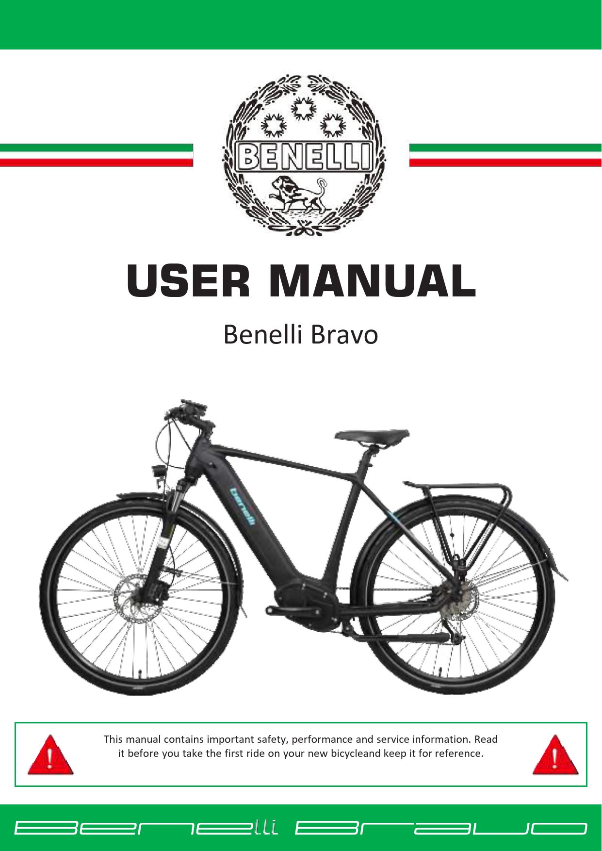
3. Vehicle and parts. Benelli Bravo View
Full PDF Document

If the inline viewer fails, it will open the original document in compatibility mode automatically. You can also open the file directly.
Extracted Text
USER MANUAL
Benelli Bravo
This manual contains important safety, performance and service information. Read it before you take the first ride on your new bicycleand keep it for reference.

Table of Contents
1. Preface........................................................................................................................................................3 1.1 Welcome ............................................................................................................................................3 1.2 Illustrations.........................................................................................................................................3
2. Safety..........................................................................................................................................................3 3. Vehicle and parts........................................................................................................................................4 4. Quick Installation Instruction......................................................................................................................5
4.1 How to set up the front wheel ...........................................................................................................5 4.2 How to set up the handlebar and display...........................................................................................6 4.3 How to install/remove the battery.....................................................................................................7 4.4 Pedal...................................................................................................................................................8 4.5 Adjust the handle bar position ...........................................................................................................8 5. Check before riding ....................................................................................................................................8 6. Riding a Bravo.............................................................................................................................................9 7. The display................................................................................................................................................10 7.1 850C button LCD color screen (LCD).................................................................................................10 7.2 ON/OFF operation ............................................................................................................................10 7.3 Pedal Assist Selection .......................................................................................................................10 7.4 Speed mode and mileage mode switch............................................................................................10 7.5 Headlight switch/display mode switch.............................................................................................11 8. Technical documents:...............................................................................................................................12 8.1 Battery and Charger .........................................................................................................................12 8.2 Storage and Cleaning........................................................................................................................13 8.3 Routine checkup and maintenance:.................................................................................................14 9. Technical Parameters ...............................................................................................................................18 10. Legal documentation............................................................................................................................18 10.1 Service and warranty ........................................................................................................................18 10.2 Warranty conditions.........................................................................................................................19 11. Fault and troubleshooting ....................................................................................................................22 12. Front Fender Installation ..................................................................................................................... 24
2

1. Preface
1.1 Welcome Dear Benelli owner: Thank you for your love of Benelli electric bicycles, and warmly welcome you to become a Benelli user. Before you start your journey riding with the wind, please read this user manual carefully.
1.2 Illustrations Illustrations shown in this document may differ in detail from the exact configurationon your particular e-bike model. The illustrations are a general reference for instruction and description purposes only.
2. Safety
E-B ike laws differ by State - check your local laws and only ride in legally permittedareas. Use helmets, protective gear and always ride responsibly. Bravo is suitable for hard ground roads, such as asphalt, bicycle paths or gravel roads. When driving on public roads, please follow the traffic rules. Bravo bike is notsuitable for off-road driving, otherwise it may cause unpredictable consequences oraccidents.
1) Please strictly abide by the traffic laws and regulations, prepare helmets, protective equipment and other protective equipment before riding, and payattention to cycling safety.
2) It is strictly forbidden for people under the age of 16 to drive electric bicycleson the road; 3) Don't lend electric bicycles to people who are not suitable to ride this bicycle 4) When riding in wet weathers, the braking distance will be extended; 5) Avoid traveling in bad weather such as heavy rain/snow 6) Don't touch or use metal to touch the charging port on the bike, otherwise itwill cause a
short circuit. 7) Bicycles are vehicles with certain risks, break the rear wheel first, and then the front wheel in
emergency braking, especially when the cycling speed is too high, you may fall over if you use the front brake suddenly. Please ride carefully. 8) Please consult your insurance company or insurance broker on the insurancecoverage of riding an electric bike. 9) Do not park bikes in building lobby, evacuation stairs, walkways, and safetyentrances. 10) Do not charge the bike in residential buildings, stay away from combustible,and do not charge for prolong period of time. 11) Maximum load for this bike is 105kg, DO NOT carry more than 25Kg on therear.
3

3. Vehicle and parts

Benelli Bravo

1Tires 5Front fork 9Power switch 13Central motor 17Chain 21Rear light 25Seat post 29Display 33Button

2Rim 6Front fender 10Frame 14Crank Set 18Rear derailleur 22Rear rack 26Chain cover 30Handle Grip

3Front Hub 7Headlight 11Battery 15Pedal 19Cassette 23Saddle 27Brake lever 31Thumb shifter

4Brake Disc 8 Headset 12Brake Caliper 16Chainwheel 20Rear fender 24Seat post 28Handlebar 32Stem

4

4. Quick Installation Instruction
4.1 How to set up the front wheel 1. Insert the front wheel in-between the front fork, make sure the brake disc sits between the brake pads
2. Take the quick release lever, slide off theends, and insert the lever rod through the hub from opposite side of the brake disc. Then, slide the spring and nut onto the rod,tighten the nut. Continue to tighten the nut while opening and closing the lever untila good resistance is achieved. 3. Make sure the lever is flipped up towards the frame to avoid snapping
5

4.2 How to set up the handlebar and display
4. Unscrew the cap from the handlebar holding stem,insert and adjust the position of handlebar. Then tighten the screw back with the cap to secure the handlebar in place.
5. Install the display on handlebar. Secure it inplace by tighten the screws 6. Then connect the blue wire on display to blue wire on bike and green wire on display to green wireon bike.
7. Install the control button on the left side of the handlebar.
6

4.3 How to install/remove the battery 1. Support the battery cover with your hand, as the battery might drop after theit is unlocked. 2. Insert the key into the keyhole near the handlebar, rotate 90� counterclockwiseto unlock the battery.
3. Then insert/remove the battery. When installing the battery, first align the bottom end of the battery with the holder, then move the upper end of thebattery closer to the holder and apply force until you hear a "click" sound.
4. The battery switch is located at the bottom, click to turn on or off the battery 7

output. 4.4 Pedal

Pay attention to Left and Right before installation

4.5 Adjust the handle bar position

1. Please turn the handlebar up, down, left and right, and make sure that the handlebaris not loose. 2. loosen the screws at  to adjust handlebar alignment with the front wheel, ensure it is perpendicular to the front wheel.Loosen the screws
at  to adjust the handlebar position 3. When adjusting the height of the handlebar,make sure that the safety wire on the stem tube is not be exposed.

5. Check before riding
The power circuit and lighting are working. The front and rear brake lever are working. The handlebars are tightened. The front & rear wheels are tightened.

8

The tire pressure is normal. Check the reflector for contamination before cycling.
6. Riding a Bravo
How to start Press the power on/off button, the motor starts. When you sit firmly on the bike, slowly rotate the throttle, and the bike will start moving, and then slowly accelerate. How to change gears
To speed up, start with a lower gear and shift to a higher gear as you speed upWhen going uphill, use a lower gear On a flat terrain, use a higher gear How to brake 1) Release the throttle and stop pedaling. 2) squeeze the both brakes slowly and then tighten. 3) Do not brake or steer sharply. Emergency braking and sharp steering are the mainfactors causing sideslip or rollover, which is extremely dangerous. If only the front orrear wheels are braked, and the bike may slide horizontally, which is extremely dangerous.
9

7. The display

7.1 850C button LCD color screen (LCD)

Use function of LCD meter
 3.2 inch colour screen  Speed

Ups ON/OFF

 battery level

 Mileage

 Time

 Headlight

Downshift

 Brake

 Pedal Assist level

Battery level SGpeeaerdindication
Pedal Assist
Power indicator MTiimleeage

7.2 ON/OFF operation 1. To turn on/off the battery power, press the power button on the bike frame. 2. To turn on/off the display power, press and hold the power button on handlebarswitch for 1 second 3. The display will turn off automatically if the ebike is left idle for more than 5mins .

7.3 Pedal Assist Selection short press the "+" or "-" button to change the Pedal Assist level. The lowest is Level 0without any assistance, and the highest is Level 3 with maximum assistance. The default is Level 1 when the e-bike is turned on.

7.4 Speed mode and mileage mode switch
1. short press the power button to switch the speed display information and mileage display mode, and the following information is displayed in a loop: averagespeed (AVG SPEED)  maximum speed (MAX SPEED)  real-time speed (RT SPEED)  cruising range (RANGE) Cumulative mileage (ODO)  riding time (TIME)  single mileage (TRIP)

10

Speed mode and mileage mode switch display interface The meter will automatically return to the real-time speed display state after 5 seconds
7.5 Headlight switch/display mode switch Long press the "+" button for 1 second, the indicator turns on the lights (supported by the controller) and switches to display day/night modes. Long press the "+" buttonfor 1 second again, the indicator turns off the lights and switches the display mode.

Day Mode Walk assistance mode6km/hr walk

Night Mode

Press the "- " button for 3 seconds, the bike enters walk-assistance mode, the display shows the

real-time speed, Pedal Assist level is P.

Release the button, thebike

exits the walk assistance mode.

Brake indication Braking cut-off shows .

11

8. Technical documents:
8.1 Battery and Charger

will prolong the battery life.

1. The battery can be charged directly in thebike, or charged on its own. 2. Please fully charge the battery beforefirst use, otherwise battery life may be reduced. 3. You can check the battery level by pressingthe display at the bottom of the battery or the battery indicator on display. 4. Please turn off the battery when charging,which

5. Connect the charger to battery properly, before connecting on the wall plug to wall socket. The red light on charger indicates the battery is charging;while green light indicates that the battery is fully charged.
6. If the bike is not used for a long time, the power will gradually decrease dueto natural discharge. Please regularly charge the battery, before it is exhausted.
7. if the bike will not be used for more than 1 months, the battery should be removed from bike and stored separately. Please recharge it at least onceevery three months.
8. The capacity of the battery will decrease after every re-charge. It is normalsee drop in range on a full charge after 6 months of frequent uses. Please contact your dealer for battery replacement.
9. The operating environment is -20~60. 10. The charging time is about 2-4 hrs. Do not charge the battery for morethan 6hrs

12

Warning 1) The user must operate according to the instructions when charging; 2) Never use third party battery or charger for Benelli bikes. 3) When the charger is working, please place it in a safe, well ventilated place, out ofreach of children. 5) Do not leave the charger connect to AC power supply when not charging. This isdangerous, and could cause fire hazards. 6) Do not cover the charger or adaptor when charging, please allow heat to dissipateeasily. 7) Store charger and battery in a dry, clear box when not in use, keep away from smallitem that might fall inside the charging port. 8) Beware of falling and impact to avoid damage. 9) Do not disassemble or replace the parts in the charger by yourself. When replacing the charger, use original charger that match the lithium battery model.
8.2 Storage and Cleaning
Do not use excessive water to wash the plastic. Use a soft cloth with a neutral solution to wipethe dirt off the plastic shells. After that, wipe it dry with a clean soft cloth. CAUTION: Do not use high-pressure water or air hoses for cleaning. It can force water into electric components, which may cause malfunctioning. CAUTION: Do not wash the E-bike components with excessive water. If the internal electrical parts are infected with water, the insulator may corrode which leads to power-drain or other problems. CAUTION: Do not use non-neutral soap solutions to wash plastic components. Non-neutral solutions may cause colour-change, distortion, scratching.
13

8.3 Routine checkup and maintenance: In order to prolong the service life of the bike and enable maintain its safety and comfort, please check and maintain it regularly. When the bike is not used for a longtime, it should also be checked regularly. The new bike should be inspected by a professional once the milage passes 300Km. All inspection must be carried out in asafe and open environment. If an abnormality is found during regular inspections, please avoid using the e-bike before the issue is resolved.
Motors and controllers: 1. Regularly remove dirt from the lids on both sides of the motor to allow heat dissipation during motor work and extend the degaussing time of the motor, thus extending the life of the motor. 2. Regularly inspect and tighten the cover screws and nuts at both ends of themotor and shafts to avoid damage to the motor during riding. 3. Regularly go to bike servicing point to check the insulation of the motor wiring and the casing. If there is no insulation, find out the cause and repair it in time. 4. Regularly check whether the connecting plug-in of the controller is loose. 5. Regularly check whether the fuse box of the whole vehicle is loose, and deal withit in time if it is loose. 6. You should start and accelerate the bike slowly to reduce the impact of highcurrents on controllers, motors and lithium batteries and extend the life of electrical components.
Bike frame and parts: 1. Check whether the front fork is bent or damaged, 2. Move the handlebar up and down, if there is any usual noise, please consult aprofession bike servicing center. 3. Check front and rear brakes respectively 4. Check if the gear can be changed within the range without abnormal resistance 5. Do not disassemble the bike by yourself unless you have mastered thetechniques, so as not to damage other parts.
14

6. Use original spare parts, otherwise it may impair the function of the bicycle orcause damage. Tyre:
1. Check the tyre pressure before riding. 2. If the tyre pressure is abnormal, check for cracks, damage and abnormal wear, 3. Stay away from stones, glass, nails or sharp objects on the ground whenriding. 4. Tyre can be hot to touch after riding. 5. Replace the tyre when more than 2/3 of the tread on tyre groove are wornout.
Chain adjustment: Adjustments should only be performed with proper tools by a trained mechanic. Please consult professional bike shops if you are unsure, incorrect chain adjustmentcan cause injuries when riding. How to check the chain: To check the chain tension, hold the chain in the middle section between the front and rearsprockets. � Move the chain up and down to check the slack on the chain; � There should be between 10-15 mm of vertical movement; � If the movement is more or less, the chain tension needs to be adjusted. How to adjust the chain: Please consult professional bike shops if you are unsure, incorrect chain adjustment cancause injuries when riding.
15

Chain

First loosen the rear axle nut and turn the adjusting nut to the left or right to correct the slack of the chain. While adjusting the chain, you must also keep the front wheel chain aligned with the rear. After adjustment, re-fix the rear axle nut, lock the adjustment nut and perform a final check to make the distance between the two sprockets is 10-15 mm. The open end of the chain spring should be opposite to
the chain movement direction

Movement
Saddle adjustment: 1. Pull the saddle to check whether the saddle is loose or skewed. 2. When adjusting the height of the saddle, pay attention to minimum andmaximum insert length. 3. Always tighten the saddle clamp after adjustment, and check the saddle beforeeach ride.
Brake adjustment 1. Check the condition of your brake regularly. To check, while ride normally, hold front then rear brakes at different times. The rear wheels will lock the motion ofbike and the front wheels will quickly slow down and the bicycle will tip forward. 2. Adjust the distance between the brake pads and the rim to adjust brakingeffect. Please consult professional servicing provider if unsure. 3. Replace the brake pads if they are severely worn (more than 2/3), always replacethe left and right brake pads together at the same time. 4. After adjusting the brake, be sure to tighten the brake wire fixing screws 5. Rubber brake pads should not be contaminated with any grease. If they are contaminated with grease, their braking performance will be greatly reduced,and they must be replaced.

16

6. Disc brakes can produce a very high braking force. Sudden brake when riding with speed can cause the whole bike to topple. Practice braking until you gainfull control of the bicycle.
7. Improper use of the additional shock-absorbing elements in the brake system (power regulator) can cause serious accidents. The specified spring force of thepower regulator depends on the total weight of the bicycle
Adjustment and maintenance: It is recommended to conduct a comprehensive inspection and maintenance of thebike after the initial 300 kilometers of riding. After that, carry out a more comprehensive inspection of the bike for every 1,000 kilometers of riding. Lubrication: Appropriately lubricate the parts that need lubrication, such as chains, brake lines,and bike supports. DO NOT lubricate Rim surface, brake pad surface, tire surface, electrical switch Recommended tightening torque of fasteners

Parts Crank arm Pedals Axle, Front Axle, Rear Stem wedge bolt Stem, fork end fixture Stem, direction fixation device Rod end, outer band Seat post, hoop Seat post clamp Brake pad Brake cable clamp Brake handle clamp V-type brakes, fastening screws Flywheel fastens screw Flywheel, lock ring

Specifications M8 9/16 of an inch general general M8 M5/M6/M7 M5/M6/M7 M5/M6 M8/M6 M7/M8 M6 M6 M5 M6 None None

Torque (N.m) 30 30 25 30 23 M5:5/ M6:10/ M7:14 M5:5/ M6:10/ M7:14 M5:5/ M6:10 M8:20/ M6:10 M7:14/ M8:20 10 10 5 10 40 30

*The above values are only reference values, please follow the attached partsmanufacturer's

operating instructions

17

9. Technical Parameters

MODEL
Dimensions(L*W*H) Wheelbase Weight Max Speed Recharge Mileage 100 km power consumption Deadweight Type of Batter Battery Capacity Motor type Rated Power Rated Speed Rated Voltage Controller undervoltage protection value Controller overcurrent protection value

Bravo
1890*700*1140mm 1150mm 25kg 25km/h 90km 0.58kw h/100km 105kg25kg lithium battery 14.5Ah Center Motor 250W 120r/min 36V 31�0.5V 15�0.5A

10. Legal documentation
10.1 Service and warranty Dear user: Thank you for using the electric bicycle produced by our company. Toprotect your safety and rights, please keep the manual properly.
18

Maintenance and precautions
1) Only use original parts purchased from manufacturer, authorized resellers, bike service provider. The manufacturer will not be responsible for any loss or injuriescaused by using a third-party part.
2) It is recommended to go to the dealer or service station for a batterymaintenance after 3 months.
3) The user should not accelerate rapidly during driving, and try to avoid suddenbrakes. 4) Please do not modify the bike body, cables, electrical components, and the structure and function
of the bike without permission; unauthorized changes to the parameters of cables and electrical components will cause deterioration of handling performance, increased noise, failure of electrical performance and other situations Occurs, resulting in the shortening of the life of the bike, causing safetyhazards, and the performance cannot be effectively guaranteed; the resulting liability losses; the company is not responsible, and the user will be responsible forit.

10.2 Warranty conditions

This warranty covers any defects in material or workmanship under normal use duringthe "Warranty

Period".

Warranty does not cover tires, tubes, brake pads or chains.

This Limited Product Warranty does not apply under the following circumstances: 1. Damage caused by operating the product outside the permitted or intendeduses described by the manufacturer's instructions 2. Damage caused by incorrect operations, such as negligent, impropermaintenance or incorrect use of the product. 3. Operation of the vehicle when it is overheating 4. Commercial use of the product, such as rental.
19

5. The products are damaged, misused, or tampered with from the original state it was delivered.
6. Unauthorised modifications to any part of the product, including but notrestricted to: a. Modification to controller b. Modification to battery c. Modification to motor d. Modification to charger e. Modification to throttle f. Modification to power system g. Modification to suspension h. Modification to brakes
7. The battery is un-sealed. 8. Installing performance parts or components on the vehicle that change theoriginal
engineering. 9. Damage caused by servicing of the product (including upgrades and expansions)performed by
anyone who is not authorised by Panmi/ Benelli to perform such services 10. Damage caused by nature or acts of God, for example, lightning strikes,cyclones, and
the like. 11. Damage caused by natural wear and tear.
20

Disclaimer: Do not tamper with your bicycle. Tampering is removing or replacing any original equipment or modifying your bicycle in anyway that may change its design and/or operation. Such changes may seriously impair the handling, stability and other aspectsof the bicycle, making it unsafe to ride. Tampering can void the warranty and render your bike not in compliance with the applicable laws and regulations. To ensure safety, quality and reliability, use only original parts or Benelli authorized replacements for repair and replacement. Benelli is not responsible for any direct, incidental or consequential damages, including, without limitation, damages for personal injury, property damage, or economic losses due to tampering.

AUTHORISE
www.panmi.com.au/warranty Email: support@panmi.com.au

21

11. Fault and troubleshooting
Error indication The display shows an error code for the failures. When a failure is detected, the LCDscreen displays an icon, and the error code at the bottom.

The error code table is as follows!

NO Status data 3 0x04

Error code meaning Shifter lever did not return (stopped at highposition)

4 0x05 6 0x07 7 0x08 8 0x09
9 0x10
10 0x11 11 0x12 12 0x13 13 0X14 13 0x21 14 0x22 15 0x23 16 0x24 17 0x25 18 0x26 19 0x30

Shift lever failure Overvoltage protection Motor Hall signal wire failure Motor phase line failure The controller temperature is high and reachesthe protection point Controller temperature sensor failure Current sensor failure Temperature failure in the battery The temperature sensor in the motor is faulty Speed sensor failure BMS Headlight failure Headlight sensor failure Torque sensor torque signal failure Torque sensor speed failure Communication failure

22

Troubleshooting NO The fault phenomenon 1 The motor hub does not work after the power is switched on
Short range ona 2
single charge

The cause of the problem

Elimination method

Battery wiring is loose ; Motor fault; Electrical cable failure;
Insufficient tire pressure; Insufficient charging or charger failure; Battery aging or damage;More uphill, strong headwind, frequent brakestart, load big

Repair and reconnection; Professional repair or replacement; Find a professional repair or repair shop Sufficient air; Sufficient electricity orcheck whether the charger plug is in bad contact: Find a professional repair or repair shop. It is recommended to use a human foot assist in these cases .

Charger not 3
charging

The charger socket fallsoff or the plug is disconnected from the socket The internal fuse of the charger is blown out Battery wiring comes off.

Tighten socket box connectors; Replace the fuse; Welding line

4 Other fault

When you encounter any problem that cannot be excluded by yourself under the above instructions Obstacles or undetermined faults; Motor hub, controller, charger and battery pack are damaged at theright time.

In case of any of the above, please contact the supplier or maintenance station. Do not open the above parts without authorization, or you willlose our warranty commitment.

23

12. Front Fender Installation
1. Insert the front end of the front fender strut into the blackadjuster (make sure the adjuster is locked)
2. Insert bolt through the flat washer, headlight bracket and the front fender mount respectively and pre-lock onto the suspension fork brace . Fix the nuts on the back of the front fork. (Loosely screw this together, should not be locked tight atthis stage)
24

3. To connect to the fender strut, the bolts is passed through theflat washer, the tail hole of the front fender, hole of the front fender strut and then fastened with the nut (4 -- 6 N.m).
4. Install the front wheel and adjust the clearance between thefront fender and the front tyre to 15-20mm.
Lock the front fender support adjuster, tightenthe screws to (4-6N.m)
and suspension fork brace tightenthe bolt to (6-10N.m).
25