LPC55S6x | Arm Cortex -M33 | 32-bit MCU | NXP Semiconductors
AN12387
Running coremark benchmark with dual CM33 cores and PowerQuad on LPC5500
Rev. 2 -- 04/2020
Application Note
1 Introduction
The LPC55S69 MCU has two Arm® Cortex®-M33 cores, each with a maximum working frequency of 100 MHz. Two additional co-processors are also integrated to strengthen the computing ability for specific use. The CASPER Crypto co-processor enables hardware acceleration for certain asymmetric cryptographic algorithms, while the PowerQuad hardware accelerator is used for DSP functions (fixed and floating-point). This application note describes the design of a benchmark demo to see the best performance of the LPC55S69 MCU. In the demo project, the two Arm Cortex-M33 cores are running the coremark standard benchmark task, while the PowerQuad is set up to execute the FFT computing task.
2 Porting coremark benchmark project on LPC5500
Contents
1 Introduction............................................ 1
2 Porting coremark benchmark project on LPC5500............................ 1
3 Enabling dual-core projects................... 2
4 Enabling PowerQuad tasks................... 5
5 Running the project for benchmark record.................................................. 7
6 Revision history..................................... 9
7 Appendix A: Purchasing LCD module used in this demo................. 10
In the original coremark template project from the offset website (www.eembc.org/coremark/index.php), the coremark standard measurement procedure is executed as a whole application project and runs only once during the whole life-cycle of the application. This usage makes sense, because users do not run other functions when wanting to measure the coremark performance.
The LPC55xx CoreMark on Cortex-M33 Porting Guide (document AN12284) shows how to port the coremark project onto the LPC5500 platform.
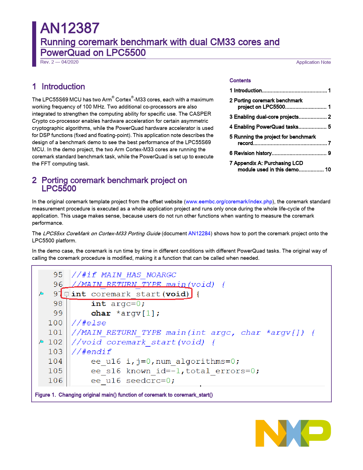
In the demo case, the coremark is run time by time in different conditions with different PowerQuad tasks. The original way of calling the coremark procedure is modified, making it a function that can be called when needed.
Figure 1. Changing original main() function of coremark to coremark_start()
NXP Semiconductors
Enabling dual-core projects
As seen in Figure 1, the original main() function name is changed to coremark_start() in the core_main.c source file. This function is the entry of the coremark task in the application. In the core_portme.c source file, insert the "gCoreMarkDone" flag variable into the portable_fini() function to indicate that the coremark task of the current cycle is done.
void portable_fini(core_portable *p) {
... gCoreMarkDone = true; }
In the demo project, the coremark task is called everytime as follows:
gCoreMarkDone = false; coremark_start(); while (!gCoreMarkDone) { }
NOTE Only CORE0 executes the coremark task time and time again. For CORE1, the coremark task is executed only once because its running condition is not changed during the whole demo with various PowerQuad tasks with CORE0.
3 Enabling dual-core projects
3.1 Memory allocation for the best performance
To achieve the best working performance, allocate the memory blocks of code and data for both cores in a suitable way and reduce the arbitration of the accessing bus in the hardware system.
In the hardware system diagram, the memories are divided into blocks and connected to the AHB bus matrix separately. Using this design, different bus masters can access different memory blocks simultaneously, without any arbitration delay.
For the LPC55S69 MCU, the available memories are shown in Figure 2.
Application Note
Running coremark benchmark with dual CM33 cores and PowerQuad on LPC5500, Rev. 2, 04/2020
2 / 11
NXP Semiconductors
Enabling dual-core projects
Figure 2. LPC5500 memory map overview (part)
The following applies to the CORE0 application in this demo: - The code is kept in the FLASH memory between 0x0000_0000 and 0x0003_FFFF (256 KB in total). The code runs in the FLASH memory. - The data (including stack and heap) is kept in the RAM1 and RAM2 memories between 0x2001_0000 and 0x2002_FFFF (128 KB in total). The following applies to the CORE1 application in this demo: - The code is kept in the FLASH memory between 0x0004_0000 and 0x0009_7FFF, (352 KB in total). After booting up, the code is copied to the RAMX memory block and run there between 0x0400_0000 and 0x0400_7FFF (32 KB in total). - The data (including stack and heap) are kept in the RAM3 memory between 0x2003_0000 and 0x2003_FFFF (64 KB in total). The RAM0 memory keeps the shared data (discussed further on in this document). The access paths are shown in Figure 3.
Application Note
Running coremark benchmark with dual CM33 cores and PowerQuad on LPC5500, Rev. 2, 04/2020
3 / 11
NXP Semiconductors
Enabling dual-core projects
Figure 3. LPC5500 hardware system diagram (part)
Figure 3 shows that no memory blocks (slaves in the AHB matrix) are owned by the two cores (masters in the AHB matrix). The only exception is the RAM0 memory, which is used to share data between the two cores.
The memory allocation is configured as the linker files of the project are made.
The linker file for CORE0 is as follows:
define symbol m_interrupts_start define symbol m_interrupts_end
= 0x00000000; //FLASH = 0x0000013F; //FLASH
define symbol m_text_start define symbol m_text_end
= 0x00000140; //FLASH = 0x0003FFFF; //FLASH
define exported symbol CORE1_image_start define exported symbol CORE1_image_end
= 0x00040000; //FLASH = 0x00097FFF; //FLASH
define symbol m_xcode_start define symbol m_xcode_end
= 0x20000000; //RAM0 = 0x2000FFFF; //RAM0
define symbol m_data_start define symbol m_data_end
= 0x20010000; //RAM1-2 = 0x2002FFFF; //RAM1-2
Application Note
Running coremark benchmark with dual CM33 cores and PowerQuad on LPC5500, Rev. 2, 04/2020
4 / 11
NXP Semiconductors
The linker file for CORE1 is as follows: define symbol m_interrupts_start define symbol m_interrupts_end define symbol m_text_start define symbol m_text_end define symbol m_data_start define symbol m_data_end
= 0x04000000; //RAM-X = 0x0400013F; //RAM-X
= 0x0400013F; //RAM-X = 0x04007FFF; //RAM-X
= 0x20030000; //RAM3 = 0x2003FFFF; //RAM3
Enabling PowerQuad tasks
3.2 Inter-communication between CORE0, CORE1, and PowerQuad task
CORE0, CORE1, and PowerQuad work at the same time after the chip comes out from a reset. The messages are printed by CORE0. As the main core, CORE0 synchronizes the work with another core or co-processor and collects the result marks together.
The inter-communication between CORE0 and PowerQuad uses the volatile global variable defined in the task_powerquad_benchmark.c source file:
volatile uint32_t gTaskPowerQuadCounter = 0u;
This variable increases when the PowerQuad task is executed everytime CORE0 runs the coremark task. When CORE0 finishes its coremark task, the portable_fini() function in the core_portme.c source file for CORE0 collects the value of "gTaskPowerQuadCounter" and prints it later.
The inter-communication between CORE0 and CORE1 uses the shared memory in RAM0. Some variables are defined at absolute addresses for both cores in the core_portme.c source file:
volatile int CORE1_coremark volatile int CORE1_costtime volatile int CORE1_finish_flag
__attribute__((section(".ARM.__at_0x20038000"))); __attribute__((section(".ARM.__at_0x20038010"))); __attribute__((section(".ARM.__at_0x20038020")));
When the CORE1 coremark task is done, it feeds its result into "CORE1_coremark" and "CORE1_costtime" and marks "CORE1_finish_flag" as "true". CORE0 waits until "CORE1_finish_flag" is "true", collects the values in "CORE1_coremark" and "CORE1_costtime", and prints them.
4 Enabling PowerQuad tasks
The PowerQuad task is handled inside the ISR (Interrupt Service Routine), which is defined as the PQ_IRQHandler() function inside the vector table. In the demo case, there are three types of computing tasks for PowerQuad: FFT with 128 points, FFT with 256 points, and FFT with 512 points.
void App_PQTask_CFFT512Case(void) {
PQ_TransformCFFT(DEMO_POWERQUAD, 512u, inputData, cfftResult); }
void App_PQTask_CFFT256Case(void) {
PQ_TransformCFFT(DEMO_POWERQUAD, 256u, inputData, cfftResult); }
void App_PQTask_CFFT128Case(void) {
PQ_TransformCFFT(DEMO_POWERQUAD, 128u, inputData, cfftResult); }
Application Note
Running coremark benchmark with dual CM33 cores and PowerQuad on LPC5500, Rev. 2, 04/2020
5 / 11
NXP Semiconductors
Enabling PowerQuad tasks
A software callback is designed to make the ISR run a different task. Different PowerQuad tasks can be installed into the ISR before launching it.
/* ISR for PowerQuad*/ void PQ_IRQHandler(void) {
uint32_t flags = POWERQUAD->INTRSTAT; /* PQ_GetStatusFlags(). */ /* A software workaround.
* Use the OVERFLOW flag instead of DONE flag to detect the DONE interrupt. / if (POWERQUAD_INTREN_INTR_OFLOW_MASK == (POWERQUAD_INTREN_INTR_OFLOW_MASK and flags) ) {
gTaskPowerQuadCounter++; //PQ_TransformCFFT(DEMO_POWERQUAD, N, inputData, cfftResult); /* start the new task. */ if (gAppPowerQuadCallback) {
(*gAppPowerQuadCallback)(); } } POWERQUAD->INTRSTAT = flags; /* PQ_ClearStatusFlags(). */ }
void App_PQInstallCallback(void (*callback)(void)) {
gAppPowerQuadCallback = callback; }
In the application, the PowerQuad tasks are triggered one by one:
void task_pq_fft_128(void); void task_pq_fft_256(void); void task_pq_fft_512(void);
void (*cAppLcdDisplayPageFunc[])(void) = {
task_pq_fft_512, task_pq_fft_256, task_pq_fft_128 /* merge the last task into this one. */ //task_end };
void task_pq_fft_512(void) {
PRINTF("%s\r\n", __func__); ... App_PQInstallCallback(App_PQTask_CFFT512Case); gCoreMarkDone = false; coremark_start(); while (!gCoreMarkDone) { } ... }
void task_pq_fft_256(void) {
PRINTF("%s\r\n", __func__); ... App_PQInstallCallback(App_PQTask_CFFT256Case); gCoreMarkDone = false;
Application Note
Running coremark benchmark with dual CM33 cores and PowerQuad on LPC5500, Rev. 2, 04/2020
6 / 11
NXP Semiconductors
Running the project for benchmark record
coremark_start(); while (!gCoreMarkDone) { } ... }
void task_pq_fft_128(void) {
PRINTF("%s\r\n", __func__); ... App_PQInstallCallback(App_PQTask_CFFT128Case); gCoreMarkDone = false; coremark_start(); while (!gCoreMarkDone) { } ... }
int main(void) {
... while (1) {
keyValue = App_GetUserKeyValue(); if (keyValue != keyValuePre) {
App_DeinitUserKey(); /* disable detecting key when changing the lcd display. */ (*cAppLcdDisplayPageFunc[keyValue])(); /* switch to new page on lcd module. */ keyValuePre = keyValue; App_InitUserKey(); /* enable detecting key for next event. */ }
__WFI(); /* sleep when in idle. */ } }
When the PowerQuad task is launched, it runs continuously with CORE0 running the coremark task. CORE0 stops the PowerQuad task after its coremark task is done. The "gTaskPowerQuadCounter" variable is used to count the cycles that the PowerQuad task runs. At the same time, this number is counted by the CORE0 coremark task. Then it can be determined how many times the PowerQuad task runs per second, and this number can be used as the performance benchmark value in the report.
5 Running the project for benchmark record
To run the demo project, build the CORE1 project first and generate the image for CORE1. Then build the CORE0 project, which includes the CORE1 image. After this, one image file includes the applications for both cores.
There are two versions of the project:
- LCD display version: this version uses the LCD module to show the result (lpc5500_coremark_dualcore_powerquad_lcd_display).
- UART terminal version: this version uses the UART terminal to output the result when there is no LCD module. It shows the same thing on the LCD when the LCD module is assembled (lpc5500_coremark_dualcore_powerquad_uart_terminal). This version is a modification of the first one.
When the LCD display version works, the result is shown on the LCD module, as shown in Figure 4.
Application Note
Running coremark benchmark with dual CM33 cores and PowerQuad on LPC5500, Rev. 2, 04/2020
7 / 11
NXP Semiconductors
Running the project for benchmark record
Figure 4. Records on LCD screen When the UART terminal version works, the result is shown in the UART terminal, as shown in Figure 5.
Application Note
Running coremark benchmark with dual CM33 cores and PowerQuad on LPC5500, Rev. 2, 04/2020
8 / 11
NXP Semiconductors
Revision history
Figure 5. Records in UART terminal
This information is summarized in Table 1.
Table 1. Benchmark summary at 96-MHz core clock
Core clock = 96 MHz
CORE 0
coremark
DualCore + PQ FFT512
338
DualCore + PQ FFT256
322
DualCore + PQ FFT128
306
CORE 1 coremark 372 372 372
PowerQuad cycles/second 28807 54795 103153
When running with 150-MHz core clock, the record is shown in .
Table 2. Benchmark summary at 150-MHz core clock
Core clock = 150 MHz DualCore + PQ FFT512 DualCore + PQ FFT256 DualCore + PQ FFT128
CORE 0 coremark 523 493 445
CORE 1 coremark 582 582 582
PowerQuad cycles/second 44577 83939 149489
The score of CORE1 is higher than the score of CORE0, because the code of CORE1 runs in the SRMAX memory, while the code of CORE0 runs in the FLASH memory. The FFT task with fewer points runs more frequently and interrupts CORE0 to restart the task in the ISR of PowerQuad. The score of CORE0 is a little lower when the PowerQuad is run more.
6 Revision history
Table 3 summarizes the changes done to this document since the initial release.
Table 3. Revision history Revision number 0
Date 03/2019
Table continues on the next page...
Substantive changes Initial release
Application Note
Running coremark benchmark with dual CM33 cores and PowerQuad on LPC5500, Rev. 2, 04/2020
9 / 11
NXP Semiconductors
Table 3. Revision history (continued) Revision number 1
Date 05/2019
2
04/2020
Appendix A: Purchasing LCD module used in this demo
Substantive changes Added Appendix A: Purchasing LCD module used in this demo. Modified Table 1 and Table 2.
7 Appendix A: Purchasing LCD module used in this demo
Purchase the LCD board at these links: · https://www.waveshare.com/product/modules/oleds-lcds/arduino-lcd/2.8inch-tft-touch-shield.htm · http://www.waveshare.net/shop/2.8inch-TFT-Touch-Shield.htm
Application Note
Running coremark benchmark with dual CM33 cores and PowerQuad on LPC5500, Rev. 2, 04/2020
10 / 11
How To Reach Us Home Page: nxp.com Web Support: nxp.com/support
Information in this document is provided solely to enable system and software implementers to use NXP products. There are no express or implied copyright licenses granted hereunder to design or fabricate any integrated circuits based on the information in this document. NXP reserves the right to make changes without further notice to any products herein.
NXP makes no warranty, representation, or guarantee regarding the suitability of its products for any particular purpose, nor does NXP assume any liability arising out of the application or use of any product or circuit, and specifically disclaims any and all liability, including without limitation consequential or incidental damages. "Typical" parameters that may be provided in NXP data sheets and/or specifications can and do vary in different applications, and actual performance may vary over time. All operating parameters, including "typicals," must be validated for each customer application by customer's technical experts. NXP does not convey any license under its patent rights nor the rights of others. NXP sells products pursuant to standard terms and conditions of sale, which can be found at the following address: nxp.com/ SalesTermsandConditions.
While NXP has implemented advanced security features, all products may be subject to unidentified vulnerabilities. Customers are responsible for the design and operation of their applications and products to reduce the effect of these vulnerabilities on customer's applications and products, and NXP accepts no liability for any vulnerability that is discovered. Customers should implement appropriate design and operating safeguards to minimize the risks associated with their applications and products.
NXP, the NXP logo, NXP SECURE CONNECTIONS FOR A SMARTER WORLD, COOLFLUX, EMBRACE, GREENCHIP, HITAG, I2C BUS, ICODE, JCOP, LIFE VIBES, MIFARE, MIFARE CLASSIC, MIFARE DESFire, MIFARE PLUS, MIFARE FLEX, MANTIS, MIFARE ULTRALIGHT, MIFARE4MOBILE, MIGLO, NTAG, ROADLINK, SMARTLX, SMARTMX, STARPLUG, TOPFET, TRENCHMOS, UCODE, Freescale, the Freescale logo, AltiVec, C5, CodeTEST, CodeWarrior, ColdFire, ColdFire+, CWare, the Energy Efficient Solutions logo, Kinetis, Layerscape, MagniV, mobileGT, PEG, PowerQUICC, Processor Expert, QorIQ, QorIQ Qonverge, Ready Play, SafeAssure, the SafeAssure logo, StarCore, Symphony, VortiQa, Vybrid, Airfast, BeeKit, BeeStack, CoreNet, Flexis, MXC, Platform in a Package, QUICC Engine, SMARTMOS, Tower, TurboLink, and UMEMS are trademarks of NXP B.V. All other product or service names are the property of their respective owners. AMBA, Arm, Arm7, Arm7TDMI, Arm9, Arm11, Artisan, big.LITTLE, Cordio, CoreLink, CoreSight, Cortex, DesignStart, DynamIQ, Jazelle, Keil, Mali, Mbed, Mbed Enabled, NEON, POP, RealView, SecurCore, Socrates, Thumb, TrustZone, ULINK, ULINK2, ULINK-ME, ULINK-PLUS, ULINKpro, µVision, Versatile are trademarks or registered trademarks of Arm Limited (or its subsidiaries) in the US and/or elsewhere. The related technology may be protected by any or all of patents, copyrights, designs and trade secrets. All rights reserved. Oracle and Java are registered trademarks of Oracle and/or its affiliates. The Power Architecture and Power.org word marks and the Power and Power.org logos and related marks are trademarks and service marks licensed by Power.org.
© NXP B.V. 2020.
All rights reserved.
For more information, please visit: http://www.nxp.com For sales office addresses, please send an email to: salesaddresses@nxp.com
Date of release: 04/2020 Document identifier: AN12387
Antenna House PDF Output Library 6.6.1502 (Windows (x64))