B PLUS Remote System User Guide
File info: application/pdf · 1 pages · 581.82KB
Safety Considerations
Signal unit : Connects signal units such as detector switches or controllers. Remote : A unit which is installed on the moving side and has following functions: to supply power for.. View
Download
Remote coupler system | Wireless power supply by B&PLUS USA
Extracted Text
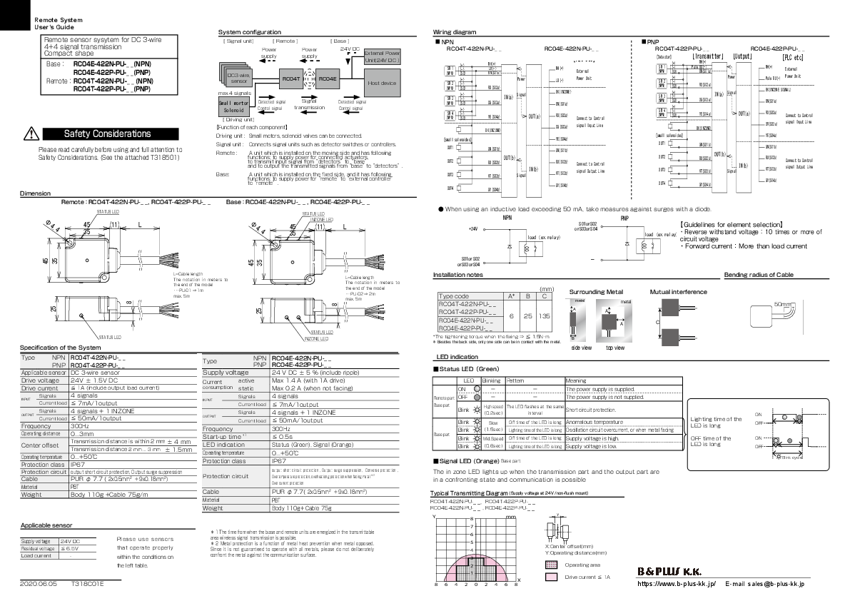
Remote System

User's Guide

System configuration

Wiring diagram

Remote sensor sysytem for DC 3-wire 4+4 signal transmission Compact shape Base RC04E-422N-PU-_ _(NPN)
RC04E-422P-PU-_ _(PNP) RemoteRC04T-422N-PU-_ _ (NPN)  RC04T-422P-PU-_ _(PNP)
Safety Considerations

[ Signal unit]

[ Remote ]

Power supply

Power supply

[ Base ] 24V DC

External Power Unit(24V DC

DC3-wire, sensor

RC04T

RC04E

Host device

max.4 signals Small mortor
Solenoid

Detected signal Control signal

Signal transmission

Detected signal Control signal

[ Driving unit]


Function of each component

Driving unit : Small motors, solenoid valves can be connected.

 NPN

 PNP

RC04T-422N-PU-_ _

RC04E-422N-PU-_ _

RC04T-422P-PU-_ _

RC04E-422P-PU-_ _

(+) SW 1 (-) (NPN) (SO)
(+) SW 2 (-) (NPN) (SO)
(+) SW 3 (-) (NPN) (SO)
(+) SW 4 (-) (NPN) (SO)
 [small solenoides]

WH(+) LB(-) BN(SI1a)
Power
RD(SI2a)
IN(a) Signal
OG(SI3a)

YE(SI4a)

OUT(a)

BK(INZONE)


[PLC etc]

WH(+)

External

LB(-)

Power Unit

BK(INZONE)

BN(S01a)

RD(SO2a) Connect to Control

[Detector] (+)
SW 1 (-) (NPN) (SO)
(+) SW 2 (-) (NPN) (SO)
(+) SW 3 (-) (NPN) (SO)
(+) SW 4 (-) (NPN) (SO)

OG(SO3a) signal Input Line

YE(SO4a)

[small solenoides]

[Transmitter] [Output]
WH(+) Pale BU(-)
BN(SI1a)
Power
RD(SI2a)
IN(a) Signal
OG(SI3a)

YE(SI4a)

OUT(a)

BK(INZONE)

[PLC etc]

WH(+)

External

Pale BU(-) Power Unit

BK(INZONE SIGNAL)

BN(S01a)

RD(SO2a) OR(SO3a)

Connect to Control signal Input Line

YE(SO4a)

Please read carefully before using and full attention to Safety Considerations. (See the attached T318501)


Signal unit : Connects signal units such as detector switches or controllers.

Remote :

A unit which is installed on the moving side and has following functions: to supply power for connected actuators, to transmit input signal from"detectors"to"base" and to output the transmitted signals from"base"to"detectors".

Base:

A unit which is installed on the fixed side, and it has following

functions: to supply power for"remote"to"external controller"

to"remote".

OUT1

OUT1

GN(SO1b)

GN(SI1b)

OUT2 OUT3


OUT(b)

BU(SO2b)


VT(SO3b)

Signal


OUT2

lIoNa(db)(ex.relaBVyUT)((SSII23bb))CsoingnneacltOtuotpCuotntLrionle 10OUT3

OUT4


GY(SO4b)

GY(SI4b)

OUT4

GN(SO1b)

OUT(b)
BU(SO2b)

VT(SO3b)

IN(b)
Signal

GY(SO4b)

GN(SI1b)

BU(SI2b) VT(SI3b)

Connect to Control signal Output Line

GY(SI4b)

Dimension RC04T-422N-RPCU0-4_T_-422N-PU-__

RRCe04mTo-t4e22RP-CRPC0U04-4_TT_--442222PN--PPUU-_-___RC04T-422P-PU-_ _

STATUSLELDED

LED

RC04E-422N-RPCU0-4_E_-422N-PU-__ BaRsCe04ER-C40224PE-R-P4CU02-42_E_N-4-P2U2P-_-P_U-R__C04E-422P-PU-_ _
LED STATUSLELDED


When using an inductive load exceeding 50 mA, take measures against surges with a diode.

4.4

 45 35

11

L


[:][:]

4.4

LED
45 35

INZONE LELDED
11

L
[:][:]


NPN

 +24V


PNP


S01orS02

Guidelinesforelement s1e0lection

orS03orS04

load

(ex.relay)Reverse withstand voltage10

times

or

more

of

:+24V :+24V

:+24V :+24V

 load (ex.relay)

circuit voltage

:-

:-

:-

:-

Forward currentMore than load current

35

45

:INZONE :INZONE

:SI1

:SI1

45

35

:INZONE :INZONE

:SO1

:SO1

S01orS02 orS03orS04


:SI2 LT=hCeanbolet:aleStniIog3nthin

:SI2 meters :toSI3

theend o:fStIh4e model:SI4

PU-01:SO11m max. 5m:SO2

:SO1 :SO2

25

:SO3

:SO3

:SO4

:SO4

25

8

:SO2

:SO2

L=Cable :leSnOg3th :SO3

TthheeP eUnn -od0t2o::aftSStiOIoh241nemminodmeelters ::toSSOI41

max. 5m:SI2

:SI2

:SI3

:SI3

:SI4

:SI4

Installation notes


(mm) Type codeA*  Bload (eCx.relay)

RC04T-422N-PU-_ _

RC04T-422P-PU-_ _ RC04E-422N-PU-_ _

6 25 135

Surrou+2n4dV ingMVectal �M1u.t5ual interference metal metal  load (ex.relay) AVcA

A

C

Bending radius of Cable 50mm

8

25

25

STATUSLELDED

LED

Specification of the System

Type

NPN

PNP

Applicable sensor

Drive voltage

Drive current

RC04T-422N-PU-_ _ RC04T-422P-PU-_ _ DC 3-wire sensor 24V � 1.5V DC  1A (include output load current)

LED STATUSLEDLED LED INZONE LELDED

Type

NPN PNP

Supply voltage

Current

active

consumption static

RC04E-422N-PU-_ _ RC04E-422P-PU-_ _
24 V DC � 5  (include ripple) Max 1.4 A (with 1A drive) Max 0.2 A (when not facing)

RC04E-422P-PU-_ _ *Thetightening torque when the fixing   1.5Nm
 Besides the back side, only one side can be in contact with the metal.
LED indicat+i2o4nV
 load (ex.relay)
 Status LEDGreen

LED Blinking Pattern

ON


B
side view  top view
 load (ex.relay)
Meaning
The power supply is supplied.

  Vc�1.5
 Vc

INPUT

Signals

4 signals

Current load  7mA/1output

Signals

4 signals + 1 INZONE

OUTPUT

Current load  50mA/1output

Frequency

300Hz

Operating distance 0...3mm

Center offset

Transmission distance is within 2 mm � 4 mm Transmission distance 2 mm ... 3 mm� 1.5mm

Operating temperature 0...+50

Protection class IP67

Protection circuit output short circuit protection, Output surge suppression

Cable

PUR  7.7 ( 2x0.5mm2 + 9x0.18mm2)

Material

PBT

Weight

Body 110g +Cable 75g/m

INPUT

Signals Current load

OUTPUT

Signals Current load

Frequency Start-up time 1

LED indication

Operating temperature

Protection class

4 signals  7mA/1output 4 signals + 1 INZONE  50mA/1output 300Hz  0.5s Status (Green), Signal (Orange) 0...+50 IP67

Protection circuit
Cable Material

output short circuit protection , Output surge suppression, Converse protection , Overtemperature protection, overheationg protection when facing metal 2 Over current protection
PUR  7.7( 2x0.5mm2 + 9x0.18mm2) PBT

Remote part OFF


 The power supply is not supplied.

Base part
Blink

High speed The LED flashes at the same Short circuit protection.

Blink

0.2sec

interval

 +24V

Slow

Off time of the LED is long Anomalous temperature  load (ex.relay)

Lighting time of the LED is long

ON OFF

Blink

1.5sec Lighting time of the LED is long Oscillation circuit overcurrent, or when metal facing

Base part

Blink

Mid.Speed Off time of the LED is long Supply voltage is high.

OFF time of the

ON

Blink

0.6sec Lighting time of the LED is long Supply voltage is low.

LED is long

OFF

 Signal LED (Orange) Base part
The in zone LED lights up when the transmission part and the output part are in a confronting state and communication is possible

Typical Transmitting Diagram (Supply voltage at 24V /non-flush mount RC04T-422N-PU-_ _, RC04T-422P-PU-_ _

Blink cycle

Weight

Body 110g+ Cable 75g

RC04E-422N-PU-_ _ , RC04E-422P-PU-_ _

Y

8

mm

Y

Applicable sensor

7

Supply voltage
Residual voltage Load current

24V DC  6.5V -

Please use sensors that operate properly within the conditions on

 1 The time from when the base and remote units are energized in the transmittable area wireless signal transmission is possible.  2 Metal protection is a function of metal heat prevention when metal opposed. Since it is not guaranteed to operate with all metals, please do not deliberately confront the metal against the communication surface.

6
X
5 X:Center offset(mm)
4 Y:Operating distance(mm)
3

the left table.

2

Operating area

2020.06.05 T318C01E

1
X 864202468

Drive current  1A

https://www.b-plus-kk.jp/ E-mail sales@b-plus-kk.jp