Model MVR
Magnetic Drive Vertical Turbine Meters
Sizes: 3/4"x1/2", 3/4", 3/4"x1", 1", 1-1/2", 2", 3", 4" and 6"
Features
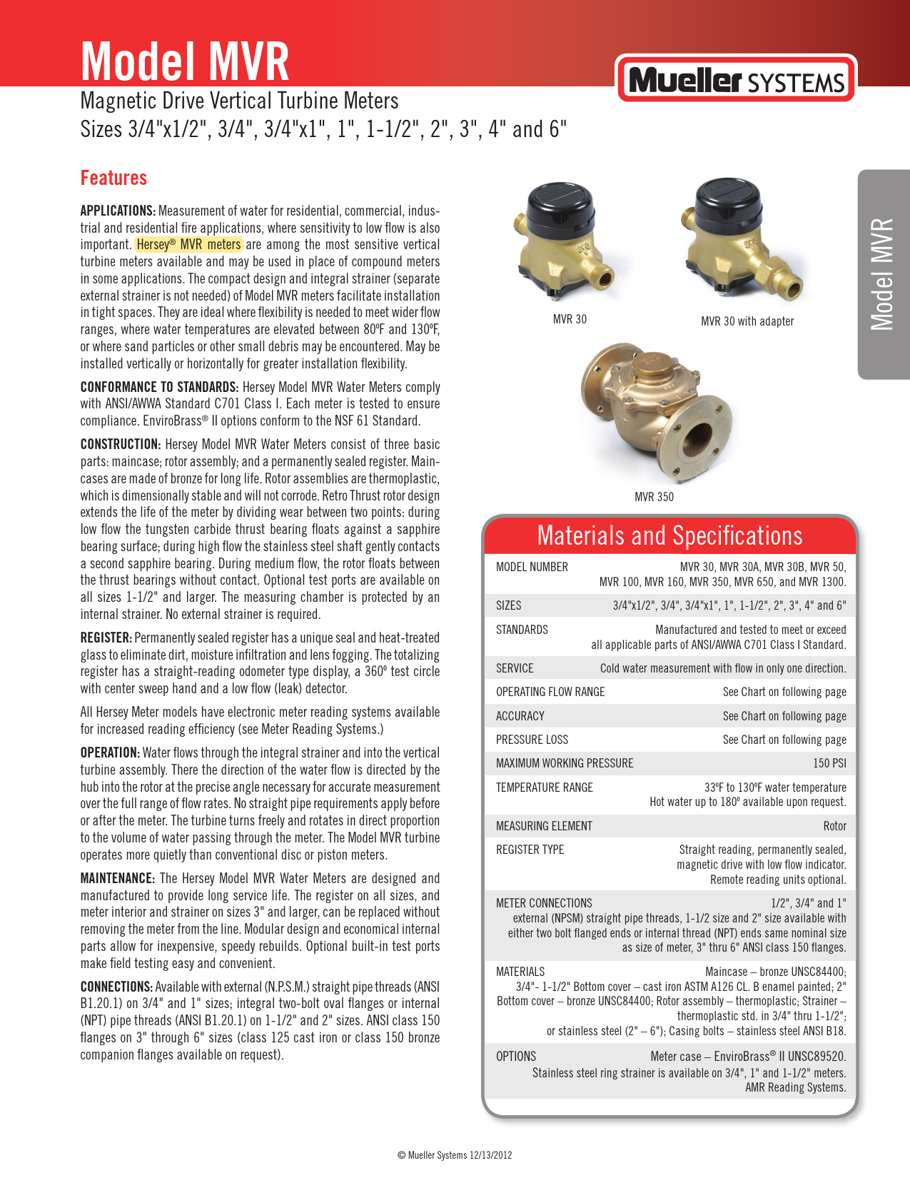
Applications
Measurement of water for residential, commercial, industrial, and residential fire applications, where sensitivity to low flow is also important. Hersey® MVR meters are among the most sensitive vertical turbine meters available and may be used in place of compound meters in some applications. The compact design and integral strainer (separate external strainer is not needed) of Model MVR meters facilitate installation in tight spaces. They are ideal where flexibility is needed to meet wider flow ranges, where water temperatures are elevated between 80°F and 130°F, or where sand particles or other small debris may be encountered. May be installed vertically or horizontally for greater installation flexibility.
Conformance to Standards
Hersey Model MVR Water Meters comply with ANSI/AWWA Standard C701 Class I. Each meter is tested to ensure compliance. EnviroBrass® II options conform to the NSF 61 Standard.
Construction
Hersey Model MVR Water Meters consist of three basic parts: maincase; rotor assembly; and a permanently sealed register. Maincases are made of bronze for long life. Rotor assemblies are thermoplastic, which is dimensionally stable and will not corrode. Retro Thrust rotor design extends the life of the meter by dividing wear between two points: during low flow the tungsten carbide thrust bearing floats against a sapphire bearing surface; during high flow the stainless steel shaft gently contacts a second sapphire bearing. During medium flow, the rotor floats between the thrust bearings without contact. Optional test ports are available on all sizes 1-1/2" and larger. The measuring chamber is protected by an internal strainer. No external strainer is required.
Register
Permanently sealed register has a unique seal and heat-treated glass to eliminate dirt, moisture infiltration and lens fogging. The totalizing register has a straight-reading odometer type display, a 360° test circle with center sweep hand and a low flow (leak) detector. All Hersey Meter models have electronic meter reading systems available for increased reading efficiency.
Operation
Water flows through the integral strainer and into the vertical turbine assembly. The direction of the water flow is directed by the hub into the rotor at the precise angle necessary for accurate measurement over the full range of flow rates. No straight pipe requirements apply before or after the meter. The turbine turns freely and rotates in direct proportion to the volume of water passing through the meter. The Model MVR turbine operates more quietly than conventional disc or piston meters.
Maintenance
The Hersey Model MVR Water Meters are designed and manufactured to provide long service life. The register on all sizes, and meter interior and strainer on sizes 3" and larger, can be replaced without removing the meter from the line. Modular design and economical internal parts allow for inexpensive, speedy rebuilds. Optional built-in test ports make field testing easy and convenient.
Connections
Available with external (N.P.S.M.) straight pipe threads (ANSI B1.20.1) on 3/4" and 1" sizes; integral two-bolt oval flanges or internal (NPT) pipe threads (ANSI B1.20.1) on 1-1/2" and 2" sizes. ANSI class 150 flanges on 3" through 6" sizes (class 125 cast iron or class 150 bronze companion flanges available on request).
Materials and Specifications
| MODEL NUMBER | SIZES | STANDARDS | SERVICE | OPERATING FLOW RANGE | ACCURACY | PRESSURE LOSS | MAXIMUM WORKING PRESSURE | TEMPERATURE RANGE | MEASURING ELEMENT | REGISTER TYPE | METER CONNECTIONS |
|---|---|---|---|---|---|---|---|---|---|---|---|
| MVR 30, MVR 30A, MVR 30B, MVR 50, MVR 100, MVR 160, MVR 350, MVR 650, and MVR 1300. | 3/4"x1/2", 3/4", 3/4"x1", 1", 1-1/2", 2", 3", 4" and 6" | Manufactured and tested to meet or exceed all applicable parts of ANSI/AWWA C701 Class I Standard. | Cold water measurement with flow in only one direction. | See Chart on following page | See Chart on following page | See Chart on following page | 150 PSI | 33°F to 130°F water temperature. Hot water up to 180°F available upon request. | Rotor | Straight reading, permanently sealed, magnetic drive with low flow indicator. Remote reading units optional. | 1/2", 3/4" and 1" external (NPSM) straight pipe threads, 1-1/2 size and 2" size available with either two bolt flanged ends or internal thread (NPT) ends same nominal size as size of meter, 3" thru 6" ANSI class 150 flanges. |
Materials
- Maincase: bronze UNSC84400
- 3/4"-1-1/2" Bottom cover: cast iron ASTM A126 CL. B enamel painted
- 2" Bottom cover: bronze UNSC84400
- Rotor assembly: thermoplastic
- Strainer: thermoplastic std. in 3/4" thru 1-1/2"; or stainless steel (2" - 6")
- Casing bolts: stainless steel ANSI B18
Options
- Meter case: EnviroBrass® II UNSC89520
- Stainless steel ring strainer is available on 3/4", 1" and 1-1/2" meters.
- AMR Reading Systems.
Performance Data
Meter Registration
| Meter Size | Initial Dial* | Capacity | Initial Dial* | Capacity |
|---|---|---|---|---|
| 3/4" | 10 Gallons | 10 Million | 1 Cubic Foot | 1 Million |
| 1" | 10 Gallons | 10 Million | 1 Cubic Foot | 1 Million |
| 1-1/2" | 100 Gallons | 100 Million | 10 Cubic Feet | 10 Million |
| 2" | 100 Gallons | 100 Million | 10 Cubic Feet | 10 Million |
| 3" | 100 Gallons | 100 Million | 10 Cubic Feet | 10 Million |
| 4" | 100 Gallons | 100 Million | 10 Cubic Feet | 10 Million |
| 6" | 1000 Gal | 1 Billion | 100 Cubic Ft | 100 Mill. |
* Registration equal to one full revolution of the sweep hand.
Flow Characteristics
| Meter Size | Typical Low Flow (95% Min.) | Typical Operating Range (100% ± 2%) | Maximum Continuous Operation | Maximum Intermittent Flow |
|---|---|---|---|---|
| 3/4" | 1/2 GPM | 1 to 30 GPM | 25 GPM | 35 GPM |
| 1" | 3/4 GPM | 1-1/2 to 50 GPM | 35 GPM | 55 GPM |
| 1-1/2" | 1-1/2 GPM | 2 to 100 GPM | 70 GPM | 110 GPM |
| 2" | 2 GPM | 3 to 160 GPM | 115 GPM | 175 GPM |
| 3" | 2-1/2 GPM | 4 to 350 GPM | 240 GPM | 390 GPM |
| 4" | 3-1/2 GPM | 5 to 650 GPM | 450 GPM | 715 GPM |
| 6" | 5 GPM | 15 to 1300 GPM | 910 GPM | 1430 GPM |
Dimensions and Weights
Diagrams illustrate different connection types for MVR meters: '3/4" and 1" STANDARD MVR', '3/4" and 1" COMPACT MVR', '1-1/2" and 2" STANDARD MVR with 2 bolt flange ends** and spool piece', '1-1/2" and 2" STANDARD MVR with Internal NPT ends', '1-1/2" and 2" COMPACT MVR with integral 2 bolt flange ends**', '1-1/2" and 2" COMPACT MVR with Internal NPT ends', and '3", 4" and 6" MVR'.
| Meter Size Ends | 3/4"x1/2" | 3/4" | 3/4"x1" | 1" | 1-1/2" | 2" | 1-1/2" | 2" | 3" | 4" | 6" |
|---|---|---|---|---|---|---|---|---|---|---|---|
| Model | MVR30 | MVR30A | MVR30B | MVR50 | MVR100 | MVR160 | MVR100 | MVR160 | MVR350 | MVR650 | MVR1300 |
| Dimensions | |||||||||||
| A | 9" | 9" | 9" | 10-3/4" | 12-5/8" | 15-1/4" | 13" | 17" | 12" | 14" | 18" |
| AA* | 7-1/2" | 7-1/2" | 7-1/2" | 9" | 9" | 10-1/2" | 9" | 10" | 8-7/16" | 9-3/8" | 12-9/16" |
| B | 5" | 5" | 5" | 5-1/2" | 5-3/4" | 6-1/4" | 5-3/4" | 6-1/4" | 8-7/16" | 9-3/8" | 12-9/16" |
| C | 1-13/16" | 1-13/16" | 1-13/16" | 2-3/8" | 2-3/8" | 3" | 2-3/8" | 3" | 3-7/8" | 4-5/8" | 6" |
| D | N/A | N/A | N/A | N/A | N/A | N/A | 4" | 4-1/2" | 6" | 7-1/2" | 9-1/2" |
| E | N/A | N/A | N/A | N/A | N/A | N/A | 5/8" | 5/8" | 3/4" | 3/4" | 7/8" |
| F | N/A | N/A | N/A | N/A | N/A | N/A | 11/16" | 15/16" | 5/8" | 11/16" | 13/16" |
| Max.width | 3-3/4" | 3-3/4" | 3-3/4" | 4-1/4" | 4-3/8" | 5-3/8" | 5-3/8" | 5-15/16" | 7-7/8" | 9-3/4" | 12-7/8" |
| Net weight | 6 (5*) | 6 (5*) | 6 (5*) | 8 (7*) | 11 (9*) | 15 (14*) | 12 (9*) | 20 (14*) | 38 | 68 | 140 |
*Compact length. **1-1/2" and 2" Flanged meters have 2 bolt oval flange pattern. NOTE: Meter couplings are optional and must be ordered separately. Weights are in pounds and are approximate.
Performance Curves
Head Loss Curves: These charts illustrate the pressure loss (in PSI) across the meter as a function of the rate of flow (in U.S. GPM). Curves are provided for 3/4" & 1", 1-1/2" & 2", 3" & 4", and 6" meter sizes, showing typical performance against AWWA STD. lines.
Accuracy Curves: These charts show the percentage registered by the meter relative to the actual flow rate (in U.S. GPM). Curves are provided for 3/4" & 1", 1-1/2" & 2", 3" & 4", and 6" meter sizes, indicating typical accuracy within AWWA STD. specifications.
*Performance curves are typical only and not a guarantee of performance.
Parts Lists and Diagrams
Models MVR-30, MVR-50, MVR-100, MVR-160
Exploded view diagram of the MVR meter for models MVR-30, MVR-50, MVR-100, and MVR-160, showing numbered components from lid to bottom case.
| Ref. No. | Description | Model MVR-30 | Model MVR-50 | Model MVR-100 | Model MVR-160 |
|---|---|---|---|---|---|
| 1 | Lid (Plastic) | 50377 | 50377 | 50377 | 50377 |
| Lid (Bronze) | 50390 | 50390 | 50390 | 50390 | |
| 2 | Black Clamp Band for Visual Register | 50379 | 50379 | 50379 | 50379 |
| Blue Clamp Band for Translator Register | B8602 | B8602 | B8602 | B8602 | |
| 3 | SST Tri-Wing Screw | 98344 | 98344 | 98344 | 98344 |
| 4 | Lid Nut | 19999 | 19999 | 19999 | 19999 |
| 5 | Sealed Registers (Specify unit of measurement) | See pages 4.9-4.11 | |||
| 6 | MVR 30 Top Case (7-1/2" length): 1/2" M.I.P. Ends | 50452 | - | - | - |
| 3/4" M.I.P. Ends | 50466 (A) | - | - | - | |
| 1" M.I.P. Ends | 50476 (B) | - | - | - | |
| MVR 50 Top Case (9" length): 1" M.I.P. Ends | - | 50566 (C) | - | - | |
| 1-1/4" M.I.P. Ends | - | 50576 (D) | - | - | |
| MVR 100 Top Case (9" length): 1-1/2" F.I.P. Ends | - | - | 50776 (E) | - | |
| 1-1/2" Bronze 2-Bolt Flange Assembly | - | - | 50784 (F) | - | |
| MVR 160 Top Case (10-1/2" length): 2" F.I.P. Ends | - | - | - | 50866 (G) | |
| 2" Bronze 2-Bolt Flange Assembly (10" length) | - | - | - | 50884 (H) | |
| 7 | Rotor | 50471 | 50571 | 50771 | 50871 |
| 8 | Inlet Hub | 50468 | 50568 | 50768 | 50867 |
| 9 | Lower Bushing | 50374 (2) | 50574 (2) | 50574 (2) | 50574 (2) |
| 10 | Interior Screw | 98394 (4) | 98394 (4) | 98394 (4) | 98394 (4) |
| 11 | Strainer (Plastic) | 50469 | 50569 | 50769 | - |
| Strainer (Metal Ring)** | 50480 | 50580 | 50780 | 50880 | |
| 12 | Liner | 50365 | 50565 | 50765 | 50865 |
| 13 | Bottom (Bronze) | 50363 | 50563 | 50763 | 50863 |
| Bottom (Cast Iron) | 50364 | 50564 | 50764 | - | |
| 14 | Case Washer | AS7792 (4) | AS7792 (4) | 98378 (4) | 98378 (4) |
| 15 | Case Bolt | 90026 (4) | 90026 (4) | 90073 (4) | 90073 (4) |
| 16 | Inlet Hub Assembly | 50862 | - | - | - |
| Bushing Spacer | 53114 | - | - | - | |
| Bushing | 54915 (2) | - | - | - | |
| Inlet Plug Assembly | 50493 | 50493 | 50493 | 53105 | |
| Sapphire Thrust Bearing (Case) | 98371 | 98371 | 98371 | 98371 | |
| Complete Interior | 50477 | 50577 | 50777 | 50872 | |
| Bearing Adhesive * | 95046 | 95046 | 95046 | 95046 | |
| Adapters: | |||||
| 3/4" Adapter | 95014 | - | - | - | |
| 3/4" Adapter Washer | 95011 | 95063 | - | - | |
| 1" Adapter | - | 95064 | - | - | |
| 1" Adapter Washer | - | 95086 | - | - | |
| 1-1/4" Adapter | - | 95007 | - | - | |
| 1-1/4" Adapter Washer | - | 95095 | - | - | |
| 1-1/2" Female Adapter | - | - | 95195 | - | |
| 2" Female Adapter | - | - | - | - | |
A: Order 3/4" Adapter 95014 and Adapter Washer 95011 to replace standard 3/4" disc meter, 9" long.
B: Order 1" Adapter 95063 and Adapter Washer 95064 with Top Case 50476 to replace 3/4" disc meter, 9" long, installed with 1" pipe connections.
C: Order 1" Adapter 95063 and Adapter Washer 95064 with Top Case 50566 to replace standard 1" disc meter, 10-3/4" long.
D: Order 1-1/4" Adapter 95086 and Adapter Washer 95007 with Top Case 50576 to replace 1" disc meter, 10-3/4" long, installed with 1-1/4" pipe connection.
E: Order 1-1/2" Adapter 95095 with Top Case 50776 to replace 1-1/2" female end meter installed with union connections. Assemble to length of 12-5/8".
F: Order 1-1/2" Bronze Spool Piece 50783 and gasket 95102 with Top Case 50784 to replace standard 1-1/2" disc meter, 13" long.
G: Order 2" Adapter 95195 with Top Case 50866 to replace standard 2" Female End disc meter, 15-1/4" long.
H: Order (2) Bronze Spool piece 50883 and gasket 95122 with Top Case 50884 for 17" length 2-90229 Bolt 2-90260 Nut.
* Purchase locally. Use a cyanoacrylic adhesive, such as Loctite Super Bonder #30-13, Eastman #916, Permabond or Aron Alpha.
** Standard on MVR 160. Optional on MVR 30, 50 100 in place of standard plastic disc strainer.
NOTE: If more than one part is required, quantity is noted after part number (in parenthesis).
Models MVR-30, MVR-50, MVR-100 and MVR-160 - Exploded View
Exploded view diagram of the MVR meter for models MVR-30, MVR-50, MVR-100, and MVR-160, showing numbered components from lid to bottom case.
Models MVR-350, MVR-650, MVR-1300
Exploded view diagram of the MVR meter for models MVR-350, MVR-650, and MVR-1300, showing numbered components from lid to bottom case.
| Ref. No. | Description | Model MVR-350 | Model MVR-650 | Model MVR-1300 |
|---|---|---|---|---|
| 1 | Top Case/Thrust Bearing | 50981 | 51181 | 51381 |
| 2 | Bottom Case | 50982 | 51182 | 51382 |
| 3 | Ring Strainer | 50985 | 51185 | 51383 |
| 4 | Rotor Assembly | 50984 | 51184 | 51384 |
| 5 | Inlet Hub Assembly | 50987 | 51187 | 51387 |
| 6 | Inlet Hub Screws | 98395 (6) | 98395 (6) | 98409 (12) |
| 7 | Top Case O-Ring | 98361 | 98362 | 98408 |
| 8 | Top Cast Screw | 90073 (8) | 90073 (10) | 90180 (14) |
| 9 | Register | See page following pages | ||
| 10 | Register Box (Bronze) | 50998 | 50998 | 50998 |
| 11 | Lid (Bronze) | 19201 | 19201 | 19201 |
| 12 | Register Box Screw | 51005P007 (2) | 51005P007 (2) | 51005P007 (2) |
| 13 | Lid Pin | AS41122 | AS41122 | AS41122 |
| 14 | Inlet Plug/Thrust Bearing | 50992 | 50992 | 51392 (2) |
| 15 | Rotor Bushing | 54915 (2) | 56915 (2) | 51391 |
| 16 | Bushing Spacer | 54914 | 51186 | 51391 |
Note: In order to retrofit translator registers on all 3"-6" MVR meters manufactured prior to 2003 a new top case (1) and top case o-ring (7) is required.
Register Options
Standard Registers
Tables list register part numbers and their internal ratio and relation to other registers for Cubic Feet and U.S. Gallons measurements.
| MVR Model | Register Part Numbers | Internal Ratio | Relation to other Registers | Register Part Numbers | Internal Ratio | Relation to other Registers |
|---|---|---|---|---|---|---|
| Cubic Feet | U.S. Gallons | |||||
| MVR-30 | B79821 | 551.99 | -4% (in relation to B79825) | B79813 | 738.92 | -4% (in relation to B79817) |
| MVR-30 | B79822 | 546.34 | -3% (in relation to B79825) | B79814 | 731.88 | -3% (in relation to B79817) |
| MVR-30 | B79823 | 540.85 | -2% (in relation to B79825) | B79815 | 723.79 | -2% (in relation to B79817) |
| MVR-30 | B79824 | 536.22 | -1% (in relation to B79825) | B79816 | 715.86 | -1% (in relation to B79817) |
| MVR-30 | B79825 | 530.07 | - | B79817 | 709.01 | - |
| MVR-30 | B79826 | 523.96 | +1% (in relation to B79825) | B79818 | 702.61 | +1% (in relation to B79817) |
| MVR-30 | B79827 | 519.6 | +2% (in relation to B79825) | B79819 | 694.85 | +2% (in relation to B79817) |
| MVR-30 | B79828 | 514.2 | +3% (in relation to B79825) | B79820 | 688.55 | +3% (in relation to B79817) |
| MVR-50 | B79861 | 269.44 | -4% (in relation to B79865) | B79851 | 360.58 | -3% (in relation to B79854) |
| MVR-50 | B79862 | 266.44 | -3% (in relation to B79865) | B79852 | 356.41 | -2% (in relation to B79854) |
| MVR-50 | B79863 | 264.51 | -2% (in relation to B79865) | B79853 | 353.17 | -1% (in relation to B79854) |
| MVR-50 | B79864 | 262.07 | -1% (in relation to B79865) | B79854 | 349.42 | - |
| MVR-50 | B79865 | 258.83 | - | B79855 | 345.93 | +1% (in relation to B79854) |
| MVR-50 | B79866 | 256.52 | +1% (in relation to B79865) | B79856 | 342.53 | +2% (in relation to B79854) |
| MVR-50 | B79867 | 254 | +2% (in relation to B79865) | B79857 | 339.04 | +3% (in relation to B79854) |
| MVR-100 | B79901 | 1973.95 | -3% (in relation to B79904) | B79891 | 2664.16 | -3% (in relation to B79894) |
| MVR-100 | B79902 | 1951.68 | -2% (in relation to B79904) | B79892 | 2646.98 | -2% (in relation to B79894) |
| MVR-100 | B79903 | 1935.27 | -1% (in relation to B79904) | B79893 | 2605.61 | -1% (in relation to B79894) |
| MVR-100 | B79904 | 1912.65 | - | B79894 | 2586.61 | - |
| MVR-100 | B79905 | 1901.98 | +1% (in relation to B79904) | B79895 | 2554.55 | +1% (in relation to B79894) |
| MVR-100 | B79906 | 1882.77 | +2% (in relation to B79904) | B79896 | 2526.66 | +2% (in relation to B79894) |
| MVR-100 | B79907 | 1862.97 | +3% (in relation to B79904) | B79897 | 2505.78 | +3% (in relation to B79894) |
| MVR-160 | B79941 | 604.34 | -3% (in relation to B79944) | B79931 | 808.31 | -3% (in relation to B79934) |
| MVR-160 | B79942 | 598.37 | -2% (in relation to B79944) | B79932 | 800.5 | -2% (in relation to B79934) |
| MVR-160 | B79943 | 592.81 | -1% (in relation to B79944) | B79933 | 792.41 | -1% (in relation to B79934) |
| MVR-160 | B79944 | 587.03 | - | B79934 | 784.64 | - |
| MVR-160 | B79945 | 580.58 | +1% (in relation to B79944) | B79935 | 775.87 | +1% (in relation to B79934) |
| MVR-160 | B79946 | 575.56 | +2% (in relation to B79944) | B79936 | 768.47 | +2% (in relation to B79934) |
| MVR-350 | B79981 | 294.32 | -2% (in relation to B79983) | B79971 | 394.09 | -2% (in relation to B79973) |
| MVR-350 | B79982 | 291.49 | -1% (in relation to B79983) | B79972 | 389.61 | -1% (in relation to B79973) |
| MVR-350 | B79983 | 288.55 | - | B79973 | 385.91 | - |
| MVR-350 | B79984 | 285.72 | +1% (in relation to B79983) | B79974 | 382.06 | +1% (in relation to B79973) |
| MVR-350 | B79985 | 283.03 | +2% (in relation to B79983) | B79975 | 378.6 | +2% (in relation to B79973) |
| MVR-350 | B79986 | 280.7 | +3% (in relation to B79983) | B79976 | 374.11 | +3% (in relation to B79973) |
| MVR-650 | B80021 | 182.28 | -3% (in relation to B80024) | B80013 | 239.51 | -1% (in relation to B80014) |
| MVR-650 | B80022 | 180.35 | -2% (in relation to B80024) | B80014 | 236.41 | - |
| MVR-650 | B80023 | 178.86 | -1% (in relation to B80024) | B80015 | 234.58 | +1% (in relation to B80014) |
| MVR-650 | B80024 | 176.9 | - | B80016 | 232.95 | +2% (in relation to B80014) |
| MVR-650 | B80025 | 175.04 | +1% (in relation to B80024) | B80017 | 230.62 | +3% (in relation to B80014) |
| MVR-650 | B80026 | 173.77 | +2% (in relation to B80024) | B80018 | 228.21 | +4% (in relation to B80014) |
| MVR-650 | B80027 | 171.53 | +3% (in relation to B80024) | B80019 | - | - |
| MVR-650 | B80028 | 170.34 | +4% (in relation to B80024) | B80020 | - | - |
| MVR-1300 | B80067 | 413.35 | -1% (in relation to B80068) | B80056 | 551.99 | 1% (in relation to B80057) |
| MVR-1300 | B80068 | 409.41 | - | B80057 | 546.34 | - |
| MVR-1300 | B80069 | 405.25 | +1% (in relation to B80068) | B80058 | 540.85 | 1% (in relation to B80057) |
Translator Register Options
Diagrams and tables detail translator register components for MVR 30 to 160 and MVR 350 to 1300 models.
MVR 30 to 160
| Ref | Description | MVR-30 | MVR-50 | MVR-100 | MVR-160 |
|---|---|---|---|---|---|
| 1 | Translator Register* Gallons Cubic Feet Specify Electronic Reading Value 4, 5, or 6 Wheel |
D35231xxx D35232xxx |
D35241xxx D35242xxx |
D35251xxx D35252xxx |
D35261xxx D35262xxx |
| 2 | Clamp Band (Plastic) Translator Only | B8602 | B8602 | B8602 | B8602 |
| 3 | Clamp Band Seal Nut | 19999 | 19999 | 19999 | 19999 |
| 4 | SST Tri-Wing Screw | 98344 | 98344 | 98344 | 98344 |
| 5 | Lens Terminal Cover | B8447 | B8447 | B8447 | B8447 |
| 6 | Terminal Lug Screw | 98197 (3) | 98197 (3) | 98197 (3) | 98197 (3) |
| 7 | Wall Pad | T1234 | T1234 | T1234 | T1234 |
| 8 | Pit Pad | T1240 | T1240 | T1240 | T1240 |
| 9 | TrueRead (not shown) | C6551G | C6551G | C6551G | C6551G |
| 10 | 1,000' Spool of Wire (not shown) | AS755 | AS755 | AS755 | AS755 |
*Call Mueller Systems Customer Service for appropriate Translator Register and AMR device part number.
MVR 350 to 1300
| Ref | Description | MVR-350 | MVR-650 | MVR-1300 |
|---|---|---|---|---|
| 1 | Translator Register* Gallons Cubic Feet* |
D35271xxx D35272xxx |
D35281xxx D35282xxx |
D35291xxx D35292xxx |
| 2 | Register Box (Bronze) Translator Only | C6525 | C6525 | C6525 |
| 3 | Register Box Screw | 51005P007 (2) | 51005P007 (2) | 51005P007 (2) |
| 4 | Lens Terminal Cover | B8447 | B8447 | B8447 |
| 5 | Terminal Lug Screw | 98197 (3) | 98197 (3) | 98197 (3) |
| 6 | Wall Pad | T1234 | T1234 | T1234 |
| 7 | Pit Pad | T1240 | T1240 | T1240 |
| 8 | TrueRead (not shown) | C6551G | C6551G | C6551G |
| 9 | 1,000' Spool of Wire (not shown) | AS755 | AS755 | AS755 |
*Call Mueller Systems Customer Service for appropriate Translator Register and AMR device part number.
