 PDF
Electronic Design V18 N03 19700201
PDF
Electronic Design V18 N03 19700201 FOR ENGINEERS AND ENGINEERING MANAGERS
FEB . 1, 1970
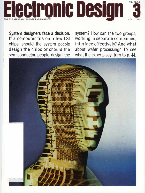
System designers face a decision. If a computer fits on a few LSI chips, should the system people design the chips or should the semiconductor people design the
system? How can the two groups, working in separate companies, interface effectively? And what · about wafer processing? To see what the experts say1 turn to p. 44.
�These new IRC precision trimmers in dual-in-line packages simplify PC board layout. Only .200-in. high, their pin spacing is the same as the T0-116 size integrated circuit. It is fully compatible with high-speed automatic inserting equipment.
Pin spacing of these IRC Vi6-in. square trimmers matches the 1,4-in. square unit. Only .031-in. larger on each side, they can cut your cost almost in half and give you three times the power rating of the 1,4-in. and 40% better resolution.
Both DIP and 5/i.6-in. are available with precision wirewound and infinite resolution Metal Glaze elements. All units are fully sealed and impervious to common industrial solvents because of a silicone rubber shaft seal and epoxy bonding at all seams.
These units, like all IRC Metal Glaze trimmers, have a maximum guaranteed TC of± 150ppmj°C
over the entire resistance range, with typical TC being ± IOOppm j°C, and at no added cost. For
complete technical information and prices, contact your I RC Industrial Distributor or write IRC St. Petersburg Division of TRW INC. , 280 l 72nd St., North, St. Petersburg, Florida 33733.
QiliJ
DIVISION OF TRW INC.
INFORMATION RETRIEVAL NUMBER 232
�Nowl HP Hot Carrier Diodes
for better-than-PN
iunction diode
perfonnance .
Hewlett-Packard will deliver Hot Carrier Diodes at 32ct each in volume quantities, less if you order more.
Instead of saving these state-of-the-art diodes for only the most advanced, critical design work, now you can use them in quantity, any place where better-than-PN junction performance will give you a product design edge. Put them into computers and other digital logic systems and use their l 00 picosecond switching speed to maximum advantage. Or think of your own application, which could be mixing, detecting, switching, clipping, clamping and A to D conversion.
Move up now to state-of-the-art performance at state-of-the marketplace prices.
HEWLETTllJ PACKARD
SOLID STATE DEVICES
HP 2800 and 2811 Series Hot Carrier Diodes are available at prices as low as 32¢ each in 100,000 quantities. Call your HP sales
office for tlTe full story on quantity quotes and specifications. Or write to Hewlett-Packard, Palo Alto, California 94304;
Europe: 1217 Meyrin"Geneva, Switzerland.
01913
ELECTRON IC D ES IGN 3, Febru ary I , 1970
INFORMATION RETRIEVAL NUMBER 2
�You're looking at35new digital printers!
$995.
You only see one? That's because you don't see all the plug-in options and features packed into 5-D's new printer ... including features found only in $3,000 printers!
The basic Model 5103 is a 5-column, asynchronous, 3-line/sec. printer, so quiet-running you can hardly hear it. It expands to a 21 column printer with 16 characters/column simply by adding economical 5-column plug-in boards. Just slide them in yourself at any time.
4E3- SYSTRON
I
OP£R AT£
I 1 - -;, 7 -. 0 2
o o e. . K-. --
' 0 0 6 .. :S Ot<"1 0 O<o .. 'J '1 ~ .... 1 006 · .,6K,"' 1 006 - >!3>~ ....
1 ooe. . >·K -.
1 00 · · ll '3 K'1 006 · '52 t(.""1 006 · '> 1 K-. 1 0 0 6 · 'JI Ot( ... 1 006 . 2 9 )( ... 1 OOe. · :o?Stc;.~
1 006 · 2'?KM.· 1 006 . 26K. ... t 00tJ. · 2'5K'l.
t 00< · 24K" 1 00b · 2"-<it. 1.Q06 · 22Ktt.
1 00<> - 2 1 1o<.K,, ' 0 0 (I . ::' 0 "<.K., 1 00£ · 1 ?1'<.tt. 1 oo6 ·1 hKM,
1 oQti ·1 7~M.
100t. ·l 6K~.
1 C' t) 6 · 1 '5 K ·1. 1 00ti e1 4Kll.
1006 · 1 3K11. 1006 -1 2'<.tot.-
1 000 . 1 t KH..
1 ,,06 · 1 Ct<1h
1 0 0 e, · 0 9 Kit,
1 006 . Q?K.n.
1 006 - 071<11. 1 ooc. . 06Kth
1 00b · O~KM,
1 00b o 04KH.
1 006 . 0'3KH,
PR IN T
Interface problems just don't exist. For example, Model 5103 handles any 4line BCD code with a simple IC socket change. No disassembly or rewiring ever. For only $995, you get a printer that offers dual source operation, handIes positive or negative logic, and features input channels that can be programmed to print in any column on the print drum. You get a printer with zero suppression, measurement units printout and two-color printing so you can use it directly with limit comparators.
Unique options for every situation. You have your choice of such useful options as plug-in boards for ± 200 V levels, 1 msec transfer time, digital clock, buffer storage, floating decimal point and more.
For complete details, write Data Products Division, 888 Galindo Street, Concord , California 94520. Phone: (415) 682-6161.
E S V B T R C N
)®CONNER
t 1- 5 6 - ? 9
1 0 0 43 · 5 7 K 11.
1 0 0 5 · 5 G '<: H.
Another S-D in;;ir11-PleAt f~!t ~ ~2t~qp ic counters / Digital voltmeters/Pulse generators/Data generators/Time
code generators I Sweep generators I Speotrum~ri~lyzers I Digital panel meters I Digital clocks I Signal generators I Oscillators
Laboratory magnets I Preg i~iQn. P,.o.w~r,,.Suppfi8sCY !o\Aa1og '&'. ·analog-hybrid computers I Data acquisition systems.
INFORMATION RETRIEVAL NUMBER 3
2
ELECTRONIC DESIGN 3, February I, 1970
�Electronic Design"'3 '°""""''"°''°""'"'""'°"'
cm. L ' "'
NEWS
21 News Scope
25 AF stretches work on navigation satellite Advantages that could lead to new tri-service system keep proposal alive despite short money.
26 Giant C-5A's instrumentation is readied for tests
30 New anemometer aids remote weather stations Lightweight instruments contain solid-state sensors that give wind direction and velocity.
37 Washington Report
TECHNOLOGY
44 LSI poses dilemma for systems designers: shall they design their own chips or leave it to the semiconductor houses? A special report.
54 Diodes make good gain-control devices for high-performance amplifiers. Four transfer functions are obtained with these simple techniques.
60 Assemble a sequential counter from flip-flops and gates by following this step-by-step method.
64 Why use current-mode flip-flops? Because the CML approach offers maximum speed and also has good noise immunity and stability.
71 Ideas for Design
79 Product Source Directory: Slotted Lines
PRODUCTS
85 Modules & Subassemblies: D/a 15-bit converters speed settling time. 88 ICs & Semiconductors: Dynamic 20-bit MOS register clocks to 15 MHz. 90 Microwaves & Lasers: MIC noise sources boast 25-dB excess noise ratio. 92 Data Processing 93 Instrumentation 94 Components 95 Packaging & Materials 95 Tools & Engineering Aids
Departments
43 Editorial: His IC brainchild is no baby any more.
13 Designer's Calendar
41 Sidelights
99 Application Notes
96 Evaluation Samples
100 New Literature
97 Design Aids
106 Advertisers' Index
98 Annual Reports
108 Information Retrieval Service
Information Retrieval Service Card inside back cover
Cover: Designed by Art Director Clifford Gardiner and photographed by Henry Ries.
ELECTRONIC DESIGN is published biweekly by Hayden Publishing Company, Inc., 850 Third Avenue , New York, N .Y. 10022. James S. Mulholland, Jr., President. Printed at Brown Printing Co., Inc., Waseca , Minn . Controlled
circulation postage paid at Waseca , Minn., and New York, N .Y. Copyright © 1970, Hayden Publishing Company.
Inc. 81,402 copies this issue.
ELECTRONIC D ESIGN 3, February I, 1970
3
���Big Jackpot in Connector
Strain Relief
GLENAIRS NEW Qwil{;. f:£
THE BIGGEST PAYOFF YET FOR CONNECTOR USERS
INSTALLED COST - DOWN A 'lode' of installed cost saving with Qwik· Ty. Reduces assembly time up to 12 to 1 over conventional cable-clamping methods.
WEIGHT SAVING - UP SLIM-LINE Qwik·Ty's weigh as much as 50% less than standard MS clamps. Addi· tional FAT TRIMMING is achieved by elimi· nating wrapping tape used in present cable clamp installations.
HOW IT WORKS No more wrapping the wires to make the bundle fit the l.D. of the clamp. Simply wrap a tie strap or lacing cord around Qwik-Ty's arm and wires are snug and tight ... IN SECONDS.
EASY MAINTENANCE TOO For quick access to wires . . . cut the strap or cord, perform wire or connector maintenance, then tie off again. It's that easy.
Available for connectors Qwik-Ty Series
MIL-C-26482 MIL·C-26500 MIL-C-27599 MIL-C-38300 MIL-C-38999 MIL-C-81511 NAS-1599
GTROO GTROl GTR04 GTROl GTR04 GTR03 GTR02
and others
· Patents Pending
' -------------:··-·1 Call or write for demonstration and literature . .. today. It'll pa GLENAIR, INC. l__e___n____a___ r__:'_t_ ®___i, 1211 Air Way, Glendale, California 91201 Phone (213) 247-6000, TWX 910-497-2066
INFORMATION RETRIEVAL NUMBER 5
6
INFORMATION RETRIEVAL NUMBER 6 ...
�Bodine helps data devices
tell it like it is...
Bodine fractional horsepo~er drives. Small. Quiet. A complete line designed to power information-handling devices precisely, accurately, dependably. Motors built with all the integrity you've designed into your product-that deliver as specified with fewer callbacks and service problems. If this is the kind of power you're looking for, you'll find no better source.
Over 3,500 standard specifications to choose from. Bodine also builds custom fhp motors to meet design requirements. Our engineers will be happy to help you pinpoint the right one for your particular application need. Computers, business machines, instrumentation, copiers-whatever your product, specify Bodine fhp drives. We've been the power behind the leading products for some 63 years. Write tor bulletin. Bodine Electric Company, 2500 W. Bradley Place, Chicago, Illinois 60618.
Bodine Motors Wear Out-It Just Takes Longer
BODINE MOTORS/CONTROLS
Ask about Bodine SCR motor speed controls
�Are You Going to Buy a New Scope This Vear?
First, you ' ll want to know a scope 's bandwidth and sensitivity. But beyond "horsepower, " aren 't there other things just as important? For example:
Does the scope have the latest technical innovations ; so it 's technically best now .. . and looks like it will be best in the future? Leadership!
Does the scope incorporate performance features that give me accurate measurements, easily? Useability!
Can it solve my measurement problems today, tomorrow and next year, economically? Value!
You're now going beyond specs and specmanship, and investigating the area of a company's design
philosophy - the " X" quantity you get in every instrument you buy. Let's look at HP's record.
In the general-purpose, laboratory oscilloscope area, HP announced the first 180 Series Scope over three years ago. Today, it is your best answer to high frequency measurement problems! And here's why. How about HP 180 leadership?
1. The HP 180 Scope was the first
8
all-solid-state scope to be introduced -July, 1966.
2. It is the only high-frequency scope utilizing mesh-dome technology to increase , simultaneously, CRT bandwidth and CRT viewing area (instead of shrinking the CRT display area or extending tube length).
3. It is the only solid-state scope that has a fully documented , environmentally specified military version.
4. It is the only high-frequency system that has a rack version only 5%'' high.
5. It is the only system that otters direct read-out TDR with 35 ps risetime (1815A plug-in).
6. The HP 181A is the only mainframe that otters both variable persistence, and fl icker-tree storageand it is the only storage scope in the 50 MHz and above frequency area.
7. The HP 180A and the 181A Mainframes are the only system-oriented mainframes to have field - proven, solid-state plug-ins - now 9 - that cover 50 MHz and 100 MHz real-time, as well as 12.4 GHz sampling and 35 ps TDR.
8. This year HP announced the Performance Champ - the 250 MHz, 10 mV, real-time 183A System :
A. The only 250 MHz (< 1.5 ns rise - time) , general - purpose real -time system .
B. The only real-time scope with 1 ns/cm sweep speed.
C. The only scope with 4 cm Ins writ ing speed .
How about HP 180 useability?
Some of the innovations above have contributed to useability. Here are some additional useability features :
1. Important contributions have been made in simplifying controls : Single- control triggering tor the 250 MHz time base ; selective use of pushbuttons ; exclusive HP mixed sweep control ; single switch signal averaging in the sampling plug-in to reduce noise and jitter.
2. The calibrator bl.lilt into the 183A Mainframe gives you 1 ns rise time at 2 kHz or 1 MHz, with 50 mV or 500 mV amplitude. Now you can check ti me, amplitude and pulse response - as well as compensate probes.
3. The 50 n input system has been adopted tor both the ioo MHz and
250 MHz vertical amplifiers-to eliminate the bug-a-boo of capacitive distortion . It you ' re in these frequencies, chances are you 're wanting a
50 n impedance match . It not, you
have a choice of ultra-low capacitance passive or active probes.
4. Carry the rugged 180 Scope anywhere you need it-with plug-ins, weight is only 30 to 35 pounds. Put it
ELECTRONIC DESIGN 3, February I , 1970
�The Performance Champs
· · · ·
· · ·
· · ·
.. .......r..::\. - - ·~~· .~
@@ ·-·
on your bench without crowdingthe scope's front panel is less than the size of this page. (Like we said , the rack model is only 51/4'' high.) But this mini-size doesn't mean a miniCRT - its 8 x 10 cm area is 30% to
100% larger than most other highfrequency scopes. How about HP 180 value?
Capability of solving today's and tomorrow 's measurement problems is a real gauge of worth , or value. To prevent mainframe obsolescence in the 180 Series, HP has adopted a design philosophy of driving the CRT vertical plates directly from the vertical plug-in . Unlike some other scopes, the delay line and all vertical ELECTRON IC DESIGN 3, February l , 1970
amplifier elements are contained in the HP vertical plug-ins.
HP's design approach keeps the full capability of the CRT available to future plug-ins, so you can take advantage of tomorrow 's technology in today's mainframes.
This philosophy- no built-in mainframe limitations- is illustrated by the design approach used in the new 183A Mainframe. A unique HP design provides a CRT with a reaHime bandwidth beyond 500 MHz. Today, IC technology limits the vertical amplifier to only 250 MHz, real-time. Tomorrow, higher bandwidth vertical amplifiers will be available. When they are, HP w ill have them . And , you can use them in your 1970183A Mainframe - because you have direct plug-in access to a 500 MHz CRT! (Compatibility with " old" plug-ins? The 183A Mainframe will take all 11 of the existing 180 Series plug-insand they 'll meet their specs.)
Doesn 't this philosophy make sense? We think so.
What other plug-in scope can offer you these values-at these prices? For example: A 50 MHz laboratory system, with plug-in versatility, complete , $2065. A .250 MHz system, $3150.
This is the year of the big change. Everyone seems to have come up with a new scope. You have to make a decision. Should you continue down the same old road? Or is it time you took a look at another manufacturer?
The HP road means going with the demonstrated leader, a system that's been de-bugged for three years, a scope that will let you buy tomorrow's state-of-the - art plug-ins and use them in today 's mainframes.
INFORMATION RETRIEVAL NUMBER 7
. .---
. ..-···@ @1.@ @
Because this is the year of the big change, your decision is important. You ' ll have to live with it for some time to come . If you 're not convinced HP is best, try a side-by-side comparison with any scope.
Call your local HP field engineer to arrange a comparison. And remember tel ask him about HP's new concept of oscilloscope service . . . have him show you HP's new video training tapes on the 180 System. For a complete, full-color brochure, write Hewlett-Packard , Pa lo Alto , California 94304. Europe: 1217 MeyrinGeneva, Switzerland.
080 111
HEWLETT. PACKARD
OSCILLOSCOPE SYSTEMS
9
�Photocell ardering abbrevi·
ation
Cl5M2 Cl602
Cl702
Cl902
Diam.X length (inches)
.55 x .18 ·25 x .5
.36X .18
.21 .X .15
Resist· ance@ 2fc ± 33V3%
55K 1 meg. 1 meg. 1 meg.
Minimum
resistance Maxiratio from mum 2 ftc to Dark volt· within 5 sec. age
1:100
250
300
300
250
Power Dissipation
@ 25°C (mw)
2000-5001 75 125 50
Type 2 CdS (photose nsi tive materia l desi gnate d by lost numbe r in ordering abbrevia ti on, I. e. CL5M2). Pea k spect ral response 5150 ang stroms, bluest re sponse photosensitive material , high stab ility, lowest te mpe ra ture e rror.
Cl503 Cl5M3
.5 x .5
7.2K
1:10,000
250
500-2501
.55 x .18
7 .2K
250
2000-5001
Cl603
.25X .5
133K
300
75
Cl603A
.25X .5
75K
300
75
Cl603Al
.25X .5
3 .5K
170 75
Cl703
.36X .18
133K
300
125
Cl703A
.36X .18
67K
300
125
Cl703l Cl903 Cl903A Cl903l
.36X .18
.21 x .15 .21 x .15 .21 x .15
2.7K 133K 67K 6 .0K
100
125
250 50
250 50
100
50
Type 3 CdSe, peak spectral re sponse 7350 angstroms, fa st re sponse, and very high lightto-dork res istance ra ti o. Can be used for high speed switching or coun ti ng. Sensitive to near infra red. For use with incand escent or ne on lcimps .
Cl504
.5 x .5
I.SK
1:1000
250
500-2501
Cl5M4
.55X .18
I.SK
250
2000-5001
Cl504l
.5X .5
0.25K
170 500-2501
Cl5M4l CL604
.55X .18
.25 x .5
0.25K 30K
170
2000-5001
300 75
Cl604l
.25X .5
1.5K
170
75
Cl704
.36X .18
30K
300
125
Cl704l Cl904 Cl904l
.36X .18
0.6K
.21 x .15
30K
.21 x .15
2K
100 125
250
50
100
50
Type 4 CdSe , pea k spectral response 6900 ang stroms, lowe st res is tance photoce lls available. Can be use d for " on-off" applicat ions when low res is tance is desired. For use with incandescent or neon lamps.
Cl505 CUMS Cl505l Cl5M5l Cl605 Cl605l Cl705 Cl705l Cl905 Cl905l
.5X .5 .55X .18 .5X .5 .55X .18 .25X .5 .25X .5 .36X .18 .36X .18
·;21 x .15 .21 x .15
9K 9K 1.5K 1.SK 166K 7 .5K 166K 3.3K 166K lOK
1:100
250 2so ·
170 170 300 170 300 100 250 100
500-2501 2000-5001 500-2501 2000-5001 75 75 125 125 50 50
Type 5 CdS, pea k spectra l re sponse 5500 angstroms (closel y matche s the human eye), most stable , lowest memory photoce ll ava ilable . Can be used in light measur ing appli ca tions and p rec ision low spee d swi tch ing . For use with incande sce nt, fluorescent or neon lamps.
Cl705Hl Cl905Hl Cl905HN
.36X .18 .21 X .15
.21 x .15
28K IOOK 700K
1:1000
100
125
100
50
100 50
Type 5H CdS, peak spectral response 5500 ang stroms (cl ose ly ma tches the human eye) . Combines high speed, stabil ity, linearity, and un ifo rm color tempe ratu re re sponse .
Photocell ordering
abbrevi· ation
Diam. X length (inches)
Resist· ance@ 2fc ±
331/3%
Minimum
resistance Maxiratio from mum 2 ftc to Dark volt· within 5 sec. age
Power
Di@ssi~t·icon
(mw)
Cl507 Cl5M7 Cl607 Cl707 Cl707l Cl907 Cl907N
.SX .5
.55 x .18
.25X .5 .36X .18 .36X .18
.21 x .15 .21 x .15
7.2K 7.2K 133K 133K 2.7K 133K 66K
1:1000
250
500-2501
250
2000-500'
300
75
300
125
100
125
250
50
100 50
Type 7 CdS, pea k spe ctral re sponse 6150 an gst ro ms, mode rat e speed and ra ti o. Can be
used in ge'neral beam brea king a p p li cations. Fo r use with inca ndescent, neon or nuor· e scen t lamps.
CL707H CL707HM CL707HL CL907H CL907HN CL907HL
.36X . 18
.36 x .18
.36X .18
.21 x .15 .21 x .15
.21 x .15
SOOK lOOK lOK 600K 300K 24K
1:1000
300
125
250
125
100
125
250
50
100
50
100 50
Type 7H CdS Pea k Spectra l response 6200 angstroms . Very fast deca y time coupl e d with low re sistance and hig h line a rity. Id ea l fo r be am brea ki ng a pp licati ons.
Photocell ordering
abb1avi· ation
Diam. X Length
(inches)
Resist· Minimum ance @· resistance 2fc ± ratio from 33V3o/o 2 ftc to Dark
within 5 sec.
Maxi-
mum Power
voltage
Dissipation
@ 2s0 c
(mw)
Type
CL703/2 .36X .18 SOK
1:10,000 300
CL703L/2 .36X .18 6.5K
1:10,000
100
CL704/2 .36 x .18 17K
1:1000
300
x CL704L/2 .36 .18 I.SK
1:1000
100
CL705/2 .36X .18 166K 1:100
300
CL705L/2 .36X .18 7 .SK 1:100
100
125
3 CdSe
125
3Cd5e
125
4 CdSe
125
4 CdSe
125
5CdSe
125
5 CdS
DUAL ELEMENT Pho toce ll s conta in two separa te el e me nt s with two separa te le ad s and o ne common le ad .
-' CLAIREX r-
~"'" r;j !'HOTOMOD
'-)
( U l02A
-0
PHOTOMOD®
PHOTOCELL-LAMP ASSEMBLIES
Part No.
CLM3006A CLM4006A CLM4012A CLM3012A CLMSHlOA CLM7H16A CLM3120A CLM4120A
Rated Lamp Voltage
6 6 12 12 10 16 120 120
Resistance (Max. Ohms) @ Rated Lamp Valtage
160 55 30 160 3000 550 1150 160
Max. Allowable Cell Voltage @ Peak AC
120V
1:
120V
I
120V
120V
120V
170V
120V
120V
FOOTNOTE, I Wit h and wi th out heat si nk .
CLAIREX ELECTRONICS® A DIVI SIO N OF CLA IR EX CORPO RAT ION 560 SOUTH THIRD AVE ., MOUNT VERNON, N .Y. 10550 · WRITE FOR NAME OF YOUR NEAREST C LAIREX REPRESENTATIVE OR DISTRIBUTOR.
INFORMATION RETRIEVAL NUMBER 8
IO
EL ECTRONIC D ESIGN 3, February 1, 1970
�· · ··· ··
E-H
the logical solution
The E-H Research Laboratories, Inc., America's leading designer and manufacturer of pulse generators and other measurement instruments, has teamed up with the lwatsu Electric Company, Ltd., Japan's foremost manufacturer of oscilloscopes. Together they make an ideal team to solve any of your logic problems.
For example, the E-H 137 pulser is an ideal stimulus source offering a source impedance of 50ohms, fast, ultra-clean, adjustable leading and trailing edge ramps, all the output levels you need for TTL and ECL logic and 100 MHz pulse repetition frequency.
Team this up with the lwatsu 212 oscilloscope and you've got a team that'll perform to your utmost satisfaction for years to come. The lwatsu 212 is the ideal wide-band scope featuring bandwidth in excess of 200 MHz, with sweep speeds and writing rate to match. One Mn input impedance matches directly with the impedance level of circuitry under test. This is the only 200 MHz bandwidth oscilloscope featuring 1ns-/cm and delayed sweep in one instrument. Big, bright 6x10 cm -display is another feature.
These are only two instruments from a broad line of E-H and lwatsu instrumentation exclusively available from E-H. So whatever your logic problems are, contact an E-H representative today for the most logi-
-~~ E-H cal solution. RESEARCH LABORATORIES, INC.
515 Eleventh Street · Box 1289, Oakland, California 94604 · Phone: (415) 834-3030 · TWX 910-366-7258 In Europe: E-H Research Laboratories (Ned) N.V., Box 1018, Eindhoven , The Netherlands, Telex 51116 In Japan: lwatsu Electric Company , Ltd ., 7-41 , 1-Chome Kugayama Suginami -Ku , Tokyo 167, Japan
INFORMATION RETRIEVAL NUMBER 9
E LECTRONIC D ESIGN 3, Febru a ry ! , 1970
11
�We call it INCONECT®. Our new Molex
modular system that provides five ways
of interconnecting electrical-electronic
printed circuit assemblies: Two ways to
connect circuit boards to chassis, three
ways to interconnect printed circuit boards.
It's a giant step forward in helping speed
production and assembly techniques in the
area of printed circuits. Unique flexibility
enables you to tailor connector compo-
nents to your specific product needs.
Easily. Simplifies assembly, testing, servic-
ing and model change requirements. It's
another example of the Molex creative approach
to circuitry problems. One that demonstrates
just how reliable and economical ~
r _ ' printed circuit connections
I ' can really be. But see for
'l10 yourself. Write for details.
8JX
Or you can make connec- ~
· tions by calling (312) 969-4550.
l 1$]·'·· l.
�Designer's Calendar
t-
FEBRUARY 1970
s M T wT F s
1 2 3 4 5 6 7 8 9 10 11 12 13 14 15 16 17 18 19 20 21 22 23 24 25 26 27 28
l:
Feb. 18-19
Instrumentation Fair (Los Angeles) Sponsor: Instrumentation Fair Inc., Calif. L. Courtney, Larry Courtney Co., 16400 Ventura Blvd., Encino, Calif. 91316
CIRCLE NO. 458
Feb. 18-20
International Solid-State Circuits Conference (Philadelphia) Sponsor: IEEE, Univ. of Penna., L. Winner, 152 W. 42 St., New York, N.Y. 10036
CIRCLE NO 459
How to Buy aGood Power Supply Wit~out Spending aBundle ·· ·
MARCH 1970
t-
s MT wT F s
1 2 3 4 5 6 7
8 9 10 11 12 13 14
15 16 17 18 19 20 21
22 23 24 25 26 27 28
29 30 31
Mar. 11-13
Scintillation & Semiconductor Counter Symposium (Washington, D.C. ) Sponsor: NBS, IEEE, R. Chase, Brookhaven National Laboratory, Upton, N.Y. 11973
CIRCLE NO. 460
Mar. 23-26
IEEE Convention and Exhibition (New York City) Sponsor: IEEE, H. L. Nicol, The Institute of Electrical and Electronics Engineers, 345 E. 47th St., New York, N.Y. 10017
CIRCLE NO. 461
-oll INFORMATION RETRIEVAL NUMBER 10
Take a long look at the Abbott line of over three thousand standard models with their prices listed. The unit shown above, for instance, is the Abbott Model AL6D-27.6A, a DC to DC converter which puts out 28 volts of regulated DC at two amps and sells for only $220.00. Other power outputs from 5 to 240 watts are available with any out put voltage
fram 5 volts to I 0 ,000 volts, all listed
as standard models in our catalog. These converters feature close regulation, short circuit protection , and hermetic sealing for rugged application found in military environment.
If you really want to save money in buying your power supply, why spend many hours writing a complicated specification? And why order a special custom-built unit which will cost a bundle - and may
Please write far your FREE copy of this new catalog or see EEM (1969-70 ELECTRONIC ENGINEERS MASTER Directory ), Pages 1834-1851.
bring a bundle of headaches. As soon as your power requirements are firmed up , check the Abbott Catalog or EEM (see below) and you may be pleasantly surprised to find that Abbott already has standard power supplies to meet your requirements - and the prices are listed. Merely phone, wire, or write to Abbott for an immediate delivery quotation. Many units are carried in stock.
Abbott manufactures a wide variety of different types of power supply modules including:
60""o to DC, Regulated 400""= to DC, Regulated 28 VDC to DC, Regulated
28 voe to 400....,, 1¢ or 3¢
60""o to 400=, 1¢or 3¢
TO: Abbott Transistor Labs ., Inc., Dept. 87 5200 West Jefferson Blvd. Los Angeles, California 90016
Sir: Please send me your latest catalog on power supply modules:
,.,.#.881 t r a n s i s to r
LABORATOR I ES. INCORPORATED
5200 W. Jefferson Blvd./ Los Angeles 90016
(213) WEbster 6-8185
Cable ABTLABS
NAME - - - - - - - DEPT. _ _ COMPANY - - - - - - - - ADDRESS - - - - - - - - - CITY & STATE - - - - - - - -
INFORMATION RETRIEVAL NUMBER 11
13
�e care enough to send
the very best.
14
ELECTRONIC DESIGN 3, February I, 1970
�r------------------------------------------------------1
National/TTL
National/DTL
National/MOS
54s. 74s. Low power and Hi-rel.
D Send me the TTL tally. D Send me your new IC catalog.
Old favorites. The whole 930 series.
D Send me the DTL data. D Send me your new IC catalog.
ROMs and registers, quite a bit better.
D Send me your MOS material. D Send me your new IC catalog.
Name Title Company Address City
State_ _ Zip _ _
Name Title Company Address City
State_ _Zip _ _
Name Title Company Address City
State_ _Zip_ _
National/Linear
Hands-down leaders in the linear line up.
D Send me the Linear Lit Pack. D Send me your new IC catalog.
National /Hybrids
Big performers with a chip on the shoulder.
D Send me the Hybrid hypothesis. D Send me your new IC catalog.
National/FET
Featuring the fabulous monolithic Dual.
D Send me the facts on your FETs. D Send me your new IC catalog.
Name
Name
Name
Title
Title
Title
Company
Company
Company
Address
Addres
Address
City
State_ _ Zip _ _ City
State_ _ Zip _ _ City
State_ _Zip_ _
i-------------------,-------------------------------------
1
1 National/Transistors
I I NPNs. PNPs. By the numbers. I Buy the carload.
1 D Send me your Transistor
I 1
tabulation.
I D Send me your new IC catalog.
I
1 National/Dice
I I The wherewithal to do your own thing.
I I D Send me the Chip charts. I D Send me your new IC catalog. I
National /883
We put put a lot of stock in hi-rel inventory.
D Send me the numbers on 883. D Send me your new IC catalog.
III Name Title
III Name____________ Title_ _ _ _ _ _ _ _ _ __
Title_ _ _ _ _ _ _ _ _ _ __
I Company
III Address City
I Company___________
III Address_ _ _ _ _ _ _ _ _ __
State_ _ Zip__ City_ _ _ _ State_ _ Zip_ _
Company_ _ _ _ _ _ _ _ _ __ Address_ _ _ _ _ _ _ _ _ __ City_____State_ _Zip_ _
-------------------L------------------------------------Reply in confidence to
It's all in our new IC catalog.
Loaded with specs, schematics and design data. High-flying lowdown on
National Semiconductor
2900 Semiconductor Drive Santa Clara, California 95051
circuit design, performance and reliability. Best be National.
The best is right for me. Send me your
D New IC catalog.
Plus shortform material on
D Transistors D FETs D Dice.
Name_ _ _ _ _ _ _ _ _ _ __ Title_ _ _ _ _ _ _ _ _ _ __ Company_ _ _ _ _ _ _ _ _ __ Address_ _ _ _ _ _ _ _ _ __
National Semiconductor , 2900 Semiconductor Drive, Santa Clara, California 95051 City
State_ _ Zip_ _
L------------------------------------------------------~
INFORMATION RETRIEVAL NUMBER 12
ELECTRONIC D ESIGN 3, February I, 1970
15
�do your ~wn thing!
Plug standard I. C.'s into Datascan's new Wrap-XTM card and interconnect them. Then to complete the system connect to function cards (eg. to decimal converters, comparators, shift registers - there are over 100 DTL, HTL, and TTL function cards in our line.)
or let us wrap it up!
We'll do the job from your schematic or block diagram, complete it with computer-aided design and automatic wire wrapping - or anywhere in between.
1
\
I
New Wrap-X Concept
is a systems approach to solving your packaging problems. You ·save time, money and trouble be-
cause the "X" factor is now part of your system
- without the cost of customizing. Standard, avail-
able, l.C.'s, plus Datascan Wrap-X cards and func-
tion logic cards are all interconnected to give ,you
one-company responsibility for completely wired
and tested hardware, at lower installed costs.
Start saving with Wrap-X cards, write tor complete Information.
Datascan DATASCAN, INC.
1111 Paullson Avenue, Clifton, N. J~07013
.
Telephone 201-478-2800
INFORMATION RETRIEVAL NUMBER 1J
16
INFORMATION RETRIEVAL NUMBER 14 ....
�product report curve tracer
New Type 576 Curve Tracer
Advanced Measurement Features for Semiconductor Testing
aw :
(.)
a< :
1-
w
>a:
::>
(.)
.,.'..
aa~w:. I
1-
(.)
::> 0
0aa:.
~ z
0a:
I-
w ~
I-
Expanded Viewing Area-combines a 10 cm x 12 cm graticule with fiber-optic readout of scale factors, step amplitude, and Beta/ div or gm/div
Swept or DC Collector Supply to 1soo v
Leakage Measurements to 1 nA/div Multi-function Switching-direct-reading power limits, polarity tracking, auto positioning, mode changes
Calibrated Display Offset-improved accuracy ( ± 2% ), increased resolution
Step Generator Range to 2 A or 40 v
Calibrated Step Offset-aid or oppose Pulsed Base Operation Kelvin Sensing for high-current tests Interlock Operator Protection Provision for Future Expansion
- - - - - - - - - - please turn page tor additional information -----------~
�Making the Measurement
EXPANDED VIEWING AREA-The large display area (10 cm x 10 cm, 12 cm usable horizontal), internal illuminated graticule, and bright trace bear directly on viewing ease, resolution, and readability.
· with the unique performance features of the Tektronix Type 576 Curve Tracer
This Zener diode display required The display above is the same 72 V
settings for collector volts, power Zener diode test previously dis-
limit, and polarity. The negative cussed except the display offset
polarity selection positioned the and magnifier are used to improve
trace-start to the upper right-hand resolution and accuracy. The cen-
corner. If desired, the display could terline value is now 70 V but the
be inverted with a single pushbut- horizontal deflection factor is 1 VI
ton . The Zener voltage at 1 mA div. The Zener voltage can now
is 72 V, accurate within 3%.
be resolved as 72.6 V within 2%,
a X10 increase in resolution and
improvement from 3% in absolute
Scale-factor readout effectively la-
accuracy.
bels the display parameters near the CRT for convenient reference
The calibrated DC STEP OFFSET
-mI
during setup and testing. The simple, but bothersome, correction for magnifiers or multipliers is computed and displayed, as is the often
allows the steps to start on a DC plateau up to X10 the step ampli-
~
:D
tude setting. It can either AID or OPPOSE the step polarity within
0 z x
used value of Beta/div or gm/div. Calibration data recording during photography is a prime convenience factor.
SETUP VERSATILITY FOR DIODES, TRANSISTORS, AND FET's-Multifunction switching makes test setup faster and more understandable. By combining and pre-programming compatible functions, a single switch movement can select several
This MOSFET drain family test setup is the same as for transistors except the step polarity was inverted for operation in the depletion region. The DC step offset could be used to view both enhancement and depletion characteristics by positioning the step-start below the zero bias level.
the maximum current or voltage limitations of the generator, a control feature which is important to certain tests. One example is the enhancement-depletion FET display previously mentioned.
"U :D
0
c 0
()
I -I :mD
"U
0
:D
-;-!
()
c :<mD
normally-used conditions.
-I
Examples:
RESOLUTION AND CONTROL is
:D )>
enhanced in the Type 576 by the
()
concept of calibrated offset. The
m
:D
DISPLAY OFFSET is a precision The display above shows a tran-
positioning control and X10 mag- sistor test with voltage drive to the
nifier which calibrates the graticule base. The DC STEP OFFSET per-
centerline value and expands the mits positioning of the small volt-
effective measurement axis to 100 age steps within the active region
cm rather than 10 cm.
of the transistor base.
Other than the normal display functions, the NPN transistor waveform {above) required selection of collector range and percent, power limit, polarity and step amplitude. Step generator polarity and positioning is combined with the polarity switch; series resistance is determined by the voltage range and power limit switch.
a Mea1urement Conompts
SEMICONDUCTOR DEVICE
MEASUREMENTS
This new concepts book is available through Tektronix Field Offices.
ADAPTABILITY-Connecting the many types of semiconductors to the instrument requires a wide range of adapters. A new line of adapters has been designed for the Type 576 which in-cludes a universal unit for single and dual FET's and transistors, guiding long-lead adapters for untrimmed units, high-current adapters with KELVIN sensing, and clip or magnetic axial-lead diode holders.
Your Tektronix Field Engineer will conduct a comprehensive demonstration of the Type 576 on request.
For additional information, contact your local Tektronix Field Office, circle the Reader Service Number, or write Tektronix, Inc., P. O. Box 500, Beaverton, Oregon 97005.
TYPE 576 CURVE TRACER . . . . . . . . . . . . . . . . . . . . . . . . . . . . $2250
U.S. Sales Price FOB Beaverton , Oregon
Tektronix, Inc.
committed to progress in waveform measurement
�·cc
GATE
IUlT
Fairchild Type U6B996079X U6B995979X U6A995879X
ICOMPlEliUNTAltY 1·2 · 4 · 1 OUTPUT CAUY
1·
25·
100·
24
99
999
15.70 10.05 11.20
12.55 8.00 9.00
10.50 6.75 7.50
February, 1970
Schweber Offers Complete Readout Package
Burroughs NIXIE® tube, B5750, is a high quality, low cost, side viewing indicator tube, which displays the numerals 0-9 and either of two internal decimal points. Mounting
centers of 0.540" center to center is possible with this tube. Fairchild's Decimal Decoder/ Driver. Cul9960, is a monolithic silicon circuit which
accepts 1-2-4-8 BCD inputs aUntegrated circuit signal levels and produces ten
mutually exclusive outputs which can directly control the ionizing potentials of
Burroughs NIXIE tube, B5750. Fairchild's Buffer-Storage Element, Cul9959, consists of four gated-latch circuits and a common driver, diffused into a single silicon substrate. Information which is
present at the four data inputs enters the latch thruout the interval of a load command
applied to the gate input terminal. With gate high, information is stored until a subsequent load command permits a change.
Fairchild's Decade Counter, Cul9958, is a complete counter consisting of four
cascaded binary triggered flip-flops modified by a feedback loop to count in the familiar 8-4-2-1 code . Provision is made for clearing and pre-setting any one of the
possible decimal states.
NIXIE is a reg istered Burroughs t rademark.
Burroughs Type
1·24
25·99
100·499
500·999
1000-UP
85750 NIXIE Tube
6.75
5.75
4.95
4.50
3.95
At Schweber the Chips are Down!
Down in the warehouse , we mean . Varieties and quantities to suit most needs. We can supply Motorola zener diode chips , thin-film chip inductors, and beam-lead resistors. As made by Union Carbide , we can supply in ch ip form : single and dual FETS.. dual bipolar transistors, op amps, and MOS devices . From General Electric , Schweber stocks forty-two different diode and transistor chips. We have ceram ic chip capacitors by Vitramon and solid tantalum chip capacitors from Kemet. If the kind of chips you are interested in are not an imal or vegetable , ca ll us at one of our seven locations listed below.
CIRCUIT DES IGN BREADBOARD
- .038
I DIRECTION
' OF WIRE
- T -·-___....I.NSErR:T-I.Oo_N,._ ~ ·
_L.130 ___
BOAR0 .063
__.12l5__ _
CLOSED ENO
-l.06it--
SPR ING JACK
Can You Afford to Breadboard Integrated Circuits?
Breadboarding ten discrete components having 2 to 4 leads into a circuit design can be a tiresome job, but imagine breadboarding ten integrated circuit devices -with 10 to 16 leads! We can offer you an easier way to prove the feasibility of your sub-system designs, and at the same time provide you with the ability to change connections , add connections , and remove connections with the flip of a finger. The easy way to do it is to use a Barnes Circuit-Design Breadboard . A good example of this type of board is Barnes model 030-501-02-10. Th is model has ten 16-lead dual-in-line sockets mounted on a printed circu it board that terminates in a standard 22-contact PCB edge connector (Amphenol 143-022 -01 ). The 22 contacts are tied to 78 individual spring jacks (see illustration) that will accept simple bus wire thus eliminating costly patch cords. Twelve of the contacts have four spring jacks per contact and ten have three. These tiepo ints are not connected to the socket leads for a very important reason . Should any of the leads require protection against high frequency coupling, a single or multi-wire shielded cable may be used from the connector contacts to the socket contacts , thus reducing coupling problems. The sockets themselves are considered the world 's finest dual- in-line socket with contacts designed for minimal insertion and withdrawal forces . The price is 97 .00 per complete board and they are immediately available from·Schweber stock. So are the Amphenol connectors and the individual sockets, model 029-275.
We are in an age of fast turn-on time and fast reaction time . If anything on this page attracts your interest, why not satisfy your curiosity now by calling any of the seven locations listed below? They are at your service for ordering, pricing, delivery information, and technical literature.
WESTBURY, NEW YORK: 516/334-7474 0 WALTHAM , MASS: 617/891·8484 0 ROCKVILLE, MD : 301 /427-4977 0 CLEVELAND, OHIO : 21 6/333-7020 HOLLYWOOD, FLA : 305/927-0511 0 HUNTSVILLE, ALA : 205/539-2756 0 TORONTO , CANADA: 416/925-2471
SCHWEBER
ELECTRONICS
Latest news on new products and prices from Schweber Electronics, Westbury, N.Y. 11590 (516) 334 -7474 ... Ed ited by Sam Kass
�... want a tantalum capacitor with proven perlormance?
Buy TYPE lSOD TANTALEX® SOLID-ELECTROLYTE CAPACITORS
INFORMATION RETRIEVAL NUMBER 825
· Hermetically-sealed in metal cases · Four case sizes, ranging from ~" to %" length · Value-packed performance characteristicslow impedances at high frequencies, low dissipation factor, minimal capacitance drift with temperature, practically no change in capacitance with life · Low leakage current limits · New higher capacitance ratings · Request Engineering Bulletin 3520F
4SC·9144R2
... like more capacitance in aluminum 'lytics?
Get SPRAGUE Type 36D
POWERLYTIC®
CAPACITORS
INFORMATION RETRIEVAL NUMBER 826
· Large cylindrical electrolytiC capacitors for use in digital computer power supplies, industrial control equipment, energy storage applications, etc · Low impedance construction · Largest
case (3" dia. x 8 %" high) provides 650,000 µF at 3 volts!
· Can be operated at +85 C · Tapped No. 10-32 terminals simplify filter bank assembly · Available with or without outer plastic insulating sleeves · Request Engineering Bulletin 3431 C
For Engineering Bulletins as noted above, write to: Technical Literature Service, Sprague Electric Co., 1347 Marshall Street, North Adams, Massachusetts 01247.
SPRAGUE®
THE BROAD-LINE PRODUCER OF ELECTRONIC PARTS
THE MARK OF RELIABILITY
' Spr11ue' 1nd ·@ · .,, reaistered trademarks of the Spr11ue Elec1 ric Co .
18
ELECTRONIC DESIGN 3, February I , 1970
�HiDhliDhling THE ISSUE
"The computer-on-a-chip is no big deal," says Lee Boysel, president of Four-Phase Systems, Cupertino, Calif. "It's almost here now. We're down to nine chips, and we're not even pushing the state of the art. I've no doubt the whole computer w ill be on one chi p within five years."
But who designs the chip-the systems company or the semiconductor manufacturer? You can find advocates for either approach in the industry today. On what do they base their decisions?,
PAGE 44
Application equations:
l\.+i = i\, 80 C0 + i\, B0 C0 = 1\ C0 if all 3 Xs are zero
Bn+I = i\, B0 C0 +I\, ii0 C0
+ A0
s 0
C 0
+1\,
ii 0
c 0
= A0
B0
+ I\,
ii 0
1f the Xs m 011 and 101 and the X m 111 is zero
are
one
Cn+I = I\, B0 C0 if all 3 Xs are zero
ll.+i = Q0 J + Q0 K(characte11stic equation)
An+! = O + A0 Cn
8n+l = B A + ii A 00 00
Cn+l = 0 + C0 {A0 B0 )
application equations from above
Resulting Boolean expressions:
For A: J =0 K= C 0 B: J= i\, K= i\,
C: J = 0 K= I\, B0
It is frequently necessary for an engineer to design a sequential binary coded decimal (BCD ) counter. Although these counters are obtainable as MSI devices, they are expensive and not likely to be found in stock. The engineer is then forced to fall back upon his old standbys, the flip-flop and the gate.
The J-K flip-flop is usually chosen because it is inexpensive and easi ly avai lable. The engineer first determines the number of stages needed; he then formulates the characteristic equation of the flip-flop he wi ll use.
The number of stages required is determined by converting the largest decimal number, N, to be counted into its binary equivalent.
PAGE 60
Two new modular 15-bit digitalto-analog converters establish new standards for state-of-the-art specifications for speed and r esolution, stability, and freedom from output transients (glitch ) . Accenting different end purposes for the same price, model DAC-15RF is designed for fast operation, whi le model DAC-15RS stresses high stabi lity.
The DAC-15RF combines a 15bit resolution with a 5-µ,s settling time to within one least significant bit of the final output valve. This means that the unit settles in 5 µ,s to 0.003 % of the final value for full-scale output changes .
PAGE 85
ELECTRONIC DESIGN 3, February l , 1970
19
�Why Intel uses Teradyne J259's to test memory devices
When we asked Intel's test supervisor, Les Vadasz, what he liked most about the Teradyne J259 computeroperated IC test system, he smiled and said: "It runs."
MOS memory. They alsotestall of Intel's new Schottky-barrier bipolar memories. They test packages. They test wafers. They classify devices. They
datalog test results. They generate test summary sheets and distribution tables. Since everything is done on a time-shared basis, it all adds up to an awesome test capability per J259, hour after dependable hour.
Intel's new lines of memory devices mark the company as a leader in its field. So does its choice of test equipment-equipment that, in the best Teradyne tradition, "just runs."
"Just running" is no small matter, as any IC producer can tell you. It's especially vital when you're testing 256-bitsilicon-gate MOS memories like Intel's. When your devices are that exotic, you want the most unexotic test system you can find. One that doesn't go off the air once a week. One that doesn't need periodic calibration. One
that "just runs." How dependable are Intel's
J259's? So dependable that Intel finds it hard to put a number on downtime,
but estimates that less than 1 percent
of its test-facility downtime is attributable to the Teradyne systems.
And Intel's J259's work hard. They make as many as 10,000 functional and parametric tests on each 256-bit
Teradyne's J259 makes sense to Intel. If you're in the business of testing circuits- integrated or otherwise-it makes sense to find out more aboutthe J259. Just use the reader service card or write to Teradyne, 183 Essex St., Boston, Massachusetts 02111.
Teradyne makes sense.
�News scone
Shakeout is rattling time-sharing business
The time-sharing industry is undergoing an ordeal of survival. Rapidly rising costs and sharpened competition have stimulated price rises, retrenchment and consolidations. The current state of the business is not unexpected (see "Where Does the Designer Go From Here?" ED 23, Nov. 8, 1969, p. C19 ), but it is causing concern nonetheless.
Price increases this year, running from 10 to 15%, are a sharp departure from the recent past, when price cuts were the rule. The industry leader, General Electric's Informat ion Service Dept., has announced a rise of 10 % . Among others, Service Bureau Corp. has raised its prices 14 %, and Tymshare, 12 % .
More ominous are office closings and manpower cuts that are spreading through the industry. ITT Data Services has closed one office and consolidated two others in the New York area, and it has also reduced its sales and technical support force by 8 % . Honeywell has frozen new employment, and Gen·eral Electric has just completed a 20 % reduction in personnel. Coronet is undergoing a reorganization.
Earnings reports, when availab le, indicate substantial losses for many time-sharing services. Many others are rumored to be sustaining losses that run into the millions.
Customer demand for software support is just one burden. For example, Com-Share Inc.'s monthly budget for software R&D is $80,000. At 10 % of sales, this requires a total business of $800,000 just to keep pace.
The bad news comes at a time when all projections for the computer service segment of the dataprocessing field indicate a very bright future. Those companies that survive this period of adversi-
ty will undoubted ly become highly profitable in the future. The big question is: How far away is the future? Upon the answer, hinges the survival of many time-sharing services.
Ambulance telemeters information to doctor
About 13% of all heart-attack patients die en route to the hospital, says Dr. Herman N. Uhlie, associate chief, Dept. of Medicine, at San Francisco's Mt. Zion Hospital. Some of these people might be saved if a doctor were in the ambulance, but there is a widespread shortage of medical men for this work.
Next best to a doctor's presence is a telemetry system installed by the San Francisco Ambulance Co. in six of its ambulances. It telemeters the patient's electrocardiogram to the hospital, where the doctor can monitor it on a CRT screen and instruct ambu lance personnel on the treatment to give.
Designed by Electro-Biometrics of Lancaster, Calif., the system consists of a modulator in the ambulance and a demodulator in the hospital. It makes use of existing radio transmitting and receiving equipment for voice communications. The patient's EKG signal frequency-modu lates an audio tone, which is transmitted by radio to the ambulance company's headquarters. There the rf component is removed, and the audio is retransmitted by telephone to the member hospital. The demodulator is displayed on a CRT and recorded on tape.
"I expect the system will have major impact," says Dr. Uhlie, "because of its very low cost and simplicity." A hospital can subscribe to the service, he points out, for a
total investment of only $700 for the demodulator plus a small fee to the ambulance company. The modulator in each ambulance costs the ambulance company between $1200 and $1500, he says.
Thick-film circuits find increasing uses
Though the "thick vs thin-film"
controversy persists, thick-film hy-
brid microcircuits are nevertheless
finding ever wider acceptance, ac-
cording to Donald C. Sutherland~
marketing manager of Du Pont's
Electrochemical Dept., Wilmington,
Del.
Speaking before a recent edi-
torial conference in New York City,
Sutherland noted that thick-film
ICs are now being used in cameras,
tape recorders, desk calcu lators and
in the logic and memory sections of
computers.
He pointed to one big U.S. manu-
facturer that has already broken
ground for a large-scale plant to
manufacture thick-film hybrid mi-
crocircuits for television sets. In
addition General Motors is intro-
ducing thick-film rnicrocircuitry in
10 % of the radios installed in its
1970 models. The circuits are sup-
plied by GM's Delco-Radio Corp.
Designers are now considering
using these circuits in as many as
25 to 30 other automobile subsys-
tems, such as fuel gauges, radia-
tor gauges and speedometers, Suth-
erland says.
·
He also announced at the meet-
ing that Du Pont is introducing-
in prototype quantities-a new type
of ceramic wiring structure intend-
ed for use in high-density packag-
ing and interconnection of silicon
integrated circuit chips. The pri-
mary purpose of the new structure,
says Sutherland, is to facilitate
packaging of rnultichip hybrid-LSI
arrays.
The structure, called Multilox,
consists of high alumina ceramic
parts that contain one or more lay-
ers of buried he1·metic wiring of
high conductivity. Hermetic risers
connect the buried wiring to the
top and bottom of the assembled
structure. The various layers are
assembled, stacked one on top of
another, and fired together as a
unit.
A unique characteristic of the de-
... INFORMATION RETRI EV A L NUMBE R 1 5
21
�News
SCOP8coNTlNUED
vice, according to Sutherland, is its ability to be processed in hightemperature oxidizing or reducing environments. "This means that any one of the three metal technologies-thick film, thin film, or active metal-may be employed on top and bottom surfaces for package sealing and lead attachments."
New-generation radar goes to White Sands
A new-generation radar has just been turned over to the Army's White Sands Missile Range in New Mexico. It is mobile and can be shuttled from one concrete pad to another over the 4000-square-mile area.
Designated the AN/MPS-36, the radar was built b·y RCA's Missile and Space Div., Moorestown, N. J., under a $4.9-million contract with White Sands. It will be used to pinpoint trajectory and velocity of the 2000 rockets and missiles fired on the range every year.
The MPS-36 marks a big step forward in mobile range radar in both performance and design. It's the first instrumentation radar designed from the outset to be fully coherent-it uses doppler signal-processing techniques to measure target velocity directly.
A coherent radar is one that derives both the transmitter frequency and receiver local-oscillator frequency from the same source. Thus slight frequency shifts between the transmitted and received signals can be accurately measured and useful doppler information can be extracted from them.
Noncoherent radar transmitters simply pulse an oscillator and get only an approximate output frequency.
The MPS-36 is far more mobile than its predecessor, the MPS-25. The new radar can be moved by . four men to a prepared site and set up in eight hours . The MPS-25 required three to four days to assemble.
The MPS-36's electronics are contained in a 40-foot van, and its 12-foot antenna is mounted on a 36-foot trailer. The antenna, which is constructed of foam-filled fiberglass with a metallized surface to provide electrical conductivity, is built in one piece. The antenna of the MPS-25 was in four sections and had to be assembletl.
Digital Equipment adds 16-bit minicomputer
Digital Equipment Corp ., Maynard, Mass., has finally announced its PDP-11 computer. This entry into the 16-bit word-length area gives the company an opportunity to compete in a field previously invaded by all major manufacturers of minicomputers.
The PDP-11 family currently consists of two members : PDP-11/ 10, with 1024 words of 16-bit readonly memory and 128 words of 16bit read-write memory, and the PDP-11/20, with 4096 words of 16bit read-write memory. Prices of t he 11/10 model start at about $7700, while those for 11/20 start at $1000 more.
The PDP-11/10 is intended primarily for use in the control market, while the PDP-11/20, with its greater capabilities, can compete with any of the more general minicomputer applications. The new computers, in a competitive price range to existing units, do not pose the serious threat other manufacturers had feared,
Digital system locates vehicles in seconds
An automatic vehicle-monitoring system that can rapidly identify and locate any auto, truck, bus or police car in a fleet, regardless of course whether it is standing or moving has been demonstrated by Hazeltine Corp., Little Neck, N. Y.
As described by James Evans, vice president of the company's Industrial Products Div., the system will red uce radio voice-channel congestion through the use of digitally coded "canned messages."
A central transmitter in a metropolitan area radiates a periodic synchronizing pulse, which initiates a "roll call" of all the vehicles in
the system. A transponder in each vehicle automatically replies in a preassigned time slot, which can be as short as 1 msec.
T he reply of the vehicle transponder is a coded pulse train. Part of this pulse train is used to obtain a location fix; the rest of the train contains digitally coded information, such as operational status, t he number of passengers in the vehicle or the need for emergency assistance.
The entire series of replies, received in sequence by fixed receiving stations, is automatically fed back to a control station, where it is processed by a computer. A complete interrogation-response sequence for a system of 5000 veh icles for exam p 1e, can be completed in five seconds, according to Evans.
Cascading of broadband amplifiers made easy
Now you can cascade your broadband (O.l to 2 GHz) amplifiers by soldering the output leads of one stage to the input leads of the next.
Avantek Corp ., Santa Clara, Calif,. offers a complete line of thin-film amplifiers in ceramic fiatpacks about the size of a razor blade. Copper tabs attached to the packages can be soldered to powersupply leads and other amplifier stages. The units are reported to have a noise figure of 6.5 dB, nearly 6 dB better than that of any other thin-film amplifier in that frequency range. They are availab le in ceramic packages in a range of gains from 9 to 26 dB and at prices starting at $350 for the lowest gain device.
Private R&D supported
Sen. Alan Cranston CD-Calif.) told 150 executives at a Western Electronic Manufacturers Association Meeting in Palo Alto that he supports present Defense Dept. regulations that allow contractor& to charge a certain amount of independent R&D as overhead. He urged that other federal agencieR adopt similar regu lations to encourage independent research by private industry.
22
INFORMATI ON RETR I EVAL NUMBER 16 ~
�The cermet material - an exclusive formulation developed by .Allen-Bradley
- provides superior load life, operating life, and electrical performance. For example, the full load operation (~ watt) for 1000 hours at 70°C produces less than 3% total resistance change. .And the temperature coefficient is less than + 250 PPM/°C for all resistance values and throughout the
complete temperature range (-55°C to + 125°C).
The Type Z is ruggedly constructed to withstand shock and vibration. The unique rotor design ensures smooth adjustment and complete stability under severe environments. The leads are permanently anchored and bonded. The connection exceeds the lead strength - opens cannot occur. Leads are weldable.
The enclosure is SEALED. It is both dust-tight as well as watertight and can be potted. Mounting pads prevent moisture migration and also postsolder washout. You can get immediate delivery at factory prices from your authorized A-B industrial electronics distributor. Or write: Marketing Dept., Electronics Div., Allen-Bradley Co., 1201 S. Second St., Milwaukee, Wis.
53204. Export Office: 1293 Broad St., Bloomfield, N. J., U. S. A. 07003.
In Canada: Allen-Bradley Canada Limited.
SPECIFICATIONS SUMMARY
Adjustment: Horizontal or vertical.
Temperature Range: -ss·c to +12s·c.
Resistances: 50 ohms through 1 megohm. Lower resistances available.
Tolerances: ±20% standard, ±10% available.
Resolution: Essentially infinite.
Rotational Ufe: Less than 2% total resistance change after 200 cycles.
Rotation: 300° single turn .
End Resistance: Less than 3 ohms.
~68E · l
�DUAL TRANSISTORS
THEIRS URS
SURE A METAL CAN IS HERMETIC.
BUT IS IT WORTH A $7.00 PRICE DIFFERENTIAL?
Sprague thinks not. In 9 out of lO industrial and instrument applications, it's beta match and VaE
tracking that count in a dual transistor. Not the can.
That's why we package in plastic. So you can save dollars on your design. With no loss in performance. Just like with ICs, where plastic DIPs are almost the rule. It's just that simple.
Now you can get what you need; the specs. Without
paying an arm and a leg for a metal can. Look over
the table of types. The specs check. And the price is
$0.92 to $2.40 at 100-999. So pick up the phone to
save a pocketful of dollars.
·f
Iv.,,_v,., I
~
5mV
l OmV
NPN / NPN
T0 - 1 0 0 T0 -200 T0-250
T0- 10 1 T0 -201
PNP / PNP
T0 - 40 0 T0 - 5 0 0 TD -550
T0-40 1 T0 -501
I I Vu1- Vu 2 !:; TA l Oµ V /'C 20µV /'C J OµV/'C
Matche d Duals
Pinn in g
BN
BP
a c 0 0 0 0 0 0
E I
E c
000 000
T0 - 2 5 0
T0-100 T0 -2 0 0
T0- 101 T0 -201
TD-22 19
T0 - 2 00 T0-20 1 T0-20 2 TD- 250
T0- 100 T0- 101 T0- 10 2 T0-22 19
T0-5 50
T0 - 4 0 0 T0-500
T0-4 01 T0 -501
T0-2 90 5
TD -500 T0-501 T0 - 5 0 2 T0 - 5 5 0
T0-400 T0 - 4 01 T0 - 4 0 2 T0-2 905
PNP /N PN
T0-60 0 T0-700 T0-600
TD-60 1 T0-701 T0-60 1
-
-
-
-
-
T0-602 TD-702 T0-602
T0 -7 0 0
T0 -701
T0-702
PRICE? DELIVERY? LOCAL DISTRIBUTORS? TECHNICAL LITERATURE? GET THE ANSWERS AT ANY OF THE NUMBERS LISTED BELOW.
ALA. Huntsville, no charge call operator, WX4000 ARI. Phoenix (602) 279-5435 CALIF. Burlingame (415) 347-8217 Los Angeles, Bell Tel ., (213) 870-0161, Gen. Tel. , (213) 391-0611 San Diego (714) 278-7640 COLO. Denver (303) 756-3611 CONN. Trumbull (203) 261·2551 DC. Washington (202) 244-6006 FLA. Orlando (305) 831-3636 Ill. Schiller Park (312) 678-2262 IND. Indianapolis (317) 546-4911 MASS. Newton (617) 969-7640 North Adams (413) 664-4411 MICH. Ann Arbor (313) 761 -4080 Detroit, no charge call operator, Enterprise 7498 MINN. Minneapolis (612) 335-7734 MO. St. Ann (314) 291-2500 NJ. Cherry Hill (609) 667-4444/(215) 467-5252 Wayne (201) 696-8200 NY. Melville (516) 293-6710 Upstate call (413) 664-4411 NC. Winston-Salem (919) 722-5151 OHIO Chagrin Falls (216) 247-6488 Dayton (513) 223-9187 Cincinnati, no charge call operator, Enterprise 3-8805 TEX. Richardson (214) 235-1256 WASH . Seattle (206) 632-7761.
SPRllGUE
THE MARK OF RELIABILITY
INFORMATION RETRIEVAL NUMBER 821
24
ELECTRON IC D ES IGN 3, Fe bru a ry I, 1970
�NEWS
AF stretches work on navigation satellite
Advantages that could lead to new tri-service system keep proposal alive despite short money
Air Force engineers, along with engineers from Aerospace Corp. in Los Angeles, have put the finishing touches on a r ev ised ver sion of a proposal for a navigation satellite system and shipped it off to the Air Force Systems Command in Washington, D.C.
The revision was more administrative than t echnical. Beca use of tight mon ey, Washington asked for the development period to be stretched out.
As the only major contender for a system that goes beyond the capabilities of the Navy Navigation Satellite (sometimes kn own as Transit), the Air Force proposal has a good chance of becoming a new tri-ser v ice system, to be called the Defense Navigation Satellite System.
If the Systems Command is satisfied with the des ig n-called the 621B- the proposal will go to the Air Staff for a final decision.
Designed for variety of users
The r es ult of independent studies made by TRW, Inc., Redondo Beach, Calif., and Hughes Aircraft Corp ., El Segundo, Calif., the 621B system will have a vari ety of applications, says a spokesman for the Systems Command's Space and l\Ii ss ile Systems Organization in Los Angeles. It can be used by surface shi ps, aircraft-military, commercial and general aviation-and even by mann ed spacecraft.
"The accuracy is better than loran, Omega or the Navy Navigation Satellite," says the Los Angeles office. "Analysis has shown that we ca n deliver weapons precisely. We can provide a weapon with grid coordinates of its own location and t hat of the tar get, whether t he system be on a n aircraft, ship or artillery in the field."
It is also repor ted accurate eno ugh to be used in mapping a nd
is much faster than the Army's Secor system. "With Secor it takes a month to put a map together, while with 621B, the job can be done in eight hours," a Systems Command engineer says.
Si gna ls from space
The network consists of a Yshaped constellation of four satellites in a near-synchronous orbit. Three such constellations could cover the entire earth . But one will give a receiver-equipped vehicle its pos ition in three dimensions, its velocity in three directions and the correct time.
The user does not transmit signals-the advantages being that radio s ilence can be maintained and t he system is not clogged by overlapp in g transmissions. As man y users as have receivers can use the network at the same time.
Each rece iver , which is equipped with a precise clock, picks up cw pseudo-random noise s ign als transmitted simultaneously from each of four satellites.
The receiver compares the time of arrival a nd-because the satellite positions are known-can calculate its position .
The clock, which is a hi gh-quality quartz cr ystal oscillator of the type commonly incor por ated in hi gh-grade field eq ui pment, works in conjunction with a correlation detector. The detector determines the time shift between the satellite signal a nd the user clock.
The s ignals conta in identifiable range codes modulated upon t he ca rrier by biphase modu lation. Satellite position information is modu lated at a low data rate. The signals may be at different carrier frequencies or they may be modulated by orthogonal codes. Either way, the user is able to identify t heir source.
The satellite kn ows its position
ELECTRONIC D ESIGN 3. F ebr uary I. 1970
from periodically updated info rmation from a ground-controlled radio station. This isn't a big problem anyway, since the satellites are nearly stationary.
This is one of the system's advantages over the Navy satellite network, which is not synchronous. Transit is in a 400 to 500-mile orbit and mu st be tracked carefully.
Besides obtaining three-dimens ional coordinates, the user can correct his clock if it's off, by t he master clock in the ground stat ion. Thi s information is transmitted via the satellite. By measuring the frequency shift, the user determines velocity in three directions.
Good things in small pac kages
The receiver, which will probably grow somewhat when it's ru gged ized, is extremely sma ll for the big job it does-7 x 3 x 12 inches. It weighs 12 pounds . Signals are received by a 0 dB hemispherical antenna providing 160 degrees of coverage. The display consists of six windows, which show coordin ates, altitude and velocity, forward, lateral and vertical. A general-purpose digital computer is used with a 4000-word memory. If t he vehicle has another computer on board, t he receiver can use it.
For a manpack system the rece iver and computer can be p ut in a 30-pound packa ge .
Despite short money that precludes an imm ed iate go-ahead from the Defense Dept., the Air Force has four contracts under way with fi scal 1969 money and hopes to continue them next year. TRW and Magnavox, in Torrance, Cali f., are independently breadboarding receivers for testing in a laboratory . Boeing in Wichita, Kansas, is in tegratin g the receiver with the other avionics ord inari ly used in a ircraft. And Grumman Aerospace in Bethpage, N.Y., is investigat in g the impact t he satelli te system w ill have on fl eet aircraft-carrier operations and on aircraft. · ·
25
�Giant C-5A's instrumentation is readied for tests
Story and photographs by John F. Mason, Military-Aerospace Editor
The world's largest aircraft-
the Military Airlift Command's
C·5A, built by Lockheed-Georgia-
has equaled or surpassed all
its performance specifications.
It can deliver more than its
required 265,000 pounds of equip-
ment and 75 men to a rough land-
ing spot 3050 nautical miles away,
unload them and take off and re-
turn without more fuel. It can
~ fly a 100,000-pound payload 5500
_ ~ miles. And empty, it flies 7275
~~
miles. The plane's fast
\ .-...: cruise speed is 470 knots, but it can slow ''"~ to 130 knots to make aerial equip-
-· ment drops. It can take off
with a medium load in 7500 feet .
26
ELECTRONIC DESIGN 3, February 1, 1970
�Flight tests have proved that the Air Force's giant C-5A cargo aircraft is "a magnificent machine," according to Gen. Jack J. Catton, commander of the Military Airlift Command, who recently delivered the ninth C-5A from the Lockheed-Georgia factory to Altus Air Force Base, Okla.
Tests have also proved that the plane can carry 265,000 pounds of vehicles with 75 drivers, and that it can deliver this load to a rough landing field 3050 nautical miles away and fly back without taking on fuel.
Now, its instrumentation is due for a check.
At Edwards Air Force Base, Calif., on the moonlike Mojave desert flats, engineers are making preparations to flight-test the C-5A's instrument landing system, the radar altimeter, engine components during engine starts and the highly complex inertial navigation system.
Because of the tremendous amount of data these instruments will produce, two television cameras will be carried in the aircraft to provide the engineers on board
with real-time displays, as well as instant playback on video tape.
If performance is questioned, that portion of the test can be redone at once. The tape will also permit unhurried reexamination of the tests on the ground.
To monitor the '1anding gear and other external portions of the aircraft, a TV camera will be carried in a fighter flying close by, sending its signals to the ground.
The C-5A will also be followed from the ground by a number of the 24 TV cameras set up at Edwards on boulders, hangars and
The flight director's command post for the test missions at
Edwards Air Force Base, Calif., is the Space Positioning Center. From the master control console
(foreground) the director can control the radars, television cameras and optical tracking instruments scattered over the hundreds of miles of dry desert lake. He talks with operators throughout the range and the flight crews in the air. Besides the TV monitors that follow the flights, a real-time computer plotter (rear) provides a threedimensional presentation of the
test aircraft at all times.
ELECTRONIC DESIGN 3, February 1, 1970
27
�Tactical Acquisition and Data Control System being installed in the Flight Vis ion room tells radars where to acqu ire in coming pl a nes.
Flight Vision Room console allows test engineers to watch flights from a number of vantage points on a number of TV screens. The 80 -inch lens shows planes 150 miles out.
Flight crew compartment seats six-two pilots , navigator, engineer, and two observers. Upcoming tests will con centrate on the instrument landing system , rada r altimeter, inertial navigator and engine readings. The display for the plane's automat ic test system is at the lower right of the en gineer's console (above) .
sma ll stands built on the desert's dry lake bed.
Some of the ground-based cameras are bore-sighted to AN / FPS16 radar antennas to provide two kinds of pictures of the action being watched. The radar, which has been the work horse of the missile ranges for years, can hold onto an aircraft as long as it's above the horizon. And the television cameras, with Ll·1t:ir 80-inch lenses, also have a very long range. A large aircraft, such as the B-70, for example, has been recognized on the home-size TV screens at 150 nautical miles. The cameras are produced by Cohu E lectronics Inc., in San Diego.
Signals from the ground-based cameras can be transmitted to 58 monitors at Edwards Air Force Base via cab le and microwave link.
One main recipient of the telecasts is the Space Positioning Center at Edwards from which the missions are directed.
From a master control console, the mission director is able to control the radars and cameras, talk with aH range operators and aircraft, and respond to the Target Acqu isition and Data Control System-a computerized system that accepts flight information from another range.
For example, if a plane takes off from the Navy's Pacific Mis-
si le Range, nearby, headed for Edwards, the information is microwaved to t he computer , w h ich calculates precise acqu isition information for each optical and radar tracker on the base-where and when each one should look to pick up the approaching target.
Besides the Space Positioning Center there is a F light Vision Center near the fl ight line that r eceives TV coverage of each mission.
A Target Acquisition and Data Control System console is currently being installed in t he F light Vision Center. and will be operational soon. It is built by Astrodata, Inc., Anaheim, Calif. · ·
28
ELECTRONIC DESIGN 3, February J' 1970
�Two bits
says
you've
never seen
a 1.5 amp
bridge
this small with
· 75 nanosecond recovery
· 25 amp surge rating
· PIV's to 600V
· Controlled avalanche · Wired or board mounted · MacJe entirely with individually
fused-in-glass diodes · Reasonably priced
Now that you have seen it, don't you want to know more? First of all, you can get our data sheet, just packed with all kinds of specs and charts too detailed to put in this ad. Just circle the reply card now.
Second .. . if you send us your circuit requirements, we'll see to it you get the right sample for the job.
And .. . if it's fast action you want, why not call F.red Swymer collect at (617) 926-0404.
580 Pleasant St. , Watertown, Mass. 02172, (617) 926-0404
UNITRODE
STANDARD RECOVERY
PIV
to f/XJV
Rating 1.5A
Surge 25A
HERE 'S WHAT IT LOOKS LIKE INSIDE
FAST RECOVERY (500 nsec)
PIV
to &XJV
Rating 1.0A
Surge 20A
ULTRA-FAST RECOVERY (75 nsec)
PIV
to 200V
Rating 1.0A Surge 20A
-- -
I TWICE ACTUAL SIZE
600V I.SA
AND HERE 'S WHAT IT LOOKS LIKE
INSIDE THE INSIDE
With the silicon die metallurgically bonded between terminal pins of the same thermal coeffic ient, the hard glass sleeve Is fused to the entire outer sil icon surface . Result - a vo idless, monol ith lc structure .
INFORMATION RETRIEVAL NUMBER 17
ELECTRON IC D ESIGN 3, F ebruary I. 1970
29
�NEWS
Anemometer aids remote weather stations
Lightweight instruments contain solid-state sensors that give wind direction and velocity
Telemetering wind direction and velocity from some remote weather stations can be rough on the circuitry. The instruments may be bouncing around in unoriented fashion on a buoy at sea or swinging from a balloon in an arctic wasteland .
Getting wind velocity is reasonably simple. Some anemometers drive a small de generator; others use a photocell and shutter pu lsecounting arrangement. But the real problem lies in establishing an electronic reference for wind direction.
Circuitry that can do this becomes undesirably complex, and the power requirements are relatively high.
Two researchers at the University of Wisconsin have developed a lightweight, solid-state device they call Windav to solve the problem. It weighs only two ounces and consumes only a few milliwatts of power. And it measures both velocity and wind direction.
Essentially it's an anemometer. But a hole in the cylindrical sleeve of the anemometer permits the measurement of wind pressure,
FLUX CONCENTRATOR . ( IN ONE ARM ONLY)
FLU X COLLE CTOR
PR ESSURE - SENSITIVE TR ANSISTOR HEA D
Internal details of wind direction and velocity of the anemometer / tra nsducer unit. Only one of the three wind cups is shown , and the flu x concent rator arm is located in one arm only.
thereby giving wind direction-because the pressure is highest, naturally, when the hole faces directly into the wind.
Two versions of the device have been developed by the researchers, Prof. Theodore Bernstein and a specialist, Joseph G. Miller, both affiliated with the university's Space Science · and Engineering Center in Madison, Wis.
The first version was produced for the U.S. Environmental Service Administration's Barbados Oceanographic and Meteorological Experiment (Bomex) program.
In this experiment, three Windays were mounted on vanes attached to a balloon cable at altitudes of 200, 400 and 600 meters. They were free to rotate about the cab le and point into the wind. A small reed switch in the anemometer base pointed toward the head of the weather vane, and as the anemometer rotated, it produced a pulse that gave the direction of the vane with respect to the earth's magnetic field .
In the latest version, which has been suggested for use on ocean buoys, the switch is replaced by a pressure-sensitive transistor. This produces a pulse in response to wind pressure through the hole in the anemometer sleeve, and consequently gives wind direction.
Key to systems' success
The success of these systems lies in the use of an arm that concentrates the earth's magnetic field; it is located inside one of the three anemometer arms (see figure) . As the an em om et er spins in the earth's fie ld, flux is at a min imum when it points north and south, and at a maximum when it points east and west.
This flux is transferred to a Sony magnetodiode assembly, t he output of which is an ac sine wave signal containing both direction and velocity information.
30
ELECTRONIC DESIGN 3, February I, 1970
�F irst, at t he zer o-cross ing axes of t he sine wave, t he flu x arm points directly north or sout h, while at 90 ° and 270° points, t he direction is either east or west.
By design, t he signal is phased so t hat t he positive-going portion is in t he easterly direction, and t he negative h alf is westerly, t hus providing a directional reference a ligned with t he magnetic nor t h.
The second type of info rmation in t he magnetodiode signal is wind velocity, because as t he a nemometer rotates, the sine-wave frequency is a direct function of wind speed.
To provide wind direction for t he solid-state system , a t iny hole is drilled in t he r otating anemometer sleeve. I nside t he sleeve, a path is provided to the pressure-sensit ive transistor diaphragm. As t he sleeve turns, wind press ure is at a maximum when t he hole faces directly into t he wind, t hus prod ucing a pulse from t he pr essure transducer . The p ulse is clipped and sharpened for telemetering .
The instant at w hich t he p ulse occurs is compared with t he sine wave, and by relating t he pulse to the number of degrees from the north reference, t he device evaluates wind direction.
And how you can prevent it.
The solid-state devices used
The magnetodiodes used in t he
instrument are a twin, matched
pair in a single case, and are
Sony's MD-230A. For fields up to
500 oersteds, t he output is linear,
with a slope of about 1 mV per
oersted. With t he added concen-
trators, an earth's field of 0.6
oersted gives a peak-to·peak a mpli-
tude of 17 to 20 mV, with 9 V
across the magnetodiodes. Revers-
al of the field, as t he anemometer
rotates, reverses the output.
The velocity signal outp ut was
= determined to be v
0.208 +
3.318 w, w here v is t he wind veloci-
ty in knots and w is the rotation
of the anemometer in revolutions
per second .
T he pressure-sensitive transis-
to r , a PT-2/ 3 P itran by Stowe
Laboratories, Stowe, Mass., oper-
ates over a differential pressure
range of 3.8 x IQ-4 to 1.25 psi
diffe rential, corresponding to a
range of about 4 to 237 knots. Be-
low 4 knots t he s ignal-to-noise ratio
fa lls below 10 :1. · ·
ELECTRONIC D ESIGN 3, February I , 1970
Whether it was caused by a technician with a wayward probe, or a piece of heavy equipment starting up nearby, or "strays," the origin of a high-voltage transient is of no consequence.
In every case, the results are the same: immediate-or eventual-failure of costly semiconductors.
Even though it may not fail immediately, the punctured device is left with a path, analogous to scar tissue, alor:ig which subsequent failures take place.
Eventually, under thermal stress or load conditions, the semiconductor gives up. Often without apparent cause.
Protection against transients
The Heinemann JA/QTM electronics protector prevents high voltage spikes, or overvoltages of any kind, from ever reaching your semiconductors. (JA/Q undervoltage protectors are also now available.)
The JA/Q provides protection against transients and overvoltages by sensing them before they reach the vulnerable portions of the circuit. It responds to dangerous conditions
by shunting them from the line and signaling a trip mechanism to open the line.
Transient response time of the JA/Q is within 500 nanoseconds. Trip time is 10 milliseconds.
And overcurrent protection
Transient/ overvoltage protection is
combined in the JA/Q with hydrau-
lic-magnetic overcurrent protection,
which may be specified with or with-
out time delay, depending on your
circuit requirements. Time delays for
typical overcurrent faults have no ef-
fect on the trip time of the protector
under transient or overvoltage con-
ditions.
To learn more about the JA/Q,
write for Bulletin 3370. We're as in-
terested in preventing failures as
you are. Heinemann Electric Com-
pany, 2616 Brunswick Pike, Trenton,
N.J. 06802.
·...
HEiNEMANN
~
INFORMATION RETRIEVAL NUMBER 18
31
�circuit
problems?
Signalite Glow Lanips have solved problenis in these areas:
· Voltage Regulation & References · Photo-Cell Drivers · SCR Triggering · Timing · Photo Choppers · Oscillators · Indicator Lights · Counters · Voltage Dividers · Surge Protectors · Logic Circuits · Flip-Flops
· Memory · Switching · Digital Readouts
Signalite glow lamps combine long life, close tolerance and economy, and are manufactured with a broad range of characteristics to meet individual application requirements. For a creative approach to your design problem ... contact Signalite's Application Engineering Department.
ULTRA HIGH LEAKAGE RESIST· ANCE. Devices with leakage resistance in excess of 1012 ohms are available for circuits requiring this property. Such applications would include sample and hold for A to D conversion, and capacitor memory systems.
SEE Signalite Application News for TYPICAL APPLICATIONS
PHOTO-CELL APPLICATIONS The A074 and A083 have been -, designed for use with Cadmium I Sulfide or. Cadmium Selenide : photocells. Applications include photo choppers, modulators, de: modulators, low noise switching devices, isolated overload pro-
-rjI1tector circuits, etc. Speed of operation is limited only by the
photo-cells.
SEE Signalite Application News for TYPICAL APPLICATIONS
SIGNALITE
APPLICATION NEWS
is used to communicate new and proven techniques and applications of Signalite's neon lamps and gas discharge tubes. Signalite rr::t~:;; Application News provides a forum for an exchange of ideas to keep the design engineer aware of the versatility of neon lamps and their many applications. Copies are available from your Signalite representative or by contacting Signalite.
INFORMATION RETRIEVAL NUMBER 20
VOLTAGE REGULATORS BETTER
THAN 1o/o ACCURACY These
subminiature voltage regulators are used in regulated power supplies, as reference sources, photomultiplier regulators, oscilloscopes calibrators, etc. They are available in voltages from 82 to 143 V. They are used in multiples as regulators in KV ranges.
See Signalite Application News for TYPICAL APPLICATIONS.
NEON TIMERS The bi-stable
characteristics and high leak-
age resistance of Signalite's
special glow lamps make them
ideal as a component for tim-
ing circuits. The basic circuit
INCORPORATED
resembles a relaxation oscilla- NEPTUNE, NEW JERSEY 077153
tor network.
(20f) 7715-2490
SEE Signalite Application News for TYPICAL APPLICATIONS
Ill
A General Instrument Company
313
INFORMATION RETRIEVAL NUMBER 19
32
INFORMATION RETRIEVAL NUMBER 21 ...
�When you can't afford a "wrong number"...
Symbolic representation of the TV, voice, ranging data and biomedical telemetry signals from the moon. Photograph courtesy of NASA.
bring ERIE in early.
Where are they? How are they? What do they see ... and say? NASA and the world want to know. And, the only way to find out is over the special Motorola S-band equipment on both the Command and Lunar Modules. Once the Apollo Astronauts are over 30,000 miles out, it's their only communications link with Earth. It simply can't fail. That's why Motorola called on ERIE TECHNOLOGICAL to develop the EMI filters and Monobloc capacitors that would help this equipment perform flawlessly on every Apollo mission since Motorola has been involved. Proof, once again, that it pays to bring ERIE in early.
ERIE TECHNOLOGICAL PRODUCTS, INC.
644 West 12th Street, Erie, Pennsylvania 16512 (814) 456-8592
�Today at Hughes, we're developing digital radar signal processors for a variety of important airborne applications. An engineering model of one of these processors has been developed for real-time operation. It uses the Cooley Tukey, or fast Fourier transform algorithm, to form a bank of 512 narrowband doppler filters, together with their associated detectors and threshold circuits. The scope photographs show a processor input signal 12 db
328
below wideband input noise, and the resulting processor output signal 15 db above rms noise in one digital filter output.
Several programs are now starting to carry this technique and others further toward operational radar systems.
It's a rapidly expanding field. And Hughes wants to grow with it. That's why qualified engineers and scientists are needed now. Particularly those with digital circuit design experience, signal processing analysis and
subsystem design experience, and microelectronic circuit applications background.
Interested? Please airmail resume today to:
Mr. Robert A. Martin Head of Employment Hughes Aerospace Divisions Dept. 50 11940 W. Jefferson Blvd. Culver City, Calif. 90230
An equal-opportunity employer -M&F
U.S. citizenship is required
;------------------,
I
I
: HUGHES:
L------------------J I
I
HUGHES AIRCRAFT COMPANY
AKRO·PACIE DIY1910NS
INFORMATION RETRIEVAL NUMBER 22 ...
���Picture yourself in your living room in front of the TV on a quiet Sunday afternoon. The ball's on the four yard line, 24 seconds to go. Your team trails by six points but has just made a first down.
That's when your set decides to burn out. And that's when you first mutter the words that officially put you in the group of enraged guys that our components are designed to stamp out.
At Corning we make components to please guys who can't stand failures. We build an extra measure of performance into all our resistors and capacitors to help you build extra reliability into all of your systems. Like you and the guys who use your equipment, we have to admit that we can't stand failures either.
Consider our tin oxide resistors, they're the best of the metal film class. Because the resistive tin film is completely oxidized and molecularly bonded to the glass core, our tin oxide resistors are imprevious to moisture and environmental degradation . No other resistor can deliver the same stability and reliability over load life. They offer guaranteed moisture resistance across all ohmic values to set a standard of
reliability that can't be matched by metal film, wire wounds, carbon comps or metal glaze resistors.
No other resistor can give the same value. Our tin oxide resistors offer long term economy over metal film, precision wire wound and metal glaze resistors. And our new C3 resistors, in addition to the benefits of small case size, compete costwise with carbon comps.
Another important Corning development for men who can't stand failures is our flame proof tin oxide resistor. Ideal for circuitry where functions, environments and duty cycles demand low power resistors with excellent frequency characteristics, our flame proof resistors can withstand overloads of up to 100 times rated power without any trace of flame . And because they open under overload, they provide protection for your other, more expensive components. For this reason, plus safety, CORNING® Flame Proof Resistors are now being widely used in Color and Monochrome TV receivers.
And consider our Glass-KTM capacitors. We developed them to give you the volumetric efficiency and economy of monolithic ceramic capacitors, but with the much
improved stability and reliability that only a glass dielectric can add. Our Glass-Kn"' capacitors are· extremely reliable for bypass and filtering applications-the traditional capacitor failure spot.
Then consider our glass capacitors. There's only one reason why they've been designed into so many major aerospace and missile programs. Only glass capacitors could give their designers the proven stability and reliability that these important systems demand.
At Corning we make components for guys who can't stand failures. Guys like your customers. Guys like you. Next time you're designing a system, reach for your CORNING® capacitor and resistor catalogs and call your local Corning authorized distributor for off-theshelf delivery. They'll help you design-in an extra measure of performance.
If you don't have our catalogs,
ask your Corning distributor for copies or drop us a line at : Corning Glass Works, Electronic Products Division, Corning, New York 14830.
CORNING
ELECTRONICS
CORNING presents "THE YOUNG AMERICANS;' an entertainment special on ABC-TV, March 12, 1970, 9:00 PM EST. We invite you to watch.
INFORMATION RETRIEVAL NUMBER 23
ELECTRONIC D ESIGN 3, February I, 1970
35
�.. l 1C .,..,.
.)..
(
'
).
1
Q.
(
J
(
)
0
.
The answer has to be VALUE.
Where else could you get a $575, 5-digit counter that measures frequency (de to 32 MHz), period (single or multiple), frequency ratio, and time interval? Or 10-mV input sensitivity up to 20 MHz, a 10-MHz crystal time-base with a stability better than ±2 x 10⁻⁵ per month, or manual attenuation up to 60 dB?
You say you want more for your money? How about automatic units-of-measurement and decimal point displays, and SPILL and COUNT indicators?
For a few more dollars we can really make it worthwhile! Get a 6-digit counter for $675, or 7 digits for $775; add a BCD data output for $50 and a rack mounting for $20. And if you have higher frequencies to loqk at, tack on our 500-MHz scaler for $850.
Now that you're interested, why not get all the details from the General Radio Company, West Concord, Mass. 01781; telephone (617) 369-4400? In Europe write Postfach 124, CH 8034 Zurich, Switzerland. To sweeten the deal, we'll tell you about our quantity discounts and Annual Purchase Agreement.
Prices apply in USA.
I GENERAL RADIO ~
INFORMATION RETRIEVAL NUMBER 24
36
ELECTRONIC DESIGN 3, February 1, 1970
�Washington Report CHARLES D. LA FOND, WAS HINGTON BUREAU
Future of Main Battle Tank hangs in balance
The role of the armored tank in U. S. land warfare plans hangs on a decision to be made by Deputy Defense Secretary David Packardwhether to cancel the high-cost Main Battle Tank (MBT-70) R&D proj ect or to continue with a more austere design. His report to the Congress, promised by January 15, was delayed. Industry and Pentagon informants believe that his choice could go either way.
The MBT-70, which had its beginnings in 1963, was intended to encompass all the technological advancements necessary to make it the world's finest armored vehicle. R&D in the program to date totals over $300-million. It is now believed the present system in production would cost nearly $700,000 for each tank. Congressional opponents say the total cost of the tank program would come to $1.5-billion during the decade.
Fiscal 1970 appropriations ($43-million) will carry the program through component testing of six developmental prototypes. The next planned step would be for construction of essentially a second-generation design requiring eight prototypes for advanced development and engineering testing. To date, all elements of the computer-controlled firing system, stabilization system, automatic loading system and laser rangefinding and electro-optical night-fighting aids have not been tested as an integrated system, according to a program spokesman.
Crime institute seeking new scientific aids
About $7-million will be spent in the next six months on research that hopefully will produce new ways to fight crime, says the National Institute of Law Enforcement. The institute is part of the Justice Dept.'s Law Enforcement Assistance Administration.
To meet a lack of new technological approaches by the scientific community, the institute is sending anticrime proposals to both private laboratories and universities. One-quarter of the institute's spending will be for lighter-weight radio transceivers for foot patrolmen, narcotics scent-detection instruments, electronic identification instruments and improvements in the use of computer systems for command and control.
Air Force considers new surveillance drone
Plans for a new surveillance drone aircraft are under consideration by the Air Force Aeronautical System Div., Dayton, Ohio. The jet craft would be used for high-altitude electronic intelligence and high-resolution photographic missions over relatively long ranges, industry informants here say. Military security on the program, called Comfy Bee, is unusually tight. One air-frame manufacturer's director of public relations, asked by this column for basic information, not only did not know his company was involved in the effort but, after learning of its e~istence, could obtain no information from the program's participants.
The Air Force is expected to request proposals soon, and several concerns probably will be selected for a feasibility study and system-design competition. Vehicle avionics are expected to be handled on a subcontract basis for the selected primes, but surveillance equipment for pod installa-
ELECTRONIC DESIGN 3, February 1, 1970
37
�Washington ReoorlcoNTINUED
tion will be handled under separate contracts, according to industry representatives here.
It's been reported that the design will require minimal manual flight controls, to permit piloting of the drone aircraft into unimproved landing zones. This would indicate a comparatively large aircraft. The last large high-performance jet drone program was managed by the Army in the early 1960s.
Computerized medical checkup can cut costs
An annual checkup at a clinic can take up to several days with conventional procedures. But this spring a new automated system for medical clinics will be tested in Washington. It is expected to speed the process and nearly halve the cost. A typical checkup fee, involving some 35 tests, can come to $150 to $200 today.
The system is under development by Health Auto-Data, Inc., a subsidiary of Quanta Systems Corp. It will be leased to the Spring Valley Medical Center, a private clinic here. "The design will be tested for at least six months before we attempt to build and lease additional systems throughout the country," says Joseph Kennedy, executive vice president of the developer. The equipment features a Digital Equipment Corp. PDP-8I general-purpose digital computer. Kennedy says it will permit a complete checkup with a printout for the reviewing physician in about 1 hour and 40 minutes.
Post Office will test 'Mailgram' service
The Post Office Dept. and Western Union have joined forces in a new attempt to improve the transmission and delivery of printed communications. During the two-year experiment, Western Union will make use of its Telex and Info-Com transmission services in 12 cities to send messages to 110 post offices. The Postal Service will deliver the messages, dubbed Mailgrams, as it would ordinary mail. If the joint venture proves a success postal officials estimate a return to the Government of $12.5million annually by ·1975. Western Union will paY: the Post Office Dept. 25 cents for each message handled.
Military and industr y to air progress in computer training
The use of computers for training personnel is a relatively new but growing field of increasing interest to both the military, which has pioneered the effort, and to industry, which ultimately will exploit it. Indicative of the recognition of this new field is an upcoming Government-industry conference (Feb. 10-11) to be held in Washington under the sponsorship of the National Security Industrial Association. The first Conference on Application of Computers to Training will discuss current research, says the proceedings chairman, Carl R. Vest. "The real need," says the GE engineer, "is to develop techniques rather than hardware."
38
INFORMATI O N RETRIEVAL NUMBER 25 ...
��Phelps Dodge Communications: the company our
customers started.
Before we organized Phelps Dodge Communications Company our customers were in the position of having to deal with a variety of our divisions in order to buy a related grouping of products. Different plants to contact. Different people to talk to. "Doesn't make sense," they complained. They were right (as customers always are) and we decided to do something about it.
We did . Phelps Dodge Communications Company is a new entity in our corporate structure formed through the combining of product lines previously manufactured and marketed by other Phelps Dodge organizations. The essential purpose behind the creation of our company was to provide our customers with a single source with full manufacturing and marketing responsibilities. Phelps Dodge Communications Company now manufactures a series of products allied in their applications to the many faceted field of communications. Total marketing responsibility and authority is centered at a headquarters office in North Haven, Connecticut. From this point we direct a network of District Managers and Technical Representatives backed by a Service Staff and strategically located warehouses. While we manufacture at four different plants, Phelps Dodge Communications is the unified easy-to-work-with entity it was originally organized to be.
Ask for a brand new brochure which describes us in detail. Or, better still , contact our Sales Office or Technical Representative nearest you.
Telephone Cable I Coaxial Cable I Connectors-Standard and ·Miniature/Land Mobile Antennas/Broadcast Antenna Components/ Microwave Components/Customized Components.
INFORMATION RETRIEVAL NUMBER 26
40
ELECTRONIC D ES IGN 3, Fe bru a ry I, 197 0
�SIDELI GHTS
~
COMMUNICATIONS
PHEL PS DODGE COMMUNICATIONS SALES OFFI CES:
California 90065, Los Angeles ; Thom pson L. Ba ker, 3043 Rosslyn Street
Californ i a 94010, Burlingame ; John W. Elsasser, 851 Burlway Road
Florida 33601 , Tampa; William D. Furr, 505 North Rome Avenue
Georgia 30326, Atlanta ; K. W. Atki nson, 3400 Peac htree Ro ad, N.E.
Illinois 60603, Chicago ; Albert W. Gall ick, 18 S. M ichigan Avenue
New Jersey 08608, Trenton; W. C. Youkers, 724 Broad St. Bank Bl dg .,143 E. State St.
Virginia 23230, Ri chmond ; Ben j am in W. Hutcheson , 3105 West Marshall Street
TECHNICAL REPRESENTATIVES
Alabama 35801, Huntsville ; W. A. Brow n & Assoc iates, Inc ., 1314 Bu fo rd St reet , N .W.
Arizona 85004, Phoenix; Hytronic Measurements, Inc., 101 7 North Th ird St reet
California 91803, Alhambra ; M. W. Riedel & Company, 22 15 West Valley Boulevard
California 94061 , Redwood City ; The Woodwort h Company, P.O. B ox 2165
Colorado 80207, Denver; Hytronic Measu rements, In c., 4940 East 39 th St.
Connecticut 06514, Hamden ; L-K A ssociates, Bo x 41 04 ·
D.C. 20036, Washington; P. F. Bell, 1028 Co nnectic ut Avenue, N.W.
Florida 33308, Ft. Lauderdale ; W. A. Brow n & A ssociates, 3039 N. E. 32nd Avenue
Florida 32548, Ft. Walton Beach ; W. A . Brown & Ass ociates, 18 Chelsea Drive
Florida 32802, Orlando; W. A . Brown & Associates, P.O. Box 513
Illinois 60635, Chi cago ; Cl aude Booth & Associ ates, 1921 North Harlem Avenue
Indiana 46809, Ft. Wayne ; Mc Donald Sales Compan y, P.O. Bo x 2848
Iowa 50314, Des Moines; Forristal-Young Sal es Company, P.O. Box 1170
Kansas 66205, Mi ssion ; Fo rristal-You ng Sales Com pany, P.O. Box 552
Massachusetts 01830, Haverhill ; L-K Associates, 359 Main Street
Missouri 63117, St. Louis ; Forristal-Young Sal es Com pany, 71 10 Oakland Avenue
New Jersey 07001 , Red Bank ; DolanMcC l oskey Associates, 16 Spring St.
New Mexico 87108, Albuquerque; Hytronic Measurements, In c., 205 San Pablo, W.
New York 14618, Rochester; Reed El ectron i cs, Inc., 2815 Monroe Avenue
New York 13850, Vestal; Re ed Elect ro nics, Inc., P.O. Box 187
North Carolina 27101 , Winston-Salem ; W. A. Brown & Assoc iates, 1108 Burke St.
Pennsylvania 19480, Eagle; P. F. Bel l, P.O. Box 300
Texas 75219, Dallas ; Hillma n En te rprises, Su ite 208, 3505 Tu rtle Creek Bou levard
Utah 84115, Salt Lake City; Hytronic Measu re men ts, Inc., 2022 S. Main St.
Washington 98114, Seattle; The Tho rson Co mpa ny, 1767 Fifteenth Ave., South
MANUFA CTURI NG PL ANTS/WAREHOUSES
Arkansas 71742, Fordyce ; P.O. Box 577
California 94010, Burlingame ; 30 Ingo l d Road
Californ i a 90065, Los Angele s; 3043 Rosslyn Street
Connecti cut 06473, North Haven ; 60 Dodge Aven ue (Headquarters)
Florida 33601 , Tampa; 505 Nort h Rome, P.O. Box 3009
Illinois 60160, Melrose Park ; 1940 No rth Jan ice Avenue
New Jersey 07746, Marlboro ; Freeho l d Road, Rte. #79
New York 10702, Yonkers; P.O. Box 448
North Carolina 28201 , Charlotte ; 919 Berryh ill Road, P.O. Box 1802
Oregon 9721 O, Portland; 2950 N. W. Yea n Avenue
Texas 77055, Houston; 8111 Kempwood Drive, Kem pwood Park
The tapes that didn't add up
"When I came home with material for a story on whether systems companies should design their own LSI chips or leave the design to semiconductor houses," says West Coast Editor E lizabeth deAtley, "I had visited 10 systems and 11 semiconductor companies in California, Texas, Michigan and Massachusetts. I listened to the tape-recorded interviews as I did my dishwashing, ballet and yoga. I was caught up by the force of each person's argument; then five minutes later I'd be listening to somebody else arguing just as compellingly, but 180 ° out of phase. So I'd ph one the first person to ask him what he thought of the second person's idea-and collected 38 hours' worth of tapes · but still no story. When I tried to summarize people's views on paper, it was Dullsville. All the lively crossfire of ideas was lost.
"Meantime, my husband had also been listening to the tapes. 'You know,' he remarked one day, 'these people sound as if they are talking to each other. How about writing the story in the form of a panel meeting?'
"So I did." It begins on p. 44.
Testing the C-5A's instruments
On a recent tour of major military centers in California, Military-Aerospace Editor John F. Mason hit Edwards Air Force Base in the Mojave Desert just in time to watch engineers prepare for flight-testing of instruments aboard the largest aircraft in the world, the Military Air Lift Command's C-5A, b uilt by LockheedGeorgia. Details on how such tests are instrumented and Mason's picture story start on p. 26.
__ ...,......_
-
ELECTRONIC DESIGN 3, February I , 1970
41
�Three fine rotary switches. Two competitors'. And ours.
The open deck rotary switch on the right is probably the most versatile type switch available today. It is simple. Functional. And very · inexpensive.
However, an open switch is highly susceptible to contamination, damage, even tampering. It must be handled carefully. Both in production and in end use.
At Stackpole, we've designed a totally enclosed rotary for only pennies more and without sacrificing flexibility. And tough as they come.
To the left is a closed type rotary often considered as top-
of-the-line. Rugged. Well made. Expensive.
Unfortunately it is severely limited. No interconnection of adjacent terminals or decks is possible.
The slots through which riveted terminals protrude in this so-called closed rotary prevent total enclosure. Permit looseness. Stackpole molds contacts and terminals right into the switch body. Everything's
rigid. Tight. We call it "Environment proof." And it costs a lot less.
That leaves the Stackpole Series 100 rotary switch. Front and center. A totally new concept in rotary construction. Decks interconnect internally. Adjacent terminals may be interconnected internally or externally. At no extra cost.
Another feature is compactness. Note the shorter build-up in length. Then there's the wear compensating dual-ball detent. Rotation is precise. Positive.
Compare. Send for a sample. Made to your specifications in 2 to 3 days. Production quantities in 2 to 3 weeks. For data, quotation or samples, contact: Stackpole Components Company, P. 0. Box 14466, Raleigh, N.C. 27610.
Right in the middle is value. Stackpole rotary switches.
2J@¥- COMPONENTS COMPANY
Also the leading producer of quality slide and rocker switches and linear potentiometers.
�Publisher
Hugh R. Roome
Editors
New York Office 850 Third Ave. New York, N.Y., 10022 (212) 751-5530
Editor, Howard Bierman Managing Editor, Frank Egan Computers, Milton J. Lowenstein Circuits, Don Mennie Microwaves, Michael J. Riezenman Microelectronics, Raymond D. Speer Management, Richard L. Turmail News Chief, Ralph Dobriner News, John N. Kessler Military-Aerospace, John F. Mason New Products, Roger Allan New Products, Lucinda Mattera Directory Manager, Greg Guercio Copy, Marion Allen
Field Offices
Washington Charles D. Lafond P.O. Box 138 Burke, Va. 22015 (702) 461-7210 Massachusetts Jim McDermott P.O. Box 470 Easthampton, Mass. 01027 (413) 527-3643 San Francisco Elizabeth de Atley 2051 Wellesley St. (Suite D) Palo Alto, Calif. 94306 (415) 321-7348 Los Angeles David Kaye 2930 Imperial Highway Inglewood, Calif. 90303 (213) 757-0183
Editorial Production
Dollie S. Viebig Richard D. Grissom
Art
Art Director, Clifford M. Gardiner Assistant, William Kelly Rita Jendrzejewski Lynn Thompson JoJo Miskimmon
Production
Manager, Thomas V. Sedita Helen De Polo Kathleen Mcconkey Leslie Stein
Circulation
Manager, Nancy L. Merritt
Information Retrieval
Genate Piccinetti
.... INFORMATION RETRIEVAL NUMBER 27
EDITORIAL
His IC brainchild is no baby any more
We were happy to learn recently that Jack Kilby of Texas Instruments was awarded a 1969 National Medal of Science Award by President Nixon and his science advisers. These medals are the Government's highest awards for distinguished achievements in science and engineering, and Kilby received his "for original conceptions and valuable contributions in the production and application of integrated circuits."
Announcement of the award started us thinking about the enormous influence I Cs have had on the electronics industry since Jack Kilby demonstrated his first circuit in 1957-58. Today ICs are a fact of life to the engineer, and anyone who does not use-or at least consider-them in his designs is just not with it. Many older designers wonder how they ever got along before ICs moved onto the scene.
But strong as the IC influence has been to date, the coming of LSI may cacise it to pale by comparison. Ordinary integrated circuits did not disrupt the conventional designer-component manufacturer relationship. They merely raisfd the design level so that the engineer designed on the function, instead of the component, plane.
But with LSI, and the equivalent of hundreds of gate functions on a single chip, the relationship between the designer and the semiconductor manufacturer may be in for an upheaval.
The LSI chip may represent most, if not all, of the designer's system-so who does the actual design? And if it's the semiconductor manufacturer, what does the designer do?
At this point in time it's too early to answer these questions with certainty. The viewpoints of knowledgeable people in the field, though, are given in the report on p. 44.
Another thought occurred to us upon hearing of Kilby's award: namely, that the so-called military-industrial complex-anathema to many-was in large part responsible for bringing the integrated circuit out of the laboratory and into use. It was the Avionics Laboratory at Wright Patterson Air Force Base that funded much of the early development work, and the guidance system of the Minuteman missile proved the operational feasibility of ICs on a large scale.
This doesn't mean, of course, that military spenders should be given carte blanche. Rather, it indicates that defense procurement and contracting are not universally wasteful, as some would have us believe.
FRANK EGAN
43
�LSI poses dilemma
By Elizabeth de Atley, West Coast Editor
"The computer-on-a-chip is no big deal," says Lee Boysel, president of Four-Phase Systems, Cupertino, Calif. "It's almost here now. We're down to nine chips, and we're not even pushing the state of the art. I've no doubt the whole computer will be on one chip within five years."
But who designs the chiir-the systems company or the semiconductor manufacturer? You can find advocates for either approach in the industry today. On what do they base their decisions?
Boysel and his associates have designed an MOS mini-computer that, they say, will do 75% of the functions of a large, general-purpose computer. It consists of a nine-chip central processing unit and lOOk-bytes of random-access memory made up of 1024-bit MOS chips, each with its own decoding. Boysel insists his company could never have accomplished this if it had let an outside semiconductor house do the chip design, as most systems companies do.
"You can't put that much of a system on one chip without having a good grasp of both the system and the technology," he says. "Either you turn over all your system secrets to a semiconductor company-and hope they care as much about your success as you do-or you do the chip design."
As LSI grows more complex, will many other systems companies conclude they must do their own chip design? If so, what will the semiconductor companies do? Straight wafer processing? Already two new plants-Nortec of Santa Clara, Calif., and Cartesian of Cupertino, Calif.-have opened their doors as specialists in wafer processmg. They leave the chip design entirely to their system customers. Do they represent the beginning of a trend?
ELECTRONIC DESIGN interviewed 10 systems and semiconductor specialists on the question "Should systems companies design their own chips?"
Here is how they answered:
I Systems Companies
..,,. s'1ould design own chip~
Robert W. Ulnckson, manager, Systems and Appli cations Engineering Dept., Fairchild Semiconductor, Mountain View, Calif.
Ralph Parris, staff engineer, Circuits and Packag· ing Dept., Product Engineering, Burroughs Corp., Plymouth, Mich.
Lau11ence C. Drew, manager, Engineering Development, Viatron Computer Systems, Bedford, Mass.
Don Farina, president, Integrated Systems Tech· nology, Inc., Santa Clara, Calif.
Daniel E. Borror, vice president, Cartesian, Inc., Cupertino, Calif.
Robert H. Norman, president Nortec Electronics Corp., Santa Clara, Calif.
Lee Boysel, president, Four·Phase Systems, Cuper· tlno, Calif.
Wiiiiam E. Ballard, manager, Tactical Communica· tions; Len A. Gille, engineering specialist, and Vince Christmas, senior member, technical staff, all of Litton Data Systems, Van Nuys, Calif.
Semiconductor Companies should
design chips
44
ELECTRON IC D ES IGN 3, F e bru a ry I. 1970
�for systems designers
Here, in panel-discussion form, is how the 10 explained their answers:
ULRICKSON (Fairchild Semiconductor): The customer can do his own chip layout and send us art work or finished masks if he wants to, but we don't feel this is the best interface. He risks the possibility that his circuits won't work. We can't promise him good circuits if we haven't laid out the chips ourselves.
BOYSEL (Four-Phase Systems): We're willing to take that risk. And we prefer to work with the semiconductor company this way because the division of labor is clear-cut. We do the chip layout down through the rubylith stage and send it out for working plates and wafer processing. When the wafers come back, we do the scribing, packaging and final test ourselves. The qeustion of who is to blame if the circuit's don't work is resolved by the performance of special test chips, interspersed among the working circuits on the wafer. We set up an acceptance criterion with the semiconductor company, based on the distribution and number of good test chips. For example, if
the test chips in the four corners of a rectangle are all good, then we assume the area inside will be good too. If the estimated yield is 10 '7c or greater, we accept the wafer. Otherwise we reject it.
ELECTRONIC DESIGN: What's in the test chip?
BOYSEL: It contains a 64-bit shift register, several MOS transistors of various sizes and a large capacitor. We use the shift register as a quick measure of functional performance. The transistors are used to test wafer parameters, like punch-through, and the capacitor to plot capacitance vs voltage at room temperature and at elevated temperature. From the resultant shift in the C-V plot, we can measure the level of contaminants in the furnaces and weed out long-term failures.
ELECTRONIC DESIGN: What correlation have you been getting between good test chips and good working circuits?
BOYSEL: Excellent. ELECTRONIC DESIGN: What have your yields on working circuits been running?
This wafer, designed by Four-Phase Systems, contains 15 test devices (dark-edged squares) interspersed among arithmetic logic circuits. The bad working circuits are marked orange.
This arithmetic logic chip of Four-Phase Systems is 110 x 120 mils-about average for an LSI chipbut, instead of 100 gates, typical for a chip of that size, it contains 700-800 logic gates.
ELECTRO IC D ES IG N 3, F ebruary I. 1970
45
�lee Boysel, President, Four-Phase Systems. "We could never have designed our computer on nine chips if we had just chunked up a logic design into pieces and given them to a semiconductor house to put on chips."
4 3
$100.00 I
CHIP COST CAL.0.JL ATIONS FOR 100 x IOO MIL MOS/LSI CIRCUIT ON 2 " WAFER
( 10 WAFER RUN )
2
ua=.r
a:
w
a.
6
efn-
5
u 0
3
2
$1.001 8 6 5 4 3
2
$0 .10 I
10°/o (300)
20°/o (600)
30% (900)
40% (1200)
50% (1500)
WAFER SORT YIELD (NUMBER OF GOOD CHIPS)
Cartesian uses these curves to show its systems custom· ers how to estimate the cost per chip for having ten wafers processed. Curve 1 shows the cost versus yield based on Cartesian's charge of $1000 for ten wafers. Curve 2 shows the cost versus yield based on their oharge of $1000 for processing ten wafers, plus their charge of $2500 for making the masks. As for the yield the customer may expect, Don Borror, Vice President of Cartesian, says 20% is not unusual. Cartesian normally intersperses test chips among the working circuits on the wafer, just as Four-Phase Systems does. Yields on these test chips have been running as high
as 50 % , says Borror.
46
BOYSEL: That depends on the chip size. On the 1024-bit random-access memories, which are 150 X 160 mils square, the yields have been between 10 % and 20 %-but you have to remember that we reject anything under 10 % . On our smaller chips, the yield has been much highereven for the most complex circuits. For example, take our arithmetic logic circuit. It's 110 X 120 mils square and contains between seven and eight times as many gates as most LSI chips that size. Yields on this device have been running between 30 % and 50 % .
ELECTRONIC DESIGN: Who processes the wafers for you?
BOYSEL: We've used both Nortec and Cartesian, with excellent results, and we expect to work with some other companies in the future.
BALLARD (Litton Data Systems) : If you design your own chips in-house, you must orient yourself to one company or else use a conglomeration of several people's design rules. If you use a conglomerate set of rules so several people can make your chips, then I don't think you can get the optimum device. For example, I doubt that you would get a very high-speed, random-access memory this way.
BOYSEL: Our memory isn't fast in the conventional sense. The system speed for lOOK bytes is only around 3 to 4 microseconds cycle time, compared with 1 to 2 microseconds for cores. But ours can do several jobs at the same time. For examp'.e, the 3-to-4-microsecond cycle time includes both a memory cycle and the input/ output memory access time. So actually it's faster than a core.
ULRICKSON (Fairchild) : Few systems houses go as far as Four-Phase in chip design. A more popular approach is what I call the middle interface. The customer designs his system using our standard cells and partitions it into chips. Then we lay out the blocks with our computer-aided design techniques, make the masks and send him prototype wafers. This gives him the maximum control over his design, and it gives us the optimum chips to integrate.
PARRIS (Burroughs Corp.): We have found this an effective interface with the semiconductor companies. We don't pay much attention to how the chip is laid out. We find it isn't necessary to get into the act on that level. What we normally do is define the performance we want in terms of speed and power and partition the system into chips. We've worked with the technology enough to know pretty much what you can put into a chip and what are the best compromises for breaking up a system. We think about things like: How much logic complexity can go into a chip? What amount of power will the chip dissipate? We think about chip area in terms of yield. We also think about testing. Some chips with a
ELECTRONIC DESIGN 3, February I, 1970
�... And then there's the question of who makes the wafer
If systems companies do their own chip
design, should they take over processing of
the wafer, too?
-
Here, in essence, is how the representa-
tives of two systems companies and one
semiconductor house answer this question:
Hewlett-Packard: "For state-of-the-art
technologies, its only good business."
Texas Instruments: "It's business sui-
cide."
The Singer Co:: "It depends on the busi-
ness you're in."
Three specialists at Hewlett-Packard's In-
strumentation Div. in Santa Clara, Calif.-
Merrill W. Brooksby, engineering section
manager; Ed Hilton, manager of ICs, and
John Hulme, manager of IC applications-
explain their answers this way:
Brooksby : We need Fairchild, Motorola
and TI far more than they need us. We buy
parts from them as soon as they become
standard and available throughout the in-
dustry. The same would be true of tech-
nologies, like MOS-LSI.
Hulme: But in the instrument business
HP has to build innovative things, and it
really would be a questionable practice to
go shopping around among component sup-
pliers two years before announcing some-
thing, because we would have to tell the
suppliers what we wanted, why and what
the specs were. And there's no reason at all
why many of them wouldn't be in the same
kind of business if they knew what was
involved.
Brooksby: Yes, there's the fear of com-
promise-on both sides actually. If they're
working on some state-of-the-art thing,
they don't want to talk to us about it either.
Hilton: To understand how to apply any
technology to instruments, we need to have
an in-house facility in that technology. If
we sit back and let them tell us what they
want to, we won't know ahead of time that
some of these things can be done. We won't
even know what to ask for. But by having
our own facility, we can often introduce an
instrument with a new kind of device in
it before anyone else does.
-
A Texas Instruments vice president,
Glenn E. Penisten, summarizes the case
against wafer processing by systems com-
panies in these words:
"I've seen it happen time and time again
when an equipment house invests in one of
the semiconductor technologies. First of all,
they have to choose which technology is
right for them out of some 12 possible
choices, including several MOS technologies
-bipolar, optoelectronic and microwave. To
have even a small state~of-the-art pilot line
in one of these 12 takes an initial outlay of between $3-million and $5-million.
"Let's take a specific example. Let's say that two years ago a calculator company had decided to build an electronic calculator with its own in-house facility. At that time bipolar DTL was the obvious choice of technologies for an electronic calculator. So our hypothetical company would have spent their $5-million or so on a small DTL pilot line. And today they would be forced to recognize they had made a bad mistake, because only MOS ii going into calculaton today. And you know why they would be forced to recognize their mistake now? Because by now they would have been forced clear out of the marketplace.
To help the customer solve this problem, says Penisten, TI has set up a Customer Engineering Center as an independent department that reports to Jack Kilby, assistant vice president.
If a customer comes in with a particular requirement, TI will contract to develop his product for him on a consultant basis if he desires. Thus he need not commit himself to a production run unless he wishes to.
"If the customer pays for the engineering knowledge," Kilby says, "the Custom Engineering Center will keep the results of the program proprietary for an agreed period
of time." Finally, there is the yes-and-no approach
to the question. "You have to decide what your business
is," says George Hare, acting technical director of the Singer Research Laboratory, Palo Alto, Calif. "If you're going to be in the business of buying and selling, get yourself a group of salesmen and buyers. That's what Montgomery Ward has done. But, generally speaking, systems houses are in the business of making something. And it isn't efficient to buy parts from somebody else and just assemble them.
"We have two criteria for deciding whether to make or buy a particular product. First: Is the volume of business we do in that product comparable to the size of a typical small company that specializes in it? If so, then it may be more efficient for us to make it ourselves, just because of the difficulties involved in communicating our needs to an outside company.
"Second: Is the industry mature enough so we are likely to find a viable reservoir of talent to support an operation in-house? Nowadays, thanks to the great universities of TI, Motorola and Fairchild, there are thousands of people all over the country who are knowledgeable in wafer processing."
ELECTRONIC DESIGN 3, February I , 1970
47
�Jerry Wozniak, Senior Staff Engineer, Lockheed Missiles & Space Co. "What's to stop the semiconductor com-
lot of buried flip-flops can be a real mess to test. It's a big help to be able to set all the flip-flops to some known state, so when you start applying test patterns, you at least know where you're starting from. Sometimes, too, you like to put in a special test pad, so even if you don't bring it out to a package pin, you can probe to see whether a logic signal has propagated some portion of the way through the chip properly.
ULRICKSON: The customer can learn what he needs to know to do all this by reading our design manual carefully. and talking to us. Then he can take his basic logic diagram and convert it to our cell set. That way he will get a much more powerful implementation of his system than he would if he designed it with nothing but NOR gates. That's what so many people do in MOS, and we have much more powerful logic blocks than just simple NOR gates. By converting the logic into the right form, it's often possible to use these more powerful blocks.
NORMAN (Nortec Electronics Corp.): This approach doesn't give the system designer the control he needs. With LSI you've got so many alternative ways to organize a system that it pays you to rethink the fundamental architecture in terms of chip layout. But to do that, you've got to do your own chip layout, because that's the tool you work with in LSI-not the packaged device.
Use rules of thumb for partitioning
ULRICKSON: The system designer does not need to know chip layout to restructure his system. That's the beauty of interfacing at the level
48
panies from going into the systems business in compe· tition with their systems customers?"
of partitioned logic. If he designs with our standard cells, we can give him rules of thumb for estimating chip area pretty accurately.
BOYSEL (Four-Phase Systems): We could never have designed our computer on nine chips if we had just chunked up a logic design into pieces and given them to a semiconductor house to put on chips. We wanted to use every available square micron, and we had to actually do the chip layout before we could know what space was available. Then we had to go back over the whole system to pull ·out functions and put them into the available spots. It was a tradeoff between the system organization and the chip layout.
Furthermore we had to do this by hand to get the complexities we're talking about. Look at our arithmetic logic chip, for example. It's at least seven times as dense as the average LSI chip. The computer just can't lay out something this complex. It would saturate the core immediately.
You've got to get your engineers right down in the dirt if you want to do this level of complexity. We start from the over-all architecture, logic design, circuit design, layout and art work. The guy who does the architectural partitioning does the circuit design himself. He does his own layout and follows it right through the art work down to the rubylith stage. He designs his own test equipment and his own test program. Then we cross-check each other. Two or three different people come in and reconstruct the design and compare it with the schematics. We do this throughout the design cycle. We spend a long time in the design phase. For example, it took us six months to design the arithmetic logic chip. But this has really paid off. We've run seven
ELECTRONIC DESIGN 3, February 1, 1970
�Fairchild's computer-aided design system will do the layout and generate test programs fo r the customer's
different circuits now-that's all the circuits for the main computer-and every single one of them worked the first time. We just don't have any failures.
ULRICKSON : It's all very well to spend six months designing a single chip if you're going to produce it in very high volume. But most LSI, by its nature, is low volume. When you put 100 gates or more on a chip, there won't be too many chips that you will be able to use more than once in a system . So the total number of chips of any one type will be equal to the total number of systems you're going to build-plus spares. Now if you're building a mini-computer, your volume may be high enough to justify the time necessary to handcraft it. But a more typical example of an LSI requirement might be some complex function in a military aircraft. You wouldn't be able to afford months of engineering time to produce maybe 100 circuits plus spares. What you want then is quick turn-around, and that we can give you with standard cells and CAD (computeraided-design). You may sacrifice some silicon area and hence yield with standard cells, but the reduced engineering cost more than compensates for this loss.
GILLE (Litton Data Systems) : The building block approach is good for us. We don't care about the chip area, because our volume is low. Our highest volume on a custom circuit is about 5000 spread out over four or five years, so the engineering development costs are a big part of the cost per circuit. If the semiconductor houses can cut this cost significantly by using CAD, then what do we care if we only get 5 ~ yield instead of 6? We don't need that many circuits
ELECTRONIC DESIGN 3, February I, 1970
chips. The customer designs his system using standard Fairchild cells.
anyway, and the biggest cost to us is their engineering development.
Systems people should develop chips
FARINA (Integrated Systems Technology, Inc.) : But the systems people can develop their own circuits as part of the total system development. The ideal approach is for the circuit-systems engineering team at the systems company to work together on the total systems problem, which may involve many chips. If they're going to optimize the total system, it's got to be an iterative process. They've got to keep reconfiguring the system to get a better chip layout. But they have the motivation to do this because they're interested in that piece of equipment. They're getting paid to do a good job on the total system. If, instead, they turn it over to a semiconductor company, those engineers are not interested in reconfiguring the system to make the total job more efficient or cheaper. They can't be. Their volume is simply too great. They're interested in making the chips as cheaply and quickly as possible, based on the input documentation they receive.
DREW (Viatron Computer Systems): If the systems house is really going to do somethin g seriously, I would say it probably has to go as far as the chip layout. There aren't that many people around the country who know what they're doing. In any one semiconductor house you may find five or six people, but they're trying to do 50 jobs, and that means they can't be effective in any one of them. They tend to take shortcuts, which lead to mistakes and stretched
49
�Leonard J. Martire, Manager, Microelectronic Products, TRW Systems. "As circuits get more complex, what do the systems houses do? Become totally dependent on an outside vendor? If we' re having difficulty interfacing now on a DTL logic spec, what's going to happen when we talk about a 500-bit shift register or something more complex?"
Laurence C. Drew, Manager, Eng!neering Development, Viatron Computer Systems. " If the systems house is really going to do something seriously, I would say it probably has to go as far as the chip layout." 50
out schedules. ELECTRONIC DESIGN: Have you found
semiconductor companies willing to work with you on this basis?
DREW: I haven't found anybody not. ELECTRONIC DESIGN: Would you make use of a small prototype shop, like Nortec? DREW: I have used Nortec-with great success! ULRICKSON (Fairchild) : Sure, we're busy. We've got more customers out there who want MOS LSI than we or the whole industry can satisfy. The market has grown much faster than we thought it would. We're currently turning some· customers away. The problem isn't in the factory-we have the capacity there. The problem is that we don't have enough people to talk to all the customers. If the customer hasn't followed our design handbook in designing his logic and partitioning his system, then we have to have one of our systems engineers sit down with his systems engineer, work out the prob'ems, partition the logic and try to convert his 'ogic diagram into our cell set. If we have to do that with a significant number of customers, we can't hire enough systems engineers to meet the need. But if he reads our design handbook and then comes here and works with us for a couple of days, he becomes fairly expert at designing in terms of our cell set, and then the prob'em gets so~ved. When he comes back a second time, it's easy to interface with him, FARINA (Integrated Systems Technology): We feel that before the systems engineer ever goes to see a semiconductor company, he ought, as a minimum, to do a plan diagram of the chip showing the building blocks as blank rectangles and interconnecting them with hand-drawn lines. From this he can determine the chip size, calculate the load capacities and determine the performance. ULRICKSON: Why should he do the interconnection himself? It's a very tedious process, and we'll just whip it into the computer and do it automatically. FARINA: But these computer routines aren't very effective. They're really just first-order aids. The semiconductor industry has been forced to use a computer because they can't afford to assign an engineer to every chip. But the computer doesn't really organize the placement of the cells in the most desirable locations.
The computer doesn't do it alone
ULRICKSON: But the computer doesn't do the layout all by itself. We use an interactive program. The computer takes a cut at it and wires it completely, but it may not be exactly what the designer wants. Our designers may go
ELECTRONIC D ES IGN 3, February I, 1970
�back to the computer five or 10 times for new routing-after moving things around and changing wires. The computer runs take only 5 or 10 minutes, so the whole process amounts to less than an hour of computer time. We have two interactive programs-placement modification and wire modification-and the designer can play with it until he's satisfied. The computer does the tedious parts. Every time the designer makes a change, the computer automatically incorporates it into the over-all design, making all the other changes that go with it.
FARINA: But why not have the systems guy do that to begin with? He wouldn't really have to use a computer because his volume is low. He may only have two or three chips a month, so he can afford to take the time to lay out and interconnect the cells by hand. In fact, we advocate that the customer use his own building blocks. We've generated a set of design rules that are compatible with pretty much all of the thickoxide MOS processes, and we can make available a library of standard cells which he can use as a basic tool, designing additional cells to do specific things more efficiently.
Now, don't get me wrong. There's a place for the CAD programs of the semiconductor industry. I would guess that they might do perhaps 75 % of all the chips, and it may not be important to optimize the chip area for those 75 %. The more important criteria may be quick turn-around time and confidence that the devices can be madebecause you assume that the cell library used by a big semicondutcor company would have had a lot of shakeout and experience in its use. But there are always those chips that are weird. For example, some chips contain both logic and a little bit of read-only memory right in the chip to microgropram just that chip. And that just doesn't lend itself to a CAD library, because you need different amounts of read-only memory, different word lengths, different ways of gating in and out, different ways of decoding, and so on. In fact, decoding is a very typical example. A standard cell library might contain a 6-bit decoder. A computer would run 32 lines from this block to various parts of the chip. But if an engineer had the capability of designing his own special cells, he might distribute the decoder throughout the chip and decode only where each term is required. In one case that we had experience with, this procedure eliminated about twothirds of the interconnect area. We feel that, given the basic ground rules, with examples of a standard cell library, it's an easy thing for the system designer to generate new cells. And, really, that's the way to minimize chip areause standard cells where they're appropriate and customize where necessary.
ELECTRONIC DESIGN: How will the design-
ELECTRONIC DESIGN 3, February I, 1970
er get working circuits? FARINA : He can get prototypes made by a
small prototype shop, or even by a large semiconductor company. If these work satisfactorily, he can then feel confident that the same devices can be made in production.
ELECTRONIC DESIGN: How should he test his chips?
FARINA: Well, he can follow any one of several approaches. He might generate a complete test program, either by hand or with CAD, in the early design stages. Or he might have the semiconductor company go ahead and package 100 prototype parts after testing the individual chips very superfically-perhaps just by means of a test transistor on the chip. Then when he gets the packaged prototype parts, he could test them one at a time with a superficial test sequence or assemble them into a test jig that is a prototype of the system and exercise the whole system with an input exerciser. This could be a PDP8 with a simulated keyboard stored in memory, or whatever he was using to demonstrate to management and their customers that they have a computer. He would use this test jig to prove out the chip designs. In a typical chip, most of the outputs will work, but there may be one or two consistently bad ones. Very seldom does the whole chip not work. We will then identify the errors, which may be either in the logic or in the artwork, and fix them. Now remember, he still hasn't devised a test sequence to test the chips in production. All he's done is obtain some chips, put them in a test jig and find out what the problems are. He may want to change the design. But so far he hasn't generated a long test sequence to use in production, which is a costly affair if it's done right. After he's rede-
signed maybe 10 % or 20 % of the chips and
knows he has a compatible set, then he devotes the engineering time neecssary to generate a more complete test sequence, either with CAD or by hand. This test sequence he then gives to the semiconductor company to use as the final acceptance criterion. Or in the case of a simple system containing no more than, say, five chips, be can, if he wishes, furnish the semiconductor people with a prototype system using the same input simulator he devised earlier, and they can use this to test the chips in production.
ELECTRONIC DESIGN: How would they do that?
FARINA: Well, suppose they're testing chip No. 5 of his system. They have a prototype system with a good chip No. 5 mounted in the test jig. When they want to test a wafer that contains chip No. 5's, they just unplug the good chip No. 5 from the board and hook up their wafer probe station in its place. The final output of the system, based on the test sequence the
51
�Don Farina, President, Integrated Systems Technology, Inc. "We feel that, given the basic ground rules with examples of a standard cell library, it's an easy thing for a systems designer to generate his own new cells."
system designer has already worked out for it, constitutes the acceptance criterian.
ULRICKSON (Fairchild): We have one customer who will accept this functional type of test. We take the entertainment module from the Boeing 747, plug it in and if music comes out the end, it's okay. But for a complex computer system, most customers want a higher level of confidence than this can give them. People say that no computer in service today has been fully checked out, and this is probably true, because the number of sequences required to do so would take a ridiculously long time to go through. Generally the user prefers to test each chip thoroughly, as well as testing the whole system. And I think this is possible today. With CAD techniques, we can identify all the logical faults that can occur on a chip and automatically generate a test sequence that will find all those faults.
ELECTRONIC DESIGN: How do you feel about the user doing the layout with his own set of standard cells and designing others as he needs them?
ULRICKSON: He can do the layout if he wants to, and if he doesn't mind taking the risk. But I don't think there's any cost advantage to be gained. In fact, there's a distinct advantage to be lost if the cells he uses aren't optimized for our technology. As for designing new cells, if he's working with us and he needs something that isn't in our library, he should talk to us. We can design a new cell in a week. Then we plug it into the machine and store it forever. We've designed new cells for about half the jobs we've done. That's our bag. We know all about how to design ICs. But if he tries to take on the design of ICs and come up with an optimized cell, he's getting himself into a can of worms that he doesn't really understand that well. And if he deludes
52
himself into thinking he does, then chances are you've got an empire builder in that company somewhere.
FARINA: I agree it would be very difficult to lay out a whole chip, or even an orginial cell, by hand without quite a bit of training. But to take an existing standard library, such as the one we provide, and to design a few new cells using exactly the same design criteria is not difficult at all. For example, the system designer might want to take a big chunk of 'logic-such as a ripple-through carry gate or an adder-and put it all in one big block. He would essentially just copy the layout of the gates in the existing cells and condense them a bit.
CHRISTMAS (Litton Data Systems) : May I interpose a remark here? We've found that the building block approach is just fine, so long as our system can be designed with the existing building blocks within their parameters. But if we need something special, like a static shift register, and the semiconductor company has to design a special building block, there aren't sophisticated enough computer design programs to take in the special criteria and incorporate them into a special part of the chip. It's a cut and patch situation, and the techniques for doing it with CAD are not well-developed at present. They can do it, but we've been surprised at the time it takes to incorporate the corrections and design the program, leaving an open space. In fact, preparing the CAD may be a bigger job than designing the chip by hand.
ULRICKSON: I'm sure this would be the case where you have a requirement for a different technology or a process that is incompatible with the rest of the cells. For example, if you had a static cell set and you had a requirement to do a dynamic cell, then this would require maybe as many as four phases of clock signals around the chip, as well as the three-power supply bus lines. This really throws a monkey wrench into the works because the cell library isn't set up for routing an extra four common wires. But if you're not violating any of the basic specs for the cell set and you just want a different function, then it's quite easy to create a new cell. It takes up about a week to lay the cell out by hand. Then it's a matter of one of our assistant drafting gals sitting down for a half hour or 45 minutes, writing the necessary codes and punching the cards, and the new cell is in. · ·
In considering the question "Should systems companies design their own chips?" some engineers may raise this possibility: "Why make a custom chip at all? Why n ot build the logic system out of standard LSI an d MS/ parts?" This alternativ e will be considered in a forthcoming issue of ELECTRONIC DESIGN.
INFORMATION RETRIEVAL NUMBER 28 ·
�JQ/f General Electric
00PQf:Jt variable transformers
help you vary voltage dependably...year after year,*
cl /c; .·
e.
, -
) "' ~
y
'~ -
Send in this coupon for free bulletin giving complete details on Volt-Pac transformer features, ratings and application data; or see your GE sales representative today.
· Laboratory tested for over one million failure-free operations.
·
··············································
Section 413-34
General Electric Company
Schenectady, New York 12305
Please send me free bulletin GEA-8110 on Volt-Pac \'ariable Transformers.
NAME---------------COMPANY _ _ _ _ _ _ _ _ _ _ _ _ _ __
TITLE _ _ _ _ _ _ _ _ _ _ _ _ _ _ __ ADDRESS _ _ _ _ _ _ _ _ _ _ _ _ _ __
GENERAL. ELECTRIC
CITY _ _ _ _ _ _ _ STATE _ _ _ _ _ ZIP_
�Diodes make good gain-control devices
for high-performance am plifie rs. Four different transfer fu nctions
are easily obtained with these simple techni ques.
The ability to vary electronically the gain of an ac amplifier is a necessity in many systems, from simple radios and television sets to sophisticated radars and communications gear. Probably the most common way of varying the gain of, say, a transistor is to vary its operating point. But this method has two drawbacks that may become serious in high-performance systems:
· It limits the amplifier's dynamic range, because the transistor is operated near cutoff when low gain is needed.
· It changes the amplifier's frequency characteristics, and other parameters as well, since they are all functions of the operating point.
In general, there exists an optimum operating point at which a transistor exhibits its best performance. Any deviation from this point will result in a degradation of some sort: loss of dynamic range, lowering of cutoff frequency, etc.
Use a diode
What, then, can the designer do if he wants to
vary the gain of a transistor without changing
its biasing? The answer, obviously, is to change
something else.
In particular, if a diode is included in either
the emitter or collector leg of the circuit, chang-
ing the diode voltage or current will vary its
impedance and thus change the circuit's gain
without affecting the transistor itself.
Furthermore, depending upon whether the
diode is placed in the emitter or collector leg and
whether it is controlled by a current or a voltage,
·four different gain vs control-signal transfer
characteristics can be obtained: linear, logarith-
mic, hyperbolic and inverse logarithmic.
The first step in implementing this scheme is
to determine the dynamic resistance of the diode
as a function of its applied voltage or current.
The voltage across a forward-biased diode is
given by
V = ('Y)KT/ q) ln(I/ Is) + IRs
(1)
provided that exp(qV/ 'Y)KT) » 1. In the equa-
Richard S. Hughes, Senior Electronic Engineer, U.S. Naval Weapons Center, China Lake, Calif.
54
tions, Is is the diode saturation current, Rs is the
ohmic (bulk) resistance, q is the electronic
charge, 'Y/ is a diode constant, K is Boltzmann's
constant, T is the absolute temperature, and V
and I are the diode's forward voltage and current.
If Eq. 1 is differentiated with respect to I,
the dynamic diode resistance is obtained. It can
be presented in two forms:
r c1 = ('Y)KT/ qI) + Rs
(2a)
= r c1 ('Y)KT/ qis) exp( - qV/ 'Y)KT) + R 5.(2b)
For modern diodes, the bulk resistance, Rs, is
on the order of 1 ohm and can be neglected in
both equations.
To make use of Eqs. 2, the two constants Is
and 'Y/ must be determined. Is is found by examin-
ing a plot of log,0 I vs V (Fig. 1) and extrapolating the straight portion (logarithmic region)
until it intersects the ordinate. Alternatively, the
reciprocal slope, m, of the straight portion can
be measured and then, using any voltage cur-
rent pair, V0 and I0, Is is given by:
log10Is = (m log,oi o - Vo) / m.
(3)
The reciprocal slope, m, is measured in volts per
decade of current. It should be noted that the
curve of Fig. 1 will change with temperature.
The other constant, 'Y), is easily found by divid-
ing the reciprocal slope, m, by the junction tem-
perature, T, and then simply consulting Fig. 2.
Typical results show that Is is a strong func-
tion of temperature while 'Y/ is relatively unaffect-
ed by it. Furthermore, it is found that 'Y/ is
quite constant for a whole diode family although
Is may vary greatly from unit to unit.
The four basic circuits
Most amplifier gains can be expressed in the form Av = R ,/R2 where R, and R2 are collector and emitter resistances, respectively. Therefore, a variable-resistance diode placed across one of these gain-determining resistors may be used to control the amplifier's gain.
The four basic configurations shown in the box illustrate the flexibility of the technique. Although simple circuits were chosen for explanatory purposes, there is no reason not to use the technique with more complicated amplifiers.
E L ECTRON IC D ES IGN 3, February I. 1970
�The four basic configurations
The four circuits shown here demonstrate the flexibility of the diode gain-control approach. In all four cases, the transistor is a 2N744 and the diode is a 1N3064 (FD-100) computer diode.
The gain equations all assume a transistor alpha of unity. Deviations from the ideal response at low values of rd are caused by diode saturation. At the other end of the scale, deviations arise as rd approaches the value of the bypassed resistance.
For the cases of the emitter-coupled diode (linear and logarithmic functions ) RE' is the parallel combination of RE and rd. When the
diode is effectively across the collector resistor (hyperbolic and inverse log .functions) Re' represents the parallel combination of Re and rd.
A good working estimate of the gain temperature coefficient for the voltage-controlled
cases is + 2 mV/° C. This means that, for de-
creasing temperatures, increasing the applied voltage by 2 mV/° C will keep the gain constant. For the current-controlled cases, the temperature coefficient is approximaitely - 0.17 %/° C. Thus, for decreasing temperatures, decreasing I by 0.17% /° C will provide constant gain.
These numbers assume silicon diodes.
LOGA RI TH MIC FUNCTION 50
Vee DIODE
10
1.0 >
<(
0.1
Av·-Rc/RE' Re= lk RE"'d
0.01 ~----~-~--~-~
0.1
0.2
03
0.4
0 .5 0 .6
CONTROL VOLTAGE ( V)
200 100
INVERSE LOG FUNCTION
10 >
<(
1.0
SATURATION
0.1 1...----,.JL.,-----,.J'=----,.J-,----,,.J.~-...,..J
0.1
0 .2
0.3
0.4
0 .5
0 .6
CONTROL VOLTAGE lVl
100 -
Vee
HYPERBOLIC FUNCTION
CONTROL CURRENT
0 .1 _ '------~ _ _ _.......__ _ ___.__
10
10 2
10 3
10 4
CONTROL CURRENT (µAl
30 25
20 15 >
<(
10
Vee
CONTROL CURRENT
5
Av=-Rc/RE'
Re· I k
RE» rd
o.___ _..___ _...__ __.__ ___,
0
0.5
1.0
1.5
2.0
CONTROL CURRENT(mA)
ELECTRON IC D ESIGN 3, F ebruary J' 1970
55
�<(
:l..
101
Is
IL-...L....-...__ __..__ __.__ ___.__ ___.._ _~
0
100
200
300
400
500
mV
1. Here's how to calculate 18 : The reciprocal slope, m,
of the straight portion of this log 101 vs. V curve is seen
to be 0.2 V per decade. For a V0 of, say, 0.4 V, 10 is
10-' A, hence log 10 10 = - 3. Plugging these numbers
into Is =
Eq. 3, a value
10-5 A = 10
of -5
µ,A as
is found for -log10l8 , Hence, verified by the extrapolated
.(dashed) line.
One problem that this diode technique shares
with more conventional methods of gain control
is the undesired changing of the circuit gain by
the gain-controlled signal itself. If the ac signal
appearing across the gain-controlling diode is
too large, it will strongly affect the circuit gain.
While this effect cannot be eliminated, it can
be kept within set limits by making sure that the
ac signal across the diodes does not exceed
Vc1=m log, 0 (Aj A, )
(4)
where Vc1 is the (instantaneous) value of the ac
signal voltage across the diode, m, is the recipro-
cal slope discussed in Fig. 1, A,. is the desired
gain of the amplifier and A, is the minimum
acceptable gain including the self-age effect.
'Consider, as an example, a gain-controlled
amplifier biased to provide a voltage gain of
10 (20 dB). Suppose that loss of 2 dB due to
self-age is the maximum that can be tolerated;
this would reduce the voltage gain to 8 (18 dB).
If, say an FD-700 diode is used in the circuit,
then m = 0.12 V/ decade.
Plugging this data into Eq. 4, it is seen that
Vc1 = 0.12 log10 (l0/ 8) :::: 12 mV,
or that the ac signal across the diode should not
be allowed to exceed 12 mV.
Gain-matching several amplifiers
Sometimes it is desired to control two or more amplifiers with one control signal. If the control signal is a current, then little problem arises
56
m/T~
2. To find the diode constant, Y/· simply divide the reciprocal slope, m, of Fig. 1 by the junction temperature and consult this graph. Although the curve of Fig. 1 is actually a family of curves-the different curves each corresponding to a different temperature-the actual number YJ will be quite temperature independent. It also won't vary much between diodes.
in having the amplifiers track each other. As Eq. 2a indicates, the diode resistance, r ,11 is a function of the current, several fundamental constants and YJ, which we have mentioned is quite constant for a given family of diodes.
If the control signal is a voltage, however, the diode resistance will depend upon Is and hence will vary from diode to diode. To ensure acceptable gain tracking at a particular temperature, the curve of Fig. 3 may be used.
It shows the maximum permissible value of (~V/ riT) x 10 -5 that can be tolerated for a specified gain match. The quantity ~V is the difference in forward voltage drop between the diodes. These voltage drops are de quantities measured over the complete range of current that the diodes are expected to carry in the actual circuit application. Of course, ~V is the difference between diode voltages at a specified current.
The curve simplifies diode selection because it's a lot easier to measure the forward de voltage drop of a sampling of diodes than it is to measure their ac resistance.
As an example of the use of the curve, suppose that two amplifiers must track to within 1.0 dB
at +100 °C. Assume a value of 2 for 'Y/· Then
~v / YJT = 0.9 x 10-s and ~V = 6.7 mV at 100 °c.
This means that for a few different values of
current, covering the operating range of the diodes in the circuit, the forward voltage drops across the diodes should not differ by more than 6.7 millivolts.
EL ECTRONIC DESIGN 3, February l, 1970
�100
rE'
jtj
.
0
10
.,
I
IZ
f Q -
s >
VI
ll
v IZ
1"I l..t'I
IL
IL
0
0.1
0 .1
I
10
100
TRACKING ERROR \dB l
3. To ensure close gain tracking of two or more amplifiers, their gain-control diodes should be selected so that their forward voltage drops do not differ by more than 6.V over a broad range of currents. The graph
shows (6.V /YJT) x lQ-5 vs the maximum permissable
gain deviation. Each value of 6.V, of course, is determined from voltages measured at the same current.
INo---i(
.......
CONTROL
IN~
f'~' IE
(
'::"
0 OUT 0 OUT
CONTROL VOLTAGE
BROAOBAlll> AMPLIFIER
Jl.O JO.I
l--'VVY---+-----tt-(--....,0 OUTPUT 0.1
4. Diodes make good variable attenuators as these simple voltage-divider circuits (top) show. Their use is recommended with feedback amplifiers which can get unstable with gain variations. For broadband applications, two diodes are needed (bottom) to prevent loading of the ac signal by the control voltage. The diodes, both FD700s , effectively act in parallel.
Diodes make good attenuators also
Clearly, since they are being treated as variable-resistance devices, diodes can be used to make simple variable attenuators as well as gafocontrolled amplifiers. Two simple circuits are shown in Fig. 4 (top) .
Using the diodes as attenuators may be advantageous in certain situations, such as with feedback amplifiers, where changing the gain of an amplifier stage may lead to circuit instability. An implementation of a diode attenuator, used for this reason, is shown in Fig. 4 (bottom).
Several points of a practical nature are worth noting. Two diodes have been used, instead of just one because a single diode would have allowed the control voltage (low-impedance source) to short out the ac signal. If the amplifier had been a bandpass type, such as an i-f amplifier, only the lower diode would be needed; the rf choke would prevent loading of the signal by the voltage source. However, the broadband amplifier in the diagram goes down to a few hertz where the choke provides little protection.
Two bypass capacitors are shown. The 1.0-µ.F unit is for the lower frequencies, and the 0.1-,uF one handles the high end of the band. Experience has shown that large capacitors have too much parasitic inductance to be useful for bypassing very high frequencies.
The setup provides essentially perfect loga-
ELECTRONIC D ESIGN 3, February I, 1970
rithmic gain control over an 18-dB range with a control voltage range of about 0.9 to 1.4 V. A 3-dB bandwidth in excess of 100 MHz is maintained, and the frequency response is essentially independent of gain setting. · ·
Bibliography: Hughes, Richard S., Semiconductor Vciriable-Gain and
Logarithmic Viedo Amplifiers, Tinnon-Brown Pub. Co., Los Angeles, 1967.
Test your retention
Here a?·e questions based on the main points of this article. Their purpose is to help you make sure you have not ove1·looked any important ideas. You'll find the a11swe1·s in the m ·ticle.
1. Where in an amplifie1· circuit would you place the gain cont1'0l diode to get a linear gain transfer fimction? Wo uld you use a current or a voltage as the control signal?
2. How can the effects of self-age be predicted?
3. Why are two diod es sometimes 11eeded to make a si11gle variable-gai11 atte11uator?
4. What type of cont1'0l sig11al (voltage or cU?-rent) wo1·ks better in matched gain situations?
57
�I I I I I GOWN MALCOLM STARR JEWELRY K.J .L. PHOTO TED CRONER
�er eror1· 1· na
...t e system 40
p.c.artwor generator
First showing I Gerber's brand new low cost precision artwork generator I designed
to produce low cost p.c. photo masters I features turnkey operation I complete software available I standard off the shelf I price $55,000 I leasing
arrangements I completely self-contained unit eliminates darkrooms I
accuracy± .0015 I call 203-644-1551 extension 40 for quick action, quick answers I
GERBER ...THE COMPANY THAT DRAWS ON YOUR IMAGINATION THE GERBER SCIENTIFIC INSTRUMENT COMPANY P.O. BOX 305 ,HARTFORD, CONNECTICUT 06101
�Assemble a sequential counter from flip-flops
and gates. Proceed from the count required to the logic diagram by following this step-by-step method.
It is frequently necessary for an engineer to design a sequential binary coded decimal (BCD) counter. Although these counters are obtainable as MSI devices, they are expensive and not likely to be found in stock. The engineer is then forced to fall back upon his old standbys, the flip-flop and the gate.
The J-K flip-flop is usually chosen because it is inexpensive and easily available. The engineer first determines the number of stages needed; he then formulates the characteristic equation of the flip-flop he will use.
The number of stages required is determined by converting the largest decimal number, N, to be counted into its binary equivalent. The number of bits in this binary equivalent, from least significant to most significant, is equal to the number of stages. The characteristic equation, which usually is not given by the manufacturer, can be derived from the truth table, which generally is provided.
Derive the characteristic equation
The process by which the characteristic equation is derived from the truth table is illustrated for two types of J-K flip-flops in Fig. 1. The first step is to expand the limited truth table given in the specification sheet to accommodate all possible variations of the output with respect to the J and K input terminals.
Both the limited and the expanded truth tables are diagramed in Fig. 2 in three-variable OR Karnaugh maps. Since there is one square for each variable and its inverse, 2"' squares, where m is the number of variables, are needed. In this case m = 3. The number of ls entered for the Q,, + , state (the state of the output after the clock pulse), should equal the number of ls entered in the Karnaugh map. Each square of the Karnaugh map represents one row of the truth table.
An unsimplified characteristic equation is obtained from the Karnaugh map as a Boolean
Howard A. Raphael, Design Engineer, Friden Div., Singer Corp., San Leandro, Calif.
60
function. Simplification yields a second order sum of products expression with two terms and containing the Q11 , J and K variables. This is the proper form of the characteristic equation.
To organize a sequential counter for a given modulo count-say, 5-a truth table, as in Fig. 3, is again set up. Since the binary equivalent of 5 is 101, three stages are needed. These are A, B and C. First, start at the reset or initial state for all stages of the counter. This must be insured by an external reset signal when the design is implemented. Then list the sequential binary count on the left side of the truth table from binary zero to the maximum possible count from the N stages. Thus, an orderly presentation of the count will proceed with each clock pulse.
The right side of the table in Fig. 3 represents the next desired state of each of the stages after the clock pulse. This sequence continues until the final count of the modulo is reached on the left side of the table. At this point, the next state becomes the initial state since this final state represents the highest possible binary number desired from the counter. The next clock pulse must return the count to zero, completing the modulo sequence. The remaining counts appearing on the left side are to be ignored by the counter, so each of these states after the clock pulse should be marked by an X indicating a "don't care" condition. The state, of course, may have either a 0 or 1 value. Which value is chosen depends on convenience when using the application equations.
Set up the application equation
For each stage of the counter, there exists one application equation. This equation is in the sum of products form and is second order. It applies the previously developed flip-flop characteristic equation to each particular stage. Also contained within the application equation is the interrelationship of all other stages with the J and K input of the stage of interest.
The application equation is derived by using the OR type of Karnaugh map to summarize the information contained within the modulo truth table. It is nothing more than a characteristic expression for each particular stage. It merely
ELECTRON IC D ESIGN 3, Febru a ry I. 1970
�J
K On+1
0
0
On
0
0
0
on
J
K
On On+I
0 0 0 0
0 0
0 0
0
0
0 0
0
0
0
0
®
@
K OM1 0 0 on
0
0
0
On
K On On+1
00 0
0 0
0
0
0
0
0
0
0
0
0
0 0
1. Flip-flops differ, depending on the manufacturer. The
limited truth table, which is a part of the specificat ion
sheet, is given for two J-K flip -flops in (a). The detailed
truth tables for these flip -flops are derived in (b). Q11 is the output prior to the clock pulse ; Q.. +, is the output
after the clock pulse.
II 10
J K On 00 01 II 10
0I 00 I
I0 0 I I
®
Qntl = Qn I K + Qn J K Qnt1 = Qn J K+ Qn J K
+QnJK + QnJK = Qn J + Qn K
+Qn]K+QnJK = ~ J + Qn K
2. The expanded truth tables of Fig. 1 are summarized into Karnaugh maps in (a) , and their characteristic equations are obtained in (b).
follows the fo rm of t he J-K characteristic equation, and simplification should proceed t o that end. E ach applicati on equation is determined by using one Ka rna ugh map of M variables for each stage_
E ach stage in t he counter has a post clock pulse st at e, co r responding t o Q,, + , that appears on the right side of the truth table. This state of a particular st age is dependent on the previous output states, Q," of a ll other stages. And th e information is conta ined in each r ow of th e truth t able for th e output of each Q" +, stage. Ther efo r e, a Q11 + , out pu t can be sum marized in
ELECTRON IC D ESIGN 3, Feb ru ary l. 1970
BINARY COUNT
DECIMAL FOR PRESENT STATE
- - - COUNT
Cn
Bn
An
0
0
0
0
0
0
2
0
0
3
0
4
0
0
5
0
6
0
7
BINARY COUNT AFTER CLOCK PULSE
Cn+I
Bn+I An+I
0
0
0
0
0
0
0
0
0
0
x
x
x
x
x
x
x
x
x
X · DON'T-CARE STATE
3. A truth table is written for a modulo 5 counter. The decimal count is given on the left; the binary count for the present state is simply the binary equivalent of the i::Jecimal count. The binary count after the clock pulse is obtained by incrementing the present binary count by one . Decimal 5, 6, 7 are not needed in modulo 5; hence the X (don 't-care) entries in the table.
10 I 0 0
xx x
Ant i
KARNAUGH MAPS AnBn 10 I0 I
x x
Bntl
II 10 I 0
x x
Cn+ I
Appl ication equations:
~+1 = An Bn en + An Bn en = An en if all 3 Xs are zero
Bn+1= An Bn en + ~ Bn en
+ An Bn en + An Bn en
= An Bn + An Bn if the Xs in 011 and 101 are one and the X in 111 is zero
en+l = ~ Bn en if all 3 Xs are zero
Qn+l = Qn J + Qn K (characteristic equation)
o An+i =
+ An en
Bn+1-- Bn -An + B- n An
en+l = 0 + Cn (An Bn)
application equations fromabove
Resulting Boolean expressions:
For A: J = 0
B: J = An
e: J = 0
e K = 0
K= An K= A B
00
4 . The Karnaugh map equivalent of the truth table in
Fig. 3 is written using J -K flip -flops with the character-
istic equation: Q,,+, =
+ Q J 11
Q K 11 · The Boolean ex-
pression for each J and K input is then obtained from
the application equations .
61
�THE WORLD'S MOST ACCURATE
FREQUENCY SWITCH
FASTER DATA TRANSMISSION
New, GO-NO-GO Audio
NEW
Switches which fire whenever
TELEMETERING
the input frequency goes
FREQUENCY
above, below, or is within
SWITCHES
certain definite frequency lim-
I hz to 40,000 hz
its are now available. Accuracies as close as I cycle per
RESPONSE LIKE
I thousand can be maintained.
Maximum response time is the length of two input cycles.
THIS
lo.sv- - -- I -40 to-185°C
All units are completely solid ~
state.
~
l 1
The input frequency can be in the form of a sine or squa re wave. Or even in pulses in which case it measures the
I .sv- - - : .,___
1990 I 2010 2000
- - Frequency Hz- -
length of time between pulses.
Frequencies from 1 hz to
40,000 hz can be handled
easily and directly. Higher
frequencies can be handled
if dividers and/ or mixers arc
incorporated.
Highpass, lowpass, and bandpass functions are all avail-
GcsH instrumentsinc
INFORMATION RETRIEVA L NUMBER 30
YOU SET THE STOPS TO SUIT YOUR CIRCUIT
TRIGGER
RESET
5. The counter schematic is derived directly from the Bool ean expressio ns of Fi g. 4.
terms of the Qn states of the other stages. Both the don't-care and the desired states are
entered into the Karnaugh maps (Fig. 4). A 0 or 1 value is chosen for each X entry. This choice is dictated by convenience. The Karnaugh maps are simplified to give the application equation. The characteristic J-K flip-flop equation is
Q,, + , = J Q" + K Q,l"
The next step is to convert the simplified application equation into the form of the desired J-K characteristic equation. This procedure is illustrated in Fig. 4. The result of equating the coefficients of the application equation to the corresponding coefficients of the characteristic equation is a set of Boolean e){pressions for the J and K inputs of each stage. The Boolean expressions are then translated directly into the schematic in Fig. 5.
This technique for designing counters follows a step-by-step procedure. It is, therefore, convenient for computer solution. This becomes a significant consideration when more than six stages are used. ··
B i blio g r a p h y : Hill, F. J., and Peterson, G. R., Introduction to Switching
Theory and Logical Design, John Wiley & Sons, New York, N. Y. Marcus, Mitchell P., "Single Map Method Simplifies Design," Electronic Design, ED 26, Dec. 20, 1969, p. 66.
THIS EXCLUSIVE
GRAYHILL ADJUSTABLE STOP FEATURE
simplifies switch selection for prototype and small production run.
· 1 to 4 Po les Pe r Deck
· 2 to 1 2 Pos iti ons Per Pole
· 1 to 12 Decks
· Sho rti ng O r Non -sho rting Conta cts
· 30 °, 36 °, 45° o r 60 ° Ang le O f Throw
· Concentric Sha ft Switch And Potenti ometer Styles Availabl«t
· Explos io n Proof Design
For your Gro yhill Engineering Catalog
/\ I offering com plete technical data-contact
B):,.uJ,;//
565 Hillgrove Avenue LaGrange, Illinois 60525
~I-=- Area Code 312, Phone 354-1040
. .. the Difference Between Excellent and Adequate
INFOR MATI O N RETRI EVAL NU M BER 31
62
Test your retention
Here are questions based on the main points of this article. Their purpose is to help you make sure you have not overlooked any important ideas. You'll find the answers in the article.
1. What is the characteristic equation of a flip-flop?
2. What is the application equation of a computer?
3. How are the application equation and the characteristic equation related?
4. How are the number of stages needed to build a sequential counter determined?
ELECTRONIC DESIGN 3, February 1, 1970
�mblY incorporatingonceennts-. . ted circuit b?ard1:::eof discrete comP Redesign o~/r':iicrocircuits m P tralab hYb"
d assembly. . ted circuit boar Initial ADS prm
Centralab makes a difference for
AMERICAN DATA SYSTEMS
Microcircuitry simplifies assembly, improves performance
American Data Systems is a new company, just a little over one year old, experiencing a meteoric growth in data communications equipment. The heart of their ADS-660 Data Distribution System is a number of printed circuit board modules. These card modules are compatible with a variety of lowspeed data terminal devices.
Initially, these plug-in boards were assembled as shown on the right - using discrete components. ADS, with help from Centralab Electronics Division, was able to redesign using thick-film hybrid circuits. The four blue hybrid microcircuits (shown on the board at the left) have replaced 9 diodes, 48 resistors , 16 transistors and 5 capacitors. The change resulted in lower circuit assembly time, fewer rejects due to faulty assembly, and increased the reliability of performance - all contributing to a significant cost saving for ADS.
Centralab capability in customer design-specified microcircuits has helped improve the performance and reliability of the data communications products of American Data Systems. For information on how Centralab hybrid microcircuits might benefit your products' reliability, write: Sales Manager, Centralab Electronics Division, Globe-Union Inc.
ADS-660 time-division-multiplexer provides for the transmission of several low-speed data circuits over a single high-speed voice grade line.
CENTRALAB
Electronics Division GLOBE-UNION INC. 575 7 NORTH GREEN BAY AVENUE MILWAUKEE, WISCONSIN 53201
M -6929
INFORMATION RETRIEVAL NUMRER 3 ?
�Why use current-mode flip-flops?
First, because the CML approach offers maximum speed. It also has good noise immunity and stabil ity.
Current-mode logic (CML) is gaining popularity as systems designers are searching for ways to increase the speed of computation. Past disadvantages due to the use of many transistors have been eliminated with the advent of integrated circuits. Integrated transistors are easy and cheap to make, and the CML circuits are very tolerant of parameter variations, since their transfer characteristics are determined by resistor ratios, not absolute values.
CML is worth a good look by logic designers, too. The basic circuit designs offer high de stability, and since the signal paths are through emitter followers and grounded base ·stages, the propagation times of the gates can be very good. Speed is further promoted by low-impedance drive circuitry, low voltage swings and avoidance of stored charge effects-the transistors are not required to saturate.
These are not the only advantages. The low output impedance of the CML circuit enables good driving capability, and performance in general is insensitive to component parameters. The nearly constant current drain of the differential-style circuit leads to greatly reduced power-supply transients. To fully understand the advantages of this approach, let's take a good look at the CML flip-flop.
Consider the gated R-S flip-flop
T.he basic building block of all CML circuits is a current switch, with the general structure shown in Fig. 1.
The logic diagram and the truth table of a gated R-S flip-flop are shown in Fig. 2. A conventional implementation of this logic element, of course, requires three separate circuits: two AND gates and a flip -flop.
The new, gated R-S flip-flop, shown in Fig. 3, eliminates the need for two-input AND gates by incorporating the gating feature in the flip-flop's structure itself. Two levels of current switches
Ury Priel, Motorola Semicon du ctor, Phoen ix, Arizona (now with Nationa l Semiconductor, Sa nta Clara, Ca lif.)
103
vbb - -
-- - -
0
1. The current switch is the core of current-mode logic. Current divides between transistors Q3 and Q" if input voltage A exactly equals the reference V bb· If A is less, Q3 is cut off, and if A is more,
Q2 is cut off.
:: ~I~::~ LOGIC DIAGRAM
TRUTH TABLE Rn 0 I
Sn
en
0
0
0
0
I-
On+ I On On
0
I
0
On
I
I
0
0 n
0
0
I
On
I
0
I
0
0
I
I
I
I
I
I
UNDETERMINED
"l
2. The gated R-S flip-flop normally requires two input gates as well as a flip-flop. Here n denotes the bit time, R and S are the reset and set inputs,
respectively, C is the clock input and Q is the
flip-flop output. The notation used is for positive logic, in wh ich 1 corresponds to the HIGH level and 0 to the LOW level.
64
EL ECTRONI C DFSIGN 3. Fehru:iry I. 19 70
�.
are used. The clock is used to gate a fixed current between
<
two grdups of emitter-coupled transistors. One transistor in the first group (consisting of E ct and E;) is conducting when the clock is LOW, and one transistor in the second group (consisting of Q4, E 5, E 8 and Q9) is conducting when the clock is HIGH. Which device will conduct in each group is determined by the state of the flip-flop and by the exterrii:ll signals at the S and R inputs.
The reference voltage for the R and S inputs is established internally, by the base-emitter voltages of the cross-coupled transistors Q1 t and Q13 when their emitter is at a logical ONE level, and by the resistors R E and RF. When the clock is HIGH, Q is ONE and VE2is HIGH; VE2 establishes
the reference voltage for the resetting signal at the R input. Similarly, when Q is ZERO, Vi;;1 becomes the reference voltage for the setting signal at the S input.
If both S and R are LOW when the clock signal is rising, the flip-flop will not change its state, as implied by the truth table of the R-S flip-flop, and the current conduction will switch from E 6 to E 5 or from E; to E8, depending on whether Q is HIGH or LOW, respectively. The logic requirement Qn+1 = Q0 when RS = ZERO makes necessary a dynamic type of reference, rather than a fixed reference, for the external signals. The multiple-emitter devices provide the solution to this problem.
The fixed reference network shown in Fig. 3 provides the flip-flop with the reference nodes Vbb
Vcc<O VOLTS)
(Vcl CLOCK
0 RT2
VEE R
(VRl
RI
016 - - -
S (Vsl
R2 "
05 Ve
Vcs
RS
R4
3 . The CML gated R-S flip-flop eliminates the twoinput AND gates by incorporating the gating in the
VEE (-5 . 2 VOLTS)
'--v---1
FIXED REFERENCE NETWORK
flip-flop circu it. The clock gates a fixed current between two groups of emitter-coupled transistors .
EL ECTRONIC DESIGN 3, February I, 1970
65
�-1.6
- 1.4
Vs ·-1.6V Ve · -2 .6V Vsa · -3.0V V E E " - 5 .2V
VR IVOLTSI
-1.2
-1.0
-0 .2
100 50...
-0 .6
I
I
-0.B
CALCULATED EXPERIMENTAL
' - - - - - - - - - - - - - - - - - - - ' -1.0
4 . The transfer characteristic of the R inputs is a function of the value of resistors RE and R ~' · The internal references VE, and Vi-:." must be set to roughly 115 mV above the desired switching threshold.
and Ve., eliminates the need for additional power supplies and simplifies the interconnections. More important, this network ensures the proper dependence of these reference voltages on temperature and power-supply voltage variations, to provide the circuit with maximum noise margins and an extended range of current mode operation.
Analyze the de behavior
Careful de analysis of the R-S flip-flop determines the nominal levels of the internal references VE1 and VE2 (Fig. 3), establishes the noise margins under variations in temperature and power supply, and fixes the range of current mode operation.
Using the nonlinear transistor model in a computer analysis, the threshold in the transfer characteristics of the R-S inputs can be determined as a function of the resistors R E and R~'· The analysis indicates that the HIGH level of VE1 or VE~ must be 115 m V above the desired switching threshold. Computed and experimentally obtained transfer characteristics between the R input, Vu, and V6 are shown in Fig. 4.
Qualitatively, the transfer mechanism is as follows: Assuming that the clock is HIGH and that Q is ONE when Vn is rising (S= ZERO), when the base potential Q9 (Vn) approaches that of E 5,
r e TE MPER ATU RE
I
-50 -25
0 +25 +50 +75 +IOO +125
Oi----.----.----.----..---~--.----.--~
- 0 .4 " !"OUTPUT (Q)
-0.B L---~:.:.:.:,.:;...;.;;.;.--:= VE
" O"OUTPUT ( Q I
-3.6
VEE !VOLTS)
- 4 .6 -4.B - 5 .0 - 5 .2 -5.4 - 5 .6 -5.8 -6.0
0
I
I
I
I
I
I
I
-0.4 t-
-0.B I-
-1.2 I-
~
-1.6 Iiii ~ - 2.0 I-
:0:.
- 2.4 I-
-2.B I-
~
-3.2 I-
· 3.6 r-
" 1" OUTPUT (QI VE
"O" OUTPUT IQ)
-
Ve I I)
vbb
Ve 10)
-
5. All voltages are temperature-dependent in a
typical CML R-S flip -flop. The Q ouputs of the flip· flop shown are roughly -0.77 V and - 1.58 V in
the ONE and ZERO states, respectively.
6. The power-supply voltage VE~: affects circuit voltage levels also. The ZERO output voltage level is t he one most affected since it is a function of
the voltage drop across R,. (or Vcoi <X ( R,. / R1.;) V1.: 1.J .
EL ECTRONIC D E SIGN 3, February I , 1970
�Q!J will start to conduct and current will flow through Rc2, t h us lowering VE2· Simultaneously, VEl will start to rise, since the current through Rei is reduced. The falling potential V1~2 will further increase the conduction of Qn at the expense of Qr., causing a regenerative ·action that results in a sharp drop in the transfer characteristics. The output levels of the flip -flop are translated down by the VB ~~ of the output emitterfollower.
The noise margins of the circuit under temperature and power-supply variations are dependent on the relative tracking of the reference node V 8 and the logic levels at the Rand S inputs. Similarly, the range of the current-mode operation is dependent on the variations of the base-collector voltage under the same conditions. The total variation in the pertinent node voltages are described qualitatively by the equation
+
~;
-aavK·- I.AK1.
+
av
- -aa-
Aa
where VT is the average base-emitter voltage, T is the absolute ·temperature, V EE is the power supply voltage, and K ; are resistor ratios. The common-base current gain is represented by a,
an d
aV!. a T
is
approximately
-1.5
mV/
°C.
The ZERO and ONE logic levels and their corre-
sponding reference nodes as functions of tempera-
ture and power-supply voltage are shown in Figs.
5 and 6. The internal reference V E shown in these
figures is approximately 115 mV above the mid-
swing level, as is dictated by the regenerative
action in the transfer characteristics. The base
collector voltages of Q1 and Q9 (Fig. 3) as func-
tions of temperature and power supply are shown
in Fig. 7. These junctions are the limiting ones
because of their sensitivity to temperature and
power-supply voltage.
Transistor Q9 saturates at high temperatures and increased power-supply voltage, while Q 1
saturates at the opposite extremes. The informa-
tion displayed in Fig. 7 is useful in the circuit
design stage, as well as in the final determination
of the worst-case range of operation for optimum
system performance.
The analysis shows that, as in all current-mode
circuits, performance is quite insensitive to device
parameters (a, V88, K;). By adding the forward bias of Q9 due to temperature and power-supply variations, the range of operation can be deter-
mined under worst-case conditions of increased
temperature and power-supply voltage. A similar
computation can be done for Q1 to determine the worst-case conditions at low temperature and
E LECTRON IC D ESIGN 3, F ebru a ry I , 1970
0 .8
<ii !::;
0 .6
~ 0 .4
w 0.2
~ !::;
0
§? -0.2
~ -0.4
~ -0.6
...J
0
0
i&J
-50
-25
~
m
Q9
0
25
50
75
TEMPERATURE (·C)
8
100 125
0 .8
0 .6
;;; 0 .4
!::;
Q9
0 02
~
0
w
~ -0.2
§!:?; - 014
~ -0.6
~ - 0 .8
...J ...J 0
0 - 4 .6 w
I/)
" m
-4.8
- 5 .0 --5.2 -5.4 VEE (VOLTS)
8
- 5.6
-5.8
- 6.0
7. The limiting temperature (a) and supply voltage
(b) effects occur in transistors Q1 and Q,,. Q,, tends
t o saturate with increasing temperature and supply
voltage, while Q, saturates under the opposite con ·
d it i o ns.
l--NM·--1
-0 .5
Q
<ii !::;
~
-1.0
t.;.;.
J
-1.5
Q
"O" LEVEL
11 l11 LEVEL
....__ __._.....__ _ ___._ _.___...__ _ __._2.0
-2.0
-1. 5
- 1.0
- 0 .5
VR ( VOLTS)
8. The switching characteristics of the flip-flop ex hi bit a sha rp cha nge of state due to the positive f eedba ck, int ri nsic of the design . Only a positivegoing signal at the R or S inputs can change the state of t he fl ip-flop , so only the ZERO noise mar· gin need be cons idered .
67
�l--NM 0 --l
Q
--0.5
(;; ~ 0
2:.
-1.0 .... :::> sQ. :9
-1.5
"o"LEVEL
"!"LEVEL
j
..__ __..__.__ _ ___._ _L - . - - ' - - - - - ' - 2.0
-2 .0
-1.5
-1.0
-0.5
lie (VOLTS)
9. The clock transfer characteristic shows the transition of the output states as the clock voltage rises . Regeneration occurs when the two V,.: nodes are at the same potential.
, - - - - - - - - - - - - , - MASTER SLAVE FLIP-FLOP
1
I
A 0--+----1
c n - -..........
I
I
IL _ _ _ _ _ _ _ _ _ _ _J
G)
~ t:t
I I I I
I I I I I
8 '1 '2
13 14
10. An antirace flip-flop (a) provides separation in time of the loading and storing of information. At time t , (b) , the slave is isolated , at time t c the master is loaded, at time t ,. the master is isolated, and at time t , the bit is transferred to the slave , and the output changes.
11 . A master-slave connection of the gated RS CML flip-flop is designed so that the master is
loaded when the clock falls. The information is transferred to the slave when the clock rises .
reduced power supply voltage. The most useful way to characterize a digital
IC is to display its terminal characteristics. Once these are known, a system can readily be designed and analyzed and a detailed knowledge of the internal components is not needed.
The R-S transfer characteristics are shown in Fig. 8. The sharp break in the curve is due to the regenerative action caused by positive feedback encountered when the signal at the base of the input transistor rises to within 115 mV of the
68
corresponding V8 potential. Since only a positivegoing signal at the R or S inputs can alter the state of the flip-flop, only the ZERO noise-ma·rgin, NM1i, is meaningful for these characteristics. NM0 is defined here as the maximum amplitude of a positive-going noise spike that, when superimposed on a ZERO input level, will not affect the state of the output.
The clock transfer characteristics are displayed in Fig. 9, where the ZERO and ONE noise margins and the transition region are defined. Regenera-
ELECTRONIC DESIGN 3, February l, 1970
�c o - - -. .
Vee
s
'be
R
VEE Vcs } FIXED REFERENCES
12. Vertical cascading gives lower speed-power products in master-slave CML circuits , because the
current flowing through the master also flows through the slave.
tive action occurs here when the clock has risen to the level at which Lhe two VE nodes are at the same potential.
Our discussion of the CML R-S flip-flop has so far been confined to its internal operation. But one important aspect of its application should be mentioned-preventing race conditions.
Investigate race conditions
Race problems are often encountered in flipflop applications such as counters and shift registers. During one clock transition the information fed into a flip-flop may race through it and introduce an error by changing the state of the next flip-flop in the register.
This prob1em is generally alleviated by using a temporary storage means and by providing a separation in time between loading of the flip-flop and displaying the information. A very effective anti-race flip-flop using both of these means, the master-slave configuration, is illustrated in Fig. 10.
A master-slave configuration of the gated R-S flip-flop of Fig. 3 is shown in Fig. 11. The master portion is loaded when the clock falls, and is transferred to the slave when the clock rises. By providing different thresholds for the isolating and loading operations, they become separated in time, as illustrated in Fig. 10, and the circuit is thus completely raceproof.
An interesting aspect of CML master-slave flipflops is the possibility of cascading them.
A considerable improvement in the speed-power product of master-slave flip-flops has been realized
ELECTRONIC DESIGN 3, February 1, 1970
by a new design in which both portions are cascaded vertically (Fig. 12). In this circuit the logic-generating current that flows in the master is also flowing in the slave, thus realizing savings in power dissipation.
Two-level translators are used to shift the R and S levels that load the master when the clock is LOW. If R is HIGH, the current will flow in Rx 1 through either E 1 or E4, depending on whether Q is ZERO or ONE, respectively. When the clock rises, this current will flow through Rn and reset the flip-flop (Q = ONE). The operation is symmetrical for the S input. · ·
Bibliography: 1. Camenzind, Hans R., "A Guide to Integrated-Circuit
Technology,'' Electro Technology, February, 1968. 2. Narud, Jan A., and Seelbach, W. C., "Advance Devel-
opments in Ultrn High Speed Integrated Circuits,'' Confernnc e on Micrn-Electronics in Equivinent, Sponsored by Electronic Equipment News, Nov. 9-11, 1966.
Test your retention
Here are questions based on the main points of this article. Their purpose is to help you make sure you have not overlooked any important ideas. You'll find the answers in the article.
1. What are the principal advantages of current-mode logic?
2. How does the cascading of CML master-slave flip-flops improve the speedpower product?
69
�Now Models 809 and 859 Voltage Regulators ·are available at $5.82 each (1000 quantity) or $8.95 (1 - 9) from local stock.
INFORMAT ION RETRIEVAL NUMBER 4 5
Beckman·
INSTRUMENTS, INC. HELIPOT DIVISION Ful lerton, California 92634
INTERNATIONAL SU8llDIAIUIES1 AMSTERDAM ; CAl"E TOWN J QIENEYA J QLENROTHEt, SCOTLANO j LONOON J NEICI CO CITY J MUNICH ; l"ARISJ STOCKHOU4 J TOkY0 1 VIENNA
�Ideas For Design
Boost discriminator performance with a differential capacitor
Discriminators are widely used as demodulamust be both accurate and easily reproducible. tors and frequency-control circuits. As such they Unfortunately, as the frequency increases these goals become less attainable. A modification in discriminator design can extend the frequency capability and permit ease of adjustment.
At low and moderate frequencies the operational characteristics of a Foster-Seely discriminator are. quite predictable, but, in common with other rf circuitry, the problems multiply rapidly as the frequency goes up. The general result is that high-frequency discriminators are often designed on a purely empirical basis that requires on-the-line modifications to make them work properly, even over a limited range. Of all the circuit components the transformer secondary is the most troublesome since:
· There are more components with parasitic capacitances connected to the secondary than to the primary. This limits the maximum inductance that can be used. The use of a secondary that is small compared to the primary is undesirable since loss of output amplitude results.
· The inductance of both halves of the secondary must be equal. So must the distributed capacity and the capacitance to ground. Unless this is arranged, an unsymmetrical response will result. This will cause the phase relationships at the output terminals and the voltage amplitudes across each half of the secondary to be unequal. Correct output phase relationship will lead and lag the reference voltage at the center tap by 90 degrees.
Not much can be done about the first problem except to follow good physical design practices and to use components having the lowest residual capacitances. The second problem is far more serious since it not only affects initial design but severely restricts the ability to obtain reasonable tolerances in either slope or linearity on production-line units.
A conventional way of making a secondary for a frequency discriminator operating in the vicinity of 30 MHz is to wind 20 turns of #30 AWG on a quarter-inch slug-tuned coil form with a third terminal inserted at the tenth turn as a center tap. The circuit is tuned to resonance by
VI
Cl 18pF
J FD type VC 16 BG or EQUIV.
L2
1.5µ.H
RI 47k CK5829
C4
0 .03µ.F
CK5829
C5 0 .03µ.F..,.
R2 47k
Discriminator with differential ca pacitor permits slope adjustment to close tolerances.
ELECTRONI C D ESIGN 3, Febru a ry I , 1970
71
�Sylvania introduces . theMSI
supermarket.
FUNCTIONAL ARRAYS, TYPICAL CHARACTERISTICS ( +25°C, + 5.0 Volts)
Function
Type Nos.
tpd (nsec)
Avg.Power Noise Immunity
(mW)
+(Volts)-
Fanout
Full Adder Dependent Carry Fast Adder Independent Carry Fast Adder Carry Decoder 4-Bit Storage Register Bus Transfer Output 4-Bit Storage Register Cascade Pullup Output 16-Bit Scratch Pad Memory
Decade Frequency Divider
4-Bit Shift Register Parity Generator/Checker Comparator Programmable Binary Divider Programmable Decade Divider Binary Counter Decade Counter Binary Up/Down Counter Decade Up/Down Counter BCD to 7-Segment Translator Dual 4-Bit Multiplexer Demultiplexer
SMlO Series SM20Series SM30 Series SM40 Series SM60 Series
SM70 Series
SM80 Series
SM90/92 Series SM91/93 Series SMllOSeries SM 120 Series SM130Series SM140 Series SM 150 Series SM 160 Series SM 170 Series SM180 Series SM190Series SM200 Series SM210 Series SM220 Series
Sum 22 Carry 10 Sum 22 Carry 10 Sum 22 Carry 10
2 20
20
25
35MHz 30MHz 25MHz
22 17 25MHz 25MHz 25MHz 25MHz 25MHz 25MHz 85 10-20 9-14
90 125 125
25 30/bit
30/bit
250
125 85
120 125 120 150 150 135 135 205 205 280 130 225
1.0 1.0 1.0 1.0 1.0 1.0 1.0 1.0 1.0 1.0
1.0 1.0
1.0 1.0
1.0 1.0
1.0 1.0 1.0 1.0 1.0 1.0 1.0 1.0 1.0 1.0 1.0 1.0 1.0 1.0 1.0 1.0 1.0 · 1.0 1.0 1.0 1.0 1.0 1.0 1.0
These arrays are available
in fanouts up to 15 and are completely compatible with SUHL I and SUHL 11
integrated c i rc u i t s.
Sylvania Electronic Components, Semiconductor Division, Woburn, Mass. 01801
SYLVANIA
GENERAL TELEPHON E& ELECTRON ICS
�IDEAS FOR DESIGN
adj usting the core. The core must be introduced at one end of the
winding. This increases the effective inductance of the adjacent half of the secondary much faster than that of the more physically remote half. A transition occurs as the slug passes through the center of the coil. This is the point of maximum coil inductance as well as the point at which the inductance of the two halves is equal. Thereafter the coil halves reverse their roles.
Secondary effects result from changes in the effective shunt capacitances of the two coil halves, their stray capacity to ground and the presence of the brass screw supporting the iron core. It is clear that the shape of the response curve, as well as its crossover frequency, is a function of core location. Since there are variations in total circuit capacitance resulting from tolerances in components and slight differences in physical assembly, no two units with identical core position will tune to the same frequency. As a result, production-line units suffer from poor uniformity of response.
Although a secondary inductor of this nature is a poor choice, it has found wide acceptance. The coil is simple to make, and the response can be adjusted by adding a piece of wire to either side of the circuit and dressing it to the chassis. Another tuning method involves the use of an unsymmetrical secondary winding. But these systems are time-consuming, inaccurate, and inadequate for equipment required to meet even modest tolerances.
The only type of secondary winding capable of satisfying the symmetry requirements is a special class of bifilar construction. The winding is started at the center tap, which is located toward the base of the coil form, and wound simultaneously in both directions, crossing the two wires sequentially every 180 degrees and ending at two terminals (located symmetrically with respect to the center tap) near the upper
end of the coil form. If properly built, both coil halves will use the
same length of wire; will have the same inductance, distributed capacitance and stray capacitance, and will tune identically when a slug is introduced for frequency adjustment. The technique has two major drawbacks: It adds a considerable amount of interwinding capacitance to the coil, thus cutting down on the maximum usable inductance, and it is impractical to make on a production-line basis.
The discriminator circuit shown (patent no. 2,974,287) was designed to overcome all these problems. Reference voltage is introduced by means of a center-tapped capacitance. Since the secondary coil no longer has a center tap, it can be tuned without affecting the shape of the response. This phantom ground arrangement has been used before, but it still suffers from many of the problems mentioned previously. Dramatic changes in characteristics of the device result from adding the differential capacitor shown in the circuit diagra:n.
The differential capacitor provides a means of balancing the capacitances of the two sides of the circuit. By restoring an exact ground reference, it can be used to adjust the response curve slope without affecting the crossover frequency. Adjusting the differential capacitor to the other side of its crossover point inverts the output response. No switch of the discriminator output wiring is needed. Frequency deviation monitors having slopes up to 120 V per MHz with a tolerance of plus or minus 1 V per MHz operating near 30 MHz, have been turned out on a production line with little difficulty. The new circuit can be adjusted with great precision, resulting in better instrumentation accuracy than previous designs.
Rob ert F. Arnesen, P.E., (formerly of Raytheon Co .), Camarillo, Calif.
VOTE FOR 311
EXCLUSIVE-OR gates replace choppers in phase-lock loop
A major problem in the design of phase-lock loops is the phase detector. Without the use of costly and complex techniques, it is usually the limiting factor in achieving accuracy.
The EXCLUSIVE-OR circuit shown in Fig. 1, consisting of a single quad-gate IC unit, can replace virtually all existing chopper or demodulator circuits used in phase-lock loops for input
frequencies ranging from de to 5 MHz. Besides the obvious advantages of simplicity, size and cost, it operates relatively free from the effects of static or dynamic offsets found in conventional phase detectors. These errors are often indistinguishable from the actual phase error voltage that drives the VCO. The de nature of the EXCLUSIVE-OR makes phase-locking insensitive to
..... INFORMATION RETRIEVAL NUMBER 46
73
�Ask for
carload prices
or send $12
for an
evaluation sample.
You'll find there's a lot to evaluate. Like that power spec- ideal for all kinds of battery-powered gear. Plus a price/performance combination that we think will eliminate a lot of in-house fijter making, even for commercial applications. Mail the coupon and a check or P.O. for $12.00 today (please attach your company letterhead). We'll respond by air with a sample FS-60 and our brand new
Filter Design Handbook. 'Till then, here are the basic specifications: D Delivers band-pass, high-pass and low-pass outputs simultaneously D Any desired form of the second order transfer function D Complex zeros anywhere in the S-plane D Multi-loop negative feedback for added stability D F, and Q of basic unit can be tuned by adding external resistors D Frequency range from DC to 10 kHz D Q range from 0.1 to 500 D Voltage gain is adjustable to 40d8 D Supply voltages from ± 2V to ± 15V with 0.3 mW power consumption D Dimensions : (14-pin DIP) 0.804" x 0.366" x 0.474" D IC hybrid construction.
Gentlemen at KTI :
Please send me an FS-60 evaluation sample. Our D check D P.O. is attached,
in the amount $12.00. Send me more information on:
D FS-60
D All active filters ·
D Hybrid subsystems
D Please add my name to your permanent mailing list
N a m e - - - - - - - - - - - - - - - - - - - - - - = - - -Company_ _ _ _ _ _ _ _ _ _ _ _ _ _ _ _ _ _ _ _ _ __
Address._ _ _ _ _ _ _ _ _ _ _ _ _ _ _ _ _ _ _ _ _ _ __
City_ _ _ _ _ _ _ _ _ _ _ _ _ _ _ _ _ _ _ _ _ _ _ __
State._ _ _ _ _ _ _ _ _ _ _ _ _ _ _ _ _ _ ZIP_ _ _ __
My applications are :_ _ _ _ _ _ _ _ _ _ _ _ _ _ _ _ _ __
PRICES: 1 - 49 $28 50 -199 $23
200 - 999 $19 1,~00 - 4,999 $16
5,000 - 9,999 10,000 - 19,999 *20,000 - 49,999
KTI
KINETIC TECHNOLOGY, INCORPORATED 3393 De La Cruz Boulevard Santa Clara, California 95051 (408) 246-8100 TWX: 910-338-0279
The name to remember for Hybrid Integrated Systems and Active Fiiiers .·.
�IDEAS FOR DESIGN
.--------
1 DTµ.L 946
1
I
I 9
8
1
12
TRUTH TABLE
EouT tc1
vco
I
L,4T - p- - - J
+4V ¢ 1. Quad gate IC OR circuit acts as phase detector
for phase-lock loops.
EKCLUSIVE-
VCDIDLE FREO.-foX 2"
OFfSET BIAS
- - - - - - - - - .;.- 2"COUNTER ~--~o (SMOOTHED)
2 . Servo system phase-lock uses EXCLUSIVE-OR and frequency divider.
noise spikes exceeding the logic threshold. In addition, the inputs need not be symmetrical if only frequency lock is desired.
A phase-lock servo utilizing the EXCLUSIVEOR is shown in Fig. 2. This loop, with a frequency divided chain, provides precise control of a high-frequency oscillator with a low-frequency input. (A high-frequency oscillator is much easier to design in the spectrum mentioned than a low-frequency oscillator.) Phase locking occurs when the inputs are 90 ° out of phase. The frequency of the phase-detector output at lock is double that of the input.
An EXCLUSIVE-OR gate coupled to two NAND gates produce a frequency divider output that is in-phase with the reference. This circuit is shown in Fig. 3. The output of the detector is essentially pure de at lock. This condition results in a smoother output frequency than that using only an EXCLUSIVE-OR gate. Power supply variations have practically no effect, and tern-
EXCLUSIVE OR
vco
TRUTH TABLE
_ __. .;... 2" COUNTER
C0 Q D E
I I0 I 0 I0 I OI
PHASE ERROR CONDITION
10 (SMOOTHEDl
0 I 00 0 0 0 l OO
IN· PHASE (NULL) CONDITION
3. Improved phase-lock loop uses EXCLUSIVE OR with two NANO gates to produce smoother output frequency.
perature effects are held to a minimum by using NAND gates on the same chip.
George S. Oshiro, Design Engineer, Teledyne Systems, Los A ngeles, Calif.
VOTE FOR 312
\. Over I under voltage monitor is inexpensive and stable
An overvoltage or undervoltage condition is indicated by this circuit. Any potential from 1 to 15 volts can be monitored. Two lamps alert the operator to any undesirable variation. The voltage differential from lamp turn-on to turn-off is about 0.2 V at any setting. High and low set points are independent of each other, and the circuit is quite stable. In six months of use the set points oh one unit did not need adjustments.
The design is inexpensive. Less than $5 will secure all components and a rugged case.
The SCRs used in the circuit should be the sensitive gate type. R3 must be experimentally
.... INFORMATION RETRIEVAL NUMBER 47
VOTE! Go through all Idea-for-Design entries, select the best, and circle the appropriate number on the ReaderService-Card .
SEND US YOUR IDEAS FOR DESIGN. You may win a grand total of $1050 (cash)! Here's how. Submit your IFD describing a new or important circuit or design technique, the clever use of a new component or test equipment, packaging tips, cost-saving ideas to our Ideas-for-Design editor. You will receive $20 for each accepted idea, $30 more if it is voted best-of-issue by our readers. The best-of-issue winners become eligible for the Idea Of the Year award of $1000.
75
�lowest rofile-smallest over-all
mercur -wetted contact rela
The Clare HGSR (only .33 cu. in.) puts more switching capacity on a board than ever before possible with long life mercury-wetted contacts.
It's fast and tough-serves most process control operations ... provides over 22 billion operations without fail or falsing. And like the widely recognized Clare HGM and half-size HGSM, it pro vides a combination of high speed and low contact noise generation ... the elimination of contact bounce and chatter and resulting false signalling. Advanced circuits can be designed with power gain up to 5000 .. . sensitivities as low as 20 mw. For solid state buffering, you get built-in input/output isolation . . . for measurement circuitry, minimal contact resistance, constant over billions of operations.
For information, circle Reader Service number, or, call your Clare Sales Engineer or local Clare Distributor. Or write for Data Sheet 802. C. P. Clare & Co., Chicago, Ill. 60645 .. .and worldwide.
· Life: 22 x 109 operations-with no maintenance
· Low, constant contact resistance -no mechanical wear or electrical erosion
· No contact bounce
· Switching speeds to 1 ms
· Versatile contact load capabilities -low level to 250 va
· High power gain-to 5000 with no noise sensitivity
-------------------------~-----' · Sensitivities as low as 20 mw
LOOK FOR
a GENERAL INSTRUMENT company
INFORMATION RETRIEVAL NUMBER 48
76
ELECTRON IC DESIGN 3, February I, 1970
�IDEAS FOR DESIGN
UNDER
. - - - - - - - - - - - . - - - - - , VOLTAGE
12V LAMP
II 115Vac
OVER VOLTAGE 12V LAMP
SCR3 2N2323
IOk POT RI 47ll
Low-cost voltage monitor with optional zener diode (D1) used for ranging.
determined for the particular series of SCRs used. This is done by adjusting Ra to the point where the undervoltage lamp turns on when no signal is present at the SCR" gate.
Any 15-V segment can be monitored by putting a zener diode (D,) in series with the positive input lead (see figure). The low set-point voltage will then be the zener voltage plus 0.8 V. By changing R i and R " it is possible to adjust the voltage range monitored.
This device was first designed for monitoring electroplating cell potential. It is especially useful in a series setup, since the potential can change from cell to cell. A drop or rise from normal in cell voltage can be a sign of electrolyte problems.
Charles L. A n drew, Control Circuitry & Electroplating Consultan t, Lemont, Pa.
VOTE FOR 313
Frequency-shift oscillator uses DTL circuits throughout
A DTL gate, used as the basis of a frequencyshift oscillator, provides variable-frequency sine waves for many applications.
As shown in the figure, the inverter A operates as a Colpitts oscillator whose frequency is determined by the parallel resonant frequency of L" C,, and C,, which in this particular case is approximately 1.2 MHz. Inductor L1 serves both as frequency-determining element and a bias path that linearizes the inverter by providing heavy negative de feedback. By adding inverters
B, C, and D and capacitors C3 and c., the oscil-
lator becomes a frequency-shift keyer. The introduction of the output saturation re-
sistance of the inverters in series with the shift capacitors causes the circuit Q and the oscillator output voltage to be reduced. To keep the Q high, it is necessary that the ratio C"/ Ca and Cj C , be kept high (10 or more) . To keep the output amplitude variations at a minimum during frequency shifting, the ratio Ca/ C., should be kept at a minimum (5 or less).
X1----+ E0 2.0VPP~
L1
_ + J.5V - ov
Cl
KEYING DATA IN
+svn n
ov _J LJ L u------1
Frequency-shift oscillator uses DTL gates to provide oscillation and frequency·shift -keyer action.
Charles A. H erbst, Consultant, COMFAX Com munications, Garden City, N.Y .
VOTE FOR 314
IFD Winn er for Septem ber 27, 1969 Basil loannou and Carl Brunnett, Design Engineers, Picker Instruments, Cleveland, Ohio. Their Idea "Divide by 3, 5, or 10 With A Minimum of Hardware" has been voted the Most Valuable of Issue Award. Vote for t he Best Idea in this Issue.
EL ECTRONIC DESIGN 3, Februa ry I, 1970
IFD Winner for October 11, 1969 B. A. Rogers, Senior Engineer, Bendix Corp., North Hollywood, Calif. His Idea "Dual Level Detector Uses One Active Device" has been voted the Most Valuable of Issue award. Vote for the Best Idea in this Issue.
77
�Depend on RCA rel iabi Iity in complementary medium-power tpraa1n.rssi.s..tor
hermetically sealed for broader applications.
ffei: industrial~ Now...RCA co::!'.!.the
spectrum with general-
purpose, p-n-p/n-p-n
transistor complements ... and they're all hermet-
ically sealed in T0-5 packaging to give you greater design flexibility and
re Ii abi Ii ty. Choose any of these broad-spectrum device fa mi Ii es - t h e . p-n-p
1~'®11 2N5781, 2N5782, 2N5783, or the n-p-n 2N5784, 2N5785 and 2N5786.
They can fit a host of switching and amplifier~ applications-in com-
puters, for example, as well .as in oscilloscopes, radar, missiles, hi-fi equipment,
aiJ<iD marine radios and satellite
communications systems. RCA silicon p-n-p
:~:a:~::n ::~~~:~P::e ~ i:~n:,s::~n ~I:tie~ s::~a~i:r~e~:I:~::~~~::
~~--
beta controlled to 1.6 A, with collector-to-emitter sustaining voltages (VcER ) up
~ to 80 V available. V" (sat.) is 1.0 V max. at 1.6 A. For complete
detai Is,
see your local RCA representative or your RCA distributor, or write RCA Elec-
~ffl; tronic Components,
Commercial Engineering, Section IG-2/UT5, Harri-
son, N.J. 07029. In Europe: RCA International Marketing S.A., 2-4 rue du Lievre,
5LJ1] 1227 Geneva, Switzerland.[JQJ]
INFORMATION RETRIEVAL NUMBER 49
78
ELECTRONIC DESIGN 3, February 1, 1970
�Product source Directory
Slotted Lines
This Product Source Directory, covering Slotted Lines, is the sixth in a continuing series of product selection data that will list comparative specifications and prices for products frequently purchased by design engineers. All categories will be arranged according to some primary parameter so that items having similar functional capabilities can be instantly compared.
How to use the tables
The tables in this section list the specifications for coaxial and waveguide slotted lines.
The following appreviations apply to all instruments listed:
ina-information not available. n/ a-not applicable.
Ap index of models by manufacturer is includ-
ed at the end of the tables. For each table, the instruments are listed in
ascending order of one major parameter. The column containing this parameter is color-coded white. Manufacturers are identified by abbreviation. The complete name of the manufacturer can be found in the following Master Cross Index along with reader service numbers.
Abbrev. Alford
GR HP Narda Om ega Omni Spectra
Company
Alford Manufacturing Co. 120 Cross Street Winchester. Mass. 01890 (6 17) 729-8050
General Radio Co. West Concord , Mass. 01781 (617) 369-44 00
Hewlett Packard Co. 1501 Page Mill Road Palo Alto, Calif. 94304 (4 15) 326-7000
Narda Microwave Corp . Commercial St. Plainview, N.Y . 11803 (5 16) 433-9000
Omega Labs Inc. Haverhill St. Rowley, Mass. 01969 (617) 948-7757
Omni Spectra Inc. 24600 Hallwood Ct. Farmingt on, Mich. 48024 (313) 255-1400
E LECTRONfC D ESIGN 3, Febru ary I , 1970
Reader Service
No.
462
463
Contact · Local
Sales Office
465
466
467
Abbrev. PRO R-S Somerset TRG Weinschel
Company
PR O Elect ronics Inc. 680 1Jericho Turnpi ke Syosset, N.Y. 11 79 1 (5 16) 364-0400
Rohde &Schwarz 111 Lexington Ave. Passaic, N.J. 07055 (20 1) 773-80 10
Somerset Radiation Labs. Inc. 2060 N. 14th St. Arlington, Va. 22216 (703) 525-4255
TRG 400 Border St. East Boston, Mass. 02 128 (617) 569-2110
Weinschel Engineering Co. P.O . Box 577 Gaithersburg , Md. 20760 (301) 948-3434
Reader Service
No. 468
469
470
471
472
79
�Coaxial Slotted Lines
Manufacturer
PRD R-5 PRD PRD PRD Sl Alford Alford Alford Alford Alford
Alford Alford Alford Alford Alford 52 R-5 Alford Alford Alford Alford
Alford Alford H-P Alford Alford 53 Alford Alford Alford Alford R-5
Alford GR Alford GR PRD 54
Alford Alford Alford Alford Alford
Alford H-P H-P Wei nsc hel Omni Spectra 55 Nardo Alford Alford
Model
2219-L LMM 2219-M 2219-K 2219-H
1198A-16 1026-13 1198A-13 1026-8 1198A-8
1198A-6 1026-6 1026-4 1198A-4 1026-2
LMD 1198A-2 1026-16 1300A-6 1300A-4
1300A-3 1300A-2 805C 2181-6 2181-4
2181-3 2181-2 3 116A-l.6 311 6A-1 LMC
2382-4 900-LB 2382-2 874-LBB 230/ 1'!231
Min GHz
0.01 0.08 0. 1 0.01 0.95
0.0375 0.05 0.05 0.075 0.075
o. 1
0. 1
o. 15
0. 15 0.3
0.3 0.3 0.375
o. 1 o. 15
0.2 0.3 0.5
o. 1
0. 15
0.2 0.3 0.35 0.6 1. 65
o. 15
0.3 0.3 0.3 4
2288-1
0.6
3028
1. 2
3300
1. 2
2920-05
1.2
2852-05/ APC-7 1.2
3407/ APC-7
1. 2
817A
1.8
816A
1.8
1021
2
20010
3
4232
4.0
3501-04
2
2400-04
2
Max GHz
0. 1 0.3 1 2.3 2.3
3 3 3 3 3
3 3 3 3 3
3 3 3 4 4
4 4 4 4.5 4.5
4.5 4.5 6 6 7.45
8.5 8 .5 8.5 9 10
12.4 18 18 18 18
18 18 18 18 18
26.5 36 36
Residual VSWR
1. 02 1. 03 1. 02 1. 02 1. 02
a a a a a
a a a a a
1. 02 a a a a
a a 1.04 a a
a a a a 1. 011
a 1. 002 a L1. 02 1. 15
Characteristic Impedance
Q
Probe Travel
cm
50
n/ a
50, 60, 75
193
50
n/ a
50
na
50
n/ a
75
408
50
318
75
318
50
204
75
204
75
153
50
153
50
102
75
102
50
51
50,60,75
50
75
51
50
408
75
153
75
102
75 75 50 50 50
50 50 50.0 50 50, 60, 75
76 51 40 153 102
76 51 40.7 25.4 16
50
102
50±0. 1%
50
50
51
50±0.5%
50
50
6
a
50
a
50
a
50
a
50
1. 013
50
1. 011
50
1.02
50
1.02
50
1.02
50
1. 05
50
1.07-1.15 50
1. 01
50
1. 02
50
28 12.7 12.7 12.7 12.7
12.7 10 10 8 10
5 10 10
Misc. Features
a a a
a
a
a a a a
a a st a
a a
hi a jk
a a a ae c
b mnp mnqr x
df dg
37
Price $
1025 1575 850 1975 900
5035 3985 4235 2550 2800
2175 1925 1550 1800 1450
1180 1700 4785 1590 1375
1275 1175 750 1380 1140
1030 915 1385 1060 2270
1140 1300 915 475 475
900 1250 1275 1050 1140
1340 925 250 1145 960
1200 1700 1300
80
INFORMATION RETRIEVAL NUMBER 50 ...
�This little relay is new!
It's about a third as big as the others. Costs less, too. Its 3PDT contacts wilt switch 3 amperes.
This little relay saves money and chassis space. It measures only 1" x 1" x 13/a" high. It costs only $4.60 in single lots·. It may be mounted directly to a chassis, in a socket or on a printed circuit board.
Meet our new KNP Series ... designed for reliable duty in appliances, vending equipment, business ma-
DC resistive; 3 amperes, 240V AC. Two sockets are available. The first
snaps into a metal chassis and requires no retaining spring . It has
chines, machine tool controls and a host of other applications.
This relay has Underwriters' Laboratories component recognition (File E 22575-Magnetic Motor Controller) for 1/10 HP, 120V AC; 3 amperes, 32V
· 3poT, 24V DC model. Quantity discounts apply.
pierced solder terminals. The second is designed for use on p. c. boards. Both sockets can be furnished with a grounding lug.
KNP relays may be ordered with printed circuit terminals for direct mounting on p. c. boards. The assembly of six relays shown above requires a board space of only 63.4 " x 1" .
KNP SERIES SPECIFICATIONS
Arrangements: 1 Form C (SPDT), 2 Form C (DPDT) and 3 Form C (3PDT).
Rating: 3 amps @ 30V DC, resistive, or 120V AC. Also available with silvercadmium oxide rated 3 amps @ 30V DC, inductive, or 120V AC .
Voltages: To 120V AC , 50/60 Hz. To llOV DC.
Pick-up @ 25°C: AC: 85 % of nominal voltage . DC: 75% of nominal voltage.
Expected Life: Elect rical: 100,000 operations minimum @ rated load . Mechanical : 10,000,000 operations minimum .
Temperature Range: -45° to + 70°C.
Get full information today. Call your local P&B sales engineer or write directly to Potter & Brumfield Division of American Machine & Foundry Company, Princeton, Indiana 47570. Phone 812/385-5251.
STANDARD P&B RELAYS ARE AVAILABLE FROM LEADING ELECTRONIC PARTS DISTRIBUTORS
A~F I POTTER & BRUMFIELD
�Waveguide Slotted Lines
Manufacturer Model
FREQUENCY
Min
Max
GHz
GHz
lrregularity SWR
Slope SWR
Residual VSWR
Omega Omega Omega Omega Omega 56 Omega Omega H-P Omega Omega
1515 1516 510 2074 511
o. 75
1. 12
1.005 inc
1.01
0.96
1.45
1.005 ina
1.01
1. 12
1.7
1.005 ina
1.01
2.3
2.7
1.005 ina
1. 01
1. 7
2.6
1.005 ina
1.01
512
2.6
3.95
1.005 ina
1.01
523/ 520
3.3
4.9
1.005 ina
1. 01
G810B
3.95
5.85
1.01
n/ a
n/ a
524/ 520
3.95
5.85
1.005 ina
1.01
525/ 520
4.9
7.05
1.005 ina
1.01
Probe
Travel
cm
71 54 32 30 30
25 10 10 10 10
H-P Nardo Omega H-P Omega 57 H-P
Somerset
Somerset PRD Omega
5810 B 222 526/ 520 H810B 527/ 520
X810B X103 X102 230/ X231 528/ 520
5.3 5.3 5.85 7.05 7.05
8.2 8.2 8.2 8.2 8.2
8.2 8.2 8.2 10 10
12.4 12.4 12.4 12.4 12.4
1.01
n/ a
n/ a
1. 01
1.01 1.01
1. 005 ina
1.01
1.01
n/ a
n/ a
1.005 ina
1.01
1.01
n/ a
n/ a
1.01
ina
1.01
1.01
ina
1.01
ina
inc
1.01
1.005 ina
1.01
10 9.4 10 10 10
10 fixed fixed 6 10
Omega
3525/ 520 10
15
1.005 ino
1.01
10
H-P
P810B
12 . 4
18
1. 01
n/ a
n/ a
10
TRG
KU740
12.4
18
1. 01
1. 01 inc
inc
PRD
230/ U231 12.4
18
ina
ina
1.01
6
Omega
529/ 520
12.4
18
1.005 ina
1.01
10
S8
Nardo
219
12.4
18
1. 01
1.01 1.01
8.9
Omega
3526/ 520 15
22
1.005 ina
1.01
10
TRG
K740
18
26.5
1.01
1. 01 ina
inc
PRD
230/ K231-F l 18
26.5
ina
inc
1.01
6
H-P
K815B
18
26.5
1.01
n/ a
n/ a
5,4
Waveguide Size Inches
Flange Type
9.75 x 4.85 7.7x3.85 6.66x3.41 3. 698 x 1. 849 4.46 x 2. 31
3 x 1-1/2 2.418 x 1.273 2x 1 2x 1 1.718 x 0.923
1-1/2 x 3/ 4 1-1/2 x 3/ 4 1-1/ 2 x 3/ 4 1-1/4 x 5/ 8 1.25 x 0.625
1 x 1/2 1 x 0.5 1 x 0.5 1 x 1/2 1 x 1/2
CPR975F CPR770F UG-417/ U CPR369F UG-435/ U
UG-53/ U CMR229 UG-407/ U UG-149A/ U CMR159
I
UG-441/U UG-441/U UG-344/ U UG-138/ U UG-51/U
UG-135/ U 39 39 UG-39/ U UG-39/ U
0.85 x o. 475
0.702 x 0.391 0.622 x 0.311 0.702 x 0.391 0. 702 x 0.391
0. 702 x 0. 391 0.59 x 0.335
0.42 x o. 17
0.5 x 2.5
0.42 x o. 17
inc UG-419/ U UG-419/ U UG-419/ U UG-419/ U
UG-419/ U WR51 UG-595/ U UG-595/ U US-595/ U
38
Misc. Features
Price $
2800 1900 1700 1800 1500
1200 505 175 500 505
u
150
335
495
u
135
490
u
125
115
65
300
490
500
u
150
795
320
500
440
500
920
500
v
525
TRG PRD H-P TRG TRG 59 TRG TRG TRG
A740
26.5
40
230/ A231-F 1 26.5
40
R815B
26.5
40
B740
33
50
U740
40
60
V740
50
75
E740
60
90
W740
75
110
1.03 ina 1.01 1.03 1.03
1.03 1.03 1.03
1. 03 inc
inc
1. 01
n/ a
n/ a
1.03 inc
1.03 inc
1.03 inc 1. 03 ina 1.03 ina
a. Depends on reducer used, check with manufacture r. b. Residual VSWR to 12 GHz, 1.015 to 18 GHz. c. Residual VSWR to 11 GHz, 1.025 to 18 GHz. d. 3.5 mm e. 7 mm f. Residual VSWR to 18 GHz, 1.02 to 36 GHz. g. Residual VSWR to 18 GHz, 1.015 to 36 GHz. h. Residual VSWR at 1 GHz, 1.01at 8 .5 GHz. i. Chart recorder for SWR 1. 002 a vailable. j. Residual VSWR to 1 GHz, 1. 035 to 4 GHz, 1.10 to 8.5 GHz. k. Accessories available.
m. APC-7 and type N connectors. n. Residual VSWR; to 8 GHz, 1.03 to 12.4 GHz, 1.04 to 18 GHz.
p. Model 817A complete swept slotted line system consisting of slotted section,
ina
0.28 x o. 14
UG-599/U
990
6
0.36 x o. 22
UG-599/ U
500
5.4
0.28 x o. 14
UG-599/ U
v
525
ina
o. 224 x o. 112
UG-383/ U
1040
Ina
o. 188 x o. 094
UG-383/ U
1050
inc
o. 148 x 0. 074
UG-385/ U
1070
inc
o. 122 x 0.061
UG-387/ U
1120
inc
o. 1 x 0.05
UG-387/ U
1800
carriage, sweep adapter with mOtched detector probes. Slope and irregularities
0. 1 dB/ half wavelength, 0.2 dB max cumulative. q. With 809C carriage at $225 and 447B probe at $125.
r. Slope and irregularities O. 1 dB/ half wavelength, O. 2 dB maximum cumulati ve . s. Slope and irregularities 0. 2 dB. t. Type N connectors
u. Waveguide sections mounts in 809C carriage at $225 with 444A detector probe at $55.
v. Waveguide section mounts in 814B carriage at $525 with 446B detector probe at $225.
w. Residual VSWR, 3-8 GHz, 1. 10, 8-18 GHz. x. Residual VSWR, 2-lOGHz, 1.03,10-18 GHz type N connector; 1.01,
2-10 GHz, 1. 02, 10-18 GHz type GPA connector.
Index by Model Numbers
Name
Alford Alford Elec-
tronics
Model
1026-2 1026-4 1026-6 1026-8 1026-13 1026-16
Code
S2 S2 S2 Sl Sl S2
Name
Model
1198A-2 l 198A-4 l 198A-6 1198A-8 1198A-13 1198A-16
82
Code
S2 S2 S2
~l
Sl Sl
Name
Model
1300A-2 1300A-3 1300A-4 1300A-6 2181-2 2181-3
Code
S3 S3 S2 S2 S3 S3
ELECTRONIC DESIGN 3, February 1, 1970
�Name
Model
Code
2181-4
S3
2181·6
S3
2288-1
S4
2382 -2
S4
2382-4
S4
2 4 0 0 -0 4
S5
2 8 5 2 -05/APC-7
S4
2920-05
S4
3028
S4
3116A-1
S3
3116A-l.6
S3
3300
S4
3407 /APC-7
S5
3501 ·04
S5
GR
874-LBB
S4
General
900-LB
S4
Radio
H·P
805C
S3
Hewlett
816A
S5
Packard 817A
S5
G810B
S6
H810B
S7
P810B
S8
S810B
S7
X810B
S7
K815B
S8
R815B
S9
Narda
219
S8
Narda
222
S7
Microwave 4232
S5
Corp.
Omega
510
S6
Omega Labs 511
S6
512
S6
523/520
S6
524/520
S6
525/520
S6
526/520
S7
527/520
S7
528/520
S7
529/520
S8
1515
S6
1516
S6
2074
S6
3525/520
S8
3526/520
S8
Omni-Spectra 20010
S5
PRO
230/A231 -Fl
S9
PRO Elec- 230/K231-Fl
S8
tronics
230/N231
S4
230/U231
S8
230/X231
S7
2219-H
Sl
2 2 1 9 -K
Sl
2 2 1 9 -L
Sl
2219-M
Sl
R·S
LMC
S3
Rohde &
LMD
S2
Schwarz LMM
Sl
Sales
Corp.
Somerset
X102
S7
Somerset
Xl03
S7
Radiation
Labs
TRG
A740
S9
TRG Inc.
8740
S9
E740
S9
K740
S8
KU740
S8
U740
S9
V740
S9
W740
S9
Weinschel
1021
S5
Weinschel
En g i-
neering
ELECTRONI C D ES IGN 3, Febru ary I , 1970
Heres some Industrial History you should know!
~I
~
APOLLO
Hundreds of projects use our
circu it boards in all phases of c ivilian and military equipment. We've got a b etter way to make printed c ircu itry.
Our circuit boards were on
Apollo, LEM. a nd seis. experi· m e nt. Sequential lami nating, extra-fi ne line w idth and spacing, plated slots and edges.
This design &production experience can give you a BIG JUMP on your next project.
CALL US NOW!
CONTROL DATA
CORPORATION
CONTROL DATA CORPORATION
PR I NTED CIRCUITS OPERATION 7800 COMPUTER AVENUE
MIN N EAPOLIS, MINN. 55435 PHON E : (61 2) 920-8600
INFORMATION RETRIEVAL NUMBER 51
83
��New Products
Modular 15-bit d/a converters set state-of-the-art specs
Analog Devices, Inc., Pastoriza Div., 221 Fifth St., Cambridg e, Mass. Phone: (617) 492-6000. P&A: $995; stock.
Two new modular 15-bit digitalto-analog converters establish new standards for state-of-the-art specification s for speed and resolution, stability, and freedom from output transients (glitch ) . Accenting different end purposes for the same price, model DAC-15RF is designed for fast operation, while model DAC-15RS stresses hi gh stability.
The DAC-15RF combines a 15bit resolution with a 5-µs settling time to within one least significant bit of the final output value. This means that the unit settles in 5 µ s to 0.003 % of the final value for full-scale output changes.
Settling time drops to 2 µ s for outp ut excurs ions of 10 % full scale (100 mV or less ) . Model DAC-15RF slews at 100 V I µs, and limi ts output t ransient spikes to a 100-mV a mplitude and a 100-ns duration.
Emphasizing stab i Ii t y rather t han speed, the DAC-15RS converter settles in 100 µ s to within plusand-minus one least significant bit of the final output. It slews at a modest rate of 0.2 V I µ s. However, this unit restricts output transients to less than one significant bit or ± 305 µV maximum.
Output transients or glitches arise from the normal and inherent assymmetry of the ON and OFF -switching times for an IC logic unit. Usually, an IC flip-flop switches OFF some 20 ns faster than it switches ON.
To cure this problem, the model DAC-15RS embodies a built-in storage register that accepts and stores the incoming di gital command pulses . The register feeds the command signals to the ladder network switches only when a strobe pulse signal tells it to do so.
In this way, the control pf
switching times is made independent of any relative delay between incoming ON and OFF switching times. The assymmetry between the converter's internal ON and OFF switching times is then reduced to second-order effects by using cascaded comp l ementary drivers for each bit.
Features common to both the new converters include a 10-V fullscale output, and a linearity of onehalf the least s ignificant bit or 0.0015 % of full scale. In addition, both modular plug-in units measure only 4.85 inches square by 1 inch t hick.
Model DAC-15RF offers a fullscale stability of ± 35 ppm / month and a maximum output noise of 500 µ V rms. For unipolar versions, zero stability is ± 25 ppm / month, and temperature coefficient is ± 7 ppm/° C of reading plus ± 6 ppm/° C of full -scale. For bipolar versions, zero stability is ± 35 ppm / month.
Model DAC-1 5RS provides a fullscale stability of ± 10 ppm / month and a maximum output noise of 300 µV rms . Unipolar vers ions have a zero stability of ± O.lppm / month, and a temperature coefficient of ±7 ppm /° C of reading. Bipolar versions give a zero stabi lity of ± 10 ppm / month.
CIRCLE NO. 250
Also m this section:
Dynamic 20-bit n-channel MOS shift register clocks at rates above 15 MHz. p. 88. Compact MIC noise sources feature excess noise ratio as high as 25 dB. p. 91. Infrared data transceiver transfers up to 250k serial bits per second. p. 92. Pocket-sized multi-tester with sensitivity of 200 f!/V costs only $5.95. p. 93. Evaluation Samples, p. 96 ....... . Design Aids, p. 97 ... . .. . Annual Reports, p. 98. Application Reports, p. 99 .... _. ..... _... . . ... New Literature, p. 100.
.... INFORMATION RETRIEVAL NUMBER 52
85
�MODULES & SUBASSEMBLIES
Low-cost FET op amps
settle to 0.01 % in 1 µs
' I
Burr-Brown Research Corp., Int ernational Airport Industrial Park, Tucson, Ariz. Phone: (602) 2941431. Price: $47, $37.
Designed for fast settling to step inputs, two new low-cost FET operational amplifiers settle to
0.01 % of final value in 1 µs. Mod-
els 3278/ 14 and 3279 / 14 op amps have minimum slewing rates of 32 VI µ, s and full-power bandwidths of 500 kHz. Both models are stable up to 1000 pF of capacitive load without external compensation.
CIRCLE NO. 251
Thin-film oscillator occupies 3/8-in.2 case
INFORMATION RETRIEVAL NUMBER 54
86
Collins Radio Co., 19700 Jamboree Blvd., N ewport B each, Calif.
A Pierce oscillator circuit and a two-stage buffer amplifier are contained in a thin-film package only 3/8-in. square. Stability and load isolation make this device useful in temperature and voltagecontrolled oscillators. It is designed to be combined with an external crystal to form an oscillator in the 10 to 30-MHz region.
CIRCLE NO . 252
ELECTRONIC DESIGN 3, February I, 1970
�Ten-bit dI a converter
1s a 1 x 1-in. flatpack
- =-
·.-.·-.--.··~-- 11 · -..·--.··_...-... ··· · .
= ..
.-
··- Fairchild Semiconductor, 313 Fair-
child Drive, Mountain · View, Calif. Phone : (415) 962-3563. P&A: $225; stock.
A 10-bit digital-to-analog converter is contained in a flatpack
measuring 1 x 1 in. The SH8090
is a hybrid circuit with a thickfilm resistor array that uses parallel or serial data inputs. It has 10-bit resolution with nine-bit accuracy. Settling time is 20 µ,s and power dissipation is 300 mW.
CIRCLE NO . 253
Analog function module has exponential output
INFORMATION RETRIEVAL NUMBER 55
Optical Electronics Inc., Box 11140, Tucson, Ariz. Phone : (6 02) 6243605. P&A: $240; stock.
Providing 10-V s ignal levels, a new variable-exponent ·function module has an analog output equal to one variable input raised to a power determined by another variable input. The 5249A generates expa nsion and compression nonlinear and exponential functions with a 1% full-scale accuracy and a bandwidth of de to 100 kHz.
CIRCLE NO . 254
ELECTRONIC D ESIGN 3, Febru a ry l , 1970
INFORMATION RETRIEVAL NUMBER 56
87
�ICs & SEMICONDUCTORS
INFORMATION RETRIEVAL NO. 255
Dynamic 20-bit shift register is 15-MHz n-channel MOS IC
Intersil Inc., 10900 N. Tantau Ave., Cupertino, Calif. Phone: (408) 257-5450. P&A: $30; stnck.
Initiating a series of n-channel l\IOS memory products, a new 20bit dynamic shift register can operate at speeds above 15 MHz over the full industrial temperature range, while driving a TTL load . Model LCM6001 achieves these speeds with on ly a slight increase in power consumption over conventional lower-speed p-channel MOS devices .
Since it is directly compatible with both DTL and TTL bipolar logic, the ICM6001 eliminates the need for level shifting. In addition, special high-voltage clock devices are not required, as with standard p-channel MOS devices. The clock signa ls needed for the ICM6001 can be generated by standard bipolar logic circuits.
l\Iodel ICl\16001 works at a 15MHz rate with two two-phase 12-V clocks. Operating speed drops to 1.5 l\IHz when clock and drain supply voltages are 5 V. Voltage can range
from - 0.6 to + 15 V; maximum
power dissipation is only 300 mW. For both clocks, repetition rate
can vary from 10 kHz to 15 MHz, whi le pu lse width goes from 10 µ,s to 20 ns. Clock delay can be as large as 80 µ,s at 10 kHz. At a 0-V condition, clock input capaci-
tance is typically 15 pF. Data input logic levels are 0 to 1
V for an OFF state and 4 V minimum for an ON state. Data outp ut logic levels are 0.4 V max imum for an OFF state and 4.5 V minimum for an ON state. Minimum data pu lse width is 0.05 µ,s.
Not limited to a maximum performance rate of 15 MHz, the oscilloscope traces below show t he ICM6001 n-channel MOS dynam ic shift register operating at a speed of 20 MHz. The scope disp lays are a simultaneous indication of both input clock signals and the data output signal. The figure on the right is a times-ten time magnification of the figure on the left.
T he upper portion of both figures show the two input clock signals, while the lower portion is a display of the output data signal. The lower left display shows the two 12-V clock pulses imposed on the data output, which is directly driving a TTL load.
The magnified figure on the right displays the relationsh ip between clock pu lses when one is imposed on the other. An ON-state clock signal is alway8 present to insure no loss of information when transferring data into t he shift register, even at clock pulse rates as fast as 20 MHz.
CIRCLE NO . 255
Plastic transistors carry 4 A at 100 V
Solitron Devices, Inc., 256 Oak Tree Rd., Tappan, N .Y. Phone:·
(914) 359-5050. Npn si licon mesa plastic power
transistors, which are compatible with T0-66 metal-case transistors, can carry a maximum collector current of 4 A at a maximum collector-emitter voltage of 100 V. Series B-13300-8 units offer a short-circuit forward current gain as high as 300. They are intended for a variety of medium-power app li c a t i o n s .
CIRCLE NO. 256
Dual pulse stretcher gives noiseless pulse
Dynamic 20-bit shift register is an n-channel MOS IC that is capable of
guaranteed performance at clock rates as high as 15 MHz. Scope tra ces show no loss of informat ion wh ile directly driving a TTL load at 20 MHz.
Motorola Semiconductor Products, Inc., P .O. Box 20924, Phoenix, A1·iz. Phone: (602) 273-6900. P&A: $4.95; stock.
Operating on threshold levels to make input rise and fa ll times u nimportant, the MC-675 dual pulse stretcher can generate a noise-free pu lse of virtually any width . The width of the output pulse is controlled by the input pu lse, an external timing capacitor and an internal or external resistor.
CIRCLE NO. 257
88
ELECTRONIC DESIGN 3, February I , 1970
�Rectifier bridges take 1000 PIV
Now on the Veeder-Root
label ...
Brcidley Semiconductor Co1·p., 275 W elton St., New Haven, Conn. Phone: (203 ) 787-7181. Avail,ability: 2 to 4 wks.
A · new line of encapsulated siricon bridge rectifiers is rated at 1.5 A and is available in voltage ratings of 50 to 1000 PIV. Series Bl bridges are intended for rapid insertion into printed circuit boards. In addition, t he new devices save the user the time and expense of selecti ng and matching individual diodes.
CIRCLE NO. 258
Economy 40-A SCRs sell for only $24.25
l nterncitional R ectifier, S emiconductor Div., 233 Kanscis St., El Segundo, Calif. Phone: (2 13 ) 6786281. P&A: $24.25; stock.
Costing as little as $24.25 each in ingle-unit quantities, a new economy series of 40-A SCRs can hand le voltage levels from 600 to 1200 V. Series 40RCS units come in an epoxy package or a glass-tometal sealed package. Applications include de motor controls and power supplies.
CIRCLE NO. 259
ELECTRON IC DESIGN 3, Februa ry I, 1970
Magneline®··· the digital and
data display with inherent memory
Now among the Veeder-Root product groups, Magneline® indicators clearly communicate numbers, colors, or symbols. In normal light, brilliant ambient light, or in the dark, you can easily see what's said. And you don't forget it. Because they won 't. When the characters of the message are pulsed into display position, they hold that position by magnetic force after the coils are de-energized, and remain on sharp display as long as needed, without any use of external power. Extremely high reliability, wide mounting variety, low power requirement, and multiplex indication are other advantages. See it and hear it all on th is record-free- entertainingly presented and playable on any hi-ti or stereo machine. Whatever your application, you 'll say thanks for the, er, Magneline. Remember? For a free copy of this informative, entertaining presentation, write:
~-N-s-:-u-M-~-N-~_&_E_EL_E_~-r-~-0-~-1c_O_o_1v-~-s-1o-~--- 1T.-1
HARTFORD. CONNECT ICUT 06102-(203) 527 -72 01
INFORMATION RETRIEVAL NUMBER 57
89
�MICROVAVES & LASERS
Solid-state switches vary attenuation
Wideband noise source IR emitting diode gives 36 dB at 1 GHz boasts broad angle
Philco-Ford Corp., Microelectronics Div., Union Meeting Road, Blue Bell, Pa. Price: $40.
Two new solid-state microwave switch modules are tiny hermetically sealed devices that produce variable attenuation of incident signals by changes in impedance determined by direct current control bias. Model L8370 features a breakdown voltage of 120 V, while model L8380 features switching speeds of 10 ns.
CIRCLE NO. 260
Microwave Semiconductor Div. of Solitron/ Microwave, 37-11 47th Ave., Long Island City, N.Y. Phone: (212) 937-0400. P&A: $375 to $800; 2 to 4 wks.
Operating in the uhf region to X-band, a new solid-state noise source offers 36 dB of excess noise at 1 GHz and 25 dB at 12.4 GHz. The model RFN / 25 unit has a VSWR of 2.5 typical (both fired and unfired ), which can be reduced to 1.2 by the use of a 10-dB pad, and requires bias power of 28 V de at 10 mA.
CIRCLE NO. 261
Fairchild Microwave and Optoelectronics, 2513 Charleston Rd., Mountain View, Calif. Phone: (415) 961-1391. P&A: $5; 4 wks.
Ideally suited for use with silicon photosensors, a new galliumarsenide infrared emitting diode has a wide angle at half intensity points. This increases the energy reaching the photosensor at close separations. Model FLD 100 offers a forward voltage of 1.35 V and a reverse voltage of 8.3 V.
CIRCLE NO . 262
r.s,.i ·~
~~"'
~\ ..··...·· >d
Camera Holder for Telescopes
Take exciting moon pictures. Bracket
attaches to any telescope. Removable rod
with adjustable bracket holds camera over
scope's eyeuiece. White metal sun projec-
tion screen included. Just attach to holder
and 11lace behind eyepiece. Point scope
at sun, move screen to focus . . . and
see suns1>ots ! Includes brackets, 283/4"
rod, projection screen. screws. directions.
Aluminum: black crinkle brackets.
Stock No. 70, 162DA
... $9.95 Ppd.
Camera Body For Astrophotos
Economical 35-mm. S.L.R. camera body comes with adapters for direct hookup has unique two-motion shutter release for maximum sharpness. Rugged, easy to operate. Pufect for astrophotographyt,, prl mefocus use. Includes focal-plane shutter, waist-level finder. removable back. selftimer, direct optical viewfinder. Shutter speeds I to I 1,000 sec. Excellent for general pictures with readily available lenses and accessories. Stock No. 70,857DA .......$79.00 Ppd.
See moon shots, orbits, stars, phases of Venus, planets close up. 60 to 180 power. Aluminized, overcoated 3''-dlam., f/ 10 primary mirror. ventilated cell. Equa-
torial mount with locks on both axes. 60x eyepiece and mounted Barlow lens. !x finder telescope , hardwood tripod . FREE: ··star Chart ," "Handbook of the Heavens." Stock No. 85,050DA ................$29.95 Ppd. Stock No . 85.105DA ....4V·"....$94.50 FOB Stock No. 85,086DA ......6......$239.50 FOB
Giant Free Catalog
Completely new 1970 edition. 148 pagesIOOO 's of Bargains. New items. categories. Illustrations. Dozens of electrical and electromagnetic parts. accessories. Enor· mous selection of Astronomical Telescopes. Microscopes, Binoculars. Magnifiers. Mau· nets, Lenses, Prisms. Many war surplus Items: for hobbyists, ex per Imenters, work· shop, factory. Write for catalog "DA."
OltDEA llY STOCK HUMBEi · O,EN ACCOUNT TO IA.TED fllMS · MONEY-BA.Ck GUAIANTEE
EDMUND SCIENTIFIC CO. ::.>R~IN~~~~~~: J~~~~~~~o~
INFORMATION RETRIEVAL NUMBER 58
90
4 Floors of Exhibits
NEW YORK COLISEUM I 10 a.m.-8 p.m. 4 Days.
50 Technical Sessions
NEW YORK HILTON I 10:00-12:30; 2:00-4:30 5 Days.
Registration - Good all days - Techn ical Sessions and
exhibits. In an d out pri vileges. IEEE Members $4.00.
Non-members $8.00. Lad ies $2.00. High School Students
$3.00 if accompanied by adult (One stud ent per adult).
Thursday only - limit of 3 students per adult.
~ IEEE
EEE CONVENTI
INT
ON
ERN
and
AETXIHOINBAILTIO:.~
70 M ARCH 23-26, 1970
INFORMATI O N RE TRI EVAL NUMB ER 59
ELECTRONIC DESIGN 3, February 1, 1970
�Small stable MIC sources give 25-d B excess noise
~~
T exas Instruments Inc., Compon ents Group, P .O. B ox 501 2, Dallas, T exas . Phone: (214) 238-2011. P&A: $700 typical; 60 days.
Designed to replace bulky argon ~gas tubes, a new series of compact microwave integrated circuit (MIC ) noise sources achieve power output levels with an excess noise ratio as high as 25 dB. All five models feature a temperature-compensated current source driver to provide constant noise power output over the temperature range of -55 to +100°c.
Model MIC-938 covers the frequency range of 2 to 4 GHz; MIC93Cl spans 4 to 6 GHz; MIC-93C2 goes from 6 to 8 GHz; MIC-93Xl ranges over 8 to 10 GHz; and model MIC-93X2 operates from 10 to 12.4 GHz.
Functioning as the heart of each noise source is a silicon avalanche noise diode, which is biased to generate a constant noise voltage from 1 to 20 GHz. This diode is constructed with an exclusive guard ring, confining the avalanche noise generator to a well-defined area in the bulk of the diode. Combining this guard-ring design with low power dissipation gives very stable ope1iation.
Measuring only 1.7 x 0.8 X 0.4
in. and weighing just 0.1 lb, these low-power MICs are ideal for use in airborne receiver noise-figure monitoring applications. In addition, their t urn-on and turn-off times of less than 1 µs permit t hem to be pulsed ON during radar deadtime intervals for continuous performance monitoring.
Due to their low-voltage triggering (5 V for OFF and 0 V for ON ), these noise sources are also compatible with the outputs of lowvoltage IC logic modules.
CIRCLE NO. 263
Small TWT amplifiers range over 2 to 11 GHz
Varian, TWT Division, 611 Hansen Way, Palo Alto, Calif. Phone: (415 ) 326-4000.
Offering typical s ma 11- s i g n a I gain and noise figure of 30 and 7.8 dB, respectively, at C, S and X bands, a line of miniature lownoise TWT amplifiers span the frequency range of 2 to 11 GHz. The VT series of conduction-cooled units uses a double-reversal permanent magnet method of focusing and inc I u des saturation-output power of 11 dB above 1 mW.
CIRCLE NO. 264
Hot-carrier diode is 59¢ plastic device
Motorola S emiconductor Products, Inc., P.O. Box 20924, Phoenix, Ariz. Phone: (602 ) 273-6900. P&A: 59 ¢; stock.
Said to be an industry first, a new hot-carrier diode is now available in an injection-molded plastic package for only 59¢ in quantities of 100 to 999. Type MBD101 is supplied in a two-lead version of the T0-92 package. Capacitance is less than 1 pF at 0 V and maximum noise figure is 7 dB at 1 GHz.
CIRCLE NO. 265
Ku-band diodes deliver 300 mW
Sylvania Electric Products, Inc., S emiconductor Div., 100 Sylvan Rd., Woburn, Mass. Phone:. ( 617) 933-3500
Three new Ku-band avalanche oscillator diodes, which are oxidepassivated devices using flip-chip construction, provide an output power of 100 ( DGA-5768 ) , 200 ( DGA-5768 ) or 300 mW ( DGA5768B ) . Depending on the model, typical operating voltage ranges from 60 to 90 V, while typical operating current is 30 to 120 mA .
CIRCLE NO . 266
ELECTRONrC D ESIGN 3, February I, 1970
Exactly
your
speed.
Servo-Tek's Speed Indicating System takes the precise rotational speed of your application and displays it on an easy-toread meter. And it tells you repeatedly and accurately even on the most delicate machinery. A temperature-compensated low torque d-c generator and a taut-band meter movement assure a maximum error of less than 1% of full scale reading . Use it as a watchdog on any industrial application where sensitive speed indication is necessary. The attractive design of our Model ST-926 modernizes an·y application and comes in a standard version or tailor-made with bi-directional indication, special scales and ranges, and with color coding for multiple readouts.
SERVO-TEK PRODUCTS COMPANY 1086 Goff/e Road, Hawthorne, New Jersey 07506.
SERllO-TEK
PRODUCTS COMPANY
For complete specifications write for our colorful technical sheets.
INFORMATION RETRIEVAL NUMBER 60
91
�Isolation was the only thing preventing a high-frequency Reed Switch Matrix
Until go
DATA PROCESSING
Infrared transceiver zips out 250 kbits/s
Computer Transmission Corp., 1508 Cotner Ave., Los Angeles, Calif. Phone: (213) 477-5020. P&A: $2900; 30 days.
Known as Optran, an infrared data transceiver system is a fullduplex point-to-point communications system linking high-speed data terminals with a central computer facility. Model 1815 will operate over the range of 1200 to 250,000 serial bits per second. A typical system consists of two terminal ends, and an optical and interface unit.
CIRCLE NO. 267
The Cunningham Reed Switch Matrix reduces high-frequency crosstalk and interference to a new low. Unique "sandwich" design seals, shields and separates matrixmounted reed switches from their controls. Offers:
--=:::
·Excellent signal characteristics: 50-ohm distributed. Broadband handling with top isolation.Low thermal noise. · 100% Random access: Any number or combination of crosspoints can be set, any place, any direction without affecting other crosspoints. · Computer compatibility: Can be directly addressed by all computers using +5 volt logic. No added interfacing needed. · Proven reliability: Up to 100 million operations. · Easy inspection and maintenance: Control and signal sections can be separated for easy access. · Applications: Interconnecting video channels; broadband data switching; test systems for nanosecond digital pulses; telemetry equipment for multiple data channels; antenna switching; medical data monitoring. Write or call for Data Sheet No. 603, Cunningham Corporation, 10 Carriage St., Honeoye Falls, New York 14472. Phone: (716) 624-2000.
Cunningham Corporation
SUBSIDIARY OF GLEASON WORKS
INFORMATION RETRIEVAL NUMBER 61
92
Computer readouts use TV monitors
Applied Digital Data Systems, Inc., 89 Marcus Blvd., Happauge, N.Y. Phone: (516) 273-7799. P&A: $1250 to $1295; 90 to 120 days.
Series MRD (Memory Raster Displays) readout devices employ standard TV monitors to display computer-generated data. These units accept data from a computer or keyboard, magnetic tape or any other sequential source, and display
-:1 the data on an ordinary 525-line
" TV monitor at any number of remote locations.
CIRCLE NO. 268
Computer power console is self-contained unit
Cregier Electrical Mfg. Co., sub. of Anixeter Bros., Inc ., 1747 N. Milwauke"e Ave., Chicdgo, Ill.
Said to be an industry first, a
1 new self-contained power distribu-
tion console features voltage-regu-
lator and circuit-breaker capabili-
ties for power entry to computer
facilities. With its solid-state
sensing circuit, Cemcor II prevents
operating malfunctions due to un-
dervo.Jtage or transient surges. Ca-
pacit;r: is 600 V at 70 to 225 A.
CIRCLE NO. 26<}
CRT dispay terminal simplifies operation
Monitor Displays, an Aydin Co., 401 Commerce Drive, Fort Washington, Pa. Phone : (2 15) 646-8100. Price: $3750.
Engineered for a minimum of operator intervention, the model 8011 CRT display simply r equires turning the display on or off and adjusting its focus and intensity. This direct-writing alphanumeric/ graphic device has a writing speed of 500,000 inches per second.
CIRCLE NO . 270
ELECTRONIC DESIGN 3, February 1, 1970
�INSTRUMENTATION
Pocket-size multitester .sells for only $5.95
Mura Corp., 355 Great N eck Rd., Great N eck, N.Y. Price : $5.95 .
A tiny pocket-sized multitester with a 2000-ohms-per-volt sensitivity on ac and de ranges retails for an amazing low price of only $5.95. The NH-45 uses 1% precision resistors and can measure ac and de voltages in three ranges of 30, 300 and 1200 V. It also measures currents up to 120 mA de and resistances from 0 to 100 kO in two ranges.
CIRCLE! NO. 271
.E U T E C T I C PREFDRIVIS
for semiconductor assembly
Waveform generator spans 0.01 Hz to 3 MHz
High-impedance DPM
has a 1000-M n input
Low-cost oscilloscope covers de to 10 MHz
ELECTRONIC DESIGN 3, February 1, 1970
Exact Electronics, Inc., Box 160, Hillsboro, Ore. Phone : (503) 6486661. P&A: $345; stock to 30 days.
Featuring a 1000 :1 voltagecontrolled frequency ratio, a new waveform generator spans the frequency range of 0.01 Hz to 3 MHz. .The model 123 produces sine, square and triangular waveforms, as well as sync pulses. It can be voltage-controlled externally by de programing or ac frequency modulation.
CIRCLE NO. 272
Analogic Corp., Audubon Rd.,
Wakefield, Mass. , Phone: (617)
246-0300. P&A: $109.50; stock to
f) wks.
·
-
Exhibiting a bias current of 0.1 nA, a new digital panel meter shows an input impedance greater than 1000 M.n. The model AN25052C is a 2-1 / 2-digit meter. It converts in 3 ms and has a full-scale reading of 199 mV. Full-scale accuracy is 0.25 % ± 1/ 2 the least significant bit.
CIRCLE 190. 273
L eader Instruments, 37-27 27 St., Long Island City, N.Y. Phone: (212) 729-7411. P&A: $339 .50; stock. P&A: $59; 2 wks.
Using solid-state components, a new low-cost 5-in. oscilloscope responds from de to 10 MHz. The model LB0-501 has triggered sweep and calibrated time base and vertical input. Its vertical sensitivity is 20 mV/ cm pk-pk 'and its triggered-sweep range is from 0.2 µs / cm to 0.2 s/ cm.
CIRCLE NO. 274
with quality service to match quality products
CRM makes perfect preforms of eutectic alloys of Gold-Tin, GoldSilicon, and Gold-Germanium. CRM preforms can help you to produce perfect ICs, hybrids, transistors, and diodes. Quality is controlled from the ingot on, including not only standard tests, but also checks of foil surface finish and flow characteristics. The extensive die inventory at CRM makes most preforms available without delay and without a tooling charge. CRM will meet your strictest specifications. CRM delivers what it promise~ CRM delivers on TIME.
Call or write CRM for a quotation on your preforms or the CRM catalog with a list of over 300 stock dies.
CONSOLIDATED
.~ REACTIVE
~ETALS 1 INC.
a D1v1s1on of CONSOLIDATED REFINING CO . Inc . 118 Hoyt Avenue, Mamaroneck, N .Y. 10543
Tel: (914) 698-2300 0 TWX 710-566-1112
INFORMATION RETRIEVAL NUMBER 62 93
�COMPONENTS
Four pulse transformers DIP 14-pin relays
fit into 0.825-in. DIP
are IC compatible
Alphanumeric readout widens viewing angle_
Sage Electronics, Box 3926, Rochester, N.Y.
Up to four pulse transformers are supplied in a 16-bit dual-in-line module measuring 0.825-in. long. These transformers can provide such uses as de isolation, impedance matching, current/voltage gain or common-mode rejection. They are rated at an average current of 150 mA (25% duty cycle), an average power of 250 mW and a peak pulse voltage of 50 V.
CIRCLE NO. 275
Grigsby-Barton, Inc., 107 N. Hickory St., Arlington Heights, JU. Phone: (3 12) 392-5900.
Three new 14-pin dual-in-line reed relays compatible with DIP IC devices are the GB812A, the GB811C, and the GB813C. All can be automatically inserted and all measure 0.175-in. high. They have electrostatic shields and internal clamp diodes, and come in a variety of pin designations. All coils are designed for 5-V IC drivers at 10 or 40 mA.
CIRCLE NO. 276
Systems T echnology, Inc., Rte 29N, Box 5387, Charlottesville, Va., Phone: (703) 973-5379.
Designed for maximum visibility, a new 16-segment alphanumeric readout shows a wide viewing angle. Its segments do not have the commonly found halo effect yet have high brightness. Each segment has its own lamp that is rated at 50,000 h. The readout is available with character heights of 1 or 5/8 in.
CIRCLE NO. 277
GOOD BUY, MR.
cHIPS BY MONOLITHIC DIELECTRICS
"IT'S GOOD BUSINESS TO HIRE THE HANDICAPPED."
ISN'T THAT A GREAT IDEA, SNOOPY?
CHIP KIT NO. 1 consists of 300 monolithic ceramic capacitor chips for hybrid circuits. Browse, examine, and test. There are 10 chips of each standard RETMA
values from 1.2 pf to 330 pf in ± 10% tolerances at
50 VDCW.
CHIP KIT NO. 2 consists of 300 sample chips, 10 chips
each of all standard RETMA values from 390 pf to .1
MFD in ± 10% tolerances at 50 VDCW.
KIT NO. 1 or KIT NO. 2-$49.50 ea. A GOOD BUY!
=-= Delivery from stock. Call direct and ask for Jim Waldal.
Monolithic
Dielectrics
Inc.
P.O. Box 647, Burbank, Calif. 91503 · (213) 848-4465
INFORMATION RETRIEVAL NUMBER 63
94
THE PRESIDENT'S COMMITTEE ON EMPLOYMENT OF THE HANDICAPPED, WASHINGTON, D. C.
ELECTRONIC DESIGN 3, February I, 1970
�PACKAGING & MATERIALS
Conductive adhesive remains flexible
TOOLS & ENGINEERING AIDS
Pulse soldering system handles microcircuits
Technical Wire Products, Inc., 129 Cermody St., Cranford, N.J. Phone: (201) 272-5500.
Conductive System 72-00002 is a one-part pure silver-loaded silicone rubber adhesive that incorporates two i_mportant characteristics for emi/ rfi shielding-high electrical conductivity and permanent flexibility. This new adhesive contains no solvents and requires no mixing or measuring. It cures in only two hours at room temperature.
CIRCLE NO . 278
· Browne Engineering Co., 1120 Coast Villag e Circle, Santa Barbara, Calif. Phone: (8 05 ) 9692268. P&A: $175; stock.
Designed for delicate hybrid microcircuit soldering processes, the model 150 Autopulse soldering system uses plug-in hand probes with soldering tips as small as 0.01 in. in diameter. These permit such delicate operations as solder-ball pickup and reflow, lead frame soldering, capacitor/ resistor chip soldering and micro-wire soldering.
CIRCLE NO. 280
Silver-filled epoxy bonds hybrid units
/ ~ ~ # A<~ ?uu ~~ ;?
Epoxy T echnology, Inc., 65 Grove St., Watertown, Mass. Price: $15/ oz.
A new two-component silverfilled epoxy compound is designed especially for bonding passive components and LIDs in hybrid circuit fabrication. Epo-Tek H21 is a 100% solids system with properties permitting rapid and reliable positioning of chip resistors, chip capacitors, LIDs, inductors and other devices. Volume resistivity is .0.0006 to 0.0009 ohm-cm.
CIRCLE NO . 279
Swivel-head plier has eight positions
\ '
~,
~\ ·
C. H. Mitchell Co. , Electronic Tools Div., 18531 V entura Blvd., Tarzana, Calif. Price: $17.95.
Able to go around corners and into blind spots, the SHP swivelhead plier features four interchangeable heads that can be set at eight locking positions (every 45 degres around the full 360-degree circle ) . Included with the set are a long-nosed head and a short duck-bill head with serrations, a duck-bill head without serrations, and a retainer-ring head.
CIRCLE NO . 281
ELECTRONIC DESIGN 3, February I. 1970
Our engineers have just completed a low-noise (2 db noise figure) IF amplifier ... with an AGC range of 60 db minimum ... in a package much smaller than our business card! Center frequency is 120 to 150 MHz with a 10 MHz bandwidth. D Gain in excess of 80 db is available. Standard input impedance is either 50 or 150 ohms. And the output impedance is 50 ohms. Power requirements are 12 VDC at 35 mA. Video detectors are available upon request. D So let's get down to business. Write or call Scientific Research Corporation, 4726 Eisenhower Blvd., Tampa, Florida 33614. Phone (813) 884-2989.
A subsidiary of Trak Microwave Corporation.
INFORMATION RETRIEVAL NUMBER 64
95
�Shock Test
Microelectronic components to
30,000 6 ~
Evaluation samples
·-..
-...-.,.lil. ~
Conductive tubing
New electrically conductive
shrinkable tubing is constructed of
spirally wound vacuum-metalized
Mylar. It is available with inside
Now available as a free evalua-
diameters from 0.09 to 1 in. and tion sample, a new aerosol mold
~
1/.,1
in lengths of 36 in. An insulating
cleaner removes silicone, grease, oil
layer of Mylar or any other de- and wax build-ups on mold, tool and
s ired film can be wound on the in- die surfaces. Called Slide, this mold
side of the ron<lucting layer, on the cleaner-plus-degreaser makes pos-
outside, or both. In fact, there can s ible fast clean-ups of electrical
be any number of alternate con- equipment oil build-ups on abrasive
ducting and ins u 1at in g layers, wheels and discs, and general de-
which means that the tubing's greasing of tools and machinery
capacitance can be controlled. A without wiping since it leaves no
free evaluation sample is available. residue. The surface to be cleaned
Niemand Bros., Inc.
is sprayed until it is flooded. This
dissolves the foreign matter or
-CIRCLE N O. 2 82
build-up, which then dries off to provide a clean dry surface. Percy
.
Harms Corp.
CIRC LE NO . 284
This new L.A.B. P4-30K shock machine tests integrated circuits and other solid state components to the high shock levels required by MILSTD 883.
A free piston provides the carriage for the test load and impinges on a pulse device supported by a pneumatically cushioned reaction mass.
Test specimens are preassembled into piston assemblies outside the machine. Several pistons may be used so that one group of specimens can be prepared or evaluated while another is undergoing shock tests.
Write or phone for full details.
L:A'B
CORPORATION A SUBSIDIARY OF MTI
P.O. Box H· l4. Skaneateles, N.Y. 13152 Tel. (315) 685·5781
INFORMATION RETRIEVAL NUMBER 65
96
Complete with product samples, a new 68-page technical manual and catalog describes more than 15,000 pressure-sensitive electronic component drafting aids, techniques and systems. In addition, the new manual is said to illustrate many new ways to save time and money in preparing master artwork for printed wiring boards. Pressuresensitive patterns, symbols, tapes and multi-pad configurations are completely detailed with illustrated how to and why sections. Bishop Graphics, Inc.
CIRCLE NO . 2 8 3
Swivel mount
The new ASMS-A adhesive swivel mount, which is now available as a free evaluation sample, has a metal base to provide a secure bond in heavy-duty harnessing applications. The new mount incorporates a swivel that permits it to be adjusted after bonding to assure 1 roper orientation with the harness. Holes in the four corners provide a means of quality control inspection for the presence of adhes ive. The new mount overcomes the problems of attaching plastics to metals. It can s upport up to 50 pounds of weight when correctl~1 installed. Panduit Corp.
CIRCLE NO. 28 5
ELECTRONIC DESIGN 3, February I, 1970
�Design Aids
Thermoplastics profile
Intended as a quick reference for design engineers is this new thermoplastics compound profile. This maximum-performance profi le li sts physical, mechanical, and thermal values of compounds. The compounds are fortified with the highest commercially-available percentage of dispersed glass fiber. It also contains a generalized index to chemical resistance for 17 base polymers w it h glass fiber fortifi cation ranging from 25 to 50%. Liquid Nitrogen Processing Corp.
CIRCLE NO. 286
Who put 500KHz-1MHz
In a tiny T0-5
COLD WELD CRYSTAL PACKAGE?
Epoxy selector
A new epoxy compound selector chart gives initial evalu ation information on sealants, potting and encapsulation compounds, adhesives and conformal coatings. The guide contains such useful information as pot life, temperature range, viscosity, color, mixing ratio, hardness and recommended uses. It can save many hours of checkin g individual product information sheets in search of a suitab le compound for a particular application. EPD Industries, Laboratories Div.
CIRCLE NO. 287
(who else but BULOVA!)
Plastics charts
Said to analyze all p lastics materials now on the market, the eighth edition of a 16-page set of plastics properties charts includes thermop lastics and thermosets, and a special section on high-pressure industrial laminates. Judicious use of color sets-off each plastics family treated, and text and figures are in easily read bold type. In all, 34 separate properties are li sted for each of the thermoplastics and thermosets, and 24 properties for the high-pressure laminates-like mechanical, electrical, physical and thermal characteristics. The charts fit conveniently into a design manual or handbook, or in a deskdrawer file fo lder. Commercial Plastics & Supply Co.
CIRCLE NO. 288
ELECTRONIC DESIGN 3, February I, 1970
Who else could offer such a broad range of low frequency output from a series of masterfully miniaturized packages? Now Bulova produces a coldweld-enclosed crystal built to an even tighter spec - in a smaller container - at a lower price!
In the T0-5 can, for example, with the frequency range of 500 KHz to 1 MHz, you get a tolerance of ±.015% (from -55°C to
+ 105°C, or to specification), and aging is 1 x 10-' per week (10·· after
four weeks), after one week stabilization at 75°C. All this with a coldweld seal to eliminate the problems from contamination and frequency shift caused by solder flux and heat.
What's more, Bulova supplies an entire line of high precision crystals in a selection of packages. Virtually the entire frequency spectrum is available, from 2 KHz to 140 MHz for oscillator and filter applications in every type of package: glass sealed, solder-seal, metal holders, ' and, of course, coldweld.
For more data, call 212-335-6000, see EEM Section 2300, or write -
- - BULOVA f FREQUENCY CONTROL PRODUCTS
p C
Electronics Division of Bulova Watch Company, Inc.
_ _ _ ___. 61-20 Woodside Ave., Woodside, N. Y. 11377 (212) 335-6000
Go Bulova, and leave the designing to us/
INFORMATION RETRIEVAL NUMBER 66
97
�Annual
Reports
Gulf+Western Industries, Inc., 437 Madison Ave., New York, N.Y.
Wires, cables, capacitors, motion pictures, consumer products.
1969: sales, $1,563,564,000; net earnings, $72,050,000.
1968: sales, $1,330,565,000; net earnings, $70,366,000.
CIRCLE NO. 296
Manufacturing electronic subassemblies, printed-circuit logic cards and automatic typesetting equipment is Datascan, Inc., 1111 Paulison Ave., Clifton, N.J. The .company reported for fiscal 1968,
net sales of $3,053,691, and net income of $241,766. For fiscal 1967, net sales were listed to be $2,241,321, and net income was indicated at $127,385.
CIRCLE NO. 289
Lear Siegler, Inc., 3171 Bundy Dr., Santa Monica, Calif.
Transportation, housing, education, automotive services.
1969: net sales, $586,909,685; net earnings, $22,366,322.
1968: net sales, $518,379,774; net earnings, $19,289,081.
CIRCLE NO . 297
Automation Sciences Inc., 215 14th St., Jersey City, N.J.
Computer software, data processing, equipment leasing, electronic desk calculators.
1969: revenues, $2,351,312; net income, $298,401.
1968: revenues, $1,727,201; net income, $197,219.
CIRCLE NO. 290
Del Electronics Corp., 250 E. Sanford Blvd., Mount Vernon, N.Y.
Regulated power supplies, capacitors, power converters, angle sensors.
1969: net sales, $2,056,952; net earnings, $57,657.
1968: net sales, $1,887,394; net earnings, $53,070.
CIRCLE NO. 293
Mohawk Data Sciences Corp., Palisade St., Herkimer, N.Y.
Electronic data processing, paper-tape readers/ punches, print stations.
1969: net sales, $60,926,761; net income, $6,652,786.
1968: net sales, $44,463,022; net income, $3,050,535.
CIRCLE NO . 298
California Computer Products, Inc., 305 N. Muller St., Anaheim, Calif.
Off-line and electronic/ microfilm plotting systems, plot heads.
1969: net sales, $20,474,026; net income, $1,127,850.
1968: net sales, $16,853, 751; net income, $1,187,447.
CIRCLE NO . 291
Digital Equipment Corp., 146 Main St., Maynard, Mass.
Computers for time sharing, industrial control and machine-tool control, computer modules.
1969: net sales, $87,867,000; net income, $9,329,000.
1968: net sales, $57 ,339,000; net income, $6,856,000.
CIRCLE NO. 294
Narda Microwave Corp., Plainview, N.Y.
Microwave sweepers, attenuators, pads, coaxial couplers and survey meters, power amplifiers.
1969: net sales, $6,110,285; net income, $55,511.
1968: net sales, $5,652,899; net income, $67,714.
CIRCLE NO . 299
Dataram Corp., Route 206, Princeton, N.J.
Ferrite memory cores, automatic core testers, memory plane and stack testers.
1969: net revenues, $749,167; net income (loss) , ·$299,386.
1968: net revenues; $29,867; net income (loss), $109,874.
CIRCLE NO. 292
98
Digital Products Corp., 4030 N.E. 6th Ave., Fort Lauderdale, Fla.
Tape recorder and interface systems, pulmonary-function analyzers, digital logic trainers, nuclear instrumentation.
1969: net sales, $167,605; net income (loss ) , $79,965.
1968: net sales, $76,077.
CIRCLE NO. 295
Northrop Corp., Northrop Bldg., Beverly Hills, Calif.
Military aircraft, space electronics, pilot training, worldwide communications, missiles.
1969: net sales, $561,200,762; net income, $18,501,303.
1968: net sales, $485,503,957; net income, $15,740,235.
CIRCLE NO . 334
ELECTRONIC DESIGN 3, February 1, 1970
�APPllCBllOD
Notes
..f·g,
.,;,
[
Signal correlation
A thorough description of auto and cross-correlation techniques is described in a new 20-page brochure. Appli cations are described in characterizing linear systems, vibration analysis and turbulent fluid flow. Also described are applications in crosstalk identification, electroencephalographic signal analysis and noise studies. Shown are two new signal correlators and a new Fourier analyzer with a di scussion of their operational theories. Princeton Applied Research Corp .
CIRCLE NO. 337
COMPARE CLOSE·UPS
Thermistors
A considerable amount of design information on disc-type thermistors is presented in a new 56-page catalo g . It contains 34 full-page graphs of resistance-temperature curves and tabulated charts. These curves and charts enable the determination of the resistance value of any thermistor at a specified temperature. Other data included are terminology definitions, thermistor lists, basic applications and ordering information. A section is devoted to washer, rod, probe and low-coefficient-type thermistors. Keystone Carbon Co.
CIRCLE NO. 335
Logic review
The December issue of "Tekscope" is now ava ilable. This 16page issue includes a discussion on a new logic for osci lloscope displays and a review of basic logic with basic lo gic diagrams. A service section includes an article on trouble-shooting o sci 11 o scope amplifiers. The last page of the issue contains a list of new and used instruments for sale and instruments wanted. Tektronix, Inc.
CIRCLE NO. 336
ELECTRONIC DESIGN 3, February l, 1970
Computer-aided design
A publication for electronic engineers consists of a seven-page magazine reprint that introduces computer-aided design in circuit, ac, de and transient analys is. It also describes ci rcuit-analys is programs for engineers who are interested in computer time-sharing. Di scussed are s imple, practical computer analysis techniques like IBM's ECAP, which is used by design engineers who find them more accurate and economical than traditional methods. Comp/ Utility, Inc.
CIRCLE NO . 338
Voltage measurement
Application of pulse and peak voltage measurement is the subject of a new 20-page technical paper. It includes a discussion of the theory and techniques utilized in measuring peak values of waveforms. These waveforms could be one-shot pulses or repetitive pulses as several hours in width. Discussed and illustrated are methods for providing instrumentation capable of consistent and accurate recording of voltage transients with measure and hold capabilities. Micro Instrument Co.
CIRCLE NO . 339
INFORMATION RETRIEVAL NUMBER 67 ...
and you'll specify Johanson.
Look at the obvious ... Johanson craftsmanship- 24 Kt. gold plating, watchmaker's precision machined parts and handcrafted assembly and soldering just not available in other trimmers. This built-in quality means you get superior performance characteristics ... 16 pF in a 10 pF package, Q greater than 5000 at 100 Mz, a temperature coefficient
of O± 15 PPM0 /C, with tuning stability
and long life. Why settle for ordinary trimmers when the best is available - send today for our new catalog sheet on our 5200 series ... and start comparing.
MANUFACTURING CORPORATION
Rockaway Valley Road , Boonton, N.J. 07005 (201) 334-2676
Electronic Accuracy Through Mechanical Precision
�New Literature
Flexible cable
Some 26 miniature flexible cables are described in a new short-form catalog. It is arranged to allow the designer to make comparisons between the optimum choice as quickly and easily as possible. Described are cables with from one to five conductors, with or without jacketing. Conductors are #30 and # 32 AWG and cables are rated at temperatures up to 220 °C. Outside diameters range from 0.095 in. for one and two-conductor cables to 0.140 in. for a five-conductor configuration. Caltron Industries.
CIRCLE NO. 340
Fasteners
Government specification types MS, N AS and AN fasteners are thoroughly detailed in a 104-page catalog. It includes part numbers and prices as well as outline drawings of thousands of fasteners and parts. Also shown are screws, bolts, nuts, washers, rivets, pins, inserts and self-locking fasteners. Century Fasteners Corp.
CIRCLE NO. 341
Resistors
Precision and power wire-wound resistors are the subject of a new 32-page catalog. Included are new advancements in the resistor field and up-dated technical information on over 35 series of wire-wound resistors. Temperature coefficient tables as well as graphical and schematical representations of performance are also shown. RCL Electronics, Inc.
CIRCLE NO. 342
100
Microwave connectors
Designated bulletin PDM-1, a new 12-page catalog includes shortform specifications and operating limits for type SMA 3-mm miniature microwave connectors. Sections are devoted to general descriptions, illustrations and dimensional sketches of straight jacks, straight plugs and bulkhead receptacles. Also covered are rightangle plugs and jacks, betweenseries and in-series adaptors and N, TNC and ENC-type connectors. Phelps Dodge Communications Co.
CIRCLE NO. 343
Data acq uisition systems
Entitled "Industrial Information Systems," a new brochure discusses data acquisition systems for industry. It examines the need and uses for such systems, as opposed to other means of data handling, from meters and recorders to computers. It also shows how a data acquisition system provides the preliminary information on which final selecton and programming of a computer is based. Actual system installations in a variety of industries are described. Electronic Modules Corp.
CIRCLE NO . 34 4
Resistive pastes
Technical data on high performance pastes is in a 16-page technical paper on thick-film resistor pastes and a four-page product catalog. Shown is such data as resistivity versus firing temperatures, temperature coefficients, effect of retiring, resistor trimming by abrasive spray or laser beams and noise and voltage coefficients. Also shown are resistor distribution and absolute values, effect of termination, and effect of geometry on resistivity. Electro-Science Laboratories, Inc.
CIRCLE NO. 345
/
Non-standard resistors
Engineers whose circuit designs involve the use of non-standard resistors can obtain design and special assistance from a new guide to non-standard resistors. It details the extended performance levels available in various types of resistors. This information is matched with charts showing the range of readily available lead and packaging variations. Included are resistor examples which illustrate the departure from standard design for achieving a specific function. Dale Electronics, Inc.
CIRCLE NO. 346
Measurement
The latest issue of the "Metricist" describes the use of a pu lse generator in frequency-domain testing. Also described is a way of using a computer-controlled frequency synthesizer in a closed-loop adaptive test system. The "Metricist" shows two new plug-in modules for a series of counter/timers. Monsanto E lectronic Instruments .
CIRCLE NO . 347
Connectors
A line of high-performance microminiature connectors is described in a new catalog. These connectors are rugged and mo isture-sealed. They feature 24-pin contacts and are epoxy-sealed within an aluminum shell. Detai led dimensional information as well as outline drawings is included. ITT Cannon Electric, a div. of International Telephone and Telegraph .
CIRCLE NO. 348
ELECTRONIC DESIGN 3, February l, 1970
�Pressure transistors
The unique characteristics of a pressure-sensitive transistor are described in a new eight-page brochure. It updates the device's technical data and describes its principles of operation. Also included are circuit design notes with schematic illustrations. Typical areas of application discussed include medicine, meteorology and industrial control. Stow Labora_tories.
CIRCLE NO. 349
Thermocouple connectors
A line of thermocouple connectors and accessories is comprehensively covered in a new 12-page catalo g. It is complete with ph otographs, dimensional drawings and temperature ratings. Covered are standard all-purpose, miniature and special-p urpose connectors. Also listed are many accessories, from neoprene jackets to adapter brackets. Thermo Electric.
CIRCLE NO. 350
Control Ier I plotter
A portable controller /plotter is described in a new six page brochure. The full-color literature details the unit's operation, features, specifications and applications with sever al examples shown of its generated graphic output. The unit is designed for high speed graphic plotting with diminished computer processing time, and may be used with virtually any computer. Timeshare Devices, Inc.
CIRCLE NO. 351
ELECTRONIC D ESIGN 3, February 1, 1970
THE ULTlMATE IN Q
JFD has developed several series of fixed and variable capacitors espe-
cially designed for Hi Q applications. Each series incorporating a variety
of mounting configurations and capacitance values for a multitude of applications.
The MVM series of Air Dielectric Variable Trimmers has a Q of greater than 3,000 measured at 100 MHz. Offered in 4 basic mounting configurations these miniature units are rugged and extremely stable. Capacitance ranges measured at 1 MHz are 0.8 through 10.0 pf, and 1.0 through 20.0 pf.
The Uniceram series of microminiature ceramic fixed capacitors, glass
encapsulated, has a Q measured at 1 MHz and 25°C (values l,OOOpf
and smaller) of 5,000 min. and features a constant ceramic dielectric that is fused into a solid monolithic structure. This construction insures complete protection from moisture and environmental stresses. JFD ceramic capacitors are available in leaded and unleaded configurations and are ideal for high speed .switching and for capacitance at VHF and higher frequencies when low inductance is essential. Capacitance range 0.5 to 3.000 pf.
Also available under the Uniceram brand is a series of Hi Q capacitors
with Hi RF power capabilities. Q measured at 1 MHz and +25°C (for
values of 1,000 pf and smaller) is 5,000 min. Entitled UFP's, these
fixed ceramic units are the smallest high RF power capacitors avail-
able and represent the state of the art in manufacturing techniques.
Capacitance range 10 pf to 3,000 pf.
·Write
11.,,. for catalogs. . ~
.
.
,.......,
'"'"
...
,,.......,,.."'.....
JFD ELECTRONICS CORP. / COMPONENTS DIVISION
15th Avenue at 62nd Street / Brooklyn, New York 11219 / Phone 212-331-1000
SUBSIDIARY OF RIKER-MAXSON CORPORATION INFORMATION RETRIEVAL NUMBER 68
101
�TempillQ0
NEW LITERATURE
steiamnaaelsrartautreed... ll
in
milliseconds!
Now you can simply and reliably monitor temperatures on smooth surfaces such as polished metal , glass or plastics, and in hard-to-reach areas-at the cost of a cent or less per application . More than 100 certified ratings to choose from . Applied by brush or aerosol spray.
Tempilaq0 dries almost immediately to a dull-opaque coating , which liquefies sharply as soon as its stated rating is reached .On cooling ,the meltedTempilaq0 does not revert to its original appearance, but remains glossy transparent-which makes subsequent interpretation easy. Accuracy of Indication : within 1% of the stated rating of the Tempilaq 0 . Response delay of a thin coating is only a few milliseconds! You 'IIfind it ideal for determining temperatures of polished metal surfaces, electronic tubes, fabrics, rubber, plastics, glass and similar items.
Technical data sheet on request.
AVAILABLE IN THE FOLLOWING DEGREES (0 F)
100 169 250 331 475 900 1400 1950 103 175 256 338 488 932 1425 2000 106 182 263 344 500 950 1450 2050 109 188 269 350 525 977 1480 2100 113 194 275 363 550 1000 1500 2150 119 200 282 375 575 1022 1550 2200 125 206 288 388 600 1050 1600 2250 131 213 294 400 625 1100 1650 2300 138 219 300 413 650 1150 1700 2350 144 225 306 425 700 1200 1750 2400 150 231 313 438 750 1250 1800 2450 156 238 319 450 800 1300 1850 2500
163 244 325 463 850 1350 1900
+s>EF<°"',_
,,.-f-
v'I>
{ Tem~U 0
0
'r
,,r'J DIVISION OF
°"'o ,,,. ~,.
-00 BIG THREE INDUSTRIAL
0 1>
GAS & EQUIPMENT CO .
132 WEST 22nd St.· NEW YORK . N.Y. 10011 Phone : 212 · 675 -6610 TWX : 212 · 640-5478 INFORMATION RETRIEVAL NUMBER 69
102
Voltage conversion
Converting sin gle or repetitive pulses to de or di gital outputs is the subject of a six-page brochure. The conversion is provided by plu gin PC card modules which store t he conver ted output in a memory until the memory is reset. A description of the modules along with their principles of operation is included. Also included are appli cations p lus a table of ordering information and specifications. Micro Instrument Co.
CIRCLE NO. 352
Nylon handbook
Various proper ties of nylon are indicated with charts in a new 28page design and machine handbook. Shown are physical, t hermal, electrical and chemical properties. Described are nylon machining techniques, standard shapes and sizes, and applicable specifications. Also detailed with graphs are des ign consi derations and discussions of design factors such as elastic ity, heat, stress and annealin g. Cadi llac Plastic and Chemical Co.
CIRCLE NO . 353
Solderless terminations
The development of a new solderless hermetic connector is t he subject of a 14-page article. In this a rticle, the hermetic connector is treated as the last bastion of soldered termin ations . Problems that have led the electron ic industry away from the use of soldered term inations are explained. Advantages and cost savings between soldered and hermetic terminations are also contrasted . Deutsch Co.
CIRCLE NO . 354
Assembly costs
A new 12-page booklet entitled "What every executive on the way up should know about bringing costs down" is meant to help in industrial management cost problems. It exp lains how management can achieve more efficient production assembly, resulting in a better return on investments in plants and with people. The discussion is about t he proper selection of fasteners as related to product assembly costs. Shakeproof Div., Illinois T ool Works Inc.
CIRCLE NO . 355
Filters
A series of general-purpose tubular fi lters are shown in a new 20-page catalog. Included are feedthru, L-section, T-section, Pi-section and double-L-section types that conform to l\IIL-F-15733E specifications. The filters are avai lable for bu lk-head mounting, hermetically-sealed appli cations or for use as feed-thru capacitors. Eight graphs show insertion loss characteristics. Hopkins Engineering Co.
CIRCLE NO . 356
Instrument components
Components for precision instruments are cataloged in a 24-page product brochure. Included in th i::; brochure are standard cells, resistance coi l units and gah·anometer suspensions. Also discussed are heli cal potentiometers, batte r y holders and a var iety of switches and instrument stands. The brochure is intended as a supplement to a recently released full-line catalo g. H. Tinsley and Co.
CIRCLE NO . 357
ELECTRON IC DESIGN 3, February 1, 1970
�condensed catalog 01 capacitors
NEWVACTEC
''PLASTIC'' PHOTOCELLS
Capacitors
A new six-page condensed catalog features eight porcelain capacitor styles, six ceramic styles, and a full line of chip capacitors. Each style is identified by capacitance range, voltage rating, temperature coefficient, available tolerances, dimensions, lead spacing, and wire size when applicable. General specifications and ordering instructions are included and each style is cross referenced to the pertinent daita sheet. Vitramon, Inc.
CIRCLE NO. 358
Push-button switches
A new line of lighted pushbutton switches is described in a 12-page catalog. The line was designed with a building block concept to enable the user to build more than 25,000 switching variations from 31 components. The catalog contains switch ratings and circuit data plus information on applications, operating characteristics and optional features. Also included are switch dimensions, mounfing recommendations and lamp life. Arrow-Hart, Inc.
CIRCLE NO. 359
Books
Over 125 current and forthcoming books are described in an illustrated 16-page catalog. It includes books with subject areas such as broadcasting, CATV, electric motors, electronic engineering, radio and television servicing, audio and high-fidelity and transistors. Tab Books.
CIRCLE NO. 360
ELECTRONIC D ESIGN 3, February I, 1970
VT 700E
VT 700
VT 800
VT 100
Actual size, priced as low as .25 each ( ± 33% tolerance) in 100.000 quantities.
low Cost Way to Meet Most Photocell Requirements
Are you spending up to a dollar for photocells when Vactec can satisfy your needs for far less? Here's a complete line made the same, and with the same quality characteristics and precise tolerances as their metal cased counterparts. Yet they cost about half as much, because instead of sealing, they are protected by a thin transparent plastic coating.
Vactec "plastic" cells are conveniently controlled by ambient light. or from closely coupled low voltage lamps for remote control. Special processing provides resistance to humidity, making these devices suitable for indoor industrial and commercial applications like controlling relays in line voltage circuits; switching SCR's on or off; phase control in proportional circuits; or as feedback elements for motor speed controls in consumer appliances.
GENERAL SPECIFICATIONS
Material
Two Cdse and three Cds materials, including the new type 3 with exceptionally
high linearity and speed .
Voltage Maximum (dark 300V .)
Dissipation at 25°C 200 mw (VT 100) 250 mw (VT 700 and VT 700E) 125 mw (VT 800)
Ambient
-40°C up to + 75°C
Resistance
Wide range as low as 6000 at 2 F.C.
Write today for Bulletins PCD -41, 57. 57£, ana 58.
VACTEC, INC.
2423 Northline Ind. Blvd .. Maryland Heights, Missouri 63042 (314) 872-8300
Specializing in standard Cds. Cdse . and Se cells. Custom engineering for every photocell need . Listed in EBG under "Semi-Conductors" and EEM Sec . 3700 .
INFORMATION RETRIEVAL NUMBER 70
103
�If your equipment calls for customdesigned protection ...
Give us your out-of-the-ordinary container requirement-and we'll meet it. Precisely. In the shortest possible time. Because we have everything it takes to do the job. Sandwich construction materials. Off-the-shelf components. Standard hardware. Over 30 years of experience in the manufacture of cases and containers. The result? Complete equipment protection against shock, vibration, and environmental hazards. Built to all required MIL specifications. We also make custom molded and standard fiberglass and ABS thermoplastic containers and cases. Call or write for our standard price lists and comprehensive design manuals.
Skydyne will 'contain'' it for you.
Skydyne: Inc.
River Road. Port Jervis. N. Y. 12771 · (914) 856-5241
(b--+jl Subsidiary of
Brooks & Perkins, Inc.
rr ~~ INFORMATION RETRIEVAL NUMBER 71 ll!L:J l!CJ ~ ~ ~ r:::::!I c::::::::J ~ ~ l!!l!ii!!D
0 ~
ELECTRONIC MOTOR
0
~
B
SPEED
D
D CONTROLS
0
0
D
0
The most complete source of every type: SCR, Variac, Transistorized, Ferrite, 172models.1/1000
to 150 H.P. From .01 RPM to
D
15,000 RPM. Low-cost and feature packed models: 1000:1
range, reversing, braking, speed
B
c
readout, remote control, positioning, feedback, 0.25% reg. Custom controls and systems. Thousands of motors, controls; hundreds of accessories, clutches, brakes, timers, etc.
D
~
D
~
0
FREE CATALOG
0
D
28 pages of variable speed motor controls
. . ' t:,.·
llffli ,'1
0
-
i'l:.1'" I l.i}"'_
lli1""_,, 11
INFORMATION RETRIEVAL NUMBER 72
104
Electronic Design
ELECTRONIC DESIGN'S function is:
· To aid progress in the electronics manufacturing industry by promoting good design.
· To give the electronic design engineer concepts and ideas that make his job easier and more productive.
· To provide a central source of timely electronics information.
· To promote two-way communication between manufacturer and engineer.
Want a subscription? ELECTRONIC DESIGN is sent free to qualified engineers and engineering managers doing design work, supervising design or setting standards in the United States and Western Europe. For a free subscription, use the postfree application form inside the back cover. If none is included, write to us direct for an application form.
If you do not qualify, you may take out a paid subscription for $25 a year in the U.S.A., $35 a year elsewhere. Single copies are $1.50 each.
If you change your address, send us an old mailing label and your new address; there is generally a prepaid postcard for this inside the back cover. You will have to requalify to continue receiving ELECTRONIC DESIGN free.
The accuracy policy of ELECTRONIC DESIGN is:
· To make reasonable efforts to ensure the accuracy of editorial matter.
· To publish prompt corrections whenever inaccuracies are brought to our attention. Corrections appear at the end of the Letters column.
· To refuse any advertisement deemed to be misleading or fraudulent.
Microfilm copies are available of complete volumes of ELECTRONIC DESIGN at $19.00 per volume, beginning with Volume 9, 1961. Work is now in process to complete the microfilm edition of Volumes 1-8. Reprints of individual articles may be obtained for $2.00 each, prepaid ($.50 for each additional copy of the same article) no matter how long the article. For further details and to place orders, contact the Customer Services Department, University Microfilms, 300 North Zeeb Road, Ann Arbor, Michigan 48106; telephone (313) 761-4700.
Want to contact us? If you have any comments or wish to submit a manuscript or article outline, address your correspondence to:
Howard Bierman, Editor, ELECTRONIC DESIGN, 850 Third Avenue,
New York, N.Y. 10022.
ELECTRONIC DESIGN 3, February l, 1970
�Electronic Design
Advertising Sales Staff Keith Aldrich Sales Manager
New York 10022 Robert W. Gascoigne Thomas P. Barth Samuel M. Deitch 850 Third Avenue (212) Plaza 1-5530 TWX: 867-7866
Philadelphia 19066 William C. Repetto P. 0. Box 206 Merion Station, Pa. (215) MA-3-5888
Boston O1945 Joseph F. Palmer P. 0. Box 645
Clifton Station Marblehead, Mass .. (617) 742-0252
Chicago 60611 Thomas P. Kavooras Berry Conner, Jr. 200 East Ontario (312) 337-0588
Cleveland Thomas P. Kavooras (Chicago) (312) 337-0588 (call collect)
Los Angeles 90303 Stanley I. Ehrenclou W. James Bischof 2930 Imperial Highway Inglewood, Calif. (213) 757-0183
San Francisco 94022 Arthur R. Shields, Jr. 175 San Antonio Rd., S 243 Los Altos, Calif. (415) 941-3084
London W. 1 For United Kingdom and Holland
Brayton C. Nichols 44 Conduit Street Tel: REGent 4714
Verviers, Belgium For Continental Europe
Andre Jamar 1, Rue Mallar, 1 (087) 253.83 Telex 41563
Tokyo Haruki Hirayama Electronic Media Service
Rm. 601, Daini Miyauchi Bldg. 6-8-14, Roppongi, Minato -ku Phone: 402-4556
Cable: Electronicmedia, Tokyo
~OUbleCail
SLAe~·rGie~NHsEItTNoIGC
RELAYS
oni2~c~ (IN Lors OF s.ooa;
Plugs into your PC board ... mates with plated conductors
Where memory without power is a requirement in the design of control circuitry, the use of the " LD " relay results in a compact-low cost module. Reliability is assured by the unique design which includes, as standard, many features not generally available in commercial relays.
Encapsulated coil, bifurcated gold or palladium contacts, low thermal EMF, plug-in without sockets or soldering, low bounce and chatter, series-break switching eliminates pig-
tails, permanent magnet avoids return spring and mechanical linkage-all of which assures continuous performance for many millions of cycles.
Available with 6, 12 or 24 VDC 1 watt coil (AC operation with series diode) in 2, 3 and 4 pole configuration . Series break swingers permit each pair of fixed contacts to be etched with common (Form C) or isolated (Form A plus Form B) switching between make and break circuits.
For data write or call 212-EX 2-4800. Printact Relay Division, Executone, Inc., Box 1430, Long Island City, N.Y. 11101
INFORMATION RETRIEVAL NUMBER 73
- ;;mr11111
112:11·111
into
I
EL
l#t£1
----~ AMERICAN BUSINESS PRESS, INC.
ELECTRONIC D ES IGN 3, Febru a ry I. 1970
INFORMATION RETRIEVAL NUMBER 74
105
�Design Data from Manufacturers
Advertisements of booklets, bTochuTes, catalogs and data sheets. To order use ReadeT-Service Card.
Terminal Block Selector
A new 24-page, completely illustrated catalog contains photos, descriptions, ratings, engineering drawings, and prices of the complete line of Curtis terminal blocks. Included are printed circuit, insulated feed-thru, quick disconnect, track type, and high current terminal blocks. Handy selection chart quickly locates the perfect block for your particular requirements. Send today for your free copy.
Curtis Development & Mfg. Co.
3236 North 33rd Street Milwaukee, Wisconsin 53216
See us at booth 4E11 - IEEE Show
174
- Calibrated Frequency Domain Measurements ... in real-time, and wider coverage to 40kHz
Calibrated frequency-domain measurements, using Ubiquitous
Spectrum Analyzer
with Ubiquitous®, the newest real-time Spectrum An alyzer for high-speed on-line frequency analysis of noi se, vibration , underwater signals, radar dop-
pler, an d machine diagnosis. Employs di gital
tim e- compression to perform 500-point analysis
of a signal compl etely as it occurs. Much faster
than di gital computers using fast-Fourier trans -
forms. Expandable at any time to multi -channel
spectrum analysis, cross-spectrum analysis , trans-
fer-fu nction analysis , auto and cross-correlation ,
Cepst rum analysis, & shock-spectrum analysis.
Federal Scientific Corporation
a subsidiary of Elgin National Industries, Inc. 615 West 131st Street, New York, N. Y. 10027
175
Advertisers' Index
Advertiser
Page
Abbott Tra nsisto r L abora to ries Inco rporated ...................................................... 13
A llen-Brad ley Co ................................................. 23
B & B M o to r & Cont ro l Co rp. ............. ... 104
Beckm a n I ns trume nts, Inc.,
H e lipo t Di visio n
........ 70
Bo dine E lect ri c Company ................................. 7
Bo urns, Inc. .......................... .......................33 , 105
Bulova Frequency Contro l P roducts
.. 97
By- Bu k Compa ny .....
................... ...106
Ce ntra lab, t he E lectro ni cs Di visio n of
G lobe-U nion, Inc. ..............
......... 63
C la irex E lectro nics, A Di visio n o f
C lairex Corpo ratio n ................... . ................ 10
C lare & Co., C . P ......................... .
. 76
Co nso li dated Reactive Me ta ls, Inc..
93
Co nt ro l D ata Corporatio n .................... ............ 83
Co rning G lass W orks, E lectro ni c P ro ducts Di visio n . _____________ .34, 35
C unn ingha m Corporatio n, Subsid iary o f
G leaso n Co rp.
92
C u rti s Deve lopme nt & Mfg. Co. ...... ........ 106
Da le Electro nics, Inc. ...
.......................... 39
D atasca n, Inc. .... ..................
................... 16
DRAFTING AIDS CATALOG
~RINTIED CIJtCUtT
DRAFTING AIDS
. -~ ::..";.::':;:...
Send today for the By-Buk Printed Circuit Draftin g Aids P-45 Catalog featuring the most comprehensive listin gs of basic pressure sensitive printed circuit drafting shapes, tapes and aids. Contains thousands of pads, tees, elbows, corners, donuts, connectors , fillets, co lored tapes , multi pads for dual in-lines , flat packs, TO cans and mo re. Here is your guide to better printed circuit draftin g. Scores of ideas to speed master artwork preparation time and reduce drafting costs. Send for your free catalog and samples.
By-Buk Company
4326 West Pico Blvd., Los Angeles, Calif. 90019 Phone: (213) 937-3511
176
106
E- H Resea rch Laboratories, Inc. .
.. 11
Ed m und Scienti fic Compa ny ........................... 90
E rie Techno logica l Prod ucts, Inc. .............. 32A
Executo ne, I nc., Printac R e lay Di visio n___ ... .1 05
Fede ra l Scientific Corp.......
................. 106
Ge nera l Elect ric Com pa ny ........... .4, 5, 53, 86, 87
G e nera l Rad io Com pa ny .... G erber Scienti fic Instrum e nt
·c;c;:;···T'he'.........5..8..,
36 59
Glenaire, In c.
6
Gosh In st ruments, Inc.
--------------·-- 62
Graybi ll , Inc. ......
............................. 62
He ine ma nn E lectri c Compa ny ................. ...... 31 H ew lett- P ackard ····································~········ ! , 8, 9 H ug hes Aircraft Com pany, Mosfet D evices.. 84
E L ECTRO NIC D ESIGN 3, F ebru ary 1, 197 0
�How would you like to have
to get 268 OK's
on every decision
you make?
Ifthe U.S. Post Office wants to get approval for a new Post Office facility, it has to get a majority of the 535 members of Congress to vote "yes."
That's268separate "yeses." And it has to get them several times between concept and completion. On the average, it takes seven years. Seven years. Why? Largely because Post Office appropriations have to compete for money with all sorts of requests that are politically more attractive. So it's no wonder the Post Office tries to make do with inadequate facilities. With crowded buildings, antiquated equipment, almost unbelievable working conditions. If you had to get 268 OK's in your business, maybe you'd give up. And maybe, like the Chicago Post Office in 1966, you'd break down, too. (Hardly a piece of mail moved for three whole weeks.)
You're in business, and you need the Post Office. You can · help put it on a businesslike, efficient basis.
Write or phone your congressman today. Tell him you want to see HR 11750 passed soon. HR 11750.The total Postal Reform bill. The only true Postal Reform bill. The bill to establish a government authority and take the Post Office out of politics.
Write or phone today. Put the Post Office on a businesslike basis. Either you do, or nobody do~s.
Citizens Committee
for Postal Reform
I I?'> fyp Stree-1 NW Wa'\h1nRfOn 0 C 70 0 0 6
I awrence F o ·srien ; Thruston 8 Morton N ational Co Chairmen
Space contributed by
Ha yden Publishing Co. Inc.
ELECTRONIC De.SIGN 3, February l , 1970
A d ve r t i s e r
Page
IEEE ......... ............................................................. 90 IRC, Division of TRW, Inc...................Cover 11
J FD E lectronics Corp./ Components Division .................... ....... ................................... 101
Jonathan Manufacturing Company .............. .. 99
Kinetics Techno logy, Incorporated ............... 74
L. A. B. Corporation ....................................... 96
Molex Products Company .............. .................. 12 Monolithic Dielectrics, Inc. ... .............. ........... 94 Monsanto Company ................................Cover III
National Semiconductor Corporation....... 14, 15
Phelps Dodge Communicat io ns Company..40, 41 Potter & Brumfield Division of
American Machine & Foundry Company.. 81
RCA Electronic Components and Devices ........ ........... ...........................78, Cover IV
Schweber Electronics .................... ..................... 17 Scientific Resea rch Corporation .................... 95 Servo-Tek Product Company .......................... 91 Signalite, Incorporated .... ................................ 32 Skydyne, Inc. ...... ............................... ................. 104 Sprague Electric Company .. ........................ 18, 24 Stac kpole Components Company .................... 42 Sylvania Electric Products, I nc. ... .... ..... ........ 72 Sys tron-Donner Corporation ........................... . 2
Tektronix, Inc. ........................ ...... .............. 16 A-B Tempi! Division of Big Three Industrial
Gas and Equipment Co . .............................. 102 Teradyne ................................................................ 20
Vactec Inc. ..........................................................103 Veeder-Root .................... ...................................... 89 Vector Electronic Company, Inc. .. ................ 107
Career Advertising
Hughes Aircraft Company, Aerospace Divisions ........... .................................. .............328
Handsome new
VECTOR.
Fixed-Panel
PATCH BOARDS
available off-the-shelf!
Lowest cost of any reliable patch-
boa rds .·· 10 cents or less per
contact !
· 7 Standard sizes-10 to 300 receptacles; may be ganged or stacked fo r additional capacity.
· Quick delivery - Wide range of standard sizes in stock at all times.
· New design-Vector's new extruded aluminum frame gives the unit greater strength and a handsome custom loo k. Damage-proof entry insures reliability of beryllium copper gold-plated con tacts. Standard panels are black phenolic with white alpha-numeric lettering, front and back.
· Mo re conta cts for your mo ney-Vector patchboards give far greater co n nection capability at much lower costs t h an X-Y type boards. In Vector patchboards, each contact is independent and can be connected to any other contact, providing maximum flexibility at lowest possible costs.
· Wide application-Vector patchboards are used for programming machines, test set-ups, as instrument patchers, or as add-on accessories to give automatic machines greater flexibility.
· Specials - Vector can provide custom units up to 15" x 36", and with special finishes, colors and printir.g, at moderate extra cost.
· Pre-programmed boards also available. 204, 300, 450, 600 and 1200 con tacts.
f
· Solderless slip-on contacts speed backboard wiring by eliminating soldering. Leads
may also be wire wrapped or soldered. Full line of stackable, multiple, and single color coded cords available.
For full information contact :
fee!N &J
ELECT RONIC CO MPANY, INC.
12460 Gladstone Ave .. Sylmar, Calif. 91342
INFORMATION RETRIEVAL NUMBER 75
107
�Information Retrieval service
All products, design aids (DA) , application notes (AN), new literature (NL) , and reprints (R) in this issue are. listed here with Page and Information Retrieval numbers. Reader requests will be promptly processed by computer and mailed to the manufacturer within three days.
Category
Page IRN
Components
amplifiers, TWT
91 264
assembly costs (NL) 102 355
book catalog (NL)
103 360
cable, flexible (NL)
100 340
capacitors (NL)
103 358
components (NL)
102 357
connectors (NL)
100 343
connectors (NL)
100 348
connectors (NL)
101 350
correlation (AN)
99 337
design, computer (AN) 99 338
diode, hot-carrier
91 265
diode, infrared
90 262
diodes, ISu-band
91 266
fasteners (NL)
100 341
filters (NL)
102 356
logic review (AN)
99 336
mount, swivel (ES)
96 285
noise source
90 261
noise sources
91 263
op amps, FET
86 251
power console
92 269
pulse stretcher
88 257
readout
94 277
rectifier bridges
89 258
relays, DIP reed
94 276
resistors (NL)
100 342
·resistors (NL)
100 346
SCRs, 40-A
89 259
shift register
88 255
switches, microwave
90 260
switches, push (NL)
103 359
terminations (NL)
102 354
thermistors (AN)
99 335
transformers, DIP
94 275
transistors (NL)
101 349
transistors, power
88 256
tubing (ES)
96 282
voltage modules (NL) 102 352
Data Processing
book ca ta log (NL)
103 360
control terminal (NL) 101 351
CRT display
92 270
data acquisition (NL) 100 344
'data transceiver
92 267
design , computer (AN) 99 338
logic review (AN)
99 336
power console
92 269
readouts, computer
92 268
shift register
88 255
ICs & Semiconductors
book catalog (NL)
103 360
'diode, hot-carrier
91 265
diode, infrared
90 262
diodes, Ku-band
91 266
logic review (AN):
99 336
pulse stretcher
88 257
rectifier bridges
89 258
SCRs, 40-A
89 259
shift register
88 255
thermistors (AN)
99 335
transistors, power
88 256
transistors (NL)
101 349
108
Category
Page IRN
Instrumentation
book catalog (NL)
103 360
components (NL)
102 357
control terminal (NL) 101 351
correlation (AN) -
99 337
data acquisition (NL) 100 344
design , computer (AN) 99 338
DPM , 2-1/2 -digit
93 273
generator, waveform
93 272
multitester
93 271
oscilloscope , 5-in.
93 274
signal measuring (NL) 100 347
voltage measuring (AN) 99 339
Microwaves & Lasers
amplifiers , TWT
91 264
book catalog (NL)
103 360
connectors (NL)
100 343
correlation (AN)
99 337
diode, hot-carrier
91 265
diode, infrared
90 262
diodes, Ku -band
91 266
noise s·ource
90 261
noise sources
91 263
signal measuring (NL) 100 347
switches
90 260
Modules & Subassemblies
amplifiers , TWT
91 264
assembly costs (NL) 102 355
book catalog (NL)
103 360
converter, d / a
87 253
converters, d I a
85 250
correlation (AN)
99 337
design , computer AN) 99 338
filters (NL)
102 356
function module
87 254
logic review (AN)
99 336
noise source
90 261
noise sources
91 263
op amps , FET
86 251
oscillator, thin-film
86 252
power console
92 269
readout
94 277
rectifier bridges
89 258
voltage modules (NL) 102 352
Packaging & Materials
adhesive, conductive
95 278
assembly costs (NL) 102 355
book ca ta log (NL)
103 360
cable, flexible (NL)
100 340
con nectars (NL)
100 343
connectors (NL)
100 348
connectors (NL)
101 350
degreaser (ES)
96 284
drafting aids (ES)
96 283
epoxy , conductive
95 279
epoxy selector (DA)
97 287
fasteners (NL)
100 341
mount, swivel (ES)
96 285
nylon handbook (NL) 102 353
plastics charts (DA)
97 288
resistive pastes (NL) 100 345
terminations (NL)
102 354
thermoplastics (DA)
97 286
Category
Page IRN
tubing (ES)
96 282
Tools & Engineering Aids
assembly costs (NL) 102 355
book catalog (NL)
103 360
control terminal (NL) 101 351
drafting aids (ES)
96 283
plier, swivel-head
95 281
soldering· system1
95 280
New Literature
assembly costs book catalog cable, flexible capacitors components connectors connectors connectors
controller I plotter
data acquisition fasteners filters nylon handbook resistive pastes resistors resistors signal measurement switches, push terminations transistors, pressure voltage converters
102 355 103 360 100 340 103 358 102 357 100 343 100 348 101 350 101 351 100 344 100 341 102 356 102 353 100 345 100 342 100 346 100 347 103 359 102 354 101 349 102 352
APPiication Notes
design, computerized logic review signal correlation thermistors voltage measurement
99 338 99 336 99 337
99 335 99 339
oas1an Aids
epoxy selector plastics charts thermoplastics
97 287 97 288 97 286
Evaluation samples
degreaser, aerosol drafting aids mount, swivel tubing, conductive
96 284 96 283 96 285 96 282
ELECTRONIC D ES IGN 3, February I , 197 0
�Programmable, of course
DCtol.3MHz Resettable with 0.01 Hz resolution over total range Less than 20 µsec switching time from any frequency to any frequency Calibrated output level AM or FM-or both simultaneously
Here is the sinewave source of the future ... all the accuracy, stability and resettability that only a frequency synthesizer can give you, plus such signal generator advantages as accurately calibrated output level, AM or FM modulation capability (or both), and built-in sweeps with
provision for sweeping externally. Now add digital programmability
of frequency, analog programmability of output level and the benefits of computer-aided IC design, and you see a classic example of Monsanto's "4th generation" instrumentation.
The Model 3100A-016 Programmable Frequency Synthesizer is $4950. Our non-programmable version, Model 3100A, is $4250. An 8-page Technical Bulletin fills out the story. For your copy write: Monsanto Company, Electronic Instruments, West Caldwell, N. J. 07006.
INFORMATION RETRIEVAL NUMBER 233
Monsanto
�Where do you go if you are looking for high - performance, high - reliability solid state power sources, traveling-wave tubes, and triode cavity devices ? Sure, you don 't need them for any one microwave system. But can you get them from a single microwave source?
Call RCA. For more than two decades, RCA has devoted itself to design and development of product that could easily be integrated into a microwave system. A superior product line has resulted. It includes:
D Packaged solid-state " black-boxes" such as Transferred Electron Oscillators, Microwave Integrated Circuits and Fer-
rite devices for a variety of applications which include phased array radar, navigation and communications.
D Ceramic-metal TWT 's that repre sent significant break-throughs in size, weight, and performance for ECM applications.
D Pulsed triode cavities with improved efficiencies, longer life , and stable performance for airborne automatic traffic control and altimeter systems. Designed into dozens of systems, from
ground support equipment to satel lite communications, any of these components are examples of advances made possible only through years of involvement with
system designers' problems. They could endow your system with advanced reliability and performance.
For more information, consult your local RCA Representative. For technical data, write : RCA Electronic Components , Section 018-2 -1 /ZM6, Commercial Engineering, Harrison , N. J. 07029. In Europe: RCA International Marketing S.A. , 2-4 rue du Lievre, 1227 Geneva, Switzerland .
In Microwaves, the hot line is RCA
�Acrobat 11.0.23 Paper Capture Plug-in