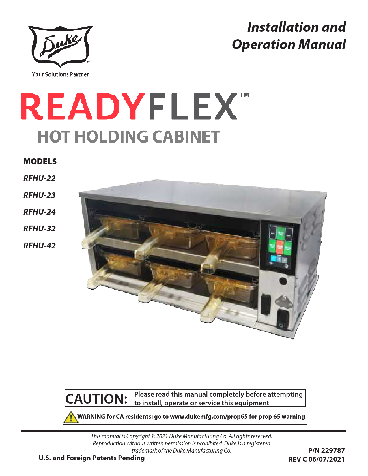
User Manual for Duke models including: RFHU-22, RFHU-23, RFHU-24, RFHU-32, RFHU-42, ReadyFlex Hot Holding Cabinet
RFHU Operator’s Manual 4 Throughout this manual, you will find the following safety words and symbols that signify important safety risks with regards to operating or maintaining the equipment.
Index of /wp-content/uploads/2021/05
MODELS RFHU-22 RFHU-23 RFHU-24 RFHU-32 RFHU-42 Installation and Operation Manual CAUTION: Please read this manual completely before attempting to install, operate or service this equipment WARNING for CA residents: go to www.dukemfg.com/prop65 for prop 65 warning This manual is Copyright © 2021 Duke Manufacturing Co. All rights reserved. Reproduction without written permission is prohibited. Duke is a registered trademark of the Duke Manufacturing Co. U.S. and Foreign Patents Pending P/N 229787 REV C 06/07/2021 RFHU Operator's Manual TABLE OF CONTENTS TO BE UPDATED Manufacturer's Introduction ........................................................................................................................................3 Important Safety Instructions.................................................................................................................................. 4-5 Installation ....................................................................................................................................................................... 6 Stacking Units .................................................................................................................................................................7 Multipan Flexible Lid Option .....................................................................................................................................8 RFHU Operating Instructions .......................................................................................................................................9 Overview ............................................................................................................................................................................................. 9 Preheating ........................................................................................................................................................................................11 Faults................................................................................................................................................................................................... 11 Units With Timer Bars....................................................................................................................................................................12 RFHU Daypart Menu .....................................................................................................................................................................13 Settings ..........................................................................................................................................................................14 Menu.................................................................................................................................................................................................. 14 Temp Mode.......................................................................................................................................................................................14 PHU Configurator...........................................................................................................................................................................14 Language .......................................................................................................................................................................................... 15 RFHU Recipe Editor........................................................................................................................................................................15 Help ..................................................................................................................................................................................................... 16 About .................................................................................................................................................................................................. 16 Tools Menu........................................................................................................................................................................................16 Network .............................................................................................................................................................................................16 PHU Volume .....................................................................................................................................................................................19 Admin ................................................................................................................................................................................................. 19 Manager ............................................................................................................................................................................................19 Access Menu ....................................................................................................................................................................................19 Temp Offset ......................................................................................................................................................................................20 Duke Connected Equipment Platform (DCEP) Programming..............................................................................21 USB Programming........................................................................................................................................................22 Cleaning Guide .............................................................................................................................................................24 Temperature Check Procedure ..................................................................................................................................26 RFHU Specification.......................................................................................................................................................27 Wire Diagrams ........................................................................................................................................................28-35 2 MANUFACTURER'S INTRODUCTION RFHU Operator's Manual The ReadyFlexTM Holding Unit (RFHU) delivers unsurpassed culinary performance for a broad variety of food products in a flexible, easy to use, easy to learn, adaptable format thus addressing the needs of the restaurant operations and profitability. The Duke ideal holding curve, the DNA of the RFHU, has been developed, improved, and refined since Duke introduced the first product holding unit in 1999. Utilizing the innovative top and bottom patented Duke technology HeatSinksTM, extended hold times with improved food quality and consistency are achieved. With the ReadyFlexTM holding unit, you can offer new menu items without limitation on how to hold them; change your recipes and hold configurations by daypart; from breakfast to lunch to dinner. Independent top and bottom heat zones are programmable to dial in perfect recipes for any food....no compromises. Utilizing an innovative and patent pending flexible lid system, the ReadyFlexTM holding unit is multi-pan capable, both 2.5" and 4" deep pan configurations can adapt to hold 1/3, 1/2, and fullsize pans, in addition to, 13x18" sheet pans. The Multi-pan feature is configurable and programmed without the use of any additional parts or tools. The easy to use, easy to learn touchscreen user interface is visual, smart, intuitive and colorful. Instore control and programming is easy and fast - change to stored library recipes or program new ones on the fly. Daypart switching is simple and pre-programmed. ReadyFlexTM Technology is ready to connect when (and if ) you are. RFHU has built-in Wi-Fi, Ethernet, USB and Mesh networking and connectivity to Bluetooth enable devices. RFHU is ready to interact with 3rd party cloud and on-premise solutions. Note: The RFHU is also available with a bottom only Duke technology HeatSink option that too provides improved holding times and food quality than traditional FWM PHU models at an even more compelling price. Note: The RFHU is available with a dedicated lid system for those that choose to have fixed pan sizes for their operations. 3 RFHU Operator's Manual IMPORTANT SAFETY INSTRUCTIONS Throughout this manual, you will find the following safety words and symbols that signify important safety risks with regards to operating or maintaining the equipment. Indicates a hazardous situation which, if not avoided, could result in death or serious injury. CAUTION Indicates a hazardous situation which, if not avoided, could result in minor or moderate injury. CAUTION Indicates Important Information Indicates electrical shock hazard which, if not avoided, could result in death or serious injury and/or equipment damage. Indicates hot surface which, if not avoided, could result in minor or moderate injury. In addition to the warnings and cautions in this manual, use the following guidelines for safe operation of the unit. · Read all instructions before using equipment. · For your safety, the equipment is furnished with a properly grounded cord connector. Do not attempt to remove or disconnect the grounded connector. · Install or locate the equipment only for its intended use as described in this manual. · Do not use corrosive chemicals on this equipment. · Do not operate this equipment if it has a damaged cord or plug, if it is not working properly, or if it has been damaged or dropped. · This equipment should be serviced by qualified personnel only. Contact the nearest Duke authorized service facility for adjustment or repair. · Do not block or cover any openings on the unit. · Do not immerse cord or plug in water. · Keep cord away from heated surfaces. · Do not allow cord to hang over edge of table or counter. 4 RFHU Operator's Manual IMPORTANT SAFETY INSTRUCTIONS The following warnings and cautions appear throughout this manual and should be carefully observed. · Turn the unit off, disconnect the power source and allow unit to cool down before performing any service or maintenance on the unit. · The procedures in this manual may include the use of chemical products. You must read the Material Safety Data Sheets before using any of these products. · The unit should be grounded according to local electrical codes to prevent the possibility of electrical shock. It requires a grounded receptacle with dedicated electrical lines, protected by fuses or circuit breaker of the proper rating, in accordance with all applicable regulations. · Disposal of the unit must be in accordance with local environmental codes and/or any other applicable codes. · This appliance is not intended for use by persons (including children) with reduced physical, sensory or mental capabilities, or lack of experience and knowledge, unless they have been given supervision or instruction concerning use of the appliance by a person responsible for their safety. · Contains Transmitter Module FCC ID: 2AQ2Q-MUR1LVUFL · Contains Transmitter Module IC: 27013-MUR1LVUFL. · This device complies with part 15 of the FCC Rules. Operation is subject to the following two conditions: 1. This device may not cause harmful interference, and 2. This device must accept any interference received, including interference that may cause undesired operation. · This equipment complies with radiation exposure limits set forth for an uncontrolled environment. This equipment should be installed and operated with a minimum separation distance of 20cm between the radiator (enclosed antenna) and your body. · This device is granted for use in Mobile only configurations in which the antennas used for this transmitter must be installed to provide a separation distance of at least 20cm from all person and not be co-located with any other transmitters except in accordance with FCC and Industry Canada multi-transmitter product procedures. · Changes or modifications not expressly approved by the party responsible for compliance could void the user's authority to operate the equipment. 5 RFHU Operator's Manual INSTALLATION UNPACKING UNIT Inspect the shipping carton and/or container, carefully noting any exterior damage on the delivery receipt; also note any damage not evident on the outside of the shipping container (concealed damage). Contact the carrier immediately and file a damage claim with them. Save all packing materials when filing a claim. Freight damage claims are the responsibility of the purchaser and are not covered by the warranty. · Follow the instructions on the Carton Box for unpacking the unit. · Inspect unit for damage. · Report any dents or breakage to source of purchase immediately. · Do not attempt to use unit if damaged. · Remove all materials from unit interior. · If unit has been stored in extremely cold area, wait a few hours before connecting power. INSTALLATION CODES AND STANDARDS In the United States, the RFHU must be installed in accordance with the following: 1. State and local codes. 2. National Electrical Code (ANSI/NFPA No. 70, latest edition) available from the National Fire Protection Association, Batterymarch Park, Quincy, MA 02269. 3. Vapor Removal from Cooking Equipment, (NFPA-96, latest edition) available from NFPA. 4. Sealed to the counter upon which the equipment is placed per NSF/ANSI 4 standard. In Canada, the RFHU must be installed in accordance with the following: 1. Local codes. 2. Canadian Electrical Code (CSA C22.2 No. 3, latest edition) available from the Canadian Standards Association, 5060 Spectrum Way, Mississauga, Ontario, Canada L4W 5N6. UNIT PLACEMENT · Do not install unit next to, below or above source of heat such as oven or deep fat fryer. · Install unit on level counter top surface. · Outlet should be located so that plug is accessible when the unit is in place. · Do not install unit in the direct path of air-conditioned airflow. The following minimum clearances must be maintained between the warmer and any combustible or non-combustible substance: Unit Right Side Left Side Rear Floor Clearance 2" 2" OPEN 0" Proper airflow around unit will cool the electrical components. With restricted airflow, the unit may not operate properly and the life of the electrical components may be reduced. A 2" clearance is recommended at the control side for longer control life expectancy. ELECTRICAL SHOCK HAZARD UNIT MUST BE SAFETY GROUNDED, EARTHED. DO NOT MODIFY, DEFEAT ELECTRICAL CONNECTIONS OR ALTER PLUG. ELECTRICAL CONNECTIONS BEFORE CONNECTING THE UNIT TO THE POWER SOURCE, VERIFY THAT THE VOLTAGE AND PHASE OF THE POWER SOURCE ARE IDENTICAL TO THE VOLTAGE AND PHASE INFORMATION ON THE DATA LABEL. EARTHING INSTRUCTIONS THE UNIT MUST BE GROUNDED. Grounding reduces risk of electric shock by providing an escape wire for the electric current if an electrical short occurs. This unit is equipped with a cord having a grounding wire with a grounding plug. The plug must be plugged into a receptacle that is properly installed and grounded. Consult a qualified electrician or service agent if grounding instructions are not completely understood, or if doubt exists as to whether the unit is properly grounded. DO NOT USE AN EXTENSION CORD. If the product power cord is too short, have a qualified electrician install a three-slot receptacle (or the country specific receptacle for International Units). This unit should be plugged into a dedicated circuit with the electrical rating as provided on the product data plate. 6 RFHU Operator's Manual STACKING UNITS The RFHU is designed to allow limited stacking capabilities. This section outlines how to safely stack the holding unit. Step 1 Remove the base pan from the unit that will be on top. The pan is held in place by four screws on the bottom of the unit. Step 2 Place bottom unit into position then stack the next unit on top. The top of the lower holding unit rests inside of the base of the upper unit. TIP HAZARD! DO NOT STACK RFHU-42 OR RFHU-34 UNITS. DO NOT EXCEED 2 HOLDING UNITS PER STACK. DO NOT PLACE HOLDING UNIT STACKS ON SURFACES THAT MAY EASILY TIP OVER. PROPER USE OF HEATSINKTM COVERS Proper usage of each is important and is outlined below: Product Type Broiled and Grilled Fried Dedicated 1/3 Size Lid Option Solid Lid No Lid Multi pan Flexible Lid Option Solid Lid Vented Lid Consult your Kitchen Operations Manual for any modifications to the above based on your specific food requirements. 7 RFHU Operator's Manual MULTIPAN FLEXIBLE LID OPTION To install the lid, with its support flanges upward lead the flanges over the tabs of the lid support brackets. Slide it all the way in until the lid drops into position, rest on the supports, and is retained front to back. It's as easy as that. Enjoy the many pan size and configuration options possible with this patent pending flexible lid system. With the Multipan Flexible Lid Option, there are solid and vented lids. Additionally, each are both provided with and without pan guides. This provides the maximum flexibility whether you choose to use 1/3, 1/2, full size pans or a combination of pan sizes. For the below examples, we will use a 2x3 PHU configuration and show a few of the 3 wide shelf configuration options and their lid orientations. 1. Configured for 1/3 size pans; a. Wells 1 & 2 with lids oriented with the pan guides to the right. b. Well 3 using a lid with no pan guide. This provides pan guides for all three 1/3 size pans, as shown. 2. Configured for one - 1/2 size pan and one - 1/3 six pan; a. Well 1 with a lid oriented with the pan guide to the left. b. Well 2 with a lid oriented with the pan guide to the right. c. Well 3 using a lid with no pan guide. This provides pan guides between the 1/2 size pan and 1/3 size pan. 3. Configured for one full size pan; a. Well 1 with a lid oriented with the pan guide to the left. b. Well 2 with a lid with no pan guide. c. Well 3 with a lid oriented with the pan guide to the right. These are just a few of the multiple pan options possible that you can configure without the use of tools and with the standard parts included with your unit. 8 RFHU Operator's Manual RFHU OPERATING INSTRUCTIONS OVERVIEW When the ReadyFlexTM Holding Unit is turned on the boot screen will appear first for 2 or 3 seconds. This will display the Duke Logo along with the firmware version number of the RFHU. Different types of information are found on the runtime screen. Details below. RUNTIME SCREEN After the RFHU has loaded the runtime screen will load. When the unit first boots each well will contain a preheating icon. This indicates the well is heating to temperature. When the recipe temperature is reached the preheat icon will clear and the well will be ready for use. In this instance a 3X4 RFHU has been detected. A "3X4" has a layout consisting of 3 rows by 4 columns containing up to 12 programmed recipes in total. 9 RFHU Operator's Manual RFHU OPERATING INSTRUCTIONS - Continued Each recipe is programmed with a "hold time". The hold time can be configured for any time between 1 minute to 540 minutes. Pressing on any well will start the timer. Three-day part menus are available to be selected on the runtime screen. When selected these will change the recipe display. For example, during Breakfast hours you may hold different recipes to lunch or dinner. Changing from "Menu 1" to "Menu 2" will change all non-running programmed recipes name to the new menu layout. When a well is started the color of the well will change to green, use this product first. When the second well of the same recipe is started the started well change to amber, use this next. When subsequent wells of the same recipe are started, they will also be amber. If a different well is started with a different recipe and there is no other well running with the recipe - then it will also have green background. When the well countdown timer expires, the timer shows a "X", the will turns red and an alarm will sound. Touching the well, cancels the alarm. To cancel an unexpired timer you must press and hold. If a well is currently running and the menu is changed the new recipe name will not take effect until the well has been stopped or expired and cleared. A Cook More time value can be programmed for each individual recipe. The "Cook More time" is used to indicate that the remaining hold time of the current recipe is low and they should start cooking/ preparing the recipe once more. A "+" symbol appears on the individual well with the cook more time indicator. For example: 10 RFHU Operator's Manual RFHU OPERATING INSTRUCTIONS - Continued PREHEATING When the RFHU first boots each well will contain a preheating icon. This indicates the well is heating to temperature. When the recipe temperature is reached the preheat icon will clear and the well will be ready for use. FAULTS On occasion faults may occur on the RFHU. If a fault occurs an indicator will appear on the well and the well will not be usable (cannot start/stop timers). 1. Top Heater High Temperature Fault 2. Top Heater Low Temperature Fault 3. Bottom Heater High Temperature Fault 4. Bottom Heater Low Temperature Fault 5. CAN Error Fault 6. Back Screen Disconnected Each fault will display an indicator that is unique for the top of fault that has appeared. 11 RFHU Operator's Manual RFHU OPERATING INSTRUCTIONS - Continued Units with optional Timer bar TO ENSURE OPTIMAL HOLD QUALITY, THE USER WOULD PRESS THE BUTTON ON THE TIMER BAR CORRESPONDING WITH THE PAN LOCATION TO ACTIVATE A HOLD CYCLE. THIS STARTS THE TIMER COUNTDOWN. 12 3 3 21 1. Status LED's: Indicates status of the pan a. Non-Illuminated timer is inactive no product in pan. b. Green timer is active product in pan (use 1ST) c. Amber timer is active product in pan (use next) d. Non-Illuminated timer active product in pan (use later) e. Flashing Green cook warning time reached (cook more product) f. Flashing Red product is expired (discard) 2. Arrow buttons a. Used for starting and stopping the timer b. Used to access menu mode c. Indicates which pan the adjacent status LED and pan display are linked to 3. Pan Display a. In startup mode it will display spinning bars then transition to PRE HEAT, and then cycle through the bottom actual temp and top actual temp b. Once unit reaches the recipe set points it will display product name. (If associated recipe requires a lid display will toggle prod name, lid.) c. Unit will display product name and hold time remaining (display will alternate between the two when a timer is active) 12 · ENSURE PROPER HEAT SINK COVERS ARE INSERTED INTO THE CORRECT LOCATION (BROILED AND MOISTURE SENSITIVE PRODUCTS ONLY). · ENSURE METAL TRIVETS ARE INSERTED INTO THE PANS FOR FRIED PRODUCTS. · UPON TURNING ON, ALLOW THE HOLDING UNIT TO HEAT FOR AT LEAST 30 MINUTES OR UNTIL THE TEMPERATURE DISAPPEARS AND THE TIMER BARS DISPLAY THE PRE PROGRAMMED PRODUCT NAMES. · IF THE TIMER BARS DISPLAY "HIGH" OR "LOW" AT ANY TIME AFTER THE PRE-HEAT PERIOD, DISCONTINUE USE OF THE AFFECTED PAN LOCATION(S) UNTIL THE HOLDING UNIT CAN BE SERVICED. RFHU Operator's Manual RFHU OPERATING INSTRUCTIONS - Continued RFHU DAYPART MENU WILL CYCLE THE UNIT THROUGH THE DIFFERENT DAYPARTS AND SHOW PRODUCTS ASSOCIATED WITH EACH MENU. · 1 Breakfast · 2 Lunch · 3 Dinner Menu Mode 1. Press and hold the paired arrows for a display segment for 3 seconds to enter Menu Mode. Display will toggle (NAME, product name) 2. 1ST button press will display (ACT TEMP, actual temp bottom, actual temp top) 3. 2ND button press will display (SET TEMP, temp set point bottom, temp set point top) 4. 3RD button press will display (TIME, receptive in minutes) 5. 4TH button press will display (LID, ON or OFF) 6. 5TH button press will display (COOK MORE TIME, cook more time in minutes) 7. 6TH button press will display (FIRM, actual firmware version) 8. 7TH button press will display (LED display will light all LEDs in a testing sequence) 13 RFHU Operator's Manual RFHU OPERATING INSTRUCTIONS - Continued SETTINGS Several Settings are available on the RFHU. To enter the Settings menu click on the cog icon ( found in the lower right hand corner of the runtime screen. ) which is Menu The "Menu" option is allows you to select the number Menus (or dayparts) you want to be available (1 to 3). PHU Configurator When the user loads the "RFHU Config" menu option within Settings the following screen will appear. Temp Mode "Temp Mode" will display an option where the temperature mode can be changed from the default of Fahrenheit to Celsius. NOTE: Any temperature throughout the control will display in the selected temperature mode. In the same way as the runtime screen the unit's configuration (for example 3X4) will be detected and displayed. The PHU config option allows the recipe mapping of each well to be modified for each menu. The number in the middle of each zone along with the color indicates that the individual wells are within the same temperature zone. Current well mapping is displayed. For example "BURG" is selected for both wells in "Zone 1". The "CHKN" recipe is selected for both wells in "Zone 2". When programming, only recipes with the same BOTTOM (and TOP) temperature can be configured next to each other within the same temperature zone. 14 RFHU Operator's Manual RFHU OPERATING INSTRUCTIONS - Continued When an individual well is pressed a list of available recipes will appear available for selection within the zone, for example: RFHU Recipe Editor Selecting the "Recipe Config" option will display the list of local recipes currently stored on the unit. These are sorted alphabetically Use the left and right navigation buttons to scroll through the available recipes for this RFHU. To assign a new recipe to the well, simply select the desired recipe. Select to exit without making a change. Select to save and update the RFHU Configuration. When the user returns to the runtime screen and the well has stopped, the new recipe name will appear where programmed. Note: If a change is made and there is a current recipe running, the new recipe name will not take affect until the previous receipt has stopped/ expired or been cleared. Language "Language" Setting. This is reserved for future use and will allow RFHU users to change the language display on all screens. Key information on each recipe is displayed on this screen view. This includes the Recipe Name (appears on the well on the runtime screen), the Hold Time, Cook More Time, Top temperature and the Bottom Temperature. Page navigation buttons can be used on each screen to navigate through each set of recipes. The "+" icon can be used to add a new local recipe. Selecting on an existing recipe will load the recipe in edit mode. Each of the 8 recipe fields can be modified here. The Duke ReadyFlex unit comes preprogrammed with generic recipes installed on the unit and provided in the software. These recipe recommendations were developed for 1/3 size pan configurations, when utilizing the flexible lid system to accommodate larger pan capacities temperature adjustments are recommended. When increasing pan capacity for fried products start with using 30-degree (F) temperature increase for both top and bottom heat and if holding moist products start with using a 10-degree (F) temperature increase for both top and bottom heat. To optimize the holding performance of the Duke ReadyFlex unit additional temperature adjustments may be necessary. 15 RFHU Operator's Manual RFHU OPERATING INSTRUCTIONS - Continued Help "Help Mode" will be reserved for future use where instructional material relating to the RFHU will be displayed. About Network The Network Config option will allow the RFHU network connection to be configured. After selecting "Network Config" the following screen will load. The "About" screen will detail specific settings available to the RFHU. This will include the unit's serial number, API key, firmware version along with the unique network MAC address used for both WiFI and ethernet connectivity. Tools Menu The following configurations are available on the TOOLS menu. Network Config can be set to "Read Only" mode if the access is locked within Tools menu. Alternatively, if "Network" is unlocked in the Access menu then changes can be made to the selected network. The RFHU supports both WiFi and Ethernet connections. In each network mode, both automatically assigned IP addresses (DHCP) and manually entered static IP addresses are supported. To modify Network Settings first ensure that Network Settings are unlocked in the Access Menu (they are by default). Then enter the "Network" option found within the "Tools" menu. 16 RFHU Operator's Manual RFHU OPERATING INSTRUCTIONS - Continued The current network selection will be highlighted, either Ethernet or WiFi. For example: To connect to a WiFI SSID click on the SSID name. The Wifi SSID password will then be required. To change to WiFi select the WiFi icon ( ) near the top of the Network Config screen. A list of available WiFi SSID's will then appear. Press anywhere within the "Enter Password" box to load the on-screen keyboard to enter the WiFi password. 17 RFHU Operator's Manual RFHU OPERATING INSTRUCTIONS - Continued Once entered select "OK" on the on-screen keyboard followed by the check button to attempt to join the WiFi SSID. If the WiFi password is incorrect the RFHU will not join the WiFi network. If the WiFI password is correct the RFHU will join the network and the RFHU will be connected. If the RFHU is currently connected to a WiFi network the connected SSID will be displayed in blue. Selecting on any of the 5 Network Settings will load an on-screen numeric keypad where the IP address details can be entered manually. To disconnect from the WiFi select the disconnect icon ( ) in the lower left hand corner of the RFHU or alternatively click on another WiFi SSID to join a different WiFI network (WiFi password entry will then be required). The "DHCP" toggle is available for both ethernet and WiFI connections. By default DHCP will be selected. Instead of being assigned an IP address automatically a static IP address will allow the network settings (IP Address, Subnet Mask, Default Gateway, Primary DNS Server, Secondary DNS Server) to be manually configured and saved. Once entered select the check button to save the newly entered settings. 18 RFHU Operator's Manual RFHU OPERATING INSTRUCTIONS - Continued PHU Volume The PHU Volume option will either enable or disable sound on the RFHU. Enter PIN "8429" and select screen will be displayed. and the following The slider can be moved either on or off. Select to save and update the PHU Volume Configuration. Select to exit without making a change. Admin The "Admin" options is reserved for future use. Manager The MANAGER menu is PIN code protected and allows the 'manager' access to the ACCESS and TEMP OFFSET functions. Selecting "MANAGER" the following screen will be displayed. Access Menu The ACCESS menu allows a number of configuration options to be "locked" or unable to be changed. When selected the following screen will appear. Each of the Recipe Config, Menu, Temp Mode (C/F) and Network can be locked or unlocked. For example, if "Recipe Config" is locked when the Recipe Config option described previously is loaded it will be in "VIEW MODE" only. Modifications such as editing existing recipe settings, delete a recipe or adding a new recipe will not be available. 19 RFHU Operator's Manual RFHU OPERATING INSTRUCTIONS - Continued Temp Offset The Temperature Offset function will allow the temperature offset to be adjusted per ZONE on the selected RFHU. After selecting the "TEMP OFFSET" function the following screen will appear. When this screen appears the TOP and BOTTOM current temperature offset value will appear. The actual temperature read from the RFHU for both the top and bottom heaters will also appear. The edit icon ( ) will load the offset editor screen for either "Top Offset" or "Bottom Offset". The screen will be divided into a grid like display. Instead of each "colored area" indicating a well it will now indicate a "Zone". In most PHU configurations a "Zone" generally means the two wells next to each other however there may be exceptions to this rule. Select a zone. After selecting a zone the following screen will appear. Once again the current temperature will be displayed. The current offset value will also be displayed. The and can be selected to increase the offset value by 1F each press. Select to exit without making a change. Select to save and update the offset value. 20 RFHU Operator's Manual RFHU OPERATING INSTRUCTIONS - Continued Duke Connected Equipment Platform (DCEP) Programming The ReadyFlexTM Holding Unit can have its recipes and well programming updated locally on the RFHU Control as mentioned in previous sections. Recipes and well programming can also be updated via Duke's cloud solution the Duke Connected Equipment Platform (DCEP). The DCEP requires the user's Account Name to be defined along with a user login and password. This can be created via the DCEP registration process without the assistance of Duke Customer Service. An option exists for this purpose on the connected. dukemfg.com landing page "Create an Account". After selecting the "Dashboard" icon to connect to a specific RFHU the programming grid will appear. As this is a connected unit the unit configuration will be detected automatically, for example a 2x2 RFHU configuration appears below. The ReadyFlexTM Holding Unit can then be added to the account using its serial number and API key which can be found on the unit itself. After logging onto the DCEP all connected devices within the account will be displayed. Multiple RFHU's are possible to be loaded within the account. The RFHU programming grid will be color coded per zone. Recipes programmed within each zone will be required to be of the same top temperature and bottom temperature. Three MENU's are available for selection for each well. The three menu's may be used as BREAKFAST, LUNCH or DINNER. The "All Day" option can be used when the well holds the exact same recipe for the entire day. To program a well select the dropdown boxes next to each MENU. A list of available recipes will be displayed. 21 RFHU Operator's Manual RFHU OPERATING INSTRUCTIONS - Continued The "SHOW LEGEND" button can also be used to display the full recipe list for the full account. A list of local recipes found on the RFHU will appear here. These can be edited, added, or deleted using the appropriate function which will update the connected RFHU local recipe set in real-time. Selecting "Create Recipe" will load the following form where a new recipe can be added. Fields between "add" and "edit" are the same. When grid programming has been completed a completely programmed PHU looks like the below. After programming the wells two options are then available. "DOWNLOAD PHU CONFIGURATION FILE" will create a local RCP formatted file with the programming. Alternatively, the "SAVE button" can selected. This will update the well programming on the unit instantly from the DCEP to the RFHU unit itself. This is a real-time recipe program update. Another option available within the DCEP is to be able to view the online RFHU Recipe List. This is available by selecting "Recipes" under "Equipment Dashboard" on the DCEP side menu. Fields consist of Recipe Name, Bottom Temp, Top Temp, Cook More enabled, Cook More Message ID, Cook more time, enabled/disabled and lid enabled/ disabled. When finished adding or editing select the "SAVE" button. The updated recipe list will be sent to the connected RFHU where it is updated in real time. USB Programming In some cases the connected RFHU unit may not be online and connected to the DCEP. If this is the case the RFHU recipe and programming settings can be modified on the actual unit UI or alternatively the RFHU Offline Configurator menu option can be used on the DCEP. This can be found under "Recipe" menu on the side menu of the DCEP. 22 RFHU Operator's Manual RFHU OPERATING INSTRUCTIONS - Continued For the user's Account an "offline recipe set" will always be available to the user. This information will be saved and be readily available if a USB file is required to be created. The RFHU Configurator is available for well programming. As the unit is not connected the RFHU configuration, for example 2x2, 2x4 will not be automatically detected. This can then be programmed in the same way as the online RFHU. For example: Instead a list of available configurations will be available for programming. These include: When finished select "DOWNLOAD PHU CONFIGURATION FILE" option. This will create a RFHU "RCP" file which contains both the recipe list and well mapping settings. This file can then be copied to the "root" directory of a USB flash drive. Plug this same USB drive into the USB port on an RFHU and if the configuration is correct both the recipe list and well programming will be uploaded on the unit itself. A confirmation message will appear on the RFHU display when a new recipe set has been successfully loaded. When a selected PHU configuration is selected the appropriate programming grid will appear. For example a 2x4 will appear as: 23 RFHU Operator's Manual CLEANING GUIDE Electrical shock hazard. Do not wash with water jet or hose. DO NOT USE CAUSTIC CLEANERS, ACIDS, AMMONIA PRODUCTS OR ABRASIVE CLEANERS OR ABRASIVE CLOTHS. THESE CAN DAMAGE THE STAINLESS STEEL AND PLASTIC SURFACES. Bottom and sides of warmer wells are very hot and cool slowly. DAILY CLEANING · Stainless Steel Surfaces To prevent discoloration or rust on stainless steel several important steps need to be taken. Stainless steel contains 70-80% iron which will rust. It also contains 12-30% chromium which forms an invisible passive film over the steel surface which acts as a shield against corrosion. As long as the protective layer is intact, the metal will not corrode. If the film is broken or contaminated, outside elements can begin to breakdown the steel and begin to form rust or discoloration. Proper cleaning of stainless steel requires soft cloths or plastic scouring pads. NEVER USE AN ACID BASED CLEANING SOLUTION! MANY FOOD PRODUCTS HAVE AN ACIDIC CONTENT WHICH CAN DETERIORATE THE FINISH. BE SURE TO CLEAN ALL FOOD PRODUCTS FROM ANY STAINLESS STEEL SURFACE. COMMON ITEMS INCLUDE, TOMATOES, PEPPERS AND OTHER VEGETABLES. THE POWER MUST BE TURNED OFF AND DISCONNECTED AT ALL TIMES WHEN PERFORMING MAINTENANCE OR REPAIR FUNCTIONS. Never use steel pads, wire brushes or scrapers. Cleaning solutions need to be alkaline based or non-chloride cleaners. Any cleaner containing chlorides will damage the protective film of the stainless steel. Chlorides are also commonly found in hard water, salts and household and industrial cleaners. If cleaners containing chlorides are used, be sure to rinse repeatedly and dry thoroughly upon completion. Routine cleaning of stainless steel can be done with soap and water. Extreme stains or grease should be cleaned with a non-abrasive cleaner and plastic scrub pad. It is always good to rub with the grain of the steel. There are also stainless steel cleaners available which can restore and preserve the finish of the steels protective layer. Early signs of stainless steel breakdown can consist of small pits and cracks. If this has begun, clean thoroughly and start to apply stainless steel cleaners in an attempt to restore the passivity of steel. NEVER USE A HIGH-PRESSURE WATER WASH FOR THIS CLEANING PROCEDURE AS WATER CAN DAMAGE ELECTRICAL COMPONENTS ELECTRICAL SHOCK HAZARD. DO NOT WASH WITH WATER JET OR HOSE. RECOMMENDED SUPPLIES Cleaning Towels Non-Scratch Scrub Pad KAYTM Degreaser KAY® SINK SANITIZER, KAYQUATTM Sanitizer, or compatible sanitizer 24 PROCEDURE CLEANING GUIDE - continued RFHU Operator's Manual 1. Turn unit off, unplug, and allow to cool for 30 minutes. 2. Remove all holding pans and heat sink covers. Wash, rinse, and sanitize at the 3 compartment sink. 3. Allow to air dry. 4. Spray a cleaning towel, or non-scratch scrub pad when necessary, with soapy solution or KAYTM Degreaser. Fully clean upper heat sink surfaces by hand, as well as lower heat sink surfaces Take care when reaching in the cabinet. Pan and lid guides present sheet metal edges which could be sharp. NOTE: Never spray cleaning solution directly onto the cabinet. 5. If daily cleaning is performed routinely, deeper, more aggressive, cleaning methods can be avoided. Over longer periods of time, fried food product can accumulate and bake on to the upper heat sink surfaces of the compartments. 6. Use a sanitizer-soaked towel and wipe out all compartments on the holding unit. Wipe top compartments first, and then lower compartments. IMPORTANT: Use clean, sanitizer-soaked towels (Important: towels must be wrung out so that they are damp and not dripping, dripping towels may harm the unit.) DAILY INSPECTION CHECKLIST: Make sure that: · Unit is free of any visible food soils. · Unit is free of grease or soils in holding compartment. · Exterior of unit is free of smudges or soil. · Holding pans are free of any food soil residue. · Pans are free of damage such as cracks. 25 RFHU Operator's Manual TEMPERATURE CHECK PROCEDURE 1. A digital temperature meter that has been calibrated must be used to get an accurate temperature reading. Use a thermocouple surface temperature probe to measure temperatures. 2. No pans should be in wells during the preheat and temperature check. Pre-heat the warmer for 30 minutes before taking any temperature readings. Do not take readings unless the cavity has been empty for 30 minutes. This will allow the temperature to stabilize and will prevent false readings. 3. The warmer cavity should be cleaned and empty before the temperature is checked. Avoid any air drafts that might flow through the cavity. 4. Temperature readings should be taken when standing on the front side of the unit with on/ off switch. Locate the surface temperature probe on the bottom of the first cavity. Position the probe half way back on the heat sink beneath the rail as shown. The top readings should be taken on either side of the rail half way back on the heat sink. Four wide units require 2 readings, left and right side. 5. All temperature controls exhibit a swing in temperature as the control cycles on and off while regulating to the set point. The correct calibration temperature is the average of several readings taken over a period of 20 minutes after the warmer has been pre-heated. The average temperature should be no greater than ± 10°F (± 6°C) from the set point. 6. The allowable range of well temperatures which can be programmed on the RFHU is 140°F-280°F (60°C-137.8°C). 7. If the calibration temperature is greater than +/- 10F (6C) from the set point, adjust the temperature offset as described under the Tools menu. The offset value should be set as the difference between the calibration temperature and the set point. 8. Repeat for all heat sinks. Center Probe Front to Back 26 RFHU SPECIFICATIONS RFHU Operator's Manual Height Width RFHU-23 Shown Above ELECTRICAL SPECIFICATION/CORD RATING (TOP AND BOTTOM HEAT) Model 120V - 60Hz Amps NEMA 208/240 V - 60Hz Amps NEMA RFHU-22 10 RFHU-23 12.5 RFHU- 24 15 RFHU-32 12.5 RFHU-42 15 5-15P 5-20P 5-20P 5-20P 5-20P 5.8/6.7 8.7/10 8.7/10 8.7/10 8.7/10 6-15P 6-15P 6-15P 6-15P 6-15P Depth 220/240V - 50/60Hz Amps Schuko 6.7 CEE7 VII 10.0 CEE7 VII 10.0 CEE7 VII 10.0 CEE7 VII 10.0 CEE7 VII DIMENSIONS 2.5" Deep Pan Config Model Height Width Depth (body only) in. cm in. cm in. cm RFHU-22 11.8 30.0 19.0 48.3 14.1 35.7 RFHU-23 11.8 30.0 26.0 66.0 14.1 35.7 RFHU- 24 11.8 30.0 33.0 83.8 14.1 35.7 RFHU-32 16.6 42.2 19.0 48.3 14.1 35.7 RFHU-42 21.5 54.6 19.0 48.3 14.1 35.7 4.0" Deep Pan Config Height Width Depth (body only) in. cm in. cm in. cm 14.5 36.8 19.0 48.3 14.1 35.7 14.5 36.8 26.0 66.0 14.1 35.7 14.5 36.8 33.0 83.8 14.1 35.7 20.6 52.3 19.0 48.3 14.1 35.7 26.8 68.1 19.0 48.3 14.1 35.7 27 RFHU Operator's Manual WIRE DIAGRAMS 2X2 - TOP & BOTTOM HEAT Touch Screen Display Ethernet 12Vdc GND CAN_H CAN_L 12Vdc GND CAN_H CAN_L Wire Diagram RFHU 2x2 *Top & Bottom Heat Antenna USB DMX PCB Main Control Rear Ethernet Front USB Beeper Dis pl ay Flex Cable (rear) Sp8ea5kWer WiFi Dau gh ter DMX PCB Front Main Control 1 2 3 4 Sw 2 208V, 230V, 240V Main Line Supply 1 2 3 4 Sw 1 1 & 2 1 & 2 3 & 4 3 & 4 12 34 S w2 12 34 S w1 B ottom Top IO3 PCB B ottom Top 1234 1234 Sw 2 Sw 1 120V Main Line Supply Temp Sense RTD (1K) 32°F(0°C) = 1,000, 180°F(82°C) = 1,320 Front Timer Bar Timer Bar 5V PCB Front Power Switch Front Timer Bar Well 1 & 3 4 3 2 1 ELC0541 Rev. D OPTIONAL Well 2 & 4 1 2 3 4 RED (5V) WHT (CAN_L) BLU (CAN_H) BLK (GND) 1 2 3 4 Dis pl ay Flex Cable (rear) Speaker 8 5W OPTIONAL DMX PCB Rear Main Control BLK (GND) BLU (CAN_H) WHT (CAN_L) RED (5V) 1 2 3 4 Well 2 & 4 OPTIONAL Well 1 & 3 Rear Timer Bar IO3 PCB P2 P1 P2 P1 P1 or P2 Control Power & CAN Bus BLU (CAN_H) WHT (CAN_L) RED (5V) BLK (GND) Well 1 & 2 Triac PCB 1 & 2 1 & 2 3 & 4 3 & 4 B ottom Top B ottom Top 22 1-61 5 Well 3 & 4 12V Power PCB Timer Bar 5V PCB Rear Timer Bar 22 1-61 5 2 Wide Shelf (Top & Bottom Heat) Temp Sense 12Vdc Heat 1 Heat 2 Heat 3 Heat 4 22 1-61 5 22 1-61 5 High L1 Limit L1 2 Well Element (300W) 120V = 48 / 2.5A 208V = 144 / 1.4A Line Cord 230V = 144 / 1.6A 240V = 144 / 1.7A Touch Screen Display Ethernet 12Vdc GND CAN_H CAN_L Ethernet 12Vdc GND CAN_H CAN_L USB USB DMX PCB Main Control Wire Diagram RFHU 2x2 * Bottom Heat only Antenna Rear Ethernet Front USB Display Flex Cable (rear) Sp8ea5kWer WiFi Daughter DMX PCB Front Main Control Beeper 1 2 3 4 Sw 2 208V, 230V, 240V Main Line Supply 1 2 3 4 Sw 1 1 & 2 3 & 4 12 34 S w2 12 34 S w1 B ottom B ottom IO3 PCB 1234 1234 Sw 2 Sw 1 120V Main Line Supply Front Timer Bar Timer Bar 5V PCB Power Switch Well 1 & 3 4 3 2 1 OPTIONAL Well 2 & 4 Front Timer Bar RED (5V) 1 WHT (CAN_L) 2 3 BLU (CAN_H) 4 BLK (GND) 1 Display Flex Cable (rear) Sp8ea5kWer Rear Timer Bar BLK (GND) BLU (CAN_H) WHT (CAN_L) RED (5V) 1 2 3 4 Well 2 & 4 OPTIONAL Well 1 & 3 2 3 4 OPTIONAL DMX PCB Rear Main Control 1 & 2 B ottom 3 & 4 B ottom IO3 PCB P2 P1 P2 P1 12Vdc Heat 1 Heat 2 Heat 3 Heat 4 Temp Sense BLU (CAN_H) WHT (CAN_L) RED (5V) BLK (GND) P1 or P2 Control Power & CAN Bus 12V Power PCB Timer Bar 5V PCB Rear Timer Bar 22 1-61 5 L1 Well 1 & 2 Well 3 & 4 22 1-61 5 High Limit 2 Wide Shelf 2 Well Element (300W) 120V = 48 / 2.5A 208V = 144 / 1.4A 230V = 144 / 1.6A 240V = 144 / 1.7A 22 1-61 5 L1 Line Cord 28 RFHU Operator's Manual WIRE DIAGRAMS 2X3 - TOP & BOTTOM HEAT Wire Diagram - RFHU 2x3 * Top & Bottom Heat ELC0539 Rev F Front Timer Bar Well 1 & 4 4 3 2 1 Well 2 & 5 GND 1 BLK (GND) BLU (CAN_H) WHT (CAN_L) RED (5V) 1 2 3 4 OPTIONAL Well 3 & 6 CAN_L CAN_H 4 3 2 5V dc 1 2 3 4 5V dc 1 2 3 CAN_L CAN_H 4 3 2 4 GND 1 Well 2 & 5 Well 3 & 6 OPTIONAL RED (5V) 1 2 WHT (CAN_L) 3 4 BLU (CAN_H) BLK (GND) Well 1 & 4 Rear Timer Bar 4 3 2 1 Touch Screen Display 22 1-61 5 Ethernet 12Vdc GND CAN_H CAN_L 12Vdc GND CAN_H CAN_L Rear Ethernet Antenna USB DMX PCB Main Control Front USB Beeper Dis pl ay Flex Cable (rear) Sp8ea5kWer WiFi Daughter DMX PCB Front Main Control 1 2 3 4 Sw 2 208V, 230V, 240V Main Line Supply 1 2 3 4 Sw 1 1234 1234 Sw 2 Sw 1 120V Main Line Supply 1 2 3 4 Sw 2 208V, 230V, 240V Main Line Supply 1 2 3 4 Sw 1 1234 1234 Sw 2 Sw 1 120V Main Line Supply 1 & 2 1 & 2 3 3 12 34 12 34 S w2 S w1 B ottom Top IO3 PCB B ottom Top Front Timer Bar 4 & 5 4 & 5 6 6 TB 5V PCB 12 34 12 34 S w2 S w1 B ottom Top IO3 PCB B ottom Top Temp Sense RTD (1K) 32°F(0°C) = 1,000, 180°F(82°C) = 1,320 Power Switch Dis pl ay Flex Cable (rear) Well 1 & 2 Well 3 Well 4 & 5 Well 6 OPTIONAL DMX PCB Rear Main Control Triac PCB 1 & 2 1 & 2 3 3 B ottom Top B ottom Top IO3 PCB P2 P1 P2 P1 BLU (CAN_H) WHT (CAN_L) RED (5V) BLK (GND) P1 or P2 Control Power & CAN Bus 22 1-61 5 Row Elements 22 1-61 5 12V Power PCB Triac PCB TB 5V PCB 4 & 5 4 & 5 6 6 B ottom Top B ottom Top Rear Timer Bar 22 1-61 5 22 1-61 5 Row Elements L1 12Vdc Heat 1 Heat 2 Heat 3 Heat 4 3 Wide Shelf (Top & Bottom Heat) Temp Sense Temp Sense High L1 Limit Line Cord L1 1 Well Element (150W) 120V = 96 / 1.25A 208V = 288 / 0.72A 230V = 288 / 0.80A 240V = 288 / 0.83A 2 Well Element (300W) 120V = 48 / 2.5A 208V = 144 / 1. 4A 230V = 144 / 1. 6A 240V = 144 / 1. 7A 29 5V dc Touch Screen Display Ethernet 12Vdc GND CAN_H CAN_L 22 1-61 5 RFHU Operator's Manual WIRE DIAGRAMS 2X3 - BOTTOM HEAT DMX PCB Main Control 30 Wire Diagram RFHU 2x3 * Bottom Heat Front Timer Bar 4 3 2 1 Well 1 & 4 BLK (GND) BLU (CAN_H) WHT (CAN_L) RED (5V) 1 2 3 4 Well 3 & 6 4 3 2 1 CAN_L CAN_H GND 1 2 3 4 ELC0542 Rev C Well 2 & 5 OPTIONAL 5V dc 1 2 3 CAN_L CAN_H 4 3 2 4 GND 1 Well 3 & 6 RED (5V) 1 2 WHT (CAN_L) 3 BLU (CAN_H) 4 BLK (GND) OPTIONAL Well 2 & 5 Well 1 & 4 Rear Timer Bar 4 3 2 1 Rear Ethernet Front USB Antenna Beeper 1 2 3 4 Sw 2 208V, 230V, 240V Main Line Supply 1 2 3 4 Sw 1 1234 1234 Sw 2 Sw 1 120V Main Line Supply 1 & 2 3 4 & 5 6 12 34 12 34 S w2 S w1 B ottom B ottom IO3 PCB B ottom B ottom Temp Sense RTD (1K) 32°F(0°C) = 1,000, 180°F(82°C) = 1,320 Front Timer Bar Power Switch IO3 PCB P2 P1 P2 P1 BLU (CAN_H) WHT (CAN_L) RED (5V) BLK (GND) P1 or P2 Control Power & CAN Bus USB Well 1 & 2 Well 3 Well 4 & 5 Well 6 Dis pl ay Flex Cable (rear) Sp8ea5kWer OPTIONAL DMX PCB Rear Main Control 12Vdc Heat 1 Heat 2 Heat 3 Heat 4 1 & 2 3 4 & 5 6 B ottom B ottom B ottom B ottom Temp Sense Temp Sense L1 Row Elements 22 1-61 5 High Limit 3 Wide Shelf 1 Well Element (150W) 120V = 96 / 1.25A 208V = 288 / 0.72A 230V = 288 / 0.80A 240V = 288 / 0.83A 2 Well Element (300W) 120V = 48 / 2.5A 208V = 144 / 1.4A 230V = 144 / 1.6A 240V = 144 / 1.7A 22 1-61 5 Rear Timer 22 1-61 5 L1 Bar L1 Line Cord RFHU Operator's Manual WIRE DIAGRAMS 2X4 - TOP & BOTTOM HEAT Wire Diagram - RFHU 2x4 * Top & Bottom Heat ELC0535 Rev C 1 OPTIONAL Well 1 & 5 4 3 2 1 Well 2 & 6 5V dc 1 2 3 CAN_L CAN_H 4 3 2 4 GND 1 Rear Timer Bar BLK (GND) BLU (CAN_H) WHT (CAN_L) RED (5V) OPTIONAL 1 2 3 4 Well 4 & 8 Well 3 & 7 Rear Ethernet Antenna 4 3 2 1 5V dc CAN_L CAN_H GND 1 2 3 4 Well 3 & 7 Well 4 & 8 Front Timer Bar RED (5V) 1 2 WHT (CAN_L) 3 BLU (CAN_H) 4 BLK (GND) Well 2 & 6 Well 1 & 5 4 3 2 Touch Screen Display Ethernet 12Vdc GND CAN_H CAN_L 12Vdc GND CAN_H CAN_L 22 1-61 5 USB DMX PCB Main Control Front USB Dis pl ay Flex Cable (rear) Dis pl ay Flex Cable (rear) S8pe5aWker IO3 PCB P2 P1 P2 P1 BLU (CAN_H) WHT (CAN_L) RED (5V) BLK (GND) P1 or P2 Control Power & CAN Bus Speaker 8 5W Beeper WiFi Daughter DMX PCB Front Main Control 1 2 3 4 Sw 2 208V, 230V, 240V Main Line Supply 1 2 3 4 Sw 1 1 & 2 1 & 2 3 & 4 3 & 4 1234 1234 Sw 2 Sw 1 120V Main Line Supply Front Timer Bar 12 34 12 34 S w2 S w1 B ottom Top IO3 PCB B ottom Top TB 5V PCB OPTIONAL DMX PCB Rear Main Control 4 Wide Shelf (Top & Bottom Heat) Temp Sense Temp Sense Triac PCB 12Vdc Heat 1 Heat 2 Heat 3 Heat 4 1 & 2 1 & 2 3 & 4 3 & 4 B ottom Top B ottom Top L1 High Limit 2 Well Element (300W) 120V = 48 / 2.5A 208V = 144 / 1.4A 230V = 144 / 1.6A 240V = 144 / 1.7A 22 1-61 5 12V Power PCB Row Elements 22 1-61 5 1 2 3 4 Sw 2 208V, 230V, 240V Main Line Supply 1 2 3 4 Sw 1 1234 1234 Sw 2 Sw 1 120V Main Line Supply 5 & 6 5 & 6 7 & 8 7 & 8 12 34 S w2 12 34 S w1 B ottom Top B ottom Top IO3 PCB Triac PCB TB 5V PCB Temp Sense RTD (1K) 32°F(0°C) = 1,000, 180°F(82°C) = 1,320 Power Switch 5 & 6 5 & 6 7 & 8 7 & 8 B ottom Top B ottom Top Rear Timer Bar 22 1-61 5 22 1-61 5 Row Elements L1 Well 1 & 2 Well 5 & 6 Well 3 & 4 Well 7 & 8 Line L1 Cord 31 RFHU Operator's Manual WIRE DIAGRAMS - 2X4 & 4X2 BOTTOM HEAT Wire Diagram RFHU 2x4 & 4x2 * Bottom Heat OPTIONAL 4 3 2 1 Well 1 & 5 OPTIONAL BLK (GND) BLU (CAN_H) WHT (CAN_L) RED (5V) 1 2 3 4 Well 4 & 8 Well 2 & 6 5V dc 1 2 3 CAN_L CAN_H 4 3 2 4 GND 1 Well 3 & 7 4 3 2 1 CAN_L CAN_H GND 1 2 3 4 Well 3 & 7 Well 2 & 6 ELC0537 Rev D Well 4 & 8 2x4 Front Timer Bar RED (5V) 1 2 WHT (CAN_L) 3 BLU (CAN_H) 4 BLK (GND) Well 1 & 5 2x4 Rear Timer Bar 4 3 2 1 5V dc Well 1 & 2 Well 3 & 4 Well 5 & 6 Well 7 & 8 Well 1 & 2 Well 5 & 6 Well 3 & 4 Well 7 & 8 Rear Ethernet OPTIONAL 4 3 2 1 OPTIONAL 4 3 2 1 Well 1 & 3 Well 5 & 7 4x2 Rear Timer Bar BLK (GND) BLU (CAN_H) WHT (CAN_L) RED (5V) 4x2 Rear Timer Bar BLK (GND) BLU (CAN_H) WHT (CAN_L) RED (5V) 1 2 3 4 1 2 3 4 Well 6 & 8 Well 2 & 4 Well 2 & 4 4x2 Front Timer Bar RED (5V) 1 2 WHT (CAN_L) 3 BLU (CAN_H) 4 BLK (GND) Well 6 & 8 4x2 Front Timer Bar RED (5V) 1 2 WHT (CAN_L) 3 BLU (CAN_H) 4 BLK (GND) Well 5 & 7 1 2 3 4 Well 1 & 3 OPTIONAL 1 2 3 4 OPTIONAL Antenna Touch Screen Display Ethernet 12Vdc GND CAN_H CAN_L Ethernet 12Vdc GND CAN_H CAN_L 22 1-61 5 USB USB DMX PCB Main Control Dis pl ay Flex Cable (rear) 2x4 Front USB Speaker 8 5W WiFi Daughter DMX PCB Front Main Control Beeper 1 2 3 4 Sw 2 208V, 230V, 240V Main Line Supply 1 2 3 4 Sw 1 1234 1234 Sw 2 Sw 1 120V Main Line Supply 4x2 1 2 3 4 Sw 2 208V, 230V, 240V Main Li ne Supply 1 2 3 4 Sw 1 1 & 2 3 & 4 5 & 6 7 & 8 12 34 12 34 S w2 S w1 B ottom B ottom IO3 PCB B ottom B ottom Temp Sense RTD (1K) 32°F(0°C) = 1,000, 180°F(82°C) = 1,320 Front Timer Bar TB 5V PCB Power Switch 1234 1234 Sw 2 Sw 1 120V Main Line Supply Dis pl ay Flex Cable (rear) OPTIONAL DMX PCB Rear Control Triac PCB 12 Vd c Heat 1 Heat 2 Heat 3 Heat 4 1 & 2 3 & 4 5 & 6 7 & 8 B ottom B ottom B ottom B ottom IO3 PCB P2 P1 P2 P1 BLU (CAN_H) WHT (CAN_L) RED (5V) BLK (GND) P1 or P2 Control Power & CAN Bus Temp Sense High L1 Limit 2 Well Element (300W) 120V = 48 / 2.5A 208V = 144 / 1.4A 230V = 144 / 1.6A 240V = 144 / 1.7A 22 1-61 5 22 1-61 5 12V Power PCB Row Elements 22 1-61 5 Line L1 Cord 32 RFHU Operator's Manual WIRE DIAGRAMS 4X2 TOP & BOTTOM HEAT Wire Diagram - RFHU 4x2 * Top & Bottom Heat Well 1 & 2 Well 3 & 4 Well 5 & 6 Well 7 & 8 Front Top Timer Bar Well 1 & 3 4 OPTIONAL 3 2 1 Front Bottom Timer Bar Well 5 & 7 4 OPTIONAL 3 2 1 BLK (GND) BLU (CAN_H) WHT (CAN_L) RED (5V) BLK (GND) BLU (CAN_H) WHT (CAN_L) RED (5V) Well 4 & 2 Well 8 & 6 ELC0536 Rev d Well 2 & 4 Well 6 & 8 RED (5V) 1 2 WHT (CAN_L) 3 BLU (CAN_H) 4 BLK (GND) RED (5V) 1 2 WHT (CAN_L) 3 BLU (CAN_H) 4 BLK (GND) Well 3 & 1 Rear Top Timer Bar OPTIONAL Well 7 & 5 Rear Bottom Timer Bar OPTIONAL 4 3 2 1 4 3 2 1 Dis pl ay Flex Cable (rear) 1 2 3 4 1 2 3 4 Touch Screen Display 12Vdc GND CAN_H CAN_L 22 1-61 5 DMX PCB Main Control Rear Ethernet Front USB Antenna IO3 PCB P2 P1 P2 P1 BLU (CAN_H) WHT (CAN_L) RED (5V) BLK (GND) P1 or P2 Control Power & CAN Bus Beeper 1 2 3 4 Sw 2 208V, 230V, 240V Main Line Supply 1 2 3 4 Sw 1 1 & 2 1 & 2 3 & 4 3 & 4 12 34 12 34 S w2 S w1 B ottom Top IO3 PCB B ottom Top OPTIONAL DMX PCB Rear Main Control Triac PCB 1 & 2 1 & 2 3 & 4 3 & 4 12Vdc Heat 1 Heat 2 Heat 3 Heat 4 B ottom Top B ottom Top 1234 1234 Sw 2 Sw 1 120V Main Line Supply Front Timer Bar TB 5V PCB 1 2 3 4 Sw 2 208V, 230V, 240V Main Line Supply 1 2 3 4 Sw 1 5 & 6 5 & 6 7 & 8 7 & 8 12 34 S w2 12 34 S w1 B ottom Top IO3 PCB B ottom Top 12V Power PCB Triac PCB TB 5V PCB 1234 1234 Sw 2 Sw 1 120V Main Line Supply Temp Sense RTD (1K) 32°F(0°C) = 1,000, 180°F(82°C) = 1,320 Power Switch 5 & 6 5 & 6 7 & 8 7 & 8 B ottom Top B ottom Top Rear Timer Bar 22 1-61 5 Temp Sense High L1 Limit 2 Well Element (300W) 120V = 48 / 2.5A 208V = 144 / 1.4A 230V = 144 / 1.6A 240V = 144 / 1.7A 22 1-61 5 Row Elements 22 1-61 5 L1 L1 Line Cord 33 RFHU Operator's Manual WIRE DIAGRAMS 3X2 TOP AND BOTTOM HEAT Wire Diagram RFHU 3x2 * Top & Bottom Heat ELC0538 Rev C Well 1 & 2 Well 3 & 4 Well 5 & 6 OPTIONAL Front Top Timer Bar OPTIONAL Front Bottom 4 Timer Bar 3 2 1 4 3 2 1 Well 3 & 5 Well 1 & 2 1 2 3 4 Well 4 & 6 RED (5V) WHT (CAN_L) BLU (CAN_H) BLK (GND) RED (5V) 1 2 WHT (CAN_L) 3 4 BLU (CAN_H) BLK (GND) OPTIONAL BLK (GND) BLU (CAN_H) WHT (CAN_L) RED (5V) OPTIONAL BLK (GND) BLU (CAN_H) WHT (CAN_L) RED (5V) 1 2 3 4 1 2 3 4 4 3 2 1 4 3 2 1 Well 2 & 1 Rear Top Timer Bar Well 6 & 4 Well 5 & 3 Rear Bottom Timer Bar Touch Screen Display Ethernet 12Vdc GND CAN_H CAN_L 12Vdc GND CAN_H CAN_L 22 1-61 5 USB DMX PCB Main Control Rear Ethernet Front USB Beeper Antenna Speaker 8 5W WiFi Daughter DMX PCB Front Main Control 1 2 3 4 Sw 2 208V, 230V, 240V Main Line Supply 1 2 3 4 Sw 1 1234 1234 Sw 2 Sw 1 120V Main Line Supply 1 & 2 1 & 2 3 & 4 3 & 4 Front Timer Bar 12 34 12 34 S w2 S w1 B ottom Top IO3 PCB B ottom Top TB 5V PCB 1 2 3 4 Sw 2 208V, 230V, 240V Main Line Supply 1 2 3 4 Sw 1 1234 1234 Sw 2 Sw 1 120V Main Line Supply 5 & 6 5 & 6 12 34 12 34 S w2 S w1 B ottom Top B ottom IO3 PCB Top Temp Sense RTD (1K) 32°F(0°C) = 1,000, 180° F(82°C) = 1,320 Power Switch IO3 PCB P2 P1 P2 P1 BLU (CAN_H) WHT (CAN_L) RED (5V) BLK (GND) Dis pl ay Flex Cable (rear) OPTIONAL DMX PCB Rear Main Control P1 or P2 Control Power & CAN Bus 2 Wide Shelf (Top & Bottom Heat) 12Vdc Heat 1 Heat 2 Heat 3 Heat 4 Temp Sense 2 Well Element (300W) 120V = 48 / 2.5A 208V = 144 / 1.4A 230V = 144 / 1.6A 240V = 144 / 1.7A Triac PCB L1 1 & 2 1 & 2 3 & 4 3 & 4 B ottom Top B ottom Top High Limit 22 1-61 5 12V Power PCB Triac PCB 5 & 6 B ottom 5 & 6 Top TB 5V PCB Rear Timer Bar 22 1-61 5 22 1-61 5 Row Elements Row Elements L1 22 1-61 5 Line L1 Cord 34 RFHU Operator's Manual WIRE DIAGRAMS - 3X2 BOTTOM HEAT ONLY Wire Diagram - RFHU 3x2 * Bottom Heat only ELC0540 Rev D OPTIONAL 4 3 2 1 OPTIONAL 4 3 2 1 Well 3 & 5 Well 1 & 2 Top Front Timer Bar 1 RED (5V) 2 WHT (CAN_L) 3 4 BLU (CAN_H) BLK (GND) Well 4 & 6 Bottom Front Timer Bar RED (5V) 1 2 WHT (CAN_L) 3 4 BLU (CAN_H) BLK (GND) Well 1 & 2 Well 3 & 4 Well 5 & 6 Top Rear Timer Bar RED (5V) WHT (CAN_L) BLU (CAN_H) BLK (GND) Bottom Rear Timer Bar RED (5V) WHT (CAN_L) 1 2 BLU (CAN_H) 3 4 BLK (GND) Well 1 & 2 1 2 3 4 Well 4 & 6 OPTIONAL 4 3 2 1 Well 3 & 5 OPTIONAL 4 3 2 1 Touch Screen Display Ethernet 12Vdc GND CAN_H CAN_L Ethernet 12Vdc GND CAN_H CAN_L 22 1-61 5 USB USB DMX PCB Main Control Rear Ethernet Antenna Dis pl ay Flex Cable (rear) Front USB Beeper Sp8ea5kWer WiFi Daughter DMX PCB Front Main Control 1 2 3 4 Sw 2 208V, 230V, 240V Main Line Supply 1 2 3 4 Sw 1 1 & 2 3 & 4 5 & 6 12 34 S w2 12 34 S w1 B ottom B ottom IO3 PCB B ottom 1234 1234 Sw 2 Sw 1 120V Main Line Supply Temp Sense RTD (1K) 32°F(0°C) = 1,000, 180°F(82°C) = 1,320 Front Timer Bar Timer Bar 5V PCB Power Switch Line Cord Speaker 8 5W OPTIONAL DMX PCB Rear Main Control Traic PCB 1 & 2 3 & 4 5 & 6 Dis pl ay Flex Cable (rear) IO3 PCB P2 P1 P2 P1 BLU (CAN_H) WHT (CAN_L) RED (5V) BLK (GND) P1 or P2 Control Power & CAN Bus 12Vdc Heat 1 Heat 2 Heat 3 Heat 4 Temp Sense Traic PCB L1 High Limit 2 Wide Shelf 2 Well Element (300W) 120V = 48 / 2.5A 208V = 144 / 1.4A 230V = 144 / 1.6A 240V = 144 / 1.7A 22 1-61 5 12V Power PCB Rear Timer Bar Row Elements 22 1-61 5 22 1-61 5 L1 L1 35 Duke Manufacturing Co. 2305 N. Broadway St. Louis, MO 63102 Phone: 314-231-1130 Toll Free: 1-800-735-3853 Fax: 314-231-5074 www.dukemfg.comAdobe PDF Library 15.0 Adobe InDesign 16.2 (Windows)