File info: application/pdf · 302 pages · 34.32MB
TEST & Measurement
Vector Network Analyzer It features exceptional stability, low trace noise
with minimum manual intervention. ... The SCPI recorder, which translates manual operation into remote control command scripts, is the dream of any test system software...
Full PDF Document

If the inline viewer fails, it will open the original document in compatibility mode automatically. You can also open the file directly.
Extracted Text
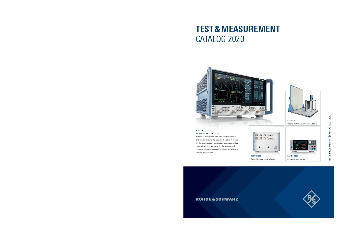
TEST & MEASUREMENT CATALOG 2020
TEST & MEASUREMENT | CATALOG 2020 | 09.00
R&S�ZNA VECTOR NETWORK ANALYZER It features exceptional stability, low trace noise and excellent raw data, making it a perfect choice for development and production applications that require high accuracy, e.g. for developing and producing components and modules for A&D and satellite applications.
�QAR Quality Automotive Radome Tester
�CMX500 Radio Communication Tester
�NGM200 Power Supply Series
TEST&MEASUREMENT CATALOG 2020
Chapter
Contents
Company profile 1 Wireless c ommunications testers and
systems
2 Oscilloscopes 3 Signal and spectrum analyzers
4 Signal generators
5 Network analyzers 6 Mobile network testing
7 EMC and field strength test solutions
8 Power meters and power sensors 9 Audio analyzers 10 Automotive test, modular instruments 11 Broadcasting test and multimedia
12 Power supplies 13 Meters and counters 14 System components
Appendix Index
Our business fields and products
Radio testers Protocol testers Conformance and preconformance testers Analog radio testers System accessories
Oscilloscopes, probes Hardware and software options, accessories
Top class, general purpose, handheld Accessories for R&S�FSx analyzers Application-specific solutions Modulation analyzers for avionics
RF vector signal generators RF analog signal generators Baseband signal generators Application-specific solutions Software solutions
Vector network analyzers Converters Accessories for network analysis
Drive and walk test scanners Benchmarking Optimization Service quality monitoring Software
EMI precompliance/compliance EMS/EMF measurements TEMPEST measurements EMC software Broadband amplifiers RF test chambers EMC accessories
Power meters, power sensors Over-the-air (OTA) power m easurement solution
Audio analyzers, audio switcher
Automotive test solutions, open test platform
RF signal generation RF signal analysis Audio/video generation Audio/video analysis
Power supplies
Multimeter, LCR meter Frequency counter, power analyzer
Open switch and control platform I/Q data recorder Step attenuator Test executive software
Service and support, trademarks
Index by type
Page
2 6
41 62
96
129 153
176
215 226 230 249
266 275 280
288 296
Company profile
Thanks to its industry-leading technological expertise, Rohde&Schwarz is a reliable partner for shaping the future of communications, information and security.
Rohde&Schwarz develops, produces and markets a wide range of electronic capital goods for industry, infrastructure operators and government customers.
The independent group is among the technology and market leaders in all of its business fields, including wireless communications and RF test and measurement, broadcast and media, air traffic control and military radiocommunications, cybersecurity and network technology.
A worldwide service and support network safeguards customer investments.
Our business fields
Test and measurement T&M instruments and systems for wireless communications, aerospace and defense, automotive, research and industrial electronics applications.
Broadcast and media Broadcast, post production and T&M equipment for network operators, broadcasters, studios, the film industry and manufacturers of entertainment electronics.
Aerospace | defense | security Communications and signal monitoring technology for armed forces and air traffic control, security products for critical infrastructures as well as T&M equipment for A&D applications.
Networks and cybersecurity Network technology for professional users as well as IT security products to protect communications and information.
2 Rohde&Schwarz Test&Measurement | Catalog 2020
TEST AND MEASUREMENT
Company profile
Test and measurement solutions for the wireless market, automotive applications, aerospace and defense, industrial electronics, research and education No industrial sector can do without electronics. Test and measurement solutions from Rohde&Schwarz are there every step of the way, from R&D to quality assurance to manufacturing and service. Our portfolio includes all types of RF T&M equipment and systems as well as complementary products.
We focus on the requirements of the mobile and wireless communications market, a market we have been closely involved with for decades, on the requirements of the automotive industry, whose added value is increasingly based on vehicles' electronic features, and on the T&M requirements of the aerospace and defense industry. Manufacturers of entertainment electronics, power electronics, RF components, IT and network equipment as well as medical technology companies and other sectors also benefit from our wide range of products.
Research and education also require an extensive portfolio of T&M equipment in various performance classes. From basic testers for training to submillimeterwave analyzers and high-power RF amplifiers for particle accelerators, the Rohde&Schwarz portfolio meets all of these requirements.
Our test and measurement portfolio
Wireless market Basic RF T&M instruments such as signal generators and
analyzers with standard-specific T&M options Wireless device RF and protocol testers for all common cellular
and non-cellular wireless communications standards Conformance and preconformance test systems Products for measuring quality in mobile networks System equipment, e.g. shielded chambers ITU-compliant radiomonitoring solutions for regulators
Automotive industry T&M equipment for infotainment, mobile communications and
wireless connectivity components T&M equipment for driver assistance systems
(radar, V2X, navigation, eCall/ERA-GLONASS) T&M equipment for onboard data buses EMC T&M equipment T&M equipment for testing the connection security of
telematics systems
Aerospace and defense Wide range of RF and microwave T&M instruments for lab and
field measurements Catalog systems and customer-specific solutions Test and measurement solutions for radar, avionics, navigation,
satellite communications and military radiocommunications Full range of EMC measuring equipment Millimeterwave and submillimeterwave components
More information | www.rohde-schwarz.com 3
Company profile
BROADCAST AND MEDIA
AEROSPACE � DEFENSE � SECURITY
Solutions for the production, processing, broadcasting, measurement and quality control of audiovisual signals Like many industries, broadcast and media has to keep pace with ongoing digitization and the shift towards inter-net based solutions. Rohde&Schwarz, an innovator in the field of broadcasting for more than 70 years, supports this transformation with groundbreaking solutions. Today, the entire signal processing chain, from camera output to transmission via the various broadcast channels, can be realized with Rohde&Schwarz products. The Rohde&Schwarz portfolio includes T&M equipment for the development, production and quality assurance of consumer electronics devices and infrastructure components as well as monitoring products for broadcast networks.
Security products for critical infrastructures At a time when crises, violent conflicts and cyberattacks regularly make the headlines, critical infrastructures and public areas need more protection than ever. Rohde&Schwarz addresses this need with products from all its different business fields. Air traffic controllers in 80 countries and at more than 200 airports and traffic management centers use our radio systems to ensure smooth air traffic. Rohde&Schwarz security scanners also provide protection in the form of efficient security checks at airports and other high-security locations.
Drones are opening up new possibilities in logistics, aerial photography and recreation. However, they can also easily be used for illegal purposes such as for industrial espionage or even violent crime. The Rohde&Schwarz drone detection system reliably detects these unwelcome onlookers so that countermeasures can be taken.
And finally, our IT security products protect IT infrastructures such as the signal lines in railway networks and control systems in supply engineering against tampering and tapping.
Our broadcast and media portfolio
TV and radio transmitters in all power classes and for all common worldwide standards
Hardware and software for professional film and video post production
Broadcast and video T&M and monitoring solutions
Security products for critical infrastructures
Radio systems for air traffic control Security scanners Radiomonitoring and direction finding systems, also specifically
for drones IT security solutions
Broadcast and media
Radio systems for air traffic control
4 Rohde&Schwarz Test&Measurement | Catalog 2020
NETWORKS AND CYBERSECURITY
SERVICES
Company profile
Solutions for business and government authorities High-performance data networks and IT components are the backbone of business and society. The volume of dormant and transmitted data is growing exponentially, driven by the digitization of all business processes, the increasing outsourcing of IT services to the cloud and the emerging internet of things.
Rohde&Schwarz operates a global service network to safeguard the investments of its customers The following services are offered locally worldwide: Calibration Maintenance and repair Product updates and upgrades Remote service over secure internet channels
Highly interconnected networks attract unwanted attention. According to the estimates of reliable organizations, cyberattacks (especially theft of intellectual property) cost the global economy hundreds of billions of dollars each year. But intangible assets are not the only assets that need protection. The large quantities of sensitive public sector data as well as personal data generated by the financial sector, the health care system and online commerce also need to be protected. Manufacturers of network components and IT security technology have to provide secure, high-performance solutions for the transmission and storage of this data.
Rohde&Schwarz offers a wide range of infrastructure components for WAN, LAN and WLAN networking as well as cybersecurity products.
Rohde&Schwarz regional service centers, plants and specialized subsidiaries provide a wide range of additional services: System integration System support Installation and commissioning Application support Development of customized modules, equipment and
systems Software development Mechanical and electrical design Manufacturing to order Technical documentation Logistics concepts
Secure radiocommunications systems
Communications intelligence systems Radar intelligence systems Satellite monitoring systems Signal and IP analysis system
Inspection of terrestrial air navigation facilities
Our network and cybersecurity portfolio
All components for secure WAN, LAN and WLAN networking Network security products, e.g. firewalls Products to protect web and cloud applications Products to protect desktop applications Secure products for mobile communications Tools for network traffic and use analysis
Networks and cybersecurity
More information | www.rohde-schwarz.com 5
Wireless communications testers and systems
CHAPTER 1 WIRELESS COMMUNICATIONS TESTERS AND SYSTEMS
To keep the backbone of mobile communications running, powerful mobile networks and mobile devices are needed. Rohde&Schwarz offers a full portfolio of wireless communications testers and systems for the complex measurements involved. The multistandard, modular and highly flexible wireless communications test solutions from Rohde&Schwarz support all main cellular communications, wireless connectivity, GNSS and broadband standards in one box. They can easily be extended to cover the latest standard enhancements. Benefit from high-speed, highprecision and exceptional flexible testing solutions � Rohde&Schwarz is the right partner to satisfy your test requirements.
6 Rohde&Schwarz Test&Measurement | Catalog 2020
Wireless communications testers and systems
Type
Designation
Description
1
Page
Radio testers 5G NR one-box solutions from Rohde&Schwarz
New R&S�CMX500
Radio communication tester
New R&S�CMPQ
Compact solution for 5G mmWave RF testing
New R&S�CMP200
Radio communication tester
New R&S�CMPHEAD30 Remote radio head
New R&S�CMQ200
Shielding cube
R&S�CMW100
Communication manufacturing test set
R&S�CMW500
Wideband radio communication tester
R&S�CMW290
Functional radio communication tester
R&S�CMW270
Wireless connectivity tester
R&S�CMW Callbox Signaling tester
R&S�CMWrun
Sequencer software tool
Overview
8
Universal test platform extension for 5G NR
10
Optimized for p roduction applications
11
Non-signaling solution for 5G mmWave RF parametric testing
12
Up/downconverter for IF mmWave
12
Compact shielding solution for 5G mmWave RF parametric testing
12
The compact RF tester for production
13
All-in-one test platform for wireless devices
14
The compact RF tester for service and IoT functional tests
16
The non-cellular expert covering WLAN, Bluetooth�, GNSS and various 18 broadcast technologies
Efficient signaling tester for the requirements of tomorrow
18
Ready-to-use solution for configuring RF and data application test
19
sequences by remote control
Protocol testers R&S�CMW500
Protocol tester
One tester for all phases of development
20
R&S�CMWcards
Signaling and application tester
Smart network emulation for all wireless device tests
21
R&S�CMWmars
Multifunctional logfile analyzer
Powerful message analyzer for all R&S�CMW applications and use
22
cases
R&S�CMW-ATE
Terminal testing solution for IMS, VoLTE and RCS Powerful test solution for network operator specific IMS services such 23 voice over LTE (VoLTE), video over LTE (IR94) and rich communication services (RCS)
R&S�CMW-PQA
Test system for performance quality analysis
Automated performance quality analysis (PQA) test solution
24
Preconformance, conformance and acceptance testers and test systems
R&S�TS8980
RF/RRM test system for LTE, WCDMA and GSM Platform for testing needs, from development to c onformance testing 25
R&S�TS-RRM
LTE, WCDMA and 5G RRM test system
Standalone platform for radio resource management (RRM) testing of 26 wireless devices in line with 3GPP LTE, 3GPP WCDMA, 3GPP 5G and operator test plans
R&S�TS-LBS
Test system for location based services
Comprehensive test solution for network and satellite-based location
27
technology testing of wireless devices and chipsets
R&S�TS8991
OTA performance test system
CTIA-compliant OTA measurements � LTE and MIMO inside
29
R&S�TS8996 R&S�TS8997
RSE test system Regulatory test system for wireless devices
Fully automatic emission measurements on wireless communications 30 equipment required for R&D and quality assurance
ETSI EN300328 V1.8.1/V1.9.1 in 2.4 GHz band, ETSI EN301893
31
V1.7.1/V1.8.1 in 5 GHz band and FCC �15.247, FCC �15.407
Analog radio testers
R&S�CMA180
Radio test set
The reference in radio testing
32
R&S�CTH
Portable radio test set
Always on duty
33
System accessories
R&S�AMS32
OTA performance measurement software
R&S�ATS800B/R
CATR benchtop/rack antenna test system
R&S�ATS1000
Antenna test system
New R&S�ATS1800C
CATR based 5G NR mmWave test chamber
R&S�DST200
RF diagnostic chamber
R&S�CMW-Z10/-Z11 RF shielding box and antenna coupler
R&S�TS712x
Shielded RF test chambers
R&S�RT-ZVC0xA
Multi-channel power probe
Over-the-air (OTA) measurements on mobile phones;
34
intermediate sensitivity and desense tests on mobile phones
5G antenna characterization in a small footprint
35
5G antenna characterization with small footprint
36
Device test and antenna characterization in a small footprint
37
Accurate radiated testing of wireless devices from 400 MHz to 18 GHz 38
Excellent shielding effectiveness and superior coupling c haracteristics 39
Reliable RF tests on devices with radio interface
39
Two-port model and four-port model
39
More information | www.rohde-schwarz.com 7
Wireless communications testers and systems
5G NR ONE-BOX SOLUTIONS FROM ROHDE&SCHWARZ
The challenges associated with 5G NR require high flexibility, end-to-end data testing solutions and reliable measurement methods. As a long-term partner of the mobile radio communications industry, Rohde&Schwarz offers a comprehensive portfolio of innovative 5G NR test solutions.
Rohde&Schwarz radio communication tester portfolio
Non-signaling (RF analyzer and generator)
LTE Advanced (plus legacy) 5G NR sub6
R&S�CMW100
Signaling (network emulation)
5G NR mmWave (plus IF)
R&S�CMPQ
R&S�CMP200
R&S�CMQ200
R&S�CMPHEAD30
R&S�CMWflexx
R&S�CMX500
R&S�CMXHEAD30
8 Rohde&Schwarz Test&Measurement | Catalog 2020
Videos
Product site
Wireless communications testers and systems
For most mobile network operators, fifth generation (5G) of mobile communications will initially be an a dditional
wide variety of combination options. The FR1 sub6 solution consists of the well-known R&S�CMW100 commu-
1
data service for transmission rates up to 20 Gbit/s. To
nications manufacturing test set and corresponding mea-
allow developers to test their mobile devices in 5G NR
surement software (see R&S�CMPQ product brochure)
non-standalone and standalone mode in line with 3GPP
specifications, the test solution must work seamlessly in One-platform strategy
both LTE and 5G NR networks.
Just like the R&S�CMW platform for LTE, Rohde&Schwarz
is sticking to the proven one-platform strategy for 5G NR.
5G signaling solutions
Both the R&S�CMP200 and R&S�CMX500 are based on
The R&S�CMX500 radio communication tester adds
this strategy. The principle of the one-platform strategy is
5G NR signaling to existing LTE test and measurement
to use the same technology, comparable hardware and
solutions. Users who already have an R&S�CMW500
the same software in all test solutions and test stages. This
or R&S�CMWflexx test system for LTE measurements
makes the test results comparable. The different test con-
can continue using it and simply add an R&S�CMX500
figurations (signaling/non-signaling) must deliver repro-
as an extension box to perform 5G NR signaling
ducibility and validated test results. Rohde&Schwarz ful-
tests. This allows them to test 5G NR use cases in
fills this requirement.
non-standalone (NSA) and standalone (SA) mode in FR1
and FR2 in accordance with 3GPP Option 3x and Option 2. The test results must provide conclusive information about
For pure 5G NR test environments in FR2, all that is
the characteristics of the DUTs without � figuratively
needed is an R&S�CMX500 radio communication tester
speaking � also testing the test solution. Rohde&Schwarz
(plus remote radio head and a shielded environment).
systems deliver accurate and consistently reproducible
test results.
5G non-signaling solutions
For 5G NR FR2 testing (mmWave), Rohde&Schwarz o ffers With the Rohde&Schwarz one-platform strategy users
the R&S�CMPQ. The R&S�CMPQ is a compact solution
ensure, that they when they finally bring their mature
based on the R&S�CMP200 radio communication tester
product to production state using R&S�CMP200
in combination with the R&S�CMPHEAD30 remote radio non-signaling test setup, they can expect same results as
head (RRH) and the R&S�CMQ200 shielding cube. The
during R&D stages when R&S�CMX500 signaling tester
instruments are matched to each other. Together they
was the test equipment.
form an easy-to-use, cutting-edge test solution with a
One-platform strategy
Signaling: sub6 + IF + mmWave
Non-signaling: IF + mmWave
Technology reuse
Same test concept
Result traceability
R&S�CMXHEAD30 R&S�CMX500
FR 1/2
Synergy effects
R&S�CMPHEAD30 R&S�CMP200
FR 2
Identical measurements
R&S�CMQ500
Identical OTA environment
R&S�CMQ200 More information | www.rohde-schwarz.com 9
Wireless communications testers and systems
R&S�CMX500 RADIO C OMMUNICATION TESTER
New
R&S�CMsquares � the powerful control center for 5G NR tests With R&S�CMsquares, users can access each measurement task in a separate measurement square. In R&S�CMsquares, the DUT is always in focus. This DUT centric approach makes it very easy to keep track of even complex test scenarios, test environments and measurement tasks. The next change is just one mouse click away.
R&S�CMsquares includes as many squares as you need: for measurements, graphical outputs and statistical views, network layout and configuration, RF connection, message analyzer, test sequencer, scripting � you name it. The R&S�CMsquares layout can always be configured to your personal preferences.
5G NR extension box to R&S�CMWflexx systems for NSA and SA modes The R&S�CMX500 hardware and software is designed to address all signaling use cases that are encountered during the lifecycle of a 5G NR mobile communications device � from the early R&D d esign stage to final integration, verification/performance testing, final product validation in a test house, quality assurance and repair.
Basic/Medium/Xpert � the new signaling concept With its Basic, Medium and Xpert signaling concept, R&S�CMX500 breaks with the traditional separation between use cases for protocol testing, RF testing and data/ performance testing. Unlike in the past where the signaling environments of e.g. RF testing and protocol testing were separated from each other and could not be accessed by the other, Basic, Medium and Xpert sit on top of each other and can be upgraded cost efficiently.
The modular hardware architecture allows configurations ranging from basic use cases such as RF parametric measurements to measurements under fading conditions and performance measurements with maximum data rates. The user always has access to all signaling events and logs.
The GUI dynamically adjusts parameter access based on the signaling option � many more parameters can be accessed with Xpert signaling than with Medium or Basic.
The Basic/Medium/Xpert signaling options build on top of each other � Xpert needs Medium, Medium needs Basic.
The R&S�CMX500 has eliminated the traditional separation between RF tester, application tester and protocol tester. It is a signaling tester that allows seamless transition between all use cases required to bring a mobile cellular device from the basic layout/design stage to the production stage. In previous tester generations, dedicated instruments were needed to address all this.
The R&S�CMX500 hardware modules are designed for versatile tasks. Users enjoy great flexibility when it comes to addressing different measurement tasks with the same test station because there are no dedicated boards for dedicated measurement tasks. With just a basic configuration, u sers are all set for signaling, fading and data E2E applications.
Its 7 HU design provides plenty of space for future extension modules � a true one-box tester.
The name of the option for an application indicates the signaling type required to operate it. For example, the "X" in the R&S�CMX-KC601X protocol conformance test package indicates that it requires the Xpert signaling functionality. Similar applications are available for "B" (Basic) and "M" (Medium) signaling.
Use cases The R&S�CMX500 is designed to cover all test requirements that may come up during the entire product lifecycle of a mobile communications device. The many components of a mobile communications device need to be independently tested on various interfaces step by step � in development, during integration when components need to work together, and in the final device. The R&S�CMX500 gives users the flexibility and versatility they need for test solutions throughout the entire product lifecycle.
10 Rohde&Schwarz Test&Measurement | Catalog 2020
Wireless communications testers and systems
R&S�CMPQ
1
COMPACT SOLUTION FOR 5G mmWave RF TESTING IN PRODUCTION
New
Validation of DUTs needs to be done in an OTA environment. All system components have to be matched exactly to get a reliable and efficient test setup. Rohde&Schwarz manufactures all system components, including the antennas, cables, feedthroughs, power sensors, remote radio head and non-signaling tester. This ensures optimal system parameters.
The split concept is a key feature of the one-box tester. The R&S�CMP200 can generate and analyze IF frequencies from 6 GHz to 20 GHz directly at the output. In higher frequency ranges, R&S�CMPHEAD30 seamlessly takes over this function.
The R&S�CMPQ is a future-proof investment. Rohde&Schwarz continually enhances the R&S�CMPQ solution with new hardware and software to meet present and future requirements and specifications.
To meet the measurement challenges of 5G device testing in the mmWave (mmW) frequency spectrum Rohde&Schwarz offers the R&S�CMPQ, a fully integrated solution from a single supplier. The R&S�CMPQ consists of the R&S�CMP200 radio communication tester, the R&S�CMPHEAD30 remote radio head and the R&S�CMQ200 shielding cube. The R&S�CMPQ provides accurate and reliable measurement results under radiated conditions.
The system concept of the R&S�CMPQ is completely flexible. The user can configure the individual devices and the system constellation independently of each other to create customized solutions for individual requirements.
The R&S�CMPQ is ideal for use in all phases of the product life cycle � from development to validation and quality assurance to production. The system is optimized for production applications. It is ultrafast, robust, reliable, cost efficient and flexible.
System software R&S�CMsquares The R&S CMsquares is a new unified test software solution with a browser-based user experience combining everything that is required for 5G NR testing. From test configuration, parameterization, measurements as well as test execution in a single environment, with a dashboard style and quick access to different types of applications, it can control all new 5G radio communication testers via a standardized GUI for a unified experience.
General purpose (GPRF) generator The ARB generator function allows users to play predefined waveforms and CW signals. Any 5G NR FR2 signals can easily be generated.
General purpose (GPRF) TX measurements A generic set of RF measurements, such as frequency selective power, FFT spectrum analyzer, I/Q versus slot, I/Q recorder and power measurement with R&S�NRPM module.
5G NR FR2 TX measurements Multi-evaluation measurement covers the full set of 5G NR FR2 measurements required by 3GPP, e.g. EVM, frequency error, equalizer spectrum flatness, in-band emission, spectrum ACLR and spectrum emission mask.
Product site
More information | www.rohde-schwarz.com 11
Wireless communications testers and systems
R&S�CMP200 R ADIO COMMUNIC ATION TESTER AND R&S�CMPHEAD30 REMOTE RADIO HEAD
New
R&S�CMP200 with R&S�CMPHEAD30 on top
Non-signaling solution for 5G mmWave RF parametric testing The R&S�CMP200 is an IF tester that combines vector signal analyzer and ARB based generator functionality. The compact integrated solution can be customized with up to three R&S�CMPHEAD30 remote radio heads (RRH), for up/downconverting signals to 5G FR2 frequencies.
The separate one-box tester and the R&S�CMPHEAD30 RRH concept allow short RF cable lengths for an optimal link budget in radiated test environments. This approach enables testing of fully assembled FR2 devices and RFICs with both IF and mmWave RF interfaces. The multi-band R&S�CMPHEAD30 covers all important FR2 bands.
Key facts of the R&S�CMP200 Ultrafast measurement speed Parallel testing of multiple DUTs IF range from 6 GHz to 20 GHz Fully automated path correction concept
Product site
Product site
R&S�CMP200 R&S�CMPHEAD30
Key facts of the R&S�CMPHEAD30 Up/downconverter for IF mmWave Integrated mmWave RF switch matrix provides two
mmWave RF paths Compact size of 250 mm � 190 mm � 30 mm Connection of up to two mmWave single-polarized
antennas Frequency range from 24.25 GHz to 31.80 GHz
and from 37.00 GHz to 43.50 GHz
R&S�CMQ200 SHIELDING CUBE New
Compact shielding solution for 5G mmWave RF parametric testing The R&S�CMQ200 is a compact and fully integrated solution to cover most 5G devices in various applications. The drawer concept enables fully automated handling in manufacturing environments. The robust mechanical design ensures millions of test cycles for reliable mass production environments. The flexible cube design covers applications for smart devices, CPEs, RFIC and prototypes. R&S�CMQ200 is ready for 5G and other technologies in the frequency range from 20 GHz to 77 GHz.
Key facts Ready for 5G and other technologies Reduced floor space: fits into 19" racks Cost-efficient for large production lot sizes: layouts with
simplified geometry Specially designed compact antennas available Antennas with special mounts and swivel heads cover
all positions of DUT antenna arrays Power sensors with CW source available
12 Rohde&Schwarz Test&Measurement | Catalog 2020
Product site
Wireless communications testers and systems
R&S�CMW100 COMMUNICATION MANUFACTURING TEST SET
1
The R&S�CMW100 together with the R&S�TS7124 RF shielded box for device testing
Production and R&D solutions for multiDUT testing The R&S�CMW100 communication manufacturing test set is a new trendsetting product for calibrating and verifying wireless devices. This follow-up to the R&S�CMW500 focuses on production and development needs. The device can be used in different phases of the R&D process (e.g. board level testing, engineering and design verification).
The R&S�CMW100 can perform receiver and transmitter tests for cellular and non-cellular technologies. Like the R&S�CMW500, the R&S�CMW100 features high measurement accuracy. The R&S�CMW100 offers parallel testing and can be used to optimize test time and capacity utilization.
The R&S�CMW100 provides high flexibility in a minimum of space. Based on a new eco-friendly hardware concept, it features extremely low energy consumption and a very compact size. The R&S�CMW100 reduces testing costs and is ideal for use in fully automated robotic production lines.
Small cell production testing The R&S�CMW500 and R&S�CMW100 can be used to calibrate and verify transceivers in small cell production lines. The use of one production line for both mobile devices and small cells provides the greatest possible flexibility.
Key facts Turnkey R&S�CMWrun based production solution for
different chipset suppliers Continuous frequency range up to 6 GHz Multitechnology solution up to 5G NR Parallel testing on up to eight RF ports High measurement performance High measurement accuracy Support of a wide range of methods for reducing test
time and maximizing capacity utilization Minimum space requirements and footprint Low weight Noise protection Dust protection High MTBF
Videos
Product site
More information | www.rohde-schwarz.com 13
Wireless communications testers and systems
R&S�CMW500 WIDEBAND RADIO COMMUNICATION TESTER
as smartphones and tablets as well as base stations. It is also an excellent platform for testing the diverse requirements of networked products in the automotive, healthcare, smart home and other IoT segments.
All-in-one test platform for wireless devices The R&S�CMW wideband radio communication tester offers universal, efficient test solutions for all modern cellular and non-cellular standards. The R&S�CMW is the world's most widely used T&M platform for development, production and service. It meets all of the requirements for a stateof-the-art wireless communication tester. The R&S�CMW can also emulate network operation under realistic conditions for protocol and RF tests.
The R&S�CMW platform offers the very latest LTE enhancements and all legacy technologies in a single compact tester, making it ideal for testing mobile devices such
The R&S�CMW500 can handle the following: LTE-A up to Cat. 20 (2 Gbps) Wireless standards and broadcast technologies,
e.g. LTE (incl. MIMO), WLAN or DVB-T and associated inter-RAT measurements All phases of development, verification and production All protocol layers, from RF tests and protocol tests to end-to-end application tests Module tests, system and integration tests, regression tests, conformance tests and production tests Multi-CMW solution for testing more complex LTE-A requirements
To adapt the R&S�CMW500 to the requirements of the application, the user simply has to select the appropriate hardware and software components.
Platform overview � preconfigured models
R&S�CMW500 The all-in-one test platform The R&S�CMW500 wideband radio communication tester is the universal test platform for RF integration and protocol development. The R&S�CMW500 includes a fully integrated end-to-end (E2E) data solution that permits comprehensive IP throughput and q uality measurements. The R&S�CMW500 can be used in all phases � from p roduct development to production to service. It is the solution with the widest range of supported technologies.
R&S�CMW290 The compact RF tester for basic functional tests The R&S�CMW290 functional radio communication tester is the cost- effective compact v ersion of the R&S�CMW500. The tester is the right instrument for users who need to measure fundamental RF characteristics or verify the functionality of wireless devices. The R&S�CMW290 provides service companies with a high-quality, customized, automated test environ ment for functional input and output tests. Powerful network emulation allows IoT/M2M system integrators to functionally test module integration and custom IP applications.
R&S�CMW270 The expert for all noncellular technologies The R&S�CMW270 wireless connectivity tester is a cost-effective alternative for development, p roduction and service. The noncellular specialist offers features comparable to those of the R&S�CMW500. It supports Bluetooth�, WLAN and broadcast technologies.
R&S�CMW100 The sub6 GHz (FR1) RF tester for production The R&S�CMW100 communications manufacturing test set is based on the R&S�CMW platform. The flexible RF interface permits simultaneous testing of up to eight RF ports. The R&S�CMW100 remote control and measurement concepts are compatible with the R&S�CMW500. Both testers use the same methods for optimizing test time and capacity u tilization. The R&S�CMW100 can be used to cost-effectively calibrate and v erify wireless devices in non-signaling mode (analyzer/generator).
R&S�CMX500 The 5G NR signaling tester The R&R�CMX500 radio communication tester is the test platform for signaling tests in all 5G frequency bands: sub6 GHz (FR1) and mmWave (FR2). In non-standalone (NSA) mode, the R&S�CMW500 supports legacy technologies in mixed operation with LTE.
R&S�CMP200 The mmWave (FR2) production tester The R&S�CMP200 radio communication tester consists of a vector signal analyzer and a generator for RF frequencies from 4 GHz to 20 GHz. Together with the R&S�CMPHEAD30 remote radio head up/downconverter for the higher frequency ranges (mmWave), it forms a compact non-signaling test platform for production testing of 5G FR2 products.
14 Rohde&Schwarz Test&Measurement | Catalog 2020
Product site
Wireless communications testers and systems
One tester for the entire product lifecycle The modular R&S�CMW platform covers all test require-
entire lifecycle � from development to certification and network optimization to production and service. An exist-
1
Use camseensts� irnadalilopchoamsems oufntihceatpiorondtuecsttlifecycle. With just one ing configuration can easily be modified to handle other
basic investment, a wireless device can be tested over its T&M tasks.
R&S�CMW platform covering the entire lifecycle of wireless devices
Systems and applications development
Protocol development
Applications certification
Protocol conformance
RF development
RF certification
Wireless device lifecycle
Applications performance and quality
Signaling performance and quality
Radio performance and quality
System application verification
Production and logistics
Service
Layer
Use of the R&S�CMW platform for wireless technologies
Technology
RF generator RF analyzer
Cellular technologies
5G NR FR1
LTE-A pro/LTE MTC
NB-IoT
WCDMA/HSPA+
GSM/GPRS/EGPRS
CDMA2000� 1xRTT,
CDMA2000� 1xEV-DO
TD-SCDMA
C-V2X
Non-cellular technologies
WLAN IEEE802.11a/b/g/n/ac/ax
Network emulation
WLAN IEEE802.11p
Bluetooth� Classic/Low energy
IEEE802.15.4 (ZigBee)
SigFox
LoRa
Broadcast technologies
GNSS (GPS, GLONASS, Beidou)
DVB-T/DAB
T-DMB
CMMB
(GPRF measurement)
(GPRF measurement)
1) Requires additional external software from partner.
Protocol testing End-to-end application testing
Fading support
(inter-RAT LTE)
1)
(offloading use cases)
More information | www.rohde-schwarz.com 15
Wireless communications testers and systems
R&S�CMW290 FUNCTIONAL RADIO COMMUNICATION TESTER
The compact RF tester for service and IoT functional tests The R&S�CMW290 is the right instrument for users who measure fundamental RF characteristics or perform Go/ NoGo checks in line with communications standards. It verifies that the frequencies and levels of the DUTs comply with specifications to ensure proper operation and that they do not interfere with other electronic devices. Since the tester supports all common cellular and non-cellular standards, both handover and coexistence tests can be performed.
The R&S�CMW290 is also the ideal solution for network emulation and functional testing of integrated wireless modules in IoT communications. Not only can users verify that the RF module was correctly installed in the system, they can also verify that the IP-based applications were correctly configured by connecting the devices client software to built-in server software or forwarding IP traffic to external servers.
Use cases Functional tests of cellular and non-cellular devices in
IoT services, reverse logistics and module assembly Calibration of cellular devices in service and reverse
logistics
Key facts Simultaneous support of all common wireless
communications standards � cellular and non-cellular up to 6 GHz on up to two channels Basic RF measurements with/without signaling and pure functional tests Configurable, simple R&S�CMWrun user interface (R&S�CMW-KT050) for efficient test sequence execution Optional: integration of manufacturer software to adjust RF modules Proven R&S�CMW quality, developed for long-term use in production environments
16 Rohde&Schwarz Test&Measurement | Catalog 2020
Videos
Product site
R&S�CMW270 WIRELESS CONNECTIVITY T ESTER
Wireless communications testers and systems
1
The R&S�CMW270 was developed to meet the specific requirements of R&D, production, quality assurance, service and network interoperability testing (IOT) - with a single, tailorable instrument. It is an ideal choice for demanding performance tests and measurements in labs and production - from IP application testing under fully controlled network conditions with a MIMO base station emulator to high-speed RF and baseband alignment with dual-tester configuration.
The non-cellular expert covering WLAN, Bluetooth�, GNSS, IEEE802.15.4 and various broadcast technologies The R&S�CMW270 is a cost-effective alternative for the development and production of equipment outside conventional cellular networks, and is specifically designed for the test requirements of internet of things (IoT) market. It is a tailored subset within the R&S�CMW500 product family. In addition to WLAN IEEE802.11a/b/g/n/ac/ax network emulation and Bluetooth� Classic/Low Energy signaling support, the R&S�CMW270 includes IEEE802.15.4 nonsignaling support plus generator and analyzer functionality.
Key facts Continuous frequency range up to 6 GHz Multiple standard RF measurements for WLAN and
Bluetooth� WLAN IEEE802.11a/b/g/n/ac/ax network emulation IP-based end-to-end test for WLAN Simultaneous uplink burst measurements during
signaling connection, PER/BER and message analyzer Bluetooth� BR/EDR/LE test mode support for pre
conformance tests Bluetooth� Classic and Bluetooth� Low Energy signaling
support for OTA tests Bluetooth� audio characteristic for HFP and A2DP General-purpose ARB generation for WLAN, Bluetooth�,
GNSS and broadcast technologies Dual-tester concept with R&S�Multi-Evaluation list
mode for speed and cost-optimized production
�CMW270 wireless connectivity tester
IEEE 802.15.4 Non-signaling RF tests ZigBee, thread and 6LoWPAN
Bluetooth� Preconformance tests for Bluetooth� Classic and Bluetooth� Low Energy Over-the-air (OTA) tests Audio characterization
�CMW270 wireless
connectivity tester
WLAN IEEE 802.11 a/b/g/n/ac/ax Signaling/non-signaling RF tests End-to-end and performance tests
Videos
Product site
More information | www.rohde-schwarz.com 17
Wireless communications testers and systems
R&S�CMW CALLBOX
RF parametric tests including fading at the user's fingertips
Efficient signaling tester for the requirements of tomorrow Short time to market and cost reduction are the perpetual goals of every developer � from chipset development to module integration. The rapid implementation of the latest wireless technologies makes the R&S�CMW callbox a must-have for every R&D lab. Complex tests can be performed easily and with high accuracy with just one contact point thanks to multi-RAT capability, including Bluetooth� and WLAN, the integrated application server and fading simulator.
R&S�CMW callbox for complex functional, mobility and IP throughput tests When it is necessary to test wireless devices under realistic conditions, examine physical RF parameters and E2E behavior or verify standard-compliant behavior of a DUT, the R&S�CMW callbox is the right solution. The R&S�CMW callbox is a base station emulator. It generates the signaling messaging and connects directly to the DUT. Depending on which technologies are emulated, a wide range of functional, mobility and fading tests can be performed on the DUT, primarily on the physical layer. Addons are available for the R&S�CMW callbox for complex IP throughput tests
Leading in LTE � always a step ahead A single R&S�CMW setup is all that is needed to easily and economically analyze 2CC up to 8CC setups. All CA scenarios can be used in either FDD or TDD or in FDD/ TDD joint operation. The R&S�CMW500 is highly flexible. LTE enhancements such as LTE-U, LTE-D, LTE-MTC and PSLTE can be rapidly deployed. To quickly develop the latest devices up to Cat21, Rohde&Schwarz offers R&S�CMWflexx, an extremely flexible high-end solution. The intuitive user interface supports users, e.g. when testing 8 DL CA up to 4x4 MIMO, including internal fading. In combination with the R&S�CMX500, even 5G NR signaling tests in non-standalone mode with LTE and other legacy technologies can be supported.
Uplink carrier aggregation is supported for up to four carriers with 16QAM, 64QAM or 256QAM.
Supported 3GPP/3GPP2 RF TRX functional tests
Technology
5G NR (EN-DC) LTE/LTE-A (FDD, TDD)
NB-IoT/eMTC
WCDMA (HSPA/HSPA+) GSM (GPRS/EGPRS) TD-SCDMA (HSPA, HSPA+) CDMA2000� 1xRTT, CDMA2000� 1xEV-DO
TX, RX and performance measurements
3GPP TS 38.521-3, chapters 6, 7
3GPP TS 36.521-1, chapters 6, 7, 8, 9 3GPP TS 36.521-1 3GPP TS 34.121-1, chapters 5, 6, 7, 9, 10
3GPP TS 51.010-1, chapters 12, 13, 14
3GPP TS 34.122-1, chapters 5, 6 3GPP2 C.S0011-D, chapters 3, 4 3GPP2 C.S0033-B, chapters 3, 4
Comprehensive complex RF signaling tests based on Bluetooth� and WLAN The R&S�CMW is the only platform to deliver all defined Bluetooth� SIG RF signaling tests in combination with other cellular technologies such as LTE-A, WCDMA, GSM, CDMA2000� and non-cellular technologies such as WLAN and GNSS. The R&S�CMWrun automation tool offers solutions for Bluetooth� BR, EDR and LE prequalification tests.
Easy testing of non-ideal signaling using the internal fading simulator To simulate fading scenarios, 3GPP has defined v arious fading profiles (pedestrian, vehicular, typical urban, high-speed train, etc.). Using the R&S�CMW platform's integrated fading simulator, the user can dynamically and individually apply 3GPP profiles for the various technologies. This one-box solution makes it easy to a ssess receiver performance under non-ideal conditions. These tests can be fully automated with the R&S�CMWrun software to check the devices' MIMO performance under fading conditions.
18 Rohde&Schwarz Test&Measurement | Catalog 2020
Videos
R&S�CMWrun SEQUENCER SOFTWARE TOOL
Wireless communications testers and systems
1
Ready-to-use solution for configuring RF and data application test sequences by remote control � for all standards supported by the R&S�CMW family The R&S�CMWrun sequencer software tool meets all requirements for executing remote-control test sequences on the R&S�CMW500 in R&D, quality assurance, production and service for both current and future wireless equipment. Typical applications are RF pre-conformance tests according to 3GPP, IP throughput test, battery life tests, video and audio (VoLTE) performance tests, coexisting tests and many more.
The software engine is based on the execution of test DLLs (plug-in assemblies). This architecture not only allows easy and straightforward configuration of test sequences without knowledge of specific remote programming of the instrument, it also provides full flexibility in configuring parameters and limits of the test items provided in the R&S�CMWrun package options for the different standards.
When the test focus is on preconformance RF testing in line with the specification rather than 3GPP validation testing, the right choice is the R&S�CMW500 RF tester, remotely controlled via R&S�CMWrun. RF preconformance testing in line with 3GPP is available for LTE, WCDMA- HSPA, GSM, CDMA2000, 1xRTT/1xEV-DO, NB-IoT and eMTC.
Using a standalone R&S�CMW500 and with just a few configuration clicks for bands, channels and bandwidth, the tool provides a comprehensive result report, giving the user a first impression of in-band compliance. This provides benefits in the very early stage of verification, before doing more complex system tests or validation.
The preconformance testing solution is available in the following standard-specific R&S�CMWrun options: R&S�CMW-KT053 WCDMA/HSPA and GSM (planned) R&S�CMW-KT054 for TDSCDMA R&S�CMW-KT055 for LTE/FDD and TDD R&S�CMW-KT058 for CDMA2000� 1xRTT/1xEV-DO R&S�CMW-KT057 for WLAN/BT Option R&S�CMW-KT052 for NB-IoT/eMTC (Cellular IoT)
R&S�CMWrun use cases
Throughput testing
3GPP
3GPP TS testing (all technologies)
Audio performance
Video analysis
Battery life testing
MIMO performance MIMO
testing
Coexistence testing
IP connection security testing
User experience testing
Preconformance testing (in-band)
R&S�CMWrun
Production and service (high-volume testing)
CDMA2000� 3GPP2 1xRTT/1xEV-DO
Bluetooth�
eCall/ ERA-GLONASS
Basic signaling with different technologies
R4
Find attenuation
R3 R3 Vin
V out
routines
Chipset support in non-signaling mode
Videos
Product site
More information | www.rohde-schwarz.com 19
Wireless communications testers and systems
R&S�CMW500 P ROTOCOL TESTER
One tester for all phases of development The R&S�CMW500 is the ideal multitechnology protocol tester, as it provides developers of wireless devices with a radio access network simulation. Equipped with powerful hardware and various interfaces to wireless devices, the R&S�CMW500 can be used throughout all phases of LTE device development � from the initial software module test to the integration of software and chipset in R&D, as well as GCF and PTCRB certification testing of conformance and performance tests of the protocol stack of 3GPP-compliant wireless devices. The R&S�CMW500 provides developers of LTE protocols with a specification-conforming reference implementation of the air interface. The comprehensive functions of the programming interfaces and the highly detailed representation in the analysis tools can be used to quickly detect discrepancies in the DUT protocol stack.
Hardware platform LTE and NB-IoT protocol tester with a layer 1 to layer 3
protocol stack implementation in accordance with 3GPP Rel. 8 to Rel. 14, incl. LTE-A features such as eCA Future-ready, powerful RF hardware that supports the 3GPP-defined LTE bandwidths from 1.4 MHz to 20 MHz and all 3GPP frequency bands up to 6 GHz For LTE-A, any combination of bands and bandwidth can be tested up to 8 carriers, incl. MIMO (R&S�CMWflexx) Data rates up to 2 Gbps downlink and 450 Mbps uplink Digital baseband fading with internal fading simulators 2x2, 4x2, 8x2, 4x4, 8x4 MIMO Multicell and multi-RAT capability for LTE and LTE-A intracell, intercell and inter-RAT handover tests (GSM, WCDMA, CDMA2000�, 1xEV-DO, WLAN incl. IEEE802.11ac/ax)
Software components Development environment for layer 1 to layer 3
signaling scenarios with automatic configuration of the layers b elow (MLAPI) for LTE, NB-IoT and WCDMA TTCN-2, TTCN-3 libraries and software tools for developing LTE signaling conformance test cases Extensive library with preconfigured messages and signaling scenarios for speeding up test development Practice-proven R&S�CMWmars software tool for carrying out, working on, automating and analyzing signaling scenarios Graphical test script tool R&S�CMWcards for simplified creation of wireless signaling tests
Protocol stack test solutions for R&D and protocol conformance
R&D/carrier acceptance tests
R&S�CMW500 protocol stacks
Protocol conformance tests
GUI-based
Scriptbased
�CMWcards test script
L3 test scenario MLAPI LLAPI
PHY test scenario
Higher-layer applications
NAS
RRC
PDCP
RLC
MAC
PHY
Higher layers Layer 3
Layer 2 Layer 1
Protocol conformance test case
DUT/UE
Rohde & Schwarz solution
20 Rohde&Schwarz Test&Measurement | Catalog 2020
Product site
Wireless communications testers and systems
R&S�CMWcards SIGNALING AND APPLICATION TESTER
1
Smart network emulation for all wireless device tests The R&S�CMWcards graphical test script definition tool lets users set up the tests they always wanted, but never had time to implement. Wireless signaling and application tests can be created on the R&S�CMW by simply setting up a hand of cards � no programming required. Revolutionary card wizards and unique game rules guide users through setting up test sequences that fully comply with test specifications. They can rapidly reproduce signaling scenarios for various wireless communications standards.
Key facts Just GUI, no programming, no code compilation Test creation, parameterization, execution and analysis
in a single tool Multicell support (up to six independent cells) Remote test execution and campaign management
with DUT automation More than 400 sample test cases included Ready to use test script packages Fine control over content of peer messages Import real network configurations using Field-to-Lab
wizard
Applications Protocol stack feature verification Regression testing Replication of field issues Roaming use cases Simulation of network failures and reject causes Data throughput and performance measurements Application tests (data, voice and video) Key performance indicator (KPI) testing
Testing scope Layer 3 signaling tests for 3GPP LTE (Rel. 8 to Rel. 14),
WCDMA, GSM and inter-RAT C-IoT tests for Cat. 1, eMTC (Cat. M1) and NB-IoT
(Cat. NB1/NB2, Rel. 14) Up to 8CC with MIMO 4x4 and DL 256QAM LBS testing with AGNSS and OTDOA LTE-U and LTE-LAA Cell selection, redirections and handovers IMS and VoLTE including call flow fallback (CSFB) and
SRVCC LTE-WLAN offload Evolved multimedia broadcast multicast service (eMBMS) Failure scenarios CMAS (WEA) and ETWS public warning system
R&S�CMWcards sample scenario for LTE inter-RAT and multicell tests
Test case simulation
Different views for parameterization and monitoring
Videos
Product site
More information | www.rohde-schwarz.com 21
Wireless communications testers and systems
R&S�CMWmars MULTIFUNCTIONAL LOGFILE ANALYZER
Powerful message analyzer for all R&S�CMW applications and use cases R&S�CMWmars is the message analyzer for all R&S�CMW signaling applications. Users can efficiently analyze recorded message logfiles and trace information on the fly in realtime while a test is running. The convenient, intuitive R&S�CMWmars user interface combined with various tools and views helps users quickly narrow down the root cause of signaling protocol and lower layer problems.
The multifunctional logfile analyzer provides access to all information elements of all protocol layers for LTE, WCDMA, GSM, TD-SCDMA, CDMA2000�, WLAN, Bluetooth�, eMTC and NB-IoT, including the IP layer. It is well-established as the standard analysis tool for customers such as chipset manufacturers, handset manufacturers and network operators as well as for device certification in test houses.
Key facts Access to all protocol stack layers of all wireless
technologies, including the IP data layer Easiest filtering thanks to optimized GUI usability Inline message and message content comparison Pass/fail view at a glance Smart UE capability view for DUT features at a glance Unique graphical timeline view for chronological
analysis Easy navigation in logfiles with powerful full-text search
features and bookmarks Realtime display of message flow (online tracing) during
test case execution Effective graphical protocol measurement charts for
throughput and BLER measurements on all layers Postprocessing (offline analysis) of recorded message
logs Powerful scripting interface for automatic logfile
analysis using predefined macros
R&S�CMWmars message logfile for a WLAN offload measurement
High-level message flow
Detailed message flow
Decoded information elements
22 Rohde&Schwarz Test&Measurement | Catalog 2020
Throughput measurements on all protocol layers
Bit analysis of information elements
Relationship of messages within protocol stack
Videos
Wireless communications testers and systems
R&S�CMW-ATE TERMINAL TESTING SOLUTION FOR IMS, VoLTE AND RCS
1
Powerful test solution for network operator specific IMS services such as voice over LTE (VoLTE), video over LTE (IR94) and rich communication services (RCS) Network operator-specific (NetOp) test case packages
for operator acceptance and certification testing GSMA IR.92 and IR.94 compliant IMS, VoLTE, SMS over IMS, IMS E911 emergency calls
and RCS (rich communication services) protocol testing of wireless devices and chipsets using different RATs up to 5G Support of various network operator-specific IMS and VoLTE test plans (NetOp) such as Verizon Wireless, AT&T, T-Mobile US, Docomo and CMCC, Deutsche Telekom and America Movil Wireless device testing for all current and future IP multimedia subsystem (IMS) functionalities P-CSCF discovery (PCO/DHCP/DNS) �� IMS registration and re-registration �� IMS authentication and re-authentication �� MO/MT calls (MTSI speech and text calls) �� Session handling �� Supplementary services �� MO/MT SMS over IMS �� Emergency calls over IMS (with and without
positioning) �� RCS (rich communication services): one to one chat,
group chat, file transfer and more
Intuitive GUI �� Easy and fast configuration of test cases with R&S�CONTEST sequencer software �� Fast and flexible test plan creation �� Fast and easy changing of parameters
Powerful reporting �� Fast and thorough problem analysis through visualization of message flow �� Automatic pcap file generation for typical IP-based analysis �� IMS-centric verdict presentation in XML log files �� Report with pass/fail verdict for seeing results at a glance
Flexible and scalable solution �� Upgradeable for LTE and NR protocol testing �� Upgradeable for R&S�CMW-PQA VoLTE performance testing under realistic network conditions �� Upgradeable for audio quality tests with the R&S�UPV audio analyzer, supporting audio analysis with established mechanisms �� Upgradeable for location based services (LBS) and SUPL 2.0 testing
Fully automated test system
Product site
More information | www.rohde-schwarz.com 23
Wireless communications testers and systems
R&S�CMW-PQA TEST SYSTEM FOR PERFORMANCE QUALITY ANALYSIS
Wireless device users are promised ever higher data rates. However, users are not just interested in the data rate. What they care about most is the quality of the service they are using on their wireless devices. This is why the R&S�CMW-PQA offers a variety of end-to-end data throughput measurements and above all, can reliably measure the quality of services such as webpage loading and video performance.
Automated performance quality analysis (PQA) test solution The R&S�CMW-PQA is the test solution for benchmarking and optimizing the performance of chipsets and wireless devices.
The R&S�CMW-PQA makes it possible to measure endto-end data throughput, call and mobility performance and the quality of services, such as video performance, on chipsets and wireless devices under realistic network conditions. It supports various network operator specific throughput and performance test plans and customized test plans can be created quickly and easily. As a result, the performance of chipsets and wireless devices can be tested under realistic conditions throughout the development process up to approval and bottlenecks during implementation can be identified.
Network operators place strong emphasis both on ensuring customer satisfaction and on simplifying network planning. Self-organizing networks (SON) and one of their features (ANR, automatic neighbor relation) represent a first step toward simplifying network optimization. As a result, wireless devices are faced with new requirements, whose fulfillment must be checked. The R&S�CMW-PQA is a platform for call and mobility performance measurements on wireless devices.
Explore the performance of chipsets and wireless devices from an end-user perspective for numerous technologies (WCDMA, HSPA+, LTE, LTA-A)
Identify bottlenecks in the wireless device's/chipset's implementation from application down to physical layer
Evaluate call and mobility performance of chipsets and wireless devices
Measure the quality of services such as webpage loading and video performance
Supports throughput and performance test plans of major network operators
The R&S�CMW-PQA is a test solution for measuring the performance of chipsets and wireless devices under realistic conditions. It simulates the complex network conditions, such as noise, fading and IP impairments, that wireless devices are exposed to in the real world. This is the basis for a variety of throughput and performance measurements.
Specifications in brief
Supported technologies Overview of test methods Throughput measurements
Call and mobility performance measurements
direction data sources
Quality of service measurements
LTE-A, LTE, WCDMA/HSPA+
uplink, downlink, bidirectional, alternating iPerf UDP, iPerf TCP, ftp, http call retainability, call accessibility, UE measurement reporting, ANR measurement reporting, reject cause handling video quality, webpage loading
24 Rohde&Schwarz Test&Measurement | Catalog 2020
Videos
Product site
Wireless communications testers and systems
R&S�TS8980 RF/RRM TEST SYSTEM FOR 5G NR, LTE, WCDMA AND GSM
1
test cases on the same platform. Either in combination with legacy technologies or stand-alone.
Scalable R&S�TS8980 setups for different requirements Full conformance/precompliance tests in line with
�� 3GPP TS 38.521-1/2/3/4 (5G NR with NSA&SA) �� 3GPP TS 36.521-1 (LTE-A Pro, NB-IoT, M1) �� 3GPP TS 34.121-1 (WCDMA) �� 3GPP TS 51.010-1 (GSM) Conducted regulatory tests in line with �� ETSI EN 301 908 25 for 5G NR �� ETSI EN 301 908 13 for LTE �� ETSI EN 301 908 2 for 3G �� ETSI EN 301 511 for 2G Supplementary network operator tests (AT&T, Verizon Wireless, etc.)
Future-proof architecture � tailored to suit customer needs 5G certification in FR1 (sub-6GHz) and FR2 (mmWave) TX, RX, demodulation&radio resource management EN-DC, CA, margin search and parallel testing
R&S�CONTEST software platform Advanced sequencer tool for all technologies Fully automated runtime optimization Debugging with breakpoints, step-by-step execution Easy-to-use graphical parameterization of test cases Online report with status of progress and pie chart Test results in HTML, XML or CSV format Internal and external database access
Leading platform for 2G, 3G, 4G and 5G testing The R&S�TS8980 is the most compact full range conformance testing solution on the market for testing in line with requirements from GCF (global certification forum), PTCRB and regulatory bodies (ETSI). It supports the entire device certification process for RF and RRM, covering the widest range of technologies including 5G NR, LTEAdvanced, WCDMA and GSM.
It is modular and fully automated for RF transmitter, receiver and performance measurements. The scalable hardware and software allows cost-efficient testing solutions and can be configured for design verification, precompliance or final type approval testing.
The R&S�TS8980 integrates seamlessly R&S�CMX mmWave transceivers, IF units and over-the-air test chambers like the R&S�ATS1800C to support 5G FR2 (mmWave)
Consistent RF tests from R&D to conformance The R&S�TS8980 test system family covers the widest range of applications on the market. Customers can rely on consistent test results from R&D stages all the way to final conformance tests.
Precise and reproducible measurement results The fully automated path calibration used in the R&S�TS8980 test system and high-speed self-test mechanisms deliver maximum accuracy and reproducibility of measurement results.
Low cost of ownership and quick results Scalable configurations ensure an optimum match of budget and functionality, starting with the R&S�TS8980S. Selected instruments can be configured to require external calibration only every 2 years. The system is designed for 24/7 operation to maximize return on investment. Short test case run times help to minimize time to market.
Videos
Product site
More information | www.rohde-schwarz.com 25
Wireless communications testers and systems
R&S�TS-RRM LTE, WCDMA AND 5G RRM TEST SYSTEM
Scalable platform for different technologies, covering the various test needs that arise in R&D, conformance and network operator acceptance testing
Automated for faster test runs and reduction of test time
Runs on R&S�CONTEST platforms such as the R&S�TS8980
Standalone platform for radio resource management (RRM) testing of wireless devices in line with 3GPP LTE, 3GPP WCDMA, 3GPP 5G and operator test plans The R&S�TS-RRM LTE and WCDMA RRM test system is a test solution for running WCDMA, LTE, inter-RAT RRM and 5G test cases on wireless devices. It is the perfect solution for the entire mobile station development lifecycle. The R&S�TS-RRM is a fully automated conformance test system prepared for running validated RRM conformance test cases in the design, precertification and type approval of wireless devices. In addition to the RRM test cases required by GCF/PTCRB, the R &S�TS-RRM also supports network operator specific RRM tests.
Key facts R&S�TS-RRM testing of radio resource management
technologies in 3GPP TS 36.521-3 (LTE), 3GPP TS 34.121-1 (WCDMA) and 3GPP TS 38.533 (5G) devices and chipsets Coverage of RRM conformance and network operator specific test plans Reusable for LBS OTDOA/eCID
Supported technologies WCDMA single mode WCDMA inter-RAT to GSM LTE single mode LTE inter-RAT to WCDMA, GSM, CDMA2000� and
TD-SCDMA 5G EN-DC (NSA) FR1 (sub-6GHz) and FR2 (mmWave) 5G NR (SA) FR1 (sub-6GHz) and FR2 (mmWave) 5G and FR2 (mmWave) 1xAoA and 2xAoA Network operator specific tests for AT&T and Verizon
Different setups R&S�TS-RRM standard setup: supports single-mode
test cases for GCF and PTCRB with almost 100% of GCF priority 1 release 8 test cases and about 70% of all GCF test cases as well as RX diversity and MIMO R&S�TS-RRM advanced setup: supports 100% of all GCF and PTCRB test cases as well as RX diversity and MIMO R&S�TS8980FTA in combination with R&S�TS-RRM: for multibox test cases supporting 100% of all GCF and PTCRB test cases as well as RX diversity and MIMO
Configuration examples
�TS-RRM advanced setup 26 Rohde&Schwarz Test&Measurement | Catalog 2020
�TS8980FTA and �TS-RRM
Product site
Wireless communications testers and systems
R&S�TS-LBS TEST SYSTEM FOR LOCATION BASED SERVICES
1
Comprehensive test solution for network and satellite-based location technology testing of wireless devices and chipsets The R&S�TS-LBS test system family is highly configurable for testing different location technologies of user equipment (UE) and chipsets.
The R&S�TS-LBS represents the second generation of Rohde&Schwarz LBS test systems. It fulfills the requirements for LBS conformance testing and operator acceptance testing on GSM, WCDMA, LTE and 5G devices and chipsets.
The R&S�TSLBS provides complete LBS test coverage through all phases
A-GNSS minimum performance
LBS protocol conformance
Networkbased positioning OTDOA/eCID
Operator acceptance field-to-lab
LBS hybrid
5G NR
Indoor positioning
LBS development features
A-GNSS OTA
LTE A-GNSS
WCDMA A-GNSS
GSM A-GPS
3 const. GNSS
OMA SUPL2.0 TTCN3
LTE LPP FDD/TDD C-plane
WCDMA RRC C-plane
GSM RRLP C-plane
LTE FDD OTDOA eCID Interband OTDOA
CA OTDOA
NB-IoT eMTC
Verizon AT&T T-Mobile DoCoMo Softbank CMCC Sprint
LTE A-GNSS OTDOA
LTE A-GNSS hybrid
Position calculation
5G NR FR1 NSA
5G NR FR1 SA
5G NR FR2 NSA
5G NR FR2 SA
WLAN Bluetooth� Barometric LPPe LPP R13 MBS ToF/TOA
Margin search PEM mode User def. scenarios OTDOA/ eCID R&D
LBS receiver testing GPS GLONASS BeiDou GALILEO
Verizon LTE GPS
CTIA 3.4 LTE A-GNSS
RED EN 303 413 L1+L2/L5
Adjacent frequency band Receiver spurious emissions
Videos
Product site
More information | www.rohde-schwarz.com 27
Wireless communications testers and systems
Location based services (LBS) testing of satellite, cellular and hybrid-based location technologies Coverage of 3GPP minimum performance, signaling
conformance (C-plane, U-plane) and network operator specific test plans Scalable platform for different technologies, covering various test needs that arise in R&D, conformance and network operator acceptance testing Automated for faster test execution and reduction of test time �� Automation of DUT for minimum manual
intervention during test runs �� Fully automatic path calibration routines that run
with minimum manual intervention
Supported technologies Support of satellite, cellular and hybrid-based location technologies in UE and chipsets Support of GNSS-based LBS
�� 3GPP minimum performance �� Protocol conformance �� Operator test plans �� OTA LBS �� 5G EN-DC (NSA) A-GNSS �� 5G NR (SA) A-GNSS Support of cellular network-based LBS (requires the R&S�TS-LBS advanced hardware platform) �� LTE OTDOA/eCID for LTE �� Operator test plans Support of hybrid location technologies �� GNSS and OTDOA/eCID
Support of indoor positioning �� WLAN, Bluetooth�, Barometric, terrestrial beacon �� LPPe, LPP R13 �� ToF/TOA
Different setups Scalable and flexible test system family suitable for applications ranging from R&D to conformance testing of GSM, WCDMA, LTE and 5G user equipment (UE) and chipsets Modular hardware and software depending on
individual test requirements Scalable hardware and software allowing cost-efficient
R&D solutions Availability of upgrade paths for preconformance and
full conformance testing Upgradeability to R&S�CMW-PQA test system for
performance quality analysis Upgradeability to R&S�TS-RRM test system for radio
resource management
R&S�CONTEST software platform Intuitive GUI and powerful reporting capabilities Debugging capabilities: breakpoints, step-by-step
execution Easy-to-use graphical parameterization of test cases DUT services including graphical antenna
configurations Online report with status of progress and pie chart for
overview Summary report with filter for report explorer Test results in HTML, XML or CSV format and internal
and external database access
R&S�TS-LBS on different platforms
GNSS testing (24 channels)
OTDOA + eCID (entry point)
5G NR extension
�TS-LBS-NR
�TS-LBS advanced (�TS-RRM advanced, (�CMW-PQA CA setup)
�TS-LBS advanced (3GPP A-GNSS + NetOP)
LBS OTDOA/eCID, 5G LBS A-GNSS LTE/WCDMA/GSM Support by means of R&S�CONTEST
28 Rohde&Schwarz Test&Measurement | Catalog 2020
�TS8991 OTA performance test system + �SMBV100B
R&S�TS8991 OTA PERFORMANCE TEST SYSTEM
Wireless communications testers and systems
1
CTIA-compliant OTA measurements Over-the-air (OTA) measurements are an essential part of the certification testing of wireless devices that require an omnidirectional antenna radiation pattern. The R&S�TS8991 OTA performance test system measures the spatial radiation and sensitivity characteristic as specified by CTIA and 3GPP.
The R&S�AMS32 system software provides ready-to-use test templates for OTA measurements and supports all common wireless standards. The integrated report function collects all measured test data such as graphics or numeric results, test environments, EUT information and hardware setup in one document.
In cooperation with Albatross Projects, a world-leading provider of solutions for RF chambers, various models of wireless performance test chambers (WPTC) were created.
Key facts Measurement of OTA performance in line with CTIA,
Wi-Fi Alliance, CWG, PTCRB standards and test cases For all major cellular and non-cellular technologies,
including A-GPS Time-optimized, configurable test sequences for
qualification and development, based on R&S�AMS32 system software Can be combined with radiated spurious emission and EMC test systems Turnkey solution with test instruments, system software, WPTC anechoic test chamber, OTA chamber and EUT positioner Passive antenna measurements with near field to far field transformation Specific system configurations for 5G OTA measurements
WPTC model overview
Model
WPTC-XS
Outer dimensions of shielding panels (W � H � D)
2.43 m � 2.40 m � 2.43 m (7.97 ft � 7.87 ft � 7.97 ft)
Frequency range of test chamber
0.6 GHz to 87 GHz
Typical range length CTIA-compliant
> 0.65 m (2.2 ft) � (R&D)
WPTC-S 3.70 m � 3.00 m � 3.10 m (12.14 ft � 9.84 ft � 10.17 ft)
0.6 GHz to 87 GHz
WPTC-M 4.60 m � 3.45 m � 3.70 m (15.09 ft � 11.32 ft � 12.12 ft)
0.6 GHz to 67 GHz
WPTC-L
5.20 m � 4.05 m � 4.30 m (17.06 ft � 13.29 ft � 14.12 ft)
0.4 GHz to 50 GHz
WPTC-XL
5.80 m � 5.10 m � 5.20 m (9.03 ft � 16.73 ft � 17.06 ft)
0.4 GHz to 50 GHz
> 1.02 m (3.3 ft) � (R&D)
> 1.30 m (4.3 ft) �
> 1.38 m (4.5 ft) �
> 1.83 m (6.0 ft) �
Product site
More information | www.rohde-schwarz.com 29
Wireless communications testers and systems
R&S�TS8996 RSE TEST SYSTEM
Fully automatic emission measurements on wireless communications equipment required for R&D and quality assurance The R&S�TS8996 RSE test system is used for EMI and spurious emission measurements on wireless communications equipment during EMC and type approval testing. Typical DUTs are mobile phones, base stations, radio sets and short-range devices.
The relevant standards stipulate a wide variety of measurements in a very wide frequency range, all of which can be covered with the R&S�TS8996. For some radiocommunications systems (i.e. short-range devices), higher frequency limits (i.e. 40 GHz) are stipulated for spurious emission measurements. The R&S�TS8996 can be easily adapted to customer requirements.
The modular design of the R&S�OSP-F7x filter unit for carrier frequency suppression allows flexible configuration and easy expansion for various frequency bands. For measuring radiated spurious emissions from radiocommunications equipment, filter configurations for the following technologies have been prepared: GSM, Bluetooth�, WLAN, WCDMA (UMTS).
LTE is supported with the R&S�OSP-B155 plug-in module in combination with the R&S�EMC32-K26 software option. It enables radiated spurious emission measurements of all LTE bands and bandwidths with one compact unit.
In the vicinity of the carrier the signal is shifted in the ideal dynamic range of the test receiver for measurement of spurious in the presence of the carrier.
Key facts Frequency range from 30 MHz to 18 (40) GHz Radiated measurements in line with ETSI EN301489,
FCC part 15 and 3GPP TS51.010 standards Conducted spurious emission measurements from
100 kHz to 12.75 GHz on antenna connector of DUT Measurement of spurious emissions from
radiocommunications equipment
System software The R&S�EMC32 software enables fully automatic simple testing. The R&S�EMC32-K2 option offers special features: Automatic setup and control of wireless link Control of different 3D DUT manipulators ERP/EIRP measurement Automatic suppression of carrier signal
The predefined test sequences allow a high degree of automation. Users are freed from tedious extra work and incorrect settings or signal connections can be avoided right from the start. Our product managers assist customers with option selection and system configuration.
Filter unit
Typical test system �TS8996 for radiated spurious emissions
Radiocommunications tester
Filter unit
EMI receiver
PC with �EMC32
Controller mast/TT
Circular polarized communication antennas
Anechoic chamber
DUT 3D turn device
30 Rohde&Schwarz Test&Measurement | Catalog 2020
Product site
Wireless communications testers and systems
R&S�TS8997 REGULATORY TEST SYSTEM FOR WIRELESS DEVICES
1
For compliance with ETSI EN300328 in 2.4 GHz band, ETSI EN301893 in 5 GHz band and FCC�15.247, FCC�15.407 All wideband transmission systems in the 2.4 GHz and 5 GHz bands must be tested to verify compliance with ETSI EN300328 (2.4 GHz band), ETSI EN301893 (5 GHz band) and FCC �15.247, FCC �15.407. The latest versions of these standards require the use of special automated test procedures and test equipment. The R&S�TS8997 fully meets these requirements. Measurements are performed using the R&S�EMC32 software platform, which is the standard solution in EMC test labs. The key components in the test system are the R&S�WMS32-Kxx options and the R&S�TS8997 specific R&S�OSP modules, which provide power measurement and path switching. A menu-driven navigation system guides users through the multistage measurements as required for the technology used and the characteristics of the device under test (DUT). The test system supports all measurements required by the standards, even for complex DUTs such as those featuring up to eight antenna ports or adaptive hopping.
The R&S�TS8997 measures the technologies typically used in wideband wireless devices, i.e. devices with a radio interface, in the 2.4 GHz and 5 GHz bands: WLAN IEEE802.11a/b/g/n/ac Bluetooth� Wireless video transmission Radio remote control
Key facts Fast wideband power measurement that exceeds
ETSI requirements Support for DUTs with up to eight antenna ports Menu-driven, automatic measurements based on radio
technology selected by the user Measurements via RF connection or antenna coupler Tested R&S�WMS32 GUI and software structure Automatic switching of test paths up to 40 GHz with
R&S�OSP-B157WX
Block diagram of the �TS8997 8-port test system
R&S�TS8997
R&S�OSP-B157W8
Power detector
Power detector
Power detector
R&S�WMS32-Kxx
Data sampling
Power detector Power detector
R&S�FSV signal and spectrum analyzer
R&S�SMB100A
RF
RF and microwave
signal generator
Power detector Power detector Power detector
R&S�SMBV100A vector signal generator
RF signal conditioning
�TS8997 test system with eight ports for up to eight DUTs
DUT 1) DUT 1) DUT 1) DUT 1) DUT 1) DUT 1) DUT 1) DUT 1)
For self-test and calibration
R&S�CMW wideband radio communication tester
LAN and USB
RF cable
1) Not included in test system.
Product site
More information | www.rohde-schwarz.com 31
Wireless communications testers and systems
R&S�CMA180 RADIO TEST SET
waveforms from software defined radios (SDR), and then loaded into the R&S�CMA180 and replayed. The advanced and efficient user interface makes it easy to learn to use the R&S�CMA180. Users can quickly reach all settings and easily perform measurements. Measurement results are clearly and conveniently displayed.
The reference in radio testing The R&S�CMA180 is a radiocommunications tester for radio systems that operate in the 100 kHz to 3 GHz range. Its technology is based fully on digital signal processing and advanced computing. Intuitive operation and efficient measurement capabilities make the R&S�CMA180 an indispensable tool for performing radio measurements.
The R&S�CMA180 demodulates and modulates all common analog RF signals, making it ideal for testing transmitters and receivers. For receiver tests, audio signals from the internal generators or from external sources can be modulated onto the RF carrier. The audio signals demodulated by the device under test (DUT) are fed into the R&S�CMA180 via analog or digital inputs and then analyzed. For transmitter tests, the R&S�CMA180 demodulates the received signal and measures the demodulated audio signal and the RF signal. The test set now also incorporates a digital signal generator and analyzer that can be used to carry out digital receiver and transmitter measurements.
Using the ARB generator, users can play back nearly any type of signal. These signals can be generated with MATLAB� or R&S�WinIQSIM2TM, including proprietary
The optional ILS, VOR and marker beacon generator as well as VoIP support in line with EUROCAE ED137B make the R&S�CMA180 invaluable for air traffic control (ATC) and radio navigation. The R&S�CMA180 can be powered by batteries, making it independent and portable. Results are displayed in a straightforward manner, and the graphical user interface is easy to operate.
Key facts Frequency range from 100 kHz to 3 GHz Analog modulation and demodulation (CW, AM, FM) Up to 150 W peak input power and up to
100 W continuous input power Signal level for receiver measurements
can be lowered to �140 dBm Integrated audio generators Audio quality tests (SINAD, THD, SNR) Integrated sweeping spectrum analyzer, tracking
generator and scope Use of R&S�NRP and R&S�NRT power sensors,
no configuration required I/Q recorder and ARB generator Digital signal analysis ILS, VOR and marker beacon generator VoIP in line with EUROCAE ED-137B for ATC radios Digital receiver and transmitter measurements
Applications in the R&S�CMA180 frequency range
30 MHz
300 MHz
VHF
UHF
3000 MHz
30
145
443
32 Rohde&Schwarz Test&Measurement | Catalog 2020
868
2400 MHz
Product site
R&S�CTH PORTABLE RADIO TEST SET
Wireless communications testers and systems
1
Robust and shockproof The compact aluminum enclosure is rugged and very solid. The corners are rubber-reinforced, making the test set ideal for outdoor use.
Splashproof Enclosure, battery compartment, keypad and display are absolutely splashproof. As a result, the R&S�CTH is ideal even for operation under poor weather conditions.
Wide temperature range All of the components are designed so that the R&S�CTH can be used over a wide temperature range. This means that the R&S�CTH is the ideal companion for all seasons and climate zones.
Ergonomic operation All of the buttons are easy to operate. Plus, the test set is designed for operation with a single hand, providing equal convenience to both right-handed and left-handed users.
Always on duty The R&S�CTH allows dependable testing of analog FM radio systems even under challenging environmental conditions. The radio test set was designed especially for outdoor use. Ensuring the smooth functioning of transceivers is the key to successful communications. The R&S�CTH performs this type of work without requiring expert knowledge. The user can simply connect the device under test (DUT) to the R&S�CTH and immediately begin transmitter and receiver measurements.
The R&S�CTH includes all the measurement functions needed for reliable testing of transceivers. The measurement results are clearly presented on a display that is optimized for outdoor use so the measured values are easily readable even under difficult lighting conditions.
Model overview
R&S�CTH100A
Transmitter measurements
Forward power
�
Reflected power
�
VSWR
Frequency counter
�
FM receiver measurements
Squelch
�
Demodulation
�
Additional measurements
Over the air
�
Distance to fault
�
Voice reporting
�
R&S�CTH200A
� � � �
� �
� � �
With its high measurement accuracy and straightforward operation, the R&S�CTH delivers u nrivaled performance and functionality for its class.
R&S�CTH100/R&S�CTH200A � the handy analog radio test set
Key facts Frequency measurement Power measurement Over-the-air measurement (R&S�CTH200A) Distance-to-fault measurement (R&S�CTH200A) Voice reporting (R&S�CTH200A) Handy and ergonomic Rugged and all-weatherproof
Product Site
More information | www.rohde-schwarz.com 33
Wireless communications testers and systems
R&S�AMS32 OTA PERFORMANCE MEASUREMENT SOFTWARE
Key features Over-the-air (OTA) measurements on mobile phones Intermediate sensitivity tests on mobile phones Desense tests on mobile phones Passive antenna measurements Conducted and radiated tests MIMO OTA measurements, Rohde&Schwarz
decomposition method (options required) Path loss and range calibration Ripple test in line with CTIA Anechoic chamber validation in line with 3GPP and
WMF R&D and viewer modes Sequencer (ability to run multiple tests in sequential
order with little or no user interaction) Configuration through intuitive GUI
Standards CTIA 3.5.2 or higher 3GPP TS 34.114 Verizon Wireless proprietary standards
Measured parameters Total radiated power (TRP) Near-horizon partial radiated power (NHPRP)
(at different angles, upper and lower hemisphere) Total isotropic sensitivity (TIS) Near-horizon partial isotropic sensitivity (NHPIS)
(at different angles, upper and lower hemisphere) Antenna gain, efficiency, directivity
Reporting HTML, RTF, PDF 3D graphics
34 Rohde&Schwarz Test&Measurement | Catalog 2020
Wireless communications testers and systems
R&S�ATS800B/R CATR BENCHTOP/RACK ANTENNA TEST SYSTEMS
1
New
R&S�ATS800B CATR benchtop antenna test system
5G antenna characterization in a small footprint The R&S�ATS800B/R antenna test systems are the ideal environment for 5G antenna, module and device characterization throughout the entire process from R&D to design verification � for both active and passive devices.
Thanks to their compact design, the R&S�ATS800B/R support far-field over-the-air RF measurements in labs of any size. They help optimize the overall RF performance of RF modules in the early phases of development. This prevents costly and time-consuming modifications for a large number of prototypes at a later stage. Over-the-air RF testing during development reduces costs and keeps the product launch on schedule with a faster time to market.
State-of-the-art reflector surface precision for high quiet zone accuracy
Unique benchtop or rack CATR system supporting over 50 GHz
Automated high-precision 2D positioner (optional) Indirect far-field method � approved by 3GPP for 5G
OTA testing
R&S�ATS800R CATR rack antenna test system
One-stop-shop solutions combining the R&S�ATS800B/R with a Rohde&Schwarz test system ensure fast and smooth measurements in the lab and provide optimized capabilities for determining a 5G device's antenna performance and characteristics in the millimeterwave range.
In summary, the R&S�ATS800B/R antenna test systems are convenient and accurate solutions for testing 5G modules in the new 5G millimeterwave frequency bands in a compact benchtop or rack setup.
Key facts Very compact far-field over-the-air (OTA) test systems
based on compact antenna test range (CATR) technology Unrivaled measurement frequency range within 0.8 m2
Product site
More information | www.rohde-schwarz.com 35
Wireless communications testers and systems
R&S�ATS1000 ANTENNA TEST SYSTEM
Passive (magnitude and phase) and active (TRP, EiRP, TIS, EiS, EVM) antenna measurements
Near-field to far-field transformation with the R&S�AMS32 test measurement and control software
Device characterization under extreme temperature conditions from �40�C to +85�C
One-stop-shop for 5G devices measurements: R&S�ATS1000 chamber, R&S�AMS32 software, test instruments
NF to FF transformation with the R&S�AMS32 test measurement and control software
Extremely fast measurements with spiral scan (dual axis rotation)
Extremely fast and accurate 3D antenna characterization
5G antenna characterization with small footprint The R&S�ATS1000 antenna test chamber is the ideal environment for 5G antenna characterization throughout the entire process from R&D to production for both active and passive devices. Due to its compact design, the R&S�ATS1000 supports far-field and near-field antenna measurements inside any R&D lab space. The mobile chamber helps to optimize the overall RF performance of antenna modules already in the initial phases of development. This avoids costly and time-consuming modifications for a large number of prototypes at a later stage. Antenna testing during development reduces costs and keeps the product launch on schedule with a faster time to market.
Thermal effects diagnostics on DUTs is becoming a requirement for 5G since device heating can affect the RF components and consequently the radiation pattern of the antennas. Engineers no longer need to depend on separate testing in an RF OTA chamber and a climatic chamber because the R&S�ATS1000 thermal solution combines both into a single chamber.
Key facts Extremely fast and accurate 3D antenna
characterization Designed for maximum compactness and mobility:
includes wheels and easily fits next to a 19" rack Frequency range from 18 GHz to 87 GHz Greater than 50 dB shielding effectiveness up to 87 GHz Broadband measurement antenna from 4 GHz to
87 GHz with very low radar cross section
36 Rohde&Schwarz Test&Measurement | Catalog 2020
R&S�ATS1000 with an integrated high- precision positioner
Product site
Wireless communications testers and systems
R&S�ATS1800C CATR BASED COMPACT 5G NR mmWave TEST CHAMBER
1
New
The compact setup of the R&S�ATS1800C can act as your best assistant from R&D to product validation. At early stages, it can help improve the overall performance of RF modules, greatly reducing the risk of costly and time-consuming modifications of prototypes at later stages. During design optimization, specific beam characterization can be measured to verify the beamforming capabilities of modules and devices.
5G NR compliant device test and antenna characterization in a small footprint The R&S�ATS1800C CATR based compact 5G NR mmWave test chamber is fully shielded from the outside world to provide the ideal environment for uninterrupted measurements of 5G antenna, module and device characterization throughout the entire lifecycle from R&D to conformance for both active and passive measurements.
Key facts Very compact and mobile far-field over-the-air (OTA) test
system based on compact antenna test range (CATR) technology State-of-the-art CATR reflector with optimized edges for uniform power distribution and high-precision surface finishing for minimal deviations in quiet zone Very high frequency range, including 5G frequency range 2 (dependent on CATR feed antenna) High shielding effectiveness of 100 dB Large, 3GPP compliant quiet zone Highly accurate spherical 3D positioner with built-in hardware triggering functionality for significantly shorter test times Suitable for conformance testing as specified by 3GPP as well as CTIA antenna performance testing and device beam characterization
R&S�ATS1800C interior view
Inside the fully shielded chamber is the compact antenna test range (CATR) consisting of a feed antenna, a bidirectional parabolic reflector and a 3D positioner. The parabolic reflector is specially designed and manufactured by Rohde&Schwarz with optimized rolled edges that promise a well distributed power of the collimated beams after reflection. Moreover, the reflector has an extremely highprecision surface roughness, which minimizes the errors introduced by the reflection. This allows the reflector to be used in a very wide frequency range for accurate measurement results.
Due to the CATR technology, the generated quiet zone is 30 cm to accommodate both a black box measurement approach and large DUTs. Heavy DUTs can be placed on the highly accurate and stable 3D positioner so that parameters such as TRP, EIRP and EIS can be automated and measured. The stability and device weight specifications of the positioner also allow for CTIA frequency range 2 (FR2) antenna performance tests where phantom heads and hands are to be used.
More information | www.rohde-schwarz.com 37
Wireless communications testers and systems
R&S�DST200 RF DIAGNOSTIC CHAMBER Compared to applications using large EMC anechoic chambers, test setups with the R&S�DST200 are compact and easy to use and generate consistent, comparable results.
Accurate radiated testing of wireless devices from 400 MHz to 18 GHz The R&S�DST200 RF diagnostic chamber is the ideal environment for RF analysis during development. It supports a wide range of radiated test applications for wireless devices and fits on any R&D lab bench, where it can be used at all times during the product design and optimization phase. The R&S�DST200 effectively assists in achieving high first-time pass rates during final type approval, which saves time and money.
Anechoic RF chamber with highly effective shielding > 110 dB for interference-free testing in unshielded environments
Wide frequency range from 400 MHz to 18 GHz covering all important wireless standards
High reproducibility of measurements due to excellent field uniformity at location of equipment under test (EUT)
Compact dimensions suitable for any lab environment Unique mechanical design provides long-term stability
and maintains high shielding effectiveness Simple and effective front door locking mechanism
without pneumatic components Automated 3D positioner for OTA precompliance
measurements Main test applications
�� Desense (self-interference) and coexistence testing �� Verification of over-the-air (OTA) performance
High-quality wireless devices have to pass special radiated tests such as desense and coexistence tests to ensure operation without self-interference. The R&S�DST200 provides support for the radiated tests that are required in R&D, quality assurance, production and service.
R&S�DST-B165 option
Specifications in brief
Frequency range Antenna polarization
Shielding effectiveness
Quiet zone Field uniformity Field perturbation
Max. EUT dimensions (W � H � D)
R&S�DST-B215 option R&S�DST-B220 option R&S�DST-B270 option 700 MHz to 3 GHz, base unit with R&S�DST-B102 option 3 GHz to 6 GHz, base unit with R&S�DST-B102 option above EUT table, � L (cylindrical) max. field variation in quiet zone with R&S�DST-B220 option with R&S�DST-B150 option, 300 MHz to 2.7 GHz with R&S�DST-B150 option, 2.7 GHz to 6 GHz with R&S�DST-B160 option, 700 MHz to 2.7 GHz with R&S�DST-B160 option, 2.7 GHz to 6 GHz R&S�DST200 without positioning options
with R&S�DST-B150 option with R&S�DST-B160 option with R&S�DST-B165 option
400 MHz to 18 GHz (extended range on request) cross-polarized right-hand circular-polarized linear-polarized > 110 dB > 100 dB 200 mm � 30 mm (7.9 in � 1.2 in) < 3.2 dB (meas.) �0.6 dB to +0.6 dB (meas.) �1.5 dB to 1.5 dB (meas.) �1 dB to +1 dB (meas.) �2.3 dB to +2.3 dB (meas.) 400 mm � 330 mm � 400 mm (15.7 in � 13.0 in � 15.7 in) 150 mm � 100 mm � 20 mm (5.9 in � 3.9 in � 0.8 in) 149 mm � 100 mm � 20 mm (5.9 in � 3.9 in � 0.8 in) 257 mm � 190 mm � 20 mm (10.1 in � 7.5 in � 0.8 in)
38 Rohde&Schwarz Test&Measurement | Catalog 2020
Product site
Wireless communications testers and systems
System accessories
1
R&S�CMW-Z10/-Z11 RF Shielding Box and Antenna Coupler
Product site
Available options include a D -Sub feedthrough (R&S�CMW-Z12), a USB 2.0 feedthrough (R&S�CMW-Z13), a RF feedthrough (R&S�CMW-Z14), a 100 Mbps LAN feedthrough (R&S�CMW-Z18) and a tool for audio measurements (R&S�CMW-Z15). All modules are optimized so that their effect on shielding characteristics is kept to a minimum. The module slots are identical, allowing each module to be inserted into any slot. The optional connectors can be flexibly assigned. It is also possible to insert customer-specific modules. The R&S�CMW-Z16 second antenna element enables diversity/MIMO measurements (requires R&S�CMW-Z14).
Excellent shielding characteristics Ultralow reflections Broadband spiral antenna allowing a wide
variety of applications
Specifications in brief Shielding effectiveness
�� 0.4 GHz to 4 GHz: > 80 dB �� 4 GHz to 6 GHz: > 60 dB Outer dimensions (W � H � D): 320.9 mm � 267.5 mm � 527.7 mm (12.6 in � 10.5 in � 20.8 in) Weight: 9 kg (19.8 lb)
R&S�TS7121 Shielded RF Test Chambers
Product site
Reliable RF tests on devices with radio interface The R&S�TS7121 RF test chambers has been designed to meet the requirements of automatic production lines. These include long life, rugged design and automatic opening and closing of the RF chamber. Featuring high shielding effectiveness over a wide frequency range, the RF test chambers perform tests on modules and devices with a radio interface in accordance with a wide variety of standards such as ISM, GSM/CDMA2000�/WCDMA, WLAN, Bluetooth�, ZigBee, WiMAXTM and LTE.
Specifications in brief Wide frequency range: 300 MHz to 14 GHz Shielding effectiveness:
�� 500 MHz < f < 3 GHz: typ. 70 dB �� 300 MHz < f < 14 GHz: typ. 35 dB Standard feedthroughs: RF 4 � N, 1 � 25 and 1 � 9 D-Sub digital I/O filters Optional feedthroughs: USB 2.0 Outer dimensions (W � H � D) automatic version: 155 mm � 305 mm � 428 mm (6.10 in � 12.00 in � 16.85 in) Weight: 25 kg (55.12 lb)
R&S�TS7124AS/R&S�TS7124M Shielded RF Test Chambers
The R&S�TS7124AS/M features a large interior working space for measurements on larger DUTs. It offers the possibility to integrate an antenna ring where numerous antennas can be placed to create an own radiation pattern. This makes radiated power measurements possible at selected orientations. The R&S�TS7124 offers higher shielding effectiveness and a rugged mechanical design for reproducible results and a long service life. The soft close option allows operation of the automatic version without additional security equipment.
Product site
Specifications in brief Frequency range: 300 MHz to 6 GHz Shielding effectiveness: > 80 dB at 6 GHz Antenna couplers: wideband antenna or
standard specific antennas Standard feedthroughs: RF 4 � N (outside) to
SMA (inside) Optional feedthroughs: digital I/O filters,
USB 2.0 filter, Ethernet filter, fiber optic, pneumatic Outer dimensions (W � H � D) of automatic version: 450 mm � 400 mm � 480 mm (17.72 in � 15.75 in � 18.90 in) Weight: approx. 35 kg (77.2 lb)
R&S�RT-ZVC02A/R&S�RT-ZVC04A Multi-Channel Power Probe
The R&S�CMW combined with the R&S�CMWrun sequencer gives users a powerful setup to optimize the power consumption of their devices.
Predefined setting and the controlled environment of the R&S�CMW500 allow users to determine the exact power consumption behavior of their devices. They can simultaneously observe up to four different measurement points to determine which IP or signaling events are increasing/decreasing power consumption. Everything is consolidated into one report.
2-port model and 4-port model 5 Msample/s sampling rate for voltage and
current 18-bit resolution for voltage and current,
32bit for power Internal multiplier for power with full sampling
rate of 5Msample/s Capable of running a measurement and
logging the data for days Autoranging
Product site
More information | www.rohde-schwarz.com 39
Oscilloscopes 40 Rohde&Schwarz Test&Measurement | Catalog 2020
CHAPTER 2 OSCILLOSCOPES
Oscilloscopes
2
Oscilloscopes that fit your requirements and your budget, from top value to top performance.
Oscilloscope innovation that delivers measurement confidence. Excellent signal fidelity, high a cquisition rate, an innovative trigger system and a clever user interface � that's what you get with Rohde&Schwarz, a leading manufacturer of oscilloscopes. Match your needs with the right oscilloscope platform, probing options and software applications. From general purpose test to solutions for specific industry standards, we have you covered.
Type
Oscilloscopes R&S�RTP
R&S�RTO2000
Designation
High-performance oscilloscope Oscilloscope
R&S�RTE1000
Oscilloscope
R&S�RTA4000
Oscilloscope
R&S�RTM3000
Oscilloscope
R&S�RTB2000
Oscilloscope
R&S�RTC1000
Oscilloscope
R&S�ScopeRider RTH Handheld oscilloscope
Bandwidth
4/6/8/13/16 GHz
600 MHz, 1/2/3 GHz, 4 GHz, 6 GHz 200/350/500 MHz, 1/1.5/2 GHz 200/350/500 MHz, 1 GHz 100/200/350/500 MHz, 1 GHz 70/100/200/300 MHz
50/70/100/200/300 MHz
60/100/200/350/500 MHz
Oscilloscope probes Oscilloscope probes compatibility chart R&S�RT-ZM modular probe system Passive probes Passive broadband probes Active broadband probes Modular broadband probes Power rail probes Multi-channel power probes High-voltage probes Current probes EMC near-field probes Logic probes (see MSO option of the oscilloscopes)
See the oscilloscope portfolio table on the next page.
Channels Description
Page
4
Signal integrity in realtime
44
2 or 4
Excellent signal fidelity and up to
46
4
16-bit vertical resolution
2 or 4
Easy to use, powerful
47
4
Class-leading signal integrity and
48
responsive ultra-deep memory
2 or 4
Daily problem-solving tool, with a
49
Rohde&Schwarz probe interface
2 or 4
Largest display with highest resolution
50
in its class
2
High sensitivity, multifunctionality and
51
a great price
2 or 4
Lab performance in a rugged and
52
portable design
55 56 57 57 58 59 59 60 60 61 61
More information | www.rohde-schwarz.com 41
OSCILLOSCOPE PORTFOLIO
R&S�
Vertical Bandwidth Number of channels
RTH1000
60/100/200/350/500 MHz1) 2 plus DMM/4
Resolution V/div 1 M V/div 50 Horizontal Sampling rate per channel (in Gsample/s)
Max. memory (per channel/1 channel active)
Segmented memory Acquisition rate (in waveforms/s) Trigger Options
10 bit 2 mV to 100 V �
1.25 (4-channel model); 2.5 (2-channel model); 5 (all channels interleaved) 125 ksample (4-channel model); 250 ksample (2-channel model); 500 ksample (50 Msample in segmented memory mode2) option 50000
advanced, digital trigger (14 trigger types)2)
Mixed signal option No. of digital channels1) Sampling rate of digital channels (in Gsample/s) Memory of digital channels
8 1.25
125 ksample
RTC1000
RTB2000
RTM3000
50/70/100/200/300 MHz1) 2
8 bit 1 mV to 10 V
70/100/200/300 MHz1) 2/4
10 bit 1 mV to 5 V
100/200/350/500 MHz/1 GHz1) 2/4
10 bit 500 �V to 10 V 500 �V to 1 V
1; 2 (2 channels interleaved) 1.25; 2.5 (2 channels interleaved)
2.5; 5 (2 channels interleaved)
1 Msample; 2 Msample
10 Msample; 20 Msample (160 Msample in segmented memory mode2))
40 Msample; 80 Msample (400 Msample in segmented memory mode2))
� 10000
option 50000 (300000 in fast segmented memory mode2))
option 64000 (2000000 in fast segmented memory mode2))
elementary (5 trigger types) basic (7 trigger types)
basic (10 trigger types)
8 1
1 Msample
16 1.25
10 Msample
16
two logic probes: 2.5 on each channel; one logic probe: 5 on each channel two logic probes: 40 Msample per channel; one logic probe: 80 Msample per channel
Analysis Cursor meas. types Stand. meas. functions Mask test
Mathematics Serial protocols triggering and decoding1)
4
13
37
31
elementary (tolerance mask around the signal)
elementary (tolerance mask around the signal)
elementary
elementary
I2C, SPI, UART/RS-232/RS-422/RS-485, I2C, SPI, UART/RS-232/
CAN, LIN, CAN-FD, SENT
RS-422/RS-485, CAN, LIN
4 32 elementary (tolerance mask around the signal) basic (math on math) I2C, SPI, UART/RS-232/RS-422/ RS-485, CAN, LIN
4 32 elementary (tolerance mask around the signal) basic (math on math) I2C, SPI, UART/RS-232/RS-422/RS-485, CAN, LIN, I2S, MIL-STD-1553, ARINC429
Display functions Applications1), 2)
data logger
high-resolution frequency c ounter, advanced spectrum analysis, harmonics analysis, user scripting
�
�
digital voltmeter (DVM), com- digital voltmeter (DVM),
ponent tester, fast Fourier
fast Fourier transform (FFT),
transform (FFT)
frequency response analysis
� power, digital voltmeter (DVM), spectrum analysis and spectrogram, frequency response analysis
Compliance testing1), 2)
�
Display and operation
Size and resolution
7", color, 800 � 480 pixel
Operation
optimized for touchscreen operation, parallel button operation
General data
Dimensions in mm (W � H � D) 201 � 293 � 74
Weight in kg
2.4
Battery
lithium-ion, > 4 h
1) Upgradeable.
2) Requires an option.
�
6.5", color, 640 � 480 pixel optimized for fast button operation
285 � 175 � 140 1.7 �
�
�
10.1", color, 1280 � 800 pixel 10.1", color, 1280 � 800 pixel optimized for touchscreen operation, parallel button operation
390 � 220 � 152 2.5 �
390 � 220 � 152 3.3 �
42 Rohde&Schwarz Test&Measurement | Catalog 2020
Oscilloscopes
2
RTA4000
RTE1000
RTO2000
RTP
200/350/500 MHz/1 GHz1) 4
10 bit 500 �V to 10 V 500 �V to 1 V
200/350/500 MHz/1/1.5/2 GHz1) 2/4
8 bit (up to 16 bit with HD mode) 500 �V to 10 V 500 �V to 1 V
600 MHz/1/2/3/4/6 GHz1) 2/4 (only 4 channels in 4 GHz and 6 GHz models) 8 bit (up to 16 bit with HD mode)2) 1 mV to 10 V (500 V to 10 V)2) 1 mV to 1 V (500 V to 1 V)2)
4/6/8/13/16 GHz1) 4 8 bit (up to 16 bit with HD mode)2)
1 mV to 1 V
2.5; 5 (2 channels interleaved)
5
100 Msample; 200 Msample (1 Gsample in segmented memory mode)
standard 64000 (2000000 in fast segmented memory mode)
50 Msample/200 Msample
standard 1000000 (1600000 in ultra-segmented memory mode)
10; 20 (2 channels interleaved in 4 GHz and 6 GHz model)
standard: 50 Msample/200 Msample; max. upgrade: 1 Gsample/2 Gsample
20; 40 (2 channels interleaved)
standard: 50 Msample/200 Msample; max. upgrade: 1 Gsample/2 Gsample
standard
standard
1000000 (2500000 in ultra-segmented memory 750000 (3200000 in ultra-segmented m emory
mode)
mode)
basic (10 trigger types)
advanced, digital trigger (13 trigger types)
advanced (includes zone trigger), digital trigger (14 trigger types)2)
advanced, digital trigger (14 trigger types) with realtime deembedding2), high-speed serial pattern trigger incl. 8/16 Gbps CDR2), zone trigger2)
16
two logic probes: 2.5 on each channel; one logic probe: 5 on each channel two logic probes: 100 Msample per channel; one logic probe: 200 Msample per channel
16 5
100 Msample
16 5
200 Msample
16 5
200 Msample
4 32 elementary (tolerance mask around the signal) basic (math on math) I2C, SPI, UART/RS-232/RS-422/ RS-485, CAN, LIN, I2S, MIL-STD-1553, ARINC429
� power, digital voltmeter (DVM), spectrum analysis and spectrogram, frequency response analysis
�
3
3
3
47
47
47
advanced (user-configurable, hardware based)
advanced (user-configurable, hardware based) advanced (user-configurable, hardware based)
advanced (formula editor)
advanced (formula editor)
advanced (formula editor)
I2C, SPI, UART/RS-232/RS-422/RS-485, CAN, LIN, I2S, MIL-STD-1553, ARINC429, FlexRayTM, CAN-FD, USB 2.0/HSIC, Ethernet, Manchester, NRZ, SENT, SpaceWire, CXPI, USB Power D elivery, automotive Ethernet 100BASE-T1
I2C, SPI, UART/RS-232/RS-422/RS-485, CAN, LIN, I2S, MIL-STD-1553, ARINC429, FlexRayTM, CAN-FD, MIPI RFFE, USB 2.0/HSIC, M DIO, 8b10b, Ethernet, Manchester, NRZ, SENT, MIPI D-PHY, S paceWire, MIPI M-PHY/U niPro, CXPI, USB 3.1 Gen1, USB-SSIC, PCIe 1.1/2.0, USB Power Delivery, automotive Ethernet 100BASE-T1
I2C, SPI, UART/RS-232/RS-422/RS-485, CAN, LIN, MIL-STD-1553, ARINC429, CAN-FD, MIPI RFFE, USB 2.0/ HSIC, MDIO, 8b10b, Ethernet, Manchester, NRZ, MIPI D-PHY, SpaceWire, MIPI M-PHY/UniPro, USB 3.1 Gen1/Gen2, USB-SSIC, PCIe 1.1/2.0, USB Power D elivery, automotive Ethernet 100BASE-T1
histogram, trend, track2)
histogram, trend, track2)
histogram, trend, track
power, 16-bit high definition mode (standard), advanced spectrum analysis and spectrogram
power, 16-bit high definition mode, advanced spectrum analysis and s pectrogram, jitter/jitter decomposition, clock data recovery, I/Q data, RF analysis, deembedding
16-bit high definition mode, advanced spectrum analysis and s pectrogram, jitter/jitter decomposition, I/Q data, RF analysis, realtime deembedding, TDR/TDT analysis
�
various options available (see PD 3607.2684.22) various options available (see PD 5215.4152.22)
10.1", color, 1280 � 800 pixel
10.4", color, 1024 � 768 pixel
optimized for touchscreen operation, parallel button operation
12.1", color, 1280 � 800 pixel
12.1", color, 1280 � 800 pixel
390 � 220 � 152 3.3 �
427 � 249 � 204 8.6 �
427 � 249 � 204 9.6 �
441 � 285 � 316 18 �
More information | www.rohde-schwarz.com 43
Oscilloscopes
R&S�RTP HIGH-PERFORMANCE OSCILLOSCOPE
Signal integrity in realtime Benefit from the advanced technology in the R&S�RTP oscilloscope. Customized frontend ASICs and realtime processing hardware enable highly accurate measurements with unprecedented speed in a compact form factor.
The R&S�RTP high-performance oscilloscope combines high-class signal integrity with a fast acquisition rate. The Rohde&Schwarz designed frontend components enable an expandable oscilloscope platform from 4 GHz to 16 GHz. Dedicated acquisition and processing ASICs and a high-precision digital trigger deliver an industry-leading acquisition rate of approx. 1 million waveforms/s.
The R&S�RTP compensates the impairment of the signal contacting in realtime while maintaining the high acquisition rate. Hardware-based compensation filters are configured using user-applied S-parameters. With the R&S�RTP, it is even possible to trigger on deembedded signals.
The R&S�RTP oscilloscope: multiple test instruments in one
Analog Voltage and time
measurements
Logic Data verification Timing verification Bus decoding
Generator Reference clock Arbitrary waveforms Modulated signals Protocol pattern
Protocol Protocol decoding Protocol triggering Symbol mapping
Frequency Spectrum analysis Signal analysis EMI debugging
Pulse source Input characterization Deskew TDR/TDT
Power Power consumption Power sequencing Power integrity
Models
Base unit
R&S�RTP164
R&S�RTP134
R&S�RTP084 R&S�RTP064 R&S�RTP044
Bandwidth
16 GHz 8 GHz 13 GHz 8 GHz 8 GHz 6 GHz 4 GHz
Channels Sampling rate
2
40 Gsample
4
(2 channels),
2
20 Gsample/s per
4
channel
4
4
4
Acquisition memory
50 Msample per channel, max. 2 Gsample
Acquisition rate
> 750000 waveforms/s
Mixed signal analysis (MSO)
16 digital channels; 400 MHz bandwidth, 5 Gsample/s sampling rate, 200 Msample memory depth
44 Rohde&Schwarz Test&Measurement | Catalog 2020
Configurator
Videos
Product site
Oscilloscopes
The R&S�RTP oscilloscope combines multiple instrument Comprehensive tools
capabilities for time-correlated debugging in one box.
Wideband RF signal analysis
Additional integrated test resources such as MSO or mul-
�� Precise wideband RF signal analysis up to 16 GHz on
tiple 18-bit high-precision voltage and current channels for
up to four channels simultaneously
power measurements make the R&S�RTP the most power-
�� Advanced RF signal analysis with R&S�VSE vector
2
ful debugging tool. With all this in a compact instrument
signal explorer application software
format plus silent operation, the R&S�RTP oscilloscope is Powerful jitter analysis
the best fit for any lab.
�� Cycle-to-cycle jitter
�� Time interval error (TIE)
Key features
�� Long-term trend
High-performance analog ASICs
�� Track
16 Gbps HW-CDR and serial pattern trigger
�� Histogram
Fastest throughput processing � ASIC
�� FFT on track
Realtime deembedding and advanced triggering
�� Eye diagram
General purpose MSO
Frequency domain analysis
�� Upgrade any R&S�RTP with the mixed signal option
�� Multichannel frequency analysis
�� Analysis of low-speed serial protocols with digital
�� Zone trigger in frequency display
channels
�� Spectrogram: display changes in power and
High-precision voltage and current channels
frequency over time
�� Optional 8 voltage and 8 current channels
�� Logarithmic display
�� Very high dynamic range with 18-bit resolution
�� Automatic peak list measurement
�� Full GUI integration
Automatic compliance tests
Integrated arbitrary waveform generator
�� Easy configuration and automatic control with
�� Device stimulus with a two-channel 100 MHz
R&S�ScopeSuite
arbitrary waveform generator
�� Flexible test execution
�� Protocol based programming with the eight channel
�� Configurable reports for result documentation
pattern generator
Serial protocol analysis
16 GHz differential pulse source
�� Isolate protocol events with protocol-specific trigger
�� Differential pulse signal with configurable parameters
�� Clear display of decoded data
�� Application as DUT stimulus or for deskewing
Works with external analysis tools like MATLAB� also
�� Reference outputs for TDT/TDR analysis
Quiet, compact and configurable
Quickly operate the instrument via touchscreen
Premium front panel design
Easily customizable waveform display with
R&S�SmartGrid technology
Features and benefits
Fast access to important tools via the toolbar
High-performance frontend
Fast configuration on the sidebar
�� Flat frequency response and high SFDR for precise Touchscreen gesture support
and fast measurements
Unique color coding
�� High input sensitivity of 2 mV/div for small signals
�� High temperature stability for consistent results
Use the app cockpit to quickly access applications
�� Low intrinsic jitter
Directly access all analysis functions
Realtime deembedding
Easily add user applications
�� Deembedding in realtime for fast results
Decode protocols in seconds
�� Correction of cascaded signal paths
�� Triggering on corrected signals
Interfaces
�� Full bandwidth for all trigger types
Four USB 3.0 and two USB 2.0 ports
Hardware accelerated processing for fast results
USB device port
�� Quickly find signal faults with > 750000 waveforms/s Removable SSD
�� Fast eye mask test and histogram
DVI-D and display port
�� Increase realtime resolution with 16-bit HD mode
LAN connector with 1 Gbps support
Versatile connectivity
GPIB IEEE-4811 interface
�� 18 GHz BNC-compatible Rohde&Schwarz probe
interface for measurement channels and external
trigger
More information | www.rohde-schwarz.com 45
Oscilloscopes
R&S�RTO2000 OSCILLOSCOPE
Turn your signals into success R&S�RTO oscilloscopes combine excellent signal fidelity, up to 16-bit vertical resolution and high acquisition rate in a compact device format in the 600 MHz to 6 GHz class. They offer a fully integrated multi-domain test solution with frequency, protocol and logic analysis functions. The brilliant touchscreen makes the oscilloscopes very comfortable to use.
Best oscilloscope performance Precise measurements due to very low noise level Up to 16-bit vertical resolution Trigger on any signal detail you can see Quickly find signal faults with 1 million waveforms/s Integrated spectrum analysis
Widest range of capabilities Industry-leading 2 Gsample deep memory First zone trigger in time and frequency domain Analyze previous acquisitions (history buffer) Deep toolset for signal analysis
Powerful user interface 12.1" capacitive touchscreen with gesture support Easily customizable waveform display with
R&S�SmartGrid technology Clear orientation thanks to color coding
Engineered for multi-domain challenges Logic analysis: unrivaled in its power class Serial protocols: easy triggering and decoding Spectrum, signal and power analysis Advanced jitter analysis Automatic compliance tests, EMI debugging
Excellent shielding to ensure low crosstalk even with high frequencies
The high definition mode increases the vertical resolution up to 16 bit
Models
Base unit
Bandwidth
R&S�RTO2064 R&S�RTO2044 R&S�RTO2034 R&S�RTO2032 R&S�RTO2024 R&S�RTO2022 R&S�RTO2014 R&S�RTO2012 R&S�RTO2004 R&S�RTO2002
6 GHz1) 4 GHz 3 GHz 3 GHz 2 GHz 2 GHz 1 GHz 1 GHz 600 MHz 600 MHz
1) 6 GHz on 2 channels, 4 GHz on 4 channels
Channels Sampling rate
4
20 Gsample/s
4
20 Gsample/s
4
10 Gsample/s
2
4
2
4
2
4
2
Acquisition memory
50 Msample per channel, max. 2 Gsample
Acquisition rate
1 million waveforms/s
Mixed signal analysis (MSO)
16 channels; 400 MHz bandwidth, 5 Gsample/s sampling rate, 200 Msample memory depth
46 Rohde&Schwarz Test&Measurement | Catalog 2020
Configurator
Videos
Product site
Oscilloscopes
R&S�RTE1000 OSCILLOSCOPE
Truly uncompromised in performance and impressively user-friendly Tools such as QuickMeas, fast mask tests, powerful spectrum analysis, history function and 77 automatic measurement functions are supplied as standard. Results are available fast thanks to hardware-assisted implementation of the measurement tools in the Rohde&Schwarz ASIC. The results are based on a large number of waveforms to
R&S�RTE oscilloscopes offer a complete multi-domain test solution
Analog Debugging Signal integrity Power analysis
Logic Debugging Data verification Bus decoding
Protocol Protocol decoding Protocol triggering Symbol mapping
Frequency Spectrum analysis EMI debugging Signal analysis
provide statistically conclusive information. R&S�RTE oscilloscopes support dedicated application solutions for complex analyses, including trigger and decoding options for serial protocols and a power analysis option.
2
More confidence in measurement results Very low inherent noise of 100 �V at 1 mV/div and
1 GHz Full measurement bandwidth up to 2 GHz, even at
500 �V/div Single-core A/D converter and up to 16-bit vertical
resolution Memory up to 200 Msample Minimal trigger jitter < 1 ps Finding rare signal faults quickly thanks to
1 million waveforms/s Accurate triggering with a digital trigger system
More fun to use High-resolution 10.4" XGA touchscreen Fully customizable display Fast access to important tools Signal details at your fingertip Fast access to instrument setups Documentation at the push of a button
Engineered for multi-domain challenges Logic analysis: 16 digital channels for analyzing logical
components in embedded designs. Serial protocols: easy triggering and decoding Power analysis Spectrum analysis EMI debugging: testing during development Integrated arbitrary waveform generator High definition: see more with 16-bit vertical resolution
Models
Base unit
R&S�RTE1022 R&S�RTE1024 R&S�RTE1032 R&S�RTE1034 R&S�RTE1052 R&S�RTE1054 R&S�RTE1102 R&S�RTE1104 R&S�RTE1152 R&S�RTE1154 R&S�RTE1202 R&S�RTE1204
Bandwidth
200 MHz 200 MHz 350 MHz 350 MHz 500 MHz 500 MHz 1 GHz 1 GHz 1.5 GHz 1.5 GHz 2 GHz 2 GHz
Channels Sampling rate
2
5 Gsample/s
4
2
4
2
4
2
4
2
4
2
4
Acquisition memory
50 Msample per channel, max. 200 Msample
Acquisition rate
1 million waveforms/s
Mixed signal analysis (MSO)
16 channels; 400 MHz, 5 Gsample/s, 100 Msample, > 200000 waveforms/s
Configurator
Videos
Product site
More information | www.rohde-schwarz.com 47
Oscilloscopes
R&S�RTA4000 OSCILLOSCOPE
A large, high-resolution capacitive touchscreen with a widely acclaimed user interface makes it easy to take advantage of all these tools.
Unrivaled signal integrity 10-bit ADC with up to 16-bit resolution 500 �V/div: full measurement bandwidth Class-leading low noise
Capture more time at full bandwidth Deep memory: standard 100 Msample per channel and
200 Msample interleaved Class-leading timebase accuracy of �0.5 ppm Standard segmented memory: 1 Gsample
Brings the power of 10 to a new level A Rohde&Schwarz designed 10-bit ADC combined with class-leading low noise, memory depth and timebase accuracy gives you sharp waveforms, more accurate measurements and confidence when facing unexpected measurement challenges.
The R&S�RTA4000 is more than just an oscilloscope. It includes a logic analyzer, protocol analyzer, spectrum analyzer, waveform and pattern generator and digital voltm eter.
Large high-resolution display in a compact housing 10.1" high-resolution capacitive touchscreen Gesture support for scaling and zooming
Protocol analysis: efficiently debug serial buses Protocol aware triggering and decoding for serial buses Segmented memory for long time captures Table view of packets/frames
Capture the longest time periods with class-leading 1000 Msample memory
�RTA4000
Comparable oscilloscopes
20
200
1000
Standard memory
Standard segmented memory
10 to 50 times more memory depth than traditional oscilloscopes in the same instrument class: Capture the longest time periods with class-leading total 1000 Msample memory.
Test signal from three different perspectives: time domain (top), spectrogram (center) and frequency domain (bottom)
Models
Base unit
Bandwidth
R&S�RTA4004 R&S�RTA4004 + R&S�RTA-B243 R&S�RTA4004 + R&S�RTA-B245 R&S�RTA4004 + R&S�RTA-B2410
200 MHz 350 MHz 500 MHz 1 GHz
Channels Sampling rate
4
2.5 Gsample/s
4
per channel,
5 Gsample/s
4
interleaved
4
Acquisition memory
Acquisition rate
100 Msample per 64000
channel,
waveforms/s
max.
200 Msample
Mixed signal analysis (MSO)
16 channels; 2.5 Gsample/s; 5 Gsample/s, interleaved; two logic probes: 100 Msample for every channel, one logic probe: 200 Msample for every channel
48 Rohde&Schwarz Test&Measurement | Catalog 2020
Configurator
Videos
Product site
Oscilloscopes
R&S�RTM3000 OSCILLOSCOPE
pattern generator, digital voltmeter and dedicated oper-
ating modes for frequency analysis, mask tests and long
data acquisitions. You can quickly and efficiently debug all
kinds of electronic systems � and the R&S�RTM3000 sat-
isfies the all-important rule of investment protection at a
2
very attractive price.
See small signal details in the presence of large signals 10-bit vertical resolution 500 �V/div: full measurement bandwidth and low noise
Scope of the art: compact, precise, versatile Ease of use combined with fast and reliable results is precisely what users get with the R&S�RTM bench oscilloscope. While other oscilloscopes are still booting up, the R&S�RTM is already displaying signals that would otherwise be lost in the noise, and evaluating results. All on one screen with two displays, with lightning fast functions. The R&S�RTM3000 is more than just an oscilloscope. It includes a logic analyzer, protocol analyzer, waveform and
Capture more time at full bandwidth 40 Msample standard and 80 Msample interleaved Segmented memory: 400 Msample with history
function
10.1" high-resolution capacitive touchscreen Touchscreen with gesture support and on-screen
annotation Fast access to important tools
Protocol analysis: efficiently debug serial buses Supported busses: I2C, UART/RS-232/RS-422/RS-485,
SPI, MIL-STD-1553, ARINC429, CAN, LIN, I2S/LJ/RJ/ TDM Table view of packets/frames
The best choice for power Analyze the transfer function of switched-mode power
supplies Measurement wizard for fast results
The right probe for the best measurement More than 30 available Rohde&Schwarz probes Automatic probe detecting via probe interface
The Bode application allows to characterize the frequency response of a variety of today's electronic designs like passive filters, amplifier circuits or negative feedback networks of switch mode power supplies.
Spectrum analysis: identify interactions between time and frequency Spectrogram: display of frequency over time Markers: find peaks automatically
Models
Base unit
Bandwidth
R&S�RTM3002
100 MHz
R&S�RTM3004
100 MHz
R&S�RTM3002 + R&S�RTM-B222 200 MHz
R&S�RTM3004 + R&S�RTM-B224 200 MHz
R&S�RTM3002 + R&S�RTM-B223 350 MHz
R&S�RTM3004 + R&S�RTM-B243 350 MHz
R&S�RTM3002 + R&S�RTM-B225 500 MHz
R&S�RTM3004 + R&S�RTM-B245 500 MHz
R&S�RTM3002 + R&S�RTM-B2210 1 GHz
R&S�RTM3004 + R&S�RTM-B2410 1 GHz
Channels Sampling rate
2
2.5 Gsample/s
4
per channel,
5 Gsample/s
2
interleaved
4
2
4
2
4
2
4
Acquisition memory
40 Msample per channel, max. 80 Msample one channel
Acquisition rate
64000 waveforms/s
Mixed signal analysis (MSO)
16 channels; 2.5 Gsample/s; 5 Gsample/s, interleaved; two logic probes: 40 Msample for every channel, one logic probe: 80 Msample for every channel
Configurator
Videos
Product site
More information | www.rohde-schwarz.com 49
Oscilloscopes
R&S�RTB2000 OSCILLOSCOPE
Dedicated operating modes for frequency analysis, mask tests and long data acquisitions are integrated. Debugging all kinds of electronic systems is easy and efficient � and satisfies the all-important rule of investment protection at a very attractive price.
See small signal details in the presence of large signals 10-bit vertical resolution 1 mV/div: full measurement bandwidth and low noise
More signal details with the power of ten Power of ten (10-bit ADC, 10 Msample memory and 10.1" touchscreen) combined with smart operating concepts make the R&S�RTB2000 digital oscilloscope the perfect tool for troubleshooting embedded designs, for university laboratories as well as for production and service departments.
Capture more time at full bandwidth 10 Msample standard and 20 Msample interleaved Segmented memory: 160 Msample with history
function Maintain fast sampling rates at all times
10.1" high-resolution capacitive touchscreen Touchscreen with gesture support and on-screen
annotation Gesture support as on your smartphone Fast access to important tools
The R&S�RTB2000 provides users with more than just an oscilloscope. It includes a logic analyzer, protocol analyzer, waveform and pattern generator and digital voltmeter.
The best choice for education Ready for the teaching lab X-in-1 integration saves space and costs
Logic analyzer option (MSO)
R&S�RTB-B1 option: integrated logic analyzer (MSO) with 16 additional digital channels. Ideal for synchronous and time-correlated analysis of analog and digital components of embedded designs.
Models
Base unit
R&S�RTB2002 R&S�RTB2004 R&S�RTB2002 + R&S�RTB-B221 R&S�RTB2004 + R&S�RTB-B241 R&S�RTB2002 + R&S�RTB-B222 R&S�RTB2004 + R&S�RTB-B242 R&S�RTB2002 + R&S�RTB-B223 R&S�RTB2004 + R&S�RTB-B243
Bandwidth
70 MHz 70 MHz 100 MHz 100 MHz 200 MHz 200 MHz 300 MHz 300 MHz
Channels Sampling rate
2
1.25 Gsample/s
4
per channel,
2.5 Gsample/s
2
interleaved
4
2
4
2
4
Acquisition memory
10 Msample per channel, max. 20 Msample one channel
Acquisition rate
50000 waveforms/s
Mixed signal analysis (MSO)
16 channels; 1.25 Gsample/s; 10 Msample
50 Rohde&Schwarz Test&Measurement | Catalog 2020
Configurator
Videos
Product site
Oscilloscopes
R&S�RTC1000 OSCILLOSCOPE
Oscilloscope for precise measurement results Bandwidth: 50 MHz to 300 MHz
8-bit vertical resolution
Max. sample rate: 2 Gsample/s
Max. memory depth: 2 Msample
2
Versatile measurement functions and fast results Wide selection of automatic measurement functions QuickView: key results at the press of a button Mask test: easy creation of a new mask with just a few
keystrokes FFT: the easy way to analyze the signal spectrum
Top-class oscilloscope at a great price High sensitivity, multifunctionality and a great price � that is what makes the R&S�RTC1000 oscilloscope so special. From embedded developers to service technicians to educators � the wide range of functions address a broad group of users. State-of-the-art, high-performance technology in a fanless design meets the high requirements of today's customers. These oscilloscopes include a wide range of upgrade options, providing true investment protection for the future.
Waveform and pattern generator
X-in-1 oscilloscope Oscilloscope Logic analyzer Protocol analyzer Waveform and pattern generator Digital voltmeter Component tester Frequency analysis mode Mask test mode
Future-ready investment and scalability Free firmware updates Bandwidth upgrades as required Serial bus analysis options via software licenses
The integrated R&S�RTC-B6 waveform and pattern generator up to 50 Mbit/s is useful for educational purposes and for implementing prototype hardware. In addition to common sine, square/pulse, ramp and noise waveforms, it outputs 4-bit patterns. Waveforms and patterns can be imported as CSV files or copied from oscilloscope waveforms. Predefined patterns for e.g. I2C, SPI, UART and CAN/LIN are provided.
Models
Base unit
R&S�RTC1002 R&S�RTC1002 + RTC-B220 R&S�RTC1002 + RTC-B221 R&S�RTC1002 + RTC-B222 R&S�RTC1002 + RTC-B223
Bandwidth
50 MHz 70 MHz 100 MHz 200 MHz 300 GHz
Channels Sampling rate
2
1 Gsample/s
2
per channel,
2 Gsample/s
2
interleaved
2
2
Acquisition memory
1 Msample per channel, 2 Msample interleaved
Acquisition rate
10000 waveforms/s
Mixed signal analysis (MSO)
8 channels; 1 Gsample/s; 2 Msample
Configurator
Videos
Product site
More information | www.rohde-schwarz.com 51
Oscilloscopes
R&S�ScopeRider RTH HANDHELD OSCILLOSCOPE
500 ksample memory depth 50000 waveforms per second 8 in 1: lab oscilloscope, logic analyzer (MSO), protocol
analyzer, data logger, digital multimeter (DMM), spectrum analyzer, harmonic analyzer and frequency counter User scripting option for "made to measure" automated scripts 7" capacitive touch display Wireless LAN remote control IP51: rugged, dust and water resistant housing
Lab performance in a rugged and portable design When debugging embedded devices in the lab or analyzing complex problems in the field, the R&S�ScopeRider RTH offers the performance and capabilities of a lab oscilloscope combined with the form factor and ruggedness of a battery-operated handheld device.
Key facts 60 MHz to 500 MHz, with 5 Gsample/s sampling rate Isolated channels: CAT IV 600 V/CAT III 1000 V 10-bit A/D converter
Designation
Type
R&S�ScopeRider RTH model
60 MHz, 2 channels, DMM
R&S�RTH1002
100 MHz, 2 channels, DMM
R&S�RTH1012
200 MHz, 2 channels, DMM
R&S�RTH1022
350 MHz, 2 channels, DMM
R&S�RTH1032
500 MHz, 2 channels, DMM
R&S�RTH1052
60 MHz, 4 channels
R&S�RTH1004
100 MHz, 4 channels
R&S�RTH1014
200 MHz, 4 channels
R&S�RTH1024
350 MHz, 4 channels
R&S�RTH1034
500 MHz, 4 channels
R&S�RTH1054
60 MHz, 2 channels, MSO, DMM
R&S�RTH1002MSO
100 MHz, 2 channels, MSO, DMM
R&S�RTH1012MSO
200 MHz, 2 channels, MSO, DMM
R&S�RTH1022MSO
350 MHz, 2 channels, MSO, DMM
R&S�RTH1032MSO
500 MHz, 2 channels, MSO, DMM
R&S�RTH1052MSO
60 MHz, 4 channels, MSO
R&S�RTH1004MSO
100 MHz, 4 channels, MSO
R&S�RTH1014MSO
200 MHz, 4 channels, MSO
R&S�RTH1024MSO
350 MHz, 4 channels, MSO
R&S�RTH1034MSO
500 MHz, 4 channels, MSO
R&S�RTH1054MSO
Application bundles
Power electronics: contains history and seg- R&S�RTH-PKPWR mented memory, advanced triggering and harmonics analysis
Industrial: contains hard shell protective car- R&S�RTH-ZELEC rying case, battery charger for lithium-ion battery and replacement lithium-ion battery pack
Automotive: contains trigger and decoding for R&S�RTH-PKAUTO serial busses: CAN/LIN, CAN-FD and SENT
Application areas
Electric and industrial installation and maintenance Field use Electric installations Motors, fans and pumps Electric drives Sensors and transducers Industrial machinery
Unmatched performance, versatility and user experience for all kinds of electric troubleshooting.
Electronic field service and maintenance
Research and product development
Lab use
Robotic systems
Embedded systems
Solar inverters
Industrial controllers
Backup power supplies
Power electronics
Avionic and military systems
General electronics
Medical equipment
Environmental testing
Rail vehicle systems
Laboratory oscilloscope performance and capabili- Portable laboratory oscilloscope for all kinds of
ties for advanced troubleshooting applications in debugging tasks with the advantage of isolated
the field.
channels for power electronics applications.
52 Rohde&Schwarz Test&Measurement | Catalog 2020
Configurator
Videos
Product site
Oscilloscopes
ONLINE PRODUCT CONFIGURATOR FOR OPTIONS AND ACCESSORIES
For each of the R&S�RTx series an online product configurator is provided. It is a convenient way to configure your oscilloscope according to your individual needs. Choose the base unit first and proceed with selecting software and hard-
ware options, further extras like probes and finally the available service and calibration options. If you have selected an 2
option which requires another option as a condition the item is marked by a red cross and a message will be displayed.
The generated listings include the type of the article with a short description, the part number and the quantity.
Check out the product configurator for the R&S�RTP series by clicking or scanning the QR code below:
When the selection is finished choose one of the following buttons:
Preview: displays a listing with the selected articles Export PDF: download a PDF file with the selected articles Export CSV: generates a CSV file with the selected articles Request a Quote: fill in the online form to get an individual quote from our sales department
Example configurator for R&S�RTP series
More information | www.rohde-schwarz.com 53
Oscilloscopes
OSCILLOSCOPE PROBES
Passive probes
Passive broadband probes
Active broadband probes
Modular broadband probes
Power rail probe
Multi-channel power probes
High-voltage probes
Current probes
EMC near-field probes
Logic probes (see MSO option of the oscilloscopes)
54 Rohde&Schwarz Test&Measurement | Catalog 2020
OSCILLOSCOPE PROBES COMPATIBILITY CHART
Oscilloscope family (R&S�)
Passive probes
Interface
RTH1000
RTC1000/ RTB2000
RTM3000/ RTE RTA4000
R&S�RT-ZP1X
BNC
R&S�RT-ZI10/10C/11
BNC
R&S�RT-ZP03/05S
BNC
R&S�RTM-ZP10
BNC
R&S�RT-ZP10
BNC
Passive broadband probes
R&S�RT-ZZ80
SMA/BNC
Active broadband probes (single-ended and differential models)
R&S�RT-ZS10L1)
BNC
R&S�RT-ZS10E/10/20/30/60 R&S�RT-ZD02/081)
Rohde&Schwarz probe interface BNC
R&S�RT-ZD10/20/30/40 Modular broadband probes
Rohde&Schwarz probe interface
R&S�RT-ZM15/30/60/90 Power rail probe
Rohde&Schwarz probe interface
R&S�RT-ZPR20/40 Multi-channel power probes
Rohde&Schwarz probe interface
R&S�RT-ZVC02/04 High voltage probes
R&S�RTE/R&S�RTO MSO interface
R&S�RT-ZH03/10/11
BNC
R&S�RT-ZD002/003/01
BNC
R&S�RT-ZHD07/15/16/60 Current probes
Rohde&Schwarz probe interface
R&S�RT-ZC02/03
BNC
R&S�RT-ZC10/20/30
BNC
R&S�RT-ZC05B/10B/15B/20B EMC near-field probes
Rohde&Schwarz probe interface
R&S�HZ-14/15/17
BNC
RTO
1) Probe requires 50 input coupling. For oscilloscopes with 1 M input a BNC feedthrough termination adapter is required. 2) Requires R&S�RT-Z1M 1M adapter.
Recommended
Usable
For more information of the complete probe portfolio and for downloading the product brochure: Probes and accessories for Rohde&Schwarz oscilloscopes (PD 3606.8866.12).
Oscilloscopes
RTP
2
2)
2)
2)
2)
2) 2) 2)
Product site
R&S�RT-ZF20 power deskew and calibration test fixture: easy deskewing for measurements on power electronics
More information | www.rohde-schwarz.com 55
Oscilloscopes
R&S�RT-ZM MODULAR PROBE SYSTEM
Addressing high-speed probing challenges The R&S�RT-ZM modular probe system delivers high performance in combination with flexible and configurable connectivity. The R&S�RT-ZM probe system includes probe tip modules for various measurement tasks and conditions. The probe tip modules can be connected to amplifier modules with bandwidths ranging from 1.5 GHz to 9 GHz. The modular probe system also offers multimode functionality, enabling users to switch between different measurement modes.
The integrated R&S�ProbeMeter functionality makes it possible to perform high-precision DC voltage measurements at the same time.
Multiple measurement modes with a single connection The multimode functionality allows users to switch between single-ended, differential and common mode measurements without reconnecting or resoldering the probe tip. The multimode functionality is implemented on the company-designed high-speed R&S�RT-ZM amplifier ASIC.
Block diagram of the R&S�RT-ZM modular probe system
�RT-ZM amplifier module
P
P
P
�RT-ZM
probe tip module
SMP Snap-on
N
N connector N
�
DC offset compensation
�
�RT-ZM amplifier ASIC Multimode
+
�
�4 V termination voltage
Micro button
Interface
�ProbeMeter ADC
Rohde & Schwarz probe interface
Block diagram of the R&S�RT-ZM modular probe system with exchangeable R&S�RT-ZM probe tip module, c onnected via a high-performance double-socket SMP snapon interface to an R&S�RT-ZM probe amplifier module with Rohde&Schwarz probe interface.
Multimode measurement
2 V 1 V 0 V
P + �
N GND
R&S�RT-ZM modular probe with R&S�RT-ZMA40
56 Rohde&Schwarz Test&Measurement | Catalog 2020
Measurement mode
Differential mode (DM)
Common mode (CM)
Singleended modes
P mode
Multimode P
N
Multimode P
N
Multimode P
N
N mode
Multimode P
N
Description
Voltage between positive and negative input pin: VDM = VP � VN
2 V Differential mode
0 V
�2 V
Mean voltage between positive
and negative input pin versus
ground:
VCM =
VP + VN 2
1 V
Common mode
0 V
Voltage between positive or negative input pin and ground:
2 V P mode
1 V
0 V
N mode
OSCILLOSCOPE PROBES IN OVERVIEW
High-quality active and passive probes complete the Rohde&Schwarz oscilloscopes. Besides excellent specifications, they feature reliability and ease of use.
Oscilloscopes
2
Passive probes
Model
Bandwidth
Probes R&S�RT-ZP1X R&S�RT-ZP03
38 MHz 300 MHz
R&S�RT-ZP05S 500 MHz R&S�RTM-ZP10 500 MHz
R&S�RT-ZP10 500 MHz
R&S�RT-ZI10 500 MHz
R&S�RT-ZI10C 500 MHz
R&S�RT-ZI10C-2 500 MHz R&S�RT-ZI10C-4 500 MHz Accessories R&S�RT-ZA1
R&S�RT-ZA4 R&S�RT-ZA5 R&S�RT-ZA6 R&S�RT-ZA21
R&S�RT-ZA40
R&S�RT-ZA27 R&S�RT-ZA28 R&S�RT-ZA29
Attenuation factor
1:1 10:1 1:1 10:1 10:1
10:1
10:1
10:1
10:1 10:1
Input impedance
Dynamic range
Comment
Order No.
1 M || 39 pF 10 M || 12 pF 1 M || 82 pF 10 M || 10 pF 10 M || 9.5 pF
10 M || 9.5 pF
10 M || 12 pF
10 M || 11 pF
10 M || 11 pF 10 M || 11 pF
55 V (RMS) CAT II
2.5 mm probe tip, spring-loaded
400 V (RMS)/55 V (RMS) robust 5 mm probe tip, no readout
300 V (RMS) 400 V (RMS), 300 V (RMS) CAT II 400 V (RMS), 300 V (RMS) CAT II
600 V (RMS) CAT IV, 1000 V (RMS) CAT III 300 V (RMS) CAT III
300 V (RMS) CAT III 300 V (RMS) CAT III
5 mm probe tip, spring-loaded 2.5 mm probe tip, s pringloaded
2.5 mm probe tip, springloaded, preadjusted for R&S�RTO/RTE/RTM/RTA for R&S�ScopeRider RTH
compact laboratory probe, for R&S�ScopeRider RTH dual-pack of R&S�RT-ZI10C quad-pack of R&S�RT-ZI10C
1333.1370.02 3622.2817.02 1333.2401.02 1409.7550.00 1409.7708.02
1326.1761.02 1326.3106.02 1333.1811.02 1333.1328.02
accessory set for R&S�RTM-ZP10/R&S�RT-ZP10 mini clips
micro clips
lead set
extension set for R&S�RT-ZI10/R&S�RT-ZI11
1409.7566.02
1416.0428.02 1416.0434.02 1416.0440.02 1326.1984.02
probe tip accessory set for R&S�RT-ZP03/-ZP05S/-ZH03, includes rigid and flexible probe tips
PCB adapter 2.5 mm
1338.0742.02 1801.4784.02
PCB adapter 2.5 mm, angled
1801.4790.02
probe positioner, 2 legs
1801.4803.02
Passive broadband probe
Model
Bandwidth
Probes R&S�RT-ZZ80
8 GHz
Attenuation factor Input impedance
Dynamic range Comment
10:1
500 || 0.3 pF 20 V (RMS)
SMA-BNC adapter included
max. input
voltage
Order No.
1409.7608.02
More information | www.rohde-schwarz.com 57
Oscilloscopes
Active broadband probes
Model
Bandwidth Attenuation factor
Active broadband probes (single-ended)
R&S�RT-ZS10L 1 GHz
10:1
R&S�RT-ZS10E 1.0 GHz
10:1
R&S�RT-ZS10 1.0 GHz
10:1
R&S�RT-ZS20 1.5 GHz
10:1
R&S�RT-ZS30 3.0 GHz
10:1
R&S�RT-ZS60 6.0 GHz
10:1
Active broadband probes (differential)
R&S�RT-ZD02 200 MHz
10:1
R&S�RT-ZD08 800 MHz
10:1
R&S�RT-ZD10 1 GHz
10:1
R&S�RT-ZD20 1.5 GHz
10:1
R&S�RT-ZD30 3.0 GHz
10:1
R&S�RT-ZD40 Accessories R&S�RT-ZA2 R&S�RT-ZA3 R&S�RT-ZA4 R&S�RT-ZA5 R&S�RT-ZA6 R&S�RT-ZA7 R&S�RT-ZA8 R&S�RT-ZA9
4.5 GHz
R&S�RT-ZA15 2 GHz
10:1
Input impedance
Dynamic range
Comment
Order No.
1 M || 0.9 pF 1 M || 0.8 pF 1 M || 0.8 pF 1 M || 0.8 pF 1 M || 0.8 pF 1 M || 0.3 pF
�8 V
BNC interface , 50 output1)
�8 V
Rohde&Schwarz probe interface
�8 V
R&S�ProbeMeter and micro button for
(�12 V offset instrument control, Rohde&Schwarz probe
compensation) interface
�8 V (�10 V offset compensation)
1333.0815.02 1418.7007.02 1410.4080.02 1410.3502.02 1410.4309.02 1418.7307.02
1 M || 3.5 pF 200 k || 1 pF 1 M || 0.6 pF 1 M || 0.6 pF 1 M || 0.6 pF
1 M || 0.4 pF
�20 V
BNC interface , 50 output
�15 V
BNC interface , 50 output
�5 V, with R&S�RT-ZA15: �70 V DC/ �46 V AC (peak)
R&S�ProbeMeter and micro button for instrument control; R&S�RT-ZA15 included with the R&S�RT-ZD10; Rohde&Schwarz probe interface
�5 V
1333.0821.02 1333.0838.02 1410.4715.02 1410.4409.02 1410.4609.02
1410.5205.02
1 M || 1.3 pF
�60 V DC/ �42.4 V AC (peak)
accessory set for R&S�RT-ZS10/20E/20/30 pin set for R&S�RT-ZS10/10E/20/30 mini clips micro clips lead set pin set for R&S�RT-ZD10/20/30 pin set for R&S�RT-ZD40 N(m) adapter for R&S�RT-Zxx oscilloscope probes
external attenuator for R&S�RT-ZD20/30, included with R&S�RT-ZD10
1416.0405.02 1416.0411.02 1416.0428.02 1416.0434.02 1416.0440.02 1417.0609.02 1417.0867.02 1417.0909.02
1410.4744.02
1) Requires 5:1 attenuation factor setting on oscilloscopes with 1 M input.
58 Rohde&Schwarz Test&Measurement | Catalog 2020
Oscilloscopes
2
Modular broadband probes
Model
System bandwidth
Rise time (10% to 90%)
Probe amplifier modules
R&S�RT-ZM15 > 1.5 GHz
< 230 ps
R&S�RT-ZM30 > 3 GHz
< 100 ps
R&S�RT-ZM60 > 6 GHz
< 75 ps
R&S�RT-ZM90 > 9 GHz
< 50 ps
R&S�RT-ZM130 > 13 GHz
< 35 ps
R&S�RT-ZM160 16 GHz
< 28 ps
Probe tip modules
R&S�RT-ZMA10 16 GHz (meas.) 28 ps
R&S�RT-ZMA11 16 GHz (meas.) 28 ps
R&S�RT-ZMA12 6 GHz (meas.) 75 ps
R&S�RT-ZMA14 16 GHz (meas.) 28 ps
R&S�RT-ZMA15 12 GHz (meas.) 37 ps
R&S�RT-ZMA30 16 GHz (meas.) 28 ps
R&S�RT-ZMA40 16 GHz (meas.) 28 ps
Multimode
P/N/DM/CM P/N/DM/CM P/N/DM/CM P/N/DM/CM P/N/DM/CM DM P/N/DM/CM
R&S�RT-ZMA50 max. 9 GHz 1) 28 ps
P/N/DM/CM
Probe tip module case R&S�RT-ZMA1 R&S�RT-ZAP
1) Firmware 4.15 or higher.
Comment
Order No.
1800.4700.02 1419.3005.02 1419.3105.02 1419.3205.02 1800.4500.02 1800.4600.02
length: 15 cm (5.9 in) length: 15 cm (5.9 in) length: 15 cm (5.9 in) length: 15 cm (5.9 in), incl. 10 solder-in flex tips length: 15 cm (5.9 in)
50 /100 , suitable for SMA, 3.5 mm and 2.92 mm systems, termination voltage �4 V, supplied from R&S�RT-ZM probe a mplifier module cable length: 1 m (39.37 in); consists of R&S�RTZMA11 and a pair of matched extension cables, temperature range: �55�C to +125�C
1419.4301.02 1419.4318.02 1419.4324.02 1338.1010.02 1419.4224.02 1419.4353.02 1419.4201.02
1419.4218.02
for up to 6 R&S�RT-ZMAxx probe tip modules 3D probe positioner
1419.3928.02 1326.3641.02
Power rail probes
Model
Bandwidth
R&S�RT-ZPR20 2.0 GHz R&S�RT-ZPR40 4.0 GHz
R&S�RT-ZA25 � R&S�RT-ZA26 �
Attenuation factor
1:1
Input impedance
50 k
�
�
�
�
Dynamic range Comment
Order No.
�0.85 V (�60 V offset compensation), optional AC coupling �
�
R&S�ProbeMeter
1800.5006.02 1800.5406.02
power rail browser kit, included with R&S�RT-ZPR20/40
1800.5329.00
pigtail cable, 15 cm, s older-in, SMA for 1800.5258.00 R&S�RT-ZPR20/40 power rail probe, included with R&S�RT-ZPR20/40
More information | www.rohde-schwarz.com 59
Oscilloscopes
Multi-channel power probes
Model
Probes
Input channels
Bandwidth/ Resolution sampling rate
Input impedance
Full-scale input range
Common mode input voltage range
R&S�RT-ZVC02 R&S�RT-ZVC04
2 current, 2 voltage
4 current, 4 voltage
1 MHz/ 5 Msample/s
1 MHz/ 5 Msample/s
18 bit 18 bit
10 M || 48 pF 1 M || shunt
10 M || 48 pF 1 M || shunt
�1.8 V to �15 V, �4.5 �A to �10 A
�1.8 V to �15 V, �4.5 �A to �10 A
�15 V �15 V
Accessories
R&S�RT-ZA30 Extended cable set for R&S�RT-ZVC, PCB probing, 1 current and 1 voltage lead, length: 32 cm
R&S�RT-ZA31 Extended cable set for R&S�RT-ZVC, 4 mm probing, 1 current and 1 voltage lead, length: 32 cm
R&S�RT-ZA33 Oscilloscope interface cable for R&S�RT-ZVC (included with R&S�RT-ZVC02/-ZVC04, 1326.0259.02/.04)
R&S�RT-ZA34 Extended cable set for R&S�RT-ZVC, 4 mm probing, 1 current and 1 voltage lead, length: 1 m
R&S�RT-ZA35 Extended cable set for R&S�RT-ZVC, PCB probing, 1 current and 1 voltage lead, length: 1 m
R&S�RT-ZA36 Solder-in cable set for R&S�RT-ZVC, 4 current and voltage solder-in cables, solder-in pins
R&S�RT-ZA37 Extended cable set for R&S�RT-ZVC, BNC connector, 1 current and 1 voltage lead, length: 16 cm
R&S�RTE-B1E Digital extension port for R&S�RT-ZVC usage with the R&S�RTE oscilloscope (included with R&S�RTE-B1)
R&S�RTO-B1E Digital extension port for R&S�RT-ZVC usage with the R&S�RTO oscilloscope (included in R&S�RTO-B1)
Order No.
1326.0259.02 1326.0259.04
1333.1686.02 1333.1692.02 1333.1770.02 1333.1892.02 1333.1905.02 1333.1911.02 1337.9130.02 1333.0750.02 1333.0738.02
High-voltage probes
Model
Bandwidth
Passive R&S�RT-ZH03 R&S�RT-ZH10
R&S�RT-ZH11
250 MHz 400 MHz
400 MHz
R&S�RT-ZI11
500 MHz
Active, differential R&S�RT-ZD002 25 MHz R&S�RT-ZD003 25 MHz R&S�RT-ZD01 100 MHz R&S�RT-ZHD07 200 MHz R&S�RT-ZHD15 100 MHz R&S�RT-ZHD16 200 MHz R&S�RT-ZHD60 100 MHz
Attenuation factor Input impedance
Dynamic range Comment
Order No.
100:1 100:1 1000:1
100:1
100 M || 6.5 pF 50 M || 7.5 pF 50 M || 7.5 pF
100 M || 4.6 pF
850 V (RMS)
1000 V (RMS), 6000 V (peak) 1000 V (RMS), 6000 V (peak) 1000 V (RMS)
robust 5 mm probe tip
1000 V (RMS) CAT II, 5 mm probe tip, spring-loaded 1000 V (RMS) CAT II, 5 mm probe tip, spring-loaded
600 V (RMS) CAT IV, 1000 V (RMS) CAT III, 3540 V (RMS) CAT 0, for R&S�ScopeR ider RTH only
1333.0873.02 1409.7720.02 1409.7737.02
1326.1810.02
10:1/100:1 20:1/200:1 100:1/1000:1 25:1/250:1 50:1/500:1 50:1/500:1 100:1/1000:1
8 M || 2.75 pF 8 M || 2.75 pF 8 M || 3.5 pF 5 M || 2.5 pF 10 M || 2 pF 10 M || 2 pF 40 M || 2 pF
�700 V �1400 V �1400 V �750 V �1500 V �1500 V �6000 V
1000 V (RMS) CAT III 1000 V (RMS) CAT III 1000 V (RMS) CAT III 300 V (RMS) CAT III 1000 V (RMS) CAT III 1000 V (RMS) CAT III 1000 V (RMS) CAT III
1337.9700.02 1337.9800.02 1422.0703.02 1800.2307.02 1800.2107.02 1800.2207.02 1800.2007.02
60 Rohde&Schwarz Test&Measurement | Catalog 2020
Model
Accessory R&S�RT-ZA24
Bandwidth
Attenuation factor Input impedance
replacement kit for R&S�RT-ZHD probes
Dynamic range Comment
Oscilloscopes
Order No.
1800.2707.00
2
Current probes
Model
Bandwidth
Sensitivity
Dynamic range Rise time
Probes R&S�RT-ZC02
R&S�RT-ZC03
R&S�RT-ZC05B
R&S�RT-ZC10 R&S�RT-ZC10B
R&S�RT-ZC15B
R&S�RT-ZC20 R&S�RT-ZC20B
R&S�RT-ZC30
Accessories R&S�RT-ZF20 R&S�RT-ZA13
20 kHz 100 kHz 2 MHz 10 MHz 10 MHz
50 MHz 100 MHz 100 MHz 120 MHz
0.01 V/A, 0.001 V/A 0.1 V/A
0.01 V/A
0.01 V/A 0.01 V/A
0.1 V/A
0.1 V/A 0.1 V/A
1 V/A
�200 A, �2000 A 5 �s
20 A (RMS), �30 A (peak)
500 A (RMS), 700 A (peak)
150 A (RMS) �300 A (peak), �500 A (peak) (single pulse)
30 A (RMS) �50 A (peak)
1 �s 175 ns 35 ns 35 ns
7 ns 3.5 ns 3.5 ns
5 A (RMS) 7.5 A (peak)
2.9 ns
power deskew and calibration test fixture external power supply for up to four Rohde&Schwarz c urrent probes
Comment
Order No.
battery powered
battery powered
power supply via Rohde&Schwarz probe interface power supply via R&S�RT-ZA13 power supply via Rohde&Schwarz probe interface
power supply via Rohde&Schwarz probe interface power supply via R&S�RT-ZA13 power supply via Rohde&Schwarz probe interface power supply via R&S�RT-ZA13
1333.0850.02 1333.0844.02 1409.8204.02 1409.7750K02 1409.8210.02
1409.8227.02 1409.7766K02 1409.8233.02 1409.7772K02
1800.0004.02 1409.7789.02
EMC near-field probes
Model
R&S�HZ-14
R&S�HZ-15 R&S�HZ-17 Accessories R&S�HZ-16
R&S�HZ-9
Frequency range
9 kHz to 1 GHz
30 MHz to 3 GHz 30 MHz to 3 GHz
100 kHz to 3 GHz
Comment
active E and H near-field probe set, requires R&S�HZ-9 external power supply compact E and H near-field probe set
compact H near-field probe set
Order No.
1026.7744.03
1147.2736.02 1339.4141.02
preamplifier 3 GHz, 20 dB, power adapter 100 V to 230 V
external power supply for R&S�HZ-14
1147.2720.02 0816.1015.03
More information | www.rohde-schwarz.com 61
Signal and spectrum analyzers
CHAPTER 3 SIGNAL AND SPECTRUM A NALYZERS
All Rohde&Schwarz signal and spectrum analyzers, from basic value and handheld models to benchtop instruments up to 85 GHz, set standards in accuracy, RF performance and usability. We support performance-oriented, cost-conscious users during the development, production, installation and servicing of RF systems. For production and monitoring systems, we also offer specially designed remote controlled ultra compact spectrum analyzers that require minimal rack space.
62 Rohde&Schwarz Test&Measurement | Catalog 2020
Signal and spectrum analyzers
Type
Designation
Frequency range
Description
3
Page
Top class
R&S�FSW
Signal and spectrum analyzer 2 Hz to
Setting standards in RF performance and usability
64
8/13.6/26.5/43/50/67/85 GHz
R&S�FSWP
Phase noise analyzer and VCO 1 MHz to 8/26.5/50 GHz
Highend analysis of signal sources and components
65
tester
R&S�FSMR
Measuring receiver
20 Hz to 3.6/26.5/43/50 GHz Combines the functions of multiple instruments
66
General purpose
New R&S�FSV3000 Signal and spectrum analyzer 10 Hz to 4/7.5/13.6/30/44 GHz Fast setup and fast measurements
67
New R&S�FSVA3000 Signal and spectrum analyzer 10 Hz to 4/7.5/13.6/30/44 GHz Ahead with demanding applications
68
New R&S�FS-SNS Smart noise sources
10 MHz to 26.5/40/55 GHz
For easy and accurate noise figure measurements
69
R&S�FSV/FSVA Signal and spectrum analyzers 10 Hz to 4/7/13.6/30/40 GHz The right choice of general purpose analyzers
70
R&S�FSVR
Realtime spectrum analyzer 10 Hz to 7/13.6/30/40 GHz
Discover the unseen
71
R&S�FPS
Signal and spectrum analyzer 10 Hz to 4/7/13.6/30/40 GHz Compact and fast for automated tests
72
R&S�FPL1000 Signal and spectrum analyzer 5 kHz to 3 GHz
Experience high performance wherever you take it
73
R&S�FSL
Spectrum analyzer
9 kHz to 3/6/18 GHz
Best performance in its class
74
R&S�FSC
Spectrum analyzer
9 kHz to 3/6 GHz
Compact, cost-efficient solution
75
R&S�FPC
Spectrum analyzer
5 kHz to 1/2/3 GHz
Unexpected performance in entry class
76
Handheld
R&S�Spectrum Handheld spectrum analyzer 5 kHz to 2/6/13.6/26.5 GHz Small form factor to handle big tasks
77
Rider FPH
R&S�FSH
Handheld spectrum analyzer 9 kHz to 3.6/8/13.6/20 GHz The all-in-one handheld platform
78
Accessories for R&S�FSx analyzers
R&S�FS-Zxx
Harmonic mixers
40 GHz to 500 GHz
Spectrum analysis in the waveguide bands above 40 GHz
79
Application-specific solutions
Application firmw are/software packages for R&S�Fxx analyzers
Overview
80
Signal analysis software
R&S�VSE
Vector signal explorer software
Desktop signal analysis
91
Modulation analyzers for avionics
R&S�EVSF1000 VHF/UHF nav/flight analyzer Efficient flight inspection of terrestrial navigation and communications systems
92
R&S�EVSG1000 VHF/UHF airnav/com analyzer Efficient servicing of air navigation and communications systems
93
R&S�EDS300 DME/pulse analyzer
Precise distance and pulse analysis for ground and air measurements
94
R&S�EDST300 TACAN/DME station tester
Maintenance checks and signal-in-space analysis on TACAN and DME stations
95
More information | www.rohde-schwarz.com 63
Signal and spectrum analyzers
R&S�FSW SIGNAL AND SPECTRUM ANALYZER
analysis bandwidth allows users to monitor wide portions of the spectrum and trigger on short duration signals.
Setting standards in RF performance and usability The high-performance R&S�FSW signal and spectrum analyzer helps engineers accomplish the most demanding tasks. Its wide internal analysis bandwidth allows the characterization of wideband components and communications systems. Its unparalleled phase noise facilitates the development of high-performance oscillators such as those used in radars. A state-of-the-art multitouch display with gesture support ensures straightforward and intuitive operation. An embedded SCPI recorder enables easy creation of executable scripts.
The R&S�FSW offers up to 8.3 GHz analysis bandwidth for measuring wideband-modulated or frequency agile signals like those used in the new 5G New Radio standard or in automotive and pulsed radars. The 800 MHz realtime
The R&S�FSW can measure multiple standards simultaneously. Users can quickly and easily detect and eliminate errors caused by interaction between signals. Featuring a multitouch display and intuitive menu structure, the R&S�FSW offers exceptional ease of operation. Various measurements can be displayed simultaneously in separate windows on the large 12.1" screen, which greatly facilitates result interpretation.
Key facts Frequency range from 2 Hz to 90 GHz (up to 500 GHz
with external harmonic mixers from Rohde&Schwarz) Low phase noise of �140 dBc (1 Hz) at 10 kHz offset,
�143 dBc at 100 kHz offset (1 GHz carrier) 60 dBc spurious-free dynamic range for 2 GHz internal
analysis bandwidth Up to 8.3 GHz analysis bandwidth 800 MHz real-time analysis bandwidth with 2.4 million
FFT/s, 0.46 �s POI and 500 MHz I/Q data streaming interface. SCPI recorder simplifies code generation New flat Windows 10 design and multitouch gesture support Multiple measurement applications can be run and displayed in parallel
Recommended signal analysis bandwidth extensions for the different signal analysis applications
Standard 10 MHz FSW-B28 28 MHz FSW-B40 40 MHz FSW-B80 80 MHz FSW-B160 160 MHz FSW-B320 320 MHz FSW-B512 512 MHz FSW-B1200 1.2 GHz FSW-B2001 2 GHz FSW-B4001/ -B6001/-B8001 4/6.4/8.3 GHz
R&S�FSW8/13/26/43/50/67/85 with bandwidth extension R&S�... (see data sheet (PD 5214.5984.22) for compatibility)
Standard applications and measurements on
single carriers, e.g. WCDMA, CDMA2000�,
TD-SCDMA, TETRA, NB-IoT
LTE, WLAN IEEE802.11a/b/g/p signals
5G NR
WLAN IEEE802.11n signals
WLAN IEEE802.11ac and WLAN IEEE802.11ax signals
WLAN IEEE802.11ad signals
WLAN IEEE802.11ay signals
Component characterization and linearization (amplifiers, frequency converters, etc.)
Pulsed radar
Wideband measurements on CW and frequency hopping radar systems
Automotive radar
Satellite RF measurements
64 Rohde&Schwarz Test&Measurement | Catalog 2020
Configurator
Videos
Product site
R&S�FSWP PHASE NOISE ANALYZER AND VCO TESTER
Signal and spectrum analyzers
Phase noise measurements on pulsed sources at the push of
a button
Simple test setup
High sensitivity despite desensitization
Automatic pulse parameter measurement
3
Highend analysis of signal sources and components The R&S�FSWP phase noise analyzer and VCO tester combines extremely lownoise internal sources and crosscorrelation technology, delivering extremely high sensitivity for phase noise measurements. As a result, it takes just seconds to measure even highly stable sources such as those found in radar applications. Additional options such as pulsed signal measurements, additive phase noise (including pulsed) characterization and integrated highend signal and spectrum analysis make the analyzer a unique test instrument.
High measurement speed Perfect for production applications Faster development
Measuring phase and amplitude noise with high sensitivity Extremely low phase noise from internal sources Crosscorrelation to improve phase noise sensitivity Accuracy of amplitude noise measurements
significantly higher than with diode detectors Display of improvement in sensitivity through
crosscorrelation Frequency offset up to maximum input frequency Measurement of Allan variance
Internal source for measuring residual phase noise, also on pulsed signals Simple and fast measurement Higher sensitivity through crosscorrelation Residual phase noise on pulsed signals Additional inputs for an external source Measuring the phase and amplitude stability of pulsed
signals
Signal and spectrum analyzer and phase noise analyzer up to 50 GHz in a single box Simple, costoptimized test setup A worthwhile investment Highend signal and spectrum analyzer
Lownoise internal DC sources for VCO characterization Complete VCO characterization Measuring higher harmonics Phase noise relative to the tuning voltage
Measuring transients or frequency hops (transient analysis) Up to 8 GHz bandwidth for frequency and phase
analysis Triggering on phase or frequency deviation Analysis linearity of FMCW chirps Automatic measurement of settling time
Typical phase noise sensitivity with R&S�FSWP-B61 option (correlations = 1, start offset = 1 Hz) 1)
Offset from carrier
1 Hz
10 Hz
100 Hz
1 kHz
10 kHz
100 kHz
RF input frequency: 1 GHz
�81
�103
�126
�156
�172
�179
1) Typical values in dBc (1 Hz).
1 MHz �179
10 MHz �179
30 MHz �179
Models
R&S�FSWP8 R&S�FSWP26 R&S�FSWP50
1 MHz to 8 GHz 1 MHz to 26.5 GHz 1 MHz to 50 GHz
Configurator
Videos
Product site
Rear view of the R&S�FSWP with interfaces and extension slots
More information | www.rohde-schwarz.com 65
Signal and spectrum analyzers
R&S�FSMR MEASURING RECEIVER
Audio analysis with automatic measurement of modulation frequency, THD and SINAD
Display of audio signals and demod ulated signals in frequency and time domain
Audio input for calibration of modulation generators
Combines the functions of multiple instruments The R&S�FSMR combines the functionality of several instruments in one and is capable of calibrating all vital parameters of signal generators and fixed or adjustable attenuators. The R&S�FSMR offers full spectrum analyzer functionality, e.g. for measuring harmonics or phase noise. The base unit does not provide for image frequency rejection in the range above 3.6 GHz since the YIG filters normally used for this would impair level linearity. The optional YIG preselection filter makes the R&S�FSMR a full-featured spectrum analyzer, also in the microwave range. The tracking YIG filter can be switched off for accurate level calibration.
The R&S�FSMR not only displays the demodulated signal or the audio signal in the time domain, the signal is also displayed selectively as an RF spectrum, generatedby means of an FFT, with harmonics and any spurious modulation, such as hum.
Versatile, high-performance spectrum analysis Full-featured spectrum analyzer Full choice of detectors Versatile resolution filter characteristics and large
bandwidth Full range of analysis functions
Level calibration � precise, repeatable and easy Exceptionally high linearity and level stability across
an extended time and temperature range enable high- precision measurements across a longer period of time Automatic VSWR correction when a power sensor with a power splitter is used Traceability to national standards, R&S�FSMR-Z2 PTBcalibrated attenuation calibration kit for verifying the linearity of the R&S�FSMR
Direct connection of power sensors for accurate power measurements Power sensor module with integratedpower splitter Control of all functions incl. power meter from front
panel or via IEC/IEEE bus or LAN Many supported power meters Automatic VSWR correction
Example: the R&S�FSMR controls the R&S�NRP-Z27 power meter
Modulation and audio analysis made easy Measurement of modulation depth, frequency
deviation and phase deviation with < 1% measurement uncertainty
Models
R&S�FSMR3 R&S�FSMR26 R&S�FSMR43 R&S�FSMR50
20 Hz to 3.6 GHz 20 Hz to 26.5 GHz 20 Hz to 43 GHz 20 Hz to 50 GHz
66 Rohde&Schwarz Test&Measurement | Catalog 2020
Configurator Product site
R&S�FSV3000 SIGNAL AND SPECTRUM ANALYZER
Signal and spectrum analyzers
New
The R&S�FSV3000 has been designed for high-speed
measurements. Production lines benefit from fast
measurement times for spectral measurements, high-
speed signal demodulation and rapid switching between
different measurement modes.
3
Fast setup and fast measurements Measurements at the push of a button, capturing rare events with event based actions and simple script programming with the SCPI recorder � setting up complex measurements in no time is the strength of the R&S�FSV3000 signal and spectrum analyzer. Its other major advantage is its fast measurement speed, for high throughout in production applications.
The R&S�FSV3000 features functions that make complex measurements fast and easy. Setting up RF p arameters with touchscreen gestures is as easy as using your smartphone. The auto set feature automatically sets the most important parameters such as frequency, level and gating. The SCPI recorder, which translates manual operation into remote control command scripts, is the dream of any test system software engineer. And event based actions support you when debugging your DUT by capturing and documenting rare events.
The R&S�FSV3000 provides digital modulation analysis up to 200 MHz analysis bandwidth for cellular and wireless standards, including 5G NR.
Key facts Frequency range of 10 Hz to 4 GHz, 7.5 GHz, 13.6 GHz,
30 GHz or 44 GHz (up to 500 GHz with external harmonic mixers from Rohde&Schwarz) Analysis bandwidth up to 200 MHz (option) SSB phase noise at 10 kHz offset (1 GHz): �107 dBc (1 Hz) Third-order intercept (TOI) at 1 GHz: +18 dBm (typ.) DANL at 1 GHz: �151 dBm DANL at 1 GHz with optional preamp: �165 dBm Ready for cloud based testing 10 Gbit/s LAN interface (option) User interface with multitouch, SCPI recorder and event based actions Measurement applications for analog and digital signal analysis, including 5G NR
FFT based ACLR measurements provide significant speed improvements versus swept measurements. The R&S�FSV3000 still has an excellent d ynamic range.
Configurator
Videos
Product site
More information | www.rohde-schwarz.com 67
Signal and spectrum analyzers
R&S�FSVA3000 SIGNAL AND SPECTRUM ANALYZER
New
It provides high throughput and yield in the production of cellular base stations and components and is equally suitable for development and verification labs.
Ahead with demanding applications An analysis bandwidth of 400 MHz, an outstanding phase noise of �120 dBc (1 Hz) at 10 kHz offset and a high dynamic range: the R&S�FSVA3000 signal and spectrum analyzer has everything needed to keep up with demanding measurement applications such as 5G NR measurements. With its high measurement speed and easy usability, it is the right instrument for demanding signal analysis tasks both in the lab and on a production line.
The R&S�FSVA3000 delivers a performance level that u ntil recently was reserved for high-end instruments. It is equally suitable for analyzing frequency agile signals and wideband signals as for linearizing power amplifiers. It supports all modern cellular and wireless standards; its frequency ranges and bandwidth options are a perfect match for 5G NR.
The R&S�FSVA3000 excels with high-speed measurements coupled with no compromise in RF performance.
The R&S�FSVA3000 features functions and wizards, which makes complex user measurement scenarios fast and easy. Setting up RF parameters with touchscreen gestures is as easy as using your smartphone. The auto set feature automatically sets the most important parameters such as frequency, level and gating. The SCPI recorder, which translates manual operation into remote control command scripts, is the dream of any test system software engineer. And event based actions support you when debugging your DUT by capturing and d ocumenting rare events.
Key facts Frequency range of 10 Hz to 4 GHz, 7.5 GHz, 13.6 GHz,
30 GHz or 44 GHz (up to 500 GHz with external harmonic mixers from Rohde&Schwarz) Analysis bandwidth up to 400 MHz SSB phase noise at 10 kHz offset (1 GHz): �120 dBc (1 Hz) Third-order intercept (TOI) at 1 GHz: +20 dBm (typ.) DANL at 1 GHz: �153 dBm DANL at 1 GHz with optional preamp: �167 dBm Ready for cloud based testing 10 Gbit/s LAN interface (option) User interface with multitouch, SCPI recorder and event based actions Measurement applications for analog and digital signal analysis, including 5G NR
Analysis of a 5G NR signal with the R&S�FSVA3-K144 (downlink) and R&S�FSVA3-K145 (uplink) options
68 Rohde&Schwarz Test&Measurement | Catalog 2020
Configurator
Videos
Product site
Signal and spectrum analyzers
R&S�FS-SNS SMART NOISE SOURCES
New
Noise figure and gain measurement
To perform noise figure and gain measurements with a
spectrum analyzer, an excess noise ratio (ENR) source
is needed that adds a well-defined (and ideally "white")
noise to the input of the DUT. The Y factor is the ratio of
3
the noise power at the output of the DUT with and with-
out this added noise. It forms the basis for calculating the
amount of noise contributed by the DUT and its resulting
noise figure and gain.
For easy and accurate noise figure measurements The R&S�FS-SNS smart noise sources enable simple and accurate noise figure and gain measurements by automatically loading all necessary setup parameters and taking the environmental temperature into account. Measurement uncertainty is calculated automatically and can even be displayed on the result screen.
Key facts Frequency range up to 26 GHz, 40 GHz or 55 GHz Supported by the R&S�FSW, R&S�FSV3000,
R&S�FSVA3000 signal and spectrum analyzers and the R&S�FSWP phase noise analyzer and VCO tester Automatic loading of ENR table ENR uncertainty and reflection coefficients table for automatic uncertainty calculation Automatic temperature readout for improved accuracy
Although the characteristics of the output signal of a noise source in the specified frequency range comes close to white noise, it still has a slight frequency response and temperature dependency. To eliminate this deviation from ideal behavior, noise sources come with written tables that indicate the ENR behavior of the noise source with respect to frequency and temperature. These correction values must be manually transferred to the noise figure measurement software.
The R&S�FS-SNS smart noise sources eliminate this time consuming and error prone activity by providing the ENR tables and environmental temperature to the spectrum analyzer in electronic format.
The R&S�FS-SNS smart noise sources are connected to the analyzer via a 7-pin cable for power supply and control interface. An adapter cable is supplied for instruments not equipped with the necessary connector. When connected to a spectrum analyzer (Fig. 2) equipped with the application firmware R&S�FSx-K30 noise figure measurements (Fig. 1), the instrument handles all needed parameters automatically.
Fig. 1: Noise figure and gain measurement with R&S�FSx-K30 application firmware. In addition to the result table and the noise figure traces, the calculated gain and Y factor uncertainty can also be displayed.
Fig. 2: When the R&S�FS-SNS smart noise source is connected, ENR, uncertainty and reflection coefficient tables are automatically loaded and the temperature is set.
More information | www.rohde-schwarz.com 69
Signal and spectrum analyzers
R&S�FSV/FSVA SIGNAL AND SPECTRUM ANALYZERS
Typical measurement tasks Standard-compliant spectrum emission measurements Spurious emission and adjacent channel leakage ratio
(ACLR) measurements EMI diagnostics: finding, classifying and eliminating
electromagnetic interference Noise factor and gain measurement AM/FM/M demodulation and vector signal analysis
The right choice of general purpose analyzers The R&S�FSV and R&S�FSVA signal and spectrum a nalyzer family always provides the right model with the optimum combination of price and performance.
The R&S�FSV is the ideal instrument for all general-purpose measurement tasks � on the bench, in production, and in the field. It provides digital modulation analysis for the latest cellular and wireless standards with up to 160 MHz analysis bandwidth for measurements on components, chipsets and base stations.
The YIG preselector bypass is a hardware option for the R&S�FSVA13/30/40. It allows signal analysis with up to 160 MHz analysis bandwidth over the instrument's full frequency range.
Wideband digital modulation analysis Frequency range up to 4/7/13.6/30/40 GHz 28 MHz signal analysis bandwidth with base unit;
40 MHz and 160 MHz optional 200 Msample signal memory for capturing long signal
sequences Analyzing cellular and wireless standards, including
IEEE802.11ac, for frequencies up to 7 GHz
Digital signal modulation analysis at microwave frequencies Modulation quality measurements over the full K band Demodulation of digitally modulated signals with up to
160 MHz analysis bandwidth for carrier frequencies up to 40 GHz. High dynamic range and low phase noise Perfect for demanding s pectral measurements such as ACLR measurements on narrowband signals and phase noise measurements with the R&S�FSV-K40 option
Rich set of analysis software In-depth pulse analysis with R&S�VSE-K6 OFDM vector signal analysis with R&S�VSE-K96 EUTRA/LTE NB-IoT (narrowband internet of things)
UL and DL with R&S�VSE-K106
Models
R&S�FSV4 R&S�FSV7 R&S�FSV13 R&S�FSV30 R&S�FSV40 R&S�FSVA4 R&S�FSVA7 R&S�FSVA13 R&S�FSVA30 R&S�FSVA40
10 Hz to 4 GHz 10 Hz to 7 GHz 10 Hz to 13.6 GHz 10 Hz to 30 GHz 10 Hz to 40 GHz 10 Hz to 4 GHz 10 Hz to 7 GHz 10 Hz to 13.6 GHz 10 Hz to 30 GHz 10 Hz to 40 GHz
YIG preselector bypass opt. YIG preselector bypass opt. YIG preselector bypass opt.
Using an R&S�FSV or R&S�FSVA in combination with the R&S�VSE vector signal explorer makes it possible to run additional measurement applications such as the R&S�VSE-K6 pulse measurements option on an external PC.
70 Rohde&Schwarz Test&Measurement | Catalog 2020
Configurator
Videos
Product site
R&S�FSVR REALTIME SPECTRUM ANALYZER
Signal and spectrum analyzers
Realtime streaming of I/Q data for recording long RF sequences
Full-featured signal and spectrum analyzer
Frequency sweep across the entire frequency range
3
from 10 Hz to 40 GHz in just a few m illiseconds
Expansion of the maximum input frequency to 110 GHz
using external mixers e.g. from Rohde&Schwarz
Outstanding level measurement accuracy up to 7 GHz
Excellent dynamic range and low phase noise
Discover the unseen
High measurement speed
The R&S�FSVR combines a full-featured signal and spec- Power measurement functions and statistical
trum analyzer with a realtime spectrum analyzer with
evaluations for analyzing digitally modulated signals
analysis software for GSM/EDGE, WCDMA/HSPA+, LTE, Versatile marker and trace evaluation functions
WiMAXTM, WLAN, analog and digital modulation m ethods, Measurement software for determining noise figure or
noise figure and phase noise measurements. In realtime
phase noise
operation, the R&S�FSVR seamlessly measures and dis-
General vector signal analysis (VSA) and special
plays the spectrum in the time domain with a span of up
analysis options for GSM/EDGE, WCDMA/HSPA+, LTE,
to 40 MHz. As a result, it captures every event for analysis,
WiMAXTM, WLAN as well as analog modulation methods
no matter how brief that event might be.
Large I/Q memory depth
Realtime spectrum analysis up to 40 GHz Spectrogram function for gapless spectrum display in
the time domain Frequency mask trigger (FMT) for triggering the
measurement on individual, sporadic events in the spectrum Persistence mode for visualizing how frequently signals occur Power versus time for analyzing the length/time variance of signals
Simple and intuitive touchscreen operation Touchscreen operation using a finger as a mouse cursor Fast access to all important functions Built-in help function Undo/redo function
Low total cost of ownership Convenient on-site retrofitting of options Easy scalability to handle specific requirements Always up-to-date with firmware updates
Frequency mask trigger
A/D converter 16 bit
128 Msample/s
Digital downconverter
50 Msample/s I 50 Msample/s Q
250000 FFT/s
Frequency mask trigger
Frequency mask trigger (FMT) for triggering the measurement on individual, sporadic events in the spectrum
Models
R&S�FSVR7 R&S�FSVR13 R&S�FSVR30 R&S�FSVR40
10 Hz to 7 GHz 10 Hz to 13.6 GHz 10 Hz to 30 GHz 10 Hz to 40 GHz
Configurator
Videos
Product site
Users can retrofit hardware options simply by using the plug&play interfaces on the rear of the instrument
More information | www.rohde-schwarz.com 71
Signal and spectrum analyzers
R&S�FPS SIGNAL AND SPECTRUM ANALYZER
Compact and fast for automated tests The R&S�FPS excels with its high measurement speed, 160 MHz signal analysis bandwidth and wide range of analysis packages for analog modulation methods and wireless/wideband communications standards. It is up to five times faster than comparable signal and spectrum analyzers and provides measurement routines optimized for speed and high data throughput, which is a crucial advantage in production applications.
Key facts Only 2 HU of rack space required � a reduction of 50%
compared with traditional instruments Frequency range up to 4/7/13.6/30/40 GHz Up to 160 MHz signal analysis bandwidth 0.4 dB level measurement uncertainty up to 7 GHz �110 dBc (1 Hz) phase noise at 10 kHz frequency offset +15 dBm third-order intercept (TOI) �155 dBm displayed average noise level (DANL)
at 1 GHz in 1 Hz bandwidth Measurement applications for GSM/EDGE (including
EDGE Evolution), WCDMA/HSPA+, LTE, WLAN, vector signal analysis Removable hard disk for applications where security is a concern
High throughput for efficient production Up to five times faster than other signal and spectrum
analyzers Fast switchover between instrument setups Fast and accurate measurement results Reduced volume in test racks Customized test routines for production applications Efficient operation via remote control
Ready for tomorrow's standards Fully digital backend ensures high measurement
accuracy and excellent repeatability 160 MHz signal analysis bandwidth, suitable for WLAN
IEEE802.11ac Easy transition to the next generation in signal analysis Always up-to-date � the firmware can be updated using
an USB storage device or the LAN port
Connectivity Supports all standard interfaces Communication with other measuring instruments and
the controller PC via GPIB, LAN (Gigabit Ethernet) or USB SCPI commands can be issued directly without going through a script interpreter. This triples the speed of measurement tasks compared with communicating via SCPI
Signal analysis bandwidth
Standard
28 MHz bandwidth (standard)
40 MHz bandwidth (optional)
LTE
exceeds the 20 MHz max. channel width of with LTE carrier aggregation, up to two
LTE signals
neighboring 20 MHz LTE channels can
be analyzed
WLAN
exceeds the 20 MHz channel width of WLAN IEEE802.11a/b/g signals
covers WLAN IEEE802.11n wideband technology
WCDMA
exceeds the 20 MHz bandwidth required � for CCDF measurements on four-carrier WCDMA signals
160 MHz bandwidth (optional) wireless communications bands can be fully analyzed
covers WLAN IEEE802.11ac wideband technology �
Models
R&S�FPS4 R&S�FPS7 R&S�FPS13 R&S�FPS30 R&S�FPS40
10 Hz to 4 GHz 10 Hz to 7 GHz 10 Hz to 13.6 GHz 10 Hz to 30 GHz 10 Hz to 40 GHz
72 Rohde&Schwarz Test&Measurement | Catalog 2020
All interfaces are located on the rear panel, making it ideal for integration into rack systems.
Configurator Product site
R&S�FPL1000 SIGNAL AND SPECTRUM ANALYZER
Signal and spectrum analyzers
DANL with preamplifier:
�166 dBm from 10 MHz to 2 GHz
Lightweight with small footprint
Battery or 12 V/24 V DC operation (option)
Use with power sensors (option)
3
40 MHz analysis bandwidth (option)
Analog and digital signal analysis (option)
Gated sweep, narrowband resolution filters and
spectrogram measurements as standard
Experience high performance wherever you take it The R&S�FPL1000 signal and spectrum analyzer makes measuring fast and simple. The intuitive touch-screen is straightforward and easy to use. With its solid RF performance, light weight and small footprint, the R&S�FPL1000 combines the functionality of a benchtop instrument with the portability of a handheld instrument.
Using the R&S�FPL1000 is as intuitive as using a smartphone. Simple swiping gestures adjust the center frequency or the reference level. Two-finger gestures change the span or the displayed power level, while the 10.1" screen with 1280�800 pixel resolution provides a clear display of the signal. Furthermore, the user can freely arrange the layout of the measurement results on the display. Using the MultiView display mode, even different measurement modes can be combined and all the results can be displayed on one screen.
One instrument for multiple applications Spectrum analysis Signal analysis of analog and digitally modulated signals Power measurements with power sensors Noise figure and gain measurements
Solid RF performance Low spurious response Low displayed average noise level (DANL) 40 MHz signal analysis bandwidth Low level measurement uncertainty Precise spectral measurements due to low phase noise
Intuitive user interface High-resolution display Multipoint touchscreen Flexible arrangement of results and MultiView Toolbar Quiet operation
Key facts Frequency range 5 kHz to 7.5 GHz SSB phase noise: �108 dBc (1 Hz) at 10 kHz offset
(1 GHz carrier)
Fully portable Battery pack and 12 V/24 V power supply Carrying bag and shoulder harness Low power consumption
Screenshot of the R&S�FPL1000 with MultiView. The sequencer consecutively performs a spectrum measurement, an adjacent channel power measurement, an I/Q analysis and a spectrogram measurement
Fully portable configuration with optional transport bag and shoulder harness as well as optional R&S�HE400LP antenna module
Product site
More information | www.rohde-schwarz.com 73
Signal and spectrum analyzers
R&S�FSL SPECTRUM ANALYZER
Exceptional p erformance for its class Continuous RF frequency range from 9 kHz to 18 GHz
and 28 MHz demodulation bandwidth Low measurement uncertainty even in microwave range
Best performance in its class The high-end approach is also evident in the operating features. When equipped with a tracking generator up to 18 GHz, the R&S�FSL18 is an easily portable, microwave scalar network analyzer. As with the higher-class analyzers from Rohde&Schwarz, the main functions of the R&S�FSL are directly accessible by fixed-assignment function keys, with a dditional functions accessed using softkeys and tables. This shortens the learning curve for new users.
Key facts Frequency range from 9 kHz to 3 GHz/6 GHz/18 GHz 3 GHz, 6 GHz and 18 GHz models with and without
tracking generator Best RF characteristics in its class Largest signal analysis bandwidth in its class (28 MHz) Low measurement uncertainty, even in microwave
range High resolution filter accuracy owing to all-digital
implementation Robust and compact Carrying handle and low weight 8 kg Optional battery operation Wide range of functions, simple operation Easy on-site upgrading with options
Fast and versatile in production High measurement speed and time-saving routines
improve throughput Remote control via LAN or IEC/IEEE bus in line with
SCPI
At home in every development lab Excellent price/performance ratio General-purpose signal analysis Wide range of personalities for various wireless/cellular
digital standards
Lightweight and compact for o nsite installation, maintenance and service Easy portability due to small size and low weight Optional internal battery pack for cordless use Power measurements with R&S�NRP-xx power s ensors Ideal for service
Easy upgrades and a wide range of interfaces On-site plug&play installation of options without
opening the instrument Additional interfaces expand the application range of
the R&S�FSL
Wide range of functions � simple operation Comprehensive set of measurement functions and
features more typical of high-end analyzers Built-in measurement routines and versatile selection of
firmware options
Models
R&S�FSL3 R&S�FSL3 R&S�FSL6 R&S�FSL6 R&S�FSL18 R&S�FSL18
9 kHz to 3 GHz 9 kHz to 3 GHz, with tracking generator 9 kHz to 6 GHz 9 kHz to 6 GHz, with tracking generator 9 kHz to 18 GHz (overrange 20 GHz) 9 kHz to 18 GHz, with tracking generator
74 Rohde&Schwarz Test&Measurement | Catalog 2020
Its compact size and low weight, plus its o ptional battery pack and soft carrying bag make the R&S�FSL ideal for mobile use.
Configurator Product site
Signal and spectrum analyzers
R&S�FSC SPECTRUM ANALYZER
Compact, cost-efficient solution The R&S�FSC is a compact, cost-efficient solution that offers all essential features of a professional spectrum analyzer with Rohde&Schwarz quality. It covers a wide range of applications from simple development tasks to production, or can be used for training RF professionals. Four different R&S�FSC models are available in the frequency range from 9 kHz to 3 GHz or 6 GHz. Separate models with tracking generator are available for each frequency range. An optional preamplifier that is a vailable for all models increases sensitivity for measuring weak signals. When installed in a rack, two R&S�FSC or one R&S�FSC and one R&S�SMC signal generator situated next to each other fit into the 19" space.
Measurement functions Noise marker for determining the noise power
referenced to 1 Hz measurement bandwidth Frequency counter with 0.1 Hz resolution Limit line monitoring (pass/fail function) for indicating
whether the DUT complies with defined limits Modulation depth measurement of AM signals
Measurement of harmonics and total harmonic distortion 3
AM/FM audio demodulator (monitoring via audio output) Scalar transmission measurement for fast and simple
determination of the transmission characteristics of DUTs such as cables, filters or amplifiers (models .13/16) Location of EMC problems on printed boards using the R&S�HZ-15 near-field probe set for emission measurements from 30 MHz to 3 GHz Field-strength measurements taking into account the specific antenna factors of the connected antenna, the field strength being displayed directly in dBV/m Power measurement on pulsed signals in the time domain with predefined settings for GSM and EDGE Channel power measurement in a definable transmission channel with predefined settings for 3GPP WCDMA, cdmaOne, CDMA2000� and LTE standards Measurement of occupied bandwidth (OBW) Adjacent channel power, absolute or referenced to the TX carrier for up to 12 channels and 12 adjacent channels Gated sweep for displaying the modulation spectrum of burst signals such as GSM or WLAN Measurement of spurious emissions
Key facts Frequency range 9 kHz to 3 GHz or 6 GHz Resolution bandwidths 10 Hz to 3 MHz High sensitivity (< �141 dBm (1 Hz), with optional
preamplifier < �161 dBm (1 Hz )) High third order intercept (> 10 dBm, typ. 15 dBm) Low measurement uncertainty (< 1 dB) Internal tracking generator (models .13/.16) LAN and USB interface for remote control and
transfer of measurement data R&S�InstrumentView software for simple
documentation of measurement results Easy operation and user interface in different languages Compact dimensions, optional 19" rack adapter Low power consumption (12 W)
Flexible remote-control anywhere, anytime Remote-control via SCPI-compatible commands Drivers for LabWindows/CVI, LabView, VXI-Plug&Play
and Linux Wireless remote-control with R&S�MobileView app1) Wired or wireless1) remote-control with
R&S�InstrumentView PC software
WWWiiirrreeellleeessssssrrreeemmmoootteeteccoconontntrrtoorllowwl iwitthhit� hR&� S�MMoMobbiolielbeViVileeiewVwieaawppppapp
WWiirrreeeddd///wwwiirirreeelleelesssssrreeremmmoottoeeteccoocnnottnrrootlrlowwliiwtthhit� Rh&� S�InInsstIrtnursumtmreuenmntVteVieniwetVwPiePCwCsosPfoCtfwtswaorafetreware
Models
R&S�FSC3 R&S�FSC3 R&S�FSC6 R&S�FSC6
Configurator Product site
9 kHz to 3 GHz 9 kHz to 3 GHz, with tracking generator 9 kHz to 6 GHz 9 kHz to 6 GHz, with tracking generator
1) Via a wireless router connected to the instrument's LAN port.
Flexible remote control on demand, anywhere, anytime. Flexible remote control on demand, anywhere, anytime.
More information | www.rohde-schwarz.com 75
Signal and spectrum analyzers
R&S�FPC SPECTRUM ANALYZER
Value of Three More than a spectrum analyzer The R&S�FPC has the Value of Three: it is the only spectrum analyzer on the market that provides the value of three instruments. Incidentally, these are the three most commonly used instruments on an RF engineer's workbench, for instance in IoT device development.
Unexpected performance in entry class Outstanding quality and innovation does not have to come with a high price tag. The R&S�FPC spectrum analyzer provides unexpected performance at a budget-friendly price. It is engineered in Germany and designed to the same quality standards as highend instruments.
Investment protection, high resolution and easy control � these traits make the R&S�FPC spectrum analyzer a perfect tool for university laboratories, research institutions as well as production and service facilities.
Key facts RF performance engineered in Germany 10.1" WXGA (1366 � 768 pixel) display � largest and
highest resolution in its class Frequency range from 5 kHz to 1 GHz, keycode
upgradeable to 2 GHz/3 GHz Resolution bandwidth settings down to 1 Hz Wi-Fi-enabled, supported by included remote control
software 3 year standard warranty R&S�FPC1500 only:
�� Tracking generator and independent CW signal generator
�� Built-in VSWR bridge �� One-port vector network analyzer with Smith
chart display
Model selection guide
Feature
R&S�FPC1000
Spectrum analyzer
One-port vector network analyzer �
Signal generator
�
Internal VSWR bridge
�
Independent signal source
�
Silent operation
Small footprint
Low power consumption
Remote control software
(free of charge)
R&S�FPC1500
Spectrum analyzer
Investment protection
High resolution
Easy virtual control
Vector network analyzer
Internal VSWR bridge
One-port vector network analyzer
Smith chart
Signal generator
Tracking generator
Independent signal source
Coupled CW mode
Wireless remote control1)
Wireless remote control with �InstrumentView PC software or �MobileView apps (available on Android and iOS)
1) Wi-Fi feature not available in some countries due to local certification requirements.
Frequency extension using keycodes: Buy what you need when you need it
5 kHz
Base unit with 1 GHz
�FPC-B2 with 2 GHz
�FPC-B3 with 3 GHz
76 Rohde&Schwarz Test&Measurement | Catalog 2020
Configurator Product site
R&S�SpectrumRider FPH HANDHELD SPECTRUM A NALYZER
Signal and spectrum analyzers
Nonreflective display and backlit keypad designed for outdoor use
Ruggedized in line with MILPRF28800F class 2
Excellent for lab diagnostics
3
Solid RF performance for diagnostics in the lab
EMI debugging with optional near-field probes
User-friendly Easy to use with smartphone-like gestures on
the touchscreen Increasing productivity through measurement wizard Configuration overview menu Setting frequencies with channel tables
The quality you expect at an unexpected price The R&S�SpectrumRider FPH is a versatile, userfriendly instrument in a rugged and appealing design. The frequency range of the basic analyzer is 5 kHz to 2 GHz/6 GHz/13.6 GHz/26.5 GHz. The upper frequency limit can easily be extended via keycode; for example from 26.5 GHz to 31 GHz. It suits both field and lab applications in indoor and outdoor measurement environments.
Key facts Frequency ranges from 5 kHz up to 31 GHz Frequency extension via keycode Solid RF performance
�� DANL: typ. �163 dBm (10 MHz to 3 GHz, preamp. on) �� TOI measurement: +10 dBm (f = 2.4 GHz) Ideal for field use: > 6 hour battery life, 2.5 kg weight Large color display with touch and gesture operation Three-year warranty as standard (battery one year)
Future-ready Software-upgradeable frequency ranges Multipurpose use in various industries,
R&D and education Easy upgrade of all options via software keycode Optional software applications
�� Power measurements with power sensors �� Internal channel power meter �� Pulse measurements with power sensors �� Interference analysis and signal strength mapping �� AM/FM/ASK/FSK analysis �� Receiver mode
Postprocessing and remote control R&S�InstrumentView software for measurement
postprocessing and documentation Remote control via LAN or USB R&S�MobileView app for remote control and file transfer
Excellent in the field Lightweight, small form factor and long battery life Wide range of accessories
Models
R&S�FPH, model .02
R&S�FPH, model .06 R&S�FPH, model .13 R&S�FPH, model .26
base unit, 5 kHz to 2 GHz
base unit, 5 kHz to 6 GHz base unit, 5 kHz to 13.6 GHz base unit, 5 kHz to 26.5 GHz
upgradeable to 3 GHz (with R&S�FPH-B3 option), upgradeable to 4 GHz (with R&S�FPH-B4 option)
upgradeable to 8 GHz (with R&S�FPH-B8 option) upgradeable to 20 GHz (with R&S�FPH-B20 option) upgradeable to 31 GHz (with R&S�FPH-B31 option)
Configurator Product site
More information | www.rohde-schwarz.com 77
Signal and spectrum analyzers
R&S�FSH HANDHELD SPECTRUM A NALYZER
Key facts Frequency range from 9 kHz to 3.6/8/13.6/20 GHz High sensitivity < �141 dBm (1 Hz),
with preamplifier < �161 dBm (1 Hz) 20 MHz demodulation bandwidth for analyzing
LTE signals Low measurement uncertainty (< 1 dB) Two-port network analyzer Rugged, splash-proof housing for rough work in the field Easy handling due to low weight (3 kg with battery) and
easy-to-reach function keys Easy operation thanks to user configurable, automatic
test sequences (wizard)
The all-in-one handheld platform The R&S�FSH is a handheld spectrum analyzer � and depending on the model and the options installed � a power meter, a cable and antenna tester and a two-port vector network analyzer in a single device. Its ruggedized housing, low weight and easy operation make it an indispensable tool for anyone who needs an efficient measuring instrument for outdoor work.
Models
R&S�FSH4, model .04 R&S�FSH4, model .14
R&S�FSH4, model .24
R&S�FSH8, model .08 R&S�FSH8, model .18
R&S�FSH8, model .28
R&S�FSH13, model .13 R&S�FSH13, model .23
R&S�FSH20, model .20 R&S�FSH20, model .30
9 kHz to 3.6 GHz, with preamplifier
9 kHz to 3.6 GHz, with preamplifier and tracking generator 100 kHz to 3.6 GHz, with preamplifier, tracking generator and internal VSWR bridge 9 kHz to 8 GHz, with preamplifier
9 kHz to 8 GHz, with preamplifier and tracking generator 100 kHz to 8 GHz, with preamplifier, tracking generator and internal VSWR bridge 9 kHz to 13.6 GHz, with preamplifier
9 kHz to 13.6 GHz, with preamplifier, tracking generator 1) and internal VSWR bridge 9 kHz to 20 GHz, with preamplifier
9 kHz to 20 GHz, with preamplifier, tracking generator 1) and internal VSWR bridge
1) Tracking generator 300 kHz to 8 GHz.
Installation and maintenance of transmitter stations Checking of signal quality in the spectral and time
domain using channel power measurements and measurements on pulsed signals Analysis of transmit signals for numerous transmission standards, also over the air (OTA) Spectrogram analysis of intermittent faults Distance-to-fault measurements on cables and one-port cable loss measurements Measuring of antenna match and testing of power amplifiers using vector network analysis Determination of transmission power with power sensors
Measurements of electromagnetic fields Field strength measurements with directional antennas Field strength measurements with isotropic antennas
Diagnostic applications in the lab or in service General spectrum analysis EMC precompliance measurements and channel scan AM modulation depth measurements Measurement of signal distortions caused by harmonics
Interference analysis, geotagging and indoor mapping Spectrogram measurements with R&S�FSH-K14/-K15 Geotagging and indoor mapping (R&S�FSH-K16/-K17)
Interference analysis with R&S�FSH-K15 option and directional antennas
78 Rohde&Schwarz Test&Measurement | Catalog 2020
Configurator Product site
Signal and spectrum analyzers
R&S�FS-Zxxx HARMONIC MIXERS
The mixers additionally feature the following Low conversion loss High 1 dB compression point High LO frequency range No biasing required Conversion loss data provided in file format
Due to their double-diode design, the mixers are operated 3
without any additional biasing. No frequency-dependent adjustment of bias current is needed � an invaluable feature for automated measurements.
Spectrum analysis in the waveguide bands above 40 GHz Frequencies in the high GHz range still require the use of external harmonic mixers. Such mixers can be connected to numerous Rohde&Schwarz analyzers that are equipped with the R&S�FSx-B21 LO/IF ports option for external mixers. Rohde&Schwarz mixers cover the frequency range up to 500 GHz. If other mixers are used, up to 1.1THz is possible.
Models
R&S�FS-Z60
Covered waveguide bands
40 GHz to 60 GHz (U band)
R&S�FS-Z75
50 GHz to 75 GHz (wideband signal analysis)
R&S�FS-Z90
60 GHz to 90 GHz (wideband signal analysis)
R&S�FS-Z110
75 GHz to 110 GHz (wideband signal analysis)
R&S�FS-Z140
90 GHz to 140 GHz
R&S�FS-Z170
110 GHz to 170 GHz
R&S�FS-Z220
140 GHz to 220 GHz
R&S�FS-Z325
220 GHz to 325 GHz
R&S�FS-Z500
325 GHz to 500 GHz
Required option: LO/IF ports for external mixers
R&S�FSV-B21
for R&S�FSV30/40
R&S�FSV-B21
for R&S�FSVR30/40
R&S�FSW-B21
for R&S�FSW26
The frequency-dependent conversion loss is calibrated over the entire frequency range. The large number of frequency points included in the resulting conversion loss table provides high level accuracy during measurements. The conversion loss table comes in file format with each mixer and can be loaded directly into the analyzer, which makes mixer configuration very easy.
The following instrument models support the harmonic mixers (R&S�FSx-B21 option required): R&S�FSV30/40 R&S�FSVA30/40 R&S�FSVR30/40 R&S�FSW26/43/50/67/85 R&S�FSWP26/50
High sensitivity The low conversion loss yields high sensitivity, which is the basis for measuring signals even at very low levels.
High large-signal immunity With a high 1 dB compression point and low conversion loss, the mixers feature a very wide dynamic range. Therefore, measurements of low-level signals can easily be performed even in the presence of high-level signals.
Straightforward spectrum display The high LO frequency range and the low order of harmonics used significantly reduce the number of unwanted mixing products. In addition, the analyzer firmware provides algorithms to identify and suppress remaining unwanted mixing products.
Wideband signal analysis The models R&S�FS-Z75, R&S�FS-Z90 and R&S�FS-Z110 have a higher IF OUT frequency range (IF OUT) of 5 MHz to 6 GHz that enables an analysis bandwidth of more than 5 GHz.
Product site
More information | www.rohde-schwarz.com 79
Signal and spectrum analyzers
APPLICATION-SPECIFIC SOLUTIONS AT A GLANCE
General measurement applications
Firmware or PC software R&S�FSx/ FPS/RTO
Page
R&S�FSV R&S�FSVA R&S�FSV/A 3000 R&S�FPS R&S�FSVR R&S�FSW R&S�FPL R&S�FSL R&S�FSMR R&S�FSWP R&S�FSH R&S�FPH R&S�RTO
-K6/-K6S -K6P -K7 -K7S -K9 -K14 -K15 -K17 -K18 -K18D -K18F -K19 -K20 -K29 -K30 -K40 -K50 -K54 -K60 -K60C -K60H -K70 -K70M -K70P -K161R/ -K512RE/ -K800RE
Pulse measurements Pulse stability measurements Analog modulation analysis FM stereo modulation analysis Measurement with power sensors Spectrogram measurements VOR/ILS measurements Multicarrier group delay measurements Amplifier measurements Direct DPD measurements Frequency response measurement Noise power ratio measurements Cable TV measurements, analog/digital Pulse measurements with power sensor Noise figure and gain measurements Phase noise measurements Spurious measurements EMI measurement application Transient measurement application Transient chirp measurement Transient hop measurement Vector signal analysis Multi modulation analysis PBRS bit error rate measurements Realtime spectrum analysis
� � � � � � � � � � � � � 82
��
� � � � � � � � � � 82
� � � � � � � � � � � � � 82
� � � � � � � � � � � � � 82
�
�
�
�
� �1) �
�
�
�1) �1)
�
�
�
�
�
�
�
� �1) �
�
�
�1)
�
�2)
�
83
� � � � � � � � � � � � � 83
������������� �
� � � � � � � � � � � � � 84
�
�
�
�3)
�
�4)
�
�
�
�
�
�
�
�
������������� �
������������� �
������������� �
������������� �
� � � � � � � � � � � � � 84
� � � � � � � � � � � � � 84
� � � � � � � � � � � � � 85
� � � � � � � � � � � �2) � 85
� � � � � � � � � � � � � 85
�
�
�
�
�
�5)
�
�
�
�6)
�
�
�
85
�
�
�
�
�
�5)
�
�
�
�6)
�
�
�
85
� � � � � � � � � � � � � 86
�
�
�
�
�
�7)
�
�
�
�
�
�
�
86
�
�
�
�
�
�7)
�
�
�
�
�
�
�
86
� � � � � � � � � � � � � 90
Measurements in line with mobile communications standards
Firmware R&S�FSx/ FPS/RTO
Page
R&S�FSV R&S�FSVA R&S�FSV/A 3000 R&S�FPS R&S�FSVR R&S�FSW R&S�FSL R&S�FSMR R&S�FSWP R&S�FSH R&S�FPH R&S�RTO
-K5
GSM/EDGE
�
�
-K10
GSM/EDGE/EDGE Evolution/VAMOS
�
�
�
-K48/-K48A 3GPP TD-SCDMA
�
�
�
-K56
EUTRA/LTE NB-IoT downlink measurements �
�
�
-K72/-K73 3GPP WCDMA DL/UL
�
�
�
-K74
3GPP WCDMA HSDPA
�10) �10)
�
-K73+/-K74+ 3GPP WCDMA HSPA+
�10)12) �10)12) �
-K82/-K83 CDMA2000�
�
�
�
-K84/-K85 1xEV-DO
�
�
�
-K76/-K77 3GPP TD-SCDMA
�
�
�
-K100/-K101 3GPP LTE FDD
�
�
�
-K102
3GPP LTE MIMO
�
�
�
-K103
3GPP LTE-Advanced uplink
�
�
�
-K104/-K105 3GPP LTE TDD
�
�
�
-K106
EUTRA/LTE NB-IoT downlink measurements �
�
�
-K118
V5GTF downlink measurements
�
�
�
-K119
V5GTF uplink measurements
�
�
�
-K144/-K145 3GPP 5G NR downlink/uplink measurements �
�
�
�
�
�
�
�
�
�
�
�
�
�
�
�
�
�
�
�
�
�
�
�
�
�
�8)
�
�
�10) �10) �11)
�
� �10)12) �10)12) �
�
�
�
�
�8)
�
�
�
�
�
�
�
�
�
�
�
�
�
�
�
�
�
�
�
�
�
�
�
�
�
�
�
�
�
�
�
�
�
�
�
�
�
�
�
�
�
�
�
�
�
�
�
�
�
�
�
� �8)9) �
�
�
�
�
�
�
�
�
�
� �8)9) �
� �8)9) �
� �8)9) �
� �8)9) �
� �8)9) �
�
�
�
� �8)9) �
�
�
�
�
�
�
� �8)9) �
�
�
�
�
�
�
�
�
�
�
�
�
�
�
� 83
�
�
�
�
� 86
� 86
� 86
� 87
� 87
� 86
� 89
� 89
� 89
� 89
� 89
�
�
�
�
� 90
80 Rohde&Schwarz Test&Measurement | Catalog 2020
Other wireless applications
Firmware or PC software R&S�FSx
Signal and spectrum analyzers Page
R&S�FSV/A R&S�FSV/A 3000 R&S�FPS R&S�FSVR R&S�FSW R&S�FSL R&S�FSMR R&S�FSWP R&S�FSH R&S�RTO
-K91 -K91N -K91AC -K91AX -K91P -K93 -K95 -K97
IEEE802.11a/b/g/j WLAN IEEE802.11n WLAN IEEE802.11ac WLAN IEEE802.11ax WLAN IEEE802.11p WLAN IEEE802.16e-2005 WiMAXTM IEEE 802.11ad WLAN IEEE 802.11aa WLAN
�
�
�
�
�
�
�
�
�
�
87
�
�
�
�
�
�
�
�
�
�
87
�
�
�
�
�
�
�
�
�
�
87
3
�
�
�
�
�
�
�
�
�
�
87
�
�
�
�
�
�
�
�
�
�
87
�
�
�
�
�
�
�
�
�
�
87
�
�
�
�
�
�
�
�
�
�
88
�
�
�
�
�
�
�
�
�
�
88
Measurement application for wire-connected communications systems
Firmware R&S�FSW
Page
R&S�FSV/A R&S�FSV/A 3000 R&S�FPS R&S�FSVR R&S�FSW R&S�FSL R&S�FSMR R&S�FSWP R&S�FSH R&S�RTO
-K192 -K193
DOCSIS3.1 downstream DOCSIS3.1 upstream
Vector signal explorer base software
PC software R&S�VSE
�
�
�
�
�
�
�
�
�
�
90
�
�
�
�
�
�
�
�
�
�
90
Page
R&S�FSV R&S�FSVA R&S�FSV/A 3000 R&S�FPS R&S�FPL R&S�FSL R&S�FSW R&S�FSWP R&S�FPL1000 R&S�RTO R&S�ZNL R&S�FSVR/ FSMR/FSH
-K6 -K7 -K10 -K60 -K60C -K60H -K70 -K72 -K91 -K91N/AC/P -K96 -K100 -K102 -K104 -K106 -K144
Pulse measurements Analog demodulation analysis GSM measurements Transient analysis Transient chirp analysis Transient hop analysis Vector signal analysis 3GPP FDD measurements IEEE 802.11a/b/g measurements IEEE 802.11n/ac/p measurements OFDM analysis EUTRA/LTE FDD EUTRA/LTE-Advanced and MIMO EUTRA/LTE TDD LTE narrowband IoT analysis 3GPP 5G NR downlink and uplink measurements
� � � � � � � � � � � � 82
� � � � � � � � � � � � 82
� � � � � � � � � � � � 83
� � � � � � � � � � � � 85
�
�
�
�
�
�
� � 13)
13)
�
�13)
�
� 85
�
�
�
�
�
�
� � 13)
13)
�
�13)
�
� 85
� � � � � � � � � � � � 86
� � � � � � � � � � � � 86
� � � � � � � � � � � � 87
� � � � � � � � � � � � 87
� � � � � � � � � � � � 88
� � � � � � � � � � � � 89
� � � � � � � � � � � � 89
� � � � � � � � � � � � 89
� � � � � � � � � � � � 89
� � � � � � � � � � � � 90
1) Standard. 2) See R&S�SpectrumRider FPH data sheet (PD 3607.2149.22); option number may differ. 3) Requires R&S�FPS-K18. 4) Requires R&S�FSW-K18. 5) Requires R&S�FSW-K60. 6) Requires R&S�FSWP-K60. 7) Requires R&S�FSW-K70. 8) Base station only. 9) See R&S�FSH (PD 5214.0482.32) data sheet; option number may differ. 10) The functionality of R&S�FS-K74 and R&S�FS-K74+ is included in R&S�FSV-K72. 11) Included in R&S�FSL-K72. 12) The functionality of R&S�FS-K73+ is included in R&S�FSV-K73. 13) Requires R&S�VSE-K60.
More information | www.rohde-schwarz.com 81
Signal and spectrum analyzers
APPLICATION-SPECIFIC SOLUTIONS
General measurement applications
R&S�FSxx-K6 Pulse Measurements R&S�FSW/FSWP-K6S Time Sidelobe Measurements R&S�FSWP-K6P Pulse Stability Measurements
Measuring pulse parameters at the touch of a key The R&S�FSW-K6 option measures � at the touch of a key � all relevant parameters such as pulse duration, pulse period, pulse rise and fall times, power drop across a pulse, and intrapulse phase modulation, and produces a trend analysis over many pulses. The user selects the results to be displayed simultaneously on the screen. The R&S�FSW delivers a full picture of a radar system within seconds.
The R&S�FSW-K6 option can be upgraded with the R&S�FSW-K6S option to automatically measure the compression parameters of modulated pulses. Results such as the mainlobe vs. sidelobe level and the time differences between the mainlobe and the sidelobes are displayed in the results summary table.
The user can upload reference pulse waveforms in I/Q format and compare phase and frequency within a pulse with the measured values.
R&S�FSWP-K6P option is an additional extension for R&S�FSWP to measure the phase and amplitude stability of pulses for amplifier characterization, either absolutely or additive.
Key facts Point-in-pulse measurements: frequency,
amplitude, phase versus pulse, trends and histograms for all parameters Pulse statistics: standard deviation, average, maximum, minimum Pulse tables User-defined measurement parameters Segmented data capturing Time sidelobe analysis (R&S�FSW-K6S option required) Pulse stability measurements (R&S�FSW-K6P option required)
R&S�FSxx/FPL/FPSK7 AM/FM/M Measurement Demodulator
Analog signal measurement The R&S�FSxx/FPL/FPS/FSLK7 AM/FM/M measurement demodulator application converts the R&S�FSV(A)3000/FSV(A)/FPL/FPS/FSL/FSW/ FSWP into an analog modulation analyzer for amplitude, frequency or phase-modulated s ignals. The following display and analysis alternatives are available:
Key facts Modulation signal versus time Spectrum of modulation signal (FFT) RF signal power versus time Spectrum of RF signal Table with numeric display of Deviation or modulation factor, RMS
weighted, +peak, �peak, �peak/2 Modulation frequency Carrier frequency offset Carrier power Total harmonic distortion (THD) and SINAD
R&S�FSV-K7S FM Stereo Measurements
Comprehensive measurement functions for complete FM stereo analysis The R&S�FSV-K7S application firmware expands the functionality of the R&S�FSV-K7 application firmware with measurements on FM stereo transmitters.
Wide variety of audio filters and detectors for standard-compliant measurements CCIR filter, weighted and unweighted 20 Hz, 50 Hz, 300 Hz highpass filters and
3 kHz, 15 kHz, 23 kHz, 150 kHz lowpass filters Selectable deemphasis of 50 s, 75 s, 750 s Detectors: �peak/2, +peak, �peak, RMS,
RMSxSQR2, quasi-peak (in line with CCIR468) and quasi-peakxSQR2
Key facts Frequency deviation measurement in
channels MPX, L, R, M, S and frequency deviation measurement of p ilot and RDS carrier Carrier power and carrier frequency measurement Audio frequency measurement Absolute and relative deviation measurement for easy-to-perform S/N ratio and crosstalk attenuation measurement AF spectrum display and display per channel Up to 4 measurement windows
82 Rohde&Schwarz Test&Measurement | Catalog 2020
Signal and spectrum analyzers
General measurement applications
R&S�FSxx/FPS-K10 GSM/EDGE/EDGE Evolution Analysis
Evolution analysis
Key facts
The R&S�FSxx/FPS-K10 measurement application Power measurement in time domain
firmware enables transmitter tests on mobile sta-
including carrier power
tions and base s tations. It provides all the func- Modulation quality tionality needed for GSM/EDGE, EDGE Evolution EVM
3
and VAMOS.
Phase/frequency error
Origin offset suppression
Spectrum measurements
Modulation spectrum
Transient spectrum
Spurious emissions
R&S�FSV/FSL-K14 Spectrogram Measurements
Spectrogram measurements
Key facts
The R&S�FSV/FSL-K14 application firmware adds Recording of up to 20000 traces:
a spectrogram display and trace recording to
approx. 5.5 h c ontinuous monitoring with
the R&S�FSV/FSVR/FSL. The spectrogram view
repetition interval set to 1 s
shows a history of the spectrum and helps ana- Time trigger, 100 ms to 5000 s repetition
lyze intermittent problems or variations in fre-
interval: allows unattended continuous
quency and level versus time. It also adds a new
monitoring
trigger, i.e. a time trigger that makes it possible to Scrolling through recorded traces with
record a trace at a regular time interval.
markers: replay and repeated analysis of
recorded data
R&S�FSW-K15 VOR/ILS Measurements .
Precise VOR and ILS modulation analysis for calibration, development, production and service The option R&S�FSW-K15 brings VOR/ILS analysis into the R&S�FSW. In the R&S�FSW analyzer, the option extends the calibration possibilities to include VOR/ILS signal generators (for example R&S�SMBV100A with R &S�SMBV-K151/-K152) and navigation/ramp testers (for example R&S�CMA).
With the R&S�FSW and the R&S�FSW-K15 option, such instruments can be calibrated by a single box without the need for an additional VOR/ILS tester.
Key facts Low measurement uncertainty for ILS DDM (difference in depth of modulation) VOR phase Modulation parameters of single signal
components such as 90/150 Hz tones, 30 Hz/9.96 kHz subcarrier All measurement parameters and spectrum overview at a glance Selective distortion measurements for all AM and FM components of VOR and ILS signals Identifier measurement and Morse code indication (1020 Hz) Easy to operate: user simply has to select between VOR and ILS
The R&S�FSW-K15 is designed to replace the R&S�FS-K15 option for the R&S�FSMR, R&S�FSU and R&S�FSQ. It offers the same function set for VOR/ILS analysis, adds some features and has the same uncertainty specification as the R&S�FS-K15.
More information | www.rohde-schwarz.com 83
Signal and spectrum analyzers
General measurement applications
R&S�FSW-K18/FPS-K18 Amplifier Measurement Application
Characterization and optimization of power amplifiers, including envelope tracking measurements The R&S�FSW-K18/FPS-K18 amplifier measurement application enables users to characterize and optimize power amplifiers. The R&S�FSW-K18/FPS-K18 supports the following measurements: Conventional power amplifier measurements
Fast and easy characterization of amplifiers, including AM/AM and AM/M traces. Measures and models the linear and nonlinear distortions of amplifiers Envelope tracking measurements
�� Full characterization of envelope tracking power amplifiers
�� Measures the impact of envelope tracking on power efficiency and signal quality, including instantaneous power-added efficiency (PAE) (R&S�FSW only)
Digital predistortion
Modeling of the amplifier and computation of a polynomial model of the power amplifier. The coefficients can be used by the R&S�SMW-K541 real-time predistortion option
The R&S�FSW-K18/FPS-K18 controls a Rohde&Schwarz vector signal generator, including downloading the currently used waveform and setting the frequency and power. The R&S�FSW-K18/FPS-K18 synchronizes the measured data with an ideal I/Q file (reference signal). In addition, the R&S�FSW-K18/ R&S�FPS-K18 is also capable of generating and uploading its own waveforms with user-configurable parameters.
R&S�FSV/FPL1/FSL/FSW/FSWP-K30 Noise Figure and Gain Measurements
Wide variety of RF measurements The R&S�FSV/FPL1/FSL/FSW/FSWPK30 application firmware expands the R&S�FSV/FSVR/FPL/ FSL/FSW/FSWP signal and spectrum analyzers by adding measurement functionality otherwise only provided by special noise measurement analyzers. The following parameters can be measured at a specified frequency or in a selectable frequency range: Noise figure in dB Noise temperature in �K Gain in dB
Noise measurements Measurement range from 0 dB to 35 dB Resolution of 0.01 dB Device measurement uncertainty of 0.05 dB Gain measurements Measurement range from �20 dB to +60 dB Resolution of 0.01 dB Measurement accuracy of �0.2 dB
R&S�FS/FSV/FSW-K40 Phase Noise Measurements
Fast and easy phase noise measurements The R&S�FS/FSV/FSW-K40 application firmware enables the R&S�FSMR/FSV/FSVR/FSW signal and spectrum analyzers to perform fast and easy phase noise measurements in development and production.
Key facts Carrier offset frequency range selectable from
1 Hz to 1 GHz in 1/3/10 sequence (1 Hz, 3 Hz, 10 Hz, 30 Hz, etc.) Number of averages, sweep mode and filter bandwidth for every measurement subrange can be individually s elected to optimize the measurement speed
Fast results for the subranges are obtained by starting the measurement at the maximum carrier offset
Verification of carrier frequency and power prior to each measurement prevents incorrect measurements
Improved dynamic range by measuring the thermal inherent noise in a reference trace and p erforming noise correction
Tabular display of residual FM, residual M and RMS jitter in addition to measurement trace
Limit lines with PASS/FAIL indication
84 Rohde&Schwarz Test&Measurement | Catalog 2020
Signal and spectrum analyzers
General measurement applications
R&S�FSW/FSWP-K50 Spurious Measurements
Advanced techniques for spurious search Performs a high-speed search around each
The R&S�FSW/FSWP signal and spectrum ana-
detected spur frequency
lyzers equipped with the R&S�FSW/FSWP-K50 Identifies and removes analyzer residual
application firmware speeds up low-level spur
spurs
search in the design, verification and production Spur search table can be updated manually,
of RF and microwave devices.
imported from a previous search or from a
Key facts
.CSV file It is possible to set two limit lines: one for
3
Automatically sets RBW based on measured
pass/fail, another for the spur detection
analyzer noise floor, spur detection threshold
threshold
and required signal to noise ratio
Search regions are highlighted in different
Automatically calculates the optimum RBW
colors for easy recognition; single spurs are
for each frequency range
identified
R&S�FSV/FSVR/FSW-K54 EMI Measurement Application
Finding, classifying and eliminating electromagnetic interference The R&S�FSV/FSW-K54 EMI measurement application adds EMI diagnostic functionality to the R&S�FSV/FSW signal and spectrum analyzers and the R&S�FSVR real-time spectrum analyzer. R&S�FSV/FSW-K54 offers EMI bandwidths for commercial and military applications, detectors such as quasi-peak, CISPR-average and RMSaverage, limit lines and correction factors. It allows users to analyze the effectiveness of shielding measures and the effects of changes in the circuit or design prior to testing in the EMC lab.
Key facts EMI bandwidths for commercial and military
standards Standard EMI detectors: quasi-peak,
CISPRaverage, RMS-average Linking of measurement markers to various
EMI detectors Limit lines and transducers for typical
measurement tasks Choice of linear or logarithmic scale on
frequency axis Seamless analysis of frequency spectrum up
to 40 MHz using the R&S�FSVR
R&S�FSW/FSWP-K60/-K60C/-K60H Transient Analysis
Analyzing transient signals, for example signals from frequency hopping radios or radar chirps The R&S�FSW/FSWP-K60 transient analysis option and its extensions R&S�FSW/FSWP-K60H and R&S�FSW/FSWP-K60C are designed to analyze transient signals, for example signals from frequency hopping radios or radar chirps. Detailed numerical results such as switching times, dwell times or rate of frequency changes as well as corresponding frequency/amplitude/ phase vs. time displays are provided.
The R&S�FSW/FSWP-K60H adds hop analysis. It detects frequency hops automatically or measures according to a predefinable hop table. Results include dwell time/hop, switching time, frequency, deviation and many more.
The R&S�FSW/FSWP-K60C adds chirp analysis. It detects FMCW chirps automatically or from a predefinable chirp table. It measures parameters such as the chirp rate, chirp length and linearity of FMCW chirps.
More information | www.rohde-schwarz.com 85
Signal and spectrum analyzers
General measurement applications
R&S�FSV/FPS/FSW/FSWP-K70 Vector Signal Analysis
Flexible modulation analysis from MSK to 16384QAM The R&S�FSV/FPS/FSW/FSWP-K70 option enables users to flexibly analyze digitally modulated single carriers down to the bit level. The clearly structured operating concept simplifies measurements, despite the wide range of analysis tools.
Modulation formats: 2FSK, 4FSK, 16FSK, 32FSK MSK, GMSK, DMSK BPSK, QPSK, Offset-QPSK, DQPSK, 8PSK,
D8PSK, /4-DQPSK, 3/8-8PSK, /8-D8PSK 16QAM, 32QAM, 64QAM, 128QAM,
256QAM, 512QAM, 1024QAM, 2048QAM, 4096QAM, 8192QAM, 16384QAM 16APSK (DVB-S2), 32APSK (DVB-S2), 2ASK, 4ASK, /4-16QAM (EDGE), �/4-16QAM (EDGE), SOQPSK
Key facts Analysis length up to 64000 symbols Analysis bandwidth depends on base unit:
10 MHz standard (optionally 40/80/160/320/ 512/1200/2000/4000/6400/8312 MHz) User definable and standard-specific settings: GSM, WCDMA, LTE, etc. Display choices for amplitude, frequency, phase, I/Q, eye diagram, amplitude, phase or frequency error, constellation or vector diagram Fast and easy-to-operate equalizer Measurement of raw bit error rate (BER) on PRBS data up to PRBS23 (with R&S�FSW-K70P extension). Multicarrier modulation analysis supported (with R&S�FSW-K70M extension)
R&S�FS-K72/-K73/-K73+/-K74/-K74+, R&S�FSV/FPS/FSW-K72/-K73 WCDMA 3GPP Measurements
Code domain power measurements (3GPP FDD) The application firmware adds measurement functions in line with the 3GPP specifications for the FDD mode to R ohde&Schwarz signal and spectrum analyzers.
Measurement of modulation quality: EVM, peak code domain error and relative code domain error
Automatic detection of active channels and their data rate
Scrambling code search Automatic detection of modulation formats in
HSDPA and HSPA+ Provides the functionality needed for base
station testing
R&S�FS-K72/-K73 Provides all the functionality for testing base stations (R&S�FS-K72) or user equipment (R&S�FS-K73) in line with WCDMA Release 99 R&S�FS-K74 Extends the capabilities of R&S�FS-K72 to encompass HSPA (high speed packet access) for base station testing (R&S�FS-K74) R&S�FS-K73+ Adds HSPA+ c apabilities to R&S�FS-K73 R&S�FS-K74+ Provides additional functionality for HSPA+ testing in line with 3GPP Release 7 R&S�FSV/FPS-K72 3GPP BS (DL) analysis, incl. HSDPA R&S�FSV/FPS-K73 3GPP UE (UL) analysis, incl. HSUPA R&S�FSW-K72 3GPP FDD (WCDMA) BS measurements, incl. HSDPA and HSDPA+ R&S�FSW-K73 3GPP FDD (WCDMA) MS measurements, incl. HSDPA and HSDPA+
R&S�FS/FSV/FPS/FSW-K76/-K77 TD-SCDMA Test
Base station and mobile station tests on TD-SCDMA with the R&S�FSMR/FSV/FSW analyzers The R&S�FS/FSV/FPS/FSW-K76/-K77 application firmware adds measurement functions in line with 3GPP as well as China Wireless Telecommunication Standard Group (CWTS) specifications to the R&S�FSMR/FSV/FPS/FSW signal and spectrum analyzers. It enhances the range of applications to include code domain power and modulation measurements on TD-SCDMA base stations.
Key facts Code domain power measurement Easy measurement of modulation quality Automatic detection of active channels Spectrum emission mask Remote control
R&S�FS/FSV/FPS/FSW-K76 Provides the functionality needed for base station testing.
R&S�FS/FSV/FPS/FSW-K77 Provides user equipment (UE) functionality.
86 Rohde&Schwarz Test&Measurement | Catalog 2020
Signal and spectrum analyzers
General measurement applications
R&S�FS/FSV/FPS/FSW-K82/-K84 Base Station Test
CDMA2000�/IS-95 base station testing
Measurement parameters
The R&S�FS/FSV/FPS/FSW-K82 application
Code domain power (code domain analyzer)
firmware enhances the range of applications
Code domain power versus time
to include code domain power and modulation
(R&S�FS/FSV/FPS/FSW-K82)
measurements on CDMA2000� signals for radio Rho
configurations 1 to 5 and radio configuration 10. Error vector magnitude (EVM)
cdmaOne base station signals can be analyzed by using radio configuration 1 or 2.
Peak code domain error Power versus symbol
3
Symbol constellation
1xEV-DO base station testing
Channel table
The R&S�FS/FSV/FPS/FSW-K84 application firm- Code domain error power
ware adds the capability to measure code do-
main power modulation accuracy on all four
channel types (p ilot, preamble, MAC and DATA)
of a 1xEV-DO base station signal.
R&S�FS/FSV/FPS/FSW-K83/-K85 Mobile Station Test
Transmitter measurements on 3GPP2 signals with the R&S�FSMR/FSV/FSW analyzers The R&S�FS/FSV/FPS/FSW-K83 application firmware enhances the range of applications to include code domain power and modulation measurements on CDMA2000� signals for radio configurations 3 and 4. 1xEV-DV reverse link channels of release C are also supported. The R&S�FS/FSV/FPS/FSW-K85 application firmware adds the capability to measure code d omain power modulation accuracy on all five channel types (PICH, RRI, DATA, ACK and DRC) as well as TRAFFIC and ACCESS operating modes of an access terminal.
Measurement parameters Code domain power Code domain power versus time Rho Error vector magnitude (EVM) Peak code domain error Power versus symbol Symbol constellation Channel table Code domain error power Power versus chip
(R&S�FS/FSV/FPS/FSW-K85)
R&S�FSx-K91/-K91n/-K91ac/-K91p/-K91ax WLAN TX Measurements
WLAN TX measurements with Rohde & Schwarz analyzers The R&S�FSx-K91/-K91n/-K91ac/-K91ax application firmware enables the R&S�FSW/ FSV/FPS/FSVR/FSL signal and spectrum analyzers to perform spectrum and modulation measurements on signals in line with the WLAN IEEE802.11a/b/g/j/n/ac standard.
Key facts Analysis at the RF or in the analog/digital
baseband Demodulation bandwidth of
28 MHz/40 MHz/120 MHz
Modulation formats for IEEE802.11a/g/j/n/p/ ac: BPSK, QPSK, 16QAM, 64QAM, 256QAM
Modulation formats for IEEE802.11b: DBPSK, DQPSK, CCK, short PLCP, long PLCP
Very low residual EVM of �44 dB/�46 dB (0.7% at 2.4 GHz)
Legacy/mixed/Greenfield mode of IEEE802.11n signals
Support of up to four MIMO streams Provides complex WLAN measurements at
a keystroke (automatic setting of modulation format) Allows remote control of all functions via IEC/IEEE bus or LAN
R&S�FSV-K93 WiMAXTM/MIMO TX Measurements
TX measurements on OFDM and O FDMA signals The R&S�FSVK93 application firmware allows TX measurements on OFDM and O FDMA signals in line with the WiMAXTM IEEE802.16-2004 and IEEE802.16e-2005 standards.
Key facts Enhances the R&S�FSL/FSV a nalyzers by
adding the capability to p erform spectrum and modulation measurem ents on signals in line with the IEEE802.16-2004 and IEEE802.16e2005 standards Supports OFDM and OFDMA Complex WiMAXTM measurements at a keystroke Measurements in RF/IF range and baseband Remote control of all functions via IEC/IEEE bus or LAN
More information | www.rohde-schwarz.com 87
Signal and spectrum analyzers
General measurement applications
R&S�FSW-K95 IEEE 802.11ad Measurements
Transmitter measurements on WLAN 802.11ad signals R&S�FSW-K95 analyzes uplink and downlink signals in line with WLAN standard 802.11ad in the 60 GHz range. Beside spectral measurements, the R&S�FSW-K95 can analyze modulation accuracy as well. The R&S�FSW-B2000 option and an additional R&S�RTO are needed to obtain a 2 GHz wide analysis bandwidth for the 1.8 GHz wide signal.
Modulation quality EVM (pilot, data) Constellation diagram I/Q offset I/Q imbalance Gain imbalance Symbol clock error Center frequency error Time skew Phase error versus symbol Phase tracking versus symbol
Spectrum measurements Spectrum mask Power spectrum Channel frequency response
R&S�VSE-K96 OFDM Signal Analysis
OFDM signal analysis The R&S�VSE-K96 OFDM signal analysis software analyzes OFDM signals that are either user-defined or compliant with standards such as IEEE802.11a/g/n/ac (WLAN) and DVB-T. Moreover, it supports development engineers in the analysis of proprietary signals in the initial phases of forthcoming OFDM standards. This includes the following: Wizard with a step-by-step guide for easy
setup of the configuration file from a captured signal Support of OFDM and OFDMA Support of any PSK or QAM modulation format (up to 4096QAM)
User-configurable and standard-independent General OFDM parameters such as signal
bandwidth, sample rate, FFT length, cyclic prefix length Preamble structure Position of the pilots and data carriers Modulation format of the data carriers Flexible assignment of cyclic prefix length
Configuration file wizard to quickly extract all necessary parameters from a signal The integrated wizard guides users through the process of creating a configuration file that describes the OFDM system. It allows users to extract the necessary parameters directly from a signal recorded by the R&S�VSE-K96 software and creates a matching configuration file. At the same time, it visualizes the structure of the signal.
R&S�FSW-K97 IEEE 802.11ay Measurements
Transmitter measurements on WLAN 802.11ay signals R&S�FSW-K97 analyzes uplink and downlink signals in line with WLAN standard 802.11ay up to 71 GHz directly with R&S�FSW85. Beside spectral measurements, the R&S�FSW-K97 can analyze modulation accuracy as well. The R&S�FSW-B2001 option allows to measure one channel. However, with the options R&S�FSW-B4001/-B6001 and -B8001, signals with channel bonding Ncb = 2, 3, 4 can be measured as well.
Spectrum measurements Spectrum mask Power spectrum Channel frequency response
Modulation quality EVM (pilot, data) Constellation diagram I/Q offset I/Q imbalance Gain imbalance Symbol clock error Center frequency error Time skew Phase error versus symbol Phase tracking versus symbol
Signal measurements Channel bonding 1-4 Automatic detection of guard interval Automatic detection of PPDU length
Bit error measurement Bit error rate payload and header
88 Rohde&Schwarz Test&Measurement | Catalog 2020
Signal and spectrum analyzers
General measurement applications
R&S�FSV/FPS/FSW-K100/-K101/-K102/-K104/-K105 EUTRA/LTE Signal Analysis
Transmitter measurements on LTE signals For advanced analysis, a number of graphical
The software analyzes the modulation quality,
displays is available.
e.g. EVM or I/Q imbalance, of 3GPP EUTRA FDD
and TDD signals in both uplink and downlink.
R&S�FSx-K100
When combining two or up to four signal analyz- EUTRA/LTE FDD downlink measurement
ers, these tasks can even be performed on MIMO application
transmitters.
R&S�FSx-K101 EUTRA/LTE FDD uplink measurement
3
The most important measurement results are
application
listed in a table to provide a quick overview of the R&S�FSx-K102
performance of the transmitter.
EUTRA/LTE downlink MIMO measure-
Error vector magnitude (EVM) of all carriers ment application (requires R&S�FSx-K100 or
EVM physical channel
R&S�FSx-K104)
EVM physical signal
R&S�FSW-K103
Frequency error
EUTRA/LTE-Advanced uplink measurement
Sampling error
application
Modulation parameters: I/Q error, gain
R&S�FSx-K104
imbalance, quadrature error
EUTRA/LTE TDD downlink measurement
Power
application
Crest factor
R&S�FSx-K105
EUTRA/LTE TDD uplink measurement applica-
tion
R&S�VSE-K100/-K102/-K104 LTE Signal Analysis
3GPP LTE and LTE-Advanced in-band
Extensive TDD support
measurements
R&S�VSE-K104 provides many TDD-specific
The R&S�VSE-K10x options cover 3GPP LTE and features such as power versus time measure-
LTE-Advanced in-band measurements. The op- ment, special subframe configurations and mea-
tions provide convenient analysis due to auto- surements on downlink dual layer beamform-
matic detection of modulation formats. Each sig- ing signals using UE-specific reference signals.
nal subframe is analyzed and the QPSK, 16QAM Users can verify all important aspects of a TDD
and 64QAM modulation formats plus the length transmitter.
of the cyclic prefix are automatically detected
and used in the analysis. The cell identity can also Supported LTE measurements
be automatically detected. This minimizes the
EVM
number of settings users have to make.
Constellation diagram
I/Q offset
Supported LTE capabilities
Gain imbalance
R&S�VSE-K100: Uplink and downlink
Quadrature error
capabilities for LTE FDD
Center frequency error (symbol clock error)
R&S�VSE-K104: Uplink and downlink
Bitstream
capabilities for LTE TDD
Allocation summary list
R&S�VSE-K102: MIMO and LTE-Advanced Averaging over multiple measurements
capabilities added to the R&S�VSE-
K100/-K104 options
With R&S�VSE-K102 option, additionally
MIMO demodulation
MIMO time alignment for
R&S�FSW-K100/-K104
Interband carrier aggregation time alignment
R&S�FPS/FSV/FSW-K106 EUTRA/LTE NB-IoT Measurement Application
LTE narrowband IoT analysis
Supported LTE measurements
The R&S�VSE-K106 option covers the modula- EVM
tion measurements for narrowband IoT (NB-IoT) Constellation diagram
specified by 3GPP for base stations and user
I/Q offset
equipment.
Gain imbalance
Quadrature error
NB-IoT focuses specifically on indoor coverage, Center frequency error (symbol clock error)
low cost and long-life battery devices. The NB-IoT Bitstream
technology can be deployed "in-band" in a spec- Allocation summary list
trum allocated to LTE within a normal LTE car-
rier or standalone for deployments in a dedicated
spectrum specifically targeting GSM refarming.
More information | www.rohde-schwarz.com 89
Signal and spectrum analyzers
General measurement applications
R&S�FSW-K144/-K145 3GPP 5G-NR DL/UL measurements
In-band measurements of 3GPP 5G NR in the downlink and uplink Each signal subframe is analyzed and a wide range of measurement results are provided, including EVM, frequency and power of different channels and signals.
With its wide internal analysis bandwidth of optionally up to 2 GHz, the R&S�FSW-K144 can capture the entire bandwidth of the downlink signal and allows you to evaluate the complete system. Its high-performance digitizer yields a low inherent error vector magnitude (EVM), providing new insight into designs.
The R&S�FSW-K144 and R&S�FSW-K145 support all specified 5G signal bandwidths from 5 MHz to 400 MHz, with multiple numerologies, multiple bandwidth parts and modulation formats from QPSK to 256QAM. The R&S�FSW-K145 supports both the OFDMA and the transform precoded modes in the uplink. Power versus time EVM EVM xPDSCH Constellation diagram I/Q offset I/Q imbalance Gain imbalance Center frequency error
R&S�FSW-K161R/-K512RE/-K800RE/-B512R/-B800R Realtime Extension
Seamless display of RF spectra Equipped with the R&S�FSWK161R/B512R/B800R real-time spectrum analyzer options, the R&S�FSW seamlessly displays 160/512/800 MHz wide RF spectra. It offers a real-time spectrogram in addition to the instantaneous spectrum and a persistence mode with the signal amplitudes shown in different colors according to their frequency of occurrence.
While R&S�FSW-B512R and R&S�FSW-B800R are special hardware options the R&S�FSW-K161R/-K512RE/-K800RE options can be installed alongside R&S�FSW-B160/-B512/-B1200/-B2001.
Frequency-dependent masks help the user reliably detect sporadic signals in the spectrum.
While realtime analysis functionality previously required an extra device, it can be provided by simply configuring or retrofitting the R&S�FSW signal and spectrum analyzer now.
R&S�FSW-K161R Real-Time Spectrum Analyzer 160 MHz bandwidth, POI = 1.87 s
R&S�FSW-B512R/-K512RE Real-Time Spectrum Analyzer 512 MHz bandwidth, POI = 0.91 s (> 15 �s for R&S�FSW-K512RE)
R&S�FSW-B800R/-K800RE Real-Time Spectrum Analyzer 800 MHz bandwidth, POI = 0.46 s (> 15 �s for R&S�FSW-K800RE)
R&S�FSW-K192 DOCSIS3.1 OFDM Downstream
Analysis of DOCSIS3.1 downstream signals Cable network providers can use the existing cable TV network to maximize both the downstream (DS) and upstream (US) data throughput by employing the data over cable service interface specification DOCSIS3.1.
The R&S�FSW-K192 analyzes DOCSIS3.1 downstream signals. This software application offers a wide range of graphical displays with detailed results as well as tables listing the key measurement parameters. In addition to manual input of signal configurations, the R&S�FSW-K192 also offers automatic detection of a variety of signal parameters.
Modulation quality MER approx. 57 dB MER versus carrier MER versus symbol MER versus symbol � carrier MER (pilot, data) Constellation diagram Center frequency error Symbol clock error Group delay
Decoding LDPC BER LDPC CWER Trigger to frame
R&S�FSW-K193 DOCSIS3.1 OFDM Upstream
Analysis of DOCSIS3.1 upstream signals Cable network providers can use the existing cable TV network to maximize both the downstream (DS) and upstream (US) data throughput by employing the data over cable service interface specification DOCSIS3.1.
The R&S�FSW-K193 analyzes DOCSIS3.1 upstream signals. The graphical results and tables are similar to R&S�FSW-K192, even if this signal has a burst structure and covers a maximum bandwidth of only 96 MHz.
Modulation quality MER ~57 dB MER versus carrier MER versus symbol MER versus symbol � carrier MER (pilot, data) Constellation diagram Center frequency error Symbol clock error Group delay
Spectrum measurements Power spectrum Power versus carrier (synchronous ACP) Spectrum flatness
90 Rohde&Schwarz Test&Measurement | Catalog 2020
Signal and spectrum analyzers
General measurement applications
R&S�VSE Vector Signal Explorer Software
Desktop signal analysis
Key facts
The R&S�VSE vector signal explorer soft-
Supports R&S�FSL/FPS/FSV/FSVA/FSW/
ware brings the experience and power of
FSWP/RTO/FPL1000/ZNL
Rohde&Schwarz signal analysis to the desktop, Control multiple instruments from one PC
offering a wide range of analysis tools for trou- Remote controllable and compatible with
bleshooting and optimizing designs on your PC.
R&S�FSW
With this software, users analyze and solve prob- Advanced pulse analysis with R&S�RTO lems in analog and digitally modulated signals for oscilloscopes
3
a wide range of standards using Rohde&Schwarz Supports all relevant mobile and wireless
signal and spectrum analyzers and oscilloscopes. communications standards
Software options R&S�VSE-K6 Pulse measurements application R&S�VSE-K7 Modulation analysis for AM/FM/M modulated single carriers R&S�VSE-K10 GSM measurements R&S�VSE-K60 Transient measurements R&S�VSE-K60C Transient chirp measurements (requires R&S�VSE-K60) R&S�VSE-K60H Transient hop measurements (requires R&S�VSE-K60) R&S�VSE-K70 Vector signal analysis R&S�VSE-K70M Multi-modulation analysis R&S�VSE-K70P PRBS bit error rate measurements R&S�VSE-K72 3GPP FDD measurements R&S�VSE-K91 IEEE802.11a/b/g measurements R&S�VSE-K91P IEEE802.11p measurements R&S�VSE-K91N IEEE802.11n measurements R&S�VSE-K91AC IEEE802.11ac measurements R&S�VSE-K96 OFDM signal analysis R&S�VSE-K100 EUTRA/LTE FDD uplink and downlink measurement application R&S�VSE-K102 EUTRA/LTE Advanced and MIMO (downlink) R&S�VSE-K104 EUTRA/LTE TDD uplink and downlink measurement application R&S�VSE-K106 EUTRA/LTE narrowband IoT analysis R&S�VSE-K144 5G uplink and downlink measurement application R&S�VSE-K544 User-defined frequency correction by SnP file
More information | www.rohde-schwarz.com 91
Signal and spectrum analyzers
R&S�EVSF1000 VHF/UHF NAV/FLIGHT ANALYZER
Key facts Precise, reproducible analyses on ILS, GBAS, VOR
and marker beacon ground systems (in line with ICAO Doc. 8071 and ICAO Annex 10) High measurement rate, at 100 data records/s Analysis of ATC COM signals High sensitivity for coverage measurements Compact, robust design (ARINC 600) Two identical signal processing units for simultaneous localizer and glidepath measurements
Excellent performance for state-of-the-art flight inspection systems Level measurements with utmost accuracy Outstanding input sensitivity, efficient preselector Precision modulation analysis in realtime Reliable measurement of identifier parameters
Efficient flight inspection of terrestrial navigation and communications systems The R&S�EVSF1000 is a signal level and modulation analyzer for installation in flight inspection aircraft. It performs measurements on ILS, GBAS, VOR and marker beacon ground stations during startup, maintenance and servicing and analyzes air traffic control communications (ATC COM) signals. The instrument's mechanical and electrical design and high sensitivity make it ideal for state-ofthe-art flight inspection. In addition, the R&S�EVSF1000 performs specialized, drone-based measurements on terrestrial navigation systems. As an integral component of a modern flight inspection system on board an aircraft, the R&S�EVSF1000 delivers precise, high-sensitivity analyses in the frequency range from 70 MHz to 410 MHz.
Highly customizable for specific tasks Simultaneous analysis of course and clearance signals
(R&S�EVSG-K1) Detailed analysis of VOR and marker beacon signals
(R&S�EVSG-K2, R&S�EVSG-K3) Testing of ground-based augmentation systems
(GBAS/SCAT-I) for satellite navigation (R&S�EVSG-K4, R&S�EVSG-K5) Integrated data recording High measurement rate RF spectrum analysis (R&S�EVSG-K10) AF spectrum analysis (R&S�EVSG-K11)
Tailored to flight inspection applications Integration into flight inspection aircraft Reliable bridging of short-term interruptions in the
on-board power supply Detailed analyses in line with ICAO requirements Compact, robust, lightweight
Virtual screen of the R&S�EVSF1000
Integrated flight inspection system
92 Rohde&Schwarz Test&Measurement | Catalog 2020
Product site
R&S�EVSG1000 VHF/UHF AIRNAV/COM ANALYZER
Signal and spectrum analyzers
Unique measurement functions for high-precision, efficient
ground inspection
Level measurements with utmost accuracy
Outstanding input sensitivity, efficient preselector
Precision modulation analysis in realtime
3
Reliable measurement of identifier parameters
AF signal analysis via the LF input
Efficient servicing of air navigation and communications systems The R&S�EVSG1000 is a portable signal level and modulation analyzer specifically designed for commissioning and servicing ILS, GBAS, VOR and marker beacon ground stations and for analyzing air traffic control communications (ATC COM) signals. The instrument's high accuracy and measurement speed, robust mechanical design and integrated battery make it ideal for high-precision measurements in the field.
Key facts High-precision analysis of ILS, GBAS, VOR and marker
beacon ground systems (in line with ICAO Doc. 8071 and ICAO Annex 10) Analysis of ATC COM signals High dynamic range of >130 dB, precise level and modulation depth measurements Spectrum preview and detailed analysis options in the frequency and time domain Extremely compact, with integratable battery Dynamic measurements at up to 100 data records/s in high measurement rate mode Simultaneous analysis of course and clearance signals on dual-frequency (2F) ILS systems
User-friendly design and application-specific extras Intuitive operation via straightforward GUI Detailed analyses in line with ICAO requirements Simple remote operation via standard interfaces Trigger and synchronization functions Easy maintenance, repair and service
Software options for customized analysis Simultaneous analysis of course and clearance signals
(R&S�EVSG-K1) Detailed analysis of VOR and marker beacon signals
(R&S�EVSG-K2, R&S�EVSG-K3) Testing of ground-based augmentation systems (GBAS/
SCAT) for satellite navigation (R&S�EVSG-K4, -K5) ATC communications signal analysis (R&S�EVSG-K6) Integrated data recording (R&S�EVSG-K21) High measurement rate (R&S�EVSG-K22) RF spectrum analysis (R&S�EVSG-K10) AF spectrum analysis (R&S�EVSG-K11) AF time domain analysis (R&S�EVSG-K12)
Hardware options and accessories Compact, robust, lightweight Battery-powered field measurements (R&S�EVSG-B3) Weather and transit protection for mobile use
(R&S�EVSG-Z1) Safe transport in a hard-shell case (R&S�EVSG-Z2) ILS/VOR test antenna (R&S�EVS-Z3) with carrying bag
VOR measurement (R&S�EVSG-K2 option)
ILS measurements with R&S�EVS-Z3 ILS/VOR test antenna
Product site
More information | www.rohde-schwarz.com 93
Signal and spectrum analyzers
R&S�EDS300 DME/PULSE ANALYZER
Measurement functions for regular verification of pulsed navigation signals High-precision distance and level measurements on
DME ground stations Accurate analysis of military TACAN stations High dynamic range of 105 dB Detailed analysis in line with ICAO requirements,
STANAG and MIL-STD
Precise distance and pulse analysis for ground and air measurements The R&S�EDS300 is a level and modulation analyzer designed for installing and maintaining pulsed, terrestrial navigation services. Its high sensitivity and compact design make the R&S�EDS300 ideal for conducting field measurements on the ground and in the air. The DME/ pulse analyzer also features trigger and synchronization capabilities for easy integration into test vehicles and flight inspection systems.
Key facts High-precision measurement of DME and TACAN
systems on the ground and in the air (in line with ICAO Doc. 8071, ICAO Annex 10, STANAG5034 and MIL-STD-291C) Total peak level deviation < 1 dB Receiver aquisition sensitivity �97 dBm 0.01 NM distance measurement uncertainty down to �80 dBm 0.2� TACAN bearing deviation for input levels �80 dBm Detailed automated pulse shape analysis Multi-DME mode for measuring up to ten DME stations quasi-simultaneously, i.e. within 50 ms (R&S�EDS-K5) Synchronization via GPS, trigger and remote interfaces
Expanded functionality and adaptation using hardware and software options Precise distance measurements on the ground and in
the air High-performance multi-DME mode for measuring up
to ten DME stations Simultaneous measurement of two different signals
using an additional RX unit Low-power interrogator for ground measurements with
variable output power Flight inspection with integrated high-power
interrogator Modulation and signal analysis of TACAN ground
stations Detailed pulse shape analysis on DME systems GPS-based measurements
User-friendly design and application-specific extras Compact, robust design for stationary and mobile
applications Remote control via LAN interface Easy measurement data transfer via USB data logger Various synchronization capabilities for integration into
existing flight inspection systems Maintenance, repair and service
GPS-based measurements using R&S�EDS-K3
R&S�EDS-Z2 rugged wheeled transport case
94 Rohde&Schwarz Test&Measurement | Catalog 2020
Configurator Product site
R&S�EDST300 TACAN/DME STATION TESTER
Signal and spectrum analyzers
Detailed analysis of TACAN bursts
Automated pulse shape analysis
Detailed analysis of station identifier
Efficient on-channel sensitivity measurement
Interrogation loading test
3
Adjacent-channel measurement and decoder rejection
High-precision measurement of reply delay and reply
delay variation
Maintenance checks and signal-in-space analysis on TACAN and DME stations The R&S�EDST300 TACAN/DME station tester is an analyzer designed for commissioning, testing and servicing pulsed terrestrial navigation systems. Its wide dynamic range and compact design make the R&S�EDST300 ideal especially for wired and field measurements on TACAN and DME ground stations.
Key facts High-precision TX/RX measurements on TACAN
and DME systems (in line with ICAO Annex 10, ICAO Doc. 8071, MILSTD291C and STANAG 5034) All required measurements with a single instrument High dynamic range (110 dB) and precise peak power measurements Precise, efficient measurement of characteristic TACAN/ DME parameters (main delay < 50 ns, bearing < 0.2�) Detailed, automated time domain analysis Extremely compact with internal battery
Signal-in-space analysis on TACAN and DME stations Efficient analysis in the field High dynamic range Modulation and signal analysis on TACAN ground
stations Site environment analysis Battery-operated field measurements
User-friendly design and application-specific extras Detailed analysis in line with relevant standards Compact, robust design for stationary and mobile
applications Remote control via LAN interface Exporting measurement data via USB data logger Power measurements using an external power sensor Maintenance, repair and service
Peak power measurements with level correction
Commissioning and regular maintenance checking of TACAN and DME ground stations Precise on-channel peak power and frequency
measurements Analysis of TACAN/DME spectrum
Analysis of main and auxiliary reference bursts (MRB, ARB)
The R&S�EDST300 TACAN/DME station tester with R&S�EDST-Z1 test antenna (960 MHz to 1215 MHz)
Product site
More information | www.rohde-schwarz.com 95
Signal generators
CHAPTER 4 SIGNAL GENERATORS
Baseband, RF and microwave signal generators from Rohde&Schwarz excel in signal quality, flexibility and usability. Rohde&Schwarz signal generators offer wide frequency ranges up to 67 GHz (up to 170 GHz with frequency multipliers), feature modulation bandwidths up to 2 GHz and support all major mobile communications and wireless digital standards. The portfolio ranges from ultracompact and unexcelled fast analog and digital signal sources, optimized for use in production and automated solutions, to premium class vector signal generators with multichannel and fading simulation capabilities for the most demanding applications.
96 Rohde&Schwarz Test&Measurement | Catalog 2020
Signal generators
4
Type
Designation
Frequency range
Description
New
RF vector signal generators R&S�SMW200A Vector signal generator
R&S�SMBV100B R&S�SGS100A
Vector signal generator SGMA RF source
R&S�SGU100A
SGMA upconverter
R&S�SGT100A R&S�SZU100A R&S�SZV100A
SGMA vector RF source I/Q upconverter Q/V band RF upconverter
100 kHz to
The fine art of signal generation
3/6/7.5/12.75/20/31.8/40/44 GHz
8 kHz to 3 GHz/6 GHz
Perfect combination of performance and usability
1 MHz to 6/12.75 GHz (CW) 80 MHz to 6/12.75 GHz (I/Q) 12 GHz to 20/40 GHz (CW) 12 GHz to 20/40 GHz (I/Q) 1 MHz to 3 GHz or 6 GHz
Compact � fast � reliable High performance up to microwave frequencies Fast and compact production solution
58.32 GHz to 64.80 GHz
Wideband mmWave vector signal generation
36 GHz to 56 GHz
Vector signal generation for component and satellite payload testing
RF analog signal generators
R&S�SMA100B
RF and microwave signal generator
R&S�SMB100A
Microwave signal generator
R&S�SMB100B
RF signal generator
R&S�SMC100A R&S�SGS100A
Signal generator SGMA RF source
R&S�SGU100A
SGMA upconverter
R&S�SMZ
Frequency multiplier
8 kHz to
Performance leadership without compromise
3/6/12.75/20/31.8/40/50/67 GHz
100 kHz to 12.75/20/31.8/40 GHz
Versatile, compact solution for signal generation up to 40 GHz
8 kHz to 1 GHz, 3 GHz or 6 GHz Perfect combination of performance and usability in a compact size
9 kHz to 1.1 GHz/3.2 GHz
Flexible and universal all-purpose signal generator
1 MHz to 6/12.75 GHz (CW) 80 MHz to 12.75 GHz (I/Q)
12 GHz to 20 GHz (CW) 12 GHz to 20 GHz (I/Q)
50/60/75/110 GHz to 75/90/110/170 GHz
Compact � fast � reliable
High performance up to microwave frequencies
Precise and a djustable output levels (for R&S�SMZ75, R&S�SMZ90 and R&S�SMZ110)
Baseband signal generators
R&S�AFQ100A R&S�AFQ100B
I/Q modulation generator UWB signal and I/Q modulation generator
R&S�HMF2525 R&S�HMF2550
Arbitrary function generators
10 Hz to 25 MHz/50 MHz
R&S�HM8150
Arbitrary function generator
10 mHz to 12.5 MHz
High-performance baseband signals Accurate, versatile and price convenient Easy to use, multifunctional and a great price
Application-specific solutions Application firmware packages for Rohde&Schwarz signal generators
Overview
Software solutions R&S�WinIQSIM2TM Simulation software
R&S�Sxx-Kxxx
Pulse sequencing, direction finding, pulse on pulse simulation, DFS signal generation
Ideal for the generation of digitally modulated signals
Generation of pulsed signals (for R&S�SMW200A, R&S�SMBV100B, R&S�SMBV100B and R&S�SGT100A)
Page
98 100 101 101 102 103 104
105 106 107 108 101 101 109
110 111 112
113
122 122
More information | www.rohde-schwarz.com 97
Signal generators
R&S�SMW200A VECTOR SIGNAL GENERATOR
The fine art of signal generation The R&S�SMW200A is the ideal generator for the digitally modulated signals required to develop the new wideband communications systems, to verify 4G and 5G base stations or in the aerospace and defense sector.
Key facts Frequency range from 100 kHz to 3/6/7.5/12.75/20/
31.8/40/44 GHz Optional second RF path with 100 kHz up to
3/6/7.5/20 GHz Up to 2 GHz I/Q modulation bandwidth (in RF) with
internal baseband Options for all important digital communications
standards Optional integrated fading simulator with up to
200 MHz bandwidth Support of all key MIMO modes including 3x3, 4x4,
8x4, 4x8 and 4x2x2 Intuitive operation via touchscreen with block diagram
as key element
Simplify your setup Wideband baseband and vector signal generator
in one box Easy generation of complex signals Max. eight baseband generators on two internal
baseband modules with realtime coder and ARB
Models
R&S�SMW200A + R&S�SMW-B1003 R&S�SMW200A + R&S�SMW-B1006 R&S�SMW200A + R&S�SMW-B1012 R&S�SMW200A + R&S�SMW-B1020 R&S�SMW200A + R&S�SMW-B1031 R&S�SMW200A + R&S�SMW-B1040 R&S�SMW200A + R&S�SMW-B1040N
R&S�SMW200A + R&S�SMW-B1044 R&S�SMW200A + R&S�SMW-B1044N
100 kHz to 3 GHz 100 kHz to 6 GHz 100 kHz to 12.75 GHz 100 kHz to 20 GHz 100 kHz to 31.8 GHz 100 kHz to 40 GHz 100 kHz to 40 GHz, I/Q modulation bandwidth and minimum pulse width limited 100 kHz to 44 GHz 100 kHz to 44 GHz, I/Q modulation bandwidth and minimum pulse width limited
Internal digital adding of baseband signals, even with frequency and level offset
Support of all important digital standards such as 5G NR, LTE (up to Release 15), NB-IoT, eMTC, 3GPP FDD/HSPA/HSPA+, GSM/EDGE/EDGE Evolution, CDMA2000�/1xEV-DO,WLAN IEEE 802.11a/b/g/n/j/p/ ac/ax/ad
No separate PC software required for digital standards Generation of radar signal scenarios for module,
receiver and DFS tests LTE and 3GPP test case wizards for easy base station
conformance testing in line with 3GPP TS 25.141 or 3GPP TS 36.141 Envelope tracking and AM/AM, AM/M predistortion options for full testing and verification of ET modulator chipsets
Bring reality to your lab Optional integrated fading section for channel
emulation with up to 200 MHz bandwidth All important fading scenarios available as presets Installation of up to four fading modules, providing as
many as 32 "logical" faders Implementation of all key MIMO fading scenarios such
as 2x2, 3x3, 4x4, 8x4 and 4x8 using a single instrument Support of complex applications such as dual-carrier
HSPA, LTE carrier aggregation with MIMO and multi-user LTE Connection of R&S�SGT100A signal generator modules to provide up to eight RF paths
Make your device even better Excellent signal quality for high accuracy
in spectral and modulation measurements Up to 2 GHz I/Q modulation bandwidth (in RF) with
internal baseband Exceptional modulation frequency response of
< 0.4 dB (meas.) over 2 GHz bandwidth High-end pulse modulation with on/off ratio > 80 dB
and rise/fall time < 10 ns Excellent spectral purity (SSB phase noise
�150 dBc (typ.) at 1 GHz, 10 kHz offset) Phase coherence option, e.g. for beamforming
applications 3/6/7.5/12.75 GHz RF paths with electronic attenuator
Grows with your needs Advanced plug-in system for retrofitting baseband
modules without instrument recalibration Software upgrades possible at any time, simple and
quick activation via key codes
98 Rohde&Schwarz Test&Measurement | Catalog 2020
Configurator
Videos
Product site
Signal generators
Speed up your development
Intuitive operating concept and clever help functions for
quick success
Block diagram as key operating element to visualize
signal flow
Adaptive GUI for overview of both simple and complex
scenarios
Graphical signal monitoring at practically every point in
the signal flow
Context-sensitive online help system with complete
user documentation SCPI macro recorder and code generator for generating
4
executable remote control code from manual operating
steps (for MATLAB�, LabWindows/CVI, etc.)
The R&S�SMW200A can be used together with many other Rohde&Schwarz instruments
R&S�SMW200A function/connection
Related option(s)
Rohde&Schwarz partner instrument
Digital baseband input
R&S�SMW-B9/-B10
e.g. R&S�CMW500 wideband radio communication tester
Digital baseband output
R&S�SMW-K18/-K19
Analog I/Q output
R&S�SMW-K16/-K17
R&S�NRP sensor connector �
e.g. R&S�SGT100A signal generator module
e.g. R&S�SGS100A signal generator module
R&S�NRPxxS power sensors, R&S�NRP-Z28/-Z98 level control sensors
Application example
R&S�CMW500 as external I/Q source, e.g. for signaling provides additional RF paths
provides additional RF paths
high-accuracy power measurement, result display on the R&S�SMW200A
Setup for antenna testing
Phase-coherent RF
�SGS100A + �SGU100A
�SGS100A + �SGU100A
20 GHz 20 GHz 20 GHz 20 GHz
TX1 TX2 TX3 TX4
�SMW200A
LO distribution
Antenna frontend
Setup with a two-path R&S�SMW200A, two R&S�SGS100A and two R&S�SGU100A to generate four phase-coherent CW or modulated signals, for example for antenna testing up to 20 GHz. The setup can be scaled to 40 GHz and duplicated if more RF paths are required.
More information | www.rohde-schwarz.com 99
Signal generators
R&S�SMBV100B VECTOR SIGNAL GENERATOR
Perfect for signal quality New realtime, user-defined frequency response
correction to compensate for the effect of test fixtures Very low single-sideband (SSB) phase noise:
< �134 dBc (meas.) at 1 GHz and 20 kHz offset Wide modulation bandwidth with perfect accuracy:
modulation frequency response of < 0.3 dB (meas.) across 500 MHz bandwidth Excellent EVM and ACPR up to high power levels
Perfect combination of performance and usability The state-of-the-art R&S�SMBV100B vector signal generator sets new standards in its class. Ultra high output power, fully calibrated wideband signal generation and intuitive touchscreen operation make the R&S�SMBV100B ideal for all kinds of applications.
Key facts Frequency range from 8 kHz to 3 GHz or 6 GHz Internal signal generation for all major digital
communication standards Easy upgrading of instrument at customer premises via
software keycodes
Perfect for output power Ultra high output power: up to +34 dBm at 1 GHz Excellent level accuracy for CW and modulated signals:
level linearity of < 0.2 dB (meas.)
Perfect for use Convenient operation via 7" touchscreen Automation made easy with context-sensitive help
system and SCPI recording Internal realtime signal generation Protecting user data
Perfect for GNSS testing Take control over your GNSS scenarios Signals, systems and scenario configuration
Overview of important software and hardware options
Software options
Hardware options
3 GHz
6 GHz
Higher frequency range �SMBVBKB106
S+ &6 d"AB 5
Higher output power �SMBVB-K31
500 MHz
Higher bandwidth �SMBVB-K523 �SMBVB-K524
Baseband realtime extension �SMBVB-K520
�SMBV100B 3 GHz base unit including ARB baseband generator
ARB memory extensions �SMBVB-K511 �SMBVB-K512 �SMBVB-K513
�SMBVB-B32 ultra high output power
�SMBVB-B1 OCXO reference oscillator
�SMBVB-B1H high performance OCXO reference oscillator
�SMBVB-B3 1 GHz reference input/output
�SMBVB-B81 rear panel connector for RF path
�SMBVB-B80 removable mass storage
100 Rohde&Schwarz Test&Measurement | Catalog 2020
Videos
Product site
Signal generators
R&S�SGS100A SGMA RF SOURCE, R&S�SGU100A SGMA UPCONVERTER
Compact � fast � reliable The R&S�SGS100A is an RF source designed to meet the requirements of automated test systems. It is available as a CW source or as a vector signal generator with an integrated I/Q modulator. With its frequency range of up to 12.75 GHz, the vector signal generator version covers the essential digital signals. The CW version can be used as a flexible local oscillator as well as for interference testing against mobile radio standards.
Key facts �SGS100A
Smallest fully integrated vector signal generator on the
market, space-saving design for system integration
High throughput due to very short frequency and level
setting times of typ. 280 �s via PCIe interface
Excellent RF performance in a compact format
Maximum output level of typ. +22 dBm for
compensating losses in the setup Closed ALC loop for CW and I/Q modes for highest level
4
repeatability
Wear-free electronic attenuator for high reliability up to
12.75 GHz
Low initial costs and low cost of ownership
Connections b etween the R&S�SGS100A and the R&S�SGU100A
The R&S�SGU100A SGMA upconverter offers a frequency extension to 20 GHz or 40 GHz. When the R&S�SGS100A and the R&S�SGU100A are connected, they act as a single instrument for both remote control and manual operation via the R&S�SGMA-GUI PC software.
R&S�SGMA-GUI PC software with the R&S�SGS100A connected to the R&S�SGU100A upconverter
R&S�SGS100A and R&S�SGU100A model overview
R&S�SGS100A alone CW source as local oscillator
1 MHz to 6 GHz with R&S�SGS-B106
1 MHz to 12.75 GHz
with R&S�SGS-B106 and R&S�SGS-B112
R&S�SGS100A together with R&S�SGU100A CW source as local oscillator
10 MHz to 20 GHz
with R&S�SGS-B106, R&S�SGS-B112 and R&S�SGU-B120
10 MHz to 40 GHz
with R&S�SGS-B106, R&S�SGS-B112, R&S�SGU-B120 and R&S�SGU-B140
Vector signal generator for generating digital signals with an external baseband signal
80 MHz to 6 GHz with R&S�SGS-B106V
80 MHz to 12.75 GHz
with R&S�SGS-B106V and R&S�SGS-B112V
Vector signal generator for generating digital signals with an external baseband signal
80 MHz to 20 GHz
with R&S�SGS-B106V, R&S�SGSB112V and R&S�SGU-B120V
80 MHz to 40 GHz
with R&S�SGS-B106V, R&S�SGS-B112V, R&S�SGU-B120V and R&S�SGU-B140V
SGS100A: Configurator Product site
SGU100A: Configurator Product site
More information | www.rohde-schwarz.com 101
Signal generators
R&S�SGT100A SGMA VECTOR RF SOURCE
Fast and compact production solution The R&S�SGT100A is an RF vector signal generator with an integrated baseband generator. It has been optimized for use in production and automated applications. Designed as a fast and compact, space-saving solution, it provides top speed to ensure optimized throughput and fits into any test system.
Key facts Fastest vector signal generator with frequency and
level switchover times of typ. 240 �s for optimized throughput in production Smallest standalone vector signal generator up to 6 GHz with integrated baseband generator (1 HU � 19") Integrated baseband generator with I/Q modulation bandwidth of up to 240 MHz (in RF) supporting all advanced digital standards, including 5G NR Excellent RF performance for EVM and ACLR Easy signal generation for digital standards such as 5G and WLAN using the R&S�WinIQSIM2TM simulation software Ideal enhancement for the R&S�SMW200A in MIMO applications with more than two receiving antennas
Models
R&S�SGT100A R&S�SGT100A + R&S�SGT-KB106
1 MHz to 3 GHz 1 MHz to 6 GHz
Optimized for use in production Smallest standalone vector signal generator with
integrated baseband generator Fast frequency and level switchover to optimize
production throughput High output level to compensate for losses in the test
system Low power consumption for reduced heat dissipation
and simplified thermal management within the system
The right signal performance in the right package Excellent modulation accuracy for large test margins Outstanding frequency response due to integrated
baseband generator Low phase noise of typ. �133 dBc at 1 GHz and 20 kHz
offset (1 Hz measurement bandwidth) Excellent level repeatability and level linearity for
outstanding reproducibility of measurements Optional high-performance oven-controlled crystal
oscillator for easy integration into test system Optional analog I/Q outputs enabling full-featured
envelope tracking testing capabilities
Low cost of ownership Low acquisition costs Simple modular design for easy servicing Easily upgradeable at customer premises Waveform package as ideal production solution Many remote control interfaces for easy integration into
the test setup R&S�SGMA-GUI PC software
Concept of realtime envelope tracking tests with R&S�SGT-K540
Baseband
On ARB
�SGT100A
I/Q mod On
Realtime envelope signal generation
RF On
RF signal
I/Q analog On
Output
Envelope signal
PA DUT
ET modulator
Equipped with the R&S�SGT-K540 option, the R&S�SGT100A calculates the envelope signal in realtime. This unique feature offers the advantage of test time reduction since no manual calculation of the envelope waveform is required.
102 Rohde&Schwarz Test&Measurement | Catalog 2020
Configurator Product site
R&S�SZU100A I/Q UPCONVERTER
Signal generators
Standard WR15
Flat frequency response independent of set level and frequency
Fully characterized in factory; no need for external frequency response correction prior to measurements
High spectral purity paired with high dynamic range Seamless integration into the R&S�SMW200A
operating concept for maximum usability
High performance for challenging applications
4
Opt. 1.85 mm (f)
Field-proven design as a flexible RF head
�� Waveguide connector WR15
�� Highest output power available close to the DUT
High frequency and large bandwidth
Opt. (HP/A)
�� Center frequency from 58.32 GHz to 64.80 GHz
�� RF modulation bandwidth �1 GHz around center
Wideband mmWave vector signal generation
frequency
The R&S�SZU100A I/Q upconverter extends the
High output power and wide dynamic range from
R&S�SMW200A vector signal generator into the mmWave
�80 dBm to +5 dBm (PEP)
range. Its 2 GHz bandwidth, flat frequency response and Easy upgrading of the R&S�SMW200A
dynamic range of over 80 dB allows the R&S�SZU100A to Multichannel operation
generate high-quality test signals in the frequency range
from 57.32 GHz to 65.80 GHz for WLAN IEEE802.11ad,
Reliable results due to outstanding signal quality
5G or microwave links as well as to test satellite and ra-
Automatic frequency response compensation
dar systems. Components, chips, transceivers, mobile
�� Flat frequency response of < 2.0 dB
devices and the communications infrastructure for these
�� Fully characterized in factory
fields of application are conveniently tested using the
�� No need for external frequency response correction
R&S�SZU100A I/Q upconverter.
Harmonics, nonharmonics and subharmonics better
than �50 dBc (level > �40 dBm)
Key facts
Wideband noise �146 dBm (1 Hz) or better
Upconversion of R&S�SMW200A generated signals to Excellent modulation quality: EVM for WLAN
mmWave frequencies
IEEE802.11ad at 60.48 GHz better than �32 dB (meas.)
R&S�SZU100A I/Q upconverter test setup
USB control
Analog I/Q (single-ended or differential)
fLO
�SMW200A Vector signal generator 3 GHz RF, 2 GHz bandwidth
Product site
R&S�SZU100A configuration via R&S�SMW200A
Level detector Waveguide connector
Shielded box DUT
�SZU100A I/Q upconverter 57.24 GHz to 65.88 GHz
58 GHz to 65 GHz band
More information | www.rohde-schwarz.com 103
Signal generators
R&S�SZV100A Q/V BAND RF UPCONVERTER
New
The R&S�SMA100A is responsible for the setup's highly precise, pure LO frequency.
The upconverter setup is controlled using PC control software via IP protocol in the LAN. This makes it easy to configure all devices.
The R&S�SZV100A can be reliably remotely operated at distances up to 10 m thanks to the PC control software and feeding of the LO and wanted signals.
Vector signal generation for component and satellite payload testing With its instantaneous 2 GHz modulation bandwidth, the R&S�SZV100A covers the entire frequency range from 36 GHz to 56 GHz and enables testing far beyond the bandwidth limits of typical satellite and IMT/5G NR applications.
The R&S�SMW200A vector signal generator and R&S�SZV100A Q/V band RF upconverter work together to provide continuous coverage of all satellite bands from VHF to V as well as the frequencies used in mobile communications.
The Q/V band upconverter setup consists of the R&S�SMW200A vector signal generator, R&S�SMA100B RF and microwave signal generator and R&S�SZV100A Q/V band RF upconverter. With its outstanding RF performance, the R&S�SMW200A provides the modulated, broadband wanted signal with bandwidths of up to 2 GHz.
The R&S�SZV100A's compact housing design, low weight and mounting points allow it to be mounted as close as possible to the DUT, for instance on the outside of the TVAC or on the DUT itself. This makes it possible to optimally supply the DUT with the high output power of +15 dBm.
Key facts Continuous frequency range from 36 GHz to 56 GHz
across the Q/V band Instantaneous modulation bandwidth up to 2 GHz High output power up to +15 dBm (specified) Setup with 20 GHz R&S�SMW200A (modulated signal)
and 20 GHz R&S�SMA100B (local oscillator) Best EVM performance using R&S�SMA100B as the
local oscillator (LO) signal source Switchable gain modes for optimized broadband noise Small form factor, low weight, mounting points for
outdoor TVAC mounting closest to the DUT Remote operation with cable length up to 10 m
between signal sources and R&S�SZV100A PC software with graphical user interface via LAN (IP)
for comfortable instrument remote control Classified as a dual use product under 3A992 and not
export control restricted
Satellite band
Q band Q band
V band V band V band
V band
Frequency range
37.5 GHz to 39.5 GHz 40.5 GHz to 42.5 GHz
42.5 GHz to 43.5 GHz 47.2 GHz to 48.9 GHz 48.9 GHz to 50.2 GHz
50.4 GHz to 51.4 GHz
Spectrum
shared shared
shared shared shared
shared
104 Rohde&Schwarz Test&Measurement | Catalog 2020
Satellite service
fixed satellite, earth exploration satellite fixed satellite, mobile satellite, broadcasting (40.5 GHz to 41 GHz) fixed satellite, radio astronomy fixed satellite fixed satellite, earth exploration s atellite (50.2 GHz to 50.4 GHz ) fixed satellite
Satellite link type
space-to-earth space-to-earth
earth-to-space earth-to-space earth-to-space
earth-to-space
Product site
R&S�SMA100B RF AND MICROWAVE SIGNAL GENERATOR
Signal generators
To meet the specific needs of any given application, the base unit's already excellent performance can be improved with options. Different levels to improve the SSB phase noise and diverse stages to maximize the output power can be selected.
Key facts
Frequency range from 8 kHz to 3 GHz, 6 GHz, 12.75 GHz, 20 GHz, 31.8 GHz, 40 GHz, 50 GHz and
4
67 GHz (overrange up to 72 GHz)
Performance leadership without compromise The R&S�SMA100B RF and microwave signal generator
Excellent SSB phase noise of �152 dBc (typ.) at 1 GHz and �132 dBc (typ.) at 10 GHz, each at 10 kHz offset
Virtually no wideband noise (�162 dBc (meas.) at 10 GHz and 30 MHz offset)
delivers maximum performance without compromise. It
Maximum output power exceeds 30 dBm across
provides purest output signals while maintaining the high-
wide frequency ranges
est output power level, far outpacing the competition. As the world's leading signal generator, it can handle the most demanding component, module and system T&M tasks in the RF semiconductor, wireless communications
Exceptionally low harmonics State-of-the-art GUI with touch display
Very high output power without compromise
and aerospace and defense industries.
Exceptionally high output level �� Ultra high output power up to 38 dBm with the
The R&S�SMA100B is the first choice for all applications
6 GHz instrument
requiring extremely clean analog signals. For LO substitu-
�� Over 30 dBm at 18 GHz and 28 dBm at 20 GHz with
tion in radar applications, the R&S�SMA100B can generate
the 20 GHz instrument
microwave signals with extremely low close-in SSB phase
�� Over 25 dBm between 20 GHz and 35 GHz with the
noise, enabling radar systems to detect even very slow ob-
40 GHz instrument
jects. For testing analog-to-digital converters (ADC), the
�� Over 19 dBm between 40 GHz and 65 GHz with the
R&S�SMA100B produces signals with extremely low jitter
67 GHz instrument
and highest spurious-free dynamic range (SFDR).
Excellent level accuracy and repeatability for CW signals, narrow pulses and modulated signals
Via a second, independent output, the R&S�SMA100B can at the same time provide extremely pure clock signals for User friendly in every detail
ADC testing with lowest wideband phase noise. In automated production environments, the
Flexible 2 HU or 3 HU housing 3 HU with larger 7" display and multiple front panel
connectors
R&S�SMA100B generator's ultra high output power
Ergonomic operation thanks to state-of-the-art GUI
eliminates the need for additional amplifiers while keeping
with touch display
harmonics extremely low.
Models R&S�SMA100B and frequency option
With the R&S�SMA100B, it is no longer necessary to choose between signal purity and high output power. It is the only signal generator that can supply signals with ultra high output power in combination with extremely low harmonic signal components, setting new standards for highend analog signal generators.
R&S�SMAB-B103 R&S�SMAB-B106 R&S�SMAB-B112 R&S�SMAB-B120 R&S�SMAB-B131 R&S�SMAB-B140 R&S�SMAB-B140N
8 kHz to 3 GHz 8 kHz to 6 GHz 8 kHz to 12.75 GHz 8 kHz to 20 GHz 8 kHz to 31.8 GHz 8 kHz to 40 GHz 8 kHz to 40 GHz, limited minimum pulse width
The R&S�SMA100B covers all fields of application, from research and development to production, service and maintenance.
R&S�SMAB-B150 R&S�SMAB-B150N R&S�SMAB-B167 R&S�SMAB-B167N
8 kHz to 50 GHz 8 kHz to 50 GHz, limited minimum pulse width 8 kHz to 67 GHz 8 kHz to 67 GHz, limited minimum pulse width
Configurator
Videos
Product site
More information | www.rohde-schwarz.com 105
Signal generators
R&S�SMB100A MICROWAVE SIGNAL GENERATOR
Versatile, compact solution for signal generation up to 40 GHz; 170 GHz with upconverter The compact, versatile R&S�SMB100A microwave signal generator with a frequency range up to 40 GHz provides outstanding spectral purity and high output power. In addition, it features easy operation, comprehensive functionality and low cost of ownership.
For even higher frequencies, the frequency range of the R&S�SMB100A can be easily extended with the R&S�SMZ frequency multiplier. The R&S�SMB100A plus R&S�SMZ solution combines easy handling with precise, a djustable output levels in the frequency range from 50 GHz to 110 GHz (adjustable output levels are not possible with R&S�SMZ170).
Key facts Wide frequency range from 100 kHz up to 40 GHz Excellent signal characteristics with low SSB phase
noise of typ. �128 dBc (at 1 GHz, 20 kHz offset) High output power of up to +27 dBm (meas.) All important analog modulations with AM, FM/M and
pulse modulation supported Optional internal low harmonic filters for the 20 GHz
and 40 GHz model to lower the harmonics to less than �50 dBc for frequencies above 150 MHz
Benefits All-purpose signal source Best signal quality in the mid-range High output power and wide level range Ideal for production Ready for aerospace and defense applications Flexible service concept
Models R&S�SMB100A and RF path/frequency option
R&S�SMB-B112 100 kHz to 12.75 GHz, with electronic step attenuator
R&S�SMB-B112L 100 kHz to 12.75 GHz, without step attenuator
R&S�SMB-B120 100 kHz to 20 GHz, with mechanical step attenuator
R&S�SMB-B120L 100 kHz to 20 GHz, without step attenuator
R&S�SMB-B131 R&S�SMB-B140
100 kHz to 31.8 GHz, with mechanical step attenuator 100 kHz to 40 GHz, with mechanical step attenuator
R&S�SMB-B140N 100 kHz to 40 GHz, with mechanical step attenuator, minimum pulse width limited
R&S�SMB-B140L 100 kHz to 40 GHz, without step attenuator
106 Rohde&Schwarz Test&Measurement | Catalog 2020
Test setup containing the R&S�SMB100A microwave signal generator (20 GHz or 40 GHz model) and the R&S�SMZ110 frequency multiplier with built-in electronically controlled attenuator.
Configurator Product site
R&S�SMB100B RF SIGNAL GENERATOR
Signal generators
Very low wideband noise of typ. �153 dBc at 15 MHz < f 6 GHz and an offset of 30 MHz
Very low nonharmonic signal components of < �76 dBc (spec.) at 1 GHz
Perfect for output power
The R&S�SMBB-K31 high output power option provides
Perfect combination of performance and usability in a compact
28 dBm at 1 GHz and 24 dBm at 6 GHz (measured values) � easy keycode activation
4
size
Ultra high output power of 34 dBm at 1 GHz and
The new R&S�SMB100B RF signal generator is all
31 dBm at 6 GHz with additional R&S�SMBB-B32 ultra
about performance and versatility in a small footprint.
high output power option (measured values)
Outstanding spectral purity and very high output power
combined with comprehensive functionality and very sim- Perfect for use
ple operation are some of the impressive features of the
Ergonomic operation thanks to state-of-the-art GUI with
R&S�SMB100B.
touchscreen
Support of R&S�NRP power sensors and display of
Key facts
measured power on the generator display
Frequency range from 8 kHz to 1 GHz, 3 GHz or 6 GHz Easy integration into existing test environments using
Outstanding single sideband (SSB) phase noise of
versatile reference frequency inputs and outputs
�134 dBc (meas.) at 1 GHz and an offset of 20 kHz
Sanitizing of user data for secured areas
Very low wideband noise of typ. �153 dBc
at 15 MHz < f 6 GHz and an offset of 30 MHz
R&S�LegacyPro: refresh your T&M equipment
Ultra high output power of 34 dBm (meas.) at 1 GHz
R&S�Legacy Pro program: replacement and emulation
Compact form factor with 2 HU and � 19" width
of obsolete signal generators using the R&S�SMB100B
Large, state-of-the-art 5" GUI with touchscreen
in an automated test environment without modifying
the control software
Perfect for signal quality
Very low SSB phase noise of �134 dBc (meas.) at 1 GHz and an offset of 20 kHz
Very low close-in SSB phase noise of �94 dBc (meas.) at 1 GHz and offset of 10 Hz
Models
R&S�SMB100B + R&S�SMBB-B101 8 kHz to 1 GHz R&S�SMB100B + R&S�SMBB-B103 8 kHz to 3 GHz R&S�SMB100B + R&S�SMBB-B106 8 kHz to 6 GHz
The main screen with all important parameters and information
Individual menu items can be added to the user menu. Added items are marked with a blue star.
Configurator
Videos
Product site
More information | www.rohde-schwarz.com 107
Signal generators
R&S�SMC100A SIGNAL GENERATOR
Flexible and universal all-purpose signal generator The R&S�SMC100A offers outstanding signal quality at an attractive price. It covers the frequency range from 9 kHz to 1.1 GHz or 3.2 GHz. Output power is typ. > +17 dBm. All important functions (AM, FM, M, PM) are already integrated in the instrument. This makes the R&S�SMC100A signal generator a flexible and versatile instrument.
Key facts Smallest size and best price/performance ratio in its
class Frequency range from 9 kHz to 1.1 GHz/3.2 GHz Maximum output level of typ. > +17 dBm AM/FM/M/PM provided as standard Integrated overvoltage protection Wear-free electronic attenuator Minimized total cost of ownership
High performance at an attractive price Low SSB phase noise of typ. �111 dBc (f = 1 GHz,
20 kHz carrier offset, 1 Hz measurement bandwidth) Wideband noise of typ. < �146 dBc (f > 1 MHz,
carrier offset > 10 MHz, 1 Hz measurement bandwidth) Nonharmonics of typ. < �72 dBc (f 1600 MHz,
carrier offset > 10 kHz) Level error < 0.9 dB Frequency and level setting times < 5 ms Optional high-stability reference oscillator
Flexible and universal all-purpose signal generator Frequency range 9 kHz to 1.1 GHz or 3.2 GHz Typical maximum level of > +17 dBm Analog modulation modes (AM/FM/M/pulse
modulation) integrated as standard Remote control compatibility with other signal
generators Multiple language support (nine selectable GUI
languages) Integrated overvoltage protection Wear-free electronic attenuator
Space-saving operation due to small dimensions Smallest signal generator in the economy class:
� 19", 2 HU Lightweight
Ideal tool for many application fields Service and maintenance Research and education Field use Secure areas Simple production applications
Minimized total cost of ownership Attractive initial cost Long calibration interval Simplified error diagnostics through built-in selftests Repair by users by means of precalibrated replacement
modules Optimization of level accuracy through level correction
with R&S�NRP power sensors
R&S�SMC100A graphical user interface
Models
R&S�SMC100A + R&S�SMC-B101 R&S�SMC100A + R&S�SMC-B101
9 kHz to 1.1 GHz 9 kHz to 3.2 GHz
R&S�SMC100A rear view with optional R&S�SMC-K4 GPIB interface and R&S�SMC-B1 OCXO option
108 Rohde&Schwarz Test&Measurement | Catalog 2020
Configurator Product site
R&S�SMZ FREQUENCY MULTIPLIER
Signal generators
Two models (R&S�SMZ75 and R&S�SMZ110) cover the wide frequency range from 50 GHz to 110 GHz
Wide dynamic range
Mechanically controlled attenuator with a dynamic
range of 25 dB
Electronically controlled attenuator with a dynamic
range of 15 dB
4
Precise output levels from 50 GHz to 170 GHz The R&S�SMZ family of frequency multipliers combines easy handling and precise output levels in the frequency range from 50 GHz to 170 GHz. It can be used in diverse applications, e.g. in the automotive sector with distance radars, in astronomy with sophisticated telescopes and in radar interferometry for analyzing the earth's surface.
The family of frequency multipliers consists of four models R&S�SMZ75/90/110/170 as well as optional attenuators (the attenuator is not available for R&S�SMZ170). The attenuator is integrated into the same housing as the frequency multiplier, which simplifies handling. The R&S�SMZ can be controlled via USB in different ways. The most convenient way is to use the R&S�SMZ together with the R&S�SMF100A or R&S�SMB100A microwave signal generator.
Key facts Wide frequency range Wide dynamic range Convenient easy handling High signal quality
Wide frequency range Frequency ranges from 50 GHz to 75 GHz, 60 GHz to
90 GHz, 75 GHz to 110 GHz and 110 GHz to 170 GHz
Easy handling Automatic detection and control of the R&S�SMZ
by means of the R&S�SMF100A or R&S�SMB100A microwave signal generator via USB Easy setups with the one-box solution consisting of the R&S�SMF100A or R&S�SMB100A, the R&S�SMZ plus an optional mechanically or electronically controlled attenuator (the attenuators are not available for the R&S�SMZ170) Frequency setting on the R&S�SMF100A or R&S�SMB100A taking the connected R&S�SMZ into consideration Level setting on the R&S�SMF100A or R&S�SMB100A taking the connected R&S�SMZ into consideration (only for built-in attenuator)1) Automatic frequency response correction of the precalibrated R&S�SMZ including attenuator by means of the R&S�SMF100A or R&S�SMB100A1) Use of the R&S�SMZ also possible with any microwave signal generator that meets the level and frequency requirements; for the convenient operation of this setup the external PC software (R&S�SMZ-K1) can be used For frequency-, phase- and pulse-modulated signals
High signal quality Very low single sideband phase noise when the
R&S�SMF100A is used as a source High accuracy of the set output level Excellent matching
Models
R&S�SMZ75
frequency multiplier, 50 GHz to 75 GHz
R&S�SMZ-B75M mechanically controlled attenuator
R&S�SMZ-B75E electronically controlled attenuator (via USB)
R&S�SMZ90
frequency multiplier, 60 GHz to 90 GHz
R&S�SMZ-B90M mechanically controlled attenuator
R&S�SMZ-B90E electronically controlled attenuator (via USB)
R&S�SMZ110
frequency multiplier, 75 GHz to 110 GHz
R&S�SMZ-B110M mechanically controlled attenuator
R&S�SMZ-B110E electronically controlled attenuator (via USB)
R&S�SMZ170
frequency multiplier, 110 GHz to 170 GHz
1) With the mechanical attenuator, users must set the setting screw to the value displayed on the R&S�SMF100A or R&S�SMB100A
The R&S�SMZ110 with the mechanically controlled attenuator (R&S�SMZ-B110M option)
Videos
Product site
More information | www.rohde-schwarz.com 109
Signal generators
R&S�AFQ100A I/Q MODULATION GENERATOR, R&S�AFQ100B UWB SIGNAL AND I/Q MODULATION GENERATOR
High-performance baseband signals Whether in the commercial or aerospace and defense field, customers require excellent signal quality, speed and high flexibility when selecting a signal source. Besides, there is a growing need for development and testing in the digital baseband domain. The signals to be created are increasingly complex and dynamic. They use complex modulation schemes and demand more and more bandwidth.
R&S�AFQ100A � fit for digital communications systems Variable memory clock rate (1 kHz to 300 MHz) can
optimally be adjusted to the useful signal RF bandwidth of 200 MHz, e.g. for compensating
higher-order non-linearities of multicarrier power amplifiers Long signal duration of up to 1 Gsample (R&S�AFQ-B11 option). Long signals are needed e.g. for bit error ratio (BER) measurements R&S�WinIQSIM2TM options for communications standards such as WiMAX, LTE, HSPA
R&S�AFQ100B � tailored to UWB applications Memory clock rate:
�� Standard mode (mode 1): variable clock rate (1 kHz to 300 MHz) can optimally be adjusted to the useful signal
�� Broadband mode (mode 2): very high clock rate of 600 MHz
RF bandwidth: �� Standard mode (mode 1): 200 MHz �� Broadband mode (mode 2): 528 MHz (especially suited for UWB applications)
Long signal duration of up to 1 Gsample (R&S�AFQ-B11 option). Long signals are needed, for example, when using multisegment waveforms to reduce switching times between different test signals
R&S�WinIQSIM2TM option for flexible UWB (ECMA-368) signal generation (R&S�AFQ-K264)
R&S�AFQ100A and R&S�AFQ100B shared features
Aerospace and defense applications High bandwidth for generating very short pulses with
short rise and fall times Accuracy < 20 ps when starting several instruments
simultaneously for phased-array antenna development and testing Removable hard disk to meet high security requirements
Outstanding signal quality Excellent spurious-free dynamic range (SFDR) of
up to typ. 83 dBc Frequency response of typ. 0.1 dB across 100 MHz
I/Q bandwidth Frequency response compensation Very pure sine-wave source
Broad scope of applications Analog I/Q outputs (balanced and unbalanced), e.g. for
D/A and A/D converter tests Multisegment waveform for reducing switching time
between different test signals Numerous trigger and marker capabilities Optional BER measurements for characterizing
receivers
Easy creation of test signals Digital standards using R&S�WinIQSIM2TM MATLAB Transfer Toolbox for easy interoperability with
MATLAB� ARB Toolbox for converting numeric I/Q data into
R&S�AFQ waveform files
Models
R&S�AFQ100A + R&S�AFQ-B10 + R&S�AFQ-B11
R&S�AFQ100B + R&S�AFQ-B11 + R&S�AFQ-B12
I/Q modulation generator waveform memory 256 Msample wWaveform memory 1 Gsample UWB signal and I/Q modulation generator waveform memory 1 Gsample waveform memory 512 Msample
110 Rohde&Schwarz Test&Measurement | Catalog 2020
R&S�AFQ100A and R&S�AFQ100B can be remote-controlled via GPIB (IEC/IEEE bus), USB and LAN (Gigabit Ethernet)
AFQ100A:
AFQ100B:
Configurator Product site
Configurator Product site
R&S�HMF2525/HMF2550 ARBITRARY FUNCTION GENERATORS
Signal generators
Output voltage: 5 mV to 10 V (Vpp) (into 50 ) Total harmonic distortion of 0.04 % (f < 100 kHz)
Waveforms: sine, square, triangle/ramp, pulse, arbitrary
(incl. predefined waveforms such as white/pink noise,
cardinal sine, exponential rise/fall)
Modulation modes: AM, FM, PWM, FSK (internal and
external)
Accurate, versatile and affordable
External connectors: TRIGGER (I/O), SWEEP (O), MODULATION (I)
4
Two models: R&S�HMF2525 with 25 MHz and
External reference input/output (10 MHz) via
R&S�HMF2550 with 50 MHz maximum frequency
BNC connector
14-bit resolution and 8 ns rise time
Arbitrary waveform generator: 250 Msample/s, 14 bit,
Besides standard waveforms such as sine, rectangle
256 kpoints
and triangle, the instruments provide powerful arbitrary Oscillographic signal display in realtime
signal functionality. In addition to predefined signal
Front USB connector to easily save and recall
shapes such as sin(x)/x, white or pink noise, they can
waveforms and settings
also output customer-specific, arbitrary curve shapes
USB/RS-232 dual interface for remote control
with a signal length of up to 256 ksample
Fanless design
The burst, sweep, gating, internal and external
triggering operating modes and the AM, FM, PM, PWM Rear view with �HO720 dual-interface, alternatively with optional
and FSK modulation functions (in each case internal and R&S�HO740 IEEE-488 (GPIB) interface
external) can be applied on all signals
Key facts Frequency range: 10 Hz to 25/50 MHz Triangle waveforms up to 10 MHz
Model overview
Model R&S�HMF2525
R&S�HMF2550
Frequency range Output voltage
10 Hz to 25 MHz
5 mV to 10 V (Vpp) (into 50 )
10 mV to 20 V (Vpp) (open circuit)
10 Hz to 50 MHz
5 mV to 10 V (Vpp) (into 50 )
10 mV to 20 V (Vpp) (open circuit)
Total harmonic distortion
typ. 0.04% (f 100 kHz)
Arbitrary waveform vertical resolution
14 bit
Arbitrary waveform signal memory length
up to 256k points
typ. 0.04% (f 100 kHz)
14 bit
up to 256k points
Interface
dual-interface USB/RS-232, opt. LAN/USB or GPIB
dual-interface USB/RS-232, opt. LAN/USB or GPIB
Signal examples
Frequency shift keying (FSK)
Amplitude modulation (AM)
Pulse width modulation (PWM)
Product site
More information | www.rohde-schwarz.com 111
Signal generators
R&S�HM8150 ARBITRARY FUNCTION GENERATOR
Versatile and price convenient Waveforms: sine wave, square wave, triangle, pulse,
sawtooth, arbitrary Rise and fall time: < 10 ns Pulse width adjustment: 100 ns to 80 s Arbitrary waveform generator: 40 Msample/s Burst, gating, external triggering, sweep Free of charge software to program arbitrary waveforms External amplitude modulation (bandwidth 20 kHz) Intuitive operation with one touch of a button �
quick change of signals
Key facts Frequency range: 10 mHz to 12.5 MHz Output voltage: 10 mV to 10 V (Vpp) (into 50 ) Waveforms: sine wave, square wave, triangle, pulse,
sawtooth, arbitrary Rise and fall time: < 10 ns Pulse width adjustment: 100 ns to 80 s Arbitrary waveform generator: 40 Msample/s Burst, gating, external triggering, sweep External amplitude modulation (bandwidth 20 kHz) Intuitive operation with one touch of a button �
quick change of signals USB/RS-232 dual-interface, optional IEEE-488 (GPIB)
interface
Rear view with �HO720 Dual-Interface, alternatively with optional R&S�HO880 IEEE-488 (GPIB) interface
Options
R&S�HO880 R&S�HZ42
IEEE-488 (GPIB) interface 19" rack adapter, 2 HU
Models overview
Model
Frequency range
Voltage output
Total harmonic distortion DC offset
R&S�HM8150
10 mHz to 12.5 MHz
10 mV to 10 V (Vpp) (into 50 ) typ. 0.05% (f < 100 kHz) 20 mV to 20 V (Vpp) (open
circuit)
�75 mV to +7.5 V
Arbitrary waveform resolution
12 bit
112 Rohde&Schwarz Test&Measurement | Catalog 2020
Product site
Signal generators
APPLICATION FIRMWARE PACKAGES FOR ROHDE&SCHWARZ SIGNAL GENERATORS
The tables provide an overview of the digital modulation systems supported by Rohde&Schwarz signal generators and show the wide range of applications covered.
Digital standards and options for Rohde&Schwarz signal generators (internal signal generation)
Option R&S�SMW R&S�SMBVB
R&S�SMW200A
-K40
GSM/EDGE
�
-K41
EDGE Evolution (incl. VAMOS)
�
-K42
3GPP FDD1)
�
-K44
GPS
�
-K46
CDMA2000�
�
-K47
1xEV-DO Rev. A
�
-K50
TD-SCDMA1)
�
-K51
TD-SCDMA enhanced BS/MS tests1)
�
-K52
DVB-H/DVB-T
�
-K54
IEEE802.11 (a/b/g/n/j/p)
�
-K55
LTE Release 8
�
-K60
Bluetooth� 4.2 (incl. EDR, low energy)
�
-K61
Multicarrier CW signal generation
�
-K62
Additive white Gaussian noise (AWGN)
�
-K66
Galileo
�
-K68
TETRA Release 2
�
-K69
LTE closed-loop BS test
�
-K71
Dynamic fading and enhanced resolution
�
-K72
Extended statistics functions
�
-K73
OTA-MIMO fading enhancements
�
-K74
MIMO fading
�
-K75
Higher order MIMO
�
-K76
Multiple entities
�
-K78
Radar echo generation
�
-K80
Bit error rate tester
�
-K81
LTE log file generation
�
-K83
3GPP FDD HSPA/HSDPA+, enhanced BS/MS tests
�
-K84
LTE Release 9 and enhanced features
�
-K85
LTE Release 10 (LTE-Advanced)
�
-K86
IEEE802.11ac
�
-K87
1xEV-DO Rev. B
�
-K89
NFC A/B/F
�
-K94
GLONASS
�
-K98
Modernized GPS
�
-K106
SBAS/QZSS
�
-K107
BeiDou
�
-K108
Real world scenarios
�
-K109
GNSS realtime interfaces (RT remote control)
�
-K111
GBAS
�
-K112
LTE Release 11 and enhanced features
�
-K113
LTE Release 12
�
-K114
OFDM signal generation
�
R&S�SMBV100B
� � � � � � � � � � � � � � � � � � � � � � � � � � � � � � � � � � � � � � � � � �
Page
117
4
117
117
123
119
119
117
117
�
120
117
121
�
123
123
123
117
117
117
117
117
117
117
123
�
117
117
117
117
120
119
121
123
123
123
123
�
�
�
117
117
122
More information | www.rohde-schwarz.com 113
Signal generators
Digital standards and options for Rohde&Schwarz signal generators (internal signal generation)
Option R&S�SMW R&S�SMBVB
R&S�SMW200A
-K115
Cellular IoT
�
-K116
DVB-S2/DVB-S2X
�
-K117
Bluetooth� 5.x
�
-K118
Verizon 5GTF signals
�
-K119
LTE Release 13/14/15
�
-K120
Advanced GNSS applications
�
-K130
OneWeb user-defined signal generation
�
-K131
LoRa�
�
-K133
Single-satellite GNSS
�
-K134
Upgrade to dual-frequency GNSS
�
-K135
Upgrade to triple-frequency GNSS
�
-K136
Add 6 GNSS channels
�
-K137
Add 12 GNSS channels
�
-K141
IEEE802.11ad
�
-K142
IEEE802.11ax
�
-K143
Cellular IoT Release 14
�
-K144
5G New Radio
�
-K146
Cellular IoT Release 15
�
-K151
ILS
�
-K152
VOR
�
-K153
DME
�
-K355
OneWeb reference signals
�
-K360
ERA-GLONASS test suite
�
-K361
eCall test suite
�
-K542
Baseband power sweep
�
-K550
Stream extender
�
-K820
Customized dynamic fading
�
-K821
MIMO subsets for higher-order MIMO
�
1) Functionality is instrument-specific. � Available � Not usable
R&S�SMBV100B
� � � � �
�
� � � � � � � � � � � � � � � � � � � � � �
Page
118 125 121
� 118
�
125 121
� � � � � 117 120 118 117 118 � � � � � � � � 117 117
114 Rohde&Schwarz Test&Measurement | Catalog 2020
Digital standards and options for Rohde&Schwarz signal generators (R&S�WinIQSIM2TM � see page 122)
Option R&S�SMW R&S�SMBVB R&S�SGT R&S�AFQ
-K240
GSM/EDGE
�
�
�
�
-K241
EDGE Evolution (incl. VAMOS)
�
�
�
�
-K242
3GPP FDD
�
�
�
�
-K243
3GPP enhanced BS/MS tests incl. HSDPA
�
�
�
�
-K244
GPS2)
�
�
�
�
-K245
3GPP FDD HSUPA
�
�
�
�
-K246
CDMA2000�
�
�
�
�
-K247
1xEV-DO Rev. A
�
�
�
�
-K248
IEEE802.11 (a/b/g)
�
�
�
�
-K249
IEEE802.16
�
�
�
�
-K250
TD-SCDMA
�
�
�
�
-K251
TD-SCDMA enhanced BS/MS test
�
�
�
�
-K252
DVB-H/DVB-T
�
�
�
�
-K253
DAB/T-DMB
�
�
�
�
-K254
IEEE802.11 (a/b/g/n/j/p)
�
�
�
�
-K255
LTE
�
�
�
�
-K259
HSPA+
�
�
�
�
-K260
Bluetooth� (incl. EDR, low energy)
�
�
�
�
-K261
Multicarrier CW
�
�
�
�
-K262
Additive white Gaussian noise (AWGN)
�
�
�
�
-K264
ECMA-368 IEEE802.15.3a (UWB)
�
�
�
�
-K266
Galileo2)
�
�
�
�
-K268
TETRA Release 2
�
�
�
�
-K283
3GPP FDD HSPA/HSDPA+, enhanced BS/MS tests
�
�
�
�
-K284
LTE Release 9 and enhanced features
�
�
�
�
-K285
LTE Release 10/LTE-Advanced
�
�
�
�
-K286
IEEE802.11ac
�
�
�
�
-K287
1xEV-DO Rev. B
�
�
�
�
-K289
NFC A/B/F
�
�
�
�
-K294
GLONASS2)
�
�
�
�
-K298
Modernized GPS2)
�
�
�
�
-K407
BeiDou2)
�
�
�
�
-K412
LTE Release 11 and enhanced features
�
�
�
�
-K413
LTE Release 12
�
�
�
�
-K414
OFDM signal generation
�
�
�
�
-K415
Cellular IoT
�
�
�
�
-K416
DVB-S2/DVB-S2X
�
�
�
�
-K417
Bluetooth� 5.x
�
�
�
�
-K418
Verizon 5GTF
�
�
�
�
-K419
LTE Release 13/14/15
�
�
�
�
-K430
OneWeb user-defined signal generation
�
�
�
�
-K441
IEEE 802.11ad
�
�
�
�
-K442
IEEE 802.11ax
�
�
�
�
-K443
Cellular IoT Release 14
�
�
�
�
-K444
5G New Radio
�
�
�
�
-K446
Cellular IoT Release 15
�
�
�
�
R&S�SMW200A R&S�SMBV100B R&S�SGT100A R&S�AFQ100A R&S�AFQ100B
Signal generators Page
�
119
�
119
�
118
�
118
�
123
4
�
118
�
119
�
119
�
120
�
�
�
119
�
119
�
�
�
�
�
120
�
117
�
117
�
121
�
�
�
123
�
�
�
123
�
120
�
117
�
117
�
117
�
117
�
119
�
121
�
123
�
123
�
123
�
117
�
117
�
122
�
118
�
125
�
121
�
�
�
118
�
125
�
117
�
120
�
118
�
117
�
118
More information | www.rohde-schwarz.com 115
Signal generators
Digital standards and options for Rohde&Schwarz signal generators (external PC software or waveforms)
Option R&S�SMW R&S�SMBVB R&S�SGT R&S�AFQ
-K256 -K300 -K301 -K304 -K306 -K308 -K315 -K350 -K352 -K353 -K354 -K355 -K501 -K502 -K503 -K504
Playback of XM radio waveforms Pulse sequencer Enhanced pulse sequencer Moving emitters and receivers Multiple emitters Direction finding Pulse on pulse simulation DFS signal generation Playback of HD RadioTM waveforms DAB+ streams T-DMB/DAB streams OneWeb reference signals Extended sequencing Wideband extended sequencing Realtime control interface Extended pulse rate
2) One satellite only. � Available � Not usable
�
�
�
�
�
�
�
�
�
�
�
�
�
�
�
�
�
�
�
�
�
�
�
�
�
�
�
�
�
�
�
�
�
�
�
�
�
�
�
�
�
�
�
�
�
�
�
�
�
�
�
�
�
�
�
�
�
�
�
�
�
�
�
�
R&S�SMW200A R&S�SMBV100B R&S�SGT100A R&S�AFQ100A R&S�AFQ100B
Page
�
�
�
126
�
126
�
126
�
126
�
124
�
127
�
127
�
�
�
�
�
�
�
�
�
124
�
124
�
124
�
124
116 Rohde&Schwarz Test&Measurement | Catalog 2020
APPLICATION-SPECIFIC SOLUTIONS
Signal generators
General measurement applications
xxx-K144 5G New Radio (internal) xxx-K444 5G New Radio (R&S�WinIQSIM2TM)
5G New Radio
Key facts
The 5G NR software option (xxx-K144, xxx-K444) All supported features are in line with 3GPP
simplifies uplink and downlink 5G NR signal con-
Release 15
figuration. It supports all waveforms, channel
Downlink and uplink (CP-OFDM and
bandwidths, modulation schemes and numerol-
DFT-S-OFDM)
ogy options specified in the standards. The intui- All numerologies
tive GUI allows configuring these and many other All channel bandwidths
parameters, such as bandwidth parts, directly on Sync (SS/PBCH)
4
the instrument.
Support of multi-bandwidth part (BWP)
Channel coding and PDSCH/PUSCH spatial
Predefined settings are also available to configure multiplexing
specific test signals quickly.
Presets for test models and FRCs
CORESETs with DMRS
Time plan
Filtering per carrier or per BWP
xxx-K55/-K69/-K81/-K84/-K85/-K112/-K113 LTE Release 9/10/11/12 (internal) xxx-K255/-K284/-K285/-K412/-K413 LTE Release 9/10/11/12 (R&S�WinIQSIM2TM)
xxx-K55 LTE uplink functionality PUSCH incl. channel coding, scrambling and
multiplexing PUCCH, PRACH Demodulation and sounding reference signals PUSCH frequency hopping type 1 and type 2 Group and sequence hopping
LTE receiver and performance testing The LTE signal generation options allow comprehensive LTE testing of base stations, mobile devices, modules and components.
xxx-K55, general features In line with 3GPP LTE Release 8 FDD and TDD Downlink (OFDMA) and uplink (SC-FDMA)
xxx-K55 LTE downlink functionality PBCH, PDSCH, PDCCH, PCFICH, PHICH Full MIMO and TX diversity support P-SYNC, S-SYNC and DL reference signals Channel coding and scrambling for PDSCH/
PBCH Predefined test models LTE test case wizard
R&S�SMW-K69 (together with R&S�SMW-K55) Support of uplink closed-loop base station
tests in line with 3GPP TS36.141 Realtime processing of feedback commands
for HARQ feedback, timing adjustment and timing advance
R&S�SMW-K81 (together with R&S�SMW-K55) Output of log files with intermediate results
(bits/symbols) from the signal generation chain Generation of summary log files with LTE signal description
xxx-K84 (together with xxx-K55) In line with 3GPP LTE Release 9 MBMS/MBSFN subframes including PMCH Downlink positioning reference signals (PRS) Dual-layer beamforming (TX mode 8) Mapping of logical antenna ports to physical
TX antennas
xxx-K85 (together with xxx-K55) In line with 3GPP LTE Release 10/
LTE-Advanced Carrier aggregation Enhanced SC-FDMA PUSCH/PUCCH synchronous transmission Clustered PUSCH PUCCH format 3 Generation of CSI reference signals Eight-layer transmission (TX mode 9) UL-MIMO
xxx-K112 (together with xxx-K55) In line with 3GPP LTE Release 11 TDD special subframe configurations DL auto sequence (enhanced Auto DCI)
xxx-K113 (together with xxx-K55) In line with 3GPP LTE Release 12 LTE FDD and TD-LTE support Uplink and downlink signal generation 256QAM in downlink
More information | www.rohde-schwarz.com 117
Signal generators
General measurement applications
xxx-K119 LTE Release 13/14/15 (internal) xxx-K419 LTE Release 13/14/15 (R&S�WinIQSIM2TM)
The releases incorporate important technological steps on the evolution path from LTE to 5G, such as further carrier aggregation enhancements, licensed assisted access (LAA) or 256QAM in uplink direction.
By means of the xxx-K119 option v ector signal generators from Rohde&Schwarz generate physical layer signals in line with 3GPP LTE Releases 13 and 14.
LTE Release 13/14/15 The additions in 3GPP LTE Releases 13, 14 and 15 � also referred to as "LTE-Advanced Pro" � further enhance the LTE standard to improve its overall efficiency.
The xxx-K119 option requires the xxx-K55 LTE option. Downlink SCell LAA functionality additionally requires xxx-K85 option.
Key facts In line with 3GPP LTE Release 13, 14 and 15 LTE FDD and TD-LTE support Uplink and downlink signal generation 256QAM in uplink for PUSCH 1024QAM in downlink for PDSCH Frame structure type 3 for downlink licensed
assisted access (LAA) Discovery reference signal (DRS) for downlink
licensed assisted access (LAA) DCI format 1C support for downlink licensed
assisted access (LAA) Cellular V2X
xxx-K115/-K143/-K146 Cellular IoT (internal) xxx-K415/-K443/-K446 Cellular IoT (R&S�WinIQSIM2TM)
xxx-K115 Cellular IoT Generation of eMTC and NB-IoT uplink and
downlink signals in line with LTE Release 13 eMTC mode: in-band SCFDMA 15 kHz tone spacing NB-IoT mode
�� In-band; guard band; standalone �� Single tone, 15 kHz/3.75 kHz �� SCFDMA 15 kHz tone spacing Frequency hopping
xxx-K146 Cellular IoT Release 15 (together with xxx-K115) Generation of eMTC and NB-IoT uplink and
downlink signals in line with LTE Release 15 for eMTC and NB-IoT TDD for all NB-IoT operational modes NPRACH Format 2 Early data transmission Wake up signals
xxx-K143 Cellular IoT Release 14 (together with xxx-K115) Generation of eMTC and NB-IoT uplink and
downlink signals in line with LTE Release 14 New PUSCH TBS sizes Wider bandwdith in CE mode
xxx-K42/-K83 3GPP FDD/HSPA/HSPA+ (internal) xxx-K242/-K243/-K245/-K259/-K283 3GPP FDD/HSPA/HSPA+ (R&S�WinIQSIM2TM)
3GPP signal generation These options provide signal generation capabilities in line with 3GPP FDD Release 11, including HSDPA, HSUPA and HSPA+.
The options combine realtime operation and arbitrary waveform mode for realtime generation of the P-CCPCH and up to three DPCHs in the downlink, for example. In the uplink, one UE can be simulated in realtime; up to 128 UEs can be simulated via the ARB and added to the realtime signal.
The xxx-K83 HSPA+ option supports higher-order modulation (64QAM) for higher data rates, multiple input multiple output (MIMO) for higher data throughput in the downlink and continuous packet connectivity (CPC) for reduction of latency and control information overhead.
The R&S�SMW-K83 combines the functionality of the R&S�SMBVB-K43/-K45 and R&S�SMBVB-K59 in one option for the R&S�SMW200A
118 Rohde&Schwarz Test&Measurement | Catalog 2020
Signal generators
General measurement applications
xxx-K40/-K41 GSM/EDGE/EDGE Evolution (internal) xxx-K240/-K241 GSM/EDGE/EDGE Evolution (R&S�WinIQSIM2TM)
GSM/EDGE signal generation
The xxx-K41 option adds EDGE E volution and
With the xxx-K40 option, GSM/EDGE signals can VAMOS features such as:
be generated in realtime, whereas the type of
Higher symbol rate (325 kHz)
modulation can be changed from slot to slot. In Higher-order modulation types: 16QAM,
addition, eight different power levels can be de-
32QAM
fined for the timeslots. All necessary burst types Mixed frames with GSM, EDGE and EGPRS2
(e.g. normal (full and half rate), EDGE, synchroni-
slots in one frame (with same symbol rate per
zation, access) are supported.
frame)
"Framed double" sequence mode for
generation of realistic test scenarios with
changing frame content Adaptive QPSK (AQPSK) modulation scheme
4
xxx-K50/-K51 TD-SCDMA (internal) xxx-K250/-K251 TD-SCDMA (R&S�WinIQSIM2TM)
TD-SCDMA signal generation The combination of the xxx-K50 and -K51 options offers easy, flexible configuration of realtime, fully coded (transport and physical layer) TD-SCDMA (3GPP TDD LCR) test signals for evaluating com-
xxx-K51 TDSCDMA e nhanced functionality Enhancing R&S�SMW/R&S�SMBVB-K50 to
support full channel coding in fixed coding schemes and user-defined coding schemes, HSDPA and HSUPA
ponents, power amplifiers, digital baseband re- Simulation of up to four TD-SCDMA cells with
ceiver chips and RF receivers in user equipment
generation of the coded P-CCPCH (BCH with
and base stations. The T D-SCDMA signal genera- running SFN) in the downlink
tion is in accordance with 3GPP TDD LCR with a Fixed reference measurement channels
chip rate of 1.28 Mcps (low chip rate mode) and
RMC 12.2 kbps to RMC 384 kbps in both
contains the HSDPA and HSUPA functionality for
uplink and downlink; user configuration
TD-SCDMA.
xxx-K50 TD-SCDMA functionality Simulation of up to four TD-SCDMA cells
with variable switching point of uplink and downlink
supported Simulation of HSDPA channels HS-SCCH,
HS-PDSCH, HS-SICH and H-RMC 0.5 Mbps, 1.1 Mbps, 1.6 Mbps, 2.2 Mbps, 2.8 Mbps (QPSK and 16QAM), H-RMC 64QAM; user configuration supported
User-configurable channel table for each slot and simulation of downlink and uplink pilot timeslot
Simulation of HSUPA channels E-DCH FRC from 1 to 4 (QPSK and 16QAM); user configuration supported
PRACH can be generated in the uplink
xxx-K46/-K47/-K87 CDMA2000� incl. 1xEV-DV and 1xEV-DO (internal) xxx-K246/-K247/-K287 CDMA2000� incl. 1xEV-DV and 1xEV-DO (R&S�WinIQSIM2TM)
xxx-K46 option for generating CDMA2000� signals Configuration of up to four base stations or
four mobile stations
All special channels and up to 78 channels in the d ownlink (depending on radio configuration)
Packet channel in line with 1xEV-DV in the downlink
Operating modes in the uplink: traffic, access, enhanced access and common control
Simulation of up to 64 additional mobile stations
CDMA2000�, 1xEV-DV and 1xEV-DO signal generation The xxx-K46 option generates signals for
All channel coding modes included in IS2000 (frame quality indicator, convolutional encoder, turbo encoder, symbol puncture, interleaver, etc.)
CDMA2000�, the North American standard for the third mobile radio generation including IS-95 as a subset.
xxx-K47 option for generating signals for 1xEV-DO (Rev. A) Simulation of up to four users in the downlink and up to four terminals in the uplink
Physical layer subtypes 0 and 1 or 2 selectable
Downlink data rate selectable through rate index and packet size
Matrix for reverse power control (RPC) allowing flexible testing of power control
Traffic and access mode in the uplink; automatic setting of different data rates and modulations by selected p ayload size
xxx-K87 option for generating signals for 1xEV-DO (Rev. B) Independent configuration of up to four traffic
channels in the downlink or four access terminals in the uplink Support of physical layer subtypes 0,1, 2 and 3 Support of multicarrier operation with up to 16 simultaneous carriers Operating modes in the uplink: traffic and access Simulation of up to 360 additional MAC users Supports configuration of public data as defined in the standard, such as long code masks for I and Q channel, preamble length, DRC length
More information | www.rohde-schwarz.com 119
Signal generators
General measurement applications
xxx-K68 TETRA Release 2 (internal) xxx-K268 TETRA Release 2 (R&S�WinIQSIM2TM)
TETRA Release 2 digital standard In line with ETSI EN300392-2 digital standard
(V3.2.1) and TETRA conformance testing specification ETSI EN300394-1 (V3.1.1) Link direction: downlink and uplink (not for T3) T1 downlink channels 0, 1, 2, 3, 4, 21, 22, 24 T1 uplink channels 7, 8, 9, 10, 11, 21, 23, 24 T2 TETRA interferer phase modulation, QAM T3 CW interferer T4 downlink channel 27 T4 uplink channels 25, 26
xxx-K54/-K86/-K142 IEEE 802.11a/b/g/n/j/p/ac/ax (internal) xxx-K248/-K254/-K286/-K442 IEEE 802.11a/b/g/n/j/p/ac/ax (R&S�WinIQSIM2TM)
WLAN signal generation The xxx-K54 option allows the generation of signals in line with the IEEE802.11a/b/g/n/j/p WLAN standards.
The options xxx-K86 and xxx-K142 enable the signal generation for IEEE 802.11ac and 802.11ax (both options require xxx-K54). The integrated frame block sequencer allows to generate a sequence of cascaded frame blocks with different WLAN modes, configurations and data rates for realistic WLAN scenario simulation.
Simple diversity and static MIMO tests are possible without additional channel simulator. Simulation of realtime MIMO channel condition is possible for instruments equipped with the R&S�SMW-B14 (2x or 4x)/R&S�SMW-K74 fading options. The number of spatial streams, space time streams and additional spatial streams is configurable as well as the modulation type per spatial stream.
xx-K54 for IEEE 802.11a/b/g/j/p Physical layer modes: OFDM (IEEE 802.11a/g/
j/p) and CCK/PBCC (IEEE.802.11b/g) Data scrambling can be activated or
deactivated (CCK/PBCC), and initial scrambler state can be set randomly or to a user-defined value (OFDM)
xxx-K54 for IEEE 802.11n Support of all mandatory physical layer
modes: HT-20 MHz, HT-40 MHz, HTDuplicate, HT-Upper, HT-Lower BPSK, QPSK, 16QAM and 64QAM modulation Additional support of the CCK and PBCC frames in accordance with IEEE 802.11a/b/g standard
xxxx-K86 for IEEE 802.11ac Support of all mandatory physical layer
modes: VHT-20 MHz, VHT-40 MHz, VHT-80 MHz, VHT-80+80 MHz and VHT-160 MHz BPSK, QPSK, 16QAM, 64QAM and 256QAM modulation
xxx-K142 for IEEE 802.11ax Support of all mandatory physical layer
modes: HE-20 MHz, HE-40 MHz, HE-80 MHz, HE-80+80 MHz and HE-160 MHz BPSK, QPSK, 16QAM, 64QAM, 256QAM and 1024QAM modulation
R&S�SMW-K141 IEEE 802.11ad (internal) R&S�SMW-K441 IEEE 802.11ad (R&S�WinIQSIM2TM)
The R&S�SMW200A excels with extraordinary flat frequency response over 2 GHz bandwidth � and that without the need for a special external calibration procedure. Baseband signals or IF signals at frequencies up to 40 GHz (depending on the R&S�SMW frequency option) are directly available at high quality out of a single instrument.
Physical layer signals in line with IEEE802.11ad The R&S�SMW-K141 option enables the R&S�SMW200A with R&S�SMW-B9 wideband baseband option to generate physical layer signals in line with the IEEE802.11ad standard.
As a result, the R&S�SMW200A instantly delivers outstanding EVM performance for IEEE802.11ad signals. The user has full control over the IEEE802.11ad signal configuration and does not need to run any tedious calibration of the test setup � not when setting up the signal scenario the first time nor when changing signal parameters, signal content, level or frequency while working.
Key facts PHY modes: single carrier and control Modulation and coding schemes (MCS)
0 to 12 DBPSK, /2-BPSK, /2-QPSK, /2-16QAM LDPC channel coding and scrambling MAC header and FCS support Data source: All1, All0, pattern,
PN sequences, data list A-MPDU support (up to 64 MDPUs) Settable last RSSI value (for single carrier
signal) Support for training sequences TRN-T and
TRN-R with settable length
120 Rohde&Schwarz Test&Measurement | Catalog 2020
Signal generators
General measurement applications
xxx-K60/-K117 Bluetooth� V 4.2 incl. EDR and LE / V 5.x (internal xxx-K260/-K417 Bluetooth� V 4.2 incl. EDR and LE / V 5.x (R&S�WinIQSIM2TM)
Bluetooth� 4.2 including EDR and LE and Bluetooth� 5.x The xxx-K60 option enables the signal genera-
xxx-K60 for Bluetooth� 4.2 In line with Bluetooth� specification 4.2,
including enhanced data rate (EDR) and low
tor to generate Bluetooth� signals in accordance with Bluetooth� specification 4.2 including enhanced data rate (EDR) and low e nergy (LE).
energy (LE) mode Support of all three transport modes, in
particular ACL+EDR, SCO and eSCO+EDR
The option xxx-K117 (requires option xxxK60), covers all improvements compared to Bluetooth� 4.2.
Support of all packet types for basic rate and enhanced data rate (EDR) modes
Automatic selection of modulation type according to chosen packet type
xxx-K117 for Bluetooth� 5.x
4
Further improvements of several low energy
characteristics for IoT applications
Quadruple the range (LE long range)
Double the speed (2 Msps)
Increase data broadcasting capacity by 800%
(LE advertising extensions)
xxx-K89 NFC A/B/F (internal) xxx-K289 NFC A/B/F (R&S�WinIQSIM2TM)
NFC A/B/F signal generation NFC is based on RFID technology and makes mobile phones suitable for numerous applications including, for example, contactless payment of tickets, downloading of information from a passive RFID tag, use as security ID, etc. Other than with RFID, some devices can also act as a reader (poller) and as a listener. There are three types of NFC, all working on the same frequency of 13.56 MHz but with different data rates and modulation characteristics: NFC-A, NFC-B and NFC-F. The xxx-K89 support all three.
Key facts Standard-conforming signals for NFC A/B/F Sequence generator with all signals from
standard Predefined sequences for polling applications Flexible definition for pulse forms Support for EMV type A and EMV type B
xxx-K131 LoRa� (internal) xxx-K431 LoRa� (R&S�WinIQSIM2TM)
LoRa� (long range) is a digital wireless communication technology owned by Semtech that enables very-long-range transmission (> 10 km in rural areas) with low power consumption. This fits perfectly to internet of things (IoT) applications in rural areas.
With the xxx-K131 option it is possible to generate LoRa� physical layer signals with the Rohde&Schwarz signal generators according to the specification.
Key facts Chirped spread spectrum (125/250/500 kHz) Individual idle time Supporting all specified coding rates and
spreading factors Configurable payload data Impairments: symbol timing error, frequency
offset, frequency drift
More information | www.rohde-schwarz.com 121
Signal generators
General measurement applications
xxx-K114 OFDM Signal Generation (internal) xxx-K414 OFDM Signal Generation (R&S�WinIQSIM2TM)
OFDM signal generation The vector signal generators from Rohde&Schwarz are ideal tools for early 5G physical layer testing. Using the xxx-K114 option, the vector signal generators flexibly generate customized 5G air interface candidate signals.
The user can choose from various waveform types such as GFDM, FBMC, UFMC or f-OFDM and parameterize the signals as desired. Pulse shaping filters, subcarrier spacing and the number of carriers as well as the modulation and data content can be set. Preamble generation, a configurable cyclic prefix length and support for sparse code multiple access (SCMA) allow the testing of components or receivers with realistic pre-5G physical layer signals. Direct internal signal generation � without the need for any external PC software � helps to speed up the signal creation process.
Optionally, the vector signal generators from Rohde&Schwarz can also be equipped with a second signal generation path. This allows simultaneous generation of a 5G candidate signal and a legacy LTE signal from a single signal generator without complicated synchronization of multiple separate signal sources.
Interdependencies between LTE and 5G are hence quickly simulated. And interference that occurs in the device under test (DUT) due to the simultaneous presence of 5G and LTE are easily discovered.
Key facts Create customized 5G signals GFDM, UFMC, FBMC, f-OFDM Sparse code multiple access (SCMA) Easy waveform parameterization Allocation time plan for visualization PN sequences, data patterns or user data lists BPSK, QPSK, 16QAM, 64QAM, 256QAM
R&S�WinIQSIM2TM Simulation Software
By offering a convenient way to create any standard-conforming waveform with all the included standards and to generate multicarrier signals as well as multisegment waveforms, R&S�WinIQSIM2TM is suitable for a wide range of applications.
Signals generated with the aid of the
R&S�WinIQSIM2TM software can be output by
the R&S�AFQ100A and R&S�AFQ100B arbi-
trary waveform generators as well as by the
R&S�SMW200A (R&S�SMW-B9/-B10 options),
R&S�SMBV100A (R&S�SMBVB-B10/-B50/-B51
options), R&S�SMBV100B and R&S�SGT100A
(R&S�SGT-K510 option) vector signal generators.
Ideal for the generation of digitally
modulated signals
Some standards also work for the
R&S�WinIQSIM2TM has been especially devel- R&S�CMW500/CMW100/CMW290 wideband
oped for easily generating digitally modulated radio communication tester, the R&S�CMW270
signals. The graphical user interface allows intui- wireless connectivity tester, the R&S�CMA180
tive operation, supported by context-sensitive radio test set and the R&S�EX-IQ-Box digital
help.
signal interface module. R&S�WinIQSIM2TM is
delivered with these arbitrary waveform gen-
erators free of charge; it is also available on the
Rohde&Schwarz website.
Large variety of digital standards 5G New Radio Verizon 5GTF signals OFDM signal generation LTE Release 9/10/11/12/13/14/15 Cellular IoT (eMTC and NB-IoT) GSM/EDGE EDGE Evolution, VAMOS 3GPP FDD with HSDPA, HSUPA and HSPA+
(HSPA Evolution) CDMA2000� with 1xEV-DV 1xEV-DO Rev. A, Rev. B TD-SCDMA WLAN IEEE 802.11a/b/g/n/j/p/ac/ax/ad IEEE 802.16 WiMAXTM supporting OFDM and
OFDMA DVB-T/DVB-H DAB/T-DMB UWB (ECMA-368) GPS, GLONASS, Galileo, BeiDou (Compass) OneWeb Bluetooth�, up to Release 5.0 TETRA Release 2 NFC A/B/F including EMV Type A/B 1 LoRa�
122 Rohde&Schwarz Test&Measurement | Catalog 2020
Signal generators
General measurement applications
R&S�SMW-B14/-B15/-K62/-K71/-K72/-K73/-K74/-K75/-K76/-K820/-K821 Multipath and Channel Simulation xxx-K62 Additive white Gaussian noise (AWGN) (internal) xxx-K262 Additive white Gaussian noise (AWGN) (R&S�WinIQSIM2TM)
Multichannel, fading and interference simulation with the R&S�SMW200A The multipath R&S�SMW200A can simulate up to 8 SISO channels as well as sophisticated MIMO channels. It is a cost-effective and powerful solution for testing the behavior of products under realistic transmission conditions. The R&S�SMW200A fading simulator allows emula-
Channel simulation options R&S�SMW-B14: Fading simulator R&S�SMW-B15: Wideband fading simulator xxx-K62: AWGN R&S�SMW-K71: Dynamic fading and
enhanced resolution R&S�SMW-K72:
Extended statistics functions
tion of both static and dynamically changing fad- R&S�SMW-K73: OTA-MIMO enhancements
ing conditions. Complex correlation between the R&S�SMW-K74: MIMO fading fading paths, geometric antenna setup definition R&S�SMW-K75: Higher order MIMO
4
(via AoA/AoD) as well as channel matrix inversion R&S�SMW-K76: Multiple entities
and user defined antenna patterns for OTA-MIMO R&S�SMW-K820:
are supported. Together with the AWGN simula-
Customized dynamic fading
tion capability, the signal generator is ideal for performance tests in line with all important digital communications standards as well as multistandard radio (MSR) test scenarios.
R&S�SMW-K821: MIMO subsets for higher order MIMO
xxx-K44/-K66/-K94/-K98/-K106/-K107 GNSS Simulation with GPS, Galileo, GLONASS, BeiDou including Augmentation Systems (QZSS, SBAS, GBAS)
R&S�SMx-K66 for Galileo The R&S�SMW-K66 allows to simulate Galileo satellites in the frequency bands E1 and E5.
R&S�SMx-K94 for GLONASS The R&S�SMW-K94 allows to simulate Glonass satellites in the frequency bands L1 and L2.
R&S�SMx-K98 for Modernized GPS The R&S�SMW-K98 allows to simulate satellites
Flexible scenario generation including moving scenarios, dynamic power control and atmospheric modeling
Configuration of realistic user environments, including obscuration and multipath, antenna characteristics and vehicle attitude
Static mode for basic receiver testing using signals with zero or constant Doppler shift
Support of Assisted GNSS (A-GNSS) test scenarios, including generation of assistance
transmitting modernized GPS signals in the frequency bands L2 and L5.
GNSS simulation Both the R&S�SMBV100B and the R&S�SMW200A can be turned into a powerful and feature-rich GNSS simulator. With capabilities to simulate multi-constellation and multifrequency as well as multi-antenna and multivehicle scenarios, GNSS test solutions from Rohde&Schwarz are able to cover a variety of test applications.
R&S�SMx-K44 for GPS The R&S�SMW-K44 allows to simulate GPS satellites in the frequency bands L1, L2 and L5.
R&S�SMx-K106 for SBAS/QZSS The R&S�SMW-K106 allows to simulate SBAS and QZSS satellites in the L1 frequency band.
R&S�SMx-K107 for BeiDou The R&S�SMW-K107 allows to simulate BeiDou satellites in the frequency bands B1 and B2.
Key facts Support of GPS, GLONASS, Galileo,
BeiDou and QZSS/SBAS, including hybrid constellations Realtime simulation of realistic constellations with unlimited simulation time
data for GPS, GLONASS, Galileo, BeiDou and QZSS/SBAS Realtime external trajectory feed for hardware in the loop (HIL) applications Logging of simulation data High signal dynamics, simulation of spinning vehicles and precision code (P code) simulations to support aerospace and defense applications Enhanced simulation capabilities for aerospace applications by supporting groundbased augmentation systems (GBAS) Support of other digital communications and radio standards in the same instrument
R&S�SMW-K78 Radar Echo Generation
Radar echo generation The R&S�SMW-K78 radar echo generation option, in conjunction with the R&S�SMW200A vector signal generator and the R&S�FSW spectrum and signal analyzer, makes it possible to artificially generate radar signal echoes. These tests can be performed via a wired connection (conducted test) or via the air interface (over the air test), eliminating much of the need for timeconsuming and costly field tests.
Key facts Realtime capability for echo generation Simulation of up to 24 independent virtual
static or moving objects 160 MHz RF bandwidth throughout the entire
frequency range up to 40 GHz Possibility to add interferers and noise Internal generator solution, no need for
external PC Intuitive and easy-to-use graphical user
interface
More information | www.rohde-schwarz.com 123
Signal generators
General measurement applications
xxx-K308 Direction Finding
The xxx-K308 option allows the user to configure test scenarios for multichannel receivers in direction finding applications. This option provides a receiver as a new simulation component. The receiver can store individual antenna patterns for each channel. Each antenna can be assigned a position, an antenna pattern and a pointing direction. The ensemble of all individual antennas is an antenna system.
Key facts Direction finding with a single emitter Up to 20 individual antenna elements Predefined antenna patterns or user-defined
antenna patterns Consideration of attitude information of
receiver and emitter Consideration of co- and cross-polarization
Configure test scenarios for multichannel receivers in direction finding applications The R&S�Pulse Sequencer software together with xxx-K308 option e nhances the capabilities of xxx-K300 and xxx-K301 options.
On the 2D map, the antenna system itself can be assigned attitude and height information. In combination with an emitter placed on the 2D map, the R&S�Pulse Sequencer software automatically calculates the individual power levels at the output of each individual receiver antenna taking into consideration free space propagation and the attitude information.
R&S�SMW-K501 Extended Sequencing R&S�SMW-K502 Wideband Extended Sequencing
In manual user mode, the R&S�SMW-K501/-K502 option allows sequencing of waveforms. It supports loops, nested loops and repetitions, enabling ultralong playtimes.
Key facts Sequencing of arbitrary waveform files Support of loops, nested loops and repetitions Realtime change of amplitude, offset
frequencies, relative phase and off times for
If used with the R&S�Pulse Sequencer software and its options, the software calculates all required signals and required sequencing lists and transfers them to the signal generator. Continuous wave signals, unmodulated rectangular CW pulses and pulses with linear frequency
waveform files instead of many individual segments Realtime signal generation of CW, unmodulated rectangular CW pulses and pulses with linear frequency modulation or Barker codes with the R&S�Pulse Sequencer
Reduces memory requirements to a minimum and increases playtime enormously The R&S�SMW-K501/-K502 extended sequencing option can be used manually via sequencing lists and waveform segments or via the R&S�Pulse Sequencer software and its options. In both cases, memory requirements are reduced to a minimum and playtime is increased enormously.
modulation or Barker codes are calculated in realtime inside the R&S�SMW200A.
Changes in amplitude, offset frequency, offset phase and off time are always applied in realtime as defined by the sequencing list.
software together with the R&S�SMW-K3xx options Ultralong playtimes Can be used manually via sequencing lists and waveform segments or via the R&S�Pulse Sequencer software and R&S�SMW-K3xx options
R&S�SMW-K503 Realtime Control Interface R&S�SMW-K504 Extended Pulse Rate
Realtime control interface for PDW streaming With the option R&S�SMW-K503 the vector signal generator R&S�SMW200A gets ready to directly receive streamed PDWs via Ethernet and TCP/IP from a customer simulator. Customers can generate highly dense radar scenarios.
Key facts Streaming of PDWs via LAN to
R&S�SMW200A R&S�SMW-K503 generates realtime pulses
with a maximum rate of up to 1 Mpulse/s per installed option on one baseband R&S�SMW-K504 allows you to upgrade to up to 2 Mpulses/s per installed option on one baseband One-box solution for PDW streaming including I/Q waveform segments Integrate the vector signal generator R&S�SMW200A into the most modern and flexible radar simulators
124 Rohde&Schwarz Test&Measurement | Catalog 2020
Signal generators
General measurement applications
R&S�SMW-K116 DVB-S2/DVB-S2X
The physical parameters of the signals are de- Signal generation form arbitrary data sources
fined to ideally fit the satellite to ground links.
and TS or GSE files
Thus the DVB-S2 modulation scheme is not only Maximum symbol rate of up to 600 MHz
used for TV broadcast but also for many other Channel coding according to the standard,
professional satellite data services for enterpris-
incl. scrambling, interleaving, outer code
es, in-flight entertainment, maritime, military and
(BCH), inner code (LDPC) with varying code
government applications. With DVB-S2X as the
rates from 1/4 to 31/45
newest version higher order modulation schemes Support of all specified Walsh-Hadamard
are added to increase the data rate in a given fre-
sequences for VL-SNR (very low signal-to-
quency band. The standard TV transmission is
noise ratio) mode
in the Ku band and other satellite links using the Configurable header information, incl.
DVB-S2/DVB-S2X physical layer testing
same physical layer are typically in the Ka band. Both are directly addressed with the microwave
baseband (BB) header, VL-SNR header, TS header, GSE header
4
The R&S�SMW200A vector signal generator
frequency options of the R&S�SMW200A up to Supported modulation schemes:
is the ideal tool for DVB-S2/DVB-S2X physical 44 GHz.
�� For DVB-S2: QPSK, 8PSK, 16APSK, 32APSK
layer testing. By means of the R&S�SMW-K116
�� For DVB-S2X: QPSK, 8APSK, 8PSK,
option, the R&S�SMW200A flexibly generates Key facts
16APSK, 32APSK, 64APSK, 128APSK,
customized DVB-S2/DVB-S2X signals. DVB-S2 Fully encoded DVB-S2 and DVB-S2X signal
256APSK
is the common standard for providing TV pro-
generation
�� For VL-SNR: QPSK, /2 BPSK
gram from satellites to millions of homes.
Support of transport stream (TS), generic
Pilot insertion and configuration
packetized (GP), generic continuous (GC),
Signals suitable for testing of satellite
generic stream encapsulated high efficiency
transponders, components and ground
mode
modems
R&S�SMW-K130 OneWeb User-Defined Signal Generation
OneWeb user-defined signal generation The R&S�SMW-K130 option allows users to easily generate standard-compliant OneWeb signals. This option support both forward link and reverse link. Users have access to all relevant setting parameters for these transmission links. It supports a single-carrier scenario for the forward link with an occupied bandwidth of 250 MHz. For the reverse link, users can configure single-carrier scenarios with a 20 MHz carrier. Multi-carrier scenarios for the reverse link can be generated by using carrier aggregation.
Key facts Fully standard-compliant OneWeb signal
generation Highest flexibility for customized signal
design Signal generation for forward link (SC-TDM)
and reverse link (SC-FDMA) Support of forward link and reverse link
parameter settings Define multicarrier scenarios for reverse link Single carrier scenarios for forward link Test of receivers in user terminal, ground
station and satellite payload Test of RF components, ground stations,
satellite payloads and user terminals
More information | www.rohde-schwarz.com 125
Signal generators
General measurement applications
xxx-K300 Pulse Sequencing xxx-K301 Enhanced Pulse Sequencing
R&S�Pulse Sequencer software The R&S�Pulse Sequencer software together with the xxx-K300 option makes it possible to generate pulsed signals with basic modulation schemes. Signals with simple pulses, pulse trains and repetition of pulses can be generated. In addition, pulse trains with different pulses and pulse breaks can be generated sequentially. All major modulation formats for modulation on pulse are available with internal and external data sources.
Typical pulse parameters such as rise and fall time, ripple, droop and overshoot, etc. can be defined. Only deterministic interpulse modulation with frequency hops, staggered pulse repetition intervals and user-defined lists can be used. Instead of pulses, waveform files can be used in the sequencer with a repetition count.
Enhanced pulse sequencing The R&S�Pulse Sequencer software together with the xxxK301 option enhances the capabilities of the xxx-K300 option. The xxx-K301 option allows users to utilize various control elements like loops, nested loops, overlays, fillers and subsequences for sequencing applications. The xxxK301 option can only be used together with the xxx-K300 option.
Key facts ARB-based signal generation and
multisegment waveform sequencing Single pulse and pulse train generation with
repetition count per pulse
Powerful sequencing tool with loops, nested loops, subsequences and overlays
Antenna diagram definition and antenna scan definition
Antenna diagrams such as pencil beams, cosecant beams, Gaussian diagrams, userdefined antenna diagrams, phased array antenna diagrams
Antenna scan types such as helical scans, circular scans, conical scans
Emitter definition based on waveforms, antenna diagram, antenna scan, attitude information, EIRP and carrier frequency
Receiver definition based on antenna diagram, antenna scan and attitude information
Calculation of signal taking into account oneway free space propagation according to emitter and receiver location on the 2D map
Import of R&S�WinIQSIM2TM or customer waveforms for interference generation
R&S�SMW-K304 Moving Emitters and Receiver
Generate scenarios including moving emitters and receiver The R&S�SMW-K304 moving emitters option adds the capability to simulate emitters and receiver moving along trajectories. Complex radar scenarios consisting of many moving emitters are processed in Pulse Sequencer Software and generated on the R&S�SMW200A vector signal generator.
Key facts Simulate movements of emitters and receiver
along trajectories Waypoint file import interface for complex
movements Automatically calculated Doppler shift and
acceleration Import waypoint files with standardized or
Rohde&Schwarz proprietary formats Graphical preview of movements and
calculated signals
R&S�SMW-K306 Multiple Emitters
Generate scenarios including many emitters with pulse dropping algorithm R&S�SMW-K306, the Pulse Sequencer Software can calculate multi emitter scenarios that contain many emitters. Real stress test cases for radar warning receivers can be generated.
Key facts Simulate wanted emitter with background
emitters Simulate several wanted emitters Simulate high pulse density to test the limits
of radar warning receivers
126 Rohde&Schwarz Test&Measurement | Catalog 2020
Signal generators
General measurement applications
R&S�SMW-K315 Pulse on Pulse Simulation
Generate demanding radar signals without pulse dropping The R&S�SMW-K315 option is a key enabler to simulate highly realistic radar signals with pulse on pulse in combination with Pulse Sequencer software or with PDW streaming. Thanks to option R&S�SMW-K502 wideband extended se-
Key facts Generate pulse-on-pulse signals using the
vector signal generator R&S�SMW200A Simulate up to six simultaneous emitters
with R&S�Pulse Sequencer software and generate pulse-on-pulse signals with one R&S�SMW200A
quencing and Pulse Sequencer software, features Achieve up to 12 MPDW/s with PDW
like ultralong playtimes and sequencing of arbi-
streaming Combine up to six independent
trary waveform segments are supported.
simultaneous signals with PDW streaming
and generate one RF signal within the
baseband bandwidth Manual turning on/off of emitters during
4
simulation
xxx-K350 DFS Signal Generation
Generation of radar signals The R&S�Pulse Sequencer (DFS) software and its respective software option for the Rohde&Schwarz signal generators have been especially developed for generation of radar signals as specified by various DFS standards.
Supported standards United States: FCC 06-96, FCC 13-22A1),
FCC KDB 905462 D02 Europe: ETSI EN301893 V2.1.1 (2018-05),
ETSI EN302502 V2.0.8 (2017 06) Japan: MIC-W53, -W56 (2019 10) Australia/New Zealand: AS/NZS 4268:2008 Korea (06-2016) China: YD/T 2950-2015 (11-2017)
More information | www.rohde-schwarz.com 127
Network analyzers 128 Rohde&Schwarz Test&Measurement | Catalog 2020
CHAPTER 5 NETWORK ANALYZERS
Network analyzers
Vector network analysis (VNA) is one of the most essential RF and microwave measurement approaches. Rohde&Schwarz offers a wide range of versatile, high-performance network analyzers up to 750 GHz and multiport solutions up to 48 ports. Rohde&Schwarz vector network analyzers are ideal for analyzing passive and active components such as filters, amplifiers, mixers and multiport modules. The network analyzers feature excellent RF characteristics and a wide variety of analysis functions that help the user evaluate important parameters at a glance.
5
Type
Designation
Frequency range
Description
Page
Vector network analyzers
New R&S�ZNA
Vector network analyzer
100 kHz to 43.5 GHz
Masters the most challenging measurement tasks
130
R&S�ZVA
Vector network analyzer
300 kHz to 8 GHz; 10 MHz High-end VNA with up to 4 sources for s ophisticated 134 to 24/40/50/67/110 GHz measurements up to 110 GHz
R&S�ZVT
Multiport vector network analyzer 300kHz to 8GHz
Network analysis with up to 8 ports
136
10 MHz to 20 GHz
R&S�ZNB4/8 R&S�ZNB20 R&S�ZNB40
Vector network analyzer
9 kHz to 4.5/8.5 GHz 100 kHz to 20 GHz 10 MHz to 40 GHz
Leading in speed, dynamic range and ease of operation 137
R&S�ZNBT8
Vector network analyzer
9 kHz to 8.5 GHz
Network analysis with up to 24 ports
138
R&S�ZNBT20/26/40
100 kHz to 20/26/40 GHz
R&S�ZNL
Vector network analyzer
5 kHz to 3 GHz/6 GHz
The 3-in-1 allrounder
139
R&S�ZNLE
Vector network analyzer
1 MHz to 3 GHz/6 GHz
Measurements as easy as ABC
140
R&S�ZND
Vector network analyzer
100 kHz to 4.5/8.5 GHz
Basic, solid-performance network analysis
141
R&S�ZVL
Vector network analyzer
9 kHz to 3/6/13.6 GHz
Cost-efficient compact class
142
R&S�ZVH
Cable and antenna analyzer
100kHz to 3.6/8GHz
The benchmark for efficiency in the field
143
R&S�CableRider ZPH Cable and antenna analyzer
2 MHz to 3 GHz/4 GHz
Expect fast, expect efficient
144
Converters R&S�ZCxxx R&S�ZVA-Zxxx
RPG ZRX
Millimeterwave converters Millimeterwave converters
High dynamic receivers for vector network analyzers
75 GHz to 750 GHz 50 GHz to 500 GHz
75 GHz to 750 GHz
Millimeterwave measurements � network analysis from 146 75 GHz to 750 GHz, depending on converter model
Millimeterwave measurements in the V, E, W, J and
147
Y bands � network analysis from 50GHz to 500 GHz,
depending on converter m odel
High-performance VNA frequency extension up to
148
750 GHz, depending on receiver model
Accessories for network analysis
R&S�ZNrun
Automated test software
R&S�ZVAX-TRM
Extension unit
R&S�ZN-Z32/-Z33 Inline calibration units
R&S�ZN-Z84/-Z85 R&S�ZCAN R&S�ZV-Z2xx R&S�ZV-Z170/ -Z135/-Z129 R&S�ZN-Z15x/ ZN-Z5x/ZV-Z5x R&S�ZV-WRxx R&S�ZCWM-xxx R&S�ZV-Z3xx/-Z4xx
Switch matrix Calibration kit Calibration kits Calibration kits
Calibration units
Waveguide calibration kits
Verification kits
10 MHz to 67 GHz 10 MHz to 40 GHz
10 MHz to 8.5/20 GHz 0 Hz to 3 GHz 0 Hz to 67 GHz 0 Hz to 9 GHz/15 GHz/40 GHz 100 kHz to 50 GHz
50 GHz to 500 GHz
45 MHz to 50 GHz
PC based server platform for automated VNA tests
145
Advanced measurements on active devices
150
Automatic calibration, delivering high accuracy with
149
thermal vacuum testing and multiport measurements
2 or 4 VNA ports, up to 48/12 test ports
150
Manual calibration (coaxial)
150
Manual calibration of VNAs (precision)
150
Manual calibration of VNAs (economy)
150
Automatic calibration of V NAs (2 to 24 ports)
151
Manual calibration (waveguide)
151
Verification of VNA specifications after system error 151 correction
More information | www.rohde-schwarz.com 129
Network analyzers
R&S�ZNA VECTOR NETWORK ANALYZER
New
Masters the most challenging measurement tasks Offering outstanding RF characteristics and a unique hardware architecture, the R&S�ZNA high-end vector network analyzer makes demanding measurements easier than ever. Another exceptional feature is the analyzer's DUTcentric operating concept, which guides users quickly and conveniently to the desired measurement setup. Two independent touchscreens provide utmost flexibility for smooth, efficient operation.
The R&S�ZNA features exceptional stability, low trace noise and excellent raw data, making it a perfect choice for development and production applications that require high accuracy, e.g. for developing and producing components and modules for A&D and satellite applications.
The R&S�ZNA offers four internal, phase-coherent sources, allowing independent control of the signal's frequency at each port as well as phase measurements on mixers. It provides two internal LO sources, a true multichannel receiver architecture, pulse generators and modulators, an internal combiner, and comprehensive trigger and synchronization capabilities. These hardware features make the R&S�ZNA a universal, compact test system for active and passive device characterization. Even intermodulation measurements on mixers and receivers can be performed without external sources, minimizing test time and simplifying test configuration.
Thanks to the phase-coherent digital sources and receivers, no reference mixers are needed for mixer phase measurements, and test setups are configured just as easily as for non-frequency-converting S-parameter measurements.
The R&S�ZNA characterizes low-noise amplifiers (LNA), receivers, frequency-converting DUTs and T/R modules precisely and efficiently; the DUT needs to be connected only once.
Key facts and benefits Four internal phase-coherent sources
�� Compact multiple source setups �� Convenient phase measurements on mixers Two internal LO sources �� Fast mixer measurements �� More accurate phase results due to parallel signal
sampling �� Rear panel LO output for mmWave systems and
general-purpose applications Eight truly parallel measurement receivers
�� Measurements on multipath DUTs and antenna arrays, use of analyzer as a powerful core in antenna test systems
Flexible signal routing and path access �� Internal combiner for intermodulation and embedded LO converter group delay measurements �� Reference signal access before or after source step attenuator for low trace noise even with very low stimulus signals (e.g. for high-gain DUTs) �� Direct IF access for antenna test systems with external up/downconversion �� Rear panel LO output and direct IF input for compact mmWave test setups: 2/4-port mmWave converter setups with 2/4-port R&S�ZNA, without additional external source
Four internal pulse modulators �� Two-tone and bidirectional pulsed signal measurements
Phase measurements on mixers without reference mixers �� Simple mixer tests in a compact setup
Spectrum analysis option �� DUT characterization and spurious search without reconnecting the DUT to a spectrum analyzer
Group delay measurements on frequency converters with embedded LOs �� Reliable, straightforward satellite receiver measurements
High dynamic range: 139 dB (typ.), up to 170 dB (typ.) with options �� Characterization of high-rejection filters �� Short test times and low trace noise
Wide power sweep range of 100 dB (typ.) �� Versatile compression measurements
Low trace noise of < 0.001 dB (at 1 kHz IF bandwidth) �� Accurate, highly reproducible measurements
DUT-centric operating concept �� Easy startup, short configuration times
130 Rohde&Schwarz Test&Measurement | Catalog 2020
Configurator Product site
Network analyzers
Hardware options
Description
Direct source and receiver access1) With start frequency down to 100 kHz Supports reversed coupler configuration
Applications and benefits
Facilitates external test setups for power measurements across a wide frequency range
Reversed coupler configuration increases dynamic range and reduces system noise figure
Hardware option
R&S�ZNAxx-B162)
R&S�ZNA 4port model with up to four internal sources
Short measurement times Flexible-to-configure, compact test setups,
e.g. for DUTs with two converter stages
R&S�ZNAxx-B32)3)
2nd internal LO source For simultaneous measurement of two different
frequencies (e.g. RF and IF signal on mixers) Additional RF source (in combination with
R&S�ZNA-B8 mmWave converter LO output)
Fast mixer and converter measurements Very low trace noise with frequency-converting
measurements General-purpose RF source up to 26.5 GHz
(e.g. to provide LO signal for external mixers)
R&S�ZNA-B5
Four/eight true receivers (no multiplexing)
Reliable multichannel phase and antenna measurements
Provided as standard in base unit
5
Direct IF access, switchable to input or output, with 2 GHz analog IF bandwidth (output) and 1 GHz analog IF bandwidth (input)
Enhanced flexibility and sensitivity, e.g. when used in antenna test systems Provides direct access to up to eight phase-
coherent receivers
R&S�ZNA-B26
Four internal pulse generators and four internal pulse modulators
Enhanced trigger and control functions (three additional trigger inputs, four trigger outputs, four pulse control I/O ports, ready for trigger, busy, RF interlock control)5)
For measurements on pulsed signals and for flexible system integration
Universal system adaptation and easy system integration
High reference frequency for low phase noise
R&S�ZNA-K7 R&S�ZNAxx-B4n2)4)
R&S�ZNA-B91
Source step attenuators, 0 dB to 70 dB in 10 dB steps Generation of low-power stimulus signals down to �110 dBm
R&S�ZNAxx-B2n2)4)
Receiver step attenuators, 0 dB to 35 dB in 5 dB steps Compression-free measurements with input power R&S�ZNAxx-B3n2)4) up to destruction limit of +27 dBm
Rear panel output for internal LO signal (when 2nd internal LO source (R&S�ZNA-B5) is installed, the 2nd LO source is made available)
Support of compact mmWave converter setups (2/4-port mmWave converter setups with 2/4-port R&S�ZNA) without additional external source
General-purpose RF source up to 26.5 GHz
R&S�R&S ZNA-B8
Switchable internal combiner Provides a two-tone signal at port 16)
Intermodulation measurements Embedded LO converter group delay
measurements (R&S�ZNA-K9 option)
R&S�ZNAxx-B2132)
Direct source monitor (reference signal) access When reconnecting the R&S�ZNAxx-B162) reference signal front panel jumper to the direct source monitor output (R&S�ZNAxx-B161/-B163)2), the signal to the reference receiver can be picked up before the source step attenuator
Low trace noise even with low output power levels as typically encountered with high-gain DUTs
Monitoring of source output power simultaneously at source monitor output and test port
R&S�ZNAxx-B161/-B1632)
1) Between 100 kHz and 10 MHz, the internal coupler can only be used to a limited extent. Here, external directional components and recalibration are required. 2) xx designates the R&S�ZNA model (R&S�ZNA26/R&S�ZNA43). 3) The 2-port R&S�ZNA models come with one RF source as standard, the 4-port R&S�ZNA models with two RF sources. 4) n designates the port number (1/2/3/4). 5) 1 GHz reference frequency input provided as standard. 6) 4-port R&S�ZNA only.
More information | www.rohde-schwarz.com 131
Network analyzers
Principle of operation of 4-port R&S�ZNA vector network analyzer
xx designates the R&S�ZNA model (R&S�ZNA26/R&S�ZNA43).
n designates the port number (1/2/3/4).
Port 1
Port 3
�ZNAxx-B21: Source step attenuator
Measurement receiver Reference receiver �ZNAxx-B23: Source step attenuator
�ZNAxx-B163: Direct source monitor access, port 1/ports 1 and 3
�ZNAxx-B31: Receiver step attenuator
Internal LO (standard)
Ports 2 and 4
To �ZNA-B8 (rear panel output)
�ZNA-B5: 2nd internal LO source
To ports 1 and 3 (to ports 2 and 4)
To ports 2 and 4
�ZNA-B26: Direct IF access (details on the right)
�ZNAxx-B33: Receiver step attenuator
�ZNA-B8: Millimeterwave converter LO (up to 26.5 GHz)
�ZNAxx-B213: Internal combiner
�ZNAxx-B4n: Pulse modulator for port n
Source 2 Source 1
(Path not supported with R&S�ZNA-B5 installed) To port 1 To rear panel I/O Measurement receiver ADC Reference receiver ADC To port 3 To rear panel I/O Measurement receiver
132 Rohde&Schwarz Test&Measurement | Catalog 2020
Port 2
Port 4
Network analyzers
Measurement receiver Reference receiver �ZNAxx-B22: Source step attenuator Measurement receiver Reference receiver �ZNAxx-B24: Source step attenuator Measurement receiver Reference receiver
�ZNAxx-B32: Receiver step attenuator
5
�ZNAxx-B34: Receiver step attenuator
To rear panel I/O Measurement receiver
ADC Reference receiver
ADC To port 4 Measurement receiver ADC Reference receiver ADC
�ZNA-B26: Direct IF access (details on the right)
�ZNA-B26: Direct IF access (details on the right)
ADC Reference receiver
ADC To port 2
Source 4 to port 4
Source 3 to port 2
Control of pulse modulators
�ZNAxx-B3: 3rd and 4th internal source
1 2 3 4
4 pulse generators
Output to �ZNA-B91
�ZNA-B91: Trigger and control I/O board
3+1 trig in, 4 trig out, 4 pulse control I/Os, RF interlock control, Ctrl I/Os (busy, ready for trigger)
�ZNA-B26: Direct IF access (detailed diagram, applies to all ports)
�ZNA-B26: Direct IF access, rear panel I/O ports
Port 4 Port 3 Port 2 Port 1
More information | www.rohde-schwarz.com 133
Source 4 Source 3
Network analyzers
R&S�ZVA VECTOR NETWORK ANALYZER
High performance up to 110 GHz with up to four test ports The R&S�ZVA series is the high-end class of the Rohde&Schwarz network analyzers. It combines operating ease and high measurement speed, uniformly implemented in the R&S�ZVA and R&S�ZVT, with exceptional RF characteristics, a wide scope of functions and high flexibility.
The R&S�ZVA series is an ideal choice for demanding measurements in the lab and in production � from filter measurements requiring maximum dynamic range to linear and nonlinear measurements on amplifiers and mixers as well as on receivers and transceivers.
The R&S�ZVA has set milestones for the most challenging applications: First VNA with four internal sources up to 67 GHz for
fast two-tone measurements on amplifiers and mixers First VNA up to 67 GHz that generates phase-coherent
signals First VNA with IF bandwidths up to 30 MHz for pulsed
measurements on amplifiers and mixers up to 110 GHz
Key facts Linear and nonlinear amplifier and mixer measurements Noise figure measurements Pulse profile measurements with 12.5 ns resolution
True differential measurements for reliable characterization of active devices with balanced ports
High output power typ. up to 18 dBm Wide dynamic range typ. > 140 dB High measurement speed < 3.5 �s per test point Wide IF bandwidth: 1/5/30 MHz Versatile calibration techniques: TOSM, TRL/LRL, TOM,
TRM, TNA, UOSM Automatic calibration units Phase and group delay measurements on mixers with
and without LO access Frequency range: 300 kHz to 8 GHz
(R&S�ZVA8), 10 MHz to 24/40/50/67/110 GHz (R&S�ZVA24/40/50/67/110)
Design and operating principle of the R&S�ZVA110 The R&S�ZVA110 consists of an R&S�ZVA67 four-port base unit that is enhanced by two R&S�ZVA-Z110E Wband converters with electronic attenuator and diplexer. The overall system has two test ports with 1 mm connectors located on the diplexer outputs.
In the frequency range from 10 MHz to 67 GHz, the test signal will be generated in the R&S�ZVA67 four-port network analyzer and routed to the 1 mm test ports via diplexers. From 67 GHz to 110 GHz, the diplexers switch over and the test signal is routed to the test port via the converters and diplexers.
The R&S�ZVA hardware platform with up to four independent signal sources and two independent receivers per test port is the right base for future measurement requirements and secure investments.
Test set design for enhanced performance and flexibility The test set includes a number of special design features. There is one measurement channel and one reference channel for each test port, an RF switch in each generator path and a generator for each pair of test ports. The R&S�ZVA24/40 four-source models and the R&S�ZVA67
Number of sources of the R&S�ZVA
Two-port
R&S�ZVA8
1 (model .08)
R&S�ZVA24
1 (model .24)
Four-port 2 (model .10) 2 (model .26)
Four-port with four sources � 4 (model .28)
R&S�ZVA40
1 (models .40/.43) 2 (models .42/.45) 4 (model .48)
R&S�ZVA50 R&S�ZVA67 R&S�ZNA26/43
1 (model .50) 2 (model .02) 1
2 (model .52) � 2
� 4 (model .04) 4 (option R&S�ZNA26/43-B3)
Upgrade options
R&S�ZVA24-U5: upgrade from R&S�ZVA24 model .26 to four sources R&S�ZVA40-U5: upgrade from R&S�ZVA40 model .26 to four sources
134 Rohde&Schwarz Test&Measurement | Catalog 2020
Configurator Product site
Network analyzers
four-port model even have a generator for each test port. This makes the R&S�ZVA an analyzer of unprecedented performance and functionality, which is especially true for the four-port model: True differential measurements on balanced DUTs Two or four independent sources, e.g. for LO and RF
signals for fast mixer or intermodulation measurements Parallel signal output and measurement at the test ports
for measuring two or more DUTs simultaneously
Direct generator/receiver access option to connect external test setups, e.g. power amplifiers, or use as a multichannel receiver, e.g. for antenna measurements
Generation of up to four coherent signals for A&D applications such as measurement of antenna arrays
Extendable to active harmonic load pull solutions (foursource models)
5
R&S�ZVA110 with continuous sweep from 10 MHz to 110 GHz
Block diagram of the R&S�ZVA8/24/40/50 four-port models
Measurement receiver Reference receiver
PORT 4
Measurement receiver Reference receiver
PORT 3
Measurement receiver Reference receiver
PORT 2
Measurement receiver Reference receiver
PORT 1
Block diagram of the R&S�ZVA24/40 four-source models and the R&S�ZVA67 four-port model
Measurement receiver Reference receiver
PORT 4
Measurement receiver Reference receiver
PORT 3
Measurement receiver Reference receiver
PORT 2
Measurement receiver Reference receiver
PORT 1
More information | www.rohde-schwarz.com 135
Network analyzers
R&S�ZVT MULTIPORT VECTOR NETWORK ANALYZER
for the individual ports enable versatile test set configuration. Based on this concept, the R&S�ZVT multiport vector network analyzers provide solutions for even the most demanding measurement tasks.
Network analysis with up to eight test ports from 300 kHz to 20 GHz The R&S�ZVT8 contains up to four internal generators and up to 8 ports with 16 receivers. The R&S�ZVT20 includes up to three internal generators and up to 6 ports with 12 receivers. This unique concept with one generator per two test ports makes the R&S�ZVT ideal for intermodulation measurements, even on mixers, (true) differential balanced measurements, multireceiver measurements with antennas or high throughput and efficiency in production. Hardware options such as direct generator/receiver access
The R&S�ZVT provides all functions of the R&S�ZVA, plus features based on multichannel and multireceiver capability Arbitrary frequency conversion measurements Multiport measurements, avoiding any time loss due to
matrix control Flexible configuration of test ports for balanced and
single-ended measurements True differential measurements, coherence mode Multiple-signal measurements, e.g. intermodulation
measurements on mixers or double-converting DUTs Enhanced performance by parallel measurements on
several DUTs Multichannel receiver with simultaneous sampling of
channels, e.g. for phase measurements on antenna arrays Automatic calibration units Point-in-pulse and pulse profile measurements with up to 16 receivers Embedding/deembedding
Meas. receiver Ref. receiver
Generator
Bias tee
R&S�ZVT with d irect generator/receiver access
Port 8
Meas. receiver Ref. receiver
Generator
Bias tee
Boosting of source level external amplifier.
Meas. receiver Ref. receiver
Generator
Bias tee
Meas. receiver Ref. receiver
Generator
Bias tee
Port 1
136 Rohde&Schwarz Test&Measurement | Catalog 2020
Internal combiner and g enerator step attenuators
�ZVT20-B21 Generator 1
Ref. receiver Meas. receiver
Bias tee
�ZVT20-B11 �ZVT20-B23
Generator 2
Ref. receiver Meas. receiver
Bias tee
Port 1 Port 3
Configurator Product site
R&S�ZNB VECTOR NETWORK ANALYZER
Network analyzers
Key facts
Frequency range from 9 kHz up to 40 GHz
Wide dynamic range of up to 140 dB
Short sweep times, e.g. 4 ms for 401 points
High temperature stability of typ. 0.01 dB/�C
Wide power sweep range of 98 dB
Wide range of IF bandwidths from 1 Hz to 10 MHz
Manual and automatic calibration
Large, high-resolution 12.1" screen
Touchscreen user interface
Two or four ports
Four-port model with two independent generators
5
Leading in speed, dynamic range and ease of operation
Expansion to up to 48ports using switch matrices
More than 60 years of experience in the field of vector net-
work analysis pay off: Rohde&Schwarz sets new bench- R&S�ZNB models
marks with its R&S�ZNB family of vector network analyzers. These analyzers feature high measurement speed, outstanding precision and exceptional ease of operation.
9 kHz 100 kHz 10 MHz
4.5 GHz 8.5 GHz 20 GHz
40 GHz
With frequency ranges of 9 kHz to 4.5 GHz, 9 kHz to 8.5 GHz, 100 kHz to 20 GHz and 100 kHz to 40 GHz, the network analyzers are targeted at applications in the mobile radio, electronic goods and aerospace and defense sectors, plus they can be used in high-speed printed board design. The R&S�ZNB is the right choice when it comes to developing, producing and servicing RF components such as amplifiers, mixers, filters, connectors and cables. The R&S�ZNB vector network analyzers feature a wide dynamic range of up to 140 dB (at 10 Hz IF bandwidth), low trace noise of less than 0.004 dB RMS (at 10 kHz IF bandwidth) and high output power of up to +13 dBm, which can be adjusted electronically in a range of more than 95 dB.
The R&S�ZNB analyzers combine high measurement accuracy with exceptional speed � better than 5 �s per point. They feature excellent temperature and long-term stability, which ensures reliable measurements over several days without having to recalibrate the units.
�ZNB40, two-port, with bias tee �ZNB40, two-port and four-port, with bias tee �ZNB20, two-port and four-port, with bias tee �ZNB8, two-port and four-port, with bias tee �ZNB8, two-port and four-port, without bias tee �ZNB4, two-port and four-port, with bias tee �ZNB4, two-port and four-port, without bias tee
Functional elements of the two-port R&S�ZNB
Measuring receiver
Reference receiver
Reflectometer 2
The short-depth, compact two-port and four-port analyzers leave plenty of space on the workbench for the measurement application. They feature low operating noise thanks to low power consumption and a sophisticated cooling concept. The low power consumption also reduces operating costs and protects the environment.
Measuring receiver
Reference receiver
Port 2 Reflectometer 1
Port 1
Configurator Product site
More information | www.rohde-schwarz.com 137
Network analyzers
R&S�ZNBT VECTOR NETWORK ANALYZER
Network analysis with up to 24 test ports The R&S�ZNBT8/20 can simultaneously test multiple DUTs or measure one DUT with up to 24 ports. The instrument offers short measurement times even in scenarios with a large number of ports. Other highlights include a wide dynamic range, high output power levels and inputs featuring high power-handling c apacity.
Up to 24 fully phasecoherent receivers Wide dynamic range of up to 140 dB Short sweep times, e.g. 1.7 ms (R&S�ZNBT8) and
2.7 ms (R&S�ZNBT20, R&S�ZNBT26, R&S�ZNBT40) for a sweep across 201 points Wide power sweep range of up to 100 dB High power-handling capacity IF bandwidths from 1 Hz to 10 MHz High temperature stability of 0.01 dB/�K More than 100 traces and channels Simple configuration of multiport measurements Manual and automatic calibration methods optimized for multiport applications Status information Compatible with all vector network analyzers from the R&S�ZVA/R&S�ZVT and R&S�ZNx families
Functional elements of an R&S�ZNBT8
These features make the R&S�ZNBT ideal for applications in the mobile radio, wireless communications and electronic goods industries. The instrument is successfully used in the development and production of active and passive multiport components and frontend modules for mobile communication devices such as smart phones. Its outstanding performance also allows efficient analysis of base station filters and other highly selective components. Thanks to its high frequency range and number of ports, the R&S�ZNBT provides easy and high speed measurements for signal integrity as well as multi-array antenna measurement applications such as 5G antenna systems. The R&S�ZNBT outperforms switch matrix based multip ort systems. Its high integration d ensity makes it a very compact solution for analyzing components with up to 24 ports while requiring no more rack space than an R&S�ZNB.
Meas. receiver Ref. receiver Generator Generator
Meas. receiver Ref. receiver Generator
The convenient user interface makes it easy to handle even very complex multiport measurements. The R&S�ZNBT supports various remote control options and is easy to integrate into automated test systems, for example for carrying out phased-array antenna measurements.
Meas. receiver Ref. receiver Generator
Reflectometer 24
Port 24 Reflectometer 3
Reflectometer 2
Port 3
Port 2
Key facts Four-port R&S�ZNBT8 base unit,
upgradeable to 8, 12, 16, 20 or 24 ports Eight-port R&S�ZNBT20, R&S�ZNBT26 or R&S�ZNBT40
base unit, upgradeable to 12, 16, 20 or 24 ports Frequency range from 9 kHz to 8.5 GHz (R&S�ZNBT8),
from 100 kHz to 20 GHz (R&S�ZNBT20), to 26.5 GHz (R&S�ZNBT26) and to 40 GHz (R&S�ZNBT40)
Meas. receiver Ref. receiver Generator
Reflectometer 1 Port 1
138 Rohde&Schwarz Test&Measurement | Catalog 2020
Configurator Product site
R&S�ZNL VECTOR NETWORK ANALYZER
Network analyzers
Instead of investing in different instruments, research labs, service centers, universities and production facilities can use one single instrument that offers even higher measurement speeds and RF performance than other instruments in comparable classes. Vector network analysis and spectrum analysis measurements can be displayed on the 10.1" multitouch screen in parallel. Clear menu structures and numerous wizards help the user to configure each measurement conveniently.
The three-in-one allrounder
Although the R&S�ZNL unifies a variety of different func-
tionalities, it is a very compact instrument with an attrac- 5
Measurement equipment for RF applications must ful-
tive form factor. Weighing only 6 to 8 kg, offering a car-
fill high quality standards. Instruments should be easy
rying handle and a battery option, the R&S�ZNL is fully
to use and offer a high versatility. Fast measurements
portable and can be operated, wherever needed.
and reliable performance are crucial. With the R&S�ZNL,
Rohde&Schwarz exceeds these expectations and offers
Key facts
even more: vector network analysis, spectrum analysis
Frequency range from 5 kHz to 3 GHz (R&S�ZNL3) or
and power meter measurements are unified in one sin-
5 kHz to 6 GHz (R&S�ZNL6)
gle, compact instrument making the R&S�ZNL a universal Two-port vector network analyzer for bidirectional
all-rounder.
measurements
Universal instrument concept
Offering frequency ranges from 5 kHz to 3 GHz or 6 GHz
�� Vector network analyzer
the R&S�ZNL is well suited for various RF component
�� Fully integrated spectrum analyzer option
measurement applications in industrial electronics and
�� Power sensor measurement with R&S�NRP power
wireless communications. Ever changing measurement
sensors
tasks in research laboratories can be demanding. The
Wide dynamic range up to 130 dB
R&S�ZNL helps to reduce investment costs due to its
Output power range from �40 dBm to typ. + 3 dBm
unique concept. The base unit can be extended with a
Measurement bandwidths from 1 Hz to 500 kHz
fully integrated spectrum analyzer option. Optionally, the Fast measurements, i.e. 16.7 ms for 401 points
R&S�ZNL can be used as a RF power meter.
(100 kHz IFBW, 200 MHz span, two-port TOSM (SOLT))
Compact size and low weight (6 kg to 8 kg)
Optional battery pack available
Comparison of the needed work bench space of different VNAs
Instrument 1 484 mm � 590 mm
Instrument 2 432 mm � 310 mm
�ZNL 408 mm � 235 mm
80 cm
~ 67 % more space
~ 29 % more space
Configurator Product site
More information | www.rohde-schwarz.com 139
Network analyzers
R&S�ZNLE VECTOR NETWORK ANALYZER
the setup. You can start measuring immediately after you switch on the instrument.
Measurements as easy as ABC The R&S�ZNLE makes vector network analyzer measurements as easy as ABC: easy to configure, easy to calibrate, easy to measure. The renowned high-quality design, an innovative user interface and its compact size make the R&S�ZNLE ideal for basic VNA applications.
The R&S�ZNLE is a two-port vector network analyzer that can be used for bidirectional measurements of S-parameters on passive components. Ordering the R&S�ZNLE requires only two decisions: the frequency range, whether or not you need a GPIB interface and whether you need to perform time domain analysis or distance-to-fault measurements.
The analyzer is available with a frequency range of 100 kHz to 3 GHz (R&S�ZNLE3 with R&S�ZNLE-B100 option) or 100 kHz to 6 GHz (R&S�ZNLE6 with R&S�ZNLE-B100 option). The optional GPIB interface lets you remotely control the R&S�ZNLE. As a standalone instrument, the R&S�ZNLE does not require an external PC to configure
Key facts Frequency range from 100 kHz to 3 GHz or to 6 GHz Two-port vector network analyzer with a full
S-parameter test set for bidirectional measurements on passive components Wide dynamic range of up to typ. 120 dB Measurement bandwidths from 1 Hz to 500 kHz Fast measurements, i.e. 8.7 ms for 401 points (100 kHz IFBW, 200 MHz span, correction off) Compact size (depth 23.5 cm) and low weight (6 kg) Standalone instrument with 10.1" WXGA touchscreen Windows 10 operating system
An economical instrument with solid performance Compact vector network analyzer Low trace noise for high accuracy High measurement speed
User interface with multi-touchscreen Wide 10.1" WXGA touchscreen Clearly structured user interface Undo/redo softkey for user-friendly operation Fully integrated context-sensitive help menu
Standard instrument for use in a lab Calibration units for quick calibration De/embedding functionality and fixture compensation Remote controllable with LAN and GPIB option
Overview of the R&S�ZNLE user interface. Here the wizard for easy configuration of S-parameters is opened as well as the context- sensitive help menu.
140 Rohde&Schwarz Test&Measurement | Catalog 2020
Product site
R&S�ZND VECTOR NETWORK ANALYZER
Network analyzers
Test set can be enhanced for bidirectional measurements
Touchscreen operation Dynamic range up to 120 dB Power sweep range up to 55 dB Bandwidths from 1 Hz to 300 kHz More than 100 traces and channels Compatible with all Rohde&Schwarz network analyzers Embedding/deembedding Output power up to +10 dBm
Basic, solid-performance network analysis
The analyzer that grows with your requirements
5
The R&S�ZND is a basic network analyzer that provides
Vector network analysis
unidirectional measurements up to 4.5 GHz. Options are Unidirectional test set
available to perform bidirectional measurements and to
Bidirectional test set
extend the frequency range to 8.5 GHz. The R&S�ZND
Easy to upgrade
supplements the R&S�ZNB family of network analyzers.
Time domain analysis for cable and filter measurements
The unidirectional R&S�ZND base model can be used to
Easy transition to analyzers from the R&S�ZNB family
measure the Sparameters S11 and S21. The R&S�ZND can Interfaces for test sequence control in production
easily be upgraded to provide bidirectional measurements
environments
and to extend the frequency range up to 8.5 GHz. Users
can tailor the instrument to their specific needs in RF com- Easy to operate
ponent production and development. The easy-to-operate Flat menu structures for efficient operation
R&S�ZND is also ideal for training purposes. The analyzer's Optimal display configuration for each measurement
large touchscreen makes it possible to display multiple re-
task
sults simultaneously. The R&S�ZND has the same remote
control command set as the analyzers from the R&S�ZNB Convenient calibration
family. Users can switch between instruments without
The right calibration method for every application
having to modify control programs.
Flexibility and accuracy with Rohde&Schwarz
calibration kits
Key facts
Automatic calibration within 30 seconds
Two-port network analyzer for unidirectional
measurements from 100 kHz to 4.5 GHz
Frequency range can be extended to 8.5 GHz
Unidirectional/bidirectional test set
Upgrade options for R&S�ZND base unit
Meas. receiver Ref. receiver
Reflectometer 2
Bidirectional test set
�ZND-K7
Port 2
�ZND 4.5 GHz unidirectional
�ZND-K5
�ZND 4.5 GHz bidirectional
�ZND-K1 �ZND-K8
Meas. receiver Ref. receiver
Reflectometer 1 �ZND-K7
Port 1
�ZND 8.5 GHz unidirectional
�ZND-K6
�ZND 8.5 GHz bidirectional
Configurator Product site
More information | www.rohde-schwarz.com 141
Network analyzers
R&S�ZVL VECTOR NETWORK ANALYZER
Complete spectrum analyzer as an option Accurate power measurement (USB connector for
R&S�NRP-Z power sensor series) Compact size and low weight (< 7 kg) 12 V DC operation and internal b attery
The cost-efficient compact class in network analysis The R&S�ZVL is a compact, powerful, and future-proof network analyzer, and therefore ideal for use in development, production, and service. It is the only instrument to combine the functions of a network analyzer, spectrum analyzer, and power meter in a single box, and will thus tremendously increase your work efficiency.
The R&S�ZVL is ideal for lab applications where the measurement tasks vary frequently; it can be used to measure S-parameters as well as the output s pectrum, ACP, and TOI without having to reconnect the device under test (DUT). With the R&S�ZVL, production lines can now be run even more flexibly, as the switchover from network analyzer to spectrum analyzer can easily be effected via remote control. Moreover, an R&S�NRP-Z power sensor, which can be directly connected to the R&S�ZVL, ensures precise power measurements.
Key facts Wide frequency range: 9 kHz to 13.6 GHz
(overrange 5 kHz to 15 GHz) Bidirectional test set: display of all four S-parameters
Versatile solution Favorable price and high performance reduce costs Compact dimensions and low weight save space and
facilitate mobile operation Upgradeability and compatibility within the instrument
family protect your investment TV and CATV applications
All-in-one solution Wide scope of functions Universal tool for installation and service
High throughput in production Dynamic range and speed for complex DUTs Sweep modes adapted to the task reduce measurement
time Multitrace display for faster DUT characterization
Easy and intuitive operation User-friendly and error-tolerant even for complex
measurement tasks Trace evaluation and marker functions facilitate manual
filter tuning Easy export and import of measurement results for
quick documentation or comparison with a golden device
Offering e xcellent specifications and a wide range of functions at a favorable price, the R&S�ZVL is every development e ngineer's ideal network analyzer.
Measurement on amplifier
142 Rohde&Schwarz Test&Measurement | Catalog 2020
Configurator Product site
R&S�ZVH CABLE AND ANTENNA ANALYZER
Network analyzers
For more efficiency in the field The R&S�ZVH cable and antenna analyzer is rugged, handy and designed for use in the field. Its low weight and simple operation make it indispensable for anyone who needs an efficient measuring instrument outdoors for the installation and maintenance of antenna systems.
When it comes to the installation or maintenance of antenna systems for mobile radio, broadcasting or radiocommunications, the R&S�ZVH cable and antenna analyzer performs fast, reliable and highly accurate measurements. Even in its basic configuration, the R&S�ZVH detects cable faults, measures the matching of filters and amplifiers and checks the loss of cable connections � the three most important tasks involved in setting up transmitter systems and putting them into operation. For further measurements such as the isolation between transmit and receive antennas or the output power of output amplifiers, suitable options are available to the RF service engineer or maintenance team.
Weighing only 3 kg, the R&S�ZVH is a handy instrument. Frequently used functions have their own function keys and are within fingertip reach. The built-in wizard lets users perform even extended test sequences fast and flawlessly. Using the R&S�InstrumentView software, test reports can be generated in just a few simple operating steps.
The brilliant color display is easy to read even under poor lighting conditions, and it has a monochrome mode for extreme conditions. The capacity of the R&S�ZVH battery enables uninterrupted operation for up to 4.5 hours. The battery is changed within seconds. And if it rains? No problem � all connectors are splash-proof.
Key facts
Frequency range from 100 kHz to 3.6 GHz or 8 GHz
Typ. 100 dB dynamic range for filter and antenna
isolation measurements
Factory calibration over entire frequency range
5
Built-in DC voltage supply (bias) for active components
such as amplifiers
Power meter option
Saving of measurement results on SD memory card or
USB memory stick
Easy operation with user-configurable test sequences
(wizard)
Easy-to-replace lithium-ion battery for up to 4.5 h of
operation
Rugged, splash-proof housing for rough work in the
field
Easy handling due to low weight (3 kg with battery) and
easy-to-reach function keys
Configurator Product site
More information | www.rohde-schwarz.com 143
Network analyzers
R&S�CableRider ZPH CABLE AND ANTENNA ANALYZER
users interact with an analyzer � simply touch the screen to add markers and change settings. These features and the ergonomic design make the R&S�Cable Rider ZPH ideal for fast and efficient on-site measurements.
Two different R&S�ZPH models are available to suit different needs; a pure one port cable and antenna analyzer as well as a two-port model with additional spectrum analysis and tracking generator features.
Expect fast, expect efficient The R&S�CableRider ZPH has all the essential basic measurement capabilities required for installing and maintaining antenna systems in the field. Its unique features ensure fast and efficient cable and antenna measurements. The easy-to-use analyzer features a touchscreen and large keypad designed for field use.
With its short boot and warm-up times and fast measurement speed, the R&S�CableRider ZPH gets down to analyzing extremely fast. Measurement setups can be predrawn and settings preconfigured. Thanks to the wizard function, fast and accurate measurements are performed in a single step. Generating measurement reports is easy with the R&S�InstrumentView software.
There is no need to calibrate the analyzer before use. It is reliably and accurately calibrated before leaving the factory. Should calibration be needed to eliminate the effects of additional cables or adapters used to connect the analyzer to the device under test (DUT), the R&S�ZN-Z103 automatic calibration unit performs the calibration in just one step.
The battery lasts up to an entire work day on just one charge. The keypad is illuminated to facilitate working in dim environments. The leading-edge capacitive touchscreen of the R&S�CableRider ZPH is changing the way
Key facts Frequency range in cable and antenna analyzer mode
from 2 MHz to 3 GHz or 4 GHz, upgrade via keycode Frequency range in spectrum analyzer mode from 5 kHz
to 3 GHz or 4 GHz, upgrade via keycode One-port model features: DTF, return loss, VSWR and
cable loss measurements Two-port model additionally features S21 measurements,
spectrum and interference analysis, AM/FM/ASK/FSK demodulation Ideal for field use: up to 9-hour battery life, 2.5 kg (5.5 lb), backlit keypad, fast boot time, non-reflective display, small form factor, ruggedized housing (IP51) Large color touchscreen Measurement wizard to speed up measurements and eliminate human error Easy and cost-efficient upgrades of all options via software keycode
Model selection guide
Feature Frequency upgrade to 4 GHz Measurement wizard R&S�InstrumentView support R&S�MobileView support DTF Return loss and VSWR Cable loss Transmission (S21) Spectrum analysis, 5 kHz to 3 GHz or 4 GHz Tracking generator capability Signal generator capability Bias tee Ideal for cable and antenna measurement and troubleshooting Ideal for verifying signal transmission Ideal for interference hunting
model .02 � � � � � � � � �
� � � �
� �
model .12 � � � � � � � � �
� � � �
� �
144 Rohde&Schwarz Test&Measurement | Catalog 2020
Configurator Product site
R&S�ZNrun AUTOMATED TEST SOFTWARE
Network analyzers
The R&S�ZNrun automated test software then takes over communications with the test equipment and configures it in accordance with the user's specifications. The software helps users boost measurement speed. The software executes the preconfigured measurements in an optimized sequence that requires the fewest possible changes to the system between one measurement and the next. If a switch matrix is used, the software keeps the number of switching operations and switching levels to a minimum.
To configure the test, the user can utilize the graphical
user interface (GUI) as well as plug-ins. It is up to the user 5
to decide whether to use one or the other, or a combina-
PC-based server platform for automated VNA tests
tion of the two. For example, a test can be configured
In production environments, measurements need to be
in the GUI and plug-ins can be used to add further test
performed on devices under test (DUT) with an ever-in-
equipment to the VNA. This ability to mix and match gives
creasing number of ports. Vector network analyzers (VNA) users a powerful tool for obtaining the best possible per-
are often used in combination with other test equipment formance from the equipment on hand.
in order to perform these tests as quickly and efficiently as
possible. With the R&S�ZNrun automated test software,
Key facts
Rohde&Schwarz offers a powerful control software appli- Configuration of tests with vector network analyzers in
cation for automated measurements. Characterization of
production systems
a complex DUT, such as a frontend module, requires de- One software package to manage and control multiple
tailed configuration of the test s etup and precise definition
test setups
of the test sequence.
Optimization of production system speed
Integration of external components (power supplies,
The R &S�ZNrun automated test software simplifies these
multimeters, etc.) in test sequences by using plug-ins
tasks. In a first step, the user sets the test equipment to be Control of DUT, e.g. via RFFE GPIO interface
used, the number of ports on the DUT and the measure- Efficient system error correction on test system
ments to be performed.
Test setups centered around the DUT
Graphical visualization and analyzing of the measured
data
R&S�ZNrun-K2 option for controlling multiple test systems
�ZNrun server
Measurement
Commu-
execution unit A nicate
VNA 1
Matrix 1a Matrix 1b
DUT 1
Functional model of R&S�ZNrun software
Configuration client
Measurement
Commu-
execution unit B nicate
VNA 2
Matrix 2a Matrix 2b
DUT 2
The m ulticlient version of the automated test software can be used to control multiple test systems in parallel, including differently configured systems.
Test equipment and DUTs
�ZNrun server
Calibration client
Measurement client
The R&S�ZNrun server controls communications between the test equipment, the DUT and the various clients of the software.
Product site
More information | www.rohde-schwarz.com 145
Network analyzers
R&S�ZCxxx MILLIMETERWAVE CONVERTERS
Network analysis up to 750 GHz The R&S�ZCxxx millimeter-wave converters allow millimeter-wave measurements in the frequency range from 60 GHz to 750 GHz (WM-2540/-2032/-1651/-1295/-864/ -570 and -380). They feature a wide dynamic range and high output power. Plus, they offer high operating convenience and allow highly stable measurements.
The converters' wide dynamic range is particularly beneficial for measurements on high-blocking filters, for antenna measurements and on-wafer amplifier measurements. It also speeds up measurements in general, as it enables the use of wider bandwidths while maintaining the same excellent performance.
Key facts Wide frequency range
60 GHz to 90/110/140/170/220/330/500/750 GHz For use with an R&S�ZNA26, R&S�ZNA43, R&S�ZVA24,
R&S�ZVA40, R&S�ZVA50, R&S�ZVA67 or R&S�ZVT20 (R&S�ZVT20 not suitable for R&S�ZC140, R&S�ZC500 and R&S�ZC750) R&S�ZC750 only with R&S�ZNA26, R&S�ZNA43, R&S�ZVA24, R&S�ZVA40 and R&S�ZVA67 R&S�ZC90E not with R&S�ZNA26 and R&S�ZNA43 High output power Wide dynamic range Variable output power (not with R&S�ZC90 and R&S�ZC110) Automatic parameter setting Easy handling Highly stable measurements
Specifications in brief
Waveguide designator Frequency range Output power at +7 dBm input power from the R&S�ZNA/ZVA/ZVT Output power attenuation Dynamic range
Waveguide designation Frequency range Output power at +7 dBm input power from the R&S�ZNA/ZVA/ZVT Output power attenuation Dynamic range
Waveguide designation Frequency range Output power at +7 dBm input power from the R&S�ZNA/ZVA/ZVT Output power attenuation Dynamic range
R&S�ZC90 WR-12 60 GHz to 90 GHz > +7 dBm (n. trc.), typ. +10 dBm
R&S�ZC90E WR-12 60 GHz to 90 GHz > +2 dBm (n. trc.), typ. +6 dBm
� > 110 dB, typ. 120 dB
electronically adjustable 0 dB to 25 dB > 105 dB, typ. 118 dB
R&S�ZC140 WM-2032 90 GHz to 140 GHz > +5 dBm to +7 dBm (n. trc.), typ. +7 dBm to +9 dBm manually adjustable: 0 dB to 40 dB > 105 dB, typ. 120 dB
R&S�ZC170 WM-1651 110 GHz to 170 GHz > +5 dBm (n. trc.), typ. +9 dBm manually adjustable: 0 dB to 40 dB > 90 dB, typ. 105 dB
R&S�ZC330
R&S�ZC500
WM-864
WM-570
220 GHz to 330 GHz > �10 dBm (n. trc.), typ. �7 dBm
330 GHz to 500 GHz > �15 dBm (n. trc.), typ. �11 dBm
manually adjustable: 0 dB to 40 dB manually adjustable: 0 dB to 40 dB
> 100 dB, typ. 115 dB
> 85 dB, typ. 100 dB
R&S�ZC110 WM-2540 75 GHz to 110 GHz > +12 dBm (n. trc.), typ. +15 dBm
� > 110 dB, typ. 120 dB R&S�ZC220 WM-1295 140 GHz to 220 GHz > �2 dBm (n. trc.), typ. +1 dBm manually adjustable: 0 dB to 40 dB > 100 dB, typ. 115 dB R&S�ZC750 WM-380 500 GHz to 750 GHz > �30 dBm (n. trc.), typ. �18 dBm
manually adjustable: 0 dB to 40 dB > 80 dB, typ. 90 dB
146 Rohde&Schwarz Test&Measurement | Catalog 2020
Videos
Product site
R&S�ZVA-ZXX MILLIMETERWAVE CONVERTERS
Network analyzers
When using a two-port network analyzer, an external generator is needed to supply the LO signals. The wide dynamic range is particularly important for high-blocking filters, for example, but it also speeds up measurements in general, as it enables the use of wider bandwidths while maintaining the same excellent performance.
Key facts
Network analysis from 50 GHz to 500 GHz depending
on converter model
Variable output power
Electronic power control (R&S�ZVA-Z110E)
5
Automatic parameter setting
Network analysis up to 500 GHz
Multiport and true differential measurements
Featuring a wide dynamic range, these Rohde&Schwarz Pulsed measurements
converters offer high operating convenience and allow fast Calibration
measurements. Two-port measurements can be performed Applications
using a four-port network analyzer and two converters; no
�� On-wafer measurements
external generator is required.
�� True differential measurements
Specifications in brief
Waveguide designation Electronic Industries Alliance (EIA) Connector type Anti-cocking flange Frequency range Output power
Output power attenuation
Range Dynamic range
R&S�ZVA-Z75
R&S�ZVA-Z90
R&S�ZVA-Z110
WR15
WR12
WR10
precision waveguide flange compatible with UG387/U-M
50 GHz to 75 GHz
60 GHz to 90 GHz
75 GHz to 110 GHz
at +7 dBm input power from the �ZVA/�ZVT
typ. +4 dBm
typ. +10 dBm
typ. +10 dBm
manually variable attenuator 0 dB to 40 dB
adjustable by RF input power reduction 0 dB to 70 dB
(manually 0 dB to 40 dB) reduction of RF input power 0 dB to 70 dB
> 90 dB, typ. 110 dB
> 100 dB, typ. 115 dB
> 100 dB, typ. 110 dB
Waveguide designation Electronic Industries Alliance (EIA) Connector type Anti-cocking flange Frequency range Output power
Output power attenuation Range
Dynamic range
R&S�ZVA-Z110E (model .40)
R&S�ZVA-Z110E (model .50)
WR10
WR10
precision waveguide flange compatible with UG387/U-M
75 GHz to 110 GHz
75 GHz to 110 GHz
at +7 dBm input power from the �ZVA/�ZVT
typ.�5 dBm
typ. 0 dBm
electronic power control
electronic power control
0 dB to 25 dB > 90 dB, typ. 105 dB
0 dB to 25 dB > 95 dB, typ. 110 dB
Videos
Product site
More information | www.rohde-schwarz.com 147
Network analyzers
RPG ZRX HIGH DYNAMIC RECEIVERS FOR VECTOR NETWORK ANALYZERS
High-performance VNA frequency extension The RPG1) vector network analyzer extenders (VNA extenders) extend the frequency of vector network analyzers up to 750 GHz. The RPG ZRXxxx high dynamic receivers offer superior broadband conversion performance. Antenna measurements are a typical application.
A typical setup includes an RPG ZRXxxx on the receiving side and an R&S�ZCxxx millimeterwave converter on the transmitting side. The available models cover a frequency range up to 750 GHz. Passive cooling is a standard feature with all these modules. They are compatible with the R&S�ZCxxx millimeterwave converters. The R&S�ZCPS power supply is also available for the RPG ZRX receivers.
Key facts Fullband operation Compatible with R&S�ZCxxx converters Applications
�� Vector network analysis �� Signal and spectrum analysis LO input power +7 dBm IF frequency range 1 MHz to 2.9 GHz
1) RPG � A Rohde&Schwarz company.
Overview of high dynamic receivers
Frequency range RF port Intrinsic mixer CL (SSB, without IF amplification) Dynamic range (with R&S�ZCxxx) LO frequency range Multiplication factor Internal IF amplifier (gain)
Frequency range RF port Intrinsic mixer CL (SSB, without IF amplification) Dynamic range (with R&S�ZCxxx) LO frequency range Multiplication factor Internal IF amplifier (gain)
Frequency range RF port Intrinsic mixer CL (SSB, without IF amplification) Dynamic range (with R&S�ZCxxx) LO frequency range Multiplication factor Internal IF amplifier (gain)
RPG ZRX90 60 GHz to 90 GHz WR12 typ. 12 dB typ. 120 dB
15 GHz to 22.5 GHz 4 13 dB RPG ZRX170 110 GHz to 170 GHz WM-1651 typ. 22 dB typ. 135 dB
11 GHz to 17 GHz 10 28 dB RPG ZRX330 220 GHz to 330 GHz WM-864 typ. 15 dB typ. 128 dB 9.16 GHz to 13.75 GHz 24 18 dB
RPG ZRX110 75 GHz to 110 GHz WM-2540 typ. 10 dB typ. 150 dB
9.37 GHz to 13.75 GHz 8 13 dB RPG ZRX220 140 GHz to 220 GHz WM-1295 typ. 11 dB typ. 140 dB
11.66 GHz to 18.33 GHz 12 20 dB RPG ZRX500 325 GHz to 500 GHz WM-570 typ. 22 dB typ. 115 dB 13.5 GHz to 20.8 GHz 24 26 dB
RPG ZRX140 90 GHz to 140 GHz WM-2032 typ. 12 dB typ. 145 dB
11.25 GHz to 17.5 GHz 8 13 dB RPG ZRX260 170 GHz to 260 GHz WM-1092 typ. 12 dB typ. 130 dB
14.16 GHz to 21.6 GHz 12 13 dB RPG ZRX750 500 GHz to 750 GHz WM-380 typ. 35 dB typ. 105 dB 13.888 GHz to 20.833 GHz 36 28 dB
148 Rohde&Schwarz Test&Measurement | Catalog 2020
R&S�ZN-Z32/-Z33 INLINE CALIBRATION UNITS
Network analyzers
R&S�ZN-Z32, 10 MHz to 8.5 GHz (for ambient conditions) R&S�ZN-Z33, 10 MHz to 40 GHz (for ambient conditions)
Automatic calibration, delivering high accuracy with thermal vacuum testing and multiport measurements The R&S�ZN-Z3x inline calibration units (ICU) provide an automatic system error correction with Rohde&Schwarz network analyzers. In contrast to common calibration units, the R&S�ZN-Z3x remain permanently connected to the test cable, facilitating a recalibration without the need for reconnection of calibration devices by the operator. Controlled via CAN bus, recalibration is possible at any time using a single keystroke in the control software tool.
Calibration solution for demanding setups:
5
TVAC (satellite) testing
When testing in a thermal vacuum chamber (TVAC),
thermal drift effects of the test system components,
e.g. RF cables, adapters, switches, or preamplifiers,
cause the original calibration to become invalid. With the
R&S�ZN-Z33 TVAC in-line calibration units permanently
connected to the ends of the test cables, a fast calibration
update can be applied after each change of the environ-
mental parameters. The factory-based temperature char-
acterization of the units, provides accurate and reliable
results in a range as wide as �30�C to +80�C.
R&S�ZN-Z33, 10 MHz to 40 GHz (for ambient conditions � TVAC qualified model (without display and control button)
R&S�ZN-Z30 CAN bus control unit (front view)
�ZN-Z33 TVAC system (�ZN-Z3ASW application software installed on PC or VNA)
LAN
LAN
RF test cables RF test cables RF test cables RF test cables CAN bus CAN bus
TVAC chamber, �ZN-Z33 in-line calibration units inside
More information | www.rohde-schwarz.com 149
Network analyzers
Accessories for network analysis
R&S�ZVAX-TRM Extension Unit
Measurements on active devices made easy The R&S�ZVAX-TRMxx (xx = 24, 40, 50, 67 GHz) extension unit for the R&S�ZVA(T) simplifies intermodulation, high-power, noise figure, embedded LO group delay and pulsed measurements on active devices, mainly transmit/receive modules or amplifiers. Besides the standard highpower test set, components for signal conditioning, such as combiners, pulse modulators and preamplifier can be fitted as options.
The R&S�ZVAX-TRMxx is directly controlled by the R&S�ZVA via a graphical user interface. The combination of an R&S�ZVA and the R&S�ZVAXTRMxx behaves like a fully integrated single box. However, if multiple R&S�ZVA analyzers are being used in a lab, they can share one extension unit. This helps ensure optimum investment utilization.
R&S�ZN-Z84 Switch Matrix
Two or four VNA ports, up to 48 test ports Frequency range: 10 MHz to 8.5 GHz Test ports: 6, 12, 18 or 24 ports, SMA(f) Up to 48 ports by combining two
R&S�ZN-Z84 matrices Port connector: SMA(f) Damage level: +23 dBm
Damage DC voltage: 12 V Impedance: 50 Switching time:
�� USB: nom. < 1 ms �� LAN: nom. < 2 ms �� Direct connect: nom. < 100 �s �� Remote control: USB, LAN, direct connect Directly controlled by R&S�ZNB
R&S�ZN-Z85 Switch Matrix
Two VNA ports with 6 test ports or four VNA ports with 12 test ports Frequency range: 10 MHz to 20 GHz Test ports: 6 or 12 ports, SMA(f) Port connector: SMA(f) Damage level: +23 dBm
Damage DC voltage: 12 V Impedance: 50 Switching time:
�� USB: nom. < 1 ms (nom.) �� LAN: < 2 ms (nom.) �� Direct connect: < 100 �s (nom.) Remote control: USB, LAN, direct connect Directly controlled by R&S�ZNB
R&S�ZCAN/ZV-Z2xx/ZV-Z170/-Z135/-Z129 M anual Calibration Kits (coaxial)
Type, connectors R&S�ZCAN, N (m) and N (f), 75 R&S�ZCAN, N (m) and N (f), 50 R&S�ZV-Z270, N (m) or N (f) R&S�ZV-Z235, 3.5 mm (m) or 3.5 mm (f) R&S�ZV-Z235E, 3.5 mm (m) or 3.5 mm (f) R&S�ZV-Z229, 2.92 mm (m) or 2.92 mm (f) R&S�ZV-Z224, 2.4 mm (m) or 2.4 mm (f) R&S�ZV-Z218, 1.85 mm (m) or 1.85 mm (f) R&S�ZV-Z210, 1.0 mm (m) or 1.0 mm (f)
4-in-1 calibration kits R&S�ZV-Z170, N (m) or N (f) R&S�ZV-Z135, 3.5 mm (m) or 3.5 mm (f) R&S�ZV-Z129, 2.92 mm (m) or 2.92 mm (f)
Frequency range 0 Hz to 3 GHz 0 Hz to 3 GHz 0 Hz to 18 GHz 0 Hz to 24 GHz 0 Hz to 33 GHz 0 Hz to 40 GHz 0 Hz to 50 GHz 0 Hz to 67 GHz 0 Hz to 110 GHz
Frequency range 0 Hz to 9 GHz 0 Hz to 15 GHz 0 Hz to 40 GHz
150 Rohde&Schwarz Test&Measurement | Catalog 2020
Network analyzers
Accessories for network analysis
R&S�ZN-Z15x/ZN-Z51/ZV-Z5x Calibration Units
Type, connector R&S�ZN-Z150, N (f) R&S�ZN-Z151, N (f) R&S�ZN-Z151, SMA (f) R&S�ZN-Z152, SMA (f) R&S�ZN-Z153, SMA (f) R&S�ZN-Z154, SMA (f) R&S�ZN-Z156, 1.85 mm (f)
R&S ZN-Z50, 3.5 mm (f) R&S ZN-Z50, 3.5 mm (f) R&S�ZN-Z51, N (f) or 3.5 mm (f), individual
configuration of each port possible
Frequency range, ports 5 kHz to 9 GHz, 2 ports 100 kHz to 8.5 GHz, 2 ports 100 kHz to 8.5 GHz, 2 ports 100 kHz to 8.5 GHz, 6 ports 100 kHz to 8.5 GHz, 4 ports 100 kHz to 8.5 GHz, 6, 12, 18 or 24 ports 1) 5 GHz to 67 GHz, 2 ports
9 kHz to 9 GHz, 2 ports 9 kHz to 26.5 GHz, 2 ports 100 kHz to 8.5 GHz, 2 or 4 ports
R&S�ZV-Z52, 3.5 mm (f)
100 kHz to 26.5 GHz, 4 ports
R&S�ZV-Z53, 3.5 mm (f) R&S�ZV-Z53, N (f)
100 kHz to 26.5 GHz, 2 ports
100 kHz to 18 GHz, 2 ports
5
R&S�ZV-Z54, 2.92 mm (f)
9 kHz to 40 GHz, 2 ports
R&S�ZV-Z55, 2.4 mm (f)
9 kHz to 50 GHz, 2 ports
R&S�ZV-Z58, N (f), for R&S�ZVT8 with up to 300 kHz to 8 GHz, 8 ports
8 test ports
R&S�ZV-Z58, 3.5 mm (f)
300 kHz to 8 GHz, 8 ports
R&S�ZV-Z59, 3.5 mm (f)
10 MHz to 20 GHz, 6 ports
1) Six-port base model with options for R&S�ZNZ154-B22, R&S�ZNZ154-B32 and R&S�ZNZ154-B42 port extensions.
R&S�ZV-WRxx/ZCWM-570 Waveguide Calibration Kits
Designation Calibration kit WR15 Calibration kit WR12 Calibration kit WR10 Calibration kit WR08 Calibration kit WR06 Calibration kit WR05 Calibration kit WR03 Calibration kit WR02 Calibration kit WM-570
Type (models with/without sliding match) R&S�ZV-WR15 R&S�ZV-WR12 R&S�ZV-WR10 R&S�ZV-WR08 R&S�ZV-WR06 R&S�ZV-WR05 R&S�ZV-WR03 R&S�ZV-WR02 R&S�ZCWM-570
Frequency range 50 GHz to 75 GHz 60 GHz to 90 GHz 75 GHz to 110 GHz 90 GHz to 140 GHz 110 GHz to 170 GHz 140 GHz to 220 GHz 220 GHz to 325 GHz 325 GHz to 500 GHz 330 GHz to 500 GHz
R&S�ZV-Z3xx/ZV-Z4xx V erification Kits
Type R&S�ZV-Z370 R&S�ZV-Z335 R&S�ZV-Z329 R&S�ZV-Z324 R&S�ZV-Z470 R&S�ZV-Z435 R&S�ZV-Z429 R&S�ZV-Z424
Frequency range 45 MHz to 18 GHz 45 MHz to 26.5 GHz 45 MHz to 40 GHz 45 MHz to 50 GHz 45 MHz to 18 GHz 45 MHz to 26.5 GHz 45 MHz to 40 GHz 45 MHz to 50 GHz
Description T-check verification device, type N (f to m) T-check verification device, 3.5 mm (f to m) T-check verification device, 2.92 mm (f to m) T-check verification device, 2.4 mm (f to m) Verification kit, type N Verification kit, 3.5 mm Verification kit, 2.92 mm Verification kit, 2.4 mm
R&S�ZN-ZTW Torque Wrench
Type R&S�ZN-ZTW (model .71) R&S�ZN-ZTW (model .19)
R&S�ZN-ZTW (model .35)
R&S�ZN-ZTW (model .10) R&S�ZN-ZTW (model .12)
Description For type N connectors, 1.5 Nm, 20 mm width For 3.5/2.92/2.4/1.85 mm connectors, 0.9 Nm,
19 mm width For 3.5/2.92/2.4/1.85 mm connectors, 0.9 Nm,
8 mm width For 1.0 mm connectors, 0.45 Nm, 6 mm width For 1.0 mm connectors, 0.34 Nm, 6 mm width
More information | www.rohde-schwarz.com 151
Mobile network testing 152 Rohde&Schwarz Test&Measurement | Catalog 2020
CHAPTER 6 MOBILE NETWORK TESTING
Mobile network testing
Tailored solutions for all test use cases along the entire mobile network lifecycle.
Rohde&Schwarz offers an extensive portfolio of standalone products and integrated solutions for testing
the entire mobile network lifecycle from the lab to the field. This allows addressing every test scenario
for all technologies � from base station installation to network acceptance and network benchmarking;
from optimization and troubleshooting to interference hunting and spectrum analysis; from IP application
awareness to QoS and QoE of voice, data, video and app-based services. Since the launch of cellular
technology, Rohde&Schwarz has been an innovator and industry reference with unique test solutions
covering the whole range of measurements in mobile networks from RF to end-user quality of experience
(QoE). Therefore, Rohde&Schwarz is a preferred and trusted supplier of global top-tier mobile network
6
operators, infrastructure vendors, testing service providers and regulators.
Type
Designation
Description
Page
Drive and walk test scanner
R&S�TSMA6
Autonomous mobile network scanner Walk and drive testing with maximum flexibility
154
R&S�TSME6
Ultracompact drive test scanner
All bands, all technologies, simultaneously, future-proof upgradeability
155
R&S�TSME30DC
Downconverter 24 GHz to 30 GHz
Upgrade R&S�TSMx6 for 5G NR millimeterwave measurements
156
Portfolio for testing the entire network lifecycle For spectrum and signal analysis, and cable and antenna measurements, please refer to chapter 3, signal and spectrum analyzers
QualiPoc Android
The premium handheld troubleshooter Ad-hoc voice and data service quality testing and verification
157
QualiPoc Android Probe Non-stop service quality monitoring and optimization
Targeted, 24/7, and unattended service quality monitoring and service level 158 agreement verification in hotspots
SmartBenchmarker
Benchmarking tests made easier
Flexible and customizable web interface that facilitates configuration,
159
execution and monitoring of benchmarking test campaigns
Benchmarker II
The reference benchmarker
Modular and scalable solution for large scale and fully fledged drive-test-
160
based quality of experience benchmarking campaigns
TCM
Test device containment module
Provides a robust, thermo-insulated casing to run devices in a temperature 161 controlled environment
New R&S�FR4 Freerider 4
Walk testing with maximum flexibility Compact, lightweight backpack system solution for walk test and drive test 162 campaigns
Benchmarker II Go
The flexible benchmarker
Highly scalable and flexible benchmarking solution
163
R&S�MNT100
RF interference locator
Spectrum clearance in mobile networks from the experts
164
R&S�PR200
Portable Monitoring Receiver
Detect, analyze and locate any emission
165
PiMPro Tower
Passive intermodulation analyzer
The challenge of keeping base stations PIM-free
166
Software R&S�ROMES4 R&S�MobileLocator NQDI
R&S�NESTOR SmartMonitor
SmartAnalytics
Automation Agent SmartLicenser
Drive test software
Mobile coverage and QoS measurements in mobile networks
167
System software
Advanced interference hunting and emitter location
168
The source of insights for business decisions
Flexible data selection and filtering can be performed for detailed trouble- 169 shooting and long-term trend analysis
Cellular network analysis software
Accurate multitechnology RF measurements for full network insights
170
Realtime service quality monitoring Informative dashboards, providing the latest results and status of the
171
probes in realtime
Powerful QoE-centric insights into your For automation of data management, alarming, and report generation
172
mobile network performance
Automation tool for data management For automation of data management, alarming, and report generation
173
Floating license server
Floating license server for QualiPoc Android and QualiPoc Android Probe
174
More information | www.rohde-schwarz.com 153
Mobile network testing
R&S�TSMA6 AUTONOMOUS MOBILE NETWORK SCANNER
Walk and drive testing with maximum flexibility The compact R&S�TSMA6 autonomous network scanner is an integrated solution for efficient walk and drive testing. It offers maximum performance, autonomy and connectivity with an integrated high-performance PC and a mobile network scanner to comply with the latest requirements for state-of-the-art mobile network testing.
In-building and urban hot spot traffic is growing tremendously, and with it mobile network testing requirements. A typical measurement setup no longer consists of a network scanner and a mobile phone. Now it has to operate a high-performance setup of scanners and smartphones/devices processing a huge amount of measurement data in order to obtain deep realtime network insights and analyze user experience. Accurate scanner based RF measurements and device based user experience analysis complement each other, creating a perfectly aligned ecosystem.
The R&S�TSMA6 combines the technology of the R&S�TSME6 multitechnology network scanner with a high-performance Intel CPU based PC. The system can run Windows PC based drive test software, which supports multiple external devices, such as smartphones, connected via USB. With its ultrabroadband frontend, the integrated scanner measures all supported technologies from 350 MHz to 6 GHz simultaneously. The future-proof architecture and in-field upgradeability for both hardware and software allows up to MIMO 4x4 measurements and paves the way for the upcoming 5G technology.
With its sophisticated and lightweight design of only 1360 g and optional hot-swappable batteries, the measurement equipment can be stowed in a carrying bag, making it the ideal companion for remote or unattended operation on efficient walk and drive test campaigns.
Technologies supported
GSM WCDMA CDMA2000� 1xEV-DO (Rel. 0/Rev. A/Rev. B) WiMAXTM IEEE802.16e TD-LTE LTE-FDD, LTE-M NB-IoT/Cat NB1 TETRA, TETRA DMO TD-SCDMA RF power scan CW channel power RSSI scan 5G NR (FR1, FR2)
SIB decoding
� � MIB
Key facts No limitation in 3GPP (e.g. LTE, WCDMA, GSM, NB-IoT)
frequency bands up to 6 GHz, including a multi-GNSS receiver for uninterrupted location tracking More than ten technologies simultaneously in one scanner Supports R&S�TSME30DC downconverter for millimeterwave measurements Compact and lightweight design with customized mechanical concept for cascading multiple scanners Maximum connectivity supporting additional scanner hardware, Windows based PC, Android based UEs and tablets using wireless and wired connections Integrated high-performance Intel i7 CPU based PC
154 Rohde&Schwarz Test&Measurement | Catalog 2020
Product site
R&S�TSME6 ULTRACOMPACT DRIVE TEST SCANNER
Mobile network testing
6
All bands, all technologies, simultaneously, future-proof upgradeability The R&S�TSME6 is designed for efficient drive and walk tests with a maximum degree of freedom and upgradeability. With its ultracompact design and multiband and multitechnology support for simultaneous measurements, the scanner fulfills all requirements for a state-of-the-art measurement tool.
With its ultrabroadband frontend, the scanner measures all supported technologies from 350 MHz to 6 GHz simul taneously. The future-proof architecture and the in-field
Technologies supported
GSM WCDMA CDMA2000� 1xEV-DO (Rel. 0/Rev. A/Rev. B) WiMAXTM IEEE802.16e TD-LTE LTE-FDD, LTE-M NB-IoT/Cat NB1 TETRA, TETRA DMO TD-SCDMA RF power scan CW channel power RSSI scan 5G NR (FR1, FR2)
SIB decoding
� � MIB
upgradeability for both hardware and software allow up to MIMO 4x4 measurements and pave the way for 5G. A compact, lightweight and sophisticated design with low power consumption of max. 13 W rounds out the features of this flexible and high-performance measurement tool that can be used for both drive and walk tests.
Key facts No limitation in 3GPP frequency bands up to 6 GHz More than ten technologies simultaneously in one
scanner Supports R&S�TSME30DC downconverter for
millimeterwave measurements Compact and lightweight design with customized
mechanical concept for cascading Low power consumption
Product site
More information | www.rohde-schwarz.com 155
Mobile network testing
R&S�TSME30DC DOWNCONVERTER
24 GHz to 30 GHz: upgrade R&S�TSMx6 for 5G NR millimeterwave measurements The R&S�TSME30DC is designed to easily upgrade the R&S�TSMx6 scanners to measure 5G NR signals in the millimeterwave frequency range. It perfectly extends the latest generation mobile network scanner family and provides all features for easy drive and walk testing. It is fully controlled by the R&S�TSMx6 and the corresponding software layers, which allows seamless, unattended operation.
With its broadband downconversion frequency range, the downconverter covers a huge part of the new mmWave frequency bands allocated for 5G NR networks. These new frequency bands show completely different behavior in terms of propagation and phase noise, which puts demanding requirements on measurement tools' hardware. Using millimeterwave frequencies necessitates beamforming for sufficient propagation.
To provide best s ensitivity, image frequency rejection and lowest phase noise, the R&S�TSME30DC adjusts internal parameters such as the intermediate frequency (IF) and the local oscillator (LO) to the measurement task. This takes place in the background and is unnoticeable by the user. It ensures that every single parameter is optimized for best system performance. The R&S�TSME30DC is also future-proof. It supports up to five scanners for future 5G NR measurements tasks and ultra high performance measurement modes.
Key facts Ultra broadband RF frequency range for
downconversion (24 GHz to 30 GHz) Fully controlled by R&S�TSMx6 scanners to simplify
operation and maximize performance Simultaneous millimeterwave and sub 6 GHz
measurements with a single scanner Customized mechanical concept, fully compatible with
the latest R&S�TSMx6 network scanner generation Future-proof concept (supports up to five scanners) Low power consumption
Multiple measurements with up to five network scanners for increased dynamic range
RF e.g. 28 GHz
Sub 6 GHz
R&S�TSME30DC (IF: 2.9 GHz to 3.5 GHz)
Intermediate frequency (IF) Control channel
R&S�TSME6
Intermediate frequency (IF)
R&S�TSME6
Sub 6 GHz and IF (user configurable)
R&S�TSME6
Data links (LAN)
PC with measurement software
156 Rohde&Schwarz Test&Measurement | Catalog 2020
R&S�TSMA6 (alternative to one R&S�TSME6 with PC)
Product site
Mobile network testing
QualiPoc Android
Key facts Smartphone-based RF optimization and service quality
assessment application, supported on a wide range of the latest Android smartphones and tablets Comprehensive range of service test functions for voice, data, video and app service tests, as well as channel and cell locking features for dedicated RF optimization Intuitive user interface, including customizable monitors and workspaces
Extensive set of service tests
QualiPoc Android provides an extensive set of service
tests. These include call tests, voice quality (including
POLQA, PESQ, and SQuad08) as well as data tests,
video streaming, and video quality. QualiPoc covers all
test functions and latest technologies such as:
5G NR, LTE-FDD, TDD-LTE, HSDPA(DC), HSUPA,
6
WCDMA, EDGE, GPRS, GSM, CDMA2000�,
EV-DO Rev.0/A
Direct decoding of L3 text messages and TCP/IP, RTP
packets on smartphones
Video quality measurements QualiPoc supports video quality measurements including video MOS for live streaming content using the non-reference video quality algorithm J.343.1. This unique feature allows to measure quality of many popular streaming services as well as live TV apps.
The premier handheld troubleshooter QualiPoc Android is a multifunctional smartphone-based tool for voice and data service quality troubleshooting and RF optimization. As the premier handheld troubleshooter, QualiPoc Android sets a new industry standard for smartphone-based mobile network testing.
Advanced RF optimization feature QualiPoc Android offers advanced channel and cell locking, a crucial RF optimization feature to control the quality and coverage of wireless networks.
OTA (over-the-air) application update With an OTA update function, users can conveniently keep their QualiPoc applications up to date. Furthermore, user can also update all the supported OTT applications directly via QualiPoc Android.
QualiPoc is based on the latest commercial Android smartphones. It supports all mobile network technologies used worldwide and covers multiple protocol layers as well as the IP stack in realtime. QualiPoc Android provides extensive test functions for voice, including MOS, data, video streaming incl. VMOS and OTT app service tests to assess. and reflect the real end-user experience (QoS/QoE) within a mobile network.
The multifunctional QualiPoc Android is a cost-efficient and powerful pocket solution for every RF engineer who performs daily tasks such as site verification and commissioning, troubleshooting and RF optimization.
Product site
More information | www.rohde-schwarz.com 157
Mobile network testing
QualiPoc Android Probe
Key use case QualiPoc Android Probes are controlled and monitored by SmartMonitor, a web-based module that can be installed on any application server or in the cloud. SmartMonitor is accessible for everyone from everywhere when access to the Internet is available. Connected to SmartMonitor, QualiPoc Android Probes are placed in critical and strategic locations or deployed in cars, taxis or buses delivering a constant flow of information about the mobile network`s quality of service.
Non-stop service quality monitoring and optimization QualiPoc Android Probe is a versatile, smartphone-based mobile network probe for unattended network-wide, nonstop service quality monitoring and optimization. It is remotely controlled via SmartMonitor and in realtime delivers a continuous stream of KPIs and insight into network quality just as the customer perceives it. This enables multiple applications in fixed or moving locations. These include targeted, 24/7 service quality monitoring in realtime, or large-scale data collection on one or more mobile networks for the purpose of optimization.
QualiPoc Android Probe evolved from the proven handheld troubleshooting solution QualiPoc Android from Rohde&Schwarz mobile network testing (MNT) offers extensive active testing functionalities for automated service quality measurements of voice, data, video, messaging, and app services. The multi-functional back-end system SmartMonitor offers tailored functionalities to control and monitor the network probes, including active alarm functions for seamless service quality monitoring.
Targeted, 24/7, and unattended service quality monitoring and service level agreement verification in hotspots Thanks to its smart design and self-healing functions, QualiPoc Android Probe continuously reports the perceived end-user service quality in real-time. Installed in stationary and moving hotspots, such as shopping malls, airports, business districts, trains, metros etc., QualiPoc Android Probe enables mobile operators to ensure a stable quality of service where it matters most. Network and service instabilities, or errors that have an adverse effect on end-user experience, are immediately detected; network and service operation centres are instantly alarmed, so that they can take prompt action.
24/7 and unattended large-scale data collection for network optimization (drive test) QualiPoc Android Probe deployed in fleets, for example taxis, buses, couriers, etc., offers a cost-efficient way to collect measurements for optimization, and enables mobile operators, infrastructure vendors, and testing service providers to continuously collect data from a real end-user perspective. The fleets are controlled and monitored via the web-based application SmartMonitor that displays the status of the probes in dashboards and on maps. Tests are remotely configured and scheduled; the performance of each service is visible in a dedicated dashboard displaying test results and alarms in realtime.
Key facts Smartphone-based (QualiPoc Android platform),
remotely controlled network measurement probe for unattended network-wide, non-stop service quality monitoring and optimization No specific license required to operate QualiPoc Android in "SmartMonitor Probe" mode Multi-application ready for desktop, wall, or in-car installation Ruggedized and future-proof hardware design with extra safety features for reliable and trouble-free 24/7 operation
158 Rohde&Schwarz Test&Measurement | Catalog 2020
Product site
SmartBenchmarker
Mobile network testing
6
Benchmarking tests made easier SmartBenchmarker is a software platform from Rohde&Schwarz mobile network testing (MNT) for benchmarking tests. It is the technological evolution of the Diversity and NQView platforms and allows the seamless configuration, execution and monitoring of benchmarking test campaigns. SmartBenchmarker is built on state-ofthe-art technology: users can control benchmarking tests either locally or remotely from the office.
SmartBenchmarker and its supported hardware components are delivering an extreme reliable platform for collecting data even under tough conditions. It has the lowest redrive rate in the industry. Turn-by-turn navigation instruction are helping to guide the user accurate through the planned drive test route. With all these features, SmartBenchmarker helps to do data collection in a very efficient way and reduces the risk for expensive redrives.
Key facts Flexible and customizable web interface that
facilitates configuration, execution and monitoring of benchmarking test campaigns Supports the existing Benchmarker II hardware chassis and all its modules, including the vehicle roof box (VRB), the test device containment module (TCM) and the phone mounting wall (PMW) Supports Benchmarker II Go Offers capabilities to control the system locally or remotely via SmartMonitor from the office via a secure and reliable connection without affecting ongoing test results Remote fleet management supported with SmartMonitor, providing advanced remote system control capabilities, smart alarming and notification tailored to specific test scenarios
Remote controlled benchmarking drive test With SmartBenchmarker, mobile network operators and service providers can perform accurate and advanced benchmarking tests that not only are in line with the latest standards and methodologies, but also reduce CAPEX and OPEX. SmartBenchmarker connected to a SmartMonitor server allows users to remotely control one or more benchmarking systems. For example, a system could comprise the Benchmarker II chassis installed in a vehicle and a number of TCMs hosted inside the VRB on top of the car. Via a secure and encrypted connection, a test supervisor can log in to the system and simultaneously manage the vehicle and monitor multiple devices (smartphones and scanners)
Product site
More information | www.rohde-schwarz.com 159
Mobile network testing
Benchmarker II
Large-scale benchmarking campaigns Benchmarker II is the ideal solution for large-scale drive test campaigns in all environments (highways, urban areas, the country side, etc.). The multi-channel solution can measure multiple operators and their services in parallel (up to 48 channels), collecting voice, messaging, video, and data KPIs. In addition, an optional RF scanner, such as the R&S�TSMA6 or R&S�TSME6, can be supported to provide a full representation of the physical RF environment.
The reference benchmarker Benchmarker II is a fully fledged solution for large-scale drive-test-based quality of experience benchmarking campaigns. It allows mobile operators and testing service providers to assess and compare service quality (QoS and QoE) based on the most comprehensive set of key performance indicators (KPI) and accurate test scenarios.
Benchmarker II is based on a highly reliable, modular and scalable hardware platform which guarantees unmatched system stability, outstanding testing flexibility, high operational efficiency and maximum future readiness. Combined with its versatile and productive data management, analysis and reporting suite, Rohde&Schwarz mobile network testing (MNT) offers the most powerful solution for network service benchmarking.
Key facts Modular and scalable solution for large scale and
fully fledged drive-test-based quality of experience benchmarking campaigns Laptop-controlled system with SmartBenchmarker Highly reliable hardware platform designed for drive testing � shock and vibration proof according to automotive standards � and equipped with self-healing features, auto shutdown, and smart power concepts as well as active cooling features to ensure uninterrupted and accurate data collection Fully modular and scalable system architecture supporting up to 48 devices located in hot swappable slide-in modules Support of a wide range of devices such as commercial smartphones (end-user devices), IoT modules, and optional RF scanners (R&S�TSMA6 or R&S�TSME6)
160 Rohde&Schwarz Test&Measurement | Catalog 2020
TEST DEVICE CONTAINMENT MODULE (TCM)
Mobile network testing
Vehicle roof box setup TCMs can be installed in the specially designed VRB vehicle roof box and connected to Benchmarker II. The VRB can contain up to 16 TCMs (measurement channels) and ensures uniform RF and temperature conditions. The roof box and the IP65 rated cable duct for the cable entry into the vehicle are ready for any weather condition.
Customized installation TCMs can also be installed in a customized setup, based on the drive test vehicle's configuration (e.g. in-car) or user-specific requirements.
Key facts
TCM provides a robust, thermo-insulated casing to run 6
devices in a temperature controlled environment
Simulation of multiple end-user scenarios (handheld,
beside head) in various environments (pedestrian,
in-car, in-house) by applying an exchangeable, intended
RF attenuation (absorbing foam) onto single test
devices
A hinged top with a single latch to release offers easy
access to test device
Vehicle roof box (VRB) or customized installation
The test device container for reliable and stable mobile
(e.g. in-car) available
network testing
The TCM test device containment module sets optimal
conditions for uninterrupted data collection in a stable en-
vironment. It ensures maximum data quality for large-scale
benchmarking campaigns with Benchmarker II and offers
the following key product benefits:
Enables the use of unmodified test devices (smartphones) and their built-in RF antennas
Ensures stable thermal environments and uniform conditions for all test devices to guarantee comparable results
Allows simulation of multiple end-user scenarios (handheld, beside head) in different environments (pedestrian, in-car, in-house), using configurable RF attenuation per device
Supports a unique device self-healing feature to minimize failures or lost data to prevent repeat drives
Offers convenient test device access and simplifies future product updates
The TCM is fully compatible with Benchmarker II and it enables multiple use cases for large-scale and fully fledged drive-test-based quality of experience benchmarking campaigns.
Product site
More information | www.rohde-schwarz.com 161
Mobile network testing
R&S�FR4 Freerider 4 New
Flexible solution Ideal backpack solution for your application Supports all Rohde&Schwarz drive test applications
Wide range of supported measurements Extensive test mobile phone support Unrivaled scanner support
Professional platform for everyday use Designed for usability and reliability Designed for the toughest environmental conditions
Walk testing with maximum flexibility The �FR4 Freerider 4 backpack system is a compact, lightweight solution for walk test and drive test campaigns. Supporting up to 12 test mobile phones and high-performance scanner measurements (including 5G millimeterwave and LTE 4x4 MIMO), it is ideal for network optimization, benchmarking and cellular network analysis. To ensure maximum autonomy, the R&S�FR4 Freerider 4 backpack system is equipped with an intelligent v oltage supply with one to eight batteries that can be hot swapped. The integrated Ethernet switch and optional USB hub allow R&S�TSMx6 scanners and QualiPoc mobile phones to be connected and charged. A light, yet water- resistant coating with air passages and silent fans allows the backpack to be used in a wide range of climates. The carrying straps can be individually adjusted to offer the best wearing comfort. An external tablet or laptop can be used to wirelessly control the measurement application running on an R&S�TSMA6 autonomous mobile network scanner or R&S�NCM2 compact integrated PC.
Key facts Modular and future-proof for network optimization,
benchmarking and cellular network analysis Supports up to 12 test mobile phones Supports 5G NR, including millimeterwave Compact and lightweight Designed for all environmental conditions
View of inside with QualiPoc, R&S�NCM2 compact integrated PC and R&S�TSME6 ultracompact drive test scanner
162 Rohde&Schwarz Test&Measurement | Catalog 2020
Product site
Benchmarker II Go
Mobile network testing
This facilitates moving the complete system to a remote location. At the destination, the system can be installed in a rental car and the drive test campaign can be started immediately.
Key facts Flexible benchmarking solution, ideal for ad hoc drive
test campaigns Modular and scalable system architecture, supporting
up to 16 smartphones and one R&S�TSME6 scanner Easy to install in any vehicle as it is powered via
standard car cigarette lighter sockets Simple and hassle-free transport to remote locations:
the size and weight are optimized to comply with free check-in and carry-on luggage requirements Controlled via laptop using SmartBenchmarker
6
Compact and transportable, the Benchmarker II Go drive test system is the ideal equipment for ad hoc benchmarking campaigns, especially at remote locations.
The flexible benchmarker The Benchmarker II Go is designed for ad-hoc drive test campaigns. The highly scalable and flexible benchmarking solution uses the same base components as the industry's leading mobile network testing system, the Benchmarker II.
The system comes precabled with up to eight commercially available smartphones and is ready to start measurements immediately. It can be installed in virtually every standard vehicle (e.g. rental car) and is powered via standard car cigarette lighter sockets. The robust transport case contains the complete test equipment, including the power supply. The in-car installation is simple and plug-and-play-like.
Thanks to its transportability and easy installation, the Benchmarker II Go is the most suitable and reliable product for benchmarking drive test campaigns abroad � saving costs in logistics, installation and transport. Weight and dimensions are within the standard limits and regulations for international flight transport and therefore Benchmarker II Go can be shipped as luggage on any flight.
Product site
More information | www.rohde-schwarz.com 163
Mobile network testing
R&S�MNT100 RF INTERFERENCE LOCATOR
Key facts Detect, analyze and locate sources of interference from
600 MHz to 6 GHz Easy-to-use solution that automatically locates
interferers strikingly faster than other solutions on the market Designed for use with antennas in dense spectrum environments thanks to extensive preselection Exceptionally high spurious-free dynamic range and fastest realtime signal processing in its class Innovative handheld dual-mode antenna for accurate manual direction finding as option Fast automatic direction finding with magnet-mounted DF antenna and interference locator software as upgrade
Sophisticated preselection DAB Interference GSM
FM
LTE
Spectrum clearance in mobile networks from the experts The increasing number of wireless products that can be bought globally over the internet contribute to the growing number of RF interferers experienced by mobile network operators. The R&S�MNT100 RF interference locator detects, analyzes and locates even complex pulsed interference signals. With the direction finding (DF) and PC-based radiolocation software upgrade, sources of interference can be located automatically and strikingly faster than with other solutions on the market.
Rohde&Schwarz has earned a high reputation among spectrum monitoring authorities worldwide for providing reliable high-performance equipment. This knowhow and experience that has been built up over decades has now been used to make radiolocation of interferers in mobile networks much faster and more accurate. The R&S�MNT100 guides the operator to the interferer location based on 600 bearings per minute in combination with sophisticated statistical analysis.
Preselection
DVB-T
UMTS
Significantly lower noise floor Very few intermodulation products Very few spurious signals
DAB Interference GSM
FM DVB-T
LTE UMTS
164 Rohde&Schwarz Test&Measurement | Catalog 2020
Product site
R&S�PR200 PORTABLE MONITORING RECEIVER
Mobile network testing
6 Fast spectral scan (panorama scan, up to 40 GHz/s) across entire frequency range and
polychrome display to reveal hidden signals
Detect, analyze and locate any emission The R&S�PR200 portable monitoring receiver is engineered to effectively support you in your spectrum monitoring and interference hunting tasks. Optimized and designed for field operations, it combines excellent RF performance with an intuitive user interface and offers an expanded range of functions.
Key facts Detect, analyze and locate RF signals from 8 kHz to
8 GHz; extendable to 18 GHz with R&S�HF907DC SHF directional antenna with downconverter Comprehensive tools for frequency and time domain analysis with up to 40 MHz real-time bandwidth High RF performance optimized for use in dense spectrum environments thanks to sub-octave preselection and automatic overload protection Optimized for demanding field operation with minimal size, weight and power Convenient, simple and intuitive operation with application-oriented user interface
Parallel time and frequency domain analysis with gated measurements for easy analysis and hunting of interference in TDD networks
Mobile direction finding that can be set up in minutes (R&S�ADD107 antenna and R&S�ADD17XZ3 vehicle adapter with magnet mount).
Product site
Realtime spectral analysis using smartphone app (Android and iOS) via an external Wi-Fi hotspot; supports gesture operation and is suitable for homing.
More information | www.rohde-schwarz.com 165
Mobile network testing
PiMPro TOWER PASSIVE INTERMODULATION ANALYZER
service companies with a comprehensive solution for base station installation and maintenance. It ideally complements the fast VSWR, cable loss, DTF and power measurements of the R&S�CableRider ZPH and R&S�ZVH cable and antenna analyzers and R&S�FSH handheld spectrum analyzer.
Performance ready to go Each lightweight, compact unit is protected by a reinforced backpack case. Even in battery mode, the PiMPro Tower can deliver two 40 W output signals. Its excellent measurement sensitivity of �135 dBm and its ability to reduce two-tone transmit signals to 24 dBm (100 mW) make the PIM analyzer the ideal instrument for measurements on base stations and DAS.
The challenge of keeping base stations PIM-free In response to the increasing demand for higher data rates, network operators have to push their networks' spectral efficiency to the theoretical limit. Passive intermodulation (PIM) is one source of interference that affects spectral efficiency: it may cause a reduction in the data rate, dropped calls or even non-accessibility of the network.
Key facts One-port measurement of PIM, RL, PiMPoint (DTP), DTF Real-world 40 W � 2 PIM testing capability Dual-band models for 1800/2100 and 1900/2100 bands Easy to operate with look and feel of a smart phone Lightest unit in the market (8.5 kg � PIM2600 model)
Site installation and maintenance Thanks to a collaboration with Communication Components Inc. (CCI), Rohde&Schwarz adds the PiMPro Tower PIM analyzer to its portfolio to provide network operators and test
PIM measurements Instantaneous PIM and RL, dynamic PIM vs time and frequency sweep measurements enable users to ensure a PIM-free site and do not require any previous instrument calibration. Fail limits, output power, frequency and IM settings are easily configured. The PiMPro Tower's unique return loss diagnostic feature at high transmit (TX) power quickly points out open cables.
One-port measurements Users are able to perform PIM, return loss, PiMPont (distance-to-PIM) and distance-to-fault measurements on a single port and without requiring additional hardware.
DTF and PiMPoint (DTP) measurements Distance-to-fault and PiMPoint (distance-to-PIM) are simultaneously measured and displayed on the same graph. The DTF and PiMPoints results guide users to the fault location.
Report generator Report data for all measurements can be stored in either HTML or PDF file format. Users can combine a limitless series of measurements with different sectors, feeders and color codes in one single PDF file. Reports can be saved in the internal memory of the PiMPro Tower PIM or to an external USB memory from the front panel of the unit.
R&S�CableRider ZPH cable and antenna analyzer See page 144
166 Rohde&Schwarz Test&Measurement | Catalog 2020
R&S�ZVH cable and antenna analyzer See page 143
R&S�FSH handheld spectrum analyzer See page 78
Configurator Product site
R&S�ROMES4 DRIVE TEST SOFTWARE
Mobile network testing
6
Straightforward R&S�ROMES4 drive test software user interface
Mobile coverage and QoS measurements The R&S�ROMES4 drive test software, the unique scanners and network problem analyzer (NPA) tool from Rohde&Schwarz provides an all-in-one solution for network analysis and optimization.
R&S�ROMES4 is the universal software platform for network engineering and network optimization systems from Rohde&Schwarz. In combination with other test and measurement equipment such as wireless communications scanners and test mobile phones, it provides solutions for all essential tasks involved in coverage measurements, interference identification, performance measurements and quality analysis in m obile networks. In addition to measuring and displaying test p arameters, data is processed instantly and statistics are calculated in realtime.
Combination with R&S�TSMx scanners When R&S�ROMES4 is combined with the R&S�TSMx band-unlimited scanners, the measurements help typical users (such as network operators, regulatory authorities, service providers, chipset manufacturers and government authorities) complete their work quickly and easily.
Key facts One software for all technologies from a single source Flexible software licenses that meet user requirements
reduce startup costs Analysis of R&S�TSME6 and R&S�TSMA6 5G NR
scanner measurements and 5G Qualcomm and Samsung (Exynos) based UE measurements Parallel measurements with up to eight mobile devices per license save time, allowing more effective utilization of existing resources and saving operating expenses (OPEX) High-precision, fast RF test and measurement equipment (Rohde&Schwarz scanners) delivers a large quantity of reliable measurements and results Automated analysis at the end of the measurement using the integrated replay function or the network problem analyzer (NPA) considerably reduces OPEX Automatic identification of GSM interference considerably reduces OPEX (up to 80% potential savings compared to standard analysis) Unique scanner for 5G NR, GSM, WCDMA, CDMA2000� 1xEV-DO, WiMAXTM, LTE, NBIoT/Cat NB1 and TETRA in all bands and decoding of broadcast information
Product site
More information | www.rohde-schwarz.com 167
Mobile network testing
R&S�MobileLocator
After 30 s1)
After 3 min1)
After 6 min1)
Result after 30 s into the mission.1) Position of interferer
Approaching the source of interference. Mobile direction finder (DF)
Position fix with 10 m accuracy after 6 min.1)
Advanced interference hunting and emitter location R&S�MobileLocator makes it possible for the first time to detect and automatically locate a transmitter from a moving DF vehicle. Within minutes, the compact DF system based on the R&S�DDF007 portable direction finder can turn a commercial vehicle into a DF platform for the frequency range from 20 MHz to 6 GHz. In combination with other Rohde&Schwarz direction finders, R&S�MobileLocator can also be used in dedicated DF vehicles and helicopters.
Faulty, poorly shielded or incorrectly configured electronic devices can unintentionally emit electromagnetic waves and interfere with or even disrupt existing radio services. Sources of such interference are frequently located in urban areas. This makes precise direction finding extremely difficult due to multipath propagation that results from radio waves being reflected and diffracted by surrounding buildings and other objects. Unless the operator has many years of experience in finding radio interference sources, having capabilities that quickly and automatically lead to the target is highly desirable.
Broad scope of application R&S�MobileLocator was developed for automatic location of fixed frequency signals in urban areas. The signal does not have to be continuously active as long as a sufficient number of signal bearings are taken. R&S�MobileLocator is not designed to locate push-to-talk (PTT) networks or frequency agile signals.
Key facts Fast, easy installation in commercial vehicles Optimized for interference hunting in urban areas
(multipath propagation) Automatic location of the transmitter's position Generation of an interference search report with all
relevant information Straightforward and easy-to-use user interface Easy to transport, easy to set up
�� Simple system configuration �� Support for laptops and tablets �� Fast setup in commercial vehicles Comprehensive, optimized system software �� Complete system software package �� Optimized web-based user interface for touchscreen
operations �� Wide variety of expansion options Straightforward interference search and signal monitoring �� Panorama scan for quick overview of all signal
activity �� Signal demodulation and audio recording �� Spectrum display in realtime bandwidth for detailed
signal monitoring
168 Rohde&Schwarz Test&Measurement | Catalog 2020
Product site
NQDI
Mobile network testing
6
Transform data into insights to support business decisions The network quality data investigator NQDI from Rohde&Schwarz mobile network testing (MNT) is a postprocessing system that maximizes the potential of the data collected with QualiPoc and Smart products for network optimization, benchmarking and monitoring. Based on data from all radio technologies, NQDI Classic provides automated data validation, detailed quality analysis, troubleshooting and long-term reporting for voice and data services.
NQDI combines the benefits of insight generated by highlevel key performance indicator (KPI) summaries with the investigative power of detailed drilldowns. This allows for the generation of comprehensive reports and maps to benchmark networks and easily identify critical areas with underperformance. In addition to traditional network related analysis � from layer 1 and layer 3 � and service related analysis based on IP and application layers, NQDI provides KPIs representing user perception for voice and video services, e.g. mean opinion score (MOS). In case of low MOS values, industry unique quality codes can directly point to the underlying causes in the network.
Key facts NQDI stores all gathered information in a scalable
database. Flexible data selection and filtering can be performed for detailed troubleshooting and long-term trend analysis A smart adapting GUI, which is sensitive to contextual information, enables users to focus on relevant information; time synchronization and correlation of numerous data layers help automate fault categorization. The quality of voice, video, messaging, and data services can be investigated using primary RF measurements, network trace events, call control parameters, IP and application level events, and voice and video quality indicators NQDI presents such information in time-synchronized views using maps, message monitors, grids, line graphs, bar graphs, pie charts, tables, or hierarchical lists. Thanks to its powerful report generator, NQDI features multiple options for reporting from predefined packages to guided KPI-based creation of Excel reports
Product site
More information | www.rohde-schwarz.com 169
Mobile network testing
R&S�NESTOR CELLULAR NETWORK ANALYSIS SOFTWARE
Accurate multitechnology RF measurements for full network insights R&S�NESTOR is a Windows based software for analyzing cellular networks over the air interface. It is widely deployed by law enforcement agencies, intelligence services, armed forces and regulatory authorities. R&S�NESTOR is used together with Rohde&Schwarz mobile network scanners, which offer the most advanced technology worldwide. It supports all relevant applications that public authorities and security organizations need to gather necessary information about cellular networks. R&S�NESTOR is used in vehicles, trains, aircraft, drones, on ships or on foot.
R&S�NESTOR combines a cutting-edge touchscreen software architecture with top-of-the-line mobile radio acquisition equipment from Rohde&Schwarz. In addition to direct acquisition, visualization and realtime analysis of all measurement data (online), the software enables users to carry out in-depth postprocessing and long-term analysis (offline).
The R&S�TSME6 and R&S�TSMA6 mobile network scanners deliver parallel measurements of 2G, 3G, 4G, 5G, CDMA2000�, EV-DO and WLAN downlink signals in all frequency bands. The R&S�NESTOR architecture supports direct (live), autonomous (offline) and networked operations as well as client/server operation over IP-based links.
R&S�NESTOR supports the following applications: Automatic detection of all GSM, UMTS, LTE (TDD and
FDD), 5G NR, CDMA2000� and EV-DO networks, bands and channels Autonomous acquisition of cell information, signal power and signal quality Mobile radio coverage measurements and determination of cell boundaries Creation and management of cell lists including geographic positions Retrieval of coverage data for forensic investigations Detection and analysis of misconfigured cells (mobile and stationary applications) Spectrum analysis in uplink and downlink bands
Key facts Cellular network analysis to measure parameters and
read out data from these networks Parallel measurements of all supported technologies
and bands for comprehensive, reliable measurement data Realtime analyses during data acquisition Data postprocessing for indepth analysis Intuitive operation for complex tasks Free map data (OpenStreetMap) User interface supporting multiple languages
170 Rohde&Schwarz Test&Measurement | Catalog 2020
Product site
SmartMonitor
Mobile network testing
6
Realtime service quality monitoring When monitoring network performance and quality of service from a real end-user perspective, it is crucial to recognize network failures or quality drops and get immediately notified, so that appropriate actions can be taken.
As a central, web-based module for controlling and monitoring a fleet of QualiPoc Android Probes, SmartMonitor can be installed on any application server at the customer IT infrastructure or in the cloud. It is accessible from anywhere with Internet access.
Precisely for that purpose, Rohde&Schwarz mobile network testing (MNT) has implemented SmartMonitor, a web-based application that provides a realtime overview of the current network situation based on QualiPoc Android Probes and offers to control complete SmartBenchmarker systems or R&S�TSMA6 scanners remotely from the office.
SmartMonitor offers an easy and straightforward fleet management, drag&drop job configuration, and realtime map-based information as well as test results, statistics and analysis, all in one tool. The reported data by the fleet of QualiPoc Android Probes is immediately displayed on SmartMonitor dashboards and provides an instant overview of the service quality and network performance from a real end-user perspective."
SmartMonitor, with its communications concept towards the probes, is an essential component to cost-effectively monitor service quality status in realtime from a real enduser perspective and helps to reduce operational costs in the field. Ultimately, SmartMonitor ensures seamless quality of service.
SmartMonitor, connected to QualiPoc Android Probes that are placed in critical and strategic locations or deployed in cars, taxis or buses, delivers a constant flow of information about a mobile network's quality of service.
Key facts Web-based SmartMonitor application for Windows,
Linux or OS X application server Informative dashboards, providing the latest results and
status of the probes in real-time Intuitive campaign configuration and fleet operation Fast and easy registering of new QualiPoc Android
Probes Remotely control QualiPoc Android Probes,
SmartBenchmarker systems or R&S�TSMA6 scanners conveniently from the office or anywhere else where internet is available Tailored user roles offer an efficient and secure system and fleet management
Product site
More information | www.rohde-schwarz.com 171
Mobile network testing
SmartAnalytics
Powerful QoE-centric insights into your mobile network performance For accurate network engineering, benchmarking, monitoring and optimization, it is necessary to process complex data and produce clear and easy-to-understand intelligence on a network to make better decisions. Correct decisions can only be made based on reliable and accurate data that is processed quickly and accurately. SmartAnalytics provides a precise and clear assessment of the operator's own network quality (QoE from enduser perspective) and competitive position in the market. SmartAnalytics provides visibility of the principle factors influencing network performance and quality of experience (QoE), including the context, development trends, problems and possible degradation causes. In addition, SmartAnalytics offers machine-learning features which allow to reveal previously hidden insights and enable guided optimization.
Network performance score (NPS) The Network Performance Score integrates all relevant RAN factors that influence the end-user QoE to provide a unified metric that quantifies the network quality in a single number. It uses objective methodology to deliver a network-wide, vendor-independent assessment that enables comparison with other networks in the same market and globally.
SmartAnalytics calculates the NPS for the whole network and can drill it down by use case, technology and other variables.
5G NR optimization and roll out 5G NR comes with a previously unseen level of configuration, this also creates a lot of challenges in the optimization and roll out of this new technology and also to coexist with older technologies. SmartAnalytics can process and aggregate the measurement data in order to simplify the process and go down to the bold facts and recommendations in order to deploy a successful 5G NR network.
Benchmarking, insights on competition SmartAnalytics provides an evaluation of the network QoE and a comparison with competitor networks. Its powerful architecture enables users to easily browse huge benchmarking data files in real time. It is also possible to easily adapt the interface to compare different networks and generate data insights on the fly.
Optimization and lab testing � go down to the bit level to understand network behavior SmartAnalytics offers drilldown, root-cause analysis in order to identify specific areas for network optimization. It goes to a level of detail that explains every parameter affecting the quality of experience perceived by end users.
172 Rohde&Schwarz Test&Measurement | Catalog 2020
Product site
Automation Agent
Mobile network testing
6
For automation of data management, alarming, and report generation The complexity of today's networks and the variety of services offered by mobile operators lead to an increased demand for testing and verification of quality of service. At the same time, pressure to reduce OPEX requires that the end-to-end effort and time for measurement campaigns are minimized, without compromising the quality of the results. This requires a tool, such as the Automation Agent, that combines the faultless and automated information management as well as the transfer and processing with automated alarms and report generation.
The Automation Agent is aimed at helping users to unlock the value of customer-perception oriented tests, performed by Rohde&Schwarz mobile network testing (MNT) measurement collection tools such as QualiPoc. The Automation Agent offers a full range of automated actions for managing the retrieval, storage, organization, and reporting of data collected during drive and walk tests. The reliable server service supports engineers in making changes to the network and helps managers make strategic decisions.
Key facts Automated data management: copies/moves/
downloads/uploads measurement files for import and backup Automated import: imports measurement files into databases Automated report processing: creates reports and content for e-mail or web distribution Automated 5G NR rollout reports Automated data warehouse statistics processing: automatically updates the data warehouse to enable interactive data analysis without the need to generate reports for each question Automated alarming: sends alarms based on KPIs or events, according to simple or complex rules, via e-mail and/or an SNMP alarm system interface Automated calculation of key performance indicators (KPIs), failure causes, and statistics
Product site
More information | www.rohde-schwarz.com 173
Mobile network testing
SmartLicenser
Floating license server for QualiPoc Android and QualiPoc Android Probe SmartLicenser is a web-based floating license server. It lets you more efficiently organize and operate QualiPoc Android or QualiPoc Android Probe fleets. The option to create different license pools offers a well-structured and organized way to operate your fleet of QualiPoc Android devices. SmartLicenser can be installed at customer premises or hosted by Rohde&Schwarz.
The user interface is very intuitive and clean. Users feel comfortable from the start. SmartLicenser is web-based and can be accessed from anywhere the Internet is available.
Dashboard The dashboard shows an overview of the current license situation, including the total license count and the number of available and used licenses. The history menu shows how every installed license was used over a specified period. This helps users monitor license usage and assess the required number of a certain license type.
Unit management Administrators can register new units (QualiPoc devices) on the SmartLicenser server. Under pool management, the administrator creates new license pools. These pools are very convenient if you want to split licenses by project, region or team and assign them to a license pool.
Licenses This section contains all tasks relevant to assigning licenses. Administrators or pool administrators can assign licenses to pools. They can view all pending requests and approve license requests, either manually or automatically.
All borrowed licenses are listed per user in a clear overview. Administrators have a complete overview of when, for how long and to whom licenses have been lent.
User management SmartLicenser offers powerful user management, where users can be defined with different access and privilege levels: The SmartLicenser administrator has full access to the
license server and creates new users The SmartLicenser pool administrator can only manage
the license pool for which he is responsible
Floating licenses All QualiPoc test options and the basic QualiPoc software are available as floating licenses. Floating licenses are installed on SmartLicenser. Via license pools, administrators can assign licenses to regions or project teams, providing a clear overview of all borrowed licenses.
Issue license request directly from QualiPoc smartphone QualiPoc devices registered to SmartLicenser recognize available licenses on the server. It is easy for a QualiPoc user to request licenses for a specific period and receive them on the device within seconds.
Manual or auto license check-in Borrowed licenses are automatically checked back into the SmartLicenser server after the validity period has expired. If licenses are not used for the entire period, the QualiPoc user can manually check the license back into SmartLicenser. By doing so, other SmartLicenser users can use this license earlier than planned and thereby increase efficiency.
174 Rohde&Schwarz Test&Measurement | Catalog 2020
PORTFOLIO FOR TESTING THE ENTIRE NETWORK LIFECYCLE
Mobile network testing
Network engineering
Network optimization
Verify new technologies and services in the lab
Meet coverage, quality and service performance objectives
The capabilities of new technologies, such as 5G NR,
The rollout of 5G NR and other new technologies, includ-
NBIoT or LTE-M, new features and services must be first ing NB-IoT and LTE-M, has initiated a surge in network op-
verified in a lab environment under special network condi- timization and troubleshooting. To ensure end-user quality
tions. The testing is done in an isolated network environ- of experience (QoE) and network performance, use case-
ment using user equipment (UE) simulators or precom-
targeted testing solutions need to offer reliable data col-
mercial devices connected to the complete radio access
lection and extensive drill-down functions in data analytics.
and the core network. Although such lab setups do not ac-
curately reflect real network environments, they do allow Data and intelligence enable operators to assess and
the verification of fundamental functions and objectives,
identify network QoE and performance-critical factors
including:
effectively and systematically. Intelligent insights, gen-
Radio connection setup and release procedures
erated from reliable and accurate data, help operators
User authentication and subscriber profile management take well-informed and fact-based decisions for strategic
Provision of end-to-end user services
investments.
6
Radio link allocation and utilization
Data bearer performance
Quality benchmarking
Compare your network with your competitors
Installation and maintenance
For mobile operators, quality of experience (QoE) is one of
Install and maintain your BTS with ease of use and high
the key factors that drives differentiation, increases reve-
efficiency
nue and reduces churn. Nowadays, subscriber growth can
Network operators are investing heavily in expanding net- only come from competing operators. How good should a
work capacity and introducing new technologies. The
mobile network or service be?
number of newly deployed BTS installations is increasing.
The situation becomes even more complex when a site
Benchmarking tests against the competition are an effec-
consists of more than one technology from more than one tive way of measuring the marginal improvements that
infrastructure supplier.
are necessary to trigger focused investments. It is also an
effective way of getting to know the competition and to
Before going live with these installations, it is crucial
gather valuable information as a source for focused pro-
to check if the components work as expected as a sys-
motional campaigns. In a mature mobile network, it is fun-
tem and that the technicians did not make any mistakes. damental to ensure that the subscriber perceived quality
However, it is not enough to perform these measurements is under control. This means ensuring that QoE keeps im-
only when the BTS is deployed.
proving or is not getting worse, especially when compared
to the competition or whenever a new technology is intro-
Interference hunting
duced, such as 5G, NB-IoT and LTE-M.
Locate and eliminate all kinds of interference
Unwanted transmitters are pervasive in today's mobile
Network monitoring
networks, degrading network capacity and reducing sub- Detect network and service instabilities instantly
scriber QoE. With the densification of cells and the deploy- Monitoring user experience and sending alerts immedi-
ment of emerging standards with higher-order modulation ately upon detecting network and service instabilities can
over legacy technologies, the RF environment is becoming drastically reduce the negative effect that network prob-
ever-more complex making networks increasingly suscep- lems have on end-user applications.
tible to interference and therefore interference hunting is a
key issue for mobile network operators and regulators.
When voice, data, video and messaging services fail to de-
liver the expected quality levels, network and service oper-
External interference can originate from a licensed or non- ations centers need to be notified instantly to take prompt
licensed radio transmitter. A few dBs of reduction in signal action. This is particularly important in critical hotspots
to noise ratio at the receiver dramatically impacts network such as shopping malls, airports, commercial centers, train
capacity with subsequent loss of revenue and subscriber stations, highly populated areas, key commuting routes
QoE, requiring operators to hunt down interference quickly. and public transport.
Use cases
More information | www.rohde-schwarz.com 175
EMC and field strength test solutions
CHAPTER 7 EMC AND FIELD STRENGTH TEST SOLUTIONS
Rohde&Schwarz offers an exceptional range of EMC and field strength test equipment, from standalone instruments to customized turnkey test chambers. EMI and EMS test instruments and systems from Rohde&Schwarz determine the causes and effects of electromagnetic interference and ensure compliance with the relevant EMC standards. The EMC test solutions support all relevant commercial, automotive, military and aerospace standards as well as ETSI and FCC standards for radiated spurious emissions and audio breakthrough measurements. Decades of experience in the field of EMC measurements has made us the world market leader.
176 Rohde&Schwarz Test&Measurement | Catalog 2020
EMC and field strength test solutions
Type
Designation
Description
Page
EMI precompliance/compliance
R&S�ESW
EMI test receiver, 2 Hz to 8/26.5/44 GHz Unrivalled dynamic range, extremely fast standard-compliant EMI measurements, 182
80 MHz realtime spectrum analysis
R&S�ESR
EMI test receiver, 9 kHz to 3/7/26 GHz More speed � more insight � more intelligence
183
R&S�ESRP
EMI test receiver, 9 kHz to 3/7 GHz
Precompliance measurements � fast and straightforward
184
R&S�ESL
EMI test receiver, 9 kHz to 3/6 GHz
The EMC expert for every lab bench
185
R&S�TS9975 EMI test system
Tests in accordance with commercial, A&D and automotive standards
186
EMS measurements
R&S�CEMS100 Compact EMS/EMI test platform
Standard-compliant all-in-one solution for EMS measurements
188
R&S�TS9982 EMS test system
Radiated and conducted EMS measurements in line with commercial, wireless,
189
automotive and A&D standards
EMF measurements
R&S�TS-EMF Portable EMF measurement system
Simple, frequency-selective measurement of EMF emissions
193
TEMPEST measurements
R&S�FSWT
Test receiver
TEMPEST measuring receiver with digital signal evaluation
EMC software R&S�ELEKTRA EMC test software R&S�EMC32 EMC measurement software platform R&S�AdVISE Visual inspection software
Swift and reliable measurements of electromagnetic disturbances For use in development, for compliance and batch testing A new way to eliminate human inattention
194 7
195 196 198
Broadband amplifiers
R&S�BBA130 Broadband amplifier
The amplifier you can tune
199
R&S�BBA150 Broadband amplifier
Excellent microwave amplifiers with high power density
200
R&S�BBL200 Broadband amplifier
Liquid-cooled power amplifiers for high field strengths
201
RF test chambers
Albatross
Test chambers
Projects
EMC accessories Disturbance voltage measurements
R&S�ENV216/ENV432/ENV4200, R&S�ESH3-Z6 R&S�ENY21/ENY41/ENY81, R&S�ENY81-CA6 R&S�EZ-12, R&S�EZ-25 R&S�ESH2-Z3, R&S�ESH3-Z2 Disturbance current measurements R&S�EZ-17, R&S�ESV-Z1 Disturbance power measurements R&S�MDS-21 Field strength measurements R&S�HZ-14/HZ-15/HZ-16/HZ-17 �HFH2-Z2E/HFH2-Z6E R&S�HZ-9 R&S�AM524 R&S�HL033/HL040E R&S�HL046E/HL050(E)/HL223 R&S�HM020E R&S�HK116E, R&S�HF907, R&S�HL562E
Compact diagnostic chambers, fully anechoic rooms for EMC and field strength 202 test solutions up to test sites for automotive test solutions
V-networks for EMC measurements on power supply networks
205
Coupling networks for EMC measurements on telecommunications ports
206
Antenna impedance converter, 150 kHz highpass filter
207
Voltage probe, pulse limiter
207
Current probes for disturbance current measurements on cables
208
Absorbing clamp for EMC measurements on cables
208
E and H near-field probe sets
209
Loop/rod antennas
210
Power supply
210
Active antenna system
211
Log-periodic antennas
211
Log-periodic antennas
212
Triple-loop antenna
213
Biconical antenna, double-ridged waveguide horn antenna, ULTRALOG antenna 213
More information | www.rohde-schwarz.com 177
EMC and field strength test solutions
INTRODUCTION
EMC = EMI + EMS Electromagnetic compatibility (EMC) is the capability of an electrical device or system to operate in its electromagnetic environment without disturbing it or being disturbed by it. EMC is an important criterion of product quality. To ensure EMC of a product in the most economical way, appropriate measures should be taken early in the design phase.
In line with the definition, EMC is subdivided into electromagnetic interference (EMI) and electromagnetic susceptibility (EMS). Legislation prescribes compliance with maximum values for EMI and minimum values for EMS. The applicable limits, the measurement methods and instruments to be employed are specified in the relevant standards.
EMS measurements For measuring electromagnetic susceptibility, the different disturbance sources occurring in practice are replaced by appropriate generators, the interfering signals of which are applied to the EUT via suitable coupling/decoupling networks and antennas.
For monitoring the proper functioning of the EUT, suitable monitoring equipment can be provided, which so far has not been defined in the relevant EMC standards. In many cases, highly shielded video cameras with monitors or automatic visual inspection software are used for this purpose.
EMC measurement software Reproducible EMC measurements are only possible if a number of rules and standards for the measuring instruments and the measurement methods used are complied with.
Conformity mark To show their conformity to the EMC requirements prescribed by law, all electrical devices have to be marked accordingly, e.g. by the CE conformity mark required in the entire European Economic Area.
EMI measurements For measuring electromagnetic disturbance, the disturbance sink is replaced by the measuring instrument. As a result, all test receivers for commercial EMI measurements should have human-like response built in: they must have a quasi-peak-weighting detector to show the human perception of disturbance as a measured value. Disturbance measurements higher than 1 GHz use peak, CISPRaverage and RMS-average weighting.
In the military sector, the disturbance sink is assumed to be a technical device that responds to the maximum disturbance level. Therefore, the peak level of disturbance is measured.
For computer-controlled EMC measurements, two different software tools are available. The R&S�ELEKTRA and R&S�EMC32 system control software include various modules for electromagnetic interference (EMI) and electromagnetic susceptibility (EMS) measurements. Due to its flexible structure the software can be optimally adapted to the requirements of almost any commercial, automotive or military EMC application.
These tools relieve the user of routine settings and offer convenience � from automatic consideration of frequencydependent transducer factors of the coupling/decoupling networks, automatic selection of the applicable limit lines, display of the results in graphical or tabular form to the generation of test reports. Similar convenience is provided by the automatic EMI test routines implemented in the R&S�ESW, R&S�ESR, R&S�ESRP and R&S�ESL test receivers. They allow fully automatic time-saving measurements without an external controller, so that very compact test setups can be implemented.
Disturbance is emitted by the equipment under test in various ways of coupling. Therefore, the EMC standards contain procedures for coupling the test receiver to the equipment under test (EUT).
EMC test systems Planning and implementation of practice-oriented EMC test systems requires a great deal of specialized know ledge. Rohde&Schwarz has been building EMC test systems for decades and has gained immense experience.
These systems are always tailored to the specific needs of the user to provide the optimum solution to the tasks at hand. We offer everything from small systems to complete test houses including shielded anechoic chamber and the required infrastructure, covering all major standards in the commercial, automotive, wireless and military range.
178 Rohde&Schwarz Test&Measurement | Catalog 2020
EMC standards in the European Economic Area The number of standards published in the Official Journal is steadily increasing. The different types of standards include basic standards, which define the measurement method and environment. Generic standards, which can be applied in all cases not covered by specific product or product family standards and the product (family) standards, which define limits or setups for defined products.
Generic standards � emission EN61000-6-3: Residential, commercial and light-
industrial environments EN61000-6-4: Industrial environments
Generic standards � immunity EN61000-6-1: Residential, commercial and light-
industry environments EN61000-6-2: Industrial environments
Basic standards � immunity EN61000-4-3:
Radiated electromagnetic field immunity test EN61000-4-6:
Immunity to conducted disturbances by RF fields
Product family standards for high-frequency emission EN55011: ISM equipment EN55012: Automotive equipment � protection of o ff-
board receivers EN55014-1: Household appliances, electric tools and
similar apparatus EN55015: Lighting equipment EN55025: Automotive equipment � protection of o n-
board receivers EN55032: Multimedia equipment EN55103-1: Audio/video equipment for professional
use
Product standards for immunity EN55014-2: Household appliances, electric tools and
similar apparatus EN61547: Lighting equipment EN55020: Sound and TV broadcast receivers EN55024: Information technology equipment EN55035: Multimedia equipment EN55103-2: Audio/video equipment for professional
use
Special standards for signal transmission in low-voltage installations EN50065-1: Signaling on low-voltage electrical
installations, Part 1: General requirements, frequency bands and electromagnetic disturbances EN50065-2-x: Immunity
EMC and field strength test solutions
Product standards containing EMC requirements
EN50083-2: Cable networks for TV and sound signals
EN50090-2-2: Electronic systems for homes and
buildings
EN62040-2: Uninterruptible power systems
EN50130-4: Alarm systems
EN50148: Electronic taximeters
EN60974-10: Arc welding equipment
EN50263: Measuring relays and protection equipment
EN50270: Gas sensors
EN50293: Road traffic signal systems
EN50295, EN60439-1, EN60947-x-x: Low-voltage
switchgear and control gear
EN50370-1, -2: Machine tools
EN60034-1: Rotating electrical machines
EN60204-31: Sewing machines
EN62052-x, EN62053-x, EN62054-x: Several AC watt-
hour meters, tariff and load control equipment
EN60601-1-2: Medical electrical equipment
EN50428, EN60669-2-x: Switches for household and
similar fixed electrical installations EN60730-x-x: Automatic electric controls for household
7
and similar use
EN60870-2-1: Telecontrol equipment and systems
EN60945: Maritime navigational equipment
EN61008-1, EN61009-1, EN61543: Residual current
circuit breakers
EN61037: Electronic ripple control receivers for tariff
and load control
EN61204-3: Low-voltage power supplies
EN61131-2: Programmable controllers
EN61326-x: Electrical equipment for measurement,
control and laboratory use
EN61800-3: Adjustable speed electrical power drive
systems
EN61812-1: Time relays for industrial and residential
use
EN617, EN618, EN619, EN620: Continuous handling
equipment
EN12015, EN12016: Elevators and escalators
EN12895: Industrial trucks
EN13241: Doors and gates
EN13309: Construction machinery with internal power
supply
EN14010: Power driven parking equipment for vehicles
ENISO14982: Agricultural and forestry machinery
ETSI EN301489: Radio equipment and services
More information | www.rohde-schwarz.com 179
EMC and field strength test solutions
HIGH-QUALITY EQUIPMENT FOR EVERY EMI STANDARD
Group of equipment
Low-voltage switchgear and control gear
Maritime navigation equipment
Medical electrical apparatus
Uninterruptible power systems (UPS)
Cabled distribution systems TV/sound
Electric railways
Mains signaling equipment
Combined equipment
Generic emission standards
Industrial, scientific and medical equipment Vehicles, boats and internal combustion engines Electrical devices, household appliances and tools Electrical lighting and similar equipment Multimedia equipment Military equipment and systems Airborne equipment
Standards
EN60947-x-x
EN60945
EN60601-1-2
EN303446-1, EN303446-2
International Europe Japan USA CISPR11 EN55011 J55011 FCC Part 18, Subpart C CISPR12/CISPR25; ECE10 EN55012 JASO D001-82 SAEJ551, J1113 CISPR14-1 EN55014-1 J55014-1 � CISPR15 EN55015 J55015 � CISPR32 EN55032 J55032 FCC Part 15 � DEF-STAN59-411 (UK); VG95370/95373 � MIL-STD-461 RTCA/DO-160
EN50121-x
EN50091-2
EN50083-2
EN50065-1
EN61000-6-3/4
Frequency range Accessories and extras
From 9 kHz1)
R&S�ELEKTRA EMC test software R&S�EZ-17 current probe R&S�EZ-25 150 kHz highpass R&S�HFH2-Z2E active loop antenna
2)
R&S�HFH2-Z8 tripod
2)
R&S�HFH2-Z6E rod antenna R&S�HZ-1 tripod R&S�ENV432 V-network R&S�ESH3-Z6 V-network R&S�ENV216 V-network R&S�ENV4200 V-network
3)
3)
5)
6)
3)
5)
5)
R&S�ENY81/ENY81-CA6 coupling network
R&S�ESH2-Z3 voltage probe
R&S�EZ-12 antenna impedance converter
R&S�HZ-14 probe set R&S�HM020E triple-loop antenna
R&S�HZ-9 power supply
From 30 MHz From 1 GHz
R&S�EZ-17 current probe R&S�ESV-Z1 current probe R&S�MDS-21 absorbing clamp R&S�HZ-15/HZ-17 probe set R&S�HK116E biconical antenna R&S�HL223 log-periodic antenna R&S�HL562E ULTRALOG antenna R&S�HZ-1 tripod R&S�HL050, R&S�HF907 antennas Other antennas on request
4)
180 Rohde&Schwarz Test&Measurement | Catalog 2020
EMC and field strength test solutions
Telecom systems of large dimensions Short range devices (SRD) 9 kHz to 246 GHz PMR equipment, DECT equipment Generic EMC standard for radio equipment GSM 900 MHz GSM 1800 MHz Fixed radio links Wireless microphones and similar equipment VHF FM broadcasting transmitters VSAT, SNG and TES equipment CB radio and ancillary equipment On-site and wide-area paging equipment Commercially available amateur radio equipment 2.4 GHz wideband transmission and HIPERLAN TETRA and ancillary equipment VHF maritime mobile radio telephone Receive-only mobile earth stations (MES) in 1.5 GHz band for data communications and GNSS 1.5/1.6/2/2.4 GHz mobile earth stations (MES) in mobile satellite services (MSS) < 1 GHz MES with low bit rate data communications (LBRDC) using satellites in low earth orbits (LEO) Ultrawideband (UWB) devices
EN300127 EN300220, EN300330, EN300440 EN301489-3 EN301489-5 EN301489-6 EN300339 EN301489-1 EN301489-7 EN300385 EN301489-4 EN301489-9 EN301489-11 EN302018-2 ETS300384, ETS300447 EN301489-12 EN301489-13 EN300741 EN301489-2 EN301489-15 EN301783-2 EN301489-17 EN301489-18 EN301843-2 EN301489-19 EN300831 EN301489-20 EN300832 EN301721 ETS301489-33
Legend
Required accessory. Recommended extra.
1) 30 Hz for military standards.
2) VG only.
3) VG, MIL, MIL-STD-461D, MIL-STD-461E only.
4) VG, DEF-STAN only.
5) See R&S�EZ-25.
6) R equires additional 10 �F capacitor between each power input
and ground.
7
Software for interactive and automatic EMC measurements with result analysis and reporting
Current probe from 20 Hz to 100 MHz, in line with CISPR16-1-1
Passband from 150 kHz to 30 MHz
Active loop antenna from 8.3 kHz to 30 MHz, for magnetic field strength
Tripod for active loop antenna (R&S�HFH2-Z9 adapter for 3D measurements)
Active rod antenna from 8.3 kHz to 30 MHz
Tripod for R&S�HFH2-Z6E rod antenna
V-network up to 32 A, four-line LISN
V-network up to 150 A (500 A), single-phase LISN
V-network up to 16 A, two-line LISN
V-network up to 200 A, four-line LISN, from 150 kHz
Eight-wire ISN from 150 kHz (replaces two-wire and four-wire ISN)
Passive probe for disturbance voltage measurement
Impedance converter from 9 kHz to 30 MHz, for vehicle antennas
Active Near-field probe set from 9 kHz to 1 GHz
Triple-loop antenna from 9 kHz to 30 MHz
Power supply for R&S�HFH2-Z2E/-Z6E active antennas and R&S�EZ-12 antenna impedance converter
Current probe from 20 Hz to 100 MHz
Current probe from 20 Hz to 600 MHz
Absorbing clamp from 30 Hz to 1000 MHz
Near-field probe set from 30 MHz to 3 GHz
Biconical antenna from 30 MHz to 300 MHz
Log-periodic antenna from 200 MHz to 1300 MHz
Biconical hybrid antenna from 30 MHz to 6 GHz
Tripod for R&S�HK116E, R&S�HL223
Directional antenna from 1 GHz to 18 GHz, e.g. log-periodic
antenna, or double-ridged waveguide horn antenna
More information | www.rohde-schwarz.com 181
EMC and field strength test solutions
R&S�ESW EMI TEST RECEIVER
Excellent RF characteristics and high measurement speed The R&S�ESW is an EMI test receiver with outstanding RF characteristics, including high dynamic range und measurement accuracy. It meets the most stringent requirements for certification measurements in line with CISPR, EN, MILSTD-461, DO160 and FCC. With its FFT-based time domain scan, the R&S�ESW captures and weights disturbance spectra in virtually no time. The instrument's realtime spectrum analysis capability with spectrogram function permits a detailed analysis of disturbance signals and their history. MultiView mode delivers a straightforward display of results, even for multiple operating modes.
The R&S�ESW EMI test receiver is ideal for demanding EMI certification measurements as required in the automotive and A&D sectors. It features the widest dynamic range with a high 1 dB compression point and high sensitivity due to its low inherent noise. The preselection in the R&S�ESW offers additional highpass filters at 150 kHz and 2 MHz as well as notch filters specifically for the licensefree ISM bands at 2.4 GHz and 5.8 GHz. It is thus ensured that high carrier signals in these bands � which are used by Bluetooth� and WLAN, for example � do not affect the instrument's dynamic range, and that even small disturbance signals outside these bands are detected.
The R&S�ESW comes with an FFT-based time domain scan as standard. Measurements that previously took minutes or hours are completed in just seconds. Even measurements that use two CISPR detectors (quasipeak, CISPR-average, RMS-average) are possible, cutting overall measurement time in half. The R&S�ESW combines the functions of an EMI test receiver with those of a full-featured spectrum analyzer in a single instrument. Realtime spectrum analysis (R&S�ESW-K55 option) with a bandwidth of 80 MHz allows users to detect hidden or superimposed disturbances and analyze their causes using persistence mode and a frequency mask trigger. The spectrogram function provides seamless spectrum display in the time domain, making even rapidly changing disturbance signals visible. This saves considerable time and cost during product development and certification.
With the MultiView function, users can display different measurements and traces � including in different operating modes � simultaneously and in a straightforward manner. Clearly structured, flat menus and the touchscreen simplify operation.
Key facts Frequency ranges 2 Hz to 8 GHz/26.5 GHz/44 GHz Compliant with CISPR16-1-1, ANSIC63.2, MILSTD461
and FCC Highest dynamic range and highest accuracy for
demanding certification measurement Ultrafast measurements with FFT-based time domain
scan Preselection with selectable highpass filters and notch
filters for the ISM bands EMI test receiver and signal and spectrum analyzer in a
single box Realtime spectrum analysis (R&S�ESWK55 option) with
80 MHz bandwidth and spectrogram function MultiView function for straightforward display of
multiple operating modes on a single screen
FFT-based time domain scan for ultrafast measurements
Time domain scan table with total measurement times for different CISPR bands
Band
Frequency
Resolution bandwidth
Measurement time
CISPR detectors
CISPR band B
150 kHz to 30 MHz
9 kHz
100 ms
peak
CISPR band B
150 kHz to 30 MHz
9 kHz
1 s
quasi-peak and CISPR-average
CISPR band C/D
30 MHz to 1000 MHz 120 kHz
10 ms
peak
CISPR band C/D
30 MHz to 1000 MHz 9 kHz
10 ms
peak
CISPR band C/D
30 MHz to 1000 MHz 120 kHz
1 s
quasi-peak
CISPR band C/D
30 MHz to 1000 MHz 9 kHz
1 s
quasi-peak and CISPR-average
Total measurement time 110 ms 2 s 620 ms 840 ms 80 s 67 s
182 Rohde&Schwarz Test&Measurement | Catalog 2020
Configurator Product site
EMC and field strength test solutions
R&S�ESR EMI TEST RECEIVER
disturbance voltage measurements using quasi-peak and average weighting. This saves considerable time and cost during product development and certification.
Besides offering functionality for EMC conformance testing, the R&S�ESR features realtime spectrum analysis capability, providing new diagnostic tools such as a spectrogram, persistence mode and frequency mask trigger. With these tools, users can detect hidden or sporadic emissions and analyze their causes.
More speed � more insight � more intelligence The R&S�ESR is an EMI test receiver for the frequency range from 10 Hz to 26.5 GHz and complies with the CISPR16-1-1 standard. It measures electromagnetic disturbances with the conventional stepped frequency scan or � at an extremely high speed � with an FFT-based time domain scan. At the same time, the R&S�ESR functions as a full-featured, powerful signal and spectrum analyzer for lab applications. Featuring realtime spectrum analysis capability with a wide range of diagnostic tools, the test receiver also enables detailed analysis of disturbance signals and their history. The R&S�ESR comes with clearly structured menus and an intuitive touchscreen, making it very easy to operate in any mode.
The R&S�ESR measures up to 6000 times faster than conventional EMI test receivers. Disturbance measurements that took hours in the past can now be completed in just seconds. This also applies to measurements across wide frequency ranges or with small step sizes as well as to
The clearly structured menus combined with the intuitive touchscreen make the test receiver very easy to operate in any mode. It displays up to six different traces on the large, 21 cm (8.4") touchscreen for fast, effective result analysis. Compact dimensions, low weight, optional ruggedized housing and optional DC power supply make the R&S�ESR an ideal choice also for mobile applications.
Key facts
EMI test receiver and signal/spectrum analyzer combined in a single instrument
7
Compliant with CISPR16-1-1 Ed. 3.1
Preselection with integrated 20 dB preamplifier
Resolution bandwidths in line with CISPR and optionally
in decade steps from 10 Hz to 1 MHz (MIL-STD-461,
DO-160)
Ultrafast time domain scan (option) or conventional
stepped frequency scan
Realtime spectrum analysis with up to 40 MHz span for
detailed investigation of disturbances (option)
Time domain display with high resolution (50 �s)
Automatic test routines
IF analysis (option)
Product site
Simultaneous display of disturbance spectrum in persistence mode (top) and as a spectrogram (bottom). The spectrogram provides seamless information about the behavior over time of disturbances emitted by a DUT. In persistence mode, users can clearly distinguish between narrowband and broadband disturbances. The position in time of a user-selected, individual spectrum (shown as a white trace in persistence mode) is indicated in the spectrogram by marker M1, which can be positioned as required.
More information | www.rohde-schwarz.com 183
EMC and field strength test solutions
R&S�ESRP EMI TEST RECEIVER
preselection module prevents overloading of the frontend and ensures reproducible results. The R&S�ESRP comes with tried-and-tested functions such as IF analysis for displaying the spectrum around disturbance signals, or spectrogram display in the analyzer mode, to help users analyze disturbance signals. The neatly organized menu structure makes it easy to navigate to a desired function or setting.
Precompliance measurements � fast and straightforward The R&S�ESRP EMI test receiver has been designed for diagnostic measurements during development and for precompliance measurements in order to prepare products for final certification testing. It measures e lectromagnetic disturbances in the frequency range from 10 Hz to 7 GHz, using either conventional stepped frequency scan or an FFT-based time domain scan, a method that significantly speeds up measurements. At the same time, the R&S�ESRP is a full-featured, powerful signal and spectrum analyzer for lab applications. The R&S�ESRP comes with a straightforward menu structure that together with the intuitive touchscreen makes the test receiver very easy to operate in any mode.
The R&S�ESRP EMI test receiver uses an FFT-based time domain scan to carry out EMI measurements that took hours in the past in just a fraction of this time. This considerably cuts time and cost in product development and in preparing the product for final certification. An optional
The instrument can simultaneously display up to six different traces on its 21 cm (8.4") touchscreen for fast, effective result analysis. Featuring compact dimensions, low weight, an optional ruggedized housing and optional DC power supply, the R&S�ESRP is perfectly suited also for mobile applications.
Key facts EMI test receiver and signal/spectrum analyzer
combined in one box Optional preselection and preamplifier (R&S�ESRP-B2) Resolution bandwidths in line with CISPR, optionally in
decade steps from 10 Hz to 1 MHz (R&S�ESRP-B29) Weighting detectors: max. peak, min. peak, average,
RMS, quasi-peak, average with meter time constant, and RMS in line with current CISPR16-1-1 version Standard-compliant disturbance measurements for pulsed disturbances with repetition frequencies 10 Hz (with R&S�ESRP-B2 preselection/preamplifier option) Very fast FFT-based time domain scan as an option (R&S�ESRP-K53) Automatic test routines IF analysis as an option (R&S�ESRP-K56)
184 Rohde&Schwarz Test&Measurement | Catalog 2020
The R&S�ESRP performs disturbance voltage measurements with quasi-peak and average weighting in a matter of seconds
Product site
EMC and field strength test solutions
R&S�ESL EMI TEST RECEIVER
The combination of very good RF characteristics and all of the important functions needed for fast, precise measurement and evaluation of the EMC of a device under test in accordance with commercial standards is unmatched in this class of instrument. The diverse analysis capabilities, high measurement speed and time-saving automated test routines make the R&S�ESL the obvious choice for any development lab that needs to prepare for EMC certification tests.
Compact, cost-effective measuring receiver The R&S�ESL EMI test receiver combines two instruments in one, measuring EMC disturbances in accordance with the latest standards and also serving as a full-featured spectrum analyzer for diverse lab applications. The R&S�ESL is the ideal instrument for small budgets.
The R&S�ESL is a compact, cost-effective measuring receiver. It includes all of the functions, bandwidths and weighting detectors that are needed to make EMC measurements in accordance with commercial standards. The receiver provides useful support to manufacturers of components, modules and devices who need to detect disturbances at the early stages of product development. They can thus take any required actions and avoid the expense of having to redevelop completed products. This also saves time and money during the certification process.
Key facts
Frequency range from 9 kHz to 3 GHz or 9 kHz to 6 GHz
covering almost all commercial EMC standards
First-ever combination of an EMI test receiver and
spectrum analyzer in the entry-level class
All major functions of an advanced EMI test receiver,
including fully automated test sequences
Weighting detectors: max./min. peak, average, RMS,
quasi-peak as well as average with meter time constant
and RMS-average in accordance with the latest version
of CISPR16-1-1 Compact, lightweight instrument, can be battery-
7
poweredfor mobile applications
Menu for selecting the main receiver settings (receiver mode). In the upper window, the SPLIT SCREEN display shows continuously updated level values for the selected detectors (max. 4) and the selected measurement frequency. In the lower window, the emission spectrum measured using the SCAN table settings is displayed. Up to six traces can be simultaneously activated.
Menu for selection of weighting detectors. Values produced by a maximum of four different detectors are simultaneously displayed numerically and as an analog bargraph.
Configurator Product site
More information | www.rohde-schwarz.com 185
EMC and field strength test solutions
R&S�TS9975 EMI TEST SYSTEM
From system design and implementation to installation and training, these turnkey systems and our EMC experts provide everything from a single source, enabling the user to concentrate on testing.
Commercial standards (examples) CISPR11 to 32 IEC/EN55011 to IEC/EN55032 ANSI-C63.4 FCC Part 15, Part 18 2014/30/EU User-specific requirements IEC60601-1-2 Edition 4.0
A&D standards (examples) MIL-STD-461 RTCA DO160 Country-specific requirements User-specific requirements
Automotive standards (examples) CISPR12 CISPR25 UN/ECE R10 User-specific requirements
Commercial application in anechoic test chamber with R&S�ESRP EMI test receiver
Tests in line with commercial, A&D and automotive standards The R&S�TS9975 is the base system for conducted and radiated EMI measurements. Due to its modular design, it covers a wide range of applications and can be very easily adapted to the measurement task at hand. Any configuration is possible � from conducted measurements and a small precompliance system with compact test cell to an accredited test system for complete vehicles. Combinations of different applications or incremental expansion can also be implemented without any problem.
For tests in line with wireless EMC standards, e.g. ETSI EN301489, see our R&S�TS8996 RSE test system for radiated spurious emissions measurements.
For a combined EMS/EMI solution in line with commercial standards, see our R&S�CEMS100 EMC test system.
Main features Conducted EMI measurements from 0.15 MHz to
30 MHz Radiated EMI measurements from 30 MHz to 40 GHz
(200 GHz) System automation via automatic path switching Equipment for system calibration
System configuration The system features a highly modular hardware and software concept. Customized systems can be configured from a variety of instruments. The system is a complete package of hardware, user-friendly software, system services and installation. Users can very quickly learn to use the system.
186 Rohde&Schwarz Test&Measurement | Catalog 2020
Product site
�TS9975 block diagram
39 HU system mainframe
�SMB100A signal generator (optional)
�OSP open switch and control platform
�ESW44 test receiver System controller �EMC32 software
Antenna mast controller
Turntable controller
Control room
AP1
AP2
EMC and field strength test solutions
Fully anechoic room
�HL562E
Option: calibration antennas
Up to 40 GHz
7
CP1
Fiber-optic links
LAN
6 GHz RF cable
40 GHz RF cable
Anechoic chamber Radiated emissions are measured mostly in an anechoic chamber as an alternative to an open area test site (OATS). This requires a remote controlled turntable and an automatic antenna mast with a control unit. These optional components can be supplied with the system and controlled by the system software. For development and quality assurance purposes, smaller test cells that easily fit into the lab are available. The upper frequency limit of the test system is 40 GHz (200 GHz using mixers) and depends on the type of DUT and the applied standard.
Test receiver The test receiver (R&S�ESW, R&S�ESR or R&S�ESRP) forms the core of the system. It evaluates and displays emissions in line with the relevant standards. If precompliance measurements are sufficient for EMC testing, a spectrum analyzer can be used instead of the test receiver.
Test antennas and LISN Suitable test antennas such as the R&S�HL562E and R&S�HF907 as well as artificial mains networks (LISN) are used for measuring emissions.
Switching unit The R&S�OSP switching unit configured with appropriate plug-in modules for switching antennas and transducers is integrated into the system.
Test software The R&S�TS9975 EMI test system comes with the R&S�EMC32 test software. The software makes it possible to carry out automatic and manual EMI measurements in line with all relevant standards. The R&S�EMC32 test software is a convenient, cost-effective and reliable tool, enabling fast and easy system operation and high throughput. The extended test and configuration capabilities ensure high reproducibility of results.
More information | www.rohde-schwarz.com 187
EMC and field strength test solutions
R&S�CEMS100 COMPACT EMS/EMI TEST PLATFORM
Components of the R&S�CEMS100
�CEMS100
�SMB100A RF and microwave signal generator
�OSP open switch and control platform
Amplifier unit
Directional coupler
Standard-compliant all-in-one solution for EMS measurements Setting up an EMS/EMI test system is a very complex process requiring significant investment. The steps involved include custom planning, design, installation and configuration of various components and standalone instruments as well as the RF-shielded anechoic chamber. Rohde&Schwarz is offering the standardized R&S�CEMS100 test platform that is a flexible, reliable and cost-effective off-the-shelf solution for radiated EMS measurements in line with IEC/EN61000-4-3. It covers the most common frequency ranges and field strengths needed for precompliance tests and certification.
The R&S�CEMS100 control software is the tried and tested R&S�EMC32, which is used on a daily basis in many test laboratories worldwide. User experience is tapped continuously to aid in further development of the software. Users and test houses that already rely on the R&S�EMC32 software have confirmed that it is very easy to integrate the R&S�CEMS100 into existing test environments.
Key facts Certifiable base system for commercial standards EMS measurements from 80 MHz to 3 GHz, 10 V/m EMS and EMI measurements without changing
antennas Scalable and expandable for further EMC applications Various proven EUT monitoring capabilities Immediate deployment with preconfigured hardware
and software
�EMC32 EMC measurement software
�NRP2 power meter
�ESR EMI test receiver (optional)
188 Rohde&Schwarz Test&Measurement | Catalog 2020
Product site
EMC and field strength test solutions
R&S�TS9982 EMS TEST SYSTEM
In the 1 GHz to 40 GHz frequency range, a mobile microwave test system is used directly adjacent to the DUT, thus
Radiated and conducted EMS measurements in line with
preventing high RF cable loss above 3 GHz. Provisions for
commercial, wireless, automotive and A&D standards
safety are included in the system, for example, we inte-
The R&S�TS9982 EMS test system is the base system
grate an interlock circuit that switches off the RF power
for conducted and radiated EMS measurements. Due
when the door of the chamber is opened.
to its modular design, it covers a wide range of applica-
tions and can be very easily adapted to the measure-
Test software
ment task at hand. Any configuration is possible � from
The R&S�TS9982 EMS test system comes with
conducted measurements and a small precompliance
R&S�EMC32 EMC test software. The software makes it
system with compact test cell to an accredited test sys-
possible to carry out automatic and manual EMS measure-
tem for complete vehicles with a field strength level of
ments to all relevant standards. R&S�EMC32 is a conve-
200 V/m or greater. Combinations of different applications nient, cost-effective and reliable tool, enabling fast and
or incremental expansion can also be implemented with- easy system operation and high throughput. The extended
out any problem. All test systems are controlled by the
test and configuration capabilities ensure high reproduc-
R&S�EMC32 test software with its various capabilities, in- ibility of results.
cluding extensive DUT and system monitoring. From sys-
tem design and implementation to installation and train-
Commercial tests
ing, these turnkey systems and our EMC experts provide Covered standards (examples)
everything from a single source, enabling the customer to This test system covers all relevant standards for radiated
concentrate on testing.
and conducted commercial measurements for the different ranges of applications.
7
System configuration
IEC/EN61000-4-3, -6, -20 and -21
The R&S�TS9982 consists of an EMS control unit, one or EN61000-6-1 and -2
more amplifiers, transducers for conducted measurements CISPR24/EN55024
(CDNs, injection clamps, etc.), antennas for radiated mea- CISPR35/EN55035
surements and a field probe. The system is software con- EN60601-1-2 Edition 4.0
trolled, which allows reproducible and fully automatic test
sequences. You can also activate the interactive test mode Features
for running further tests or making modifications. The
A typical test level is 10 V (+80% AM 1 kHz modulation)
EMS control unit contains a signal generator, a power me- in the 150 kHz to 80 MHz frequency range for conducted
ter and the R&S�OSP switching unit, which is configured measurements and a field strength of 10 V/m (+80% AM
with appropriate plug-in modules. This includes the control 1 kHz modulation) from 80 MHz to 6 GHz in a uniform
of an interlock circuit and the possibility to drive external field area of 1.5 m � 1.5 m.
power relays up to 10 kW. Based on experience gained
from the large number of systems implemented world-
wide, all system components have been ideally matched
to one another, yielding efficient field generation on the
DUT.
More information | www.rohde-schwarz.com 189
EMC and field strength test solutions
System design Transducers (conducted): The system can include a coupling/decoupling network (CDN), EM clamp and a bulk current injection (BCI) clamp as transducers.
Antenna: The EMS antenna is optimally designed for efficient field generation in line with EN61000-4-3. Due to its compact design, it is also suitable for small anechoic chambers.
Amplifiers: The amplifier power is optimally adapted to the transducers or the antenna as well as to the required test level, yielding an excellent price/performance ratio. The R&S�BBA and R&S�BBL series amplifiers are designed in such a way that with the required upward modulation of 80%, the amplifier's 1 dB compression point is not exceeded and spurious emissions do not exceed a value of �15 dBc. In line with EN61000-4-3, the amplifier saturation check after completion of the field uniformity calibration is mandatory. Monitoring of the amplifier's forward and reflected power and of the injected current in the case of BCI, is integrated in the system.
Accessories The system comes with all accessories (such as a field probe, including tripod and load resistor) necessary for operation and calibration. Also all test routines for multimedia tests in line with the new EN55035 are available.
Wireless tests Standards Measurements of this type are based on the standards and technical regulations published by the European Telecommunications Standards Institute (ETSI). EMC is defined in ETSI EN301489 with its subparts for the different wireless services. CDMA2000�, 1xEV-DO GSM, GPRS, EDGE UMTS, HSPA, HSPA+ LTE Bluetooth� WLAN IEEE802.11
Coverage of other standards is available on request. In addition, measurements in line with the commercial standards for ITE and telecommunications equipment conforming to IEC/EN61000-4-3, -6 (EMS) are available. The system can be used both in design and type approval testing.
Main features The standards specify a wide variety of measurements in a very wide frequency range. Conducted and radiated EMS measurements Audio breakthrough measurement to monitor audio
quality in uplink and downlink Multiple monitoring capabilities
Audio breakthrough measurement
Communications tester
RF generator
Power meter
Power amplifier
Power sensor
Power sensor
Audio analyzer
Communications antenna
EMS antenna
Artificial mouth
Acoustic tube (plastic)
Audio box
Calibrator
Measurement microphone
190 Rohde&Schwarz Test&Measurement | Catalog 2020
EMC and field strength test solutions
Automatic stimulation and monitoring of the air link to The audio test system must be very sensitive and it must
the wireless device
not interact with the electric field applied at the DUT.
Automatic handover between different services or
Therefore, the audio signal is transferred from the DUT to
frequency bands
the reception unit via a plastic tube. The reception unit it-
System automation through automatic path switching self is shielded against electromagnetic fields and placed
Equipment for calibration of the audio path and system at an appropriate distance from the DUT.
check
Automotive tests
Test software
Standards
The R&S�EMC32 control software features all necessary
ISO11451 and ISO11452
measurement routines for testing wireless devices. It sup- UNECE Regulation 10
ports fully automatic measurements for certification as
Customer-specific requirements
well as interactive measurements during development and
device modification.
Features
The system allows tests to be performed in line with the
System design
above standards. It can also take additional requirements
The R&S�TS9982 EMS test system is based on a standard into account, such as those of different vehicle manu-
commercial EMS test system as defined by IEC/EN61000- facturers � in particular special test levels and frequency
4-3 and -6 for radiated and conducted measurements. In ranges as well as pulse modulations as they are used to
addition, it is equipped with all necessary components to test electromagnetic susceptibility to radar applications.
establish and maintain the radio link and to monitor DUT performance. This includes the monitoring of audio quality,
Precompliance test systems based on test cells (e.g. GTEM cells) are also available. The scope of systems rang-
7
bit error rate measurements and interfaces to equipment es from compact car component test systems to test sites
for end-to-end data testing.
for vehicles, including electric powered and hybrid cars.
Communications tester An R&S�CMW500 wideband radio communication tester is integrated into the test system to set up, switch and control the link to the DUT in a defined operating state. It combines all common wireless standards in one unit. The R&S�CMW500 is also used for analysis of the wireless link quality to the DUT and as an interface for audio and data throughput monitoring.
Audio equipment The audio measurement is carried out by the R&S�UPP audio analyzer. All accessories for measurement and calibration such as microphone and artificial mouth are included.
System design These systems are designed on the basis of customer requirements. Due to the high field strengths and the associated amplifier power (R&S�BBA and R&S�BBL series amplifiers), stringent demands are placed on the infrastructure, while the large DUTs require special concepts for efficient field generation. In addition to pure field generation, features such as efficient system utilization, high degree of system automation, complex interfaces to the DUT and service concepts are important factors for these projects.
More information | www.rohde-schwarz.com 191
EMC and field strength test solutions
Software The R&S�EMC32 software includes the specific functionality necessary for automotive applications. Versatile monitoring possibilities � from TTL levels to TCP/IP, GPIB and RS-232 communications to CAN, LIN, MOST and FlexRayTM bus monitoring � are also important for these measurements.
A&D tests Standards MIL-STD-461 MIL-STD-464 RTCA DO-160 Customer-specific requirements Country-specific requirements
Features The detailed configuration of the test system depends on the required measurements, test levels and the DUT characteristics. It may range from a test system for a single test to the coverage of all EMC tests in line with MIL-STD-461 and RTCA DO-160. The system design is based on experience gained from the large number of A&D test systems implemented worldwide.
EMS microwave test
Microwave tests up to 40 GHz The test system for 1 GHz to 18 GHz or 40 GHz is a mobile rack that includes all necessary equipment such as signal generator, power amplifier and power meter. This prevents cable losses, allowing more amplifier power to be used for field generation. The system can be configured for different test levels up to 200 V/m CW and 3000 V/m pulsed at a test distance of 1 m. It is controlled by the EMC software from outside the chamber via fiber-optic link.
192 Rohde&Schwarz Test&Measurement | Catalog 2020
R&S�TS-EMF PORTABLE EMF MEASUREMENT SYSTEM
EMC and field strength test solutions
Suitable for a wide range of applications Investigation of specific problems or radio signals by
directly setting individual measurement parameters Additional manual measurements using a full-featured
spectrum analyzer Optional storage of raw measurement data for further
in-depth result evaluation Precise extrapolation for WCDMA using CPICH
demodulation Support for LTE measurements through decoding and
frequency-selective procedure
Future-oriented
Simple, frequency-selective measurement of EMF emissions Coverage of the complete frequency range from 9 kHz
In combination with Rohde&Schwarz spectrum analyzers,
to 6 GHz, extendable up to 40 GHz using additional
the R&S�TS-EMF measurement system detects high-
antennas
frequency electromagnetic fields (EMF). The isotropic an- Measurements of advanced radio services with wide
tenna, together with the software, which has been specifically designed for EMF measurements, allows simple and
bandwidths and high crest factors
7
precise on-site evaluation of total and individual emissions.
Key facts Automated EMF measurements Precise measurements of even complex scenarios and
RF signals Wide frequency range from 9 kHz to 6 GHz using
isotropic antennas Isotropic antenna for detecting fields independent of
direction and polarization Combined use possible with various Rohde&Schwarz
spectrum analyzers and test receivers
Safety based on exact measurements for reproducible and reliable results Evaluation of total emissions, individual radio services
or individual frequencies Measurements in line with all common EMF standards
and measurement methods Correct evaluation of even complex scenarios or
RF signals Excellent reproducibility using automated
measurements
Efficient on-site measurements Fast, simple measurements owing to predefined test
routines On-site interpretation of results using integrated report
generation Easy adaptation to local conditions Versatile use due to the compact one-box solution with
the R&S�FSL spectrum analyzer
Product site
More information | www.rohde-schwarz.com 193
EMC and field strength test solutions
R&S�FSWT TEST RECEIVER
windows. At a weight of up to 28 kg, the R&S�FSWT is easy to transport. This considerably facilitates on-site measurements, e.g. on ships.
TEMPEST measuring receiver with digital signal evaluation Thanks to its digitally implemented measurement bandwidth of up to 500 MHz and its very high sensitivity, the R&S�FSWT fulfills the requirements for a TEMPEST measuring receiver. The intuitive, straightforward operating concept permits users to accomplish measurement tasks quickly and easily..
The R&S�FSWT is the right T&M instrument for applications that require checking the information content of even the smallest signals. With two equivalent, switchable RF inputs, up to 500 MHz measurement and analysis bandwidth and two independently settable analog outputs for video voltage and demodulators, it fits perfectly into typical test setups and easily replaces older instruments. The R&S�FSWT can optionally be equipped with preselection and preamplifier in the base unit (5 HU). Twenty-one switchable filters with very low insertion loss suppress even strong out-of-band signals. With preamplifier, the noise figure at 100 MHz is only 1.5 dB. The test receiver measures and demodulates even weak signals reliably.
Thanks to its selection of measurement bandwidth and detectors, the R&S�FSWT is also used for EMI measurements in line with commercial and military standards.
All measurement bandwidths from 1 Hz to 500 MHz are digitally implemented with extremely high accuracy. Video voltage, IF, AM, FM and other signals are exactly reconstructed by two digital/analog converters and fed to two analog outputs. The outputs are configured independently of the other instrument settings; the user observes the signals in parallel on an oscilloscope. Alternatively, the test receiver can save the I/Q data for offline analysis, in which case it transmits the data via the remote control interface to a PC for further processing.
Its large 12.1" touchscreen, clear diagrams and flat menus make the R&S�FSWT easy to operate; different measurements can be displayed simultaneously in separate
Key facts Frequency range from 10 Hz to 26.5 GHz Low phase noise of �137 dBc (1 Hz) at 10 kHz from
1 GHz carrier Digital IF with signal analysis and measurement
bandwidth of up to 500 MHz Two equivalent RF inputs Two settable analog outputs with 250 MHz bandwidth
for video, demodulation, IF and I/Q Optional preselection and preamplifier in base unit Measuring receiver and spectrum analyzer in one
instrument Vector signal analyzer function with external R&S�VSE
software < 0.4 dB total measurement uncertainty up to 8 GHz 12.1" (31 cm) touchscreen for convenient operation Simultaneous use and display of multiple measurement
applications
Powerful analysis functions The IF analysis function simplifies the manual
adjustment of the receiver. The user always sees the position of the signal of interest Simultaneous display of up to four bargraph detectors and up to six traces in the scan window Test setup consisting of a combination of antenna factors (transducers) in defined frequency ranges. Antenna gain and cable loss, for example, are automatically included in the measurement result The user saves limit lines in a separate library on the instrument. The R&S�FSWT automatically compares the frequency scan to the assigned limit line and generates a list of the frequencies of interest The R&S�EMC32 measurement software can be used to remotely control the R&S�FSWT. The software measures spectra, offers extensive analysis functions and generates informative test reports PC monitors and video screens emit electromagnetic radiation, which may reveal the displayed content. The R&S�FSWT-K57 video raster option reconstructs this content on the screen of the R&S�FSWT. The software application runs on the R&S�FSWT and is activated by keycode. There is no need for additional external devices By adding the optional external generator control, the R&S�FSWT can be combined with a signal generator to form a simple scalar network analyzer, e.g. for checking cables and filters
194 Rohde&Schwarz Test&Measurement | Catalog 2020
Product site
R&S�ELEKTRA EMC TEST SOFTWARE
EMC and field strength test solutions
7
Swift and reliable measurements of electromagnetic disturbances The R&S�ELEKTRA EMC test software controls complete EMC systems and automates measurements on equipment under test (EUT) that is being tested for emissions (EMI) and immunity (EMS) compliance. New, reliable and highly efficient automatic and interactive measuring procedures create accurate results and allow in-depth analysis of EMI and EMS measurements during development and certification. This reduces the time needed to develop and certify products.
Key facts Creates test plans with multiple tests for easy
management of EUTs Intuitive, interactive and automatic EMC measurements Covers most common EMC standards with predefined
settings/templates Efficient result analysis and reporting Scalable and flexible platform � from small systems for
R&D debugging to multi-site EMC certification labs with multi-user and multi-project management
R&S�ELEKTRA features a predefined software library in accordance with the common standards � including relevant limit lines, test setups and transducer factors � to simplify configuration and enable users to start testing faster.
The ability to create EUT test plans allows users to build and define EUT-applicable tests and prepare comprehensive reports in advance. The dashboard with favorites (frequently used items), tagging and search functions and the all-in-one page interface enhances usability and allows users to easily navigate through the huge amount of data created during EMC testing.
Planning, execution and reporting of test campaigns based on the EUT enables users to maintain an overview. Test setups, measurement procedures and reports can be tailored to user requirements for tests that differ from the standards. R&S�ELEKTRA has an open interface that supports a huge variety of instruments and system components.
Service options
CISPR11 CISPR14 CISPR15 CISPR32 CISPR35 IEC61000-4-3 IEC61000-4-6 CISPR12 CISPR25 ISO11451 ISO11452 MIL-STD-461 ETSI/Wireless
EMI
supported supported supported supported not applicable not applicable not applicable supported supported not applicable not applicable supported �
EMS
not applicable supported not applicable not applicable supported supported supported not applicable not applicable � � � �
Product site
More information | www.rohde-schwarz.com 195
EMC and field strength test solutions
R&S�EMC32 EMC MEASUREMENT S OFTWARE PLATFORM
R&S�EMC32 as virtual instrument, e.g. user interface for 3D result evaluation
For use in development, for compliance and batch testing The R&S�EMC32 EMC measurement software can be used for all electromagnetic interference (EMI) and electromagnetic susceptibility (EMS) measurements. The software is a modern and powerful tool for controlling and monitoring Rohde&Schwarz devices as well as third-party equipment. Its comprehensive and modular configuration capabilities and its open software structure ensure reliable collection, evaluation and documentation of measurement results.
Key facts Cost-efficient Flexible and scalable Future-ready Modular concept allowing flexible adaptation to
customer needs Predefined hardware setups to support easy generation
of test setups Support of measurements in line with all major
standards in the commercial, wireless, automotive and military range Manual and automatic EMI and EMS measurements Fully automatic and interactive sequences Customer or EUT-specific data handling Extensive EUT monitoring capabilities and user-specific actions Interface to lab management system User administration for managing different user profiles
EMS qualification test with several EUT monitoring channels
196 Rohde&Schwarz Test&Measurement | Catalog 2020
Product site
EMC and field strength test solutions
Basic packages and expansion modules for the R&S�EMC32
EMC measurement software
Module
Application
R&S�EMC32-S
Basic package for EMS measurements
R&S�EMC32-EB Basic package for EMI measurements
R&S�EMC32-K1 R&S�EMC32-K2 R&S�EMC32-K3
R&S�EMC32-K4
Enhanced EMS functionality for automotive/ A&D measurements
Measurement of audio breakthrough and spurious emissions in wireless communications
Susceptibility measurements in reverberation chambers in line with EN61000-4-21 (R&S�EMC32-K4 also required)
EMS auto test functionality
R&S�EMC32-K6 R&S�EMC32-K7 R&S�EMC32-K8 R&S�EMC32-K10
Measurements in line with MIL-STD-461E/F CS103/4/5 Generic drivers for RF generators, power meters and oscilloscopes Database interface to laboratory management systems EMI auto test functionality
R&S�EMC32-K10A EMI auto test extension for spurious measurements in line with ETSI EN300328, 301893
R&S�EMC32-K11 Test plan generation and automatic control with test sequencer
R&S�EMC32-K21 Automation of additional measurement tasks using macro language
R&S�EMC32-K22 Measurement of RF radiation patterns of antennas and EUTs
R&S�EMC32-K23 3D evaluation for R&S�EMC32-K10 EMI auto test
R&S�EMC32-K24 Interactive measurement for R&S�EMC32-K10 EMI auto test
R&S�EMC32-K251 TD-SCDMA option for R&S�EMC32-K2
R&S�EMC32-K26 LTE option for R&S�EMC32-K2
R&S�EMC32-K27 Dual receiver measurement
R&S�EMC32-K33
EMI measurements in reverberation chambers in line with EN61000-4-21 (R&S�EMC32-K10 also required)
R&S�EMC32-K35
Measurements in line with CISPR35 and CISPR33; EMS measurements on multimedia receivers in line with CISPR35/EN55035
R&S�EMC32-K48 Shielding effectiveness measurement
Basic packages and expansion modules for the R&S�EMC32 EMC measurement software
R&S�EMC32-K51 EMI evaluation with flexible scan sequences (e.g. in line with GMW3091/3097)
R&S�EMC32-K56 EMI measurement in line with MIL-STD: transmitter in transmit mode
R&S�EMC32-K84 Report interface to word processing apps
R&S�EMC32-U9E Update to version 9 for R&S�EMC32-EB, -E and -E+ basic package
R&S�EMC32-U9S Update to version 9 for R&S�EMC32-S basic package
Application overview (examples)
Application
Standards EMS
Standards EMI
Industrial and household products (commercial)
Information technology/multi media devices (commercial)
Medical devices (commercial)
IEC/EN61000-4-3, -6
CISPR24/EN55024, CISPR35/EN55035, IEC/EN61000-4-3, -6
EN60601-1-2, EN60601-2-x
CISPR11/EN55011, CISPR14-1/EN55014-1, ANSI-C63.4 FCC 15, 18 CISPR22/EN55022, CISPR32/EN55032, ANSI-C63.4 FCC 15, 18
EN60601-1-2, CISPR11/EN55011
Wireless devices
ETSI EN301498-x,
ETSI EN301489-x,
7
(commercial)
ETSI EN300826
3GPP TS51.010,
ETSI EN301908-1,
ETSI EN300328-1,
FCC part 15
Automotive
ISO11451, ISO11452, SAEJ1113, SAEJ551, UNECE Regulation 10, reverberation chamber (mode-tuned)
2004/104/EC CISPR12, SAEJ551/2 CISPR25, SAEJ1113/41 reverberation chamber (mode-tuned)
Military/avionics
Consumer products, radio/TV (commercial)
MIL-STD-461, CS103, CS104, CS105, RTCA/DO-160, MIL-STD-464
MIL-STD-461, CE101, CE102, CE106, RE101, RE102, RE103, RTCA/DO-160, VG95370-95377, DEF-STAN49-41, GAM-EG13
CISPR13/EN55013, CISPR32/EN55032
Interactive measurement mode in EMI measurements
More information | www.rohde-schwarz.com 197
EMC and field strength test solutions
R&S�AdVISE VISUAL INSPECTION SOFTWARE
R&S�AdVISE uses object based algorithms to analyze the incoming video signal of an HDTV camera attached to a PC. With the aid of parameters defined by the user, the software detects any deviations from the target status of the EUT and documents these deviations in a video protocol and status report. R&S�AdVISE can be connected to system software such as R&S�EMC32 via a remote control interface. The system software controls the test sequence and creates its own report containing the results.
A new way to eliminate human inattention R&S�AdVISE visual inspection software automates the process of visually monitoring an equipment under test (EUT) during a test sequence. This eliminates human inattention, ensures reproducible results and simplifies the test documentation. A typical application is EMS testing with R&S�EMC32 test software.
Visually monitoring an EUT during a complex test sequence is time-consuming and requires utmost concentration. Errors can be overlooked in a momentary lapse of attention. Furthermore, many events cannot be reliably monitored with the naked eye, such as slight changes in color or brightness or deviation from a predefined flashing frequency.
Analysis focuses on the regions of interest (ROI), with which the user marks which areas of the picture are to be analyzed and which methods are to be used. The R&S�AdVISE system analyzes data at rates of up to 30 frames per second and can see transitory events that a human may miss.
The intuitive and clearly structured user interface makes it possible to configure measurements in only a few minutes. The operator can intervene at any point during the test sequence to deactivate or adjust individual regions.
Key facts Automatic error recognition for EUTs based on camera
signal evaluation Continuous monitoring of up to 32 regions of interest at
30 frames per second High-performance image processing thanks to object
based evaluation with optimized test methods Generation of event-controlled video protocols and test
reports Runs independently and under the control of a system
software
R&S�AdVISE in a networked system with the R&S�EMC32 EMC control software
EUT
�AdVISE
�EMC32
198 Rohde&Schwarz Test&Measurement | Catalog 2020
Shielded camera
RF
HDMITM,
USB
HD-SDI Transmitter
Video capture device
�BBA150, �SMB100A, �NRP
Ethernet
Product site
R&S�BBA130 BROADBAND AMPLIFIER
EMC and field strength test solutions
control interface (automated operation) or via a web browser. The modular design allows you to later upgrade the power and frequency range. The comprehensive service concept and global availability of spare parts promote the trust and confidence of customers around the world.
An amplifier for every application
User-optimized tuning
Adjustable bias point
The amplifier you can tune
Choice between maximum output power or higher
The R&S�BBA130 broadband amplifiers offer a variety of
mismatch tolerance
setting options so you can optimally tune the output sig-
nal to your specific application. During operation, you can Flexible control and operation
adjust the operating class for transistors between Class A Manual operation
and Class AB as well as choose between maximum output Local and remote operation via web browser and PC
power or higher mismatch tolerance at the output.
Remote control via Ethernet
Safety thanks two different interlocks
The primary area of application for R&S�BBA130 broadband amplifiers is design and product validation test-
Key facts
7
ing during RF component development, production and
Three frequency ranges:
quality assurance.
�� 80 MHz to 1.0 GHz
�� 0.69 GHz to 3.2 GHz
The R&S�BBA130 broadband amplifiers feature a light-
�� 2.5 GHz to 6.0 GHz
weight, modular design that is optimized for the specific Output power from 22 W to 4200 W
frequency range. The amplifiers are available as a desk-
Operating class for transistors adjustable between
top and a rack model. The low-power amplifiers are 4 HU,
Class A and Class AB
19" desktop models that can also be installed in a rack.
Suitable for amplitude, frequency, phase and pulse
Devices with higher power are rack models. The amplifiers
modulation
can be operated via the display and buttons, via a remote Warranty and flexible service level agreements
Model overview
4200 W
Power classes �BBA130 (band BC) �BBA130 (band D) �BBA130 (band E)
100/180/240/350/750/1500/1800/2100/2700/4200 W 45/90/160/300/600/1200 W 22/45/90/150/280/550 W
1200 W
550 W ~~
100 W 45 W 22 W
80 MHz
690 MHz
1 GHz
2.5 GHz
3.2 GHz
6 GHz
Product site
More information | www.rohde-schwarz.com 199
EMC and field strength test solutions
R&S�BBA150 BROADBAND AMPLIFIER
Excellent amplifiers with high power density The R&S�BBA150 broadband amplifier family generates power in the frequency range from 4 kHz to 6 GHz. The compact amplifiers are rugged and feature high availability. They are ideal for amplitude, frequency, phase and pulse modulation. Extensive switching options for input, output and sample ports are available for different applications.
The broadband amplifiers cover a total of four frequency bands: 9 kHz to 250 MHz, 4 kHz to 400 MHz, 80 MHz to 1 GHz, 0.69 GHz to 3.2 GHz and 2.5 GHz to 6 GHz. They can be used to address a variety of applications, including the various standards for EMS measurements. In the industry environment, the R&S�BBA150 broadband amplifiers are suitable for development and product validation tests in quality assurance and in the development and production of components. Other fields of use include research, physical engineering and communications.
Model overview
The R&S�BBA150 broadband amplifiers are based on a modular, lightweight design that is optimized for the required frequency band. The low-power amplifier comes as a 4 HU 19" rackmount that can be used as a desktop model or installed in a rack. Devices with higher power must be installed in racks. The amplifiers are operated either using display and buttons, or via remote control interface (automated operation) or via a web browser. The modular concept is a prerequisite for upgrading power and frequency range later on.
Flexible control and operation Manual operation Local and remote operation via web browser and PC Safety thanks to two different interlocks
All in one device Compact design and modular structure Twin-band and dual-band amplifiers in four height units Extensive switching options for inputs, outputs and
sample ports
Key facts Frequency bands: 9 kHz to 250 MHz, 4 kHz to
400 MHz, 80 MHz to 1.0 GHz, 0.69 GHz to 3.2 GHz, 2.5 GHz to 6.0 GHz Output power from 15 W to 3000 W 100% mismatch tolerance Suitable for amplitude, frequency, phase and pulse modulation Warranty and flexible service level agreements
3000 W 2500 W
800 W 600 W 400 W
Power classes �BBA150 (band A) 125/160/200/400/700/1300/2500 W �BBA150 (band AB) 75/125/160/200/350/600 W �BBA150 (band BC) 70/125/160/250/500/1000/1250/1500/2000/3000 W �BBA150 (band D) 30/60/110/200/400/800 W �BBA150 (band E) 15/30/60/100/200/400 W
125 W
70 W 30 W
~~
15 W
4 kHz 9 kHz
80 MHz 250 MHz 400 MHz 690 MHz
1 GHz
2.5 GHz
3.2 GHz
6 GHz
200 Rohde&Schwarz Test&Measurement | Catalog 2020
Product site
R&S�BBL200 BROADBAND AMPLIFIER
EMC and field strength test solutions
Liquid-cooled power amplifiers for high field strengths The R&S�BBL200 broadband amplifiers from 9 kHz to 225 MHz open up applications requiring high field strengths and high amplifier power. Especially in EMC environments, they easily fulfill typical requirements as specified by relevant standards as well as those resulting from the physical characteristics of the antennas being used. This includes outstanding performance at 1 dB compression and high mismatch tolerance. The amplifiers are designed for continuous operation and deliver constant power even under mismatch conditions.
Reliable with high availability Outstanding expertise in amplifier development Cost benefit due to low downtime Rugged even under mismatch conditions
Flexible control and operation Manual operation
7
Local and remote operation via web browser and PC
Ethernet or GPIB remote control
Integration into the R&S�EMC32 measurement software
Safety thanks to two different interlocks
Excellent service and quick maintenance Outstanding service concept Maximum investment protection through service level
agreements From pre-sale to service � at your doorstep
Key facts Frequency range from 9 kHz to 225 MHz 3000 W, 5000 W and 10000 W output power 100% mismatch tolerance Designed for continuous operation even under
mismatch conditions Liquid-cooled, compact and quiet For amplitude, frequency, phase and pulse modulation Three year warranty and flexible service level
agreements
Product site
Operating panel on the R&S�BBL200 web GUI More information | www.rohde-schwarz.com 201
EMC and field strength test solutions
COMPACT DIAGNOSTIC CHAMBERS
Precompliant test sites provide consistent and reproducible measurements of an EUT's EMI performance. They allow fully compliant EMS tests for certification. Recognized as a working tool to assist R&D engineers during development, the family of precompliant EMC test sites includes semi-anechoic chambers (SAC) as well as fully anechoic rooms (FAR) for 3 m test distance.
The end user has a choice between the two types of test sites. In connection with chamber validation, correlation factors from the 3 m FAR performance to a 10 m OATS
can be worked out and provided. Compact in size with a total height between 2.6 m (8.4 ft) and 3.6 m (11.8 ft), the precompliant test site (CDC) is ideal for office and laboratory areas.
The completely modular configuration of the CDC and the durable pan shielding system allows time-and costefficient upgrading to a compliant 3 m test site at a later stage. All precompliant test sites provide shielding in line with EN50147-1. Conducted EMC measurements in accordance with all relevant standards can be performed in all chambers, provided that the geometry of the test site allows it.
Room dimensions without white caps FAR/SAC
Room type (L � W � H)
Total required space
E-CDC, QZ � 1 m
6.1 m � 3.1 m � 2.71 m (20 ft � 10.1 ft � 8.9 ft)
M-CDC, QZ � 1 m
7.3 m � 3.1 m � 3.16 m (24 ft � 10.1 ft � 10.4 ft)
C-CDC, QZ � 1.2 m
7.5 m � 3.3 m � 3.46 m (24.6 ft � 10.8 ft � 11.4 ft)
XL-CDC, QZ � 1.5 m
7.8 m � 4.2 m � 3.76 m (25.6 ft � 13.8 ft � 12.3 ft)
Shielding external
6.1 m � 3.1 m � 2.55 m (20 ft � 10.1 ft � 8.4 ft) 7.3 m � 3.1 m � 3.0 m (24 ft � 10.1 ft � 9.8 ft) 7.3 m � 3.4 m � 3.3 m (24 ft � 11.2 ft � 10.8 ft) 7.6 m � 4.0 m � 3.6 m (24.9 ft � 13.1 ft � 11.8 ft)
Clear internal
5.52 m � 2.2 m � 1.66 m/1.97 m (18.1 ft � 7.2 ft � 5.44 ft/6.5 ft) 6.59 m � 1.93 m � 1.86 m/2.30 m (21.6 ft � 6.3 ft � 6.1 ft/7.55 ft) 6.59 m � 2.23 m � 2.15 m/2.59 m (21.6 ft � 7.3 ft � 7.05 ft/8.5 ft) 6.89 m � 2.83 m � 2.15 m/2.89 m (22.6 ft � 9.3 ft � 7.05 ft/9.4 ft)
Performance
Example of C-CDC NSA FS
Standard
ANSIC63.4, CISPR16-1-4, EN55016-1-4
Frequency range 30 MHz to 1 GHz
Test distance
3 m
Test volume
1.2 m
1.2 m
Test frequency
30 MHz to 100 MHz 101 MHz to 200 MHz
Test axis
off axis
off axis
Deviation
�6 dB
�5 dB
1.2 m 201 MHz to 1 GHz off axis �4 dB
Site VSWR CISPR16-1-4, EN55016-1-4 1 GHz to 18 GHz 3 m 1.2 m
off axis 6 dB
Field uniformity IEC61000-4-3, EN61000-4-3 80 MHz to 18 GHz 3 m 1.5 m � 1.5 m vertical plane 80 MHz to 18 GHz in axis 0 dB to +6 dB/75% rule
202 Rohde&Schwarz Test&Measurement | Catalog 2020
EMC and field strength test solutions
FULLY COMPLIANT ANECHOIC TEST CHAMBERS
Fully compliant test sites and their components are designed to have the lowest possible contribution to the total measurement uncertainty of the test facility, (i.e. to allow reproducible, accurate and fast measurements). Our family of fully compliant EMC test sites includes all semianechoic chambers (SAC) for 3 m, 5 m and 10 m test distance and fully anechoic rooms (FAR) for 3 m and 5 m test distance.
The chamber validation of these solutions is described in CISPR16-1-4. The final dimensions of the 10 m semi-anechoic chambers depend a lot on the dimensions of the EUT, whereas the dimensions of the fully-anechoic 3 m and 5 m chambers easily can be standardized. All fully compliant test sites provide shielding compliant to EN50147-1 and IEEE299. Conducted EMC measurements, in accordance with all relevant standards can be performed in all chambers, provided that the geometry of the test site allows it.
7
Room dimensions without white caps
Room type (L � W � H)
Total required space
FAR 3 m, QZ � 1.5 m
9.0 m � 4.8 m � 4.4 m (29.5 ft � 15.7 ft � 14.4 ft)
SAC 3 m, QZ � 2 m
10 m � 6.1 m � 6.05 m (32.8 ft � 20.0 ft � 19.8 ft)
SAC 5 m, QZ � 3 m
13.1 m � 8.3 m � 6.5 m (42.9 ft � 27.2 ft � 21.3 ft)
SAC 10 m, QZ � 3 m
20.2 m � 13.0 m � 9.25 m (66.3 ft � 42.7 ft � 30.35 ft)
SAC 10 m, QZ � 4 m
21.2 m � 13.4 m � 9.25 m (69.6 ft � 43.9 ft � 30.35 ft)
Performance
Example for 3 m FAR Standard
Frequency range Test distance Test volume Test axis Deviation
NSA CISPR16-1-4, ANSIC63.4, EN55016-1-4 30 MHz to 1 GHz 3 m 1.5 m off axis �4 dB
Shielding external 8.8 m � 4.6 m � 4.2 m (28.9 ft � 15.1 ft � 13.8 ft) 9.4 m � 5.5 m � 5.55 m (30.8 ft � 18.0 ft � 18.2 ft) 12.1 m � 7.3 m � 6.0 m (39.7 ft � 24.0 ft � 19.7 ft) 19 m � 11.8 m � 8.55 m (62.3 ft � 38.7 ft � 28.05 ft) 20.2 m � 12.4 m � 8.55 m (66.3 ft � 40.7 ft � 28.05 ft)
Site VSWR CISPR16-1-4, EN55016-1-4
1 GHz to 18 GHz 3 m 1.5 m off axis 6 dB
Clear internal 7.7 m � 3.4 m � 2.8 m (25.3 ft � 10.9 ft � 10.7 ft) 8.36 m � 4.33 m � 4.8 m (27.4 ft � 14.2 ft � 15.7 ft) 11.06 m � 5.5 m � 5.25 m (36.3 ft � 18.0 ft � 17.2 ft) 17.5 m � 10.0 m � 7.15 m (57.4 ft � 32.8 ft � 23.5 ft) 18.7 m � 10.6 m � 7.15 m (61.3 ft � 34.7 ft � 23.5 ft)
Field uniformity IEC61000-4-3, EN61000-4-3
80 MHz to 18 GHz 3 m 1.5 m � 1.5 m (vertical plane) in axis 0 dB to +6 dB/75% rule
More information | www.rohde-schwarz.com 203
EMC and field strength test solutions
EMC TEST SITES FOR THE AUTOMOTIVE INDUSTRY
The family of EMC test sites for the automotive industry and their suppliers of electric and electronic subassemblies (ESA) include semi-anechoic chambers (SAC) for 1 m, 3 m, 5 m and 10 m test distance. For 20 years, the automotive industry has considered the semi-anechoic chamber as "state-of-the-art" for vehicle testing and the same has held true for component testing for the last decade. The CISPR25 and automotive chamber differ in terms of size, cost and the variety of measurements to be performed.
CISPR25 or ESA test chambers are used for emission and immunity testing on electronic subassemblies. A higher integration along with much higher ESA clock frequencies in vehicles makes the "inner EMC" of vehicles the challenge of today. The vehicle is driven by the chassis dynamometer to simulate various traffic situations and cover all functional stresses. All CISPR25 and automotive test sites provide a shielding compliant to EN50147-1 and IEEE299. Conducted EMC measurements in accordance with all relevant standards can be performed in all chambers, provided that the geometry of the test site and its configuration allows it.
Room dimensions without white caps
Room type (L � W � H)
Total required space
CISPR25
5.5 m � 4.3 m � 3.5 m (18.04 ft � 14.11 ft � 11.48 ft)
SAC 5 m, Automotive QZ � 4 m
16.1 m � 10.6 m � 6.6 m (52.8 ft � 33.1 ft � 21.65 ft)
SAC 10 m, Automotive QZ � 5.5 m 25.1 m � 16.4 m � 9.8 m (82.3 ft � 53.8 ft � 32.15 ft)
Shielding external
5.5 m � 4.3 m � 3.3 m (18.04 ft � 14.11 ft � 10.83 ft) 15.1 m � 9.1 m � 6.0 m (49.5 ft � 29.9 ft � 19.69 ft) 24.1 m � 15.4 m � 9.0 m (79 ft � 50.5 ft � 29.52 ft)
Clear internal
4.62 m � 3.42 m � 2.86 m (15.16 ft � 11.22 ft � 9.38 ft) 14.06 m � 7.3 m � 5.2 m (46.1 ft � 24.0 ft � 17.1 ft) 22.64 m � 13.6 m � 7.6 m (74.27 ft � 44.62 ft � 24.9 ft)
Performance
Site attenuation, example of CISPR25 (ALSE validation)
Standard
CISPR25
Frequency range
150 kHz to 30 MHz
Test distance
1 m
Test bench size
2.5 m � 1.0 m
Test axis
in axis
Deviation
�6 dB
CISPR25 30 MHz to 1 GHz 1 m 2.5 m � 1.0 m in axis �6 dB
CISPR25 1 GHz to 2.5 GHz 1 m 2.5 m � 1.0 m in axis �6 dB
204 Rohde&Schwarz Test&Measurement | Catalog 2020
EMC and field strength test solutions
EMC ACCESSORIES FOR DISTURBANCE VOLTAGE/CURRENT/POWER AND FIELD STRENGTH MEASUREMENTS
Disturbance voltage measurements
R&S�ENV216 Two-Line V-Network
Product site
R&S�ENV432 Four-Line V-Network
Disturbance voltage measurements on single-phase EUTs Several models for Germany, United Kingdom,
France, China/Australia, USA Air-core design and artificial hand Switch-selectable highpass filter of 150 kHz Built-in 10 dB attenuator pad Built-in pulse limiter (can be switched off) Remote control with TTL levels (compatible
with Rohde&Schwarz EMI test receivers) Compact, lightweight
Specifications in brief Frequency range: 9 kHz to 30 MHz Power-handling capacity up to 16 A constant
current (country-specific) Simulated impedance (50 H + 5 ) || 50
in line with CISPR16-1-2 Amd. 2:2006 V-network in line with CISPR, EN, VDE,
ANSI, FCC Part 15 and MIL-STD-461D, E and F Calibrated in line with CISPR16-1-2
Disturbance voltage measurements on
Specifications in brief
threephase EUTs
Frequency range from 9 kHz to 30 MHz
Meets the requirements of CISPR 1612,
Power-handling capacity up to 32 A,
EN55016-1-2 and ANSI C63.4
constant current
Air-core design and artificial hand
Simulated impedance (50 �H + 5 ) || 50
Built-in 10 dB attenuator pad
in line with CISPR16-1-2
Built-in pulse limiter (can be switched off)
V-network in line with CISPR, EN, VDE,
7
Automatic temperature monitoring
ANSI, FCC Part 15 and MIL-STD-461D, E
Remote control with TTL levels (compatible
and F
with Rohde&Schwarz measuring receivers) Calibrated in line with CISPR16-1-2
Product site
R&S�ENV4200 200 A Four-Line V-Network
Disturbance voltage measurements at high currents The R&S�ENV4200 V-network meets the requirements of CISPR16-1-2, EN55016-1-2 and ANSI C63.4 for V-networks with impedance in the frequency range from 150 kHz to 30 MHz. The maximum attainable current of the V-network is limited by the voltage drop at the standardized inductances (CISPR16-1-2 limits the voltage drop to 5% of the AC supply voltage) and by unavoidable heat losses.
Specifications in brief Frequency range from 150 kHz to 30 MHz Power-handling capacity up to 200 A
constant current Simulated impedance 50 H || 50 in line
with CISPR16-1-2 V-network for RFI voltage measurements
in line with CISPR, EN, VDE, ANSI and FCC Part 15 Calibrated in line with CISPR16-1-2
Product site
Key facts Air-core design and artificial hand Built-in 10 dB attenuator pad Built-in pulse limiter (can be switched off) Automatic temperature monitoring Remote control with TTL levels (compatible
with Rohde&Schwarz measuring receivers)
R&S�ESH3-Z6 150 A Single-Line V-Network
Product site
Measurements of disturbance voltage and Specifications in brief
susceptibility in low-impedance power
Frequency range: 0.1 MHz to 200 MHz
supply networks
Continuous current up to 115 A
The R&S�ESH3-Z6 is a single-phase V-network Simulated impedance: 5 �H || 50 in line
with an simulated impedance of 5 H || 50
with
for the frequency range from 100 kHz to
�� CISPR25 (on-board power supply systems)
200 MHz. The R&S�ESH3-Z6 is rated for a contin- �� MIL-STD-461, DEF-STAN 59-411 and
uous current up to 115 A and can handle s urges
DO-160
of up to 500 A for a maximum time of 30 s. Its Calibrated in line with CISPR16-1-2
screw terminals ensure a low-impedance connec-
tion of test device and power s upply.
More information | www.rohde-schwarz.com 205
EMC and field strength test solutions
Disturbance voltage measurements
R&S�ENY21 Two-Wire Coupling Network
Product site
Radio disturbance and immunity measurements on unshielded, symmetrical telecommunications ports Radio disturbance measurements in line with
�� CISPR22:2005 and EN55022:2010 figure D.1 (150 kHz to 30 MHz)
�� CISPR32 and EN55032 figure G.1 Immunity measurements in line with
CISPR24 and EN55024 (150 kHz to 80 MHz) CISPR16-1-2 compliant Adapter sets to meet standardized LCL
requirements (55 dB and 65dB) and to accommodate various telecommunications interfaces High transmission bandwidth for w anted signal (100 MHz)
Specifications in brief Frequency range
�� Radio disturbance: 150 kHz to 30 MHz �� Immunity: 150 kHz to 80 MHz Asymmetrical impedance �� Imp. (0.15 MHz to 30 MHz): 150 � 20 �� Phase angle (0.15 MHz to 30 MHz): 0� � 20� �� Imped. (> 30 MHz to 80 MHz): 150 � 40 Voltage division factor in asymmetrical circuit �� 150 kHz to 30 MHz: typ. 10 dB � 2 dB Maximum permissible values �� Max. RF input voltage: < 15 V �� Max. DC voltage between line/ground: 100 V �� Max. AC voltage b etween line/ground: 63 V �� Max. DC current: 600 mA (current on each
individual wire of one or different pairs)
R&S�ENY41 Four-Wire Coupling Network
Product site
R&S�ENY81 Eight-Wire Coupling Network
Product site
Radio disturbance and immunity measurements on unshielded, symmetrical telecommunications ports Radio disturbance measurements in line with
�� CISPR22:2005 and EN55022:2010 fig D.2 (150 kHz to 30 MHz)
�� CISPR32 and EN55032 figure G.2 Immunity measurements in line with
CISPR24 and EN55024 (150 kHz to 80 MHz) CISPR16-1-2 compliant Adapter sets to meet standardized LCL
requirements (55 dB and 65dB) and to accommodate various telecommunications interfaces High transmission bandwidth for w anted signal (100 MHz)
Radio disturbance measurements on unshielded, symmetrical telecommunications ports Radio disturbance measurements in line with
�� CISPR22:2005 and EN55022:2010 figure D.3 (150 kHz to 30 MHz)
�� CISPR32 and EN55032 figure G.3 CISPR16-1-2 compliant Adapter sets to meet standardized LCL
requirements (55 dB and 65dB) and to accommodate various telecommunications interfaces High transmission bandwidth for w anted signal (100 MHz)
Specifications in brief Frequency range
�� Radio disturbance: 150 kHz to 30 MHz �� Immunity: 150 kHz to 80 MHz Asymmetrical impedance �� Imp. (0.15 MHz to 30 MHz): 150 � 20 �� Phase angle (0.15 MHz to 30 MHz): 0� � 20� �� Imp. (> 30 MHz to 80 MHz): 150 � 40 Voltage division factor in asymmetrical circuit �� 150 kHz to 30 MHz: typ. 10 dB � 2 dB Maximum permissible values �� Max. RF input voltage: < 15 V �� Max. DC voltage between line/ground: 100 V �� Max. AC voltage b etween line/ground: 63 V �� Max. DC current: 600 mA (current on each
individual wire of one or different pairs)
Specifications in brief Frequency range: 150 kHz to 30 MHz Asymmetrical impedance
�� Imp. (0.15 MHz to 30 MHz): 150 � 20 �� Phase angle (0.15 MHz to 30 MHz): 0� � 20� Voltage division factor in asymmetrical circuit �� 150 kHz to 30 MHz: typ. 10 dB � 2 dB Maximum permissible values �� Max. RF input voltage: < 15 V �� Max. DC voltage between line/ground: 100 V �� Max. AC voltage b etween line/ground: 63 V �� Max. DC current: 600 mA (current on each
individual wire of one or different pairs)
R&S�ENY81-CA6 Eight-Wire Coupling Network for cable category CAT6
Product site
Radio disturbance measurements
Specifications in brief
on unshielded, symmetrical
Frequency range
telecommunications ports
�� Radio disturbance: 150 kHz to 30 MHz
Radio disturbance measurements in line with
�� Immunity: 150 kHz to 80 MHz
�� CISPR22:2005 and EN55022:2010 fig. D.3 Asymmetrical impedance
�� CISPR32 and EN55032 figure G.3
�� Imped. (0.15 MHz to 30 MHz): 150 � 20
Immunity measurements in line with CISPR24 �� Phase angle (0.15 MHz to 30 MHz): 0 � � 20�
and EN55024 (150 kHz to 80 MHz)
�� Imped. (> 30 MHz to 80 MHz): 150 � 40
CISPR16-1-2 compliant
Voltage division factor in asymmetrical circuit
75 dB longitudinal conversion loss (LCL)
�� 150 kHz to 30 MHz: typ. 9.5 dB � 1 dB
High transmission bandwidth for w anted
�� > 30 MHz to 80 MHz: typ. 9.5 dB � 2 dB
signal (250 MHz)
Maximum permissible values
�� Max. RF input voltage: < 15 V
�� Max. DC voltage between line/ground: 100 V
�� Max. AC voltage b etween line/ground: 63 V
�� Max. DC current: 600 mA (current on each
individual wire of one or different pairs)
206 Rohde&Schwarz Test&Measurement | Catalog 2020
EMC and field strength test solutions
Disturbance voltage measurements
R&S�EZ-12 Antenna Impedance Converter
Product site
R&S�EZ-25 150 kHz Highpass Filter
Broadband matching unit for test receivers and spectrum analyzers with low- impedance inputs The R&S�EZ-12 is used for high-impedance measurements of disturbance voltage at the feedpoint of a vehicle-mounted antenna in the long-, medium-, shortwave and FM bands in line with VDE0879 Part 2 and CISPR25. For measurements in the VHF FM range, the antenna signal can be switched to a separate 50 input.
Flat frequency response High sensitivity and overload capacity Calibration in line with CISPR25:2008 Remotely controlled FM range switch
Specifications in brief Frequency range: 150 kHz to 30 MHz
(120 MHz) RF input: SO10599-1 Input impedance: > 100 k, < 10 pF
(at 1 MHz) Gain factor for direct input to antenna
connector: +11.2 dB �1 dB Correction factor (nom. gain in line with
CISPR25 is 10 dB): 10 dB VSWR: 1.4 Noise voltage at output (input terminated
with antenna simulator; AVG, bandwidth = 10 kHz) �� f > 150 kHz: < �5 dB�V �� f > 500 kHz: < �7 dB�V 1 dB compression point: > 107 dB�V
Conducted emission measurements in the Specifications in brief
presence of longwave mains disturbance Passband: 150 kHz to 30 MHz
signals
Insertion loss in passband: 9.5 dB to 11.5 dB
For the measurement of equipment that requires VSWR in passband: < 1.2
higher selectivity at the transition between
Stopband: below 130 kHz
130 kHz and 150 kHz as shown in Fig. 2 of
Minimum attenuation in stopband: 60 dB
CISPR16-1-1 (e.g. signaling equipment as
Attenuation in transition region
7
defined in EN50065-1), a highpass filter may
�� 146 kHz: < 12 dB
be added in front of the measuring receiver to
�� 145 kHz: > 12 dB
improve the selectivity and achieve the values
�� 140 kHz: > 24 dB
stipulated in EN50065 Part 1 without impairing
�� 130 kHz: > 60 dB
the passband of the measuring receiver.
Max. input voltage (continuous): 137 dB�V
Conducted emission measurements in line Max. impulse energy (50 �s): 50 mWs
with EN50065 Part 1
RF connectors: N (female)
Very steep slope in line with CISPR16-1-1
Suitable for any CISPR measuring receiver
Relative attenuation > 50 dB below 130 kHz
Built-in 10 dB attenuation pad for exact 50
termination of LISN
Product site High pulse energy capability (50 mWs)
Calibrated response
R&S�ESH2-Z3 Voltage Probe, R&S�ESH2-Z31 Attenuator
R&S�ESH3-Z2 Pulse Limiter
R&S�ESH2-Z3 passive voltage probe The passive voltage probe is suitable for measuring disturbance voltages on AC supply lines. The R&S�ESH2-Z3 meets the requirements of CISPR16-1-2 and EN55016-1-2.
R&S�ESH2-Z31 attenuator For checking the disturbance source impedance in line with EN55016-2-1 and CISPR16-2-1.
Specifications in brief (R&S�ESH2-Z3) Frequency range: 9 kHz to 30 MHz Measurement range (AVG, 200 Hz IF
bandwidth with Rohde&Schwarz test receivers): typ. 10 dB�V to 150 dB�V Attenuation, uncertainty of calibration: 30 dB, 0.5 dB Input impedance: 1.5 k � 5% || 8 pF Max. input voltage �� f < 63 Hz: 250 V �� f > 63 Hz to 30 MHz: 30 V
High RF input levels and high-energy disturbance Specifications in brief
pulses generated on artificial mains networks
Frequency range: 0 Hz to 30 MHz
when the DUT is switched on and off can dam- Insertion loss: 10 dB � 0.3 dB
age the RF input circuits of test receivers. The Frequency response: �0.3 dB
R&S�ESH3-Z2 pulse limiter limits and reduces SWR with 50 termination,
the disturbance level.
input/output: 1.06/ 1.25
Power handling capacity in continuous mode:
1 W
Pulse power handling capacity:
E = 0.1 Ws (6 ms)
RF connectors (input/output): N (female/male)
More information | www.rohde-schwarz.com 207
EMC and field strength test solutions
Disturbance current measurements
R&S�EZ-17 Current Probe
Emission and susceptibility measurements The R&S�EZ-17 model .02 with its extremely flat frequency response is optimal for current measurements and for measuring screening effectiveness.
Due to its high load capacity, model .03 is recommended for EMS measurements (bulk current injection).
Product site
Model .02 for emission measurements Model .03 for emission and susceptibility
measurements High sensitivity and overload capability Wide frequency range High load capacity for DC and AC current Small dimensions despite large inner
diameter (30 mm) Simple clamping thanks to spring-loaded
mechanism
R&S�ESV-Z1 VHF Current Probe
The R&S�ESV-Z1 current probe is used for selective or broadband measurements of very small or very large RF currents in electric lines. It is shielded against electrostatic effects and complies with CISPR16-1-2 and VDE0876.
Specifications in brief (model .02/model .03) Frequency range: 20 Hz to 100 (200) MHz Range with constant transducer factor
(�3 dB): 1 MHz/2 MHz to 100 MHz Transducer factor reduced by 20 dB/decade in
range from 20 Hz to 1 MHz/2 MHz Source impedance: 0.8 / 1 Transfer impedance ZT in range with constant
transducer factor: 3.16 /7.1 Transducer factor k in range with flat
frequency response: �10 dB/�17 dB Load capacity (RF current measurement)
�� Max. DC current or peak, AC current: 300 A (f < 1 kHz)
�� Max. RF current (RMS): 2 A (f > 1 MHz)/1 A (f > 1 MHz)
Load capacity of model .03 (EMS measurement) �� Max. power at RF connector: 10 W (f > 1 MHz)
RF connector: N (female)
Specifications in brief Frequency range: 9 kHz to 600 MHz Measurement range (AVG, 7.5 kHz IF
bandwidth): �33 dB�A to +117 dB�A Transfer admittance (Yt = Iin/Vout):
0.1 S (20 MHz to 600 MHz) Transducer factor (k = 20 log (Yt/s):
�20 dB (20 MHz to 600 MHz) Max. current (superimposed on RF current or
peak AC current): 50 A Max. diameter of conductor: 13.5 mm (0.53 in)
Disturbance power measurements
R&S�MDS-21 Absorbing Clamp
Product site
Measurement of disturbance power and
They can also be used in conjunction with two-
screening effectiveness on cables
port measuring devices to measure the screening
The R&S�MDS-21 absorbing clamp meets the re- effectiveness of cables in line with IEC62153-4
quirements of CISPR16-1-3/EN55016-1-3 for dis- and EN50083-2.
turbance power measurements in the frequency
range of 30 MHz to 1000 MHz and is applicable MDS absorbing clamps are also used to test the
for screening effectiveness measurements.
efficiency of disturbance suppression devices
for high-voltage ignition systems in line with
The disturbance emitted by electrical applianc- CISPR12/EN55012.
es, machines and systems must comply with
the limits specified in national and international Specifications in brief
standards. Meyer de Stadelhofen (MDS) absorb- Frequency range from 30 MHz to 1000 MHz
ing clamps in conjunction with EMI measuring Maximum cable diameter: 20 mm
receivers are used to measure the disturbance Clamp opens for easy insertion of the test
power on cables in line with CISPR13/EN 55013, cable
CISPR14-1/EN55014-1 and EN50083-2.
Ball bearing rollers for continuous use in
automatic measurements
Requirements and calibration in line with
CISPR 16-1-3
208 Rohde&Schwarz Test&Measurement | Catalog 2020
EMC and field strength test solutions
Field strength measurements
R&S�HZ-14 Probe Set for E and H Near-Field Measurements
Diagnostic tools for detecting EMC trouble Specifications in brief
spots
H-field probes
The R&S�HZ-14 near-field probe set can be used
�� Max. input power:
together with test receivers, spectrum analyzers
30 MHz: 0.5 W; > 30 MHz: 0.25 W
or oscilloscopes to determine electromagnetic
�� Max. permissible voltage of uninsulated
emissions of any type. The main application is
conductor (0 Hz to 120 Hz): 500 V (Vp)
the diagnosis of emissions from printed boards, E-field probe
cables and leakage spots in shielded enclosures.
�� Frequency response: �3 dB
The two passive H-field probes can be used for
�� Sensitivity: 13 mV/V
a local susceptibility test. The R&S�HZ-14 probe
�� Max. permissible voltage at probe tip: 20 V
set allows quantitative analysis. It comes in a
RF connector: SMA (female)
handy transit case.
Preamplifier
�� Frequency range: 9 kHz to 1 GHz
Equipment supplied
�� Gain: 30 dB � 2 dB, typ. �1 dB
Two passive H-field probes
�� Noise figure: < 4 dB (at +25 �C, 100 MHz),
(9 kHz to 30 MHz and 30 MHz to 1 GHz)
typ. < 3 dB
One active E-field probe (9 kHz to 1 GHz)
�� Max. output level (1 dB compression):
One 30 dB preamplifier for the H-field probe
8 dBm
(can be powered from all Rohde&Schwarz
�� Input/output: BNC female/N male
test receivers and spectrum analyzers)
�� Impedance: 50
Test jig for functional testing of H-field
�� VSWR: < 1.5
probes and simplified normalization of H-field �� DC powering: 10/15 V � 0.1 V, < 100 mA
measurements with the aid of a tracking
�� DC connector: LEMO
generator and normalization functions
Product site
provided in spectrum analyzers
7
R&S�HZ-15 Probe Set for E and H Near-Field Emission Measurements
Product site
The R&S�HZ-15 probe set contains special
Specifications in brief
probes from 30 MHz to 3 GHz for near-field
Frequency range: 30 MHz to 3 (1.5) GHz
emission measurements on electronic modules One E-field probe with large surface of
and can be used together with test receivers,
approx. 2 cm � 5 cm up to 1.5 GHz
spectrum analyzers and oscilloscopes. Inserting One E-field probe with sharp tip of 0.2 mm
the optional R&S�HZ-16 preamplifier between
in width
the near-field probe and the spectrum analyzer Two H-field probes with loop diameter of
makes it easier to measure very weak high-fre-
approx. 10 mm and 25 mm
quency fields of up to 3 GHz.
One H-field probe with active groove of
0.5 mm
Five probes for easy diagnostic
RF connector: SMB (female)
measurements
Isolation voltage: 60 V DC/42.4 V AC (peak)
Special, electrically shielded magnetic field
probes
Probe tips adapted to near-field measurement
High-resolution measurements
Easy-to-determine magnetic field orientation
Easy operation and handling
R&S�HZ-16 Preamplifier for E and H Near-Field Emission Measurements
Product site
Inserting the R&S�HZ-16 preamplifier between the near-field probe and the measuring instrument makes it easier to measure very weak highfrequency fields of up to 3 GHz. The input and output are provided as 50 BNC connectors.
Specifications in brief Frequency range: 100 kHz to 3 GHz Gain: typ. 20 dB Noise figure: nom. 4.5 dB Max. input power: +13 dBm Operating voltage: 12 V Plug-in power supply: 100 V to 240 V,
50 Hz/60 Hz, Euro connector (2 mm � 4 mm), adapter for USA and Japan
R&S�HZ-17 Probe Set for H Near-Field Emission Measurements
The R&S�HZ-17 probe set contains two passive H near-field probes from 30 MHz to 3 GHz. Inserting the optional R&S�HZ-16 preamplifier between the near-field probe and the spectrum analyzer makes it easier to measure very weak high-frequency fields of up to 3 GHz.
Product site
Special, electrically shielded magnetic field probes
High-resolution measurements Easy-to-determine magnetic field orientation Easy operation and handling
Specifications in brief Frequency range: 30 MHz to 3 GHz Two H-field probes with loop diameter of
approx. 25 mm One H-field probe with active groove of
0.5 mm RF connector: SMB (female) Isolation voltage: 60 V DC/42.4 V AC (peak)
More information | www.rohde-schwarz.com 209
EMC and field strength test solutions
Field strength measurements
�HFH2-Z2E Active Loop Antenna
Product site
Broadband active loop antenna for measuring the magnetic field strength components The R&S�HFH2-Z2E active loop antenna measures the magnetic field strength in the LF, MF and HF frequency range. It can be used for EMI measurements in line with various standards (i.e. CISPR, MIL, FCC, ANSI, ETSI).
Each antenna is individually calibrated It is characterized by an almost frequency-
independent antenna factor and very high sensitivity In strong field environments, an attenuator can be activated to reduce distortion. An integrated RF detector with a threshold circuit reports overload of the antenna The antenna is supplied via a coaxial cable using the optional R&S�IN600 bias unit
Specifications in brief Frequency range: 8.3 kHz to 30 MHz Polarization: linear/vertical Nominal impedance: 50 VSWR:
�� 8.3 kHz to 20 kHz: < 1.8 �� > 20 kHz to 30 MHz: < 1.6 Antenna factor in normal mode: �� 8.3 kHz to 20 kHz: 20 dB/m � 2 dB �� > 20 kHz to 30 MHz: 20 dB/m � 1.5 dB Antenna factor in attenuation mode: �� 8.3 kHz to 20 kHz: 30 dB/m � 2 dB �� > 20 kHz to 30 MHz: 30 dB/m � 1.5 dB Antenna connector: BNC female Power supply (via coaxial cable): +24 V DC �3 V/+1 V (max. 150 mA) Loop diameter: 600 mm (24 in)
�HFH2-Z6E Active Rod Antenna
Product site
Broadband active rod antenna for measuring the electrical component of radiated EMI in test setups in line with CISPR25 The R&S�HFH2-Z6E active rod antenna is used to measure the electrical field strength in the LF, MF and HF frequency range. It can be used for EMI measurements in line with various standards (i.e. CISPR, MIL, FCC, ANSI, ETSI).
Each antenna is individually calibrated It is characterized by an almost frequency-
independent antenna factor and very high sensitivity In strong field environments, an attenuator can be activated to reduce distortion. An integrated RF detector with a threshold circuit reports overload of the antenna The antenna is supplied via a coaxial cable using the optional R&S�IN600 bias unit
Specifications in brief Frequency range: 8.3 kHz to 30 MHz Polarization: linear/vertical Nominal impedance: 50 VSWR: < 1.6 Antenna factor in normal mode:
�� 8.3 kHz to 20 kHz 10 dB(1/m) � 2 dB �� > 20 kHz to 30 MHz 10 dB(1/m) � 1.5 dB Antenna factor in attenuation mode: �� 8.3 kHz to 20 kHz: 20 dB(1/m) � 2 dB �� > 20 kHz to 30 MHz: 20 dB(1/m) � 1.5 dB Antenna connector: N female Power supply (via coaxial cable): +24 V DC �3 V/+1 V (max. 150 mA) Rod height: approx. 1040 mm (41 in)
R&S�HZ-9 External Power Supply
Low-noise linear regulator Power supply for the R&S�EZ-12 antenna impedance converter and the R&S�HZ-14 probe set for E and H near-field measurements in situations where these instruments cannot be supplied directly from a measuring receiver or when it is not possible to connect the instrument to the measuring receiver (standalone operation)
Specifications in brief Output voltages: �10 V � 0.1 V Max. current load: 100 mA DC connector: 12-contact Tuchel female AC supply: 100 V to 120 V/220 V to 240 V,
�10% Dimensions (W � H � D):
129 mm � 67 mm � 205 mm (5.08 in � 2.64 in � 8.07 in) Weight: 1.7 kg (3.75 lb)
Product site
210 Rohde&Schwarz Test&Measurement | Catalog 2020
EMC and field strength test solutions
Field strength measurements
R&S�AM524 Active Antenna System
Product site
For measuring low-level signals in anechoic chambers The R&S�AM524 active antenna system has been designed for measuring low-level signals in anechoic chambers. Criteria for dimensioning such antennas are different from those of active antennas used outside shielded rooms.
Essential parameters for antennas used in anechoic chambers are for instance low dimensions, high large-signal immunity and maximum sensitivity.
Extremely high sensitivity Excellent large-signal characteristics Wide frequency range Especially suitable for TEMPEST
measurements Individual calibration in line with ANSI C63.5
Specifications in brief Frequency range (in three subranges)
100 Hz to 1 GHz Input impedance 50 Antenna factor (without attenuator or
amplifier) �� 100 Hz to 30 MHz: 0 dB �� 100 MHz: �10 dB �� 1 GHz: typ. 19 dB Field sensitivity (f = 1 Hz, S/N = 0 dB) �� 100 Hz: typ. 0 dB(�V/m) �� 100 kHz: typ. �43 dB(�V/m) �� 30 MHz: typ. �51 dB(�V/m) �� 100 MHz: typ. �54 dB(�V/m) �� 1 GHz: typ. �37 dB(�V/m)
R&S�HL033 Log-Periodic Broadband Antenna
Detection and measurement of RF signals Specifications in brief
Extremely broadband
Frequency range: 80 MHz to 2 GHz
Only one antenna required to cover a wide Polarization: linear
frequency range
Input impedance: 50
Low frequency dependence of radiation
VSWR: 2
7
patterns and input impedance
Max. input power (Tamb = +30�C)
Can be used as transmit antenna
�� 80 MHz: 460 W + 100% AM
Metal parts electrically connected to mast
�� 2 GHz: 120 W + 100% AM
flange for protection against electric charges Gain: typ. 6.5 dBi
and lightning
Max. wind speed (without ice deposit):
Highly weatherproof
150 km/h
Stable installation due to optional center
Dimensions (L � W):
bracket Product site Individual calibration in line with ANSI C63.5
approx. 1800 mm � 1960 mm (70.87 in � 77.17 in)
Weight: approx. 6 kg (13 lb)
R&S�HL040E Log-Periodic Broadband Antenna
Product site
For broadband transmission and reception Specifications in brief
under open-field and laboratory conditions Frequency range: 400 MHz to 6 GHz
Precise construction and optionally available in- Polarization: linear
dividual calibration make the antenna suitable for Input impedance: 50
field strength and EMI measurements.
VSWR: < 2.0
Max. input power:
Power rating and matching (VSWR) allow its use
�� 400 MHz: 100 W CW
in EMS measurements where field strengths of
�� 1 GHz: 90 W CW
10 V/m or higher are required.
�� 3 GHz: 50 W CW
�� 6 GHz: 35 W CW
Wide frequency range
Gain: typ. 5.5 dBi
Suitable for susceptibility and emission
Front-to-back ratio
measurements
�� 400 MHz to 4.5 GHz: > 20 dB
Stable radiation patterns over frequency range �� 4.5 GHz to 6 GHz: > 15 dB
ensure optimum illumination of EUT
Cross-polarization: typ. - 25 dB
Low cross-polarization
Max. wind speed (without ice deposit):
Compact size, low weight
275 km/h
Ease of handling
Dimensions (H � W � L):
Sturdy design
approx. 130 mm � 430 mm � 550 mm
(5.1 in � 16.9 in � 21.6 in)
Weight: approx. 2.5 kg (5.5 lb)
More information | www.rohde-schwarz.com 211
EMC and field strength test solutions
Field strength measurements
R&S�HL046E High Gain Log-Periodic Antenna
Product site
Antenna for EMS measurements High antenna gain, i.e. low amplifier power
required No change of antennas needed over wide
frequency range Uniform object irradiation due to optimized
radiation patterns Small size, suitable for use in test chambers Reduced influence of test chamber Antenna gain approximately constant over
entire frequency range Wall mounting possible
Specifications in brief Frequency range: 80 MHz to 3 GHz Polarization: linear Input impedance: 50 VSWR: < 2 (< 2.5 GHz); < 2.5 ( 2.5 GHz) Practical gain: typ. > 8 dBi Max. input power
�� 80 MHz: 1400 W + 100% AM �� 3 GHz: 250 W + 100% AM Optional trolley �� Height continuously adjustable between
approx. 1 m and 1.75 m above ground �� Optional pneumatic actuators
R&S�HL050 Log-Periodic Antenna
Product site
R&S�HL050E Log-Periodic Antenna
Product site
Log-periodic directional antenna for linear polarization Extremely wide frequency range Rotation-symmetrical radiation patterns High gain due to V-shaped configuration of
antenna elements Can be used in the lab and for open-area
applications Can be used as a separate antenna or as a
feed for microwave directional antennas
Specifications in brief Frequency range: 850 MHz to 26.5 GHz Polarization: linear Input impedance: 50 VSWR: 2.5 Max. input power: 10 W to 2 W Gain: typ. 8.5 dBi Max. wind speed (without ice deposit):
180 km/h Dimensions ( � H, with radome):
approx. 210 mm � 300 mm (8.27 in � 11.81 in) Weight: approx. 0.7 kg (1.54 lb)
For EMI and EMS measurements Outstanding power rating and matching (VSWR) allow its use in EMS applications where field strengths of 10 V/m or higher are required.
Wide frequency range Suitable for susceptibility and emission
measurements Stable radiation patterns over frequency
range ensure optimum illumination of EUT Very low cross-polarization Compact size, low weight Ease of handling Outstanding power rating up to 6 GHz
Specifications in brief Frequency range: 750 MHz to 6 GHz Polarization: linear Input impedance: 50 VSWR: typ. 2.5; < 2 Max. input power: 100 W CW Gain: typ. 8.5 dBi Dimensions ( � H, with radome):
approx. 210 mm � 450 mm (8.3 in � 17.7 in) Weight: approx. 1.4 kg (3.1 lb)
R&S�HL223 Log-Periodic Antenna
Product site
For measurement, monitoring and
Specifications in brief
transmission
Frequency range: 200 MHz to 1.3 GHz
Owing to its broadband characteristics and the Polarization: linear
virtually frequency-independent radiation pat- Input impedance: 50
terns, the R&S�HL223 covers a very wide fre-
VSWR: typ. 2, 1.6
quency range. The sturdy construction makes the Max. input power: 1500 W to 600 W CW
antenna suitable for stationary and mobile appli- Gain: typ. > 6 dBi
cations. Each antenna is supplied with an individ- Max. wind speed (without ice deposit):
ual calibration certificate so that measurements
200 km/h
can be performed in addition to monitoring and Dimensions (L � W):
transmitting.
approx. 710 mm � 765 mm
(27.95 in � 30.12 in)
Weight: approx. 2 kg (4.41 lb)
212 Rohde&Schwarz Test&Measurement | Catalog 2020
EMC and field strength test solutions
Field strength measurements
R&S�HM020E Triple-Loop Antenna
Product site
Fully automatic measurement of magnetic field strength The R&S�HM020E triple-loop antenna allows fully automatic measurement of the magnetic field strength in the X, Y and Z plane as prescribed in CISPR15 and CISPR16-1-4.
Fully automatic measurements of the magnetic field strength in the X, Y and Z planes of a DUT placed at the antenna center
Remote control via a Rohde&Schwarz EMI receiver
Loop system suitable for mobile use and foldable into one plane
Wooden pedestal for 100 kg load available permitting the loops to be moved freely
Measuring method in line with CISPR15 (refers to CISPR16-1-4)
Specifications in brief Frequency range: 9 kHz to 30 MHz Loop planes: switchable between
X, Y and Z plane Nominal impedance: 50 RF connector: N female Dimensions (W � H � D); weight
�� Loops set up: approx. 2.49 m � 2.07 m � 2.57 m (98 in � 82 in � 101 in)
�� Loops in transport crate: approx. 2.50 m � 0.43 m � 2.13 m (98 in � 17 in � 84 in)
�� Basic pedestal: approx. 0.9 m � 0.9 m � 1.0 m (35 in � 35 in � 39 in)
�� Adapter pedestal: approx. 0.9 m � 0.9 m � 0.5 m (max.) (35 in � 35 in � 20 in (max.))
�� Load capacity of pedestal: 100 kg (221 lb)
R&S�HK116E Biconical Antenna
For radiated emission measurements
Specifications in brief
Wide frequency range
Frequency range: 20 MHz to 300 MHz
Radiation patterns virtually independent of frequency
Polarization: linear Input impedance: 50
7
Individual calibration in line with ANSI C63.5 VSWR: typ. 2.5
(free-space calibration) and ARP958 Low weight
Max. input power: 75 W CW Dimensions (L � W � H):
approx. 1380 mm � 530 mm � 780 mm
(54.3 in � 20.9 in � 30.7 in)
Weight: approx. 3 kg (6.6 lb)
Product site
R&S�HF907 Double-Ridged Waveguide Horn Antenna
Product site
Broadband directional antenna, ideal for EMC measurements Wide frequency range High gain and low VSWR for measurement
of weak signals and generation of high field strengths without any significant return loss Radiation pattern contains only one main lobe over the entire frequency range Ideal for use in EMC laboratories Compact size, low weight Each antenna is calibrated individually in line with ANSI C63.5 and SAE ARP958
Specifications in brief Frequency range: 800 MHz to 18 GHz Polarization: linear Polarization decoupling: > 25 dB, typ. > 30 dB Input impedance: 50 VSWR: 3.0 (f < 1.5 GHz); < 2.0 (f 1.5 GHz) Max. input power: 300 W CW/500 W PEP Gain: typ. 5 dBi to 14 dBi Dimensions (L � W � H):
approx. 280 mm � 305 mm � 226 mm (11.0 in � 12.0 in �9 in) Weight: approx. 1.9 kg (4.2 lb)
R&S�HL562E ULTRALOG Antenna
Product site
EMI and EMS measurements in an
Specifications in brief
extremely wide frequency range
Frequency range: 30 MHz to 6 GHz
Suitable for immunity tests and emission
Polarization: linear
measurements
Cross-polarization: < -20 dB
No change of antennas needed throughout Nominal impedance: 50
the whole frequency range
VSWR: typ. < 2
Radiation patterns in E and H plane practically Max. input power (Tamb = +40�C)
rotationally symmetrical (from 200 MHz to
�� 30 MHz: 225 W CW
6 GHz)
�� 80 MHz: 900 W CW
Compact size, low weight
�� 250 MHz: 750 W CW
High gain, low antenna factor
�� 1 GHz: 420 W CW
Movable tripod optionally available
�� 3 GHz: 270 W CW
Individual calibration in line with ANSI C63.5
�� 6 GHz: 150 W CW
Gain: typ. 8 dBi from 200 MHz
More information | www.rohde-schwarz.com 213
Power meters and power sensors 214 Rohde&Schwarz Test&Measurement | Catalog 2020
CHAPTER 8 POWER METERS AND POWER SENSORS
Power meters and power sensors
Power meters and power sensors from Rohde&Schwarz stand for highest measurement accuracy and reliability � and have done so for decades. Rohde&Schwarz power sensors are intelligent standalone instruments with a flexible connection concept.
The comprehensive USB-capable sensor portfolio is designed to operate with the power meter base unit or a PC/laptop. The latest power sensor family can also be controlled via LAN. This makes power meters from Rohde&Schwarz unique on the market.
8
Type
R&S�NRX R&S�NRP R&S�NRPxxS/SN R&S�NRP18S-xx
R&S�NRPxxT/TN/ TWG R&S�NRPxxA/AN R&S�NRP-Zxx R&S�NRQ6
R&S�NRPV R&S�NRP-Z5 R&S�NRPC R&S�NRT2
R&S�NRT-Zxx R&S�NRPM
Designation
Description
Page
Power meter
Versatile, user-friendly base unit
216
Power sensors
USB and LAN power sensors
217
Three-path diode power sensors Fast and accurate power measurements for CW and modulated signals
217
High-power three-path diode Fast and accurate power measurements for CW and modulated signals
217
power sensors
Thermal power sensors
Highest measurement accuracy
217
Average power sensors Power sensors Frequency selective power sensor Virtual power meter Sensor hub Calibration kits Power reflection meter
Power sensors Over-the-air (OTA) power measurement solution
Designed for EMC applications
217
USB power sensors for power measurements with a base unit or standalone on a PC 218
A milestone in power measurements
219
RF power measurements with R&S�NRP and R&S�NRP-Zxx power sensors on a PC 220
Connecting up to four R&S�NRPxxS/SN and R&S�NRP-Zxx power sensors
220
Calibration of power sensors
221
Directional power meter measures forward and reflection power between
222
source and load
Intelligent sensors: simply plug in and measure
222
For 5G, WLAN IEEE 802.11ad and IEEE 802.11ay and automotive radar
223
Power sensor overview on page 224
More information | www.rohde-schwarz.com 215
Power meters and power sensors
R&S�NRX POWER METER
tical markers. It is also possible to display the ratio of two traces. The statistical amplitude distribution of the envelope power is shown as CCDF, CDF or PDF in a statistics window.
Hardware interfaces for remote control and triggering The R&S�NRX provides three different remote interfaces for integration in automated test setups as standard: Ethernet, USB and optionally GPIB (R&S�NRX-B8). A trigger input on the rear panel permits external triggering for synchronized power measurements.
Versatile, user-friendly base unit The R&S�NRX simultaneously supports up to four power sensors of the R&S�NRP and R&S�NRQ family. Function keys on the front panel provide quick access to the most important functions. Users can open the frequency setting menu or zero the connected sensors at the push of a button. Presets for all major mobile radio standards, such as 3GPP LTE, 3GPP WCDMA, GSM/EDGE, WLAN and Bluetooth�, ensure correct measurement.
Expandable to up to four measurement channels The R&S�NRX standard configuration includes one measurement channel. The base unit can be optionally expanded to two (R&S�NRX-K2 or four (R&S�NRX-K2 and R&S�NRX-K4) measurement channels.
Power reflection measurements The R&S�NRX optionally provides the R&S�NRX-B9 interface for the R&S�NRT2 directional power sensors.
The 5" TFT color display supports the intuitive, windowbased operating concept. Key parameters and functions are color-coded and can be seen at a glance. Results are presented in numerical and graphical display windows that can be easily configured.
Trace measurements and statistical measurements are presented in graphical windows. The trace mode allows simultaneous display of two traces in one measurement window. Level differences and time offset can be seen at a glance and accurately measured using horizontal and ver-
Code emulation of the R&S�NRP2 The R&S�NRX can interpret the command set of the predecessor, the R&S�NRP2.
Sensor check source An optional high-precision 50 MHz/1 GHz reference source module can be used in CW mode to check the function of all R&S�NRP power sensors and in pulse mode the pulse measurement performance of the R&S�NRP-Z8x and R&S�NRQ power sensors.
Multiple ways to operate the R&S�NRP power sensors
R&S�NRPxxS/T/TWG/A: R&S�NRP-ZK6 or R&S�NRP-ZK8 R&S�NRPxxSN/TN/AN: R&S�NRP-ZK6 or R&S�NRP-ZK8
Power meter R&S�NRX Supported Rohde & Schwarz instruments
R&S�NRPxxS(N) R&S�NRPxxT(N) R&S�NRPxxTWG R&S�NRPxxA(N)
R&S�NRPxxS/T/TWG/A: R&S�NRP-ZKU R&S�NRPxxSN/TN/AN: R&S�NRP-ZKU or LAN
R&S�NRPxxS/T/TWG/A: R&S�NRP-ZK6 or R&S�NRP-ZKU R&S�NRPxxSN/TN/AN: R&S�NRP-ZK6 or R&S�NRP-ZKU
PC/laptop
Signal generators e.g. R&S�SMW200A
Signal and spectrum analyzers e.g. R&S�FSW
216 Rohde&Schwarz Test&Measurement | Catalog 2020
Network analyzers e.g. R&S�ZVA
Product site
R&S�NRP USB AND LAN POWER SENSORS
Power meters and power sensors
Control and monitoring via LAN and USB Easy LAN operation from a web browser R&S�NRPxxS(N) for widest dynamic range R&S�NRPxxT(N) for highest accuracy R&S�NRPxxA(N) for EMC applications
The R&S�NRP power sensors have long been recognized for delivering supreme precision and speed. The R&S�NRPxxS(N), R&S�NRPxxT(N)and R&S�NRPxxA(N) power sensors take power measurements to the next level. They offer USB capability and can be additionally controlled via LAN. This makes the R&S�NRP power meter portfolio unique in the industry.
Taking power measurements to the next level
Intelligent, LAN enabled power measurements
The R&S�NRPxxS(N) three-path diode power sensors, R&S�NRPxxT(N) thermal power sensors and R&S�NRPxxA(N) average power sensors are self-contained, fully characterized instruments. They can be operated with the R&S�NRP2 base unit, with a laptop/
Almost every sensor available as LAN model Remote monitoring via LAN over any distance Power supply via Power over Ethernet (PoE) Built-in web GUI with full power measurement support
PC via USB, and with many Rohde&Schwarz instruments
(e.g. signal generators, signal and spectrum analyzers,
Sensor types
8
network analyzers). The R&S�NRPxxSN, R&S�NRPxxTN
Three-path diode power sensors
and R&S�NRPxxAN power sensors additionally offer LAN
R&S�NRP8S(N)1) 8 GHz, �70 dBm to +23 dBm, N (m)
capability, allowing remote control over large distances.
R&S�NRP18S(N)1) 18 GHz, �70 dBm to +23 dBm, N (m)
Key facts Maximum dynamic range: �70 dBm to +45 dBm Frequency range: DC to 110 GHz More than 50000 readings/s Flexible operation with R&S�NRP2 base unit, laptop/PC
and many Rohde&Schwarz instruments
R&S�NRP33S(N)1) 33 GHz, �70 dBm to +23 dBm, 3.5 mm (m) R&S�NRP40S(N)1) 40 GHz, �70 dBm to +20 dBm, 2.92 mm (m) R&S�NRP50S(N)1) 50 GHz, �70 dBm to +20 dBm, 2.4 mm (m) High power three-path diode power sensors (up to 30 W) R&S�NRP18S-10 18 GHz, �60 dBm to +33 dBm, N (m) R&S�NRP18S-20 18 GHz, �50 dBm to +42 dBm, N (m) R&S�NRP18S-25 18 GHz, �45 dBm to +45 dBm, N (m)
Remote monitoring of power sensors
TVAC-compliant three-path diode power sensor R&S�NRP33SN-V 33 GHz, �70 dBm to +23 dBm, 3.5 mm (m), LAN
Thermal power sensors
R&S�NRP18T(N)1) 18 GHz, �35 dBm to +20 dBm, N (m)
WLAN
DUT PoE switch R&S�NRPxxSN/TN/AN
R&S�NRP33T(N)1) R&S�NRP40T(N)1) R&S�NRP50T(N)1)
33 GHz, �35 dBm to +20 dBm, 3.5 mm (m) 40 GHz, �35 dBm to +20 dBm, 2.92 mm (m) 50 GHz, �35 dBm to +20 dBm, 2.4 mm (m)
R&S�NRP67T(N)1) 67 GHz, �35 dBm to +20 dBm, 1.85 mm (m)
Internet LAN
R&S�NRP110T
110 GHz, �35 dBm to +20 dBm, 1 mm (m)
Thermal waveguide power sensors
R&S�NRP75TWG 75 GHz, �35 dBm to +20 dBm, WR-15
R&S�NRP90TWG 90 GHz, �35 dBm to +20 dBm, WR-12
Mobile Internet
PoE switch
DUT R&S�NRPxxSN/TN/AN
R&S�NRP110TWG 110 GHz, �35 dBm to +20 dBm, WR-10 Average power sensors R&S�NRP6A(N)1) 6 GHz, �70 dBm to +23 dBm, N (m) R&S�NRP18A(N)1) 18 GHz, �70 dBm to +23 dBm, N (m)
Simultaneous, location-independent remote monitoring of multiple R&S�NRPxxSN/TN/AN power sensors using a web browser
1) The R&S�NRPxxN models additionally offer LAN capability, allowing remote control over large distances.
Product site
Product site
Product site
R&S�NRPxxS(N) R&S�NRPxxT(N)/TWG R&S�NRPxxA(N)
Product site R&S�NRP18S-xx
More information | www.rohde-schwarz.com 217
Power meters and power sensors
R&S�NRP-Zxx POWER SENSORS
The right sensor for all applications The R&S�NRP-Zxx power sensors function as independent measuring instruments and are completely characterized over frequency, level and temperature. The sensors can be operated either on an R&S�NRX base unit or directly on a laptop/PC. They are also supported by numerous signal generators, signal analyzers, spectrum analyzers and network analyzers from Rohde&Schwarz.
Feeding accurate power level to a device under test The R&S�NRP-Z28/-Z98 level control sensors provide an integrated power splitter. One part is measured by the integrated power sensor and displayed on a Rohde&Schwarz signal generator, on the R&S�NRX base unit or on a laptop/ PC. The other part, which is identical to the measured part, is output at the sensor's RF output and can be directly fed to the DUT.
Solution for accurate level calibration The R&S�NRP-Z27/-Z37 power sensor modules turn the R&S�FSMR measuring receivers into precision power meters with a wide dynamic range from �115 dBm to +30 dBm. The R&S�NRP-Z27 and -Z37 power sensor modules were developed especially for level calibration using the R&S�FSMR measuring receiver. These sensors act as highly accurate references for determining the absolute power level.
R&S�FSMR measuring receiver with R&S�NRP-Z27/-Z37 power sensor module
Source R&S�NRP-Z27/-Z37
R&S�FSMR Measuring receiver
Up to 44 GHz The R&S�NRP-Z8x wideband power sensors are ideal for power measurements on microwave link modules. Especially the R&S�NRP-Z86 model .44 (upper frequency limit of 44 GHz) can be used for the development, production, installation and maintenance of the latest generation of microwave link modules. The user benefits from the sensor's high measurement speed and large dynamic range.
Cost-effective solution for production applications The R&S�NRP-Z211/-Z221 two-path diode power sensors combine all key characteristics relevant for their use in production. They are cost-effective, fast, precise and USB- capable. The sensors support the same measurement functions as the R&S�NRPxxS three-path diode power sensors and offer the best price/performance ratio in their class.
Constant monitoring of signal generator output power and automated level correction using the R&S�NRP-Z28/-Z98 level control sensor
See also the chapter probes in overview on page 224.
R&S�SMBV100B Vector signal generator
DUT R&S�NRP-Z28/-Z98
R&S�NRP-Z81/-Z85/-Z86 wideband power sensors
R&S�NRP-Z211/-Z221 two-path diode power sensors
218 Rohde&Schwarz Test&Measurement | Catalog 2020
Product site
R&S�NRQ6 FREQUENCY SELECTIVE POWER SENSOR
Power meters and power sensors
Key facts Frequency selective power measurements Frequency range: 50 MHz to 6 GHz Power measurement range: �130 dBm to +20 dBm 100 MHz measurement bandwidth I/Q data capturing for RF vector signal analysis Phase coherent measurements for low-power
modulated signals
Diverse measurement functions
Continuous average power measurements down to
�130 dBm � precise and fast
I/Q data capturing for RF vector signal analysis
Phase coherent measurements
A milestone in power measurements
Trace measurements
The R&S�NRQ6 combines the accuracy of a power me-
ACLR measurements
ter with excellent dynamic range. It is based on receiver
Ultrafast triggered pulse measurements
technology and can perform band-limited power measure- RF power, EVM and phase measurements with one
ments � i.e. power measurements on a selected transmis-
single instrument
sion channel � down to �130 dBm. The R&S�NRQ6 deliv-
ers high-precision, high-speed measurements beyond the Easy operation
limits of currently available power meters.
Intuitive web GUI
8
Diverse autoset functions
In addition to conventional continuous average measure- Automatic frequency tracking
ments, the R&S�NRQ6 has a trace display function and
Spectrum display for signal check
also performs ACLR measurements � a common mo-
Hardware interfaces for user convenience
bile communications application. Using the optional
R&S�NRQ6-K1 I/Q data interface, I/Q data can be down-
Applications
loaded from the power sensor to a PC for further analysis. TX power calibration
Band-limited power measurements on multistandard
The R&S�NRQ6-K2 power servoing option enables a dedi-
radios (MSR)
cated high-speed remote control channel for fast power
Fast power servoing with R&S�NRQ6 and
servoing between an R&S�NRQ6 and an R&S�SGT100A
R&S�SGT100A
RF vector RF source. This significantly improves the typical Calibration of multiple active antenna modules for
setting time via SCPI.
beamforming
Using additionally the R&S�NRQ6-K3 phase coherent measurements option, complex phase coherent measurements can be carried out by configuring one master R&S�NRQ6 and one or multiple slave R&S�NRQ6.
The R&S�NRQ6 is controlled via LAN, requiring power over Ethernet (PoE+). The sensor's integrated web server makes it possible to operate the GUI without any extra software � all that is needed is a PC with a web browser. The intuitive GUI is well structured and easy to operate thanks to diverse autoset functions.
Product site
Using the optional R&S�NRQ6-K1 I/Q data interface, I/Q data can be downloaded from the power sensor to a PC for further analysis
More information | www.rohde-schwarz.com 219
Power meters and power sensors
R&S�NRPV VIRTUAL POWER METER
Multifunctional trace mode window The trace mode is supported by all three-path diode power sensors, two-path diode power sensors and wideband power sensors. Up to four trace measurements and four mathematical traces can be simultaneously displayed in one window.
Convenient power measurements via PC Sophisticated PC application In combination with the R&S�NRPV virtual power meter software, the USB capability of the R&S�NRP power sensors can be ideally utilized. The software covers all sensor functions and supports up to four sensors connected to a laptop/PC via the R&S�NRP-Z3/-Z4 USB adapter cables or the R&S�NRP-Z5 sensor hub. The sensors are automatically detected when plugged in and added to all open measurement windows (hot plugging).
This cost-effective measurement solution supports all available measurement modes. Mathematical calculations during measurements to determine the SWR, difference or ratio are possible in the ContAv, gated average and burst average numerical modes and in the graphical trace mode.
Intelligent licensing: dongle-free on multiple PCs The R&S�NRPV virtual power meter software can be installed on an unlimited number of laptops/PCs. For use with the R&S�NRPV software, each R&S�NRP-Zxx power sensor has to be activated individually using the sensorrelated R&S�NRPZ-K1 keycode option. Once activated, the sensor can be operated on any laptop/PC. This licensing concept eliminates the need for USB dongles and does not tie a license to a specific laptop/PC.
Key facts Support of all sensor dependent measurement modes Support of all R&S�NRPxxS(N), R&S�NRPxxT(N),
R&S�NRPxxA(N) series power sensors (free of charge) R&S�NRP-Zxx operational with a sensor based keycode
option R&S�NRPZ-K1 Multiple traces in one measurement window Automatic pulse analysis Flexible marker functionality Dongle free on multiple PCs
Product site
R&S�NRP-Z5 SENSOR HUB
220 Rohde&Schwarz Test&Measurement | Catalog 2020
Connecting up to four R&S�NRP and R&S�NRP-Zxx power sensors The R&S�NRP-Z5 can host up to four R&S�NRP power sensors. A professional trigger solution allows simultaneous internal and external triggering of all connected sensors.
Key facts Connection of up to four R&S�NRPxxS(N),
R&S�NRPxxT(N), R&S�NRPxxA(N) (with R&S�NRP-ZK6) or R&S�NRP-Zxx power sensors Internal triggering, individual for each sensor Bidirectional trigger bus for external and synchronous triggering Trigger master mode (with R&S�NRP-Z8x)
Product site
R&S�NRPC CALIBRATION KITS
Power meters and power sensors
High quality and reliability More than 30 years of experience in manufacturing
power meters Superior to thermistor-based power standards Verification sensor for daily checking Exchangeable test port
Precise and accurate Direct link to Germany's national metrology institute Gamma correction as an important prerequisite Dependable specifications
Cost-efficient Flexible, modular concept High throughput
Remote-control calibration
Optional verification sensor R&S�NRPCxx-B1
R&S�Recal+ user interface ZVX_Recal plug-in for integrating Rohde&Schwarz
vector network analyzers
No miscalibrations
Integration into application programs
8
Calibration of power sensors The five modular R&S�NRPC calibration kits are used to calibrate R&S�NRP power sensors, as well as other power sensors from Rohde&Schwarz make, to a very high level of accuracy. Following calibration, the sensors are within the specified calibration uncertainties and usually remain below these uncertainties. Each calibration kit includes a highly accurate power standard that is traceable to primary power standards of the Physikalisch-Technische Bundesanstalt (PTB, Germany's national metrology institute) by means of a calibration accredited by the Deutsche Akkreditierungsstelle (DAkkS, Germany's national accreditation body).
Verification sensor The R&S�NRPCxx-B1 option is used for regular verification of each R&S�NRPC model. It consists of a thermal power sensor calibrated to the associated power standard and aligned such that it displays, for each frequency point, the same value as the power standard.
Key facts Program-controlled calibration of the power sensors of
the R&S�NRP and R&S�FSH families Short measurement times for high throughput Modular concept for cost-effective, flexible operation DAkkS-accredited, PTB-traceable
Calibration kits with optional verification sensors
R&S�NRPC18
DC to 18 GHz, 10 �W to 100 mW, N
R&S�NRPC18-B1 Verification sensor for R&S�NRPC18
R&S�NRPC33
DC to 33 GHz, 10 �W to 100 mW, 3.5 mm
R&S�NRPC33-B1 Verification sensor for R&S�NRPC18
R&S�NRPC40
DC to 40 GHz, 10 �W to 100 mW, 2.92 mm
R&S�NRPC40-B1 Verification sensor for R&S�NRPC18
R&S�NRPC50
DC to 50 GHz, 10 �W to 100 mW, 2.4 mm
R&S�NRPC50-B1 Verification sensor for R&S�NRPC18
R&S�NRPC67
DC to 67 GHz, 10 �W to 100 mW, 1.85 mm
R&S�NRPC67-B1 Verification sensor for R&S�NRPC18
Application example: power meter R&S�NRX with R&S�NRP08S and R&S�NRP50S 3-path diode power sensors
Product site
More information | www.rohde-schwarz.com 221
Power meters and power sensors
R&S�NRT2 POWER REFLECTION METER, R&S�NRT-Zxx DIRECTIONAL POWER SENSORS
Direct operation of the R&S�NRT-Zxx directional power sensors from a PC
Frequency range from 25 MHz to 4 GHz (sensor-dependent)
Versatile applications Continuous monitoring of transmitter systems Power measurements with digital modulation
Power measurement on transmitters, amplifiers, industrial RF and microwave generators Directional power sensors measure forward and reverse power under operating conditions. These measurements are required when installing, servicing and monitoring transmitters, antennas and RF generators. The R&S�NRT family consists of the R&S�NRT2 power reflection m eter and various R&S�NRT-Zxx directional power sensors. Thanks to their wide range of measurement functions and high accuracy, they are suitable for use in research, development and production.
The R&S�NRT-Zxx directional power sensors are self- contained measuring instruments. They can be connected directly to the R&S�NRT2 or, via the R&S�NRT-Z5 USB interface adapter, to the PC (communications via USB).
The compact R&S�NRT2 power reflection meter supports all the measurement functions of the R&S�NRT-Zxx directional power sensors. The large, user-friendly touchscreen simultaneously displays the forward and reverse power. The base unit is exceptionally easy and intuitive to use and can be remotely controlled via LAN, GPIB (R&S�NRT2-B8 option) or USB.
R&S�NRT2 power reflection meter Simple touchscreen operation Simultaneous display of forward and reverse power Analog bargraph and autoscale Visual limit monitoring 100% code compatibility with predecessor model
R&S�NRT-Zxx directional power sensors The R&S�NRT-Zxx directional power sensors are fully calibrated, independent measuring instruments that can also be used without the base unit.
The R&S�NRT-Z14, R&S�NRT-Z43 and R&S�NRT-Z44 power sensors make high-precision power and reflection measurements extremely cost-effective. Direct monitoring on a PC is very useful in applications where data needs to be collected (e.g. in development labs and for maintenance of base stations) as well as for purely remote controlled applications such as power monitoring in transmitter stations and EMC test systems. The R&S�V-NRT Windows user interface (supplied with the sensors) allows users to define measurement functions and also display and store individual results and series of measurements.
Key facts Simultaneous display of forward and reverse power Measurement of average power, average burst power,
peak power, crest factor, CCDF and mismatch 5" color touchscreen
Power reflection meter with optional power sensors
R&S�NRT2
Power reflection meter (base unit)
Directional power sensors (optional)
R&S�NRT-Z14
120 (300) W, 25 MHz to 1 GHz
R&S�NRT-Z43
30 (75) W, 0.4 GHz to 4 GHz
R&S�NRT-Z44
120 (300) W, 0.2 GHz to 4 GHz
222 Rohde&Schwarz Test&Measurement | Catalog 2020
The optional R&S�NRT-Z5 USB interface adapter enables direct connection of an R&S�NRT-Zxx directional power sensors to a laptop/PC
R&S�NRT2:
R&S�NRT-Zxx:
Product site
Product site
Power meters and power sensors
R&S�NRPM OVER-THE-AIR (OTA) POWER MEASUREMENT SOLUTION
8
For 5G, WLAN IEEE802.11ad and IEEE802.11ay and automotive radar The R&S�NRPM OTA power measurement solution is designed to calibrate the transmit antenna output power and test the beamforming function over the air.
The R&S�NRPM OTA power measurement solution is ideal for these measurements. The fully calibrated R&S�NRPM antenna modules, a Vivaldi antenna with an integrated diode detector, measure the power directly at the receive antenna. The number of antenna modules can be selected to scale the system to meet different test requirements. The economical base configuration with one antenna module measures the power of the incident wave from the DUT to the antenna module. More antenna modules can be added to test the beamforming function.
Components of the R&S�NRPM OTA power measurement solution
R&S�NRPM3
Three-channel sensor module
R&S�NRPM-A90 R&S�NRPM-A90 single-polarized antenna module
R&S�NRPM-A90D R&S�NRPM-A90D dual-polarized antenna module
R&S�NRPM-ZD3 R&S�NRPM-ZD3 filtered cable feedthrough for
shielded RF test box
R&S�NRPM-Z3
R&S�NRPM-Z3 interface module for benchtop
application
Monitoring and operation can be performed by connecting the R&S�NRPM3 sensor module to a laptop/PC via R&S�NRP-ZKU USB interface cable (available as accessories).
Key facts For 5G, WLAN IEEE802.11ad and IEEE802.11ay and
automotive radar Frequency range from 18 GHz to 90 GHz Ideal for beamforming tests Fully calibrated antenna module with integrated diode
detector Highest sensitivity Low reflection antenna module Scalable to customer requirements Fits perfectly into Rohde&Schwarz shielded RF test box
Solution components Single-polarized antenna module Dual-polarized antenna module Filtered cable feedthrough Three-channel sensor module Interface module for benchtop application Measuring and monitoring with R&S�Power Viewer Plus
software Compact test setup with R&S�TS7124 shielded
RF test box
Test applications General OTA power calibration System calibration for OTA receiver tests TX antenna gain calibration TX beamforming verification
Videos
Product site
More information | www.rohde-schwarz.com 223
Power meters and power sensors
POWER SENSOR OVERVIEW Level range
�70 dBm �60 �50 �40 �30 �20 �10 0 +10 +20 +30 +40 dBm
R&S�NRP8S(N)
R&S�NRP18S(N)
R&S�NRP33S(N)
Three-path diode powersensors
R&S�NRP40S(N) R&S�NRP50S(N)
R&S�NRP18S-10
R&S�NRP18S-20
R&S�NRP18S-25
TVAC-compliant threepath diode power sensor
R&S�NRP33SN-V
R&S�NRP18T(N)
�70 dBm �70 dBm �70 dBm �70 dBm �70 dBm
�60 dBm �50 dBm �45 dBm
�70 dBm �35 dBm
+23 dBm +23 dBm +23 dBm +20 dBm +20 dBm
+33 dBm +42 dBm +45 dBm
+23 dBm +20 dBm
R&S�NRP33T(N)
�35 dBm
+20 dBm
Thermal power sensors
R&S�NRP40T(N) R&S�NRP50T(N)
�35 dBm �35 dBm
+20 dBm +20 dBm
R&S�NRP67T(N)
�35 dBm
+20 dBm
Thermal waveguide power sensors
EMC average power sensors
R&S�NRP110T R&S�NRP75TWG R&S�NRP90TWG R&S�NRP110TWG R&S�NRP6A(N) R&S�NRP18A(N)
�70 dBm �70 dBm
�35 dBm �35 dBm �35 dBm �35 dBm
+20 dBm +20 dBm +20 dBm +20 dBm
+23 dBm +23 dBm
Wideband power sensors
Two-path diode power sensors
R&S�NRP-Z81 R&S�NRP-Z85 R&S�NRP-Z86, model .40 R&S�NRP-Z86, model .44 R&S�NRP-Z211 R&S�NRP-Z221
�60 dBm �60 dBm �60 dBm �60 dBm �60 dBm �60 dBm
+20 dBm +20 dBm +20 dBm +20 dBm +20 dBm +20 dBm
R&S�NRP-Z27 Power sensor modules
R&S�NRP-Z37
�24 dBm �24 dBm
+26 dBm +26 dBm
Level control sensors
R&S�NRP-Z28 R&S�NRP-Z98
�67 dBm �67 dBm
+20 dBm +20 dBm
224 Rohde&Schwarz Test&Measurement | Catalog 2020
Power meters and power sensors
Frequency range
DC
1 kHz
10 kHz
100 kHz
DC DC DC DC DC DC
8 kHz 8 kHz
DC DC
9 kHz
1 MHz
10 MHz 100 MHz 10 MHz 10 MHz 10 MHz 50 MHz 50 MHz 10 MHz 10 MHz 10 MHz 10 MHz
50 MHz 50 MHz 50 MHz 50 MHz 10 MHz 10 MHz
10 MHz
1 GHz
10 GHz
100 GHz
Connector type
8 GHz
N (m)
18 GHz
N (m)
33 GHz
3.5 mm (m)
40 GHz
2.92 mm (m)
50 GHz
2.4 mm (m)
18 GHz
N (m)
18 GHz
N (m)
18 GHz
N (m)
33 GHz
3.5 mm (m)
18 GHz
N (m)
33 GHz
3.5 mm (m)
40 GHz
2.92 mm (m)
50 GHz 67 GHz
2.4 mm (m)
8
1.85 mm (m)
110 GHz
1 mm (m)
50 GHz
75 GHz
WR15
60 GHz
90 GHz WR12
6 GHz
75 GHz
110 GHz WR10 N (m)
18 GHz 18 GHz
N (m) N
8 GHz
40 GHz 40 GHz
44 GHz
2.92 mm 2.4 mm 2.4 mm N
18 GHz
N
18 GHz 26.5 GHz
N 3.5 mm
18 GHz
N
6 GHz
N
More information | www.rohde-schwarz.com 225
Audio analyzers
CHAPTER 9 AUDIO ANALYZERS
Measurement accuracy and dynamic range at the limits of what is possible combined with unique measurement capabilities make audio analyzers from Rohde&Schwarz ideal for research, development and quality assurance tasks.
Rohde&Schwarz audio analyzers enable users to perform virtually all measurements required in the audio world. For analog and digital interfaces, audio analyzers specially designed for use in production deliver the high measurement speed, parallel signal processing in multichannel applications and stable continuous operation that are vital in this environment.
Type
R&S�UPV R&S�UPP R&S�UPZ
Designation
Audio analyzer Audio analyzer Audio switcher
Description
Compact instrument for all audio measurements Audio analyzer for use in the lab and in production Multichannel switcher for audio channel inputs and outputs
Page
227 228 229
226 Rohde&Schwarz Test&Measurement | Catalog 2020
Audio analyzers
R&S�UPV AUDIO ANALYZER
All test signals/measurement functions in a single box Wide variety of analog and digital (optional) test signals Extensive measurement capabilities, on analog and
digital (optional) interfaces Efficient as well as multichannel FFT analysis with a
resolution down to the mHz range User-programmable filters can be adapted to the
measurement task at hand in only a few seconds Everything included; no peripherals required
Largest variety of interfaces in a single instrument
Analog generator outputs as standard
Compact instrument for all audio measurements
Dual-channel analyzer with analog inputs as standard
The R&S�UPV enables users to perform virtually all mea- Expansion to 8 or 16 measurement channels
surements that are necessary in the audio world: frequen- Digital audio interfaces (optional)
cy response measurement, total harmonic distortion (THD) Digital protocol analysis and generation (optional)
displays, spectral displays, analysis of digital interfaces and Jitter and interface test (optional)
much more. The generator is just as versatile. It can be
Test of audio ICs with I�S interfaces (optional)
used to create any conceivable signal from sine-wave and Virtually any audio circuit adaptable using the universal
noise signals up to multisine-wave signals.
serial interface (optional)
PDM bitstream analysis (optional)
Key facts
Suitable for all interfaces: analog, digital and combined Options for other applications
Simultaneous display of multiple measurement
The PESQ�1) measurement option analyzes speech
functions
signals in line with psycho-acoustic methods
Sampling rate up to 400 kHz
The PEAQ� measurement option analyzes broadband
User-programmable filters for analyzer and generator
audio signals in line with psycho-acoustic methods
Compact all-in-one instrument with integrated PC Slots for optional interfaces
The POLQA� measurement option analyzes broadband 9
speech quality in line with psycho-acoustic methods
1) PESQ�, PEAQ� and POLQA� are registered trademarks of OPTICOM Dipl.-Ing. M. Keyhl GmbH, Germany.
Standard-compliant measurements on hearing aids Acoustic measurements on mobile phones
R&S�UPV-B41 option: I2S interface; R&S�UPV-B42 option: universal serial interface �UPV-B41
�UPV-B42
Configurator Product site
Audio device Analog interfaces R&S�UPV-B2 option: digital audio interfaces
More information | www.rohde-schwarz.com 227
Audio analyzers
R&S�UPP AUDIO ANALYZER
All test signals and measurement functions in a single box Generation of a wide variety of analog and � optional �
also digital test signals Broad scope of measurements on both analog and �
optional � digital interfaces Powerful and even multichannel FFT analysis with
resolution down to below 1 Hz User-programmable filters that can be adapted in
seconds to the individual measurement task Integrated control PC; manual operation requires only
an external monitor and a mouse and keyboard
Audio analyzer for use in the lab and in production High measurement speed, parallel signal processing in multichannel applications and high reliability in continuous operation are vital requirements to be met by audio analyzers used in production. If, on top of that, a cost-efficient instrument is what you need, the solution is the R&S�UPP audio analyzer.
Key facts Suitable for all interfaces: analog, digital and combined Parallel measurements on up to eight channels Up to 80 kHz bandwidth and 200 kHz sampling rate User-programmable filters for analyzer and generator Compact instrument with integrated PC and low height
Powerful and fast Parallel measurements for high throughput High measurement speed throughout the system Ideal for use in production Multichannel measurements by means of cascading
Large variety of interfaces in a single instrument Two-, four- or eight-channel analyzer with analog inputs Analog generator outputs (two-channel) Eight-channel generator (optional) AES/EBU and S/PDIF interfaces for measuring digital
audio components (optional) I�S interfaces for testing audio ICs (optional) HDMITM device testing (optional) Interfaces for the generator and analyzer can be set
independently of one another and used together in any combination
Convenient operation throughout State-of-the-art and intuitive user interface All measurement results at a glance Effective online help functions
Cascading several �UPP audio analyzers
Master
Channels 1 to 8 Slave
Clock Trigger
If more than eight channels have to be measured in parallel, several R&S�UPP audio analyzers can be cascaded. The master, an R&S�UPP800, controls the other audio analyzers, so the entire cascade acts as a single measuring instrument.
LAN Slave
Channels 9 to 16
Clock Trigger
Channels 17 to 24
Clock Trigger
Slave
Channels 25 to 28 228 Rohde&Schwarz Test&Measurement | Catalog 2020
Configurator Product site
Audio analyzers
R&S�UPZ AUDIO SWITCHER
Available as input and output switcher The R&S�UPZ audio switcher � like the R&S�UPV and
R&S�UPP audio analyzers � comes with XLR connectors.
Since there is a difference between male and female con-
nectors in the XLR system, the R&S�UPZ is available both
as an input and as an output model. Both models feature
two switching channels, enabling users to simultaneously
operate the two generator or measurement channels of
Multichannel switcher for audio channel inputs and outputs the audio analyzer.
As an add-on unit to the Rohde&Schwarz audio analyzers,
the R&S�UPZ audio switcher can be used whenever in-
Applications for testing multichannel amplifiers
put or output signals have to be switched over to multiple The standard application is paired or individual switching
channels or DUTs. Users can directly operate the switch- of the DUTs or measurement channels to be tested. In
er from the graphical user interface of the R&S�UPV and each case, one signal path is connected to an assigned
R&S�UPP audio analyzers or from a PC via its RS-232-C or channel. A special feature is measuring the crosstalk of
USB 2.0 interfaces.
the individual channels of multichannel amplifiers, which
requires a particularly critical measurement. For this appli-
Key facts
cation, the signal coupled into a channel will be measured
Available as input and output switcher
while all other amplifier channels are driven at the same
Cascading of up to 128 channels
time. The output switcher enables users to switch signal
Operation directly from the R&S�UPV or R&S�UPP
path B through to all channels in parallel, while signal path
audio analyzers
A can be switched to any selectable channel.
Control via RS-232 or USB 2.0
Switch paths with the �UPZ switcher
Wide variety of applications for all kinds of audio measurements
AB
Surround applications in homes, multichannel mixing con-
soles in sound studio environments, multichannel amplifi-
9
ers as well as the adaptation of several DUTs in production
are just some examples of the wide variety of applications that are possible using the R&S�UPZ audio switcher. As an
34
add-on unit to the R&S�UPV and R&S�UPP audio analyzers,
the R&S�UPZ is directly operated from the graphical user
AB
interface. Remote control, e.g. in production environments,
also runs via the audio analyzer.
12 3 45 6 7 8
Up to 16 input switchers plus 16 output switchers can be cascaded, allowing up to 128 input or output channels to be switched
The R&S�UPZ together with the R&S�UPV
More information | www.rohde-schwarz.com 229
Automotive test, modular instruments
CHAPTER 10 AUTOMOTIVE TEST, MODULAR INSTRUMENTS
Production testing is performed in various industries, from automotive to communications to infotainment. Testing departments need to flexibly configure required functions in compact units to cover present and future requirements without large additional investments.
230 Rohde&Schwarz Test&Measurement | Catalog 2020
Automotive test, modular instruments
Type
Designation
Description
Page
Automotive test solutions
R&S�AREG100A
Automotive radar echo generator
R&S�TS6710
TRM radar test solution
New R&S�TS6
TRM test library
New R&S�QAR
Quality automotive radome tester
Reliable and simple production testing of automotive radar sensors
232
All-in-one solution for efficient RF characterization
233
Test automation software for TRM characterization in R&D and production
234
A new era in material characterization
235
R&S�CompactTSVP test system versatile platform at a glance
236
Modular instrument chassis
R&S�TS-PCA3
R&S�CompactTSVP industrial test and Open test platform based on CompactPCI and PXI
238
measurement chassis
R&S�TS-PWA3
R&S�PowerTSVP industrial switching
Open test platform based on CAN bus
238
application chassis
System controllers
R&S�TS-PSC6x R&S�TS-PSC57 R&S�TS-PSCX
System controller System controller Interface panel
CompactPCI embedded system controller (Intel� CoreTM i7)
239
CompactPCI embedded system controller (Intel� CoreTM2 Duo)
239
Front interface panel for R&S�TS-PSC5 system controller
239
R&S�TS-PSC0
System controller
CompactPCI � PCI remote system controller
239
R&S�TS-PSC07
System controller
CompactPCI � PCIexpress remote system controller
239
Digital multimeter and in-circuit test
R&S�TS-PSAM
Analog source and measurement module Scanning multimeter and data acquisition unit
240
R&S�TS-PICT
In-circuit test extension
Analog ICT in conjunction with the R &S�TS-PSAM
240
Signal routing and switching
R&S�TS-PMB
Switch matrix module
High-density, 90-channel, full matrix relay-multiplexer module
240
R&S�TS-PSM1
Power switching module
High-power multiplexer and multiple DUT power switching module
240
R&S�TS-PSM2
Multiplex and switch module
Medium-power multiplexer and switching module
241
R&S�TS-PSM3
High-power switching module
Automotive DUT supply and load switching up to 30 A
241
R&S�TS-PSM4
Multiplex and switch module
Power multiplexer and DUT power switching module
241
R&S�TS-PSM5
High-power switching module
Automotive DUT supply and load switching up to 50 A
241
Communications, digital I/O and mixed signal acquisition
R&S�TS-PDFT
Digital functional test m odule
Programmable 32-bit digital pattern I/O and serial communications interfaces 243
R&S�TS-PXM1 R&S�TS-PXB2 R&S�TS-PIO2
Switching extension module Backplane extension module Analog and digital I/O module
R&S�TS-PIO3B and R&S�TS-PTRF R&S�TS-PIO4
R&S�TS-PIO5
Digital I/O module and signal port and transmission module 32channel programmable digital I/O module LVDS digital functional test module
Arbitrary waveform generator and signal analyzer
Switching extension module with a total of 32 switches
243
Fast, comprehensive tests in automobile production
243
Analog and digital 16-channel stimulus and measurement unit for mixed
244
signal DUT testing
Digital control and coil driver with power outputs
244
Flexibly programmable 32-bit digital inputs and 32-bit digital outputs that are 244 able to a cquire and generate static or dynamic d igital patterns
Very flexibly programmable bidirectional LVDS channels to acquire and
245
generate static or dynamic digital patterns
R&S�TS-PFG
Function generator module
Dual-channel arbitrary waveform generator with isolated outputs
245
R&S�TS-PAM
Signal analyzer module
Eight-channel digitizer and waveform a nalyzer
245
Power supplies
R&S�TS-PSU
Power supply and load module
Four-quadrant source with integrated m easurement unit
246
R&S�TS-PSU12
Power supply and load module
Four-quadrant source with integrated m easurement unit
246
In-system calibration
R&S�TS-ISC
In-system calibration kit
On-site calibration solution for the R&S�CompactTSVP
247
R&S�TS-PCAL2
Calibration module
On-site calibration module for chassis rear I/O
247
10
More information | www.rohde-schwarz.com 231
Automotive test, modular instruments
R&S�AREG100A AUTOMOTIVE RADAR ECHO GENERATOR
Simulate echoes with minimum delay for SRR sensor tests and for LRR sensor tests
Select additional Doppler offsets to simulate radial velocity1)
Reliable and simple production testing of automotive radar sensors The R&S�AREG100A automotive radar echo generator is a smart and robust solution for testing automotive radar sensors in production. The R&S�AREG100A gives engineers the advantage of test case flexibility combined with simple and robust operation.
Key facts Supports 24 GHz, 77 GHz and 79 GHz automotive radar
sensors Future-proof frontend with instantaneous bandwidth
up to 4 GHz 4 m minimum object distance short-range radar testing Individually controllable radial velocity for each object1)
Reliable and flexible echo generation Simulate up to four artificial objects at fixed distances
at the same time
Test today's and tomorrow's radar sensors Choose a 24 GHz ISM band frontend or an E-band
frontend from 76 GHz to 77 GHz or 81 GHz Wideband E-band frontend with 4 GHz instantaneous
bandwidth for short range radar sensor tests with any FMCW or I/Q modulated radar signal
Ready for RED2) Measure the sensor's equivalent radiated isotropic
power (EIRP) in line with the applicable standards � with a connected R&S�NRP8S(N) power sensor Verify robustness of radar sensors to in-band interferers � with a connected analog or vector signal generator Measure occupied bandwidth and unwanted emissions � with a connected signal and spectrum analyzer
Simple and stable operation Linux-based operating system for maximum software
stability Optimized for minimal footprint of just 3 HU SCPI macro recorder with automatic code generator Intuitive GUI for user-friendly operation
1) Under development. 2) Radio Equipment Directive (RED).
Rohde&Schwarz reference solution for reliably testing the robustness of automotive radar sensors to in-band interferers as defined by RED2)
Interferer generation in line with RED
Echo generation
�AREG100A
IF
frontend
Any 6 GHz analog signal generator, e.g. �SMB100B
�AREG100A base unit
24 GHz or 77 GHz/79 GHz
IF interferer signal
Radar signal
Echo signal
Echo + interferer signal
232 Rohde&Schwarz Test&Measurement | Catalog 2020
DUT on positioner
�ATS1500C shielded chamber
Configurator Product site
R&S�TS6710 TRM RADAR TEST SOLUTION
Automotive test, modular instruments
State-of-the-art AESA radars contain several thousand TRMs each and each TRM must be tested separately during development and production. To handle the large number of different measurements and measurement values involved, testing requires a high degree of automation.
This test automation is carried out by the R&S�TRM-LIB test software together with the R&S�ZVA network analyzer and the R&S�ZVAX-TRM signal conditioning units or R&S�OSP-TRM. Because the R&S�ZVA can cover all test cases, the use of the R&S�FSW spectrum analyzer within the setup is optional for enhanced performance.
Combined with device specific components for DUT power supply and control the all-in-one solution R&S�TS6710 offers extremely short test times for ensuring the high throughput required in production. In addition, it allows measurements to be flexibly configured for development. These capabilities help the manufacturer develop modules, reduce production cycles and make production more efficient.
Since the test details can be adapted to the customer requirements and because of the wide parameter ranges, the R&S�TS6710 supports the measurement of TRMs for diverse applications, e.g. due to its wide frequency range for future broadband radar equipment.
Key facts
10
Very short test times
Optional multiplexing of 12 DUTs per test system
Test sequencer for user-configurable test runs
Open C# interface for control of customer DUT
Turnkey solution from a single source
Based on Rohde&Schwarz standard components
�� R&S�ZVA vector network analyzer for
RF measurements
�� R&S�ZVAX-TRM or R&S�OSP-TRM for RF signal
conditioning and DUT multiplexing
�� R&S�CompactTSVP for fast communications
with the TRM
All-in-one solution for efficient RF characterization The R&S�TS6710 TRM radar test system allows manufacturers of state-of-the-art AESA radar equipment to perform fast, automatic RF measurements on transmit-receive modules (TRM) in development and production. The R&S�TRM-LIB test case library covers all common tests for a TR module and its components. The module control can be implemented locally by an open C# interface.
Typical system configuration
R&S�TRM-LIB R&S�ZVA
Automation software with open interface to DUT Network analyzer
R&S�ZVAX-TRM or R&S�OSP-TRM Signal conditioning unit
R&S�FSW (optional)
Spectrum analyzer
R&S�TSVP (optional)
DUT control interface and system controller
Power supplies and accessories (optional)
Product site
More information | www.rohde-schwarz.com 233
Automotive test, modular instruments
R&S�TS6 TRM TEST LIBRARY New
The R&S�TS6 TRM test library software automates all tests typical for a TRM characterization. It utilizes an R&S�ZVA vector network analyzer and additional equipment such as R&S�ZVAX-TRM or R&S�OSP-TRM signal conditioning units, different power supplies, switch matrices and an R&S�FSW signal and spectrum analyzer.
TRM test solution using a single �ZVA vector network analyzer (with or without �ZVAX-TRM extension unit) controlled by the �TS6 TRM test library software
Test automation software for TRM characterization in R&D and production The RF characterization of a transmit-receive module (TRM), the core component of state-of-the-art AESA radars, requires extensive testing with several thousand results in many different test scenarios. The �TS6 TRM test library software automates this measurement including system calibration, test execution, result evaluation and documentation. TRM-specific control implementation is possible locally via an open C# plug-in.
State-of-the-art AESA radars contain several thousand TRMs each, and each TRM must be tested separately during the development and production stage. To handle the large number of different measurements and result values, these tests require a high degree of automation.
The test software comprises the R&S�TSrun test sequencer and TRM-specific test cases for all common types of TRM tests. Configuration by test parameters for each test case ensures the flexibility to adopt DUT-specific requirements. DUT control and triggering are always device-specific and locally programmable via an open C# software plug-in.
The R&S�TS6 TRM test library combines the advantages of standard software as a proven solution based on decades of experience in TRM testing and regular updates with the flexibility of an open device control and a wide range of parametrization of test parameters.
Key facts All typical tests for a TRM covered by standard software DUT-specific test case adaptation by parametrization Open C# DUT control interface Automation reduces calibration and testing effort Modular and scalable: support for Rohde&Schwarz
equipment typical for TRM tests, from a single vector network analyzer to a fully loaded TRM test solution Suitable for development and production High throughput thanks to optimized test cases
�TS6 TRM test library test cases and typical hardware configurations
Test case
S-parameter over DUT states Compression point Spurious emissions Pulse profile (rise time, fall time, power droop)
Noise figure Out-of-band rejection Harmonics Power added efficiency Intermodulation
Test mode
RX, TX RX, TX RX, TX TX
�ZVA
�ZVA, �ZVAX-TRM
Supported modulation
CW
CW, pulsed
RX
1)
RX, TX
RX, TX
TX
2)
2)
RX
3)
1) CW only. 2) Requires a supported power supply. 3) Requires a power combiner.
�ZVA, �OSP- Additional �FSW TRM, �TSVP
CW, pulsed
CW, pulsed
1)
2)
3)
234 Rohde&Schwarz Test&Measurement | Catalog 2020
Product site
Automotive test, modular instruments
R&S�QAR QUALITY AUTOMOTIVE RADOME TESTER
New
production to verification of radome material and integration of 76 GHz to 81 GHz radars. Operating in the 72 GHz to 82 GHz frequency range, the R&S�QAR is ideal for verifying materials that will cover a radar sensor. With its support of spatially resolved reflection and transmission loss measurements, the R&S�QAR provides an intuitive and powerful way to evaluate the radar performance of a radome. The high resolution of the resulting images allows you to identify even the smallest disturbances in the radome design. Since the frequency range of the R&S�QAR matches that of automotive radar sensors (76 GHz to 81 GHz), any faults visible in the millimeterwave image directly correlate to the performance of the radome/radar sensor combination.
A new era in material characterization The R&S�QAR is a millimeterwave imaging system for the most demanding radome material and fascia measurements and validations. Thanks to its outstanding performance, speed, quality and intuitive operation, it is the perfect tool for applications ranging from development and
Key facts Combines two measurements
�� Spatially resolved reflectivity measurement �� Material transmission frequency response
(attenuation) Frequency range: 72 GHz to 82 GHz Spatial resolution: approx. 2 mm Maximum DUT size: 0.3 m � 0.5 m Measurement cycle: approx. 6 s Easy normalization, data storage and export Supports barcode readers and scan protocols
Measurement result of a plastic Rohde&Schwarz part with 500 �m thickness mismatch
10
Product site
More information | www.rohde-schwarz.com 235
Automotive test, modular instruments
R&S�CompactTSVP TEST SYSTEM VERSATILE PLATFORM AT A GLANCE
Open test platform based on CompactPCI and PXI The R&S�CompactTSVP family of products is an open test platform based on CompactPCI and PXI and has been developed for high-performance ATE applications. The chassis contains a mechanical frame, digital backplane, analog backplane, mains switching and filtering, power supply and diagnostic extensions. The R&S�CompactTSVP is offered as a test and measurement platform (R&S�TS-PCA3) and as a switching application platform (R&S�TS-PWA3).
Key facts Comprehensive system approach:
�� System oriented, compact basic unit and modular instruments for DC and LF signals from own production
�� Floating stimulus and measurement technology �� Optimized signal concept (analog measurement bus,
Rear I/O concept) �� Conceptual solutions to handle high voltages and
currents �� Integration of DUT supply modules and loads �� High reliable mass interconnect solution for quick
change of application specific fixtures and adapters �� System technology allows combination of functional
and in-circuit test �� Wide range of functionality in a compact system
design, ideal for in-line applications High test speed (by "intelligent" modules) Standardized and powerful software modules (GTSL,
EGTSL) with simulation and tracing possibilities Integration of cPCI/PXI-Modules from the market
without modification Integrated selftest secures readiness of system use and
allows detailed diagnostics in case of system fault Option for in-system calibration permits high system
availability in mass production lines
Interoperable with commercially available CompactPCI or PXI modules For various application requirements, such as special interface functionality or additional test and measurement modules, the R&S�CompactTSVP is interoperable with commercially available 3 HU CompactPCI and PXI products.
R&S�CompactTSVP front view
R&S�CompactTSVP rear view
�TS-PCPA optional power supply extension kit
�TS-PSC5x/6x system controller (not included)
Analog measurement bus
�TS-PSP1 included with chassis
Combined CompactPCI and PXI backplane
Dedicated slot for switching module (slot 16)
R&S�TS-PSYS1 with CAN bus remote control output, digital I/O lines
System controller rear I/O module
Analog measurement bus
Mains input and filtering
236 Rohde&Schwarz Test&Measurement | Catalog 2020
Configurator Product site
General concept of the R&S�PowerTSVP module format
Analog measurement bus
Extended R&S�PowerTSVP
DUT
switching module
Automotive test, modular instruments
CAN bus and trigger
Module-specific breakout connector
To R&S�CompactTSVP or external Instrument
Power supply or load
Analog measurement bus The analog measurement bus offers short routing of signals to the measurement modules and electrical immunity to the digital PCI backplane. The highly sophisticated handling of analog signals led to the interconnection solution for the R&S�CompactTSVP analog bus. The analog bus is located d irectly above the front connector area where space is provided for on-board signal conditioning and signal routing using coupling relays for the analog bus. The eight lines of the system-wide analog measurement bus are available at all peripheral slots. They are used to temporarily interconnect DUT signals routed via switching modules and various measurement or stimulus modules that have access to the analog measurement bus. The implementation is a physically dedicated backplane located 160mm from the digital CompactPCI/PXI backplane.
System layout R&S�TS-PCA3 CompactTSVP
R&S�TS-PCA3 CompactTSVP with external PC
�TS-PCA3 CompactTSVP
�TS-PCA3 CompactTSVP
10
The R&S�TS-PCA3 CompactTSVP chassis with an embedded computer as a system controller for modular instrumentation. With its 14peripheral slots, medium-pincount ATE systems can be built as a one-box approach.
Medium-pincount ATE with external general-purpose PC using transparent PCI link via standardized StarFabric interface. Standard PC equipment and exotic extensions may be present, though the user may want to keep the external PC. The StarFabric interface does not require special software drivers and does not slow down the system.
R&S�TS-PCA3 CompactTSVP and R&S�TS-PWA3 PowerTSVP
R&S�TS-PWA3 PowerTSVP
�TS-PCA3 CompactTSVP
CAN �TS-PWA3 PowerTSVP
�TS-PWA3 PowerTSVP
The combination of the R&S�TS-PCA3 CompactTSVP and the R&S�TSPWA3 PowerTSVP stands for high performance and high pincount ATE systems. For high-power applications, the parts of a system that handle signals with high currents or high voltages can be separated at a safe distance from the R&S�TSPCA3 as a dedicated measurement unit.
Medium-pincount ATE with an external standard PC using a third-party CAN bus interfaceto control the R&S�TS-PWA3 PowerTSVP chassis. The CAN interface can be based on various standard interfaces such as USB to CAN or a PCI standard PC board. With this application scenario, rightsized switching applications can be used for various requirements ranging from general-purpose signals, high power load and power supply switching up to RF switching.
More information | www.rohde-schwarz.com 237
Automotive test, modular instruments
R&S�TS-PCA3 R&S�CompactTSVP INDUSTRIAL TEST AND MEASUREMENT CHASSIS
Open test platform based on CompactPCI and PXI The R&S�CompactTSVP concept represents true innovation in state-of-the-art PC-based instrumentation while offering traditional capabilities found in high-performance ATE systems. The versatile platform accelerates the adoption of CompactPCI and PXI in all major fields of industrial test and measurement applications.
Key facts Modular instrument chassis for CompactPCI and PXI
modules Standard 19" 4HU rackmount enclosure for
3 HU CompactPCI CompactPCI backplane conforming to PICMG 2.0
Rev.3.0 specification Rear I/O support for easy system cabling
(IEEE1101.11-1998) Sophisticated analog measurement bus subsystem Support of PXI trigger concept 14 peripheral slots for versatile instrumentation Seamless test adaptation by using standardized adapter
components Simple and efficient module connection concept Easily expandable ATE switching High-pincount switching expansion by cascading an
R&S�PowerTSVP chassis Cost-effective peripheral control via CAN Rohde&Schwarz commitment to industrial standards
R&S�TS-PWA3 R&S�PowerTSVP INDUSTRIAL SWITCHING APPLICATION CHASSIS
Open test platform based on CAN bus The R&S�TS-PWA3 R&S�PowerTSVP chassis was created as a cost-efficient subsystem for switching applications. It can be used to build systems ranging from dedicated switching instruments to complex switching applications in test and measurement systems.
The chassis contains a mechanical frame, digital backplane, analog backplane, mains switching and filtering, power supply and diagnostic extensions. For cost-effective peripheral control via CAN bus, the R&S�TS-PSYS2 slave interface is included as a rear I/O module.
Key facts Modular switching instrument chassis Standard 19" rackmount 4HU enclosure 6 peripheral slots for switching instrumentation Rear I/O support for easy system cabling
(IEEE1101.11-1998) Sophisticated analog measurement bus subsystem Support of system-wide trigger concept Seamless test adaptation by using standardized adapter
components Simple and efficient module connection concept Easily expandable ATE switching High-pincount switching applications, e.g. for in-circuit
test (ICT) High-power switching Cost-effective peripheral control via controller area
network (CAN) Switching extension for R&S�CompactTSVP
238 Rohde&Schwarz Test&Measurement | Catalog 2020
Product site R&S�TS-PCA3 R&S�PCompactTSVP
Product site R&S�TS-PWA3 R&S�PowerTSVP
Automotive test, modular instruments
Modules of the R&S�CompactTSVP family: system controllers
R&S�TS-PSC6x System Controller (Intel� CoreTM i7)
CompactPCI embedded system controller Test and measurement computing platform for R&S�CompactTSVP instruments.
Users can configure the system by choosing the hardware, operating system and software that meets their specific requirements. The configuration can be extended at any time.
Key facts Intel� CoreTM i7-5700EQ processor Includes rear I/O module 256 Gbyte SSD (R&S�TS-PSC6S) Windows10 operating system
(R&S�TS-PSC6W)
Specifications in brief Packaging:
3 HU dual-slot CompactPCI CPU board Processor: Intel� CoreTM i7-5700EQ 2.6 GHz RAM: 16 Gbyte DDRL SDRAM SDD: 2.5", 256 Gbyte, SATA Computer interfaces
�� 2 � USB 2.0 �� 1 � USB 3.0 �� 3 � 1 Gbit Ethernet �� 1 � RS-232 �� 1 � DisplayPort �� 1 � VGA Operating system: Windows 10
R&S�TS-PSC57 System Controller (Intel� CoreTM2 Duo)
CompactPCI embedded system controller Test and measurement computing platform for R&S�CompactTSVP instruments.
The CompactPCI system controller board combines the performance of Intel's CoreTM2 Duo 2.26 GHz CPU with the high integration of the GS45 Express chipset. Legacy interfaces can be accessed on the R&S�CompactTSVP instrument rear panel via the additional rear I/O module, which is included.
Specifications in brief Packaging:
3 HU dual-slot CompactPCI CPU board Processor: Intel� CoreTM2 Duo 2.26 GHz RAM: 4 Gbyte DDR3 SO-DIMM HDD: 250 Gbyte, enhanced availability type Computer interfaces
�� 5 � USB 2.0 �� 3 � 1 Gbit Ethernet �� 1 � PS/2 �� 1 � RS-232 �� 1 � DVI-I Operating system: Windows 7 Ultimate
R&S�TS-PSCX Interface Panel
Front interface panel for system controller Specifications in brief
R&S�TS-PSC5x and R&S�TS-PSC6x
Legacy expansion panel for R&S�TS-PSC5x
Accessory product to expand the legacy ports
and R&S�TS-PSC6x system controller
of the R&S�TS-PSC5 industrial embedded
4 � USB 2.0
computer.
2 � Ethernet, RJ-45
Monitor interfaces
The R&S�CompactTSVP chassis can be equipped
to be deployed as a benchtop instrument.
10
R&S�TS-PSC0 System Controller
Product site
R&S�TS-PSC07 System Controller
CompactPCI � PCI remote system controller An external PC � can be used as
R&S�CompactTSVP system controller for the R&S�CompactTSVP chassis (R&S�TS-PCA3) Ideal for solutions where the system design requires the PCI-bus-based hardware to be integrated into the system
Specifications in brief Remote interface: StarFabric External host PC: PCI bus Implementation: transparent PCI bridge,
serial PCI to CompactPCI link Interface location: rear panel of
R&S�CompactTSVP chassis, controller slot 1
The transparent, serial S tarFabric interface is ready to run without any software installation and has nearly no influence on the system performance compared to the e mbedded controller solution.
CompactPCI � PCIexpress remote system controller Modern desktop and industrial PCs that are equipped with PCIexpress extension slots can also be used as a system controller for the R&S�CompactTSVP chassis (R&S�TS-PCA3).
The transparent downstream PCIe X1 cable interface is ready to run without software driver installation and provides sophisticated system performance.
Specifications in brief Remote interface: PCIexpress External host PC: PCIexpress bus Implementation: transparent PCIe bridge Interface location: rear panel of
R&S�CompactTSVP chassis, controller slot 1
More information | www.rohde-schwarz.com 239
Automotive test, modular instruments
Modules of the R&S�CompactTSVP family: digital multimeter and in-circuit test
R&S�TS-PSAM Analog Source and Measurement Module
Scanning multimeter and data acquisition Specifications in brief
unit
Voltage ranges
Floating measurement of voltage, current
�� DC: �10 mV to �125 V
(AC/DC) and resistance in 2 and 4-wire mode
�� AC: �20 mV to �90 V (RMS)
Analog in-circuit test with short, contact and Current ranges
continuity test
�� DC: �1 �A to �1 A
Test of resistors, diodes, bipolar transistors,
�� AC: �100 �A to �1 A
jumpers/switches and discharge of capacitors Resistance ranges: 1 to 10 M
Measurement synchronization via PXI clock Sample rate: 0.01 sample/s to 200 ksample/s
and trigger
DC source: �5 V, 100 mA, 4-quadrant
Discharge unit: max. 125 V DC, 400 mA
Bus interface: CompactPCI/PXI
Product site
R&S�TS-PICT In-Circuit Test Extension
Analog ICT in conjunction with the R&S�TS-PSAM Test of R, L, C, diodes, transistors, parallel
R-C For guarded measurements in 3, 4, 6-wire
technology Measurement of inductors, capacitors and
impedances
Specifications in brief AC source: referenced to GND Voltage: 0.1 V, 0.2 V, 1.0 V Voltage offset: off, pos., neg. Impedance: 1 , 10 , 1 k, 10 k Frequency: DC, 100 Hz, 1 kHz, 10 kHz Measurement unit: referenced to GND Current ranges: 1 �A to 200 mA Sample rate: max. 200 ksample/s Working voltage: max. 60 V DC Bus interface: CompactPCI/PXI
Product site
R&S�TS-PMB Switch Matrix Module
Product site
High-density, 90-channel, full matrix relay-multiplexer module The R&S�TS-PMB establishes test channels for functional and in-circuit tests. It provides all routing of signals between DUT and measurement modules via the R&S�CompactTSVP analog bus.
The general-purpose switch matrix module can handle input signals up to 125 V and up to 1 A. It provides self-test capability and fast switching of signal paths.
Specifications in brief Switching: relay, full matrix Configuration: 90 channels to 2 � 4 buses Deployed as
�� Single matrix: 90 pins to 4 bus lines �� Single matrix: 45 pins to 8 bus lines �� Dual matrix: 45 pins to 4 bus lines Analog measurement bus access to 8 bus lines Voltage: max. 125 V DC Current: max. 1 A Power: max. 10 W Switch time: 0.5 ms (incl. bouncing) Bus interface: CAN
R&S�TS-PSM1 Power Switching Module
Product site
High-power multiplexer and multiple DUT power switching module Power switching module for supplies and
loads Can handle voltages up to 70 V with
�� 8 high-power channels with max. 16 A �� 10 power channels with max. 2 A �� 4 high-power 4-to-1 multiplexer channels
with max. 16 A Indirect high-current measurements on
high-power channels via shunt resistors; routing of corresponding voltage via analog measurement bus Self-test of all relays via analog measurement bus and R&S�TS-PSAM
Specifications in brief Switching: high and medium-power relays Configuration MP: 10 � SPST front � front/rear Configuration HP
�� 8 � SPST rear � front, shunt �� 2 � SP 4:1 MUX front � front �� 2 � SP 4:1 MUX rear � rear Voltage: max. 60 V DC Current MP/HP: max. 2 A/16 A Power MP/HP: max. 150 W/480 W Switch time MP: 5 ms (incl. bouncing) Switch time HP: 10 ms (incl. bouncing) Bus interface: CAN
240 Rohde&Schwarz Test&Measurement | Catalog 2020
Automotive test, modular instruments
Modules of the R&S�CompactTSVP family: signal routing and switching
R&S�TS-PSM2 Multiplex and Switch Module
Product site
Medium-power multiplexer and switching module Medium-power switching module for
voltages up to 125 V and 2 A Eight independent groups of 3 SPST/1 SPDT
relay channels or 4-to-1 DPST relay multiplexers Relay multiplexers can be cascaded via local power buses Indirect current measurements on each SPxT channel via shunt resistors Direct current measurements up to 1 A on all channels via R&S�CompactTSVP analog measurement bus and R&S�TS-PSAM
Specifications in brief Switching: 8 independent relay groups Configuration
�� 3 � SPST + SPDT, shunt or �� DP 4:1 MUX Voltage: max. 125 V DC Current: max. 2 A Power: max. 60 W Switch time: 5 ms (incl. bouncing) Bus interface: CAN
R&S�TS-PSM3 High-Power Switching Module
Automotive DUT supply and load switching up to 30 A 8 high-power channels for currents up to
30 A 8 medium-power channels for currents up
to 2 A Switching voltage up to 30 V Integrated current measurement via current
sensors and analog bus coupling Rear I/O access to the power signals for
unique flexibility during system integration and seamless adaptation to power supplies and loads within a system paradigm based on R&S�PowerTSVP Product site Unique comprehensive selftest and measurement of relay contact resistance
R&S�TS-PSM4 Multiplex and Switch Module
Specifications in brief High-power channels
�� Switching voltage: max. DC 30 V �� Switching current: max. 30 A �� Switching power: max. DC 900 W �� Operate/release time: typ. < 8 ms Medium-power channels �� Switching voltage: max. DC 30 V �� Switching current: max. 2 A �� Switching power: max. DC 60 W �� Operate/release time: typ. < 6 ms Adaptation to R&S�TS-PRIO3 rear I/O module �� All high-power and medium-power
channels
Product site
Power multiplexer and DUT power switching module 12 high-power channels for currents up to
16 A 8 medium-power channels for currents up
to 2 A Switching voltage up to 30 V Integrated current measurement via shunt
resistors and analog bus coupling Rear I/O access to the power signals for
unique flexibility during system integration and seamless adaptation to power supplies and loads within a system paradigm based on R&S�PowerTSVP Unique comprehensive selftest and measurement of relay contact resistance
Specifications in brief High-power channels
�� Switching voltage: max. DC 30 V �� Switching current: max. 16 A �� Switching power: max. DC 480 W �� Operate/release time: typ. < 4 ms Medium-power channels �� Switching voltage: max. DC 30 V �� Switching current: max. 2 A �� Switching power: max. DC 60 W �� Operate/release time: typ. < 6 ms Adaptation to R&S�TS-PRIO2 rear I/O module �� All high-power and medium-power
channels
R&S�TS-PSM5 High-Power Switching Module
Product site
Automotive DUT supply and load switching Specifications in brief
up to 50 A
High-power channels
4 high-power channels for currents up to 50 A �� Switching voltage: max. DC 24 V
4 medium-power channels for currents up to
�� Switching current: max. 50 A
2 A
�� Switching power: max. DC 1120 W
Switching voltage up to 24 V
�� Operate/release time: typ. < 14 ms
Integrated current measurement via current Medium-power channels
sensors and analog bus coupling
�� Switching voltage: max. DC 30 V
Rear I/O access to the power signals for
�� Switching current: max. 2 A
unique flexibility during system integration
�� Switching power: max. DC 60 W
and seamless adaptation to power supplies
�� Operate/release time: typ. < 6 ms
and loads within a system paradigm based on Adaptation to R&S�TS-PRIO5 rear I/O module
R&S�PowerTSVP
�� All high-power and medium-power channels
Unique comprehensive selftest and
measurement of relay contact resistance
10
More information | www.rohde-schwarz.com 241
Automotive test, modular instruments
Modules of the R&S�CompactTSVP family: rear I/O instrument extensions
Support slide � rear I/O module application
4 HU
Standard cPCI/PXI module Front
130 mm
160 mm
80 mm
DUT
Rear
External loads or supplies
R&S�TS-PRIOx rear I/O instrument extensions
R&S�TS-PRIO4, rear I/O transmission module for R&S�TS-PIO3B, R&S�TS-PTR
R&S�TS-PRIO3, rear I/O module for R&S�TS-PSM3
Rear I/O extensions for switching modules
The R&S�TS-PRIOx modules are a ruggedized implementation of modular rear I/O switching module extensions to make high current switching an intrinsic part of the test system.
Distribution of a power supply to multiple DUTs Flexible distribution of power supplies to DUTs including sense lines via
medium-power relays Connection of test loads, original loads or simulated and electronic
actuators in automotive test scenarios Multiplexing of power supplies and electronic loads
Switching module R&S�TS-PIO3B, R&S�TS-PTR R&S�TS-PMB, R&S�TS-PSM2 R&S�TS-PSM3 R&S�TS-PSM4 R&S�TS-PSM5
Suitable rear I/O R&S�TS-PRIO4 R&S�TS-PRIO R&S�TS-PRIO3 R&S�TS-PRIO2 R&S�TS-PRIO5
Specifications in brief Feedthrough from rear panel to switching module All switching lines typically supported In conjunction with power switch modules, both force and sense lines
are supported High-power rear I/O provides mounting brackets for ground terminals
242 Rohde&Schwarz Test&Measurement | Catalog 2020
Automotive test, modular instruments
Modules of the R&S�CompactTSVP family: communications, digital I/O and mixed signal acquisition
R&S�TS-PDFT Digital Functional Test Module
Programmable 32-bit digital pattern I/O and serial communications interfaces 32 digital output channels with pattern
acquisition rate up to 20 MHz One programmable output level per group High output current and short-circuit
protection Four high-power open drain channels,
fully protected and capable of pulse width modulation Five SPST relay channels 32 digital input channels with two programmable input threshold levels per group for hysteresis or level monitoring
Specifications in brief Output channels: 32, in 4 groups Voltage/group: �3 V to +10 V, tristate Current/channel: 80 mA Sample rate: 0.01 sample/s to 20 Msample/s Input channels: 32, in 4 groups Threshold/group: 0 V to 9.5 V Data buffer: 128/64/32 kbyte at 8/16/32 bit DUT interfaces: CAN, K-line, RS-232, SPI, I2C Bus interface: CompactPCI/PXI
R&S�TS-PXM1 Switching Extension Module
Product site
General-purpose switching extension of the R&S�TS-PIO3B digital I/O module Breakout and routing of internal signals from
adjacent PXI modules, e.g. boundary scan lines Discrete wiring of DUTs with auxiliary voltages in the functional test Connection of load resistances to DUT outputs Simple control via one R&S�TS-PIO3B control port each for up to eight R&S�TS-PXM1 switching extension modules Can be used on slots A1 to A4, which in the past were ordinarily not used for DUT connections and in front of controller slots 1 and 2; if needed, PXI slots can be kept free for additional measurement modules
Specifications in brief Relay organization: 8 � 4PDT Switching voltage: 30 V DC (max.) Switching current: 2 A (max.) Switching power: 60 W (max.) Relay control: 8 bit, low active
R&S�TS-PXB2 Backplane Extension Module
R&S�TS-PXB2
Flexible expansion of the R&S�CompactTSVP and R&S�PowerTSVP with two additional CAN bus slots The R&S�TS-PXB2 is a backplane extension module for slots A1 and A2.
As a result, PXI slots can be kept free to preferably equip them with measurement modules. The cabling kit for the backplane option likewise includes a breakout of the system CAN bus on the rear I/O slot 4 for controlling remote modules directly in the test fixture.
Specifications in brief Expansion by two CAN bus slots at slots A1,
A2 without linkup to the analog bus Breakout of the CAN bus to the rear panel Breakout of each of the 24 digital I/O channels
of slots A1 and A2 on the rear panel Use in the R&S�CompactTSVP and
R&S�PowerTSVP Bus interface: CAN
10
Product site
Furthermore, the R&S�TS-PXB2 option makes it possible to route 24 signals to the instrument's backplane, e.g. to the R&S�TS-PIO3B option�s digital I/O ports 5, 6 and 7.
More information | www.rohde-schwarz.com 243
Automotive test, modular instruments
Modules of the R&S�CompactTSVP family: communications, digital I/O and mixed signal acquisition
R&S�TS-PIO2 Analog and Digital I/O Module
Product site
Analog and digital 16-channel stimulus and measurement unit for mixed signal DUT testing Analog and digital signal acquisition with
high measurement resolution of 24 bit for level ranges up to �27 V Sampling rate of up to 5 ksample/s for inputs and outputs Autocorrection feature for all input and output channels Analog and digital stimulus outputs, offering static and dynamic signal outputs 16-bit resolution, high output level up to �27 V Versatile signal switching and DUT interconnection Stimulus and acquisition channels providing floating operation
Specifications in brief Output channels: 16, in 4 groups, floating
high/low voltage: �27 V/�27 V (L per group) Current/channel: 12 � 15 mA, 4 � 100 mA Modes: analog, digital, frequency Input channels: 16, in 4 groups, floating High/low threshold: �27 V/�27 V
(both per group) Data buffer: 4 � 5 ksample (Aout/Dout/Ain/Din) Sample rate: 0.01 sample/s to 5 ksample/s Bus interface: CAN
R&S�TS-PIO3B Digital I/O Module and R&S�TS-PTRF Signal Port and Transmission Module
Product site
Digital control and coil driver with power outputs The R&S�TS-PIO3B is a versatile digital I/O module with 64 (model .02) or 40 (model .04) channels. It offers eight ports with eight digital I/O lines each that have MOSFET output drivers. The circuitry is designed to drive RF relays with all common control voltages. The high currentcarrying capacity makes the module a universal coil driver. An SPI interface offers the capability to control external SPI modules.
The transmission to front module R&S�TS-PTRF is designed to either route the digital signals to the front connector or distribute digital ports to control auxiliary modules, e.g. R &S�TS-PXM1.
Specifications in brief Digital I/O channels
�� 64, in 8 groups (model .02) �� 40, in 5 groups (model .04) Voltage: 0 V to 35 V Current output: max. 200 mA per bit, 1 A per port Analog inputs: 8 Level range : 0 V to 5 V Resolution: 10 bit Accuracy: �(100 mV + 5%) SPI interface: SPI SCLK MOSI 5 V TTL output with 300 series MISO 5 V TTL input Bus interface: CAN
Easy deployment by sophisticated software Selftest software Soft front panels for immediate use LabWindows/CVI device driver support Test software library R&S�GTSL in DLL format
R&S�TS-PIO4 32Channel Programmable Digital I/O Module
Product site
Flexibly programmable 32-bit digital inputs Specifications in brief
and 32-bit digital outputs that are able to Output channels: 32, in 8 groups of 4 bit
acquire and generate static or dynamic
Voltage/group: �6 V to +10 V, tristate
digital patterns
High output current with 150 mA per channel
32 digital input and 32 digital output channels Input channels: 32, in 8 groups of 4 bit
40 MHz sample rate, depending on levels and Threshold/group: �6.0 V to 7.1 V
number of channels
Sample rate: 0.01 sample/s to 40 Msample/s
FPGA-based flexibility and realtime task
Resolution: 12.5 ns
execution independent of operating system Data buffer: 2 Msample at 32 bit
8 groups of 4 channels each: �6 V to +10 V Bus interface: CompactPCI/PXI
Tristate control for every output channel in
dynamic mode
Easy deployment by sophisticated software
Programmable DIO level (high and low) per Selftest software
group with 14 bit resolution
Soft front panels for immediate use
Two programmable input threshold levels per LabWindows/CVI device driver support
group for hysteresis or level monitoring
Test software library R&S�GTSL in DLL format
High output current with 150 mA per channel
Synchronization/triggering (bidirectional) via
PXI trigger bus or XTI (TTL)
External clock input via EXT_CLK input pin
(TTL)
244 Rohde&Schwarz Test&Measurement | Catalog 2020
Automotive test, modular instruments
Modules of the R&S�CompactTSVP family: in-system calibration
R&S�TS-PIO5 LVDS Digital Functional Test Module
Product site
Very flexibly programmable bidirectional LVDS channels to acquire and generate static or dynamic digital patterns Two MDR connectors with 10 LVDS channels
each (8 � data, 1 � general purpose, 1 � clock); bidirectional LVDM with fixed termination (100 ) onboard Two single-ended control lines per connector 10 RS-485 (RS-422) compatible I/O channels with interface connector onboard Stimulation with digital realtime data streams with 2 Mpattern (32-bit) memory onboard Acquisition of digital realtime data streams LVDS transceivers with internal ESD protection FPGA based flexibility and simultaneous task operation independent of the operating system Self-test software Software front panels for immediate use LabWindows/CVI device driver support Test software library GTSL in DLL format
Specifications in brief 5 V/max. 0.30 A power supply available at
each digital connector, protected by diode and fuse Pattern rate up to 200 Mbit, 5 ns resolution Triggering (bidirectional) via PXI trigger bus; resolution based on PXI or external clock, 10 ns Synchronization via �� TTL external clock input (SMB plug) �� LVDS clock lines (MDR connector) �� PXI clock 10 MHz Jitter and signal delay compensation in steps of typically 2.5 ns, 180� phase shift or delay of numerous clock cycles (combination possible)
Modules of the R&S�CompactTSVP family: arbitrary waveform generator and signal analyzer
R&S�TS-PFG Function Generator Module
Product site
Dual-channel arbitrary waveform generator with isolated outputs Arbitrary waveform generator module
featuring two floating signal outputs with independent channel isolation High output level range up to 40 V (Vpp) High sampling rate of 25 Msample/s per channel Output of standard waveforms up to 1 MHz sine, square, triangle, arbitrary waveform Sequencing of multiple memory sections and multiple repetitions
Specifications in brief Channels: 2, fully independent, floating,
cascadable Voltage ranges: �1 V, �5 V, �10 V, �20 V Voltage resolution: 16 bit Output current: max. 250 mA Data buffer: 1 Msample per channel Sample rate: 0.01 sample/s to 25 Msample/s Standard waveforms: sine wave, triangle,
square wave (1 Hz to 1 MHz), DC static Pulse: min. 500 ns (1% to 99%) Output ranges: �1 V to �20 V, max. 40 V (Vpp) Output current: max. �250 mA Bus interface: CompactPCI/PXI
10
R&S�TS-PAM Signal Analyzer Module
Eight-channel digitizer and waveform analyzer Digitizer module featuring two fully
independent, floating acquisition units Acquisition modes with up to eight single-
ended or four differential channels High sampling rate of 20 Msample/s for each
acquisition unit Multichannel signal recording for up to eight
channels at 5 Msample/s Synchronous acquisition of eight program-
mable comparator signals and PXI trigger Wide dynamic range with 14-bit resolution
Specifications in brief Acquisition units: 2, fully independent and
floating Data buffer: 1 Msample per acquisition unit Channels per unit: 4 Voltage ranges: �0.2 V to 100 V (per channel) Resolution: 14 bit Sample rate: 0.02 sample/s to 20 Msample/s Relay multiplexer: 3:1 per channel Bus interface: CompactPCI/PXI
Product site
More information | www.rohde-schwarz.com 245
Automotive test, modular instruments
Modules of the R&S�CompactTSVP family: power supplies
R&S�TS-PSU Power Supply and Load Module
Product site
Four-quadrant source with integrated measurement unit Two independent, floating channels of four-
quadrant sources with separate sensing per channel Programmable current and voltage limiting Integrated voltage and current measurement unit per channel Electronic load simulation of 20 W per channel Output and recording of voltage and current profiles Protection against overvoltage, overcurrent, overtemperature and short circuits 4-to-1 relay multiplexer for force and sense lines of each channel
Specifications in brief Output channels: 2, floating, fully
independent, 4 quadrants, cascadable Voltage ranges: �15 V, �50 V (16 bit) Current ranges: 10 mA, 100 mA, 3 A (16 bit) Data buffer: 2 � 10 ksample (Vout/Iout) Measurement unit: voltage or current Data buffer: 10 ksample Sample rate: 0.01 sample/s to 10 ksample/s Bus interface: CAN
R&S�TS-PSU12 Power Supply and Load Module
Four-quadrant source with integrated measurement unit Two independent, floating channels of four-
quadrant sources with separate sensing per channel Programmable current and voltage limiting Same feature set as the R&S�TS-PSU but with R&S�TS-PDC internal primary power supply
Specifications in brief Output channels: 2, floating, fully
independent, 4 quadrants, cascadable Voltage ranges: �12 V (16 bit) Current ranges: 10/100/500 mA (16 bit) Data buffer: 2 � 10 ksample (Vout/Iout) Measurement unit: voltage or current Data buffer: 10 ksample Sample rate: 0.01 sample/s to 10 ksample/s Bus interface: CAN
Product site
246 Rohde&Schwarz Test&Measurement | Catalog 2020
Automotive test, modular instruments
Modules of the R&S�CompactTSVP family: in-system calibration
R&S�TS-ISC In-System Calibration Kit
On-site calibration solution for the R&S�CompactTSVP The R&S�TS-ISC in-system calibration kit contains the fundamental tools for c alibrating all modular instruments available for the R&S�CompactTSVP product family.
The most important benefit for systems deployed on the factory floor is that all modules that must be calibrated may remain in the instrument chassis slots. Additionally, a dedicated type of highly accurate multimeter is required to achieve a corresponding measuring accuracy during calibration.
Specifications in brief The R&S�TS-ISC in-system calibration kit consists of the following components: R&S�TS-PCAL2 calibration module Calibration adapters
�� R&S�TS-PCALA �� R&S�TS-PCALB �� R&S�TS-PCALC R&S�TS-PKL cable for connecting the adapters to the external multimeter
Product site
R&S�TS-PCAL2 Calibration Module
On-site calibration module for chassis rear I/O The R&S�TS-PCAL2 calibration module is used to provide traceable calibration signals. It can be integrated into multiple chassis on the factory floor to prepare each R&S�CompactTSVP instrument for on-site calibration without changing the module configuration.
An on-board relay multiplexer connects the components to the analog bus lines on an R&S�TS-PMB module which has to be installed in front of the R&S�TS-PCAL2 module.
Specifications in brief The R&S�TS-PCAL2 provides the following functionalities: Floating 5 V reference source Three reference resistors for resistance
measurements Ground-referenced current source, adjustable
up to 1 A current measurements Floating signal generator for dynamic
measurements of �� DC: �40 V to +40 V �� AC, sinusoidal:
2 V to 80 V (Vpp) in frequency range from 20 Hz to 50 kHz 0.2 V to 2 V (Vpp) in frequency range from 50 kHz to 1 MHz
10
More information | www.rohde-schwarz.com 247
Broadcasting and multimedia test and measurement solutions 248 Rohde&Schwarz Test&Measurement | Catalog 2020
Broadcasting and multimedia test and measurement solutions
CHAPTER 11 BROADCASTING AND MULTIMEDIA TEST AND MEASUREMENT SOLUTIONS
Rohde&Schwarz supplies producers of consumer electronics with all the T&M equipment needed to develop and produce satellite receivers, TVs and other consumer electronics equipment, including highresolution formats such as UltraHD. For broadcasters as well as cable network operators, we offer highperformance instruments for digital and analog baseband generation, modulation, demodulation and analysis, including baseband analysis. Our multistandard platforms cover the wide variety of broadcast and video technologies, providing great flexibility at all stages of the value chain.
Type
Designation
Description
RF signal generation
R&S�BTC
Broadcast test center
R&S�TA-TRS
Sequencer
R&S�SFE100
Test transmitter
R&S�SFC
Compact modulator
R&S�SFC-U
USB compact modulator
R&S�SFD
DOCSIS signal generator
R&S�CLGD
DOCSIS cable load generator
R&S�SLG
Satellite load generator
Reference signal generator with audio/video analysis functions RF performance testing for TV, radio and satellite receivers Powerful broadcast s ignal generator for p roduction test systems Test signals for TV and audio broadcasting � compact and cost-effective Test signals for TV and audio broadcasting � compact and cost-effective Signal generator for DOCSIS3.1 downstream and upstream Multichannel signal generator for DOCSIS4.0 Multichannel digital satellite TV modulator
RF signal analysis
R&S�ETL
TV analyzer
R&S�ETC
Compact TV analyzer
R&S�DSA
DOCSIS signal analyzer
R&S�DVMS
Digital TV monitoring system family
R&S�BCDRIVE Broadcast drive test software
Universal reference for analyzing TV, mobile TV and sound broadcasting signals Economical TV transmitter testing Best signal quality for maximum data throughput Ensuring high quality of digital TV network operation Efficient coverage analysis for terrestrial broadcast signals
Audio/video generation
R&S�VTC/VTE Video test center/video tester
R&S�VTS
Compact video tester
Stream Libraries
A/V interface testing of consumer electronics devices Test signal libraries for development, production and testing of TV components
Audio/video analysis
R&S�DVMS
Digital TV monitoring system family
R&S�VTC/VTE Video test center/video tester
R&S�VTS
Compact video tester
Ensuring high quality of digital TV network operation A/V interface testing of consumer electronics devices
Page
250 251 252
253 11
253 254 255 256
257 258 259 260 262
263 265
260 263
More information | www.rohde-schwarz.com 249
Broadcasting and multimedia test and measurement solutions
R&S�BTC BROADCAST TEST CENTER
Due to its extremely fine scalability, the R&S�BTC can be tailored to meet different customer and test requirements while simultaneously optimizing costs. This eliminates the need for expensive and time-consuming test setups with many separate T&M instruments. Integrated and automated test sequence control as well as test suites ensure that test results are reproducible while reducing test times.
Reference signal generator with audio/video analysis functions The R&S�BTC broadcast test center is a reference signal generator featuring analysis functions and automated tests for audio, video and multimedia applications. It is a unique combination of outstanding technical features and a modular, flexible design to meet the highest demands.
Key facts Signal generation and DUT analysis Modular design Automated test sequences in line with recognized
test specifications Realtime video/audio transport stream generation Realtime signal generation for all global
broadcasting standards
The multistandard R&S�BTC offers a complete DUT environment in a single instrument. As a high-end signal generator, it generates RF signals for all global broadcasting standards, simulates transmission channels and simultaneously carries out audio and video tests on DUTs. All this is made possible by using diverse interface, generator and analysis modules.
Due to its modular design, the R&S�BTC hardware can be ideally adapted to different measurement tasks.
Realtime support for all global TV and audio broadcasting standards
The powerful R&S�BTC platform offers all global TV and audio broadcasting standards that can be implemented by means of FPGA software coders. The required realtime coder is loaded into the FPGA by tapping the touchscreen. The user will then have access to all required parameters.
250 Rohde&Schwarz Test&Measurement | Catalog 2020
Configurator Product site
Broadcasting and multimedia test and measurement solutions
R&S�TA-TRS SEQUENCER TEST SOFTWARE
RF performance testing for TV, radio and satellite receivers R&S�TA-TRS is a sequencer test software that further enhances seamless RF test experience for broadcast receivers. It features a user-friendly interface and unique test configurations such as loss compensation, multiple interfering signals, and smart learning of DUT control by infrared remote control.
Automated testing in line with EN303340, EN303345, EN303372-2 Automated image comparisons with reference image
and perceptual evaluation of video quality Optional camera solution for automated error detections Modern intuitive GUI with signal path compensation Ease of report generation
Incorporated with the R&S�BTC broadcast test center,
All-in-one broadcast solution
11
R&S�VTx platforms and other Rohde&Schwarz broadcast Support RF signals generations of all global
signal generators, R&S�TA-TRS offers users easy execution
broadcasting standards and real-time interference
and management of test cases for product validation and
signal generations
production testing.
�� Support DUT audio and video analysis
�� Spectrum, measurement results and video at a
R&S�TA-TRS sequencer is based on the ETSI RED require-
glance
ments for TV, radio and satellite receivers as specified in
User-friendly selection for test execution with path
ETSI EN303340, EN303345 and EN303372-2.
compensation
Perceptual evaluation of video and audio quality using
R&S�TA-TRS sequencer supports composite, HDMITM and
R&S�VTx
camera inputs for a comprehensive solution for video and Ensure reproducibility and consistency in test results
audio quality analysis. With R&S�TA-TRS reducing the re- Efficient utilization of resources
quired testing and development time, thus effectively low- Reduces time and cost of testing
ers investment, maintenance costs and increases man-
Ability to re-test failed test case
power efficiency.
Ability to resume test
Product site
More information | www.rohde-schwarz.com 251
Broadcasting and multimedia test and measurement solutions
R&S�SFE100 TEST TRANSMITTER
Powerful broadcast signal generator for production test systems The R&S�SFE100 is a multistandard test transmitter providing realtime coding for broadcast signals. It supports all common digital and analog TV standards and a number of audio broadcasting standards. Its flexible customization options make the R&S�SFE100 suitable for a wide variety of applications � from production and quality assurance to simple development applications. The R&S�SFE100 is available with or without front panel controls.
The R&S�SFE100 is a compact and reliable instrument that can be equipped with a power amplifier that is unique in this class and makes the R&S�SFE100 particularly valuable in production test systems. Plus, it can be used as a simple and economical signal generator and as a second RF channel for special applications available with the R&S�SFU.
The R&S�SFE100 can be equipped with the appropriate digital or analog baseband signal sources. This makes it possible to replay test signals from Rohde&Schwarz libraries as well as proprietary test signals. The R&S�SFE100 thus combines two functions in one box, which significantly simplies even complex production test systems. An optional arbitrary waveform generator allows the user to generate any type of modulation signal and to replay proprietary waveform files regardless of the available realtime coders.
Alternatively, the R&S�SFE100 can be remotely controlled from a PC. In this case, the test transmitter is operated via the same convenient graphical user interface as is used for the R&S�SFE and the R&S�SFU. For applications that do not require local control, an R&S�SFE100 model without display and keys is available.
Versatile multistandard test transmitter with realtime coding
High-precision signal generation over wide frequency and level range
Integrated power amplifier for high output levels (optional)
Integrated baseband signal sources User-friendly control elements and convenient remote
operation Economical models without display and keys Optimized for use in production test systems Low power consumption
In production test systems, the signals from multiple R&S�SFE100 test transmitters are combined via a coupling network and then distributed over large distances.
Occupying only one height unit, the R&S�SFE100 is extremely compact. Nevertheless, all functions can be selected locally on the instrument.
Overview of R&S�SFE100 models
Model
.12
Front-panel control
�
Remote control via LAN
USB and monitor ports
Digital standards
Analog standards
�
Transport stream generator
�
Transport stream player
Audio/video generator
�
Noise generator
ARB generator
�
Power amplifier
�
.13
.02
.03
�
�
�
�
�
�
�
�
252 Rohde&Schwarz Test&Measurement | Catalog 2020
Configurator Product site
Broadcasting and multimedia test and measurement solutions
R&S�SFC COMPACT MODULATOR, R&S�SFC-U USB COMPACT MODULATOR
Test signals for TV and audio broadcasting � handy and economical The R&S�SFC compact modulator and the R&S�SFC-U USB compact modulator are economical multistandard signal sources. They support realtime coding for all conventional digital and analog TV and audio broadcasting standards. The R&S�SFC is equipped with a built-in computer, making it ideal for standalone operation. The R&S�SFC-U is a USB device designed for use with a PC.
Key facts High precision modulator with MER > 40 dB Level range from 0 dBm to �31.5 dBm, optionally
to �110 dBm Transport stream player and audio/video generator AWGN generator Digital and analog standards for cable, satellite and
terrestrial TV �� Terrestrial: DVB-T2, DVB-T, DVB-H, DTMB, CMMB,
T-DMB, ISDB-T, ISDB-TB, ATSC/8VSB, ATSC-M/H, MediaFLOTM �� Cable: DVB-C2, DVB-C, J.83/B, ISDB-C �� Satellite: DVB-S2, DVB-S, DIRECTV �� Analog TV: B/G, D/K, I, M/N, L Digital and analog audio broadcasting standards �� DAB, DAB+, ISDB-TSB, FM/RDS Realtime signal generation and coding Additional standards available as software options
The R&S�SFC and R&S�SFC-U have an extremely compact design. Though small in size, they are full-featured TV and audio broadcasting signal generators with integrated transport stream player, audio/video generator and optional noise source. Even when it comes to signal quality, Rohde&Schwarz makes no compromises in this price class.
The R&S�SFC compact modulator is particularly well-
suited for rack installation in production test systems. It is
controlled using remote desktop via LAN or remotely with
SCPI commands. The instrument can also be operated
directly with a mouse, keyboard and monitor � with the
11
same tried-and-tested graphical user interface (GUI) as the
R&S�SFU and R&S�SFE.
User-friendly, simple GUI of the R&S�SFC-U software on PC
The R&S�SFC-U USB compact modulator offers the same
signal generator functions as the R&S�SFC in an even small-
er housing, making room on the lab bench for the DUT and
TV test signal generation
other equipment. The R&S�SFC-U is connected to the USB
with the R&S�SFC-U
port of a host PC and controlled from the PC. The wide
range of functions make the R&S�SFC-U ideal for develop-
ing software and hardware for TVs and set-top boxes. In ad-
dition, both instruments support the other tried-and-tested
functions included in the Rohde&Schwarz professional
broadcast signal generators, such as external reference,
digital I/Q input, 1PPS input and ASI transport stream input.
R&S�SFC:
R&S�SFC-U:
Configurator Product site
Configurator Product site
More information | www.rohde-schwarz.com 253
Broadcasting and multimedia test and measurement solutions
R&S�SFD DOCSIS SIGNAL GENERATOR
Thanks to its digital signal generation capabilities, the R&S�SFD is ideal for testing tuners, cable modems and upstream CMTS receivers in R&D and production and also for simulating DOCSIS3.1 signals in real cable segments. For realistic signal generation, the R&S�SFD can add interference such as noise, phase noise, hum, tilt and even a defined bit error rate.
Signal generator for DOCSIS3.1 downstream and upstream The R&S�SFD produces signals for DOCSIS3.1, DOCSIS3.0, digital cable TV in line with J.83/A/B/C and analog cable TV. Its downstream frequency range is 47 MHz to 1794 MHz for DOCSIS3.1 and 47 MHz to 1218 MHz for DOCSIS3.0 and TV. Within this range, the R&S�SFD generates a DOCSIS3.1 channel with up to 192 MHz bandwidth.
The level, frequency, forward error correction (FEC) and constellation of this channel can be set. The R&S�SFD can alternatively produce a digital, QAM-modulated or analog TV signal. The DOCSIS3.1 channel or digital TV channel is modulated in realtime. The data to be transmitted can be fed in via IP or internally generated by the R&S�SFD.
The generator is accommodated in �19" housing that takes up a mere two height units. The complex signal generation process can be conveniently configured from a PC or via a web interface. Remote control through SCPI commands enables the generator to be used in automatic test systems. The R&S�SFD can be adapted to different application requirements thanks to its software option concept.
Key facts Frequency range in downstream: 47 MHz to 1218 MHz
(extendable to 1794 MHz) Frequency range in upstream: 5 MHz to 204 MHz DOCSIS3.1, DOCSIS3.0, J.83/A/B/C and analog TV Up to 192 MHz signal bandwidth for DOCSIS3.1 ARB generator bandwidth up to 200 MHz Signal interference and distortion simulation
The upstream frequency range is 5 MHz to 204 MHz. Within this range, a DOCSIS3.1 orthogonal frequency division multiple access (OFDMA) signal can be generated in realtime. A DOCSIS3.0 TDMA or CDMA signal can be produced in realtime in the 5 MHz to 85 MHz range.
Overview of the R&S�SFD interfaces and function blocks
LAN Trigger
SFP+
Control interface Data interface
ARB generator
Upstream DOCSIS 3.1/ DOCSIS 3.0
Downstream DOCSIS 3.1/ DOCSIS 3.0 J.83/A/B/C
MPEG file playout
AC hum
AWGN/phase noise
Tilt
BER
Up/downstream D/A converter
Digital frequency transposing
Upstream 5 MHz to 204 MHz
Downstream 47 MHz to 1218 MHz (1794 MHz)
254 Rohde&Schwarz Test&Measurement | Catalog 2020
Configurator Product site
Broadcasting and multimedia test and measurement solutions
R&S�CLGD DOCSIS CABLE LOAD GENERATOR
a large number of digital and analog TV signals that can be placed anywhere below or between the DOCSIS 3.1 signals.
Multichannel signal generator for DOCSIS 4.0 The R&S�CLGD is a multichannel signal generator for simulating a cable TV network with full channel loading. It generates broadband data signals for DOCSIS 4.0 (FDX), DOCSIS 3.1 as well as digital and analog TV channels. In the downstream or upstream, signals can be freely combined, allowing users to simulate any conceivable channel loading scenario in the lab.
The R&S�CLGD is the first generator that simultaneously produces signals for DOCSIS 4.0, DOCSIS 3.1, DOCSIS 3.0, digital cable TV in line with J.83/A/B/C and analog cable TV. Its downstream frequency range is 47 MHz to 1002 MHz for TV and 47 MHz to 1794 MHz for DOCSIS 3.1. Within this range, the R&S�CLGD generates multiple DOCSIS 3.1 channels with up to 192 MHz bandwidth each.
The R&S�CLGD FDX mode extends R&S�CLGD functionality with DOCSIS 4.0 test feature set. It includes the flexible configurable generation of FDX downstream and upstream channels. In addition the CLGD generates the FDX sounding (OUDP). The level, frequency, forward error correction (FEC) and constellation of these channels can be set independently. At the same time, the R&S�CLGD produces
DS operating range: 54 MHz to 258 MHz
The DOCSIS 3.1 channels and digital TV channels are implemented in realtime. The data to be transmitted can be fed in via IP or internally generated by the R&S�CLGD. The upstream frequency range is from 5 MHz to 204 MHz. Within this range, DOCSIS 3.1 orthogonal frequency division multiple access (OFDMA) signals can be freely combined with DOCSIS 3.0 TDMA or CDMA signals.
The flexible multichannel signal generation capabilities of the R&S�CLGD enable it to simulate network loading in a reproducible manner, making it ideal for testing tuners, cable modems and upstream CMTS receivers. The influence of QAM and TDMA/CDMA signals in adjacent channels on DOCSIS 3.1 signal reception is a research topic of great interest. The R&S�CLGD makes such simulations realistic by adding different types of interference, such as noise, reflections and narrowband interference.
Key facts Frequency range in downstream: 47 MHz to 1218 MHz
(extendable to 1794 MHz) Frequency range in upstream: 5 MHz to 204 MHz DOCSIS 4.0 (FDX), DOCSIS 3.1, DOCSIS 3.0, J.83/A/B/C
and analog TV Up to eight times 192 MHz signal bandwidth for
DOCSIS 3.1 ARB generator bandwidth up to 200 MHz
11
DOCSIS 3.1
FDX allocated spectrum 96 MHz
192 MHz
288 MHz
384 MHz
576 MHz DS: downstream US: upstream
FDX DOCSIS
Non-FDX US
DS QAM or OFDM (non-FDX CMs)
Non-FDX
DS
US
US
DS QAM or OFDM (non-FDX CMs)
DS QAM or OFDM (all CMs)
Non-FDX
DS
DS
US
US
US
DS QAM or OFDM (non-FDX CMs)
DS QAM or OFDM (all CMs)
Non-FDX
DS
DS
DS
US
US
US
US
DS QAM or OFDM (non-FDX CMs)
DS QAM or OFDM (all CMs)
Non-FDX US
DS
US
US
DS
US
US
DS QAM or OFDM (non-FDX CMs)
DS QAM or OFDM (all CMs)
Non-FDX US
DS
US
US
DS
US
US
DS
US
US
DS QAM or OFDM (all CMs)
108 MHz
108 MHz
108 MHz
108 MHz
108 MHz
Configurator
Product site
More information | www.rohde-schwarz.com 255
Broadcasting and multimedia test and measurement solutions
R&S�SLG SATELLITE LOAD GENERATOR
Multichannel digital satellite TV modulator The R&S�SLG satellite load generator is a multichannel signal generator for digital satellite TV. It is the world's first integrated instrument to simulate TV satellite bands with full channel load. The R&S�SLG generates satellite TV signals using different standards and parameters and combines them in any desired manner. Users can simulate any conceivable uplink and downlink configurations in the lab. The R&S�SLG covers all satellite IF frequency bands used worldwide. Up to 16 transponders can transmit MPEG transport streams; the other transponders carry PRBS data. The transport streams are fed into the instrument via IP or ASI inputs. The R&S�SLG uses its integrated transport stream generator to play short transport stream files. Each channel can contain an ARB waveform or a CW carrier instead of a TV signal.
The R&S�SLG is primarily suited for performing RF tests on satellite TV components. Its interfaces, which are commonly used in consumer electronics and professional
satellite electronics, make the generator ideal for testing tuners and set-top boxes as well as upconverters, amplifiers and satellite payloads. Because it can simultaneously generate multiple channels with high symbol rates, the R&S�SLG is also well suited for performing stress tests on systems that process large data quantities, such as transcoders, conditional access middleware and military surveillance data processing systems. The R&S�SLG can be fully remote controlled, making it ideal for integration into automatic test systems. All this functionality has been packed into a compact 19" 1 HU housing. Previously a rack full of modulators was needed to generate as many satellite TV signals as the R&S�SLG does.
Key facts Satellite IF range from 250 MHz to 3225 MHz Up to 32 simultaneous transponder signals Independent setting of symbol rate, FEC, level and
frequency DVB-S/S2, DVB-S2 wideband, DVB-S2X, DVB-S2X
channel bonding and ISDB-S/S2 and ISDB-S3 standards Echostar turbo coding Signal quality of typ. 40 dB MER
Signal flow
2 � 10/100/100BASE-T
2 � ASI
10 GigE
Data routing
Data carrier
FEC
FEC
FEC
FEC
Mod.
Mod.
Mod.
Mod.
Load carrier
(no FEC) Mod.
(no FEC) Mod.
(no FEC) Mod.
�SLG
TS player
(no FEC) Mod.
PN23
��� ��� ��� ��� ���
D/A converter
���
ARB 1
���
ARB 2
���
ARB 3
���
ARB 4
���
CW
AWGN/ phase noise
RF output 256 Rohde&Schwarz Test&Measurement | Catalog 2020
Configurator Product site
Broadcasting and multimedia test and measurement solutions
R&S�ETL TV ANALYZER
Video display and output for MPEG-2, H.264 (MPEG-4), HEVC and AVS/AVS+ coded video signals
Decoding and display of HEVC and AVS/AVS+ coded video signals
Support of UHD video resolution (optional) TS over IP interface (decode, analyze, generate and
stream received TS, optional) SSD with 256 Gbyte
Universal reference for analyzing TV, mobile TV and sound broadcasting signals The R&S�ETL TV analyzer has been successful on the market for years. For many network operators and manufacturers, it is the ultimate reference measurement tool. The R&S�ETL combines the functionality of a TV (analog and digital) and FM (radio) signal analyzer, a video and MPEG TS analyzer and a spectrum analyzer in a single instrument. The R&S�ETL also contains generators to create analog video signals, audio signals and MPEG-2 transport streams.
Acceptance testing, maintenance and servicing of TV, mobile TV, DAB and FM transmitters Precise analysis of signal quality at transmitter output Measurements to optimize transmitter operating
parameters Measurement of spurious emissions Detection of faults Documentation of signal parameters Remote maintenance via IP networks with remote
desktop function
Quality assurance during the production of modulators and TV, DAB and FM transmitters Reproducible analysis of signal quality of modulators
and transmitters
Key facts Frequency range from 500 kHz to 3 GHz Preselection with additional 75 RF input Realtime demodulation for analog TV, DVB-T, DVB-T2,
DVB-H, ATSC/8VSB, ATSC Mobile DTV, ISDB-T(B), DTMB, T-DMB/DAB, FM (radio), CDR1), J.83/A/C, DVBC, J.83/B Advanced frontend and FPGA-based demodulation Fast and accurate measurements of transmission impairments (e.g. level, MER(f), BER, echo pattern, amplitude and phase response)
Optimization of TV, mobile TV, DAB and FM transmitter networks Measurement of receive levels and signal quality at
reception site Checking and optimization of digital single-frequency
networks (SFN) Systematic determination of receive quality in
transmission area (coverage measurement)
11 1) CDR analysis requires a PC with dedicated software and Ethernet connection to the R&S�ETL.
Hardware-based video decoding (MPEG-2/H.264 (MPEG-4)/HEVC/AVS(+)) with video output on integrated screen and CCVS/HDMITM output
Echo pattern with SFN frequency offset measurement (red lines)
Configurator Product site
More information | www.rohde-schwarz.com 257
Broadcasting and multimedia test and measurement solutions
R&S�ETC COMPACT TV ANALYZER
spectrum and scalar network analysis as well as power measurements. For tests that require higher sensitivity and selectivity, users can activate an integrated preselector followed by a preamplifier.
Economical TV transmitter testing The R&S�ETC compact TV analyzer offers a comprehensive set of measurement functions for DVB-T2, DVB-T/ DVB-H and ISDB-T digital TV transmitter testing. It is also useful for service and maintenance of TV transmitters as well as for testing modulators in R&D or quality assurance environments. The design of the analyzer is ideal for coverage measurements in broadcast network planning. The R&S�ETC is specialized in TV analysis and also performs
The channel impulse response measurement is essential for analyzing receive signal problems
The core component of the R&S�ETC is an FPGA-based realtime digital TV demodulator that optimizes realtime BER measurements and provides a demodulated MPEG-2 transport stream at the ASI output. The instrument also offers a comprehensive set of transmitter measurement functions including amplitude, phase and group delay measurements for DVB-T2, DVB-T and ISDB-T. Further advantages of the compact TV analyzer are its high measurement speed and fast booting and mode switching times, which significantly reduces the time needed for test procedures.
To facilitate data exchange and monitoring, the R&S�ETCView Windows-based PC software, which comes with the instrument, allows users to document measurement results. The data can be transferred via a USB or LAN interface.
Key facts Support of DVB-T2, DVB-T/DVB-H and ISDB-T digital TV
standards Wide frequency range up to 3.6 GHz or 8 GHz Precision MER measurement in realtime
(typ. 44 dB at 500 MHz) Wide input level range from �76 dBm to +10 dBm for
quasi-error-free transport stream decoding Spectrum analyzer DANL of typ. �165 dBm (1 Hz) Comprehensive analysis of digital signal transmission Support of MPEG decoding and analysis Easy operation, network coverage analysis and
automatic test measurement
The R&S�ETC internal power meter allows users to measure power levels with a power sensor
R&S�ETC is used for DUT analysis and result data is transferred using R&S�ETCView
258 Rohde&Schwarz Test&Measurement | Catalog 2020
Configurator Product site
R&S�DSA DOCSIS SIGNAL ANALYZER
Broadcasting and multimedia test and measurement solutions
In addition to DOCSIS signals, the R&S�DSA can analyze digital TV signals such as J.83 A/B/C and DVB-C. Although IP data transfer is consuming more and more transmission capacity, digital TV transmission continues to play an important role in cable TV networks. The R&S�DSA can analyze digital TV, helping users to ensure interference-free coexistence of DOCSIS and digital TV channels.
Best signal quality for maximum data throughput Only the highest signal quality ensures maximum throughput. The R&S�DSA DOCSIS signal analyzer has been designed for supporting users by ensuring the highest signal quality. DOCSIS is the standard for transmitting IP data within hybrid fiber coaxial (HFC) cable TV networks. The new DOCSIS 3.1 standard supports unprecedented data rates, meeting the demand for increased data throughput.
The R&S�DSA allows precise, gapless signal analysis of DOCSIS 3.0, EuroDOCSIS 3.0 and DOCSIS 3.1 signals on the physical layer in realtime. A user can detect effects that degrade signal quality, e.g. ingress, reflections and laser clipping. With its dual receivers, the R&S�DSA analyzes downstream and upstream signals. The frequency spectrum and key signal characteristics are displayed in compact overviews and diagrams, providing conclusive information about the signal quality.
Convenient operation via the 10.1" touchscreen, intuitive pictograms and logically structured menus allow even less-experienced users to operate the instrument after a quick introduction.
Key facts Demodulation and analysis of DOCSIS 3.0/3.1 and
EuroDOCSIS 3.0 downstream and upstream signals in realtime Demodulation and analysis of digital TV signals (J.83/A/B/C, DVB-C) in realtime Residual MER 50 dB with DOCSIS 3.1 Residual MER 56 dB with SC-QAM Dual receivers for �� Downstream (47 MHz to 1794 MHz) �� Upstream (5 MHz to 204 MHz) Integrated spectrum analyzer 10.1" (25.6 cm) touchscreen Remote desktop function SCPI/ SNMP remote control
11
Assessing the quality of an HFC network with the R&S�DSA and a field strength meter
CMTS
With its MER performance of 50 dB, the R&S�DSA enables high quality measurements at a CMTS in contrast to field test instruments
Line amplifier
Cable modem
R&S�DSA
MER 50 dB
MER
?
43 dB
Distance
Distance
Configurator Product site
More information | www.rohde-schwarz.com 259
Broadcasting and multimedia test and measurement solutions
R&S�DVMS DIGITAL TV MONITORING SYSTEM FAMILY
Ensuring high quality of digital TV network operation The R&S�DVMS family is a professional, attractively priced and compact solution for monitoring digital TV networks. It includes the R&S�DVMS1 and the R&S�DVMS4. Typical fields of applications for the R&S�DVMS family are signal monitoring at transmitter site, satellite uplink or headend.
The R&S�DVMS1 (1 HU, � rack width) makes it possible to simultaneously monitor an RF signal and an ASI signal or as an alternative up to four IP flows. The R&S�DVMS4 (1 HU) allows simultaneous monitoring of up to four RF/IP/ ASI signals. Interface modules for DVB-T/DVB-T2, DVB-S/ DVB-S2 as well as for IP (optical/electrical) are available.
All relevant errors at the RF, IP, TS and T2-MI level are recognized and reported immediately. Thumbnail display and electronic program guide (EPG) simplify visual monitoring of the transmitted contents. Remote access is supported via an integrated web server allowing independent, simultaneous access from different locations. SNMP and SNMP traps are supported for integration into central network management systems.
High-quality analysis functions and easy-to-understand displays complement the system`s extensive array of monitoring functions. The analysis functions include program clock reference (PCR) analysis and buffer analysis as well as analysis of data and object carousels as used for system software update (SSU) and HbbTV�, for example. As a result, the R&S�DVMS is also ideal for troubleshooting, for example at a multiplex center or headend. Due to its small size, the R&S�DVMS1 in particular is a versatile and valuable tool for development.
Key facts Simultaneous monitoring of up to four signals RF modules for DVB-T/DVB-T2 and DVB-S/DVB-S2 IP module for electrical and optical (SFP) connections Support for DVB, ATSC and ISDB-T/ISDB-TB transport
streams T2-MI and BTS support Optional functions for detailed analysis Modular and extremely compact design (1 HU)
Comparison of models
Number of module slots Maximum number of simultaneously monitored inputs
R&S�DVMS1
1
4 (1 � TS and/or 1 � RF or 4 � TS IP)
R&S�DVMS4
4
4 (TS, RF and TS IP in any combination)
TS interfaces integrated in base � unit
4 � TS
Total maximum bit rates of all inputs used
360 Mbit/s (IP), 360 Mbit/s 86 Mbit/s (ASI/RF) (IP + ASI + RF)
Integrated display (configure IP address, check firmware version or input status)
Width
� � rack
yes full rack
260 Rohde&Schwarz Test&Measurement | Catalog 2020
Configurator Product site
Immediate detection of all relevant errors at the RF, IP, TS, T2MI and BTS level Extensive RF measurements for DVB-T/DVB-T2 and
DVBS/DVBS2 signals Extensive IP measurements Template function for transmission parameters Monitoring of DVB, ATSC and ISDB-specific TS T2-MI monitoring Template function for transport stream characteristics Detection of transport stream changes Data rate monitoring EPG/EIT monitoring MIP monitoring in SFN networks Encryption monitoring
Extensive analysis and visualization functions Constellation display Spectrum display (DVB-T and DVB-T2) Echo pattern display (DVB-T and DVB-T2) MDI display (IP flows) Thumbnail display EPG display Graphic display of data rates and table repetition rates Table interpreter PCR analysis PTS analysis Elementary stream analysis for video and audio
according to buffer model Analysis of DVB object and data carousels Analysis of video encoding quality (qPSNR analysis)
Simple operation and configuration Clearly structured dialogs for all settings (monitoring
characteristics, signal input and instrument) Detailed configuration capabilities for all monitoring
functions and limits Convenient callup of measurement functions via view
selector window Protection against unauthorized use by defining
userspecific operation rights
Broadcasting and multimedia test and measurement solutions
Extensive range of monitoring features Monitoring of multiple DVB-T/DVB-H and DVB-S/
DVBS2 signals through a single input with scheduler suite Triggered recording and archiving of transport stream segments Detailed monitoring and error logging Different profiles for bit rate measurements for longterm and peak evaluation Permanent or temporary suppression of error messages with hiding of events function
Powerful network functions Multiple user access via standard web browser
(Javabased) or VNC viewer Integration in network management systems via built-in
SNMP interface Simple data exchange using FTP Firewall-protected access Streaming of selected program or PID to any point in
network
Use of multiple R&S�DVMS in one system The instruments of the R&S�DVMS family have a powerful SNMP interface. As a result, they can easily be integrated into SNMP-based network management software.
Connection to a central monitoring station via SNMP
1 2
���
11
Central monitoring
station (SNMP)
���
N
More information | www.rohde-schwarz.com 261
Broadcasting and multimedia test and measurement solutions
R&S�BCDRIVE BROADCAST DRIVE TEST SOFTWARE
Reliable coverage of specific regions is of central importance for terrestrial broadcast network operators. They use complex simulation programs during the planning phase to predict the coverage that will be provided by planned transmitter sites. However, because it is impossible to make a detailed determination of a region's complex propagation characteristics in advance, a series of real field measurements are needed after commissioning to verify that the planned network coverage was achieved..
Efficient coverage analysis for terrestrial broadcast signals The R&S�BCDRIVE broadcast drive test software controls one or more R&S�ETL or R&S�ETC TV analyzers, including one GPS receiver, in order to efficiently analyze coverage for a large number of terrestrial broadcast standards.
Key facts Support of all relevant measurements in line with a
variety of terrestrial broadcast standards Highly informative output through precise signal quality
recording every second using the R&S�ETL or R&S�ETC TV analyzer Efficient drive tests through intuitive program operation and measurement of multiple frequencies in parallel Effective conversion of test results for Google Earth, or alternatively in CSV format for maximum flexibility
System overview
GPS signal
Broadcast signal(s)
One or more R&S�ETL, R&S�ETC or R&S�ETH TV analyzers and a GPS receiver
�BCDRIVE broadcast drive test software
Individual analysis with spreadsheet file
Effective analysis with Google Earth file
262 Rohde&Schwarz Test&Measurement | Catalog 2020
Product site
Broadcasting and multimedia test and measurement solutions
R&S�VTC VIDEO TEST CENTER, R&S�VTE VIDEO TESTER, R&S�VTS COMPACT VIDEO TESTER
Model overview
R&S�VTC video test center High-end platform for A/V interface testing of consumer electronics devices
Accommodates up to eight different test modules Large 11.6" touchscreen 4 HU, 19" Extensive protocol testing
and audio/video analysis capabilities Powerful built-in PC with up to two hard drives
R&S�VTE video tester Compact all-purpose tester for A/V interface testing in quality assurance and for test system integration
Accommodates up to three different test modules 7" touchscreen 3 HU, � 19" Extensive protocol testing
and audio/video analysis capabilities Powerful built-in PC with up to two hard drives
R&S�VTS compact video tester A/V interface testing in d evice manufacturing
Cost-effective A/V interface testing with one test module Extremely compact with only
1 HU, � 19" Operation via remote control/
operation or external I/O Protocol testing and
basic audio/video analysis capabilities Power-saving built-in PC
11
A/V interface testing of consumer electronics devices Rohde&Schwarz offers audio/video T&M instruments covering the entire value chain in the consumer electronics sector � the R&S�VTC video test center for development applications, the R&S�VTE video tester for automated applications in test setups and the R&S�VTS compact video tester for manufacturing applications.
The R&S�VTC/VTE/VTS video testers are used for testing video and audio interfaces on consumer electronics equipment. With test modules for HDMITM and analog A/V interfaces and comprehensive analysis capabilities, these instruments support a spectrum of applications.
The future-oriented, modular platforms accommodate up to eight (R&S�VTC), three (R&S�VTE) or one (R&S�VTS) test module(s) and can be equipped with additional software to optimally suit the requirements of specific applications.
The test instruments perform standard interface protocol tests and also analyze media content in realtime during application tests on consumer electronics equipment. This makes it easy to verify whether mobile devices provide the required video quality when video content is transmitted over a Long Term Evolution (LTE) link. It is also possible to measure the picture failure point (PFP) on broadcast and cellular terminal devices.
Configurator Product site
More information | www.rohde-schwarz.com 263
Broadcasting and multimedia test and measurement solutions
Key facts Universal platform for HDMI 2.0, MHL 1.4/2.2 and
analog A/V interfaces Protocol compliance testing Enhanced video and audio analysis Touchscreen user interface with multilingual support Integrated test automation and report generation
Mobile high-definition link (MHL) interface testing Realtime protocol analysis Control bus (CBUS) testing Generation of user-defined patterns and patterns in line
with MHL, CEA-861-E Compliance testing of sources, sinks and dongles for
MHL interfaces
High-definition multimedia interface (HDMITM) testing HDMITM signal analysis up to 18 Gbit/s HDMITM signal generation up to 18 Gbit/s (6G mode) HDMI 1.4 and 2.0a testing in line with the HDMITM
compliance test specification (CTS)
Time domain analysis solution with full 6 Gbps support for TMDS sources Powerful eye diagram analysis using subsampling Precompliance measurement solution for HDMITM
sources
Analog audio/video interface testing Composite (CCVS, CVBS) signal analysis YCbCr/RGB/RGBHV component signal analysis Powerful two-channel audio analysis
RF test signal generation for TV and audio broadcast standards Realtime coding of all relevant analog and digital
standards Integrated transport stream player and analog audio/
video generator Extensive test signal libraries of transport streams and
analog test patterns
Complementary functions for media content analysis Video analysis of composite or digital component
signals in the time domain Double-ended video and audio quality analysis Audio analysis Psycho-acoustic measurements
Easy operation Local operation via touchscreen Remote control and remote operation over a network
from a tablet or PC Remote control for integration in automated test
systems Integrated R&S�AVBrun test sequencer
The difference picture analysis function detects video degradations and analyzes them using suitable metrics
The R&S�VT-K2150 audio analysis option supports essential audio measurements on the available interfaces
264 Rohde&Schwarz Test&Measurement | Catalog 2020
Broadcasting and multimedia test and measurement solutions
STREAM LIBRARIES
Baseband streams for special customer requirements Generation of customer-specific transport streams with
the R&S�DV-ASC advanced stream combiner software Generation of customer-specific transport streams or
analog CCVS signals as a service
Large variety of applications Testing of TVs, set-top boxes and mobile TV handsets EMC testing of TVs in line with CISPR Testing of decoders and encoders Testing of analog/digital TV networks and transmitters Testing of radio receivers
Test signal libraries for development, production and testing of TV components Whenever the development, production and testing of TV components or devices is involved, suitable test signals are needed. To meet this need, Rohde&Schwarz offers not only the generators and modulators that are required but also an extensive collection of stream libraries. The R&S�DV-ASC advanced stream combiner software complements the stream library collection. This software provides an easy way to generate customized MPEG-2 transport streams for DVB, ATSC and ISDB-T. Alternatively, Rohde&Schwarz offers the generation of customized test signals as a service.
Key facts Support of numerous transmission standards High-quality video and audio contents Efficient use
Extensive collection of libraries HEVC stream library Basic stream library Extended SDTV library Extended HDTV library 3D TV library ISDB-T transport streams CMMB transport streams ATSC and ATSC Mobile DTV streams DVB-T2-MI streams T-DMB/DAB streams DAB+ streams French DMB streams MDI streams Transport streams for EMC tests Analog TV test pattern
Support of numerous transmission standards Digital TV Mobile TV Audio broadcasting Analog TV
High-quality video contents High-quality video sequences also for 4k Precise test patterns Numerous resolutions, including full HD MPEG-2, H.264 coding and HEVC coding
High-quality audio contents Detailed audio signals Precise test tones Surround/multichannel sound Various coding methods, including MPEG-4 HE-AAC v2
Efficient use
Standard-compliant, reliable operation worldwide
Available at the push of a button
Clear and simple property rights
11
Comprehensive documentation
Product site
More information | www.rohde-schwarz.com 265
Power supplies
CHAPTER 12 POWER SUPPLIES
Having the right power supply for the right application is crucial. Rohde&Schwarz provides a wide range of laboratory power supplies that are tailored to a variety of uses with the features required for a specific application.
Type
Designation
Basic power supplies R&S�HMC8041 R&S�HMC8042 R&S�HMC8043 R&S�HM7042-5
R&S�NGE102B R&S�NGE103B
Power supply series
Triple power supply Power supply series
Performance power supplies
R&S�HMP2020 R&S�HMP2030 R&S�HMP4030 R&S�HMP4040
Power supply series
New
Specialty power supplies R&S�HM8143 R&S�NGL200/NGM200
Three-channel arbitrary power supply Power supply series
Modular power supply and load module
R&S�TS-PSU
Power supply/load module for R&S�CompactTSVP family
Description 100 W, up to 32 V and up to 10 A/5 A/3 A 155.5 W, up to 32 V and up to 5 A 66 W/100 W, up to 32 V and up to 3 A
188 W, up to 32 V and up to 5 A/10 A per channel 384 W, up to 32 V and up to 10 A per channel
130 W, up to 30 V and up to 2 A 60 W/120 W, up to 20 V and up to 6 A
20 W per channel, up to �50 V and up to 3 A
Page 267 268 269
270
271 272 244
266 Rohde&Schwarz Test&Measurement | Catalog 2020
R&S�HMC8041/HMC8042/HMC8043 POWER SUPPLY SERIES
Power supplies
Compact and easy to use One, two or three channels � the R&S�HMC804x power supplies with their specifications and wide range of functions are ideal for use in development labs and industrial environments. Thanks to their high energy efficiency, the power supplies remain cool and quiet, even at maximum load. Practical interfaces and connectors allow users to work quickly and conveniently with the R&S�HMC804x, even in 19" racks. Convenient functions enable the instruments to be used in special applications.
Key facts 0 V to 32 V per channel, max. 10 A/5 A/3 A per channel
(model dependent) High efficiency, low heat dissipation and quiet fans Low residual ripple due to linear postregulation Convenient parallel and serial operation Overvoltage protection (OVP) for all outputs Overpower protection (OPP) for all outputs FuseLink (freely combinable electronic fuses) EasyArb function for user-definable V/I curves EasyRamp for simulating a start-up curve (directly
programmable on device) Sequencing (sequenced start of channels) Analog input for external control via voltage
(0 V to 10 V) and current (4 mA to 20 mA) Trigger input for starting/controlling EasyArb Data logging to USB flash drive in CSV format
EasyArb EasyArb is the time/current flow or time/voltage curve that is individually programmable in each channel, with up to 512 points. Programming is possible via remote software or directly on the instrument.
Ideal for industrial environment: power supply units in industrial production are often found in 19" racks. All R&S�HMC804x models can be integrated into 19" racks with the R&S�HZC95 rackmounting kit.
EasyRamp function Sometimes test sequences should avoid the abrupt rise of the supply voltage. The EasyRamp function allows users to simulate a startup curve. After the channels are switched on, the increase in output voltage will be practically linear to the set voltage value within a defined time span.
Sequencing function
The R&S�HMC804x power supply includes a sequenc-
12
ing function that can be adjusted via a menu. Sequencing
enables you to automatically and consecutively con-
nect available channels to the device under test, with
adjustable time offsets when the MASTER on/off key is
activated.
Model overview
Model
Number of channels
R&S�HMC8041 1 R&S�HMC8041G 1 R&S�HMC8042 2 R&S�HMC8042G 2 R&S�HMC8043 3 R&S�HMC8043G 3
Output voltage Maximum output
Total output
per channel
current per channel power
32 V 32 V 32 V 32 V 32 V 32 V
max. 10 A max. 10 A max. 5 A max. 5 A max. 3 A max. 3 A
max. 100 W max. 100 W max. 100 W max. 100 W max. 100 W max. 100 W
Overvoltage protection
GPIB interface
adjustable for each channel � adjustable for each channel adjustable for each channel � adjustable for each channel adjustable for each channel � adjustable for each channel
Configurator Product site
More information | www.rohde-schwarz.com 267
Power supplies
R&S�HM7042-5 TRIPLE POWER SUPPLY
Parallel and serial operating mode Because all channels are galvanically separated, they can be combined: In the parallel operating mode, channels can be bundled
to achieve higher currents In the serial operating mode, channels can be combined
for higher output voltages
Lab performance in a rugged and portable design 2 x 0 V to 32 V/max. 2 A; 1 x 0 V to 5.5 V/max. 5 A High-performance, inexpensive laboratory power supply Floating, overload and short-circuit proof outputs Separate voltage and current displays for each output Display resolution: 10 mV/1 mA at channel 1 + 3;
10 mV/10 mA at channel 2 Protection of sensitive loads by current limit and
electronic fuse Low residual ripple, high output power, excellent
regulation Temperature-controlled fan
Benefits
Straightforward operation
The separate output channels can work like individual power supplies Small, compact and quiet
Features
All functions can be operated from the front panel; separate rotary knobs for each channel to adjust voltage and current All channels are galvanically separated and can be combined for higher voltage or current
Combination of primary transformer, secondary switching regulator and additional linear control reduces weight and size
Rear view of the R&S�HM7042-5
Model overview
Model
R&S�HM7042-5
Number of channels
3
Output voltage per channel
channel 1: 0 V to 32 V channel 3: 0 V to 32 V channel 2: 0 V to 5.5 V
Maximum output current per channel
channel 1: 2 A channel 3: 2 A channel 2: 5 A
Total output power max. 155.5 W
Resolution
channel 1: 10 mV/ 1 mA channel 3: 10 mV/ 1 mA channel 2: 10 mV/ 10 mA
268 Rohde&Schwarz Test&Measurement | Catalog 2020
Product site
R&S�NGE100B POWER SUPPLY SERIES
Power supplies
Comfort features for special applications Tracking and link functions Five memory keys to save/recall instrument settings
Reduced to the max The R&S�NGE100B power supply series consists of robust, high-performance, affordable instruments. They offer high efficiency combined with low ripple plus a variety of comfort functions that are not usually found in this class of power supplies.
Meets your daily needs All channels galvanically isolated and earth-free All channels electrically equivalent with the same
voltage, current and power Parallel and serial operation Short-circuit-proof outputs Protection functions to safeguard instrument and DUT Modern architecture; small, compact and quiet Tailored to be used in education, labs and system racks
Easy operation Straightforward operation Color-coding of operating conditions
Connectivity � everything you need Front connectors with 4 mm safety binding posts USB interface (virtual COM port and TMC class) LAN interface (LXI) with integrated web server
(R&S�NGE-K101 option) Wireless LAN, unique in this class
(R&S�NGE-K102 option) Digital trigger in/out (4 bit) on the rear
(R&S�NGE-K103 option)
Key facts R&S�NGE102B with two or R&S�NGE103B with three
channels Max. output power of 66 W with R&S�NGE102B,
100 W with R&S�NGE103B (33.6 W per channel) Max. output voltage of 32 V per channel
(up to 64 V/96 V in serial operation) Max. output current of 3 A per channel
(up to 6 A/9 A in parallel operation) Electronic fuse (OCP), overvoltage protection (OVP),
overpower protection (OPP), overtemperature protection (OTP) USB interface (CDC/TMC), optional LAN (LXI), optional wireless LAN Optional digital I/O (4 bit)
Operation modes
12
Parallel operation up to 9 A
Serial operation up to 96 V
Model overview
Model
R&S�NGE102B R&S�NGE103B
Number of channels 2
3
Output voltage per channel 0 V to 32 V
0 V to 32 V
Max. output current Total output
per channel
power
3 A
max. 66 W
3 A
max. 100 W
Protection functions
Interfaces
Electronic fuse (OCP), overvoltage protection (OVP), overpower protection (OPP), overtemperature protection (OTP)
Standard: USB, optional: LAN, WLAN, digital trigger I/O (4 bit)
Configurator Product site
More information | www.rohde-schwarz.com 269
Power supplies
R&S�HMP2020/HMP2030 R&S�HMP4030/HMP4040 POWER SUPPLY SERIES
Key facts R&S�HMP2020: 1 � 0 V to 32 V/max. 10 A;
1 � 0 V to 32 V/m ax. 5 A (188 W) R&S�HMP2030: 3 � 0 V to 32 V/max. 5 A (188 W) R&S�HMP4030: 3 � 0 V to 32 V/max. 10 A (384 W) R&S�HMP4040: 4 � 0 V to 32 V/max. 10 A (384 W) Low residual ripple due to linear postregulators Realtime voltage, current and power values High programming and readback resolution: 1 mV and
0.1/0.2/1.0 mA (depending on current and model) FuseLink (electronic fuse) freely combinable for all
channels FuseDelay tunable up to 250 ms Independently adjustable overvoltage protection (OVP)
for each channel EasyArb function directly programmable on device Advanced parallel and serial operation Front connectors: 4 mm safety sockets Rear connectors for all channels, including SENSE LAN/USB dual interface, remote control via SCPI-based
commands
Up to four channels in a single instrument The R&S�HMP power supplies are primarily designed for industrial use � for production environments as well as for development labs. These rugged instruments offer high efficiency with low residual ripple and many protection functions. Four models: 2 or 3 channels with 188 W total output
power, 3 or 4 channels with 384 W total output power Galvanically isolated, floating outputs with overload and
short-circuit protection Remote sensing eliminates voltage drops on the load
leads Comfortable programming features and 19" rack
adapters ensure perfect integration into production environments
Benefits
Up to 4 channels in a single compact box
Channels galvanically isolated and floating Overcurrent protection (electronic fuse) and overvoltage protection
Easily programmable time/voltage or time/ current curves
Features
Flexible configuration for any specific application, including sense lines for each channel to compensate voltage drops over the supply leads
Serial operation with up to 128 V or parallel operation with up to 40 A
To safeguard the instrument and the DUT. The fuse link technology switches off all selected channels when one of them reaches its current limit
To vary voltage or current during a test sequence; can be programmed manually via the user interface or via the external interfaces
Options and accessories
R&S�HO740 IEEE-488 (GPIB) interface R&S�HO720 Dual interface RS-232/USB R&S�HZ42 19" rack adapter, 2 HU, for R&S�HMP2020/HMP2030 R&S�HZP91 19" rack adapter, 4 HU, for R&S�HMP4030/HMP4040
Connections for all channels � including sense lines � are also provided on the rear panel (shown here: R&S�HMP4040 with opt. R&S�HO740 IEEE-488 interface)
Model overview
Model
Number of channels
R&S�HMP2020 2
R&S�HMP2030 3 R&S�HMP4030 3 R&S�HMP4040 4
Output voltage Maximum output Total output Max. output power Max. voltage in
per channel current per channel power
per channel
serial operation
0 V to 32 V
channel 1: 10 A
max. 188 W channel 1: 160 W 64 V
channel 2: 5 A
channel 2: 80 W
0 V to 32 V
5 A
max. 188 W 80 W
96 V
0 V to 32 V
10 A
max. 384 W 160 W
96 V
0 V to 32 V
10 A
max. 384 W 160 W
128 V
Max. current in parallel operation 15 A
15 A 30 A 40 A
270 Rohde&Schwarz Test&Measurement | Catalog 2020
R&S�HMP2000:
R&S�HMP4000:
Configurator
Product site
Product site
R&S�HM8143 ARBITRARY POWER SUPPLY
Power supplies
Flexible solution for special applications The R&S�HM8143 power supply is the perfect choice whenever two-quadrant operation is needed. Besides the source functionality, it also provides electronic loads to accurately sink current and dissipate power in a controlled manner, for example to emulate the characteristics of a battery being charged or unloaded.
Key facts 2 � 0 V to 30 V/max. 2 A, 1 � 5 V/max. 2 A (130 W) Realtime voltage and current values Linear regulated, two-quadrant power supply (current
source and sink) Setting and readback resolution: 10 mV, 1 mA Electronic fuse and tracking mode Advanced parallel (up to 6 A) and serial (up to 65 V)
operation Front connectors: 4 mm safety sockets Sense connectors for line loss compensation
(30 V channels) External modulation of output voltages up to 20 kHz Arbitrary module: 4096 points, 12 bit RS-232/USB dual interface, optionally IEEE-488 (GPIB)
The R&S�HM8143 offers two channels with up to 30 V source and sink functionality plus one source channel with 5 V. Electronic fuse and modulation inputs are additional features.
Parallel and serial operating mode In the parallel operating mode, channels can be bundled to achieve higher currents. In the serial operating mode, channels can be combined for higher output voltages.
Modulation inputs The R&S�HM8143 provides two modulation inputs on the rear, so it can be used as a power amplifier with a frequency range from DC to 20 kHz. Applications include testing of AC motors, relays, etc.
Benefits
Two channels with source/sink functionality Additional 5 V source channel Electronic fuse
Modulation inputs
Features
Two-quadrant functionality can be used to source or sink current, e.g. to emulate any charging/unloading application
Can be used to supply often used 5 V circuitries without needing another instrument
Overcurrent protection can be set to switch off all channels in case the configured current limit is overdriven
Via external modulation signals, the R&S�HM8143 can be used as a power amplifier, for example to supply AC motors
Model and options
R&S�HM8143 R&S�HO880 R&S�HZ42
Arbitrary power supply IEEE-488 (GPIB) interface 19" rackmount kit, 2 HU
Electronic fuse
In order to provide even better protection than current lim- Rear view with R&S�HO720 dual-Interface, alternatively with optional R&S�HO880
iting, the R&S�HM8143 offers the feature of an electronic IEEE-488 (GBIP) interface
12
fuse. As soon as the current limit is reached, all outputs
are simultaneously disabled.
Arbitrary function The arbitrary mode can be used to generate a time/voltage flow. A table comprising up to 1024 voltage and time values can be defined using external software tools.
Product site
More information | www.rohde-schwarz.com 271
Power supplies
R&S�NGL200/NGM200 POWER SUPPLY FAMILY
New
Key facts
Number of output channels
R&S�NGL201/ R&S�NGM201
1
R&S�NGL202/ R&S�NGM202
2
Total output power
60 W
120 W
Max. output power per channel
60 W
Output voltage per channel
0 V to 20 V
Max. output current per channel
6 V: 6 A, > 6 V: 3 A
Load recovery time
< 30 �s
Max. power and current per channel when used as a load
60 W, 3 A
High precision source and sink Thanks to their high accuracy and fast load recovery time, the R&S�NGL200 and R&S�NGM200 power supplies are perfect for challenging applications. Their two-quadrant architecture allows them to function both as a source and a sink to simulate batteries and loads. Their short recovery times enable them to handle fast load changes that occur for example when mobile communications devices switch from sleep mode to transmit mode.
The single-channel R&S�NGL201/NGM201 and the twochannel R&S�NGL202/NGM202 deliver up to 60 W of output power per channel. The output channels are floating, galvanically isolated and protected against overload and short circuits.
Thanks to their fast recovery time of < 30 �s and minimum overshoot even during a demanding load change, the R&S�NGL200 and R&S�NGM200 power supplies are ideal for powering IoT devices and other battery-operated devices.
With a resolution of up to 6� digits when measuring voltage, current and power, the R&S�NGL200 and R&S�NGM200 power supplies are perfect for characterizing devices that have low power consumption in standby mode and high current in full load operation. In many cases, an additional digital multimeter is no longer necessary.
The linear two-quadrant design of the output stages allows the R&S�NGL200/NGM200 power supply series to operate as a source and sink with minimum residual ripple and noise, ideally supporting the development of power amplifiers and MMICs.
Technology for challenging tasks Fast load regulation Minimum residual ripple and low noise Readings with up to 6� digit resolution Galvanically isolated, floating channels Output stage isolated with relays Two quadrants: operates as source and sink Constant voltage, constant current and constant
resistance modes Variable internal impedance Protection functions to safeguard instrument and DUT Safety limits to safeguard the DUT
Easy operation High-resolution touchscreen Color coding of operating modes QuickArb function EasyRamp function Save and recall instrument settings
Ideal for use in labs and test systems Tailored for use in labs and system racks Remote sensing for lead resistance compensation Front and rear connectors Full remote capabilities Fast on the bus and on the bench Compact form factor, quiet operation
Fast load regulation
Current
Voltage, standard power supply
Power supplies usually respond to abrupt load changes with overshoot and slow recovery times. Thanks to specially optimized control circuits, the R&S�NGL200/NGM200 series achieves recovery times of < 30 �s.
272 Rohde&Schwarz Test&Measurement | Catalog 2020
Voltage, �NGL
R&S�NGL200:
Time
Configurator Product site
Power supplies
R&S�NGM200 exclusive features Multiple measurement ranges Two voltage measurement ranges and four ranges to measure current provide a high accuracy and resolution down to 1 �V/10 nA.
Battery simulation: the main parameters to characterize a battery's condition are summarized in one display
High-speed acquisition The R&S�NGM200 power supplies offer the high-speed FASTLog functionality to capture voltage and current measurement results. With an acquisition rate of up to 500 ksample/s, voltage and current results are available every 2 �s. With this high-speed acquisition, even spikes in the microsecond range are captured.
Battery simulation Real batteries show different characteristics depending on the type of battery and its charging condition. Capacity, open circuit voltage (VOC) and equivalent series resistance (ESR) are important battery characteristics that depend on its state of charge. The optional R&S�NGM-K106 functionality allows users to simulate the behavior of batteries under different charging conditions, e.g. when powering a DUT.
Digital voltmeter functionality Like other power supplies, the R&S�NGM200 instruments measure the voltage supplied to the DUT. In addition, the R&S�NGM-K104 option activates a port that allows the internal digital voltmeter to be connected to any point in the customer's circuitry.
Voltage
FastLog functionality
Min: 2.036 12 V Avg: 2.313 08 V Max: 2.682 64 V
5 4 3 2 1 0
R&S�NGM200: Configurator Product site
Min: 1.813 26 V Avg: 2.454 01 V Max: 4.786 46 V
The FastLog functionality follows voltage/current variations with a resolution of up to 2 s. It detects spikes that would be overseen by slower instruments.
12
Standard logging samples FastLog high-speed acquisition
Time
More information | www.rohde-schwarz.com 273
Meters and counters 274 Rohde&Schwarz Test&Measurement | Catalog 2020
CHAPTER 13 METERS AND COUNTERS
Meters and counters
Get accurate and reliable voltage, current, power, frequency, impedance and temperature measurements with Rohde&Schwarz meters.
Type
Digital multimeter R&S�HMC8012
LCR meter R&S�HM8118
Frequency counter R&S�HM8123
Power analyzer R&S�HMC8015
Designation Digital multimeter LCR bridge/meter Universal counter Power analyzer
Description 5�-digit digital multimeter (480000 points) Universal, flexible and easy to use 10-digit resolution for precise measurement results All in one: the compact class that has it all
13
Page 276 277 278 279
More information | www.rohde-schwarz.com 275
Meters and counters
R&S�HMC8012 DIGITAL MULTIMETER
See more � up to three results in parallel Measurement range: DC to 100 kHz Resolution: 1 �V, 100 nA, 1 m, 1 pF, 1 Hz, 0.1�C/F Basic accuracy: 0.015% (DC) True RMS measurement, AC and AC + DC 5�-digit display (480000 counts) Simultaneous display of three measurement functions,
e.g. DC+AC+statistics Measurement rate: up to 200 values/s Measurement functions: V (DC), I (DC), V (AC), I (AC),
frequency, resistance (two- and four-wire), temperature, capacitance, diode and continuity test Mathematic functions: limit testing, min./max., average, offset, DC power, calculation of dB and dBm Data logging to internal memory or USB flash drive in CSV format Interfaces: USB-TMC/-VCP, Ethernet (LXI) IEEE-488 (GPIB) port (R&S�HMC8012-G) SCPI commands largely compatible with Keysight 34410A
Benefits
See more at a glance with three values displayed on one screen
Features
Measured voltage, measured current, calculated power
Limit testing on color display Programmable test functions such as for easy minimum/maximum limit and min./max. analysis
10 A range as standard
One current input with up to 10 A and no need to change connectors for different ranges
Saves up to 4 GB of data
Writes directly to USB thumb drive
directly onto storage devices
Rear panel interfaces (shown here: R&S�HMC8012-G with IEEE-488 interface)
Models and options
R&S�HMC8012 R&S�HMC8012-G
R&S�HZC95
Digital multimeter, 5�-digit
Digital multimeter, 5�-digit, incl. IEEE-488 (GPIB) interface 19" rack adapter, 2 HU for R&S�HMC series
276 Rohde&Schwarz Test&Measurement | Catalog 2020
Product site
R&S�HM8118 LCR BRIDGE/METER
Meters and counters
Universal, flexible and easy to use Basic accuracy: 0.05% Up to 12 measurements per second Parallel and serial mode Internal programmable voltage and current bias Kelvin cable and four-terminal SMD test adapter
included R&S�HO118 binning interface (optional) for automatic
sorting of components
Benefits
Versatile functionality, all usually needed measurements included
Easy to use
Easy to interface for remote control Quiet on the bench
Features
The R&S�HM8118 provides the full range of measurements to characterize resistors, capacitors and inductors; results are displayed in absolute, relative or average values Frequently used functions are directly accessible via front panel keys
RS-232/USB interface; optional GPIB
Fanless design
R&S�HZ181 4-terminal test fixture including shorting plate
R&S�HZ186 4-terminal transformer test cable
R&S�HO118 binning interface: The R&S�HO118 binning interface enables use with external hardware that sorts components by physical type after measurement. Data lines for eight sorting containers and control lines (ALARM, INDEX, EOM, TRIG).
Models and options
R&S�HM8118 R&S�HO880 R&S�HO118
R&S�HZ181
R&S�HZ186 R&S�HZ42
200 kHz LCR bridge/meter Interface IEEE-488 (GPIB) Binning interface (service center installation only) Four-terminal test fixture including shorting plate
Four-terminal transformer test cable 19" rack adapter, 2 HU
13
Product site
More information | www.rohde-schwarz.com 277
Meters and counters
R&S�HM8123 UNIVERSAL COUNTER
Wide frequency range and accurate results Measurement range: DC to 3 GHz Input A/B (BNC): DC to 200 MHz Input C (SMA): 100 MHz to 3 GHz Input impedance A/B: 50 or 1 M (switchable),
sensitivity 25 mV Input impedance C: 50 , sensitivity 30 mV 10-digit resolution (at 10 s gate time) Nine measurement functions, external GATE and
ARMING connectors (BNC) External reference input (10 MHz) via BNC connector �HM8123: TCXO (temperature stability: �0.5 � 10�6),
�HM8123-X: OCXO (temperature stability: �1.0 � 10�8) RS-232/USB dual interface, optionally IEEE-488 (GPIB) Fanless design
Benefits
High accuracy
Two identical inputs A and B Additional input for higher frequencies Easy to use
Features
High sensitivity and switchable attenuators to adapt to a wide range of input levels
10-digit resolution for precise measurements
Optional OCXO for even higher accuracy Can be used for interchannel measurements such as frequency ratio A/B, time interval A:B, phase A to B Widens the frequency range up to 3 GHz
Frequently used functions are directly accessible via front-panel keys
Rear panel interfaces with USB/RS-232 interface as standard
External arming
Arming signal
50 ns
Models and options
R&S�HM8123
R&S�HM8123-X
R&S�HO880 R&S�HZ42
Universal counter with TCXO (temperature stability: �0.5 � 10�6) Universal counter with OCXO (temperature stability: �1.0 � 10�8) Interface IEEE-488 (GPIB)
19" rack adapter, 2 HU
Input A
Number of periods counted
Measurement time
External arming prevents undesired signals from triggering of a measurement
278 Rohde&Schwarz Test&Measurement | Catalog 2020
Product site
R&S�HMC8015 POWER ANALYZER
Meters and counters
All in one: the new compact class that has it all The R&S�HMC8015 power analyzer is the first compact tester for AC/DC load and standby current characterization that enables measurements without additional tools such as a computer or remote infrastructure. In addition to a numerical and graphical display with 26 key parameters, the instrument delivers performance and compliance protocols in line with IEC62301, EN50564 and EN61000-3-2.
Key facts Power measurement range: 50 W to 12 kW Analog bandwidth: DC to 100 kHz Sampling rate: 500 ksample/s 16bit resolution for current and voltage Basic accuracy: 0.05% 26 different measurement and mathematical functions
Benefits
Clear display of all measured parameters
High measurement accuracy
Everyday measurement functions
Features
Simultaneous display of up to 10 numerical measurement functions
Userconfigurable measurement display Graphical display modes1) for inrush,
harmonic analysis, waveform and trend chart
Basic accuracy: 0.05% Signal acquisition from DC to 100 kHz at a
sampling rate of 500 ksample/s Simultaneous display of current and
voltage, each with 16bit resolution
26 different measurement and mathematical functions
Limit testing with pass/fail indication for up to six selectable limits
USB port (virtual COM port, TMC) Ethernet port (LXI) IEEE-488 (GPIB) port (R&S�HMC8015-G) Compliance test3) for key standby and harmonic
standards Remote control via SCPI-based commands Driver packages for LabVIEW, LabWindows/CVI,
VXI, IVI.net
1) With HVC151 advanced analysis option. 2) With HVC152 advanced I/O option. 3) With HVC153 compliance test option.
Enhanced functions Graphical display modes1) for inrush, harmonic analysis,
waveform and trend chart Advanced I/O option2) provides a current-proportional
voltage input and PASS/FAIL function Compliance test option3) includes wizards for the
IEC62301, EN50564 and EN61000-3-2 standards
Ports and extensibility Front panel: 4 mm safety connectors Rear panel: 4 BNC ports2) for analog and digital inputs
and outputs Additional sensor input2) for current probe or shunt
Models and options
R&S�HMC8015 R&S�HMC8015-G R&S�HZC50 R&S�HZC51
R&S�HZC815-US R&S�HZC815-EU R&S�HZC815-GB R&S�HZC815-CHN R&S�HOC/HVC151 R&S�HOC/HVC152 R&S�HOC/HVC153 R&S�HZC95
Power analyzer Power analyzer, incl. IEEE-488 (GPIB) interface AC/DC current probe, 30 A, 4 mm connectors AC/DC current probe, 1000 A, 4 mm connectors
Line adapter, US version Line adapter, EU version Line adapter, GB version Line adapter, CHN/AUS version Advanced analysis, voucher upgrade Advanced I/O, voucher upgrade Compliance test, voucher upgrade 19" rack adapter, 2 HU
13
R&S�HMC8015 power analyzer with the �HZC815 adapter
Rear panel interfaces (shown here: R&S�HMC8015-G with GPIB interface)
Product site
More information | www.rohde-schwarz.com 279
System components
CHAPTER 14 SYSTEM COMPONENTS
For demanding computational tasks, Rohde&Schwarz offers the versatile, flexible equipment you need for everyday use � from the system controller and switch unit to the test chamber. All feature excellent EMC shielding, reliable test results and modular solutions.
Type
Designation
R&S�OSP R&S�IQW R&S�RSC R&S�QuickStep
Open switch and control platform I/Q wideband data recorder Step attenuator Test executive software
Description
Modular solution for RF switch and control tasks Bring real RF scenarios to your lab Precise signal levels and high repeatability Flexibility and excellent performance
Page
281 285 286 287
280 Rohde&Schwarz Test&Measurement | Catalog 2020
R&S�OSP OPEN SWITCH AND CONTROL PLATFORM
System components
R&S�OSP220 with 3 slots each on the front and rear panel.
Modular, reliable, cost-efficient Thanks to the modular design of the R&S�OSP family, users can quickly and easily set up test and measurement configurations for applications in production, test labs and development. The ability to implement complex wiring configurations with a single switch and control platform is an essential prerequisite for reliable and reproducible measurements that can be automated to enable cost-efficient test sequences.
R&S�OSP230 with built-in touchscreen, 2 slots on the front panel and 3 slots on the rear panel.
Compact and flexible The R&S�OSP units come with a powerful CPU that provides maximum flexibility in controlling switch and control modules, enables the use of internal and external interfaces and supports a convenient web interface. The web GUI delivers a compact menu display on a built-in touchscreen (R&S�OSP230 and optionally R&S�OSP320) and an extended view on a connected monitor or PC.
R&S�OSP320 with 5 slots each on the front and rear panel. The front panel can optionally be configured with 3 slots and a touchscreen.
Modular solution for RF switch and control tasks The product family is available in three models (R&S�OSP220, R&S�OSP230 and R&S�OSP320) plus a satellite box (R&S�OSPB200S2) to meet the requirements of diverse test scenarios � ranging from desktop configurations for laboratory measurements to complex, rack-integrated test systems.
The R&S�OSP switch and control units can be controlled via Ethernet. Manual control via a touchscreen or an external monitor and a keyboard and mouse is also possible. Multiple units can be combined into a system via LAN.
The units have module slots on their front and rear panels, allowing users to implement application-specific configurations, from simple RF switch functions to automatic path switchover in complex RF test systems.
Typical applications include mobile and wireless communications as well as broadcast and EMC applications.
The R&S�OSP units come in a compact 2 HU 19" cabinet (R&S�OSP220 and R&S�OSP230) with up to six module slots and a 3 HU version (R&S�OSP320) with up to ten module slots.
The module slots on the front and rear panels can be combined into wider slots to accept larger modules that provide an extended range of functions.
Powerful control and RF relay modules Switch and control modules can be inserted into the front and rear module slots. Different types of modules can be combined in an R&S�OSP unit � from simple RF switch modules to more complex, application-specific modules � allowing users to tailor their R&S�OSP platform cost-efficiently as required for the application at hand.
The following module types are available:
Universal electromechanical RF relay modules up to
67 GHz in different versions, i.e. with terminated and
non-terminated, failsafe and latching relays
Solid-state relay (SSR) modules (up to 10 GHz)
Digital I/O modules and multiplexer module
14
Special modules such as the R&S�OSPB104, R&S�OSPB114 and R&S�OSPPMI simplify the implementation of EMS test systems.
The R&S�OSPB200S2 satellite box, in combination with up to two R&S�OSP modules, enables remotely controlled RF switch and control tasks close to the DUT or the antennas.
Product site
More information | www.rohde-schwarz.com 281
System components
Front view of the 2 HU R&S�OSP220 switch and control unit
3 module slots on front panel
Front view of the 2 HU R&S�OSP230 switch and control unit
Status display
2 � USB 2.0, HDMITM
Trigger I/O connectors with status LEDs (�OSP-K100)1)
2 module slots on front panel
Touchscreen
Rear view of the 2 HU R&S�OSP220 and R&S�OSP230 switch and control units
Mains connector with power switch and fuse
Standby switch with status LEDs
Ethernet, microSD card slot, USB 3.0
3 module slots on rear panel
Front view of the 3 HU R&S�OSP320 switch and control unit
Up to 5 module slots on front panel
Rear view of the 3 HU R&S�OSP320 switch and control unit
Trigger I/O connectors with status LEDs (�OSP-K100)1)
Standby switch with status LEDs
Optional touchscreen module (�OSP-B300M) 2 � USB 2.0, HDMITM
Mains connector with power switch and fuse
4-bit trigger input1)
1) Preconfigured.
Ethernet, microSD card slot, USB 3.0 5 module slots on rear panel
282 Rohde&Schwarz Test&Measurement | Catalog 2020
System components
Easy system integration All R&S�OSP units can be controlled via Ethernet. This makes it possible to connect R&S�OSP units to a PC or laptop in the lab, integrate them into a test system or remotely operate them from a workstation over a corporate network or the internet.
The units can be controlled with SCPI commands either via PTY or from application programs such as LabVIEW, LabWindows/CVI, Keysight VEE, C++, C#, Visual Basic and Visual Basic .NET.
Virtually unlimited expandability All R&S�OSP models can be combined via Ethernet into a local network or a corporate or global network in a master/
slave configuration. This makes it possible to substantially enhance the R&S�OSP units' functionality, including trigger function and path control, plus it provides an economical way to expand existing R&S�OSP systems to meet future requirements.
As an alternative to networking multiple R&S�OSP units, the compact R&S�OSPB200S2 satellite box can be used for remote operation. The satellite box shifts RF switch and control tasks close to the DUT or the antennas. This reduces the number of long RF cables required, improving RF performance of the setup and saving cost. The satellite box is controlled via a serial electrical bus cable (wired link) or a fiber-optic link (FOL), as required in a given application.
Possible combinations of R&S�OSP base units and satellite boxes
LAN
Any R&S�OSP models can
be combined via Ethernet.
Fiber-optic link (FOL) or Serial electrical bus cable
Fiber-optic link (FOL)
or Serial electrical bus cable
Multiple satellite boxes can be controlled from one R&S�OSP unit.
Example modules
14
More information | www.rohde-schwarz.com 283
System components
Designation
Switch and control units and satellite boxes 1) Switch and control unit (2 HU) with 3+3 module slots and monitor interface Switch and control unit (2 HU) with 3+2 module slots, touchscreen and monitor interface Switch and control unit (3 HU) with 5+5 module slots and monitor interface Satellite box, with electrical interface (wired link) Satellite box, with fiber-optic link (FOL) interface and electrical interface (wired link) R&S�OSP switching modules2) RF switch modules with electromechanical RF relays
RF switch modules with non-terminated relays up to 67 GHz 6 � changeover relays SPDT (SMA), 0 Hz to 18 GHz 6 � SPDT (SMA), 0 Hz to 18 GHz, latching 2 � multiposition relays SP6T (SMA), 0 Hz to 18 GHz 2 � SP6T (SMA), 0 Hz to 18 GHz, latching 6 � SPDT (SMA), 0 Hz to 26.5 GHz 6 � SPDT (SMA 2.92 mm, K), 0 Hz to 40 GHz n � SPDT (2.4 mm), 0 Hz to 50 GHz, n = 3 or 6 n � SPDT (2.4 mm), 0 Hz to 50 GHz, latching, n = 3 or 6 n � SPDT (1.85 mm), 0 Hz to 67 GHz, latching, n = 3 or 6 n � SP6T (SMA), 0 Hz to 26.5 GHz, n = 1 or 2 2 � SP6T (SMA 2.92 mm, K), 0 Hz to 40 GHz n � SP6T (2.4 mm), 0 Hz to 50 GHz, n = 1 or 2 1 � SP6T (2.4 mm), 0 Hz to 50 GHz, latching 2 � transfer relays DPDT (SMA), 0 Hz to 18 GHz 2 � DPDT (SMA), 0 Hz to 26.5 GHz 2 � DPDT (2.92 mm, K), 0 Hz to 40 GHz n � DPDT (2.4 mm), 0 Hz to 50 GHz, n = 1 or 2 1 � SP8T (SMA) and 2 � SPDT (SMA), 0 Hz to 18 GHz 1 � SP8T (SMA), 2 � SPDT (SMA), 0 Hz to 26.5 GHz RF switch modules with terminated relays up to 40 GHz 3 � SPDT (SMA), 0 Hz to 18 GHz, terminated 3 � SPDT (SMA), 0 Hz to 26.5 GHz, terminated 3 � SPDT (SMA 2.92 mm, K), 0 Hz to 40 GHz, terminated 1 � SP6T (SMA), 0 Hz to 18 GHz, terminated 1 � SP6T (SMA), 0 Hz to 26.5 GHz, terminated 1 � SP6T (2.92 mm), 0 Hz to 40 GHz, terminated 6 � SPDT (SMA) and 1 � SP6T (SMA), 0 Hz to 18 GHz, terminated 3 � SPDT (SMA) and 2 � SP6T (SMA), 0 Hz to 18 GHz, terminated 6 � SPDT (SMA) and 3 � SP6T (SMA), 0 Hz to 18 GHz, terminated 6 � SPDT (SMA) and 3 � SP6T (SMA), 0 Hz to 26.5 GHz, terminated 6 � SPDT (2.92 mm) and 3 � SP6T (2.92 mm), 0 Hz to 40 GHz, terminated 3 � SP6T (SMA), 0 Hz to 18 GHz, terminated 1 � SP8T (SMA), terminated and 2 � SPDT (SMA), non-terminated, 0 Hz to 18 GHz 1 � SP8T (SMA), terminated and 2 � SPDT (SMA), non-terminated, 0 Hz to 26.5 GHz RF switch modules with relays up to 12.4 GHz with N (f) connectors 3 � SPDT (N), 0 Hz to 12.4 GHz, and 3 � SPDT (BNC), 0 Hz to 900 MHz 2 � SPDT (N), 0 Hz to 12.4 GHz 6 � SPDT (N), 0 Hz to 12.4 GHz 1 � SP6T (N), 0 Hz to 12.4 GHz 2 � DPDT (N), 0 Hz to 12.4 GHz RF switch modules with RF solid-state relays (SSR) 6 � SPDT (SMA), SSR, 9 kHz to 6 GHz 6 � SPDT (SMA), SSR, 9 kHz to 10 GHz, terminated n � SP6T (SMA), SSR, 9 kHz to 10 GHz, terminated, n = 1 to 3 3 � DP3T (SMA), power SSR 10 W, 9 kHz to 8 GHz, external termination optional Other modules Passive module, for integration of one R&S�NRP-Zxx power sensor (with USB interface) EMS module, with drivers for four external power relays, additional digital inputs/outputs, interlock EMS module, for small systems with 1 � DPDT (N), digital inputs/outputs, interlock with SPDT Digital I/O module, 16 � digital inputs, 16 � digital outputs Multiplexer module, 6-channel, 4-wire multiplexer Remote control module for one R&S�OSP satellite box
Type
R&S�OSP220 R&S�OSP230 R&S�OSP320 R&S�OSP-B200S2 R&S�OSP-B200S2
Order No.
1528.3105K02 1528.3105K03 1528.3111K02 1528.3134.02 1528.3134.04
R&S�OSP-B101 R&S�OSP-B101L R&S�OSP-B102 R&S�OSP-B102L R&S�OSP-B111E R&S�OSP-B111 R&S�OSP-B111U R&S�OSP-B111UL R&S�OSP-B111VL R&S�OSP-B112E R&S�OSP-B112 R&S�OSP-B112U R&S�OSP-B112UL R&S�OSP-B116 R&S�OSP-B116E R&S�OSP-B116H R&S�OSP-B116U R&S�OSP-B119 R&S�OSP-B119E
R&S�OSP-B121 R&S�OSP-B121E R&S�OSP-B121H R&S�OSP-B122 R&S�OSP-B122E R&S�OSP-B122H R&S�OSP-B123 R&S�OSP-B124 R&S�OSP-B125 R&S�OSP-B125E R&S�OSP-B125H R&S�OSP-B126 R&S�OSP-B129 R&S�OSP-B129E
R&S�OSP-B106 R&S�OSP-B131 R&S�OSP-B132 R&S�OSP-B133 R&S�OSP-B136
R&S�OSP-B107 R&S�OSP-B127 R&S�OSP-B128 R&S�OSP-B142
R&S�OSP-PM-I R&S�OSP-B104 R&S�OSP-B114 R&S�OSP-B103 R&S�OSP-B108 R&S�OSP-B200R
1505.5101.02 1505.5101.52 1505.5201.02 1505.5201.52 1505.4605.26 1505.4605.02 1505.4605.5n 1528.1531.1n 1515.5991.1n 1528.1560.1n 1505.4611.02 1528.1560.5n 1528.1548.11 1515.5827.02 1515.5827.26 1515.5827.40 1515.5827.5n 1515.5856.02 1515.5856.26
1515.5504.02 1515.5504.26 1515.5504.40 1515.5510.02 1528.1525.26 1528.1525.02 1515.5527.02 1515.5533.02 1515.5540.02 1515.5540.26 1515.5540.40 1515.5556.02 1517.7004.02 1517.7004.26
1505.5601.02 1505.4740.02 1505.4757.02 1528.3157.02 1522.4500.02
1505.5901.02 1505.4728.02 1505.4734.1n 1505.4792.03
1515.5985.02 1505.5401.02 1505.4711.02 1505.5301.02 1505.5718.02 1528.3140.02/.04
1) For options and accessories, see data sheet PD 5216.1340.22.
2) Relays are failsafe, non-terminated unless otherwise specified.
284 Rohde&Schwarz Test&Measurement | Catalog 2020
R&S�IQW WIDEBAND I/Q DATA RECORDER
System components
The smart GUI concept makes working with I/Q data quick and easy. Easily removable and lockable SSD memory packs provide the necessary flexibility and security. With its very short boot time, the Linux-based operating system ensures fast availability while reducing vulnerability to external malware attacks.
Along with wide bandwidth and high speed, the R&S�IQW features easy operation and a high level of security.
Bring real RF scenarios to the lab The R&S�IQW wideband I/Q data recorder is a versatile instrument for fast and reliable realtime recording, storage and playback of wideband I/Q data streams. In contrast to field tests, recording of live RF scenarios allows users to perform tests in the lab under real-world conditions reproducibly and at lower cost.
The wide recording bandwidth and high sampling rate and bit depth of the R&S�IQW are ideally suited for deployment in areas such as aerospace and defense, and for R&D of wideband communications systems.
Key facts Realtime recording, storage and playback of digital I/Q
data with bandwidths up to 100/200/512 MHz Accurate data acquisition with a sampling rate up to
640 Msample/s and 16-bit digital I/Q data (complex) Fast data provision and memory expansion with easily
removable memory packs (SSD) up to 15 Tbyte Easy operation with the 5.7" TFT touchscreen user
interface or by remote control with the SCPI command set and web-based responsive GUI Linux operating system for fast, stable operation and protection against malware Import and export of I/Q data via USB 3.0 and 40 Gbit LAN interface Recording of GPS coordinates
In combination with Rohde&Schwarz signal and spectrum analyzers and signal generators, the R&S�IQW can be used in a wide variety of situations for recording, archiving and playback of GNSS, communications and radar signals, as well as complex signal scenarios.
Recording, storage and playback of RF live signals
�IQW recording and playback
Field RF spectrum
2 � 16-bit digital I/Q data
Plug & play solution
2 � 16-bit digital I/Q data
Lab
RF spectrum
14
Source: �FSW
Configurator Product site
Sink: �SMW200A
More information | www.rohde-schwarz.com 285
System components
R&S�RSC STEP ATTENUATOR
of wireless communications, electronic products and aerospace and defense. The R&S�RSC is available with one internal step attenuator and allows up to four a dditional external step attenuators to be controlled.
Precise signal levels and high repeatability The R&S�RSC is a switchable, mechanical step attenuator. It is available in various models with different upper frequency limits (6 GHz or 18 GHz), maximum attenuation ranges and minimum settable step sizes. The R&S�RSC can also control external step attenuators with frequency ranges from DC to 40 GHz or 67 GHz.
The R&S�RSC step attenuator is an ideal choice in all applications that call for precise signal levels. Operation is intuitive and all settings are visible at a glance. Featuring high attenuation accuracy and high linearity, the R&S�RSC delivers reliable results and ensures stable conditions for the test setup. This simplifies work for developers of RF components.
In automated test systems, the R&S�RSC stands out for its high repeatability of 0.02 dB, long life and high reliability with specified 10 million switching cycles.
Various frequency ranges from DC to 6 GHz, 18 GHz, 40 GHz and 67 GHz are available to meet the requirements
The R&S�RSC offers a wide scope of functions, including frequency response correction and display of attenuation deviation relative to a nominal value. Moreover, it can display an overall attenuation value, taking into account additional test setup components such as high-power attenuators. The R&S�RSC covers a broad range of applications from power measurements to high-precision calibration.
Its low weight and compact dimensions make the R&S�RSC ideal for flexible applications in the lab. The step attenuator can be manually operated via its front panel keypad. The built-in screen shows current d evice settings at a glance. The R&S�RSC takes up just half a rack width (� 19"). It can be delivered with RF connectors optionally on the front or rear panel. Various interfaces (IEC/IEEE, LAN and USB) are available for remote control. These features make the device ideal for system applications as well.
Key facts Step attenuators with frequency ranges up to 6 GHz,
18 GHz, 40 GHz and 67 GHz Maximum attenuation ranges up to 139.9 dB, 115 dB
and 75 dB Minimum step sizes of 0.1 dB, 1 dB and 5 dB Control of one internal plus up to four external step
attenuators by a single R&S�RSC Outstanding accuracy due to frequency response
correction and user calibration
Specifications in brief
Frequency range Attenuation range Connectors Minimum attenuation step size Matching Attenuation uncertainty (relative to attenuation at 0 dB) Repeatability Maximum power handling capability
Maximum voltage Operating life Switching speed
up to up to
CW pulse < 10 �s pulse < 10 �s
R&S�RSC models .03/.131) DC to 6 GHz 0 dB to 139 dB type N (f) 1 dB
> 20 dB < 0.2 dB + 1% of attenuation value
R&S�RSC models .04/.141) DC to 6 GHz 0 dB to 139.9 dB type N (f) 0.1 dB
> 20 dB < 0.07 dB + 0.5% of attenuation value (corrected)
> 10 � 106 switching cycles < 25 ms
R&S�RSC models .05/.151) DCto 18GHz 0 dB to 115 dB type N (f) 5 dB
> 20 dB < 0.6 dB + 1% of attenuation value
typ. 0.02 dB 1 W
200 W 150 V
R&S�RSC-Z405
R&S�RSC-Z675
external step attenuator external step attenuator
DCto 40GHz
DCto 67GHz
0 dB to 75 dB
0 dB to 75 dB
2.92 mm (f)
1.85 mm (f)
5 dB
5 dB
> 20 dB < 0.5 dB
> 20 dB < 0.5 dB
> 1 � 106 switching cycles < 30 ms
1) Model .0x: RF connectors on front panel; model .1x: RF connectors on rear panel.
286 Rohde&Schwarz Test&Measurement | Catalog 2020
Product site
R&S�QUICKSTEP TEST EXECUTIVE SOFTWARE
System components
Test execution with R&S�QuickStep
Flexibility and excellent performance The powerful R&S�QuickStep test executive software fulfills the demanding performance requirements of production tests and provides the flexibility for test automation in R&D and verification. The use of R&S�QuickStep in combination with Rohde&Schwarz instruments significantly increases test development efficiency and minimizes the effort for transfer and correlation of tests between different test systems in R&D, verification and production.
R&S�QuickStep provides a high-speed test sequencer in combination with a powerful graphical user interface for the parameterization and control of test execution. Test procedures are designed in a graphical editor as flowcharts, based on the provided or additionally developed test functions. New test functions can be developed with Visual Studio� in C++ or C# based on automatically generated source code templates or in Python with R&S�Forum.
Users with different needs and profiles � including R&D engineers, application experts, test engineers, test technicians right up to the operator on the production floor � are involved in the development and execution of tests. R&S�QuickStep takes this into account by providing rolespecific graphical user interfaces and intrinsic workflows.
Special software development skills and intensive education are not necessary, not even for the development of new test functionalities.
The use of one common test executive in all domains increases the efficiency of test development and shortens the time to market due to significantly reduced effort for test transfer and correlation.
Key facts
Performance-optimized design for low overhead test
execution
Intrinsic parallelism for efficient use of test system
resources
Role-specific graphical user interfaces with excellent
usability
Graphical editor for simple development of new test
14
procedures
Efficient and simple extension of available test functions
Development of new functions in C++ or C# with
Microsoft Visual Studio� based on source code
templates
Development of new functions in Python in
combination with R&S�Forum
Graphical test procedure editor
Product site
More information | www.rohde-schwarz.com 287
Appendix
APPENDIX SERVICE AND SUPPORT
Description Rohde&Schwarz contact information Service that adds value Training and application support Global sales and service locations, trademarks Index by type
288 Rohde&Schwarz Test&Measurement | Catalog 2020
Page
289 290 293 294 296
Appendix
ROHDE&SCHWARZ CONTACT INFORMATION
Rohde&Schwarz GmbH&Co. KG www.rohde-schwarz.com
Corporate communications Rohde&Schwarz GmbH&Co. KG Corporate Communications M�hldorfstra�e 15 81671 Munich, Germany Phone +49 89 4129 139 58 Fax +49 89 4129 135 63 press@rohde-schwarz.com
Sales The addresses of the local sales companies can be found at: www.sales.rohde-schwarz.com
Rohde&Schwarz Cybersecurity GmbH M�hldorfstra�e 15 | 81671 M�nchen Info: +49 89 4129-206 000 E-mail: cybersecurity@rohde-schwarz.com www.cybersecurity.rohde-schwarz.com
Plants Memmingen plant info.memmingen@rohde-schwarz.com
Teisnach plant info.teisnach@rohde-schwarz.com
Vimperk plant info.vimperk@rohde-schwarz.com
Rohde&Schwarz training www.training.rohde-schwarz.com
Singapore and Malaysia plants Phone +65 6307 0000
Rohde&Schwarz customer support Our customer support center will be happy to answer any questions regarding our products and service: www.rohde-schwarz.com/support
More information | www.rohde-schwarz.com 289
Appendix
SERVICE THAT ADDS VALUE
Dear Customers, we are often asked what has made Rohde&Schwarz so successful over so many decades and enabled the company to drive technological progress in its fields of business. One aspect is the passion with which we work every day in our development labs to push the limits of what is physically feasible. Another is our desire to create only products that meet customer expectations in terms of technology, functionality and quality.
Investment protection, tailor-made Rohde&Schwarz offers full-range service at your command. You can mix and match our s ervices according to your technical and budgetary requirements.
�Extended Warranty The �Extended Warranty offers cost control while giving you full service from the start. If there is a problem, you are insured against extra service costs. For a fraction of the purchase price, you can rest easy for years with the security afforded by manufacturer service.
Our service philosophy is another key factor to our success. For us it goes without saying that we offer our customers the best possible support in all phases of the product lifecycle. We therefore provide a wide variety of customized service offerings, which we plan in dialog with our customers and our specialists as early as the product development phase. This lets us identify and cater to individual needs early on, in order to minimize costs while maximizing availability and autonomy. Our comprehensive and continually growing range of services is designed to ensure that you are satisfied with every aspect of our products. We are convinced that this commitment, implemented by our worldwide network of dedicated, expert service personnel, is one of the major factors behind the success of our company.
Low, predictable costs Safe and dependable Transparent and flexible
To make sure you get the full benefit of the functionality and precision of your instruments for the longest possible time, we offer a range of services that are tailored to your specific needs. Choose extended warranty for complete protection in case of repair, or the attractive extended warranty with calibration coverage package for additional regular calibration of your instrument. Both are available with terms of one to four years.
Extended warranty: Repair in case of malfunction R&S�Manufacturer Calibration if necessary during repair Firmware updates Preventive maintenance and reliability modifications
Extended warranty with calibration coverage additionally covers: Planned calibrations in line with Rohde&Schwarz
guidelines and ISO/IEC17025 Calibration as needed during technical upgrades
290 Rohde&Schwarz Test&Measurement | Catalog 2020
Appendix
Rohde&Schwarz calibration services Our various calibration products enable us to tailor our services to your individual needs. Whether you choose our Rohde&Schwarz manufacturer calibration or a Rohde&Schwarz accredited calibration � you will always receive a service package that is more complete and comprehensive than what a pure service provider can provide. We offer attractive contract solutions for all our products. Our sales and service representatives will be happy to help you determine the right solution for your requirements.
R&S�Accredited Calibration R&S�Accredited Calibration ensures compliance with international standards and calibration data traceability. Many standards require R&S�Accredited Calibration as proof of competence. Our accredited service centers not only measure accredited parameters, they also verify all product characteristics. R&S�Accredited Calibration is as comprehensive and indepth as R&S�Manufacturer Calibration and provides additional accreditation documentation.
R&S�Manufacturer Calibration R&S�Manufacturer Calibration ensures you a comprehensive range of services. As the manufacturer, we take care of all required adjustments, software updates and hardware modifications. We document each calibration with a certificate that contains both the incoming and outgoing status of your instrument. This enables you to evaluate your instrument's past performance and draw conclusions
about future performance. Like all Rohde&Schwarz calibrations, R&S�Manufacturer Calibration is based on national and international standards.
Multivendor Performance Calibration We also service other manufacturers' instruments. As an equipment manufacturer, we know the relevant parameters for a definitive calibration. That is what makes us a competent partner for calibrating other manufacturers' instruments. During multivendor performance calibration, all required manufacturer-specified instrument parameters are measured. You receive a calibration certificate and documentation of measurement results. These services are also available as accredited services.
Depot calibration Take advantage of all the benefits of our fast and efficient depot service. With Rohde&Schwarz depot calibration, your instrument is returned after just a few days. Express depot calibration takes just one day plus shipping time. We will be happy to take care of the logistics for you � just ask.
Onsite calibration Would you like to reduce your downtime even more? We can come to you with our mobile calibration system � no need for timeconsuming packing and shipping. Our sales and service representatives will be happy to sit down with you and tailor a calibration concept to your needs.
R&S�Accredited Calibration R&S�Manufacturer Calibration
ISO17025 accredited
�
ISO9001 certified
Calibrated in line with ISO17025
Traceability to national/international
standards
Virus and malware scan for
Rohde&Schwarz products
Incoming results
Comprehensive measurement in line with
manufacturer specifications
Firmware update
Required adjustments
Preventive maintenance/performance
modifications
Outgoing results (after repair or
adjustment)
Calibration certificate
�Online Service Management
Service report
Cleaning
Electrical safety test
Multivendor Performance Calibration
optionally accredited
� � �
�
More information | www.rohde-schwarz.com 291
Appendix
Rohde&Schwarz standard price repair If a Rohde&Schwarz product ever does need to be repaired, smooth handling is required: without hassle, without losing time and without any unpleasant surprises regarding costs. That`s why Rohde&Schwarz offers its customers a standard price repair option: an intelligent comprehensive solution featuring guaranteed all-inclusive fixed prices, little handling effort and efficient procedures.
Scope of the Rohde&Schwarz standard price repair: Repair of the equipment Full calibration in line with ISO17025, including
documentation of the test results1) 12-month service warranty on the entire equipment2) Latest firmware and hardware updates3)
With the standard price repair, you are always on the safe side: Defined fixed price Smooth handling Minimum effort Reliable repair by the manufacturer Updates and calibration included Extensive service warranty
Efficient: A good management system should make even complex things easier. The �Online Service Management helps you organize your service cases, making previous, current and scheduled calibrations easy to enter and manage. The easy operation and clear navigation save you time as well as unnecessary paperwork
Functions and operation Equipment: Manage your equipment - see at a glance
whether an instrument was recently calibrated or needs to be in the near future Service requests: Place service requests, track the status of orders or review past services. You can also download calibration and service reports Contracts and more: Keep your contracts in view and store your personal data - user, division, contact information and much more
�Online Service Management �Online Service Management provides you with a clear overview and helps you save time by simplifying the management of instrument data, service cases and test equipment. You also benefit from numerous service management functions. A clear user interface makes operation intuitive.
Advantages Secure: �Online Service Management gives you
secure access to all service-related data, 24/7. Just log on to the password-protected area at my.rohde-schwarz.com/service to conveniently manage your service requests and calibration schedule, wherever you are Comprehensive: To make sure that you have more time for your core business, we put all your instrument data together in one place for an easy overview. It shows you all the documentation and configuration data for your instruments, as well as the status of repairs and calibrations. At a glance, you can track service cases, make new requests and see active and inactive warranties
1) For equipment requiring calibration. 2) Applies to the repaired component if the system consists of several compo-
nents, e.g. amplifier modules. Please see our General Conditions of Delivery and Service for more warranty information. 3) Such modifications, e.g. precautionary component replacement, are performed as part of the continuous product improvement process and do not change the specifications or other product characteristics.
292 Rohde&Schwarz Test&Measurement | Catalog 2020
Appendix
TRAINING AND APPLICATION SUPPORT
The product portfolio of Rohde&Schwarz is accompanied by a comprehensive choice of training seminars and detailed application notes. By offering comprehensive application notes and practiceoriented training, we want to show you how to use our products most effectively. This ranges from first-time users who can choose from detailed introductory courses and practical T&M examples up to seasoned users who can gain deep insight into the numerous � and very special � ways to use the high-performance solutions from Rohde&Schwarz.
Training The extensive choice of seminars includes everything from standard training classes on numerous topics in radio engineering and test and measurement to practice-oriented product training for Rohde&Schwarz solutions. If needed, customer-specific training programs specially designed to meet your wishes and requirements are held in order to achieve optimum benefit for the participants. Skilled trainers convey concise, practice-oriented knowledge at our state-of-the-art, fully equipped training center in M unich. Alternatively, training can also be held on the customer's premises or at any other location of choice. Limiting the number of participants helps ensure better communications between participant and trainer. Knowledge is conveyed more intensely and extra time is available for questions so that the participants can put their newly gained knowledge and skills into practice immediately after the seminar.
Comprehensive choice of training seminars
Standard seminars Detailed seminars are offered on numerous topics in radio engineering and T&M such as RF and EMC testing, as well as classes covering the fields of wireless communications, television and antennas from the basics up to workshop level.
Customized seminars These seminars aim at providing optimum benefit for customers and their participants. The training content is tailored specifically to the customer's wishes and requirements.
Hands-on experience Practical exercises are an essential part of all seminars to help ensure that the material just learned can be tried out immediately using stateof-the-art test setups. This is crucial for understanding and clarifying the training content in detail.
Small groups The number of participants is intentionally kept small so that everyone has sufficient time for questions as well as the opportunity to try out the class content in a hands-on environment.
Trainers/training staff The trainers continuously keep their technical knowledge up to date. They not only possess technical expertise, they are also able to convey it in an understandable and lasting manner.
Location Classes may be held at the state-of-the-art training center at company headquarters in Munich. Optionally, seminars can take place on the customer's premises or at any other suitable location.
Timetable Standard training classes are scheduled twice a year. For dates, see the Rohde&Schwarz homepage. The schedule for customized seminars is drawn up together with the individual customer.
Languages The seminars are conducted either in German or English. If needed, special training classes can be held in other languages.
Registration and organization All detailed information regarding the seminars � including class descriptions, registration, cost, procedure and content � is provided on the Rohde&Schwarz homepage.
More information | www.rohde-schwarz.com 293
Appendix
Skill and up-to-date knowledge are top priorities in all our seminars. The company's intensive participation in relevant bodies � such as for the standardization of state-of-the-art wireless communications � is reflected in training classes, which are always cutting-edge both in theory and T&M expertise. Our customers also benefit from this.
Application support Rohde&Schwarz has created a series of application notes, application cards and application videos to share our knowledge of instruments, principles and methods and to assist you in getting the best performance from your Rohde&Schwarz instruments. Comprehensive white papers inform about changes in standardization, latest trends in our fields of business, or the state of the art in emerging technologies.
Local application engineers help you successfully implement your specific application on site using Rohde&Schwarz T&M solutions and provide advice on all T&M matters
Application-relevant questions will be answered at tm-applications@rohde-schwarz.com
A large number of application notes, often combined with helpful application programs or T&M examples, can be downloaded from www.rohde-schwarz.com/ appnote
Use apps from Rohde&Schwarz on your smart phone or tablet on Google Play, Apple App Store or Windows Phone Store
Abstracts of some popular application notes
Download application notes from www.rohde-schwarz.com/appnote
Narrowband Internet of Things (3GPP NB-IoT) White Paper (1MA266) As part of Release 13, 3GPP has specified a new radio interface. NB-IoT is optimized for machine-type traffic. It is kept as simple as possible in order to reduce device costs and to minimize battery consumption. In addition, it is also adapted to work in difficult radio conditions. In this white paper we introduce the NB-IoT technology and it'-s close connection to LTE.
R&S�Commander � Versatile Software Tool for use with Rohde & Schwarz Instruments (1MA74) R&S�Commander is a popular software tool that makes your daily business easier when operating R ohde&Schwarz T&M instruments and especially when using them via remote control. In addition to many other useful functions, screenshots from T&M instruments can be generated and trace data can be output in o rder to process it on your computer. The tool also provides convenient access to the T&M equipment's file management system.
Doherty, Balanced, Push-Pull & Spatial Amplifier Optimization
Radar Echo Generator � Application Note (1MA283)
Application Note (1MA279)
In-the-field RADAR tests are expensive to carry out and have a compli-
The advent of 5G, with its inevitable microwave and millimeterwave air
cated setup and operation. One of the main advantages of the radar echo
interfaces, increase the design challenges associated with its construction; generator is its ability to generate arbitrary virtual radar echo signals in
not least of all because of the potential for increased dispersion in the
realtime in the laboratory using only commercial measurement equipment.
constituent amplifiers and combiners. This application note describes a This not only allows to reproduce the results and automate the tests, but
measurement-based development methodology by which the Doherty
also significantly reduces measurement efforts and costs while providing
amplifier may be enhanced, increasing performance and/or performance greater utility for the existing common test equipment. This application
bandwidth. The methodology may also be extended to balanced, spatially note presents a solution for testing the complete radar system by generat-
combined and anti-phase ("push-pull") amplifiers.
ing any kind of radar echo signals with arbitrary range, doppler frequency
and radar cross section.
294 Rohde&Schwarz Test&Measurement | Catalog 2020
Appendix
ROHDE&SCHWARZ WORLDWIDE
Sales locations Lead service centers Service centers
Canada
Portland
USA Los Angeles
Toronto Dallas
Ottawa Columbia/Maryland
Monterrey
Mexico Mexico City
Colombia Brazil
Rio de Janeiro
Chile
S�o Paulo Uruguay
Argentina
Finland
Norway
Sweden
Estonia
Denmark
United Kingdom
Netherlands
Latvia Lithuania
Poland
Russian Federation
Belgium
Czech Republic
Ukraine
France
Austria
Hungary
Switzerland
Slovenia Romania
Spain Portugal
Italy
Serbia
Bulgaria
Greece
Turkey
Azerbaijan
Cologne Memmingen
Germany Teisnach
Algeria
Egypt
Malta
Cyprus
Azerbaijan
UAE Saudi Arabia
Kazakhstan
Mongolia
Islamabad Pakistan
Karachi Oman
Beijing Xi'an Chengdu China
South SDeaoeujel onJapSaanitama
Korea
Tokyo
Gumi City Osaka
New Delhi
India
Mumbai Hyderabad
Shanghai
Guangzhou Taipei
Shenzhen
Taiwan
Hanoi
Hong Kaohsiung Kong
Vietnam
Thailand Bangalore
Ho Chi Minh City
Penang Malaysia
Selangor
Philippines
Singapore
Indonesia
South Africa
Australia
Melbourne
Sydney Canberra
New Zealand
TRADEMARKS
Trade names are trademarks of the owners R&S� is a registered trademark of Rohde&Schwarz GmbH&Co. KG. Example: R&S�FSC spectrum analyzer Windows� is a registered trademark of Microsoft Corp., USA WiMAXTM Forum is a registered trademark of the WiMAX Forum. WiMAX, the WiMAX Forum logo, WiMAX Forum
Certified and the WiMAX Forum Certified logo are trademarks of the WiMAX Forum The Bluetooth� word mark and logos are registered trademarks owned by Bluetooth SIG, Inc. and any use of such
marks by Rohde&Schwarz is under license CDMA2000� is a registered trademark of the Telecommunications Industry Association (TIA-USA) Dolby� is a registered trademark of Dolby Laboratories. The terms HDMITM and HDMI High-Definition Multimedia Interface and the HDMI logo are trademarks or registered
trademarks of HDMI Licensing LLC in the United States and other countries. MHLTM, Mobile High-Definition Link and the MHL Logo are trademarks or registered trademarks of the MHL, LLC.
Published by Rohde&Schwarz GmbH&Co. KG Arrangement, layout: Gerhard Kr�tschmer, Josef Reicherzer � department GF-BS1
More information | www.rohde-schwarz.com 295
Appendix
INDEX BY TYPE
Type
A R&S�AdVISE R&S�AFQ100A R&S�AFQ100B R&S�AFQ-Kxxx R&S�AM524 R&S�AMS32 R&S�AREG100A R&S�ATS800B/R R&S�ATS1000 R&S�ATS1800C Automation Agent B R&S�BBA130 R&S�BBA150 R&S�BBL200 R&S�BCDRIVE R&S�BTC Benchmarker II Benchmarker II Go C R&S�CableRider ZPH R&S�CEMS100 R&S�CLGD R&S�CMPQ R&S�CMP200 R&S�CMPHEAD30 R&S�CMQ200 R&S�CMW-ATE R&S�CMW-PQA R&S�CMW-Z10/-Z11 R&S�CMA180 R&S�CMW100 R&S�CMW270 R&S�CMW290 R&S�CMW500 R&S�CMW500 R&S�CMW Callbox R&S�CMWcards R&S�CMWmars R&S�CMWrun R&S�CMX500 R&S�CTH D R&S�DSA R&S�DST200 R&S�DVMS E R&S�EDS300 R&S�EDST300
Designation
New
Visual inspection software I/Q modulation generator UWB signal and I/Q modulation generator Application-specific solutions (firmware or software � overview) Active antenna system OTA performance measurement software Automotive radar echo generator CATR benchtop/rack antenna test system Antenna test system CATR based 5G NR mmWave test chamber The automation tool for data management
Broadband amplifier Broadband amplifier Broadband amplifier Broadcast drive test software Broadcast test center The reference benchmarker The flexible benchmarker
New New New New
New
Cable and antenna analyzer Compact EMS/EMI test platform DOCSIS cable load generator Compact solution for 5G mmWave RF testing Radio communication tester Remote radio head Shielding cube Terminal testing solution for IMS, VoLTE and RCS Test system for performance quality analysis RF shielding box and antenna coupler Radio test set Communication manufacturing test set Wireless connectivity tester Functional radio communication tester Wideband radio communication tester Protocol tester Signaling tester Signaling and application tester Multifunctional logfile analyzer Sequencer software tool Radio communication tester Portable radio test set
DOCSIS signal analyzer RF diagnostic chamber Digital TV monitoring family
DME/pulse analyzer Maintenance checks and signal-in-space analysis on TACAN and DME stations
296 Rohde&Schwarz Test&Measurement | Catalog 2020
Page
198 110 110 113 211 34 230 35 36 37 173
199 200 201 262 250 160 163
144 188 255 11 12 12 12 23 24 39 32 13 17 16 14 20 18 21 22 19 10 33
259 38 260
94 95
Type
R&S�ELEKTRA
R&S�EMC32
R&S�ENV216
R&S�ENV432
R&S�ENV4200
R&S�ENY21/41/81
R&S�ENY81-CA6
R&S�ESH2-Z3
R&S�ESH3-Z2
R&S�ESL
R&S�ESR
R&S�ESRP
R&S�ESV-Z1
R&S�ESW
R&S�ETC
R&S�ETL
R&S�EVSF1000
R&S�EVSG1000
R&S�EZ-12
R&S�EZ-17
R&S�EZ-25
F
R&S�FPC
R&S�SpectrumRider FPH
R&S�FPL1000
R&S�FPS
R&S�FPS-Kxxx
R&S�FR4 Freerider 4
New
R&S�FS-SNS
New
R&S�FS-Zxx
R&S�FSC
R&S�FSH
R&S�FSL
R&S�FSMR
R&S�FSx-Kxxx
R&S�FSV3000
New
R&S�FSVA3000
New
R&S�FSV/FSVA
R&S�FSVR
R&S�FSW
R&S�FSWP
R&S�FSWT
H
R&S�HF907
R&S�HFH2-Z2/-Z6
R&S�HK116E
R&S�HL033/HL040E
R&S�HL046E
R&S�HL050/HL050E/HL223
R&S�HL562E
R&S�HM020
R&S�HM8118
R&S�HM8123
R&S�HM8143
Designation
EMC test software EMC measurement software platform Two-line V-network Four-line V-network 200 A four-line V-network Two/four/eight-wire coupling network Eight-wire coupling network for cable category CAT6 Voltage probe Pulse limiter EMI test receiver EMI test receiver EMI test receiver VHF current probe EMI test receiver Compact TV analyzer TV analyzer VHF/UHF Nav/Flight analyzer VHF/UHF Airnav/Com analyzer Antenna impedance converter Current probe 150 kHz highpass filter
Spectrum analyzer Handheld spectrum analyzer Signal and Spectrum analyzer Signal and spectrum analyzer Application-specific solutions (firmware or software � overview) Walk testing with maximum flexibility Smart noise sources External mixers Spectrum analyzer Handheld spectrum analyzer Spectrum analyzer Measuring receiver Application-specific solutions (firmware or software � overview) Signal and spectrum analyzer Signal and spectrum analyzer Signal and spectrum analyzer Realtime spectrum analyzer Signal and spectrum analyzer Phase noise analyzer and VCO tester Test receiver
Double-ridged waveguide horn antenna Loop antenna, rod antenna Biconical antenna Log-periodic broadband antennas High gain log-periodic antenna Log-periodic antennas ULTRALOG Triple-loop antenna LCR bridge/meter Universal counter Three-channel arbitrary power supply
Appendix
Page
195 196 205 205 205 206 206 207 207 185 183 184 208 182 258 257 92 93 207 208 207
76 77 73 72 80 162 69 79 75 78 74 66 80 67 68 70 71 64 65 194
213 210 213 211 212 212 213 213 277 278 271
More information | www.rohde-schwarz.com 297
Appendix
Type
R&S�HMC8012 R&S�HMC8015 R&S�HMC804x R&S�HMF25xx R&S�HMP20x0 R&S�HMP40x0 R&S�HZ-9 R&S�HZ-14, R&S�HZ-15 R&S�HZ-16 I R&S�IQW M R&S�MDS-21 R&S�MNT R&S�MobileLocator N R&S�NESTOR R&S�NGE100B R&S�NGL200 R&S�NGM200 R&S�NRP R&S�NRP-Zxx R&S�NRP-Z5 R&S�NRPC R&S�NRPM R&S�NRPV R&S�NRQ6 R&S�NRT/NRT-Zxx R&S�NRX NQDI O R&S�OSP P PiMPro Tower Q R&S�QAR R&S�QuickStep QualiPoc Android QualiPoc Android Probe R R&S�ROMES4 R&S�RSC R&S�RTA4000 R&S�RTB2000 R&S�RTC1000 R&S�RTE1000 R&S�ScopeRider RTH R&S�RTM3000 R&S�RTO2000 R&S�RTO-Kxxx R&S�RTP R&S�RT-Zxx S R&S�ScopeRider RTH
Designation
Digital multimeter Power analyzer Power supplies Arbitrary function generators Programmable two/three-channel power supply Programmable three/four-channel power supply Power supply H near-field probe set, probe set for E and H near-field emission m easurements Preamplifier
I/Q wideband data recorder
Absorbing clamp RF interference locator System software
New New
Cellular network analysis software Power supply series Power supply series Power supply series USB and LAN power sensors Power sensors Sensor hub Calibration kits Over-the-air (OTA) power measurement solution Virtual power meter Frequency selective power sensor Power reflection meter/power sensors Power meter The source of insights for business decisions
Open switch and control platform
Passive intermodulation analyzer
Quality automotive radome tester Test executive software The premier handheld troubleshooter Non-stop service quality monitoring and optimization
Drive test software Step attenuator Oscilloscopes Oscilloscopes Oscilloscopes Oscilloscopes Handheld oscilloscopes Oscilloscopes Oscilloscopes Application-specific solutions (firmware or software � overview) High-performance oscilloscope Oscilloscope probes
Handheld oscilloscopes
298 Rohde&Schwarz Test&Measurement | Catalog 2020
Page
276 279 267 111 270 270 210 209 209
285
208 164 168
170 269 272 272 217 218 220 221 223 220 219 222 216 169
281
166
233 287 157 158
167 286 48 50 51 47 52 49 46 80 44 57
52
Type
R&S�SFC R&S�SFC-U R&S�SFD R&S�SFE100 R&S�SGS100A R&S�SGT100A R&S�SGT-Kxxx R&S�SGU100A R&S�SLG R&S�SMA100B R&S�SMB100A R&S�SMB100B R&S�SMBV100B R&S�SMC100A R&S�SMW200A R&S�SMx-Kxxx R&S�SMZ R&S�SpectrumRider FPH R&S�Stream Libraries R&S�SZU100A R&S�SZV100A SmartAnalytics SmartBenchmarker SmartLicenser SmartMonitor T R&S�TA-TRS R&S�TS-EMF R&S�TS-ISC R&S�TS-LBS R&S�TS-PAM R&S�TS-PCA3 R&S�TS-PCAL2 R&S�TS-PDFT R&S�TS-PFG R&S�TS-PICT R&S�TS-PIO2 R&S�TS-PIO3B R&S�TS-PIO4 R&S�TS-PIO5 R&S�TS-PMB R&S�TS-PRIOx R&S�TS-PSAM R&S�TS-PSC0 R&S�TS-PSC07 R&S�TS-PSC57 R&S�TS-PSC6x R&S�TS-PSCX R&S�TS-PSM1 R&S�TS-PSM2 R&S�TS-PSM3 R&S�TS-PSM4 R&S�TS-PSM5 R&S�TS-PSU
New
Designation
Compact modulator USB compact modulator DOCSIS� signal generator Test transmitter SGMA RF source SGMA vector RF source Application-specific solutions (firmware or software � overview) SGMA upconverter Satellite load generator RF and microwave signal generator Microwave signal generator RF and microwave signal generator Vector signal generator Signal generator Vector signal generator Application-specific solutions (firmware or software � overview) Frequency multiplier Handheld spectrum analyzer Test signal libraries I/Q upconverter RF upconverter Automation tool for data management Benchmarking tests made easier Floating license server Realtime service quality monitoring
Sequencer Portable EMF measurement system In-system calibration kit Test system for location based services Signal analyzer module R&S�CompactTSVP test and measurement chassis Calibration module Digital functional test module Function generator module In-circuit test extension Analog and digital I/O module Digital I/O module 32-channel programmable digital I/O module LVDS digital functional test module Switch matrix module Rear I/O transmission module Analog source and measurement module System controller System controller System controller System controller Interface panel Power switching module Multiplex and switch module High-power switching module Multiplex and switch module High-power switching module Power supply and load module
Appendix
Page
253 253 254 252 101 102 113 101 256 105 106 107 100 108 98 113 109 77 265 103 104 172 159 174 171
251 193 245 27 243 236 245 241 243 238 242 242 242 243 238 240 238 237 237 237 237 237 238 239 239 239 239 244
More information | www.rohde-schwarz.com 299
Appendix
Type
R&S�TS-PSU12
R&S�TS-PWA3
R&S�TS-PXM1
R&S�TS-PXB2
R&S�TS-RRM
R&S�TS6
R&S�TS6710
R&S�TS712x
R&S�TS8980
R&S�TS8991
R&S�TS8996
R&S�TS8997
R&S�TS9975
R&S�TS9982
R&S�TSMA6
R&S�TSME6
R&S�TSME30DC
New
TCM
U
R&S�UPP
R&S�UPV
R&S�UPZ
V
R&S�VTC/VTE/VTS
W
R&S�WinIQSIM2TM
Z
R&S�ZCAN
R&S�ZCxxx
R&S�ZCWM-570
R&S�ZN-Z15x/-Z5x
R&S�ZN-Z32/-Z33
R&S�ZN-Z84
R&S�ZN-Z85
R&S�ZN-ZTW
R&S�ZNA
New
R&S�ZNB
R&S�ZNBT
R&S�ZND
R&S�ZNL
R&S�ZNLE
R&S�ZNrun
R&S�CableRider ZPH
RPG ZRXxxx
R&S�ZV-WRxx
R&S�ZV-Z170/-Z135/-Z129/-Z2xx
R&S�ZV-Z3xx/-Z4xx/-Z5x
R&S�ZVA-Zxxx
R&S�ZVA
R&S�ZVAX-TRM
R&S�ZVH
R&S�ZVL
R&S�ZVT
Designation
Power supply and load module R&S�PowerTSVP switching application chassis Switching extension module Backplane extension module LTE and WCDMA RRM test system TRM test library TRM radar test solution Shielded RF test chambers RF/RRM test system for LTE, WCDMA and GSM OTA performance test system RSE test system Regulatory test system for wireless devices EMI test system EMS test system Autonomous mobile network scanner Ultracompact drive test scanner Downconverter Test device containment module
Audio analyzer Audio analyzer Audio switcher
Video test center/video tester/compact video tester
Simulation software
Manual calibration kits Millimeterwave converters Waveguide calibration kits Calibration units Inline calibration units Switch matrix Switch matrix Torque wrench Vector network analyzer Vector network analyzer Vector network analyzer Vector network analyzer Vector network analyzer Vector network analyzer Automated test software Cable and antenna analyzer High dynamic receivers for VNAs Waveguide calibration kits Calibration kits Verification kits Millimeterwave converters Vector network analyzer Extension unit Cable and antenna analyzer Vector network analyzer Multiport vector network analyzer
300 Rohde&Schwarz Test&Measurement | Catalog 2020
Page
244 236 241 241 26 232 231 39 25 29 30 31 186 189 154 155 156 161
228 227 229
263
122
150 146 151 151 149 150 150 151 130 137 138 141 139 140 145 144 148 151 151 151 147 134 150 143 142 136
5213759042
PD 5213.7590.42 | Version 09.00 PDP 1 en
R&S� is a registered trademark of Rohde & Schwarz GmbH & Co. KG Trade names are trademarks of the owners Printed in Germany (gk/jr) PD 5213.7590.42 | Version 09.00 | February 2020 Subject to change
� 2020 Rohde & Schwarz GmbH & Co. KG 81671 Munich, Germany