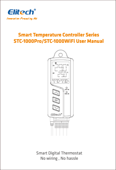
Smart Temperature Controller Series STC-1000Pro/STC-1000WiFi User Manual
Brand: Elitech
1.0 Overview
The Elitech STC-1000Pro/STC-1000WiFi is a plug-and-play smart digital temperature controller. It features two pre-wired heating and cooling outlets designed to maintain appliances at ideal temperatures automatically. The controller is built with V-0 classified flame-retardant ABS materials for safety and reliability. Its design includes a three-button interface and a 2.5-inch LCD for intuitive viewing of temperatures and parameter settings, such as high/low temperature alarms, temperature calibration, and °C/°F unit switching. The STC-1000WiFi model is a wireless controller that offers enhanced functionality via the Elitech app.
The STC-1000Pro/STC-1000WiFi, available in UK/EU/US versions, is suitable for applications requiring automatic temperature control, including homebrew, aquariums, incubation, pet breeding, seedling heat mats, and culture fermentation.
In the box
The package includes:
- Power Plug*
- Temperature Probe
- Main Controller
- Cooling and Heating Outlets*
* Available in UK/EU/US version
Diagram Description: The diagram illustrates the components. The temperature probe connects to the main controller. The main controller features a display showing PV (Present Value) and SV (Set Value), and buttons labeled SET, HEATING, COOLING, and MODE. It also has indicators for HEATING and COOLING. The controller connects to appliances via Cooling and Heating Outlets.
1.1 Display
The LCD display shows various indicators and values:
| No. | Icon | Function |
|---|---|---|
| 1 | ? (Wi-Fi symbol) | Wi-Fi Connection Status |
| 2 | ❄️ (Snowflake symbol) | Cooling Mode |
| 3 | ? (Bell symbol) | Alarm |
| 4 | ☀️ (Sun symbol) | Heating Mode |
| 5 | ⚙️ (Gear symbol) | Settings |
| 6 | PV | Current Value |
| 7 | SV | Set Value |
| 8 | Parameters | See 3.0 Parameter Instruction |
| 9 | Csp | Cooling start point |
| 10 | Hsp | Heating start point |
Note: Csp (Cooling start point) = TS (Temperature Set-point) + CD (Cooling Differential); Hsp (Heating start point) = TS (Temperature Set-point) - HD (Heating Differential).
2.0 Operation
⚠️ Incorrect operation may cause serious damages to you or your device. Please read and understand the following procedures before starting.
2.1 Probe Installation
Plug the temperature probe fully into the headphone jack at the bottom of the main controller. Failure to do so will trigger a buzzer alarm and display an "Err" code on the LCD after powering on.
Diagram Description: An illustration shows the temperature probe being plugged into the main controller with an upward arrow and the text "Fully Plug In".
2.2 Power On
Plug the controller into a 100V to 250V power outlet. The LCD will illuminate and display the current temperature and other parameters. The controller also features Heating and Cooling LED indicators.
Diagram Description: The controller is shown plugged into a wall socket. The diagram highlights the Heating LED indicator and the Cooling LED indicator on the controller unit.
2.3 Parameter Viewing and Settings
2.3.1 Parameter Viewing
Press the SET button or the UP/DOWN buttons to enter parameter viewing mode. Parameters and their relative values are displayed in ascending order. The controller will automatically exit viewing mode after 5 seconds of inactivity.
2.4 Parameter Settings
The STC-1000Pro supports parameter settings via buttons. The STC-1000WiFi supports settings via buttons or the Elitech app.
2.4.1 Button Operation
Press and hold the SET button for 3 seconds to enter the parameter setting mode; the buzzer will beep and the ⚙️ icon will appear on the LCD.
Press the UP or DOWN buttons to switch between parameters. Press and hold UP or DOWN to increase or decrease the setting value quickly.
Press and hold the SET button for 3 seconds to save settings and exit. Alternatively, the controller will save and exit after 15 seconds of inactivity.
Flow Chart Description: The parameter setting process is illustrated. Pressing SET for 3 seconds enters the mode. The display cycles through Temperature Set Value, Cooling Differential, Heating Differential, and Protection Time. Settings can be adjusted with UP/DOWN buttons. Pressing SET for 3 seconds or 15 seconds of inactivity saves and exits. Another path shows Temperature Unit, Temperature Calibration, Low Alarm Limit, and High Alarm Limit.
2.4.2 App Operation (STC-1000WiFi Only)
Open the Elitech app, connect the STC-1000WiFi to your preferred Wi-Fi, and remotely view and set parameters, monitor temperature, analyze graphs, and export data.
Further procedures are detailed in Section 8.0 Elitech App Operation.
3.0 Parameter Instructions
The display shows various codes and values related to parameters:
Diagram Description: The LCD display is shown with various indicators and numerical values. Codes like HSD, TS, CD, HD, PT, AH, AL, CA, MS, N, S, Swt, MF, Hsp, Csp, %RH, Srt are visible along with numerical readouts for PV and SV. The diagram also indicates the cooling start point (Csp), temperature set-point (TS), and heating start point (Hsp).
Parameter Instructions Table
| No. | Code | Function | Setting Range | Default | Unit |
|---|---|---|---|---|---|
| 1 | TS | Temperature Set-point | -40 - 110 -40 - 230 | 25 77 | °C °F |
| 2 | CD | Cooling Differential | 0.2 - 15 1 - 30 | 2.0 3 | °C °F |
| 3 | HD | Heating Differential | 0.2 - 15 1 - 30 | 2.0 3 | °C °F |
| 4 | PT | Protection Time | 0 - 10 | 3 | min |
| 5 | AH | High Alarm Limit | -40 - 110 -40 - 230 | 35 95 | °C °F |
| 6 | AL | Low Alarm Limit | -40 - 110 -40 - 230 | 0 32 | °C °F |
| 7 | CA | Temperature Calibration | -10 - 10 -15 - 15 | 0 0 | °C °F |
| 8 | CF | Temperature Unit | °C/°F | C | --- |
Note: The °C/°F icon will flash on the LCD during temperature unit settings.
3.1 Parameter Functions
3.1.1 Temperature Setting - TS, HD, CD, PV, SV
In normal operation, the PV displays the current value, and the SV displays the set value. The controller automatically switches between cooling and heating modes based on the TS (Temperature Set-point), HD (Heating Differential), and CD (Cooling Differential) parameters.
Cooling Mode
- The controller enters cooling mode when PV (Current Value) > TS (Temperature Set-point) + CD (Cooling Differential). The ❄️ icon and the green LED turn on, and the cooling outlet activates.
- If the green LED flashes, the compressor is under protection status (see Section 3.1.2 Protection Time - PT).
- The controller exits cooling mode when PV (Current Value) ≤ TS (Temperature Set-point). The ❄️ icon and the green LED turn off.
Heating Mode
- The controller enters heating mode when PV (Current Value) ≤ TS (Temperature Set-point) - HD (Heating Differential). The ☀️ icon and the red LED turn on, and the heating outlet activates.
- The controller exits heating mode when PV (Current Value) > TS (Temperature Set-point). The ☀️ icon and the red LED turn off.
Example:
If TS = 25°C, CD = 3°C, HD = 3°C:
- Csp (Cooling start point) = TS + CD = 28°C
- Hsp (Heating start point) = TS - HD = 22°C
When PV ≥ 28°C (Csp), the controller enters cooling mode. When PV ≤ 25°C (TS), it exits cooling mode.
When PV ≤ 22°C (Hsp), the controller enters heating mode. When PV ≥ 25°C (TS), it exits heating mode.
Diagram Description: The diagram visually represents the temperature control logic. It shows the relationship between the current temperature (PV), the Temperature Set-point (TS), the Cooling Start Point (Csp), and the Heating Start Point (Hsp). It indicates the ranges for cooling and heating activation based on these set points and differentials.
3.1.2 Protection Time - PT (Cooling Mode Only)
Frequent start/stop cycles can reduce appliance lifespan. The PT parameter (Protection Time, or cooling start delay time) is recommended to protect your appliance. Set it according to your requirements.
Example: When PT is set to 3 minutes, the controller will enter cooling mode if PV > Csp (Cooling start point) AND either of the following conditions is met:
- The controller has been powered on for more than 3 minutes.
- The interval between two adjacent cooling modes is more than 3 minutes.
3.1.3 High Alarm Limit - AH
When PV (Current Value) > AH (High Alarm Limit), a high temperature alarm is triggered. The LCD displays the error code "EAH", the ? icon, and a buzzer sounds. Pressing any button mutes the buzzer, but the error code remains until PV < AH.
3.1.4 Low Alarm Limit - AL
When PV (Current Value) ≤ AL (Low Alarm Limit), a low temperature alarm is triggered. The LCD displays the error code "EAL", the ? icon, and a buzzer sounds. Pressing any button mutes the buzzer, but the error code remains until PV > AL.
Note: The controller functions normally during AH or AL alarms.
3.1.5 Temperature Calibration - CA
If the PV deviates from the standard or actual temperature, use the CA parameter to correct it. The calibration value can be positive, zero, or negative. Calibrated PV = PV (before calibration) + CA (temperature calibration).
3.1.6 Celsius/Fahrenheit - CF
The controller supports Celsius or Fahrenheit display. The US version defaults to Fahrenheit, while the UK/EU version defaults to Celsius. Modify the CF parameter in Section 2.4 Parameter Settings if your preferred unit differs from the default.
4.0 Installation
⚠️ For your personal and appliance's safety, power on the controller only after installation is complete.
This controller supports hanging-mount installation. Please check and confirm the installation distances and nail sizes before installation.
Diagram Description: The diagram shows the controller unit and indicates mounting hole sizes: 9mm and 7mm, suggesting suitable nail or screw sizes for wall mounting.
5.0 Cooling/Heating Outlet
⚠️ Take care when using electricity!
Plug your refrigeration and heating appliances into the corresponding cooling and heating outlets on the controller.
If the status is normal, the controller will automatically start cooling or heating according to the set parameters. The corresponding ❄️ or ☀️ icon, and green or red LED will indicate the current working status.
Diagram Description: The diagram shows a Refrigeration Appliance connected to the COOLING outlet and a Heating Appliance connected to the HEATING outlet on the controller.
Note: If you only need to connect one appliance, or if an outlet will not be used for a long time, it is advisable to disconnect it to prevent potential damage to the controller.
6.0 Error Code
If certain conditions occur, the buzzer will beep, and an error code will appear on the LCD. Pressing any button will mute the buzzer, but the error code will persist until the issue is resolved.
- "Err": The probe may be disconnected or not installed correctly. Try re-installing the probe. If the "Err" code persists, replace the probe.
- "EAH": The controller is in a high temperature alarm state (current temperature PV > AH). Check and resolve the issue to prevent damage or loss.
- "EAL": The controller is in a low temperature alarm state (current temperature PV ≤ AL). Check and resolve the issue to prevent damage or loss.
7.0 Reset
⚠️ Please power on the controller before resetting.
7.1 Reset to Default Parameters
Press and hold all three buttons (SET + UP + DOWN) simultaneously until the screen turns off. Release the buttons; the controller will auto-restart with default parameters.
7.2 Reset Wi-Fi (STC-1000WiFi Only)
To reset or change the connected Wi-Fi, press and hold the SET and UP buttons until the ? icon flashes on the LCD. Release the buttons and wait for the ? icon to disappear, indicating the Wi-Fi has been successfully reset.
Note: Do not disconnect the power during the reset procedures.
8.0 Elitech App Operation
The STC-1000WiFi features an embedded Wi-Fi module for remote viewing, configuration, and other operations via the Elitech app.
- Download the latest Elitech app from the App Store or Google Play. Register for a free Elitech account and sign in.
- Connect your mobile phone to a preferred Wi-Fi network (2.4 GHz Wi-Fi only).
- Check the sticker on the controller's back for the QR code and 20-digit GUID.