uAvionix echoUAT ADS-B Transceiver Installation Guide
File info: application/pdf · 49 pages · 1.72MB
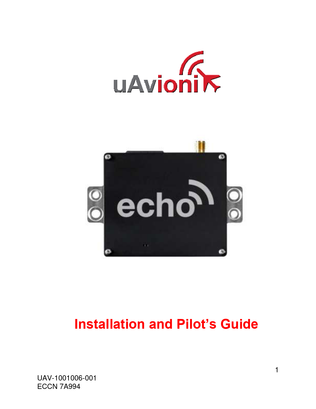
echoUAT Installation and Pilot's Guide
FCC ID 2AFFTUAT016 FAA Transmit License Manned and un-manned aircraft. Software RTCA DO-178B Level C Hardware RTCA DO-254 Level C Power Requirements 11 – 33VDC. Typical 2W On/Alt, 0.1W Standby DO-160G Category Z Altitud…
echoUAT Installation and User Guide
PDF echoUAT Installation and User Guide
multiplexer cable, echo Mux, to transfer Squawk code and pressure altitude directly to the echoUAT. The echoUAT may be "hard-wired" to Trig TT20/22 systems ,Sandia STX 165/r and Apollo SL-70 transponders with no procure…
Full PDF Document

If the inline viewer fails, it will open the original document in compatibility mode automatically. You can also open the file directly.
Extracted Text
Installation and Pilot's Guide
1 UAV-1001006-001 ECCN 7A994

� 2018 uAvionix Corporation. All rights reserved. uAvionix Corporation 300 Pine Needle Lane Bigfork, MT 59911
http://www.uavionix.com support@uavionix.com
Except as expressly provided herein, no part of this guide may be reproduced, transmitted, disseminated, downloaded or stored in any storage medium, for any purpose without the express written permission of uAvionix. uAvionix grants permissions to download a single copy of this guide onto an electronic storage medium to be viewed for personal use, provided that the complete text of this copyright notice is retained. Unauthorized commercial distribution of this manual or any revision hereto is strictly prohibited.
uAvionix� is a registered trademark of uAvionix Corporation, and may not be used without express permission of uAvionix.
2 UAV-1001006-001 ECCN 7A994

1 Revision History

Revision A B C D E F G H I J K L

Date 2/27/2017 3/6/2017 3/28/2017 5/25/17 5/31/2017 8/14/2017 8/17/2017 11/24/2017 12/21/2017 2/19/2018 4/2/2018 10/10/2018

Comments Initial release
GTX Protocol Support Export Control Traffic on COM1 Aligns with Echo Installer App Updates Added Garmin GTN and GRT SafeFly app notes Added AFS traffic app note Updated Apollo SL70 app note with TX setting echoUATmux harness/Navworx Retrofit Update transponder language Update Legacy Transponder wiring diagram C-1

3 UAV-1001006-001 ECCN 7A994

2 Warnings / Disclaimers
All device operational procedures must be learned on the ground. Received weather and traffic information is to be used as an aid to situational awareness, and is merely supplemental and advisory in nature. uAvionix is not liable for damages arising from the use or misuse of this product.
This equipment is classified by the United States Department of Commerce's Bureau of Industry and Security (BIS) as Export Control Classification Number (ECCN) 7A994. These items are controlled by the U.S. Government and authorized for export only to the country of ultimate destination for use by the ultimate consignee or end-user(s) herein identified. They may not be resold, transferred, or otherwise disposed of, to any other country or to any person other than the authorized ultimate consignee or end-user(s), either in their original form or after being incorporated into other items, without first obtaining approval from the U.S. government or as otherwise authorized by U.S. law and regulations.
4 UAV-1001006-001 ECCN 7A994

3 Limited Warranty
uAvionix products are warranted to be free from defects in material and workmanship for one year from the of installation in the aircraft. For the duration of the warranty period, uAvionix, at its sole option, will repair or replace any product which fails in normal use. Such repairs or replacement will be made at no charge to the customer for parts or labor, provided that the customer shall be responsible for any transportation cost.
Restrictions: This warranty does not apply to cosmetic damage, consumable parts, damage caused by accident, abuse, misuse, water, fire or flood, damage caused by unauthorized servicing, or product that has been modified or altered.
Disclaimer of Warranty: IN NO EVENT, SHALL UAVIONIX BE LIABLE FOR ANY INCIDENTAL, SPECIAL, INDIRECT OR CONSEQUENTIAL DAMAGES, WHETHER RESULTING FROM THE USE, MISUSE OR INABILITY TO USE THE PRODUCT OR FROM DEFECTS IN THE PRODUCT. SOME STATES DO NOT ALLOW THE EXCLUSION OF INCIDENTAL OR CONSEQUENTIAL DAMAGES, SO THE ABOVE LIMITATIONS MAY NOT APPLY TO YOU.
Warranty Service: Warranty repair service shall be provided directly by uAvionix. Proof of purchase for the product from uAvionix or authorized reseller is required to obtain and better expedite warrant service.
Please email or call uAvionix with a description of the problem you are experiencing. Also, please provide the model, serial number (if applicable), shipping address and a daytime contact number.
You will be promptly contacted with further troubleshooting steps or return instructions. It is recommended to use a shipping method with tracking and insurance.
5 UAV-1001006-001 ECCN 7A994

4 Contents
1 Revision History ................................................................................. 3 2 Warnings / Disclaimers ....................................................................... 4 3 Limited Warranty ................................................................................ 5 5 Introduction ........................................................................................ 8
5.1 Features ...................................................................................... 8 5.2 Regulatory Compliance ............................................................... 9
5.2.1 FCC Grant of Equipment Authorization .................................. 9 5.3 Interfaces ...................................................................................10 5.4 Software and Airborne Electronic Hardware Configuration. .........10 5.5 Supplied Accessories .................................................................10 6 Technical Specifications ....................................................................12 6.1 Markings.....................................................................................12 7 Equipment Limitations .......................................................................13 7.1 Installation ..................................................................................13
7.1.1 Modifications and Use Outside of Intended Scope ................13 7.1.2 Deviations .............................................................................13 7.1.3 Configurable Options ............................................................13 7.1.4 Approvals..............................................................................13 7.2 Unpacking and Inspecting...........................................................13 7.3 Mounting ....................................................................................13 7.4 Connections ...............................................................................14 7.5 Connector Pin Assignments........................................................15 7.6 Cooling Requirements ................................................................15 7.7 Wiring Considerations.................................................................16 7.8 Antenna Installation ....................................................................17 7.8.1 Antenna ................................................................................17 7.8.2 Antenna Cable ......................................................................18
6 UAV-1001006-001 ECCN 7A994

8 Installation Setup...............................................................................20 8.1.1 Connecting to the echoUAT via Wi-Fi....................................20
8.2 Configuration ..............................................................................21 8.2.1 Control ..................................................................................21 8.2.2 Aircraft Address Programming ..............................................22 8.2.3 Call Sign ...............................................................................22 8.2.4 Flight-plan ID ........................................................................22 8.2.5 CSID Logic............................................................................22 Note: CSID should always be "Enabled", unless there is a special circumstance requiring it be set to "Disabled". ...................................23 8.2.6 Anonymous Mode .................................................................23 8.2.7 Emitter Category ...................................................................23 8.2.8 VFR Squawk code ................................................................23 8.2.9 ADSB-In Capability ...............................................................23 8.2.10 VSO (knots) ..........................................................................24 8.2.11 Aircraft Length and Width in Meters ......................................24 8.2.12 GPS Antenna Offset..............................................................25
8.3 Installation ..................................................................................25 8.3.1 Serial Port Setup ...................................................................26
9 Normal Operation ..............................................................................27 9.1 Electronic Flight Bag Application.................................................27
10 Environmental Qualification Forms ....................................................29
7 UAV-1001006-001 ECCN 7A994

5 Introduction
The echoUAT is a remotely mounted ADS-B transceiver that incorporates a dual-link (1090 MHz and 978 MHz) receiver and 978 MHz UAT Class B1S transmitter. An internal power transcoder detects altitude, ident and squawk codes from older-style Mode C or Mode S transponders by decoding the replies via the aircraft electrical system. No additional wiring to the transponder is required. The echoUAT has integrated Wi-Fi support to interface with most EFB applications, and integrates with a wide variety of existing EFIS systems. For use with either the SKYFYX GPS source or with an existing rule compliant GPS source.
It is designed to meet the performance requirements of TSO-C154c, and is compliant with FAR 91.225 and FAR 91.227 for operation in the National Airspace System.
! The system is for use in Experimental and LSA aircraft only.
5.1 Features
The echoUAT performs the following functions:
� UAT transmission (978 MHz) o Transmits ADS-B Out data on the 978 MHz frequency. o Optional Anonymous Mode with 1200 VFR squawk code.
� UAT reception (978 MHz) o Receives ADS-B In data from other UAT transmitters, including aircraft, vehicles, and ground stations. This includes ADS-B, ADS-R, TIS-B and FIS-B data.
� 1090ES reception (1090 MHz) o Receives ADS-B In data from aircraft equipped with 1090 MHz Extended Squitter transmitters.
� Transponder interface
8 UAV-1001006-001 ECCN 7A994

o The power transcoder allows monitoring of existing Mode C, or Mode S transponders via the aircraft electrical system.
o Direct serial connection for direct-wire transponders or EFIS integration.
� Traffic correlation o Traffic information from both UAT and 1090ES are correlated to provide a coherent view of nearby aircraft.
� GDL 90 output o Traffic and FIS-B data is translated to standard GDL 90 format.
� Wi-Fi EFB connection o The GDL 90 data is transmitted over the built-in Wi-Fi interface for reception by standards compliant Electronic Flight Bag (EFB) applications.
5.2 Regulatory Compliance
The echoUAT meets the Minimum Operational Performance Standards of DO-282B Class B1S, and meets the performance requirements of TSOC154c. It complies with the ADS-B Final Rule Technical Amendment, dated 2/9/2015, affecting 14 CFR 91.225 (b)(1)(ii) which permits ADS-B Out in the National Airspace System for devices meeting the performance requirements of TSO-C154c. Accordingly, when installed in accordance with the installation instructions of this guide, the device complies with the aircraft requirements of 14 CFR 91.227.
(Per the February 9, 2015 rule change to 14 CFR 91.225 (b)(1)(ii)) (A letter of authorization from the aircraft manufacturer is needed for installation in LSA
aircraft)
5.2.1 FCC Grant of Equipment Authorization This equipment has been issued an FCC Grant of Equipment Authorization.
The equipment contains FCC ID 2AFFTUAT016 and is marked on the equipment nameplate.
The equipment also contains FCC ID 2ADUIESP-12 and is marked on the equipment nameplate.
9 UAV-1001006-001 ECCN 7A994

5.3 Interfaces
The echoUAT has a single SMA antenna connection, a 6-pin Host interface and an integrated Wi-Fi adapter.

Interface COM1
COM2 RX COM2 TX Wi-Fi

Specification Setup Mode, Altitude, Squawk, Ident GPS Position
GPS Position
ADS-B Traffic ADS-B Uplink Services Setup ADS-B Traffic ADS-B Uplink Services

Devices Dynon, MGL, GRT, AFS, Garmin, Sandia, Apollo
SKYFYX, Garmin WAAS, Accord Micro-i MGL, GRT, AFS
iPad, Android

5.4 Software and Airborne Electronic Hardware Configuration.

Part Software Airborne Electronic Hardware

Part Number UAV-1001007-001 UAV-1001008-001

Revision A A

5.5 Supplied Accessories

Part echoUAT SMA-BNC Adapter Wiring Harness Monopole Antenna echoUAT User Manual

Part Number UAV-1000957-001 UAV-1001011-001 UAV-1001010-001 UAV-1001009-001 UAV-1001006-001

Revision A
A H

10 UAV-1001006-001 ECCN 7A994

11 UAV-1001006-001 ECCN 7A994

6 Technical Specifications

Specification Compliance FCC ID FAA Transmit License Software Hardware Power Requirements Altitude Operating Temperature Humidity Transmit Frequency Transmit Power Transmitter Modulation Receiver Frequency Receiver Sensitivity Weight Height Length Width

Characteristics Meets the performance requirements of TSO-C154c 2AFFTUAT016 Manned and un-manned aircraft.
RTCA DO-178B Level C RTCA DO-254 Level C 11 � 33VDC. Typical 2W On/Alt, 0.1W Standby DO-160G Category Z 18,000ft -45�C to +70�C
Tested to Category DO-160G Category B2 978MHz �1MHz
20W nominal 1M29G1D
978MHz 1090MHz 978MHz: -90 to -3dBm 1090MHz: -79 to 0dBm 60grams 19mm 55mm 65mm

6.1 Markings

12 UAV-1001006-001 ECCN 7A994

7 Equipment Limitations
7.1 Installation
7.1.1 Modifications and Use Outside of Intended Scope This device has been designed and tested to conform to all applicable standards in the original form and when configured with the components shipped with the device. It is not permissible to modify the device, use the device for any use outside of the intended scope.
7.1.2 Deviations There are no deviations from the MPS of TSO-C154c Class B1S Device.
7.1.3 Configurable Options Accessing or altering configurable options not intended to be operated may cause pilot distraction.
7.1.4 Approvals Approvals do not cover adaptations to the aircraft necessary to accommodate ancillary equipment such as power provisions, mounting devices or external antennas; such items must still be approved under existing minor modification/change processes applicable to the aircraft.
7.2 Unpacking and Inspecting
Carefully unpack the device and make a visual inspection of the unit for evidence of any damage incurred during shipment. If the unit is damaged, notify the shipping company to file a claim for the damage. To justify your claim, save the original shipping container and all packing materials.
7.3 Mounting
The echoUAT is designed to be mounted in any convenient location in the cockpit, the cabin, or an avionics bay.
The following installation procedure should be followed, remembering to allow adequate space for installation of cables and connectors.
� Select a position in the aircraft that is not too close to any high external heat source. The echoUAT is not a significant heat source
13 UAV-1001006-001 ECCN 7A994

itself and does not need to be kept away from other devices for this reason. � Avoid sharp bends and placing the cables too near to the aircraft control cables. � Secure the transceiver to the aircraft via the four (4) mounting holes. It should be mounted on a flat surface. � If possible, care should be taken to mount EchoUAT in a location with the top case being visible for initial or periodic inspection of the LED status lights. Note: Installation of the echoUAT must be in accordance with AC43.13-2B, Chapter 1
7.4 Connections
! Whenever power is supplied to the transceiver, a 50ohm load
must be provided to the SMA connection. You can use the supplied antenna or a commercially available 50ohm load.
14 UAV-1001006-001 ECCN 7A994

7.5 Connector Pin Assignments

Pin

Type

Physical

Default Config

1

Ground

-

-

2

Aircraft

11-33V

-

Power

3

COM1 TX RS232 Out RS232 38400bps

RS485 A(-)

81O

4

COM1 RX RS-232 In RS232 38400bps

RS485 B(+)

81O

5

COM2 TX RS-232 Out 115200bps 81N

6

COM2 RX RS-232 In 115200bps 81N

Mating Connector: Molex 0436450600, Pins: 0462350001

Default Protocol
-
TMAP
TMAP
GDL 90 NMEA

Note: Use a 1A circuit breaker between the power source and echoUAT. Optionally, a 3a gang circuit breaker can be used when combining echoUAT and SkyFYX on the same circuit.

LED RED GREEN

SOLID FAULT Powered

FLASHING Transmit Receive

7.6 Cooling Requirements
echoUAT is designed to meet all applicable TSO requirements without forced-air cooling.
Attention should, however, be given to the incorporation of cooling provisions to limit the maximum operating temperature if the echoUAT is installed in close proximity to other avionics. The reliability of equipment operating in close proximity in an avionics bay can be degraded if adequate cooling is not provided.

15 UAV-1001006-001 ECCN 7A994

7.7 Wiring Considerations

The echoUAT was designed and tested using unshielded, untwisted wiring. There may, however, be technical benefits of improved electromagnetic emissions and susceptibility to and from the transponder system. The use of twisted wire can reduce interference and break-through on adjacent audio wiring if it is not possible to route them separately.

The distance between the echoUAT and the power source is limited by the impedance of the wire between them. The echoUAT is powered directly from aircraft power, and, therefore, the acceptable voltage drop in the power line is what limits the distance.

A 1A circuit breaker should be used between the echoUAT and the power source. A 3A gang circuit breaker can be used when echoUAT and SkyFYX are combined on the same circuit.

The echoUAT requires an impedance of less than 0.5ohm in the power line for satisfactory operation. The following table provides guidance for a typical aircraft hook-up wire. Note that different brands may vary � please check your supplier for more details.

Gauge 20 AWG 22 AWG 24 AWG

ohm/km 35 64 99

Length for 0.5ohm 14.2m 7.8m 5.0m

An alternative to a harness built from individual wires, particularly for a long cable run, is to use a multi-core cable. Aviation grade cables with 6 or more cores are often more expensive than individual wires, and, therefore, are not generally a good choice. For aircraft where those situations do not apply, an attractive alternative solution may be to use 3 or 4 pair data cable.
Please note that not all data cable is suitable for this application. Cables with solid cores should not be used. Cables should be selected based on the wear characteristics of their insulation material, including temperature rating, resistance to solvents and oils, and flammability. Most inexpensive commercial data cables have poor flammability properties.
16 UAV-1001006-001 ECCN 7A994

7.8 Antenna Installation
7.8.1 Antenna The antenna should be installed according to the manufacturer's instructions.
The following considerations should be taken into account when determining an acceptable location for the antenna.
� The antenna should be well removed from any projections, the engine(s) and propeller(s). It should also be well removed from landing gear doors, access doors or other openings which will break the ground plane for the antenna.
� The antenna should be mounted on the bottom surface of the aircraft and in a vertical position when the aircraft is in level flight.
� Avoid mounting the antenna within 1 meter of an existing transponder, ADF sense antenna or any COMM antenna and 2 meters from the DME antenna.
� Where practical, plan the antenna location to keep the cable lengths as short as possible and avoid sharp bends in the cable to minimize the VSWR or signal loss.
Electrical connection to the antenna should be protected to avoid loss of efficiency due to exposure to liquids and moisture. All antenna feeders shall be installed in such a way to minimize RF energy radiated inside the aircraft.
When a conventional aircraft monopole antenna is used, it relies on a ground plane for correct behavior. For ideal performance, the ground plane should be large relative to the wavelength of the transmission, which is 275mm. In a metal, skinned aircraft this is usually easily accomplished, but is more difficult in a composite or fabric skinned aircraft. In these cases, a metallic ground plane should be fabricated and fitted under the antenna.
The ground plane should be as large as you can sensibly make it. Because it is a function of the wavelength of the transmission, the smallest practical ground plane for a transponder is a approx. 120mm per side. As the size increases, the performance improves, until the ground plane is approx.
17 UAV-1001006-001 ECCN 7A994

700mm on each side. Anything much larger than that size is unlikely to result in significant further improvement. The thickness of the material used to construct the ground plane is not critical, providing it is sufficiently conductive. A variety of proprietary mesh and grid solutions are available. Heavyweight aluminum foil meets the technical requirement, but obviously needs to be properly supported. 7.8.2 Antenna Cable The echoUAT is designed to meet Class B1S. Excessive loss in the cable and connectors will degrade both transmitter output power and receiver sensitivity. An acceptable cable:
� has less than 1.5dB loss for the run length needed, � has a characteristic impedance of 50ohms, � has double braid screens or has foil and braid screen. Once the cable run length is known, a cable type with low enough loss per meter that meets the above requirements can be chosen. Longer runs require lower loss cable. The following table is a guide to the maximum usable lengths of some common cable types. Actual cable loss varies between manufacturers. There are many variants, and the table is based on typical data. Use it as a guide only and refer to the manufacturer's data sheet for your specific chosen cable for accurate values.
18 UAV-1001006-001 ECCN 7A994

Length
(meters) 2.54 2.54 3.16 3.81 4.5 5.25 6.42 6.81 8.22 12.59

Insertion Loss (dB/m) 0.59 0.59 0.47 0.39 0.33 0.29 0.23 0.18 0.18 0.12

MIL-C 17 Specialists SSB Electronic

M17/128 RG400
RG304
RG393

3C142B
311601 311501
311201 3108801

Aircell 5 Aircell 7

When routing the cable:
� Route the cable away from any significant heat sources � Route the cable wiring away from potential interference sources such
as ignition wiring, 400Hz generators, fluorescent lighting and electric motors � Allow a minimum separation of 300mm from an ADF antenna cable � Keep the cable run as short as possible � Avoid routing the cable around tight bends � Avoid kinking the cable, even temporarily, during installation � Secure the cable so that it cannot interfere with other systems

19 UAV-1001006-001 ECCN 7A994

8 Installation Setup
Download the "uAvionix Echo Installer" app from the IOS App store or Google Play. Note: Do not use the "uAvionix Ping Installer" app by mistake.
8.1.1 Connecting to the echoUAT via Wi-Fi To connect to the echoUAT, join a device to the wireless network named "Echo-XXXX" using the procedure for your device. iOS is shown below: 1. Go to Settings > Wi-Fi, and make sure that Wi-Fi is turned on. 2. Tap the SSID Ping-XXXX where XXXX is a random string. i.e. Ping6A8E. 3. No WPA Password is required.* *Some early software builds require a WPA password... Enter uavionix as the WPA password for the secure Wi-Fi network, then tap join. Note: The No Internet Connection message is normal when iOS is connected to echoUAT.
20 UAV-1001006-001 ECCN 7A994

4. Launch the Echo App on your tablet or smartphone.
Make sure "EchoUAT is the Selected Device Type.
8.2 Configuration
The configuration section will set the following parameters: � Control � ICAO Number � Call Sign � Flight Plan ID � CSID Logic � Anonymous Mode � Emitter Category � VFR Code � ADS-B In Capability � Vso � Aircraft Length and Width � GPS Antenna Offset
8.2.1 Control Select the desired control type. This setting configures the echoUAT for Transmit, Receive or Standby.
� UAT TX Enabled: Enables both transmit and receive functions. This is the recommended mode for 2020 compliance..
21 UAV-1001006-001 ECCN 7A994

� Receive Only: Disables transmission but continues to receive and provide ADS-B data to a GDL90 compatible display or application.
� Standby: Disables both the transmit and receive functions. GDL90 position data (GPS) is still available from the device.
8.2.2 Aircraft Address Programming The ICAO address is a 24-bit number issued to the aircraft by the registration authority of the aircraft. These addresses are usually written as a 6-digit hexadecimal number, although you may also encounter one written as an 8-digit octal number. The echoUAT understands the hexadecimal format, so you must first convert an octal number to hexadecimal before entering.
Tip: By using the N-Number Look Up function on https://www.faa.gov, locate and use the "Mode S Code (base 16 / hex)" value.
8.2.3 Call Sign The CALL SIGN can be up to an 8 digit code that corresponds to the tail number of the aircraft. (0-9, A-F).
Note: This is typically your aircraft N-number, unless otherwise advised by the FAA or ATC.
8.2.4 Flight-plan ID Flight Plan ID, if provided, is used in accordance with product specific transmission requirements. CSID Logic is applied to determine if the Flight Plan ID is transmitted.
Flight Plan IDs are intended to contain Mode 3/A (12-bit) or expanded (18bit) codes, and shall only contain between 4 and 6 characters, consisting of ASCII encoded values for digits 0-7.
Tip: Generally, this field will be left blank, unless otherwise advised by the controlling authority.
8.2.5 CSID Logic Specifies Call Sign Identification (CSID) transmission behavior. Always set CSID Logic to "Enabled" for 91.227 Compliance. A setting of "Disabled" will result in a failure to generate an ADS-B Performance report.
Description
22 UAV-1001006-001 ECCN 7A994

Disabled, CSID always set to 1 (Callsign) Enabled, CSID alternates between 1 (Callsign) and 0 (Flight Plan ID)
Note: CSID should always be "Enabled", unless there is a special circumstance requiring it be set to "Disabled".

8.2.6 Anonymous Mode When checked, this enables the EchoUAT to transmit a self-assigned ICAO and sets the Call Sign to a random string such as "PINGFDF8" when the squawk code matches the defined VFR squawk code. Note that anonymous mode is only active if a flight plan has not been filed (per AC 20-165).

Tip: Anonymous Mode must be "DISABLED" for the FAA Performance test flight in order for the FAA to register the flight to the aircraft's Call Sign.

8.2.7 Emitter Category To assist ATC tracking of aircraft, an aircraft category can be transmitted. Select the aircraft category that most closely matches the aircraft.

Emitter Category

Light Airplane

Rotorcraft

Small Airplane

Glider / Sailplane

Large Airplane

Lighter Than Air

Large Airplane with High Vortex

Parachute

Heavy Airplane

Ultralight

Highly Maneuverable Airplane

UAV

Space Craft

Tip: Fixed wing with a maximum takeoff weight less than 15,000 lbs are

Light Airplanes.

8.2.8 VFR Squawk code This sets the default VFR squawk code. E.g. 1200 for the USA.
8.2.9 ADSB-In Capability Sets the ADS-B in equipment capability reporting. EchoUAT is capable of receiving on frequencies. The recommended setting is "Both UAT and 1090".
23 UAV-1001006-001 ECCN 7A994

ADS-B In capability None UAT 1090 Both UAT and 1090
8.2.10 VSO (knots) This parameter allows the echoUAT to automatically switch between airborne and ground modes. Enter the VSO value for your aircraft. Setting VSO to 0 passes control of the Air/Ground state to the EFIS.
Airspeed (in kts) that the aircraft typically flies after take-off. 0 � 999 knots
Tip: If in doubt, you can set this to your maximum taxi speed. EchoUAT uses ground speed and does not account for headwind or tailwinds, that might affect the Air/Ground state.

8.2.11 Aircraft Length and Width in Meters When on the ground, ADS-B transmits encoded aircraft size information which is used by ATC to identify taxiing routes and potential conflicts. Enter the length and width (wingspan) fields and the appropriate size codes will be calculated for transmission.

Aircraft Length in Meters
L  15 15 < L  25 25 < L  35 35 < L  45 45 < L  55 55 < L  65 65 < L  75 75 < L  85 L > 85

Aircraft Width (wing span) in Meters
W  72.5 72.5 < W  80

24 UAV-1001006-001 ECCN 7A994

8.2.12 GPS Antenna Offset The GPS antenna offset is used in conjunction with the length and width to manage taxiway conflicts. A typical GPS does not report the geographic position of the center of the aircraft, or even the tip of the nose of the aircraft; instead, it usually reports the location of the actual GPS antenna (not the GPS receiver). In normal flight operation, this distinction is of no importance at all, but if ADS-B is used to manage taxiway conflicts, a significant offset in antenna position could mean the aircraft footprint is not in the same place as the ADS-B reported position. Although the GPS Antenna Offset is primarily intended for position correction on large transport aircraft, General Aviation aircraft can also have a significant offset. For example, if the aircraft has a long tail boom and the GPS antenna is on top of the tail, the GPS position could be 4 meters or more from the nose of the aircraft.

GPS Antenna Lateral Offset from roll axis (Meters)
0 Left 2 Left 4 Right 2 Right 4 Right 6

GPS Antenna Longitudinal Offset from aircraft nose (Meters)
0 to 60 Meters in 2 Meter increments

8.3 Installation
The installation section will set the following parameters:

� Setup Source � Control Source � GPS Source � Traffic/Uplink Output � COM1 Rate, Data and Phy � COM1 Protocol � COM2 Rate
25 UAV-1001006-001 ECCN 7A994

� COM2 Protocol

8.3.1 Serial Port Setup Please use this parameter to configure the echoUAT to interface with a supported EFIS system or another supported device.

Supported Parameters

Parameter Source

SETUP CONTROL GPS

APP EFIS (COM1) EFIS (COM1) XPDR MONITOR EFIS (COM1)

Port
NA COM1 COM1 NA COM1

Baud Rate NA PROG PROG NA NA

Data Interface Protocol

NA PROG PROG NA NA

NA PROG PROG NA NA

NA PROG PROG NA NA

EXT GPS (COM2) COM2

PROG PROG RS232 NEMA

GARMIN

COM2

PROG PROG RS232 ADSB+

TRAFFIC EFIS (COM1)

COM1

PROG PROG RS232 GDL90

MFD (COM2)

COM2

PROG PROG RS232 GDL90

*PROG � User Programmable. Confirm the selection matches the supported device

settings. Example EFIS Baud Rate should match EchoUAT setting and EFIS settings.

Equipment Examples

Equipment
Dynon/Skyview MGL GRT
GTX33/330 GTX32/327 SL70 STX165 TC20
KT76A TC20 + TT2x

Setup Source EFIS APP EFIS

Control Source EFIS EFIS EFIS

APP APP APP APP APP

Panel Panel Panel Panel Panel

APP APP

X MON Panel

Traffic Uplink COM2 COM2 COM2
COM2 COM2 COM2 COM2 COM2
COM2 COM2

GPS Source EFIS COM2 EFIS

COM1 Rate 38400 38400 38400

COM2 COM2 COM2 COM2 COM2

9600 9600 9600 9600 38400

COM2 NA COM2 38400

COM1 Data 81O 81O 81O
81N 81N 81N 81N 81O
NA 81O

COM1 Phy RS232 RS232 RS485 T RS232 RS232 RS232 RS232 RS485 T NA RS485

COM1 Protocol TMAP TMAP TMAP
GTX GTX GDL GDL TMAP
NA TMAP

GPS Source = COM2, If you are using a Garmin GPS with ADS-B+ with GRT, Traffic will be set to EFIS Com1.

Equipment Examples Cont.

Equipment

COM2 Rate

COM2 Protocol

26 UAV-1001006-001 ECCN 7A994

uAvionix SkyFYX Accord Micro-i Garmin GPS-20A Garmin GNS 4xxW Garmin GNS 5xxW

115200 115200 9600 9600 9600

NMEA NMEA ADSB+ ADSB+ ADSB+

Commit and Confirm Configuration
1. After entering the correct information for all fields press Update. You should receive a message confirming the configuration. Tap OK.

2. Tap "Monitor" just below the Echo logo. Confirm the ICAO, Callsign and Emitter shown are the correct values for your aircraft.
3. Programming of the echoUAT is now complete.
9 Normal Operation
9.1 Electronic Flight Bag Application
Launch your GDL 90 compatible Electronic Flight Bag (EFB) application.
Configure your EFB as necessary to access the uAvionix ADS-B device. In most applications, it will be automatically detected. If you do not see a device connection for the echo, ping, or uAvionix, please contact your EFB provider for additional support. ADS-B traffic and flight information should begin streaming to the application when in range. Depending on the proximity to the nearest ADS-B ground station, FIS-B data (METARs, TAFs, TFRs, etc) may not be available while on the ground.

27 UAV-1001006-001 ECCN 7A994

Typical iOS application displaying ADS-B traffic from echoUAT is shown below.
Altitude must be pre-flight cross-checked by comparing the aircraft's altimeter with the GPS altitude displayed on the EFB application. For additional questions or support please visit http://uavionix.com/support
28 UAV-1001006-001 ECCN 7A994

10 Environmental Qualification Forms

Nomenclature Part No: UAV-1000957-001 Manufacturer Address
Conditions
Temperature and Altitude Low temperature ground survival Low Temperature Short-Time Operating Low Temperature Operating High Temperature Operating High Temperature Short-Time Operating High Temperature Ground Survival Loss of Cooling
Altitude Decompression Overpressure Temperature Variation Humidity Operation Shocks Crash Safety Vibration
Explosion Waterproofness Fluids Susceptibility Sand and Dust Fungus Salt Spray Magnetic Field Power Input Voltage Spike AF Conducted Susceptibility Induced Signal Susceptibility RF Susceptibility RF Emissions Lightening Induced Transient Susceptibility Lightening Direct Effects Icing Electrostatic Discharge Fire, Flammability

echoUAT ADS-B Transmitter

uAvionix Inc

380 Portage Ave, Palo Alto, CA 94306

DO-160G

Description of Conducted Tests

Section

4.0

Equipment tested to Category B2

4.5.1

-55�C

4.5.1

-45�C

4.5.2 4.5.4 4.5.3

-45�C +70�C +70�C

4.5.3

+85�C

4.5.5
4.6.1 4.6.2 4.6.3 5.0 6.0 7.2 7.3 8.0
9.0 10.0 11.0 12.0 13.0 14.0 15.0 16.0 17.0 18.0 19.0 20.0 21.0 22.0

Cooling air not required (+70�C operating without cooling) 35,000feet Equipment identified as Category B2 � no test Equipment identified as Category B2 � no test Equipment tested to Category B2 Equipment tested to Category B2 Equipment tested to Category B Equipment tested to Category B type 5 Aircraft zone 2: type 3, 4, 5 to Category S level M, type 1 (Helicopters) to Category U level G Equipment identified as Category X � no test Equipment identified as Category X � no test Equipment identified as Category X � no test Equipment identified as Category X � no test Equipment identified as Category X � no test Equipment identified as Category X � no test Equipment identified as Category Z Equipment identified as Category ZX Equipment identified as Category B Equipment identified as Category B Equipment identified as Category AC Equipment identified as Category TT Equipment identified as Category B Equipment identified as Category XXXX � no test

23.0

Equipment identified as Category X � no test

24.0

Equipment identified as Category X � no test

25.0

Equipment identified as Category X � no test

26.0

Equipment identified as Category C

29 UAV-1001006-001 ECCN 7A994

Appendix A � Interconnect Diagrams
30 UAV-1001006-001 ECCN 7A994

31 UAV-1001006-001 ECCN 7A994

32 UAV-1001006-001 ECCN 7A994

ADF ADS-B ADS-R ATC DME EFB EFIS FCC FAA FIS-B GPS ICAO LSA RTCA TIS-B TSO UAT VSO VSWR

Appendix B - Acronyms
Automatic Direction Finder Automatic Dependent Surveillance Broadcast Automatic Dependent Surveillance Rebroadcast Air Traffic Control Distance Measuring Equipment Electronic Flight Book Electronic Flight Information System Federal Communications Commission Federal Aviation Administration Flight Information Services Broadcast Global Positioning System International Civil Aviation Organization Light Sport Aircraft Radio Technical Commission for Aeronautics Traffic Information Services Broadcast  Technical Standard Order Universal Access Transceiver Minimum Flight Speed in Landing Configuration
Voltage Standing Wave Ratio

33 UAV-1001006-001 ECCN 7A994

Appendix C-1 Legacy Transponder App Note

This is the simplest configuration and uses the power transcoder. SETUP is performed over Wi-Fi from and Android or iOS device. CONTROL, SQUAWK and Barometric ALTITUDE is decoded from the Legacy Transponder interrogation replies through the aircraft electrical system. A compliant GPS source such as a Garmin GPS 20A, Dynon SV-GPS-2020 or uAvionix skyFYX provides the position source for UAT transmissions. Traffic and Weather can also be displayed on the Android / iOS device via Wi-Fi.

Configure the echoUAT as follows for legacy transponder.

Setup Source APP

Control Source Transponder Monitor

GPS Source External COM2

Traffic
MFD COM2

COM1 Rate N/A

COM1 Data N/A

COM1 Phy N/A

COM1 Protocol N/A

COM2 Rate 115200

COM2 Protocol NMEA

34 UAV-1001006-001 ECCN 7A994

Appendix C-2 GRT EFIS App Note
GRT EFIS with SafeFly 2020 GPS App Note

The GRT EFIS exchanges Setup, Control and GPS data with the echoUAT. The echoUAT can also send ADS-B traffic and uplink data to GRT EFIS.

EchoUAT app settings:

If your transponder is controlled by the GRT EFIS:

Setup

Control GPS Traffic COM1

Source Source Source

Rate

EFIS

EFIS

EFIS MFD 38400

COM1 COM2

If your transponder is panel mounted:

COM1 Data 81O

COM1 Phy RS232

COM1 Protocol TMAP

COM2 Rate 115200

Setup Source EFIS

Control Source Transponder Monitor

GPS Source EFIS COM1

Traffic
MFD COM2

COM1 Rate 38400

COM1 Data 81O

COM1 Phy RS232

COM1 Protocol TMAP

COM2 Rate 115200

GRT EFIS Settings:
General Setup:

Serial Port X* In: Serial Port X* Out: Serial Port X* Rate: SAVE

Safe-Fly GPS and SPC Safe-Fly GPS ans SPC 115,200

*Serial port "X" refers to the serial port on the EFIS that is wired to the "Serial Control In/Out" of the Safe-Fly GPS module.

SPC Serial Port 1 Rate: SPC Serial Port 1 Output SPC Serial Port 1 Input

38400 EchoUAT/TMAP EchoUAT/TMAP

Serial Port Y* In ADS-B Serial Port Y* Rate 38,400 if connected to SafeFlySPC or 115,200 if connected to EFIS SAVE
Serial port "Y" refers to the serial port used to receive ADS-B data into the EFIS. For best performance the ADS-B In (Pin 5) on the EchoUAT should be wired directly to a high speed port on the EFIS and not connected to the serial combiner on the SafeFly GPS. If wiring through the SafeFly we recommend a baud rate of 38,400. If wiring directly to the GRT EFIS we recommend 115,200.
35 UAV-1001006-001 ECCN 7A994

GRT EFIS Setup Continued:

General Setup: Flight ID and Address

Flight ID:

(leave blank)

Mode S Code:

Enter ICAO code or six digit Mode S code from registration

SAVE

General Setup: TT22/EchoUAT

Aircraft Category:

Light Aircraft (less than 15,000lbs takeoff weight)

Aircraft Width:

Enter width in meters

Aircraft Length:

Enter length in meters

VFR ID:

Enter Tail or N-Number

GPS Input:

Compliant TMAP

GPS Rate:

9600

Test Squitters:

Never

TIS Output:

Off

UAT/978 Receiver:

Yes

1090ES Receiver:

Yes

GPS Antenna Offset Linear: Enter GPS longitudinal offset in meters from nose

GPS Antenna Offset Lateral: Enter GPS lateral offset in meters

SAVE

Once all settings are complete the Echo App monitor screen should display the same parameters as entered into the GRT. Verify all fields are populated prior to flight.

36 UAV-1001006-001 ECCN 7A994

Example Wiring:
37 UAV-1001006-001 ECCN 7A994

Appendix C-3 Dynon Skyview EFIS App Note

The Skyview exchanges Setup, Control and GPS data with the echoUAT. The echoUAT does not exchange ADS-B Weather and Traffic (GDL-90) data.

Equipment
Dynon Skyview

Setup Source EFIS

Control Source EFIS

GPS Source EFIS

COM1 Rate 38400

COM1 Data 81O

COM1 Phy RS232

COM1 Protocol TMAP

Setup / Control
SYSTEM SETUP SERIAL PORT SETUP SERIAL PORT 1 SETUP SERIAL IN DEVICE SELECT: DYNON SV-XPNDR-262
TRANSPONDER SETUP GPS DATA: DYNON SV-GPS-2020 TRANSPONDER HEX CODE: enter the ICAO hex number of the aircraft VFR CODE: enter the default VFR squawk code (1200 for the US) AUTO ALT/GND: AUTOMATIC (AIR DATA) AIRCRAFT CATEGORY: select the appropriate aircraft category AIRCRAFT LENGTH: the length of the aircraft in ft AIRCRAFT WIDTH: the width of the aircraft in ft MAXIMUM CRUISE SPEED: select the appropriate cruise speed range TIS TRAFFIC: OFF

38 UAV-1001006-001 ECCN 7A994

Appendix C-4 Apollo SL70 App Note

The Apollo SL70 outputs Altitude, Mode, Squawk and Mode C code over RS232. The configured baud rate needs to be determined and programmed into the echo app.

Determine the baud rate of the serial port as follows:

The SL70 has a built-in setup mode to simplify the checkout. To operate the SL70 in the
setup mode, hold down the "IDENT" and "ALT" buttons while switching on the power. To return to normal operation, switch the power off, then back on.

RS-232 Baud Rate Determination.

To view the baud rate: In test mode, rotate the LARGE knob to the "SL70 CONF" (SL70 Configuration) page, then rotate the SMALL knob to the "BAUD" (baud rate) page. The baud rates available are 1200, 2400, 4800, 9600, and 19200. The TX setting must be
configured to EXT for squawk to pass to the echoUAT.

Equipment SL70

Setup Source APP

Control Source Panel

GPS Source COM2

COM1 Rate 9600

COM1 COM1 Data Phy 81N RS232

COM1 Protocol GDL

39 UAV-1001006-001 ECCN 7A994

Appendix C-5 Sandia STX165/R App Note

The STX165 outputs Altitude, Mode, Squawk and Mode C code over RS232. The baud rate, if fixed, and needs to be programmed into the echo app.

Equipment STX165

Setup Source APP

Control Source Panel

GPS Source COM2

COM1 Rate 9600

COM1 Data 81N

COM1 Phy RS232

COM1 Protocol GDL

40 UAV-1001006-001 ECCN 7A994

Appendix C-6 Garmin GTX32/327 App Note

The GTX327 outputs Mode, Squawk code over RS232. The baud rate, if fixed, and needs to be programmed into the echo app. Pressure altitude is decoded via the power transcoder or optional echoUATmux wiring harness. The RS232 OUTPUT must be set to "REMOTE".

Equipment
Garmin GTX327

Setup Source APP

Control Source Panel

GPS Source COM2

COM1 Rate 9600

COM1 Data 81N

COM1 Phy RS232

COM1 Protocol GTX

41 UAV-1001006-001 ECCN 7A994

Appendix C-7 MGL EFIS App Note

The MGL EFIS Controls the echoUAT.

At time of writing, (iEFIS G3 version A.1.0.3.4) integration with MGL is in process. EFIS setup and EFIS GPS will be available once the integration is completed. We currently recommend configuration using the echo mobile application. Wire traffic to the EFIS per MGL guidance.

Equipment Setup Control GPS Traffic COM1 COM1 COM1 COM1

Source Source Source Uplink Rate Data Phy

Protocol

MGL

APP EFIS COM2 COM2 38400 81O RS232 TMAP

Menu System setup menu Serial port 1 (Internal): Ping Transponder Transponder setup menu Type: Ping Mode-S on RS232

Appendix C-8 AFS Advanced Flight Systems EFIS App Note
42 UAV-1001006-001 ECCN 7A994

AFS EFIS models that support GDL90 traffic can receive traffic and weather from the echoUAT. Some supported models are the 3400S, 4000 and 5000 series.

The configuration requires the echoUAT pin 5 (COM2 TX) is connected to an available serial RX port on AFS EFIS. If using a Garmin GPS source connect pin 3(COM1 TX) on the echoUAT.

Weather and traffic are also supported using the AFS wireless adapter. Note: No configuration of echoUAT is required for wireless traffic

The AFS serial port should be configured for ADSB115K

The echoUAT should be configured to send traffic and weather to the AFS EFIS by setting the following settings in the echo installer mobile application.

For installations on echoUAT COM2 (pin 5)

Equipment AFS EFIS

Setup Source
APP

Control Source
As required

GPS Source
As required

Traffic Uplink COM2

COM2 Rate 115200

For installations on echoUAT COM1 (pin 3)

Equipment

Setup Control Source Source

Traffic / COM1 Uplink Rate

COM1 COM1 Data PHY

COM1 PROTOCOL

GDL90 EFIS, APP GRT, AFS, ETC

As required EFIS 115200 81N COM1

RS232 GDL90

Verify that the ADSB unit is talking to the EFIS. The CHECK -> ABOUT EFIS page will display the ADSB OSHIP messages (scroll down). The OSHIP message counter should be counting up.

43 UAV-1001006-001 ECCN 7A994

Appendix C-9 Garmin GNS 4XXW-530W GPS App Note

The GNS 400W-530W series supports Garmin ADS-B+ output.
The following software requirements are necessary to use the GNS 400W-530W as a rule compliant position source.
400 SERIES: GNS 400W / 420W / 420AW / 430W / 430AW 500 SERIES: GNS 500W / 500W TAWS / 530W / 530W TAWS / 530AW / 530AW TAWS
Main software version 5.03 or later and GPS software version 5.0 or later Software updates are available from your local Garmin supplier Note this information does not apply to the GNS480
Serial Connection The GNS series has 4 serial ports for use with various avionics. EchoUAT needs a single wire from one of the available RS-232 Out on the Garmin to Pin 6 the Echo. The connector on the 400 Series is P4001 The connector on the 500 Series is P5001

Pin

Pin Name

41

GPS RS-232 Out 3

54

GPS RS-232 Out 4

56

GPS RS-232 Out 1

58

GPS RS-232 Out 2

44 UAV-1001006-001 ECCN 7A994

Pin 41 is shown as example for output on GPS Out 3. Pins 54, 56 or 58 can be used as alternates.

After wiring is complete configure the GNS to send ADS-B+ to Echo as follows:

Power on the GNS and press and hold the ENT key and turn the unit on. Release the ENT key when the display activates. After the GNS has completed startup you can access the port configuration using the right-hand knob.

Configuration pages can be accessed by ensuring the cursor is off and rotating the small right knob.

To change data on the displayed Configuration Page, press the small right knob (CRSR) to turn on the cursor. Rotate the large right knob to change between data fields. Rotate the small knob to change a field that the cursor is on. Once you have made the desired selction, press the ENT key to accept the entry.

Use the small knob to reach the MAIN RS232 CONFIG page Select the CHNL number that matches the pin Echo is wired to example pin 41= Out 3 Select ADS-B+ for the Output Value Press Enter Power the GNS Off and then On

Echo Installer Application Settings:

Equipment

Setup Control Source Source

GPS Source

COM2 COM2 Rate Protocol

GNS 4xxW-5xxW APP As required COM2 9600

ADS-B+

45 UAV-1001006-001 ECCN 7A994

If using a Garmin GPS with the EchoUAT and an EFIS proceed to Appendix C11 Traffic on COM1 App note.
Appendix C-10 Garmin GTN 6XX-7XX App Note

The GTN 6xx-7xx series supports Garmin ADS-B+ output.
The following software requirements are necessary to use the GTN 6xx-7xx as a rule compliant position source.
600 SERIES: GTN 625 / 635 / 650 700 SERIES: GTN 725 / 750
Main software version 3.00 or later and GPS software version 5.0 or later
Serial Connection
The GTN series has 4 serial ports for use with various avionics. EchoUAT needs a single wire from one of the available RS-232 Out on the Garmin GTN to Pin 6 the EchoUAT.
Connector P1001

LOOKING AFT
TOWARD PILOT'S SEAT

Pin

Pin Name

5

GPS RS-232 Out 4

6

GPS RS-232 Out 3

7

GPS RS-232 Out 2

8

GPS RS-232 Out 1

46 UAV-1001006-001 ECCN 7A994

GTN Pin 7 is shown as example for output on RS-232 Out 2. Pins 5, 6, or 8 can be used as alternates.
After wiring is complete configure the GTN to send ADS-B+ to Echo as follows:
To access configuration mode, remove power from the GTN. With the GTN turned off (circuit breaker pulled), touch and hold the HOME key and reapply power to the GTN (push in the circuit breaker). Release the HOME key when the display activates and the name `Garmin' appears fully lit on the screen. While in configuration mode, pages can be selected by touching the desired key on the display. Some pages may require page scrolling to view all of the information and keys on the page. This can be done by touching the screen and dragging the page in the desired direction, or by touching the Up or Down keys.

Startup the GTN in Configuration Mode Tap RS232 Tap the Output that matches the GTN pin EchoUAT is wired to, example pin 7= Output 2 Select ADS-B+ for the Output Value. If two entries are available for ADS-B+ choose ADS-B+ format 1. Press Back to return to the configuration mode home screen. Power the GTN Off and then On

Configure the EchoUAT application to receive ADS-B+ data from the GTN.

Echo Installer Application Settings:

Equipment

Setup GPS Source Source

COM2 COM2 Rate Protocol

GTN 6xx-7xx

APP COM2 9600

ADS-B+

If using a Garmin GPS with the EchoUAT and an EFIS proceed to Appendix C11 Traffic on COM1 App note.
47 UAV-1001006-001 ECCN 7A994

Appendix C-11 Traffic on COM 1 via GDL90 App Note
When EchoUAT is connected to a GPS source with a lower rate, traffic delivery to an EFIS on will also be impacted. To improve the responsiveness of traffic it can be optionally output on COM1 (Pin3).

Note that in this configuration the EFIS cannot be set for control of the echoUAT

Settings for Traffic on COM1 are as follows:

Equipment

Setup Control Source Source

Traffic / COM1 COM1 COM1 Uplink Rate Data PHY

COM1 PROTOCOL

GDL90 EFIS, APP GRT, AFS, ETC

Transponder EFIS 38400- 81N

Monitor

COM1 115200

RS232 GDL90

After EchoUAT is configured for COM1 Traffic the EFIS will need configured to receive the data.
As an example the GRT EFIS would be set to the following settings:
Serial Port Input: ADS-B Serial Port Rate: 115200

48 UAV-1001006-001 ECCN 7A994

Appendix C-12 echoUATmux harness for Navworx
The optional echoUATmux harness allows plug and play connectivity to aircraft previously wired for the Navworx ADS600EXP. The harness allows echoUAT to support a GTX327/GTX330 with a separate serial altitude encoder. Icarus, Garmin/Trimble, Northstar, Magellan formats are currently supported.
The pin out of the DB9 is shown below.

Pin # I/O

1

I

2

--

3

I

4

--

5

I

6

O

7

O

8

--

9

--

Name GTX Transponder Control RX
-Altitude Encoder RX -Aircraft Ground COM 1 Traffic TX COM 2 Traffic TX -Aircraft Power

Description RS232 RX Data from Transponder configured for Remote Mode Not Used RS232 Altitude Encoder Input Not Used Main Aircraft Power Ground RS232 GDL90 to EFIS RS232 GDL90 to EFIS Not Used Main Aircraft Power Input (+11 to +31VDC)

Configure the echoUAT as follows using the echo mobile application.

Equipment

Setup Control Source Source

Traffic / COM1 COM1 COM1 Uplink Rate Data PHY

COM1 PROTOCOL

GTX 327 RS-232 Encoder EFIS (optional)

APP

EFIS/Panel MFD 115200 81N RS232 GDL

COM1

COM2

CONTROL

49 UAV-1001006-001 ECCN 7A994