DURApulse GS20 AC Drive Quick-Start Guide and Installation Instructions
Sensorless Vector Control Variable Frequency Micro-drive
Introduction
Automationdirect.com thanks you for purchasing the Durapulse GS20 AC drive. This guide introduces GS20 drive features and helps configure it quickly.
Note: Please read this instruction sheet thoroughly before installation and retain for later reference.
Safety Information
DANGER:
- The ground terminal of the GS20 drive must be grounded correctly, complying with local laws.
- After power off, capacitors may retain charge for several minutes. Verify the "CHARGE" LED is off and DC bus voltage is < 25VDC before touching terminals. (Capacitor discharge takes at least 5 minutes).
- CMOS ICs are sensitive to static electricity. Take anti-static measures; do not touch circuit boards with bare hands. Never disassemble internal components.
- If wiring changes are needed, turn off power and allow sufficient time for capacitor discharge before proceeding. Failure to do so may result in short circuit and fire.
- DO NOT install the GS20 drive in locations with high temperature, direct sunlight, or flammable materials.
WARNING:
- Never apply power to the output terminals U/T1, V/T2, W/T3. If a fault occurs, refer to fault code descriptions and corrective actions before re-operating.
- DO NOT use Hi-pot test for internal components; semiconductors are easily damaged by high voltage.
CAUTION:
- Long motor lead lengths can cause reflective waves, potentially damaging motor insulation. Use an inverter-rated motor (1600V insulation) and consider a load reactor.
- Nominal supply voltage should be ≤ 120/240/480 VAC (model dependent).
- Nominal supply current capacity should be ≤ 100kA.
- Install in a clean, well-ventilated, dry location, free from corrosive gases or liquids.
- Store within -40°C to +85°C ambient temperature and 0% to 90% relative humidity (non-condensing).
- Do not apply AC power with the front cover removed. After a fault, wait 5 seconds before pressing RESET.
- Install a line reactor ahead of the drive to improve power factor. Do not install power correction capacitors in the main AC supply circuit to prevent drive faults.
Wiring Diagrams
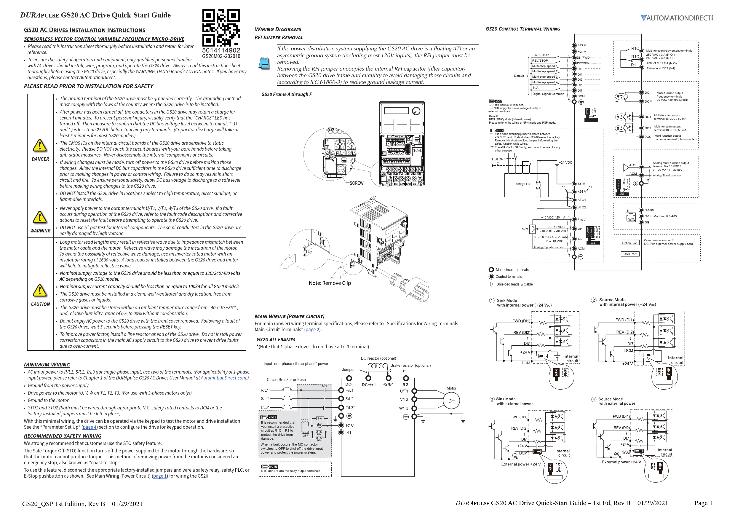
RFI Jumper Removal
If the power system is floating (IT) or asymmetric ground (e.g., most 120V inputs), remove the RFI jumper. This uncouples the internal RFI capacitor to avoid damage and reduce ground leakage current (IEC 61800-3).
GS20 Frame A through F: Note: Remove Clip.
Main Wiring (Power Circuit)
Refer to "Specifications for Wiring Terminals - Main-Circuit Terminals" (page 2) for terminal specifications.
GS20 ALL FRAMES (Note: 1-phase drives lack a T/L3 terminal)
- AC input power to R/L1, S/L2, T/L3 (use two terminals for single-phase input).
- Ground from the power supply.
- Drive power to the motor (U, V, W on T1, T2, T3) (3-phase motors only).
- Ground to the motor.
- STO1 and STO2 (must be wired through appropriate N.C. safety-rated contacts to DCM or use factory-installed jumpers).
With minimal wiring, the drive can be operated via keypad for testing. Configure for keypad operation in "Parameter Set Up" (page 4).
Recommended Safety Wiring (STO)
AutomationDirect strongly recommends using the Safe Torque Off (STO) feature. STO immediately turns off power to the motor hardware, preventing torque production. This is a "coast to stop" method.
To use STO: Disconnect factory jumpers and wire a safety relay, safety PLC, or E-Stop pushbutton as shown in control-circuit wiring diagrams (page 1). From the factory, STO terminals are jumpered, bypassing the STO circuitry. STO is recommended for personnel safety.
Wiring Diagram Description:
- Main Power Input: R/L1, S/L2, T/L3* terminals connected to AC input power via Circuit Breaker or Fuse.
- Motor Output: U/T1, V/T2, W/T3 terminals connected to the motor.
- Optional Components: DC reactor, Brake resistor.
- Safety Circuit: STO1 and STO2 terminals wired through safety contacts to +24VDC (from Safety PLC or external supply) and DCM (Digital Signal Common). The factory jumpers between STO1/STO2 and DCM must be removed to enable STO.
- Relay Output: R1C (N.C.), R1 (N.O.) terminals for multi-function relay output. A protective circuit at R1C-R1 is recommended.
GS20 Control Terminal Wiring
Default Mode: NPN (SINK) Mode (internal power). Refer to NPN/PNP wiring diagrams.
- Digital Inputs (DI1-DI7): DI1/FWD, DI2/REV, DI3-DI6 for multi-step speed, DI7 (up to 33 kHz pulse input).
- Digital Signal Common (DCM).
- +24V: Internal power supply for digital inputs. Note: +24V is for STO only and cannot be used for other purposes.
- STO1, STO2: Safety Torque Off inputs.
- Relay Output (R1O, R1C, R1): Multi-function relay output terminals (250 VAC/3A N.O., 250 VAC/3A N.C., 250 VAC/1.2A N.O.).
- Digital Output (DO, DOC): Multi-function output terminals (30 VDC/30 mA, 33 kHz).
- Analog Output (AO1): Multi-function analog output terminal (0-10 VDC / 0-20 mA / 4-20 mA).
- Analog Input (AI1, AI2): For analog signals (0-10 VDC, 0-20 mA/4-20 mA).
- Analog Signal Common (ACM).
- +10V, SGND: For potentiometer or external signals.
- Modbus RS-485 (SG+, SG-).
- Communication card/Option Slot.
- USB Port.
Note: Do NOT apply mains voltage directly to external terminals.
Note 1 (STO Jumper): Factory default shorts +24V, S1, S2. Remove this jumper before using the safety function.
Note 2 (+24V for STO): +24V is exclusively for STO use.
External Terminal Control Circuits
Setting value: 1 (Two-wire operation control)
- FWD/STOP: DI1
- REV/STOP: DI2
- Common: DCM
Setting value: 2 (Two-wire operation control)
- RUN/STOP: DI1
- FWD/REV: DI2
- Common: DCM
Setting value: 3 (Three-wire operation control)
- RUN: DI1
- REV/FWD: DI2
- STOP: DI3
- Common: DCM
Specifications for Wiring Terminals
Control Circuit
| Terminal | Wire Gauge | Torque |
|---|---|---|
| Control | 24-18 AWG [0.21-0.82 mm²] | n/a (spring terminals) |
| Relay | 24-16 AWG [0.21-1.31 mm²] | 5 kg-cm [4.3 lb-in] |
Recommended Ferrule Terminals:
| Wire Gauge | Manufacturer | Model Name | A (MAX) | B (MAX) | D (MAX) | W (MAX) |
|---|---|---|---|---|---|---|
| 0.25 mm² [24 AWG] | PHOENIX CONTACT | AI 0,25-8 YE | 12.5 | 8 | 2.6 | 1.1 |
| 0.34 mm² [22 AWG] | PHOENIX CONTACT | AI 0,34-8 TQ | 12.5 | 8 | 3.3 | 1.3 |
| 0.5 mm² [20 AWG] | PHOENIX CONTACT | AI 0,5-8 WH | 14 | 8 | 3.5 | 1.4 |
| - | Z+F | V30AE000006 | 14 | 8 | 2.6 | 1.15 |
Main-Circuit Terminals
Notes:
- For Ta ≥ 45°C, use copper wire with 600V rating and ≥ 90°C temperature resistance.
- For UL compliant installation: Use 75°C rated copper wire or better. Use specified ring lug parts. Use crimp tools KST2000D-1322/IZUMI 5N18 (22-8 AWG) or IZUMI 9H-60 (6-4 AWG).
| Drive Models | Max Wire Gauge | Min Wire Gauge | Ring Lug P/N | Screw | Torque (±10%) | Ring Lug Dimensions (mm) | ||||||||
|---|---|---|---|---|---|---|---|---|---|---|---|---|---|---|
| A | B | C | D | d2 | E | F | W | t | ||||||
| GS21-10P2, GS21-20P2 | 16 AWG [1.3 mm²] | - | RNBS 2-3.7 | M3.5 | 9 kg-cm [7.8 lb-in.] [0.88 N·m] | 9.8 (Max) | 3.2 (Max) | 4.8 (Min) | 4.1 (Max) | 3.7 (Min) | 13.0 (Min) | 4.2 (Min) | 6.6 (Max) | 0.8 (Max) |
| GS23-20P2, GS23-20P5 | 18 AWG [0.82 mm²] | - | RNBS 1-3.7 | - | - | - | - | - | - | - | - | - | - | - |
| GS21-10P5, GS21-20P5, GS23-40P5, GS21-21P0, GS23-41P0, GS23-51P0 | 14 AWG [2.1 mm²] | 18 AWG [0.82 mm²] | RNBS 2-3.7 | - | - | - | - | - | - | - | - | - | - | - |
| GS23-22P0, GS23-42P0, GS23-52P0 | 12 AWG [3.3 mm²] | 14 AWG [2.1 mm²] | RNBS 2-4 | M4 | 15 kg-cm [13.0 lb-in.] [1.47 N·m] | 12.1 (Max) | 3.6 (Max) | 6.1 (Min) | 5.6 (Max) | 4.3 (Min) | 13.0 (Min) | 4.5 (Min) | 7.2 (Max) | 1 (Max) |
| GS21-21P0 | 16 AWG [1.3 mm²] | 18 AWG [0.82 mm²] | RNBS 1-3.7 | - | - | - | - | - | - | - | - | - | - | - |
| GS23-23P0, GS23-25P0, GS23-43P0, GS23-45P0, GS23-53P0, GS23-55P0 | 8 AWG [8.4 mm²] | 10 AWG [5.3 mm²] | RNBS 8-4 | M4 | 20 kg-cm [17.4 lb-in.] [1.96 N·m] | 17.8 (Max) | 5.0 (Max) | 6.1 (Min) | 7.2 (Max) | 4.3 (Min) | 13.0 (Min) | 5.5 (Min) | 8.0 (Max) | 1.2 (Max) |
| GS23-27P5, GS23-47P5, GS23-4010, GS23-57P5, GS23-5010 | 8 AWG [8.4 mm²] | 10 AWG [5.3 mm²] | RNBS 5-4 | - | - | - | - | - | - | - | - | - | - | - |
| GS23-2010, GS23-2015*, GS23-4015, GS23-4020 | 6 AWG [13.3 mm²] | 6 AWG [13.3 mm²] | RNBS 14-5 | M5 | 25 kg-cm [21.7 lb-in.] [2.45 N·m] | 27.1 (Max) | 6.1 (Max) | 10.5 (Min) | 11.5 (Max) | 5.3 (Min) | 13.0 (Min) | 6.5 (Min) | 12.2 (Max) | 1.7 (Max) |
| GS23-4025, GS23-4030 | 2 AWG [33.6 mm²] | 4 AWG [21.2 mm²] | RNBS 22-6 | M6 | 40 kg-cm [34.7 lb-in.] [3.92 N·m] | 35.0 (Max) | 9.0 (Max) | 13.3 (Min) | 14.0 (Max) | 6.2 (Min) | 13.0 (Min) | 19.5 (Min) | 18.0 (Max) | 1.8 (Max) |
* The GS23-2015 drive must be wired with a ring terminal of the specified dimensions.
Digital Keypad Functions and Indications
Note: Drive default is AUTO mode. Local mode can be set with I/O configuration or GS4-KPD only.
Keypad Navigation Example
| Instruction | Press Key | Display Will Show |
|---|---|---|
| First menu to display after power up. | RUN |
n/a |
| Displays the present frequency setting of the drive | MENU |
F60.00 |
| Displays the actual output frequency of the drive | MENU (once) |
450.00 |
| Displays user defined output | MENU (twice) |
U 180 |
| Displays output current | MENU (three times) |
I 180 |
| Displays Frd if configured for Forward operation. Press UP/DOWN to change to Reverse. Press ENTER to confirm. | MENU (four times) |
Frd |
| Displays current PLC setting. Press UP/DOWN to change, then ENTER to confirm. | MENU (five times) |
PLC0 |
| Displays the counter value. Enable counter by setting P00.04 to 1. | MENU |
20 |
| Navigate to parameter number (XX.YY), change value, press ENTER. | ENTER, then UP/DOWN, then ENTER |
06.00 (parameter number) |
| From parameter number, press ENTER to show value. Adjust value with UP/DOWN, press ENTER to confirm. | ENTER, then UP/DOWN, then ENTER |
10 (parameter value) |
| Once value is set, press ENTER to save and display End message. | ENTER |
End |
| Displays when data has been accepted and stored. | n/a |
End |
| Displays when an external fault is detected. | n/a |
EF |
| Displays when data is not accepted or value exceeded. | n/a |
Err |
Descriptions of Keypad Functions
- RUN Key: Valid only when keypad is the command source. Can be pressed during stopping. In "LOCAL" mode, RUN is valid only if keypad is the command source.
- STOP/RESET Key: Highest priority. Executes STOP command regardless of drive status. RESET key clears faults. (Keypad STOP is effective only if configured for keypad RUN/STOP).
- ENTER Key: Go to next menu level or accept parameter entry/command.
- MENU Key: Return to Main Menu or cycle through menu options.
- UP/DOWN Arrows: Increase/decrease value or select menu items. Long press MENU for left direction.
Frequency Setting Dial (Potentiometer)
Can be set as the main frequency input. Set Parameter 00-20 or 00-30 to '7-Digital Keypad Dial'.
Descriptions of LED Functions
- RUN LED: Steady ON: Drive is running. Blinking: Drive is stopping or in base block. Steady OFF: Drive is not running.
- FWD LED: Steady ON: Operating in Forward mode. Blinking: Changing direction. Steady OFF: Operating in Reverse mode.
- REV LED: Steady ON: Operating in Reverse mode. Blinking: Changing direction. Steady OFF: Operating in Forward mode.
- STOP LED: Steady ON: Drive is stopped or stopping. Blinking: Standby (run but no output). Steady OFF: Not executing STOP command.
- PLC LED: Steady ON: PLC STOP (PLC 2) initiated. Blinking: PLC Run (PLC1) initiated. Steady OFF: No PLC functions implemented (PLC 0).
GS20 Fault Codes
| Code | Description | Code | Description |
|---|---|---|---|
| 0 | No Error | 54 | Communication Error (CE1) |
| 1 | Overcurrent during Accel (ocA) | 55 | Communication Error (CE2) |
| 2 | Overcurrent during Decel (ocd) | 56 | Communication Error (CE3) |
| 3 | Overcurrent during constant speed (ocn) | 57 | Communication Error (CE4) |
| 4 | Ground Fault (GFF) | 58 | PC Communication Time Out (CE10) |
| 6 | Overcurrent during Stop (ocS) | 61 | Y-Delta connection Error (ydc) |
| 7 | Overvoltage during Accel (ovA) | 62 | Decel Energy Backup Error (dEb) |
| 8 | Overvoltage during Decel (ovd) | 63 | Slip Error (oSL) |
| 9 | Overvoltage during constant speed (ovn) | 72 | Channel 1 (S1~DCM) safety loop error (STL1) |
| 10 | Overvoltage during Stop (ovS) | 76 | Safety Torque Off (STO) |
| 11 | Low voltage during Accel (LvA) | 77 | Channel 2 (S2~DCM) safety loop error (STL2) |
| 12 | Low voltage during Decel (Lvd) | 78 | Internal loop error (STL3) |
| 13 | Low voltage during constant speed (Lvn) | 79 | U Phase over current before run (Aoc) |
| 14 | Low voltage during Stop (LvS) | 80 | V Phase over current before run (boc) |
| 15 | Input phase loss (OrP) | 81 | W Phase over current before run (coc) |
| 16 | IGBT Overheat 1 (oH1) | 82 | U Phase output phase loss (oPL1) |
| 18 | Thermister 1 open (tH1o) | 83 | V Phase output phase loss (oPL2) |
| 21 | Drive over-load (oL) | 84 | W Phase output phase loss (oPL3) |
| 22 | Electronics thermal relay protection 1 (EoL1) | 87 | Drive over load in low frequency (oL3) |
| 23 | Electronics thermal relay protection 2 (EoL2) | 89 | Initial rotor position detection error (roPd) |
| 24 | Motor Overheat-PTC (oH3) | 121 | Internal communication error (CP20) |
| 26 | Over Torque 1 (ot1) | 123 | Internal communication error (CP22) |
| 27 | Over Torque 2 (ot2) | 124 | Internal communication error (CP30) |
| 28 | Under current (uc) | 126 | Internal communication error (CP32) |
| 31 | Memory read-out error (cF2) | 127 | Software version error (CP33) |
| 33 | U phase current sensor detection error (cd1) | 128 | Over-torque 3 (ot3) |
| 34 | V phase current sensor detection error (cd2) | 129 | Over-torque 4 (ot4) |
| 35 | W phase current sensor detection error (cd3) | 134 | Electronics thermal relay 3 protection (EoL3) |
| 36 | Clamp current detection error (Hd0) | 135 | Electronics thermal relay 4 protection (EoL4) |
| 37 | Over-current detection error (Hd1) | 140 | GFF detected when power on (Hd6) |
| 40 | Auto tuning error (AuE) | 141 | GFF occurs before run (b4GFF) |
| 41 | PID Feedback loss (AFE) | 142 | Auto tuning error 1 (DC test stage) (AUE1) |
| 42 | PG feedback error (PGF1) | 143 | Auto tuning error 2 (High frequency test stage) (AUE2) |
| 43 | PG feedback loss (PGF2) | 144 | Auto tuning error 3 (Rotary test stage) (AUE3) |
| 44 | PRG feedback stall (PGF3) | - | - |
| 45 | PG slip error (PGF4) | - | - |
| 48 | Analog current input loss (ACE) | - | - |
| 49 | External Fault input (EF) | - | - |
| 50 | Emergency Stop (EF1) | - | - |
| 51 | External Base Block (bb) | - | - |
| 52 | Password Error (Pcod) | - | - |
Parameter Setup
DURApulse GS20 AC Drives offer parameter setup from the keypad for common applications. Choose parameters from the tables below and set them as shown.
To Configure Parameters:
- From the power-up screen, press
MENUuntilH 0.00(actual drive frequency) is displayed, then pressENTER. - Use UP/DOWN arrows to select a parameter group, then press
ENTER. - Use UP/DOWN arrows to select a parameter number, then press
ENTER. - Change the parameter value using UP/DOWN arrows, then press
ENTER. - Press
MENUto exit to the main menu. - Repeat as needed.
Refer to the user manual for detailed parameter information.
DURApulse GS20 Parameter Settings - Quick Configuration*
| Group # | Parameter | Description | Range | Default | User |
|---|---|---|---|---|---|
| 00 | 00 00 | GS20 Model ID | Read Only | n/a | - |
| 00 | 00 01 | Displays AC drive rated current | Displays value based on model | n/a | - |
| 00 | 00 02 | Restore to default** | 0=No function, 1=Parameter write protect, 2=Reset to GS2 mode (1 of 2), 5=Reset kWH display to 0, 6=Reset PLC, 7=Reserved, 8=Keypad doesn't respond, 9=Reset 50Hz defaults, 10=Reset 60Hz defaults, 11=Reset 50Hz defaults (keep user config), 12=Reset 60Hz defaults (keep user config), 20=Reset to GS2 mode (2 of 2) |
0 | - |
| 00 | 00 06 | Firmware Version | Read Only | n/a | - |
| 00 | 00 10 | Control Mode | 0=Speed mode, 2=Torque mode |
0 | - |
| 00 | 00 11 | Speed Control Mode | 0=VF (IM V/F control), 1=VFPG (IM V/F control + Encoder), 2=SVC (Parameter 05.33 set as IM or PM), 5=FOC (Field Oriented Control) |
0 | - |
| 00 | 00 16 | Load Selection | 0=VT, 1=CT |
1 | - |
| 00 | 00 20 | Frequency Command Source (Auto) | 0=Digital keypad, 1=Communication RS-485 input, 2=External analog input, 3=External UP/DOWN terminal, 4=Pulse input without direction, 7=Digital keypad dial |
0 | - |
| 00 | 00 21 | Operation Command Source (Auto) | 0=Digital keypad, 1=External terminals, 2=Communication RS-485 input, 5=Communication card |
0 | - |
| 00 | 00 22 | Stop Method | 0=Ramp to stop, 1=Coast to stop |
0 | - |
| 00 | 00 23 | Motor Direction Control | 0=Enable forward/reverse, 1=Disable reverse, 2=Disable forward |
0 | - |
| 01 | 01 00 | Motor 1 Max Frequency | 0.00-599.00 Hz | 60 | - |
| 01 | 01 01 | Motor 1 Base Frequency | 0.00-599.00 Hz | 60 | - |
| 01 | 01 02 | Motor 1 Rated Voltage | 110V/230V: 0.0~255.0; 460V: 0.0~510.0V | 220.0 / 440.0 | - |
| 01 | 01 09 | Startup Frequency | 0.00-599.0 Hz | 0.5 | - |
| 01 | 01 10 | Output Frequency Upper Limit | 0.00-599.0 Hz | 599.0 | - |
| 01 | 01 11 | Output Frequency Lower Limit | 0.00-5.99.0 Hz | 0.00 | - |
| 01 | 01 12 | Acceleration Time 1 | P01.45=0: 0.00-600.00 sec; P01.45=1: 0.00-6000.00 sec | 10.00 | - |
| 01 | 01 13 | Deceleration Time 1 | P01.45=0: 0.00-600.00 sec; P01.45=1: 0.00-6000.00 sec | 10.00 | - |
| 01 | 01 20 | Jog Acceleration Time | P01.45=0: 0.00-600.00 sec; P01.45=1: 0.00-6000.00 sec | 10.00 | - |
| 01 | 01 21 | Jog Deceleration Time | P01.45=0: 0.00-600.00 sec; P01.45=1: 0.00-6000.00 sec | 10.00 | - |
| 01 | 01 22 | Jog Frequency | 0.00-599.0 Hz | 0.5 | - |
| 02 | 02 00 | 2-wire / 3-wire Control | 0=No function, 1=2-wire mode 1 (FWD/STOP), 2=2-wire mode 2 (RUN/STOP), 3=3-wire (RUN, REV/FWD, STOP), 4=2-wire mode 1 fast start, 5=2-wire mode 2 fast start, 6=3-wire fast start. Note: Fast start skips IGBT detection. |
1 | - |
| 02 | 02 01 | Multi-function Input Command 1 (FWD/DI1) | See "Multi-function Input Selections" on page 5 | 0 | - |
| 02 | 02 02 | Multi-function Input Command 2 (REV/DI2) | See "Multi-function Input Selections" on page 5 | 0 | - |
| 02 | 02 03 | Multi-function Input Command 3 (DI3) | See "Multi-function Input Selections" on page 5 | 1 | - |
| 02 | 02 04 | Multi-function Input Command 4 (DI4) | See "Multi-function Input Selections" on page 5 | 2 | - |
| 02 | 02 05 | Multi-function Input Command 5 (DI5) | See "Multi-function Input Selections" on page 5 | 3 | - |
| 02 | 02 06 | Multi-function Input Command 6 (DI6) | See "Multi-function Input Selections" on page 5 | 4 | - |
| 02 | 02 07 | Multi-function Input Command 7 (DI7) | See "Multi-function Input Selections" on page 5 | 0 | - |
| 02 | 02 13 | Multi-function Output 1 (R1) | See "Multi-function Output Selections" on page 5 | 11 | - |
| 02 | 02 16 | Multi-function Output 2 (DO1) | See "Multi-function Output Selections" on page 5 | 0 | - |
| 02 | 02 17 | Multi-function Output 3 (DO2) | See "Multi-function Output Selections" on page 5 | 0 | - |
| 03 | 03 00 | Analog Input Selection (AI1) | See "AI Multi-function Input Selections" on page 5 | 1 | - |
| 03 | 03 01 | Analog Input Selection (AI2) | See "AI Multi-function Input Selections" on page 5 | 0 | - |
| 03 | 03 20 | Multi-function Output (AO1) | See "AO1 Multi-function Output Selections" on page 5 | 0 | - |
| 03 | 03 29 | AI2 terminal input selection | 0=4-20 mA, 1=0-10 V, 2=0-20 mA |
0 | - |
| 04 | 00 04 to 14 | Multi-step Speed Frequency 1-15 | 0.00-599.00 Hz | 0.00 | - |
| 05 | 05 00 | Motor Parameter Auto-tuning | 0=No function, 1=Dynamic test (IM), 2=Static test (IM), 5=Rolling auto-tuning (PM), 6=Simple rolling auto-tuning (IM), 12=FOC sensorless inertia estimation, 13=High frequency stall test (PM) |
0 | - |
| 05 | 05 01 | Motor 1 Full Load Amps (FLA) | 10-120% of drive rated current | ###.## | - |
| 05 | 05 03 | Motor 1 Rated RPM | 0-65535 | 1710 | - |
| 05 | 05 04 | Motor 1 Number of poles | 2-20 | 4 | - |
| 06 | 06 06 | Over-torque Detection Selection (Motor 1) | 0=No function, 1=Continue (constant speed), 2=Stop (constant speed), 3=Continue (RUN), 4=Stop (RUN) |
0 | - |
| 06 | 06 07 | Over-torque Detection Level (Motor 1) | 10-250% (of drive rated current) | 120 | - |
| 06 | 06 08 | Over-torque Detection Time (Motor 1) | 0.1-60.0 seconds | 0.1 | - |
| 06 | 06 13 | Motor 1 Electronic Thermal Overload Relay | 0=Inverter motor (external cooling), 1=Standard motor (shaft fan), 2=Disabled |
2 | - |
| 06 | 06 14 | Motor 1 Electronic Thermal Relay Time | 30.0-600.0 | 60 | - |
| 06 | 06 55 | Drive Derating Method | 0=Constant rated current (limit carrier by load/temp), 1=Constant carrier frequency (limit load by carrier), 2=Constant rated current (same as 0) but disable current limit |
0 | - |
| 07 | 07 10 | Restart after fault action | 0=Stop operation, 1=Speed tracking (current speed), 2=Speed tracking (min output frequency) |
0 | - |
| 07 | 07 11 | Number of times of restart after fault | 0-10 | 0 | - |
| 07 | 07 19 | Fan cooling control | 0=Always ON, 1=OFF after 1 min stop, 2=ON when running, OFF when stopped, 3=ON when IGBT temp reaches ~600°C |
3 | - |
| 08 | 08 00 | Terminal selection of PID feedback | 0=No function, 1=Negative PID (AI), 2=Negative PID (DI7), 4=Positive PID (AI), 5=Positive PID (DI7), 7=Negative PID (Comm), 8=Positive PID (Comm) |
0 | - |
| 08 | 08 01 | Proportional gain (P) | 0.0-1000.0 (P08.23 bit 1=0); 0.00-100.00 (P08.23 bit 1=1) | 1.00 | - |
| 08 | 08 02 | Integral time (I) | 0.00-100.00 sec. | 1.00 | - |
| 08 | 08 03 | Differential time (D) | 0.00-1.00 sec. | 0.00 | - |
| 08 | 08 04 | Upper limit of integral control | 0.0-100.0% | 100.0 | - |
| 08 | 08 05 | PID output command limit (positive limit) | 0.0-110.0% | 100.0 | - |
| 08 | 08 06 | PID feedback value by communication protocol | -200.00-200.00% | 0.00 | - |
| 08 | 08 07 | PID delay time | 0.0-2.5 sec. | 0.0 | - |
| 08 | 08 08 | Feedback signal detection time | 0.0-3600.0 sec. | 0.0 | - |
| 08 | 08 09 | Feedback signal fault treatment | 0=Warn & continue, 1=Fault & ramp stop, 2=Fault & coast stop, 3=Warn & operate at last frequency |
0 | - |
| 08 | 08 65 | PID target value source | 0=Freq command (P00.20/30), 1=P08.66 setting, 2=RS-485 input, 3=External analog input, 6=Comm card, 7=Keypad dial |
0 | - |
| 13 | 13 00 | Application Selection | 00=Disabled, 01=User parameter, 02=Compressor, 03=Fan, 04=Pump, 05=Conveyor, 06=Machine tool, 07=Packing, 08=Textiles |
0 | - |
* Assumes default V/Hz mode with no feedback. For other modes, see User Manual. ** Reboot drive after resetting defaults.
Note: Drive default is Auto mode. For Local/Hand, use Discrete input settings (P02.00-P02.07) and P00.29-P00.31.
Multi-function Input Selections
Description: 0=No function, 1=Multi-step speed 1, 2=Multi-step speed 2, 3=Multi-step speed 3, 4=Multi-step speed 4, 5=Reset, 6=JOG, 7=Accel/decel speed inhibit, 8=1st/2nd accel/decel time select, 9=3rd/4th accel/decel time select, 10=External Fault (EF), 11=Base Block (B.B.), 12=Output stop, 13=Cancel auto accel/decel time, 15=Speed command from AI1, 16=Speed command from AI2, 18=Force to stop, 19=Digital up, 20=Digital down, 21=PID function disabled, 22=Clear counter, 23=Input counter value (DI6), 24=FWD JOG, 25=REV JOG, 26=TQC/FOC mode select, 27=ASR1/ASR2 select, 28=Emergency stop (EF1), 29=Y-connection confirmation, 30=A-connection confirmation, 31=High torque bias, 32=Middle torque bias, 33=Low torque bias, 38=Disable EEPROM write, 39=Torque command direction, 40=Force coasting stop, 41=HAND switch, 42=AUTO switch, 48=Mechanical gear ratio switch, 49=Enable drive, 50=Slave dEb action, 51=PLC mode bit 0, 52=PLC mode bit 1, 56=Local/Remote select, 58=Enable fire mode (with RUN), 59=Enable fire mode (without RUN), 70=Force auxiliary frequency to 0, 71=Disable PID, force PID output to 0, 72=Disable PID, retain output, 73=Force PID integral gain to 0, 74=Reverse PID feedback, 81=Simple positioning zero point, 82=OOB loading balance, 83=Multi-motor (IM) bit 0, 84=Multi-motor (IM) bit 1.
Multi-function Output Selections
Description: 0=No function, 1=Indication during RUN, 2=Operation speed reached, 3=Desired frequency reached 1, 4=Desired frequency reached 2, 5=Zero speed (Freq command), 6=Zero speed (including STOP), 7=Over-torque 1, 8=Over-torque 2, 9=Drive is ready, 10=Low voltage warning, 11=Malfunction indication, 13=Overheat warning, 14=Software brake signal, 15=PID feedback error, 16=Slip error, 17=Count value reached (no reset), 18=Count value reached (reset), 19=External interrupt B.B., 20=Warning output, 21=Over-voltage, 22=Over-current stall prevention, 23=Over-voltage stall prevention, 24=Operation mode, 25=Forward command, 26=Reverse command, 29=Output when frequency ≥ P02.34, 30=Output when frequency < P02.34, 31=Y-connection, 32=A-connection, 33=Zero speed (actual output freq), 34=Zero speed (actual output freq, incl. STOP), 35=Error output 1, 36=Error output 2, 37=Error output 3, 38=Error output 4, 40=Speed reached (incl. STOP), 42=Crane function, 43=Motor speed detection, 44=Low current output, 45=UVW output electromagnetic valve switch, 46=Master dEb output, 51=Analog output (RS-485), 52=Output control (Comm cards), 53=Fire mode indication, 66=SO output logic A, 67=Analog input level reached, 68=SO output logic B, 73=Over-torque 3, 74=Over-torque 4, 75=Forward RUN status, 76=Reverse RUN status.
AI Multi-function Input Selections
Description: 0=No function, 1=Frequency command, 2=Torque command, 3=Torque compensation, 4=PID target value, 5=PID feedback signal, 6=Thermistor (PTC) input, 7=Positive torque limit, 8=Negative torque limit, 9=Regenerative torque limit, 10=Positive/negative torque limit, 11=PT100 thermistor, 12=Auxiliary frequency input, 13=PID compensation value.
AO1 Multi-function Output Selections
Description: 0=Output frequency (Hz), 1=Frequency command (Hz), 2=Motor speed (Hz), 3=Output current (rms), 4=Output voltage, 5=DC bus voltage, 6=Power factor, 7=Power, 8=Output torque, 9=AI1, 10=AI2, 12=Iq current command, 13=Iq feedback, 14=Id current command, 15=Id feedback, 16=Vq-axis voltage command, 17=Vd-axis voltage command, 18=Torque command, 19=PG2 (DI7) frequency command, 21=RS-485 analog output, 22=Comm card analog output, 23=Constant voltage output.
Optional Configuration Setting: GS2 Mode
GS2 mode allows operation with legacy GS2 parameter configuration. Note: Parameters cannot be locked or read-only, and PLC must be disabled to enter GS2 mode.
To Enter GS2 Mode: Set P00.02=2 (enter GS2 mode 1/2), press ENTER. Set P00.02=20 (enter GS2 mode 2/2), press ENTER. Reboot drive.
To Exit GS2 Mode: Set P09.08=20 (reset to GS20 mode), press ENTER. Reboot drive. Configure GS20 parameters.
Cooling and Heat Dissipation
| Model Number | Airflow Rate (cfm) | Airflow Rate (m³/hr) | Power Dissipation (Watts) - External (Heat sink) | Power Dissipation (Watts) - Internal | Power Dissipation (Watts) - Total |
|---|---|---|---|---|---|
| GS21-10P2 | 8.0 | 10.0 | 18.0 | 0.0 | 0.0 |
| GS21-10P5 | 14.2 | 13.1 | 27.3 | - | - |
| GS21-11P0 | 16.0 | 27.2 | 29.1 | 23.9 | 53.0 |
| GS21-20P2 | 8.0 | 10.3 | 18.3 | - | - |
| GS21-20P5 | 16.3 | 14.5 | 30.8 | 0.0 | 0.0 |
| GS21-21P0 | 29.1 | 20.1 | 49.2 | - | - |
| GS21-22P0 | 29.1 | 23.9 | 53.0 | 16.0 | 27.2 |
| GS21-23P0 | 70.0 | 35 | 105 | - | - |
| GS23-2010 | 244.5 | 79.6 | 324.1 | 53.7 | 91.2 |
| GS23-2015 | 374.2 | 86.2 | 460.4 | - | - |
| GS23-2020 | 492.0 | 198.2 | 690.2 | 67.9 | 115.2 |
| GS23-20P2 | 8.6 | 10.0 | 18.6 | 0.0 | 0.0 |
| GS23-20P5 | 16.5 | 12.6 | 29.1 | - | - |
| GS23-21P0 | 31.0 | 13.2 | 44.2 | 10.0 | 16.99 |
| GS23-22P0 | 50.1 | 24.2 | 74.3 | 16.0 | 27.2 |
| GS23-23P0 | 76.0 | 30.7 | 106.7 | - | - |
| GS23-25P0 | 108.2 | 40.1 | 148.3 | 23.4 | 39.7 |
| GS23-4010 | 164.7 | 55.8 | 220.5 | 53.7 | 91.2 |
| GS23-4015 | 234.5 | 69.8 | 304.3 | - | - |
| GS23-4020 | 319.8 | 74.3 | 394.1 | 67.9 | 115.2 |
| GS23-4025 | 423.5 | 181.6 | 605.1 | - | - |
| GS23-4030 | 501.1 | 200.3 | 701.4 | - | - |
| GS23-40P5 | 17.6 | 11.1 | 28.7 | - | - |
| GS23-41P0 | 10.0 | 16.99 | 30.5 | 10.0 | 16.99 |
| GS23-42P0 | 45.9 | 21.7 | 67.6 | 16.0 | 27.2 |
| GS23-43P0 | 60.6 | 22.8 | 83.4 | - | - |
| GS23-45P0 | 93.1 | 42 | 135.1 | 23.4 | 39.7 |
| GS23-47P5 | 132.8 | 39.5 | 172.3 | - | - |
| GS23-5010 | 0.0 | 0.0 | 0.0 | 17.6 | 11.1 |
| GS23-51P0 | 23.5 | 12.5 | 36.0 | - | - |
| GS23-52P0 | 10.0 | 16.99 | 38.1 | 10.0 | 16.99 |
| GS23-53P0 | 56.6 | 22.2 | 68.8 | 16.0 | 27.2 |
| GS23-55P0 | 76.1 | 30 | 106.1 | - | - |
| GS23-57P5 | 93.9 | 37 | 130.9 | 23.4 | 39.7 |
Notes:
- External Flow Rate is across the heat sink. Internal Flow Rate is through the chassis.
- Published flow rates are for active cooling with fans. Unpublished rates (-) are for passive cooling.
- Required airflow is for a single drive in a confined space. For multiple drives, multiply by the number of drives.
- For power dissipation (Watt Loss), use the Total value. For multiple drives, multiply by the number of drives.
- Heat dissipation is calculated by rated voltage, current, and default carrier frequency.
Environment for Operation, Storage, and Transportation
DO NOT expose the GS20 drive to dust, direct sunlight, corrosive/inflammable gases, high humidity, liquids, or high vibration. Salt in air must be < 0.01 mg/cm² annually.
| Environment | Installation Location | Surrounding Temperature | Rated Humidity | Air Pressure | Pollution Level | Altitude | Package | Drop | Vibration (Operating) | Vibration (Non-operating) | Impact (Operating) | Impact (Non-operating) | Protection Level |
|---|---|---|---|---|---|---|---|---|---|---|---|---|---|
| Operation | IEC60364-1/IEC60664-1 Pollution degree 2, Indoor use only | -40°C to +85°C (Storage) -20°C to +70°C (Transportation) |
Max. 90% (Operation) Max. 95% (Storage/Transportation) |
86 to 106 kPa (Operation/Storage) 70 to 106 kPa (Transportation) |
Class 3C2; Class 3S2 (Operation) Class 2C2; Class 2S2 (Storage) Class 1C2; Class 1S2 (Transportation) |
0-1000m: Normal. 1000-2000m: Decrease 1% current or 0.5°C temp per 100m. Max altitude for Corner Grounded is 2000m. Contact ADC for >2000m. | - | ISTA procedure 1A | 1.0mm pk-pk (2-13.2 Hz); 0.7-1.0G (13.2-55 Hz); 2.0G (55-512 Hz) | 2.5 G peak (5Hz-2kHz) | IEC/EN60068-2-27: 15G, 11ms | 30G | IP40 (main unit) IP20 (wiring area) |
Minimum Mounting Clearances
Important considerations:
- Prevent debris (fiber, paper, wood, metal particles) from adhering to the heat sink.
- Install in a metal cabinet. Use metal separation between drives installed below each other to prevent mutual heating and fire risk.
- Install in Pollution Degree 2 environments only (normally nonconductive pollution, temporary conductivity from condensation expected).
Diagram Description: Inflow arrows (Blue), Outflow arrows (Red).
| Installation Method | A (mm) Max | B (mm) Max | C (mm) | Operation Temperature Max (w/out derating) | Operation Temperature Max (Derating) |
|---|---|---|---|---|---|
| Single drive installation | 50 | 30 | 50 | 60 | 60 |
| Side-by-side horizontal installation | 50 | 30 | 30 | 50 | 60 |
| Zero stack installation | 50 | 30 | 0 | 40 | 50 |
Dimension Diagrams
Units = mm [in]
GS20 Frame A
Overall dimensions: Height 128.0 [5.04], Width 68.0 [2.68], Depth 118.0 [4.65]. Mounting hole detail shown.
Models by Frame Size A1-A5: Lists models like GS21-10P2, GS23-20P2, GS23-40P5, GS23-21P0 etc. with their corresponding frame designation (A1-A5) and dimension D.
GS20 Frame B
Overall dimensions: Height 142.0 [5.59], Width 72.0 [2.83], Depth 130.0 [5.12]. Mounting hole detail shown.
Models by Frame Size B1-B2: Lists models like GS23-22P0, GS21-21P0 etc. with their frame designation (B1-B2) and dimension D/D1.
GS20 Frame C
Overall dimensions: Height 157.0 [6.18], Width 87.0 [3.43], Depth 152.0 [5.98]. Mounting hole detail shown.
Models by Frame Size C1: Lists models like GS21-11P0, GS23-23P0, GS23-43P0 etc. with their frame designation (C1) and dimension D.
GS20 Frame D
Overall dimensions: Height 207.0 [8.15], Width 109.0 [4.29], Depth 154.0 [6.06]. Mounting hole detail shown.
Models by Frame Size D1: Lists models like GS23-27P5, GS23-4010, GS23-5010 etc. with their frame designation (D1) and dimension D/D1.
GS20 Frame E
Overall dimensions: Height 250.0 [9.84], Width 115.0 [4.53], Depth 130.0 [5.12]. Mounting hole detail shown.
Models by Frame Size E1: Lists models like GS23-2010, GS23-4015, GS23-4020 etc. with their frame designation (E1) and dimension D.
GS20 Frame F
Overall dimensions: Height 300.0 [11.81], Width 154.0 [6.06], Depth 175.0 [6.89]. Mounting hole detail shown.
Models by Frame Size F1: Lists models like GS23-2020, GS23-4025, GS23-4030 etc. with their frame designation (F1) and dimension D.
NEMA 1 Conduit Boxes
GS20 drives can optionally be fitted with NEMA 1 conduit boxes. Dimensional diagrams show how the box affects the overall unit dimensions for each frame size (A, B, C, D, E, F).
