800, 900 and 1000 Base and Corner Base Unit Assembly
Introduction and Important Information
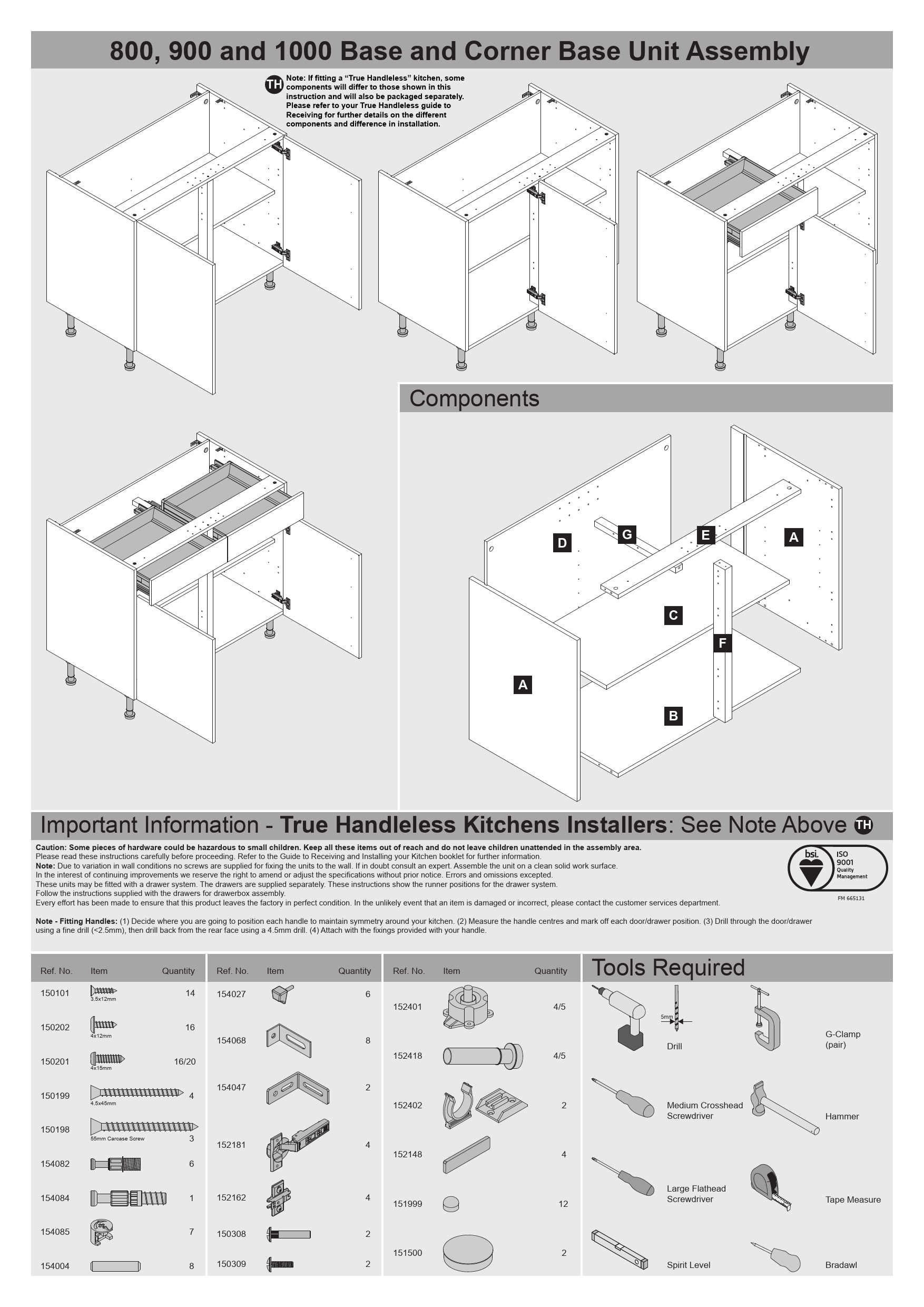
This guide details the assembly of 800, 900, and 1000mm Base and Corner Base Units. It is designed for use with kitchen installations, including compatibility with the "True Handleless" system, which may require consulting separate documentation for specific components and installation differences.
⚠️ Caution: This product contains small hardware parts that can be a choking hazard for young children. Ensure all components are kept out of reach of children and that children are not left unattended in the assembly area.
Before commencing assembly, please read these instructions thoroughly. For additional guidance, refer to the "Guide to Receiving and Installing your Kitchen" booklet.
? Note: Wall fixing screws are not included, as wall conditions vary. If you are unsure about wall fixing methods, consult a qualified professional. Assemble the unit on a clean and stable work surface.
We reserve the right to amend or adjust specifications without prior notice to facilitate ongoing product improvements. Errors and omissions are excepted.
These units can accommodate drawer systems, which are supplied separately. The diagrams within this guide illustrate the correct positions for drawer runners. Please follow the specific instructions provided with your drawer system for drawerbox assembly.
Quality assurance ensures that products leave the factory in perfect condition. Should you encounter any damaged or incorrect items, please contact the customer services department.
? Note - Fitting Handles: 1. Determine the desired position for handles to ensure symmetry within your kitchen layout. 2. Measure the handle centres and mark the corresponding positions on each door or drawer front. 3. Drill through the door/drawer using a fine drill bit (less than 2.5mm). Subsequently, drill from the rear face using a 4.5mm drill bit. 4. Secure the handles using the fixings provided with the handles.
Components Overview
The primary components for assembling the base and corner base units include:
- Panel A: Side Panels (typically two vertical panels forming the sides of the unit).
- Panel B: Base Panel (the bottom horizontal panel).
- Panel D: Back Panel (a thin panel fitted to the rear of the unit).
- Panel E: Top Panel (the top horizontal panel).
- Panel F: Plinth or Kickboard (a panel fitted at the base front for aesthetic and structural support).
- Support C: A structural element, often a horizontal or vertical brace, typically for the back panel or internal structure.
- Support G: A component, likely for mounting drawer runners or shelf supports.
Refer to the assembly diagrams for precise placement and orientation of each component.
Parts List
| Ref. No. | Item Description | Quantity |
|---|---|---|
| 150101 | 3.5x12mm | 14 |
| 154027 | 6 | |
| 150202 | 4x12mm | 16 |
| 154068 | 8 | |
| 150201 | 4x15mm | 16/20 |
| 150199 | 4.5x45mm | 4 |
| 154047 | 2 | |
| 150198 | 55mm Carcase Screw | 3 |
| 152181 | 4 | |
| 154082 | 6 | |
| 154084 | 1 | |
| 152162 | 4 | |
| 154085 | 7 | |
| 154004 | 8 | |
| 150308 | 2 | |
| 150309 | 2 | |
| 152401 | 4/5 | |
| 152418 | 4/5 | |
| 152402 | 2 | |
| 152148 | 4 | |
| 151999 | 12 | |
| 151500 | 2 |
Tools Required
- Drill
- Medium Crosshead Screwdriver
- Hammer
- Large Flathead Screwdriver
- Tape Measure
- G-Clamp (pair)
- Bradawl
Assembly Instructions
Steps 1-13: Base Unit Construction
Steps 1-2: Attach drawer runners (Part 154082) to the inside faces of the side panels (A). These are specified as "98mm Drawer runner". A note indicates "Modification required at this stage, see True Handleless guide for further details."
Steps 3-4: Begin assembling the main cabinet frame. Connect base panel (B) and other structural supports (like C) to side panels (A) using dowels and screws (e.g., 150199, 150202). A note advises drilling centre holes for panels B and E on standard Base Units, and consulting the kitchen plan for specific drill points on Corner Base Units based on door size. Use scrap wood for support during drilling.
Steps 5-6: Secure the top panel (E) to the side panels (A) using the appropriate fixings.
Steps 7-11: Fit the back panel (D) into the rear of the assembled frame. Secure it using screws (e.g., 150198). A specific instruction notes: "Note: Countersunk screw goes into back panel D."
Step 12: Attach the plinth or kickboard (Panel F) to the bottom front edge of the unit using screws.
Step 13: This step illustrates the assembly of a unit configured "Without Drawers".
Steps 14-22: Drawer Runner and Drawer Box Assembly
Steps 14-17: Attach the drawer runners (Parts 154085 and 154084) to the interior faces of the side panels (A) of the main cabinet. These runners are designed to receive the drawer box. Note the designation "1 x 'L'; 1 x 'R'" for the runners, indicating left and right specific parts.
Steps 18-20: Assemble the drawer box components. This involves connecting the drawer sides, front, back, and base. Attach the corresponding parts of the drawer runners to the sides of the assembled drawer box.
Steps 21-22: Insert the completed drawer box, with its attached runners, into the cabinet. The runners on the drawer box should engage with the runners fixed to the cabinet sides. Instructions include "Do Not Over Tighten" and indicators for "Start" and "Locked" positions for the runners.
Steps 23-25: Installation and Wall Fixing
Steps 23-25: These steps cover the final installation, including fixing the unit to the wall. Diagrams show drilling pilot holes in the cabinet for wall mounting. It is noted that screws appropriate for the specific wall type are not supplied. Wall anchors or suitable fixings should be used as required.
Steps 26-29: Door Hinge Fitting
Steps 26-29: Fit the cabinet hinges to the doors and the corresponding mounting points on the cabinet side panels (A). Specific hardware such as screws (151500, 152402, 150101) are shown for this process. This stage typically includes provisions for door adjustment.
Steps 30-31: Additional Drawer Runner Installation
Steps 30-31: These steps illustrate the attachment of additional drawer runners to the cabinet, potentially for different drawer types or configurations.
Steps 32-37: Fixed Fascia Fitting
Steps 32-37: This section details the process of fitting a "Fixed Fascia". This is a decorative panel that is attached to the front of the unit, often covering the cabinet frame or acting as a visual element. The fitting involves using brackets and screws (e.g., 150101, 151999, 150202, 154068, 152148).
Steps 38-41: Corner Post Fitting
Steps 38-41: These steps describe the installation of a "Corner Post", a component used to join two base units at a corner. The process involves fitting the corner post to an adjacent unit first, then attaching an optional blanking panel to the corner base unit, and finally securing the corner post to the corner base unit's mullion. Hardware such as 150124 and 154081 is indicated. It is noted that any excess length on the corner post does not require trimming as it will be concealed within the void.
Unit Size Guide
The following table provides dimensions for different unit sizes, required door sizes, total length on plan, and the corresponding void dimensions.
| Unit Size (mm) | Required Door Size (mm) | Total Length on Plan (mm) | Void "x" (mm) |
|---|---|---|---|
| 800 | 300 | 925 | 125 |
| 800 | 400 | 1025 | 225 |
| 800 | 500 | 1125 | 325 |
| 1000 | 400 | 1025 | 25 |
| 1000 | 500 | 1125 | 125 |
| 1000 | 600 | 1225 | 225 |
