MEIG SLM900 Multi-Mode Multi-Band Smart LTE Module Datasheet
File info: application/pdf · 5 pages · 416.33KB
User Manual
MeiG Smart Technology Co., Ltd SLM900 Module 2APJ4-SLM900 2APJ4SLM900 slm900
Full PDF Document

If the inline viewer fails, it will open the original document in compatibility mode automatically. You can also open the file directly.
Extracted Text
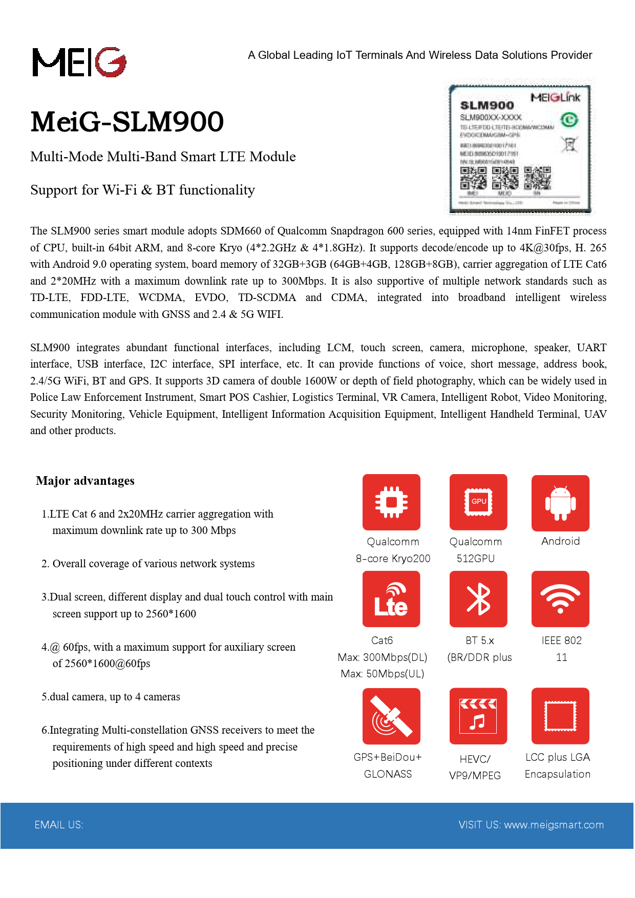
A Global Leading IoT Terminals And Wireless Data Solutions Provider

MeiG-SLM900
Multi-Mode Multi-Band Smart LTE Module
Support for Wi-Fi & BT functionality
The SLM900 series smart module adopts SDM660 of Qualcomm Snapdragon 600 series, equipped with 14nm FinFET process of CPU, built-in 64bit ARM, and 8-core Kryo (4*2.2GHz & 4*1.8GHz). It supports decode/encode up to 4K@30fps, H. 265 with Android 9.0 operating system, board memory of 32GB+3GB (64GB+4GB, 128GB+8GB), carrier aggregation of LTE Cat6 and 2*20MHz with a maximum downlink rate up to 300Mbps. It is also supportive of multiple network standards such as TD-LTE, FDD-LTE, WCDMA, EVDO, TD-SCDMA and CDMA, integrated into broadband intelligent wireless communication module with GNSS and 2.4 & 5G WIFI.
SLM900 integrates abundant functional interfaces, including LCM, touch screen, camera, microphone, speaker, UART interface, USB interface, I2C interface, SPI interface, etc. It can provide functions of voice, short message, address book, 2.4/5G WiFi, BT and GPS. It supports 3D camera of double 1600W or depth of field photography, which can be widely used in Police Law Enforcement Instrument, Smart POS Cashier, Logistics Terminal, VR Camera, Intelligent Robot, Video Monitoring, Security Monitoring, Vehicle Equipment, Intelligent Information Acquisition Equipment, Intelligent Handheld Terminal, UAV and other products.

Major advantages

1.LTE Cat 6 and 2x20MHz carrier aggregation with maximum downlink rate up to 300 Mbps
2. Overall coverage of various network systems

Qualcomm

Qualcomm

8-core Kryo200 512GPU

Android

3.Dual screen, different display and dual touch control with main screen support up to 2560*1600

4.@ 60fps, with a maximum support for auxiliary screen of 2560*1600@60fps

Cat6 Max: 300Mbps(DL) Max: 50Mbps(UL)

5.dual camera, up to 4 cameras

BT 5.x (BR/DDR plus

IEEE 802 11

6.Integrating Multi-constellation GNSS receivers to meet the requirements of high speed and high speed and precise positioning under different contexts

GPS+BeiDou+ GLONASS

HEVC/ VP9/MPEG

LCC plus LGA Encapsulation

EMAIL US:

VISIT US: www.meigsmart.com

MeiG-SLM900
Multi-network Smart LTE Module
Support for Wi-Fi & BT functionality
The equipment under test (EUT) is the smart module of Model SLM900(Model name). It supports Triple-bandGSM/GPRSsolution(GSM850 ,PCS1900),GPRS/EDGE Class 12 Triple-band UMTS (B2,B4,B5)HSDPACategory 24,HSUPACategory 6also supportsIEEE802.11a/b/g/n/acBluetooth version2.1+EDR,BT3.0+EDR,BT5.0,GPS
operating frequency is 1.57542GHz.
The Qualcomm device incorporates the UMTS/LTE technology -- the technology for RF transceivers(SDR660) that converts received signals directly from RF-to-baseband and transmits signals directly from baseband-to-RF (known as direct conversion or zero intermediate frequency (ZIF) processing). This technique eliminates the need for large IF surface acoustic wave (SAW) filters and supporting IF and LO circuits, thereby reducing the handset parts count and facilitating multiband, multimode handsets that can be produced in smaller form factors. RF transmitter The RF transmitters are capable to perform as well as UMTS and HSPAmodulation signals with excellent noise performance, thus no interstate filter in between transceiver and PA is required: Triple-band UMTS, with one low band and two high bands selected from: Low band Band 5 (826 to 836 MHz) High band Band 2 (1852 -1907 MHz) Band 4 (1712 -1752 MHz) Triple-band GSM Low band � GSM 850 (824 to 849 MHz) High band � PCS 1900 (1930 to 1989 MHz)

MeiG-SLM900
Multi-network Smart LTE Module
Support for Wi-Fi & BT functionality
LTE Band 2/4/5/7/12/13/17/25/26 � Band 2 (1850-1910 MHz) � Band 4 (1710 -1755MHz) � Band 5 (824 - 849 MHz) � Band 7 (2500 - 2570 MHz) �Band 12 (699-716MHz) �Band 13 (777-787 MHz) �Band 17 (704-716 MHz) �Band25 (1820-1915 MHz) Band26 (814-849 MHz) The transmit signal paths include a shared set of baseband amplifiers, a dedicated quadrature upconversion for each band type (low and high), gain control RF amplification, and multiple output driver amplifiers for each band type. Three UMTS output drivers support one low band and Two high bands; LTE support Bands: 2/4/5/7/12/13/17/25/26 Numerous secondary Tx functions are also integrated: a reference for the transmit DACs, the Tx phase-locked loop (PLL), the Tx local oscillator circuit, the Tx LO generation and distribution circuits, an RMS Tx power detector, and various interface, control, and status circuits. The RF transmitter interfaces internally with the baseband circuits for its analog baseband input and status and control signaling. Power reduction features controlled by baseband circuits (such as selective circuit powerdown, gain control, and transmit puncturing) extend handset talk time. The driver amplifier outputs are routed externally to the final stages of the transmit chains, culminating with the antenna switch whose output drives the antenna. Sophisticated Tx LO circuits implement the frequency plan and are completely integrated on-chip. All Tx LO signals are generated by the on-chip Tx local oscillator under the control of its PLL.

MeiG-SLM900
Multi-network Smart LTE Module
Support for Wi-Fi & BT functionality
C.AppendBixFoAdCy-CwoCrnaOupteioranti.on
A1.Requir�Temh1i5es.n1etq9ouLfipaFmbCeeClnlitKncgDormBeqp9ul9iier6es3mw69eitnhDts0F.3CCforamdioadtiuolne ceexrptiofsicuaretiolinm: its set forth for an uncontrolled 1.1List of TeanphvpisilridocaenbvmlieceenFtcC.oTCmhrpiuslileqs:uwipitmhepnatrtsh1o5uoldf tbheeiFnCstCallRedulaensd. Ooperateiodnwisithsumbijneictmtoumthedifsotallnocwei2n0gctmwo The moducbleoentcwodmeiteiponlnies:s (w1)itTh hFiCs CdePvaicret 2m, a1y5Bno,1t5cCau,1s5eEh,a2r2m,2f4u,l2i7n.terference, and (2) this device must accept any 1.2Summaitrnhitezeeraftedhrieeanstopcrec&riefciyceoiouvpreedbr,oaidtniyocnlTuahdleiunhsgeoiscntotpenrdofiedtriueocnntcsLe: athbaetlimngayRceaqusireeumnednetsi:red operation. SLM320 u�NseO15tTh.2IeC1iEnIdn: efTophremendhaetoinsotnGptroPoSduuscechrti.pmusitnmclaukdessuarfeutlhlyatinFtCegCraltaebdelginlogbraelqnuaivreigmaetinotns asaretemlliette. sTyhsitsemincludes solution thAcaltensayurlCpyphvoairnstgsibeGlsePoeSrx,mteGorLidoOirfiNlcaaAbteiSolSno,snBntehoietDeooxuupt.sreiIdtsesluoypfaptpohpretrsofivsnteadlnpdbrayordthuNecMtpahErotAuys-ri0en1sgp8to3hnapstriobdtlioespcfoloalry. csotmhepclioanntceents 1.3Limitedcshomouowlddnuvloeidprocedures: The modutilhneeibsuealsoeSwr'isn: gaulethMoroidtyultaoro.perate the equipment. Resolve: S�Cuop1np5tl.a1yi0ne5sxaIFnmCfopCrlemIDaast:i2foAonlPltoJow4t-shS:eLuMse9r0. 0 InstallationN1.No8tIoent:feoTsr:hmisateiqounipomn etenstthmasodbesenantdesatedddiatniodnfaolutensdtitnogcroemqupilryemweitnhtst:he limits for a Class B digital 1) SNM90dW0eMvhieconed,sueltetiPngowueprthsuepcpolnyfriganugraetiiosnD, Cif t3h.5eVpa~i4ri.2nVg ,anwdhecnallyobuoxusoeptSioNnMs f9o0r0tesMtinogdduolendoetswigonrkp,rothdeuct, the power ptseusrptsepurlaynctatnonpoatret x1c5eoedf tthheisFrCanCgeR.ules. These limits are designed to provide reasonable protection 2) When canogenaenidenscstoSNcoMor9d0in0ateMwoitdhutlheetomtohdeuhloesmt daenvuifcaec,tuthrerhtosat cdceevsiscethme utessttbme opdoewseorfotwffa.re. 3) Make suh1ra.e9rAmthdfeudlmitiinootdneuarlfetrepesintnicnsegc,ionPrraercrtet1lsy5idiSennustbiaapllaeridnt .sBtadlliastciloanim. Tehr:is equipment generates uses and can radiate 4) Make surTarhedeitohmaot dthuelamr tordanuslemditotesr insoot nalyloFwCuCsearusthtooriezpeldacfeorotrhdeesmpoecliitfiiocnr.ule parts (FCC Part 2, 5)All typesf1r5oeBqf u,a1en5ntCecny,1ne5ansEe.trh)gayltisactnand,bief nuosetdinwstiathlleadtraanndsmusiettderin aEcxctoerrdnaanlcaenwteintnhathweitihnsmtrauxcitmiounms, mgaaiyn cnaoutse Exceedingho6an.4rtm9hdefuBglir.ant, and that the host product manufacturer is responsible for compliance to any other FCC 1.4Trace airnnuttleenrsfnetahreadntecasepigptnolsy:ratNodoitoht eacpohpmolsimtcanubonltiecc.aotivoenrse.dHboywtheevemr,otdhuelraeritsrannosmguiattrearngtereantthaotf icnetretrifeicreanticoen.will not 1.5RF expo1c.s1cu0urIernicfnornamsiadteiorantioonnst:est modes and additional testing requirements: This equippWmarehtneictnuctloeasmrtipnlgsiet,astlelwastieitohrsnF.nCIefCetdhritasodeiraqetfuieoirpnmtoeextnphtoedsuuosreeesrlcmiamuainstesuashlea,tramfnofdruthtlhifenotsrearamfnepruelnenccpoeonwttoreorlalsdeudipoeponlryvtineroeleenvdmisseitnotn.uTsehias equipmentrsepscheeocpiuatlildoanbd,eapintesrtaplloewdearnsduoppelyrated withmini mum distance 20cm between the radiator & your body. 1.6Antennwash:ich can be determined by turning the equipment off and on, the user is encouraged to try to The moducleordroeecst tnhoet have a standard antenna. 1.7Label ainndtecrfoemrepnlciaenbcye ionnfeoromr amtioorne of the following measures: This devic-eRceoomripenlitesorwrietlhocpaatret 1th5eorfectheeivFinCgCanRtuelnensa..Operation is subject to the condition that this device does not ca-Iunscerehaasremtfhuel sinetpearrfaetrieonncbe.eAtwnyeeCnhtahnegeeqsuoiprmmeondtifaincdatrioecnesivneort.expressly approved by the party rNphripwneeuaaohsqtrrreptiumtsreciouefc:hfennauuTrsncclleaihaytbnirnintlsceo-c-RTeT&iMASZTFHetebnnCCeeonahhhiepFdtfeserqpenvtootxylaiiaftdrop:iuss:niadEennn:ogrrGr::i+lt2reerns5gu+eeoy/xpclea/cut80a1qqhetrnoT8pwmehndattl61c5uuamm6oerbitecinFwte21mioiiod2soceto,ppdlenpt10nChu.wh1odfhimm,nctli50.ernn5oyhineoit.teha4Iemfee.ho4ridmfnaean2,dnnsel2neeqsoctta7bttmr7aohabiFeug.e8ubcsgl8ttiyuCeisyehs6oiecc6pilirnmoen7omthCdde7mTuinous6uiiqec9prenntrelRlnaunatcddlagnetatiiliuh.iiepltnsnbcvoaGlenstmgeioelonedoen,swmdiNsiextlit.dnaho.nonipTaonsetgsHttenhta.dhthya2rdaenodeeilF3ulqoweClslofCa3suueneooeeut7ssdicCiuvpdl.teoe,iclnGaemrmendriaL'nrdsntau.u,eitdrdotdTdatsnatasoihenu.aodtchaeaitpcictoihahorrisoRoefoaeeo/cfrrmerTnoradiidmqairsaVtpateecnuedyfnlnsxuddiuy(ticpopitWegltoeowmwocngidnnshewoieueiit,uittnpdnfhajhietrfiitetrmhreecnhtartfoegrihgaenliaeteinteruhptnmnceneeiserletneeofmeiitntmrohficrvstnratuerehieoiitssdmsteahrmtetese)rosteeqt,ufdilnruutrfMconpehiacoistsrt.apadoieertiosamttansiurhoonfnhtrCaeeonsacafonrn,algoenewardtbmergn.s2tlhdcsaece0DianleycBtcepnoihmvwusrcdrottinatairrsihtbulcyigdielceeoosicitntettann,trowaoitethloerrtcceeoandoeeorcrleainrmclaevvredcgpetedifiuhatccouririeetolni,istnrsnha,tedaiator interference by one or more of the following measures:
-Reorient or relocate the receiving antenna. -Increase the separation between the equipment and receiver. -Connect the equipment into an outlet on a circuit different from that to which the receiver is connected. -Consult the dealer or an experienced radio/TV technician for help.