GREE XK76 Wired Controller User Manual
File info: application/pdf · 32 pages · 4.69MB
XK76 user manual (002)
PDF XK76 user manual (002)
....,, C}/., CHOO' 0000 MOOE. Thank you for choosing the DWUNI Wired Controller. Please read this user manual carefully before operation and retain it for future reference. Lit12012504. User Notices.
XK76 user manual (002) - files.hvacnavigator.com
Wired Controller DWUNI User Manual 3.7 Function Settings Press MENU/OK button on main page to enter main menu page. Press "/\'' or "V" or"<" or">" button to select the fu…
Full PDF Document

If the inline viewer fails, it will open the original document in compatibility mode automatically. You can also open the file directly.
Extracted Text
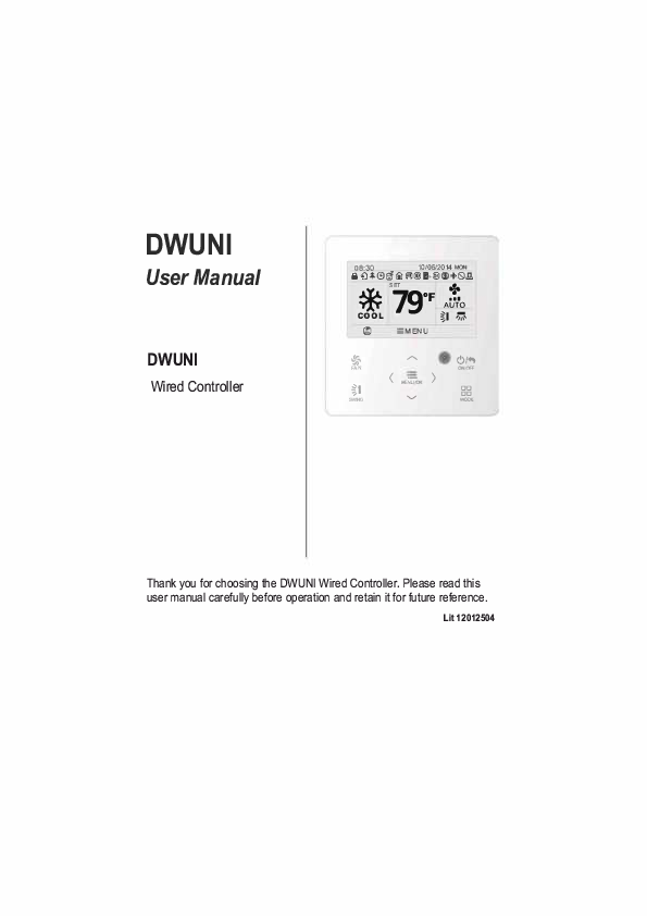
DWUNI
User Manual
DWUNI
Wired Controller

iH0l8:3+0 C!l

fJ

1ll

10/06/2014 MON
@J l,@l (!)6.1.Q.

* 79 + SET

0F AiNo

'm' COOL

I


j'
FAN
%1
SWNG

-:MENU
- ( ) MENIJOI
....,,

C}/.,
CHOO' 0000 MOOE

Thank you for choosing the DWUNI Wired Controller. Please read this user manual carefully before operation and retain it for future reference.
Lit12012504

User Notices
For correct installation and operation, please read all instructions carefully. Before reading the instructions, please be aware of the following items:
(1) It is prohibited to install the wired controller at wet places or direct sunlight. (2) Do not frequently disassemble the wired controller. (3) Do not operate the wired controller with wet hands. (4) Do not remove or install the wired controller by yourself. If there are any
questions, please contact Tech Support at 844-873-4445. (5) The wired controller is a generic model, applicable for several kinds of units. Some functions of the wired controller are not available for certain kinds of units, for more details please refer to the owner's manual of unit. The setting of unavailable will not affect unit's operation. (6) The wired controller is universal. The remote receiver is either in the indoor unit or in the wired controller. Please refer to the specific models.

This row left intentionally blank
This row left intentionally blank energy savings are

and ON/OFF

Wired Controller DWUNI User Manual
Main menu User function menu Sleep function setting --------I-DEMAND function setting Absence function setting Memory function setting Fixed-angle louver function setting Save function setting ----Dry function setting Quiet function setting Air function setting Fahrenheit Temperature Setting
Once Daily Weekly timer Two week timer Countdown timer on Countdown timer off
Time format setting Clock setting
Unit status view Current error view
Unit ON/OFF lock Mode setting lock Temperature setting lock Fan speed setting lock
Key lock
Fig. 3 Menu structure 4

In cooling, dry, fan, and heating modes, the temperature

Wired Controller DWUNI User Manual
3.7 Function Settings
Press MENU/OK button on main page to enter main menu page. Press"/\'' or"V" or"<" or">" button to select the function setting symbol. Then press MENU/OK button to enter user function setting page. Press"/\" or"V" button to select specific function item. Press "<" or ">" button to turn on or turn off this function. If the function item can't be set, it will display as gray. Please refer to Fig. 8.

* +��� 08:3_0

10/06/2014 MON
I,
SET
79 0f
AUTO

COOL

:MENU

*

,,...._

C)/ ..

FAN
ii
SWNG

�- ( ) MENU OK
......,,

ONO'!'

MOOE

In main page

MENU
t+J[9][i]
 TIMER FUNCTION CLOCK
El
LOCK

l

i'
FAN
ii
SWNG

,,...._

�._..,,� C)/..

ONO'!'

( ) ME{}
......,,


MOOE

Press MENU/OK button to enter main menu page

FUNCTION ----
SLEEP

----

!DEMAND

HOLIDAY

MEMORY

:MENU

*

,,...._

FAN

(

)

ii
SWNG

M.;cr
......,,

---!imOFF
---!imOFF ONtillil l!DIOFF
4 ��
C)/ ..
ONO'!'

MOOE

MENU

El [9]. . Ci] TIMER 1=111t��I 1m;LocK

LOCK

I

:MENU I

4 �

I

I

,,-.... I

(..Tm ......,,


MOOE

Press MENU/OK button to enter function setting page;
press "A'or "V"to selecl function item, and press "<'or ">'button to sel the function

Press ">"button to select function setting item

Fig. 8 Function settings

8

is

Wired Controller DWUNI User Manual
3.7.2 This section left intentionally blank
3.7.3 I-DEMAND Function Setting
After entering user function page, press "/\" or "V" button to select IDEMAND function option and press" <"or">"button to turn on or turn off this function with auto saving.
Note:
� This function is only available in cooling mode. � When this function has been set, set temperature is displayed in 81 �F(2TC). In
this case, temperature setting and fan speed setting are disabled. � This function is canceled when turning off the unit or switching modes. � This function and sleep function cannot be on simultaneously. If I-Demand function is
set first and then Sleep function is set, I-Demand function is canceled while Sleep function is valid, and vice versa.
3.7.4 Absence Function Setting
After entering user function page, press"/\" or"V" button to select Holiday function option and press"<" or">" button to turn on or turn off this function with auto saving.
This function is used to maintain indoor temperature so that unit can recover fast heating.
Note:
�This function is only available in heating mode. �When this function has been set, set temperature is displayed as 46�F(8 'C) ( 46 "F) . In this case, temperature setting and fan speed setting are disabled. �This function is canceled when switching modes. �This function and Sleep function cannot be on simultaneously. If Absence function is set first and then Sleep function is set, Absence function is canceled while
Sleep function is valid, and vice versa.
3.7.5 Memory Function Setting
After entering user function page, press"/\"or"V"button to select Memory function and press"<"or" "button > turn on or turn off Memory function with auto saving.
3.7.6 Fixed-angle SWING (Louver) Mode Setting
After entering user function page, press"/\"or"V"button to select Lock swing function option and press" <"or">"button to turn on or turn off this function with auto saving.
Note: If Fixed-angle swing function is not available for the connected unit, this
function is canceled automatically after setting.
10

Wired Controller DWUNI User Manual
3.7.7 Save Function Setting
After entering user function page, press"/\" or"V" button to select save function and press"<" or">" button to turn on or turn off save function. Press MENU button to enter save function setting page.
After entering save function setting page, press "<" or ">" button to select cooling or heating temperature limits. After selecting cooling or heating temperature limits, press"/\" or"V" button to adjust temperature limits value. After setting, press MENU button to save the setting.
Note: When save function has been set, auto mode cannot be set.
3.7.8 This section left intentionally blank
3.7.9 X-fan Function Setting
After entering User Function page, press"/\" or"V" button to select Dry function option and press"<" or">" button to turn on or turn off this function with auto saving.
Note:
� This function is only available in cooling mode and dry mode. � When this function is on, if the air conditioner is turned off, the indoor fan
will still operate at low speed for a while to dry the residual water inside the unit.
3.7.10 Quiet Function Setting
After entering user function page, press''/\" or ''V" button to select Quiet function and press"<" or">" button to turn on or turn off this function with auto saving.
Note: This function is only available in cooling mode, heating mode and
auto mode.
3.7.11 Fahrenheit Temperature Setting
After entering user function page, press"/\" or"V" button to select Fahrenheit temperature function and press"<" or">" button to turn on or turn off this function with auto saving. After closing this function, Fahrenheit temperature is displayed.
11

to return to last page.

3.9 Current Error View

Wired Controller DWUNI User Manual

When error occurs in the unit, error symbol is displayed on the main page of wired controller to indicate that the unit has an error. In this case, you can enter error view page to view the current error.
Press MENU button to enter the menu and select the function symbol to be viewed. Then press MENU button to enter view function page. Press"/\" or"V" button to select error information. Press MENU button to enter error view page. If there are too many errors, press "/\" or "V" to turn pages. Press BACK button to return to the last page. Please refer to Fig. 9.

08:30AM

10/06/2014 MON

Et,

::MENU

*
FAN
ti
SWNG

- > ,,...._
MENU(>(

c;,.,
ONOFF

...._,,

DDDD
MOOE

MENU
11[9][1] Bm TIMER FUNCTION CLOCK

LOCK

::MENU

c;,.,

l: < ONOFF

SWNG

MENU(>( >

...._,,

DDDD
MOOE

----------

ERROR INFORMATION E6

SEARCH UNITSfATUS

*

,,...._

� c;,., RETURN
.....:::_ .

FAN

�- > MENUIQK

. ONOFF

%1
SWNG

...._,,

DDDD
MOOE

::MENU

*

,,...._

c;,.,

FAN

< �- > MENU OK

ONOFF

%1
SWNG

...._,,

DDDD
MOOE

Fig. 9 Current Error View 13

Wired Controller DWUNI User Manual

Error Return air temperature sensor open/ short circuited evaporator temperature sensor open/ short circuited Indoor unit liquid valve temperature sensor ooen/short circuited Indoor gas valve temperature sensor ooen/ short circuited 1PM temperature sensor open/short circuited Outdoor ambient temperature sensor ooen/ short circuited Outdoor unit condenser mid-tube temoerature sensor ooen/short circuited Discharge temperature sensor open/ short circuited Indoor and outdoor communication error
DC bus under-voltage protection
DC bus over-voltage protection Compressor phase current sensing circuit error Compressor demagnetization protection
PFC protection
1PM Temperature Protection
Over-power protection System charge shortage or blockage orotection Capacitor charging error
High pressure protection
Low pressure protection
Compressor stalling
Over-speeding
Drive board temperature sensor error
AC contactor protection
Temperature drift protection
Sensor connection protection
DC bus voltage drop error
Outdoor fan 1 error protection
Outdoor fan 2 error protection

Error Code
F1

Error Drive board communication error

F2 Compressor overheating protection

b5 Indoor and outdoor units unmatched

b7

Communication line misconnected or exoansion valve error

P7 Running mode conflict

F3 Pump-down

F4 Jumper error

F5 Forced defrosting

E6 Compressor startup failure

PL High discharge temperature protection

PH Overload protection

U1 Whole unit over-current protection

HE Over phase current protection

He Compressor desynchronizing

P8 1PM Current protection

L9

Compressor phase loss/reversal orotection

FD

Frequency restricted/reduced with whole unit current orotection

PU

Frequency restricted/reduced with 1PM current orotection

E1

Frequency restricted/reduced with high discharoe temoerature

E3

Frequency restricted/reduced with antifreezina orotection

LE

Frequency restricted/reduced with overload orotection

LF

Frequency restricted/reduced with 1PM temoerature orotection

PF Indoor unit full water error

pg Anti-freezing protection

PE AC input voltage abnormal

Pd Whole unit current sensing circuit error

U3 4-way valve reversing error

L3 Motor stalling LA PG motor zero-crossing protection

Error Code
P6 H3 LP dn E7 Fa C5 H1 Le E4 E8 E5 P5 H7 H5 Ld F8 En F9 FH F6 EU E9 E2 pp U5 U7 H6 U8

14

countdown timer ON, and countdown timer OFF
The wired controller can set one time clock timer. If the unit is OFF, timer ON can be set. If the unit is ON, the timer OFF can be set. The timer is carried out just once when the timer time is reached and then the timer turns OFF automatically.
In timer function setting page, when one time timer is selected, press "" or "" button to turn ON or turn OFF this timer function. Press MENU button to enter timer time setting page, as shown in Fig. 12.
Press "" or "�" button to select timer hour or minute and press "" or "" button to adjust time. Holding "" or "" button increases or decreases time rapidly. After finishing setting, press MENU button to save timer time.

turned ON
You can set the everyday timer content for a week. For each day, you can set eight segments of timer content. The unit executes the corresponding timer setting for the week.

Then press MENU button to enter the timer programming for that day.
VHOHFW WKH GDWH WR VHW
HQWHU WLPHU SURJUDPPLQJ IRU WKDW GD\ VHOHFW WKH WLPH WR VHW

You can set the everyday timer content for two weeks. For each day, you can set eight segments of timer content. The unit will execute the corresponding timer setting for two weeks.

ON

OFF ON/OFF

can be set. In unit ON status, the timer OFF can be set, or timer OFF and timer ON can

be set simultaneously. In unit OFF status, timer ON can be set,or timer OFF and timer

ON can be set simultaneously. If timer OFF in x hours and timer ON in y hours are set

simultaneously in unit ON status, the unit will turn OFF in x hours and then the unit will

turn ON in y hours after timer OFF.

The Timer Function is carried out just once and then it is canceled automatically.

canceled

turned ON or turned OFF.


Sponge 20h20h3 PP Screw M4h25

CN4 CN3 CN2
CN4 CN3CN2

CN2 terminal is used for connecting indoor unit and it must be connected. CN3 terminal and CN4 terminal are used for connecting the centralized controller
and these two terminals have the same function. Customers can select one or two terminal(s) for connection according to the needs.

Fig. 23 Installation diagram for wired controller
Fig. 23 is the simple installation process of wired controller; please pay attention to the following items:
(1) Before installation, please cut off the power for indoor unit; (2) Pull out the four-core twisted pair line from the installation holes and then let it go
through the rectangular hole behind the back plate of the wired controller.

(3) Stick the back plate of wired controller on the wall and then use screw M4�25 to fix back plate and installation hole on waltlogether, attach the sponge 20�20�3 at the screw hole and then press it with fingers to make sure it's attached firmly.
(4) Insert four-pin cable twisted pair line into the slot of the wired controller and then buckle the front panel and the back plate of the wired controller together.
(5) Block the four-core wire into the groove at the left side of wiring column; bundle the front panel of wired controller to its back plate.
Note:
Separate the signal and communication lines of the wired controller from the power cord and connection lines between the indoor and outdoor unit, with a minimum interval of 20cm, otherwise the communication of the unit will probably work abnormally.
If the air conditioning unit is installed where is vulnerable to electromagnetic interference,then the signal and communication lines of the wired controller must be the shielding twisted pair lines.
The 4-core terminal connects the air conditioner, while the 2-core terminal connects the centralized controller. The connecting method for the 2-core connection wire is same as that of 4-core connection wire.
No need to set the wire of wired controller into the clasp.
For matching with different models, the patch cord and the connection wire are provided in the packaging box of wired controller. As shown in fig. A.
Fig. A: Schematic diagram of patch cord and connection wire
If the air conditioner has been installed with the patch cord (fig. C) connecting the wired controller.

Only use the connection wire (fig. B) in the packing box of wired controller. Connect the terminal � to the terminal � of patch cord which has been installed on the air conditioner; insert terminal � four pin terminal of wired controller. Remove connector cap "3" prior to installing cable.
Fig. B: Schematic diagram of connection wire: Connect terminal � with wired controller CN2; connect terminal � with the terminal � of patch cord
Fig. C: Schematic diagram of patch cord: Terminal � is the protection terminal connect terminal � to the terminal � of connection wire connect terminal � to the terminal of wired controller of air conditioner
If the air conditioner hasn't been installed with the patch cord used for connecting the wired controller.
Use the connection wire and patch cord in the packing box of wired controller. Pull out the protection terminal of patch cord at first, connect the connection wire with the patch cord according to fig. D, and then insert the terminal � of connection wire into the needle stand CN2 of wired controller and insert the terminal � of patch cord into the terminal of wired controller of air conditioner as well.
Fig. D: Schematic diagram after the connection wire and the patch cord have been connected: connect the terminal � of connection wire and the terminal � of patch cord
25

26
LIT-12012504 . Revised October 2020