File info: application/pdf · 192 pages · 2.64MB
RTAF SE/HE/XE/HSS/HSE/XSE/XSS R134a, R513A ... - Trane
not conform to the rules of this manual, it may entail cancellation of warranty and liabilities by the manufacturer. Startup MUST be performed by Trane, ...
Introduction ....................................................................................................... 4. Pre-Installation .
R134a, R513A, R1234ze. Air-cooled. Helical-rotary chillers. 300 - 1900 kW. July 2020. Confidential and proprietary Trane information. Original instructions.
Extracted Text
RTAF SE/HE/XE/HSS/HSE/XSE/XSS R134a, R513A, R1234ze Air-cooled Helical-rotary chillers 300 - 1900 kW
July 2020
Sintesis chillers are part of the Trane Technologies EcoWiseTM portfolio of products that are designed to lower their environmental impact with next-generation, low global warming potential (GWP) refrigerants and high efficiency operation.
RLC-SVX19J-GB
Confidential and proprietary Trane information Original instructions
Table of Contents
Introduction.........................T..e...c..h...n...i.c...a..l...D...a...t.a.................................................. 4
Pre-Installation.................................................................................................... 5
UFWnDit Model Number Description ....0.8.....................1.2................2.0.............3.0............457
Power supply
(V/Ph/Hz)
230/1/50
Capacities
GCoeolinngecarpaaclityDonawtaater.(.1.) .................(.kW..).............5.,.2....................8.,.3...............1.5.............1.8.,8..........3.09,1
Heating capacity on water (2)
(kW)
6,3
11,9
18,9
20,9
38,2
GFaennmeroatolrData RTAF 090-205 Standard E(ftyfipcei)ency - Standard and Low Noise (SN&2LNx d) i-reRct1d3r4ivae -ceRn5tr1ifu3gAa.l..........................9
GFaennpeorwalerDinaptuat R(3T) AF 090-185 Standard Ef(kfiWc)iency - Stan0d,2a3rd and Low Noise0,(4S6N&LN) - R1203,645 ze..............1..,.0.4................1.,5111 GSCetuarnrrtee-unrptaalammDppasst(a3)RTAF 90-205 Standard Effi((cAAi))ency - Extra 13L,,o12 w Noise (XLN) - R251,,3254a - R513A....39..,,.13...................1.4.4.,,7.1................15.61,,553
GAeirnfleorwal Data RTAF 090-185 Standard Efficiency - Extra Low Noise (XLN) - R1234 ze.......................................................15
Gmnoeinmnimeinruaalml Data RTAF 090-205 Standard E((fmmfi33c//hhi))ency - AC E48x92t00ra Low Noise - R113964850a0 - R513A......21..43.00..00..................31.08..00..00..............42..57100700
Gmeanxiemruaml Data RTAF 090-185 Standard E(fmfi3c/hi)ency - AC E9x8t0ra Low Noise - R11293740 ze................2..6.0..0..................3.6..0..0..............5..41090
GMWeaanitneercreoanillteDriantga/leRavTiAngFc0o9nn0e-c2t0io5nsHigh Efficie(tnypcey) - Standard and Low Noise - R134a - R5IS1O3AR7...r.o..t.a.t.i.n..g..f.e..m...a.l.e...........................21
General Data RTAF 090-185 High Efficie(nDciay) - Standard3/a4n" d Low Noise - R132/43"4 ze...............1..1../2.."................1...1./.2..".............1..12/23"
GEElleeencctterriirccaphloeDawtaeerrtas(auRcpcTpelAsysFor0y9fo0r-2bl0o5weHr iognhly)Effic(iVe/nPhc/yH-z)AC Extra23L0/o1w/50Noise - R123304/1a/5-0Ro5r 14030A/3../.5.0.........4.0..0../3../.5.0..............4.0..0./.3../5..0..........4.0..0./235/50 GHeeanteinrgaclaDpaactiatyRTAF 090-185 High Efficie(nkWcy) - AC Extra L2o/4w Noise - R1234 ze.8.........................1.0.....................1..2..................1227
GHeotnweartaelr Dcoailta(acRcTesAsoFry09fo0r-b2l0ow5eEr xotnrlya) Efficiency - Standard and Low Noise - R134a - R513A................................................29
Heating capacity (4)
(kW)
6,3
12
17,4
22,4
34,5
GGe2nfieltrear l(fDilteartaboRxTaAccFes0so9r0y-)185 Extra Efficiency - Standard and Low Noise - R1234 ze..........................................................31
GQeunanetritayl Data RTAF 090-245 Extra Efficiency - Extra Low2 Noise - R134a - R5123A.....................2......................2...................233 GDGei4mnfeielntresariol(fnDilstea(rtLabxoWRxxTatAchc)Fes0so9r0y-)185 Extra Efficie(mnmcy) - Extra 3L8o6wx22N1xo8ise - R1234 z4e8..6..x.2..7.1..x.8.............5..8.6..x..3.2..1.x..8..........5..8.6..*.4..2.1..*.8.......5..8.6..*.63251*8
GQeunanetritayl data RTAF 090-245 High Seasonal Efficiency - S- tandard and Low N2oise - R134a - R2513A..............2...................237
GDCeoimnndeenernsaisolantdesa(ptuLaxmWRpTx(tAahc)Fce0ss9o0r-y2) 25 High Seaso((ntmyapmle))Efficiency - S- tandard and Lo4w86Nx2o64isxe48- R12354C8e6znxet3r..i1.f.4u.x.g.4a..8l........5..8.6..*..4.1..4.*..4.8......5.8..6.*..63194*48
GWeanteerrfalolwd-altifat hReTigAhFt 090-245 High Seas(lo/hn-aml mEf)ficiency - Extra Low Noise - R134a - R513A.2..4..-..5.0..0.....................................41
GNSeoount naedvraaleillvadebllae(Ltfa/oMrR/FHTWAsDpFe3e00da9)n0d-2FW25D4H5igh Seasonal Efficiency - Extra Low Noise - R1234 ze.........................................................43
GSeounnedraprleDssautrae lRevTeAl (F5)090-245 High Seaso(dnBa(Al)E) fficiency36S/4h0/o43rt - Standard an3d8/4L1o/4w4 Noise - 4R61/5304/5a3 - R513A47../5..2../5..7..........4.7../.5425/58
GSUeonunitneddrimapolewndseairotnlaesvReTl (A5)F 090 225 High Seaso(dnBa(Al )E) fficiency46S/5h0o/5r3t - Standard an4d8/5L1o/5w4 noise - R516/2603/463ze...........5.7../6..2../6..7..........5.7../.6427/68 GWeidntehrxaDl eDpathta RTAF 090-245 High Seaso(mnaml)Efficienc8y90Sxh6o0r0t - Extra Low 1N0o90isxe71-0R134a -1R29501x38A2.0..........1.2..9..0..x..9..7..0......1.2..9.0..x491090
GHeeingehtral data RTAF 090-225 High Seaso(nmaml)Efficiency S2h50ort - Extra Low No3is0e0 - R1234 ze...3..5.0....................4.5..0................6.5501
Shipped unit dimensions
GWeidntehrxaDl eDpathta RTAF 250-450 Standard E(fmfimci)ency - St9a3n3dxa6r4d4 and low Noi1s1e33- xR715344a - R511333A3.x...8.6..4.........1..3.3..3..x...1.0..0.8.......1.3..3.3.*513133
GHeeingehtral Data RTAF 210-340 Standard E(fmfimci)ency - Stan2d6a0rd and low Noise 3-1R01234 ze.........3..6.0....................4.6..0................6.6505 GCWeoelniogeuhrrtal Data RTAF 250-450 standard eff(kicgi)ency Extra L3o2w Noise - R134a - R456 13A........g.a..l.v.a..n..i6s.1.e.d...s.t.e..e.l............7.6.................1.1587
GReecnoemrmalenDdaetdafuRsTeAsiFze210-340 standard efficiency Extra Low Noise - R1234 ze....................................................................59
GUUennniitt eawrlioathnleeDl(eaacMttar/igcRI)hTeAatFer2(g5I0) -450 Standard Ef((fAAic))iency 1-6A(C2kWE8x)/,1t26r5a(4LkoWw) Noi4s0e(-23R01V3)8,3/41*a616- (R40501V3)A......3.8.*/.12..60..................38.*./.22.5.5..............3.8.*/622515
General Data RTAF 210-340 Standard Efficiency - AC Extra Low Noise - R1234 ze............................................................63
G((12e)) CCnooennrddaiittiiloonnDss::aWWtaaatteeRrr TeennAtteeFrriinn2gg//5llee0aavv-4iinn5gg 0tteemmHppieegrraahttuuErreef:: f57i0/c1/24ie5�Cn�C,cA, yAiriri-ninlSeltetttaetmenmpdpearearrtaduturerae2n72/0d1�9C�LCDoBDwB- /NWNoBmo-iniNsaolemaii-rnfaRllo1awi3r f4loaw- R513A.................................................65
G((34e)) WAntaehterigrahelnsDtpeeraeindtgaw/leiRtahvTinnAogmFtein2ma1pl 0eari-ra3tful4orwe0.9H0/7i0g�hC, Eaifrfiincleitetnemcpyer-atSurtea2n0d�CaDrBd, NaonmdinLaloaiwr floNwo. ise - R1234 ze...........................................................67
G(5e) AnerercatalngDualatraglaRssTwAoFol2d5uc0t -14m5500 loHniggishplEacfefdicoinetnhce yblo-wAerC.ThEexmteraasuLreomwentNisotaikseen i-nRth1e3ro4oam-coRn5ta1in3inAg ..th..e..b.l.o.w..e..r.u..n.i.t.........................................69
GHeeant eexrcahalnDgeartoapeRraTtiAngFlim2i1ts0: -340 High Efficiency - AC Extra Low Noise - R1234 ze...................................................................71 GF*WweaDnte:errteaml pDeraattuareR: mTaAxF1020�5C0-450 Extra Efficiency - Standard and Low Noise - R134a - R513A................................................73 G*aebnsoelurtaelseDrvaicteaprResTsAurFe: m21in01-3ba4r/0maExx11trbaarEs fficiency - Standard and Low Noise - R1234 ze..........................................................75
GAcecnesesorraielsD- HaottawRatTerAcoFil:250-450 Extra Efficiency - Extra Low Noise - R134a - R513A..............................................................77 G**waebanstoeerlurtteaemlspeDervraaictteuarperR:emsTsiAunr.Fe+:2m2� 1Cin/0m1-a3bxa4.r1/0m00aE�xxC11trbaarEs fficiency - Extra Low Noise - R1234 ze........................................................................79
General Data RTAF 250-410 High Seasonal Efficiency Short - Standard and Low Noise - R134a - R513A......................81
General Data RTAF 210-405 High Seasonal Efficiency Short - Standard and Low Noise - R1234 ze................................83
General Data RTAF 250-410 High Seasonal Efficiency Short - Extra Low Noise - R134a - R513A.....................................85
General Data RTAF 210-405 High Seasonal Efficiency Short - Extra Low Noise - R1234 ze..............................................87
General Data RTAF 250-550 High Seasonal Efficiency - Standard and Low Noise - R134a - R513A.................................89
General Data RTAF 210-470 High Seasonal Efficiency - Standard and Low Noise - R1234 ze..........................................91
General Data RTAF 250-550 High Seasonal Efficiency - Extra Low Noise - R134a - R513A...............................................93
General Data RTAF 210-470 High Seasonal Efficiency - Extra Low Noise - R1234 ze.........................................................95
General data RTAF 100-330 Extra Seasonal Efficiency - Standard and Low Noise - R134a..............................................97
General data RTAF 100-330 Extra Seasonal Efficiency - Extra Low Noise - R134a.............................................................99
General data RTAF 100-330 Extra Seasonal Efficiency - Whisper Low Noise - R134a...................................................... 101
General data RTAF 100-330 Extra Seasonal Short - Standard and Low Noise - R134a................................................... 103
General data RTAF 100-330 Extra Seasonal Short - Standard and Low Noise Low Ambient - R134a............................ 105
42 � 2020 Trane
RULNCT-SPVRXC0190J2-GB
Table of Contents
General data RTAF 100-330 Extra Seasonal Short - Extra Low Noise - R134a.................................................................. 107 General data RTAF 100-330 Extra Seasonal Short - Whisper Low Noise - R134a............................................................. 109 General data RTAF 100-330 Extra Seasonal Short � AC Extra Low Noise - R134a............................................................111 General data RTAF 100-330 Extra Seasonal Short � AC Whisper Low Noise - R134a...................................................... 113
SoIunnsdtaplolawteior nlevReelsquirements............................................................................. 115
DiscChahrgileled Water Piping Recommendations...................................................... 118
MMeeaaEssvuurraeemmpeeonnrttsacottanokderintioPinnisap: rionogm..a.d..ja..c.e.n.t..t.o..t.h.e..r.o.o..m...c.o.n..ta..in..in..g..t.h.e..F.W...D.,..a.t.t.h..e..o.u.t.l.e.t..o.f.t.h..e..r.e.c.t.a.n.g..u.l.a.r..d.u..c.t.(.1...5 1m19
long) fixed to its discharge opening.
Drainage.......................................................................................................... 120
Fan
Power level in dB(A), per Hz frequency band
Overall power
Unit
speed
125
250
500
1000
2000
4000
8000
dB(A)
Evaporator W1 atersid55e.........5.0............4.2...........3.7............3.7...........3.1...........3.0............4.6122
FWD 08
2
57
54
47
40
30
38
40
50
3
58
57
50
42
32
40
43
53
Optional Inte1 grated57Pump 5P1 ackage45...........4.2............3.4...........3.3...........2.8............4.8126
FWD 10
2
58
54
48
45
38
39
35
51
3
60
58
50
48
40
42
39
54
FWDP12artial Heat 21Recove55r87y.........55.41............44.85...........44.52............33.84...........33.93...........32.58............54.18135
3
60
58
50
48
40
42
39
54
FWDT1o4 tal Heat R21ecovery6516............66.62............55.50...........54.38............43.79...........43.68...........43.56............65.06138
3
63
69
58
56
50
50
49
63
FWDO20ptional Fre21e-Cooli65n17 g........66.63............55.51...........54.39...........44.70............43.69...........43.57............65.07142
3
63
69
58
56
50
50
49
63
IntaEkevaporator Waterside..................................................................................... 161
MeaGsuerenmeernat cloEndleiticontsr:ical Recommendations .......................................................... 166
Measurements taken at the horizontal air intake.
Installer-SupFapn lied ComponPeownertlesve.l.i.n..d.B.(A..),.p.e.r..H.z.f.r.e.q.u.e.n.c.y.b..a.n.d.................................O.v.e.r.a.ll.p1ow6e8r
Unit
speed
125
250
500
1000
2000
4000
8000
dB(A)
FWDO08perating Pr21inciple65s36 ..........65.25............65.05...........65.03............54.36...........54.35...........54.32............65.47 170
3
66
65
63
62
56
55
57
67
FWDC10ontrols ......21............66.62...........65.38............65.05...........65.28............55.61...........54.58...........54.24............66.61 173
3
70
67
63
65
59
59
57
69
1
62
58
55
58
51
48
44
61
FWDT1r2acer TD7 O2perator66Interfa6c3 e ........6.0...........6.2............5.6...........5.5...........5.2............6.6 173
3
70
67
63
65
59
59
57
69
1
66
65
65
65
57
50
46
68
FWDO14perating M32ap........77.83...........77.62............76.39...........77.51............66.94...........65.49...........65.37............77.48 174
1
68
72
64
64
56
52
50
69
FWDP20re-Start Ch32eckout77.68...........77.69............76.18...........77.41...........66.95............66.61...........66.61............77.85 175
Unit Start Up Procedures .............................................................................. 178
Periodic Maintenance .................................................................................... 180
Condenser Coils MCHE Maintenance........................................................... 186
Integrated Pump Maintenance (Optional with Pump Package)................. 187
Log Check Sheet............................................................................................. 188
Recommended service routine frequencies................................................. 189
Additional services......................................................................................... 190
RULNCT--SPVRXC1090J2--GGBB
131
Introduction
Technical Data
Foreword
Important notice: No shipping claims will be accepted by TRANE if the above mentioned procedure is not respected.
These instructions are given as a guide to good practice in
the installation, start-up, operation, and maintenance by
the user, of Trane RTAF chillers, manufactured in France. A sFPeWopwDaerrastuepmplyanual is available for the use(Va/Pnhd/Hmz)aintenance08 oCfatphaecituiensit's control, TracerTM UC800. They do not contain full sCeorovlicneg cparpoacceitdy uornewsanteerc(e1)ssary for the cont(iknWu)ed successfu5l,2
For more information, refer to the general sales conditions of your local TRANE sales office.
12
20
30
45
Note: Unit inspection in Franc2e30. D/1/e5l0ay to send registered letter
in case of visib8le,3and concealed15damage is o1n8l,y8 72 hours3.0,1
oHpeeartiantgiocnapoacfittyhiosnewqauteipr (m2)ent. The services(koWf )a qualified 6,3
tFeacnhmnioctioarn should be employed through t(htyepem) edium of a
mFCauanrirnpetnoetwnaeamrnipncspe(u3ct)o(3n) tract with a reputable se(rk(vAWi)c)e company.01,,213
RSetaardt-utphiasmmpsanual thoroughly before unit s(tAa)rt-up.
3,2
UAniritflsoware assembled, pressure tested, dehydrated, charged
amnnoidnmimtineuaslmted in accordance with factory sta((nmmd33//ahhr))d before
490 820
smhaipximmeumnt.
(m3/h)
980
Main coil
Warnings and Cautions Water entering/leaving connections
(type) (Dia)
3/4"
11,9
18,9
20,9
38,2
Loose
Pa0r,4t6s
Inventory 2 x direct drive centrifugal 0,65
1,04
1,51
Check all the ac25c,,25essories and lo39,,o13se parts tha1t44,a,71re shippe1d56,,55 with the unit against the shipping list. Included in these
items will be th9e80water vessel 1d4r0a0in plugs, ri1g8g0i0ng and 2700
electrical diag1ra65m0s, service lite23ra00ture, which3a0r0e0 placed 4500 inside the con1tr9o70l panel and/o2r6s0t0arter panel3f6o0r0shipmen5t4.00
If optional elastomericISisOoRla7torortsatainrgefoemrdaelered with the unit (model numbe3r/4d"igit 42 =1) th1e1y/2a"re shipped1 1m/2o" unted o1n1/2"
WEEllaeeccrnttrriiiccnphgoesawateenrr ds(auCcpcapelusystoiorynfsorabplpoewaerr oantlay)ppro(pV/rPiah/tHezs) ections230/1/50 tHheroatuingghcoaupatctihtyis manual. Your personal sa(fkeWty) and the 2/4 pHrootpwearteorpceorila(taicocnesosof rtyhfiosrmbloawcheirnoenlrye) quire that you follow
the horizontal support frame of the chiller. The isolators' location23a0n/1d/5d0isotrr4ib00u/t3i/o50n wei4g0h0t/3d/5i0agram is40p0l/a3c/5e0d with400/3/50 the service litera8ture inside the1s0tarter/contro1l 2panel. 12
tHheeamtincgacraepfaucliltyy.(T4h) e constructor assumes n(koWl)iability
6,3
fGQo2ur aifnnilttseittrya(lflialtetirobnosx oacrcseessrovriyc)ing performed by unqualified 2
12
Warranty 2
17,4
22,4
34,5
2
2
2
pDeimrseonnsinoenls. ( LxWxth)
(mm)
386x221x8 Warranty is4b8a6xs2e7d1xo8n the ge5n8e6xr3a2l1txe8rms an5d86c*4o2n1d*8ition5s8o6*f621*8
G4 filter (filter box accessory)
Quantity
-
WDiAmReNnsIiNonGs:(InLxdWicxatthe)sapotentiallyhazardo(umsmsi)tuationwhich- ,if
nCootndaevnosiadteedp,ucmopu(ladccreesssuorlty)in death or serio(tyupsei)njury.
the manufacturer. The warranty is void if the equipment is repaired or4m86ox2d26i4fixe4d8 withou58t6txh32e14wx4r8itten a5p86p*r42o1v4*a4l8of t5h8e6*6214*48 manufacturer, if the operatiCnegntlriimfuigtasl are exceeded or if the
Water flow - lift height
(l/h - mm)
control system or the electric2a4l-w50ir0ing is modified. Damage
Not available for FWD30 and FWD45
due to misuse, lack of maintenance or failure to comply
CSAouUnTdIOlevNe:lI(nLd/Mic/Hatsepseeadp)otentially hazardous situation which, if nSootuanvdopirdeessdu,rme laeyverle(s5u) lt in minor or moder(adtBe(Ain))jury. It ma3y6a/4l0s/o43 bSUeonuuitnsddeimpdoetwnoseiarolnleesvretla(5g)ainst unsafe practices(doBr(Afo))r equipm4e6n/5t0o/5r3
with the manufacturer's instructions or recommendations is not covere34d88//b4511y//45t44he warran45ty66//56o00b//56l3i3gation. I45f77t//h5622e//56u77ser do45e77//s5622//5688 not conform to the rules of this manual, it may entail
pWroidptherxtyD-edpathmage-only accidents.
(mm)
890 x 600 cancellation10o9f0wxa7r1r0anty and12l9ia0bxi8li2ti0es by 1th29e0mx 9a7n0ufac12tu90rexr.1090
Height
(mm)
250
SSWhaiidptfpheexdtDuyenpitthRdimeecnsoionms mendation(smm)
933 x 644
Height
(mm)
260
TWoeaigvhotid death, injury, equipment or prop(ekrgt)y damage, th3e2
fCoolllouwring recommendations should be observed during
Startup MUST3b0e0 performed b3y5T0rane, or an a45u0thorized 650
agent of Tra1n1e3,3txo7V5A4 LIDATE1t3h33isxW86A4RRAN1T33Y3. Cx o10n0t8ract1o3r33*1133 must provide a31t0wo-week start3u6p0 notification4t6o0 Trane (or6a6n0 agent of Trane s4p6ecifically autho61rized to perfo7r6m startup).118
galvanised steel
Unit Description mReacionmtemneanndceed afunsde ssiezervice visits:
1UU. Tnniihtt eawliomthnaeexl(eaimcMtr/uigcmI)heaaltleorw(gaI)ble pressures for s((yAAs))tem lea16k (t2eksWt8i)/n,126g5 (4kW)
8/16 40 (230V),3*16 (400V)
8/16 3*20
8/25 3*25
8/25 3*25
on low and high pressure side are given in the chapter
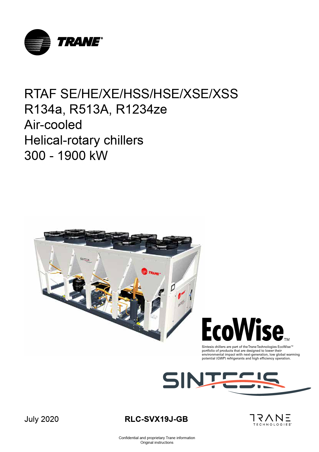
The Sintesis RTAF units are helical-rotary type, air-cooled
"(1In) Csotnadllitaiotnios:nW".atIenrseuntreerintgo/ledavoinng otetmepxercaetuered: a((23p))pACrot onhdipgithrioisanptsee:eWddawteeivtrheicnneotem.riinnga/lleaairvifnlogwt.emperature:
57t0/e1/24s5�tC�pC, A,rAeirisrinsinleultertteetmebmpypereaurtausturienre2g72/01�9C�CDcBDhB-i/lNWleoBmr-sinNadolmeasiirnifagllonawier dflofwor outdoor installation. circuits are factory-piped, leak tested and
The refrigerant dehydrated. Every
2((45. ))DWAiarseteccrtoaennngtneurelaincrgtg/llaeaaslvlsipwngoootwelmdeuprcetrsa1utmupr5ep09llo0ie/n7gs0 i�bsCpe, lafaiocreridneleoatntnethmyepsbeleroarwtvuerirec.Ti2hn0eg�mCoeDanBsu, rNeommeinntailsuatinarkfieltonwisi.n ethleercotormicacolnlytaitneinsgtethde bfolorweprruonpit.er control operation before
the unit.
shipment.
Heat exchanger operating limits:
3F.WSDe: rvice work on the refrigeration system and the
Chilled water inlet and outlet openings are covered for
e*lweactterritceamlpesryatsutree:mmasxh1o00u�lCd be carried out only by qualified and shipment. The Sintesis RTAF features Trane's exclusive
e*xabpseorluiteenscerevdicepperersssourne:nmeinl. 1 bar/max 11 bars
Adaptive ControlTM logic, which monitors the control
4A*.wcTcaoetessraotverimoesipd-erHaaotnut rwyea: rtmeisrinkc.o,+ili2:t� iCs/mraexc. o10m0�mC ended to place the unit on a*nabasorleutae swerivtihcelpimresistuerde: macinc1ebsasr./max 11 bars
variables that govern the operation of the chiller unit. Adaptive control logic can adjust capacity variables to avoid chiller shutdown when necessary, and keep producing
Reception
chilled water. The units feature two independent refrigerant circuits. On the HSE HSS version, 1 compressor per circuit
On arrival, inspect the unit before signing the delivery note. Specify any visible damage on the delivery note, and send a registered letter of protest to the last carrier of the goods within 7 days of delivery.
Notify the local TRANE sales office at the same time. The delivery note must be clearly signed and countersigned by the driver.
is controlled by a dedicated variable speed Adaptive Frequency Drive. Each refrigerant circuit is provided with filter, sight glass, electronic expansion valve, and charging valves. The shell-and-tube CHILTM (Compact-High performance-Integrated design-Low charge) evaporator is manufactured in accordance with the Pressure Equipment Directive (PED) code. Each evaporator is fully insulated and equipped with water drain and vent connection.
Any concealed damage shall be notified by a registered letter of protest to the last carrier of the goods within 7 days of delivery. Notify the local TRANE sales office at the same time.
Units are shipped with full oil charge and can be ordered with either a factory refrigerant charge or optional refrigerant pre-charge.
4
RULNCT-SPVRXC0190J2-GB
Pre-Installation
Inspection
When the unit is delivered, verify that it is the correct unit and that it is properly equipped.
SoIRunesnppdoerctptaaonllyweaxeptrepraliroeervncetodlmsampoangeenotsr
for visible damage. material shortage to
the carrier and make a "unit damage" notation on the Discchaarrrigeer's delivery receipt. Specify the extent and type of
damage found and notify the appropriate Trane Sales MeaOsfufirceem. ent conditions: Measurements taken in a room adjacent to the room containing the FWD, at the outlet of the rectangular duct (1.5 m longD)ofinxoetdptrooicteseddiswchitahrginestoaplleantiionng.of a damaged unit
without sales office approval.
Fan
UnitInspection sCpehedecklis1t25
1
55
Power level in dB(A), per Hz frequency band
250
500
1000
2000
50
42
37
37
4000 31
8000 30
Overall power dB(A) 46
FWDT0o8 protect against l2oss due to 5d7amage inc5u4rred in tra4n7sit,
40
30
38
40
50
complete the follow13ing checkli55s78t upon rec55e17ipt of the u4550nit.
42 42
32 34
40 33
43 28
53 48
FWD�10Inspect the indivi2dual pieces58of the ship5m4 ent befor4e8
45
38
39
35
51
accepting the uni13t. Check for5670obvious da5518mage to th45e50
48 42
40 34
42 33
39 28
54 48
FWD 12unit or packing m2aterial. 58
54
48
45
38
39
35
51
�
Inspect the unit fo13 r conceale56d60 damage a6528s soon as
50 50
48 48
40 39
42 38
39 36
54 56
FWD 14possible after del2ivery and b6e1fore it is s6t6ored.
55
53
47
46
45
60
Concealed damag3 e must be6r3eported w6it9hin 10 day5s8
56
50
50
49
63
after receipt. 1
FWD 20
2
57
63
51
49
40
39
37
57
61
66
55
53
47
46
45
60
� If concealed dam3age is disco63vered, stop69unpacking58
56
50
50
49
63
the shipment. Do not remove damaged material from
Intakethe receiving location. Take photos of the damage, if
possible. The owner must provide reasonable evidence
Meastuhraetmtheentdcaomnadgiteiodnisd: not occur after delivery.
Mea� sNuroetmifyenthtse tcaakrerinera'st ttheermhionraizl oonf ttahleadiraimntaagkee.
immediately, by phone and by mail. Request an
Unit
immediate,
joinstpFaeinnedspection1o25f
the
dam2aP5og0weewr leitvheltihne5d0B0(A),
per
Hz
frequency 1000
band 2000
carrier and the co1nsignee. 56
55
55
53
46
4000 45
8000 42
Overall power dB(A) 57
FWD� 08Notify repair.
the Do
Tnroatnreeps132aaliersthreepurneist666e,263nhtoawtievveearn, 566ud852natrirl adnagmeafgo566e530r
is
60 62 58
53 56 51
53 55 48
53 57 44
64 67 61
FWD 10inspected by the 2transportat6i6on represe6n3tative. 60
62
56
55
52
66
3
70
67
63
65
59
59
57
69
FWDS12torage
1 2
62
58
55
58
51
48
44
61
66
63
60
62
56
55
52
66
3
70
67
63
65
59
59
57
69
Extended storage o1f the unit p6r6ior to the i6n5stallation 65
65
57
50
46
68
FWDre14quires the followi2ng precaut7i3ons:
72
69
71
64
59
57
74
3
78
76
73
75
69
64
63
78
Store the unit in a s1ecured are6a8, to avoid 7in2tentional 64
64
56
52
50
69
FWDd2a0mages.
2
76
76
68
71
65
61
61
75
3
78
79
71
74
69
66
66
78
Close the suction, discharge and liquid-line isolation
valves.
At least every three months (quarterly), check the pressure in the refrigerant circuits to verify that the refrigerant charge is intact. If it is not, contact a qualified service organization and the appropriate Trane sales office.
Note: If the unit is stored before servicing near a construction site it is highly recommended to protect micro-channel coils from any concrete dust. Failure to do so may considerably reduce reliability of the unit.
RULNCT--SPVRXC1090J2--GGBB
151
Pre-Installation
Technical Data
Installation Requirements
A list of the contractor responsibilities typically associated with the unit installation process is provided in Table 1.
Table 1 � Installation requirements
FWD PToywpeer supply Capacities CFooulnindgatciaopnacity on water (1) Heating capacity on water (2) Fan motor FCRauingrrgpeinontwgaemr ipnsp(u3t)(3) Start-up amps Air flow minimum nIosomlaintiaoln maximum Main coil Water entering/leaving connections
Electric heater (accessory for blower only) Electric power supply HEeleactitnrgicaclapacity Hot water coil (accessory for blower only) Heating capacity (4) G2 filter (filter box accessory) Quantity Dimensions ( LxWxth) G4 filter (filter box accessory) Quantity Dimensions ( LxWxth) Condensate pump (accessory) WWaatteerrflpoiwpin- glift height Not available for FWD30 and FWD45 Sound level (L/M/H speed) Sound pressure level (5) Sound power level (5) UInnsitudlaimtioennsions WHWeiadigttehhrtxPDipeipntghConnection Components Shipped unit dimensions Width x Depth Height Weight COotlhoeurr Materials Recommended fuse size Unit alone (aM/gI) Unit with electric heater (gI)
TT(rrVaa/Pnnhee/HSIznu)sptpallileedd
08Trane Supplied Field Installed
F1i2eld Field
SInusptpallileedd2302/01/50
30
45
(kW)
5,2
(kW)
6,3
(type)
(kW)
0,23
(A)
1,1
(A)
3,2
�8,3Meet foundation1r5equirements 18,8
30,1
11,9
18,9
20,9
38,2
� Safet2y xchdairiencst drive centrifugal
0�,46Clevis connecto0rs,65
1,04
1,51
�2,2Lifting beam 3,1
4,7
5,5
�5,5Spreader bar 9,3
14,1
16,5
(m3/h) (m3/h) (m3/h)
49�0 Elastomeric 820 isolators 980 (optional)
980
1400
1800
1�65E0lastomeric iso2la3t0o0rs (optional)3000
1970
2600
3600
2700 4500 5400
(type)
(Dia)
3/4"
�(VC(/(oPkirpWhct/uHi)oiztn)balr)eakers 2302//14/50 � Unit mounted
s(tkaWrt)er
6,3
(mm)
2 386x221x8
3��/4CE" lierccutriticISbarOl ecaRok7nenrroe1stca1(ttoi/o2inp"ngtsioftenomalua)nleit m1o1u/n2t"ed starte1r 1/2" � Wiring sizes per submittal and NEC
230/1/50�orT4e0r0m/3in/5a0l lugs400/3/50
400/3/50
400/3/50
�8 Ground connecti1o0n(s)
12
12
� BAS wiring (optional)
�12Control voltage 1w7,i4ring
22,4
34,5
�2 Chilled water pum2 p contactor and2 wiring
2
486x�27O1pxt8ion relays58a6nxd32w1ixr8ing 586*421*8 586*621*8
-
(mm)
-
(type) �(l/hFlo- wmmsw) itch
(dB(A))
36/40/43
(dB(A)) � Insulation
46/50/53
� G((mmrommo))ved pipe
890 x 600 250
� R-134a, R-513A
o(mr Rm1)234ze 933 x 644
r(emfrmig)erant
260
� F(uklgl )factory
32
charge or pre-
load charge
�
D(o((rAApyt))inointraol)gen16
8/16 (2kW),25
(4kW)
� Taps for thermometers and gauges
486x�226T4hx4e8rmomete5r8s6x3214x48
2
2
586*414*48 586*614*48
� Water flow pCreensstruifrueggalauges
� Isolation and 2b4al-a5n0c0ing valves in water piping
� Vents and drain
� Waterside pressure relief valves
38/�41W/4a4ter strainer46/50/53
48/51/54
56/60/63
47/52/57 57/62/67
� Insulation
47/52/58 57/62/68
1090 x 710
1290 x 820
1290 x 970 1290 x 1090
300
350
450
650
1133 x 754
1333 x 864
1333 x 1008
310
360
460
46
61
76
� Glycol for gGallyvcaonlisferedestceoenlfiguration
1333*1133 660 118
8/16 40 (230V),3*16 (400V)
8/16 3*20
8/25 3*25
8/25 3*25
("1S) CinotnedsitiisonMs:oWdaetlerReTnAteFriInngs/letaavlliantgiotenmperature: 7/12 �C, Air inlet temperature 27/19�C DB/WB - Nominal air flow
(((Cf234o)))orWACmotTanhrpteadilgreintheiteonisontpSenser:eeiWnCrdgvahw/itleceeitrecahvke"innnSotgemhrtieeinnmega/tplleeaaarinrvaitdfnulogrRwete.e9mq0/up7e0ers�aCttu, raeir:
50/45 �C, Air inlet inlet temperature
temperature 20�C DB - Nominal 20 �C DB, Nominal air flow.
air
flow
(5) A rectangular glass wool duct 1m50 long is placed�onTrthaenbel,owoerr.aTnhe measurement is taken in the room containing the blower unit.
Heat exchanger operating limits: F*CWwhaDitle:ler rteSmtpaerrta-tuurpe:Cmoamx 1m00is�sCioning(a)
agent of Trane specifically authorized to
*absolute service pressure: min 1 bar/max 11 bars
Accessories - Hot water coil: *water temperature: min. +2� C/max. 100� C
perform startup of Trane� products
*absolute service pressure: min 1 bar/max 11 bars (a) Start-up must be performed by Trane or an agent of Trane specifically authorized to perform start-up and warranty of Trane� products. Contractor
shall provide Trane (or an agent of Trane specifically authorized to perform start-up) with notice of the scheduled start-up at least two weeks prior to the
scheduled start-up.
64
RULNCT-SPVRXC0190J2-GB
Unit Model Number Description
Digit 1, 2, 3, 4 � Unit model
Digit 12 - Efficiency
RTAF = Air-Cooled Chiller
N = Standard Efficiency
Digit 5 to 7 - Nominal Tonnage
090 = 90 tons
So1u0n0 d= 1p0o0 wtonesr levels
101 = 101 tons Brine application - 2 compressors
Disc1h05ar=ge105 tons 110 = 110 tons
H = High Efficiency A = Extra Efficiency U = High Seasonal Short (HSS) V = High Seasonal Efficiency B = Extra Seasonal Efficiency (XSE) C = Extra Seasonal Short (XSS)
Mea1s2u0r=em12e0nttocnosnditions:
Digit 13 � Agency listing
Mea1s2u5r=em12e5nttsontasken in a room adjacent to the room containingC t=heCEFWMDar,kaint gthe outlet of the rectangular duct (1.5 m
long13) 0fix=e1d3t0otoitnssdischarge opening. 140 = 140 tons
141 = 141 tons BrinFaenapplication -
Unit145 = 145 tons speed
125
3
compProewsserolresvel
250
in dB(A), 500
Digit 14 � Pressure vessel code
2 = PED (Pressure equipment directive)
perDHz=1fr0Ae0qu0usetnrcaylibaann2dc0o0d0 e
4000
8000
Overall power dB(A)
150 = 150 tons 1
FWD10585 = 155 tons
2 3
55
50
42
Digi3t715 � Acous3t7ic level 31
30
46
57 58
54 57
47 50
X = 44S20tandard no3320ise (SN)
38 40
40 43
50 53
165 = 165 tons 1
57
51
45
L = L4o2 w noise (L34N)
33
28
48
FWD11700 = 170 tons 2
175 = 175 tons
3 1
FWD11825 = 185 tons 2
58
54
48
60
58
50
57
51
45
58
54
48
190 = 190 tons 3
60
58
50
191 = 191 tons Brine1 applicatio5n6 - 4 compr6e2ssors 50
FWD21040 = 200 tons
2 3
61
66
55
63
69
58
205 = 205 tons 1
57
63
51
FWD22100 = 210 tons 2 225 = 225 tons 3
61
66
55
63
69
58
A = A45C Extra Lo3w8 Noise 39
35
51
Q
=
44L28ow
Noise
34w40ith
Night
N3432oise
SetBa23c89k
(NNSB)
54 48
E = E45xtra Low N3o8 ise (XLN)39
35
51
W =4W8 hisper Lo4w0 noise (W4L2N)
39
54
48
39
38
36
56
Digi5t316 � Opera47ting map :4a6irside 45
60
X = 5S6tandard am50bient 50
49
63
L = L543o9 w ambien44t70
39 46
37 45
57 60
H = 5H6igh ambie5n0t
50
49
63
Inta22k34e05
= =
230 245
tons tons
Digit 17 � Relief valve option L = Single Relief Valve High Pressure side
MMeeaa222ss567uu055rr===eemm222567ee055nntttttsooocnnnotasssnkdeintioant sth: e horizontal air intake.
D = Dual Relief Valve with 3 way valve High Pressure side Digit 18 � Water connection
280 = 280 tons Unit285 = 285 tons
Fan speed
125
X = Grooved pipe connection
Power level in dB(A), perWHz=freGqruoenocvyebdanpdipe with coupling and pipe stuObverall power
250
500
1000
2000
4000
8000
dB(A)
300 = 300 tons 1
56
55
55
Digi5t319 � Opera46ting map w45ater side 42
57
FWD30085 = 305 tons 2
310 = 310 tons
3 1
FWD31300 = 330 tons 2
63 66
62 65
60 63
N = 66C20omfort coo5563ling (above55534.4�C)
53 57
64 67
62
58
55
P = P58rocess coo5l1ing (below448 .4�C) (Brin4e4 applicatio61n)
66
63
60
C = I6c2e Making 5(-67�C to 20�C55)
52
66
340 = 340 tons 3
FWD33155205
= =
350 355
tons tons
1 2 3
370 = 370 tons 1
70
67
63
65
59
59
57
69
62
58
55
Digi5t820 � Evapo51rator Confi4g8urations 44
61
66
63
60
2 = S62tandard pa5s6s evapora5to5 r
52
66
70 66
67 65
63 65
T = S6655tandard Pa55s79s Evapora55t09or + Turbul45a67tors
69 68
FWD31840 = 380 tons 2
400 = 400 tons
3 1
FWD42005 = 405 tons 2
73 78
72 76
69 73
Digi77t5121 � Therm6694al Insulatio65n49
57 63
74 78
68
72
64
N = 6S4tandard 56
52
50
69
76
76
68
H = 7H1igh perfor6m5 ance 61
61
75
410 = 410 tons 3
78
79
71
X = 7N4one
69
66
66
78
415 = 415 tons 450 = 450 tons 470 = 470 tons 510 = 510 tons
Digit 22 � Condenser Coating N = Aluminum Micro Channel C = E-Coated Micro Channel (Free Cooling excluded)
550 = 550 tons
Digit 23 - Heat Recovery
Digit 8 � Unit voltage D = 400V/50Hz/3ph 4 = 460V/60Hz/3ph J = 380V/60Hz/3ph
Digit 9 � Manufacturing Location E = Europe
Digit 10, 11 � Design sequence A0 = Factory assigned
X = No Heat Recovery P = Partial Heat Recovery Q = Partial Heat Recovery with on site fan control (PHR +) T = Total Heat Recovery (full equipment) V = Total Heat Recovery (no piping connection)
Digit 24 � Hydraulic module X = Pump signal On/Off 1 = Dual pump standard pressure 3 = Dual pump high pressure
RULNCT--SPVRXC1090J2--GGBB
171
Unit Model Number Description
Technical Data
Digit 25 - Free Cooling
Digit 40 � Power socket
X = No Free Cooling
X = None
F = Total Free-Cooling Direct
P = Included (230V - 100W)
G = Partial Free-cooling Direct HFW=DTotal Free Cooling Glycol Free JPo=wPear srtuipapllyFree Cooling Glycol Free
Capacities
DCiogoiltin2g6ca�paDciitsycoonnwnaetecrt(s1)witch
(V/Ph/Hz) (kW)
Digit 41 � Factory tests
08 X = No final pe1r2formances tes2t0
30
B = Visual inspection with c2u3s0/t1o/5m0 er
5,2 E = Performan8c,3e test w/o cust1o5mer
18,8
FH=eaWtinigthcaFpuacsitey on water (2) BFFaa=nn Wmpooiwttoherrcinirpcuut i(t3)breaker
(kW) (type) (kW)
6,3
11,9
18,9
20,9
Digit 42 � Installatio2nxadcirceectsdsroivreycentrifugal
0,23 X = None 0,46
0,65
1,04
DCiugrrietn2t 7am�pUs n(3d) er/Over Voltage
(A)
XSAti=ar rftlN-ouwopnaemps
(A)
1,1 3,2
1 4
= =
Neoprene Neoprene
25Ips,,25aodlastors
3,1 9,3
4,7 14,1
1m=inIimnculmuded
(m3/h)
2no=mIinncalluded with ground fault protectio(mn3/h)
maximum
(m3/h)
490 820
Digit 43 � Lite19r68a50t0ure languag21e430000
980 B = Bulgarian1970
2600
1800 3000 3600
DMigaiintc2o8il � Human Interface language CW=ateSrpeantneirsinhg/leaving connections DEle=ctGricerhmeaatenr (accessory for blower only)
(type) (Dia)
C = Spanish 3/4" D = German 3/4"
E = English
ISO R7 rotating female
1 1/2"
1 1/2"
EEl=ecEtrincgploiswher supply
(V/Ph/Hz)
230/1/50 F = Fren2c30h/1/50 or 400/3/50 400/3/50
400/3/50
FH=eaFtinregncacphacity HHHoe=at twDinaugtetccrahcpoaicl i(tayc(c4e)ssory for blower only) IG=2 Iftialtelira(nfilter box accessory)
(kW) (kW)
2/4 H = Dutch
8
6,3 I = Italian
12
K = Finnish
10
12
17,4
22,4
MQu=anStiwty edish PDGi4=mfPeilntoesrliio(sfnihlste(rLbxoWxxatchc)essory) RQu=anRtuityssian
(mm)
2 L = Danish 2 386x221x8 M = Swedis4h86x271x8
-
N = Norvegian2
2 586x321x8
2
2 586*421*8
2
TDi=mCenzseiocnhs ( LxWxth)
(mm)
-
P = Polish 486x264x48
586x314x48
586*414*48
UCo=ndGenresaetke pump (accessory) VWNo=atteParvofalroitlawubgl-euliffeot srheeFiWghDt30 and FWD45 2So=uRndolmevaeln(iLa/Mn/H speed)
(type) (l/h - mm)
R = Russian T = Czech U = Greek
Centrifugal 24 - 500
6So=uHndupnrgesasruiraenlevel (5)
(dB(A))
36/40/43 V = Portugu3e8s/e41/44
46/50/53
8SUo=nuiTtnuddirmpkoeiswnhseironlesvel (5)
(dB(A))
46/50/53 Z = Slovenia4n8/51/54
56/60/63
DWHiegidigitthht2x9De�pSthmart com protocol XSh=ipNpeodnuenit dimensions BW=idtBhaxcDneeptthinterface MHe=ighMt odbus interface LCWo=eliogLuhortnTalk interface
(mm) (mm)
(mm) (mm) (kg)
890 x 600 2 = Romani1a0n90 x 710 250 3 = Serbian 300
4 = Slovak
933 x 644 260
5 = Croatian113331x0754
32 6 = Hungarian46
8 = Turkish
1290 x 820 350
1333 x 864 360 61
galvanised steel
DRUiengcitoitaml3om0nee�n(daCeMdo/gmfuI)sme suizneication customer (A)
XUn=itNwoithneelectric heater (gI)
(A)
A = External set point & capacity outputs
(1) Conditions: Water entering/leaving temperature: 7/12 �C, Air
inlet
8/16 Digit 44 � Shi8p/p16ing package 8/16 16 (2kW),25 (4kWX) = Sta4n0 d(2a3r0dV)p,3r*o16te(4c0ti0oVn) 3*20 temperature 27/19�CADB=/WCBo- Nnotmaiinnael ariirzfalotwion package
47/52/57 57/62/67
1290 x 970 450
1333 x 1008 460 76
8/25 3*25
DXF((((2345i=))))=gWAACiFotaNtrnhetieed3icogrtil1athnedinonseg�ntpieusenr:lFeaiWnsdrlgotagw/atllweeailtraslhvseesinnwndwotgeomrfotiielinltnomgdca/uwplhleceaatrirvas1itfmwnulogr5wei0tt.e9clmo0h/np7g0eri�saCtpu, lraaeicr:e5idn0l/eo4tn5tet�hCme,pAbeilrroawitnuelrere.tTt2he0em�mpCeeDraaBstu,urNreeom2m0ei�nnCtailDsD01aBtiari==-kgfNeloinRRotwmi11.n4i33nt5ha44el�aaaroiRrFFofmaaeloccfwcrttoioongtrreayyinraipfnungrlettlh-ercebhfloarwirgegreeurnaitn. t charge
DHFWiegaDti:tex3ch2an�geEr loepcertartiincgalilmPitas:nel Protection
2 = R513A Factory pre-charge
X*w=ateErntecmlpoesrauturree: wmaixth10d0�eCadfront protection 1*a=bsEolnutce lsoersvuicereprwessiuthre: ImPin210bainr/mtearxn11abl aprsrotection
3 = R513A Factory full refrigerant charge L = Factory Nitrogen Charge for R1234ze unit
45
30,1 38,2
1,51 5,5 16,5
2700 4500 5400
1 1/2"
400/3/50 12
34,5
2 586*621*8
2 586*614*48
47/52/58 57/62/68
1290 x 1090 650
1333*1133 660 118
8/25 3*25
Accessories - Hot water coil:
D*wigatietr 3te3mp�erMatuares:tmeirn.S+2l�aCv/emax. 100� C X*a=bsoOlupteesnervfiocerpFreusstuurer:emUins1ebar/max 11 bars
M = Factory Nitrogen Charge for R513A unit N = Factory Nitrogen Charge for R134a unit Y = R1234ze Factory pre-charge
Digit 34 � Unit User Interface
Z = R1234ze Factory full refrigerant charge
L = Standard, Local UI supplied (TD7)
Digit 46 � Oil Cooler (Only applicable to XSE/XSS)
Digit 35 � Energy meter
X = No
X = No energy meter M = Energy meter installed
C = Yes For SE/HE/XE/HSS/HSE, this digit is always = X
Digit 36 � Open for future use = X
Digit 37 � Variable Primary Flow X = None F = Constant Speed Pump -AFD Adjustment P = Variable Speed Pump - Constant delta P T = Variable Speed Pump - Constant delta T
Digit 38 � Open for future use = X
Digit 47 � Expansion valve (Only applicable to XSE/XSS) L = Large valve U = Undersized valve (Only for XSE & XSS) For SE/HE/XE/HSS/HSE, this digit is always = X
Digit 48 � Design special X = none S = special
D84igit 39 � Open for future use = X
RULNCT-SPVRXC0190J2-GB
General Data
Table 2a � General Data RTAF 090-245 Standard Efficiency - Standard and Low Noise (SN&LN) - R134a - R513A
RTAF RTAF RTAF RTAF RTAF RTAF RTAF RTAF RTAF RTAF RTAF RTAF RTAF RTAF
090
105
125
140
145
150
155
170
175
185
190
200
205 245 (10)
SE SN LN SE SN LN SE SN LN SE SN LN SE SN LN SE SN LN SE SN LN SE SN LN SE SN LN SE SN LN SE SN LN SE SN LN SE SN LN SE SN LN
Cooling Capacity (1) (kW)
326
375
440
505
522
542
564
581
615
655
675
707
732
816
SouUnnitdelecptroicawl daetar(2l)evels
(3) (5)
DischargMineapxuitminumcoPooliwnger
(kW) 136.4 157.6 185.8
214
217.7 236.4 240.1 258.8 263.0 285.4 289.1 308.3 312.0
312
Unit rated amps
Measure(+MmFaaxne+cnoCmotnpctrrool)nditions(:A)
229
267
317
367
375
402
410
437
449
484
492
523
531
530
MeasureUnmit estnarttsuptaamkpesn in a room adjacent to the room containing the FWD, at the outlet of the rectangular duct (1.5 m
long)
fix(ocSeof mttdahpretrti+nloagRrgLAieAtmssotpfsd2nisdcharg(Ae)
opening.
276
331
442
492
500
555
563
590
574
637
645
637
645
644
Unit FWD 08
FWD 10
compr+RLA of all fans+ control)
Fan
speed
Displacement Power Factor (DPF)
1
2
Max power cable cross section
3 (mm2)
Disconnect switch size
1 2 (A)
Compressor
3 1
FWD 12 Quantity
2#
Type
3
125 0.8755
57 1x24508
57 40058
60 57 2 58 Scre6w0
0.86 1x240
400
2 Screw
Power level in dB(A), per Hz frequency band
250
500
1000
2000
05.085
0.85 420.84
0.8537 0.85
03.876
54
47
40
30
15x2740 2x300 502x300 2x30042 2x300 2x33200
51
45
42
34
55040
630 48 630
63045 630
63380
58
50
48
40
51 524 S5cr8ew
45 2 48 2 Screw 50Screw
42 2 45 Screw48
2 Screw
34 328 Sc4r0ew
4000
0.85 310.86
38
2x300 402x300
33
630 39800
42
2 Screw
33 39 2 42Screw
Overall power
8000
dB(A)
0.85 30 0.85
0.4865
0.85
40
50
2x30043 2x300 2x53030 2x300
28
48
800 35 800
85001
800
39
54
28 2 35 2 Screw39 Screw
48 521 Sc5re4w
2 Screw
Model (9)
1
45/4556 50/50 7602/50 70/70 5070/70 85/7048 85/70 853/985 100/70 31800/85 100/8536 100/100 1005/1600 100/100
FWD 14 Max Compr Power
input Circuit 1/Circuit 2
2 3 kW 1
61 60/6603
57
71/71
66 9699/71 63
55 99/99 5899/99
51
53 121/9596 121/99
49
47 1215/0121
40
144/99
46
45
60
51044/121 144/12419 144/144 1446/1344 144/144
39
37
57
FWD 20
Max Amps Circuit 1 / 2
Circuit 2 (3) (5)
3
(A)
97/9671 116/116 16666/116 166/166 51566/166 201/16563 201/166 2014/7201 240/166 42640/201 240/20415 240/240 2406/2040 240/240
63
69
58
56
50
50
49
63
Start up Amps Circuit 1 / Circuit 2 (3) (5)
Intake Motor RPM
(A) (rpm)
144/144 180/180 291/180 291/291 291/291 354/291 354/291 354/354 354/291 354/354 354/354 354/354 354/354 354/354
3000
3000
3000
3000
3000
3000
3000
3000
3000
3000
3000
3000
3000
3000
MeasureOCiimrlcsuueitmn1pt/hcCeaiortcenuridt 2itions(W: )
150/150 150/150 150/150 150/150 150/150 150/150 150/150 150/151 150/150 150/150 150/150 150/150 150/150 150/150
MeaEsvuaproermatoernts taken at the horizontal air intake.
Quantity
#
1
1
1
1
1
1
1
1
1
1
1
1
1
1
Unit FWD 08 FWD 10 FWD 12 FWD 14 FWD 20
Type
Fan
Evaporator model speed
1151B25 115A
Evaporator Water Content volume
1 (l) 2
5156 58 63
Antifreeze Heater
3 (W)
164066 1640
Two pass
1
62
evaporator
2
66
Evap. Water Flow rate - Minimum
3 (l/s) 1
8.070 9.4 62
Evap. Water Flow rate - Maximum (6)
2 3
(l/s)
29.666 70
34.7
Nominal water connection size (Grooved coupling)
1 (in) 2 (DN) 3
66 4" - 17030
78
Two pass evaporato1r with turbulato6r8
4" - 100
Evap. Water Flow rate - Minimum (6)
2 3
(l/s)
6.676 7.8 78
Evap. Water Flow rate - Maximum
(l/s)
26.6
31.2
Power level in dB(A), perFHlozodferdeqshueellnacnydbtuabnedheat exchanger
126550B
165B 500165B
1651A000 165A
220000B0 200B 4002000B
5754
74 55 74
78 53 78
9496
99 45 99
62
60
60
53
53
166540
1640 631640
164062 1640
205460
2040 552040
58
55
58
51
48
63
60
62
56
55
1617.6 58
11.6 6311.6 55
12.465 12.4 58
1529.4 51
12.4 5914.2 48
4633.1 67
43.1 6043.1 63
46.062 46.0 65
4566.0 59
46.0 5552.6 59
65
65
65
57
50
5"7-2125 5" - 125 659" - 125 5" - 12751 5" - 125 5" 6- 4125 5" - 125 569" - 150
76
73
75
69
64
72
64
64
56
52
796.7
9.7 68 9.7
10.371 10.3
1605.3
10.3 6111.8
79
71
74
69
66
38.7
38.7
38.7
41.3
41.3
41.3
41.3
47.2
Overall power
2008B000 250C
d25B0(CA) 250B
99 42 109
15097
118
53
64
204057 2040
206470
2040
44
61
52
66
14.2 57 16.2 44
166.92 61
17.9
52.652 60.3 57
606.63 69
66.5
46
68
6" - 15507 6" - 150 6" -71450 6" - 150
63
78
50
69
11.861 13.5 66
137.55 78
14.9
47.2
54.1
54.1
59.7
Nominal water connection size (Grooved coupling)
(in) (mm)
4" - 100 4" - 100 5" - 125 5" - 125 5" - 125 5" - 125 5" - 125 5" - 125 5" - 125 6" - 150 6" - 150 6" - 150 6" - 150 6" - 150
Hydraulic Module Components
Standard head pressure pump option (Twin pump)
Available Head Pressure (1)
(kPa)
140
128
142
119
119
177
177
NA
173
154
154
143
143
143
Max Motor Power input
(kW)
5.5
5.5
7.5
7.5
7.5
11.0
11.0
NA
11.0
11.0
11.0
11.0
11.0
11.0
Max Amps
(A)
11
11
14
14
14
21
21
NA
21
21
21
21
21
21
High head pressure pump option (Twin Pump)
Available Head Pressure (1)
(kPa)
252
239
223
NA
244
NA
235
NA
231
264
264
254
254
254
Max Motor Power input
(kW)
11.0
11.0
11.0
NA
15.0
NA
15.0
NA
15.0
18.5
18.5
18.5
18.5
18.5
Max Amps
(A)
21
21
21
NA
28
NA
28
NA
28
35
35
35
35
35
Expansion Tank Volume
(l)
80
80
80
NA
80
NA
80
NA
80
80
80
80
80
80
RULNCT--SPVRXC1090J2--GGBB
191
General Data
Technical Data
Table 2a � General Data RTAF 090-245 Standard Efficiency - Standard and Low Noise (SN&LN) - R134a - R513A (continued)
RTAF RTAF RTAF RTAF RTAF RTAF RTAF RTAF RTAF RTAF RTAF RTAF RTAF RTAF
090
105
125
140
145
150
155
170
175
185
190
200
205 245 (10)
SE SN LN SE SN LN SE SN LN SE SN LN SE SN LN SE SN LN SE SN LN SE SN LN SE SN LN SE SN LN SE SN LN SE SN LN SE SN LN SE SN LN
FWD
Max User water loop Volume for factory
Powemr osuunptepdlyexpansion
(l)
6000
6000(V/Ph6/0H0z0)
08
NA
6000
NA
6000
12
NA
20 6000 23600/010/50 6000
30
6000
45
6000
6000
Capatcaintikes(1)
CooliMnagx.caWpaatecri-tsyidoen water (1)
(kW)
5,2
8,3
15
18,8
30,1
FHaenatmiOwpnaopigtcehtkorcoaaaurgttipenpagucPmirteypsosunrewater(k(2Pa))
1000
1000 (kW10)00 (type)
NA
61,3000
NA
1000 11,N9A
1000
11080,09 1000
12000,09
2 x direct drive centrifugal
1000 381,2000
Fan power input (3)
(kW)
0,23
0,46
0,65
1,04
1,51
CurreMOnpatexar.amWtinaptgserP(-r3sei)sdseure
(kPa)
450
450 (A)450
NA
1,4150
NA
450 2,N2A
450
435,01
450
445,07
450 5,5450
Start-wuitph apmumppspackage
(A)
3,2
5,5
9,3
14,1
16,5
Air floAnwtifreeze Heater minimwiuthmpump package
(W)
2400
2400 (m32/h4)00
2400 4924000
2400
2400 9288000
2800
21840000 2800
21880000 2800 27020800
nCoonmdiennasler MmaaixniTmcyopueiml WateQr ueanntteitrying/leaving conn#ections4/4
(m3/h) (m3/h)
4/4 (typ4e/)4
820
1650
2300
980 Full aluminum Micro ch1a9nn7e0l heat exchanger 2600
3000 3600
4/4
5/5
4/4
5/5
4/4
IS6/O4 R7 ro5ta/5ting fem6/6ale 5/5
4500 5400
6/6
6/6
Face area per coil
(m�)
2.4
2.4 (Dia2).4
2.4 3/42".4
2.4
2.4 3/42".4
2.4
121.4/2" 2.4
121.4/2" 2.4 1 1/22".4
EColencdterincshereaFtaenr (accessory for blower only)
ElectrQiucapnotitwy er supply
#
4/4
4/4 (V/Ph/4H/4z)
HeatiDnigamceatperacity
(mm)
800
800
Hot water coil (accessory for blower only)
HeatiSntgancdaapradc/ityHi(g4h) ambient fan option
(kW8)00 (kW)
G2 filtFearn(/fimlteortobr oTyxpaeccessory)
QuantAitiryflow per Fan
(m3/h) 20000 20000 20000
4/4 230/15//550 4/4 2350/5/1/50 o5r/4500/3/560/4 4050//53/50 6/6 4050//53/50 6/6 400/36/5/60
800 2/8400
800
800
8800
800
81000
800
81020
800 12800
20000
6,3 220000
12
Propeller fan / Fixed speed - AC motor
20000 20000 220000 20000
17,4 200200
20000
22,4 200200
34,5 20000 220000
DGi4mfeilntMpesearirxo(MfnPioolsttweo(errLrbxinoWpxuxtatchc)esso(krWy))
1.40
1.40 (mm1.)40
1.40386x212.410x8 1.40
1.40486x217.410x8 1.40 5861x.43021x8 1.40 5861*.44021*8 1.40586*612.14*08
QuantMitayx Amps per DimenMsoitoonr s ( LxWxth)
(A)
3.4
3.4
3.4
(mm)
3.4
-3.4
-
3.4
3.4
23.4
3.4
3.24
3.4
3.24
3.4
2 3.4
486x264x48
586x314x48
586*414*48 586*614*48
CondeMnostoarteRPpMump (access(roprmy) 932
932 (typ9e3)2
932
932
932
932
932
932 Cen9t3ri2fugal 932
932
932
932
WateLrofwlowam-bliieftnht efaignhotption
(l/h - mm)
24 - 500
Not avFaanila/bmleotofor rTyFpWe D30 and FWD45
SSoouunnddAiplrefrlvoeweslsp(ueLrr/eMFal/enHveslp(e5e)d(m) 3/h) 20000
SUonuitnddMpimeaprxoeMPwnoostewoiroer rnleisnvpeult(5)
(kW)
1.30
WidthMMxaoxtDoAremppths per Height
(A)
2.3
ShippMedotournRitPMdimensions (rpm)
910
20000 (dB2(A00))00 1.30 (dB(1A.3))0
2.3 (mm2).3
(mm)
910
910
Propeller fan / Variable speed - EC motor
20000 36/42000/4030 1.30 46/510./3503
20000 1.30
20000 38/24010/4040 1.30 48/511./3504
20000 4260/50000/53 20000 1.30 561/.6300/63 1.30
4270/50200/57 2000047/5220/05080 571/.6320/67 1.30 57/621/.6380
2.3 890 x2.6300 2.3
250
910
910
910
2.3 1090 x2.3710
300
910
910
2.3 12920.3x 820 2.3 12920.3x 970 2.31290 x 21.0390
350
450
650
910
910
910
910
910
910
SWyisdtethmxdDateap(t5h)
(mm)
933 x 644
1133 x 754
1333 x 864
1333 x 1008 1333*1133
HeighNtb of refrigerant Weigchirtcuit
#
2
2 (mm2)
2
2602
2
2
3102
2
3260
2
4260
2 6602
(kg)
32
46
61
76
118
ColouMrinimum cooling Recolmoamd e%n(d4e)d(7f)use size
%
30
30
30
30
30
30
30
30
30galvan3is0ed stee3l0
30
30
30
Unit aRlo13n4ea/(aRM51/3gAI) Unit wrCeiitrfhrciugeietlr1eacn/ttrCciichrcahurgietea2ter (g(Ik)g)
41/39
(A) 40/38 (A4)2/38
8/16
8/16
4126/4(02kW4),52/543(4kW4)4/38 4407(/24310V),534*/1460 (40507V/)43
8/16 536*/5200 59/53
8/25
8/25
630*/5265 63/59 3*6235/59
(8)
(1) Conditions: Water entering/leaving temperature: 7/12 �C, Air inlet temperature 27/19�C DB/WB - Nominal air flow
(2) (3)
ACot nhO/digiCilthiicrochsnuapsiret:geW2edaCwtierictrhueitnnot1emriinnga/lle(ala)irvifnlogwt.em6/p6erature:65/60/45
�C, 6A/i6r
inlet
te6m/6peratur6e /260�C
DB7-/N6 ominal7a/6ir
flow
7/6
7/6
7/7
7/7
8/8
8/8
8/8
(4) WaPtOerEeOnitletryinpge/leaving temperature 90/70 �C, air inlet temperature 20 �C DB, Nominal air flowO. IL0048E or OIL0023E
(5) A rectangular glass wool duct 1m50 long is placed on the blower.The measurement is taken in the room containing the blower unit.
Heat exchanger operating limits: FWD: *water temperature: max 100� C *absolute service pressure: min 1 bar/max 11 bars (1) Indicative performance at Evaporator water temperature: 12�C / 7�C - Condenser air temperature 35�C - for detailed performances consult AccOersdsoerrieWs r-iHteotUwpa.ter coil: (2*w) Uatnerdteerm4p0e0raVtu/3re/5: 0mHinz.. +2� C/max. 100� C (3*a)bRsaotluetde Cseornvidceitiporneswsuirteh:omuitnP1ubmarp/mPaaxck11agbaer.s (4) P ercent minimum load may be adjusted around 15%-20% according to operating conditions by local sales office. (5) E lectrical & system data are indicative and subject to change without notice. Please refer to unit nameplate data. (6) N ot applicable for Glycol application - see tables with Minimum Flow with Glycol. (7) M ax speed - range is 60% to 100% of max speed. (8) R efrigerant charge may vary according to option - for instance +20% for process (digit 19 = p). For real value refer to unit nameplate. (9) D ata containing information on two circuits shown as follows: ckt1/ckt2. (10) Size 245 not avalaible in R513A.
140
RULNCT-SPVRXC0190J2-GB
General Data
Table 2b � General Data RTAF 090-185 Standard Efficiency - Standard and Low Noise (SN&LN) - R1234 ze
RTAF
RTAF
RTAF
RTAF
RTAF
RTAF
RTAF
RTAF
090
100
110
120
130
145
155
185
SE SN LN SE SN LN SE SN LN SE SN LN SE SN LN SE SN LN SE SN LN SE SN LN
Cooling Capacity (1)
Sound power levels Unit electrical data (2) (3) (4)
(kW)
325
357
387
419
450
502
544
602
Maximum Power input in cooling
(kW)
162
176
190
201
212
242
269
273
DischargUneit rated amps (Max compressor+fan+control)
(A)
272
295
318
339
360
409
450
458
Unit start up amps starting Amps of the larges compr+RLA of 2nd compr+RLA of all fans+control)
(A)
MeasureDmispleacnemt ecnot nPodwietriFoanctsor: (DPF)
370 0.87
412 0.87
435 0.87
467 0.88
488 0.85
559 0.86
600 0.87
608 0.87
MeasureMmax eponwtesr ctaabkleecnrosisnseactiornoom adjacent to the roommm�conta1i*n2i4n0g th1e*2F4W0 D, 1a*t24th0 e ou1*t2le40t of t1h*e240recta2n*3g0u0 lar d2*u3c0t0 (1.52m*300
long) fixDeisdcontnoecittsswidtcihsscizhearge opening.
(A)
400
400
500
500
500
630
630
630
Compressor
Quantity
Fan
Unit
Type
speed
125
FWD 08 FWD 10
Model (9)
1
55
Max Compr Power inpu32t (Circuit 1 / Circ55u87it 2) Max Amps Circuit1 / C1ircuit 2 (3) (5) 57
Start up Amps Circuit12/ Circuit 2 (3)(55)8
Motor RPM
3
60
Oil sump heater Circui1t1 / Circuit 2 57
FWD E1v2aporator
2
58
3
60
Quantity
1
56
FWD 14 Type
2
61
Evaporator model 3
63
Evaporator Water Cont1ent volume 57
FWD 20 Antifreeze Heater 2
61
Two pass evaporato3r
63
Power lev#el in dB(A), 2per Hz freq2uency ba2nd
2
2
2
250
500 Screw 1S0c0r0ew
Scre2w000 Screw 400S0crew
Sc8re0w00
50
42 45/45
5357/45
55/5537 65/55 3165/65
78/6350
54 57
kW
47 50
73/73
844720/73
87/873320
98/87
430898/98
125/449308
51
(A) 45 119/119 14422/119 142/14324 163/142 31363/163 204/12683
54
(A) 48 217/217 25495/217 259/25398 291/259 32991/291 354/23951
58
(rpm) 50 3000
438000
300040 3000 423000
300309
51
(W) 45
42
34
150/13530
28
54
48
45
38
39
35
58
50
48
62
# 50 1
481
66
55
53
40
42
39
1 39
1
38 1
136
Floo4d7ed shell and tub4e6heat exchanger45
69
58 115B
51615A
115A50 165C 50165B
2004C9
63
(l) 51 51
4958
58 40
64
39 74
8937
66
(W) 55 1.640
51.3640
1.64047 1.640 461.640
1.64405
69
58
56
50
50
49
O2verall pow2 er
Screw dB(AS)crew
78/78 46 78/78 125/125 5530125/125 204/204 48204/204 354/354 51354/354
3000 54 3000
48
51
54
1
56 1
60
200C 63 200B
89 57 99
1.640 60 2.040 63
Evap. Water Flow rate - Minimum (6)
Intake Evap. Water Flow rate - Maximum
(l/s) (l/s)
8.0 29.6
9.4 34.7
9.4 34.7
11.1 41.2
11.6 43.1
13.0 48.0
13.0 48.0
14.2 52.6
Nominal water connection size (Grooved coupling)
MeasureTwmoepnastsceovanpdoriatitoornwsi:th turbulator
(in) - (mm) 4" - 100 4" - 100 4" - 100 5" - 125 5" - 125 6" - 150 6" - 150 6" - 150
MeasureEmvaep.nWtastetraFkloewnrataet- tMhineimhumor(6iz) ontal air intake. (l/s)
6.6
7.8
7.8
9.3
9.7
10.8
10.8
11.8
Evap. Water Flow rate - Maximum
(l/s)
26.6
31.2
31.2
37.0
38.7
43.1
43.1
47.2
Nominal water connFeactnion size (Grooved coupling) Power(inle) v-e(lmimn )dB(A4"),-p1e0r0 Hz 4fr"e-q1u0e0ncy4b"a-n1d00 5" - 125
Unit Hydraulic Module Compsopneeendts
125
250
500
1000
2000
FWD 08 FWD 10
Standard head press1ure pump optio5n6 (twin pumps5) 5
Available Head Pressu2re (1)
63
62
3
66
65
Max. Motor Power 1
62
58
Max Amps
2
66
63
55 (kPa) 60 129
63 (kW) 55 5.5 (A) 60 11.0
53 61026 62 558.5 6121.0
46 111 53
56 5.5 51 11.056
107 5.5 11.0
High head pressure 3pump option (t7w0in pumps) 67
63
65
59
Available Head Pressu1re (1)
62
58
(kPa) 55 246
52843
227 51 222
FWD 12 FWD 14 FWD 20
Max. Motor Power 2
66
63
Max Amps
3
1
Expansion Tank Volum2e
70
67
66
65
73
72
Max User water loop V3olume for factory78mounted
76
expansion tank (1) 1
68
72
Max. Water-side Opera2ting Pressure wit7h6out pump packa7g6e
(kW) 60 11.0 (A) 63 20.8
65 (l) 69 80
(l) 73 6000 64
(kPa) 68 1000
6121.0 6250.8 65 7180
765000 64 711000
11.056 20.859
57 80 64
600069 56
100065
11.0 20.8
80
6000
1000
Max. Water-side Opera3ting Pressure wi7th8pump package79
(kPa) 71 450
74450
450 69 450
5" - 125
4000 45 53136 55 48 7.5 5514.4 59 48212 5511.0 5920.8 50 59 80 646000 52 611000 66450
6" - 150
8000 42
12513 57
7.544 14.542
57 23474 15.502 28.507
46 8057 600603
50 100601 45606
6" -O1v5e0rall 6p"o-w1e5r0
dB(A)
57
160 11.0 20.8
64 151 67 61 11.0 66 20.8
69
226 61 218
15.0 28.0
80
66 15.0 69 28.0 68 74 80
6000 1000
78 6000 69 75 1000
450 78 450
Antifreeze Heater with pump package
(W)
2400
2400
2400
2400
2400
2400
2400
2800
Condenser
Type
MCHE
Quantity
#
4/4
4/4
4/4
4/4
4/4
5/5
5/5
6/6
Face area per coil
(m�)
2.4
2.4
2.4
2.4
2.4
2.4
2.4
2.4
Condenser Fan (nominal conditions)
Quantity
#
4/4
4/4
4/4
4/4
4/4
5/5
5/5
6/6
Diameter
(mm)
800
800
800
800
800
800
800
800
Standard / High ambient fan option
Fan / motor Type
Propeller fan / Fixed speed - AC motor
Airflow per Fan
(m�/h)
20000
20000
20000
20000
20000
20000
20000
20000
Max Power input per Motor
(kW)
1.4
1.4
1.4
1.4
1.4
1.4
1.4
1.4
Max Amps per Motor
(A)
3.4
3.4
3.4
3.4
3.4
3.4
3.4
3.4
Motor RPM
(rpm)
932
932
932
932
932
932
932
932
RULNCT--SPVRXC1090J2--GGBB
11
General Data
Technical Data
Table 2b � General Data RTAF 090-185 Standard Efficiency - Standard and Low Noise (SN&LN) - R1234 ze (continued)
RTAF
RTAF
RTAF
RTAF
RTAF
RTAF
RTAF
RTAF
090
100
110
120
130
145
155
185
SE SN LN SE SN LN SE SN LN SE SN LN SE SN LN SE SN LN SE SN LN SE SN LN
FWDLow ambient fan option PowerFasnup/ pmloytor Type
08 (V/Ph/Hz)
12
20
30
45
Propeller fan / Variable2s3p0e/e1d/5-0EC motor
CapacAitiireflosw per Fan
(m�/h)
20000
20000
20000
20000
20000
20000
20000
20000
CoolinMgaxcaPpowaceritiynpount pwear tMeorto(1r )
(kW)
(kW) 5,2 1.4
1.4
1.84,3
1.4
11.45
1.4 18,81.4
13.40,1
HeatinMgaxcaApmapcsitpyeroMnowtoar ter (2) Fan mMoototorr RPM Fan power input (3) CSyusrtreemntdaamtaps (3)
(kW)
(A)
6,3 3.4
3.4
3.141,9
3.4
138.4,9
3.4 20,93.4
33.48,2
(type)
(rpm)
932
932
932
29x32direct d9r3iv2e centri9fu32gal
932
932
(kW)
0,23
0,46
0,65
1,04
1,51
(A)
1,1
2,2
3,1
4,7
5,5
Start-Nubpoaf mrefprisgerant circuit
(A)
#
3,2 2
2
25,5
2
92,3
2
14,12
216,5
Air floMwinimum cooling load % (6)
%
30
30
30
30
30
30
30
30
minimReufrmigerant charge Circuit1 / Circuit 2 (8)
(m3/h)
(kg) 49041/39
40/38
40/93880
41/42
4124/4000
55/45 180505/45
602/47600
nomiOnial lcharge Circuit1 / Circuit 2 MmaaixnimPcOouEimlOil type (10)
(m3/h)
(l)
820 5/5
5/5
51/5650
6/5
263/600
6/6 30060/6
64/6500
(m3/h)
980
1970 OIL00317 or OI2L06003015
3600
5400
Water entering/leaving connections
(type)
ISO R7 rotating female
(Dia)
3/4"
3/4"
1 1/2"
1 1/2"
1 1/2"
Electric heater (accessory for blower only)
Electric power supply
(V/Ph/Hz)
230/1/50
230/1/50 or 400/3/50 400/3/50
400/3/50
400/3/50
((((((((((1234567891DCWNSDGQGQHHH0)))))))))ooiioeeo4u2uamm)IOURPENMRDunaattaantffOOelaeettandrnoeenniwiadeaiillrdtfrtIInndnenttdtttvcixcerLLaaeeiicenggiftssaeatted00tglrlrarrsyyciiseeoirpni00ooelcctpWco((Cavrawipt463ffaannraevntiieobal0cm61rpplelssleeitttlnilo-nc70Eaaaeete&d.i((p(apdeitVlnccirrLlionubLLf-eifcii/si/Uo(tbbttt3rmiMxxhmlrraiyyynerooof/hapWWOacs5ogu/pnxxn(eF.fcrtH0Ir4omexxgLiWgeimHaa(wg)nrmtte0assecchhhzDfalspiGc0ccoot.m))itoncd6eh3seelraeyrc7e0aoamss6dysceEdtssyu0aasoaoom)fta%onmvotlrratPiardyyaarorayuEtr))ypenboyyF)mvplbWiaoo1hanlpeip0nwcadcDo0cPavaiet4co%rdeawtr5aaircjobdottuokoioneivsnafncrteeg-limegywrnesadc)ate.aunuoaxetidsetroesstorsapdpustu(bteelhnoib/loemhe(((odnj((tmmdneskkywp-1.ceWWpwmm-emn5taefr%))itr))oa)matolhyrts-u2)ciMofhnr0oer%asidl:ntlnoea1iagmrnw2cesc�csuCeawo:m3ncr+/i8dtdk72h6Fti�01nxtlo26Coh%/2gu--/,2cwe432-kttrf1toCneow2xoor.oi8isnttppihdcnreoeeGor.canlrePytseislcenessorgtarl(as.idccieoritginrtoieedtnmfi1et4t9irp4oo8et8=n6ocr6sxpoaxu21t)nb2822un.26ty7Frii4tn1eolxonuxr438cae85rame�tloaCeslpua-vllsfaeaoelsturetoeh5dC5df8eer8fe2a6imet6n4ctaxfa1xetei31-rl.b7223.rei01,5uf24dt4u0t1oxgp0xp4uae8r8lnerfifoternrmaabma5l5ne8e8c6po6e*2li*sal142224ti21c,se24o4.1O*n*4Is8L8u0lt0351585866o*3*r16422621,2541**488
Sound pressure level (5)
(dB(A))
36/40/43
38/41/44
46/50/53
47/52/57
47/52/58
Sound power level (5)
(dB(A))
46/50/53
48/51/54
56/60/63
57/62/67
57/62/68
Unit dimensions
Width x Depth
(mm)
890 x 600
1090 x 710
1290 x 820
1290 x 970 1290 x 1090
Height
(mm)
250
300
350
450
650
Shipped unit dimensions
Width x Depth
(mm)
933 x 644
1133 x 754
1333 x 864
1333 x 1008 1333*1133
Height
(mm)
260
310
360
460
660
Weight
(kg)
32
46
61
76
118
Colour
galvanised steel
Recommended fuse size
Unit alone (aM/gI)
(A)
8/16
8/16
8/16
8/25
8/25
Unit with electric heater (gI)
(A)
16 (2kW),25 (4kW)
40 (230V),3*16 (400V)
3*20
3*25
3*25
(1) Conditions: Water entering/leaving temperature: 7/12 �C, Air inlet temperature 27/19�C DB/WB - Nominal air flow (2) Conditions: Water entering/leaving temperature: 50/45 �C, Air inlet temperature 20�C DB - Nominal air flow (3) At high speed with nominal air flow. (4) Water entering/leaving temperature 90/70 �C, air inlet temperature 20 �C DB, Nominal air flow. (5) A rectangular glass wool duct 1m50 long is placed on the blower.The measurement is taken in the room containing the blower unit.
Heat exchanger operating limits: FWD: *water temperature: max 100� C *absolute service pressure: min 1 bar/max 11 bars
Accessories - Hot water coil: *water temperature: min. +2� C/max. 100� C *absolute service pressure: min 1 bar/max 11 bars
142
RULNCT-SPVRXC0190J2-GB
General Data
Table 3a � General Data RTAF 90-245 Standard Efficiency - Extra Low Noise (XLN) - R134a - R513A
RTAF RTAF RTAF RTAF RTAF RTAF RTAF RTAF RTAF RTAF RTAF RTAF RTAF RTAF
090
105
125
140
145
150
155
170
175
185
190
200
205 245 (10)
SE XLN SE XLN SE XLN SE XLN SE XLN SE XLN SE XLN SE XLN SE XLN SE XLN SE XLN SE XLN SE XLN SE XLN
Cooling Capacity (1) (kW)
326
375
440
505
522
542
564
581
615
655
675
707
732
816
Sound power levels Unit electrical data (2) (3) (5)
Maximum Power
Dischargineput in cooling Unit rated amps
(kW) 137.2 158.4 186.6
215
218.7
237
241.1
260
264.0
286
290
309
313.2
313
(Max compr
(A)
221
259
309
359
365
394
400
429
439
474
480
513
519
518
Measure+mFane+nCotnctrooln) ditions:
MeasureU(SmntiatresttinnagrttsAumptpaasmkpesn in a room adjacent to the room containing the FWD, at the outlet of the rectangular duct (1.5 m
long) fixoceof mdthpert+loaRrgLieAtssot fd2insdcharg(Ae) ope2n6i8ng. 323
434
484
490
547
553
582
564
627
633
627
633
632
compr+RLA of all
fans+ control)
Fan
Unit
Displacement Powesr peed
Factor (DPF)
1
FWD 08 Max power cable
cross section
2(mm2) 3
Disconnect switch
FWD 10 size
1 (A) 2
Compressor
3
0.91025 55
1x24507 58
40057 58
60
0.89 1x240
400
Power level in dB(A), per Hz frequency band
20.5807 50
0.87 5000.87 42
0.817000 0.87 37
200.8080 37
1x52440 2x300 472x300 2x30040 2x300 2x33000
57
50
42
32
55010
630 45630
630 42 630
63340
54
48
45
38
58
50
48
40
0.87 40000.87 31
2x300 328x300 40
630 33800 39
42
Overall power
0.878000 0.87 30
d0.B8(7A) 0.87 46
2x30040 2x300 2x35000 2x300
43
53
800 28 800
80408
800
35
51
39
54
Quantity
1#
2 57 2
521
2 45 2
2 42 2
324
2 33 2
2 28 2
248
2
FWD 12 Type
2
Screw58 Screw Sc5r4ew Screw 48Screw Screw45 Screw Sc3re8w Screw 3S9crew Screw35 Screw Scr5e1w Screw
FWD 14
Model (9)
Max Compr Power input Circuit 1/Circuit 2
3 1 2 kW 3
45/4650 56
60/6601 63
50/50 71/71
705/850 62
996/671 69
70/70 99/98
5070/70 50
5599/99 58
85/7048 85/70 48
121/9583 121/99 56
854/085 39
1214/7121 50
100/70 144/99
41200/85 38
41464/120 50
100/8539 100/100 36
144/12415 144/143 49
1005/1400 56
1446/1044 63
100/100 144/144
FWD 20
Max Amps Circuit 1 / 1
Circuit 2 (3) (5)
2
(A)
57
63
51
49
40
39
37
57
97/9671 116/116 1666/6116 166/165 51566/166 201/16553 201/166 2014/7201 240/166 42460/200 240/20415 240/239 2406/2040 240/240
Start up Amps
3
63
69
58
56
50
50
49
63
Circuit 1 / Circuit 2
(A) 144/144 180/180 291/180 291/290 291/291 354/290 354/291 354/354 354/291 354/353 354/354 354/353 354/354 354/354
(3) (5)
Intake Motor RPM
(rpm) 3000
3000
3000
3000
3000
3000
3000
3000
3000
3000
3000
3000
3000
3000
MeasureOCimirlcsuueitmn1pt/hcCeaiortcenuridt 2itions(W: )
150/150 150/150 150/150 150/150 150/150 150/150 150/150 150/150 150/150 150/150 150/150 150/150 150/150 150/150
MeaEsvuaproermatoernts taken at the horizontal air intake.
Quantity
#
1
1
1
1
1
1
1
1
1
1
1
1
1
1
Unit FWD 08 FWD 10 FWD 12 FWD 14 FWD 20
Type
Fan
Evaporator model speed
1151B25 115A
Evaporator Water Content volume
1 (l) 2
51 56 58 63
Antifreeze Heater 3 (W)
164066 1640
Two pass evaporato1r
62
Evap. Water Flow rate - Minimum
2 3 (l/s)
66 8.070 9.4
Evap. Water Flow rate - Maximum (6)
1 2
(l/s)
62 29.666 34.7
Nominal water connection size (Grooved coupling)
3
1
(in) (DN)
2
70 4" - 16006 4" - 100
73
Two pass evaporato3r with turbulato7r8
Evap. Water Flow rate - Minimum (6)
1 2
(l/s)
6.66768
7.8
Evap. Water Flow rate - Maximum
3 (l/s)
26.678 31.2
Power level in dB(A)F,lopoedreHd zshferlel qanudentucbye bhaeantdexchanger
126550B
165B 500165B
1651A000 165A
220000B0 200B 4002000B
5754
74 55 74
78 53 78
9496
99 4599
62
60
60
53
53
166540
1640 631640
164062 1640
205460
2040 552040
58
55
58
51
48
63 1617.6
60 11.6 6311.6
62 12.465 12.4
56 125.94
12.4
55 5914.2
58 4633.1
55 43.1 6043.1
58 46.062 46.0
51 465.60
46.0
48 5552.6
67
63
65
59
59
5" 6-5125 5" - 125 655" - 125 5" - 12655 5" - 125 5" -57125 5" - 125 560" - 150
72
69
71
64
59
76
73
75
69
64
7796.27
9.7
64 68
9.7
10.37614 10.3
165056.3
10.3 651211.8
3789.7
38.7 7138.7
41.374 41.3
461.93
41.3 6647.2
Overall power
200B8000 250C
2d5B0(CA) 250B
99 42 109 53
10597
118
64
2040 57 2040
206470
2040
44
61
52 14.2 57 16.2
66 166.29
17.9
44 52.6 52 60.3
61 606.63
66.5
57
69
6" - 15406 6" - 150 6" -61850 6" - 150
57
74
63
78
11.8
50 61
13.5
1376.595
14.9
47.2 66 54.1
547.81
59.7
Nominal water connection size (Grooved coupling)
(in) (mm)
4" - 100 4" - 100 5" - 125 5" - 125 5" - 125 5" - 125 5" - 125 5" - 125 5" - 125 6" - 150 6" - 150 6" - 150 6" - 150 6" - 150
Hydraulic Module Components
Standard head pressure pump option (Twin pump)
Available Head Pressure (1)
(kPa)
140
128
142
119
119
177
177
NA
173
154
154
143
143
143
Max Motor Power input
(kW)
5.5
5.5
7.5
7.5
7.5
11.0
11.0
NA
11.0
11.0
11.0
11.0
11.0
11.0
Max Amps
(A)
11
11
14
14
14
21
21
NA
21
21
21
21
21
21
High head pressure pump option (Twin Pump)
Available Head Pressure (1)
(kPa)
252
239
223
NA
244
NA
235
NA
231
264
264
254
254
254
Max Motor Power input
(kW)
11.0
11.0
11.0
NA
15.0
NA
15.0
NA
15.0
18.5
18.5
18.5
18.5
18.5
Max Amps
(A)
21
21
21
NA
28
NA
28
NA
28
35
35
35
35
35
Expansion Tank Volume
(l)
80
80
80
NA
80
NA
80
NA
80
80
80
80
80
80
RULNCT--SPVRXC1090J2--GGBB
113
General Data
Technical Data
Table 3a � General Data RTAF 90-245 Standard Efficiency - Extra Low Noise (XLN) - R134a - R513A (continued)
RTAF RTAF RTAF RTAF RTAF RTAF RTAF RTAF RTAF RTAF RTAF RTAF RTAF RTAF
090
105
125
140
145
150
155
170
175
185
190
200
205 245 (10)
SE XLN SE XLN SE XLN SE XLN SE XLN SE XLN SE XLN SE XLN SE XLN SE XLN SE XLN SE XLN SE XLN SE XLN
Max User water loop
FWDVolume for factory Powemr osuunptepdlyexpansion
(l)
6000
6000(V/Ph6/0H0z0)
NA
068000
NA
6000
1N2A
6000 2630020/010/50 6000
603000
6000 465000
Capatcaintikes(1)
CooliMnagx.caWpaatecri-tsyidoen water (1)
(kW)
5,2
8,3
15
18,8
30,1
HeatiOwnpigtehrcoaauttipnpagucPmirteypsosunrewater(k(P2a))
1000
1000 (kW10)00
NA
61,0300
NA
1000 11N,9A
1000 110080,9 1000 12000,9 1000 381,2000
Fan mpaoctkoarge
(type)
2 x direct drive centrifugal
Fan pMoawx.eWr aintepr-ustid(e3)
(kW)
0,23
0,46
0,65
1,04
1,51
CurreOnptearamtinpgsP(r3e)ssure
(kPa)
450
450 (A4)50
NA
14,150
NA
450 2,N2A
450
4350,1
450
445,07
450 5,5450
Start-wuitph apmumppspackage
(A)
3,2
5,5
9,3
14,1
16,5
Air floAnwtifreeze Heater minimwiuthmpump package
(W)
2400
2400 (m32/h40)0
2400 4294000
2400
2400 9288000
2800
21840000 2800
21880000 2800 27208000
nCoonmdiennasler
(m3/h)
820
1650
2300
3000
4500
maxiTmypuem
MainQcuoainltity
#
4/4
Water entering/leaving connections
Face area per coil
(m�)
2.4
(m3/h)
4/4
4/4
(type)
2.4 (Dia2).4
980 Full aluminum Micro cha1n9n7e0l heat exchanger 2600
3600
5400
4/4
5/5
4/4
5/5
4/4
6/4
5/5
6/6
5/5
6/6
6/6
ISO R7 rotating female
2.4
3/24."4
2.4
2.4
3/24."4
2.4
12.14/2" 2.4
12.14/2" 2.4 1 1/22."4
EColencdterincshereaFtaenr (accessory for blower only)
ElectrQiucapnotitwy er supply
#
4/4
4/4 (V/Ph4/H/4z) 4/4 230/51//550 4/4 253/05/1/50 o5r/5400/3/560/4 4050/5/3/50 6/6 4050//53/50 6/6 400/36//560
HeatiDnigamceatperacity
(mm)
800
800 (kW80) 0
800
28/400
800
800
8800
800
80100
800
80102
800 12800
Hot wSatatenrdacrodil/(aHcicgehsasmorbyiefnotrfbalnoowpetiroonnly)
GQHe2uaaftniilnttFAeigatirrynfcl(o/faiwmpltaepoecrtoribtrFyoTayxn(4pae) ccess(mor3y/h) )
20000
20000
(kW)
20000
20000
6,3 202000
Propeller fan / Fixed s1p2eed - AC motor 20000 20000 220000 20000
17,4 200200
20000
22,4 200200
34,5 20000 220000
DGi4mfeilntMpesearirxo(MfnPioolsttweo(errLrbxinoWpxuxtatchc)ess(okrWy))
1.1
1.1 (mm1.)1
1.1 386x212.11x8 1.1
1.1 486x217.11x8 1.1 5861x.1321x8 1.1 5861*.4121*8 1.1586*612.11*8
QuantMitayx Amps per DimenMsoitoonr s ( LxWxth)
(A)
1.8
1.8
1.8
(mm)
1.8
-1.8 -
1.8
1.8
21.8
1.8
1.82
1.8
1.28
1.8
21.8
486x264x48
586x314x48
586*414*48 586*614*48
CondeMnostoarteRPpMump (acces(sropmry)) 860
860 (typ8e6)0
860
860
860
860
860
860 Cen8t6r0ifugal 860
860
860
860
WateLrofwlowam-bliieftnht efaignhotption
(l/h - mm)
24 - 500
Not avFaanila/bmleotofor rTyFpWe D30 and FWD45
Propeller fan / Variable speed - EC motor
SoundAilreflvowelp(eLr/MFa/nH speed(m) 3/h)
SSoouunnddMpeapprxroMePwosoteswourerrrleeinvlpeeuvlte(5l)(5) (kW)
Unit dMimaxeAnmsiposnpser WidthMxotDorepth
(A)
HeighMt otor RPM
(rpm)
Shipped unit dimensions
SWyisdttehmxdDateap(t5h)
WHeeiigghNchitbrtcoufitrefrigerant
#
CReocloouMlmorianmdime%unm(d4ec)do(o7fl)iunsge size %
Unit Unit
RrCawe1ilrfio3rctihnu4giaeete/r1Ral(ean5/cMt1Ct3cri/hArigccaIur)hgitee2ater
(g(kI)g)
20000 1.1 1.8 860
2 30
41/39
20000 20000
(dB(A)) 1.1 (dB(A1.)1)
1.8 (mm1.)8 860 (mm86)0
(mm)
2 (mm2) (kg)
30
30
(A) 40/38 (A42)/38
20000 20000
36/40/43 1.1 46/510./153
20000 1.1
20000 20000
38/41/44 1.1 48/511./154
20000 1.1
20000 20000
46/50/53 561/.610/63 1.1
20000 20000 20000
47/52/57
47/52/58
571/6.12/67 1.1 57/621/.618
1.8 890 x1.6800 1.8
860
258600
860
933 x 644
2
2620
2
32
30
30
30
1.8 1090 1x.8710 1.8 12910.8x 820 1.8 12910.8x 970 1.81290 x11.8090
860
308600
860
836500
860
846500
860 658060
1133 x 754
2
3120
46
30
30
1333 x 864
2
3260
2
61
30 galvan3i0sed stee3l0
1333 x 1008 1333*1133
4260
2 6602
76
118
30
30
30
8/16
8/16
412/640(2kW4)5,2/543(4kW44) /38 4407/(42130V),534*/4106 (40507V/4) 3
8/16 563/*5200 59/53
8/25
8/25
630/*5265 63/59 3*6235/59
(8)
(1) (2)
CCooOCnniiddrlciicttuiihooitannr2ssg::eWWCaairttceeurrieet nn1ttee/rriinngg//ll(eelaa) vviinngg
temperature: 7/12 �C, Air inlet temperature 27/19�C DB/WB - Nominal air flow tem6/p6erature6: /560/45 �C,6A/6ir inlet t6e/m6peratur6e/620�C DB7-/6Nomina7l /a6ir flow 7/6
7/6
7/7
7/7
8/8
8/8
8/8
(3) At high speed with nominal air flow.
(4) WaPtOerEeOnitletryinpge/leaving temperature 90/70 �C, air inlet temperature 20 �C DB, Nominal air flowO. IL0048E or OIL0023E
(5) A rectangular glass wool duct 1m50 long is placed on the blower.The measurement is taken in the room containing the blower unit.
Heat exchanger operating limits: FWD: *water temperature: max 100� C *absolute service pressure: min 1 bar/max 11 bars (1) Indicative performance at Evaporator water temperature: 12�C / 7�C - Condenser air temperature 35�C - for detailed performances consult AccOersdsoerrieWs r-iHteotUwpa.ter coil: (2*w) Uatnerdteerm4p0e0raVtu/3re/5: 0mHinz.. +2� C/max. 100� C (3*a)bRsaotluetde Cseornvidceitiporneswsuirteh:omuitnP1ubmarp/mPaaxck11agbaer.s (4) P ercent minimum load may be adjusted around 15%-20% according to operating conditions by local sales office. (5) E lectrical & system data are indicative and subject to change without notice. Please refer to unit nameplate data. (6) N ot applicable for Glycol application - see tables with Minimum Flow with Glycol. (7) M ax speed - range is 60% to 100% of max speed. (8) R efrigerant charge may vary according to option - for instance +20% for process (digit 19 = p). For real value refer to unit nameplate. (9) D ata containing information on two circuits shown as follows: ckt1/ckt2. (10) S ize 245 not avalaible in R513A.
144
RULNCT-SPVRXC0190J2-GB
General Data
Table 3b � General Data RTAF 090-185 Standard Efficiency - Extra Low Noise (XLN) - R1234 ze
RTAF
RTAF
RTAF
RTAF
RTAF
RTAF
RTAF
RTAF
090
100
110
120
130
145
155
185
SE XLN SE XLN SE XLN SE XLN SE XLN SE XLN SE XLN SE XLN
Cooling Capacity (1)
Sound power levels Unit electrical data (2) (3) (4)
(kW)
325
357
388
419
450
502
544
603
Maximum Power input in cooling
(kW)
163
177
191
202
213
243
270
274
DischargUneit rated amps (Max compressor+fan+control)
(A)
264
287
310
331
352
399
440
446
Unit start up amps starting Amps of the larges compr+RLA of 2nd compr+RLA of all fans+control)
(A)
MeasureDmispleacnemt ecnot nPodwietriFoanctsor: (DPF)
362 0.89
404 0.89
427 0.89
459 0.88
480 0.87
549 0.88
590 0.89
596 0.89
MeasureMmax eponwtesr ctaabkleecnrosisnseactiornoom adjacent to the roommm�conta1i*n2i4n0g th1e*2F4W0 D, 1a*t24th0 e ou1*t2le40t of t1h*e240recta2n*3g0u0 lar d2*u3c0t0 (1.52m*300
long) fixDeisdcontnoecittsswidtcihsscizhearge opening.
(A)
400
400
500
500
500
630
630
630
Compressor
Quantity
Fan
Unit FWD 08
Type
speed
125
Model (9)
1
55
2
57
Max Compr Power inpu3t (Circuit 1 / Circ5u8it 2)
Max Amps Circuit1 / C1ircuit 2 (3) (5) 57
FWD 10 Start up Amps Circuit12/ Circuit 2 (3)(55)8
Motor RPM
3
60
Oil sump heater Circui1t1 / Circuit 2 57
FWD E1v2aporator
2
58
3
60
Quantity
1
56
FWD 14 Type
2
61
Evaporator model 3
63
Evaporator Water Cont1ent volume 57
FWD 20 Antifreeze Heater 2
61
Two pass evaporato3r
63
Power lev#el in dB(A), 2per Hz freq2uency ba2nd
2
2
2
250
500 Screw 1S0c0r0ew
Scre2w000 Screw 400S0crew
Sc8re0w00
50
42 45/45
5357/45
55/5537 65/55 3165/65
78/6350
54
47
40
30
38
40
57
kW 50 73/73
8472/73
87/8732 98/87
4098/98
125/4938
51
(A) 45 119/119 14422/119 142/14324 119/142 31319/163 119/12683
54
(A) 48 217/217 25495/217 259/25398 291/259 32991/291 354/23951
58
(rpm) 50 3000
438000
300040 3000 423000
300309
51
(W) 45
42
34
15033
28
54
48
45
38
39
35
58
50
48
62
# 50 1
481
66
55
53
40
42
39
1 39
1
38 1
136
Floo4d7ed shell and tub4e6heat exchanger45
69
58 115B
51615A
115A50 165C 50165B
2004C9
63
(l) 51 51
4958
58 40
64
39 74
8937
66
(W) 55 1640
513640
164047 1640
461640
164405
69
58
56
50
50
49
O2verall pow2 er
Screw dB(AS)crew 78/78 46 78/78
50 125/125 53125/125 204/204 48204/204
354/354 51354/354
3000 54 3000
48
51
54
1
56 1
60
200C 63 200B
89 57 99
1640 60 2040 63
Evap. Water Flow rate - Minimum (6)
Intake Evap. Water Flow rate - Maximum
(l/s) (l/s)
8.0 29.6
9.4 34.7
9.4 34.7
11.1 41.2
11.6 43.1
13.0 48.0
13.0 48.0
14.2 52.6
Nominal water connection size (Grooved coupling)
(in) - (mm)
MeasureTwmoepnastsceovanpdoriatitoornwsi:th turbulator
MeasureEmvaep.nWtastetraFkloewnrataet- tMhineimhumor(6iz) ontal air intake. (l/s)
4" - 100 6.6
4" - 100 7.8
4" - 100 7.8
5" - 125 9.3
5" - 125 9.7
6" - 150 10.8
6" - 150 10.8
6" - 150 11.8
Evap. Water Flow rate - Maximum
(l/s)
26.6
31.2
31.2
37.0
38.7
43.1
43.1
47.2
Nominal water connFeactnion size (Grooved coupling) Power(inle) v-e(lmimn )dB(A4"),-p1e0r0 Hz 4fr"e-q1u0e0ncy4b"a-n1d00 5" - 125
Unit Hydraulic Module Compsopneeendts
125
250
500
1000
2000
FWD 08 FWD 10
Standard head press1ure pump optio5n6 (twin pumps5) 5
Available Head Pressu32re (1)
63 66
62 65
Max. Motor Power 1
62
58
Max Amps
2
66
63
55
(kPa)
60 63
129
(kW) 55 5.5
(A) 60 11.0
53
6612026 558.5 6121.0
46
111
53 56
5.5 51
11.056
107 5.5 11.0
High head pressure 3pump option (t7w0in pumps) 67
63
65
59
Available Head Pressu1re (1)
62
58
(kPa) 55 246
52843
227 51
222
FWD 12 FWD 14
Max. Motor Power 2
Max Amps
3 1
Expansion Tank Volum2e
66
63
(kW) 60 11.0
6121.0
11.056 11.0
70 66
67 65
(A)
63 65
20.8
662550.8
20.85579
20.8
73
72
(l) 69 80
7180
80 64
80
FWD 20
Max User water loop V3olume for factory78mounted
76
expansion tank (1) 1
68
72
Max. Water-side Opera2ting Pressure wit7h6out pump packa7g6e
(l) 73 6000 64
(kPa) 68 1000
765000 64
711000
600069 56
100065
6000 1000
Max. Water-side Opera3ting Pressure wi7th8pump package79
(kPa) 71 450
74450
450 69 450
5" - 125
4000 45 5553136 48 7.5 5514.4 59 48212 5511.0 550920.8 59 80 646000 52 611000 66450
6" - 150
8000 42
1255173 7.544 14.542
57 23474 15.502 28.45067 8057 600603
50 100601 45606
6" -O1v5e0rall 6p"o-w1e5r0
dB(A)
57
160 11.0 20.8
64 67
151
61 11.0
66 20.8
69
226 61 218
15.0 28.0
80
66 15.0
69 68
28.0
74 80
6000 1000
78 6000 69
75 1000
450 78 450
Antifreeze Heater with pump package
(W)
2360
2360
2360
2360
2360
2360
2360
2760
Condenser
Type
Quantity
#
4/4
4/4
4/4
4/4
4/4
5/5
5/5
6/6
Face area per coil
(m�)
2.4
2.4
2.4
2.4
2.4
2.4
2.4
2.4
Condenser Fan (nominal conditions)
Quantity
#
4/4
4/4
4/4
4/4
4/4
5/5
5/5
6/6
Diameter
(mm)
800
800
800
800
800
800
800
800
Standard / High ambient fan option
Fan / motor Type
Propeller fan / Fixed speed - AC motor
Airflow per Fan
(m�/h)
20000
20000
20000
20000
20000
20000
20000
20000
Max Power input per Motor
(kW)
1.1
1.1
1.1
1.1
1.1
1.1
1.1
1.1
Max Amps per Motor
(A)
1.8
1.8
1.8
1.8
1.8
1.8
1.8
1.8
Motor RPM
(rpm)
860
860
860
860
860
860
860
860
RULNCT--SPVRXC1090J2--GGBB
115
General Data
Technical Data
Table 3b � General Data RTAF 090-185 Standard Efficiency - Extra Low Noise (XLN) - R1234 ze (continued)
RTAF
RTAF
RTAF
RTAF
RTAF
RTAF
RTAF
RTAF
090
100
110
120
130
145
155
185
SE XLN SE XLN SE XLN SE XLN SE XLN SE XLN SE XLN SE XLN
Low ambient fan option
FPWowDerFasnup/ pmloytor Type CapacAitiireflosw per Fan
(V/Ph/Hz)
(m�/h)
08
20000
20000
Pro1p2eller fan / Variable2s3p0e2/e01d/5-0EC motor
20000
20000
20000
20000
30
20000
45
20000
CoolinMgaxcaPpowaceritiynpount pwear tMeorto(1r )
(kW)
(kW) 5,2 1.1
1.1
1.81,3
1.1
11.15
1.1 18,81.1
13.10,1
HeatinMgaxcaApmapcsitpyeroMnowtoar ter (2)
(kW)
(A)
6,3 1.8
1.8
1.181,9
1.8
18.8,9
1.8 20,91.8
13.88,2
Fan mMoototorr RPM
(type)
(rpm)
860
860
860
28x60direct d8r6iv0e centri8fu60gal
860
860
FSaynstepmowdeartainput (3) Current amps (3) Start-Nubpoaf mrefprisgerant circuit Air floMwinimum cooling load % (6)
(kW)
0,23
0,46
0,65
1,04
1,51
(A)
1,1
2,2
3,1
4,7
5,5
(A)
#
3,2 2
2
25,5
2
92,3
2
14,12
216,5
%
30
30
30
30
30
30
30
30
minimReufrmigerant charge Circuit1 / Circuit 2
(m3/h)
(kg) 49041/39
40/38
40/93880
41/42
4124/4000
55/45 180505/45
602/47600
nomiOnial lcharge Circuit1 / Circuit 2
(m3/h)
(l)
820 5/5
5/5
51/5650
6/5
263/600
6/6 30060/6
64/6500
maximPOuEmOil type (10) Main coil
(m3/h)
980
1970 OIL00317 or OI2L06003015
3600
5400
Water entering/leaving connections
(type)
ISO R7 rotating female
(Dia)
3/4"
3/4"
1 1/2"
1 1/2"
1 1/2"
Electric heater (accessory for blower only)
Electric power supply
(V/Ph/Hz)
230/1/50
230/1/50 or 400/3/50 400/3/50
400/3/50
400/3/50
(1H)eIantdinicgactiavpeapceitryformance at Evaporator water tem(kpWer)ature: 12�C / 7�2C/4- Condenser air temperat8ure 35�C - for detai1le0d performances12consult
12
HoOt rwdaetreWr crioteil U(apc.cessory for blower only)
(2H)eUatnindgerc4a0p0aVci/t3y/5(04H) z.
(kW)
6,3
12
17,4
22,4
34,5
(3G)2R failtteedr (Cfioltnedritbioonx awcictheossuotrPyu) mp Package.
(4Q)uPaenrtciteynt minimum load may be adjusted around 15%-20% according2 to operating conditions b2y local sales office2.
2
2
(5D)imE leenctsriiocnasl &( LsxyWstexmth)data are indicative and sub(jmecmt t)o change w3i8th6xo2u2t1nxo8tice. Please refer4t8o6xu2n7it1nx8ameplate 5d8a6tax.321x8
586*421*8 586*621*8
(6G)4N foilttearp(pfillitcearbbleoxfoarcGcelyscsoolrya)pplication - see tables with Minimum Flow with Glycol.
(7Q)uManatxitsypeed - range is 60% to 100% of max speed.
-
2
2
2
2
(8D)imR eefnrisgioenrasn(t LcxhWarxgtehm) ay vary according to optio(mn m- f)or instance +20%- for process (digit 1498=6xp2).6F4oxr48real value58r6exfe3r1t4ox4u8nit nam58e6p*la4t1e4.*48 586*614*48
(9C)oDnadteancsoantetapinuimngp i(nafcocremssaotiroyn) on two circuits sh(otywpne)as follows: ckt1/ckt2.
Centrifugal
(1W0a) tOerILf0lo0w66-Elioftr hOeILig0h0t67E may have been used(lo/hn-emarmly)orders and there is no restriction to continue to use the2m4 -b5u0t 0preferable oil is OIL00315 or
NotOaIvLa0i0la3b1l7e. for FWD30 and FWD45
Sound level (L/M/H speed)
Sound pressure level (5)
(dB(A))
36/40/43
38/41/44
46/50/53
47/52/57
47/52/58
Sound power level (5)
(dB(A))
46/50/53
48/51/54
56/60/63
57/62/67
57/62/68
Unit dimensions
Width x Depth
(mm)
890 x 600
1090 x 710
1290 x 820
1290 x 970 1290 x 1090
Height
(mm)
250
300
350
450
650
Shipped unit dimensions
Width x Depth
(mm)
933 x 644
1133 x 754
1333 x 864
1333 x 1008 1333*1133
Height
(mm)
260
310
360
460
660
Weight
(kg)
32
46
61
76
118
Colour
galvanised steel
Recommended fuse size
Unit alone (aM/gI)
(A)
8/16
8/16
8/16
8/25
8/25
Unit with electric heater (gI)
(A)
16 (2kW),25 (4kW)
40 (230V),3*16 (400V)
3*20
3*25
3*25
(1) Conditions: Water entering/leaving temperature: 7/12 �C, Air inlet temperature 27/19�C DB/WB - Nominal air flow (2) Conditions: Water entering/leaving temperature: 50/45 �C, Air inlet temperature 20�C DB - Nominal air flow (3) At high speed with nominal air flow. (4) Water entering/leaving temperature 90/70 �C, air inlet temperature 20 �C DB, Nominal air flow. (5) A rectangular glass wool duct 1m50 long is placed on the blower.The measurement is taken in the room containing the blower unit.
Heat exchanger operating limits: FWD: *water temperature: max 100� C *absolute service pressure: min 1 bar/max 11 bars
Accessories - Hot water coil: *water temperature: min. +2� C/max. 100� C *absolute service pressure: min 1 bar/max 11 bars
146
RULNCT-SPVRXC0190J2-GB
General Data
Table 4a � General Data RTAF 090-245 Standard Efficiency - AC Extra Low Noise - R134a - R513A
RTAF RTAF RTAF RTAF RTAF RTAF RTAF RTAF RTAF RTAF RTAF RTAF RTAF RTAF
090
105
125
140
145
150
155
170
175
185
190
200
205 245 (10)
SoundCooplinog wCapeacirty l(1e) ve(klWs)
Unit electrical data (2) (3) (5)
SE AC XLN
324
SE AC XLN
373
SE AC XLN
436
SE AC XLN
499
SE AC XLN
518
SE AC XLN
535
SE AC XLN
558
SE AC XLN
572
SE AC XLN
608
SE AC XLN
647
SE AC XLN
668
SE AC XLN
698
SE AC XLN
724
SE AC XLN
810
DischargMineapxuitminumcoPooliwnger
(kW) 133.1 154.3 182.5
211
213.6 233.08 236.0 255.48 258.9 281.26 284.1 304.16 307.0 307.0
Unit rated amps
Measure(+MmFaaxne+cnoCmotnpctrrooln) ditions(A:)
221
259
309
359
364
394
399
429
438
473
479
512
518
517
MeasureUmnit estnarttsuptaamkpesn in a room adjacent to the room containing the FWD, at the outlet of the rectangular duct (1.5 m
long)
fix(oceSof mtdtahpretrti+nloagRrgLAieAtmssotpfsd2insdchar(gA)e
opening.
268
323
434
484
489
547
552
582
563
626
632
626
632
631
Unit FWD 08
FWD 10
compr+RLA of all fans+ control)
Fan
speed
Displacement Power Factor (DPF)
1
2
Max power cable cross section
3(mm2)
Disconnect switch size
1 2 (A)
Compressor
3 1
FWD 12 Quantity
2#
Type
3
125 0.8855 0.87
57 1x24058 1x240
57 400 58 400
60 57 2 58 2 Screw60 Screw
Power level in dB(A), per Hz frequency band
250
500
1000
2000
0.5806
0.85 420.85
0.86 37 0.86
0.3867
54
47
40
30
1x52740 2x300 520x300 2x30042 2x300 2x33020
51
45
42
34
55040
630 48630
630 45 630
63308
58
50
48
40
51 524 Sc5re8w
2 Screw
45 48 2 5S0crew
42 2 45 2 Screw48 Screw
34 238 Scr4e0w
0.86 2x300
630
2 Screw
4000 301.86 38 420x300 33 39800 42 33 392 4S2crew
Overall power
8000
dB(A)
0.86 30 0.86
0.8466 0.86
40
50
2x300 43 2x300 2x35030 2x300
28
48
800 35 800
80501
800
39
54
28 2 35 2 Screw 39 Screw
48 251 Scre5w4
2 Screw
Model (9)
1
45/4556 50/50 706/520 70/70 5700/70 85/7048 85/70 85/3895 100/70 13080/85 100/8536100/100 100/51600 100/100
FWD 14
Max Compr Power input Circuit 1/Circuit 2
2 3 kW 1
61 60/6063 71/71
57
66 996/791
63
99/72
55 5989/99 51
53 121/9856 121/99
49
47 121/51021
40
144/99
46
45
60
15404/121 144/12149144/144 144/61344 144/144
39
37
57
FWD 20
Max Amps Circuit 1 / Circuit 2 (3) (5)
2 (A) 3
97/9761 116/116 1666/1616 166/117 15656/166 201/16553 201/166 201/42701 240/166 24460/201 240/20145240/240 240/62040 240/240
63
69
58
56
50
50
49
63
Start up Amps
Circuit 1 / Circuit 2
Intake (3) (5)
(A) 144/144 180/180 291/180 291/181 291/291 354/290 354/291 354/354 354/291 354/354 354/354 354/354 354/354 354/354
Motor RPM
(rpm) 3000
3000
3000
3000
3000
3000
3000
3000
3000
3000
3000
3000
3000
3000
MeasureOCimirlcsuueitmn1pt/hcCeaiortcenuridt 2ition(sW:) 150/150 150/150 150/150 150/150 150/150 150/150 150/150 150/150 150/150 150/150 150/150 150/150 150/150 150/150 MeaEsvuaproermatoernts taken at the horizontal air intake.
Unit FWD 08 FWD 10 FWD 12 FWD 14 FWD 20
Quantity
#
Type
Fan
Evaporator model
speed 1
Evaporator Water Content volume
2 (l) 3
Antifreeze Heater
1 (W)
1
1
115B15265 51 63 66
164062
115A 58
1640
Two pass evaporato2r
66
Evap. Water Flow rate - Minimum
3 (l/s) 1
8.0 70 9.4 62
Evap. Water Flow rate - Maximum (6)
2 (l/s) 3
29.666 34.7 70
Nominal water connection size (Grooved coupling)
1 (in) 2 (DN) 3
66 4" - 10703 4" - 100
78
Two pass evaporato1r with turbulato6r8
Evap. Water Flow rate - Minimum (6)
2 (l/s) 3
6.6 76 7.8 78
Evap. Water Flow rate - Maximum
(l/s)
26.6
31.2
1
1
1
1
1
1
1
Power level in dB(AF),lopoederdHszhefrlleaqnudetnubcey hbeaant dexchanger
1265555B0
165B 55051065B
165A105030 165A
22004060B0 200B
1
404250000B
7642
74 6074
78 60 78
9593
99
5399
65 165480
63 1640 551640
62 1640 58 1640
56 205410
2040
55 428040
63
60
62
56
55
116.76 58
11.6
6311.6 55
12.4 65 12.4 58
125.49 51
12.4
5194.2 48
463.31 67
43.1 6043.1 63
46.0 62 46.0 65
465.60 59
46.0
5552.6 59
65
65
65
57
50
5" -71225 5" - 125 65"9- 125 5" - 12751 5" - 125 5" -61425 5" - 125 65"9- 150
76
73
75
69
64
72
64
64
56
52
97.67
9.7 689.7
10.3 71 10.3
106.53
10.3 6111.8
79
71
74
69
66
38.7
38.7
38.7
41.3
41.3
41.3
41.3
47.2
1
1
1
1
Overall power
200B804200250C
2d5B05C(7A) 250B
99 53 109
10694
118
57 2040 44 2040
67 204601
2040
52
66
14.2 57 16.2 44
16.629 61
17.9
52.6 52 60.3 57
606.36 69
66.5
46
68
6" - 150576" - 150 6" - 71450 6" - 150
63
78
50
69
11.8 61 13.5 66
137.55 78
14.9
47.2
54.1
54.1
59.7
Nominal water connection size (Grooved coupling)
(in) (mm)
4" - 100 4" - 100 5" - 125 5" - 125 5" - 125 5" - 125 5" - 125 5" - 125 5" - 125 6" - 150 6" - 150 6" - 150 6" - 150 6" - 150
Hydraulic Module Components
Standard head pressure pump option (Twin pump)
Available Head Pressure (1)
(kPa)
140
128
142
119
119
177
177
NA
173
154
154
143
143
143
Max Motor Power input
(kW)
5.5
5.5
7.5
7.5
7.5
11.0
11.0
NA
11.0
11.0
11.0
11.0
11.0
11.0
Max Amps
(A)
11
11
14
14
14
21
21
NA
21
21
21
21
21
21
High head pressure pump option (Twin Pump)
Available Head Pressure (1)
(kPa)
252
239
223
NA
244
NA
235
NA
231
264
264
254
254
254
Max Motor Power input
(kW)
11.0
11.0
11.0
NA
15.0
NA
15.0
NA
15.0
18.5
18.5
18.5
18.5
18.5
Max Amps
(A)
21
21
21
NA
28
NA
28
NA
28
35
35
35
35
35
Expansion Tank Volume
(l)
80
80
80
NA
80
NA
80
NA
80
80
80
80
80
80
RULNCT--SPVRXC1090J2--GGBB
117
General Data
Technical Data
Table 4a � General Data RTAF 090-245 Standard Efficiency - AC Extra Low Noise - R134a - R513A (continued)
RTAF RTAF RTAF RTAF RTAF RTAF RTAF RTAF RTAF RTAF RTAF RTAF RTAF RTAF
090
105
125
140
145
150
155
170
175
185
190
200
205 245 (10)
SE AC XLN
SE AC XLN
SE AC XLN
FWDMax User water
PowelorospuVpoplulyme for Capafecaxictptiaeonrsysiomnoutanntked(1)
(l)
Cooling capacity on water (1)
FHaenatmiMOwnopiagtexhtor.coaauWrttipnapatgeucrPmi-rtseypisdoseunrewate(rkP(2a))
Fan ppoawckeargeinput (3)
6000 1000
6000 (V/P6h0/H00z)
1000
(kW)
(kW) (ty1p0e0)0
(kW)
CurreMnatxa. mWaptser(-3si)de
Start-OupperaamtinpgsPressure (kPa)
450
Air flowwith pump package
(A) 450 (A4)50
minimAnutmifreeze Heater nomiwniathl pump package
(W)
mCoanxdiemnusemr
2360
2360
(m23/3h6)0 (m3/h) (m3/h)
MainTcyopeil
WateQr ueanntteitrying/leaving con#nection4s/4
4/4 (typ4e/4)
Face area per coil
(m�)
2.4
2.4 (Di2a.)4
Electric heater (accessory for blower only)
EColencdterincsperoFwaenr supply
(V/Ph/Hz)
HeatiQnuganctaitpyacity
#
4/4
4/4 (kW4/)4
Hot wDaiatmeretceoril (accessory(mfomr)blow8e0r0only) 800
800
HeatiSntgancdaapradc/ityHi(g4h) ambient fan option
G2 filtFearn(/fimlteortobr oTyxpaeccessory)
QuantAitiryflow per Fan
(m3/h)
Dimensions ( LxWxth)
G4 filtMpeearrx(MfPioolttweoerrrbinopxutaccess(okWry))
Quantity
DimenMMsaoixtoonAr smp( sLpxeWr xth) (A)
Condensate pump (accessory) WaterMfolotowr R-PlMift height (rpm)
18000 1.2
2.9 900
NSyostteamvadilaatbale(5f)or FWD30 and FWD45
(kW)
18000 18000
(mm)
1.2
1.2
2.9 (mm2.9) (type)
900 (l/h -9m00m)
SSoouunnNcddibrcploeurfivtereselsfr(uiLgre/eMral/neHtveslp(e5e)d)#
SounMdinpimowumercoleovlinegl (5) Unit dloiamd e%ns(4io) n(7s)
%
WidthR1x34Dae/Rp5th13A
HeighrCetirfrciugiet r1an/tCcihrcaurgite2
(kg)
Shipp(8e)d unit dimensions
WidthOilxcDhaerpgeth HeighCtircuit 1 / Circuit 2
(l)
WeigPhOtE Oil type Colour
2 30 41/39
2
2
(dB(A))
30 (dB(3A0))
(mm) 40/38 (m42m/3)8
(mm)
6/6
6/6 (m6m/6)
(kg)
Recommended fuse size
Unit alone (aM/gI)
(A)
Unit with electric heater (gI)
(A)
SE AC XLN NA
NA
NA
SE AC XLN
08
6000
5,2 6,3
1000
0,23 1,1 34,520
SE AC XLN NA
NA
NA
SE AC XLN 6000
1000
450
SE AC XLN
12
NA
8,3 11,9
NA
0,46 2,2 5N,5A
SE AC XLN
6000
SE AC XLN
SE AC XLN
20
263000/01/50 6000
SE AC XLN
30
6000
SE AC XLN
6000
SE AC XLN
45
6000
15
18,8
18,9
20,9
21x00d0irect 1d0r0iv0e cen1t0r0if0ugal 1000
0,65
1,04
3,1
4,7
450
4590,3 450
41540,1
1000 450
30,1 38,2
1000
1,51 5,5 164,50
2360
4/4 2.4
4293600 820
2360
2360
9287600 1650
2760
27164000 2760 2300
980
1970
2600
Full aluminum Micro channel heat exchanger
5/5
4/4
5/5
4/4
6IS/4O R7 ro5/t5ating fe6m/6ale
32/4.4"
2.4
2.4
32/4.4"
2.4
21.41/2" 2.4
27168000 3000 3600
5/5
12.41/2"
2760
6/6 2.4
27207060 4500 5400
6/6
1 12/2.4"
230/1/50
4/4
25//45
4/4
800
800
800
6,3
230/1/50 or 400/3/50
5/5
58/5
6/4
800
800
800
12
400/3/50
5/510
6/6
800
800
17,4
400/3/50
400/3/50
5/152
6/6
162/6
800
800
800
22,4
34,5
Propeller fan / Fixed speed - AC motor
18000 182000 18000 18000 182000 18000 180020 18000 180020 18000 128000
386x221x8
486x271x8
586x321x8
586*421*8 586*621*8
1.2
1.2
1.2
1.2
1.2
1.2
1.2
1.2
1.2
1.2
1.2
-
2
2
2
2
2.9
2-.9
2.9
2.9 486x226.94x48 2.9 5862x.9314x482.9 5862*.4914*482.9586*621.49*48
Centrifugal
900
900
900
900
900
900
29400- 500 900
900
900
900
2
2
2
36/40/43
30 46/5300/53 30
890 x 600 42/40 4255/043 44/38
2
2
2
38/41/44
30 48/5310/54 30
2
2
46/50/53
563/060/63 30
2
2
2
47/52/57
47/52/58
573/062/67 30 57/623/068
1090 x 710
1290 x 820
1290 x 970 1290 x 1090
47/41 5340/040 57/43 56/35500 59/53 60/45560 63/59 66530/59
933 x 644
6/6
266/06
32
1133 x 754
7/6
7/6
371/06
OIL0048E or OIL002436E
1333 x 864
7/6
7/3760 7/7
61
galvanised steel
1333 x 1008 1333*1133 8/4860 8/8 6680/8
76
118
8/16 16 (2kW),25 (4kW)
8/16 40 (230V),3*16 (400V)
8/16 3*20
8/25 3*25
8/25 3*25
(1((12))) ICCnoodnnicddaiitttiiooivnness::pWWeaarttfeeorrreemnnttaeenrriicnnegg//alleetaaEvviivnnaggpttoeemmrappteeorrraattwuurraeet::e57r0/1t/e245m�C�pC, eA, Arirairitnuinlrelete:tte1tme2m�pCpere/arta7ut�urCere2-72C/01o�9Cn�CdDeBDnB-s/NWeorBma-iinrNatolemamiirnpfalelorawairtuflroew35�C - for detailed performances consult (3) OAtrdheigrhWsprieteedUwpit.h nominal air flow. (2(4)) UWnatdeer ren4t0e0riVng/3/l/e5a0vHinzg. temperature 90/70 �C, air inlet temperature 20 �C DB, Nominal air flow.
(3(5)) RAarteecdtaCngounladritgiolansswwiothool duutcPtu1m5p0Ploancgkaisgpel.aced on the blower.The measurement is taken in the room containing the blower unit.
(4) P ercent minimum load may be adjusted around 15%-20% according to operating conditions by local sales office.
((56HF*Ww))eaENaDttloe:eertcxtctaerhpmiacpnpalgelicer&aar tbousplryeees:rftamoetrimanxGgd1lly0iam0cta�oitCsla:arpe pinlidcaictaiotinve-
and subject to change without see tables with Minimum Flow
notice. Please with Glycol.
refer
to
unit
nameplate
data.
(7*a)bMsoalxutsepseerevdic-e rparnesgseuries: 6m0i%n 1toba1r0/m0a%x 1o1f bmarasx speed.
(8) R efrigerant charge may vary according to option - for instance +20% for process (digit 19 = p). For real value refer to unit nameplate.
(9A)ccDeasstaorcieosn-tHaiontiwngateinr fcoorilm: ation on two circuits shown as follows: ckt1/ckt2.
(1*0w)aSteirzteem24p5ernatoutrea:vmalina.ib+l2e� iCn/mRa5x1.31A00.� C *absolute service pressure: min 1 bar/max 11 bars
148
RULNCT-SPVRXC0190J2-GB
General Data
Table 4b � General Data RTAF 090-185 Standard Efficiency - AC Extra Low Noise - R1234 ze
RTAF
RTAF
RTAF
RTAF
RTAF
RTAF
RTAF
RTAF
090
100
110
120
130
145
155
185
SE AC XLN SE AC XLN SE AC XLN SE AC XLN SE AC XLN SE AC XLN SE AC XLN SE AC XLN
Cooling Capacity (1)
Sound power levels Unit electrical data (2) (3) (4)
(kW)
328
359
389
420
451
503
545
606
Maximum Power input in cooling
(kW)
158.5
172.5
186.5
197.5
208.5
238.4
265.4
268.3
DischargUneit rated amps (Max compressor+fan+control)
(A)
263.7
286.7
309.7
330.7
351.7
398.6
439.5
445.3
Unit start up amps starting Amps of the larges compr+RLA of 2nd compr+RLA of all fans+control)
(A)
MeasureDmispleacnemt ecnot nPodwietriFoanctsor: (DPF)
361.7 0.87
403.7 0.87
426.7 0.87
458.7 0.87
479.7 0.87
548.5 0.87
589.5 0.87
595.3 0.87
MeasureMmax eponwtesr ctaabkleecnrosisnseactiornoom adjacent to the roommm�conta1i*n2i4n0g th1e*2F4W0 D, 1a*t24th0 e ou1*t2le40t of t1h*e240recta2n*3g0u0 lar d2*u3c0t0 (1.52m*300
long) fixDeisdcontnoecittsswidtcihsscizhearge opening.
(A)
400
400
500
500
500
630
630
630
Compressor
Quantity
Fan
Unit FWD 08
Type
speed
125
Model (9)
1
55
2
57
Max Compr Power inpu3t (Circuit 1 / Circ5u8it 2)
Max Amps Circuit1 / C1ircuit 2 (3) (5) 57
FWD 10 Start up Amps Circuit12/ Circuit 2 (3)(55)8
Motor RPM
3
60
Oil sump heater Circui1t1 / Circuit 2 57
FWD E1v2aporator
2
58
3
60
Quantity
1
56
FWD 14 Type
2
61
Evaporator model 3
63
Evaporator Water Cont1ent volume 57
FWD 20 Antifreeze Heater 2
61
Two pass evaporato3r
63
Power lev#el in dB(A), 2per Hz freq2uency ba2nd
2
2
2
250
500 Screw 1S0c0r0ew
Scre2w000 Screw 400S0crew
Sc8re0w00
50
42 45/45
5357/45
55/5537 65/55 3165/65
78/6350
54
47
40
30
38
40
57
kW 50 73/73
8472/73
87/8732 98/87
4098/98
125/4938
51
(A) 45 119/119 14422/119 142/14324 163/142 31363/163 204/12683
54
(A) 48 217/217 25495/217 259/25398 291/259 32991/291 354/23951
58
(rpm) 50 3000
438000
300040 3000 423000
300309
51
(W) 45
42
34
150/13530
28
54
48
45
38
39
35
58
50
48
62
# 50 1
481
66
55
53
40
42
39
1 39
1
38 1
136
Floo4d7ed shell and tub4e6heat exchanger45
69
58 115B
51615A
115A50 165C 50165B
2004C9
63
(l) 51 51
4958
58 40
64
39 74
8937
66
(W) 55 1.640
51.3640
1.64047 1.640 461.640
1.64405
69
58
56
50
50
49
O2verall pow2 er
Screw dB(AS)crew 78/78 46 78/78
50 125/125 53125/125 204/204 48204/204
354/354 51354/354
3000 54 3000
48
51
54
1
56 1
60
200C 63 200B
89 57 99
1.640 60 2.040 63
Evap. Water Flow rate - Minimum (6)
Intake Evap. Water Flow rate - Maximum
(l/s) (l/s)
8.0 29.6
9.4 34.7
9.4 34.7
11.1 41.2
11.6 43.1
13.0 48.0
13.0 48.0
14.2 52.6
Nominal water connection size (Grooved coupling)
(in) - (mm)
MeasureTwmoepnastsceovanpdoriatitoornwsi:th turbulator
MeasureEmvaep.nWtastetraFkloewnrataet- tMhineimhumor(6iz) ontal air intake. (l/s)
4" - 100 6.6
4" - 100 7.8
4" - 100 7.8
5" - 125 9.3
5" - 125 9.7
6" - 150 10.8
6" - 150 10.8
6" - 150 11.8
Evap. Water Flow rate - Maximum
(l/s)
26.6
31.2
31.2
37.0
38.7
43.1
43.1
47.2
Nominal water connFeactnion size (Grooved coupling) Power(inle) v-e(lmimn )dB(A4"),-p1e0r0 Hz 4fr"e-q1u0e0ncy4b"a-n1d00 5" - 125
Unit Hydraulic Module Compsopneeendts
125
250
500
1000
2000
FWD 08 FWD 10
Standard head press1ure pump optio5n6 (twin pumps5) 5
Available Head Pressu32re (1)
63 66
62 65
Max. Motor Power 1
62
58
Max Amps
2
66
63
55
(kPa)
60 63
129
(kW) 55 5.5
(A) 60 11.0
53
6612026 558.5 6121.0
46
111
53 56
5.5 51
11.056
107 5.5 11.0
High head pressure 3pump option (t7w0in pumps) 67
63
65
59
Available Head Pressu1re (1)
62
58
(kPa) 55 246
52843
227 51
222
FWD 12 FWD 14
Max. Motor Power 2
Max Amps
3 1
Expansion Tank Volum2e
66
63
(kW) 60 11.0
6121.0
11.056 11.0
70 66
67 65
(A)
63 65
20.8
662550.8
20.85579
20.8
73
72
(l) 69 80
7180
80 64
80
FWD 20
Max User water loop V3olume for factory78mounted
76
expansion tank (1) 1
68
72
Max. Water-side Opera2ting Pressure wit7h6out pump packa7g6e
(l) 73 6000 64
(kPa) 68 1000
765000 64
711000
600069 56
100065
6000 1000
Max. Water-side Opera3ting Pressure wi7th8pump package79
(kPa) 71 450
74450
450 69 450
5" - 125
4000 45 5553136 48 7.5 5514.4 59 48212 5511.0 550920.8 59 80 646000 52 611000 66450
6" - 150
8000 42
1255173 7.544 14.542
57 23474 15.502 28.45067 8057 600603
50 100601 45606
6" -O1v5e0rall 6p"o-w1e5r0
dB(A)
57
160 11.0 20.8
64 67
151
61 11.0
66 20.8
69
226 61 218
15.0 28.0
80
66 15.0
69 68
28.0
74 80
6000 1000
78 6000 69
75 1000
450 78 450
Antifreeze Heater with pump package
(W)
2360
2360
2360
2360
2360
2360
2360
2760
Condenser
Type
Quantity
#
4/4
4/4
4/4
4/4
4/4
5/5
5/5
6/6
Face area per coil
(m�)
2.4
2.4
2.4
2.4
2.4
2.4
2.4
2.4
Condenser Fan (nominal conditions)
Quantity
#
4/4
4/4
4/4
4/4
4/4
5/5
5/5
6/6
Diameter
(mm)
800
800
800
800
800
800
800
800
Standard / High ambient fan option
Fan / motor Type
Propeller fan / Fixed speed - AC motor
Airflow per Fan
(m�/h)
18000
18000
18000
18000
18000
18000
18000
18000
Max Power input per Motor
(kW)
1.2
1.2
1.2
1.2
1.2
1.2
1.2
1.2
Max Amps per Motor
(A)
2.9
2.9
2.9
2.9
2.9
2.9
2.9
2.9
Motor RPM
(rpm)
900
900
900
900
900
900
900
900
RULNCT--SPVRXC1090J2--GGBB
119
General Data
Technical Data
Table 4b � General Data RTAF 090-185 Standard Efficiency - AC Extra Low Noise - R1234 ze (continued)
RTAF
RTAF
RTAF
RTAF
RTAF
RTAF
RTAF
RTAF
090
100
110
120
130
145
155
185
SE AC XLN SE AC XLN SE AC XLN SE AC XLN SE AC XLN SE AC XLN SE AC XLN SE AC XLN
System data
FPWowDeNrbsoufprpeflryigerant circuit CapaMciitniiemsum cooling load % (6)
(V/Ph/Hz)
#
08 2
2
212
2
23022/01/50
2
30 2
245
%
30
30
30
30
30
30
30
30
CooliRnegfricgaepraanctitcyhaorgnewCiarcteurit1(1/)Circuit 2
(kW)
(kg)
5,244/42
43/41
43/84,13
44/45
451/453
58/48 185,88/48
63/3409,1
HeatiOnigl cchaaprgaecCitiyrcuoint1w/ aCtirecrui(t22)
(kW)
(l)
6,3 5/5
5/5
5/151,9
6/5
16/86,9
6/6 20,96/6
6/368,2
Fan mPOoEtoOril type (10)
(type)
OIL200x3d1i7reocr tOdILr0iv0e31c5entrifugal
Fan power input (3)
(kW)
0,23
0,46
0,65
1,04
1,51
Current amps (3)
(A)
1,1
2,2
3,1
4,7
5,5
Start-up amps
(A)
3,2
5,5
9,3
14,1
16,5
Air flow
minimum
(m3/h)
490
980
1400
1800
2700
(1n)oImndinicaaltive performance at Evaporator water tem(mp3e/hra) ture: 12�C / 7�8C20- Condenser air temper1a6tu5r0e 35�C - for deta2i3le0d0 performance3s00co0nsult 4500
maOxridmeurmWrite Up.
(m3/h)
980
1970
2600
3600
5400
(2M) aU inndceoril400V/3/50Hz.
(3W)aRtaetreednCteornindgit/iloenavwinitghcoount nPeucmtiponPsackage.
(type)
ISO R7 rotating female
(4) P ercent minimum load may be adjusted around(D1i5a%) -20% accordi3n/g4"to operating conditions3b/4y" local sales offic1e1./2"
1 1/2"
1 1/2"
(5E)leEcltercictrhiceaalt&ers(yasctceemssdoarytafoarebilnodwiceartoivnelya)nd subject to change without notice. Please refer to unit nameplate data.
(6E)leNcotrticappolwicearbsleupfoprlyGlycol application - see tab(Vle/Pshw/Hitzh) Minimum23F0lo/1w/5w0ith Glycol. 230/1/50 or 400/3/50 400/3/50
400/3/50
400/3/50
(7H)eMatainxgscpaepeadc-itryange is 60% to 100% of max spee(dk.W)
2/4
8
10
12
12
(8H)oRt ewfraitgeerraconitlc(haaccrgeessmorayyfvoarrbyloawcceorrdoinnlgy)to option - for instance +20% for process (digit 19 = p). For real value refer to unit nameplate.
(9H)eDataitnagccoanptacinitiyng(4i)nformation on two circuits sho(kwWn)as follows: ckt16/,c3kt2.
12
17,4
22,4
34,5
(1G02) fOilItLe0r0(6fi6ltEerobr oOxILa0c0c6e7sEsomrya)y have been used on early orders and there is no restriction to continue to use them but preferable oil is OIL00315 or
QuaOnItLit0y0317.
2
2
2
2
2
Dimensions ( LxWxth)
(mm)
386x221x8
486x271x8
586x321x8
586*421*8 586*621*8
G4 filter (filter box accessory)
Quantity
-
2
2
2
2
Dimensions ( LxWxth)
(mm)
-
486x264x48
586x314x48
586*414*48 586*614*48
Condensate pump (accessory)
(type)
Centrifugal
Water flow - lift height
(l/h - mm)
24 - 500
Not available for FWD30 and FWD45
Sound level (L/M/H speed)
Sound pressure level (5)
(dB(A))
36/40/43
38/41/44
46/50/53
47/52/57
47/52/58
Sound power level (5)
(dB(A))
46/50/53
48/51/54
56/60/63
57/62/67
57/62/68
Unit dimensions
Width x Depth
(mm)
890 x 600
1090 x 710
1290 x 820
1290 x 970 1290 x 1090
Height
(mm)
250
300
350
450
650
Shipped unit dimensions
Width x Depth
(mm)
933 x 644
1133 x 754
1333 x 864
1333 x 1008 1333*1133
Height
(mm)
260
310
360
460
660
Weight
(kg)
32
46
61
76
118
Colour
galvanised steel
Recommended fuse size
Unit alone (aM/gI)
(A)
8/16
8/16
8/16
8/25
8/25
Unit with electric heater (gI)
(A)
16 (2kW),25 (4kW)
40 (230V),3*16 (400V)
3*20
3*25
3*25
(1) Conditions: Water entering/leaving temperature: 7/12 �C, Air inlet temperature 27/19�C DB/WB - Nominal air flow (2) Conditions: Water entering/leaving temperature: 50/45 �C, Air inlet temperature 20�C DB - Nominal air flow (3) At high speed with nominal air flow. (4) Water entering/leaving temperature 90/70 �C, air inlet temperature 20 �C DB, Nominal air flow. (5) A rectangular glass wool duct 1m50 long is placed on the blower.The measurement is taken in the room containing the blower unit.
Heat exchanger operating limits: FWD: *water temperature: max 100� C *absolute service pressure: min 1 bar/max 11 bars
Accessories - Hot water coil: *water temperature: min. +2� C/max. 100� C *absolute service pressure: min 1 bar/max 11 bars
240
RULNCT-SPVRXC0190J2-GB
General Data
Table 5a � General Data RTAF 090-245 High Efficiency - Standard and Low Noise - R134a - R513A
RTAF
RTAF
RTAF
RTAF
RTAF
RTAF
RTAF
RTAF
RTAF
090
105
125
145
155
175
190
205
245 (10)
HE SN LN HE SN LN HE SN LN HE SN LN HE SN LN HE SN LN HE SN LN HE SN LN HE SN LN
Sound power levels Cooling Capacity (1) Unit electrical data (2) (3) (5)
(kW)
331
383
452
532
577
632
689
751
829
Total Power input in cooling
DischargUenit rated amps (Max compr
+Fan+Control)
(kW) (A)
140.1 237
161.3 275
189.5 325
221.4 383
243.8 418
266.7 457
292.8 500
315.7 539
315.7 539
MeasureUofmntitheesntlaatrrtgcueopstnacmdomiptsipo(rS+ntRasLr:Atinogf
Amps 2nd
(A)
284
339
450
508
571
582
653
653
653
Measurecommeprn+tRsLAtaokf aelnl fainns+acornotoroml) adjacent to the room containing the FWD, at the outlet of the rectangular duct (1.5 m
long) fixUendit Ptooweitrsfadctiosrcharge opening.
0.86
0.85
0.85
0.84
0.85
0.85
0.85
0.85
0.85
Max power cable cross section
(mm�)
240
240
240
2*300
2*300
2*300
2*300
2*300
3*300
Disconnect switch sFiazen
(A)
Unit Compressor
speed
125
Quantity
1
FWD 08
2
Type
3
Model (9)
1
55 # 57 58 57
FWD 10
Max Compr Power in2put Circuit 1/
Circuit 2
3
58 60
kW
Max Amps Circuit 1 /1 Circuit 2
FWD 12 (3) (5)
2
57 58
(A)
Start up Amps Circu3it 1 / Circuit
2 (3) (5)
1
60 56 (A)
FWD 14 Motor RPM
2
61(rpm)
Oil 2
sump
heater
Circ13uit
1
/
Circuit
63 57 (W)
FWD 20
2
61
Evaporator
3
63
Quantity
#
40P0ower leve4l0i0n dB(A), p50e0r Hz frequ6e3n0cy band 630
250
500
1000
2000
250 54 Scr5e7w 45/5415
2 42 47
Screw 50 50/50 45
2 Screw 70/50
37 2 40 42 Screw 42 70/70
372 30 S3c2rew 8354/70
60/556840
71/71
48 50
99/71
45 48
99/99
1432081/99
97/559417
116/1164485 166/116 4452166/166
2033184/166
58 144/61244
50
48
180/18050 291/180 48291/291
40 35349/291
300606 69
3000 55 58
3000
53 3000 56
437000 50
150/61350 150/15051 150/150 49150/150 15400/150
66
55
53
47
69
58
56
50
1
1
1
1
1
630
4000 231
38 Scre4w0 100/3730 144/439299 240/1336936
42 354/23981
300406 50
150/13590 46 50
1
800
800Overall po80w0er
8000
dB(A)
2 30 40
Screw 43 100/85 28
2 Screw 100/100
46 2 50 53Screw 41800/100
144/1213395 144/144 5514144/144
240/2013258 240/240 5421840/240
39
54
354/35436 354/354 53654/354
3000 45 3000 49
60 3000 63
150/15037 150/150 51750/150
45
60
49
1
1
63
1
Intake Type
Evaporator model
115B
115A
165B
Flooded shell and tube heat exchanger
165B
165A
200B
200B
250B
250B
MeasureEmvapeonrattocroWnadteirtCioonntsen:t volume
(l)
51
MeasureAmntiferenetzse Htaeakteern at the horizon(tWa)l air in16t4a0ke.
Two pass evaporator
58 1640
74 1640
74 1640
78 1640
99 2040
99 2040
118 2040
118 2040
Unit FWD 08
FWD 10
Evap. Water Flow rate - Minimum (l/s)
Fan
Evap. (6)
Water
Flowspraeteed-
Maximum 125(l/s)
1
56
N(Gormooinvaeldwcaotuepr lcinogn)n32ection size
6663((iDnN) )-
Two pass evaporat1or with
62
turbulator
2
66
Evap. Water Flow ra3te - Minimum
(6)
1
70 (l/s) 62
FWD 12 Evap. Water Flow ra2te - Maximum 66 (l/s)
Nominal water conn3ection size 70(in) -
(Grooved coupling)1
66(mm)
FWD H14ydraulic Module Comp2onents
Standard head pre3ssure pump
option
1
FWD 20 Available Head Pres32sure (1)
Max Motor Power input
73 78 68 7768(kPa)
(kW)
8.0
9.4
11.6
11.6
12.4
Power level in dB(A), per Hz frequency band
292.560
34.7 500 43.1 100043.1
204060.0
55
55
53
46
4" - 61200 4" - 10060 5" - 125 605" - 125 5"53- 125
65
63
62
56
58
55
58
51
63
60
62
56
6.667
7.8 63
9.7
65 9.7
5190.3
58
55
58
51
266.63
31.2 60 38.7 62 38.7
5461.3
4" - 6615700
4" - 1006653 5" - 125 66555" - 125
5"5579- 125
72
69
71
64
76
73
75
69
72
64
64
56
1377969 5.5
126
68 71
137
71 74
115
5.5
7.5
7.5
6619574 11.0
14.2
524.0600 45
6" - 15530 55 48 55
11.589 48
47.525 6" - 1555090
59 64 52 1666961 11.0
14.2
17.9
17.9
Overall power
52.6 8000 66.5 dB(A6)6.5
42
57
6" - 15053 6" - 150 664" - 150
57
67
44
61
52
66
11.8 57 14.9 44
69 14.9 61
47.2 52 59.7 66 59.7
6" - 1504567 6" - 150 66689" - 150
57
74
63
78
50
69
150
61 66
11.0
144 11.0
75 78
144
11.0
Max Amps
(A)
11.0
11.0
14.0
14.0
21.0
21.0
21.0
21.0
21.0
High head pressure pump option
Available Head Pressure (1)
(kPa)
250
237
219
242
232
226
261
256
256
Max Motor Power input
(kW)
11.0
11.0
11.0
15.0
15.0
15.0
18.5
18.5
18.5
Max Amps
(A)
21.0
21.0
21.0
28.0
28.0
28.0
35.0
35.0
35.0
Expansion Tank Volume
(l)
80
80
80
80
80
80
80
80
80
Max User water loop Volume for
factory mounted expansion tank
(l)
(1)
6000
6000
6000
6000
6000
6000
6000
6000
6000
Max. Water-side Operating Pressure without pump package
(kPa)
1000
1000
1000
1000
1000
1000
1000
1000
1000
Max. Water-side Operating Pressure with pump package
(kPa)
450
450
450
450
450
450
450
450
450
Antifreeze Heater with pump package
(W)
2360
2360
2360
2360
2360
2760
2760
2760
2760
RULNCT--SPVRXC1090J2--GGBB
121
General Data
Technical Data
Table 5a � General Data RTAF 090-245 High Efficiency - Standard and Low Noise - R134a - R513A (continued)
RTAF
RTAF
RTAF
RTAF
RTAF
RTAF
RTAF
RTAF
RTAF
090
105
125
145
155
175
190
205
245 (10)
HE SN LN HE SN LN HE SN LN HE SN LN HE SN LN HE SN LN HE SN LN HE SN LN HE SN LN
FCWonDdenser PoweTryspuepply
08
12
20
30
45
(V/Ph/Hz)
Full aluminum Micro channel heat ex2c3h0a/n1g/5er0
CapaQciutiaenstity
#
5/5
5/5
5/5
6/6
6/6
7/5
7/7
7/7
6/6
CooliFnagcecaapreaaciptyerocnoilwater (1)
(m�)
(k2W.4)
2.4 5,2 2.4
2.4
8,32.4
2.4 15 2.4
182,.84
2.340,1
HCoenatdinengscearpFaacnity on water (2) Fan motor Fan pQouwaenrtitiynput (3)
(kW)
(type)
#
(k5W/5)
6,3 5/5 0,23 5/5
11,9
18,9
20,9
2 x direct drive centrifugal
6/6
0,466/6
7/5 0,65 7/7
1,70/47
38,2 6/16,51
CurreDnitamametpesr (3)
(mm)
(8A0)0
800 1,1 800
800
2,2800
800 3,1 800
48,070
8005,5
Start-Sutpanadmaprds / High ambient fan
(A)
3,2
5,5
9,3
14,1
16,5
Air flowption
minimFuamn / motor Type
(m3/h)
490
Propeller fan / 9F8ix0ed speed - AC mo1t4o0r 0
1800
2700
nominAairlflow per Fan maximum Main cMoaixl Power input per Motor WaterMeanxteArminpgs/lpeearvMinogtocronnections
(m3/h) (kW) (A)
(2m030/h00) (m3/h)
1.4 (ty3p.4e)
20000 820 20000
980
1.4
1.4
3.4
3.4
20000 1.4 3.4
162500000 1970
1.4 3.4
200002300 20000
2600
1.4
1.4
ISO R37.4rotating f3e.m4 ale
320000000 3600
1.4 3.4
200405000 5400
1.4 3.4
Motor RPM
(rpm) (D9i3a2)
932 3/4" 932
932
3/49"32
932 1 1/2" 932
1 19/322"
93121/2"
ESlyesctterimc hdeaatate(r5(a)ccessory for blower only)
HEleeacttirNnicbg pocfoarwpeaefrcriigtseyurapnptlycircuit
#
Hot wMainteimr cuomilc(oaoclcinegsslooardy %for(4b)lo(7w)er only%)
(V/(PkWh2/H) z) 30
2
230/1/50 2/4
2
30
30
2230/1/50
or 8
4200/3/50
2
400/3/50 10
2
30
30
30
30
4001/232/50 30
40201/23/50 30
HeatiRn1g3c4aap/Ra5c1it3yA(4re) frigerant charge G2 filCteirrcu(fiitlt1er/ bCoirxcuaitc2ce(s8s)ory)
(kg)
(4k3W/4)1
42/40 6,3 45/41
48/46
1520/44
60/46 17,4 62/56
2626,/462
66/3642,5
QuanOtiitlycharge Circuit 1 / Circuit 2
(l)
6/6
6/6 2 6/6
6/6
2 7/6
7/6 2 7/7
82/8
8/82
DimePnOsEioOnisl t(yLpxeWxth)
(mm)
386x221x8
OIL408064x82E7o1rx8OIL0023E 586x321x8
586*421*8 586*621*8
G4 filter (filter box accessory)
Quantity
-
2
2
2
2
Dimensions ( LxWxth)
(mm)
-
486x264x48
586x314x48
586*414*48 586*614*48
Condensate pump (accessory)
(type)
Centrifugal
Water flow - lift height
(l/h - mm)
24 - 500
(1N)oItnadvicaailtaivbelepfeorrfoFrWmDan3c0eaantdEFvWapDo4r5ator water temperature: 12�C / 7�C - Condenser air temperature 35�C - for detailed performances consult
SoOunrddelreWverlit(eL/UMp/.H speed)
(2S)oUund eprr4e0ss0uVr/e3/l5e0vHezl .(5)
(dB(A))
36/40/43
38/41/44
46/50/53
47/52/57
47/52/58
(3S)oRuantdedpoCwonerdilteiovenlw(5i)thout Pump Package.
(dB(A))
46/50/53
48/51/54
56/60/63
57/62/67
57/62/68
(4U)nPiterdciemnetnmsionnims um load may be adjusted around 15%-20% according to operating conditions by local sales office.
(5W) iEdltehctxriDcaelp&thsystem data are indicative and sub(jmecmt t)o change w8it9h0oxut6n0o0tice. Please refer10to90unxit7n10ameplate 1d2a9ta0. x 820
1290 x 970 1290 x 1090
(6H)eNigohttapplicable for Glycol application - see table(ms wmi)th Minimum F2lo5w0 with Glycol.
300
350
450
650
(7S)hMipapxedspueneidt d-irmanegnesioisn6s0% to 100% of max speed.
(8W) iRdethfrixgeDreapntthcharge may vary according to optio(mn -mfo) r instance 9+3230%x 6fo4r4 process (digit 191=1P3)3. Fxo7r5r4eal value r1e3f3e3r txo8u6n4it nam1e3p3la3tex. 1008 1333*1133
(9H)eDigahtat containing information on two circuits sh(omwmn )as follows: ckt12/6c0kt2.
310
360
460
660
(1W0e) iSgihzte 245 not avalaible in R513A.
(kg)
32
46
61
76
118
Colour
galvanised steel
Recommended fuse size
Unit alone (aM/gI)
(A)
8/16
8/16
8/16
8/25
8/25
Unit with electric heater (gI)
(A)
16 (2kW),25 (4kW)
40 (230V),3*16 (400V)
3*20
3*25
3*25
(1) Conditions: Water entering/leaving temperature: 7/12 �C, Air inlet temperature 27/19�C DB/WB - Nominal air flow (2) Conditions: Water entering/leaving temperature: 50/45 �C, Air inlet temperature 20�C DB - Nominal air flow (3) At high speed with nominal air flow. (4) Water entering/leaving temperature 90/70 �C, air inlet temperature 20 �C DB, Nominal air flow. (5) A rectangular glass wool duct 1m50 long is placed on the blower.The measurement is taken in the room containing the blower unit.
Heat exchanger operating limits: FWD: *water temperature: max 100� C *absolute service pressure: min 1 bar/max 11 bars
Accessories - Hot water coil: *water temperature: min. +2� C/max. 100� C *absolute service pressure: min 1 bar/max 11 bars
242
RULNCT-SPVRXC0190J2-GB
General Data
Table 5b � General Data RTAF 090-185 High Efficiency - Standard and Low Noise - R1234 ze
RTAF
RTAF
RTAF
RTAF
RTAF
RTAF
RTAF
RTAF
090
100
110
120
130
145
155
185
SE AC XLN SE AC XLN SE AC XLN SE AC XLN SE AC XLN SE AC XLN SE AC XLN SE AC XLN
Cooling Capacity (1)
Sound power levels Unit electrical data (2) (3) (4)
(kW)
331
365
397
430
463
512
557
614
Maximum Power input in cooling
(kW)
165
179
193
204
215
246
273
277
DischargUneit rated amps (Max compressor+fan+control)
(A)
280
303
326
347
368
417
458
466
Unit start up amps starting Amps of the larges compr+RLA of 2nd compr+RLA of all fans+control)
(A)
MeasureDmispleacnemt ecnot nPodwietriFoanctsor: (DPF)
378 0.86
420 0.86
443 0.86
475 0.86
496 0.85
567 0.86
608 0.87
616 0.86
MeasureMmax eponwtesr ctaabkleecnrosisnseactiornoom adjacent to the roommm�conta1i*n2i4n0g th1e*2F4W0 D, 1a*t24th0 e ou1*t2le40t of t1h*e240recta2n*3g0u0 lar d2*u3c0t0 (1.52m*300
long) fixDeisdcontnoecittsswidtcihsscizhearge opening.
(A)
400
400
500
500
500
630
630
630
Compressor
Quantity
Fan
Unit FWD 08
Type
speed
125
Model (9)
1
55
2
57
Max Compr Power inpu3t (Circuit 1 / Circ5u8it 2)
Max Amps Circuit1 / C1ircuit 2 (3) (5) 57
FWD 10 Start up Amps Circuit12/ Circuit 2 (3)(55)8
Motor RPM
3
60
Oil sump heater Circui1t1 / Circuit 2 57
FWD E1v2aporator
2
58
3
60
Quantity
1
56
FWD 14 Type
2
61
Evaporator model 3
63
Evaporator Water Cont1ent volume 57
FWD 20 Antifreeze Heater 2
61
Two pass evaporato3r
63
Power lev#el in dB(A), 2per Hz freq2uency ba2nd
2
2
2
250
500 Screw 1S0c0r0ew
Scre2w000 Screw 400S0crew
Sc8re0w00
50
42 45/45
5357/45
55/5537 65/55 3165/65
78/6350
54
47
40
30
38
40
57
kW 50 73/73
8472/73
87/8732 98/87
4098/98
125/4938
51
(A) 45 119/119 14422/119 142/14324 163/142 31363/163 204/12683
54
(A) 48 217/217 25495/217 259/25398 291/259 32991/291 354/23951
58
(rpm) 50 3000
438000
300040 3000 423000
300309
51
(W) 45
42
34
150/13530
28
54
48
45
38
39
35
58
50
48
62
# 50 1
481
66
55
53
40
42
39
1 39
1
38 1
136
Floo4d7ed shell and tub4e6heat exchanger45
69
58 115B
51615A
115A50 165C 50165B
2004C9
63
(l) 51 51
4958
58 40
64
39 74
8937
66
(W) 55 1640
513640
164047 1640
461640
164405
69
58
56
50
50
49
O2verall pow2 er
Screw dB(AS)crew 78/78 46 78/78
50 125/125 53125/125 204/204 48204/204
354/354 51354/354
3000 54 3000
48
51
54
1
56 1
60
200C 63 200B
89 57 99
1640 60 2040 63
Evap. Water Flow rate - Minimum (6)
Intake Evap. Water Flow rate - Maximum
(l/s) (l/s)
8.0 29.6
9.4 34.7
9.4 34.7
11.1 41.2
11.6 43.1
13.0 48.0
13.0 48.0
14.2 52.6
Nominal water connection size (Grooved coupling)
(in) - (mm)
MeasureTwmoepnastsceovanpdoriatitoornwsi:th turbulator
MeasureEmvaep.nWtastetraFkloewnrataet- tMhineimhumor(6iz) ontal air intake. (l/s)
4" - 100 6.6
4" - 100 7.8
4" - 100 7.8
5" - 125 9.3
5" - 125 9.7
6" - 150 10.8
6" - 150 10.8
6" - 150 11.8
Evap. Water Flow rate - Maximum
(l/s)
26.6
31.2
31.2
37.0
38.7
43.1
43.1
47.2
Nominal water connFeactnion size (Grooved coupling) Power(inle) v-e(lmimn )dB(A4"),-p1e0r0 Hz 4fr"e-q1u0e0ncy4b"a-n1d00 5" - 125
Unit Hydraulic Module Compsopneeendts
125
250
500
1000
2000
FWD 08 FWD 10
Standard head press1ure pump optio5n6 (twin pumps5) 5
Available Head Pressu32re (1)
63 66
62 65
Max. Motor Power 1
62
58
Max Amps
2
66
63
55
(kPa)
60 63
129
(kW) 55 5.5
(A) 60 11
53
6612026 558.5 6211
46
111
53 56
107
5.5 51
5.5
11 56
11
High head pressure 3pump option (t7w0in pumps) 67
63
65
59
Available Head Pressu1re (1)
62
58
(kPa) 55 246
52843
227 51
222
FWD 12 FWD 14
Max. Motor Power 2
Max Amps
3 1
Expansion Tank Volum2e
66
63
(kW) 60 11.0
6121.0
11.056 11.0
70 66
67 65
(A)
63 65
21
665521
21
59 57
21
73
72
(l) 69 80
7180
80 64
80
FWD 20
Max User water loop V3olume for factory78mounted
76
expansion tank (1) 1
68
72
Max. Water-side Opera2ting Pressure wit7h6out pump packa7g6e
(l) 73 6000 64
(kPa) 68 1000
765000 64
711000
600069 56
100065
6000 1000
Max. Water-side Opera3ting Pressure wi7th8pump package79
(kPa) 71 450
74450
450 69 450
5" - 125
4000
45
5553136 48 7.5 55 14
59
48212
5511.0
59 50
21
59 80
646000 52
611000
66450
6" - 150
8000 42
1255173 7.544 1452
57 23474 15.502 284567 8057 600603
50 100601 45606
6" -O1v5e0rall 6p"o-w1e5r0
dB(A)
57
160 11.0
21
64 67
151
61 11.0
66 21
69
226 61 218
15.0 28 80
66 15.0
69 68
28
74 80
6000 1000
78 6000 69
75 1000
450 78 450
Antifreeze Heater with pump package
(W)
2360
2360
2360
2360
2360
2360
2360
2760
Condenser
Type
Quantity
#
5/5
5/5
5/5
5/5
5/5
6/6
6/6
7/7
Face area per coil
(m�)
2.4
2.4
2.4
2.4
2.4
2.4
2.4
2.4
Condenser Fan (nominal conditions)
Quantity
#
5/5
5/5
5/5
5/5
5/5
6/6
6/6
7/7
Diameter
(mm)
800
800
800
800
800
800
800
800
Standard / High ambient fan option
Fan / motor Type
Propeller fan / Fixed speed - AC motor
Airflow per Fan
(m�/h)
20000
20000
20000
20000
20000
20000
20000
20000
Max Power input per Motor
(kW)
1.4
1.4
1.4
1.4
1.4
1.4
1.4
1.4
Max Amps per Motor
(A)
3.4
3.4
3.4
3.4
3.4
3.4
3.4
3.4
Motor RPM
(rpm)
932
932
932
932
932
932
932
932
RULNCT--SPVRXC1090J2--GGBB
1213
General Data
Technical Data
Table 5b � General Data RTAF 090-185 High Efficiency - Standard and Low Noise - R1234 ze (continued)
RTAF
RTAF
RTAF
RTAF
RTAF
RTAF
RTAF
RTAF
090
100
110
120
130
145
155
185
SE AC XLN SE AC XLN SE AC XLN SE AC XLN SE AC XLN SE AC XLN SE AC XLN SE AC XLN
System data
FPWowDeNrbsoufprpeflryigerant circuit CapaMciitniiemsum cooling load % (6)
(V/Ph/Hz)
#
08 2
2
212
2
23022/01/50
2
30 2
245
%
30
30
30
30
30
30
30
30
CoolinRgefcriagperaacnittychoanrgewCaitrecurit(11)/ Circuit 2
(kW)
(kg)
5,244/42
43/41
43/84,13
44/45
451/453
58/48 185,88/48
63/3409,1
HeatinOgil ccahapragceitCyircounit1w/aCteirrcu(i2t)2
(kW)
(l)
6,3 5/5
5/5
5/151,9
6/5
16/86,9
6/6 20,96/6
6/368,2
Fan mPOoEtoOril type (10)
(type)
OIL200x3d1i7reocr tOdILr0iv0e31c5entrifugal
Fan power input (3)
(kW)
0,23
0,46
0,65
1,04
1,51
Current amps (3)
(A)
1,1
2,2
3,1
4,7
5,5
Start-up amps
(A)
3,2
5,5
9,3
14,1
16,5
Air flow
minimum
(m3/h)
490
980
1400
1800
2700
(1n)oImndinicaaltive performance at Evaporator water tem(mp3e/hra) ture: 12�C / 7�8C20- Condenser air temper1a6tu5r0e 35�C - for deta2i3le0d0 performance3s00co0nsult 4500
maOxridmeurmWrite Up.
(m3/h)
980
1970
2600
3600
5400
(2M) aU inndceoril400V/3/50Hz.
(3W)aRtaetreednCteornindgit/iloenavwinitghcoount nPeucmtiponPsackage.
(type)
ISO R7 rotating female
(4) P ercent minimum load may be adjusted around(D1i5a%) -20% accordi3n/g4"to operating conditions3b/4y" local sales offic1e1./2"
1 1/2"
1 1/2"
(5E)leEcltercictrhiceaalt&ers(yasctceemssdoarytafoarebilnodwiceartoivnelya)nd subject to change without notice. Please refer to unit nameplate data.
(6E)leNcotrticappolwicearbsleupfoprlyGlycol application - see tab(Vle/Pshw/Hitzh) Minimum23F0lo/1w/5w0ith Glycol. 230/1/50 or 400/3/50 400/3/50
400/3/50
400/3/50
(7H)eMatainxgscpaepeadc-itryange is 60% to 100% of max spee(dk.W)
2/4
8
10
12
12
(8H)oRt ewfraitgeerraconitlc(haaccrgeessmorayyfvoarrbyloawcceorrdoinnlgy)to option - for instance +20% for process (digit 19 = p). For real value refer to unit nameplate.
(9H)eDataitnagccoanptacinitiyng(4i)nformation on two circuits sho(kwWn)as follows: ckt16/,c3kt2.
12
17,4
22,4
34,5
(1G02) fOilItLe0r0(6fi6ltEerobr oOxILa0c0c6e7sEsomrya)y have been used on early orders and there is no restriction to continue to use them but preferable oil is OIL00315 or
QuaOnItLit0y0317.
2
2
2
2
2
Dimensions ( LxWxth)
(mm)
386x221x8
486x271x8
586x321x8
586*421*8 586*621*8
G4 filter (filter box accessory)
Quantity
-
2
2
2
2
Dimensions ( LxWxth)
(mm)
-
486x264x48
586x314x48
586*414*48 586*614*48
Condensate pump (accessory)
(type)
Centrifugal
Water flow - lift height
(l/h - mm)
24 - 500
Not available for FWD30 and FWD45
Sound level (L/M/H speed)
Sound pressure level (5)
(dB(A))
36/40/43
38/41/44
46/50/53
47/52/57
47/52/58
Sound power level (5)
(dB(A))
46/50/53
48/51/54
56/60/63
57/62/67
57/62/68
Unit dimensions
Width x Depth
(mm)
890 x 600
1090 x 710
1290 x 820
1290 x 970 1290 x 1090
Height
(mm)
250
300
350
450
650
Shipped unit dimensions
Width x Depth
(mm)
933 x 644
1133 x 754
1333 x 864
1333 x 1008 1333*1133
Height
(mm)
260
310
360
460
660
Weight
(kg)
32
46
61
76
118
Colour
galvanised steel
Recommended fuse size
Unit alone (aM/gI)
(A)
8/16
8/16
8/16
8/25
8/25
Unit with electric heater (gI)
(A)
16 (2kW),25 (4kW)
40 (230V),3*16 (400V)
3*20
3*25
3*25
(1) Conditions: Water entering/leaving temperature: 7/12 �C, Air inlet temperature 27/19�C DB/WB - Nominal air flow (2) Conditions: Water entering/leaving temperature: 50/45 �C, Air inlet temperature 20�C DB - Nominal air flow (3) At high speed with nominal air flow. (4) Water entering/leaving temperature 90/70 �C, air inlet temperature 20 �C DB, Nominal air flow. (5) A rectangular glass wool duct 1m50 long is placed on the blower.The measurement is taken in the room containing the blower unit.
Heat exchanger operating limits: FWD: *water temperature: max 100� C *absolute service pressure: min 1 bar/max 11 bars
Accessories - Hot water coil: *water temperature: min. +2� C/max. 100� C *absolute service pressure: min 1 bar/max 11 bars
244
RULNCT-SPVRXC0190J2-GB
General Data
Table 6a � General Data RTAF 090-205 High Efficiency- AC Extra Low Noise - R134a - R513A
RTAF
RTAF
RTAF
RTAF
RTAF
RTAF
RTAF
RTAF
090
105
125
145
155
175
190
205
HE AC XLN HE AC XLN HE AC XLN HE AC XLN HE AC XLN HE AC XLN HE AC XLN HE AC XLN
Cooling Capacity (1)
Sound power levels Unit electrical data (2) (3) (5)
(kW)
330
381
450
529
572
627
683
744
Maximum Power input in cooling
(kW)
136
157
185
216
239
262
287
310
DischargUenit rated amps (Max compr +Fan+Control)
(A)
226
264
314
370
405
444
485
524
Unit start up amps (Starting Amps of the largest compr+RLA of 2nd compr+RLA of all fans+ control)
(A)
MeasureDmispleacnetmecnot nPodwietrioFanctsor: (DPF)
273 0.88
328 0.86
439 0.86
495 0.85
558 0.86
569 0.85
638 0.86
638 0.86
MeasureMmax eponwtesr ctaabkleecnrosisnseactiornoom adjacent to(mthme2)room1x24c0ontain1xin24g0 the F1Wx24D0 , at th2xe30o0 utlet 2ox3f0t0he rec2xt3a0n0gular2xd3u00ct (1.52xm300
long) fixDeisdcontnoecittsswidtcihsscizhearge opening.
(A)
400
400
500
630
630
800
800
800
Compressor
Quantity
Fan
Unit FWD 08
Type
speed
125
Model (9)
1
55
2
57
Max Compr Power inpu3t Circuit 1/Circu5it82
Max Amps Circuit 1 / C1ircuit 2 (3) (5) 57
FWD 10 Start up Amps Circuit 21 / Circuit 2 (3) 5(58)
Motor RPM
3
60
Oil sump heater Circui1t 1 / Circuit 2 57
FWD E1v2aporator
2
58
3
60
Quantity
1
56
FWD 14 Type
2
61
Evaporator model 3
63
Evaporator Water Cont1ent volume 57
FWD 20 Antifreeze Heater 2
61
Two pass evaporato3r
63
P#ower level2in dB(A), p2er Hz freque2ncy band 2
2
2
2 Overall po2wer
250
Screw500 Screw 1000Screw
2S0c0r0ew
Scr4e0w00
Screw8000 Screw dB(AS)crew
50
45/45 42 50/50 37 70/50
7307/70
85/7301
100/70 30 100/85 46100/100
54
47
40
30
38
40
50
5kW7
60/60 50 71/71 42 99/71
9392/99
121/4909
144/99 43 144/121 53144/144
5(A1)
97/97 45 116/116 42166/116
16364/166
201/13636
240/16628 240/201 48240/240
5(A4)
144/14448 180/180 45291/180
29318/291
354/23991
354/29135 354/354 51354/354
(r5p8m)
3000 50 3000 48 3000
43000
300402
3000 39 3000
54 3000
(5W1)
150/15045 150/150 42150/150
15304/150
150/13534
150/15028 150/150 48150/150
54
48
45
38
39
35
51
58
50
48
40
6#2
1 50
1
48 1
391
42
39
54
1 38
1 36
1
56 1
66
55
53
Flooded sh4e7ll and tube heat4e6xchanger
45
60
69
115B 58 115A 56 165B
51065B
1655A0
200B 49 200B
63 250B
6(l3)
51 51
58
49 74
4074
7839
99 37 99
57 118
(6W6)
1640 55 1640 53 1640
69
58
56
417640 50
164406 50
2040 45 49
2040
60 2040 63
Evap. Water Flow rate - Minimum
Intake Evap. Water Flow rate - Maximum (6)
(l/s) (l/s)
8.0 29.6
9.4 34.7
11.6 43.1
11.6 43.1
12.4 46.0
14.2 52.6
14.2 52.6
17.9 66.5
MeasureNmomeinnatl wcaotenr dcointnioecntiosn: size (Grooved coupling)
(in) (DN)
MeasureTwmoepnastssetvaakpoernatoartwtihthetuhrbourliaztoorntal air intake.
Evap. Water Flow rate - Minimum (6)
(l/s)
4" - 100 6.6
4" - 100 7.8
5" - 125 9.7
5" - 125 9.7
5" - 125 10.3
6" - 150 11.8
6" - 150 11.8
6" - 150 14.9
Evap. Water Flow raFtean- Maximum
Unit
Nominal water consnpeceteiodn size (Groov1e2d5coupling)
1
56
FWD H0y8draulic Module Compon2ents
63
(Plo/sw) er leve26l .i6n dB(A), 3p1e.r2 Hz frequ3e8.n7cy band38.7
((2mi5n55m)0-)
4" - 100500 4" - 100 10050" - 125
55
53
25"00- 0125 46
62
60
60
53
Standard head press3ure pump optio6n6 (Twin pump)65
63
62
56
Available Head Pressu1re (1)
62
(k5P8a)
139 55
126
58 137
51115
FWD 10 FWD 12
Max Motor Power inpu2t
66
Max Amps
3
70
1
62
High head pressure 2pump option (T6w6in Pump)
Available Head Pressu3re (1)
70
(6kW3 ) (6A7) 58
63 (k6P7a)
5.5 60
5.5
62 7.5
11 63
11
65 14
55
58
60
62
250 63
237
65 219
576.5 5914 51
56 52942
Max Motor Power inpu1t
66
(6kW5 )
11.0 65
11.0
65 11.0
5175.0
FWD 14 Max Amps
2
73
(7A2)
21 69
21
71 21
6428
FWD 20
Expansion Tank Volum3e
78
Max User water loop V1olume for factory6m8 ounted
expansion tank (1) 2
76
Max. Water-side Opera3ting Pressure wit7h8out pump
package
7(l6) 72 7(l6)
79
(kPa)
80 73 64
6000 68
71
1000
80 6000 1000
75 80 64 71 6000
74
1000
6980 56 665000
69
1000
41.3
5" -4102050 45 53 55
17448 11.505 2159
48 55 23259 15.500 2859 8064 52 600601 66
1000
47.2
47.2Overall p5o9w.7er
6" - 1508000 6" - 150 dB(6A" )- 150
42
57
53
64
57
67
169 44 150
61 144
11.0 52 21 57
44
11.0 21
66 11.0 69 21 61
52 226 57 261
66 69 256
15.0 46 18.5
68 18.5
28 57 35
74 35
80 63 50
6000 61
80 6000
78 80 69
75 6000
66
1000
1000
78
1000
Max. Water-side Operating Pressure with pump package
(kPa)
450
450
450
450
450
450
450
450
Antifreeze Heater with pump package
(W)
2360
2360
2360
2360
2360
2760
2760
2760
Condenser
Type
Full aluminum Micro channel heat exchanger
Quantity
#
5/5
5/5
5/5
6/6
6/6
7/5
7/7
7/7
Face area per coil
(m�)
2.4
2.4
2.4
2.4
2.4
2.4
2.4
2.4
Condenser Fan
Quantity
#
5/5
5/5
5/5
6/6
6/6
7/5
7/7
7/7
Diameter
(mm)
800
800
800
800
800
800
800
800
Standard / High ambient fan option
Fan / motor Type Airflow per Fan
(m3/h)
20000
20000
Propeller fan / Fixed speed - AC motor
20000
20000
20000
20000
20000
20000
Max Power input per Motor
(kW)
1.40
1.40
1.40
1.40
1.40
1.40
1.40
1.40
Max Amps per Motor
(A)
3.4
3.4
3.4
3.4
3.4
3.4
3.4
3.4
Motor RPM
(rpm)
932
932
932
932
932
932
932
932
RULNCT--SPVRXC1090J2--GGBB
1215
General Data
Technical Data
Table 6a � General Data RTAF 090-205 High Efficiency- AC Extra Low Noise - R134a - R513A (continued)
RTAF
RTAF
RTAF
RTAF
RTAF
RTAF
RTAF
RTAF
090
105
125
145
155
175
190
205
HE AC XLN HE AC XLN HE AC XLN HE AC XLN HE AC XLN HE AC XLN HE AC XLN HE AC XLN
Low ambient fan option
FPWowDerFasnup/ pmloytor Type CapacAitirieflosw per Fan
(V/P(hm/H3/zh))
08
18000
18000
Propell1er2fan / Fix speed - 2A3C02m/01o/t5o0r
18000
18000
18000
18000
30
18000
45
18000
CoolinMgaxcaPpowaecritiynpount pwear tMeorto(1r )
(kW(k)W)
1.2 5,2 1.2
1.2
8,31.2
1.2 15 1.2
181,.82
1.320,1
HeatinMgaxcaApmapcsitpyeroMnowtoar ter (2)
(kW(A) )
2.9 6,3 2.9
2.9
11,92.9
2.9 18,9 2.9
202,.9
2.398,2
Fan mMoottoorr RPM
(ty(prepm) )
900
900
900
900 2 x dire90c0t drive ce9n0tr0ifugal 900
900
FSaynstepmowdeatrain(5p)ut (3) Current amps (3) Start-Nubpoaf mrefprisgerant circuit Air floMwinimum cooling load % (4) (7)
(kW) (A) (A)#
%
0,23
1,1 2 3,2 2
30
30
0,46
2,2
2
5,5 2
30
30
0,65
3,1 2 9,3 2
30
30
1,04 4,7 142,1
30
1,51 5,5 216,5
30
minimR1u3m4a/R513A refrigerant charge Circuit 1 / Circuit nomi2na(8l )
(m3(/hkg)) (m3/h)
43/41 490 42/40 820
45/41
98408/46 1650
50/44 1400 60/46 2300
16820/506 3000
66/267200 4500
maxiOmilucmharge Circuit 1 / Circuit 2
(m3/h(l))
6/6 980 6/6
6/6
19760/6
7/6 2600 7/6
3670/70
8/58400
MainPcOoEilOil type
OIL0048E or OIL0023E
Water entering/leaving connections
(type)
ISO R7 rotating female
(Dia)
3/4"
3/4"
1 1/2"
1 1/2"
1 1/2"
Electric heater (accessory for blower only)
Electric power supply
(V/Ph/Hz)
230/1/50
230/1/50 or 400/3/50 400/3/50
400/3/50
400/3/50
Heating capacity
(kW)
2/4
8
10
12
12
(1H)oItnwdiactaetrivceopile(rafcocremsasonrcye faotrEbvlaopwoerratoonrlyw)ater temperature: 12�C / 7�C - Condenser air temperature 35�C - for detailed performances consult
HeOatridnegr cWarpiateciUtyp(.4)
(kW)
6,3
12
17,4
22,4
34,5
(2G)2U fniltdeerr(4fi0lt0eVr /b3o/5x0Haczc. essory)
(3Q)uRaantteitdyCondition without Pump Package.
2
2
2
2
2
(4D)imP eerncseinotnms i(nLimxWumxthlo) ad may be adjusted aroun(dm1m5%) -20% acco3r8d6inx2g2t1oxo8perating conditi4o8n6sxb2y71lox8cal sales o5f8fi6cxe3. 21x8
586*421*8 586*621*8
(5G)4E flieltcetric(failte&r sbyosxteamccdeastsaorayr)e indicative and subject to change without notice. Please refer to unit nameplate data.
(6Q)uNaontiatypplicable for Glycol application - see tables with Minimum Flo-w with Glycol.
2
2
2
2
(7D)imM eanxssiopnesed( L- xraWnxgteh)is 60% to 100% of max spee(md.m)
-
486x264x48
586x314x48
586*414*48 586*614*48
(8C)oRnedfernigseartaenpt uchmaprg(eacmceasysovaryry) according to optio(tnyp- ef)or instance +20% for process (digit 19 = p). For real valuCeernetfreirfutogaulnit nameplate.
(9W)aDteartaflcoownt-aliinftinhgeiignhfot rmation on two circuits s(lh/how- mn mas)follows: ckt1/ckt2.
24 - 500
Not available for FWD30 and FWD45
Sound level (L/M/H speed)
Sound pressure level (5)
(dB(A))
36/40/43
38/41/44
46/50/53
47/52/57
47/52/58
Sound power level (5)
(dB(A))
46/50/53
48/51/54
56/60/63
57/62/67
57/62/68
Unit dimensions
Width x Depth
(mm)
890 x 600
1090 x 710
1290 x 820
1290 x 970 1290 x 1090
Height
(mm)
250
300
350
450
650
Shipped unit dimensions
Width x Depth
(mm)
933 x 644
1133 x 754
1333 x 864
1333 x 1008 1333*1133
Height
(mm)
260
310
360
460
660
Weight
(kg)
32
46
61
76
118
Colour
galvanised steel
Recommended fuse size
Unit alone (aM/gI)
(A)
8/16
8/16
8/16
8/25
8/25
Unit with electric heater (gI)
(A)
16 (2kW),25 (4kW)
40 (230V),3*16 (400V)
3*20
3*25
3*25
(1) Conditions: Water entering/leaving temperature: 7/12 �C, Air inlet temperature 27/19�C DB/WB - Nominal air flow (2) Conditions: Water entering/leaving temperature: 50/45 �C, Air inlet temperature 20�C DB - Nominal air flow (3) At high speed with nominal air flow. (4) Water entering/leaving temperature 90/70 �C, air inlet temperature 20 �C DB, Nominal air flow. (5) A rectangular glass wool duct 1m50 long is placed on the blower.The measurement is taken in the room containing the blower unit.
Heat exchanger operating limits: FWD: *water temperature: max 100� C *absolute service pressure: min 1 bar/max 11 bars
Accessories - Hot water coil: *water temperature: min. +2� C/max. 100� C *absolute service pressure: min 1 bar/max 11 bars
246
RULNCT-SPVRXC0190J2-GB
General Data
Table 6b � General Data RTAF 090-185 High Efficiency- AC Extra Low Noise - R1234 ze
RTAF
RTAF
RTAF
RTAF
RTAF
RTAF
RTAF
RTAF
090
100
110
120
130
145
155
185
HE AC XLN HE AC XLN HE AC XLN HE AC XLN HE AC XLN HE AC XLN HE AC XLN HE AC XLN
Cooling Capacity (1)
Sound power levels Unit electrical data (2) (3) (4)
(kW)
328
360
392
424
457
506
549
607
Maximum Power input in cooling
(kW)
161
175
189
200
211
241
268
271
DischargUneit rated amps (Max compressor+fan+control)
(A)
269
292
315
336
357
404
445
451
Unit start up amps starting Amps of the larges compr+RLA of 2nd compr+RLA of all fans+control)
(A)
MeasureDmispleacnemt ecnot nPodwietriFoanctsor: (DPF)
367 0.87
409 0.87
432 0.87
464 0.86
485 0.86
554 0.87
595 0.87
601 0.87
MeasureMmax eponwtesr ctaabkleecnrosisnseactiornoom adjacent to the roommm�conta1i*n2i4n0g th1e*2F4W0 D, 1a*t24th0 e ou1*t2le40t of t1h*e240recta2n*3g0u0 lar d2*u3c0t0 (1.52m*300
long) fixDeisdcontnoecittsswidtcihsscizhearge opening.
(A)
400
400
500
500
500
630
630
630
Compressor
Quantity
Fan
Unit FWD 08
Type
speed
125
Model (9)
1
55
2
57
Max Compr Power inpu3t (Circuit 1 / Circ5u8it 2)
Max Amps Circuit1 / C1ircuit 2 (3) (5) 57
FWD 10 Start up Amps Circuit12/ Circuit 2 (3)(55)8
Motor RPM
3
60
Oil sump heater Circui1t1 / Circuit 2 57
FWD E1v2aporator
2
58
3
60
Quantity
1
56
FWD 14 Type
2
61
Evaporator model 3
63
Evaporator Water Cont1ent volume 57
FWD 20 Antifreeze Heater 2
61
Two pass evaporato3r
63
Power lev#el in dB(A), 2per Hz freq2uency ba2nd
2
2
2
250
500 Screw 1S0c0r0ew
Scre2w000 Screw 400S0crew
Sc8re0w00
50
42 45/45
5357/45
55/5537 65/55 3165/65
78/6350
54
47
40
30
38
40
57
kW 50 73/73
8472/73
87/8732 98/87
4098/98
125/4938
51
(A) 45 119/119 14422/119 142/14324 163/142 31363/163 204/12683
54
(A) 48 217/217 25495/217 259/25398 291/259 32991/291 354/23951
58
(rpm) 50 3000
438000
300040 3000 423000
300309
51
(W) 45
42
34
150/13530
28
54
48
45
38
39
35
58
50
48
62
# 50 1
481
66
55
53
40
42
39
1 39
1
38 1
136
Floo4d7ed shell and tub4e6heat exchanger45
69
58 115B
51615A
115A50 165C 50165B
2004C9
63
(l) 51 51
4958
58 40
64
39 74
8937
66
(W) 55 1640
513640
164047 1640
461640
164405
69
58
56
50
50
49
O2verall pow2 er
Screw dB(AS)crew 78/78 46 78/78
50 125/125 53125/125 204/204 48204/204
354/354 51354/354
3000 54 3000
48
51
54
1
56 1
60
200C 63 200B
89 57 99
1640 60 2040 63
Evap. Water Flow rate - Minimum (6)
Intake Evap. Water Flow rate - Maximum
(l/s) (l/s)
8.0 29.6
9.4 34.7
9.4 34.7
11.1 41.2
11.6 43.1
13.0 48.0
13.0 48.0
14.2 52.6
Nominal water connection size (Grooved coupling)
(in) - (mm)
MeasureTwmoepnastsceovanpdoriatitoornwsi:th turbulator
MeasureEmvaep.nWtastetraFkloewnrataet- tMhineimhumor(6iz) ontal air intake. (l/s)
4" - 100 6.6
4" - 100 7.8
4" - 100 7.8
5" - 125 9.3
5" - 125 9.7
6" - 150 10.8
6" - 150 10.8
6" - 150 11.8
Evap. Water Flow rate - Maximum
(l/s)
26.6
31.2
31.2
37.0
38.7
43.1
43.1
47.2
Nominal water connFeactnion size (Grooved coupling) Power(inle) v-e(lmimn )dB(A4"),-p1e0r0 Hz 4fr"e-q1u0e0ncy4b"a-n1d00 5" - 125
Unit Hydraulic Module Compsopneeendts
125
250
500
1000
2000
FWD 08 FWD 10
Standard head press1ure pump optio5n6 (twin pumps5) 5
Available Head Pressu32re (1)
63 66
62 65
Max. Motor Power 1
62
58
Max Amps
2
66
63
55
(kPa)
60 63
129
(kW) 55 5.5
(A) 60 11
53
6612026 558.5 6211
46
111
53 56
107
5.5 51
5.5
11 56
11
High head pressure 3pump option (t7w0in pumps) 67
63
65
59
Available Head Pressu1re (1)
62
58
(kPa) 55 246
52843
227 51
222
FWD 12 FWD 14
Max. Motor Power 2
Max Amps
3 1
Expansion Tank Volum2e
66
63
(kW) 60 11.0
6121.0
11.056 11.0
70 66
67 65
(A)
63 65
21
665521
21
59 57
21
73
72
(l) 69 80
7180
80 64
80
FWD 20
Max User water loop V3olume for factory78mounted
76
expansion tank (1) 1
68
72
Max. Water-side Opera2ting Pressure wit7h6out pump packa7g6e
(l) 73 6000 64
(kPa) 68 1000
765000 64
711000
600069 56
100065
6000 1000
Max. Water-side Opera3ting Pressure wi7th8pump package79
(kPa) 71 450
74450
450 69 450
5" - 125
4000
45
5553136 48 7.5 55 14
59
48212
5511.0
59 50
21
59 80
646000 52
611000
66450
6" - 150
8000 42
1255173 7.544 1452
57 23474 15.502 284567 8057 600603
50 100601 45606
6" -O1v5e0rall 6p"o-w1e5r0
dB(A)
57
160 11.0
21
64 67
151
61 11.0
66 21
69
226 61 218
15.0 28 80
66 15.0
69 68
28
74 80
6000 1000
78 6000 69
75 1000
450 78 450
Antifreeze Heater with pump package
(W)
2360
2360
2360
2360
2360
2360
2360
2760
Condenser
Type
Quantity
#
5/5
5/5
5/5
5/5
5/5
6/6
6/6
7/7
Face area per coil
(m�)
2.4
2.4
2.4
2.4
2.4
2.4
2.4
2.4
Condenser Fan (nominal conditions)
Quantity
#
5/5
5/5
5/5
5/5
5/5
6/6
6/6
7/7
Diameter
(mm)
800
800
800
800
800
800
800
800
Standard / High ambient fan option
Fan / motor Type
Propeller fan / Fixed speed - AC motor
Airflow per Fan
(m�/h)
18000
18000
18000
18000
18000
18000
18000
18000
Max Power input per Motor
(kW)
1.2
1.2
1.2
1.2
1.2
1.2
1.2
1.2
Max Amps per Motor
(A)
2.9
2.9
2.9
2.9
2.9
2.9
2.9
2.9
Motor RPM
(rpm)
900
900
900
900
900
900
900
900
RULNCT--SPVRXC1090J2--GGBB
1217
General Data
Technical Data
Table 6b � General Data RTAF 090-185 High Efficiency- AC Extra Low Noise - R1234 ze (continued)
RTAF
RTAF
RTAF
RTAF
RTAF
RTAF
RTAF
RTAF
090
100
110
120
130
145
155
185
HE AC XLN HE AC XLN HE AC XLN HE AC XLN HE AC XLN HE AC XLN HE AC XLN HE AC XLN
Low ambient fan option
FPWowDerFasnup/ pmloytor Type CapacAitiireflsow per Fan
(V/Ph/Hz)
(m�/h)
08
18000
18000
Pro1p2eller fan / Variable2s3p0e2/e01d/5-0EC motor
18000
18000
18000
18000
30
18000
45
18000
CoolinMgaxcaPpowaceritiynpount pwear tMeorto(1r )
(kW)
(kW) 5,2 1.2
1.2
1.82,3
1.2
11.25
1.2 18,81.2
13.20,1
HeatinMgaxcaApmapcsitpyeroMnowtoar ter (2)
(kW)
(A)
6,3 2.9
2.9
2.191,9
2.9
128.9,9
2.9 20,92.9
23.98,2
Fan mMoototorr RPM
(type)
(rpm)
900
900
900
29x00direct d9ri0v0e centri9fu00gal
900
900
FSaynstepmowdeartainput (3) Current amps (3) Start-Nubpoaf mrefprisgerant circuit Air floMwinimum cooling load % (6)
(kW)
0,23
0,46
0,65
1,04
1,51
(A)
1,1
2,2
3,1
4,7
5,5
(A)
#
3,2 2
2
25,5
2
92,3
2
14,12
216,5
%
30
30
30
30
30
30
30
30
minimReufrmigerant charge Circuit 1 / Circuit 2 (8)
(m3/h)
(kg) 49044/42
43/41
43/94810
44/45
4154/4030
58/48 180508/48
632/47900
nomiOnial lcharge Circuit 1 / Circuit 2
(m3/h)
(l)
820 5/5
5/5
51/5650
6/5
263/600
6/6 30060/6
64/6500
maximPOuEmOil type (10) Main coil
(m3/h)
980
1970 OIL00317 or OI2L06003015
3600
5400
Water entering/leaving connections
(type)
ISO R7 rotating female
(Dia)
3/4"
3/4"
1 1/2"
1 1/2"
1 1/2"
Electric heater (accessory for blower only)
Electric power supply
(V/Ph/Hz)
230/1/50
230/1/50 or 400/3/50 400/3/50
400/3/50
400/3/50
(1H)eIantdinicgactiavpeapceitryformance at Evaporator water tem(kpWer)ature: 12�C / 7�2C/4- Condenser air temperat8ure 35�C - for detai1le0d performances12consult
12
HoOt rwdaetreWr crioteil U(apc.cessory for blower only)
(2H)eUatnindgerc4a0p0aVci/t3y/5(04H) z.
(kW)
6,3
12
17,4
22,4
34,5
(3G)2R failtteedr (Cfioltnedritbioonx awcictheossuotrPyu) mp Package.
(4Q)uPaenrtciteynt minimum load may be adjusted around 15%-20% according2 to operating conditions b2y local sales office2.
2
2
(5D)imE leenctsriiocnasl &( LsxyWstexmth)data are indicative and sub(jmecmt t)o change w3i8th6xo2u2t1nxo8tice. Please refer4t8o6xu2n7it1nx8ameplate 5d8a6tax.321x8
586*421*8 586*621*8
(6G)4N foilttearp(pfillitcearbbleoxfoarcGcelyscsoolrya)pplication - see tables with Minimum Flow with Glycol.
(7Q)uManatxitsypeed - range is 60% to 100% of max speed.
-
2
2
2
2
(8D)imR eefnrisgioenrasn(t LcxhWarxgtehm) ay vary according to optio(mn m- f)or instance +20%- for process (digit 1498=6xp2).6F4oxr48real value58r6exfe3r1t4ox4u8nit nam58e6p*la4t1e4.*48 586*614*48
(9C)oDnadteancsoantetapinuimngp i(nafcocremssaotiroyn) on two circuits sh(otywpne)as follows: ckt1/ckt2.
Centrifugal
(1W0a) tOerILf0lo0w66-Elioftr hOeILig0h0t67E may have been used(lo/hn-emarmly)orders and there is no restriction to continue to use the2m4 -b5u0t 0preferable oil is OIL00315 or
NotOaIvLa0i0la3b1l7e. for FWD30 and FWD45
Sound level (L/M/H speed)
Sound pressure level (5)
(dB(A))
36/40/43
38/41/44
46/50/53
47/52/57
47/52/58
Sound power level (5)
(dB(A))
46/50/53
48/51/54
56/60/63
57/62/67
57/62/68
Unit dimensions
Width x Depth
(mm)
890 x 600
1090 x 710
1290 x 820
1290 x 970 1290 x 1090
Height
(mm)
250
300
350
450
650
Shipped unit dimensions
Width x Depth
(mm)
933 x 644
1133 x 754
1333 x 864
1333 x 1008 1333*1133
Height
(mm)
260
310
360
460
660
Weight
(kg)
32
46
61
76
118
Colour
galvanised steel
Recommended fuse size
Unit alone (aM/gI)
(A)
8/16
8/16
8/16
8/25
8/25
Unit with electric heater (gI)
(A)
16 (2kW),25 (4kW)
40 (230V),3*16 (400V)
3*20
3*25
3*25
(1) Conditions: Water entering/leaving temperature: 7/12 �C, Air inlet temperature 27/19�C DB/WB - Nominal air flow (2) Conditions: Water entering/leaving temperature: 50/45 �C, Air inlet temperature 20�C DB - Nominal air flow (3) At high speed with nominal air flow. (4) Water entering/leaving temperature 90/70 �C, air inlet temperature 20 �C DB, Nominal air flow. (5) A rectangular glass wool duct 1m50 long is placed on the blower.The measurement is taken in the room containing the blower unit.
Heat exchanger operating limits: FWD: *water temperature: max 100� C *absolute service pressure: min 1 bar/max 11 bars
Accessories - Hot water coil: *water temperature: min. +2� C/max. 100� C *absolute service pressure: min 1 bar/max 11 bars
248
RULNCT-SPVRXC0190J2-GB
General Data
Table 7a � General Data RTAF 090-205 Extra Efficiency - Standard and Low Noise - R134a - R513A
RTAF
RTAF
RTAF
RTAF
RTAF
RTAF
RTAF
RTAF
090
105
125
145
155
175
190
205
XE SN LN XE SN LN XE SN LN XE SN LN XE SN LN XE SN LN XE SN LN XE SN LN
Sound power levels Cooling Capacity (1) Unit electrical data (2) (3) (5)
(kW)
326
380
447
526
569
633
690
752
Maximum Power input in cooling
DischargUenit rated amps (Max compr +Fan+Control)
(kW) (A)
141.1 227
162.3 265
190.5 315
222.6 371
245.0 406
267.9 445
294.2 486
317.1 525
Unit start up amps (Starting Amps of the
Measurelfaamrngsee+sntctcooncmtroopnlr)+dRiLtAioonf 2sn:d compr+RLA of all
(A)
274
329
440
496
559
570
639
639
MeasureUmnitePnowtsertfaackteorn in a room adjacent to the room0.9c0ontain0i.n89g the F0W.88D, at th0e.87outlet o0.f87the rec0t.a87ngular0d.8u8ct (1.50m.87
long) fixMeadx ptoowietrscadbilescchroassrgseectioonpening.
(mm�)
240
240
240
2*300
2*300
2*300
2*300
2*300
Disconnect switch size
Compressor
Fan
Unit
Quantity
speed 1
125 55
FWD 08 Type
2
57
Model (9)
3
58
Max Compr Power in1put Circuit 1/Ci5rc7uit 2
FWD 10
Max Amps Circuit 1 /2Circuit 2 (35)8(5)
3
60
Start up Amps Circu1it 1 / Circuit 2 57 (3) (5)
FWD 12 Motor RPM
2
58
Oil sump heater Circ3uit 1 / Circuit 260
Evaporator
1
56
FWD 14 Quantity
2 3
61 63
Type
1
57
FWD 20 Evaporator model 2
61
Evaporator Water Co3ntent volume 63
(A)
400
400
500
630
630
630
800
800
Power level in dB(A), per Hz frequency band
Overall power
255#00
2
500 42
2
1000 37
2
2037020
4203100
2
8000 30
2
dB(A) 46
2
54
Screw 47 Screw 40 Screw
S3c0rew
Scre3w8
Screw 40 Screw 50Screw
57
45/45 50 50/50 42 70/50
7302/70
85/7400
100/70 43 100/85 51300/100
5kW1 5(A4) 58 5(A1) (r5p4m)
60/60 45 97/97 48
50 144/14445
3000 48
71/71 116/116 180/180
3000
42 99/71 45166/116 48 42291/180 45 3000
9394/99 16368/166
40 29314/291
338000
121/3939 201/13696
42 354/23931
300309
144/99 28 240/16635
39 354/29128
3000 35
144/121 240/201 354/354
3000
41844/144 52140/240 54 43854/354 51 3000
(5W8) 150/15050 150/150 48150/150 15400/150 150/14520 150/15039 150/150 51450/150
62
50
48
39
38
36
56
66#96
1
55 58
1
53 56
1
54071
15406
1
45 49
1
60 63
1
63
51
49 Flooded sh4e0ll and tube hea3t9exchanger 37
57
66
115B 55 115A 53 165B
41765B
1654A6
200B 45 200B 60 250B
6(9l)
51 58
58
56 74
5074
7850
99 49 99
63 118
Antifreeze Heater
Intake Two pass evaporator
(W)
1640
1640
1640
1640
1640
2040
2040
2040
Evap. Water Flow rate - Minimum
(l/s)
MeasureEmvaepn. Wt actoernFdloiwtiorantes-: Maximum (6)
(l/s)
MeasureNmomeinnatsl wtaatekrecnonanetctihoneshizoe r(Gizrooonvteadl air int(iank) e- .
coupling)
(DN)
8.0 29.6
4" - 100
9.4 34.7
4" - 100
11.6 43.1
5" - 125
11.6 43.1
5" - 125
12.4 46.0
5" - 125
14.2 52.6
6" - 150
14.2 52.6
6" - 150
17.9 66.5
6" - 150
Two pass evaporaFatonr with turbulator
Unit
Evap. Water Flowspraeteed- Minimum 1(62)5
Evap. Water Flow ra1te - Maximum 56
FWD 08 Nominal water conn2ection size (Gro6o3ved
coupling)
3
66
Hydraulic Module Comp1onents
62
FWD 10
2
66
Standard head pre3ssure pump o7p0tion
Available Head Pres1sure (1)
62
FWD 12 Max Motor Power in2put
66
FWD 14
Max Amps
3
70
High head pressur21e pump option7636
Available Head Pres3sure (1)
78
Max Motor Power in1put
68
FWD 20 Max Amps
2
76
Expansion Tank Volu3me
78
Power level in dB(A), per Hz frequency band
2(l5/s0)
6.6 500 7.8 1000 9.7
2090.07
(5l/5s)
26.6 55 31.2 53 38.7
4368.7
(6in2) (m65m)
60
60
4" - 10063 4" - 100 625" - 125
53 5"56- 125
58
55
58
51
63
60
62
56
67 (k5P8a)
63
65
141 55 128 58 142
59 51121
(6k3W)
5.5 60 5.5 62 7.5
576.5
6(A7)
11.0 63 11.0 65 14.4
5194.4
65
65
65
57
72 (k7P6a)
69
71
253 73
239
75 224
64 62945
(7k2W)
11.0 64 11.0 64 11.0
5165.0
7(A6)
20.8 68 20.8 71 20.8
6258.0
7(9l)
80 71
80
74 80
6980
104.0300
41.435
53 5" - 15255
48
55
59 17498
11.505
20.589 50
59 23674 15.502
28.601 8066
Overall power
11.8 8000 11.8 dB(A1)4.9
47.2 42 47.2 57 59.7
53
64
6" - 15057 6" - 150 676" - 150
44
61
52
66
57 172 44 153
69 61 149
11.0 52 11.0 66 11.0
20.8 57 46
20.8
69 20.8 68
57 230 63 264
74 78 260
15.0 50 18.5 69 18.5
28.0 61 34.5 75 34.5
80 66
80
78 80
Max User water loop Volume for factory mounted expansion tank (1)
(l)
6000
6000
6000
6000
6000
6000
6000
6000
Max. Water-side Operating Pressure without pump package
(kPa)
1000
1000
1000
1000
1000
1000
1000
1000
Max. Water-side Operating Pressure with pump package
(kPa)
450
450
450
450
450
450
450
450
Antifreeze Heater with pump package
(W)
2360
2360
2360
2360
2360
2760
2760
2760
Condenser
Type
Full aluminum Micro channel heat exchanger
Quantity
#
5/5
5/5
5/5
6/6
6/6
7/5
7/7
7/7
Face area per coil
(m�)
2.4
2.4
2.4
2.4
2.4
2.4
2.4
2.4
Condenser Fan
Quantity
#
5/5
5/5
5/5
6/6
6/6
7/5
7/7
7/7
Diameter
(mm)
800
800
800
800
800
800
800
800
Standard / High ambient fan option
Fan / motor Type
Propeller fan / Variable speed - EC motor
Airflow per Fan
(m3/h) 15000
17400
17400
17400
17400
20000
20000
20000
Max Power input per Motor
(kW)
0.6
0.9
0.9
0.9
0.9
1.3
1.3
1.3
Max Amps per Motor
(A)
1.1
1.6
1.6
1.6
1.6
2.3
2.3
2.3
Motor RPM
(rpm)
710
810
810
810
810
910
910
910
RULNCT--SPVRXC1090J2--GGBB
1219
General Data
Technical Data
Table 7a � General Data RTAF 090-205 Extra Efficiency - Standard and Low Noise - R134a - R513A (continued)
RTAF
RTAF
RTAF
RTAF
RTAF
RTAF
RTAF
RTAF
090
105
125
145
155
175
190
205
XE SN LN XE SN LN XE SN LN XE SN LN XE SN LN XE SN LN XE SN LN XE SN LN
FWDLow ambient fan option PowerFasnup/pmlyotor Type
08 (V/Ph/Hz)
12
20
30
45
Propeller fan / Variable spee2d3-0E/1C/5m0otor
CapacAitiireflsow per Fan
(m3/h) 15000
17400
17400
17400
17400
20000
20000
20000
CoolinMgacxaPpoawceitryinopnutwpaetreMr o(1to) r
(kW(k)W)
0.6 5,2 0.9
0.9
8,30.9
0.9 15 1.3
181,.83
1.330,1
HeatinMgacxaApmacpistypeornMwotaotrer (2) Fan motor Fan poMwoteorriRnPpMut (3)
(kW(A) ) (type) (k(Wrp)m)
1.1 6,3 1.6 710 0,23 810
1.6
11,91.6
1.6 18,9 2.3
202,.93
2 x direct drive centrifugal
810
0,48610
810 0,65 910
19,0140
2.338,2 9110,51
CSyusrrteenmt admatpas((53))
(A)
1,1
2,2
3,1
4,7
5,5
Start-Nubpoafmrepfrsigerant circuit
(A)#
2 3,2 2
2
5,5 2
2 9,3 2
142,1
216,5
Air floMwinimum cooling load % (4) (7) mnoinmimiRCn1iuar3clmu4iat/2R5(183) A refrigerant charge Circuit 1 / maximum MainOciol iclharge Circuit 1 / Circuit 2 WatePr OeEntOeirlintygp/eleaving connections
% (m3/h) (m3(/hkg) ) (m3/h)
(l)
(type)
30
30
490
43/41 820 42/40
980
6/6
6/6
30 45/41
6/6
30 980 164580/46 1970
6/6
30
30
1400
50/442300 60/46
2600
7/6
7/6
OIL0048E oISr OOILR070r2o3tEating female
30 1800 36020/506 3600
7/7
30 2700
66/465200 5400
8/8
(Dia)
3/4"
3/4"
1 1/2"
1 1/2"
1 1/2"
Electric heater (accessory for blower only)
Electric power supply
(V/Ph/Hz)
230/1/50
230/1/50 or 400/3/50 400/3/50
400/3/50
400/3/50
Heating capacity
(kW)
2/4
8
10
12
12
Hot water coil (accessory for blower only)
(1H)eIantdinicgactiavpeapceitryfo(r4m) ance at Evaporator water tem(kpWer)ature: 12�C / 7�6C,3- Condenser air tempera1tu2re 35�C - for deta1il7e,4d performance2s2c,4onsult 34,5
G2Ofrildteerr W(firltieter Ubopx. accessory)
(2Q)uUanndtietyr 400V/3/50Hz.
2
2
2
2
2
(3D)imRaetnesdioCnosn(dLitxioWnxwthit)hout Pump Package.
(mm)
386x221x8
486x271x8
586x321x8
586*421*8 586*621*8
(4G)4Pfeilrtceern(tfimlteinr ibmouxmaclcoeasdsomrya)y be adjusted around 15%-20% according to operating conditions by local sales office.
(5Q)uEalnetcittryical & system data are indicative and subject to change withou- t notice. Please refer to u2nit nameplate data.2
2
2
(6D)imNoent saipopnlsic(abLxleWfoxrthG) lycol application - see table(ms wmi)th Minimum Flo-w with Glycol.
486x264x48
586x314x48
586*414*48 586*614*48
(7C)oMndaexnsspaeteedpu- mrapng(aecicse6s0s%oryto) 100% of max spee(tdy.pe)
Centrifugal
(8W)aRteefrrifgloewra-ntlifcthhaergigehmt ay vary according to op(tli/ohn- -mfomr)instance +20% for process (digit 19=P). For real value re2f4er-t5o0u0nit nameplate.
(9N)oDt aatvaaciloanbtlaeinfoinrgFWinDfo3r0maantidonFWonDt4w5o circuits shown as follows: ckt1/ckt2.
Sound level (L/M/H speed)
Sound pressure level (5)
(dB(A))
36/40/43
38/41/44
46/50/53
47/52/57
47/52/58
Sound power level (5)
(dB(A))
46/50/53
48/51/54
56/60/63
57/62/67
57/62/68
Unit dimensions
Width x Depth
(mm)
890 x 600
1090 x 710
1290 x 820
1290 x 970 1290 x 1090
Height
(mm)
250
300
350
450
650
Shipped unit dimensions
Width x Depth
(mm)
933 x 644
1133 x 754
1333 x 864
1333 x 1008 1333*1133
Height
(mm)
260
310
360
460
660
Weight
(kg)
32
46
61
76
118
Colour
galvanised steel
Recommended fuse size
Unit alone (aM/gI)
(A)
8/16
8/16
8/16
8/25
8/25
Unit with electric heater (gI)
(A)
16 (2kW),25 (4kW)
40 (230V),3*16 (400V)
3*20
3*25
3*25
(1) Conditions: Water entering/leaving temperature: 7/12 �C, Air inlet temperature 27/19�C DB/WB - Nominal air flow (2) Conditions: Water entering/leaving temperature: 50/45 �C, Air inlet temperature 20�C DB - Nominal air flow (3) At high speed with nominal air flow. (4) Water entering/leaving temperature 90/70 �C, air inlet temperature 20 �C DB, Nominal air flow. (5) A rectangular glass wool duct 1m50 long is placed on the blower.The measurement is taken in the room containing the blower unit.
Heat exchanger operating limits: FWD: *water temperature: max 100� C *absolute service pressure: min 1 bar/max 11 bars
Accessories - Hot water coil: *water temperature: min. +2� C/max. 100� C *absolute service pressure: min 1 bar/max 11 bars
340
RULNCT-SPVRXC0190J2-GB
General Data
Table 7b � General Data RTAF 090-185 Extra Efficiency - Standard and Low Noise - R1234 ze
RTAF
RTAF
RTAF
RTAF
RTAF
RTAF
RTAF
RTAF
090
100
110
120
130
145
155
185
XE SN LN XE SN LN XE SN LN XE SN LN XE SN LN XE SN LN XE SN LN XE SN LN
Cooling Capacity (1)
Sound power levels Unit electrical data (2) (3) (4)
(kW)
328
360
395
427
459
509
552
614
Maximum Power input in cooling
(kW)
166
180
194
205
216
247
274
278
DischargUneit rated amps (Max compressor+fan+control)
(A)
270
293
316
337
358
405
446
452
Unit start up amps starting Amps of the larges compr+RLA of 2nd compr+RLA of all fans+control)
(A)
MeasureDmispleacnemt ecnot nPodwietriFoanctsor: (DPF)
368 0.89
410 0.89
433 0.89
465 0.88
486 0.87
555 0.88
596 0.89
602 0.89
MeasureMmax eponwtesr ctaabkleecnrosisnseactiornoom adjacent to the roommm�conta1i*n2i4n0g th1e*2F4W0 D, 1a*t24th0 e ou1*t2le40t of t1h*e240recta2n*3g0u0 lar d2*u3c0t0 (1.52m*300
long) fixDeisdcontnoecittsswidtcihsscizhearge opening.
(A)
400
400
500
500
500
630
630
630
Compressor
Quantity
Fan
Unit FWD 08
Type
speed
125
Model (9)
1
55
2
57
Max Compr Power inpu3t (Circuit 1 / Circ5u8it 2)
Max Amps Circuit1 / C1ircuit 2 (3) (5) 57
FWD 10 Start up Amps Circuit12/ Circuit 2 (3)(55)8
Motor RPM
3
60
Oil sump heater Circui1t1 / Circuit 2 57
FWD E1v2aporator
2
58
3
60
Quantity
1
56
FWD 14 Type
2
61
Evaporator model 3
63
Evaporator Water Cont1ent volume 57
FWD 20 Antifreeze Heater 2
61
Two pass evaporato3r
63
Power lev#el in dB(A), 2per Hz freq2uency ba2nd
2
2
2
250
500 Screw 1S0c0r0ew
Scre2w000 Screw 400S0crew
Sc8re0w00
50
42 45/45
5357/45
55/5537 65/55 3165/65
78/6350
54
47
40
30
38
40
57
kW 50 73/73
8472/73
87/8732 98/87
4098/98
125/4938
51
(A) 45 119/119 14422/119 142/14324 163/142 31363/163 204/12683
54
(A) 48 217/217 25495/217 259/25398 291/259 32991/291 354/23951
58
(rpm) 50 3000
438000
300040 3000 423000
300309
51
(W) 45
42
34
550/53530
28
54
48
45
38
39
35
58
50
48
62
# 50 1
481
66
55
53
40
42
39
1 39
1
38 1
136
Floo4d7ed shell and tub4e6heat exchanger45
69
58 115B
51615A
115A50 165C 50165B
2004C9
63
(l) 51 51
4958
58 40
64
39 74
8937
66
(W) 55 1640
513640
164047 1640
461640
164405
69
58
56
50
50
49
O2verall pow2 er
Screw dB(AS)crew 78/78 46 78/78
50 125/125 53125/125 204/204 48204/204
354/354 51354/354
3000 54 3000
48
51
54
1
56 1
60
200C 63 200B
89 57 99
1640 60 2040 63
Evap. Water Flow rate - Minimum (6)
Intake Evap. Water Flow rate - Maximum
(l/s) (l/s)
8.0 29.6
9.4 34.7
9.4 34.7
11.1 41.2
11.6 43.1
13.0 48.0
13.0 48.0
14.2 52.6
Nominal water connection size (Grooved coupling)
(in) - (mm)
MeasureTwmoepnastsceovanpdoriatitoornwsi:th turbulator
MeasureEmvaep.nWtastetraFkloewnrataet- tMhineimhumor(6iz) ontal air intake. (l/s)
4" - 100 6.6
4" - 100 7.8
4" - 100 7.8
5" - 125 9.3
5" - 125 9.7
6" - 150 10.8
6" - 150 10.8
6" - 150 11.8
Evap. Water Flow rate - Maximum
(l/s)
26.6
31.2
31.2
37.0
38.7
43.1
43.1
47.2
Nominal water connFeactnion size (Grooved coupling) Power(inle) v-e(lmimn )dB(A4"),-p1e0r0 Hz 4fr"e-q1u0e0ncy4b"a-n1d00 5" - 125
Unit Hydraulic Module Compsopneeendts
125
250
500
1000
2000
FWD 08 FWD 10
Standard head press1ure pump optio5n6 (twin pumps5) 5
Available Head Pressu32re (1)
63 66
62 65
Max. Motor Power 1
62
58
Max Amps
2
66
63
55
(kPa)
60 63
129
(kW) 55 5.5
(A) 60 11.0
53
6612026 558.5 6121.0
46
111
53 56
5.5 51
11.056
107 5.5 11.0
High head pressure 3pump option (t7w0in pumps) 67
63
65
59
Available Head Pressu1re (1)
62
58
(kPa) 55 246
52843
227 51
222
FWD 12 FWD 14
Max. Motor Power 2
Max Amps
3 1
Expansion Tank Volum2e
66
63
(kW) 60 11.0
6121.0
11.056 11.0
70 66
67 65
(A)
63 65
20.8
662550.8
20.85579
20.8
73
72
(l) 69 80
7180
80 64
80
FWD 20
Max User water loop V3olume for factory78mounted
76
expansion tank (1) 1
68
72
Max. Water-side Opera2ting Pressure wit7h6out pump packa7g6e
(l) 73 6000 64
(kPa) 68 1000
765000 64
711000
600069 56
100065
6000 1000
Max. Water-side Opera3ting Pressure wi7th8pump package79
(kPa) 71 450
74450
450 69 450
5" - 125
4000 45 5553136 48 7.5 5514.4 59 48212 5511.0 550920.8 59 80 646000 52 611000 66450
6" - 150
8000 42
1255173 7.544 14.542
57 23474 15.502 28.45067 8057 600603
50 100601 45606
6" -O1v5e0rall 6p"o-w1e5r0
dB(A)
57
160 11.0 20.8
64 67
151
61 11.0
66 20.8
69
226 61 218
15.0 28.0
80
66 15.0
69 68
28.0
74 80
6000 1000
78 6000 69
75 1000
450 78 450
Antifreeze Heater with pump package
(W)
2360
2360
2360
2360
2360
2360
2360
2760
Condenser
Type
Quantity
#
5/5
5/5
5/5
5/5
5/5
6/6
6/6
7/7
Face area per coil
(m�)
2.4
2.4
2.4
2.4
2.4
2.4
2.4
2.4
Condenser Fan (nominal conditions)
Quantity
#
5/5
5/5
5/5
5/5
5/5
6/6
6/6
7/7
Diameter
(mm)
800
800
800
800
800
800
800
800
Standard / High ambient fan option
Fan / motor Type
Propeller fan / Fixed speed - AC motor
Airflow per Fan
(m�/h)
15000
17400
17400
17400
17400
20000
20000
20000
Max Power input per Motor
(kW)
0.6
0.9
0.9
0.9
0.9
1.3
1.3
1.3
Max Amps per Motor
(A)
1.1
1.6
1.6
1.6
1.6
2.3
2.3
2.3
Motor RPM
(rpm)
710
810
810
810
810
910
910
910
RULNCT--SPVRXC1090J2--GGBB
131
General Data
Technical Data
Table 7b � General Data RTAF 090-185 Extra Efficiency - Standard and Low Noise - R1234 ze (continued)
RTAF
RTAF
RTAF
RTAF
RTAF
RTAF
RTAF
RTAF
090
100
110
120
130
145
155
185
XE SN LN XE SN LN XE SN LN XE SN LN XE SN LN XE SN LN XE SN LN XE SN LN
Low ambient fan option
FPWowDerFasnup/ pmloytor Type CapacAitiireflosw per Fan
(V/Ph/Hz)
(m�/h)
08
15000
17400
Pro1p2eller fan / Variable2s3p0e2/e01d/5-0EC motor
17400
17400
17400
20000
30
20000
45
20000
CoolinMgaxcaPpowaceritiynpount pwear tMeorto(1r )
(kW)
(kW) 5,2 0.6
0.9
0.89,3
0.9
01.95
1.3 18,81.3
13.30,1
HeatinMgaxcaApmapcsitpyeroMnowtoar ter (2)
(kW)
(A)
6,3 1.1
1.6
1.161,9
1.6
18.6,9
2.3 20,92.3
23.38,2
Fan mMoototorr RPM
(type)
(rpm)
710
810
810
28x10direct d8r1iv0e centri9fu10gal
910
910
FSaynstepmowdeartainput (3) Current amps (3) Start-Nubpoaf mrefprisgerant circuit Air floMwinimum cooling load % (6)
(kW)
0,23
0,46
0,65
1,04
1,51
(A)
1,1
2,2
3,1
4,7
5,5
(A)
#
3,2 2
2
25,5
2
92,3
2
14,12
216,5
%
30
30
30
30
30
30
30
30
minimStuamndard unit
(m3/h)
490
980
1400
1800
2700
nomiRneaflrigerant charge Circuit 1 / Circuit 2
(m3/h)
(kg) 82044/42
43/41
431/46150 44/45
4253/4030
58/48 300580/48
634/45900
maximOilucmharge Circuit 1 / Circuit 2 MainPcOoEilOil type (10) Water entering/leaving connections
(m3/h)
(l)
980 5/5
5/5
51/5970
6/5
266/600
6/6 36006/6
65/6400
(type)
OIL00317 or OIL00315
ISO R7 rotating female
(Dia)
3/4"
3/4"
1 1/2"
1 1/2"
1 1/2"
Electric heater (accessory for blower only)
Electric power supply
(V/Ph/Hz)
230/1/50
230/1/50 or 400/3/50 400/3/50
400/3/50
400/3/50
Heating capacity
(kW)
2/4
8
10
12
12
(1H)oItnwdiactaetrivceopile(rafcocremsasonrcye faotrEbvlaopwoerratoonrlyw)ater temperature: 12�C / 7�C - Condenser air temperature 35�C - for detailed performances consult
HeOatridnegr cWarpiateciUtyp(.4)
(kW)
6,3
12
17,4
22,4
34,5
(2G)2U fniltdeerr(4fi0lt0eVr /b3o/5x0Haczc. essory)
(3Q)uRaantteitdyCondition without Pump Package.
2
2
2
2
2
(4D)imP eerncseinotnms i(nLimxWumxthlo) ad may be adjusted aroun(dm1m5%) -20% acco3r8d6inx2g2t1oxo8perating conditi4o8n6sxb2y71lox8cal sales o5f8fi6cxe3. 21x8
586*421*8 586*621*8
(5G)4E flieltcetrric(faillte&r sbyosxteamccdeastsaorayr)e indicative and subject to change without notice. Please refer to unit nameplate data.
(6Q)uNaonttiatypplicable for Glycol application - see tables with Minimum Flo-w with Glycol.
2
2
2
2
(7D)imM eanxssiopnesed( L- xraWnxgteh)is 60% to 100% of max spee(md.m)
-
486x264x48
586x314x48
586*414*48 586*614*48
(8C)oRnedfernigseartaenpt uchmaprg(eacmceasysovaryry) according to optio(tnyp- efo) r instance +20% for process (digit 19 = p). For real valueCreenfterriftuogualnit nameplate.
(9W)aDteartaflcoownt-aliinftinhgeiignhfot rmation on two circuits s(lh/how- mn mas)follows: ckt1/ckt2.
24 - 500
(1N0o)tO aIvLa0i0la6b6lEe oforrOFILW0D06370EanmdayFWhaDv4e5been used on early orders and there is no restriction to continue to use them but preferable oil is OIL00315 or
SouOnIdL0le0v3e1l7.(L/M/H speed)
Sound pressure level (5)
(dB(A))
36/40/43
38/41/44
46/50/53
47/52/57
47/52/58
Sound power level (5)
(dB(A))
46/50/53
48/51/54
56/60/63
57/62/67
57/62/68
Unit dimensions
Width x Depth
(mm)
890 x 600
1090 x 710
1290 x 820
1290 x 970 1290 x 1090
Height
(mm)
250
300
350
450
650
Shipped unit dimensions
Width x Depth
(mm)
933 x 644
1133 x 754
1333 x 864
1333 x 1008 1333*1133
Height
(mm)
260
310
360
460
660
Weight
(kg)
32
46
61
76
118
Colour
galvanised steel
Recommended fuse size
Unit alone (aM/gI)
(A)
8/16
8/16
8/16
8/25
8/25
Unit with electric heater (gI)
(A)
16 (2kW),25 (4kW)
40 (230V),3*16 (400V)
3*20
3*25
3*25
(1) Conditions: Water entering/leaving temperature: 7/12 �C, Air inlet temperature 27/19�C DB/WB - Nominal air flow (2) Conditions: Water entering/leaving temperature: 50/45 �C, Air inlet temperature 20�C DB - Nominal air flow (3) At high speed with nominal air flow. (4) Water entering/leaving temperature 90/70 �C, air inlet temperature 20 �C DB, Nominal air flow. (5) A rectangular glass wool duct 1m50 long is placed on the blower.The measurement is taken in the room containing the blower unit.
Heat exchanger operating limits: FWD: *water temperature: max 100� C *absolute service pressure: min 1 bar/max 11 bars
Accessories - Hot water coil: *water temperature: min. +2� C/max. 100� C *absolute service pressure: min 1 bar/max 11 bars
342
RULNCT-SPVRXC0190J2-GB
General Data
Table 8a � General Data RTAF 090-245 Extra Efficiency - Extra Low Noise - R134a - R513A
RTAF
RTAF
RTAF
RTAF
RTAF
RTAF
RTAF
RTAF
RTAF
090
105
125
145
155
175
190
205
245
XE XLN
XE XLN
XE XLN
XE XLN
XE XLN
XE XLN
XE XLN
XE XLN
XE XLN
Sound power levels Cooling Capacity (1) Unit electrical data (2) (3) (5)
(kW)
326
380
447
526
569
633
689
752
830
Maximum Power input in cooling
DischargUenit rated amps (Max compr
+Fan+Control)
(kW) (A)
141.1 227
162.3 265
190.5 315
222.6 371
245.0 406
267.9 445
294.2 486
317.1 525
317.1 525
MeasureUofmntitheesntlaatrrtgcueopstnacmdomiptsipo(rS+ntRasLr:Atinogf
Amps 2nd
(A)
274
329
440
496
559
570
639
639
639
Measurecommeprn+tRsLAtaokf aellnfainns+acornotoroml) adjacent to the room containing the FWD, at the outlet of the rectangular duct (1.5 m
long) fixUendit Ptooweitrsfadctiosrcharge opening.
0.90
0.89
0.88
0.87
0.87
0.87
0.88
0.87
0.87
Max power cable cross section
(mm�)
240
240
240
2*300
2*300
2*300
2*300
2*300
2*300
Disconnect switch sFiazen
(A)
Unit Compressor
speed
125
Quantity
1
FWD 08
2
Type
3
Model (9)
1
55 # 57 58 57
FWD 10
Max Compr Power in2put Circuit 1/
Circuit 2
3
58 60
kW
Max Amps Circuit 1 /1 Circuit 2
FWD 12 (3) (5)
2
57 58
(A)
Start up Amps Circu3it 1 / Circuit
2 (3) (5)
1
60 56 (A)
FWD 14 Motor RPM
2
61 (rpm)
Oil sump heater Circ13uit 1 / Circuit 25673 (W)
FWD E2v0aporator
2
61
Quantity
3
63 #
4P0o0wer level40in0 dB(A), p5e0r0Hz freque6n30cy band 630
250
500
1000
2000
520 54 Sc5re7w 455/145
2 42 47
Screw50 50/5045
2 Screw 70/50
37 2 40 42 Screw 42 70/70
37 2 30 3S2crew 3845/70
6055/8460
71/715408
99/71
45 48
99/99
1432081/99
9755/4197
116/1144685 166/116 4452166/166
2330841/166
58 1446/2144
50
48
180/18500 291/180 48291/291
40 33594/291
306060 15066/39150
300055 150/1555018
3000 53 3000 150/150 4596150/150
437000 1455000/150
66
55
53
47
619
1 58
1 56 1
50 1
630
4000 231 38 Scr4e0w 1003/370 14443/2999 240/3319366 42 354/32891 304060 150/3519050 46 150
800
80O0verall po8w0e0r
8000
dB(A)
2 30 40
Screw43 100/8528
2 Screw 100/100
46 2 50 53 Screw 48100/100
144/1213395 144/144 5541144/144
240/2013258 240/240 5418240/240
39
54
354/35436 354/354 56354/354
3000 45 150/1534079
3000 60 3000 150/150 5673150/150
45
60
1 49
1
63 1
Type
Flooded shell and tube heat exchanger
Intake Evaporator model
Evaporator Water Content volume
(l)
115B 51
115A 58
165B 74
165B 74
165A 78
200B 99
200B 99
250B 118
250B 118
MeasureAmntiferenetzecHoenadteirtions:
(W)
1640
MeasureTmwoepnatsss teavkapeonraatotrthe horizontal air intake.
Evap. Water Flow rate - Minimum (l/s)
8.0
1640 9.4
1640 11.6
1640 11.6
1640 12.4
2040 14.2
2040 14.2
2040 17.9
2040 17.9
Unit FWD 08
Evap. (6)
Water
Flow Fraatne speed
Maximum 125
(l/s)
Nominal water conn1ection size (Grooved coupling)2
56 (in) 63 (DN)
Two pass evaporat3or with
66
turbulator
1
62
FWD 10
Evap. (6)
Water Flow ra2te - Minimum 3
66 70
(l/s)
Evap. Water Flow ra1te - Maximum 62 (l/s)
FWD 12 Nominal water conn2ection size
(Grooved coupling)3
Hydraulic Module Comp1onents
FWD 14
Standard option
head
pre32ssure
pump
1
FWD 20 Available Head Pres2sure (1)
Max Motor Power in3put
66 (in) 70 (mm) 66 73 78 68 76 (kPa) 78 (kW)
Max Amps
(A)
2P9o.6wer leve3l 4in.7dB(A), p4e3r.1Hz frequ4e3n.c1y band 46.0
250
500
1000
2000
4" -51500 62
4" - 10505 5" - 125 535" - 125
60
60
54"6- 125 53
65
63
62
56
58
55
58
51
66.63
7.8 60
9.7 62 9.7
5610.3
67
63
65
59
265.86
31.2 55
38.7 58 38.7
5141.3
63 4" -61700
60
62
4" - 10603 5" - 125 65 5" - 125
56 55"9- 125
65
65
65
57
72
69
71
64
76
73
75
69
72
64
64
56
17462
128 68
143 71 122
65179
57.59
5.5 71
7.5 74 7.5
6911.0
11.0
11.0
14.4
14.4
20.8
52.6 4000 6" -41550
53 55 48 115.85 59 474.28 55 6" -51950 50 59 64 52 17621 116.60
20.8
52.6
66O.5verall po6w6.e5r
8000
dB(A)
6" - 15042 6" - 150 576" - 150
53
64
57
67
44
61
11.8 52 57
14.9
66 14.9 69
47.2 44 59.7 61 59.7
52
66
6" - 15057 6" - 150 696" - 150
46
68
57
74
63
78
50 153 61 11.0 66
149 11.0
69 75 149 78 11.0
20.8
20.8
20.8
High head pressure pump option
Available Head Pressure (1)
(kPa)
253
240
224
245
237
230
264
260
260
Max Motor Power input
(kW)
11.0
11.0
11.0
15.0
15.0
15.0
18.5
18.5
18.5
Max Amps
(A)
20.8
20.8
20.8
28.0
28.0
28.0
34.5
34.5
34.5
Expansion Tank Volume
(l)
80
80
80
80
80
80
80
80
80
Max User water loop Volume for factory mounted expansion tank (1)
(l)
6000
6000
6000
6000
6000
6000
6000
6000
6000
Max. Water-side Operating Pressure without pump package
(kPa)
1000
1000
1000
1000
1000
1000
1000
1000
1000
Max. Water-side Operating Pressure with pump package
(kPa)
450
450
450
450
450
450
450
450
450
Antifreeze Heater with pump package
(W)
2360
2360
2360
2360
2360
2760
2760
2760
2760
RULNCT--SPVRXC1090J2--GGBB
1313
General Data
Technical Data
Table 8a � General Data RTAF 090-245 Extra Efficiency - Extra Low Noise - R134a - R513A (continued)
RTAF
RTAF
RTAF
RTAF
RTAF
RTAF
RTAF
RTAF
RTAF
090
105
125
145
155
175
190
205
245
XE XLN
XE XLN
XE XLN
XE XLN
XE XLN
XE XLN
XE XLN
XE XLN
XE XLN
FCWonDdenser PoweTryspuepply
08
12
20
30
45
(V/Ph/Hz)
Full aluminum Micro channel heat e2x3ch0a/1n/g5e0r
CapaQciutiaenstity
#
5/5
5/5
5/5
6/6
6/6
7/5
7/7
7/7
7/7
CooliFnagcecaapreaaciptyerocnoiwl ater (1)
(m�) (kW2.)4
2.4 5,2 2.4
2.4
8,3 2.4
2.4 15
2.4
182,8.4
23.40,1
HCoenatdinengscearpFaacnity on water (2) Fan motor Fan pQouwaenrtitiynput (3) CurreDnitamametpesr (3)
# (mm)
(kW)
(type) (kW5/)5 (A8)00
6,3
5/5 0,23 5/5 800 1,1 800
11,9
18,9
20,9
2 x direct drive centrifugal
6/6
0,466/6
7/5 0,65 7/7
1,074/7
800
2,2 800
800 3,1 800
4,8700
38,2
71/7,51 8050,5
Start-Sutpanadmaprds / High ambient fan
(A)
3,2
5,5
9,3
14,1
16,5
Air flowption
minimFuamn / motor Type
(m3/h)
490
Propeller fan / 9V8ar0iable speed - EC m14o0to0r
1800
2700
nominAairlflow per Fan maximum Main cMoaixl Power input per Motor WaterMeanxteArminpgs/lpeearvMinogtocronnections
(m3/h) (kW) (A)
(m153/0h0) 0 (m3/h)
0.5 (typ0.e8)
17400 820 17400
980
0.8
0.8
1.2
1.2
17400 0.8 1.2
165107400 1970
0.8
200002300 20000
2600
1.1
1.1
1.2 ISO R17.8rotating fe1m.8ale
302000000 3600
1.1 1.8
204050000 5400
1.1 1.8
Motor RPM
(rpm) (D6ia6)0
760 3/4" 760
760 3/4"760
8601 1/2" 860
1 18/26"0
81610/2"
ElectrLiocwheaamtebrie(anctcfeasnsoorpytifoonr blower only)
HEleeacttirniFcganpcoa/wpmaeocrtiotsyruTpyppley
(V/Ph/Hz) (kW)
Hot wAaitreflrocwopile(raFcacnessory for blower onl(ym)3/h) 15000
230/1/50 2/4
Propel2le3r0f/a1n/5/0Vo8arri4a0bl0e/3s/p5e0ed - EC40m01o/03to/5r0
17400
17400
17400
17400
20000
20000
400/3/50 12 20000
400/3/50 12
20000
HeatinMgacxaPpoawceitryin(p4u) t per Motor
(kW) (kW0.)5
0.8 6,3 0.8
0.8
12 0.8
1.1 17,4 1.1
221,4.1
13.14,5
G2 filtMerax(fiAltmepr sbpoexraMcocteosrsory)
(A)
0.8
1.2
1.2
1.2
1.2
1.8
1.8
1.8
1.8
QuantMitoytor RPM DGSyi4msfteielntmesrido(fanitlstae(r(L5bx)oWxxatchc)essory) QuanNtibtyof refrigerant circuit
(rpm)
660
(mm)
#
2
760 2 760 386x221x8
2-
2
760
2 760
486x271x8
2
22
860 2
860
2860
586x321x8
586*421*8
22
2
22
8602 586*621*8
22
DimeMnisniiomnusm( LcoxoWlinxgthl)oad % (4) (7)
% (mm30)
30 -
30
30 486x2643x048
53806x314x48 30 586*41340*48 5863*0614*48
CondRe1n3s4aate/Rp5u1m3Apre(afrcigceersasnotrych) arge WateCr ifrlcouwit 1- l/iftCihrceuigith2t (8)
(type) (kg) (l/h 4-3m/4m1)
42/40
45/41
48/46
50/44
Centrifugal 60/2446 - 500 62/56
66/62
66/62
Not aOvial iclhaabrlgeefoCrirFcuWitD13/0CainrcduiFt W2 D45 SSoouunnPddOplEervOeesillst(uyLrp/eMe l/eHveslp(e5e)d)
(l)
6/6
(dB(A))
6/6
6/6
36/40/43
6/6
7/6
7/6
7/7
OIL3080/4481E/4o4r OIL0023E 46/50/53
8/8 47/52/57
8/8 47/52/58
Sound power level (5)
(dB(A))
46/50/53
48/51/54
56/60/63
57/62/67
57/62/68
Unit dimensions
Width x Depth
(mm)
890 x 600
1090 x 710
1290 x 820
1290 x 970 1290 x 1090
Height
(mm)
250
300
350
450
650
(((((((1234567SWCRUWHU)))))))ehoenneiIOURPENMcidliiinipogttoelgatrnodeapuhhrawdmthdtcixceertlcettxioeaedmdtarrsrpnhnitpDWcCeuipte4aeveenonl0mrleeil(pdniice0at&dtitaepdecVMnhdbdt-ei/siUrti3m/lrriymigefofc/apus5oIunne).fths0romegnmeHewrmesazsaliGitot.oiinedhszlanyercao6dscet(u0aogmta%lIat)PaaruEtypeomvpbia1nlpeip0dco0Paaic%rdataaicjottukoionvsafrteg-mewesadae.anaxetderstorsaputubeenbleme((djmmd(es((kpAA1.cgwmme5t)))r%it))atoht-u2cMhr0e%ai:nn1iag1m2c6e�cuC(wom29r/ikdt37WhFi3�8n2loC3o)/6xgu,12w20-6t6t5oCn4w(oo4o4inttkpihdcWeeeGr.)anlPytsilceneorgalas.cie4or 0nrteed(mf2iet3irp1o01etnVo3rsa)833u,4t3/b1un1x6*y06ri1t7el65on34ca(54am�0lCes0paV- llf)eaogstreaodl1dvfe3faait3ctna3a833eii6*l./s6.e1x12e0d60d8p6se4terfeolrma1n3c3e3384s*7/6x262c05o510n0s8ult
1333*1133 660 118
8/25 3*25
(8(1))RCeofnrdigiteiornasn: tWcahtearrgenetemriangy/lveaavryinagctcemorpdeirnagtutroe: o7/p1t2io�Cn, -Afiroirnilnetstteamncpeer+at2u0re%27fo/1r9�pCroDcBe/WssB(d- Nigoimt 1in9a=lPa)i.r Ffloowr real value refer to unit nameplate. (9(2)) DCaontadictioonnsta: Winaintegr einntfeorrinmga/lteiaovninogntetmwpoercaitrucruei:t5s0s/4h5o�wC,nAairsinfoleltlotewmsp:ecrkatt1ur/cek2t02�.C DB - Nominal air flow
(3) At high speed with nominal air flow.
(4) Water entering/leaving temperature 90/70 �C, air inlet temperature 20 �C DB, Nominal air flow.
(5) A rectangular glass wool duct 1m50 long is placed on the blower.The measurement is taken in the room containing the blower unit.
Heat exchanger operating limits: FWD: *water temperature: max 100� C *absolute service pressure: min 1 bar/max 11 bars
Accessories - Hot water coil: *water temperature: min. +2� C/max. 100� C *absolute service pressure: min 1 bar/max 11 bars
344
RULNCT-SPVRXC0190J2-GB
General Data
Table 8b � General Data RTAF 090-185 Extra Efficiency - Extra Low Noise - R1234 ze
RTAF
RTAF
RTAF
RTAF
RTAF
RTAF
RTAF
RTAF
090
100
110
120
130
145
155
185
XE XLN XE XLN XE XLN XE XLN XE XLN XE XLN XE XLN XE XLN
Cooling Capacity (1)
Sound power levels Unit electrical data (2) (3) (4)
(kW)
328
359
394
426
459
508
552
614
Maximum Power input in cooling
(kW)
166
180
194
205
216
247
274
278
DischargUneit rated amps (Max compressor+fan+control)
(A)
270
293
316
337
358
405
446
452
Unit start up amps starting Amps of the larges compr+RLA of 2nd compr+RLA of all fans+control)
(A)
MeasureDmispleacnemt ecnot nPodwietriFoanctsor: (DPF)
368 0.89
410 0.89
433 0.89
465 0.88
486 0.87
555 0.88
596 0.89
602 0.89
MeasureMmax eponwtesr ctaabkleecnrosisnseactiornoom adjacent to the roommm�conta1i*n2i4n0g th1e*2F4W0 D, 1a*t24th0 e ou1*t2le40t of t1h*e240recta2n*3g0u0 lar d2*u3c0t0 (1.52m*300
long) fixDeisdcontnoecittsswidtcihsscizhearge opening.
(A)
400
400
500
500
500
630
630
630
Compressor
Quantity
Fan
Unit FWD 08
Type
speed
125
Model (9)
1
55
2
57
Max Compr Power inpu3t (Circuit 1 / Circ5u8it 2)
Max Amps Circuit1 / C1ircuit 2 (3) (5) 57
FWD 10 Start up Amps Circuit12/ Circuit 2 (3)(55)8
Motor RPM
3
60
Oil sump heater Circui1t1 / Circuit 2 57
FWD E1v2aporator
2
58
3
60
Quantity
1
56
FWD 14 Type
2
61
Evaporator model 3
63
Evaporator Water Cont1ent volume 57
FWD 20 Antifreeze Heater 2
61
Two pass evaporato3r
63
Power lev#el in dB(A), 2per Hz freq2uency ba2nd
2
2
2
250
500 Screw 1S0c0r0ew
Scre2w000 Screw 400S0crew
Sc8re0w00
50
42 45/45
5357/45
55/5537 65/55 3165/65
78/6350
54
47
40
30
38
40
57
kW 50 73/73
8472/73
87/8732 98/87
4098/98
125/4938
51
(A) 45 119/119 14422/119 142/14324 163/142 31363/163 204/12683
54
(A) 48 217/217 25495/217 259/25398 291/259 32991/291 354/23951
58
(rpm) 50 3000
438000
300040 3000 423000
300309
51
(W) 45
42
34
150/13530
28
54
48
45
38
39
35
58
50
48
62
# 50 1
481
66
55
53
40
42
39
1 39
1
38 1
136
Floo4d7ed shell and tub4e6heat exchanger45
69
58 115B
51615A
115A50 165C 50165B
2004C9
63
(l) 51 51
4958
58 40
64
39 74
8937
66
(W) 55 1640
513640
164047 1640
461640
164405
69
58
56
50
50
49
O2verall pow2 er
Screw dB(AS)crew 78/78 46 78/78
50 125/125 53125/125 204/204 48204/204
354/354 51354/354
3000 54 3000
48
51
54
1
56 1
60
200C 63 200B
89 57 99
1640 60 2040 63
Evap. Water Flow rate - Minimum (6)
Intake Evap. Water Flow rate - Maximum
(l/s) (l/s)
8.0 29.6
9.4 34.7
9.4 34.7
11.1 41.2
11.6 43.1
13.0 48.0
13.0 48.0
14.2 52.6
Nominal water connection size (Grooved coupling)
(in) - (mm)
MeasureTwmoepnastsceovanpdoriatitoornwsi:th turbulator
MeasureEmvaep.nWtastetraFkloewnrataet- tMhineimhumor(6iz) ontal air intake. (l/s)
4" - 100 6.6
4" - 100 7.8
4" - 100 7.8
5" - 125 9.3
5" - 125 9.7
6" - 150 10.8
6" - 150 10.8
6" - 150 11.8
Evap. Water Flow rate - Maximum
(l/s)
26.6
31.2
31.2
37.0
38.7
43.1
43.1
47.2
Nominal water connFeactnion size (Grooved coupling) Power(inle) v-e(lmimn )dB(A4"),-p1e0r0 Hz 4fr"e-q1u0e0ncy4b"a-n1d00 5" - 125
Unit Hydraulic Module Compsopneeendts
125
250
500
1000
2000
FWD 08 FWD 10
Standard head press1ure pump optio5n6 (twin pumps5) 5
Available Head Pressu32re (1)
63 66
62 65
Max. Motor Power 1
62
58
Max Amps
2
66
63
55
(kPa)
60 63
129
(kW) 55 5.5
(A) 60 11.0
53
6612026 558.5 6121.0
46
111
53 56
5.5 51
11.056
107 5.5 11.0
High head pressure 3pump option (t7w0in pumps) 67
63
65
59
Available Head Pressu1re (1)
62
58
(kPa) 55 246
52843
227 51
222
FWD 12 FWD 14
Max. Motor Power 2
Max Amps
3 1
Expansion Tank Volum2e
66
63
(kW) 60 11.0
6121.0
11.056 11.0
70 66
67 65
(A)
63 65
20.8
662550.8
20.85579
20.8
73
72
(l) 69 80
7180
80 64
80
FWD 20
Max User water loop V3olume for factory78mounted
76
expansion tank (1) 1
68
72
Max. Water-side Opera2ting Pressure wit7h6out pump packa7g6e
(l) 73 6000 64
(kPa) 68 1000
765000 64
711000
600069 56
100065
6000 1000
Max. Water-side Opera3ting Pressure wi7th8pump package79
(kPa) 71 450
74450
450 69 450
5" - 125
4000 45 5553136 48 7.5 5514.4 59 48212 5511.0 550920.8 59 80 646000 52 611000 66450
6" - 150
8000 42
1255173 7.544 14.542
57 23474 15.502 28.45067 8057 600603
50 100601 45606
6" -O1v5e0rall 6p"o-w1e5r0
dB(A)
57
160 11.0 20.8
64 67
151
61 11.0
66 20.8
69
226 61 218
15.0 28.0
80
66 15.0
69 68
28.0
74 80
6000 1000
78 6000 69
75 1000
450 78 450
Antifreeze Heater with pump package
(W)
2360
2360
2360
2360
2360
2360
2360
2760
Condenser
Type
Quantity
#
5/5
5/5
5/5
5/5
5/5
6/6
6/6
7/7
Face area per coil
(m�)
2.4
2.4
2.4
2.4
2.4
2.4
2.4
2.4
Condenser Fan (nominal conditions)
Quantity
#
5/5
5/5
5/5
5/5
5/5
6/6
6/6
7/7
Diameter
(mm)
800
800
800
800
800
800
800
800
Standard / High ambient fan option
Fan / motor Type
Propeller fan / Fixed speed - AC motor
Airflow per Fan
(m�/h)
15000
17400
17400
17400
17400
20000
20000
20000
Max Power input per Motor
(kW)
0.5
0.8
0.8
0.8
0.8
1.1
1.1
1.1
Max Amps per Motor
(A)
0.8
1.2
1.2
1.2
1.2
1.8
1.8
1.8
Motor RPM
(rpm)
660
760
760
760
760
860
860
860
RULNCT--SPVRXC1090J2--GGBB
1315
General Data
Technical Data
Table 8b � General Data RTAF 090-185 Extra Efficiency - Extra Low Noise - R1234 ze (continued)
RTAF
RTAF
RTAF
RTAF
RTAF
RTAF
RTAF
RTAF
090
100
110
120
130
145
155
185
XE XLN XE XLN XE XLN XE XLN XE XLN XE XLN XE XLN XE XLN
Low ambient fan option
FPWowDerFasnup/ pmloytor Type CapacAitiireflosw per Fan
(V/Ph/Hz)
(m�/h)
08
15000
17400
Pro1p2eller fan / Variable2s3p0e2/e01d/5-0EC motor
17400
17400
17400
20000
30
20000
45
20000
CoolinMgaxcaPpowaceritiynpount pwear tMeorto(1r )
(kW)
(kW) 5,2 0.5
0.8
0.88,3
0.8
01.85
1.1 18,81.1
13.10,1
HeatinMgaxcaApmapcsitpyeroMnowtoar ter (2)
(kW)
(A)
6,3 0.8
1.2
1.121,9
1.2
18.2,9
1.8 20,91.8
13.88,2
Fan mMoototorr RPM
(type)
(rpm)
660
760
760
27x60direct d7r6iv0e centri8fu60gal
860
860
FSaynstepmowdeartainput (3) Current amps (3) Start-Nubpoaf mrefprisgerant circuit Air floMwinimum cooling load % (6)
(kW)
0,23
0,46
0,65
1,04
1,51
(A)
1,1
2,2
3,1
4,7
5,5
(A)
#
3,2 2
2
25,5
2
92,3
2
14,12
216,5
%
30
30
30
30
30
30
30
30
minimReufrmigerant charge Circuit 1 / Circuit 2
(m3/h)
(kg) 49044/42
43/41
43/94810
44/45
4154/4030
58/48 180508/48
632/47900
nomiOnial lcharge Circuit 1 / Circuit 2
(m3/h)
(l)
820 5/5
5/5
51/5650
6/5
263/600
6/6 30060/6
64/6500
maximPOuEmOil type (10) Main coil
(m3/h)
980
1970 OIL00317 or OI2L06003015
3600
5400
Water entering/leaving connections
(type)
ISO R7 rotating female
(Dia)
3/4"
3/4"
1 1/2"
1 1/2"
1 1/2"
Electric heater (accessory for blower only)
Electric power supply
(V/Ph/Hz)
230/1/50
230/1/50 or 400/3/50 400/3/50
400/3/50
400/3/50
(1H)eIantdinicgactiavpeapceitryformance at Evaporator water tem(kpWer)ature: 12�C / 7�2C/4- Condenser air temperat8ure 35�C - for detai1le0d performances12consult
12
HoOt rwdaetreWr crioteil U(apc.cessory for blower only)
(2H)eUatnindgerc4a0p0aVci/t3y/5(04H) z.
(kW)
6,3
12
17,4
22,4
34,5
(3G)2R failtteedr (Cfioltnedritbioonx awcictheossuotrPyu) mp Package.
(4Q)uPaenrtciteynt minimum load may be adjusted around 15%-20% according2 to operating conditions b2y local sales office2.
2
2
(5D)imE leenctsriiocnasl &( LsxyWstexmth)data are indicative and sub(jmecmt t)o change w3i8th6xo2u2t1nxo8tice. Please refer4t8o6xu2n7it1nx8ameplate 5d8a6tax.321x8
586*421*8 586*621*8
(6G)4N foilttearp(pfillitcearbbleoxfoarcGcelyscsoolrya)pplication - see tables with Minimum Flow with Glycol.
(7Q)uManatxitsypeed - range is 60% to 100% of max speed.
-
2
2
2
2
(8D)imR eefnrisgioenrasn(t LcxhWarxgtehm) ay vary according to optio(mn m- f)or instance +20%- for process (digit 1498=6xp2).6F4oxr48real value58r6exfe3r1t4ox4u8nit nam58e6p*la4t1e4.*48 586*614*48
(9C)oDnadteancsoantetapinuimngp i(nafcocremssaotiroyn) on two circuits sh(otywpne)as follows: ckt1/ckt2.
Centrifugal
(1W0a) tOerILf0lo0w66-Elioftr hOeILig0h0t67E may have been used(lo/hn-emarmly)orders and there is no restriction to continue to use the2m4 -b5u0t 0preferable oil is OIL00315 or
NotOaIvLa0i0la3b1l7e. for FWD30 and FWD45
Sound level (L/M/H speed)
Sound pressure level (5)
(dB(A))
36/40/43
38/41/44
46/50/53
47/52/57
47/52/58
Sound power level (5)
(dB(A))
46/50/53
48/51/54
56/60/63
57/62/67
57/62/68
Unit dimensions
Width x Depth
(mm)
890 x 600
1090 x 710
1290 x 820
1290 x 970 1290 x 1090
Height
(mm)
250
300
350
450
650
Shipped unit dimensions
Width x Depth
(mm)
933 x 644
1133 x 754
1333 x 864
1333 x 1008 1333*1133
Height
(mm)
260
310
360
460
660
Weight
(kg)
32
46
61
76
118
Colour
galvanised steel
Recommended fuse size
Unit alone (aM/gI)
(A)
8/16
8/16
8/16
8/25
8/25
Unit with electric heater (gI)
(A)
16 (2kW),25 (4kW)
40 (230V),3*16 (400V)
3*20
3*25
3*25
(1) Conditions: Water entering/leaving temperature: 7/12 �C, Air inlet temperature 27/19�C DB/WB - Nominal air flow (2) Conditions: Water entering/leaving temperature: 50/45 �C, Air inlet temperature 20�C DB - Nominal air flow (3) At high speed with nominal air flow. (4) Water entering/leaving temperature 90/70 �C, air inlet temperature 20 �C DB, Nominal air flow. (5) A rectangular glass wool duct 1m50 long is placed on the blower.The measurement is taken in the room containing the blower unit.
Heat exchanger operating limits: FWD: *water temperature: max 100� C *absolute service pressure: min 1 bar/max 11 bars
Accessories - Hot water coil: *water temperature: min. +2� C/max. 100� C *absolute service pressure: min 1 bar/max 11 bars
346
RULNCT-SPVRXC0190J2-GB
General Data
Table 9a � General data RTAF 090-245 High Seasonal Efficiency - Standard and Low Noise - R134a - R513A
RTAF
RTAF
RTAF
RTAF
RTAF
RTAF
RTAF
RTAF
RTAF
090
105
125
145
155
175
190
205
245
SoundCopolinogwCapearcityle(1v) els
(kW)
HSE SN LN
330
HSE SN LN
383
HSE SN LN
450
HSE SN LN
530
HSE SN LN
575
HSE SN LN
637
HSE SN LN
695
HSE SN LN
747
HSE SN LN
869
Unit electrical data (2) (3) (4)
DischargMeaximum Power input in cooling
Unit rated amps (Max compr +Fan+Control)
(kW) (A)
143.5 220
165.1 253
193.9 296
226.6 346
249.5 381
272.8 416
299.6 457
322.9 493
339.0 517
MeasureUlamnrgiteessnttactrotcmuoppnra+mdRpiLtsAio(oSnfta2srn:tdincgoAmmppr+s RoLf Athoef all
(A)
220
253
296
346
381
416
457
493
517
Measurefamnse+ncotsntrtoal)ken in a room adjacent to the room containing the FWD, at the outlet of the rectangular duct (1.5 m
long) fixUendit Ptooweitrsfadctiosrcharge opening.
0.95
0.95
0.95
0.95
0.95
0.95
0.95
0.95
0.95
Max power cable cross section
(mm�) 240
240
240
2*300 2*300 2*300 2*300 2*300 2*300
Disconnect switch sFizaen
Unit Compressor
speed
125
Quantity
1
55
FWD 08 Type
2
57
3
58
Model (8)
1
57
FWD 10 Max Compr Power in2put Circuit 1/Ci5rc8uit 2
Max Amps Circuit 1 /3Circuit 2 (36)0(4)
FWD 12
Start up Amps Circui1t 1 / Circuit 2 57(3) (4)
2
58
Motor RPM
3
60
Oil sump heater Circ1uit 1 / Circuit 256
FWD E1v4aporator
2
61
Quantity
3
63
FWD 20 Type
1
57
2
61
Evaporator model 3
63
Evaporator Water Content volume
P(Ao)wer lev4e0l0in dB(A4),0p0er Hz fr5e0q0uency b6a3n0d
630
630
800
250
500
1000
2000
4000
8000
5#0
2 42 2
372
2 37
2
31 2
230
54 57
Screw
47 50
Screw
S44c20rew
Screw3320 Screw
43S08crew
Scre44w30
51
45/45 45 50/50
7402/50
70/7034 85/70 31300/70 100/2885
k5W4
61/61 48 72/72 10415/72 101/10318 124/101 13497/101 147/13254
(5A8)
93/93 50110/110 15438/110 153/15430 188/153 24224/153 224/13898
(5A1) 54 (rp5m8 ) (6W2)
93/93 45110/110 48
3000 50 3000 150/150 50150/150
15432/110 45 340800
15408/150
153/15334 38
3000 40 150/15309
188/153 3000
150/150
23234/153 39 423000 13580/150
224/12888 35
300309 150/13560
66
55
53
47
46
45
6#9
1 58 1
561
1 50
1
50 1
1 49
63 66
51 55
49 53
Flooded she44l70l and tube hea43t 69exchanger
37 45
69
115B 58 115A
15665B
165B50 165A
50200B
2004B9
(l)
51
58
74
74
78
99
99
8O00verall po8w00er
dB(A)
2 46 2
Screw
50 53
Screw
100/100 48120/120
147/147 51156/156
224/224 54236/236
224/224 48236/236 51
3000 54 3000 150/150 56150/150
60
1 63 1 57
60 250B 63 250B
118
118
Intake Antifreeze Heater
Two pass evaporator
(W)
1640
1640
1640
1640
1640
2040
2040
2040
2040
MeasureEmvaep.nWt acteornFdloiwtiroatnes-:Minimum
(l/s)
8.0
9.4
11.6
11.6
12.4
MeasureEmvaep.nWtsatetar kFleownraatte t-hMeaxhimourmizo(5n) tal air in(tla/sk)e. 29.6
Nominal water connection size (Grooved coupling)
(in) (DN)
4" - 100
34.7 4" - 100
43.1 5" - 125
43.1 5" - 125
46.0 5" - 125
Unit
Two pass evaporaFtaonr with turbulator
speed
125
Evap. Water Flow ra1te - Minimum (556)
Power level in dB(A), per Hz frequency band
250 (l5/s5)
500 6.6 55 7.8
1000 593.7
2000 9.7 46 10.3
FWD 08 Evap. Water Flow ra2te - Maximum 63
(l6/s2)
26.6 60 31.2
3680.7
38.7 53 41.3
Nominal water conn3ection size (Gro6o6ved
coupling)
1
62
(in6)5(m5m8 )
4" - 100 634" - 100 55
5"6-2125 58
5" - 12556 5" - 125 51
FWD H10ydraulic Module Comp2onents
66
Standard head pre3ssure pump o7p0tion
FWD 12 Available Head Pres21sure (1)
62 66
Max Motor Power in3put
70
63
60
62
56
67
63
65
59
(k65P38a)
141
55 60
128
1654282
121
51 56
179
(k6W7)
4.9 63 5.1
665.5
6.9 59 9.3
Max Amps
1
66
(6A5)
5.5 65 5.5
675.5
7.5 57 11.0
FWD 14 FWD 20
High head pressur2e pump option73
Available Head Pres3sure (1)
78
1
68
Max Motor Power in2put
76
Max Amps
3
78
72
(k7P6a) 72
(k7W6) (7A9)
11 253 11.0 20.8
69 11 73 239 64 68 11.0 71 20.8
7114 27254 64 1711.0 2704.8
14 64 245 69
56 15.0 65 28.0 69
21 237 15.0 28.0
Expansion Tank Volume
(l)
80
80
80
80
80
14.2
52.6
6" - 150
4000 4511.8 5347.2 65"5- 150 48 55 59 5458172 599.6 5011.0 5921 64230 52 6115.0 6628.0 80
14.2 52.6
17.9 66.5
17.9 66.5
6" - 150
8000 11.482 47.523 6" - 15570
44 52 57 1535424 9.857 11.406 2157 26463 50 18.651 34.656 80
6" - 150 6" - 150
Overall power
dB(A) 14.9 57 14.9 59.7 64 59.7
6" - 150 676" - 150 61
66
69
149 10.0
61 66
149
69 10.0
11.0 68 11.0
21 260 18.5 34.5
74 21 78 260 69 75 18.5 78 34.5
80
80
Max User water loop Volume for factory mounted expansion tank (1)
(l)
6000
6000
6000
6000
6000
6000
6000
6000
6000
Max. Water-side Operating Pressure without pump package
(kPa)
1000
1000
1000
1000
1000
1000
1000
1000
1000
Max. Water-side Operating Pressure with pump package
(kPa)
450
450
450
450
450
450
450
450
450
Antifreeze Heater with pump package
(W)
2360
2360
2360
2360
2360
2760
2760
2760
2760
Condenser
Type
Full aluminum Micro channel heat exchanger
Quantity
#
5/5
5/5
5/5
6/6
6/6
7/5
7/7
7/7
7/7
Face area per coil
(m�)
2.4
2.4
2.4
2.4
2.4
2.4
2.4
2.4
2.4
Condenser Fan
Quantity
#
5/5
5/5
5/5
6/6
6/6
7/5
7/7
7/7
7/7
Diameter
(mm)
800
800
800
800
800
800
800
800
800
Standard / High ambient fan option
Fan / motor Type Airflow per Fan
(m3/h) 15000
17400
Propeller fan / Variable speed - EC motor 17400 17400 17400 20000
20000
20000
20000
Max Power input per Motor
(kW)
0.6
0.9
0.9
0.9
0.9
1.3
1.3
1.3
1.3
RULNCT--SPVRXC1090J2--GGBB
1317
General Data
Technical Data
Table 9a � General data RTAF 090-245 High Seasonal Efficiency - Standard and Low Noise - R134a - R513A (continued)
RTAF
RTAF
RTAF
RTAF
RTAF
RTAF
RTAF
RTAF
RTAF
090
105
125
145
155
175
190
205
245
HSE SN HSE SN HSE SN HSE SN HSE SN HSE SN HSE SN HSE SN HSE SN
LN
LN
LN
LN
LN
LN
LN
LN
LN
FWD Max Amps per Motor PCoawpaecrMitsoiuetosprpRlyPM CooliLnogwcaapmabciiteyntonfawn aotpetrio(1n)
(A)
1.1 08 1.6
1.6
1.612
1.6
2.230
2.3
302.3
2.345
(V/P(hrp/Hmz))
710
810
810
810
810
23901/01/50 910
910
910
(kW)
5,2
8,3
15
18,8
30,1
HeatinFganca/pmaoctiotyr Toynpewater (2)
(kW)
6,3
Propeller fan / V1a1r,9iable speed - EC m1o8t,o9r
20,9
38,2
Fan mAoitroflor w per Fan
(t(ymp3e/)h) 15000 17400 17400 17400 1274x0d0irect2d0r0iv0e0 cent2ri0f0u0g0al 20000 20000
Fan poMwaxerPoinwpeurtin(3p)ut per Motor Current amps (3) Start-uMpaxamAmppss per Motor Air floMwotor RPM
(k(WkW) )
0.6 0,230.9
0.9
0.09,46
0.9
10.,365
1.3 1,041.3
1.13,51
(A)
1,1
2,2
3,1
4,7
5,5
(A()A)
1.1 3,21.6
1.6
1.65,5
1.6
29.3,3
2.3 14,12.3
2.136,5
(rpm)
710
810
810
810
810
910
910
910
910
mSyisntiemmumdata (4)
(m3/h)
490
980
1400
1800
2700
nomiNnbalof refrigerant circuit MmaaixniMmciouniimml um cooling load % (6) WateRCr 1ier3cnu4tiaet/r2Rin5(g17/3)leAarveifnriggecroannnt echcatirognesCircuit 1 /
ElectrOicil hcheaartgeer C(aircccueitss1o/ryCifrocuribt l2ower only)
(m3/#h) (m3/%h)
(ty(pkeg)) (Dia)
(l)
2 820 2 15 980 15
43/41
42/40
3/4"
5/5
5/5
2 15 45/41 5/5
21650 115970
48/46 3/4"
6/5
2
22300
2 30002
15
216500
15 360015
50/I4S4O R7 r6o0t/a4t6ing fem62a/l5e6
66/62
1 1/2"
1 1/2"
6/6
6/6
6/6
6/6
42500 155400
66/62 1 1/2" 7/7
ElectrPiOcEpOowil teyrpseupply
(V/Ph/Hz)
230/1/50
23O0/I1L/05003o17r 4o0r 0O/I3L/500311 400/3/50
400/3/50
400/3/50
Heating capacity
(kW)
2/4
8
10
12
12
Hot water coil (accessory for blower only)
Heating capacity (4)
(kW)
6,3
12
17,4
22,4
34,5
G2 filter (filter box accessory)
Quantity
2
2
2
2
2
(1D)imInednicsaiotinvse (pLexrfWorxmtha)nce at Evaporator water tem(mpmer)ature: 12�C3/876�xC22- 1Cxo8ndenser air temp4e8r6axt2u7r1ex385�C - for d5e8t6axil3e2d1pxe8rforma5n8c6e*s4c2o1n*s8ult 586*621*8
G4Ofrildter W(firltieter Ubopx. accessory)
(2Q)uUandtietyr 400V/3/50Hz.
-
2
2
2
2
(3D)imRaetnesdioCnosn(dLitxioWnxwthit)hout Pump Package.
(mm)
-
486x264x48
586x314x48
586*414*48 586*614*48
(4C)oEnldeecntrsicaatel &pusmyspte(maccdeastasoarrye) indicative and sub(jteycptet)o change without notice. Please refer to unit nameplate Cdeantatr.ifugal
(5W)aNteort falopwpli-calibftlehefoigrhGtlycol application - see ta(bl/lhes- wmimth)Minimum Flow with Glycol.
24 - 500
(6N)oMt avxasilpaebeled f-orranFWgeDi3s060a%ndtoFW10D04%5 of max speed.
(7S)oRuenfdrigleevrealn(tLc/Mha/rHgespmeeady)vary according to option - for instance +20% for process (digit 19=P). For real value refer to unit nameplate.
(8S)oDuantdapcroenstsauinreinlgevineflo(5rm) ation on two circuits sh(doBw(nA)a)s follows: c3k6t1/4/c0k/4t23.
38/41/44
46/50/53
47/52/57
47/52/58
Sound power level (5)
(dB(A))
46/50/53
48/51/54
56/60/63
57/62/67
57/62/68
Unit dimensions
Width x Depth
(mm)
890 x 600
1090 x 710
1290 x 820
1290 x 970 1290 x 1090
Height
(mm)
250
300
350
450
650
Shipped unit dimensions
Width x Depth
(mm)
933 x 644
1133 x 754
1333 x 864
1333 x 1008 1333*1133
Height
(mm)
260
310
360
460
660
Weight
(kg)
32
46
61
76
118
Colour
galvanised steel
Recommended fuse size
Unit alone (aM/gI)
(A)
8/16
8/16
8/16
8/25
8/25
Unit with electric heater (gI)
(A)
16 (2kW),25 (4kW)
40 (230V),3*16 (400V)
3*20
3*25
3*25
(1) Conditions: Water entering/leaving temperature: 7/12 �C, Air inlet temperature 27/19�C DB/WB - Nominal air flow (2) Conditions: Water entering/leaving temperature: 50/45 �C, Air inlet temperature 20�C DB - Nominal air flow (3) At high speed with nominal air flow. (4) Water entering/leaving temperature 90/70 �C, air inlet temperature 20 �C DB, Nominal air flow. (5) A rectangular glass wool duct 1m50 long is placed on the blower.The measurement is taken in the room containing the blower unit.
Heat exchanger operating limits: FWD: *water temperature: max 100� C *absolute service pressure: min 1 bar/max 11 bars
Accessories - Hot water coil: *water temperature: min. +2� C/max. 100� C *absolute service pressure: min 1 bar/max 11 bars
348
RULNCT-SPVRXC0190J2-GB
General Data
Table 9b � General data RTAF 090-225 & 101 High Seasonal Efficiency - Standard and Low Noise - R1234 ze
RTAF RTAF RTAF RTAF RTAF RTAF RTAF RTAF RTAF RTAF RTAF
090
100
110
120
130
145
155
185
200
225 101 (10)
SoundCooplinog Cwapaecirty (l1e) vels
Unit electrical data (2) (3) (4)
(kW)
HSE SN HSE SN HSE SN HSE SN HSE SN HSE SN HSE SN HSE SN HSE SN HSE SN HSE SN
LN
LN
LN
LN
LN
LN
LN
LN
LN
LN
LN
326
358
394
426
460
510
554
614
725
841
781
DischargMeaximum Power input in cooling Unit amps (4) (5)
(kW)
169
184
198
222
245
270
292
296
338
385
378
Unit rated amps (Max compressor+fan+control)
(A)
259
281
302
338
374
412
445
451
516
587
575
MeasureUnmit estnartt ucpoanmdpsitsitoarntinsg: Amps of the
Measurelamrgees ncotmsptr+aRkLeAnof i2nndacormopor+mRLAaodf ajall cent to th(Ae) room2c59ontai2n81ing t3h0e2 FW3D38, at th37e4 outl4e1t2 of th44e5 rect4a51ngula51r6duct58(71.5 m575
fans+control)
long) fixDeisdplatcoemietnst PdoiwsecrhFaactrogr e(DPoFp) ening.
mm�
0.95
0.95
0.95
0.95
0.95
0.95
0.95
0.95
0.95
0.95
0.95
Max power cable cross section
Disconnect switch sizFean
Unit
speed
125
Compressor
1
55
FWD 08 Quantity
2
57
Type
3
58
Model (8)
1
57
FWD 10 FWD 12
Max Compr Power inpu2t Circuit 1 / Circu5i8t 2
Max Amps Circuit 1 / C13ircuit 2 (3) (4)
60 57
Start up Amps Circuit12/ Circuit 2 (3)(45)8
Motor RPM
3
60
Oil sump heater Circuit11 / Circuit 2 56
FWD E1v4aporator
2
61
Quantity
3
63
1
57
FWD 20 Type
2
61
Evaporator model
3
63
Evaporator Water Content volume
1*240 1*240 1*240 1*240 1*240
P(oAw) er level4i0n0 dB(A4),0p0er Hz50fr0equen5c0y0 band500
250
500
1000
2000
2*300 2*300
630
630
4000
2*300 2*300 2*300 2*300
630
800 Ov8e0ra0ll pow80e0r
8000
dB(A)
50
42
37
37
31
30
46
54#
2 47 2
240
2
320
2
38 2
2 40 2
2 50 2
57
Screw50 Screw Scre4w2 Screw S3cr2ew Screw 4S0crew Screw 43Screw Screw53 Screw
51
74/7445 89/74 89/4892 112/89 1123/4112 134/112 13334/134 134/13428155/155 179/17498 179/179
5k4W 55(18A) 5(4A) (5rp8m)
45/4548 55/45 55/4555 65/55 653/865 78/65 3798/78 78/78 3578/78 78/7851 78/78 113/1145350 135/113 135/4413285 171/135 17134/40171 203/171 2340323/203 203/2032389236/236 271/2745184 271/271 113/11438 135/113 135/41355 171/135 1713/8171 203/171 23093/203 203/20335236/236 271/27511 271/271
300050 3000 300408 3000 340000 3000 432000 3000 39 3600 420054 4200
6(W2 )
50
48
39 150/150 38
36
56
66
55
53
47
46
45
60
69#
1 58 1
156
1
510
1
50 1
1 49 1
1 63 1
63
51
49
40
39
37
57
66
55
53
Flooded4s7hell and tube he4a6t exchanger 45
60
69
115B58 115A 1155A6 165C 15605B 200C 52000C 200B 49 250B 250B63 165B
(l)
51
58
58
64
74
89
89
99
118
118
74
Intake Antifreeze Heater Evap. Water Flow rate - Minimum (6)
(W)
1640 1640 1640 1640 1640 1640 1640 2040 2040 2040 1640
MeasureEEmvvaappe..nWWtaattceeorr FFnlloodwwirrtaaittoeen-- sMM:aaxxiimmuumm
(l/s) (l/s)
MeasureNmomeinnatl swattaerkceonnneacttiotnhseizeh(Gorroiozvoedntal
coupling)
air
intake.
(in) - (mm)
8.0 29.6
9.4 34.7
9.4 34.7
11.1 41.2
11.6 43.1
13.0 48.0
13.0 48.0
14.2 52.6
17.9 66.5
17.9 66.5
11.6 43.1
4" - 100 4" - 100 4" - 100 5" - 125 5" - 125 6" - 150 6" - 150 6" - 150 6" - 150 6" - 150 5" - 125
Evap. Water Flow rFaaten- Minimum (6)
Power level in dB(A), per Hz frequency band
Overall power
Unit
Evap. Water Flow rsaptee-edMinimum 125
2(5l/0s)
6.6500 7.8
71.0800 9.3 209.070 10.8 401000.8 11.8 800014.9 14d.9B(A) 9.7
Evap. Water Flow rate1- Maximum 56
5(l5/s)
FWD 08
Nominal water coupling)
connec32tion
size
(Groove66d63
62 (in)6-5(mm)
Hydraulic Module Compon1ents
62
58
FWD 10
2
66
63
Standard head pressur3e pump option (t7w0in pumps)
67
Standard head press1ure pump optio6n2
58
26.6 55 31.2 60
31.523 60
37.0
3486.7 53
43.1
4453.1 53
47.2 42 59.7 53
59.757 38.7 64
4" - 10603 4" - 100 4" - 16020 5" - 125 5" 5-6125 6" - 150 65"5- 150 6" - 150576" - 150 6" - 15607 5" - 125
55
58
51
48
44
61
60
62
56
55
52
66
63
65
59
59
57
69
55
58
51
48
44
61
FWD 12 Available Head Pressu2re (1)
66
(6k3Pa)
129 60 126
11612 107
15366
121 55160
151 52 131
89 66 93
Max Amps
3
70
(6k7W)
5.5 63 5.5
5.565 5.5
75.95
7.5 5191.0
11.0 57 11.0
11.069 11.0
FWD 14
High head pressure pu1mp option (twin6p6umps)
High head pressure 32pump option
73 78
Available Head Pressu1re (1)
68
6(5A) 72 76 (7k2Pa)
11.0 65 69 73
246 64
11.0 243
11.605 71 75
22674
11.0 222
1547.4 64 69 25162
14.4 237
5020.8 59 64 52226
20.8 46 20.8 57 63
218 50 244
20.868 74 78
19769
20.8 209
FWD 20 Max Amps
2
76
(7k6W)
11.068 11.0
11.701 11.0
1615.0
15.0 6115.0
15.0 61 18.5
18.575 18.5
Max. Rated Amps 3
78
7(9A)
20.871 20.8 20.784 20.8 2609.8 28.0 6628.0 28.0 66 34.5 34.578 34.5
Expansion Tank Volume
(l)
80
80
80
80
80
80
80
80
80
80
80
Max User water loop Volume for factory mounted expansion tank (1)
(l)
6000 6000 6000 6000 6000 6000 6000 6000 6000 6000 6000
Max. Water-side Operating Pressure without pump package
(kPa)
1000 1000 1000 1000 1000 1000 1000 1000 1000 1000 1000
Max. Water-side Operating Pressure with pump package
(kPa)
450
450
450
450
450
450
450
450
450
450
450
Antifreeze Heater with pump package
(W)
2360 2360 2360 2360 2360 2360 2360 2760 2760 2760 2360
Condenser
Type
Quantity
#
5/5
5/5
5/5
5/5
5/5
6/6
6/6
7/7
7/7
7/7
5/5
Face area per coil
(m�)
2.4
2.4
2.4
2.4
2.4
2.4
2.4
2.4
2.4
2.4
2.4
Condenser Fan (nominal conditions)
Quantity
#
4/4
5/5
5/5
5/5
5/5
6/6
6/6
7/7
7/7
7/7
5/5
Diameter
(mm)
800
800
800
800
800
800
800
800
800
800
800
RULNCT--SPVRXC1090J2--GGBB
1319
General Data
Technical Data
Table 9b � General data RTAF 090-225 & 101 High Seasonal Efficiency - Standard and Low Noise - R1234 ze (continued)
RTAF RTAF RTAF RTAF RTAF RTAF RTAF RTAF RTAF RTAF RTAF
090
100
110
120
130
145
155
185
200
225 101 (10)
HSE SN HSE SN HSE SN HSE SN HSE SN HSE SN HSE SN HSE SN HSE SN HSE SN HSE SN
LN
LN
LN
LN
LN
LN
LN
LN
LN
LN
LN
FWDStandard / High ambient fan option
PowerFasnup/ pmloytor Type CapacAitirieflosw per Fan Cooling capacity on water (1) HeatinMgaxcaPpowaecritiynpount pwear tMeorto(2r ) Fan mMoatxorAmps per Motor
(V/Ph/Hz)
(m�/h)
(kW) (kW(k) W) (type()A)
08
15000 17400
5,2 0.6 6,3 0.9
1.1
1.6
17400 0.9 1.6
12
20
30
Propeller fan / Variable spe2e3d0-/1EC/5m0 otor
17400 0.9 1.6
17400
8,3 11,09.9
1.6
20000 1.3
20000 20000
15 11.38,9 1.3
20000 20000
18,8 1.230,9 1.3
2 x2.d3irect d2r.i3ve cen2t.r3ifugal 2.3
2.3
45
17400
30,1 308.9,2
1.6
Fan poMwoteor RinPpMut (3)
(kW(r)pm)
710 0,23810
810
810 0,48610
910
901,065 910
9110,04 910
18,1501
CurreLnotwamampbsie(3n)t fan option Start-uFapna/mmpostor Type AmiirnfilmoAwuirmflow per Fan nominMaalx Power input per Motor maximMuaxmAmps per Motor
(A) (A)
(m3(/mh�) /h) (m3/(hk)W) (m3/h(A) )
1,1 3,2
15000 49017400 0.6 820 0.9 1.1 9801.6
17400 0.9 1.6
2,2
3,1
Propelle5r,5fan / Variable speed 9- ,E3C motor
17400 91870400 0.9 16500.9 1.6 19710.6
20000 1.3 2.3
201040000 12.3300 22.6300
20000 1.3 2.3
4,7 14,1
200108000 20000 13.3000 1.3 2.33600 2.3
5,5 16,5
127740000 405.900 514.600
Main cMooitlor RPM
(rpm)
710
710
810
810
810
810
810
910
910
910
910
WSyastteermednatetaring/leaving connections
Nb of refrigerant circuit
Electric heater (accessory for blower only) ElectrMicinipmouwmecrosoulinpgplloyad % (6) HeatiRnegfricgaepraanctictyharge Circuit 1 / Circuit 2
(type) (Dia)#
(V/Ph/H%z) (kW()kg)
2 3/4" 2 30230/1/5300 44/42 2/443/41
2 30 43/41
2 3/4"2
ISO R7 rotating female
2
121/2" 2
12 1/2" 2
2303/01/50 or34000/3/5030 40300/3/50 30 44/45 485/43 58/48 58/1408 63/49
43000/3/50 30 66/6122 66/62
1 12/2" 4003/03/50
T1B2D
Hot wOailtcehracrgoeilC(iarccuciet s1s/oCryircfuoitr2blower only)
(l)
5/5
5/5
5/5
6/5
6/6
6/6
6/6
6/6
7/7
7/7
6/6
HeatiPnOgE cOailptaycpiety(1(14))
(kW)
6,3
12OIL00317 or OIL0031157,4
22,4
34,5
G2 filter (filter box accessory)
Quantity
2
2
2
2
2
Dimensions ( LxWxth)
(mm)
386x221x8
486x271x8
586x321x8
586*421*8 586*621*8
G4 filter (filter box accessory)
Quantity
-
2
2
2
2
(1D)imInednicsaiotinvse (pLexrfWorxmtha)nce at Evaporator water tem(mpmer)ature: 12�C / 7�C- - Condenser air tem4p8e6rxa2tu6r4ex4385�C - for 5d8e6taxi3le1d4xp4e8rforma5n8c6e*s41co4*n4s8ult 586*614*48
CoOndrdeenrsWatreitpeuUmpp. (accessory)
(type)
Centrifugal
(2W)aUtenrdfelor w40-0Vlif/t3/h5e0iHghz.t
(l/h - mm)
24 - 500
(3N)oRtaatveadilCaobnledfiotironFWwDith30ouatnPduFmWpDP4a5ckage.
(4S)oPuenrdcelenvt eml i(nLi/mMu/Hmslpoeaeddm) ay be adjusted around 15%-20% according to operating conditions by local sales office.
(5S)oEulnedctprirceasls&urseysletevmel (d5a)ta are indicative and sub(djeBc(tAt)o) change wi3th6/o4u0t/4n3otice. Please refer t3o8/u4n1i/t4n4ameplate d4a6ta/5. 0/53
47/52/57
47/52/58
(6S)oNunodt appopwliecar blelevefol r(5G) lycol application - see tab(ledsB(wAi)t)h Minimum46F/l5o0w/5w3ith Glycol.
48/51/54
56/60/63
57/62/67
57/62/68
(7U)nMitadximspeenesdio-nrsange is 60% to 100% of max speed.
(8W) iRdethfrixgeDreapntthcharge may vary according to optio(mn m- f)or instance 8+9200%x 6fo0r0process (digit 1910=9p0).xF7o1r0real value1r2e9f0erxto82u0nit nam1e2p9l0atxe.970 1290 x 1090
(9H)eDigahtat containing information on two circuits sh(omwmn )as follows: ckt12/5c0kt2.
300
350
450
650
(1S0h)ipN poetdsuuintaitbdleimfoerncsoiomnfsort application - data are indicative - consult Order Write Up.
(1W1)idOthILx00D6e6pEthor OIL0067E may have been used o(nmemar)ly orders an9d33thxe6re44is no restriction to11c3o3nxtin7u54e to use th1e3m33bxut8p6r4eferab1le33o3il xis1O0I0L800311533o3r *1133
HeigOhILt00317.
(mm)
260
310
360
460
660
Weight
(kg)
32
46
61
76
118
Colour
galvanised steel
Recommended fuse size
Unit alone (aM/gI)
(A)
8/16
8/16
8/16
8/25
8/25
Unit with electric heater (gI)
(A)
16 (2kW),25 (4kW)
40 (230V),3*16 (400V)
3*20
3*25
3*25
(1) Conditions: Water entering/leaving temperature: 7/12 �C, Air inlet temperature 27/19�C DB/WB - Nominal air flow (2) Conditions: Water entering/leaving temperature: 50/45 �C, Air inlet temperature 20�C DB - Nominal air flow (3) At high speed with nominal air flow. (4) Water entering/leaving temperature 90/70 �C, air inlet temperature 20 �C DB, Nominal air flow. (5) A rectangular glass wool duct 1m50 long is placed on the blower.The measurement is taken in the room containing the blower unit.
Heat exchanger operating limits: FWD: *water temperature: max 100� C *absolute service pressure: min 1 bar/max 11 bars
Accessories - Hot water coil: *water temperature: min. +2� C/max. 100� C *absolute service pressure: min 1 bar/max 11 bars
40
RULNCT-SPVRXC0190J2-GB
General Data
Table 10a � General data RTAF 090-245 High Seasonal Efficiency - Extra Low Noise - R134a - R513A
RTAF
RTAF
RTAF
RTAF
RTAF
RTAF
RTAF
RTAF
RTAF
090
105
125
145
155
175
190
205
245
HSE XLN HSE XLN HSE XLN HSE XLN HSE XLN HSE XLN HSE XLN HSE XLN HSE XLN
Sound power levels Cooling Capacity (1) Unit electrical data (2) (3) (4)
(kW)
330
383
451
533
575
638
694
755
875
Maximum Power input in cooling
DischargUenit rated amps (Max compr +Fan+Control)
(kW) (A)
143.5 220
165.1 253
193.9 296
226.6 346
249.5 381
272.8 416
299.6 457
322.9 493
339.0 517
Unit start up amps (Starting Amps of the
Measurelfaamrngse+esntccotoncmtrooplnr)+dRiLtAioonf 2sn:d compr+RLA of all
(A)
220
253
296
346
381
416
457
493
517
MeasureUmnitePonwtesr tfaacktoern in a room adjacent to the roo0m.95conta0i.n9i5ng th0e.9F5WD, a0.t95the ou0t.9le5t of t0h.e95recta0n.g95ular d0u.9c5t (1.5 0m.95
long) fixMeadx ptooweitrscadbliesccrhoassrsgeectioonpening.
(mm�) 240
240
240
2*300 2*300 2*300 2*300 2*300 2*300
Disconnect switch size
Compressor
Fan
Unit
Quantity
speed 1
125 55
FWD 08 Type
2
57
Model (8)
3
58
Max Compr Power in1put Circuit 1/Cir5c7uit 2
FWD 10
Max Amps Circuit 1 /2Circuit 2 (35)8(4)
3
60
Start up Amps Circui1t 1 / Circuit 2 57(3) (4)
FWD 12 Motor RPM
2
58
Oil sump heater Circu3it 1 / Circuit 260
Evaporator
1
56
FWD 14 Quantity
2 3
61 63
Type
1
57
FWD 20 Evaporator model 2
61
Evaporator Water Co3ntent volume 63
(A)
400
400
500
630
630
630
800
Power level in dB(A), per Hz frequency band
25#500
2
500 42
2
1030720
2
2000 37
2
4031002
2803000
54
Screw 47 Screw
S4c0rew
Screw30 Screw 3S8crew
Scre4w0
57
45/45 50 50/50
7402/50
70/7032 85/70 41000/70 100/4835
k5W1 (5A4) 58 (5A1) (rp5m4 )
61/61 45 72/72 93/93 48110/110
50 93/93 45110/110 3000 48 3000
10412/72 15435/110
48 15432/110
340500
101/10314 153/15338
40 153/15334
3000 38
124/101 188/153 188/153
3000
13437/101 23294/153 42 23234/153 393000
147/12284 224/13858
39 224/12888
300305
(5W8) 150/150 50150/150 15408/150 150/15400 150/150 14520/150 150/13590
62
50
48
39
38
36
66#96
1
55 58
1
63
51
55631
1
47 50
1
46 50
1
1
45 49
49 Flooded she4l0l and tube hea3t 9exchanger 37
66
115B 55 115A
15635B
165B47 165A 46200B
2004B5
(6l9)
51 58 58
5764
74 50 78
5099
9949
800
800
Overall power
2
dB(A) 46
2
Screw 50 Screw
100/100 53120/120
147/147 48156/156 224/224 51236/236
54 224/224 48236/236
3000 51 3000
150/150 54150/150
56
1
60 63
1
57
250B 60 250B
118 63 118
Antifreeze Heater
Intake Two pass evaporator
(W)
1640
1640
1640
1640
1640
2040
2040
2040
2040
Evap. Water Flow rate - Minimum
(l/s)
8.0
MeasureEmvaep.nWtacteornFdlowitiroatnes-:Maximum (5)
(l/s)
29.6
MeasureNmomeinnatlswtaatekrecnonnaetcttihonesihzeo(rGizrooonvetdal
coupling)
air
in(tina)k-e.
(DN)
4" - 100
9.4 34.7
4" - 100
11.6 43.1
5" - 125
11.6 43.1
5" - 125
12.4 46.0
5" - 125
14.2 52.6
6" - 150
14.2 52.6
6" - 150
17.9 66.5
6" - 150
17.9 66.5
6" - 150
Two pass evaporaFtaonr with turbulator
Unit
Evap. Water Flowsrpaeteed- Minimum (152)5
Evap. Water Flow ra1te - Maximum 56
FWD 08 Nominal water conn2ection size (Gro6o3ved
coupling)
3
66
Hydraulic Module Comp1onents
62
FWD 10
2
66
Standard head pre3ssure pump op7t0ion
Available Head Pres1sure (1)
62
FWD 12 Max Motor Power in2put
66
FWD 14
Max Amps
3
70
High head pressure21 pump option7636
Available Head Pres3sure (1)
78
Max Motor Power in1put
68
FWD 20 Max Amps
2
76
Expansion Tank Volum3 e
78
Power level in dB(A), per Hz frequency band
(2l/5s0)
6.6 500 7.8
1090.70
9.72000 10.3
(l5/s5)
26.6 55 31.2
3583.7
38.7 46 41.3
(in6)2(m6m5 )
60 4" - 100 634" - 100
60 5"6-2125
53 5" - 12556 5" - 125
58
55
58
51
63
60
62
56
67
63
65
59
(k5P8a)
142 55 128
15483
122 51 179
(k6W3)
5.5 60 5.5
672.5
7.5 56 11.0
(6A7)
11.0 63 11.0
1645.4
14.4 59 20.8
65
65
65
57
72
69
71
64
(k7P6a)
253 73 240
27254
245 69 237
(k7W2)
11.0 64 11.0
1614.0
15.0 56 15.0
(7A6)
20.8 68 20.8
2701.8
28.0 65 28.0
(7l)9
80 71 80
7840
80 69 80
400101.8
4547.2
53 65"5- 150
48
55
59 48172
5511.0
5920.8 50
59 64230 5215.0
6128.0 6680
118.0800
47.422
53 6" - 15570
44
52
57 15344
11.502
20.587 46
57 26463 18.50
34.651 8066
Overall power 14.9 dB(A1) 4.9
59.7 57 59.7
64 6" - 150 676" - 150
61
66
69 149 61 149
11.0 66 11.0
20.8 69 20.8 68
74 260 78 260 18.5 69 18.5
34.5 75 34.5 80 78 80
Max User water loop Volume for factory mounted expansion tank (1)
(l)
6000
6000
6000
6000
6000
6000
6000
6000
6000
Max. Water-side Operating Pressure without pump package
(kPa)
1000
1000
1000
1000
1000
1000
1000
1000
1000
Max. Water-side Operating Pressure with pump package
(kPa)
450
450
450
450
450
450
450
450
450
Antifreeze Heater with pump package
(W)
2360
2360
2360
2360
2360
2760
2760
2760
2760
Condenser
Type
Full aluminum Micro channel heat exchanger
Quantity
#
5/5
5/5
5/5
6/6
6/6
7/5
7/7
7/7
7/7
Face area per coil
(m�)
2.4
2.4
2.4
2.4
2.4
2.4
2.4
2.4
2.4
Condenser Fan
Quantity
#
5/5
5/5
5/5
6/6
6/6
7/5
7/7
7/7
7/7
Diameter
(mm)
800
800
800
800
800
800
800
800
800
Standard / High ambient fan option
Fan / motor Type
Propeller fan / Variable speed - EC motor
Airflow per Fan
(m3/h) 15000 17400 17400 17400 17400 20000 20000 20000 20000
Max Power input per Motor
(kW)
0.5
0.8
0.8
0.8
0.8
1.1
1.1
1.1
1.1
Max Amps per Motor
(A)
0.8
1.2
1.2
1.2
1.2
1.8
1.8
1.8
1.8
RULNCT--SPVRXC1090J2--GGBB
141
General Data
Technical Data
Table 10a � General data RTAF 090-245 High Seasonal Efficiency - Extra Low Noise - R134a - R513A (continued)
RTAF
RTAF
RTAF
RTAF
RTAF
RTAF
RTAF
RTAF
RTAF
090
105
125
145
155
175
190
205
245
HSE XLN HSE XLN HSE XLN HSE XLN HSE XLN HSE XLN HSE XLN HSE XLN HSE XLN
FWD Motor RPM PoweLroswupapmlybient fan option
(rpm)
660 08 760
760
76012
760
86200
860
30860
86405
(V/Ph/Hz)
230/1/50
CapacFitaines/ motor Type
Propeller fan / Variable speed - EC motor
CoolinAgirfcloawpapceitryFaonn water (1)
(k(mW3)/h) 15000 5,217400 17400 174080,3 17400 2001050 20000 182,80000 2003000,1
HeatinMgacxaPpoawceitryinopnutwpaetreMr o(2to) r Fan motor Fan poMwaxerAimnppsutpe(3r)Motor
(kW(kW) )
0.5 6,3 0.8
0.8
0.181,9
0.8
11.81,9
1.1 20,91.1
13.18,2
(type)
2 x direct drive centrifugal
(kW(A))
0.8 0,231.2
1.2
1.02,46
1.2
10.,865
1.8 1,041.8
11.8,51
CurrenMtoatomr pRsPM(3)
((Arp) m)
660 1,1760
760
7602,2
760
836,01
860 4,7860
8650,5
Sytasrtte-umpdaamtaps(4)
(A)
3,2
5,5
9,3
14,1
16,5
Air floNwb of refrigerant circuit mnoinmimiMniuanlmimum cooling load % (6) maxiRm1u3m4a/R513A refrigerant charge Circuit 1 / MainCcirociul it 2 (7) WateOr iel nchtearrignegC/lieracuviitn1g /coCnirncueict t2ions
# ((mm33//%hh)) (m3(/khg))
(typ(el))
2 15
43/41
2
490 820
15
98402/40
6/6
6/6
2 15 45/41 6/6
2 115968500 48/149670
6/6
2 15
50/44
2 2114350000 602/64060
2 15
62/56
2 3108000015 366060/62
7/IS6O R7 ro7t/a6ting fem7a/l7e
8/8
2 1425570000 665/64200
8/8
POE Oil type
(Dia)
3/4"
OIL0031/47"or OIL00311 1 1/2"
1 1/2"
1 1/2"
Electric heater (accessory for blower only)
Electric power supply
(V/Ph/Hz)
230/1/50
230/1/50 or 400/3/50 400/3/50
400/3/50
400/3/50
Heating capacity
(kW)
2/4
8
10
12
12
Hot water coil (accessory for blower only)
Heating capacity (4)
(kW)
6,3
12
17,4
22,4
34,5
(1G)2Infidltiecrat(ifvileteprebrofoxrmacacnecsesoartyE) vaporator water temperature: 12�C / 7�C - Condenser air temperature 35�C - for detailed performances consult
QuOarndtietryWrite Up.
2
2
2
2
2
(2D)imUnendseiro4n0s0(VL/3x/W50xHthz.)
(mm)
386x221x8
486x271x8
586x321x8
586*421*8 586*621*8
(3G)4Rfailtteedr (Cfioltnedritbionx awcictheossuotrPyu) mp Package.
(4Q)uEalnetcitryical & system data are indicative and subject to change withou- t notice. Please refer to u2nit nameplate data.2
2
2
(5D)imNoent saipopnlsic(abLxleWfoxrthG) lycol application - see table(ms wmi)th Minimum Flo-w with Glycol.
486x264x48
586x314x48
586*414*48 586*614*48
(6C)oMndaexnsspaetedpu- mrapng(aecicse6s0s%oryto) 100% of max spee(tdy.pe)
Centrifugal
(7W)aRtefrrifgloewra-ntlifcthhaergigehmt ay vary according to op(tli/ohn- -mfomr)instance +20% for process (digit 19=P). For real value re2f4er-t5o0u0nit nameplate.
(8N)oDt aatvaaciloanbtlaeinfoinrgFWinDfo3r0maantidonFWonDt4w5o circuits shown as follows: ckt1/ckt2.
Sound level (L/M/H speed)
Sound pressure level (5)
(dB(A))
36/40/43
38/41/44
46/50/53
47/52/57
47/52/58
Sound power level (5)
(dB(A))
46/50/53
48/51/54
56/60/63
57/62/67
57/62/68
Unit dimensions
Width x Depth
(mm)
890 x 600
1090 x 710
1290 x 820
1290 x 970 1290 x 1090
Height
(mm)
250
300
350
450
650
Shipped unit dimensions
Width x Depth
(mm)
933 x 644
1133 x 754
1333 x 864
1333 x 1008 1333*1133
Height
(mm)
260
310
360
460
660
Weight
(kg)
32
46
61
76
118
Colour
galvanised steel
Recommended fuse size
Unit alone (aM/gI)
(A)
8/16
8/16
8/16
8/25
8/25
Unit with electric heater (gI)
(A)
16 (2kW),25 (4kW)
40 (230V),3*16 (400V)
3*20
3*25
3*25
(1) Conditions: Water entering/leaving temperature: 7/12 �C, Air inlet temperature 27/19�C DB/WB - Nominal air flow (2) Conditions: Water entering/leaving temperature: 50/45 �C, Air inlet temperature 20�C DB - Nominal air flow (3) At high speed with nominal air flow. (4) Water entering/leaving temperature 90/70 �C, air inlet temperature 20 �C DB, Nominal air flow. (5) A rectangular glass wool duct 1m50 long is placed on the blower.The measurement is taken in the room containing the blower unit.
Heat exchanger operating limits: FWD: *water temperature: max 100� C *absolute service pressure: min 1 bar/max 11 bars
Accessories - Hot water coil: *water temperature: min. +2� C/max. 100� C *absolute service pressure: min 1 bar/max 11 bars
42
RULNCT-SPVRXC0190J2-GB
General Data
Table 10b � General data RTAF 090-225 & 101 High Seasonal Efficiency - Extra Low Noise - R1234 ze
RTAF RTAF RTAF RTAF RTAF RTAF RTAF RTAF RTAF RTAF RTAF
090
100
110
120
130
145
155
185
200
225 101 (10)
HSE XLN HSE XLN HSE XLN HSE XLN HSE XLN HSE XLN HSE XLN HSE XLN HSE XLN HSE XLN HSE XLN
Cooling Capacity (1)
Sound power levels Unit electrical data (2) (3) (4)
(kW)
326
357
393
426
460
510
554
614
725
841
781
Maximum Power input in cooling
(kW)
169
184
198
222
245
270
292
296
338
385
378
DischargUneit rated amps (Max compressor+fan+control)
(A)
259
281
302
338
374
412
445
451
516
587
575
Unit start up amps starting Amps of the
larges compr+RLA of 2nd compr+RLA of all
Measurefamns+ecnonttrcolo) nditions:
(A)
259
281
302
338
374
412
445
451
516
587
575
MeasureDimspleacnemtsenttaPkoweenr Fianctoar (rDoPFo)m adjacent to the room0.c9o5 nta0i.n95ing t0h.9e5 FW0D.9,5 at t0h.9e5 out0l.e9t5 of t0h.9e5 rec0t.a95ngul0a.9r5duc0t.9(51.5 m0.95
long) fixMeadx ptooweirtcsabdleiscrcohssasregctieonopening.
mm�
1*240 1*240 1*240 1*240 1*240 2*300 2*300 2*300 2*300 2*300 2*300
Disconnect switch size
(A)
400
400
500
500
500
630
630
630
800
800
800
Compressor
Fan
Unit
Quantity
speed
125
Type
1
55
FWD 08 Model (9)
2
57
FWD 10
Max Compr Power inpu3t (Circuit 1 / Circ5u8it 2)
Max Amps Circuit1 / Ci21rcuit 2 (3) (5)
57 58
Start up Amps Circuit13/ Circuit 2 (3)(56) 0
Motor RPM
1
57
FWD 12 Oil sump heater Circuit21 / Circuit 2 58
Evaporator
3
60
Quantity
1
56
FWD 14
2
61
Type
3
63
Evaporator model
1
57
FWD 20 Evaporator Water Cont2ent volume 61
Antifreeze Heater
3
63
Power level in dB(A), per Hz frequency band
25#0
2 500 2
12000 2
20200
2 40020
Overall power
2 8000 2
2dB(A) 2
50
Screw42 Screw Scre3w7 Screw Sc3r7ew Screw 3S1crew Screw 30Screw Screw46 Screw
54
45/4547 55/45 55/5450 65/55 653/065 78/65 3788/78 78/78 4078/78 78/7850 78/78
5k7W
74/7450 89/74 89/8492 112/89 1123/2112 134/112 14304/134 134/13441355/155 179/17593 179/179
55(41A)
113/1144385135/113 135/1443525 171/135 17133/84171 203/171 2330933/203 203/2033225836/236 271/2754118 271/271
5(8A)
113/11530135/113 135/14385 171/135 1714/0171 203/171 24023/203 203/20332936/236 271/27514 271/271
(5rp1m)
300045 3000 300402 3000 330400 3000 333000 3000 283600 420048 4200
5(W4 )
48
45
38 150/150 39
35
51
58
50
48
40
42
39
54
62#
1 50 1
148
1
319
1
381
1 36 1
1 56 1
66
55
53
47
46
45
60
69
58
56
Flooded 5sh0ell and tube he5at0exchanger 49
63
63
115B51 115A 1154A9 165C 14650B 200C 32900C 200B 37250B 250B57 165B
6(6l)
51 55 58
5853 64
4774
89 4689
99 45 118
118 60 74
6(W9 )
164058 1640 164506 1640 156040 1640 510640 2040 492040 204063 1640
Two pass evaporator
Intake Evap. Water Flow rate - Minimum (6)
(l/s)
8.0
9.4
9.4
11.1
11.6
13.0
13.0
14.2
17.9
17.9
11.6
Evap. Water Flow rate - Maximum
(l/s)
29.6
34.7
34.7
41.2
43.1
48.0
48.0
52.6
66.5
66.5
43.1
MeasureNcmooumpeilninnagtl)wcaotenr cdointnieocntiosn:size (Grooved
(in) - (mm) 4" - 100 4" - 100 4" - 100 5" - 125 5" - 125 6" - 150 6" - 150 6" - 150 6" - 150 6" - 150 5" - 125
MeasureTwmoepnastssetvaapkoernatoartwtihthetuhrbourlaiztoorntal air intake.
Evap. Water Flow rate - Minimum (6)
(l/s)
6.6
7.8
7.8
9.3
9.7
10.8
10.8
11.8
14.9
14.9
9.7
Evap. Water Flow ratFea-nMaximum
P(ol/ws)er leve2l 6in.6dB(A3)1,.p2er Hz31f.r2equen37c.y0 band38.7 43.1 43.1 47.2 59.7 Ov5e9r.7all po3w8e.7r
Unit
Nominal water coupling)
consnpece1teiodn
size
(Groov1e52d65
250
500
1000
2000
4000
8000
dB(A)
(in)5-5(mm) 4" - 105054" - 100 4" - 15030 5" - 125 5" 4- 6125 6" - 150 64"5- 150 6" - 150 462" - 150 6" - 15507 5" - 125
FWDH0y8draulic Module Compon32ents
63 66
62 65
60 63
60 62
53 56
53 55
53 57
64 67
Standard head press1ure pump optio6n2(twin pumps)58
55
58
51
48
44
61
FWD 10 Available Head Pressu2re (1)
66
(6k3Pa)
126 60 111
10762 136
15261
160 51551
131 52 89
93 66 N/A
Max. Motor Power 3
70
(6k7W)
5.5 63 5.5
5.565 5.5
75.95
7.5 5191.0
11.0 5711.0
11.069 11.0
Max Amps
1
62
5(8A)
11.0 55 11.0
11.508 11.0
1541.4
14.4 4280.8
20.8 4420.8
20.861 20.8
FWD 12 FWD 14
High head pressure p2ump option (tw66in pumps)
Available Head Pressu13re (1)
70 66
Max. Motor Power 2
73
63 (66k57Pa) 7(k2W)
60
246
63 65
11.069
243 11.0
62 2266755 11.701
222 11.0
56 2551792 1614.0
237 15.0
55 5509226 5195.0
218 15.0
52
57 46
244
57 18.5
66
197
69 68
18.574
209 18.5
Max Amps
3
78
7(6A)
20.873 20.8
20.785 20.8
2609.8
28.0 6248.0
28.0 63 34.5
34.578 34.5
Expansion Tank Volum1e
68
7(2l)
80 64 80
8064 80
5860
80 5280
80 50 80
80 69 80
FWD 20 Max User water loop V2olume for factory76mounted
expansion tank (1) 3
78
76 7(9l)
68 600071 6000
71 600704
6000
65 660900
61 6000 666000
61 6000 666000
75 600078 6000
Max. Water-side Operating Pressure without pump package
(kPa)
1000 1000 1000 1000 1000 1000 1000 1000 1000 1000 1000
Max. Water-side Operating Pressure with pump package
(kPa)
450
450
450
450
450
450
450
450
450
450
450
Antifreeze Heater with pump package
(W)
2360 2360 2360 2360 2360 2360 2360 2760 2760 2760 2360
Condenser
Type
Quantity
#
5/5
5/5
5/5
5/5
5/5
6/6
6/6
7/7
7/7
7/7
5/5
Face area per coil
(m�)
2.4
2.4
2.4
2.4
2.4
2.4
2.4
2.4
2.4
2.4
2.4
Condenser Fan (nominal conditions)
Quantity
#
5/5
5/5
5/5
5/5
5/5
6/6
6/6
7/7
7/7
7/7
5/5
Diameter
(mm)
800
800
800
800
800
800
800
800
800
800
800
RULNCT--SPVRXC1090J2--GGBB
1413
General Data
Technical Data
Table 10b � General data RTAF 090-225 & 101 High Seasonal Efficiency - Extra Low Noise - R1234 ze (continued)
RTAF RTAF RTAF RTAF RTAF RTAF RTAF RTAF RTAF RTAF RTAF
090
100
110
120
130
145
155
185
200
225 101 (10)
HSE XLN HSE XLN HSE XLN HSE XLN HSE XLN HSE XLN HSE XLN HSE XLN HSE XLN HSE XLN HSE XLN
Standard / High ambient fan option
FPWowDerFasnup/ pmloytor Type CapacAitirieflosw per Fan
(V/Ph/Hz)
(m�/h)
08
15000 17400
17400
Propelle1r2fan / Variable spe2ed30-2/E01C/5m0otor
17400 17400 17400 17400 20000
30
20000 20000
45
20000
CoolinMgaxcaPpowaecritiynpount pweratMeorto(1r )
(kW(k) W)
0.5 5,2 0.8
0.8
0.8 8,03.8
0.8
0.815 1.1
1.118,8 1.1
13.01,1
HeatinMgaxcaApmapcsitpyeroMnowtoar ter (2)
(kW()A)
0.8 6,3 1.2
1.2
1.2 11,19.2
1.2
11.28,9 1.8
1.820,9 1.8
13.88,2
Fan mMoottoorr RPM
(typ(erp)m)
660
760
760
760
760 2 x76d0irect d76ri0ve cen8t6r0ifugal860
860
860
Fan pLoowwearminbpieuntt(f3a)n option Current amps (3) Start-uFapna/mmpostor Type Air floAwirflow per Fan
(kW) (A) (A)
(m�/h)
0,23 1,1 3,2
15000 17400
17400
0,46
0,65
2,2
3,1
Propelle5r,5fan / Variable speed -9,E3C motor
17400 17400 17400 17400 20000
1,04 4,7 14,1
20000 20000
1,51 5,5 16,5
20000
minimMuamx Power input per Motor
(m3/(hk)W)
0.5 4900.8
0.8
0.8 9800.8
0.8
01.4800 1.1
1.11800 1.1
217.100
nominMaalx Amps per Motor
(m3/h(A) )
0.8 8201.2
1.2
1.2 16510.2
1.2
12.2300 1.8
1.38000 1.8
415.800
maximMuotmor RPM MSyasitnemcodial ta Water entering/leaving connections
Nb of refrigerant circuit
ElectrMicinihmeuamtecro(oalicncgelosasdor%y (f6o)r blower only)
(m3(/hrp)m)
(type) (Dia)#
%
660 980760
760
760 1977600
760
7266000 860
8630600 860
5864000
ISO R7 rotating female
2 3/4" 2
2
2 3/42"
2
121/2" 2
21 1/2" 2
1 21/2"
30
30
30
30
30
30
30
30
30
30
30
ElectrRiecfrpigoewraenrt cshuaprgpelyCircuit 1 / Circuit 2 (8)
(V/Ph/(Hkgz))
44/42230/14/35/041 43/41 24340//415/50 o45r/44030/3/5580/48 4580/04/83/5063/49 6460/602/3/5066/62 44030//433/50
HeatiOnigl cchaarpgaecCitiyrcuit 1 / Circuit 2
(kW)(l)
5/5 2/4 5/5
5/5
6/5
86/6
6/6
6/610 6/6
7/712 7/7
6/162
Hot wPOatEeOr icl otyipl e(a(c1c1e) ssory for blower only)
Heating capacity (4)
(kW)
6,3
OIL00317 or OIL00315
12
17,4
22,4
34,5
G2 filter (filter box accessory)
Quantity
2
2
2
2
2
Dimensions ( LxWxth)
(mm)
386x221x8
486x271x8
586x321x8
586*421*8 586*621*8
G4 filter (filter box accessory)
(1Q)uIanndtiictaytive performance at Evaporator water temperature: 12�C / 7�C- - Condenser air temperat2ure 35�C - for detail2ed performances2consult
2
DimOrednesrioWnrsit(eLUxpW. xth)
(mm)
-
486x264x48
586x314x48
586*414*48 586*614*48
(2C)oUndnednesr a4t0e0pVu/3m/5p0H(azc.cessory)
(type)
Centrifugal
(3W)aRtaetrefdloCwon- dliifttiohneiwghitthout Pump Package. (l/h - mm)
24 - 500
(4N)oPtearvcaeinlat bmleinfiomr uFmWDlo3a0damndayFbWeDa4d5justed around 15%-20% according to operating conditions by local sales office.
(5S)oEulnedctlreicvaell&(Ls/Mys/tHemspdeeadta) are indicative and subject to change without notice. Please refer to unit nameplate data.
(6S)oNunodt apprpelsiscuabrelelefovrelG(l5y)col application - see tab(ledsB(wAi)t)h Minimum36F/l4o0w/4w3ith Glycol.
38/41/44
46/50/53
47/52/57
47/52/58
(7S)oMunadx pspoeweedr -lervaenlg(e5)is 60% to 100% of max spe(eddB.(A))
46/50/53
48/51/54
56/60/63
57/62/67
57/62/68
(8U)nRitedfriimgeernasnitocnhsarge may vary according to option - for instance +20% for process (digit 19 = p). For real value refer to unit nameplate.
(9W) iDdathtaxcDoneptatihning information on two circuits sh(omwmn )as follows: 8c9kt01/xck6t020.
1090 x 710
1290 x 820
1290 x 970 1290 x 1090
(1H0e)igN hott suitable for comfort application - data are(minmdic) ative - consul2t 5O0rder Write Up.
300
350
450
650
(1S1h)ipO pILe0d0u6n6Eit odrimOeILn0s0io6n7sE may have been used on early orders and there is no restriction to continue to use them but preferable oil is OIL00315 or
WidOthILx00D3e1p7.th
(mm)
933 x 644
1133 x 754
1333 x 864
1333 x 1008 1333*1133
Height
(mm)
260
310
360
460
660
Weight
(kg)
32
46
61
76
118
Colour
galvanised steel
Recommended fuse size
Unit alone (aM/gI)
(A)
8/16
8/16
8/16
8/25
8/25
Unit with electric heater (gI)
(A)
16 (2kW),25 (4kW)
40 (230V),3*16 (400V)
3*20
3*25
3*25
(1) Conditions: Water entering/leaving temperature: 7/12 �C, Air inlet temperature 27/19�C DB/WB - Nominal air flow (2) Conditions: Water entering/leaving temperature: 50/45 �C, Air inlet temperature 20�C DB - Nominal air flow (3) At high speed with nominal air flow. (4) Water entering/leaving temperature 90/70 �C, air inlet temperature 20 �C DB, Nominal air flow. (5) A rectangular glass wool duct 1m50 long is placed on the blower.The measurement is taken in the room containing the blower unit.
Heat exchanger operating limits: FWD: *water temperature: max 100� C *absolute service pressure: min 1 bar/max 11 bars
Accessories - Hot water coil: *water temperature: min. +2� C/max. 100� C *absolute service pressure: min 1 bar/max 11 bars
44
RULNCT-SPVRXC0190J2-GB
General Data
Table 11a � General Data RTAF 090-245 High Seasonal Efficiency Short - Standard and Low Noise - R134a - R513A
RTAF RTAF RTAF RTAF RTAF RTAF RTAF RTAF RTAF RTAF RTAF RTAF RTAF RTAF
090
105
125
140
145
150
155
170
175
185
190
200
205 245 (9)
SoundCooplinog wCapeacirty l(1e) vels
Unit electrical data (2) (3) (4)
(kW)
HSS SN HSS SN HSS SN HSS SN HSS SN HSS SN HSS SN HSS SN HSS SN HSS SN HSS SN HSS SN HSS SN HSS SN
LN
LN
LN
LN
LN
LN
LN
LN
LN
LN
LN
LN
LN
LN
330
378
443
509
526
545
567
582
617
656
676
706
731
839
DischargMcoeaoxliinmgum Power input in
(kW)
140
161
190
219
223
242
246
265
269
292
296
315
319
339
Unit rated amps (Max
Measurecommpern+tFacno+Cnodntirtoilo) ns:
(A)
214
247
290
334
340
369
375
404
410
445
451
481
487
516
MeasureU(SmntiatresttinnagrttsAumptpaasmkopefsnthein a room adjacent to the room containing the FWD, at the outlet of the rectangular duct (1.5 m
long) fixlcaeormdgepsrtt+ocRoLimAtsporf+daRillLsAfcanohfsa+2nrdge op(Ae)ning2.14
247
290
334
340
369
375
404
410
445
451
481
487
516
control)
Unit
Displacement Power FFacntor
(DPF)
speed
Max power cable cross1
FWD 08 section
2
Disconnect switch size3
Compressor
1
FWD 10 FWD 12 FWD 14 FWD 20
Quantity
2
Type
3 1
Model (9)
2
Max Compr Power inpu3t Circuit 1/Circuit 2 1
Max Amps Circuit 1 / C2ircuit
2 (3) (4)
3
Start up Amps Circuit 11 /
Circuit 2 (3) (4)
2
Motor RPM
3
Oil sump heater Circuit 1 /
Circuit 2
IntakEevaporator
0.95
125 (mm2) 551x240
57 (A) 58 400
57 # 58 2
5670Screw 5845/45 kW 6061/61 56 (A) 6193/93 63 (A) 5793/93 61 (rpm) 63 3000
0.95Powe0r.9l5evel i0n.9d5B(A),0p.9e5r Hz 0fr.e95quenc0y.9b5 and 0.95
250
500
1000
2000
0.95
0.95
4000
0.95
0.95 Ov0e.r9a5ll pow0.e9r5
8000
dB(A)
1x24050 1x240 2x30402 2x300 2x33700 2x300 23x7300 2x300 312x300 2x30030 2x300 2x30406 2x300
54
47
40
30
38
40
50
400 57 500
63500 630
64320
630 36230
630 40800
800 43 800
80053 800
51
45
42
34
33
28
48
2 54 2 Screw5518 Screw 50/5054 70/50
248 Scre45w50 70/7408
2 Screw 70/70
425 Sc44r28ew 854/570
2 Screw 85/70
382 S34c40rew 8358/85
2 39 2 Screw 3432Screw 100/70 31900/85
2 35 2
2 51 2
Screw2389 Screw Screw4584 Screw
100/8535100/100 100/15010 120/120
72/7258 101/72 101/15001 101/101 1244/8101 124/101 12440/124 147/101 41247/124 147/12439147/147 147/15447 156/156
62
50
48
39
38
36
56
110/11606 153/110 153/15553 153/153 1885/3153 188/153 14887/188 224/153 42624/188 224/18845224/224 224/26204 236/236
69
58
56
50
50
49
63
110/11603 153/110 153/15513 153/153 1884/9153 188/153 14880/188 224/153 32924/188 224/18837224/224 224/25274 236/236
66 300069 3000
55 300508 3000
53 350060
3000
47 530000
46 3000 503000
45 3000 49 3000
60 300063 3000
(W) 150/150 150/150 150/150 150/150 150/150 150/150 150/150 150/150 150/150 150/150 150/150 150/150 150/150 150/150
Quantity
#
1
1
1
MeasureTympeent conditions:
MeasureEmvapeonrattosr mtaokdeel n at the horizon1t1a5lB air1i1n5tAake1.65B
1 165B
1
1
1
1
1
1
Flooded shell and tube heat exchanger
165B 165A 165A 200B 200B 200B
1 200B
1 250C
1 250C
1 250B
Unit
Evaporator Water Content
volume
Fan
Antifreeze Heater speed
(l)
51
(W) 1251640
58
74
74
74
78
78
99
Power level in dB(A), per Hz frequency band
1640250 1640 1654000 1640 11064000 1640 20200040
99
99
2040 40020040
99
109
109
118
Overall power
204080002040 20d4B0(A) 2040
Two pass evaporato1r
56
55
55
53
46
45
42
57
FWD 08
Evap. Water Flow rate2 -
Minimum
3
(l/s)
63 66
8.0
9.4
62 65
11.6
11.66630
11.6
166220.4
12.4
551634.2
14.2 555314.2
14.2
53 57
16.2
16.26674 17.9
FWD 10
Evap. Water Flow rate1 -
Maximum (5)
2
(l/s) 62 29.6 66
34.758 63
43.1
43.65105
43.1
4656.280
46.0
555612.6
52.6 545852.6
52.6
44 52
60.3
60.36661 66.5
Nominal water conne3ction size (Grooved couplin1g)
(in) (DN)
740" - 100 62
4" - 10607 5" - 125 58
5" - 16235 55
5" - 125
5" -65125 58
5" - 125
6"59- 150 51
6" - 150 569" - 150 48
6" - 150576" - 150 44
6" - 16509 6" - 150 61
FWD 12 Two pass evaporato2r with turbulato6r6
63
60
62
56
55
52
66
Evap. Water Flow rate3 -
Minimum (5)
1
70 (l/s) 66 6.6
67 7.8 65 9.7
63 9.765 9.7
65 160.53
10.3
59 5171.8
59 11.8 5011.8
57 11.8 46 13.5
69 13.568 14.9
FWD 14
Evap. Water Flow rate2 -
Maximum
3
(l/s)
73 78
26.6
31.2
72 76
38.7
38.76739
38.7
4771.513
41.3
664947.2
47.2 654947.2
47.2
57 63
54.1
54.17748 59.7
FWD 20
Nominal water conne1ction size (Grooved couplin2g)
(in) (mm)
67468" - 100
4" - 1077062 5" - 125
5" - 1662845
5" - 125
5" -7614125
5" - 125
665" 56- 150
6" - 150 65612" - 150
6" - 15065106" - 150
6" - 1765059
6" - 150
Hydraulic Module Compon3ents
78
79
71
74
69
66
66
78
Standard head pressure pump option (Twin pump)
Available Head Pressure (1)
(kPa)
141
128
142
121
121
179
179
NA
172
153
153
148
148
148
Max Motor Power input
(kW)
5.5
5.5
7.5
7.5
7.5
11.0
11.0
NA
11.0
11.0
11.0
11.0
11.0
11.0
Max Amps
(A)
11
11
14
14
14
21
21
NA
21
21
21
21
21
21
High head pressure pump option (Twin Pump)
Available Head Pressure (1)
(kPa)
253
239
224
NA
245
NA
237
NA
230
264
264
259
259
259
Max Motor Power input
(kW)
11.0
11.0
11.0
NA
15.0
NA
15.0
NA
15.0
18.5
18.5
18.5
18.5
18.5
Max Amps
(A)
21
21
21
NA
28
NA
28
NA
28
35
35
35
35
35
Expansion Tank Volume
(l)
80
80
80
NA
80
NA
80
NA
80
80
80
80
80
80
Max User water loop
Volume for factory mounted
(l)
expansion tank (1)
6000 6000 6000
NA
6000
NA
6000
NA
6000 6000 6000 6000 6000 6000
Max. Water-side Operating
Pressure without pump
(kPa) 1000 1000 1000
NA
1000
NA
1000
NA
1000 1000 1000 1000 1000 1000
package
Max. Water-side Operating
Pressure with pump
(kPa)
450
450
450
NA
450
NA
450
NA
450
450
450
450
450
450
package
Antifreeze Heater with pump package
(W)
2360 2360 2360 2360 2360 2360 2360 2760 2760 2760 2760 2760 2760 2760
RULNCT--SPVRXC1090J2--GGBB
1415
General Data
Technical Data
Table 11a � General Data RTAF 090-245 High Seasonal Efficiency Short - Standard and Low Noise - R134a - R513A (continued)
RTAF RTAF RTAF RTAF RTAF RTAF RTAF RTAF RTAF RTAF RTAF RTAF RTAF RTAF
090
105
125
140
145
150
155
170
175
185
190
200
205 245 (9)
HSS SN HSS SN HSS SN HSS SN HSS SN HSS SN HSS SN HSS SN HSS SN HSS SN HSS SN HSS SN HSS SN HSS SN
LN
LN
LN
LN
LN
LN
LN
LN
LN
LN
LN
LN
LN
LN
FCWonDdenser
PoweTrypseupply CapaQciutaienstity Cooling capacity on water (1) HeatiFnagcecaarpeaacpietyr coonil water (2) FCaonndmenosteorr Fan
# (m�)
(V/Ph/Hz)
4/4
4/4
4/4
(kW)
2.4
2(.k4W) 2.4
(type)
08
12
20
30
Full aluminum Micro channel heat exchang2e3r 0/1/50
4/4
5/5
4/4
5/5
4/4
6/4
5/5
6/6
5/5
6/6
5,2
8,3
15
18,8
2.4 6,3 2.4
2.4
2.4 11,92.4
2.4
21.84,9 2.4
2.240,9 2.4
2 x direct drive centrifugal
45
6/6
30,1 328.4,2
Fan pQouwanetrityinput (3)
#
4/4
4(/k4W) 4/4
4/40,23 5/5
4/4
5/5 0,464/4
6/4
50/,565 6/6
5/15,04 6/6
16,/561
CurreDniat mameteprs (3)
(mm)
800
Start-Sutpanadmarpds/ High ambient fan option
AmiirnfilmoFwuamn / motor Type nominAairlflow per Fan
(m3/h) 15000
maximMuamx Power input per Motor (kW)
0.6
80(0A) 800 (A)
(m3/h) 17(m4030/h) 17400
(0m.93/h) 0.9
800 1,1 800
800
800 2,2800
800
830,01 800
3,2
5,5
9,3
490
Propeller fan / Variab9l8e0speed - EC motor 1400
1740082017400 17400 17400 162500000 20000 220300000
0.9 980 0.9
0.9
0.9 19701.3
1.3
216.300
20000 1.3
8040,7 800 14,1
1800 203000000 20000
13.3600 1.3
850,05 16,5
2700 240500000 514.03 0
Main cMoaixl Amps per Motor
(A)
1.1
1.6
1.6
1.6
1.6
1.6
1.6
2.3
2.3
2.3
2.3
2.3
2.3
2.3
WaterMeontoterrRinPMg/leaving connecti(orpnms) 710
Low ambient fan option
Electric heater (accessory for blower only)
ElectriFcanpo/ wmeotrosr uTypppely
HeatinAgirfcloawpapceirtyFan
(m3/h) 15000
8(t1y0pe) 810 (Dia)
(V/Ph/Hz) 17(4k0W0 ) 17400
810
810
810
810
910 IS9O10R7 ro9t1a0ting fe9m10ale 910
910
910
3/4"
3/4"
1 1/2"
1 1/2"
1 1/2"
230/1/50 Propeller fa2n30/ /V1a/5ri0abolers4p0ee0d/3-/5E0C motor400/3/50
400/3/50
400/3/50
174002/4 17400 17400 17400 820000 20000 2001000 20000 2000102 20000 2010200
Hot waMtaexrPcoowiel r(aincpcuetspseorrMyoftoorr blo(wkWe)r only0).6
0.9
0.9
0.9
0.9
0.9
0.9
1.3
1.3
1.3
1.3
1.3
1.3
1.3
HeatinMgaxcaApmapcsitpyer(4M)otor
(A)
1.1
1(.k6W) 1.6
1.6 6,3 1.6
1.6
1.6 122.3
2.3
21.73,4 2.3
22.32,4 2.3
324.3,5
G2 filtMerot(ofriltRePrMbox accessory) (rpm) 710
810
810
810
810
810
810
910
910
910
910
910
910
910
QSyusatnem titydata (4)
2
2
2
2
2
Dimensions ( LxWxth)
(mm)
386x221x8
486x271x8
586x321x8
586*421*8 586*621*8
G4 filNtebro(ffirletferirgberoaxntaccircceusitsory) #
2
2
2
2
2
2
2
2
2
2
2
2
2
2
QuanMtiitnyimum cooling load % (6) %
30
30
20
20 - 20
20
20 2 20
20
202
20
202
20
220
DimeRn1s3io4an/sR5( 1L3xAWrexftrhig)erant CondcehnasrgaeteCpircuumit p1 /(aCcircceusitsory) (kg) Water2 f(l7o)w - lift height NSoout naOCdviiarllceiculhvaitaebr2llge(eLfC/oMirrc/FuHiWt s1Dp/e3e0da)nd FWD(l)45 SounPdOpErOeisl styupree level (5)
41/39 6/6
(mm) 4(0t/y3p8e) 42/38 (l/h - mm)
6/6
6/6
(dB(A))
-
42/40 45/43
6/6
6/6
36/40/43
44/38 7/6
486x264x48
47/41 54/40
7/6
7/6
586x314x48
586*414*48 586*614*48
57/43 Ce5n6t/r5if0ugal59/53 60/56 63/59 63/59
24 - 500
7/6
7/7
7/7
8/8
8/8
8/8
OIL0031378o/4r 1O/I4L400311
46/50/53
47/52/57
47/52/58
Sound power level (5)
(dB(A))
46/50/53
48/51/54
56/60/63
57/62/67
57/62/68
Unit dimensions
Width x Depth
(mm)
890 x 600
1090 x 710
1290 x 820
1290 x 970 1290 x 1090
Height
(mm)
250
300
350
450
650
Shipped unit dimensions
(1W) iIdntdhicxatDiveeptpherformance at Evaporator water tem(mpmer)ature: 12�C 9/ 373�Cx-6C4o4ndenser air temp11e3ra3tuxr7e5345�C - for d1e3t3a3ilexd8p6e4rforma1n3c3e3sxco10n0s8ult
HeOigrhdter Write Up.
(mm)
260
310
360
460
(2W)eUignhdter 400V/3/50Hz.
(kg)
32
46
61
76
(3C)oRloauterd Condition without Pump Package.
galvanised steel
(4R)eEcolemctmriceanld&edsyfustseemsidzeata are indicative and subject to change without notice. Please refer to unit nameplate data.
(5U)nNitoatloapnpeli(caaMb/lgeI)for Glycol application - see tables(Aw)ith Minimum F8lo/1w6 with Glycol.
8/16
8/16
8/25
(6U)nMitawxitshpeeeledct-rricanhgeeatiesr6(0g%I) to 100% of max speed(A. )
16 (2kW),25 (4kW)
40 (230V),3*16 (400V)
3*20
3*25
(7) R efrigerant charge may vary according to option - for instance +20% for process (digit 19 = p). For real value refer to unit nameplate.
1333*1133 660 118
8/25 3*25
(8(1)) DCaontadictioonnsta: Winaintegr einntfeorrinmga/lteiaovninogntetmwpoercaitrucruei:t7s/1s2h�oCw, Aniraisnlfeotltleomwpse:rcaktut1re/c2k7t/21.9�C DB/WB - Nominal air flow (9(2)) 2C4o5ndHitSioSnsi:sWaavtaeirlaenbtleeriinng/lloewavianngdtesmtapnerdaaturdre:a5m0/b45ie�nCt, (Aniroitnalevtateilmabpleeraitnurheig20h�CamDBbi-eNnotm). inal air flow
(3) At high speed with nominal air flow.
(4) Water entering/leaving temperature 90/70 �C, air inlet temperature 20 �C DB, Nominal air flow. (5) A rectangular glass wool duct 1m50 long is placed on the blower.The measurement is taken in the room containing the blower unit.
Heat exchanger operating limits: FWD: *water temperature: max 100� C *absolute service pressure: min 1 bar/max 11 bars
Accessories - Hot water coil: *water temperature: min. +2� C/max. 100� C *absolute service pressure: min 1 bar/max 11 bars
46
RULNCT-SPVRXC0190J2-GB
General Data
Table 11b � General data RTAF 090-225 High Seasonal Efficiency Short - Standard and Low noise - R1234ze
RTAF RTAF RTAF RTAF RTAF RTAF RTAF RTAF RTAF RTAF
090
100
110
120
130
145
155
185
200
225
SoundCooplinog Cwapaecirty (l1e) vels
Unit electrical data (2) (3) (4)
(kW)
HSS SN LN
320
HSS SN LN
349
HSS SN LN
386
HSS SN LN
416
HSS SN LN
448
HSS SN LN
502
HSS SN LN
543
HSS SN LN
608
HSS SN LN
722
HSS SN LN
839
DischargMeaximum Power input in cooling Unit amps (4) (5)
(kW)
166
180
194
218
241
266
288
292
335
382
Unit rated amps (Max compressor+fan+control)
(A)
253
275
296
332
368
406
439
445
510
581
MeasureUnmit estnartt ucpoanmdpsitsitoarntinsg: Amps of the
Measurelamrgees ncotmsptr+aRkLeAnof i2nndacormopor+mRLAaodf jaall cent to th(Ae) room 2c5o3 ntain27in5 g the29F6 WD,3a32t the 3o6u8 tlet o40f6the re43c9tangu44la5 r duc51t0(1.5 m581
fans+control)
long) fixDeisdplatcoemietnst PdoiwsecrhFaacrtogr e(DPoFp) ening.
mm�
0.95
0.95
0.95
0.95
0.95
0.95
0.95
0.95
0.95
0.95
Max power cable cross section
Power factor
Fan
Unit
speed
125
Disconnect switch size1
55
FWD C0o8mpressor
2
57
Quantity
3
58
Type
1
57
FWD 10 FWD 12
Model (8)
2
58
Max Compr Power inpu13t Circuit 1 / Circ56ui70t 2 Max Amps Circuit1 / C2ircuit 2 (3) (4) 58
Start up Amps Circuit13/ Circuit 2 (3)(46)0
Motor RPM
1
56
FWD 14 Oil sump heater Circuit21 / Circuit 2 61
Evaporator
3
63
1
57
FWD 20 Quantity
2
61
Type
3
63
Evaporator model
P(okAw)er leve1l *in24d0B(A1),*p24e0r Hz 1fr*e2q4u0enc1y*b2a40nd 1*240
250
500
1000
2000
5(0A)
40042 400
35070
500 37 500
2*300 2*300
4000
63031
630
54
47
40
30
38
57#
2 50 2
422
2 32 2
2 40
2
51
Screw45 Screw S4cr2ew Screw 34Screw Scre3w3 Screw
54
45/4548 55/45 5455/55 65/55 3865/65 78/6359 78/78
55k18W
74/744550 89/74
844928/89
112/89 3440112/112 134/1341322 134/134
5(4A)
45/4548 55/45
5455/55
65/55 3865/65
78/6359 78/78
5(8A)
113/11530 135/113 13458/135 171/135 40171/171 203/14721 203/203
(6rp2m)
300050 3000
340800
3000 39 3000
300308 3000
6(6W)
0.55055 0.550 05.5350 0.550 470.550 0.55406 0.550
69
58
56
50
50
63
51
49
40
39
66#
1 55
1
513
1 47 1
1 46
1
69
58
56
Flooded 5sh0ell and tube he5at0exchanger
115B
115A
115A
165C
165B
200C
200C
2*300
8000 36030 40 432 2Sc8rew 3785/78 1233489/134 3785/78 23039/203 336000 405.550 49 37 451 49
200B
O2*v3e0r0all po2*w3e0r0 dB(A)
800 46 800
50
2 53 2
Screw 48 Screw
78/78 51 78/78 155/1554584179/179 78/78 51 78/78 236/23654271/271
3600 56 4200
0.550 60 0.550
63
57 1 60 1
63
250B
250B
Intake Evaporator Water Content volume Antifreeze Heater
(l)
51
58
58
64
74
89
89
99
118
118
(W)
1640
1640
1640
1640
1640
1640
1640
2040
2040
2040
MeasureEEvmvaappe..nWWtaattceeorr FnFloldowwitrairotaetne- sM- :aMxiinmimumum (6)
(l/s)
MeasureEmvape.nWtastetraFlkowenratae t- Mthaxeimhumorizontal air inta(l/kse) .
8.0 29.6
9.4 34.7
9.4 34.7
11.1 41.2
11.6 43.1
13.0 48.0
13.0 48.0
14.2 52.6
17.9 66.5
17.9 66.5
Nominal water connection size (Grooved
coupling)
Fan
(in)Po- w(memr )leve4"l i-n10d0B(A4)", -p1e0r0Hz4f"r-eq10u0enc5y" -b1a2n5d 5" - 125
Unit
Evap. Water Flowsrpaeteed- Minimum (162)5
250
500
1000
2000
Evap. Water Flow rate1- Minimum 56
5(l5/s)
FWD 08 Evap. Water Flow rate32- Maximum
63 66
66(l52/s)
Nominal water coupling)
connec1tion
size
(Groove6d2
FWD 10
2
66
Hydraulic Module Compon3ents
70
(in)5-8(mm) 63 67
Standard head pressur1e pump option (t6w2in pumps)
58
6.6 55 26.66630
7.8 31.2
4" - 10505 4" - 100
60
63
55
573.8 366120.2 4"5-8100 62 65 58
9.3 37.0
46 9.7
53 56
38.7
5" - 125 515" - 125
56
59
51
FWD 12 Standard head press2ure pump optio6n6
63
60
62
56
Available Head Pressu3re (1)
70
(6k7Pa)
12963 126
61151
107 59 136
FWD 14
Max Amps
1
66
High head pressure p32ump option (twin77p83umps)
High head pressure 1pump option 68
(6k5W) 77(62A) 72
5.5 65 11.07639
64
5.5 11.0
655.5 177151.0 64
5.5 11.0
57 7.5
64 69
14.4
56
FWD 20 Available Head Pressu2re (1)
76
(7k6Pa)
24668 243
72217
222 65 212
Max Amps
3
78
7(k9W)
11.071 11.0
1714.0
11.0 69 11.0
6" - 150 6" - 150
4000
10.485 43.55153
10.8 43.1
6" - 14580 6" - 150
55
59
48
55
12159 160
7.550 14.65449
11.0 20.8
52
23761
226
15.606 15.0
6" - 150
8000 4121.8 554737.2 64" 4- 150 52 57 44 52 51751 4161.0 652370.8 50 62118 6165.0
6O" v- e1r5a0ll p6o" w- 1e5r0
dB(A)
14.9 57 14.9
59.7
64 67
59.7
6" - 150616" - 150
66
69
61
66
131 69 89
11.0 68 11.0
20.8
74 78
20.8
69
244 75 197
18.5 78 18.5
Max. Rated Amps
(A)
20.8
20.8
20.8
20.8
20.8
28.0
28.0
28.0
34.5
34.5
Expansion Tank Volume
(l)
80
80
80
80
80
80
80
80
80
80
Max User water loop Volume for factory mounted expansion tank (1)
(l)
6000
6000
6000
6000
6000
6000
6000
6000
6000
6000
Max. Water-side Operating Pressure without pump package
(kPa)
1000
1000
1000
1000
1000
1000
1000
1000
1000
1000
Max. Water-side Operating Pressure with pump package
(kPa)
450
450
450
450
450
450
450
450
450
450
Antifreeze Heater with pump package
(W)
2360
2360
2360
2360
2360
2360
2360
2760
2760
2760
Condenser
Type
Full aluminum Micro channel heat exchanger
Quantity
#
4/4
4/4
4/4
4/4
4/4
5/5
5/5
6/6
6/6
6/6
Face area per coil
(m�)
2.4
2.4
2.4
2.4
2.4
2.4
2.4
2.4
2.4
2.4
Condenser Fan (nominal conditions)
Quantity
#
4/4
4/4
4/4
4/4
4/4
5/5
5/5
6/6
6/6
6/6
Diameter
(mm)
800
800
800
800
800
800
800
800
800
800
RULNCT--SPVRXC1090J2--GGBB
1417
General Data
Technical Data
Table 11b � General data RTAF 090-225 High Seasonal Efficiency Short - Standard and Low noise - R1234ze (continued)
RTAF RTAF RTAF RTAF RTAF RTAF RTAF RTAF RTAF RTAF
090
100
110
120
130
145
155
185
200
225
HSS SN HSS SN HSS SN HSS SN HSS SN HSS SN HSS SN HSS SN HSS SN HSS SN
LN
LN
LN
LN
LN
LN
LN
LN
LN
LN
FWDStandard / High ambient fan option
PowerFasnup/ pmloytor Type CapacMitaiexsPower input per Motor Cooling capacity on water (1) HeatinMgaxcaApmapcsitpyeroMnowtoar ter (2) Fan mMoottoorr RPM
(V/Ph/Hz)
(m�/h)
(kW) (kW(k) W) (type()A)
08
15000 15000
5,2 0.6 6,3 0.6
1.1
1.1
17400 0.9 1.6
12
20
30
Propeller fan / Variable spe2ed30-/E1C/5m0otor
17400 17400
8,3 0.9 11,9 0.9
17400 17400
15 0.9 18,9 0.9
20000 20000
18,8 1.3 20,9 1.3
1.6
1.62 x dire1c.6t drive 1c.e6ntrifug2a.l3
2.3
45
20000
30,1 13.83,2
2.3
Fan poRwateedr minoptuort R(3P)M
(kW(r)pm)
710 0,23 710
810
8100,46 810
810 0,65810
910 1,04 910
911,051
CurreLnotwamampbsie(3n)t fan option Start-uFapna/mmpostor Type AmiirnfilmoMwuamx Power input per Motor nominMaalx Amps per Motor maximMuotmor RPM
(A) (A)
(m3(/mh)�/h) (m3/(hk)W) (m3/h()A)
1,1 3,2
1500049015000 0.6 820 0.6 1.1 980 1.1
17400 0.9 1.6
2,2
3,1
Propelle5r,5fan / Variable speed -9,E3C motor
17400980 17400 0.91650 0.9 1.61970 1.6
17400140107400 0.9 23000.9 1.6 26001.6
4,7 14,1
20000180020000 1.3 3000 1.3 2.3 3600 2.3
5,5 16,5
202070000 14.5300 25.4300
MainMcaoxiilmum ambient operation High ambient (8)
(rpm)
710
710
810
810
810
810
810
910
910
910
WSyastteermednatetaring/leaving connections
Nb of refrigerant circuit
Electric heater (accessory for blower only) ElectrMicinipmouwmecrosoulinpgplloyad % (6) HeatiRnegfricgaepraanctitcyharge Circuit 1 / Circuit 2
(type) (Dia)#
(V/Ph/H%z) (kW()kg)
2 3/4" 2 30230/1/5030 41/39 2/4 40/38
ISO R7 rotating female
2
2 3/4" 2
2 1 1/2" 2
2 1 1/2" 2
30 230/13/500 or 40030/3/50 30400/3/5300
40/38
41/42 8 42/40
55/45 10 55/45
30400/3/5030 60/46 12 63/59
121/2" 40300/3/50 63/1529
Hot wOailtcehracrgoeilC(iarccuciet s1s/oCryircfuoitr 2blower only)
(l)
5/5
5/5
5/5
6/5
6/6
6/6
6/6
6/6
7/7
7/7
HeatiPnOgEcOaipl taycpiety(1(04))
(kW)
6,3
12OIL00317 or OIL0031157,4
22,4
34,5
G2 filter (filter box accessory)
Quantity
2
2
2
2
2
Dimensions ( LxWxth)
(mm)
386x221x8
486x271x8
586x321x8
586*421*8 586*621*8
G4 filter (filter box accessory)
Quantity
-
2
2
2
2
(1D)imInednicsaiotinvse (pLexrfWorxmtha)nce at Evaporator water tem(mpmer)ature: 12�C / 7�C- - Condenser air tem4p8e6rxa2tu6r4ex4385�C - for 5d8e6taxi3le1d4xp4e8rforma5n8c6e*s41co4*n4s8ult 586*614*48
CoOndrdeenrsWatreitpeuUmpp. (accessory)
(type)
Centrifugal
(2W)aUtenrdfelor w40-0Vlif/t3/h5e0iHghz.t
(l/h - mm)
24 - 500
(3N)oRtaatveadilCaobnledfiotironFWwDith30ouatnPduFmWpDP4a5ckage.
(4S)oPuenrdcelenvt eml i(nLi/mMu/Hmslpoeaeddm) ay be adjusted around 15%-20% according to operating conditions by local sales office.
(5S)oEulnedctprirceasls&urseysletevmel (d5a)ta are indicative and sub(djeBc(tAt)o) change wi3th6/o4u0t/4n3otice. Please refer t3o8/u4n1i/t4n4ameplate d4a6ta/5. 0/53
47/52/57
47/52/58
(6S)oNunodt appopwliecar blelevefol r(5G) lycol application - see tab(ledsB(wAi)t)h Minimum46F/l5o0w/5w3ith Glycol.
48/51/54
56/60/63
57/62/67
57/62/68
(7U)nMitadximspeenesdio-nrsange is 60% to 100% of max speed.
(8W) iRdethfrixgeDreapntthcharge may vary according to optio(mn m- f)or instance 8+9200%x 6fo0r0process (digit 1910=9p0).xF7o1r0real value1r2e9f0erxto82u0nit nam1e2p9l0atxe.970 1290 x 1090
(9H)eDigahtat containing information on two circuits sh(omwmn )as follows: ckt12/5c0kt2.
300
350
450
650
(1S0h)ipO pILe0d0u6n6iEt doirmOeILn0si0o6n7sE may have been used on early orders and there is no restriction to continue to use them but preferable oil is OIL00315 or
WidOthILx00D3e1p7.th
(mm)
933 x 644
1133 x 754
1333 x 864
1333 x 1008 1333*1133
Height
(mm)
260
310
360
460
660
Weight
(kg)
32
46
61
76
118
Colour
galvanised steel
Recommended fuse size
Unit alone (aM/gI)
(A)
8/16
8/16
8/16
8/25
8/25
Unit with electric heater (gI)
(A)
16 (2kW),25 (4kW)
40 (230V),3*16 (400V)
3*20
3*25
3*25
(1) Conditions: Water entering/leaving temperature: 7/12 �C, Air inlet temperature 27/19�C DB/WB - Nominal air flow (2) Conditions: Water entering/leaving temperature: 50/45 �C, Air inlet temperature 20�C DB - Nominal air flow (3) At high speed with nominal air flow. (4) Water entering/leaving temperature 90/70 �C, air inlet temperature 20 �C DB, Nominal air flow. (5) A rectangular glass wool duct 1m50 long is placed on the blower.The measurement is taken in the room containing the blower unit.
Heat exchanger operating limits: FWD: *water temperature: max 100� C *absolute service pressure: min 1 bar/max 11 bars
Accessories - Hot water coil: *water temperature: min. +2� C/max. 100� C *absolute service pressure: min 1 bar/max 11 bars
48
RULNCT-SPVRXC0190J2-GB
General Data
Table 12a � General Data RTAF 090-245 High Seasonal Efficiency Short - Extra Low Noise - R134a - R513A
RTAF RTAF RTAF RTAF RTAF RTAF RTAF RTAF RTAF RTAF RTAF RTAF RTAF RTAF
090
105
125
140
145
150
155
170
175
185
190
200
205 245 (9)
SoundCooplinog Cwapaecirty (l1e) vels (kW)
Unit electrical data (2) (3) (4)
HSS XLN
330
HSS XLN
378
HSS XLN
443
HSS XLN
509
HSS XLN
526
HSS XLN
545
HSS XLN
567
HSS XLN
582
HSS XLN
617
HSS XLN
656
HSS XLN
676
HSS XLN
706
HSS XLN
731
HSS XLN
839
DischargMcoeaoxliinmgum Power input in
(kW)
140
161
190
219
223
242
246
265
269
292
296
315
319
339
Unit rated amps (Max compr
Measure+mFane+nCotnctrool)nditions:
(A)
214
247
290
334
340
369
375
404
410
445
451
481
487
516
MeasureU(SnmtiatresttinnagrttsAumptpaasmkopefsnthein a room adjacent to the room containing the FWD, at the outlet of the rectangular duct (1.5 m
long) fixlcaeormgdepsrtt+ocRoLimAtpsorf+daRlilLsAfacnohfs+a2nrdge op(eAn) ing.214
247
290
334
340
369
375
404
410
445
451
481
487
516
control)
Unit
Displacement Power Faacntor
(DPF)
speed
Max power cable cross1
FWD 08 section
2
Disconnect switch size3
Compressor
1
FWD 10 FWD 12 FWD 14 FWD 20
Quantity
2
Type
3 1
Model (9)
2
Max Compr Power inpu3t
Circuit 1/Circuit 2
1
Max Amps Circuit 1 / C2ircuit
2 (3) (4)
3
Start up Amps Circuit 11 /
Circuit 2 (3) (4)
2
Motor RPM
3
Oil sump heater Circuit 1 /
Circuit 2
IntakEveaporator
0.95
125
(mm2)55 1x240 57
(A) 58 400
57
# 58 2
60 57
Screw
58 45/45
kW 60 61/61 56
(A) 61 93/93 63
(A) 57 93/93
61 (rpm) 63 3000
0.9P5owe0r .l9e5vel in0.d9B5 (A), 0p.e9r5 Hz fr0e.9q5uenc0y.9b5and 0.95
250
500
1000
2000
0.95
0.95
4000
0.95
0.95 Ove0r.a9l5l pow0e.9r 5
8000
dB(A)
1x24500 1x240 2x34020 2x300 23x7300 2x300 327x300 2x300 312x300 2x30030 2x300 2x34006 2x300
54
47
40
30
38
40
50
40057 500
63500
630
46230
630 32630
630 40 800
800 43 800
80503 800
51
45
42
34
33
28
48
2 54 Scre55w18 50/5504
2 Screw 70/50
248 Scr45e50w 704/780
2 Screw 70/70
452 S44c28rew 8455/70
2 Screw 85/70
38 2 34S40crew 3885/85
2 39 2 Screw 3432Screw 100/70 39100/85
2 35 2
251
2
Screw2389 Screw Scre45w84 Screw
100/8355 100/100 100/51010 120/120
72/7528 101/72 1015/1001 101/101 12448/101 124/101 14204/124 147/10142147/124 147/12349 147/147 147/51447 156/156
62
50
48
39
38
36
56
110/16160 153/110 1535/1553 153/153 18583/153 188/153 14878/188 224/15346224/188 224/18485 224/224 224/62204 236/236
69
58
56
50
50
49
63
110/16130 153/110 1535/1153 153/153 18489/153 188/153 14808/188 224/15339224/188 224/18387 224/224 224/52274 236/236
66 300609 3000
55 305080
3000
53 350600
47 3000 503000
46 3000 50 3000
45 300049 3000
60 300603
3000
(W) 150/150 150/150 150/150 150/150 150/150 150/150 150/150 150/150 150/150 150/150 150/150 150/150 150/150 150/150
Quantity
#
1
1
1
MeasureTympeent conditions:
MeasureEvmapeornattosr mtaodkeel n at the horizont1a15l Bair i1n15tAake.165B
1 165B
1
1
1
1
1
1
Flooded shell and tube heat exchanger
165B 165A 165A 200B 200B 200B
1 200B
1 250C
1 250C
1 250B
Unit
Evaporator Water Content
volume
Fan
Antifreeze Heater speed
(l)
51
(W) 125 1640
58
74
74
74
78
78
99
Power level in dB(A), per Hz frequency band
1642050 1640 1564000 1640 11060400 1640 20020040
99
99
204040002040
99
109
109
118
Overall power
20480000 2040 2d0B40(A) 2040
Two pass evaporato1r
56
55
55
53
46
45
42
57
FWD 08
Evap. Water Flow rate2 -
Minimum
3
(l/s)
63 66
8.0
9.46652 11.6
1166.306
11.6
661220.4
12.4 556314.2
14.2
53 55
14.2
14.25573 16.2
16.66274
17.9
FWD 10
Evap. Water Flow rate1 -
Maximum (5)
2
(l/s) 62 29.6 66
34.758 63
43.1
4365.105
43.1
465628.0
46.0 556152.6
52.6
48 55
52.6
52.65424 60.3
60.66361
66.5
Nominal water connec3tion size (Grooved couplin1g)
(in) (DN)
704" 62
-
100
4" - 16070 58
5" - 125
5" -61325 55
5" - 125
5"6-5125 58
5" - 125
65"9- 150 51
6" - 150596" - 150 48
6" - 15507 6" - 150 44
6" - 16590 61
6" - 150
FWD 12 Two pass evaporato2r with turbulato6r6
63
60
62
56
55
52
66
Evap. Water Flow rate3-
Minimum (5)
1
70 (l/s) 66 6.6
67 7.865 9.7
63
65
59
59
57
69
96.75
9.7
1605.3
10.3 5711.8
11.8 50 11.8
11.846 13.5
13.658 14.9
FWD 14
Evap. Water Flow rate2-
Maximum
3
(l/s)
73 78
26.6
31.27762 38.7
3876.739
38.7
477151.3
41.3 669447.2
47.2
59 64
47.2
47.26537 54.1
54.77148
59.7
FWD 20
Nominal water connec1tion size (Grooved couplin2g)
(in) (mm)
67684"
-
100
4" - 1770620
5" - 125
5" -6618425
5" - 125
5"76-14125
5" - 125
665"56- 150
6" - 15065126" - 150
6" - 1565010 6" - 150
6" - 1765590
6" - 150
Hydraulic Module Compon3ents
78
79
71
74
69
66
66
78
Standard head pressure pump option (Twin pump)
Available Head Pressure (1) (kPa)
142
128
143
122
122
179
179
NA
172
153
153
148
148
148
Max Motor Power input
(kW)
5.5
5.5
7.5
7.5
7.5
11.0
11.0
NA
11.0
11.0
11.0
11.0
11.0
11.0
Max Amps
(A)
11
11
14
14
14
21
21
NA
21
21
21
21
21
21
High head pressure pump option (Twin Pump)
Available Head Pressure (1) (kPa)
253
240
224
NA
245
NA
237
NA
230
264
264
259
259
259
Max Motor Power input
(kW)
11.0
11.0
11.0
NA
15.0
NA
15.0
NA
15.0
18.5
18.5
18.5
18.5
18.5
Max Amps
(A)
21
21
21
NA
28
NA
28
NA
28
35
35
35
35
35
Expansion Tank Volume
(l)
80
80
80
NA
80
NA
80
NA
80
80
80
80
80
80
Max User water loop
Volume for factory mounted
(l)
6000 6000 6000
NA
6000
NA
6000
NA
6000 6000 6000 6000 6000 6000
expansion tank (1)
Max. Water-side Operating Pressure without pump package
(kPa) 1000 1000 1000
NA
1000
NA
1000
NA
1000 1000 1000 1000 1000 1000
Max. Water-side Operating Pressure with pump package
(kPa)
450
450
450
NA
450
NA
450
NA
450
450
450
450
450
450
Antifreeze Heater with pump package
(W)
2360 2360 2360 2360 2360 2360 2360 2760 2760 2760 2760 2760 2760 2760
RULNCT--SPVRXC1090J2--GGBB
1419
General Data
Technical Data
Table 12a � General Data RTAF 090-245 High Seasonal Efficiency Short - Extra Low Noise - R134a - R513A (continued)
RTAF RTAF RTAF RTAF RTAF RTAF RTAF RTAF RTAF RTAF RTAF RTAF RTAF RTAF
090
105
125
140
145
150
155
170
175
185
190
200
205 245 (9)
HSS XLN
HSS XLN
HSS XLN
HSS XLN
HSS XLN
HSS XLN
HSS XLN
HSS XLN
HSS XLN
HSS XLN
HSS XLN
HSS XLN
HSS XLN
HSS XLN
FCWonDdenser
PoweTrypseupply CapaQciutaienstity Cooling capacity on water (1) HeatiFnagcecaarpeaacpietyr coonil water (2) FCaonndmenosteorr Fan
# (m�)
(V/Ph/Hz)
4/4
4/4
4/4
(kW)
2.4
(2k.W4 ) 2.4
(type)
08
12
20
30
45
Full aluminum Micro channel heat exchan2g3er0/1/50
4/4
5/5
4/4
5/5
4/4
6/4
5/5
6/6
5/5
6/6
6/6
5,2
8,3
15
18,8
30,1
2.46,3 2.4
2.4
2.4 11,9 2.4
2.4
128.,49
2.4
22.04,9 2.4 382,.24
2 x direct drive centrifugal
Fan pQouwanetrityinput (3)
#
4/4
(4k/W4 ) 4/4
4/40,23 5/5
4/4
5/5 0,464/4
6/4 05,6/55
6/6
51/,504 6/6 1,65/16
CurreDniat mameteprs (3)
(mm)
Start-Sutpanadmarpds/ High ambient fan option
AmiirnfilmoFwuanm/ motor Type nominAairlflow per Fan
(m3/h)
maximMuamx Power input per Motor
(kW)
800
15000 0.5
8(0A0)
800
(A)
(m3/h) 1(m7430/h0) (m0.38/h)
17400 0.8
8001,1 800
800
800 2,2 800
800
38,010
3,2
5,5
9,3
490
Propeller fan / Varia9b8le0 speed - EC motor1400
17408020 17400 17400 17400165200000 20000 220300000
0.8980 0.8
0.8
0.8 19701.1
1.1 2610.10
800
20000 1.1
840,07 800 58,050
14,1
16,5
1800 230000000
316.100
20000 1.1
2700 425000000 5410.10
Main cMoaixl Amps per Motor
(A)
0.8
1.2
1.2
1.2
1.2
1.2
1.2
1.8
1.8
1.8
1.8
1.8
1.8
1.8
WaterMeontoter rRinPMg/leaving connectio(rnpsm) 660 (t7y6p0e) 760
Low ambient fan option
(Dia)
Electric heater (accessory for blower only)
ElectriFcanpo/ wmeotrosr uTypppely
(V/Ph/Hz)
HeatinAgirfcloawpapceirtyFan
(m3/h) 15000 1(7k4W00) 17400
760
760
760
760
860 ISO860R7 rot8a6ti0ng fem86a0le 860
860
860
3/4"
3/4"
1 1/2"
1 1/2"
1 1/2"
230/1/50
Propeller 2fa3n0//1V/5ar0iaoblre4s0pe0e/3d/5- 0EC moto4r00/3/50
400/3/50
400/3/50
174020/4 17400 17400 17400 8 20000 20000 2010000 20000 2001020 20000 2102000
Hot waMtaexrPcoowiel r(aincpcuetspseorrMyoftoorr blow(keWr)only)0.5
0.8
0.8
0.8
0.8
0.8
0.8
1.1
1.1
1.1
1.1
1.1
1.1
1.1
HeatinMgaxcaApmapcsitpyer(4M)otor
(A)
0.8
(1k.W2 ) 1.2
1.26,3 1.2
1.2
1.2 12 1.8
1.8 117.,84
1.8
12.28,4 1.8 341,.58
G2 filtMerot(ofriltRePrMbox accessory) (rpm) 660
760
760
760
760
760
760
860
860
860
860
860
860
860
QSyusatnem titydata (4)
Dimensions ( LxWxth)
G4 filNtebro(ffirletferirgebroaxntaccircceusitsory)
#
2
(mm)
386x221x8
2
2
2
2
2
2
2
2
2
486x271x8
586x321x8
586*421*8 586*621*8
2
2
2
2
2
2
2
2
2
QuanMtiitnyimum cooling load % (6)
%
-
30 or215%
2
2
2
DimeRn1s3io4an/sR5( 1L3xAWrexfrthig)erant CondcehnasrgaeteCiprcuumit p1 /(aCcircceusitsory) (kg) Water2 f(l7o)w - lift height NSoout naOCdviiarllceiculhvaitaebr2llge(eLfC/oMirrc/uFHiWt s1Dp/e3e0da)nd FWD(4l)5 SounPdOpErOeisl styupree level (5)
(mm) 41/39 (4t0y/p3e8) 42/38
(l/h - mm)
6/6
6/6
6/6
(dB(A))
-
42/40 45/43
6/6
6/6
36/40/43
44/38 7/6
486x264x48
47/41 54/40
7/6
7/6
586x314x48
586*414*48 586*614*48
57/43Cen5t6ri/f5u0gal 59/53 60/56 63/59 63/59
24 - 500
7/6
7/7
7/7
8/8
8/8
8/8
OIL0033187/o4r1O/4I4L00311
46/50/53
47/52/57
47/52/58
Sound power level (5)
(dB(A))
46/50/53
48/51/54
56/60/63
57/62/67
57/62/68
Unit dimensions
Width x Depth
(mm)
890 x 600
1090 x 710
1290 x 820
1290 x 970 1290 x 1090
Height
(mm)
250
300
350
450
650
Shipped unit dimensions
(1W) iIdntdhicxatDiveeptpherformance at Evaporator water tem(mpmer)ature: 12�C 9/ 373�Cx-6C4o4ndenser air temp11e3ra3tuxr7e5345�C - for d1e3t3a3ilexd8p6e4rforma1n3c3e3sxco10n0s8ult
HeOigrhdter Write Up.
(mm)
260
310
360
460
(2W)eUignhdter 400V/3/50Hz.
(kg)
32
46
61
76
(3C)oRloauterd Condition without Pump Package.
galvanised steel
(4R)eEcolemctmriceanld&edsyfustseemsidzeata are indicative and subject to change without notice. Please refer to unit nameplate data.
(5U)nNitoatloapnpeli(caaMb/lgeI)for Glycol application - see tables(Aw)ith Minimum F8lo/1w6 with Glycol.
8/16
8/16
8/25
(6U)nMitawxitshpeeeledct-rricanhgeeatiesr6(0g%I) to 100% of max speed(A. )
16 (2kW),25 (4kW)
40 (230V),3*16 (400V)
3*20
3*25
(7) R efrigerant charge may vary according to option - for instance +20% for process (digit 19=P). For real value refer to unit nameplate.
1333*1133 660 118
8/25 3*25
(8(1)) DCaontadictioonnsta: Winaintegr einntfeorrinmga/lteiaovninogntetmwpoercaitrucruei:t7s/1s2h�oCw, Aniraisnlfeotltleomwpse:rcaktut1re/c2k7t/21.9�C DB/WB - Nominal air flow (9(2)) 2C4o5ndHitSioSnsi:sWaavtaeirlaenbtleeriinng/lloewavianngdtesmtapnerdaaturdre:a5m0/b45ie�nCt, (Aniroitnalevtateilmabpleeraitnurheig20h�CamDBbi-eNnotm). inal air flow
(3) At high speed with nominal air flow.
(4) Water entering/leaving temperature 90/70 �C, air inlet temperature 20 �C DB, Nominal air flow. (5) A rectangular glass wool duct 1m50 long is placed on the blower.The measurement is taken in the room containing the blower unit.
Heat exchanger operating limits: FWD: *water temperature: max 100� C *absolute service pressure: min 1 bar/max 11 bars
Accessories - Hot water coil: *water temperature: min. +2� C/max. 100� C *absolute service pressure: min 1 bar/max 11 bars
540
RULNCT-SPVRXC0190J2-GB
General Data
Table 12b � General data RTAF 090-225 High Seasonal Efficiency Short - Extra Low Noise - R1234 ze
RTAF RTAF RTAF RTAF RTAF RTAF RTAF RTAF RTAF RTAF
090
100
110
120
130
145
155
185
200
225
HSS XLN HSS XLN HSS XLN HSS XLN HSS XLN HSS XLN HSS XLN HSS XLN HSS XLN HSS XLN
Cooling Capacity (1)
Sound power levels Unit electrical data (2) (3) (4)
(kW)
319
348
385
426
448
501
542
608
722
839
Maximum Power input in cooling
(kW)
166
180
194
218
241
266
288
292
335
382
DischargUneit rated amps (Max compressor+fan+control)
(A)
253
275
296
332
368
406
439
445
510
581
Unit start up amps starting Amps of the
larges compr+RLA of 2nd compr+RLA of all
Measurefamns+ecnonttrcool) nditions:
(A)
253
275
296
332
368
406
439
445
510
581
MeasureDimspleacnemtsenttaPkoweenr Fianctoar (rDoPFo)m adjacent to the room0c.9o5ntain0.i9n5g th0e.9F5WD,0.a95t the 0o.9u5tlet o0.f95the r0e.9c5tang0u.9la5r du0c.t95(1.5 m0.95
long) fixMeadx ptooweirtcsabdleiscrcohssasregctieonopening.
mm�
1*240 1*240 1*240 1*240 1*240 2*300 2*300 2*300 2*300 2*300
Disconnect switch size
(A)
400
400
500
500
500
630
630
630
800
800
Compressor
Fan
Unit
Quantity
speed
125
Type
1
55
FWD 08 Model (9)
2
57
FWD 10
Max Compr Power inpu3t (Circuit 1 / Circ5u8it 2)
Max Amps Circuit1 / C21ircuit 2 (3) (5)
57 58
Start up Amps Circuit13/ Circuit 2 (3)(56)0
Motor RPM
1
57
FWD 12 Oil sump heater Circuit21 / Circuit 2 58
Evaporator
3
60
Quantity
1
56
FWD 14
2
61
Type
3
63
Evaporator model
1
57
FWD 20 Evaporator Water Cont2ent volume 61
Antifreeze Heater 3
63
Power level in dB(A), per Hz frequency band
25#0
2 500 2
10200
2 2000 2
24000 2
50
Screw42 Screw S3cr7ew Screw 37Screw Scre3w1 Screw
54
45/4547 55/45 5450/55 65/55 3065/65 78/6358 78/78
5k7W
74/7450 89/74 8492/89 112/89 32112/112 134/14102 134/134
55(41A)
113/1144385 135/113 1344552/135 171/135 3384171/171 203/1337931 203/203
5(8A)
113/11530 135/113 13458/135 171/135 40171/171 203/14721 203/203
(5rp1m)
300045 3000
340200
3000 34 3000
300303 3000
5(4W)
55048 550
45550
550 38 550
55039 550
58
50
48
40
42
62#
1 50
1
418
1 39 1
1 38
1
66
55
53
47
46
69
58
56
Flooded 5sh0ell and tube he5at0exchanger
63
115B51 115A
14195A
165C 40 165B
2003C9 200C
6(6l)
51 55 58
5538
64 47 74
8946
89
6(9W)
164058 1640
156640
1640 50 1640
164500 1640
80020 3Sc0rew 4780/78 14343/134 2320358/203 23039/203 238000 35550 39 361 45 49 32700B 4599 429040
Overall power 2 dB(A) 2
Screw 46 Screw 78/78 50 78/78 155/15553179/179 236/2365418271/271 236/23654271/271 3600 48 4200 550 51 550
54 1 56 1
60 63 250B 57 250B 118 60 118 2040 63 2040
Two pass evaporator
Intake Evap. Water Flow rate - Minimum (6)
(l/s)
8.0
9.4
9.4
11.1
11.6
13.0
13.0
14.2
17.9
17.9
Evap. Water Flow rate - Maximum
(l/s)
29.6
34.7
34.7
41.2
43.1
48.0
48.0
52.6
66.5
66.5
MeasureNcmooumpeilninnagtl)wcaotenr dcointnieocntiosn:size (Grooved
(in) - (mm) 4" - 100 4" - 100 4" - 100 5" - 125 5" - 125 6" - 150 6" - 150 6" - 150 6" - 150 6" - 150
MeasureTwmoepnastssetvaapkoernatoartwtihthetuhrbourlaiztoorntal air intake.
Evap. Water Flow rate - Minimum (6)
(l/s)
6.6
7.8
7.8
9.3
9.7
Evap. Water Flow raFtean- Maximum
P(ol/ws)er level2i6n.6dB(A)3, 1p.e2r Hz f3re1.q2uency37b.a0nd 38.7
Unit
Nominal water coupling)
consnpece1teiodn
size
(Groov1e52d65
250
500
1000
2000
(in)5-5(mm) 4" - 10505 4" - 100 4"5-3100 5" - 125 465" - 125
FWD H0y8draulic Module Compon32ents
63 66
62 65
60 63
60 62
53 56
Standard head press1ure pump optio6n2 (twin pumps)58
55
58
51
FWD 10 Available Head Pressu2re (1)
66
(6k3Pa)
12960 126
61121
107 56 136
Max. Motor Power 3
70
(6k7W)
5.5 63 5.5
655.5
5.5 59 7.5
Max Amps
1
62
5(8A)
11.055 11.0
1518.0
11.0 51 14.4
FWD 12 FWD 14
High head pressure 2pump option (t6w6in pumps)
Available Head Pressu13re (1)
70 66
Max. Motor Power 2
73
63 (66k57Pa) (7k2W)
60 2466653 11.069
243 11.0
62 6622557 1711.0
222 11.0
56
59 57
212
64 11.0
Max Amps
3
78
7(6A)
20.873 20.8
2705.8
20.8 69 20.8
Expansion Tank Volum1e
68
7(2l)
80 64 80
6840
80 56 80
FWD 20 Max User water loop V2olume for factory76mounted
expansion tank (1) 3
78
76 7(9l)
68 600071 6000
71 670400
65 6000 69 6000
10.8
10.8
43.1
43.1
4000
6" - 14550 6" - 150
53
55
48
12155
160
7.559 11.0
14.448 20.8
55
2375509 15.509
226 15.0
28.604 28.0
8052
80
61 600606
6000
11.8
47.2
8000 64" 2- 150 53 57 44 51251 5171.0 4240.8 52 4526718 5175.0 6238.0 5080 61 666000
14.9
14.9
O5v9e.7rall po5w9.e7r dB(A)
6" - 150576" - 150
64
67
61 131 66 89
11.0 69 11.0
20.8 61 20.8
66
244
69 68
197
18.5 74 18.5
34.5 78 34.5
80 69 80
75 6000 78 6000
Max. Water-side Operating Pressure without pump package
(kPa)
1000
1000
1000
1000
1000
1000
1000
1000
1000
1000
Max. Water-side Operating Pressure with pump package
(kPa)
450
450
450
450
450
450
450
450
450
450
Antifreeze Heater with pump package
(W)
2360
2360
2360
2360
2360
2360
2360
2760
2760
2760
Condenser
Type
Quantity
#
4/4
4/4
4/4
4/4
4/4
5/5
5/5
6/6
6/6
6/6
Face area per coil
(m�)
2.4
2.4
2.4
2.4
2.4
2.4
2.4
2.4
2.4
2.4
Condenser Fan (nominal conditions)
Quantity
#
4/4
4/4
4/4
4/4
4/4
5/5
5/5
6/6
6/6
6/6
Diameter
(mm)
800
800
800
800
800
800
800
800
800
800
RULNCT--SPVRXC1090J2--GGBB
151
General Data
Technical Data
Table 12b � General data RTAF 090-225 High Seasonal Efficiency Short - Extra Low Noise - R1234 ze (continued)
RTAF RTAF RTAF RTAF RTAF RTAF RTAF RTAF RTAF RTAF
090
100
110
120
130
145
155
185
200
225
HSS XLN HSS XLN HSS XLN HSS XLN HSS XLN HSS XLN HSS XLN HSS XLN HSS XLN HSS XLN
Standard / High ambient fan option
FPWowDerFasnup/ pmloytor Type CapacAitirieflosw per Fan
(V/Ph/Hz)
(m�/h)
08
15000 15000
17400
Propelle1r2fan / Variable spe2ed30-2/E01C/5m0otor
17400 17400 17400 17400
30
20000 20000
45
20000
CoolinMgaxcaPpowaecritiynpount pwear tMeorto(1r )
(kW(k) W)
0.5 5,2 0.5
0.8
0.8 8,3 0.8
0.8 15 0.8
1.1 18,8 1.1
13.01,1
HeatinMgaxcaApmapcsitpyeroMnowtoar ter (2)
(kW()A)
0.8 6,3 0.8
1.2
1.2 11,9 1.2
1.2 18,9 1.2
1.8 20,9 1.8
13.8,2
Fan mMoottoorr RPM
(typ(erp)m)
660
660
760
760
7602 x dire76c0t drive 7c6e0ntrifug8a6l0
860
860
Fan pLoowwearminbpieuntt(f3a)n option Current amps (3) Start-uFapna/mmpostor Type Air floAwirflow per Fan
(kW) (A) (A)
(m�/h)
0,23 1,1 3,2
15000 15000
17400
0,46
0,65
2,2
3,1
Propelle5r,5fan / Variable speed -9,E3C motor
17400 17400 17400 17400
1,04 4,7 14,1
20000 20000
1,51 5,5 16,5
20000
minimMuamx Power input per Motor
(m3/(hk)W)
0.5 490 0.5
0.8
0.8 980 0.8
0.8 14000.8
1.1 1800 1.1
12.7100
nominMaalx Amps per Motor
(m3/h(A) )
0.8 820 0.8
1.2
1.21650 1.2
1.2 23001.2
1.8 3000 1.8
14.5800
maximMuotmor RPM MSyasitnemcodilata Water entering/leaving connections
Nb of refrigerant circuit
ElectrMicinihmeuamtecro(oalicncgelosasdor%y (f6o)r blower only)
(m3/(hrp)m)
(type) (Dia)#
%
660 980 660
760
7601970 760
760 2600760
860 3600 860
8564000
ISO R7 rotating female
2 3/4" 2
2
2 3/4" 2
2 1 1/2" 2
2 1 1/2" 2
121/2"
30
30
30
30
30
30
30
30
30
30
ElectrRiecfrpigoewraenrt cshuaprgpelyCircuit 1 / Circuit 2
(V/Ph/(Hkgz))
41/23930/1/540/38 40/38230/411/5/402or 44020//430/50 55/44500/3/5550/45 60/4600/3/5603/59 46030/5/39/50
HeatiOnigl cchaaprgaecCitiyrcuit 1 / Circuit 2
(kW)(l)
5/5 2/4 5/5
5/5
6/5 8 6/6
6/6 10 6/6
6/6 12 7/7
7/172
Hot wPaOtEeOr icl otyipl e(a(c1c0e) ssory for blower only)
Heating capacity (4)
(kW)
6,3
OIL00317 or OIL00315
12
17,4
22,4
34,5
G2 filter (filter box accessory)
Quantity
2
2
2
2
2
Dimensions ( LxWxth)
(mm)
386x221x8
486x271x8
586x321x8
586*421*8 586*621*8
G4 filter (filter box accessory)
(1Q)uIanndtiictaytive performance at Evaporator water temperature: 12�C / 7�C- - Condenser air temperat2ure 35�C - for detail2ed performances2consult
2
DimOrednesrioWnrsit(eLUxpW. xth)
(mm)
-
486x264x48
586x314x48
586*414*48 586*614*48
(2C)oUndnednesr a4t0e0pVu/3m/5p0H(azc.cessory)
(type)
Centrifugal
(3W)aRtaetrefdloCwon- dliifttiohneiwghitthout Pump Package. (l/h - mm)
24 - 500
(4N)oPtearvcaeinlat bmleinfiomr uFmWDlo3a0damndayFbWeDa4d5justed around 15%-20% according to operating conditions by local sales office.
(5S)oEulnedctlreicvaell&(Ls/Mys/tHemspdeeadta) are indicative and subject to change without notice. Please refer to unit nameplate data.
(6S)oNunodt apprpelsiscuabrelelefovrelG(l5y)col application - see tab(ledsB(wAi)t)h Minimum36F/l4o0w/4w3ith Glycol.
38/41/44
46/50/53
47/52/57
47/52/58
(7S)oMunadx pspoeweedr -lervaenlg(e5)is 60% to 100% of max spe(eddB.(A))
46/50/53
48/51/54
56/60/63
57/62/67
57/62/68
(8U)nRitedfriimgeernasnitocnhsarge may vary according to option - for instance +20% for process (digit 19 = p). For real value refer to unit nameplate.
(9W) iDdathtaxcDoneptatihning information on two circuits sh(omwmn )as follows: 8c9kt01/xck6t020.
1090 x 710
1290 x 820
1290 x 970 1290 x 1090
(1H0e)igO hILt 0066E or OIL0067E may have been used o(nmemar)ly orders and 2th5e0re is no restriction to co3n0t0inue to use them3b5u0t preferable oi4l 5is0 OIL00315 o6r50
ShipOpILe0d0u3n1i7t. dimensions
Width x Depth
(mm)
933 x 644
1133 x 754
1333 x 864
1333 x 1008 1333*1133
Height
(mm)
260
310
360
460
660
Weight
(kg)
32
46
61
76
118
Colour
galvanised steel
Recommended fuse size
Unit alone (aM/gI)
(A)
8/16
8/16
8/16
8/25
8/25
Unit with electric heater (gI)
(A)
16 (2kW),25 (4kW)
40 (230V),3*16 (400V)
3*20
3*25
3*25
(1) Conditions: Water entering/leaving temperature: 7/12 �C, Air inlet temperature 27/19�C DB/WB - Nominal air flow (2) Conditions: Water entering/leaving temperature: 50/45 �C, Air inlet temperature 20�C DB - Nominal air flow (3) At high speed with nominal air flow. (4) Water entering/leaving temperature 90/70 �C, air inlet temperature 20 �C DB, Nominal air flow. (5) A rectangular glass wool duct 1m50 long is placed on the blower.The measurement is taken in the room containing the blower unit.
Heat exchanger operating limits: FWD: *water temperature: max 100� C *absolute service pressure: min 1 bar/max 11 bars
Accessories - Hot water coil: *water temperature: min. +2� C/max. 100� C *absolute service pressure: min 1 bar/max 11 bars
542
RULNCT-SPVRXC0190J2-GB
General Data
Table 13a � General Data RTAF 250-450 Standard Efficiency - Standard and low Noise - R134a - R513A
RTAF
RTAF
RTAF
RTAF
RTAF
RTAF
RTAF
RTAF
250
280
310
350
355 (10)
380
410
450 (10)
SE SN LN SE SN LN SE SN LN SE SN LN SE SN LN SE SN LN SE SN LN SE SN LN
Cooling Capacity (1)
(kW)
857
971
1073
1192
1173
1321
1445
1588
Sound power levels Unit electrical data (2) (3) (5) Maximum Power input in cooling
(kW)
369
418
464
520
523
570
619
698
Unit rated amps (Max compr
Discharg+eFan+Control)
(A)
628
710
788
880
886
966
1052
1185
Unit start up amps (Starting Amps of the
largest compr+RLA of 2nd compr+RLA of (A)
781
863
902
1033
968
1119
1166
1267
Measurealml faensn+tcconotrnold) itions:
MeasureDmispleacnetmsenttaPkoweenr Fianctoar (rDoPoF)m adjacent to th0e.8r5oom co0n.8t5aining t0h.8e5 FWD, a0.t86the outl0e.8t6of the r0e.8c6tangula0r.8d5uct (1.50.m86
long) fixMeadx ptooweirtcsabdleiscrcohssasregcteionopening. (mm2)
4x185
4x185
4x185
4x185
4x185
4x185
4x185
6x185
Disconnect switch size
(A)
1250
1250
1250
1250
1250
1250
1250
1600
Compressor
Fan
Unit
Quantity
speed
125
Type
1
55
FWD 08 Model (9)
2 3
57 58
Max Compr Power inpu1t Circuit 1/
57
FWD 10 Circuit 2
2
58
Max Amps Circuit 1 / C3ircuit 2 (3) (5) 60
1
57
FWD 12 Start up Amps Circuit 21 / Circuit 2 (3)58
(5)
3
60
Motor RPM
1
56
FWD 14 Oil sump heater Circui2t 1 / Circuit 2 61
Evaporator
3
63
Quantity
1
57
FWD 20
2
61
Type
3
63
Evaporator model
#
kW (A) (A) (rpm) (W) #
Power level in dB(A), per Hz frequency band
2503
5030
13000
4 2000
Overall power
3 4000 4 8000 4
dB(A)4
5S0crew
S4cr2ew
Scre3w7
Screw37
Screw 31 Screw 30 Screw
46Screw
855574-85/70
85-1540070/85 100-10440/20100
85-85/30 85-8532
115-115/ 38 85-100/ 40115-115/ 115 40 85-100 43 115-115
51000-100/ 51300-100
12511-121/99 121-14454/121 144-1444/2144
54
48
45
121-1213/4 121-12318
164-164/ 33 121-144/ 28144-144/ 164 39 121-144 35 144-144
41864-164/ 51164-164
2051-8201/166 201-25400/201 240-2440/8240
51
45
42
201-2014/0 201-20314
273-273/ 42 201-240/ 39240-240/ 273 33 201-240 28 240-240
52473-273/ 42873-273
3554-4354/291 354-34584/354 354-3544/5354
58
50
48
354-3543/8 354-35440
354-354/ 39 354-354/ 35354-354/ 354 42 354-354 39 354-354
53154-354/ 53454-354
623000
350000
300408
3000 39
3000 38 3000 36 3000
563000
36060/150
3050/5150
300/15530
300/30407
300/300 46 300/300 45 300/300
63000/300
69
58
56
50
50
49
63
63 1 66
69
300D
511 55
58
300B
149
1 40
1 39
1
53
47
46
56Flooded shell a5n0d tube heat exch5a0nger
300A
500D
300A
500C
37 1 45
49
500B
57 1 60
63
500B
Intake Evaporator Water Content volume Antifreeze Heater
(l)
97
(W)
2240
108 2240
120 2240
146 2440
120 2440
159 2440
170 2440
170 2440
Two pass evaporator
MeasureEmvaep.nWtacteor Fnlodwitriaoten-sM:inimum
(l/s)
17.7
20.1
22.8
25.0
22.8
27.8
30.3
30.3
MeasureEmvaep.nWtastetraFkloewnrataet- tMhaxeimhuomr(i6z)ontal(l/as)ir intak65e.8.
74.5
84.8
92.8
84.8
103.0
112.5
112.5
Nominal water connection size (Grooved
coupling)
Fan
(in) (DN)
P6o"w- 1e5r0level in6"d-B1(5A0), per H6"z-f1re5q0uency8b" a- n2d00
Unit
Two pass evaporastpoerewdith turbulat1o2r5
250
500
1000
2000
Evap. Water Flow rate1 - Minimum (6) 56 (l/s)
5515
FWD 08 Evap. Water Flow rate2 - Maximum 63
3
66
Nominal water coupling)
conne1ction
size
(Groov6e2d
FWD 10
2
66
Hydraulic Module Compon3ents
70
(l/s)
(in) (mm)
6259.1 65 56"8- 150 63 67
Standard head press1ure pump optio6n2 (Twin pump)58
5157 6660.9 63 6"5-5150 60 63 55
1953 76.610
62 6" - 15580
62 65 58
21 46 83.4 53
56 8" - 20501
56 59 51
FWD 12 Available Head Pressu2re (1)
66 (kPa)
63167
16108
9562
146 56
Max Motor Power inpu3t
70 (kW)
6715.0
1653.0
15.605
22.0 59
FWD 14 FWD 20
Max Amps
1
66 (A)
High head pressure 2pump option (T7w3in Pump)
3
78
Available Head Pressu1re (1)
68 (kPa)
Max Motor Power inpu2t
76 (kW)
6528 72
76 72223 7618.5
6258 69
73 26249 2628.0
2865 71
75 19634 22.701
39.7 57 64
69 NA 56 NA 65
Max Amps
3
78 (A)
7934.5
3791.7
39.774
NA 69
6" - 150
8" - 200
8" - 20O0 verall8p" o- w20e0r
4000
8000
dB(A)
19 45 76.1 53
55
23 92.5
42 25 53 101.1 57
57 25 64101.1 67
6" - 150 48 8" - 200 44 8" - 200
681" - 200
55
52
66
59
57
69
48
44
61
82 55
134
52 120
66 80
15 59 22.0 57 22.0
69 22
28 50 59
39.7
46 39.7 57
68 39.7 74
64
63
175 52
NA
50 NA
22 61
NA
61 NA
78 69 NA 75 NA
39.7 66
NA
66 NA
78 NA
Expansion Tank Volume
(l)
80
160
160
160
160
160
160
160
Max User water loop Volume for factory mounted expansion tank (1)
(l)
4000
8000
8000
8000
80000
8000
8000
4000
Max. Water-side Operating Pressure without pump package
(kPa)
1000
1000
1000
1000
1000
1000
1000
1000
Max. Water-side Operating Pressure with pump package
(kPa)
450
450
450
450
450
450
450
450
Antifreeze Heater with pump package
(W)
3300
3400
3400
3600
3400
3600
3600
3600
Condenser
Type
Full aluminum Micro channel heat exchanger
Quantity
#
10/4
10/6
10/6
10/8
10/6
10/10
12/10
12/10
Face area per coil
(m�)
2.4
2.4
2.4
2.4
2.4
2.4
2.4
2.4
Condenser Fan
Quantity
#
10/4
10/6
10/6
10/8
10/6
10/10
12/10
12/10
Diameter
(mm)
800
800
800
800
800
800
800
800
Standard / High ambient fan option
Fan / motor Type Airflow per Fan
(m3/h)
20000
20000
Propeller fan / Fixed speed - AC motor
20000
20000
20000
20000
20000
20000
Max Power input per Motor
(kW)
1.4
1.4
1.4
1.4
1.4
1.4
1.4
1.4
Max Amps per Motor
(A)
3.4
3.4
3.4
3.4
3.4
3.4
3.4
3.4
Motor RPM
(rpm)
932
932
932
932
932
932
932
932
RULNCT--SPVRXC1090J2--GGBB
1513
General Data
Technical Data
Table 13a � General Data RTAF 250-450 Standard Efficiency - Standard and low Noise - R134a - R513A (continued)
RTAF
RTAF
RTAF
RTAF
RTAF
RTAF
RTAF
RTAF
250
280
310
350
355 (10)
380
410
450 (10)
SE SN LN SE SN LN SE SN LN SE SN LN SE SN LN SE SN LN SE SN LN SE SN LN
Low ambient fan option
FPWowDerFasnup/ pmloytor Type CapacAitiireflosw per Fan
(m3/h()V/Ph/H20z0)00
08
20000
Propeller fan /1V2ariable speed - EC2m30o2/t01o/r50
20000
20000
20000
20000
30
20000
45
20000
CoolinMgaxcaPpowaceritiynpount pwear tMeorto(1r )
(kW) (kW)1.30
1.350,2
1.30
1.380,3
1.30
15 1.30
11.380,8
1.3300,1
HeatinMgaxcaApmapcsitpyeroMnowtoar ter (2)
(A) (kW) 2
26,3
2
211,9
2
18,9 2
220,9
2 38,2
Fan mMoototorr RPM
(rpm) (type)910
910
910
910
2 x9d10irect drive 9c1e0ntrifugal 910
910
FSaynstepmowdeartain(p5)ut (3) Current amps (3) Start-Nubpoaf mrefprisgerant circuit Air floMwinimum cooling load % (4) (7)
(kW)
(A) # (A) 2
%
15
0,23
1,1
23,2
2
15
15
0,46 2,2 2 5,5
15
0,65
3,1
2
9,3 2
15
15
1,04 4,7 124,1
15
1,51 5,5 2 16,5
15
minimR1u3m4a/R513A refrigerant charge nomiCniarcluit 1 / Circuit 2 (8)
(kg) (m3/h9)3/45 (m3/h)
96/44990 820
97/52
94/99180 1650
97/52
140908/100 2300
10178/10004 3000
107/2107400 4500
maximOilucmharge Circuit 1 / Circuit 2
(l) (m3/h1) 6/8
169/880
16/8
16/119670
16/8
260016/16
1366/1060
16/516400
MainPcOoEilOil type
OIL0048E or OIL0023E
Water entering/leaving connections
(type)
ISO R7 rotating female
(Dia)
3/4"
3/4"
1 1/2"
1 1/2"
1 1/2"
Electric heater (accessory for blower only)
Electric power supply
(V/Ph/Hz)
230/1/50
230/1/50 or 400/3/50 400/3/50
400/3/50
400/3/50
Heating capacity
(kW)
2/4
8
10
12
12
(1H)oItnwdiactaetrivceopile(rafcocremsasonrcye faotrEbvlaopwoerratoonrlyw)ater temperature: 12�C / 7�C - Condenser air temperature 35�C - for detailed performances consult
HeOatridnegr cWarpiateciUtyp(.4)
(kW)
6,3
12
17,4
22,4
34,5
(2G)2Ufniltdeerr(4fi0lt0eVr /b3o/5x0Haczc. essory)
(3Q)uRaantteitdyCondition without Pump Package.
2
2
2
2
2
(4D)imPeerncseinotnms i(nLimxWumxthlo) ad may be adjusted aroun(dm1m5%) -20% acco3r8d6inx2g2t1oxo8perating conditi4o8n6sxb2y71lox8cal sales o5f8fi6cxe3. 21x8
586*421*8 586*621*8
(5G)4Eflieltcetric(failte&r sbyosxteamccdeastsaorayr)e indicative and subject to change without notice. Please refer to unit nameplate data.
(6Q)uNaontiatypplicable for Glycol application - see tables with Minimum Flo-w with Glycol.
2
2
2
2
(7D)imMeanxssiopnesed( L- xraWnxgteh)is 60% to 100% of max spee(md.m)
-
486x264x48
586x314x48
586*414*48 586*614*48
(8C)oRnedfernigseartaenpt uchmaprg(eacmceasysovaryry) according to optio(tnyp- efo) r instance +20% for process (digit 19=P). For real value Creefnetrritfouguanlit nameplate.
(9W)aDteartaflcoownt-aliinftinhgeiignhfot rmation on two circuits s(lh/how- mn mas)follows: ckt1/ckt2.
24 - 500
(1N0o)tS aivzeasila3b5l5eafnodr F4W50Da3r0eannodt aFvWaDila4b5le with R513A.
Sound level (L/M/H speed)
Sound pressure level (5)
(dB(A))
36/40/43
38/41/44
46/50/53
47/52/57
47/52/58
Sound power level (5)
(dB(A))
46/50/53
48/51/54
56/60/63
57/62/67
57/62/68
Unit dimensions
Width x Depth
(mm)
890 x 600
1090 x 710
1290 x 820
1290 x 970 1290 x 1090
Height
(mm)
250
300
350
450
650
Shipped unit dimensions
Width x Depth
(mm)
933 x 644
1133 x 754
1333 x 864
1333 x 1008 1333*1133
Height
(mm)
260
310
360
460
660
Weight
(kg)
32
46
61
76
118
Colour
galvanised steel
Recommended fuse size
Unit alone (aM/gI)
(A)
8/16
8/16
8/16
8/25
8/25
Unit with electric heater (gI)
(A)
16 (2kW),25 (4kW)
40 (230V),3*16 (400V)
3*20
3*25
3*25
(1) Conditions: Water entering/leaving temperature: 7/12 �C, Air inlet temperature 27/19�C DB/WB - Nominal air flow (2) Conditions: Water entering/leaving temperature: 50/45 �C, Air inlet temperature 20�C DB - Nominal air flow (3) At high speed with nominal air flow. (4) Water entering/leaving temperature 90/70 �C, air inlet temperature 20 �C DB, Nominal air flow. (5) A rectangular glass wool duct 1m50 long is placed on the blower.The measurement is taken in the room containing the blower unit.
Heat exchanger operating limits: FWD: *water temperature: max 100� C *absolute service pressure: min 1 bar/max 11 bars
Accessories - Hot water coil: *water temperature: min. +2� C/max. 100� C *absolute service pressure: min 1 bar/max 11 bars
544
RULNCT-SPVRXC0190J2-GB
General Data
Table 13b � General Data RTAF 210-340 Standard Efficiency - Standard and low Noise - R1234 ze
RTAF
RTAF
RTAF
RTAF
RTAF
RTAF
210
230
265
285
305
340
SE SN LN SE SN LN SE SN LN SE SN LN SE SN LN SE SN LN
Net Cooling Capacity (1)
Sound power levels Unit electrical data (2) (3) (5)
(kW)
724
806
886
994
1080
1186
Maximum Power input in cooling
(kW)
349
403
408
481
535
539
DischargUneit rated amps (Max compr+Fan+Control)
Unit start up amps (Starting Amps of the largest compr
(A)
590
672
680
810
892
900
(A)
740
822
830
960
1042
1050
MeasureDimspleacnemt ecnot nPodwietrifoacntosr:(DPF) MeasureMmax ePonwtesr ctaablkeecrnossinseactiornoom
adjacent
to
the
room
contmamin� ing
0.88
th4e*1F8W5 D,
0.87
at4*t1h8e5
0.87
outle4t*1o8f5
the
0.86
0.87
re4*c1t8a5ngula4r*1d8u5 ct
0.87
(1.54*m185
Disconnect switch size
(A)
1250
1250
1250
1250
1250
1250
longC)omfipxreedssotro its discharge opening.
Quantity
Unit
Type Model
Fan
speed
125
1
55
FWD 08 Max Compr Power inpu2t Circuit1 / Circu5it72
3
58
Max Amps Circuit1 / C1ircuit 2 (3) (5) 57
FWD 10
2
58
Start up Amps Circuit13/ Circuit 2 (3)(56)0
1
57
FWD 12 Motor RPM
2
58
Oil sump heater Circuit31 / Circuit 2 60
Evaporator
1
56
FWD 14 Quantity
2
61
Type
3
63
FWD 20 Evaporator model
1 2
57 61
Evaporator Water Cont3ent volume
63
Antifreeze Heater
#
3
3
Power level in dB(A), per Hz frSecqreuwency baSncdrew
250
500
1000
2000
50
42
653-778/65
78-783/778
54 57
47 (kW) 50
9480-125/ 4298
125-13205/ 12352
51 54
45 (A) 48
16443152-62304/
2042-023340844/
58
50 (A)
294138-53454/
3543-5344504/
51
45
42
34
54
48(rpm)
435000
300308
58
50 (W)
47800
70400
3
4
4
4
Screw
Screw
ScrewOverall Spcorewwer
4000
8000
dB(A)
78-78/7381 65-78/65-783078-78/78-78 784-678/78-78
125-1253/8 125 40
98-125/ 40 125-125/ 98-125 43 125-125
51025-125/ 51325-125
2042-0240433/93
163-204/ 163-204
28 35
204-204/ 204-204
5422180044--220044/
3543-534544/2 33
3000 39
291-354/ 291-354
39
354-354/ 354-354
28
3000 35 3000
53345544--335544/ 48 513000
700 42
850 39 850
54 850
62
50
48
39
38
36
56
66
55 #
531
147
1 46
1
45 1
60 1
69
58
56
50Flooded shell an5d0tube heat exch4a9nger
63
63 66
51 55
5433900E
30044D70
300D
39 46
500E
37 45
500D
6507500D
69
58 (l)
5686
9750
97 50
130 49 146
63 146
(W)
2240
2240
2240
2440
2440
2440
Intake Two pass evaporator Evap. Water Flow rate - Minimum
(l/s)
15.7
17.7
17.7
22.2
25.0
25.0
MeasureNEmvoampei.nnWatlawtceaorteFnrlodcwoinrtnaieotecnt-iosMn:asxizime u(Gmro(6ov)ed coupling) MeasureTwmoepnastssetvaapkoernatoartwtihthetuhrbourlaiztoorntal air intake.
(l/s) (in) - (mm)
58.5 6" - 150
65.8 6" - 150
65.8 6" - 150
82.6 8" - 200
92.8 8" - 200
92.8 8" - 201
Evap. Water Flow rate - Minimum
(l/s)
13.2
14.8
Evap. Water Flow raFtean- Maximum (6)
Unit
Nominal water consnpece1teiodn size (Groov1e52d65coupling)
FWD H0y8draulic Module Compon2ents
63
Power level in dB((Al/)s,) per Hz fr5e2q.u5ency ban5d9.1
250 55
5(5i0n50) - (mm)
1605" 03- 0150
6" 2- 04160500
62
60
60
53
Standard head press3ure pump optio6n6 (Twin pump)65
63
62
56
Available Head Pressu1re (1)
62
58
55(kPa)
5N8/A
N/5A1
FWD 10 Max. Motor Power Inp2ut
66
63
Max. Rated Amps 3
70
67
1
62
58
FWD 12 High head pressure 2pump option (T6w6in pump)
63
Available Head Pressu3re (1)
70
67
60 (kW) 63 (A) 55
60 63(kPa)
6121.0 6250.8 58 6N2/A 6N5/A
115.06 205.89
51 N/5A6 N/5A9
Max. Motor Power Inp1ut
66
65
65 (kW)
6158.5
185.57
FWD 14 Max. Amps
2
73
72
69 (A)
7314.5
346.54
FWD 20
Expansion Tank Volume3
78
76
Max User water loop V1olume for factory6m8 ounted expans7io2n tank (1)
2
76
76
Max. Water-side Opera3ting Pressure wit7h8out pump packa7g9e
Max. Water-side Operating Pressure with pump package
73 (l) 64 (l) 68 71(kPa)
(kPa)
7N5/A 6N4/A 71 7N4/A
N/A
N/6A9 N/5A6
65 N/6A9
N/A
14.8
59.1
6" - 154004500 53 55
N/A 48 15.0 55 29.0 59
48 N/A 55 N/A 59 22.0 50 39.7 59 N/A 64 N/A 52
61 N/A 66
N/A
18.5
20.8
20.8
74.2
83.4Overall p8o3.w4 er
8" - 200 8042008" - 200 dB58(7"A-) 201
53
64
57
67
N/A 44 N/A
61 N/A
15.0 29.0 N/A N/A
52 15.0 57 29.0 44 52 N/A 57 N/A
6622.0 6939.7 61 66 N/A 69 N/A
22.0 46 22.0
68 0.0
39.7 57 39.7
74 0.0
N/A 63 N/A
N/A 50 N/A 61
N/A 66 N/A
N/A
N/A
78 N/A 69 N/A 75 78 N/A
N/A
Antifreeze Heater with pump package
(W)
3300
3300
3400
3600
3600
3600
Condenser
Type
Full aluminum Micro channel heat exchanger
Quantity
#
10/4
10/4
10/6
10/8
10/8
10/10
Face area per coil
(m�)
2.4
2.4
2.4
2.4
2.4
2.4
Condenser Fan
Quantity
#
10/4
10/4
10/6
10/8
10/8
10/10
Diameter
(mm)
800
800
800
800
800
800
Standard / High ambient fan option
Fan / motor Type
Propeller fan / Fixed speed - AC motor
Airflow per Fan
(m�/h)
20000
20000
20000
20000
20000
20000
Max Power Input per Motor
(kW)
1.4
1.4
1.4
1.4
1.4
1.4
Max Amps per Motor
(A)
3.4
3.4
3.4
3.4
3.4
3.4
Motor RPM
(rpm)
932
932
932
932
932
932
RULNCT--SPVRXC1090J2--GGBB
1515
General Data
Technical Data
Table 13b � General Data RTAF 210-340 Standard Efficiency - Standard and low Noise - R1234 ze (continued)
RTAF
RTAF
RTAF
RTAF
RTAF
RTAF
210
230
265
285
305
340
SE SN LN SE SN LN SE SN LN SE SN LN SE SN LN SE SN LN
Low ambient fan option
FPWowDerFasnup/ pmloytor Type CapacAitirieflosw per Fan
(V/Ph/Hz)
08
(m�/h)
20000
12Propeller fan / Va2ri3a0b2/le01/s5p0eed - EC motor30
20000
20000
20000
20000
45
20000
CoolinMgaxcaPpowaecritIynpount pwear tMeort(o1r)
(kW)
5,(2kW)
1.3
81,.33
1.3
15 1.3
118.3,8
1.330,1
HeatinMgaxcaApmapcsitpyeroMnowtoar ter (2)
(kW)
6,3(A)
2.3
121.,39
2.3 18,9 2.3
220.3,9
2.338,2
Fan mMoottoorr RPM
(type)
(rpm)
910
910 2 x d9ir1e0ct drive c9e1n0trifugal 910
910
FSaynstepmowdeartain(5p)ut (3) Current amps (3) Start-Nubpoaf mrefprisgerant circuit Air floMwinimum cooling load % (4) (7)
(kW) (A) (A)
0,23 1,1 3,2#
%
0,46
2,2
2
5,25
15
15
0,65
3,1
2
9,3 2
15
15
1,04 4,7 142,1
15
1,51 5,5 2 16,5
15
minimStuamndard unit
(m3/h)
490
980
1400
1800
2700
nomiRneafrligerant charge Circuit 1 / Circuit 2
(m3/h)
82(0kg)
90/40
1936/5404
93/49 230090/88
9340/0910
94/946500
maxiOmilucmharge Circuit 1 / Circuit 2 (8) MainPcOoEilOil type (10) Water entering/leaving connections
(m3/h) (type)
980(l)
13/7
11937/07
13/7 260013/13
OIL00317 or OIL00315
ISO R7 rotating female
1336/0130
13/153400
(Dia)
3/4"
3/4"
1 1/2"
1 1/2"
1 1/2"
Electric heater (accessory for blower only)
Electric power supply
(V/Ph/Hz)
230/1/50
230/1/50 or 400/3/50 400/3/50
400/3/50
400/3/50
Heating capacity
(kW)
2/4
8
10
12
12
(1H)oItnwdiactaetrivceopile(rafcocremsasonrcye faotrEbvlaopwoerratoonrlyw)ater temperature: 12�C / 7�C - Condenser air temperature 35�C - for detailed performances consult
HeOatridnegr cWarpiateciUtyp(.4)
(kW)
6,3
12
17,4
22,4
34,5
(2G)2U fniltdeerr(4fi0lt0eVr /b3o/5x0Haczc. essory)
(3Q)uRaantteitdyCondition without Pump Package.
2
2
2
2
2
(4D)imP eerncseinotnms i(nLimxWumxthlo) ad may be adjusted aroun(dm1m5%) -20% acco3r8d6inx2g2t1oxo8perating conditi4o8n6sxb2y71lox8cal sales o5f8fi6cxe3. 21x8
586*421*8 586*621*8
(5G)4E flieltcetrric(faillte&r sbyosxteamccdeastsaorayr)e indicative and subject to change without notice. Please refer to unit nameplate data.
(6Q)uNaonttiatypplicable for Glycol application - see tables with Minimum Flo-w with Glycol.
2
2
2
2
(7D)imM eanxssiopnesed( L- xraWnxgteh)is 60% to 100% of max spee(md.m)
-
486x264x48
586x314x48
586*414*48 586*614*48
(8C)oRnedfernigseartaenpt uchmaprg(eacmceasysovaryry) according to optio(tnyp- efo) r instance +20% for process (digit 19 = p). For real valueCreenfterriftuogualnit nameplate.
(9W)aDteartaflcoownt-aliinftinhgeiignhfot rmation on two circuits s(lh/how- mn mas)follows: ckt1/ckt2.
24 - 500
(1N0o)tO aIvLa0i0la6b6lEe oforrOFILW0D06370EanmdayFWhaDv4e5been used on early orders and there is no restriction to continue to use them but preferable oil is OIL00315 or
SouOnIdL0le0v3e1l7.(L/M/H speed)
Sound pressure level (5)
(dB(A))
36/40/43
38/41/44
46/50/53
47/52/57
47/52/58
Sound power level (5)
(dB(A))
46/50/53
48/51/54
56/60/63
57/62/67
57/62/68
Unit dimensions
Width x Depth
(mm)
890 x 600
1090 x 710
1290 x 820
1290 x 970 1290 x 1090
Height
(mm)
250
300
350
450
650
Shipped unit dimensions
Width x Depth
(mm)
933 x 644
1133 x 754
1333 x 864
1333 x 1008 1333*1133
Height
(mm)
260
310
360
460
660
Weight
(kg)
32
46
61
76
118
Colour
galvanised steel
Recommended fuse size
Unit alone (aM/gI)
(A)
8/16
8/16
8/16
8/25
8/25
Unit with electric heater (gI)
(A)
16 (2kW),25 (4kW)
40 (230V),3*16 (400V)
3*20
3*25
3*25
(1) Conditions: Water entering/leaving temperature: 7/12 �C, Air inlet temperature 27/19�C DB/WB - Nominal air flow (2) Conditions: Water entering/leaving temperature: 50/45 �C, Air inlet temperature 20�C DB - Nominal air flow (3) At high speed with nominal air flow. (4) Water entering/leaving temperature 90/70 �C, air inlet temperature 20 �C DB, Nominal air flow. (5) A rectangular glass wool duct 1m50 long is placed on the blower.The measurement is taken in the room containing the blower unit.
Heat exchanger operating limits: FWD: *water temperature: max 100� C *absolute service pressure: min 1 bar/max 11 bars
Accessories - Hot water coil: *water temperature: min. +2� C/max. 100� C *absolute service pressure: min 1 bar/max 11 bars
546
RULNCT-SPVRXC0190J2-GB
General Data
Table 14a � General Data RTAF 250-450 standard efficiency Extra Low Noise - R134a - R513A
RTAF
RTAF
RTAF
RTAF
RTAF
RTAF
RTAF
RTAF
250
280
310
350
355
380
410
450
SE XLN
SE XLN
SE XLN
SE XLN
SE XLN
SE XLN
SE XLN
SE XLN
Cooling Capacity (1)
(kW)
858
972
1074
1193
1186
1322
1447
1589
Sound power levels Unit electrical data (2) (3) (5) Maximum Power input in cooling
(kW)
371
420
466
522
525
572
621
700
Unit rated amps (Max compr
Discharg+eFan+Control)
(A)
614
694
772
862
870
946
1030
1163
Unit start up amps (Starting Amps of the
largest compr+RLA of 2nd compr+RLA of (A)
767
847
886
1015
952
1099
1144
1245
Measurealml faensn+tcconotrnold) itions:
Mloneags) ufirxeDMemiasdxplepatocnoewtmesiretnsctatabdPkloeiewscenrcrohsFisaancsrteoagcrtei(orDnooPoFp)menaindgja.c(memn2t)to
th0e.8r7oom 4x185
co0n.8t8aining 4x185
t0h.8e7 FWD,
4x185
a0.t88the
4x185
outl0e.8t 7of 4x185
the
r0e.8c7tangula0r.8d7uct
4x185
4x185
(1.50.m87 6x185
Disconnect switch size
(A)
1250
1250
1250
1250
1250
1250
1250
1600
Compressor
Fan
Unit
Quantity
speed
125
Type
1
55
FWD 08 Model (9)
2
57
3
58
Max Compr Power inpu1t Circuit 1/
57
FWD 10 Circuit 2
2
58
FWD 12
Max Amps Circuit 1 / C3ircuit 2 (3) (5) 60
1
57
Start up Amps Circuit 21 / Circuit 2 (3)58
(5)
3
60
Motor RPM
1
56
FWD 14 Oil sump heater Circui2t 1 / Circuit 2 61
Evaporator
3
63
Quantity
1
57
FWD 20 Type
2
61
3
63
Evaporator model
#
kW (A) (A) (rpm) (W) #
Power level in dB(A), per Hz frequency band
2503
5030
13000
4 2000
5S0crew
S4cr2ew
Scre3w7
Screw37
3 4000 Screw 31
4 Screw
Overall power
8000 4
dB(A)4
30 Screw
46Screw
8554-85/70 57
85-14070/85 100-1040/0100
50
42
85-85/30 85-8532
115-115/ 38 85-100/ 40100-100/ 115 40 85-100 43 100-100
51015-115/ 51315-115
12511-121/99 121-14454/121 144-1444/2144
54
48
45
121-1213/4 121-12318
164-164/ 33 121-144/ 28144-144/ 164 39 121-144 35 144-144
41864-164/ 51164-164
2051-8201/166 51
3554-4354/291 58 623000
201-25400/201 45
354-34584/354 50 350000
240-2440/8240 42
354-3544/5354 48
300408
201-2014/0 201-20314
354-3543/8 354-35440
3000 39
273-273/ 42 273 33
354-354/ 39 354 42 3000 38
201-240/ 201-240
354-354/ 354-354
3000
39240-240/ 28 240-240
35354-354/ 39 354-354 36 3000
52473-273/ 42873-273
53154-354/ 53454-354 563000
36060/150
3050/5150
300/15530
300/30407
300/300 46 300/300 45 300/300
63000/300
69
58
56
50
50
49
63
63 1 66 69
300D
511 55 58
300B
149
1 40
1 39
1
5563Flooded shell a54n07d tube heat exch54a06nger
300A
500D
300A
500C
37 1 45 49
500B
57 1 60 63
500B
Intake Evaporator Water Content volume Antifreeze Heater
(l)
97
(W)
2240
108 2240
120 2240
146 2440
120 2440
159 2440
170 2440
170 2440
Two pass evaporator
MeasureEmvaep.nWtacteor Fnlodwitriaoten-sM:inimum
(l/s)
17.7
20.1
22.8
25.0
22.8
27.8
30.3
30.3
MeasureEmvaep.nWtastetraFkloewnrataet- tMhaeximhuomr(i6z)ontal(l/as)ir intak65e.8.
74.5
84.8
92.8
84.8
103.0
112.5
112.5
Nominal water connection size (Grooved
coupling)
Fan
(in) (DN)
6" - 150
6" - 150
6" - 150
8" - 200
Power level in dB(A), per Hz frequency band
Unit
Two pass evaporastpoerewdith turbulat1o2r5
250
500
1000
2000
Evap. Water Flow rate1 - Minimum (6) 56 (l/s)
5514.8
1565.7
19.503
20.8 46
FWD 08 Evap. Water Flow rate2 - Maximum 63 (l/s)
6259.1
Nominal water conne3ction size (Groov6e6d
coupling)
1
62
(in) (mm)
65 56"8- 150
FWD H10ydraulic Module Compon2ents
66
63
3
70
67
Standard head press1ure pump opti6on2 (Twin pump)58
FWD 12 Available Head Pressu2re (1)
66 (kPa)
63167
6660.9 63 6"5-5150
60
63
55 16108
76.610 62
6" - 15580
62
65
58 9562
83.4 53 56
8" - 20501
56
59
51 146 56
Max Motor Power inpu3t
70 (kW)
6715
6135
1565
22 59
Max Amps
1
66 (A)
6528
6258
2865
39.7 57
FWD 14 FWD 20
High head pressure 2pump option (T7w3in Pump)
Available Head Pressu3re (1) 1
Max Motor Power inpu2t
78 (kPa) 68 76 (kW)
Max Amps
3
78 (A)
72
76223 72 76 19 7934.5
69
27239 64 6282 3791.7
71
19735 64
2271 39.774
64
NA 69 56
NA 65 NA 69
Expansion Tank Volume
(l)
80
160
160
160
6" - 150
8" - 200
8" - 200
8" - 200
Overall power
4000
8000
dB(A)
19.0 45 23.1 42 25.3
57 25.3
76.1 53 55
92.5
53 101.1 57
64101.1 67
6" - 150 48 8" - 200 44 8" - 200
681" - 200
55
52
66
59
57
69
48
44
82 55
134
52 120
61 66 80
15 59
22
57 22
69 22
28 50 39.7 46 39.7
68 39.7
59
57
74
175 64
NA
63 NA
52
50
22 61
NA
61 NA
39.7 66
NA
66 NA
78 NA 69 75 NA 78 NA
160
160
160
160
Max User water loop Volume for factory mounted expansion tank (1)
(l)
4000
4000
4000
4000
4000
4000
4000
4000
Max. Water-side Operating Pressure without pump package
(kPa)
1000
1000
1000
1000
1000
1000
1000
1000
Max. Water-side Operating Pressure with pump package
(kPa)
450
450
450
450
450
450
450
450
Antifreeze Heater with pump package
(W)
3300
3400
3400
3600
3400
3600
3600
3600
Condenser
Type
Full aluminum Micro channel heat exchanger
Quantity
#
10/4
10/6
10/6
10/8
10/6
10/10
12/10
12/10
Face area per coil
(m�)
2.4
2.4
2.4
2.4
2.4
2.4
2.4
2.4
Condenser Fan
Quantity
#
10/4
10/6
10/6
10/8
10/6
10/10
12/10
12/10
Diameter
(mm)
800
800
800
800
800
800
800
800
Standard / High ambient fan option
Fan / motor Type Airflow per Fan
(m3/h)
20000
20000
Propeller fan / Variable Speed - EC motor
20000
20000
20000
20000
20000
20000
Max Power input per Motor
(kW)
1.1
1.1
1.1
1.1
1.1
1.1
1.1
1.1
Max Amps per Motor
(A)
1.8
1.8
1.8
1.8
1.8
1.8
1.8
1.8
Motor RPM
(rpm)
860
860
860
860
860
860
860
860
RULNCT--SPVRXC1090J2--GGBB
1517
General Data
Technical Data
Table 14a � General Data RTAF 250-450 standard efficiency Extra Low Noise - R134a - R513A (continued)
RTAF
RTAF
RTAF
RTAF
RTAF
RTAF
RTAF
RTAF
250
280
310
350
355
380
410
450
SE XLN
SE XLN
SE XLN
SE XLN
SE XLN
SE XLN
SE XLN
SE XLN
Low ambient fan option
FPWowDerFasnup/ pmloytor Type CapacAitiireflosw per Fan
(m3/h()V/Ph/H20z0)00
08
20000
Propeller fan /1V2ariable speed - EC2m30o2/t01o/r50
20000
20000
20000
20000
30
20000
45
20000
CoolinMgaxcaPpowaceritiynpount pwear tMeorto(1r )
(kW) (kW)1.10
1.150,2
1.10
1.180,3
1.10
15 1.10
11.180,8
1.1300,1
HeatinMgaxcaApmapcsitpyeroMnowtoar ter (2)
(A) (kW)1.80
1.860,3
1.80
1.8101,9
1.80
18,91.80
12.800,9
1.8308,2
Fan mMoototorr RPM
(rpm) (type)860
860
860
860
2 x8d60irect drive 8c6e0ntrifugal 860
860
FSaynstepmowdeartain(p5)ut (3) Current amps (3) Start-Nubpoaf mrefprisgerant circuit Air floMwinimum cooling load % (4) (7)
(kW)
(A) # (A) 2
%
15
0,23
1,1
23,2
2
15
15
0,46 2,2 2 5,5
15
0,65
3,1
2
9,3 2
15
15
1,04 4,7 124,1
15
1,51 5,5 2 16,5
15
minimR1u3m4a/R513A refrigerant charge nomiCniarcluit 1 / Circuit 2 (8)
(kg) (m3/h9)3/45 (m3/h)
96/44990 820
97/52
94/99180 1650
97/52
140908/100 2300
10178/10004 3000
107/2107400 4500
maximOilucmharge Circuit 1 / Circuit 2
(l) (m3/h1) 6/8
169/880
16/8
16/119670
16/8
260016/16
1366/1060
16/516400
MainPcOoEilOil type
OIL0048E or OIL0023E
Water entering/leaving connections
(type)
ISO R7 rotating female
(Dia)
3/4"
3/4"
1 1/2"
1 1/2"
1 1/2"
Electric heater (accessory for blower only)
Electric power supply
(V/Ph/Hz)
230/1/50
230/1/50 or 400/3/50 400/3/50
400/3/50
400/3/50
Heating capacity
(kW)
2/4
8
10
12
12
(1H)oItnwdiactaetrivceopile(rafcocremsasonrcye faotrEbvlaopwoerratoonrlyw)ater temperature: 12�C / 7�C - Condenser air temperature 35�C - for detailed performances consult
HeOatridnegr cWarpiateciUtyp(.4)
(kW)
6,3
12
17,4
22,4
34,5
(2G)2Ufniltdeerr(4fi0lt0eVr /b3o/5x0Haczc. essory)
(3Q)uRaantteitdyCondition without Pump Package.
2
2
2
2
2
(4D)imPeerncseinotnms i(nLimxWumxthlo) ad may be adjusted aroun(dm1m5%) -20% acco3r8d6inx2g2t1oxo8perating conditi4o8n6sxb2y71lox8cal sales o5f8fi6cxe3. 21x8
586*421*8 586*621*8
(5G)4Eflieltcetric(failte&r sbyosxteamccdeastsaorayr)e indicative and subject to change without notice. Please refer to unit nameplate data.
(6Q)uNaontiatypplicable for Glycol application - see tables with Minimum Flo-w with Glycol.
2
2
2
2
(7D)imMeanxssiopnesed( L- xraWnxgteh)is 60% to 100% of max spee(md.m)
-
486x264x48
586x314x48
586*414*48 586*614*48
(8C)oRnedfernigseartaenpt uchmaprg(eacmceasysovaryry) according to optio(tnyp- efo) r instance +20% for process (digit 19=P). For real value Creefnetrritfouguanlit nameplate.
(9W)aDteartaflcoownt-aliinftinhgeiignhfot rmation on two circuits s(lh/how- mn mas)follows: ckt1/ckt2.
24 - 500
Not available for FWD30 and FWD45
Sound level (L/M/H speed)
Sound pressure level (5)
(dB(A))
36/40/43
38/41/44
46/50/53
47/52/57
47/52/58
Sound power level (5)
(dB(A))
46/50/53
48/51/54
56/60/63
57/62/67
57/62/68
Unit dimensions
Width x Depth
(mm)
890 x 600
1090 x 710
1290 x 820
1290 x 970 1290 x 1090
Height
(mm)
250
300
350
450
650
Shipped unit dimensions
Width x Depth
(mm)
933 x 644
1133 x 754
1333 x 864
1333 x 1008 1333*1133
Height
(mm)
260
310
360
460
660
Weight
(kg)
32
46
61
76
118
Colour
galvanised steel
Recommended fuse size
Unit alone (aM/gI)
(A)
8/16
8/16
8/16
8/25
8/25
Unit with electric heater (gI)
(A)
16 (2kW),25 (4kW)
40 (230V),3*16 (400V)
3*20
3*25
3*25
(1) Conditions: Water entering/leaving temperature: 7/12 �C, Air inlet temperature 27/19�C DB/WB - Nominal air flow (2) Conditions: Water entering/leaving temperature: 50/45 �C, Air inlet temperature 20�C DB - Nominal air flow (3) At high speed with nominal air flow. (4) Water entering/leaving temperature 90/70 �C, air inlet temperature 20 �C DB, Nominal air flow. (5) A rectangular glass wool duct 1m50 long is placed on the blower.The measurement is taken in the room containing the blower unit.
Heat exchanger operating limits: FWD: *water temperature: max 100� C *absolute service pressure: min 1 bar/max 11 bars
Accessories - Hot water coil: *water temperature: min. +2� C/max. 100� C *absolute service pressure: min 1 bar/max 11 bars
548
RULNCT-SPVRXC0190J2-GB
General Data
Table 14b � General Data RTAF 210-340 standard efficiency Extra Low Noise - R1234 ze
RTAF
RTAF
RTAF
RTAF
RTAF
RTAF
210
230
265
285
305
340
SE XLN
SE XLN
SE XLN
SE XLN
SE XLN
SE XLN
Net Cooling Capacity (1)
Sound power levels Unit electrical data (2) (3) (5)
(kW)
725
806
886
995
1080
1187
Maximum Power input in cooling
(kW)
350
404
408
483
537
541
DischargUneit rated amps (Max compr+Fan+Control)
Unit start up amps (Starting Amps of the largest compr
(A)
576
658
664
792
874
880
(A)
726
808
814
942
1024
1030
MeasureDimspleacnemt ecnot nPodwietrifoacntosr:(DPF) MeasureMmax ePonwtesr ctaablkeecrnossinseactiornoom
adjacent
to
the
room
contmamin� ing
0.88
th4e*1F8W5 D,
0.89
at4*t1h8e5
0.89
outle4t*1o8f5
the
0.88
0.89
re4*c1t8a5ngula4r*1d8u5 ct
0.89
(1.54*m185
Disconnect switch size
(A)
1250
1250
1250
1250
1250
1250
longC)omfipxreedssotro its discharge opening.
Quantity
Unit
Type Model
Fan
speed
125
1
55
FWD 08 Max Compr Power inpu2t Circuit1 / Circu5it72
3
58
Max Amps Circuit1 / C1ircuit 2 (3) (5) 57
FWD 10
2
58
Start up Amps Circuit13/ Circuit 2 (3)(56)0
1
57
FWD 12 Motor RPM
2
58
Oil sump heater Circuit31 / Circuit 2 60
Evaporator
1
56
FWD 14 Quantity
2
61
Type
3
63
FWD 20 Evaporator model
1 2
57 61
Evaporator Water Cont3ent volume
63
Antifreeze Heater
#
3
3
Power level in dB(A), per Hz frSecqreuwency baSncdrew
250
500
1000
2000
50
42
653-778/65
78-783/778
54 57
47 (kW) 50
9480-125/ 4298
125-13205/ 12352
51 54
45 (A) 48
16443152-62304/
2042-023340844/
58
50 (A)
294138-53454/
3543-5344504/
51
45
42
34
54
48(rpm)
435000
300308
58
50 (W)
47800
70400
3
4
4
4
Screw
Screw
ScrewOverall Spcorewwer
4000
8000
dB(A)
78-78/7381 65-78/65-783078-78/78-78 784-678/78-78
125-1253/8 125 40
98-125/ 40 125-125/ 98-125 43 125-125
51025-125/ 51325-125
2042-0240433/93
163-204/ 163-204
28 35
204-204/ 204-204
5422180044--220044/
3543-534544/2 33
3000 39
291-354/ 291-354
39
354-354/ 354-354
28
3000 35 3000
53345544--335544/ 48 513000
700 42
850 39 850
54 850
62
50
48
39
38
36
56
66
55 #
531
147
1 46
1
45 1
60 1
69
58
56
50Flooded shell an5d0tube heat exch4a9nger
63
63 66
51 55
5433900E
30044D70
300D
39 46
500E
37 45
500D
6507500D
69
58 (l)
5686
9750
97 50
130 49 146
63 146
(W)
2240
2240
2240
2440
2440
2440
Intake Two pass evaporator Evap. Water Flow rate - Minimum
(l/s)
15.7
17.7
17.7
22.2
25.0
25.0
MeasureNEmvoampei.nnWatlawtceaorteFnrlodcwoinrtnaieotecnt-iosMn:asxizime u(Gmro(6ov)ed coupling) MeasureTwmoepnastssetvaapkoernatoartwtihthetuhrbourlaiztoorntal air intake.
(l/s) (in) - (mm)
58.5 6" - 150
65.8 6" - 150
65.8 6" - 150
82.6 8" - 200
92.8 8" - 200
92.8 8" - 201
Evap. Water Flow rate - Minimum
(l/s)
13.2
14.8
Evap. Water Flow raFtean- Maximum (6)
Unit
Nominal water consnpece1teiodn size (Groov1e52d65coupling)
FWD H0y8draulic Module Compon2ents
63
Power level in dB((Al/)s,) per Hz fr5e2q.u5ency ban5d9.1
250 55
5(5i0n50) - (mm)
1605" 03- 0150
6" 2- 04160500
62
60
60
53
Standard head press3ure pump optio6n6 (Twin pump)65
63
62
56
Available Head Pressu1re (1)
62
58
55(kPa)
5N8/A
N/5A1
FWD 10 Max. Motor Power Inp2ut
66
63
Max. Rated Amps 3
70
67
1
62
58
FWD 12 High head pressure 2pump option (T6w6in pump)
63
Available Head Pressu3re (1)
70
67
60 (kW) 63 (A) 55
60 63(kPa)
6121.0 6250.8 58 6N2/A 6N5/A
115.06 205.89
51 N/5A6 N/5A9
Max. Motor Power Inp1ut
66
65
65 (kW)
6158.5
185.57
FWD 14 Max. Amps
2
73
72
69 (A)
7314.5
346.54
FWD 20
Expansion Tank Volume3
78
76
Max User water loop V1olume for factory6m8 ounted expans7io2n tank (1)
2
76
76
Max. Water-side Opera3ting Pressure wit7h8out pump packa7g9e
Max. Water-side Operating Pressure with pump package
73 (l) 64 (l) 68 71(kPa)
(kPa)
7N5/A 6N4/A 71 7N4/A
N/A
N/6A9 N/5A6
65 N/6A9
N/A
14.8
59.1
6" - 154004500 53 55
N/A 48 15.0 55 29.0 59
48 N/A 55 N/A 59 22.0 50 39.7 59 N/A 64 N/A 52
61 N/A 66
N/A
18.5
20.8
20.8
74.2
83.4Overall p8o3.w4 er
8" - 200 8042008" - 200 dB58(7"A-) 201
53
64
57
67
N/A 44 N/A
61 N/A
15.0 29.0 N/A N/A
52 15.0 57 29.0 44 52 N/A 57 N/A
6622.0 6939.7 61 66 N/A 69 N/A
22.0 46 22.0
68 0.0
39.7 57 39.7
74 0.0
N/A 63 N/A
N/A 50 N/A 61
N/A 66 N/A
N/A
N/A
78 N/A 69 N/A 75 78 N/A
N/A
Antifreeze Heater with pump package
(W)
3300
3300
3400
3600
3600
3600
Condenser
Type
Full aluminum Micro channel heat exchanger
Quantity
#
10/4
10/4
10/6
10/8
10/8
10/10
Face area per coil
(m�)
2.4
2.4
2.4
2.4
2.4
2.4
Condenser Fan
Quantity
#
10/4
10/4
10/6
10/8
10/8
10/10
Diameter
(mm)
800
800
800
800
800
800
Standard / High ambient fan option
Fan / motor Type
Propeller fan / Variable speed - EC motor
Airflow per Fan
(m�/h)
20000
20000
20000
20000
20000
20000
Max Power Input per Motor
(kW)
1.1
1.1
1.1
1.1
1.1
1.1
Max Amps per Motor
(A)
1.8
1.8
1.8
1.8
1.8
1.8
Motor RPM
(rpm)
860
860
860
860
860
860
RULNCT--SPVRXC1090J2--GGBB
1519
General Data
Technical Data
Table 14b � General Data RTAF 210-340 standard efficiency Extra Low Noise - R1234 ze (continued)
RTAF
RTAF
RTAF
RTAF
RTAF
RTAF
210
230
265
285
305
340
SE XLN
SE XLN
SE XLN
SE XLN
SE XLN
SE XLN
Low ambient fan option
FPWowDerFasnup/ pmloytor Type CapacAitirieflosw per Fan
(V/Ph/Hz)
08
(m�/h)
20000
12Propeller fan / Va2ri3a0b2/le01/s5p0eed - EC motor30
20000
20000
20000
20000
45
20000
CoolinMgaxcaPpowaecritIynpount pwear tMeort(o1r)
(kW)
5,(2kW)
1.1
81,.31
1.1
15 1.1
118.1,8
1.130,1
HeatinMgaxcaApmapcsitpyeroMnowtoar ter (2)
(kW)
6,3(A)
1.8
111.,89
1.8 18,9 1.8
210.8,9
1.838,2
Fan mMoottoorr RPM
(type)
(rpm)
860
860 2 x d8ir6e0ct drive c8e6n0trifugal 860
860
FSaynstepmowdeartain(5p)ut (3) Current amps (3) Start-Nubpoaf mrefprisgerant circuit Air floMwinimum cooling load % (4) (7)
(kW) (A) (A)
0,23 1,1 3,2#
%
0,46
2,2
2
5,25
15
15
0,65
3,1
2
9,3 2
15
15
1,04 4,7 142,1
15
1,51 5,5 2 16,5
15
minimReufrmigerant charge Circuit 1 / Circuit 2
(m3/h)
49(0kg)
90/40
9938/044
93/49 140090/88
9148/0901
94/926700
nomiOnial lcharge Circuit 1 / Circuit 2
(m3/h)
820(l)
13/7
11635/70
13/7 230013/13
1330/0130
13/143500
maxiPmOuEmOil type (10) Main coil
(m3/h)
980
1970
OIL00317 2o6r 0O0IL00315
3600
5400
Water entering/leaving connections
(type)
ISO R7 rotating female
(Dia)
3/4"
3/4"
1 1/2"
1 1/2"
1 1/2"
Electric heater (accessory for blower only)
Electric power supply
(V/Ph/Hz)
230/1/50
230/1/50 or 400/3/50 400/3/50
400/3/50
400/3/50
(1H)eIantdinicgactiavpeapceitryformance at Evaporator water tem(kpWer)ature: 12�C / 7�2C/4- Condenser air temperat8ure 35�C - for detai1le0d performances12consult
12
HoOt rwdaetreWr crioteil U(apc.cessory for blower only)
(2H)eUatnindgerc4a0p0aVci/t3y/5(04H) z.
(kW)
6,3
12
17,4
22,4
34,5
(3G)2R failtteedr (Cfioltnedritbioonx awcictheossuotrPyu) mp Package.
(4Q)uPaenrtciteynt minimum load may be adjusted around 15%-20% according2 to operating conditions b2y local sales office2.
2
2
(5D)imE leenctsriiocnasl &( LsxyWstexmth)data are indicative and sub(jmecmt t)o change w3i8th6xo2u2t1nxo8tice. Please refer4t8o6xu2n7it1nx8ameplate 5d8a6tax.321x8
586*421*8 586*621*8
(6G)4N foilttearp(pfillitcearbbleoxfoarcGcelyscsoolrya)pplication - see tables with Minimum Flow with Glycol.
(7Q)uManatxitsypeed - range is 60% to 100% of max speed.
-
2
2
2
2
(8D)imR eefnrisgioenrasn(t LcxhWarxgtehm) ay vary according to optio(mn m- f)or instance +20%- for process (digit 1498=6xp2).6F4oxr48real value58r6exfe3r1t4ox4u8nit nam58e6p*la4t1e4.*48 586*614*48
(9C)oDnadteancsoantetapinuimngp i(nafcocremssaotiroyn) on two circuits sh(otywpne)as follows: ckt1/ckt2.
Centrifugal
(1W0a) tOerILf0lo0w66-Elioftr hOeILig0h0t67E may have been used(lo/hn-emarmly)orders and there is no restriction to continue to use the2m4 -b5u0t 0preferable oil is OIL00315 or
NotOaIvLa0i0la3b1l7e. for FWD30 and FWD45
Sound level (L/M/H speed)
Sound pressure level (5)
(dB(A))
36/40/43
38/41/44
46/50/53
47/52/57
47/52/58
Sound power level (5)
(dB(A))
46/50/53
48/51/54
56/60/63
57/62/67
57/62/68
Unit dimensions
Width x Depth
(mm)
890 x 600
1090 x 710
1290 x 820
1290 x 970 1290 x 1090
Height
(mm)
250
300
350
450
650
Shipped unit dimensions
Width x Depth
(mm)
933 x 644
1133 x 754
1333 x 864
1333 x 1008 1333*1133
Height
(mm)
260
310
360
460
660
Weight
(kg)
32
46
61
76
118
Colour
galvanised steel
Recommended fuse size
Unit alone (aM/gI)
(A)
8/16
8/16
8/16
8/25
8/25
Unit with electric heater (gI)
(A)
16 (2kW),25 (4kW)
40 (230V),3*16 (400V)
3*20
3*25
3*25
(1) Conditions: Water entering/leaving temperature: 7/12 �C, Air inlet temperature 27/19�C DB/WB - Nominal air flow (2) Conditions: Water entering/leaving temperature: 50/45 �C, Air inlet temperature 20�C DB - Nominal air flow (3) At high speed with nominal air flow. (4) Water entering/leaving temperature 90/70 �C, air inlet temperature 20 �C DB, Nominal air flow. (5) A rectangular glass wool duct 1m50 long is placed on the blower.The measurement is taken in the room containing the blower unit.
Heat exchanger operating limits: FWD: *water temperature: max 100� C *absolute service pressure: min 1 bar/max 11 bars
Accessories - Hot water coil: *water temperature: min. +2� C/max. 100� C *absolute service pressure: min 1 bar/max 11 bars
640
RULNCT-SPVRXC0190J2-GB
General Data
Table 15a � General Data RTAF 250-450 Standard Efficiency - AC Extra Low Noise - R134a - R513A
RTAF
RTAF
RTAF
RTAF
RTAF
RTAF
RTAF
RTAF
250
280
310
350
355
380
410
450
SE AC XLN SE AC XLN SE AC XLN SE AC XLN SE AC XLN SE AC XLN SE AC XLN SE AC XLN
Cooling Capacity (1)
(kW)
848
960
1060
1177
1166
1305
1428
1582
Sound power levels Unit electrical data (2) (3) (5) Maximum Power input in cooling
(kW)
363
412
457
513
516
562
610
689
Unit rated amps (Max compr
Discharg+eFan+Control)
(A)
612
692
770
860
868
944
1027
1160
Unit start up amps (Starting Amps of the
largest compr+RLA of 2nd compr+RLA
(A)
765
845
884
1013
950
1097
1141
1242
Measureofmallefnants+coconntdroilt)ions:
MeasureDmispleacnetmsenttaPkoewenr Fianctoar (rDoPoF)m adjacent to th0e.86room co0.n86taining 0th.8e6 FWD, 0a.t86the outl0e.8t6of the r0e.8c6tangula0r.8d6 uct (1.50.m86
long) fixMeadx ptooweirtscabdleiscrcohssasregcteionopening.(mm2)
4x185
4x185
4x185
4x185
4x185
4x185
4x185
6x185
Disconnect switch size
(A)
1250
1250
1250
1250
1250
1250
1250
1600
Compressor
Fan
Unit
Quantity
speed
125
Type
1
55
FWD 08
2
57
Model (9)
3
58
Max Compr Power inpu1t Circuit 1/
57
FWD 10 Circuit 2
2
58
3
60
Max Amps Circuit 1 / C1ircuit 2 (3) (5) 57
FWD 12 Start up Amps Circuit 21 / Circuit 2 (3)58
(5)
3
60
Motor RPM
1
56
FWD 14 Oil sump heater Circui2t 1 / Circuit 2 61
Evaporator
3 1
63 57
FWD 20 Quantity
2
61
Type
3
63
Evaporator model
#
kW (A) (A) (rpm) (W) #
Power level in dB(A), per Hz frequency band
Overall power
2503
5300
31000
4 2000
3 4000 4 8000 4
dB(A)4
5S0crew
Sc4r2ew
Scre3w7
Screw 37
Screw 31 Screw 30 Screw
46Screw
54 8557-85/70
47
40
85-15000/85 100-1004/2100
85-85/30 85-85 32
115-115/ 38 85-100/ 115 40 85-100
40100-100/ 43100-100
51105-115/ 51315-115
51
45
42
12514-121/99 121-14484/121 144-1444/5144
121-1213/ 4 121-12138
164-164/ 33 121-144/ 28144-144/ 164 39 121-144 35144-144
41684-164/ 51164-164
58
50
48
2015-1201/166 201-24450/201 240-2404/2240
201-2014/ 0 201-20134
273-273/ 42 201-240/ 39240-240/ 273 33 201-240 28240-240
52743-273/ 42873-273
35455-84354/291 354-3545084/354 354-35444/85354
354-3543/ 8 354-35440
354-354/ 39 354-354/ 35354-354/ 354 42 354-354 39354-354
53514-354/ 53454-354
632000
350000
300408
3000 39
3000 38 3000
36 3000
563000
36060/150 69
3005/5150 58
300/15530 56
300/30047 50
300/300 46 300/300 50
45300/300 49
63000/300 63
63
51
49
40
39
37
57
66 1
515
1 53
1 47
1 46
1
45 1
60 1
69
58
56Flooded shell an5d0tube heat exch5a0nger
49
63
300D
300B
300A
500D
300A
500C
500B
500B
Intake Evaporator Water Content volume
Antifreeze Heater
(l)
97
(W)
2240
108 2240
120 2240
146 2440
120 2440
159 2440
170 2440
170 2440
MeasureTmwoepnastsceovanpdoritaitoorns:
MeasureEEmvvaaepp..nWWtaastteetrraFFkllooewwnrraattaeet-- tMMhianeximimhuumomr(i6z)onta((lll//ass))ir inta16k75e..78.
20.1 74.5
22.8 84.8
25.0 92.8
22.8 84.8
27.8 103.0
30.3 112.5
30.3 112.5
Nominal water connection size
(Grooved coupling) Fan
(in) (DN)
P6"o-w1e5r0level i6n" d- B15(A0), per 6H"z- f1r5e0quency8"b-a2n0d0
Unit
Two pass evaporastpoerewdith turbulat1o2r5
FWD 08
Evap. Water Flow rate1 - Minimum (6) 56
2
63
Evap. Water Flow rate3 - Maximum 66
Nominal water conne1ction size
62
FWD 10 (Grooved coupling) 2
66
Hydraulic Module Compon3ents
70
(l/s)
(l/s)
(in) (mm)
250 5154.8 62 6559.1 65"8- 150 63 67
500 1565.7 60 6663.9 6" 5- 5150 60 63
1000 19.053
60 76.162 6" - 15580
62 65
2000 20.8 46
53 83.4 56 8" - 20051
56 59
Standard head press1ure pump opti6on2 (Twin pump)58
55
58
51
FWD 12 Available Head Pressu2re (1)
66 (kPa)
63167
16108
9562
146 56
Max Motor Power inpu3t
70 (kW)
6715
6153
1565
22 59
Max Amps
1
66 (A)
6528
6285
2865
39.7 57
FWD 14
2
73
72
69
71
64
High head pressure 3pump option (T7w8in Pump) 76
73
75
69
Available Head Pressu1re (1)
68 (kPa)
72223
26249
19364
NA 56
FWD 20 Max Motor Power inpu2t
76 (kW)
7619
6228
2271
NA 65
Max Amps
3
78 (A)
7934.5
3791.7
39.774
NA 69
6" - 150
8" - 200
4000
19.0 45 53
76.1 55
23.1 92.5
6" - 150 48 8" - 200
55
59
48
82 55 134
15 59
22
28 50 39.7 59
64
175 52
NA
22 61 NA
39.7 66
NA
8" - 200Overal8l "p-o2w0e0r
8000
dB(A)
42 25.3 53 57 101.1
5725.3 64 67101.1
448" - 200
681" - 200
52
66
57
69
44
61
52 120
66 80
57 22 46 39.7 57
69 22 6839.7 74
63 50 NA
78 69 NA
61 NA
75 NA
66 NA
78 NA
Expansion Tank Volume
(l)
80
160
160
160
160
160
160
160
Max User water loop Volume for factory mounted expansion tank (1)
(l)
4000
4000
4000
4000
4000
4000
4000
4000
Max. Water-side Operating Pressure without pump package
(kPa)
1000
1000
1000
1000
1000
1000
1000
1000
Max. Water-side Operating Pressure with pump package
(kPa)
450
450
450
450
450
450
450
450
Antifreeze Heater with pump package
(W)
3300
3400
3400
3600
3400
3600
3600
3600
Condenser
Type
Full aluminum Micro channel heat exchanger
Quantity
#
10/4
10/6
10/6
10/8
10/6
10/10
12/10
12/10
Face area per coil
(m�)
2.4
2.4
2.4
2.4
2.4
2.4
2.4
2.4
Condenser Fan
Quantity
#
10/4
10/6
10/6
10/8
10/6
10/10
12/10
12/10
Diameter
(mm)
800
800
800
800
800
800
800
800
Standard / High ambient fan option
Fan / motor Type Airflow per Fan
(m3/h)
18000
18000
Propeller fan / Variable Speed - EC motor
18000
18000
18000
18000
18000
18000
Max Power input per Motor
(kW)
1.2
1.2
1.2
1.2
1.2
1.2
1.2
1.2
Max Amps per Motor
(A)
2.9
2.9
2.9
2.9
2.9
2.9
2.9
2.9
Motor RPM
(rpm)
900
900
900
900
900
900
900
900
RULNCT--SPVRXC1090J2--GGBB
161
General Data
Technical Data
Table 15a � General Data RTAF 250-450 Standard Efficiency - AC Extra Low Noise - R134a - R513A (continued)
RTAF
RTAF
RTAF
RTAF
RTAF
RTAF
RTAF
RTAF
250
280
310
350
355
380
410
450
SE AC XLN SE AC XLN SE AC XLN SE AC XLN SE AC XLN SE AC XLN SE AC XLN SE AC XLN
Low ambient fan option
FPWowDerFasnup/ pmloytor Type CapacAitiireflosw per Fan
(m3/h)(V/Ph/1H8z0)00
08
18000
Propeller fan1/2Fix speed - AC m2o3to0r2/01/50
18000
18000
18000
18000
30
18000
45
18000
CoolinMgaxcaPpowaceritiynpount pwear tMeorto(1r )
(kW) (kW)1.2
1.25,2
1.2
1.28,3
1.2
15 1.2
11.28,8
1.230,1
HeatinMgaxcaApmapcsitpyeroMnowtoar ter (2)
(A) (kW)2.9
2.96,3
2.9
2.911,9
2.9
18,92.9
22.90,9
2.938,2
Fan mMoototorr RPM
(rpm) (type9)00
900
900
900
2 x90d0irect drive9c0e0ntrifugal 900
900
FSaynstepmowdeartain(p5)ut (3) Current amps (3) Start-Nubpoaf mrefprisgerant circuit Air floMwinimum cooling load % (4) (7)
(kW)
(A)
#
(A) 2
%
15
0,23
1,1
23,2
2
15
15
0,46 2,2 2 5,5
15
0,65
3,1
2
9,3 2
15
15
1,04 4,7 124,1
15
1,51 5,5 2 16,5
15
minimR1u3m4a/R513A refrigerant charge nomiCniarcluit 1 / Circuit 2 (8)
(kg) (m3/h93) /45 (m3/h)
96/44990 820
97/52
94/99180 1650
97/52
140908/100 2300
1071/810004 3000
107/1207400 4500
maximOilucmharge Circuit 1 / Circuit 2
(l) (m3/h1)6/8
169/880
16/8
16/119670
16/8
260106/16
163/61060
16/156400
MainPcOoEilOil type
OIL0048E or OIL0023E
Water entering/leaving connections
(type)
ISO R7 rotating female
(Dia)
3/4"
3/4"
1 1/2"
1 1/2"
1 1/2"
Electric heater (accessory for blower only)
Electric power supply
(V/Ph/Hz)
230/1/50
230/1/50 or 400/3/50 400/3/50
400/3/50
400/3/50
Heating capacity
(kW)
2/4
8
10
12
12
(1H)oItnwdiactaetrivceopile(rafcocremsasonrcye faotrEbvlaopwoerratoonrlyw)ater temperature: 12�C / 7�C - Condenser air temperature 35�C - for detailed performances consult
HeOatridnegr cWarpiateciUtyp(.4)
(kW)
6,3
12
17,4
22,4
34,5
(2G)2Ufniltdeerr(4fi0lt0eVr /b3o/5x0Haczc. essory)
(3Q)uRaantteitdyCondition without Pump Package.
2
2
2
2
2
(4D)imPeerncseinotnms i(nLimxWumxthlo) ad may be adjusted aroun(dm1m5%) -20% acco3r8d6inx2g2t1oxo8perating conditi4o8n6sxb2y71lox8cal sales o5f8fi6cxe3. 21x8
586*421*8 586*621*8
(5G)4Eflieltcetric(failte&r sbyosxteamccdeastsaorayr)e indicative and subject to change without notice. Please refer to unit nameplate data.
(6Q)uNaontiatypplicable for Glycol application - see tables with Minimum Flo-w with Glycol.
2
2
2
2
(7D)imMeanxssiopnesed( L- xraWnxgteh)is 60% to 100% of max spee(md.m)
-
486x264x48
586x314x48
586*414*48 586*614*48
(8C)oRnedfernigseartaenpt uchmaprg(eacmceasysovaryry) according to optio(tnyp- efo) r instance +20% for process (digit 19=P). For real value Creefnetrritfouguanlit nameplate.
(9W)aDteartaflcoownt-aliinftinhgeiignhfot rmation on two circuits s(lh/how- mn mas)follows: ckt1/ckt2.
24 - 500
Not available for FWD30 and FWD45
Sound level (L/M/H speed)
Sound pressure level (5)
(dB(A))
36/40/43
38/41/44
46/50/53
47/52/57
47/52/58
Sound power level (5)
(dB(A))
46/50/53
48/51/54
56/60/63
57/62/67
57/62/68
Unit dimensions
Width x Depth
(mm)
890 x 600
1090 x 710
1290 x 820
1290 x 970 1290 x 1090
Height
(mm)
250
300
350
450
650
Shipped unit dimensions
Width x Depth
(mm)
933 x 644
1133 x 754
1333 x 864
1333 x 1008 1333*1133
Height
(mm)
260
310
360
460
660
Weight
(kg)
32
46
61
76
118
Colour
galvanised steel
Recommended fuse size
Unit alone (aM/gI)
(A)
8/16
8/16
8/16
8/25
8/25
Unit with electric heater (gI)
(A)
16 (2kW),25 (4kW)
40 (230V),3*16 (400V)
3*20
3*25
3*25
(1) Conditions: Water entering/leaving temperature: 7/12 �C, Air inlet temperature 27/19�C DB/WB - Nominal air flow (2) Conditions: Water entering/leaving temperature: 50/45 �C, Air inlet temperature 20�C DB - Nominal air flow (3) At high speed with nominal air flow. (4) Water entering/leaving temperature 90/70 �C, air inlet temperature 20 �C DB, Nominal air flow. (5) A rectangular glass wool duct 1m50 long is placed on the blower.The measurement is taken in the room containing the blower unit.
Heat exchanger operating limits: FWD: *water temperature: max 100� C *absolute service pressure: min 1 bar/max 11 bars
Accessories - Hot water coil: *water temperature: min. +2� C/max. 100� C *absolute service pressure: min 1 bar/max 11 bars
642
RULNCT-SPVRXC0190J2-GB
General Data
Table 15b � General Data RTAF 210-340 Standard Efficiency - AC Extra Low Noise - R1234 ze
RTAF
RTAF
RTAF
RTAF
RTAF
RTAF
210
230
265
285
305
340
SE AC XLN SE AC XLN SE AC XLN SE AC XLN SE AC XLN SE AC XLN
Net Cooling Capacity (1)
Sound power levels Unit electrical data (2) (3) (5)
(kW)
720
799
882
987
1070
1180
Maximum Power input in cooling
(kW)
343
397
400
474
528
531
DischargUneit rated amps (Max compr+Fan+Control)
Unit start up amps (Starting Amps of the largest compr
(A)
575
657
662
790
872
878
(A)
725
807
812
940
1022
1028
MeasureDimspleacnemt ecnot nPodwietrifoacntosr:(DPF) MeasureMmax ePonwtesr ctaablkeecrnossinseactiornoom
adjacent
to
the
room
contmamin� ing
0.86
th4e*1F8W5 D,
0.88
at4*t1h8e5
0.87
outle4t*1o8f5
the
0.87
0.88
re4*c1t8a5ngula4r*1d8u5 ct
0.88
(1.54*m185
Disconnect switch size
(A)
1250
1250
1250
1250
1250
1250
longC)omfipxreedssotro its discharge opening.
Quantity
Unit
Type Model
Fan
speed
125
1
55
FWD 08 Max Compr Power inpu2t Circuit1 / Circu5it72
3
58
Max Amps Circuit1 / C1ircuit 2 (3) (5) 57
FWD 10
2
58
Start up Amps Circuit13/ Circuit 2 (3)(56)0
1
57
FWD 12 Motor RPM
2
58
Oil sump heater Circuit31 / Circuit 2 60
Evaporator
1
56
FWD 14 Quantity
2
61
Type
3
63
FWD 20 Evaporator model
1 2
57 61
Evaporator Water Cont3ent volume
63
Antifreeze Heater
#
3
3
Power level in dB(A), per Hz frSecqreuwency baSncdrew
250
500
1000
2000
50
42
653-778/65
78-783/778
54 57
47 (kW) 50
9480-125/ 4298
125-13205/ 12352
51 54
45 (A) 48
16443152-62304/
2042-023340844/
58
50 (A)
294138-53454/
3543-5344504/
51
45
42
34
54
48(rpm)
435000
300308
58
50 (W)
47800
70400
3
4
4
4
Screw
Screw
ScrewOverall Spcorewwer
4000
8000
dB(A)
78-78/7381 65-78/65-783078-78/78-78 784-678/78-78
125-1253/8 125 40
98-125/ 40 125-125/ 98-125 43 125-125
51025-125/ 51325-125
2042-0240433/93
163-204/ 163-204
28 35
204-204/ 204-204
5422180044--220044/
3543-534544/2 33
3000 39
291-354/ 291-354
39
354-354/ 354-354
28
3000 35 3000
53345544--335544/ 48 513000
700 42
850 39 850
54 850
62
50
48
39
38
36
56
66
55 #
531
147
1 46
1
45 1
60 1
69
58
56
50Flooded shell an5d0tube heat exch4a9nger
63
63 66
51 55
5433900E
30044D70
300D
39 46
500E
37 45
500D
6507500D
69
58 (l)
5686
9750
97 50
130 49 146
63 146
(W)
2240
2240
2240
2440
2440
2440
Intake Two pass evaporator Evap. Water Flow rate - Minimum
(l/s)
15.7
17.7
17.7
22.2
25.0
25.0
MeasureNEmvoampei.nnWatlawtceaorteFnrlodcwoinrtnaieotecnt-iosMn:asxizime u(Gmro(6ov)ed coupling) MeasureTwmoepnastssetvaapkoernatoartwtihthetuhrbourlaiztoorntal air intake.
(l/s) (in) - (mm)
58.5 6" - 150
65.8 6" - 150
65.8 6" - 150
82.6 8" - 200
92.8 8" - 200
92.8 8" - 201
Evap. Water Flow rate - Minimum
(l/s)
13.2
14.8
Evap. Water Flow raFtean- Maximum (6)
Unit
Nominal water consnpece1teiodn size (Groov1e52d65coupling)
FWD H0y8draulic Module Compon2ents
63
Power level in dB((Al/)s,) per Hz fr5e2q.u5ency ban5d9.1
250 55
5(5i0n50) - (mm)
1605" 03- 0150
6" 2- 04160500
62
60
60
53
Standard head press3ure pump optio6n6 (Twin pump)65
63
62
56
Available Head Pressu1re (1)
62
58
55(kPa)
5N8/A
N/5A1
FWD 10 Max. Motor Power Inp2ut
66
63
Max. Rated Amps 3
70
67
1
62
58
FWD 12 High head pressure 2pump option (T6w6in pump)
63
Available Head Pressu3re (1)
70
67
60 (kW) 63 (A) 55
60 63(kPa)
6121.0 6250.8 58 6N2/A 6N5/A
115.06 205.89
51 N/5A6 N/5A9
Max. Motor Power Inp1ut
66
65
65 (kW)
6158.5
185.57
FWD 14 Max. Amps
2
73
72
69 (A)
7314.5
346.54
FWD 20
Expansion Tank Volume3
78
76
Max User water loop V1olume for factory6m8 ounted expans7io2n tank (1)
2
76
76
Max. Water-side Opera3ting Pressure wit7h8out pump packa7g9e
Max. Water-side Operating Pressure with pump package
73 (l) 64 (l) 68 71(kPa)
(kPa)
7N5/A 6N4/A 71 7N4/A
N/A
N/6A9 N/5A6
65 N/6A9
N/A
14.8
59.1
6" - 154004500 53 55
N/A 48 15.0 55 29.0 59
48 N/A 55 N/A 59 22.0 50 39.7 59 N/A 64 N/A 52
61 N/A 66
N/A
18.5
20.8
20.8
74.2
83.4Overall p8o3.w4 er
8" - 200 8042008" - 200 dB58(7"A-) 201
53
64
57
67
N/A 44 N/A
61 N/A
15.0 29.0 N/A N/A
52 15.0 57 29.0 44 52 N/A 57 N/A
6622.0 6939.7 61 66 N/A 69 N/A
22.0 46 22.0
68 0.0
39.7 57 39.7
74 0.0
N/A 63 N/A
N/A 50 N/A 61
N/A 66 N/A
N/A
N/A
78 N/A 69 N/A 75 78 N/A
N/A
Antifreeze Heater with pump package
(W)
3300
3300
3400
3600
3600
3600
Condenser
Type
Full aluminum Micro channel heat exchanger
Quantity
#
10/4
10/4
10/6
10/8
10/8
10/10
Face area per coil
(m�)
2.4
2.4
2.4
2.4
2.4
2.4
Condenser Fan
Quantity
#
10/4
10/4
10/6
10/8
10/8
10/10
Diameter
(mm)
800
800
800
800
800
800
Standard / High ambient fan option
Fan / motor Type
Propeller fan / Variable speed - EC motor
Airflow per Fan
(m�/h)
18000
18000
18000
18000
18000
18000
Max Power Input per Motor
(kW)
1.2
1.2
1.2
1.2
1.2
1.2
Max Amps per Motor
(A)
2.9
2.9
2.9
2.9
2.9
2.9
Motor RPM
(rpm)
900
900
900
900
900
900
RULNCT--SPVRXC1090J2--GGBB
1613
General Data
Technical Data
Table 15b � General Data RTAF 210-340 Standard Efficiency - AC Extra Low Noise - R1234 ze (continued)
RTAF
RTAF
RTAF
RTAF
RTAF
RTAF
210
230
265
285
305
340
SE AC XLN SE AC XLN SE AC XLN SE AC XLN SE AC XLN SE AC XLN
Low ambient fan option
FPWowDerFasnup/ pmloytor Type CapacAitirieflosw per Fan
(V/Ph/Hz)
08
(m�/h)
20000
12Propeller fan / Va2ri3a0b2/le01/s5p0eed - EC motor30
20000
20000
20000
20000
45
20000
CoolinMgaxcaPpowaecritIynpount pwear tMeort(o1r)
(kW)
5,(2kW)
1.1
81,.31
1.1
15 1.1
118.1,8
1.130,1
HeatinMgaxcaApmapcsitpyeroMnowtoar ter (2)
(kW)
6,3(A)
1.8
111.,89
1.8 18,9 1.8
210.8,9
1.838,2
Fan mMoottoorr RPM
(type)
(rpm)
860
860 2 x d8ir6e0ct drive c8e6n0trifugal 860
860
FSaynstepmowdeartain(5p)ut (3) Current amps (3) Start-Nubpoaf mrefprisgerant circuit Air floMwinimum cooling load % (4) (7)
(kW) (A) (A)
0,23 1,1 3,2#
%
0,46
2,2
2
5,25
15
15
0,65
3,1
2
9,3 2
15
15
1,04 4,7 142,1
15
1,51 5,5 2 16,5
15
minimReufrmigerant charge Circuit 1 / Circuit 2
(m3/h)
49(0kg)
90/40
9938/044
93/49 140090/88
9148/0901
94/926700
nomiOnial lcharge Circuit 1 / Circuit 2
(m3/h)
820(l)
13/7
11635/70
13/7 230013/13
1330/0130
13/143500
maxiPmOuEmOil type (10) Main coil
(m3/h)
980
1970
OIL00317 2o6r 0O0IL00315
3600
5400
Water entering/leaving connections
(type)
ISO R7 rotating female
(Dia)
3/4"
3/4"
1 1/2"
1 1/2"
1 1/2"
Electric heater (accessory for blower only)
Electric power supply
(V/Ph/Hz)
230/1/50
230/1/50 or 400/3/50 400/3/50
400/3/50
400/3/50
(1H)eIantdinicgactiavpeapceitryformance at Evaporator water tem(kpWer)ature: 12�C / 7�2C/4- Condenser air temperat8ure 35�C - for detai1le0d performances12consult
12
HoOt rwdaetreWr crioteil U(apc.cessory for blower only)
(2H)eUatnindgerc4a0p0aVci/t3y/5(04H) z.
(kW)
6,3
12
17,4
22,4
34,5
(3G)2R failtteedr (Cfioltnedritbioonx awcictheossuotrPyu) mp Package.
(4Q)uPaenrtciteynt minimum load may be adjusted around 15%-20% according2 to operating conditions b2y local sales office2.
2
2
(5D)imE leenctsriiocnasl &( LsxyWstexmth)data are indicative and sub(jmecmt t)o change w3i8th6xo2u2t1nxo8tice. Please refer4t8o6xu2n7it1nx8ameplate 5d8a6tax.321x8
586*421*8 586*621*8
(6G)4N foilttearp(pfillitcearbbleoxfoarcGcelyscsoolrya)pplication - see tables with Minimum Flow with Glycol.
(7Q)uManatxitsypeed - range is 60% to 100% of max speed.
-
2
2
2
2
(8D)imR eefnrisgioenrasn(t LcxhWarxgtehm) ay vary according to optio(mn m- f)or instance +20%- for process (digit 1498=6xp2).6F4oxr48real value58r6exfe3r1t4ox4u8nit nam58e6p*la4t1e4.*48 586*614*48
(9C)oDnadteancsoantetapinuimngp i(nafcocremssaotiroyn) on two circuits sh(otywpne)as follows: ckt1/ckt2.
Centrifugal
(1W0a) tOerILf0lo0w66-Elioftr hOeILig0h0t67E may have been used(lo/hn-emarmly)orders and there is no restriction to continue to use the2m4 -b5u0t 0preferable oil is OIL00315 or
NotOaIvLa0i0la3b1l7e. for FWD30 and FWD45
Sound level (L/M/H speed)
Sound pressure level (5)
(dB(A))
36/40/43
38/41/44
46/50/53
47/52/57
47/52/58
Sound power level (5)
(dB(A))
46/50/53
48/51/54
56/60/63
57/62/67
57/62/68
Unit dimensions
Width x Depth
(mm)
890 x 600
1090 x 710
1290 x 820
1290 x 970 1290 x 1090
Height
(mm)
250
300
350
450
650
Shipped unit dimensions
Width x Depth
(mm)
933 x 644
1133 x 754
1333 x 864
1333 x 1008 1333*1133
Height
(mm)
260
310
360
460
660
Weight
(kg)
32
46
61
76
118
Colour
galvanised steel
Recommended fuse size
Unit alone (aM/gI)
(A)
8/16
8/16
8/16
8/25
8/25
Unit with electric heater (gI)
(A)
16 (2kW),25 (4kW)
40 (230V),3*16 (400V)
3*20
3*25
3*25
(1) Conditions: Water entering/leaving temperature: 7/12 �C, Air inlet temperature 27/19�C DB/WB - Nominal air flow (2) Conditions: Water entering/leaving temperature: 50/45 �C, Air inlet temperature 20�C DB - Nominal air flow (3) At high speed with nominal air flow. (4) Water entering/leaving temperature 90/70 �C, air inlet temperature 20 �C DB, Nominal air flow. (5) A rectangular glass wool duct 1m50 long is placed on the blower.The measurement is taken in the room containing the blower unit.
Heat exchanger operating limits: FWD: *water temperature: max 100� C *absolute service pressure: min 1 bar/max 11 bars
Accessories - Hot water coil: *water temperature: min. +2� C/max. 100� C *absolute service pressure: min 1 bar/max 11 bars
644
RULNCT-SPVRXC0190J2-GB
General Data
Table 16a � General Data RTAF 250-450 High Efficiency - Standard and Low Noise - R134a - R513A
RTAF
RTAF
RTAF
RTAF
RTAF
RTAF
RTAF
RTAF
250
280
310
350
355
380
410
450
HE SN LN HE SN LN HE SN LN HE SN LN HE SN LN HE SN LN HE SN LN HE SN LN
Cooling Capacity (1)
(kW)
872
986
1102
1233
1214
1352
1456
1605
Sound power levels Unit electrical data (2) (3) (5) Maximum Power input in cooling
(kW)
373
422
482
528
541
577
623
702
Unit rated amps (Max compr
Discharg+eFan+Control)
(A)
636
718
828
896
926
982
1060
1193
Unit start up amps (Starting Amps of the
largest compr+RLA of 2nd compr+RLA of (A)
789
871
942
1049
1008
1135
1174
1275
Measurealml faensn+tcconotrnold) itions:
MeasureDmispleacnemtsenttaPkoweenr Fianctoar (rDoPFo)m adjacent to th0e.8r5oom co0n.8t5aining t0h.8e5 FWD, a0.t86the outl0e.8t5of the r0e.8c5tangula0r.8d5uct (1.50.m85
long) fixMeadx ptooweirtcsabdleiscrcohssasregctieonopening. (mm2)
4x185
4x185
4x185
4x185
4x185
4x185
4x185
6x185
Disconnect switch size
(A)
1250
1250
1250
1250
1250
1250
1250
1600
Compressor
Fan
Unit
Quantity
speed
125
Type
1
55
FWD 08 Model (9)
2 3
57 58
Max Compr Power inpu1t Circuit 1/
57
FWD 10 Circuit 2
2
58
Max Amps Circuit 1 / C3ircuit 2 (3) (5) 60
1
57
FWD 12 Start up Amps Circuit 21 / Circuit 2 (3) 58
(5)
3
60
Motor RPM
1
56
FWD 14 Oil sump heater Circui2t 1 / Circuit 2 61
Evaporator
3
63
Quantity
1
57
FWD 20
2
61
Type
3
63
Evaporator model
#
kW (A) (A) (rpm) (W) #
Power level in dB(A), per Hz frequency band
2503
5030
13000
4 2000
Overall power
3 4000 4 8000 4
dB(A)4
5S0crew
S4cr2ew
Scre3w7
Screw37
Screw 31 Screw 30 Screw
46Screw
855574-85/70
85-1540070/85 100-10440/20100
85-85/30 85-8532
115-115/ 38 85-100/ 40100-100/ 115 40 85-100 43 100-100
51015-115/ 51315-115
12511-121/99 121-14454/121 144-1444/2144
54
48
45
121-1213/4 121-12318
164-164/ 33 121-144/ 28144-144/ 164 39 121-144 35 144-144
41864-164/ 51164-164
2051-8201/166 201-25400/201 240-2440/8240
51
45
42
201-2014/0 201-20314
273-273/ 42 201-240/ 39240-240/ 273 33 201-240 28 240-240
52473-273/ 42873-273
3554-4354/291 354-34584/354 354-3544/5354
58
50
48
354-3543/8 354-35440
354-354/ 39 354-354/ 35354-354/ 354 42 354-354 39 354-354
53154-354/ 53454-354
623000
350000
300408
3000 39
3000 38 3000 36 3000
563000
36060/150
3050/5150
300/15530
300/30407
300/300 46 300/300 45 300/300
63000/300
69
58
56
50
50
49
63
63 1 66
69
300D
511 55
58
300B
149
1 40
1 39
1
53
47
46
56Flooded shell a5n0d tube heat exch5a0nger
300A
500D
300A
500C
37 1 45
49
500B
57 1 60
63
500B
Intake Evaporator Water Content volume Antifreeze Heater
(l)
97
(W)
2240
108 2240
120 2240
146 2440
120 2440
159 2440
170 2440
170 2440
Two pass evaporator
MeasureEmvaep.nWtatceor Fnlodwitraioten-sM:inimum
(l/s)
17.7
20.1
22.8
25.0
22.8
27.8
30.3
30.3
MeasureEmvaep.nWtastetraFkloewnrataet- tMhaxeimhumor(i6z)ontal(l/as)ir intak65e.8.
74.5
84.8
92.8
84.8
103.0
112.5
112.5
Nominal water connection size (Grooved
coupling)
Fan
(in) (DN)
P6o"w- 1e5r0level in6"d-B1(5A0), per H6"z-f1re5q0uency8b" a- n2d00
Unit
Two pass evaporastpoer ewdith turbulat1o2r5
250
500
1000
2000
Evap. Water Flow rate1- Minimum (6) 56 (l/s)
5514.8
FWD 08 Evap. Water Flow rate2- Maximum 63
3
66
Nominal water coupling)
connec1tion
size
(Groov6ed2
FWD 10
2
66
Hydraulic Module Compon3ents
70
(l/s)
(in) (mm)
6259.1 65 56"8- 150 63 67
Standard head press1ure pump optio6n2 (Twin pump)58
1565.7 6660.9 63 6"5-5150 60 63 55
19.503 76.610
62 6" - 15580
62 65 58
20.8 46 83.4 53
56 8" - 20501
56 59 51
FWD 12 Available Head Pressu2re (1)
66 (kPa)
63160
16006
11652
139 56
Max Motor Power inpu3t
70 (kW)
6715
6135
1565
22 59
Max Amps
1
66 (A)
6528
6258
2865
39.7 57
FWD 14 High head pressure 2pump option (T7w3in Pump) 72
69
71
64
3
78
76
73
75
69
Available Head Pressu1re (1)
68 (kPa)
72216
26240
17644
NA 56
FWD 20 Max Motor Power inpu2t
76 (kW)
76 19
6282
2271
NA 65
Max Amps
3
78 (A)
7934.5
3791.7
39.774
NA 69
6" - 150
4000 19.0 45 76.1 53
55 6" - 150 48
55 59 48 82 55 15 59 28 50 59 64 175 52 22 61 39.7 66
8" - 200
23.1 92.5 8" - 200
127 22 39.7
NA NA NA
8" - 20O0 verall8p" o- w20e0r
8000
dB(A)
42 25.3 53 101.1 57
57 25.3 64101.1 67
44 8" - 200
681" - 200
52
66
57
69
44
61
52 116
66 77
57 22
69 22
46 39.7 57
68 39.7 74
63 50 NA 61 NA
78 69 NA 75 NA
66 NA
78 NA
Expansion Tank Volume
(l)
80
160
160
160
160
160
160
160
Max User water loop Volume for factory mounted expansion tank (1)
(l)
4000
8000
8000
8000
8000
8000
8000
8000
Max. Water-side Operating Pressure without pump package
(kPa)
1000
1000
1000
1000
1000
1000
1000
1000
Max. Water-side Operating Pressure with pump package
(kPa)
450
450
450
450
450
450
450
450
Antifreeze Heater with pump package
(W)
3300
3400
3400
3600
3400
3600
3600
3600
Condenser
Type
Full aluminum Micro channel heat exchanger
Quantity
#
12/4
12/6
14/6
12/10
14/6
12/12
12/12
12/12
Face area per coil
(m�)
2.4
2.4
2.4
2.4
2.4
2.4
2.4
2.4
Condenser Fan
Quantity
#
12/4
12/6
14/6
12/10
14/6
12/12
12/12
12/12
Diameter
(mm)
800
800
800
800
800
800
800
800
Standard / High ambient fan option
Fan / motor Type Airflow per Fan
(m3/h)
20000
20000
Propeller fan / Fix Speed - AC motor
20000
20000
20000
20000
20000
20000
Max Power input per Motor
(kW)
1.4
1.4
1.4
1.4
1.4
1.4
1.4
1.4
Max Amps per Motor
(A)
3.4
3.4
3.4
3.4
3.4
3.4
3.4
3.4
Motor RPM
(rpm)
932
932
932
932
932
932
932
932
RULNCT--SPVRXC1090J2--GGBB
1615
General Data
Technical Data
Table 16a � General Data RTAF 250-450 High Efficiency - Standard and Low Noise - R134a - R513A (continued)
RTAF
RTAF
RTAF
RTAF
RTAF
RTAF
RTAF
RTAF
250
280
310
350
355
380
410
450
HE SN LN HE SN LN HE SN LN HE SN LN HE SN LN HE SN LN HE SN LN HE SN LN
Low ambient fan option
FPWowDerFasnup/ pmloytor Type CapacAitiireflsow per Fan
(m3/h()V/Ph/H20z0) 00
08
20000
Propeller fan12/ Fix Speed - EC m2o3t0o2r/01/50
20000
20000
20000
20000
30
20000
45
20000
CoolinMgaxcaPpowaceritiynpount pwear tMeorto(1r )
(kW) (kW) 2.0
2.50,2
2.0
2.08,3
2.0
15 2.0
12.80,8
2.030,1
HeatinMgaxcaApmapcsitpyeroMnowtoar ter (2)
(A) (kW) 3
36,3
3
311,9
3
18,9 3
230,9
338,2
Fan mMoototorr RPM
(rpm) (type)860
860
860
860
2 x8d60irect drive 8c6e0ntrifugal 860
860
FSaynstepmowdeartain(p5)ut (3) Current amps (3) Start-Nubpoaf mrefprisgerant circuit Air floMwinimum cooling load % (4) (7)
(kW)
(A) # (A) 2
%
15
0,23
1,1
23,2
2
15
15
0,46 2,2 25,5
15
0,65
3,1
2
9,3 2
15
15
1,04 4,7 124,1
15
1,51 5,5 216,5
15
minimR1u3m4a/R513A refrigerant charge nomiCniarcluit 1 / Circuit 2 (8)
(kg) (m3/h10) 8/43 (m3/h)
1044/9503 820
112/54
102/99860 1650
112/54
1401003/108 2300
10178/10100 3000
107/2171000 4500
maximOilucmharge Circuit 1 / Circuit 2
(l) (m3/h1) 6/8
169/880
16/8
16/119670
16/8
260016/16
1366/1060
16/514600
MainPcOoEilOil type
OIL0048E or OIL0023E
Water entering/leaving connections
(type)
ISO R7 rotating female
(Dia)
3/4"
3/4"
1 1/2"
1 1/2"
1 1/2"
Electric heater (accessory for blower only)
Electric power supply
(V/Ph/Hz)
230/1/50
230/1/50 or 400/3/50 400/3/50
400/3/50
400/3/50
Heating capacity
(kW)
2/4
8
10
12
12
(1H)oItnwdiactaetrivceopile(rafcocremsasonrcye faotrEbvlaopwoerratoonrlyw)ater temperature: 12�C / 7�C - Condenser air temperature 35�C - for detailed performances consult
HeOatridnegr cWarpiateciUtyp(.4)
(kW)
6,3
12
17,4
22,4
34,5
(2G)2Ufniltdeerr(4fi0lt0eVr /b3o/5x0Haczc. essory)
(3Q)uRaantteitdyCondition without Pump Package.
2
2
2
2
2
(4D)imPeerncseinotnms i(nLimxWumxthlo) ad may be adjusted aroun(dm1m5%) -20% acco3r8d6inx2g2t1oxo8perating conditi4o8n6sxb2y71lox8cal sales o5f8fi6cxe3. 21x8
586*421*8 586*621*8
(5G)4Eflieltcetric(failte&r sbyosxteamccdeastsaorayr)e indicative and subject to change without notice. Please refer to unit nameplate data.
(6Q)uNaontiatypplicable for Glycol application - see tables with Minimum Flo-w with Glycol.
2
2
2
2
(7D)imMeanxssiopnesed( L- xraWnxgteh)is 60% to 100% of max spee(md.m)
-
486x264x48
586x314x48
586*414*48 586*614*48
(8C)oRnedfernigseartaenpt uchmaprg(eacmceasysovaryry) according to optio(tnyp- efo) r instance +20% for process (digit 19=P). For real value Creefnetrritfouguanlit nameplate.
(9W)aDteartaflcoownt-aliinftinhgeiignhfot rmation on two circuits s(lh/how- mn mas)follows: ckt1/ckt2.
24 - 500
Not available for FWD30 and FWD45
Sound level (L/M/H speed)
Sound pressure level (5)
(dB(A))
36/40/43
38/41/44
46/50/53
47/52/57
47/52/58
Sound power level (5)
(dB(A))
46/50/53
48/51/54
56/60/63
57/62/67
57/62/68
Unit dimensions
Width x Depth
(mm)
890 x 600
1090 x 710
1290 x 820
1290 x 970 1290 x 1090
Height
(mm)
250
300
350
450
650
Shipped unit dimensions
Width x Depth
(mm)
933 x 644
1133 x 754
1333 x 864
1333 x 1008 1333*1133
Height
(mm)
260
310
360
460
660
Weight
(kg)
32
46
61
76
118
Colour
galvanised steel
Recommended fuse size
Unit alone (aM/gI)
(A)
8/16
8/16
8/16
8/25
8/25
Unit with electric heater (gI)
(A)
16 (2kW),25 (4kW)
40 (230V),3*16 (400V)
3*20
3*25
3*25
(1) Conditions: Water entering/leaving temperature: 7/12 �C, Air inlet temperature 27/19�C DB/WB - Nominal air flow (2) Conditions: Water entering/leaving temperature: 50/45 �C, Air inlet temperature 20�C DB - Nominal air flow (3) At high speed with nominal air flow. (4) Water entering/leaving temperature 90/70 �C, air inlet temperature 20 �C DB, Nominal air flow. (5) A rectangular glass wool duct 1m50 long is placed on the blower.The measurement is taken in the room containing the blower unit.
Heat exchanger operating limits: FWD: *water temperature: max 100� C *absolute service pressure: min 1 bar/max 11 bars
Accessories - Hot water coil: *water temperature: min. +2� C/max. 100� C *absolute service pressure: min 1 bar/max 11 bars
646
RULNCT-SPVRXC0190J2-GB
General Data
Table 16b � General Data RTAF 210-340 High Efficiency - Standard and Low Noise - R1234 ze
RTAF
RTAF
RTAF
RTAF
RTAF
RTAF
210
230
265
285
305
340
HE SN LN HE SN LN HE SN LN HE SN LN HE SN LN HE SN LN
Net Cooling Capacity (1)
Sound power levels Unit electrical data (2) (3) (5)
(kW)
726
820
892
1006
1094
1201
Maximum Power input in cooling
(kW)
352
410
410
489
543
546
DischargUneit rated amps (Max compr+Fan+Control)
Unit start up amps (Starting Amps of the largest compr
(A)
598
688
688
826
908
916
(A)
748
838
838
976
1058
1066
MeasureDimspleacnemt ecnot nPodwietrifoacntosr:(DPF) MeasureMmax ePonwtesr ctaablkeecrnossinseactiornoom
adjacent
to
the
room
contmamin� ing
0.86
th4e*1F8W5 D,
0.87
at4*t1h8e5
0.87
outle4t*1o8f5
the
0.86
0.87
re4*c1t8a5ngula4r*1d8u5 ct
0.87
(1.54*m185
Disconnect switch size
(A)
1250
1250
1250
1250
1250
1250
longC)omfipxreedssotro its discharge opening.
Quantity
Unit
Type Model
Fan
speed
125
1
55
FWD 08 Max Compr Power inpu2t Circuit1 / Circu5it72
3
58
Max Amps Circuit1 / C1ircuit 2 (3) (5) 57
FWD 10
2
58
Start up Amps Circuit13/ Circuit 2 (3)(56)0
1
57
FWD 12 Motor RPM
2
58
Oil sump heater Circuit31 / Circuit 2 60
Evaporator
1
56
FWD 14 Quantity
2
61
Type
3
63
FWD 20 Evaporator model
1 2
57 61
Evaporator Water Cont3ent volume
63
Antifreeze Heater
#
3
3
Power level in dB(A), per Hz frSecqreuwency baSncdrew
250
500
1000
2000
50
42
653-778/65
78-783/778
54 57
47 (kW) 50
9480-125/ 4298
125-13205/ 12352
51 54
45 (A) 48
16443152-62304/
2042-023340844/
58
50 (A)
294138-53454/
3543-5344504/
51
45
42
34
54
48(rpm)
435000
300308
58
50 (W)
47800
70400
3
4
4
4
Screw
Screw
ScrewOverall Spcorewwer
4000
8000
dB(A)
78-78/7381 65-78/65-783078-78/78-78 784-678/78-78
125-1253/8 125 40
98-125/ 40 125-125/ 98-125 43 125-125
51025-125/ 51325-125
2042-0240433/93
163-204/ 163-204
28 35
204-204/ 204-204
5422180044--220044/
3543-534544/2 33
3000 39
291-354/ 291-354
39
354-354/ 354-354
28
3000 35 3000
53345544--335544/ 48 513000
700 42
850 39 850
54 850
62
50
48
39
38
36
56
66
55 #
531
147
1 46
1
45 1
60 1
69
58
56
50Flooded shell an5d0tube heat exch4a9nger
63
63 66
51 55
5433900E
30044D70
300D
39 46
500E
37 45
500D
6507500D
69
58 (l)
5686
9750
97 50
130 49 146
63 146
(W)
2240
2240
2240
2440
2440
2440
Intake Two pass evaporator Evap. Water Flow rate - Minimum
(l/s)
15.7
17.7
17.7
22.2
25.0
25.0
MeasureNEmvoampei.nnWatlawtceaorteFnrlodcwoinrtnaieotecnt-iosMn:asxizime u(Gmro(6ov)ed coupling) MeasureTwmoepnastssetvaapkoernatoartwtihthetuhrbourlaiztoorntal air intake.
(l/s) (in) - (mm)
58.5 6" - 150
65.8 6" - 150
65.8 6" - 150
82.6 8" - 200
92.8 8" - 200
92.8 8" - 201
Evap. Water Flow rate - Minimum
(l/s)
13.2
14.8
Evap. Water Flow raFtean- Maximum (6)
Unit
Nominal water consnpece1teiodn size (Groov1e52d65coupling)
FWD H0y8draulic Module Compon2ents
63
Power level in dB((Al/)s,) per Hz fr5e2q.u5ency ban5d9.1
250 55
5(5i0n50) - (mm)
1605" 03- 0150
6" 2- 04160500
62
60
60
53
Standard head press3ure pump optio6n6 (Twin pump)65
63
62
56
Available Head Pressu1re (1)
62
58
55(kPa)
5N8/A
N/5A1
FWD 10 Max. Motor Power Inp2ut
66
63
Max. Rated Amps 3
70
67
1
62
58
FWD 12 High head pressure 2pump option (T6w6in pump)
63
Available Head Pressu3re (1)
70
67
60 (kW) 63 (A) 55
60 63(kPa)
6121.0 6250.8 58 6N2/A 6N5/A
115.06 205.89
51 N/5A6 N/5A9
Max. Motor Power Inp1ut
66
65
65 (kW)
6158.5
185.57
FWD 14 Max. Amps
2
73
72
69 (A)
7314.5
346.54
FWD 20
Expansion Tank Volume3
78
76
Max User water loop V1olume for factory6m8 ounted expans7io2n tank (1)
2
76
76
Max. Water-side Opera3ting Pressure wit7h8out pump packa7g9e
Max. Water-side Operating Pressure with pump package
73 (l) 64 (l) 68 71(kPa)
(kPa)
7N5/A 6N4/A 71 7N4/A
N/A
N/6A9 N/5A6
65 N/6A9
N/A
14.8
59.1
6" - 154004500 53 55
N/A 48 15.0 55 29.0 59
48 N/A 55 N/A 59 22.0 50 39.7 59 N/A 64 N/A 52
61 N/A 66
N/A
18.5
20.8
20.8
74.2
83.4Overall p8o3.w4 er
8" - 200 8042008" - 200 dB58(7"A-) 201
53
64
57
67
N/A 44 N/A
61 N/A
15.0 29.0 N/A N/A
52 15.0 57 29.0 44 52 N/A 57 N/A
6622.0 6939.7 61 66 N/A 69 N/A
22.0 46 22.0
68 0.0
39.7 57 39.7
74 0.0
N/A 63 N/A
N/A 50 N/A 61
N/A 66 N/A
N/A
N/A
78 N/A 69 N/A 75 78 N/A
N/A
Antifreeze Heater with pump package
(W)
3300
3300
3400
3600
3600
3600
Condenser
Type
Full aluminum Micro channel heat exchanger
Quantity
#
12/4
12/6
12/6
12/10
12/10
12/12
Face area per coil
(m�)
2.4
2.4
2.4
2.4
2.4
2.4
Condenser Fan
Quantity
#
12/4
12/6
12/6
12/10
12/10
12/12
Diameter
(mm)
800
800
800
800
800
800
Standard / High ambient fan option
Fan / motor Type
Propeller fan / Fixed speed - AC motor
Airflow per Fan
(m�/h)
20000
20000
20000
20000
20000
20000
Max Power Input per Motor
(kW)
1.4
1.4
1.4
1.4
1.4
1.4
Max Amps per Motor
(A)
3.4
3.4
3.4
3.4
3.4
3.4
Motor RPM
(rpm)
932
932
932
932
932
932
RULNCT--SPVRXC1090J2--GGBB
1617
General Data
Technical Data
Table 16b � General Data RTAF 210-340 High Efficiency - Standard and Low Noise - R1234 ze (continued)
RTAF
RTAF
RTAF
RTAF
RTAF
RTAF
210
230
265
285
305
340
HE SN LN HE SN LN HE SN LN HE SN LN HE SN LN HE SN LN
Low ambient fan option
FPWowDerFasnup/ pmloytor Type CapacAitirieflosw per Fan
(V/Ph/Hz)
08
(m�/h)
20000
12Propeller fan / Va2ri3a0b2/le01/s5p0eed - EC motor30
20000
20000
20000
20000
45
20000
CoolinMgaxcaPpowaecritIynpount pwear tMeort(o1r)
(kW)
5,(2kW)
1.1
81,.31
1.1
15 1.1
118.1,8
1.130,1
HeatinMgaxcaApmapcsitpyeroMnowtoar ter (2)
(kW)
6,3(A)
1.8
111.,89
1.8 18,9 1.8
210.8,9
1.838,2
Fan mMoottoorr RPM
(type)
(rpm)
860
860 2 x d8ir6e0ct drive c8e6n0trifugal 860
860
FSaynstepmowdeartain(5p)ut (3) Current amps (3) Start-Nubpoaf mrefprisgerant circuit Air floMwinimum cooling load % (4) (7)
(kW) (A) (A)
0,23 1,1 3,2#
%
0,46
2,2
2
5,25
15
15
0,65
3,1
2
9,3 2
15
15
1,04 4,7 142,1
15
1,51 5,5 2 16,5
15
minimReufrmigerant charge Circuit 1 / Circuit 2
(m3/h)
49(0kg)
98/40
19048/049
104/49 1400100/92
11082/0906
102/1207200
nomiOnial lcharge Circuit 1 / Circuit 2
(m3/h)
820(l)
13/7
11635/70
13/7 230013/13
1330/0130
13/143500
maxiPmOuEmOil type (10) Main coil
(m3/h)
980
1970
OIL00317 2o6r 0O0IL00315
3600
5400
Water entering/leaving connections
(type)
ISO R7 rotating female
(Dia)
3/4"
3/4"
1 1/2"
1 1/2"
1 1/2"
Electric heater (accessory for blower only)
Electric power supply
(V/Ph/Hz)
230/1/50
230/1/50 or 400/3/50 400/3/50
400/3/50
400/3/50
(1H)eIantdinicgactiavpeapceitryformance at Evaporator water tem(kpWer)ature: 12�C / 7�2C/4- Condenser air temperat8ure 35�C - for detai1le0d performances12consult
12
HoOt rwdaetreWr crioteil U(apc.cessory for blower only)
(2H)eUatnindgerc4a0p0aVci/t3y/5(04H) z.
(kW)
6,3
12
17,4
22,4
34,5
(3G)2R failtteedr (Cfioltnedritbioonx awcictheossuotrPyu) mp Package.
(4Q)uPaenrtciteynt minimum load may be adjusted around 15%-20% according2 to operating conditions b2y local sales office2.
2
2
(5D)imE leenctsriiocnasl &( LsxyWstexmth)data are indicative and sub(jmecmt t)o change w3i8th6xo2u2t1nxo8tice. Please refer4t8o6xu2n7it1nx8ameplate 5d8a6tax.321x8
586*421*8 586*621*8
(6G)4N foilttearp(pfillitcearbbleoxfoarcGcelyscsoolrya)pplication - see tables with Minimum Flow with Glycol.
(7Q)uManatxitsypeed - range is 60% to 100% of max speed.
-
2
2
2
2
(8D)imR eefnrisgioenrasn(t LcxhWarxgtehm) ay vary according to optio(mn m- f)or instance +20%- for process (digit 1498=6xp2).6F4oxr48real value58r6exfe3r1t4ox4u8nit nam58e6p*la4t1e4.*48 586*614*48
(9C)oDnadteancsoantetapinuimngp i(nafcocremssaotiroyn) on two circuits sh(otywpne)as follows: ckt1/ckt2.
Centrifugal
(1W0a) tOerILf0lo0w66-Elioftr hOeILig0h0t67E may have been used(lo/hn-emarmly)orders and there is no restriction to continue to use the2m4 -b5u0t 0preferable oil is OIL00315 or
NotOaIvLa0i0la3b1l7e. for FWD30 and FWD45
Sound level (L/M/H speed)
Sound pressure level (5)
(dB(A))
36/40/43
38/41/44
46/50/53
47/52/57
47/52/58
Sound power level (5)
(dB(A))
46/50/53
48/51/54
56/60/63
57/62/67
57/62/68
Unit dimensions
Width x Depth
(mm)
890 x 600
1090 x 710
1290 x 820
1290 x 970 1290 x 1090
Height
(mm)
250
300
350
450
650
Shipped unit dimensions
Width x Depth
(mm)
933 x 644
1133 x 754
1333 x 864
1333 x 1008 1333*1133
Height
(mm)
260
310
360
460
660
Weight
(kg)
32
46
61
76
118
Colour
galvanised steel
Recommended fuse size
Unit alone (aM/gI)
(A)
8/16
8/16
8/16
8/25
8/25
Unit with electric heater (gI)
(A)
16 (2kW),25 (4kW)
40 (230V),3*16 (400V)
3*20
3*25
3*25
(1) Conditions: Water entering/leaving temperature: 7/12 �C, Air inlet temperature 27/19�C DB/WB - Nominal air flow (2) Conditions: Water entering/leaving temperature: 50/45 �C, Air inlet temperature 20�C DB - Nominal air flow (3) At high speed with nominal air flow. (4) Water entering/leaving temperature 90/70 �C, air inlet temperature 20 �C DB, Nominal air flow. (5) A rectangular glass wool duct 1m50 long is placed on the blower.The measurement is taken in the room containing the blower unit.
Heat exchanger operating limits: FWD: *water temperature: max 100� C *absolute service pressure: min 1 bar/max 11 bars
Accessories - Hot water coil: *water temperature: min. +2� C/max. 100� C *absolute service pressure: min 1 bar/max 11 bars
648
RULNCT-SPVRXC0190J2-GB
General Data
Table 17a � General Data RTAF 250-450 High Efficiency - AC Extra Low Noise - R134a - R513A
RTAF
RTAF
RTAF
RTAF
RTAF
RTAF
RTAF
RTAF
250
280
310
350
355
380
410
450
HE AC XLN HE AC XLN HE AC XLN HE AC XLN HE AC XLN HE AC XLN HE AC XLN HE AC XLN
Cooling Capacity (1)
(kW)
864
978
1093
1222
1211
1341
1442
1600
Sound power levels Unit electrical data (2) (3) (5) Maximum Power input in cooling
(kW)
366
414
472
519
531
567
613
692
Unit rated amps (Max compr
Discharg+eFan+Control)
(A)
618
698
799
871
897
955
1033
1166
Unit start up amps (Starting Amps of the
largest compr+RLA of 2nd compr+RLA
(A)
771
851
913
1024
979
1108
1147
1248
Measureofmallefannts+coconntdroilt)ions:
MeasureDmispleacnemtsenttaPkoweenr Fianctoar (rDoPFo)m adjacent to th0e.86room co0.n86taining 0th.8e6 FWD, 0a.t86the outl0e.8t6of the r0e.8c6tangula0r.8d6 uct (1.50.m86
long) fixMeadx ptooweirtcsabdleiscrcohssasregctieonopening.(mm2)
4x185
4x185
4x185
4x185
4x185
4x185
4x185
6x185
Disconnect switch size
(A)
1250
1250
1250
1250
1250
1250
1250
1600
Compressor
Fan
Unit
Quantity
speed
125
Type
1
55
FWD 08
2
57
Model (9)
3
58
Max Compr Power inpu1t Circuit 1/
57
FWD 10 Circuit 2
2
58
3
60
Max Amps Circuit 1 / C1ircuit 2 (3) (5) 57
FWD 12 Start up Amps Circuit 21 / Circuit 2 (3) 58
(5)
3
60
Motor RPM
1
56
FWD 14 Oil sump heater Circui2t 1 / Circuit 2 61
Evaporator
3 1
63 57
FWD 20 Quantity
2
61
Type
3
63
Evaporator model
#
kW (A) (A) (rpm) (W) #
Power level in dB(A), per Hz frequency band
Overall power
2503
5300
31000
4 2000
3 4000 4 8000 4
dB(A)4
5S0crew
Sc4r2ew
Scre3w7
Screw 37
Screw 31 Screw 30 Screw
46Screw
54 8557-85/70
47
40
85-15000/85 100-1004/2100
85-85/30 85-85 32
115-115/ 38 85-100/ 115 40 85-100
40100-100/ 43100-100
51105-115/ 51315-115
51
45
42
12514-121/99 121-14484/121 144-1444/5144
121-1213/ 4 121-12138
164-164/ 33 121-144/ 28144-144/ 164 39 121-144 35144-144
41684-164/ 51164-164
58
50
48
2015-1201/166 201-24450/201 240-2404/2240
201-2014/ 0 201-20134
273-273/ 42 201-240/ 39240-240/ 273 33 201-240 28240-240
52743-273/ 42873-273
35455-84354/291 354-3545084/354 354-35444/85354
354-3543/ 8 354-35440
354-354/ 39 354-354/ 35354-354/ 354 42 354-354 39354-354
53514-354/ 53454-354
632000
350000
300408
3000 39
3000 38 3000
36 3000
563000
36060/150 69
3005/5150 58
300/15530 56
300/30047 50
300/300 46 300/300 50
45300/300 49
63000/300 63
63
51
49
40
39
37
57
66 1
515
1 53
1 47
1 46
1
45 1
60 1
69
58
56Flooded shell an5d0tube heat exch5a0nger
49
63
300D
300B
300A
500D
300A
500C
500B
500B
Intake Evaporator Water Content volume
Antifreeze Heater
(l)
97
(W)
2240
108 2240
120 2240
146 2440
120 2440
159 2440
170 2440
170 2440
MeasureTwmoepnastsceovanpdoriatitoorns:
MeasureEEmvvaaepp..nWWtaastteetrraFFkllooewwnrraattaeet-- tMMhianxeimimhuummor(i6z)onta((lll//ass))ir inta16k75e..78.
20.1 74.5
22.8 84.8
25.0 92.8
22.8 84.8
27.8 103.0
30.3 112.5
30.3 112.5
Nominal water connection size
(Grooved coupling) Fan
(in) (DN)
P6"o-w1e5r0level i6n" d- B15(A0), per 6H"z- f1r5e0quency8"b-a2n0d0
Unit
Two pass evaporastpoer ewdith turbulat1o2r5
FWD 08
Evap. Water Flow rate1- Minimum (6) 56
2
63
Evap. Water Flow rate3- Maximum 66
Nominal water connec1tion size
62
FWD 10 (Grooved coupling) 2
66
Hydraulic Module Compon3ents
70
(l/s)
(l/s)
(in) (mm)
250 5154.8 62 6559.1 65"8- 150 63 67
500 1565.7 60 6663.9 6" 5- 5150 60 63
1000 19.053
60 76.162 6" - 15580
62 65
2000 20.8 46
53 83.4 56 8" - 20051
56 59
Standard head press1ure pump optio6n2 (Twin pump)58
55
58
51
FWD 12 Available Head Pressu2re (1)
66 (kPa)
63160
16006
11562
139 56
Max Motor Power inpu3t
70 (kW)
6715
6153
1565
22 59
Max Amps
1
66 (A)
6528
6285
2865
39.7 57
FWD 14
2
73
72
69
71
64
High head pressure 3pump option (T7w8in Pump) 76
73
75
69
Available Head Pressu1re (1)
68 (kPa)
72216
26240
17464
NA 56
FWD 20 Max Motor Power inpu2t
76 (kW)
7619
6228
2271
NA 65
Max Amps
3
78 (A)
7934.5
3791.7
39.774
NA 69
6" - 150
8" - 200
4000
19.0 45 53
76.1 55
23.1 92.5
6" - 150 48 8" - 200
55
59
48
82 55 127
15 59
22
28 50 39.7 59
64
175 52
NA
22 61 NA
39.7 66
NA
8" - 200Overal8l "p-o2w0e0r
8000
dB(A)
42 25.3 53 57 101.1
5725.3 64 67101.1
448" - 200
681" - 200
52
66
57
69
44
61
52 116
66 77
57 22 46 39.7 57
69 22 6839.7 74
63 50 NA
78 69 NA
61 NA
75 NA
66 NA
78 NA
Expansion Tank Volume
(l)
80
160
160
160
160
160
160
160
Max User water loop Volume for factory mounted expansion tank (1)
(l)
4000
8000
8000
8000
8000
8000
8000
8000
Max. Water-side Operating Pressure without pump package
(kPa)
1000
1000
1000
1000
1000
1000
1000
1000
Max. Water-side Operating Pressure with pump package
(kPa)
450
450
450
450
450
450
450
450
Antifreeze Heater with pump package
(W)
3300
3400
3400
3600
3400
3600
3600
3600
Condenser
Type
Full aluminum Micro channel heat exchanger
Quantity
#
12/4
12/6
14/6
12/10
14/6
12/12
12/12
12/12
Face area per coil
(m�)
2.4
2.4
2.4
2.4
2.4
2.4
2.4
2.4
Condenser Fan
Quantity
#
12/4
12/6
14/6
12/10
14/6
12/12
12/12
12/12
Diameter
(mm)
800
800
800
800
800
800
800
800
Standard / High ambient fan option
Fan / motor Type Airflow per Fan
(m3/h)
18000
18000
Propeller fan / Fix Speed - AC motor
18000
18000
18000
18000
18000
18000
Max Power input per Motor
(kW)
1.2
1.2
1.2
1.2
1.2
1.2
1.2
1.2
Max Amps per Motor
(A)
2.9
2.9
2.9
2.9
2.9
2.9
2.9
2.9
Motor RPM
(rpm)
900
900
900
900
900
900
900
900
RULNCT--SPVRXC1090J2--GGBB
1619
General Data
Technical Data
Table 17a � General Data RTAF 250-450 High Efficiency - AC Extra Low Noise - R134a - R513A (continued)
RTAF
RTAF
RTAF
RTAF
RTAF
RTAF
RTAF
RTAF
250
280
310
350
355
380
410
450
HE AC XLN HE AC XLN HE AC XLN HE AC XLN HE AC XLN HE AC XLN HE AC XLN HE AC XLN
Low ambient fan option
FPWowDerFasnup/ pmloytor Type CapacAitiireflosw per Fan
(m3/h)(V/Ph/1H8z0)00
08
18000
Propeller fan1/2Fix Speed - AC m2o3to02r/01/50
18000
18000
18000
18000
30
18000
45
18000
CoolinMgaxcaPpowaceritiynpount pwear tMeorto(1r )
(kW) (kW)1.2
1.52,2
1.2
1.28,3
1.2
15 1.2
11.82,8
1.230,1
HeatinMgaxcaApmapcsitpyeroMnowtoar ter (2)
(A) (kW)2.9
2.69,3
2.9
2.911,9
2.9
18,92.9
22.09,9
2.938,2
Fan mMoototorr RPM
(rpm) (type9) 00
900
900
900
2 x90d0irect drive9c0e0ntrifugal 900
900
FSaynstepmowdeartain(p5)ut (3) Current amps (3) Start-Nubpoaf mrefprisgerant circuit Air floMwinimum cooling load % (4) (7)
(kW)
(A)
#
(A) 2
%
15
0,23
1,1
23,2
2
15
15
0,46 2,2 2 5,5
15
0,65
3,1
2
9,3 2
15
15
1,04 4,7 124,1
15
1,51 5,5 2 16,5
15
minimR1u3m4a/R513A refrigerant charge nomiCniarcluit 1 / Circuit 2 (8)
(kg) (m3/1h0)8/43 (m3/h)
1044/5930 820
112/54
102/99860 1650
112/54
1410003/108 2300
1071/810100 3000
107/1217000 4500
maximOilucmharge Circuit 1 / Circuit 2
(l) (m3/h1)6/8
169/880
16/8
16/119670
16/8
260106/16
163/61060
16/156400
MainPcOoEilOil type
OIL0048E or OIL0023E
Water entering/leaving connections
(type)
ISO R7 rotating female
(Dia)
3/4"
3/4"
1 1/2"
1 1/2"
1 1/2"
Electric heater (accessory for blower only)
Electric power supply
(V/Ph/Hz)
230/1/50
230/1/50 or 400/3/50 400/3/50
400/3/50
400/3/50
Heating capacity
(kW)
2/4
8
10
12
12
(1H)oItnwdiactaetrivceopile(rafcocremsasonrcye faotrEbvlaopwoerratoonrlyw)ater temperature: 12�C / 7�C - Condenser air temperature 35�C - for detailed performances consult
HeOatridnegr cWarpiateciUtyp(.4)
(kW)
6,3
12
17,4
22,4
34,5
(2G)2U fniltdeerr(4fi0lt0eVr /b3o/5x0Haczc. essory)
(3Q)uRaantteitdyCondition without Pump Package.
2
2
2
2
2
(4D)imP eerncseinotnms i(nLimxWumxthlo) ad may be adjusted aroun(dm1m5%) -20% acco3r8d6inx2g2t1oxo8perating conditi4o8n6sxb2y71lox8cal sales o5f8fi6cxe3. 21x8
586*421*8 586*621*8
(5G)4E flieltcetric(failte&r sbyosxteamccdeastsaorayr)e indicative and subject to change without notice. Please refer to unit nameplate data.
(6Q)uNaontiatypplicable for Glycol application - see tables with Minimum Flo-w with Glycol.
2
2
2
2
(7D)imM eanxssiopnesed( L- xraWnxgteh)is 60% to 100% of max spee(md.m)
-
486x264x48
586x314x48
586*414*48 586*614*48
(8C)oRnedfernigseartaenpt uchmaprg(eacmceasysovaryry) according to optio(tnyp- ef)or instance +20% for process (digit 19 = p). For real valuCeernetfreirfutogaulnit nameplate.
(9W)aDteartaflcoownt-aliinftinhgeiignhfot rmation on two circuits s(lh/how- mn mas)follows: ckt1/ckt2.
24 - 500
Not available for FWD30 and FWD45
Sound level (L/M/H speed)
Sound pressure level (5)
(dB(A))
36/40/43
38/41/44
46/50/53
47/52/57
47/52/58
Sound power level (5)
(dB(A))
46/50/53
48/51/54
56/60/63
57/62/67
57/62/68
Unit dimensions
Width x Depth
(mm)
890 x 600
1090 x 710
1290 x 820
1290 x 970 1290 x 1090
Height
(mm)
250
300
350
450
650
Shipped unit dimensions
Width x Depth
(mm)
933 x 644
1133 x 754
1333 x 864
1333 x 1008 1333*1133
Height
(mm)
260
310
360
460
660
Weight
(kg)
32
46
61
76
118
Colour
galvanised steel
Recommended fuse size
Unit alone (aM/gI)
(A)
8/16
8/16
8/16
8/25
8/25
Unit with electric heater (gI)
(A)
16 (2kW),25 (4kW)
40 (230V),3*16 (400V)
3*20
3*25
3*25
(1) Conditions: Water entering/leaving temperature: 7/12 �C, Air inlet temperature 27/19�C DB/WB - Nominal air flow (2) Conditions: Water entering/leaving temperature: 50/45 �C, Air inlet temperature 20�C DB - Nominal air flow (3) At high speed with nominal air flow. (4) Water entering/leaving temperature 90/70 �C, air inlet temperature 20 �C DB, Nominal air flow. (5) A rectangular glass wool duct 1m50 long is placed on the blower.The measurement is taken in the room containing the blower unit.
Heat exchanger operating limits: FWD: *water temperature: max 100� C *absolute service pressure: min 1 bar/max 11 bars
Accessories - Hot water coil: *water temperature: min. +2� C/max. 100� C *absolute service pressure: min 1 bar/max 11 bars
740
RULNCT-SPVRXC0190J2-GB
General Data
Table 17b � General Data RTAF 210-340 High Efficiency - AC Extra Low Noise - R1234 ze
RTAF
RTAF
RTAF
RTAF
RTAF
RTAF
210
230
265
285
305
340
HE AC XLN HE AC XLN HE AC XLN HE AC XLN HE AC XLN HE AC XLN
Net Cooling Capacity (1)
Sound power levels Unit electrical data (2) (3) (5)
(kW)
726
820
892
1006
1094
1201
Maximum Power input in cooling
(kW)
346
403
403
479
533
538
DischargUneit rated amps (Max compr+Fan+Control)
Unit start up amps (Starting Amps of the largest compr
(A)
580
668
668
802
884
890
(A)
730
818
818
952
1034
1040
MeasureDimspleacnemt ecnot nPodwietrifoacntosr:(DPF) MeasureMmax ePonwtesr ctaablkeecrnossinseactiornoom
adjacent
to
the
room
contmamin� ing
0.86
th4e*1F8W5 D,
0.87
at4*t1h8e5
0.87
outle4t*1o8f5
the
0.87
0.87
re4*c1t8a5ngula4r*1d8u5 ct
0.87
(1.54*m185
Disconnect switch size
(A)
1250
1250
1250
1250
1250
1250
longC)omfipxreedssotro its discharge opening.
Quantity
Unit
Type Model
Fan
speed
125
1
55
FWD 08 Max Compr Power inpu2t Circuit1 / Circu5it72
3
58
Max Amps Circuit1 / C1ircuit 2 (3) (5) 57
FWD 10
2
58
Start up Amps Circuit13/ Circuit 2 (3)(56)0
1
57
FWD 12 Motor RPM
2
58
Oil sump heater Circuit31 / Circuit 2 60
Evaporator
1
56
FWD 14 Quantity
2
61
Type
3
63
FWD 20 Evaporator model
1 2
57 61
Evaporator Water Cont3ent volume
63
Antifreeze Heater
#
3
3
Power level in dB(A), per Hz frSecqreuwency baSncdrew
250
500
1000
2000
50
42
653-778/65
78-783/778
54 57
47 (kW) 50
9480-125/ 4298
125-13205/ 12352
51 54
45 (A) 48
16443152-62304/
2042-023340844/
58
50 (A)
294138-53454/
3543-5344504/
51
45
42
34
54
48(rpm)
435000
300308
58
50 (W)
47800
70400
3
4
4
4
Screw
Screw
ScrewOverall Spcorewwer
4000
8000
dB(A)
78-78/7381 65-78/65-783078-78/78-78 784-678/78-78
125-1253/8 125 40
98-125/ 40 125-125/ 98-125 43 125-125
51025-125/ 51325-125
2042-0240433/93
163-204/ 163-204
28 35
204-204/ 204-204
5422180044--220044/
3543-534544/2 33
3000 39
291-354/ 291-354
39
354-354/ 354-354
28
3000 35 3000
53345544--335544/ 48 513000
700 42
850 39 850
54 850
62
50
48
39
38
36
56
66
55 #
531
147
1 46
1
45 1
60 1
69
58
56
50Flooded shell an5d0tube heat exch4a9nger
63
63 66
51 55
5433900E
30044D70
300D
39 46
500E
37 45
500D
6507500D
69
58 (l)
5686
9750
97 50
130 49 146
63 146
(W)
2240
2240
2240
2440
2440
2440
Intake Two pass evaporator Evap. Water Flow rate - Minimum
(l/s)
15.7
17.7
17.7
22.2
25.0
25.0
MeasureNEmvoampei.nnWatlawtceaorteFnrlodcwoinrtnaieotecnt-iosMn:asxizime u(Gmro(6ov)ed coupling) MeasureTwmoepnastssetvaapkoernatoartwtihthetuhrbourlaiztoorntal air intake.
(l/s) (in) - (mm)
58.5 6" - 150
65.8 6" - 150
65.8 6" - 150
82.6 8" - 200
92.8 8" - 200
92.8 8" - 201
Evap. Water Flow rate - Minimum
(l/s)
13.2
14.8
Evap. Water Flow raFtean- Maximum (6)
Unit
Nominal water consnpece1teiodn size (Groov1e52d65coupling)
FWD H0y8draulic Module Compon2ents
63
Power level in dB((Al/)s,) per Hz fr5e2q.u5ency ban5d9.1
250 55
5(5i0n50) - (mm)
1605" 03- 0150
6" 2- 04160500
62
60
60
53
Standard head press3ure pump optio6n6 (Twin pump)65
63
62
56
Available Head Pressu1re (1)
62
58
55(kPa)
5N8/A
N/5A1
FWD 10 Max. Motor Power Inp2ut
66
63
Max. Rated Amps 3
70
67
1
62
58
FWD 12 High head pressure 2pump option (T6w6in pump)
63
Available Head Pressu3re (1)
70
67
60 (kW) 63 (A) 55
60 63(kPa)
6121.0 6250.8 58 6N2/A 6N5/A
115.06 205.89
51 N/5A6 N/5A9
Max. Motor Power Inp1ut
66
65
65 (kW)
6158.5
185.57
FWD 14 Max. Amps
2
73
72
69 (A)
7314.5
346.54
FWD 20
Expansion Tank Volume3
78
76
Max User water loop V1olume for factory6m8 ounted expans7io2n tank (1)
2
76
76
Max. Water-side Opera3ting Pressure wit7h8out pump packa7g9e
Max. Water-side Operating Pressure with pump package
73 (l) 64 (l) 68 71(kPa)
(kPa)
7N5/A 6N4/A 71 7N4/A
N/A
N/6A9 N/5A6
65 N/6A9
N/A
14.8
59.1
6" - 154004500 53 55
N/A 48 15.0 55 29.0 59
48 N/A 55 N/A 59 22.0 50 39.7 59 N/A 64 N/A 52
61 N/A 66
N/A
18.5
20.8
20.8
74.2
83.4Overall p8o3.w4 er
8" - 200 8042008" - 200 dB58(7"A-) 201
53
64
57
67
N/A 44 N/A
61 N/A
15.0 29.0 N/A N/A
52 15.0 57 29.0 44 52 N/A 57 N/A
6622.0 6939.7 61 66 N/A 69 N/A
22.0 46 22.0
68 0.0
39.7 57 39.7
74 0.0
N/A 63 N/A
N/A 50 N/A 61
N/A 66 N/A
N/A
N/A
78 N/A 69 N/A 75 78 N/A
N/A
Antifreeze Heater with pump package
(W)
3300
3300
3400
3600
3600
3600
Condenser
Type
Full aluminum Micro channel heat exchanger
Quantity
#
12/4
12/6
12/6
12/10
12/10
12/12
Face area per coil
(m�)
2.4
2.4
2.4
2.4
2.4
2.4
Condenser Fan
Quantity
#
12/4
12/6
12/6
12/10
12/10
12/12
Diameter
(mm)
800
800
800
800
800
800
Standard / High ambient fan option
Fan / motor Type
Propeller fan / Fixed speed - AC motor
Airflow per Fan
(m�/h)
18000
18000
18000
18000
18000
18000
Max Power Input per Motor
(kW)
1.2
1.2
1.2
1.2
1.2
1.2
Max Amps per Motor
(A)
2.9
2.9
2.9
2.9
2.9
2.9
Motor RPM
(rpm)
900
900
900
900
900
900
RULNCT--SPVRXC1090J2--GGBB
171
General Data
Technical Data
Table 17b � General Data RTAF 210-340 High Efficiency - AC Extra Low Noise - R1234 ze (continued)
RTAF
RTAF
RTAF
RTAF
RTAF
RTAF
210
230
265
285
305
340
HE AC XLN HE AC XLN HE AC XLN HE AC XLN HE AC XLN HE AC XLN
Low ambient fan option
FPWowDerFasnup/ pmloytor Type CapacAitirieflosw per Fan
(V/Ph/Hz)
08
(m�/h)
18000
12Propeller fan / Va2ri3a0b2/le01/s5p0eed - EC motor30
18000
18000
18000
18000
45
18000
CoolinMgaxcaPpowaecritIynpount pwear tMeort(o1r)
(kW)
5,(2kW)
1.2
81,.32
1.2
15 1.2
118.2,8
1.230,1
HeatinMgaxcaApmapcsitpyeroMnowtoar ter (2)
(kW)
6,3(A)
2.9
121.,99
2.9 18,9 2.9
220.9,9
2.938,2
Fan mMoottoorr RPM
(type)
(rpm)
900
900 2 x d9ir0e0ct drive c9e0n0trifugal 900
900
FSaynstepmowdeartain(5p)ut (3) Current amps (3) Start-Nubpoaf mrefprisgerant circuit Air floMwinimum cooling load % (4) (7)
(kW) (A) (A)
0,23 1,1 3,2#
%
0,46
2,2
2
5,25
15
15
0,65
3,1
2
9,3 2
15
15
1,04 4,7 142,1
15
1,51 5,5 2 16,5
15
minimReufrmigerant charge Circuit 1 / Circuit 2
(m3/h)
49(0kg)
98/40
19048/049
104/49 1400100/92
11082/0906
102/1207200
nomiOnial lcharge Circuit 1 / Circuit 2
(m3/h)
820(l)
13/7
11635/70
13/7 230013/13
1330/0130
13/143500
maxiPmOuEmOil type (10) Main coil
(m3/h)
980
1970
OIL00317 2o6r 0O0IL00315
3600
5400
Water entering/leaving connections
(type)
ISO R7 rotating female
(Dia)
3/4"
3/4"
1 1/2"
1 1/2"
1 1/2"
Electric heater (accessory for blower only)
Electric power supply
(V/Ph/Hz)
230/1/50
230/1/50 or 400/3/50 400/3/50
400/3/50
400/3/50
(1H)eIantdinicgactiavpeapceitryformance at Evaporator water tem(kpWer)ature: 12�C / 7�2C/4- Condenser air temperat8ure 35�C - for detai1le0d performances12consult
12
HoOt rwdaetreWr crioteil U(apc.cessory for blower only)
(2H)eUatnindgerc4a0p0aVci/t3y/5(04H) z.
(kW)
6,3
12
17,4
22,4
34,5
(3G)2R failtteedr (Cfioltnedritbioonx awcictheossuotrPyu) mp Package.
(4Q)uPaenrtciteynt minimum load may be adjusted around 15%-20% according2 to operating conditions b2y local sales office2.
2
2
(5D)imE leenctsriiocnasl &( LsxyWstexmth)data are indicative and sub(jmecmt t)o change w3i8th6xo2u2t1nxo8tice. Please refer4t8o6xu2n7it1nx8ameplate 5d8a6tax.321x8
586*421*8 586*621*8
(6G)4N foilttearp(pfillitcearbbleoxfoarcGcelyscsoolrya)pplication - see tables with Minimum Flow with Glycol.
(7Q)uManatxitsypeed - range is 60% to 100% of max speed.
-
2
2
2
2
(8D)imR eefnrisgioenrasn(t LcxhWarxgtehm) ay vary according to optio(mn m- f)or instance +20%- for process (digit 1498=6xp2).6F4oxr48real value58r6exfe3r1t4ox4u8nit nam58e6p*la4t1e4.*48 586*614*48
(9C)oDnadteancsoantetapinuimngp i(nafcocremssaotiroyn) on two circuits sh(otywpne)as follows: ckt1/ckt2.
Centrifugal
(1W0a) tOerILf0lo0w66-Elioftr hOeILig0h0t67E may have been used(lo/hn-emarmly)orders and there is no restriction to continue to use the2m4 -b5u0t 0preferable oil is OIL00315 or
NotOaIvLa0i0la3b1l7e. for FWD30 and FWD45
Sound level (L/M/H speed)
Sound pressure level (5)
(dB(A))
36/40/43
38/41/44
46/50/53
47/52/57
47/52/58
Sound power level (5)
(dB(A))
46/50/53
48/51/54
56/60/63
57/62/67
57/62/68
Unit dimensions
Width x Depth
(mm)
890 x 600
1090 x 710
1290 x 820
1290 x 970 1290 x 1090
Height
(mm)
250
300
350
450
650
Shipped unit dimensions
Width x Depth
(mm)
933 x 644
1133 x 754
1333 x 864
1333 x 1008 1333*1133
Height
(mm)
260
310
360
460
660
Weight
(kg)
32
46
61
76
118
Colour
galvanised steel
Recommended fuse size
Unit alone (aM/gI)
(A)
8/16
8/16
8/16
8/25
8/25
Unit with electric heater (gI)
(A)
16 (2kW),25 (4kW)
40 (230V),3*16 (400V)
3*20
3*25
3*25
(1) Conditions: Water entering/leaving temperature: 7/12 �C, Air inlet temperature 27/19�C DB/WB - Nominal air flow (2) Conditions: Water entering/leaving temperature: 50/45 �C, Air inlet temperature 20�C DB - Nominal air flow (3) At high speed with nominal air flow. (4) Water entering/leaving temperature 90/70 �C, air inlet temperature 20 �C DB, Nominal air flow. (5) A rectangular glass wool duct 1m50 long is placed on the blower.The measurement is taken in the room containing the blower unit.
Heat exchanger operating limits: FWD: *water temperature: max 100� C *absolute service pressure: min 1 bar/max 11 bars
Accessories - Hot water coil: *water temperature: min. +2� C/max. 100� C *absolute service pressure: min 1 bar/max 11 bars
742
RULNCT-SPVRXC0190J2-GB
General Data
Table 18a � General Data RTAF 250-450 Extra Efficiency - Standard and Low Noise - R134a - R513A
RTAF
RTAF
RTAF
RTAF
RTAF
RTAF
RTAF
RTAF
RTAF
250
280
310
350
355
380
410
415
450
XE SN LN XE SN LN XE SN LN XE SN LN XE SN LN XE SN LN XE SN LN XE SN LN XE SN LN
Cooling Capacity (1)
(kW)
876
990
1107
1237
1218
1359
1463
1479
1606
Sound power levels Unit electrical data (2) (3) (5) Maximum Power input in cooling
(kW)
374
424
485
530
544
580
625
625
704
Unit rated amps (Max compr
Discharg+eFan+Control)
(A)
620
700
802
874
900
958
1036
1037
1169
Unit start up amps (Starting Amps of the
largest compr+RLA of 2nd compr+RLA
(A)
773
853
916
1027
982
1111
1150
1151
1251
Measureofmallefnants+coconntdroilt)ions:
MeasureDmispleacnetmsenttaPkoweenr Fianctoar (rDoPoF)m adjacent to th0.e87room 0c.8o8ntainin0.g88the FW0.D88, at the0.8o7utlet o0f.8t8he rec0ta.8n7 gular 0d.8u7ct (1.50m.87
long) fixMeadx ptooweirtcsabdleiscrcohssasregcteionopening.(mm2) 4x185
4x185
4x185
4x185
4x185
4x185
4x185
4x185
6x185
Disconnect switch size
(A)
1250
1250
1250
1250
1250
1250
1250
1250
1600
Compressor
Fan
Unit
Quantity
speed
125
Type
1
55
FWD 08 Model (9)
2
57
3
58
Max Compr Power inpu1t Circuit 1/
57
FWD 10 Circuit 2
2
58
Max Amps Circuit 1 / C3ircuit 2 (3) (5) 60
1
57
FWD 12 Start up Amps Circuit 21 / Circuit 2 (3) 58
(5)
3
60
Motor RPM
1
56
FWD 14 Oil sump heater Circui2t 1 / Circuit 2 61
Evaporator
3
63
Quantity
1
57
FWD 20 Type
2
61
3
63
Evaporator model
#
kW (A) (A) (rpm) (W) #
Power level in dB(A), per Hz frequency band
2530
3500
3 1000 4
20003
S5c0rew
Scre4w2
Screw 37 Screw
3S7crew
44000 Scr3e1w
8554-85/ 5770
85-10407/ 8550
100-100/ 40 85-85/ 100 42 85-85
13105-115/ 32115
85-13080/ 85-14000
12511-121/ 5499
121-14445/ 12148
144-144/ 42 121-121/ 144 45 121-121
13644-164/ 38164
121-31434/ 121-31944
20518-201/ 51166
201-24500/ 20145
240-240/ 48 201-201/ 240 42 201-201
24703-273/ 34273
201-42420/ 201-32340
35544-354/ 52891
354-35448/ 35450
354-354/ 45 354-354/ 354 48 354-354
33584-354/ 40354
354-33594/ 354-43254
632000
300050
3000 48 3000
393000
303008
30606/150 300/15550 300/150 53 300/300 34070/300 300/43600
69
58
56
50
50
631 66 69
300D
1 51 55 58
300B
1 300A
49 1
40 1
139
5563Flooded shell an54d07tube heat exch54a06nger
500D
300A
500C
Overall power 4 8000 4 dB(A)4 Screw 30 Screw 46Screw
100-100/40 100-100/ 51015-115/ 100-10043 100-101 51315-115
144-144/28 144-144/ 41864-164/ 144-14435 144-144 51164-164
240-240/39 240-240/ 52473-273/ 240-24028 240-240 42873-273
354-354/35 354-354/ 53154-354/ 354-35439 354-354 53454-354
3000 36 3000
56 3000
300/30045 300/300 63000/300
49
63
1 37
1
45
57 1 60
49
500B
500B
63
500B
Intake Evaporator Water Content volume Antifreeze Heater
(l)
97
(W)
2240
108 2240
120 2240
146 2440
120 2440
159 2440
170 2440
170 2440
170 2440
Two pass evaporator
MeasureEmvaep.nWtatceor Fnlodwitraioten-sM:inimum
(l/s)
17.7
20.1
22.8
25.0
22.8
27.8
30.3
30.3
30.3
MeasureEmvaep.nWtastetraFkloewnrataet- tMhaxeimhumor(i6z)onta(ll/sa)ir inta65k.e8 .
74.5
84.8
92.8
84.8
103.0
112.5
112.5
112.5
Nominal water connection size
(Grooved coupling) Fan
(in) (DN)
6" - 150
6" - 150
6" - 150
8" - 200
6" - 150
Power level in dB(A), per Hz frequency band
Unit
Two pass evaporastpoer ewdith turbulat1o2r5
250
500
1000
2000
Evap. Water Flow rate1- Minimum (6) 56 (l/s)
5154.8
FWD 08 Evap. Water Flow rate2- Maximum 63 (l/s)
6529.1
N(Gormooinvaeldwcaotuepr lcinogn)nec13tion size
66 62
(in) (mm)
65 6"5-8 150
FWD H1y0draulic Module Compon2ents
66
63
3
70
67
Standard head press1ure pump optio6n2 (Twin pump)58
FWD 12 Available Head Pressu2re (1)
66 (kPa)
61360
16.755 66.960
63 6" - 15550
60
63
55 10660
19.0 53 20.8 76.1 60 83.4
62 6" - 150 58 8" - 200
62
65
58 115 62 139
4619.0 5376.1 56 65"1- 150
56
59
51 5682
Max Motor Power inpu3t
70 (kW)
6715
1563
15 65 22
5915
FWD 14 FWD 20
Max Amps
1
66 (A)
High head pressure 2pump option (T7w3in Pump)
Available Head Pressu13re (1)
78 68
(kPa)
Max Motor Power inpu2t
76 (kW)
Max Amps
3
78 (A)
6528 72
7726216 7168.5 7394.5
2865 69
2206743 2268 39.771
28 65 39.7
71
174
75 64
NA
22 71 NA
39.7 74 NA
5728 64
5669175 6522 6939.7
Expansion Tank Volume
(l)
80
160
160
160
160
8" - 200
4000 234.15 925.53
55 8" - 42800
55 59 48 12575 2529 395.70 59 N56A24 N6A1 N6A6
160
8" - 200
8" - 200
8" - 200
Overall power
8000
dB(A)
25.3 42 101.1 53
57 8" - 20044
25.3 101.1
8" - 200
57 25.3 64101.1 67 681" - 200
52
66
57
69
44 116 52 116
61 66 77
22 57
22
69 22
39.7 46 57
39.7
68 39.7 74
NA
63 50
NA
NA 61
NA
NA 66
NA
78 69
NA
75 NA
78 NA
160
160
160
Max User water loop Volume for factory mounted expansion tank (1)
(l)
40000
8000
8000
8000
8000
8000
8000
8000
8000
Max. Water-side Operating Pressure without pump package
(kPa)
1000
1000
1000
1000
1000
1000
1000
1000
1000
Max. Water-side Operating Pressure with pump package
(kPa)
450
450
450
450
450
450
450
450
450
Antifreeze Heater with pump package
(W)
3300
3400
3400
3600
3400
3600
3600
3600
3600
Condenser
Type
Full aluminum Micro channel heat exchanger
Quantity
#
12/4
12/6
14/6
12/10
14/6
12/12
12/12
12/12
12/12
Face area per coil
(m�)
2.4
2.4
2.4
2.4
2.4
2.4
2.4
2.4
2.4
Condenser Fan
Quantity
#
12/4
12/6
14/6
12/10
14/6
12/12
12/12
12/12
12/12
Diameter
(mm)
800
800
800
800
800
800
800
800
800
Standard / High ambient fan option
Fan / motor Type Airflow per Fan
(m3/h)
20000
20000
Propeller fan / Variable Speed - EC motor
20000
20000
20000
20000
20000
22500
20000
Max Power input per Motor
(kW)
1.3
1.3
1.3
1.3
1.3
1.3
1.3
1.9
1.3
Max Amps per Motor
(A)
2.3
2.3
2.3
2.3
2.3
2.3
2.3
3.0
2.3
Motor RPM
(rpm)
910
910
910
910
910
910
910
1020
910
RULNCT--SPVRXC1090J2--GGBB
1713
General Data
Technical Data
Table 18a � General Data RTAF 250-450 Extra Efficiency - Standard and Low Noise - R134a - R513A (continued)
RTAF
RTAF
RTAF
RTAF
RTAF
RTAF
RTAF
RTAF
RTAF
250
280
310
350
355
380
410
415
450
XE SN LN XE SN LN XE SN LN XE SN LN XE SN LN XE SN LN XE SN LN XE SN LN XE SN LN
Low ambient fan option
FPWowDerFasnup/ pmloytor Type CapacAitirieflosw per Fan
(m3/h)(V/Ph2/0H0z0)0
08
20000
20000
Propeller fan / V1a2riable Speed - EC2m30o2t/o01r/50
20000
20000
20000
20000
30
22500
45
20000
CoolinMgaxcaPpowaecritiynpount pwear tMeorto(1r )
(kW) (kW1) .3
1.3 5,2 1.3
1.3
8,3 1.3
1.3 15 1.3
181,.89
1.330,1
HeatinMgaxcaApmapcsitpyeroMnowtoar ter (2)
(A) (kW2) .3
2.3 6,3 2.3
2.3 11,9 2.3
2.3 18,9 2.3
203,.90
2.338,2
Fan mMoottoorr RPM
(rpm) (type9)10
910
910
910
910 2 x dire9c1t0drive cen9t1r0ifugal 1020
910
FSaynstepmowdeartain(5p)ut (3) Current amps (3) Start-Nubpoaf mrefprisgerant circuit Air floMwinimum cooling load % (4) (7)
(kW)
(A)
#
(A) 2
%
15
0,23
1,1
2 3,2
2
15
15
0,46
2,2
2
5,5 2
15
15
0,65
3,1
2 9,3
2
15
15
1,04 4,7 14,21
15
1,51 5,5 216,5
15
minimR1u3m4a/R513A refrigerant charge nomiCniarcluit 1 / Circuit 2 (8)
(kg) (m31/0h8)/43 (m3/h)
104/53490 112/54 820
102/96 981012/54 1650
103/1018400 107/110 2300
112850/1022 3000
107/2171000 4500
maxiOmilucmharge Circuit 1 / Circuit 2
(l) (m3/1h6)/8
16/8 980 16/8
16/16 197016/8
16/162600 16/16
31660/106
16/514600
MainPcOoEilOil type
OIL0048E or OIL0023E
Water entering/leaving connections
(type)
ISO R7 rotating female
(Dia)
3/4"
3/4"
1 1/2"
1 1/2"
1 1/2"
Electric heater (accessory for blower only)
Electric power supply
(V/Ph/Hz)
230/1/50
230/1/50 or 400/3/50 400/3/50
400/3/50
400/3/50
Heating capacity
(kW)
2/4
8
10
12
12
(1H)oItnwdiactaetrivceopile(rafcocremsasonrcye faotrEbvlaopwoerratoonrlyw)ater temperature: 12�C / 7�C - Condenser air temperature 35�C - for detailed performances consult
HeOatridnegr cWarpiateciUtyp(.4)
(kW)
6,3
12
17,4
22,4
34,5
(2G)2Ufniltdeerr(4fi0lt0eVr /b3o/5x0Haczc. essory)
(3Q)uRaantteitdyCondition without Pump Package.
2
2
2
2
2
(4D)imPeerncseinotnms i(nLimxWumxthlo) ad may be adjusted aroun(dm1m5%) -20% acco3r8d6inx2g2t1oxo8perating conditi4o8n6sxb2y71lox8cal sales o5f8fi6cxe3. 21x8
586*421*8 586*621*8
(5G)4Eflieltcetric(failte&r sbyosxteamccdeastsaorayr)e indicative and subject to change without notice. Please refer to unit nameplate data.
(6Q)uNaontiatypplicable for Glycol application - see tables with Minimum Flo-w with Glycol.
2
2
2
2
(7D)imMeanxssiopnesed( L- xraWnxgteh)is 60% to 100% of max spee(md.m)
-
486x264x48
586x314x48
586*414*48 586*614*48
(8C)oRnedfernigseartaenpt uchmaprg(eacmceasysovaryry) according to optio(tnyp- efo) r instance +20% for process (digit 19=P). For real value Creefnetrritfouguanlit nameplate.
(9W)aDteartaflcoownt-aliinftinhgeiignhfot rmation on two circuits s(lh/how- mn mas)follows: ckt1/ckt2.
24 - 500
Not available for FWD30 and FWD45
Sound level (L/M/H speed)
Sound pressure level (5)
(dB(A))
36/40/43
38/41/44
46/50/53
47/52/57
47/52/58
Sound power level (5)
(dB(A))
46/50/53
48/51/54
56/60/63
57/62/67
57/62/68
Unit dimensions
Width x Depth
(mm)
890 x 600
1090 x 710
1290 x 820
1290 x 970 1290 x 1090
Height
(mm)
250
300
350
450
650
Shipped unit dimensions
Width x Depth
(mm)
933 x 644
1133 x 754
1333 x 864
1333 x 1008 1333*1133
Height
(mm)
260
310
360
460
660
Weight
(kg)
32
46
61
76
118
Colour
galvanised steel
Recommended fuse size
Unit alone (aM/gI)
(A)
8/16
8/16
8/16
8/25
8/25
Unit with electric heater (gI)
(A)
16 (2kW),25 (4kW)
40 (230V),3*16 (400V)
3*20
3*25
3*25
(1) Conditions: Water entering/leaving temperature: 7/12 �C, Air inlet temperature 27/19�C DB/WB - Nominal air flow (2) Conditions: Water entering/leaving temperature: 50/45 �C, Air inlet temperature 20�C DB - Nominal air flow (3) At high speed with nominal air flow. (4) Water entering/leaving temperature 90/70 �C, air inlet temperature 20 �C DB, Nominal air flow. (5) A rectangular glass wool duct 1m50 long is placed on the blower.The measurement is taken in the room containing the blower unit.
Heat exchanger operating limits: FWD: *water temperature: max 100� C *absolute service pressure: min 1 bar/max 11 bars
Accessories - Hot water coil: *water temperature: min. +2� C/max. 100� C *absolute service pressure: min 1 bar/max 11 bars
744
RULNCT-SPVRXC0190J2-GB
General Data
Table 18b � General Data RTAF 210-340 Extra Efficiency - Standard and Low Noise - R1234 ze
RTAF
RTAF
RTAF
RTAF
RTAF
RTAF
210
230
265
285
305
340
XE SN LN XE SN LN XE SN LN XE SN LN XE SN LN XE SN LN
Net Cooling Capacity (1)
Sound power levels Unit electrical data (2) (3) (5)
(kW)
730
824
895
1011
1101
1205
Maximum Power input in cooling
(kW)
346
403
403
479
533
536
DischargUneit rated amps (Max compr+Fan+Control)
Unit start up amps (Starting Amps of the largest compr
(A)
580
668
668
802
884
890
(A)
730
818
818
952
1034
1040
MeasureDimspleacnemt ecnot nPodwietrifoacntosr:(DPF) MeasureMmax ePonwtesr ctaablkeecrnossinseactiornoom
adjacent
to
the
room
contmamin� ing
0.86
th4e*1F8W5 D,
0.87
at4*t1h8e5
0.87
outle4t*1o8f5
the
0.87
0.87
re4*c1t8a5ngula4r*1d8u5 ct
0.87
(1.54*m185
Disconnect switch size
(A)
1250
1250
1250
1250
1250
1250
longC)omfipxreedssotro its discharge opening.
Quantity
Unit
Type Model
Fan
speed
125
1
55
FWD 08 Max Compr Power inpu2t Circuit1 / Circu5it72
3
58
Max Amps Circuit1 / C1ircuit 2 (3) (5) 57
FWD 10
2
58
Start up Amps Circuit13/ Circuit 2 (3)(56)0
1
57
FWD 12 Motor RPM
2
58
Oil sump heater Circuit31 / Circuit 2 60
Evaporator
1
56
FWD 14 Quantity
2
61
Type
3
63
FWD 20 Evaporator model
1 2
57 61
Evaporator Water Cont3ent volume
63
Antifreeze Heater
#
3
3
Power level in dB(A), per Hz frSecqreuwency baSncdrew
250
500
1000
2000
50
42
653-778/65
78-783/778
54 57
47 (kW) 50
9480-125/ 4298
125-13205/ 12352
51 54
45 (A) 48
16443152-62304/
2042-023340844/
58
50 (A)
294138-53454/
3543-5344504/
51
45
42
34
54
48(rpm)
435000
300308
58
50 (W)
47800
70400
3
4
4
4
Screw
Screw
ScrewOverall Spcorewwer
4000
8000
dB(A)
78-78/7381 65-78/65-783078-78/78-78 784-678/78-78
125-1253/8 125 40
98-125/ 40 125-125/ 98-125 43 125-125
51025-125/ 51325-125
2042-0240433/93
163-204/ 163-204
28 35
204-204/ 204-204
5422180044--220044/
3543-534544/2 33
3000 39
291-354/ 291-354
39
354-354/ 354-354
28
3000 35 3000
53345544--335544/ 48 513000
700 42
850 39 850
54 850
62
50
48
39
38
36
56
66
55 #
531
147
1 46
1
45 1
60 1
69
58
56
50Flooded shell an5d0tube heat exch4a9nger
63
63 66
51 55
5433900E
30044D70
300D
39 46
500E
37 45
500D
6507500D
69
58 (l)
5686
9750
97 50
130 49 146
63 146
(W)
2240
2240
2240
2440
2440
2440
Intake Two pass evaporator Evap. Water Flow rate - Minimum
(l/s)
15.7
17.7
17.7
22.2
25.0
25.0
MeasureNEmvoampei.nnWatlawtceaorteFnrlodcwoinrtnaieotecnt-iosMn:asxizime u(Gmro(6ov)ed coupling) MeasureTwmoepnastssetvaapkoernatoartwtihthetuhrbourlaiztoorntal air intake.
(l/s) (in) - (mm)
58.5 6" - 150
65.8 6" - 150
65.8 6" - 150
82.6 8" - 200
92.8 8" - 200
92.8 8" - 201
Evap. Water Flow rate - Minimum
(l/s)
13.2
14.8
Evap. Water Flow raFtean- Maximum (6)
Unit
Nominal water consnpece1teiodn size (Groov1e52d65coupling)
FWD H0y8draulic Module Compon2ents
63
Power level in dB((Al/)s,) per Hz fr5e2q.u5ency ban5d9.1
250 55
5(5i0n50) - (mm)
1605" 03- 0150
6" 2- 04160500
62
60
60
53
Standard head press3ure pump optio6n6 (Twin pump)65
63
62
56
Available Head Pressu1re (1)
62
58
55(kPa)
5N8/A
N/5A1
FWD 10 Max. Motor Power Inp2ut
66
63
Max. Rated Amps 3
70
67
1
62
58
FWD 12 High head pressure 2pump option (T6w6in pump)
63
Available Head Pressu3re (1)
70
67
60 (kW) 63 (A) 55
60 63(kPa)
6121.0 6250.8 58 6N2/A 6N5/A
115.06 205.89
51 N/5A6 N/5A9
Max. Motor Power Inp1ut
66
65
65 (kW)
6158.5
185.57
FWD 14 Max. Amps
2
73
72
69 (A)
7314.5
346.54
FWD 20
Expansion Tank Volume3
78
76
Max User water loop V1olume for factory6m8 ounted expans7io2n tank (1)
2
76
76
Max. Water-side Opera3ting Pressure wit7h8out pump packa7g9e
Max. Water-side Operating Pressure with pump package
73 (l) 64 (l) 68 71(kPa)
(kPa)
7N5/A 6N4/A 71 7N4/A
N/A
N/6A9 N/5A6
65 N/6A9
N/A
14.8
59.1
6" - 154004500 53 55
N/A 48 15.0 55 29.0 59
48 N/A 55 N/A 59 22.0 50 39.7 59 N/A 64 N/A 52
61 N/A 66
N/A
18.5
20.8
20.8
74.2
83.4Overall p8o3.w4 er
8" - 200 8042008" - 200 dB58(7"A-) 201
53
64
57
67
N/A 44 N/A
61 N/A
15.0 29.0 N/A N/A
52 15.0 57 29.0 44 52 N/A 57 N/A
6622.0 6939.7 61 66 N/A 69 N/A
22.0 46 22.0
68 0.0
39.7 57 39.7
74 0.0
N/A 63 N/A
N/A 50 N/A 61
N/A 66 N/A
N/A
N/A
78 N/A 69 N/A 75 78 N/A
N/A
Antifreeze Heater with pump package
(W)
3300
3300
3400
3600
3600
3600
Condenser
Type
Full aluminum Micro channel heat exchanger
Quantity
#
12/4
12/6
12/6
12/10
12/10
12/12
Face area per coil
(m�)
2.4
2.4
2.4
2.4
2.4
2.4
Condenser Fan
Quantity
#
12/4
12/6
12/6
12/10
12/10
12/12
Diameter
(mm)
800
800
800
800
800
800
Standard / High ambient fan option
Fan / motor Type
Propeller fan / Variable speed - EC motor
Airflow per Fan
(m�/h)
20000
20000
20000
20000
20000
20000
Max Power Input per Motor
(kW)
1.3
1.3
1.3
1.3
1.3
1.3
Max Amps per Motor
(A)
2.3
2.3
2.3
2.3
2.3
2.3
Motor RPM
(rpm)
910
910
910
910
910
910
RULNCT--SPVRXC1090J2--GGBB
1715
General Data
Technical Data
Table 18b � General Data RTAF 210-340 Extra Efficiency - Standard and Low Noise - R1234 ze (continued)
RTAF
RTAF
RTAF
RTAF
RTAF
RTAF
210
230
265
285
305
340
XE SN LN XE SN LN XE SN LN XE SN LN XE SN LN XE SN LN
Low ambient fan option
FPWowDerFasnup/ pmloytor Type CapacAitirieflosw per Fan
(V/Ph/Hz)
08
(m�/h)
20000
12Propeller fan / Va2ri3a0b2/le01/s5p0eed - EC motor30
20000
20000
20000
20000
45
20000
CoolinMgaxcaPpowaecritIynpount pwear tMeort(o1r)
(kW)
5,(2kW)
1.3
81,.33
1.3
15 1.3
118.3,8
1.330,1
HeatinMgaxcaApmapcsitpyeroMnowtoar ter (2)
(kW)
6,3(A)
2.3
121.,39
2.3 18,9 2.3
220.3,9
2.338,2
Fan mMoottoorr RPM
(type)
(rpm)
910
910 2 x d9ir1e0ct drive c9e1n0trifugal 910
910
FSaynstepmowdeartain(5p)ut (3) Current amps (3) Start-Nubpoaf mrefprisgerant circuit Air floMwinimum cooling load % (4) (7)
(kW) (A) (A)
0,23 1,1 3,2#
%
0,46
2,2
2
5,25
15
15
0,65
3,1
2
9,3 2
15
15
1,04 4,7 142,1
15
1,51 5,5 2 16,5
15
minimReufrmigerant charge Circuit 1 / Circuit 2
(m3/h)
49(0kg)
98/40
19048/049
104/49 1400100/92
11082/0906
102/1207200
nomiOnial lcharge Circuit 1 / Circuit 2
(m3/h)
820(l)
13/7
11635/70
13/13 230013/13
1330/0130
13/143500
maxiPmOuEmOil type (10) Main coil
(m3/h)
980
1970
OIL00317 2o6r 0O0IL00315
3600
5400
Water entering/leaving connections
(type)
ISO R7 rotating female
(Dia)
3/4"
3/4"
1 1/2"
1 1/2"
1 1/2"
Electric heater (accessory for blower only)
Electric power supply
(V/Ph/Hz)
230/1/50
230/1/50 or 400/3/50 400/3/50
400/3/50
400/3/50
(1H)eIantdinicgactiavpeapceitryformance at Evaporator water tem(kpWer)ature: 12�C / 7�2C/4- Condenser air temperat8ure 35�C - for detai1le0d performances12consult
12
HoOt rwdaetreWr crioteil U(apc.cessory for blower only)
(2H)eUatnindgerc4a0p0aVci/t3y/5(04H) z.
(kW)
6,3
12
17,4
22,4
34,5
(3G)2R failtteedr (Cfioltnedritbioonx awcictheossuotrPyu) mp Package.
(4Q)uPaenrtciteynt minimum load may be adjusted around 15%-20% according2 to operating conditions b2y local sales office2.
2
2
(5D)imE leenctsriiocnasl &( LsxyWstexmth)data are indicative and sub(jmecmt t)o change w3i8th6xo2u2t1nxo8tice. Please refer4t8o6xu2n7it1nx8ameplate 5d8a6tax.321x8
586*421*8 586*621*8
(6G)4N foilttearp(pfillitcearbbleoxfoarcGcelyscsoolrya)pplication - see tables with Minimum Flow with Glycol.
(7Q)uManatxitsypeed - range is 60% to 100% of max speed.
-
2
2
2
2
(8D)imR eefnrisgioenrasn(t LcxhWarxgtehm) ay vary according to optio(mn m- f)or instance +20%- for process (digit 1498=6xp2).6F4oxr48real value58r6exfe3r1t4ox4u8nit nam58e6p*la4t1e4.*48 586*614*48
(9C)oDnadteancsoantetapinuimngp i(nafcocremssaotiroyn) on two circuits sh(otywpne)as follows: ckt1/ckt2.
Centrifugal
(1W0a) tOerILf0lo0w66-Elioftr hOeILig0h0t67E may have been used(lo/hn-emarmly)orders and there is no restriction to continue to use the2m4 -b5u0t 0preferable oil is OIL00315 or
NotOaIvLa0i0la3b1l7e. for FWD30 and FWD45
Sound level (L/M/H speed)
Sound pressure level (5)
(dB(A))
36/40/43
38/41/44
46/50/53
47/52/57
47/52/58
Sound power level (5)
(dB(A))
46/50/53
48/51/54
56/60/63
57/62/67
57/62/68
Unit dimensions
Width x Depth
(mm)
890 x 600
1090 x 710
1290 x 820
1290 x 970 1290 x 1090
Height
(mm)
250
300
350
450
650
Shipped unit dimensions
Width x Depth
(mm)
933 x 644
1133 x 754
1333 x 864
1333 x 1008 1333*1133
Height
(mm)
260
310
360
460
660
Weight
(kg)
32
46
61
76
118
Colour
galvanised steel
Recommended fuse size
Unit alone (aM/gI)
(A)
8/16
8/16
8/16
8/25
8/25
Unit with electric heater (gI)
(A)
16 (2kW),25 (4kW)
40 (230V),3*16 (400V)
3*20
3*25
3*25
(1) Conditions: Water entering/leaving temperature: 7/12 �C, Air inlet temperature 27/19�C DB/WB - Nominal air flow (2) Conditions: Water entering/leaving temperature: 50/45 �C, Air inlet temperature 20�C DB - Nominal air flow (3) At high speed with nominal air flow. (4) Water entering/leaving temperature 90/70 �C, air inlet temperature 20 �C DB, Nominal air flow. (5) A rectangular glass wool duct 1m50 long is placed on the blower.The measurement is taken in the room containing the blower unit.
Heat exchanger operating limits: FWD: *water temperature: max 100� C *absolute service pressure: min 1 bar/max 11 bars
Accessories - Hot water coil: *water temperature: min. +2� C/max. 100� C *absolute service pressure: min 1 bar/max 11 bars
746
RULNCT-SPVRXC0190J2-GB
General Data
Table 19a � General Data RTAF 250-450 Extra Efficiency - Extra Low Noise - R134a - R513A
RTAF
RTAF
RTAF
RTAF
RTAF
RTAF
RTAF
RTAF
250
280
310
350
355
380
410
450
XE XLN
XE XLN
XE XLN
XE XLN
XE XLN
XE XLN
XE XLN
XE XLN
Cooling Capacity (1)
(kW)
875
990
1107
1237
1217
1358
1463
1606
Sound power levels Unit electrical data (2) (3) (5) Maximum Power input in cooling
(kW)
374
424
485
530
544
580
625
704
Unit rated amps (Max compr
Discharg+eFan+Control)
(A)
620
700
802
874
900
958
1036
1169
Unit start up amps (Starting Amps of the
largest compr+RLA of 2nd compr+RLA of (A)
773
853
916
1027
982
1111
1150
1251
Measurealml faensn+tcconotrnold) itions:
MeasureDmispleacnetmsenttaPkoewenr Fianctoar (rDoPoF)m adjacent to th0e.8r7oom co0n.8t8aining t0h.8e8 FWD, a0.t88the outl0e.8t7of the r0e.8c8tangula0r.8d7uct (1.50.m87
long) fixMeadx ptooweirtscabdleiscrcohssasregcteionopening. (mm2)
4x185
4x185
4x185
4x185
4x185
4x185
4x185
6x185
Disconnect switch size
(A)
1250
1250
1250
1250
1250
1250
1250
1600
Compressor
Fan
Unit
Quantity
speed
125
Type
1
55
FWD 08 Model (9)
2 3
57 58
Max Compr Power inpu1t Circuit 1/ 57
FWD 10 Circuit 2
2
58
Max Amps Circuit 1 / C3ircuit 2 (3) (5) 60
1
57
FWD 12 Start up Amps Circuit 21 / Circuit 2 (3)58
(5)
3
60
Motor RPM
1
56
FWD 14 Oil sump heater Circui2t 1 / Circuit 2 61
Evaporator
3
63
Quantity
1
57
FWD 20
2
61
Type
3
63
Evaporator model
#
kW (A) (A) (rpm) (W) #
Power level in dB(A), per Hz frequency band
2503
5030
13000
4 2000
Overall power
3 4000 4 8000 4
dB(A)4
5S0crew
S4cr2ew
Scre3w7
Screw37
Screw 31 Screw 30 Screw
46Screw
855574-85/70
85-1540070/85 100-10440/20100
85-85/30 85-8532
115/115/ 38 85-100/ 40100-100/ 115 40 85-100 43 100-100
51015-115/ 51315-115
12511-121/99 121-14454/121 144-1444/2144
54
48
45
121-1213/4 121-12318
164-164/ 33 121-144/ 28144-144/ 164 39 121-144 35 144-144
41864-164/ 51164-164
2051-8201/166 201-25400/201 240-2440/8240
51
45
42
201-2014/0 201-20314
273-273/ 42 201-240/ 39240-240/ 273 33 201-240 28 240-240
52473-273/ 42873-273
3554-4354/291 354-34584/354 354-3544/5354
58
50
48
354-3543/8 354-35440
354-354/ 39 354-354/ 35354-354/ 354 42 354-354 39 354-354
53154-354/ 53454-354
623000
350000
300408
3000 39
3000 38 3000 36 3000
563000
36060/150
3050/5150
300/15530
300/30407
300/300 46 300/300 45 300/300
63000/300
69
58
56
50
50
49
63
63 1 66
69
300D
511 55
58
300B
149
1 40
1 39
1
53
47
46
56Flooded shell a5n0d tube heat exch5a0nger
300A
500D
300A
500C
37 1 45
49
500B
57 1 60
63
500B
Intake Evaporator Water Content volume Antifreeze Heater
(l)
97
(W)
2240
108 2240
120 2240
146 2440
120 2440
159 2440
170 2440
170 2440
Two pass evaporator
MeasureEmvaep.nWtacteor Fnlodwitriaoten-sM:inimum
(l/s)
17.7
20.1
22.8
25.0
22.8
27.8
30.3
30.3
MeasureEmvaep.nWtastetraFkloewnrataet- tMhaeximhuomr(i6z)ontal(l/as)ir intak65e.8.
74.5
84.8
92.8
84.8
103.0
112.5
112.5
Nominal water connection size (Grooved
coupling)
Fan
(in) (DN)
P6o"w- 1e5r0level in6"d-B1(5A0), per H6"z-f1re5q0uency8b" a- n2d00
Unit
Two pass evaporastpoerewdith turbulat1o2r5
250
500
1000
2000
Evap. Water Flow rate1 - Minimum (6) 56 (l/s)
5514.8
FWD 08 Evap. Water Flow rate2 - Maximum 63
3
66
Nominal water coupling)
conne1ction
size
(Groov6e2d
FWD 10
2
66
Hydraulic Module Compon3ents
70
(l/s)
(in) (mm)
6259.1 65 56"8- 150 63 67
Standard head press1ure pump opti6on2 (Twin pump)58
1565.7 6660.9 63 6"5-5150 60 63 55
19.503 76.610
62 6" - 15580
62 65 58
20.8 46 83.4 53
56 8" - 20501
56 59 51
FWD 12 Available Head Pressu2re (1)
66 (kPa)
63160
16006
11652
139 56
Max Motor Power inpu3t
70 (kW)
6715
6135
1565
22 59
Max Amps
1
66 (A)
6528
6258
2865
39.7 57
FWD 14 High head pressure 2pump option (T7w3in Pump) 72
69
71
64
3
78
76
73
75
69
Available Head Pressu1re (1)
68 (kPa)
72216
26240
17644
NA 56
FWD 20 Max Motor Power inpu2t
76 (kW)
7618.5
6282
2271
NA 65
Max Amps
3
78 (A)
7934.5
3791.7
39.774
NA 69
6" - 150
4000 19.0 45 76.1 53
55 6" - 150 48
55 59 48 82 55 15 59 28 50 59 64 175 52 22 61 39.7 66
8" - 200
23.1 92.5 8" - 200
127 22 39.7
NA NA NA
8" - 20O0 verall8p" o- w20e0r
8000
dB(A)
42 25.3 53 101.1 57
57 25.3 64101.1 67
44 8" - 200
681" - 200
52
66
57
69
44
61
52 116
66 77
57 22
69 22
46 39.7 57
68 39.7 74
63 50 NA 61 NA
78 69 NA 75 NA
66 NA
78 NA
Expansion Tank Volume
(l)
80
160
160
NA
160
NA
NA
160
Max User water loop Volume for factory mounted expansion tank (1)
(l)
4000
8000
8000
8000
8000
8000
8000
8000
Max. Water-side Operating Pressure without pump package
(kPa)
1000
1000
1000
1000
1000
1000
1000
1000
Max. Water-side Operating Pressure with pump package
(kPa)
450
450
450
450
450
450
450
450
Antifreeze Heater with pump package
(W)
3300
3400
3400
3600
3400
3600
3600
3600
Condenser
Type
Full aluminum Micro channel heat exchanger
Quantity
#
12/4
12/6
14/6
12/10
14/6
12/12
12/12
12/12
Face area per coil
(m�)
2.4
2.4
2.4
2.4
2.4
2.4
2.4
2.4
Condenser Fan
Quantity
#
12/4
12/6
14/6
12/10
14/6
12/12
12/12
12/12
Diameter
(mm)
800
800
800
800
800
800
800
800
Standard / High ambient fan option
Fan / motor Type Airflow per Fan
(m3/h)
20500
20500
Propeller fan / Fixed Speed - EC motor
20500
20500
20500
20500
20500
20500
Max Power input per Motor
(kW)
1.1
1.1
1.1
1.1
1.1
1.1
1.1
1.1
Max Amps per Motor
(A)
1.9
1.9
1.9
1.9
1.9
1.9
1.9
1.9
Motor RPM
(rpm)
885
885
885
885
885
885
885
885
RULNCT--SPVRXC1090J2--GGBB
1717
General Data
Technical Data
Table 19a � General Data RTAF 250-450 Extra Efficiency - Extra Low Noise - R134a - R513A (continued)
RTAF
RTAF
RTAF
RTAF
RTAF
RTAF
RTAF
RTAF
250
280
310
350
355
380
410
450
XE XLN
XE XLN
XE XLN
XE XLN
XE XLN
XE XLN
XE XLN
XE XLN
Low ambient fan option
FPWowDerFasnup/ pmloytor Type CapacAitiireflosw per Fan
(m3/h()V/Ph/H20z0)00
08
20000
Propeller fan 1/ 2Fixed Speed - EC 2m3o0t2o/01r /50
20000
20000
20000
20000
30
20000
45
20000
CoolinMgaxcaPpowaceritiynpount pwear tMeorto(1r )
(kW) (kW) 1.1
1.51,2
1.1
1.18,3
1.1
15 1.1
11.81,8
1.130,1
HeatinMgaxcaApmapcsitpyeroMnowtoar ter (2)
(A) (kW) 1.8
1.68,3
1.8
1.811,9
1.8
18,9 1.8
12.08,9
1.838,2
Fan mMoototorr RPM
(rpm) (type)860
860
860
860
2 x8d60irect drive 8c6e0ntrifugal 860
860
FSaynstepmowdeartain(p5)ut (3) Current amps (3) Start-Nubpoaf mrefprisgerant circuit Air floMwinimum cooling load % (4) (7)
(kW)
(A) # (A) 2
%
15
0,23
1,1
23,2
2
15
15
0,46 2,2 2 5,5
15
0,65
3,1
2
9,3 2
15
15
1,04 4,7 124,1
15
1,51 5,5 2 16,5
15
minimR1u3m4a/R513A refrigerant charge nomiCniarcluit 1 / Circuit 2 (8)
(kg) (m3/h10) 8/43 (m3/h)
1044/9530 820
112/54
102/99860 1650
112/54
1401003/108 2300
10178/10100 3000
107/2117000 4500
maximOilucmharge Circuit 1 / Circuit 2
(l) (m3/h1) 6/8
169/880
16/8
16/119670
16/8
260016/16
1366/1060
16/516400
MainPcOoEilOil type
OIL0048E or OIL0023E
Water entering/leaving connections
(type)
ISO R7 rotating female
(Dia)
3/4"
3/4"
1 1/2"
1 1/2"
1 1/2"
Electric heater (accessory for blower only)
Electric power supply
(V/Ph/Hz)
230/1/50
230/1/50 or 400/3/50 400/3/50
400/3/50
400/3/50
Heating capacity
(kW)
2/4
8
10
12
12
(1H)oItnwdiactaetrivceopile(rafcocremsasonrcye faotrEbvlaopwoerratoonrlyw)ater temperature: 12�C / 7�C - Condenser air temperature 35�C - for detailed performances consult
HeOatridnegr cWarpiateciUtyp(.4)
(kW)
6,3
12
17,4
22,4
34,5
(2G)2Ufniltdeerr(4fi0lt0eVr /b3o/5x0Haczc. essory)
(3Q)uRaantteitdyCondition without Pump Package.
2
2
2
2
2
(4D)imPeerncseinotnms i(nLimxWumxthlo) ad may be adjusted aroun(dm1m5%) -20% acco3r8d6inx2g2t1oxo8perating conditi4o8n6sxb2y71lox8cal sales o5f8fi6cxe3. 21x8
586*421*8 586*621*8
(5G)4Eflieltcetric(failte&r sbyosxteamccdeastsaorayr)e indicative and subject to change without notice. Please refer to unit nameplate data.
(6Q)uNaontiatypplicable for Glycol application - see tables with Minimum Flo-w with Glycol.
2
2
2
2
(7D)imMeanxssiopnesed( L- xraWnxgteh)is 60% to 100% of max spee(md.m)
-
486x264x48
586x314x48
586*414*48 586*614*48
(8C)oRnedfernigseartaenpt uchmaprg(eacmceasysovaryry) according to optio(tnyp- efo) r instance +20% for process (digit 19=P). For real value Creefnetrritfouguanlit nameplate.
(9W)aDteartaflcoownt-aliinftinhgeiignhfot rmation on two circuits s(lh/how- mn mas)follows: ckt1/ckt2.
24 - 500
Not available for FWD30 and FWD45
Sound level (L/M/H speed)
Sound pressure level (5)
(dB(A))
36/40/43
38/41/44
46/50/53
47/52/57
47/52/58
Sound power level (5)
(dB(A))
46/50/53
48/51/54
56/60/63
57/62/67
57/62/68
Unit dimensions
Width x Depth
(mm)
890 x 600
1090 x 710
1290 x 820
1290 x 970 1290 x 1090
Height
(mm)
250
300
350
450
650
Shipped unit dimensions
Width x Depth
(mm)
933 x 644
1133 x 754
1333 x 864
1333 x 1008 1333*1133
Height
(mm)
260
310
360
460
660
Weight
(kg)
32
46
61
76
118
Colour
galvanised steel
Recommended fuse size
Unit alone (aM/gI)
(A)
8/16
8/16
8/16
8/25
8/25
Unit with electric heater (gI)
(A)
16 (2kW),25 (4kW)
40 (230V),3*16 (400V)
3*20
3*25
3*25
(1) Conditions: Water entering/leaving temperature: 7/12 �C, Air inlet temperature 27/19�C DB/WB - Nominal air flow (2) Conditions: Water entering/leaving temperature: 50/45 �C, Air inlet temperature 20�C DB - Nominal air flow (3) At high speed with nominal air flow. (4) Water entering/leaving temperature 90/70 �C, air inlet temperature 20 �C DB, Nominal air flow. (5) A rectangular glass wool duct 1m50 long is placed on the blower.The measurement is taken in the room containing the blower unit.
Heat exchanger operating limits: FWD: *water temperature: max 100� C *absolute service pressure: min 1 bar/max 11 bars
Accessories - Hot water coil: *water temperature: min. +2� C/max. 100� C *absolute service pressure: min 1 bar/max 11 bars
748
RULNCT-SPVRXC0190J2-GB
General Data
Table 19b � General Data RTAF 210-340 Extra Efficiency - Extra Low Noise - R1234 ze
RTAF
RTAF
RTAF
RTAF
RTAF
RTAF
210
230
265
285
305
340
XE XLN
XE XLN
XE XLN
XE XLN
XE XLN
XE XLN
Net Cooling Capacity (1)
Sound power levels Unit electrical data (2) (3) (5)
(kW)
730
824
895
1011
1101
1205
Maximum Power input in cooling
(kW)
346
403
403
479
533
536
DischargUneit rated amps (Max compr+Fan+Control)
Unit start up amps (Starting Amps of the largest compr
(A)
580
668
668
802
884
890
(A)
730
818
818
952
1034
1040
MeasureDimspleacnemt ecnot nPodwietrifoacntosr:(DPF) MeasureMmax ePonwtesr ctaablkeecrnossinseactiornoom
adjacent
to
the
room
contmamin� ing
0.86
th4e*1F8W5 D,
0.87
at4*t1h8e5
0.87
outle4t*1o8f5
the
0.87
0.87
re4*c1t8a5ngula4r*1d8u5 ct
0.87
(1.54*m185
Disconnect switch size
(A)
1250
1250
1250
1250
1250
1250
longC)omfipxreedssotro its discharge opening.
Quantity
Unit
Type Model
Fan
speed
125
1
55
FWD 08 Max Compr Power inpu2t Circuit1 / Circu5it72
3
58
Max Amps Circuit1 / C1ircuit 2 (3) (5) 57
FWD 10
2
58
Start up Amps Circuit13/ Circuit 2 (3)(56)0
1
57
FWD 12 Motor RPM
2
58
Oil sump heater Circuit31 / Circuit 2 60
Evaporator
1
56
FWD 14 Quantity
2
61
Type
3
63
FWD 20 Evaporator model
1 2
57 61
Evaporator Water Cont3ent volume
63
Antifreeze Heater
#
3
3
Power level in dB(A), per Hz frSecqreuwency baSncdrew
250
500
1000
2000
50
42
653-778/65
78-783/778
54 57
47 (kW) 50
9480-125/ 4298
125-13205/ 12352
51 54
45 (A) 48
16443152-62304/
2042-023340844/
58
50 (A)
294138-53454/
3543-5344504/
51
45
42
34
54
48(rpm)
435000
300308
58
50 (W)
47800
70400
3
4
4
4
Screw
Screw
ScrewOverall Spcorewwer
4000
8000
dB(A)
78-78/7381 65-78/65-783078-78/78-78 784-678/78-78
125-1253/8 125 40
98-125/ 40 125-125/ 98-125 43 125-125
51025-125/ 51325-125
2042-0240433/93
163-204/ 163-204
28 35
204-204/ 204-204
5422180044--220044/
3543-534544/2 33
3000 39
291-354/ 291-354
39
354-354/ 354-354
28
3000 35 3000
53345544--335544/ 48 513000
700 42
850 39 850
54 850
62
50
48
39
38
36
56
66
55 #
531
147
1 46
1
45 1
60 1
69
58
56
50Flooded shell an5d0tube heat exch4a9nger
63
63 66
51 55
5433900E
30044D70
300D
39 46
500E
37 45
500D
6507500D
69
58 (l)
5686
9750
97 50
130 49 146
63 146
(W)
2240
2240
2240
2440
2440
2440
Intake Two pass evaporator Evap. Water Flow rate - Minimum
(l/s)
15.7
17.7
17.7
22.2
25.0
25.0
MeasureNEmvoampei.nnWatlawtceaorteFnrlodcwoinrtnaieotecnt-iosMn:asxizime u(Gmro(6ov)ed coupling) MeasureTwmoepnastssetvaapkoernatoartwtihthetuhrbourlaiztoorntal air intake.
(l/s) (in) - (mm)
58.5 6" - 150
65.8 6" - 150
65.8 6" - 150
82.6 8" - 200
92.8 8" - 200
92.8 8" - 201
Evap. Water Flow rate - Minimum
(l/s)
13.2
14.8
Evap. Water Flow raFtean- Maximum (6)
Unit
Nominal water consnpece1teiodn size (Groov1e52d65coupling)
FWD H0y8draulic Module Compon2ents
63
Power level in dB((Al/)s,) per Hz fr5e2q.u5ency ban5d9.1
250 55
5(5i0n50) - (mm)
1605" 03- 0150
6" 2- 04160500
62
60
60
53
Standard head press3ure pump optio6n6 (Twin pump)65
63
62
56
Available Head Pressu1re (1)
62
58
55(kPa)
5N8/A
N/5A1
FWD 10 Max. Motor Power Inp2ut
66
63
Max. Rated Amps 3
70
67
1
62
58
FWD 12 High head pressure 2pump option (T6w6in pump)
63
Available Head Pressu3re (1)
70
67
60 (kW) 63 (A) 55
60 63(kPa)
6121.0 6250.8 58 6N2/A 6N5/A
115.06 205.89
51 N/5A6 N/5A9
Max. Motor Power Inp1ut
66
65
65 (kW)
6158.5
185.57
FWD 14 Max. Amps
2
73
72
69 (A)
7314.5
346.54
FWD 20
Expansion Tank Volume3
78
76
Max User water loop V1olume for factory6m8 ounted expans7io2n tank (1)
2
76
76
Max. Water-side Opera3ting Pressure wit7h8out pump packa7g9e
Max. Water-side Operating Pressure with pump package
73 (l) 64 (l) 68 71(kPa)
(kPa)
7N5/A 6N4/A 71 7N4/A
N/A
N/6A9 N/5A6
65 N/6A9
N/A
14.8
59.1
6" - 154004500 53 55
N/A 48 15.0 55 29.0 59
48 N/A 55 N/A 59 22.0 50 39.7 59 N/A 64 N/A 52
61 N/A 66
N/A
18.5
20.8
20.8
74.2
83.4Overall p8o3.w4 er
8" - 200 8042008" - 200 dB58(7"A-) 201
53
64
57
67
N/A 44 N/A
61 N/A
15.0 29.0 N/A N/A
52 15.0 57 29.0 44 52 N/A 57 N/A
6622.0 6939.7 61 66 N/A 69 N/A
22.0 46 22.0
68 0.0
39.7 57 39.7
74 0.0
N/A 63 N/A
N/A 50 N/A 61
N/A 66 N/A
N/A
N/A
78 N/A 69 N/A 75 78 N/A
N/A
Antifreeze Heater with pump package
(W)
3300
3300
3400
3600
3600
3600
Condenser
Type
Full aluminum Micro channel heat exchanger
Quantity
#
12/4
12/6
12/6
12/10
12/10
12/12
Face area per coil
(m�)
2.4
2.4
2.4
2.4
2.4
2.4
Condenser Fan
Quantity
#
12/4
12/6
12/6
12/10
12/10
12/12
Diameter
(mm)
800
800
800
800
800
800
Standard / High ambient fan option
Fan / motor Type
Propeller fan / Fixed speed - EC motor
Airflow per Fan
(m�/h)
20000
20000
20000
20000
20000
20000
Max Power Input per Motor
(kW)
1.1
1.1
1.1
1.1
1.1
1.1
Max Amps per Motor
(A)
1.8
1.8
1.8
1.8
1.8
1.8
Motor RPM
(rpm)
860
860
860
860
860
860
RULNCT--SPVRXC1090J2--GGBB
1719
General Data
Technical Data
Table 19b � General Data RTAF 210-340 Extra Efficiency - Extra Low Noise - R1234 ze (continued)
RTAF
RTAF
RTAF
RTAF
RTAF
RTAF
210
230
265
285
305
340
XE XLN
XE XLN
XE XLN
XE XLN
XE XLN
XE XLN
Low ambient fan option
FPWowDerFasnup/ pmloytor Type CapacAitirieflosw per Fan
(V/Ph/Hz)
08
(m�/h)
20000
12Propeller fan / Va2ri3a0b2/le01/s5p0eed - EC motor30
20000
20000
20000
20000
45
20000
CoolinMgaxcaPpowaecritIynpount pwear tMeort(o1r)
(kW)
5,(2kW)
1.1
81,.31
1.1
15 1.1
118.1,8
1.130,1
HeatinMgaxcaApmapcsitpyeroMnowtoar ter (2)
(kW)
6,3(A)
1.8
111.,89
1.8 18,9 1.8
210.8,9
1.838,2
Fan mMoottoorr RPM
(type)
(rpm)
860
860 2 x d8ir6e0ct drive c8e6n0trifugal 860
860
FSaynstepmowdeartain(5p)ut (3) Current amps (3) Start-Nubpoaf mrefprisgerant circuit Air floMwinimum cooling load % (4) (7)
(kW) (A) (A)
0,23 1,1 3,2#
%
0,46
2,2
2
5,25
15
15
0,65
3,1
2
9,3 2
15
15
1,04 4,7 142,1
15
1,51 5,5 2 16,5
15
minimReufrmigerant charge Circuit 1 / Circuit 2
(m3/h)
49(0kg)
98/40
19048/049
104/49 1400100/92
11082/0906
102/1207200
nomiOnial lcharge Circuit 1 / Circuit 2
(m3/h)
820(l)
13/7
11635/70
13/7 230013/13
1330/0130
13/143500
maxiPmOuEmOil type (10) Main coil
(m3/h)
980
1970
OIL00317 2o6r 0O0IL00315
3600
5400
Water entering/leaving connections
(type)
ISO R7 rotating female
(Dia)
3/4"
3/4"
1 1/2"
1 1/2"
1 1/2"
Electric heater (accessory for blower only)
Electric power supply
(V/Ph/Hz)
230/1/50
230/1/50 or 400/3/50 400/3/50
400/3/50
400/3/50
(1H)eIantdinicgactiavpeapceitryformance at Evaporator water tem(kpWer)ature: 12�C / 7�2C/4- Condenser air temperat8ure 35�C - for detai1le0d performances12consult
12
HoOt rwdaetreWr crioteil U(apc.cessory for blower only)
(2H)eUatnindgerc4a0p0aVci/t3y/5(04H) z.
(kW)
6,3
12
17,4
22,4
34,5
(3G)2R failtteedr (Cfioltnedritbioonx awcictheossuotrPyu) mp Package.
(4Q)uPaenrtciteynt minimum load may be adjusted around 15%-20% according2 to operating conditions b2y local sales office2.
2
2
(5D)imE leenctsriiocnasl &( LsxyWstexmth)data are indicative and sub(jmecmt t)o change w3i8th6xo2u2t1nxo8tice. Please refer4t8o6xu2n7it1nx8ameplate 5d8a6tax.321x8
586*421*8 586*621*8
(6G)4N foilttearp(pfillitcearbbleoxfoarcGcelyscsoolrya)pplication - see tables with Minimum Flow with Glycol.
(7Q)uManatxitsypeed - range is 60% to 100% of max speed.
-
2
2
2
2
(8D)imR eefnrisgioenrasn(t LcxhWarxgtehm) ay vary according to optio(mn m- f)or instance +20%- for process (digit 1498=6xp2).6F4oxr48real value58r6exfe3r1t4ox4u8nit nam58e6p*la4t1e4.*48 586*614*48
(9C)oDnadteancsoantetapinuimngp i(nafcocremssaotiroyn) on two circuits sh(otywpne)as follows: ckt1/ckt2.
Centrifugal
(1W0a) tOerILf0lo0w66-Elioftr hOeILig0h0t67E may have been used(lo/hn-emarmly)orders and there is no restriction to continue to use the2m4 -b5u0t 0preferable oil is OIL00315 or
NotOaIvLa0i0la3b1l7e. for FWD30 and FWD45
Sound level (L/M/H speed)
Sound pressure level (5)
(dB(A))
36/40/43
38/41/44
46/50/53
47/52/57
47/52/58
Sound power level (5)
(dB(A))
46/50/53
48/51/54
56/60/63
57/62/67
57/62/68
Unit dimensions
Width x Depth
(mm)
890 x 600
1090 x 710
1290 x 820
1290 x 970 1290 x 1090
Height
(mm)
250
300
350
450
650
Shipped unit dimensions
Width x Depth
(mm)
933 x 644
1133 x 754
1333 x 864
1333 x 1008 1333*1133
Height
(mm)
260
310
360
460
660
Weight
(kg)
32
46
61
76
118
Colour
galvanised steel
Recommended fuse size
Unit alone (aM/gI)
(A)
8/16
8/16
8/16
8/25
8/25
Unit with electric heater (gI)
(A)
16 (2kW),25 (4kW)
40 (230V),3*16 (400V)
3*20
3*25
3*25
(1) Conditions: Water entering/leaving temperature: 7/12 �C, Air inlet temperature 27/19�C DB/WB - Nominal air flow (2) Conditions: Water entering/leaving temperature: 50/45 �C, Air inlet temperature 20�C DB - Nominal air flow (3) At high speed with nominal air flow. (4) Water entering/leaving temperature 90/70 �C, air inlet temperature 20 �C DB, Nominal air flow. (5) A rectangular glass wool duct 1m50 long is placed on the blower.The measurement is taken in the room containing the blower unit.
Heat exchanger operating limits: FWD: *water temperature: max 100� C *absolute service pressure: min 1 bar/max 11 bars
Accessories - Hot water coil: *water temperature: min. +2� C/max. 100� C *absolute service pressure: min 1 bar/max 11 bars
840
RULNCT-SPVRXC0190J2-GB
General Data
Table 20a � General Data RTAF 250-410 High Seasonal Efficiency Short - Standard and Low Noise - R134a - R513A
RTAF
RTAF
RTAF
RTAF
RTAF
RTAF
250
280
310
350
380
410
SoundCopolinogwCapearcityle(1v) els
Unit electrical data (2) (3) (5)
(kW)
HSS SN LN 862
HSS SN LN 968
HSS SN LN 1066
HSS SN LN 1195
HSS SN LN 1312
HSS SN LN 1432
DischargMeaximum Power input in cooling
(kW)
375
425
471
527
577
627
Unit rated amps (Max compr +Fan+Control)
(A)
588
668
739
836
920
997
MeasureUcomnmitepsrnt+atrRtLcuAoponafmd2niptdsio(cSontmasrp:tri+ngRLAAmopfsaollf
the largest fans+
(A)
741
782
853
989
1034
1111
Measurecomnteronl)ts taken in a room adjacent to the room containing the FWD, at the outlet of the rectangular duct (1.5 m
long) fixUendit Ptooweitrsfadctiosrcharge opening.
0.92
0.92
0.92
0.91
0.91
0.91
Max power cable cross section
(mm�)
4*300
4*300
4*300
4*300
4*300
4*300
Disconnect switch sFizaen
Unit Compressor
speed
125
Quantity
1
55
FWD 08 Type
2
57
3
58
Model (9)
1
57
FWD 10
2
58
Max Compr Power in3put Circuit 1/Ci6rc0uit 2
1
57
FWD 12 Max Amps Circuit 1 /2Circuit 2 3
(35)8(4) 60
Start up Amps Circui1t 1 / Circuit 2 56 (3) (4)
FWD 14
2
61
Motor RPM
3
63
Oil sump heater Circ1uit 1 / Circuit 257
FWD E2v0aporator
2
61
3
63
Quantity
Pow(Ae)r level in12d5B0(A), per Hz 1fr2e5q0uency band1250
250
500
1000
2000
50 # 54
57
432 Sc4re7w
50
337 Sc4r0ew
42
337 S3cr0ew
32
51
85-8455/70
85-14020/85 100-13040/100
54
48
45
38
58kW 51
124-15201/101 124-14484/124 147-14404/147
45
42
34
54(A) 58
188-24081/153 188-24450/188 224-23480/224
50
48
40
62(A) 66
188-35504/153 188-34584/188 224-33594/224
55
53
47
6(9rpm)
305080
350600
350000
63(W) 66
3005/1150 55
3004/9150 53
30400/150 47
69
58
56
50
#
1
1
1
1250
4000 314 S3c8rew 40
85-8353/85-85 39
12442-121/ 12343-121 18389-201/ 18482-201 18388-354/ 18486-354
350000 30309/300
46 50
1
1250
8000 304 S4c0rew 43
885325-58-110000/ 12349-144/ 12218-144 18385-240/ 18389-240 18386-354/ 18485-354
439000 30307/300
45 49
1
Overal1l 2p5o0wer
dB(A)
464 5S0crew 53 1105400180--110000/ 14574-144/ 14487-144 23581-240/ 25348-240 22546-354/ 26204-354
633000
35070/300 60
63 1
Intake Type
Evaporator model
300D
Flooded shell and tube heat exchanger
300B
300A
500D
500C
500B
Evaporator Water Content volume
(l)
MeasureAmntiferenetzecHoenadteirtions:
(W)
MeasureOmneepnatsss etavakpeonraatotrthe horizontal air intake.
97 2240
108 2240
120 2240
146 2440
159 2440
170 2440
Unit FWD 08
Evap. Water Flow rate - Minimum
Evap. Water Flow Fraatne - Maximum (6)
speed
125
Nominal water coupling)
conn1ection 2
size
(Gro5o6ved 63
One pass with turb3ulator evapor6a6tor
Evap. Water Flow ra1te - Minimum (662)
FWD 10 Evap. Water Flow ra2te - Maximum 66
Nominal water conn3ection size (Gro7o0ved
coupling)
1
62
FWD H12ydraulic Module Comp32onents
66 70
Standard head pre1ssure pump o6p6tion
FWD 14 Available Head Pres2sure (1)
73
Max Motor Power in3put
78
FWD 20
Max Amps
1
68
2
76
High head pressur3e pump option78
Available Head Pressure (1)
(l/s)
17.7
20.1
22.8
Po(wl/se)r level in6d5.B8(A), per Hz 7fr4e.q5uency band84.8
250
500
1000
2000
6525((iDnN) )-
6" -51550 60
6" 5- 3150 60
6" 4-6150 53
65
63
62
56
58(l/s)
145.58
1568.7
1591.0
63(l/s)
596.01
6662.9
7566.1
67(in) 5(8mm) 63
63 6" -51550
60
65 6" 5- 8150
62
59 6" 5-1150
56
67
63
65
59
65
65
65
57
72(kPa)
16697
17118
6945
76(kW)
1753
715
6195
72(A)
2684
6248
5268
76
68
71
65
79
71
74
69
(kPa)
223
229
193
25.0
92.8 4000 8"4-5200
53 55 2408.8 8535.4 59 8"4-8200 55 59 50 51946 6242 5392.7 61 66 N/A
27.8
103.0 8000 8"42- 200
53 57 4243.1 5922.5 57 8"44- 200 52 57 46 51734 6322 5309.7 61 66 N/A
30.3 Overal1l 1p2o.5wer
dB(A)
85"7- 200 64
67 6215.3
61601.1 69 86"1- 200
66
69
68 74120
7822 6399.7 75
78 N/A
Max Motor Power input
(kW)
18.5
22
22
N/A
N/A
N/A
Max Amps
(A)
34.5
39.7
39.7
N/A
N/A
N/A
Expansion Tank Volume
(l)
80
160
160
160
160
160
Max User water loop Volume for factory mounted expansion tank (1)
(l)
4000
8000
8000
8000
8000
8000
Max. Water-side Operating Pressure without pump package
(kPa)
1000
1000
1000
1000
1000
1000
Max. Water-side Operating Pressure with pump package
(kPa)
450
450
450
450
450
450
Antifreeze Heater with pump package
(W)
3300
3400
3400
3600
3600
3600
Condenser
Type
Full aluminum Micro channel heat exchanger
Quantity
#
10/4
10/6
10/6
10/8
10/10
12/10
Face area per coil
(m�)
2.4
2.4
2.4
2.4
2.4
2.4
RULNCT--SPVRXC1090J2--GGBB
181
General Data
Technical Data
Table 20a � General Data RTAF 250-410 High Seasonal Efficiency Short - Standard and Low Noise - R134a - R513A (continued)
RTAF
RTAF
RTAF
RTAF
RTAF
RTAF
250
280
310
350
380
410
HSS SN LN
HSS SN LN
HSS SN LN
HSS SN LN
HSS SN LN
HSS SN LN
FCWonDdenser Fan PoweQr usaunptiptyly
(V/Ph/Hz#)
08 10/4
10/6
12 10/6
20 1203/08/1/50
30 10/10
45 12/10
CapaDciitaimeseter
(mm)
800
800
800
800
800
800
CooliSntgancadpaardcit/yHoinghwaamtebr i(e1n) t fan option
(kW)
5,2
8,3
15
18,8
30,1
HeatinFganca/pmaoctiotyr Toynpewater (2) Fan motor Fan poAwirfelorwinppeurtF(a3n)
(kW) ((tkyWp(e)m) 3/h)
6,3 20000,023
Propeller11fa,9n / Variable speed1-8E,9C motor
20,9
2 x direct drive centrifugal
20000
02,406000
20000,065
200001,04
38,2 215001,51
CurrenMtaaxmPopwse(r3)input per Motor
(A) (kW)
1.31,1
1.3
2,12.3
1.33,1
1.3 4,7
1.4 5,5
Start-uMpaxamAmppss per Motor
(A) (A)
2.33,2
2.3
5,25.3
2.39,3
2.3 14,1
2.5 16,5
Air floMwotor RPM mnoinmimiLnouawlmambient fan option maximFaunm/ motor Type Main cAoirifllow per Fan
(rpm) (m3/h) (m3/h) (m3/h)
(m3/h)
910 490 820 980
20000
910
910
980
910 1400
910 1800
1650
2300
Propelle1r 9fa7n0 / Variable speed2-60E0C motor
3000 3600
20000
20000
20000
20000
984 2700 4500 5400
21500
WaterMeanxteProinwge/rleinapvuint gpecroMnonteocrtions
(type()kW)
1.3
1.3
1.3 ISO R7 1ro.3tating female1.3
1.4
Max Amps per Motor Electric heater (accessory for blower only) ElectriMcoptoorwRePrMsupply HSyesatteinmg dcaaptaac(i5ty)
(Dia) (A)
(V/Ph/H(rzp)m) (kW)
2.33/4"
293100/1/50 2/4
2.3
3/42".3
910 230/1/50 o9r14000/3/50 8
2.131/2"
941000/3/50 10
2.3 1 1/2"
914000/3/50 12
2.51 1/2"
984400/3/50 12
Hot wNabteorf creofirlig(aercacnetscsiorcruyitfor blower only)
#
2
2
2
2
2
2
HeatiMnginicmaupmaccitoyol(i4n)g load % (4) (7) GQ2uafnilRCttei1itrry3cu4(fiaitl/t2Re5r(18b3)oAxreafcrcigeesrsaonrtyc)harge Circuit 1 / Dimensions ( LxWxth) G4 filOteilrc(hfialrteger bCoirxcuaitcc1e/ssCoirrcyu)it 2 QuanPtOityE Oil type
(kW) %
(kg) (mm)
(l)
106,3
108/427 386x221x8 16/8
-
10 111/55
16/8
1210
1017,4
1213/56 486x271x8
16/8
110/1023 586x321x8 16/16
O2IL00317 or OIL003112
10 22,4
10 34,5
114/113 2
125/1182
586*421*8 586*621*8
16/16
16/16
2
2
Dimensions ( LxWxth)
(mm)
-
486x264x48
586x314x48
586*414*48 586*614*48
Condensate pump (accessory)
(type)
Centrifugal
Water flow - lift height
(l/h - mm)
24 - 500
Not available for FWD30 and FWD45
Sound level (L/M/H speed)
(1S)oIunnddicpatrievsesupreerfloervmela(n5c)e at Evaporator water te(mdBp(eAr)a)ture: 12�C /376�/C40-/4C3ondenser air tempe3r8a/4tu1r/4e435�C - for de4t6a/i5le0d/5p3erforman4c7e/s52co/5n7sult 47/52/58
SoOunrddepr oWwrietre lUevpe. l (5)
(dB(A))
46/50/53
48/51/54
56/60/63
57/62/67
57/62/68
(2U)nUitnddiemre4n0s0iVon/3s/50Hz.
(3W) iRdathtexd DCeopntdhition without Pump Package.
(mm)
890 x 600
1090 x 710
1290 x 820
1290 x 970 1290 x 1090
(4H)ePigehrctent minimum load may be adjusted aroun(dm1m5%) -20% accordin25g0to operating conditions3b0y0 local sales offic3e5. 0
450
650
(5S)hEiplepcetdricuanli&t dsiymsetenmsiodnasta are indicative and subject to change without notice. Please refer to unit nameplate data.
(6W) iNdtoht xapDpelipctahble for Glycol application - see table(ms wmi)th Minimum93F3loxw64w4ith Glycol.
1133 x 754
1333 x 864
1333 x 1008 1333*1133
(7H)eMigahxt speed - range is 60% to 100% of max spee(md.m)
260
310
360
460
660
(8W)eRigefhrtigerant charge may vary according to optio(nkg- )for instance +203%2 for process (digit 19 = p4).6For real value refe6r1to unit namepla7t6e.
118
(9C)oDloautar containing information on two circuits shown as follows: ckt1/ckt2.
galvanised steel
Recommended fuse size
Unit alone (aM/gI)
(A)
8/16
8/16
8/16
8/25
8/25
Unit with electric heater (gI)
(A)
16 (2kW),25 (4kW)
40 (230V),3*16 (400V)
3*20
3*25
3*25
(1) Conditions: Water entering/leaving temperature: 7/12 �C, Air inlet temperature 27/19�C DB/WB - Nominal air flow (2) Conditions: Water entering/leaving temperature: 50/45 �C, Air inlet temperature 20�C DB - Nominal air flow (3) At high speed with nominal air flow. (4) Water entering/leaving temperature 90/70 �C, air inlet temperature 20 �C DB, Nominal air flow. (5) A rectangular glass wool duct 1m50 long is placed on the blower.The measurement is taken in the room containing the blower unit.
Heat exchanger operating limits: FWD: *water temperature: max 100� C *absolute service pressure: min 1 bar/max 11 bars
Accessories - Hot water coil: *water temperature: min. +2� C/max. 100� C *absolute service pressure: min 1 bar/max 11 bars
842
RULNCT-SPVRXC0190J2-GB
General Data
Table 20b � General Data RTAF 210-405 High Seasonal Efficiency Short - Standard and Low Noise - R1234 ze
RTAF
RTAF
RTAF
RTAF
RTAF
RTAF
RTAF
RTAF
RTAF
RTAF
210
230
265
275
285
300
305
340
385
405
SoundNetpCooolwing eCarpaclietyv(1e) ls
Unit electrical data (2) (3) (5)
(kW)
HSS SN LN
727
HSS SN LN
809
HSS SN LN
887
HSS SN LN
999
HSS SN LN
998
HSS SN LN
1105
HSS SN LN
1085
HSS SN LN
1188
HSS SN LN
1310
HSS SN LN
1426
DischargMeaximum Power input in cooling Unit rated amps (Max compr+Fan+Control)
(kW) (A)
379
421
425
468
511
515
554
558
605
652
591
656
662
727
807
799
872
878
949
1021
Unit start up amps (Starting Amps of the largest
Measurecommpernt conditions:
(A)
741
806
812
877
957
949
1022
1028
1099
1171
MeasureDmispleacnemtsenttaPkoweenr fianctoar (rDoPFo) m adjacent to the room0.9c3ontai0n.9i3ng th0e.93FWD0,.9a3t the0o.9u2 tlet 0o.9f3the r0e.9c2tang0u.9la2 r du0c.9t2(1.5 m0.92
long) fixMeadx Ptooweirtcsabdleiscrcohssasregctieonopening.
mm�
4*185 4*185 4*185 4*185 4*185 4*185 4*185 4*185 4*185 6*185
Disconnect switch size
(A)
1250
1250
1250
1250
1250
1250
1250
1250
1250
1600
Compressor
Fan
Unit
Quantity
speed
125
Type
1
55
FWD 08
2
57
Model (9)
3
58
FWD 10 Max Compr Power inpu21t Circuit1/ Circui55t287
Max Amps Circuit1 / C13ircuit 2 (3) (4)
60 57
FWD 12 Start up Amps Circuit12/ Circuit 2 (3)(45)8
3
60
Motor RPM
1
56
FWD 14 Oil sump heater Circui2t1 / Circuit 2 61
Evaporator
3
63
1
57
FWD 20 Quantity
2
61
Type
3
63
Evaporator model
Power level in dB(A), per Hz frequency band
2#50
3 500 3
10300
3 2000 4
34000 4
80040
Overall power 4 dB(A) 4
50
Screw42 Screw Sc3r7ew Screw 37Screw Scre3w1 Screw S3c0rew Screw 46 Screw
54
65-78/47 78-78/ 784-708/ 78-78/ 3065-78/ 78-738/8 78-78/ 7480-78/ 78-78/ 50 78-78/
57
65 50 78
4782
78 3265-78
7840 78-78 7483-78 78-78 53 78-78
(k55W41 )
112-1254/5 134-125/ 1344-1225/ 155-125/ 31412-125/ 179-13253/ 134-125/ 13248-125/ 155-1254/ 8179-125:
112 48 134
14354
155 31812-125 17939 134-125 13345-125 155-12551179-125
(55A18)
171-2045/0 203-204: 2034-2804/ 236-204/ 42003-204/ 271-24042/ 203-204/ 23093-204/ 236-2045/4271-204/
171 45 203
24023
236 32403-204 27133 203-204 20238-204 236-20448271-204
(5A4) 58
171-3544/8 203-354/ 203465354/ 239-204/ 31871-354/ 271-33549/ 203-354/ 20335-354/ 236-3545/ 1271-354/
171 50 203
24083
236 41071-354 27142 203-354 20339-354 236-35454271-354
(r6p2m)
3000 50 3000
340080
3000 393000
300308 3000
336000
3000 56 3000
(6W6)
700 55 700
75030
700 47 850
70046 850
48550
850 60 850
69
58
56
50
50
49
63
63
51
49
40
39
37
57
6#6
1 55 1
513
1 47 1
1 46
1
451
1 60 1
69
58
56
Flooded s5h0ell and tube hea5t0exchanger 49
63
300E
300D
300D
300B
500E
300B
500D
500D
500C
500B
Intake Evaporator Water Content volume Antifreeze Heater
(l)
86
97
97
108
130
108
146
146
159
170
(W)
2240
2240
2240
2240
2440
2240
2440
2440
2440
2440
MeasureTEwmvoaepp.naWstastceeorvaFnlpodowriatraitootern-sM:aximum (6)
(l/s)
15.7
17.7
17.7
20.1
22.2
20.1
25.0
25.0
27.8
30.3
MeasureEmvaep.nWtastetraFkloewnrataet- tMhaxeimhumorizontal air int(al/sk)e.
58.5
65.8
65.8
74.5
82.6
74.5
92.8
92.8
103.0 112.5
Two pass evaporator with turbulator
(in) - (mm) 6" - 150 6" - 150 6" - 150 6" - 150 8" - 200
Unit FWD 08
Two pass evaporatFoarnwith turbulator Evap. Water Flow rsaptee1e- dMaximum (6)15265 Evap. Water Flow rate2- Maximum 63
Power level in dB(A), per Hz frequency band
2(5l5/5s0) (6l/2s)
13.255050 14.8 52.5 60 59.1
1105403.80 5690.1
16.7 20460018.5 66.9 53 74.2
Nominal water connec3tion size (Groov6ed6
coupling)
1
62
(in) -65(mm) 6" - 15063 6" - 150 6" -62150 6" - 150 586" - 200
58
55
58
51
FWD H1y0draulic Module Compon2ents
66
63
60
62
56
Standard head press3ure pump optio7n0 (Twin pump)67
63
65
59
FWD 12 FWD 14
Max. Motor Power Inp1ut
62
Max. Motor Power 2
66
High head pressure p13ump option (Twin6760pump)
High head pressure 2pump option (T7w3in pump)
(k5P8a) (k6W3 ) (66A57)
72
N/A 55
11.0 60
20.8
63 65
N/A 69
N/A 11.0 20.8 N/A
N5/8A 1652.0 266955.0 N7/1A
N/A 15.0 29.0 N/A
51 N/A
56 15.0
59 57
29.0
64 N/A
Max. Motor Power Inp3ut
78
(k7P6a)
N/A 73 N/A
N7/5A
N/A 69 N/A
Max. Amps
1
68
(k7W2 )
18.5 64 18.5
2624.0
22.0 56 22.0
FWD 20 Max. Rated Amps 2 Expansion Tank Volum3e
76
(7A6)
34.5 68 34.5
3791.7
39.7 65 39.7
78
7(l9)
N/A 71 N/A
N7/4A
N/A 69 N/A
6" - 150 8" - 200
164.704500 66.953
20.8 83.4
6" - 15550 8" - 200 48
55
59
N/A48 15.055 29.05509 N/A59
N/A 15.0 29.0 N/A
N/A64 N/A
22.052 22.0
39.761 N/A66
39.7 N/A
8" - 201
80422000.8 5833.4
8"57- 201 44 52 57 4N4/A 5222.0 453679.7 5N7/A 6N3/A 500.0 601.0 6N6/A
8" - 200 8" - 200
Overall power
23.1dB5(7A)25.3 92.5 64 101.1
8" - 200678" - 200 61
66
69
N/A 61
22.0 66
39.7
69 68
N/A 74
N/A 22.0 39.7 N/A
N/A 78 N/A
0.0 69 0.0
0.0 75 0.0 N/A 78 N/A
Max User water loop Volume for factory mounted expansion tank (1)
(l)
N/A
N/A
N/A
N/A
N/A
N/A
N/A
N/A
N/A
N/A
Max. Water-side Operating Pressure without pump package
(kPa)
N/A
N/A
N/A
N/A
N/A
N/A
N/A
N/A
N/A
N/A
Max. Water-side Operating Pressure with pump package
(kPa)
N/A
N/A
N/A
N/A
N/A
N/A
N/A
N/A
N/A
N/A
Antifreeze Heater with pump package
(W)
3300
3300
3400
3400
3600
3400
3600
3600
3600
3600
Condenser
Type
Full aluminum Micro channel heat exchanger
Quantity
#
10/4
10/4
10/6
10/6
10/8
10/6
10/8
10/10 12/10 12/10
Face area per coil
(m�)
2.4
2.4
2.4
3.4
2.4
2.4
2.4
2.4
2.4
2.4
Condenser Fan
Quantity
#
10/4
10/4
10/6
10/6
10/8
10/6
10/8
10/10 12/10 12/10
Diameter
(mm)
800
800
800
800
800
800
800
800
800
800
Standard / High ambient fan option
Fan / motor Type
Propeller fan / Variable speed - EC motor
Max Power Input per Motor
(m�/h)
20000 20000 20000 20000 20000 20000 20000 20000 20000 20000
Max Amps per Motor
(kW)
1.3
1.3
1.3
1.3
1.3
1.3
1.3
1.3
1.3
1.3
Motor RPM
(A)
2.3
2.3
2.3
2.3
2.3
2.3
2.3
2.3
2.3
2.3
Rated motor RPM
(rpm)
910
910
910
910
910
910
910
910
910
910
RULNCT--SPVRXC1090J2--GGBB
1813
General Data
Technical Data
Table 20b � General Data RTAF 210-405 High Seasonal Efficiency Short - Standard and Low Noise - R1234 ze (continued)
RTAF
RTAF
RTAF
RTAF
RTAF
RTAF
RTAF
RTAF
RTAF
RTAF
210
230
265
275
285
300
305
340
385
405
HSS SN HSS SN HSS SN HSS SN HSS SN HSS SN HSS SN HSS SN HSS SN HSS SN
LN
LN
LN
LN
LN
LN
LN
LN
LN
LN
FWDStandard / High ambient fan option
PowerFasnup/ pmloytor Type CapacMitaiexsPower Input per Motor Cooling capacity on water (1) HeatinMgaxcaApmapcsitpyeroMnowtoar ter (2) Fan mMoototorr RPM
(V/Ph/Hz)
(m�/h)
(kW) (kW(k)W) (typ(eA))
08
20000 20000
5,2 1.3 6,3 1.3
2.3
2.3
20000 1.3 2.3
12
20
30
Propeller fan / Variable spee2d3-0/E1C/5m0otor
20000 20000
8,3 1.3 11,9 1.3
20000 20000
15 1.3 18,91.3
20000 20000
18,8 1.3 20,9 1.3
2.3
2.32 x dir2e.c3t drive 2c.e3ntrifug2a.l3
2.3
45
20000
30,1 13.83,2
2.3
Fan pMoawxiemruimnpaumtb(i3en) t operation High ambient (8)
(kW(rp)m)
55 0,23 55
55
55 0,46 55
55 0,65 55
55 1,04 55
515,51
CSyusrtreemntdaamtap(s5()3) Start-Muipnimamumpscooling load % (4) (7) AmiirnfilmoMwiunmimum cooling load % (6) nomiRneaflrigerant charge Circuit 1 / Circuit 2 maximOilucmharge Circuit 1 / Circuit 2
(A) (A)#
(m3/h%) (m3(/hkg)) (m3/h(l))
1,1 2 3,2 2
15 490 15 90/40 82093/44 13/7 98013/7
2 15 93/49 13/7
2,2 2 5,5 2
15 980 15 96/51165090/88 13/7197013/13
3,1 2 9,3 2
15 140015 96/51 230904/91 13/7 260103/13
4,7 2 14,1 2
5,5 126,5
15 1800 15 94/963001008/100 13/13360013/13
217500 1074/510004
135/41030
MainPcOoEilOil type (10)
OIL00317 or OIL00315
Water entering/leaving connections
(type)
ISO R7 rotating female
(Dia)
3/4"
3/4"
1 1/2"
1 1/2"
1 1/2"
Electric heater (accessory for blower only)
Electric power supply
(V/Ph/Hz)
230/1/50
230/1/50 or 400/3/50 400/3/50
400/3/50
400/3/50
Heating capacity
(kW)
2/4
8
10
12
12
(1H)oItnwdiactaetrivceopile(rafcocremsasonrcye faotrEbvlaopwoerratoonrlyw)ater temperature: 12�C / 7�C - Condenser air temperature 35�C - for detailed performances consult
HeOatridnegr cWarpiateciUtyp(.4)
(kW)
6,3
12
17,4
22,4
34,5
(2G)2U fniltdeerr(4fi0lt0eVr /b3o/5x0Haczc. essory)
(3Q)uRaantteitdyCondition without Pump Package.
2
2
2
2
2
(4D)imP eerncseinotnms i(nLimxWumxthlo) ad may be adjusted aroun(dm1m5%) -20% acco3r8d6inx2g2t1oxo8perating conditi4o8n6sxb2y71lox8cal sales o5f8fi6cxe3. 21x8
586*421*8 586*621*8
(5G)4E flieltcetric(failte&r sbyosxteamccdeastsaorayr)e indicative and subject to change without notice. Please refer to unit nameplate data.
(6Q)uNaontiatypplicable for Glycol application - see tables with Minimum Flo-w with Glycol.
2
2
2
2
(7D)imM eanxssiopnesed( L- xraWnxgteh)is 60% to 100% of max spee(md.m)
-
486x264x48
586x314x48
586*414*48 586*614*48
(8C)oRnedfernigseartaenpt uchmaprg(eacmceasysovaryry) according to optio(tnyp- efo) r instance +20% for process (digit 19 = p). For real valueCreenfterriftuogualnit nameplate.
(9W)aDteartaflcoownt-aliinftinhgeiignhfot rmation on two circuits s(lh/how- mn mas)follows: ckt1/ckt2.
24 - 500
(1N0o)tO aIvLa0i0la6b6lEe oforrOFILW0D06370EanmdayFWhaDv4e5been used on early orders and there is no restriction to continue to use them but preferable oil is OIL00315 or
SouOnIdL0le0v3e1l7.(L/M/H speed)
Sound pressure level (5)
(dB(A))
36/40/43
38/41/44
46/50/53
47/52/57
47/52/58
Sound power level (5)
(dB(A))
46/50/53
48/51/54
56/60/63
57/62/67
57/62/68
Unit dimensions
Width x Depth
(mm)
890 x 600
1090 x 710
1290 x 820
1290 x 970 1290 x 1090
Height
(mm)
250
300
350
450
650
Shipped unit dimensions
Width x Depth
(mm)
933 x 644
1133 x 754
1333 x 864
1333 x 1008 1333*1133
Height
(mm)
260
310
360
460
660
Weight
(kg)
32
46
61
76
118
Colour
galvanised steel
Recommended fuse size
Unit alone (aM/gI)
(A)
8/16
8/16
8/16
8/25
8/25
Unit with electric heater (gI)
(A)
16 (2kW),25 (4kW)
40 (230V),3*16 (400V)
3*20
3*25
3*25
(1) Conditions: Water entering/leaving temperature: 7/12 �C, Air inlet temperature 27/19�C DB/WB - Nominal air flow (2) Conditions: Water entering/leaving temperature: 50/45 �C, Air inlet temperature 20�C DB - Nominal air flow (3) At high speed with nominal air flow. (4) Water entering/leaving temperature 90/70 �C, air inlet temperature 20 �C DB, Nominal air flow. (5) A rectangular glass wool duct 1m50 long is placed on the blower.The measurement is taken in the room containing the blower unit.
Heat exchanger operating limits: FWD: *water temperature: max 100� C *absolute service pressure: min 1 bar/max 11 bars
Accessories - Hot water coil: *water temperature: min. +2� C/max. 100� C *absolute service pressure: min 1 bar/max 11 bars
844
RULNCT-SPVRXC0190J2-GB
General Data
Table 21a � General Data RTAF 250-410 High Seasonal Efficiency Short - Extra Low Noise - R134a - R513A
RTAF
RTAF
RTAF
RTAF
RTAF
RTAF
250
280
310
350
380
410
HSS XLN
HSS XLN
HSS XLN
HSS XLN
HSS XLN
HSS XLN
Sound power levels Cooling Capacity (1) Unit electrical data (2) (3) (4)
(kW)
861
968
1065
1195
1311
1431
Maximum Power input in cooling
(kW)
375
425
471
527
577
627
DischargUenit rated amps (Max compr +Fan+Control)
(A)
588
668
739
836
920
997
Unit start up amps (Starting Amps of the largest
Measureccoommnteprorn+l)tRLcAoonfd2nitdioconmsp:r+RLA of all fans+
(A)
741
782
853
989
1034
1111
MeasureUmnitePnowtsertfaackteorn in a room adjacent to the room co0.n92taining th0e.9F2WD, at th0.e92outlet of 0t.h9e1 rectangu0.l9a1r duct (1.05.9m1
long) fixMeadx ptoowietrscadbilescchroassrgseectioonpening.
(mm�)
4*300
4*300
4*300
4*300
4*300
4*300
Disconnect switch size
Compressor
Fan
Unit
Quantity
speed 1
125 55
FWD 08 Type
2
57
Model (8)
3
58
1
57
FWD 10 Max Compr Power in32put Circuit 1/Ci65rc08uit 2
FWD 12 Max Amps Circuit 1 /21Circuit 2
(355)87(4)
3
60
Start up Amps Circui1t 1 / Circuit 2 56 (3) (4)
FWD 14 Motor RPM
2
61
Oil sump heater Circ13uit 1 / Circuit 25673
FWD E2v0aporator
2
61
Quantity
3
63
(A)
1250
1250
1250
Power level in dB(A), per Hz frequency band
250 50
#
54
540320 Sc4r7ew
1033070 S4cr0ew
2037030 S3c0rew
57
85-5805/70
85-14020/85 100-31200/100
51
45
42
34
54 58
kW
124-1542081/101 124-1444854/124 147-4310844/147
51 54
(A)
188-2440851/153 188-2444520/188 224-3328440/224
58 62 (A)
50
48
40
188-35504/153 188-34584/188 224-33954/224
66(rpm) 6639(W)
350500 30055/18150
350300 3045096/150
340700 3045000/150
66
55
53
47
69 #
518
516
501
1250
4031040 S3c8rew 85-8450/85-85 33 12349-121/ 12442-121 18383-201/ 18389-201 18482-354/ 18388-354 436000 3035090/300 46 501
1250
1250
Overall power
8030040 4S0crew
dB4(6A4) 5S0crew
8453-100/ 8258-100
15030-100/ 14080-100
12345-144/
15417-144/
13291-144
15447-144
18288-240/
24284-240/
13858-240
25214-240
18389-354/ 13868-354
25244-354/ 25264-354
435000 3340790/300
630000 3560730/300
45
60
491
63 1
Type
Flooded shell and tube heat exchanger
Intake Evaporator model
Evaporator Water Content volume
300D
(l)
97
300B 108
300A 120
500D 146
500C 159
500B 170
MeasureAmntiferenetzecHoenadteirtions:
(W)
MeasureOmneepnatsss etavakpeonraatotrthe horizontal air intake.
Evap. Water Flow rate - Minimum
(l/s)
2240 17.7
2240 20.1
2240 22.8
2440 25.0
2440 27.8
2440 30.3
Evap. Water Flow Fraatne - Maximum (5)
Unit
Nominal water cosnpneeecdtion size (Gr1o2o5ved
coupling)
1
56
FWD 08 One pass with turb2ulator evapor6a3tor
Evap. Water Flow ra3te - Minimum (656)
FWD 10
Evap.
Water
Flow
ra21te
-
Maximum
62 66
Nominal water coupling)
conn3ection 1
size
(Gro7o0ved 62
FWD H12ydraulic Module Comp2onents
66
Standard head pre3ssure pump o7p0tion
Available Head Pres1sure (1)
66
FWD 14 Max Motor Power in2put
73
3
78
Max Amps
1
68
FWD 20 High head pressur2e pump option76
Available Head Pres3sure (1)
78
Pow(l/esr) level in6d5B.8(A), per Hz f7re4q.5uency band84.8
25(0in) 55(DN)
6"5-01050 55
61"0-01050 53
62"0-01050 46
62
60
60
53
65(l/s) 6538(l/s) 5687((minm) -)
1643.8 565905.1 6" 6- 3150 55
1662.7 665628.9 6" 6-5150 58
1596.0 755661.1 6"5-9150 51
63
60
62
56
67
63
65
59
65(kPa)
16657
16158
5975
72(kW)
6195
76
73
7115
6145
75
69
72 (A)
6248
6248
5268
76
68
71
65
79(kPa)
27213
27249
61993
92.8
84"00- 0200 45 53 5250.8 548583.4
8"59- 200 48 55 59 51046 5922 64 5329.7 61 6N6/A
103.0
880"0-0200 42 53 5273.1 549242.5 85"7- 200 44 52 57 46134 5722 63 5309.7 61 66N/A
Overall11p2o.w5 er d8B"(A- )200 57 64 6725.3 6616101.1 86"9- 200 61 66 69 68120 7422 78 6939.7 75 78N/A
Max Motor Power input
(kW)
18.5
22
22
N/A
N/A
N/A
Max Amps
(A)
34.5
39.7
39.7
N/A
N/A
N/A
Expansion Tank Volume
(l)
80
160
160
160
160
160
Max User water loop Volume for factory mounted expansion tank (1)
(l)
4000
8000
8000
8000
8000
8000
Max. Water-side Operating Pressure without pump package
(kPa)
1000
1000
1000
1000
1000
1000
Max. Water-side Operating Pressure with pump package
(kPa)
450
450
450
450
450
450
Antifreeze Heater with pump package
(W)
3300
3400
3400
3600
3600
3600
Condenser
Type
Full aluminum Micro channel heat exchanger
Quantity
#
10/4
10/6
10/6
10/8
10/10
12/10
Face area per coil
(m�)
2.4
2.4
2.4
2.4
2.4
2.4
RULNCT--SPVRXC1090J2--GGBB
1815
General Data
Technical Data
Table 21a � General Data RTAF 250-410 High Seasonal Efficiency Short - Extra Low Noise - R134a - R513A (continued)
RTAF
RTAF
RTAF
RTAF
RTAF
RTAF
250
280
310
350
380
410
HSS XLN
HSS XLN
HSS XLN
HSS XLN
HSS XLN
HSS XLN
FCWonDdenser Fan PoweQr usaunptiptyly
(V/Ph/Hz)#
08 10/4
10/6
12 10/6
20 1203/08/1/50
30 10/10
45 12/10
CapaDciitaimeseter
(mm)
800
800
800
800
800
800
CooliSntgancadpaardcit/yHoinghwaamtebr i(e1n) t fan option
(kW)
5,2
8,3
15
18,8
30,1
HeatinFganca/pmaoctiotyr Toynpewater (2) Fan motor Fan poAwirfelorwinppeurtF(a3n)
(kW) ((tkyWpe()m) 3/h)
6,3 20000,203
Propelle1r1f,a9n / Variable speed18- ,E9C motor
20,9
2 x direct drive centrifugal
20000
0,2406000
20000,065
200001,04
38,2 205001,51
CurrenMtaaxmPopwse(r3)input per Motor
(A) (kW)
1.11,1
1.1
2,21.1
1.13,1
1.1 4,7
1.1 5,5
Start-uMpaxamAmppss per Motor
(A) (A)
1.38,2
1.8
5,51.8
1.89,3
1.8 14,1
1.9 16,5
Air floMwotor RPM mnoinmimiLnouawlmambient fan option maximFaunm/ motor Type Main cAoirifllow per Fan
(rpm) (m3/h) (m3/h) (m3/h)
(m3/h)
860 490 820 980
20000
860
860
980
860 1400
860 1800
1650
2300
Propelle1r9f7a0n / Variable speed26-0E0C motor
3000 3600
20000
20000
20000
20000
885 2700 4500 5400
20500
WaterMeanxteProinwge/rleinapvuint gpecroMnonteocrtions
(type)(kW)
1.1
1.1
1.1 ISO R7 r1o.t1ating female1.1
1.1
Max Amps per Motor Electric heater (accessory for blower only) ElectriMcoptoorwRePrMsupply HSyesatteinmg dcaaptaac(i4ty)
(Dia) (A)
(V/Ph/H(rzp) m) (kW)
1.38/4"
283600/1/50 2/4
1.8
3/41".8
860 230/1/50 or864000/3/50 8
11.81/2"
480600/3/50 10
1.81 1/2"
864000/3/50 12
1.91 1/2"
884500/3/50 12
Hot wNabteorf creofirlig(aercacnetscsiorcruyitfor blower only)
#
2
2
2
2
2
2
HeatiMnginicmaupmaccitoyol(i4n)g load % (6)
(kW) %
GQ2uafnilR2ttei1t(r3y74()fail/tRe5r1b3oAxreafcrcigeesrsaonrtyc)harge Circuit 1 / Circuit (kg)
Dimensions ( LxWxth) G4 filOteilrc(hfialrteger bCoirxcuaitcc1e/ssCoirrcyu)it 2
(mm) (l)
QuanPtOityE Oil type
106,3
93/425 386x221x8
16/8 -
10 96/49 16/8
1210
1017,4
297/52 486x271x8
16/8
94/921 586x321x8 16/16
O2IL00317 or OIL003121
10 22,4
10 34,5
98/100 2
107/1042
586*421*8 586*621*8
16/16
16/16
2
2
Dimensions ( LxWxth)
(mm)
-
486x264x48
586x314x48
586*414*48 586*614*48
Condensate pump (accessory)
(type)
Centrifugal
Water flow - lift height
(l/h - mm)
24 - 500
Not available for FWD30 and FWD45
Sound level (L/M/H speed)
(1S)oIunnddicpatrievsesupreerfloervmela(n5c)e at Evaporator water te(mdBp(eAr)a)ture: 12�C /376�/C40-/4C3ondenser air tempe3r8a/4tu1r/4e435�C - for de4t6a/i5le0d/5p3erforman4c7e/s52co/5n7sult 47/52/58
SoOunrddepr oWwrietre lUevpe. l (5)
(dB(A))
46/50/53
48/51/54
56/60/63
57/62/67
57/62/68
(2U)nUitnddiemre4n0s0iVon/3s/50Hz.
(3W) iRdathtexd DCeopntdhition without Pump Package.
(mm)
890 x 600
1090 x 710
1290 x 820
1290 x 970 1290 x 1090
(4H)eEiglehcttrical & system data are indicative and sub(jmecmt t)o change with2o5u0t notice. Please refer to 3u0n0it nameplate data3.50
450
650
(5S)hNipopteadpupnliictadbilme efonrsGiolnyscol application - see tables with Minimum Flow with Glycol.
(6W) iMdtahxxspDeeepdth- range is 60% to 100% of max spee(md.m)
933 x 644
1133 x 754
1333 x 864
1333 x 1008 1333*1133
(7H)eRigehfrtigerant charge may vary according to optio(mn -mfo) r instance +202%60for process (digit 19=P)3. 1F0or real value refe3r6t0o unit namepla4te6.0
660
(8W)eDigahtat containing information on two circuits sho(wkgn) as follows: ckt13/c2kt2.
46
61
76
118
Colour
galvanised steel
Recommended fuse size
Unit alone (aM/gI)
(A)
8/16
8/16
8/16
8/25
8/25
Unit with electric heater (gI)
(A)
16 (2kW),25 (4kW)
40 (230V),3*16 (400V)
3*20
3*25
3*25
(1) Conditions: Water entering/leaving temperature: 7/12 �C, Air inlet temperature 27/19�C DB/WB - Nominal air flow (2) Conditions: Water entering/leaving temperature: 50/45 �C, Air inlet temperature 20�C DB - Nominal air flow (3) At high speed with nominal air flow. (4) Water entering/leaving temperature 90/70 �C, air inlet temperature 20 �C DB, Nominal air flow. (5) A rectangular glass wool duct 1m50 long is placed on the blower.The measurement is taken in the room containing the blower unit.
Heat exchanger operating limits: FWD: *water temperature: max 100� C *absolute service pressure: min 1 bar/max 11 bars
Accessories - Hot water coil: *water temperature: min. +2� C/max. 100� C *absolute service pressure: min 1 bar/max 11 bars
846
RULNCT-SPVRXC0190J2-GB
General Data
Table 21b �General Data RTAF 210-405 High Seasonal Efficiency Short - Extra Low Noise - R1234 ze
RTAF
RTAF
RTAF
RTAF
RTAF
RTAF
RTAF
RTAF
RTAF
RTAF
210
230
265
275
285
300
305
340
385
405
HSS XLN HSS XLN HSS XLN HSS XLN HSS XLN HSS XLN HSS XLN HSS XLN HSS XLN HSS XLN
Cooling Capacity (1)
SouUnnitdamppso(4w) (5e) r levels
(kW)
725
806
886
997
996
1102
1081
1186
1307
1423
Maximum power input in cooling
(kW)
379
421
425
468
511
515
554
558
605
652
DischargUneit rated amps (Max compr+Fan+Control)
(A)
Unit start up amps (Start up Amps of the
larges compr+RLA of the 2nd compr+RLA of all
(A)
Measurefamns+ecnonttrcool) nditions:
591
656
662
727
807
799
872
878
949
1021
741
806
812
877
957
949
1022
1028
1099
1171
MeasureDmispleacnemtsenttaPkoweenr Fianctoar (rDoPFo)m adjacent to the room0.9c3ontai0n.9i3ng th0e.93FWD0,.9a3t the0o.9u2 tlet 0o.9f3the r0e.9c2tang0u.9la2 r du0c.9t2(1.5 m0.92
long) fixMeadx ptooweirtcsabdleiscrcohssasregctieonopening.
4*185 4*185 4*185 4*185 4*185 4*185 4*185 4*185 4*185 6*185
Disconnect switch size
(A)
1250
1250
1250
1250
1250
1250
1250
1250
1250
1600
Compressor
Fan
Unit
Compressor Numbesrppeeer dCircuit
125
Type
1
55
FWD 08
2
57
Max Compr Power inpu3t Circuit1/ Circui5t28
FWD 10
Max Amps Circuit1 / C21ircuit 2 (3) (5)
57 58
Start up Amps Circuit113/ Circuit 2 (3)(556)70
FWD 12 Locked Rotor Amps Cir2cuit1 / Circuit 2 5(48)
3
60
Motor maxRPM (variab1le speed)
56
FWD 14 Oil sump heater Circui2t1 / Circuit 2 61
Evaporator
3
63
1
57
FWD 20 Quantity
2
61
Type
3
63
Evaporator model
Power level in dB(A), per Hz frequency band
2#50
2 500 2
10200
2 2000 2
24000 2
80020
Overall power 2 dB(A) 2
50
Screw42 Screw Sc3r7ew Screw 37Screw Scre3w1 Screw S3c0rew Screw 46 Screw
54 (k5W7 )
65-78/47 78-78/ 65 50 78
784-708/ 4782
78-78/ 3065-78/ 78 3265-78
78-738/8 78-78/ 7840 78-78
7480-78/ 7483-78
78-78/ 50 78-78/ 78-78 53 78-78
51
112-1254/5 134-125/ 1344-1225/ 155-125/ 31412-125/ 179-13253/ 134-125/ 13248-125/ 155-1254/ 8179-125:
54
112 48 134
14354
155 31812-125 17939 134-125 13345-125 155-12551179-125
(55A18)
171-2045/0 203-204: 2034-2804/ 236-204/ 42003-204/ 271-24042/ 203-204/ 23093-204/ 236-2045/4271-204/
171 45 203
24023
236 32403-204 27133 203-204 20238-204 236-20448271-204
(5A4) 58
171-3544/8 203-354/ 203465354/ 239-204/ 31871-354/ 271-33549/ 203-354/ 20335-354/ 236-3545/ 1271-354/
171 50 203
24083
236 41071-354 27142 203-354 20339-354 236-35454271-354
(r6p2m)
3000 50 3000
340080
3000 393000
300308 3000
336000
3000 56 3000
(6W6)
700 55 700
75030
700 47 850
70046 850
48550
850 60 850
69
58
56
50
50
49
63
63
51
49
40
39
37
57
6#6
1 55 1
513
1 47 1
1 46
1
451
1 60 1
69
58
56
Flooded s5h0ell and tube hea5t0exchanger 49
63
300E
300D
300D
300B
500E
300B
500D
500D
500C
500B
Intake Evaporator Water Content volume Antifreeze Heater
(l)
86
97
97
108
130
108
146
146
159
170
(W)
2240
2240
2240
2240
2440
2240
2440
2440
2440
2440
MeasureAEmnvtaiefpr.neWetzaetceoHr Fenlaodtweirtraioten-sM:aximum (6)
(l/s)
15.7
17.7
17.7
20.1
22.2
20.1
25.0
25.0
27.8
30.3
MeasureEmvaep.nWtastetraFkloewnrataet- tMhaxeimhumorizontal air int(al/sk)e.
58.5
65.8
65.8
74.5
82.6
74.5
92.8
92.8
103.0 112.5
Two pass evaporator with turbulator
(in) - (mm) 6" - 150 6" - 150 6" - 150 6" - 150 8" - 200
Unit FWD 08
Nominal water conFnaenction size (Grooved coupling)Power level in dB(A), per Hz frequency band
Evap. Water Flow rsaptee1e- dMaximum (6)15265
2(5l5/5s0)
13.255050 14.8
1105403.80
16.7 20460018.5
Evap. Water Flow rate2- Maximum 63
(6l/2s)
52.5 60 59.1
5690.1
66.9 53 74.2
Nominal water connec3tion size (Groov6ed6
coupling)
1
62
(in) -65(mm) 6" - 15063 6" - 150 6" -62150 6" - 150 586" - 200
58
55
58
51
FWD H1y0draulic Module Compon2ents
66
63
60
62
56
Standard head press3ure pump optio7n0 (Twin pump)67
63
65
59
FWD 12 FWD 14
Max. Motor Power Inp1ut
62
Max. Motor Power 2
66
High head pressure p13ump option (Twin6760pump)
High head pump)
pressure
2pump 3
option
(T7w3in 78
Max. Motor Power Inp1ut
68
(k5P8a) (k6W3 ) (66A57) 72 76 (k7P2a)
N/A 55
11.0 60
20.8
63 65
N/A 69
73 N/A 64
N/A 11.0 20.8
N/A
N/A
N5/8A 1652.0 266955.0 N7/1A 75 N6/4A
N/A 15.0 29.0
N/A
N/A
51 N/A
56 15.0
59 57
29.0
64 N/A
69 56 N/A
FWD 20 Max. Amps
2
76
(k7W6 )
18.5 68 18.5
2721.0
22.0 65 22.0
Max. Rated Amps 3
78
(7A9)
34.5 71 34.5
3794.7
39.7 69 39.7
6" - 150 8" - 200
164.704500 66.953
20.8 83.4
6" - 15550 8" - 200 48
55
59
N/A48 15.055 29.05509
N/A 15.0 29.0
N/A59 N/A
64 N/A52 N/A
22.061 22.0
39.766 39.7
8" - 201
80422000.8 5833.4
8"57- 201 44 52 57 4N4/A 5222.0 453679.7 5N7/A 63 5N0/A 601.0 606.0
8" - 200 8" - 200
Overall power
23.1dB5(7A)25.3 92.5 64 101.1
8" - 200678" - 200 61
66
69
N/A 61
22.0 66
39.7
69 68
N/A 22.0 39.7
N/A 74 N/A
78 N/A 69 N/A
0.0 75 0.0
0.0 78 0.0
Expansion Tank Volume
(l)
N/A
N/A
N/A
N/A
N/A
N/A
N/A
N/A
N/A
N/A
Max User water loop Volume for factory mounted expansion tank (1)
(l)
N/A
N/A
N/A
N/A
N/A
N/A
N/A
N/A
N/A
N/A
Max. Water-side Operating Pressure without pump package
(kPa)
N/A
N/A
N/A
N/A
N/A
N/A
N/A
N/A
N/A
N/A
Max. Water-side Operating Pressure with pump package
(kPa)
N/A
N/A
N/A
N/A
N/A
N/A
N/A
N/A
N/A
N/A
Antifreeze Heater with pump package
(W)
3300
3300
3400
3400
3600
3400
3600
3600
3600
3600
Condenser
Type
Full aluminum Micro channel heat exchanger
Quantity
#
10/4
10/4
10/6
10/6
10/8
10/6
10/8
10/10 12/10 12/10
Face area per coil
(m�)
2.4
2.4
2.4
3.4
2.4
2.4
2.4
2.4
2.4
2.4
Condenser Fan
Quantity
#
10/4
10/4
10/6
10/6
10/8
10/6
10/8
10/10 12/10 12/10
Diameter
(mm)
800
800
800
800
800
800
800
800
800
800
RULNCT--SPVRXC1090J2--GGBB
1817
General Data
Technical Data
Table 21b �General Data RTAF 210-405 High Seasonal Efficiency Short - Extra Low Noise - R1234 ze (continued)
RTAF
RTAF
RTAF
RTAF
RTAF
RTAF
RTAF
RTAF
RTAF
RTAF
210
230
265
275
285
300
305
340
385
405
HSS XLN HSS XLN HSS XLN HSS XLN HSS XLN HSS XLN HSS XLN HSS XLN HSS XLN HSS XLN
Standard / High ambient fan option
FPWowDerFasnup/ pmloytor Type CapacMitaiexsPower Input per Motor
(V/Ph/Hz)
(m�/h)
08
20000 20000
20000
Propeller12fan / Variable spee2d3-02/E01C/5m0otor
20000 20000 20000 20000
30
20000 20000
45
20000
CoolinMgaxcaApmapcsitpyeroMnowtoar ter (1)
(kW(k)W)
1.1 5,2 1.1
1.1
1.1 8,3 1.1
1.1 15 1.1
1.1 18,8 1.1
13.01,1
HeatinMgotcoarpRaPcMity on water (2)
(kW(A) )
1.8 6,3 1.8
1.8
1.8 11,9 1.8
1.8 18,91.8
1.8 20,9 1.8
13.8,2
Fan mRoattoerd motor RPM
(ty(prepm) )
860
860
860
860
8602 x dir8e6c0t drive8c6e0ntrifug8a6l0
860
860
Fan pSotwanedrairndpu/tH(i3g)h ambient fan option Current amps (3) Start-uFapna/mmpostor Type Air floMwax Power Input per Motor
(kW) (A) (A)
(m�/h)
0,23 1,1 3,2
20000 20000
20000
0,46
0,65
2,2
3,1
Propelle5r ,f5an / Variable speed -9E,3C motor
20000 20000 20000 20000
1,04 4,7 14,1
20000 20000
1,51 5,5 16,5
20000
minimMuamx Amps per Motor
(m3(/khW) )
1.1 490 1.1
1.1
1.1 980 1.1
1.1 14001.1
1.1 1800 1.1
12.7100
nominMaoltor RPM
(m3/(hA))
1.8 820 1.8
1.8
1.8 1650 1.8
1.8 23001.8
1.8 3000 1.8
14.5800
maximMuamximum ambient operation High ambient (8) MSyasitnemcodilata (5) Water entering/leaving connections
Minimum cooling load % (4) (7)
ElectrMicinihmeuamtecro(oalicncgelsosador%y f(o6)r blower only)
(m3(/h�C))
(type) (Dia#)
%
860 980 860
860
860 1970 860
860 2600860
860 3600 860
8564000
ISO R7 rotating female
2 3/4" 2
2
2 3/4" 2
2 1 1/2" 2
2 1 1/2" 2
121/2"
15
15
15
15
15
15
15
15
15
15
ElectrRiecfrpigoewraenrt cshuaprgpelyCircuit 1 / Circuit 2
(V/Ph(/kHgz))
90/42030/1/9530/44 93/49 2309/16//5501 or 49000/8/38/50 96/54100/39/540/91 94/94600/31/5006/100 140070/1/30/450
HeatiOnigl cchaaprgaecCitiyrcuit 1 / Circuit 2
(kW()l)
13/7 2/4 13/7
13/7
13/7 8 13/13
13/7 1013/13 13/13 12 13/13 13/1123
Hot wPaOtEerOicl otyilpe(a(c1c0e)ssory for blower only)
Heating capacity (4)
(kW)
6,3
OIL00317 or OIL00315
12
17,4
22,4
34,5
G2 filter (filter box accessory)
Quantity
2
2
2
2
2
Dimensions ( LxWxth)
(mm)
386x221x8
486x271x8
586x321x8
586*421*8 586*621*8
G4 filter (filter box accessory)
(1Q)uIanndtiictaytive performance at Evaporator water temperature: 12�C / 7�C- - Condenser air temperat2ure 35�C - for detail2ed performances2consult
2
DimOrednesrioWnrsit(eLUxpW. xth)
(mm)
-
486x264x48
586x314x48
586*414*48 586*614*48
(2C)oUndnednesr a4t0e0pVu/3m/5p0H(azc.cessory)
(type)
Centrifugal
(3W)aRtaetrefdloCwon- dliifttiohneiwghitthout Pump Package. (l/h - mm)
24 - 500
(4N)oPtearvcaeinlat bmleinfiomr uFmWDlo3a0damndayFbWeDa4d5justed around 15%-20% according to operating conditions by local sales office.
(5S)oEulnedctlreicvaell&(Ls/Mys/tHemspdeeadta) are indicative and subject to change without notice. Please refer to unit nameplate data.
(6S)oNunodt apprpelsiscuabrelelefovrelG(l5y)col application - see tab(ledsB(wAi)t)h Minimum36F/l4o0w/4w3ith Glycol.
38/41/44
46/50/53
47/52/57
47/52/58
(7S)oMunadx pspoeweedr -lervaenlg(e5)is 60% to 100% of max spe(eddB.(A))
46/50/53
48/51/54
56/60/63
57/62/67
57/62/68
(8U)nRitedfriimgeernasnitocnhsarge may vary according to option - for instance +20% for process (digit 19 = p). For real value refer to unit nameplate.
(9W) iDdathtaxcDoneptatihning information on two circuits sh(omwmn )as follows: 8c9kt01/xck6t020.
1090 x 710
1290 x 820
1290 x 970 1290 x 1090
(1H0e)igO hILt 0066E or OIL0067E may have been used o(nmemar)ly orders and 2th5e0re is no restriction to co3n0t0inue to use them3b5u0t preferable oi4l 5is0 OIL00315 o6r50
ShipOpILe0d0u3n1i7t. dimensions
Width x Depth
(mm)
933 x 644
1133 x 754
1333 x 864
1333 x 1008 1333*1133
Height
(mm)
260
310
360
460
660
Weight
(kg)
32
46
61
76
118
Colour
galvanised steel
Recommended fuse size
Unit alone (aM/gI)
(A)
8/16
8/16
8/16
8/25
8/25
Unit with electric heater (gI)
(A)
16 (2kW),25 (4kW)
40 (230V),3*16 (400V)
3*20
3*25
3*25
(1) Conditions: Water entering/leaving temperature: 7/12 �C, Air inlet temperature 27/19�C DB/WB - Nominal air flow (2) Conditions: Water entering/leaving temperature: 50/45 �C, Air inlet temperature 20�C DB - Nominal air flow (3) At high speed with nominal air flow. (4) Water entering/leaving temperature 90/70 �C, air inlet temperature 20 �C DB, Nominal air flow. (5) A rectangular glass wool duct 1m50 long is placed on the blower.The measurement is taken in the room containing the blower unit.
Heat exchanger operating limits: FWD: *water temperature: max 100� C *absolute service pressure: min 1 bar/max 11 bars
Accessories - Hot water coil: *water temperature: min. +2� C/max. 100� C *absolute service pressure: min 1 bar/max 11 bars
848
RULNCT-SPVRXC0190J2-GB
General Data
Table 22a � General Data RTAF 250-550 High Seasonal Efficiency - Standard and Low Noise - R134a - R513A
RTAF
RTAF
RTAF
RTAF
RTAF
RTAF
RTAF
RTAF
RTAF
RTAF
RTAF
250
280
310
350
370
380
400
410
450
510
550
HSE SN LN HSE SN LN HSE SN LN HSE SN LN HSE SN LN HSE SN LN HSE SN LN HSE SN LN HSE SN LN HSE SN LN HSE SN LN
Cooling Capacity (1)
(kW)
880
Sound power levels Unit electrical data (2) (3) (4)
997
1115
1243
1397
1354
1496
1473
1592
1801
1899
Maximum Power input in
Dischargcoeoling
(kW)
379
429
491
535
641
585
641
631
651
813
813
Unit rated amps (Max compr +Fan+Control)
(A)
594
674
769
848
999
932
999
1003
1035
1287
1288
MeasureUmnit estnartt ucpoanmdpsitions: Measure(laSmrtgaerestitnncgtosAmmptpra+skRoeLfAnthoefin2nda roo(mA) adja7c4e7 nt to t7h88e room883contai1n00in1 g the10F81WD, a1t04t6he ou1t0l8e1t of th11e17rectan11g4u9 lar d1u3c69t (1.5 1m370 long) fixcceoomndtprort+lo)RLiAtsofdaillsfcanhsa+rge opening.
Displacement Power Factor
(DPF)
Fan
Unit
Max power cable crsopsseed
section
1
FWD 08 Disconnect switch size2
Compressor
3
FWD 10 Quantity
1 2
Type
3
Model (8)
1
FWD 12
2
FWD 14 FWD 20
Max Compr Power inpu3t Circuit 1/Circuit 2 1
Max Amps Circuit 1 / 2
Circuit 2 (3) (4)
3
Start up Amps Circuit 11 /
Circuit 2 (3) (4)
2
Motor RPM
3
Oil sump heater Circuit 1 /
Circuit 2
IntakEveaporator
0.92
(mm2)
125 55 4x185
(A) 57 1250
58
#
57 58
3
60 Screw
5785-85/ 58 70
kW (A) (A) (rpm)
60124-121/ 56 101 61188-201/ 63 153 57188-354/ 61 153 63 3000
(W) 300/150
0P.9o2wer lev0e.l9i2n dB(A)0,.9p1er Hz fr0e.q9u3ency b0a.n91d
0.93
0.91
250 4x51085
500 4x185 42 4x185
1000 43x7185
2000
4000
4x18537 4x185 314x185
125540
1250 47 1250
410250
125030 1250 381250
57
50
42
32
40
55341 Sc5re8w
3
45 48
4
Screw 50 Screw
44523 S4c8rew
4
34 38
Screw40
3 Screw
33 39
4
42Screw
85-51100/ 100-100/45 85-85/
8554
100 48 85-85
14402-115/ 85-1003/4 160-115/ 31030-100/
41540
85-10308
160
31900-100
1245-1844/ 16224
1886-2640/ 16898
1886-3354/ 16868 306090
147-144/50 124-121/ 147 50 124-121
224-240/55 188-201/ 224 58 188-201
224-354/51 188-354/ 224 55 188-354 3000 58 3000
21488-164/ 42818
33513-273/ 53631
33419-354/ 53331 536600
124-14440/ 124-14349 188-24407/ 188-24500 188-35440/ 188-35447
300050
218-164/ 218
331-273/ 331
331-354/ 331
4200
41427-144/ 31847-144 42264-240/ 52024-240 32294-354/ 42624-354 503000
300/150 300/150 300/300 300/300 300/300 300/300 300/300
0.91
8000 6x13805 160400
43 43258 Scre3w9 120-12080/ 120-31050 157-13494/ 157-31464 238-24450/ 238-42490 238-33574/ 238-43554 300409
300/300
0O.9v1erall po0w.9e1r
dB(A) 6x185 46 6x185
1600 50 1600
53
4 Screw
48 51
4
54 Screw
140-115/ 48160-115/ 140-115 51160-115
218-164/ 54218-164/ 218-164 56218-164 331-273/ 60331-273/ 331-273 63331-273 331-354/ 57331-354/ 331-354 60331-354
3600 63 4200
300/300 300/300
Quantity
#
1
1
1
MeasureTympeent conditions:
MeasureEvmapeornattosr mtaodkeel n at the horizon3ta00lDair in3t0a0kBe. 300A
1 500D
1
1
1
Flooded shell and tube heat exchanger
300A
500C
300A
1 500B
1 500B
1 500N
1 500N
Unit
Evaporator Water Content
volume
Fan
Antifreeze Heater speed
(l)
97
(W) 125 2240
Two pass evaporato1r
56
FWD 08
Evap. Water Flow rate2 -
Minimum
3
(l/s)
63 66
17.7
FWD 10
Evap. Water Flow rate1 -
Maximum (5)
2
(l/s)
62 66
65.8
Nominal water conne3ction size (Grooved couplin1g)
(in) (DN)
706" - 150 62
FWD 12 Two pass evaporato2r with turbulato6r6
Evap. Water Flow rate3 -
Minimum (5)
1
70 (l/s) 66 14.8
FWD 14
Evap. Water Flow rate2 -
Maximum
3
(l/s)
73 78
59.1
FWD 20
Nominal water conne1ction size (Grooved couplin2g)
(in) (mm)
67686" - 150
Hydraulic Module Compon3ents
78
108
120
146
120
159
Power level in dB(A), per Hz frequency band
2225400
2240 500 2440
10204040
24420000
55
55
53
46
2660.521
22.8
60 63
25.0
662205.0
27.85563
7654.385
84.8
55 60
92.8
659282.8
103.05561
6" -61750 58
6" - 15063 8" - 200 55
86" 5- 200 58
8" - 20509 51
63
60
62
56
67 166.57
63 19.0 65 20.8
65 6250.8
59 23.157
6776.629
76.1
69 73
83.4
778513.4
92.56694
6" -7762150
6" - 1506684 8" - 200
876" 14- 200
8" - 2065056
79
71
74
69
120 2440
27.8 103.0 8" - 200
23.1 92.5 8" - 200
170
40020440 45 555330.3 5458112.5 589" - 200 48 55 59 5025.3 6549101.1 65812" - 200 66
170
24840000 42
30.55373 11254.524 8" - 25070
44 52 57 25.436 10165.137 8" - 2650100 66
188
188
Overall power
2440 dB(A)2440
57
30.3
64 67
30.3
112.5
61 66
112.5
8" - 200 698" - 200 61
66
69 25.3 68 25.3
101.1
74 78
101.1
8" - 200 76598" - 200
78
Standard head pressure pump option (Twin pump)
Available Head Pressure (1)
(kPa)
160
106
115
139
NA
127
NA
116
100
NA
NA
Max Motor Power input
(kW)
15
15
15
22
NA
22
NA
22
30
NA
NA
Max Amps
(A)
28
28
28
39.7
NA
39.7
NA
39.7
54.1
NA
NA
High head pressure pump option (Twin Pump)
Available Head Pressure (1)
(kPa)
216
220
174
NA
NA
NA
NA
NA
NA
NA
NA
Max Motor Power input
(kW)
18.5
22
22
NA
NA
NA
NA
NA
NA
NA
NA
Max Amps
(A)
34.5
39.7
39.7
NA
NA
NA
NA
NA
NA
NA
NA
Expansion Tank Volume
(l)
80
160
160
160
NA
160
NA
160
160
NA
NA
Max User water loop
Volume for factory mounted expansion tank
(l)
4000
8000
8000
8000
NA
8000
NA
8000
8000
NA
NA
(1)
Max. Water-side Operating
Pressure without pump
(kPa)
1000
1000
1000
1000
NA
1000
NA
1000
1000
NA
NA
package
Max. Water-side Operating
Pressure with pump
(kPa)
450
450
450
450
NA
450
NA
450
450
NA
NA
package
Antifreeze Heater with pump package
(W)
3300
3400
3400
3600
3400
3600
3400
3600
3600
3600
3600
RULNCT--SPVRXC1090J2--GGBB
1819
General Data
Technical Data
Table 22a � General Data RTAF 250-550 High Seasonal Efficiency - Standard and Low Noise - R134a - R513A (continued)
RTAF
RTAF
RTAF
RTAF
RTAF
RTAF
RTAF
RTAF
RTAF
RTAF
RTAF
250
280
310
350
370
380
400
410
450
510
550
HSE SN LN HSE SN LN HSE SN LN HSE SN LN HSE SN LN HSE SN LN HSE SN LN HSE SN LN HSE SN LN HSE SN LN HSE SN LN
Condenser
FPWowDeTrypseupply CapaQciutaienstity
(V/Ph/Hz)
08
Full aluminum Micro ch1an2nel heat exchang2er302/01/50
30
45
#
12/4
12/6
14/6
12/10
12/8
12/12
12/8
12/12
12/12
12/12
12/12
CooliFnagcecaarpeaacpietyr coonil water (1) (m�)
2.4
(kW2.)4
2.4 5,2 2.4
2.4
2.84,3
2.4
21.45
2.4 18,82.4
23.40,1
HCoenadtienngsecraFpaancity on water (2)
(kW)
6,3
11,9
18,9
20,9
38,2
Fan mQouatontrity
#
12/4 (ty1p2e/)6
14/6
12/10
12/8
12/12
212x/8direct d12ri/v1e2 centr1if2u/1g2al 12/12
12/12
Fan pDoiawmeerteinr put (3)
(mm)
Current amps (3) Start-Sutpanadmarpds/ High ambient fan option
Air floFwan / motor Type
minimAuirmflow per Fan
(m3/h)
800 20000
(kW80)0 (A) (A)
(m230/h00) 0
800 0,23800
800
8000,46
800
800,605
1,1
2,2
3,1
3,2
5,5
9,3
Propeller fan / Variable Speed - EC motor
20000 49020000
20000
20090800 20000
211450000
800 1,04800 4,7 14,1
22400 180220400
8010,51 5,5 16,5
22247000 0
nominMaalx Power input per maximMuomtor
(kW)
1.3
(m31/h.3)
1.3 820 1.3
1.3
11.3650
1.3
213.400
1.5 30001.5
14.5500
(m3/h)
980
1970
2600
3600
5400
Main cMoaixl Amps per Motor
(A)
2.3
2.3
2.3
2.3
2.3
2.3
2.3
2.5
2.6
2.6
2.6
WaterMeontoter rRinPMg/leaving connect(iropnms)
910 (typ91e0)
Low ambient fan option
(Dia)
Electric heater (accessory for blower only)
ElectriFcanpo/ wmeotrosr uTypppely
(V/Ph/Hz)
HeatinAgirfcloawpapceirtyFan
(m3/h)
20000
(k2W00)00
910
910
910
910
9I1S0O R7 ro9ta84ting fem1a0l2e0
1020
3/4"
3/4"
1 1/2"
1 1/2"
230/1/50 Propeller 2fa3n0//1F/i5xe0doSrp4ee0d0/-3E/5C0motor 400/3/50
20000 2/420000
20000
200080
20000
2115000
400/3/50 22400 1222400
1020
1 1/2"
400/3/50 2241020
Hot wMataexrPcoowiel r(aincpcuetspseorry HeatinMgotcoarpacity (4)
for
blo(kwWe)r
only)1.3
1.3
(kW)
1.3
1.3
6,3
1.3
1.3
1.3
12
1.4
1.5
1.5
17,4
22,4
1.5
34,5
G2 filtMerax(fAilmteprsbpoerxMaoctcoer ssory) (A)
2.3
2.3
2.3
2.3
2.3
2.3
2.3
2.5
2.6
2.6
2.6
QuantMitoytor RPM
(rpm)
910
910
910
2 910
910
9102
910
9824
1020
21020
10220
DSyimsteem nsdioantas ((4L)xWxth)
G4 filNtebro(ffriletferirgebroaxntaccircceuistsory) #
Quantity
DimeM(n4is)nii(om7n)usm(cLoxolWingxtloha)d %
%
Condensate pump (accessory)
WateRcrh1fal3or4gwae/RC-5ilr1icf3utAithr1eei/fgriChgietrcraunitt
(kg)
Not a2va(7il)able for FWD30 and FWD45
(mm)
2
2
10
(mm10)
(type)
108/43 (l/h 1-0m4/m53)
386x221x8
2
2
-
10
- 10
112/54
102/96
2 10
112/54
486x271x8
586x321x8
586*421*8 586*621*8
2
2
2
4861x0264x48 10
103/108 112/54
2
2
2
2
2
586x13014x48 10 586*4141*048
Centrifugal
12047-/151000 107/110 140/140
2
2 5861*0614*48
140/140
SounOdillechvaerlge(LC/Mirc/uHit s1p/eed) SounCdirpcuriets2sure level (5)
(l)
16/8 (dB1(A6/)8)
16/8 36/40/1463/16
16/16
1368//1461/44 16/16 4166/5/106/53 16/16 47/521/65/716
4167//5162/58
SounPdOpEoOwil etyrpleevel (5) Unit dimensions
(dB(A))
46/50/53
OIL0031748o/r5O1I/5L040311
56/60/63
57/62/67
57/62/68
Width x Depth
(mm)
890 x 600
1090 x 710
1290 x 820
1290 x 970 1290 x 1090
Height
(mm)
250
300
350
450
650
Shipped unit dimensions
Width x Depth
(mm)
933 x 644
1133 x 754
1333 x 864
1333 x 1008 1333*1133
(1H)eIingdhitcative performance at Evaporator water tem(mpmer)ature: 12�C / 7�2C60- Condenser air tempera3t1u0re 35�C - for deta3il6e0d performance4s6c0onsult
WeOigrdhet r Write Up.
(kg)
32
46
61
76
(2C)oUlonudrer 400V/3/50Hz.
galvanised steel
(3R)eRcoamtedmCenodnedditifounsewsitihzeout Pump Package.
(4U)nEitleacltorniceal(a&Ms/ygsI)tem data are indicative and subje(Act) to change with8o/u16t notice. Please refer to8u/n16it nameplate data8./16
8/25
(5U)nNitowt iatphpelilceacbtrliec fhoeraGtelyr c(oglI)application - see tables(Aw)ith Mini1m6u(m2kWFlo),w25w(4itkhWG)lycol. 40 (230V),3*16 (400V)
3*20
3*25
660 118
8/25 3*25
(6) Max speed - range is 60% to 100% of max speed. ((78(((123))))) RDACCeaoot fnnthraddiiggiicttheiiooosrnnnapsstnea::etWWidncaaihwntteeaigtrrrhgeeinnnneottfeeommrrriiainnmnggyaa//lllvteeaiaaaoirvvrnyiifnnlooaggwncttc.eetmmowrppdoeeirrncaaigttruuctrruoeei::to57s0/p1s/t24hi5o�oCn�wC, -A,nAfiroairirsniinlfneoltesltttleoatmenwmcpsepe:rec+arkta2utt01ure%r/ce2k7f2to/021r�.9C�pCDroBDcB-e/NWssoBm(d-inNigaolimta1iirn9fa=lloPaw)i.r Ffloowr real value refer to unit nameplate.
(4) Water entering/leaving temperature 90/70 �C, air inlet temperature 20 �C DB, Nominal air flow.
(5) A rectangular glass wool duct 1m50 long is placed on the blower.The measurement is taken in the room containing the blower unit.
Heat exchanger operating limits: FWD: *water temperature: max 100� C *absolute service pressure: min 1 bar/max 11 bars
Accessories - Hot water coil: *water temperature: min. +2� C/max. 100� C *absolute service pressure: min 1 bar/max 11 bars
940
RULNCT-SPVRXC0190J2-GB
General Data
Table 22b � General Data RTAF 210-470 & 141-191 High Seasonal Efficiency - Standard and Low Noise - R1234 ze
RTAF RTAF RTAF RTAF RTAF RTAF RTAF RTAF RTAF RTAF RTAF RTAF RTAF
210
230
265
275
285
300
305
340
385
405
470
141
191
SoundN(1e)tpCooolwing eCarpalcietyvels(kW)
HSE SN LN
732
HSE SN LN
828
HSE SN LN
896
HSE SN LN
1006
HSE SN LN
1112
HSE SN LN
1013
HSE SN LN
1105
HSE SN LN
1206
HSE SN LN
1317
HSE SN LN
1433
HSE SN LN
1694
HSE SN HSE SN
LN
LN
Not suitable for comfort application
Unit electrical data (2)
Disc(h3a) r(g5)e
Maximum Power input in cooling
(kW)
382
429
429
472
519
523
562
566
609
656
763
511
644
MeasureUmnit erantetd camopnsd(Mitaixons: Measurecommpern+Ftasn+tCaoknetrnol)in a
room
ad5j9a7cent6t6o8
the
6r6o8om
c7o33ntaini8n19g
the8F11WD,
a88t4the
o8u90tlet
o9f5t5he
re10c2t7angu11la61r
duc7t93(1.5
m1009
long) fixU(eSntdiatrstttinaogrtiAutmpspasdmoipfsstchhe arge(Ao)penin7g47.
818
818
883
969
961
1034
1040
1105
1177
1161
943
1159
largest compr
Unit
Displacement Power Fan
factor (DPF)
speed
(A)
Max Power cable cross1
FWD 08 section
2
(mm�)
Disconnect switch size3
(A)
Compressor
1
FWD 10 Quantity
Type
2
#
3
1
FWD 12 Model (9)
2
FWD 14
3
Max Compr Power input
1
Circuit 1 / Circuit 2 2
Max Amps Circuit 1 / 3
Circuit 2 (3) (4)
1
(kW)
FWD 20 Start up Amps
2
Circuit 1 / Circuit 2 3
(A)
(3)(4)
0.93
125
0.93 Pow0e.r93level in0.9d3B(A), p0.e9r2Hz fre0q.9u3ency 0b.a9n2d 0.92
250
500
1000
2000
0.92
4000
0.92
0.95
8000
O0v.e9r3all po0w.9e2r dB(A)
45*5185 57
4*185 50 4*185 54
4*14825 47
4*185
347*185 40
4*185 37 4*185 30
4*13815 38
6*185 360*185 40
4*18546 6*185 50
518250
1250 57 1250
125500 1250 412250
1250 32 1250
12450
1600 413600
1250 53 1600
57
51
45
42
34
33
28
48
583
3 54 3
348
4
453
4 38 4
439
4
35 4
3 51 3
S56c70rew
Screw
58 51
Screw
Scre45w50
Screw
44S28crew
Screw
40 34
Screw
Scr34e32w
Screw 23S89crew
Screw4584 Screw
65586-758/
78-78/ 78
54
78-78/ 78
787-87488/
65-78/ 65-78
74857-878/
7788--7788/ 38
78-78/ 78-78
7788--377988/
78-78/ 78-78
377588--7788/
787-788/51
78-78/ 78-78
60
58
50
48
40
42
39
54
11526-125/ 61112
134-125/62134-125/ 134 66 134
155-15205/ 15555
112-125/ 112-125
17498-125/ 53179
134-1253/ 9134-125/ 134-12547134-125
155-31825/ 155-41625
179125:179-
125
13769-179/ 14759-179
179-1255/6179-125/ 179 60 179-125
17613-204/ 203- 69203-204/ 236-25084/ 203-204/ 27516-204/ 203-2045/ 0203-204/ 236-52004/ 271-204/ 24791-271/ 271-2046/3271-204/
51771 204:20363 203
23561 203-204 49271 203-20440203-204 236-32904 271-204 23771-271 271 57 271-204
61
66
55
53
47
46
45
60
176113-73154/
2032-03354/692032603354/ 2392-3256084/
171-354/ 171-354
275162-73154/
220033--3355445/ 0220033--335544/
223366--53305544/
271-354/ 271-354
22477911--227711/ 2712-731546/3227711--335544/
Intake Motor RPM
(rpm)
3000
3000
3000
Oil sump heater Circuit 1 / Circuit 2
(W)
700
700
700
MeaEsvuaproermatoernt conditions:
MeasureQmuanetintyts taken at the#horizon1tal air 1intake.1
3000 700
1
3000 850
1
3000 700
1
3000 850
1
3000 850
1
3000 850
1
3000 850
1
3000 850
1
3000 700
1
3000 850
1
Unit FWD 08 FWD 10 FWD 12 FWD 14 FWD 20
Type
Evaporator model Fan
Evaporator Water speed
Content volume
1
(l)
300E
125 5686
Antifreeze Heater 2
Two pass
3
evaporator
1
Evap. Water Flow rate2
- Maximum (6)
3
Evap. Water Flow rate1
- Maximum
2
Two pass evaporator 3
with turbulator
1
(W)
(l/s) (l/s) (in) (mm)
63 66 62 66 7105.7 62 6568.5 70 66" 6- 150
Two pass evaporato2r with turbulato7r3
Evap. Water Flow rate3
- Maximum (6)
1
(l/s)
78 6183.2
Evap. Water Flow rate2
- Maximum
3
(l/s)
76 7582.5
Flooded shell and tube heat exchanger
300D Pow3e0r0lDevel i3n00dBB(A), 5p0e0rEHz fre30q0uBency 5b0a0nDd 500D
250 97 55 97
500 10585
1000
130
53108
2000 146 46 146
62
60
60
53
65
63
62
56
58
55
58
51
63 17.7 67 17.7
60 206.13
22.2
62 6250.1
56 25.0 59 25.0
58 65.8 63 65.8
55 746.50
82.6
58 6724.5
51 92.8 56 92.8
67
63
65
59
6" - 150656" - 150 6" - 61550 8" - 200 66"5- 150 8" - 200578" - 201
72
69
71
64
76 14.8 72 14.8
73 166.74
18.5
75 6146.7
69 20.8 56 20.8
76 59.1 79 59.1
68 667.91
74.2
71 7646.9
65 83.4 69 83.4
500C
4000 15495
53 55 48 55 275.89 48 1035.50 59 8" - 52000 59 64 235.12 61 926.56
500B
500N
8000 170 42188
53
57
44
30.3
52 5730.3
44 112.5 51212.5
57 8" - 200 84"6- 200
57
63
25.3 5025.3
101.1
61 61601.1
O3v0e0rEall po5w0e0Er dB(A)
86 57 130 64 67 61 66
15.7 69 22.2 61
58.5 66 82.6 69
6" - 15068 8" - 200 74 78
13.2 69 18.5 75
52.5 78 74.2
Nominal water connection size (Grooved coupling)
(in) (mm)
6" - 150 6" - 150 6" - 150 6" - 150 8" - 200 6" - 150 8" - 200 8" - 201 8" - 200 8" - 200 8" - 200 6" - 150 8" - 200
Hydraulic Module Components
Standard head pressure pump option (Twin pump)
Max. Motor Power Input
(kPa)
N/A
N/A
N/A
N/A
N/A
N/A
N/A
N/A
N/A
N/A
N/A
N/A
N/A
Max. Motor Power
(kW)
11.0
11.0
15.0
15.0
15.0
15.0
15.0
22.0
22.0
22.0
0.0
15.0
15.0
High head pressure pump option (Twin pump)
(A)
20.8
20.8
29.0
29.0
29.0
29.0
29.0
39.7
39.7
39.7
0.0
29.0
29.0
RULNCT--SPVRXC1090J2--GGBB
191
General Data
Technical Data
Table 22b � General Data RTAF 210-470 & 141-191 High Seasonal Efficiency - Standard and Low Noise - R1234 ze (continued)
RTAF RTAF RTAF RTAF RTAF RTAF RTAF RTAF RTAF RTAF RTAF RTAF RTAF
210
230
265
275
285
300
305
340
385
405
470
141
191
HSE SN HSE SN HSE SN HSE SN HSE SN HSE SN HSE SN HSE SN HSE SN HSE SN HSE SN HSE SN HSE SN
LN
LN
LN
LN
LN
LN
LN
LN
LN
LN
LN
LN
LN
FWDHigh head pressure
Poweprusmupppolpytion (Twin Capapciutmieps)
CoolinMgaxc.aMpoatcoirtyPoownerwater HeatinIgnpcuat pacity on water
(1()kPa) (2)
Fan mMoatxo.rAmps
(kW)
N/A
N/A 18.5
(NV//APh/Hz)N/A
N/(AkW) N/A (kW)
18(.t5ype) 22.0
08
N/A
N/A
N/A5,2 6,3
22.0
N/A 22.0
N/A
N/A 22.0
12
N/A
N/A
20 N/2A30/1/5N0/A
30
N/A
N/A
N/A8,3 11,9
22.0
N/A
N/A 15 N/A
N/A 18,8 N/A
18,9
20,9
0.20 x dire0c.t0drive c0e.0ntrifuga0l.0
18.5
45
N/A
N3/0A,1 38,2
22.0
Fan poMwaxe.rRiantpedutAm(3p)s
(A)
35
35(kW) 40
400,23 40
40
400,46 0
0 0,65 0
0 1,04 35
140,51
CurreEnxtpaanmsipons T(a3n)k Start-Vuoplumame ps
(A)
1,1
2,2
3,1
4,7
5,5
(l)
N/A
N/A(A) N/A
N/A3,2 N/A
N/A
N/A5,5 N/A
N/A 9,3 N/A
N/A 14,1 N/A
N1/6A,5
Air floMwax User water loop
minimVoulumme for factory mnoamxiimmtnaaonuulkmn(t1e)d expansion
(l)
N/A
MainMOcpaoexir.laWtinatgerP-rseisdseure
(kPa)
N/A
Watewr iethnotuetripnugm/lpepaavciknaggeconnections
Max. Water-side
ElectrOicpehraetaintgerPr(eascscueressory fo(rkbPalo) wer oNn/lAy) Electrwicithppouwmeprpsauckpapgley
N/(Am3/h) N/A (m3/h) (m3/h)
N/A
N/A
(type)
(Dia)
N/A
N/A
(V/Ph/Hz)
N/A490 N/A 820 980
N/A
N/A
3/4"
N/A
N/A
230/1/50
N/A
N/A980 N/A
N/A 1400 N/A
N/A1800 N/A
1650
2300
3000
1970
2600
3600
N/A
N/A
N/A
N/A
N/A
N/A
N/A
ISO R7 rotating female
3/4"
1 1/2"
1 1/2"
N/A
N/A
N/A
N/A
N/A
230/1/50 or 400/3/50 400/3/50
N/A
N/A
400/3/50
N27/A00 4500 5400
N/A
1 1/2"
N/A
400/3/50
HeatiAnngtifcraeepzaecHiteyater with Hot wpaumtepr pcaocikl a(gaeccessory
for(bWlo) wer
o3n3l0y0)
(kW)
3300
3400
2/4
3400
3600
3400
8
3600
3600
10
3600
3600
12
3600
3300
12
3600
HCoenadtienngsecrapacity (4)
G2 filTtyepre(filter box accessory)
QuanQtiutayntity
#
Dimensions ( LxWxth)
G4 filFtaecre(afirletaerpebrocxoial ccessory()m�)
QCounadnetnitsyer Fan
12/4 2.4
(kW)
12/6
12/6
(mm)
2.4
2.4
6,3
12
Full aluminum Micro channel heat exchanger
12/6 2 12/10 386x221x8
12/8
12/102 12/12 486x271x8
3.4
2.4
2.4
2.4
2.4
-
2
17,4
12/12 2 12/12
586x321x8
2.4
2.4
2
22,4
34,5
12/12 2 10/4
586*421*8
2.4
2.4
2
10/28 586*621*8
2.4
2
DimeQnusaiontnitsy ( LxWxth)
#
12/4
12(/m6 m) 12/6
12/6 - 12/10 12/8 41826/1x0264x4128/12 125/8162x3141x24/812 1528/162*414*1408/4 5861*06/814*48
CondDeinamsaetteerpump (accessor(ym)m)
800
WateSr tfalonwdar-dlif/t hHeigighhatmbient fan option NSoout nadvFaalneilva/ebmlleo(Ltfo/orMrT/yFHpWesDpe3e0da)nd FWD45
SSoouunnddMMaoppxtrooePwrsoeswurerrleeIvnlpeeuvl te(5pl)e(r5) Unit dMimaxeAnmsiposnpser Motor
(m�/h) (kW)
20000 1.3
WidthMxotDoreRpPthM
(A)
2.3
80(t0ype) 800 (l/h - mm)
20(0d0B0(A))20000
(dB(A))
1.3
1.3
2.(3mm) 2.3
800
800
800
800
800
8C0e0ntrifug8a00l
24 - 500
Propeller fan / Variable speed - EC motor
203060/040/4320000
46/50/53
1.3
1.3
829.30 x 6002.3
20000
1.3 2.3
203080/401/4422400
48/51/54
1.3
1.5
102.930 x 7102.6
2004060/50/2503000
56/60/63
1.3
1.3
21.2390 x 822.03
800
800
800
2244070/52/5270000
57/62/67
1.5
1.3
4270/05020/58 57/62/68
1.3
21.2690 x 9720.3 12902.3x 1090
HeighRt ated motor RPM
(rpm)
910
91(0mm) 910
910250 910
910
910300 1020
910 350 910
1020450 910
961500
ShippSetadnudnaritdd/imHiegnhsaiomnbsient fan option
WidthFaxnD/empothtor Type WHeeiigghhAttirflow per Fan
(m�/h) 20000
CReoclooumMMr maoxtoePrnodweedr
input
fuse
per
size
(kW)
1.3
Unit aMloanxeAm(apMs /pgeIr)Motor
(A)
2.3
Unit wMiothtorelRePcMtric heater (gI)(rpm)
910
(mm)
200(0m(k0gm)) 20000
1.3
1.3
933 x 644 Propeller fan / Var1i1ab3l3e sxp7ee5d4- EC motor1333 x 864
2000203620 20000
20000
2000304160 22400
200003661020000
1.3
1.3
1.3
1.3
1.5 ga1lv.3anised 1s.t3eel
1333 x 1008
2240047660 20000
1.5
1.3
1333*1133 20610160800
1.3
2.3(A) 2.3
2.38/16 2.3
910(A) 910 16 (29k1W0 ),25 (491k0W)
2.3
2.38/16 2.6
2.3 8/16 2.3
91040 (2309V10),3*161(042000V) 910 3*20 910
2.6 8/25 2.3 10203*25 910
28./325 931*025
System data (5)
(1) (2)
CCooNcnnibddrciiouttiifiootrnnessf::rWWigeaarttaeenrr teenntteerriinngg//lleeaavv#iinngg
temperature: tempera2ture:
7/12 �C, Air inlet temperature 27/19�C DB/WB - Nominal air 50/452 �C, Air in2let temper2ature 20�C2DB - Nom2inal air flo2w
flow
2
2
2
2
2
2
(3) At high speed with nominal air flow.
(4) (5)
WA arM%etecinrt(ai4emn)ngut(eum7rl)aincroggo/llleainasgvsilwnogaodotelmdupcetra1%tmur5e0
90/70 long
�1C5, air inle1t 5temperat1u5re 20 is placed on the blower.The
�C D15B, Nomin1a5l air flow1. 5 measurement is taken in the
15
15
room containing the
15 blower
unit.
15
15
15
15
Heat
Refrigerant charge eCxicrchuaint g1e/r Copirecuraitti2ng
limits:
(kg)
98/40
FWD: Oil charge Circuit 1 / *wateCr itrecmuitpe2rature: max 100� C
(l)
13/7
*absolute service pressure: min 1 bar/max 11 bars POE Oil type (10)
104/49 13/7
104/49 13/7
108/51 13/7
100/92 13/13
108/53 102/96 102/102 108/108 107/110 112/110 102/35
13/7
13/13 13/13
OIL00317 or OIL00315
13/13
13/13
13/13
13/13
98/95 13/13
Accessories - Hot water coil: *water temperature: min. +2� C/max. 100� C *absolute service pressure: min 1 bar/max 11 bars
(1) Indicative performance at Evaporator water temperature: 12�C / 7�C - Condenser air temperature 35�C - for detailed performances consult Order Write Up.
(2) U nder 400V/3/50Hz. (3) R ated Condition without Pump Package. (4) P ercent minimum load may be adjusted around 15%-20% according to operating conditions by local sales office. (5) E lectrical & system data are indicative and subject to change without notice. Please refer to unit nameplate data. (6) N ot applicable for Glycol application - see tables with Minimum Flow with Glycol. (7) M ax speed - range is 60% to 100% of max speed. (8) R efrigerant charge may vary according to option - for instance +20% for process (digit 19 = p). For real value refer to unit nameplate. (9) D ata containing information on two circuits shown as follows: ckt1/ckt2. (10) O IL0066E or OIL0067E may have been used on early orders and there is no restriction to continue to use them but preferable oil is OIL00315 or
OIL00317.
942
RULNCT-SPVRXC0190J2-GB
General Data
Table 23a � General Data RTAF 250-550 High Seasonal Efficiency - Extra Low Noise - R134a - R513A
RTAF
RTAF
RTAF
RTAF
RTAF
RTAF
RTAF
RTAF
RTAF
RTAF
RTAF
250
280
310
350
370
380
400
410
450
510
550
HSE XLN HSE XLN HSE XLN HSE XLN HSE XLN HSE XLN HSE XLN HSE XLN HSE XLN HSE XLN HSE XLN
Cooling Capacity (1)
(kW)
879
Sound power levels Unit electrical data (2) (3) (4)
997
1115
1243
1404
1354
1504
1463
1591
1810
1911
Maximum Power input in
Dischargcoeoling
(kW)
379
429
491
535
641
585
641
631
651
813
813
Unit rated amps (Max compr +Fan+Control)
(A)
594
674
769
848
999
932
999
1003
1035
1287
1288
MeasureUnmit estnartt ucpoanmdpsitions: Measure(laSmrtgaerestitnncgtosAmmptpra+skRoeLfAnthoefin2nda roo(mA) adja7c4e7 nt to t7h88e room883contai1n00in1 g the10F81WD, a1t04t6he ou1t0l8e1t of th11e17rectan11g4u9 lar d1u3c69t (1.5 1m370 long) fixcceoomndtprort+lo)RLiAtsofdalilsfacnhs+arge opening.
Displacement Power Factor
(DPF)
Fan
Unit
Max power cable crosspseed
section
1
FWD 08 Disconnect switch size2
Compressor
3
FWD 10 Quantity
1 2
Type
3
Model (8)
1
FWD 12
2
FWD 14 FWD 20
Max Compr Power inpu3t
Circuit 1/Circuit 2
1
Max Amps Circuit 1 / C2ircuit
2 (3) (4)
3
Start up Amps Circuit 11 /
Circuit 2 (3) (4)
2
Motor RPM
3
Oil sump heater Circuit 1 /
Circuit 2
IntakEveaporator
0.92
(mm2)
125 55 4x185
(A) 57 1250
58
#
57 58
3
60 Screw
5785-85/ 58 70
kW (A) (A) (rpm)
60124-121/ 56 101 61188-201/ 63 153 57188-354/ 61 153 63 3000
(W) 300/150
0P.9o2wer lev0e.l9i2n dB(A)0,.9p1er Hz fr0e.q9u3ency b0a.n91d
0.93
0.91
250 4x51085
500 4x185 42 4x185
1000 43x7185
2000
4000
4x18537 4x185 314x185
125540
1250 47 1250
410250
125030 1250 381250
57
50
42
32
40
55341 Sc5re8w
3
45 48
4
Screw 50 Screw
44523 S4c8rew
4
34 38
Screw40
3 Screw
33 39
4
42Screw
85-51100/ 100-100/45 85-85/
8554
100 48 85-85
14402-115/ 85-1003/4 160-115/ 31030-100/
41540
85-10308
160
31900-100
1245-1844/ 16224
1886-2640/ 16898
1886-3354/ 16868 306090
147-144/50 124-121/ 147 50 124-121
224-240/55 188-201/ 224 58 188-201
224-354/51 188-354/ 224 55 188-354 3000 58 3000
21488-164/ 42818
33513-273/ 53631
33419-354/ 53331 536600
124-14440/ 124-14349 188-24407/ 188-24500 188-35440/ 188-35447
300050
218-164/ 218
331-273/ 331
331-354/ 331
4200
41427-144/ 31847-144 42264-240/ 52024-240 32294-354/ 42624-354 503000
300/150 300/150 300/300 300/300 300/300 300/300 300/300
0.91
8000 6x13805 160400
43 43258 Scre3w9 120-12080/ 120-31050 157-13494/ 157-31464 238-24450/ 238-42490 238-33574/ 238-43554 300409
300/300
0O.9v1erall po0w.9e1r
dB(A) 6x185 46 6x185
1600 50 1600
53
4 Screw
48 51
4
54 Screw
140-115/ 48160-115/ 140-115 51160-115
218-164/ 54218-164/ 218-164 56218-164 331-273/ 60331-273/ 331-273 63331-273 331-354/ 57331-354/ 331-354 60331-354
3600 63 4200
300/300 300/300
Quantity
#
1
1
1
MeasureTympeent conditions:
MeasureEvmapeornattosr mtaodkeel n at the horizon3ta00lDair in3t0a0kBe. 300A
1 500D
1
1
1
Flooded shell and tube heat exchanger
300A
500C
300A
1 500B
1 500B
1 500N
1 500N
Unit
Evaporator Water Content
volume
Fan
Antifreeze Heater speed
(l)
97
(W) 125 2240
Two pass evaporato1r
56
FWD 08 Evap. Water Flow rate2-
Minimum
3
(l/s)
63 66
17.7
FWD 10
Evap. Water Flow rate1-
Maximum (5)
2
(l/s)
62 66
65.8
Nominal water connec3tion size (Grooved couplin1g)
(in) (DN)
706" - 150 62
FWD 12 Two pass evaporato2r with turbulato6r6
Evap. Water Flow rate3-
Minimum (5)
1
70 (l/s) 66 14.8
FWD 14
Evap. Water Flow rate2-
Maximum
3
(l/s)
73 78
59.1
FWD 20
Nominal water connec1tion size (Grooved couplin2g)
(in) (mm)
67686" - 150
Hydraulic Module Compon3ents
78
108
120
146
120
159
Power level in dB(A), per Hz frequency band
2225400
2240 500 2440
10204040
24420000
55
55
53
46
2660.521
22.8
60 63
25.0
662202.8
27.85563
7654.385
84.8
55 60
92.8
658284.8
103.05561
6" -61750 58
6" - 15063 8" - 200 55
66" 5- 150 58
8" - 20509 51
63
60
62
56
67 166.57
63 19.0 65 20.8
65 6159.0
59 23.157
6776.629
76.1
69 73
83.4
777516.1
92.56694
6" -7762150
6" - 1506684 8" - 200
676" 14- 150
8" - 2065056
79
71
74
69
120 2440
22.8 84.8 6" - 150
19.0 76.1 6" - 150
170
40020440 45 555330.3 5458112.5 589" - 200 48 55 59 5025.3 6549101.1 65812" - 200 66
170
24840000 42
30.55373 11254.524 8" - 25070
44 52 57 25.436 10165.137 8" - 2650100 66
188
188
Overall power
2440 dB(A)2440
57
30.3
64 67
30.3
112.5
61 66
112.5
8" - 200 698" - 200 61
66
69 25.3 68 25.3
101.1
74 78
101.1
8" - 200 76598" - 200
78
Standard head pressure pump option (Twin pump)
Available Head Pressure (1)
(kPa)
160
106
115
139
NA
127
NA
116
100
NA
NA
Max Motor Power input
(kW)
15
15
15
22
NA
22
NA
22
30
NA
NA
Max Amps
(A)
28
28
28
39.7
NA
39.7
NA
39.7
54.1
NA
NA
High head pressure pump option (Twin Pump)
Available Head Pressure (1)
(kPa)
216
220
174
NA
NA
NA
NA
NA
NA
NA
NA
Max Motor Power input
(kW)
18.5
22
22
NA
NA
NA
NA
NA
NA
NA
NA
Max Amps
(A)
34.5
39.7
39.7
NA
NA
NA
NA
NA
NA
NA
NA
Expansion Tank Volume
(l)
80
160
160
160
NA
160
NA
160
160
NA
NA
Max User water loop
Volume for factory mounted (l)
4000
8000
8000
8000
NA
8000
NA
8000
8000
NA
NA
expansion tank (1)
Max. Water-side Operating
Pressure without pump
(kPa)
1000
1000
1000
1000
NA
1000
NA
1000
1000
NA
NA
package
Max. Water-side Operating
Pressure with pump
(kPa)
450
450
450
450
NA
450
NA
450
450
NA
NA
package
Antifreeze Heater with pump package
(W)
3300
3400
3400
3600
3400
3600
3400
3600
3600
3600
3600
RULNCT--SPVRXC1090J2--GGBB
1913
General Data
Technical Data
Table 23a � General Data RTAF 250-550 High Seasonal Efficiency - Extra Low Noise - R134a - R513A (continued)
RTAF
RTAF
RTAF
RTAF
RTAF
RTAF
RTAF
RTAF
RTAF
RTAF
RTAF
250
280
310
350
370
380
400
410
450
510
550
HSE XLN HSE XLN HSE XLN HSE XLN HSE XLN HSE XLN HSE XLN HSE XLN HSE XLN HSE XLN HSE XLN
Condenser
FPWowDeTrypseupply CapaQciutaienstity
(V/Ph/Hz)
08
Full aluminum Micro ch1a2nnel heat exchang2e3r 02/01/50
30
45
#
12/4
12/6
14/6
12/10
12/8
12/12
12/8
12/12
12/12
12/12
12/12
CooliFnagcecaarpeaacpietyr coonil water (1) (m�)
2.4
(kW2.)4
2.4 5,2 2.4
2.4
2.84,3
2.4
21.45
2.4 18,82.4
23.40,1
HCoenadtienngsecraFpaancity on water (2)
(kW)
6,3
11,9
18,9
20,9
38,2
Fan mQouatontrity
#
Fan pDoiawmeerteinr put (3)
(mm)
Current amps (3)
Start-Sutpanadmarpds/ High ambient fan option
Air floFwan / motor Type
minimAuirmflow per Fan
(m3/h)
12/4 800
20000
(ty1p2e/)6 (kW80)0 (A) (A)
(m230/h00) 0
14/6 800
12/10
0,23 800 1,1
12/8 800
12/12
8000,46 2,2
212x/8direct d1r2i/v1e2 centr1if2u/g12al
800
080,605
800
3,1
3,2
5,5
9,3
Propeller fan / Variable Speed - EC motor
12/12
1,04800 4,7
14,1
20000 49020000
20000
20090800 20000
210450000
22200 180203700
12/12
8100,51 5,5 16,5
232770000
nominMaalx Power input per Motor (kW)
1.1 (m31/h.1)
1.1 820 1.1
1.1
11.1650
1.1
213.100
1.2 30001.3
14.5300
maximMuamx Amps per Motor
(A)
1.8
(m31/h.8)
Main cMooitlor RPM
(rpm)
Water entering/leaving connections
Low ambient fan option
860
860
(type)
(Dia)
ElectriFcanhe/ amteotro(raTcycpeessory for blower only)
ElectriAcirpfloowwpeerrsFuapn ply
(m3/h) 20000 (V/P2h0/0H0z0)
1.8 980 1.8
1.8
11.8970
1.8
216.900
2.0 36002.1
860
860
860
860
860
885
955
1020
ISO R7 rotating female
3/4"
3/4"
1 1/2"
Propeller fan / Variable Speed - EC motor
1 1/2"
20000230/1/2500000
20000230/1/25000o00r 400/32/050000 420005/300/50 22200 400/32/357000
25.4100
1020
1 1/2"
4230700/30/50
HeatinMgaxcaPpowaceritiynput per Motor (kW)
1.1
(kW1.)1
1.1 2/4 1.1
1.1
1.18
1.1
11.10
1.2
12 1.3
1.132
Hot wMataexrAcmopils(paecrcMesotsoorry for blo(wA)er only)1.8
1.8
1.8
1.8
1.8
1.8
1.8
1.9
2.0
2.1
2.1
GHe2aftiilntMegrotc(ofariplRtaePcrMibtyox(4a) ccessory) (rpm)
860
(kW86)0
860 6,3 860
860
86102
860
8187,54
955 22,14020
103240,5
QSyusatnemtitydata (4)
2
2
2
2
2
DimeNnbsioofnresfr(igLexraWntxcthir)cuit
#
2
(mm2)
2 386x221x28
2
4862x271x8 2 586x2321x8 2 586*4212*8 5862*621*8
G4 filMteinrim(fuilmtercoboolinxgalocacdessory) Quan%tit(y6)
%
10
10
10
10
-
10
10
10
2
10
2
10
10
2
10
2
DimeRn1s3io4an/sR5(1L3xAWrexfrtihg)erant CondcehnasrgaeteCiprcuumit p1 /(aCcircceusitsory) (kg) Wate2r f(l7o)w - lift height NSoout naOCdviiarllceiculhvaitaebr2lglee(LfC/oMirrc/uFHiWt s1Dp/e3e0da)nd FW(Dl)45 SounPdOpErOeisl styupree level (5)
(mm) 108/43 (ty10p4e/)53
(l/h - mm)
16/8
16/8
(dB(A))
-
112/54 102/96
16/8
16/16
36/40/43
112/54 16/8
486x264x48
103/108 112/54
16/16
16/8
586x314x48
586*414*48
Ce1n07tr/i1f1u0gal 107/110 140/140
24 - 500
16/16
16/16
16/16
586*614*48
140/140 16/16
OIL0031378o/r4O1/I4L040311
46/50/53
47/52/57
47/52/58
Sound power level (5)
(dB(A))
46/50/53
48/51/54
56/60/63
57/62/67
57/62/68
Unit dimensions
Width x Depth
(mm)
890 x 600
1090 x 710
1290 x 820
1290 x 970 1290 x 1090
Height
(mm)
250
300
350
450
650
Shipped unit dimensions
(1W) iIdntdhicxatDiveeptpherformance at Evaporator water tem(mpmer)ature: 12�C 9/ 373�Cx-6C4o4ndenser air temp11e3ra3tuxr7e5345�C - for d1e3t3a3ilexd8p6e4rforma1n3c3e3sxco10n0s8ult
HeOigrhdter Write Up.
(mm)
260
310
360
460
(2W)eUignhdter 400V/3/50Hz.
(kg)
32
46
61
76
(3C)oRloauterd Condition without Pump Package.
galvanised steel
(4R)eEcolemctmriceanld&edsyfustseemsidzeata are indicative and subject to change without notice. Please refer to unit nameplate data.
(5U)nNitoatloapnpeli(caaMb/lgeI)for Glycol application - see tables(Aw)ith Minimum F8lo/1w6 with Glycol.
8/16
8/16
8/25
(6U)nMitawxitshpeeeledct-rricanhgeeatiesr6(0g%I) to 100% of max speed(A. )
16 (2kW),25 (4kW)
40 (230V),3*16 (400V)
3*20
3*25
(7) Refrigerant charge may vary according to option - for instance +20% for process (digit 19=P). For real value refer to unit nameplate.
1333*1133 660 118
8/25 3*25
(8(1)) DCaontadictioonnsta: Winaintegr einntfeorrinmga/lteiaovninogntetmwpoercaitrucruei:t7s/1s2h�oCw, Aniraisnlfeotltleomwpse:rcaktut1re/c2k7t/21.9�C DB/WB - Nominal air flow
(2) Conditions: Water entering/leaving temperature: 50/45 �C, Air inlet temperature 20�C DB - Nominal air flow
(3) At high speed with nominal air flow.
(4) Water entering/leaving temperature 90/70 �C, air inlet temperature 20 �C DB, Nominal air flow.
(5) A rectangular glass wool duct 1m50 long is placed on the blower.The measurement is taken in the room containing the blower unit.
Heat exchanger operating limits: FWD: *water temperature: max 100� C *absolute service pressure: min 1 bar/max 11 bars
Accessories - Hot water coil: *water temperature: min. +2� C/max. 100� C *absolute service pressure: min 1 bar/max 11 bars
944
RULNCT-SPVRXC0190J2-GB
General Data
Table 23b � General Data RTAF 210-470 & 141-191 High Seasonal Efficiency - Extra Low Noise - R1234 ze
RTAF RTAF RTAF RTAF RTAF RTAF RTAF RTAF RTAF RTAF RTAF RTAF RTAF
210
230
265
275
285
300
305
340
385
405
470
141
191
HSE XLN HSE XLN HSE XLN HSE XLN HSE XLN HSE XLN HSE XLN HSE XLN HSE XLN HSE XLN HSE XLN HSE XLN HSE XLN
SoundCooplinog wCapeacirty l(1e) vels(kW)
731
826
895
1004
1012
1110
1103
1205
1315
1430
1698
Not suitable for comfort application
Unit electrical data (2) (3) (4)
DischargMeaximum power input
in cooling
(kW)
382
429
429
472
519
523
562
566
609
656
763
511
644
MeasureUcomnmitperran+teFtdanca+moCpnosnd(trMiotali)xons: (A)
597
668
668
733
819
811
884
890
956
1027
1161
793
1009
MeasureUmnit estnarttsuptaamkpesn in a room adjacent to the room containing the FWD, at the outlet of the rectangular duct (1.5 m
long) fix(laeSrtdgaersttinocgomiAtpmsrp+sdRoLifsAtcohhfe arge(Ao)penin7g47.
818
818
883
969
961
1034
1040
1105
1177
1161
943
1159
2nd compr+RLA of all
Unit FWD 08
fans+control)
Fan
Displacement Powesr peed
Factor (DPF)
1
Max power cable cross2
section
3
mm2
Disconnect switch size1
(A)
102.593 55
45*7185 58 517250
Power level in dB(A), per Hz frequency band
0.93 250 0.93
0.59030 0.92 1000.093
0.922000 0.92
50
42
37
37
4*185 54 4*185 4*14875 4*185 440*185 4*185 30 4*185
57 1250 51 1250
50 125405
1250
42 412250
32 1250 34 1250
04.90200 31
4*13885 40
123530
0.92 6*185 1600
8000.095 30
460*185 43 218600
Overall power
0.93dB(A) 0.92 46
4*18550 6*185 53
1250 48 1600
FWD C1o0mpressor
2
58
54
48
45
38
39
35
51
Quantity
3
#
603
3 58 3
350
3
483
4 40 4
442
4
39 4
4 54 4
Type
1
S5c7rew Screw 51 Screw Scre4w5 Screw 4S2crew Screw 34 Screw Scr3e3w Screw 2S8crew Screw48 Screw
FWD 12
2
Model (9)
3
6558-78/ 6065
78-78/ 54 78-78/ 78 58 78
78-7488/ 7850
65-78/ 65-78
7485-78/ 4878
78-78/38 78-78/ 78-78 40 78-78
78-3798/ 78-4728
78-78/ 78-78
3758-78/ 3798-78
78-78/51 78-78/ 78 54 78-78
Max compr Power
FWD 14 input Circuit 1/
Circuit 2
1 2 3
(kW)
56 11621-125/
61312
62 134-125/66134-125/
134 69 134
50 155-15255/
15558
112-125/ 112-125
48 17593-125/
56179
39 134-1254/ 7134-125/ 134-12550134-125
38 155-41625/ 155-51025
179125:179-
125
36 14759-179/ 14799-179
56 179-1256/0179-125/
179 63 179-125
Max Amps Circuit1 / 1
FWD 20 Circuit 2 (3)(5)
2
(A)
17517-204/ 203-204:63203-204/ 236-25014/ 203-204/ 27419-204/ 203-2044/ 0203-204/ 236-32904/ 271-204/ 23771-271/ 271-2045/7271-204/
61171
203 66 203
23565 203-204 53271 203-20447203-204 236-42604 271-204 24751-271 271 60 271-204
Startup Amps Circuit 3
1/Circuit 2
(A)
17613-354/ 203-354/692036354/ 239-25084/ 171-354/ 27516-354/ 203-3545/ 0203-354/ 236-53054/ 271-354/ 24791-271/ 271-3546/3271-354/
171
203
203
236 171-354 271 203-354 203-354 236-354 271-354 271-271 271 271-354
Intake Motor RPM Oil sump heater Circuit1 / Circuit 2
(rpm) (W)
3000 700
3000 700
3000 700
MeaEsvuaproermatoernt conditions:
MeasureQmuanetintyts taken at the#horizon1tal air 1intake.1
3000 700
1
3000 850
1
3000 700
1
3000 850
1
3000 850
1
3000 850
1
3000 850
1
3000 850
1
3000 700
3000 850
Type
Flooded shell and tube heat exchanger
Unit FWD 08 FWD 10 FWD 12 FWD 14 FWD 20
Evaporator model Fan
300E 300D Pow3e0r0lDevel i3n0d0BB(A), 5p0e0rEHz fre30q0uBency 5b0a0nDd 500D
Evaporator Water speed
Content volume
1
(l)
125 5686
250 97 55 97
500 10585
1000
130
53108
2000 146 46 146
Antifreeze heater
2
(W)
63
62
60
60
53
Two pass
3
evaporator
1
66
65
63
62
56
62
58
55
58
51
Evap. Water Flow rate2
- Minimum
3
(l/s)
66 7105.7
63 17.7 67 17.7
60 206.13
22.2
62 6250.1
56 25.0 59 25.0
Evap. Water Flow rate1
- Maximum (6)
2
(l/s)
62 6568.5
58 65.8 63 65.8
55 746.50
82.6
58 6724.5
51 92.8 56 92.8
Two pass evaporato3r
with turbulator
1
(in) (mm)
70
67
63
65
59
66" 6- 150 6" - 150656" - 150 6" - 61550 8" - 200 66"5- 150 8" - 200578" - 201
Nominal water connec2tion size (Groove7d3coupling)
72
69
71
64
Evap. Water Flow rate3
- Minimum
1
(l/s)
78 6183.2
76 14.8 72 14.8
73 166.74
18.5
75 6146.7
69 20.8 56 20.8
Evap. Water Flow rate2
- Maximum (6)
3
(l/s)
76 7582.5
76 59.1 79 59.1
68 667.91
74.2
71 7646.9
65 83.4 69 83.4
500C
4000 15495
53 55 48 55 275.89 48 1035.50 59 8" - 52000 59 64 235.12 61 926.56
500B
500N
8000
170
42188
53
57
44
30.3
52 5730.3
44 112.5 51212.5
57 8" - 200 84"6- 200
57
25.3
63 5025.3
101.1
61 61601.1
O3v0e0rEall po5w0e0Er dB(A)
86 57 130 64 67 61 66
15.7 69 22.2 61
58.5 66 85.6 69
6" - 15068 8" - 200 74 78
13.2 69 18.5 75
52.5 78 74.2
Nominal water connection size (Grooved coupling)
(in) (mm)
6" - 150 6" - 150 6" - 150 6" - 150 8" - 200 6" - 150 8" - 200 8" - 201 8" - 200 8" - 200 8" - 200 6" - 150 8" - 200
Hydraulic Module Components
Standard head pressure pump option (Twin pump)
Max. Motor Power Input
(kPa)
N/A
N/A
N/A
N/A
N/A
N/A
N/A
N/A
N/A
N/A
N/A
N/A
N/A
Max. Motor Power
(kW)
11.0
11.0
15.0
15.0
15.0
15.0
15.0
22.0
22.0
22.0
0.0
15.0
15.0
High head pressure pump option (Twin pump)
(A)
20.8
20.8
29.0
29.0
29.0
29.0
29.0
39.7
39.7
39.7
0.0
29.0
29.0
RULNCT--SPVRXC1090J2--GGBB
1915
General Data
Technical Data
Table 23b � General Data RTAF 210-470 & 141-191 High Seasonal Efficiency - Extra Low Noise - R1234 ze (continued)
RTAF RTAF RTAF RTAF RTAF RTAF RTAF RTAF RTAF RTAF RTAF RTAF RTAF
210
230
265
275
285
300
305
340
385
405
470
141
191
HSE XLN HSE XLN HSE XLN HSE XLN HSE XLN HSE XLN HSE XLN HSE XLN HSE XLN HSE XLN HSE XLN HSE XLN HSE XLN
High head pressure
FWDpump option (Twin
N/A
Poweprusmupp)ply
CapacMitaiexs. Motor Power CoolinIgnpcuat pacity on water
(kPa)
(1)
N/A
HeatinMgaxc.aApmacpisty on water (2()kW)
18.5
Fan mMoatxo.rRated Amps
(A)
35
Fan pEoxwpaenrsiionnpTuatnk(3) CurreVnotluammeps (3)
(l)
N/A
Start-Muapx aUmsepr swater loop
Air floVowlume for factory minimmuoumnted expansion
(l)
N/A
nomitnaanlk (1)
maxiMmauxm. Water-side
MainOwcpitoehirolauttinpguPmrepspsaucrekage
(kPa)
N/A
Water entering/leaving connections
Max. Water-side
Operating Pressure
(kPa)
N/A
Electrwicithhpeuamteprp(aacckcaegsesory for blower only)
ElectrAinctipfroeewzeerHseuatpepr lwyith Heatipnugmcpappaacckaitgye
(W)
3300
HCoontdwenasteerr coil (accessory for blower only)
GHe2aftiilTntyegprec(faipltaecribtyox(4a) ccessory)
QuanQtiutayntity
#
12/4
DimeFnascieoanrsea( pLexrWcoxilth)
(m�)
2.4
GCo4nfdieltnesre(rfiFltaenr box accessory)
QuanQtiutayntity
#
12/4
DimeDnisaimoentser( LxWxth)
(mm)
800
Condensate pump (accessory)
WateSr tfalonwdar-dlif/t hHeigighhatmbient fan option
Not avFaanila/bmleotfoor rTyFpWe D30 and FWD45
SoundMalexvPeolw(eLr/MIn/pHutsppeered) SoundMoptroerssure level (5)
(m�/h)
20000
SoundMapxoAwmeprslepverelM(o5to) r
(kW)
1.3
Unit dMimoteornRsiPoMns
(A)
2.3
WidthRxatDedemptohtor RPM
(rpm)
910
HeighSttandard / High ambient fan option Shipped unit dimensions WidthFaxnD/empothtor Type
WHeeiigghhMMttaoxtoPrower Input per
(m�/h)
20000
ColouMr ax Amps per Motor
(kW)
1.3
RecomMmotoernRdPeMd fuse size (A)
2.3
Unit aMloanxiem(uamMa/mgIb)ient
Unit woiptehraetlioenctHriigchheater (gI) (�C)
910
ambient (8)
N/A
N/A
(V/Ph/Hz)
N/A
N/A
(kW)
18.(5kW) 22.0
3(5type) 40
(kW) N/A(A) N/A
(A)
N/(Am3/h) N/A
(m3/h)
(m3/h)
N/A
N/A
(type) N/(ADia) N/A
(V/Ph/Hz) 330(0kW) 3400
N/A 08 N/A
N/A
N/A
5,2
22.06,3 22.0
40
40
0,23
N/A1,1 N/A
3,2
N/A490 N/A
820
980
N/A
N/A
N/A3/4" N/A 230/1/50 34002/4 3600
N/A
N/A12 N/A
N/A 20 N/A
N/A 30 N/A
230/1/50
N/A 22.0 40 N/A
N/A
8,3 22.101,9
40
0,46 N/A2,2
5,5
N/A
N/A
N/A
N/A
N/A
15
18,8
0.0
0.0 18,9 0.0
0.0 20,9 18.5
02 x direc0t drive ce0ntrifugal0
35
0,65
1,04
N/A
N/A 3,1 N/A
N/A 4,7 N/A
9,3
14,1
N/A
N/A980 N/A
N/A 1400 N/A
N/A1800 N/A
1650
2300
3000
1970
2600
3600
N/A
N/A
N/A
N/A
N/A
N/A
N/A
ISO R7 rotating female
N/A
N/A3/4" N/A
N/A1 1/2"N/A
N/A1 1/2" N/A
230/1/50 or 400/3/50 400/3/50
3400
36008 3600
3600 10 3600
400/3/50 3600 12 3300
N/4A5
N/A
30,1 2328.0,2
40
1,51 N5/A,5 16,5
N27/A00 4500 5400
N/A
1N/1A/2"
400/3/50 361020
(kW)
12/6
12/6
2.(4mm) 2.4
6,3 Full aluminum Micro cha1nn2el heat exchanger 17,4
12/6 2 12/10 338.64x221x82.4
12/8 2.4
12/102 12/12 428.64x271x82.4
12/12 2 12/12 25.486x321x2.84
22,4
34,5
12/12 2 10/4
10/28
25.846*421*28.4 5862*.4621*8
12/6
12/6
80(0mm) 800 (type)
(l/h - mm)
12/6 800 -
12/10 800
12/8 800
12/102 12/12 48860x0264x48800
12/12 2 12/12 850806x314x84080 Centrifugal
24 - 500
Propeller fan / Variable speed - EC motor
12/12 2 10/4
10/28
588060*414*84080 5868*06014*48
20000 20000
(dB(A)) 1(.d3B(A)) 1.3
2.3
2.3
91(0mm) 910 (mm)
20000 20000
36/40/43 14.63/50/531.3
2.3
2.3
891900 x 600910 250
20000
1.3 2.3 910
20000 20000
38/41/44 14.83/51/54 1.3
2.3
2.3
1901900 x 710910 300
20000 20000
46/50/53 1.356/60/631.3
2.3
2.3
9112090 x 892100 350
22400 20000
47/52/57 1.557/62/671.3
20000
47/52/58 571/.632/68
2.6
2.3
2.3
11022900 x 979010 129901x0 1090
450
650
(mm)
933 x 644 Propeller fan / Var1i1ab3l3e sxp7ee5d4- EC motor1333 x 864
200(0m0m) 20000
(kg)
1.3
1.3
2.3
2.3
20002060 20000
32
1.3
1.3
2.3
2.3
20000
1.3 2.3
20003010 20000
46
1.3
1.3
2.3
2.3
2000036020000
61 ga1lv.3anised 1s.t3eel
2.3
2.3
(A)
8/16
910(A) 910 16 (29k1W0 ),25 (491k0W)
8/16
8/16
91040 (2309V10),3*16 (941000V) 910 3*20 910
1333 x 1008
22400460 20000
76
1.5
1.3
2.6
2.3
8/25 10203*25 910
1333*1133 20606000 118
1.3
2.3
8/25 931*025
(S1y)sCtoenmdidtiaotnas:(W5)ater entering/leaving temperature: 7/12 �C, Air inlet temperature 27/19�C DB/WB - Nominal air flow
(2) (3)
ACot Ncnhibdrigciouthifiotsrnpesef:reWigdeawrtaeintrhtennotemriinnga/lleaairv#ifnlogwt.empera2ture:
50/45 2
�C,
Air
inlet 2
temperature 2
20�C DB 2
-
Nominal 2
air
flow 2
2
2
2
2
2
2
(4) Water entering/leaving temperature 90/70 �C, air inlet temperature 20 �C DB, Nominal air flow.
(5) A rM%ecint(ai4mn)ug(mu7l)acrogolliansgs lwoaodol duct 1%m50 long i1s5placed o1n5the blow1e5r.The me1a5suremen1t 5is taken i1n5the room15containin1g5the blow1e5r unit. 15
15
15
15
Heat eRxecfhriagnegraenr tocphearragtieng limits: FWD: Circuit 1 / Circuit 2 (8)
(kg)
98/40
*wateOr itlecmhapregreatCuirrec:umit a1x/100� C *absoCluirtceusiter2vice pressure: min
1
(bla) r/max
1113b/a7rs
104/49 13/7
104/49 13/7
108/51 13/7
100/92 13/13
108/53 13/7
102/96 102/102 108/108 107/110 112/110 102/35 13/13 13/13 13/13 13/13 13/13 13/13
98/95 13/13
AccesPsoOrEieOsil- tHyoptew(1a0te)r coil: *water temperature: min. +2� C/max. 100� C *absolute service pressure: min 1 bar/max 11 bars
OIL00317 or OIL00315
(1) Indicative performance at Evaporator water temperature: 12�C / 7�C - Condenser air temperature 35�C - for detailed performances consult Order Write Up.
(2) U nder 400V/3/50Hz. (3) R ated Condition without Pump Package. (4) P ercent minimum load may be adjusted around 15%-20% according to operating conditions by local sales office. (5) E lectrical & system data are indicative and subject to change without notice. Please refer to unit nameplate data. (6) N ot applicable for Glycol application - see tables with Minimum Flow with Glycol. (7) M ax speed - range is 60% to 100% of max speed. (8) R efrigerant charge may vary according to option - for instance +20% for process (digit 19 = p). For real value refer to unit nameplate. (9) D ata containing information on two circuits shown as follows: ckt1/ckt2. (10) O IL0066E or OIL0067E may have been used on early orders and there is no restriction to continue to use them but preferable oil is OIL00315 or
OIL00317.
946
RULNCT-SPVRXC0190J2-GB
General Data
Table 24 � General Data RTAF 100-330 Extra Seasonal Efficiency � Standard Noise and Low Noise � R134a
RTAF
RTAF
RTAF
RTAF
RTAF
100
165
200
265
330
XSE-SN LN
XSE-SN LN
XSE-SN LN
XSE-SN LN
XSE-SN LN
Cooling Capacity (1)
Sound power levels Unit electrical data (2) (3) (4)
(kW)
369
589
729
984
1223
Maximum power input in cooling
(kW)
143
237
273
371
470
DischargUneit rated amps (Max compr+Fan+Control)
(A)
218
362
416
566
715
Unit start up amps (Starting Amps of the larges compr+RLA of 2nd compr+RLA of all fans+control)
(A)
MeasureDimspleacnemt ecnot PnodweitriFoacntosr:(DPF)
218 0.94
362 0.95
416 0.95
566 0.95
715 0.95
MeasureMamx peonwtesr ctaablkeecrnossinsecatiornoom adjacent to the ro(ommm2)contain2i*n30g0 the FWD2,*a30t0the outlet2*o3f00the rectan4*g1u85lar duct (14.*518m5
long) fixDeisdcontnoecittsswidtcihsscizhearge opening.
(A)
630
630
630
1250
1250
Compressor
Quantity
Fan
Unit
Type
speed
125
1
55
FWD 08 Model (9)
2
57
FWD 10
Max Compressor powe3r input circuit1/c5ir8cuit 2
Max Amps Circuit1 / Ci21rcuit 2
57 58
Startup Amps Circuit 13/Circuit 2
60
Motor RPM (variable sp1eed)
57
FWD 12
2
58
Oil sump heater Circuit31 / Circuit 2 60
Evaporator
1
56
FWD 14 Quantity
2
61
Type
3
63
Evaporator model
1
57
FWD 20 Evaporator Water Cont32ent volume
61 63
Antifreeze heater
Power lev#el in dB(A), pe1r Hz frequency b1and
2
2
250
500 Screw 1000 Screw 2000
Scre4w000
S8cr0e0w0
50
42
37
37
31
30
54
47 100 / 0 40
165 / 0 30
100 / 13080
100 /40165
57
(A) 50 122 / 0 42
213 / 0 32
122 /14220
51 54
(A)
45 48
186 / 0
42 45
323
/
0
34 38
186 / 1338936
122 /43213 186 /3258323
58
50 186 / 0 48
323 / 0 40
186 / 14826
186 /39323
51
(rpm) 45
5800 42
54
48
45
58
(W) 50
340
48
5250 34 38
340 40
5800-583030 39
55042
5800-258250 35
55309
62
50
48
39
38
36
66
# 55
1
53
1 47
1 46
145
69
58
56
Flood5e0d Shell and Tub5e0Heat Exchanger49
63
51 166D 49
166C 40
66 69
(I)
55 58
57
53 56
66
47 50
(W)
1640
1640
200A39 1055406
2040
33307B 1144095
2040
Overall 2power dSBc(rAew) 46 16550/ 165 21533/ 213 3254318/ 323 32534/ 323 525408-5250 51 55450 56 601 63 35370B 6613010
2040
Intake Evaporator Evap. Water Flow rate - Minimum
(l/s)
8.7
10.7
15.3
20.1
20.1
Evap. Water Flow rate - Maximum (6)
(l/s)
MeasureNmomeinnatl wcaotenr cdointnieocntiosn:size (Grooved coupling)
(in) - (mm)
MeasureEvmapeonrattsortwaikthetnurabutlathtoershorizontal air intake.
32.1 5" - 125
39.5 5" - 125
56.6 6" - 150
74.5 6" - 150
74.5 6" - 150
Unit
Evap. Water Flow ratFea-nMinimum Evap. Water Flow rsaptee-edMaximum
125
Power le(vl/esl) in dB(A), p7e.2r Hz frequency8b.9and
250
(l/s) 500 28.8 1000
35.4 2000
Nominal water connec1tion size (Groove5d6coupling)
55 (in) - (mm)55 5" - 125 53
5" - 125 46
FWD H0y8draulic Module Compon2ents
63
62
60
60
53
FWD 10
Standard head press3ure pump optio6n6(Twin pump)65
Available Head Pressu1ret
62
58
2
66
63
Max Motor Power inpu3t
70
67
Max Amps
1
62
58
63
(kPa) 55 60
(kW) 63 (A) 55
62
143
58
62
5.5
65
11
58
56
143 51 56
11.0 59 21 51
FWD 12 High head pressure p2ump option (T6w6in Pump) 63
60
62
56
Available Head Pressu3ret
70
67
(kPa) 63
183 65
205 59
Max Motor Power inpu1t
66
65
(kW) 65
11
65
15 57
FWD 14 Max Amps
2 3
73 78
72 76
(A)
69 73
21
71 75
28
64 69
Expansion Tank Volum1e
68
72
(I) 64
80
64
80 56
FWD 20
Max User water loop V2olume for factor7y6mounted
76
expansion tank (1) 3
78
79
Max. Water-side Operating Pressure without pump package
(I) 68
71
(kPa)
6000 71
74
1000
6000 65
69
1000
12.7
50.48000
6" - 15405
53
55
14348 55
11.059 21 48
55
25459
19 50
35
59 64
80 52
600061
66
1000
16.7
6860.900 6" -41250
53 57 11484 52 155.07 2484 52 22507 2426 465037 8500 606010 66
1000
Max. Water-side Operating Pressure with pump package
(kPa)
450
450
450
450
Antifreeze Heater with pump package
(kPa)
2400
2400
2400
2400
Condenser
Type
Full aluminum Micro channel heat exchanger
Quantity
#
10
12
7/7
8/10
Face area per coil
(m�)
2.4
2.4
2.4
2.4
Condenser Fan (nominal conditions)
Quantity
#
10
12
7/7
8/10
Diameter
(mm)
800
800
800
800
Overal1l 6p.7ower dB6(6A.9) 6"5�7 150 64 67 61140 66 6292.0 6410 66 61974 680 77480 6890 670500 78
1000 450 2400
12/10 2.4
12/10 800
Standard fan
Fan / motor Type Airflow per Fan Power per Motor Rated Amps per Motor Rated motor RPM
(m3/h) (kW) (A) (rpm)
20000 1.3 2.3 910
Propeller fan / Variable speed - EC motor
20000
20000
20000
1.3
1.3
1.3
2.3
2.3
2.3
910
910
910
20000 1.3 2.3 910
RULNCT--SPVRXC1090J2--GGBB
1917
Technical Data
Table 24 � General Data RTAF 100-330 Extra Seasonal Efficiency � Standard Noise and Low Noise � R134a (continued)
RTAF
RTAF
RTAF
RTAF
RTAF
100
165
200
265
330
XSE-SN LN
XSE-SN LN
XSE-SN LN
XSE-SN LN
XSE-SN LN
FDWimDentions PowerUnsiut pLepnlgyth
(V/Ph/Hz) (mm)
08
5645
12
6770
20
30
7895230/1/50 10145
45
12395
CapacUitniiet sWidth
(mm)
2220
2220
2220
2220
2220
CoolinUgnitcaHpeiagchitty on water (1)
(kW)
(mm) 5,2 2526
2526 8,3
2526 15
2526 18,8
2526 30,1
HWeeaigtihntgs capacity on water (2)
Fan mSohtipopring Weight(5) Fan power input (3) CurrenOtpearmatipnsg (W3e)ight(5) SOtpaerrta-utipngamlimpists
(kW) (type) (kW)
(A) (A)
6,3
(kg)
3450
0,23
(kg)
1,1 3520
3,2
11,9
4065
0,46 4150 2,2
5,5
18,9
2 x d5ir2e7c5t drive centri6fu7g90al
0,65
5405 3,1
6940
9,3
20,9
1,04 4,7 14,1
38,2
7730
1,51 7900 5,5
16,5
Air flMowinimum Starting/Operating Ambient (7) minimum nominSatalndard ambient unit
(m3/h) (m3/h)
490
(�C)
820 -10
980 -101650
1400 -10 2300
1800 -10 3000
2700 -10 4500
maximLouwmAmbient (Option)
(m3/h)
(�C) 980 -20
-20 1970
-20 2600
-20 3600
-20 5400
Main Mcoaxilimum ambient operation Standard ambient (8)
(�C)
46
46
46
46
46
WaterMeanxitmeruimnga/mlebaievnint gopceorantinoencHtiigohnsambient (8)
System data
Electric heater (accessory for blower only) ElectrNicbpoof wreferrigseurapnpt lcyircuit HeatinMgincimaupmacciotyoling load % (6)
(type) (Dia)
(V/Ph/Hz) (kW)
(�C)
Not available
3/4"
# 230/1/50 1
%
2/4 30
Not available
3/4"
NISoOt aRva7ilarbolteating fNeomt aavleailable
Not available
1 1/2"
1 1/2"
1 1/2"
230/1/150 or 400/3/50 2 400/3/50
30 8
15 10
2 400/3/50
15
12
2 400/3/50 15 12
Hot wStaatnedr acrodilu(naictcessory for blower only) Heating capacity (4) G2 filtRe1r3(4failtreefrribgeorxanatcccheasrgseorCyir)cuit1 / Circuit 2
(kW)
6,3
(kg)
79
12
93
17,4
68/66
22,4
78/86
34,5
93/86
QuantOitilycharge Circuit1 / Circuit 2
(l)
2 11.5
13.5 2
11.5/11.5 2
11.5/13.5 2
13.5/13.5 2
DimeBnrsinioenaspp( lLicxaWtioxnthu)nit G4 filter (filter box accessory) QuantRi1ty34a refrigerant charge Circuit1 / Circuit 2
(mm)
386x221x8
(kg)
- 91
486x271x8 107 2
586x321x8
586*421*8 586*621*8
78/76 2
90/99 2
107/99 2
DimenOsiliochnasrg(eLCxirWcuxitt1h)/ Circuit 2
(mm)
(l)
- 13.0
4185.60x264x48 13/51386x314x48 13/15586*414*48 155/8156*614*48
CondTeynpesate pump (accessory)
(type)
OIL00317 orCOeInL0tr0i3fu11gal
Water flow - lift height
(l/h - mm)
24 - 500
Not available for FWD30 and FWD45
Sound level (L/M/H speed)
Sound pressure level (5)
(dB(A))
36/40/43
38/41/44
46/50/53
47/52/57
47/52/58
(1S)oIunnddicpatoivweepr elervfoerlm(5a)nce at Evaporator water te(mdBp(eAr)a)ture: 12�C /476�/C50-/5C3ondenser air tempe4r8a/5tu1r/5e435�C - for de5t6a/i6le0d/6p3erforman5c7e/s62co/6n7sult Ord57e/r62/68
WUrnitiet dUimp.ensions
(2W) iUdtnhdxerD4e0p0tVh/3/50Hz.
(mm)
890 x 600
1090 x 710
1290 x 820
1290 x 970 1290 x 1090
(3H)eRigahtet d Condition without Pump Package.
(mm)
250
300
350
450
650
(4S)hPipeprceednut nmitindiimmuemnsliooands may be adjusted around 15%-20% according to operating conditions by local sales office.
(5W) iEdltehctxriDcaelp&thsystem data are indicative and sub(jmecmt t)o change w9it3h3oxut6n4o4tice. Please refer11to33unxit75n4ameplate 1d3a3ta3. x 864
1333 x 1008 1333*1133
(6H)eNigohttapplicable for Glycol application - see table(ms wmi)th Minimum F2lo6w0 with Glycol.
310
360
460
660
(7W)eMigahxt speed - range is 60% to 100% of max speed(k.g)
32
46
61
76
118
(8C)oRloeufrrigerant charge may vary according to option - for instance +20% for process (digit 19 = p). For real vagluaelvraenfeisretdo sutneietlnameplate.
(9R)eDcoamtamcoenntdaeindinfugsienfsoizremation on two circuits shown as follows: ckt1/ckt2.
Unit alone (aM/gI)
(A)
8/16
8/16
8/16
8/25
8/25
Unit with electric heater (gI)
(A)
16 (2kW),25 (4kW)
40 (230V),3*16 (400V)
3*20
3*25
3*25
(1) Conditions: Water entering/leaving temperature: 7/12 �C, Air inlet temperature 27/19�C DB/WB - Nominal air flow (2) Conditions: Water entering/leaving temperature: 50/45 �C, Air inlet temperature 20�C DB - Nominal air flow (3) At high speed with nominal air flow. (4) Water entering/leaving temperature 90/70 �C, air inlet temperature 20 �C DB, Nominal air flow. (5) A rectangular glass wool duct 1m50 long is placed on the blower.The measurement is taken in the room containing the blower unit.
Heat exchanger operating limits: FWD: *water temperature: max 100� C *absolute service pressure: min 1 bar/max 11 bars
Accessories - Hot water coil: *water temperature: min. +2� C/max. 100� C *absolute service pressure: min 1 bar/max 11 bars
948
RULNCT-SPVRXC0190J2-GB
Table 25 � General Data RTAF 100-330 Extra Seasonal Efficiency � Extra Low Noise � R134a
RTAF
RTAF
RTAF
RTAF
RTAF
100
165
200
265
330
XSE-XLN
XSE-XLN
XSE-XLN
XSE-XLN
XSE-XLN
Cooling Capacity (1)
Sound power levels Unit electrical data (2) (3) (4)
(kW)
369
589
729
984
1223
Maximum power input in cooling
(kW)
143
237
273
371
470
DischargUneit rated amps (Max compr+Fan+Control)
(A)
218
362
416
566
715
Unit start up amps (Starting Amps of the larges compr+RLA of 2nd compr+RLA of all fans+control)
(A)
218
362
416
566
715
Measurement conditions:
Displacement Power Factor (DPF)
0.94
0.95
0.95
0.95
0.95
Measurements taken in a room adjacent to the room containing the FWD, at the outlet of the rectangular duct (1.5 m
long) fixMeaxdptooweirtcsabdleicsrcoshsasrecgtieonopening.
(mm2)
2*300
2*300
2*300
4*185
4*185
Disconnect switch size
(A)
630
630
630
1250
1250
Compressor
Fan
Unit
Quantity
speed
125
Type
1
55
FWD 08 Model (9)
2
57
3
58
Max Compressor powe1r input circuit1/c5ir7cuit 2
FWD 10 Max Amps Circuit1 / Ci2rcuit 2
58
3
60
Startup Amps Circuit 11/Circuit 2
57
FWD 12 Motor max RPM (variab2le speed)
58
Oil sump heater Circuit31 / Circuit 2 60
Evaporator
1
56
FWD 14
2
61
Quantity
3
63
Type
1
57
FWD 20 Evaporator model 2
61
Evaporator Water Cont3ent volume
63
Power level in dB(A), per Hz frequency band
250
# 500
1 1000
1 2000
50
42 Screw 37
Screw 37
24000 Screw31
82000 Scr3e0w
54
47 100 / 0 40
165 / 0 30
100 / 13080
100 /40165
57
50
42
32
40
43
51
(A) 45 122 / 0 42
213 / 0 34
122 / 13232
122 /28213
54
(A) 48 186 / 0 45
323 / 0 38
186 / 13896
186 /35323
58
50
48
40
42
39
51
45 186 / 0 42
323 / 0 34
186 / 13836
186 /28323
54
(rpm) 48 5800 45
5250 38
5800-583090
5800-355250
58
(W) 50
340 48
340 40
55042
55309
62
50
48
39
38
36
66
55
53
69
# 58
1
56
63
51
49
47
46
45
1 50
1 50
149
Flood4e0d Shell and Tub3e9Heat Exchanger37
66
55 166D 53
166C 47
200A46
33405B
69
(I) 58
57
56
66 50
10550
11409
Overall power dB(2A) S4c6rew 16550/ 165 53 21438/ 213 32531/ 323 54 32438/ 323 525501-5250 55450 56 60 631 57 36300B 61310
Intake
Antifreeze heater Evaporator
Evap. Water Flow rate - Minimum
(W) (l/s)
1640 8.7
1640 10.7
2040 15.3
2040 20.1
2040 20.1
MeasureEmvape.nWtatceroFnlodwirtaitoen- sM:aximum (6)
(l/s)
MeasureNmomeinnatl swattaerkceonnneacttiotnhseizeh(Gorrooizvoednctoauplliangir) intake.(in) - (mm)
Evaporator with turbulators
32.1 5" - 125
39.5 5" - 125
56.6 6" - 150
74.5 6" - 150
74.5 6" - 150
Evap. Water Flow ratFea-nMinimum
Power le(vl/esl) in dB(A), p7e.2r Hz frequency8b.9and
Unit
Evap. Water Flow rsaptee-edMaximum 125
Nominal water connec1tion size (Groove5d6coupling)
FWD 08
2
63
Hydraulic Module Compon3ents
66
250
(l/s) 500 28.8 1000
55 (in) - (mm)55 5" - 125 53
62
60
60
65
63
62
35.4 2000 5" - 125 46
53 56
Standard head press1ure pump optio6n2(Twin pump)58
55
58
51
FWD 10 Available Head Pressu2ret
66
63
(kPa) 60
143 62
143 56
Max Motor Power inpu3t
70
67
Max Amps
1
62
58
FWD 12 High head pressure p32ump option (T76w06in Pump)
63 67
Available Head Pressu1re
66
65
(kW) 63 (A) 55
60
63 (kPa) 65
6
65
11
58
62
65
183
65
11 59 21 51
56
59 205 57
FWD 14 Max Motor Power inpu2t
73
72
(kW) 69
11
71
15 64
Max Amps
3
78
76
(A) 73
21
75
28 69
Expansion Tank Volum1e
68
72
FWD 20 Max User water loop V2olume for factor7y6mounted
76
expansion tank (1) 3
78
79
(A) 64
21
64
68
71
(l) 71 6000 74
28 56 65
6000 69
12.7
50.48000 6" - 15405
53
55
48
14355
11 59 21 48
55
59 25450 19 59
35 64
35 52 61
600066
16.7
6860.900 6" -41250
53
57
44
11582
1557 2484 52
57 22406 2527
4603
4500 61 606060
Overal1l 6p.7ower dB6(6A.9) 6"5�7 150 64
67
61
61640
6292 6410 66
69 61874 740
780
690 75 670800
Max. Water-side Operating Pressure without pump package
(kPa)
1000
1000
1000
1000
1000
Max. Water-side Operating Pressure with pump package
(kPa)
450
450
450
450
450
Antifreeze Heater with pump packagee
(kPa)
2400
2400
2400
2400
2400
Condenser
Type
Full aluminum Micro channel heat exchanger
Quantity
#
10
12
7/7
8/10
12/10
Face area per coil
(m�)
2.4
2.4
2.4
2.4
2.4
Condenser Fan (nominal conditions)
Quantity
#
10
12
7/7
8/10
12/10
Diameter
(mm)
800
800
800
800
800
Standard fan
Fan / motor Type Airflow per Fan Power per Motor Rated Amps per Motor Rated motor RPM
(m3/h) (kW) (A) (rpm)
20000 1.1 1.8 860
Propeller fan / Variable speed - AC motor
20000
20000
20000
1.1
1.1
1.1
1.8
1.8
1.8
860
860
860
20000 1.1 1.8 860
RULNCT--SPVRXC1090J2--GGBB
1919
Technical Data
Table 25 � General Data RTAF 100-330 Extra Seasonal Efficiency � Extra Low Noise � R134a (continued)
RTAF
RTAF
RTAF
RTAF
RTAF
100
165
200
265
330
XSE-XLN
XSE-XLN
XSE-XLN
XSE-XLN
XSE-XLN
FDWimDentions PowerUnsiut pLepnlgyth
(V/Ph/Hz) (mm)
08
5645
12
6770
20
30
7895230/1/50 10145
45
12395
CapacUitniiet sWidth
(mm)
2220
2220
2220
2220
2220
CoolinUgnitcaHpeiagchitty on water (1)
(kW)
(mm) 5,2 2526
2526 8,3
2526 15
2526 18,8
2526 30,1
Heating capacity on water (2) FWaenigmhtostor
(kW)
6,3
(type)
11,9
18,9
20,9
38,2
2 x direct drive centrifugal
Fan pSohwipeprinignpWuetig(h3t)(5)
(kW)
(kg) 0,23 3600
42350,46
5515 0,65
7070 1,04
8030 1,51
CurrenOtpearmatipnsg (W3e)ight(5)
(A)
(kg)
1,1 3670
4320 2,2
5645 3,1
7220 4,7
8200 5,5
SOtpaerrta-utipngamLimpsits
(A)
3,2
Air flow
minimMiunmimum Starting/Operating Ambient (7)
(m3/h)
490
5,5
9,3
14,1
16,5
980
1400
1800
2700
nominSatalndard ambient unit
(m3/h)
(�C) 820 -10
-101650
-10 2300
-10 3000
-10 4500
maximLouwmAmbient (Option)
(m3/h)
Main coil WaterMeanxitmeruimnga/mlebaievnint gopceorantinoencSttioanndsard ambient (8) (type)
Maximum ambient operation High ambient (8)
(Dia)
(�C) (�C) (�C)
980 -20
46
3/4N"ot available
-201970
46
Not availa3b/4le"
-20 2600
-20 3600
-20 5400
ISO 4R67 rotating fema4le6
46
Not availab1le1/2" Not availabl1e 1/2" Not availa1bl1e/2"
ESylesctetrmic dhaetaater (accessory for blower only)
ElectrNicbpoof wreferrigseurapnpt lcyircuit
(V/Ph/Hz) # 230/1/50 1
230/1/150 or 400/3/50 2 400/3/50
2 400/3/50 2 400/3/50
HeatinMgincimaupmacciotyoling load % (6) Hot water coil (accessory for blower only) HeatiSntgancdaapradcuitnyit(4)
(kW) (kW)
%
2/4 30
6,3
30 8 12
15 10 17,4
15
12
22,4
15 12 34,5
G2 filtRe1r3(4failtreefrribgeorxanatcccheasrgseorCyir)cuit1 / Circuit 2
(kg)
79
93
68/66
78/86
93/86
QuantOitilycharge Circuit1 / Circuit 2 Dimensions ( LxWxth)
(mm)
(l)
2 11.5
386x221x8
13.5 2 486x271x8
11.5/11.5 2
11.5/13.5 2
13.5/13.5 2
586x321x8
586*421*8 586*621*8
G4 fiBltreirne(fialtpeprlibcaotxioancucneistsory)
QuantRi1ty34a refrigerant charge Circuit1 / Circuit 2
(kg)
DimenOsiliochnasrg(eLCxirWcuxitt1h)/ Circuit 2 Condensate pump (accessory)
(mm)
(l)
(type)
WateTrypfleow - lift height
(l/h - mm)
- 91 - 13.0
107 2
78/76 2
4185.60x264x48
13/51386x314x48 Centrifugal
OIL00317 or O2I4L0-0351010
90/99 2
107/99 2
13/15586*414*48 155/8156*614*48
Not available for FWD30 and FWD45
Sound level (L/M/H speed)
Sound pressure level (5)
(dB(A))
36/40/43
38/41/44
46/50/53
47/52/57
47/52/58
Sound power level (5)
(dB(A))
46/50/53
48/51/54
56/60/63
57/62/67
57/62/68
(1U)nIintddiicmateivnesipoenrsformance at Evaporator water temperature: 12�C / 7�C - Condenser air temperature 35�C - for detailed performances consult Order
WWriidtethUxp.Depth
(mm)
890 x 600
1090 x 710
1290 x 820
1290 x 970 1290 x 1090
(2H)eUignhdter 400V/3/50Hz.
(mm)
250
300
350
450
650
(3S)hRipapteedd Cuonnitdditiimonenwsiitohnosut Pump Package.
(4W) iPdethrcxenDtempitnhimum load may be adjusted aroun(dm1m5%) -20% acco9rd3i3nxg 6to44operating conditi1o1n3s3bxy7l5o4cal sales o1f3fi3c3e.x 864
1333 x 1008 1333*1133
(5H)eEiglehcttrical & system data are indicative and sub(jmecmt t)o change with2o6u0t notice. Please refer to 3u1n0it nameplate data3.60
460
660
(6W)eNigoht tapplicable for Glycol application - see table(skgw)ith Minimum Fl3o2w with Glycol.
46
61
76
118
(7C)oMloauxr speed - range is 60% to 100% of max speed.
galvanised steel
(8R)eRcoemfrimgeernadnet dchfaursgeesmizeay vary according to option - for instance +20% for process (digit 19 = p). For real value refer to unit nameplate.
(9U)nDitaatalocnoen(taaMin/ignIg) information on two circuits sho(wAn) as follows: ckt81//1ck6t2.
8/16
8/16
8/25
8/25
Unit with electric heater (gI)
(A)
16 (2kW),25 (4kW)
40 (230V),3*16 (400V)
3*20
3*25
3*25
(1) Conditions: Water entering/leaving temperature: 7/12 �C, Air inlet temperature 27/19�C DB/WB - Nominal air flow (2) Conditions: Water entering/leaving temperature: 50/45 �C, Air inlet temperature 20�C DB - Nominal air flow (3) At high speed with nominal air flow. (4) Water entering/leaving temperature 90/70 �C, air inlet temperature 20 �C DB, Nominal air flow. (5) A rectangular glass wool duct 1m50 long is placed on the blower.The measurement is taken in the room containing the blower unit.
Heat exchanger operating limits: FWD: *water temperature: max 100� C *absolute service pressure: min 1 bar/max 11 bars
Accessories - Hot water coil: *water temperature: min. +2� C/max. 100� C *absolute service pressure: min 1 bar/max 11 bars
1400
RULNCT-SPVRXC0190J2-GB
Table 26 � General Data RTAF 100-330 Extra Seasonal Efficiency � Whisper Low Noise � R134a
RTAF
RTAF
RTAF
RTAF
RTAF
100
165
200
265
330
XSE-WLN
XSE-WLN
XSE-WLN
XSE-WLN
XSE-WLN
Cooling Capacity (1)
Sound power levels Unit electrical data (2) (3) (4)
(kW)
345
552
691
914
1110
Maximum power input in cooling
(kW)
134
229
264
358
456
DischargUneit rated amps (Max compr+Fan+Control)
(A)
212
358
414
560
713
Unit start up amps (Starting Amps of the larges compr+RLA of 2nd compr+RLA of all fans+control)
(A)
MeasureDimspleacnemt ecnot PnodweitriFoacntosr:(DPF)
212 0.94
358 0.95
414 0.95
560 0.95
713 0.95
MeasureMamx peonwtesr ctaablkeecrnossinsecatiornoom adjacent to the roo(mmm2c)ontain2i*n3g00the FWD2,*a30t0the outlet2*o3f00the rectan4g*1u85lar duct (14.*518m5
long) fixDeisdcontnoecittsswidtcihsscizhearge opening.
(A)
630
630
630
1250
1250
Compressor
Quantity
Fan
Unit
Type
speed
125
1
55
FWD 08 Model (9)
2
57
FWD 10
Max Compressor powe3r input circuit1/c5ir8cuit 2
Max Amps Circuit1 / Ci21rcuit 2
57 58
Startup Amps Circuit 13/Circuit 2
60
Motor RPM (variable sp1eed)
57
FWD 12
2
58
Oil sump heater Circuit31 / Circuit 2 60
Evaporator
1
56
FWD 14 Quantity
2
61
Type
3
63
Evaporator model
1
57
FWD 20 Evaporator Water Cont32ent volume
61 63
Antifreeze heater
Power leve#l in dB(A), pe1r Hz frequency b1and
2
2
250
500 Screw 1000
Screw2000
Scr4e0w00
S8c0re0w0
50
42
37
37
31
30
54
47 100 / 0 40
165 / 0 30
100 / 13080
100 4/ 0165
57
(A) 50 122 / 0 42
213 / 0 32
122 / 14202
51 54
(A)
45 48
186 / 0
42 45
323
/
0
34 38
186 / 1338936
122 4/ 3213 186 32/ 58323
58
50 186 / 0 48
323 / 0 40
186 / 14826
186 3/ 9323
51
(rpm) 45
5800 42
54
48
45
58
(W) 50
340 48
5250 34 38
340 40
5800-538300 39
55042
58002-58250 35 53590
62
50
48
39
38
36
66
# 55
1
53
1 47
1 46
415
69
58
56
Floo5d0ed Shell and Tub5e0Heat Exchange4r 9
63
51
166D 49
166C 40
66 69
(I)
55 58
57
53 56
66
47 50
(W)
1640
1640
200A39 1055406
2040
33307B 1441950
2040
Overall p2ower dBS(cAre)w 46 16550/ 165 21533/ 213 3254318/ 323 32534/ 323 524508-5250 51 55450 56 601 63 53730B 6613010
2040
Intake Evaporator Evap. Water Flow rate - Minimum
(l/s)
8.7
10.7
15.3
20.1
20.1
Evap. Water Flow rate - Maximum (6)
(l/s)
MeasureNmomeinnatl wcaotenr cdointnieocntiosn:size (Grooved coupling)
(in) - (mm)
MeasureEvmapeonrattsortwaikthetnurabutlathtoershorizontal air intake.
32.1 5" - 125
39.5 5" - 125
56.6 6" - 150
74.5 6" - 150
74.5 6" - 150
Unit
Evap. Water Flow ratFea-nMinimum Evap. Water Flow rsaptee-edMaximum
125
Power lev(le/sl)in dB(A), p7e.r2Hz frequency 8b.a9nd
250
(l/s) 500 28.8 1000
35.4 2000
Nominal water connec1tion size (Groove5d6coupling)
55 (in) - (mm)55 5" - 125 53
5" - 125 46
FWD H0y8draulic Module Compon2ents
63
62
60
60
53
FWD 10
Standard head press3ure pump optio6n6(Twin pump)65
Available Head Pressu1ret
62
58
2
66
63
Max Motor Power inpu3t
70
67
Max Amps
1
62
58
63
(kPa) 55 60
(kW) 63 (A) 55
62
143 58
62
5.5
65
11 58
56
143 51 56
11 59 21 51
FWD 12 High head pressure p2ump option (T6w6in Pump) 63
60
62
56
Available Head Pressu3re
70
67
(kPa) 63
183 65
205 59
Max Motor Power inpu1t
66
65
(kW) 65
11 65
15 57
FWD 14 Max Amps
2 3
73 78
72 76
(A)
69 73
21
71 75
28
64 69
Expansion Tank Volum1e
68
72
(l) 64
80
64
80 56
FWD 20
Max User water loop V2olume for factor7y6mounted
76
expansion tank (1) 3
78
79
Max. Water-side Operating Pressure without pump package
(l) 68
71
(kPa)
6000 71
74
1000
6000 65
69
1000
12.7
504.8000
6" - 14550
53
55
14348 55
11 59 21 48
55
25459
19 50
35
59 64
8052
600061
66
1000
16.7
6860.090 6" -41250
53 57 14148 52 1557 2484 52 25270 2426 465037 8500 606010 66
1000
Max. Water-side Operating Pressure with pump package
(kPa)
450
450
450
450
Antifreeze Heater with pump packagee
(kPa)
2400
2400
2400
2400
Condenser
Type
Full aluminum Micro channel heat exchanger
Quantity
#
10
12
7/7
8/10
Face area per coil
(m�)
2.4
2.4
2.4
2.4
Condenser Fan (nominal conditions)
Quantity
#
10
12
7/7
8/10
Diameter
(mm)
800
800
800
800
Overal1l 6p.o7wer dB6(6A.)9 6"57� 150 64 67 61140 66 6922 6140 66 61974 680 77480 6980 765000 78
1000 450 2400
12/10 2.4
12/10 800
Standard fan
Fan / motor Type Airflow per Fan Power per Motor Rated Amps per Motor Rated motor RPM
(m3/h) (kW) (A) (rpm)
20000 1.1 1.8 860
Propeller fan / Variable speed - AC motor
20000
20000
20000
1.1
1.1
1.1
1.8
1.8
1.8
860
860
860
20000 1.1 1.8 860
RULNCT--SPVRXC1090J2--GGBB
1101
Technical Data
Table 26 � General Data RTAF 100-330 Extra Seasonal Efficiency � Whisper Low Noise � R134a (continued)
RTAF
RTAF
RTAF
RTAF
RTAF
100
165
200
265
330
XSE-WLN
XSE-WLN
XSE-WLN
XSE-WLN
XSE-WLN
FDWimDentions PowerUnsiut pLepnlgyth
(V/Ph/Hz)
(mm)
08
5645
12
6770
20 7895230/1/50
30
10145
45
12395
CapacUitniiet sWidth
(mm)
2220
2220
2220
2220
2220
CoolinUgnitcaHpeiagchitty on water (1)
(kW)
(mm) 5,2 2526
25268,3
2526 15
2526 18,8
2526 30,1
Heating capacity on water (2) FWaenigmhtostor
(kW)
6,3
(type)
11,9
18,9
20,9
38,2
2 x direct drive centrifugal
Fan pSohwipeprinignpWuetig(h3t)(5)
(kW)
(kg) 0,23 3720
43550,46
5755 0,65
7310 1,04
8270 1,51
CurrenOtpearmatipnsg (W3e)ight(5)
(A)
(kg) 1,1 3790
44402,2
5885 3,1
7460 4,7
8440 5,5
SOtpaerrta-utipngamLimpsits
(A)
3,2
Air flow
minimMiunmimum Starting/Operating Ambient (7)
(m3/h)
490
5,5
9,3
14,1
16,5
980
1400
1800
2700
nominSatalndard ambient unit
(m3/h)
(�C) 820 -10
-101650
-10 2300
-10 3000
-10 4500
maximLouwmAmbient (Option)
(m3/h)
Main coil WaterMeanxitmeruimnga/mlebaievnint gopceorantinoencSttioanndsard ambient (8) (type)
Maximum ambient operation High ambient (8)
(Dia)
(�C) (�C) (�C)
980 -20
46
3/4N"ot available
-201970
46
Not avail3a/b4le"
-20 2600
-20 3600
-20 5400
ISO R476 rotating fema4le6
46
Not availa1ble1/2" Not availab1le1/2" Not avail1ab1le/2"
ESylesctetrmic dhaetaater (accessory for blower only)
ElectrNicbpoof wreferrigseurapnpt lcyircuit
(V/Ph/Hz)
# 230/1/50 1
230/1/510 or 400/3/50 2 400/3/50
2 400/3/50 2400/3/50
HeatinMgincimaupmacciotyoling load % (6) Hot water coil (accessory for blower only) HeatiSntgancdaapradcuitnyit(4)
(kW) (kW)
%
2/4 30
6,3
30 8 12
15 10 17,4
15 12 22,4
15 12 34,5
G2 filtRe1r3(4failtreefrribgeorxanatcccheasrgseorCyir)cuit1 / Circuit 2
(kg)
79
93
68/66
78/86
93/86
QuantOitilycharge Circuit1 / Circuit 2 Dimensions ( LxWxth)
(mm)
(l)
2 11.5
386x221x8
13.5 2 486x271x8
11.5/11.5 2
11.5/13.5 2
13.5/13.52
586x321x8
586*421*8 586*621*8
G4 fiBltreirne(fialpteprlibcaotxioancucneistsory)
QuantRi1ty34a refrigerant charge Circuit1 / Circuit 2
(kg)
DimenOsiliochnasrg(eLCxirWcuxitt1h)/ Circuit 2 Condensate pump (accessory)
(mm)
(l)
(type)
WateTrypfleow - lift height
(l/h - mm)
-
91
-
13.0
107 2
78/76 2
41856.0x264x48
13/51836x314x48 Centrifugal
OIL00317 or O2I4L0-0530101
90/99 2
107/99 2
13/15586*414*48 155/8165*614*48
Not available for FWD30 and FWD45
Sound level (L/M/H speed)
Sound pressure level (5)
(dB(A))
36/40/43
38/41/44
46/50/53
47/52/57
47/52/58
Sound power level (5)
(dB(A))
46/50/53
48/51/54
56/60/63
57/62/67
57/62/68
(1U)nIintddiicmateivnesipoenrsformance at Evaporator water temperature: 12�C / 7�C - Condenser air temperature 35�C - for detailed performances consult Order
WWriidtethUxp.Depth
(mm)
890 x 600
1090 x 710
1290 x 820
1290 x 970 1290 x 1090
(2H)eUignhdter 400V/3/50Hz.
(mm)
250
300
350
450
650
(3S)hRipapteedd Cuonnitdditiimonenwsiitohnosut Pump Package.
(4W) iPdethrcxenDtempitnhimum load may be adjusted aroun(dm1m5%) -20% acco9rd3i3nxg 6to44operating conditi1o1n3s3bxy7l5o4cal sales o1f3fi3c3e.x 864
1333 x 1008 1333*1133
(5H)eEiglehcttrical & system data are indicative and sub(jmecmt t)o change with2o6u0t notice. Please refer to 3u1n0it nameplate data3.60
460
660
(6W)eNigoht tapplicable for Glycol application - see table(skgw)ith Minimum Fl3o2w with Glycol.
46
61
76
118
(7C)oMloauxr speed - range is 60% to 100% of max speed.
galvanised steel
(8R)eRcoemfrimgeernadnet dchfaursgeesmizeay vary according to option - for instance +20% for process (digit 19 = p). For real value refer to unit nameplate.
(9U)nDitaatalocnoen(taaMin/ignIg) information on two circuits sho(wAn) as follows: ckt81//1ck6t2.
8/16
8/16
8/25
8/25
Unit with electric heater (gI)
(A)
16 (2kW),25 (4kW)
40 (230V),3*16 (400V)
3*20
3*25
3*25
(1) Conditions: Water entering/leaving temperature: 7/12 �C, Air inlet temperature 27/19�C DB/WB - Nominal air flow (2) Conditions: Water entering/leaving temperature: 50/45 �C, Air inlet temperature 20�C DB - Nominal air flow (3) At high speed with nominal air flow. (4) Water entering/leaving temperature 90/70 �C, air inlet temperature 20 �C DB, Nominal air flow. (5) A rectangular glass wool duct 1m50 long is placed on the blower.The measurement is taken in the room containing the blower unit.
Heat exchanger operating limits: FWD: *water temperature: max 100� C *absolute service pressure: min 1 bar/max 11 bars
Accessories - Hot water coil: *water temperature: min. +2� C/max. 100� C *absolute service pressure: min 1 bar/max 11 bars
1402
RULNCT-SPVRXC0190J2-GB
Table 27 � General Data RTAF 100-330 Extra Seasonal Short �Standard Noise & Low Noise � R134a
RTAF
RTAF
RTAF
RTAF
RTAF
100
165
200
265
330
XSS-SN-LN
XSS-SN-LN
XSS-SN-LN
XSS-SN-LN
XSS-SN-LN
Cooling Capacity (1)
Sound power levels Unit electrical data (2) (3) (4)
(kW)
358
576
700
934
1176
Maximum power input in cooling
(kW)
134
229
264
358
456
DischargUneit rated amps (Max compr+Fan+Control)
(A)
212
358
414
560
713
Unit start up amps (Starting Amps of the larges compr+RLA of 2nd compr+RLA of all fans+control)
(A)
MeasureDimspleacnemt ecnot PnodweitriFoacntosr:(DPF)
212 0.94
358 0.95
414 0.95
560 0.95
713 0.95
MeasureMamx peonwtesr ctaablkeecrnossinsecatiornoom adjacent to the roo(mmm2c)ontain2i*n3g00the FWD2,*a30t0the outlet2*o3f00the rectan4g*1u85lar duct (14.*518m5
long) fixDeisdcontnoecittsswidtcihsscizhearge opening.
(A)
630
630
630
1250
1250
Compressor
Quantity
Fan
Unit
Type
speed
125
FWD 08 Model
1
55
2
57
FWD 10
Max Compressor powe3r input circuit1/c5ir8cuit 2
Max Amps Circuit1 / Ci1rcuit 2
57
2
58
Startup Amps Circuit 13/Circuit 2
60
Motor RPM (variable sp1eed)
57
FWD 12
2
58
Oil sump heater Circuit31 / Circuit 2 60
Evaporator
1
56
FWD 14 Quantity
2
61
Type
3
63
Evaporator model
1
57
FWD 20 Evaporator Water Cont2ent volume
61
3
63
Antifreeze heater
Power leve#l in dB(A), pe1r Hz frequency b1and
2
2
250
500 Screw 1000
Screw2000
Scr4e0w00
S8c0re0w0
50
42
37
37
31
30
54
47 100 / 0 40
165 / 0 30
100 / 13080
100 4/ 0165
57
(A) 50 122 / 0 42
213 / 0 32
122 / 14202
51
(A) 45 186 / 0 42
323 / 0 34
186 / 13836
54
48
45
38
39
122 4/ 3213 186 2/ 8323
35
58
50 186 / 0 48
323 / 0 40
186 / 14826
186 3/ 9323
51
(rpm) 45
5800 42
54
48
45
58
(W) 50
340 48
5250 34 38
340 40
5800-538300 39
55042
58002-58250 35 53590
62
50
48
39
38
36
66
# 55
1
53
1 47
1 46
415
69
58
56
Floo5d0ed Shell and Tub5e0Heat Exchange4r 9
63
51 166D 49
166C 40
66
(I) 55
57
53
66 47
69
58
56
50
(W)
1640
1640
200A39 10546
50
2040
33307B 14150 49
2040
Overall p2ower
dBS(cAre)w 46
16550/ 165
21533/ 213 32438/ 323
51 32534/ 323
524508-5250 51 55450
56 601
63
53730B 61010 63
2040
Evaporator
Intake Evap. Water Flow rate - Minimum
(l/s)
8.7
10.7
15.3
20.1
20.1
Evap. Water Flow rate - Maximum (6)
(l/s)
MeasureNmomeinnatl wcaotenr cdointnieocntiosn:size (Grooved coupling)
(in) - (mm)
MeasureEvmapeonrattsortwaikthetnurabutlathtoershorizontal air intake.
32.1 5" - 125
39.5 5" - 125
56.6 6" - 150
74.5 6" - 150
74.5 6" - 150
Unit
Evap. Water Flow ratFea-nMinimum Evap. Water Flow rsaptee-edMaximum 125 Nominal water connec1tion size (Groove5d6coupling)
Power lev(le/sl)in dB(A), p7e.r2Hz frequency 8b.a9nd
250
(l/s) 500 28.8 1000
35.4 2000
55 (in) - (mm)55 5" - 125 53
5" - 125 46
FWD H0y8draulic Module Compon2ents
63
62
60
60
53
FWD 10
Standard head press3ure pump optio6n6(Twin pump)65
Available Head Pressu1ret
62
58
2
66
63
Max Motor Power inpu3t
70
67
Max Amps
1
62
58
63 (kPa) 55
60 (kW) 63 (A) 55
62
143 58
62
5.5
65
11 58
56 143 51
56 11 59 20.8 51
FWD 12 High head pressure p2ump option (T6w6in Pump) 63
60
62
56
Available Head Pressu3re
70
67
(kPa) 63
183 65
205 59
FWD 14 FWD 20
Max Motor Power inpu1t
66
65
Max Amps
2
73
72
3
78
76
Expansion Tank Volum1e
68
72
Max User water loop V2olume for factor7y6mounted
76
expansion tank (1) 3
78
79
Max. Water-side Operating Pressure without pump package
(kW) 65 (A) 69
73 (l) 64
(l) 68 71
(kPa)
11 65
20.8 71
75
80
64
6000 71
74
1000
15 57 28 64
69 80 56
6000 65 69
1000
12.7
504.8000 6" - 14550
53 55 14348 55 11 59 20.848 55 25459 18.550 34.559 64 8052 600061 66
1000
16.7
6860.090 6" -41250
53 57 14148 52 185.75 344.45 52 25270 406 507 63 8500 606010 66
1000
Max. Water-side Operating Pressure with pump package
(kPa)
450
450
450
450
Antifreeze Heater with pump packagee
(kPa)
2400
2400
2400
2400
Condenser
Type
Full aluminum Micro channel heat exchanger
Quantity
#
6
8
5/5
5/7
Face area per coil
(m�)
2.4
2.4
2.4
2.4
Condenser Fan (nominal conditions)
Quantity
#
6
8
5/5
5/7
Diameter
(mm)
800
800
800
800
Overal1l 6p.o7wer dB6(6A.)9 6"57� 150 64 67 61140 66 6922 6319.7 66 61974 680 740 78 6980 765000 78
1000 450 2400
8/8 2.4
8/8 800
Standard fan
Fan / motor Type Airflow per Fan Power per Motor Rated Amps per Motor Rated motor RPM
(m3/h) (kW) (A) (rpm)
20000 1.4 3.4 932
Propeller fan / Fixed speed - AC motor
20000
20000
20000
1.4
1.4
1.4
3.4
3.4
3.4
932
932
932
20000 1.4 3.4 932
RULNCT--SPVRXC1090J2--GGBB
1103
Technical Data
Table 27 � General Data RTAF 100-330 Extra Seasonal Short �Standard Noise & Low Noise � R134a (continued)
RTAF
RTAF
RTAF
RTAF
RTAF
100
165
200
265
330
XSS-SN-LN
XSS-SN-LN
XSS-SN-LN
XSS-SN-LN
XSS-SN-LN
FDWimDentions PowerUnsiut pLepnlgyth
(V/Ph/Hz) (mm)
08
4520
12
4520
20 5645230/1/50
30
7254
45
9396
CapacUitniiet sWidth
(mm)
2220
2220
2220
2220
2220
CoolinUgnitcaHpeiagchitty on water (1)
(kW)
(mm) 5,2 2526
2526 8,3
2526 15
2526 18,8
2526 30,1
Heating capacity on water (2) FWaenigmhtostor
(kW)
6,3
(type)
11,9
18,9
20,9
38,2
2 x direct drive centrifugal
Fan pSohwipeprinignpWuetig(h3t)(5)
(kW)
(kg) 0,23 2850
34150,46
4635 0,65
5810 1,04
6750 1,51
CurrenOtpearmatipnsg (W3e)ight(5)
(A)
(kg)
1,1 2920
3500 2,2
4765 3,1
5960 4,7
6915 5,5
SOtpaerrta-utipngamLimpsits
(A)
3,2
Air flow
minimMiunmimum Starting/Operating Ambient (7)
(m3/h)
490
5,5
9,3
14,1
16,5
980
1400
1800
2700
nominSatalndard ambient unit
(m3/h)
(�C) 820 -10
-101650
-10 2300
-10 3000
-10 4500
maximLouwmAmbient (Option)
(m3/h)
Main coil WaterMeanxitmeruimnga/mlebaievnint gopceorantinoencSttioanndsard ambient (8) (type)
Maximum ambient operation High ambient (8)
(Dia)
(�C) (�C) (�C)
980 -20
46
3/4N"ot available
-201970
46
Not availa3b/4le"
-20 2600
-20 3600
-20 5400
ISO 4R67 rotating fema4le6
46
Not availab1le1/2" Not availabl1e 1/2" Not availa1bl1e/2"
ESylesctetrmic dhaetaater (accessory for blower only)
ElectrNicbpoof wreferrigseurapnpt lcyircuit
(V/Ph/Hz) # 230/1/50 1
230/1/150 or 400/3/50 2 400/3/50
2 400/3/50 2 400/3/50
HeatinMgincimaupmacciotyoling load % (6) Hot water coil (accessory for blower only) HeatiSntgancdaapradcuitnyit(4)
(kW) (kW)
%
2/4 30
6,3
30 8 12
15 10 17,4
15
12
22,4
15 12 34,5
G2 filtRe1r3(4failtreefrribgeorxanatcccheasrgseorCyir)cuit1 / Circuit 2
(kg)
66
80
61/60
69/78
81/80
QuantOitilycharge Circuit1 / Circuit 2 Dimensions ( LxWxth)
(mm)
(l)
2 11.5
386x221x8
13.5 2 486x271x8
11.5/11.5 2
11.5/13.5 2
13.5/13.5 2
586x321x8
586*421*8 586*621*8
G4 fiBltreirne(fialtpeprlibcaotxioancucneistsory)
QuantRi1ty34a refrigerant charge Circuit1 / Circuit 2
(kg)
DimenOsiliochnasrg(eLCxirWcuxitt1h)/ Circuit 2 Condensate pump (accessory)
(mm)
(l)
(type)
WateTrypfleow - lift height
(l/h - mm)
- 75 - 13.0
92 2
70/69 2
4185.60x264x48
13/51386x314x48 Centrifugal
OIL00317 or O2I4L0-0351010
79/90 2
93/92 2
13/15586*414*48 155/8156*614*48
Not available for FWD30 and FWD45
Sound level (L/M/H speed)
Sound pressure level (5)
(dB(A))
36/40/43
38/41/44
46/50/53
47/52/57
47/52/58
Sound power level (5)
(dB(A))
46/50/53
48/51/54
56/60/63
57/62/67
57/62/68
(1U)nIintddiicmateivnesipoenrsformance at Evaporator water temperature: 12�C / 7�C - Condenser air temperature 35�C - for detailed performances consult Order
WWriidtethUxp.Depth
(mm)
890 x 600
1090 x 710
1290 x 820
1290 x 970 1290 x 1090
(2H)eUignhdter 400V/3/50Hz.
(mm)
250
300
350
450
650
(3S)hRipapteedd Cuonnitdditiimonenwsiitohnosut Pump Package.
(4W) iPdethrcxenDtempitnhimum load may be adjusted aroun(dm1m5%) -20% acco9rd3i3nxg 6to44operating conditi1o1n3s3bxy7l5o4cal sales o1f3fi3c3e.x 864
1333 x 1008 1333*1133
(5H)eEiglehcttrical & system data are indicative and sub(jmecmt t)o change with2o6u0t notice. Please refer to 3u1n0it nameplate data3.60
460
660
(6W)eNigoht tapplicable for Glycol application - see table(skgw)ith Minimum Fl3o2w with Glycol.
46
61
76
118
(7C)oMloauxr speed - range is 60% to 100% of max speed.
galvanised steel
(8R)eRcoemfrimgeernadnet dchfaursgeesmizeay vary according to option - for instance +20% for process (digit 19 = p). For real value refer to unit nameplate.
(9U)nDitaatalocnoen(taaMin/ignIg) information on two circuits sho(wAn) as follows: ckt81//1ck6t2.
8/16
8/16
8/25
8/25
Unit with electric heater (gI)
(A)
16 (2kW),25 (4kW)
40 (230V),3*16 (400V)
3*20
3*25
3*25
(1) Conditions: Water entering/leaving temperature: 7/12 �C, Air inlet temperature 27/19�C DB/WB - Nominal air flow (2) Conditions: Water entering/leaving temperature: 50/45 �C, Air inlet temperature 20�C DB - Nominal air flow (3) At high speed with nominal air flow. (4) Water entering/leaving temperature 90/70 �C, air inlet temperature 20 �C DB, Nominal air flow. (5) A rectangular glass wool duct 1m50 long is placed on the blower.The measurement is taken in the room containing the blower unit.
Heat exchanger operating limits: FWD: *water temperature: max 100� C *absolute service pressure: min 1 bar/max 11 bars
Accessories - Hot water coil: *water temperature: min. +2� C/max. 100� C *absolute service pressure: min 1 bar/max 11 bars
1404
RULNCT-SPVRXC0190J2-GB
Table 28 � General Data RTAF 100-330 Extra Seasonal Short �Low Ambient Standard Noise & Low Noise � R134a
RTAF
RTAF
RTAF
RTAF
RTAF
100
165
200
265
330
XSS-LA-SN-LN XSS-LA-SN-LN
XSS-LA-SN-LN XSS-LA-SN-LN XSS-LA-SN-LN
Cooling Capacity (1)
Sound power levels Unit electrical data (2) (3) (4)
(kW)
358
563
701
935
1177
Maximum power input in cooling
(kW)
135
229
265
360
458
DischargUneit rated amps (Max compr+Fan+Control)
(A)
206
350
404
548
697
Unit start up amps (Starting Amps of the larges compr+RLA of 2nd compr+RLA of all fans+control)
(A)
MeasureDimspleacnemt ecnot PnodweitriFoacntosr:(DPF)
206 0.94
350 0.95
404 0.95
548 0.95
697 0.95
MeasureMamx peonwtesr ctaablkeecrnossinsecatiornoom adjacent to the roo(mmm2c)ontain2i*n3g00the FWD2,*a30t0the outlet2*o3f00the rectan4g*1u85lar duct (14.*518m5
long) fixDeisdcontnoecittsswidtcihsscizhearge opening.
(A)
630
630
630
1250
1250
Compressor
Quantity
Fan
Unit
Type
FWD 08 Model
speed
125
1
55
2
57
FWD 10
Max Compressor powe3r input circuit1/c5ir8cuit 2
Max Amps Circuit1 / Ci21rcuit 2
57 58
Startup Amps Circuit 13/Circuit 2
60
Motor RPM (variable sp1eed)
57
FWD 12
2
58
Oil sump heater Circuit31 / Circuit 2 60
Evaporator
1
56
FWD 14 Quantity
2
61
Type
3
63
Evaporator model
1
57
FWD 20 Evaporator Water Cont32ent volume
61 63
Antifreeze heater
Power leve#l in dB(A), pe1r Hz frequency b1and
2
2
250
500 Screw 1000
Screw2000
Scr4e0w00
S8c0re0w0
50
42
37
37
31
30
54
47 100 / 0 40
165 / 0 30
100 / 13080
100 4/ 0165
57
(A) 50 122 / 0 42
213 / 0 32
122 / 14202
51 54
(A)
45 48
186 / 0
42 45
323
/
0
34 38
186 / 1338936
122 4/ 3213 186 32/ 58323
58
50 186 / 0 48
323 / 0 40
186 / 14826
186 3/ 9323
51
(rpm) 45
5800 42
54
48
45
58
(W) 50
340 48
5250 34 38
340 40
5800-538300 39
55042
58002-58250 35 53590
62
50
48
39
38
36
66
# 55
1
53
1 47
1 46
415
69
58
56
Floo5d0ed Shell and Tub5e0Heat Exchange4r 9
63
51
166D 49
166C 40
66 69
(I)
55 58
57
53 56
66
47 50
(W)
1640
1640
200A39 1055406
2040
33307B 1441950
2040
Overall p2ower dBS(cAre)w 46 16550/ 165 21533/ 213 3254318/ 323 32534/ 323 524508-5250 51 55450 56 601 63 53730B 6613010
2040
Intake Evaporator Evap. Water Flow rate - Minimum
(l/s)
8.7
10.7
15.3
20.1
20.1
Evap. Water Flow rate - Maximum (6)
(l/s)
MeasureNmomeinnatl wcaotenr cdointnieocntiosn:size (Grooved coupling)
(in) - (mm)
MeasureEvmapeonrattsortwaikthetnurabutlathtoershorizontal air intake.
32.1 5" - 125
39.5 5" - 125
56.6 6" - 150
74.5 6" - 150
74.5 6" - 150
Unit
Evap. Water Flow ratFea-nMinimum Evap. Water Flow rsaptee-edMaximum
125
Power lev(le/sl)in dB(A), p7e.r2Hz frequency 8b.a9nd
250
(l/s) 500 28.8 1000
35.4 2000
Nominal water connec1tion size (Groove5d6coupling)
55 (in) - (mm)55 5" - 125 53
5" - 125 46
FWD H0y8draulic Module Compon2ents
63
62
60
60
53
FWD 10
Standard head press3ure pump optio6n6(Twin pump)65
Available Head Pressu1ret
62
58
2
66
63
Max Motor Power inpu3t
70
67
Max Amps
1
62
58
63
(kPa) 55 60
(kW) 63 (A) 55
62
143 58
62
5.5
65
11 58
56
143 51 56
11 59 20.8 51
FWD 12 High head pressure p2ump option (T6w6in Pump) 63
60
62
56
Available Head Pressu3re
70
67
(kPa) 63
183 65
205 59
Max Motor Power inpu1t
66
65
(kW) 65
11 65
15 57
FWD 14 Max Amps
2 3
73 78
72 76
(A)
69 73
20.8
71 75
28
64 69
Expansion Tank Volum1e
68
72
(l) 64
80
64
80 56
FWD 20
Max User water loop V2olume for factor7y6mounted
76
expansion tank (1) 3
78
79
Max. Water-side Operating Pressure without pump package
(l) 68
71
(kPa)
6000 71
74
1000
6000 65
69
1000
12.7
504.8000 6" - 14550
53 55 14348 55 11 59 20.848 55 25459 18.550 34.56549 8052 600061 66
1000
16.7
6860.090 6" -41250
53 57 14148 52 185.75 344.45 52 25270 406 65037 8500 606010 66
1000
Max. Water-side Operating Pressure with pump package
(kPa)
450
450
450
450
Antifreeze Heater with pump packagee
(kPa)
2400
2400
2400
2400
Condenser
Type
Full aluminum Micro channel heat exchanger
Quantity
#
6
8
5/5
5/7
Face area per coil
(m�)
2.4
2.4
2.4
2.4
Condenser Fan (nominal conditions)
Quantity
#
6
8
5/5
5/7
Diameter
(mm)
800
800
800
800
Overal1l 6p.o7wer dB6(6A.)9 6"57� 150 64 67 61140 66 6922 6319.7 66 61974 680 77480 6980 765000 78
1000 450 2400
8/8 2.4
8/8 800
Standard fan
Fan / motor Type Airflow per Fan Power per Motor Rated Amps per Motor Rated motor RPM
(m3/h) (kW) (A) (rpm)
20000 1.3 2.3 860
Propeller fan / Variable speed - EC motor
20000
20000
20000
1.3
1.3
1.3
2.3
2.3
2.3
860
860
860
20000 1.3 2.3 860
RULNCT--SPVRXC1090J2--GGBB
1105
Technical Data
Table 28 � General Data RTAF 100-330 Extra Seasonal Short �Low Ambient Standard Noise & Low Noise � R134a (continued)
RTAF
RTAF
RTAF
RTAF
RTAF
100
165
200
265
330
XSS-LA-SN-LN XSS-LA-SN-LN
XSS-LA-SN-LN XSS-LA-SN-LN XSS-LA-SN-LN
FDWimDentions PowerUnsiut pLepnlgyth
(V/Ph/Hz) (mm)
08
4520
12
4520
20 5645230/1/50
30
7254
45
9396
CapacUitniiet sWidth
(mm)
2220
2220
2220
2220
2220
CoolinUgnitcaHpeiagchitty on water (1)
(kW)
(mm) 5,2 2526
2526 8,3
2526 15
2526 18,8
2526 30,1
Heating capacity on water (2) FWaenigmhtostor
(kW)
6,3
(type)
11,9
18,9
20,9
38,2
2 x direct drive centrifugal
Fan pSohwipeprinignpWuetig(h3t)(5)
(kW)
(kg) 0,23 2850
34150,46
4635 0,65
5810 1,04
6750 1,51
CurrenOtpearmatipnsg (W3e)ight(5)
(A)
(kg)
1,1 2920
3500 2,2
4765 3,1
5960 4,7
6915 5,5
SOtpaerrta-utipngamLimpsits
(A)
3,2
Air flow
minimMiunmimum Starting/Operating Ambient (7)
(m3/h)
490
5,5
9,3
14,1
16,5
980
1400
1800
2700
nominSatalndard ambient unit
(m3/h)
(�C) 820 -10
-101650
-10 2300
-10 3000
-10 4500
maximLouwmAmbient (Option)
(m3/h)
Main coil WaterMeanxitmeruimnga/mlebaievnint gopceorantinoencSttioanndsard ambient (8) (type)
Maximum ambient operation High ambient (8)
(Dia)
(�C) (�C) (�C)
980 -20
46
3/4N"ot available
-201970
46
Not availa3b/4le"
-20 2600
-20 3600
-20 5400
ISO 4R67 rotating fema4le6
46
Not availab1le1/2" Not availabl1e 1/2" Not availa1bl1e/2"
ESylesctetrmic dhaetaater (accessory for blower only)
ElectrNicbpoof wreferrigseurapnpt lcyircuit
(V/Ph/Hz) # 230/1/50 1
230/1/150 or 400/3/50 2 400/3/50
2 400/3/50 2 400/3/50
HeatinMgincimaupmacciotyoling load % (6) Hot water coil (accessory for blower only) HeatiSntgancdaapradcuitnyit(4)
(kW) (kW)
%
2/4 30
6,3
30 8 12
15 10 17,4
15
12
22,4
15 12 34,5
G2 filtRe1r3(4failtreefrribgeorxanatcccheasrgseorCyir)cuit1 / Circuit 2
(kg)
66
80
61/60
69/78
81/80
QuantOitilycharge Circuit1 / Circuit 2 Dimensions ( LxWxth)
(mm)
(l)
2 11.5
386x221x8
13.5 2 486x271x8
11.5/11.5 2
11.5/13.5 2
13.5/13.5 2
586x321x8
586*421*8 586*621*8
G4 fiBltreirne(fialtpeprlibcaotxioancucneistsory)
QuantRi1ty34a refrigerant charge Circuit1 / Circuit 2
(kg)
DimenOsiliochnasrg(eLCxirWcuxitt1h)/ Circuit 2 Condensate pump (accessory)
(mm)
(l)
(type)
WateTrypfleow - lift height
(l/h - mm)
- 75 - 13.0
92 2
70/69 2
4185.60x264x48
13/51386x314x48 Centrifugal
OIL00317 or O2I4L0-0351010
79/90 2
93/92 2
13/15586*414*48 155/8156*614*48
Not available for FWD30 and FWD45
Sound level (L/M/H speed)
Sound pressure level (5)
(dB(A))
36/40/43
38/41/44
46/50/53
47/52/57
47/52/58
Sound power level (5)
(dB(A))
46/50/53
48/51/54
56/60/63
57/62/67
57/62/68
(1U)nIintddiicmateivnesipoenrsformance at Evaporator water temperature: 12�C / 7�C - Condenser air temperature 35�C - for detailed performances consult Order
WWriidtethUxp.Depth
(mm)
890 x 600
1090 x 710
1290 x 820
1290 x 970 1290 x 1090
(2H)eUignhdter 400V/3/50Hz.
(mm)
250
300
350
450
650
(3S)hRipapteedd Cuonnitdditiimonenwsiitohnosut Pump Package.
(4W) iPdethrcxenDtempitnhimum load may be adjusted aroun(dm1m5%) -20% acco9rd3i3nxg 6to44operating conditi1o1n3s3bxy7l5o4cal sales o1f3fi3c3e.x 864
1333 x 1008 1333*1133
(5H)eEiglehcttrical & system data are indicative and sub(jmecmt t)o change with2o6u0t notice. Please refer to 3u1n0it nameplate data3.60
460
660
(6W)eNigoht tapplicable for Glycol application - see table(skgw)ith Minimum Fl3o2w with Glycol.
46
61
76
118
(7C)oMloauxr speed - range is 60% to 100% of max speed.
galvanised steel
(8R)eRcoemfrimgeernadnet dchfaursgeesmizeay vary according to option - for instance +20% for process (digit 19 = p). For real value refer to unit nameplate.
(9U)nDitaatalocnoen(taaMin/ignIg) information on two circuits sho(wAn) as follows: ckt81//1ck6t2.
8/16
8/16
8/25
8/25
Unit with electric heater (gI)
(A)
16 (2kW),25 (4kW)
40 (230V),3*16 (400V)
3*20
3*25
3*25
(1) Conditions: Water entering/leaving temperature: 7/12 �C, Air inlet temperature 27/19�C DB/WB - Nominal air flow (2) Conditions: Water entering/leaving temperature: 50/45 �C, Air inlet temperature 20�C DB - Nominal air flow (3) At high speed with nominal air flow. (4) Water entering/leaving temperature 90/70 �C, air inlet temperature 20 �C DB, Nominal air flow. (5) A rectangular glass wool duct 1m50 long is placed on the blower.The measurement is taken in the room containing the blower unit.
Heat exchanger operating limits: FWD: *water temperature: max 100� C *absolute service pressure: min 1 bar/max 11 bars
Accessories - Hot water coil: *water temperature: min. +2� C/max. 100� C *absolute service pressure: min 1 bar/max 11 bars
1406
RULNCT-SPVRXC0190J2-GB
Table 29 � General Data RTAF 100-330 Extra Seasonal Short �EC Extra Low Noise � R134a
RTAF
RTAF
RTAF
RTAF
RTAF
100
165
200
265
330
XSS-EC XLN
XSS-EC XLN
XSS-EC XLN
XSS-EC XLN
XSS-EC XLN
Cooling Capacity (1)
Sound power levels Unit electrical data (2) (3) (4)
(kW)
358
563
701
935
1177
Maximum power input in cooling
(kW)
135
229
265
360
458
DischargUneit rated amps (Max compr+Fan+Control)
(A)
206
350
404
548
697
Unit start up amps (Starting Amps of the larges compr+RLA of 2nd compr+RLA of all fans+control)
(A)
MeasureDimspleacnemt ecnot PnodweitriFoacntosr:(DPF)
206 0.94
350 0.95
404 0.95
548 0.95
697 0.95
MeasureMamx peonwtesr ctaablkeecrnossinsecatiornoom adjacent to the roo(mmm2c)ontain2i*n3g00the FWD2,*a30t0the outlet2*o3f00the rectan4g*1u85lar duct (14.*518m5
long) fixDeisdcontnoecittsswidtcihsscizhearge opening.
(A)
630
630
630
1250
1250
Compressor
Quantity
Fan
Unit
Type
FWD 08 Model
speed
125
1
55
2
57
FWD 10
Max Compressor powe3r input circuit1/c5ir8cuit 2
Max Amps Circuit1 / Ci21rcuit 2
57 58
Startup Amps Circuit 13/Circuit 2
60
Motor RPM (variable sp1eed)
57
FWD 12
2
58
Oil sump heater Circuit31 / Circuit 2 60
Evaporator
1
56
FWD 14 Quantity
2
61
Type
3
63
Evaporator model
1
57
FWD 20 Evaporator Water Cont32ent volume
61 63
Antifreeze heater
Power leve#l in dB(A), pe1r Hz frequency b1and
2
2
250
500 Screw 1000
Screw2000
Scr4e0w00
S8c0re0w0
50
42
37
37
31
30
54
47 100 / 0 40
165 / 0 30
100 / 13080
100 4/ 0165
57
(A) 50 122 / 0 42
213 / 0 32
122 / 14202
51 54
(A)
45 48
186 / 0
42 45
323
/
0
34 38
186 / 1338936
122 4/ 3213 186 32/ 58323
58
50 186 / 0 48
323 / 0 40
186 / 14826
186 3/ 9323
51
(rpm) 45
5800 42
54
48
45
58
(W) 50
340 48
5250 34 38
340 40
5800-538300 39
55042
58002-58250 35 53590
62
50
48
39
38
36
66
# 55
1 53
1 47
1 46
415
69
58
56
Floo5d0ed Shell and Tub5e0Heat Exchange4r 9
63
51
166D 49
166C 40
66 69
(I)
55 58
57
53 56
66
47 50
(W)
1640
1640
200A39 1055406
2040
33307B 1441950
2040
Overall p2ower dBS(cAre)w 46 16550/ 165 21533/ 213 3254318/ 323 32534/ 323 524508-5250 51 55450 56 601 63 53730B 6613010
2040
Intake Evaporator Evap. Water Flow rate - Minimum
(l/s)
8.7
10.7
15.3
20.1
20.1
Evap. Water Flow rate - Maximum (6)
(l/s)
MeasureNmomeinnatl wcaotenr cdointnieocntiosn:size (Grooved coupling)
(in) - (mm)
MeasureEvmapeonrattsortwaikthetnurabutlathtoershorizontal air intake.
32.1 5" - 125
39.5 5" - 125
56.6 6" - 150
74.5 6" - 150
74.5 6" - 150
Unit
Evap. Water Flow ratFea-nMinimum Evap. Water Flow rsaptee-edMaximum
125
Power lev(le/sl)in dB(A), p7e.r2Hz frequency 8b.a9nd
250
(l/s) 500 28.8 1000
35.4 2000
Nominal water connec1tion size (Groove5d6coupling)
55 (in) - (mm)55 5" - 125 53
5" - 12546
FWD H0y8draulic Module Compon2ents
63
62
60
60
53
FWD 10
Standard head press3ure pump optio6n6(Twin pump)65
Available Head Pressu1ret
62
58
2
66
63
Max Motor Power inpu3t
70
67
Max Amps
1
62
58
63
(kPa) 55 60
(kW) 63 (A) 55
62
143 58
62
5.5
65
11 58
56
143 51 56
11 59 20.8 51
FWD 12 High head pressure p2ump option (T6w6in Pump) 63
60
62
56
Available Head Pressu3re
70
67
(kPa) 63
183 65
205 59
Max Motor Power inpu1t
66
65
(kW) 65
11 65
15 57
FWD 14 Max Amps
2 3
73 78
72 76
(A)
69 73
20.8
71 75
28
64 69
Expansion Tank Volum1e
68
72
(l) 64
80
64
80 56
FWD 20
Max User water loop V2olume for factor7y6mounted
76
expansion tank (1) 3
78
79
Max. Water-side Operating Pressure without pump package
(l) 68
71
(kPa)
6000 71
74
1000
6000 65
69
1000
12.7
504.8000 6" - 14550
53 55 14348 55 11 59 20.848 55 25459 18.550 34.56549 8052 600061 66
1000
16.7
6860.090 6" -41250
53 57 14148 52 185.75 344.45 52 25270 406 65037 8500 606010 66
1000
Max. Water-side Operating Pressure with pump package
(kPa)
450
450
450
450
Antifreeze Heater with pump packagee
(kPa)
2400
2400
2400
2400
Condenser
Type
Full aluminum Micro channel heat exchanger
Quantity
#
6
8
5/5
5/7
Face area per coil
(m�)
2.4
2.4
2.4
2.4
Condenser Fan (nominal conditions)
Quantity
#
6
8
5/5
5/7
Diameter
(mm)
800
800
800
800
Overal1l 6p.o7wer dB6(6A.)9 6"57� 150 64 67 61140 66 6922 6319.7 66 61974 680 77480 6980 765000 78
1000 450 2400
8/8 2.4
8/8 800
Standard fan
Fan / motor Type Airflow per Fan Power per Motor Rated Amps per Motor Rated motor RPM
(m3/h) (kW) (A) (rpm)
20000 1.1 1.8 860
Propeller fan / Variable speed - EC motor
20000
20000
20000
1.1
1.1
1.1
1.8
1.8
1.8
860
860
860
20000 1.1 1.8 860
RULNCT--SPVRXC1090J2--GGBB
1107
Technical Data
Table 29 � General Data RTAF 100-330 Extra Seasonal Short �EC Extra Low Noise � R134a (continued)
RTAF
RTAF
RTAF
RTAF
RTAF
100
165
200
265
330
XSS-EC XLN
XSS-EC XLN
XSS-EC XLN
XSS-EC XLN
XSS-EC XLN
FDWimDentions PowerUnsiut pLepnlgyth
(V/Ph/Hz) (mm)
08
4520
12
4520
20
30
5645 230/1/50 7254
45
9396
CapacUitniiet sWidth
(mm)
2220
2220
2220
2220
2220
CoolinUgnitcaHpeiagchitty on water (1)
(kW)
(mm) 5,2 2526
2526 8,3
2526 15
2526 18,8
2526 30,1
Heating capacity on water (2) FWaenigmhtostor
(kW)
6,3
(type)
11,9
18,9
20,9
38,2
2 x direct drive centrifugal
Fan pSohwipeprinignpWuetig(h3t)(5)
(kW)
(kg) 0,23 2900
34650,46
4735 0,65
5910 1,04
6850 1,51
CurrenOtpearmatipnsg (W3e)ight(5)
(A)
(kg)
1,1 2970
3550 2,2
4865 3,1
6060 4,7
7015 5,5
Start-up amps AOpirefrlaotwing Limits
(A)
3,2
5,5
9,3
14,1
16,5
mnoinmimiMniuanlmimum Starting/Operating Ambient (7)
(m3/h) (m3/h)
490 820
980 1650
1400 2300
1800 3000
2700 4500
maximStuamndard ambient unit
(m3/h)
(�C) 980 -10
-101970
-10 2600
-10 3600
-10 5400
Main LcoowilAmbient (Option)
(�C)
-20
-20
-20
-20
-20
WaterMeanxitmeruimnga/mlebaievnint gopceorantinoencSttioanndsard ambient (8) (type)
ElectrMicaxhiemautmera(macbcieenstsoopreyraftoiornbHliogwh aemr boinenlyt )(8)
(Dia)
ESylesctetrmic dpaotwa er supply
(V/Ph/Hz)
(�C) (�C)
46
3/4N"ot available
230/1/50
46
Not availa3b/4le"
ISO 4R67 rotating fema4le6
46
Not availab1le1/2" Not availabl1e 1/2" Not availa1bl1e/2"
230/1/50 or 400/3/50 400/3/50
400/3/50
400/3/50
HeatinNgb ocfarpeafrcigiteyrant circuit
(kW)
#
2/4 1
18
2 10
2
12
2 12
Hot wMaitneimr cuomilc(oaoclicnegslosaodry%fo(6r)blower only)
%
30
30
15
15
15
GHe2aftiiSlnttegarnc(dfaaiplrtaedcruibtnyoitx(4a) ccessory)
(kW)
6,3
12
17,4
22,4
34,5
QuantRi1ty34a refrigerant charge Circuit1 / Circuit 2
(kg)
2 66
80 2
61/60 2
69/78 2
81/80 2
DimenOsiliochnasrg(eLCxirWcuxitt1h)/ Circuit 2
(mm)
(l) 386x221x181.5
1438.56x271x8 11.5/1518.56x321x8 11.5/135.856*421*813.5/51836.5*621*8
G4 filter (filter box accessory) QuanBtritinye application unit
-
2
2
2
2
DimenRs1i3o4nasre(frLigxeWraxnthc)harge Circuit1 / Circuit 2
(mm)
(kg)
- 75
49826x264x48 70/56986x314x48 79/95086*414*48 935/8926*614*48
CondeOnilscahtaergpeuCmircpui(ta1c/cCeisrcsuoitry2)
(type)
(l)
13.0
WateTrypfleow - lift height Not available for FWD30 and FWD45
(l/h - mm)
15.0
13/1C3entrifugal 13/15 OIL00317 or O2I4L0-0351010
15/15
Sound level (L/M/H speed)
Sound pressure level (5)
(dB(A))
36/40/43
38/41/44
46/50/53
47/52/57
47/52/58
Sound power level (5)
(dB(A))
46/50/53
48/51/54
56/60/63
57/62/67
57/62/68
(W((((((((123456789UWHSWCRUWHU)))))))))rehoeennneiiiIURPENMRDcdiidlitiiinigpogetttoelgaeattnodeahpuhhhrdawmtfhtUdtcixceratertlictitxxioeaempdmdgtarscrpnhni.etpDDcoCeeuipte4raevenneenonal0mleeil(ppstdnnice0aa&dtiittaepdctVoMnihhdnbdt-eicn/sirti3m/ihlrriymisgnefofc/aaus5oIgunne)frths0romeggnimeHewnrmeesazfsaliGitoot.moiinedhszlranyercaoam6dscety(u0aogamta%vtlIat)PiaaaoruEtrypenoymvpbiao1anlpeip0ncdco0cPaaitco%rdawtaaircjodottukoionivsafncrteg-imegwresadcate.aunoaxetidetrosstorsappustubteehnibloeme((((odjmmmmd(nes((wkpAA1.cgwmm-mmen5t)))fr%it))o))aatohrts-u2ciMfhnr0oe%asil:ntlnoa1iag1mnw2c6ec�csuCe(wo:m289cr+/ikdt9k372WhFt0i3�081n22loC3o)%//x56xgu,1c2w200-k6t66t5ftoCno04w2(oor40.o4inttpkpihdcWreoeeGr.)canlePytsislcenesorgal(as.dcie4orig0nrtieedt(mf2i1et39irp11o01e0t=nVo3r9spa)83033u,4t)3/b01un1.xx6*y006Fri1t7e7ol65on1r340ca(5r4ame�0laCes0lpaV-vllf)aeaoglstureaoedl11dvfer32faaiet39ctna3fa83033eeii6*l./s56.re1xx12e00d6t0do88p62sue40tnerfieotlrnmama11n3e2c3p9e338l044sa*7/56x2t6x2ce005o51.90n70s08ult
O1r2d9e0r x 1090 650
1333*1133 660 118
8/25 3*25
(1) Conditions: Water entering/leaving temperature: 7/12 �C, Air inlet temperature 27/19�C DB/WB - Nominal air flow (2) Conditions: Water entering/leaving temperature: 50/45 �C, Air inlet temperature 20�C DB - Nominal air flow (3) At high speed with nominal air flow. (4) Water entering/leaving temperature 90/70 �C, air inlet temperature 20 �C DB, Nominal air flow. (5) A rectangular glass wool duct 1m50 long is placed on the blower.The measurement is taken in the room containing the blower unit.
Heat exchanger operating limits: FWD: *water temperature: max 100� C *absolute service pressure: min 1 bar/max 11 bars
Accessories - Hot water coil: *water temperature: min. +2� C/max. 100� C *absolute service pressure: min 1 bar/max 11 bars
1408
RULNCT-SPVRXC0190J2-GB
Table 30 � General Data RTAF 100-330 Extra Seasonal Short �EC Whisper Low Noise � R134a
RTAF
RTAF
RTAF
RTAF
RTAF
100
165
200
265
330
XSS-EC WLN
XSS-EC WLN
XSS-EC WLN
XSS-EC WLN
XSS-EC WLN
Cooling Capacity (1)
Sound power levels Unit electrical data (2) (3) (4)
(kW)
335
524
675
901
1064
Maximum power input in cooling
(kW)
135
229
265
360
458
DischargUneit rated amps (Max compr+Fan+Control)
(A)
206
350
404
548
697
Unit start up amps (Starting Amps of the larges compr+RLA of 2nd compr+RLA of all fans+control)
(A)
MeasureDimspleacnemt ecnot PnodweitriFoacntosr:(DPF)
206 0.94
350 0.95
404 0.95
548 0.95
697 0.95
MeasureMamx peonwtesr ctaablkeecrnossinsecatiornoom adjacent to the ro(ommm2)contain2i*n30g0 the FWD2,*a30t0the outlet2*o3f00the rectan4*g1u85lar duct (14.*518m5
long) fixDeisdcontnoecittsswidtcihsscizhearge opening.
(A)
630
630
630
1250
1250
Compressor
Quantity
Fan
Unit
Type
speed
125
FWD 08 Model
1
55
2
57
FWD 10
Max Compressor powe3r input circuit1/c5ir8cuit 2
Max Amps Circuit1 / Ci21rcuit 2
57 58
Startup Amps Circuit 13/Circuit 2
60
Motor RPM (variable sp1eed)
57
FWD 12
2
58
Oil sump heater Circuit31 / Circuit 2 60
Evaporator
1
56
FWD 14 Quantity
2
61
Type
3
63
Evaporator model
1
57
FWD 20 Evaporator Water Cont32ent volume
61 63
Antifreeze heater
Power lev#el in dB(A), pe1r Hz frequency b1and
2
2
250
500 Screw 1000 Screw 2000
Scre4w000
S8cr0e0w0
50
42
37
37
31
30
54
47 100 / 0 40
165 / 0 30
100 / 13080
100 /40165
57
(A) 50 122 / 0 42
213 / 0 32
122 / 14202
51 54
(A)
45 48
186 / 0
42 45
323
/
0
34 38
186 / 1338936
122 /43213 186 /3258323
58
50 186 / 0 48
323 / 0 40
186 / 14826
186 /39323
51
(rpm) 45
5800 42
54
48
45
58
(W) 50
340
48
5250 34 38
340 40
5800-583030 39
55042
5800-258250 35
55309
62
50
48
39
38
36
66
# 55
1
53
1 47
1 46
145
69
58
56
Flood5e0d Shell and Tub5e0Heat Exchanger49
63
51 166D 49
166C 40
66 69
(I)
55 58
57
53 56
66
47 50
(W)
1640
1640
200A39 1055406
2040
33307B 1144095
2040
Overall 2power dSBc(rAew) 46 16550/ 165 21533/ 213 3254318/ 323 32534/ 323 525408-5250 51 55450 56 601 63 35370B 6613010
2040
Intake Evaporator Evap. Water Flow rate - Minimum
(l/s)
8.7
10.7
15.3
20.1
20.1
Evap. Water Flow rate - Maximum (6)
(l/s)
MeasureNmomeinnatl wcaotenr cdointnieocntiosn:size (Grooved coupling)
(in) - (mm)
MeasureEvmapeonrattsortwaikthetnurabutlathtoershorizontal air intake.
32.1 5" - 125
39.5 5" - 125
56.6 6" - 150
74.5 6" - 150
74.5 6" - 150
Unit
Evap. Water Flow ratFea-nMinimum Evap. Water Flow rsaptee-edMaximum
125
Power le(vl/esl) in dB(A), p7e.2r Hz frequency8b.9and
250
(l/s) 500 28.8 1000
35.4 2000
Nominal water connec1tion size (Groove5d6coupling)
55 (in) - (mm)55 5" - 125 53
5" - 125 46
FWD H0y8draulic Module Compon2ents
63
62
60
60
53
FWD 10
Standard head press3ure pump optio6n6(Twin pump)65
Available Head Pressu1ret
62
58
2
66
63
Max Motor Power inpu3t
70
67
Max Amps
1
62
58
63 (kPa) 55
60 (kW) 63 (A) 55
62
143
58
62
5.5
65
11
58
56 143 51
56 11 59 20.8 51
FWD 12 High head pressure p2ump option (T6w6in Pump) 63
60
62
56
Available Head Pressu3re
70
67
(kPa) 63
183 65
205 59
FWD 14 FWD 20
Max Motor Power inpu1t
66
65
Max Amps
2 3
73
72
78
76
Expansion Tank Volum1e
68
72
Max User water loop V2olume for factor7y6mounted
76
expansion tank (1) 3
78
79
Max. Water-side Operating Pressure without pump package
(kW) 65
(A)
69 73
(l) 64
(l) 68
71
(kPa)
11
65
20.8
71 75
80
64
6000 71
74
1000
15 57
28
64 69
80 56
6000 65
69
1000
12.7
50.48000 6" - 15405
53 55 14348 55 11 59 20.848 55 25459 18.550 34.56549 80 52 600061 66
1000
16.7
6860.900 6" -41250
53 57 11484 52 185.57 344.54 52 22507 046 06537 8500 606010 66
1000
Max. Water-side Operating Pressure with pump package
(kPa)
450
450
450
450
Antifreeze Heater with pump packagee
(kPa)
2400
2400
2400
2400
Condenser
Type
Full aluminum Micro channel heat exchanger
Quantity
#
6
8
5/5
5/7
Face area per coil
(m�)
2.4
2.4
2.4
2.4
Condenser Fan (nominal conditions)
Quantity
#
6
8
5/5
5/7
Diameter
(mm)
800
800
800
800
Overal1l 6p.7ower dB6(6A.9) 6"5�7 150 64 67 61140 66 6292 6319.7 66 61974 680 77480 6890 670500 78
1000 450 2400
8/8 2.4
8/8 800
Standard fan
Fan / motor Type Airflow per Fan Power per Motor Rated Amps per Motor Rated motor RPM
(m3/h) (kW) (A) (rpm)
20000 1.1 1.8 860
Propeller fan / Variable speed - EC motor
20000
20000
20000
1.1
1.1
1.1
1.8
1.8
1.8
860
860
860
20000 1.1 1.8 860
RULNCT--SPVRXC1090J2--GGBB
1109
Technical Data
Table 30 � General Data RTAF 100-330 Extra Seasonal Short �EC Whisper Low Noise � R134a (continued)
RTAF
RTAF
RTAF
RTAF
RTAF
100
165
200
265
330
XSS-EC WLN
XSS-EC WLN
XSS-EC WLN
XSS-EC WLN
XSS-EC WLN
FDWimDentions PowerUnsiut pLepnlgyth
(V/Ph/Hz) (mm)
08
4520
12
4520
20 5645230/1/50
30
7254
45
9396
CapacUitniiet sWidth
(mm)
2220
2220
2220
2220
2220
CoolinUgnitcaHpeiagchitty on water (1)
(kW)
(mm) 5,2 2526
2526 8,3
2526 15
2526 18,8
2526 30,1
Heating capacity on water (2) FWaenigmhtostor
(kW)
6,3
(type)
11,9
18,9
20,9
38,2
2 x direct drive centrifugal
Fan pSohwipeprinignpWuetig(h3t)(5)
(kW)
(kg) 0,23 3020
35850,46
4975 0,65
6150 1,04
7090 1,51
CurrenOtpearmatipnsg (W3e)ight(5)
(A)
(kg)
1,1 3090
3670 2,2
5105 3,1
6300 4,7
7255 5,5
SOtpaerrta-utipngamLimpsits
(A)
3,2
Air flow
minimMiunmimum Starting/Operating Ambient (7)
(m3/h)
490
5,5
9,3
14,1
16,5
980
1400
1800
2700
nominSatalndard ambient unit
(m3/h)
(�C) 820 -10
-101650
-10 2300
-10 3000
-10 4500
maximLouwmAmbient (Option)
(m3/h)
Main coil WaterMeanxitmeruimnga/mlebaievnint gopceorantinoencSttioanndsard ambient (8) (type)
Maximum ambient operation High ambient (8)
(Dia)
(�C) (�C) (�C)
980 -20
46
3/4N"ot available
-201970
46
Not availa3b/4le"
-20 2600
-20 3600
-20 5400
ISO 4R67 rotating fema4le6
46
Not availab1le1/2" Not availabl1e 1/2" Not availa1bl1e/2"
ESylesctetrmic dhaetaater (accessory for blower only)
ElectrNicbpoof wreferrigseurapnpt lcyircuit
(V/Ph/Hz) # 230/1/50 1
230/1/150 or 400/3/50 2 400/3/50
2 400/3/50 2 400/3/50
HeatinMgincimaupmacciotyoling load % (6) Hot water coil (accessory for blower only) HeatiSntgancdaapradcuitnyit(4)
(kW) (kW)
%
2/4 30
6,3
30 8 12
15 10 17,4
15
12
22,4
15 12 34,5
G2 filtRe1r3(4failtreefrribgeorxanatcccheasrgseorCyir)cuit1 / Circuit 2
(kg)
66
80
61/60
69/78
81/80
QuantOitilycharge Circuit1 / Circuit 2 Dimensions ( LxWxth)
(mm)
(l)
2 11.5
386x221x8
13.5 2 486x271x8
11.5/11.5 2
11.5/13.5 2
13.5/13.5 2
586x321x8
586*421*8 586*621*8
G4 fiBltreirne(fialtpeprlibcaotxioancucneistsory)
QuantRi1ty34a refrigerant charge Circuit1 / Circuit 2
(kg)
DimenOsiliochnasrg(eLCxirWcuxitt1h)/ Circuit 2 Condensate pump (accessory)
(mm)
(l)
(type)
WateTrypfleow - lift height
(l/h - mm)
- 75 - 13.0
92 2
70/69 2
4185.60x264x48
13/51386x314x48 Centrifugal
OIL00317 or O2I4L0-0351010
79/90 2
93/92 2
13/15586*414*48 155/8156*614*48
Not available for FWD30 and FWD45
Sound level (L/M/H speed)
Sound pressure level (5)
(dB(A))
36/40/43
38/41/44
46/50/53
47/52/57
47/52/58
Sound power level (5)
(dB(A))
46/50/53
48/51/54
56/60/63
57/62/67
57/62/68
(1U)nIintddiicmateivnesipoenrsformance at Evaporator water temperature: 12�C / 7�C - Condenser air temperature 35�C - for detailed performances consult Order
WWriidtethUxp.Depth
(mm)
890 x 600
1090 x 710
1290 x 820
1290 x 970 1290 x 1090
(2H)eUignhdter 400V/3/50Hz.
(mm)
250
300
350
450
650
(3S)hRipapteedd Cuonnitdditiimonenwsiitohnosut Pump Package.
(4W) iPdethrcxenDtempitnhimum load may be adjusted aroun(dm1m5%) -20% acco9rd3i3nxg 6to44operating conditi1o1n3s3bxy7l5o4cal sales o1f3fi3c3e.x 864
1333 x 1008 1333*1133
(5H)eEiglehcttrical & system data are indicative and sub(jmecmt t)o change with2o6u0t notice. Please refer to 3u1n0it nameplate data3.60
460
660
(6W)eNigoht tapplicable for Glycol application - see table(skgw)ith Minimum Fl3o2w with Glycol.
46
61
76
118
(7C)oMloauxr speed - range is 60% to 100% of max speed.
galvanised steel
(8R)eRcoemfrimgeernadnet dchfaursgeesmizeay vary according to option - for instance +20% for process (digit 19 = p). For real value refer to unit nameplate.
(9U)nDitaatalocnoen(taaMin/ignIg) information on two circuits sho(wAn) as follows: ckt81//1ck6t2.
8/16
8/16
8/25
8/25
Unit with electric heater (gI)
(A)
16 (2kW),25 (4kW)
40 (230V),3*16 (400V)
3*20
3*25
3*25
(1) Conditions: Water entering/leaving temperature: 7/12 �C, Air inlet temperature 27/19�C DB/WB - Nominal air flow (2) Conditions: Water entering/leaving temperature: 50/45 �C, Air inlet temperature 20�C DB - Nominal air flow (3) At high speed with nominal air flow. (4) Water entering/leaving temperature 90/70 �C, air inlet temperature 20 �C DB, Nominal air flow. (5) A rectangular glass wool duct 1m50 long is placed on the blower.The measurement is taken in the room containing the blower unit.
Heat exchanger operating limits: FWD: *water temperature: max 100� C *absolute service pressure: min 1 bar/max 11 bars
Accessories - Hot water coil: *water temperature: min. +2� C/max. 100� C *absolute service pressure: min 1 bar/max 11 bars
1410
RULNCT-SPVRXC0190J2-GB
Table 31 � General Data RTAF 100-330 Extra Seasonal Short �AC Extra Low Noise � R134a
RTAF
RTAF
RTAF
RTAF
RTAF
100
165
200
265
330
XSS-AC XLN
XSS-AC XLN
XSS-AC XLN
XSS-AC XLN
XSS-AC XLN
Cooling Capacity (1)
Sound power levels Unit electrical data (2) (3) (4)
(kW)
355
570
692
921
1162
Maximum power input in cooling
(kW)
132
225
260
353
450
DischargUneit rated amps (Max compr+Fan+Control)
(A)
206
349
403
547
696
Unit start up amps (Starting Amps of the larges compr+RLA of 2nd compr+RLA of all fans+control)
(A)
MeasureDimspleacnemt ecnot PnodweitriFoacntosr:(DPF)
206 0.93
349 0.93
403 0.93
547 0.93
696 0.93
MeasureMamx peonwtesr ctaablkeecrnossinsecatiornoom adjacent to the ro(ommm2)contain2i*n30g0 the FWD2,*a30t0the outlet2*o3f00the rectan4*g1u85lar duct (14.*518m5
long) fixDeisdcontnoecittsswidtcihsscizhearge opening.
(A)
630
630
630
1250
1250
Compressor
Quantity
Fan
Unit
Type
speed
125
FWD 08 Model
1
55
2
57
FWD 10
Max Compressor powe3r input circuit1/c5ir8cuit 2
Max Amps Circuit1 / Ci21rcuit 2
57 58
Startup Amps Circuit 13/Circuit 2
60
Motor RPM (variable sp1eed)
57
FWD 12
2
58
Oil sump heater Circuit31 / Circuit 2 60
Evaporator
1
56
FWD 14 Quantity
2
61
Type
3
63
Evaporator model
1
57
FWD 20 Evaporator Water Cont32ent volume
61 63
Antifreeze heater
Power lev#el in dB(A), pe1r Hz frequency b1and
2
2
250
500 Screw 1000 Screw 2000
Scre4w000
S8cr0e0w0
50
42
37
37
31
30
54
47 100 / 0 40
165 / 0 30
100 / 13080
100 /40165
57
(A) 50 122 / 0 42
213 / 0 32
122 / 14202
51 54
(A)
45 48
186 / 0
42 45
323
/
0
34 38
186 / 1338936
122 /43213 186 /3258323
58
50 186 / 0 48
323 / 0 40
186 / 14826
186 /39323
51
(rpm) 45
5800 42
54
48
45
58
(W) 50
340
48
5250 34 38
340 40
5800-583030 39
55042
5800-258250 35
55309
62
50
48
39
38
36
66
# 55
1
53
1 47
1 46
145
69
58
56
Flood5e0d Shell and Tub5e0Heat Exchanger49
63
51 166D 49
166C 40
66 69
(I)
55 58
57
53 56
66
47 50
(W)
1640
1640
200A39 1055406
2040
33307B 1144095
2040
Overall 2power dSBc(rAew) 46 16550/ 165 21533/ 213 3254318/ 323 32534/ 323 525408-5250 51 55450 56 601 63 35370B 6613010
2040
Intake
Evaporator Evap. Water Flow rate - Minimum
(l/s)
8.7
10.7
15.3
20.1
20.1
Evap. Water Flow rate - Maximum (6)
(l/s)
MeasureNmomeinnatl wcaotenr cdointnieocntiosn:size (Grooved coupling)
(in) - (mm)
Measurements taken at the horizontal air intake. Evaporator with turbulators
32.1 5" - 125
39.5 5" - 125
56.6 6" - 150
74.5 6" - 150
74.5 6" - 150
Evap. Water Flow ratFea-nMinimum
Power le(vl/esl) in dB(A), p7e.2r Hz frequency8b.9and
Unit
Evap. Water Flow rsaptee-edMaximum 125
250
(l/s) 500 28.8 1000
35.4 2000
Nominal water connec1tion size (Groove5d6coupling)
55 (in) - (mm)55 5" - 125 53
5" - 125 46
FWD H0y8draulic Module Compon2ents
63
62
FWD 10
Standard head press3ure pump optio6n6(Twin pump)65
1
62
58
Available Head Pressu2ret
66
63
Max Motor Power inpu3t
70
67
60 63 55 (kPa) 60 (kW) 63
60
62
58
143
62
5.5
65
53 56 51 143 56 11 59
Max Amps
1
62
58
(A) 55
11
58
20.8 51
FWD 12 High head pressure p2ump option (T6w6in Pump) 63
60
62
56
Available Head Pressu3re
70
Max Motor Power inpu1t
66
FWD 14
2
73
Max Amps
3
78
Expansion Tank Volum1e
68
67
(kPa) 63
183 65
65
(kW) 65
11
65
72
69
71
76
(A) 73
20.8 75
72
(l) 64
80
64
205 59
15 57 64
28 69 80 56
FWD 20 Max User water loop V2olume for factor7y6mounted
76
expansion tank (1) 3
78
79
(l) 68 6000 71
71
74
6000 65 69
Max. Water-side Operating Pressure without pump package
(kPa)
1000
1000
12.7
50.48000 6" - 15405
53 55 48 14355 11 59 20.848 55 25459 18.550 59 34.564 80 52 600061 66
1000
16.7
6860.900 6" -41250
53 57 44 11582 185.57 344.54 52 22507 046 57 063 8500 606010 66
1000
Max. Water-side Operating Pressure with pump package
(kPa)
450
450
450
450
Antifreeze Heater with pump packagee
(kPa)
2400
2400
2400
2400
Condenser
Type
Full aluminum Micro channel heat exchanger
Quantity
#
6
8
5/5
5/7
Face area per coil
(m�)
2.4
2.4
2.4
2.4
Condenser Fan (nominal conditions)
Quantity
#
6
8
5/5
5/7
Diameter
(mm)
800
800
800
800
Overal1l 6p.7ower dB6(6A.9) 6"5�7 150 64 67 61 61640 6292 6319.7 66 61974 680 74 780 6890 670500 78
1000 450 2400
8/8 2.4
8/8 800
Standard fan
Fan / motor Type Airflow per Fan Power per Motor Rated Amps per Motor Rated Motor RPM
(m3/h) (kW) (A) (rpm)
18000 1.2 2.9 900
Propeller fan / Variable speed - EC motor
18000
18000
18000
1.2
1.2
1.2
2.9
2.9
2.9
900
900
900
18000 1.2 2.9 900
RULNCT--SPVRXC1090J2--GGBB
111
Technical Data
Table 31 � General Data RTAF 100-330 Extra Seasonal Short �AC Extra Low Noise � R134a (continued)
RTAF
RTAF
RTAF
RTAF
RTAF
100
165
200
265
330
XSS-EC WLN
XSS-EC WLN
XSS-EC WLN
XSS-EC WLN
XSS-EC WLN
FDWimDentions PowerUnsiut pLepnlgyth
(V/Ph/Hz) (mm)
08
4520
12
4520
20 5645230/1/50
30
7254
45
9396
CapacUitniiet sWidth
(mm)
2220
2220
2220
2220
2220
CoolinUgnitcaHpeiagchitty on water (1)
(kW)
(mm) 5,2 2526
2526 8,3
2526 15
2526 18,8
2526 30,1
Heating capacity on water (2) FWaenigmhtostor
(kW)
6,3
(type)
11,9
18,9
20,9
38,2
2 x direct drive centrifugal
Fan pSohwipeprinignpWuetig(h3t)(5)
(kW)
(kg) 0,23 2900
34650,46
4735 0,65
5910 1,04
6850 1,51
CurrenOtpearmatipnsg (W3e)ight(5)
(A)
(kg)
1,1 2970
3550 2,2
4865 3,1
6060 4,7
7015 5,5
Start-up amps AOpirefrlaotwing Limits
(A)
3,2
5,5
9,3
14,1
16,5
mnoinmimiMniuanlmimum Starting/Operating Ambient (7)
(m3/h) (m3/h)
490 820
980 1650
1400 2300
1800 3000
2700 4500
maximStuamndard ambient unit
(m3/h)
(�C) 980 -10
-101970
-10 2600
-10 3600
-10 5400
Main LcoowilAmbient (Option)
(�C)
-20
-20
-20
-20
-20
WaterMeanxitmeruimnga/mlebaievnint gopceorantinoencSttioanndsard ambient (8) (type)
ElectrMicaxhiemautmera(macbcieenstsoopreyraftoiornbHliogwh aemr boinenlyt )(8)
(Dia)
ESylesctetrmic dpaotwa er supply
(V/Ph/Hz)
(�C) (�C)
46
3/4N"ot available
230/1/50
46
Not availa3b/4le"
ISO 4R67 rotating fema4le6
46
Not availab1le1/2" Not availabl1e 1/2" Not availa1bl1e/2"
230/1/50 or 400/3/50 400/3/50
400/3/50
400/3/50
HeatinNgb ocfarpeafrcigiteyrant circuit
(kW)
#
2/4 1
18
2 10
2
12
2 12
Hot wMaitneimr cuomilc(oaoclicnegslosaodry%fo(6r)blower only)
%
30
30
15
15
15
GHe2aftiiSlnttegarnc(dfaaiplrtaedcruibtnyoitx(4a) ccessory)
(kW)
6,3
12
17,4
22,4
34,5
QuantRi1ty34a refrigerant charge Circuit1 / Circuit 2
(kg)
2 66
80 2
61/60 2
69/78 2
81/80 2
DimenOsiliochnasrg(eLCxirWcuxitt1h)/ Circuit 2
(mm)
(l) 386x221x181.5
1438.56x271x8 11.5/1518.56x321x8 11.5/135.856*421*813.5/51836.5*621*8
G4 filter (filter box accessory) QuanBtritinye application unit
-
2
2
2
2
DimenRs1i3o4nasre(frLigxeWraxnthc)harge Circuit1 / Circuit 2
(mm)
(kg)
- 75
49826x264x48 70/56986x314x48 79/95086*414*48 935/8926*614*48
CondeOnilscahtaergpeuCmircpui(ta1c/cCeisrcsuoitry2)
(type)
(l)
13.0
WateTrypfleow - lift height Not available for FWD30 and FWD45
(l/h - mm)
15.0
13/1C3entrifugal 13/15 OIL00317 or O2I4L0-0351010
15/15
Sound level (L/M/H speed)
Sound pressure level (5)
(dB(A))
36/40/43
38/41/44
46/50/53
47/52/57
47/52/58
Sound power level (5)
(dB(A))
46/50/53
48/51/54
56/60/63
57/62/67
57/62/68
(W((((((((123456789UWHSWCRUWHU)))))))))rehoeennneiiiIURPENMRDcdiidlitiiinigpogetttoelgaeattnodeahpuhhhrdawmtfhtUdtcixceratertlictitxxioeaempdmdgtarscrpnhni.etpDDcoCeeuipte4raevenneenonal0mleeil(ppstdnnice0aa&dtiittaepdctVoMnihhdnbdt-eicn/sirti3m/ihlrriymisgnefofc/aaus5oIgunne)frths0romeggnimeHewnrmeesazfsaliGitoot.moiinedhszlranyercaoam6dscety(u0aogamta%vtlIat)PiaaaoruEtrypenoymvpbiao1anlpeip0ncdco0cPaaitco%rdawtaaircjodottukoionivsafncrteg-imegwresadcate.aunoaxetidetrosstorsappustubteehnibloeme((((odjmmmmd(nes((wkpAA1.cgwmm-mmen5t)))fr%it))o))aatohrts-u2ciMfhnr0oe%asil:ntlnoa1iag1mnw2c6ec�csuCe(wo:m289cr+/ikdt9k372WhFt0i3�081n22loC3o)%//x56xgu,1c2w200-k6t66t5ftoCno04w2(oor40.o4inttpkpihdcWreoeeGr.)canlePytsislcenesorgal(as.dcie4orig0nrtieedt(mf2i1et39irp11o01e0t=nVo3r9spa)83033u,4t)3/b01un1.xx6*y006Fri1t7e7ol65on1r340ca(5r4ame�0laCes0lpaV-vllf)aeaoglstureaoedl11dvfer32faaiet39ctna3fa83033eeii6*l./s56.re1xx12e00d6t0do88p62sue40tnerfieotlrnmama11n3e2c3p9e338l044sa*7/56x2t6x2ce005o51.90n70s08ult
O1r2d9e0r x 1090 650
1333*1133 660 118
8/25 3*25
(1) Conditions: Water entering/leaving temperature: 7/12 �C, Air inlet temperature 27/19�C DB/WB - Nominal air flow (2) Conditions: Water entering/leaving temperature: 50/45 �C, Air inlet temperature 20�C DB - Nominal air flow (3) At high speed with nominal air flow. (4) Water entering/leaving temperature 90/70 �C, air inlet temperature 20 �C DB, Nominal air flow. (5) A rectangular glass wool duct 1m50 long is placed on the blower.The measurement is taken in the room containing the blower unit.
Heat exchanger operating limits: FWD: *water temperature: max 100� C *absolute service pressure: min 1 bar/max 11 bars
Accessories - Hot water coil: *water temperature: min. +2� C/max. 100� C *absolute service pressure: min 1 bar/max 11 bars
1412
RULNCT-SPVRXC0190J2-GB
Table 32 � General Data RTAF 100-330 Extra Seasonal Short �AC Whisper Low Noise � R134a
RTAF
RTAF
RTAF
RTAF
RTAF
100
165
200
265
330
XSS-AC WLN
XSS-AC WLN
XSS-AC WLN
XSS-AC WLN
XSS-AC WLN
Cooling Capacity (1)
Sound power levels Unit electrical data (2) (3) (4)
(kW)
339
518
667
888
1075
Maximum power input in cooling
(kW)
132
225
260
353
450
DischargUneit rated amps (Max compr+Fan+Control)
(A)
206
349
403
547
696
Unit start up amps (Starting Amps of the larges compr+RLA of 2nd compr+RLA of all fans+control)
(A)
MeasureDimspleacnemt ecnot PnodweitriFoacntosr:(DPF)
206 0.93
349 0.93
403 0.93
547 0.93
696 0.93
MeasureMamx peonwtesr ctaablkeecrnossinsecatiornoom adjacent to the ro(ommm2)contain2i*n30g0 the FWD2,*a30t0the outlet2*o3f00the rectan4*g1u85lar duct (14.*518m5
long) fixDeisdcontnoecittsswidtcihsscizhearge opening.
(A)
630
630
630
1250
1250
Compressor
Quantity
Fan
Unit
Type
speed
125
FWD 08 Model
1
55
2
57
FWD 10
Max Compressor powe3r input circuit1/c5ir8cuit 2
Max Amps Circuit1 / Ci21rcuit 2
57 58
Startup Amps Circuit 13/Circuit 2
60
Motor RPM (variable sp1eed)
57
FWD 12
2
58
Oil sump heater Circuit31 / Circuit 2 60
Evaporator
1
56
FWD 14 Quantity
2
61
Type
3
63
Evaporator model
1
57
FWD 20 Evaporator Water Cont32ent volume
61 63
Antifreeze heater
Power lev#el in dB(A), pe1r Hz frequency b1and
2
2
250
500 Screw 1000 Screw 2000
Scre4w000
S8cr0e0w0
50
42
37
37
31
30
54
47 100 / 0 40
165 / 0 30
100 / 13080
100 /40165
57
(A) 50 122 / 0 42
213 / 0 32
122 / 14202
51 54
(A)
45 48
186 / 0
42 45
323
/
0
34 38
186 / 1338936
122 /43213 186 /3258323
58
50 186 / 0 48
323 / 0 40
186 / 14826
186 /39323
51
(rpm) 45
5800 42
54
48
45
58
(W) 50
340
48
5250 34 38
340 40
5800-583030 39
55042
5800-258250 35
55309
62
50
48
39
38
36
66
# 55
1
53
1 47
1 46
145
69
58
56
Flood5e0d Shell and Tub5e0Heat Exchanger49
63
51 166D 49
166C 40
66 69
(I)
55 58
57
53 56
66
47 50
(W)
1640
1640
200A39 1055406
2040
33307B 1144095
2040
Overall 2power dSBc(rAew) 46 16550/ 165 21533/ 213 3254318/ 323 32534/ 323 525408-5250 51 55450 56 601 63 35370B 6613010
2040
Intake
Evaporator Evap. Water Flow rate - Minimum
(l/s)
8.7
10.7
15.3
20.1
20.1
Evap. Water Flow rate - Maximum (6)
(l/s)
MeasureNmomeinnatl wcaotenr cdointnieocntiosn:size (Grooved coupling)
(in) - (mm)
MeasureEvmapeonrattsortwaikthetnurabutlathtoershorizontal air intake.
32.1 5" - 125
39.5 5" - 125
56.6 6" - 150
74.5 6" - 150
74.5 6" - 150
Unit
Evap. Water Flow ratFea-nMinimum Evap. Water Flow rsaptee-edMaximum
125
Power le(vl/esl) in dB(A), p7e.2r Hz frequency8b.9and
250
(l/s) 500 28.8 1000
35.4 2000
Nominal water connec1tion size (Groove5d6coupling)
55 (in) - (mm)55 5" - 125 53
5" - 125 46
FWD H0y8draulic Module Compon2ents
63
62
60
60
53
FWD 10
Standard head press3ure pump optio6n6(Twin pump)65
Available Head Pressu1ret
62
58
2
66
63
Max Motor Power inpu3t
70
67
Max Amps
1
62
58
63 (kPa) 55
60 (kW) 63 (A) 55
62
143
58
62
5.5
65
11
58
56 143 51
56 11 59 20.8 51
FWD 12 High head pressure p2ump option (T6w6in Pump) 63
60
62
56
Available Head Pressu3re
70
67
(kPa) 63
183 65
205 59
FWD 14 FWD 20
Max Motor Power inpu1t
66
65
Max Amps
2
73
72
3
78
76
Expansion Tank Volum1e
68
72
Max User water loop V2olume for factor7y6mounted
76
expansion tank (1) 3
78
79
Max. Water-side Operating Pressure without pump package
(kW) 65 (A) 69
73 (l) 64
(l) 68 71
(kPa)
11
65
20.8 71 75
80
64
6000 71
74
1000
15 57 28 64
69 80 56
6000 65 69
1000
12.7
50.48000 6" - 15405
53 55 14348 55 11 59 20.848 55 25459 18.550 34.559 64 80 52 600061 66
1000
16.7
6860.900 6" -41250
53 57 11484 52 185.57 344.54 52 22507 046 057 63 8500 606010 66
1000
Max. Water-side Operating Pressure with pump package
(kPa)
450
450
450
450
Antifreeze Heater with pump packagee
(kPa)
2400
2400
2400
2400
Condenser
Type
Full aluminum Micro channel heat exchanger
Quantity
#
6
8
5/5
5/7
Face area per coil
(m�)
2.4
2.4
2.4
2.4
Condenser Fan (nominal conditions)
Quantity
#
6
8
5/5
5/7
Diameter
(mm)
800
800
800
800
Overal1l 6p.7ower dB6(6A.9) 6"5�7 150 64 67 61140 66 6292 6319.7 66 61974 680 740 78 6890 670500 78
1000 450 2400
8/8 2.4
8/8 800
Standard fan
Fan / motor Type Airflow per Fan Power per Motor Rated Amps per Motor Rated Motor RPM
(m3/h) (kW) (A) (rpm)
18000 1.2 2.9 900
Propeller fan / Variable speed - EC motor
18000
18000
18000
1.2
1.2
1.2
2.9
2.9
2.9
900
900
900
18000 1.2 2.9 900
RULNCT--SPVRXC1090J2--GGBB
113
Technical Data
Table 32 � General Data RTAF 100-330 Extra Seasonal Short �AC Whisper Low Noise � R134a (continued)
RTAF
RTAF
RTAF
RTAF
RTAF
100
165
200
265
330
XSS-AC WLN
XSS-AC WLN
XSS-AC WLN
XSS-AC WLN
XSS-AC WLN
FDWimDentions PowerUnsiut pLepnlgyth
(V/Ph/Hz) (mm)
08
4520
12
4520
20 5645230/1/50
30
7254
45
9396
CapacUitniiet sWidth
(mm)
2220
2220
2220
2220
2220
CoolinUgnitcaHpeiagchitty on water (1)
(kW)
(mm) 5,2 2526
2526 8,3
2526 15
2526 18,8
2526 30,1
Heating capacity on water (2) FWaenigmhtostor
(kW)
6,3
(type)
11,9
18,9
20,9
38,2
2 x direct drive centrifugal
Fan pSohwipeprinignpWuetig(h3t)(5)
(kW)
(kg) 0,23 3020
35850,46
4975 0,65
6150 1,04
7090 1,51
CurrenOtpearmatipnsg (W3e)ight(5)
(A)
(kg)
1,1 3090
3670 2,2
5105 3,1
6300 4,7
7255 5,5
SOtpaerrta-utipngamLimpsits
(A)
3,2
Air flow
minimMiunmimum Starting/Operating Ambient (7)
(m3/h)
490
5,5
9,3
14,1
16,5
980
1400
1800
2700
nominSatalndard ambient unit
(m3/h)
(�C) 820 -10
-101650
-10 2300
-10 3000
-10 4500
maximLouwmAmbient (Option)
(m3/h)
Main coil WaterMeanxitmeruimnga/mlebaievnint gopceorantinoencSttioanndsard ambient (8) (type)
Maximum ambient operation High ambient (8)
(Dia)
(�C) (�C) (�C)
980 -20
46
3/4N"ot available
-201970
46
Not availa3b/4le"
-20 2600
-20 3600
-20 5400
ISO 4R67 rotating fema4le6
46
Not availab1le1/2" Not availabl1e 1/2" Not availa1bl1e/2"
ESylesctetrmic dhaetaater (accessory for blower only)
ElectrNicbpoof wreferrigseurapnpt lcyircuit
(V/Ph/Hz) # 230/1/50 1
230/1/150 or 400/3/50 2 400/3/50
2 400/3/50 2 400/3/50
HeatinMgincimaupmacciotyoling load % (6) Hot water coil (accessory for blower only) HeatiSntgancdaapradcuitnyit(4)
(kW) (kW)
%
2/4 30
6,3
30 8 12
15 10 17,4
15
12
22,4
15 12 34,5
G2 filtRe1r3(4failtreefrribgeorxanatcccheasrgseorCyir)cuit1 / Circuit 2
(kg)
66
80
61/60
69/78
81/80
QuantOitilycharge Circuit1 / Circuit 2 Dimensions ( LxWxth)
(mm)
(l)
2 11.5
386x221x8
13.5 2 486x271x8
11.5/11.5 2
11.5/13.5 2
13.5/13.5 2
586x321x8
586*421*8 586*621*8
G4 fiBltreirne(fialtpeprlibcaotxioancucneistsory)
QuantRi1ty34a refrigerant charge Circuit1 / Circuit 2
(kg)
DimenOsiliochnasrg(eLCxirWcuxitt1h)/ Circuit 2 Condensate pump (accessory)
(mm)
(l)
(type)
WateTrypfleow - lift height
(l/h - mm)
- 75 - 13.0
92 2
70/69 2
4185.60x264x48
13/51386x314x48 Centrifugal
OIL00317 or O2I4L0-0351010
79/90 2
93/92 2
13/15586*414*48 155/8156*614*48
Not available for FWD30 and FWD45
Sound level (L/M/H speed)
Sound pressure level (5)
(dB(A))
36/40/43
38/41/44
46/50/53
47/52/57
47/52/58
Sound power level (5)
(dB(A))
46/50/53
48/51/54
56/60/63
57/62/67
57/62/68
(1U)nIintddiicmateivnesipoenrsformance at Evaporator water temperature: 12�C / 7�C - Condenser air temperature 35�C - for detailed performances consult Order
WWriidtethUxp.Depth
(mm)
890 x 600
1090 x 710
1290 x 820
1290 x 970 1290 x 1090
(2H)eUignhdter 400V/3/50Hz.
(mm)
250
300
350
450
650
(3S)hRipapteedd Cuonnitdditiimonenwsiitohnosut Pump Package.
(4W) iPdethrcxenDtempitnhimum load may be adjusted aroun(dm1m5%) -20% acco9rd3i3nxg 6to44operating conditi1o1n3s3bxy7l5o4cal sales o1f3fi3c3e.x 864
1333 x 1008 1333*1133
(5H)eEiglehcttrical & system data are indicative and sub(jmecmt t)o change with2o6u0t notice. Please refer to 3u1n0it nameplate data3.60
460
660
(6W)eNigoht tapplicable for Glycol application - see table(skgw)ith Minimum Fl3o2w with Glycol.
46
61
76
118
(7C)oMloauxr speed - range is 60% to 100% of max speed.
galvanised steel
(8R)eRcoemfrimgeernadnet dchfaursgeesmizeay vary according to option - for instance +20% for process (digit 19 = p). For real value refer to unit nameplate.
(9U)nDitaatalocnoen(taaMin/ignIg) information on two circuits sho(wAn) as follows: ckt81//1ck6t2.
8/16
8/16
8/25
8/25
Unit with electric heater (gI)
(A)
16 (2kW),25 (4kW)
40 (230V),3*16 (400V)
3*20
3*25
3*25
(1) Conditions: Water entering/leaving temperature: 7/12 �C, Air inlet temperature 27/19�C DB/WB - Nominal air flow (2) Conditions: Water entering/leaving temperature: 50/45 �C, Air inlet temperature 20�C DB - Nominal air flow (3) At high speed with nominal air flow. (4) Water entering/leaving temperature 90/70 �C, air inlet temperature 20 �C DB, Nominal air flow. (5) A rectangular glass wool duct 1m50 long is placed on the blower.The measurement is taken in the room containing the blower unit.
Heat exchanger operating limits: FWD: *water temperature: max 100� C *absolute service pressure: min 1 bar/max 11 bars
Accessories - Hot water coil: *water temperature: min. +2� C/max. 100� C *absolute service pressure: min 1 bar/max 11 bars
1414
RULNCT-SPVRXC0190J2-GB
Installation Requirements
Installation Responsibilities
Compressor Nameplate
Generally contractor must do the following items when installing an RTAF unit:
The compressor nameplate provides following information:
So1u. ndInsptaollwtheerulneitvoenlsa flat foundation strong enough to � Compressor model number.
support unit loading and level (within 5 mm across � Compressor serial number.
Dischargthee length and width of the unit).
� Compressor electrical characteristics.
2. Install the units as per instructions contained in this � Utilization range
Measuremmaennutacl.onditions: Mea3s. ureWmheenretsstpaekceinfieind,aproovimdeaadnjadceinnsttatoll
tvhaelvreosoimn
containin�g
thReeFcWomD,maet nthdeedouretlferitgoefrathnet
rectangular
duct
(1.5
m
long) fixtehde wtoaittesrdpiispcihnagrguepsotpreeanminga.nd downstream of the evaporator water connections, to isolate the
Storage
Unit
FWD40.8
evaporator forFamn aintenance, and to bPaowlaenrcleevealninddtBr(iAm),
the system. speed
125
250
500
Furnish and ins21tall a wate55r75flow prove5540device and44/72or
peEr Hxtze1fr0ne0dq0ueedncsytobaran2dg0e00of the un4i0t0p0 rior to requ3ir7es the follo37wing preca31utions:
40
30
38
t8h0e00instaOllvaetrdiaoBlln(Apo) wer
30
46
40
50
auxiliary conta3cts to prove58chiller wat5e7r flow. 50
1. S42tore the un3i2t in a secu4r0ed area, to4a3 void inten5t3ional
5. Furnish and ins1tall water p57ressure ga5u1ges in the 4i5nlet
FWD 10 and outlet of th32e evaporat65o08r water bo55x84.
48 50
2.
d4452amages.
34 38
33 39
28 35
48 51
C48lose the su4c0tion, disch4a2rge and liq39uid-line iso54lation
6. Supply and ins1tall an air v5e7nt cock to5t1he top of t4h5e
v42alves. 34
33
28
48
FWD 12 evaporator wat2er box. 58
54
48
7. Furnish and ins3tall straine6r0s ahead of5a8ll pumps a50nd
FWD 14 automatic mod21ulating val65v16es.
62 66
50 55
3. A4485t least eve43r08y three mo43n29ths, conne33c95t a gauge 55a41nd m48anually ch3e9ck the pre3s8sure in the36refrigerant5c6ircuit. I5f3the refrige4r7ant pressu4r6e is below4153 Bar at 2600�C (or
8. Provide and ins3tall field w6i3ring accord6i9ng to 58
schematics pro1vided in th5e7control pa6n3el.
51
FWD92.0 Install heat tap32e and insul66a31te the chill66e96d water lin55e85s
1506 Bar at 105�C0 ), call a qu50alified serv4i9ce organiz6a3tion
a5439nd the app44r70opriate Tra43n69e sales off43ic57e.
57 60
56
50
50
49
63
and any other portion of the system, as required, to Note: if the unit is stored before servicing near a
Intake prevent sweating under normal operating conditions construction site it is highly recommended to protect
or freezing during low ambient temperature
micro channel coils from any concrete and iron element.
Measurecomnednittioconns.ditions:
Failure to do so may considerably reduce reliablity of
Mea1s0u. reEmnseunrtestthaaktetnheatctohme phroersizsoonr taanl daior iilnsteapkea.rator
the unit.
heaters have been operating for a minimum of
24 hours befoFraenstarting. Failure to doPoswoermleaveyl in dB(A), peLr HifztfirenqguenacynbdandMoving Instructions Overall power
Unit result in equisppmeeednt dama1g25e.
250
500
1000
2000
4000
8000
dB(A)
11. Start the unit u1nder super5v6ision of a q55ualified se5rv5ice A sp5e3cific lifting46method is4r5ecommen4d2ed, which 5c7an be
FWD 08 technician.
2 3
63 66
62 65
60 63
desc66r20ibed as fo55ll63ow:
53 55
53 57
64 67
1
FWDN10ameplates 2
62
58
55
66
63
60
3
70
67
63
The RTAF outdoor u1 nit namep6l2ates are ap5p8lied to the55
FWDe1x2terior of the cont2rol panel. A66compresso63r nameplat6e0 is
located on each com13 pressor.
70 66
67 65
63 65
FWD 14
2
73
72
69
Unit Namep13late
78 68
76 72
73 64
FWDT2h0e unit nameplate32 provides t77h68e followin77g69informatio7618n:
� Unit model and size description
58
51
48
44
61
1. 6L2ifting poin5t6s are built 5i5nto the uni5t2, see lifting66
6i5nstruction5l9abel on the59unit.
57
69
2. 65S28lings and 55s61preader ba54r58 must be p5424rovided by66c61rane
6o5perator an5d9 attached 5o9n the liftin5g7 points. 69
3. 6U5 se the 4 o5r78 rigging 5p0oints (acco4r6ding to un6i8t size)
77w51 hich are b66u94ilt into the6549unit.
57 63
74 78
4. 6T4he minimu56m lifting ca52pacity of e5a0ch sling as69well as
7t1he spreade65r bar must6b1e higher t6h1an the tabu75lated
7u4nit shippin69g weight. 66
66
78
5. CAUTION! Lift and handle with care. Avoid shocks
� Unit serial number
while handling.
� Identifies unit electrical requirements
� Lists correct operating charges of R-134a and refrigerant oil
� Lists unit test pressures
RULNCT--SPVRXC1090J2--GGBB
115
Installation Requirements
Technical Data
Dimension and Weights
Notes: 1. Area above unit required for operation, maintenance,
Dimensions details, dimensions of hydraulic
panel access and airflow: NO OBSTRUCTIONS ABOVE
connections, electrical connections, isolator positioning,
UNIT
sFpWeDcific features for heat recovery and free cooling 08 aProewienrcsluupdpleyd in submittals and diagra(mV/sPhp/Hrzo)vided in
2. For installat1io2ns with obstru20ctions or mu3l0tiple units,45 refer to Trane office for C2lo30s/e1/5S0pacing and Restricted
dCoacpaucmitieesntation package.
Cooling capacity on water (1)
CFHaeenantmintogetocrar poacfityGonrawvateitr y(2)
(kW) (kW) (type)
Airflow advices.
5,2 6,3
3.
Minimum
c1l81e,,39arance
of
19910185,m9 m
on
the 21s80i,,d89 e
of
the
30,1 38,2
unit is required fo2rxcdoiirlecrtedprliavececemnterinfutg.aIlf sufficient
SFCeaunerrpeinnotwsatemrruipncspt(ui3ot)n(3s) on lifting drawings ava(k(iAlWa))ble on requ0e1,,2s13t.
Start-up amps
(A)
3,2
WAiAr fRloNwING! Heavy Objects!
Emnnoisnmiuminruaelmthat
all
the
lifting
equipment
us((emmd33//hhi))s
properly
490 820
rmataexdimfuomr weight of the unit being lifted(.mE3/ahc) h of the 980
cMaabinlecsoi(lchains or slings), hooks, and shackles used to lift
toWEhfleeaucteutnrriniceti.nhttLeemairftitenuirgns/(tlgaecbaccveeaisnbcsgoalecrpyosanf(onbcrelhecbtalioooiwnnfssesruooprnplsyol)inrtginsg)((tmDtyhpiaaee)y) ennotitrebewtehieg3/h4"t
sEalemctericlepnowgethr s.uApdpljyust as necessary for (eVv/Pehn/Huz)nit lift. O23th0/e1/r50
liHfetiantigngacrarpaancgityements could cause equip(mkWe)nt or proper2t/y4 dHHaoemat twianaggteecra.cpFoaaiclii(tlayuc(rc4ee)stsoorfyofollrobwlowinesr tornulyc)tions a(kbWo)ve or prope6r,l3y liGft2 ufilnteirt (cfiolteurldborxeascuceltssionryu)nit dropping and possibly
cQruuasnhtiitnyg operator/technician which could result in deat2h
clearance is0,4n6ot available o0,n65the side of1t,0h4e unit, co1i,l51 replacemen2t,2should be per3f,o1rmed throu4g,7h top of un5,i5t. 4. Enough clea5,r5ance is requir9e,3d in front of14th,1e control16,5
panels. Mus98t 0be measured14f0r0om front o1f8p0a0nel, not2e70n0d
of unit base16. 50
2300
3000
4500
5. Clearances1s97h0ould be suffi2c6i0e0nt for tube36p0u0ll out of5400
evaporator (2.5 m iInSOthRe7 reovtaatpinogrfaemtoarlewater box side of the unit for32/4"compressors1 1u/2n"its and 4.51 1m/2"for 3 an1d1/2"
4 compressors units)
6. Refer23to0/1s/5u0bom8r 4it0t0a/3l /d50rawin40g0s1/03f/o50r compl4e0m01/23e/n50tary
400/3/50 12
information.
12
17,4
22,4
34,5
Unit Isolati2on and Leve2 ling
2
2
oDGri4msfeeilntresiroio(ufnilsste(irnLbxjouWxrxyat.chc)essory)
Quantity
(mm)
386x221x8 Provide a fo48u6nx2d7a1txi8on with5s8u6xff3i2c1ixe8nt stre5n86g*t4h21a*n8d m58a6s*s621*8 - to support the 2unit operating w2 eight (that is2, including2
WDiAmRenNsiIoNnGs (!LIxmWpxrtho)per Unit Lift!
(mm)
-
TCeosntdleinftsauteniptuamppp(raoccxeismsoaryt)ely 10 cm to ve(rtiyfpye)proper center oWNfoagtteraravfavloiilatwybl-elliifffott rhpeFoiWginhDtt3.0TaondavFoWiDd4d5 ropping(l/ohf- umnmit), reposition liSfotiunngd lpevoeiln(tL/iMf /uHnsipteiesd)not level. Failure to properly lift
completed4p86ipx2i6n4gx,48full ope5r8a6xti3n1g4x4c8harge5s86o*f41r4e*f4r8ige5r8a6n*t614*48 and oil, and water). Refer Ctoe2n4ut-rni5fiu0tg0oalperating weights. The unit must be leveled within 5 mm over its length and width. Use shims as necessary to level the unit. For
uSnoiutncdopureldssurreesluevltelin(5)unit dropping and (pdoBs(As)i)bly crush3i6n/4g0/43
osSUWeponrieudiitontrhdaduixtmpsoDoeriwnen/tpsejeiturohcnlrheysvneailcn(i5da) npowshsiicbhlecoequuldiprmeseunltt(d(iomnBr(mAdp))e)raotpheortry-
46/50/53
8o9n0 lxy600
additional re34d88//u4511c//t45i44on of sou45n66d//5600a//n5633d vibrat45io77//n5622, //i56n77stall t45h77e//5622//5688 optional elastomeric isolators.
1090 x 710
1290 x 820
1290 x 970 1290 x 1090
dHaemighatge.
Shipped unit dimensions
(mm)
250 Sound con3s00ideration 350
450
650
CWHeliedigthahtxraDenpcthes
(mm) (mm)
933 x 644 260
WCWohelioeguhnrt installing the unit, provide enoug(hkgs) pace around32
The most e1f1f3e3ctxiv75e4form of13a3c3oxu8s6t4ical is1o33la3txio1n00i8s to1333*1133
locate the unit341a60way from any3661s0ound sensi4t76i6v0e area.
660 118
Structurally transmittedgsaolvuannidsedcasnteebl e reduced by
tRheecoumnmitetnodeadllfouswe stihzee installation and maintenance
elastomeric vibration eliminators. Spring isolators are
pUenrist aolnonnee(lauMn/grIe) stricted access to UUnniot bwsitthruelcetcetrdic fhleoawtero(gf Ic) ondenser
all air
serv(Aic)e points. 8/16 is es(As)ential t1o6 (2kW),25
(4kWn)ot rec4o0m(2m30Ve)8n,3/d1*6e16d(.4C00oVn) sult critical sound applications.
a38*n/1260acoustical
3e8*/n225g5 ineer
in38*/2255
m(1)aCionntdaitiinonsc:hWialtleerrenctaerpinag/cleiatvyinag ntedmpoepraeturrea:t7i/n12g�Ce, fAfiircinielent tcemy.pWerahtueren27/19�CFDoBr/WmB -aNxoimminualmair ifsloowlation effect, isolate water lines and
d((23e))tACeot rnhmdigithiionsnpisen:eWgdawtueitrnheinntotepmrilinangac/lleeaaimrvifnleogwnt.etm, pgeirvateurec:a5r0e/4f5u�Cl,cAoirninsleitdteemrapetriaotunre
20�C
DB - Nominal air flow
electrical conduit.
Rubber
isolated
piping
hangers
can
t(o4) eWnatseruernitnerginga/lesauvinffgicteimepnetraatuirre f9l0o/7w0 �Ca,cariroinslest ttehmepecraotunrde 2e0n�sCeDrB, Nominal baier fluows.ed to reduce the sound transmitted through water
c(o5)iAlsrehcteanagtu-ltarragnlasssfewroosl udurcfta1cme5.0
long
is
placed
on
the
blower.The
measurement
is taken in the room containing the blower unit.
piping. To reduce sound transmitted
through
electrical
Heat exchanger operating limits: FWD: *water temperature: max 100� C *absolute service pressure: min 1 bar/max 11 bars
conduit, use flexible electrical conduit. EU and Local Regulations codes on sound emissions should always be considered. Since the environment
Accessories - Hot water coil: *water temperature: min. +2� C/max. 100� C *absolute service pressure: min 1 bar/max 11 bars
in which a sound source is located affects the sound pressure, unit placement must be carefully evaluated.
1416
RULNCT-SPVRXC0190J2-GB
Installation Requirements
Elastomeric Isolators Installation (Optional) Isolator Pads Installation (Optional)
Isolators are ready to install. Mountings have to
Isolators are ready to install. Mountings have to
be placed on a rigid and level foundation. External
be placed on a rigid and level foundation. External
equipment should not transmit additional vibration to
Southnedchpilloerw.Tehre pleovsietiolsn of elastomeric isolator and
equipment should not transmit additional vibration to the chiller. The position of pads isolator is given in the
weight per point are given in the Neoprene isolators
pad isolators installation or selection drawing which is
Discihnasrtgaellation drawing which is supplied with the chiller.
supplied with the chiller.
Wrong placement along the unit may result in excessive
Meadseufrleemcteionnt.conditions:
Figure 2 � Isolator pads
Measurements taken in a room adjacent to the room containing the FWD, at the outlet of the rectangular duct (1.5 m
long1). fixSedectuoreitsthdeisicshoalartgoersoptoenthinegm. ounting surface
using the mounting slots in the isolator's base
90
plate. Do NOTFafnully tighten the isolatPoorwsermleoveulnintidnBg(A), per Hz frequency band
Unit
bolts at this stpimeeed. See the12i5solators s2u5b0 mittals fo50r0
1000
FWD 08 isolators locat21ion, maxim55u75m weights5540, and isolat44o72rs
37 40
diagrams. 3
58
57
50
42
2000 37 30 32 450
4000 31 38 40
8000 30 40 43
Overall power dB(A) 46 50 53
2. Align the mou1nting holes57in the base51of the unit45
42
34
33
28
48
FWD 10 with the thread32 ed positio65n08ing pins o55n84the top of54t08he
45 48
38 40
39 42
35 8
51
39
54
isolators. 1
57
51
45
42
34
33
28
48
FWD 312. Install the unit2on the isol5a8tors and s5e4cure the 48
45
38
39
35
51
isolators to the3 unit with 6a0nut. The m58aximum 50
FWD 14 isolators defle21ction shoul65d16 be 13 mm6662.
50 55
248
40
4 42
396
48
39
38
36
53
RTAF40790_105_125_1465_155_175 45
54 56 60
4. Level the unit 3carefully. F6u3lly tighten6t9he isolator58
56
50
50
49
63
mounting bolt1s.
57
FWD 20
2
61
63 66
51 55
49 153
40
39
47
3 46
37 455
57 60
Figure 1 � Elastome3ric Isolator63
69
58
56
50
50
49
63
Intake
117.6
9.6
Measurement conditions:
40.6
Measurements taken at the horizontal air intake.
2
4
6
8
RTAF 190 HE_190 XE_190 HSE_205 HE_205 XE_205 HSE
159 Unit 63.5
FWD 08 FWD 10
14.2
FWD 12 FWD 14 2
FWD 20 1
127 Fan
speed
125
1
56
2
63
3
66
1 2
16
62 66
3
70
1
62
2
66
3
70
1 2
4
66 73
3
78
1
68
2
76
3
78
3
Power level in dB(A), per Hz f1requency band 3
250
500
55
12.575
1000 53
2000 46
62
60
60
53
65
63
62
56
7508
55
58
51
63
60
62
56
67
63
65
59
58
55
58
51
63
60
62
56
67
63
65
59
65 72
6
65 69
65 71
57 64
76
73
75
69
72
64
64
56
76
68
71
65
79
71
74
69
5
5
4000 45 53 55 48 55 59 48 55 59 50 59 64 52 61 66
8000 42 53 57 44 52 57 44 52 57 46 57 63 50 61 66
Ov7erall power dB(A) 57 64 67 61 66 69 61 66 69 68 74 78 69 75 78
2
4
1
3
6
8
5
7
RULNCT--SPVRXC1090J2--GGBB
117
Chilled Water Piping Recommendations
Technical Data
Water Treatment
Notice: Coil Damage! Failure to follow instructions below could result in
In the evaporator the following material are in contact
freecooling coil freeze. For units with free-cooling option,
with water:
introduction of uninhibited water into the system is not
�FWWDater boxes are made of cast iron (GJL250 EN-code0)8
�PCoaTwpuaebcrietsiuepspplalytes are made of steel (P265(GV/HPh/cHoz)de)
�CoToulibngescaapraecitmy oandweaotefr c(1o)pper
(kW)
5,2
�FHaeTnautmirnbogtuoclaraptaocirtsy ownhweanterp(r2e)sent in evapora((ttkyoWpre))tubes are 6,3
Famn paodweeroifnppuhto(3s)phorous brass.
(kW)
0,23
recommended1,2as it could lea2d0 to internal c30orrosion an45d risk of coil freeze. To avoid f2r3e0e/1-/c50ooling coil damage:
� If the building loop needs to be charged with water for tfereseti-ncgoopluinrgp181os,,39seersv,ic2isexosdlhairetuectt-fodr1ref1i8fve5,e9v-caceolvnoterliifanunggadlcom21i80los,,89dbuylactlionsgin33g80,,21
valve.
0,46
0,65
1,04
1,51
WSCtuharrrete-nunpt tahammeppussn(3i)t
is
supplied
with
hydraulic((AAm)) odule,
the
1,1 3,2
fAoilrloflowwing additional materials are in contact with water:
� Completely 25d,,25rain any wate39r,,13inadvertentl14y4,,71introduce15d6,,55 into the system, and replace with glycol fluid as
�mnoPinmuiminmualmp frame and connections are ma((mmde33//hho)) f cast iron489200
�mWaxiamteumr pipes are made of iron
(m3/h)
980
�MWPaaitineprceeonislteerainlign/lgeasvianrgecmonanedcetioonfs EPDM rub(btyepre)(ethylene
propylene diene monomer rubber) (Dia)
3/4"
�EElleePccuttrrmiicc pphoesaweteearr ls(iauncpgcpeslsysaorrey fmorabdloewoerf osnillyic) on c(Va/Prbh/iHdze)
230/1/50
required for98th0 e free-coolin14g00system. 1800
2700
1650
2300
3000
4500
� If water was19i7n0troduced fo2r6h0y0dronic tes3t6in00g, and w5a4s00
not immediately replaced with glycol solution, a glycol
(ffrreeee-zceooinlihnigb3/is4toy" sr)tesmoIlS/ucOtoiRoil7nsrof1mota1rut/2inas"gtnbyfeemloiannletgrote1dru1m/c2"esdtotoratghe1e.1/2"
230/1/50 or 400/3/50 400/3/50
400/3/50
400/3/50
�HeSattirnagincaepraicsitymade of stainless steel (kW)
Hot water coil (accessory for blower only)
2/4 Evaporator8Piping 10
12
12
Heating capacity (4)
(kW)
6,3 Evaporator wa1t2er connection1s7,4are grooved22.,4
34,5
NGo2 tfiilcteer!(filter box accessory) DQiurat,ntsitcyale, products of corrosion, and other foreign 2 mwDGQia4uamattfeenielnttrreistirayiao(nlfnidwlste(sirlLylbxsoaWtxdexavtmchec)recssoseomlryyp)aoffneecnt thse. aFtotrreaingsn(mfemmr)abtetetwr ienetnh38et6hxe2-21x8 cDhimilleendsi-ownas t(eLrxWsyxstht)em can also increase(pmrme)ssure drop -
Thoroughly flu2sh all water pip2ing to the un2it before 2 making the48fi6nxa27l1pxi8ping co5n8n6xe3c2t1iox8ns to t5h86e*u42n1i*t8. 586*621*8 Components and layout will vary slightly, depending on the locatio4n86oxf226c4oxn48nection5s86axn321d4xt4h8e wa5te86r*s42o14u*r4c8es 5(8s6e*e6214*48
aCnodndceonsnasteeqpuumepnt(alycc, ersesdoruyc) e water flow. P(tryoppe)er water
figure Typical RTAF water Cpeipntirnifgugfailgure).
tWreaatetrmfleownt- mliftuhsetigbhet determined locally(l,/hd-empmen) ding on the tNSyooputenadvoalfeilvasebyllse(Ltfe/oMmr /FHWasnDpe3de0dlao)ncdaFlWwDa4t5er characteristics.
Sound pressure level (5)
(dB(A))
36/40/43
24 - 500
An air vent is located on top of the evaporator at the chiller water38o/4u1t/l4e4t. Be sure46t/o50p/5r3ovide ad47d/5it2i/o57nal air47/52/58
NSoeuitnhdeproswaelrtlenvoerl (b5)rackish water is recom(dBm(Ae))nded for4u6/s5e0/53 vents at the4h8/i5g1h/5e4st points5i6n/6t0h/6e3 piping 5t7o/6r2e/6m7 ove a5i7r/62/68
iUnnTirt adnimeenasirio-cnos oled chillers. Use of either will lead to an
from the chilled water system. Install necessary pressure
uWHneipdigtrhhetxdDicetpatbh ly shorter life cycle. Trane e((nmmcmmo))urages th89e02x50600 gauges to m10o903n0xi0t7o1r0the ent1e2r9i03n5gx08a2n0d leav12in904g5x0c9h7i0lled12w90a6t5xe01r090
eSmhippploedyumnietndtimoefnasiornesputable water treatment specialist,
pressure.
fWamidtihliax rDwepitthh local water conditions, to(amsms)ist in this933 x 644 dWHeeetiigeghrhtmt ination and in the establishmen(tm(kogmf))a proper w2a36t20er tCreolaotumr ent program.
Recommended fuse size
1133 x 754
1333 x 864
1333 x 1008 1333*1133
Provide shut o3f1f0valves in line36s0to the gaug4e6s0 to isolat6e60 them from the46system wghalevannit6sh1eedystaeerle not in76use. Use 118
rubber vibration eliminators to prevent vibration
CUAniUt aTloIOneN(a!MIf/guI)sing an acidic commercia(lAf)lushing 8/16 transmission 8t/h16rough the wa8t/e16r lines. 8/25
8/25
sUonliut twioithn,elceoctnrisc threuactetra(gtIe) mporary bypass (aAr)ound t1h6e(2kW),25 (4kW)
40 (230V),3*16 (400V)
3*20
3*25
3*25
u(1n) iCtontoditiponrse:vWeatnert edntaemringa/lgeaevitnog tienmtpeerrantuarel:c7o/12m�Cp, oAinr iennlettstemopferature 27/19�CIDfBd/WeBsi-rNeodm,inianl saitrafllolwthermometers in the lines to monitor t((h23))eACotenhvdigaithiposnopse:reWadtawoteirtrh.eTnnroteamrininngea/lleaaaisrvifsnlougwmt.emepsernatuorer:e50s/p45o�Cn,sAiibr iinlliettytefmoprerature 20�C DeBn- tNeorminingal aairnfdlowleaving water line to control water flow e(4q) uWiaptemr eentnertinfga/leilauvirnegstemwpheriacthurere90s/7u0l�tCs, afirroinmlet tuemnptreeraatutreed20o�Cr DB, Nominal baiar fllaown.ce. Install shutoff valves on both the entering and i(m5) pA rreocptaengrulylartgrleasastweodolwduactte1mr 5o0rlosnag lisinpelacoedrobnrtahecbklioswher.wThaetmeera.surement isletaakevniningthewroaotmercolnintaeinsingsothethblaowt etrhuenite. vaporator can be isolated
IHf ecaat elcxcihuamngecr hopleorratiidngeliimsitus:sed for water treatment, an aF*pWwapDte:lircteambpleeractuorer:rmoasxio10n0�iCnhibitor must also be used. Failure t*oabdsoolutseosemrvicaeyprreesssuurel:tminin 1dbaamr/maagx e11 tboarssystem components.
for service. CAUTION! The chilled-water connections to the
DAcocenssoortieuss- eHout wnattreer acotiel: d or improperly treated water. E*wqauteipr tmemepenrtatudrae:mmian.g+e2�mC/maayx.o10c0c�uCr.
*absolute service pressure: min 1 bar/max 11 bars
evaporator are to be "grooved pipe" type connections. Do not attempt to weld these connections, because the heat generated from welding can cause microscopic
and macroscopic fractures on the cast iron water boxes
that can lead to premature failure of the water box. An
optional grooved pipe stub and coupling is available for
welding on flanges.
To prevent damage to chilled-water components, do not allow evaporator pressure (maximum working pressure) to exceed 10 Bar. The maximum service pressure depends on free cooling type and potential pump package option. The value of max service pressure is indicated on unit nameplate.
A pipe strainer must be installed in the entering water
line. Failure to do so can allow waterborne debris to
enter the evaporator.
1418
RULNCT-SPVRXC0190J2-GB
Evaporator Piping
Evaporator Piping Components
Piping components include all devices and controls used to provide proper water system operation and unit operating safety. A typical RTAF evaporator piping is shown below.
SoFuignudrep3o�wTyepircalleRvTeAlFsevaporator water piping
Discharg5e
3
Meas4urement conditions: Measurements taken in a room adjacent to the room containing the FWD, at the outlet of the rectangular duct (1.5 m long) fixed to its discharge opening.
Unit
7
FWD 08
FWD 10
FWD 12
FWD 14
FWD 20
Intake
Fan
Power level in dB(A), per Hz frequency band
Overall power
speed 1
125 55
B25500
6 500
42
2
57
54
47
1000 37 40
2000
37 2
30
40001
31 38
8000
A 30
40
dB(A) 46 50
3
58
57
50
42
32
40
43
53
1
57
51
45
42
34
33
28
48
2
58
54
48
45
38
39
35
51
3
60
581
50
48
40
42
39
54
1
57
51
45
42
34
33
28
48
2
58
54
48
45
38
39
35
51
3
60
58
50
48
40
42
39
54
1
56
62
50
48
39
38
36
56
2
61
66
55
53
47
46
45
60
3
63
69
58
56
50
50
49
63
1
57
63
51
49
40
39
37
57
2 3
61 63
661
69
55
7 C58
53 56
47
46
45
50 2
50 1
49
60 63
A
Measurement conditions:
Measurements taken at the horizontal air intake. 1 = Isolation valve
Pi = Pressure gauge
2 = Vibration isolatFoanrs Unit3 = Evaporator � Espnededview (2-p12a5ss)
Power level in dB(A), peFr THz=frWeqauetenrcyFbloanwd Switch
Overall power
250
500 T1 =10E0v0 aporato2r0W00ater Inle4t0T0e0mperatu8r0e00Sensor dB(A)
4 = Evaporator Wat1erbox 56
55
55
T2 =5E3vaporator4W6 ater Outle45t Temperat4u2re Sensor 57
FWD50=8 Vent
2 3
6 = Strainer
1
63 66
62 65
60 63
A = I66s20olate unit f55o63r initial wa5553ter loop cle55a73ning
64 67
62
58
55
B = V5e8nt must be51installed a4t8the high p4o4int of the 6li1ne
FWD710= Drain
2
66
63
60
C = D62rain must b56e installed5a5t the low p52oint of the6l6ine
3
70
67
63
65
59
59
57
69
1
62
58
55
58
51
48
44
61
FWD 12
2
66
63
60
62
56
55
52
66
3
70
67
63
Entering Chille1d Water6P6 iping 65
65
FWD 14
2
73
72
69
� Air vents to bleed3 the air fro7m8 the syste7m6 (to be pla73ced
FWDo2n0 the highest poin21t)
68 76
72 76
64 68
� Water pressure g3auges with7s8hutoff val7v9es
71
65
59
59
57
69
65
57
50
46
68
Lea77v51ing
Chil66l94ed
Wate65r49
Piping
57 63
74 78
� Air7614vents to bl65e56ed the air 65fr12om the sy65s10tem (to be76p59 laced
on th7e4 highest p6o9int)
66
66
78
� Vibration eliminators
� Water pressure gauges with shut off valves
� Shutoff (isolation) valves
� Vibration eliminators
� Thermometers if desired (temperature readings
� Shutoff (isolation) valves
available on chiller controller display)
� Thermometers (temperature readings available on the
� Clean-out tees
chiller controller display)
� Pipe strainer
� Clean-out tees
� Balancing valve
� Flow Proving Device
RULNCT--SPVRXC1090J2--GGBB
119
Drainage
Technical Data
A large capacity drain must be provided for water vessel drain-down during shutdown or repair. The evaporator is provided with drain connections. An air vent on top of the evaporator waterbox prevents vacuum by removing air from evaporator for complete drainage.
Drain connections and vents are also provided on header pipes for use when free-cooling option.
EFvWaDporator configuration varies with unit size.
08
12
20
30
Power supply
(V/Ph/Hz)
�Ca2paccoitmiespressors unit: 2-pass evaporator
230/1/50
�Co3o/l4incgocmapapcrietysosnowrsatuern(i1t): 1-pass evapora(ktWo)r
5,2
Heating capacity on water (2)
(kW)
6,3
8,3
15
18,8
11,9
18,9
20,9
FFiagnumreot4or� Drain and vent position on e(vtyappe)orator
2 x direct drive centrifugal
Fan power input (3)
(kW)
0,23
0,46
0,65
1,04
Current amps (3)
(A)
1,1
2,2
3,1
4,7
Start-up amps
(A)
3,2
5,5
9,3
14,1
Air flow
minimum
(m3/h)
490
980
1400
1800
nominal
(m3/h)
820
1650
2300
3000
maximum
(m3/h)
980
1970
2600
3600
Main coil
Water entering/leaving connections
(type)
ISO R7 rotating female
(Dia)
3/4"
3/4"
1 1/2"
1 1/2"
Electric heater (accessory for blower only)
Electric power supply
(V/Ph/Hz)
230/1/50
230/1/50 or 400/3/50 400/3/50
400/3/50
Heating capacity
(kW)
2/4
8
10
12
Hot water coil (accessory for blower only)
Heating capacity (4)
(kW)
6,3
12
17,4
22,4
G2 filter (filter box accessory)
Quantity
2
2
2
2
Dimensions ( LxWxth)
(mm)
386x221x8
486x271x8
586x321x8
586*421*8
G4 filter (filter box accessory)
Quantity
-
2
2
2
Dimensions ( LxWxth)
(mm)
-
486x264x48
586x314x48
586*414*48
Condensate pump (accessory)
(type)
Centrifugal
Water flow - lift height
(l/h - mm)
24 - 500
Not available for FWD30 and FWD45
Sound level (L/M/H speed)
Sound pressure level (5)
(dB(A))
36/40/43
38/41/44
46/50/53
47/52/57
Sound power level (5)
(dB(A))
46/50/53
48/51/54
56/60/63
57/62/67
Unit dimensions
Width x Depth
(mm)
890 x 600
1090 x 710
1290 x 820
1290 x 970
Height
(mm)
250
300
350
450
Shipped unit dimensions
FWigiduthrex 5De�ptDhrain and air vent fitting loca(mtimo)n on the 9e3v3axp6o4r4ator water sid11e33 x 754
1333 x 864
1333 x 1008
Height
(mm)
260
310
360
460
Weight
(kg)
32
46
61
76
Colour
galvanised steel
Recommended fuse size
Unit alone (aM/gI)
(A)
8/16
8/16
8/16
8/25
Unit with electric heater (gI)
(A)
16 (2kW),25 (4kW)
40 (230V),3*16 (400V)
3*20
3*25
45
30,1 38,2
1,51 5,5 16,5
2700 4500 5400
1 1/2"
400/3/50 12
34,5
2 586*621*8
2 586*614*48
47/52/58 57/62/68
1290 x 1090 650
1333*1133 660 118
8/25 3*25
(1) Conditions: Water entering/leaving temperature: 7/12 �C, Air inlet temperature 27/19�C DB/WB - Nominal air flow (2) Conditions: Water entering/leaving temperature: 50/45 �C, Air inlet temperature 20�C DB - Nominal air flow (3) At high speed with nominal air flow. (4) Water entering/leaving temperature 90/70 �C, air inlet temperature 20 �C DB, Nominal air flow. (5) A rectangular glass wool duct 1m50 long is placed on the blower.The measurement is taken in the room containing the blower unit.
Heat exchanger operating limits: FWD: *water temperature: max 100� C *absolute service pressure: min 1 bar/max 11 bars
Accessories - Hot water coil: *water temperature: min. +2� C/max. 100� C *absolute service pressure: min 1 bar/max 11 bars
1420
RULNCT-SPVRXC0190J2-GB
Drainage
Notice: Waterbox Damage! Failure to follow these instructions could result in
Evaporator Flow Switch
damage to the waterbox. Do not use Teflon� pipe tape
Specific connection and schematic wiring diagram
or overtighten when installing valves, drains, plugs, and are shipped within the unit. Some piping and control
Sovuenntds opnocwaset rirolenvwealtserboxes.
schemes, particularly those using a single water pump for both chilled and hot water, must be analyzed to
RTAF chillers are equipped with two drain connections, Discohnaergloecated on each waterbox. Waterboxes also include
determine how and/or if a flow sensing device will provide the desired operation.
vent connections to assist in bleeding air from the
Meachsuilrleedmwenattecrolnodoipti.oTnhse:se vent connections should not
Flow Switch Installation � Typical Requirements
Meabseuaressmuemnetsdttaokebne icnapaarboloemofavdejnatcienngt atoll cthheillreodowmatceorntaining the FWD, at the outlet of the rectangular duct (1.5 m
longp)ipfiixnegd. to its discharge opening.
1. Mount the switch upright, with a minimum of
10 pipes diameters of straight horizontal run on
UnitIn order to complsepFtaeeneldy remove12w5 ater from2P5o0twheer leevvealpino5dr0Ba0(tAo)r, tubes and waterbox1es, vent an55d drain con5n0 ections on42
per
Hz
freeqaucehncsyidbaen.dDo 103o070r valves. 2T03h70e0
not install close to elbows,Oovreirfailcl eposw, er arrow o4n0310t0he switc8h0300m0 ust poindBt4(6iAn) the
FWDb0o8th waterboxes sh2ould be op5e7ned. Use p54ressurized47
4d0irection of30the flow. F3o8r additiona40l informati5o0n,
air to ensure all wa3ter is remo5v8ed from th5e7 evaporato50r. FWDIn10addition, two-pas21s supply w55a87terboxes s5541hould have4485
drainage capability3through su6p0 ply water5p8iping. 50
Incomplete drainag1e increases57the risk of5d1amage du4e5
FWDto12expansion assoc32iated with t65r08apped wat55e84r freezing.5408
1
56
62
50
FWDN1o4 te: If evaporator2will be dra6in1 ed for win6t6er storage5,5the
4c2onsult the3f2low switch40informatio4n3 sheet com53ing
44w52 ith the pa33r84t.
33 39
28 35
48 51
2. 4T8o prevent 4s0witch flutte42ring, remo3v9e all air fro5m4 the
4w2 ater syste3m4 . Tracer U3C3800 provid28es a 6 seco4n8 d
4t5ime delay 3a8fter a "loss3-9of-flow" d3i5agnostic be51fore 44s88hutting the3490unit down34.82Contact a T3369rane servic55e64 5r3epresentat4i7ve if nuisa4n6ce machin4e5shutdown6s0
heaters must be dis3connected63to prevent6o9verheating58.
FWDIt20is
also
mandatory21
to
fulfill
th65e17
drainage66f63or
winter
51 55
season for unit arri3ving from f6a3ctory. 69
58
5p6ersist. 50
50
49
63
3. 54A39 djust the 44s70witch to op43e69n when w43a57ter flow fa65l07ls 5b6elow nom5i0nal values.50Evaporator49data is giv6e3n
on the General Information Section. Flow Switch
IntaSkuefficient glycol quantity and concentration must be
contacts are closed on proof of water flow.
introduced in the lower part of the evaporator head to
4. Install a pipe strainer in the entering evaporator-
Meapsruevreemntednatmcoangdeitfiroonms:stagnating water freezing.
water line to protect components.
Measurements taken at the horizontal air intake.
Pressure Gauges
CAUTION! Control voltage from the chiller to the flow
Fan
Power level in dB(A), perpHrzofvreiqnugendceyvbiacnedis 110V AC.
UnitInstall field-supplsiepededpressure1c25omponen2t5s0as shown50i0n
1000
2000
4000
8000
Overall power dB(A)
Figure 6. Locate pre1ssure gaug56es or taps 5in5 a straight55
FWDr1u008npoipfepdipiaem; aevtoeirdfrp1o32lamcidnigsctohnemt666in263 nueitayr).elbo566w852
(at
least
a66t30
55
FWDT1o0 read manifold pr2essure gau6g6 es, open o63ne valve an60d
close the other (dep3ending on7t0he side of6t7he desired63 FWDre12ading), this elimin21 ate errors66r62esulting fr65o38m differen65t05ly
calibrated gauges i3nstalled at 7u0nmatched6e7levations.63
1
66
65
65
Not65ic03e: Evapora54t36or Damag54e35!
42 53
57 64
If th6e2microproc5e6ssor calls5f5or a pump5t7o start and67
wate58r does not5f1low, the ev4a8porator m4a4y be dama6g1 ed
cata6s2trophically5.6It is the re5s5ponsibility52of the insta66lling cont56r85actor and/55o19r the custo45m89 er to ens45u47re that a p66u19mp
will6a2lways be r5u6nning whe55n called up5o2n by the c6h6iller
cont6r5ols.
59
59
57
69
65
57
50
46
68
FWDP14ressure
Relie32f
Valves
73 78
72 76
69 73
71 75
64 69
59 64
57 63
74 78
FWDIn20stall a water pres21sure relief v6768alve in the77e62vaporator6684
64 71
56 65
52 61
50 61
69 75
inlet piping betwee3n evaporat7o8r and the i7n9let shutoff71
74
69
66
66
78
valve. Water vessels with close-coupled shutoff valves
have high potential for hydrostatic pressure buildup on
a water temperature increase. Refer to applicable local
codes for relief valve installation.
RULNCT--SPVRXC1090J2--GGBB
1121
Evaporator Waterside
Technical Data
Figure 6a � Evaporator water pressure drop with standard tubes - Sizes 090-330
FWD Power supply Capacities Cooling capacity on water (1) Heating capacity on water (2) Fan motor Fan power input (3) Current amps (3) Start-up amps Air flow minimum nominal maximum Main coil Water entering/leaving connections
Electric heater (accessory for blower only) Electric power supply Heating capacity Hot water coil (accessory for blower only) Heating capacity (4) G2 filter (filter box accessory) Quantity Dimensions ( LxWxth) G4 filter (filter box accessory) Quantity Dimensions ( LxWxth) Condensate pump (accessory) Water flow - lift height Not available for FWD30 and FWD45 Sound level (L/M/H speed) Sound pressure level (5) Sound power level (5) Unit dimensions Width x Depth Height Shipped unit dimensions Width x Depth Height Weight Colour Recommended fuse size Unit alone (aM/gI) Unit with electric heater (gI)
(V/Ph/Hz)
(kW) (kW) (type) (kW) (A) (A)
(m3/h) (m3/h) (m3/h)
(type) (Dia)
(V/Ph/Hz) (kW)
(kW)
(mm)
(mm) (type) (l/h - mm)
(dB(A)) (dB(A))
(mm) (mm)
(mm) (mm) (kg)
(A) (A)
08
5,2 6,3
0,23 1,1 3,2
490 820 980
3/4"
230/1/50 2/4
6,3
2 386x221x8
-
36/40/43 46/50/53
890 x 600 250
933 x 644 260 32
8/16 16 (2kW),25 (4kW)
12
20
30
45
230/1/50
8,3
15
18,8
30,1
11,9
18,9
20,9
38,2
2 x direct drive centrifugal
0,46
0,65
1,04
1,51
2,2
3,1
4,7
5,5
5,5
9,3
14,1
16,5
980 1650 1970
1400 2300 2600
1800 3000 3600
2700 4500 5400
ISO R7 rotating female
3/4"
1 1/2"
1 1/2"
1 1/2"
230/1/50 or 400/3/50 8
400/3/50 10
400/3/50 12
400/3/50 12
12
17,4
22,4
34,5
2 486x271x8
2 586x321x8
2
2
586*421*8 586*621*8
2 486x264x48
2 586x314x48 Centrifugal
24 - 500
2
2
586*414*48 586*614*48
38/41/44 48/51/54
46/50/53 56/60/63
47/52/57 57/62/67
47/52/58 57/62/68
1090 x 710 300
1290 x 820 350
1290 x 970 1290 x 1090
450
650
1133 x 754 310 46
1333 x 864 360 61
galvanised steel
1333 x 1008 460 76
1333*1133 660 118
8/16 40 (230V),3*16 (400V)
8/16 3*20
8/25 3*25
8/25 3*25
(1) Conditions: Water entering/leaving temperature: 7/12 �C, Air inlet temperature 27/19�C DB/WB - Nominal air flow (2) Conditions: Water entering/leaving temperature: 50/45 �C, Air inlet temperature 20�C DB - Nominal air flow (3) At high speed with nominal air flow. (4) Water entering/leaving temperature 90/70 �C, air inlet temperature 20 �C DB, Nominal air flow. (5) A rectangular glass wool duct 1m50 long is placed on the blower.The measurement is taken in the room containing the blower unit.
Heat exchanger operating limits: FWD: *water temperature: max 100� C *absolute service pressure: min 1 bar/max 11 bars
Accessories - Hot water coil: *water temperature: min. +2� C/max. 100� C *absolute service pressure: min 1 bar/max 11 bars
1422
RULNCT-SPVRXC0190J2-GB
Evaporator Waterside
Figure 6b � Evaporator water pressure drop with standard tubes - Sizes 210-550
Evaporator water pressure drop with standard tubes - Size 210-550 (3 & 4 Compressor unit)
Sound po1w000er levels
1. RTAF 250/ RTAFG 230 + 265
Discharge
2. RTAF 280/ RTAFG
Measurement conditions:
275 + 300
Measurements taken in a room adjacent to the room containing the FWD, at the outlet of the rectangular duct (1.5 m
Pressure Drop (KPa)
long) fixed to its discharge opening.
1
2 4
7
3. RTAF 310
100
Fan
Power level in dB(A), per Hz frequency band
Overall power
Unit
speed
125
250
500
1000
2000
4000
8000
dB(A)
FWD 08
1
55
50
42
37
37
31
4.3R0TAF 350/ RT4A6FG
2 3
57 58
54 57
47 50
40 42
30 32
38 40
3044530+ 340
50 53
1
57
51
45
42
34
33
28
48
FWD 10
2 3
58 60
54 58
48 50
45 48
38 40
39 42
5.33R95TAF 380/ RT55A41FG
1
57
51
45
42
34
33
38258
48
FWD 12
2
58
54
48
45
38
39
35
51
10
3
1
60
58
50
48
40
42
39
54
56
62 5 6 8 50
48
39
38
6.3R6TAF 410 + 4560 /
FWD 14
2
61
66
55
53
47
46
RT4A5FG 405 60
3
63
69
58
56
50
50
49
63
1
57
63
51
49
40
39
37
57
FWD 20
2
61
66
55
53
47
46
7.4R5TAF 510 + 55600 /
3
63
69
58
56
50
50
49
63
RTAFG 470
Intake
1
Measurement co1nditions:
10
100
Measurements taken at the horizontal air intake.
Unit FWD 08 FWD 10 FWD 12 FWD 14 FWD 20
Fan
speed
125
1
56
2
63
3
66
1
62
2
66
3
70
1
62
2
66
3
70
1
66
2
73
3
78
1
68
2
76
3
78
Volume flow rate (L/S)
Power level in dB(A), per Hz frequency band
250
500
1000
2000
55
55
53
46
62
60
60
53
65
63
62
56
58
55
58
51
63
60
62
56
67
63
65
59
58
55
58
51
63
60
62
56
67
63
65
59
65
65
65
57
72
69
71
64
76
73
75
69
72
64
64
56
76
68
71
65
79
71
74
69
1000
4000 45 53 55 48 55 59 48 55 59 50 59 64 52 61 66
8. RTAFG 285+ 191
8000 42 53 57 44 52 57 44 52 57 46 57 63 50 61 66
Overall power dB(A) 57 64 67 61 66 69 61 66 69 68 74 78 69 75 78
RULNCT--SPVRXC1090J2--GGBB
1123
Evaporator Waterside
Technical Data Evaporator water pressure drop with Turbulators - Sizes 090-330
Figure 7a � Evaporator water pressur(e1 &dr2oCpomwpritehssoTruUrbniut)lators - Sizes 090-330
10000
1. RTAF-RTAFG-090
FWD
Power supply
Capacities
Cooling capacity on water (1)
Heating capacity on water (2)
Fan Fan
mpoowt1oe0r0r0input
(3)
Current amps (3)
Start-up amps
Air flow
minimum
nominal
maximum
Main coil
Water entering/leaving connections
Pressure Drop (KPa)
100 Electric heater (accessory for blower only) Electric power supply Heating capacity Hot water coil (accessory for blower only) Heating capacity (4) G2 filter (filter box accessory) Quantity Dimensions ( LxWxth) G4 filter (filter box accessory) Quantity 10 Dimensions ( LxWxth) Condensate pump (accessory) Water flow - lift height Not available for FWD30 and FWD45 Sound level (L/M/H speed) Sound pressure level (5) Sound power level (5) Unit dimensions Width x Depth Height 1 Shipped unit1 dimensions Width x Depth Height Weight Colour Recommended fuse size Unit alone (aM/gI) Unit with electric heater (gI)
08 (V/Ph/Hz)
(kW)
5,2
(kW)
6,3
(type)
(kW)
0,23
(A)
1,1
(A)
3,2
(m3/h)
490
(m3/h)
820
(m3/h)
980
(type)
(Dia)
3/4"
(V/Ph/Hz) (kW)
230/1/50 2/4
(kW)
6,3
(mm)
92
(mm)
(l/h(ty-pme)m4) 6
2 386x221x8
-
(dB(A)) (dB(A))
36/40/43 46/50/53
(mm) (mm)
(mm) (mm) (kg)
890 x 600 250
10
Volume f9lo3w32ra6xt0e6(4L4/S)
32
(A)
8/16
(A)
16 (2kW),25 (4kW)
12
20 2. RTAF 105 -RT3A0FG 100/110 45
230/1/50
8,3 1
11,9
15 3. RTAF 125/14108/,1845-RTAFG 13030,1
18,9
20,9
38,2
2 x direct drive centrifugal
0,46
2,2 3
0,65
1,04
1,51
3,1 4. RTAF 150/1545,7
5,5
5,5
9,3
5
14,1
16,5
980 1650
7
1400 5. RTAF 170/1178500
2300
3000
2700 4500
1970
2600
3600
5400
10
11 12 8 ISO R7 rotating6.feRmTAaFl1e85/190
3/4"
1 1/2"
1 1/2"
1 1/2"
230/1/50 or 400/3/50 8
400/3/507. RTAF 2004/20005/3/50
10
12
400/3/50 12
12
2 486x271x8
2 486x264x48
17,4 8. RTAF 245 22,4
34,5
2
2
586x321x98. RTAF XS5E8-160*0421*8
2
2
586x314x48
586*414*48
Centrifug1a0l. RTAF XSE-165
24 - 500
2 586*621*8
2 586*614*48
38/41/44 48/51/54
1090 x 710 300
1133 x 754 310 46
11. RTAF XSE-200
46/50/53
47/52/57
56/60/63
57/62/67
1290 x 82102. RTAF X1S2E9-2065x/390700
350
450
100 1333 x 864
1333 x 1008
360
460
61
76
galvanised steel
47/52/58 57/62/68
1290 x 1090 650
1333*1133 660 118
8/16 40 (230V),3*16 (400V)
8/16 3*20
8/25 3*25
8/25 3*25
(1) Conditions: Water entering/leaving temperature: 7/12 �C, Air inlet temperature 27/19�C DB/WB - Nominal air flow (2) Conditions: Water entering/leaving temperature: 50/45 �C, Air inlet temperature 20�C DB - Nominal air flow (3) At high speed with nominal air flow. (4) Water entering/leaving temperature 90/70 �C, air inlet temperature 20 �C DB, Nominal air flow. (5) A rectangular glass wool duct 1m50 long is placed on the blower.The measurement is taken in the room containing the blower unit.
Heat exchanger operating limits: FWD: *water temperature: max 100� C *absolute service pressure: min 1 bar/max 11 bars
Accessories - Hot water coil: *water temperature: min. +2� C/max. 100� C *absolute service pressure: min 1 bar/max 11 bars
1424
RULNCT-SPVRXC0190J2-GB
Evaporator Waterside
Figure 7b � Evaporator water pressure drop with Turbulators - Sizes 210-550
Evaporator water pressure drop with Turbulators - Sizes 210-550
Sound power levels
1000.0 Discharge
(3 & 4 Compressor unit)
1. RTAF 250/ RTAFG
Measurement conditions:
230 + 265
Measurements taken in a room adjacent to the room containing the FWD, at the outlet of the rectangular duct (1.5 m
long) fixed to its discharge opening.
2. RTAF 280/ RTAFG
Fan
Unit
speed
125
1
55
FWD 08
2
57
3
58
100.0
1
57
FWD 10
2
58
3
60
1
57
FWD 12
2
58
3
60
1
56
FWD 14
2
61
3
63
1
57
FWD 20
2
61
3
63
1 2 3 6 7 Power level in dB(A), per Hz frequency band
250
500
1000
2000
50
42
37
37
54
47
40
30
57
50
42
32
51
45
42
34
54
48
45
38
58
50
48
40
51
45
42
34
54
48
45
38
58
50
48
40
62
50
48
39
66
55
53
47
69
58
56
50
63
51
49
40
66
55
53
47
69
58
56
50
275 + 300 Overall power
4000
8000
dB(A)
31
30
46
38 40
3. 44R30TAF 310
50 53
33
28
48
39
35
51
42
39
54
33
28
48
39
4. 3R5TAF 350/ RT5A1FG
42 38
3033569+ 340
54 56
46
45
60
50
49
63
39 46
5. 43R57TAF 380/ RT65A07FG
50
38459
63
Pressure Drop (KPa)
Intake 10.0
45 8
Measurement conditions: Measurements taken at the horizontal air intake.
6. RTAF 410 + 450 / RTAFG 405
Unit FWD 08
FWD 10 FWD 12
1.0 1.0
FWD 14
FWD 20
Fan speed
1 2 3 1 2 3 1 2 3 1 2 3 1 2 3
Power level in dB(A), per Hz frequency band
125
250
500
1000
2000
56
55
55
53
46
63
62
60
60
53
66
65
63
62
56
62
58
55
58
51
66
63
60
62
56
70
67
63
65
59
62
58
55
58
51
66 10.0 63
60
100.0 62
56
70
67
63
65
59
66
Vo6lu5me flow ra6te5 (L/S) 65
57
73
72
69
71
64
78
76
73
75
69
68
72
64
64
56
76
76
68
71
65
78
79
71
74
69
4000 45 53 55 48 55 59 48
105050.0
59 50 59 64 52 61 66
78. 0R0T0AF 51O0v+erd5aBl5l(0Apo)/wer
RT54A32FG 470
57 64
57
67
44
61
8.5R2TAFG 285+61691
57
69
44
61
52
66
57
69
46
68
57
74
63
78
50
69
61
75
66
78
RULNCT--SPVRXC1090J2--GGBB
1125
Optional Integrated Pump Package
Installation � Mechanical
Technical Data
Chiller can be ordered with an optional integrated hydraulic module. In this case, chiller will be provided with the
following components factory mounted and tested:
�FWTwD in centrifugal water pump, Low pressure or High 0p8ressure (option) 12
20
30
45
�PoWweartesurpsptlryainer to protect the pump (aVg/Pahi/nHsz)t impurities in the circuit
230/1/50
Capacities
�CoEoxlipngancaspiaocnitymonodwuatleer w(1)ith expansion ve(ksWse) l and press5u,2re relief valve suffic8i,3ent to ensure t1h5e expansio1n8,o8f the wat3e0r,1
Heloatoinpg acabpialictiyty on water (2)
(kW)
6,3
11,9
18,9
20,9
38,2
�FFaaTnnhmpeoorwtmoerrailnpinuts(u3l)ation for antifreeze pro(t(tekyWpcet)i)on
0,23
2 x direct drive centrifugal
0,46
0,65
1,04
1,51
�CuBrraelnatnacminpsg(3v)alve for equilibrate the flow(A)of water circ1u,1it
Start-up amps
(A)
3,2
�AiDr frlaowin valve
2,2
3,1
4,7
5,5
5,5
9,3
14,1
16,5
�mnoTinmeimimnuaplmerature sensor
(m3/h)
490
(m3/h)
820
980 1650
1400 2300
1800 3000
2700 4500
Nmoatxeim: Aumpressure switch device to detec(mt 3l/ah)ck of water9i8s0not included in th1e97p0ump packag2e60. 0Installation36o0f0this type54o00f
dMWeaavitneicrceeoniiltserhinigg/hlelayvirnegccoomnnmecteionndsed to avoid(tyspeea) ling
ISO R7 rotating female
damage due to operation of pump with(oDiuat) enough wa3/t4e"r.
3/4"
1 1/2"
1 1/2"
1 1/2"
Electric heater (accessory for blower only)
OElnecctrhicilpleorwserizseuspp0ly90, 105, 125 and 250 (sVt/aPhn/dHza)rd effici2e3n0c/1y/5;0the suctio2n30p/1ip/5e0 iosr 4n0o0t/3i/n50stalle4d00o/3n/50the pum4p00f/l3a/5n0ge fo4r00/3/50
sHHhoeiatptwipnaigtnecgracppoaiuclir(taypcocesses.oTryhfiosr oblpoewreartoionlny)will ha(kvWe) to be done2o/4nce the chiller is de8livered on job 1s0ite according12to the
12
fHoellaotiwngincagpaficgituy r(4e). Fasteners and gaskets(kaWre) fixed to th6e,3pipe assembly. 12
17,4
22,4
34,5
G2 filter (filter box accessory)
FDQigiumauenrnteistyi8on�s S( LhxiWpxptihn)g arrangement and O(mpmer)ational a3r8r6axn222g1exm8 ent
2 486x271x8
2 586x321x8
2
2
586*421*8 586*621*8
UGn4 iftiltseirz(efil0te9r0b-o1x2a5ccessory)
Quantity
-
2
2
2
2
Dimensions ( LxWxth)
(mm)
-
486x264x48
586x314x48
586*414*48 586*614*48
Condensate pump (accessory)
(type)
Centrifugal
Water flow - lift height
(l/h - mm)
24 - 500
Not available for FWD30 and FWD45
Sound level (L/M/H speed)
Sound pressure level (5)
(dB(A))
36/40/43
38/41/44
46/50/53
47/52/57
47/52/58
Sound power level (5)
(dB(A))
46/50/53
48/51/54
56/60/63
57/62/67
57/62/68
Unit dimensions
Width x Depth
(mm)
890 x 600
1090 x 710
1290 x 820
1290 x 970 1290 x 1090
Height
(mm)
250
300
350
450
650
Shipped unit dimensions
Width x Depth
(mm)
933 x 644
1133 x 754
1333 x 864
1333 x 1008 1333*1133
Height
(mm)
260
310
360
460
660
Weight
(kg)
32
46
61
76
118
Colour
galvanised steel
Recommended fuse size
Unit alone (aM/gI)
(A)
8/16
8/16
8/16
8/25
8/25
Unit with electric heater (gI)
(A)
16 (2kW),25 (4kW)
40 (230V),3*16 (400V)
3*20
3*25
3*25
(1) Conditions: Water entering/leaving temperature: 7/12 �C, Air inlet temperature 27/19�C DB/WB - Nominal air flow
(2) Conditions: Water entering/leaving temperature: 50/45 �C, Air inlet temperature 20�C DB - Nominal air flow
(3) At high speed with nominal air flow.
Unit size 250 (4) Water entering/leaving temperature 90/70 �C, air inlet temperature 20 �C DB, NominaFl aiigr uflorwe. 9 � The junction box
(5) A rectangular glass wool duct 1m50 long is placed on the blower.The measurement is taken in the room containing the blower unit.
Inlet pipe assembly
Heat exchanger FWD:
opleorcataingolinmiftos:r
shipping
*water temperature: max 100� C
*absolute service pressure: min 1 bar/max 11 bars
Accessories - Hot water coil: *water temperature: min. +2� C/max. 100� C *absolute service pressure: min 1 bar/max 11 bars
To be installed on the pump flange
The heater cable will be routed along the frame cross member to be connected to the heater terminal block located inside the junction box according to the following figure.
1426
RULNCT-SPVRXC0190J2-GB
Optional Integrated Pump Package
Pump Curves
In the figures below are described Pump Curves with a combination of Standard Head - High Head with standard tubes and turbulators inside the evaporator for the whole unit range, sizes 090 to 245 and sizes 250 to 450.
SouFingudrep1o0 w� PeurmlpevCuerlvse - Sizes 090-245 - Standard Head - Standard Tube
Discharge
Pump Curve - Sizes: 090-245 : Standard Head-Standard Tube
Measurem3e0n5t conditions:
1. RTAF / RTAFG 090
Measurements taken in a room adjacent to the room containing the FWD, at the outlet of the rectangular duct (1.5 m
long) fixed to its discharge opening.
2. RTAF 105 / RTAFG 100+110
255
Fan
Unit
speed
125
1
55
FWD 08
2
57
3
58
Available Pressure (KPa)
FWD 10
205
1 2
57 58
3
60
1
57
FWD 12
2
58
3
60
155
1
56
FWD 14
2
61
3
63
1
57
FWD 20
2
61
105
3
63
Power level in dB(A), per Hz frequency band
250
500
1000
2000
50
42
37
37
54
47
40
30
57
50
42
32
51
45
42
34
54
48
45
38
58
50
48
40
51
45
42
34
54
48
45
38
58
50
48
40
62
50
48
39
66
55
53
47
69
58
56
50
63
51
49
40
66
55
53
47
69
58
56
50
Intake
2
9
Measureme5n5t conditions:
10 3
Measurements taken at the horizontal air in1take.
11
8 6 7
Unit
Fan
speed
125
5 Power level in dB(A), per Hz frequency band
250
500
1000
2000
5
1
56
55
55
53
46
FWD 08
2
2 3
12
63 66
22
62 65
326630
662042
53 56
52
FWD 10
1 2
62 66
Flo65w38
rate
(L/s)
55 60
58 62
51 56
3
70
67
63
65
59
1
62
58
55
58
51
FWD 12
2
66
63
60
62
56
3
70
67
63
65
59
1
66
65
65
65
57
FWD 14
2
73
72
69
71
64
3
78
76
73
75
69
1
68
72
64
64
56
FWD 20
2
76
76
68
71
65
3
78
79
71
74
69
40030. RTAF 12850/00RTAFGOv1e3rd0aBll(Apo) wer
31
30
46
38
40
50
404. RAF 140 /43145
53
33
28
48
39
35
51
425. RTAF 1503/9155 SE-HE-XE54-
33HSS-HSE 28
48
39
35
51
426. RTAF 1703/9175 / RTAFG51485
38
36
56
46
45
60
507. RTAF 1854/9190
63
39
37
57
46
45
60
508. RTAF 2004/9205 SE-HS 63
9. RTAF 205 HE-XE-HSE/245 HSE/ RTAFG 200 / 225 / 101
10. RTAF 100 XSE/XSS
Overall power
400101. RTAF 186050X0SE/XSS dB(A)
45
42
57
53
53
64
5512. RTAF 20507XSE/XSS 67
48
44
61
55
52
66
59
57
69
48
44
61
55
52
66
59
57
69
50
46
68
59
57
74
64
63
78
52
50
69
61
61
75
66
66
78
RULNCT--SPVRXC1090J2--GGBB
1127
Optional Integrated Pump Package
Technical Data
Figure 11 � Pump Curve - Sizes 090-245 - High Head - Standard Tube
405
FWD
Pump Curve-Sizes :090-245-High Head-Standard Tube
08
12
1. RTAF / RTAFG 090
20
30
45
Power supply
(V/Ph/Hz)
230/1/50
Capacities
2. RTAF 105 / RTAFG 100 + 110
CHoeoatliinn3gg55ccaappaacciittyy
on on
water water
(1) (2)
(kW)
5,2
(kW)
6,3
8,3
15
18,8
30,1
11,9
18,9
20,9
38,2
Fan motor Fan power input (3)
(type)
(kW)
0,23
2 x direct drive3c.eRnTtAriFfu1g2a5l/ RTAFG 130
0,46
0,65
1,04
1,51
Current amps (3)
(A)
1,1
2,2
3,1
4,7
5,5
Available Pressure (KPa)
Start-u3p05amps
Air flow
(A)
3,2
5,5
9,3 4. RTAF 140/14154,1
16,5
minimum
(m3/h)
490
980
1400
1800
2700
nominal
Mmaaixnimc2ou5im5l
(m3/h)
820
(m3/h)
980
1650 1970
223600005. RTAF 150/133506500S00E-HE-XE-HSS45-540000
HSE
Water entering/leaving connections
(type)
(Dia)
3/4"
ISO R7 rotating female
3/4"
1 1/2"6. RTAF 170/11751//2"RTAFG 1851 1/2"
Electric heater (accessory for blower only)
Electri2c0p5ower supply
(V/Ph/Hz)
230/1/50
230/1/50 or 400/3/50 400/3/50
400/3/50
400/3/50
Heating capacity
(kW)
2/4
8
10 7. RTAF 185/19102
12
Hot water coil (accessory for blower only)
Heating capacity (4)
(kW)
6,3
12
17,4
22,4
34,5
G2 filt1e5r 5(filter box accessory)
Quantity
Dimensions ( LxWxth)
(mm)
2 386x221x8
486x2271x88
8. RTAF 200/205 SE-HSS
2
2
2
586x321x8
586*421*8 586*621*8
G4 filter (filter box accessory)
DQiumaennt1ist0yio5ns ( LxWxth)
Condensate pump (accessory) Water flow - lift height
-
(mm)
3-
(type)
(l/h - mm)
9
2
486x62647x-4182 5
2 9. RTAF 205 HE-X2E-HSE/ 245 2 586x314HxS4E8/ RTAG5F8-62*0401/242*54/8101586*614*48 Ce2n4t-ri5fu01g00a.lRTAF 100 XSE/XSS
Not available for FWD30 and FWD45
Sound 5le5vel (L/M/H speed)
Sound pressure level (5)
(dB(A))
2 36/4100/43
4
38/41/44
46/50/5131. RTAF 16547X/S5E2//X5S7S 47/52/58
Sound power level (5) Unit dimensions
(dB(A))
461/50/53
48/51/54
11
56/60/63
57/62/67
57/62/68
Width x 5Depth
(mm)
890 x 600
1090 x 710
1290 x 8120. RTAF 201029X0SEx/X9S7S0 1290 x 1090
Height Shipped
un2it
dimens7ions
12
17
2(m2 m) 27
32250 37
42 30407
52 350
450
650
Width x Depth Height
(mFmlo)w Rate (L/9s3)3 x 644
(mm)
260
1133 x 754 310
1333 x 864 360
1333 x 1008 1333*1133
460
660
Weight
(kg)
32
46
61
76
118
Colour
galvanised steel
Recommended fuse size
Unit alone (aM/gI)
(A)
8/16
8/16
8/16
8/25
8/25
Unit with electric heater (gI)
(A)
16 (2kW),25 (4kW)
40 (230V),3*16 (400V)
3*20
3*25
3*25
(1) Conditions: Water entering/leaving temperature: 7/12 �C, Air inlet temperature 27/19�C DB/WB - Nominal air flow (2) Conditions: Water entering/leaving temperature: 50/45 �C, Air inlet temperature 20�C DB - Nominal air flow (3) At high speed with nominal air flow. (4) Water entering/leaving temperature 90/70 �C, air inlet temperature 20 �C DB, Nominal air flow. (5) A rectangular glass wool duct 1m50 long is placed on the blower.The measurement is taken in the room containing the blower unit.
Heat exchanger operating limits: FWD: *water temperature: max 100� C *absolute service pressure: min 1 bar/max 11 bars
Accessories - Hot water coil: *water temperature: min. +2� C/max. 100� C *absolute service pressure: min 1 bar/max 11 bars
1428
RULNCT-SPVRXC0190J2-GB
Optional Integrated Pump Package
Figure 12 � Pump Curve - Sizes 250 - 450 - Standard Head - Standard Tubes
Pump Curve-Size:250-450-Standard Head-Standard Tube Sound40p5 ower levels
1. RTAF 250 SE-HSS-HE-XE-HSE 2. RTAF 280 SE-HSS-HE-XE-HSE
Discharge
355
3. RTAF 310 SE-HSS-HE-XE-HSE
Measurement conditions:
Measurements taken in a room adjacent long) fixed to its discharge opening.
to
the
room
containing
the
FWD,
at
the
outlet
of
the
rec4t.aRnTgAFu3la50rSdE-uHcSSt-H(1E.-5XEm-HSE
305
Unit
FWD 08 255
FWD 10
205
FWD 12
FWD 14
155
FWD 20
Available Pressure (KPa)
Fan speed
1 2 3 1 2 3 1 2 3 1 2 3 1 2 3
125 55 57 58 57 58
6010
57 58 60 56 61 63 57 61 63
Power level in dB(A), per Hz frequency band
250
500
1000
2000
50
42
37
37
54
47
40
30
57
50
42
32
51
45
42
34
54
48
45
38
12
58 51
50 45
48 42
40 34
54
48
45
38
58
50
48
40
62
50
48
39
66
55
53
47
69
58
56
50
63
51
49
40
66
55
53
47
69
58
56
50
105
Intake
3
Measurement conditions:
7 8 1,2
Measurem55ents taken at the horizontal air intake.
11
UnitNote:
Standard 5
Fan
Hsepaededpump
1
no152t65available2P5i5o9n50wseirzleevse3l 1i7n305d5,0B504(A0)0, p, 4e5r1H05za1fr05ne03qd0u5e6n5c0y.
band 2000 46
FWD 08
2
63
62
60
60
53
2
3 22
66 42
65 62 63
82 62
102 56
FWD 10
1 2
62 66
65F38low Rate (L/s)6505
58 62
51 56
3
70
67
63
65
59
1
62
58
55
58
51
FWD 12
2
66
63
60
62
56
3
70
67
63
65
59
1
66
65
65
65
57
FWD 14
2
73
72
69
71
64
3
78
76
73
75
69
1
68
72
64
64
56
FWD 20
2
76
76
68
71
65
3
78
79
71
74
69
5. RTAF 380 SE-HOSvSe-rHaEll-XpEo-HwSeEr
4000
8000
dB(A)
31
30
46
38 40
6. RTA44F30410 SE-HSS-HE55-30XE-HSE/
33
RTAF 42580 HSE
48
39
35
51
42
11. RT3A9F 265 XSE 54
33
28
48
39
35
51
42
12. RT3A9F 265 XSS 54
38
36
56
46
45
60
50 39
13. RT34A79F 330 XSE/XSS5673
46
45
60
50
49
63
7. RTAF-G 210
8. RTAF-G 230
4000 45 53
12255
48 55 59 48 55 59 50 59 64 52 61 66
9. RTAF-G 265
Overall power
8000
dB(A)
10. RT4A2F-G 285/191 57
53
64
57
67
44
61
52
66
57
69
44
61
52
66
57
69
46
68
57
74
63
78
50
69
61
75
66
78
RULNCT--SPVRXC1090J2--GGBB
1129
Optional Integrated Pump Package
Technical Data
Figure 13 � Pump Curve - Sizes 250 - 280 - 310 - High Head - Standard Tubes
Pump Curve: Size-250-280-310 High Head-Standard Tubes
FWD 455
Power supply
Capacities
08 (V/Ph/Hz)
12
2302/01/15.0RTAF 250 S3E0-HSS-HE-XE-45
HSE
Cooling capacity on water (1)
Heating40ca5pacity on water (2)
(kW)
5,2
(kW)
6,3
8,3
15
18,8
30,1
11,9
18,92. RTAF 280 S2E0-,9HSS-HE-XE-38,2
Fan motor Fan power input (3)
(type)
(kW)
0,23
0,46 2 x direct d0ri,v6e5HcSeEntrifugal 1,04
1,51
Available Pressure drop (KPa)
SCtuarrrte-unpt3a5am5mppss(3)
Air flow
(A)
1,1
(A)
3,2
2,2 5,5
39,,133. RTAF 310 S14E4,-,71HSS-HE-XE-156,,55
HSE
minimum
(m3/h)
490
980
1400
1800
2700
mnoamxiimnau3lm05
(m3/h)
820
(m3/h)
980
1650 1970
23009. RTAF 265 3X0S0E0
2600
3600
4500 5400
Main coil
Water entering/leaving connections
(type)
255
(Dia)
3/4"
Electric heater (accessory for blower only)
3/4"
ISO R7 ro1ta1t/2in1"g0.feRmTAalFe2651 1X/S2S"
1 1/2"
Electric power supply Heating capacity
(V/Ph/Hz) (kW)
2302//124/50
230/1/50 or 400/3/50 8
400/3/50
400/3/50
10 4. RTAF-G 21102
400/3/50 12
Hot wa2te0r5coil (accessory for blower only)
3
Heating capacity (4)
(kW)
6,3
12
17,4
22,4
34,5
G2 filter (filter box accessory)
Quantity
Dimens1io5n5s ( LxWxth)
G4 filter (filter box accessory)
(mm)
386x22211x08 9
1
5
2 486x271x8
2 5. RTAF-G 2302
2
586x321x8
586*421*8 586*621*8
Quantity
-
2
2 6. RTAF-G 2652
2
Dimensions ( LxWxth)
Conden1s0a5te pump (accessory)
(mm)
-
(type)
486x264x48
586x314x48 Centrifugal
586*414*48 586*614*48
Water flow - lift height Not available for FWD30 and FWD45
(l/h - mm)
24 - 5700. RTAF-G 285/191
Sound Sound
ple5rve5esls(uLr/eMl/eHveslp(e5e)d)
(dB(A))
36/40/43
38/41/44
46/50/53
47/52/57
47/52/58
Sound power level (5) Unit dimensions
NWHSheoidiitgptehph:texdHDui5genphitt2hdhimeaendsipounsm12p
is
not
(dB(A))
(mm)
2a2vailable(mf3o2mr )sizes
46/50/53
890 x 600
34520, 327500, 38502,
4
400,
61049870/51x/574180
41602, 41350,045702,
510
56/60/86.3RTAF-G 3507/562/67
1290 x 820
and35550 0.
1290 x 970 450
57/62/68
1290 x 1090 650
Width x Depth Height
(mm)
933 x 644
(Fmlomw) Rate (L/s) 260
1133 x 754 310
1333 x 864 360
1333 x 1008 1333*1133
460
660
Weight
(kg)
32
46
61
76
118
Colour
galvanised steel
Recommended fuse size
Unit alone (aM/gI)
(A)
8/16
8/16
8/16
8/25
8/25
Unit with electric heater (gI)
(A)
16 (2kW),25 (4kW)
40 (230V),3*16 (400V)
3*20
3*25
3*25
(1) Conditions: Water entering/leaving temperature: 7/12 �C, Air inlet temperature 27/19�C DB/WB - Nominal air flow (2) Conditions: Water entering/leaving temperature: 50/45 �C, Air inlet temperature 20�C DB - Nominal air flow (3) At high speed with nominal air flow. (4) Water entering/leaving temperature 90/70 �C, air inlet temperature 20 �C DB, Nominal air flow. (5) A rectangular glass wool duct 1m50 long is placed on the blower.The measurement is taken in the room containing the blower unit.
Heat exchanger operating limits: FWD: *water temperature: max 100� C *absolute service pressure: min 1 bar/max 11 bars
Accessories - Hot water coil: *water temperature: min. +2� C/max. 100� C *absolute service pressure: min 1 bar/max 11 bars
1430
RULNCT-SPVRXC0190J2-GB
Optional Integrated Pump Package
Figure 14 � Pump Curve - Sizes 090-245 - Standard Head - Tube with Turbulators
Pump Curve-Sizes: 090-245: Standard Head -Tube with Turbulators
Sound30p5ower levels
1. RTAF / RTAFG 090
Discharge
2. RTAF 105 / RTAFG 100+110 Measurement conditions: Measure2m55ents taken in a room adjacent to the room containing the FWD, at the outlet of the rectangular duct (1.5 m
long) fixed to its discharge opening.
3. RTAF 125 / RTAFG 130
Unit
FWD 08 205
FWD 10
FWD 12
155
FWD 14
FWD 20
105 Intake
Available Pressure (KPa)
Fan
speed
125
1
55
2
57
3
58
1
57
2
58
3
60
1
57
2
58
3
60
1
56
2
61
3
63
1
57
2
61
3
63
Power level in dB(A), per Hz frequency band
250
500
1000
2000
50
42
37
37
54
47
40
30
57
50
42
32
51
45
42
34
54
48
45
38
58
50
48
40
51
45
42
34
54
48
45
38
58
50
48
40
62
50
48
39
66
55
53
47
69
58
56
50
63
51
49
40
66
55
53
47
69
58
56
50
Overall power
4000
8000
314. RAF 140 /31045
dB(A) 46
38
40
50
40
43
53
33
28
48
395. RTAF 150/31555 SE-HE-XE-H51SS-HSE
42
39
54
33
28
48
39
35
51
426. RTAF 170/31975 / RTAFG 15845
38
36
56
46
45
60
50
49
63
397. RTAF 185/31790
57
46
45
60
50
49
63
8. RTAF 200/205 SE-HS
Measurement conditions: Measurements taken at the horizontal air intake.
55
Unit
FWD 08
FWD 10
5
FWD 12
2
FWD 14
FWD 20
Fan
speed
125
1
56
2
63
3
66
1
62
2
66
3
70
7
1 2
12
62 66
17
3
70
1
66
2
73
3
78
1
68
2
76
3
78
Power level in dB(A), per Hz frequency band
250
500
1000
2000
55 62
46505
53
8 46
60
53
65
1
58 63 67
2 10
63
355 60 63
11 5
62
1582
62 65
9 6,7
56 51 56 59
265238
27
55 60
32
653287
42
51 56
47
Flo6w7 Rate (L/s) 63
65
59
65
65
65
57
72
69
71
64
76
73
75
69
72
64
64
56
76
68
71
65
79
71
74
69
9. RTAF 205 HE-XE-HSE/245 HSE/
RTAFG 200 / 225 / 101
Overall power
40450010. RTAF 10800420X0SE/XSS
dB(A) 57
53
53
64
55
57
67
545811. RTAF 1655424XSE/XSS
61 66
59
57
69
48
44
61
559512. RTAF 2005572XSE/XSS
66 69
50
46
68
59
57
74
64
63
78
52
50
69
61
61
75
66
66
78
RULNCT--SPVRXC1090J2--GGBB
1131
Optional Integrated Pump Package
Technical Data
Figure 15 � Pump Curve - Sizes 090-245 - High Head - Tube with Turbulators
Pump Curves-Sizes:090-245- High Head-Tube with Turbulators
FWD 405
Power supply
Capacities
Cooling capacity on water (1)
Heating capacity on water (2)
Fan m3o5t5or
Fan power input (3)
Current amps (3)
Start-up amps
Air flow
minim3u0m5
nominal
maximum
Available Pressure Drop (KPa)
Main coil
Water entering/leaving connections
255
Electric heater (accessory for blower only)
Electric power supply
Heating capacity
Hot water coil (accessory for blower only)
GHe2aftiilnt2eg0r5c(faipltaecribtyox(4a) ccessory)
Quantity
Dimensions ( LxWxth)
G4 filter (filter box accessory)
DQiumaennt1ist5yi5ons ( LxWxth)
Condensate pump (accessory)
Water flow - lift height
Not available for FWD30 and FWD45
Sound level (L/M/H speed)
Sound10p5ressure level (5)
Sound power level (5)
Unit dimensions
Width x Depth
Height
Shippe5d5unit dimensions
Width x Depth
Height
Weight
Colour
Recomm5ended fuse size
Unit Unit
awliothnee2l(eacMtr/igcI)hea7ter
(gI)
12
17
(V/Ph/Hz)
(kW) (kW) (type) (kW) (A) (A)
(m3/h) (m3/h) (m3/h)
(type) (Dia)
(V/Ph/Hz) (kW)
(kW)
(mm)
(mm) (type) (l/h - mm)
(dB(A)) (dB(A))
(mm) (mm)
(mm) (mm)
(kg) 2 1
((2AA2))
08
12
20 1. RTAF / R3T0AFG 090 45
230/1/50
5,2
8,3
15
18,8
30,1
6,3
11,9
18,9 2. RTAF 12005,9/ RTAFG 10038,2
0,23
0,46
2
x
direct
drive 0,65
centr+if1u1g0al
1,04
1,51
1,1 3,2
2,2 5,5
3,1 9,3
3. RTAF 112445,,71/ RTAFG 130156,,55
490
980
1400
1800
2700
820 980
1650 1970
2300 2600
4. RTAF 133406000/00145
4500 5400
3/4"
230/1/50 2/4
6,3
ISO R7 rotating female
3/4"
1 1/2" 5. RTAF 11510//21"55 SE-HE- 1 1/2"
230/1/50 or 400/3/50 8
400/3/50 XE-HSS4-H00SE/3/50
400/3/50
10
12
12
6. RTAF 170/175 / RTAFG
12
17,4 185 22,4
34,5
2 386x221x8
-
2 486x271x8
8
2 486x264x48
9
2 586x321x8
7. RTA5F861*8245/2119*08
2 586*621*8
2
2
2
586x314x48 8. RT5A8F62*0401/42*0458SE-H5S8S6*614*48
Centrifugal
24 - 500
36/40/43
7 46/50/53
890 x 600 250
1138/41/44 48/51/54
1090 x 710 300
9. RTAF 205 HE-XE-HSE/
46/50/53 245 HS4E7//R5T2A/5G7F- 47/52/58
56/60/63
57/62/67
57/62/68
200/225/101
1290 x 820 10. RT1A2F9010x09X7S0E/XS1S290 x 1090
350
450
650
4933 x 644
3
260 32
1133 x 754 310 46
1333 x 864 11. R1T3A3F31x651X0S0E8/XSS1333*1133
360
460
660
61
76
118
10 5
6
12
galvanised steel
12. RTAF 200 XSE/XSS
2176 (2kW8)/,123652(4kW) 37 40 (23402V)8,3/1*616 (44700V) 5238*/1260
8/25 3*25
8/25 3*25
Flow Rate (L/s) (1) Conditions: Water entering/leaving temperature: 7/12 �C, Air inlet temperature 27/19�C DB/WB - Nominal air flow
(2) Conditions: Water entering/leaving temperature: 50/45 �C, Air inlet temperature 20�C DB - Nominal air flow (3) At high speed with nominal air flow. (4) Water entering/leaving temperature 90/70 �C, air inlet temperature 20 �C DB, Nominal air flow. (5) A rectangular glass wool duct 1m50 long is placed on the blower.The measurement is taken in the room containing the blower unit.
Heat exchanger operating limits: FWD: *water temperature: max 100� C *absolute service pressure: min 1 bar/max 11 bars
Accessories - Hot water coil: *water temperature: min. +2� C/max. 100� C *absolute service pressure: min 1 bar/max 11 bars
1432
RULNCT-SPVRXC0190J2-GB
Optional Integrated Pump Package
Figure 16 � Pump Curve - Sizes 250 - 450 - Standard Head - Tubes with Turbulators
Pump Curves-Sizes: 250-450-Standard Head-Tubes with Turbulators
Sound40p5 ower levels
1. RTAF 250 SE-HSS-HE-
Discharge
XE-HSE
Measure3m55ent conditions:
2. RTAF 280 SE-HSS-HEXE-HSE
Measurements taken in a room adjacent to the room containing the FWD, at the outlet of the rectangular duct (1.5 m
long) fixed to its discharge opening.
3. RTAF 310 SE-HSS-HE-
XE-HSE
305 1
Fan
Unit
speed
11 125
Power level in dB(A), per Hz frequency band
250
500
1000
2000
4000
Overall power
8040. 0RTAF 350 SEd-BH(SAS)-HE-
FWD 08
1
55
50
42
37
37
31
3X0E-HSE
46
2
57
54
47
40
30
38
40
50
Avvaialbe Pressure Drop (KPa)
FWD 10 255
3
58
57
50
42
32
40
453. RTAF 380 SE-H53SS-HE-
1 2
57 58
51 54
45 48
42 45
34 38
33 39
32X58E-HSE
48 51
3 1
156670
58 51
50 45
48 42
40 34
42 33
39
54
268. RTAF 410 SE-H48SS-HE-
FWD 12
2
58
54
48
45
38
39
3X5E-HSE/ RTAF 45501 HSE
3
60
58
50
48
40
42
39
54
FWD 14 205
1
56
62
50
48
39
38
3160. RTAF 265 XS5E6
2
61
66
55
53
47
46
45
60
3
63
69
58
56
50
50
49
63
FWD 20
1
57
63
51
49
40
39
37
57
2
61
66
55
53
47
46
4151. RTAF 265 XS6S0
3
63
69
58
56
50
50
49
63
155 Intake
12. RTAF 330 XSE/XSS
Measurement conditions: Measure1m05ents taken at the horizontal air intake.
Fan
Power level in dB(A), per Hz frequency band
Unit
speed
125
250
500
1000
2000
Note: Standard Hea1d pump no5t6available 5in5 sizes 3705,5400, 510 a5n3d 550. 46
FWD 08
2
63
62
60
60
53
55
3
66
1565
63
62
56
1
62
58
55
58
51
FWD 10
FWD 12 5
2 3 1 2
66 70 62 66
14 13
66732
58 63
10 3
12
60 63 55 60
4
62
65
5
586
62
56 59 51 56
3
70
67
63
65
59
2
1 22
66 42 65
62 65
8625
57102
FWD 14
2
73
72
69
71
64
3
78
76 Flow Rate (7L3/s)
75
69
1
68
72
64
64
56
FWD 20
2
76
76
68
71
65
3
78
79
71
74
69
13. RTAFG-210
4000 45 53 55 48 55 59 48 55 59
50 122
59 64 52 61 66
801040. RTAFGO-v2e3r0daBll(Apo) wer
42
57
53
64
5175. RTAFG-265 67
44
61
52
66
451476.
RTAFG-141
69 61
52
66
57
69
46
68
57
74
63
78
50
69
61
75
66
78
RULNCT--SPVRXC1090J2--GGBB
1133
Optional Integrated Pump Package
Technical Data
Figure 17 � Pump Curve - Sizes 250 - 280 - 310 - High Head - Standard Tubes
Pump curve- Size 250-280-310: High head- Standard tube
FWD 455
08
12
20
30
45
Power supply Capacities
(V/Ph/Hz)
230/1/570. RTAF-G 210
Cooling capacity on water (1)
Heating4c0a5pacity on water (2)
(kW)
5,2
(kW)
6,3
8,3
15
18,8
30,1
11,9
18,9
20,9
38,2
Fan motor
(type)
2 x direct drive 8c.eRnTtrAifFu-Gga2l30
Fan power input (3)
(kW)
0,23
0,46
0,65
1,04
1,51
Current amps (3)
Start-up3a5m5 ps
Air flow
1
(A)
1,1
(A)
3,2
2,2
3,1
4,7
5,5
5,5
9,3
14,1
16,5
9. RTAF-G 265
minimum
(m3/h)
490
980
1400
1800
2700
nominal
maximu3m05
Main coil
(m3/h)
820
(m3/h)
980
1650
2300
3000
4500
1970
260011. RTAF-G 28356/00191
5400
Available Pressure (KPa)
Water entering/leaving connections
(type)
ISO R7 rotating female
Electric 2h5e5ater (accessory for blower only)
Electric power supply
(Dia) (V/Ph/Hz)
3/4" 230/1/50
3/4" 230/1/50 or 400/3/50
1 1/2"
1 1/2"
12. RTAF-G 305
400/3/50
400/3/50
1 1/2" 400/3/50
Heating capacity
(kW)
2/4
8
10
12
12
Hot water coil (accessory for blower only)
Heating2c0a5pacity (4)
(kW)
6,3
12
17,4 1. RTAF 250 SE2-2H,S4S-HE-XE-HSE34,5
G2 filter (filter box accessory)
Quantity
Dimensions ( LxWxth)
G4 filter1(5fi5lter box accessory)
Quantity
(mm)
2 386x221x8
-
13 3 2
2 486x271x8
2
2
2
2
586x3212x.8RTAF 28508S6E*-4H2S1S*-H8E-XE-5H8S6E*621*8
2
2
2
Dimensions ( LxWxth)
(mm)
-
486x264x48
586x314x48
586*414*48 586*614*48
Condensate pump (accessory)
Water flo10w5 - lift height
(type) (l/h - mm)
Centrifu3g.aRl TAF 310 SE-HSS-HE-XE-HSE
24 - 500
Not available for FWD30 and FWD45
Sound level (L/M/H speed) Sound pressure level (5)
(dB(A))
36/40/43
38/41/44
46/50/5130. RTAF 26457X/5S2E/57
47/52/58
Sound po5w5 er level (5)
(dB(A))
46/50/53
48/51/54
56/60/63
57/62/67
57/62/68
Unit dimensions
Width x Depth
Height
Shipped u5nit dimensions
(mm) (mm)
890 x 600 250
7
18099030x071110 12
129035x081230. RTAF 216259X04S5xS0970
1290 x 1090 650
Width x Height
Dept2h
12
22
((mmmm3))2
9343226x0644
52
11363321x0754
72
1333 x 864 360
1333 x 1008 1333*1133
460
660
Weight Colour
Wa(tkegr)flow rates (l/s)32
46
61
76
118
galvanised steel
Recommended fuse size
Unit alone (aM/gI)
(A)
8/16
8/16
8/16
8/25
8/25
NUonittew: iHthigelhechtriecahdeapteurm(gIp) is not available f(oAr) sizes 1365(02,kW37),025, 3(48k0W,)400, 4401(02,304V1)5,3,*41650(4,050V1)0 and35*2500.
3*25
3*25
(1) Conditions: Water entering/leaving temperature: 7/12 �C, Air inlet temperature 27/19�C DB/WB - Nominal air flow (2) Conditions: Water entering/leaving temperature: 50/45 �C, Air inlet temperature 20�C DB - Nominal air flow (3) At high speed with nominal air flow. (4) Water entering/leaving temperature 90/70 �C, air inlet temperature 20 �C DB, Nominal air flow. (5) A rectangular glass wool duct 1m50 long is placed on the blower.The measurement is taken in the room containing the blower unit.
Heat exchanger operating limits: FWD: *water temperature: max 100� C *absolute service pressure: min 1 bar/max 11 bars
Accessories - Hot water coil: *water temperature: min. +2� C/max. 100� C *absolute service pressure: min 1 bar/max 11 bars
1434
RULNCT-SPVRXC0190J2-GB
Partial Heat Recovery
Heat recovery option is made with a plate heat exchanger in series with the air-cooled condenser. This heat exchanger benefits the discharge gas superheat as well as a part of the condensing gas heat to be transferred to hot water system.
PHR General data SoTuanblde 3p3o�wGeenrelreavl Dealsta Partial Heat Recovery (PHR) RTAF with Fix Speed Compressor - R134a
PHR
RTAF
RTAF
RTAF
RTAF
RTAF
RTAF
RTAF
RTAF
RTAF
RTAF
RTAF
Discharge
Efficiency Level(s)
090
105
125
140
145
150
155
170
175
185
190
SE/HE/XE SE/HE/XE SE/HE/XE SE/HE/XE SE/HE/XE SE/HE/XE SE/HE/XE SE/HE/XE SE/HE/XE SE/HE/XE SE/HE/XE
MeaHseuarteinmg ceanpatcictyo(n1d) itions:
MeaCsounrdeenmGsreoesrsnhtesattinagkCeanpaciinty a(1)roo(kmW)adjac82ent to th94e room11c0ontain1i2n7g the F1W31 D, at t1h36e outle1t41of the 1r4e6ctangu1l5a4r duct1(614.5 m 169
long) fixeTdypeto its discharge opening.
Stainless steel Copper Brazed plate Heat exchanger
Circuit 1 BPHE Fan
Unit
speed
Circuit 2 BPHE
1
FWD 08
Nominal water conne2ction size (Grooved couplin3g)
Water content volum1e
FWD 10
2
3
PHR
1
FWD 12
2
3
Efficiency Level(s)
1
FWD H14eating capacity (1) 2
Gross heating Capac3ity (1)
Condenser
1
FWD 20 Type
2
3
Circuit 1 BPHE
Intake Circuit 2 BPHE
B3-095 28pl
125B3-095 55 28pl
(in) (mm)
55287" - 50mm
(l) 57 10.0
58
60
57 RTAF 58 200 60 56SE/HE/XE
61
(kW) 63 177
57
61
63B3-095
40pl
B3-095
B3-095
B3-095
B3-095
B3-095
B3-095
B3-095
P28opwl er leve2l8ipnl dB(A), 2p8eprl Hz freq2u8epnl cy ban4d0pl
40pl
40pl
B23-50095
B3-095500 B3-095 100B03-095
B32-000950
B3-0954000 B3-095
2580pl
28pl 42 28pl
3728pl
403p7l
40pl 31 40pl
2" -555740mm 2" - 50m54m07 2" - 50mm 244"20- 50mm 2" - 533020mm 2" - 50mm4308 2" - 50mm
1501.0
10.0 45 10.0
4210.0
123.40
12.0 33 12.0
54
48
45
38
39
58
50
48
40
42
R5T1AF 25045 58 SE/6H2E/XE
RTAF45 245 48
50 SE/HE/X5E0
RTAF 250 SE/HE/XE
42RTAF 45280 48 4S8E/HE/XE
RT3A4F 31308
40 SE/H3E9/XE
RTAF 33 RTAF 350 39 355
42 SE/HE/XE38 SE/HE/XE
66
55
53
47
46
16893
198 58 215
56 244
26590
299 50 294
63
51
49
40
39
66
B36-9095
40pl
55
B3-09558
40pl
Stainless53steel Copper Bra4z7ed plate Heat ex4c6hanger
B3-095 56B3-095
B3-50095
B3-095 50 B3-095
70pl
70pl
70pl
70pl
70pl
B3-095
B3-095
B3-095
40pl Ove4r0apll power40pl
80B03-0095
B3d-0B9(5A) B3-095
3040pl
40p4l6
40pl
2"44-3050mm 2" - 5055m30m 2" - 50mm
2812.0
12.408
12.0
35
51
39
54
2R8TAF 35380 39 S3E6/HE/XE
RTA4F8 41051
54 SE/HE5/6XE
RTAF 450 SE/HE/XE
45
60
49331
36263
398
37
57
45
60
4B93-095
70pl
B3-06935
70pl
B3-095 70pl
B3-095 40pl
B3-095 40pl
B3-095 40pl
B3-095 40pl
B3-095 40pl
B3-095 40pl
B3-095 70pl
B3-095 40pl
B3-095 70pl
B3-095 70pl
B3-095 70pl
MeasuremNsiozeme(innGatrlocwovoaetnedrdccooiutnpinoliencngt)ison:
(in) (mm)
2" - 50mm 2" - 50mm
2" - 50mm
2" - 50mm
2" - 50mm
2" - 50mm
2" - 50mm
2" - 50mm
2" - 50mm
2" - 50mm 2" - 50mm
MeasuremWaetenr ctosntteankt veonlumaet the ho(l)rizont1a2l.0air int1a2k.0e. 12.0
30.0
30.0
30.0
35.0
30.0
35.0
35.0
35.0
UnitTable 34 � GeneraslpFDaeneadta Partia1l2H5 eat Reco2Pv5oe0wreyr (lePvHelRin) 5Rd0BT0(AA)F, pweritHhz 1Vfr0ae0qr0iuaebncley bSapn2ed0e0d0 Compre40s0s0or (with 8V0F0D0 ) - RO1v3e4rdaaBll(Apo) wer
PHR
1
R5T6AF
RTAF55 RTAF 55RTAF
RT5A3F
RTAF 46 RTAF
4R5TAF
RTA4F2
RTAF 57 RTAF
FWD 08
2
Efficiency Level(s)
3
1
FWD H10eating capacity (1)
2
60390 HS6E6/HSS
62
66
105 62 HSE/HS6S5
58
63
125 HSE/HSS
60145 6H3SE/HSS 55
60
15650 HSE/6H2SS
58
62
175 53 190 HSE/HSS56 HSE/HSS
51
56
53205 H5S5E/HSS 48
55
24553 HSE/H5S7S
44
52
250 64 280 HSE/HSS 67 HSE/HSS
61
66
Gross heating Capacity (1)
3 (kW) 1
7803 62
FWD C1o2ndenser
2
66
96 67
113
63 133
58
55
63
60
14645 58
62
160 59 174 51
56
59187 48
55
21587 44
52
221 69 250 61
66
Type
3
70
67 Stainless steel6C3opper Brazed p6la5te Heat exchang5e9r
59
57
69
FWD 14 Circuit 1 BPHE
1 2
B36-6095 7283pl
B3-09565 28pl 72
B3-095 28pl
65B3-095 6928pl
B3-06955 407p1l
B3-095 57 B3-095 40pl 64 40pl
5B03-095 5940pl
B3-04965 40p5l7
B3-095 68 B3-095 70pl 74 70pl
Circuit 2 BPHE
3
1
B37-8095 6288pl
B3-09576 28pl 72
B3-095 28pl
73B3-095 6428pl
B3-70955 406p4l
B3-095 69 B3-095 40pl 56 40pl
6B43-095 5240pl
B3-06935 40p5l0
B3-095 78 B3-095 40pl 69 40pl
FWD 20 Nominal water
2
76
76
68
71
65
61
61
75
connection size
3(in) - (mm) 2" -7580mm 2" - 50m7m9 2" - 50mm 27"1- 50mm 2" - 5704mm 2" - 50mm69 2" - 50mm 2"6-650mm 2" - 506m6m 2" - 50mm782" - 50mm
(Grooved coupling)
Water content volume
(l)
10.0
10.0
10.0
10.0
12.0
12.0
12.0
12.0
12.0
30.0
30.0
PHR
Efficiency Level(s) Heating capacity (1)
Gross heating Capacity (1) Condenser
Type Circuit 1 BPHE
Circuit 2 BPHE Nominal water connection size (Grooved coupling) Water content volume
RTAF 310 HSE/HSS
RTAF 350 HSE/HSS
RTAF 380 HSE/HSS
RTAF 410 HSE/HSS
RTAF 450 HSE/HSS
RTAF 100 XSE/XSS
RTAF 165 XSE/XSS
RTAF 200 XSE/XSS
RTAF 265 XSE/XSS
RTAF 330 XSE/XSS
(kW)
280
312
340
369
399
92
147
182
246
306
(in) (mm)
(l)
B3-095 70pl
B3-095 40pl
B3-095 70pl
B3-095 70pl
Stainless steel Copper Brazed plate Heat exchanger
B3-095 70pl
B3-095 70pl
B3-095 70pl
B3-095 40pl
B3-095 70pl
B3-095 70pl
B3-095 70pl
B3-095 70pl
B3-095 40pl
B3-095 40pl
B3-095 40pl
B3-095 70pl
B3-095 70pl
B3-095 70pl
2" - 50mm 2" - 50mm 2" - 50mm 2" - 50mm 2" - 50mm 2" - 50mm 2" - 50mm 2" - 50mm 2" - 50mm 2" - 50mm
30.0
35.0
35.0
35.0
35.0
10.0
10.0
15.0
30.0
30.0
(1) Indicative performance at Evaporator water temperature : 12�C/7�C - Condenser air temperature 35�C - Condenser water temperature 40�C/45�C .
RULNCT--SPVRXC1090J2--GGBB
1135
Partial Heat Recovery
Technical Data
PHR General data
Table 35 � General Data Partial Heat Recovery (PHR) RTAF with Variable Speed Compressor - R1234ze
PHR
RTAF
RTAF
RTAF
RTAF
RTAF
RTAF
RTAF
RTAF
RTAF
RTAF
RTAF
090
100
110
120
130
145
155
185
200
210
225
FEWffiDciency Level(s)
Power supply CHaepaaticnigtiecsapacity (1)
HSS/
HSS/
(HVS/PEh/Hz) HSE
HS0S8/
HSE
HSS/ HSE
HSS/ HSE
1H2SS/
HSE
HSS/
2H0SS/
HSE 230/H1S/5E0
HSS/ 30HSS/
HSE
HSE
HSS4/5
HSE
CoolinGgrcosasphaecaitiyngonCawpaactiteyr ((11))
(kW)
81(kW) 89
958,2
106
114
8,1327
138
11553
180 18,8184
20380,1
HCeoantdienngscear pacity on water (2)
(kW)
6,3
11,9
18,9
20,9
38,2
Fan moTytoper Fan power input (3) CurrenCtiracmuitp1s (B3P)HE Start-up amps Air flowCircuit 2 BPHE minimum mnoamxiimnN(auGlomrmooinvaeldwcaotuepr lcinogn)nection size Main cWoailter content volume
(in) (mm)
(l)
(type) Stainless steel Copper Brazed plate Heat exchanger (D2axnfodsisr)ect drive centrifugal
(kW)
0,23
0,46
0,65
1,04
B3-0(9A5) B3-095
28p(lA)
28pl
B3-10,915 283p,l2
B3-095 28pl
B3-095 28pl
B23,2-095 5,258pl
B3-095 40pl
B33,1-095 94,30pl
B3-095 4,7B3-095 40pl 14,170pl
B3-095 B3-095 B3-095 B3-095 B3-095 B3-095 B3-095 B3-095 B3-095 B3-095
1,51 B3-059,55
401p6l,5
B3-095
28(mpl 3/h) 28pl
284p9l0
28pl
28pl
98208pl
40pl
144000pl
40pl 180040pl
420p7l00
2'' - 5(m0m3/mh)2'' - 50mm 2'' - 5802m0m 2'' - 50mm 2'' - 50mm 21''6-5500mm 2'' - 50mm 22''3-0500mm 2'' - 50mm302'0' 0- 50mm 2'' - 4550m00m
(m3/h)
10.0
10.0
980
10.0
10.0
1970
10.0
10.0
12.0
2600
12.0
3600
10.0
10.0
5400
12.0
Water entering/leaving connections
(type)
ISO R7 rotating female
(Dia)
3/4"
3/4"
1 1/2"
1 1/2"
1 1/2"
EPlHecRtric heater (accessory for blower only) RTAF
RTAF
RTAF
RTAF
RTAF
RTAF
RTAF
RTAF
RTAF
RTAF
Electric power supply
230(V/Ph/Hz2)65
23705/1/50 285
23300/10/50 or 4030/53/50 344000/3/50 385 4004/30/550
4070/3/50
HEeffaictiienngcycaLpeavceilt(ys)
HSS/HSE(kWH)SS/HSE
HHoetatwinagtecrapcoacilit(yac(1ce)ssory for blower only)
Heating capacity (4)
(kW)
G2 filteGrro(fsisltheerabtiongx Caacpcaecsitsyo(r1y))
(kW)
208
225
QCuonadnetintyser
HSS/H2S/4E 6,3
252
2
HSS/HSE 254
HSS/HSE 8 HSS/HSE HSS/HSE10 HSS/HSE
12
279
277
2
17,4
302
330
2
HS1S2/HSE 22,4
359
2
HSE12 34,5
425
2
DimenTsyiopens ( LxWxth)
Sta(inmlemss)steel Copper3B8r6axze2d21Pxla8tes Heat Exchanger4(8D6axn2fo7s1s)x8
586x321x8
586*421*8 586*621*8
G4 filter (filter box accessory) QuantiCtyircuit 1 BPHE
B3-095 70pl
B3-095 70pl
B3-095
70pl-
B3-095 70pl
B3-095
B3-095
70pl 2 70pl
B3-095
B3-095
70pl 2
70pl
B3-095
720pl
B3-095
70pl2
Dimensions ( LxWxth) CondeCnisrcauteit 2puBmPHpE(accessory)
B3-095 (mmB) 3-095 40pl (type) 40pl
B3-09-5
40pl
B3-095 70pl
B3-049856x264Bx34-0895
40pl
70pl
B35-8069x5314x4B38-095 586*B431-049*548 5B836-0*96514*48
7C0eplntrifuga7l 0pl
70pl
70pl
Water Nfloomwin-alliwftahteerigcohntnection
(in) -
Not avsaizileab(GlerofoovredFWcouDp3li0nga)nd FWD(4m5m)
(l/h - mm)
2" - 50mm 2" - 50mm 2" - 50mm 2" - 50mm
24 - 500
2" - 50mm 2" - 50mm 2'' - 50mm 2'' - 50mm
2'' - 50mm
2'' - 50mm
SoundWleavteerlc(oLn/tMen/tHvsolpuemeed) Sound pressure level (5)
(l)
30
30
(dB(A))
30
35
36/40/43
30
35
38/41/44
35
35
46/50/53
35
47/52/57
35
47/52/58
Sound power level (5)
(dB(A))
46/50/53
48/51/54
56/60/63
57/62/67
57/62/68
PUWHnidittRhdixmGDeneepsintohnesral data
(mm)
890 x 600
1090 x 710
1290 x 820
1290 x 970 1290 x 1090
THaebigleht36 � General Data Partial Heat Re(mcomv) ery (PHR) R25T0AF with Fix Speed3C00ompressor - R3510234ze
450
650
SPhHiRpped unit dimensions Width x Depth Height
(mm) (mm)
RTAF
RTAF
933 x 644
90 260 100
RTAF
RTAF
1133 x 754
110 310
120
RTAF
1333 x 864 361030
RTAF
RTAF
1333 x 1008 1333*1133
145460
155 660
WEfefiicgiehnt cy Level(s)
(kg)
SE/HE/XE 32 SE/HE/XE
SE/HE/XE 46 SE/HE/XE
SE6/1HE/XE
SE/HE/7X6E
SE/HE/X11E8
CHoelaotuinrg capacity (1)
galvanised steel
RecomGmroesnsdheeadtifnugsCeaspiazceity (1)
(kW)
82
89
97
105
113
126
136
UCnonitdaelnosneer (aM/gI) Unit wTityhpeelectric heater (gI)
(A)
8/16
8/16
8/16
8/25
(A)
16 (2kW),25 (4kWS)tainless 4st0ee(l2C3o0pVp)e,3r *B1ra6ze(d40p0laVte) Heat ex3c*h2a0nger (Danfoss) 3*25
8/25 3*25
(1) CondCiitricounist :1WBatPeHrEentering/leaving temperature: 7/12 �C, Air inleBt 3te-0m9p5e2ra8tpulre 27B/31-90�9C5D2B8/pWl B -BN3o-0m9i5na2l8apilr flowB3-095 28pl B3-095 28pl
(2) CondCiitricounist :2WBatPeHrEentering/leaving temperature: 50/45 �C, Air inlBe3t -t0e9m5p2e8raptlure 2B03�-C09D5B2-8NplomiBn3a-l0a9ir5f2lo8wpl B3-095 28pl B3-095 28pl
(3) At high speed with nominal air flow.
(4) (5)
WA aretecNcrtooaeumnnpgtilnieunarlgailn)rwgga/llteaeasrvsciwnognonoteelcmdtiupocentrsa1itmzuer5e(0G9lro0o/no7gv0ei�sdCp, laaicreidnleotntet((hmmienpm)be-)lroawtuer2re.'T'2h-0e5�m0CmeDmaBsu, rNeomm2e'in'n-tail5sa0timarkmfelonwi.n
2'' - 50mm
2'' - 50mm 2'' - 50mm
the room containing the blower unit.
Water content volume
(l)
10.0
10.0
10.0
10.0
10.0
Heat exchanger operating limits:
FWD:
*water temperature: max 100� C *PaHbRsolute service pressure: min 1 bar/max 11 bars
RTAF 185
RTAF 210
RTAF 230
RTAF 265
RTAF 285
AEcfcfiecsiseonrcieysL-eHveolt(ws)ater coil: *water temperature: min. +2� C/max. 100� C *Haebasotilnugtecsaeprvaiccietyp(re1s)sure: min 1 bar/max 11 bars
SE/HE/XE
SE/HE/XE
SE/HE/XE
SE/HE/XE
SE/HE/XE
Gross heating Capacity (1)
(kW)
151
182
202
222
249
B3-095 28pl B3-095 28pl 2'' - 50mm
10.0
RTAF 305 SE/HE/XE
271
B3-095 40pl B3-095 40pl 2'' - 50mm
12.0
RTAF 340 SE/HE/XE
297
Condenser
Type
Stainless steel Copper Brazed Plates Heat Exchanger (Danfoss)
Circuit 1 BPHE
B3-095 40pl
B3-095 70pl B3-095 70pl B3-095 70pl B3-095 70pl B3-095 70pl B3-095 70pl
Circuit 2 BPHE
B3-095 40pl
B3-095 40pl B3-095 40pl B3-095 40pl B3-095 70pl B3-095 70pl B3-095 70pl
Nominal water connection size (Grooved coupling)
(in) - (mm)
2" - 50mm
2" - 50mm
2" - 50mm 2" - 50mm
2" - 50mm
2" - 50mm
2" - 50mm
Water content volume
(l)
12
30
30
30
35
35
35
(1) Indicative performance at Evaporator water temperature : 12�C/7�C - Condenser air temperature 35�C - Condenser water temperature 40�C/45�C . For accurate value refer to OWU.
1436
RULNCT-SPVRXC0190J2-GB
Partial Heat Recovery
Figure 18 � Water pressure drop - heat recovery heat exchanger Figure 22. Partial Heat Recovery Pressure Drop- Heat Exchanger only
100
Sound power levels
70
Discharge
50
1
23
4
Measurement conditions: Measurements taken in a
room
adjacent
to
the
room
containing
the
FWD,
at
the
outlet
of
the1R1.Tr.RAeRTFcTAGtAFa0F9n9090g/0/11u/0015l00a//151r2/1150d2//151u4/210c04//t11043/(15104.55
m
long) fixe3d0 to its discharge opening.
Pressure drop (kPa)
20 Unit FWD 08 FWD 10 10
FWD 12 6 FWD 14 4 FWD 20
2
Intake
Fan
speed
125
1
55
2
57
3
58
1
57
2
58
3
60
1
57
2
58
3
60
1
56
2
61
3
63
1
57
2
61
3
63
Power level in dB(A), per Hz frequency band
250
500
1000
2000
50
42
37
37
54
47
40
30
57
50
42
32
51
45
42
34
54
48
45
38
58
50
48
40
51
45
42
34
54
48
45
38
58
50
48
40
62
50
48
39
66
55
53
47
69
58
56
50
63
51
49
40
66
55
53
47
69
58
56
50
2. RTAF
150/155/165/170/175/O18v5e/r1a9l0l /power
4000 22.00R/T2A05F/2485000
dB(A)
31 1R5T0A/F1G551/147503/1/05157/51/8158/52/0109/022/254060
38 /205/245 40
50
40
43
53
33
28
48
39 42 33 39
32R23.51.TRR00ATT//F22AA63GFF50//2228650503233///3258952178050///333301000//33/3535505
51 54 48 51
42
39
54
38 46
4R4.T.RARTFTAGAFF33550430/356/8308/04/1401/04/54050
56 60
50 285/305/3404/3985/405/470 63
39
37
57
46
45
60
50
49
63
Measurement conditions:
Measurem1 ents taken at the horizontal air intake.
1
2
3
4
5
6
7 8 9 10
Fan
Power level in dB(WAa),teprefrloHwz f(Lre/sq)uency band
Unit
speed
125
250
500
1000
2000
4000
1
56
55
55
53
46
45
FWD 08
2
63
62
60
60
53
53
3
66
65
63
62
56
55
1
62
58
55
58
51
48
FWD 10
2
66
63
60
62
56
55
3
70
67
63
65
59
59
1
62
58
55
58
51
48
FWD 12
2
66
63
60
62
56
55
3
70
67
63
65
59
59
1
66
65
65
65
57
50
FWD 14
2
73
72
69
71
64
59
3
78
76
73
75
69
64
1
68
72
64
64
56
52
FWD 20
2
76
76
68
71
65
61
3
78
79
71
74
69
66
8000 42 53 57 44 52 57 44 52 57 46 57 63 50 61 66
Overall power dB(A) 57 64 67 61 66 69 61 66 69 68 74 78 69 75 78
RULNCT--SPVRXC1090J2--GGBB
1137
Total Heat Recovery
Technical Data
THR General data
Table 37 � General Data Total Heat Recovery (THR) RTAF with Fix Speed Compressor - R134a
THR
RTAF
RTAF
RTAF
RTAF
RTAF
RTAF
RTAF
RTAF
RTAF
RTAF
RTAF
090
105
125
140
145
150
155
170
175
185
190
FEWffiDciency Level(s)
SE/HE/ XE
SE/HE/ XE
SE/HE/
0X8E
SE/HE/ XE
SE/HE/ SE/HE/
XE 12 XE
SE/HE/
SE/HE/
XE 20 XE
SE/HE/
X3E0
SE/HE/ SE/HE/
XE 45 XE
PHoewateinr gsucapppalycity (1)
(V/Ph/Hz)
230/1/50
Capacities Gross heating Capacity (1) (kW)
885
378
443
527
612
612
681
681
743
751
811
CCooondlienngsecar pacity on water (1) Heating capaTcyitpye on water (2)
Fan motor Circuit 1 BPHE
Fan power input (3)
Current ampsCi(r3cu) it 2 BPHE
Start-up ampNsominal water connection
Air flow
size (Grooved coupling)
(in) (mm)
(kW)
(kW) BB11551166((22NtNky(pp--AWpWWll )e))
4" (-A)
100mm
B56N-W 112pl
B56N-W 112pl
4" 100mm
5,2
6,3
B56N-W
B11501116,,222N13pp-Wll 34",2-
100mm
8,3
15
18,8
Stainless steel Cop1p1e,9r Brazed plate Heat 1e8x,c9hanger
20,9
B56N-W 112pl
B56N-W 112pl
BB1155116622NNpp--WWll 02,,426BB1155776666NNpp--2WWll x diBBre11557766c66NNt pp--dWWll0r3i,v,61e5 BBc1155e7766n66NNtppr--WWillfugaBBl 115577661466NN,pp,0--7WWll4
4" -
4" - 5,5 5" -
5" - 9,3 5" -
51"4-,1
100mm 100mm 125mm 125mm 125mm 125mm
30,1
38,2
B56N-W B56N-W
176pl
B56N-W 176pl
15,,551B11577666Npp-Wll
5" - 16,5 5" -
125mm 125mm
minimum nominal
Water content volume (THR Full)
(l)
maximum
Water Content Volume (THR only)
(l)
Main coil Antifreeze Heater
(W)
Water enterinBgP/HleEahveiantgersconnections (W)
9(5m.03/h) (m3/h) 3(3m.03/h)
900
1(3t2ype) (Dia)
95.0
33.0 900 132
4959.00 820 9338.00
900 132
3/4"
95.0
33.0 900 132
95.0 980 128.0 1650
33.0 1970 52.0
128.01400 128.0 2300
52.02600 52.0
12188.000 3000 5326.000
900
900
900
900
132
132 ISO R1732rotating1f3e2male
3/4"
1 1/2"
900 132
1 1/2"
128.0 2700128.0 4500
52.0 5400 52.0
900
900
132
132
1 1/2"
ETlHeRctric heater (accessory for blower only) Electric power supply
HHEoeffatictwiienangtceycraLcpeoavicel il(t(aysc)cessory for blower only)
HHeeaattiinngg ccaappaacciittyy((14)) G2 filter (filteGr rboossxhaecactiensgsCoarpya)city (1) QCuonadnetintyser Dimensions (TyLpxeWxth)
(kW)
G4 filter (filteCrirbcouxit 1acBcePHssEory)
Quantity Dimensions (CLirxcuWitx2thB)PHE
RTAF RTAF
2(0V0/Ph/H2z0)5
SE/HE(k/WS)E/HE/
XE
XE
(kW)
811 887
(mm)
B56N-W B56N-W 176pl 176pl
B56N-W B56N-W
176p(ml m1)76pl
RTAF
RTAF
RTAF
RTAF
RTAF
252030/1/50 280 230/1/5301o0r 400/3/50 350 400/3/53055
SE
HE2//X4E
SE
HE/XE
SE
H8E/XE
SE
HE/XE10SEX/HEE/
RTAF
348000/3/50
SE H1E2/XE
RTAF
RTAF
441000/3/50 450
SE
H1E2/XE
SE/HE/ XE
6,3
12
17,4
22,4
34,5
1047 1035 1180 1160 1321 1295 1475 1452 1470 1618 1590 1760 1727 1936
2
386x221x8
B427L 318pl
B56N-W 176pl -
2
2
Stainless stee4l8C6oxp2p7er1xB8razed plate H58ea6txe3x2c1hxan8ger
B427L
B427L
B427L
B427L
318pl
B56N-W 176pl
318pl
B56N-2W 48167x62pl64x48
318pl
318pl
B427L 2B56N-W
318p5l86x3141x7468pl
2
586*421*8
B427L 318pl
B427L2 538168*p4l 14*48
2
586*621*8
B427L
B427L
318pl
318pl
B427L 2
B427L
538168p*l614*48318pl
Condensate pNuommipna(lawcacteesrscoonryn)ection
Water flow - lsiifzteh(eGirgohovted coupling)
Not availableWfaotrerFcWonDte3n0t avnoldumFeWD45
Sound Sound
plerveesls(uW((LTTr/aeHHMtRRel/erHoFvCuneoslllyln)p)t(ee5en)tdV) olume
Sound powerAnletivfreele(z5e)Heater
Unit dimensioBPnHsE heaters
Width x Depth
(in) - 5" (-type5)" (mm) 12(5l/mhm- m12m5m) m
(l) 128.0 128.0
(l) 52(.d0B(A5)2) .0 (W) 90(0dB(A9))00
(W) 132 132
(mm)
6" - 150mm 6" - 150mm
200
200
9316/40/43
91
90406/50/53 900
165
165
890 x 600
6" - 150mm 200
6" - 150Cme2mn4t-ri5f1u056g00"am-lm
230
200
6" - 150mm 230
6" - 150mm 230
6" 150mm
230
389/141/44 4980/50 1/54
165
1090 x 710
129 46/50/5931
900 56/60/69300
165
165
1290 x 820
14279/52/57 95070/62/67
200
1290 x 970
14279/52/58 129
95070/62/68 900
200
200
1290 x 1090
THaebigleht38 � General Data Total Heat Rec(omvme)ry (THR) RT2A5F0 with Variable Spe3e00d Compresso3r50(with VFD) -45R0134a 650
SThHiRpped unit dimensions Width x Depth
HEeffiigcihetncy Level(s)
WHeeaigtihntg capacity (1)
Colour
Gross heating Capacity (1)
RCeocnodmenmseernded fuse size
(kW)
RTAF RTAF RTAF RTAF
0(m90m) 105 913235x 644140
HS(Sm/HmSE) HSS/HSE HSS/2H6S0E HSS
(kg)
32
RTAF 145 HSS/HSE
387
449
533
619
RTAF RTAF
1113530 x 754155 HS3S10 HSS/HSE 46
RTAF RTAF
1173033 x 816745 HSS 36H0SS/HSE
61
687
675 ga7lv47anised7s4t1eel
RTAF
RTAF
RTAF
1183533 x 1008 1901333*1133200
HSS 460 HSS/HSE 660 HSS
76
118
813
786
888
Unit alone (aMTyp/geI)
(A)
8/16
Stainless steel C8o/p1p6er Brazed plate Hea8t/1e6xchanger
8/25
8/25
Unit with elecCtirrcicuiht 1eaBtPeHrE(gI)
B56(NA-W)
112pl
B56N-1W6
112pl
(B25k6WN)-,W25
112pl
(4Bk5W6N) -W
1124p0l
(23B05V6N),-3W*16B5(64N0-0WV)
176pl 176pl
B56N-W3*2B056N-W
176pl 176pl
B56N-W3*25
176pl
B56N-W 3*25 B56N-W
176pl
176pl
(1) (2)
Conditions: Conditions:
WCiractuerit e2nBtePrHinEg/leaving Water entering/leaving
temperature: temperature:
570/1/B24155�16C�2NC,p-A,WlAiririnBinl15el16te2Nttept-meWl mppeBrea15rta16ut2Nurpe-rWle272/01�9CB�C5D6BDNB--/WNWo1Bm1-2inNpalolmaiirnBfa15llo76aw6Nipr-WlflowB15766Np-Wl
B56N-W 176pl
B56N-W 176pl
(3) (4)
At high speeNdowmitnhalnwomateinracloanirneflcotwio.n Water enterisnigze/le(aGvrionogvetedmcopuepralitnugr)e 90/70
(in) - 4" -
4" -
�C(,mamir )inle1t0t0emmmpera1tu0r0em2m0
�C1D040B"m, -Nmomina4l "ai-r
100mm flow.
5" -
5" -
5" -
5" -
125mm 125mm 125mm 125mm
(5)
A
rectangulaWr agtlearsscownoteonltdvuocltum1me 50 (THR Full)
long
is
p(lal)ced
on95th.0e
blow9er5..T0he
me9a5su.0rement
is
ta9k5e.n0
in
the
roo1m28c.o0ntain1in2g8.t0he
blo1w28e.r0unit.128.0
B56N-W 176pl 5" -
125mm
128.0
B56N-W 176pl
5" - 125mm
128.0
B56N-W 176pl 5" -
125mm
128.0
Heat exchangerWoapteraCtionngtelinmt iVtso:lume
FWD:
(THR only)
(l)
33.0
33.0
33.0
33.0
52.0
52.0
52.0
52.0
52.0
52.0
52.0
*water temperaAtuntriefr:emezaex H10ea0t�eCr
(W)
900
900
900
900
900
900
900
900
900
900
900
*absolute serviBcePHpErehsesautreer:smin 1 bar/max 11 ba(rWs )
132
132
132
132
132
132
132
132
132
132
132
ATcHcRessories - Hot water coil: *water temperature: min. +2� C/max. 100� C
*EafbfiscoieluntceyseLrevviceel(psr)essure: min 1 bar/max 11 bars
Heating capacity (1)
Gross heating Capacity (1)
(kW)
Condenser
Type
Circuit 1 BPHE
Circuit 2 BPHE
Nominal water connection size (Grooved coupling) Water content volume (THR Full) Water Content Volume (THR only) Antifreeze Heater BPHE heaters
(in) (mm)
(l)
(l) (W) (W)
RTAF 205 HSS/HSE
RTAF 245 (2)
HSS
RTAF 250 HSS/HSE
RTAF 280 HSS/HSE
RTAF 310 HSS/HSE
RTAF 350 HSS/HSE
RTAF 380 HSS/HSE
856
1055
1035
1152
1283
1444
1582
B56N-W 176pl
B56N-W 176pl
B56N-W 176pl B56N-W 176pl
Stainless steel Copper Brazed plate Heat exchanger
B427L 318pl
B427L 318pl
B427L 318pl
B427L 318pl
B427L 318pl
B56N-W 176pl
B56N-W 176pl
B56N-W 176pl
B427L 318pl
B427L 318pl
5" - 125mm 5" - 125mm 6" - 150mm 6" - 150mm 6" - 150mm 6" - 150mm 6" - 150mm
128.0
128.0
200
200
200
230
230
52.0
52.0
91
91
91
129
129
900
900
900
900
900
900
900
132
132
165
165
165
200
200
RTAF 410 HSS/HSE
1714
B427L 318pl B427L 318pl 6" - 150mm
230
129 900 200
RTAF 450 HSE
1907
B427L 318pl B427L 318pl 6" - 150mm
230
129 900 200
(1) Indicative performance at Evaporator water temperature : 12�C / 7�C - Condenser air temperature 35�C - Condenser water temperature 40�C/45�C . For accurate value refer to OWU.
(2) D ata may vary according to compressor selection for a given tonage.
1438
RULNCT-SPVRXC0190J2-GB
Total Heat Recovery
THR General data
Table 39 � General Data Total Heat Recovery (THR) RTAF with Fix Speed Compressor - R1234ze
THR
RTAF
RTAF
RTAF
RTAF
RTAF
RTAF
RTAF
RTAF
090
100
110
120
130
145
155
185
Efficiency Level(s)
SouHneadtingpcaopawcitey r levels Gross heating Capacity (1)
(kW)
SE/HE/XE 379
SE/HE/XE 415
SE/HE/XE 452
SE/HE/XE 486
SE/HE/XE 522
SE/HE/XE 573
SE/HE/XE 635
SE/HE/XE 742
Condenser
Discharge
Type Circuit 1 BPHE
Stainless steel Copper Brazed plate Heat exchanger B56N-W 112pl B56N-W 112pl B56N-W 112pl B56N-W 112pl B56N-W 112pl B56N-W 112pl B56N-W 176pl B56N-W 176pl
Circuit 2 BPHE
B56N-W 112pl B56N-W 112pl B56N-W 112pl B56N-W 112pl B56N-W 112pl B56N-W 112pl B56N-W 176pl B56N-W 176pl
Measurement Ncoomnindaliwtiaotenr sco:nnection MeasurementssWizatetae(rkGceroonnotveeindnt cvoaouluprmloinego)m
ad((mji(nalm))c-)en4t''t-o9150.t00hmemroo4''m-9150c.00omnmtain4'i'n-9g150.00tmhme
4'' - 100mm 4'' - 100mm
FWD9,5.a0t the ou9t5l.e0t of
4'' - 100mm 5'' - 125mm
the9r5e.0ctangul1a2r8.d0 uct
5'' - 125mm
(1.5128m.0
long) fixed to iAtnstifdreieszechHeaartegre opening(W. )
900.0
900.0
900.0
900.0
900.0
900.0
900.0
900.0
BPHE heaters
(W)
132.0
132.0
132.0
132.0
132.0
132.0
132.0
132.0
Fan
Unit
THR
speed 1
FWD 08
2
EHfefiactiienngccyaLpeavcGeitrl(yoss()s1h)eatin13g Capacity
FWD 1C0ondenser - Water Coole2d (THR)
Type
3
Circuit 1 BPH1E
FWD 12
Circuit 2 BPH2E
Nominal wate3r connection
FWD 14
size (Groove1d coupling)
Water conten2t volume Antifreeze He3ater BPHE heaters1
FWD 20
2
THR General d3ata
125 55 57 58 57(kW) 58 60 57 58 60(in) 5(6mm) 61 (l) 63(W) 57(W) 61 63
Power level in dB(A), per Hz frequency band
250 R5TA0F 25140 SE/H57E/XE
500 42RTAF 47230 5S0E/HE/XE
1000 37 RTAF 40 265 42 SE/HE/XE
2000 37 30 32
4000 RTAF 31 285 38 SE/HE/XE 40
8000 RTAF30 30540 SE/HE/4X3E
85415
45 948
42 1105
34
1163 33
126828
54
48
45
38
39
35
58
B4275L 1318pl B56N-5W4 176pl
50
Stainles4s8steel Copper Br4a0zed Plates Heat 4E2xchanger
39
B44257L 318pl
42B427L 318pl 34 B427L 318p3l 3
B427L 32188pl
B5468N-W 176pl
4B556N-W 176pl 38 B427L 318p3l 9
B427L 33158pl
6" - 1655280mm
26060 96090 16635
655" 00- 150mm
55 200 58 900 51 165
44886" - 150mm
40 39
53 200
47
56 900
50
49 165
40
6" - 150mm3482
230 46 900 50 200 39
6" - 15033m69m
23045 90049 20037
66
55
53
47
46
45
69
58
56
50
50
49
IntaTkaeble 40 � General Data Total Heat Recovery (THR) RTAF with Variable Speed Compressor - R1234ze
THR
RTAF
RTAF
RTAF
RTAF
RTAF
RTAF
RTAF
RTAF
Measurement conditions: MeaEsfuficrieemncyeLnetvsel(tsa)ken at the
horizontal
090
100
HSS/
HSS/
airHSinE take.HSE
110
HSS/ HSE
120
HSS/ HSE
130
HSS/ HSE
145
HSS/ HSE
155
HSS/ HSE
185
HSS/ HSE
Heating capacity (1)
Condenser
Unit FWD 08
Gross heating Capacity
Fan
Type speed 1
Circuit 1 BPH2E
(kW)
125 56 63
377
415
452
488
525
577
643
746
Power level in dB(A), per Hz frequency band
250
B56N-W55 B56N-W 112pl 62 112pl
500
B5565N-W 16102pl
Stainl1e0ss00steel Copper 2B0ra0z0ed plate Heat4e0x0c0hanger
B56N-W53 B56N-W B5466N-W B56N-W45 B56N-W
112pl 60 112pl
15123pl
176pl 53 176pl
FWD 10 FWD 12
Circuit 2 BPH3E 1
Nsiozem(inGarlowovaete2drccoounpnliencgt)ion Water conten3t volume Antifreeze He1ater BPHE heaters2
3
66
62 6(6(minm) -) 70 (l) 62(W) 66(W) 70
B56N-W65 B56N-W
112pl 58 112pl
1040''m-m63
4'' 100mm
95.0 67 95.0
900.0 58 900.0
132.0 63 132.0
67
B5663N-W 15152pl 10640'0'm-m 9653.0 95050.0 16302.0 63
B56N-W62 B56N-W
112pl 58 112pl
1040''m-m62
4'' 100mm
95.0 65 95.0
900.0 58 900.0
132.0 62 132.0
65
B5566N-W 15121pl 10450'6'm-m 9559.0 95001.0 15326.0 59
B56N-W55 B56N-W
176pl 48 176pl
5'' 125mm
55
5'' 125mm
128.0 59 128.0
900.0 48 900.0
132.0 55 132.0
59
1
66
65
65
65
57
50
FWD 1T4HR
2
73
RTAF 72 RTAF
R6T9AF
RTAF 71 RTAF
R6T4AF
RTAF 59 RTAF
3
78
210 76 230
72365
275 75 285
36090
305 64 340
FWD 2E0fficiency Level(s)
1 2
68
HSS/ 72 HSS/
H6S4S/
HSS/ 64 HSS/
H5S6S/
HSS/ 52 HSS/
76
HSE 76 HSE
6H8SE
HSE 71 HSE
H6S5E
HSE 61 HSE
Heating capacity (1) 3
Gross heating Capacity
78
(kW)
79
848
955
71
1107
74
1165
1240
69
1291
66
1394
1485
Condenser - Water Cooled (THR)
Type
Circuit 1 BPHE
B427L 318pl
B427L 318pl
B427L 318pl
B427L 318pl
B427L 318pl
B427L 318pl
B427L 318pl
B427L 318pl
RTAF 200 HSS/ HSE
746
8000 B564N2-W
17563pl B565N7-W
17464pl 12555''m2-m 12587.0 90404.0 13522.0
57 46 RT5A7F 36835 H5S0S/ H6S1E 66
1622
B427L 318pl
Circuit 2 BPHE
Nominal water connection size (Grooved coupling) Water content volume
(in) (mm)
(l)
B56N-W 176pl
6" 150mm
200
B56N-W 176pl
6" 150mm
200
B56N-W 176pl
6" 150mm
200
B56N-W 176pl
6" 150mm
200
B427L 318pl
6" 150mm
230
B56N-W 176pl
6" 150mm
200
B427L 318pl
6" 150mm
230
B427L 318pl
6" 150mm
230
B427L 318pl
6" 150mm
230
Antifreeze Heater BPHE heaters
(W)
900
900
900
900
900
900
900
900
900
(W)
165
165
165
165
200
165
200
200
200
Overall power
dB(A) R4T6AF 35400 SE/5H3E/XE
144884 51
54
B4274L8318pl B4275L1318pl 6" - 5516450mm
62300 69030 52070
60
63
RTAF 225 HSS/ HSE
RTAF 101 HSS/ HSE
1035
1034
Overall power
dB(A)
B56N-W 57B56N-W 176pl 64 176pl
B56N-W 67B56N-W
176pl 61 176pl
5'' 125mm
661255''m-m
128.0 69 128.0
900.0 61 900.0
132.0 66 132.0
69
68
RTAF 74 RTAF 405 78 470
HSS/ 69 HSS/ HSE 75 HSE
78
1783
2139
B427L 318pl
B427L 318pl
6" 150mm
230
900
200
B427L 318pl
B427L 318pl
6" 150mm
230
900
200
(1) Indicative performance at Evaporator water temperature : 12�C / 7�C - Condenser air temperature 35�C - Condenser water temperature 40�C/45�C . For accurate value refer to OWU.
(2) Data may vary according to compressor selection for a given tonage.
RULNCT--SPVRXC1090J2--GGBB
1139
Total Heat Recovery
2 versions:
Technical Data
- Digit 23=T
Full equipment (BPHE + Water lines + 3-ways water valve + heaters + flow-switch + insulation)
- Digit 23=V Naked (BPHE + insulation)
-FTWhDis type of unit remains an air-cooled chiller before m08odification into a To12tal Heat Recov2e0ry unit. Star3t0up and Sh4u5t
PCdoaowpawecrintsiueasprpelyalways carried out in chille(rV/mPho/Hdze) . (freeze protection by standard tank)
230/1/50
-CAoollliFngreceapcaociotylionngwoaptetrio(1n) s exclude Total (HkWea) t Recovery5a,2nd not developed f8o,3r high ambien1t5.
18,8
30,1
-FHOaenaptmienorgatoctarinpagcimty aonpw: aMtear (x2i)mum water tem((tpkyWpeer))ature depen6d,3s on compressor l1o1a,9d an2dx odipreecrtadt1rii8nv,e9gcceontnridfuigtiaol n2s0.,9It may va38ry,2
Ffarnopmow3e0r �inCputot (36)1�C. For details perform(kaWn)ce consult O0,r2d3er Write Up.
0,46
0,65
1,04
1,51
-SCFtualrrorte-wunpt-saamwmpiptssc(h3): The flow-switch is fitted o((AAn)) water line to13,,12monitor a to low w25a,,25ter flow throu39g,,h13 the Total H14e4,a,71t Recove1r56y,,55 AhirefalotwExchanger.
-mnHoinmeimaintuaelmrs are placed on water piping to((mmh33e//hha)) t the whole4892T00otal Heat Recover1y9685s00ystem (wate21r43p0000iping, wate31r0800300-ways va42l57v00e00,
mBaPxiHmEu)m.
(m3/h)
980
1970
2600
3600
5400
-MWTcooaaitnneprccreeooninltteetrrcianttgi/tolhenaevoTinofgt3ac5ol%nHn.eecattioRnsecovery
cir(ctyupiet )during
(Dia)
winter
3/4"
or
off
mode,
circuit mustISbOeRf7ilrloetdatibnyg
3/4"
1 1/2"
fbeymaglelycol with
1 1/2"
at
least a
1 1/2"
-EIlnecttrroicdhueactteiro(nacocefsasonryefxopr ablnoswieornontalyn) k and safety valve is recommended on the water circuit.
Electric power supply
(V/Ph/Hz)
230/1/50
230/1/50 or 400/3/50 400/3/50
400/3/50
400/3/50
-HTehateinwg acatpearcvityalve is a safety device to a(lkloWw) a limited w2/a4ter flow below 25�C8 of THR enterin10g water. Abo1v2e 25�C, 12
Hthotew3a-tewr acoyisl (wacacetsesrovryaflovreblioswfeurlol nolyp)en.
Heating capacity (4)
(kW)
6,3
12
17,4
22,4
34,5
G2 filter (filter box accessory)
Quantity
2
2
2
2
2
Dimensions ( LxWxth)
(mm)
386x221x8
486x271x8
586x321x8
586*421*8 586*621*8
G4 filter (filter box accessory)
Quantity
-
2
2
2
2
Dimensions ( LxWxth)
(mm)
-
486x264x48
586x314x48
586*414*48 586*614*48
Condensate pump (accessory)
(type)
Centrifugal
Water flow - lift height
(l/h - mm)
24 - 500
Not available for FWD30 and FWD45
Sound level (L/M/H speed)
Sound pressure level (5)
(dB(A))
36/40/43
38/41/44
46/50/53
47/52/57
47/52/58
Sound power level (5)
(dB(A))
46/50/53
48/51/54
56/60/63
57/62/67
57/62/68
Unit dimensions
Width x Depth
(mm)
890 x 600
1090 x 710
1290 x 820
1290 x 970 1290 x 1090
Height
(mm)
250
300
350
450
650
Shipped unit dimensions
Width x Depth
(mm)
933 x 644
1133 x 754
1333 x 864
1333 x 1008 1333*1133
Height
(mm)
260
310
360
460
660
Weight
(kg)
32
46
61
76
118
Colour
galvanised steel
Recommended fuse size
Unit alone (aM/gI)
(A)
8/16
8/16
8/16
8/25
8/25
Unit with electric heater (gI)
(A)
16 (2kW),25 (4kW)
40 (230V),3*16 (400V)
3*20
3*25
3*25
(1) Conditions: Water entering/leaving temperature: 7/12 �C, Air inlet temperature 27/19�C DB/WB - Nominal air flow (2) Conditions: Water entering/leaving temperature: 50/45 �C, Air inlet temperature 20�C DB - Nominal air flow (3) At high speed with nominal air flow. (4) Water entering/leaving temperature 90/70 �C, air inlet temperature 20 �C DB, Nominal air flow. (5) A rectangular glass wool duct 1m50 long is placed on the blower.The measurement is taken in the room containing the blower unit.
Heat exchanger operating limits: FWD: *water temperature: max 100� C *absolute service pressure: min 1 bar/max 11 bars
Accessories - Hot water coil: *water temperature: min. +2� C/max. 100� C *absolute service pressure: min 1 bar/max 11 bars
1440
RULNCT-SPVRXC0190J2-GB
Total Heat Recovery
Figure 19 � THR pressure drop - Heat Exchanger Only
THR pressure drop - Only Heat Exchangers 150
Sound power levels
100
Discharge
1
2
34
Measurement conditions: Measurements taken in a room adjacent to the room containing the FWD, at the outleR1t.TRAoTFAfGFt00h9900e//1100r50e//1121c50t//11a42n00//1g1435u0 lar duct (1.5 m
long) fixed to its discharge opening. 50
45
40
Unit
35
Fan
speed
125
1
55
FWD 08 30
2
57
Pressure dro3p
58
25 value not acc1urate
57
Power level in dB(A), per Hz frequency band
250
500
1000
2000
50
42
37
37
54
47
40
30
57
50
42
32
51
45
42
34
4000
8000
2.RTAF31
30
1550/1553/1870/175/185/190/20400/205/24
RTAFG41045/155/185/200/24253
33
28
Overall power dB(A) 46 50 53 48
Pressure drop (kPa)
FWD 10
below this lin2e:
58
54
48
45
38
39
35
51
20 please consid3er a
60
58
50
48
40
42
39
54
pressure dro1p of
57
51
45
42
34
3.RTAF32350/280/310/355 28
48
FWD 12
15
10 kPa
2 3
58
54
48
45
38
RTAFG32910/230/265/275/33005
51
60
58
50
48
40
42
39
54
1
56
62
50
48
39
38
36
56
FWD 14
2
61
66
55
53
47
46
45
60
3
63
69
58
56
50
50
49
63
10
1
57
63
51
49
40
4.RTAF33950/380/410/415/45307
57
FWD 20
2
61
66
55
53
47
RTAFG42685/305/340/385/44055/470
60
3
63
69
58
56
50
50
49
63
Intake
Measurem5 3e0nt conditions: 60
90
120 150 180 210 240 300
600
Measurements taken at the horizontal Waaitrerifnlotwa(mk3e/h.)
Figure 20 � THR preFasnsure drop - BPHE + 3PWowaeyrslevvaelvined+BW(A)a, tpeer HPzipfrienqguency band
Unit
speed
125
250
500
1000
2000
FWD 08
600
1 THR pressu5r6e drop - BPHE55+ 3-ways val5v5e + Water pip5in3g
46
2
63
62
60
60
53
3
66
65
63
62
56
500
1
62
58
55
58
51
FWD 10
2
66
63
60
62
56
400
3
70
67
63
65
59
1
62
58
55
58
51
FWD 12 300
2
66
63
60
62
56
3
70
67
63
65
59
1
66
65
65
65
57
FWD 14 200
2
73
72
69
71
64
3
78
76
73
75
69
1
68
72
64
64
56
FWD 20
2
76
76
68
71
65
3
78
79
71
74
69
Pressure drop (kPa)
100
70 60 50
40
Overall power
4000
8000
dB(A)
45
42
57
53
53
64
55
57
67
48
44
61
55
52
66
59
57
69
48
44
61
55
52
66
1R.TRATFA55GF0900990/01/0100/511/102/152/10/44510673/0145
69 68
59
57
74
64
63
78
52
50
69
61
61
75
66
66
78
2. RTAF 150/155/170/175/185/190/200/20 5/245
RTAFG 145/155/185/200/225
3. RTAF 250/280/310/355 RTAFG 210/230/265/275/300
30
4. RTAF 350/380/410/415/450
20
RTAFG 285/305/340/385/405/470
10 10
RULNCT--SPVRXC1090J2--GGBB
20
30 40 50 60 70
100
Water flow (m3/h)
200
300 400 500 600
1141
Optional Free-Cooling
Technical Data
Table 41a � General data for free cooling option sizes 090- 205 - R134a
RTAF RTAF RTAF RTAF RTAF RTAF RTAF RTAF RTAF RTAF
090
105
125
145
155
175
185
190
200
205
General
FWDHeat-Exchanger Type PoweFrasnutpyppely(1) (SE-SN/HE-SN/HE-LN) CapaciPtoiewser per Motor
CoolinMgoctaopr aRcPiMty on water (1) HeatiFnagn ctayppeac(i2t)y SoEn-LwNa/XteEr-S(2N)/XE-LN/HSS-SN/ Fan mHoSSto-rLN/HSE-SN/HSE-LN Fan poPwowererinppeur tM(o3t)or Current amps (3) Start-uMpoatomr pRsPM Air floFawn type (3) SE-XLN/XE-XLN/HSS-SN/ minimHSuSm-XLN/HSE-XLN nominPaolwer per Motor
maximMuomtor RPM MainIncopuilt water connection size Wate(rGernotoevreidngc/oleupalviningg) connections
ElectrO(iGcurtohpoeuvatetwdearct(oeaurcpccloiennsgns)eocrtyiofnosrizbelower only) HEDleieracettcirnticgFprceoaewpCaecoriotsyluinpgplOyption (4) HTootat lwFareteerCcoooillin(gacOcpetsiosnory for blower only)
HeatiCnogilscaqpuacnittiyty(4S)E-SN/SE-LN/SE-XLN/ G2 filHteSrS(-fSilNte/Hr SbSo-xLNa/cHcSeSss-XoLrNy)(5)
QuanCtiotiyls quantity HE-SN/HE-LN/XE-SN/XE-LN/ DimeXnEs-iXoLnNs/H( SLxEW-SNxt/hH)SE-LN/HSE-XLN (6)
G4 filSteurm(mfiletrernobmoxinaalcwceastesrorflyo)w QuanStiutmy mer unit pressure drop Dimensions ( LxWxth) CondWeninstaetreupnuitmprpes(saucrceedssroopry) WateFrrfeleowCo-olliinftghweeigighhtt (5)
Not aAvdadiiltaiobnlealfwoartFeWr cDon3t0enatn(dwFitWhoDut4E5vap.) (5)
SounFdreleevCeolo(lLin/gMw/Heigshpte(e6d)) SSoouunnAdddppdiroteiwosnesaurlrlweeavlteeevlre(c5lo)(n5t)ent (without Evap.) (6) UPanrtitiadl iFmreeenCsoioonlinsg type WidthCoxilsDqeupathntity
HeighStummer nominal water flow ShippSeudmumneirt udnimit eprnessisounrse drop Width x Depth HeighWtinter unit pressure drop WeigAhdtditional Free Cooling weight Colou(wr ithout water) (5) RecoAmdmditeionndael dwafutesrecosnizteent (without Evap.) (5)
Unit Aadlodniteion(aaMl F/rgeIe) Cooling weight Unit (wwiitthhoeultewctartiecrh) e(6a)ter (gI)
(V/Ph/Hz) AC
(kW)
1.79
(rp(mkW) ) 932 (kW) (type) EC
(kW(k)W) (A)
(rpm(A) )
1.47 910
ECXLN (m3/h) (k(Wm)3/h) 1.21 (rp(mm)3/h) 860
(in) (D(tNy)pe)
4''
-
100
(in()D-ia) (DN)
4''
-
100
(V/Ph/Hz)
(kW)
08 AC
1.79 9352,2
6,3 EC
1.04,723 1,1
9130,2
ECXLN 490
1.82210 869080
AC 1.79 932
EC
1.47 910
ECXLN
1.21 860
4" - 100 5" - 125
3/4" 4" - 100 5" - 125
230/1/50 2/4
#(kW) 7
#(mm) 9
(L/s)
15.8
(kPa)
74
(mm) (k(Ptay)pe) 143
(l(/khg-) mm) 502
(L)
183
(kg)
607
(((ddL)BB((AA)))) 223
76,3
7
3869x2221x8 9
18.4 88-
165
21.4 100 187
502
502
183
185
607
655
342662//45300//4533 231
#(mm) (L(/ms)m)
(kPa) (mm)
(k(Pma)m) (kg(k)g)
4 16.1 75 132
393
8904 x 600 4 182.650 21.6
89
76
933 x 644
152060
165
39332
395
(L) (kg(()AA))
134
134
135
397 16 (2k3W98)7/,1265 (4kW43)5
Alum1in2um heat exchanger20
AC
AC
AC 230/1A/C50
1.79
1.79
1.78
1.76
AC 1.79
932
89,332
932
19532
932
11,9
18,9
EC
EC 2 x dECirect drivEeCcentrifuEgCal
1.47 910
0,14.647 2,2 59,510
1.47 910
0,16.547 3,1 99,310
1.47 910
30 AC
1.79 18,8932 20,9
EC
1,041.47 4,7 14,1910
ECXLN
1.21 860
ECXLN 980 1615.201 1987600
ECXLN
1.21 860
ECXLN 1400 2310.201 2680600
ECXLN ECXLN 1800
1.21 30001.21 860 3600860
45 AC
1.78 9320,1
38,2 EC
1.14,751 5,5
91106,5
ECXLN 2700
1.425100 8564000
5" - 125 5" - 125 6I"S-O1R570 r6o"ta-t1in6g8.f3em6"al-e150 6" - 168.3 6" - 150
3/4"
1 1/2"
1 1/2"
1 1/2"
5" - 125 5" - 125 6" - 150 6" - 168.3 6" - 150 6" - 168.3 6" - 150
230/1/50 or 400/3/50 400/3/50
400/3/50
400/3/50
8
10
12
12
9
129
11 486x221711x8
25.6
27.5
82
290
486x264x48
182
197
648
653
231
231
742
742
270 3488//452117//45044
9
17,49
11 586x232/1x8
30.4
27.5
95
296
586x314x48 204 Centr2if1u7gal
694 24 -558040
262
216
782
/
301 4566//5600///5633
11 22,4 11
13586*2421*/ 8
33.4
35.0
115 2 104
586*414*48
204
217
782
584.0
301
216.3
862
/
338 4577//5622//5677/
1314,5
5861*32621*8 36.0 1172
586*614*48 209 779 301 869 453773//56822//5688
6 1090 x6710 26.0 32080.0
6 1290 x6820 30.8 32560.3
6 1290 x 9670 33.8 45035.7
85
92
1133 x 754
149
311059
548
45648
183
183
97
93
1333 x 864
167
361062
117
108
1333 x 1008
191 460162
584
65184
580 76 584
galvanised steel
216
216
214
216
4504(0230V)8,3/51*46146 (400V5)80
38*/12/60
577
8/25 3*25
/
12906 x 1090 366.650 119
1333*1133 196660 581018
214 5378*7/2255
Additional water content (without Evap.) (6) (L)
137
137
140
181
181
214
/
(1) Conditions: Water entering/leaving temperature: 7/12 �C, Air inlet temperature 27/19�C DB/WB - Nominal air flow
G(2l)yCcoonldFitrieonesO: Wpatitoernentering/leaving temperature: 50/45 �C, Air inlet temperature 20�C DB - Nominal air flow
T(3o)tAalt Fhriegeh sCpoeoelidngwittyhpneominal air flow.
(4) (5)
WA arCeteocrtilaesnnqgteuuralainnrgtgi/tllyeaas(vs5iwn) gootelmdupcetra1tmur5e09lo0/n7g0
i�sCp, laaicreidnleotn#tethmepbelroawtue7rre.T2h0e
�mCeDaBs7u, rNeommeinntailsa7tiarkfelonwi.n
the9
room
con9taining
the
9blower
unit9.
Coils quantity (6)
#
9
9
9
11
11
11
/
Heat eSxucmhamngeerrnoopmerinatainl gwalitmeirtsfl:ow FWD: *wateSr utemmmpeerra&turWe:inmtearx u1n0i0t�pCressure drop
(L/s) (kPa)
14.8 63.9
17.2 74.5
20.1 79.9
23.9 77.9
25.7 84.4
28.3 89.3
30.2 NA
*absoGlultyecosel rPvuicmepprMesasxuPreo:wmeirnin1pbuatr/(mkWax)11 bars (kW)
5.5
5.5
11
11
11
11
11
218
11 13 31.1 90.4 11
/
9 / 32.5 NA 11
218
11 13 33.6 90.1 11
AccesGsolyriceosl -PHuomt pwMataexr cAomil:ps @ 110 V
(A)
*wateFr rteeemzpeeprarotutreec:tmionin.-+M2a� xC/Pmoawxe. r10in0p�uCt
kW
*absoFlurteeeszeervpircoetepcrteisosnur-eM: maxinA1mbpasr/max 11 bars
A
10.2 0.72 1.8
10.2 0.72 1.8
20.5 0.72 1.8
20.5 0.9 2.25
20.5 0.9 2.25
20.5 0.9 2.25
20.5 0.9 2.25
20.5 0.9 2.25
20.5 1.02 2.55
20.5 1.02 2.55
Additional Free Cooling weight (without water) (5)
(kg)
1032
1032
1069
1320
1307
1326
1326
1467
1326
1473
Additional Free Cooling weight (without water) (6)
(kg)
1125
1125
1227
1395
1395
1414
/
1561
/
1561
Additional water content (without Evap.) (5) (L)
69
69
88
109
109
111
111
126
111
126
Additional water content (without Evap.) (6) (L)
69
69
88
109
109
111
/
126
/
126
Glycol content (5)
(L)
238
238
238
304
304
306
306
360
306
360
Glycol content (6)
(L)
279
279
283
342
342
345
/
396
/
396
Additional baseframe length (5)
(m)
/
/
/
/
/
/
/
/
/
/
Additional baseframe length (6)
(m)
/
/
/
/
/
/
/
/
/
/
1442
RULNCT-SPVRXC0190J2-GB
Optional Free-Cooling
Table 41a � General data for free cooling option sizes 090- 205 - R134a (continued)
RTAF RTAF RTAF RTAF RTAF RTAF RTAF RTAF RTAF RTAF
090
105
125
145
155
175
185
190
200
205
Partial Free Cooling type
SoundCopils oquwanteityr(5l)evels Coils quantity (6)
#
4
4
4
6
6
6
6
6
6
6
#
4
4
4
6
6
6
/
6
/
6
Summer nominal water flow
DischargSeummer & Winter unit pressure drop
(L/s) (kPa)
15.1 51
17.5 57
20.3 58
24.3 82
26.1 88
28.7 65
30.7 NA
31.5 77
33.2 NA
34.2 75
Glycol Pump Max Power input (kW)
(kW)
4.0
4.0
4.0
4.0
4.0
5.5
5.5
5.5
5.5
5.5
MeasureGmlyceolnPtumcop nMdaxitAiomnpss@: 110 V
(A)
7.8
7.8
7.8
7.8
7.8
10.2
10.2
10.2
10.2
10.2
MeasureFrmeeezenptrsotteactkioenn- iMnaxaPorwoeorminpuatdjacent tkoW the r0o.6o6m co0n.6t6ainin0g.6t6he FW0.6D6, at t0h.6e6 outle0.t72of the0.r7e2ctan0g.u72lar du0.c7t2 (1.5 0m.72
long) fixFeredezteopriottsecdtiiosnc-hMaarxgAemopspening.
A
1.65
1.65
1.65
1.65
1.65
1.80
1.80
1.80
1.80
1.80
Unit FWD 08 FWD 10 FWD 12 FWD 14 FWD 20
Additional Free Cooling weight
(without water) (5)Fan
Additional Free Cosoplienegdweight 125
(without water) (6) 1
55
Additional water cont2ent (without Ev5a7p.) (5)
Additional water cont3ent (without Ev5a8p.) (6)
Glycol content (5)
1 2
57 58
Glycol content (6) 3
60
Additional baseframe1length (5) 57
Additional baseframe2length (6) 58
3
60
1
56
2
61
3
63
1
57
2
61
3
63
(kg)
777
777
789
928
928
Power level in dB(A), per Hz frequency band
(kg) 250 785
570805
801 1000 918
2902040
50
42
37
37
(L) 54 54
4574
73 40 73
3703
(L) 57 785
75805
801 42 918
93224
(L)
51 54
175
1447855
173
42 45
219
2331849
(L) 58 279
25709
283 48 342
34402
(m) 51 1.125 14.1525 1.125 42 /
3/4
(m) 54 /
4/8
/ 45 /
3/8
58
50
48
40
62
50
48
39
66
55
53
47
69
58
56
50
63
51
49
40
66
55
53
47
69
58
56
50
1027
1027
1023 4000 / 31
90 38 90
1023 40 /
239
33 39
239
345 42 /
/ 33 /
/ 39 /
42
38
46
50
39
46
50
1023
18001090 30 9400
104139 2323588 33996 2/8 3/5 39 36 45 49 37 45 49
1027
1023
Overall power
/ dB(A)1019 46
90 50 90
/ 53 1019
239
48 51
238
/ 54 396
/ 48 /
/ 51 / 54
56
60
63
57
60
63
(1) SE-SN/HE-SN/HE-LN
Inta(k2)eSE-LN/XE-SN/XE-LN/HSS-SN/HSS-LN/HSE-SN/HSE-LN
(3) SE-XLN/XE-XLN/HSS-SN/HSS-XLN/HSE-XLN
Mea(4s)uMraexmSepenetdc-ornandgiteioisn6s0:% to 100% of max speed Mea((56s))uSHrEEe--SSmNNe//SHnEEt--sLLNNt/a/SXkEEe--XSnLNNa/X/tHEtS-hLSNe-S/XhNEo/H-XrSiLzSNo-L/nHNtS/aHEl-SSaSNi-rX/HLiSnNEt-aLkNe/H. SE-XLN
Unit FWD 08 FWD 10 FWD 12 FWD 14 FWD 20
Fan
speed
125
1
56
2
63
3
66
1
62
2
66
3
70
1
62
2
66
3
70
1
66
2
73
3
78
1
68
2
76
3
78
Power level in dB(A), per Hz frequency band
250
500
1000
2000
55
55
53
46
62
60
60
53
65
63
62
56
58
55
58
51
63
60
62
56
67
63
65
59
58
55
58
51
63
60
62
56
67
63
65
59
65
65
65
57
72
69
71
64
76
73
75
69
72
64
64
56
76
68
71
65
79
71
74
69
4000 45 53 55 48 55 59 48 55 59 50 59 64 52 61 66
8000 42 53 57 44 52 57 44 52 57 46 57 63 50 61 66
Overall power dB(A) 57 64 67 61 66 69 61 66 69 68 74 78 69 75 78
RULNCT--SPVRXC1090J2--GGBB
1143
Optional Free-Cooling
Technical Data
Table 41b � General data for free cooling option sizes 250- 410 - R134a
RTAF
RTAF
RTAF
RTAF
RTAF
RTAF
250 (4)
280
310
350
380
410
General
FWDHeat-Exchanger Type PoweFrasnutpyppely(1) (SE-SN/HE-SN/HE-LN)
(V/Ph/Hz)
08 AC
CapaciPtoiewser per Motor
(kW)
1.78
CoolinMgoctaopr aRcPiMty on water (1)
(kW) (rpm)
5,9232
HeatiFnagn ctayppeac(i2t)y SoEn-LwNa/XteEr-S(2N)/XE-LN/HSS-SN/HSS-L(kNW/ )
Fan mHoStEo-Sr N/HSE-LN
(type)
6,3 EC
Fan poPwowererinppeur tM(o3t)or Current amps (3) Start-uMpoatomr pRsPM
(kW) (A) (A)
(kW) (rpm)
0,213.47 1,1 3,9210
Air floFawn type (3) SE-XLN/XE-XLN/HSS-SN/HSS-XLN/HSE-
minimXLuNm
(m3/h)
ECXLN 490
nominPaolwer per Motor
(m3/h) (kW)
8210.21
maximMuomtor RPM
(m3/h) (rpm)
988060
Main coil WateIrnepnuttewriantge/rlecaonvninegcticoonnsnizeect(iGornosoved coupling)(type)
(Dia)
ElectrOicuthpeuat tweart(earcccoensnseocrtyiofnosrizbelo(wGreoroovendlyc)oupling)
HEDleieracettcirnticgFprceoaewpaCecoriotsyluinpgplOyption HToottalwFareteerCcoooillin(agcOcpetsisoonry for blower only)
(V/Ph/Hz) (kW)
(in) (DN)
(in) (DN)
6" - 150
3/4" 6" - 150
230/1/50 2/4
HeatiCnogilscaqpuaacnittiyty(4S)E-SN/SE-LN/SE-XLN/HSS-SN/HS(Sk-WLN)/ G2 filHteSrS(-fXilLtNer(b6)ox accessory)
#
6,314
QuanCtiotiyls quantity HE-SN/HE-LN/XE-SN/XE-LN/XE-XLN/
DimeHnSsEio-nSNs /(HLSxEW-LxNt/hH)SE-XLN (7)
(mm)
# 386x222116x8
G4 filSteurm(mfileter rnobmoxinalccweastseor rflyo)w
(L/s)
42.0
QuanStiutmy mer unit pressure drop Dimensions ( LxWxth) CondWeninstaetreupnuitmprpes(saucrceesdsroopry) WateFrrfeloewCo-olliifntghweeigighhtt (6)
(kPa) (mm) (type) (kPa) (l/h - mm) (kg)
- 93 207 1090
Not aAvdadilitaiobnlealfworatFeWr cDon3t0enatn(dwFitWhoDut45Evap.) (6)
(L)
602
SounFdreleevCeolo(lLin/Mg w/Heisgphtee(7d))
(kg)
1239
SSoouunnAdddppdiroteiwosnesaurlrlweevalteeevlre(c5lo)(n5t)ent (without Evap.) (7)
(dB(A)) (dB(A))
(L)
3466//45006//645333
UPanrittiadl iFmreeenCsiooonlisng type
WidthCoxilsDqeupathntity
(mm)
# 890 x 6800
HeighStummer nominal water flow
(mm) (L/s)
25402.5
ShippSeudmumneirt udnimit epnressisounrse drop
Width x Depth HeighWt inter unit pressure drop
(mm) (mm)
WeigAhdt ditional Free Cooling weight (without water) (6(k) g)
(kPa) (kPa) (kg)
94.2 933 x 644
216800.5 32786
ColouArdditional water content (without Evap.) (6)
(L)
413
RecomAdmditeionndaeldFrfeuesCeosoilzineg weight (without water) (7)
Unit Unit
awAldiotdhniteieol(neaacMl twr/igactI)ehrecaotnetren(gt I()without
Evap.)
(7)
(A) (A)
Free Cooling Glycol Free Option
(kg)
807
(L1)6 (2kW8)/,1426156(4kW)
AC 1.79 932
EC
1.47 910
ECXLN
1.21 860
1A2luminum heat exch2a0nger
AC
23A0C/1/50
1.78
1.79
30 AC 1.79
8,3 932
93125
93218,8
11,9
18,9
20,9
EC 2 x direct drEiCve centrifugaEl C
0,46 1.47 2,2 5,5 910
10.,4675 3,1 991,03
1.471,04 4,7
91014,1
ECXLN 980 16501.21 1970 860
ECXLN 1400 12.32010 2866000
ECXLN 1800
1.213000 8603600
45 AC
1.79 93230,1
38,2 EC
1.471,51 5,5
91016,5
ECXLN 2700
1.214500 8605400
6" - 150
6" - 150ISO R78r"ot-a2ti0n0g femal8e" - 200
6" - 150
3/4" 6" - 150
1 1/2" 8" - 200
1 1/2" 8" - 200
230/1/50 or 400/3/50 400/3/50
400/3/50
8
10
12
8" - 200
1 1/2" 8" - 200
400/3/50 12
16
12 16
18 486x2271x280
47.6 106 215
52.7 2 118 486x264x48
229
1239
1373
663
663
1350 726
1596 3488//4511//4574487
1178,4
586x222321x8 58.6 928
586x314x48 Cen2t0ri5fugal
2144-25500 765
1627 45668//569002//5633
20 22,4
22 34,5
52846*2421*8 64.8 109 2 586*414*48 210
1522
829
1757 9455776//5622//5677
52846*2621*8 70.1 119 2 586*614*48 219
1629
892
1760 9545677//5622//5688
8 1090 x 71100
48.0
300 53.3
129010x 820 5395.90
107.2 201.7
807 416
119.5 1133 x 754
310184.4 46 1084
479
101.0 1333 x 864
20346.06 96913 galvan5i1s8ed steel
804
1081
44103 (230V)8,3/1*61647(6400V)
993 358*1/12860
112090 x 970 65.9450
111.9 1333 x 1008 224.3460 104976 532
1049 53238*/2255
112290 x 1090 71.5650
122.9 1333*1133
209.1660 1086118 578
1112 58238*/2255
(T1o)tCaol nFrdeiteioCnos:oWlinagtetryepnetering/leaving temperature: 7/12 �C, Air inlet temperature 27/19�C DB/WB - Nominal air flow
(2) (3)
ACot Cnhdiogiithlsiosqnpuse:aeWndtaiwtteyitrh(e6nn)otemriinnga/lleaairvifnlogwt.emperature:
50/45
�C,
Air
inlet#temperatureN2/A0�C
DB
-
Nomi1na6l
air
flow
16
18
(4) WaCteorilesnqteurainngti/tleya(v7in)g temperature 90/70 �C, air inlet temperature#20 �C DB, No1m6 inal air flow. 18
20
22
(5) A rSecutmanmgeurlanr ogmlaisnsawl wooaltedrucflto1wm50 long is placed on the blower(.LT/hs)e measure3m9.e7nt is taken in4t4h.e4 room conta4in9in.2g the blower5u4n.i7t.
20 24 60.5
22 24 65.4
Heat eSxuchmamngeerr&opWerinattienrgulnimititpsr:essure drop
(kPa)
77
FWD: Glycol Pump Max Power input (kW) *water temperature: max 100� C *absoGlultyecsoel rPvuicme pprMesasxurAem: mpsin@1 1ba1r0/mVax 11 bars
(kW)
22
(A)
38
Freeze protection - Max Power input
kW
1.8
A*wccaetessFrorteeriemezspe-eprHarotouttreweca:ttmieorinnc.-o+iMl2:�axC/Ammaxp.s100� C
A
4.5
*absoAludtedistieornvaicleFprereessCuoroel:inmginw1eibgahrt/m(waxith11oubtarwsater) (6)
(kg)
N/A
84 22 38 1.8 4.5 2354
92 22 38 1.8 4.5 2354
101 22 38 1.8 4.5 2541
98 22 38 1.8 4.5 2752
107 22 38 2.04 5.1 2869
Additional Free Cooling weight (without water) (7)
(kg)
2354
2475
2595
2762
3009
3013
Additional water content (without Evap.) (6)
(L)
N/A
245
245
281
311
311
Additional water content (without Evap.) (7)
(L)
245
245
245
281
311
311
Glycol content (6)
(L)
N/A
765
765
825
918
982
Glycol content (7)
(L)
765
828
888
952
1045
1045
Additional baseframe length (6)
(m)
N/A
1.125
1.125
1.125
1.125
1.125
Additional baseframe length (7)
(m)
1.125
1.125
/
1.125
/
/
Partial Free Cooling type
Coils quantity (6)
#
N/A
8
10
10
10
12
Coils quantity (7)
#
8
8
10
10
10
12
1444
RULNCT-SPVRXC0190J2-GB
Optional Free-Cooling
Table 41b � General data for free cooling option sizes 250- 410 - R134a (continued)
RTAF
RTAF
RTAF
RTAF
RTAF
RTAF
250 (4)
280
310
350
380
410
Summer nominal water flow
(L/s)
40.2
44.8
49.8
55.9
61.6
66.8
SoundSupmmoewr &eWrintleer uvniet plrsessure drop Glycol Pump Max Power input (kW)
(kPa) (kW)
96 11.0
78 11.0
85 11.0
80 11.0
87 11.0
94 11.0
Glycol Pump Max Amps @ 110 V
DischargFreeeze protection - Max Power input
(A)
20.5
kW
1.32
20.5 1.32
20.5 1.32
20.5 1.44
20.5 1.44
20.5 1.44
Freeze protection - Max Amps
A
3.30
3.30
3.30
3.60
3.60
3.60
MeasureAmddietinontalcForenedCiotioolinngsw: eight (without water) (6)
(kg)
N/A
1422
1551
1675
1736
1775
MeasureAmddietinontasl FtraekeeCnooliinngawerioghotm(wiathdoujat cweatnert) t(o7) the ro(okgm) cont1a3i4n8ing the F14W19D, at the15o4u7 tlet of th16e75rectangu1l7a3r6 duct (1.1580m3
long) fixAedddittioonailtwsadteirsccohntaerngt (ewiothpouetnEivnapg.). (6)
(L)
N/A
132
132
182
182
182
Additional water content (without Evap.) (7)
(L)
111
132
132
182
182
182
Glycol content (6) Fan
Power l(eLv)el in dB(NA/)A, per Hz freq4u9e6ncy band 560
Unit
Glycol content (7)speed
125
FWD 08 Additional baseframe21 length (6)
55 57
Additional baseframe3 length (7) 58
250 (L)
50 54
(m)
57 (m)
500 475
42 47
N/A
501.125
1000493 43071.125 421.125
2000556 33071.125 32 /
1
57
51
45
42
34
FWD 10
2
58
54
48
45
38
3
60
58
50
48
40
1
57
51
45
42
34
FWD 12
2
58
54
48
45
38
3
60
58
50
48
40
1
56
62
50
48
39
FWD(11)4SE-SN/HE-SN/HE-LN 2
61
66
55
53
47
(2) SE-LN/XE-SN/XE-LN/H3 SS-SN/HSS-L6N3/HSE-SN/HS6E9-LN
58
56
50
(3) SE-XLN/XE-XLN/HSS1-SN/HSS-XLN/5H7SE-XLN 63
51
49
40
FWD(42)0Option is not define f2or size 250 opt6io1n SE-SN/SE-6L6N/SE-XLN/HS5S5-LN/HSS-XLN53
47
(5) Max Speed - range is360% to 100%6o3f max speed 69
58
56
50
(6) SE-SN/SE-LN/SE-XLN/HSS-SN/HSS-LN/HSS-XLN
Inta(k7)eHE-SN/HE-LN/XE-SN/XE-LN/XE-XLN/HSE-SN/HSE-LN/HSE-XLN
575 4005075
33811.125 401.125 33 39 42 33 39 42 38 46 50 39 46 50
589 8005089
43100.125 43 / 28 35 39 28 35 39 36 45 49 37 45 49
Overall 6p3o5wer dB(6A3)9 54106.125 53 / 48 51 54 48 51 54 56 60 63 57 60 63
Measurement conditions: Measurements taken at the horizontal air intake.
Unit FWD 08 FWD 10 FWD 12 FWD 14 FWD 20
Fan
speed
125
1
56
2
63
3
66
1
62
2
66
3
70
1
62
2
66
3
70
1
66
2
73
3
78
1
68
2
76
3
78
Power level in dB(A), per Hz frequency band
250
500
1000
2000
55
55
53
46
62
60
60
53
65
63
62
56
58
55
58
51
63
60
62
56
67
63
65
59
58
55
58
51
63
60
62
56
67
63
65
59
65
65
65
57
72
69
71
64
76
73
75
69
72
64
64
56
76
68
71
65
79
71
74
69
4000 45 53 55 48 55 59 48 55 59 50 59 64 52 61 66
8000 42 53 57 44 52 57 44 52 57 46 57 63 50 61 66
Overall power dB(A) 57 64 67 61 66 69 61 66 69 68 74 78 69 75 78
RULNCT--SPVRXC1090J2--GGBB
1145
Optional Free-Cooling
Technical Data
Chiller integrated free-cooling
General information
operation mode
The chiller integrated free-cooling system fluid based
The power of chiller integrated free-cooling relies on
tFhWeDchiller control to maximize the use of free-cooling 08 wPCoahwpeaencritsoiueusptpdlyoor temperatures are favor(Va/bPlhe/H. Tz)he choice bCeotowlinegecnapcaocmitypornewsastoerr (r1e) frigeration and (FkWre)e-Cooling 5,2
rHeefaritginegrcaatpiaocnitywoinllwbaetemr (2a)de and activated(kWde) pending on6,3
tFharneme otteomr perature measurements: (type)
Fan power input (3)
(kW)
0,23
�CuTrrheentaammpbsie(3n)t air temperature
(A)
1,1
�SAtiTar rhftl-oeuwpeavmappsorator entering and leaving t(eAm) perature 3,2
consist in a set of "Macro-channels" or "Radiators" coils,
fit in the same1f2rame than the20MCHE conde3n0ser coils 45 of the chiller refrigerant circ23u0i/t1./5F0ree-cooling coils will
be full aluminum, flat radiator design type, with low air
pressure drop8t,3o avoid fan pe1r5formances d18e,8gradation3.0,1
11,9
18,9
20,9
38,2
Free-cooling coils ar2exfditirienctsderirvieescewntriitfhugtahl e evaporator,
and a set of w0a,4t6er regulation0,v6a5lves ensur1e,0s4the syste1m,51
to reach the re25q,,25uired free-coo39l,,13ing capacity14.4,,71
5,5 16,5
�mTinhimeucmhilled water set point
(m3/h)
490
nominal
(m3/h)
820
Fmreaxei-mcuomoling coils are fit in series with (tmh3e/he) vaporator,980
980 1650 1970
1400 2300 2600
1800 3000 3600
2700 4500 5400
aMnadinacosiel t of water regulation valves allows the coils
ttWEooleabocteteurritcbednhyote-eoaprtiraenrgtse/(slameecacdvpeisnewsgrohacreytounnfornertehscbteliowoywnhseairrceohnnlayor) elofanvg(o(teDyrrpiaaenb))eleedfoerdfdreuee-3/4"
cEoleocltirnicgp.ower supply
(V/Ph/Hz)
230/1/50
ISO R7 rotating female
3/4"
1 1/2"
1 1/2"
230/1/50 or 400/3/50 400/3/50
400/3/50
1 1/2" 400/3/50
THHhoeratetwienagtoecrpacpeoaricali(ttayicncgesmsoorydfeorsbcloawnebr oendlyi)fferen(tkiWat)ed:
2/4
8
10
12
12
1H. eatiSngumcapmaceitryo(4p)eration or Compressor(rkeWf)rigeration 6,3
GQ2uafnimltteitroy(dfielter box accessory)
2
12
17,4
22,4
34,5
2
2
2
2
IDnimtheinssioonpse(raLxtiWoxnthm) ode, ambient tempe(mramtu) re is hig3h8e6xr221x8 tFDGQhri4ueamaenfenil-nttcteishtoryioe(ofniltlsitene(mrgLbxpoiWsxexrnatachoct)tuesarsecotroiyvf) athteedf,lucoidmepnrteesrsi(nmogrmst)haereervuanpnoirnagt--o, r. aCnodndceonsnattreopluims pd(oancceesisnorfyu)nction of the fa(tnyp/ce)ompressor
486x271x8
2 486x264x48
586x321x8
2 586x314x48 Centrifugal
586*421*8 586*621*8
2
2
586*414*48 586*614*48
lWogatiecr oflof wop- leifrtahteiiognht.
(l/h - mm)
Not available for FWD30 and FWD45
2S.ounMd liedv-esle(La/sMo/Hnsoppeeedr)ation or combined refrigeration +
24 - 500
SounFdrperee-scsouroellienvgel m(5)ode
(dB(A))
36/40/43
Sound power level (5)
(dB(A))
46/50/53
IUnntiht disimoepnesiroantsion mode, free-cooling will be enabled
38/41/44 48/51/54
46/50/53 56/60/63
47/52/57 57/62/67
47/52/58 57/62/68
wWhidethnexvDeerptthhe outdoor temperature is b(melmo)w the 890 x 600 eHveaigphot rator entering water temperature(.mTmh)e operating250 lSWohgiidpitcpheixsdDudenepitsthdcirmibeensdiobnes low. The free-cooli(nmgms)ystem 933 x 644 oHpeeigrhattes combined with the mechanica(ml cmo)mpressor 260
1090 x 710 300
1133 x 754 310
1290 x 820 350
1333 x 864 360
1290 x 970 1290 x 1090
450
650
1333 x 1008 1333*1133
460
660
rWeferigighet ration. Most of the time, free-coo(lkign)g will only 32 pCRaeorclotoiumarlmlyencdoevdefrustehseizreequired cooling duty. In other words, mUneict halaonneic(aaMl r/geIf)rigeration will complete w(Ah) at has alrea8d/1y6
46
61
76
118
galvanised steel
8/16
8/16
8/25
8/25
bUeneitnwditheleilveectrreicdhebaytefrr(egeI)-cooling.
(A)
16 (2kW),25 (4kW)
40 (230V),3*16 (400V)
3*20
3*25
3*25
3(1.) CoWndiitniotnes:rWoatpereernatetriiongn/leoavrinFgutellmfpreeraetu-rceo: 7o/1l2in�Cg, Amir ionldetetemperature 27/19�C DB/WB - Nominal air flow B((23e)) lACoot wnhdigithaiosncpsee:eWrdtaawteiitrnhennaotemmriinbngai/lleeaanirvtifnlotgewtm.emppeerartautreu: r5e0/,45a�nC,dAidr ienpletetnemdpienragture 20�C DB - Nominal air flow o(4n) Wthateer cenhteilrlinegd/lewaviangtetermspeertaptuorei9n0t/7r0e�Cq,uaier sintleetdte,mtpheerateurnet2i0re�C DB, Nominal air flow. c(5o)oAlriencgtandguulatrygliasssdweoloilvdeurcet 1dm5b0ylotnhgeis fprlaeceed-coon othleinblgowseyr.Tshteemmea.surement is taken in the room containing the blower unit. CHoeamt epxcrheansgseor orpserdaotingnloimtitos:perate, since the free-cooling cF*oWwiaDltse: rwtemilpl ebraetuareb: mleaxto100d� eCliver the requested chilled water t*eambsoplueterasetruvircee.pTrehsseurree: mgiun l1abtaior/mnaxo1f1tbhares capacity is described
iAncctehsesorniees x- Ht ostewcatteior cnoi.l:In this mode, only fans are running.
*water temperature: min. +2� C/max. 100� C *absolute service pressure: min 1 bar/max 11 bars
1446
RULNCT-SPVRXC0190J2-GB
Figure 21 � Flow chart � Free-Cooling � Direct free cooling version
Optional Free-Cooling
Sound power levels
ITEM
DESIGNATION
Discharge
1 2
B
3
DRY COOLER COILS WATER STRAINER
MODULATING VALVE
ITEM TT
DESIGNATION TEMPERATURE SENSOR
7
1
Measureme4 nt conDdRiAtINioVALnVEs:
Measureme56 ntsVAtLVaESkFEOeRRVnPICREEiVSnASLUVRaEE POrIoNTom adjacent to the room containing the FWD, at the outlet of the rectangular duct (1.5 m
long) fixed7to itPsREdSSiUsREcRhELaIErF gVAeLVEopening.
4
8
ANTIFREEZE PROTECTION
9
Unit FWD 08
FWD 10
FWD 12
FWD 14
A
FWD 20
EVAPORFAaTnOR
speed
1 TT 2
3
1
2
3
1
4
2
3
1
2
3
TT
1 2
3
125 9 55 57 58 57 58 60 57 858 60 56 61 63 57 61 63
Power level in dB(A), per Hz frequency band
250
500
1000
2000
50
42
37
37
T5T4
47
40
3 30
57
50
42
32
51
45
42
34
54
48
45
38
58
50
48
40
51
45
43 2
34
5
54
48
45
38
58
50
48
40
62
50
48
39
66
55
53
47
69
58
56
50
63
51
49
40
66
55
53
47
69
58
56
6 50 4
4000 31 38 40 33 39 42 33 39 42 38 46 50 39 46 50 2
8000 30 40 43 28 35 39
5 28 35 39 36 45 49 37 45 49 4
Overall power dB(A) 46 50 53 48 51 54 48 51 54 56 60 63 57 60 63
Intake
Measurement con4ditions:
3
2
1
Measurements taken at the horizontal air intake.
Fan
Power level in dB(A), per Hz frequency band
Overall power
UnitNote: glycol free scpoeoedling chille12d5water set2p50oint shou5ld00be in the10ra00nge of [42�0C00- 20� C]. 4W00a0ter & Gly80c0o0l mixturdeBi(sA)filled
FWDo0n8 the free cooling21coils on va65l36ve item 4 (65325/4").
55 60
53 60
46 53
45 53
42 53
57 64
3
66
65
63
62
56
55
57
67
1
62
58
55
58
51
48
44
61
FWD 10
2
66
63
60
62
56
55
52
66
3
70
67
63
65
59
59
57
69
1
62
58
55
58
51
48
44
61
FWD 12
2
66
63
60
62
56
55
52
66
3
70
67
63
65
59
59
57
69
1
66
65
65
65
57
50
46
68
FWD 14
2
73
72
69
71
64
59
57
74
3
78
76
73
75
69
64
63
78
1
68
72
64
64
56
52
50
69
FWD 20
2
76
76
68
71
65
61
61
75
3
78
79
71
74
69
66
66
78
RULNCT--SPVRXC1090J2--GGBB
1147
Optional Free-Cooling
Technical Data
Figure 22 � Total and Partial Free-Cooling option
FWD
08
12
20
30
45
Power supply
(V/Ph/Hz)
230/1/50
Capacities
Cooling capacity on water (1)
(kW)
5,2
8,3
15
18,8
30,1
Heating capacity on water (2)
(kW)
6,3
11,9
18,9
20,9
38,2
Fan motor
(type)
2 x direct drive centrifugal
Fan poaw.Teor itnapluFt r(e3)e Cooling, Direct free co(koWli)ng version 0,23
b.Partial F0r,e46e Cooling, Di0r,e6c5t free cooli1n,0g4 version 1,51
Current amps (3)
(A)
1,1
2,2
3,1
4,7
5,5
ISf ttahrte-urpe aismpasneed to get a definition for p(Aa)rtial heat rec3o,2very coil distributio5n,5, please conta9c,3t the Trane S14a,l1es office.16,5
Air flow
Free-Cooling Enabling Conditions minimum
nominal maximum
(m3/h) (m3/h) (m3/h)
490 820 980
Iwnitohrdceormtoprmesas119x96o8i75rm000tihzee ftoanllodwemin221go436000pl000oegraictioisnaopfp331fl086riee000000de:cooling425574000000
TMoaginectotilhe free cooling active, condition is to have unit in
aWcatitvereecntoeorinlign/lgeamvinogdceonannedctitohnas t Outdoor eEnleocutrigchheaactecro(ardcciensgsotroy ffoirgbulorewebreolnolyw) .
(t(tDeypimae))perature
lo3w/4"
When unit is configured in "Partial free cooling", when free cooling re3a/4c"hes itIsSOfuRl7l cro1atpa1t/a2inc"gitfyemaanled th1e1r/2e" is a cal1l 1/2" for compressor start, then the first circuit to start shall
TEhleectrfircepeowcoerosluinpgplyfunction is enabled w(Vh/Pehn/Hoz)utdoor a2i3r0/1/50 be circu2it302/1(/i5f0aovra4i0l0a/b3/l5e0).Thi4s0a0/l3s/o50means4c0o0/m3/5p0resso4r00/3/50
tHHeoemat twpinaegtrecaratcpuoariclei(tayicscebsesolorywfoAr cbtloivweercohnillyl)ed wat(ekWr )cooling set 2/4 balancing funct8ion is disabled1i0n these cond1i2tions.
12
pHoeiantitngmcianpuacsitFy C(4_) offset.
(kW)
6,3 Note: UC800 w1i2ll not lockout c17o,4mpressor b2e2l,o4 w free 34,5
AGQ2uhafynilstteittrey(rfeiltseirsbsohx oacucledssaolrsyo) apply to avoid short FDriemeenCsoioonlsin( LgxWenxathb) ling logic. The Free C(omomli)ng
cycling of2 offse3t8i6sxa22n1x8
coouot lwinhgecnhoaun48tgd6exo22oo71vrxea8rirpiosinbte,l5ob86wuxt23"t2hl1oxew8coammpb5ri8ee6ns*24st2ol1irm*8isit"lo5c8k6e*d2621*8
aGd4jufilstetar b(filleterpbaorxaamcceetsesrortyo) make free cooling active.
set at -10�C. So FC will be the only source of cooling
IDQf iufmraeenentistycioonos l(inLxgWfxuthn)ction is enabled, free(mcomo)ling become--s
below -10�C. 2
486x264x48
2 586x314x48
2
2
586*414*48 586*614*48
tChoend1esntssatteagpuemopf(cacocoeslisnogry.) Free cooling is(tythpee) first stage to
Centrifugal
eWnagteargfelowfo-rlicftohoeilginhtg capacity loading a(ln/hd- tmhme)last stage to cNSooonut nsadivdaleeilvarebillne(Lfc/oMar /pFHWascDpie3tey0dau)nndlFoWadD4in5g.
24 - 500
Sound pressure level (5)
(dB(A))
36/40/43
38/41/44
46/50/53
47/52/57
47/52/58
Sound power level (5)
(dB(A))
FUigniut rdeim2e3ns�ioFnsree-cooling enabling conditions
46/50/53
48/51/54
56/60/63
57/62/67
57/62/68
Width x Depth
(mm)
890 x 600
1090 x 710
1290 x 820
1290 x 970 1290 x 1090
Height Shipped unit dimensions
1 deg. C (mm)
250
300
350
450
650
Width x Depth
(mm)
933 x 644
1133 x 754
1333 x 864
1333 x 1008 1333*1133
HeFirgehetCooling Active Weight
(mm)
260
(kg)
32
310
360
460
660
46
61
76
118
Colour
galvanised steel
RUeFncrietoeamlComoneoenli(dnaegMdI/ngfauIc)steivseize Unit with electric heater (gI)
(A)
8/16
Free Cooling Targ(Ae)t Offset 16 (2kW),25 (4kW)
8/16 40 (230V),3*16 (400V)
8/16 3*20
8/25 3*25
8/25 3*25
(1) (2)
Conditions: Conditions:
Water Water
entering/leaving entering/leaving
temperature: temperature:
570/1/245�C�C, A, AiririCnihnleiltelltetetrmeEmpnpetreearrtauitnuregre2W72/0a1�9tCe�CDr BDTeB-m/NWopBme-rinaNatoulmareiirnfalloawir
flow
(3) At high speed with nominal air flow.
(4) (5)
Water entering/leaving temperature 90/70 A rectangular glass wool duct 1m50 long
�C, air inlet temperature 20 is placed on the blower.The
�C DB, Nominal air flow. measurement is taken in
theOruotodmoocor nAtairinTinegmtphee rbaltouwreer
unit.
Heat exchanger operating limits:
FWD:
Free Cooling Activation Target
*water temperature: max 100� C
*absolute service pressure: min 1 bar/max 11 bars
Accessories - Hot water coil: *water temperature: min. +2� C/max. 100� C *absolute service pressure: min 1 bar/max 11 bars
1448
RULNCT-SPVRXC0190J2-GB
Figure 24 � Flow chart - Free cooling - Glycol free version
Optional Free-Cooling
Sound power levels
ITEM
Discharge
1 2
DESIGNATION DRY COOLER COILS
PUMP
ITEM TT
DESIGNATION TEMPERATURE SENSOR
7
1
B
3
MODULATING VALVE
Measurem54ent conDdRAiBItNPiHVoEALnVEs:
Measurem6ents taken in a EXPANSION TANK room adjacent to the room containing the FWD, at the outlet of the rectangular duct (1.5 m
long)
fixed78 to
its discharge opening. PRESSURE RELIEF VALVE ANTIFREEZE PROTECTION
4
9
EVAPORATOR
Unit
10
BYPASS MANUAL VALVE
Fan (PARTIAL FREE COOLING ONLY)
speed
125 9
Power level in dB(A), per Hz frequency band
250
500
1000
2000
4000
8000
Overall power dB(A)
FWD 08
TT 1 2
55
T5T0
42 5
37 TT
37
31
30
46
57
54
47
40
30
38
40
50
3
58
57
50
42
32
40
43
53
1
57
51
45
42
34
33
28
48
FWD 10
2
58
54
48
45 6
38
39
35
51
3
60
58 10
50
48
40
42
39
54
FWD 12
4
1 2
57 858
51 54
45 48
42 45
34 38
33 3
28
39
35
48 51
3
60
58
50
48
40
42
39
54
1
56
62
50
48
39
38
36
56
FWD 14
2
61
66
55
53
47
46
45
60
A
FWD 20
3 TT 1
2
63
69
58
56
50
50
49
63
57 61
63 66
51 585
49 TT
42 0
53
47
39 46
37
57
45 4
60
3
63
69
58
56
50
50
49
63
Intake
Measurement con4ditions:
3
2
1
Measurements taken at the horizontal air intake.
UnitNote: glycol free scpFoaeonedling chille12d5water set2Pp5o0owienrtlesvheloinu5ldd0B0(bAe), pinertHhze1fr0rea0q0nugenecyobf a[n42d�0C00- 20� C]. 4G00ly0col is fil8le0d00on thOevefrdraBell(eApo) wer
cooling coils on val1ve item 4 (536/4").
55
55
53
46
45
42
57
FWD 08
2
63
62
60
60
53
53
53
64
3
66
65
63
62
56
55
57
67
1
62
58
55
58
51
48
44
61
FWD 10
2
66
63
60
62
56
55
52
66
3
70
67
63
65
59
59
57
69
1
62
58
55
58
51
48
44
61
FWD 12
2
66
63
60
62
56
55
52
66
3
70
67
63
65
59
59
57
69
1
66
65
65
65
57
50
46
68
FWD 14
2
73
72
69
71
64
59
57
74
3
78
76
73
75
69
64
63
78
1
68
72
64
64
56
52
50
69
FWD 20
2
76
76
68
71
65
61
61
75
3
78
79
71
74
69
66
66
78
RULNCT--SPVRXC1090J2--GGBB
1149
Optional Free-Cooling
Technical Data
Note for installation
All Submittal, lifting diagram, neoprene pads positioning
and wiring diagrams have been supplied with chiller
oFrWdDer.
08
Power supply
(V/Ph/Hz)
TChapeamcitiaexsimum pressure of the Glycol side when unit
12
20
30
230/1/50
iCsoeoqlinugipcpapeadcitwy iotnhwfareteer (c1o) oling is 400 kPa(kfWo)r Glycol 5,2
fFHraeenaetmionogptotciaropnacoityr o6n0w0katPear (f2o) r Direct free co(o(tkylWpine))g except on6,3 eFvaanppoowraetroinrpsuitd(3e) for glycol free 1000 kPa(kWR)efer to unit0,23
nCaumrreenpt alamtpesf(o3)r rated value.
(A)
1,1
8,3
15
18,8
11,9
18,9
20,9
2 x direct drive centrifugal
0,46
0,65
1,04
2,2
3,1
4,7
PSAutiarmrftl-opuwpoapmeprsation with Glycol free : it is re(Aq)uested to ha3v,2e amminiimnuimmum water side pressure of 250(mkP3/ah) to avoid 490
5,5
9,3
14,1
980
1400
1800
cnaovmitinaatlion.
(m3/h)
820
maximum
(m3/h)
980
GMlayicnocloiflree option : To avoid component damage, a filter
1650 1970
2300 2600
3000 3600
(W1 amtemr enmtereinsgh/)lemaviunsgtcbonensecutipopnslied by the (ctyupset)omer and
iEnlsetcatrlilcehdeaatetrt(haeccuesnsoitryinfoler tb.lower only)
(Dia)
3/4"
UElneicttrisc psohwiperpseudppwlyithout glycol conten(tVo/Pnh/Hthz)e free co2o30l/i1n/5g0
cHirecautinitg. capacity
(kW)
2/4
Hot water coil (accessory for blower only)
FHreeaetincgocoalpinacgitylo(4o)p venting must be perfo(krWm) ed by using6,3
ISO R7 rotating female
3/4"
1 1/2"
1 1/2"
230/1/50 or 400/3/50 8
400/3/50 10
400/3/50 12
12
17,4
22,4
MG2anfilutearl(foiltveer rbroidx eacmcesosdorey)to run the free cooling pump and
oDQpiumeanenntiinstyigonfsr(eLexWcoxothl)ing and closing bypas(msmv)alve.
2 386x221x8
2 486x271x8
2 586x321x8
2 586*421*8
AGt41fi0ltetro(f2ilt0e�rCboaxmacbcieessnotr,yt)he expansion shall be pressurized ayDCQteoiumt2na5fdeninet0lilnsteyiksodapnteaso.(prIuLgtxmlsWyphxc(otaohucl)clpedsrsbeoserys)cuhreeciksendewarhzeenrog((tm.ylypmec))ol loop is no--t
2 486x264x48
2 586x314x48 Centrifugal
2 586*414*48
AWllatFerrefleo-wco- loifltihnegiguhtnits must be freeze-(pl/hro- tmemct)ed with at lNSeoaoutsnatdv3al0eilva%eblleE(Lft/ohMry/FHlWesnDpee3e0Gda)lnydcFoWl Din45the cooling loop circuit wSohuinchd pisretshsueremleoveslt(c5)onvenient percenta(dgBe(Ain)) order to36/40/43
38/41/44
24 - 500 46/50/53
47/52/57
pSrooutnedcptotwheer ulenveitl (a5g) ainst freezing. Upon(drBe(cAe))ipt, make46s/5u0r/5e3
tUWhnaidittthdthixmeDerneepsiitohsnns o remaining test water in(mthme) free coo8li9n0gx 600
cHireciguhitt as it may freeze during winter pe(mrimo)ds.
250
48/51/54
1090 x 710 300
56/60/63
1290 x 820 350
57/62/67
1290 x 970 450
PSrhoiptepecdtiuonnitcdoimveenrsaiognes with 30% Ethylene Glycol:
Width x Depth
(mm)
-HFerigehetzing point without burst effect = -(1m3m�C)
933 x 644 260
1133 x 754 310
1333 x 864 360
1333 x 1008 460
-CWFoerlioeguehrtzing point with burst effect = -50�C(k.g)
32
46
61
76
galvanised steel
WReactoemrmceanndebdefutrsae psipzeed in BPHE and specific care must be
tUUannkiiett nawliotthnoeerl(eeacmMtr/iogcIv)heeaitterco(gmI) pletly from BPHE((AAd)) uring 1o6ff(2mkW8o)/d,126e5 (4kW)
8/16 40 (230V),3*16 (400V)
8/16 3*20
8/25 3*25
if drainage is the winter protection chosen.
(1) Conditions: Water entering/leaving temperature: 7/12 �C, Air inlet temperature 27/19�C DB/WB - Nominal air flow (2) Conditions: Water entering/leaving temperature: 50/45 �C, Air inlet temperature 20�C DB - Nominal air flow (3) At high speed with nominal air flow. (4) Water entering/leaving temperature 90/70 �C, air inlet temperature 20 �C DB, Nominal air flow. (5) A rectangular glass wool duct 1m50 long is placed on the blower.The measurement is taken in the room containing the blower unit.
45
30,1 38,2
1,51 5,5 16,5
2700 4500 5400
1 1/2"
400/3/50 12
34,5
2 586*621*8
2 586*614*48
47/52/58 57/62/68
1290 x 1090 650
1333*1133 660 118
8/25 3*25
Heat exchanger operating limits: FWD: *water temperature: max 100� C *absolute service pressure: min 1 bar/max 11 bars
Accessories - Hot water coil: *water temperature: min. +2� C/max. 100� C *absolute service pressure: min 1 bar/max 11 bars
1450
RULNCT-SPVRXC0190J2-GB
Optional Free-Cooling
The free cooling option circuit consists of copper,
metal system.
carbon steel, cast iron, zinc, synthetic rubber, brass, and The building glycol loop should not be vented to
Aluminum AA3102, AA3003, AA4045 in addition to other atmosphere. A closed system is required to limit
materials that may be in the building loop connected
oxidation potential within the loop.
Sotsuoenltehdcetepcdhoialwltedre.eTrshireleeidnvhceoilbnsicteedntgralytcioonl
solution should be to ensure adequate
inhibitor content. It is not advised to dilute a stronger Discchoanrcgeentrate due to inhibitor dilution. Glycol fluid should
be free from foreign solid particles. A maintenance
Make-up water should be avoided.
Free cooler by-pass valve adjustment
For intervention on free cooler by-pass valve it is recommended to consult the valve service literature.
Measschueredmuleensthcoounldditbioensse:lected per the glycol manufacturer's For every new referencing of the motor end travel, an
Mearesquureirmemenetnsttsatkoeninisnuraeraodoemquaadtjeacpernottetoctitohne drouorimngcontaininagdtahpetaFtWioDn ,oaftththeemooutolertsohfotuhled rbeectdaonngeulbayr dpucsthi(n1.g5 m
longp)rofidxuecdt tuosiatgsed.ischarge opening.
button 2.
Notice: EquipmenFtaDnamage! UnitFailure to follow isnpseetrductions
1b2e5low
Power level
could25c0ause
in dB(A), 500
To change the bypass
pepr Hrozc1fr0ee0dq0uuernec:y
band 2000
percentage
4000
follows
8000
below
Overall power dB(A)
equipment damage1.
55
50
42
FWDD0O8 NOT USE UNTR32EATED WA55T87ER. Glycol5574solution
47 50
must be utilised wi1th the Dire5c7t Free Coo5li1ng option.45
-37No tuning3i7s needed o31n free cool3in0 g valve w4h6ich
40always sta3y0s on full o3p8ening/clos4u0re.
50
42
32
40
43
53
-42For bypas3s4valve Beli3m3 o, minimu28m opening48
FWDG1l0ycol percentage s2hould be b5a8sed on fre5e4ze avoidan48ce requirements. The g13lycol solut56i70on requires5518an inhibito4550r
FWDp1a2ckage to be caref2ully chosen58with the a5i4d of a qual4i8fied
45can be adj3u8sted by pu39shing the r3e5lease butto51n
4428(4) and by34t40urning han3432dle 5 to 5023%89 opening 45fo84 r
45instance (4385�)
39
35
51
water treatment sp3ecialist to 6a0bate corro5s8ion in a mi5x0ed
48
40
42
39
54
1
56
62
50
48
39
38
36
56
FWD 14
2
61
66
55
53
47
46
45
60
3
63
69
58
56
50
50
49
63
1
57
63
51
49
40
39
37
57
FWD 20
2
61
66
55
53
47
46
45
60
3
63
69
58
56
50
50
49
63
Intake
Measurement conditions: Measurements taken at the horizontal air intake.
Unit FWD 08 FWD 10 FWD 12 FWD 14 FWD 20
Fan
speed
125
1
56
2
63
3
66
1
62
2
66
3
70
1
62
2
66
3
70
1
66
2
73
3
78
1
68
2
76
3
78
Power level in dB(A), per Hz frequency band
250
500
1000
2000
55
55
53
46
62
60
60
53
65
63
62
56
58
55
58
51
63
60
62
56
67
63
65
59
58
55
58
51
63
60
62
56
67
63
65
59
65
65
65
57
72
69
71
64
76
73
75
69
72
64
64
56
76
68
71
65
79
71
74
69
4000 45 53 55 48 55 59 48 55 59 50 59 64 52 61 66
8000 42 53 57 44 52 57 44 52 57 46 57 63 50 61 66
Overall power dB(A) 57 64 67 61 66 69 61 66 69 68 74 78 69 75 78
RULNCT--SPVRXC1090J2--GGBB
1151
Optional Free-Cooling
Technical Data
With a Phillips screwdriver, move the end of travel. Fix it to always keep an opening between 100% and the minimum desired (50%) in example below.
FWD
08
12
20
30
45
Power supply
(V/Ph/Hz)
230/1/50
Capacities
Cooling capacity on water (1)
(kW)
5,2
8,3
15
18,8
30,1
Heating capacity on water (2)
(kW)
6,3
11,9
18,9
20,9
38,2
Fan motor
(type)
2 x direct drive centrifugal
Fan power input (3)
(kW)
0,23
0,46
0,65
1,04
1,51
Current amps (3)
(A)
1,1
2,2
3,1
4,7
5,5
Start-up amps
(A)
3,2
5,5
9,3
14,1
16,5
Air flow
minimum
(m3/h)
490
980
1400
1800
2700
nominal
(m3/h)
820
1650
2300
3000
4500
maximum
(m3/h)
980
1970
2600
3600
5400
Main coil
Water entering/leaving connections
(type)
ISO R7 rotating female
(Dia)
3/4"
3/4"
1 1/2"
1 1/2"
1 1/2"
Electric heater (accessory for blower only)
Electric power supply
(V/Ph/Hz)
230/1/50
230/1/50 or 400/3/50 400/3/50
400/3/50
400/3/50
Heating capacity
(kW)
2/4
8
10
12
12
Hot water coil (accessory for blower only)
Heating capacity (4)
(kW)
6,3
12
17,4
22,4
34,5
G2 filter (filter box accessory)
Quantity
2
2
2
2
2
Dimensions ( LxWxth)
(mm)
386x221x8
486x271x8
586x321x8
586*421*8 586*621*8
G4 filter (filter box accessory)
Quantity
-
2
2
2
2
Dimensions ( LxWxth)
(mm)
-
486x264x48
586x314x48
586*414*48 586*614*48
Condensate pump (accessory) Water flow - lift height
(type) (l/h - mm)
If the minimum opening isCe2mn4to-ri5fdu0ig0faiel d after the first
Not available for FWD30 and FWD45
powering, motor re-calibration is needed to validate the
Sound level (L/M/H speed) Sound pressure level (5) Sound power level (5) Unit dimensions
(dB(A)) (dB(A))
new operating range. When motor is powered, push
36/40/43 46/50/53
green led bu34t88t//o4511n//45(442). Motor45m66//56e00m//5633orizes th4577e//56n22//e56w77 refe45r77e//n5622c//56e88
of end of travel position on its signal (2...10 VDC)
Width x Depth
(mm)
890 x 600
1090 x 710
1290 x 820
1290 x 970 1290 x 1090
NHeoitgehtfor maintenance : Check glycol cir(mcumit) pressure b2e50fore free cooling o3p0e0ration season35s0tarts. Run g4l5y0col pump650 fSWehwiidptphmexdinDuuenptitethdsiminenmsioannsual override during(mmmo) nthly ma9i3n3txen64a4nce operation11w33hxe7n54free coo1l3i3n3gxi8s64contin1u33o3uxs1ly00O8 FF1t3o33*1133 aHveoigihdt possible glycol cristalization. Pum(mpmO) verride fun26c0tion is located in TD3170 via Button S3e6t0tings -> Ma4n6u0al Contro6l60
SWeetitgihntgs -> Free Cooling Pump Override(k. g)
32
46
61
76
118
Colour
galvanised steel
Recommended fuse size
Unit alone (aM/gI)
(A)
8/16
8/16
8/16
8/25
8/25
Unit with electric heater (gI)
(A)
16 (2kW),25 (4kW)
40 (230V),3*16 (400V)
3*20
3*25
3*25
(1) Conditions: Water entering/leaving temperature: 7/12 �C, Air inlet temperature 27/19�C DB/WB - Nominal air flow (2) Conditions: Water entering/leaving temperature: 50/45 �C, Air inlet temperature 20�C DB - Nominal air flow (3) At high speed with nominal air flow. (4) Water entering/leaving temperature 90/70 �C, air inlet temperature 20 �C DB, Nominal air flow. (5) A rectangular glass wool duct 1m50 long is placed on the blower.The measurement is taken in the room containing the blower unit.
Heat exchanger operating limits: FWD: *water temperature: max 100� C *absolute service pressure: min 1 bar/max 11 bars
Accessories - Hot water coil: *water temperature: min. +2� C/max. 100� C *absolute service pressure: min 1 bar/max 11 bars
1452
RULNCT-SPVRXC0190J2-GB
Optional Free-Cooling
Water Pressure Drops - Coils
The free cooling water pressure drops given in charts below (coil + valve) should be added to evaporator pressure drop to get full unit pressure drop.
SoFuignudrep2o5 w� Weartelrepvreeslssure drop - Partial Free-Cooling - Sizes 090-245
Discharge
1600
Figure 29 . Water Pressure Drop - Partial Free Cooling-Direct Free Cooling version-
Sizes 090- 245
A. RTAF 090 SE, HSS
Measu1r4e0m0 ent conditions: Measurements taken in a
room
adjacent
to
the
room
conAtaBinCinDgEtFhe
FWD,
at
the
outlet
of
the
reBc. tRaTnAgF u09la0rHdEu, XcEt ,(H1S.5E
m
long) fixed to its discharge opening.
C. RTAF 105 SE, HSS
Pressure drop (kPa)
Unit FWD 08 700
560 FWD 10
420 FWD 12
FWD 14 280
FWD 20
Fan
speed
125
1
55
2
57
3
58
1
57
2
58
3
60
1
57
2
58
3
60
1
56
2
61
3
63
1
57
2
61
3
63
Power level in dB(A), per Hz frequency band
250
500
1000
2000
50
42
37
37
54
47
40
30
57
50
42
32
51
45
42
34
54
48
45
38
58
50
48
40
51
45
42
34
54
48
45
38
58
50
48
40
62
50
48
39
66
55
53
47
69
58
56
50
63
51
49
40
66
55
53
47
69
58
56
50
Intake
Measur1e4m0 ent conditions:
GH I J KL M NO P
Measurements taken at the horizontal air intake.
4000 31 38 40 33 39 42 33 39 42 38 46 50 39 46 50
D. RTA8F001005 HE,OXvEe,rdaHBlSl(ApEo) wer
30
46
E. RTAF41025 SE, HSS 50
43
53
F. RTAF21825 HE, XE, H4S8E
35
51
39
54
G. RTAF28145 SE, HSS 48
35
51
H. RTAF39145 HE, XE, H5S4E
36
56
I. RTAF 4419555 SE, HSS
60 63
37
57
J. RTAF41555 HE, XE, H6S0E
49
63
K. RTAF 175/185/200 SE, HSS
L. RTAF 175 HE, XE, HSE
M. RTAF 190 SE, HSS
Unit FWD 08
70 5
FWD 10
FWD 12
FWD 14
FWD 20
Fan
speed
125
1
56
2
63
3
66
1
10 62
2
66
3
70
1
62
2
66
3
70
1
66
2
73
3
78
1
68
2
76
3
78
Power level in dB(A), per Hz frequency band
250
500
1000
2000
55
55
53
46
62
60
60
53
65 58 20
63
62
56
5530
40 58 50
51
Wat6e3r flow rates (l6/s0)
62
56
67
63
65
59
58
55
58
51
63
60
62
56
67
63
65
59
65
65
65
57
72
69
71
64
76
73
75
69
72
64
64
56
76
68
71
65
79
71
74
69
4000 45 53
1045085 55 59 48 55 59 50 59 64 52 61 66
N. RTAF 190 HE,OXvEe,raHlSl pEower
8000
dB(A)
O. RTAF42205 SE, HSS 57
53
64
57
67
P. RTAF42405 HE, XE, H6S1E
RTAF 24552 HSE
66
57
69
44
61
52
66
57
69
46
68
57
74
63
78
50
69
61
75
66
78
RULNCT--SPVRXC1090J2--GGBB
1153
Optional Free-Cooling
Technical Data
Figure 26 � Water pressure drop -Partial Free-Cooling - Direct Free Cooling version - Sizes 250-410
Figure 30. Water Pressure Drop - Partial Free Cooling - Direct Free Cooling version -
1500
sizes 250-410
FWD Power supply Capacities Cooling capacity on water (1) Heating capacity on water (2) Fan9m00otor Fan power input (3) Current amps (3) Star7t-2u0p amps Air flow minimum nom5in40al maximum Main coil Water entering/leaving connections
Pressure drop (kPa)
Elec3tr6ic0 heater (accessory for blower only) Electric power supply
Heating capacity
Hot water coil (accessory for blower only)
Heating capacity (4)
G2 filter (filter box accessory)
Quantity
Dimensions ( LxWxth)
G4 filter (filter box accessory)
Quan18ti0ty Dimensions ( LxWxth)
Condensate pump (accessory)
Water flow - lift height
Not available for FWD30 and FWD45
Sound level (L/M/H speed)
Sound pressure level (5) Sound power level (5)
K-L
Unit dimensions Widt9h0x Depth
A-B
E-F
Height 10
20
Shipped unit dimensions
Width x Depth
Height
Weight
Colour
Recommended fuse size
Unit alone (aM/gI)
Unit with electric heater (gI)
(V/Ph/Hz)
(kW) (kW) (type) (kW) (A) (A)
(m3/h) (m3/h) (m3/h)
(type) (Dia)
(V/Ph/Hz) (kW)
(kW)
(mm)
(mm) (type) (l/h - mm)
08
5,2 C-D 6,3
0,23 1,1 3,2
490 820 980
3/4"
230/1/50 2/4
6,3
2 386x221x8
-
(dB(A)) (dB(A))
36/40/43 46/50/53
(mm)
890 x 600
(mm) 40
25600
Water flow rates (l/s)
(mm)
933 x 644
(mm)
260
(kg)
32
(A)
8/16
(A)
16 (2kW),25 (4kW)
I-J 12
20 A. RTAF 25030SE, HSS 45 230/1/50
8,3
15
18,8
30,1
11,9
18,9 B. RTAF 25200,H9E, XE, 38,2
2 x direct drive cenHtSriEfugal
0,46
0,65
1,04
1,51
2,2
3,1 C. RTAF 2840,7SE, HSS 5,5
5,5
9,3
14,1
16,5
980 1650 1970
1400
1800
2300 D. RTAF 238000H0E, XE,
2600 HSE
3600
2700 4500 5400
ISO R7 rotating fEem. RaTlAeF 310 SE, HSS
3/4"
1 1/2"
1 1/2"
1 1/2"
230/1/50 or 400/3/50 8
12
2 486x271x8
2 486x264x48
400/3/50
400/3/50
400/3/50
10 F. RTAF 31012HE, XE,
12
HSE
17,4
22,4
34,5
I. RTAF 380 SE, HSS
2
2
2
586x321x8
586*421*8 586*621*8
2 J. RTAF 3802HE, XE,
2
586x314x48HSE 586*414*48 586*614*48
Centrifugal
24 - 500 K. RTAF 410 SE, HSS
38/41/44 48/51/54
1090 x 710
100
300
46/50/53
47/52/57
47/52/58
56/60/63 L. RTAF 5471/062H/6E7, XE, 57/62/68
HSE
1290 x 820 200 350
1290 x 970 1290 x 1090
450
650
1133 x 754 310 46
1333 x 864 360 61
galvanised steel
1333 x 1008 460 76
1333*1133 660 118
8/16 40 (230V),3*16 (400V)
8/16 3*20
8/25 3*25
8/25 3*25
(1) Conditions: Water entering/leaving temperature: 7/12 �C, Air inlet temperature 27/19�C DB/WB - Nominal air flow (2) Conditions: Water entering/leaving temperature: 50/45 �C, Air inlet temperature 20�C DB - Nominal air flow (3) At high speed with nominal air flow. (4) Water entering/leaving temperature 90/70 �C, air inlet temperature 20 �C DB, Nominal air flow. (5) A rectangular glass wool duct 1m50 long is placed on the blower.The measurement is taken in the room containing the blower unit.
Heat exchanger operating limits: FWD: *water temperature: max 100� C *absolute service pressure: min 1 bar/max 11 bars
Accessories - Hot water coil: *water temperature: min. +2� C/max. 100� C *absolute service pressure: min 1 bar/max 11 bars
1454
RULNCT-SPVRXC0190J2-GB
Optional Free-Cooling
Figure 27 � Water pressure drop - Total Free Cooling - Direct Free cooling version - Sizes 090 -245
Figure 31 . Water Pressure Drop - Total Free Cooling-Direct Free Cooling version-
700
Sizes 090- 245
A. RTAF 090 SE, HSS
Sound power levels
B. RTAF 090 HE, XE, HSE
Discharge
A-C-E
C. RTAF 105 SE, HSS
Measure40m0 ent conditions:
G-I-K
D. RTAF 105 HE, XE, HSE
Measurements taken in a room adjacent to the room containing the FWD, at tPhe outlet of the rectangular duct (1.5 m
long) fix3e2d0 to its discharge opening.
E. RTAF 125 SE, HSS
Pressure drop (kPa)
Unit
240
FWD 08
FWD 10 160
FWD 12
FWD 14 FWD 20 80
Fan
speed
125
1
55
2
57
3
58
1
57
2
58
3
60
1
57
2
58
3
60
1
56
2
61
3
63
1
57
2
61
3
63
Power level in dB(A), per Hz frequency band
250
500
1000
2000
50
42
37
37
54
47
40
30
57
50
42
32
51
45
42
34
54
48
45
38
58
50
48
40
51
45
42
34
54
48
45
38
58
50
48
40
62
50
48
39
66
55
53
47
69
58
56
50
63
51
49
40
66
55
53
47
69
58
56
50
4000 31 38 40 33 39 42 33 39 42 38 46 50 39 46 50
F. RTAF 125 HE, XE, HSE Overall power
8000
dB(A)
G. RTAF30145 SE, HSS 46
40
50
H. RTAF43145 HE, XE, H5S3E
28
48
I. RTAF31555 SE, HSS 51
39
54
J. RTAF3258155 HE, XE, H54S18E
39
54
K. RTAF36175/185/200 S5E6,
HSS 45
60
L. RTAF49175 HE, XE, H6S3E
37
57
M.
RTAF4495190
SE,
HSS
60 63
Intake
N
Measurement conditions:
Measurements Bta-Dke-Fn at Hth-Je-Lh-oMr-iOzontal air intake.
40
5
Fan
10
Pow2e0r level in dB3(0A), per H4z0frequ5e0ncy band
Unit
speed
125
Wa2te5r0flow rates (5l/0s0)
1000
2000
1
56
55
55
53
46
FWD 08
2
63
62
60
60
53
3
66
65
63
62
56
1
62
58
55
58
51
FWD 10
2
66
63
60
62
56
3
70
67
63
65
59
1
62
58
55
58
51
FWD 12
2
66
63
60
62
56
3
70
67
63
65
59
1
66
65
65
65
57
FWD 14
2
73
72
69
71
64
3
78
76
73
75
69
1
68
72
64
64
56
FWD 20
2
76
76
68
71
65
3
78
79
71
74
69
N. RTAF 190 HE, XE, HSE
O. RTAF 205 SE, HSS
100
4000 45 53 55 48 55 59 48 55 59 50 59 64 52 61 66
P. RTAF 205 HE, XE, HSE RTAF 245 HSE
8000 42 53 57 44 52 57 44 52 57 46 57 63 50 61 66
Overall power dB(A) 57 64 67 61 66 69 61 66 69 68 74 78 69 75 78
RULNCT--SPVRXC1090J2--GGBB
1155
Optional Free-Cooling
Technical Data
Figure 28 � Water pressure drop - Total Free Cooling - Direct Free Cooling Version- Sizes 250-410
Figure 32. Water pressure drop - Total Free Cooling - Direct Free Cooling Version-
600
Sizes 250-450
FWD Power supply Capacities Cooling capacity on water (1) Heating40c0apacity on water (2) Fan motor Fan power input (3) Current3a2m0 ps (3) Start-up amps Air flow minimum nomina2l 40 maximum Main coil Water entering/leaving connections
Pressure drop (kPa)
Electric 1h6e0ater (accessory for blower only)
Electric power supply
Heating capacity
Hot water coil (accessory for blower only)
Heating capacity (4)
G2 filter (filter box accessory)
Quantity
Dimensions ( LxWxth)
G4 filter (filter box accessory)
Quantity80 Dimensions ( LxWxth)
Condensate pump (accessory)
Water flow - lift height
Not available for FWD30 and FWD45
Sound level (L/M/H speed)
Sound pressure level (5)
Sound power level (5) Unit dimensions
B-C
HJ
Width x Depth
Height 40
Shipped un1i0t dimensions
20
Width x Depth
Height
Weight
Colour
Recommended fuse size
Unit alone (aM/gI)
Unit with electric heater (gI)
(V/Ph/Hz)
(kW) (kW) (type) (kW) (A) (A)
(m3/h) (m3/h) (m3/h)
(type) (Dia)
(V/Ph/Hz) (kW)
(kW)
(mm)
(mm) (type) (l/h - mm)
08
12
20
30
45
230/1/50
5,2 6,3
0,23 A
1,1
D
3,2
E
8,3
11,9
F G
I K0,46 2,2
5L,5
15
18,8
30,1
18,9
20,9
38,2
2 x direct drive centrifugal
0,65
1,04
1,51
3,1
4,7
5,5
9,3 A. RTAF 21540,1SE, HSS 16,5
490 820 980
3/4"
230/1/50 2/4
6,3
2 386x221x8
-
980 1650 1970
1400 2300 2600
B. RTAF HSE
23150800000HE, 3600
XE,
2700 4500 5400
C. RTAF 280 SE, HSS
ISO R7 rotating female
3/4"
1 1/2"
1 1/2"
1 1/2"
D. RTAF 280 HE, XE,
230/1/50 or 400/3/50
400/3/50 HSE 400/3/50
400/3/50
8
10 E. RTAF 31102 SE, HSS 12
12
2 486x271x8
17,4
22,4
34,5
F. RTAF 310 HE, XE,
2
HSE
2
2
586x321x8 G. RTA5F863*5402S1*E8, HSS586*621*8
2 486x264x48
2
2
2
586x314x48H. RTA5F863*54014H*E4,8XE,586*614*48 Centrifugal HSE
24 - 500 I. RTAF 380 SE, HSS
(dB(A)) (dB(A))
36/40/43 46/50/53
38/41/44 48/51/54
46/50/53 56/60/63
47/52/57 57/62/67
47/52/58 57/62/68
(mm)
890 x 600
(mm)
40
250 60
W(mamter) flow rates 9(3l/3s)x 644
(mm)
260
(kg)
32
1090 x 710 300
80 100
1133 x 754 310 46
1290 x 820 350 200
1333 x 864 360 61
galvanised steel
1290 x 970 450
1333 x 1008 460 76
1290 x 1090 650
1333*1133 660 118
(A)
8/16
8/16
8/16
(A)
16 (2kW),25 (4kW)
40 (230V),3*16 (400V)
3*20
8/25 3*25
8/25 3*25
(1) Conditions: Water entering/leaving temperature: 7/12 �C, Air inlet temperature 27/19�C DB/WB - Nominal air flow (2) Conditions: Water entering/leaving temperature: 50/45 �C, Air inlet temperature 20�C DB - Nominal air flow (3) At high speed with nominal air flow. (4) Water entering/leaving temperature 90/70 �C, air inlet temperature 20 �C DB, Nominal air flow. (5) A rectangular glass wool duct 1m50 long is placed on the blower.The measurement is taken in the room containing the blower unit.
Heat exchanger operating limits: FWD: *water temperature: max 100� C *absolute service pressure: min 1 bar/max 11 bars
Accessories - Hot water coil: *water temperature: min. +2� C/max. 100� C *absolute service pressure: min 1 bar/max 11 bars
1456
RULNCT-SPVRXC0190J2-GB
Optional Free-Cooling
Figure 29 � Water Pressure Drop - Glycol Free - Partial Free Cooling - Sizes 90-205 Figure 33 . Water Pressure Drop - Partial Free Cooling - Glycol Free -Sizes 090- 245
600
Sound power levels
Discharg4e00
A-B-C-D-E
Measurement conditions:
Measurements taken in a room adjacent to the room containing the FWD, at the outlet of the rectangular duct (1.5 m
long) fixe20d0 to its discharge opening.
A. RTAF 090
Pressure drop (kPa)
Unit FWD 08 100 FWD 10 80
60 FWD 12 FWD 14 40
FWD 20 20
Intake
Fan speed
1 2 3 1 2 3 1 2 3 1 2 3 1 2 3
125 55 57 58 57 58 60 57 58 60 56 61 63 57 61 63
F-G-H
Power level in dB(A), per Hz frequency band
250
500
1000
2000
50
42
37
37
54
47
40
30
57
50
42
32
51
45
42
34
54
48
45
38
58
50
48
40
51
45
42
34
54
48
45
38
58
50
48
40
62
50
48
39
66
55
53
47
69
58
56
50
63
51
49
40
66
55
53
47
69
58
56
50
4000 31 38 40 33 39 42 33 39 42 38 46 50 39 46 50
B. RTAF 105Overall power
8000
dB(A)
C. R30TAF 125
46
D. 44R30TAF 145
50 53
E. R3258TAF 155
48 51
F. R39TAF 175
54
28
48
G. 3R5TAF 185/190 51
39
54
H. R36TAF 200/205 56
45
60
49
63
37
57
45
60
49
63
Measurement conditions:
Measurements taken at the horizontal air intake.
Unit
10 5
FWD 08
FWD 10
FWD 12
FWD 14
FWD 20
Fan speed
1 2 3 1 2 3 1 2 3 1 2 3 1 2 3
10
125 56 63 66 62 66 70 62 66 70 66 73 78 68 76 78
Power20level in dB(A3),0per Hz fr4e0quenc5y0band
Wa2te5r0flow rates (5l/0s0)
1000
2000
55
55
53
46
62
60
60
53
65
63
62
56
58
55
58
51
63
60
62
56
67
63
65
59
58
55
58
51
63
60
62
56
67
63
65
59
65
65
65
57
72
69
71
64
76
73
75
69
72
64
64
56
76
68
71
65
79
71
74
69
100
4000 45 53 55 48 55 59 48 55 59 50 59 64 52 61 66
8000 42 53 57 44 52 57 44 52 57 46 57 63 50 61 66
Overall power dB(A) 57 64 67 61 66 69 61 66 69 68 74 78 69 75 78
RULNCT--SPVRXC1090J2--GGBB
1157
Optional Free-Cooling
Technical Data
Figure 30 � Water Pressure Drop - Glycol Free - Total Free Cooling - Sizes 90-205
Figure 34 . Water Pressure Drop - Total Free Cooling - Glycol Free -Sizes 090- 245
250
FWD Power20s0upply Capacities Coolin1g50capacity on water (1) Heating capacity on water (2) Fan motor Fan power input (3) Curren1t0a0mps (3) Start-up amps Air flow minimum nominal maximum Main c5o0il Water entering/leaving connections
Pressure drop (kPa)
40 Electric heater (accessory for blower only)
Electric power supply
Heating30capacity
Hot water coil (accessory for blower only)
Heating capacity (4)
GQ2uafniltteit2ry0(filter box accessory)
Dimensions ( LxWxth)
G4 filter (filter box accessory)
Quantity
Dimensions ( LxWxth)
Condensate pump (accessory)
Water f1lo0w - lift height
Not available for FWD30 and FWD45
Sound level (L/M/H speed)
Sound pressure level (5)
Sound power leAv-eBl (-5C)
Unit dimensions
Width x5Depth
Height 5
10
Shipped unit dimensions
Width x Depth
Height
Weight
Colour
Recommended fuse size
Unit alone (aM/gI)
Unit with electric heater (gI)
08 (V/Ph/Hz)
(kW)
5,2
(kW)
6,3
(type)
(kW)
0,23
(A)
1,1
(A)
3,2
(m3/h)
490
(m3/h)
820
(m3/h)
980
(type)
(Dia)
3/4"
(V/Ph/Hz) (kW)
230/1/50 2/4
(kW)
6,3
(mm)
2 386x221x8
(mm) (type) (l/h - mm)
G-H
(dB(A)) (dB(A))
-
36/40/43 46/50/53
(mm) (mm) 20
890 x 600
25300
40
W(mamter) flow rates 9(3l/3s)x 644
(mm)
260
(kg)
32
(A)
8/16
(A)
16 (2kW),25 (4kW)
12
D-E-F
8,3 11,9
0,46 2,2 5,5
980 1650 1970
20
30
230/1/50
15
18,8
18,9
20,9
2 x direct drive centrifugal
0,65
1,04
3,1
4,7
9,3
14,1
A. RTAF 090
1400
1800
2300 B. RTAF 1035000
2600
3600
45
30,1 38,2
1,51 5,5 16,5
2700 4500 5400
ISO R7 rotating fCe.mRaTlAeF 125
3/4"
1 1/2"
1 1/2"
1 1/2"
230/1/50 or 400/3/50 8
12
D. RTAF 145
400/3/50
400/3/50
10
12
E. RTAF 155
17,4
22,4
400/3/50 12
34,5
2 486x271x8
F. RTAF 175/185/200
2
2
2
586x321x8
586*421*8 586*621*8
G. RTAF 190
2 486x264x48
2
2
586x314x48H. RTA5F8260*5414*48 Centrifugal
24 - 500
2 586*614*48
38/41/44 48/51/54
46/50/53 56/60/63
47/52/57 57/62/67
47/52/58 57/62/68
1090 x 710 50 300
1133 x 754 310 46
1290 x 820 100350
1290 x 970 1290 x 1090
450
650
1333 x 864 360 61
galvanised steel
1333 x 1008 460 76
1333*1133 660 118
8/16 40 (230V),3*16 (400V)
8/16 3*20
8/25 3*25
8/25 3*25
(1) Conditions: Water entering/leaving temperature: 7/12 �C, Air inlet temperature 27/19�C DB/WB - Nominal air flow (2) Conditions: Water entering/leaving temperature: 50/45 �C, Air inlet temperature 20�C DB - Nominal air flow (3) At high speed with nominal air flow. (4) Water entering/leaving temperature 90/70 �C, air inlet temperature 20 �C DB, Nominal air flow. (5) A rectangular glass wool duct 1m50 long is placed on the blower.The measurement is taken in the room containing the blower unit.
Heat exchanger operating limits: FWD: *water temperature: max 100� C *absolute service pressure: min 1 bar/max 11 bars
Accessories - Hot water coil: *water temperature: min. +2� C/max. 100� C *absolute service pressure: min 1 bar/max 11 bars
1458
RULNCT-SPVRXC0190J2-GB
Optional Free-Cooling
Figure 31 � Water Pressure Drop - Glycol Free - Partial Free Cooling - Sizes 250- 410
Figure 35 . Water Pressure Drop - Partial Free Cooling -Glycol free - Sizes 250- 410
600
Sound power levels
A
D- E-F
400
Discharge
Measurement conditions:
Measurements taken in a room adjacent to the room containing the FWD, at the outlet of the rectangular duct (1.5 m
long) fix2e0d0 to its discharge opening.
A. RTAF 250
Pressure drop (kPa)
Unit FWD 08 100 FWD 10 80
60 FWD 12
FWD 14 40
FWD 20
Fan
speed
125
1
55
2
57
3
58
1
57
2
58
3
60
1
57
2
58
3
60
1
56
2
61
3
63
1
57
2
61
3
63
Power level in dB(A), per Hz frequency band
250
500
1000
2000
50
42
37
37
54
47
40
30
57
50
42
32
51
45
42
34
54
48
45
38
58
50
48
40
51
45
42
34
54
48
45
38
58
50
48
40
62
50
48
39
66
55
53
47
69
58
56
50
63
51
49
40
66
55
53
47
69
58
56
50
4000 31 38 40 33 39 42 33 39 42 38 46 50 39 46 50
B. RTAF 280
C. RTAF 31O0verall power
8000
dB(A)
D.3R0TAF 350 46
E.4R0TAF 380 50
43
53
F.2R8TAF 410 48
35
51
39
54
28
48
35
51
39
54
36
56
45
60
49
63
37
57
45
60
49
63
20
Intake
B-C
Measurement conditions:
Measurements taken at the horizontal air intake.
Unit
10 10
FWD 08
FWD 10
FWD 12
FWD 14
FWD 20
Fan speed
1 2 3 1 2 3 1 2 3 1 2 3 1 2 3
20
125 56 63 66 62 66 70 62 66 70 66 73 78 68 76 78
Pow4e0r level in dB(A60), per Hz 8fr0equen1c0y0 band
Wa2te5r0flow rates (5l/0s0)
1000
2000
55
55
53
46
62
60
60
53
65
63
62
56
58
55
58
51
63
60
62
56
67
63
65
59
58
55
58
51
63
60
62
56
67
63
65
59
65
65
65
57
72
69
71
64
76
73
75
69
72
64
64
56
76
68
71
65
79
71
74
69
200
4000 45 53 55 48 55 59 48 55 59 50 59 64 52 61 66
8000 42 53 57 44 52 57 44 52 57 46 57 63 50 61 66
Overall power dB(A) 57 64 67 61 66 69 61 66 69 68 74 78 69 75 78
RULNCT--SPVRXC1090J2--GGBB
1159
Optional Free-Cooling
Technical Data
Figure 32 � Water Pressure Drop - Glycol Free - Total Free Cooling - Sizes 250-410
Figure 36. Water Pressure Drop - Total Free Cooling - Glycol Free - Sizes 250-410
200
E-F
FWD Power supply Capacities Cooling capacity on water (1) Heating capacity on water (2) Fan motor Fan pow10e0r input (3) Current amps (3) Start-up amps Air flow 80 minimum nominal maximum60 Main coil Water entering/leaving connections
Pressure drop (kPa)
Electric heater (accessory for blower only)
Electric p4o0wer supply Heating capacity
Hot water coil (accessory for blower only)
Heating capacity (4)
G2 filter (filter box accessory)
Quantity
Dimensions ( LxWxth)
G4 filter (filter box accessory)
Quantity Dimensio2n0s ( LxWxth)
Condensate pump (accessory)
Water flow - lift height
Not available for FWD30 and FWD45
Sound level (L/M/H speed)
Sound pressure level (5)
Sound power level (5)
Unit dimensions
Width x 1D0epth
Height 10
20
Shipped unit dimensions
Width x Depth
Height
Weight
Colour
Recommended fuse size
Unit alone (aM/gI)
Unit with electric heater (gI)
(V/Ph/Hz)
(kW) (kW) (type) (kW) (A) (A)
(m3/h) (m3/h) (m3/h)
(type) (Dia)
(V/Ph/Hz) (kW)
(kW)
(mm)
(mm) (type) (l/h - mm)
08
A-B-C-D
12
20
30
45
230/1/50
5,2 6,3
0,23 1,1 3,2
490 820 980
3/4"
230/1/50 2/4
8,3 11,9
0,46 2,2 5,5
980 1650 1970
15
18,8
18,9
20,9
2 x direct drive centrifugal
0,65
1,04
3,1
A. RTA4F,7 250
9,3
14,1
B. RTAF 280
1400 2300 2600
C. RT31A08F0000310 D. RT3A6F00350
ISO R7 rotating femalEe. RTAF 380
3/4"
1 1/2"
1 1/2"
230/1/50 or 400/3/50 400/3/50
F. RTAF 410 400/3/50
8
10
12
30,1 38,2
1,51 5,5 16,5
2700 4500 5400
1 1/2"
400/3/50 12
6,3
12
17,4
22,4
34,5
2 386x221x8
2 486x271x8
2 586x321x8
2
2
586*421*8 586*621*8
-
2
2
2
2
-
486x264x48
586x314x48
586*414*48 586*614*48
Centrifugal
24 - 500
(dB(A)) (dB(A))
36/40/43 46/50/53
38/41/44 48/51/54
46/50/53 56/60/63
47/52/57 57/62/67
47/52/58 57/62/68
(mm) (mm) 40
890 x 600 250 60
W(mamte)r flow rates9(3l/3s)x 644
(mm)
260
(kg)
32
1090 x 710 80 100 300
1133 x 754 310 46
1290 x 820 230500
1290 x 970 1290 x 1090
450
650
1333 x 864 360 61
galvanised steel
1333 x 1008 460 76
1333*1133 660 118
(A)
8/16
8/16
8/16
(A)
16 (2kW),25 (4kW)
40 (230V),3*16 (400V)
3*20
8/25 3*25
8/25 3*25
(1) Conditions: Water entering/leaving temperature: 7/12 �C, Air inlet temperature 27/19�C DB/WB - Nominal air flow (2) Conditions: Water entering/leaving temperature: 50/45 �C, Air inlet temperature 20�C DB - Nominal air flow (3) At high speed with nominal air flow. (4) Water entering/leaving temperature 90/70 �C, air inlet temperature 20 �C DB, Nominal air flow. (5) A rectangular glass wool duct 1m50 long is placed on the blower.The measurement is taken in the room containing the blower unit.
Heat exchanger operating limits: FWD: *water temperature: max 100� C *absolute service pressure: min 1 bar/max 11 bars
Accessories - Hot water coil: *water temperature: min. +2� C/max. 100� C *absolute service pressure: min 1 bar/max 11 bars
1460
RULNCT-SPVRXC0190J2-GB
Evaporator Waterside
Freeze Protection
OR
Depending on the ambient temperature the unit may be exposed to freeze, there are multiple options for freeze
2. Freeze inhibitor
Sop(ulrenoatsdetcfptrieooenwz.eTehperroylteaercveteiolilnsst)etdo
in order of the lowest
highest ambient ambient (most
a. Freeze protection can be accomplished by adding sufficient glycol to protect against freezing down to the
freeze protection).
lowest ambient expected.
DiscFhoarraglel chiller running with water under cold ambient
b. See "evaporator glycol requirement" section for
temperature (below 0�C), it is extremely important to
guidance on determining the glycol concentration.
Meakseuerpefmulelnwt actoenrdfliotiwonisn: the evaporator for an extended
Note: Use of glycol type antifreeze reduces the cooling
Meatismuereamfteenr tlsastat kceonmipnreasrsooormstoapdsja.Tcehnist wtoiltlhperoroteocmt containingcatphaecFitWy Dof, tahtethueniotuatnledt mofutshtebreecotannsgiduelarer dduinctth(1e.5demsign
longe)vafipxoedrattoorittsubdeisfcrhoamrgfereoepzeinnginbgy. refrigerant migration. of the system specifications.
This is why evaporator water pump output relay must
Unitbe
used
to
controslpFtaehnede
chilled
1w25ater
pump2P5.oT0wherisleivselnino5td0B0(A),
per
Hz frequency 1000
band 2000
OR
4000
mandatory if glycol1 is used wi5t5h protectio5n0 down to 42
37
37
31
FWDlo08west ambient exp2ected. 57
54
47 3. D40rain wat30er circui3t8
8000 30 40
Overall power dB(A) 46 50
3
58
57
50
42
32
40
43
53
1. Water pump1and hea5t7ers 51
45
FWD 10
2
58
54
48
a. Heaters are facto3ry installed60on water b5o8xes and 50 FWD 12evaporator shell21. They will p5587rotect it fro55m41 freezing4485
For 4a2mbient tem34peratures 3b3elow -20�C28and for tho48se
insta45llation not3i8ncluding e3it9her option351 or 2 abov5e1
desc44r28ibed
40 34
42 33
39 28
54 48
a. S4h5ut off pow3e8r supply to39unit and to35all heaters5.1
in ambient temp3eratures do6w0 n to -20�C58.Heaters ar5e0
b. Pu48rge the wa4t0er circuit 42
39
54
installed on the w1 ater pipin5g6 and on th6e2 pumps of50
FWD 14units equipped w32 ith hydrau66l31ic module.6696
55 58
b. Install heat tape 1on all wate5r7piping, pu6m3 ps, and o5th1 er
c. Bl54o38w out the43e79vaporator43t68o ensure t43h56at no liquid6506is left in5s6ide the eva5p0 orator and50the water4l9ines. Drain63the
pu4m9 p.
40
39
37
57
FWD 20components tha2t may be da61maged if e6x6posed to 55
53
47
46
45
60
freezing tempera3tures. Hea6t3tape must6b9e designe5d8
CAU5T6ION! Evap5o0 rator dam5a0ge!
49
63
for low ambient temperature applications. Heat tape Intakeselection should be based on the lowest expected
If insufficient concentration or no glycol is used, the evaporator water pumps must be controlled by the
ambient temperature. Meacs.uTrreamceernTMt cUoCn8d0it0iocnosn:troller can start the pump(s) when Measufrreemezeinngtsctoankdeintioant sthaerehodreitzeocntteadl.aFior rinthtaiskeo.ption the
UC800 to avoid severe damage to the evaporator due to freezing. A power loss of 15 minutes during freezing can damage the evaporator. It is the responsibility of the
pumps must be controlled by the RTAF unit and this
installing contractor and/or the customer to ensure that a
Unit
d.
function validastpFeaednedon the Water circuit valv1es need
ch12il5ler to5s6tay
contro2Pl5ol0ewre. r open a55t all
level in dB(A), 500
times.55
perpHuzmfrepquwenilclysbtaanrdt when called upon by the chillOevrecraollnptorwolesr. Ple1a05s03e0 consult2t04h60e0 table n4a04m500ed "Reco8m04200mendeddLB5o(7Aw)
FWDN0o8 te: Water pump 32control and6663heater com6652bination w66i30ll protect the evapora1tor down t6o2any ambie58nt tempera5t5ure
Evap60orator Refr5i3gerant Cut5o3ut (LRTC) 5a3nd % Glyc6o4l for
RTA6F2chillers". 56
55
57
67
With58factory-fitt5e1d disconn4e8ct switch o4p4tion, evap6o1rator
FWDp1r0ovided power is a2vailable to66the pump a63nd the UC86000 controller. This opti3on will NOT70protect th6e7evaporato6r3
FWDin12the event of pow21er failure to6662the chiller65u38nless back6505up
trac66e52heating is55t96aken from559t5he live sid55e72 of the iso66la96tor. As a58consequen5c1e, the hea4t8ers are ene4r4gized as lo6n1 g as the 6m2ain switch56is closed. S55upply volta52ge to the h6e6ating
power is supplied t3o the neces7s0ary compo67nents. 63 FWDN1o4 te: When no chil21ler operatio76n36 is possib76le25 and the p66u95mp
tape66s55 is 400V.
59 57
59 50
57 46
69 68
Avo7id1 the use o6f4very low o5r9 near mini5m7 um chille7d4 fluid
is already off, UC8030 pump co7n8trol functio76n for freez7e3
flow75rates throu6g9 h the chill6e4r. Higher v6e3locity chill7e8d fluid
protection will com1mand the p68ump to tur7n2 on:
64
FWD �t2e0OmNpeifrtahtueraev, eervaagpe32oorafttohreleeavva77ipn68ogratetomrpeenrta77e69truinreg, wanadtetrh7618e
flow64reduces fre56eze risk in 5a2ll situation5s0.
69
Flow7741 rates belo66w95 published6661limits hav66e61increased7785
freeze potential and have not been considered by freeze
evaporator refrigerant pool temperature is less than
protection algorithms.
Low Evaporator Refrigerant Temperature Cutout (LERTC) � Avoid applications and situations that result in a
+ 2.2�C for a period of time
requirement for rapid cycling or repeated starting and
� OFF again if the evaporator refrigerant pool temperature stopping of the chiller. Keep in mind that chiller control
rise above LERTC + 3.3�C for a period of time
algorithms may prevent a rapid compressor restart
Note: The period of time referenced for ON and OFF conditions above described is dependent on past running conditions and present temperature measured.
after shutting down when the evaporator has been operating near or below the LERTC limit. � Maintain refrigerant charge at appropriate levels. If charge is in question, contactTrane service. A reduced
� ON if entering OR leaving water temperature < LWTC for 16.2�C-sec
or low level of charge can increase the likelihood of freezing conditions in the evaporator and/or LERTC diagnostic shutdowns.
� OFF again if water temperature > LWTC for 30 min
The warranty will be void, in case of freezing due to the lack of use of either of these protections.
RULNCT--SPVRXC1090J2--GGBB
1161
Evaporator Waterside (not for free cooling version)
Technical Data
Evaporator Glycol Requirement
Table 42 � Leaving water temperature cutout & glycol mass percent recommended for RTAF chillers with
SFtWaDndard tubes
08
12
20
30
45
Power supply Capacities CoolUinngitctayppaecity on water (1)
(V/Ph/Hz)
Ethylene Glycol
(kW)
5,2
8,3
230/1/50 15
18,8
30,1
HeaTtienvgapcaopraatcoitry on water (2) Fancomoolatonrt (K)
(kW)
2
(type) 3
6,3 4
11,9 5
18,9
20,9
2 x dire6ct drive centrifu7gal
38,2 8
Fan LpWowTe(r�Cin)put (3) LWTC (�C)
SCtuarrrte-unpt a4ammppss(3)
1.2
Air flow 2
-0.8
minimum0
-2.8
%wt Glycol (kW)%wt Glycol
-
(A) (A)
4
-
8
13 (m3/h) 13
0,2%3 wt Glycol
1,1 3,2
4
8
490 13
%wt Gl0y,c4o6l
4
2,2 5,5
9
15 980
%wt Glyco0l,65
4
3,1 9,3
10
19 1400
%wt Glyco1l,04
4
4,7 14,1
12
%wt Gly1co,5l1
5
5,5 16,5
-
- 1800
- 2700
nominal-2
-4.8
maximu-m4
-6.8
Main coil
Water en-5tering/leaving co-7n.n8ections
-6
-8.8
18 (m3/h) 18
22
(m3/h) 22
24 (type) 25
25
(Dia) 29
820 19 980 -
-
3/4" -
- 1650 - 1970
-
- 3/4"
- 2300
-
- 2600
-
ISO R-7 rotating femal-e
- 1 1/2"
-
3000 3600
1 1/2"
- 4500 - 5400
-
- 1 1/2"
Electric -h7eater (accessory-9f.o8r blower only)27
-
-
-
-
-
-
Electric -p8ower supply -10.8
29 (V/Ph/Hz) -
HHoeat twinagt-ec9racpoaicl i(tayccessor-y1f1o.8r blower only)31
(kW)
-
Heating-1c0apacity (4) -12.8
-
(kW)
-
G2 filte-r1(1filter box acces-s1o3r.y8)
-
-
230/1/50 2/4 -
6,3 -
230/1/5-0 or 400/3/50 -8
- 12 -
- 400/3/50
-
10
- 17,4 -
- 400/3/50
-
12
- 22,4 -
- 400/3/50 - 12
- 34,5 -
Quantit-y12
-14.8
Dimensions ( LxWxth)
-
-
2
-
(mm)
386x221x8
-2 486x271x8
-
2
586x321x8
-
2
-2
586*421*8 586*621*8
TGQa4ubaflnielttei4try3(fi�lteLrebaovxiancgcewssoartye)r temperature cutout & glycol m- ass percent recom2mended for RTA2 F chillers wit2h
2
SDtimanendsaiordnst(uLbxWesxth)
(mm)
-
486x264x48
586x314x48
586*414*48 586*614*48
Condensate pump (accessory)
Water flow - lift height Not Uavnaitiltaybplee for FWD30 and FWD45
(type) (l/h - mm)
Monopropylene Glycol
Centrifugal 24 - 500
SouTnedvalepvoerla(tLo/Mr /H speed) Soucnodolapnrets(sKu)re level (5)
2 (dB(A)) 3
36/40/43 4
358/41/44
6 46/50/53
7 47/52/57
8 47/52/58
SounLW d pTo(w�Ce)r level (5L)WTC (�C)
Unit dim4ensions
1.2
Width x Depth
Height 2
-0.8
Shipped0unit dimensions-2.8
%wt Glyco(ldB(A% )) wt Glycol 46/50%/5w3 t Glycol
-
4
4
(mm)
890 x 600
10
(mm)
9
250 10
15
16
21
%wt4G8l/y5c1o/5l 4 4
1090 x 710 12 300 -
%wt Gly5c6o/6l 0/63 %wt Gly5c7o/l62/67%wt G5ly7c/6o2l /68
4 1290 x 820
- 350 -
5
1290 x 970
-
450
-
1290 x 1090 - 650 -
Width x-D2 epth
-4.8
20 (mm) - 933 x 644 -
11-33 x 754
- 1333 x 864 - 1333 x 1008 -1333*1133
Height -4
-6.8
Weight Colour
-5
-7.8
Recomm-6ended fuse size-8.8
Unit alo-n7e (aM/gI)
-9.8
27
(mm)
-
-
(kg)
-
-
-
-
(A)
-
260 -
32
-
-
8/16 -
- 310 - 46
-
- 8/16
- 360
-
ga-lvani6s1ed steel -
-
-
- 8/16
-
460 76
8/25
- 660 - 118
-
- 8/25
Unit wit-h8electric heater-(1g0I.)8
-
(A)
- 16 (2kW),25 (4k-W)
40 (230-V),3*16 (400V) - 3*20
- 3*25
- 3*25
T((12h)) eCCootnnaddbiittiilooennssa:: WWbaaotteevrr eeennitteesrriifnnogg//rlleeaaRvvTiinnAgg Ftteemmsppizeerreaasttuurr0ee::95700/1/24t5o�C�C,2A,4Air5irin.inlFelteottertmemRppeTreAartauFturerse2i72z/0e1�9Cs�CD2BD5B-0/NWotBom-in5Na5olm0aii,rnfapllolaweiraflsoew consult your local Trane Sales Office.
(3) At high speed with nominal air flow. (4) Water entering/leaving temperature 90/70 �C, air inlet temperature 20 �C DB, Nominal air flow. (5) A rectangular glass wool duct 1m50 long is placed on the blower.The measurement is taken in the room containing the blower unit.
Heat exchanger operating limits: FWD: *water temperature: max 100� C *absolute service pressure: min 1 bar/max 11 bars
Accessories - Hot water coil: *water temperature: min. +2� C/max. 100� C *absolute service pressure: min 1 bar/max 11 bars
1462
RULNCT-SPVRXC0190J2-GB
Evaporator Waterside
Table 44 � Leaving water temperature cutout & glycol mass percent recommended for RTAF chillers with Turbulators
Ethylene Glycol
Unit type
T evaporator
SouncdLoW olaTpn(ot�(CwK)) er leLW veTCls(�C)
2 %wt Glycol
3 %wt Glycol
4 %wt Glycol
5 %wt Glycol
6 %wt Glycol
7 %wt Glycol
8 %wt Glycol
4
1.2
-
3
3
3
3
4
4
Discharge 2
-0.8
-
8
8
9
9
10
11
0
-2.8
-
13
13
14
15
15
16
Measurem-2ent condition-4s.:8
17
18
19
19
19
20
-
Measurem-4ents taken in-6a.8room adjac2e1nt to the ro2o2m containin2g2 the FWD, a2t4the outlet o2f3the rectangu24lar duct (1.5 m-
long) fixed-5to its discha-r7g.8e opening. 23
24
24
25
25
-
-
-6
-8.8
25
26
26
27
27
-
-
-7
Fan-9.8
27
Power l2e7vel in dB(A), pe2r 8Hz frequency ba2n8d
29
-
Overall po-wer
Unit
-8
spe-e1d0.8
125 28
250 29 500
29 1000
302000
341000
800-0
dB(A)-
-9 FWD 08 -10
-11
FWD 10 -12
1-11.8
55 30
50 30
42
31 37
32 37
-31
30-
46 -
2-12.8
57 31
54 32
47
33 40
34 30
-38
40-
50 -
3
58
57
50
42
32
40
43
53
1-13.8
57 33
51 33
45
35 42
- 34
-33
28-
48 -
2-14.8
58 34
54 35
48
- 45
- 38
-39
35-
51 -
3
60
58
50
48
40
42
39
54
Table 45 � Leaving w1 ater temp5e7rature cut5o1ut & Ethyl4e5ne Glycol 4m2 ass perce3n4t recomme33nded for RT28AF chillers4w8 ith
FWDs1t2andard tubes wit32h turbulato65r08s
54 58
48 50
45 48
38 40
39 42
35 39
51 54
FWD 14 Unit type
T evaporator FWD 20 coolant (K)
LWT (�C)
1 2 3 1 2 LW3TC (�C)
56
61
63
57 2 61 % 63wt Glycol
62
Mo5n0opropylene G4l8ycol
39
66
55
53
47
69
58
56
50
63
3
51
4 49
5 40
66
55
53
47
69%wt Glycol 58 %wt Glyco5l6 %wt Gly5c0ol
38
46
50
639 46 %wt G5l0ycol
36
45
49
377 45 %w4t 9Glycol
56
60
63
57 8 60 %6w3t Glycol
4
1.2
-
3
3
3
4
4
6
Intake 2
0
-0.8
-
-2.8
-
9
10
11
12
13
13
16
17
18
18
19
20
Measurem-2ent condition-4s.:8
20
22
22
23
24
25
-
Measurem-4ents taken at-6t.h8e horizonta2l5air intake. 26
27
28
30
-
-
-5
-7.8
27
28
29
31
-
-
-
-6
Fan-8.8
29
Power l3e0vel in dB(A), pe3r 2Hz frequency ba-nd
-
-
Overall po-wer
Unit
-7
spee-9d.8
125 31
250 32 500
- 1000
- 2000
4-000
800-0
dB(A)-
-8
1-10.8
56 32
55 34
55
- 53
- 46
-45
42-
57 -
FWD 08
2
63
62
60
60
53
53
53
64
The table above is f13or RTAF siz66e26s 090 to 2564855. For RTA56F53sizes 250 56to82 550, plea55s16e consult y45o85 ur local Tr45a47ne Sales O66f17fice
FWD 10
2
66
63
60
62
56
55
52
66
3
70
67
63
65
59
59
57
69
1
62
58
55
58
51
48
44
61
FWD 12
2
66
63
60
62
56
55
52
66
3
70
67
63
65
59
59
57
69
1
66
65
65
65
57
50
46
68
FWD 14
2
73
72
69
71
64
59
57
74
3
78
76
73
75
69
64
63
78
1
68
72
64
64
56
52
50
69
FWD 20
2
76
76
68
71
65
61
61
75
3
78
79
71
74
69
66
66
78
RULNCT--SPVRXC1090J2--GGBB
1163
Evaporator Waterside
Technical Data
Table 46 � Recommended Low Evaporator Refrigerant Cutout (LRTC) and % Glycol for RTAF chillers size 090 to 245
Ethylene Glycol
Mono Propylene Glycol
Low
FWD
PCoawpaecriGtsilueyspcpolly
Solution
CooPlienrgcecnatpaagceity on waterF(r1e)eze
Hea(twinegigchatpa%ci)ty on watPeor i(n2t) (�C)
refrigerant tem(Vpe/Prha/tHuzr)e Cutou(tkWLR) TC
(�(kCW) )
Fan motor
(type)
Fan powe0r input (3)
0
Current amps (3)
-1(k.W9 ) (A)
Start-up a2mps
-0.6
-2(.A4)
Air flow minimum4
-1.3
-(3m.23/h)
mnoamxiimnaulm5
-1.7
-((3mm.633//hh))
Main coil6
-2.1
Water entering/leaving connections
-3.9 (type)
8
-2.8
-4(D.7ia)
Electric heater (accessory for blower only)
Electric p1o0wer supply
-3.6
(V-5/P.h5/Hz)
Heating 1c2apacity
-4.5
Hot water coil (accessory for blower only)
-6(k.W4 )
Heating 1c4apacity (4)
-5.4
-7(k.W3 )
G2 filter (filter box accessory)
Quantity15
-5.8
-7.7
DGi4mfeilntesri1o(6fnilste(rLbxoWxxatchc)essor-y6).3
-(8m.2m)
Quantity18 Dimensions ( LxWxth)
-7.4
-9.3 (mm)
Condens2a0te pump (accesso-r8y.)4
-1(t0y.p3e)
Water flow - lift height Not avai2la2ble for FWD30 an-d9.F6WD45
(l/h - mm) -11.5
Sound Sound
ple2rve4esls(uLr/eMl/eHveslp(e5e)d)-10.8
-(1d2B.(7A))
Sound p2o5wer level (5) -11.4
-(1d3B.(3A))
Unit dimensions
Width x 2D6epth
-12.1
-(1m4m)
HSheiigphpted2u8nit dimensions -13.5
-1(m5.m4 )
Width x 3D0epth Height
-14.9
-1(m6.m8 ) (mm)
Weight 32
-16.5
-18(k.g4)
Colour Recomm3e4nded fuse size -18.2
-20.1
Unit Unit
awliothn3e5el(eacMtr/igcI)heater
(g-I1) 9.1
-20((AA.6))
M08inimum Recommended
5,2LWTC 6,3(�C)
0,231.7 1,1 3,21.1
4900.4
820 980
0
-0.4
3/4"-1.2
230/1-/510.9 2/4-2.8
6,3-3.7
2 -4.2 386x22-14x.87
- -5.7 -
-6.8
-7.9
36/40-/493.2 46/50-/593.8
890 x-61000.4 25-011.8
933 x-61434.3 260 32-14.8
-15 16 (2kW8)/,1265-1(54kW)
12 Solution Free8z,3e Point11(�,9C)
00,46 2,2 -0.56,5
Low refrig2e0rant tem23p0e/r1a/5tu0re
30
45
Minimum
Cutou1t5LRTC (1�8C,)9
R1e8c,8ommended30,1 20L,W9 TC (�C) 38,2
2 x direct drive centrifugal
-01,.695 3,1
1,04 1.7
1,51
4,7
5,5
-29.,34
14,1 1.1
16,5
-19.280 -111.9657500 -1.8
-23.4/4"
-134.010
-22336.00400
-3.7 ISO R7 rotating female
1-41./32"
1800 0.5
3000 3600
0.2
-0.2
1 1/2"-0.8
2700 4500 5400
1 1/2"
230/1/5-03.o1r 400/3/50 -3.88
400-5/3/50 -51.07
400/3/5-01.4 12 -2.2
400/3/50 12
-4.162
-167.,44
22,4 -2.9 34,5
-4.92 48-65x.3271x8
-6.22 486x264x48
-7.1
-8
-62.8 586-x73.221x8
-82.1 586x314x48 Cen-8tr.i9fugal
24 - 500 -9.9
2 -3.3
2
586*421-*38.7 586*621*8
2 -4.5
2
586*414*48 586*614*48
-5.4
-6.3
3-89/.411/44 4-89/.561/54
4-61/500.9/53 5-61/610.4/63
47/52/5-77.4 57/62/6-77.9
47/52/58 57/62/68
1-01900.1x 710 -113.030
129-01x2 820 -1335.02
1-11323.x6 754 310
-146
-15.5
13-3134x.5864 360
-1651.9 galvanised steel
-17.4
40 (230-V16)8,3./13*616 (400V)
-138*8/12.620
1290 x 9-780.4 1290 x 1090
450 -9.7
650
1333 x 1-01008.9 1333*1133
460
660
76 -12.3 118
-13.8 38*/2255-14.6
8/25 3*25
36
-19.9
-20.6
-15
-17.1
-18.9
-15
(1) Conditions: Water entering/leaving temperature: 7/12 �C, Air inlet temperature 27/19�C DB/WB - Nominal air flow
(2) Condit3io8ns: Water entering/l-e2a1vi.n8g temperature: 50/4-25 0�C.6, Air inlet temperature -210�5C DB - Nominal air f-lo1w8.8
-20.6
-15
(3) At high speed with nominal air flow.
(4) Water 4en0tering/leaving temp-e2r3at.u8re 90/70 �C, air inle-t2t0em.6perature 20 �C DB, No-m1i5nal air flow.
-20.7
-20.6
(5) A rectangular glass wool duct 1m50 long is placed on the blower.The measurement is taken in the room containing the blower unit.
-15
Heat exch4a2nger operating limit-s2: 5.9
-20.6
-15
-22.7
-20.6
-15
FWD: *water
tem44perature:
max
100�
-C28.1
-20.6
-15
-24.8
-20.6
-15
*absolute4s5ervice pressure: mi-n219b.a3r/max 11 bars -20.6
-15
-25.9
-20.6
-15
A*wccaetessroterim4es6p-erHaotut rwea: tmerinc.o+il2:� C-/3m0a.x5. 100� C
-20.6
-15
-27.1
-20.6
-15
*absolute4s8ervice pressure: mi-n312b.a9r/max 11 bars -20.6
-15
-29.5
-20.6
-15
50
-35.6
-20.6
-15
-32.1
-20.6
-15
CAUTION! 1. Additional glycol beyond the recommendations will
adversely affect unit performance. The unit efficiency will be reduced and the saturated evaporator temperature will be reduced. For some operating conditions this effect can be significant. 2. If additional glycol is used, then use the actual % glycol to establish the low refrigerant cutout set point.
3. The minimum low refrigerant cutout set point allowed is - 20.6�C.This minimum is established by the solubility limits of the oil in the refrigerant.
4. With glycol application, ensure that there is no fluctuation of brine flow versus Order Write Up value, as a reduction of flow will adversely affect unit performance and behaviour.
1464
RULNCT-SPVRXC0190J2-GB
Evaporator Waterside
Table 47 � Recommended Low Evaporator Refrigerant Cutout (LRTC) and % Glycol for RTAF chillers size 245 to 550
Ethylene Glycol
Mono Propylene Glycol
Sound power levels
Glycol
Solution
DischarPgerecentage
(weight %)
Freeze Point (�C)
Minimum Recommended
LRTC (�C)
Minimum Recommended
LWTC (�C)
Solution Freeze Point (�C)
Minimum Recommended
LRTC (�C)
Minimum Recommended
LWTC (�C)
Measurement conditions: Measureme0nts taken in a0r.o0om adjacent t0o.0the room contai2n.8ing the FWD, a0t.0the outlet of th0e.0rectangular duc2t.8(1.5 m
long) fixed2to its discharg-e0.6opening.
-1.4
2.2
-0.6
-1.4
2.2
4
Unit
5
FWD 08
6
8
FWD 10
10
12
FWD 12
14
15 FWD 14
16
FWD 20
18
20
-1.3
Fan
speed-1.7
125
1 2
-2.0
55 57
3 -2.8
58
1
57
2 -3.6
58
3
60
1 -4.5
57
2 3
-5.4
58 60
1 -5.9
56
2
61
3 -6.3
63
1
57
2 -7.4
61
3 -8.4
63
-2.1
1.5
-1.2
Power level in dB(A), per Hz frequency band
-2.5250
500 1.1
1000
-1.25000
-2.95540
42 47
0.7
37 40
-1.83307
-3.657 51
50 0.0
42
45
42
-2.532 34
-4.554
48 -0.8
45
-3.138
58 -5.351
50
48
45 -1.7
42
40 -3.834
-6.25584
48 50
-2.6
45 48
-4.64308
-6.762 66
50 -3.1
48
55
53
-5.039 47
-7.269
58 -3.6
56
-5.450
63 -8.266
51
49
55 -4.6
53
40 -6.247
-9.369
58 -5.7
56
-7.150
-2.0
400-02.3 3381-2.6 40-3.3 33 39-4.0 42 33-4.7 4329-5.4 38-5.8 46 50-6.2 39 46-7.0 50-7.9
8000 30 40 43 28 35 39 28 35 39 36 45 49 37 45 49
1.6 Overall power
1.3dB(A)
1.0
46 50
0.3 53 48
-0.451
54 -1.148
-1.85541
-2.256 60
-2.663
57 -3.460
-4.363
Intake 22
-9.6
-10.4
-6.8
-8.0
24
-10.8
-11.6
-8.0
Measurem2e5nt conditions-:11.4
-12.3
-8.7
Measurements taken at the horizontal air intake.
26
-12.1
-12.9
-9.3
-9.0 -9.6 -10.1
28 Unit
30 FWD 08
32
FWD 10
34
35
FWD 12
36
38
FWD 14
40
42 FWD 20
44
Fan -13.5
speed
125
1 -15.0
56
2
63
3 -16.5
66
1 2
-18.2
62 66
3 -19.0
70
1
62
2 -19.9
66
3 1
-21.8
70 66
2 -23.8
73
3
78
1 -25.9 68
2
76
3 -28.1
78
-14.P3ower level in dB(A-1),0p.e7r Hz frequency b-1an1d.3
250
500
1000
2000
-15.855
55 -12.2
53
-12.646
62 -17.365
60
60
63 -13.7
62
53 -14.056
-19.06538
55 60
-15.0
58 62
-15.55561
-19.967 58
63 -15.0
65
55
58
-16.359 51
-20.663
60 -15.0
62
-17.156
-20.66657
63 65
-15.0
65 65
-18.85579
-20.672 76
69 -15.0
71
73
75
-20.764 69
-20.672
64 -15.0 64
-22.656
76 -20.679
68
71
71 -15.0
74
65 -24.869
45
-29.3
-20.6
-15.0
-25.9
-8.8
-9.9
-10.4
-11.0
-12.2 4000
45-13.4 53 55-14.8 5458-16.3 59-17.1 48 55-17.9 5509-19.6 59-20.6 64 52-20.6 61 66-20.6
-20.6
8000 42 53 57 44 52 57 44 52 57 46 57 63 50 61 66
-5.2
-6.3
-6.8
-7.4
O-v8e.r5all power dB(A)
-9.857 64
-11.267 -12.76661 -13.569
61 -14.366 -15.06689 -15.074
78 -15.069
75 -15.078
-15.0
46
-30.5
-20.6
-15.0
-27.1
-20.6
-15.0
48
-33.0
-20.6
-15.0
-29.5
-20.6
-15.0
50
-35.6
-20.6
-15.0
-32.1
-20.6
-15.0
CAUTION! 1. Additional glycol beyond the recommendations will
adversely affect unit performance. The unit efficiency will be reduced and the saturated evaporator temperature will be reduced. For some operating conditions this effect can be significant. 2. If additional glycol is used, then use the actual % glycol to establish the low refrigerant cutout set point. 3. The minimum low refrigerant cutout set point allowed is - 20.6�C.This minimum is established by the solubility limits of the oil in the refrigerant.
4. With glycol application, ensure that there is no fluctuation of brine flow versus Order Write Up value, as a reduction of flow will adversely affect unit performance and behaviour.
5. Tables above should not be interpreted as suggesting operating ability or performance characteristics at all tabulated glycol percentages. Full unit simulation is required for proper prediction of unit performance for specific operating conditions. For information on specific conditions, contact Trane.
RULNCT--SPVRXC1090J2--GGBB
1165
General Electrical Recommendations
Electrical Parts
Technical Data
When reviewing this manual keep in mind.
The compressor contains hot, pressurized refrigerant.
� All field-installed wiring must be in accordance with
Motor terminals act as a seal against this refrigerant.
FPWowDeltoroscsuaaplptrilsey fgyuplartoiopners,eCqEuidpimreecntitvgersoaun(nVdd/Pighnu/Hgizdr) eelqinueirse.mBee0ns8tusre Capaacciticeosrding CE
Cloaorseesnhmouo1ltd2orbetetramkeinnawls2.h30e2/01n/5s0ervicing N3O0 T to dam4a5ge or
CHoeoatl�iinnggTcchaaeppaafccoiittlyylooownn wwinaagtteerrs((t12a))ndardized value((skkWW- ))Maximum A56,,m23 ps Fan mSohtoorrt Circuit Amps - Starting Amps(tyapree) displayed on unit
Do not op8e,3rate compress1o5r without te1r8m,8inal box3c0o,1ver
in place. 11,9
18,9
20,9
2 x direct drive centrifugal
38,2
Fan pnoawmereinpplautte(3.)
(kW)
0,23
Current amps (3)
(A)
1,1
Start�-upAallmfpies ld-installed wiring must be c(Ah)ecked for pro3,p2er
Air fltoewrminations, and for possible shorts or grounds.
minimum
(m3/h)
490
nominal
(m3/h)
820
maxiNmoumte: always refer to wiring diagra(mm3s/h)shipped wi9th80chiller
Mainocroiul nit submittal for specific electrical schematic and
Watecroenntnereincgti/olenaviinngfocormnnaecttiioonns.
(type) (Dia)
3/4"
ElectIrmic pheoarttear n(atc:cetossoprryefvoer nbltowcoernotrnolyl) malfunctions, do not run
Electlroicwpovwoelrtasugpeplwy iring (<30V) in cond(Vu/iPthw/Hizt)h condu2c3t0o/1r/s50
HHoeat twcinaagtrecrraycpionaiclgi(taymccoesrseortyhfaonr b3lo0wveor lotnsl.y)
(kW)
2/4
Heating capacity (4)
(kW)
6,3
G2 fiWlteAr (RfilNteIrNbGox!aHccaezssaorrdyo) us Voltage with Capacitor!
QuanDtiitsyconnect all electric power, including remote 2 DGi4mfeidlnteissrioc(fnoilstne(nrLbexocWxtxsatchac)nesdsodryis) charge all moto(mr mst)art/run a3n8d6x221x8 QuanAtiFtyD (Adaptive Frequency TM Drive) capacitors bef-ore
Dimesnesriovnics i(nLgxW. Fxothl)low proper lockout/ta(gmomu)t procedures- to
CWoantederennflssoawuter-epliuftthmhepeip(gahoctcwesesrorcya) nnot be inad(vl/he(try-tpmeen)mt)ly energized.
Not available for FWD30 and FWD45
Soun�d Fleoverlv(La/Mria/Hbslpeeferde)quency drives or other energy storing
Souncdopmrepssounreelnevtselp(5r)ovided by Trane or (odBth(Ae)r) s, refer t3o6/t4h0/e43 SUonuitnaddpimppoerwnosepirornleisavetel (5m) anufacturer's literatu(drBe(Af)o) r allowa4b6l/e50/53 Widtwh xaiDtienpgth periods for discharges capa(mcmito) rs. Verify89w0 xith60a0n
Heigahtppropriate voltmeter that all capa(cmitmo)rs have disc2h50arged
Shipped unit dimensions
Widt�h xDDCepbthus capacitors retain hazardo(musmv) oltages 9a3f3texr6i4n4put
Heigphtower has been disconnected. Foll(omwm)proper lock2o6u0t/
Weigthatgout procedures to ensure the po(wkge) r cannot be32 CReoclooiumnr madenvdeerdtefunstelysiezenergized Unit Aalfotneer(daMis/cgoI) nnecting input power, wa(Ait) five (5) min8u/1t6es for
Unit uwnitihtselewcthriicchheaatreer (egqI)uipped with EC fa(An)s and w16a(i2tktWw),e2n5 t(y4kW)
0,46
0,65
1,04
1,51
Failure to 2f,o2llow all electr3i,c1al safety pre4,c7autions co5,u5 ld
result in d5e,5ath or serious9ly,3 injure. 14,1
16,5
980
1400
1800
2700
CAUTION1!65T0o avoid corro23s0i0on, overhea30t0in0g or gen4e50ra0 l
damage,a19t7te0 rminalconn2e6c0t0ions,unitis3d60e0signedfo5r4c0o0 pper
mono-conductorsISoOnRl7y.roIntatcinagsfeemoaflemulticonductor cable, an interm3e/4d"iate connect1io1/n2"box must1b1e/2"added. F1o1r/2c" able
with alternative material, bi-material connecting devices are mmaa2nd3de0a/c1t/a5os0reyo8.rbC4y0a0cb/3al/es5e0robuytii4nn0gs01t/03ian/5lls0eidr.eDcoonn4ot0rt0o1a/23ll/pl5o0awneclosn4h0do01u/u23i/lt5d0tobe
interfere w12ith other comp17o,4nents, struc2t2u,4ral memb34e,5rs
or equipment. Control voltage (115V) wiring in conduit must b4e86sxe22p71axr8ate from58c6ox23n2d1xu8it carr5y8i6n*g242l1o*w8 vo5l8ta6*g26e21*8 (<30V) wiring. To prevent control malfunctions, do not
run low vo2ltage wiring (<320V) in condu2it with cond2uctors
carryin4g86mx2o64rxe48than 305CV8e6.nxt3ri1f4uxg4a8l
586*414*48 586*614*48
WARNING!
24 - 500
The Warning Label is displayed on the equipment and sho34w88//n4511o//45n44 wiring d45i66a//g5600r//a5633ms and 45s77c//h5622e//56m77 atics.4577S//56tr22i//56c88t adherence to these warnings must be observed. Failure
to do s1o09m0 axy71r0esult in1p29e0rsxo8n20al inju1r2y90oxr 9d7e0ath1.290 x 1090 CAUTION3!0U0 nits must no3t50be linked to45th0 e neutral650
wiring 1o1f33thxe75in4 stallati1o3n3.3 Ux n86it4s are1c3o33mxp1a00ti8ble1w33i3th*11th33e
following3n10eutral operati3n6g0 conditions4:60
660
46
61
76
118
TNS
gaIlvTanised steel TNC
TT
Standa8r/1d6
Specia8/l16
40 (230V),3*16 (400V)
3*20
Spec8i/a2l5
3*25
Sta8n/2d5ard*
3*25
(1) Co(n2d0iti)onms:iWnautetreesntefroinrg/ulenaviitnsg wtemhpiecrhatuarer:e7/e12q�uC,iApipr ienldet wtemitpheravtuarreia27b/1l9e�C DB/WB - Nominal air flow
(2) Cofnrdeitqiounse: nWcatyerdenrtievrieng(/l0eaVvinDgCte)mbpeerfaoturree: 5t0o/4u5c�Ch,iAnirginalent tyeminpetreatrunrea2l0�C DB - No*mDinaifl faeirrfelonwtial protection should be suited for industrial
(3) (4)
WAtachteoigrmhensptpeeoreinndgew/lenitahtvsinn.ogmteinmapl eariratfulorwe .90/70
�C,
air
inlet
temperature
20
�C
DB,
Nominal
air
flowm. achinery
with
current
leak
which
can
be
higher
than
(5) A rFeactialnugruelartgolafsos wllooowl dutcht e1mse50ilnonsgtrisupclatcieodnosn tchoe ubllodwerre.Tsheumltedaseuraetmhenot ris taken5in0t0hemroAom(csoenvtaeinrinagl tmhe obltoowresr uannit.d frequency drives).
Heat esxechraionguesr oipnejrautirnyg limits:
FWD:
*water temperature: max 100� C
*absoFluotersaerdvidceitpiroesnsaurle:inmfino1rmbara/mtiaoxn11rbeargsarding the safe discharge
Accesosofriceas -pHaoct iwtaoterrsc,osil:ee "Adaptive FrequencyTM Drive (AFD3) *wateCr taepmapecriattourre:Dmins.c+h2�aCr/gmeax". 1a0n0�dC BAS-SVX19B-E4.
*absolute service pressure: min 1 bar/max 11 bars
Hazardous Voltage � Pressurized Burning Fluid! Before removing compressor terminal box cover for servicing, or servicing power side of control panel, CLOSE COMPRESSOR DISCHARGE SERVICE VALVE and disconnect all electric power including remote disconnects. Discharge all motor start/run capacitors. Follow lockout/tagout procedures to ensure the power cannot be inadvertently energized. Verify with an appropriate voltmeter that all capacitors have discharged.
1466
RULNCT-SPVRXC0190J2-GB
General Electrical Recommendations
Electrical data
To get the following electrical data details: Refer to General Data tables for each unit configuration and size.
-SMoauxinmdumpoPowweerr ilnepvuet (lksW)
- Unit rated amps (Max compr +Fan+Control)
-DUisnciht asrtagret up amps (Starting Amps of the largest compr+RLA of 2nd compr+RLA of all fans+ control)
- Compressor Power factor -MMDeeisaacssouunrreenmmeceetnnsttwsciottacnkhdesintiizoienn(saA: )room adjacent to the room containing the FWD, at the outlet of the rectangular duct (1.5 m -loSnhgo)rtfiCxierdcutiot Ritastdinisgcfhoarrgalel soipzesni=n3g5. kA
For the control of every unit
-UMnitax power input is s1pF.ae4nekdW
125
Power level in dB(A), per Hz frequency band
250
500
1000
2000
- Max Amps is 3.4 A 1
FWD 08
2
Fan data
3
55
50
42
37
37
57
54
47
40
30
58
57
50
42
32
F-WMDo1t0or AC : I max=4.021A - P max=55187.85 kW
51 54
45 48
42 45
34 38
- Motor EC : I max=3.03A - P max=610.95 kW 58
50
48
40
1
57
51
45
42
34
WFWirDin1g2 diagrams are sh2ipped with58unit and ca5n4 be found4i8n the unit 4c5ontrol pan3e8l.
3
60
58
50
48
40
1
56
62
50
48
39
NFWotDe1:4Rating is made f2or 400 V, 3 6p1hases, 50 H66z power su5p5 ply.
53
47
3
63
69
58
56
50
1
57
63
51
49
40
FWD 20
2
61
66
55
53
47
3
63
69
58
56
50
4000 31 38 40 33 39 42 33 39 42 38 46 50 39 46 50
8000 30 40 43 28 35 39 28 35 39 36 45 49 37 45 49
Overall power dB(A) 46 50 53 48 51 54 48 51 54 56 60 63 57 60 63
Intake
Measurement conditions: Measurements taken at the horizontal air intake.
Unit FWD 08 FWD 10 FWD 12 FWD 14 FWD 20
Fan
speed
125
1
56
2
63
3
66
1
62
2
66
3
70
1
62
2
66
3
70
1
66
2
73
3
78
1
68
2
76
3
78
Power level in dB(A), per Hz frequency band
250
500
1000
2000
55
55
53
46
62
60
60
53
65
63
62
56
58
55
58
51
63
60
62
56
67
63
65
59
58
55
58
51
63
60
62
56
67
63
65
59
65
65
65
57
72
69
71
64
76
73
75
69
72
64
64
56
76
68
71
65
79
71
74
69
4000 45 53 55 48 55 59 48 55 59 50 59 64 52 61 66
8000 42 53 57 44 52 57 44 52 57 46 57 63 50 61 66
Overall power dB(A) 57 64 67 61 66 69 61 66 69 68 74 78 69 75 78
RULNCT--SPVRXC1090J2--GGBB
1167
Installer-Supplied Components
Technical Data
Customer wiring interface connections are shown in the electrical schematics and connection diagrams that
Heater Power Supply
are shipped with the unit. The installer must provide the The evaporator shell is insulated from ambient air and
following components if not ordered with the unit:
protected from freezing for temperature down to -20�C
FWD
08
Powe�r sPuopwplyer supply wiring (in condui(tV)/fPohr/Haz)ll field-wired
Capacciotiensnections
Cooling capacity on water (1)
(kW)
5,2
Heatin�gAclalpcaocintytroonlw(ianteter (r2c)onnecting) wirin(kgW()in conduit) 6fo,3r field
Fan msoutoprplied devices
(type)
FCaunrrpe�notwFauemrsipensdp(u-3dt)(i3s)connect switches
(kW) (A)
0,23 1,1
Start-up amps
(A)
3,2
by two the1r2mostatically-c2o0ntrolled imm30ersion hea4t5ers combined with evapora23to0/r1/p50umps activation through
Tracer UC800. Whenever the ambient temperature
drops belo8,w3 0�C the therm15ostat energ1i8z,e8s the hea3t0e,1rs and the Tr1a1c,9er U2Cx8d0i0recatcdt1rii8vv,ea9tceesntrtihfuegaplum20,p9s. If amb3i8e,n2 t temperatu0,r4e6s below -20�0C,6a5 re expecte1d,0,4contact y1o,5u1r
Trane loca2l,2office.
3,1
5,5
9,3
4,7
5,5
14,1
16,5
AmiirnfilPmowuomwer Supply Wiring
(m3/h)
490
mnoamxiAimnlaullmpower supply wiring must be si((zmme33//dhh))and selecte89d2800
Mainaccocilordingly by the project engineer in accordance
Watewr eitnhtesritnagn/ledaavrindgIcEoCnn6e0ct3io6n4s. All wiring(tympeu)st comply with Electlroicchaelacteord(aecsc.eTsshoeryifnosrtbalollwinegr o(nolyr)electr(iDciaa)l) contractor3/4" Electmricupsotwperrosuvpidpley and install the syste(Vm/Phin/Htze)rconnec2t3i0n/1g/50
Heatwingircinapga,caitys well as-the power supply(kwWi)ring. It mus2t/4be
Hot wpartoepr ceorilly(asciczeessdoraynfdorebqlouwieprpoendly)with the appropriate fuseGHe2aftidilnteigsrcc(faoiplntaencriebtyocx(t4as) cwceitscsohreys) . The type and i(nkWst)allation loca6t,3ion(s)
Quanotfitythe fused-disconnect switches must comply with2 all
Dimeanpspiolnics a( bLxleWxctohd) es.
G4 filter (filter box accessory)
(mm)
386x221x8
CAUTION9!8T0he control p1a4n0e0 l main pro1c80e0ssor doe2s700
not check1f6o50r loss of pow2e30r0to the hea3t0t0a0pe nor d4o5e0s0 it verify th19e7r0mostat oper2a6t0io0 n. A quali3fi6e0d0 technic5ia40n0
must frequently vISeOrifRy7 prootawtinegr fteomtahlee heat tape and confirm o3p/4e"ration of the1 h1/e2a" t tape the1r1m/2"ostat, to1a1v/2o" id
catastrophic damage to the evaporator.
230/1/50 or 400/3/50 400/3/50
400/3/50
400/3/50
8
10
12
12
CAUTION! With factory-fitted disconnect switch, trace
heating is 1t2aken from the17l,i4ve side of t2h2e,4isolator s34o,5
power remains on. Supply voltage to the heating tapes
is 400V4.86x2271x8
2 586x321x8
2
2
586*421*8 586*621*8
In case of winter water drainage for freeze protection, it
Quantity
-
DimeCnusitonhso(leLxsWinxttho) the sides of the cont(rmoml p) anel for the-
Condaepnpsartoeppruimatpe(layc-cseiszseodry)power wiring c(otynpde)uits. The wiring
Wateirsflpoaws-sleiftdhtehigrhotugh these conduits(la/hn-dmcmo)nnected to the NSoout natdevarleimlvaebinlle(aLfl/oMrb/FlHoWscDpke3se0.da)nd FWD45
is compuls2ory to disconne2ct the evapor2ator heater2s to protec4t8t6hxe2m64xf4r8om bu5rCn8e6innxt3rgi1f4udxgu4a8le to o5v86e*r4h1e4*a4t8. 586*614*48
24 - 500
Water Pump Power Supply
Sound pressure level (5)
(dB(A))
36/40/43
SounTdoppowroevr iledveelp(5r)oper phasing of 3 ph(adsBe(Ai)n) put, ma4k6e/50/53 UWnidittchdoixmnDenneepsictohtnios ns as shown in field wirin(mgmd)iagrams 8a9n0dx a60s0 Heigshttated on the yellow WARNING lab(emlmin) the starter25p0anel.
ShipPperdopuneirt deiqmuenipsimonesnt grounds must be provided to each
WidtghrxoDuenpdthconnection in the panel (mm)
Height
(mm)
933 x 644 260
Provide3p8o/4w1/4e4r-supply w46i/r5i0n/5g3with fu4s7e/5d2/d57isconn4e7/c5t2/58
switch(e4s8)/5f1o/5r4the chille5d6/w60a/6t3er pump5(7s/6)2. /67
57/62/68
1090 x 710
1290 x 820
Intercon30n0 ecting Wi3r5i0ng
1290 x 970 1290 x 1090
450
650
Chilled1-1W33axte7r54Flow (Pu13m33px) 8In64terloc1k333 x 1008 1333*1133
310
360
460
660
Weight
(kg)
32
ColoCurAUTION! Customer wiring interface connections are
RTAF requ4i6res a fieldga-slvuapni6ps1elidesdte, eclontrol-7v6oltage con11t8act
Recosmhmoewndneidnfutsheesiezelectrical schematics and connection
input through a flow proving switch (6S51) and an
Unit Unit
dawliioathngeerl(aeamcMtr/sigcIt)hheaattear r(geI)shipped
with
the
((uAAn)) it. The16in(s2ktaW8l)l/,1e26r5
(4kW)
must provide the following components if not ordered
auxiliary c8/o1n6 tact (6K51). 8C/1o6nnect the p8r/2o5ving swit8c/2h5 and au4x0il(i2a3r0yVc),3o*n1t6a(c4t00tVo) term3in*2a0l 2 connec3to*2r5J2 cards3*(125A14).
(1) Cowndiitthiontsh: Weauterneint.tering/leaving temperature: 7/12 �C, Air inlet temperature 27/19�C DB/WRB e- Nfeormitnoal tahireflofwield wiring diagram for details.
(2) Conditions: Water entering/leaving temperature: 50/45 �C, Air inlet temperature 20�C DB - Nominal air flow
(3) At high speed with nominal air flow.
(4) WaWterAeRntNeriInNg/Glea!viTngotepmrpeevraetunret 9in0/7ju0 r�Cy, aoirrindleet atetmhp,erdatiusrceo20n�nCeDcBt, Naolml inal air floCw.hilled-Water Pump Control
(5) A rectangular glass wool duct 1m50 long is placed on the blower.The measurement is taken in the room containing the blower unit.
electrical power sources before completing wiring
Heat cexochnanngeecr toipoenrastintgolimthitse: unit.
FWD: *water temperature: max 100� C
*absoCluAteUseTrvIiOceNpr!esTsuhree: muisne1 boafr/mcoaxp1p1 ebarrsmono-conductors is the
An evaporator water-pump output relay closes when the chiller is given a signal to go into the AUTO mode of operation from any source. The contact is opened to
Accespsorreiefse-rrHeotdwsatoerlucotiil:on to avoid corrosion and overheating *watearttetmepremratiunrea: lmcino. n+2n� eC/cmtaixo. n10s0.� C
*absolute service pressure: min 1 bar/max 11 bars
turn off the pump in the event of most machine-level diagnostics, to prevent the buildup of pump heat.
Control Power Supply
Chiller is provided with control power transformer, it is not necessary to provide additional control power voltage to the unit.
CAUTION! The evaporator water pump output relay must be used to control the chilled water pump and to benefit from the water pump timer function at startup and shutdown of the chiller. This is required when the chiller is in operation under freezing conditions, especially if the chilled water loop does not contain glycol.
CAUTION! Refer to Freeze Protection section for information about the evaporator circulating pump.
1468
RULNCT-SPVRXC0190J2-GB
Installer-Supplied Components
Alarm and Status Relay Outputs (Programmable Relays)
See RTAF User Guide for alarm and status relay outputs.
Sound power levels EDLS and ECWS Analog Input Signal Wiring DDisecthaairlgse
MSeeeasRuTrAeFmUesnetrcGonudiditeiofnosr:EDLS and ECWS. Measurements taken in a room adjacent to the room containing the FWD, at the outlet of the rectangular duct (1.5 m long) fixed to its discharge opening.
Unit FWD 08 FWD 10 FWD 12 FWD 14 FWD 20
Fan
speed
125
1
55
2
57
3
58
1
57
2
58
3
60
1
57
2
58
3
60
1
56
2
61
3
63
1
57
2
61
3
63
Power level in dB(A), per Hz frequency band
250
500
1000
2000
50
42
37
37
54
47
40
30
57
50
42
32
51
45
42
34
54
48
45
38
58
50
48
40
51
45
42
34
54
48
45
38
58
50
48
40
62
50
48
39
66
55
53
47
69
58
56
50
63
51
49
40
66
55
53
47
69
58
56
50
4000 31 38 40 33 39 42 33 39 42 38 46 50 39 46 50
8000 30 40 43 28 35 39 28 35 39 36 45 49 37 45 49
Overall power dB(A) 46 50 53 48 51 54 48 51 54 56 60 63 57 60 63
Intake
Measurement conditions: Measurements taken at the horizontal air intake.
Unit FWD 08 FWD 10 FWD 12 FWD 14 FWD 20
Fan
speed
125
1
56
2
63
3
66
1
62
2
66
3
70
1
62
2
66
3
70
1
66
2
73
3
78
1
68
2
76
3
78
Power level in dB(A), per Hz frequency band
250
500
1000
2000
55
55
53
46
62
60
60
53
65
63
62
56
58
55
58
51
63
60
62
56
67
63
65
59
58
55
58
51
63
60
62
56
67
63
65
59
65
65
65
57
72
69
71
64
76
73
75
69
72
64
64
56
76
68
71
65
79
71
74
69
4000 45 53 55 48 55 59 48 55 59 50 59 64 52 61 66
8000 42 53 57 44 52 57 44 52 57 46 57 63 50 61 66
Overall power dB(A) 57 64 67 61 66 69 61 66 69 68 74 78 69 75 78
RULNCT--SPVRXC1090J2--GGBB
1169
Operating Principles
Technical Data
This section describes the overall flow chart principle for RTAF. Detailed information for a given order is supplied with order package documentation.
Figure 33 � Example of Typical Refrigerant System Schematic & Oil Lube Circuit Schematic
FWD
08 RELEASED 12/Apr/2016 08:39:25 GMT
12
20
30
45
Power supply
(V/Ph/Hz)
230/1/50
Capacities
Cooling capacity on water (1)
(kW)
5,2
8,3
15
18,8
30,1
Heating capacity on water (2)
(kW)
6,3
11,9
18,9
20,9
38,2
Fan motor
(type)
2 x direct drive centrifugal
Fan power input (3)
(kW)
0,23
0,46
0,65
1,04
1,51
Current amps (3)
(A)
1,1
2,2
3,1
4,7
5,5
Start-up amps
(A)
3,2
5,5
9,3
14,1
16,5
Air flow
minimum
(m3/h)
490
980
1400
1800
2700
nominal
(m3/h)
820
1650
2300
3000
4500
maximum
(m3/h)
980
1970
2600
3600
5400
Main coil
Water entering/leaving connections
(type)
ISO R7 rotating female
(Dia)
3/4"
3/4"
1 1/2"
1 1/2"
1 1/2"
Electric heater (accessory for blower only)
Electric power supply
(V/Ph/Hz)
230/1/50
230/1/50 or 400/3/50 400/3/50
400/3/50
400/3/50
Heating capacity
(kW)
2/4
8
10
12
12
Hot water coil (accessory for blower only)
Heating capacity (4)
(kW)
6,3
12
17,4
22,4
34,5
G2 filter (filter box accessory)
Quantity
2
2
2
2
2
Dimensions ( LxWxth)
(mm)
386x221x8
486x271x8
586x321x8
586*421*8 586*621*8
G4 filter (filter box accessory)
Quantity
-
2
2
2
2
Dimensions ( LxWxth)
(mm)
-
486x264x48
586x314x48
586*414*48 586*614*48
Condensate pump (accessory)
(type)
Centrifugal
Water flow - lift height
(l/h - mm)
24 - 500
Not available for FWD30 and FWD45
Sound level (L/M/H speed)
Sound pressure level (5)
(dB(A))
36/40/43
38/41/44
46/50/53
47/52/57
47/52/58
Sound power level (5)
(dB(A))
46/50/53
48/51/54
56/60/63
57/62/67
57/62/68
Unit dimensions
Width x Depth
(mm)
890 x 600
1090 x 710
1290 x 820
1290 x 970 1290 x 1090
Height
(mm)
250
300
350
450
650
Shipped unit dimensions
Width x Depth
(mm)
933 x 644
1133 x 754
1333 x 864
1333 x 1008 1333*1133
Height
(mm)
260
310
360
460
660
Weight
(kg)
32
46
61
76
118
Colour
galvanised steel
Recommended fuse size
Unit alone (aM/gI)
(A)
8/16
8/16
8/16
8/25
8/25
Unit1wi=thSeclercetrwic hceoamterp(rgeI)ssor
(A)
16 (2kW),25 (4kW) PT4=0 (P2r3e0Vs)s,3u*r1e6 t(4ra00nVs)ducer3*20
3*25
3*25
(1) Co2nd=itioEnvs:aWpaoterraentoterring/leaving temperature: 7/12 �C, Air inlet temperature 27/19�C DB/WPBS- NHom=inHaliagirhflopwressure relief valve
(2) (3)
ACot3nhdi=githiAosnpiser:-eWcdaowteoitrhleenndotemrciinnoga/nlleadairveifnlnogwst.eemrperature:
50/45
�C,
Air
inlet
temperature
20�C
DB
-
NoPmSinLal=airLfoloww
pressure
relief
valve
(4) Wa4te=r eEntverainpg/oleraavitnogrtewmpaetreatrurien9l0e/7t0c�Co,nainr ienclettitoemnperature 20 �C DB, Nominal air floPw.ZH = High pressure switch
(5) A 5rec=tanEgvulaarpgolarsas twoorolwduactt e1mr 5o0ulotnlgetiscpolancend eonctthioe nblower.The measurement is takenTinTth=eTroeommpcoenrtaaintuinrgethse eblnowseorrunit.
Heat 6exc=haOngielrsoeperrvatiicneg livmaitlsv: e F*WwaDte:7r t=emOpeirlastuerep: amraax t1o00r� C *abso8lu=te sDerivsiccehparersgsueres: emrinv1icbear/vmaalxv1e1 bars
TCE = Electronic expansion valve TC = Expansion valve OS = Optical sensor
Acces9so=rieLs i-qHuotidwastehr cuotil:off valve *wate1r0tem=pFerialttuerre: dmrinie. +r2� C/max. 100� C *abso1l1ute=seErvliecectprreosnsuirce:emxinp1abnasr/mioanx 1v1 abalvrse
Option A = Auxilliary oil cooler Option B = Dual Relief Valve Option C = Heat Recovery
12 = Sight glass
Option D = Refrigerant tank according the unit size and
13 = Relief valve
the unit version
14 = Service valve
15 = Oil line solenoid valve
16 = Oil filter
17 = Suction service valve
18 = Schraeder valve
19 = PHR water inlet connection
20 = PHR water outlet connection
21 = Refrigerant tank
1470
RULNCT-SPVRXC0190J2-GB
Operating Principles
Refrigerant Circuit
Refrigerant Cycle with Economizer
Each unit has two refrigerant circuits, with one or
two rotary screw per circuit. Each refrigerant circuit
ivnSaclolvueud,nelisqdauipcdoolmiwnpeerserhsusleotorvfsfeuvlcastlivoen,
and discharge service removable core filter,
liquid line sight glass with moisture indicator, charging
pDoirstcahnadrgeelectronic expansion valve. Fully modulating
compressors and electronic expansion valve provide
vMareiabsulerecmapeanctitcyomndoidtiuolnast:ion over the entire operating
rManegaes.urements taken in a room adjacent to the room containing the FWD, at the outlet of the rectangular duct (1.5 m
long) fixed to its discharge opening.
Refrigerant Cycle
Fan
Power level in dB(A), per Hz frequency band
Overall power
TUynpitical refrigerant cycspleeodn the RT1A25F is repre2s5e0nted 500
1000
2000
4000
8000
dB(A)
on the pressure enthalp1y diagram5s5hown in th50e figure 42
bFeWloDw08. Key state points32are indicat55e87d on the fi55g74ure. The
47 50
cycle for the full load de1 sign point5i7s represen5t1ed in the 45
pFlWotD. 10
2
58
54
48
3
60
58
50
37
37
31
30
46
Liquid re40frigerant e3it0her leaves3t8he micro c4h0annel 50
condens4e2r at point 352a and a pa4r0t of it flows43to the 53
seconda4r2y expansio34n valve and33enters BPH28E econom4iz8er
at point44685 and then 43t08he flow is v4329aporized to3395the
51 54
1
57
51
FFiWguDr1e234 � Pressure en2thalpy (P-h5)8diagram 54
3 R134a/R5136A0
58
1
56
62
FWD 14
2
61
66
45 compres42sor econom34izer port a3t3state 3a. M28eanwhile 48
48 the majo45r part flow3s8to BPHE e3c9onomizer a35cting as 51
50 50
an
addit44i88ve
subcool34e90r
and
refri34g82erant
is
co33o69led
down
54 56
55 to state 553b then the4m7 ajor part4o6f the liquid45flow goes60
FWD 20
Intake
3
63
1
57
2
61
33
63
3b
69
58 through5t6he main e5x0pansion va5l0ve and ret4u9rns to the 63
63
51 evapora4t9or at state 410.
39
37
57
66
2 55
53
47
46
45
60
69
58
56
50
50
49
63
2b Refrigerant and Oil
RTAF use R134a, R513A or R1234ze, Trane believes that
kPa
Measurement conditions: Measurements taken at the horizontal air intake.
responsible refrigerant practices are important to the environment, our customers, and the air conditioning industry. All technicians who handle refrigerants must be
4 Fan
1Power level in dB(Ap), rpoepr Hezrlfyreqquueanlciyfiebadn.dAll local and UE regulations inOwvehraalltpower
Unit
speed
125
1b250
500 handlin1g00,0reclaimin20g0,0recoveri4n0g00and recy8c00li0ng, musdtBb(Ae)
FWD 08
1
56
55
55 followed53.
46
45
42
57
2 3
63 66
62 65
60 63
R134a/R6652013A/R123455z63e is a med55i53um pressu55r73e refrigera66n74t.
1 KJ/kg 62
58
55 It may n5o8t be used 5in1 any cond4i8tion that w4o4uld cause61
FWD 10
2
66
63
60
The RTAF chiller uses a3shell and t7u0be evapor6a7tor design63
wfFloWitwhDi1rne2gfriingseirdaenttuebveasphoar321avtiinnggeonnhtahn766ec062esdheslul rsfiadcee665as738n(dstawtaetser
55 60 63
4 to 1). The suction line1s are desig6n6ed to mini6m5 ize
65
pFrWeDss1u4re drop (states 12to 1b) the c73ompressor72is a twin- 69 rotor helical rotary com13pressor de67s88igned simi77l62arly to the6743 cFoWmDp2r0essors offered in2other Trane76screw com76pressor 68
based chiller (states 1b3to 2). The d7i8scharge lin7e9s include 71
the chill6e2r to operat5e6 in vacuum55without a5p2urge syste6m6 .
RTAF
is
56n85ot
equippe5519d
with
a
pu45r89ge
system45.47Therefore
69 61
RTAF m6u2st not be o5p6erated in a55condition 5t2hat would 66
result in65a saturated59condition 5in9 the chille5r7of -26�C o6r9
lower. R61534a/R513A5/7R1234ze re5q0 uires the 4u6se of speci6f8ic
POE oils7751as designa66t94ed on the u6549nit namep65la37te and list77e48d
on the ta64ble 31. 56
52
50
69
Table 4871� Trane oil 6a5ccording to61refrigeran6t1
75
74
69
66
66
78
a highly efficient oil separation system that removes
Refrigerant
Trane OIL
99,8% of the oil from the refrigerant stream going to
R134a & R513 fixed
OIL0048E/OIL0023E
the heat exchangers (states 2 to 2b). De-superheating,
speed compr
condensing and sub-cooling are accomplished in a
R513A
OIL0048E/OIL0023E
microchannel cooled heat exchanger where refrigerant is condensed inside the microchannel (states 2b to 3b). Refrigerant flow through the system is balanced by an electronic expansion valve (states 3b to 4).
R134a+R513 with VFD R1234ze
OIL00317/OIL00315
OIL00317/OIL00315 OIL066E/OIL067E possible if on nameplate
RULNCT--SPVRXC1090J2--GGBB
1171
Operating Principles
Technical Data
Compressor and Lube Oil System
The rotary screw compressor is semi-hermetic, direct
drive, with rolling element bearings, differential
FWDrefrigerant pressure oil pump and oil heater. The m08otor Poweisr saupspulyction gas cooled, hermetica(Vll/yPhs/Heza)led, two-pole
Capascqitiueisrrel cage induction motor.
CoolCinagpcaapcaitcyitycoonnwtraotelri(s1)done via a slide(vkWal)ve on fixed 5s,2peed
FHaenatmcinoogmtocarppraecistysoonr ownateSrE(2,)HE and XE vers((tikyoWpne)s) .
6,3
Fan pAonweardinapputtiv(3e) frequency drive provid(keWs )capacity co0n,2t3rol of
12
20
30
230/1/50
8,3
15
18,8
11,9
18,9
20,9
2 x direct drive centrifugal
0,46
0,65
1,04
Currethntealmepasd(3c)ompressor on each circuit(Ao)n HSE/HSS v1e,1rsion.
SAtiar rftlF-ouowprammpasximum efficiency, larger tonn(Aa)ge units utili3z,e2 both minifmixuemd speed and variable speed com(mp3/hre) ssors stag4e9d0 in
nomtinhael same circuit.
(m3/h)
820
maximOuilmseparator is provided separate(mfr3o/hm) the comp9r8e0ssor. MWaaitneOrceiolnilftielrtirnagt/lieoanvinisg pcornonveicdtieodnsinternal to(ttyhpee)compressor.
Check valves in the compressor dis(cDhiaa)rge and lub3e/4"oil
2,2 5,5
980 1650 1970
3/4"
3,1
4,7
9,3
14,1
1400 2300 2600
1800 3000 3600
ISO R7 rotating female
1 1/2"
1 1/2"
Electsriycshteeamtera(arceceaslssoorypforor bvliodweedr.only)
Electric power supply
(V/Ph/Hz)
230/1/50
230/1/50 or 400/3/50 400/3/50
400/3/50
HHoeat twCinagotecrnacpdoaiclei(taynccseessroray fnordbloFwaenr osnly)
(kW)
2/4
8
10
12
Heating capacity (4)
(kW)
6,3
G2 fiTltehre(failtierrcbooox laecdcesMsoicryr)ochannel condenser coils use all
Quanatlituyminum brazed fin construction.
2
DGQi4umafeniTmlnttehistiryieco(rfnciolstoce(ihrlLbaxiosWnxncxatoechlmc)etsupsbooersy,e) tdhoeffitnhsreleoccaotmed(pmbomen)tewnetse:nththe3e8fl6axt2-21x8
Dimemnsiicornosc(hLaxWnnxtehl) tubes, and two refrig(emrma)nt manifolds-. Coils
12
2 486x271x8
2 486x264x48
17,4
2 586x321x8
2 586x314x48
22,4
2 586*421*8
2 586*414*48
Condceannsabteepculmepan(aecdceswsoitrhy) high pressure(wtypaet)er (see Condenser WNoatteaCrvofaloiillawsbl-MeliffCot rHheFEiWgmhDt3a0inantdenFWanDc4e5 for inst(rl/uhc-tmiomn)s). SounTdhleevcelo(nL/dMe/Hnsspeerecdo) il has an integral subcooling circuit.
SounTdhperemssuarxeimlevueml (5)allowable working (pdrBe(As)s)ure of th3e6/40/43
SUWoniuditntclhdedoixampnkDoedwnetepseeintrsohstnleeesvdrelias(5t)2455.0bbarasr.s.
Condenser(dsBa(Are))
(mm)
factory p46r/o50o/5f 3and
890 x 600
HeigDhtirect-drive vertical-discharge airfo(mil mco) ndenser fa2n5s0 are
38/41/44 48/51/54
1090 x 710 300
Centrifugal 24 - 500
46/50/53 56/60/63
1290 x 820 350
47/52/57 57/62/67
1290 x 970 450
Shipdpeydnuanmit idcimalelynsbioanlsanced.
Width x Depth
(mm)
933 x 644
1133 x 754
1333 x 864
1333 x 1008
WHeeiiggEhhttvaporator
(mm)
260
(kg)
32
310
360
460
46
61
76
Colour
RecoTmhmeeendveadpfousreatsoizre is a shell and tube heat exchanger design
galvanised steel
Unitcaolonnset(rauMc/tgeI)d from carbon steel shells(Aa) nd tube she8e/1t6s
8/16
8/16
8/25
Unitwwiitthheilnectterircnhaelaltyera(ngId) externally finned(As)eamle1s6s(2ckoWp)p,2e5r(4kW)
40 (230V),3*16 (400V)
3*20
3*25
(1) Cotnudbitieonss:mWaetecrheantneriicnag/llelyaviengxpteamnpedraetudrei:n7/t1o2 �tCh, Aeirtiunlbetetesmhpeereattusre. T27u/1b9e�CsDB/WB - Nominal air flow
(2) (3)
ACotanhrdigeithiocsnplsee:eaWdnawtaeitrbhelnneotemrwiinnigat/llheaaidrvifnilosgwmt.emopuenrattuarbe:l5e0/w45a�Ct,eArirbinolext etesm.pTeurabtueres20�C
DB
-
Nominal
air
flow
(4) Wadteiar emnteertinegr/leeaxvitnegrtieomrpeirsat1ur9em90m/70.�CE,aaicrhinlteut tbemepiesraitunrde 2iv0 i�dC uDBa,lNlyominal air flow.
(5) A rreecptalnagculearagblalses.wool duct 1m50 long is placed on the blower.The measurement is taken in the room containing the blower unit.
Heat Texhcheanegveraoppeorartaintgolrimiists:designed, tested and stamped in F*WwaDte:arctecmopredraatunrec:emawx i1t0h0�PCED 97/23/EC or 2014/68/EU Pressure *absorleutge uselravitcieopnrefsosurrea: mrienf1rbigare/mraaxn1t1 sbaidrse working pressure of
Acces1s4oribesa-rHso.t Swattaenr cdoail:rd water connections are grooved for *wateVr itcemtapuerlaitcures:tmyilne. +p2�ipCe/mcaxo. u10p0�liCngs. Water boxes are available *absoilnute1seorrvic2e ppraessssuree:smcino1nbfaigr/muarxa1t1iobanrss according to unit size and
include an air vent, a drain and fittings for temperature
control sensors. Evaporator is insulated with closed cell
insulation.
45
30,1 38,2
1,51 5,5 16,5
2700 4500 5400
1 1/2"
400/3/50 12
34,5
2 586*621*8
2 586*614*48
47/52/58 57/62/68
1290 x 1090 650
1333*1133 660 118
8/25 3*25
1472
RULNCT-SPVRXC0190J2-GB
Controls/Tracer TD7 Operator Interface
Controls Overview
Sintesis RTAF units use the following control/interface components:
S� ToraucnerdTMpUoCw80e0rColenvtreolllser
D� TisrcahcaerrgTeD7 Operator Interface
CMoemasumreumneinctactoinodnitioInnst:erfaces
TMheeraesuarreemfoeunrtscotankneenctiinonasrooonmtheadUjaCc8e0n0t tthoatthseurpopoomrt containing the FWD, at the outlet of the rectangular duct (1.5 m tlhoencgo) mfixmeduntiocaittsiodnisinchtearrfgaeceo.pSeeneinRgT.AF User Guide
to locate the following ports: "Wiring and Ports
DUensitcription" section.spFaened
125
Power level in dB(A), per Hz frequency band
250
500
1000
2000
4000
8000
Overall power dB(A)
1
55
50
42
37
37
31
30
46
F�WBDA0C8net MS/TP
2
3
� MODBUS Slave 1
57
54
47
40
30
38
40
50
58
57
50
42
32
40
43
53
57
51
45
42
34
33
28
48
F�WLoDn10Talk using LCI-C (32from the IP65C083 bus)
54 58
48 50
45 48
38 40
39 42
35 39
51 54
1
57
51
45
42
34
33
28
48
SFeWeDc1h2iller User Guide f32or informa65t08ion on
54 58
48 50
45 48
38 40
39 42
35 39
51 54
communication interfac1e.
56
62
50
48
39
38
36
56
FWD 14
2
61
66
55
53
47
46
45
60
Tracer TD7 Op13 erato56r73 Interf66a39 ce
58 51
56 49
50 40
50 39
49 37
63 57
FWD 20
2
61
66
55
53
47
46
45
60
3
63
69
58
56
50
50
49
63
Operator Interface
InInftoarkmeation is tailored to operators, service technicians
aisnMMenftdoeepaaroomssiwuunarrnttseeieo,mmrlnsieem.ynnWiotttssuhc,eotnadnnekidaeeoigdnptineooaorntnasstttah:iincedgianhayfoo-crtriohzm-ioldlaneattriya,oltbnhaa,eisarrineisnd,itslarikeksepep.oecrtisfi.c
Day-to-day operationaFlainnformation is presenPteowdear tletvheel in dB(A), per Hz frequency band
Overall power
dUisnipt lay. Logically orgsapneiezded group1s25of inform2a5t0ion-chille5r00
mrFeWopDdoer0t8sofpoupt einrfaotiromna, taioctni321vceodnviaegnnieons665tt636liycsa, tsyeottuinrgf665is525nagnedrtips.
55 60 63
1000 53 60 62
2000 46 53 56
4000 45 53 55
8000 42 53 57
dB(A) 57 64 67
1
62
58
55
58
51
48
44
61
TFrWaDc1e0 rTM TU
2 3
66
63
60
62
56
55
52
66
70
67
63
65
59
59
57
69
TFhWeDT1D27 operator interf21ace allows66f62or daily op65e38ration
55 60
58 62
51 56
48 55
44 52
61 66
tasks and setpoint chan3ges. Howe7v0er to adeq6u7ately 63
65
59
59
57
69
service Sintesis RTAF c1hillers, Trac6e6rTM TU serv65ice tool is 65
65
57
50
46
68
rFeWqDui1r4ed
(Non-Trane
pe32rsonnel,
co77n83 tact
your
77lo62cal Trane
69 73
71 75
64 69
59 64
57 63
74 78
office for software purc1hase inform68ation). Trac7e2r TU adds64
64
56
52
50
69
aFWleDve20l of sophistication2 that impro76ves service76technician68
71
65
61
61
75
effectiveness and minim3 izes chille7r8downtime7.9This
71
74
69
66
66
78
portable PC-based service-tool software supports service
and maintenance tasks.
RULNCT--SPVRXC1090J2--GGBB
1173
Operating Map
Technical Data
RTAF Operating Map R134a / R513A / R1234ze
To check unit configuration versus ambient, refer to operating map figure below: Standard ambient, High ambient or Low ambient.
FWD
08
Powe-r sSutpapnlydard ambient units:
(V/Ph/Hz)
12
20
30
45
230/1/50
Capacities -10�C Air temperature 46�C
Cool-ingLcoawpacaimty boniewnatteurn(1it)s:
(kW)
5,2
FHaenatminogtocar pacit-y2o0n�CwateAr (i2r)temperature 4((tk6yWp�eC))
6,3
Fan p-owHeigr ihnpaumt (3b)ient units:
(kW)
0,23
8,3
15
18,8
30,1
11,9
18,9
20,9
38,2
2 x direct drive centrifugal
0,46
0,65
1,04
1,51
Current amps (3-)10�C Air temperature 55(A�)C
1,1
Start-up amps
(A)
3,2
2,2
3,1
4,7
5,5
5,5
9,3
14,1
16,5
Air flow
miniFmiugmure 35 � RTAF Operating Map (m3/h)
490
980
1400
1800
2700
nominal maxim6u0m
(m3/h)
820
(m3/h)
980
1650 1970
2300 2600
3000 3600
4500 5400
Main coil
Water entering/leaving connections
(type)
ISO R7 rotating female
50 Electric heater (accessory for blower only)
(Dia)
3/4H" igh ambient 3/4"
1 1/2" Part load 1 1/2"
1 1/2"
Electric power supply
(V/Ph/Hz)
230/1/50
230/1/50 or 400/3/50 400/3/50
400/3/50
400/3/50
Heating capacity
(kW)
2/4
Hot wa4t0er coil (accessory for blower only)
8
10
12
12
Entering Air Temperature �C R134a - 3&4 compressors units limitation
Heating capacity (4)
(kW)
6,3
12
17,4
22,4
34,5
G2 filter (filter box accessory)
Quanti3ty0 Dimensions ( LxWxth) G4 filter (filter box accessory) Quantity Dimen2s0ions ( LxWxth) Condensate pump (accessory) Water flow - lift height
2
(mm)
386x221x8
Standard ambient R134a
-
(mm)
-
(type)
(l/h - mm)
2 486x271x8
2 486x264x48
2
2
2
586x321x8
586*421*8 586*621*8
Additonal
2 working 2 586x314x48area fo5r86*414*48 CentrifugaRl 1234ze
24 - 500
Mcu5ar8xre6n*t6214*48 limitation
Not av1a0ilable for FWD30 and FWD45 Sound level (L/M/H speed)
Sound pressure level (5) Sound power level (5)
(dB(A)) (dB(A))
3466P//45ar00t//45lo33ad (Economizer OF34F88)//4511//4544
46/50/53 56/60/63
47/52/57 57/62/67
47/52/58 57/62/68
Unit dim0 ensions
Width x D-1e5pth
-10
-5
(mm) 0
890 x5 600
10 1090 x 71150
129020x 820
122950 x 970 129300 x 1090
Height
(mm)
250
300
350
450
650
SWhiidptphe-1xd0Duenpitthdimensions
(mm)
933 x 644
1133 x 754
1333 x 864
1333 x 1008 1333*1133
Height Weight
(mm) (kg)
2362L0ow ambient
310 46
360
460
660
61
76
118
Colour-20
galvanised steel
Recommended fuse size
Unit alone (aM/gI) Unit with electric heater (gI)
-30
(A)
Leaving8/W16ater Temperature �C 8/16
8/16
(A)
16 (2kW),25 (4kW)
40 (230V),3*16 (400V)
3*20
8/25 3*25
8/25 3*25
(1) Conditions: Water entering/leaving temperature: 7/12 �C, Air inlet temperature 27/19�C DB/WB - Nominal air flow (2) Conditions: Water entering/leaving temperature: 50/45 �C, Air inlet temperature 20�C DB - Nominal air flow
(3) AtNhioghtespse:ed with nominal air flow.
(4) Water entering/leaving temperature 90/70 �C, air inlet temperature 20 �C DB, Nominal air flow.
(5) A r-ecMtanignuilmar gulamss wsotaolrdtu-uctp1m/o5p0 elornagtiisopnlaceadtolnothwe balomwebr.iTehne mt aeaisrurteemmenpt eisrtaakteunrien tbhearsooemdcoonntawinining dthesbploeweedr ulnoitw. er than 2m/s.
- Maximum ambient operation is for unit at 12�C/7�C operating conditions.
Heat exchanger operating limits:
FWD: - It is not possible to have a unit operating low and high ambient. For specific application with wide ambient contact *wateTrrtaemnpeersataulree:smoaxff1i0c0e� C.
*absolute service pressure: min 1 bar/max 11 bars
- For RTAF 250 to 450 with a single pass evaporator, Leaving Water Temperature cannot exceed 18.3�C. Acces-sTorhiees -cHuort vweateor fcoliil:mit current may vary from one machine size to another, but it will always be a parallel curve to that
*water temperature: min. +2� C/max. 100� C
*absosluhteoswernvicienprtehsseuroe:pmeinra1 tbianr/gmamx 1a1pba.rs
* Economizer is only available in the RTAF sizes 355 & 450 SE/HE/XE and 370, 400, 510 & 550 HSE.
1474
RULNCT-SPVRXC0190J2-GB
Pre-Start Checkout
Installation Checklist
Unit Voltage Power Supply
Complete this checklist as the unit is installed, and verify Unit voltage must meet the criteria given in the
that all recommended procedures are accomplished
installation Electrical Section. Measure each lead of
btSheefoodureentatdhileepduoniniwtsitsreusrcttalierotnevsde.glTsihviesncihnetchkelis"tIndsoteasllantoiot nreplace
the supply voltage at the main power fused-disconnect switch for the unit. If the measured voltage on any lead
Mechanical" and "Installation Electrical" sections of tDhis cmharngueal. Read both sections completely, to become
is not within the specified range, notify the supplier of the power and correct the situation before operating the
familiar with the installation procedures, prior beginning unit.
tMheewasourrke.ment conditions:
Measurements taken in a room adjacent
Glonegn) efixreadlto its discharge opening.
to
the
room
contaiUninngitthVe oFWltDa, gatetheImoubtleat loaf nthceerectangular
duct
(1.5
m
WtvUhenehriiteffioneldlion:wstianlglatpiorenstisarctsopFpmae1rneodpcleedteu,rbeesf15mo255ruessttbaretirneg2vP55oi0te0whweereuldenveaitln,ind5d40B20(AEte2),hv%xprecee.reneVHst-ouszplia1fthvr03aleale07gyq0suevefeoainsmilcltyy.absTgbtahaeelnema2dinm03m70ccb0aeaaxnilisamcndauceumetseeb4ra03meml10lt0oiwonwteeoaedrbnsulettshoiune8ong03pv00bteh0ahralehasenefoascOtlevlooaeifrnswdaaBd4lil(6nApgo) wer
FWD 08
2
57
54
1. Inspect all wiring c3onnections5i8n the com5p7ressor
47 50
calculati44o20ns:
30 32
38 40
40 43
50 53
FWDp1o0wer circuits (disc21onnects, te55r87minal bloc55k41,
45 48
contactors, compre3ssor juncti6o0n box term58inals and 50
42
34
33
% Imbal4a5nce = [(Vx3�8 Vave) x 10390/Vave]
48
40
42
28 35 39
48 51 54
so forth) to ensure 1they are cle57an and tigh51t.
45
2F.WDO12pen all refrigeran2t valves in 5th8e discharg54e, liquid, 48
and oil return lines13.
60
58
50
56
62
50
3F.WDC1h4 eck the power-su2pply voltag61e to the un6i6t at the 55
main-power fused-3disconnect6s3witch. Volt6a9ge must 58
FWDb2e0 within the voltag21 e use rang65e17 and also 66s63tamped
51 55
on the unit namepl3ate. Voltage63fluctuation69must not 58
42
34
33
28
48
Vave = (4V51 + V2 + V338)/3
39
35
51
48
40
42
39
54
Vx = pha48se with gre3a9test differ3e8nce from V3a6ve (withou5t6
regard
t55o63the
sign)
47 50
46 50
45 49
60 63
49
40
39
37
57
Unit V53oltage47Phasin4g6
45
60
56
50
50
49
63
exceed 10%.Voltage imbalance must not exceed 2% It is important that proper rotation of the compressors
4I.ntaCkeheck the unit power phasing L1-L2-L3 in the starter be established before the unit is started. Proper motor
to ensure that it has been installed in a "A-B-C" phase rotation requires confirmation of the electrical phase
Measseuqrueemnecne.t conditions:
sequence of the power supply. The motor is internally
5M. eaFsilulrtehme envtasptoarkaetonracthtihlledh-owraiztoenr tcailrcauiriti.nVteanktet.he
connected for clockwise rotation with the incoming
system while it is being filled. Open the vents on
power supply phases A-B-C.
the top of the evapFaonrator water box whilePofwilelirnlegvealninddB(A), per Hz frequency band
Overall power
Unitclose when fillingspiesecdomplete1d25.
250
500
6F.WDC0l8ose the fused-dis21connect sw65i36tch(es) tha65t25supplies
55 60
When r1o05t03a0tion is c2lo0460c0kwise, th4e0450p0hase seq80u420e0nce is
dB(A) 57
usually c60alled "ABC5",3when cou5n3terclockwi5s3e "CBA" 64
power to the chilled3 -water pum66p starter. 65
63
62
56
55
57
67
7. Start the chilled-wa1ter pump t6o2 begin circ5u8lation of 55
FWDt1h0e water. Inspect a32ll piping fo76r06leakage a66n73d make
60 63
any necessary repa1irs.
62
58
55
8F.WDW12ith water circulat2ing through66the system63, adjust 60
the water flow and3check the w70ater pressu67re drop 63
FWDt1h4rough the evapor21ator.
66 73
65 72
65 69
9. Adjust the chilled-w3ater flow s7w8 itch for pr7o6 per
73
operation.
1
68
72
64
1F0W. DR2e0apply power to c32omplete th77e68 procedur77e69s
68 71
11. Prove all Interlock and Interconnecting Wiring
Interlock and External as described in the Electrical
This dire58ction may 5b1e reversed48by intercha4n4 ging any 6tw1 o
of the lin6652e wires.
56 59
55 59
52 57
66 69
58
51
48
44
61
1. Stop62the unit fro5m6 TD7/UC85050.
52
66
2. Open6655the electri55c79al disconn55e09ct or circu45it67protection6689
switc7h1 that prov6i4des line po5w9 er to the 5li7ne power 74
term7i5nal block(s6)9in the star6t4er panel (o6r3to the unit78
mou6n4ted discon5n6ect).
52
50
69
3. Conn7741ect the pha66s95e-sequenc66e61 indicator66l61eads to the7785
line power terminal block (L1-L2-L3).
4. Turn power on by closing the unit supply-power
Installation section.
fused-disconnect switch.
12. Check and set, as required, all UC800TD7 menu
5. Read the phase sequence on the indicator. The ABC
items.
LED of the phase indicator will glow.
13. Stop the chilled-water pump.
14. Energize the compressor and oil separator heaters
24 hours, prior to unit start up.
RULNCT--SPVRXC1090J2--GGBB
1175
Pre-Start Checkout
Technical Data
WARNING! It is imperative that L1, L2, and L3 in the
Figure 36 � Pump Package
starter be connected in the A-BC phase sequence to prevent equipment damage due to reverse rotation.
B
F
B
A
FWDWARNING!To prevent injury or death due to
08
Poweerlesucptrpolycution, take extreme care w(Vh/Pehn/Hpz)erforming service
F
A
12
20
30
45
230/1/50
Capapcritoiecsedures with electrical power energized.
Cooling capacity on water (1)
(kW)
5,2
8,3
15
18,8
30,1
Heating capacity on water (2)
(kW)
6,3
Fan mCoAtUorTION! Do not interchange any(tlyopaed) leads that are
11,9
18,9
20,9
38,2
2 x direct drive centrifugal
Fan pfroowmer itnhpeutu(3n)it contactors or the mot(okWr )terminals. D0,o2i3ng so
0,46
0,65
1,04
1,51
Curremntaaymdpas m(3)age the equipment.
(A)
1,1
Start-up amps
(A)
3,2
2,2
3,1
4,7
5,5
5,5C
9,3
14,1
16,5
Water Air flow
minimum
System
Flow
Ra(mt3e/h)s
490
98C0
1400
1800
2700
nominal
(m3/h)
820
maxiEmsutmablish a balanced chilled-water (fmlo3/wh) through th9e80
Mainecvoailporator. The flow rates should be between the
Watemr einntiemrinugm/leaavnindg mconanxeicmtiounms values gi(vtyepne)on the pressure
drop curves.
(Dia)
3/4"
Electric heater (accessory for blower only)
1650
2300
E E3000 D 4500
A = Pump19v7e0nt screw 2D60=0 Drain and36fi0l0l valve 5400
B = Air vent valveISO R7 rotEati=ngPfuemmapledrain plug
C = Drain 3v/4a"lve
1F1/=2" Motor dr1ai1n/2"hole plu1g1/2"
Water System Pressure Drop Electric power supply
Heating capacity
(V/Ph/Hz) (kW)
230/1/50 2/4
Expansion Tank 230/1/50 or 400/3/50 8
400/3/50 10
400/3/50 12
400/3/50 12
(Pump Package Option) Hot water coil (accessory for blower only)
HeatMingecaaspuarceityth(4e) water-pressure drop th(krWo)ugh the eva6p,3orator
12
17,4
22,4
34,5
G2 fioltenr t(fhileterfibeolxdaicncsetsasollrey)d pressure taps on the system water
Quanptiitpying. Use the same gauge for each measurement2. Do
Dimennositoinnsc(lLuxdWextvha) lves, strainers, or fitt(imngms) in the p3r8e6sxs2u21rxe8
GQ4uafnidltteritory(pfilrteerabdoixnagcsce. ssory)
-
Integrated Pump Dimensions ( LxWxth)
Condensate pump (accessory)
Packa((tmygpmee))
(Optio-nal)
The factory2 installed expa2nsion tank ini2tial pressur2e should4b86ex2a7d1jxu8sted ab5o8u6xt302.15x8bars h5i8g6h*4e2r1*th8an 5th86e*6s2t1a*t8ic
pressure applied to the chiller water inlet. The static pressu4r8e6xis226g4xiv48en by t5h8e6xm321a4xx4im8 um5w86a*t42e1r4*c4i8rcu5it86h*e621ig4*h4t8 compare to chiller locaCteinotrnif:uegaxlample: the chiller is at
Water flow - lift height
(l/h - mm)
Not aBveafiloabrele sfotraFrtWinDg30uapndthFWe Dp4u5mp, the pipe system must be
Sountdholervoelu(gL/hMl/yH cslpeeaedn)ed, flushed and filled with clean water. SounDdoprnesostusretalervtetlh(5e) pump until it has b(deBe(An))vented. T3o6/e40n/4s3ure SUonuitncddoimprroeewncseitrovnlesevnelt(i5n)g, open the vent scre(dwB(lAo))cated on4t6h/5e0/p53ump WidthhoxuDseipnthg on the suction side (see ne(mxmt f)igure). 890 x 600
ground level and the ci2r4cu- i5t0l0oop goes from basement
(at -4m compare to chiller) to third floor at 10 metres
above g3r8o/4u1n/4d4, the stati4c6/p50r/e5s3sure to4u7/s5e2/5is7 10 m4e7t/5re2/s58 of water48(1/51B/5a4r) and the56e/6x0p/6a3nsion ta5n7/k62i/n67itial pr5e7/s6s2u/6r8e
should be 1.5 bars.
1090 x 710
1290 x 820
1290 x 970 1290 x 1090
Height
(mm)
250
ShipTpehdeuwnitadrrimanentsyiodnos es not cover any damage caused by
300
350
450
650
The expansion tank volume has been selected for
WidtfhluxsDheipnthg the pipe system by means(momf t)he pump9.33 x 644
Height
(mm)
260
CWoeliogSuhrht aft seal run-in : the seal faces are(klgu)bricated by t3h2e Recopmummenpdeedd fluiqseusidiz,e meaning that there may be a certain
typical 1l1o3o3px 7v5o4lume. T1h3e33foxl8lo64wing 1t3a3b3lex 1s0u0m8 m1a3r3i3ze*1s13t3he msuapxpiomrutemd341bv60oyltuhmeeexogpfaatlvhnaesn3ii6cso61eh0ndiltslaetendeklwaattderif4f7l6eo60roepntthcaotncda61i16nt80iobnes. If this maximum volume versus the required volume of
Unitaamlonoeu(anMt /ogIf) leakage from the shaft se(Aa)l.
8/16
the install8a/1t6ion is not eno8/u1g6 h, it will be8/2n5ecessary8/t2o5 add
UnitWwihtheenletchtreic pheuamterp(gisI) started up for the(Af)irst tim16e,(2okrWw),2h5e(4nkW) an4a0d(2d3i0tVio),n3*a1l6e(x40p0aVn) sion3t*a2n0k located o3*n25the low p3*re25ssure
(1) Coandniteiowns: sWhataerftensteerainlg/ilseavininsgttaemllpeedra,tuarec: 7e/1r2ta�Cin, Ariruinnle-tintemppeerraitourde 2i7s/19�C DB/WsBi-dNeomoifnatlhaeir filnowstallation.
(2) Cornedqitiuonirs:eWdatbereefnoterreingt/hleaevilnegatekmapgeeratiusrer: e50d/4u5 c�Ce,dAirtoinleatntemapcecraetpurtea2b0�lCeDB - Nominal air flow
(3) (4) (5)
WAAtalerheetevicvgrtaaheenpnslgtp.oeuerUlreainadrngtgw/edlleait.aeshvsArinwnosngomootaeilnrmdramupleceasatrira1ultfmullcotr5owe0n.n9loo0d/n7gil0teii�saoCp,knlaaasicrge,idnetlheowtnetetihlmleelpabbelkroeawitnuderrgee.T2thwe0ec�imCltleeDadBsu,.rNeommeinntailsatiarkfelonTswiat.nabthtleiecro4po9mre�csoMsnutaarinexiniogmfthueemxblpowwaenar sutenioirt.nlotoapnkvolume
in
function
of
HFWeaDt:CexAchUanTgeIOr oNpe!raWtinghleimnitsu: sing freeze inhibitor, never fill the *watesrytesmtepemratuwrei:tmhaxp1u0r0e� Cglycol; this will damage the shaft seal. *absoAlultwe saeryvsicefiplrlestshuere:smyisnt1ebmar/mwaixt1h1 bdairlsuted solution. Maximum Accescsoorniecs e- Hnottrwaattieorncoiol:f glycol is 45% for unit with pump **wabastoeprluatteecmkspeaervgraiceteu.rper:emssiunr.e+:2m� Cin/m1 abxa.r1/m00a�xC11 bars
RTAF 090 - 250
Static pressure Pure water (l) Ethylene glycol 20% (l)
1 Bar 6342 3409
2 Bar 3996 2148
3 Bar 1370 736
If the chiller is installed in a humid environment or a location with high air humidity, the bottom drain hole on the pump motor should be opened. The enclosure class of the motor is then changed from IP55 to IP44. The function of the drain holes is to drain off water which has entered the stator housing with air humidity.
Ethylene glycol 30% (l) Ethylene glycol 45% (l)
RTAF 280 - 550
Static pressure Pure water (l)
2273 1515
1 Bar 9292
1432
491
955
327
2 Bar 5854
3 Bar 2007
Ethylene glycol 20% (l)
5689
3584
1229
Ethylene glycol 30% (l)
4912
3095
1061
Ethylene glycol 45% (l)
4073
2566
880
1476
RULNCT-SPVRXC0190J2-GB
Pre-Start Checkout
Tracer UC800 Set-Up
Using Tracer TU service tool, adjust the settings. Refer to TracerTU manual and UC800 user guide for instruction
Sonosuenttidngps.ower levels
CAUTION! To prevent compressor damage, do not Dopisecrhaatergtehe unit until all refrigerant valves and oil-line
service valves are opened.
Measurement conditions:
MIMePaOsuRrTeAmNeTn!tAs tcalkeeanr sinigahtrgoloamssaadlojanceendtoteos tnhoet rmooemancontaining the FWD, at the outlet of the rectangular duct (1.5 m
ltohnagt )thfeixseydstoemitsisdpisrcohpaerrglye cohpaerngiendg..Also check system
discharge superheat, approach temperature and unit
operating pressures. Fan
Unit
speed
125
Power level in dB(A), per Hz frequency band
250
500
1000
2000
4000
8000
Overall power dB(A)
1
55
50
42
37
37
31
30
46
FWD 08
2
57
54
47
40
30
38
40
50
3
58
57
50
42
32
40
43
53
1
57
51
45
42
34
33
28
48
FWD 10
2
58
54
48
45
38
39
35
51
3
60
58
50
48
40
42
39
54
1
57
51
45
42
34
33
28
48
FWD 12
2
58
54
48
45
38
39
35
51
3
60
58
50
48
40
42
39
54
1
56
62
50
48
39
38
36
56
FWD 14
2
61
66
55
53
47
46
45
60
3
63
69
58
56
50
50
49
63
1
57
63
51
49
40
39
37
57
FWD 20
2
61
66
55
53
47
46
45
60
3
63
69
58
56
50
50
49
63
Intake
Measurement conditions: Measurements taken at the horizontal air intake.
Unit FWD 08 FWD 10 FWD 12 FWD 14 FWD 20
Fan
speed
125
1
56
2
63
3
66
1
62
2
66
3
70
1
62
2
66
3
70
1
66
2
73
3
78
1
68
2
76
3
78
Power level in dB(A), per Hz frequency band
250
500
1000
2000
55
55
53
46
62
60
60
53
65
63
62
56
58
55
58
51
63
60
62
56
67
63
65
59
58
55
58
51
63
60
62
56
67
63
65
59
65
65
65
57
72
69
71
64
76
73
75
69
72
64
64
56
76
68
71
65
79
71
74
69
4000 45 53 55 48 55 59 48 55 59 50 59 64 52 61 66
8000 42 53 57 44 52 57 44 52 57 46 57 63 50 61 66
Overall power dB(A) 57 64 67 61 66 69 61 66 69 68 74 78 69 75 78
RULNCT--SPVRXC1090J2--GGBB
1177
Unit Start Up Procedures
Technical Data
Daily Unit Start Up
4. Clean the air filter located on the door of the control panel of AFD only on following unit type:
The timeline for the sequence of operation begins with a
- RTAF HSE sizes 155 and 175 on circuit 1
power-up of the main power to the chiller. The sequence
- RTAF HSE sizes 190 and 205 on each circuit
FWDassumes 2 circuits, 2 compressors, Sintesis air coo08led PoweRrTsAupFpclyhiller with no diagnostics o(Vr/mPha/Hlzf)unctioning
Capaccoitmiesponents. External events such as the operator placing
Cooltinhgeccahpailclietyr oinn wAaUteTrO(1)or STOP, chilled(wkWa)ter flow thro5,u2gh FHaenatmtinhogetocear pvaacpitoy roantowra,tearn(2d) application of l((otkyWapde)) to the chill6e,d3 Fan pwoawteerrinlopuotp(3c) ausing loop water-temp(keWr)ature increa0s,2e3s,
Curreanrteadmepps i(c3t)ed and the chiller respons(eAs) to those eve1,n1ts SAtiar rftla-ourwpe asmhposwn, with appropriate delays (nAo) ted. The effe3c,2ts miniomfudmiagnostics, and other external i(nmt3e/hr)locks other4t9h0an
nomeinvaal porator water-flow proving, are(mn3o/ht) considered8.20
maxNimoutme: unless the UC800 TD7 and bu(mild3/hin) g automat9i8o0n MWaaitnesryceosnitlteerminga/lreeavcinognctornonlleicntigontshe chilled-w(tyaptee)r pump, the
manual unit start sequence is as fol(lDoiaw) s. Operato3r/4a"ctions
Electarircehneaoteter d(a.ccessory for blower only)
Electric power supply
(V/Ph/Hz)
230/1/50
General Heating capacity
Hot water coil (accessory for blower only)
(kW)
2/4
Heating capacity (4)
(kW)
6,3
G2 fiIlftetrh(efiltperrebsoex nactccehsseocrky)out, as discussed above, has been
Season12al Unit 2S30t2/01a/5r0tup Pr3o0 cedure45
1. Close a8,l3l valves and re1i5nstall the dr1a8,i8n plugs in30t,h1 e
evapo1r1a,9tor.
18,9
20,9
38,2
2. Servic0e,4t6he a2uxxdilirieacrtyd0eri,vq6e5uciepnmtriefungtalac1c,0o4rding to t1h,5e1 startup2,a2 nd maintena3n,c1e instructio4n,7s provided5,b5 y the
respec5t,i5ve equipment9,m3 anufacture1r4s,1.
16,5
3. Close the vents in the evaporator chilled-water
circuit19s68.500
1400 2300
1800 3000
2700 4500
4. Open 1a9l7l0the valves in26t0h0e evapora3to60r0chilled-w54a0t0er
circuits.
5. Open 3a/l4l"refrigISeOraRn7trov1taa1lt/2ivn"egsf.emale 1 1/2"
1 1/2"
6. If the evaporator was previously drained, vent and fill
2t3h0e/1e/5v0aopr o40r0a/t3o/5r0and4c0h0i/3ll/e50d-water4c0i0r/c3u/5i0t. Whe4n00a/3l/l50air is remo8ved from the s1y0stem (includ1i2ng each pa1s2s),
install 1th2 e vent plugs1i7n,4the evapor2a2t,4or water b34o,5xes. 7. Check the adjustment and operation of each safety
Quanctoitmy pleted, the unit is ready to start.
2
Dimensions ( LxWxth)
(mm)
386x221x8
GQ4uafniltt1eitr.y(fPilrteersbsotxhaeccSesTsOorPy)key on the TD7 display.
-
Dimen2s.ioAnss( nLxeWcextshs)ary, adjust the set po(imnmt v) alues on the-
CondensaTteDp7ummpe(nacucsesusosriyn)g Tracer TU. (type) WNoattearv3fal.oilawCbll-oelisffoterhteFhiWgehDt3fu0saendd -FdWisDc4o5nnect sw(l/hitc- hmmfo)r the chilledSound levwela(tLe/Mr /pHusmpeepd.)Energize the pump(s) to start water
and ope2 rating control.2
2
2
8. Clos48e6xa2l7l 1dxi8sconnec5t86sxw32i1tcxh8 es. 586*421*8 586*621*8
9. Refer to2 the sequence 2for daily unit 2start up for2the
rem48a6ixn2d64exr4o8 f the s5e8a6xs3o1n4xa4l8start5u8p6*.414*48 586*614*48
Centrifugal
CAUTION! Ensure that 2th4 e- 5c0o0mpressor and oil separator
heaters have been operating for a minimum of 24 hours
Sound precsisrucruelaletvieoln(5)
(dB(A))
36/40/43
before s3t8a/r4t1i/n44g. Failure4t6o/5d0/o53so may4r7e/5s2u/5l7t in eq4u7/i5p2m/58ent
SUWoniuditnthdd4ixmp.DoeCswneupsheitcroehtnlciesokventlh(l5ien) see, roviilcleinvea, lavneds
on th(edBd(iAs)c) harge lin46e/,50/53 liquid(mlinme) for each89c0irxcu60it0.
Height These valves must be open (ba(cmkms)eated) befo2r5e0
damage4.8/51/54
56/60/63
57/62/67
57/62/68
1090 x 710
1290 x 820
1290 x 970 1290 x 1090
System300 Restart 3a50fter Ext4e50nded 650
Shipped usntiat rdtiimnegnsthioenscompressors. WHeidigthht5x.DVeeptrhify that chilled-water pump ((rmmummns)) for at le9a3s32t6xo06n4e4 Weight minute after the chiller is comm(kagn)ded to stop 3(2for
Shut1d133oxw754n
1333 x 864
1333 x 1008 1333*1133
310
360
460
660
1. Verify t4h6at the liquid-li6n1e service va7lv6 es, oil line11,8
Colour normal chilled-water systems).
RUUennciittoawm6liomt.hneePcenol(rdeaeoecMsdtlri/signfcuItg)hshe,eeaastiAnezerdU(gTaI)Oll
key. If safety
itnhteerclhoicllkes((rAAac))roenctrloosl1e6cda(2,llktsWh8f)e/o,126ru5 n(4iktW)
compressor discghaalvragneisesdersvteiecle valves, and optional
suctio8n/1s6ervice valves8/1a6re open (ba8c/2k5 seated) 8/25 2.40C(h2e30cVk),t3h*e16o(4il00sVe)parat3o*r20oil level (se3e*2M5 aintena3n*2c5e
(1) (2)
CCoonnddiittiioowrnnessis::lWWlpaasottteenarr seernnte.tteeTtrroiihnngget//llheecaaeovviimlnneggaptteevrmmeinppseegsrraaottcuurhrr(eeis::l)57le0/1w/d245i�l�C�lC, wlA,oAiraiarintdienlelrteattntetemedmmppeurepanrteaultorurearae2td7u2/01r�i9eCn�C;DBDB-/NWoBm3-.inNapFolmiraloiilrnctfalhloeawedirueflorvewaspsoercattioornw) ater
circuit.
Vent
the
system
(3) (4) (5)
At high speed with nominal air flow.
WA aAretecfrttaeennrgteutrlhainregg/llseaasyvssiwntgeootmelmduphcetara1stmubr5e0e9leo0/nn7g0
oi�sCpp, laeaicrreaidntleointntgethmefpobelrroawtaueprre.Tp2hr0eo�mCxeDiamBsu, arNetomemelinyntailsatiarkfelonwi.n
while it is being filled. Open thtehreooemvcaonptaoinriangtothrewblohwileer ufniiltl.ing,
the and
vent on close it
the top of when filling
30 minutes and has become stabilized, complete the HFWeaDt:reexcmhanagienrionpgerastitnagrltimuitps: procedures, as follows:
is completed. 4. Close the fused-disconnect switches that provide
*water temperature: max 100� C
*absolu1te. sCervhiceecpkretshsueree: mvianp1obarra/mtoaxr1r1ebfarrsigerant pressure and the
power to the chilled-water pump. 5. Start the evaporator water pump and, while water is
Accessoriesc-oHnotdweantesr ecoril:refrigerant pressure under Refrigerant **wabastoerlutteemspReerevraipcteuorperr:etmsosiunnr.e+:t2hm� eCin/Tm1Dabxa7.r.1/m00a�xC11 bars
circulating, inspect all piping for leakage. Make any necessary repairs before starting the unit.
2. Check the EXV sight glasses after enough time has
6. While the water is circulating, adjust the water flow
elapsed to stabilize the chiller. The refrigerant flow
and check the water pressure drops through the
through the sight glasses should be clear. Bubbles in
evaporator. Refer to "water-system flow rates" and
the refrigerant indicate either low refrigerant charge
"water-system pressure drop"
or excessive pressure drop in the liquid line, or an
7. Adjust the flow switch on the evaporator piping for
expansion valve that is stuck open. A restriction in
proper operation
the line can sometimes be identified by a noticeable 8. Stop the water pump. The unit is now ready for
temperature differential between the two sides of the
startup as described "Startup procedures"
restriction. Frost will often form on the line at this
point. Proper refrigerant charges are shown in the
General Information Section;
3. Measure the system discharge superheat.
1478
RULNCT-SPVRXC0190J2-GB
Unit Start Up Procedures
CAUTION! To prevent damage to the compressor, ensure Extended Shutdown Procedure
that all refrigerant valves are open before starting the
unit. Do not use untreated or improperly treated water. The following procedure is to be followed if the system
Equipment damage may occur.
is to be taken out of service for an extended period of
TSeomunpdopraorwyeSr lheuvetdlsown and Restart
TDeimscphoarragrey Shutdown is used for control operation, maintenance or to repair the unit typically less than one wMeeeaks. urement conditions:
time (i.e. seasonal shutdown):
1. Test the unit for refrigerant leaks and repair as necessary
2. Open the electrical disconnect switches for the chilled-water pump. Lock the switches in the "OPEN"
Measurements taken in a room adjacent to the room containinpgotshietioFnW. D, at the outlet of the rectangular duct (1.5 m
Tloonsgh)uftixtheed utoniittsdodwisnchfaorrgaesohpoernt itnimg.e, use the following 3. Close all chilled-water supply valves. Drain the water
procedure:
from the evaporator.
Fan
Power level in dB(A),4p.erOHpzefnreqtuheencuynbiatnmd ain electrical disconnect and Ouvneirta-ll power
U1n.itPress the STOP ksepyeeodn the TD172. T5 he comp2r5e0ssors FWDw08ill continue to ope21 rate and, a55f75ter unload55i40ng for
20 seconds, will sto3p when th5e8compress5o7r
500 42
mou103n07t0ed
disco2n03n700ect
(if
ins4t03a10l0led)
and 8l03o00c0k
in
the
dB(A) 46
47
"OPE40N" position30.
38
40
50
50 5. At le4a2st every th3r2ee months40(quarterly)4,3check 53
contactors de-ener1gize.
57
51
45
FW2.DS1t0op the water circ2ulation by t5u8rning off t5h4e chilled 48
water
pump
at
leas13t
one
minu56t70e
after
the 55s18top
of
the
50 45
the r44e52frigerant p33r84essure in t33h93e unit to v32e58rify the
48 51
refrig48erant charg40e integrity.42
39
54
6. Opti4o2nal pump.3T4he pump i3s3maintena2n8ce-free. If t4h8e
FWDc1o2mpressors.
2
58
54
48
pum4p5 is to be d3r8ained for a3l9ong period35of inactivi5ty1,
3
60
58
50
TFoWrDe1s4tart the unit after21a temporar65y16 shutdown6662, enable th55e50
chilled-water pump and3 press the 6A3UTO key. 69
58
injec44t88a few drop3490s of silicon34e82 oil on the3369shaft betw55e64en the m53otor stool4a7nd the cou4p6 ling. This 4w5ill present60
the s5h6aft seal fa5c0es from sti5c0king.
49
63
1
57
63
51
49
40
39
37
57
TFhWeDu2n0 it will start norm2ally, provid6e1d the follo6w6 ing
conditions exist:
3
63
69
55
53
47
46
45
60
58 CAUTIO5N6! Lock the5c0hilled-wat5e0r pump dis4c9onnects o6p3en
to prevent pump damage. Lock the disconnect switch
�InTthakeeUC800 receives a call for cooling and the
dMiffeearseunrteiaml-eton-tsctaornt disitiaobnosv:e the set point �MAelal ssuyrsetemmenotpsetraakteinngaitnttheerlohcokrsizaonndtaslaafiertiynctairkceu.its are satisfied
in the "OPEN" position to prevent accidental startup and damage to the system when it has been set up for extended shutdown.
During an extended shutdown period, especially over the
Fan
Power level in dB(Aw), pinerteHrz sfreeaquseonncy, tbhaendevaporator must be drained oOf vweraatlel pr,ower
Unit
speed
125
250
500
CAUTION! Under freezi1ng conditio5n6 s, the chil5le5d water 55
pFuWmDp08must remain in o2peration d6u3ring the fu6ll2 shutdown60
if the ch10il0l0ed water2l0o0o0p does n40o0t0contain8g0l0y0col, to preve65n03t any risk 54o36f evaporat54o35r freeze-up54.32
pcFoeWnrDitoa1di0nogf ltyhceocl,htiolleprreifvteh213net cahniyllerdiskw666oa626fteervlaopoopradt656oo385ersfrneoetze-
63 55 60
62 58 62
56 51 56
55 48 55
57 44 52
up. Refer to charts 1 an3d 2.
70
67
63
65
59
59
57
dB(A) 57 64 67 61 66 69
1
62
58
55
58
51
48
44
61
FWD 12
2
66
63
60
62
56
55
52
66
3
70
67
63
65
59
59
57
69
1
66
65
65
65
57
50
46
68
FWD 14
2
73
72
69
71
64
59
57
74
3
78
76
73
75
69
64
63
78
1
68
72
64
64
56
52
50
69
FWD 20
2
76
76
68
71
65
61
61
75
3
78
79
71
74
69
66
66
78
RULNCT--SPVRXC1090J2--GGBB
1179
Periodic Maintenance
General
Technical Data
Refrigerant Emission Control
Perform all maintenance procedures and inspections at Conservation and emission reduction can be
the recommended intervals. This will increase the life of accomplished by following recommended Trane
FWDthe chiller and minimize the possibility of costly fa0il8ures.
Power supply
(V/Ph/Hz)
CapaWcitiees ekly Maintenance
Cooling capacity on water (1)
(kW)
5,2
HeatAinfgtecarptahceityuonnitwhataesr (b2)een operating fo(krWa)pproximate6ly,3
FFCaaunnrrmpe3ono0potwteamoermrraiipnntsipun(ut3gte)(sc3)oannddittihoenssyasntdemcohmaps lsettae(b(tky(tiAWhpli)eez))epdr,occheedcukrteh01s,e,21b3 elow:
Start-up amps
(A)
3,2
Air fl1o.w Check on the TD7 pressure for evaporator, condenser,
mnoinmiminualmand intermediate oil.
(m3/h) (m3/h)
490 820
maxi2m.umInspect the entire system for u(nmu3/shu) al conditio9n80s and
Main coil inspect the condenser coils for dirt and debris. If the
Water entecroinigls/leaarveindg icrotyn,nercetfioenrsto coil clea((ntDyipinae)g) .
3/4"
operation,1m2 aintenance, a20nd service pr3o0cedures, 45 with specific attention t2o30t/h1/e50following:
1. Refrig8e,3rant used in an15y type of air1-8c,o8nditionin30g,1or refrig1e1r,9ating2 xeqdiureicptmd1rei8vn,e9tcsenhtorifuulgdalbe20r,9ecovered3a8,n2d/or recyc0le,4d6 for reuse, re0,p6r5ocessed (re1,c0l4aimed). N1,e51ver
releas2e,2refrigerant in3t,o1 the atmosp4h,7ere.
5,5
2. Alway5s,5determine po9s,3sible recycl1e4,o1r reclaim16,5
requir9e80ments of the1r4e0c0overed ref1r8i0g0erant be2fo70r0e
begin1n65in0 g recovery 2b3y00any metho3d0.00
4500
3. Use a1p97p0roved conta2in60m0 ent vesse3ls60a0nd safet5y400
standards. CoISmOpRl7yrowtaittihngaflelmaapleplicable transportation stand3a/4r"ds when shi1pp1/i2n"g refriger1a1n/2t"contain1e1rs/2."
Monthly Maintenance Electric heater (accessory for blower only)
Electric power supply
(V/Ph/Hz)
230/1/50
Heating capacity
(kW)
2/4
Hot w1.aterPceoirlf(oacrcmessaolrlywfoerebklolywemr oaninlyt)enance procedures.
Heat2in.g caRpeacciotyrd(4)the system subcooling.(kW) GQ2uafni3ltt.eitry(fRilteecr oborxdatchceesssoyrsyt)em superheat. Dime4n.sionMs a( LkxeWaxnthy) repairs necessary. (mm)
6,3
2 386x221x8
G4 filter (filter box accessory)
4. To minimize emissions while recovering refrigerant, 23u0s/1e/5r0eoc8ry4c0l0in/3g/50equip40m01/e03n/5t0. Alway4s0a01/t23t/e5m0 pt to40u01s/23e/50 methods that will pull the lowest possible vacuum while 1r2ecovering and17c,4ondensing2r2e,4frigerant 3in4,t5o containment.
5. Ref4r8i6gxe227ra1xn8t-system586cxl23e2a1nx8up me5t8h6o*d242s1*th8 at u58s6e*26fi2l1te*8rs and dryers are preferred. Do not use solvents that
DQiumaenAntistynionns (uLxaWlxtMh) aintenance (mm)
-
CWoanted1re.nflsoawPtee- plriufftomhrpemi(gahcatclelswsoerye)kly and mont(hl/hl(tyy-ppmer)mo)cedures Not a2v.ailaCblheefocrkFtWhDe3o0ialnsduFmWpD4o5il level while the unit is off.
have o2zone depletion2factors. Prop2erly dispose2 of
us4e8d6xm26a4xte48rials.
586x314x48 Centrifugal
586*414*48 586*614*48
6. Take extra care to p2r4o-p5e00rly maintain all service
equipment that directly supports refrigeration
Sound level (L/M/H speed)
SSUoonuuitnnNodddiiomlpptaroeeewnns:sesaRiurolyronleessuvlieetsivlne(t5oel)(5cd)heatenrgminingeotfhtehecoonildi((isddtiBBno((AAon))t))orfetqhueiroeidl34..66//M4500a//45k33e an 7.
service work, such as gauges, hoses, vacuum
pum3488p//45s11,//45a44nd recycli45n66g//5600e//56q33uipmen45t77.//5622//5677
47/52/58 57/62/68
Stay aware of unit enhancements, conversion
Width x Depth
(mm)
890 x 600
ref1r0ig90erxa7n10ts, comp12a9t0ibxle82p0arts, a12n9d0 xm9a70nufa12c9t0urxe1r0'9s0
Heig1h.t Have Trane or another qualified(mlmab) oratory pe2r5fo0 rm SWhiidptphexdDuaenpictthodimmepnrseiosnssor oil analysis to de(mtemrm) ine syst9e33mx 644 Height moisture content and acid leve(ml. Tmh) is analysis2i6s0a
recom30m0 endations th3a5t0 will reduce45r0efrigerant650
em1i1s3s3iox n75s4and inc1r3e3a3sxe8e64quipm13e3n3txo1p00e8rati1n3g33*1133 efficie3n10cies. Follow th36e0 manufactu4r6e0r's specifi6c60
Weight valuable diagnostic tool.
(kg)
32
CRUeonclioto2uamr.lomneeCtnh(doaeeMndc/tgfahuI)cislteleasri,zqetuoaclihfieecdk
service organization to leak-test operating an(Ad) safety cont8r/o1l6s, and
8.
guidel4i6nes for conver6s1ion of existin76g system. 118 In order to assisgtailvnanreisdedusctienegl power-generation emiss8i/1o6ns, always at8t/e16mpt to imp8r/o2v5e equipm8/2e5nt
Unit with teolecitnriscpheecatteer l(geIc) trical component(sA)for def1ic6i(e2nkWci)e,2s5 (4kW)
40p(2e3r0fVo)r,3m*1a6n(c40e0sVw) ith i3m*2p0roved mai3n*t2e5nance an3*d25
(1)
3. Inspect all piping components for leakage and
Conditions: Water entering/leaving temperature: 7/12 �C, Air inlet temperature
27/19�C
DB/WB
-
Noompinealraairtifolowns
that
will
help
conserve
energy
resources.
(2) Conditiodnsa: Wmaategr een.tering/leaving temperature: 50/45 �C, Air inlet temperature 20�C DB - Nominal air flow
Refrigerant and Oil-charge (3) At4h.igh sCpeleedawnithannodmirneapl aairifnlotwa. ny areas that show signs of
(4) Water entering/leaving temperature 90/70 �C, air inlet temperature 20 �C DB, Nominal air flow.
Management (5) A rectancguolarrrgolassisowno.ol duct 1m50 long is placed on the blower.The measurement is taken in the room containing the blower unit. 5. Clean the condenser coils.
Heat exchanger operating limits:
FWD:6. Clean the air filter located on the door of the control *water temppearantuerel: omfaxA1F00D� Conly on following unit type:
*absolute service pressure: min 1 bar/max 11 bars
Proper oil and refrigerant charge is essential for proper unit operation, unit performances, and environmental
- All RTAF HSE/HSS R134a bigger than size 145 Accessories - Hot waantedr coaill:l RTAF HSE/HSS R1234ze bigger than
*water temperature: min. +2� C/max. 100� C
protection. Only trained and licensed service personnel should service the chiller.
*absolute service psreiszseur1e1: m0info1rbacri/mrcaux 1i1t b1a.rs
- All RTAF HSE/HSS R134a bigger than size 155. Some of the symptoms of a refrigerant under-charged
All RTAF HSE/HSS R1234ze bigger than size 120 unit:
for circuit 2.
� Larger-than-normal evaporator approach temperatures
7. Check and tighten all electrical connections as
(leaving water temperature � saturated evaporator
necessary.
temperature). If the refrigerant charge is correct the
CAUTION! A clear sight glass alone does not mean that the system is properly charged. Also check the rest of the system operating conditions. WARNING! Position all electrical disconnects in the "Open" position and lock them to prevent injury or death
approch temperature is between 1�C and 1.5�C on circuit 1 and between 2�C and 2.5�C on circuit 2.These values are given for units running at full load and with water without antifreeze
� Low Evaporator-refrigerant temperature limit
due to electrical shock.
� Low Refrigerant-Temperature cutout diagnostic
� Fully-open expansion valve
� Possible whistling sound coming from liquid line
(due to high vapor velocity)
1480
RULNCT-SPVRXC0190J2-GB
Periodic Maintenance
� Possible low discharge superheat at high loads � High condenser + Subcooler pressure drop Some of the symptoms of a refrigerant over-charged unit � Condenser Pressure Limit
�SHoiguhn�dPrpesoswureeCrulteovuet dlsiagnostic
ensure a 2 circuit fully loaded chiller then he must lockout one circuit and perform charge optimization for 1 circuit at a time
� When the refrigerant charge optimization is done per circuit the chiller load must not be lower than 60%
�DMiscohrea-rtghean-normal number of fans running � Erratic fan control
This procedure should be followed when adding refrigerant to an undercharged unit:
�MHeiagshuerre-tmhaen-tncoornmdaitlioconms: pressor power
1. Attach the charging hose to the evaporator service
�cMlhoVaneeraggrs)yeufliirosxewecmdodertirnosetccsihttsattarhdgkeieesdncsihusiancprheagarerhrgoeoeoapmtseuantpainsedtgrjaah.rceteauntptisitfobtehthtewereereofrnoigm1e0r�caConnt tai2n.ingvFaitxhlvetehFe(W9lmeDam,vain[t3gt/h8weinaoctehur]tlsfeleattroepf)o.thiOnetpr(eewncatttahenergstueelmravrpicdeeuracvttaul(rv1e.e5.tom
and 15�C when the unit is running at full load
be steady as much as possible).
�UnCitompressor
rattle
Fan
ospr egerdinding
s1o2u5nd
at
Power
star2t50up
level
in dB(A3),.perAHdz jfuresqtuewnacytebranfldow
500
1000
2000
within
operating
4000
range
8000
andOvkeeraellppiotwer
dB(A)
Some of the symptoms1 of an oil o5v5er-charged50unit
FWD 08
2
57
54
42 47
stea3d7y.
37
31
30
a) N4o0te approac3h0 temperat3u8re T1 40
46 50
� Larger-than-normal e3vaporator a5p8 proach te5m7 peratures50
(FLWeaDv1i0ng-water-tempera21ture � Satu55r87ated Evap55o41rator
45 48
Temperature)
3
60
58
50
b) A44d22d 2kg of R3314234a, R513A3430or R1234z24e83refrigeran45t83
c) N4o5te approac3h8 temperat3u9re T2
35
51
48
40
42
39
54
�FWLoDw12Evaporator-refrig21erant Temp5587erature lim55i41t
45
d) If4T2n - Tn+1 <304.2 (with n=313 charge28addition 48
48
coun45t) then cha3r8ge is good3a9 nd optimi3z5ation is do5n1e
� Low Refrigerant � Tem3 perature C6u0 tout diagn58ostic
1
56
62
50 50
48
40
42
39
54
e) If4T8n - Tn+1 > 309.2 (with n=318 charge36addition 56
�FWLoDw14unit capacity 2
61
66
55
coun53t) then per4fo7 rm steps 4b6) to e) if ne4e5ded
60
� Low discharge superh13 eat (specia5673lly at high 66lo39ads)
�FWCDom20pressor rattle or2grinding so61und
66
58
56
50
50
49
63
51
49
40
39
37
57
55 This pro5c3edure sho4u7ld be follow46ed when r4e5moving 60
3
63
69
� High oil-sump level after normal shutdown
SInotmakeeof the symptoms of an oil under-charged unit
58 refrigera5n6t to an ov5e0rcharged u5n0it:
49
63
1. Fix the leaving water set point (water temperature to be steady as much as possible)
� Compressor rattling or grinding sound Measurement conditions: �MLeoawsuerr-etmhaenn-tnsotramkeanl partetshseurheodrirzoopnttahlroauirgihntoaikles.ystem
2. Adjust water flow within operating range and keep it steady
� Seized or Welded compressors
a) Note approach temperature T1
� Low oil-sump level aFfatner normal shutdown Power level in dB(A), pebr H) Az fdredqu2ekngcyobfaRnd134a or R513A or R1234ze refrOigveerraallnptower
Unit
speed
125
250
500
1000
2000
4000
8000
dB(A)
� Lower-than-normal o1il concentra5t6ions in the55evaporato5r5
c) No5t3e approach46temperatu4r5e T2
42
57
FWD 08
2
63
62
60
R134a/R513A/R131234ze66F26 ield � C5685harging5653
d) Ke66e20p perform55i63ng step b u5553ntil Tm+1
53 57
64 67
- Tm 5>8 0.5 (with 5m1 = 1 > cha4r8ge remova4l4count) 61
PFWroD 1c0edure
2 3
66 70
63 67
60 63
e) On6652ce step d) i55s96 confirmed5595add 4kg o55f72R134a, R5166963A
1
62
58
55
or R152834ze refrig51erant and n48ote T3 44
61
TFhWisD p12rocedure should 2be followed66when the 6u3nit is empty of all refrigerant3and under7v0acuum. Ad67d the
charge through the eva1porator ser6v6ice valve. 65
60 63 65
ft)hIefnT6661c552-hTanrg<e0i.s2g(555wo796oitdh
n = and
3op555ti095mchizaargtieonadis455d672ditoionnecoun666t896)
FWD 14
2
73
72
69
1. Respect refrigerant13type on th67e88nameplat77e62and do no67t43
FWDm20ix R134a with R5123A
76
76
68
gp)erIffoT677r4511m-Tnst>ep(wei)t566ht694onf)=if3neecdh565e249adrge
additi5o7n
63 50
count)
th74en
78 69
71
65
61
61
75
2. Note the weight of3the amoun7t8of charge7r9emoved. 71 Isolat7i4on of t6h9 e Refri6g6 erant C66harge 7o8 n Compare it to the nameplate value. A difference in
charge may indicate a leak.
the Low side of the System
3. Attach the charging hose to the evaporator service valve (9mm [3/8inch] flare). Open the service valve.
4. Add charge to the evaporator to bring the total circuit charge up to the level indicated in the unit nameplate.
By closing the suction-line service valve, refrigerant charge can be isolated in the evaporator for maintenance on the compressor.
Returning the unit to running conditions:
5. Close the service valve and disconnect the charging 1. Open all the valves.
hose.
2. Manually Open EXV for 15 minutes to allow the
Chiller settings
Prior starting refrigerant charge optimization, the technician must insure the following chiller conditions:
� Constant water flow on a air purged circuit is strictly necessary during the whole operation (water fl ow to be within allowed operating range)
� A fully loaded chiller is highly recommended for a
refrigerant drain to the evaporator by gravity.
3. Let the unit sit with heaters on to drive refrigerant out of the oil and warm up the compressor bearings. Depending upon ambient conditions, this may take up to 24 hours.
4. After the oil level has returned to normal, the unit can be put back into operation.
successful operation. In case the technician is not able to
RULNCT--SPVRXC1090J2--GGBB
1181
Periodic Maintenance
Technical Data
Low side Charge-isolation Procedure 13. Remove the vacuum hose from the liquid and attach the charging hose.
After normal shutdown, most of the charge resides in the 14. Replace the stored charge in the liquid line.
evaporator. Running cold water through the evaporator 15. Remove the charging hose.
FWDmay also drive much of the refrigerant to the evap0o8rator. 16. Open 1t2he liquid-line i2s0olation valve3.0
45
Power supply
(V/Ph/Hz)
Capa1c.itiesMake sure the circuit is off.
Cool2in.g caCplaocsitye otnhewastuerc(t1i)on-line isolation(kvWa)lve.
5,2
FHaenatm3in.ogtocarCplaocsitye otnhewalitqeru(i2d) line service va(l(tvkyWpee.))
6,3
Fan p4o.werCilnopsuet (t3h) e liquid line service val(vkWe )
0,23
Curre5n.t amMpas n(3u) ally open the EXV
(A)
1,1
SAtiar rftl6-ou.wp amUpsse a liquid pump or vacuum p(uAm) p to move 3,2 minimumrefrigerant from the condenser(mto3/ht)he evapora4t9o0r.
nominal The liquid pump will only be e(fmfe3/cht)ive if there8i2s0 a lot
maximumof charge in the condenser. It m(ma3/yh)be connect9e8d0 to
MWaaitnerceoniltethrinegc/leoanvdinegncsoennredctriaonins port on th(etyplieq)uid-line isolation
valve.
(Dia)
3/4"
Electric heater (accessory for blower only)
HHEloeeatcttwNtirnhiacgoitesptcreoavcwp:aoaIeilfclrvia(tseayuc.ppcTupehslmysisoprpyiofsorrttobilsobwoeenurlyosneildsyo), lcaotne(dVn/(ePkwcWh/thH)iezt)nbtehfoerveac2lv3lo0e2/s/14ii/sn50gback
Heatsinegactaepda.ciItfya(4v) acuum pump is used, t(khWe)n connect it6t,o3 the
G2 fidlteisrc(fhilaterrgbeo-xliancecessseorrvyi)ce valve near to the oil separator. DQiumaenAntistvyioancsu(uLmxWpxtuh)mp will be required fo(mr mp)art of the386x2221x8 G4 fiplteror (cfieltderubroex. accessory)
Quantity
-
DCWoiamntedeTarnenhnfslyiseooawnuteesn-v(plaiiuLtfpt,xmhWobperexia(gtlahohtco)twcersitsshoerlya)crgeneteenrloinueghoft(otlh/h((hetmy-opmsmlehd))mea)lll.lTthheercehfoarr-ge,en, foor
Not asvpaeilacbialel fporeFcWaDu3t0ioands FaWreD4r5equired to restart the unit after
Sounisdolelvaetlin(Lg/Mt/hHespceheadr)ge in the evaporator.
Sound pressure level (5)
(dB(A))
36/40/43
230/1/50
Lubrication System
8,3
15
18,8
30,1
The lubric1a1,t9ion system h1a8s,9been desig2n0,e9d to keep38m,2 ost
of the oil 0li,n46es fi2llxeddirwecitthd0rio,v6ei5l caesntlroifunggalas1,t0h4ere is a p1,r5o1per
oil level in2,t2he oil sump. 3,1
4,7
5,5
The total o5,i5l charge can b9e,3removed b1y4,d1raining t1h6e,5
oil system, the oil return line from the evaporator, the
evaporato196r8,500and the com21p43r00e00ssor. Very31s08m0000all quan42ti57t00ie00 s of
oil may b1e97f0ound in othe2r6c00omponents36. 00
5400
Proper charging of the oil system is critical to the reliability3o/4f"the cIoSOmRp7rero1stsa1to/2inr"gafnemdaclehill1er1./T2"oo little1o1i/l2" can cause the compressor to run hot and inefficiently.
Wh2e3n0/1ta/5k0eonr 4t0o0/a3n/50extre4m00e/3,/5lo0 w oil le4v0e0/l3m/50ay res4u00lt/3/50 in instant f8ailure of the co1m0 pressor. Too12much oil w12ill
result in h1ig2h oil-circulati1o7,n4 rates, whi2c2h,4will foul 3th4,e5 condenser and evaporator performances. This will result
in inefficien2 t operation of 2the chiller.Tak2en to an ex2treme, high oi4l8l6exv2e7l1sx8may res5u86ltx3in21ex8rratic e58x6p*a42n1s*i8on-v5a86lv*6e21*8
control or s2hut down of th2e chiller due 2to evaporat2or low ev4a8p6ox2r6a4txo4r8 refrige58ra6xn3t14tex4m8 pera5t8u6r*e41. T4*o4o8 m5u8c6h*6o14il*48 may contribute to longCetnetrrimfugbalearing wear. Additionally, excessive compressor w24e-a5r00is probable when the
compressor is started with the oil lines dry.
38/41/44
46/50/53
47/52/57
47/52/58
Refrigerant Sound power level (5)
Unit dimensions
Filter
Repl(adBc(Ae))ment46�/50/53
Changing Width x Depth
Height
Procedures
(mm) (mm)
890 x 600 250
Shipped unit dimensions
WidtAh xdDiretpythfilter is indicated by a tempe(mramt)ure gradi9e3n3tx 644
Heigahtcross the filter, corresponding to a(mpmre) ssure drop2.60If the CWoeliogtuhertmperature downstream of the filte(krg)is 4,4�C lowe3r2 than Recotmhme eunpdsedtrfeuasemsizteemperature, the filter should be replaced.
UnitAalotneem(apMe/rgaI)ture drop can also indicat(eA)that the uni8t /i1s6
Unituwnitdheerlecchtraicrgheeadte.r (gI)
(A)
16 (2kW),25 (4kW)
� Oil sys4t8e/m51/5c4onsists of56th/6e0/6f3ollowing57c/6o2m/67ponen5t7s/6:2/68
� Comp1r0e9s0sxo7r10 � Oil separ3a00tor
1290 x 820 350
1290 x 970 450
� Discha11r3g3exl7in54e with s1e3r3v3icxe86v4alve 1333 x 1008
310
360
460
� Oil line fr4o6m separator t6o1 compressor76
� Oil line drain (lowegsatlvpanoiisnedt ostfeethl e system)
1290 x 1090 650
1333*1133 660 118
� Oil coole8r/1(6with HA & Lo8/w16 temperatu8r/2e5brine op8ti/2o5n)
40 (230V),3*16 (400V)
3*20
3*25
3*25
� Oil temperature sensor
(1) (2)
CCoo1nn.ddiittiiooWnnss::iWWthaatteetrrheeenntteeurriinnnggit//lleeoaavvfiifnn,ggvtteeemmrippfeeyrraatttuuhrreea::t570/t1/h245e�C�C,EA, XAiriVrininleilstettectmelmoppesreeartadutur.ere272/01�9C�CDBDB- /NWo�BmO-inNialolmlaiiinrnfaelloawsirhfluowtoff
valve
with
flare
service
connection
(3) (4)
WAtahteigr hensCtpeelroeindsgw/eleitathvhinneogmlteiinqmaupl eairidrat-fulloriwen.9e0/i7s0o�Cla, atiiroinnletvtaemlvpeer.ature
20
�C
DB,
Nominal
air
flo�w.Oil
filter
(internal
to
compressor)
with
flare-fitting
(5) A 2re.ctangAutlatar gclhassthweoolvdaucctu1umm50 lhonogsiseptlaocetdhoen tshee rbvloiwceer.Tphoe rmteoasutrhemeent is takensienrthveicroeomcoconnntaeincintgiothne balonwderSucniht.rader valve
Heat exchanlgiqeruoipder-alitinngelifmilittse: r flange. FWD:3. Evacuate the refrigerant from the liquid-line and **wabastoerlutteemspesertvroaictreuerpe.r:emssauxre1:0m0�inC1 bar/max 11 bars
4. Remove the vacuum hose. A*wccaetes5sro.terimespD-ereHaoptutrrweea:stmesrinct.oh+il2e:� CS/mchaxr.a1d00e� rC valve to equalize pressure in *absolute sethrveicelipqreussiudrel:imnien 1wbiatrh/maaxtm11 boasrspheric pressure.
� Oil flow-control valve (internal to the compressor after the filter)
� Oil return line from evaporator with shutoff valve, oil filter, and solenoid control valve (for the manifold compressor circuits only)
6. Remove the bolts that retain the filter flange. 7. Remove the old filter element. 8. Inspect the replacement filter element and lubricate
Oil charging data. The oil quantity is written on the nameplate of the unit.
the o-ring with Trane oil advised for the unit
(see general data table).
9. Install the new filter element in the filter housing.
10. Inspect the flange gasket and replace it with a new
one if damaged.
11. Install the flange and torque the bolts to 19-22 Nm
(14-16 lb-ft).
12. Attach the vacuum hose and vacuum the liquid line.
1482
RULNCT-SPVRXC0190J2-GB
Periodic Maintenance
Figure 37 � Oil system schematic: Oil level measurement. The field charging procedure depends on the circumstances that resulted in the need for oil charge.
1. Some services procedures may result in loss of
Sound power levels
small quantities of oil that must be replaced (oil analysis, compressor filter replacement, re-tubing
Discharge
the evaporator, and so forth). 2. Additionally, some maintenance procedures
may result in virtually all the oil being removed
Measurement conditions:
(compressor motor burn or total removal of the
Measurements taken in a room adjacent to the room containingchthaergFeWtoDt,raotutbhlee sohuotloett aofutnhiet).rectangular duct (1.5 m
long) fixed to its discharge opening.
3. Finally, leaks may result in a loss of oil that must be
replaced.
Fan
Power level in dB(A), per Hz frequency band
Overall power
Unit
speed
125
1
55
250 50
500 42
Prelu103b070ricatio203n700
4000 31
8000 30
dB(A) 46
FWD 08 FWD 10 FWD 12
2
57
54
47
40
30
38
40
50
3
58
57
50 Prior to 4th2 e oil charg32ing proced4u0re, a smal4l3amount of53oil
1
57
51
45 shall be4i2njected in 3th4 e port lab3e3led "1" on28Figure 39 O48il
2
58
54
48 pushed 4in5 to this loc3a8tion drain3s9into the di3s5charge po5rt1,
3 1
60 57
58 51
50 45
which
al44l28ows
the
oi34l 40to
effective3432ly
cover
th23e89rotor
end
54 48
2
58
54
48 faces an4d5 rotor tips3.8
39
35
51
3
60
58
50
48
40
42
39
54
FWD 14 FWD 20
1 2
56
62
61
66
50 55
The only5438issue is th43a79t if the sch43r68aeder is no43t56 present
56 60
3
63
69
58 on this p56ort, the 7/1560o-ring bos5s0 plug norm49ally in this63
1
57
63
51 location4w9 ill have to40be replace3d9 by a 7/163-s7chraeder 57
2
61
66
55 fitting (T5r3ane part n4u7mber VAL0476306). 45
60
3
63
69
58
56
50
50
49
63
1In=taOkiel separator 2 = Valve
If this part is not available quickly, schraeder fitting 2 or 3 (Figure 39) could be removed and put in location 1. The
3M=e1a/s4u"reremfreignet rcaotniodnithioonsse:
plug would then replace the removed schraeder fitting.
4M=eSaisguhrtemglaesnsts taken at the horizontal air intake. 5 = Minimum oil level
1. Add 7/16 schraeder port where plug is shown
6 = Maximum oil levelFan
Power level in dB(A), per(HFzigfrueqreue3n9cy).band
Overall power
Unit
speed
125
250
500 2. Pul1l0c00ompress2o0r00and unit 4i0n0t0o Vacuum80.00
dB(A)
HFoWwD 0t8o measure the oil21level:
56 63
3
66
55 62 65
55 3. Con5n3ect oil line46to port (Fig4u5 re 38). 42
60 63
4.
Let 66v20acuum dra55w63 in � litre5553of oil.
53 57
57 64 67
1. Use the oil drain va1lve on the 6o2il line and5t8he
55
58
51
48
44
61
FWDs1e0rvice valve on th2e oil separa6t6or (bottom63side). This60 Option: 6p2ump in � 5li6tre of oil. I5n5any case,5n2ever
66
measurement can b13 e made, w67h20en the circ5687uit is not
63 55
FWDr1u2nning. Note: the 2bottom pla6te6 of the oil6s3eparator i6s0
complet6e5 the entire5o9 il charge b59y this port.5T7 his could 69 lead to d6528rastic dam55a61ges for the5458compresso5424r. Oil inject66e61d
approximately 25m3m thick. 70
67
63 should b65e preheate5d9.
59
57
69
2F.WDT1h4 e
initial
oil
charg21e
should
b76e36approxim76a25tely
at
the
65 69
level in of the abov3e chart. Thi7s8is the app7r6oximate 73
65
57
5. Remo77v51e the oil li66n94e.
50 59 64
46 57 63
68 74 78
oil level if all the oi1l is in the o6il8 lines, filte7r2, and oil 64
64
56
52
50
69
FWDs2u0mp, and the unit2is in vacuu7m6 so that th76ere is no 68 Figure 3871
65
61
61
75
refrigerant dissolve3d in the oil7.8
79
71
74
69
66
66
78
3. After the unit has run for a while, the oil level in the
sump can vary greatly. However, if the unit has run at
"normal" conditions for a long time, the level should
resemble the level in the above chart: Minimum level
should be 50 mm, maximum should be 115 on 8" oil
separators (compressors type M or L), 140 mm on
1
10" oil separators (compressor typ N) and 147 mm
on 12" oil separators. However excessive oil in the
system will deteriorate the evaporator approach
temperature.
RULNCT--SPVRXC1090J2--GGBB
1183
Periodic Maintenance
Technical Data
Figure 39 GP2 Compressor
connection should be made on the unit at the
service valve that is on the discharge line.
Hook up one end of the oil-charging fitting and
immerse the other end into the oil container. Let
FWD Power supply
3 (V/Ph/Hz)
08
the12vacuum draw 2th0 e required a3m0 ount of o4i5l into
the unit
230/1/50
Capacities
Cooling capacity on water (1)
Heating capacity on water (2)
Fan motor
Fan power input (3)
Current amps (3)
2
Start-up amps
Air flow
minimum
(kW)
5,2
(kW)
6,3
(type)
1(kW) (A)
0,23 1,1
(A)
3,2
(m3/h)
490
� HHao18vo1,,e3k9 tuhpe2ouxnndeiitreeacnttddth1ro1i8ev5f,e9stchaeemntoreifiulp-gcrahel sas21r8g0u,,i89rnegahsothsee 33too80i,,l21.the oil0c,4h6arging fitting0,6a5nd the othe1r,0e4 nd to an1,o5i1l
pum2,2p. Use the pu3m,1p to the dra4w,7 oil out of5,t5he oil5c,5ontainer and p9,u3sh the requ1i4r,e1 d amoun16t,o5 f oil
int9o80the unit
1400
1800
2700
nominal
(m3/h)
820
1650
2300
3000
4500
maximum Main coil Water entering/leaving connections
(m3/h)
(type) (Dia)
980
Note: the c19o7m0 pressor filte26r0h0as an inte3r6n0a0l shutoff5v40a0lve
that will prevent oIiSlOfrRo7mroetantitnegrfienmgatlehe compressor while
3/4"
the compre3/s4s" or is not run1 n1/i2n"g. Therefo1r1e/2, "there is1n1o/2"
EElleeccttFrriiiccgphuoerawetee4rr 0s(au:cpGcpePlsys4orCyofomr pblroewsesroornly)
Heating capacity Hot water coil (accessory for blower only) Heating capacity (4) G2 filter (filter box accessory) Quantity Dimensions ( LxWxth)
(V/Ph/Hz) (kW) (kW)
(mm)
230/1/50 2/4
6,3
2 386x221x8
concern about flooding the compressor with oil. CAU23T0I/O1/5N0!o8Ur 4s0e0/o3/n50ly Tra4n0e01/03O/5i0l 00048E40i0n1/23R/5T0AF SE40H01/E23/50 and XE chillers andTrane OIL 00317 for HSE version in the RTAF u1n2its to avoid a1n7,y4 catastroph2i2c,4damage 3t4o,5the caodmdepdref4os8s6rxop22rr7e1oxlru8ubnriifti.cDate5i8do6unxc23t2to1fxra8ovmoidfino5av8l6e*cr24-hc2ah1r*ag8reg,ina5gl8l.6c*h262a1r*g8e
G4 filter (filter box accessory) Quantity Dimensions ( LxWxth)
-
Field O2il-Chargin2g Proced2ure 2
(mm)
-
486x264x48
586x314x48
586*414*48 586*614*48
Condensate pump (accessory) Water flow - lift height Not available for FWD30 and FWD45
(type) (l/h - mm)
Use the initial chargingCepntrroifucgeadl ure under the following
circumstances;
24 - 500
Sound level (L/M/H speed)
Sound pressure level (5) Sound power level (5)
(dB(A)) (dB(A))
36/40/43 46/50/53
� W38h/4e1n/44virtually a4l6l/5o0f/5t3he oil ha4s7/5b2e/5e7n rem4o7/v5e2/d58
48/51/54
56/60/63
57/62/67
57/62/68
Unit dimensions Width x Depth Height
(mm) (mm)
890 x 600 250
� 1I0f9t0hxe7o10il charge12i9s0rxe8m20oved f1r2o9m0 xt9h7e0 co1m29p0rxe1s0s9o0r an3d00oil system on3l5y0, and the un4i5t0has been6r5u0n for
Shipped unit dimensions Width x Depth
(mm)
933 x 644
more than 15 minutes
1133 x 754
1333 x 864
1333 x 1008 1333*1133
Height Weight
(mm)
260
(kg)
32
310
360
460
660
� If th46e oil charge is 6r1emoved from76the comp1r1e8ssor
Remaining Colour
Recommended fuse size
Oil
Charge
UUnniitt1aw.liothneAel(deacMdtr/ig0cI.)h9e5atleirtr(egIs) (0.9kg) of oil to th((AAe)) moto1r6c(a2vkWit8y)/,126o5r(4kW) suction line prior to installing the compressor into
and oil systegmalvoannilsye,dasntedelthe unit has been run
for8/m16ore than 15 8m/1i6nutes. How8e/2v5er, reduc8e/2t5he 40 (23a0Vm),3o*u1n6 t(4o00f Vo)il add3e*2d0 to the uni3t*b2y5 the nor3m*2a5l
quantity of oil in the refrigeration system
(1) Conditiotnhs:eWcatherilelnetre.ring/leaving temperature: 7/12 �C, Air inlet temperature 27/19�C DB/WB - Nominal air flow
(2) (3)
ACot2nh.digithiosInfpse:teWhdaewteiutrhennniottemriisinngan/lleaoairvtifnleogqwt.eumippepraetudrew: 50it/4h5
s�Cu, Acitriionlnet-tleinmeperiastourlea2t0i�oCnDB
-
Nominal air flow
Note: this procedure
can
be
followed
event
with
the
(4) (5)
WA aretecrtaennvvgteuaarlaillnvvrggee/llessaas,,vsitiwnthgoseothenlmdoutpuhcetrlead1tmuccr5heo0a9lno0r/ntg7ag0eii�snCmp, nlaaaicoreyidnclbeohtneatetrhtmgrepaebepl.roapwItfueerried.tT2hhi0ena�mCsteDhaiBsseu,orNelomamteiinnotanilsatiarkfelonrtwhei.nefrthiuegnreoirotam. nctoncthainairngg etheisbololwaetreudnit.in
the
evaporating
section
of
Heat exchanegveraoppoerraatintog rli.mIints: either case, the high side of the system
FWD: *water
temspehraotuureld: mnaxo1t0b0�eC
pressurized.
If small quantities of oil were removed to service
*abso3lu. te sTerhviece opriels-sliunree: msihn u1 tboarf/mf avxa1l1vbearms ust be open to allow the refrigeration components, such as the evaporator,
Accessorieso-iHl ottowpatearscsoili:nto the oil lines and the oil separator.
replace the oil that was removed back into the serviced
*wate4r.temTpehraeturoei:lmcinh. a+2r�gCi/nmgaxp. 1o00r�tCis a 6mm (�") flare fitting with *absolute saervsiccehprraesesudree:rmvina1lvbear/tmhaax t11isbaorsn the side of the oil filter
component prior to vacuum and recharge of the refrigerant.
housing. This is the port that must be used to add oil
into the compressor so that the filter and lines are full If oil was removed to service a compressor or change
at the first start of the compressor.
the filter follow this procedure:
5. On single-compressor circuits, all the oil should be
put into the circuit through the oil-charging port on 1. If the compressor is a new compressor or has
the compressor filter housing. On two-compressor
been removed from the system and reworked, add
circuits, put approximately � of the oil into the unit
0.95 litre (0.90kg) of oil to the motor cavity prior to
through each of the two oil-charging ports on the two
installing the compressor into the chiller.
compressors.
2. Install the compressor in the system. Make sure that
6. Oil may be put into the unit using either of two
the filter shutoff valve is closed. Other compressor
methods:
isolation valves may also be closed depending
� Have the unit in vacuum. Note that the vacuum
upon the service that was completed. For example, changing the oil filter would require the compressor
1484
RULNCT-SPVRXC0190J2-GB
Periodic Maintenance
to be isolated and pulled into vacuum.
Note: Ensure that the compressor is not pressurized.
3. Open the flare fitting on the oil-line shutoff valve.
4. Open the flare fitting on the filter housing. This
Souicsontmdhepprpeoosrswtotreh. art lmeuvsetlbse used to put oil into the
5. Install one end of the charging hose on the oil Dischchaargrgeing port (with the Schrader valve) and the other
on the oil canister. M6. eaLsuiftrethmeeonitl ccoanndisitteior,nos:r use a pump, to pour oil into Meatshuerefimlteernthsotuaskienng.in a room adjacent to the room containing the FWD, at the outlet of the rectangular duct (1.5 m l7o. ngW) fhixeendotiol citosmdeisscohuartgoef othpeenflianrge.fitting on the oil-line
shutoff valve, the filter is full. Stop adding oil.
U8.nit
Put
the
cap
on
thsepFaefneldare
on
th1e25oil-line
sh2Pu5o0twoefrflvevaellvien,5d0B0(A), per
Hz frequency 1000
band 2000
remove the chargi1ng hose, an5d5 put the c5a0p back on 42
37
37
4000 31
8000 30
Overall power dB(A) 46
FWD t0h8e flare on the filt2er housing5.7
54
47
40
30
38
40
50
3
58
57
50
42
32
40
43
53
1
57
51
45
42
34
33
28
48
FWD 10
2
58
54
48
45
38
39
35
51
9. Vacuum the compr3essor (low 6s0ide) and p5re8 pare it 50
48
40
42
39
54
for inclusion in the1system. Th5e7re is a serv51ice valve 45
42
34
33
28
48
FWDo1n2 the suction line32and on the65e08vaporator55.84Use these5408
45 48
38 40
39 42
35 39
51 54
valves to vacuum t1he compre5s6sor.
62
50
48
39
38
36
56
1F0W. DO14pen the oil-line sh2utoff valve6.1Sever dam66age to the55
53
47
46
45
60
compressor can res3ult if the o6il3-line shuto6f9f valve is 58
56
50
50
49
63
FWDc2l0osed when the co21mpressor i65s17 started.
63 66
51 55
49 53
40 47
39 46
37 45
57 60
11. Open the other com3 pressor is6o3lation valv6e9s.
58
56
50
50
49
63
NInottaek:ethis procedure assumes that the oil that is put into
the filter housing does not have contaminants such as
nMonea-csounredmenesnatbcleongdaisteiosn.Ts:he oil forces these gases out
oMf tehaesufirletemr eantds otailk-leineasththuetohffovraizlovne,tawl iathiroiuntathke.need
to pull a vacuum on this small volume. If the oil has
been in an open contaFianner or is otherwise conPotawmerilnevaetleidn,dB(A), per Hz frequency band
Overall power
tUhneint this small volumsepemedust be su12b5ject to va2c5u0um as 500
wFWelDl. 0H8owever,
the
filter21
cavity
is
fu6536ll
of
oil. Th65e25refore,
be
55 60
1000 53 60
2000 46 53
4000 45 53
8000 42 53
dB(A) 57 64
sure to use a flash tank3in line with66the vacuum65 pump to 63
62
56
55
57
67
ensure that the oil that 1is pulled ou62t of the filte58r cavity 55
58
51
48
44
61
dFoWeDs1n0ot
slug
the
vacuu32m
pump.
66 70
63 67
60 63
62 65
56 59
55 59
52 57
66 69
1
62
58
55
58
51
48
44
61
WFWADRN12ING! Catastrophi2c damage t6o6 the comp6r3essor will 60
62
56
55
52
66
occur if the oil-line shut3off valve o7r0the isolati6o7n valves 63
65
59
59
57
69
aFrWeDle1f4t closed on unit s21tartup.
66 73
65 72
65 69
65 71
57 64
50 59
46 57
68 74
3
78
76
73
75
69
64
63
78
1
68
72
64
64
56
52
50
69
FWD 20
2
76
76
68
71
65
61
61
75
3
78
79
71
74
69
66
66
78
RULNCT--SPVRXC1090J2--GGBB
1185
Condenser Coils MCHE Maintenance
Technical Data
Cleaning Procedures
Note: It is better to clean the coil from the opposite direction of normal air flow (inside of unit out) because
It is mandatory to clean regularly the coils for a proper this allows the debris to be pushed out rather than forced
unit operation. Eliminate pollution and other residual
further into the coil.
FWDmaterial help to extend the life of the coils and the0u8 nit.
Power supply
(V/Ph/Hz)
CapaCcAitiUesTION! Equipment Damage! Do not use coil cleaning
Coolainggecnatpsactioty colnewanateurn(1c)oated RTAF coil(sk.WU) se clean wa5t,2er
FHaenatominnogltoycar.pUacsiety oonf cwoaitlerc(l2e)aning agents on((tkyuWpne))coated RTA6F,3coils
Fan cpoowueldr incpauuts(3e) damage to coils.
(kW)
0,23
12
20
30
45
1. U se a soft brush o2r3v0a/1c/5u0um to remove base debris
or surface loaded fibers from both sides of the coil.
8,3
15
18,8
30,1
Note: Rem1o1v,9e so2lixddrireesctiddu1ri8ve,e9icseentsrsifuegnatlia2l0t,o9 preserv3e8,2
performan0c,4e6of the coil an0,d65avoid corro1,s0i4on over t1h,5e1
Current amps (3)
(A)
1,1
SAtiar rftRl-ouewpgaumlaprs coil maintenance, including(Afr)equent clean3,i2ngminiemnuhmances the unit's operating effici(emn3/chy) by minim4iz9i0ng
nomcinoaml pressor head pressure and am(pme3/rha) ge draw. T8h2e0
maxcimounmdenser coil (non-coated and e-c(moa3/hte) d) should b98e0 MWaaitnecrlceeonailtnereindg/aletalveinagstcoonnncecetioenasch quarter (otyrpme) ore if the unit is
located in a "dirty" or corrosive env(Dirioa)nment. Clea3/n4"ing
length of th2,e2 product life. 3,1
5,5
9,3
4,7
5,5
14,1
16,5
2. Using98a0 sprayer and14w00ater ONLY,1c80le0an the c2o7i0l0
follo1w65in0 g the guide2li3n0e0s below. 3000
4500
a. Sp1r9a7y0er nozzle pr2e6s0s0ure should36n0o0 t exceed5400
40 bars. ISO R7 rotating female b. The3/4m" aximum so1u1r/c2e" angle sh1o1u/2ld" not ex1c1e/e2"d
Electwricithheactleera(ancsceesrssooryrfodrebtleorwgeernotnslyi)s strongly discouraged due
HHEloeeatcttwtpironiracgottepchvroaeecwpoaesaiclruli(ltsaf-yufacipclcpueislemysnoirtny. uAfomnr ybclobowrneesratocrnuhlcyi)tniotnh;e(Vst/t(PukrWhab/iHe)gzsh) ct awnarteers2us3lh02t//o14in/u50ld
Heatrinegfrciagpearcaitny t(4l)eaks.
(kW)
6,3
G2 filter (filter box accessory)
DQiumaenImntistypioonsrt(aLnxtW: xOthn)ly in extreme cases s(hmomu)ld any ty3p86ex2o22f1x8 G4 ficltheer m(filitcerabl ocxleaaccneessrooryr) detergent be used on micro channel
25 degrees (Figure 22) to the face of the coil.
230/1F/o50r ob8re4s0t0/r3e/5s0ults
s4p00r1/a03/y50the
mic4ro001c/23h/5a0nnel
400/3/50 12
perpendicular to face of the coil.
c. Spr1a2y nozzle shou1l7d,4be approxi2m2,4ately 5 to314,05 cm
d. f4Ur8os6xme227at1thxl8eeacsotilas1u55r8f�6axfca23e2n1. xty8 pe of5s86p*r24a2y1*n8ozz5le8.6*2621*8
Quanctoitiyls. If it becomes absolutely necessary because w-ater DCWoiamntedearnelnofslisonoawnetes-d(p�liiuLfdAtxmhWnpiesxio(gtaphthc)tHccelesnsaeonruytt)rhael ccoleial,nsepre. ci(fl/yh((tmya-pmmec))mle)aner that is- : Not available�fAornFWalDk3a0lianned cFWleDa4n5er that is no higher than 8 on
Figure 41 � 2Sprayer source2angle
486x264x48
586x314x48
Centrifugal
24 - 500
2
2
586*414*48 586*614*48
Sound level (L/tMh/eHpspHeesdc)ale.
Sound Sound
pproewsesur� rlAeevnleevlae(5cl )i(d5)ic
cleaner
that
is
no((ddlBBo((AAw))))er
than
63466o//n4500//4533
Unit dimensionths e pH scale.
38/41/44 48/51/54
46/50/53 56/60/63
47/52/57 57/62/67
47/52/58 57/62/68
Width x Dept�hDoes not contain any hydro(mflmuo) ric acids8.90 x 600
Height
(mm)
250
1090 x 710 300
1290 x 820 350
1290 x 970 1290 x 1090
450
650
SWhiidptBpheexdsDuuenpritethdtimoefnosliloonws the instructions p(rmomvi)ded with93a3nxy644 Heigchlteaner chosen. Keep in mind that i(tmims )still MANDA26T0ORY
1133 x 754 310
1333 x 864 360
1333 x 1008 1333*1133
460
660
Weigthhtat the coils are thoroughly rinsed(wkgi)th water afte3r2the CReoclooaumprmpelincdaetdiofunseosfiztehe cleaner even if the instructions specify Unitaal"oNneo(aRMi/ngsI)e" cleaner. Cleaners or de(Ate) rgents that8a/1r6e
46
61
76
118
galvanised steel
8/16
8/16
8/25
8/25
Unitlwefitthoenlectthriec hceoaitledr (ugeI) to improper rinsi(nAg) will s1i6g(n2ikfWic)a,2n5t(l4ykW) To a4v0o(2i3d0Vd)a,3m*1a6g(4e00frVo) m th3e*2s0pray wand3c*2o5ntacting3t*h2e5
(1) Coinndcitrioenas:sWeattehr eenpteorinsgs/liebaviilnitgyteomfpecraoturrreo: s7/i1o2n�C,dAairminlaetgteemopenrattuhree2m7/1i9c�CroDB/WcoB i-lN, ommiankaleairsfulorwe the 90� attachment does not come in
(2) Cocnhdaitinonnse: Wl acteoriel.ntering/leaving temperature: 50/45 �C, Air inlet temperature 20�C DB - Ncoomnintaal caitr fwlowith the tube and fin as abrasion to the coil
(3) At high speed with nominal air flow. (4) Water entering/leaving temperature 90/70
�C,
air
inlet
temperature
20
�C
DB,
Nominal
air
flcowo.uld
result.
(5) A Nrecotatneg:uQlarugalarstsewrolyol dculecta1nmi5n0 glon(goirs pmlacoerdeonfothre hblaowrserh.Theenmveiarsournemmeentnist)taken in the room containing the blower unit.
Heat iesxcehasnsgeernotpiearlattinog elimxittes:nd the life of a MCHE coil and is FWD:required to maintain warranty coverage. Failure to clean **wabastoearlutMteemsCpeerHvraiEcteurcpeor:emislsauwxre1i:0lm0l�ivnCo1ibdart/mhaex w11 abarrrsanty and may result in
reduced efficiency and durability in the environment.
Accessories - Hot water coil:
*water temperature: min. +2� C/max. 100� C
*absoWluAte RseNrviIcNe Gpre!ssHuraez: mairnd1obuars/mVaox l1t1abgares! Disconnect all electric
Maintenance of Flanges Connection
It is mandatory to apply marine grease all around the coil flange connections to the piping on a regular basis (for instance twice a year) to avoid traps of moisture and dirt in the gasket recess.
power, including remote disconnects before servicing. Follow proper lockout/ tagout procedures to ensure the
Repair / Replacement of Micro channel
power cannot be inadvertently energized. Failure to
Coil
disconnect power before servicing could result in death
or serious injury.
Micro channel coils are considerably more robust in
1. Disconnect Power to the unit.
design than tube and fin condenser coils, however they
2. Wear proper personal protection equipment such as are not indestructible. When damage or a leak occurs in
a face shield, gloves and waterproof clothing.
the field, it is possible to temporarily repair the coil until
3. Remove enough panels from the unit to gain safe another coil can be ordered.
access to the micro channel coil.
If the leak is found to be within the tube area of the coil,
a field repair kit (KIT16112) is available through your
local Trane parts center. Because of the all-aluminum
construction and aluminum's high thermal expansion
rate, a leak located at or on the header assembly cannot
be repaired.
1486
RULNCT-SPVRXC0190J2-GB
Integrated Pump Maintenance (Optional with Pump Package)
Water Pump Maintenance
CAUTION! The lifting eyebolts of the motor are suitable
ftSohreotchuoenmwdpeleipgtehotpwoufemtrhpeloemnvotehtolesrloiftninlyg.
It is not allowed to carry eyebolts of the motor.
MDisochtaorgre
CMheeacksuthreemmeonttocroantdrietigounlsa:r intervals. It is important tMo keeaespurtehme emnotstotar kcelenainnina roorodmer taodjeancseunrtetoadtehqeuraotoem containing the FWD, at the outlet of the rectangular duct (1.5 m vleonntgil)aftiixoend. Itfothites pduismchpairsgiensotpaellneidngin. a dusty environment, both pump and motor must be cleaned
and checked regularly.Fan
Power level in dB(A), per Hz frequency band
Unit
speed
125
250
500
1000
2000
Lubrication 1
FWD 08
2
55
50
42
57
54
47
37
37
40
30
The pump shaft seal mFWaiDn1t0enance. Visual
ldeoa213ekasgneoct hreeqcku555878iarreeahnoywsepve555ec417riarlequired.445850
42 42 45
32 34 38
Distinctly visible leakag3e will requ6ir0e an excha5n8 ge of the 50
48
40
seal.
FWD 12
1
57
51
45
42
34
2
58
54
48
45
38
3
60
58
50
48
40
The bearing of motors 1must be gr5e6ased at the62shortest 50
48
39
pFeWrDio1d4 (4000 hours , ma2 intenance6n1ameplate6o6r yearly 55
53
47
sTFehWrevDimc20eo)t.oTrhme ruesqturiurneddgu213rreinagseluqburaicna656t173tiitoyni.s
10g
p66e39r
66
bearing.5518
55
56 49 53
50 40 47
3
63
69
58
56
50
4000 31 38 40 33 39 42 33 39 42 38 46 50 39 46 50
8000 30 40 43 28 35 39 28 35 39 36 45 49 37 45 49
Overall power dB(A) 46 50 53 48 51 54 48 51 54 56 60 63 57 60 63
Use lithium-based grease. Intake
For further details about pump maintenance please cMonesauslutrtehme epnutmcponsduiptipolniesr: website. Measurements taken at the horizontal air intake.
Figure 42 � Motor bearings
Fan
Unit
speed
125
1
56
FWD 08
2
63
3
66
1
62
FWD 10
2
66
3
70
1
62
FWD 12
2
66
3
70
1
66
FWD 14
2
73
3
78
1
68
FWD 20
2
76
3
78
Power level in dB(A), per Hz frequency band
250
500
1000
2000
55
55
53
46
62
60
60
53
65
63
62
56
58
55
58
51
63
60
62
56
67
63
65
59
58
55
58
51
63
60
62
56
67
63
65
59
65
65
65
57
72
69
71
64
76
73
75
69
72
64
64
56
76
68
71
65
79
71
74
69
4000 45 53 55 48 55 59 48 55 59 50 59 64 52 61 66
8000 42 53 57 44 52 57 44 52 57 46 57 63 50 61 66
Overall power dB(A) 57 64 67 61 66 69 61 66 69 68 74 78 69 75 78
RULNCT--SPVRXC1090J2--GGBB
1187
Log Check Sheet
Technical Data
The operator log sheet are included for use as appropriate, for installation completion verification before Trane Start-up is scheduled, and for reference during the Trane Start-up.
Operator Log
FWD
Sintesis RTAF chiller with UC800 0C8ontroller - Tracer Adapti1V2iew Reports - Log2S0heet
30
45
Power supply
(V/Ph/Hz)
Start
15 minutes 230/310/50minutes
1 hour
Capacities CooliAncgtivceaCphaillceidtyWaotner wSeatpteoirnt(1) HeatiEnngtecriangpaWcaitteyr Toenmpweraattuerre (2)
(kW) (kW)
Evaporator
5,2
8,3
6,3
11,9
15
18,8
30,1
18,9
20,9
38,2
Fan mLeoatvoinrg Water Temperature
Fan power input (3)
Ckt 1
CurreSRneatftruairgametreapdnstRPe(rf3rei)sgseurraent(kTPeam)perature (�C)
Start-AuppproaamchpTsemperature (�C)
(type) (kW) (A) (A)
0,23 1,1 3,2
2 x direct drive centrifugal
0,46
0,65
1,04
1,51
2,2
3,1
4,7
5,5
5,5
9,3
14,1
16,5
Air floWwater flow Status
minimEXuVm% Open nomiSnaatul rated Refrigerant Temperature (�C) Ckt 2 maximReufrimgerant Pressure (psia) MainAcpopriol ach Temperature (�C)
(m3/h) (m3/h) (m3/h)
490 820 980
980 1650 1970
1400 2300 2600
1800 3000 3600
2700 4500 5400
WateWr aetnerteflroiwngSt/aletuasving connections
EXV % Open
ElectrOicutdhoeoar tTeemr p(aercactuersesory for blower only)
Electric power supply
Ckt 1
(type) (Dia)
(V/Ph/Hz)
3/4" Condenser 230/1/50
ISO R7 rotating female
3/4"
1 1/2"
1 1/2"
230/1/50 or 400/3/50 400/3/50
400/3/50
1 1/2" 400/3/50
HeatiAnigr flcoawp(a%c)ity
(kW)
2/4
Hot wSaattuerratceod iRle(faricgecreasnst oTermypfeorartubrleo(w�Ce)r only)
HeatiRSneugfbrcicgoaeorlpainnagtciPintrye�sCs(4ur)e (kPa)
(kW)
6,3
G2 filter (filter box accessory)
Ckt 2
8
10
12
12
12
17,4
22,4
34,5
QuanAtiirtyflow (%) DimeSnastuiorantesd(RLefxriWgexratnht)Temperature (�C) G4 filRSteeufbrrcig(ofeoirllaitnnegtriPnbre�osCxsuraec(ckePsa)sory) Quantity
(mm)
2 386x221x8
- Compressor 1A
2 486x271x8
2
2 586x321x8
2
2 586*421*8
2
2 586*621*8
2
DimeRnusninoinngsS(taLtuxsWxth)
(mm)
-
486x264x48
586x314x48
586*414*48 586*614*48
CondSetnarstas te pump (accessory) WateROr uiflnlPonriwensgs-uTrilmeife(tkh(PHaer):igmhint) Not available for FWD30 and FWD45 SounRdunlenvineglS(tLat/uMs /H speed)
(type) (l/h - mm)
Compressor 1B
Centrifugal 24 - 500
SounSdtaprtrsessure level (5) SounROduilnpPnorienwsgseuTrrimele(ekv(PHear)l:m(5in)) Unit dimensions WidthAcxtivDe eDpemthand Limit Setpoint
(dB(A)) (dB(A))
(mm)
36/40/43 46/50/53
Motor 1A
890 x 600
38/41/44 48/51/54
1090 x 710
46/50/53 56/60/63
1290 x 820
47/52/57 57/62/67
47/52/58 57/62/68
1290 x 970 1290 x 1090
HeighAtverage Motor Current (%)
ShippPeerdceuntnSitpedeidmensions
WidthAAFFxDD
DAAvveeeprraatgghee
Input Input
Current Voltage
(Amps) (Volts)
HeighAtFD Input Power (KW)
(mm)
(mm) (mm)
250
933 x 644 260
300
1133 x 754 310
350
1333 x 864 360
450
650
1333 x 1008 1333*1133
460
660
WeigAhFtD Output Power (KW) ColouArFD Speed (rpm)
RecomActmiveenDedmeadndfuLsimeitsSizeetpoint Unit aAvloernaege(MaMoto/rgCI)urrent (%)
(kg)
32
46
61
76
118
Motor 1B
galvanised steel
(A)
8/16
8/16
8/16
8/25
8/25
Unit wPeirtchenet lSepceterdic heater (gI)
(A)
16 (2kW),25 (4kW)
40 (230V),3*16 (400V)
3*20
3*25
3*25
AFD Average Input Current (Amps)
(1) CoAnFdDitiAovnesr:aWgeaItnepruetnVtoeltraingge/(leVaolvtsin)g temperature: 7/12 �C, Air inlet temperature 27/19�C DB/WB - Nominal air flow
(2) CoAnFdDitiIonnpsu:t WPoawteerr (eKnWte)ring/leaving temperature: 50/45 �C, Air inlet temperature 20�C DB - Nominal air flow
(3) At AhFigDhOsuptpeuetdPwowitehr n(KoWm)inal air flow.
(4) (5)
WaAteFrDeSnpteeerdin(grp/lmea)ving temperature A rReucntanningguSlatartguslass wool duct 1m50
90/70 long
�C, air inlet temperature 20 is placed on the blower.The
�mCeDaBsu, rNeomCmoeim nntapilrseatsiarskofelron2wiA.n
the
room
containing
the
blower
unit.
Starts Heat eRxucnhnainnggeTrimoep(eHrar:tminign)limits: FWD: Oil Pressure (psia) *water temperature: max 100� C *absoRluutnensinegrvSitcaetupsressure: min 1 bar/max 11 bars
Compressor 2B
Starts AccessRounrineisng- THimotew(Hart:emr icno)il:
*wateOr itlePmrepsesuraretu(rpes:iam) in. +2� C/max. 100� C
*absolute service pressure: min 1 bar/max 11 bars
Motor 2A
Active Demand Limit Setpoint
Average Motor Current (%)
Percent Speed
AFD Average Input Current (Amps)
AFD Average Input Voltage (Volts)
AFD Input Power (KW)
AFD Output Power (KW)
AFD Speed (rpm)
Motor 2B
Active Demand Limit Setpoint
Average Motor Current (%)
Percent Speed
AFD Average Input Current (Amps)
AFD Average Input Voltage (Volts)
AFD Input Power (KW)
AFD Output Power (KW)
AFD Speed (rpm)
Date: Technician: Owner:
1488
RULNCT-SPVRXC0190J2-GB
Recommended service routine frequencies
As a commitment to our customers, we have created a wide service network staffed with experienced factoryauthorized technicians. At Trane we offer all the benefits of after sales service direct from the manufacturer and we are committed to our mission statement to provide efficient customer care.
We would be delighted to discuss your individual requirement with you. For further information regarding Trane
mSaoinutenndanpceoawgreeremleevnetslsplease contact your localTRANE sales office.
Discharge
MeYaesaurremeCsnoitomcnmoinnigsd-itiotIinonsns:pveisc-it Measurements taken in a room
Seasonal
shut Seasonal
addjoacwennt
start up to the room
Oil Vibration analysis analysis con(2ta)ining th(e3F)WD,
amAtnnatahninneuctaeoelu- tlePmtnroateaifivnvnteechtneee--recatnaTa(nu1lgby)uesliasr
Compressor R'newal duc(t4(1).5 m
long) fixed to its discharge opening.
1
x
x
x
x
x
xx
Unit 2
Fan speed
125 x
Power level in dB(A), per Hz frequency band
250x
500x
1000
20x00
x4x0x00
8000
Overall power dB(A)
FWD 308
1
55
50
42
37
37
31
30
46
2
57 x
54 x
47x
40
3x0
xx3x8
40
50
4 FWD 10
3
58
57
50
42
32
40
43
53
1
57 x
51 x
45x
42
3x4
xx3x3
28
48
2
58
54
48
45
38
39
35
51
5
3
60 x
58 x
50x
48x
4x0
xx4x2
x39
54
1
57
51
45
42
34
33
28
48
FWD 612
2
58 x
54 x
48x
45x
3x8
xx3x9
35
51
3
60
58
50
48
40
42
39
54
7 FWD 14
1
56 x
62 x
50x
48x
3x9
xx3x8
36
56
2
61
66
55
53
47
46
45
60
8
3
63 x
69 x
58x
56x
5x0
xx5x0
49
63
1
57
63
51
49
40
39
37
57
FWD 920
2 3
61 63
x
66 69
x
5585x
5563x
54x07
xx54x06
45 49
60 63
10 Intake
x
x
x
x
over 10 Measurement conditions:
every year
every year
every year (2)
x
Measurements taken at the horizontal air intake.
x
every year
xxx
3 every year
x
every 3 years
40 000 h
This timetable is applicable to units operating in normal conditions with an average of 4000 hours per year.
IfUonipt erating conditionsspFaeanerde abnorm12a5lly severe2P5,o0wanerilnevdeilvinid5du0B0a(Al )t,ipmereHtazb1fr0lee0q0umenucsytbbaen2dm000ade for th40a0t0unit. 8000
Overall power dB(A)
1
56
55
55
53
46
45
42
57
FWD 08
2
63
62
60
60
53
53
53
64
(1)
Tube testing re3quired if ag66gressive w6a5ter conditi6o3ns exist. A6p2plies to co5n6 densers o5n5ly on wate5r7 cooled un6i7ts.
(F2W) D 10 Schedule as pe21r previous66a62nalysis res6538ult or at lea65s05t once a y65e28ar.
51 56
48 55
44 52
61 66
(3)Year 1 to defin3e equipmen70t baseline.6S7ubsequen6t3year base6d5on oil ana5l9ysis results59or schedul5e7 as per 69
FWD 12 vibration analy21sis.
62 66
58 63
55 60
58 62
51 56
48 55
44 52
61 66
(4)Recommended3 at 40 000 7r0un hours o6r7100 000 e6q3uivalent o6p5erating ho5u9rs whichev59er comes f5ir7st.
69
Schedule also 1depends on66results fro6m5 oil analy6s5is / vibratio6n5 analysis.57
50
46
68
FWD 14
2
73
72
69
71
64
59
57
74
3
78
76
73
75
69
64
63
78
SFeWaDso20nal start up and s21hutdown a67r68e mainly re7762commende6684d for Comf76o14rt Air Cond6556itionning a65n12d annual a65n10 d prevent76i59ve
maintenance are mainl3y recomme7n8ded for Pr7o9cess appli7c1ation. 74
69
66
66
78
RULNCT--SPVRXC1090J2--GGBB
1189
Additional services
Technical Data
Oil analysis
Annual cooling tower maintenance
Trane Oil Analysis is a predictive tool used to detect
This Service includes the inspection and maintenance of
minor issues before they become major problems. It also the cooling tower at least once a year.
reduces failure detection time and allows planning for
FWDappropriate maintenance. Oil changes can be redu0c8ed
Powebrysuhpapllfy resulting in lower operatin(Vg/Pcho/Hszt)s and a lower
CCaopoaliicmnigtipecsaapcatcoitynotnhweaetenrv(1ir)onment.
(kW)
5,2
FHaenatmVinogitbocarrpaactitiyoonn waantera(2l)ysis
(kW) (type)
6,3
Fan pVoiwbrear tiniopunt a(3n) alysis is required when(koWil) analysis re0v,2e3als
Currethnteapmrpess(e3)nce of wear indicating the (sAt)art of possib1l,e1
Startb-uepaarminpgs or motor failure. Trane oil an(Aa)lysis has the3,a2bility Amiirnfiltmoowuimdentify the type of metallic part(imcl3e/hs) in the oil w49h0ich,
nomwinahlen combined with the vibration(man3/ha)lysis, will c8le20arly
maxipmouimnt out the failing components. (m3/h)
980
Main coil
WateVr iebnrtaertiinogn/leaanvianglycsoinsnsehctoiounlsd be perfor(tmypeed) on a regular
basis to build a vibration trend of th(Deiae) quipment a3n/4d"
EElleeccttarriivccophioedawtueerrns(pauclpcapenlsynsoerdy fdorobwlonwteimr oenlya)nd c(oV/sPths/.Hz)
230/1/50
HeatCingocmapapcirtyessor R'newal
(kW)
2/4
HHoeat twTinoagteecrancpsoauiclir(taeyc(ca4e)slosonrygfloirfebtloimweer ofonlryT) rane c(koWm) pressors, s6y,s3tem
G2 fiolteilr a(fniltdervbiobxractcioesnsoarrye) regularly analyzed. These tests build
Quanatidtyetailed picture of the condition of internal system2 DGi4mfeiclntoesrmio(fnpilstoe(rnLbexoWnxtxastch.c)Oesvseorry)time, they also h(memlp) build a 3`w86ex2a2r1x8 Quantrtietynd' of the equipment. This informs our service e-xperts
Dimewnshioenths e( LrxyWoxuthr)compressor is due fo(mr mm)inor mainten- ance
CWoantedorernflsoaawtceo- plmiuftmphpelei(gtahectcoesvseorryh)aul.
(type) (l/h - mm)
Not aSvayilsabtlee fmor FuWpD3g0 ranaddFeWD45
SSoouunnTddhpliersveesSlse(uLrr/evMil/ecHveeslpp(er5eo)dv)ides a consulting(dsBe(Arv))ice.
36/40/43
SounUdppgowraedr ilenvgely(5o)ur equipment will in(cdrBe(aAs))e the uni4t6/50/53 UWnidittrhdeixmliDaenebpsiiltohitnys and can reduce the opera(mtimng) costs 890 x 600 Heigbhty optimizing the controls A list of (smomlu) tions / 250
Shiprpeecdoumnitmdiemnednsaitoinosns to the system will be explained to the
WHeidigtchhutxsDtoepmther Actual upgrade for the sy((mmstmmem)) will be93c3o26xs0t6e4d4
Weigshet parately.
(kg)
32
CReoclooWumrmaetnederd tfursee asiztement
UnitTalhoinseS(aeMr/vgiIc) e provides all of the nece(Ass) ary chemica8/l1s6
Unittwoitphreolepcetrriclyhetaretear t(geI)ach water system(fAo) r the p1e6r(i2okWd ),25 (4kW)
This involves checking the motor.
24 hour1s2 duty
20 230/1/50
30
45
This service includes emergency calls outside of the
office nor1m81,,39al working ho11u85,r9s.
18,8
30,1
20,9
38,2
This Service is o2nxlydiarevcat dilraivbelecewntriitfhugaalMaintenance
Contract, 0w2,,42h6 ere available03,.,615
1,04
1,51
4,7
5,5
Trane S5e,5lect Agreem9,3 ents 14,1
16,5
Trane Sele98c0t Agreements14a0r0e program1s80t0ailored to2700 your need16s5,0your busine2s3s00and your a3p0p0l0ication. T4h50e0y offer four19d7i0fferent levels26o0f0coverage.3F60ro0 m preve54n0t0ive
maintenance planISsOtoR7furoltlaytincgomfemparleehensive solutions, you have the o3/p4"tion of selec1ti1n/g2" the cover1a1g/2e" that be1s1t/s2"uits
your requirements.
230/1/50 or 400/3/50 400/3/50
400/3/50
400/3/50
5 years m8 otor-comp10ressor wa12rranty 12
This Servic12e will provide1a7,45 years par2t2a,4nd labor 34,5 warranty for the motor compressor only.
This Servic2e is only availa2ble for units c2overed by a2
5 years48M6xa2i7n1txe8nance C58o6nxt3r2a1cxt8.
586*421*8 586*621*8
Tube4a86nx2a264lxy4s8 is
2 586x314x48
2
2
586*414*48 586*614*48
- Eddy Current Tube TeCsetnintrgifufgoarl prediction of tube failure/
wear
24 - 500
- Frequency - every 5 years for first 10 years (depending
on the3w8/a41t/e4r4 quality),4t6h/5e0n/5e3 very 3 4y7e/5a2r/s57therea47ft/5e2r/.58
48/51/54
56/60/63
57/62/67
57/62/68
Energy enhancement
WeffiethctTirv1ae0n9we030axB0y7us1i0ltdoinogpAtimd12vi9za03en5xt0tah82ge0eeynoeurg1c2ya9e04n5fxf0ni9co7iw0enecx1y2p9ol0of65xry0e1o0cu9o0rst
existing113s3ysxt7e5m4 and g1e3n3e3rxa8te64imme13d3i3axte10s0a8ving13s3.3E*1n1e33rgy
managem3e1n0 t solutions a3r6e0not only fo4r6n0 ew syste6m60s or building46s. Trane Bgualivldanini6s1gedAsdtevelantage7o6 ffers solu1t1i8ons designed to unlock energy savings in your existing
system. 8/16
40 (230V),3*16 (400V)
8/16 3*20
8/25 3*25
8/25 3*25
(1) Codnedistioignsn: Wataetedr e.ntering/leaving temperature: 7/12 �C, Air inlet temperature 27/19�C DB/WB - Nominal air flow
(2) (3)
ACotTnhhdigiethiosinpnse:seWdpaweteictrhteinnootenmrisinngaw/lleaiailrvlifnlbogwet.emcopenradtuurec:t5e0d/45a�tC,aAgirrineleetdtemuppeoranture
20�C
DB
-
Nominal
air
flow
(4) Waintetreenrvtearinlsg/laeanvdingTtreamnpeeraStuererv90i/c7e0 �FC,irasirtinwletiltelmspuebramturiet2a0 �wC DriBt,tNeonminal air flow. (5) A rreecptaongrutlatrogltahssewcouolsdtuoctm1me5r0 alofntgeirs eplaaccehd oinntshpe eblcotwieor.nTh.e measurement is taken in the room containing the blower unit.
HFWeaDt:Texhcheasngeerroeppeorartitnsg lwimiiltls:indicate any corrosion, scaling, and *watearltgemapgerraotuwre:tmhaixn10t0h� eC system.
*absolute service pressure: min 1 bar/max 11 bars
Refrigerant analysis
Accessories - Hot water coil:
*wateTr hteimspSereatruvrei:cmeini.n+c2�luC/dmeaxs. 1a00t�hCorough analysis for
*absocluotenstearmviceinparetsisourne: amnind1 sbaor/lmuatxio11nbuarps grade.
It is recommended that this analysis be performed every six months.
1490
RULNCT-SPVRXC0190J2-GB
Trane - by Trane Technologies (NYSE: TT), a global climate innovator - creates comfortable, energy efficient indoor environments for commercial and residential applications. For more information, please visit trane.com or tranetechnologies.com.
Trane has a policy of continuous product and product data improvement and reserves the right to change design and specifications without notice. We are committed to using environmentally conscious print practices.
RLC-SVX19J-GB July 2020
Supersedes RLC-SVX19H-GB (June 2019)
Confidential and proprietary Trane information
� 2020 Trane