ADuCM410/ADuCM420 Hardware Reference Manual (Rev. 0)
File info: application/pdf · 225 pages · 3.18MB
ADuCM410/ADuCM420 Hardware Reference Manual (Rev. 0)
analog microcontrollers, afe, ad da converters, Amplifiers, References, UART, SPI, SRAM, Flash, clocks, oscillators, MDIO, Cortex-M33
"analog microcontrollers, afe, ad da converters, Amplifiers, References, UART, SPI, SRAM, Flash, clocks, oscillators, MDIO, Cortex-M33"
Adi R Manual Pdf - Diagnostic instruments for autism spectrum disorder
EVAL-ADuCM420 Evaluation Board | Analog Devices
Full PDF Document

If the inline viewer fails, it will open the original document in compatibility mode automatically. You can also open the file directly.
Extracted Text
ADuCM410/ADuCM420 Hardware Reference Manual
UG-1807
One Technology Way � P.O. Box 9106 � Norwood, MA 02062-9106, U.S.A. � Tel: 781.329.4700 � Fax: 781.461.3113 � www.analog.com
ADuCM410/ADuCM420 Reference Manual
SCOPE
This manual provides a detailed description of the ADuCM410 and ADuCM420 functionality and features.
DISCLAIMER
Information furnished by Analog Devices, Inc., is believed to be accurate and reliable. However, no responsibility is assumed by Analog Devices for its use, nor any infringements of patents or other rights of third parties that may result from its use. Specifications subject to change without notice. No license is granted by implication or otherwise under any patent or patent rights of Analog Devices. Trademarks and registered trademarks are the property of their respective owners. See the ADuCM410 and ADuCM420 data sheets for the functional block diagrams.
PLEASE SEE THE LAST PAGE FOR AN IMPORTANT WARNING AND LEGAL TERMS AND CONDITIONS.
Rev. 0 | Page 1 of 225
UG-1807
ADuCM410/ADuCM420 Hardware Reference Manual
TABLE OF CONTENTS
Scope .................................................................................................. 1
ADC Channel Sequencer .......................................................... 28
Disclaimer.......................................................................................... 1
ADC Transfer Function............................................................. 29
Revision History ............................................................................... 4
ADC Oversampling and Output Data Rate............................ 30
Using the ADuCM410/ADuCM420 Reference Manual ............. 5
Digital Comparators Overview ................................................ 30
Introduction to the ADuCM410 and ADuCM420 ...................... 6
PGA/TIA Input Amplifier (ADuCM410 Only) ..................... 30
Main Features of the ADuCM410 and ADuCM420 ............... 7
Temperature Sensor Channel ................................................... 33
Clocking Architecture...................................................................... 8
Other Internal Channels ........................................................... 34
Clocking Architecture Operation: Switching Clock Settings When PLL Clock Is Included...................................................... 8
PLL Interrupt ................................................................................ 9
Register Summary: Clock Gating and Other Settings (Clock) ....................................................................................................... 10
Register Details: Clock Gating and Other Settings (Clock) . 10
ADC Calibration ........................................................................ 34
ADC Interrupts .......................................................................... 34
ADC Power-Up Requirements................................................. 35
Register Summaries: ADC Control, ADC Voltage Programmable Gain Amplifier (PGA), and ADC Temperature Sensor Registers .................................................. 37
Power Management Unit ............................................................... 13 Power Management Unit Features ........................................... 13 Power Management Unit Overview......................................... 13 Power Management Unit Operation........................................ 13 Register Summary: Power Management Unit ........................ 14 Register Details: Power Management Unit ............................. 14
Arm Cortex-M33 Processor.......................................................... 15 Arm Cortex-M33 Processor Features...................................... 15 Arm Cortex-M33 Processor Overview ................................... 15 Arm Cortex-M33 Processor Operation .................................. 15 Arm Cortex-M33 Processor Related Documents .................. 16
System Exceptions and Peripheral Interrupts............................. 17 Cortex-M33 and Fault Management ....................................... 17 External Interrupt Configuration............................................. 21 Register Summary: External Interrupts .................................. 22 Register Details: External Interrupts ....................................... 22
Reset ................................................................................................. 24 Reset Features.............................................................................. 24 Reset Operation .......................................................................... 24 Register Summary: Reset........................................................... 25 Register Details: Reset................................................................ 25
Analog Pin Functionality............................................................... 26 ADC Circuit .................................................................................... 27
ADC Circuit Features ................................................................ 27 ADC Circuit Block Diagram..................................................... 27 ADC Circuit Overview.............................................................. 28 ADC Circuit Operation ............................................................. 28
Register Details ADC Control, ADC Voltage Programmable Gain Amplifier (PGA), and ADC Temperature Sensor Registers....................................................................................... 38 Voltage References.......................................................................... 54 External ADC Reference Details.............................................. 54 Analog Comparators...................................................................... 55 Analog Comparators Features .................................................. 55 Analog Comparator Overview ................................................. 55 Analog Comparator Operation ................................................ 55 Register Summary: Analog Comparators ............................... 55 Register Details: Analog Comparators .................................... 55 VDACS............................................................................................. 61 DAC Features .............................................................................. 61 DAC Overview ........................................................................... 61 DAC Operation .......................................................................... 61 DAC to Bias Comparator or TIA ............................................. 62 VDAC Power-Up Requirements .............................................. 62 Register Summary: DAC ........................................................... 63 Register Details: DAC ................................................................ 63 Flash Controller .............................................................................. 64 Flash Controller Features .......................................................... 64 Flash Controller Overview........................................................ 65 Flash Protection and Integrity .................................................. 67 Flash Controller Performance and Command Duration ..... 69 Flash Erase/Program Requirements ........................................ 69 Flash Block Switching ................................................................ 69 Register Summary: Flash Controller (Flash).......................... 74 Register Details: Flash Controller (Flash) ............................... 75
Rev. 0 | Page 2 of 225
ADuCM410/ADuCM420 Hardware Reference Manual
UG-1807
Static Random Access Memory (SRAM) .....................................84 SRAM Features ............................................................................84 SRAM Configuration: Instruction SRAM vs. Data SRAM ...84 ECC Protection............................................................................85 Initialization in Cache and Instruction SRAM .......................85 Register Summary: SRAM Controller (SRAM)......................85 Register Details: SRAM Controller (SRAM)...........................86
Cache.................................................................................................89 Cache Programming Model ......................................................89 Programming Guidelines...........................................................89 Register Summary: Cache Controller ......................................89 Register Details: Cache Controller ...........................................89
I2C Serial Interfaces.........................................................................91 I2C Features ..................................................................................91 I2C Overview................................................................................91 I2C Operation...............................................................................91 I2C Operating Modes..................................................................93 Register Summaries: I2C Master/Slave I2C0, I2C1, and I2C2 .......................................................................................................97 Register Details: I2C Master/Slave I2C0, I2C1, and I2C2 ......99
UART Serial Interface.................................................................. 111 UART Features ......................................................................... 111 UART Overview ....................................................................... 111 UART Operation ...................................................................... 111 Register Summary: UART0, UART1 ..................................... 115 Register Details: UART0, UART1 .......................................... 116
Serial Peripheral Interfaces ......................................................... 124 SPI Features............................................................................... 124 SPI Overview ............................................................................ 124 SPI Operation ........................................................................... 124 SPI Transfer Initiation ............................................................. 125 SPI Interrupts............................................................................ 127 SPI Wire-OR'ed Mode (WOM) .............................................. 128 SPI CSERR Condition ............................................................. 128 SPI DMA ................................................................................... 128 SPI and Power-Down Modes ................................................. 129 Register Summary: Serial Peripheral Interface (SPI0, SPI1, SPI2)........................................................................................... 130 Register Details: Serial Peripheral Interface (SPI0, SPI1, SPI2) .................................................................................................... 131
MDIO............................................................................................. 140 MDIO Features ......................................................................... 140
MDIO Overview .......................................................................140 MDIO Operation ......................................................................140 Register Summary: MDIO Interface ......................................143 Register Details: MDIO Interface ...........................................143 Digital Inputs/Outputs .................................................................147 Digital Inputs/Outputs Features .............................................147 Digital Inputs/Outputs Block Diagram..................................147 Digital Inputs/Outputs Overview...........................................147 Digital Inputs/Outputs Operation..........................................147 Interrupts ...................................................................................149 Digital Port Multiplex...............................................................150 Register Summary: Digital Input/Output..............................152 Register Details: Digital Input/Output...................................154 General-Purpose Timers (16-Bit)...............................................161 Timer Features and Overview.................................................161 General-Purpose Timers Operation ......................................161 Register Summary: General-Purpose Timers .......................162 Register Details: General-Purpose Timers ............................163 General-Purpose Timers (32-Bit)...............................................165 Timer Compare Feature...........................................................165 Timer Capture Feature .............................................................165 Register Summaries: 32-Bit Timer 0 and 32-Bit Timer 1 ....166 Register Details: 32-Bit Timer 0 and 32-Bit Timer 1 ...........167 Wake-Up Timer.............................................................................169 Wake-Up Timer Features.........................................................169 Wake-Up Timer Block Diagram .............................................169 Wake-Up Timer Overview ......................................................169 Wake-Up Timer Operation .....................................................169 Register Summary: WUT ........................................................171 Register Details: WUT .............................................................171 Watchdog Timer............................................................................175 Watch Dog Timer Features......................................................175 Watchdog Timer Block Diagram ............................................175 Watch Dog Timer Operation ..................................................175 Windowed Watchdog Feature .................................................176 Interrupt Mode..........................................................................176 Register Summary: Watchdog Timer Register Map (WDT) ..................................................................................................... 176 Register Details: Watchdog Timer Register Map (WDT) ...177 Direct Memory Access (DMA) Controller................................179 DMA Features ...........................................................................179
Rev. 0 | Page 3 of 225
UG-1807
ADuCM410/ADuCM420 Hardware Reference Manual
DMA Overview ........................................................................ 179 DMA Operation ....................................................................... 180 DMA Interrupts........................................................................ 180 DMA Priority ............................................................................ 180 Channel Control Data Structure ............................................ 180 Control Data Configuration ................................................... 181 DMA Transfer Types (CHNL_CFG, Bits[2:0]) .................... 183 Address Calculation ................................................................. 185 PLA Trigger Channel ............................................................... 185 Aborting DMA Transfers ........................................................ 186 Flash DMA Channel ................................................................ 186 Register Summary: DMA ........................................................ 187 Register Summary: DMA Request ......................................... 187 Register Details: DMA ............................................................. 188 Register Details: DMA Request .............................................. 195 Programmable Logic Array (PLA)............................................. 198 PLA Features ............................................................................. 198 PLA Overview........................................................................... 198 PLA Operation.......................................................................... 200 Register Summary: PLA .......................................................... 202 Register Details: PLA ............................................................... 202
Downloader................................................................................... 208 I2C Downloader ........................................................................ 208 MDIO Downloader.................................................................. 208
Pulse Width Modulator (PWM) ................................................ 209 PWM Features .......................................................................... 209 PWM Overview........................................................................ 209 PWM Operation....................................................................... 209 PWM Interrupt Generation.................................................... 212 Register Summary: PWM ....................................................... 213 Register Details: PWM ............................................................ 213
Cyclic Redundancy Check .......................................................... 218 CRC Features ............................................................................ 218 CRC Functional Description .................................................. 218 CRC Data Transfer ................................................................... 221 CRC Programming Model ...................................................... 221 Register Summary: CRC ......................................................... 222 Register Details: CRC .............................................................. 222
Silicon Identification .................................................................... 224 Register Summary: Silicon Identification ............................. 225 Register Details: Silicon Identification .................................. 225
REVISION HISTORY
1/2021--Revision 0: Initial Version
Rev. 0 | Page 4 of 225
ADuCM410/ADuCM420 Hardware Reference Manual
UG-1807
USING THE ADUCM410/ADUCM420 REFERENCE MANUAL
Table 1. Number Notations
Notation Description
Bit N
Bits are numbered in little endian format, where the least significant bit of a number is referred to as Bit 0.
V[x:y]
A range from Bit x to Bit y of a value or a field (V) is represented in bit field format V[x:y].
0xNN
Hexadecimal (Base 16) numbers are preceded by the 0x prefix.
0bNN
Binary (Base 2) numbers are preceded by the 0b prefix.
Table 2. Register Access Conventions
Mode
Description
R/W
Memory location has read and write access.
RC
Memory location is cleared after reading it.
R
Memory location is read access only. A read always returns 0, unless otherwise specified.
W
Memory location is write access only.
R/W1C
Memory location has read access. To clear to 0, write 1 once to the memory location
Memory mapped register (MMR) bits that are not documented are reserved. When writing to MMRs with reserved bits, the reserved bits must be written with the value in the reset column of the relevant MMR description, unless otherwise specified.
Rev. 0 | Page 5 of 225
UG-1807
ADuCM410/ADuCM420 Hardware Reference Manual
INTRODUCTION TO THE ADUCM410 AND ADUCM420
The ADuCM410 and ADuCM420 are fully integrated, single package devices that include high performance analog peripherals together with digital peripherals (controlled by a 160 MHz Arm� Cortex�-M33 processor) and integrated flash for code and data.
The analog-to-digital converter (ADC) on the devices provides 16-bit (ADuCM410) and 12-bit (ADuCM420), 2 MSPS data acquisition using up to 16 input pins that can be programmed for single-ended or differential operation with a programmable gain amplifier (PGA) or transimpedance amplifier (TIA) for voltage and current measurements. Additionally, the die temperature and supply voltages can be measured.
The ADC input voltage is 0 V to VREF. A sequencer is provided that allows a user to select a set of ADC channels to be measured in sequence without software involvement during the sequence. The sequence can optionally repeat automatically at a user-selectable rate.
Up to 12 channels of 12-bit voltage digital-to-analog converters (VDACs) are provided with output buffers supported.
The ADuCM410 and ADuCM420 can be configured so that the digital and analog outputs retain their output voltages through a watchdog or software reset sequence. Therefore, a product can remain functional even while the ADuCM410 or ADuCM420 is resetting itself.
The ADuCM410 and ADuCM420 have a low power Arm Cortex-M33 processor and a 32-bit reduced instruction set computer (RISC) machine that offers up to 240 million instructions per second (MIPS) peak performance with a floating-point unit (FPU). Also integrated are 2� 512 kB Flash/EE memories and 128 kB static random access memory (SRAM)--both with single-error correction (SEC) and double error detection (DED) error checking and correction (ECC). The flash comprises two separate 512 kB blocks supporting execution from one flash block and simultaneous writing and/or erasing of the other flash block.
The ADuCM410 and ADuCM420 operate from an on-chip oscillator and have a phase-locked loop (PLL) of 160 MHz. This clock can optionally be divided down to reduce current consumption. Additional low power modes can be set via the ADuCM410 and ADuCM420 software.
The device includes a management data input/output (MDIO) interface capable of operating up to 10 MHz. User programming is eased by incorporating physical address (PHYADR) and device address (DEVADD) hardware comparators. The nonerasable kernel code combined with flags in user flash allow user code to reliably switch between the two hardware independent flash blocks.
The ADuCM410 and ADuCM420 integrate a range of on-chip peripherals that can be configured under software control, as required in the application. These peripherals include two universal asynchronous receiver transmitters (UARTs), three I2C and three serial peripheral interface (SPI) serial input/output communication controllers, general-purpose inputs/outputs (GPIOs), a 32-element programmable logic array (PLA), five general-purpose timers, a wake-up timer (WUT), and a system watchdog timer (WDT). A 16-bit pulse-width modulation (PWM) with eight output channels is also provided.
The GPIO pins (Px.x) power up in high impedance input mode. In output mode, the software chooses between open-drain mode and push/pull mode. The pull-up and pull-down resistors can be disabled and enabled in the software. The GPIO pins can be configured with different voltage levels according to the IOVDDx pin, such as 3.3 V, 1.8 V, and 1.2 V. In GPIO output mode, the inputs can remain enabled to monitor the GPIO pins. The GPIO pins can also be programmed to handle digital or analog peripheral signals, in which case, the pin characteristics are matched to the specific requirement.
A large support ecosystem is available for the Arm Cortex-M33 processor to ease product development of the ADuCM410 and ADuCM420. Access is via the Arm serial wire debug port. On-chip factory firmware supports in-circuit serial download via MDIO or I2C. These features are incorporated into a low cost, quick start development system supporting this precision analog microcontroller.
Note that throughout this user guide, multifunction pins, such as P2.3/BM/PLAI10, are referred to either by the entire pin name or by a single function of the pin, for example, P2.3, when only that function is relevant.
Rev. 0 | Page 6 of 225
ADuCM410/ADuCM420 Hardware Reference Manual
UG-1807
MAIN FEATURES OF THE ADUCM410 AND ADUCM420
The analog-to-digital converter (ADC) includes the following features:
� Multichannel, 16-bit, 2 MSPS SAR ADC with 16-bit no missing codes (ADuCM410) or 12-bit no missing codes (ADuCM420) � Low drift, on-chip voltage reference � Voltage and current input measurements supported, including PGA with programmable gain setting (ADuCM410) and TIAs with
programmable gain resistors (ADuCM410)
The digital-to-analog converters (DACs) include the following features:
� 12 VDACs that are 12-bit monotonic � Low drift, on-chip 2.5 V voltage reference source with two buffered reference outputs
The ADuCM410 and ADuCM420 include four comparators with configurable hysteresis levels.
The ADuCM410 and ADuCM420 contain the following communication features:
� Two UART channels with industry-standard, 16450 UART peripheral and support for direct memory access (DMA). � Three I2C channels with 2-byte transmit and receive first in, first out (FIFO) buffers for the master and slave, support for DMA, an
automatic clock stretching option, and support for 3.4 Mbps, 1 Mbps, 400 kbps, and 100 kbps. � Three SPIs with master or slave mode, separate 4-byte receive and transmit FIFOs, and receive and transmit DMA channels � MDIO slave at up to 10 Mbps � 16-bit, 8-channel PWM � 12 GPIO pins with configurable input/output (I/O) level (3.3 V or 1.8V)
The processor operates using the following:
� Arm Cortex-M33 processor operating from an internal 160 MHz system clock � 1 MB Flash/EE memory, 128 kB SRAM (ADuCM410) or 512 kB Flash/EE memory, 64 kB SRAM (ADuCM420) � In-circuit download and debug via serial wire � On-chip I2C or MDIO download capability
The on-chip peripherals include the following:
� Five general-purpose timers � Wake-up timer � Watchdog timer � 32-element PLA
The ADuCM410 and ADuCM420 are packaged in a 5 mm � 5 mm, 81-ball CSP_BGA package and 3.46 mm � 3.46 mm 64-ball WLCSP. The temperature range is -40�C to +105�C.
The ADuCM410 and ADuCM420 offer a low cost development system and third-party compiler and emulator tool support. The devices can be used in optical networking applications, such as 100 Gbps, 200 Gbps, and 400 Gbps optical transceivers.
Rev. 0 | Page 7 of 225
UG-1807
ADuCM410/ADuCM420 Hardware Reference Manual
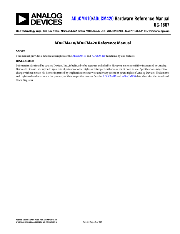
CLOCKING ARCHITECTURE
AFE_CLK �2
DAC ADC
HCLK DIV CDHCLK (CLKCON[2:0])
CLK_CortexM33
ANA_UCLK GPIO_UCLK PWM_UCLK SPI0_UCLK SPI1_UCLK SPI2_UCLK
DIV PCLK1 CDPCLK1 (CLKCON[8:6])
I2C0_UCLK I2C1_UCLK I2C2_UCLK UART0_UCLK UART1_UCLK MDIO_UCLK
OSC 16MHz
Sysclk(uclk)mux
CLKMUX (CLKCON0[1:0])
01 EXTCLK P2.1 11
00 SPLL
SYSCLK
PCLK0 DIV
CDPCLK0 (CLKCON1[5:3])
GPT0 TO GPT4 CLK (CON[6:5])
PCLK0 00 01
OSC 32kHz 10 AFE_CLK 11
WUT_UCLK PLA_UCLK GPT_UCLK
GPTCLK
GPT0 TO GPT4 COUNT
PLACLK
P0.3 000 P0.2 001 P4.7 010 HCLK 011 GPTIMER0 101 GPTIMER2 110 OSC 16M 100 OSC 32kHz 111
PLAClock
PLA_CLK1
PLA BLOCK1
PLACLK
P0.3 000 P0.2 001 P4.7 010 HCLK 011 GPTIMER0 101 GPTIMER1 110
OSC 32kHz 111
OSC 16M 100
PLA_CLK0
PLA BLOCK0
WUT COUNT
OSC 32kHz
EXTCLK P2.1 11 01/10
00 PCLK0
WDT_UCLK
CLK (T4CON[10:9])
Figure 1. Clock Architecture Overview
CLOCKING ARCHITECTURE OPERATION: SWITCHING CLOCK SETTINGS WHEN PLL CLOCK IS INCLUDED
When the PLL is the source clock for any ADuCM410 and ADuCM420 block, follow these steps to change the clock divide ratio:
1. Set the internal oscillator as the source clock. 2. Configure the required clock divide coefficient. 3. Set PLL as the root clock again.
PLAClock
23831-002
Rev. 0 | Page 8 of 225
ADuCM410/ADuCM420 Hardware Reference Manual
UG-1807
PLL INTERRUPT
Analog Devices recommends the user always enable the PLL interrupt source for the unlikely event that a PLL loss of lock error occurs. If the PLL loses lock, the risk of a system error is high, which may result in a hard fault or bus fault exception occurring.
The ADuCM410 and ADuCM420 PLL interrupt source triggers on the loss of lock. In this interrupt handler function, Analog Devices recommends first switching the system clock to the internal oscillator source. Then user code can recover as required, possibly via a software reset or alerting a host to a hardware error on the ADuCM410 and ADuCM420.
After a reset, the internal kernel program enables and selects the kernel as the high speed system clock (HCLK) source. Therefore, the first read of the CLKSTAT0 register likely shows both the SPLLUNLOCK and SPLLLOCK bits set. Before enabling the PLL interrupt source, clear these bits by writing 1 to the SPLLUNLOCKCLR and SPLLLOCKCLR bits of CLKSTAT0.
The following is example code to enable the PLL interrupts, and shows an example interrupt service routine:
pADI_CLK->CLKCON0 |=
BITM_CLOCK_CLKCON0_SPLLIE;
// Enable PLL interrupts
NVIC_EnableIRQ(PLL_IRQn);
// Enable PLL detection interrupt
void PLL_Int_Handler() {
uint32_t ulPLLSTA = 0;
ulPLLSTA = pADI_CLK->CLKSTAT0;
if ((ulPLLSTA & BITM_CLOCK_CLKSTAT0_SPLLUNLOCK)
== BITM_CLOCK_CLKSTAT0_SPLLUNLOCK)
// PLL loss of lock error detected
{
// Change CPU clock source to Internal Oscillator
pADI_CLK->CLKCON0 &= 0xFFFC;
// Return to internal oscillator - PLL unstable
ucPLLLoss = 1;
// Set flag to indicate loss of PLL Lock error
}
if ((ulPLLSTA & BITM_CLOCK_CLKSTAT0_SPLLLOCK)
== BITM_CLOCK_CLKSTAT0_SPLLLOCK)
// PLL lock detected
{
// Change CPU clock source to PLL � PLL is stable
pADI_CLK->CLKCON0 &= 0xFFFC;
pADI_CLK->CLKCON0 |= 0x1;
// PLL is stable
ucPLLLoss = 0;
// Set flag to indicate loss of PLL Lock error
}
pADI_CLK->CLKSTAT0 |=
// Clear PLL Lock/Unlock detection flags
BITM_CLOCK_CLKSTAT0_SPLLLOCKCLR |
BITM_CLOCK_CLKSTAT0_SPLLUNLOCKCLR;
}
Rev. 0 | Page 9 of 225
UG-1807
ADuCM410/ADuCM420 Hardware Reference Manual
REGISTER SUMMARY: CLOCK GATING AND OTHER SETTINGS (CLOCK)
Table 3. Clock Register Summary
Address
Name
0x40060000
CLKCON0
0x40060004
CLKCON1
0x40060008
CLKSTAT0
Description Miscellaneous Clock Settings Register. Clock Dividers Register. Clock Status Register.
Reset 0x043D 0x0048 0x0019
Access R/W R/W R/W
REGISTER DETAILS: CLOCK GATING AND OTHER SETTINGS (CLOCK) Miscellaneous Clock Settings Register
Address: 0x40060000, Reset: 0x043D, Name: CLKCON0
CLKCON0 is used to configure clock sources used by various blocks such as the core and memories as well as peripherals. All unused bits are read only, returning a value of 0.
Table 4. Bit Descriptions for CLKCON0
Bits Bit Name
Settings
[15:12] RESERVED
[11:10] ANAROOTCLKMUX
00
01
10
11
9
SPLLIE
0 1 [8:6] RESERVED [5:2] CLKOUT
[1:0] CLKMUX
0000 0001 0010 0011 0100 0101 0110 0111 1000 1001 1010 1011 1100 1101 1110, 1111
00 01 10 11
Description Reserved. Clock Mux Select for ADC and DAC Blocks. Reserved. 32 MHz Oscillator Clock. Only option allowed. Reserved. Reserved. PLL Unlock and Lock Interrupt Enable. If this bit is enabled, an interrupt is generated if the PLL transits from lock to unlock or from unlock to lock. PLL Interrupt Is Not Generated. PLL Interrupt Is Generated. Reserved. GPIO Clock Output Select. Used to select which clock is output on GPIO pin (P2.2). Implemented as a 16 to 1 mux. 16 MHz Internal High Frequency Oscillator. HCLK Reserved. 32 kHz Internal Oscillator HCLK Peripheral Clock 0 (PCLK0). Peripheral Clock 1 (PCLK1). Reserved. Reserved. Timer 0 Clock. Wake-Up Timer Clock. Timer 3 Clock. HCLK. SPLL Clock. Reserved
Clock Mux Select. Determines HCLK clock source. High Frequency Internal Oscillator. System PLL is Selected (160 MHz). Reserved. External GPIO Port is Selected (ECLKIN on P2.1).
Reset 0x0 0x1 0x0 0x0 0xF
0x1
Access R R/W R/W R/W R/W
R/W
Rev. 0 | Page 10 of 225
ADuCM410/ADuCM420 Hardware Reference Manual
UG-1807
Clock Dividers Register Address: 0x40060004, Reset: 0x0048, Name: CLKCON1 CLKCON1 is used to set the divide rates for the universal clock (UCLK) and PCLK0/PCLK1. This register can be written at any time. All unused bits are read only, returning a value of 0. Writing unused bits has no effect. Analog Devices only guarantees operation for clock divider settings of �1, �2, �4, and �8.
Table 5. Bit Descriptions for CLKCON1
Bits Bit Name Settings Description
[15:9] RESERVED
Reserved.
[8:6] CDPCLK1
PCLK1 Divide Bits. PCLK1 must be HCLK.
000 Divide by 1 (PCLK1 is Equal to Root Clock).
001 Divide by 2 (PCLK1 is Half the Frequency of Root Clock).
010 Divide by 4 (PCLK1 is Quarter the Frequency of Root Clock, 40 MHz).
011 Divide by 8.
100 Divide by 16. Reserved. Analog Devices has not characterized for this clock divide setting.
101 Divide by 32. Reserved. Analog Devices has not characterized for this clock divide setting.
110 Divide by 64. Reserved. Analog Devices has not characterized for this clock divide setting.
111 Divide by 128. Reserved. Analog Devices has not characterized for this clock divide setting.
[5:3] CDPCLK0
PCLK0 Divide Bits. PCLK0 must be HCLK.
000 Divide by 1 (PCLK0 is Equal to Root Clock).
001 Divide by 2 (PCLK0 is Half the Frequency of Root Clock).
010 Divide by 4 (PCLK0 is Quarter the Frequency of Root Clock, 40 MHz).
011 Divide by 8.
100 Divide by 16. Reserved. Analog Devices has not characterized for this clock divide setting.
101 Divide by 32. Reserved. Analog Devices has not characterized for this clock divide setting.
110 Divide by 64. Reserved. Analog Devices has not characterized for this clock divide setting.
111 Divide by 128. Reserved. Analog Devices has not characterized for this clock divide setting.
[2:0] CDHCLK
HCLK Divide Bits. HCLK must be PCLKx.
000 Divide by 1 (HCLK is Equal to Root Clock).
001 Divide by 2 (HCLK is Half the Frequency of Root Clock).
010 Divide by 4 (HCLK is Quarter the Frequency of Root Clock).
011 Divide by 8.
100 Divide by 16. Reserved. Analog Devices has not characterized for this clock divide setting.
101 Divide by 32. Reserved. Analog Devices has not characterized for this clock divide setting.
110 Divide by 64. Reserved. Analog Devices has not characterized for this clock divide setting.
111 Divide by 128. Reserved. Analog Devices has not characterized for this clock divide setting.
Reset 0x00 0x1
Access R R/W
0x1 R/W
0x0 R/W
Rev. 0 | Page 11 of 225
UG-1807
ADuCM410/ADuCM420 Hardware Reference Manual
Clock Status Register
Address: 0x40060008, Reset: 0x0019, Name: CLKSTAT0 CLKSTAT0 is used to monitor the PLL and oscillator status. With interrupts enabled, the user is free to run initialization code or idle the core while clock components stabilize.
Table 6. Bit Descriptions for CLKSTAT0
Bits Bit Name
Settings Description
[15:5] RESERVED
Reserved.
4
SPLLUNLOCK
System PLL Unlock Flag.
0 No PLL Unlock Event Was Detected.
1 A PLL Unlock Event Was Detected. Cleared by writing a 1 to SPLLUNLOCKCLR.
3
SPLLLOCK
System PLL Lock Flag.
0 No PLL Lock Event Was Detected.
1 A PLL Lock Event Was Detected. Cleared by writing a 1 to SPLLLOCKCLR.
2
SPLLUNLOCKCLR
System PLL Unlock. Writing a 1 to this bit clears the SPLLUNLOCK bit.
1
SPLLLOCKCLR
System PLL Lock. Writing a 1 to this bit clears sticky status and SPLLOCK status bit.
0
SPLLSTATUS
System PLL Status. Indicates the current status of the PLL. Initially, the system PLL is unlocked. After a stabilization period, the PLL locks and is ready for use as the system clock source. This is a read only bit. A write has no effect.
0 The PLL Is Not Locked or Not Properly Configured. The PLL is not ready for use as the system clock source.
1 The PLL Is Locked and Is Ready for Use as the System Clock Source.
Reset 0x0 0x1
0x1
0x0 0x0 0x1
Access R R
R
R/W R/W R
Rev. 0 | Page 12 of 225
ADuCM410/ADuCM420 Hardware Reference Manual
UG-1807
POWER MANAGEMENT UNIT
POWER MANAGEMENT UNIT FEATURES
The power management unit (PMU) controls the different power modes of the ADuCM410 and ADuCM420.
Four power modes are available: active, core sleep, system sleep, and hibernate.
POWER MANAGEMENT UNIT OVERVIEW
The Cortex-M33 power saving modes are linked to the PMU modes and are described in this section. The PMU is in the always on section. Each mode gives a power reduction benefit with a corresponding reduction in functionality.
POWER MANAGEMENT UNIT OPERATION
The debug tools can prevent the Cortex-M33 from fully entering its power saving modes by setting bits in the debug logic. Only a power-on reset resets the debug logic. Therefore, the device must be power cycled after using serial wire debug with application code containing the wait for interrupt (WFI) instruction.
Power Mode: Active Mode (Mode 0)
The system is fully active. Memories and all user enabled peripherals are clocked, and the Cortex-M33 processor executes instructions. Note that the Cortex-M33 processor manages its internal clocks and can be in a partial clock gated state. This clock gating affects only the internal Cortex-M33 processing core. Automatic clock gating is used on all blocks. User code can use a WFI command to put the CortexM33 processor into a power saving mode (Mode 1, Mode 2, or Mode 3). The WFI instruction is independent of the power mode settings of the PMU.
When the ADuCM410 and ADuCM420 wake up from any of the low power modes (Mode 1 to Mode 3), the devices return to Mode 0.
Power Mode: Core Sleep Mode (Mode 1)
In core sleep mode, the system gates the clock to the Cortex-M33 core after the Cortex-M33 enters sleep mode. The rest of the system remains active. No instructions can be executed. However, DMA transfers can continue to occur between peripherals and memories. The Cortex-M33 processor HCLK is active, and the device wakes up using the nested vectored interrupt controller (NVIC).
Power Mode: System Sleep Mode (Mode 2)
In system sleep mode, the system gates the high speed system bus clock (HCLK) and the peripheral bus clocks (PCLK0 and PCLK1) after the Cortex-M33 enters sleep mode. The gating of these clocks stops all Arm high performance bus (AHB) activities and all peripherals attached to the Arm peripheral bus (APB). Peripheral clocks are all off, and they are no longer user programmable. The NVIC clock remains active, and the NVIC processes wake-up events.
Power Mode : Hibernate Mode (Mode 3)
In hibernate mode, the system disables power to all combinational logic and places sequential logic in retain mode. Because HCLK is stopped, the number of sources capable of waking up the system is restricted. A limited number of interrupts can wake the device from this mode (see Table 11).
Power Mode 1 to Power Mode 3 must be entered when the processor is not in an interrupt handler. If Power Mode 1 to Power Mode 3 are entered when the processor is in an interrupt handler, the power-down mode can only be exited by a reset or a higher priority interrupt source.
The following is example code of how to enter hibernate mode: void EnterHibernateMode(void)
{
int32_t index = 0;
SCB->SCR = 0x04; Control register bit2
// sleep deep mode - write to the Cortex-M33 System
pADI_ALLON->PWRKEY = 0x4859; // key1
pADI_ALLON->PWRKEY = 0xF27B; // key2
pADI_ALLON->PWRMOD = 0x3; // Hibernate state
pADI_ALLON->PWRKEY = 0x4859; // key1
Rev. 0 | Page 13 of 225
UG-1807
ADuCM410/ADuCM420 Hardware Reference Manual
pADI_ALLON->PWRKEY = 0xF27B;
pADI_ALLON->PWRMOD |= 0x8; Sleep mode
// key2
// Deep sleep � not required when entering Core
for (index=0;index<2;index++); __WFI(); for (index=0;index<2;index++); }
REGISTER SUMMARY: POWER MANAGEMENT UNIT
Table 7. Power Management Register Summary
Address
Name
Description
0x40005000
PWRMOD
Power modes
0x40005004
PWRKEY
Key protection for PWRMOD
Reset 0x0000 0x0000
Access RW RW
REGISTER DETAILS: POWER MANAGEMENT UNIT Power Modes Register
Address: 0x40005000, Reset: 0x0000, Name: PWRMOD
Table 8. Bit Descriptions for PWRMOD
Bits Bit Name Settings Description
[15:4] RESERVED
Reserved.
3
WICENACK
Wake-Up Controller Acknowledgment for Hibernate Mode (Mode 3).
0 Disable Sleep Deep.
1 Enable Sleep Deep. Must be set to enter system sleep and hibernate modes.
2
RESERVED
Reserved.
[1:0] PWRMOD
Power Modes Control Bits. When read, these bits contain the last power mode value entered by user code. Note that, to place the Cortex in hibernate mode (Mode 3), the Cortex-M33 System Control Register (Address 0xE000ED10) must be configured to 0x4 or 0x06.
00 Active Mode.
01 Core Sleep Mode.
10 System Sleep Mode.
11 Hibernate Mode.
Reset 0x0 0x0
Access R R
0x0 R 0x0 R/W
Key Protection for PWRMOD Register Address: 0x40005004, Reset: 0x0000, Name: PWRKEY
Table 9. Bit Descriptions for PWRKEY
Bit(s) Bit Name Description
[15:0] PWRKEY
Power control key register. The PWRMOD register is key protected. Two writes to the key are necessary to change the value in the PWRMOD register: first 0x4859, then 0xF27B. Then, write to the PWRMOD register. A write to any other register before writing to PWRMOD returns the protection to the lock state.
Reset 0x0
Access RW
Rev. 0 | Page 14 of 225
ADuCM410/ADuCM420 Hardware Reference Manual
UG-1807
ARM CORTEX-M33 PROCESSOR
ARM CORTEX-M33 PROCESSOR FEATURES
The high performance features include the following:
� 1.5 Dhrystone MIPS/MHz � Many instructions, including multiply, are single cycle. � Optimized for single-cycle flash usage. � Hardware division and fast digital signal processing (DSP) orientated multiply and accumulate.
The low power features include the following:
� Low standby current. � Core implemented using advanced clock gating so that only the actively used logic consumes dynamic power. � Low power features including architectural clock gating, sleep mode, and a power aware system with optional wake-up interrupt
controller.
The advanced interrupt handling features include the following:
� The NVIC supports up to 480 interrupts, and eight levels of priority are available. The ADuCM410 and ADuCM420 support 74 of these interrupts. The vectored interrupt feature greatly reduces interrupt latency because software is not required to determine which interrupt handler to serve. In addition, software is not required to set up nested interrupt support.
� The Arm Cortex-M33 processor automatically pushes registers onto the stack at the entry interrupt and retrieves them at the exit interrupt. The pushing and retrieving reduce interrupt handling latency and allow interrupt handlers to be normal C functions.
� Dynamic priority control for each interrupt. � Latency reduction using late arrival interrupt acceptance and tail chain interrupt entry. � Immediate execution of a nonmaskable interrupt request for safety critical applications.
The system includes advanced fault handling features, including various exception types and fault status registers.
The ADuCM410 and ADuCM420 also have the following debug support features:
� Serial wire debug (SWD) interfaces. � Flash patch and breakpoint unit for implementing breakpoints. � Data watchpoint and trigger unit for implementing watchpoints trigger resources and system profiling. The ADuCM410 and
ADuCM420 are limited to one hardware watchpoint. With only one comparator, the data watchpoint and trigger unit does not support data matching for watchpoint generation.
ARM CORTEX-M33 PROCESSOR OVERVIEW
The ADuCM410 and ADuCM420 contain an embedded Arm Cortex-M33 processor. The Arm Cortex-M33 processor provides a high performance, low cost platform that meets the system requirements of minimal memory implementation, reduced pin count, and low power consumption while delivering computational performance and system response to interrupts.
ARM CORTEX-M33 PROCESSOR OPERATION
Several Arm Cortex-M33 processor components are flexible in their implementation. This section details the actual implementation of these components in the ADuCM410 and ADuCM420.
Serial Wire Debug
The ADuCM410 and ADuCM420 support the serial wire interface via SWO, SWCLK, and SWDIO. The devices do not support the 5-wire Joint Action Test Group (JTAG) interface.
Rev. 0 | Page 15 of 225
UG-1807
ADuCM410/ADuCM420 Hardware Reference Manual
ROM Table
The ADuCM410 and ADuCM420 implement the default read only memory (ROM) table. Nested Vectored Interrupt Controller Interrupts (NVICs)
The Arm Cortex-M33 processor includes an NVIC, which offers the following features:
� Nested interrupt support � Vectored interrupt support � Dynamic priority changes support � Interrupt masking
In addition, the NVIC has a nonmaskable interrupt (NMI) input.
The NVIC is implemented on the ADuCM410 and ADuCM420, and more details are available in the System Exceptions and Peripheral Interrupts section. Wake-Up Interrupt Controller
The ADuCM410 and ADuCM420 have a modified wake-up controller that provides the lowest possible power-down current. More details on this feature are available in the Power Management Unit section. It is not recommended to enter power saving mode while servicing an interrupt. However, if the device does enter power saving mode while servicing an interrupt, it can only wake up by a higher priority interrupt source. �DMA
The ADuCM410 and ADuCM420 implement the Arm �DMA. See the Direct Memory Access (DMA) Controller section for more details. Floating-Point Unit (FPU)
The Cortex-M33 contains a single precision, floating-point computation unit.
The FPU adds 45 IEEE� 754TM-2008-compatible, single-precision floating-point instructions. Using floating-point instructions usually yields an average of 10 times increase in performance over the equivalent software libraries.
Ensure the compiler is instructed to use the FPU for floating-point arithmetic (see the ADuCM410 and ADuCM420 evaluation kits for examples). Peripheral Address Accesses Using a Cortex-M33 core
Unaligned peripheral address accesses are not supported on the Cortex-M33 core. Unaligned address accesses result in a usage exception fault. Access for a Cortex-M33 core is different compared to a Cortex-M3, which does not generate such an exception for unaligned address accesses.
An example code of an unaligned memory access follows: R0 = 4
R1 = 0x40064001
STR R0, [R1]
When R1 = 0x20001001(SRAM location), there is no issue.
When R1 = 0x40064001, which is the PWMCON0 Byte 1 address, a usage fault exception occurs.
If using the C-based header file definitions provided with the Analog Devices evaluation software, the usage fault errors are not a concern.
ARM CORTEX-M33 PROCESSOR RELATED DOCUMENTS
The following list contains documentation related to the Arm Cortex-M3:
� Cortex-M33 Revision r1p0 Technical Reference Manual. � ARMv8-M Architecture Reference Manual (DDI 0553) � Arm Debug Interface Architecture Specification v5 . � PrimeCell �DMA Controller (PL230) Technical Reference Manual Revision r0p0 (DDI 0417)
Rev. 0 | Page 16 of 225
ADuCM410/ADuCM420 Hardware Reference Manual
UG-1807
SYSTEM EXCEPTIONS AND PERIPHERAL INTERRUPTS
CORTEX-M33 AND FAULT MANAGEMENT
The ADuCM410 and ADuCM420 integrate an Arm Cortex-M33 processor, which supports several system exceptions and interrupts generated by peripherals. Table 10 lists the Arm Cortex-M33 processor system exceptions.
Table 10. System Exceptions
Number Type
1
Reset
2
NMI
3
Hard fault
4
Memory management fault
5
Bus fault
6 7 to 10 11 12 13 14
Usage fault Reserved SVCALL Debug monitor Reserved PENDSV
15
SYSTICK
Priority -3 (highest) -2 -1 Programmable Programmable
Programmable Not applicable. Programmable Programmable Not applicable Programmable
Programmable
Description Any reset. Nonmaskable interrupt not connected on the ADuCM410 and ADuCM420. All fault conditions if the corresponding fault handler is not enabled. Access to invalid locations. Prefetch fault, memory access fault, data abort, and other address/memory related faults. Same as undefined instruction executed or invalid state transition attempt. Not applicable. System supervisor call with SVC instruction. Used for system function calls. Debug monitor (breakpoint, watchpoint, or external debug requests). Not applicable. Pending request for system service. Used for queuing system calls until other tasks and interrupts are serviced. System tick timer.
The NVIC controls the peripheral interrupts and are listed in Table 11. All interrupt sources can wake up the device from core sleep mode (Mode 1). Only a limited number of interrupts can wake up the processor from the low power modes, system sleep and hibernate (Mode 2 and Mode 3), as shown in Table 11. When the device is woken up from Mode 2 or Mode 3, it returns to Mode 0. If the processor enters any power mode from Mode 1 to Mode 3 while the processor is in an interrupt handler, only an interrupt source with a higher priority than the current interrupt can wake up the device (higher value in the IPRx registers).
The following two steps are usually required to configure an interrupt:
1. Configure a peripheral to generate an interrupt request to the NVIC. 2. Configure the NVIC for that peripheral request.
Table 11. Interrupt Vector Table
Interrupt Number
Vector
0
Wake-up timer
1
External Interrupt 0
2
External Interrupt 1
3
External Interrupt 2
4
External Interrupt 3
5
External Interrupt 4
6
External Interrupt 5
7
External Interrupt 6
8
External Interrupt 7
9
External Interrupt 8
10
External interrupt 9
11
Watchdog Timer
12
16-Bit General-Purpose Timer 0 (GPT0)
13
16-Bit General-Purpose Timer 1 (GPT1)
14
16-Bit General-Purpose Timer 2 (GPT2)
15
32-Bit General-Purpose Timer 0 (GPT3)
16
32-Bit General-Purpose Timer 1 (GPT4)
17
MDIO
18
Flash controller
19
UART Channel 0 (UART0)
Wake Up Processor from Mode 1 Yes Yes Yes Yes Yes Yes Yes Yes Yes Yes Yes Yes Yes Yes Yes Yes Yes Yes Yes Yes
Wake Up Processor from Mode 2 or Mode 3 Yes Yes Yes Yes Yes Yes Yes Yes Yes Yes Yes Yes No No No No No No No No
Rev. 0 | Page 17 of 225
UG-1807
ADuCM410/ADuCM420 Hardware Reference Manual
Interrupt Number 20 21 22 23 24 25 26 27 28 29 30 31 32 33 34 35 36 37 37 39 40 41 42 43 44 45 46 47 48 49 50 51 52 53 54 55 56 57 58 59 60 61 62 63 64 65 66 67 68 69 70 71
Vector UART Channel 1 (UART1) SPI Channel 0 (SPI0) SPI Channel 1 (SPI1) SPI Channel 2 (SPI2) I2C Channel 0 (I2C0) slave I2C0 master I2C Channel 1 (I2C1) slave I2C1 master I2C Channel 2 (I2C2) slave I2C2 master PLA Channel 0 (PLA0) PLA Channel 1 (PLA1) PLA Channel 2 (PLA2) PLA Channel 3 (PLA3) PWM trip PWM Pair 0 (IRQPWM0) PWM Pair 1 (IRQPWM1) PWM Pair 2 (IRQPWM2) PWM Pair 3 (IRQPWM3) SRAM error DMA error DMA Channel 0 (SPI0 transmit) done DMA Channel 1 (SPI0 receive) done DMA Channel 2 (SPI1 transmit) done DMA Channel 3 (SPI1 receive) done DMA Channel 4 (SPI2 transmit) done DMA Channel 5 (SPI2 receive) done DMA Channel 6 (UART0 transmit) done DMA Channel 7 (UART0 receive) done DMA Channel 8 (UART1 transmit) done DMA Channel 9 (UART1 receive) done DMA Channel 10 (I2C0 slave transmit) done DMA Channel 11 (I2C0 slave receive) done DMA Channel 12 (I2C0 master) done DMA Channel 13 (I2C1 Slave transmit) done DMA Channel 14 (I2C1 slave receive) done DMA Channel 15 (I2C1 master) done DMA Channel 16 (I2C2 slave transmit) done DMA Channel 17 (I2C2 slave receive) done DMA Channel 18 (I2C2 master) done DMA Channel 19 (MDIO transmit) done DMA Channel 20 (MDIO receive) done DMA Channel 21 (flash) done DMA Channel 22 (ADC) done PLL High frequency oscillator ADC Sequencer Comparator 0 Comparator 1 Comparator 2 Comparator 3
Wake Up Processor from Mode 1 Yes Yes Yes Yes Yes Yes Yes Yes Yes Yes Yes Yes Yes Yes Yes Yes Yes Yes Yes Yes Yes Yes Yes Yes Yes Yes Yes Yes Yes Yes Yes Yes Yes Yes Yes Yes Yes Yes Yes Yes Yes Yes Yes Yes Yes Yes Yes Yes Yes Yes Yes Yes
Rev. 0 | Page 18 of 225
Wake Up Processor from Mode 2 or Mode 3 No No No No No No No No No No No No No No No No No No No No No No No No No No No No No No No No No No No No No No No No No No No No No No No No No No No No
ADuCM410/ADuCM420 Hardware Reference Manual
UG-1807
Interrupt Number 72 73 74 75 76 77 78 79 80 81 82 83 84 85 86 87 88
Vector VDAC Reserved Reserved Reserved Reserved Reserved Reserved Reserved Reserved Reserved Reserved Reserved Reserved Reserved Reserved GPIO Interrupt A GPIO Interrupt B
Wake Up Processor from Mode 1 Yes Not applicable Not applicable Not applicable Not applicable Not applicable Not applicable Not applicable Not applicable Not applicable Not applicable Not applicable Not applicable Not applicable Not applicable Not applicable Not applicable
Wake Up Processor from Mode 2 or Mode 3 No Not applicable Not applicable Not applicable Not applicable Not applicable Not applicable Not applicable Not applicable Not applicable Not applicable Not applicable Not applicable Not applicable Not applicable Not applicable Not applicable
Internal to the Arm Cortex-M33 processor, the highest user-programmable priority (0) is treated as fourth priority, which is after a reset, an NMI, and a hard fault. The ADuCM410 and ADuCM420 implement three priority bits, which means that eight priority levels are available as programmable priorities. Note that 0 is the default priority for all the programmable priorities. If the same priority level is assigned to two or more interrupts, their hardware priority (a lower interrupt number) determines the order in which the processor activates them. For example, if both SPI0 and SPI1 interrupts occur simultaneously, SPI0 takes priority because its interrupt number is lower.
To enable an interrupt for any peripheral listed from Interrupt 0 to Interrupt 31 in Table 11, set the appropriate bit in the ISER0 register. ISER0 is a 32-bit register, and each bit corresponds to the first 32 entries in Table 11.
For example, to enable the interrupt source for External Interrupt 4 in the NVIC, set ISER0, Bit 5 = 1. Similarly, to disable External Interrupt 4, set ICER0, Bit 5 = 1.
To enable an interrupt for any peripheral listed from Interrupt 32 to Interrupt 63 in Table 11, set the appropriate bit in the ISER1 register. ISER1 is a 32-bit register, and Bit 0 to Bit 31 in ISER1 correspond to Interrupt 32 to Interrupt 63 in Table 11.
For example, to enable the PWM Pair 0 interrupt source in the NVIC, set ISER1, Bit 3 = 1. Similarly, to disable the PWM Pair 0 interrupt, set ICER1, Bit 3 = 1.
Similarly, ISER2 and ICER2 enable and clear the interrupt sources in Interrupt 64 to Interrupt 88 in Table 11.
Alternatively, the Cortex microcontroller software interface standard (CMSIS) provides several useful NVIC functions in the core_cm33.h file. The NVIC_EnableIRQ(PWM0_IRQn) function enables the PWM Pair 0 interrupt. The interrupt can be disabled by calling the NVIC_DisableIRQ(PWM0_IRQn) function.
To set the priority of a peripheral interrupt, the IPRx bits can be set appropriately or, alternatively, the NVIC_SetPriority() function can be called. For example, NVIC_SetPriority(GPT0_IRQn, 2) configures the General-Purpose Timer 0 interrupt with a priority level of 2.
Table 12 lists the registers to enable and disable relevant interrupts and set the priority levels. The registers in Table 12 are defined in the CMSIS core_cm33.h file, which is shipped with tools from third party vendors.
Rev. 0 | Page 19 of 225
UG-1807
ADuCM410/ADuCM420 Hardware Reference Manual
Table 12. NVIC Registers
Address
Analog Devices Header File Name
0xE000E004 ICTR
0xE000E010 STCSR
0xE000E014 STRVR
0xE000E018 STCVR
0xE000E01C STCR
0xE000E100 ISER0
0xE000E104 ISER1
0xE000E108 ISER2
0xE000E180 ICER0
0xE000E184 ICER1
0xE000E188 ICER2
0xE000E200 ISPR0
0xE000E204 ISPR1
0xE000E208 ISPR2
0xE000E280 ICPR0
0xE000E284 ICPR1
0xE000E288 ICPR2
0xE000E300 0xE000E304 0xE000E308 0xE000E400 0xE000E404 0xE000E408 0xE000E40C 0xE000E410 0xE000E414 0xE000E418 0xE000E41C 0xE000E420 0xE000E424 0xE000E428 0xE000E42C 0xE000E430 0xE000E434 0xE000E438 0xE000E43C 0xE000E440 0xE000E444 0xE000E448 0xE000E44C 0xE000E450
IABR0 IABR1 IABR2 IPR0 IPR1 IPR2 IPR3 IPR4 IPR5 IPR6 IPR7 IPR8 IPR9 IPR10 IPR11 IPR12 IPR13 IPR14 IPR15 IPR16 IPR17 IPR18 IPR19 IPR20
Description
Shows the number of interrupt lines that the NVIC supports. SYSTICK control and status register. SYSTICK reload value register. SYSTICK current value register. SYSTICK calibration value register. Set the appropriate bit, IRQ0 to IRQ31, to enable. Each bit corresponds to Interrupt 0 to Interrupt 31 in Table 11. Set the appropriate bit, IRQ32 to IRQ63, to enable. Each bit corresponds to Interrupt 32 to Interrupt 63 in Table 11. Set the appropriate bit, IRQ64 to IRQ88, to enable. Each bit corresponds to Interrupt 64 to Interrupt 88 in Table 11. Clear IRQ0 to IRQ31 by setting the appropriate bit. Each bit corresponds to Interrupt 0 to Interrupt 31 in Table 11. Clear IRQ32 to IRQ63 by setting the appropriate bit. Each bit corresponds to Interrupt 32 to Interrupt 63 in Table 11. Clear IRQ64 to IRQ88 by setting the appropriate bit. Each bit corresponds to Interrupt 64 to Interrupt 88 in Table 11. Set the appropriate bit, IRQ0 to IRQ31, to force the interrupt source to its pending state. Each bit corresponds to Interrupt 0 to Interrupt 31 in Table 11. Set the appropriate bit, IRQ32 to IRQ63, to force the interrupt source to its pending state. Each bit corresponds to Interrupt 32 to Interrupt 63 in Table 11. Set the appropriate bit, IRQ64 to IRQ88, to force the interrupt source to its pending state. Each bit corresponds to Interrupt 64 to Interrupt 88 in Table 11. Clear the appropriate bit, IRQ0 to IRQ31, to remove the interrupt source from its pending state. Each bit corresponds to Interrupt 32 to Interrupt 38 in Table 11. Clear the appropriate bit, IRQ32 to IRQ63, to remove the interrupt source from its pending state. Each bit corresponds to Interrupt 32 to Interrupt 63 in Table 11. Clear the appropriate bit, IRQ64 to IRQ88, to remove the interrupt source from its pending state. Each bit corresponds to Interrupt 64 to Interrupt 88 in Table 11. IRQ0 to IRQ31 active bits. IRQ32 to IRQ63 active bits. IRQ64 to IRQ80 active bits. IRQ0 to IRQ3 priority. IRQ4 to IRQ7 priority. IRQ8 to IRQ11 priority. IRQ12 to IRQ15 priority. IRQ16 to IRQ19 priority. IRQ20 to IRQ23 priority. IRQ24 to IRQ27 priority. IRQ28 to IRQ31 priority. IRQ32 to IRQ35 priority. IRQ36 to IRQ39 priority. IRQ40 to IRQ43 priority. IRQ44 to IRQ47 priority. IRQ48 to IRQ51 priority. IRQ52 to IRQ55 priority. IRQ56 to IRQ59 priority. IRQ60 to IRQ63 priority. IRQ64 to IRQ67 priority. IRQ68 to IRQ71 priority. IRQ72 to IRQ75 priority. IRQ76 to IRQ79 priority. IRQ80 to IRQ83 priority.
Rev. 0 | Page 20 of 225
Access R RW RW RW R RW
RW
RW
RW
RW
RW
RW
RW
RW
RW
RW
RW
RW RW RW RW RW RW RW RW RW RW RW RW RW RW RW RW RW RW RW RW RW RW RW RW
ADuCM410/ADuCM420 Hardware Reference Manual
UG-1807
Address 0xE000E454 0xE000E458 0xE000ED00 0xE000ED04 0xE000ED08 0xE000ED0C 0xE000ED10 0xE000ED14 0xE000ED18 0xE000ED1C 0xE000ED20 0xE000ED24 0xE000ED28 0xE000ED2C 0xE000ED34 0xE000ED38 0xE000EF00
Analog Devices Header File Name IPR21 IPR22 CPUID ICSR VTOR AIRCR SCR CCR SHPR1 SHPR2 SHPR3 SHCRS CFSR HFSR MMAR BFAR STIR
Description IRQ84 to IRQ87 priority. IRQ88 priority. Central processing unit ID (CPUID) base register. Interrupt control and status register. Vector table offset register. Application interrupt/reset control register. System control register. Configuration control register. System Handlers Register 1. System Handlers Register 2. System Handlers Register 3. System handler control and state. Configurable fault status. Hard fault status. Memory manage fault address register. Bus fault address. Software trigger interrupt register.
Access RW RW R RW RW RW RW RW RW RW RW RW RW RW RW RW W
EXTERNAL INTERRUPT CONFIGURATION
The ADuCM410 and ADuCM420 implement 10 external interrupts that can be separately configured to detect any combination of the following type of events:
� Rising edge: the logic detects a transition from low to high and generates a pulse. Only one pulse is sent to the Cortex-M33 per rising edge.
� Falling edge: the logic detects a transition from high to low and generates a pulse. Only one pulse is sent to the Cortex-M33 per falling edge.
� Rising edge or falling edge: the logic detects a transition from low to high or high to low and generates a pulse. Only one pulse is sent to the Cortex-M33 per edge.
� High level: the logic detects a high level. The appropriate interrupt is asserted and sent to the Cortex-M33. The interrupt line is held asserted until the external source deasserts. The high level must be maintained for one core clock (HCLK) cycle minimum to be detected.
� Low level: the logic detects a low level. The appropriate interrupt is asserted and sent to the Cortex-M33. The interrupt line is held asserted until the external source deasserts. The low level must be maintained for one core clock (HCLK) cycle minimum to be detected.
The external interrupt detection unit block is in the always on section and allows external interrupts to wake up the device when in hibernate mode.
Ensure that the associated GPxIE register bit is enabled for the required external interrupt input. The GPxIE register enables the input path circuit for the external interrupt.
External Interrupt Request (IRQ) Mode
Five external interrupt modes can be enabled or disabled. These modes are set up via the EI0CFG, EI1CFG, and EI2CFG registers.
Table 13. External Interrupt Mode Selection for IRQxMDE (x = 0 to 9)
Settings
External interrupt Mode
0x0
Rising edge
0x1
Falling edge
0x2
Rising or falling edge
0x3
High level
0x4
Low level
0x5
Falling edge (same as 0x1)
0x6
Rising or falling edge (same as 0x2)
0x7
High level (same as 0x3)
Rev. 0 | Page 21 of 225
UG-1807
ADuCM410/ADuCM420 Hardware Reference Manual
REGISTER SUMMARY: EXTERNAL INTERRUPTS
Table 14. External Interrupts Register Summary
Address
Name
Description
0x40005020
EI0CFG
External Interrupt Configuration 0
0x40005024
EI1CFG
External Interrupt Configuration 1
0x40005028
EI2CFG
External Interrupt Configuration 2
0x40005030
EICLR
External interrupt clear
Reset 0x0000 0x0000 0x0000 0x0000
Access RW RW RW RW
REGISTER DETAILS: EXTERNAL INTERRUPTS External Interrupt Configuration 0 Register
Address: 0x40005020, Reset: 0x0000, Name: EI0CFG
Table 15. Bit Descriptions for EI0CFG
Bits Bit Name Settings Description
15
IRQ3EN
External Interrupt 3 Enable Bit
0x0 External Interrupt 3 Disabled.
0x1 External Interrupt 3 Enabled.
[14:12] IRQ3MDE
External Interrupt 3 Mode Registers. See Table 13 for more details.
11
IRQ2EN
External Interrupt 2 Enable Bit
0x0 External Interrupt 2 Disabled.
0x1 External Interrupt 2 Enabled.
[10:8] IRQ2MDE
External Interrupt 2 Mode Registers. See Table 13 for more details.
7
IRQ1EN
External Interrupt 1 Enable Bit
0x0 External Interrupt 1 Disabled.
0x1 External Interrupt 1 Enabled.
[6:4] IRQ1MDE
External Interrupt 1 Mode Registers. See Table 13 for more details.
3
IRQ0EN
External Interrupt 0 Enable Bit
0x0 External Interrupt 0 Disabled.
0x1 External Interrupt 0 Enabled.
[2:0] IRQ0MDE
External Interrupt 0 Mode Registers. See Table 13 for more details.
Reset Access 0x0 R/W
0x0 R/W 0x0 R/W
0x0 R/W 0x0 R/W
0x0 R/W 0x0 R/W
0x0 R/W
External Interrupt Configuration 1 Register Address: 0x40005024, Reset: 0x0000, Name: EI1CFG
Table 16. Bit Descriptions for EI1CFG
Bits Bit Name Settings Description
15
IRQ7EN
External Interrupt 7 Enable Bit
0x0 External Interrupt 7 Disabled.
0x1 External Interrupt 7 Enabled.
[14:12] IRQ7MDE
External Interrupt 7 Mode Registers. See Table 13 for more details.
11
IRQ6EN
External Interrupt 6 Enable Bit
0x0 External Interrupt 6 Disabled.
0x1 External Interrupt 6 Enabled.
[10:8] IRQ6MDE
External Interrupt 6 Mode Registers. See Table 13 for more details.
7
IRQ5EN
External Interrupt 5 Enable Bit
0x0 External Interrupt 5 Disabled.
0x1 External Interrupt 5 Enabled.
[6:4] IRQ5MDE
External Interrupt 5 Mode Registers. See Table 13 for more details.
3
IRQ4EN
External Interrupt 4 Enable Bit
0x0 External Interrupt 4 Disabled.
0x1 External Interrupt 4 Enabled.
[2:0] IRQ4MDE
External Interrupt 4 Mode Registers. See Table 13 for more details.
Rev. 0 | Page 22 of 225
Reset Access 0x0 R/W
0x0 R/W 0x0 R/W
0x0 R/W 0x0 R/W
0x0 R/W 0x0 R/W
0x0 R/W
ADuCM410/ADuCM420 Hardware Reference Manual
External Interrupt Configuration 2 Register Address: 0x40005028, Reset: 0x0000, Name: EI2CFG
Table 17. Bit Descriptions for EI2CFG
Bits
Bit Name
Settings Description
[15:8] RESERVED
Reserved.
7
IRQ9EN
External Interrupt 9 Enable Bit
0 External Interrupt 9 Disabled.
1 External Interrupt 9 Enabled.
[6:4]
IRQ9MDE
External Interrupt 9 Mode Registers. See Table 13 for more details.
3
IRQ8EN
External Interrupt 8 Enable Bit
0 External Interrupt 8 Disabled.
1 External Interrupt 8 Enabled.
[2:0]
IRQ8MDE
External Interrupt 8 Mode Registers. See Table 13 for more details.
UG-1807
Reset 0x0 0x0
Access R R/W
0x0
R/W
0x0
R/W
0x0
R/W
External Interrupt Clear Register Address: 0x40005030, Reset: 0x0000, Name: EICLR
Table 18. Bit Descriptions for EICLR
Bits Bit Name Settings Description
[15:10] RESERVED
Reserved.
9
IRQ9
External Interrupt 9. Set to 1 to clear an internal interrupt flag. Cleared automatically by hardware.
8
IRQ8
External Interrupt 8. Set to 1 to clear an internal interrupt flag. Cleared automatically by hardware.
7
IRQ7
External Interrupt 7. Set to 1 to clear an internal interrupt flag. Cleared automatically by hardware.
6
IRQ6
External Interrupt 6. Set to 1 to clear an internal interrupt flag. Cleared automatically by hardware.
5
IRQ5
External Interrupt 5. Set to 1 to clear an internal interrupt flag. Cleared automatically by hardware.
4
IRQ4
External Interrupt 4. Set to 1 to clear an internal interrupt flag. Cleared automatically by hardware.
3
IRQ3
External Interrupt 3. Set to 1 to clear an internal interrupt flag. Cleared automatically by hardware.
2
IRQ2
External Interrupt 2. Set to 1 to clear an internal interrupt flag. Cleared automatically by hardware.
1
IRQ1
External Interrupt 1. Set to 1 to clear an internal interrupt flag. Cleared automatically by hardware.
0
IRQ0
External Interrupt 0. Set to 1 to clear an internal interrupt flag. Cleared automatically by hardware.
Reset 0x0 0x0
Access R R/W
0x0 R/W
0x0 R/W
0x0 R/W
0x0 R/W
0x0 R/W
0x0 R/W
0x0 R/W
0x0 R/W
0x0 R/W
Rev. 0 | Page 23 of 225
UG-1807
ADuCM410/ADuCM420 Hardware Reference Manual
RESET
RESET FEATURES
There are four kinds of resets: external reset, power-on reset (POR), watchdog timeout, and software system reset.
RESET OPERATION
The software system reset is provided as part of the Cortex-M33 processor. To generate a software system reset, the application interrupt or reset control register must be written to 0x05FA0004. This register is part of the NVIC register and is located at Address 0xE000ED0C.
Analog peripherals have the option of maintaining their state after a software or watchdog reset. This function is enabled by default, but can be disabled through RSTCFG, Bit 3. Note that while debugging, the software tools generally only issue a software reset. Therefore, an external reset is needed to return registers to their default values.
The GPIO pins and PLA also have the option of maintaining their state after a software or watchdog reset. By default, this function is enabled. Writing a value of 0x1 to RSTCFG configures the GPIO pins and PLA to reset after a software or watchdog reset. Before writing to this register, 0x2009 must be written to RSTKEY followed by 0x0426. After the two keys are written to RSTKEY, RSTCFG must be immediately written.
The RSTSTA register stores the cause for the reset until the bit is cleared by writing to the RSTSTA register. RSTSTA can be used during a reset exception service routine to identify the source of the reset.
The watchdog timer is enabled by default after a reset. The default timeout period is approximately 32 sec.
User code must disable the watchdog timer at the start of user code when debugging or when the watchdog timer is not required, as follows:
pADI_WDT->T3CON = 0x00;
// Disable watchdog timer
Table 19. Device Reset Implications
Reset Software Reset Watchdog Timeout External Reset Pin POR
Reset External Pins to Default State Yes/No1 Yes/No1 Yes Yes
Execute Kernel Yes Yes Yes Yes
Impact
Reset All MMRs Except RSTSTA Yes/No1 Yes/No1 Yes Yes
Reset All Peripherals Yes/No1 Yes/No1 Yes Yes
1 GPIOs, PLA, and analog peripherals have the option of retaining their output state during a watchdog or software reset.
Valid SRAM Yes Yes Yes No
RSTSTA After Reset Event RSTSTA, Bit 3 = 1 RSTSTA, Bit 2 = 1 RSTSTA, Bit 1 = 1 RSTSTA, Bit 0 = 1
Rev. 0 | Page 24 of 225
ADuCM410/ADuCM420 Hardware Reference Manual
UG-1807
REGISTER SUMMARY: RESET
Table 20. Reset Register Summary
Address
Name
0x40005008
RSTCFG
0x4000500C
RSTKEY
0x40005040
RSTSTA
Description Reset configuration Key protection for RSTCFG Reset status
Reset 0x000F 0x0000 0x0000
Access RW RW RW
REGISTER DETAILS: RESET Reset Configuration Register
Address: 0x40005008, Reset: 0x0000, Name: RSTCFG
Table 21. Bit Descriptions for RSTCFG
Bits Bit Name
Settings
[15:4] RESERVED
3
ANA_RETAIN
0
1
[2:1] RESERVED
0
GPIO_PLA_RETAIN
0 1
Description Reserved. Analog Blocks Retain Status After Watchdog or Software Reset Analog Blocks Retain Status After Watchdog or Software Reset. Analog Blocks Do Not Retain Status After Watchdog or Software Reset. Reserved. GPIO/PLA Retain Their Status After Watchdog Timer Reset and Software Reset. P2.1 and 2.3 are not affected by this register. They do not retain their state. GPIO/PLA Retain Status After Watchdog or Software Reset. GPIO/PLA Does not Retain Status After Watchdog or Software Reset.
Reset 0x0 0x1
Access R R/W
0x1 R/W 0x1 R/W
Key Protection for RSTCFG Register Address: 0x4000500C, Reset: 0x0000, Name: RSTKEY
Table 22. Bit Descriptions for RSTKEY
Bit(s) Bit Name Description
[15:0] RSTKEY
Reset configuration key register. The RSTCFG register is key protected. Two writes to the key are necessary to change the value in the RSTCFG register: first 0x2009, then 0x0426. The RSTCFG register must then be written to. A write to any other register on the APB before writing to RSTCFG returns the protection to the lock state.
Reset Access 0x0 RW
Reset Status Register Address: 0x40005040, Reset: 0x0000, Name: RSTSTA
Table 23. Bit Descriptions for RSTSTA
Bit(s) Bit Name Description
[15:4] RESERVED Reserved.
3
SWRST
Software reset. Set automatically to 1 when the Cortex-M33 system reset is generated. Cleared by
writing 1 to this bit.
2
WDRST Watchdog timeout. Set automatically to 1 when a watchdog timeout occurs. Cleared by writing 1
to this bit.
1
EXTRST External reset. Set automatically to 1 when an external reset occurs. Cleared by writing 1 to this bit.
0
POR
Power-on reset. Set automatically when a power-on reset occurs. Cleared by writing one to this bit.
Reset 0x0 0x0
Access R RW1C
0x0 RW1C
0x0 RW1C 0x0 RW1C
Rev. 0 | Page 25 of 225
UG-1807
ADuCM410/ADuCM420 Hardware Reference Manual
ANALOG PIN FUNCTIONALITY
The ADuCM410 and ADuCM420 combine multiple functions on the same analog input/output pins. This section details the alternate functions of each analog I/O pin and describes the limitations.
Table 24. Pin Mnemonic AIN15/COM3N/BUF0_VREF AIN14/COM3P/BUF0_VREF
AIN2/PADC0P AIN3/PADC1P
AIN5/PADC2P AIN6/PADC3P AIN8/COP0P AIN10/COM1P AIN12/COM2P AIN13/COM2N AIN9/COM0N/PGA2OUT AIN11/COM1N/PGA0OUT AIN4/PADC01N/VDAC0 AIN7/PADC23N/VDAC2 VDAC8/P5.0 VDAC9/P5.1 VDAC10/P5.2 VDAC11/P5.3 VDAC3/P4.0/PLAI11 VDAC6/P4.1/PLAO28 VDAC5/P4.4 VDAC7/P4.2
Comments Three analog functions can be used at the same time: the buffered reference outputs can be measured via AIN15 or AIN14 while connected to the Comparator 3 amplifier. Higher input current flows in these analog pins if the comparator is enabled. Both functions can be used at the same time for all these pins. Only one of the AINx or PADCxP inputs can be sampled by the ADC at any given time. Higher input current flows in these analog pins if the comparator is enabled.
The comparator function can be enabled at the same time as either the AINx or PGAxOUT function. Higher input current flows in these analog pins if the comparator is enabled. Only AIN4 and AIN7 can be used with the VDAC or PGA function. The VDAC and PGA functions cannot be used at the same time Use only one of these two options on each pin at any given time.
Do not use the digital GPIO function and DAC output function at the same time.
Rev. 0 | Page 26 of 225
ADuCM410/ADuCM420 Hardware Reference Manual
UG-1807
ADC CIRCUIT
ADC CIRCUIT FEATURES
The ADuCM410 and ADuCM420 incorporate a fast, multichannel, 16-bit ADC and 12-bit ADC, respectively.
A flexible input multiplexer supports 16 external inputs and several internal channels. The internal channels include the following:
� A temperature sensor channel. � An internal 2.5 V reference. � An external reference. � IOVDD0 � 2 and IOVDD1 supply voltages. � AVDD � 2 and DVDD � 2 supply voltages.
An input precharge buffer can be selected for any channel to allow very low input current and input leakage specifications on these input channels.
A high precision, low drift internal 2.5 V reference source is provided. An external reference can also be connected to the ADCREFP and ADCREFN pins.
The programmable ADC update rate is from 100 kSPS to 2 MSPS.
Each channel has its own distinct data register for its conversion result. For example, when AIN0 is selected, the result appears in ADCDAT0. If AIN7 is selected, the result appears in ADCDAT7. For a differential measurement, the result always appears in the data register of the positive channel.
ADC CIRCUIT BLOCK DIAGRAM
PGA/TIA CHANNEL 0
PGA/TIA CHANNEL 1
PGA/TIA CHANNEL 2
PGA/TIA CHANNEL 3
VOLTAGE INPUTS: AIN0 TO AIN15
ADC PREBUFFER
+ -
+
16-BIT ADC 2MSPS
POST PROCESSING BLOCKS: OFFSET/GAIN CALIBRATION
ADC INPUT MUX
23831-003
INTERNAL CHANNELS: TEMPERATURE SENSOR INTERNAL VOLTAGE REFERENCE POWER SUPPLY VOLTAGES
Figure 2. ADC Circuit Block Diagram
Rev. 0 | Page 27 of 225
UG-1807
ADuCM410/ADuCM420 Hardware Reference Manual
ADC CIRCUIT OVERVIEW
The ADuCM410 incorporates a fast, multichannel, 16-bit ADC, and the ADuCM420 has a 12-bit ADC that can provide a throughput of up to 2 MSPS. This ADC block provides the user with a multichannel multiplexer, a precharge buffer for high impedance input channels, an on-chip reference, and a successive approximation register (SAR) ADC.
A high precision, low drift, factory calibrated, 2.5 V reference is provided on chip. An external reference can also be connected to the ADCREFP and ADCREFN pins.
ADC CIRCUIT OPERATION
The input mux selects one of the external AIN0 to AIN15 channels or internal channels (such as PGAs, TIAs, or temperature sensor).
ADC CHANNEL SEQUENCER
An ADC sequencer is provided to reduce the processor overhead of sampling and reading individual channels. The ADC sequencer allows the user to select the ADC input channels that the ADC samples, via the ADCSEQCH, ADCSEQCHMUX0, and ADCSEQCHMUX1 registers, and provides an interrupt source that is asserted at the end of the sequence. The sequencer can only work in continuous mode. The sequencer can also be programmed to restart from the first configured channel, but the current ADC conversion must first be executed completely.
Sequencer Mode: Single Sequence
When ADCSEQC, Bits[7:0] is equal to 255, the sequencer runs in a single sequence. The sequencer automatically causes a halt after one sequence.
Sequencer Mode: Repeat Sequence
When ADCSEQC, Bits[7:0] is not equal to 255, the sequencer runs in a repeat sequence. After one sequence ends and waits a period of ADCSEQC, Bits[7:0] � ADCCNVC or ADCCNVSLOW cycles, the sequencer runs again. The repeat sequence can be stopped by configuring ADCSEQC, Bits[7:0] to 255. The sequencer cannot be turned off immediately by configuring ADCSEQC, Bits[7:0] to 255 until all the current channels in the sequence loop finish.
SEQT = = 255
SINGLE SEQUENCE SEQT 255
SEQ
SEQT = = 255
23831-004
REPEAT SEQUENCE
SEQ
WAIT
SEQ
WAIT
SEQ
WAIT
SEQ
Figure 3. Single and Repeat Sequences
AINx and Negative (N)/Positive (P) Mux Channel Selection Channel P or Channel N selection is used for mux selection in sequencer mode, which can be configured through ADCSEQCHMUX0, Bits[29:0] and ADCSEQCHMUX1, Bits[9:0], respectively.
Table 25. Channel N or Channel P Selection
Channel
Settings
Channel N
0x0
0x1
0x2
0x3
0x4
0x5
0x6
0x7
0x8
0x9
0xA to 0xF
Channel P
0x0
0x1
Selection REFN REFP AIN1 AIN3 AIN5 AIN7 AIN9 AIN11 AIN13 AIN15 All other combinations are reserved REFN REFP
Rev. 0 | Page 28 of 225
ADuCM410/ADuCM420 Hardware Reference Manual
UG-1807
ADC TRANSFER FUNCTION Single-Ended Mode
In single-ended mode, the input range is 0 V to VREF. The output coding is straight binary with
1 LSB = FS/65,536
where FS is full scale.
or
VREF/65,536 = 2.50 V/65,536 = 38.14 �V
In differential mode, the equation is
(2 � VREF)/65,536 = (2 � 2.50 V)/65,536 = 76.28 �V
The data values in ADCDATx are aligned such that the most significant bit (MSB) is in ADCDATx, Bit 19 and, therefore, the least significant bit (LSB) is in ADCDATx, Bit 4. The ideal code transitions occur midway between successive integer LSB values (that is, � LSB, 3/2 LSB, 5/2 LSB, ..., FS - 3/2 LSB). The ideal input/output transfer characteristic is shown in Figure 4.
ADCD ATx[19:4]
0000 1111 1111 1111 1111 0000 1111 1111 1111 1110 0000 1111 1111 1111 1101 0000 1111 1111 1111 1100
VREF 1LSB =
65536
0000 0000 0000 0000 00 11
0000 0000 0000 0000 0010
0000 0000 0000 0000 0001
0000 0000 0000 0000 0000 0V 1LSB
VOLTAGE INPUT
VREF � 1LSB
NOTES 1. IN ADCDATx, x IS 0 TO 29, AS SHOWN IN ADC DATA
AND FLAGS REGISTER TABLE.
Figure 4. ADC Transfer Function: Single-Ended Mode
23831-005
TIA Channel with AC Mode Enabled
The ADuCM410 supports both sinking and sourcing current measurements via the TIA.
To enable this,
� Set PGAxCON, Bit 1 = 1 to enable TIA mode. � Set PGAxCON, Bit 2 = 1 to enable AC mode. � Clear PGAxCON, Bit 3 = 0 to bypass the feedback on the amplifier. � Clear PGAxCON, Bit 4 = 0 to support the full current sink range .
With this configuration, the ADC output is signed with Bit 19 as the sign bit.
When sinking current, the ADC codes in Bits[19:4] of ADCDAT16, ADCDAT17, ADCDAT18, and ADCDAT19 range from 0xFFFF to 0x8000
When sourcing current, the ADC codes in Bits[19:4] of ADCDAT16, ADCDAT17, ADCDAT18, and ADCDAT19 range from 0x0000 to 0x7FFF.
When sinking current, set the common-mode voltage of the TIA as high as possible to maximize the output range. A value of 2.5 V on the VDAC allows a TIA output range of 2.5 V (zero-scale input current) down to 0.25 V (close to full-scale input current range). The 0.25 V value is the minimum output voltage supported by the TIA (see the ADuCM410 data sheet for more details).
When sourcing current, set the common-mode voltage of the TIA as low as possible to maximize the output range. A value of 0.25 V on the associated VDAC allows a TIA output range of 0.25 V (zero-scale input current) up to 2.5 V (close to full-scale input current range). The 2.5 V value is the maximum output voltage supported by the TIA (see the ADuCM410 data sheet for more details).
Rev. 0 | Page 29 of 225
UG-1807
ADuCM410/ADuCM420 Hardware Reference Manual
ADC OVERSAMPLING AND OUTPUT DATA RATE
ADCCNVC configures the ADC conversion rate for the AIN0 to AIN15 ADC channels.
ADCCNVCSLOW configures the ADC conversion for the following ADC channels:
� Temperature sensor and PGA channels. These channels have an optional chop feature, meaning two samples are taken per conversion with chop enabled.
� Internal supply channels: AVDD � 2, IOVDD0 � 2, DVDD � 2, and IOVDD1.
ADCCON, Bits[12:10] configure the ADC oversampling feature . The oversampling feature results in the ADC output rate selected by the user in ADCCNVC and ADCCNVCSLOW, but, internally, the ADC oversamples by the value selected via ADCCON, Bits[12:10].
For example, if ADCCON, Bits[12:10] = 0b010 for an oversampling rate of 4� and ADCCNVC = 0x100, the ADC output rate seen by the user is still 125 kSPS, but the ADC takes four samples at 600 kSPS and averages these results to still achieve the 125 kSPS throughput rate.
The user must ensure that the ADC conversion rate never exceeds 2 MSPS for the AIN0 to AIN15 channels. Care must be taken when enabling oversampling that
(32 MHz/ADCCNVC) � Oversampling Rate 2 MSPS All ADC input channels support oversampling rates up to 16.
However, only the external AIN0 to AIN15 channels support the oversampling rate of 32. The internal channels and the PGA and TIA channels do not support the oversampling value of 32. Oversampling and the TIA Channels
For the TIA channels, there are limitations to the maximum ADC update rates allowed. Therefore, the user must be careful with the value loaded into the ADCCNVCSLOW register and the selected oversampling rate.
When using TIA mode, it is recommended to enable chop mode of the TIA amplifier via the PGAxCHPCON registers.
Table 26. TIA Channels Oversampling Constraints
TIA Gain
Maximum Allowed Effective ADC Sampling Rate1 (kSPS) Comments
250 , 750 , 2 k 800
If OSR = 8, maximum ADCCNVCSLOW value allowed is 100 kSPS. ADC interrupt occurs at 100 kSPS, but, internally, ADC is taking eight samples at 800 kSPS. If chop is enabled, ADC interrupt occurs at 50 kSPS rate.
5 k, 10 k, 20 k 200
If OSR = 8, maximum ADCCNVCSLOW value allowed is 25 kSPS. ADC interrupt occurs at 25 kSPS, but, internally, ADC is taking eight samples at 200 kSPS. If chop is enabled, ADC interrupt occurs at 12.5 kSPS rate.
100 k
100
If OSR = 4, maximum ADCCNVCSLOW value allowed is 25 kSPS. ADC interrupt occurs at 25 kSPS, but, internally, ADC is taking four samples at 100 kSPS. If chop is enabled, ADC interrupt occurs at 12.5 kSPS rate.
1 (ADCCNVCSLOW � Oversampling Rate) � Chop Rate. If chopping is enabled, chop rate = 2. Else, chop rate = 1.
DIGITAL COMPARATORS OVERVIEW
Four independent ADC digital comparators compare the ADC result with a digital threshold. If this threshold is exceeded for the required ADC channel, an interrupt is triggered. Each digital comparator has a dedicated interrupt vector. The interrupts are described in the System Exceptions and Peripheral Interrupts section.
The interrupt can be triggered by the ADC going above or below the threshold value.
The positive input of the comparator is configured by ADCCMPx, Bits[17:2], which set the ADC result threshold value.
PGA/TIA INPUT AMPLIFIER (ADUCM410 ONLY)
The ADuCM410 contains four input amplifiers that can be configured as programmable voltage gain amplifiers or as TIAs to convert current inputs to a voltage that the ADC can measure.
When using the PGA or TIA channels, it is recommended to enable chopping via the PGAxCHPCON registers. With chopping enabled, the ADC sampling time is doubled because two samples are needed per ADC result.
Rev. 0 | Page 30 of 225
ADuCM410/ADuCM420 Hardware Reference Manual
UG-1807
TIA Mode (ADuCM410 Only) In TIA mode, the input amplifiers are configured to measure the output current from external photodiodes. A VDAC channel is required to set the noninverting input bias voltage. The ADC measures the differential voltage across the inverting terminal and the output voltage of the amplifier, thus measuring the voltage drop across the TIA gain resistors, RTIA. Disable all biasing amplifiers. For example, to disable the 0.2 V and 1.25 V bias voltage amplifiers, use the following code:
pADI_PGA->PGABIASCON = 0x3F; // Disable 1.25V and disable 0.2V bias buffers to TIA amplifier.
This register setting allows the selected VDAC channel to set the noninverting input voltage of the amplifier.
TIA MODE PGAxCON[1] = 1
ADC INPUT MUX
23831-006
PGA0CON [12:11] DAC 8 TO DAC 11
AINx/PADCx P
DRIVE STRENGTH PGAxCON [14]
PGAxCON [3] + �
PGAxCON [10:8]
ADCCHA [4:0]
SELECT PGA0, PGA1, PGA2, OR PGA3 CHANNEL
TO ADC
ADCCHA[8:5] � WRITE NOT REQUIRED
ADC MEASURES VOLTAGE DIFFERENCE BETWEEN SELECTED VDAC AND TIA OUTPUT
ADC
Figure 5. PGA Amplifier in TIA Mode
The following code configures the Channel 0 amplifier for TIA mode:
DacWr(pADI_DAC8,0xC00);
// Set VDAC8 to 1.875V
pADI_PGA->PGABIASCON = 0x3F; // Disable 1.25V and 0.2V bias buffers to TIA amplifier
pADI_PGA->PGA0CHPCON = 1;
// 1 = disable chop; 0=enable chop
pADI_PGA->PGA0CON = 0x410E; // Extra drive (bit 14), Gain res=750ohms (bit 8), bypass cap (bit 3), TIA/AC mode (bits 3 & 1). VDAC8 bias. Clear Bit 4.
pADI_ADC->ADCCHA = 0x10; // PGA0 = p input, VREFN = N input
The following code converts the ADC results to current in �A:
data = ((pADI_ADC->ADCDAT16) >> >>BITP_ADC_ADCDAT_N__DAT); // read PGA0 result and right shift 4 places.
fPGAVoltage = (data /65536.0)*2500;
fPGACurrent = (fPGAVoltage/uiGainAdjust)*1000; // if RTIA = 750, then uiGainAdjust = 750.
AdcData[i] = AdcData[i]>>BITP_ADC_ADCDAT_N__DAT;
iADCDAT_BiPol = (uint32_t)AdcData[i];
if (AdcData[i] < 32768)
// if Sourcing current
{
volt = (iADCDAT_BiPol/32768.0f*2500);
current = -(volt*1000)/RTIA;
}
else
{
Rev. 0 | Page 31 of 225
UG-1807
ADuCM410/ADuCM420 Hardware Reference Manual
iADCDAT_BiPol = (65535 - iADCDAT_BiPol) ;
volt = iADCDAT_BiPol/32768.0f*2500;
current = (volt*1000)/RTIA;
}
PGA DC Mode (ADuCM410 Only)
PGA dc mode measures an external photodiode current. The photodiode current is converted to a voltage externally by connecting the diode to a resistor and biasing this resistor with 200 mV via internal biasing amplifiers (see the PGABIASCON register in Table 52). Each side of this external resistor is connected to the PGA amplifier, but it can also be used to amplify and measure a differential dc voltage.
When the PGA is selected as the ADC positive input, select the reference negative terminal as the ADC N channel (ADCCHA, Bits[8:5] = 0b0000.
To use PGA Channel 0, apply an external voltage across AIN2 and AIN4. Select the PGA0 channel from the ADC mux as the positive input (see Table 31).
In single-ended mode, the input range is 0 to VREF. The output coding is straight binary with
1 LSB = (FS/65,536)/PGAGAIN
where: FS is full scale. PGAGAIN is set by PGA0CON, Bits[7:5].
To calculate a voltage from the PGA channels, assuming PGA Channel 0 is measured relative to VREFN,
(((ADCDATx/65,536) � VREF)/PGAGAIN) + Biasing Amplifier Voltage
For example, if VREF = 2.5 V and PGAGAIN = 4,
(((ADCDATx/65,536) � 2.5)/4) + 0.2
To calculate a voltage from the PGA channels, assuming PGA Channel 0 and external voltage applied between AIN2 and AIN4,
(((ADCDATx/65,536) � VREF)/PGAGAIN)
For example, if VREF = 2.5 V and PGAGAIN = 4,
(((ADCDATx/65,536) � 2.5)/4)
PGA DC MODE PGAxCON[2:1] = 00b
AIN11/COM1N/ PGA0OUT
AIN2/PADC0P
EXTERNAL PRECISION RESISTOR
I TO V EXTERNALLY
AIN4/PADC01N/ VDAC0
AIN3/PADC1P
0.2V + �
+ �
PGA0CON[7:5] PGA0OUTN + �
PGA0 PGA1
SELECT PGA0, PGA1, PGA2, OR PGA3 CHANNEL
TO ADC ADCCHA[4:0]
AIN9/COM0N/PGA2OUT AIN5/PADC2P
AIN7/PADC23N/VDAC2
0.2V + �
PGA1CON[7:5]
+ �
PGA2CON[7:5]
PGA2
ADCCHA[8:5]� WRITE NOT REQUIRED,
FOR EXAMPLE, OF PGA0 CHANNEL,
ADC MEASURES VOLTAGE DIFFERENCE: PGA0OUT � PGA0OUTN
ADC
AIN6/PADC3P
+
PGA3
�
PGA3CON[7:5]
ADC INPUT MUX
23831-007
Figure 6. PGA Amplifier in DC PGA Gain Mode Rev. 0 | Page 32 of 225
ADuCM410/ADuCM420 Hardware Reference Manual
UG-1807
PGA AC Mode (ADuCM410 Only)
In PGA ac mode, an external ac voltage signal is connected to the noninverting input of the PGA amplifier.
The following are key points on the amplifier operation in ac mode:
� All four PGA channels can be independently used to measure external ac signals. � Select PGA0, PGA1, PGA2, or PGA3 for the ADC N terminal and P terminal mux inputs to measure each channel. � The measurement is a differential measurement. � Optional output low-pass filter on the PGA0 and PGA2 channels only. An external capacitor can be connected to the
AINx/COMxN/PGAxOUT pin. The connection to this capacitor can be bypassed via PGAxCON, Bit 3. � RLOWPASS is typically 1 k. A recommended external capacitor if using the output filter is 10 nF. � RHIGHPASS is typically 265 k.
The output voltage at the P terminal of the ADC input mux is
= VCM_OUT + (Gain set by PGAxCON, Bits[7:5] � VIN)
where VCM_OUT is the voltage seen by the N terminal of the ADC mux (the output of the common-mode voltage buffer).
AINx/PADCxP
RHIGHPASS
PGABIASCON[5:0]
R VCM_OUT
AINx/COMxN/PGAxOUT
RLOWPASS P
PGAxCON[7:5]
MUX N
ADC
23831-008
Figure 7. PGA Amplifier in AC PGA Gain Mode
TEMPERATURE SENSOR CHANNEL
The temperature sensor ADC channel measures the die temperature. At least a single-point calibration is recommended. By default, the temperature sensor channel enables chop mode, where the ADC hardware takes two samples and averages them in hardware before the result is sent to ADCDAT20. The temperature sensor channel is measured differentially. Configure ADCCHA, Bits[4:0] = 0x14. ADCCHA, Bits[8:5] are ignored. Chopping can be enabled or disabled via the TMPSNSCHPCON register. With chopping disabled, the ADC sampling period for this channel is set by ADCCNVCSLOW. With chopping enabled, this sampling period is 2� the sampling time set by ADCCNVCSLOW. The temperature sensor channel offset and gain calibration registers are ADCOFTEMP and ADCGNTEMP. To calculate the die temperature in �C, use the following equation:
Temperature = ((ADCDAT20 >> 4)/6.01) - 273.15
Rev. 0 | Page 33 of 225
UG-1807
ADuCM410/ADuCM420 Hardware Reference Manual
The following is an example initialization function for the ADC temperature sensor channel: void TempSensorTest() {
float fTemperature = 0.00;
pADI_TMPSNS->TMPSNSCON = BITM_VCM_MMRS_TMPSNSCON_ENTMPSNS; // Enable the temperature sensor
AdcPinSingleExt(CHAN_TEMPSNS);
// Select ADC temperature Sensor channel
NVIC_EnableIRQ(ADC_IRQn);//enable interrupt
AdcGo(ENUM_ADC_ADCCON_CONVTYPE_CONT);//ADC continuous conversion
while(conversionDone==0); //wait for conversion finish � set in the ADC interrupt handler function
fTemperature = ((REG_ADC_TEMP_DAT20 >>4)/6.01)-273.15; PRINTF("Temp. Sensor Result,%fC",fTemperature); }
OTHER INTERNAL CHANNELS
Apart from the PGA, TIA, and temperature sensor channels, the ADuCM410 and ADuCM420 ADC mux also supports measurement of the power supply rails.
For the DVVD supply rail, the ADC positive Channel 29 of ADCCHA, Bits[4:0] can be configured to measure either DVDD � 2 or AGND. The selection is made via ADCCON, Bit 8.
ADC CALIBRATION
The ADuCM410 and ADuCM420 ADC is factory calibrated for voltage offset and gain. These calibration values are stored in the ADCOFGNDIFF register (see Table 45).
This register is user accessible if further system calibration is required. This register applies to both single-ended and differential operation.
The PGA channels have additional gain calibration registers: ADCOFGNPGA0, ADCOFGNPGA1, ADCOFGNPGA2, and ADCOFGNPGA3. These registers are not factory calibrated and contain a default value These registers allow a user to calibrate for the errors associated with PGA amplifiers when configured to either measure a voltage or a current in TIA mode. The calibration range is ~�3% . Therefore, this range is not enough to fully calibrate the absolute error of the TIA gain resistor. If calibration is required for this resistor, calibration must be completed at a system level where a known current into the TIA is used for calibration.
The ADC temperature sensor channel has its own offset and gain calibration registers, ADCOFTEMP and ADCGNTEMP. These registers contain a factory default value.
ADC INTERRUPTS
The following code shows how to set up the ADuCM410 and ADuCM420 ADC to trigger interrupts to Cortex-M33 after every conversion:
uint32_t sta;
uint32_t data;
sta = 0;
AdcSetup(&gAdcSetup); initialization function of ADC
// Call
AdcPinSingleExt(SING_END_CHAN_AIN1_REFN); // Single Ended measurement of AIN1 channel
NVIC_EnableIRQ(ADC_IRQn); nVIC
// Enable ADC interrupt in the
AdcGo(ENUM_ADC_ADCCON_CONVTYPE_CONT);//ADC continuous conversion
// Example interrupt Handler for the ADC:
Rev. 0 | Page 34 of 225
ADuCM410/ADuCM420 Hardware Reference Manual
UG-1807
void ADC_Int_Handler(void)
{
sta = pADI_ADC->ADCIRQSTAT;
//must read to clear status
if(sta&BITM_ADC_ADCIRQSTAT_CNVIRQSTAT) //Continuous conversion triggered interrupt
{
data = REG_ADC_REF_AIN1_DAT1 result
// read ADCDAT1 register for the ADC
}
}
Polling Status Bits for ADC Conversions
The following code shows how to poll the ADC status bits to determine if an ADC conversion has completed, if the ADC interrupts are not used in the user application:
uint32_t sta;
uint32_t data;
sta = 0;
AdcGo(ENUM_ADC_ADCCON_CONVTYPE_CONT); //Function call to start continuous ADC conversions
while ((sta & 0x1) == 0) conversion to complete
// Wait for
{
sta = pADI_ADC->ADCIRQSTAT;
}
data = pADI_ADC->ADCDATx; register
// read the selected ADC Data
ADC POWER-UP REQUIREMENTS
The digital logic associated with the ADC block requires the AVDD supply to be fully powered up latest, 25 ms after the DVDD supply.
If the AVDD supply powers up more than 25 ms after DVDD, there is a risk that the ADC block does not power up properly and results in inaccurate ADC results.
If the AVDD supply cannot be powered up within 25 ms of the DVDD supply, restart the ADC by setting the RESTARTADC bit, ADCCON, Bit 6, and wait for 20 ms before starting ADC conversions.
The following function demonstrates how to restart the ADC and set the 20 ms delay:
void ResetAdcBlock(void)
{
pADI_ADC->ADCCON |= 0x40;
// Power down ADC and ADC reference buffer
delay(20mS);
// delay 20mS
}
Then, measure the AVDD/2 channel to endure the measured voltage is greater than 2.85 V, as follows:
float AdcAvddTest(void)
{
AdcPinInt(CHAN_AVDD_DIV2);
//select internal AVDD/2 ADC channel
conversionDone = 0;
// Clear conversion flag
NVIC_EnableIRQ(ADC_IRQn);
// Enable interrupt
AdcGo(ENUM_ADC_ADCCON_CONVTYPE_CONT);
// ADC continuous conversion
while(conversionDone==0); //wait for conversion finish AdcData = AdcData>>BITP_ADC_ADCDAT_N__DAT; iADCDAT = (int16_t)AdcData;
Rev. 0 | Page 35 of 225
UG-1807
ADuCM410/ADuCM420 Hardware Reference Manual
fAvddVolts = (float)(iADCDAT/65535.0f); fAvddVolts = (float)( fAvddVolts *2500); return fAvddVolts; } //Sample ADC interrupt handler void ADC_Int_Handler() { uint32_t data,sta;
// Convert ADC sample to a voltage
sta = pADI_ADC->ADCIRQSTAT; //must read to clear status
if(sta&BITM_ADC_ADCIRQSTAT_CNVIRQSTAT)
//conversion triggered interrupt
{
data = REG_ADC_AVDD_DIV2_DAT21;
// Read AVDD/2 channel
if(!conversionDone)
{
AdcData = data;
}
conversionDone = 1;
dataCnt = 0;
AdcGo(ENUM_ADC_ADCCON_CONVTYPE_IDLE); //stop conversion
}
}
Rev. 0 | Page 36 of 225
ADuCM410/ADuCM420 Hardware Reference Manual
UG-1807
REGISTER SUMMARIES: ADC CONTROL, ADC VOLTAGE PROGRAMMABLE GAIN AMPLIFIER (PGA), AND ADC TEMPERATURE SENSOR REGISTERS
Table 27. ADC Register Summary
Address
Name
0x40068000 to ADCDATx 0x40068074
0x40068078 ADCCON
0x4006807C PREBUFCON
0x40068080 ADCCNVC
0x40068084 ADCCNVCSLOW
0x40068088 0x4006808C 0x40068090 0x40068094 0x40068098 0x4006809C 0x400680A0 0x400680A4 0x400680A8 0x400680AC 0x400680B0 0x400680B4
ADCCHA ADCIRQSTAT ADCSEQ ADCSEQC ADCSEQS ADCSEQCH ADCSEQCHMUX0 ADCSEQCHMUX1 ADCCMP ADCCMPIRQSTAT ADCOFGNDIFF ADCOFTEMP
0x400680B8 ADCGNTEMP
0x400680BC 0x400680C0 0x400680C4 0x400680C8 0x40068154 0x40068158 0x4006815C
ADCOFGNPGA0 ADCOFGNPGA1 ADCOFGNPGA2 ADCOFGNPGA3 ADCCMP1 ADCCMP2 ADCCMP3
Description ADCDAT Result and Flags for Each ADC Input Channel.
ADC Configuration. Precharge Buffer Control. ADC Conversion Cycle for Positive Input AINx Channels. ADC Conversion Cycle for Positive Input TIA and Internal Channels. ADC Channel Select. ADC Interrupt Status. ADC Sequencer Control. ADC Sequencer Configuration. ADC Sequencer Status. ADC Sequencer Channel 0. ADC Sequencer Channel 1. ADC Sequencer Channel 1. Digital Comparator 0 Configuration. Digital Comparator Interrupt Status. ADC Offset Gain Differential Channel Error Correction. ADC Offset Gain Temperature Sensor Channel Error Correction. ADC Offset Gain Temperature Sensor Channel Error Correction. ADC Offset Gain PGA0 Channel Error Correction. ADC Offset Gain PGA1 Channel Error Correction. ADC Offset Gain PGA2 Channel Error Correction. ADC Offset Gain PGA3 Channel Error Correction. Digital Comparator 1 Configuration. Digital Comparator 2 Configuration. Digital Comparator 3 Configuration.
Reset 0x00000000
Access R
0x00000200
R/W
0x00000003
R/W
0x00000010
R/W
0x00000140
R/W
0x00000000
R/W
0x00000000
R
0x00000000
R/W
0x00000000
R/W
0x00000000
R
0x00000000
R/W
0x00000000
R/W
0x00000000
R/W
0x00040000
R/W
0x00000000
R/W
Factory calibration value R/W
Factory calibration value R/W
Factory calibration value R/W
0x00004000
R/W
0x00004000
R/W
0x00004000
R/W
0x00004000
R/W
0x00040000
R/W
0x00040000
R/W
0x00040000
R/W
Table 28. PGA Register Summary
Address
Name
0x40069000
PGABIASCON
0x40069020
PGA0CON
0x40069024
PGA0CHPCON
0x40069028
PGA3CHPCON
0x40069070
PGA1CON
0x40069074
PGA1CHPCON
0x400690A0
PGA2CON
0x400690A4
PGA2CHPCON
0x400690D0
PGA3CON
Description PGA Bias Circuit Control Signal Register. PGA0 Control Register. PGA0 Chop Function Control Register. PGA3 Chop Function Control Register. PGA1 Control Register. PGA1 Chop Function Control Register. PGA2 Control Register. PGA2 Chop Function Control Register. PGA3 Control Register.
Reset 0x0000003F 0x00000009 0x00000001 0x00000001 0x00000011 0x00000001 0x00000009 0x00000001 0x00000011
Access R/W R/W R/W R/W R/W R/W R/W R/W R/W
Table 29. Temperature Sensor Register Summary
Address
Name
Description
0x40069600 TMPSNSCON
Temperature Sensor Control Register.
0x40069604 TMPSNSCHPCON
Temperature Sensor channel Chopping Control Register.
Reset 0x00000002 0x00000000
Access R/W R/W
Rev. 0 | Page 37 of 225
UG-1807
ADuCM410/ADuCM420 Hardware Reference Manual
REGISTER DETAILS ADC CONTROL, ADC VOLTAGE PROGRAMMABLE GAIN AMPLIFIER (PGA), AND ADC TEMPERATURE SENSOR REGISTERS ADCx Data and Flags Register
Address: 0x40068000 to 0x40068074 (Increments of 0x04), Reset: 0x00000000, Name: ADCDATx
Table 30. Bit Descriptions for ADCDATx
Bits Bit Name Settings Description
[31:20] RESERVED
Reserved.
[19:4] DAT
ADCx Data. ADC conversion result for each channel.
ADCDAT0: AIN0 Channel Data.
ADCDAT1: AIN1 Channel Data.
ADCDAT2: AIN2 Channel Data.
ADCDAT3: AIN3 Channel Data.
ADCDAT4: AIN4 Channel Data.
ADCDAT5: AIN5 Channel Data.
ADCDAT6: AIN6 Channel Data.
ADCDAT7: AIN7 Channel Data.
ADCDAT8: AIN8 Channel Data.
ADCDAT9: AIN9 Channel Data.
ADCDAT10: AIN10 Channel Data.
ADCDAT11: AIN11 Channel Data.
ADCDAT12: AIN12 Channel Data.
ADCDAT13: AIN13 Channel Data.
ADCDAT14: AIN14 Channel Data.
ADCDAT15: AIN15 Channel Data.
ADCDAT16: PGA0 Channel Data.
ADCDAT17: PGA1 Channel Data.
ADCDAT18: PGA2 Channel Data.
ADCDAT19: PGA3 Channel Data.
ADCDAT20: Temperature Sensor Channel Data.
ADCDAT21: AVDD/2 Channel Data.
ADCDAT22: IOVDD0/2 Channel Data.
ADCDAT23: IOVDD1 Channel Data.
ADCDAT24: Reserved.
ADCDAT25: Reserved.
ADCDAT26: Reserved.
ADCDAT27: Reserved.
ADCDAT28: Reserved.
ADCDAT29: AGND or DVDD/2 Channel Data.
3
RESERVED
Reserved.
2
RDY
Data Read Flag. Flag indicating whether data has already been read.
0 Data is Not Ready or Has Been Read Out.
1 Data is Ready to Be Read.
1
UVF
Underflow Flag. It is meaningless in oversampling mode.
0 Not Underflow.
1 Underflow. Set if the DAT value is zero scale.
0
OVF
Overflow Flag. This bit is meaningless in oversampling mode.
0 Not Overflow.
1 Overflow. Set if the DAT value is full scale. May indicate that the input being measured is above the ADC reference voltage.
Reset 0x0 0x0
Access R R
0x0 R 0x0 R
0x0 R
0x0 R
Rev. 0 | Page 38 of 225
ADuCM410/ADuCM420 Hardware Reference Manual
ADC Configuration Register Address: 0x40068078, Reset: 0x00000200, Name: ADCCON
Table 31. Bit Descriptions for ADCCON
Bits Bit Name
Settings Description
[31:20] RESERVED
Reserved.
[19:15] GPTEVENTEN
Enable General-Purpose Timer (GPT) Event to Trigger Conversion. Each bit of GPTEVENTEN[4:0] is used independently to enable GPT0, GPT1, GPT2, GPT3, or GPT4 event to trigger ADC conversion.
GPTEVENTEN[4]: enable bit for GPT4 event.
GPTEVENTEN[3]: enable bit for GPT3 event.
GPTEVENTEN[2]: enable bit for GPT2 event.
GPTEVENTEN[1]: enable bit for GPT1 event.
GPTEVENTEN[0]: enable bit for GPT0 event
14
CNVIRQEN
Enable Conversion Interrupt.
0 Disable interrupt source.
1 Enable interrupt source.
13
RESERVED
Reserved.
[12:10] OSR
Oversampling Ratio.
000 Oversampling Disable. ADC output rate controlled by ADCCNVC.
001 Oversampling �2. ADCCNVC must be 0x20.
010 Oversampling �4. ADCCNVC must be 0x40.
011 Oversampling �8. ADCCNVC must be 0x80.
100 Oversampling �16. ADCCNVC must be 0x100.
101 Oversampling �32. ADCCNVC must be 0x200. Limited only to AINx channels. PGA and internal channels not supported with this setting.
110, 111 Oversampling Disable. ADC output rate controlled by ADCCNVC or ADCCNVCSLOW.
9
PDADC
ADC Power-Down.
0 ADC Active.
1 Power Down ADC.
8
VDDSEL
Select Whether Channel 29 is DVDD Channel or AGND Channel.
0 Channel 29 is Half of DVDD Channel.
1 Channel 29 is AGND Channel.
7
PDREFBUF
ADC Reference Buffer Power-Down.
0 Normal Mode.
1 Power Down Reference.
6
RESTARTADC
Restart ADC.
0 No Effect.
1 Write to 1 to Restart the ADC Block. Automatically clears to 0 after write.
5
PINMOD
PIN Conversion Mode (Uses P2.0).
0 Conversion is Controlled by Pin Level.
1 Conversion is Controlled by Pin Edge.
4
SEQDMA
DMA Request Enable for ADC Sequencer Conversions.
1 Enable DMA Request.
0 Disable DMA Request.
3
CNVDMA
DMA Request Enable for ADC Conversions (Nonsequencer Based).
1 Enable DMA request.
0 Disable DMA request.
UG-1807
Reset 0x0 0x0
Access R R/W
0x0 R/W
0x0 R 0x0 R/W
0x1 R/W 0x0 R/W 0x0 R/W 0x0 R/W 0x0 R/W 0x0 R/W 0x0 R/W
Rev. 0 | Page 39 of 225
UG-1807
ADuCM410/ADuCM420 Hardware Reference Manual
Bits Bit Name
Settings Description
Reset Access
[2:0] CONVTYPE
ADC Conversion Type Selection.
0x0 R/W
0 No Conversion. ADC is halted.
1 ADC Controlled by GPIO Pin (P2.0). When PINMOD = 0, ADC conversion is controlled by the pin signal level, active low. When PINMOD = 1, ADC conversion is controlled by the falling edge of the pin signal. (Limited to 0.8 MSPS update rate.)
10 Software Single Conversion (Limited to 0.8 MSPS update rate).
11 Software Continue Conversion. Sequence is working under this mode.
100 PLA Conversion.
101 GPT Triggered Conversion.
Precharge Buffer Control Register Address: 0x4006807C, Reset: 0x00000003, Name: PREBUFCON
Table 32. Bit Descriptions for PREBUFCON
Bits
Bit Name
Settings
[31:2]
RESERVED
1
PRGBYPN
0
PRGBYPP
Description Reserved. Bypass N Channel Input Buffer. 0 Enable N Channel Input Buffer. 1 Disable N Channel Input Buffer. Bypass P Channel Input Buffer. 0 Enable P Channel Input Buffer. 1 Disable P Channel Input Buffer.
Reset 0x0 0x1
0x1
Access R R/W
R/W
ADC Conversion Cycle for Positive Input AINx Channels Register Address: 0x40068080, Reset: 0x00000010, Name: ADCCNVC
Table 33. Bit Descriptions for ADCCNVC
Bits Bit Name Settings Description
[31:0] CNVC
Configures the ADC Sampling frequency for Channel AIN0 to Channel AIN15. For example, conversion frequency = 32 MHz/ADCCNVC. Default frequency is 2 MHz. Ensure frequency is 2 MHz. Configure ADCCNVC only after setting ADCON, Bits[2:0] to 0x0 to disable the ADC conversion.
Reset Access 0x10 R/W
ADC Conversion Cycle for Positive Input TIA and Internal Channels Register Address: 0x40068084, Reset: 0x00000140, Name: ADCCNVCSLOW
Table 34. Bit Descriptions for ADCCNVCSLOW
Bits Bit Name Settings Description
[31:0] CNVCSLOW
Configures the ADC Sampling frequency for Internal Channels and PGA/TIA Channels. 32 MHz/ADCCNVCSLOW. Default frequency is 100 kSPS. Configure
ADCCNVCSLOW only after setting ADCON, Bits[2:0] to 0x0 to disable the ADC conversion. When chopping is enabled, the ADC update frequency is divided by 2.
Reset Access 0x140 R/W
Rev. 0 | Page 40 of 225
ADuCM410/ADuCM420 Hardware Reference Manual
ADC Channel Select Register Address: 0x40068088, Reset: 0x00000000, Name: ADCCHA
Table 35. Bit Descriptions for ADCCHA
Bits Bit Name Settings
Description
[31:9] RESERVED
Reserved.
[8:5] ADCCN
ADC N Channel Selection. In normal conversion mode, for certain ADCCP configurations, hardware needs ADCCN for further mux selection of N channel.
0000 ADCREFN.
0001 ADCREFP.
0010 AIN1.
0011 AIN3.
0100 AIN5.
0101 AIN7.
0110 AIN9.
0111 AIN11.
1000 AIN13.
1001 AIN15.
1010 to ADCREFN. 1111
[4:0] ADCCP
ADC P Channel Selection.
0 AIN0.
1 AIN1.
10 AIN2.
11 AIN3.
100 AIN4.
101 AIN5.
110 AIN6.
111 AIN7.
1000 AIN8.
1001 AIN9.
1010 AIN10.
1011 AIN11.
1100 AIN12.
1101 AIN13.
1110 AIN14.
1111 AIN15.
10000 PGA0.
10001 PGA1.
10010 PGA2.
10011 PGA3.
10100 Internal temperature sensor.
10101 AVDD/2.
10110 IOVDD0/2.
10111 IOVDD1.
11000 to Reserved. 11100
11101 AGND or DVDD � 2 (see ADCCON, Bit 8).
11110 to Reserved 11111
UG-1807
Reset 0x0 0x0
Access R R/W
0x0 R/W
Rev. 0 | Page 41 of 225
UG-1807
ADuCM410/ADuCM420 Hardware Reference Manual
ADC Interrupt Status Register Address: 0x4006808C, Reset: 0x00000000, Name: ADCIRQSTAT
Table 36. Bit Descriptions for ADCIRQSTAT
Bits
Bit Name
Settings
[31:2]
RESERVED
1
SEQIRQSTAT
0
1
0
CNVIRQSTAT
0
1
Description Reserved. Sequence Conversion IRQ Status flag No interrupt/Interrupt Clear. Interrupt Set. Single Conversion IRQ Status flag. No interrupt/Interrupt Clear. Interrupt Set.
Reset 0x0 0x0
Access R R
0x0
R
ADC Sequencer Control Register Address: 0x40068090, Reset: 0x00000000, Name: ADCSEQ
Table 37. Bit Descriptions for ADCSEQ
Bits Bit Name Settings Description
[31:4] RESERVED
Reserved.
3
SEQIRQEN
Enable Sequencer Interrupt Generation.
1 Enable Sequencer interrupts.
0 Disable Sequencer interrupts.
2
SEQSTL
Sequencer Stall.
0 Running Sequence.
1 Stalling Sequence.
1
SEQREN
Sequence Restart. Sequence restart used to force sequencer to start at first channel when sequence is working. Set to 1 to restart the sequencer. Cleared after writing 1.
0
SEQEN
Sequence Enable. Set to 1 to enable the sequencer. Cleared after writing 1.
Reset 0x0 0x0
Access R R/W
0x0 R/W
0x0 W 0x0 W
ADC Sequencer Configuration Register Address: 0x40068094, Reset: 0x00000000, Name: ADCSEQC
Table 38. Bit Descriptions for ADCSEQC
Bits Bit Name Settings Description
[31:8] RESERVED
Reserved.
[7:0] SEQT
Repeat Sequence Interval. Define programmable delay of 0 to 254 between sequences. A delay 255 causes a halt after one sequence.
Reset 0x0 0x0
Access R R/W
Rev. 0 | Page 42 of 225
ADuCM410/ADuCM420 Hardware Reference Manual
UG-1807
ADC Sequencer Status Register Address: 0x40068098, Reset: 0x00000000, Name: ADCSEQS
Table 39. Bit Descriptions for ADCSEQS
Bits Bit Name Settings Description
[31:3] RESERVED
Reserved.
2
SEQSTAT
Sequencer Status.
1 Sequencer is Busy. Sequencer is running/stalled or starting next sequence.
0 Sequence is Idle. Sequencer becomes idle when sequencer is turned off. For a single sequencer, the sequencer is turned off automatically after one sequence loop ends. For repeat sequences, the sequencer is turned off after software configures the SEQT to 255 in the ADCSEQC register. The sequencer cannot be turned off immediately after software configures SEQT to 255. The sequencer cannot be turned off until all the current channels in the sequence loop have ended.
1
SEQSTLSTAT
Stall Sequencer Status.
0 Sequence Still Run.
1 Sequence Has Stalled.
0
CNVSTAT
ADC Conversion Idle/Busy Flag.
0 ADC Conversion is Idle.
1 ADC Conversion is Busy.
Reset 0x0 0x0
0x0 0x0
Access R R
R R
ADC Sequencer Channel 0 Register Address: 0x4006809C, Reset: 0x00000000, Name: ADCSEQCH
Table 40. Bit Descriptions for ADCSEQCH
Bits
Bit Name
Settings
[31:30]
RESERVED
[29:0]
SEQCH
Description Reserved. Sequence Channel Selection. SEQCH[0]: Channel 0. SEQCH[1]: Channel 1. ... SEQCH[29]: Channel 29.
Reset 0x0 0x0
Access R R/W
ADC Sequencer Channel 1 Register Address: 0x400680A0, Reset: 0x00000000, Name: ADCSEQCHMUX0
Table 41. Bit Descriptions for ADCSEQCHMUX0
Bits
Bit Name Settings
Description
[31:30] RESERVED
Reserved.
29
DIF11
When AIN11 is P Channel in Sequencer Mode, N Channel Mux Selection:
0 ADCREFN
1 ADCREFP
[28:25] DIF10
When AIN10 is P Channel in Sequencer Mode, N Channel Mux Selection:
0 ADCREFN
1 ADCREFP
10 AIN1
11 AIN3
100 AIN5
101 AIN7
110 AIN9
111 AIN11
1000 AIN13
1001 AIN15
1010 to 1111 ADCREFN
Rev. 0 | Page 43 of 225
Reset 0x0 0x0
Access R R/W
0x0 R/W
UG-1807
ADuCM410/ADuCM420 Hardware Reference Manual
Bits
Bit Name
24
DIF9
[23:20] DIF8
19
DIF7
[18:15] DIF6
14
DIF5
[13:10] DIF4
9
DIF3
[8:5] DIF2
Settings
0 1
0 1 10 11 100 101 110 111 1000 1001 1010 to 1111
0 1
0 1 10 11 100 101 110 111 1000 1001 1010 to 1111
0 1
0 1 10 11 100 101 110 111 1000 1001 1010 to 1111
0 1
0 1 10 11
Description When AIN9 is P Channel in Sequencer Mode, N Channel Mux Selection: ADCREFN. ADCREFP. When AIN8 is P Channel in Sequencer Mode, N Channel Mux Selection: ADCREFN. ADCREFP. AIN1. AIN3. AIN5. AIN7. AIN9. AIN11. AIN13. AIN15. ADCREFN. When AIN7 is P Channel in Sequencer Mode, N Channel Mux Selection: ADCREFN. ADCREFP. When AIN6 is P Channel in Sequencer Mode, N Channel Mux Selection: ADCREFN. ADCREFP. AIN1. AIN3. AIN5. AIN7. AIN9. AIN11. AIN13. AIN15. ADCREFN. When AIN5 is P Channel in Sequencer Mode, N Channel Mux Selection: ADCREFN ADCREFP When AIN4 is P Channel in Sequencer Mode, N Channel Mux Selection: ADCREFN. ADCREFP. AIN1. AIN3. AIN5. AIN7. AIN9. AIN11. AIN13. AIN15. ADCREFN. When AIN3 is P Channel in Sequencer Mode, N Channel Mux Selection: ADCREFN. ADCREFP. When AIN2 is P Channel in Sequencer Mode, N Channel Mux Selection: ADCREFN. ADCREFP. AIN1. AIN3.
Rev. 0 | Page 44 of 225
Reset Access 0x0 R/W 0x0 R/W
0x0 R/W 0x0 R/W
0x0 R/W 0x0 R/W
0x0 R/W 0x0 R/W
ADuCM410/ADuCM420 Hardware Reference Manual
Bits
Bit Name Settings
Description
100 AIN5.
101 AIN7.
110 AIN9.
111 AIN11.
1000 AIN13.
1001 AIN15.
1010 to 1111 ADCREFN.
4
DIF1
When AIN1 is P Channel in Sequencer Mode, N Channel Mux Selection:
0 ADCREFN.
1 ADCREFP.
[3:0] DIF0
When AIN0 is P Channel in Sequencer Mode, N Channel Mux Selection:
0 ADCREFN.
1 ADCREFP.
10 AIN1.
11 AIN3.
100 AIN5.
101 AIN7.
110 AIN9.
111 AIN11.
1000 AIN13.
1001 AIN15.
1010 to 1111 ADCREFN.
ADC Sequencer Channel 1 Register Address: 0x400680A4, Reset: 0x00000000, Name: ADCSEQCHMUX1
Table 42. Bit Descriptions for ADCSEQCHMUX1
Bits
Bit Name Settings
Description
[31:10] RESERVED
Reserved.
9
DIF15
When AIN15 is P Channel in Sequencer Mode, N Channel Mux Selection:
0 ADCREFN.
1 ADCREFP.
[8:5]
DIF14
When AIN14 is P Channel in Sequencer Mode, N Channel Mux Selection:
0 ADCREFN.
1 ADCREFP.
10 AIN1.
11 AIN3.
100 AIN5.
101 AIN7.
110 AIN9.
111 AIN11.
1000 AIN13.
1001 AIN15.
1010 to 1111 ADCREFN.
4
DIF13
When AIN13 is P Channel in Sequencer Mode, N Channel Mux Selection:
0 ADCREFN.
1 ADCREFP.
[3:0]
DIF12
When AIN12 is P Channel in Sequencer Mode, N Channel Mux Selection:
0 ADCREFN.
1 ADCREFP.
10 AIN1.
11 AIN3.
100 AIN5.
Rev. 0 | Page 45 of 225
UG-1807
Reset Access
0x0 R/W 0x0 R/W
Reset 0x0 0x0
Access R R/W
0x0 R/W
0x0 R/W 0x0 R/W
UG-1807
ADuCM410/ADuCM420 Hardware Reference Manual
Bits
Bit Name Settings
Description
101 AIN7.
110 AIN9.
111 AIN11.
1000 AIN13.
1001 AIN15.
1010 to 1111 ADCREFN.
Reset Access
Digital Comparator 0, Comparator 1, Comparator 2, and Comparator 3 Configuration Registers Address: 0x400680A8, Reset: 0x00040000, Name: ADCCMP Address: 0x40068154, Reset: 0x00040000, Name: ADCCMP1 Address: 0x40068158, Reset: 0x00040000, Name: ADCCMP2 Address: 0x40068158, Reset: 0x00040000, Name: ADCCMP3
Table 43. Bit Descriptions for ADCCMP, ADCCOMP1, ADCCOMP2, ADCCOMP3
Bits Bit Name Settings Description
[31:24] RESERVED
Reserved.
[23:19] CH
Channel Index for Data Comparison. List matches ADCCP bits in the ADCCHA register (see Table 35).
00000 AIN0.
00001 AIN1.
... ...
11101 AGND.
18
IRQEN
Enable IRQ Generation.
1 Enable.
0 Disable.
[17:2] THR
Compare Threshold Value. Threshold value for comparison.
1
CMPDIR
Select Digital Comparator Direction.
0 Generate interrupt if smaller than or equal to threshold value.
1 Generate interrupt if greater than threshold value.
0
EN
Digital Comparator Enable.
0 Disable Comparator.
1 Enable Comparator.
Reset 0x0 0x0
0x1
0x0 0x0
0x0
Access R R/W
R/W
R/W R/W
R/W
Rev. 0 | Page 46 of 225
ADuCM410/ADuCM420 Hardware Reference Manual
Digital Comparator Interrupt Status Register Address: 0x400680AC, Reset: 0x00000000, Name: ADCCMPIRQSTAT
Table 44. Bit Descriptions for ADCCMPIRQSTAT
Bits
Bit Name
Settings
[31:12]
RESERVED
11
COMP3PLACLR
10
COMP2PLACLR
9
COMP1PLACLR
8
COMP0PLACLR
7
COMP3IRQCLR
6
COMP2IRQCLR
5
COMP1IRQCLR
4
COMP0IRQCLR
3
COMP3IRQSTA
2
COMP2IRQSTA
1
COMP1IRQSTA
0
COMP0IRQSTA
Description Reserved Comparator 3 to PLA Interrupt Clear Comparator 2 to PLA Clear Comparator 1 to PLA Clear Comparator 0 to PLA Clear Comparator 3 Interrupt Clear Comparator 2 Interrupt Clear Comparator 1 Interrupt Clear Comparator 0 Interrupt Clear Comparator 3 Interrupt Status Comparator 2 Interrupt Status Comparator 1 Interrupt Status Comparator 0 Interrupt Status
UG-1807
Reset 0x0 0x0 0x0 0x0 0x0 0x0 0x0 0x0 0x0 0x0 0x0 0x0 0x0
Access R R/W R/W R/W R/W R/W R/W R/W R/W R R R R
ADC Offset Gain Differential Channel Error Correction Register Address: 0x400680B0, Reset: 0x00004000, Name: ADCOFGNDIFF
Table 45. Bit Descriptions for ADCOFGNDIFF
Bits
Bit Name Settings Description
[31:15] OFFSET
Offset Error Correction. Signed number, twos complement form: Offset Factor = 4 fractional bits + 12 MSB bit + 1 sign bit
[14:0] GAIN
Gain Error Correction. Unsigned number: Gain Factor = (219 � 16,384 + Gain[14:0])/219
ADC Offset Gain Temperature Sensor Channel Error Correction Register Address: 0x400680B4 Reset: 0x00000000, Name: ADCOFTEMP
Table 46. Bit Descriptions for ADCOFTEMP
Bits
Bit Name Settings Description
[31:17] RESERVED
Reserved.
[16:0] OFFSET
Offset Error Correction. Signed number, twos complement form: Offset Factor = 4 fractional bits + 12 MSB bit + 1 sign bit
ADC Offset Gain Temperature Sensor Channel Error Correction Register Address: 0x400680B8, Reset: 0x00080000, Name: ADCGNTEMP
Table 47. Bit Descriptions for ADCGNTEMP
Bits
Bit Name Settings Description
[31:20] RESERVED
Reserved.
[19:0] GAIN
Gain Error Correction. Unsigned number: Gain Factor = Gain[19:0]/219
Reset 0x0
0x4000
Access R/W
R/W
Reset 0x0 0x0
Access R R/W
Reset 0x0 0x80000
Access R R/W
Rev. 0 | Page 47 of 225
UG-1807
ADuCM410/ADuCM420 Hardware Reference Manual
ADC Offset Gain PGA0 Channel Error Correction Register Address: 0x400680BC, Reset: 0x00004000, Name: ADCOFGNPGA0
Table 48. Bit Descriptions for ADCOFGNPGA0
Bits Bit Name Settings Description
[31:15] RESERVED
Reserved.
[14:0] GAIN
Gain Error Correction. Additional gain correction. Unsigned number: Gain Factor = (219 � 16,384 + Gain[14:0])/219
Reset 0x0 0x4000
Access R R/W
ADC Offset Gain PGA1 Channel Error Correction Register Address: 0x400680C0, Reset: 0x00004000, Name: ADCOFGNPGA1
Table 49. Bit Descriptions for ADCOFGNPGA1
Bits Bit Name Settings Description
[31:15] RESERVED
Reserved.
[14:0] GAIN
Gain Error Correction. Additional gain correction Unsigned number: Gain Factor = (219 � 16,384 + Gain[14:0])/219
Reset 0x0 0x4000
Access R R/W
ADC Offset Gain PGA2 Channel Error Correction Register Address: 0x400680C4, Reset: 0x00004000, Name: ADCOFGNPGA2
Table 50. Bit Descriptions for ADCOFGNPGA2
Bits Bit Name Settings Description
[31:15] RESERVED
Reserved.
[14:0] GAIN
Gain Error Correction. Additional gain correction Unsigned number: Gain Factor = (219 � 16,384 + Gain[14:0])/219
Reset 0x0 0x4000
Access R R/W
ADC Offset Gain PGA3 Channel Error Correction Register Address: 0x400680C8, Reset: 0x00004000, Name: ADCOFGNPGA3
Table 51. Bit Descriptions for ADCOFGNPGA3
Bits Bit Name Settings Description
[31:15] RESERVED
Reserved.
[14:0] GAIN
Gain Error Correction. Additional gain correction Unsigned number: Gain Factor = (219 � 16,384 + Gain[14:0])/219
Reset 0x0 0x4000
Access R R/W
PGA Bias Circuit Control Signal Register Address: 0x40069000, Reset: 0x0000003F, Name: PGABIASCON
Table 52. Bit Descriptions for PGABIASCON
Bits Bit Name
Settings Description
[31:6] RESERVED
Reserved.
5
PD3BUF1P25
PGA Channel 3 Common-Mode Buffer Power-Down Control.
0 1.25 V Buffer Enable.
1 1.25 V Buffer Power-Down.
4
PD2BUF1P25
PGA Channel 2 Common-Mode Buffer Power-Down Control.
0 1.25 V Buffer Enable.
1 1.25 V Buffer Power-Down.
Reset 0x0 0x1
Access R R/W
0x1 R/W
Rev. 0 | Page 48 of 225
ADuCM410/ADuCM420 Hardware Reference Manual
Bits Bit Name
Settings Description
3
PD1BUF1P25
PGA Channel 1 Common-Mode Buffer Power-Down Control.
0 1.25 V Buffer Enable.
1 1.25 V Buffer Power-Down.
2
PD0BUF1P25
PGA Channel 0 Common-Mode Buffer Power-Down Control.
0 1.25 V Buffer Enable.
1 1.25 V Buffer Power-Down.
1
PD2BUF0P2
PGA Channel 2 200 mV Common-Mode Buffer Power-Down Control.
0 200 mV Buffer Enable.
1 200 mV Buffer Power-Down.
0
PD0BUF0P2
PGA Channel 0 200 mV Common-Mode Buffer Power-Down Control.
0 200 mV Buffer Enable.
1 200 mV Buffer Power-Down.
UG-1807
Reset Access 0x1 R/W
0x1 R/W
0x1 R/W
0x1 R/W
PGA0 Control Register Address: 0x40069020, Reset: 0x00000009, Name: PGA0CON
Table 53. Bit Descriptions for PGA0CON
Bits
Bit Name
Settings Description
[31:8] RESERVED
Reserved.
14
DRVEN
Sink Current Increase in TIA Mode.
0 Normal Drive.
1 Enable Current Sink Boost.
[12:11] TIAVDACSEL
TIA Bias Voltage (VBIAS) Selection. TIA can select VDAC8, VDAC 9, VDAC 10, or VDAC 11 as VBIAS.
0 Select VDAC8 as TIA VBIAS.
1 Select VDAC9 as TIA VBIAS.
10 Select VDAC10 as TIA VBIAS.
11 Select VDAC11 as TIA VBIAS.
[10:8] TIAGAIN
TIA Gain Resistor Configuration.
0 RTIA = 250 .
1 RTIA = 750 .
10 RTIA = 2 k.
11 RTIA = 5 k.
100 RTIA = 10 k.
101 RTIA = 20 k.
110 RTIA = 100 k.
[7:5]
PGAGAIN
PGA Gain Configuration.
0 Gain = 1.
1 Gain = 2.
10 Gain = 4.
11 Gain = 6.
100 Gain = 8.
101 Gain = 10.
4
Reserved
Reserved.
3
CAPBYPASS
Bypass the External Capacitor. PGA has external capacitor option to filter noise. Capacitor can be bypassed or selected.
1 Bypass the External Capacitor.
0 Select the External Capacitor.
2
PGAMODE
PGA DC Mode or AC Mode Select.
0 PGA DC Mode Enable.
1 PGA AC Mode Enable.
Reset 0x0 0x0 0x0
0x0
0x0
0x0 0x1 0x0
Access R R/W R/W
R/W
R/W
R/W R/W R/W
Rev. 0 | Page 49 of 225
UG-1807
ADuCM410/ADuCM420 Hardware Reference Manual
Bits
Bit Name
Settings Description
1
MODE
PGA or TIA Mode Selection.
0 PGA Mode Enable.
1 TIA Mode Enable.
0
PDPGACORE
PGA Core Power-Down.
0 Enable the PGA.
1 Power Down the PGA.
Reset Access
0x0
R/W
0x1
R/W
PGA0 Chop Function Control Register Address: 0x24, Reset: 0x00000001, Name: PGA0CHPCON
Table 54. Bit Descriptions for PGA0CHPCON
Bits Bit Name Settings Description
[31:1] RESERVED
Reserved.
0
CHOPOFF
Disable Chop Function. PGA has chop function to reduce offset. Function can be disabled.
0 Enable Chop Function. Recommended setting. Results in 2� increase in ADC sample time.
1 Disable Chop Function.
Reset 0x0 0x1
Access R R/W
PGA1 Control Register Address: 0x70, Reset: 0x00000011, Name: PGA1CON
Table 55. Bit Descriptions for PGA1CON
Bits Bit Name Settings Description
[31:15] RESERVED
Reserved.
14
DRVEN
Sink Current increase in TIA Mode.
0 Normal Drive.
1 Enable Current Sink Boost.
[13:8] RESERVED
Reserved.
[12:11] TIAVDACSEL
TIA VBIAS Selection. TIA can select VDAC8, VDAC9, VDAC10, or VDAC11 as VBIAS.
0 Select VDAC8 as TIA VBIAS.
1 Select VDAC9 as TIA VBIAS.
10 Select VDAC10 as TIA VBIAS.
11 Select VDAC11 as TIA VBIAS.
[10:8] TIAGAIN
TIA Gain Configuration. TIA has 250 , 750 , 2 k, 5 k, 10 k, 20 k, or 100 k resistor value selection.
0 RTIA = 250 .
1 RTIA = 750 .
10 RTIA = 2 k.
11 RTIA = 5 k.
100 RTIA = 10 k.
101 RTIA = 20 k.
110 RTIA = 100 k.
[7:5] PGAGAIN
PGA Gain Configuration. PGA gain can be configured as 1, 2, 4, 6, 8, or 10.
0 Gain = 1.
1 Gain = 2.
10 Gain = 4.
11 Gain = 6.
100 Gain = 8.
101 Gain = 10.
[4:3] RESERVED
Reserved.
2
PGAMODE
PGA DC Mode or AC Mode Select.
0 PGA DC Mode Enable.
1 PGA AC Mode Enable.
Rev. 0 | Page 50 of 225
Reset 0x0 0x0
Access R R/W
0x0 R/W 0x0 R/W
0x0 R/W
0x0 R/W
0x1 R/W 0x0 R/W
ADuCM410/ADuCM420 Hardware Reference Manual
UG-1807
Bits Bit Name Settings Description
1
MODE
PGA or TIA Mode Selection.
0 PGA Mode Enable.
1 TIA Mode Enable.
0
PDPGACORE
PGA Core Power Down.
0 Enable the PGA.
1 Power Down the PGA
Reset Access 0x0 R/W
0x1 R/W
PGA1 Chop Function Control Register Address: 0x74, Reset: 0x00000001, Name: PGA1CHPCON
Table 56. Bit Descriptions for PGA1CHPCON
Bits Bit Name Settings Description
[31:1] RESERVED
Reserved.
0
CHOPOFF
Disable Chop Function. PGA has chop function to reduce offset, can be disabled.
0 Enable Chop Function. Recommended setting. Results in 2� increase in ADC sample time.
1 Disable Chop Function.
Reset 0x0 0x1
Access R R/W
PGA2 Control Register Address: 0xA0, Reset: 0x00000019, Name: PGA2CON
Table 57. Bit Descriptions for PGA2CON
Bits Bit Name Settings Description
[31:15] RESERVED
Reserved.
14
DRVEN
Sink Current Increase in TIA Mode.
0 Normal Drive.
1 Enable Current Sink Boost.
[13:8] RESERVED
Reserved.
[12:11] TIAVDACSEL
TIA VBIAS Selection. TIA can select VDAC8, VDAC9, VDAC10, or VDAC11 as VBIAS.
0 Select VDAC8 as TIA VBIAS.
1 Select VDAC9 as TIA VBIAS.
10 Select VDAC10 as TIA VBIAS.
11 Select VDAC11 as TIA VBIAS.
[10:8] TIAGAIN
TIA Gain Configuration. TIA has 250 , 750 , 2 k, 5 k, 10 k, 20 k, or 100 k resistor value selection.
0 RTIA = 250 .
1 RTIA = 750 .
10 RTIA = 2 k.
11 RTIA = 5 k.
100 RTIA = 10 k.
101 RTIA = 20 k.
110 RTIA = 100 k.
[7:5] PGAGAIN
PGA Gain Configuration. PGA gain can be configured as 1, 2, 4, 6, 8, or 10.
0 Gain = 1.
1 Gain = 2.
10 Gain = 4.
11 Gain = 6.
100 Gain = 8.
101 Gain = 10.
4
Reserved
Reserved.
Reset 0x0 0x0
Access R R/W
0x0 R/W 0x0 R/W
0x0 R/W
0x0 R/W 0x1 R/W
Rev. 0 | Page 51 of 225
UG-1807
ADuCM410/ADuCM420 Hardware Reference Manual
Bits Bit Name Settings Description
Reset Access
3
CAPBYPASS
Bypass the External Capacitor. PGA has external capacitor option to filter noise. Capacitor can be bypassed or selected.
0x1 R/W
1 Bypass the External Capacitor.
0 Select the External Capacitor.
2
PGAMODE
PGA DC Mode or AC Mode Select.
0x0 R/W
0 PGA DC Mode Enable.
1 PGA AC Mode Enable.
1
MODE
PGA or TIA Mode Selection.
0x0 R/W
0 PGA Mode Enable.
1 TIA Mode Enable.
0
PDPGACORE
PGA Core Power-Down.
0x1 R/W
0 Enable the PGA.
1 Power Down the PGA
PGA2 Chop Function Control Register Address: 0xA4, Reset: 0x00000001, Name: PGA2CHPCON
Table 58. Bit Descriptions for PGA2CHPCON
Bits Bit Name Settings Description
[31:1] RESERVED
Reserved.
0
CHOPOFF
Disable Chop Function. PGA has chop function to reduce offset. Function can be Disabled.
0 Enable Chop Function. Recommended setting. Results in 2� increase in ADC sample time.
1 Disable Chop Function.
Reset 0x0 0x1
Access R R/W
PGA3 Control Register Address: 0xD0, Reset: 0x00000011, Name: PGA3CON
Table 59. Bit Descriptions for PGA3CON
Bits Bit Name Settings Description
[31:15] RESERVED
Reserved.
14
DRVEN
Sink Current increase in TIA Mode.
0 Normal Drive.
1 Enable Current Sink Boost.
[13:8] RESERVED
Reserved.
[12:11] TIAVDACSEL
TIA VBIAS Selection. TIA can select VDAC8, VDAC9, VDAC10, or VDAC11 as VBIAS.
0 Select VDAC8 as TIA VBIAS.
1 Select VDAC9 as TIA VBIAS.
10 Select VDAC10 as TIA VBIAS.
11 Select VDAC11 as TIA VBIAS.
[10:8] TIAGAIN
TIA Gain Configuration. TIA has 250 , 750 , 2 k, 5 k, 10 k, 20 k, or 100 k resistor value selection.
0 RTIA = 250 .
1 RTIA = 750 .
10 RTIA = 2 k.
11 RTIA = 5 k.
100 RTIA = 10 k.
101 RTIA = 20 k.
110 RTIA = 100 k.
Reset 0x0 0x0
Access R R/W
0x0 R/W 0x0 R/W
0x0 R/W
Rev. 0 | Page 52 of 225
ADuCM410/ADuCM420 Hardware Reference Manual
UG-1807
Bits Bit Name Settings Description
[7:5] PGAGAIN
PGA Gain Configuration. PGA gain can be configured as 1, 2, 4, 6, 8, or 10.
0 Gain = 1.
1 Gain = 2.
10 Gain = 4.
11 Gain = 6.
100 Gain = 8.
101 Gain = 10.
[4:3] RESERVED
Reserved.
2
PGAMODE
PGA DC Mode or AC Mode Select.
0 PGA DC Mode Enable.
1 PGA AC Mode Enable.
1
MODE
PGA or TIA Mode Selection.
0 PGA Mode Enable.
1 TIA Mode Enable.
0
PDPGACORE
PGA Core Power-Down.
0 Enable the PGA.
1 Power Down the PGA
PGA3 Chop Function Control Register
Address: 0x28, Reset: 0x00000001, Name: PGA3CHPCON
Table 60. Bit Descriptions for PGA3CHPCON
Bits Bit Name Settings Description
[31:1] RESERVED
Reserved.
0
CHOPOFF
Disable Chop Function. PGA has chop function to reduce offset. Function can be Disabled.
0 Enable Chop Function. Recommended setting. Results in 2� increase in ADC sample time.
1 Disable Chop Function.
Reset Access 0x0 R/W
0x1 R/W 0x0 R/W 0x0 R/W 0x1 R/W
Reset 0x0 0x1
Access R R/W
Temperature Sensor Enable Register Address: 0x40069600, Reset: 0x00000002, Name: TMPSNSCON
Table 61. Bit Descriptions for TMPSNSCON
Bits
Bit Name
Settings
[31:2]
RESERVED
1
ENTMPSNS
0
1
0
RESERVED
Description Reserved. Temperature Sensor Enable Bit. Disable Temperature Sensor Channel. Enable Temperature Sensor Channel. Reserved.
Reset 0x0 0x1
Access R R/W
0x0
R
Temperature Sensor Chop Control Register Address: 0x40069604, Reset: 0x00000000, Name: TMPSNSCHPCON
Table 62. Bit Descriptions for TMPSNSCHPCON
Bits
Bit Name
Settings
[31:1]
RESERVED
0
CHOFFTMPSNS
0
1
Description Reserved. Chopping Control Bit. Enable Temperature Sensor Channel Chopping. Disable Temperature Sensor Chopping.
Reset 0x0 0x0
Access R R/W
Rev. 0 | Page 53 of 225
UG-1807
ADuCM410/ADuCM420 Hardware Reference Manual
VOLTAGE REFERENCES
The ADuCM410 and ADuCM420 contain a 2.5 V, internal, band gap-based voltage reference source. Internal buffers connect this reference source to the ADC and the string DACs. The ADC reference requires a 4.7 �F capacitor connected between the ADCREFP and ADCREFN pins.
EXTERNAL ADC REFERENCE DETAILS
An option exists to connect an external voltage reference for the ADC.
To select an external reference source, follow these steps:
1. Connect the external reference to the ADCREFP and ADCREFN pins. 2. Power down the internal reference by setting ADCCON, Bit 7 = 1. 3. Restart the ADC by setting ADCCON, Bit 6 = 1 (RESTARTADC bit).
Buffered Reference Voltage Output Details
The AIN14/COM3P/BUF0_VREF and AIN15/COM3N/BUF1_VREF pins can optionally be configured as buffered reference voltage outputs. By default, both pins are inputs. To configure these pins as reference voltage outputs, configure the VCMBUFCON register appropriately.
The output voltage for each pin can be individually configured to output 1.25 V or 2.5 V.
Address: 0x40069610, Reset: 0x00000013, Name: VCMBUFCON
Table 63. Bit Descriptions for VCMBUFCON
Bits
Bit Name
Settings
Description
[31:5]
RESERVED
Reserved.
4
MUXSEL1
Select 2.5 V or 1.25 V.
0 Buffer 1 output = 2.5 V.
1 Buffer 1 output = 1.25 V.
3
RESERVED
Reserved.
2
MUXSEL0
Select 2.5 V or 1.25 V.
0 Buffer 0 output = 2.5 V.
1 Buffer 0 output = 1.25 V.
1
PDBUF1
Power-Down Unit Gain Buffer 1.
0 Enable Buffer 1 output.
1 Disable Buffer 1 output.
0
PDBUF0
Power-Down Unit Gain Buffer 0.
0 Enable Buffer 0 output.
1 Disable Buffer 0 output.
Reset 0x0 0x1
0x0 0x0
0x1
0x1
Access R R/W
R/W R/W
R/W
R/W
Rev. 0 | Page 54 of 225
ADuCM410/ADuCM420 Hardware Reference Manual
UG-1807
ANALOG COMPARATORS
The ADuCM410 and ADuCM420 contain four analog comparators.
ANALOG COMPARATORS FEATURES
Each analog comparator compares two analog signals and gives an output indicating which of the input signals is higher. Each comparator output can generate an interrupt and is connected to a PLA element.
ANALOG COMPARATOR OVERVIEW
For the negative input options of the Comparator 0 pin, see COMPCON0, Bits[12:10], and for the positive input options, see COMPCON0, Bits[15:13]. The output pin is P0.0/SCLK0/COMOUT0/PLAI0. For the negative input options of the Comparator 1 pin, see COMPCON1, Bits[12:10], and for the positive input options, see COMPCON1, Bits[15:13]. The output pin is P0.1/MISO0/COMOUT1/PLAI1. For the negative input options of the Comparator 2 pin, see COMPCON2, Bits[12:10], and for the positive input options, see COMPCON2, Bits[15:13]. The output pin is P1.0/SIN1/COMOUT2/PLAI4. For the negative input options of the Comparator 3 pin, see COMPCON3, Bits[12:10], and for the positive input options, see COMPCON3, Bits[15:13]. The output pin is P1.1/SOUT1/COMOUT3/PLAI5. The comparator outputs are connected to the interrupt logic and can be used as described in the System Exceptions and Peripheral Interrupts section.
ANALOG COMPARATOR OPERATION
If required, change the hysteresis for each comparator via COMPCONx, Bits[4:0]. COMPCONx, Bit 7 selects the output polarity. Enable the comparator with COMPCONx, Bit 17.
REGISTER SUMMARY: ANALOG COMPARATORS
Table 64. COMP Register Summary
Address
Name
0x40068A00
COMPCON0
0x40068A04
COMPCON1
0x40068A08
COMPCON2
0x40068A0C
COMPCON3
0x40068A10
COMPIRQSTAT
Description Analog Comparator 0 Control Register. Analog Comparator 1 Control Register. Analog Comparator 1 Control Register. Analog Comparator 1 Control Register. Analog Comparators Interrupt Status Register.
Reset 0x00000060 0x00000060 0x00000060 0x00000060 0x00000000
Access R/W R/W R/W R/W R
REGISTER DETAILS: ANALOG COMPARATORS
Address: 0x40068A00, Reset: 0x00000060, Name: COMPCON0
Table 65. Bit Descriptions for COMPCON0
Bits
Bit Name Settings Description
[31:21] RESERVED
Reserved.
[20:19] INTMODE
Interrupt Mode.
0 Generate interrupt if rising edge happens.
1 Generate interrupt if falling edge happens.
10 Generate interrupt if low level happens.
11 Generate interrupt if high level happens.
18
INTEN
Interrupt Enable.
17
EN
Enable Comparator.
16
RESERVED
Reserved. Leave as 0.
[15:13] INPOS
Select Comparator Positive Input Source.
0 All input switches off.
1 Enable AIN8.
10 Enable PGA0.
11 Enable P0.6.
Rev. 0 | Page 55 of 225
Reset 0x0 0x0
Access R R/W
0x0
R/W
0x0
R/W
0x0
R/W
0x0
R/W
UG-1807
ADuCM410/ADuCM420 Hardware Reference Manual
Bits [12:10]
9 8 7 [6:5] [4:0]
Bit Name INNEG
OUT Reserved INV RESERVED HYS
Settings
000 001 010 011 100 101 110 111
0 1
0 1
0 1 10 11 110 111 1100 1101 1110 10001 10010 10011 10110 10111 11100 11101 11110 11111
Description Select Comparator Negative Input Source. All input switches off. Enable half AVDD input. Enable AIN9. Enable VDAC8 input. Enable VDAC9 input. Enable VDAC10 input. Enable VDAC11 input. Enable 1.25 V reference input from AIN15/COM3N/BUF1_VREF. Comparator Interrupt Select. Disable output to P0.0/SCLK0/COMOUT0/PLAI0. Enable output to P0.0/SCLK0/COMOUT0/PLAI0. Reserved. Always leave as 0. Select Output Logic State. Output is high if + (positive) input is higher than - (negative) input. Output is high if - (negative) is higher than + (positive) input. Reserved. Comparator Hysteresis Bits. Hysteresis disabled. 10 mV hysteresis enabled. 25 mV hysteresis. 35 mV hysteresis. 50 mV hysteresis. 60 mV hysteresis. 75 mV hysteresis. 85 mV hysteresis. 100 mV hysteresis. 110 mV hysteresis. 125 mV hysteresis. 135 mV hysteresis. 150 mV hysteresis. 160 mV hysteresis. 175 mV hysteresis. 185 mV hysteresis. 200 mV hysteresis. 210 mV hysteresis.
Reset Access
0x0
R/W
0x0
R/W
0x0
R/W
0x0
R/W
0x3
R/W
0x0
R/W
Address: 0x40068A04, Reset: 0x00000060, Name: COMPCON1
Table 66. Bit Descriptions for COMPCON1
Bits
Bit Name Settings Description
[31:21] RESERVED
Reserved.
[20:19] INTMODE
Interrupt Mode.
0 Generate interrupt if rising edge happens.
1 Generate interrupt if falling edge happens.
10 Generate interrupt if low level happens.
11 Generate interrupt if high level happens.
18
INTEN
Interrupt Enable.
17
EN
Enable Comparator.
Reset 0x0 0x0
Access R R/W
0x0
R/W
0x0
R/W
Rev. 0 | Page 56 of 225
ADuCM410/ADuCM420 Hardware Reference Manual
Bits 16 [15:13]
Bit Name RESERVED INPOS
[12:10] INNEG
9
OUT
8
Reserved
7
INV
[6:5]
RESERVED
[4:0]
HYS
Settings
0 1 10 11
000 001 010 011 100 101 110 111
0 1
0 1
0 1 10 11 110 111 1100 1101 1110 10001 10010 10011 10110 10111 11100 11101 11110 11111
Description Reserved. Leave as 0. Select Comparator Positive Input Source. All input switches off. Enable AIN10. Enable PGA1. Enable P0.7. Select Comparator Negative Input Source. All input switches off. Enable Half AVDD input. Enable AIN11. Enable VDAC8 input. Enable VDAC9 input. Enable VDAC10 input. Enable VDAC11 input. Enable 1.25 V reference input from AIN15/COM3N/BUF1_VREF. Comparator Interrupt Select. Disable output to P0.1/MISO0/COMOUT1/PLAI1. Enable output to P0.1/MISO0/COMOUT1/PLAI1. Reserved. Always leave as 0. Select Output Logic State. Output is high if + (positive) input is higher than - (negative) input. Output is high if - (negative) is higher than + (positive) input. Reserved. Comparator Hysteresis Bits. Hysteresis disabled. 10 mV hysteresis enabled. 25 mV hysteresis. 35 mV hysteresis. 50 mV hysteresis. 60 mV hysteresis. 75 mV hysteresis. 85 mV hysteresis. 100 mV hysteresis. 110 mV hysteresis. 125 mV hysteresis. 135 mV hysteresis. 150 mV hysteresis. 160 mV hysteresis. 175 mV hysteresis. 185 mV hysteresis. 200 mV hysteresis. 210 mV hysteresis.
Address: 0x40068A08, Reset: 0x00000060, Name: COMPCON2
Table 67. Bit Descriptions for COMPCON2
Bits Bit Name Settings Description
[31:21] RESERVED
Reserved.
[20:19] INTMODE
Interrupt Mode.
0 Generate interrupt if rising edge happens.
1 Generate interrupt if falling edge happens.
10 Generate interrupt if low level happens.
11 Generate interrupt if high level happens.
Rev. 0 | Page 57 of 225
UG-1807
Reset 0x0 0x0
Access R/W R/W
0x0
R/W
0x0
R/W
0x0
R/W
0x0
R/W
0x3
R/W
0x0
R/W
Reset 0x0 0x0
Access R R/W
UG-1807
ADuCM410/ADuCM420 Hardware Reference Manual
Bits 18 17 16 [15:13]
[12:10]
9 8 7 [6:5] [4:0]
Bit Name INTEN EN RESERVED INPOS
INNEG
OUT Reserved INV RESERVED HYS
Settings
0 1 10 11
000 001 010 011 100 101 110 111
0 1
0 1
0 1 10 11 110 111 1100 1101 1110 10001 10010 10011 10110 10111 11100 11101 11110 11111
Description Interrupt Enable. Enable Comparator. Reserved. Leave as 0. Select Comparator Positive Input Source. All input switches off. Enable AIN12. Enable PGA2. Enable P2.0. Select Comparator Negative Input Source. All input switches off. Enable Half AVDD input. Enable AIN13. Enable VDAC8 input. Enable VDAC9 input. Enable VDAC10 input. Enable VDAC11 input. Enable 1.25 V reference input from AIN15/COM3N/BUF1_VREF. Comparator Interrupt Select. Disable output to P1.0/SIN1/COMOUT2/PLAI4. Enable output to P1.0/SIN1/COMOUT2/PLAI4. Reserved. Always leave as 0. Select Output Logic State. Output is high if + (positive) input is higher than - (negative) input. Output is high if - (negative) is higher than + (positive) input. Reserved. Comparator Hysteresis Bits. Hysteresis disabled. 10 mV hysteresis enabled. 25 mV hysteresis. 35 mV hysteresis. 50 mV hysteresis. 60 mV hysteresis. 75 mV hysteresis. 85 mV hysteresis. 100 mV hysteresis. 110 mV hysteresis. 125 mV hysteresis. 135 mV hysteresis. 150 mV hysteresis. 160 mV hysteresis. 175 mV hysteresis. 185 mV hysteresis. 200 mV hysteresis. 210 mV hysteresis.
Reset 0x0 0x0 0x0 0x0
Access R/W R/W R/W R/W
0x0 R/W
0x0 R/W
0x0 R/W 0x0 R/W
0x3 R/W 0x0 R/W
Rev. 0 | Page 58 of 225
ADuCM410/ADuCM420 Hardware Reference Manual
Address: 0x40068A0C, Reset: 0x00000060, Name: COMPCON3
Table 68. Bit Descriptions for COMPCON3
Bits Bit Name Settings Description
[31:21] RESERVED
Reserved.
[20:19] INTMODE
Interrupt Mode.
0 Generate interrupt if rising edge happens.
1 Generate interrupt if falling edge happens.
10 Generate interrupt if low level happens.
11 Generate interrupt if high level happens.
18
INTEN
Interrupt Enable.
17
EN
Enable Comparator.
16
RESERVED
Reserved. Leave as 0.
[15:13] INPOS
Select Comparator Positive Input Source.
0 All input switches off.
1 Enable AIN14.
10 Enable PGA3 output.
11 Enable P2.1.
[12:10] INNEG
Select Comparator Negative Input Source.
000 All input switches off.
001 Enable half AVDD input.
010 Enable AIN15
011 Enable VDAC8 input.
100 Enable VDAC9 input.
101 Enable VDAC10 input.
110 Enable VDAC11 input.
111 Enable 1.25 V reference input from AIN15/COM3N/BUF1_VREF.
9
OUT
Comparator Interrupt Select.
0 Disable output to P1.1/SOUT1/COMOUT3/PLAI5.
1 Enable output to P1.1/SOUT1/COMOUT3/PLAI5.
8
Reserved
Reserved. Always leave as 0.
7
INV
Select Output Logic State.
0 Output is high if + (positive) input is higher than - (negative) input.
1 Output is high if - (negative) is higher than + (positive) input.
[6:5] RESERVED
Reserved.
[4:0] HYS
Comparator Hysteresis Bits.
0 Hysteresis disabled.
1 10 mV hysteresis enabled.
10 25 mV hysteresis.
11 35 mV hysteresis.
110 50 mV hysteresis.
111 60 mV hysteresis.
1100 75 mV hysteresis.
1101 85 mV hysteresis.
1110 100 mV hysteresis.
10001 110 mV hysteresis.
10010 125 mV hysteresis.
10011 135 mV hysteresis.
10110 150 mV hysteresis.
10111 160 mV hysteresis.
11100 175 mV hysteresis.
11101 185 mV hysteresis.
11110 200 mV hysteresis.
11111 210 mV hysteresis.
Rev. 0 | Page 59 of 225
UG-1807
Reset 0x0 0x0
Access R R/W
0x0 R/W 0x0 R/W 0x0 R/W 0x0 R/W
0x0 R/W
0x0 R/W
0x0 R/W 0x0 R/W
0x3 R/W 0x0 R/W
UG-1807
ADuCM410/ADuCM420 Hardware Reference Manual
Address: 0x40068A10, Reset: 0x00000000, Name: COMPIRQSTAT
Table 69. Bit Descriptions for COMPIRQSTAT
Bits
Bit Name
Description
[31:4] RESERVED
Reserved.
3
COMP3
Comparator 3 Interrupt Status. Set when the interrupt source active.
2
COMP2
Comparator 2 Interrupt Status. Set when the interrupt source active.
1
COMP1
Comparator 1 Interrupt Status. Set when the interrupt source active.
0
COMP0
Comparator 0 Interrupt Status. Set when the interrupt source active.
Reset 0x0 0x0 0x0 0x0 0x0
Access R R R R R
Rev. 0 | Page 60 of 225
ADuCM410/ADuCM420 Hardware Reference Manual
UG-1807
VDACS
DAC FEATURES
The 12-bit DACs convert digital input Code 0 to Code 4095 to an analog output voltage. Each channel can drive �2.5 mA current with a maximum 100 pF capacitance load. Setting DACCON, Bit 9 can boost the drive capability of the DAC to 10 mA.
DAC OVERVIEW
The ADuCM410 and ADuCM420 have 12, 12-bit DACs that support two full-scale ranges: 50 mV to 2.5 V and 50 mV to AVDD.
DAC OPERATION
The VDAC converts the digital codes to analog voltages by the following equation:
V= OUT
C 4095
�
VFULLSCALE
where: VOUT is the DAC output. C is the code written to DACDATx. VFULLSCALE is the DAC full-scale voltage. VFULLSCALE can be 2.5 V when DACCONx, Bit 5 = 0, or 3.3 V when DACCONx, Bit 5 = 1.
DAC Pin Mux
To use DAC3 and DAC5 to DAC11, the user must set the appropriate GPxCON bits to output the VDAC signal to an external GPIO (see the relationship shown in Table 70). VDAC0 shares the same pin as AIN4. VDAC2 shares the same pin as AIN7. If a user enables VDAC0 or VDAC2 and selects those channels as ADC inputs, the ADC measures the VDAC output.
Table 70. DAC Pin Multiplex
GPIO
GPxCON, CONx Bit Setting
P4.0
01
P4.4
01
P4.1
01
P4.2
01
P5.0
10
P5.1
10
P5.2
10
P5.3
10
VDAC Signal DAC3 DAC5 DAC6 DAC7 DAC8 DAC9 DAC10 DAC11
Rev. 0 | Page 61 of 225
UG-1807
ADuCM410/ADuCM420 Hardware Reference Manual
DAC TO BIAS COMPARATOR OR TIA
DAC8 to DAC11 can be selected as the bias voltage for the TIA or comparator. In Figure 8, DAC_BUF refers to a VDAC output buffer.
� TIA
+
PGAxCON[12:11]
DAC_BUF + �
COMPCON[15:13]
1�A
COMPCON[12:10]
+
COMP �
ROUTING
RES
GPIO
GP5CON
23831-009
Figure 8. DAC8 to DAC11 Output
Writing to DACDATx Register
The settling time for the voltage DACs is typically 10 s.
Writing to a DACDATx register of the DAC channel more frequently than 100 kHz (<10 s) may result in an unexpected voltage level on the DAC output pin.
Also, from a digital perspective, do not write user code to the same DACDATx register <1 s after a previous write to the same register.
VDAC POWER-UP REQUIREMENTS
The digital logic associated with the VDAC blocks requires the AVDD supply to be fully powered up within 25 ms maximum after the DVDD supply.
If the AVDD supply powers up more than 25 ms after DVDD, there is a risk that the VDAC block does not power up properly and results in incorrect VDAC operation.
If the AVDD supply cannot be powered up within 25 ms of the DVDD supply, it is recommended to follow the ADC power-up and AVDD measurement sequences described in the ADC Power-Up Requirements section. Then, restart the VDAC by setting the EN bit (DACCONx, Bit 4) and wait for 10 s before initializing the VDACs.
The following function demonstrates how to restart the VDAC and set the 10 s delay for Channel 0 (repeat for the other channels):
void ResetDacBlocks(void)
{
pADI_VDAC->DACCON0 &=~( BITM_DAC_DACCON_N__EN); // Power down VDAC0
delay(1uS); 1uS
// short delay �
pADI_VDAC->DACCON0 |=
BITM_DAC_DACCON_N__EN;
// Enable data writes
delay(10uS);
// short delay � 10uS
}
Rev. 0 | Page 62 of 225
ADuCM410/ADuCM420 Hardware Reference Manual
REGISTER SUMMARY: DAC
Table 71. DAC Register Summary Address 0x40069800 to 0x4006982C (Increments of 0x04) 0x40069830 to 0x4006985C (Increments of 0x04)
Name DACCONx DACDATx
Description DAC Control Register DAC Data Register
UG-1807
Reset 0x00000D02 0x00000000
Access R/W R/W
REGISTER DETAILS: DAC DAC Control Register
Address: 0x40069800 to 0x4006982C (Increments of 0x04), Reset: 0x00000D02, Name: DACCONx
Table 72. Bit Descriptions for DACCONx
Bits Bit Name Settings Description
[31:10] RESERVED
Reserved.
9
DRV
Drive Boost Enable. Can drive 10 mA load.
0 Normal Work Mode.
1 Drive Ability Boost Mode. Data sheet minimum and maximum specifications are not applicable when this bit is set.
8
PD
DAC Power-Down.
0 DAC Enable.
1 DAC Power Down.
[7:6] RESERVED
Reserved.
5
FSLVL
Select Output Full Scale.
0 Full Scale is 2.5 V (VREF).
1 Full Scale is 3.3 V (AVDD). Data sheet minimum and maximum specifications are not applicable when this bit is set.
4
EN
DAC Input Data Clear. Set to 1 to enable VDAC writes.
0 DAC Data Clear.
1 DAC Data Normal Input.
3:0
RESERVED
Reserved.
Reset 0x3 0x0
Access R R/W
0x1 R/W
0x0 R/W 0x0 R/W
0x0 R/W 0x2 R
DAC Data Register Address: 0x40069830 to 0x4006985C (Increments of 0x04), Reset: 0x00000000, Name: DACDATx
Table 73. Bit Descriptions for DACDATx
Bits
Bit Name
Settings
[31:28]
RESERVED
[27:16]
DATAIN
[15:0]
Reserved
Description Reserved. DAC Input Data. Reserved.
Reset 0x0 0x0 0x0000
Access R R/W R/W
Rev. 0 | Page 63 of 225
UG-1807
ADuCM410/ADuCM420 Hardware Reference Manual
FLASH CONTROLLER
FLASH CONTROLLER FEATURES
The flash controller provides 1 MB Flash/EE memory in two blocks of 512 kB each (Flash 0 and Flash 1), as well as a 16 kB information space, which contains factory code.
ECC is supported. The single-error correction (SEC) and double error detection (DED) ECC block can detect 1-bit or 2-bit errors during a flash read cycle. Any errors are reported via interrupt sources. ECC is always enabled.
Each flash page is 8 kB in size. Flash accesses are 72 bits wide, with 8 bits dedicated to ECC and the remaining 64 bits for read/write accesses (see Figure 10).
Flash read/write protection is provided with the ability to lock out SWD access to the flash.
24-bit signature functionality is provided for verifying the flash contents. This functionality can be set up to generate a CRC number for the whole of flash or for configurable flash blocks. The hardware automatically stores the 4-byte signature result at the top of the highest address page included in the sign operation.
Two separate internal buses are connected to the flash blocks: one for code access and the other for DMA accesses. The DMA bus has higher priority.
PRIVATE PERIPHERAL BUS INTERNAL
PRIVATE PERIPHERAL BUS INTERNAL
0xE00F 0xFFFF
0xE004 0x0000 0xE003 0xFFFF 0xE000 0x0000
RESERVED
PERIPHERAL CONTROL REGISTERS
(APB BASED REGISTERS)
0x4008 0xFFFF 0x4000 0x0000
RESERVED
SRAM
SRAM (CODE)
RESERVED INFORMATION SPACE
0x2001 0x8000
0x2000 0x0000 0x1000 0x7FFF 0x1000-0000
0x0010 0x3FFF 0x0010 0x0000 0x000F 0xFFFF
FLASH BLOCK 1
0x0008 0x0000 0x0007 0xFFFF
23831-010
FLASH BLOCK 0
0x0000 0x0000
Figure 9. ADuCM410 and ADuCM420 Memory Map (Default)
Rev. 0 | Page 64 of 225
ADuCM410/ADuCM420 Hardware Reference Manual
ONE PAGE
ECC 1kB
DATA 8kB
UG-1807
1024
23831-011
8 BITS
64 BITS
Figure 10. ADuCM410 and ADuCM420 Flash Page Overview
FLASH CONTROLLER OVERVIEW
The flash controller supports read operation on one flash block and erase/write operation on the other block. Peripheral DMA support is also provided for flash keyhole-based writes. A kernel is present in the information space.
The flash controller supports buffered read, executing code from a 64-bit read while fetching the next 64 bits. There is a 32-bit interface for MMR access.
Flash User Space Organization
The user space is the portion of flash memory for user data and program code. Several address ranges in user space are reserved for use as metadata to enable various protection and integrity features.
The top 24 bytes of user space (uppermost page) in each flash block (Flash 0 and Flash 1) are reserved for a signature, user write protection, and the user failure analysis allow key (USERFAAKEYx). See Figure 11 and Figure 12.
Only the signature word is reserved in other user space pages. These other pages can use the most significant word for user space integrity checks on user defined blocks of pages. The signature calculation only seeks the expected signature value from the most significant word of the most significant page targeted for verification.
64 BITS
SIGNATURE[31:0]
RSVD[31:0]
RSVD[31:0] RSVD[31:0]
WRPROT0[31:0]
USERFAAKEY0 [31:0]
UPPER MOST PAGE IN USER MEMORY
REST OF UPPERMOST PAGE IN USER MEMORY
23831-012
Figure 11. Uppermost Page of User Flash 0
Rev. 0 | Page 65 of 225
UG-1807
ADuCM410/ADuCM420 Hardware Reference Manual
64 BITS
SIGNATURE[31:0]
RSVD[31:0]
RSVD[31:0] RSVD[31:0]
WRPROT1[31:0]
USERFAAKEY1 [31:0]
UPPER MOST PAGE IN USER MEMORY
REST OF UPPERMOST PAGE IN USER MEMORY
23831-013
Figure 12. Uppermost Page of User Flash 1
In Figure 11 and Figure 12, the bits are defined as follows: � Signature[31:0]: this location holds the expected value for signature verification (integrity check). � RSVD[31:0]: reserved for future use. � WRPROTx[31:0]: this location holds a bit field representing write protection state for each of the 32 evenly sized groups of pages in
the user space. � USERFAAKEYx: this location holds the user definable failure analysis key. Basic Flash Operations To erase a flash page, complete these steps: 1. Load the user key into the FEEKEY register 2. Load FEEADR0 with an address from the page that is to be erased. 3. Call the erase page command in the FEECMD register.
The following is an example function: uint32_t FeePErs(uint32_t lAddr) {
if(pADI_FLASH->FEESTA&BITM_FLASH_FEESTA_CMDBUSY) return 0;
pADI_FLASH->FEEKEY = FLASH_USER_KEY; // (0xF123 F456) pADI_FLASH->FEEADR0 = lAddr; pADI_FLASH->FEECMD = ENUM_FLASH_FEECMD_CMD_ERASEPAGE; return 1; } To perform basic writes to a flash location, complete these steps. Writes are 64 bits wide. 1. Load the user key into the FEEKEY register. 2. Load FEEFLADR with the address to write to. 3. Load FEEFLDATA1 and FEEFLDATA0 with the 64-bit value to write. 4. Call the write command in the FEECMD register.
The following is an example function: uint32_t FeeWr(uint32_t lAddr, uint64_t udData) {
if(pADI_FLASH->FEESTA&BITM_FLASH_FEESTA_CMDBUSY) return 0;
pADI_FLASH->FEEKEY = FLASH_USER_KEY;
Rev. 0 | Page 66 of 225
ADuCM410/ADuCM420 Hardware Reference Manual
UG-1807
pADI_FLASH->FEEFLADR = lAddr;
pADI_FLASH->FEEFLDATA0 = (uint32_t)udData;
pADI_FLASH->FEEFLDATA1 = udData>>32;
pADI_FLASH->FEECMD = ENUM_FLASH_FEECMD_CMD_WRITE;
return 1;
}
FLASH PROTECTION AND INTEGRITY Flash Keys
The user key, 0xF123 F456, is entered via the 32-bit FEEKEY register. This key must be entered to run certain user commands (ERASEPAGE, sign, MASSERASE_ACTIVE, MASSERASE_PASSIVE, and abort) or to write to certain locations at the top of the flash blocks. When entered, the key remains asserted unless a write access to the write protection registers (FEEPRO0, FEEPRO1) or a command is written to the FEECON0 register. When the command starts, the key clears. If this key is entered to enable writes to certain locations in flash, the key must be cleared afterward. To clear the key, write any 32-bit value other than 0xF123 F456 to the key register.
Flash Failure Analysis Key
It may be necessary to perform failure analysis on devices that are returned by a user even though read protection is enabled. A method is provided to allow failure analysis of protected memory by a user flash failure analysis key (USERFAAKEYx).
The user must set the key as two 32-bit values near the top of each user flash block. Supplying this key to Analog Devices allows access to user code for debug purposes.
For Flash 0, the address for the USERFAAKEY0 is 0x7FFE8.
For Flash 1, the address for the USERFAAKEY1 is 0xFFFE8.
Read Protection--Locking/Unlocking Serial Wire Debug (SWD) Port
Clear the JTAGDEBUGEN bit in the flash user setup register to 0 (see FEECON1 in the User Setup Register section). Clearing this bit locks the serial wire debug port. Debug port writes are ignored. Debug port reads return 0.
User Write Protection
User write protection is provided to prevent accidental writes to pages in user space and to protect blocks of user code when downloading extra code to flash. If a block of data is protected by FEEPROx (FEEPRO0 or FEEPRO1) bits, writes cannot happen to any location in that associated flash block.
0x7FFF0 is the 32-bit location that controls the write protection settings of Flash 0. Similarly, 0xFFFF0 is the 32-bit location that controls the write protection settings of Flash 1. Each bit of 0xFFFF0 protects two flash pages, 16 kB per protection bit. For write protection, memory is split into 32 blocks (512 kB/32 = 16 kB).
The write protection bits are uploaded by the flash controller into local memory mapped registers (FEEPRO0, Bits[31:0] and FEEPRO1, Bits[31:0]) after reset. To write to these memory mapped registers, a user must first write the user key (0xF123 F456) to the key register, FEEKEY. After the write protection is written, it cannot be rewritten without a mass erase of the user space or a page erase of the last page (if the last page is not protected). After an erase, the device must be reset to deassert the uploaded copy of the write protection bits.
The following is the sequence to program the write protection location in flash:
1. Ensure the last page of user space is erased. 2. Write 0xF123 F456, the user key, to the key register (FEEKEY). 3. Write the required write protection directly to flash. Write 0 to enable protection. For example, clearing Bit 27 at Flash
Address 0x7FFF0 write protects the 0x60000 to 0x63FFF flash addresses.
FeeWr(0x7FFF0, (0xFEFFFFFF) | 0xFFFFFFFF00000000); // Protect flash addresses 0x60000 to 0x63FFF
4. Verify that the write completed by polling the status register or enabling a command complete interrupt. 5. Reset the device, and the write protection is uploaded from the user space and activated by the flash controller.
If the write protection in flash has not been programmed, that is 0xFFFF FFFF is uploaded from flash on power-up, the FEEPRO0 and FEEPRO 1 registers can be written to directly from the APB interface to allow a user to verify the write protection before committing it to flash.
Rev. 0 | Page 67 of 225
UG-1807
ADuCM410/ADuCM420 Hardware Reference Manual
The LSB of write protection word corresponds to the lowest addressable block in the flash (Flash 0 or Flash 1). The MSB of the write protection word corresponds to the top addressable block in flash (Flash 0 or Flash 1). Therefore, if the write protection in flash has been programmed, the MSB of the write protection must be programmed to 0 to prevent erasing of the top block, which has the write protection word.
If an attempt is made to write to the FEEPROx word in flash without setting the user key first, an appropriate flag in CMDFAIL is set.
Signature and ECC
The signature is used to check the integrity of the flash device. The flash signature is calculated only on the 64-bit data and not the 64-bit data + 8-bit ECC. The signature is split into two 32-bit values. The sequence for CRC calculations is the first lower 32 bits, and then the next higher 32 bits of the 64-bit flash data with increasing flash address. The 32 bit data is pushed into the CRC polynomial until the specified end address and the result in the CRC is the remainder.
ECC is checked on each 72-bit flash read. If errors are corrected by ECC, the appropriate status flag is set in FEESTA (see the Status Register section) after the signature check is completed. If errors are detected and cannot be corrected by ECC, the appropriate flag in FEESTA again is set after the signature check is completed. A signature check is treated as a failure when the computed signature is not equal to the stored signature. Software can call a signature check command occasionally or whenever a new block of code is about to be executed. The signature is a 24-bit CRC with the following polynomial x24 + x23 + x6 + x5 + x + 1.
The sign command can be used to generate a signature and check the signature of a block of code, where a block can be a single page or multiple pages. A 24-bit linear feedback shift register (LFSR) is used to generate the signature. The hardware assumes that the signature for a block is stored in the upper four bytes of the most significant page of a block. Therefore, these four bytes are not included when generating the signature. Use the following procedure to generate a signature:
1. Write the start address of the block to the FEEECCADDRC0 register. 2. Write the end address of the block to the FEEECCADDRC1 register. Make sure the address does not cross from Flash 0 to Flash 1. 3. Write the sign command to the command register. 4. When the command is completes, the signature is available in the signature register. The signature is compared with the data stored
in the upper four bytes of the uppermost page of the block. If the data does not match the signature, a fail status is returned in the status register.
While the signature is being computed for a particular flash, all other accesses to the same flash are stalled.
The FEEADDRx addresses are byte addresses but only pages need to be identified. That is, the lower 10 bits are ignored by the hardware.
After a POR, the controller calculates the signature for the kernel in the information space of Flash 0. During this signature calculation, if there is an ECC error corrected and computed signature is the same as the value stored in flash, the signature check is considered a pass and the controller continues its operation normally. During this signature calculation, if there is an ECC 2-bit error detected and the computed signature is the same as the value stored in flash, the signature check is considered a failure and the controller gives a bus error for any instruction code request thereafter (see the Status Register section).
Flash ECC is enabled by default. It is recommended to keep flash ECC enabled for normal operation although special keys are available to disable the flash ECC feature.
Integrity Check of Internal Flash Page 0 by the On-Chip Kernel
Flash Page 0 is in the address range of 0x00000 to 0x01FFF. Users must reserve the top 32 bits of this page for a Page 0 checksum at Address 0x01FFC.
After every reset, the kernel program checks the value stored at Address 0x01FFC. If the value is 0xFFFFFFFF (no checksum present), the kernel does not run the signature command for Page 0.
If the kernel reads a value not equal to 0xFFFFFFFF at Address 0x01FFC, the kernel assumes that a user generated checksum has been calculated for Page 0 and placed at 0x01FFC. The kernel then runs a signature for Address 0x00000 to Address 0x01FFB and compares the result to the value stored at 0x01FFC. If the kernel signature result matches the value stored at 0x01FFC, the kernel assumes the Page 0 contents are valid and transfers code execution to user code. But, if the kernels signature does not match the value stored at Address 0x01FFC, the kernel does not switch to user code and enters download mode instead.
When developing code, ensure Flash Address 0x01FFC = 0xFFFFFFFF. Analog Devices example projects show how to set this up for IAR Embedded Workbench� via a default linker file and in Keil� Vision�5 via a scatter file. Each program assigns Address 0x01FFC as a dedicated checksum location with 0xFFFFFFFF as the default value.
The kernel only runs a signature on Page 0. The reason is the time duration is too long to complete a signature command on a larger flash area.
Rev. 0 | Page 68 of 225
ADuCM410/ADuCM420 Hardware Reference Manual
UG-1807
It is recommended that user code periodically generate a signature for all its flash memory space. Place the function calling the signature for all of user flash in Page 0. The sign command can run on one or more pages and automatically compares the computed checksum with the checksum written at an offset of 0x1FFC of the last page included in the signature calculation.
This offset allows the Page 0 check after any reset to detect an error in the entire flash area, not just Page 0.
FLASH CONTROLLER PERFORMANCE AND COMMAND DURATION
All flash functions are slower than the CPU execution speed. Apart from flash reads, all other flash operations are significantly slower, as detailed in Table 74.
Table 74. Typical Flash Execution Times
Operation
Typical Time
Write 72-Bit Location
46 �s
Fast Write
20 �s
Mass Erase One Flash Block Page Erase One Page Sign Flash 0/Flash 1 User Space
11 ms 11 ms 8.192 ms
Comments Flash clock assumed to be 16 MHz Sequential writes within single flash page, using the WRALCOMP bit in the FEESTA register to trigger writes to the FEEFLDATAx registers.
128k cycles, 512 kB, and flash clock of 16 MHz
In general, use the timings in Table 74 as a guideline only. Software must use the flash status information or the interrupt system to detect when flash operations are complete. If one of the operations in Table 74 executes in the same block as the block from which the CPU fetches instructions, the CPU stalls until the operation is complete.
FLASH ERASE/PROGRAM REQUIREMENTS
Do not program the same flash address more than one time between erase operations.
Do not program the same bit location to 0 more than one time between erase operations.
Violating these guidelines may result in a weakened flash cell that may not retain its correct value for the data sheet defined minimum period.
FLASH BLOCK SWITCHING
For MDIO applications, the system memory is separated into two flash blocks, as shown in Figure 13. See Table 75 for the key definitions.
Table 75. Definition of Keys
Key1, 2
Description
K1B0
Key 1 in Flash 0 at 0x7FFC0
K1B1
Key 1 in Flash 1 at 0xFFFC0
K2B0
Key 2 in Flash 0 at 0x7FFC8
K2B1
Key 2 in Flash 1 at 0xFFFC8
Key 1
Key used to identify latest revision in active flash block at 0x7FFC0
Key 2
Key used for trial runs in active flash block at 0x7FFC8
Key 1'
Key 1 for the other flash block at 0xFFFC0
Key 2'
Key 2 for the other flash block at 0xFFFC8
0xFFs
0xFFFFFFFFFFFFFFFF
Rev. 0 | Page 69 of 225
UG-1807
0xFFFFF FLASH 1
0x80000
ADuCM410/ADuCM420 Hardware Reference Manual
FLASH BLOCK 0 ACTIVE (FEECON1 [3] = 0)
SIGNATURE
USER WRITE PROT USERFAAKEY1 SWD DISABLE NOT USED KEY2' (K2B1) NOT USED KEY1' (K1B1)
0xFFFFF 0xFFFFC 0xFFFF0 0xFFFE8 0xFFFE0
0xFFFC8
0xFFFC0
0x7FFFF FLASH 1
0x0
FLASH BLOCK 1 ACTIVE (FEECON1 [3] = 1)
SIGNATURE
USER WRITE PROT USERFAAKEY1 SWD DISABLE NOT USED KEY2 (K2B1) NOT USED KEY1 (K1B1)
0x7FFFF 0x7FFFC 0x7FFF0 0x7FFE8 0x7FFE0
0x7FFC8
0x7FFC0
0x7FFFF FLASH 0
0x0
INACTIVE PROGRAM
(IMAGE B)
0x80000
SIGNATURE
USER WRITE PROT USERFAAKEY0 SWD DISABLE NOT USED KEY2 (K2B0) NOT USED KEY1 (K1B0)
0x7FFFF 0x7FFFC 0x7FFF0 0x7FFE8 0x7FFE0
0x7FFC8
0x7FFC0
0xFFFFF FLASH 0
0x80000
ACTIVE PROGRAM
(IMAGE B)
0x0
SIGNATURE
USER WRITE PROT USERFAAKEY0 SWD DISABLE NOT USED KEY2' (K2B0) NOT USED KEY1' (K1B0)
0xFFFFF 0xFFFFC 0xFFFF0 0xFFFE8 0xFFFE0
0xFFFC8
0xFFFC0
23831-014
ACTIVE PROGRAM (IMAGE A)
0x0
Figure 13. Memory Map for MDIO Flash Swapping
ACTIVE PROGRAM
(IMAGE B)
0x80000
Flash Block Partitioning
In the MDIO dual program image configuration, there are two types of modes: unswitched mode and switched mode. In unswitched mode, Flash 0 is mapped from 0 to 0x7FFFF, and Flash 1 is mapped from 0x80000 to 0xFFFFF. In switched mode, Flash 1 is mapped from 0 to 0x7FFFF, and Flash 0 is mapped from 0x80000 to 0xFFFFF. The user only needs to build code to run in the 0 to 0x7FFFF address range and only run code in this range. A mechanism is provided in the kernel to run from the appropriate flash block after any reset, which is described in the subsequent subsections of the MDIO section.
For additional information, see Figure 14, Table 76, and Table 75. Program Image
The choice of which blocks are used is determined by the kernel and based on keys placed at the top of the two 512 kB program image blocks. The six modes of operation are as follows:
� Debug mode � Downloader mode (no valid code) � Normal code execution from Program Image A (Flash 0) � Trial run from Program Image A (Flash 0) � Normal code execution from Program Image B (Flash 1) � Trial run from Program Image B (Flash 1)
Each of these modes can only be entered via a reset. Every reset causes the kernel to run, and the kernel chooses the appropriate mode according to keys in the program images.
Rev. 0 | Page 70 of 225
ADuCM410/ADuCM420 Hardware Reference Manual
UG-1807
Each program image contains two keys (see Table 75 for key definitions). For the active program image, Key 1 at Address 0x7FFC0 has a numeric value that indicates the update number. A higher Key 1 value means a more recent update. Key 2 at Address 0x7FFC8 manages the trial runs. A value of 0xFFFFFFFF (erased) indicates a new download. A trial run that has passed must be indicated by changing the value to 0.
Key 1 of the other program image is at 0x7FFC0, and Key 2 of the other program image is at 0x7FFC8.
The user program space CRCs can be stored at 0x7FFFC for Flash 0 and at 0xFFFFC for Flash 1. The CRC is not required as part of the block selection mechanism, but to increase robustness, it is recommended to include it. The user code can check this CRC periodically.
Note that the keys are placed just below the 512 kB boundary, which is assumed to be the top of the program space. There is no restriction against placing code above or below this boundary.
Debug Mode
If after a reset the kernel determines that the download pin function (P2.3) is high, the kernel enters user code regardless of the keys. This debug mode is intended for debugging only.
Choosing the Active Block
After any reset, the kernel chooses the active program image. Figure 14 is the flowchart for choosing the active program image.
Initially, the kernel assumes that the program image with the larger Key 1 is made active. If the associated Key 2 is not 0, this code has not passed the trial run and must not yet be used. Instead, the kernel investigates using the other program image. If Key 2 of the other program image is 0, that program image is chosen. Based on these decisions, the kernel then sets the active program image and exits to the user code. If neither program image has a valid Key 2, the kernel enters its own download mode.
Trial Run Mode
After the user code is entered, the code checks whether to perform a trial run or a normal run. A trial run is indicated if the active Key 1 is less than Key 1. In a trial run, the old code first checks that the new program image is functioning correctly. The trial run starts in the old program image and performs initial checks, such as CRCs and other checks that the user deems necessary, on the new program image. The trial run can then continue by switching to the new image using Bit 3 (swap) of the FEECON1 register. It is recommended that the code that performs the switching be at a fixed location in Flash Page 0 and be the same in all revisions. Ensure the code following the switching point includes enough identical code so that the CPU pipeline plus the flash look ahead buffers contain the expected code after switching. The user must also clear the memory cache to prevent old code from executing after the switch.
After the new flash blocks are deemed correct, the user code must write 0 to Key 2 of the new flash block to mark the block as correct. The user code can then initiate normal operation. Alternatively, a software reset can be issued, and the device then enters normal mode in the new program image.
A reset may occur during a trial run (for instance, due to power loss) or during a watchdog event (due to program hanging or a deliberate software reset). In this case, a trial run restarts in the old code, and the trial run code then decides how to proceed.
Normal Mode
The user code must check whether to perform a trial run or a normal run. A normal run is indicated if the active Key 1 is larger than the other Key 1. During normal operation, the MDIO master can send download information to the active user code so that new code is written to the other program image. Such a download must also write the new Key 1 with a value of one more than the active Key 1. The new Key 2 must be left erased as 0xFFs (see Table 75). After the download, the device must be reset to allow a trial run to occur.
Typical Sequence
See Table 76 for a typical sequence and Table 75 for definitions of the keys.
On a new device, the initial code can be downloaded via serial wire if P2.3 is held high and P2.1 is held high during a reset. Otherwise, the kernel enters its own downloader because there is no valid key. At the end of the download to Flash 0, Key 1 is set to 1, and Key 2 is set to 0.
After a reset, normal code is run from Flash 0 because its Key 1 is greater than Key 1 (0xFFs = -1) and its Key 2 is 0. User code can receive MDIO frames instructing it to download code to Flash 1, which results in the new Key 2 being erased and 2 being written to the new Key 1.
After a reset, the kernel activates Flash 0 for a trial run on the new code because Key 2 of Flash 1 is 0xFFs. If the trial run passes, the user code sets Key 2 to 0 and issues a software reset.
After a reset, the kernel selects Flash 1 because its Key 1 is still larger than Key 1 and the active Key 2 is 0. User code can receive MDIO frames instructing it to download code, which results in Key 2 being erased and 3 being written to Key 1.
The sequence to switch back to Flash 0 is similar to the sequence to switch to Flash 1.
Rev. 0 | Page 71 of 225
UG-1807
ADuCM410/ADuCM420 Hardware Reference Manual
Table 76. Example Block Switching Sequence
No. of Software Downloads3
Key 2 of Flash 0
Key 1 of Flash 0
Not applicable
0xFFFFFFFF 0xFFFFFFFF
1
0
1
1
0
1
2
0
1
2
0
1
2
0
1
2
0
1
3
0xFFFFFFFF 3
3
0xFFFFFFFF 3
3
0
3
3
0
3
4
0
3
4
0
3
4
0
3
4
0
3
...
...
...
Key 2 of Flash 1 0xFFFFFFFF 0xFFFFFFFF
0xFFFFFFFF 0xFFFFFFFF
0xFFFFFFFF
0 0 0
0
0 0 0xFFFFFFFF
0xFFFFFFFF
0 0 ...
Key 1 of Flash 1 0xFFFFFFFF 0xFFFFFFFF
0xFFFFFFFF 2
2
2 2 2
2
2 2 4
4
4 4 ...
Status
Initial startup
Kernel has downloaded Code 1 to Flash 0 Code1 normal execution in Flash 0
Code1 has downloaded Code 2 to Flash 1 Code1 starts a trial run on Code 2 in Flash 1 Code 2 trial run complete Code 2 normal execution in Flash 1
Code 2 has downloaded Code 3 to Flash 0 Code 2 starts trial run on Code 3 in Flash 0 Code 3 trial mode complete Code 3 normal execution in Flash 0
Code 3 has downloaded Code 4 to Flash 1 Code 3 starts a trial run on Code 4 in Flash 1 Code 4 trial mode complete Code4 normal execution in Flash 1 ...
Reset Required Not applicable Yes
No Yes
No
Yes No Yes
No
Yes No Yes
No
Yes No ...
1 Key 1, Key 2, Key 1', and Key 2' refer to the keys as seen by the user. 2 K1B0, K1B1, K2B0, and K2B1 refer to the keys as seen by the kernel before block switching occurs. 3 The ellipsis (...) means the sequence can be infinite.
Rev. 0 | Page 72 of 225
ADuCM410/ADuCM420 Hardware Reference Manual
HARDWARE
RESET SWITCH TO FLASH 1
KERNEL CODE
Y P2.3 = HIGH
N
N
Y
K1B0 < K1B1
Y K2B0 = 0
N N
K2B1 = 0 Y
RUN DOWNLOADER
SWITCH TO FLASH 1
Y K2B1 = 0
N
N K2B0 = 0
Y
USER CODE
KEY2 = 0 N
ERROR
CHANGE TO USER CODE
N
Y
KEY1' > KEY1
TRIAL RUN Y
N TRIAL OK
Y
NORMAL RUN
WRITE KEY2' = 0
FLASH OTHER BLOCK (KEY2' = 0xFFs, K1' = K1 + 1)
NOTES 1. K1 REFERS TO KEY 1. IT IS NOT BLOCK SPECIFIC.
Figure 14. Flowchart Flash Swapping
23831-015
UG-1807
Rev. 0 | Page 73 of 225
UG-1807
ADuCM410/ADuCM420 Hardware Reference Manual
REGISTER SUMMARY: FLASH CONTROLLER (FLASH)
Table 77. Flash Register Summary
Address
Name
0x40048000
FEESTA
0x40048004
FEECON0
0x40048008
FEECMD
0x4004800C FEEFLADR
0x40048010
FEEFLDATA0
0x40048014
FEEFLDATA1
0x40048018
FEEADR0
0x4004801C FEEADR1
0x40048020
FEEKEY
0x40048028
FEEPRO0
0x4004802C FEEPRO1
0x40048034
FEESIG
0x40048038
FEECON1
0x40048040
FEEWRADDRA
0x40048048
FEEAEN0
0x4004804C FEEAEN1
0x40048050
FEEAEN2
0x40048064
FEEECCCONFIG
0x40048074
FEEECCADDRC0
0x40048078
FEEECCADDRC1
0x40048094
FEEECCADDRD0
0x40048098
FEEECCADDRD1
Description Status Register. Command Control Register--Interrupt Enable Register. Command Register. Flash Address Keyhole Register. Flash Data Register--Keyhole Interface, Lower 32 Bits. Flash Data Register--Keyhole Interface, Upper 32 Bits. Lower Page Address. Upper Page Address. Flash Key Register. Write Protection Register for Flash 0. Write Protection Register for Flash 1. Flash Signature. User Setup Register. Write Abort Address Register. Lower 32 Bits of the System IRQ Abort Enable Register. Middle 32 Bits of the System IRQ Abort Enable Register. Upper 32 Bits of the System IRQ Abort Enable Register. Flash ECC Configuration Register. Flash 0 ECC Error Address via Code Bus. Flash 1 ECC Error Address via Code Bus. Flash 0 ECC Error Address via DMA Bus. Flash 1 ECC Error Address via DMA Bus.
Reset 0x00000000 0x00000000 0x00000000 0x00000000 0x00000000 0x00000000 0x00000000 0x00000000 0x00000000 0xFFFFFFFF 0xFFFFFFFF 0x00XXXXXX 0x00000011 0xXXXXXXXX 0x00000000 0x00000000 0x00000000 0x00000012 0x00000000 0x00000000 0x00000000 0x00000000
Access R R/W R/W R/W R/W R/W R/W R/W W R/W R/W R R/W R R/W R/W R/W R/W R R R R
Rev. 0 | Page 74 of 225
ADuCM410/ADuCM420 Hardware Reference Manual
UG-1807
REGISTER DETAILS: FLASH CONTROLLER (FLASH) Status Register
Address: 0x40048000, Reset: 0x00000000, Name: FEESTA Program flash and Flash 0 are synonymous in this user guide. Either name is used. Similarly, data flash and Flash 1 are the same.
Table 78. Bit Descriptions for FEESTA
Bits Bit Name
Settings
31
Reserved.
[30:29] ECCERRCNTD1
00 01 10 11 [28:27] ECCHRESPDMA
00 01 10
11 [26:25] ECCHRESPCODE
00 01 10
11 [24:22] ECCERRCNTC1
[21:20] ECCERRCNTD0
00 01 10 11 [19:17] ECCERRCNTC0
Description
Reserved.
ECC Error Count via DMA Bus of Flash 1. Counts the number of extra 1-bit ECC errors that occur between first ECC error and the ECC error interrupt service routine. 2-bit errors have no effect on this count.
No error.
1 extra 1-bit ECC error occurred after initial DMA bus ECC error to Flash 1.
2 extra 1-bit ECC errors occurred after initial DMA bus ECC error to Flash 1.
3 extra 1-bit ECC errors occurred after initial DMA bus ECC error to Flash 1.
ECC Error Response on DMA Bus. These bits are set if ECC errors occur during an AHB read of a location on the data code (DCODE) bus.
No error. Completed read from program flash via AHB.
During AHB read to flash, 2-bit error detected, not corrected.
1-bit error is corrected for one flash location while doing AHB read to program flash.
Reserved.
ECC Error Response on Code Bus. These bits are set if ECC errors occur during an AHB read of a location on code bus.
No error. Completed read from program flash via AHB.
During AHB read to flash, 2-bit error detected, not corrected.
1-bit error is corrected for one flash location while doing AHB read to program flash.
Reserved.
ECC Error Count via Code Bus of Flash 1. This is a 3-bit counter in the flash controller, which counts the number of ECC 1-bit errors detected during data flash reads via AHB. It does not count if an ECC 2-bit error is detected. The counter is cleared when the status register is read by the user. This is useful in the following scenario: if an interrupt is enabled for 1-bit errors, an interrupt is generated by the flash controller on the first 1-bit error detection or correction. This counter shows the number of further 1-bit error corrections that happened between the interrupt generation and the interrupt service. On reaching the maximum count, the counter stays at 0b111. This value is cleared when the status register is read.
ECC Error Count via DMA Bus of Flash 0. Counts the number of extra 1-bit ECC errors that occur between the first ECC error and the ECC error interrupt service routine. 2-bit errors have no effect on this count.
No error.
1 extra 1-bit ECC error occurred after initial DMA bus ECC error to Flash 0.
2 extra 1-bit ECC errors occurred after initial DMA bus ECC error to Flash 0.
3 extra 1-bit ECC errors occurred after initial DMA bus ECC error to Flash 0.
ECC Error Count via Code Bus of Flash 0. This is a 3-bit counter in the flash controller, which counts the number of ECC 1-bit errors detected during data flash reads via AHB. It does not count if an ECC 2-bit error is detected. The counter is cleared when the status register is read by the user. This is useful in the following scenario: if an interrupt is enabled for 1-bit errors, or an interrupt is generated by the flash controller on the first 1-bit error detection or correction. This counter shows the number of further 1-bit error corrections that happened between the interrupt generation and interrupt service. On reaching the maximum count, the counter stays at 0b111. This value is cleared when the status register is read.
Reset 0x0 0x0
0x0
0x0
0x0
0x0
0x0
Access R R
RC
RC
RC
R
RC
Rev. 0 | Page 75 of 225
UG-1807
ADuCM410/ADuCM420 Hardware Reference Manual
Bits [16:15]
14 13 [12:11]
[10:9]
[8:7]
6 [5:4]
Bit Name ECCERRINITSIGN
Reserved SIGNERR ECCREADERRFLSH1
ECCREADERRFLSH0
ECCERRCMD
RESERVED CMDFAIL
Settings 00 01 10 11
00 01 10 11
00 01 10 11
00 01 10 11
00 01
10 11
Description
This value is cleared when the status register is read.
No error, completed flash read operation during initial signature check, page signature check.
During initial signature check, 2-bit error detected, not corrected for at least one flash location.
1-bit error is corrected for one flash location while doing signature commands.
During initial signature command, 1-bit error and 2-bit errors are detected on one or more flash locations.
Reserved
Initial Signature Check Error on Info Space. After reset, the flash controller automatically checks the Info space signature.
If the signature check fails, this bit is set to 1.
To clear this bit, the correct signature must be programmed to the most significant long word address in the information space.
ECC Interrupt Errors During AHB Read to Flash 1.
No error. Completed read from data flash via AHB bus.
1-bit error is corrected for one flash location while doing an AHB read of data flash.
During AHB read to Flash 1, 2-bit error detected, not corrected.
During AHB read, either ECC error or ECC corrected error detected. This condition can arise if multiple ECC errors in Flash 1 occur before the status register is read.
ECC Interrupt Errors During AHB Read to Flash 0.
No error. Completed read from program Flash 0 via AHB.
During AHB read to Flash 0, 2-bit error detected, not corrected.
1-bit error is corrected for one flash location while doing AHB read of Flash 0.
During AHB read, indicates either an ECC error or ECC corrected error occurred. This condition can arise if multiple ECC errors in Flash 0 occur before the status register is read.
ECC Errors Produced During Signature Commands. These bits are set to appropriate values, when a sign command is run. To generate interrupt on these bits, user needs to set the appropriate bit in FEECMD, Bits[4:0].
No error, completed flash read operation during signature check.
During signature commands, 2-bit error is detected on one or more flash locations, not corrected.
1-bit error is corrected for one or more flash locations while doing signature commands.
During signature commands, 1-bit error and 2-bit errors are detected on one or more flash locations.
Reserved.
Command Failed. These two bits indicate the status of a command on completion. If multiple commands are executed without a read of the status register, the first error encountered is stored. These bits clear to 00 when read.
Completion of a command or a write.
Attempted sign check, write or erase of a protected location or out of memory location. the Command is Ignored. If the sign command is executed and the resulting signature does not match the data in the upper four bytes of the upper page in a block, then this is the resulting status.
Read verify error. After an erase, the controller reads the corresponding word(s) to verify that the transaction completed. If data read is not all 0xFFs, this is the resulting status.
Indicates that a command or a write was aborted by an abort command or a system interrupt has caused an abort.
Reset 0x0
0x0 0x0 0x0
0x0
0x0
0x0 0x0
Access R
R R RC
RC
RC
R RC
Rev. 0 | Page 76 of 225
ADuCM410/ADuCM420 Hardware Reference Manual
UG-1807
Bits Bit Name
3
WRALCOMP
2
CMDCOMP
1
WRCLOSE
0
CMDBUSY
Settings
Description
Write Almost Complete--Keyhole Registers Open for Access. This bit can generate an interrupt when IWRALCOMP in the FEECON0 register is set to 1. This bit is set after the first 36 bits of a 72-bit write are completed. For sequential writes within a flash page, this bit can be used to load the next value into the FEEFLDATAx registers, which speeds up programming of a flash page. This bit clears when read.
Command Complete. This bit asserts when a command completes and clears when read. If there are multiple commands, this status bit asserts after the first command completes and stays asserted until read.
Keyhole Registers Closed for Access. This bit is asserted when the user has written all keyhole registers for a flash write and the controller has started the write. This bit clears only after WRALCOMP flag is set to 1.
Command Busy. This bit is asserted when the flash block is executing any command entered via the command register.
Reset Access 0x0 RC
0x0 RC 0x0 R 0x0 R
Command Control Register--Interrupt Enable Register Address: 0x40048004, Reset: 0x00000000, Name: FEECON0
Table 79. Bit Descriptions for FEECON0
Bits Bit Name
Settings Description
[31:3] RESERVED
Reserved.
2
IENERR
Command Fail Interrupt Enable. If this bit is set, an interrupt is generated when a command or flash write completes with an error status.
0 Disable.
1 Enable.
1
IWRALCOMP
Write Almost Complete Interrupt Enable. Returns 0 when read. Use to speed up write interrupts when programming within a flash page.
0 Disable.
1 Enable.
0
IENCMD
Command Complete Interrupt Enable. When set, an interrupt is generated when a command or flash write completes.
0 Disable.
1 Enable.
Reset 0x0 0x0
Access R R/W
0x0 R/W
0x0 R/W
Rev. 0 | Page 77 of 225
UG-1807
ADuCM410/ADuCM420 Hardware Reference Manual
Command Register Address: 0x40048008, Reset: 0x00000000, Name: FEECMD
Table 80. Bit Descriptions for FEECMD
Bits Bit Name Settings Description
[31:5] RESERVED
Reserved.
[4:0] CMD
Commands. Write command values to this register to begin a specific operation.
00000 Idle. No command executed. Does not need a key.
00001
ERASEPAGE. Write the address of the page to be erased to the PAGEADDR0 bits, then write this code to the CMD bits and the flash erases the page. When the erase has completed, the flash reads every location in the page to verify all words in the page are erased. If there is a read verify error, this is indicated in the status register. To erase multiple pages, wait until a previous page erase has completed. Check the status, then issue a command to start the next page erase. Before entering this command, the user key must be written to the key register.
00010
Sign. Use this command to generate a signature for a block of data. The signature is generated on a page by page basis. To generate a signature, the address of the first page of the block is entered in the PAGEADDR0 bits, the address of the last page is written to the PageAddr1 register, then write this code to the CMD bits. When the command has completed, the signature is available for reading in the sign register. The last four bytes of the last page in a block is reserved for storing the signature. Before entering this command, user key must be written to the key register. More information on this command is in the Signature and ECC section.
00100 Write. This command needs a user key for writing into write protection location and USERFAAKEYx location. No key is required for other flash locations. This command takes the address and data from FLADDR and FLDATAx keyhole bits.
00101
MASSERASE_ACTIVE. Erase all Flash 0 user space during nonMDIO mode and erase the active flash user space during (depends on the swap bit) in MDIO mode. To enable this operation, the user key must first be written to the key register (this is to prevent accidental erases). When the mass erase has completed, the controller reads every location to verify that all locations are 0xFF FFFF FFFF FFFF FFFF. If there is a read verify error, this error is indicated in the status register.
00110
MASSERASE_PASSIVE. Erase all Flash 1 user space during nonMDIO mode, and the nonactive flash user block during (depends on the swap bit) in MDIO mode. To enable this operation, the user key must first be written to the key register (this is to prevent accidental erases). When the mass erase has completed, the controller reads every location of the data flash user space to verify that all locations are 0xFF FFFF FFFF FFFF FFFF. If there is a read verify error, this error is indicated in the status register. ECC is disabled for this command.
00111 Reserved. Do not use.
01000
Abort. If this command is issued, then any command currently in progress is stopped. The status indicates the command is completed. Note that this is the only command that can be issued while another command is already in progress. This command can also be used to stop a write that may be in progress. If a write or erase is aborted, the flash timing is violated, and it is not possible to determine if the write or erase completed. To enable this operation, the user key must first be written to the key register (this is to prevent accidental aborts).
01111 to All other values are reserved. 11111
Reset 0x0 0x0
Access R R/W
Rev. 0 | Page 78 of 225
ADuCM410/ADuCM420 Hardware Reference Manual
Flash Address Keyhole Register Address: 0x4004800C, Reset: 0x00000000, Name: FEEFLADR
Table 81. Bit Descriptions for FEEFLADR
Bits Bit Name Settings Description
[31:21] RESERVED
Reserved.
[20:3] FLADDR
Memory Mapped Address for the Flash Location. Used to specify flash address for write command. The least significant three bits always reads zero. The maximum byte address for the whole flash memory map is 0x10 3FFF.
[2:0] RESERVED
Reserved.
UG-1807
Reset 0x0 0x0
Access R R/W
0x0 R
Flash Data Register--Keyhole Interface, Lower 32 Bits Address: 0x40048010, Reset: 0x00000000, Name: FEEFLDATA0
Table 82. Bit Descriptions for FEEFLDATA0
Bits Bit Name Settings Description
[31:0] FLDATA0
Lower 32 Bits of 64-Bit Data to Be Written to Flash. Upper address bits of the page address.
Reset Access 0x0 R/W
Flash Data Register--Keyhole Interface, Upper 32 Bits Address: 0x40048014, Reset: 0x00000000, Name: FEEFLDATA1
Table 83. Bit Descriptions for FEEFLDATA1
Bits Bit Name Settings Description
[31:0] FLDATA1
Upper 32 Bits of 64-Bit Data to Be Written to Flash. If DMA is enabled, then this register
acts as a FIFO. A write to this register pushes the old data to the lower 32 bits of 64-bit data (FLDATA0) and current data is written to the upper 32 bits. When the FIFO is full,
this register is written twice, and flash write command is automatically triggered.
Reset Access 0x0 R/W
Lower Page Address Register
Address: 0x40048018, Reset: 0x00000000, Name: FEEADR0 This register is a byte addressable register for the whole flash address map. This register is used by the signature and the page erase commands for the page address. Flash page size is 8 kB. The least significant 13 bits are ignored for calculating the start address.
Table 84. Bit Descriptions for FEEADR0
Bits Bit Name Settings Description
[31:21] RESERVED
Reserved.
[20:13] PAGEADDR0
Page Address 0. Used by signature check and erase commands for specifying page address. The Flash 1 user space address map starts at 0x80000, which does not change irrespective of the Flash 0 user space.
[12:0] RESERVED
Reserved.
Reset 0x0 0x0
Access R R/W
0x0 R
Rev. 0 | Page 79 of 225
UG-1807
ADuCM410/ADuCM420 Hardware Reference Manual
Upper Page Address Register
Address: 0x4004801C, Reset: 0x00000000, Name: FEEADR1
This register is byte addressable register for the whole flash address map. This register is used by the signature and check blank commands for specifying the page address. The Flash 0 and Flash 1 user page size is 8 kB. The least significant 13 bits are ignored for calculating the end address.
Table 85. Bit Descriptions for FEEADR1
Bits Bit Name Settings Description
[31:21] RESERVED
Reserved.
[20:13] PAGEADDR1
Page Address 1. Used by signature check, blank check, erase commands for specifying page address. Upper address bits of the page address. The Flash 1 address map starts at 0x80000. This does not change irrespective of the Flash 0 user space.
[12:0] RESERVED
Reserved.
Reset 0x0 0x0
Access R R/W
0x0 R
Flash Key Register Address: 0x40048020, Reset: 0x00000000, Name: FEEKEY
Table 86. Bit Descriptions for FEEKEY
Bits
Bit Name
Settings
[31:0]
KEY
Description Key Register. The user key is 0xF123 F456.
Reset 0x0
Access W
Write Protection Register for Flash 0 Address: 0x40048028, Reset: 0xFFFFFFFF, Name: FEEPRO0 User key is required to write to this register.
Table 87. Bit Descriptions for FEEPRO0
Bits Bit Name Settings Description
[31:0] WRPROT0
Write Protection for Flash 0. Write 0 to protect a section of Flash 0. This register is read only if the write protection bits for Flash 0 has been programmed. For more information, see the User Write Protection section.
Reset 0xFFFFFFFF
Access R/W
Write Protection Register for Flash 1 Address: 0x4004802C, Reset: 0xFFFFFFFF, Name: FEEPRO1 User key is required to write to this register.
Table 88. Bit Descriptions for FEEPRO1
Bits Bit Name Settings Description
[31:0] WRPROT1
Write Protection for Flash 1. Write 0 to protect a section of Flash 1. This register is read only if the write protection bits for Flash 1 has been programmed. For more information, see the User Write Protection section.
Reset 0xFFFFFFFF
Access R/W
Flash Signature Register Address: 0x40048034, Reset: 0x00XXXXXX, Name: FEESIG
Table 89. Bit Descriptions for FEESIG
Bits
Bit Name
[31:24]
RESERVED
[23:0]
Sign
Settings
Description Reserved Signature
Reset 0x0 0xXXXXXX
Access R R
Rev. 0 | Page 80 of 225
ADuCM410/ADuCM420 Hardware Reference Manual
UG-1807
User Setup Register
Address: 0x40048038, Reset: 0x00000000, Name: FEECON1 A user key is required to write to this register. After writing to FEECON1, a 32-bit value must be written again to FEEKEY, to reassert the key protection.
Table 90. Bit Descriptions for FEECON1
Bits Bit Name
Settings
[31:9] RESERVED
8
SWAPINFLASHEN
7
RESERVED
6
SWAPFLASH1
5
SWAPFLASH0
4
MDIOMODE
3
SWAPPROGRAMCODE
2
AUTOINCREN
1
KHDMAEN
0
JTAGDEBUGEN
Description
Reserved.
Swap Inside Flash Enable. This bit is only read only. If this bit is set, the user space of each physical flash is logically divided into a top half and a bottom half. Top and bottom image swapping can be enabled.
Reserved.
Swap Top and Bottom Image Inside Flash 1. This bit is applicable only if SWAPINFLASHEN (Bit 8) is set. If this bit is set, the program code is in the top half of Flash 1. If this bit is cleared, the program code is in the bottom half of Flash 1.
Swap Top and Bottom Image Inside Flash 0. This bit is applicable only if SWAPINFLASHEN (Bit 8) is set. If this bit is set, the program code is in the top half of Flash 0. If this bit is cleared, the program code is in the bottom half of Flash 0.
MDIO Mode. This bit is only for read only purposes for the user. If this bit is set, MDIO address swapping can be enabled.
Swap Program Code for MDIO Mode. This bit is applicable only if MDIOMODE (Bit 4) is set. If this bit is set, the program code is in Flash 1. If this bit is cleared, the program code is in Flash 0. If this bit is 0, the address swap for user space Flash 0 and Flash 1 is inactive. And if this bit is 1, the address swap for user space Flash 0 and Flash 1 is active.
Address Auto-Increment for Keyhole Access. If this bit is set, the address specified in the FLADDR bits is auto-incremented and there is no need to write to the FLADDR bits. Address is incremented after the WRALCOMP of the write command or completion of a read command. The incremented address can be read back by reading back FLADDR. FLADDR cannot be written if the AUTOINCREN bit is enabled. This bit needs to be cleared by the user after the intended use is completed. If DMA is enabled (KHDMAEN), this bit is set automatically.
Keyhole DMA Enable. If this bit is 1, then a flash keyhole can be written via DMA. Flash has a separate DMA associated to it.
JTAG Debug Enable. If this bit is 1, access via the serial wire debug interface is enabled. If this bit is 0, access via the serial wire debug interface is disabled. The kernel sets this bit to 1 when it has finished executing, thus enabling debug access to a user.
Reset 0x0 0x0 0x0 0x0
0x0
0x0 0x0
0x0
0x0 0x0
Access R R R/W R/W
R/W
R R/W
R/W
R/W R/W
Write Abort Address Register Address: 0x40048040, Reset: 0xXXXXXXXX, Name: FEEWRADDRA
Table 91. Bit Descriptions for FEEWRADDRA
Bits Bit Name
Settings Description
[31:0] WRABORTADDR
Write Abort Address. If a write is aborted, then this register contains the address of the location being written when the write was aborted. This register must be read after the command is aborted. This register must be read before any other command is started. After reset, the value is 0x0, but after initial signature check is completed, this value can be random.
Reset 0xXXXXXXXX
Access R
Rev. 0 | Page 81 of 225
UG-1807
ADuCM410/ADuCM420 Hardware Reference Manual
Lower 32 Bits of the System IRQ Abort Enable Register Address: 0x40048048, Reset: 0x00000000, Name: FEEAEN0
Table 92. Bit Descriptions for FEEAEN0
Bits Bit Name
Settings Description
[31:0] SYSIRQABORTEN
Lower 32 Bits of System Interrupt Abort Enable. To allow a system interrupt to abort a write or a command (erase, sign), write a 1 to the appropriate bit in this register.
Reset Access 0x0 R/W
Middle 32 Bits of the System IRQ Abort Enable Register Address: 0x4004804C, Reset: 0x00000000, Name: FEEAEN1
Table 93. Bit Descriptions for FEEAEN1
Bits Bit Name
Settings Description
[31:0] SYSIRQABORTEN
Middle 32 Bits of System Interrupt Abort Enable. To allow a system interrupt to abort a write or a command (erase, sign), write a 1 to the appropriate bit in this register.
Reset Access 0x0 R/W
Upper 32 Bits of the System IRQ Abort Enable Register Address: 0x40048050, Reset: 0x00000000, Name: FEEAEN2
Table 94. Bit Descriptions for FEEAEN2
Bits Bit Name
Settings Description
[31:0] SYSIRQABORTEN
Upper 32 Bits of System Interrupt Abort Enable. To allow a system interrupt to abort a write or a command (erase, sign), write a 1 to the appropriate bit in this register.
Configurable ECC Enable/Disable, Error Response Register
Address: 0x40048064, Reset: 0x00000012, Name: FEEECCCONFIG
FEEKEY needs to be written to before accessing this register. FEEKEY = 0x5ECCACCE.
Reset Access 0x0 R/W
Table 95. Bit Descriptions for FEEECCCONFIG
Bits Bit Name
Settings Description
[31:7] RESERVED
Reserved.
[6:5] ECCADDRCON
ECC Error Address Control Bit.
0 ECC Error Address Register Cannot Be Cleared Until Reset. Current ECC error address is returned directly when reading FEEECCADDRCx MMRs.
1 ECC Error Address Register Cannot Be Cleared Until Reset. ECC error address is latched on read of FEESTA MMR and is returned when reading FEEECCADDRCx MMRs.
10 to 11 Previous ECC Error Address Register is Cleared on Read of FEESTA MMR. ECC error address is latched on read of FEESTA MMR and is returned when reading FEEECCADDRCx MMRs.
[4:3] ECCINTRERROR
Interrupt Enable When an ECC Error Happens During an AHB Read.
00 Interrupt is Not Generated Even If There is an ECC Error While Reading from Flash via AHB. This applies to both flash.
01 Interrupt is Generated Only If 2-Bit Error is Detected During AHB Read to Flash 0 or Flash 1.
10 Interrupt is Generated Only If 1-Bit Error Corrected During AHB Read to Flash 0 or Flash 1.
11 Interrupt is Generated If Either 2-Bit Detected or 1-Bit Error Corrected During AHB Read to Flash 0 or Flash 1.
Reset 0x0 0x0
0x2
Access R R/W
R/W
Rev. 0 | Page 82 of 225
ADuCM410/ADuCM420 Hardware Reference Manual
UG-1807
Bits Bit Name
Settings Description
Reset Access
[2:1] ECCAHBERROR
Configures How to Generate an AHB Error on ECC.
0x1 R/W
00 AHB Error is not Generated Even If There is an ECC Error While Reading from Flash via AHB. This applies to both flash.
01 AHB Error is Generated Only If 2-Bit Error is Detected During AHB Read to Flash 0 or Flash 1.
10 AHB Error is Generated Only If 1-Bit Error Corrected During AHB Read to Flash 0 or Flash 1.
11 AHB Error is Generated If Either 2-Bit Detected or 1 Bit Error Corrected During AHB Read to Flash 0 or Flash 1.
0
ECCDISABLE
ECC Disable Bit. ECC module can be disabled by setting a bit. When ECC is
0x0 R/W
disabled, ECC module is bypassed, no error correction or error detection is on the
data, and raw data from flash location (64-bit + 8-bit ECC) is available.
Flash 0 ECC Error Address via Code Bus Register Address: 0x40048074, Reset: 0x00000000, Name: FEEECCADDRC0
Table 96. Bit Descriptions for FEEECCADDRC0
Bits
Bit Name
Settings Description
[31:21] RESERVED
Reserved.
[20:0] FLECCADDRC0
Flash 0 Address for Which ECC Error is Detected via Code Bus.
Reset 0x0 0x0
Access R R
Flash 1 ECC Error Address via Code Bus Register Address: 0x40048078, Reset: 0x00000000, Name: FEEECCADDRC1
Table 97. Bit Descriptions for FEEECCADDRC1
Bits
Bit Name
Settings Description
[31:21] RESERVED
Reserved.
[20:0] FLECCADDRC1
Flash 1 Address for Which ECC Error is Detected via Code Bus.
Reset 0x0 0x0
Access R R
Flash 0 ECC Error Address via DMA Bus Register Address: 0x40048094, Reset: 0x00000000, Name: FEEECCADDRD0
Table 98. Bit Descriptions for FEEECCADDRD0
Bits
Bit Name
Settings Description
[31:21] RESERVED
Reserved.
[20:0] FLECCADDRD0
Flash 0 Address for Which ECC Error is Detected via DMA Bus.
Reset 0x0 0x0
Access R R
Flash 1 ECC Error Address via DMA Bus Register Address: 0x40048098, Reset: 0x00000000, Name: FEEECCADDRD1
Table 99. Bit Descriptions for FEEECCADDRD1
Bits
Bit Name
Settings Description
[31:21] RESERVED
Reserved.
[20:0] FLECCADDRD1
Flash 1 Address for Which ECC Error is Detected via DMA Bus.
Reset 0x0 0x0
Access R R
Rev. 0 | Page 83 of 225
UG-1807
ADuCM410/ADuCM420 Hardware Reference Manual
STATIC RANDOM ACCESS MEMORY (SRAM)
This section provides an overview of the SRAM functionality of the ADuCM410 and ADuCM420 processor.
SRAM FEATURES
The SRAM used by the ADuCM410 and ADuCM420 processor supports the following features:
� Low power controller for data SRAM, instruction SRAM, and cache SRAM. � Total available memory: 128 kB. � Configurable code, system, and cache SRAM space partitions. � SRAM controller consists of four SRAM banks, SRAM0 (32 kB), SRAM1 (32 kB), SRAM2 (64 kB), and SRAM cache (8 kB). � When the cache controller is not enabled, the 8 kB SRAM can optionally be used as system SRAM. � SECDED is available on all SRAM memories. � Read, modify, and write for byte and half-word accesses are supported.
ADDR
MODE 0 8kB CACHE SRAMCON[1:0] = 0bX0 CACHESETUP[0] = 0b1
SRAM DETAILS
MODE 1 CACHE OFF SRAMCON[1:0] = 0bX0 CACHESETUP[0] = 0b0
MODE 2 8kB CACHE SRAMCON[1:0] = 0bX1 CACHESETUP[0] = 0b1
MODE 3 CACHE OFF SRAMCON[1:0] = 0bX1 CACHESETUP[0] = 0b0
BANK 0
0x1000_0000 0x1000_7FFF 0x1000_9FFF
32kB ISRAM
32kB ISRAM 8kB ISRAM
BANK 1
0x2000_0000 0x2000_7FFF
32kB DSRAM
32kB DSRAM
32kB DSRAM
32kB DSRAM
BANK 2
0x2000_8000 0x2001_7FFF
64kB DSRAM
64kB DSRAM
64kB DSRAM
64kB dSRAM
BANK 3
0x2001_8000 0x2001_FFFF 0x2002_1FFF
32kB DSRAM
32kB DSRAM 8kB DSRAM
23831-016
NOT MAPPED CAN USE OR NOT USE AS SRAM THROUGH SRAMCON[1] WHEN CACHE SETUP[0] IS 0
Figure 15. ADuCM410 and ADuCM420 SRAM Memory Details
SRAM CONFIGURATION: INSTRUCTION SRAM vs. DATA SRAM
By default, Bank 0 can optionally be configured as instruction SRAM (ISRAM) or data SRAM (DSRAM). Bank 1 and Bank 2 only support DSRAM. 32 kB of SRAM is mapped at Start Address 0x1000 0000 as Instruction SRAM (see Mode 0 in Figure 15). 32 kB and 64 kB of DSRAM are mapped in two sections: the first starting address is 0x2000 0000 (Bank 1) and the second starting address is 0x2000 8000 (Bank 2). If cache memory is not used, the cache memory can be optionally used by SRAM as seen in Mode 1 in the memory map.
If REMAP = 1 in the SRAMCON register and cache memory is enabled, the 32 kB of SRAM is mapped at Start Address 0x2001 8000 as DSRAM (see Mode 2 in Figure 15). If cache memory is disabled, the cache memory can be used by SRAM as seen in Mode 3 in the memory map.
Default configuration of SRAM at power-up and hardware reset, the 32 kB of SRAM is made available as ISRAM. If the user needs to exercise the option of using additional 8 kB of SRAM, the CCEN bit in the cache setup register must be set to 0 at the start of the user code. The registers listed in Table 100 require unlock keys to be configured.
When the cache controller is enabled, the SRAM bank associated with the cache is not accessible outside of the cache feature. A bus error (unmapped address) is generated if access is attempted.
Rev. 0 | Page 84 of 225
ADuCM410/ADuCM420 Hardware Reference Manual
UG-1807
ECC PROTECTION
The purpose of the ECC error interrupts is to notify that information in the SRAM has been lost and to prevent further actions that may otherwise be corrupted by memory errors. ECC for SRAM is always enabled. Analog Devices strongly recommends that ECC always be turned on. The ECC disable feature may only be useful for debugging purposes.
The SRAM controller uses a Hsiao algorithm, which protects every data bit by a unique combination of parity bits. When SRAM detects ECC errors in an access on any interface, the details of the erroneous access can be seen in the following registers: SRAMECCSTA, SRAMECCAx, SRAMECCDx, and SRAMECCPx, where x is 0 to 2. An interrupt is signaled on the corresponding interrupt ports. By default, ECC is enabled across three SRAM blocks, which can be seen on SRAMECCCON, Bits[2:0]. SRAMECCCON, Bits[6:5] are used to control the error type reported by interrupt. SRAMECCON, Bits[8:7] are used to select the stored or current error information. The following error information cannot be captured until its error status is cleared. Latched error information comes from current error information and is stored when reading the SRAMECCSTA register.
INITIALIZATION IN CACHE AND INSTRUCTION SRAM
When cache memory is used, parity can also be enabled on its associated SRAM bank (Bank 3). In this case (when SRAM Bank 3 is used as cache memory), initialization is not required because initialization is only required when the user performs byte or half-word accesses to the SRAM with parity check enabled. When SRAM Bank 3 is used as cache memory, all the accesses are word accesses. To prevent undesired bus errors, the controller ignores any initialization of SRAM Bank 3 when the cache is enabled.
As with the cache memory, the SRAM banks used as instruction memory do not require any previous initialization when ECC checks are enabled. If triggered on ISRAM, initialization is completed. If the ISRAM was initialized and an access to it was received, the access is halted until initialization is completed.
REGISTER SUMMARY: SRAM CONTROLLER (SRAM)
Table 100. ISRAM Register Summary
Address
Name
0x40065000
SRAMCON
0x4006500C
SRAMECCCON
0x40065010
SRAMECCSTA
0x40065014
SRAMECCA0
0x40065018
SRAMECCD0
0x4006501C
SRAMECCP0
0x40065020
SRAMECCA1
0x40065024
SRAMECCD1
0x40065028
SRAMECCP1
0x4006502C
SRAMECCA2
0x40065030
SRAMECCD2
0x40065034
SRAMECCP2
Description SRAM Control Register. SRAM ECC Control Register. SRAM ECC Status Register. SRAM0 ECC Error Address Register. SRAM0 ECC Error Data Register. SRAM0 ECC Error Parity Register. SRAM1 ECC Error Address Register. SRAM1 ECC Error Data Register. SRAM1 ECC Error Parity Register. SRAM2 ECC Error Address Register. SRAM2 ECC Error Data Register. SRAM2 ECC Error Parity Register.
Reset 0x00000000 0x000000CF 0x00000000 0x00000000 0x00000000 0x00000000 0x00000000 0x00000000 0x00000000 0x00000000 0x00000000 0x00000000
Access R/W R/W R R R R R R R R R R
Rev. 0 | Page 85 of 225
UG-1807
ADuCM410/ADuCM420 Hardware Reference Manual
REGISTER DETAILS: SRAM CONTROLLER (SRAM) SRAM User Key 0 Register
Address: 0x40002134, Reset: 0x00000000, Name: USERKEY0
Table 101. Bit Descriptions for USERKEY0
Bits Bit Name Settings Description
[31:0] KEY
Key register for SRAMCON.
Write 0x8D5F9FEC to enable protected registers to be modified or to allow protected commands to be executed.
Reset Access 0x0 R/W
SRAM User Key 1 Register Address: 0x40002144, Reset: 0x00000000, Name: USERKEY1
Table 102. Bit Descriptions for USERKEY1
Bits Bit Name Settings Description
[31:0] KEY1
Key register for SRAMECCCON.
Write 0xCDFAA5C8 to enable protected registers to be modified or to allow protected commands to be executed.
Reset Access 0x0 R/W
SRAM Control Register Address: 0x40065000, Reset: 0x00000002, Name: SRAMCON SRAMCON register is key protected. SRAM USERKEY0 must be written to first before modifying this register.
Table 103. Bit Descriptions for SRAMCON
Bits
Bit Name
Settings Description
[31:2] RESERVED
Reserved.
1
CSEL
Use Cache as a Part of SRAM0. Key Protected.
0 Cache Not Part of SRAM. Clear for normal Cache operation.
1 Cache Is Part of SRAM.
0
REMAP
SRAM0 Selection. Key Protected.
0 SRAM0 as Instruction SRAM (ISRAM).
1 SRAM0 as Data SRAM (DSRAM).
Reset 0x0 0x0
Access R R/W
0x0
R/W
SRAM ECC Control Register Address: 0x4006500C, Reset: 0x000000C7, Name: SRAMECCCON SRAMECCCON register is key protected. SRAM USERKEY1 must be written to first before modifying this register.
Table 104. Bit Descriptions for SRAMECCCON
Bits Bit Name
Settings Description
[31:9] RESERVED
Reserved.
[8:7] RECERRTYPE
ECC Error Address and Data Record Type.
0x0 Return Current Error Address and Data Information. Current ECC error address and data registers cannot be cleared until reset. Current ECC error address is returned on reading SRAMECCA0, SRAMECCA1, and SRAMECCA2. The data value can be read via SRAMECCD0, SRAMECCD1, or SRAMECCD2.
0x1 Return Stored Error Address and Data Information. Current ECC error address and data registers cannot be cleared until reset. The error address is latched when the ECC error status register is read. The latched ECC error address and data are returned on reading the address and data registers.
0x2, 0x3
Return Stored Error Address and Data Information. Current ECC error address and data registers are cleared when the ECC error status register is read. The error address is latched at the same time. The latched ECC error address and data are returned on reading the address and data registers.
Rev. 0 | Page 86 of 225
Reset 0x0 0x1
Access R R/W
ADuCM410/ADuCM420 Hardware Reference Manual
Bits Bit Name
Settings Description
[6:5] INTERRTYPE
ECC Interrupt Error Response Type.
0x0 No Error Report.
0x1 2-Bit Error Report.
0x2 1-Bit Error Report.
0x3 1-Bit or 2-Bit Error Report.
[4:3] BUSERRTYPE
ECC AHB Bus Error Response Type.
0x0 No Error Report.
0x1 2-Bit Error Report.
0x2 1-Bit Error Report.
0x3 1-Bit or 2-Bit Error Report.
[2:0] EN
ECC Check Enable.
0x0 Disable All SRAM ECC.
0x1 SRAM0 ECC Enable.
0x2 SRAM1 ECC Enable.
0x3 SRAM2 ECC Enable.
0x4 SRAM0 and SRAM1 ECC Enable.
0x5 SRAM0 and SRAM2 ECC Enable.
0x6 SRAM1 and SRAM2 ECC Enable.
0x7 SRAM0, SRAM1, and SRAM2 ECC Enable.
SRAM ECC Status Register Address: 0x40065010, Reset: 0x00000000, Name: SRAMECCSTA
Table 105. Bit Descriptions for SRAMECCSTA
Bits
Bit Name
Settings
Description
[31:11]
RESERVED
Reserved.
[10:8]
ERRCNT
ECC Error Counter.
[7:6]
RESERVED
Reserved.
5
S2ERR1B
Set if there is an SRAM2 ECC 1-Bit Error.
4
S2ERR2B
Set if there is an SRAM2 ECC 2-Bit Error.
3
S1ERR1B
Set if there is an SRAM1 ECC 1-Bit Error.
2
S1ERR2B
Set if there is an SRAM1 ECC 2-Bit Error.
1
S0ERR1B
Set if there is an SRAM0 ECC 1-Bit Error.
0
S0ERR2B
Set if there is an SRAM0 ECC 2-Bits Error.
SRAM0 ECC Error Address Register
Address: 0x40065014, Reset: 0x00000000, Name: SRAMECCA0
Table 106. Bit Descriptions for SRAMECCA0
Bits
Bit Name
Settings
[31:0]
ADDR
Description ECC Error Address
SRAM0 ECC Error Data Register Address: 0x40065018, Reset: 0x00000000, Name: SRAMECCD0
Table 107. Bit Descriptions for SRAMECCD0
Bits
Bit Name
Settings
[31:0]
DATA
Description ECC Error Raw Data
UG-1807
Reset Access 0x1 R/W
0x1 R/W
0x7 R/W
Reset 0x0 0x0 0x0 0x0 0x0 0x0 0x0 0x0 0x0
Access R R R R R R R R R
Reset 0x0
Access R
Reset 0x0
Access R
Rev. 0 | Page 87 of 225
UG-1807
ADuCM410/ADuCM420 Hardware Reference Manual
SRAM0 ECC Error Parity Register Address: 0x4006501C, Reset: 0x00000000, Name: SRAMECCP0
Table 108. Bit Descriptions for SRAMECCP0
Bits
Bit Name
Settings
[31:7]
RESERVED
[6:0]
PARITY
Description Reserved. ECC Error Raw Parity.
Reset 0x0 0x0
Access R R
SRAM1 ECC Error Address Register Address: 0x40065020, Reset: 0x00000000, Name: SRAMECCA1
Table 109. Bit Descriptions for SRAMECCA1
Bits
Bit Name
Settings
[31:0]
ADDR
Description ECC Error Address
Reset 0x0
Access R
SRAM1 ECC Error Data Register Address: 0x40065024, Reset: 0x00000000, Name: SRAMECCD1
Table 110. Bit Descriptions for SRAMECCD1
Bits
Bit Name
Settings
[31:0]
DATA
Description ECC Error Raw Data
Reset 0x0
Access R
SRAM1 ECC Error Parity Register Address: 0x40065028, Reset: 0x00000000, Name: SRAMECCP1
Table 111. Bit Descriptions for SRAMECCP1
Bits
Bit Name
Settings
[31:7]
RESERVED
[6:0]
PARITY
Description Reserved. ECC Error Raw Parity.
Reset 0x0 0x0
Access R R
SRAM2 ECC Error Address Register Address: 0x4006502C, Reset: 0x00000000, Name: SRAMECCA2
Table 112. Bit Descriptions for SRAMECCA2
Bits
Bit Name
Settings
[31:0]
ADDR
Description ECC Error Address
Reset 0x0
Access R
SRAM2 ECC Error Data Register Address: 0x40065030, Reset: 0x00000000, Name: SRAMECCD2
Table 113. Bit Descriptions for SRAMECCD2
Bits
Bit Name
Settings
[31:0]
DATA
Description ECC Error Raw Data
Reset 0x0
Access R
SRAM2 ECC Error Parity Register Address: 0x40065034, Reset: 0x00000000, Name: SRAMECCP2
Table 114. Bit Descriptions for SRAMECCP2
Bits
Bit Name
Settings
[31:7]
RESERVED
[6:0]
PARITY
Description Reserved. ECC Error Raw Parity.
Rev. 0 | Page 88 of 225
Reset 0x0 0x0
Access R R
ADuCM410/ADuCM420 Hardware Reference Manual
UG-1807
CACHE
Enabling cache memory provides a significant performance increase for applications executing from Flash. Cache memory coexists with SRAM. When cache memory is enabled, part of the SRAM is allocated to cache and thus this cache memory cannot be used for other purposes. Instruction cache is 8 kB.
CACHE PROGRAMMING MODEL
Instruction cache is enabled on power-up.
PROGRAMMING GUIDELINES
The sequence to configure the cache is as follows:
1. Read the CCEN bit in the cache setup register to make sure that cache memory is enabled by default. 2. Write the user key to cache key register. 3. Set the necessary bit configuration for the cache setup register.
REGISTER SUMMARY: CACHE CONTROLLER
Table 115. Cache Register Summary
Address
Name
0x40044000
STAT
0x40044004
SETUP
0x40044008
KEY
0x40044034
ECCSTAT
0x40044038
ECCADDR
Description Cache Status Register. Cache Setup Register. Cache Key Register. Cache SRAM ECC Status Register. Cache SRAM ECC Address Register.
Reset 0x00008001 0x00008001 0x00000000 0x00000000 0x00000000
Access R R/W W R R
REGISTER DETAILS: CACHE CONTROLLER Cache Status Register
Address: 0x40044000, Reset: 0x00000000, Name: STAT
Table 116. Bit Descriptions for STAT
Bits Bit Name Settings Description
[31:2] RESERVED
Reserved.
1
CCLCK
Code Cache Lock Status. This bit is set when the cache memory is locked, and cleared when cache is unlocked. Reads are looked upon in cache, and reads are not allocated for misses.
0
CCEN
Cache Enable Status. If this bit is set to 1 then cache is enabled. 0 when cache is disabled.
Reset 0x800 0x0
Access R R
0x1 R
Cache Setup Register
Address: 0x40044004, Reset: 0x00000000, Name: SETUP A cache user key is required to enable a write to this location. Key is cleared after a write to this register. See the Cache Key Register section.
Table 117. Bit Descriptions for SETUP
Bits Bit Name Settings Description
[31:1] RESERVED
Reserved.
0
CCEN
Cache Enable.
1 Instruction cache is enabled for AHB accesses.
0 Instruction cache is disabled, and all AHB accesses are via flash memory.
Reset 0x0 0x1
Access R R/W
Rev. 0 | Page 89 of 225
UG-1807
ADuCM410/ADuCM420 Hardware Reference Manual
Cache Key Register Address: 0x40044008, Reset: 0x00000000, Name: KEY
Table 118. Bit Descriptions for KEY
Bits Bit Name Settings Description
[31:0] KEY
Cache Key Register. Unlock protected features by writing 0xF123 F456 to this register. Returns 0x0 if read. The key is cleared automatically after writing to the cache setup register.
Reset Access 0x0 W
Cache SRAM ECC Status Register Address: 0x40044034, Reset: 0x00000000, Name: ECCSTAT This register is cleared on a read.
Table 119. Bit Descriptions for ECCSTAT
Bits Bit Name
Settings Description
[31:7] RESERVED
Reserved.
[6:4] ECCERRORCNT
Cache as SRAM ECC Error Counter.
[3:2] ECCHRESPSTA
Cache as SRAM ECC Error Instruction Cache Status.
0 No Error.
1 1-Bit Error.
10 2-Bit Error.
11 Reserved.
[1:0] ECCINTSTA
Cache as SRAM ECC Error Interrupt Status.
0 No Error.
1 1-Bit Error.
10 2-Bit Error.
11 Either 1-Bit Error or 2-Bit Error.
Reset 0x0 0x0 0x0
Access R R R
0x0
R
Cache SRAM ECC Address Register Address: 0x40044038, Reset: 0x00000000, Name: ECCADDR
Table 120. Bit Descriptions for ECCADDR
Bits
Bit Name
Settings
[31:11]
RESERVED
[10:0]
ECCADDR
Description Reserved. Cache as SRAM ECC Error Address.
Reset 0x0 0x0
Access R R
Rev. 0 | Page 90 of 225
ADuCM410/ADuCM420 Hardware Reference Manual
UG-1807
I2C SERIAL INTERFACES
I2C FEATURES
The ADuCM410 and ADuCM420 contain three independent I2C channels.
The I2C interface features master or slave mode with 2-byte transmit and receive FIFOs. Slave mode supports four slave address/ID registers with independent transmission FIFOs for each of the four slave addresses.
The I2C interface supports 7-bit and 10-bit addressing modes: four 7-bit device addresses, or one 10-bit address and two 7-bit addresses in slave mode, and repeated starts in master and slave modes. Clock stretching can be enabled by other devices on the bus without causing any issues with the ADuCM410 and ADuCM420. Master arbitration, continuous read mode for the master or up to 512 bytes, fixed read, and internal and external loopback are also available.
The I2C0 and I2C2 channels support 3.4 MHz, high-speed mode in slave mode.
Support for DMA in master and slave modes is provided, as well as software control on the slave of the no acknowledge (NACK) signal.
I2C OVERVIEW
The I2C data transfer uses a serial clock signal (SCLx) and a serial data signal (SDAx). These signals are configured in a wire-AND'ed format that allows arbitration in a multimaster system.
The transfer sequence of an I2C system consists of a master device initiating a transfer by generating a start condition while the bus is idle. The master transmits the slave device address and the direction of the data transfer during the initial address transfer. If the master does not lose arbitration and the slave acknowledges the initial address transfer, the data transfer is initiated, which continues until the master issues a stop condition, and the bus becomes idle. Figure 16 shows a typical I2C transfer.
A master device can be configured to generate the serial clock. The frequency is programmed by the user in the serial clock divisor register, DIV. The master channel can be set to operate in fast mode (400 kHz), standard mode (100 kHz), or high speed mode (3.4 MHz).
MSB
SD
SLAVE ADDRESS
LSB R/W
MSB
DATA
LSB
SCLx
23831-017
START BIT
STOP BIT
Figure 16. Typical I2C Transfer Sequence
The user programs the I2C bus peripheral address in the I2C bus system. This ID can be modified any time a transfer is not in progress. The user can set up to four slave addresses that are recognized by the peripheral. The peripheral is implemented with a 2-byte FIFO for the receive shift register, and four independent 2-byte FIFOs for the transmit shift register. The IRQ and status bits in the control registers are available to signal to the processor core when the FIFOs need to be serviced.
I2C OPERATION
I2C Startup
The following steps are required to run the I2C peripheral:
1. PCLK1 is the system clock to the I2C blocks. Configure the PCLK1 frequency via CLKCON1, Bits[8:6]. 2. Configure the digital pins for I2C operation via the GPxCON register. 3. Configure the I2C registers as required for slave or master operation. 4. Enable the I2C slave or master interrupt source as required.
Note that, when using I2C, the user must disable the internal pull-up resistors on the I2C pins via the GP0PE register.
Rev. 0 | Page 91 of 225
UG-1807
ADuCM410/ADuCM420 Hardware Reference Manual
Table 121. GPIO Multiplex GPIO P0.4 P0.5 P1.2 P1.3 P0.6 P0.7
GPxCON (CONx Bit Setting) 01 01 01 01 01 01
I2C Signal SCL0 SDA0 SCL1 SDA1 SCL2 SDA2
Addressing Modes
7-Bit Addressing
The ID0, ID1, ID2, and ID3 registers contain the slave device IDs. The device compares the four IDx registers to the address byte. To be correctly addressed, the seven MSBs of either ID register must be identical to that of the seven MSBs of the first received address byte. The LSB of the ID registers (the transfer direction bit) is ignored in the process of address recognition.
The master addresses a device using the ADDR0 register.
10-Bit Addressing
This feature is enabled by setting SCTL, Bit 1 for master and slave mode.
The 10-bit address of the slave is stored in the ID0 and ID1 registers, where the ID0 register contains the first byte of the address, and the R/W bit and the upper five bits must be programmed to 11110, as shown in Figure 17. The ID1 register contains the remaining eight bits of the 10-bit address. The ID2 and ID3 registers can still be programmed with 7-bit addresses.
The master communicates to a 10-bit address slave using the ADDR0 and ADDR1 registers. The format is described in Figure 17. To perform a read from a slave with a 10-bit address, the master must first send a 10-bit address with the read/write bit cleared, and then the master must generate a repeated start and send only the first byte of the address with the read/write bit set. A repeated start is generated by writing to the ADDR0 register while the master is still busy.
I2C ADDR0 AND I2C ID0
I2C ADDR1 AND I2C ID1
7 6 5 4 3 2 1 0 76543210
23831-018
1 1 1 1 0 2 MSB R/W
8 LSB
Figure 17. 10-Bit Address Format of I2C ADDR0/ADDR1 Registers
A repeated start condition occurs when a second start condition is sent to a slave without a stop condition being sent in between. This sequence allows the master to reverse the direction of the transfer by changing the R/W bit without having to give up control of the bus.
An example of a transfer sequence is shown in Figure 18. This sequence is generally used in cases where the first data sent to the devices sets up the register address to be read from.
SDAx
MSB SLAVE ADDRESS
LSB R/W
MSB
DATA
LSB
MSB SLAVE ADDRESS
LSB R/W
MSB DATA
LSB
23831-019
SCLx 1
START BIT
3 TO 6
2
7
8
9
ACK BIT
2 TO 7
1
8
9
ACK BIT
1
START BIT
3 TO 6
2
7
8
9
ACK BIT
2 TO 7
1
8
9
ACK STOP BIT BIT
Figure 18. I2C Repeated Start Sequence
On the slave side, an interrupt is generated (if enabled in the SCTL register) when a repeated start and a slave address are received. This sequence can be differentiated from receiving a start and slave address by using the start and REPSTART status bits in the SSTAT MMR.
On the master side, the master generates a repeated start if the ADDR0 register is written while the master is still busy with a transaction. After the state machine has started to transmit the device address, it is safe to write to the ADDR0 register.
For example, if a transaction involving a write, a repeated start, and then a read/write is required, write to the ADDR0 register either after the state machine starts to transmit the device address or after the first MTXREQ interrupt is received. When the transmit FIFO empties, a repeated start is generated.
Rev. 0 | Page 92 of 225
ADuCM410/ADuCM420 Hardware Reference Manual
UG-1807
Similarly, if a transaction involving a read, a repeated start, and then a read/write is required, write to the first master address byte register, ADDR0, either after the state machine starts to transmit the device address or after the first MRXREQ interrupt is received. When the requested receive count is reached, a repeated start is generated. I2C Clock Control
The I2C master in the system generates the serial clock for a transfer. The master channel can be configured to operate in fast mode (400 kHz) or standard mode (100 kHz) or high speed mode (3.4 MHz).
The bit rate is defined in the DIV MMR as follows:
fSCL = fPCLK1/(Prescale + 1)/(Low + High)
where: fSCL is the I2C baud rate. fPCLK1 is the PCLK1 frequency. Prescale is the prescaler for the SCLx clock via TCTL, Bits[11:9]. High is the high period of the clock, via I2C DIV, Bits[15:8] = serial clock high time� PCLK1 period. Low is the low period of the clock, via I2C DIV, Bits[7:0] = serial clock low time� PCLK1 period.
For 100 kHz SCLx operation with a low time of 5 �s, a high time of 5 �s, and a PCLK1 frequency of 160 MHz, divided by 7 + 1 prescale.
High = 5 �s/(1/20,000,000) = 100
Low = 5 �s/(1/20,000,000) = 100
fSCLx = 160,000,000/(7 + 1)/(100 + 100) = 100 kHz TCTL, Bits[11:9] = 0x7 and DIV = 0x6464 to achieve a 100 kHz I2C baud rate. Resetting the I2C Block
Three steps are needed to reset the I2C block.
In master mode, 1. Clear MCTL, Bit 0 to 0 to disable the I2C master. 2. Set SHCTL, Bit 0 to 1, which is a write only register. Writing to this bit resets the start and stop detection circuits of the I2C block and
clears the LINEBUSY status bit (MSTAT, Bit 10). 3. Set MCTL, Bit 0 to 1 to reenable the I2C master.
In slave mode,
1. Clear SCTL, Bit 0 to 0 to disable the I2C slave. 2. Set SHCTL, Bit 0 to 1, which is a write only register. Writing to this bit resets the start and stop detection circuits of the I2C block. 3. Set SCTL, Bit 0 to 1 to reenable the I2C slave
Do not reset the I2C peripheral on two consecutive communication sequences.
I2C OPERATING MODES Master Transfer Initiation
If the master enable bit, MASEN (MCTL, Bit 0) is set, a master transfer sequence is initiated by writing a value to the ADDR0 register. If there is valid data in the MTX register, it is the first byte transferred in the sequence after the address byte during a write sequence.
Slave Transfer Initiation
If the slave enable bit SLVEN (SCTL, Bit 0) is set, a slave transfer sequence is monitored for the device address in Register ID0, Register ID1, Register ID2, or Register ID3. If the device address is recognized, the device participates in the slave transfer sequence.
Note that a slave operation always starts with the assertion of one of three interrupt sources, a read request (MRXREQ/SRXREQ), a write request (MTXREQ, STXREQ), or a general call interrupt (GCINT), and the software must always look for a stop interrupt to ensure that the transaction has completed correctly and to deassert the stop interrupt status bit.
Rev. 0 | Page 93 of 225
UG-1807
ADuCM410/ADuCM420 Hardware Reference Manual
Receive/Transmit Data FIFOs
The transmit data path consists of a master transmit FIFO and four slave transmit FIFOs, the MTX and STX registers (each two bytes deep), and a transmit shifter. The transmit status bits in MSTAT, Bits[1:0] and SSTAT, Bit 0 denote whether there is valid data in the transmit FIFO. Data from the transmit FIFO is loaded into the transmit shifter when a serial byte begins transmission. If the transmit FIFO is not full during an active transfer sequence, the transmit request bit (MSTAT, Bit 2 or SSTAT, Bit 2) asserts. Figure 19 shows the effect of not having the slave transmit FIFO full at the start of a read request from a master. An extra transmit interrupt can be generated after the read bit. This extra transmit interrupt occurs if the transmit FIFO is not full.
DEVICE ADDRESS
STOP
ACK
ACK
ACK
READ
SDAx LINE
DATA (n)
DATA (n + 1)
DATA (n + 2)
DATA (n + x)
NO ACK
R/W ACK
23831-020
TRANSMIT INTERRUPT
TRANSMIT INTERRUPT
TRANSMIT INTERRUPT
TRANSMIT INTERRUPT
TRANSMIT INTERRUPT
EXTRA TRANSMIT INTERRUPT POSSIBLE IF FIFO LOADED IN PREVIOUS INTERRUPT
Figure 19. I2C Slave Transmit Interrupt Details
In the slave, if there is no valid data to transmit when the transmit shifter is loaded, the transmit underflow status bit asserts (MSTAT, Bit 12 and SSTAT, Bit 1). In slave mode, the transmit FIFO must be loaded with a byte before the falling edge of SCLx before the acknowledge or no acknowledge is asserted.
If the transmit FIFO is empty on the falling edge of SCLx for a R/W bit, the slave returns a no acknowledge because the slave in this case controls the acknowledge or no acknowledge.
If the first byte is transmitted correctly in a slave transmit sequence, but the transmit FIFO is empty for any subsequent bytes in the same transfer, the slave returns the previous transmitted byte. This operation is due to the master having control of the acknowledge/no acknowledge during a slave transfer sequence.
The master generates a stop condition if there is no data in the transmit FIFO and the master is writing data.
The receive data path consists of a master and slave receive FIFO, MRX and SRX, each two bytes deep. The receive request interrupt bit (MSTAT, Bit 3 or SSTAT, Bit 3) indicates whether there is valid data in the receive FIFO. Data is loaded into the receive FIFO after each byte is received. If valid data in the receive FIFO is overwritten by the receive shifter, the receive overflow status bit is asserted (MSTAT, Bit 9 or I2C_SSTAT, Bit 4).
Automatic Clock Stretching
It is recommended that automatic clock stretching be enabled, especially in slave mode.
A timeout feature is added to ensure that the I2C block never erroneously holds the SCLx pin low indefinitely. A separate status bit for master and slave mode indicates if a stretch timeout occurred.
The ASTRETCHSCL register controls automatic clock stretching. If automatic clock stretching is enabled, the I2C hardware holds the SCLx signal low after the falling edge of SCLx before an acknowledge or no acknowledge during the following conditions:
� The transmit FIFO is empty when a valid read request is active for the master or slave. � If the transmit FIFO is still empty at the end of the timeout period, the following occurs:
� If the transmit FIFO is empty on the falling edge of SCLx for a R/W bit, the slave returns a no acknowledge after the timeout period.
� If the first byte is transmitted correctly in a slave transmit sequence, but the transmit FIFO is empty for any subsequent bytes in the same transfer with clock stretch enabled, the slave returns the previous transmitted byte at the end of the timeout period.
� The receive FIFO is full when another byte is about to be received. If the receive FIFO has still not been read at the end of the timeout period, a no acknowledge is returned, and the master ends the sequence with a stop condition.
Rev. 0 | Page 94 of 225
ADuCM410/ADuCM420 Hardware Reference Manual
UG-1807
The stretch timeout period is calculated as follows:
Stretch Timeout Period in Master Mode = (PCLK1/(Prescale + High + Low)) � 2ASTRETCHSCL, Bits[3:0]
where: Prescale is the prescaler for the SCLx clock via TCTL, Bits[11:9] High is the high period of the clock, via I2C DIV, Bits[15:8]. Low is the low period of the clock, via I2C DIV, Bits[7:0]. ASTRETCHSCL, Bits[3:0] = 0b0001 to 0b1110 (21 to 214). The timeout period is infinite if ASTRETCHSCL, Bits[3:0] = 0b1111.
Stretch Timeout Period in Slave Mode = (PCLK1/(Prescale + High + Low)) � 2ASTRETCHSCL, Bits[7:4]
where: Prescale is the prescaler for the SCLx clock via TCTL, Bits[11:9] High is the high period of the clock, via I2C DIV, Bits[15:8]. Low is the low period of the clock, via I2C DIV, Bits[7:0] ASTRETCHSCL, Bits[7:4] = 0b0001 to 0b1110 (21 to 214). The timeout period is infinite if ASTRETCHSCL, Bits[7:4] = 0b1111.
Master No Acknowledge
When receiving data, the master responds with a no acknowledge if its FIFO is full and an attempt is made to write another byte to the FIFO. This last byte received is not written to the FIFO and is lost.
No Acknowledge from the Slave
If the slave does not want to acknowledge a read access, not writing data into the slave transmit FIFO results in a no acknowledge.
If the slave does not want to acknowledge a master write, assert the no acknowledge bit in the slave control register, SCTL, Bit 7.
Normally, the slave acknowledges all bytes written into the receive FIFO. If the receive FIFO fills up, the slave cannot write further bytes to the FIFO, and the slave does not acknowledge subsequent bytes not written to the FIFO. The master must then stop the transaction.
The slave does not acknowledge a matching device address if the read/write bit is set and the transmit FIFO is empty. Therefore, there is very little time for the microcontroller to respond to a slave transmit request and the assertion of an acknowledge. It is recommended that EARLYTXR (SCTL, Bit 5) be asserted for this reason.
General Call
An I2C general call is for addressing every device on the I2C bus. A general call address is 0x00 or 0x01. The first byte, the address byte, is followed by a command byte.
If the address byte is 0x00, Byte 2 (the command byte) can be one of the following:
� 0x6: the I2C interface (master and slave) is reset. The general call interrupt status asserts, and the general call ID bits, GCID (SSTAT, Bits[9:8]), are 0x1. User code must take corrective action to reset the entire system or simply reenable the I2C interface.
� 0x4: the general call interrupt status bit is asserted, and the general call ID bits (GCID) are 0x2.
If the address byte is 0x01, a hardware general call is issued. Byte 2 in this case is the hardware master address.
The general call interrupt status bit is set on any general call after the second byte is received, and user code must take corrective action to reprogram the device address.
If SCTL, Bit 2 (GCEN) is set to 1, the slave always acknowledges the first byte of a general call. The slave acknowledges the second byte of a general call if the second byte is 0x04 or 0x06, or if the second byte is a hardware general call and HGCEN (SCTL[3]) is set to 1.
The I2C ALT register contains the alternate device ID for a hardware general call sequence. If the hardware general call enable bit (HGCEN), the general call enable bit (GCEN), and the slave enable bit (SLVEN) are all set, the device recognizes a hardware general call. When a general call sequence is issued and the second byte of the sequence is identical to ALT, the hardware call sequence is recognized for the device. I2C Reset Mode
The slave state machine is reset when SLVEN is written to 0. The master state machine is reset when MASEN is written to 0. I2C Test Modes
The device can be placed in an internal loopback mode by setting the loopback bit (MCTL, Bit 2). There are four FIFOs (master transmit and receive, and slave transmit and receive). Therefore, the I2C peripheral can, in effect, be set up to talk to itself. External loopback can be performed if the master is set up to address the slave address.
Rev. 0 | Page 95 of 225
UG-1807
ADuCM410/ADuCM420 Hardware Reference Manual
I2C Low Power Mode
If the master and slave are both disabled (MASEN = SLVEN = 0), the I2C section is off.
Power-Down Considerations
The following points must be considered when the device is being powered down to hibernate mode. If the master or slave is idle (which can be known from the respective status registers), it can be immediately disabled by clearing the MASEN bit in the MCTL master control register or the SLVEN bit in the SCTL slave control register, respectively.
If the MASEN and SLVEN bits are active, there are four scenarios as follows:
� I2C is a master and is receiving data. In this case, the device receives data based on the count programmed in the MRXCNT register. The device is in continuous read mode if the extend bit (MRXCNT, Bit 8) is set. To stop the read transfer, clear the extend bit and assign the MRXCNT register with the count value + 1, where the count value in the MCRXCNT register gives the current read count. The +1 signifies that there is some room for the completion. If the newly programmed value is less than the current count, the master receives until the current count overflows and reaches the programmed count, which ends the transfer after receiving the next byte. After the transaction complete interrupt is received, the core disables the master by clearing the MASEN bit in the MCTL register.
� I2C is a master and it is transmitting data. The software flushes the transmit FIFO by setting MFLUSH (STAT, Bit 9) and disables the transmit request by clearing IENMTX (MCTL, Bit 5), which ends the current transfer after transmitting the byte in progress. When the transaction complete interrupt is received, the user code clears the MASEN bit in the MCTL register. Disabling the master before completion can cause the bus to hang indefinitely.
� I2C is a slave and is receiving data. The software sets the NACK bit (Bit 7) in the SCTL register. Setting the NACT bit gives a no acknowledge for the next communication, after which the external master must stop. On receiving the stop interrupt, the core disables the slave by clearing the SLVEN bit of the SCTL register.
� I2C is a slave and it does transmit. After slave transmit starts, it cannot no acknowledge any further transactions (acknowledge is driven only by the master). Therefore, the slave must wait until the external master issues a stop condition. After receiving the stop interrupt, the slave can be disabled. This method is a safe way to exit. However, if the slave must be disabled immediately, it can be done only at the cost of wrong data being transmitted (0xFF), because the SDAx line is not driven anymore, and is pulled up during data phase. Note that the bus does not hang in this case.
DMA Requests
Nine DMA channels in total are provided to service the I2C master and slave for each I2C port (three DMA channels per port).
DMA enable bits are provided in the slave control register and in the master control register.
Rev. 0 | Page 96 of 225
ADuCM410/ADuCM420 Hardware Reference Manual
REGISTER SUMMARIES: I2C MASTER/SLAVE I2C0, I2C1, AND I2C2
Table 122. I2C0 Register Summary
Address
Name
0x40020800
MCTL
0x40020804
MSTAT
0x40020808
MRX
0x4002080C
MTX
0x40020810
MRXCNT
0x40020814
MCRXCNT
0x40020818
ADDR0
0x4002081C
ADDR1
0x40020820
BYT
0x40020824
DIV
0x40020828
SCTL
0x4002082C
SSTAT
0x40020830
SRX
0x40020834
STX
0x40020838
ALT
0x4002083C
ID0
0x40020840
ID1
0x40020844
ID2
0x40020848
ID3
0x4002084C
STAT
0x40020850
SHCTL
0x40020854
TCTL
0x40020858
ASTRETCHSCL
0x4002085C
IDFSTA
0x40020860
SLVADDR1
0x40020864
SLVADDR2
0x40020868
SSTAT2
Description Master Control. Master Status. Master Receive Data. Master Transmit Data. Master Receive Data Count. Master Current Receive Data Count. First Master Address Byte. Second Master Address Byte. Start Byte. Serial Clock Period Divisor. Slave Control. Slave I2C Status/Error/IRQ. Slave Receive. Slave Transmit. Hardware General Call ID. First Slave Address Device ID. Second Slave Address Device ID. Third Slave Address Device ID. Fourth Slave Address Device ID. Master and Slave FIFO Status. Shared Control. Timing Control. Automatic Stretch SCLx. ID FIFO Status Register. Slave 10-Bit Address, First Byte. Slave 10-Bit Address, Second Byte. Slave I2C Status/IRQ 2.
Table 123. I2C1 Register Summary
Address
Name
0x40020C00
MCTL
0x40020C04
MSTAT
0x40020C08
MRX
0x40020C0C
MTX
0x40020C10
MRXCNT
0x40020C14
MCRXCNT
0x40020C18
ADDR0
0x40020C1C
ADDR1
0x40020C20
BYT
0x40020C24
DIV
0x40020C28
SCTL
0x40020C2C
SSTAT
0x40020C30
SRX
0x40020C34
STX
0x40020C38
ALT
0x40020C3C
ID0
0x40020C40
ID1
0x40020C44
ID2
0x40020C48
ID3
0x40020C4C
STAT
0x40020C50
SHCTL
Description Master Control. Master Status. Master Receive Data. Master Transmit Data. Master Receive Data Count. Master Current Receive Data Count. First Master Address Byte. Second Master Address Byte. Start Byte. Serial Clock Period Divisor. Slave Control. Slave I2C Status/Error/IRQ. Slave Receive. Slave Transmit. Hardware General Call ID. First Slave Address Device ID. Second Slave Address Device ID. Third Slave Address Device ID. Fourth Slave Address Device ID. Master and Slave FIFO Status. Shared Control.
Rev. 0 | Page 97 of 225
UG-1807
Reset 0x0000 0x6000 0x0000 0x0000 0x0000 0x0000 0x0000 0x0000 0x0000 0xC6C7 0x0000 0x0001 0x0000 0x0000 0x0000 0x0000 0x0000 0x0000 0x0000 0x0000 0x0000 0x0205 0x0000 0x0000 0x0000 0x0000 0x0000
Reset 0x0000 0x6000 0x0000 0x0000 0x0000 0x0000 0x0000 0x0000 0x0000 0xC6C7 0x0000 0x0001 0x0000 0x0000 0x0000 0x0000 0x0000 0x0000 0x0000 0x0000 0x0000
Access R/W R/W R R/W R/W R R/W R/W R/W R/W R/W R/W R R/W R/W R/W R/W R/W R/W R/W R/W R/W R/W R/W R/W R/W R
Access R/W R/W R R/W R/W R R/W R/W R/W R/W R/W R/W R R/W R/W R/W R/W R/W R/W R/W R/W
UG-1807
Address 0x40020C54 0x40020C58 0x40020C5C 0x40020C60 0x40020C64 0x40020C68
Name TCTL ASTRETCHSCL IDFSTA SLVADDR1 SLVADDR2 SSTAT2
Table 124. I2C2 Register Summary
Address
Name
0x40021000
MCTL
0x40021004
MSTAT
0x40021008
MRX
0x4002100C
MTX
0x40021010
MRXCNT
0x40021014
MCRXCNT
0x40021018
ADDR0
0x4002101C
ADDR1
0x40021020
BYT
0x40021024
DIV
0x40021028
SCTL
0x4002102C
SSTAT
0x40021030
SRX
0x40021034
STX
0x40021038
ALT
0x4002103C
ID0
0x40021040
ID1
0x40021044
ID2
0x40021048
ID3
0x4002104C
STAT
0x40021050
SHCTL
0x40021054
TCTL
0x40021058
ASTRETCHSCL
0x4002105C
IDFSTA
0x40021060
SLVADDR1
0x40021064
SLVADDR2
0x40021068
SSTAT2
ADuCM410/ADuCM420 Hardware Reference Manual
Description Timing Control Register. Automatic Stretch SCLx. ID FIFO Status. Slave 10 Bits Address First Byte. Slave 10 Bits Address Second Byte. Slave I2C Status/IRQ 2.
Reset 0x0205 0x0000 0x0000 0x0000 0x0000 0x0000
Access R/W R/W R/W R/W R/W R
Description Master Control. Master Status. Master Receive Data. Master Transmit Data. Master Receive Data Count. Master Current Receive Data Count. First Master Address Byte. Second Master Address Byte. Start Byte. Serial Clock Period Divisor. Slave Control. Slave I2C Status/Error/IRQ. Slave Receive. Slave Transmit. Hardware General Call ID. First Slave Address Device ID. Second Slave Address Device ID. Third Slave Address Device ID. Fourth Slave Address Device ID. Master and Slave FIFO Status. Shared Control. Timing Control Register. Automatic Stretch SCLx. ID FIFO Status. Slave 10-Bit Address, First Byte. Slave 10-Bit Address, Second Byte. Slave I2C Status/IRQ 2.
Reset 0x0000 0x6000 0x0000 0x0000 0x0000 0x0000 0x0000 0x0000 0x0000 0xC6C7 0x0000 0x0001 0x0000 0x0000 0x0000 0x0000 0x0000 0x0000 0x0000 0x0000 0x0000 0x0205 0x0000 0x0000 0x0000 0x0000 0x0000
Access R/W R/W R R/W R/W R R/W R/W R/W R/W R/W R/W R R/W R/W R/W R/W R/W R/W R/W R/W R/W R/W R/W R/W R/W R
Rev. 0 | Page 98 of 225
ADuCM410/ADuCM420 Hardware Reference Manual
UG-1807
REGISTER DETAILS: I2C MASTER/SLAVE I2C0, I2C1, AND I2C2 Master Control Register
Address: 0x40020800, Reset: 0x0000, Name: MCTL
Table 125. Bit Descriptions for MCTL
Bits Bit Name
Settings Description
15 RESERVED
Reserved
14 RESERVED
Reserved
13 PRESTOP_BUS_CLR
Prestop Bus Clear. Use this bit in conjunction with BUS_CLR_EN. If this bit is set, the master stops sending SCLx clocks if SDAx is released before 9 SCLx cycles.
12 BUS_CLR_EN
Bus Clear Enable. If this bit is set, the master initiates a bus clear operation by sending up to 9 extra SCLx cycles if arbitration was lost. This bit is added to come out of an SDAx stuck situation due to a misbehaving slave. Therefore, use this bit with caution. Set this bit only when there is no other active I2C master.
11 MTXDMA
Enable Master Tx DMA Request.
1 Set to 1 by user code to enable I2C master DMA Tx requests.
0 Cleared by user code to disable DMA mode.
10 MRXDMA
Enable Master Rx DMA Request.
1 Set to 1 by user code to enable I2C master DMA Rx requests.
0 Cleared by user code to disable DMA mode.
9 MXMITDEC
Decrement Master Tx FIFO Status When Transmitted One Byte.
1 If set to 1, the master transmit FIFO status is decremented when a byte has been transmitted.
0 If set to 0, the master transmit FIFO status is decremented when the byte is unloaded from the FIFO into a shadow register at the start of the byte transmission.
8 IENCMP
Transaction Completed (Or Stop Detected) Interrupt Enable. When set to 1, an interrupt is generated when a stop condition is detected.
7 IENACK
Acknowledge Not Received Interrupt Enable. When set to 1, an interrupt is generated when a no acknowledge is returned by a slave.
6 IENALOST
Arbitration Lost Interrupt Enable. When set to 1, an interrupt is generated when the master loses control of the bus and when arbitration is lost.
5 IENMTX
Transmit Request Interrupt Enable. When set to 1, an interrupt is generated when a byte transmit is completed.
4 IENMRX
Receive Request Interrupt Enable. When set to 1, an interrupt is generated when a byte is received.
3 RESERVED
Reserved
2 LOOPBACK
Internal Loopback Enable. When this bit is set, SCLx and SDAx out of the device are multiplexed onto their corresponding inputs. Note that it is also possible for the master to loop back a transfer to the slave if the device address corresponds, that is, external loopback.
1 COMPETE
Start Backoff Disable. Setting this bit enables the device to compete for ownership even if another device is currently driving a start condition.
0 MASEN
Master Enable.
1 When the bit is 1, the master is enabled.
0 When the bit is 0, all master state machine flops are held in reset and the master is disabled. Disable the master when not in use because the disable gates the clock to the master and saves power. Do not clear this bit until a transaction has completed. See the TCCOMP bit in the master status register. Note that APB writable register bits are not reset by this bit. Cleared by default.
Reset 0x0 0x0 0x0
Access R/W R/W R/W
0x0 R/W
0x0 W 0x0 W 0x0 R/W
0x0 R/W 0x0 R/W 0x0 R/W 0x0 R/W 0x0 R/W 0x0 R/W 0x0 R/W
0x0 R/W 0x0 R/W
Rev. 0 | Page 99 of 225
UG-1807
ADuCM410/ADuCM420 Hardware Reference Manual
Master Status Register Address: 0x40020804, Reset: 0x6000, Name: MSTAT
Table 126. Bit Descriptions for MSTAT
Bits Bit Name
Settings Description
15 Reserved
Reserved
14 SCL_FILTERED
State of SCLx Line. This bit is the output of the glitch filter on SCLx. SCLx is always pulled high when undriven.
13 SDA_FILTERED
State of SDAx Line. This bit is the output of the glitch filter on SDAx. SDAx is always pulled high when undriven.
12 MTXUFLOW
Master Transmit Underflow. Set to 1 when the I2C master ends the transaction due to Tx FIFO empty condition. This bit is asserted only when the IENMTX bit is set.
11 MSTOP
Stop Condition Driven by This I2C Master. Set to 1 when this I2C master drives a stop condition on the I2C bus. This bit, when set, can indicate a transaction completion, Tx underflow, Rx overflow, or a no acknowledge by the slave. This bit is different from the TCOMP because this bit is not asserted when the stop condition occurs due to any other I2C master. No interrupt is generated when this bit is set. However, if IENCMP is 1, every stop condition generates an interrupt and this bit can be read. When this bit is read, it clears to 0. Read this bit only if IENCMP in MCTL is set to 1.
10 LINEBUSY
I2C Bus is Busy.
1 Set to 1 when a start is detected on the I2C bus.
0 Cleared to 0 when a stop is detected on the I2C bus.
9
MRXOF
Master Receive FIFO Overflow.
1 Set to 1 when a byte is written to the receive FIFO when the FIFO is already full.
0 When the bit is read, this bit clears to 0.
8
TCOMP
Transaction Complete or Stop Detected. Set to 1 when a stop condition is detected on the I2C bus. If IENCMP is 1, an interrupt is generated when this bit is set. This bit is only set to 1 if the master is enabled (MASEN = 1 in the MCTL register). Use this bit to determine when it is safe to disable the master. It can also be used to wait for another master transaction to complete on the I2C bus when this master loses arbitration. When read, this bit clears to 0. This bit can drive an interrupt.
7
NACKDATA
No Acknowledge Received in Response to Data Write. Set to 1 when a no acknowledge is received in response to a data write transfer. If IENNACK is 1, an interrupt is generated when this bit is set to 1. This bit can drive an interrupt. This bit is cleared on a read of the MSTAT register.
6
MBUSY
Master Busy. When set to 1, this bit indicates that the master state machine is servicing a transaction. It clears to 0 if the state machine is idle or another device has control of the I2C bus.
5
ALOST
Arbitration Lost. This bit is set to 1 if the master loses arbitration. If IENALOST = 1 in the MCTL register, an interrupt is generated when this bit is set to 1. This bit is cleared on a read of the MSTAT register. This bit can drive an interrupt.
4
NACKADDR
Acknowledge Not Received in Response to an Address. This bit sets to 1 if a no acknowledge is received in response to an address. If IENNACK is 1, an interrupt is generated when this bit is set to 1. This bit is cleared on a read of the MSTAT register. This bit can drive an interrupt.
3
MRXREQ
Master Receive Request. This bit is set to 1 when there is data in the receive FIFO. If IENMRX = 1 in the MCTL register, an interrupt is generated when this bit is set to 1. This bit can drive an interrupt. The bit is cleared to 0 if the receive FIFO is empty.
2
MTXREQ
Master Transmit Interrupt Bit. This bit is set to 1 when the direction bit is 0 (write) and the transmit FIFO is not full. If TXRIEN is 1, an interrupt is generated when this bit is set to 1. This bit is cleared to 0 by loading the transmit FIFO or with a stop or start condition.
[1:0] MTXFSTA
Master Transmit FIFO Status. These 2 bits show the master transmit FIFO status and can be decoded as follows:
00, 01 FIFO empty.
10 1 byte in FIFO.
11 FIFO full.
Reset 0x0 0x1 0x1 0x0 0x0
0x0 0x0 0x0
0x0
0x0 0x0 0x0 0x0 0x0
0x0
Access R R R RC RC
R RC RC
RC
R RC RC R R/W
R
Rev. 0 | Page 100 of 225
ADuCM410/ADuCM420 Hardware Reference Manual
UG-1807
Master Receive Data Register Address: 0x40020808, Reset: 0x0000, Name: MRX
Table 127. Bit Descriptions for MRX
Bits Bit Name Settings Description
[15:8] RESERVED
Reserved.
[7:0] ICMRX
Master Receive Register. This register allows access to the receive data FIFO. The FIFO can hold 2 bytes.
Reset 0x0 0x0
Access R R
Master Transmit Data Register Address: 0x4002080C, Reset: 0x0000, Name: MTX
Table 128. Bit Descriptions for MTX
Bits Bit Name Settings Description
[15:8] RESERVED
Reserved.
[7:0] I2CMTX
Master Transmit Register. This register allows access to the transmit data FIFO. The FIFO can hold 2 bytes.
Reset 0x0 0x0
Access R R/W
Master Receive Data Count Register Address: 0x40020810, Reset: 0x0000, Name: MRXCNT
Table 129. Bit Descriptions for MRXCNT
Bits Bit Name Settings Description
[15:9] RESERVED
Reserved.
8
EXTEND
Extended Read. Use this bit if greater than 256 bytes are required in a single read sequence. For example, to receive 412 bytes, write 0x100 (extend = 1) to the MRXCNT register. Wait for the first byte to be received, then check the MCRXCNT register for every byte received thereafter. When Count[7:0] returns to 0, 256 bytes have been received. Then write 0x09C to the MRXCNT register.
[7:0] COUNT
Receive Count. Program the number of bytes required minus one to this register. If just 1 byte is required, write 0 to this register. If greater than 256 bytes are required, use the extend bit.
Reset 0x0 0x0
0x0
Access R R/W
R/W
Master Current Receive Data Count Register Address: 0x40020814, Reset: 0x0000, Name: MCRXCNT
Table 130. Bit Descriptions for MCRXCNT
Bits Bit Name Settings Description
[15:8] RESERVED
Reserved.
[7:0] COUNT
Current Receive Count. This register gives the total number of bytes received so far minus 1. If 257 bytes are requested, this register reads 0 when the transaction has completed.
Reset 0x0 0x0
Access R R
First Master Address Byte Register Address: 0x40020818, Reset: 0x0000, Name: ADDR0
Table 131. Bit Descriptions for ADDR0
Bits Bit Name Settings Description
[15:8] RESERVED
Reserved.
[7:0] ADR1
Address Byte 1. If a 7 bit address is required, Bit 7 to Bit 1 of ADR1 are programmed with the address and Bit 0 of ADR1 is programmed with the direction (read or write). If a 10-bit address is required, Bit 7 to Bit 3 of ADR1 are programmed with 11110, Bit 2 to Bit 1 of ADR1 are programmed with the 2 MSBs of the address, and Bit 0 of ADR1 is programmed to 0.
Rev. 0 | Page 101 of 225
Reset 0x0 0x0
Access R R/W
UG-1807
ADuCM410/ADuCM420 Hardware Reference Manual
Second Master Address Byte Register Address: 0x4002081C, Reset: 0x0000, Name: ADDR1
Table 132. Bit Descriptions for ADDR1
Bits Bit Name Settings Description
[15:8] RESERVED
Reserved.
[7:0] ADR2
Address Byte 2. This register is only required when addressing a slave with a 10-bit address. Bit 7 to Bit 0 of ADDR2 are programmed with the lower 8 bits of the address.
Reset 0x0 0x0
Access R R/W
Start Byte Register Address: 0x40020820, Reset: 0x0000, Name: BYT
Table 133. Bit Descriptions for BYT
Bits Bit Name Settings Description
[15:8] RESERVED
Reserved.
[7:0] SBYTE
Start Byte. This register can be used to generate a start byte at the start of a transaction. To generate a start byte followed by a normal address, first write to MTX, then write to the address register (ADDR0). This writing to ADDR0 drives the byte written in MTX on to the bus followed by a repeated start. This register can be used to drive any byte on to the I2C bus followed by a repeated start byte.
Reset 0x0 0x0
Access R R/W
Serial Clock Period Divisor Register Address: 0x40020824, Reset: 0xC6C7, Name: DIV
Table 134. Bit Descriptions for DIV
Bits Bit Name Settings Description
[15:8] HIGH
Serial Clock High Time. These bits control the SCLx clock high time. The timer is driven by PCLK1. See the I2C Clock Control section.
[7:0] LOW
Serial Clock Low Time. These bits control the SCLx clock low time. The timer is driven by PCLK1. See the I2C Clock Control section.
Reset Access 0xC6 R/W
0xC7 R/W
Slave Control Register Address: 0x40020828, Reset: 0x0000, Name: SCTL
Table 135. Bit Descriptions for SCTL
Bits Bit Name Settings Description
15 ID_FIFO_EN
ID FIFO Enable. If this bit set to 1, each slave device ID has a separate transmit FIFO.
14 STXDMA
Enable Slave Tx DMA Request.
1 Set to 1 to enable I2C slave DMA Rx requests.
0 Cleared by user code to disable DMA mode.
13 SRXDMA
Enable Slave Rx DMA Request. Set to 1 by user code to enable I2C slave DMA Rx requests. Cleared by user code to disable DMA mode.
12 IENREPST
Repeated Start Interrupt Enable.
1 An interrupt is generated when the REPSTART status bit is set to 1.
0 An interrupt is not generated when the REPSTART status bit is set.
11 SXMITDEC
Decrement Slave Tx FIFO Status When Transmitted a Byte.
1 The transmit FIFO status is decremented when a byte has been transmitted.
0 The transmit FIFO status is decremented when the byte is unloaded from the FIFO into a shadow register at the start of byte transmission.
10 IENSTX
Set to 1 to enable the Slave Transmit Request Interrupt Enable.
9 IENSRX
Set to 1 to enable the Slave Receive Request Interrupt Enable.
8 IENSTOP
Set to 1 to enable the Stop Condition Detected Interrupt Enable.
7 NACK
No Acknowledge Next Communication. Set this bit to 1 to no acknowledge the next I2C communication. This bit can only be set in nonstretch mode.
Rev. 0 | Page 102 of 225
Reset 0x0 0x0
Access R/W R/W
0x0 R/W 0x0 R/W
0x0 R/W
0x0 R/W 0x0 R/W 0x0 R/W 0x0 R/W
ADuCM410/ADuCM420 Hardware Reference Manual
UG-1807
Bits Bit Name 6 Reserved 5 EARLYTXR
4 GCSBCLR 3 HGCEN
2 GCEN 1 ADR10EN
0 SLVEN
Settings 1 0
1 0 1 0
Description
Reserved.
Early Transmit Request Mode.
Set to 1 to enable a transmit request just after the rising edge of the direction bit SCLx clock pulse.
When cleared to 0, the transmit request interrupt is asserted just after the falling edge of the direction bit SCLx clock pulse.
General Call Status Bit Clear. The general call status and general call ID bits are cleared when a 1 is written to this bit. The general call status and general call ID bits are not reset by anything other than a write to this bit or a full reset.
Hardware General Call Enable. When this bit and the general call enable bit are set, after receiving a general call and address of 0x00 and a data byte, checks the contents of the ALT register against the receive shift register. If they match, the device has received a hardware general call. This is used if a device needs urgent attention from a master device without knowing which master it needs to turn to. This is a call to whom it may concern. The device that requires attention embeds its own address into the message. The LSB of the ALT register must always be written to a 1, as per I2C January 2000 specification. General Call Enable. This bit enables the I2C slave to acknowledge an I2C general call, Address 0x00 (write).
Enabled 10-bit Addressing.
When this bit is set to 1, 10-bit addressing is enabled. One 10-bit address is supported by the slave and is stored in ID0 and ID1, where ID0 contains the first byte of the address and the upper 5 bits must be programmed to 11110. ID3 and ID4 can be programmed with 7-bit addresses at the same time.
If this bit is cleared to 0, the slave can support four slave addresses, programmed in Register ID0 to Register ID3.
Slave Enable.
Set to 1 to enable slave mode.
When cleared to 0, all slave state machine flops are held in reset and the slave is disabled. Note that APB writable register bits are not reset.
Reset 0x0 0x0
0x0 0x0
0x0 0x0
0x0
Access R/W R/W
W R/W
R/W R/W
R/W
Slave I2C Status/Error/IRQ Register Address: 0x4002082C, Reset: 0x0001, Name: SSTAT
Table 136. Bit Descriptions for SSTAT
Bits Bit Name
Settings Description
15
SLV_HS_MODE
Slave High Speed Mode. Set to 1 if high speed master code (00001xxx) is received. After stop, this bit is cleared.
14
START
Start and Matching Address.
1 Set to 1 if one of the following is received: Start + matching device address, a general call (0000_0000) code and general call is enabled, high speed (0000_1XXX) code is received, or a start byte (0000_0001) is received.
0 It is cleared to 0 after a stop or start condition is received.
13
REPSTART
Repeated Start and Matching Address. This bit can drive an interrupt.
1 Set to 1 if a start is already asserted and then a repeated start is detected.
0 It is cleared when read or on receiving a stop condition.
[12:11] IDMAT
Device ID Matched.
00 Received Address Matched ID Register 0.
01 Received Address Matched ID Register 1.
10 Received Address Matched ID Register 2.
11 Received Address Matched ID Register 3.
10
STOP
Stop After Start and Matching Address.
1 Set to 1 if the slave device received a stop condition after a previous start condition and a matching address. If IENSTOP in the slave control register is set to 1, the slave interrupt request asserts when this bit is set.
0 Cleared to 0 by a read of the status register.
Rev. 0 | Page 103 of 225
Reset Access 0x0 R 0x0 R
0x0 RC 0x0 R
0x0 RC
UG-1807
Bits Bit Name [9:8] GCID
7
GCINT
6
SBUSY
5
NOACK
4
SRXOF
3
SRXREQ
2
STXREQ
1
STXUR
0
STXFSEREQ
ADuCM410/ADuCM420 Hardware Reference Manual
Settings
00 01 10 11
1 0
Description
General ID. GCID is cleared when the GCSBCLR is written to 1. These status bits are not cleared by a general call reset.
No general call.
General call reset and program address.
General call program address.
General call matching alternative ID.
General Call Interrupt. This bit always drives an interrupt. Set to 1 if the slave device receives a general call of any type. To clear, write 1 to the GCSBCLR bit in the slave control register. If a general call reset was received, all registers are at their default values. If it was a hardware general call, the Rx FIFO holds the second byte of the general call, and this byte can be compared with the ALT register.
Slave Busy.
Set to 1 if the slave device receives an I2C start condition.
Cleared to 0 when the address does not match an ID register, or if the slave device receives an I2C stop condition, or if a repeated start + address does not match any ID register.
Acknowledge Not Generated by the Slave. Set to 1 if the slave responded to its device address with a no acknowledge. It is set if there was no data to transmit and the sequence was a slave read, or if the NACK bit was set in the slave control register and the device was addressed. This bit is cleared on a read of the SSTAT register.
Slave Receive FIFO Overflow. Set to 1 when a byte is written to the slave receive FIFO when the FIFO is already full. This bit is cleared on a read of the SSTAT register.
Slave Receive Request. Set to 1 whenever the slave receive FIFO is not empty. Read or flush the slave receive FIFO to clear this bit. This bit asserts on the falling edge of the SCLx clock pulse that clocks in the last data bit of a byte. This bit can drive an interrupt.
Slave Transmit Interrupt Bit. This bit is set to 1 when the direction bit for a transfer is received high. Thereafter, if the transmit FIFO is not full, this bit remains set. If EARLYTXR = 0 in the SCTL register, this bit is set to 1 on the falling edge of the SCLx pulse that clocks in the direction bit (if the device address matched also). If EARLYTXR = 1 in the SCTL register, this bit is set to 1 on the rising edge of the SCLx pulse that clocks in the direction bit (if the device address matched also). A write to STX clears this bit.
Slave Transmit FIFO Underflow. Set to 1 if a master requests data from the device, and the Tx FIFO is empty.
Slave Tx FIFO Status or Early Request. If EARLYTXR = 0, this bit is set to 1 whenever the slave Tx FIFO is empty. If EARLYTXR = 1, this bit is set when the direction bit for a transfer is received high. This bit sets on the positive edge of the SCLx clock pulse that clocks in the direction bit (if the device address matched also). This bit asserts only once for a transfer. It is cleared when SSTAT is read.
Reset 0x0
0x0
0x0 0x0 0x0 0x0 0x0
0x0 0x1
Access R
R
R RC RC RC R/W
RC R/W
Slave Receive Register Address: 0x40020830, Reset: 0x0000, Name: SRX
Table 137. Bit Descriptions for SRX
Bits
Bit Name
Settings
[15:8]
RESERVED
[7:0]
I2CSRX
Description Reserved. Slave Receive Register.
Reset 0x0 0x0
Access R R
Rev. 0 | Page 104 of 225
ADuCM410/ADuCM420 Hardware Reference Manual
UG-1807
Slave Transmit Register Address: 0x40020834, Reset: 0x0000, Name: STX
Table 138. Bit Descriptions for STX
Bits
Bit Name
Settings
[15:10] RESERVED
[9:8]
ID_SEL
00
01
10
11
[7:0]
I2CSTX
Description Reserved. ID FIFO Select. Select which ID FIFO is loaded into STX data. ID_FIFO_EN in the SCTL register must be set to 1 for these bits to work. Select Address Matched ID0. Select Address Matched ID1. Select Address Matched ID2. Select Address Matched ID3. Slave Transmit Register.
Reset 0x0 0x0
0x0
Access R R/W
R/W
Hardware General Call ID Register Address: 0x40020838, Reset: 0x0000, Name: ALT
Table 139. Bit Descriptions for ALT
Bits Bit Name Settings Description
[15:8] RESERVED
Reserved.
[7:0] ALT
Slave Alternative Bits. These bits are used in conjunction with HGCEN in the SCTL register to match a master generating a hardware general call. ALT is used when a master device cannot be programmed with a slave address and instead the slave must recognize the master address.
Reset 0x0 0x0
Access R R/W
First Slave Address Device ID Register Address: 0x4002083C, Reset: 0x0000, Name: ID0
Table 140. Bit Descriptions for ID0
Bits Bit Name Settings Description
[15:8] RESERVED
Reserved.
[7:0] ID0
Slave Device ID0. ID0[7:1] is programmed with the device ID. ID0[0] is do not care. See the ADR10EN bit in the slave control register to see how this register is programmed with a 10-bit address.
Reset 0x0 0x0
Access R R/W
Second Slave Address Device ID Register Address: 0x40020840, Reset: 0x0000, Name: ID1
Table 141. Bit Descriptions for ID1
Bits Bit Name Settings Description
[15:8] RESERVED
Reserved.
[7:0] ID1
Slave Device ID1. ID1[7:1] is programmed with the device ID. ID1[0] is do not care. See the ADR10EN bit in the slave control register to see how this register is programmed with a 10-bit address.
Reset 0x0 0x0
Access R R/W
Rev. 0 | Page 105 of 225
UG-1807
ADuCM410/ADuCM420 Hardware Reference Manual
Third Slave Address Device ID Register Address: 0x40020844, Reset: 0x0000, Name: ID2
Table 142. Bit Descriptions for ID2
Bits Bit Name Settings Description
[15:8] RESERVED
Reserved.
[7:0] ID2
Slave Device ID2. ID2[7:1] is programmed with the device ID. ID2[0] is do not care. See the ADR10EN bit in the slave control register to see how this register is programmed with a 10-bit address.
Reset 0x0 0x0
Access R R/W
Fourth Slave Address Device ID Register Address: 0x40020848, Reset: 0x0000, Name: ID3
Table 143. Bit Descriptions for ID3
Bits Bit Name Settings Description
[15:8] RESERVED
Reserved.
[7:0] ID3
Slave Device ID3. ID3[7:1] is programmed with the device ID. ID3[0] is do not care. See the ADR10EN bit in the slave control register to see how this register is programmed with a 10-bit address.
Reset 0x0 0x0
Access R R/W
Master and Slave FIFO Status Register Address: 0x4002084C, Reset: 0x0000, Name: STAT
Table 144. Bit Descriptions for STAT
Bits Bit Name
Settings Description
[15:11] RESERVED
Reserved.
10
STX_FLUSH_ALL
Flush the Entire Slave Transmit ID FIFOs. If ID_FIFO_EN = 1 in the SCTL register, and this bit is set, slave transmit FIFOs of all four devices are flushed.
9
MFLUSH
Flush the Master Transmit FIFO. Writing a 1 to this bit flushes the master transmit FIFO. The master transmit FIFO must be flushed if arbitration is lost or a slave responds with a no acknowledge. User must clear this bit to 0 for the master FIFO to work as normal.
8
SFLUSH
Flush the Slave Transmit FIFO. Writing a 1 to this bit flushes the slave transmit FIFO. User must clear this bit to 0 for the slave FIFO to work as normal. Use this bit when the slave ID FIFO is not used (SCTL, Bit 15 = 0).
[7:6] MRXFSTA
Master Receive FIFO Status. The status is a count of the number of bytes in a FIFO.
00 FIFO empty.
01 1 byte in the FIFO.
10 2 bytes in the FIFO.
11 Reserved.
[5:4] MTXSFA
Master Transmit FIFO Status. The status is a count of the number of bytes in a FIFO.
00 FIFO empty.
01 1 byte in the FIFO.
10 2 bytes in the FIFO.
11 Reserved.
[3:2] SRXFSTA
Slave Receive FIFO Status. The status is a count of the number of bytes in a FIFO.
00 FIFO empty.
01 1 byte in the FIFO.
10 2 bytes in the FIFO.
11 Reserved.
Reset 0x0 0x0
Access R R/W
0x0 W
0x0 W 0x0 R
0x0 R
0x0 R
Rev. 0 | Page 106 of 225
ADuCM410/ADuCM420 Hardware Reference Manual
Bits Bit Name [1:0] STXFSTA
Settings
00 01 10 11
Description Slave Transmit FIFO Status. The status is a count of the number of bytes in a FIFO. FIFO empty. 1 byte in the FIFO. 2 bytes in the FIFO. Reserved.
UG-1807
Reset Access 0x0 R
Shared Control Register Address: 0x40020850, Reset: 0x0000, Name: SHCTL
Table 145. Bit Descriptions for SHCTL
Bits Bit Name Settings Description
[15:1] RESERVED
Reserved
0
RESET
Write 1 to this bit to reset the I2C start and stop detection circuits. Setting this bit resets the LINEBUSY status bit. Ensure this bit is cleared to 0 after it is set.
Reset 0x0 0x0
Access R/W W
Timing Control Register Address: 0x40020854, Reset: 0x0205, Name: TCTL
Table 146. Bit Descriptions for TCTL
Bits Bit Name
Settings Description
[15:12] FILTER_TICKS
SCLx and SDAx Glitch Filter Ticks. Determines in UCLK cycles the width of glitches that are filtered.
Glitch Filter Ticks tSP/PCLK1
where tSP is the pulse width of the spikes that must be suppressed by the input filter.
[11:9] PRE_DIV
Prescale Divide Counter for SCLx. See the I2C Clock Control section.
8
FILTEROFF
Input Filter Control.
1 Set to 1 to enable the SCLx/SDAx glitch filter.
0 Clear to 0 to disable the SCLx/SDAx glitch filter.
[7:6] RESERVED
Reserved.
[5:0] THDATIN
Data in Hold Start. THDATIN determines the hold time requirement that must be met before a start or stop condition is recognized. The hold time observed between the SDAx and SCLx falling edges must exceed the programmed value to be recognized as a valid start.
THDATIN = tSHD/(Clock Period)
For example, at 16 MHz PCLK (62.5 ns) and setting a minimum tSHD limit of 300 ns, (300 ns)/(62.5 ns) = 5.
Reset 0x0
0x1 0x0
0x0 0x5
Access R/W
R/W R/W
R R/W
Automatic Stretch SCLx Register Address: 0x40020858, Reset: 0x0000, Name: ASTRETCHSCL
Table 147. Bit Descriptions for ASTRETCHSCL
Bits Bit Name
Settings Description
15 CLR_ADDR_ACK_IRQ
Write Clear Address Acknowledge IRQ. Write 1 to clear the address acknowledge interrupt.
14 SSCL_IRQ_IEN
Slave Stretch Interrupt Enable.
1 Set to 1 to enable a slave mode interrupt when the I2C slave hardware holds the SCLx pin low. Interrupt is asserted when the SSCL_IRQ bit is set to 1 in the SSTAT2 register.
0 Clear to 0 to disable this interrupt source.
Reset Access 0x0 W
0x0 R/W
Rev. 0 | Page 107 of 225
UG-1807
ADuCM410/ADuCM420 Hardware Reference Manual
Bits Bit Name
Settings Description
Reset Access
13 ADDR_ACK_IEN
Slave Address Acknowledge Interrupt Enable.
0x0 R/W
1 Set to 1 to enable an interrupt when clock stretching occurs after the acknowledge of a bus address. Interrupt is asserted when ADDR_ACK_IRQ is set to 1 in the SSTAT2 register.
0 Clear to 0 to disable this interrupt source. Clear this bit by setting CLR_ADDR_ACK_IRQ = 1.
12 Reserved
Reserved
0x0 R/W
11 SSCL_AFTER_ACK
Slave Stretch After Acknowledge.
0x0 R/W
1 Set to 1 for hardware to hold SCLx low after ACK bit. Recommended setting. See Figure 16 for ACK bit details.
0 Clear to 0. Hardware stretch can happen before ACK bit.
10 Reserved
Reserved
0x0 R/W
9
TIMEOUT_SSCL_SLV
Slave Automatic Stretch Timeout Status.
0x0 R
1 Set to 1 when slave automatic stretch timeout occurs.
0 Cleared to 0 when this bit read.
8
TIMEOUT_SSCL_MAS
Master Automatic Stretch Timeout status.
0x0 R
1 Set to 1 when master automatic stretch timeout occurs.
0 Cleared to 0 when this bit read.
[7:4] STRETCH_MODE_SLV
Automatic Stretch Mode Control for Slave. These bits control automatic
0x0 R/W
stretch mode for slave operation. These bits allow the slave to hold the
SCLx line low and gain more time to service an interrupt, load a FIFO, or
read a FIFO. Use the timeout feature to avoid a bus lockup condition
where the slave indefinitely holds SCLx low. As a slave transmitter, SCLx is
automatically stretched from the negative edge of SCLx (if the slave
transmit FIFO is empty) before sending an acknowledge or no
acknowledge for address byte, or before sending data for a data byte.
Stretching stops when the slave transmit FIFO is no longer empty or a
timeout occurs. As a slave receiver and SSCL_AFTER_ACK = 0, the SCLx
clock is automatically stretched from the negative edge of SCLx before
sending an acknowledge or no acknowledge when the slave receive FIFO
is full. When SSCL_AFTER_ACK = 1, the SCLx clock is automatically
stretched from the negative edge of SCLx before receiving data for a data
byte when the slave receive FIFO is full. Stretching stops when the slave
receive FIFO is no longer in an overflow condition or a timeout occurs.
0000 Automatic slave clock stretching disabled.
0001 to Automatic slave clock stretching enabled. The timeout period is explained 1110 in the Automatic Clock Stretching section. Note that the I2C bus baud rate has no influence on the slave stretch timeout period.
1111 Automatic slave clock stretching enabled with indefinite timeout period.
[3:0] STRETCH_MODE_MAS
Automatic Stretch Mode Control for Master. These bits control automatic 0x0 R/W stretch mode for master operation. These bits allow the master to hold the SCLx line low and gain more time to service an interrupt, load a FIFO, or read a FIFO. Use the timeout feature to avoid a bus lockup condition where the master indefinitely holds SCLx low. As a master transmitter, SCLx is automatically stretched from the negative edge of SCLx (if the master transmit FIFO is empty) before sending an acknowledge or no acknowledge for an address byte, or before sending data for a data byte. Stretching stops when the master transmit FIFO is no longer empty or a timeout occurs. As a master receiver, the SCLx clock is automatically stretched from the negative edge of SCLx before receiving a data byte when the master receive FIFO is full. Stretching stops when the master receive FIFO is no longer in an overflow condition or when a timeout occurs. Do not change this value when communicating over the I2C bus.
0000 Automatic master clock stretching disabled.
0001 to Automatic master clock stretching enabled. The timeout period is 1110 explained in the Automatic Clock Stretching section.
1111 Automatic master clock stretching enabled with indefinite timeout period.
Rev. 0 | Page 108 of 225
ADuCM410/ADuCM420 Hardware Reference Manual
ID FIFO Status Register Address: 0x4002085C, Reset: 0x0000, Name: IDFSTA
Table 148. Bit Descriptions for IDFSTA
Bits Bit Name Settings Description
15 STX3UR
Slave Transmit ID3 FIFO Underflow. Set to 1 if a master requests data from the device, and the Tx FIFO is empty.
14 STX2UR
Slave Transmit ID2 FIFO Underflow. Set to 1 if a master requests data from the device, and the Tx FIFO is empty.
13 STX1UR
Slave Transmit ID1 FIFO Underflow. Set to 1 if a master requests data from the device, and the Tx FIFO is empty.
12 STX0UR
Slave Transmit ID0 FIFO Underflow. Set to 1 if a master requests data from the device, and the Tx FIFO is empty.
11 SFLUSH3
Flush the Slave Transmit ID3 FIFO. Writing a 1 to this bit flushes the slave transmit ID3 FIFO.
10 SFLUSH2
Flush the Slave Transmit ID2 FIFO. Writing a 1 to this bit flushes the slave transmit ID2 FIFO.
9 SFLUSH1
Flush the Slave Transmit ID1 FIFO. Writing a 1 to this bit flushes the slave transmit ID1 FIFO.
8 SFLUSH0
Flush the Slave Transmit ID0 FIFO. Writing a 1 to this bit flushes the slave transmit ID0 FIFO.
[7:6] STX3FSTA
Slave Transmit ID3 FIFO Status. The status is a count of the number of bytes in a FIFO.
00 FIFO empty.
01 1 byte in the FIFO.
10 2 bytes in the FIFO.
11 Reserved.
[5:4] STX2FSTA
Slave Transmit ID2 FIFO Status. The status is a count of the number of bytes in a FIFO.
00 FIFO empty.
01 1 byte in the FIFO.
10 2 bytes in the FIFO.
11 Reserved.
[3:2] STX1FSTA
Slave Transmit ID1 FIFO Status. The status is a count of the number of bytes in a FIFO.
00 FIFO empty.
01 1 byte in the FIFO.
10 2 bytes in the FIFO.
11 Reserved.
[1:0] STX0FSTA
Slave Transmit ID0 FIFO Status. The status is a count of the number of bytes in a FIFO.
00 FIFO empty.
01 1 byte in the FIFO.
10 2 bytes in the FIFO.
11 Reserved.
UG-1807
Reset Access 0x0 RC 0x0 RC 0x0 RC 0x0 RC 0x0 W 0x0 W 0x0 W 0x0 W 0x0 R
0x0 R
0x0 R
0x0 R
Slave 10-Bit Address, First Byte Register Address: 0x40020860, Reset: 0x0000, Name: SLVADDR1
Table 149. Bit Descriptions for SLVADDR1
Bits
Bit Name
Settings
[15:8]
RESERVED
[7:0]
SLV_ADR1
Description Reserved. Slave 10-Bit Address, First Byte.
Reset 0x0 0x0
Access R R/W
Rev. 0 | Page 109 of 225
UG-1807
ADuCM410/ADuCM420 Hardware Reference Manual
Slave 10-Bit Address, Second Byte Register Address: 0x40020864, Reset: 0x0000, Name: SLVADDR2
Table 150. Bit Descriptions for SLVADDR2
Bits
Bit Name
Settings
[15:8]
RESERVED
[7:0]
SLV_ADR2
Description Reserved. Slave 10-Bit Address, Second Byte.
Reset 0x0 0x0
Access R R/W
Slave I2C Status/IRQ 2 Register Address: 0x40020868, Reset: 0x0000, Name: SSTAT2
Table 151. Bit Descriptions for SSTAT2
Bits Bit Name
Settings Description
[15:3] RESERVED
Reserved.
2
RW_DIRECTION
Slave I2C R/W Direction.
1 Set 1 during a read.
0 Cleared to 0 during a write.
1
ADDR_ACK_IRQ
Slave Address Acknowledge Interrupt State. This bit is cleared by writing 1 to it.
0
SSCL_IRQ
Stretch Interrupt State. When SSCL_IRQ_IEN is set to 1 in the ASTRETCHSCL register, this bit can generate an interrupt.
Reset 0x0 0x0
Access R R
0x0 R/W 0x0 R
Rev. 0 | Page 110 of 225
ADuCM410/ADuCM420 Hardware Reference Manual
UG-1807
UART SERIAL INTERFACE
UART FEATURES
The ADuCM410 and ADuCM420 feature two industry-standard 16450 and 16550 UART peripherals with support for DMA.
UART OVERVIEW
The UART peripherals are full duplex UARTs, compatible with the industry-standard 16450 and 16550. The UARTs are responsible for converting data between serial and parallel formats. The serial communication follows an asynchronous protocol, supporting various word lengths, stop bits, and parity generation options.
This UARTs also contain interrupt handling hardware. The UARTs feature a fractional divider that facilitates high accuracy baud rate generation.
Interrupts can be generated from several unique events, such as a full or empty data buffer, transfer error detection, and break detection.
UART OPERATION Serial Communications
An asynchronous serial communication protocol is followed with these options:
� 5 data bits to 8 data bits � 1, 2, or 1� stop bits � Even or odd parity, or none � Programmable over sample rate by 4, 8, 16, or 32 when the OSR bits are equal to 0, 1, 2, 3 (decimal) in the LCR2 register. � The baud rate is as follows:
Baud Rate = (PCLK1/((M + N/2048) � 2LCR2_OSR + 2 � DIV))
where: PCLK1 is the divided root clock as configured via CLKCON1, Bits[8:6]. M = 1 to 3. See Table 164. N = 0 to 2047. See Table 164. DIV = 1 to 65,536. LCR2_OSR is the oversample rate via the OSR bits in the LCR2 register (0 to 3 decimal).
All data-words require a start bit and at least one stop bit, which creates a range from 7 bits to 12 bits for each word. Transmit operation is initiated by writing to the transmit buffer register (TX). After a synchronization delay, the data is moved to the internal transmit shift register (TSR), where it is shifted out at a baud (bit) rate equal to the following with the start, stop, and parity bits appended as required:
PCLK1 � (2LCR2_OSR + 2 � DIV) � (M + (N � 2048))
All data-words begin with a low going start bit. The transfer of the transmit buffer register to the transmit shift register causes the transmit register empty status bit (THRE) to be set. Table 152 shows an example of baud rates assuming PCLK1 = 20 MHz.
Receive operation uses the same data format as the transmit configuration, except for the number of stop bits, which is always one. After detection of the start bit, the received word is shifted into the receive shift register. After the appropriate number of bits (including stop bits) are received, the receive shift register is transferred to the receive buffer register, after the appropriate synchronization delay, and the receive buffer register full status flag (STA) is updated. A sampling clock equal to 2LCR2_OSR + 2 times the baud rate is used to sample the data as close to the midpoint of the bit as possible. A receive filter is also present that removes outlier pulses of less than two times the sampling clock period.
Note that data is transmitted and received least significant bit first, that is, Bit 0 of the transmit shift register.
While the UART implementation supports modem control signals, only serial transmit and receive functionality is supported.
The following modem inputs in the UART MSR register are tied high internally: DCD, RI, DSR, and CTS.
The following modem outputs in the UART MCR register are not connected: RTS, DTR, OUT1, and OUT2.
Baud Rate Generator
To bypass the fractional divider FBR, Bit 15 must be 0, resulting in Baud Rate = PCLK1/(2LCR2_OSR + 2 � DIV)
Rev. 0 | Page 111 of 225
UG-1807
ADuCM410/ADuCM420 Hardware Reference Manual
To estimate the DIVN and DIVM values, the fractional baud rate generator is used for fine-tuning of the baud rate if the integer, DIV, adds too much error to the rate. Setting DIV to 0 disables the UART logic.
Table 152. Baud Rate Examples Based on a 20 MHz PCLK1
Baud Rates
OSR
DIV
DIVM
9600
3
64
1
19,200
3
31
1
38,400
3
15
1
57,600
3
9
1
115,200
3
4
1
230,400
3
1
2
460,800
3
1
1
DIVN 35 102 174 421 729 1459 923
Actual Rate 9599.25 19203 38398 57603 115232 230413 460866
Error (%) -0.0078 +0.0050 -0.0050 +0.0100 +0.0100 +0.0100 +0.0100
Rev. 0 | Page 112 of 225
ADuCM410/ADuCM420 Hardware Reference Manual
UG-1807
Programmed Input/Output Mode
In programmed input/output mode, the software is responsible for moving data to and from the UART. This movement is typically accomplished by interrupt service routines that respond to the transmit and receive interrupts by either reading or writing data as appropriate. This mode puts certain constraints on the software itself in that the software must respond within a certain time to prevent overflow errors from occurring in the receive channel.
Polling the status flag is processor intensive and not typically used unless the system can tolerate the overhead. Interrupts can be disabled using the IEN register.
Do not write to the transmit buffer register when it is not empty or read the receive buffer register when it is not full because doing so produces an incorrect result. In the former case, the transmit buffer register is overwritten by the new word and the previous word is never transmitted. In the latter case, the previously received word is read again. Both errors must be avoided in software by correctly using either interrupts or status register polling. These errors are not detected in hardware.
Power-Down Modes
When powering down the chip into hibernate, the recommendation is to finish all the on-going UART transfers and then enter hibernate mode. However, if the user decides to hibernate as early as possible (current data transfers are ignored), disable the UART by clearing the DIV register before entering hibernate mode.
If hibernate mode is selected while a UART transfer is ongoing, the transfer does not continue upon returning from hibernate. All the intermediate data, states, and status logic in UART are cleared.
After hibernation, the UART can be enabled by setting the proper DIV register settings if previously cleared. In addition, if DMA mode is needed, IEN, Bits[5:4] must be configured.
To have a safe wake-up, the UART block must be either disabled by clearing the DIV register before entering hibernate mode, or left enabled before entering hibernate mode. Apply a long break (>10 �s), at least 1 frame period longer than the system power-up time) to the device before any following UART transactions, so that the UART can see the break condition after waking up.
Interrupts
The UART peripherals have one interrupt output each to the interrupt controller for both receive and transmit interrupts. The IIR register must be read by the software to determine the cause of the interrupt. Note that in DMA mode, the break interrupt is not available. When receiving in input/output mode, the interrupt is generated for the following cases:
� Receive full. � Receive overrun error. � Receive parity error. � Receive framing error. � Receive FIFO timeout if FIFO (16550) is enabled. � Break interrupt (SINx held low). � Modem status interrupt (changes to DCD, RI, DSR, or CTS). � Transmit empty.
Buffer Requirements
The UARTs are double buffered (holding register and shift register).
DMA Mode
In DMA mode, user code does not move data to and from the UART. DMA request signals going to the external DMA block indicate that the UART is ready to transmit or receive data. These DMA request signals can be disabled in the UART interrupt enable register, IEN.
FIFO Mode 16550
16-byte deep transmit FIFO and receive FIFOs are implemented for 16550 compatible mode. The FIFOs are disabled by default. When enabled in FCR, Bit 0, the internal FIFOs are activated, allowing 16 bytes (plus 3 bits of error data per byte in the receive FIFO) to be stored in both receive and transmit modes to minimize system overhead and maximize system efficiency.
The interrupt and/or DMA trigger level of the receive FIFOs is programmable via FCR, Bits[7:6]. The DMA request has programmable modes by the FCR register. DMA Mode 1 only works when the FIFO is enabled and works like burst mode.
Rev. 0 | Page 113 of 225
UG-1807
ADuCM410/ADuCM420 Hardware Reference Manual
Autobaud Rate Detection The autobaud detection block is used for two UART devices to match baud rate automatically without presumptions. Enable the receiver device to detect mode before the common baud rate is configured. ACR, Bit 0 must be enabled for the receiver device to work in autobaud detection mode. A 20-bit counter logic counts cycle numbers from the programmed rising or falling edge to another rising or falling edge. An interrupt is generated when the number of expected edges is reached. The counter can possibly overflow and generate a timeout interrupt, for example, a continuous break condition or no expected edges. Disable autobaud detection to clear the internal counter, and reenable autobaud detection for another run if needed. The autobaud detection result can be calculated via the UART baud rate configuration as follows from
Counted Bits � 2OSR + 2 � DIV � (DIVM + DIVN � 2048) = CNT, Bits[19:0] where Counted Bits is the effective bit number between the active starting edge and the ending edge. Counted Bits is determined by application code upon the selected edges and the character used for autobaud detection. If CNT < 8 � Counted Bits, OSR = 0, DIV = 1, then
DIVN = 512 � CNT � Counted Bits - 2048 If CNT < 16 � Counted Bits, OSR = 1, DIV = 1, then
DIVN = 256 � CNT � Counted Bits - 2048 If CNT < 32 � Counted Bits, OSR = 2, DIV = 1, then
DIVN = 128 � CNT � Counted Bits - 2048 If CNT 32 � Counted Bits, OSR = 3, and if CNT is exactly divided by (32 � Counted Bits), DIV = CNT � 32 � Counted Bits, then
DIVN = 64 � CNT � DIV � Counted Bits - 2048 To reduce truncation errors, always set DIVM to 1. Set DIV to the nearest power of 2 if not exactly divided. RS845 Half-Duplex Mode To support RS485 multiplexing of the transmit and receiver as half duplex, configure the RSC register so that the transmit driver is enabled when SOUTx is asserted. Receive Line Inversion For specific applications like a UART communication through the optical link, it is possible to have a receive line working at the opposite level, that is, idling at a low level. CTL, Bit 4 can be used to invert the receive line for this purpose. Do not use the receive line inversion together with the RS485 application. CTL, Bit 4 must be configured first before the UART and autobaud detection are enabled. Clock Gating The clock driving UART logic is automatically gated off when idling and not accessed. The automatic clock gating can be disabled through CTL, Bit 1.
Rev. 0 | Page 114 of 225
ADuCM410/ADuCM420 Hardware Reference Manual
REGISTER SUMMARY: UART0, UART1
Table 153. UART Register Summary
Address
Name
UART0
0x40020000
RX or TX
0x40020004
IEN
0x40020008
IIR
0x4002000C
LCR
0x40020010
MCR
0x40020014
LSR
0x40020018
MSR
0x4002001C
SCR
0x40020020
FCR
0x40020024
FBR
0x40020028
DIV
0x4002002C
LCR2
0x40020030
CTL
0x40020034
RFC
0x40020038
TFC
0x4002003C
RSC
0x40020040
ACR
0x40020044
ASRL
0x40020048
ASRH
UART1
0x40020400
RX or TX
0x40020404
IEN
0x40020408
IIR
0x4002040C
LCR
0x40020410
MCR
0x40020414
LSR
0x40020418
MSR
0x4002041C
SCR
0x40020420
FCR
0x40020424
FBR
0x40020428
DIV
0x4002042C
LCR2
0x40020430
CTL
0x40020434
RFC
0x40020438
TFC
0x4002043C
RSC
0x40020440
ACR
0x40020444
ASRL
0x40020448
ASRH
Description
Receive Buffer or Transmit Buffer. Interrupt Enable. Interrupt ID. Line Control. Modem Control Line Status. Modem Status. Scratch Buffer. FIFO Control. Fractional Baud Rate. Baud Rate Divider. Second Line Control. UART Control. Receive FIFO Byte Count. Transmit FIFO Byte Count. RS485 Half-Duplex Control. Autobaud Control. Autobaud Status (Low). Autobaud Status (High).
Receive Buffer or Transmit Buffer. Interrupt Enable. Interrupt ID. Line Control. Modem Control. Line Status. Modem Status. Scratch Buffer. FIFO Control. Fractional Baud Rate. Baud rate Divider. Second Line Control. UART Control. Receive FIFO Byte Count. Transmit FIFO Byte Count. RS485 Half-Duplex Control. Autobaud Control. Autobaud Status (Low). Autobaud Status (High).
UG-1807
Reset
RW
0x0000
R
0x0000
R/W
0x0001
R
0x0000
R/W
0x0000
R/W
0x0060
R
0x00XX
R
0x0000
R/W
0x0000
R/W
0x0000
R/W
0x0000
R/W
0x0002
R/W
0x0100
R/W
0x0000
R
0x0000
R
0x0000
R/W
0x0000
R/W
0x0000
R
0x0000
R
0x0000
R
0x0000
R/W
0x0001
R
0x0000
R/W
0x0000
R/W
0x0060
R
0x00XX
R
0x0000
R/W
0x0000
R/W
0x0000
R/W
0x0000
R/W
0x0002
R/W
0x0100
R/W
0x0000
R
0x0000
R
0x0000
R/W
0x0000
R/W
0x0000
R
0x0000
R
Rev. 0 | Page 115 of 225
UG-1807
ADuCM410/ADuCM420 Hardware Reference Manual
REGISTER DETAILS: UART0, UART1 Receive Buffer Register or Transmit Buffer Register
Address: 0x40020000, Reset: 0x0000, Name: RX or TX (UART0) Address: 0x40020400, Reset: 0x0000, Name: RX or TX (UART1)
Table 154. Bit Descriptions for RX
Bits
Bit Name
[15:8]
RESERVED
[7:0]
RBR
Settings
Description Reserved. Receive Buffer Register.
Table 155. Bit Descriptions for TX
Bits
Bit Name
[15:8]
RESERVED
[7:0]
TBR
Settings
Description Reserved. Transmit Buffer Register.
Reset 0x0 0x0
Reset 0x0 0x0
Access R R
Access R R
Interrupt Enable Register Address: 0x40020004, Reset: 0x0000, Name: IE (UART0) Address: 0x40020404, Reset: 0x0000, Name: IE (UART1)
Table 156. Bit Descriptions for IEN
Bits Bit Name Settings Description
[15:6] RESERVED
Reserved.
5
EDMAR
DMA Requests in Receive Mode.
0x0 DMA Requests Disabled.
0x1 DMA Requests Enabled.
4
EDMAT
DMA Requests in Transmit Mode.
0x0 DMA Requests are Disabled.
0x1 DMA Requests are Enabled.
3
EDSSI
Modem Status Interrupt. Interrupt is generated when any of MSR, Bits[3:0] are set.
0x0 Interrupt Disabled.
0x1 Interrupt Enabled.
2
ELSI
Receive Status Interrupt.
0x0 Interrupt Disabled.
0x1 Interrupt Enabled.
1
ETBEI
Transmit Buffer Empty Interrupt.
0x0 Interrupt Disabled.
0x1 Interrupt Enabled.
0
ERBFI
Receive Buffer Full Interrupt.
0x0 Interrupt Disabled.
0x1 Interrupt Enabled.
Reset 0x0 0x0
Access R R/W
0x0 R/W
0x0 R/W
0x0 R/W
0x0 R/W
0x0 R/W
Interrupt ID Register Address: 0x40020008, Reset: 0x0001, Name: IIR (UART0) Address: 0x40020408, Reset: 0x0001, Name: IIR (UART1)
Table 157. Bit Descriptions for IIR
Bits Bit Name Settings Description
[15:8] RESERVED
Reserved.
[7:6] FEND
FIFO Enabled.
0x0 FIFO Not Enabled, 16450 Mode.
0x3 FIFO Enabled, 16550 Mode.
All other combinations are reserved.
Rev. 0 | Page 116 of 225
Reset 0x0 0x0
Access R R
ADuCM410/ADuCM420 Hardware Reference Manual
UG-1807
Bits Bit Name Settings Description
[5:4] RESERVED
Reserved.
[3:1] STAT
Interrupt Status. When IIR, Bit 0 is low (active low), this indicates an interrupt and the following decoding of IIR, Bits[3:1] is used.
0x0 Modem Status Interrupt (Read MSR Register to Clear).
0x1 Transmit Buffer Empty Interrupt (Write to Tx Register or Read IIR Register to Clear).
0x2 Receive Buffer Full Interrupt (Read Rx Register to Clear).
0x6 Receive FIFO Timeout Interrupt (Read Rx Register to Clear).
0x3 Receive Line Status Interrupt (Read LSR Register to Clear).
0
NIRQ
Interrupt Flag.
0x0 Interrupt Occurred. Source of interrupt indicated in the STAT bits.
0x1 No Interrupt Occurred.
Reset 0x0 0x0
Access R RC
0x1 RS
Line Control Register Address: 0x4002000C, Reset: 0x0000, Name: LCR (UART0) Address: 0x4002040C, Reset: 0x0000, Name: LCR (UART1)
Table 158. Bit Descriptions for LCR
Bits Bit Name Settings Description
[15:7] RESERVED
Reserved.
6
BRK
Set Break.
1 Force TxD to 0.
0 Normal TxD operation.
5
SP
Stick parity. Used to force parity to defined values. When set, the parity is based on the following bit settings:
When EPS = 1 and PEN = 1, the parity is forced to 0.
When EPS = 0 and PEN = 1, the parity is forced to 1.
When EPS = X (don't care) and PEN = 0, no parity is transmitted.
0x0 Parity is not forced based on EPS and PEN bits.
0x1 Parity forced based on EPS and PEN bits.
4
EPS
Parity Select. This bit only has meaning if parity is enabled (PEN set).
0x0 Odd parity is transmitted and checked.
0x1 Even parity is transmitted and checked.
3
PEN
Parity Enable. Used to control the parity bit transmitted and checked. The value transmitted and the value checked are based on the settings of EPS and SP bit.
0x0 Parity is not transmitted or checked.
0x1 Parity is transmitted and checked.
2
STOPPED
Stop Bit. Used to control the number of stop bits transmitted. In all cases, only the first stop bit is evaluated on data received.
0x0 Send 1 stop bit regardless of the word length select bit (WLS).
0x1 Send several stop bits based on the word length. Transmit 1.5 stop bits if the word length is 5 bits (WLS = 0x0), or 2 stop bits if the word length is 6 (WLS = 0x1), 7 (WLS = 0x2), or 8 bits (WLS = 0x3).
[1:0] WLS
Word Length Select. Selects the number of bits per transmission.
0x0 5 bits.
0x1 6 bits.
0x2 7 bits.
0x3 8 bits.
Reset 0x0 0x0 0x0
0x0 0x0 0x0
0x0
Access R R/W R/W
R/W R/W R/W
R/W
Rev. 0 | Page 117 of 225
UG-1807
ADuCM410/ADuCM420 Hardware Reference Manual
Modem Control Register Address: 0x40020010, Reset: 0x0000, Name: MCR (UART0) Address: 0x40020410, Reset: 0x0000, Name: MCR (UART1)
Table 159. Bit Descriptions for MCR
Bits Bit Name Settings Description
[15:5] RESERVED
Reserved.
4
LOOPBACK
Loopback Mode. In loopback mode, the SOUTx signal is forced high. The modem signals are also directly connected to the status inputs (RTS to CTS, DTR to DSR, OUT1 to RI, and OUT2 to DCD).
0x0 Normal Operation, Loopback Disabled.
0x1 Loopback Enabled.
3
OUT2
Output 2. Not connected to an external pin.
0x0 Force OUT2 to a Logic 1.
0x1 Force OUT2 to a Logic 0.
2
OUT1
Output 1. Not connected to an external pin.
0x0 Force OUT1 to a Logic 1.
0x1 Force OUT1 to a Logic 0.
1
RTS
Request to Send. Not connected to an external pin.
0x0 Force RTS to a Logic 1.
0x1 Force RTS to a Logic 0.
0
DTR
Data Terminal Ready. Not connected to an external pin.
0x0 Force DTR to a Logic 1.
0x1 Force DTR to a Logic 0.
Reset 0x0 0x0
0x0 0x0 0x0 0x0
Access R R/W
R/W R/W R/W R/W
Line Status Register Address: 0x40020014, Reset: 0x0060, Name: LSR (UART0) Address: 0x40020414, Reset: 0x0060, Name: LSR (UART1)
Table 160. Bit Descriptions for LSR
Bits Bit Name Settings Description
[15:8] RESERVED
Reserved.
7
FIFOERR
FIFO Error. Data byte in RX FIFO has parity error, frame error, or break indication. Can only be used in 16550 mode. Read to clear if no more error in RX FIFO.
6
TEMT
Transmit and Shift Register Empty Status.
0x0 TX register has been written to and contains data to be transmitted. Take care not to overwrite its value.
0x1 TX register is empty, and it is safe to write new data to the TX register. The previous data may not have been transmitted yet and can still be present in the shift register.
5
THRE
Transmit Register Empty.
0x0 TX register has been written to and contains data to be transmitted. Take care not to overwrite its value.
0x1 TX register is empty, and it is safe to write new data to the TX register. The previous data may not have been transmitted yet and can still be present in the shift register.
4
BI
Break Indicator. If set, this bit clears after LSR is read.
0x0 SINx was not detected to be longer than the maximum word length.
0x1 SINx was held low for more than the maximum word length.
3
FE
Framing Error. If set, this bit clears after LSR is read.
0x0 No invalid stop bit was detected.
0x1 An invalid stop bit was detected on a received word.
2
PE
Parity Error. If set, this bit clears after LSR is read.
0x0 No parity error was detected.
0x1 A parity error occurred on a received word.
Reset 0x0 0x0
Access R RC
0x1 R
0x1 R
0x0 RC 0x0 RC 0x0 RC
Rev. 0 | Page 118 of 225
ADuCM410/ADuCM420 Hardware Reference Manual
Bits Bit Name Settings Description
1
OE
Overrun Error. If set, this bit clears after LSR is read.
0x0 Receive data has not been overwritten.
0x1 Receive data was overwritten by new data before RX register was read.
0
DR
Data Ready. This bit is cleared only by reading RX.
0x0 RX register does not contain new receive data.
0x1 RX register contains receive data that must be read.
UG-1807
Reset Access 0x0 RC
0x0 RC
Modem Status Register Address: 0x40020018, Reset: 0x00XX, Name: MSR (UART0) Address: 0x40020418, Reset: 0x00XX, Name: MSR (UART1)
Table 161. Bit Descriptions for MSR
Bits Bit Name Settings Description
[15:8] RESERVED
Reserved.
7
DCD
Data Carrier Detect. Not connected to an external pin.
0x0 DCD is Currently Logic High.
0x1 DCD is Currently Logic Low.
6
RI
Ring Indicator. Not connected to an external pin.
0x0 RI is Currently Logic High.
0x1 RI is Currently Logic Low.
5
DSR
Data Set Ready. Not connected to an external pin.
0x0 DSR is Currently Logic High.
0x1 DSR is Currently Logic Low.
4
CTS
Clear to Send. Not connected to an external pin.
0x0 CTS is Currently Logic High.
0x1 CTS is Currently Logic Low.
3
DDCD
Delta Data Carrier Detect. If set, this bit autoclears after MSR is read.
0x0 Data Carrier Detect Bit Has Not Changed State Since MSR Register Was Last Read.
0x1 Data Carrier Detect Bit Changed State Since MSR Register Last Read.
2
TERI
Trailing Edge RI. If set, this bit clears after MSR is read.
0x0 Ring Indicator Bit Has Not Changed from 0 to 1 Since MSR Register Last Read.
0x1 Ring Indicator Bit Changed from 0 to 1 Since MSR Register Last Read.
1
DDSR
Delta DSR. If set, this bit clears after MSR is read.
0x0 Data Set Ready Bit Has Not Changed State Since MSR Register Was Last Read.
0x1 Data Set Ready Bit Changed State Since MSR Register Last Read.
0
DCTS
Delta Clear to Send. If set, this bit autoclears after MSR is read.
0x0 Clear to Send Bit Has Not Changed State Since MSR Register Was Last Read.
0x1 Clear to Send Bit Changed State Since MSR Register Last Read.
Reset 0x0 0xX
Access R R
0xX R
0xX R
0xX R
0xX R
0xX R
0xX R
0xX R
Scratch Buffer Register Address: 0x4002001C, Reset: 0x0000, Name: SCR (UART0) Address: 0x4002041C, Reset: 0x0000, Name: SCR (UART1)
Table 162. Bit Descriptions for SCR
Bits Bit Name Settings Description
[15:8] RESERVED
Reserved.
[7:0] SCR
Scratch. The scratch register is an 8-bit register used to store intermediate results. The value contained in the scratch register does not affect UART functionality or performance. Only 8 bits of this register are implemented. Bit 15 to Bit 8 are read only and always return 0x00 when read. Writable with any value from 0 to 255. A read returns the last value written.
Rev. 0 | Page 119 of 225
Reset 0x0 0x0
Access R R/W
UG-1807
ADuCM410/ADuCM420 Hardware Reference Manual
FIFO Control Register Address: 0x40020020, Reset: 0x0000, Name: FCR (UART0) Address: 0x40020420, Reset: 0x0000, Name: FCR (UART1)
Table 163. Bit Descriptions for FCR
Bits Bit Name Settings Description
[15:8] RESERVED
Reserved.
[7:6] RFTRIG
Rx FIFO Trigger Level.
0x0 1 Byte to Trigger Rx Interrupt.
0x1 4 Bytes to Trigger Rx Interrupt.
0x2 8 Bytes to Trigger Rx Interrupt.
0x3 14 Bytes to Trigger Rx Interrupt.
[5:4] RESERVED
Reserved.
3
FDMAMD
FIFO DMA Mode.
0x0 In DMA Mode 0, the Rx DMA request is asserted whenever there is data in the Rx register or the Rx FIFO and deasserted whenever the Rx FIFO is empty. The Tx DMA request is asserted whenever the TX register or Tx FIFO is empty and deasserted whenever data is written.
0x1 In DMA Mode 1, Rx DMA request is asserted whenever the Rx FIFO trigger level or timeout reached and deasserted when the Rx FIFO is empty. The Tx DMA request is asserted whenever the Tx FIFO is empty and deasserted when the Tx FIFO is full.
2
TFCLR
Clear Tx FIFO.
1 Set to 1 to clear the Tx FIFO.
1
RFCLR
Clear Rx FIFO.
1 Set to 1 to clear the Rx FIFO.
0
FIFOEN
FIFO Enable to Work in 16550 Mode.
0x0 Disable 16550 Mode.
0x1 Enable 16550 Mode.
Reset 0x0 0x0
Access R R/W
0x0 R 0x0 R/W
0x0 W 0x0 W 0x0 R/W
Fractional Baud Rate Register Address: 0x40020024, Reset: 0x0000 Name: UART0 Address: 0x40020424, Reset: 0x0000 Name: UART1 Name: FBR
Table 164. Bit Descriptions for FBR
Bits Bit Name Settings Description
15
FBEN
Fractional Baud Rate Generator Enable. The generating of fractional baud rate can be described by the following formula and the final baud rate of UART operation is calculated as Baud Rate = (PCLK1/((M + N/2048) � 2LCR2_OSR + 2 � DIV)).
[14:13] RESERVED
Reserved.
[12:11] DIVM
Fractional Baud Rate M Divide Bit 1 to Bit 3. This bit must not be 0 when fractional baud rate is enabled.
[10:0] DIVN
Fractional Baud Rate N Divide Bit 0 to Bit 2047.
Reset 0x0
0x0 0x0 0x0
Access R/W
R R/W R/W
Rev. 0 | Page 120 of 225
ADuCM410/ADuCM420 Hardware Reference Manual
UG-1807
Baud Rate Divider Register Address: 0x40020028, Reset: 0x0000, Name: DIV (UART0) Address: 0x40020428, Reset: 0x0000, Name: DIV (UART1) Internal UART baud generation counters are restarted whenever the DIV register is accessed by writing, regardless of whether the value is the same or different.
Table 165. Bit Descriptions for DIV
Bits
Bit Name
Settings
[15:0] DIV
Description
Baud Rate Divider. The range of allowed DIV values is from 1 to 65,535. If set to 0, UART logic disables.
Reset 0x0
Access R/W
Second Line Control Register Address: 0x4002002C, Reset: 0x0002, Name: LCR2 (UART0) Address: 0x4002042C, Reset: 0x0002, Name: LCR2 (UART1)
Table 166. Bit Descriptions for LCR2
Bits
Bit Name
[15:2]
RESERVED
[1:0]
OSR
Settings
Description Reserved. Oversample Rate. 0x0 Oversample by 4. 0x1 Oversample by 8. 0x2 Oversample by 16. 0x3 Oversample by 32.
Reset 0x0 0x2
Access R R/W
UART Control Register Address: 0x40020030, Reset: 0x0100, Name: CTL (UART0) Address: 0x40020430, Reset: 0x0100, Name: CTL (UART1)
Table 167. Bit Descriptions for CTL
Bits
Bit Name
Settings
[15:8]
REV
[7:5]
RESERVED
4
RXINV
0x0
0x1
[3:0]
RESERVED
Description UART Revision ID. Reserved. Invert Receiver Line. Do not Invert Receiver Line (Idling High). Invert Receiver Line (Idling Low). Reserved.
Reset 0x1 0x0 0x0
Access R R R/W
0x0
R/W
Receive FIFO Byte Count Register Address: 0x40020034, Reset: 0x0100, Name: RFC (UART0) Address: 0x40020434, Reset: 0x0100, Name: RFC (UART1)
Table 168. Bit Descriptions for RFC
Bits
Bit Name
Settings
[15:5]
RESERVED
[4:0]
RFC
Description Reserved. Current number of bytes in the Rx FIFO.
Reset 0x0 0x0
Access R R
Rev. 0 | Page 121 of 225
UG-1807
ADuCM410/ADuCM420 Hardware Reference Manual
Transmit FIFO Byte Count Register Address: 0x40020038, Reset: 0x0000, Name: TFC (UART0) Address: 0x40020438, Reset: 0x0000, Name: TFC (UART1)
Table 169. Bit Descriptions for TFC
Bits
Bit Name
Settings
[15:5]
RESERVED
[4:0]
TFC
Description Reserved. Current number of bytes in the Tx FIFO.
Reset 0x0 0x0
Access R R
RS485 Half-Duplex Control Register Address: 0x4002003C, Reset: 0x0000, Name: RSC (UART0) Address: 0x4002043C, Reset: 0x0000, Name: RSC (UART1)
Table 170. Bit Descriptions for RSC
Bits
Bit Name
Settings
[15:4] RESERVED
3
DISTX
2
DISRX
1
OENSP
0x0
0x1
0
OENP
0x0
0x1
Description Reserved. Set to 1 to hold off Tx when receiving. Set to 1 to disable Rx when transmitting. SOUTx Deassert Before Full Stop Bit. SOUTx Deassert Same Time as Full Stop Bit. SOUTx Deassert Half Bit Earlier Than Full Stop Bit. SOUTx Polarity. Active High. Active Low.
Reset 0x0 0x0 0x0 0x0
Access R R/W R/W R/W
0x0
R/W
Autobaud Control Register Address: 0x40020040, Reset: 0x0000, Name: ACR (UART0) Address: 0x40020440, Reset: 0x0000, Name: ACR (UART1)
Table 171. Bit Descriptions for ACR
Bits
Bit Name
Settings
[15:12]
RESERVED
[11:8]
EEC
0x0
0x1
0x2
0x3
0x4
0x5
0x6
0x7
0x8
7
RESERVED
[6:4]
SEC
0x0
0x1
0x2
0x3
0x4
0x5
0x6
0x7
Description Reserved. Ending Edge Count. First Edge. Second Edge. Third Edge. Fourth Edge. Fifth Edge. Sixth Edge. Seventh Edge. Eighth Edge. Ninth Edge. Reserved. Starting Edge Count. First Edge (Always the Falling Edge of Start Bit). Second Edge. Third Edge. Fourth Edge. Fifth Edge. Sixth Edge. Seventh Edge. Eighth Edge.
Rev. 0 | Page 122 of 225
Reset 0x0 0x0
Access R R/W
0x0
R
0x0
R/W
ADuCM410/ADuCM420 Hardware Reference Manual
Bits
Bit Name
Settings
Description
3
RESERVED
Reserved.
2
TOIEN
Timeout Interrupt.
0x0 Disable Enable Timeout.
0x1 Enable Timeout.
1
DNIEN
Done Interrupt.
0x0 Disable Done Interrupt.
0x1 Enable Done Interrupt.
0
ABE
Autobaud Rate Detection Bit.
0x0 Disable Autobaud Rate Detection.
0x1 Enable Autobaud Rate Detection
Autobaud Status (Low) Register Address: 0x40020044, Reset: 0x0000, Name: ASRL (UART0) Address: 0x40020444, Reset: 0x0000, Name: ASRL (UART1)
Table 172. Bit Descriptions for ASRL
Bits
Bit Name
Settings
[15:4]
CNT[11:0]
3
NEETO
2
NSETO
1
BRKTO
0
DONE
Description Autobaud Counter Value Timed Out Due to No Valid Ending Edge Found Timed Out Due to No Valid Start Edge Found Timed Out Due to Long Time Break Condition Autobaud Rate Detection Complete
Autobaud Status (High) Register Address: 0x40020048, Reset: 0x0000 Name: ASRH (UART0) Address: 0x40020448, Reset: 0x0000 Name: ASRH (UART1)
Table 173. Bit Descriptions for ASRH
Bits
Bit Name
Settings
[15:8]
RESERVED
[7:0]
CNT[19:12]
Description Reserved. Autobaud Counter Value.
UG-1807
Reset 0x0 0x0
Access R R/W
0x0
R/W
0x0
R/W
Reset 0x0 0x0 0x0 0x0 0x0
Access R RC RC RC RC
Reset 0x0 0x0
Access R R
Rev. 0 | Page 123 of 225
UG-1807
ADuCM410/ADuCM420 Hardware Reference Manual
SERIAL PERIPHERAL INTERFACES
SPI FEATURES
The ADuCM410 and ADuCM420 integrate three complete hardware SPIs with the following standard SPI features:
� Master or slave mode � Transfer and interrupt mode � Continuous transfer mode � Serial clock phase and polarity flexibility � Transmit and receive FIFOs � Interrupt mode; interrupt after one, two, three, four, five, six, seven, or eight bytes � LSB first transfer option � Loopback mode � Receive overflow mode and transmit underrun mode � Wire-OR'ed output mode (open drain) � Full duplex communications supported (simultaneous transmit/receive) � CSx software override support � 3-pin SPI support for master or slave (single bidirectional data pin)
SPI OVERVIEW
The ADuCM410 and ADuCM420 integrate three complete hardware serial peripheral interfaces. SPI is an industry-standard, synchronous serial interface that allows eight bits of data to be synchronously transmitted and simultaneously received, that is, full duplex. The three SPIs implemented on the ADuCM410 and ADuCM420 can operate to a maximum bit rate of 40 Mbps in both master and slave modes when the system clock is configured for 160 MHz. The maximum baud rate is HCLK/4.
The SPI blocks have an additional DMA feature. Each SPI block has two DMA channels that interface with a �DMA controller of the Arm Cortex-M33 processor. One DMA channel is used for transmitting data, and the other is used for receiving data.
SPI OPERATION
The SPI port can be configured for master or slave operation and consists of four sets of signals: MISOx, MOSIx, SCLKx, and CSx (where x = 0, 1, or 2).
Note that the GPIOs used for SPI communication must be configured in SPI mode before enabling the SPI peripheral. The peripheral can be enabled by setting CTL, Bit 0 = 1.
Master Input, Slave Output (MISOx)
MISOx is configured as an input line in master mode and an output line in slave mode. The MISOx line on the master (data in) must be connected to the MISOx line in the slave device (data out). The data is transferred as byte wide (8-bit) serial data, MSB first.
Master Out, Slave Input (MOSIx)
MOSIx is configured as an output line in master mode and an input line in slave mode. The MOSIx line on the master (data out) must be connected to the MOSIx line in the slave device (data in). The data is transferred as byte-wide (8-bit) serial data, MSB first.
Serial Clock Input/Output (SCLKx)
The master serial clock (SCLKx) synchronizes the data being transmitted and received through the MOSIx SCLKx period. Therefore, a byte is transmitted or received after eight SCLKx periods. SCLKx is configured as an output in master mode and as an input in slave mode.
In master mode, the CTL register controls the polarity and phase of the clock, and the bit rate is defined in the DIV register as follows:
fSERIALCLOCK
=
2 � (1 +
SPICLK SPIx DIV, Bits[5:0])
where SPICLK is the 160 MHz system clock divided by the factor set in the CLKCON1, Bits[2:0]. By reducing the clock rate to the SPI blocks, it is possible to reduce the power consumption of the SPI block. The maximum SCLKx frequency allowed is 40 MHz.
In slave mode, the CTL register must be configured with the phase and polarity of the expected input clock. The slave accepts data from an external master up to 40 Mbps.
Rev. 0 | Page 124 of 225
ADuCM410/ADuCM420 Hardware Reference Manual
UG-1807
In both master and slave mode, data is transmitted on one edge of the SCLKx signal and sampled on the other. Therefore, it is important that the polarity and phase be configured the same for the master and slave devices.
Chip Select Input (CSx)
In SPI slave mode, a transfer is initiated by the assertion of CSx, which is an active low input signal. The SPI port then transmits and receives 8-bit data until the transfer is concluded by pulling CSx high. In slave mode, CSx is always an input.
In SPI master mode, CSx is an active low output signal. CSx asserts itself automatically at the beginning of a transfer and deasserts itself upon completion.
SPI TRANSFER INITIATION
In master mode, the transfer and interrupt mode bit, TIM (CTL, Bit 6), determines the way an SPI serial transfer is initiated. If the TIM bit is set, a serial transfer is initiated after a write to the transmit FIFO. If the TIM bit is cleared, a serial transfer is initiated after a read of the receive FIFO. The receive FIFO must be read while the SPI interface is idle. A read during an active transfer does not initiate another transfer.
When the MASEN (CTL, Bit 1) and TIM (CTL, Bit 6) bits are set, the SPI simultaneously receives and transmits data when RDCTL, Bit 0 = 0. Therefore, during data transmission, the SPI is also receiving data and filling up the receive FIFO. If the data is not read from the receive FIFO, the overflow interrupt occurs when the FIFO starts to overflow. If the user does not want to read the receive data or receive overflow interrupts, RFLUSH (CTL, Bit 12) can be set and the receive data is not saved to the receive FIFO. Otherwise, to read some of the receive data but avoid an overflow condition, this interrupt can be disabled by clearing IEN, Bit 10. Similarly, when the user only wants to receive data and does not want to write data to the transmit FIFO, the transmit FIFO flush enable, TFLUSH (CTL, Bit 13) can be set to avoid receiving underflow interrupts from the transmit FIFO. Alternatively, to send the FIFO data but avoid underflow interrupts, clear Bit 9 in the EIN register.
Transmit Initiated Transfer
For transfers initiated by a write to the transmit FIFO, the SPI starts transmitting as soon as the first byte is written to the FIFO, irrespective of the configuration in IEN, Bits[2:0]. The first byte is immediately read from the FIFO, written to the transmit shift register, and the transfer commences.
If the continuous transfer enable bit (CTL, Bit 11) is set, the transfer continues until no valid data is available in the transmit FIFO. There is no stall period between transfers where CSx is deasserted. CSx is asserted and remains asserted for the duration of the transfer until the transmit FIFO is empty. Determining when the transfer stops does not depend on IEN, Bits[2:0]. The transfer stops when there is no valid data left in the FIFO. Conversely, the transfer continues while there is valid data in the FIFO.
If the continuous transfer enable bit (CTL, Bit 11) is cleared, each transfer consists of a single 8-bit serial transfer. If valid data exists in the transmit FIFO, a new transfer is initiated after a stall period where CSx is deasserted.
Receive Initiated Transfer
Transfers initiated by a read of the receive FIFO depend on the number of bytes received in the FIFO. If IRQMODE is set to 7 and a read to the receive FIFO occurs, the SPI initiates an 8-byte transfer. If continuous mode is set, the eight bytes occur continuously with no deassertion of CSx between bytes. If continuous mode is not set, the eight bytes occur with stall periods between transfers where CSx is deasserted (pulled high). However, in continuous mode, if CNT, Bits[13:0] is greater than 0, CSx is asserted for the entire frame duration. The SPI introduces stall periods by not clocking SCLKx until the FIFO space is available.
If continuous mode is not set, the eight bytes occur with stall periods between transfers where the chip select output is deasserted.
If SPI_IEN, Bits[2:0] = 0x6, a read of the receive FIFO initiates a 7-byte transfer.
If SPI_IEN, Bits[2:0] = 0x1, a read of the receive FIFO initiates a 2-byte transfer.
If SPI_IEN, Bits[2:0] = 0x0, a read of the receive FIFO initiates a 1-byte transfer.
A read of the receive FIFO while the SPI is receiving data does not initiate another transfer after the present transfer is complete.
In continuous mode, if CNT, Bits[13:0] > 0 and CNT, Bit 15 = 1, a read of the receive FIFO at the end of an SPI frame (to obtain the last set of bytes received) always initiates a new SPI frame. Therefore, to stop SPI transfers at any given frame, clear CNT, Bit 15 before reading the final set of receive-bytes.
The SPI transfer protocol diagrams (see Figure 20 and Figure 21) illustrate the data transfer protocol for the SPI and the effects of the CPHA and CPOL bits in the control register (CTL) on that protocol.
Rev. 0 | Page 125 of 225
UG-1807
CLOCK CYCLE NUMBER
SPI CLOCK (CPOL = 0)
1
2
SPI CLOCK (CPOL = 1)
MOSIx
(FROM MASTER)
XX
MSB
6
MISOx
(FROM
XX
MSB
6
SLAVE)
CS0/CS1
ADuCM410/ADuCM420 Hardware Reference Manual
3
4
5
6
7
8
5
4
3
2
1
LSB
XX
5
4
3
2
1
LSB
XX
23831-022
CLOCK CYCLE NUMBER
SPI CLOCK (CPOL = 0)
SPI CLOCK (CPOL = 1)
MOSIx
(FROM
XX
MASTER)
MISOx
(FROM
XX
SLAVE)
CS0/CS1
1
2
MSB
6
MSB
6
Figure 20. SPI Transfer Protocol, CPHA = 0
3
4
5
6
7
5
4
3
2
1
5
4
3
2
1
8
LSB
XX
LSB
XX
23831-023
Figure 21. SPI Transfer Protocol, CPHA = 1
SPI Data Underrun and Overflow
If the transmit zeros enable bit, ZEN (CTL, Bit 7), is cleared, the last byte from the previous transmission is shifted out when a transfer is initiated with no valid data in the FIFO. If the ZEN bit = 1, 0s are transmitted when a transfer is initiated with no valid data in the FIFO.
If the receive overflow overwrite enable bit, RXOF (CTL, Bit 8), is set and there is no space left in the FIFO, the valid data in the receive FIFO is overwritten by the new serial byte received. If the RXOF bit is cleared and there is no space left in the FIFO, the new serial byte received is discarded.
When the RXOF bit is set, the contents of the SPI receive FIFO are undefined, and its contents must be discarded by user code.
Full Duplex Operation
Simultaneous reads and writes are supported on the SPI. When implementing full duplex transfers in master mode, use the following procedure:
1. Initiate a transfer sequence via a transmit on MOSIx. Set CTL, Bit 6 = 1. If interrupts are enabled, interrupts are triggered when a transmit interrupt occurs but not when a byte is received.
2. If using interrupts, the SPI transmit interrupt indicated by STAT, Bit 5 or the transmit FIFO underrun interrupt (STAT, Bit 4) is asserted approximately 3 SPI SCLKx to 4 SPI SCLKx periods into the transfer of the first byte. Reload a byte into the transmit FIFO, if necessary, by writing to the SPIx TX register.
3. The first byte received via the MISO pin does not update the receive FIFO status bits (FIFOSTAT , Bits[11:8]) until 12 SPI SCLKx periods after CSx goes low. Therefore, two transmit interrupts may occur before the first receive byte is ready to be handled.
4. After the last transmit interrupt occurs, it may be necessary to read two more bytes. It is recommended that FIFOSTAT, Bits[11:8] be polled outside of the SPI interrupt handler after the last transmit interrupt is handled.
Rev. 0 | Page 126 of 225
ADuCM410/ADuCM420 Hardware Reference Manual
UG-1807
SPI INTERRUPTS
There is one interrupt line per SPI and four sources of interrupts. STAT, Bit 0 reflects the state of the interrupt line, and STAT, Bits[7:4] reflect the state of the four sources.
The SPI generates either TXIRQ or RXIRQ. Both interrupts cannot be enabled at the same time. The appropriate interrupt is enabled using the TIM bit (CTL, Bit 6). If TIM = 1, TXIRQ is enabled. If TIM = 0, RXIRQ is enabled.
All interrupts are sticky and are cleared only when the appropriate interrupt bits in the STAT register are written with 1s. The interrupt line from the device is cleared only after all the interrupt sources are cleared.
Transmit Interrupt
If TIM (CTL, Bit 6) is set, the transmit FIFO status causes the interrupt. IEN, Bits[2:0] control when the interrupt occurs, as shown in Table 174.
Table 174. IEN, Bits[2:0] IRQ Mode Bits
IEN, Bits[2:0] Interrupt Condition
000
An interrupt is generated after each byte that is transmitted. The interrupt occurs when the byte is read from the FIFO and
written to the shift register.
001
An interrupt is generated after every two bytes that are transmitted.
010
An interrupt occurs after every third byte that is transmitted.
011
An interrupt occurs after every fourth byte that is transmitted.
100
An interrupt occurs after every fifth byte that is transmitted.
101
An interrupt occurs after every sixth byte that is transmitted.
110
An interrupt occurs after every seventh byte that is transmitted.
111
An interrupt occurs after every eighth byte that is transmitted.
The interrupts are generated depending on the number of bytes transmitted and not on the number of bytes in the FIFO, which is unlike the receive interrupt that depends on the number of bytes in the receive FIFO and not on the number of bytes received.
The transmit interrupt is cleared by a read to the status register. The status of this interrupt can be read by reading STAT, Bit 5. The interrupt is disabled if CTL, Bit 13 is left high.
A write to the control register, CTL, resets the transmitted byte counter back to 0. For example, in a case where IEN, Bits[2:0] = 0x3 and CTL is written to after three bytes are transmitted, the transmit interrupt does not occur until another four bytes are transmitted.
Receive Interrupt
If the TIM bit (CTL, Bit 6) is cleared, the receive FIFO status causes the interrupt. IEN, Bits[2:0] control when the interrupt occurs. The interrupt is cleared by a read of the STAT register. The status of this interrupt can be read by reading STAT, Bit 6.
Interrupts are only generated when data is written to the FIFO. For example, if IEN, Bits[2:0] are set to 0x00, an interrupt is generated after the first byte is received. When the status register is read, the interrupt is deactivated. If the byte is not read from the FIFO, the interrupt is not regenerated. Another interrupt is not generated until another byte is received in the FIFO.
The interrupt depends on the number of valid bytes in the FIFO and not on the number of bytes received. For example, when IEN, Bits[2:0] = 0x1, an interrupt is generated after a byte is received if there are two or more bytes in the FIFO. The interrupt is not generated after every two bytes received.
The interrupt is disabled if SPIx IEN, Bit 12 is left high.
Underrun/Overflow Interrupts
Bit 7 and Bit 4 in the STAT register generate SPI interrupts.
When a transfer starts with no data in the transmit FIFO, Bit 4 in the STAT register is set to indicate an underrun condition, which causes an interrupt. The interrupt and status bit are cleared upon a read of the status register. This interrupt occurs irrespective of IEN, Bits[2:0]. This interrupt is disabled if CTL, Bit 13 is set.
When data is received and the receive FIFO is already full, Bit 7 in the STAT register is set to 1, indicating an overflow condition, which causes an interrupt. The interrupt and status bit are cleared upon a read of the status register. This interrupt occurs irrespective of IEN, Bits[2:0]. This interrupt is disabled if CTL, Bit 12 is set.
When the SPI receive overflow bit (STAT, Bit 7) is set to 1, the contents of the SPI receive FIFO are undetermined and must not be used. The user must flush the receive FIFO upon detecting this error condition.
Rev. 0 | Page 127 of 225
UG-1807
ADuCM410/ADuCM420 Hardware Reference Manual
All interrupts are cleared by either a read of the status register or when CTL, Bit 0 is cleared to 0. The receive and transmit interrupts are also cleared if the relevant flush bits are set to 1. Otherwise, the interrupts remain active even if the SPI is reconfigured.
SPI WIRE-OR'ED MODE (WOM)
To prevent contention when the SPI is used in a multimaster or multislave system, the data output lines, MOSIx and MISOx, can be configured to behave as open-circuit drivers. An external pull-up resistor is required when this feature is selected. The WOM bit (CTL, Bit 4) controls the pad enable outputs for the data lines.
SPI CSERR CONDITION
The CSERR bit (STAT, Bit 12) indicates if an erroneous deassertion of the CSx signal has been detected before the completion of all eight SCLKx cycles. This bit generates an interrupt and is available in all modes of operation: slave, master, and during DMA transfers.
If an interrupt generated by the CSERR bit (STAT, Bit 12) occurs, the SPI enable bit (CTL, Bit 0) must be disabled and reenabled to ensure
that the recovery and subsequent transfers are error free. The CSRST bit (CTL, Bit 14) must always be set in both slave mode and master
mode except when a midbyte stall in SPI communication is required. In this case, the CSERR flag is set but can be ignored.
8 BITS
5 BITS
3 BITS
8 BITS
TRANSMIT DATA
DATA 0
DATA 1
DATA 1
DATA 2
CS0/CS1/CS2
23831-021
CTL[14] CSRST = 0 STAT[12] NOTES 1. THE SPI MUST ONLY BE REENABLED WHEN THE CS0/CS1/CS2 SIGNAL IS HIGH.
Figure 22. SPI Communication: Midbyte Stall
Note that the SPI must only be reenabled when the CSx signal is high.
SPI DMA
DMA operation is provided on both SPI channels. Two DMA channels are dedicated to transmit and receive. The SPI DMA channels must be configured in the �DMA controller of the Arm Cortex-M33 processor.
To avoid generating overflow interrupts, the receive FIFO flush bit must be set, or the SPI interrupt must be disabled in the NVIC. If only the DMA receive request (DMA, Bit 2) is enabled, the transmit FIFO is underrun. To avoid an underrun interrupt, the SPI interrupt must be disabled.
The SPI transmit (STAT, Bit 5) and SPI receive (STAT, Bit 6) interrupts are not generated when using DMA. The SPI TXUR (STAT, Bit 4) and RXOF (STAT, Bit 7) interrupts are generated when using DMA. IEN, Bits[2:0] are not used in transmit mode and must be set to 0x00 in receive mode.
The enable bit (DMA, Bit 0) controls the start of a DMA transfer. DMA requests are only generated when enable = 1. At the end of a DMA transfer, that is, when receiving a DMA SPI transfer interrupt, this bit must be cleared to prevent extra DMA requests to the �DMA controller. The data still present in the transmit FIFO is transmitted if in transmit mode.
DMA Master Transmit Configuration
The DMA SPI transmit channel must be configured.
The NVIC must be configured to enable DMA transmit master interrupt (see Table 11).
When configuring the SPI for DMA mode, note the following:
� DIV, Bits[15:0] configure the serial clock frequency. This is user configurable. � CTL = 0x1043. The CNT register configures the SPI in master mode and transmit mode. The receive FIFO flush is enabled. The
CNT register sets the number of bytes to transfer and resolves the odd byte transfer requirement when used with the even byte transfer size of the DMA. � The DMA register enables the FIFO to accept 16-bit core data writes. The SPI TX and RX registers are 16-bit in DMA mode.
Rev. 0 | Page 128 of 225
ADuCM410/ADuCM420 Hardware Reference Manual
UG-1807
When all data present in the DMA buffer is transmitted, the DMA generates an interrupt. User code disables the DMA request. Data is still in the transmit FIFO because the DMA request is generated each time there is free space in the transmit FIFO to always keep the FIFO full. User code can check how many bytes are still present in the FIFO using the FIFO status register.
DMA Master Receive Configuration
The CNT register is available in DMA receive master mode only. CNT sets the number of receive bytes required by the SPI master or the number of clocks that the master needs to generate. When the required number of bytes is received, no more transfers are initiated. To initiate a DMA master receive transfer, complete a dummy read by user code. Add this dummy read to the SPIx CNT number.
The counter counting the bytes as they are received is reset either when the SPI is disabled in CTL, Bit 0, or if the CNT register is modified by user code.
SPI AND POWER-DOWN MODES
In master mode, before entering power-down mode, it is recommended to disable the SPI block in CTL, Bit 0. In slave mode, when either transmitting or receiving, interrupt driven or DMA, the CSx line level must be checked via the GPIO registers to ensure that the SPI is not communicating and that the SPI block is disabled while the CSx line is high. At power-up, the SPI block can be reenabled.
While being powered-down, the following fields are retained:
� All bit fields of the CTL register except the SPIEN bit. The SPIEN bit is reset to 0 on power-up and to allow a clean start of the design at wake-up.
� IRQMODE bit field in the IEN register. � Value bit field in the DIV register. � THREEPIN bit field in the RDCTL register. � RDYPOL bit field in the FLOWCTL register.
All other bit fields are not retained. Therefore, they are all reset on power-up. On exiting the power-down mode, the software reprograms all the nonretained registers as required. Then, the SPI block must be reenabled by setting CTL, Bit 0.
Rev. 0 | Page 129 of 225
UG-1807
ADuCM410/ADuCM420 Hardware Reference Manual
REGISTER SUMMARY: SERIAL PERIPHERAL INTERFACE (SPI0, SPI1, SPI2)
Table 175. SPI Register Summary
Address
Name
SPI0
0x40054000
STAT
0x40054004
RX
0x40054008
TX
0x4005400C
DIV
0x40054010
CTL
0x40054014
IEN
0x40054018
CNT
0x4005401C
DMA
0x40054020
FIFOSTAT
0x40054024
RDCTL
0x40054028
FLOWCTL
0x4005402C
WAITTMR
0x40054034
CSOVERRIDE
SPI1
0x40058000
STAT
0x40058004
RX
0x40058008
TX
0x4005800C
DIV
0x40058010
CTL
0x40058014
IEN
0x40058018
CNT
0x4005801C
DMA
0x40058020
FIFOSTAT
0x40058024
RDCTL
0x40058028
FLOWCTL
0x4005802C
WAITTMR
0x40058034
CSOVERRIDE
SPI2
0x4005C000
STAT
0x4005C004
RX
0x4005C008
TX
0x4005C00C
DIV
0x4005C010
CTL
0x4005C014
IEN
0x4005C018
CNT
0x4005C01C
DMA
0x4005C020
FIFOSTAT
0x4005C024
RDCTL
0x4005C028
FLOWCTL
0x4005C02C
WAITTMR
0x4005C034
CSOVERRIDE
Description
Status. Receive. Transmit. SPI Baud Rate Selection. SPI Configuration 1. SPI Configuration 2. Transfer Byte Count. SPI DMA Enable. FIFO Status. Read Control. Flow Control. Wait Timer for Flow Control. Chip Select Override.
Status. Receive. Transmit. SPI Baud Rate Selection. SPI Configuration 1. SPI Configuration 2. Transfer Byte Count. SPI DMA Enable. FIFO Status. Read Control. Flow Control. Wait Timer for Flow Control. Chip Select Override.
Status. Receive. Transmit. SPI Baud Rate Selection. SPI Configuration 1. SPI Configuration 2. Transfer Byte Count. SPI DMA Enable. FIFO Status. Read Control. Flow Control. Wait Timer for Flow Control. Chip Select Override.
Reset
RW
0x0800
R/W
0x0000
R
0x0000
W
0x0000
R/W
0x0000
R/W
0x0000
R/W
0x0000
R/W
0x0000
R/W
0x0000
R
0x0000
R/W
0x0000
R/W
0x0000
R/W
0x0000
R/W
0x0800
R/W
0x0000
R
0x0000
W
0x0000
R/W
0x0000
R/W
0x0000
R/W
0x0000
R/W
0x0000
R/W
0x0000
R
0x0000
R/W
0x0000
R/W
0x0000
R/W
0x0000
R/W
0x0800
R/W
0x0000
R
0x0000
W
0x0000
R/W
0x0000
R/W
0x0000
R/W
0x0000
R/W
0x0000
R/W
0x0000
R
0x0000
R/W
0x0000
R/W
0x0000
R/W
0x0000
R/W
Rev. 0 | Page 130 of 225
ADuCM410/ADuCM420 Hardware Reference Manual
UG-1807
REGISTER DETAILS: SERIAL PERIPHERAL INTERFACE (SPI0, SPI1, SPI2) Status Register
SPI0: Address: 0x40054000, Reset: 0x0800, Name: STAT SPI1: Address: 0x40058000, Reset: 0x0800, Name: STAT SPI2: Address: 0x4005C000, Reset: 0x0800, Name: STAT
Table 176. Bit Descriptions for STAT
Bits Bit Name Settings Description
15
RDY
Detected an Edge on Ready Status for Flow Control. This bit indicates that there was an active edge on the SRDYx/MISOx line depending on the flow control mode.
If FLOWCTL, Bits[1:0] = 0x2, this bit is set whenever an active edge is detected on the DRDYx signal.
If FLOWCTL, Bits[1:0] = 0x3, this bit is set if an active edge is detected on MISOx signal. For all other values of FLOWCTL, Bits[1:0], this bit is always 0.
When IEN, Bit 11 is set, this bit causes an interrupt and is cleared when this bit is read. This bit can be used for staggered flow control on the transmit side, along with a CSx override if required.
14
CSFALL
Detected a Falling Edge on CSx When in Slave Mode. This can be used to identify the start of an SPI data frame.
0x0 Write 1 to this bit to clear it to 0.
0x1 Set to 1 if there was a falling edge of CSx line, when the device was a slave in continuous transfer mode and IEN, Bit 8 is asserted
13
CSRISE
Detected a Rising Edge on CSx when in Slave Mode. This bit causes an interrupt. This can be used to identify the end of an SPI data frame.
0x0 Write 1 to this bit to clear it to 0.
0x1 Set to 1 when there was a rising edge of CSx line, when the device was a slave in continuous transfer mode and IEN, Bit 8 is asserted.
12
CSERR
Detected a CSx Error Condition in Slave Mode.
0x0 Write 1 to this bit to clear it to 0.
0x1 CSx line was deasserted abruptly by an external master, even before the full byte of data was transmitted completely. This bit causes an interrupt.
11
CS
CSx Status. This uses SCLK to HCLK synchronization. Therefore, there can be a slight delay when CSx changes state.
0x0 CSx interrupt did not occur.
0x1 CSx interrupt occurs.
[10:8] RESERVED
Reserved.
7
RXOVR
SPI Rx FIFO Overflow.
0x0 Write 1 to this bit to clear it to 0.
0x1 Set when the Rx FIFO was already full when new data was loaded to the FIFO. This bit generates an interrupt except when RFLUSH (Bit 12 in CTL) is set.
6
RXIRQ
SPI Rx IRQ. Set when a receive interrupt occurs. Not available in DMA mode.
0x0 Write 1 to this bit to clear it to 0.
0x1 Set when a receive interrupt occurs. This bit is set when TIM (CTL, Bit 6) is cleared, and the required number of bytes have been received.
5
TXIRQ
SPI Tx IRQ. SPI Tx IRQ Status Bit. Not available in DMA mode.
0x0 Write 1 to this bit to clear it to 0.
0x1 Set when a transmit interrupt occurs. This bit is set when TIM (CTL, Bit 6) is set, and the required number of bytes have been transmitted.
4
TXUNDR
SPI Tx FIFO Underflow.
0x0 Write 1 to this bit to clear it to 0.
0x1 Set to 1 when a transmit is initiated without any valid data in the Tx FIFO. This bit generates an interrupt except when TFLUSH (Bit 13 in CTL) is set.
Reset 0x0
0x0
0x0
0x0 0x1 0x0 0x0 0x0 0x0 0x0
Access R/W1C
R/W1C
R/W1C
R/W1C R R R/W1C R/W1C R/W1C R/W1C
Rev. 0 | Page 131 of 225
UG-1807
ADuCM410/ADuCM420 Hardware Reference Manual
Bits Bit Name Settings Description
3
TXDONE
SPI Tx Done in Read Command Mode.
0x0 Write 1 to this bit to clear it to 0.
0x1 Set when the entire transmit is completed in a read command. This bit generates an interrupt if IEN, Bit 12 is set.
2
TXEMPTY
SPI Tx FIFO Empty Interrupt.
0x0 Write 1 to this bit to clear it to 0.
0x1 Set to 1 when the Tx FIFO is empty and IEN, Bit 14 is set.
1
XFRDONE
SPI Transfer Completion. This bit indicates the status of SPI transfer completion in master mode.
0x0 Write 1 to this bit to clear it to 0.
0x1 Set to 1 when the transfer of CNT, Bits[13:0] number of bytes is finished. This bit generates an interrupt if this bit is set.
0
IRQ
SPI Interrupt Status.
0x0 Cleared when all the interrupt sources are cleared.
0x1 Set to 1 when an SPI-based interrupt occurs.
Reset Access 0x0 R/W1C
0x0 R/W1C 0x0 R/W
0x0 R
Receive Register SPI0: Address: 0x40054004, Reset: 0x0000, Name: RX SPI1: Address: 0x40058004, Reset: 0x0000, Name: RX SPI2: Address: 0x4005C004, Reset: 0x0000, Name: RX
Table 177. Bit Descriptions for RX
Bits Bit Name Settings Description
[15:8] BYTE2
8-Bit Receive Buffer, Used Only in DMA Mode, where all FIFOs happen as half-word accesses. They return zeros if DMA register is disabled.
[7:0] BYTE1
8-Bit Receive Buffer.
Reset Access 0x0 R
0x0 R
Transmit Register SPI0: Address: 0x40054008, Reset: 0x0000, Name: TX SPI1: Address: 0x40058008, Reset: 0x0000, Name: TX SPI2: Address: 0x4005C008, Reset: 0x0000, Name: TX
Table 178. Bit Descriptions for TX
Bits Bit Name Settings Description
[15:8] BYTE2
8-Bit Transmit Buffer Used Only in DMA Modes, where all FIFOs happen as half-word accesses. They return zeros if DMA register is disabled.
[7:0] BYTE1
8-Bit Transmit Buffer.
Reset Access 0x0 W
0x0 W
Rev. 0 | Page 132 of 225
ADuCM410/ADuCM420 Hardware Reference Manual
UG-1807
SPI Baud Rate Selection Register SPI0: Address: 0x4005400C, Reset: 0x0000, Name: DIV SPI1: Address: 0x4005800C, Reset: 0x0000, Name: DIV SPI2: Address: 0x4005C00C, Reset: 0x0000, Name: DIV
Table 179. Bit Descriptions for DIV
Bits Bit Name Settings Description
[15:9] RESERVED
Reserved.
8
SFR
Slave Free Run Mode. Set only when SPI input clock is <HCLK/2.
0 Clear to 0 for normal SPI slave read operations. Receive interrupt occurs approximately two SPI clocks into the next byte transfer or on the rising edge of the chip select signal.
1 Set to 1 to enable slave free run mode. Receive interrupt occurs early, on the last SPI clock (eighth clock) of the received byte.
[7:6] RESERVED
Reserved.
[5:0] DIV
SPI Clock Divider. DIV is the factor used to divide HCLK to generate the serial clock.
Reset 0x0
0x0 0x0
Access R
R R/W
SPI Configuration 1 Register SPI0: Address: 0x40054010, Reset: 0x0000, Name: CTL SPI1: Address: 0x40058010, Reset: 0x0000, Name: CTL SPI2: Address: 0x4005C010, Reset: 0x0000, Name: CTL
Table 180. Bit Descriptions for CTL Bits Bit Name Settings Description
15 RESERVED
Reserved.
14 CSRST
0 If this bit is clear, the bit counter continues from where it stopped. The SPI can receive the remaining bits when CSx is asserted, and user code must ignore the CSERR interrupt in the SPI STAT register.
1 If this bit is set, the bit counter is reset after a CSx error condition and the user code is expected to clear CTL, Bit 0 (SPIEN). It is strongly recommended to set this bit for a safe recovery after a CSx error.
13 TFLUSH
SPI Tx FIFO Flush Enable.
0x0 Clear this bit to disable Tx FIFO flushing.
0x1 Set this bit to flush the Tx FIFO. This bit does not clear itself and must be toggled if a single flush is required. If this bit is left high, either the last transmitted value or 0x00 is transmitted depending on the ZEN bit. Any writes to the Tx FIFO are ignored while this bit is set.
12 RFLUSH
SPI Rx FIFO Flush Enable.
0x0 Clear this bit to disable Rx FIFO flushing.
0x1 Set this bit to flush the Rx FIFO. This bit does not clear itself and must be toggled if a single flush is required. If this bit is set, all incoming data is ignored, and no interrupts are generated. If set and TIM = 0, a read of the Rx FIFO initiates a transfer.
11 CON
Continuous Transfer Enable.
0x0 Cleared by user to disable continuous transfer. Each transfer consists of a single 8-bit serial transfer. If valid data exists in the SPIx TX register, a new transfer is initiated after a stall period of 1 serial clock cycle.
0x1 Set by user to enable continuous transfer. In master mode, the transfer continues until no valid data is available in the SPIx TX register. CSx is asserted and remains asserted for the duration of each 8-bit serial transfer until Tx is empty.
10 LOOPBACK
Loopback Enable.
0x0 Cleared by user to be in normal mode.
0x1 Set by user to connect MISOx to MOSIx and test software.
9 OEN
Slave MISOx Output Enable.
0x0 Clear this bit to disable the output driver on the MISOx line. The MISOx line is open circuit when this bit is clear.
0x1 Set this bit for MISOx to operate as normal.
Rev. 0 | Page 133 of 225
Reset 0x0 0x0
0x0
0x0 0x0
0x0 0x0
Access R R/W
R/W
R/W R/W
R/W R/W
UG-1807
ADuCM410/ADuCM420 Hardware Reference Manual
Bits Bit Name 8 RXOF 7 ZEN 6 TIM
5 LSB 4 WOM 3 CPOL 2 CPHA 1 MASEN 0 SPIEN
Settings 0x0 0x1
0x0 0x1 0x0 0x1
0x0 0x1 0x0 0x1
0x0 0x1 0x0 0x1
0x0 0x1 0x0 0x1
Description Rx Overflow Overwrite Enable. Cleared by user, the new serial byte received is discarded. Set by user, the valid data in the SPI RX register is overwritten by the new serial byte received. Transmit Zeros Enable. Clear this bit to transmit the last transmitted value when there is no valid data in the Tx FIFO. Set this bit to transmit 0x00 when there is no valid data in the Tx FIFO. SPI Transfer and Interrupt Mode. Cleared by user to initiate transfer with a read of the RX register. Interrupt only occurs when the Rx FIFO has IEN, Bits[2:0] + 1 number of bytes or more in it. Set by user to initiate transfer with a write to the TX register. Interrupt only occurs when IEN, Bits[2:0] +1 number of bytes have been transmitted. LSB First Transfer Enable. MSB transmitted first. LSB transmitted first. SPI Wire-OR'ed Mode. Normal output levels. Enables open circuit data output enable (open-drain operation). External pull-ups required on data output pins. Serial Clock Polarity. Serial clock idles low. Serial clock idles high. Serial Clock Phase Mode. Serial clock pulses at the end of each serial bit transfer. Serial clock pulses at the beginning of each serial bit transfer. Master Mode Enable. Clearing this bit issues a synchronous reset to the design and most status bits, while other MMRs are unaffected. Enable Slave Mode. Enable Master Mode. SPI Enable. Disable SPI. Enable SPI.
Reset 0x0 0x0 0x0
0x0 0x0 0x0 0x0 0x0 0x0
Access R/W R/W R/W
R/W R/W R/W R/W R/W R/W
SPI Configuration 2 Register SPI0: Address: 0x40054014, Reset: 0x0000, Name: IEN SPI1: Address: 0x40058014, Reset: 0x0000, Name: IEN SPI2: Address: 0x4005C014, Reset: 0x0000, Name: IEN
Table 181. Bit Descriptions for IEN
Bits Bit Name Settings Description
15 RESERVED
Reserved.
14 TXEMPTY
Tx FIFO Empty Interrupt Enable.
0x0 Interrupt Disabled.
0x1 Interrupt Enabled.
13 XFRDONE
SPI Transfer Completion Interrupt Enable.
0x0 Interrupt Disabled.
0x1 Interrupt Enabled.
12 TXDONE
SPI Transmit Done Interrupt Enable. This bit enables the TXDONE (STAT, Bit 3) interrupt in read command mode. This can be used to signal the change of SPI transfer direction in read command mode.
0x0 Interrupt Disabled.
0x1 Interrupt Enabled.
Rev. 0 | Page 134 of 225
Reset 0x0 0x0
Access R R/W
0x0 R/W
0x0 R/W
ADuCM410/ADuCM420 Hardware Reference Manual
UG-1807
Bits Bit Name Settings Description
Reset Access
11 RDY
Ready Signal Edge Interrupt Enable. This bit enables the STAT, Bit 15 interrupt whenever 0x0 R/W an active edge occurs on SRDYx/MISOx signals.
0 Interrupt Disabled.
1 Interrupt Enabled.
10 RXOVR
Rx Overflow Interrupt Enable.
0x0 R/W
0x0 Interrupt Disabled.
0x1 Interrupt Enabled.
9 TXUNDR
Tx Underflow Interrupt Enable.
0x0 R/W
0x0 Interrupt Disabled.
0x1 Interrupt Enabled.
8 CS
Enable Interrupt on Every CSx Edge in Slave Mode.
0x0 R/W
0x0 Interrupt Disabled.
0x1 If this bit is set and the SPI module is configured as a slave in continuous mode, any edge on CSx generates an interrupt and the corresponding status bits (STAT, Bit 13 and
Bit 14) are asserted. This bit has no effect if the SPI is not in continuous mode or if it is a master.
[7:3] RESERVED
Reserved.
0x0 R
[2:0] IRQMODE
SPI IRQ Mode Bits. These bits configure when the Tx/Rx interrupts occur in a transfer. For 0x0 R/W DMA Rx transfer, these bits are 0b000.
0x0 Interrupt Occurs After 1 Byte is Transferred or Received. Tx interrupt occurs when 1 byte has been transferred. Rx interrupt occurs when 1 or more bytes have been received into the FIFO.
0x1 Interrupt Occurs After 2 Byte are Transferred or Received. Tx interrupt occurs when 2 bytes have been transferred. Rx interrupt occurs when 2 or more bytes have been received into the FIFO.
0x2 Interrupt Occurs After 3 Bytes are Transferred or Received. Tx interrupt occurs when 3 bytes have been transferred. Rx interrupt occurs when 3 or more bytes have been received into the FIFO.
0x3 Interrupt Occurs After 4 Bytes are Transferred or Received. Tx interrupt occurs when 4 bytes have been transferred. Rx interrupt occurs when 4 or more bytes have been received into the FIFO.
0x4 Interrupt Occurs After 5 Bytes are Transferred or Received. Tx interrupt occurs when 5 bytes have been transferred. Rx interrupt occurs when 5 or more bytes have been received into the FIFO.
0x5 Interrupt Occurs After 6 Bytes are Transferred or Received. Tx interrupt occurs when 6 bytes have been transferred. Rx interrupt occurs when 6 or more bytes have been received into the FIFO.
0x6 Interrupt Occurs After 7 Bytes are Transferred or Received. Tx interrupt occurs when 7 bytes have been transferred. Rx interrupt occurs when 7 or more bytes have been received into the FIFO.
0x7 Interrupt Occurs After 8 Bytes are Transferred or Received. Tx interrupt occurs when 8 bytes have been transferred. Rx interrupt occurs when 8 or more bytes have been received into the FIFO.
Rev. 0 | Page 135 of 225
UG-1807
ADuCM410/ADuCM420 Hardware Reference Manual
Transfer Byte Count Register SPI0: Address: 0x40054018, Reset: 0x0000, Name: CNT SPI1: Address: 0x40058018, Reset: 0x0000, Name: CNT SPI2: Address: 0x4005C018, Reset: 0x0000, Name: CNT This register is only used in master mode.
Table 182. Bit Descriptions for CNT
Bits Bit Name
Settings Description
15
FRAMECONT
Continue SPI Data Frame. Use this bit in conjunction with CON, Bit 11, and CNT Bits[13:0]. If CNT, Bits[13:0] = 0, then this field has no effect because the SPI master continues with transfers if the Tx or Rx FIFO is ready. If CON, Bit 11 = 0, then this field has no effect because all SPI frames are single byte wide irrespective of other control fields.
0x0 This bit is cleared when the SPI master transfers only one frame of bytes set by CNT Bits[13:0].
0x1 Set to 1 when the SPI master transfers each data in frames of bytes set by CNT, Bits[13:0].
14
RESERVED
Reserved.
[13:0] VALUES
Transfer Byte Count. This count indicates the number of bytes to be transferred. This count is used in both receive and transmit transfer types. The count value ensures that a master mode transfer terminates at the proper time and that 16-bit DMA transfers are byte padded or discarded as required to match odd transfer counts. Reset by clearing CTL, Bit 0 or if the CNT register is updated.
Reset Access 0x0 R/W
0x0 R 0x0 R/W
SPI DMA Enable Register SPI0: Address: 0x4005401C, Reset: 0x0000, Name: DMA SPI1: Address: 0x4005801C, Reset: 0x0000, Name: DMA SPI2: Address: 0x4005C01C, Reset: 0x0000, Name: DMA
Table 183. Bit Descriptions for DMA
Bits Bit Name Settings Description
[15:3] RESERVED
Reserved.
2
RXEN
Enable Receive DMA Request.
0x0 Disable Tx DMA interrupt.
0x1 Enable Tx DMA interrupt.
1
TXEN
Enable Transmit DMA Request. This bit needs to be cleared as soon as a Tx DMA done interrupt is received to prevent extra Tx DMA requests to the �DMA controller.
0x0 Disable Tx DMA interrupt.
0x1 Enable Tx DMA interrupt.
0
EN
Enable DMA for data transfer. This bit must be cleared to prevent extra DMA request to the �DMA controller.
0x0 Disable to end DMA transfer.
0x1 Enable to start DMA transfer.
Reset 0x0 0x0
Access R R/W
0x0 R/W
0x0 R/W
Rev. 0 | Page 136 of 225
ADuCM410/ADuCM420 Hardware Reference Manual
UG-1807
FIFO Status Register SPIO0: Address: 0x40054020, Reset: 0x0000, Name: FIFOSTAT SPIO1: Address: 0x40058020, Reset: 0x0000, Name: FIFOSTAT SPIO2: Address: 0x4005C020, Reset: 0x0000, Name: FIFOSTAT
Table 184. Bit Descriptions for FIFOSTAT
Bits Bit Name Settings Description
[15:12] RESERVED
Reserved.
[11:8] RX
SPI Rx FIFO Status. This bit specifies the number of bytes in the Rx FIFO when DMA is
disabled. In DMA mode, it refers to the number of half words in the Rx FIFO.
0x0 Rx FIFO empty.
0x1 1 valid byte/half word in Rx FIFO.
0x2 2 valid bytes/half words in Rx FIFO.
0x3 3 valid bytes/half words in Rx FIFO.
0x4 4 valid bytes/half words in Rx FIFO.
0x5 5 valid bytes/half words in Rx FIFO.
0x6 6 valid bytes/half words in Rx FIFO.
0x7 7 valid bytes/half words in Rx FIFO.
0x8 8 valid bytes/half words in Rx FIFO (Rx FIFO full).
All other combinations are reserved.
[7:4] RESERVED
Reserved.
[3:0] TX
SPI Tx FIFO Status. This bit specifies the number of bytes in Tx FIFO when DMA is
disabled. In DMA mode, it refers to the number of half words in Tx FIFO.
0x0 Tx FIFO empty.
0x1 1 valid byte/half word in Tx FIFO.
0x2 2 valid bytes/half words in Tx FIFO.
0x3 3 valid bytes/half words in Tx FIFO.
0x4 4 valid bytes/half words in Tx FIFO.
0x5 5 valid bytes/half words in Tx FIFO.
0x6 6 valid bytes/half words in Tx FIFO.
0x7 7 valid bytes/half words in Tx FIFO.
0x8 8 valid bytes/half words in Tx FIFO (Tx FIFO full).
All other combinations are reserved.
Read Control Register
SPI0: Address: 0x40054024, Reset: 0x0000, Name: RDCTL
SPI1: Address: 0x40058024, Reset: 0x0000, Name: RDCTL
SPI2: Address: 0x4005C024, Reset: 0x0000, Name: RDCTL
This register is only used in master mode.
Reset 0x0 0x0
Access R R
0x0 R 0x0 R
Table 185. Bit Descriptions for RDCTL
Bits Bit Name Settings Description
[15:9] RESERVED
Reserved.
8
THREEPIN
Three-Pin SPI Mode. This field specifies if the SPI interface has a bidirectional data pin (3-pin interface) or dedicated unidirectional data pins for Tx and Rx (4-pin interface). This is only valid in read command mode and when FLOWTCTL, Bits[1:0] = 0x1. If 3-pin mode is selected, then the MOSIx line is driven by the master during transmit phase. After a wait time of cycles set in WAITTMR, Bits[15:0], the slave is expected to drive the same MOSIx line. FLOWCTL, Bits[1:0] must be programmed to 0x1 to introduce wait states for allowing turnaround time. Otherwise, the slave only has a turnaround time of half the SCLKx period (between sampling and driving edges of SCLKx). If this mode is used, RDCTL, Bit 1 must be 0.
0x0 SPI in 4-pin Interface.
0x1 SPI in 3-pin Interface
[7:6] RESERVED
Reserved.
Reset 0x0 0x0
0x0
Access R R/W
R
Rev. 0 | Page 137 of 225
UG-1807
ADuCM410/ADuCM420 Hardware Reference Manual
Bits Bit Name Settings Description
Reset Access
[5:2] TXBYTES
Transmit Byte Count for Read Command. This bit specifies the number of bytes to be 0x0 R/W transmitted - 1 before reading data from a slave. This bit can take values from 0 to 15 corresponding to 1 to 16 Tx bytes. If there is a latency between the command transmission and data reception, the number of Tx bytes (mostly 0s) to be padded for that delay must also be accounted for in this count.
1
OVERLAP
Tx/Rx Overlap Mode. In most of the slaves, the read data starts only after the master 0x0 R/W completes the transmission of command + address. In case of overlapping mode, Bits[13:0] in the CNT register refer to the total number of bytes to be received. Therefore, the extra status bytes (which are in addition to the actual read bytes) must be accounted for while programming CNT, Bits[13:0].
0x0 Overlap disabled.
0x1 Overlap enabled
0
CMDEN
Read Command Enable. This bit specifies read command mode where a command + 0x0 R/W address is transmitted and read data is expected in the same CSx frame.
0x0 Read command disabled.
0x1 Read command enabled.
Flow Control Register SPI0: Address: 0x40054028, Reset: 0x0000, Name: FLOWCTL SPI1: Address: 0x40058028, Reset: 0x0000, Name: FLOWCTL SPI2: Address: 0x4005C028, Reset: 0x0000, Name: FLOWCTL This register is only used in master mode.
Table 186. Bit Descriptions for FLOWCTL
Bits Bit Name Settings Description
[15:6] RDBURSTSZ
Read Data Burst Size. This bit specifies the number of bytes to be received - 1 in a single burst from a slave before waiting for flow control. This is not valid if mode (FLOWCTL, Bits[1:0]) is disabled. For all other values of FLOWCTL, Bits[1:0], this bit is valid. This bit can take values from 0 to 1023, implying a read burst of 1 to 1024 bytes, respectively. This mode is useful for reading fixed width conversion results periodically.
5
RESERVED
Reserved.
4
RDYPOL
Polarity of SRDYx/MISOx Line.
0x0 Polarity is Active High. SPI Master Waits Until SRDYx/MISOx Becomes high.
0x1 Polarity is Active Low. SPI Master Waits Until SRDYx/MISOx Becomes low.
[3:2] RESERVED
Reserved.
[1:0] MODE
Flow Control Mode. When SRDYx signal is used for flow control, any signal can be tied to this SRDYx input of the SPI module. For example, it can be an off-chip input, an on-chip timer output, or any other control signal.
0x0 Flow Control is Disabled.
0x1 Flow Control is Based on Timer (WAITTMR register).
0x2 Flow Control is Based on SRDYx Signal.
0x3 Flow Control is Based on MISOx Signal.
Reset Access 0x0 R/W
0x0 R 0x0 R/W
0x0 R 0x0 R/W
Rev. 0 | Page 138 of 225
ADuCM410/ADuCM420 Hardware Reference Manual
UG-1807
Wait Timer for Flow Control Register SPI0: Address: 0x4005402C, Reset: 0x0000, Name: WAITTMR SPI1: Address: 0x4005802C, Reset: 0x0000, Name: WAITTMR SPI2: Address: 0x4005C02C, Reset: 0x0000, Name: WAITTMR This register is only used in master mode.
Table 187. Bit Descriptions for WAITTMR
Bits Bit Name Settings Description
[15:0] TRIMS
Wait Timer for Flow Control. This bit specifies the number of SCLK cycles to wait before continuing the SPI read. This field can take values of 0 to 65,535. This field is only valid if FLOWCTL[1:0] = 1. A value of 0 implies a wait time of 1 SCLK cycle.
Reset 0x0
Access R/W
Chip Select Override Register SPI0: Address: 0x40054034, Reset: 0x0000, Name: CSOVERRIDE SPI1: Address: 0x40058034, Reset: 0x0000, Name: CSOVERRIDE SPI2: Address: 0x4005C034, Reset: 0x0000, Name: CSOVERRIDE This register is only used in master mode.
Table 188. Bit Descriptions for CSOVERRIDE
Bits Bit Name Settings Description
[15:2] RESERVED
Reserved.
[1:0] CTL
CSx Override Control. This bit overrides the actual CSx output from the master state
machine. It may be needed for special SPI transfers. Use this register with caution because the SPI hardware expects 8 bits per byte. If this condition is not met, the internal bit shift counter can go out of synchronization, resulting in incorrect values received or transmitted.
0x0 Disable CSx override.
0x1 CSx is forced to drive 0x1.
0x2 CSx is forced to drive 0x0.
All other combinations are reserved.
Reset 0x0 0x0
Access R R/W
Rev. 0 | Page 139 of 225
UG-1807
ADuCM410/ADuCM420 Hardware Reference Manual
MDIO
MDIO FEATURES
The MDIO interface hardware can receive complete MDIO frames without software intervention. The MDIO interface hardware can also transmit complete MDIO frames without software intervention if the data to be sent is provided before receiving the turnaround bits of the read or post read increment address frame. To assist in using and supplying the relevant data, interrupts are generated at the end of every complete frame. If the PHYADR or DEVADD received does not match the expected values, the frame is not acted upon. Interrupts can also be generated after every valid PHYADR and DEVADD to permit more sophisticated control within frames.
MDIO OVERVIEW
This MDIO interface is designed for compliance with C formfactor pluggable (CFP) management interface architecture (as per Draft CFP MSA Management Interface Specification Version 2.0 r07, June 30, 2011) as shown in Figure 23. This architecture includes an MDIO hardware interface to handle the serial communications. The data between this CFP MDIO interface and the MDIO defined memory blocks is transferred via software.
HOST MDIO INTERFACE
(STA)
MDIO BUS 2
3 OR 5
PORT ADD BUS
CFP MODULE (MMD)
0x0000 0x7FFF
REGISTERS FOR IEEE 802.3
INTERNAL BUS
0x8000
NONVOLATILE MEMORY (NVM)
CFP MDIO INTERFACE
CFP REGISTER SET
0xFFFF
DIGITAL DIAGNOSTIC MONITORING
(DDM)
CPU/CONTROL LOGIC
23831-041
Figure 23. CFP Management interface Architecture
MDIO OPERATION MDIO Frame Structure
The MDIO interface uses the communication data frame structure defined in IEEE� 802.3TM Clause 45. The frame structure is shown in Figure 24. See the IEEE 802.3 standard for all DEVADD device type MDIO definitions. Each frame can be either an address frame or a data frame. The total bit length of each frame is 64, consisting of 32 bits of preamble, and the frame command body. The command body consists of six portions, as illustrated in Figure 24. More information about the various frame types is provided in Table 189. All values are transmitted MSB first.
32-BIT PREAMBLE
ST OP
PHYADR
DEVADD
TA
16-BIT ADDRESS/DATA
00
OP
ACCESS TYPE
DEVADD
DEVICE TYPE
ACCESS TYPE
CONTENT
00
ADDRESS
00000
RESERVED
ADDRESS
REG ADDRESS
01
WRITE
00001
PMA/PMD
WRITE
WRITE DATA
11
READ
00010
WIS
READ
READ DATA
10
POST READ
00011
INCREMENT ADDRESS 00100
PCS PHY XS
READ INCREMENT READ DATA
00101
DTE XS
ST = START BITS (2 BITS), OP = OPERATION CODE (2 BITS), PHYADR = PHYSICAL PORT ADDRESS (5 BITS), DEVADD = MDIO DEVICE ADDRESS (OR CALLED DEVICE TYPE, 5 BITS), TA = TURNAROUND BITS (2 BITS), 16-BIT ADDRESS/DATA IS THE PAYLOAD.
Figure 24. MDIO Frame Structure
23831-024
Rev. 0 | Page 140 of 225
ADuCM410/ADuCM420 Hardware Reference Manual
UG-1807
Table 189. Frame Details for Different Frame Types1
Management Frame Fields
Frame
Idle
PRE
ST
OP
PHYADR DEVADD TA
Address/Data
Idle
Write Address
High-Z 1...1 00
00
aaaaa
aaaaa
10
aaaaaaaaaaaaaaaa High-Z
Write Data
High-Z 1...1 00
01
aaaaa
aaaaa
10
dddddddddddddddd High-Z
Read Data
High-Z 1...1 00
11
aaaaa
aaaaa
Z0
dddddddddddddddd High-Z
Post Read Increment Address High-Z 1...1 00
10
aaaaa
aaaaa
Z0
dddddddddddddddd High-Z
1 During the idle condition, MDC and MDIO are not actively driven. During the second turnaround (TA) bit and during the 16-bit data of the read and post read increment address frames, MDIO is driven by the ADuCM410/ADuCM420. Z0 means TA is high-Z followed by a 0.
Idle Condition (Idle) The idle condition for the MDIO is a high impedance state. Preamble (PRE) At the beginning of each transaction, the station management entity (STA) host sends a sequence of at least 32 contiguous bits one bit at a time to the MDIO, with 32 corresponding clock cycles on MDC, to establish the start of a frame. Start of Frame (ST) After the preamble, ST (consisting of two zero bits) indicates the start of the frame information. Operation Code (OP) OP specifies the action to be taken, as described in Table 190.
Table 190. Operation Code OP Descriptions 00 Set the address for a subsequent write or read frame. 01 Write to the previously set address. 11 Read from the previously set address. 10 Read from the previously set address. Then increment the address. The user code must increment the address in the MDADR register.
Physical Address (PHYADR)
This address is five bits, allowing 32 unique addresses. The PHYADR is set either by five pins or by software.
Device Address (DEVADD)
This address is five bits and selects the device type. In the CFP standard, only MDIO Device Address 1 is supported.
Turnaround (TA)
This time is used to change from being driven by the STA to being driven by the MDIO manageable devices (ADuCM410 or ADuCM420 MDIO slave) as per Figure 24.
Address/Data
The address/data field is 16 bits.
Typical Usage Sequence
Most of the MDIO interface is implemented in hardware, thus requiring minimal software effort.
1. Enable the MDIO onto the physical pins by writing 0x1555 to GP3CON. 2. Set the frame parameters by means of MDPHY, MDCON, and MDPIN. 3. Set the interrupts with MDIEN plus the required system interrupt settings. At this stage, the address and write frames can be received
in MDRXD and MDADR, respectively. 5. Data must be placed in MDTXD in advance of the read or post read increment address frame so that it can be automatically inserted
for the frame.
No software intervention is required during any of the transmissions, although frame progress can be monitored with MDFRM during or upon completion of each frame. Do not use MDSTA to check the frame progress because this MMR is automatically cleared, and bits can be lost if read at an inappropriate time. If it is required to monitor frame progress, base the appropriate time to read MDSTA on interrupts or poll the MDIO interrupt bit in ISPR0 in the interrupt system. Read MDSTA only once per frame. The MDIO must have the highest interrupt priority of all peripherals. Otherwise, MDIO events are likely to be lost.
Rev. 0 | Page 141 of 225
UG-1807
ADuCM410/ADuCM420 Hardware Reference Manual
MDIO Interrupt Power-Up Register Write Sequence
To avoid false MDIO interrupts on startup, the order of register writes is important. The following is a code example showing how to correctly configure the MDIO interrupt on startup:
pADI_MDIO->MDCON = 0x0006;
pADI_MDIO->MDPHY = 0x0700;
sta = pADI_MDIO->MDSTA;
//read the MDSTA register to clear any interrupts
pADI_MDIO->MDIEN = 0x000F;
NVIC_ClearPendingIRQ(MDIO_IRQn);
//clear any pending interrupts in the Cortex
Rev. 0 | Page 142 of 225
ADuCM410/ADuCM420 Hardware Reference Manual
REGISTER SUMMARY: MDIO INTERFACE
Table 191. MDIO Register Summary
Address
Name
Description
0x40022000
MDCON
MDIO Block Control.
0x40022004
MDFRM
MDIO Received Frame Control Information.
0x40022008
MDRXD
MDIO Received Data.
0x4002200C
MDADR
MDIO Received Address.
0x40022010
MDTXD
MDIO Data for Transmission.
0x40022014
MDPHY
MDIO PHYADR Software Values and Selection and DEVADD.
0x40022018
MDSTA
MDIO Progress Signaling Through Frame.
0x4002201C
MDIEN
MDIO Interrupt Enables.
0x40022020
MDPIN
MDIO Read PHYADR Pins.
0x40022028
DMAEN
MDIO DMA Enable.
0x4002202C
MDTESTCON
MDIO TA Bit Control Register.
UG-1807
Reset 0x0000 0x0000 0xXXXX 0xXXXX 0x0000 0x0400 0x0000 0x0000 0x001F 0x0000 0x0800
Access R/W R R R R/W R/W R R/W R R/W R/W
REGISTER DETAILS: MDIO INTERFACE MDIO Block Control Register
Address: 0x40022000, Reset: 0x0000, Name: MDCON Control for the MDIO block.
Table 192. Bit Descriptions for MDCON
Bits Bit Name Settings Description
[15:9] RESERVED
Reserved.
8
MD_EN
MDIO Enable.
0 MDIO is disabled. Changing this bit from 1 to 0 resets all MDIO block settings.
1 MDIO is enabled.
[7:3] RESERVED
Reserved.
2
MD_DRV
Enable Open Drain or Push/Pull of MDIO Output Pin Drivers.
0 MDIO Open Drain.
1 MDIO Push/Pull.
1
MD_PHM
Enable PHY Address Bit Width.
0 5 Bits. PHYADD is active.
1 3 Bits. PHYADD is active, two MSBS are ignored.
0
MD_RST
Reset MDIO Block.
0 Writing 0 has no effect on the MDIO block.
1 Reset MDIO block by setting to 1. Internal hardware automatically clears this bit to 0.
Reset 0x0 0x0
Access R R/W
0x0 R 0x0 R/W
0x0 R/W
0x0 W
MDIO Received Frame Control Information Register Address: 0x40022004, Reset: 0x0000, Name: MDFRM Contains control information of last frame received.
Table 193. Bit Descriptions for MDFRM
Bits
Bit Name
Settings
[15:12]
RESERVED
[11:7]
MD_DEV
[6:2]
MD_PHY
[1:0]
MD_OP
00
01
10
11
Description Reserved. Received DEVADD. Only 0x01 is supported Received PHYADR. Received OP Address Frame. Write Frame. Post Read Increment Address Frame. Read Frame.
Rev. 0 | Page 143 of 225
Reset 0x0 0x0 0x0 0x0
Access R R R R
UG-1807
ADuCM410/ADuCM420 Hardware Reference Manual
MDIO Received Data Register Address: 0x40022008, Reset: 0xXXXX, Name: MDRXD Data received from last write frame.
Table 194. Bit Descriptions for MDRXD
Bits
Bit Name
Settings
[15:0]
MD_RXD
Description Received Data
Reset 0xXXXX
Access R
MDIO Received Address Register Address: 0x4002200C, Reset: 0xXXXX, Name: MDADR Data received from last address frame.
Table 195. Bit Descriptions for MDADR
Bits
Bit Name
Settings
[15:0]
MD_ADR
Description Received Address
Reset 0xXXXX
Access R
MDIO Data for Transmission Register Address: 0x40022010, Reset: 0x0000, Name: MDTXD Data to be transmitted by next data frame.
Table 196. Bit Descriptions for MDTXD
Bits Bit Name Settings Description
[15:0] MD_TXD
Tx Data. Data that is transmitted by the next read or post read increment address frame.
Reset Access 0x0 R/W
MDIO PHYADR Software Values and Selection and DEVADD Register Address: 0x40022014, Reset: 0x0400, Name: MDPHY Sets Expected Values for Control Part of Frame
Table 197. Bit Descriptions for MDPHY
Bits Bit Name
Settings Description
15
RESERVED
Reserved.
[14:10] MD_DEVADD
Expected DEVADD. Normally 01.
[9:5] MD_PHYSEL
Selects Expected PHYADR Bits. For each of the 5 bits:
0 Sets expected PHYADR, Bit x = PRTADDRx, where x = 0 to 4. For example, PHYADR, Bit 0 = PRTADDR0.
1 Sets expected PHYADR, Bit x = MD_PHYSW, Bit x, where x = 0 to 4. For example, PHYADR, Bit 0 = MD_PHYSW, Bit 0.
[4:0] MD_PHYSW
Software Provided PHYADR. Chosen according to corresponding MD_PHYSEL.
Reset 0x0 0x1 0x0
Access R R/W R/W
0x0 R/W
Rev. 0 | Page 144 of 225
ADuCM410/ADuCM420 Hardware Reference Manual
UG-1807
MDIO Progress Signaling Through Frame Register
Address: 0x40022018, Reset: 0x0000, Name: MDSTA MDSTA reflects the matching of the incoming signal (frame) on the MDIO pins. Matching and not matching refer to the signal matching the PHYADR and DEVADD register values.
Table 198. Bit Descriptions for MDSTA
Bits Bit Name Settings Description
[15:8] RESERVED
Reserved.
7
MD_PHYN
PHY Address Not Matching Status. Set at end of PHYADR if PHYADR not matching. Cleared by reading the MMR.
6
MD_PHYM
PHY Address Matching Status. Set at end of PHYADR if PHYADR matching. Cleared by reading the MMR.
5
MD_DEVN
Device Address None Match Status. Set at end of DEVADD if DEVADD not matching. Cleared by reading the MMR.
4
MD_DEVM
Device Address Matching Status. Set at end of DEVADD if DEVADD matching. Cleared by reading the MMR.
3
MD_RDF
Read Frame Status. Set at end of read frame. Cleared by reading the MMR.
2
MD_INCF
Post Read Increment Address Frame Status. Set at end of post read increment address frame. Cleared by reading the MMR.
1
MD_ADRF
Address Frame Status. Set at end of address frame. Cleared by reading the MMR.
0
MD_WRF
Write Frame Status. Set at end of write frame. Cleared by reading the MMR.
Reset 0x0 0x0
Access R RC
0x0 RC
0x0 RC
0x0 RC
0x0 RC 0x0 RC
0x0 RC 0x0 RC
MDIO Interrupt Enables Register Address: 0x4002201C, Reset: 0x0000, Name: MDIEN Enables interrupts on specified events.
Table 199. Bit Descriptions for MDIEN
Bits Bit Name Settings Description
[15:8] RESERVED
Reserved.
7
MD_PHYNI
Interrupt Enable for MD_PHYN. If set, the interrupt is requested when MD_PHYN becomes active.
6
MD_PHYMI
Interrupt Enable for MD_PHYM. If set, the interrupt is requested when MD_PHYM becomes active.
5
MD_DEVNI
Interrupt Enable for MD_DEVN. If set, the interrupt is requested when MD_DEVN becomes active.
4
MD_DEVMI
Interrupt Enable for MD_DEVM. If set, the interrupt is requested when MD_DEVM becomes active.
3
MD_RDFI
Interrupt Enable for MD_RDF. If set, the interrupt is requested when MD_RDF becomes active.
2
MD_INCFI
Interrupt Enable for MD_INCF. If set, the interrupt is requested when MD_INCF becomes active.
1
MD_ADRI
Interrupt Enable for MD_ADRF. If set, the interrupt is requested when MD_ADRF becomes active.
0
MD_WRFI
Interrupt Enable for MD_WRF. If set, the interrupt is requested when MD_WRF becomes active.
Reset 0x0 0x0
Access R R/W
0x0 R/W
0x0 R/W
0x0 R/W
0x0 R/W
0x0 R/W
0x0 R/W
0x0 R/W
MDIO Read PHYADDR Pins Register Address: 0x40022020, Reset: 0x0000, Name: MDPIN Reads the MDIO address pins.
Table 200. Bit Descriptions for MDPIN
Bits
Bit Name
Settings
[15:5]
RESERVED
[4:0]
MD_PIN
Description Reserved. PRTADDRx Pins. Reads PRTADDRx pins.
Rev. 0 | Page 145 of 225
Reset 0x0 0x1F
Access R R
UG-1807
ADuCM410/ADuCM420 Hardware Reference Manual
MDIO DMA Enable Register Address: 0x40022028, Reset: 0x0000, Name: DMAEN
Table 201. Bit Descriptions for DMAEN
Bits
Bit Name
Settings
[15:4]
RESRRVED
3
WR_DATA
2
WR_ADR
1
INCRD_DATA
0
RD_DATA
Description Reserved Write Data Write Address Increment Read Data Read Data
Reset 0x0 0x0 0x0 0x0 0x0
Access R/W R/W R/W R/W R/W
MDIO TA Bit Control Register Address0x4002202C, Reset: 0x0800, Name: MDTESTCON
Table 202. Bit Descriptions for MDTESTCON
Bits
Bit Name
Settings
[15:14]
RESERVED
13
EN_TA_OUTPUT
12
TA_1_VALUE
11
TA_0_VALUE
[10:0]
RESERVED
Description Reserved Enable TA Bit Output Control During OP Phase Output Value During Second Bit of OP Phase Output Value During First Bit of OP Phase Reserved.
Reset 0x0 0x0 0x0 0x1 0x0
Access R R/W R/W R/W R/W
Rev. 0 | Page 146 of 225
ADuCM410/ADuCM420 Hardware Reference Manual
UG-1807
DIGITAL INPUTS/OUTPUTS
DIGITAL INPUTS/OUTPUTS FEATURES
The ADuCM410 and ADuCM420 feature multiple bidirectional general-purpose digital input/output (GPIO) pins. Most of the GPIO pins have multiple functions, configurable by user code. At power-up, all but one of these pins are configured as GPIOs. One pin (P2.2/POR/CLKOUT/SWO) reflects the state of the POR. This pin can also be configured by user code to be used as a GPIO. On power-up, these pins are configured as inputs with their corresponding pull-up or pull-down disabled. There are six 8-bit wide ports. However, not all bits on some ports are accessible. Inaccessible bits must be ignored.
DIGITAL INPUTS/OUTPUTS BLOCK DIAGRAM
OUTPUT ENABLE GPxOE
PULL UP/DOWN ENABLE GPxPE
IOVDDx
PULL UP/DOWN SELECT GPxPS
OUTPUT DATA GPxOUT, GPxSET, GPxCLR, GPxTGL
GPIO PIN
INPUT ENABLE GPxIE
INPUT DATA GPxIN
23831-025
Figure 25. GPIO Block diagram
DIGITAL INPUTS/OUTPUTS OVERVIEW
The GPIOs are grouped into six ports: Port 0 to Port 5. Each GPIO can be configured as an input, output, or fully open circuit. In input mode, the internal pull-up/pull-down can be enabled by software. All GPIOs except P3.0 to P3.6 in MDIO mode are functional over the full supply range (IOVDD0 = 2.85 V to 3.6 V (maximum)). The absolute maximum input voltage is IOVDDx + 0.3 V. When the ADuCM410 and ADuCM420 enter a power saving mode, the GPIO pins retain their states. Configurable GPIO Power Supply Control The ADuCM410 and ADuCM420 have two digital power supply rails: IOVDD0 and IOVDD1. IOVDD0 is nominally a 3 V supply rail. IOVDD1 is nominally a 1.2 V or 1.8 V supply rail. See the ADuCM410 and ADuCM420 data sheets for the full input voltage ranges. For P0.3 to P0.0 and P1.7 to P1.0, the I/O supply rail is selected by GP0PWR and GP1PWR. Each of these pins can be configured for its output stage to be powered from either IOVDD0 or IOVDD1. The 1.2 V supply is only recommended for GPIO mode and SPI mode and is not recommended for UART or I2C mode. Inaccessible Bits Some of the bits of P2, P3, P4, and P5 are not connected to external pins. The pin definitions in Table 205 indicate which are accessible. The inaccessible bits are still implemented. Therefore, the pull-ups/pull-downs for these bits must be disabled using the GPxPE MMRs so that they do not consume excess power. Unused outputs must also be disabled using the GPxOE MMRs. These settings are the default at power-up.
DIGITAL INPUTS/OUTPUTS OPERATION
Each digital input/output is configured, read, and written independent of the other bits. General-Purpose Input Data (GPxIN) GPxIN contains the pin input levels if enabled as inputs by GPxIE. General-Purpose Output Data (GPxOUT) The values of GPxOUT are output on the GPIO pins when configured as outputs by GPxOE.
Rev. 0 | Page 147 of 225
UG-1807
ADuCM410/ADuCM420 Hardware Reference Manual
Input/Output Data Out Enable (GPxOE)
GPxOE enables the values of GPxOUT to be output on the GPIO pins. Input/Output Pull-Up Enable GPxPE
In input mode, GPxPE enables/disables internal pull-ups/pull-downs. All Port 0 to Port 3 pins have internal pull-ups and internal pulldowns. The pull-ups/pull-downs are implemented as MOSFET transistors. Therefore, the pull-up current varies with the voltage applied to the pin.
If a pin is configured as an output, the internal pull-up/pull-down is disabled even in open-drain mode. Input/Output Data In Enable (GPxIE)
GPxIE enables the GPIO pin input levels to be available in GPxIN. Open-Drain Enable (GPxODE)
GPxODE configures pins in output mode to open-drain mode. In this mode, the outputs can sink current if the corresponding bit in GPxOUT, Bits[7:0] is low. If the bit in GPxOUT, Bits[7:0] is high, the pin is high impedance.
To enable a pin as an open-drain output, set the appropriate bits in GPxOEN and GPxODE. If a pin is configured as an output, the internal pull-up is disabled even in open-drain mode, regardless of GPxPE, Bits[7:0].
If internal pull-ups are required in open drain mode, it is possible to configure the GPIOs in pseudo open-drain mode, by setting the corresponding bits of GPxOUT and GPxODE to 0b0 and the corresponding bit of GPxPE to 0b1. To change between a low output and an open-drain high output with a pull-up, the corresponding bit in GPxOE can be changed from 0b1 to 0b0. Bit Set
Bit set mode sets one or more GPIO data outputs without affecting other outputs within a port. Only the GPIO corresponding with the write data bit equal to 1 is set. The remaining GPIOs are unaffected. Bit Clear
Bit clear mode clears one or more GPIO data outputs without affecting other outputs within a port. Only the GPIO corresponding with the write data bit equal to 1 is cleared. The remaining GPIOs are unaffected. Bit Toggle Bit toggle mode toggles one or more GPIO data outputs without affecting other outputs within a port. Only the GPIO corresponding to the write data bit equal to 1 is toggled. The remaining GPIOs are unaffected. Drive Strength Control
GPIO drive strength can be controlled depending on user configuration. Each GPIO port has a drive strength control register, GPxDS, Bits[15:0]. The value of the register bits determines the drive strength, as shown in Table 203.
Note the order of the DSx bits in Table 203. A setting of 0x1 results in a higher driver strength than 0x2. I2C Channel 0 and Channel 2 have a current sink capability to 20 mA. I2C Channel 1 is limited to a 12 mA maximum current sink.
Table 203. Drive Strength Control Table Drive Strength (DSx, Bits[15:0]) 0x0 0x2 0x1 0x3
GPIOs with I2C0/I2C2 Function (mA) 2 8 16 20
All Other GPIOs (mA) 2 4 8 12
Rev. 0 | Page 148 of 225
ADuCM410/ADuCM420 Hardware Reference Manual
UG-1807
INTERRUPTS
Each GPIO pin can be associated with an interrupt. Interrupts can be independently enabled for each GPIO pin and are always edge triggered. Only one interrupt is generated with each GPIO pin transition. The polarity of the detected edge can be positive (low to high) or negative (high to low). Each GPIO interrupt event can be mapped to one of two interrupts, Interrupt A or Interrupt B, allowing the system more flexibility in terms of how GPIO interrupts are grouped for servicing and how interrupt priorities are set. The interrupt status of each GPIO pin can be determined and cleared by accessing the GPxINT status registers. Set the appropriate bit in the GPxIENx registers to enable the full input path.
Interrupt Polarity
The polarity of the interrupt determines if the interrupt is accepted on the rising or the falling edge. Each GPIO pin has a corresponding interrupt register (GPxPOL) based on the port in which it is grouped. The interrupt registers configure the interrupt polarity of each pin. When set to 0, an interrupt event latches on a high to low transition on the corresponding pin. When set to 1, an interrupt event latches on a low to high transition on the corresponding pin.
Interrupt A Enable
Each GPIO port has a corresponding Interrupt Enable A register (GPxIENA) that is enabled or masked for each pin in the port. The bits in these registers determine if a latched edge event interrupts the core (Interrupt A) or is masked. In either case, the occurrence of the event is captured in the corresponding bit of the GPxINT status register. When set to 0, Interrupt A is not enabled (masked). No interrupts to the core are generated by this GPIO pin. When set to 1, Interrupt A is enabled. On a valid detected edge, an interrupt source to the core is generated.
Interrupt B Enable
Each GPIO port has a corresponding Interrupt B enable register (GPxIENB) that is enabled or masked for each pin in the port. The bits in these registers determine if a latched edge event interrupts the core (Interrupt B) or is masked. In either case, the occurrence of the event is captured in the corresponding bit of the GPxINT status register. When set to 0, Interrupt B is not enabled (masked). No interrupts to the core are generated by this GPIO pin. When set to 1, Interrupt B is enabled. On a valid detected edge, an interrupt source to the core is generated.
Interrupt Status
Each GPIO port has an interrupt status register (GPxINT) that captures the interrupts occurring on its pins. These register bits indicate that the appropriately configured rising or falling edge has been detected on the corresponding GPIO pin.
When an event is detected, GPxINT remains set until cleared, even if the GPIO pin transitions back to a nonactive state. Out of reset, pull-up resistors combined with falling edge detect can result in the GPxINT status being cleared. However, this may not be the case if external circuits change the voltage level on the pin. Check the status of the GPxINT registers before enabling the GPxIENA and GPxIENB interrupts initially, as well as any time the GPIOx pins are configured.
Interrupt bits are cleared by writing 1 to the appropriate bit location in GPxINT. Writing 0 has no effect. If interrupts are enabled to the core (GPxIENA, GPxIENB), an interrupt GPxINT value of 1 results in an interrupt to the core. Clear this GPxINT bit during servicing of the interrupt. When read as 1, a rising or falling edge (GPxPOL selectable) is detected on the corresponding GPIO pin. This bit can be software cleared by writing 1 to the appropriate GPxINT bit.
The following is example code to enable P1.1 as an input interrupt:
pADI_GPIO1->PE = 0x2;
// Enable internal pull-up resistors on P1.1
pADI_GPIO1->IE = 0x1;
// Enable P1.1 input path
pADI_GPIO1->IENA = 0x2;
// Enable External Interrupt A on P1.1
pADI_GPIO1->POL = 0x0;
// Interrupt on falling edge
NVIC_EnableIRQ(GPIO_INTA_IRQn);
// Enable GPIO_INTA interrupt source in NVIC
The following is example code for a GPIO pin interrupt handler routine:
void GPIO_A_Int_Handler()
{
unsigned int uiIntSta = 0;
uiIntSta = pADI_GPIO1->INT;
if ((uiIntSta & 0x2) ==0x2) // interrupt expected on P1.1
{
Rev. 0 | Page 149 of 225
UG-1807
ADuCM410/ADuCM420 Hardware Reference Manual
pADI_GPIO1->INT |= 0x2; } }
// Clear the interrupt
DIGITAL PORT MULTIPLEX
This block provides control over the GPIO functionality of specified pins because some of the pins offer the choice to work as a GPIO or to have other specific functions. Blank cells mean not applicable.
Table 204. GPIO Multiplex Table
GPIO GP0CON Controls These Bits
P0.0 P0.1 P0.2 P0.3 P0.4 P0.5 P0.6 P0.7 GP1CON Controls These Bits P1.0 P1.1 P1.2 P1.3 P1.4 P1.5 P1.6 P1.7
GP2CON Controls These Bits P2.0 P2.11 P2.2 P2.31 P2.4
00
GPIO (GP0CON[1:0] = 0x0) GPIO (GP0CON[3:2] = 0x0) GPIO (GP0CON[5:4] = 0x0) GPIO/IRQ0 (GP0CON[7:6] = 0x0)
GPIO (GP0CON[9:8] = 0x0) GPIO (GP0CON[11:10] = 0x0) GPIO/IRQ3 (GP0CON[13:12] = 0x0) GPIO/IRQ4 (GP0CON[15:14] = 0x0)
GPIO (GP1CON[1:0] = 0x0) GPI0 (GP1CON[3:2] = 0x0) GPIO (GP1CON[5:4] = 0x0) GPIO (GP1CON[7:6] = 0x0) GPIO (GP1CON[9:8] = 0x0) GPIO (GP1CON[11:10] = 0x0) GPIO (GP1CON[13:12] = 0x0) GPIO/IRQ1 (GP1CON[15:14] = 0x0)
GPIO (GP2CON[1:0] = 0x0) GPIO/IRQ2 (GP2CON[3:2] = 0x0) GPIO (GP2CON[5:4] = 0x0) GPIO/BM (GP2CON[7:6] = 0x0) GPIO (GP2CON[9:8] = 0x0)
Configuration Modes
01
10
SPI0 SCLK0 (GP0CON[1:0] = 0x1)
SPI0 MISO0 (GP0CON[3:2] = 0x1)
SPI0 MOSI0 (GP0CON[5:4] = 0x1)
SPI0 CS0 (GP0CON[7:6] = 0x1)
I2C0 SCL0 (GP0CON[9:8] = 0x1)
I2C0 SDA0 (GP0CON[11:10] = 0x1)
I2C2 SCL2 (GP0CON[13:12] = 0x1)
I2C2 SDA2 (GP0CON[15:14] = 0x1)
COMOUT0 (GP0CON[1:0] = 0x2)
COMOUT1 (GP0CON[3:2] = 0x2)
PLACLK1 (GP0CON[5:4] = 0x2)
PLACLK0 (GP0CON[7:6] = 0x2)
UART0 SIN0 (GP0CON[9:8] = 0x2)
UART0 SOUT0 (GP0CON[11:10] = 0x2)
COMPDIN0 (GP0CON[11:10] = 0x2)
COMPDIN1 (GP0CON[11:10] = 0x2)
UART1 SIN1 (GP1CON[1:0] = 0x1)
UART1 SOUT1 (GP1CON[3:2] = 0x1)
I2C1 SCL1 (GP1CON[5:4] = 0x1)
I2C1 SDA1 (GP1CON[7:6] = 0x1)
SPI1 SCLK1 (GP1CON[9:8] = 0x1)
SPI1 MISO1 (GP1CON[11:10] = 0x1)
SPI1 MOSI1 (GP1CON[13:12] = 0x1)
SPI1 CS1 (GP1CON[15:14] = 0x1)
COMOUT2 (GP1CON[1:0] = 0x2)
COMOUT3 (GP1CON[3:2] = 0x2)
PWM0 (GP1CON[5:4] = 0x2)
PWM1 (GP1CON[7:6] = 0x2)
PWM2 (GP1CON[9:8] = 0x2)
PWM3 (GP1CON[11:10] = 0x2)
PWM4 (GP1CON[13:12] = 0x2)
PWM5 (GP1CON[15:14] = 0x2)
ADCCONV (GP2CON[1:0] = 0x1)
ECLKIN (GP2CON[3:2] = 0x1)
POR (GP2CON[5:4] = 0x1)
COMPDIN2 (GP2CON[1:0] = 0x2)
COMPDIN3 (GP2CON[3:2] = 0x2)
CLKOUT (GP2CON[5:4] = 0x2)
SPI2 MOSI2 (GP2CON[9:8] = 0x1)
11
PLAI0 (GP0CON[1:0] = 0x3) PLAI1 (GP0CON[3:2] = 0x3) PLAI2 (GP0CON[5:4] = 0x3) PLAI3 (GP0CON[7:6] = 0x3)
PLAO2 (GP0CON[9:8] = 0x3) PLAO3 (GP0CON[11:10] = 0x1) PLAO4 (GP0CON[13:12] = 0x3) PLAO[5] (GP0CON[15:14] = 0x3)
PLAI4 (GP1CON[1:0] = 0x3) PLAI5 (GP1CON[3:2] = 0x3) PLAI6 (GP1CON[5:4] = 0x3) PLAI7 (GP1CON[7:6] = 0x3) PLAO10 (GP1CON[9:8] = 0x3) PLAO11 (GP1CON[11:10] = 0x3) PLAO12 (GP1CON[13:12] = 0x3) PLAO13 (GP1CON[15:14] = 0x3)
PLAI8 (GP2CON[1:0] = 0x3) PLAI9 (GP2CON[3:2] = 0x3) SWO (GP2CON[5:4] = 0x3) PLAI10 (GP2CON[7:6] = 0x3) PLAO18 GP2CON[9:8] = 0x3)
Rev. 0 | Page 150 of 225
ADuCM410/ADuCM420 Hardware Reference Manual
UG-1807
GPIO P2.5 P2.6 P2.7
GP3CON Controls These Bits P3.0 P3.1 P3.2 P3.3 P3.4 P3.5 P3.6 P3.7
GP4CON Controls These Bits P4.02 P4.12 P4.22 P4.32 P4.42 P4.5 P4.7
GP5CON Controls These Bits P5.02 P5.12 P5.22 P5.3,2 P5.4, P5.5, P5.6
00 GPIO (GP2CON[11:10] = 0x0) GPIO/IRQ5 (GP2CON[13:12] = 0x0) GPIO/IRQ6 (GP2CON[15:14] = 0x0)
GPIO/IRQ8 (GP3CON[1:0] = 0x0) GPIO (GP3CON[3:2] = 0x0) GPIO (GP3CON[5:4] = 0x0) GPIO (GP3CON[7:6] = 0x0) GPIO/IRQ9 (GP3CON[9:8] = 0x0) GPIO (GP3CON[11:10] = 0x0) GPIO (GP3CON[13:12] = 0x0) GPIO (GP3CON[15:14] = 0x0)
GPIO (GP4CON[1:0] = 0x0) GPIO (GP4CON[3:2] = 0x0) GPIO (GP4CON[5:4] = 0x0) GPIO (GP4CON[7:6] = 0x0) GPIO (GP4CON[9:8] = 0x0) GPIO (GP4CON[11:10] = 0x0) GPIO/IRQ7 (GP4CON[15:14] = 0x0)
GPIO (GP5CON[1:0] = 0x0) GPIO (GP5CON[3:2] = 0x0) GPIO (GP5CON[5:4] = 0x0) GPIO (GP5CON[7:6] = 0x0)
Configuration Modes
01
10
SPI2 MISO2 (GP2CON[11:10] = 0x1)
SPI2 SCLK2 (GP2CON[13:12] = 0x1)
SPI2 CS2
(GP2CON[15:14] = 0x1)
PRTADDR0 (GP3CON[1:0] = 0x1)
PRTADDR1 (GP3CON[3:2] = 0x1)
PRTADDR2 (GP3CON[5:4] = 0x1)
PRTADDR3 (GP3CON[7:6] = 0x1)
PRTADDR4 (GP3CON[9:8] = 0x1)
MCK (GP3CON[11:10] = 0x1)
MDIO (GP3CON[13:12] = 0x1)
SRDY0 (GP3CON[1:0] = 0x2)
PWMSYNC (GP3CON[3:2] = 0x2)
PWMTRIP (GP3CON[5:4] = 0x2)
UART0 SIN0 (GP3CON[7:6] = 0x2)
UART0 SOUT0 (GP3CON[9:8] = 0x2)
SRDY1 (GP3CON[11:10] = 0x2)
SRDY2 (GP3CON[13:12] = 0x2)
VDAC3 (GP4CON[1:0] = 0x1) VDAC6 (GP4CON[3:2] = 0x1) VDAC7 (GP4CON[5:4] = 0x1)
VDAC5 (GP4CON[9:8] = 0x1)
PWM6 (GP4CON[7:6] = 0x2)
PWM7 (GP4CON[11:10] = 0x2) PLACLK2 (GP4CON[15:14] = 0x2)
VDAC8 (GP5CON[1:0] = 0x2) VDAC9 (GP5CON[3:2] = 0x2) VDAC10 (GP5CON[5:4] = 0x2) VDAC11 (GP5CON[7:6] = 0x2)
1 These pins do not retain their state after a reset. 2 Never configure this pin as an output if the associated VDAC output is enabled.
11 PLAO19 (GP2CON[11:10] = 0x3) PLAO20 (GP2CON[13:12] = 0x3) PLAO21 (GP2CON[15:14] = 0x3)
PLAI12 (GP3CON[1:0] = 0x3) PLAI13 (GP3CON[3:2] = 0x3) PLAI14 (GP3CON[5:4] = 0x3) PLAI15 (GP3CON[7:6] = 0x3) PLAO26 (GP3CON[9:8] = 0x3) PLAO27 (GP3CON[11:10] = 0x3) PLAO30 (GP3CON[13:12] = 0x3) PLAO29 (GP3CON[15:14] = 0x3)
PLAI11 (GP4CON[1:0] = 0x3) PLAO28 (GP4CON[1:0] = 0x3)
Rev. 0 | Page 151 of 225
UG-1807
ADuCM410/ADuCM420 Hardware Reference Manual
REGISTER SUMMARY: DIGITAL INPUT/OUTPUT
Table 205. GPIO Register Summary
Address
Name
Description
0x40050000
GP0CON GPIO Port 0 Configuration.
0x40050004
GP0OE
GPIO Port 0 Output Enable.
0x40050008
GP0IE
GPIO Port 0 Input Path Enable.
0x4005000C
GP0IN
GPIO Port 0 Registered Data Input.
0x40050010
GP0OUT GPIO Port 0 Data Output.
0x40050014
GP0SET
GPIO Port 0 Data Out Set.
0x40050018
GP0CLR
GPIO Port 0 Data Out Clear.
0x4005001C
GP0TGL
GPIO Port 0 Pin Toggle.
0x40050020
GP0ODE GPIO Port 0 Open-Drain Enable.
0x40050028
GP0PE
GPIO Port 0 Pull-Up/Pull-Down Enable.
0x4005002C
GP0PS
GPIO Port 0 Pull Select.
0x40050030
GP0SR
GPIO Port 0 Slew Rate
0x40050034
GP0DS
GPIO Port 0 Drive Select.
0x40050038
GP0PWR GPIO Port 0 Power Select.
0x4005003C
GP0POL
GPIO Interrupt Polarity Select.
0x40050040
GP0IENA GPIO Port 0 Interrupt A Enable.
0x40050044
GP0IENB GPIO Port 0 Interrupt B Enable.
0x40050048
GP0INT
GPIO Port 0 Interrupt Status.
0x40050050
GP1CON GPIO Port 1 Configuration.
0x40050054
GP1OE
GPIO Port 1 Output Enable.
0x40050058
GP1IE
GPIO Port 1 Input Path Enable.
0x4005005C
GP1IN
GPIO Port 1 Registered Data Input.
0x40050060
GP1OUT GPIO Port 1 Data Output.
0x40050064
GP1SET
GPIO Port 1 Data Out Set.
0x40050068
GP1CLR
GPIO Port 1 Data Out Clear.
0x4005006C
GP1TGL
GPIO Port 1 Pin Toggle.
0x40050070
GP1ODE GPIO Port 1 Open Drain Enable.
0x40050078
GP1PE
GPIO Port 1 Pull Enable.
0x4005007C
GP1PS
GPIO Port 1 Pull Select.
0x40050080
GP1SR
GPIO Port 1 Slew Rate.
0x40050084
GP1DS
GPIO Port 1 Drive Select.
0x40050088
GP1PWR GPIO Port 1 Power Select.
0x4005008C
GP1POL
GPIO Interrupt Polarity Select.
0x40050090
GP1IENA GPIO Port 1 Interrupt A Enable.
0x40050094
GP1IENB GPIO Port 1 Interrupt B Enable.
0x40050098
GP1INT
GPIO Port 1 Interrupt Status.
0x400500A0
GP2CON GPIO Port 2 Configuration.
0x400500A4
GP2OE
GPIO Port 2 Output Enable.
0x400500A8
GP2IE
GPIO Port 2 Input Path Enable.
0x400500AC
GP2IN
GPIO Port 2 Registered Data Input.
0x400500B0
GP2OUT GPIO Port 2 Data Output.
0x400500B4
GP2SET
GPIO Port 2 Data Out Set.
0x400500B8
GP2CLR
GPIO Port 2 Data Out Clear.
0x400500BC
GP2TGL
GPIO Port 2 Pin Toggle.
0x400500C0
GP2ODE GPIO Port 2 Open Drain Enable.
0x400500C8
GP2PE
GPIO Port 2 Pull Enable.
0x400500CC
GP2PS
GPIO Port 2 Pull Select.
0x400500D0
GP2SR
GPIO Port 2 Slew Rate.
0x400500D4
GP2DS
GPIO Port 2 Drive Select.
0x400500DC
GP2POL
GPIO Interrupt Polarity Select.
0x400500E0
GP2IENA GPIO Port 2 Interrupt A Enable.
Rev. 0 | Page 152 of 225
Reset 0x0000 0x00 0x00 0x00 0x00 0x00 0x00 0x00 0x00 0x00 0xFF 0x00 0x0000 0x0F 0x00 0x00 0x00 0x00 0x0000 0x00 0x00 0x00 0x00 0x00 0x00 0x00 0x00 0x00 0xFF 0x00 0x0000 0xFF 0x00 0x00 0x00 0x00 0x0010 0x04 0x0A 0x0A 0x00 0x00 0x00 0x00 0x00 0x0A 0xFD 0x00 0x0000 0x00 0x00
Access R/W R/W R/W R R/W W W W W R/W R/W R/W R/W R/W R/W R/W R/W R/W R/W R/W R/W R R/W W W W W R/W R/W R/W R/W R/W R/W R/W R/W R/W R/W R/W R/W R R/W W W W W R/W R/W R/W R/W R/W R/W
ADuCM410/ADuCM420 Hardware Reference Manual
Address 0x400500E4 0x400500E8 0x400500F0 0x400500F4 0x400500F8 0x400500FC 0x40050100 0x40050104 0x00000108 0x4005010C 0x40050110 0x40050118 0x4005011C 0x40050120 0x40050124 0x4005012C 0x40050130 0x40050134 0x40050138 0x40050140 0x40050144 0x40050148 0x4005014C 0x40050150 0x40050154 0x40050158 0x4005015C 0x40050160 0x40050168 0x4005016C 0x40050170 0x40050174 0x4005017C 0x40050180 0x40050184 0x40050188 0x40050190 0x40050194 0x40050198 0x4005019C 0x400501A0 0x400501A4 0x400501A8 0x400501AC 0x400501B0 0x400501B8 0x400501BC 0x400501C0 0x400501C4 0x400501CC 0x400501D0 0x400501D4 0x400501D8
Name GP2IENB GP2INT GP3CON GP3OE GP3IE GP3IN GP3OUT GP3SET GP3CLR GP3TGL GP3ODE GP3PE GP3PS GP3SR GP3DS GP3POL GP3IENA GP3IENB GP3INT GP4CON GP4OE GP4IE GP4IN GP4OUT GP4SET GP4CLR GP4TGL GP4ODE GP4PE GP4PS GP4SR GP4DS GP4POL GP4IENA GP4IENB GP4INT GP5CON GP5OE GP5IE GP5IN GP5OUT GP5SET GP5CLR GP5TGL GP5ODE GP5PE GP5PS GP5SR GP5DS GP5POL GP5IENA GP5IENB GP5INT
Description GPIO Port 2 Interrupt B Enable. GPIO Port 2 Interrupt Status. GPIO Port 3 Configuration. GPIO Port 3 Output Enable. GPIO Port 3 Input Path Enable. GPIO Port 3 Registered Data Input. GPIO Port 3 Data Output. GPIO Port 3 Data Out Set. GPIO Port 3 Data Out Clear. GPIO Port 3 Pin Toggle. GPIO Port 3 Open Drain Enable. GPIO Port 3 Pull Enable. GPIO Port 3 Pull Select. GPIO Port 3 Slew Rate. GPIO Port 3 Drive Select. GPIO Interrupt Polarity Select. GPIO Port 3 Interrupt A Enable. GPIO Port 3 Interrupt B Enable. GPIO Port 3 Interrupt Status. GPIO Port 4 Configuration. GPIO Port 4 Output Enable. GPIO Port 4 Input Path Enable. GPIO Port 4 Registered Data Input. GPIO Port 4 Data Output. GPIO Port 4 Data Out Set. GPIO Port 4 Data Out Clear. GPIO Port 4 Pin Toggle. GPIO Port 4 Open Drain Enable. GPIO Port 4 Pull Enable. GPIO Port 4 Pull Select. GPIO Port 4 Slew Rate. GPIO Port 4 Drive Select. GPIO Interrupt Polarity Select. GPIO Port 4 Interrupt A Enable. GPIO Port 4 Interrupt B Enable. GPIO Port 4 Interrupt Status. GPIO Port 5 Configuration. GPIO Port 5 Output Enable. GPIO Port 5 Input Path Enable. GPIO Port 5 Registered Data Input. GPIO Port 5 Data Output. GPIO Port 5 Data Out Set. GPIO Port 5 Data Out Clear. GPIO Port 5 Pin Toggle. GPIO Port 5 Open Drain Enable. GPIO Port 5 Pull Enable. GPIO Port 5 Pull Select. GPIO Port 5 Slew Rate. GPIO Port 5 Drive Select. GPIO Interrupt Polarity Select. GPIO Port 5 Interrupt A Enable. GPIO Port 5 Interrupt B Enable. GPIO Port 5 Interrupt Status.
Rev. 0 | Page 153 of 225
UG-1807
Reset 0x00 0x00 0x0000 0x00 0x00 0x00 0x00 0x00 0x00 0x00 0x00 0x00 0xFF 0x00 0x0000 0x00 0x00 0x00 0x00 0x0000 0x00 0x00 0x00 0x00 0x00 0x00 0x00 0x00 0x00 0xFF 0x00 0x0000 0x00 0x00 0x00 0x00 0x0000 0x00 0x00 0x00 0x00 0x00 0x00 0x00 0x00 0x00 0xFF 0x00 0x0000 0x00 0x00 0x00 0x00
Access R/W R/W R/W R/W R/W R R/W W W W W R/W R/W R/W R/W R/W R/W R/W R/W R/W R/W R/W R R/W W W W W R/W R/W R/W R/W R/W R/W R/W R/W R/W R/W R/W R R/W W W W W R/W R/W R/W R/W R/W R/W R/W R/W
UG-1807
ADuCM410/ADuCM420 Hardware Reference Manual
REGISTER DETAILS: DIGITAL INPUT/OUTPUT
Note that not all bits are accessible to the user on a port. Inaccessible bits are reserved and must be ignored. See Table 204 for more details on the accessible bits. GPIO Port Configuration Register Address: 0x40050000, Reset: See Table 205, Name: GP0CON Address: 0x40050050, Reset: See Table 205, Name: GP1CON Address: 0x400500A0, Reset: See Table 205, Name: GP2CON Address: 0x400500F0, Reset: See Table 205, Name: GP3CON Address: 0x40050140, Reset: See Table 205, Name: GP4CON Address: 0x40050190, Reset: See Table 205, Name: GP5CON
Table 206. Bit Descriptions for GP0CON, GP1CON, GP2CON, GP3CON, GP4CON, and GP5CON
Bit(s)
Bit Name
Description1
[15:14]
CON7
Configuration bits for Port x.7. See Table 204.
[13:12]
CON6
Configuration bits for Port x.6. See Table 204.
[11:10]
CON5
Configuration bits for Port x.5. See Table 204.
[9:8]
CON4
Configuration bits for Port x.4. See Table 204.
[7:6]
CON3
Configuration bits for Port x.3. See Table 204.
[5:4]
CON2
Configuration bits for Port x.2. See Table 204.
[3:2]
CON1
Configuration bits for Port x.1. See Table 204.
[1:0]
CON0
Configuration bits for Port x.0. See Table 204.
Access RW RW RW RW RW RW RW RW
1 x is 0 for Port 0, 1 for Port 1, 2 for Port 2, 3 for Port 3, 4 for Port 4, and 5 for Port 5.
GPIO Port Output Enable Register Address: 0x40050004, Reset: See Table 205, Name: GP0OE Address: 0x40050054, Reset: See Table 205, Name: GP1OE Address: 0x400500A4, Reset: See Table 205, Name: GP2OE Address: 0x400500F4, Reset: See Table 205, Name: GP3OE Address: 0x40050144, Reset: See Table 205, Name: GP4OE Address: 0x40050194, Reset: See Table 205, Name: GP5OE
Table 207. Bit Descriptions for GP0OE, GP1OE, GP2OE, GP3OE, GP4OE, and GP5OE
Bits
Bit Name
Settings
Description
[7:0] OE
Pin Output Drive Enable.
0x0 Disable the output on the corresponding GPIO.
0x1 Enable the output on the corresponding GPIO.
Reset 0x0
Access RW
Rev. 0 | Page 154 of 225
ADuCM410/ADuCM420 Hardware Reference Manual
GPIO Port Input Path Enable Register Address: 0x40050008, Reset: See Table 205, Name: GP0IE Address: 0x40050058, Reset: See Table 205, Name: GP1IE Address: 0x400500A8, Reset: See Table 205, Name: GP2IE (default value = 0x0A) Address: 0x400500F8, Reset: See Table 205, Name: GP3IE Address: 0x40050148, Reset: See Table 205, Name: GP4IE Address: 0x40050198, Reset: See Table 205, Name: GP5IE
Table 208. Bit Descriptions for GP0IE, GP1IE, GP2IE, GP3IE, GP4IE, and GP5IE
Bits
Bit Name
Settings
Description
[7:0] IE
Input Path Enable.
0x0 Disable the output on the corresponding GPIO.
0x1 Enable the output on the corresponding GPIO.
GPIO Port Registered Data Input
Address: 0x4005000C, Reset: See Table 205, Name: GP0IN
Address: 0x4005005C, Reset: See Table 205, Name: GP1IN
Address: 0x400500AC, Reset: See Table 205, Name: GP2IN (default value = 0x0A)
Address: 0x400500FC, Reset: See Table 205, Name: GP3IN
Address: 0x4005014C, Reset: See Table 205, Name: GP4IN
Address: 0x4005019C, Reset: See Table 205, Name: GP5IN
Table 209. Bit Descriptions for GP0IN, GP1IN, GP2IN, GP3IN, GP4IN, and GP5IN
Bit(s)
Bit Name
Description
[7:0]
IN
Registered Data Input. Each bit reflects the state of the GPIO pin.
GPIO Port Data Output Register Address: 0x40050010, Reset: See Table 205, Name: GP0OUT Address: 0x40050060, Reset: See Table 205, Name: GP1OUT Address: 0x400500B0, Reset: See Table 205, Name: GP2OUT Address: 0x40050100, Reset: See Table 205, Name: GP3OUT Address: 0x40050150, Reset: See Table 205, Name: GP4OUT Address: 0x400501A0, Reset: See Table 205, Name: GP5OUT
Table 210. Bit Descriptions for GP0OUT, GP1OUT, GP2OUT, GP3OUT, GP4OUT, and GP5OUT
Bits Bit Name
Settings
Description
[7:0] OUT
Data Out.
0x0 Cleared by user to drive the corresponding GPIO low.
0x1 Set by user to drive the corresponding GPIO high.
UG-1807
Reset 0x0
Access RW
Access R
Reset 0x0
Access RW
Rev. 0 | Page 155 of 225
UG-1807
ADuCM410/ADuCM420 Hardware Reference Manual
GPIO Port Data Out Set Register Address: 0x40050014, Reset: See Table 205, Name: GP0SET Address: 0x40050064, Reset: See Table 205, Name: GP1SET Address: 0x400500B4, Reset: See Table 205, Name: GP2SET Address: 0x40050104, Reset: See Table 205, Name: GP3SET Address: 0x40050154, Reset: See Table 205, Name: GP4SET Address: 0x400501A4, Reset: See Table 205, Name: GP5SET
Table 211. Bit Descriptions for GP0SET, GP1SET, GP2SET, GP3SET, GP4SET, and GP5SET
Bits Bit Name
Settings
Description
[7:0] SET
Set the output high.
0x0 Clearing this bit has no effect.
0x1 Set by user code to drive the corresponding GPIO high.
GPIO Port Data Out Clear Register Address: 0x40050018, Reset: See Table 205, Name: GP0CLR Address: 0x40050068, Reset: See Table 205, Name: GP1CLR Address: 0x400500B8, Reset: See Table 205, Name: GP2CLR Address: 0x40050108, Reset: See Table 205, Name: GP3CLR Address: 0x40050158, Reset: See Table 205, Name: GP4CLR Address: 0x400501A8, Reset: See Table 205, Name: GP5CLR
Table 212. Bit Descriptions for GP0CLR, GP1CLR, GP2CLR, GP3CLR, GP4CLR, and GP5CLR
Bits Bit Name
Settings
Description
[7:0] CLR
Set the output to low.
0x0 Clearing this bit has no effect.
0x1 Each bit is set to drive the corresponding GPIO pin low.
GPIO Port Pin Toggle Register Address: 0x4005001C, Reset: See Table 205, Name: GP0TGL Address: 0x4005006C, Reset: See Table 205, Name: GP1TGL Address: 0x400500BC, Reset: See Table 205, Name: GP2TGL Address: 0x4005010C, Reset: See Table 205, Name: GP3TGL Address: 0x4005015C, Reset: See Table 205, Name: GP4TGL Address: 0x400501AC, Reset: See Table 205, Name: GP5TGL
Table 213. Bit Descriptions for GP0TGL, GP1TGL, GP2TGL, GP3TGL, GP4TGL, and GP5TGL
Bits Bit Name
Settings
Description
[7:0] TGL
Toggle the output of the port pin.
0x0 Clearing this bit has no effect.
0x1 Set by user code to invert the corresponding GPIO pin.
Reset 0x0
Access RW
Reset 0x0
Access RW
Reset 0x0
Access RW
Rev. 0 | Page 156 of 225
ADuCM410/ADuCM420 Hardware Reference Manual
GPIO Port Open Drain Enable Register Address: 0x40050020, Reset: See Table 205, Name: GP0ODE Address: 0x40050070, Reset: See Table 205, Name: GP1ODE Address: 0x400500C0, Reset: See Table 205, Name: GP2ODE Address: 0x40050110, Reset: See Table 205, Name: GP3ODE Address: 0x40050160, Reset: See Table 205, Name: GP4ODE Address: 0x400501B0, Reset: See Table 205, Name: GP5ODE
Table 214. Bit Descriptions for GP0ODE, GP1ODE, GP2ODE, GP3ODE, GP4ODE, and GP5ODE
Bits Bit Name
Settings
Description
[7:0] ODE
Open-Drain Enable.
0x0 Set output mode to push-pull for corresponding GPIO pin.
0x1 Set output mode to open drain for corresponding GPIO pin.
GPIO Port Pull-Up Enable Register Address: 0x40050028, Reset: See Table 205, Name: GP0PE Address: 0x40050074, Reset: See Table 205, Name: GP1PE Address: 0x400500C4, Reset: See Table 205, Name: GP2PE (default value = 0x0A) Address: 0x40050118, Reset: See Table 205, Name: GP3PE Address: 0x40050168, Reset: See Table 205, Name: GP4PE Address: 0x400501B8, Reset: See Table 205, Name: GP5PE
Table 215. Bit Descriptions for GP0PE, GP1PE, GP2PE, GP3PE, GP4PE, and GP5PE
Bits Bit Name
Settings
Description
[7:0] PE
Pull-Up Operation Enable in input mode.
0x0 Disable the pull-up operation on the corresponding GPIO.
0x1 Enable the pull-up operation on the corresponding GPIO.
GPIO Port Pull Up/Down Register Address: 0x4005002C, Reset: See Table 205, Name: GP0PS Address: 0x4005007C, Reset: See Table 205, Name: GP1PS Address: 0x400500CC, Reset: See Table 205, Name: GP2PS (default value = 0xFD) Address: 0x4005011C, Reset: See Table 205, Name: GP3PS Address: 0x4005016C, Reset: See Table 205, Name: GP4PS Address: 0x400501BC, Reset: See Table 205, Name: GP5PS
Table 216. Bit Descriptions for GP0PS, GP1PS, GP2PS, GP3PS, GP4PS, and GP5PS
Bits
Bit Name
Settings
Description
[7:0]
PS
Pull-Up/Down Selection Input Mode.
0x0 Select pull-down on the corresponding GPIO.
0x1 Select pull-up on the corresponding GPIO.
UG-1807
Reset 0x0
Access RW
Reset 0x0
Access R/W
Reset 0xFF
Access R/W
Rev. 0 | Page 157 of 225
UG-1807
ADuCM410/ADuCM420 Hardware Reference Manual
GPIO Port Slew Rate Register Address: 0x40050030, Reset: See Table 205, Name: GP0SR Address: 0x40050080, Reset: See Table 205, Name: GP1SR Address: 0x400500D0, Reset: See Table 205, Name: GP2SR Address: 0x40050120, Reset: See Table 205, Name: GP3SR Address: 0x40050170, Reset: See Table 205, Name: GP4SR Address: 0x400201C0, Reset: See Table 205, Name: GP5SR
Table 217. Bit Descriptions for GP0SR, GP1SR, GP2SR, GP3SR, GP4SR, and GP5SR
Bits
Bit Name
Settings
Description
[7:0]
SR
Slew Rate Selection.
0x0 Fast slew rate.
0x1 Slow slew rate.
Reset 0x0
Access R/W
GPIO Port Drive Select Register Address: 0x40050034, Reset: See Table 205, Name: GP0DS Address: 0x40050084, Reset: See Table 205, Name: GP0DS Address: 0x400500D4, Reset: See Table 205, Name: GP2DS Address: 0x40050124, Reset: See Table 205, Name: GP3DS Address: 0x40050174, Reset: See Table 205, Name: GP4DS Address: 0x400501C4, Reset: See Table 205, Name: GP5DS
Table 218. Bit Descriptions for GP0DS, GP1DS, GP2DS, GP3DS, GP4DS, and GP5DS
Bits Bit Name Settings Description
[15:14] DS7
Pin x.7 Drive Strength.
[13:12] DS6
Pin x.6 Drive Strength.
[11:10] DS5
Pin x.5 Drive Strength.
[9:8] DS4
Pin x.4 Drive Strength.
[7:6] DS3
Pin x.3 Drive Strength.
[5:4] DS2
Pin x.2 Drive Strength.
[3:2] DS1
Pin x.1 Drive Strength.
[1:0] DS0
Pin x.0 Drive Strength.
GPIO Port Power Select Register Address: 0x40050038, Reset: See Table 205, Name: GP0PWR
Table 219. Bit Descriptions for GP0PWR,
Bits Bit Name
Settings
Description
[7:4] Reserved
Reserved
[3:0] PWR
Port 0.3 to Port 0.0 Power Select.
0x0 Low power 1.2 V or 1.8 V by default. (IOVDD1 rail selected).
0x1 Enable high power supply 3.3 V. (IOVDD0 rail selected).
Address: 0x40050088, Reset: See Table 205, Name: GP1PWR
Table 220. Bit Descriptions for GP1PWR
Bits Bit Name
Settings
Description
[7:0] PWR
Port 1.x Power Select.
0x0 Low power 1.2 V or 1.8 V by default (IOVDD1 rail selected).
0x1 Enable high power supply 3.3 V (IOVDD0 rail selected).
Rev. 0 | Page 158 of 225
Reset 0x0 0x0 0x0 0x0 0x0 0x0 0x0 0x0
Access R/W R/W R/W R/W R/W R/W R/W R/W
Reset 0x0 0xF
Access R/W R/W
Reset 0x0
Access R/W
ADuCM410/ADuCM420 Hardware Reference Manual
GPIO Port Interrupt Polarity Select Register Address: 0x4005003C, Reset: 0x0000, Name: GP0POL Address: 0x4005008C, Reset: 0x0000, Name: GP1POL Address: 0x400500DC, Reset: 0x0000, Name: GP2POL Address: 0x4005012C, Reset: 0x0000, Name: GP3POL Address: 0x4005017C, Reset: 0x0000, Name: GP4POL Address: 0x400501CC, Reset: 0x0000, Name: GP5POL
Table 221. Bit Descriptions for GP0POL, GP1POL, GP2POL, GP3POL, GP4POL, and GP5POL
Bits Bit Name Settings Description
[7:0] POL
GPIO Pin Interrupt Polarity Control.
0 Clear this bit for pin interrupts triggered on a high to low transition.
1 Set this bit for pin interrupts triggered on a low to high transition.
GPIO Port Interrupt A Enable Registers Address: 0x40050040, Reset: 0x00, Name: GP0IENA Address: 0x40050090, Reset: 0x00, Name: GP1IENA Address: 0x400500E0, Reset: 0x00, Name: GP2IENA Address: 0x40050130, Reset: 0x00, Name: GP3IENA Address: 0x40050180, Reset: 0x00, Name: GP4IENA Address: 0x400501D0, Reset: 0x00, Name: GP5IENA
Table 222. Bit Descriptions for GP0IENA, GP1IENA, GP2IENA, GP3IENA, GP4IENA, GP5IENA
Bits
Bit Name
Settings
Description
[7:0] INTAEN
GPIO Pin Interrupt A Enable Register.
0 Clear this bit to disable the corresponding pin interrupt.
1 Set this bit to enable the corresponding pin interrupt.
GPIO Port Interrupt B Enable Registers Address: 0x40050044, Reset: 0x00, Name: GP0IENB Address: 0x40050094, Reset: 0x00, Name: GP1IENB Address: 0x400500E4, Reset: 0x00, Name: GP2IENB Address: 0x40050134, Reset: 0x00, Name: GP3IENB Address: 0x40050184, Reset: 0x00, Name: GP4IENB Address: 0x400501D4, Reset: 0x00, Name: GP5IENB
Table 223. Bit Descriptions for GP0IENB, GP1IENB, GP2IENB, GP3IENB, GP4IENB, GP5IENB
Bits
Bit Name
Settings
Description
[7:0] INTBEN
GPIO Pin Interrupt B Enable Register.
0 Clear this bit to disable the corresponding pin interrupt.
1 Set this bit to enable the corresponding pin interrupt.
UG-1807
Access R/W
Access R/W
Access R/W
Rev. 0 | Page 159 of 225
UG-1807
ADuCM410/ADuCM420 Hardware Reference Manual
GPIO Port Interrupt Status Registers Address: 0x40050048, Reset: 0x00, Name: GP0INT Address: 0x40050098, Reset: 0x00, Name: GP1INT Address: 0x400500E8, Reset: 0x00, Name: GP2INT Address: 0x40050138, Reset: 0x00, Name: GP3INT Address: 0x40050188, Reset: 0x00, Name: GP4INT Address: 0x400501D8, Reset: 0x00, Name: GP5INT
Table 224. Bit Descriptions for GP0INT, GP1INT, GP2INT, GP3INT, GP4INT, and GP5INT
Bits Bit Name Settings Description
[7:0] INTSTATUS
GPIO Pin Interrupt Status Register.
0 Indicates no interrupt on corresponding pin.
1 When set, this bit indicates the corresponding pin interrupt event has been latched. To clear this bit and interrupt event, write 1 to the same bit. Writing 0 has no effect
Access R/W1C
Rev. 0 | Page 160 of 225
ADuCM410/ADuCM420 Hardware Reference Manual
UG-1807
GENERAL-PURPOSE TIMERS (16-BIT)
The ADuCM410 and ADuCM420 have three 16-bit general-purpose timers. For information about the 32-bit timers, see the GeneralPurpose Timers (32-Bit) section.
The three 16-bit general-purpose timers, GPT0, GPT1, and GPT2, are identical in their operation. They can be configured as count up or count down timers.
TIMER FEATURES AND OVERVIEW
The clock sources of the general-purpose timers include the following:
� PCLK0 � System clock (SYSCLK) � 32 kHz low frequency oscillator � Analog root clock (selected by CLKCON0, Bits[11:10])
The selected input clock source can be divided by a prescaler factor of 1, 4, 16, 256, or 32768, as set by CON, Bits[1:0].
The timers can be configured in free running or periodic modes. In free running mode, the counter decrements from full scale to zero scale, or increments from zero scale to full scale, and then restarts. In periodic mode, the counter decrements or increments from the value in the load register (LD) until zero scale or full scale is reached, and then restarts at the value stored in the load register.
The value of a counter can be read at any time by accessing its value register (VAL).
The CON register selects the timer mode, configures the clock source, selects count up or count down, and starts the counter.
An interrupt signal is generated each time the value of the counter reaches 0 when counting down, or each time the counter value reaches the maximum value when counting up. An IRQ can be cleared by writing 1 to the time clear interrupt register of that particular timer (CLRI).
GENERAL-PURPOSE TIMERS OPERATION Free Running Mode
In free running mode, the timer is started by setting the enable bit (CON, Bit 4) to 1 and the MOD bit (CON, Bit 3) to 0. The timer increments from zero scale to full scale if counting up or full scale to zero scale if counting down. Full scale is 216 � 1, or 0xFFFF in hexadecimal format. Upon reaching full scale (or zero scale), a timeout interrupt occurs and STA, Bit 0 is set. To clear the timer interrupt, user code must write 1 to CLRI, Bit 0. If CON, Bit 7 is set, the timer keeps counting and reloads when the CLRI register is written.
Periodic Mode
In periodic mode, the initial LD value must be loaded before starting the timer by setting the enable bit (CON, Bit 4) to 1. The timer value either increments from the value in LD to full scale or decrements from the value in LD to zero scale, depending on the CON, Bit 2 settings (count up or count down). Upon reaching full scale or zero scale, the timer generates an interrupt. The LD is reloaded into VAL, and the timer continues counting up or down. The timer must be disabled prior to changing the CON or LD register. If the LD register is changed while the timer is being loaded, undefined results may occur. By default, the counter is reloaded automatically when generating the interrupt signal. If CON, Bit 7 is set to 1, the counter is also reloaded when user code writes 1 to CLRI, which allows user changes to the LD to take effect immediately instead of waiting until the next timeout.
The timer interval is calculated as follows:
If the timer is set to count down,
Interval = (LD � Prescaler)/Source Clock
For example, if LD = 0x100, Prescaler = 4, and Source Clock = SYSCLK, the interval is 6.4 s (where UCLK = 160 MHz).
If the timer is set to count up,
Interval = ((Full Scale - LD) � Prescaler)/Source Clock
Rev. 0 | Page 161 of 225
UG-1807
ADuCM410/ADuCM420 Hardware Reference Manual
Asynchronous Clock Source
Timers are started by setting the enable bit (CON, Bit 4) to 1 in the control register of the corresponding timer.
However, when the timer clock source is the 32 kHz low frequency oscillator, the following precautions must be taken:
� Do not write to the control register (CON) if STA, Bit 6 is set. Therefore, STA must be read prior to configuring the control register (CON). When STA, Bit 6 is cleared, the register can be modified, ensuring that synchronizing the timer control between the processor and the timer clock domains is complete. STA, Bit 6 is the timer busy status bit.
� After clearing the interrupt in CLRI, ensure that the register write has completed before returning from the interrupt handler. Use the data synchronization barrier (DSB) instruction if necessary and check that STA, Bit 7 = 0.
__asm void asmDSB() { nop DSB BX LR }
� The value of a counter can be read at any time by accessing its value register (VAL). In an asynchronous configuration, VAL must always be read twice. If the two readings are different, it must be read a third time to determine the correct value.
STA must be read prior to writing to any timer register after setting or clearing the enable bit. When STA, Bit 7 is cleared, registers can be modified, which ensures that the timer has completed synchronization between the processor and the timer clock domains. The typical synchronization time is two timer clock periods.
REGISTER SUMMARY: GENERAL-PURPOSE TIMERS
GPT0 base address: 0x40000000
GPT1 base address: 0x40000400
GPT2 base address: 0x40000800
Table 225. Timer Register Summary
Address
Name
Base Address + 0x00
LD
Base Address + 0x04
VAL
Base Address + 0x08
CON
Base Address + 0x0C
CLRI
Base Address + 0x1C
STA
Description 16-Bit Load Value Register. 16-Bit Timer Value Register. Control Register. Clear Interrupt Register. Status Register.
Reset 0x0000 0x0000 0x000A 0x0000 0x0000
Access R/W R R/W R/W R
Rev. 0 | Page 162 of 225
ADuCM410/ADuCM420 Hardware Reference Manual
UG-1807
REGISTER DETAILS: GENERAL-PURPOSE TIMERS 16-Bit Load Value Register
Address: Base Address + 0x00, Reset: 0x0000, Name: LD
Table 226. Bit Descriptions for LD
Bits Bit Name Settings Description
[15:0] LOAD
Load Value. The up or down counter is periodically loaded with this value. If periodic mode is selected (CON, Bit 3 = 1), Load[15:0] writes during up or down counter timeout events are delayed until the event has passed.
Reset Access 0x0 R/W
16-Bit Timer Value Register Address: Base Address + 0x04, Reset: 0x0000, Name: VAL
Table 227. Bit Descriptions for VAL
Bits Bit Name Settings Description
[15:0] COUNT_VAL
Current Count. Reflects the current up or down counter value. This value is delayed two PCLK0 cycles due to clock synchronizers.
Reset Access 0x0 R
Control Register Address: Base Address + 0x08, Reset: 0x000A, Name: CON
Table 228. Bit Descriptions for CON
Bits Bit Name Settings Description
[15:8] RESERVED
Reserved.
7
RLD
Reload Control. RLD is only used for periodic mode. This bit allows the user to select whether the up or down counter is reset only on a timeout event or also when CLRI, Bit 0 is set.
1 Resets the Up/Down Counter when CLRI, Bit 0 is Set.
0 Up/Down Counter is Only Reset on a Timeout Event.
[6:5] CLK
Clock Select. Used to select a timer clock from the four available clock sources.
00 PCLK0.
01 SYSCLK.
10 Low Frequency 32 kHz Oscillator.
11 Analog Root Clock (Clock selected by CLKCON0, Bits[11:10]).
4
ENABLE
Timer Enable. Used to enable and disable the timer. Clearing this bit resets the timer, including the TVAL register.
0 Timer is Disabled (default).
1 Timer is Enabled.
3
MOD
Timer Mode. This bit is used to control whether the timer runs in periodic or free running mode. In periodic mode, the up or down counter starts at the defined Load[15:0] value. In free running mode, the up or down counter starts at 0x0000 or 0xFFFF depending on whether the timer is counting up or down.
0 Free Run. Timer Runs in Free Running Mode.
1 Periodic. Timer Runs in Periodic Mode (Default).
2
UP
Count Up. Used to control whether the timer increments (counts up) or decrements (counts down) the up or down counter.
0 Timer is Set to Count Down (Default).
1 Timer is Set to Count Up.
Reset 0x0 0x0
Access R R/W
0x0 R/W
0x0 R/W 0x1 R/W
0x0 R/W
Rev. 0 | Page 163 of 225
UG-1807
ADuCM410/ADuCM420 Hardware Reference Manual
Bits Bit Name Settings Description
[1:0] PRE
Prescaler. Controls the prescaler division factor applied to the selected clock of the timer. If PCLK or SYSCLK is selected as the timer clock source, prescaler value of 0 means divide by 4. Else, it means divide by 1.
00 Source Clock/1 or Source Clock/4.
01 Source Clock/16.
10 Source Clock/256.
11 Source Clock/32,768.
Reset Access 0x2 R/W
Clear Interrupt Register Address: Base Address + 0x0C, Reset: 0x0000, Name: CLRI
Table 229. Bit Descriptions for CLRI
Bits Bit Name Settings Description
[15:1] RESERVED
Reserved.
0
TMOUT
Clear Timeout Interrupt. This bit is used to clear a timeout interrupt.
Reset 0x0 0x0
Access R R/W1C
Status Register Address: Base Address + 0x1C, Reset: 0x0000, Name: STA
Table 230. Bit Descriptions for STA
Bits Bit Name Settings Description
[15:8] RESERVED
Reserved.
7
PDOK
CLRI Synchronization. This bit is set automatically when the user sets CLRI, Bit 0 = 1. It is cleared automatically when the clear interrupt request has crossed clock domains and taken effect in the timer clock domain.
0 Clear. The Interrupt is Cleared in the Timer Clock Domain.
1 Set. CLRI, Bit 0 is Being Updated in the Timer Clock Domain.
6
BUSY
Timer Busy. This bit informs the user that a write to CON is still crossing into the timer clock domain. Check this bit after writing CON, and suppress further writes until this bit is cleared.
0 Timer Ready to Receive Commands to CON.
1 Timer Not Ready to Receive Commands to CON.
[5:1] RESERVED
Reserved.
0
TMOUT
Timeout Event Occurred. This bit is set automatically when the value of the counter reaches zero while counting down or reaches full scale when counting up. This bit is cleared when CLRI, Bit 0 is set by the user.
0 No Timeout Event Has Occurred.
1 A Timeout Event Has Occurred.
Reset 0x0 0x0
Access R R
0x0 R
0x0 R 0x0 R
Rev. 0 | Page 164 of 225
ADuCM410/ADuCM420 Hardware Reference Manual
UG-1807
GENERAL-PURPOSE TIMERS (32-BIT)
The two 32-bit general-purpose timers are basic 32-bit counters with an overflow interrupt. They are intended to be used as a long-term time counter within a system. Their clock source is programmable. These two timers only support counting upward. Also, they only support free running mode. Periodic mode is not supported.
TIMER COMPARE FEATURE
To use the timer as a normal timer with interrupts, use the compare function. An interrupt can be generated when the count value register matches a selected compare value register.
TIMER CAPTURE FEATURE
The capture feature is used to timestamp an interrupt event from another peripheral.
The event for each timer is selectable via the EVENT_SEL bits in the CFGx registers of each timer. For example, if the Timer 0 CFG0 event bits are configured to select the ADC as its interrupt source, the 32-bit count value of Timer 0 is loaded into the CC0 register when an ADC interrupt occurs.
The captured value in the CCx register holds its value and cannot be overwritten until the associated status bit is cleared. To clear an associated status, write 1 to it.
The following example instructions show how to configure the ADC as the capture channel for 32-bit Timer 0: void Init32BitTimers(void)
{
pADI_GPTH0->CFG0 = BITP_TIMER_CFG_N__CC_EN | // Capture enabled
BITM_TIMER_CFG_N__CC_EN | // Capture/Compare enabled
0x20;
// Capture ADC Event
pADI_GPTH0->CTL = 0x5;
// Start 32-bit Timer0 with /1
NVIC_EnableIRQ(GPT3_IRQn);
// enable 32-bit T0 IRQ
}
void GP_Tmr3_Int_Handler()
{
if (( pADI_GPTH0->STATUS& 0x1) == 0x1) // Check that the Capture bit0 is set
{
uiADCTime = pADI_GPTH0->CC0; // Read the Capture value
pADI_GPTH0->STATUS = 0x1;
// Clear the Capture status flag
}
Table 231. 32-Bit Timers Event Capture Selection Table
EVENT_SEL Bits (Decimal)
GPT0 Capture Source
0
Analog Comparator 2
1
Analog Comparator 3
2
SPI1
3
MDIO
4
Flash
5
Cache
6
SRAM
7
PWMTRIP
8
ADC
9
ADC sequencer
10
Reserved
11
Reserved
12
SPI2
GPT1 Capture Source External Interrupt 8 External Interrupt 7 DMA done (any) MDIO Flash Cache Reserved Reserved Digital comparator (any) External Interrupt 0 External Interrupt 1 External Interrupt 2 Reserved
Rev. 0 | Page 165 of 225
UG-1807
EVENT_SEL Bits (Decimal) 13 14 15
ADuCM410/ADuCM420 Hardware Reference Manual
GPT0 Capture Source 32-bit Timer 1 Digital comparator (any) GPT0
GPT1 Capture Source SPI2 SPI1 SPI0
REGISTER SUMMARIES: 32-BIT TIMER 0 AND 32-BIT TIMER 1
Table 232. Timer 0 Register Summary
Address
Name
Description
0x40000C00
CTL
Timer Control.
0x40000C04
CNT
Count Value.
0x40000C08
STATUS
Timer Status.
0x40000C10
CFG0
Capture Compare Configuration 0.
0x40000C14
CFG1
Capture Compare Configuration 1.
0x40000C18
CFG2
Capture Compare Configuration 2.
0x40000C1C
CFG3
Capture Compare Configuration 3.
0x40000C20
CC0
Compare and Capture Value 0.
0x40000C24
CC1
Compare and Capture Value 1.
0x40000C28
CC2
Compare and Capture Value 2.
0x40000C2C
CC3
Compare and Capture Value3.
Reset 0x00000170 0x00000000 0x00000000 0x00000000 0x00000000 0x00000000 0x00000000 0x00000000 0x00000000 0x00000000 0x00000000
Access R/W R/W R/W R/W R/W R/W R/W R/W R/W R/W R/W
Table 233. Timer 1 Register Summary
Address
Name
Description
0x40001000
CTL
Timer Control.
0x40001004
CNT
Count Value.
0x40001008
STATUS
Timer Status.
0x40001010
CFG0
Capture Compare Configuration 0.
0x40001014
CFG1
Capture Compare Configuration 1.
0x40001018
CFG2
Capture Compare Configuration 2.
0x4000101C
CFG3
Capture Compare Configuration 3.
0x40001020
CC0
Compare and Capture Value 0.
0x40001024
CC1
Compare and Capture Value 1.
0x40001028
CC2
Compare and Capture Value 2.
0x4000102C
CC3
Compare and Capture Value3.
Reset 0x00000170 0x00000000 0x00000000 0x00000000 0x00000000 0x00000000 0x00000000 0x00000000 0x00000000 0x00000000 0x00000000
Access R/W R/W R/W R/W R/W R/W R/W R/W R/W R/W R/W
Rev. 0 | Page 166 of 225
ADuCM410/ADuCM420 Hardware Reference Manual
UG-1807
REGISTER DETAILS: 32-BIT TIMER 0 AND 32-BIT TIMER 1 Timer Control 0 and Timer Control 1 Registers
Timer 0: Address: 0x40000C00, Reset: 0x00000170, Name: CTL Timer 1: Address: 0x40001000, Reset: 0x00000170, Name: CTL
Table 234. Bit Descriptions for CTL
Bits Bit Name Settings Description
[31:9] RESERVED
Reserved.
[8:4] PRE
Clock Prescaler. The input clock of the timer is divided by this value + 1. The default value of 23 provides a divide by 24. Therefore, a 24 MHz clock results in a 1 �s timer tick. A setting of 0 provides divide by 1, and a setting of 31 provides divide by 32. This setting cannot be changed while the timer is enabled. Write attempts to modify this value while the timer is enabled are ignored. This value can be modified in the same cycle when the timer is enabled or disabled.
[3:2] SEL
Clock Source Select. This field sets the source for the timer clock. Timer clock source can only be changed while the timer is disabled. If the timer clock source is written while the timer is enabled, the write is ignored. The timer clock source can be changed simultaneously on the same cycle that the timer is enabled or disabled but is ignored if the timer is currently enabled and the write leaves it enabled.
00 PCLK0.
01 SYSCLK.
10 High Frequency Oscillator (16 MHz).
11 Reserved.
1
RESERVED
Reserved.
0
EN
Timer Enable. This bit enables the timer counter. Set to 1 to enable the timer.
Reset 0x0 0x17
0x0
0x0 0x0
Access R R/W
R/W
R R/W
Count Value 0 and Count Value 1 Registers Timer 0: Address: 0x40000C04, Reset: 0x00000000, Name: CNT Timer 1: Address: 0x40001004, Reset: 0x00000000, Name: CNT
Table 235. Bit Descriptions for CNT
Bits Bit Name Settings Description
[31:0] CNT
Current Counter Value. This register is incremented once every timer tick. Writes to this register are buffered and only written to the counter when the timer is enabled, and the clock source is running. If the timer is enabled and this register is written, it is buffered until the next timer clock edge. If another write to the counter occurs while a write is pending and the timer is enabled, the write returns a bus error. If the timer counter is written multiple times while the timer is disabled, only the last write is buffered and pending (to be committed to the counter when the timer is enabled). This register rolls over from 232 - 1 to 0.
Reset 0x0
Access R/W
Rev. 0 | Page 167 of 225
UG-1807
ADuCM410/ADuCM420 Hardware Reference Manual
Timer Status 0 and Timer Status 1 Registers Timer 0: Address: 0x40000C08, Reset: 0x00000000, Name: STATUS Timer 1: Address: 0x40001008, Reset: 0x00000000, Name: STATUS
Table 236. Bit Descriptions for STATUS
Bits Bit Name
Settings Description
[31:4] RESERVED
Reserved.
3
CC3_STATUS
CC3 Status. In capture mode (mode bit in CFG3 = 1), CC3_STATUS indicates the selected event is captured. In compare mode (mode bit in CFG3 = 0), CC3_STATUS indicates the counter has passed the CC3 value (CNT - CC3 0). This bit is cleared when written with 1, if the CC3 register is written, or if the timer is disabled.
2
CC2_STATUS
CC2 Status. In capture mode (mode bit in CFG2 = 1), CC2_STATUS indicates the selected event is captured. In compare mode (mode bit in CFG2 = 0), CC2_STATUS indicates the counter has passed the CC2 value (CNT - CC2 0). This bit is cleared when written with 1, if the CC2 register is written, or if the timer is disabled.
1
CC1_STATUS
CC1 Status. In capture mode (mode bit in CFG1 = 1), CC1_STATUS indicates the selected event is captured. In compare mode (mode bit in CFG1 = 0), CC1_STATUS indicates the counter has passed the CC1 value (CNT - CC1 0). This bit is cleared when written with 1, if the CC2 register is written, or if the timer is disabled.
0
CC0_STATUS
CC0 Status. In capture mode (mode bit in CFG0 = 1), CC0_STATUS indicates the selected event is captured. In compare mode (mode bit in CFG0 = 0), CC0_STATUS indicates the counter has passed the CC0 value (CNT - CC0 0). This bit is cleared when written with 1, if the CC2 register is written, or if the timer is disabled.
Reset 0x0 0x0
Access R R/W
0x0 R/W
0x0 R/W
0x0 R/W
Compare Configuration 0 and Compare Configuration 1 Registers Timer 0: Address: 0x40000C10 to 0x40000C1C (Increments of 0x04), Reset: 0x00000000, Name: CFGx (for x = 0 to 3) Timer 1: Address: 0x40001010 to 0x4000101C (Increments of 0x04), Reset: 0x00000000, Name: CFGx (for x = 0 to 3)
Table 237. Bit Descriptions for CFG0 to CFG3
Bits Bit Name Settings Description
[31:6] RESERVED
Reserved.
[5:2] EVENT_SEL
Capture Events Select. Each CCx can select only one capture event from the 16-bit capture event bus. The value of EVENT_SEL decides which capture event is selected. Capture Event 0 to Capture Event 3 are connected to Compare Event 0 to Compare Event 3, respectively, of the other timer. Capture Event 4 and Capture Event 5 are connected to GPIO Interrupt 0 and Interrupt 1, respectively.
1
CC_EN
Capture Compare Enabled.
0
MODE
Capture or Compare Mode.
0 Compare.
1 Capture.
Reset 0x0 0x0
0x0 0x0
Compare Value 0 and Compare Value 1 Registers
Timer 0: Address: 0x40000C20 to 0x40000C2C (Increments of 0x04), Reset: 0x00000000, Name: CCx (for x = 0 to 3)
Timer 1: Address: 0x40001020 to 0x4000102C (Increments of 0x04), Reset: 0x00000000, Name: CCx (for x = 0 to 3)
Access R R/W
R/W R/W
Table 238. Bit Descriptions for CCx (for x = 0 to 3)
Bits Bit Name Settings Description
[31:0] CC
Compare Value. This field holds the compare value that generates the compare event. Comparison is signed. Therefore, if written with a value that has occurred in the past, an interrupt is generated immediately. Compare value can be set to generate an interrupt up to 231 - 1 timer clock cycles into the future and generate an interrupt immediately if the count has occurred up to 231 cycles in the past.
Reset Access 0x0 R/W
Rev. 0 | Page 168 of 225
ADuCM410/ADuCM420 Hardware Reference Manual
UG-1807
WAKE-UP TIMER
WAKE-UP TIMER FEATURES
The wake-up timer features for the ADuCM410 and ADuCM420 include the following:
� 32-bit counter (count down or count up) � Three clock sources with programmable prescaler (1, 16, 256, or 32768)
� Peripheral clock (PCLK0) � 32 kHz internal low frequency oscillator � External clock (ECLKIN) � Four compare points, one automatic increment
WAKE-UP TIMER BLOCK DIAGRAM
12-BIT INTERVAL A
32-BIT COMPARE A 32-BIT COMPARE B 32-BIT COMPARE C 32-BIT COMPARE D
CLOCK SOURCES
PCLK0
LOW FREQUENCY OSCILLATOR
ECLKIN
PRESCALER 1, 16, 256, OR 32768
32-BIT UP/DOWN COUNTER
TIMER 4 INTERRUPT MCU WAKE-UP
23831-027
TIMER 4 VALUE
Figure 26. Wake-Up Timer Block Diagram
WAKE-UP TIMER OVERVIEW
The wake-up timer (Timer 4) block consists of a 32-bit counter clocked from one of three different sources: the system clock (PCLK0), the internal low frequency oscillator, or an external clock applied on the P2.1/DM/IRQ2/ECLKIN/COMPDIN3/PLAI9 pin. The selected clock source can be scaled down using a prescaler of 1, 16, 256, or 32768. The wake-up timer continues to run independent of the clock source used when the PCLK0 clock is disabled.
The timer can be used in free running or periodic mode. In free running mode, the timer counts from 0x00000000 to 0xFFFFFFFF and then restarts at 0x00000000. In periodic mode, the timer counts from 0x00000000 to T4WUFDx (x = 0 or 1).
In addition, the wake-up timer has four specific time fields to compare with the wake-up counter: T4WUFAx, T4WUFBx, T4WUFCx, and T4WUFDx. All four wake-up compare points can generate interrupts or wake-up signals. When the timer is in free running mode, T4WUFAx, T4WUFBx, T4WUFCx, andT4WUFDx must be reconfigured in the software to generate a periodic interrupt.
WAKE-UP TIMER OPERATION
The wake-up timer comparator registers must be configured before starting the timer. The timer is started by writing to the control enable bit (T4CON, Bit 7). The timer increments until the value reaches full scale in free running mode or when T4WUFDx matches the wake-up value (T4VALx).
The wake-up timer is a 32-bit timer. Its current value is stored in two 16-bit registers: T4VAL1x stores the upper 16 bits, and T4VAL0x stores the lower 16 bits.
When T4VAL0x is read, T4VAL1x is frozen at its current value until it is subsequently read. The freeze control bit (T4CON, Bit 3) must be set to freeze the T4VALx value between the lower and upper reads.
Clock Selection
Clock selection is made by setting T4CON, Bits[10:9].
If PCLK0 is selected (T4CON, Bits[10:9] = 00), configuring T4CON, Bits[1:0] = 00 results in a prescaler of 4.
The hardware synchronizes to the low frequency oscillator clock domain automatically, and precautions concerning asynchronous clocks do not apply.
Rev. 0 | Page 169 of 225
UG-1807
ADuCM410/ADuCM420 Hardware Reference Manual
Compare Field Registers Hardware Updated Field
T4INC is a 12-bit interval register that updates the compare value in T4WUFAx by using hardware. When a new value is written in T4INC, Bits[16:5] of the internal 32-bit compare register (T4WUFAx) are loaded with the new T4INC value. If the new compare value is less than the T4WUFDx value in periodic mode or less than 0xFFFFFFFF in free running mode, this 32-bit compare register is automatically incremented with the contents of T4INC (shifted by five) each time the wake-up counter reaches the value in this compare register. If the new compare value is greater than these limits, it is recalculated as follows.
In free running mode, the new value is
T4WUFAx = Old T4WUFxA + (32 � T4INC) - 0xFFFFFFFF
In periodic mode, the new value is
T4WUFAx = Old T4WUFAx + (32 � T4INC) - T4WUFDx
T4INC is compared with Bits[16:5] of the timer value. Because the timer value is shifted left by five bits, its value must be multiplied by 32 to obtain the compare value.
With the default value of 0xC8 (where, for calculation purposes, 0xC8 = 200 in decimal), a prescaler = 1, and a 32 kHz clock selected,
Interval = ((200 � 32) + 1) � 1/32,768 = 195.3155 ms
To modify the interval value, the timer must be stopped so that the interval register can be loaded in the compare register if T4CON, Bit 11 = 0.
To modify the interval value, set STOPINC (T4CON, Bit 11 = 1) while the timer is running.
The new T4INC value takes effect after the next Wake-Up Field A interrupt. If the user is writing to this register while the timer is enabled, the STOPINC bit must be set before writing to it, and then STOPINC must be cleared after the update.
Software Updated Field
T4WUFBx, T4WUFCx, and T4WUFDx (each consisting of a low and high bit field) are 32-bit values programmed by the user in the T4WUFx0 and T4WUFx1 registers (x = B, C, or D). T4WUFDx contains the load value when the wake-up timer is configured in periodic mode.
The T4WUFBx and T4WUFCx registers can be written to at any time. However, the corresponding interrupt enable (T4IEN, Bit 1 or T4IEN, Bit 2) must be disabled. After the register is updated, the interrupt can be reenabled.
In periodic mode, the T4WUFDx registers can be written to only when the timer is disabled. In free running mode, the T4WUFDx registers can be written to while the timer is running. Before doing so, the corresponding interrupt enable (T4IEN, Bit 3) must be disabled. After the register is updated, the interrupt can be reenabled.
In free running mode, T4WUFBx, T4WUFCx, and T4WUFDx can be written to at any time, but the corresponding interrupt enable in the T4IEN register must be disabled. After the register is updated, the interrupt can be reenabled. In periodic mode, this interrupt requirement is only applicable to T4WUFBx and T4WUFCx.
FREE RUNNING: 0xFFFFFFFF PERIODIC: T4WUFDx = T4VALx
T4INC
T4WUFDx T4INC
TIMER VALUE
23831-028
T4INC
T4INC
T4WUFCx
T4INC
T4WUFBx
0x00000000
INTERUPTS
T4WUFAx
T4WUFAx
T4WUFAx
(T4INCx, T4WUFBx,
T4WUFAx
T4WUFAx
T4WUFCx, AND T4WUFDx
VALUES ARE SET BY USER)
Figure 27. Wake-Up Timer Fields Action Rev. 0 | Page 170 of 225
T4WUFAx
ADuCM410/ADuCM420 Hardware Reference Manual
UG-1807
Interrupts/Wake-Up Signals An interrupt is generated when the counter value corresponds to any of the compare points or full scale in free running mode. The timer continues counting or is reset to 0. The wake-up timer generates five maskable interrupts. They are enabled in the T4IEN register. Interrupts can be cleared by setting the corresponding bit in the T4CLRI register. Note that it takes two 32 kHz clock cycles for the interrupt clear to take effect when the 32 kHz internal oscillator is used. Ensure that the register write has fully completed before returning from the interrupt handler. Use the DSB instruction if necessary. The following is a code example showing how to implement the DSB Arm Cortex-M33 instruction in a C program:
void Ext_Int4_Handler ()
{
EiClr(EXTINT4);
__DSB();
}
During that time, do not place the device in any of the power-down modes. IRQCRY (T4STA, Bit 6) indicates when the device can be placed in power-down mode.
REGISTER SUMMARY: WUT
Table 239. WUT Register Summary
Address
Name
0x40003000
T4VAL0
0x40003004
T4VAL1
0x40003008
T4CON
0x4000300C
T4INC
0x40003010
T4WUFB0
0x40003014
T4WUFB1
0x40003018
T4WUFC0
0x4000301C
T4WUFC1
0x40003020
T4WUFD0
0x40003024
T4WUFD1
0x40003028
T4IEN
0x4000302C
T4STA
0x40003030
T4CLRI
0x4000303C
T4WUFA0
0x40003040
T4WUFA1
Description Current Count Value--Least Significant 16 Bits. Current Count Value--Most Significant 16 Bits. Control. 12-Bit Interval for Wake-Up Field A. Wake-Up Field B--Least Significant 16 Bits. Wake-Up Field B--Most Significant 16 Bits. Wake-Up Field C--Least Significant 16 Bits. Wake-Up Field C--Most Significant 16 Bits. Wake-Up Field D--Least Significant 16 Bits. Wake-Up Field D--Most Significant 16 Bits. Interrupt Enable. Status. Clear Interrupt. Wake-Up Field A--Least Significant 16 Bits. Wake-Up Field A--Most Significant 16 Bits.
REGISTER DETAILS: WUT
Current Count Value--Least Significant 16 Bits Register
Address: 0x40003000, Reset: 0x0000, Name: T4VAL0
Reset 0x0000 0x0000 0x0040 0x00C8 0x1FFF 0x0000 0x2FFF 0x0000 0x3FFF 0x0000 0x0000 0x0000 0x0000 0x1900 0x0000
Access R R R/W R/W R/W R/W R/W R/W R/W R/W R/W R R/W R/W R/W
Table 240. Bit Descriptions for T4VAL0
Bits Bit Name Settings Description
[15:0] T4VALL
Current Count Low. Least significant 16 bits of current count value.
Reset 0x0
Access R
Current Count Value--Most Significant 16 Bits Register Address: 0x40003004, Reset: 0x0000, Name: T4VAL1
Table 241. Bit Descriptions for T4VAL1
Bits Bit Name Settings Description
[15:0] T4VALH
Current Count High. Most significant 16 bits of current count value.
Reset 0x0
Access R
Rev. 0 | Page 171 of 225
UG-1807
ADuCM410/ADuCM420 Hardware Reference Manual
Control Register Address: 0x40003008, Reset: 0x0040, Name: T4CON
Table 242. Bit Descriptions for T4CON
Bits Bit Name Settings Description
[15:12] RESERVED
Reserved.
11
STOPINC
Disables Updating Field A Register T4WUFAx. This bit, when set, stops the Wake-Up Field A register. T4WUFAx is updated with the interval register I2INC value. This allows the user to update the interval T4INC or T4WUFAx registers safely.
[10:9] CLK
Clock Select.
00 PCLK0 is Peripheral Clock 0 (Default).
01 32 kHz Internal Low Frequency Oscillator.
10 32 kHz Internal Low Frequency Oscillator.
11 ECLKIN: External Clock from P2.1/DM/IRQ2/ECLKIN/COMPDIN3/PLAI9.
8
WUEN
Wakeup Enable.
0 Cleared by User to Disable the Wake up Timer When the Core Clock (HCLK) is off.
1 Set by User to Enable the Wake-Up Timer Even When the Core Clock (HCLK) is Off.
7
ENABLE
Timer Enable.
0 Disable the Timer (Default).
1 Enable the Timer.
6
TMODE
Timer Mode.
0 Periodic. Cleared by User to Operate in Periodic Mode. In this mode, the timer counts up to T4WUFDx.
1 Free Run. Set by User to Operate in Free Running Mode (default).
[5:4] RESERVED
Reserved.
3
FREEZE
Freeze Enable.
0 Cleared by User to Disable This Feature (default).
1 Set by User to Enable the Freeze of the High 16-bits After the Lower Bits Have Been Read from T4VAL0. This ensures that the software reads an atomic shot of the timer. T4VAL1 unfreezes after it has been read.
2
RESERVED
Reserved.
[1:0] PRE
Prescaler.
00 Source Clock/1 (default). If the selected clock source is PCLK0, then this setting results in a prescaler of 4.
01 Source Clock/16.
10 Source Clock/256.
11 Source Clock/32,768.
12-Bit Interval for Wake-Up Field A Register
Address: 0x4000300C, Reset: 0x00C8, Name: T4INC
Reset 0x0 0x0 0x0
0x0 0x0 0x1
0x0 0x0
0x0 0x0
Access R R/W R/W
R/W R/W R/W
R R/W
R R/W
Table 243. Bit Descriptions for T4INC
Bits
Bit Name
Settings
[15:12]
RESERVED
[11:0]
INTERVAL
Description Reserved. Interval for Wake-Up Field A.
Reset 0x0 0xC8
Access R R/W
Wake-Up Field B--Least Significant 16 Bits Register Address: 0x40003010, Reset: 0x1FFF, Name: T4WUFB0
Table 244. Bit Descriptions for T4WUFB0
Bits
Bit Name Settings Description
[15:0] T4WUFBL
Wake-Up Field B Low. Least significant 16 bits of Wake-Up Field B.
Reset 0x1FFF
Access R/W
Rev. 0 | Page 172 of 225
ADuCM410/ADuCM420 Hardware Reference Manual
Wake-Up Field B--Most Significant 16 Bits Register Address: 0x40003014, Reset: 0x0000, Name: T4WUFB1
Table 245. Bit Descriptions for T4WUFB1
Bits
Bit Name
Settings Description
[15:0] T4WUFBH
Wake-Up Field B High. Most significant 16 bits of Wake-Up Field B.
UG-1807
Reset 0x0
Access R/W
Wake-Up Field C--Least Significant 16 Bits Register Address: 0x40003018, Reset: 0x2FFF, Name: T4WUFC0
Table 246. Bit Descriptions for T4WUFC0
Bits
Bit Name Settings Description
[15:0] T4WUFCL
Wake-Up Field C Low. Least significant 16 bits of Wake-Up Field C.
Reset 0x2FFF
Access R/W
Wake-Up Field C--Most Significant 16 Bits Register Address: 0x4000301C, Reset: 0x0000, Name: T4WUFC1
Table 247. Bit Descriptions for T4WUFC1
Bits
Bit Name
Settings Description
[15:0] T4WUFCH
Wake-Up Field C High. Most significant 16 bits of Wake-Up Field C.
Reset 0x0
Access R/W
Wake-Up Field D--Least Significant 16 Bits Register Address: 0x40003020, Reset: 0x3FFF, Name: T4WUFD0
Table 248. Bit Descriptions for T4WUFD0
Bits
Bit Name
Settings Description
[15:0] T4WUFD0
Wake-Up Field D Low. Least significant 16 bits of Wake-Up Field C.
Reset 0x3FFF
Access R/W
Wake-Up Field D--Most Significant 16 Bits Register Address: 0x40003024, Reset: 0x0000, Name: T4WUFD1
Table 249. Bit Descriptions for T4WUFD1
Bits
Bit Name
Settings Description
[15:0] T4WUFDH
Wake-Up Field D High. Most significant 16 bits of Wake-Up Field D.
Reset 0x0
Access R/W
Interrupt Enable Register Address: 0x40003028, Reset: 0x0000, Name: T4IEN
Table 250. Bit Descriptions for T4IEN
Bits Bit Name Settings Description
[15:5] RESERVED
Reserved.
4
ROLL
Rollover Interrupt Enable. Used only in free running mode. Set by user to generate an interrupt when the timer rolls over. Cleared by user to disable the rollover interrupt (default).
3
WUFD
T4WUFDx Interrupt Enable. Set by user code to generate an interrupt when T4VALx reaches T4WUFDx. Cleared by user code to disable T4WUFDx interrupt (default).
2
WUFC
T4WUFCx Interrupt Enable. Set by user code to generate an interrupt when T4VALx reaches T4WUFCx. Cleared by user code to disable T4WUFCx interrupt (default).
1
WUFB
T4WUFBx Interrupt Enable. Set by user code to generate an interrupt when T4VALx reaches T4WUFBx. Cleared by user code to disable T4WUFBx interrupt (default).
0
WUFA
T4WUFAx Interrupt Enable. Set by user code to generate an interrupt when T4VALx reaches T4WUFAx. Cleared by user code to disable T4WUFAx interrupt (default).
Rev. 0 | Page 173 of 225
Reset 0x0 0x0
Access R R/W
0x0 R/W 0x0 R/W 0x0 R/W 0x0 R/W
UG-1807
ADuCM410/ADuCM420 Hardware Reference Manual
Status Register Address: 0x4000302C, Reset: 0x0000, Name: T4STA
Table 251. Bit Descriptions for T4STA
Bits Bit Name Settings Description
[15:9] RESERVED
Reserved.
8
PDOK
Enable Bit Synchronization. Indicates when a change in the enable bit is synchronized to the 32 kHz clock domain. It is set high when the enable bit (Bit 7) in the control register is set or cleared. It returns low when the change in the enable bit has been synchronized to the 32 kHz clock domain.
7
FREEZE
Timer Value Freeze. Set automatically to indicate that the value in T4VAL1 is frozen. Cleared by automatically when T4VAL1 is read.
6
IRQCRY
Wake-Up Status to Power Down. Set automatically when any of the interrupts are still set in the external crystal clock domain. Cleared automatically when the interrupts are cleared, allowing power-down mode. User code must wait for this bit to be cleared before entering power-down mode.
5
RESERVED
Reserved.
4
ROLL
Rollover Interrupt Flag. Used only in free running mode. Set automatically to indicate a rollover interrupt has occurred. Cleared automatically after a write to T4CLRI.
3
WUFD
T4WUFDx Interrupt Flag. Set automatically to indicate a comparator interrupt has occurred. Cleared automatically after a write to the corresponding bit in T4CLRI.
2
WUFC
T4WUFCx Interrupt Flag. Set automatically to indicate a comparator interrupt has occurred. Cleared automatically after a write to the corresponding bit in T4CLRI.
1
WUFB
T4WUFBx Interrupt Flag. Set automatically to indicate a comparator interrupt has occurred. Cleared automatically after a write to the corresponding bit in T4CLRI.
0
WUFA
T4WUFAx Interrupt Flag. Set automatically to indicate a comparator interrupt has occurred. Cleared automatically after a write to the corresponding bit in T4CLRI.
Clear Interrupt Register
Address: 0x40003030, Reset: 0x0000, Name: T4CLRI
Reset 0x0 0x0
0x0 0x0
0x0 0x0 0x0 0x0 0x0 0x0
Access R R
R R
R R R R R R
Table 252. Bit Descriptions for T4CLRI
Bits Bit Name Settings Description
[15:5] RESERVED
Reserved.
4
ROLL
Rollover Interrupt Clear. Used only in free running mode. Set by user code to clear a roll over interrupt flag. Cleared automatically after synchronization.
3
WUFD
T4WUFDx Interrupt Clear.
2
WUFC
T4WUFCx Interrupt Clear. Set by user code to clear a T4WUFCx interrupt flag. Cleared automatically after synchronization.
1
WUFB
T4WUFBx Interrupt Clear. Set by user code to clear a T4WUFBx interrupt flag. Cleared automatically after synchronization.
0
WUFA
T4WUFAx Interrupt Clear. Set by user code to clear a T4WUFAx interrupt flag. Cleared automatically after synchronization.
Wakeup Field A--Least Significant 16 Bits Register
Address: 0x4000303C, Reset: 0x1900, Name: T4WUFA0
Reset 0x0 0x0
Access R R/W
0x0 R/W 0x0 R/W
0x0 R/W
0x0 R/W
Table 253. Bit Descriptions for T4WUFA0
Bits Bit Name Settings Description
[15:0] T4WUFAL
Wake-Up Field A Low. Least significant 16 bits of Wake-Up Field A.
Wakeup Field A--Most Significant 16 Bits Register
Address: 0x40003040, Reset: 0x0000, Name: T4WUFA1
Reset 0x1900
Access R/W
Table 254. Bit Descriptions for T4WUFA1
Bits Bit Name Settings Description
[15:0] T4WUFAH
Wake-Up Field A High. Most significant 16 bits of Wake-Up Field A.
Reset 0x0
Access R/W
Rev. 0 | Page 174 of 225
ADuCM410/ADuCM420 Hardware Reference Manual
UG-1807
WATCHDOG TIMER
WATCH DOG TIMER FEATURES
Watchdog timer (WDT) is used to recover from an illegal software state. After the WDT is enabled by user code, it requires periodic servicing to prevent it from forcing a reset of the processor.
WATCHDOG TIMER BLOCK DIAGRAM
16-BIT LOAD
LOW FREQUENCY OSCILLATOR
PRESCALER 1, 16, 256, OR 4096
16-BIT DOWN COUNTER
WATCHDOG TIMER RESET WATCHDOG TIMER INTERRUPT
23831-029
TIMER VALUE
Figure 28. Watchdog Timer Block Diagram
The watchdog timer is clocked by the 32 kHz on-chip low frequency oscillator (see the Clocking Architecture section). The watchdog timer is always clocked while in debug mode, except during reset, and when it is selectively disabled while in hibernate mode.
The watchdog timer is a 16-bit countdown timer with a programmable prescaler. The prescaler source is selectable and can be scaled by a factor of 1, 16, 256, or 4096.
The watchdog timer is a windowed timer, meaning it has an upper and lower refresh period. The watchdog timer triggers a reset if the following occurs:
� The timer is not refreshed before the largest interval. The largest interval is set by the user via the LD register. � The timer is refreshed before the shortest interval. The shortest interval is set by the user via the MINLD register. � The timer is refreshed by writing 0xCCCC to CLRI. Ensure STA, Bit 1 = 0 before writing to the CLRI register to ensure the previous
refresh cycle is complete. � A watchdog timer reset is forced by writing a value other than 0xCCCC to the CLRI register.
WATCH DOG TIMER OPERATION
After any reset, the watchdog timer is initialized with an initial configuration. This initial configuration can be modified by user code. However, setting the EN bit in the WDT CON register write protects the WDT CON register. This means the watchdog timer keeps running. Only a reset clears the write protection and allows reconfiguring of the timer. When the watchdog timer is not enabled, it can be reconfigured at any time.
When the watchdog timer decrements to 0, a reset is generated. This reset can be prevented by writing 0xCCCC to the CLRI register. Writing 0xCCCC to CLRI causes the watchdog timer to reload with the WDT configuration (in free running mode). The watchdog timer immediately begins a new timeout period and starts to count again.
The reset output of the watchdog timer works solely from the 32 kHz clock and does not require the system clock to be active. Therefore, the watchdog timer can work with all the power-down modes, including hibernate mode.
In MCU software debugging mode, disable the WDT first before software debugging.
In summary, the key features include the following:
� Watchdog timer is on by default with a timeout period of 16 sec. � Clock for the watchdog timer is a 32 kHz oscillator. � The watchdog timer control register is a write once register. Therefore, after initialization, it is not possible to disable it without a full
reset of the chip. � The exact value of 0xCCCC must be written to the CLRI register. Any other value causes a reset.
Rev. 0 | Page 175 of 225
UG-1807
ADuCM410/ADuCM420 Hardware Reference Manual
The following is an example function to refresh the watchdog timer:
uint32_t WdtRefresh(void)
{
//BITM_WDT_STA_CLRI set means previous Watchdog Timer refresh is still in progress, do not try another refresh
if(!(pADI_WDT->STA & BITM_WDT_STA_CLRI)) // Check STA[1] is clear before refreshing
{
pADI_WDT->CLRI = (uint16_t)WDT_REFRESH_VALUE; // 0xCCCC is the REFRESH_VALUE
}
return 1;
}
WINDOWED WATCHDOG FEATURE
The windowed watchdog feature provides extra robustness to the watchdog timer for safety critical applications. With the windowed watchdog feature enabled, the watchdog timer resets if the user code refreshes the watchdog timer either too quickly or too slowly.
When this feature is enabled in the WDT control register (CON, Bit 9) set to 1, the watchdog timer must be refreshed before the counter value reaches 0, but it must be refreshed after the counter has passed the value written to the MINLD register.
The following are example instructions to set up the windowed watchdog feature:
pADI_WDT->LD = 0x800; //16 second timeout period
pADI_WDT->MINLD = 0x600;
// Min window is 4s after start
pADI_WDT->CON = 0x248;
// Enable Windowed feature
INTERRUPT MODE
If a watchdog reset occurs while debugging via the SWD port, communications between the debugger and the ADuCM410 and ADuCM420 can be lost.
If debugging, the user can optionally configure the watchdog timer to generate an interrupt instead of a reset. Enable this feature only during code development and debugging. Enable the watchdog timer to generate a reset in user full applications.
If the watchdog timer interrupt source does not wake up the device from hibernate modem, then setting CON, Bit 0 = 1 or 0 has no effect in interrupt mode.
The following are example instructions to set up the watchdog timer in interrupt mode:
pADI_WDT->LD = 0x200; //4second timeout period
pADI_WDT->CON = 0x44A; // WDT IRQ, Window On, periodic, Clock div256,
NVIC_EnableIRQ(WDT_IRQn); // Enable the NVIC interrupt for the Watchdog timer
REGISTER SUMMARY: WATCHDOG TIMER REGISTER MAP (WDT)
Table 255. WDT Register Summary
Address
Name
0x40004000
LD
0x40004004
VALS
0x40004008
CON
0x4000400C
CLRI
0x40004018
STA
0x4000401C
MINLD
Description Watchdog Timer Load Value Register. Current Count Value Register. Watchdog Timer Control Register. Refresh Watchdog Register. Timer Status Register. Minimum Load Value Register.
Reset 0x1000 0x1000 0x00E9 0x0000 0x0000 0x0800
Access R/W R R/W W R R/W
Rev. 0 | Page 176 of 225
ADuCM410/ADuCM420 Hardware Reference Manual
UG-1807
REGISTER DETAILS: WATCHDOG TIMER REGISTER MAP (WDT) Watchdog Timer Load Value Register
Address: 0x40004000, Reset: 0x1000, Name: LD
Table 256. Bit Descriptions for LD
Bits Bit Name Settings Description
[15:0] LOAD
WDT Load Value. User programmable value. This is the value that the counter starts
from and counts down to 0.
Reset Access 0x1000 R/W
Current Count Value Register Address: 0x40004004, Reset: 0x1000, Name: VALS
Table 257. Bit Descriptions for VALS
Bits
Bit Name
Settings
[15:0]
CCOUNT
Description
Current WDT Count Value. Read only register. Returns the counters value when read.
Reset 0x1000
Access R
Watchdog Timer Control Register Address: 0x40004008, Reset: 0x0069, Name: CON
Table 258. Bit Descriptions for CON
Bits Bit Name Settings Description
[15:11] RESERVED
Reserved.
10
WDTIRQEN
WDT Interrupt Enable. Set to 1 to enable an interrupt to the interrupt controller. Clear to 0 to disable the interrupt source.
9
MINLOADEN
Timer Window Control. When enabled, if user refreshes the timer before the counter reaches value in MINLOAD, a reset or IRQ occurs.
8
CLKDIV2
Clock Source.
7
RESERVED
Reserved.
6
MDE
Timer Mode Select.
0 Free Running Mode. Note that in free running mode, the timer wraps around at 0x1000.
1 Periodic Mode (Default). In this mode, the counter counts from the WDT LD value down to 0.
5
EN
Timer Enable.
4
RESERVED
Reserved.
[3:2] PRE
Prescaler for the Input Clock of the Timer.
00 Source Clock/1.
01 Source Clock/16.
10 Source Clock/256 (Default).
11 Source Clock/4096.
1
IRQ
WDT Interrupt Enable.
0 Watchdog Timer Timeout Creates a Reset.
1 Watchdog Timer Timeout Creates an Interrupt Instead of Reset.
0
PDSTOP
Power Down Stop Enable.
0 Continue Counting When in Hibernate. The watchdog timer continues its countdown while in hibernate mode.
1 Stop Counter When in Hibernate. When hibernate mode is entered, the watchdog counter suspends its countdown. As hibernate mode is exited, the countdown resumes from its current count value (the count is not reset).
Reset 0x0 0x0
Access R R/W
0x0 R/W
0x0 R/W 0x0 R 0x1 R/W
0x1 R/W 0x1 R 0x2 R/W
0x0 R/W 0x1 R/W
Rev. 0 | Page 177 of 225
UG-1807
ADuCM410/ADuCM420 Hardware Reference Manual
Refresh Watchdog Register Address: 0x4000400C, Reset: 0x0000, Name: CLRI Clear watchdog.
Table 259. Bit Descriptions for CLRI
Bits Bit Name Settings Description
[15:0] CLRWDG
Refresh Register. User writes 0xCCCC to reset, reload, or restart the counter or clear IRQ. A write of any other value causes a watchdog reset or IRQ. Write only, reads 0.
Reset Access 0x0 W
Timer Status Register Address: 0x40004018, Reset: 0x0000, Name: STA Timer status.
Table 260. Bit Descriptions for STA
Bits Bit Name Settings Description
[15:7] RESERVED
Reserved.
6
TMINLD
WDT MINLOAD Write Status.
5
RESERVED
Reserved.
4
LOCKS
Lock Status.
0 Timer Operation Not Locked.
1 Timer Enabled and Locked. Set automatically in hardware when WDTCON, Bit 5 has been set by user code.
3
CON
WDTCON Write Status.
2
TLD
WDTVAL Write Status.
1
CLRI
WDTCLRI Write Status.
0
IRQ
WDT Interrupt. Set to 1 when the watchdog timer interrupt occurs.
0 Watchdog Timer Interrupt Not Pending.
1 Watchdog Timer Interrupt Pending. Cleared by writing to WDT CLRI register.
Reset 0x0 0x0 0x0 0x0
Access R R R R
0x0 R 0x0 R 0x0 R 0x0 R
Minimum Load Value Register Address: 0x4000401C, Reset: 0x0800, Name: MINLD Watchdog timer minimum timeout period. Lower window limit.
Table 261. Bit Descriptions for MINLD
Bits Bit Name Settings Description
[15:0] MINLOAD
WDT Minimum Load Value. If the software writes to WDT CLRI before the counter reaches the MINLOAD value, a WDT reset or IRQ occurs.
Reset Access 0x800 R/W
Rev. 0 | Page 178 of 225
ADuCM410/ADuCM420 Hardware Reference Manual
UG-1807
DIRECT MEMORY ACCESS (DMA) CONTROLLER
DMA FEATURES
The ADuCM410 and ADuCM420 provide 31 dedicated and independent DMA channels.
Each DMA channel has two programmable priority levels. Each priority level arbitrates using a fixed priority that is determined by the DMA channel number. Channels with lower numbers have higher priority. For example, the SPI0 transmit has the highest priority, and the next highest is the SPI0 receive.
Each DMA channel can access a primary and/or alternate channel control structure.
Normally, DMA requests are triggered by a dedicated peripheral for peripheral related channels. However, there are two channels, TRIG0 and TRIG1, that can be triggered by the PLA. For example, if the PLA outputs a clock based on a timer, the DMA can transfer data from SRAM to a DACDATx register, which allows user waveforms to be generated on a DAC output.
Multiple DMA transfer types are supported, including memory to memory, memory to peripheral, and peripheral to memory.
DMA OVERVIEW
DMA provides high speed or timer-based data transfers between peripherals and memory. Data can be moved quickly by DMA without any processor actions, which keeps processor resources free for other operations.
The DMA controller has 31 channels in total. The 31 channels are dedicated to managing DMA requests from specific peripherals. Channels are assigned as shown in Table 262.
Table 262. DMA Channel Assignment Channel 0 1 2 3 4 5 6 7 8 9 10 11 12 13 14 15 16 17 18 19 20 21 22 23 24 25 26 27 28 29 30
Peripheral SPI0 Tx SPI0 Rx SPI1 Tx SPI1 Rx SPI2 Tx SPI2 Rx UART0 Tx UART0 Rx UART1 Tx UART1 Rx I2C0 slave Tx I2C0 slave Rx I2C0 master I2C1 slave Tx I2C1 slave Rx I2C1 master I2C2 slave Tx I2C2 slave Rx I2C2 master Reserved Reserved Flash ADC Reserved Reserved Reserved Reserved TRIG0 TRIG1 Software 0 Software 1
Rev. 0 | Page 179 of 225
UG-1807
ADuCM410/ADuCM420 Hardware Reference Manual
The channels are connected to dedicated hardware DMA requests. A software trigger is also supported on each channel. The trigger is configured by the software.
The DMA controller supports multiple DMA transfer data widths: independent source and destination transfer size (byte, half word, and word). Source and destination addresses must be aligned on the data size.
The DMA controller supports peripheral to memory, memory to peripheral, and memory to memory transfers and access to flash or SRAM as the source and destination.
DMA OPERATION
The DMA controller performs direct memory transfer by sharing the system bus with the Cortex-M33 processor. The DMA request may stall the processor access to the system bus for some bus cycles when the processor and DMA are targeting the same destination (memory or peripheral).
DMA INTERRUPTS
An interrupt can be produced for each DMA channel when a transfer is complete. Separate interrupt enable bits are available in the NVIC for each DMA channel.
The DMA controller fetches channel control data structures located in the SRAM memory to perform data transfers. When enabled to use DMA operation, the DMA capable peripherals request the DMA controller for a transfer. At the end of the programmed number of DMA transfers for a channel, the DMA controller generates an interrupt corresponding to that channel. This interrupt indicates the completion of the DMA transfer.
DMA PRIORITY
The number and priority level determine the priority of a channel. Each channel can have two priority levels: default or high. All channels at a high priority level have higher priority than all channels at the default priority level. At the same priority level, a channel with a lower channel number has higher priority than a channel with a higher channel number. The DMA channel priority levels can be changed by writing into the appropriate bit in the PRISET register (see the DMA Channel Priority Set Register section for details).
CHANNEL CONTROL DATA STRUCTURE
Every channel has two control data structures associated with it: primary and alternate. For simple transfer modes, the DMA controller uses either the primary or the alternate data structure. For more complex data transfer modes, such as ping pong or scatter gather, the DMA controller uses both the primary and alternate data structures. Each control data structure (primary or alternate) occupies four 32-bit locations in the memory, as shown in Table 263. The entire channel control data structure is shown in Table 264.
Table 263. Channel Control Data Structure
Offset
Name
0x00
SRC_END_PTR
0x04
DST_END_PTR
0x08
CHNL_CFG
0x0C
Reserved
Description Source end pointer Destination end pointer Control data configuration Reserved
Before the controller can perform a DMA transfer, the data structure related to the DMA channel must be programmed at the designated location in system memory, SRAM.
� The source end pointer memory location contains the end address of the source data. � The destination end pointer memory location contains the end address of the destination data. � The control data configuration memory location contains the channel configuration control data.
The programming determines the source and destination data size, number of transfers, and the number of arbitrations.
Rev. 0 | Page 180 of 225
ADuCM410/ADuCM420 Hardware Reference Manual
UG-1807
Table 264. Memory Map of Primary and Alternate DMA Structures
Primary Structures
Channel
Register Description
Offset Address
Channel 30
Reserved; set to 0
0x1EC
Control
0x1E8
Destination end pointer
0x1E4
Source end pointer
0x1E0
...
...
...
Channel 1
Reserved; set to 0
0x01C
Control
0x018
Destination end pointer
0x014
Source end pointer
0x010
Channel 0
Reserved; set to 0
0x00C
Control
0x008
Destination end pointer
0x004
Source end pointer
0x000
Alternate Structures
Register Description
Offset Address
Reserved; set to 0
0x2EC
Control
0x2E8
Destination end pointer
0x2E4
Source end pointer
0x2E0
...
...
Reserved; set to 0
0x21C
Control
0x218
Destination end pointer
0x214
Source end pointer
0x210
Reserved; set to 0
0x20C
Control
0x208
Destination end pointer
0x204
Source end pointer
0x200
The user must define DMA structures in their source code, as shown in the examples in the Example Code: Define DMA Structures section. After the structure has been defined, its start address must be assigned to the DMA base address pointer register, PDBPTR.
Each register for each DMA channel is then at the offset address, as specified in Table 264, plus the value in the PDBPTR register.
Example Code: Define DMA Structures
To define DMA structures, use the following code:
memset(dmaChanDesc,0x0,sizeof(dmaChanDesc)); // Set up the DMA base address pointer register.
uiBasPtr = (unsigned int)&dmaChanDesc;
// Set up the DMA base pointer.
pADI_DMA->CFG = 1;
// Enable DMA controller
pADI_DMA->PDBPTR = uiBasPtr;
CONTROL DATA CONFIGURATION
For each DMA transfer, the CHNL_CFG memory location provides the control information for the DMA transfer to the controller.
Table 265. Control Data Configuration
Bit(s) Name
Description
[31:30] DST_INC
Destination address increment. The address increment depends on the source data width as follows:
Source Data Width DST_INC Destination Address Increment
Byte
00
Byte.
01
Half word.
10
Word.
11
No increment. Address remains set to the value that the DST_END_PTR
memory location contains.
Half Word
00
Reserved.
01
Half word.
10
Word.
11
No increment. Address remains set to the value that the DST_END_PTR
memory location contains.
Word
00
Reserved.
01
Reserved.
10
Word.
11
No increment. Address remains set to the value that the DST_END_PTR
memory location contains.
Rev. 0 | Page 181 of 225
UG-1807
ADuCM410/ADuCM420 Hardware Reference Manual
Bit(s) [29:28] [27:26]
[25:24] [23:18] [17:14] [13:4]
3 [2:0]
Name DST_SIZE SRC_INC
SRC_SIZE Reserved R_POWER N_MINUS_1
Reserved CYCLE_CTRL
Description
Size of the destination data. Must match SRC_SIZE.
00: byte.
01: half word.
10: word.
11: reserved.
Source address increment. The address increment depends on the source data width as follows:
Source Data Width SRC_INC Source Address Increment
Byte
00
Byte.
01
Half word.
10
Word.
11
No increment. Address remains set to the value that the SRC_END_PTR
memory location contains.
Half Word
00
Reserved.
01
Half word.
10
Word.
11
No increment. Address remains set to the value that the SRC_END_PTR
memory location contains.
Word
00
Reserved.
01
Reserved.
10
Word.
11
No increment. Address remains set to the value that the SRC_END_PTR
memory location contains.
Size of the source data.
00: byte.
01: half word.
10: word.
11: reserved.
Undefined. Write as 0.
Set these bits to control how many DMA transfers can occur before the controller rearbitrates. Must be set to 0000 for all DMA transfers involving peripherals. Note that the operation of the DMA is indeterminate if a value other than 0000 is programmed in this location for DMA transfers involving peripherals.
The number of configured transfers minus 1 for that channel. The 10-bit value indicates the number of DMA transfers (not the total number of bytes) minus one. The possible values are
0x000: 1 DMA transfer.
0x001: 2 DMA transfers.
0x002: 3 DMA transfers.
...
0x3FF: 1024 DMA transfers.
Undefined. Write as 0.
The transfer types of the DMA cycle.
000: stop (invalid).
001: basic.
010: autorequest.
011: ping pong.
100: memory scatter gather primary.
101: memory scatter gather alternate.
110: peripheral scatter gather primary.
111: peripheral scatter gather alternate.
During the DMA transfer process, but before arbitration, CHNL_CFG is written back to system memory with the N_MINUS_1 field changed to reflect the number of transfers yet to be completed. When the DMA cycle is complete, the CYCLE_CTRL bits are made invalid to indicate the completion of the transfer.
Rev. 0 | Page 182 of 225
ADuCM410/ADuCM420 Hardware Reference Manual
UG-1807
DMA TRANSFER TYPES (CHNL_CFG, BITS[2:0])
The DMA controller supports five types of DMA transfers. The various types are selected by programming the appropriate values into the CYCLE_CTRL bits (Bits[2:0]) in the CHNL_CFG location of the control data structure.
Invalid (CHNL_CFG, Bits[2:0] = 000)
CHNL_CFG[2:0] = 000 means no DMA transfer is enabled for the channel. After the controller completes a DMA cycle, it sets the cycle type to invalid to prevent it from repeating the same DMA cycle.
Basic (CHNL_CFG, Bits[2:0] = 001)
In basic mode, the controller can be configured to use either the primary or alternate data structure. The peripheral must present a request for every data transfer. After the channel is enabled, when the controller receives a request, it performs the following steps:
1. The controller performs a transfer. If the number of transfers remaining is zero, the flow continues at Step 3. 2. The controller arbitrates. If a higher priority channel is requesting service, the controller services that channel. If the peripheral or
software signals a request to the controller, the controller restarts at Step 1. 3. At the end of the transfer, the controller generates the corresponding DMA channel interrupt in the NVIC.
Autorequest (CHNL_CFG, Bits[2:0] = 010)
When the controller operates in autorequest mode, it is only necessary for the controller to receive a single request to enable it to complete the entire DMA cycle. This mode allows a large data transfer to occur without significantly increasing the latency for servicing higher priority requests or requiring multiple requests from the processor or peripheral. This mode is very useful for a memory to memory copy application.
Autorequest is not suitable for peripheral use, except for the ADC sequencer mode, where several peripheral operations must be completed.
In this mode, the controller can be configured to use either the primary or alternate data structure. After the channel is enabled, when the controller receives a request, it performs the following operations:
1. The controller performs min(2R_POWER, N) transfers for the channel, where R_POWER is Bits[17:14] of the control data configuration register, and N is the number of transfers. If the number of transfers remaining is zero, the flow continues at Step 3.
2. A request for the channel is automatically generated. The controller arbitrates. If the channel has the highest priority, the DMA cycle restarts at Step 1.
3. At the end of the transfer, the controller generates an interrupt for the corresponding DMA channel.
Ping Pong (CHNL_CFG, Bits[2:0] = 011)
In ping pong mode, the controller performs a DMA cycle using one of the data structures and then performs a DMA cycle using the other data structure. The controller continues to alternate between using the primary and alternate data structures until it reads a data structure that is invalid, or the host processor disables the channel.
This mode is useful for transferring data from peripheral to memory using different buffers in the memory. In a typical application, the host must configure both primary and alternate data structures before starting the transfer. As the transfer progresses, the host can subsequently configure primary or alternate control data structures in the interrupt service routine when the corresponding transfer ends.
The DMA controller interrupts the processor after the completion of transfers associated with each control data structure. The individual transfers using either the primary or alternate control data structure work the same as a basic DMA transfer.
Memory Scatter Gather (CHNL_CFG, Bits[2:0] = 100 or 101)
In memory scatter gather mode, the controller must be configured to use both the primary and alternate data structures. The controller uses the primary data structure to program the control configuration for the alternate data structure. The alternate data structure is used for actual data transfers, which are like an autorequest DMA transfer. The controller arbitrates after every primary transfer. The controller needs only one request to complete the entire transfer. This mode is used when performing multiple memory to memory copy tasks. The processor can configure all the tasks simultaneously and does not need to intervene in between each task. The controller generates the corresponding DMA channel interrupt in the NVIC when the entire scatter gather transaction completes using a basic cycle.
In this mode, the controller receives an initial request and then performs four DMA transfers using the primary data structure to program the control structure of the alternate data structure. After this transfer completes, the controller starts a DMA cycle using the alternate data structure. After the cycle completes, the controller performs another four DMA transfers using the primary data structure. The controller continues to alternate between using the primary and alternate data structures until the processor configures the alternate data structure for a basic cycle, or the DMA reads an invalid data structure.
Rev. 0 | Page 183 of 225
UG-1807
ADuCM410/ADuCM420 Hardware Reference Manual
Table 266 lists the fields of the CHNL_CFG memory location for the primary data structure, which must be programmed with constant values for the memory scatter gather mode.
Table 266. CHNL_CFG for Primary Data Structure in Memory Scatter Gather Mode, CHNL_CFG, Bits[2:0] = 100
Bit(s)
Name
Description
[31:30]
DST_INC
10: configures the controller to use word increments for the address.
[29:28]
DST_SIZE
10: configures the controller to use word transfers.
[27:26]
SRC_INC
10: configures the controller to use word increments for the address.
[25:24]
SRC_SIZE
10: configures the controller to use word transfers.
[23:18]
Reserved
Undefined. Write as 0.
[17:14]
R_POWER
0010: indicates that the DMA controller is to perform four transfers.
[13: 4]
N_MINUS_1
Configures the controller to perform N DMA transfers, where N is a multiple of 4.
3
Reserved
Undefined. Write as 0.
[2:0]
CYCLE_CTRL
100: configures the controller to perform a memory scatter gather DMA cycle.
Peripheral Scatter Gather (CHNL_CFG, Bits[2:0] = 110 or 111)
In peripheral scatter gather mode, the controller must be configured to use both the primary and alternate data structure. The controller uses the primary data structure to program the control structure of the alternate data structure. The alternate data structure is used for actual data transfers, and each transfer takes place using the alternate data structure with a basic DMA transfer. The controller does not arbitrate after every primary transfer. This mode is used when there are multiple peripheral to memory DMA tasks to be performed. The Cortex-M33 can configure all the tasks simultaneously and does not need to intervene in between each task. This mode is very similar to memory scatter gather mode except for arbitration and request requirements. The controller generates the corresponding DMA channel interrupt in the NVIC when the entire scatter gather transaction completes using a basic cycle.
In peripheral scatter gather mode, the controller receives an initial request from a peripheral and then performs four DMA transfers using the primary data structure to program the alternate control data structure. The controller then immediately starts a DMA cycle using the alternate data structure without rearbitrating.
After this cycle completes, the controller rearbitrates, and if it receives a request from the peripheral that has the highest priority, it performs another four DMA transfers using the primary data structure. The controller then immediately starts a DMA cycle using the alternate data structure without rearbitrating. The controller continues to alternate between using the primary and alternate data structures until the processor configures the alternate data structure for a basic cycle, or the DMA reads an invalid data structure.
Table 267 lists the fields of the CHNL_CFG memory location for the primary data structure, which must be programmed with constant values for the peripheral scatter gather mode.
Table 267. CHNL_CFG for Primary Data Structure in Peripheral Scatter Gather Mode, CHNL_CFG, Bits[2:0] = 110
Bit(s)
Name
Description
[31:30]
DST_INC
10: configures the controller to use word increments for the address.
[29:28]
DST_SIZE
10: configures the controller to use word transfers.
[27:26]
SRC_INC
10: configures the controller to use word increments for the address.
[25:24]
SRC_SIZE
10: configures the controller to use word transfers.
[23:18]
Reserved
Undefined. Write as 0.
[17:14]
R_POWER
0010: indicates that the DMA controller performed four transfers without rearbitration.
[13: 4]
N_MINUS_1
Configures the controller to perform N DMA transfers, where N is a multiple of 4.
3
Reserved
Undefined. Write as 0.
[2:0]
CYCLE_CTRL
110: configures the controller to perform a memory scatter gather DMA cycle.
Rev. 0 | Page 184 of 225
ADuCM410/ADuCM420 Hardware Reference Manual
UG-1807
ADDRESS CALCULATION
The DMA controller calculates the source read address based on the content of SRC_END_PTR, the source address increment setting in CHNL_CFG, and the current value of N_MINUS_1 (CHNL_CFG, Bits[13:4]). Similarly, the destination write address is calculated based on the content of DST_END_PTR, the destination address increment setting in CHNL_CFG, and the current value of N_MINUS_1 (CHNL_CFG, Bits[13:4]). For SRC_INC = 0, 1, or 2,
Source Read Address = SRC_END_PTR - (N_MINUS_1 << (SRC_INC)) For SRC_INC = 3,
Source Read Address = SRC_END_PTR For DST_INC = 0, 1, or 2,
Destination Write Address = DST_END_PTR - (N_MINUS_1 << (DST_INC)) For DST_INC = 3,
Destination Write Address = DST_END_PTR N_MINUS_1 is the number of configured transfers minus 1 for that channel.
PLA TRIGGER CHANNEL
TRIG0 and TRIG1 (DMA Channel 27 and DMA Channel 28) are PLA triggered channels. The DMA requests are generated by PLA logic, which can be configured by the user. These two channels have the same flexibility as the software channel, which means the source address and destination address are specified by software. For example, DACDAT0 or SPI0 TX can be the destination address. Also, the R_POWER field is not limited to 0 as other peripheral channels. Use Case 1: VDAC Waveform Generation via PLA Triggered DMA Channel In this case, consider a square wave generated from PLA Element 3. The DACDAT0 data register can be updated at a rate of 20 kHz. See the Programmable Logic Array (PLA) section for details about how to generate such a signal from the PLA. The REQ0SEL register allows the user to select which PLA source to trigger a DMA via the TRIG0 channel. The PLA_REQ0, PLA_REQ1, PLA_REQ2, and PLA_REQ3 options in REQ0SEL correspond to the requests in PLA_IRQ0 and PLA_IRQ1. The following code explains how to set these registers: //DMAREQ setting, only two channels available, use channel 0 in this case pADI_DMAREQ->REQEN |=BITM_DMAREQ_GPLA_DMA_EN0;// DMA channel 0 enabled pADI_DMAREQ->REQ0SEL = ENUM_DMAREQ_DMA_REQ0_SEL_PLA_REQ0; // request from PLA_IRQ0 pADI_PLA->PLA_IRQ0 = 3; //source of IRQ0 is set to PLA element 3 pADI_DMAREQ->PLAREQEN |= BITM_DMAREQ_PLA_DMA_REQ0_EN; //PLA request 0 enabled
//DMA descriptor setting srcEndPtr = (uint32_t)((uint32_t)gWaveDat + (WAVE_DATA_BUFFER_LEN/2- 1)*4); //source data code from SRAM. destEndPtr = (uint32_t)(&pADI_VDAC->DACDAT1); //transfer to VDAC1 channel ctrlCfg.Bits.r_power = 0; //2^0, one word each request ctrlCfg.Bits.n_minus_1 = WAVE_DATA_BUFFER_LEN/2-1;
Rev. 0 | Page 185 of 225
UG-1807
ADuCM410/ADuCM420 Hardware Reference Manual
Use Case 2: SPI Frame Transfer
The DMA can be used with an SPI master interface. The R_POWER setting determines the SPI frame length.
Refer to the Use Case 1: VDAC Waveform Generation via PLA Triggered DMA Channel section for a DMA triggered via the PLA.
The DMA descriptor settings for SPI0 TX follows:
srcEndPtr = (uint32_t)(SpiTxBuf + SPI_TX_BUFFER_LEN- 1);
destEndPtr = (uint32_t)(&pADI_SPI0->TX);
ctrlCfg.Bits.r_power = 2; //2^2, 4 byte each frame
ctrlCfg.Bits.n_minus_1 = SPI_TX_BUFFER_LEN-1; //8 bytes in total
The frame continue bit of pADI_SPI0->CNT[15] must be set to 1 for continuous transfer.
In this case,
pADI_SPI0->CNT = 0x8004
Figure 29 shows a 20 kHz PLA signal triggered SPI frame. The baud rate of each byte is specified in the SPI module.
BYTE 0 BYTE 1 BYTE 2 BYTE 3
BYTE 0 BYTE 1 BYTE 2 BYTE 3
23831-030
50�s
Figure 29. SPI Frame Triggered via PLA DMA (TRIG0 Channel)
ABORTING DMA TRANSFERS
It is possible to abort a DMA transfer that is in progress by writing to the bit of the appropriate channel in the ENCLR register. Configure the bit corresponding to the channel that needs to be aborted. Do not set CFG = 0 because this can corrupt the DMA structures.
FLASH DMA CHANNEL
DMA Channel 21 is the flash DMA channel. The DMA supports keyhole writes to either Flash 0 or Flash 1. See Table 90 for more details on enabling flash keyhole writes. At the end of a flash channel DMA transfer, a flash DMA interrupt, if enabled, is asserted. This interrupt, indicating that the DMA transfer is complete to the flash, does not mean the flash has been programmed. This is especially true if user code is running user code from Flash 0 or Flash 1 while the DMA write is to the other flash block. After the flash write is initiated, an additional 50 s is required before the flash busy status flag goes inactive to show the flash write command has fully completed. See Bit 0 in Table 78 for more details.
Rev. 0 | Page 186 of 225
ADuCM410/ADuCM420 Hardware Reference Manual
UG-1807
REGISTER SUMMARY: DMA
Table 268. DMA Register Summary
Address
Name
0x40040000 STAT
0x40040004 CFG
0x40040008 PDBPTR
0x4004000C ADBPTR
0x40040014 SWREQ
0x40040020 RMSKSET
0x40040024 RMSKCLR
0x40040028 ENSET
0x4004002C ENCLR
0x40040030 ALTSET
0x40040034 ALTCLR
0x40040038 PRISET
0x4004003C PRICLR
0x40040048 ERRCHNLCLR
0x4004004C ERRCLR
0x40040050 INVALIDDESCCLR
0x40040800 BSSET
0x40040804 BSCLR
0x40040810 SRCADDRSET
0x40040814 SRCADDRCLR
0x40040818 DSTADDRSET
0x4004081C DSTADDRCLR
0x40040FE0 REVID
Description DMA Status. DMA Configuration. DMA Channel Primary Control Data Base Pointer. DMA Channel Alternate Control Data Base Pointer. DMA Channel Software Request. DMA Channel Request Mask Set. DMA Channel Request Mask Clear. DMA Channel Enable Set. DMA Channel Enable Clear. DMA Channel Primary Alternate Set. DMA Channel Primary Alternate Clear. DMA Channel Priority Set. DMA Channel Priority Clear. DMA per Channel Error Clear. DMA Bus Error Clear. DMA per Channel Invalid Descriptor Clear. DMA Channel Bytes Swap Enable Set. DMA Channel Bytes Swap Enable Clear. DMA Channel Source Address Decrement Enable Set. DMA Channel Source Address Decrement Enable Clear. DMA Channel Destination Address Decrement Enable Set. DMA Channel Destination Address Decrement Enable Clear. DMA Controller Revision ID.
REGISTER SUMMARY: DMA REQUEST
Reset 0x001E0000 0x00000000 0x00000000 0x00000200 0x00000000 0x00000000 0x00000000 0x00000000 0x00000000 0x00000000 0x00000000 0x00000000 0x00000000 0x00000000 0x00000000 0x00000000 0x00000000 0x00000000 0x00000000 0x00000000 0x00000000 0x00000000 0x00000002
Access R W R/W R W R/W W R/W W R/W W W W R/W R/W R/W R/W W R/W W R/W W R
Table 269. DMA Request Register Summary
Address
Name
Description
0x40007000 REQEN
General-Purpose Timers (16-Bit and 32-Bit) and PLA DMA Request Enable.
0x40007004 REQ0SEL
General-Purpose Timers (16-Bit and 32-Bit) and PLA DMA Request 0 Select.
0x40007008 REQ1SEL
General-Purpose Timers (16-Bit and 32-Bit) and PLA DMA Request 1 Select.
0x4000700C PLAREQEN
PLA DMA Requests Enable.
0x40007010 GPTREQEN
General-Purpose Timers (16-Bit and 32-Bit) DMA Requests Enable.
0x40007014 GPT_MDA_REQ_TTYPE General-Purpose Timers (16-Bit and 32-Bit) Trigger Type.
Reset 0x00 0x00 0x00 0x00 0x00 0x0000
Access R/W R/W R/W R/W R/W R/W
Rev. 0 | Page 187 of 225
UG-1807
ADuCM410/ADuCM420 Hardware Reference Manual
REGISTER DETAILS: DMA DMA Status Register
Address: 0x40040000, Reset: 0x001E0000, Name: STAT
Table 270. Bit Descriptions for STAT
Bits Bit Name Settings Description
[31:21] RESERVED
Reserved.
[20:16] CHANM1
Number of Available DMA Channels Minus 1. With 31 channels available, the register reads back 0x1E.
[15:1] RESERVED
Reserved.
0
MEN
Enable Status of the Controller.
Reset 0x0 0x1E
0x0 0x0
Access R R
R R
DMA Configuration Register Address: 0x40040004, Reset: 0x00000000, Name: CFG
Table 271. Bit Descriptions for CFG
Bits
Bit Name
[31:1]
RESERVED
0
MEN
Settings
Description Reserved. Controller Enable.
Reset 0x0 0x0
Access R W
DMA Channel Primary Control Data Base Pointer Register
Address: 0x40040008, Reset: 0x00000000, Name: PDBPTR
The DMA PDBPTR register must be programmed to point to the primary channel control base pointer in the system memory. The amount of system memory that must be assigned to the DMA controller depends on the number of DMA channels used and whether the alternate channel control data structure is used. This register cannot be read when the DMA controller is in the reset state.
Table 272. Bit Descriptions for PDBPTR
Bits Bit Name Settings Description
[31:0] ADDR
Pointer to the Base Address of the Primary Data Structure. 5 + log2(M) LSBs are reserved and must be written 0. M is number of channels.
Reset Access 0x0 R/W
DMA Channel Alternate Control Data Base Pointer Register
Address: 0x4004000C, Reset: 0x00000200, Name: ADBPTR
The DMA ADBPTR read only register returns the base address of the alternate channel control data structure. This register removes the necessity for application software to calculate the base address of the alternate data structure. This register cannot be read when the DMA controller is in the reset state.
Table 273. Bit Descriptions for ADBPTR
Bits
Bit Name
Settings
[31:0]
ADDR
Description Base Address of the Alternate Data Structure
Reset 0x200
Access R
Rev. 0 | Page 188 of 225
ADuCM410/ADuCM420 Hardware Reference Manual
UG-1807
DMA Channel Software Request Register
Address: 0x40040014, Reset: 0x00000000, Name: SWREQ The DMA SWREQ register enables the generation of software DMA requests. Each bit of the register represents the corresponding channel number in the DMA controller. M is the number of DMA channels.
Table 274. Bit Descriptions for SWREQ
Bits Bit Name Settings Description
31
RESERVED
Reserved.
[30:0] CHAN
Generate Software Request. Set the appropriate bit to generate a software DMA request on the corresponding DMA channel. Bit 0 corresponds to DMA Channel 0. Bit M - 1 corresponds to DMA Channel M - 1.
CHAN[C] = 0, does not create a DMA request for Channel C.
CHAN[C] = 1, generates a DMA request for Channel C.
These bits are automatically cleared by the hardware after the corresponding software request completes.
Reset 0x0 0x0
Access R W
DMA Channel Request Mask Set Register Address: 0x40040020, Reset: 0x00000000, Name: RMSKSET
Table 275. Bit Descriptions for RMSKSET
Bits Bit Name Settings Description
31 RESERVED
Reserved.
[30:0] CHAN
Mask Requests from DMA Channels. This register disables DMA requests from peripherals. Each bit of the register represents the corresponding channel number in the DMA controller. Set the appropriate bit to mask the request from the corresponding DMA channel. Bit 0 corresponds to DMA Channel 0. Bit M - 1 corresponds to DMA Channel M - 1.
0 When read: CHAN[C] = 0, requests are enabled for Channel C. When written: CHAN[C] = 0, no effect.
1 When read: CHAN[C] = 1, requests are disabled for Channel C. When written: CHAN[C] = 1, disables the peripheral associated with Channel C from generating DMA requests. Use the DMA RMSKSET register to enable DMA requests.
Reset 0x0 0x0
Access R R/W
DMA Channel Request Mask Clear Register Address: 0x40040024, Reset: 0x00000000, Name: RMSKCLR
Table 276. Bit Descriptions for RMSKCLR
Bits Bit Name Settings Description
31 RESERVED
Reserved.
[30:0] CHAN
Clear REQ_MASK_SET Bits in DMA RMSKSET. This register enables DMA requests from peripherals by clearing the mask set in the DMA RMSKSET register. Each bit of the register represents the corresponding channel number in the DMA controller. Set the appropriate bit to clear the corresponding CHAN bit in the DMA RMSKSET register. Bit 0 corresponds to DMA Channel 0. Bit M - 1 corresponds to DMA Channel M - 1
0 When written: CHAN[C] = 0, no effect. Use the RMSKSET register to disable DMA requests.
1 When written: CHAN[C] = 1, enables peripheral associated with Channel C to generate DMA requests.
Reset 0x0 0x0
Access R W
Rev. 0 | Page 189 of 225
UG-1807
ADuCM410/ADuCM420 Hardware Reference Manual
DMA Channel Enable Set Register Address: 0x40040028, Reset: 0x00000000, Name: ENSET
Table 277. Bit Descriptions for ENSET
Bits Bit Name Settings Description
31 RESERVED
Reserved.
[30:0] CHAN
Enable DMA Channels. This register allows the enabling of DMA channels. Reading the register returns the enable status of the channels. Each bit of the register represents the corresponding channel number in the DMA controller. Set the appropriate bit to enable the corresponding channel. Bit 0 corresponds to DMA Channel 0. Bit M - 1 corresponds to DMA Channel M � 1.
When read: CHAN[C] = 0, Channel C is disabled. CHAN[C] = 1, Channel C is enabled.
When written: CHAN[C] = 0, no effect. CHAN[C] = 1, Channel C is enabled.
Use the DMA ENCLR register to disable the channel. CHAN[C] = 1 enables Channel C.
Reset 0x0 0x0
Access R R/W
DMA Channel Enable Clear Register Address: 0x4004002C, Reset: 0x00000000, Name: ENCLR
Table 278. Bit Descriptions for ENCLR
Bits Bit Name Settings Description
31
RESERVED
Reserved.
[30:0] CHAN
Disable DMA Channels. This register allows the disabling of DMA channels. This register is write only. Each bit of the register represents the corresponding channel number in the DMA controller. The controller disables a channel automatically by setting the appropriate bit, when it completes the DMA cycle. Set the appropriate bit to disable the corresponding channel. Bit 0 corresponds to DMA Channel 0.Bit M - 1 corresponds to DMA Channel M - 1.
When written: CHAN[C] = 0, no effect. CHAN[C] = 1, disables Channel C.
Use the DMA ENSET register to enable the channel.
Reset 0x0 0x0
Access R W
DMA Channel Primary Alternate Set Register
Address: 0x40040030, Reset: 0x00000000, Name: ALTSET
The DMA ALTSET register enables the user to configure the appropriate DMA channel to use the alternate control data structure. Reading the register returns the status of the data structure in use for the corresponding DMA channel. Each bit of the register represents the corresponding channel number in the DMA controller.
The DMA controller sets or clears these bits automatically as necessary for ping pong, memory scatter gather, and peripheral scatter gather transfers.
Table 279. Bit Descriptions for ALTSET
Bits Bit Name Settings Description
31 RESERVED
Reserved.
[30:0] CHAN
Control Structure Status or Select Alt Structure. Returns the channel control data structure status or selects the alternate data structure for the corresponding DMA channel. Bit 0 corresponds to DMA Channel 0. Bit M - 1 corresponds to DMA Channel M � 1.
When read: CHAN[C] = 0, DMA Channel C is using the primary data structure. CHAN[C] = 1, DMA Channel C is using the alternate data structure.
When written: CHAN[C] = 0, no effect.
Use the DMA ALTCLR register to set CHAN[C] to 0. Setting CHAN[C] = 1 selects the alternate data structure for Channel C.
Reset 0x0 0x0
Access R R/W
Rev. 0 | Page 190 of 225
ADuCM410/ADuCM420 Hardware Reference Manual
UG-1807
DMA Channel Primary Alternate Clear Register
Address: 0x40040034, Reset: 0x00000000, Name: ALTCLR
The DMA ALTCLR write only register allows the user to configure the appropriate DMA channel to use the primary control data structure. Each bit of the register represents the corresponding channel number in the DMA controller.
The DMA controller sets or clears these bits automatically as necessary for ping pong, memory scatter gather, and peripheral scatter gather transfers.
Table 280. Bit Descriptions for ALTCLR
Bits Bit Name Settings Description
31 RESERVED
Reserved.
[30:0] CHAN
Select Primary Data Structure. Set the appropriate bit to select the primary data structure for the corresponding DMA channel. Bit 0 corresponds to DMA Channel 0. Bit M - 1 corresponds to DMA Channel M � 1.
When written: CHAN[C] = 0, no effect.
Use the DMA_ALTSET register to select the alternate data structure. Setting CHAN[C] = 1 selects the primary data structure for Channel C.
Reset 0x0 0x0
Access R W
DMA Channel Priority Set Register Address: 0x40040038, Reset: 0x00000000, Name: PRISET
Table 281. Bit Descriptions for PRISET
Bits Bit Name Settings Description
31 RESERVED
Reserved.
[30:0] CHAN
Configure Channel for High Priority. This register configures the priority level of a DMA channel. Reading the register returns the status of the channel priority mask. Each bit of the register represents the corresponding channel number in the DMA controller. Bit 0 corresponds to DMA Channel 0. Bit M - 1 corresponds to DMA Channel M � 1.
When read: CHAN[C] = 0, DMA Channel C is using the default priority level. CHAN[C] = 1, DMA Channel C is using the high priority level.
When written: CHAN[C] = 0, no effect. CHAN[C] = 1 sets Channel C to the high priority level.
Use the DMA_PRICLR register to set Channel C to the default priority level.
Reset 0x0 0x0
Access R W
DMA Channel Priority Clear Register Address: 0x4004003C, Reset: 0x00000000, Name: PRICLR
Table 282. Bit Descriptions for PRICLR
Bits Bit Name Settings Description
31 RESERVED
Reserved.
[30:0] CHPRICLR
Configure Channel for Default Priority Level. The DMA PRICLR write only register enables the user to configure a DMA channel to use the default priority level. Each bit of the register represents the corresponding channel number in the DMA controller. Set the appropriate bit to select the default priority level for the specified DMA channel. Bit 0 corresponds to DMA Channel 0. Bit M - 1 corresponds to DMA Channel M � 1.
When set to 0, no effect. Use the DMA PRISET register to set Channel C to the high priority level.
When set to 1, Channel C uses the default priority level.
Reset 0x0 0x0
Access R W
Rev. 0 | Page 191 of 225
UG-1807
ADuCM410/ADuCM420 Hardware Reference Manual
DMA per Channel Error Clear Register Address: 0x40040048, Reset: 0x00000000, Name: ERRCHNLCLR
Table 283. Bit Descriptions for ERRCHNLCLR
Bits Bit Name Settings Description
31 RESERVED
Reserved.
[30:0] CHAN
Bus Error Status. This register is used to read and clear the DMA bus error status. The error status is set if the controller encountered a bus error while performing a transfer or when it reads an invalid descriptor (whose cycle control is 0b000). If a bus error occurs or an invalid cycle control is read on a channel, that channel is automatically disabled by the controller. The other channels are unaffected. Write 1 to clear bits.
0 When read as 0, no bus error or an invalid cycle control has occurred. When written to 0, no effect.
1 When read as 1, a bus error or invalid cycle control is pending. When written to 1, bit is cleared.
Reset 0x0 0x0
Access R R/W1C
DMA Bus Error Clear Register Address: 0x4004004C, Reset: 0x00000000, Name: ERRCLR
Table 284. Bit Descriptions for ERRCLR
Bits Bit Name Settings Description
31 RESERVED
Reserved.
[30:0] CHAN
Bus Error Status. This register is used to read and clear the DMA bus error status. The error status is set if the controller encountered a bus error while performing a transfer. If a bus error occurs or invalid cycle control is read on a channel, that channel is automatically disabled by the controller. The other channels are unaffected. Write one to clear bits.
When read: 0 = no bus error or invalid cycle control occurred. 1 = a bus error or invalid cycle control is pending.
When written: 0 = no effect. 1 = bit is cleared.
Reset 0x0 0x0
Access R R/W1C
DMA per Channel Invalid Descriptor Clear Register Address: 0x40040050, Reset: 0x00000000, Name: INVALIDDESCCLR
Table 285. Bit Descriptions for INVALIDDESCCLR
Bits Bit Name Settings Description
31
RESERVED
Reserved.
[30:0] CHAN
Per Channel Invalid Descriptor Status Clear. This register is used to read and clear the per channel DMA invalid descriptor status. The per channel invalid descriptor status is set if the controller reads an invalid descriptor (whose cycle control is 0b000). If it reads an invalid cycle control for a channel, that channel is automatically disabled by the controller. The other channels are unaffected. Write one to clear bits.
When read: 0 = no invalid cycle control occurred. 1 = an invalid cycle control is pending.
When written: 0 = no effect. 1 = bit is cleared.
Reset 0x0 0x0
Access R R/W1C
Rev. 0 | Page 192 of 225
ADuCM410/ADuCM420 Hardware Reference Manual
UG-1807
DMA Channel Bytes Swap Enable Set Register Address: 0x40040800, Reset: 0x00000000, Name: BSSET
Table 286. Bit Descriptions for BSSET
Bits Bit Name Settings Description
31 RESERVED
Reserved.
[30:0] CHAN
Byte Swap Status. This register is used to configure a DMA channel to use byte swap. Each bit of the register represents the corresponding channel number in the DMA controller. Bit 0 corresponds to DMA Channel 0. Bit M - 1 corresponds to DMA Channel M � 1.
0 When read as 0, Channel C byte swap is disabled. When written as 0, no effect.
1 When read as 1, Channel C byte swap is enabled. When written as 1, byte swap on Channel C is enabled.
Reset 0x0 0x0
Access R R/W
DMA Channel Bytes Swap Enable Clear Register Address: 0x40040804, Reset: 0x00000000, Name: BSCLR
Table 287. Bit Descriptions for BSCLR
Bits Bit Name Settings Description
31
RESERVED
Reserved.
[30:0] CHAN
Disable Byte Swap. The DMA BSCLR write only register enables the user to configure a DMA channel to not use byte swapping and use the default operation. Each bit of the register represents the corresponding channel number in the DMA controller.
0 No effect. Use the BSSET register to enable byte swap on Channel C.
1 Disables byte swap on Channel C.
Reset 0x0 0x0
Access R W
DMA Channel Source Address Decrement Enable Set Register Address: 0x40040810, Reset: 0x00000000, Name: SRCADDRSET
Table 288. Bit Descriptions for SRCADDRSET
Bits Bit Name Settings Description
31
RESERVED
Reserved.
[30:0] CHAN
Source Address Decrement Status and Configuration. The DMA SRCADDRSET register is used to configure the source address of a DMA channel to decrement the address instead of incrementing the address after each access. Each bit of the register represents the corresponding channel number in the DMA controller. Bit 0 corresponds to DMA Channel 0. Bit M - 1 corresponds to DMA Channel M � 1.
0 When read as 0, Channel C source address decrement is disabled. When written as 0, no effect. Use the SRCADDRCLR register to disable the source address decrement on Channel C.
1 When read as 1, Channel C source address decrement is enabled. When written as 1, source address decrement on Channel C is enabled.
Reset 0x0 0x0
Access R R/W
Rev. 0 | Page 193 of 225
UG-1807
ADuCM410/ADuCM420 Hardware Reference Manual
DMA Channel Source Address Decrement Enable Clear Register Address: 0x40040814, Reset: 0x00000000, Name: SRCADDRCLR
Table 289. Bit Descriptions for SRCADDRCLR
Bits Bit Name Settings Description
31 RESERVED
Reserved.
[30:0] CHAN
Disable Source Address Decrement. The DMA SRCADDRCLR write only register enables the user to configure a DMA channel to use the default source address in decrement mode. Each bit of the register represents the corresponding channel number in the DMA controller. Bit 0 corresponds to DMA Channel 0. Bit M - 1 corresponds to DMA Channel M � 1.
0 No effect. Use the SRCADDRSET register to enable source address decrement on Channel C.
1 Disables address source decrement on Channel C.
Reset 0x0 0x0
Access R W
DMA Channel Destination Address Decrement Enable Set Register Address: 0x40040818, Reset: 0x00000000, Name: DSTADDRSET
Table 290. Bit Descriptions for DSTADDRSET
Bits Bit Name Settings Description
31 RESERVED
Reserved.
[30:0] CHAN
Destination Address Decrement Status. The DSTADDRSET register is used to configure the destination address of a DMA channel to decrement the address instead of incrementing the address after each access. Each bit of the register represents the corresponding channel number in the DMA controller. Bit 0 corresponds to DMA Channel 0. Bit M - 1 corresponds to DMA Channel M � 1.
0 When read as 0, Channel C destination address decrement is disabled. When written as 0, no effect. Use the DSTADDRCLR register to disable destination address decrement on Channel C.
1 When read as 1, Channel C destination address decrement is enabled. When written as 1, destination address decrement on Channel C is enabled.
Reset 0x0 0x0
Access R R/W
DMA Channel Destination Address Decrement Enable Clear Register Address: 0x4004081C, Reset: 0x00000000, Name: DSTADDRCLR
Table 291. Bit Descriptions for DSTADDRCLR
Bits Bit Name Settings Description
31 RESERVED
Reserved.
[30:0] CHAN
Disable Destination Address Decrement. The DSTADDRCLR write only register enables the user to configure a DMA channel to use the default destination address in increment mode. Each bit of the register represents the corresponding channel number in the DMA controller. Bit 0 corresponds to DMA Channel 0. Bit M - 1 corresponds to DMA Channel M � 1.
0 No effect. Use the DSTADDRSET register to enable destination address decrement on Channel C.
1 Disables destination address decrement on Channel C.
Reset 0x0 0x0
Access R W
DMA Controller Revision ID Register Address: 0x40040FE0, Reset: 0x00000002, Name: REVID
Table 292. Bit Descriptions for REVID
Bits
Bit Name
Settings
[31:8]
RESERVED
[7:0]
DMAREVID
Description Reserved. DMA Controller Revision ID.
Reset 0x0 0x2
Access R R
Rev. 0 | Page 194 of 225
ADuCM410/ADuCM420 Hardware Reference Manual
REGISTER DETAILS: DMA REQUEST PLA DMA Request Enable Register
Address: 0x40007000, Reset: 0x00, Name: REQEN
Table 293. Bit Descriptions for REQEN
Bits Bit Name
Settings
Description
[7:2] RESERVED
Reserved.
1
GPLA_DMA_EN1
General-Purpose Timers (16-Bit and 32-Bit) and PLA DMA Request 1.
0 Disable
1 Enable
0
GPLA_DMA_EN0
General-Purpose Timers (16-Bit and 32-Bit) and PLA DMA Request 0.
0 Disable
1 Enable
UG-1807
Reset 0x0 0x0
Access R R/W
0x0
R/W
General-Purpose Timers (16-Bit and 32-Bit) and PLA DMA Request 0 Select Register Address: 0x40007004, Reset: 0x00, Name: REQ0SEL
Table 294. Bit Descriptions for REQ0SEL
Bits Bit Name
Settings
[7:4] RESERVED
[3:0] DMA_REQ0_SEL
0 1 10 11 100 101 110 111 1000 1001 to 1111
Description Reserved. General-Purpose Timers (16-Bit and 32-Bit) and PLA DMA Request 0 Source Select PLA DMA Request 0. PLA DMA Request 1. PLA DMA Request 2. PLA DMA Request 3. GPT0 DMA Request. GPT1 DMA Request. GPT2 DMA Request. 32-Bit Timer 0 DMA Request. 32-Bit Timer 1 DMA Request. Reserved.
Reset 0x0 0x0
Access R R/W
General-Purpose Timers (16-Bit and 32-Bit) and PLA DMA Request 1 Select Register Address: 0x40007008, Reset: 0x00, Name: REQ1SEL
Table 295. Bit Descriptions for REQ1SEL
Bits Bit Name
Settings
[7:4] RESERVED
[3:0] DMA_REQ1_SEL
0 1 10 11 100 101 110 111 1000 1001 to 1111
Description Reserved. General-Purpose Timers (16-Bit and 32-Bit) and PLA DMA Request 1 Source Select. PLA DMA Request 0. PLA DMA Request 1. PLA DMA Request 2. PLA DMA Request 3. GPT0 DMA Request. GPT1 DMA Request. GPT2 DMA Request. 32-Bit Timer 0 DMA Request. 32-Bit Timer 1 DMA Request. Reserved.
Rev. 0 | Page 195 of 225
Reset 0x0 0x0
Access R R/W
UG-1807
ADuCM410/ADuCM420 Hardware Reference Manual
PLA DMA Requests Enable Register Address: 0x4000700C, Reset: 0x00, Name: PLAREQEN
Table 296. Bit Descriptions for PLAREQEN
Bits
Bit Name
[7:4]
RESERVED
3
PLA_DMA_REQ3_EN
Settings
2
PLA_DMA_REQ2_EN
1
PLA_DMA_REQ1_EN
0
PLA_DMA_REQ0_EN
Description Reserved. PLA DMA Request 3. 0 Disable. 1 Enable. PLA DMA Request 2. 0 Disable. 1 Enable. PLA DMA Request 1. 0 Disable. 1 Enable. PLA DMA Request 0. 0 Disable. 1 Enable.
Reset 0x0 0x0
0x0
0x0
0x0
Access R R/W
R/W
R/W
R/W
General-Purpose Timers (16-Bit and 32-Bit) DMA Requests Enable Register Address: 0x40007010, Reset: 0x00, Name: GPTREQEN
Table 297. Bit Descriptions for GPTREQEN
Bits Bit Name
Settings
Description
[7:5] RESERVED
Reserved.
4
GPT32_DMA_REQ1_EN
32-Bit Timer 1 DMA Request.
0 Disable.
1 Enable.
3
GPT32_DMA_REQ0_EN
32-Bit Timer 0 DMA Request.
0 Disable.
1 Enable.
2
GPT_DMA_REQ2_EN
16-Bit Timer 2 DMA Request.
0 Disable.
1 Enable.
1
GPT_DMA_REQ1_EN
16-Bit Timer 1 DMA Request.
0 Disable.
1 Enable.
0
GPT_DMA_REQ0_EN
16-Bit Timer 0 DMA Request.
0 Disable.
1 Enable.
Reset 0x0 0x0
Access R R/W
0x0
R/W
0x0
R/W
0x0
R/W
0x0
R/W
Rev. 0 | Page 196 of 225
ADuCM410/ADuCM420 Hardware Reference Manual
General-Purpose Timers (16-Bit and 32-Bit) Trigger Type Register Address: 0x40007014, Reset: 0x0000, Name: GPT_MDA_REQ_TTYPE
Table 298. Bit Descriptions for GPT_MDA_REQ_TTYPE
Bits
Bit Name
Settings Description
[15:10] RESERVED
Reserved.
[9:8] GPT32_REQ1_TYPE
32-Bit General-Purpose Timers Request 1 DMA Type.
00 High Level Trigger Interrupt and High Level Trigger DMA Request.
01 Rising Edge Trigger Interrupt and Rising Edge Trigger DMA Request.
10 Low Level Trigger Interrupt and Low Level Trigger DMA Request.
11 Falling Edge Trigger Interrupt and Falling Edge Trigger DMA Request.
[7:6] GPT32_REQ0_TYPE
32-Bit General-Purpose Timers Request 0 DMA Type.
00 High Level Trigger Interrupt and High Level Trigger DMA Request.
01 Rising Edge Trigger Interrupt and Rising Edge Trigger DMA Request.
10 Low Level Trigger Interrupt and Low Level Trigger DMA Request.
11 Falling Edge Trigger Interrupt and Falling Edge Trigger DMA Request.
[5:4] GPT_REQ2_TYPE
General-Purpose Timer Request 2 DMA Type.
00 High Level Trigger Interrupt and High Level Trigger DMA Request.
01 Rising Edge Trigger Interrupt and Rising Edge Trigger DMA Request.
10 Low Level Trigger Interrupt and Low Level Trigger DMA Request.
11 Falling Edge Trigger Interrupt and Falling Edge Trigger DMA Request.
[3:2] GPT_REQ1_TYPE
General-Purpose Timer Request 1 DMA Type.
00 High Level Trigger Interrupt and High Level Trigger DMA Request.
01 Rising Edge Trigger Interrupt and Rising Edge Trigger DMA Request.
10 Low Level Trigger Interrupt and Low Level Trigger DMA Request.
11 Falling Edge Trigger Interrupt and Falling Edge Trigger DMA Request.
[1:0] GPT_REQ0_TYPE
General-Purpose Timer Request 0 DMA Type.
00 High Level Trigger Interrupt and High Level Trigger DMA Request.
01 Rising Edge Trigger Interrupt and Rising Edge Trigger DMA Request.
10 Low Level Trigger Interrupt and Low Level Trigger DMA Request.
11 Falling Edge Trigger Interrupt and Falling Edge Trigger DMA Request.
UG-1807
Reset 0x0 0x0
Access R R/W
0x0 R/W
0x0 R/W
0x0 R/W
0x0 R/W
Rev. 0 | Page 197 of 225
UG-1807
ADuCM410/ADuCM420 Hardware Reference Manual
PROGRAMMABLE LOGIC ARRAY (PLA)
PLA FEATURES
The ADuCM410 and ADuCM420 integrate a PLA that consists of two independent but interconnected PLA blocks. Each block consists of 16 PLA elements for a total of 32 elements: Element 0 to Element 31.
PLA OVERVIEW
Each PLA element contains a two-input lookup table that can be configured to generate any logic output function based on two inputs and a flip flop.
(BLOCK 1) ELEMENT 31 BLOCK 0 ELEMENT 2 BLOCK 0 ELEMENT 4 BLOCK 0 ELEMENT 6 BLOCK 0 ELEMENT 8
BLOCK 0 ELEMENT 10 BLOCK 0 ELEMENT 12 BLOCK 0 ELEMENT 14
PLA_DIN0[0] 2
0
PLA_ELEMx[6]
PLA_CLK
23831-031
PLA_ELEMx[12:10]
BLOCK 0 ELEMENT 1 BLOCK 0 ELEMENT 3 BLOCK 0 ELEMENT 5 BLOCK 0 ELEMENT 7 BLOCK 0 ELEMENT 9 BLOCK 0 ELEMENT 11 BLOCK 0 ELEMENT 13 BLOCK 0 ELEMENT 15
1 3
GPIO INPUT
LOOKUP TABLE
PLA_ELEMx[4:1]
PLA_ELEMx[9:7] PLA_ELEMx[5]
Figure 30. PLA Element: Block 0, Element 0
BLOCK 0 ELEMENT 0 BLOCK 0 ELEMENT 2 BLOCK 0 ELEMENT 4 BLOCK 0 ELEMENT 6 BLOCK 0 ELEMENT 8 BLOCK 0 ELEMENT 10 BLOCK 0 ELEMENT 12 BLOCK 0 ELEMENT 14
PLA_DIN0[n] 2 0
PLA_ELEMx[6]
PLA_ELEMx[12:10]
BLOCK 0 ELEMENT 1
BLOCK 0 ELEMENT 3
BLOCK 0 ELEMENT 5 BLOCK 0 ELEMENT 7 BLOCK 0 ELEMENT 9 BLOCK 0 ELEMENT 11
1 3
GPIO INPUT
BLOCK 0 ELEMENT 13
BLOCK 0 ELEMENT 15
PLA_ELEMx[9:7] PLA_ELEMx[5]
PLA_CLK LOOKUP
TABLE
PLA_ELEMx[4:1]
NOTES 1. WHERE x IS THE ELEMENT NUMBER INPUT TO MUX0. 2. PLA_DIN0[N] MEANS ANY BIT IN THE PLA_DIN0 REGISTER.
Figure 31. PLA Element: Block 0, Element 1 to Element 15
(BLOCK 0) ELEMENT 15 BLOCK 1 ELEMENT 18 BLOCK 1 ELEMENT 20 BLOCK 1 ELEMENT 22 BLOCK 1 ELEMENT 24 BLOCK 1 ELEMENT 26 BLOCK 1 ELEMENT 28 BLOCK 1 ELEMENT 30
(BLOCK 0) ELEMENT 0 2
0
PLA_ELEMx[6]
PLA_CLK
4 PLA_ELEMx[0]
4 PLA_ELEMx[0]
23831-032
PLA_ELEMx[12:10]
BLOCK 1 ELEMENT 17 BLOCK 1 ELEMENT 19 BLOCK 1 ELEMENT 21 BLOCK 1 ELEMENT 23 BLOCK 1 ELEMENT 25 BLOCK 1 ELEMENT 27 BLOCK 1 ELEMENT 29 BLOCK 1 ELEMENT 31
1 3
GPIO INPUT
LOOKUP TABLE
PLA_ELEMx[4:1]
PLA_ELEMx[9:7] PLA_ELEMx[5]
NOTES 1. WHERE x IS THE ELEMENT NUMBER INPUT TO MUX0.
Figure 32. PLA Element: Block 1, Element 16
4 PLA_ELEMx[0]
23831-033
Rev. 0 | Page 198 of 225
ADuCM410/ADuCM420 Hardware Reference Manual
BLOCK 1 ELEMENT 16 BLOCK 1 ELEMENT 18 BLOCK 1 ELEMENT 20 BLOCK 1 ELEMENT 22 BLOCK 1 ELEMENT 24 BLOCK 1 ELEMENT 26 BLOCK 1 ELEMENT 28 BLOCK 1 ELEMENT 30
(BLOCK 0) ELEMENT y 2
0
PLA_ELEMx[6]
PLA_CLK
PLA_ELEMx[12:10]
BLOCK 1 ELEMENT 17
BLOCK 1 ELEMENT 19
BLOCK 1 ELEMENT 21
BLOCK 1 ELEMENT 23
1
BLOCK 1 ELEMENT 25
BLOCK 1 ELEMENT 27
BLOCK 1 ELEMENT 29
BLOCK 1 ELEMENT 31
3 DGND
LOOKUP TABLE
PLA_ELEMx[4:1]
PLA_ELEMx[9:7] PLA_ELEMx[5]
NOTES 1. WHERE x IS THE ELEMENT NUMBER INPUT TO MUX0. 2. WHERE y IS THE ELEMENT NUMBER INPUT TO MUX0 � 16.
Figure 33. PLA Element: Block 1, Element 17 to Element 27
BLOCK 1 ELEMENT 16 BLOCK 1 ELEMENT 18 BLOCK 1 ELEMENT 20 BLOCK 1 ELEMENT 22 BLOCK 1 ELEMENT 24 BLOCK 1 ELEMENT 26 BLOCK 1 ELEMENT 28 BLOCK 1 ELEMENT 30
(BLOCK 0) ELEMENT y 2
0
PLA_ELEMx[6]
PLA_CLK
PLA_ELEMx[12:10]
BLOCK 1 ELEMENT 17
BLOCK 1 ELEMENT 19
BLOCK 1 ELEMENT 21
BLOCK 1 ELEMENT 23
1
BLOCK 1 ELEMENT 25
BLOCK 1 ELEMENT 27
BLOCK 1 ELEMENT 29
BLOCK 1 ELEMENT 31
PLA_ELEMx[9:7]
COMPARATOR 3 OUTPUT [x � 28]
(x = 28 TO 31 ASSUMED HERE)
LOOKUP TABLE
PLA_ELEMx[4:1]
PLA_ELEMx[5] NOTES 1. WHERE x IS THE ELEMENT NUMBER INPUT TO MUX0. 2. WHERE y IS THE ELEMENT NUMBER INPUT TO MUX0 � 16.
Figure 34. PLA Element: Block 1, Element 28 to Element 31
4 PLA_ELEMx[0]
4 PLA_ELEMx[0]
23831-035
23831-034
UG-1807
Rev. 0 | Page 199 of 225
UG-1807
ADuCM410/ADuCM420 Hardware Reference Manual
PLA OPERATION
The PLA is configured via a set of user MMRs. The outputs of the PLA can be routed to the internal interrupt system, to the PLA_DOUTx MMRs, or to any of the PLA output pins.
The GPIO inputs to the PLA are connected to their corresponding elements, when the GPxCON register for each pin is configured for PLA mode. The pin is also connected to the PLA when GPxCON = 0 and GPxIE/GPxOE = 1. Connection between the pin and PLA element is not guaranteed when GPxCON 0 and not configured for PLA operation.
A PLA block can have several clock sources for its output flip flops, or the flip flops can be individually bypassed. All output flip flops in the same block that are not bypassed share the same clock source. The configuration of the clock sources can be found in the PLA clock select register (PLA_CLK).
Each PLA element in a block can be connected to other elements in the same block by configuring the output of Mux 0 and Mux 1. The configuration of these two multiplexers can be found in the PLA_ELEMx configuration register. A complete list of the possible connections is given in Table 299 and Table 300.
The four blocks can be interconnected as shown in Figure 35.
There are two interrupts available for the PLA. These inputs can be configured to trigger the output of any element using the PLA_IRQ0 and PLA_IRQ1 registers. The interrupt levels are configurable for logic high, logic low, rising edge, or falling edge.
BLOCK 1
BLOCK 0
OUTPUT ELEMENT (0 TO 16)
0
BLOCK 0 ELEMENT 0 (ELEMENT 0)
4
OUTPUT
BLOCK 1 ELEMENT 16 0
2
BLOCK 0 ELEMENT 0
0
(ELEMENT 15)
4
OUTPUT
BLOCK 1 ELEMENT 31
0
4
2
Figure 35. PLA Block 0 to Block 1 Interconnection
23831-036
Rev. 0 | Page 200 of 225
ADuCM410/ADuCM420 Hardware Reference Manual
Table 299. Element GPIO Input/Output1
PLA Block 0
Element
Input
Output
0
P0.0
1
P0.1
2
P0.2
P0.4
3
P0.3
P0.5
4
P1.0
P0.6
5
P1.1
P0.7
6
P1.2
7
P1.3
8
P2.0
9
P2.1
10
P2.3
P1.4
11
P4.0
P1.5
12
P3.0
P1.6
13
P3.1
P1.7
14
P3.2
15
P3.3
1 Blank cells means not applicable.
Element 16 17 18 19 20 21 22 23 24 25 26 27 28 29 30 31
PLA Block 1 Input
COMOUT0 COMOUT1 COMOUT2 COMOUT3
Table 300. Lookup Table Configuration PLA_ELEMx, Bits[4:1] 0000 0001 0010 0011 0100 0101 0110 0111 1000 1001 1010 1011 1100 1101 1110 1111
Function 0 A NOR B A AND B A A AND B B A XOR B A NAND B A AND B A XNOR B B A OR B A A OR B A OR B 1
UG-1807
Output
P2.4 P2.5 P2.6 P2.7
P3.4 P3.5 P4.1 P3.7 P3.6
Rev. 0 | Page 201 of 225
UG-1807
ADuCM410/ADuCM420 Hardware Reference Manual
REGISTER SUMMARY: PLA
Table 301. PLA Register Summary
Address
Name
0x40006000 to 0x4000603C PLA_ELEMx
0x40006040 to 0x4000607C PLA_ELEMx
0x40006080
PLA_CLK
0x40006084
PLA_IRQ0
0x40006088
PLA_IRQ1
0x4000608C
PLA_ADC
0x40006090
PLA_DIN0
0x40006098
PLA_DOUT0
0x4000609C
PLA_DOUT1
0x400060A0
PLA_LCK
0x400060A4
PLA_IRQTYPE
Description Element Configuration Registers for Block 0, Element 0 to Element 15. Element Configuration Registers for Block 1, Element 16 to Element 31. PLA Clock Select Register. Interrupt Register for Block 0. Interrupt Register for Block 1. ADC Configuration Register. Data Input for Block 0 Register. Data Output for Block 0 Register. Data Output for Block 1 Register. Write Lock Register. PLA Interrupt Request and DMA Request Type Register.
REGISTER DETAILS: PLA
Element Configuration Registers for Block 0, Element 0 to Element 15
Address: 0x40006000 to 0x4000603C (Increments of 0x04), Reset: 0x0000, Name: PLA_ELEMx
Reset 0x0000 0x0000 0x0000 0x0000 0x0000 0x0000 0x0000 0x0000 0x0000 0x0000 0x0000
Access R/W R/W R/W R/W R/W R/W R/W R R R/W R/W
Table 302. Bit Descriptions for PLA_ELEMx
Bits Bit Name Settings Description
[15:13] RESERVED
Reserved.
[12:10] MUX0
Mux for Even Element Feedback (in Respective Block).
000 Feedback from Element 0 (all Except Element 0). If Element 0, input is from Block 1, Element 31.
001 Feedback from Element 2.
010 Feedback from Element 4.
011 Feedback from Element 6.
100 Feedback from Element 8.
101 Feedback from Element 10.
110 Feedback from Element 12.
111 Feedback from Element 14.
[9:7] MUX1
Mux for Odd Element Feedback (In Respective Block).
000 Feedback from Element 1.
001 Feedback from Element 3.
010 Feedback from Element 5.
011 Feedback from Element 7.
100 Feedback from Element 9.
101 Feedback from Element 11.
110 Feedback from Element 13.
111 Feedback from Element 15.
6
MUX2
Mux Between PLA_DINx Register or Even Feedback. Select Between Corresponding Bit from PLA_DINx Register or Even Feedback Mux.
0 PLA_DINx Input.
1 Even Feedback Mux.
5
MUX3
Mux Between GPIO Bus Input or Odd Feedback Input. Select Between GPIO Bus Input or Odd Feedback Input.
0 Odd Feedback Mux.
1 GPIO Input.
Reset 0x0 0x0
Access R R/W
0x0 R/W
0x0 R/W 0x0 R/W
Rev. 0 | Page 202 of 225
ADuCM410/ADuCM420 Hardware Reference Manual
UG-1807
Bits Bit Name Settings Description
[4:1] TBL
Lookup Table Configuration. Inputs from MUX2 and MUX3.
0000 0.
0001 NOR.
0010 B and Not A.
0011 NOT A.
0100 A and Not B.
0101 Not B.
0110 XOR.
0111 NAND.
1000 AND.
1001 XNOR.
1010 B.
1011 B or Not A.
1100 A.
1101 A or Not B.
1110 OR.
1111 1.
0
MUX4
Select or Bypass Flip Flop Output.
0 Flip Flop Output.
1 Bypass Output.
Element Configuration Registers for Block 1, Element 16 to Element 31
Address: 0x40006040 to 0x4000607C (Increments of 0x04), Reset: 0x0000, Name: PLA_ELEMx
Table 303. Bit Descriptions for PLA_ELEMx
Bits Bit Name Settings Description
[15:13] RESERVED
Reserved.
[12:10] MUX0
Mux for Even Element Feedback (in Respective Block).
000 Feedback from Element 16 (all Except Element 16). If Element 16, input is from Block 1, Element 15.
001 Feedback from Element 18.
010 Feedback from Element 20.
011 Feedback from Element 22.
100 Feedback from Element 24.
101 Feedback from Element 26.
110 Feedback from Element 28.
111 Feedback from Element 30.
[9:7] MUX1
Mux for Odd Element Feedback (In Respective Block).
000 Feedback from Element 17.
001 Feedback from Element 19.
010 Feedback from Element 21.
011 Feedback from Element 23.
100 Feedback from Element 25.
101 Feedback from Element 27.
110 Feedback from Element 29.
111 Feedback from Element 31.
6
MUX2
Mux Between PLA_DIN0 Register or Even Feedback. Select Between Corresponding Bit from Block 0 or Even Feedback Mux.
0 Block 0 Feedback
1 Even Feedback Mux.
5
MUX3
Mux Between GPIO Bus Input or Odd Feedback Input for Block 1.
0 Odd Feedback Mux.
1 GPIO Input.
Reset Access 0x0 R/W
0x0 R/W
Reset 0x0 0x0
Access R R/W
0x0 R/W
0x0 R/W 0x0 R/W
Rev. 0 | Page 203 of 225
UG-1807
ADuCM410/ADuCM420 Hardware Reference Manual
Bits Bit Name Settings Description
[4:1] TBL
Lookup Table Configuration. Inputs from MUX2 and MUX3.
0000 0.
0001 NOR.
0010 B and Not A.
0011 NOT A.
0100 A and Not B.
0101 Not B.
0110 EXOR.
0111 NAND.
1000 AND.
1001 EXNOR.
1010 B.
1011 B or Not A.
1100 A.
1101 A or Not B.
1110 OR.
1111 1.
0
MUX4
Select or Bypass Flip Flop Output.
0 Flip Flop Output.
1 Bypass Output.
Reset Access 0x0 R/W
0x0 R/W
PLA Clock Select Register Address: 0x40006080, Reset: 0x0000, Name: PLA_CLK
Table 304. Bit Descriptions for PLA_CLK
Bits
Bit Name
Settings
[15:7]
RESERVED
[6:4]
BLOCK1
000
001
010
011
100
101
110
111
3
RESERVED
[2:0]
BLOCK0
000
001
010
011
100
101
110
111
Description Reserved. Clock Select for Block 1. GPIO Clock on P0.3. GPIO Clock on P0.2. GPIO Clock on P4.7. HCLK. 16 MHz Internal Oscillator. Timer 0. Timer 2. 32 kHz Internal Low Frequency Oscillator. Reserved. Clock Select for Block 0. GPIO Clock on P0.3. GPIO Clock on P0.2. GPIO Clock on P4.7. HCLK. 16 MHz Internal Oscillator. Timer 0. Timer 2. 32 kHz Internal Low Frequency Oscillator.
Reset 0x0 0x0
Access R R/W
0x0
R
0x0
R/W
Rev. 0 | Page 204 of 225
ADuCM410/ADuCM420 Hardware Reference Manual
Interrupt Register for Block 0 Address: 0x40006084, Reset: 0x0000, Name: PLA_IRQ0
Table 305. Bit Descriptions for PLA_IRQ0
Bits Bit Name Settings Description
[15:13] RESERVED
Reserved.
12
IRQ1_EN
IRQ1 Enable.
0 Disable IRQ1 Interrupt.
1 Enable IRQ1 Interrupt.
[11:8] IRQ1_SRC
IRQ1 Source Select (Element 0 to Element 15). 4-bit value corresponds to element number (for example, 1011 selects Element 11).
[7:5] RESERVED
Reserved.
4
IRQ0_EN
IRQ0 Enable.
0 Disable IRQ0 Interrupt.
1 Enable IRQ0 Interrupt.
[3:0] IRQ0_SRC
IRQ0 Source Select (Element 0 to Element 15). 4-bit value corresponds to element number (for example, 1011 selects Element 11).
UG-1807
Reset 0x0 0x0
Access R R/W
0x0 R/W
0x0 R 0x0 R/W
0x0 R/W
Interrupt Register for Block 1 Address: 0x40006088, Reset: 0x0000, Name: PLA_IRQ1
Table 306. Bit Descriptions for PLA_IRQ1
Bits Bit Name Settings Description
[15:13] RESERVED
Reserved.
12
IRQ3_EN
IRQ3 Enable.
0 Disable IRQ3 Interrupt.
1 Enable IRQ3 Interrupt.
[11:8] IRQ3_SRC
IRQ3 Source Select (Element 16 to Element 31). Element number corresponds to 4-bit value + 16 (for example, 1011 selects Element 27).
[7:5] RESERVED
Reserved.
4
IRQ2_EN
IRQ2 Enable.
0 Disable IRQ2 Interrupt.
1 Enable IRQ2 Interrupt.
[3:0] IRQ2_SRC
IRQ2 Source Select (Element 16 to Element 31). Element number corresponds to 4-bit value + 16 (for example, 1011 selects Element 27).
Reset 0x0 0x0
0x0 0x0 0x0
0x0
Access R R/W
R/W R R/W
R/W
ADC Configuration Register Address: 0x4000608C, Reset: 0x0000, Name: PLA_ADC
Table 307. Bit Descriptions for PLA_ADC
Bits Bit Name
Settings Description
[15:6] RESERVED
Reserved.
5
CONVST_EN
Bit to Enable ADC Start Convert from PLA.
0 Disable.
1 Enable.
[4:0] CONVST_SRC
Element for ADC Start Convert Source. The binary value corresponds to the element number. For example, Element 23 is 10111.
Reset 0x0 0x0
Access R R/W
0x0 R/W
Rev. 0 | Page 205 of 225
UG-1807
ADuCM410/ADuCM420 Hardware Reference Manual
Data Input for Block 0 Register Address: 0x40006090, Reset: 0x0000, Name: PLA_DIN0
Table 308. Bit Descriptions for PLA_DIN0
Bits
Bit Name
Settings
[15:0]
DIN
Description Input Bit to Element 15 to Element 0.
Reset 0x0
Access R/W
Data Output for Block 0 Register Address: 0x40006098, Reset: 0x0000, Name: PLA_DOUT0
Table 309. Bit Descriptions for PLA_DOUT0
Bits
Bit Name
Settings
15
E15
14
E14
13
E13
12
E12
11
E11
10
E10
9
E9
8
E8
7
E7
6
E6
5
E5
4
E4
3
E3
2
E2
1
E1
0
E0
Description Output Bit from Element 15 Output Bit from Element 14 Output Bit from Element 13 Output Bit from Element 12 Output Bit from Element 11 Output Bit from Element 10 Output Bit from Element 9 Output Bit from Element 8 Output Bit from Element 7 Output Bit from Element 6 Output Bit from Element 5 Output Bit from Element 4 Output Bit from Element 3 Output Bit from Element 2 Output Bit from Element 1 Output Bit from Element 0
Reset 0x0 0x0 0x0 0x0 0x0 0x0 0x0 0x0 0x0 0x0 0x0 0x0 0x0 0x0 0x0 0x0
Access R R R R R R R R R R R R R R R R
Data Output for Block 1 Register Address: 0x4000609C, Reset: 0x0000, Name: PLA_DOUT1
Table 310. Bit Descriptions for PLA_DOUT1
Bits
Bit Name
Settings
15
E31
14
E30
13
E29
12
E28
11
E27
10
E26
9
E25
8
E24
7
E23
6
E22
5
E21
4
E20
3
E19
2
E18
1
E17
0
E16
Description Output Bit from Element 31 Output Bit from Element 30 Output Bit from Element 29 Output Bit from Element 28 Output Bit from Element 27 Output Bit from Element 26 Output Bit from Element 25 Output Bit from Element 24 Output Bit from Element 23 Output Bit from Element 22 Output Bit from Element 21 Output Bit from Element 20 Output Bit from Element 19 Output Bit from Element 18 Output Bit from Element 17 Output Bit from Element 16
Reset 0x0 0x0 0x0 0x0 0x0 0x0 0x0 0x0 0x0 0x0 0x0 0x0 0x0 0x0 0x0 0x0
Access R R R R R R R R R R R R R R R R
Rev. 0 | Page 206 of 225
ADuCM410/ADuCM420 Hardware Reference Manual
Write Lock Register Address: 0x400060A0, Reset: 0x0000, Name: PLA_LCK Can only be set once every reset
Table 311. Bit Descriptions for PLA_LCK
Bits
Bit Name
Settings
[15:1]
RESERVED
0
LOCKED
Description Reserved. Set to Disable Writing to Registers. 0 Writing to Registers Allowed. 1 Writing to Registers Disabled.
UG-1807
Reset 0x0 0x0
Access R R/W1S
PLA Interrupt Request and DMA Request Type Register Address: 0x400060A4, Reset: 0x0000, Name: PLA_IRQTYPE Selects a high/low level or falling/rising edge as PLA interrupt type or the PLA to DMA trigger type.
Table 312. Bit Descriptions for PLA_IRQTYPE
Bits Bit Name Settings Description
[15:8] RESERVED
Reserved.
[7:6] IRQ3_TYPE
IRQ3 and DMA Request 3 Type. PLA interrupt Request 0 type select.
0 High Level Trigger Interrupt and High Level Trigger DMA Request.
1 Rising Edge and High Level Trigger DMA Request.
10 Reserved.
11 Falling Edge and Low Level Trigger DMA Request.
[5:4] IRQ2_TYPE
IRQ2 and DMA Request 2 Type. PLA interrupt Request 0 type select.
0 High Level Trigger Interrupt and High Level Trigger DMA Request.
1 Rising Edge and High Level Trigger DMA Request.
10 Reserved.
11 Falling Edge and Low Level Trigger DMA Request.
[3:2] IRQ1_TYPE
IRQ1 and DMA Request 1 Type. PLA interrupt Request 0 type select.
0 High Level Trigger Interrupt and High Level Trigger DMA Request.
1 Rising Edge and High Level Trigger DMA Request.
10 Reserved.
11 Falling Edge and Low Level Trigger DMA Request.
[1:0] IRQ0_TYPE
IRQ0 and DMA Request 0 Type. PLA interrupt Request 0 type select.
0 High Level Trigger Interrupt and High Level Trigger DMA Request.
1 Rising Edge and High Level Trigger DMA Request.
10 Reserved.
11 Falling Edge and Low Level Trigger DMA Request.
Reset 0x0 0x0
Access R R/W
0x0
R/W
0x0
R/W
0x0
R/W
Rev. 0 | Page 207 of 225
UG-1807
ADuCM410/ADuCM420 Hardware Reference Manual
DOWNLOADER
The ADuCM410 and ADuCM420 support both I2C and MDIO interfaces for downloading code to the microcontroller. If the P2.3/BM/PLAI10 pin is low, the ADuCM410 and ADuCM420 enter download mode via the BM function. The user selects either MDIO or I2C by configuring the P2.1/DM/IRQ2/ECLKIN/COMPDIN3/PLAI9 pin (high for I2C, low for MDIO) via the DM function.
I2C DOWNLOADER
The ADuCM410 and ADuCM420 contain firmware that is inaccessible to the user but runs after every reset to set up the device and to allow programming of the device via the I2C interface on the P0.4/SCL0/SIN0/PLAO2 and P0.5/SDA0SOUT0/PLAO3 pins. The mechanism to enter the downloader and the protocol used are described in the AN-806 Application Note, Flash Programming via I2C-- Protocol Type 5.
To enter I2C download mode, the P2.3/BM/PLAI10 pin must be low and the P2.1/DM/IRQ2/ECLKIN/COMPDIN3/PLAI9 pin must be high during any reset sequence.
The relevant pins for I2C download mode include the following:
� P2.1/DM/IRQ2/ECLKIN/COMPDIN3/PLAI9 selects the download mode type (0 = MDIO, 1 = I2C) � P2.3/BM/PLAI10 P2.3 selects download mode (1 = user code executed, 0 = download mode) � P0.4/SCL0/SIN0/PLAO2: I2C Channel 0 is used � P0.5/SDA0/SOUT0/PLAO3: I2C Channel 0 is used
MDIO DOWNLOADER
To enter the MDIO downloader, the P2.3/BM/PLAI10 and P2.1/DM/IRQ2/ECLKIN/COMPDIN3/PLAI9 pins must be pulled low during a reset sequence.
The relevant pins for MDIO download mode include the following:
� P2.1/DM/IRQ2/ECLKIN/COMPDIN3/PLAI9 selects the download mode type (0 = MDIO, 1 = I2C) � P2.3/BM/PLAI10 selects download mode (1 = user code executed, 0 = download mode) � P3.5/MCK/SRDY1/PLAO27: MDIO slave clock function � P3.6/MDIO/SRDY2/PLAO30: MDIO slave data function
Rev. 0 | Page 208 of 225
ADuCM410/ADuCM420 Hardware Reference Manual
UG-1807
PULSE WIDTH MODULATOR (PWM)
PWM FEATURES
The PWM features an 8-channel PWM interface, with H bridge mode supported on two pairs.
PWM OVERVIEW
The ADuCM410 and ADuCM420 integrate an 8-channel PWM interface. Eight channels are grouped as four pairs (0 to 3). The first two pairs of PWM outputs (PWM0, PWM1, PWM2, and PWM3) can be configured in standard mode or to drive a H bridge. Pair 2 and Pair 3 can only be configured in standard mode. The PWM pairs and modes are summarized in Table 313.
Table 313. PWM Channel Grouping
Port Name
Description
PWM0
High-side PWM output for Pair 0
PWM1
Low-side PWM output for Pair 0
PWM2
High-side PWM output for Pair 1
PWM3
Low-side PWM output for Pair 1
PWM4
High-side PWM output for Pair 2
PWM5
Low-side PWM output for Pair 2
PWM6
High-side PWM output for Pair 3
PWM7
Low-side PWM output for Pair 3
PWM Mode Available H bridge and standard H bridge and standard H bridge and standard H bridge and standard Standard Standard Standard Standard
On power-up, the PWM outputs default to H bridge mode for Pair 0 and Pair 1. In the standard mode, users have control over the period of each pair of outputs and over the duty cycle of each individual output.
In the event of external fault conditions, a falling edge on the PWMTRIP signal provides an instantaneous shutdown of the PWM controller. All PWM outputs are placed in an off state (that is, in low state for the low side and high state for the high side), and a PWMTRIP interrupt can be generated.
PWM OPERATION
The PWM clock is selectable via the PWMCON0 register with one of the following values: PWM universal clock (PWM_UCLK) divided by 2, 4, 8, 16, 32, 64, 128, or 256.
In all modes, the PWMxCOMx MMRs control the point at which the PWM output changes state. An example is shown in Figure 36.
Each pair has an associated counter. The PWMxLEN register defines the length of the PWM period.
The count value of the 16-bit timer and the compare register contents set the PWM waveforms.
An example for PWM Pair 0 (Port PWM0 and Port PWM1) is as follows:
� The low-side waveform (PWM1) goes high when the timer count reaches the value held in the PWM0LEN register, and it goes low when the timer count reaches the value held in the PWM0COM2 register or when the high-side waveform PWM0 goes low.
� The high-side waveform (PWM0) goes high when the timer count reaches the value held in the PWM0COM0 register, and it goes low when the timer count reaches the value held in the PWM0COM1 register.
Rev. 0 | Page 209 of 225
UG-1807
PAIR 0 TIMER
0xFFFF
PWM0LEN
PWM0COM0
PWM0COM1 PWM0COM2
0x0000
PAIR 0 OUTPUTS
PWM0 HIGH SIDE
ADuCM410/ADuCM420 Hardware Reference Manual
PWM0COM2 PWM0COM1 PWM0COM0 PWM0LEN
PWM1 LOW SIDE
23831-037
NOTES 1. NOTE THAT THE HIGH-SIDE PWM OUTPUT FOR EACH CHANNEL MUST HAVE A HIGH DURATION PERIOD GREATER THAN
OR EQUAL TO THE HIGH PERIOD DURATION OF THE LOW-SIDE OUTPUT. FOR EXAMPLE, THE HIGH PERIOD FOR PWM0 MUST BE GREATER THAN OR EQUAL TO THE HIGH PERIOD OF PWM1.
Figure 36. Waveform of PWM Channel Pair in Standard Mode
Table 314 lists equations for the period and duration for both the outputs of a PWM channel. tPWM_UCLK is the PWM clock period selected by CLKCON1, Bits[2:0], which divides UCLK. NPRESCALE is the prescaler value as determined by PWMCON0, Bits[8:6].
Table 314. PWM Equations
PWM
Period
Low Side (PWM1)
tPWM_UCLK � (PWM0LEN + 1) � NPRESCALE
High Side (PWM0) tPWM_UCLK � (PWM0LEN + 1) � NPRESCALE
Duration
For the high duration, if PWM0COM2 < PWM0COM1, then tPWM_UCLK � (PWM0LEN - PWM0COM2) � NPRESCALE. Otherwise, tPWM_UCLK � (PWM0LEN - PWM0COM1) � NPRESCALE.
For low duration, tPWM_UCLK � (PWM0COM0 - PWM0COM1) � NPRESCALE.
Rev. 0 | Page 210 of 225
ADuCM410/ADuCM420 Hardware Reference Manual
UG-1807
Standard Mode In standard mode, each pair is controlled individually by a selection of registers, as shown in Table 315.
Table 315. Compare Register Descriptions in Standard Mode (Base Address: 0x40064000)
Pair
Name
Description
0
PWM0COM0
PWM0 output goes high when the PWM timer reaches the count value stored in this register.
PWM0COM1
PWM0 output goes low when the PWM timer reaches the count value stored in this register.
PWM0COM2
PWM1 output goes low when the PWM timer reaches the count value stored in this register.
PWM0LEN
PWM1 output goes high when the PWM timer reaches the count value stored in this register.
1
PWM1COM0
PWM2 output goes high when the PWM timer reaches the count value stored in this register.
PWM1COM1
PWM2 output goes low when the PWM timer reaches the count value stored in this register.
PWM1COM2
PWM3 output goes low when the PWM timer reaches the count value stored in this register.
PWM1LEN
PWM3 output goes high when the PWM timer reaches the count value stored in this register.
2
PWM2COM0
PWM4 output goes high when the PWM timer reaches the count value stored in this register.
PWM2COM1
PWM4 output goes low when the PWM timer reaches the count value stored in this register.
PWM2COM2
PWM5 output goes low when the PWM timer reaches the count value stored in this register.
PWM2LEN
PWM5 output goes high when the PWM timer reaches the count value stored in this register.
3
PWM3COM0
PWM6 output goes high when the PWM timer reaches the count value stored in this register.
PWM3COM1
PWM6 output goes low when the PWM timer reaches the count value stored in this register.
PWM3COM2
PWM7 output goes low when the PWM timer reaches the count value stored in this register.
PWM3LEN
PWM7 output goes high when the PWM timer reaches the count value stored in this register.
1
2
Figure 37. PWM Output on PWM0 and PWM1 (PWM0 Channel 2)
23831-038
Rev. 0 | Page 211 of 225
UG-1807
ADuCM410/ADuCM420 Hardware Reference Manual
H Bridge Mode
In H bridge mode, the period and duty cycle of the four outputs are controlled using the Pair 0 registers: PWM0COM0, PWM0COM1, PWM0COM2, and PWM0LEN. In addition, Bit 9, Bit 5, Bit 4, and Bit 2 in the PWMCON0 register control the state of the output as summarized in Table 316.
An example of the H bridge configuration is shown in Figure 38. Note that only PWM0 to PWM3 participate in H bridge mode. Other outputs (PWM4 and PWM5) do not, and continue to generate the standard mode output.
PWM0 G
CHANNE S
PWM2
D M�
PWM1
PWM3
23831-039
N CHANNE
Figure 38. Example H Bridge Configuration
Table 316. PWM Output in H Bridge Mode
PWM Control Bit(s) in PWMCON01
ENA, POINV, HOFF, DIR,
Bit 9 Bit 5
Bit 4 Bit 2 PWM0
0
X
0
X
1 (disable)
X
X
1
X
1 (disable)
1
0
0
0
0 (enable)
1
0
0
1
High side
1
1
0
0
Low side
1
1
0
1
1 (disable)
PWM1 1 (enable) 0 (disable) 0 (disable) Low side High side 1 (enable)
PWM2 1 (disable) 1 (disable) High side 0 (Enable) 1 (Disable) Low side
PWM Outputs2
PWM3 1 (enable) 0 (disable) Low side 0 (Disable) 1 (Enable) High side
State of Motor Brake Free run Move controlled by low side on PWM3 Move controlled by low side on PWM1 Move controlled by low side on PWM0 Move controlled by low sideLow side on PWM2
1 X is don't care. 2 High sideE is the inverse of high side, and Low sideE is the inverse of low side, as programmed in the PWM0 registers.
PWM INTERRUPT GENERATION PWM Trip Function Interrupt
When the PWM trip function is enabled (TRIP_EN, PWMCON1, Bit 6) and the PWM trip input signal goes high (rising edge), the PWM peripheral disables itself (PWMCON0, Bit 0 = 0) and generates the PWM trip interrupt. The interrupt is cleared by setting PWMCLRI, Bit 4.
When using the PWM trip interrupt, clear the PWM interrupt before exiting the ISR to prevent the generation of multiple interrupts.
PWM Output Pairs Interrupts
In standard mode, each PWM pair has a dedicated interrupt: IRQPWM0, IRQPWM1, or IRQPWM2.
When the interrupt generation is enabled (PWMCON0, Bit 10) and the counter value for Pair 0 changes from PWM0LEN to 0, the PWM also generates the IRQPWM0 interrupt. The interrupt is cleared by setting PWMCLRI, Bit 0.
When the interrupt generation is enabled (PWMCON0, Bit 10) and the counter value for Pair 1 changes from PWM1LEN to 0, the PWM also generates the IRQPWM1 interrupt. The interrupt is cleared by setting PWMCLRI, Bit 1.
When the interrupt generation is enabled (PWMCON0, Bit 10) and the counter value for Pair 2 changes from PWM2LEN to 0, the PWM also generates the IRQPWM2 interrupt. The interrupt is cleared by setting PWMCLRI, Bit 2.
When the interrupt generation is enabled (PWMCON0, Bit 10) and the counter value for Pair 3 changes from PWM3LEN to 0, the PWM also generates the IRQPWM3 interrupt. The interrupt is cleared by setting PWMCLRI, Bit 3.
In H bridge mode, Pair 0 and Pair 1 are used in the bridge configuration and generate one interrupt only, IRQPWM0. While Pair 0 and Pair 1 are in H bridge mode, Pair 2 can be used in standard mode, and they can generate the IRQPWM2 interrupt.
Rev. 0 | Page 212 of 225
ADuCM410/ADuCM420 Hardware Reference Manual
UG-1807
REGISTER SUMMARY: PWM
Table 317. PWM Register Summary
Address
Name
0x40064000
PWMCON0
0x40064004
PWMCON1
0x40064008
PWMICLR
0x40064010
PWM0COM0
0x40064014
PWM0COM1
0x40064018
PWM0COM2
0x4006401C
PWM0LEN
0x40064020
PWM1COM0
0x40064024
PWM1COM1
0x40064028
PWM1COM2
0x4006402C
PWM1LEN
0x40064030
PWM2COM0
0x40064034
PWM2COM1
0x40064038
PWM2COM2
0x4006403C
PWM2LEN
0x40064040
PWM3COM0
0x40064044
PWM3COM1
0x40064048
PWM3COM2
0x4006404C
PWM3LEN
Description PWM control register ADC conversion start and trip control register Hardware trip configuration register Compare Register 0 for PWM0 and PWM1 Compare Register 1 for PWM0 and PWM1 Compare Register 2 for PWM0 and PWM1 Period value register for PWM0 and PWM1 Compare Register 0 for PWM2 and PWM3 Compare Register 1 for PWM2 and PWM3 Compare Register 2 for PWM2 and PWM3 Period value register for PWM2 and PWM3 Compare Register 0 for PWM4 and PWM5 Compare Register 1 for PWM4 and PWM5 Compare Register 2 for PWM4 and PWM5 Period value register for PWM4 and PWM5 Compare Register 0 for PWM6 and PWM7 Compare Register 1 for PWM6 and PWM7 Compare Register 2 for PWM6 and PWM7 Period value register for PWM6 and PWM7
Reset 0x0012 0x0000 0x0000 0x0000 0x0000 0x0000 0x0000 0x0000 0x0000 0x0000 0x0000 0x0000 0x0000 0x0000 0x0000 0x0000 0x0000 0x0000 0x0000
RW RW RW RW1C RW RW RW RW RW RW RW RW RW RW RW RW RW RW RW RW
REGISTER DETAILS: PWM PWM Control Register
Address: 0x40064000, Reset: 0x0012, Name: PWMCON0
Table 318. Bit Descriptions for PWMCON0
Bit(s) Bit Name Setting Description
15 SYNC
Set to enable PWM synchronization from PWMSYNC.
0 Ignore transition from PWMSYNC.
1 All PWM counters are reset on the next clock cycle after detection of a falling edge from PWMSYNC.
14 PWM5INV
Set to invert PWM7 output.
13 PWM5INV
Set to invert PWM5 output.
12 PWM3INV
Set to invert PWM3 output.
11 PWM1INV
Set to invert PWM1 output.
10 PWMIEN
Set to enable interrupts for PWM.
9
ENA
When HOFF = 0 and HMODE = 1, this bit serves as an enable for Pair 0 and Pair 1.
0 Disable Pair 0 and Pair 1.
1 Enable Pair 0 and Pair 1.
[8:6] PWMCMP
PWM clock prescaler. Sets HCLK (UCLK) divider.
000 PWM_UCLK/2.
001 PWM_UCLK/4.
010 PWM_UCLK/8.
011 PWM_UCLK/16.
100 PWM_UCLK/32.
101 PWM_UCLK/64.
110 PWM_UCLK/128.
111 PWM_UCLK/256.
5
POINV
Set to invert PWM outputs for Pair 0 and Pair 1 when PWM is in H bridge mode.
4
HOFF
Set to turn off the high side for Pair 0 and Pair 1 when PWM is in H bridge mode.
Reset Access 0x0 RW
0x0 RW 0x0 RW 0x0 RW 0x0 RW 0x0 RW 0x0 RW
0x0 RW
0x0 RW 0x1 RW
Rev. 0 | Page 213 of 225
UG-1807
ADuCM410/ADuCM420 Hardware Reference Manual
Bit(s) 3
2 1 0
Bit Name LCOMP
DIR HMODE PWMEN
Setting
0 1
0 1
0 1
Description
Signal to load a new set of compare register values. In standard mode, this bit is cleared when the new values are loaded in the compare registers for all the channels. In H bridge mode, this bit is not cleared. However, the user must write a value of 1 to this bit for the compare registers to be loaded. Use the values previously store in the compare and length registers. Load the internal compare registers with values stored in the PWMxCOMx and PWMxLEN registers.
Direction control when PWM is in H bridge mode. PWM2 and PWM3 act as output signals while PWM0 and PWM1 are held low. PWM0 and PWM1 act as output signals while PWM2 and PWM3 are held low.
Set to enable H bridge mode.
Master enable for PWM. Disable all PWM outputs. Enable all PWM outputs.
Reset 0x0
0x0 0x1 0x0
Access RW
RW RW RW
ADC Conversion Start and Trip Control Register Address: 0x40064004, Reset: 0x0000, Name: PWMCON1
Table 319. Bit Descriptions for PWMCON1
Bit(s) Bit Name Description
[15:7] RESERVED Reserved. Return 0 on reads.
6
TRIP_EN
Set to enable PWM trip functionality.
[5:0]
RESERVED Reserved.
Reset 0x00 0x0 0x0
Access Reserved RW Reserved
Hardware Trip Configuration Register Address: 0x40064008, Reset: 0x0000, Name: PWMICLR
Table 320. Bit Descriptions for PWMICLR
Bit(s) Bit Name Description
[15:5] RESERVED Reserved. Return 0 on reads.
4
TRIP
Write a 1 to clear latched IRQ PWM trip interrupt. Returns 0 on reads.
3
PWM3
Write a 1 to clear latched IRQ PWM3 interrupt. Returns 0 on reads.
2
PWM2
Write a 1 to clear latched IRQ PWM2 interrupt. Returns 0 on reads.
1
PWM1
Write a 1 to clear latched IRQ PWM1 interrupt. Returns 0 on reads.
0
PWM0
Write a 1 to clear latched IRQ PWM0 interrupt. Returns 0 on reads.
Reset 0x000 0x0 0x0 0x0 0x0 0x0
Access Reserved RW1C RW1C RW1C RW1C RW1C
Compare Register 0 for PWM0 and PWM1 Address: 0x40064010, Reset: 0x0000, Name: PWM0COM0
Table 321. Bit Descriptions for PWM0COM0
Bit(s) Bit Name Description
[15:0] COM0
Compare Register 0 data
Reset 0x0
Access RW
Compare Register 1 for PWM0 and PWM1 Address: 0x40064014, Reset: 0x0000, Name: PWM0COM1
Table 322. Bit Descriptions for PWM0COM1
Bit(s) Bit Name Description
[15:0] COM1
Compare Register 1 data
Reset 0x0
Access RW
Rev. 0 | Page 214 of 225
ADuCM410/ADuCM420 Hardware Reference Manual
Compare Register 2 for PWM0 and PWM1 Address: 0x40064018, Reset: 0x0000, Name: PWM0COM2
Table 323. Bit Descriptions for PWM0COM2
Bit(s)
Bit Name
Description
[15:0]
COM2
Compare Register 2 data
Period Value Register for PWM0 and PWM1 Address: 0x4006401C, Reset: 0x0000, Name: PWM0LEN
Table 324. Bit Descriptions for PWM0LEN
Bit(s)
Bit Name
Description
[15:0]
LEN
Period value
Compare Register 0 for PWM2 and PWM3 Address: 0x40064020, Reset: 0x0000, Name: PWM1COM0
Table 325. Bit Descriptions for PWM1COM0
Bit(s)
Bit Name
Description
[15:0]
COM0
Compare Register 0 data
Compare Register 1 for PWM2 and PWM3 Address: 0x40064024, Reset: 0x0000, Name: PWM1COM1
Table 326. Bit Descriptions for PWM1COM1
Bit(s)
Bit Name
Description
[15:0]
COM1
Compare Register 1 data
Compare Register 2 for PWM2 and PWM3 Address: 0x40064028, Reset: 0x0000, Name: PWM1COM2
Table 327. Bit Descriptions for PWM1COM2
Bit(s)
Bit Name
Description
[15:0]
COM2
Compare Register 2 data
Period Value Register for PWM2 and PWM3 Address: 0x4006402C, Reset: 0x0000, Name: PWM1LEN
Table 328. Bit Descriptions for PWM1LEN
Bit(s)
Bit Name
Description
[15:0]
LEN
Period value
Compare Register 0 for PWM4 and PWM5 Address: 0x40064030, Reset: 0x0000, Name: PWM2COM0
Table 329. Bit Descriptions for PWM2COM0
Bit(s)
Bit Name
Description
[15:0]
COM0
Compare Register 0 data
Rev. 0 | Page 215 of 225
UG-1807
Reset 0x0
Access RW
Reset 0x0
Access RW
Reset 0x0
Access RW
Reset 0x0
Access RW
Reset 0x0
Access RW
Reset 0x0
Access RW
Reset 0x0
Access RW
UG-1807
ADuCM410/ADuCM420 Hardware Reference Manual
Compare Register 1 for PWM4 and PWM5 Address: 0x40064034, Reset: 0x0000, Name: PWM2COM1
Table 330. Bit Descriptions for PWM2COM1
Bits
Bit Name
Settings
[15:0]
PWM2COM1
Description Compare Register 1 for PWM4 and PWM5
Compare Register 2 for PWM4 and PWM5 Address: 0x40064038, Reset: 0x0000, Name: PWM2COM2
Table 331. Bit Descriptions for PWM2COM2
Bits
Bit Name
Settings
[15:0]
PWM2COM2
Description Compare Register 2 for PWM4 and PWM5
Period Value Register for PWM4 and PWM5 Address: 0x4006403C, Reset: 0x0000, Name: PWM2LEN
Table 332. Bit Descriptions for PWM2LEN
Bits
Bit Name
Settings
[15:0]
PWM2LEN
Description Period Value Register for PWM4 and PWM5
Compare Register 0 for PWM6 and PWM7 Address: 0x40064040, Reset: 0x0000, Name: PWM3COM0
Table 333. Bit Descriptions for PWM3COM0
Bits
Bit Name
Settings
[15:0]
PWM3COM0
Description Compare Register 0 for PWM6 and PWM7
Compare Register 1 for PWM6 and PWM7 Address: 0x40064044, Reset: 0x0000, Name: PWM3COM1
Table 334. Bit Descriptions for PWM3COM1
Bits
Bit Name
Settings
[15:0]
PWM3COM1
Description Compare Register 1 for PWM6 and PWM7
Compare Register 2 for PWM6 and PWM7 Address: 0x40064048, Reset: 0x0000, Name: PWM3COM2
Table 335. Bit Descriptions for PWM3COM2
Bits
Bit Name
Settings
[15:0]
PWM3COM2
Description Compare Register 2 for PWM6 and PWM7
Period Value Register for PWM6 and PWM7 Address: 0x4006404C, Reset: 0x0000, Name: PWM3LEN
Table 336. Bit Descriptions for PWM3LEN
Bits
Bit Name
Settings
[15:0]
PWM3LEN
Description Period Value Register for PWM6 and PWM7
Reset 0x0
Access R/W
Reset 0x0
Access R/W
Reset 0x0
Access R/W
Reset 0x0
Access R/W
Reset 0x0
Access R/W
Reset 0x0
Access R/W
Reset 0x0
Access R/W
Rev. 0 | Page 216 of 225
ADuCM410/ADuCM420 Hardware Reference Manual
Compare Register 1 for PWM4 and PWM5 Address: 0x40064034, Reset: 0x0000, Name: PWM2COM1
Table 337. Bit Descriptions for PWM2COM1
Bit(s)
Bit Name
Description
[15:0]
COM1
Compare Register 1 data
Compare Register 2 for PWM4 and PWM5 Address: 0x40064038, Reset: 0x0000, Name: PWM2COM2
Table 338. Bit Descriptions for PWM2COM2
Bit(s)
Bit Name
Description
[15:0]
COM2
Compare Register 2 data
Period Value Register for PWM4 and PWM5 Address: 0x4006403C, Reset: 0x0000, Name: PWM2LEN
Table 339. Bit Descriptions for PWM2LEN
Bit(s)
Bit Name
Description
[15:0]
LEN
Period value
UG-1807
Reset 0x0
Access RW
Reset 0x0
Access RW
Reset 0x0
Access RW
Rev. 0 | Page 217 of 225
UG-1807
ADuCM410/ADuCM420 Hardware Reference Manual
CYCLIC REDUNDANCY CHECK
The CRC accelerator computes the CRC for a block of memory locations. The exact memory location can be in the SRAM, flash, or any combination of memory mapped registers. The CRC accelerator generates a checksum that can be compared to an expected signature. The final CRC comparison is the responsibility of the MCU.
CRC FEATURES
The CRC used by the ADuCM410 and ADuCM420 MCU supports the following features:
� Generation of a CRC signature for a block of data. � Programmable polynomial length of up to 32 bits. � Operates on 32 bits of data at a time. � MSB first and LSB first CRC implementations. � Various data mirroring capabilities. � Initial seed to be programmed by user. � DMA controller (using software DMA) can be used for data transfer to offload workload from the MCU.
CRC FUNCTIONAL DESCRIPTION
The following sections detail the functionality of the CRC. Control for address decrement and increment options for computing the CRC on a block of memory is in the DMA controller.
CRC POLYNOMIAL CRC RESULT
CRC COMPUTATION
CRC CONTROL
APB INTERFACE MIRROR OPTIONS
23831-040
CRC INPUT DATA
Figure 39. CRC Block Diagram
CRC Architectural Concepts The CRC accelerator works on 32-bit data words, which are written to the block by the MCU. The CRC accelerator guarantees immediate availability of the CRC output. CRC Operating Modes The accelerator calculates CRC on the data stream it receives, 32 bits at a time. The CRC is then written into the block by the MCU directly. The CRC works on 32-bit data words. For data words less than 32 bits in size, the MCU must pack the data into 32-bit data units. Data mirroring on the input data can be performed at bit, byte, or word level (only for 32-bit data) by setting the CTL register, Bits[4:2]. When operating, the CRC algorithm runs on the incoming data stream written to the IPDATA register. For every new word of data received, the CRC is computed, and the result register is updated with the calculated CRC. The CRC accelerator guarantees the immediate availability of the CRC result up to the current data in the result register. The CRC engine uses the current result for generating the next result when a new data word is received. The result register can be programmed with an initial seed. The bit width of the seed value for an x-bit polynomial must be x. The seed must be justified in the result register.
Rev. 0 | Page 218 of 225
ADuCM410/ADuCM420 Hardware Reference Manual
UG-1807
Polynomial
The CRC accelerator supports the calculation of the CRC using any length polynomial. The polynomial must be written to the polynomial register. For MSB first implementation, omit the highest power while programming the CRC polynomial register and left justify the polynomial. For LSB first implementation, right justify the polynomial and omit the LSB. The result register contains x-bit MSBs as a checksum for an x-bit CRC polynomial.
The following examples illustrate the CRC polynomial.
16-Bit Polynomial Programming for MSB First Calculation: CRC-16-CCITT
The 16-bit polynomial for MSB first calculation is x16 + x12 + x5 + 1 = (1) 0001 0000 0010 0001 = 0x1021
where the largest exponent (x16 term) is implied. Therefore, the polynomial is 0001 0000 0010 0001.
When left justified in the polynomial register, the register format is detailed in Table 340.
Table 340. 16-Bit Polynomial Programming Register Format, MSB First Calculation Register CRC Polynomial Register (POLY)
CRC Result Register (Result)
Initial Seed Programmed in CRC Result Register (Result)
Bit(s) [31:24] [23:16] [15:8] [7:0] [31:24] [23:16] [15:8] [7:0] [31:24] [23:16] [15:8] [7:0]
Value 0001 0000 0010 0001 0x08B0 0x08B0 CRC Result 0x08B0 0x08B0 CRC Seed 0x08B0 0x08B0
16-Bit Polynomial Programming for LSB First Calculation: CRC-16-CCITT The 16-bit polynomial for LSB first calculation is
x16 + x12 + x5 + 1 = 1000 0100 0000 1000 (1) = 0x8408 where the smallest exponent (x0 term) is implied. Therefore, the polynomial is 1000 0100 0000 1000. When right justified in the polynomial register, the register format is detailed in Table 341.
Table 341. 16-Bit Polynomial Programming Register Format, LSB First Calculation Register CRC Polynomial Register (POLY)
CRC Result Register (Result)
Initial Seed Programmed in CRC Result Register (Result)
Bit(s) [31:24] [23:16] [15:8] [7:0] [31:24] [23:16] [15:8] [7:0] [31:24] [23:16] [15:8] [7:0]
Value 0x08B0 0x08B0 1000 0100 0000 1000 0x08B0 0x08B0 CRC Result 0x08B0 0x08B0 CRC Seed
Rev. 0 | Page 219 of 225
UG-1807
ADuCM410/ADuCM420 Hardware Reference Manual
8-Bit Polynomial Programming for MSB First Calculation: CRC-8-ATM The 8-bit polynomial for MSB first calculation is
x8 + x2 + x + 1 = (1) 0000 0111 = 0x07 where the largest exponent (x8 term) is implied. Therefore, the polynomial is 0000 0111. When left justified in the polynomial register, the register format is detailed in Table 342. Table 342. 8-Bit Polynomial Programming Register Format, MSB First Calculation Register CRC Polynomial Register (POLY)
CRC Result Register (Result)
Initial Seed Programmed in CRC Result Register (Result)
Bit(s) [31:24] [23:16] [15:8] [7:0] [31:24] [23:16] [15:8] [7:0] [31:24] [23:16] [15:8] [7:0]
Value 0000 0111 0x08B0 0x08B0 0x08B0 CRC result 0x08B0 0x08B0 0x08B0 CRC seed 0x08B0 0x08B0 0x08B0
8-Bit Polynomial Programming for LSB First Calculation: CRC-8-ATM The 8-bit polynomial for LSB first calculation is
x8 + x2 + x + 1 = 1000 0011 (1) = 0x83 where the smallest exponent (x0 term) is implied. Therefore, the polynomial is 1000 0011. When right justified in the polynomial register, the register format is detailed in Table 343. Table 343. 8-Bit Polynomial Programming Register Format, LSB First Calculation Register CRC Polynomial Register (POLY)
CRC Result Register (Result)
Initial Seed Programmed in CRC Result Register (Result)
Bit(s) [31:24] [23:16] [15:8] [7:0] [31:24] [23:16] [15:8] [7:0] [31:24] [23:16] [15:8] [7:0]
Value 0x08B0 0x08B0 0x08B0 1000 0011 0x08B0 0x08B0 0x08B0 CRC result 0x08B0 0x08B0 0x08B0 CRC seed
Rev. 0 | Page 220 of 225
ADuCM410/ADuCM420 Hardware Reference Manual
UG-1807
The CRC engine uses the following 32-bit CRC polynomial as the default (as per the IEEE 802.3 standard): g(x) = x32 + x26 + x23 + x22 + x16 + x12 + x11 + x10 + x8 + x7 + x5 + x4 + x2 + x + 1
This value is programmed for MSB first calculation by default as shown in Table 344.
Table 344. Default CRC Polynomial Register (POLY) Value Bit(s) [31:24] [23:16] [15:8] [7:0]
Value 0x04 0xC1 0x1D 0xB7
Reset and Hibernate Modes
The CRC configuration bits are retained, except for the block enable bit (CTL, Bit 0). The block must be enabled again after exiting hibernate mode. The CRC polynomial and CRC result registers are retained after exiting hibernate mode. See Table 345 for details on the CRC registers after a reset and in hibernate mode.
Table 345. Reset and Hibernate by Register
Register
Reset
CTL
0x10000000
POLY
0x04C11DB7
IPDATA
0x0
Result
0x0
Hibernate Apart from the EN bit, all other bits retained Retained Not retained Retained
CRC DATA TRANSFER
The data stream can be written to the block using the MCU directly.
CRC PROGRAMMING MODEL
The CRC block is provided to calculate the CRC signature over a block of data in the background while the core performs other tasks.
Core Access Steps
To access the core, take the following steps:
1. Program the POLY register with the required polynomial justified, as detailed in the Polynomial section. 2. Program the result register with the initial seed. The seed must be justified and written to the result register, as detailed in the
Polynomial section. 3. Enable accelerator function by writing to the CTL register. Note that the following steps require a single write to the CTL register:
a. Set the EN bit high. b. Modify the W16SWP, BYTMIRR, and BITMIRR bits in the CTL register, which configure the application with different
mirroring options. For more information, see the Mirroring Options section. c. Set or reset the LSBFIRST bit to indicate whether to use LSB first or MSB first in CRC calculation.
The core can start sending data to the CRC block by writing into the IPDATA register. The CRC accelerator continues to calculate the CRC if data is written to the IPDATA register. The application is responsible for counting the number of words written to the CRC block. After all the words are written, the application can read the result register. 4. Read the result register. This register contains the x-bit result in x MSB bits for MSB first and in x LSB bits for LSB first CRC calculation. 5. Calculate CRC on the next data block. To calculate the CRC on the next block of data, repeat Step 1 to Step 4. 6. Disable the CRC accelerator block by clearing the EN bit in CTL to ensure that the block is in a low power state.
Mirroring Options
The W16SWP, BITMIRR, and BYTMIRR bits in CTL determine the sequence of the bits in which the CRC is calculated. Table 346 details all the mirroring options used within the CRC block for a 32-bit polynomial.
DIN, Bits[31:0] is the data being written to the IPDATA register, and CIN, Bits[31:0] is the data after the mirroring of the data. The serial engine calculates CIN, Bits[31:0] starting with the MSB bit and ending with LSB bit in sequence (CIN, Bit 31 to CIN, Bit 0 in descending order).
Rev. 0 | Page 221 of 225
UG-1807
ADuCM410/ADuCM420 Hardware Reference Manual
Table 346. Mirroring Options for 32-Bit Input Data (DIN) with 32-Bit Polynomial
W16SWP BYTMIRR BITMIRR DIN, Bits[31:0] CRC Input Data (CIN, Bits[31:0])
0
0
0
DIN, Bits[31:0] CIN, Bits[31:0] = DIN, Bits[31:0]
0
0
1
DIN, Bits[31:0] CIN, Bits[31:0] = DIN, Bits[24:31]; DIN, Bits[16:23]; DIN, Bits[8:15]; DIN, Bits[0:7]
0
1
0
DIN, Bits[31:0] CIN, Bits[31:0] = DIN, Bits[23:16]; DIN, Bits[31:24]; DIN, Bits[7:0]; DIN, Bits[15:8]
0
1
1
DIN, Bits[31:0] CIN, Bits[31:0] = DIN, Bits[16:23]; DIN, Bits[24:31]; DIN, Bits[0:7]; DIN, Bits[8:15]
1
0
0
DIN, Bits[31:0] CIN, Bits[31:0] = DIN, Bits[15:0]; DIN, Bits[31:16]
1
0
1
DIN, Bits[31:0] CIN, Bits[31:0] = DIN, Bits[8:15]; DIN, Bits[0:7]; DIN, Bits[24:31]; DIN, Bits[16:23]
1
1
0
DIN, Bits[31:0] CIN, Bits[31:0] = DIN, Bits[7:0]; DIN, Bits[15:8]; DIN, Bits[23:16]; DIN, Bits[31:24]
1
1
1
DIN, Bits[31:0] CIN, Bits[31:0] = DIN, Bits[0:7]; DIN, Bits[8:15]; DIN, Bits[16:23]; DIN, Bits[24:31]
REGISTER SUMMARY: CRC
Table 347. CRC Register Summary Address 0x40040000 0x40040004 0x40040008 0x4004000C
Name CTL IPDATA RESULT POLY
Description CRC control register Input data word register CRC result register Programmable CRC polynomial
Reset 0x10000000 0x00000000 0x00000000 0x04C11DB7
Access R/W W R/W R/W
REGISTER DETAILS: CRC CRC Control Register
Address: 0x40040000, Reset: 0x10000000, Name: CTL
Table 348. Bit Descriptions for CTL
Bits
Bit Name Settings Description
[31:28] REVID
Revision ID.
[27:5] Reserved
Reserved.
4
W16SWP
Word 16-Bit Swap. This bit swaps 16-bit half words within a 32-bit word.
0 Word 16-bit swap disabled.
1 Word 16-bit swap enabled.
3
BYTMIRR
Byte Mirroring. This bit swaps 8-bit bytes within each 16-bit half word.
0 Byte mirroring is disabled.
1 Byte mirroring is enabled.
2
BITMIRR
Bit Mirroring. This bit swaps bits within each byte.
0 Bit mirroring is disabled.
1 Bit mirroring is enabled.
1
LSBFIRST
LSB First Calculation Order.
0 MSB first CRC calculation.
1 LSB first CRC calculation.
0
EN
CRC Peripheral Enable.
0 CRC peripheral is disabled.
1 CRC peripheral is enabled.
Reset 0x1 0x0 0x0
Access R R R/W
0x0
R/W
0x0
R/W
0x0
R/W
0x0
R/W
Input Data Word Register Address: 0x40040004, Reset: 0x00000000, Name: IPDATA
Table 349. Bit Descriptions for IPDATA
Bits
Bit Name
Settings
[31:0]
VALUE
Description Data Input.
Reset 0x0
Access W
Rev. 0 | Page 222 of 225
ADuCM410/ADuCM420 Hardware Reference Manual
CRC Result Register Address: 0x40040008, Reset: 0x00000000, Name: RESULT
Table 350. Bit Descriptions for RESULT
Bits
Bit Name
Settings
[31:0]
VALUE
Description CRC Reset.
Programmable CRC Polynomial Register Address: 0x4004000C, Reset: 0x04C11DB7, Name: POLY
Table 351. Bit Descriptions for POLY
Bits
Bit Name
Settings
[31:0]
VALUE
Description CRC Reduction Polynomial.
UG-1807
Reset 0x0
Access R/W
Reset 0x4C11DB7
Access R/W
Rev. 0 | Page 223 of 225
UG-1807
ADuCM410/ADuCM420 Hardware Reference Manual
SILICON IDENTIFICATION
This section gives details of the silicon revision number tracking via CHIPID, Bits[3:0] and other details.
The automated test equipment (ATE) test program, kernel revisions, and unique chip ID number can be read from the read only locations detailed in Table 352.
The kernel revision number uses the following format:
� Bits[15:12] = silicon revision number, starting from 1 with the first revision of silicon. � Bits[11:4] = kernel major revision number. For prerelease silicon, this is ASCII for a letter. � Bits[3:0] = kernel minor revision number. Number between 0 and 0xF, starting from 0xF and decrementing with newer minor
revisions
For example, if the value read from 0x101FE8 = 0x258d, this translates to BXd as follows:
� 2 = B (second silicon revision) � 0x58 = ASCII X (kernel major revision) � d = d (kernel minor revision)
Table 352. Kernel and ATE Test Program Revision Details
Address
Name
0x101FE8
Kernel revision number
0x101FEC
ATE test program revision
0x101FF0
6-byte unique part ID number
Description 16-bit value 16-bit value 6-byte value
Access R R R
Rev. 0 | Page 224 of 225
ADuCM410/ADuCM420 Hardware Reference Manual
UG-1807
REGISTER SUMMARY: SILICON IDENTIFICATION
Table 353. Silicon Identification Register Summary
Address
Name
Description
0x40002020
ADIID
Analog Devices ID Register
0x40002024
CHIPID
Chip ID Register
0x40002134
USERKEY0 Open to Customer to Protect Important Registers
REGISTER DETAILS: SILICON IDENTIFICATION
Analog Devices ID Register
Address: 0x40002020, Reset: 0x00000000, Name: ADIID
Reset 0x00000000 0x00000000 0x00000000
Access R R W
Table 354. Bit Descriptions for ADIID
Bits
Bit Name Settings Description
[31:16] RESERVED
Reserved.
[15:0] ADIID
Analog Devices ID. The fixed value of 0x4144 is presented at this register.
Reset 0x0 0x4144
Access R R
Chip ID Register Address: 0x40002024, Reset: 0x00000571, Name: CHIPID
Table 355. Bit Descriptions for CHIPID
Bits
Bit Name
Settings
[31:16]
RESERVED
[15:4]
PARTID
[3:0]
REVISION
Description Reserved. Part Identifier. Silicon Revision Number.
Open to Customer to Protect Important Registers
Address: 0x40002134, Reset: 0x00000000, Name: USERKEY0
Table 356. Bit Descriptions for USERKEY0
Bits
Bit Name
Settings
[31:0]
KEY
Description User Key. Unlock: write 0x8D5F9FEC. Lock: write 0x0.
Reset 0x0 0x57 0x1
Reset 0x0
Access R R R
Access W
I2C refers to a communications protocol originally developed by Philips Semiconductors (now NXP Semiconductors).
ESD Caution ESD (electrostatic discharge) sensitive device. Charged devices and circuit boards can discharge without detection. Although this product features patented or proprietary protection circuitry, damage may occur on devices subjected to high energy ESD. Therefore, proper ESD precautions should be taken to avoid performance degradation or loss of functionality.
Legal Terms and Conditions Information furnished by Analog Devices is believed to be accurate and reliable. However, no responsibility is assumed by Analog Devices for its use, nor for any infringements of patents or other rights of third parties that may result from its use. No license is granted by implication or otherwise under any patent or patent rights of Analog Devices. Trademarks and registered trademarks are the property of their respective owners. Information contained within this document is subject to change without notice. Software or hardware provided by Analog Devices may not be disassembled, decompiled or reverse engineered. Analog Devices' standard terms and conditions for products purchased from Analog Devices can be found at: http://www.analog.com/en/content/analog_devices_terms_and_conditions/fca.html.
�2021 Analog Devices, Inc. All rights reserved. Trademarks and registered trademarks are the property of their respective owners.
UG23831-1/21(0)
Rev. 0 | Page 225 of 225