File info: application/pdf · 104 pages · 56.75MB
Document preview and download links are below.
Extracted Text
FOR ENGINEERS AND ENGINEERING MANAG ER S
DEC.20, 1975
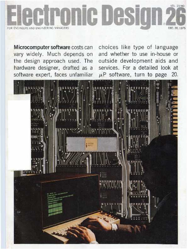
Microcomputer software costs can
vary widely. Much depends on the design approach used. The hardware designer, drafted as a software expert, faces unfamiliar
choices Iike type of language and whether to use in-house or outside development aids and services. For a detailed look at �P software, turn to page 20.
You'll find this new element In BOURNS� Model 3541 ten-tum
precision potentiometer .�� a new
member of BOURNS popular 3540 family of compact (?la" dia., % n deep), low-cost multi-turn potentiometers.
Significant specifications of the Model 3541: service life of 5,000,000 shaft revolutions; linearity 0.25%; temperature coefficient of �100 ppm/�C maximum; reliable SILVERWELD� direct terminal-to-element bond; output smoothness of 0.015%; essentially infinite resolution; rugged, mechanically locked construction (no rear lid "pop-off"); speciat heat resistant insert around terminals to prevent damage during soldering.
If a low-cost wirewound satisfies your control requirement �.� you can't do better than our Model 3540 ten-tum at $3.97*. Same quality construction features, same 0.25% linearity .���with rotational life of 1,000,000 revolutions. A wide range of standard and custom options are available, including three- and five-turn versions.
FREE SAMPLE: Write or phone the BOURNS PANEL POWER PEOPLE and tell us about your application. We'll send you the Model 3540/41 that best suits your needs.
Available off-the-shelf from extensive factory stock and nearly 100 local distributor inventories. TRIMPOT PRODUCTS DIVISION, BOURNS, INC., 1200 Columbia Avenue, Riverside, California 92507. Telephone 714 684-1700. TWX 910 332-1252.
INFORMATION IETllEVAL NUMIER 256
�1,000 pl-. - R.C., U.S. Dolla111, F.O.B. Rlve111lde, Catlfomla
-
. - i'
..
-
r
Model
Frequency Range (M Hz)
Conver-
sion loss (dB) Total Range
lsolation,dB
Lower band edge to one decade higher .
Mid range
LO-Rf LO�IF
LO�RF LO�IF
Upper band edge to one octave lower
LO-RF LO�IF
SRA-11 H
RF, L0-10-3000 IF� DC-1000
9.5 typ. 12 max.
27 typ. 27 typ. 20 min. 20 min.
25 typ . 25 typ . 18 min. 18 min .
23 typ. 23 typ. 16 min. 16 min.
SRA�lH
RF, L0�.5-500 IF � DC-500
6.5 typ . 55 typ. 45 typ. 45 typ. 40 typ. 35 typ. 30 typ. 8.5 max. 45 min. 35 min. 30 min . 30 min. 25 min. 20 min.
SRA-2H
RF, LO� 2 �1000 IF� DC-1000
7.5 typ. 9.5 max.
50 typ. 45 typ. 40 min. 35 min.
45 typ. 40 typ . 25 min. 25 min .
35 typ. 25 typ. 25 min. 20 min .
SRA-3H
RF, L0-.05-200 IF� DC-200
5.5 typ. 7.5 max.
55 typ. 45 typ. 45 min. 35 min.
45 typ . 40 typ. 30 min . 30 min .
35 typ. 30 typ, 25 min . 20 min .
SRA-1WH
RF, L0-1-750 IF� DC-750
5.5 typ , 50 typ. 45 typ. 45 typ. 40 typ . 35 lyp. 30 typ. 7.5 max. 40 min. 35 min . 25 min. 25 min. 25 min. 20 min.
Conversion compression: 1 dB at +10 dBm rf input
Price Quant .
$79.95 (1�24)
$15.95 (5-24)
$29 .95 (4-24)
$17.95 (5-24)
$19.95 (5-24)
World's largest supplier of double balanced mixers
OMini-Circuits Laboratory 837-843 Utica Avenue, Brooklyn, NY 11203 (212) 342-2500 lnt'I Telex 620156 Domestic Telex 125460 A 01v1s1on Sc1ent1f1 c r:omponents Corp
International Representatives: [l AUSTRALIA General Electronic Services , 99 Alexander Street. New South Wales , Australia 2065 ; O ENGLAND Dale Electronics. Dale House. Wharf Road , Frimley Green, Camberley Surrey ; O FRANCE S. C . I. E. � D. I. M. E. S., 31 Ru e George � Sand, 91120 Palaiseau, France ; 0 GERMANY, AUSTRIA, SWITZERLAND Industrial Elec tronics GMBH , Kluberstrasse 14, 6000 Frankfurt / Main, Germany : O ISRAEL
nVectronics , Ltd ., 69 Gordon Street, Tel-Aviv , Israel ; O JAPAN Densho Kaisha. Ltd .. Eguchi Building, 8-1 1 Chome Hamamatsu cho Minato-ku, Tokyo :
EASTERN CANADA B. D. Hummel . 2224 Maynard Avenue , Utica . NY 13502 (315) 736- 7821 : 0 NETHERLANDS, BELGIUM, LUXEMBOURG: Coimex,
veldweg 11, Hattem. Holland .
US Distributors: 0 NORTHERN CALIFORNIA Ca in-White & Co.. Foothill Office Center. 105 Fremont Avenue , Los Alt os. CA 94022 (4t5 J 948-6533 : 0 SOUTHERN CALIFORNIA, ARIZONA Crown Elec tronics. 11440 Coll ins Street, No . Hollvwood , CA 91601 (213) 877-3550
INFORMATION RETRIEVAL NUMBER 3
2
ELECTRONIC D ESIGN 26 , December 20, 1975
NEWS
15 News Scope
20 Experts tell how to hold down the high cost of microprocessor programs-An Electronic Design special report.
28 A sensor-minicomputer 1network at Sandia Laboratories predicts when static discharges and lightning strikes might occur.
43 Washington Report
TECHNOLOGY
33 MICROPROCESSOR DESIGN
50 Employ �P software tools properly, and you ' ll shorten development time and reduce errors. Get to know the three types of design aids offered by vendors .
58 Assembly language for �Ps: Mnemonic programming isn't hard once you learn the coding. Here's how to organize and write a program .
66 Let a �P keep track of your process. Built around a central processor, this analog monitor samples and displays transducer outputs.
70 Ideas for Design: Keyboard circuit saves time, needs no microprocessor scanning software. Single-chip pulse generator provides 50 MHz with adjustable duty cycle. Current sinks increase the range of IC function generators.
PRODUCTS
77 Integrated Circuits: Hybrid FET-input op amps match modules for performance at low cost.
80 Instrumentation: It looks like a logic analyzer; it's also a word generator.
82 Modules & Subassemblies: A/d converters with accuracies to 0.0015% drop prices sharply.
79 Components
86 Discrete Semiconductors
84 Packaging & Materials
87 Data .Processing
85 Power Sources
DEPARTMENTS
47 Editorial: Delegating authority
93 Bulletin Board
7
Across the Desk
93 Vendors Report
88 Design Aids
98 Advertisers' Index
88 Application Notes
100 Product Index
89 New Literature
100 Information Retrieval Card
Cover: Photo by Patrick S. Tchrakian, courtesy of Intel Corp.
ELECTRONIC DESIGN is publ ished biweekly by Hayden Publishing Company , Inc., 50 Essex St. Roche lle Park , NJ 07662. Jam.es S. Mulholland Jr., President. Printed at Brown Printing Co., Waseca. MN. Controlled circula tion post~ge paid at Waseca, MN and New York. NY. postage pending Rochelle Park. NJ . Copyright 'Cl 1975. Hayden Publishing Company, Inc. All rights reserved. POSTMASTER: Please send form 3579 to ELECTRONIC DESIGN . P.0 Box 13803. Philadelphia, PA 19101.
ELECTRONIC DESIGN 26, December 20, 1975
3
Introducing the 9900 Microprocessor and 990 Series Micro/Minicomputers
4
ELECTRONIC DESIGN 26. December 20. 1975
Upward Compatible Software and Downward Competitive Prices
At TI, we've started a new family tradition in micro/minicomputers with the 990 computer family . . . a new tradition based upon a heritage of semiconductor leadership.
The 990 computer family sets new price/performance standards because of an important milestone in MOS technology . ..
The TMS 9900 single-chip, 16-bit microprocessor.
Powerful enough to be the heart of a full minicomputer, the TMS 9900 is also the best microprocessor going for terminals, machine monitoring and control, and a host of OEM applications.
All In the Family
The same company . . . Texas Instruments . . . makes every member of the family, and makes every member software compatible, from the bottom up. The new Model 990/4 microcomputer and Model 990/10 mimcomputer use the instruction set of the TMS 9900 microprocessor. This means that software developed for the low-end computers will be compatible with the higher performance models. And, users can expand their systems with a minimum of interface and software adaptation.
The TMS 9900 Microprocessor
The TMS 9900 is a 16-bit, single-chip microprocessor using MOS N-channel silicon-gate technology. Its unique architecture permits data manipulation not easily achievable in earlier devices. With its repertoire of versatile instructions and high-speed interrupt capability, the TMS 9900 microprocessor provides computing power expected from a 16-bit TTL comput er.
The Model 990/4 Microcomputer
It's a complete computer on a single printed circuit board using t he TMS 9900 as its central
processor. The 990/4 is ideally suited for terminal control, peripheral device interface control, and as a CPU for OEM customers.
In addition to the TMS 9900 microprocessor, the 990/4 microcomputer contains up to SK bytes of dynamic RAM, up to 2K bY1'.es of static RAM and/or PROM, eight vectored interrupts, front panel interface, real-time clock mput, two I/O buses for low- and high-speed devices, and optional ROM utilities.
With the 990/4, you can select a low-cost OEM package, a 7-inch or 1214-inch rack-mountable chassis, or a table-top enclosure . . . and memory expansion to 58K bytes.
Price: The Model990/4 microcomputer with 512 bytes ofmemo-
ry is only $368 * without chassis
and power supply. This same model with BK bytes ofmemory
is only $512 *.
State-of-the-art TMS 9900 microprocessor . . .16-bit, single-chip CPU with minicomputer instruction power.
The Model 990/10 Minicomputer The most powerful member ofthe
family is the Model 990/10 general-purpose minicomputer. The 990/10, a TTL implementation of the 990 architecture, provides the high-performance speeds demanded in many applications.
A memory mapping feature providing memory protection and privileged instructions supports memory expansion to two million bytes. And TILINE ** , an
asynchronous high-speed I/O bus, supports both high-speed and low-speed devices. Chassis options
are the same as those for the 990/4. Price: With 16K bytes ofmemo-
ry, chassis, power supply and programmer's panel, the Model 990110
minicomputer is only $1968 *.
Built Better Backed Better
In addition to the family of
compatible hardware, Texas
Instruments backs you with
complete software and support.
Standard software packages
include memory-resident and
disc-based operating systems,�
FORTRAN, COBOL, and BASIC
compilers; and program
development packages with
utilities. And, for you to develop
application programs for the
990/9900 family, we offer cross
support on timesharing networks
and standalone software
development systems. One is a
lov �cost system using the 990/4 . . .
th ~ other is a disc-based system
us ,ngthe 990/10. And, a
prototyping system is offered for
TMS 9900 users to develop custom
software and firmware modules.
TI supp Jrts you with training and
applications assistance, plus an
installed nationwide service
network backed by TI-CARE t , our
automated remote diagnostic,
servi �e dispatching, and real-time
field service management
in~ormation system.
"'et to know our new family. Call
your nearest TI office, or write
Texas Instruments Incorporated,
MP./S0.7B84o,xH1o4u44st,on,
~ 0
'T'exas 77001. Or, phone
[)
� :omputer Equipment
Marketing at f512) 258-5121.
Arlington, Va. (703) 527-2800 � Atlanta, Ga. (404) 458.J79 1 � Boston, Ma. (6 17) 890-7400 � Chicago, II. (3 12) 67 1-0300 � Clark, N.J. (201) 574-9800 � Cleveland, Oh. (216) 4b.-2990 � Costa Mesa, Ca. (714) 540�73t l � Dallas, Tx. (214) 238-5318 � Dayton, Oh. (513) 253-6128 � Denver, Co. (303) 75 1-1780 � Oetroit, Mi. (313) 353-0830 � El Segundo, Ca. (213) 973-2571 � Hamden, Ct. (203) 281�0074 � Houston, Tx. 713) 494.5115 � Indianapolis, In. (317) 248-8555 � Milwa ukee, Wi. (414) 475-1690 � Minnea polis, Mn. (612) 835-5711 � Philadelphia, Pa. (215) 643-6450 � Rochester, N.Y. (716) 461-1800 � San franciscc Ca. (415) 392-0229 � Seattle, Wa. (206) 455-1711 � St. Louis, Mo. (314) 993-4546 � Sunnyvale, Ca. (408) 732-1840 � Winter Par~ fl. (305) 644-3535 � Amstelveen, Holla nd 020-456256 � Bedford, En gland 58701 � Beirut, ' banon 452010 � Cheshire, England 061 442 8448 � Copenhagen, De nmark (01) 917400 � Croydon, England 01�686�0061 � Essen, Germany 01241120916 �Fran kfurt, Ger ma ny 0611 /39 90 61 � Freising, Germa ny 0816lt 801 �Milan,ltaly02.688�8051 �Montreal, Canada (514) 341�5224 � Nice, France (93 ) 20-0101 � Paris, France (I) 630�2343 � Slough, England 33411 � Stockholm, Swed en 62 71 59/ 62 71 65 � Sydn ey, Australia 831 -2555 � Tokyo, Ja�'" (3) 402-6 181 � Toronto, Canada (416) 889-7373
TEXAS INSTRUMENTS
INCORPORATED
*OE M quantity 50. .S. domest ic prices.
ELECT RON IC D ES IGN 26. D ecembe r 20, 1975
INFORMATION RETRIEVAL NUMBER 4
�� Trademark ufTexas Instruments. t Service Mark of Texas Instruments.
5
Cut package count ��� Simplify board layout ��� Reduce equipment size ��� with
MULTI-COMP� RESISTOR� CAPACITOR NETWORKS
(Metonet�Film Resistors, Monolythic�Ceramic Copocitors)
Sr. Vice President, Publisher
Peter Coley
Editors
Edito rial Offices 50 Essex St. Rochelle Park, NJ 07662 (201 ) 843 -0550 TWX : 710 -990 5071 Cable: Haydenpubs Rochellepark
Editor-in-Chief George Rostky Managing Editors: Ralph Dobriner Michael Elphick
STANDARDIZED DESIGNS FOR BETTER AVAILABILITY, BETTER PRICES
R lnl
C1
Associate Editors: Dave Bursky Morris Grossman John F. Mason Stanley Runyon Edward A. Torrero
100
470 2000 lOOpF
150
500 2200 330pF
200
680 3300 O.Ol�F
220
1000
4700 C2
330 1500 6800 0.05�F
BYPASSED PULL-UP AND R-C COUPLING NETWORKS
R IOI
c
100
470 2000
150
500 2200 lOOOpF
200
680 3300 3300pF
220 1000 4700 O.Ol�F
330 1500 6800
SPEED-UP NETWORKS
R IOI
c (pf)
100
470 2000
150
500 2200
100
200
680 3300
220 1000 4700
330
330 1500 6800
* ACTIVE TERMINATOR NETWORKS OTHEI PACKAGES, CllCUIT CONFIGURATIONS, AND RATINGS AVAILABLE ON SPECIAL OIDEI
Sprague puts more passive component families into
dual in-line packages than any other manufacturer:
e TANTALUM CAPACITORS
e
e CERAMIC CAPACITORS
e
e TANTALUM-CERAMIC NETWORKS
e
e RESISTOR-CAPACITOR NETWORKS
e
e PULSE TRANSFORMERS
e
e TOROIDAL INDUCTORS
e
For more information on Sprague DIP components, write or ca// Ed Geiss/er," Manager, Specialty Components Marketing, Sprague Electric Co., 347 Marshall St., North Adams, Mass. 01247. Te/. 413/664-4411 .
THE BllOAD-UNE PRODUCE/I OF ELECT/IONIC PA/ITS
HYBRID CIRCUITS TAPPED DELAY LINES SPECIAL COMPONENT COMBINATIONS THICK-FILM RESISTOR NETWORKS THIN-FILM RESISTOR NETWORKS ION -IMPLANTED RESISTOR NETWORKS
4 1T�2 1S l Rt
SPRAGUE "
THE MARK OF RELIABILITY
Contributing Editors: Peter N. Budzilovich Alberto Socolovsky Nathan Sussman
Editorial Field Offices
East Jim McDermott, Eastern Editor P.O. Box 272 Easthampton, MA 01027 (4 13) 527 -3632
West David N. Kaye , Senior Western Editor 8939 S. Sepulveda Blvd., Su ite 510 Los Angeles, CA 90045 (2 13) 641-6544 TWX : 1-910-328-7240
Editorial Production
Marjorie A. Duffy
Art
Art Director, William Kelly Richard Luce An t hony J. Fischetto
Production
Manager, Dollie S. Viebig Helen De Polo Ann e Molfetas
Circulation
Manager, Evan Phoutrides
Information Retrieval
Peggy Long
Promotion, Creative Layouts
Manager, Albert B. Stempel Maxine Correal Nancy Gordon (Reprints)
INFORM ATI ON RET RI EVA L NUMBER 5
6
E LECTRON IC D ES IGN 26. D ece mber 20. 197 5
Across the D.esk .
Thin-Trim � capacitors
�How to turn an HP-45 into a stop watch
Readers of ELECTRONIC DESIGN
who are also the owners of Hew-
lett-Packard HP-45 calculators may
be interested to know they can use
their machines as a digital stop
watch and elapsed-time indicator,
similar to the functions found on
the HP-55 programmable version.
To gain access to the clock
function, first clear the machine.
using the gold alternate-function
key. Then press the RCL key,
and then simultaneously press
the CHS key and the digits 7 & 8,
or 4 & 5, or 1 & 2. The machin e
now displays the format:
HMOINUURTSES
-f�r T"
r
SECONDS----- -
HUNDREDTHS-OF-SECONDS
To start the clock function. press the CHS key. Pressing the CHS key again will stop the clock without resetting the display to zero. (To reset the display to zero, press the CLx key. )
To saYe power during battery operation, you can turn off the last two digits (hundredth of seconds l by pressing the EEX key; depressing the EEX key will again turn on the last two digits.
The clock function can also be used as an elapsed-ti me indicator for timing and storing the elapsedtime measu rements of up to nine se_parate e,�ents 1assu ming all e\�ents sta rted from the same point in time). This function can be quite handy for measurement of physical phenomena, chemical reactions or eYen at a race track. While the clock is running, de-
pressing any digit key ( 1 to 9) stores the displayed time up to that point in the respective register, the clock keeps running and is not otherwise affected.
After the clock is stopped by pressure on the CHS key, pressing any of the digit keys recalls to the display the time displayed in the respective register. Note that the STO key (while the clock is running ) and the RCL key <after the clock is stopped) need not be pressed; the "store" and "recall" functions are automatically executed, depending on whether the clock is running or stopped. ( The CLx key shou ld again be pressed after the last measurement is recalled. as the clock, when started again. will resume counting from the number on the display.)
After the clock function is no longer needed, you can 1�eturn the machine to normal operation by pressing the ENTER key (which returns the machine to fixed-point, 2-decimal operation ) or by turning the machine OFF and then OK again. (The latter method is preferred, as the registers are cleared before the machine i used; however, the registers do not need to be cleared if the user wishes to store new elapsed-time data, as the registers are oYerwritten with new data any time the clock is running and one of the digit keys is depressed. )
While the clock function is operating, the only keys haYing any effect are the CHS, EEX, CLx. ".", and the digit keys. All other keys, including the - , + , x , and -:- , are nonoperating.
Accuracy? It seems the HP-45 was designed with the HP-55 in
( continu ed on page 1.1 1
Electronic Design welcomes the opinions of its readers on the issues raised in the magazine's. editorial columns. Address letters to Managing Editor, Elec-
tronic Design, 50 Essex St. Rochelle Park, N.J. 07662. Try to keep letters
under 200 words. Letters must be signed. Names will be withheld on request.
J,,; Tucked in the corner of this l'J)I Pulsar Watch is a miniature capacitor which is used to trim the crystal. This Thin-Trim capacitor is one of our 9410 series, has an adjustment range of 7 to 45 pf., and is .200" x .2 00" x .050" thick. The Thin-Trim concept provides a variable device to replace fixed tuning techniques and cut-and-try methods of adjustment. Thin-Trim capacitors are available in a variety of lead configurations making them very easy to mount.
A smaller version of the 9410 is the 9402 series with a maximum capacitance value of 25 pf. These are perfect for applications in sub-miniature circuits such as ladies electronic wrist watches and phased array MIC's .
Johanson Manufacturing Corporation, Rockaway Valley Road. , Boonton, N.J. 07005. Phone (201) 334-2676, TWX 710987-8367.
INFORMATION RETRIEVAL NUMBER 6 ....
~AA/\.1111'.'ArTI IDl/\.lr. rllDDllDATlr'\/\.I
AMI6800:
ole
Smart Te rminal.
Complete program editing
through CRT and keyboard. Also
includes Modem communication Magnetic Tape.
to remote computers. (Avail. Feb.)
Cross product softwareassembler, loader,
simulator.
(Avail. Now)
AMI6800
Family.
Its all here: MPU,
RAM , ROM , PIA, Ewluation Board.
ACIA, PROM, USRT and Modem.
Includes everything you need to evaluate parts, program
PROMs and , connected
with a peripheral , run
Dual floppy Disk.
Storage for resident software- assembler, editor, etc. (Avail. Feb. )
Disk Program Storage.
500K bytes for program development and online data storage.
Cuts out the paper tape! (Avail. '� ... Feb.)
Our AMI 6800 Kit is a big step for ward in simplifying your design,evaluation and test programs. For example, our intelligent CRT is simple to operate with either resident or remote software. It really is smart, because it contains an S6800 !An<l its planned to have an in-circuit emulator added later.
Our dual disk is extremely useful for developing programs, and saves you hours of paper tape shuffling. And our Evaluat ion Boa rd is loaded wi th
all the parts yo u need to get yo ur product on the market on time.
Now for the Caboodle.The dictionary calls it a "package:' You'll call it the neatest set of instructions for any kit you\re ever bought .
Now why don't you call your nearest AMI sales office or distributor, and ask them for the whole Kit and Caboodle. Or write AMI, 3800 Homestead Road. Santa Clara, CA 95 05l. What could be easier?
Here~ wbere
you pickup your Kit.
SALES OFFICES
Manhattan Beach CA � {213) 379-2452 San Jo!;e C A � (408) 249-4550 Altamonte Sp ri ngs FL� (305) 83()..8889 Elk Grove Village IL � (3 12 ) 437-6496 Norwoo d MA � (617) 762-0726 Livonia Ml � {3 13 ) 478- 9339 Mi nn eapohs MN � (6 12 ) 559-9004 Monsay NY � {914 ) 352-5333 Cleveland O H � ( 216 ) 292-6850 Ambler PA � {215 ) 64 3-0 217 Ric hard son TX � {214 ) 231-5721
8
E L ECTRON IC D ES IG 26. Dece mber 20. 197 5
Software Brochure.
A rundown on AMI software
products including assembler, loader and simulator. (Ava il. ow)
AMI 6800 Brochure.
List of goodies. All you want to know about the AMI 6800 family.
Evaluation Board Application Notes.
The why and wherefore of our Prototyping System, and how to make the most of it! (Avail. Jan.)
(Avail. Now)
NCS.S Users Manual.
All the mag ic necessary to work with National CSS time-sharing network. (Avail. Now)
Assembly ~~e
Programming Manual.
Describes the instruction set and how to use the AMI Assembler and
AMI Guide to Standard Products.
Hardware Reference Manual.
A detailed description of each component in the system, and how to make them work!
(Avail. Jan .)
DISTRIBUTORS
Flo rida - H o llywood (30 5 ) 9 2 7-0511
Geo rg1a - At1an1a (404 ) 449-9170
ALTA ELECTRONICS
Illinois- Elk Grove Village
Utah - Salt Lake City (801 } 486-72 2 7
(31 2} 593- 2740
ARROW ELECTRONICS
Minnesota- Bloomington (612} 888-5522
Io wa - Cedar Rapids � Lore nz S ales (319) 393-0100
Maryland - Rockville (301 ) 881 -3300
Massachusetts-Waltham
CENTURY ELECTRONICS
(617) 890-8484
New Mexico- Albuquerque
Michigan - Troy (313) 583-9242
(505) 292-2700
Minnesota - Edina (612 ) 941-5280
Utah - Salt Lake City (801) 487-8551
New Jersey- Somerset
INTERMARK ELECTRONICS Washington - Seattle (206) 767-3160
( 201 ) 469-6008
New York - Rochester (716) 461-4000 Westbury (516) 334-7474
SCHWEBER ELECTRONICS �
Oh10 - Beachwood (216 ) 464-2970
Cahfornia - Costa Mesa {213) 924-5594 Texas - Aus11n (512 ) 837-2890
and (714 ) 556-3880
Dallas (214 ) 661-5010
Connecticut-Danbury (203) 792-3500
Houston { 713) 784 -3600
ELECTRON IC D ES IGN 26. D ecember 20. 1975
Canada- Mississauga, Ont (416) 678-9050
SEMICOMPCORP Cahfornia- Newport Beach
(213) 971 -5253 and ( 714 ) 833-3070
STERLING ELECTRONICS Arizona- Phoenix (602) 258-4531 Louisiana- Metairie
(504) 887-7610 Massachusetts- Watertown
(617 ) 926-9720 NewJersey-Perlh Amboy
(201 ) 442-8000 New Mexico- Albuquerque
(505) 345-6601 Texas - Dallas (214 ) 357-9131
Houston (713) 627-9800
V1rg1ma-Richmond Meridian�� (804) 335-6521
AV WEATHERFORD CO Arizona - Phoenix (602 ) 272-7144 Cal1forn1a-Anahe1m (714 ) 547-0891
Glendale (213) 849-3451 Palo Alto (415) 493-5373 Pomona (714 ) 623-1261 San D1ego
( 714 ) 278-7400 Colorado- Englewood
{303) 761 -5432 New Mexico- Albuquerque
{505} 642-0866 Texas - Dallas ( 214 ) 243-1571
Hous1on (713) 688-7406 Washington-Seattle
(206) 243-6340
it's
standard atAIMlle
AMFRI CAN MI C ROS \' ~T EMS. INC
INFORMATION RETRIEVAL NUMBER 7
9
Meet the Best
AC CalibrationTeam Going
When you put the Fluke
5200A Precision ac Calibra-
tor and 5205A Precision
Power Amplifier together,
you'll be working with a
fully programmable ac cal
set-up offering outstanding
range, superb stability and
excellent accuracy.
Now you can calibrate ac devices up to 1200 volts rms over a frequency range of de to 1.2 MHz. DC output of 1600 volts is available. Current levels range up to 200 milliamperes with a total output power of 220 watts.
Response is a fast 0.5 sec?nd .. Both instruments are short-c1rcu1t proof. These Fluke instruments are the only ones on the market to meet the safety requirements of IEC 348. The field installable programming capability is offered in 8, 12, 16 or 52 bit formats so the system interfaces easily with almost any computer.
Midband accuracy is 0.02% overall and long term stability 200 ppm for six months. Instruments are fully guarded and interlocked. Phase lock and quadrature outputs are featured.
How much? Cost of the 5200A and 5205A
c�alibrator set-up in the U.S. is $8990. That's more than some other calibrators. But with Fluke, the short circuit feature alone will give you lower cost of ownership. Your Fluke sales engineer can point out other features that make our system your better buy.
Or use either unit alone The Fluke 5205A Power Ampli-
fier is a true dual mode instrument usable as a stand-alone, de coupled HV precision amplifier and 1200 range calibrator amplifier. The 5205A is the only unit on the market that can deliver 200 mA rms at 100 volts as well as at 1000 volts. And it's the unit with the usable accuracy statement, 0.04% for 90 days at 23�C -+- 5� C. Fluke specs accuracy,
time and temperature span!
Gain is 100 with a midband accuracy of 0.04%. Get de to 120 KHz and get up to 1200 volts rms or 1600 volts de at current levels up to 200 mA and 220 watts output power. Price of the 5205A alone is $3995 (U.S. price).
If you don't need the high voltage capability set-up, use the 5200A alone. Get outputs up to 50 mA from 100 microvolts to 120 volts with midband accuracies of 0.02%. The instrument offers isolated remote programming for all functions including frequency and amplitude. Price in the U.S. is $4995.
Learn more about using full ac measure power.
Call your nearby Fluke sales engineer listed in EEM and the Gold Book for a demonstration or complete literature. Or if more convenient, dial our toll-free hotline, 800-426-0361, for data out today.
John Fluke Mfg. Co., Inc.
:IF::L:U=:K:E:t P.O. Box 43210
Mountlake Terrace, WA 98043
For a demo, circle 291 For literature only, circle 292
10
ELECTRON IC D ESIGN 26, D ece mbe r 20, 197 5
O.K., y o u g u y s ,
back to the old
drawing board.
It's a whole new ball game. And just when you'd made all your panel lamp decisions, right? But Monsanto's patented nitrogen doping process for GaAsP on GaP substrates has improved the light-emitting efficiencies of our LED lamps so dramatically that every good designer will want to take another look.
Monsanto has T-1 and T-1 % replacement lamps in standard red color (improved significantly over last year's red LEDs) and new bright red which is unbelievably bright. Red. Plus green, yellow, and a dazzling new orange. In two lens choices and two lead lengths. And all improved, as you can see on the chart.
BRIGHTNESS
IMPROVEMENT
Model Number Color
Size
Luminous Viewing Intensity Angle
51748* Orange T�l
5.0 med
90�
52748* Green T�l
1.0 med
90�
53748* Yellow T�l
4 .0 m e d
90�
57748* Red
T�l
5.0 med
90�
5152** Orange T�1 %
40.0 med
28"
5252** Green T-1 %
15.0 med
28�
5352** Yellow T�1 %
45.0 med
28"
5752** Red
T-1 %
40.0 med
28�
*Also available with 1" lead lengths, low profile (.138" high) lens, and 180� viewing angle.
��Also available with 24� and 65� viewing angles.
Last year there were some sockets that demanded filament lamps, despite their inherent failure-and-replacement problems. Bright was needed, and�damn the torpedos.
This year you just might find the bright you need in a shake-rattle-and-roll-proof LED lamp. Come and see.
If you can take the time, you just might be able to add a lot of T to your MTBF.
So it's reset to zero, folks, if you want the best indicator lamps (and widest choice of functional differentiation colors) in your gear.
For product information, circle the service number or call your local Monsanto man. Or write Monsanto Electronics Division, 3400 Hillview Avenue, Palo Alto, CA 94304.
Putting innovation to work.
tL1M1ceoosmncpsieaannncytoe. :
INFORMATION RETRIEVAL NUMBER 9
Fl.I ("T RON !(' D ES IGN 26. Decem ber 20 , 1975
II
things get.
The five switches you see here have all been designed to operate reliably under extremely rugged environmental conditions. Exactly the kinds of environments where Command, Communications & Control Systems are required to work.
But if these switches aren't exactly what you need, you're not out of luck.
Because they're only a sampling of literally thousands of MICRO SWITCH listings available to fill your needs. Including toggle switches.Lighted pushbuttons. Unlighted pushbuttons.Key switches. Sealed keyboards. Plus hermetically and environmentally sealed limit, proximity and basic switches.
All of them available almost anywhere in the world, through over 500 MICRO SWITCH Authorized Distributors and Branch Offices.
And if that still isn't enough, our Application Engineers will work with you to modify an existing MICRO SWITCH product to your needs. Or come up with a new one, through our field and factory engineering staff.
If you'd like more information on the devices you see here, or more information on how we can help, write or call your nearest MICRO SWITCH Branch Office or Authorized Distributor.
MICRO SWITCH
FREEPORT ILLINOIS 61032
A DIVISION OF HONEYWELL
MICRO SWITCH products a1e a v ail<> hie worldwide through Honeyv.rell Intcr 11 atl011dl
ACROSS THE DESK
Misplaced Caption Dept.
(continued from page 7)
mind, and consequently it uses some of the circuitry of th e HP-55 . However, the HP-55's internal osc ill ator is apparently "trimmed" for the required frequency, while that of the HP-45 is not. At any rnte, the HP-45 should exhibit reasonable accuracy as is. ( My own HP-45 measures about 5.3 % slow when compared with a known time standard; I have used my machine on internal battery pack and on external power pack, and obtained simi lar accuracy results both ways.)
Owners of the HP-45 can compare their machines against a known time standard and use the resu lting correction factor as required in future measurements. And although the absolute accuracy of the HP-45 may not equal that of the HP-55, the time fun ction used during relati ve measurements-and particularly the storing of up to nine elapsed-time measu rements-can be ver y, ver y useful indeed.
Paul E. Miller Engineering T echnician AMF Electrical Products Development Div. 1025 N. Royal St. Alexandria, VA 22314
Jobs, anyone?
In the April 1, 1975 issue we published an editorial in which we offer ed to try to match out-ofwork engineers with potential employers. As one might expect, W C' received far more applications for jobs than announcements for job openings. We were successful in effecting a few matches but we're still overstocked on resumes of engineers sprinkled around the cou ntry (and one in Germany who would like to come back to the U.S.). Some of the credentials look awfully impressive,
If yo u haYe some jobs ava ilabl e, get in touch with our Evelyn Morris (ELECTRONIC DESIGN , 50 Essex St., Rochelle Park, NJ 07662 ) . Good engineer s are �going to be a lot tougher to find a few months from now.
~ CIRCLE 261 FOR DATA ~ CIRCLE 262 FOR SALESMAN CALL
"We've got to clear out of the cafeteria for the next shift."
So rry. That's Pierre-Auguste Renoir's "The Luncheon of the Boating Party at BougiYal," which hangs in the Philips� Memorial Gallery in Washington.
Calculator errors and how some arise
In the Sept. 27 issue, a letter from Peter A. Stark discussed two types of alleged mi stakes made by some calcu lators t hat employ algebraic notation with parentheses. I would like to point out that his seco nd exampl e actually gives th e correct answer. It is hi s lack of understanding of the sequential operations of s uch ca lcu lators that causes the apparent error.
Algebraic calcu lators perform complex chain calcu lati ons in the order in which they a re enter ed, rather than according to the standard mathematical hierarchy ( in which exponentiation is done first, then multiplication and di vis ion, . then addition and subtraction ). For example, most users are aware that AB & CD must be enter ed as
A x B + (C x D) = .
Entering it as A x B+C x D=
gives the e rron eous answer
(AB + C)D.
The calculation that tripped up Mr. Stark was of the general fo rm A3B\ for which he shou ld have e n te r ed
A xr 3 x (B XY3) = .
The incorrect answer was obtained by entering it as
A xr 3 x B XY3 = , whi ch g ives ( A3 B) ".
George Fergus 3341 W. Cu llom Ave. Chi cago, IL 60618
13
The tight-fisted IC testers.
FOR INCOMING IC INSPECTION $1K STILL GOES A LONG WAY.
The three IC testers below are unique, thoroughly proven, and they are the tight-fisted, inflation-beating answer to the requirements of incoming inspection. All identify the bad devices as rapidly and unfailingly as machines costing five to six times as much.
In addition to being economical ESI testers are reliable, simple to operate and will test devices as they are developed. For a demonstration or technical information on any of these instruments, circle the appropriate numbers below. If you need immediate response, please call Jim c�urrier (503) 646-4141, Portland, OR.
!In,
ELECTRO SCIENTIRC
LINEAR IC TESTER
$990.
Devices tested : Monolithic or Hybrid Operational amplifiers .
Tests performed: E0 s, 18 _, 18 +, DC
open loop gain , DC CMRR , oscillation detection. � Remarks, 3-digit direct reading digital display which enables go-no-go testing .
MODEL 1234
For demo circle Reader Service# 271 For literature only circle #272
DIGITAL IC TESTER
$580.
Devices tested : 14 and 16 pins . TTL, DTL and CMOS @ 5V.
Tests performed : Fixed pattern functional test.
Remarks : Performs 220 inspections per test in from 1 to 5 seconds. No comparison with a " good" IC is necessary. 4-digit display gives absolute test results. Can also be used to check continuity of resistor network.
MODEL 1248
For demo circle Reader Service :J:t273 For literature only circle #274
DIGITAL IC TESTER
$1195.
Devices tested : TTL, DTL@ 5V, HTL@ 15V, CMOS @5V, 10V, 15V.
Tests performed: Same as 1248. Remarks : Interfaces with manual and
automatic handlers. Multiple voltages for CMOS.
MODEL 1249
For demo circle Reader Service :J:t 275 For literature only circle #276
punch were built in the Soviet Union and use standard 80-column cards.
DECEMBER 20, 1975
East German computer proves better than expected
Tests and studies by Control Data Corp. show that East European data-processing machines are much more advanced than most U.S. experts have believed, while the peripheral equipment Jags behind that produced in this country.
For example, the Robotron ES1040 medium-to-large-scale computer, made in East Germany, is three to four times faster than the IBM 370/ 145 in processing scientific calculations, but in commercial applications the speed of the two machines are comparable, according to the CDC report.
However, when the memory speed of the German ES-1040 was tested along with that of the IBM 370/ 145 and the CDC Cyber 73, the ES-1040 took twice as Jong as the IBM machine and atbout six times longer than the Cyber 73.
Tog.ether, the two tests--that of arithmetic speed and memory speed -reveal that the ES-1040 is approximately twice as powerful as the IBM 370 / 145 in internal computing power.
Other findings by CDC:
The core memory of the ES-1040 is somewhat slow compared with the processor's speed-performance could be enhanced considerably with a faster memory.
� The ES-1040 executes the IBM 360 instruction set.
� The system could be improved through the use of more modern peripherals, chiefly in the mass storage area.
� In general, the East German machine is "very reliable."
The ES-1040 is constructed from ICs made in East Germany that are identical in logic to those produced in the U.S. by Texas Instruments, Motorola and Fairchild. The appearance of the ES-1040 prototype in late 1972 indicates a technology lag of three to four years �in the IC area.
The logic design of the CPU is also very advanced, CDC says.
The processor employs microprogram control, a technique not too different from that used in the IBM 370 series. The processor includes a "lookahead" instruction feature, which allows various processor functions to be overlapped.
The memory is composed of 21mil cores, has an access time of 450 ns and a system level cycle time of 1350 ns. The memory is composed of two to four independent modules, allowing memory interleaving. The path to memory is eight bytes wide. The theoretical memory transfer rate is about 142 million bps. CDC testing on a two-module memory showed that the memory speed was not well matched to the speed of the CPU.
The input/ output channels operate under microprogram control and are compatible with the IBM multiplexer and selector channels. These channels are fast enough to allow connection of most modern U.S. peripherals, CDC says.
The two disc drives that came with the ES-1040 can store about seven million characters. The Control Data disc drives now connected to the ES-1040 have four times that capacity, and can also transfer data at twice the speed.
The tape drives that came with the East German machine were found to be equivalent in performance to U.S. units, but bulkier.
The East German printer offers a feature not provided by any U.S. manufacturer, CDC says. It allows different forms to be printed simultaneously. However, CDC points out that its printer outperforms the East German product in other ways: better print quality, slightly higher speed and an interchangeable character set.
Both the card reader and the
Soft-recovery test cuts cost of diodes 30%
A new procedure for characterizing power diodes that removes ambiguities and cuts costs by 30 % is reported by General Electric, Schenectady, NY.
GE says it has achieved this by finding an easy way to test the soft-recovery characteristics of these devices. Until now, this characteristic has been hard to test, and even the results of the tests were open to many different interpretations, notes Ralph Locher, a product engineer for GE.
High-current diodes (over 100 A ) , when used in an antiparallel connection with SCRs in large switching supplies, prevent spikes caused by collapsing magnetic fields from destroying the SCRs. However, these diodes must have peak inverse voltages that are high enough to withstand the spikes.
By being able to measure the soft recovery time of the diodes accurately, Locher says, the more efficient units can be picked and thus diodes with lower PIVs can be used. And the lower the PIV, the . lower the cost of the diode.
For example, GE says, where a 250-A, 1000-V device had to be used at a cost of $26 in 10-to-99piece lots, a 250-A, 600-V diode can now be used at a cost of about $20 for similar quantities. Diodes are available with current ratings of 100 to 1000 A rms and with PIVs from 50 to 1500 V.
3-D radar improves target resolution
A monopulse tracking radar capable of providing three-dimensional target information and range resolution down to 1.5 ft is under development at the Naval Research Laboratory, Washington, DC.
Other features include the following:
� Ability to counteract enemy repeater-type countermeasures.
� Improved low-angle multipath tracking.
ELECTRONIC DESIGN 26, December 20, 1975
15
� Increased resolution of multiple targets.
� Improved target tracking in chaff and clutter.
The experimental radar uses a very narrow pulse width of 3 ns in conjunction with wideband monopulse processing to obtain azimuth and elevation information of each resolved part of the target.
Present high-range-resolution radars provide only one dimensional range-amplitude profiles. The 3-D radar, according to two of its developers, Dean Howard and David Cross, extends this capability, in that a target aircraft can be resolved into its major structural parts. Prominent features such as engines, tail surfaces, and wings can be located precisely in both range and angle. This is accomplished by processing the highspeed return pulses through special sampling and holding circuits, which convert the pulses io digital form for display, storage and analysis by computer patternrecognition methods.
According to Cross, the next step in the program is to improve the radar performance and extend its range. This will be done by pulse-compression techniques to increase average transmitted power.
A similar radar, developed at Lincoln Laboratory, Lexington , MA, has been in use since 1968, primarily for long-range tracking. The Naval Research Laboratory radar differs in its method of processing and using target angular information.
Speed of CCD memory is boosted tenfold
A tenfold increase in speedfrom about 20 MHz to over 230 MHz- has been achieved for a CCD dual-speed, shift-register device. The development by Rockwell International's Autonetics Group in Anaheim, CA, is aimed at a transient recorder application.
According to Dr. Barry French, CC D r esearch group leader: "The device can operate in two modes. In the first mode it accepts data at up to 234 Mb / s and transfers it out at up to 86 Mb/ s. We call this the fast-slow mode. In the second mode it operates in a continuous way with up to 86 Mb/ s data in
and up to 86 Mb / s data out." This device has 130 cells and
uses a two-phase overlapping gate approach-that is, there is a separate gate for transfer and a separate gate for storage associated with each cell. Charge transfer efficiency per cell is 0.999 at a 230 Mb/ s transfer rate.
French notes that the device has a ion-implanted epitaxial n-channel that is deeply buried. It also has a gate length of 0.2 mil in the direction of charge propagation. Each cell has a 10-mil-wide channel that allows the full cell to contain about 0.76 picocoulombs of charge.
Laser 'thermometer' to detect 80 million C
A laser "thermometer" to measure temperatures as high as 80 million degrees centigrade is being developed at the Massachusetts Institute of Technology, Cambridge. for thermonuclear fusion research.
The temperature-measuring system, being designed at MIT's Francis Bitter National Magnet Laboratory, consists of a new highpower, methyl fluoride gas laser and an infrared detection system. The laser wavelength is 500 �,m -in the far infrared.
The system, being developed under a $350,000 contract with the Federal Energy Research and Development Administration, will measure the temperature of deuterium ions in a plasma confined by strong magnetic fields inside a tokamak-a structure shaped light a hollow doughnut.
The thermal measurements will monitor the ion temperatures, according to Dr. Daniel R. Cohn, who is in charge of plasma physics research at the Magnet Laboratory.
"Measurements of ion temperatures are a crucial indicator of progress towards self-sustained thermonuclear fusion," says Cohn . "The hotter the ions, the more often they will fuse into helium ions, giving off energy in the process."
Fusion occurs at 80 million C, he notes.
Ion temperature is measured by use of a phenomenon called Thomson Scattering, Cohn explains. The laser beam is directed at the plasma, and as the beam hits and
bounces off the ions, the laser frequency is shifted. By measurement of this shift, both ion temperature and concentration of impurities in the plasma can be determined.
ROM capacity cut in voice synthesizer
A digital coding system used in a new electronic voice synthesizer reduces the required ROM capacity to only 2% of that needed in competitive voice systems, according to John E . Stork, president of Speech Technology, Inc., system developer.
"Conventional voice digitizing requires at least 50,000 bits / s to reproduce telephone-grade speech," Stork points out. "With our coding method, we compress that down to 1000 bits/ s."
The Speech Technology synthesizer-the Model 200-uses a standard approach, Stork explains, in that it produces an electrical analog of the voice tract. It duplicates the resonances and other characteristics of speech.
"We take voice recordingswords or statements-and digitize them at a 100,000 bits/ s rate. But our trick is to extract from the recording features that can be stored in the digitizer and recalled upon command.
"We do that by running the voice data through a computer analysis that compresses and transforms the data into unique code sequences that control the soundgeneration portion of the synthesizer.
"To produce a particular sound, you send a 24-bit code to a control register in the synthesizer. The code--it is transferred in and out of the register in microsecondsprograms the resonances, pitch frequencies and other sounds needed.
"For example, a sound like the vowel 'aah' in the word fox lasts for some 100 or 200 ms in normal speech. So the code directs the synthesizer to make that sound for 100 to 200 ms.
"Upon termination of that period, the code is replaced in the register by another code group, which is sent in for, say, 10 to 50 ms, until it is replaced by still another code, and so on."
16
ELECTRONIC DESIGN 26, December 20, 197 5
JOIN OUR BME� KAP'M SAVINGS PLAN
SAVE 303 TO 503 ON THE COST OF MONOLITHIC
CERAMIC CAPACITORS
This major cost saving is the result of our new BMETM capacitor technology. We've eliminated precious metals entirely from the electrodes and terminations of our BMETM capacitors. No precious metals means lower cost. So now we offer you our complete line of monolithic ceramic capacitors - BME ChipsTM, BME Radi alsTM and BME AxialsTM - at a genuine savings of 30 % to 50 % .
This significant reduction is not based o n a momentary drop in precious metal prices. This is a long-term solution due to the replacement of precious metals by non-noble metals which are not subject to the same dramatic cost spirals.
SAVE WITH RELIABILITY
Our BMETM capacitors have not sacrificed the inherent electrical � and mechanical Ceramolithic� quality. Their reliability can be demonstrated by the extensive test procedures to which they have been subjected . Write to our Applications Engineering Department for complete test reports.
SAVE WITH DESIGN FLEXIBILITY
Now you can se ri ously consider monolithics to replace micas and tantalums. Our BMETM capacitors feature non-polarity, a wide range of capacitance value, low leakage , high volumetric efficiency, availability in chip, radial and axial packages at prices competitive with mica below IOOOpF and tantalum up to 2 .21-tF.
nPICAL SELLING PRICES PER UNIT QUANTITIES OF 5000 OR MORE
BMETM �T' DIELECTRIC (COG)
I thru 100 pF, 5 %, 50WVDC IOOO pF, 5%, 50WVDC
BMETM "S" DIELECTRI C ( X7R )
.OJ �. F. 20 %, 50WYDC . I �. F, 20 %, 25WVDC 1.0 �. F, 20 % , 25WYDC
BMETM " R" DIELECTRI C (Z5U)
. I �. F , + 80 -20 %, 25WVDC .47 �. F, + 80 - 20 %, 25WYDC 1.0 �. F, + 80 - 20 % . 25WYDC 2.2 �. F, +80 - 20 %, 25WVDC
BME-ChipTM
5.1 � 12�
BME-ChipTM
3.5� 9�
52�
BME-Ch ipTM
5.7 � 13 � 19� 35�
BME-Axi a lTM 6.8 � 16�
BM E-Axi a JTM 5.8� 16�
BME-Axi alTM 8.8� 16.5 � 27 �
BM E-R adi alTM
7.5� 16�
BME-Radi a lTM
5.8� 14� 73�
BM E-Radia JTM
8.8� 16.5 �
25 � 49�
JOIN THE USCC/CENTRALAB BMETM CAPACITOR SAVINGS PLAN
Get all the details today . Write on your company letterhead for your concise Savings Plan Price list your pass book to the lowest monolithic ceramic capacitor prices available. Compare it with anyone else's price list and see.
Remember, USCC/ CentralabQuality, Volume, Savings.
- USCC/Centralab Electronics Division � Globe-Union Inc.
4561 Colorado Boulevard � Los Angeles , Ca. 90039 (213) 240-4880
INFORMATION RETRIEVAL NUMBER 13
ELECTRON IC D tS IG 26. Dece mber 20. 1975
17
'Electronic Design 's
brought in for
James Zaros Vice President of Sales
Datel Systems, Inc.
Tell us what you
.J
think about the
GOLD BOOK.
(If it's good, we'd like
to hear it. If it's bad,
we want to improve it.)
GOLD BOOK just
two pending orders
'
" We're getting a good flow of orders from engineers who tell our salesmen that they have the GOLD BOOK in front of them while they're talking on the phone." writes Mr. James Zaros, Vice President of Sales , Datel Systems, Inc ., Canton , Mass.
"I have just confirmed that we have two specific orders pending in our plant, one for $25,000 and one for $50,000, that we know are directly traceable to the GOLD BOOK. "In addition to these phone and mail contacts, we also are receiving a fair number of direct response cards - the ones that are bound in the GOLD BOOK - many of which represent actual or potential business. "Yes, the GOLD BOOK is definitely working for us."
Datel carries 10 short-form catalog pages in the 1975-76 GOLD BOOK. They feature , among other products, Datel's line of A / D and D/ A converters, wideband operational amplifiers and analog multiplexers. The pages are packed with detailed specs, data and price information . Datel makes it easy for engineers to talk business over the phone . Because the GOLD BOOK is primarily distributed to Electronic Design 's audience , Datel gets the best of both worlds - 78 ,000 engineers and engineering managers, purchasing ag ents and distributors throughout the U.S. plus 13,000 in key markets abroad . These are the men who have the authority to specify and buy.
ELECTRONIC DESIGN'S GOLD BOOK IS WORKING ���IT'S WORKING FOR READERS���AND IT'S WORKING FOR ADVERTISERS, TOO.
REPORT ON MICROCOMPUTER SOFTWARE
Experts tell how to hold down high cost of processor programs
The hardware designer, enticed by ads for low-cost microprocessor boards, has several surprises in store when he embarks on his first micro-systems design.
First, he'll learn that for a simple microprocessor control system, he'll wind up with at least 25 additional chips surrounding the basic processor. For fairly complex systems, the number can ri se substantially above 100.
But the big shock comes when the designer gets into microcomputer software. It can cost from hundreds of dollars to thousands for the finished system. For a $30 microprocessor, software has been known to cost $65,000 to $70,000.
Like it or not, the designer will have to become involved in programming to produce effective designs at minimum cost. And he'll find himself in a design team that includes a specialized programmer.
A two-man team
You need at least two people on the microprocessor team," says Gordon Gould, hardware designer for Advanced Electronics Development, Chester, CT , who has several successful micro-systems designs to his credit.
"You need the hardware man and the programmer. But the hardware man, to be effective, must have a good knowledge of programming language.
Software is more an integral part of microcomputer design than it is for a large computer, Gould notes, because much of the processing is related to the outside world rather than number crunching.
Jim McDermott Eastern Editor
20
Microprocessor software programs can cost orders of magnitude more than the hardware. Programs can be generated using only a teletypewriter and a time-sharing service (top). But the slow speed of this system limits the lines of instruction code produced per hour. Fast, cost-effective software generation requires an investment like that of the National Development System (bottom) that incorporates an IMP-16P, an interactive CRT, a high-speed printer, a floppy-disc system and a teletypewriter.
ELECTRONIC D ESIGN 26, December 20, 1975
Costs of software development can vary widely, Gould points out, depending upon which of several approaches is taken and the skill of the programmer. A ski llful programmer can reduce hardware costs by assigning hardware functions to software.
"Our initial discussions on a design," says Tony Matthews, the programmer teamed with Gould, "are based on the assumption that software does everything. Then we back off from it when we find we can't.
"We use this attack because once the software is completed. there is no more design work to do."
Gou ld notes: "The more functions you can delegate to software, the better off you are, because you have more flexibility. For example, as changes come along, you can revise the software -on paper-and leave the hardware alone. Also, the less hardware, the lower the cost and the more reliable the system is."
Decision-making in microprocessor hardware and software design can be a confusing experience. Some 60 or 70 vendors-semiconductor manufacturers, independent microprocessor hardware and software design houses and microprocessor hardware distributorsare marketing microprocessor design courses as well as software and development aids. The aids range from 4-bit microprocessor kits that are programmed by manual operation to extensive emulation systems, like Intel's MDS or National's IMP-16.
In addition time-sharing houses are available for running crossassembler programs provided by the microchip manufacturer. And many of these programs can also be run on in-house computers.
Kits and courses help
For the hardware designer digging into microprocessor system design for the first time, the purchase of a kit or attendance at one of the many courses now given throughout the country can be of substantial advantage.
"Kits are extremely useful as a primary learning tool," says Robert K. Lowry, executive vice president of Technology Marketing, Inc., a design house for computer based systems.
Just what microprocessor course to take depends upon how well the course presentation fits the designer's approach to study. For example, Jerry Ogden, president of Microcomputer Technology, Inc., Reston, VA, who conducts seminars and is also responsible for the training at the 13 Cramer Microprocessor Design Centers, points out that "our courses are an intellectual exercise.
"We're different from others," he says, "in that we don't teach
Once a microcomputer is in hand, the tendency is great for a user to develop his own instruction set. But this, according to Robert Richards, president of Megadata, Bohemia, NY, a microcomputer design house, "is the biggest mistake the designer can make.
"While instruction sets and documentation are getting better," he says, "they're still not as good as anything from a company like DEC or Data General."
For minimum software costs,
PROGRAM ASSEMBLY
ENTER
SOURCE ASSEMBLY STATEMENT
SYSTEM DEVELOPMENT FLOW
TEXT EDITOR
SOURCE PROGRAM (SYMBOLIC TABLES)
ASS EMBL ER
PROGRAM DEBUG AND REASSEMBLY
REAL-TIME EMULATION WITH PROTOTYPE HARDWARE
FINAL PROGRAM TEST WITH USER HARDWARE
FINISHED PRODUCT
OBJECT PROGRAM
DEBUG AN D TRACE
REASSEMBLE
ROM EMULATION WITH RAM
REA SSEMBLE
PROMIEEROM PROGRAMMER
UTILITY
DETECTED PROGRAM ERRORS
UPDATE SOURCE LISTING
RUN PROTOTYPE HARDWARE
MODIFY SOURCE PROGRAM
DEVELOPED SYSTEM IN STAND-ALONE TEST
WITH PROMIEEROM
GENERATE ROM PROGRAM MASK
"p
Microprocessor system software development-assembly, test, debug, re� assembly and verification-requires a series of organized steps. The final step puts the program in a ROM.
in terms of hands-on experience. We don't believe that you need hands-on work m the initial stages."
On the other hand, Edwin Lee, president of Pro-Log, Monterey, CA, insists on a hands-on approach in his courses. And he's dead set against the usual course approach that considers the microprocessor a "baby computer." He uses "a very simple documentation approach" to software.
One reason for the high cost of microprocessor software is that the languages are still fairly new. This software has not yet reached the high degree of refinement and power that software for minicomputers and large machines has achieved.
Richards advises the designer to follow Megadata's procedure.
"We evolve our microprocesso�r technology about well-known minicomputer systems," he notes. "For example, we're using Intersil's IM 6100 because it uses the DEC PDP-8/E instruction set.
"Software cost problems arise when you throw capable programmers into a new and totally unfamiliar instruction set. Finding programmers who can program by the pound-and that's the way to _look at it-is a lot easier for us, because there are so many available with experience on the DEC machine."
A. Thampy Thomas, manager of microprocessor development at In-
ELECTRONIC DESIGN 26, December 20, 1975
21
te rsi~Cupertino, CA, agrees with that ph~sophy.
"About two years ago we decided to build a microprocessor that emulated an existing instruction set, so we could use the software already developed for it," Thomas says.
The reason for that decision, he notes, is that "microprocessors usually take about two years to develop a resident assembler.
"For example," Thomas continues, "both Intel and ational supported their microprocessors for two years on a Fortran processor before they wrote an assembler in the microprocessor language.
a microprocessor satisfactorily. Chuck Pedal, marketing director
for microcomputers at MOS Technology, Norristown, PA, suggests that for a small program, such as debugging a printer or a piece of hardware, the use of a Teletype can be satisfactory.
For a larger program, on the order of 1 to 2 k, he recommends a resident assembler that has some kind of file structure.
"You can probably use a cassette and perhaps use a paper tape," Pedal says. But, in any event, a printout is mandatory, he notes.
For larger programs, Pedal says it's best to use the cross-assembler
A complete microcomputer software-hardware development package is con� tained in Intel's MDS system . Its multiprocessor configuration permits design, development and debugging of systems based on the Intel 8080.
"In our case, the moment we came out, we had four or five selfassemblers available from DEC. We have compilers that recognize Fortran, Basic, Cobol and other high-level languages. And all this software was available without any development effort."
Minicomputer manufacturers are beginning to reduce microcomputer software costs by marketing new microprocessor boards and chip sets that are compatible with their own software.
One such manufacturer is General Automation. It is providing a one-board GA-16 / 110 and a twoboard GA-16 / 220 microprocessor set. Both use the software developed over the last six years for the General Automation SPEC-16 minicomputer. In addition the micros are also compatible with the latest GA-16 / 330 and GA-16/ 440 minicomputer software.
Designers disagree on how much equipment is needed to program
on a large computer, preferably in-house.
Richard Lee, manager of engineering development at Boonton Electronics, Boonton, NJ, has a different view. He says:
"There are only two reasonable approaches to software development. One is to go with a timesharing house to do your program development, and the other is to buy either a resident operating system device or a cross-assembler operating system with a minicomputer."
Needed: two capabilities
"You must have, in a productive system, file-handling and file-editing capability in order to get the job done in any reasonable length of time. It is possible to write programs in machine language, but your productivity is small. And even the little resident assemblers found in some of the development
kits-the stand-alone processor. like the Intellec 8-is not a very productive machine because its editing capability is minimal.
"In particular, the data inputoutput program gets to be enormous. You read paper tape forever for one cycle of a program development. And when you find you made a mistake, you do it again and again.
"When you think of the time you're spending and of the valu e of the time, you have to realize that software is a substantial investment in any microprocessor-based system. I think Intel is on the right track with its MDS system, where you can use a floppy disc and put through program changes in a realistically small amount of time.
"We have a PDP-8/ E system, which has a dual mag tape drive and a line printer. I've been looking at 8-bit processors, and so far I haven't found any instruction set that I can't trick the DEC P AL8 assembler into assembling for me.
"Another thing you need is a reasonable rate of creating hard copy. You can run with a Teletype, but to do a 4-k listing means that you walk away from it and let it run for the morning.
"So you have to size the development equipment to suit the job you're running. My own impression is that people sadly underestimate the amount of software they're going to wind up wanting to have. You usually wind up with three times the program you expected in terms of added functions. And that's liable to be five or six times as big in memory locations."
In-house development backed
George F. Martin, vice president of Advanced Electronics Development, favors an in-house development system for producing new designs.
"A company that's just designing one or two systems can't usually justify the cost of a full development system," he says.
"We started with just a microprocessor and a Teletype for editing, but it took a 12-hour day to edit and assemble one large program.
"If you're a small manufacturing
22
ELECTRONJC DESIGN 26. December 20. 197 5
If you've been waiting for better features and more capability in a portable tape recorder -you've got it. The Model 5600E from Honeywell! Our new portable gives you up to 28 tracks, 7 speeds, field-convertible intermediate or wideband, solid ferrite wideband heads and 10 1/2-inch reel capacity. There's also a variety of rack and shock mount configurations and an integral de power supply option. Our meter monitoring isn't typical either. Not with simultaneous monitoring of record input and reproduce output on any channel, plus track monitoring with rms or peak ac or de meter coupling, and there's more . . . Like electronics and parts commonality with other Honeywell portables; a 3,000-hour ferrite head warranty and a proven transport all in a
lightweight compact package. Get complete technical specifications by
calling Darrell Petersen, (303) 771-4700, or write Honeywell Test Instruments Division, P. 0. Box 5227E, Denver, Colorado 80217.
one
FOR LITERATURE REQUEST CIRCLE # 241
FOR DEMONSTRATION REQUEST CIRCLE 'IF 242
Microprocessor manufacturers and software support
Manufacturer
Advanced Micro Devices
American Microsystems
Electronic Arrays
Fairchild General
Instrument
Intel
lntersil
Monolithic Memories
MOS Technology
Mostek
Microprocessor and
architecture
Microprocessor Hardware/
system on
software
a card
development
systems
Emulator to test system in place
2901 4-bit slice
-
9080 8-bit CPU
-
-
-
-
-
Cross assembler
-
v
Manufacturer's software support
Resident Simulator Debug Diagnostic Editor
assembler
program program
-
-
-
-
-
v v vvv
S6800 8-bit CPU
v
-
-
Fortran IV
-
Fortran IV -
-
-
EA9002 8-bit CPU
v
F8 8-bit CPU
v
CP -1600 16-bit CPU
v
4004 4-bit CPU
v
4040 4-bit CPU
v
8008 8-bit CPU
v
8080/A 8-bit CPU
v
IM6100 12-bit CPU
v
6701 4-bit slice
v
-
-
Fortran IV Time-share
v
v ---
v
-
Fortran IV
v
Fortran IV
v
v
v
v
-
Fortran IV
v
Fortran IV
v
v
v
v
-
Fortran IV
v
Fortran IV
v
v
v
v
-
Fortran IV
v
Fortran IV
v
v
v
v
v
Fortran IV
v
Fortran IV
v
v
v
v
v
Fortran IV
v
Fortran IV
v
v
v
v
PDP8/E Fortran IV
v
v vvv
v
-
-
v -
v vv
6501/2/3 8-bit CPU
v
v
v
Fortran IV
v
Fortran IV
v
v -
F8 8-bit CPU
v-v
v
Fortran IV
v v Time-sharing
v
v
Motorola
M6800 8-bit CPU
v
IMP -4 / 8 / 1 6 4-bit slices
v
National Semiconductor
INS4004 4-bit CPU SCAMP-ISP500A 8-bit CPU
-
v
PACE-I PC -1 6 16-bit CPU
v
NEC Microcomputers
� PD8080A 8-bit CPU
�v
Plessey
MIPROC 16-bit CPU
v
RCA
CPD 1800 8-bit CPU
v
Rockwell
PPS-4/2 4-bit CPU
v
PPS -8 8-bit CPU
v
Signetics
2650 8-bit CPU
v
TMS 1000/1200 4-bit � Comp.
-
Texas Instruments
TMS8080 8-bit CPU
-
TMS 9900 16-bit CPU
v
Western Digital
MCP1600 9-bit CPU
v
v
v
Fortran IV
v
Fortran IV
v
v v
v
-
Fortran IV
v
-
-
-
-
-
-
v v v
-
-
-
v v
-
v
Fortran IV Time -s haring
Fortran IV
v v
v
-
v vv v vv
v
v
Fortran IV
v
Fortran IV
v
v
v
v
-
Time-share DECIO
-
Time-share DEC 10
-
-
-
v
v
Fortran IV
v
v vvv
v
v
Fortran IV Time-share
v
v vvv
,1
v
Fortran IV Time-share
v
v v vv
v
v
Fortran IV
-
Fortran IV
v
v
v
v
-
Time-share
v v Time-share
v v
-
-
Time -share
-
Time -share
v
v
v
v
v Time-share
-
Time-share
v
v
v
-
v Time-share
-
Time -share
v
v -
24
ELECTRONIC DESIGN 26. December 20. 1975
It's good to know that in low power dividers you
don't have to be constantly comparing which is best, which is new, on and on.
Just look to Plessey semiconductors if you're
working on hand-held or mobile synthesizers,
or high-speed instrumentation.
It makes sense. Plessey offers the most
comprehensive line of dividers with frequencies of
up to 1.2 GHz, and division ratios of 2, 4, 5, 10, 10111, 16, 20 or 32. Three guaranteed temperature ranges are available: -40�C to +ss0 c, 0�c to +70�C, or -ss0 c to +125�C on MIL grades.
Most important, you get an incredibly low
power drain. For example:
Power
TVpe Description
consumption
Motorola Mc12012 + 10111 at 200 MHz 95 mA typical
Plessey SP8695 + 10111 at 200 MHz 20 mA typical
Fairchild 95H90 + 10111 at 200 MHz 70 mA typical
Plessey SP8690 + 10111 at 200 MHz 14 mA typical
Other examples of Plessey�s extremely low power
devices with no competition:
Power
TVPe
Description
consumption
SP8667
+ 10 at 1.2 GHZ
80 mA typical
SP8602
-;- 2 at 500 MHZ
12 mA typical
SP8685
+ 10111 at 500 MHz
45 mA typical
SP8655
+ 32 at 200 MHZ
10 mA typical
SP8660
+ 10 at 200 MHZ
10 mA typical
SP8790
-;- 4 at 200 MHZ
10 mA typical
Still scratching your head, and saying, "Well, maybe...?" Then we�ve got something for you. Request copies of our data sheets with all the facts.
The truth is there for all to see.
PLESSEY SEMICONDUCTORS
1674 McGaw Ave nue, Santa Ana, Ca liforn ia 92705,
Tel: (714) 540-9979, TWX : 910-595-1930; Cheney Manor,
�
Swindon Wiltshire, England, Tel: (0793) 6251. Telex: 449637;
West Germa ny, Tel : 811 3516021, Telex: 5215322; France,
Tel : 727-4349, Telex: 62789; Italy, Tel : 3491741, Telex : 33245;
Sweden.Tel : (08) 23 55 40, Telex: 10558.
IN FORMATION RETRIEVAL NUMBER 17
om.pare Plesse
hi h-speed dividers with the competitia-___
Rubbish
company and you want to automate your product, you can live with that, because in three months you'll have a system that you'll be selling for the next five years. So you don't want a lot of expensive prototyping equipment around.
"But in our business-designing microprocessor systems under contract-the initial $3000 for the prototype was a good investment."
In fact, each additional dollar invested, until we got up around $12,000, bought us more speed. For example, part o.f our system is an expensive high-speed card reader.
"But above $12,000 it takes considerably more dollars to get more programming output per hour. We believe that Intel has taken the right approach for our kind of need with its MDS system."
But Martin's advice is to go slowly and carefully before you make a large investment, "because once you start with a microcomputer that has its own unique software and development hardware, the investment in the software �grows so rapidly that to convert to another system is usually a prohibitive expense."
The extent of development and software support provided by semiconductor manufacturers is very impor-tant in holding down softy.rare cost. A look at the table shows that for some microprocessors, across-the-board software support is provided.
The case for 16 bits
Another point that has been made is that in some cases software costs can be lower with use of a 16-bit processor, instead of an 8-bit device. The hardware price is usually about the same.
One reason for lower 16-bit software costs is that in some applications it may take more than 8 bits to define one instruction. In the 8-bit machine the machine must read in and fetch from two memory locations to get the instruction.
In one example, a system using a 16-bit processor took 1800 lines of coding in 1800 memory locations. Use of the 8-bit machine for the same job would have taken 5000 to 6000 memory locations. For, although the microprocessor is only 8 bits wide, the number of locations could have been divided
by 2, but the software would still have come out with 2500 to 3000 lines of coding. And this would have required the debugging of 700 to 1200 lines more than necessary with the 16-bit machine.
High-level languages useful?
There has been much argument about the usefulness of high-level languages for microprocessor system development. So far four highlevel languages for microprocessors have been offered.
The first entry, introduced two years ago, was Intel's PL/M. Motorola has just announced a
.... ii
,----""11 .,,_..... .........
Microcomputer emulators, like this Rockwell PPS-8MP, shorten the time and reduce costs required for software design and system debugging.
new language: MPL. Plessey has a high-level language called PLMIPROC, which is a super-set of Algol. And a "super-enhanced industrial Basic" has been generated by MITS, Inc., Albuquerque, NM, for the company's Altair 8800 microcomputer.
Phil Roybal, microprocessor marketing manager of National Semiconductor, Santa Clara, CA, feels that most high-level languages are not good for bit manipulation or I/ 0 instructions.
"That is why," he says, "almost no minicomputers or large-scale machines use these languages for writing the operating systems and the drivers or anything normally done with microprocessors.
"If you can intermix high-level and assembly languages, it helps. Unfortunately, some are attracted to the high-level languages because it looks so easy to program. But they're wrong."
James Lally, manager of systems products for Intel, Santa Clara , CA, notes that "you use languages like Basic or Fortran or Cobol or Algol to do programming in which there is a lot of numerical analysis."
But Lally points out that the operating system itself is generally written in assembly language. Intel's PL/ M language, he insists, is different from Fortran and the others, in that it is a systems oriented, rather than an applications oriented, language. The best indication of the effectiveness of a systems language is its use by the manufacturer, Lally says.
"We've used PL/ M exclusively in the development of all of our software," he notes. "We've written o_ur disc operating system, the ICE 80 executive, all of our assemblers and our text editors-everything-in PL/ M."
Language merger
Robert Albrecht, a Basic language expert and an executive of the People's Computing Co., a nonprofit organization in Menlo Park, CA, likes MITS' unique merger of Basic and machine language.
"The enhanced Altair Basic can load in octal machine-language instructions as part of data statements in Basic, and then position them in memory," he notes.
And Altair Basic has a potential for teaching machine-language programming, Albrecht points out.
The language can also be used to control output devices and perform bit manipulation, according to Paul Wasmund, programming specialist at MITS.
"You can directly address any I/0 port with the IN and OUT instructions that correspond to the IN and OUT instuctions of the machine itself," Wasmund says.
"It also has 'peek and poke' functions for recalling any memory location desired. In addition there's a WAIT function that gives you a bit mask. For example, if you use a bit mask for ONE, the computer waits for that ONE to go either high or low, depending upon what else you tell it in the WAIT statement.
"With this function you can wait on a port until it inputs, and as a result the computer can handle devices like a/ d's." ��
26
INFORMATION RETRIEVAL NUMBER 18 ...
NEWS
Sensor-minicomputer network tells when lightning will strike
Because Sandia Laboratories conducts many tests of military ordnance in the sands at Albuquerque, NM, atmospheric static discharges and lightning are a constant hazard. They might trigger explosions, with resulting damage to telemetering cables and instrumentation at the test sites. Sandia asked: Why not predict when static discharges and lightning strikes might occur?
The result has been a minicomputer-controlled network called the Lightning Early Warning System. It collects and processes atmospheric and potential-gradient data from 14 sensors placed from two to 30 miles from a m;iin station, reports William W. Shurtleff, project leader. The data are interpreted at the main station and then retransmitted to test sites that store explosives.
The computer controlling the system-a Hewlett-Packard 2114B with a 20-k memory-also obtains weather data from four remote stations located in known paths of lightning and dust storms.
Although the Sandia application for the early-warning system is unique, Shurtleff sees the basic long-line acquisition and monitoring functions applied to other uses, such as in solar energy experiments and intruder detection.
He points out that the weather station acquisition system, in particular, is a general-purpose, longdistance system that can be adapted to other applications.
The potential-gradient sensors are laid out in a grid system. Data are fed to the main station, analyzed and retransmitted to users at the various test sites. If the potential gradient at any sensor
reaches 2000 V/ m, visual and audible alarms are sounded. The explosives are then stored until the danger is past.
The user, or test site operator, can adjust the potential level at which an alarm sounds. He may, says Shurtleff, reduce the level to as low as 500 V/ m when he is monitoring tests that employ particularly sensitive explosives.
The test-site equipment has, as part of its display, a potentialgradient map with 2000 V/ m warning lights. The observer can follow the path of a storm by watching the sequence in which the lights go on and off (see photo).
Sensors are radioactive
The key element of the system, Shurtleff explain s, is the potential-
� �.. ..... .. .�... �. . I : ' r--f STATION
CAUTION CAUTION POINT
Al.ARM '
Al.ARM POINT
- - - POTENTIAL GRADIENT DISPLAY MAP - -
..:-1
KIRTLAND EAST
::---f'-r-.....J � �
(SANDIA AREAi
�-�-�1
I i
r�---�-�-,
.
'-�
J
-�-�1
--�-�-�:.-:-o --
!
LOCAL READING
STATION
H1GH IN SYSTEM
i
.N..
-�-�----~;. ,..,:;:;' --- � ---f2-'.a'' ~.:'�'~�-�-�---
LOCAi. ON
REMOTE OFF POTENTIAL Al.ARM GRADIENT
� �TEST PHONE SYSTEM STATUS
� � � � OR FE PE CARRIER
Display panel of on-site early-warning system equipment has a map with sensors pinpointed by warning lights.
28
Storms can be traced by watching the lights go on. The system is installed at Sandia Laboratories test sites.
INFORMATION RETRIEVAL NUMBER 19 ....
Amphenol Scot Pot:M Amphenol trif!1mers.
Two bargain~ your competitors may not know about � �
YET.
38 10wirewound 6034 cermet
The w o rd is o ut -Ampheno l offers a bi g se lecti on of qu ality precision pots and tr immers. They ca n repl ace wh at you ' re using now - in fo rm , fit, and fun cti on -a nd save you money in th e barga in .
Our Scot Pot is as good as (or better th an) any oth er 10-turn wirew o und mini ature prec ision pot on the market. It has im proved electri ca l, mechani ca l, and enviro nmental characteri sti cs. Yet Scot Pots cos t as mu ch as 25% less th an other equi va lent pots.
And th at's news th at w on't stay secret for very long.
Our %" rectangular trimmers come in a full range of resistances and in all popu lar pin spac ings. They' re.sea led to with stand automati c boa rd cl ea ning. And th ey' re highly stable- no drift. Two series to choose fro m : 38 10 wirewound (ava ilable w ith Vista-Trim fo r fast, approxim ate vi sual settin gs). And 6034 cerm et trimmers. Both series save you plenty. Ask fo r a quote and see how much you ca n beat th e compet ition by.
For off-the-shelf delivery, ca ll your loca l Ampheno l Ind ustri al Di stributo r. Your competitors may have already di scovered hi s great servi ce-so sho uld you. G ive him a call. Or for more inform ati o n (a nd spec sheets on our pots and trimm ers) contact : George Boyd, Ampheno l Connector D ivision, Contro ls Operati o n, 280 1 South 25th Avenue, Broadvi ew , Illino is 60153. Phone: (3 12) 261 -2 000.
I I When you can connect it I I and forget it...thats quality.
AMPHENOL
The Switch Is To
!\CL
SWITCHES
From A Sophisticated
/j' "PIP"�
("Programmable In-Line Package")
To
- 13 Series of Low Cost
COMMERCIAL SWITCHES
From
KEYLOCK SWITCHES To HOMING SWITCHES
From
4 POSITIONS To 24 POSITIONS
From
1 DECK To 20 DECKS
RCL DELIVERS FROM STOCK
Call our hotline for prompt service and delivery. (201) 374-3311
RCL Electronics
General Sales Office:
700 So. 21st Street Irvington, N. J. 07111
INFORMATION RETRIEVAL NUMBER 20
30
NEWS
(continued from page 28)
gradient sensor. Eleven of these probes are linked to the central station by telephone wires and three by an rf telemetering system. Designed by Sweeney Manufacturing, Denver, each sensor contains a small amount of radioactive tritium, which ionizes the air surrounding the probe. The output ionization signal, which is detected by an electrometer FET amplifier, increases with an ambient, positive potential and decreases with a negative.
The FET output is detected, amplified and converted to a frequency by a Sandia-designed voltage-controlled oscillator. With a zero ambient atmospheric potential at the probe, the VCO output is 1000 cycles. For a positive 2000 V/ m gradient, the frequency increases to 1500 Hz; for a negative 2000 V / m voltage, the frequency decreases to 500 Hz.
The probe signal is sent over phone lines or an rf transmitter. The transceiver is powered by a solar-ene1�gy panel.
As Shurtleff explains the rfprobe operation, the main station, under computer control, sends out a tone that is unique to a field station. Upon receiving the tone, the field unit switches from standby to full power, takes a reading and sends back a tone frequency that is proportional to the gradient measured. The field transceiver unit then returns to standby power status to wait for the next interrogation signal.
At the main station, the rf signal is received, detected, amplified and filtered to produce a pure af tone. The tone is multiplexed into a frequency-to-voltage converter, which translates it to a de voltage that is proportional to the measured potential gradient.
The de voltage is fed to an a/ d converter having 11 bits plus a sign bit. The a / d output is computer-compatible.
System .needs maintenance
Experience with the rf system has shown that the batteries must be recharged once every six months, despite the constant charge from the solar panel.
Shurtleff points out that recalibration and maintenance are performed at the same time and that the system has worked wel l through snow, rain and dust storms.
Signals received at the main station via remote-probe telephone lines are converted, in the same way as the rf signals, to digital data that can be fed into the computer.
In addition to the probes, the four remote weather stations transmit, over phone lines and upon computer command, wind speed, wind direction and temperature. The weather system has 16 channels at each station, thus providing 13 spares that can be used for additional meteorological data or weather-related experiments.
The computer requests a weather station to transmit data by sending a 360-Hz tone over its telephone line. The tone resets an a/ d converter at that station to the first channel, and a reading is taken locally. The reading is converted to a series of digitally encoded FSK tones that contain the station and channel numbers, and 10 bits of data that are sent back down the line to the computer.
In like fashion, the readings of the other weather channels are converted, encoded and transmitted to the computer, until all active channels are interrogated and have replied. The system is then automatically reset and ready to start over again.
At the main station, the data tones are converted to digital levels, checked for errors and presented to the computer. Once the computer request has been satisfied, the 360-Hz tone is turned off and the process stops.
The remote stations have their own self-test features, Shurtleff points out, including test points, LED displays of critical levels and manual cycling capabil ity.
After a weather station was struck by lightning, destroying a wind-direction sensor and translator circuitry, lightning surge arrestors were placed at all stations.
At the main station, the programming support consists of a high speed paper-tape reader and punch and a Texas Instruments operator terminal. Twin cassette tapes are avai lable for recording data and programs. � �
ELECTRONIC DESIGN 26. December 20, 197 5
rr - - - - - - - -- - - . . ..-
.. .. .. .. ..
L---l�JL. ""'
.L.l..J l
..,.
.
,..
.
_JL
.l
. , - - . . . - - - - L ~-LJ ._ �, ,J,.. .....
-
~J" L . L . l .. I �
The biggest thirig to ever hit the OEM market, gets even bigger.
The four slot version of the Nova 3 gets pretty big. Up to 32K words of
memory. But Nova 3 doesn't stop there. If
you want to go further, consider the 12 slot Nova 3.
It can take on up to 128K words of memory. And our optional Memory Management Unit makes efficient use of all that memory, without a lot of systems overhead.
If you're going to need more 1/0 than
the 12 slot Nova 3 can give you, there's an optional 12 slot expansion chassis.
And if one fully expanded Nova 3 still isn't big enough to handle the problem, you can add more Nova 3's and make multiprocessor systems. And they come with standard off-the-shelf software.
Why do we go to the trouble of offering such a wide range of configurations?
So you can meet any number of different systems requirements with the same processor. Without buying a lot of
different spares. Without training your people in a lot of different test and maintenance procedures.
And so you can take your smallest product and make it a lot bigger. Without systems redesign. Without rebuilding your interfaces. Without rewriting your software.
And, no matter how small a Nova 3 you start out with, you get big performance. Nova 3 executes instructions in only 700 nanoseconds. Or more than twice as fast as the computers you're apt to compare it with.
Yet for all its bigness, there is one small feature in the Nova 3. Price. You can get a 64K word MOS memory Nova 3 with Memory Management Unit, Automatic Program Load and Power Fail Protection for just $16,800~~ (Or a smaller Nova 3 for an even smaller price. A 4K MOS system for $2,600~ )
Write for the brochure. You may discover that bigger is better.
*Single unit price before OEM and quantity discounts get figured in.
Data General
Nova 3: The biggest thing to ever hit the OEM market.
�� Data General. Dept. N2. Route 9. Southboro. Mass. 01772 (6 17) 485-9100. Data General {Canada) Ltd.. Ontario. Data General Europe. 15 Rue Le Sueur. Paris 751 16. France. Data General Au,tralia. Melboume(03) 82-1361 Sydney (02) 908-1366.
INFORMATION RETRIEVAL NUMBER 21
Introducing Digital's Direct Sales Catalog. The world's first catalog to offer computers and computer-related products by mail, with off-the-shelf delivery.
In addition to the convenience of catalog buying, you also get a nifty 5% discount on quantities to 49, plus another 4% if you send cash with your order.
Products offered include microcomputers, logic modules, terminals, even things like cabinets, connectors, supplies, and accessories.
You get a 10-day free trial period, plus our standard 90-day warranty. (Though since we're selling by mail, you do have to install the equipment yourself.)
The Digital Direct Sales Catalog. A 9% discount. A 100% convenience.
For your free copy, call 800-225-9480 (Mass. 617-481-7400 ext. 6608). Or write: Components Group, Digital Equipment Corp., One Iron Way, Marlborough, Mass. 01752. (Catalog sales to U.S. only.)
INFORMATION RETRIEVAL NUMBER 22
Compiler for 6800 offers a high-level language �to speed �C programming
No longer does Intel have the only high-level language, and associated compiler, for microprocessors. Motorola now offers a compiler for its language, called MPL, that works with systems based on the company's 6800 �,P. Thus 6800 users have many of the benefits hitherto available only to users of the 8080 and 8008. But in addition the MPL (short for Microprocessor Programming Language) compiler contains such features as the ability to accept assembly-language statements, to manipulate bits, and to handle and reference data structures-collections of different kinds of data.
Both Intel's PL/ M and Motorola's MPL languages are based on IBM's PL/ 1. The Intel compiler has been the sole mic.roprocessorcompatible entry for the past two years or so.
Similar compilers are expected next year from Fairchild and Na~ional Semiconductor among others, though at least one manufacturerTexas Instruments-plans to introduce Cobol, Fortran and Basic for its new �P (see "Processor Family Debuts," Electronic Design 22, Oct. 25, 1975, p. 137).
Like Intel's PL/ M, the MPL compiler from Motorola (Phoenix, AZ 85036. 602-244-3466) can be used to reduce programming costs, increase software reliability and simplify program maintenance and documentation when compared with an assembly-language approach. But a program written in assembly language typically requires less memory space than one written in a high-level language.
(continued on pag e 34 J
Floppy-disc systems speed program development
The most time-consuming part of a microcomputer design- program development-can be slashed by a faotor of 10 or more by the use of the floppy-disc operating system, or FDOS, from le.om (6741 Variel St., Canoga Park, CA 91303. 213-348-1391). With FDOS,
a typical edit and assembly sequence takes 5 to 10
minutes, compared with 3 hours for a teletypewriter and 45 minutes with a high-speed paper-tape reader.
FDOS works in conjunction with the company's FD360 floppy-disc. Versions of the combined hardware/ software system are offered for use with Intel's MDS-800 development tool and the Micropac 80A design aid from Process Computer Systems (Fli.nt, Ml). However, the basic FDOS/ FD360 system can be applied to most microprocessors with the aid of standard interface circuitry.
Contained in FDOS are such single-command operations as disc-to-disc program editing and assembling, disc-to-memory program loading, and file transferring between paper tape and disc or between discs. Also, the operating system allows variable-length named files. The storage area on each diskette is available for any number of files of any length from a single sector of 128 bytes up to an entire diskette, or 256-k bytes. The files may contain program sourae data, program object data or user-generated data.
Prices for the MDS-compatible version start at $2650 for a single-drive system, including all software and an MDS..jnterface card. The corresponding price for the Mic.ropac-compatible unit is $2400. Delivery is 2 to 4 weeks.
CIRCLE NO. 501
ELECTRONIC D ESIGN 26, December 20, 1975
33
MICROPROCESSOR DESIGN
(continued from page 33)
An important difference, however, between PL/ M and MPL is that the Motorola compiler produces assembly language as an output, rather than going directly to machine code as PL/ M does. MPL works in conjunction with the 6800's assembler. Thus MPL takes slightly longer for compilations because of the additional step.
But this provides several direct benefits. First, assembly-language statements can be embedded in a compiler-language program. Thus, you can optimize portions of a program by writing them in assembly language, without the entire program written that way. Another benefit is that assembly-language subroutines from, say, a user's library can be applied directly within a program otherwise written in the compiler language.
In addition, program debugging can be greatly simplified. You can more easily see what the computer is doing. If necessary you can use Motorola's Exorciser development system to insert breakpoints in the program, follow the processor's execution step-by-step and actually see the instructions in the assembly-language output as they are to be executed.
Further, portions of the program already written in the compiler language can be shortened somewhat if, say, available memory space is slightly less than that called for by the program. Motorola's MPL allows programs that occupy memory space as large as 65-k bytes, as does the latest PL/ M versions.
In another difference, MPL permits data structures, like those found in Cobol. A particular data structure can include 8-bit and 16-bit
integers, as well as, alphanumeric characters such as might exist in an inventory system or anywhere that data isn't homogeneous. Data structures contrast with the more common data arrays-like those of Fortran-in which data must be of the same type.
The types of data that can be handled by MPL include bit, binary (1 or 2 bytes long), decimal, and label. The compiler's ability to manipulate individual bits overcomes one of the major drawbacks of existing high-level languages. Micros spend much of their time talking to the "outside world" in terms of bits, but earlier languages don't permit bit manipulation.
Another feature of MPL is that it can perform an automatic conversion of two binary numbers of different length or a binary and decimal number for arithmetic operations. And it allows three-dimensional arrays of data. Thus three levels of data can be stored and indexed.
Other improvements include signed integer arithmetic-the language allows the representation of negative numbers. Also subroutine arguments may be passed in internal registers, thereby saving program steps and memory space for subroutine calls.
Presently the MPL compiler is available on GE time-share services. Beginning during the first quarter of next year, versions priced at $1250 will be available in Fortran on standard cards or magnetic tapes. Portable versions will run on any computer that has a word length of 16 bits or more. Thus many popular minis as well as large computers will be able to run the compiler. For more information
CIRCLE NO. 502 MOTOROLA, 503 INTEL.
(continued on page 36)
~\C\{���
~~~,Qrna\St 't:tlu~~ttsUq�bet
oo ooeo�� �����ooo
If you have to read your microcomputer the old -fashioned way - bit by bit. from rows of lights - the computer's making you do its work!
� Don 't toggle in a program on a bank of switches - key it in.
� Don 't read date and addresses bit by bit - read a series of fully decoded digits (octal or hex) .
� Don 't debug by single-stepping through a program - set breakpoints.
Still available from Martin Research -
~- 't ' ' l ' . �1 . -
l l f O I 3 3 1 OJ
i
... . ) .....
~c "' ;:� ..�
'
,�
]:-:-:�
; ;[ J .�.�.� .Jr;~� -
�
\.rL_ ; x
M
-.:..
�I( ;
~ ~
our innovative book, Microcomputer Design. An industry standard for the engineer designing with microprocessors.
With 8080 , $150. With 8008-1. $110.
With 8008, $100 . Alone, $75 .
School and quantity
�-
� Here's the a~wer~� 1
discounts. Over 300 pages, dozens of schematics .
~........ Worth its weight in
microprocessors I
The modular micros from Mart in Research . A20-pad keyboard ; six bright digits ; and a Monitor program in a PROM make program
Li:!'~i=!:~I~!!=3 .
entry easy. And , even the smallest system comes with enough RAM to get started I The MIKE 2 system, with the 8008 and the
ma rt in r8588 rCh
8080-based MIKE 3 use the same busstructure. Accessories -
like our 4K RAM - work with these and other 8-bit CPU's. And ,
3336 Commercial Ave.
systems start at under $4001
Northbrook. IL 60062 (312) 498-5060
INFORMATION RETRIEVAL NUMBER 23
34
ELECTRONIC D ESIGN 26, December 20. 1975
Hot-molded resistors provide low temperature coefficient and unmatched reliability.
The Resistance Temperature Coefficient of Allen-Bradley hot-molded fixed resistors is
typically less than 200 PPM over the entire resistor range shown in the normal equip-
ment operating temperature of +15�C to + 75�C. Excellent RTC ratings have al-
ways been an Allen-Bradley benefit. And consistency of Allen-Bradley resistors
means repeatable results and tight performance patterns. Allen-Bradley resistors offer the lowest cost-on the board-where it counts!
k +15"band
1
�e-
'
10 ~
,o�
Ii/
10s
10
~
is unsurpassed. Over 700 million unit test hours without a single failure.
?h-~
Insulation and resistance element integrally molded into one solid structure.
fU&,~
characteristics offer outstanding protection against surges and transients.
Quality in the best tradition.
(f.l~ ~~~~~;:;~RADLEY
Milwaukee , Wi sco nsin 53204
EC 11 3
INFORMATION RETRIEVAL NUMBER 24
MICROPROCESSOR DESIGN
Next in kits: do-it-yourself gas-discharge displays
Look for Burroughs to enter the rapidly growing microcomputer design-aid field with a display kit that will make it easier to monitor and check a developing micro system. The Plainfield, NJ, manufacturer is rumored to be working on a kit to be used with do-ityourself processor systems to be offered by Intel, Motorola and others. The Burroughs' entry will have a single-line Self-Scan display with 16 or 32 characters, and it will contain a de-to-de converter to translate the low �,P voltage levels to the 180 V or so needed for the gas-discharge displays.
16-bit microcomputer system cycles in 350 � s
Plessey Microsystems, Inc. (1674 McGaw Ave.,
Santa Ana, CA 92705. 714-540-9945) has introduced
the Miproc 16, a high-speed 16-bit microcomputer with
a cycle time of 350 ns. The computer has 82 instructions,
which include multiply and divide. It is a complete
processor on a card and is configured for parallel fetch
and execution.
Included in the Miproc 16 are two separate program
memory and data memory architectures, so most
instructions take a single cycle. Conditional branches
take 700 ns, and multiply or divide times are 5.6 and 11.2 �,s, respectively. The system
is supported by a versatile prototype development system and a Fortran IV cross-assembler
simulator for use on the Tymshare and GE Mark III networ~s.
The price of the CPU board is between $700 to $800 for large quantities, and delivery
is 30 days.
CIRCLE NO. 504
Security field turns to micros for monitoring and control
The security electronics field, long dominated by the relay and battery, is taking on new sophistication with the introduction of microprocessor-controlled monitoring and scanning equipment. The microprocessor is starting to do a good portion of the job once done exclusively by either hard-wired logic or manual control.
For years, large apartment complexes and office buildings have used guards, sitting at panels of video monitors, to detect trouble. Today these monitors are still used, but added to their effectiveness are �,P-controlled scanners that can monitor alarms in up to 1000 locations. In addition card readers controlled by microprocessors are permitting selective access to restricted areas.
Whether the system application is scanning or selective access, microprocessors are ideal as control elements because of their inherent flexibility, says Victor White, vice president of Receptors, Inc., Torrance, CA. "We presently use the Digital Equipment Corp. LSI-11 microcomputer to handle the data from our Model 300 multiplex monitoring and control system," he notes. The LSI-11 is built around a custom microprocessor.
Microprocessor systems developed by Keltron, Waltham, MA, are based on the Intel 8080. These systems can monitor up to 1000 points and provide visual and audible alarms. Two basic systems are being offered by Keltron: the DM-600, a 100-zone system, and the DM-700, a 1000-zone system. The smaller system, complete with all zone circuits, costs about $3500 and can connect to an optional printer, if hard-copy printout of conditions is needed. The larger system costs about $6000 when equipped with 100 zone circuits and a printer, but it is expandable to 1000 zones.
( continued on pa,g e 38 )
36
ELECTRONIC DESIGN 26, December 20, 197 5
The real test for a display's readability is direct sunlight. Most of them are washouts.
By comparison, Beckman displays stand out. With wider viewing angles and more brightness by the foot Important factors when you're looking at critical readouts in the air or on the ground.
The reason for most of our product advantages can be summed up in two words: Neo1>ticTM displays. Combining neon and advanced electronics for a feat in human engineering.
Besides outstanding visibility, Beckman Neoptic displays give you letter-perfect numbers. No breaks or gaps. Natural, flowing lines to the eye. In any number. And in pleasing oranges you can filter to bright reds. Perfect for the designer who wants his numbers to look like numbers. Not like jigsaw puzzles.
Beckman Neoptic displays are the des?Pner's designs. Modular. In character heights from I/a" to 1. Arranged on
one- to four-digit, plug-in building blocks that save space and assembly time.
Reliabihty is part of the Beckman Neoptic display picture. Assured by extensive in-process testing and 100%bum-in. As a result, we can give you a warranty that's good for 1 year. (Or you may qualify for our Warranty Plus Option.)
To top it all, Beckman Neoptic displays can give you a visible edge in your market- a simple case of product differentiation.
This is how Beckman displays beat the daylights out of all others. Point for point, digit by digit. Clearly and decisively. And if you're not convinced, just plug in one of ours. Then compare it to theirs.The difference will show up day or night.
QFor complete details, write: Beckman Instruments, Inc., Information Displays Operations, BeckmanJ P.O. Box 3579, Scottsdale, Arizona 85257, or call: (602) 947-8371.
INFORMATION DISPLAYS OPERATIONS
INFORMATION RETRIEVAL NUMBER 25
Beckman beats the ~ts
out of all other displayS.
MICROPROCESSOR DESIGN
(continued from page 36)
Selective entrance or exit in large company stock rooms, data-processing centers and vaults can be critical. To keep track of who enters and leaves, microprocessors and other dedicated processors are being used to control the opening and closing of doors and gates.
Encoded pass cards, about the size of plastic credit cards, contain data that are keyed back to a central controller or used by a "smart lock" to open doors. The controllers can usually check the code against a list of stolen and defunct cards and either generate an alarm if an illegal card turns up or open the door if the card holder is authorized.
On large processor-controlled systems entry codes can be changed at the flick of a switch. Smart locks, on the other hand, must either be rewired or all the pass cards must be changed. Processor-controlled system prices start at $10,000 for a system that can handle 1000 remote readers and 20,000 individuals. Smart readers cost about $650 each.
PC-board PROM permits easy word changes
The Plug-Prom ROM uses small, 0.5 x 1-in. plug-in
printed-circuit boards to program half an 8-bit word.
Two plugs are needed for each memory word. Each plug
is labeled with a hexadecimal value (O to 9, A to F)
that programs a diode matrix.
The Plug-Prom connects easily to any system using a
short cable with a 24-pin plug on the end and is electrically
equivalent to a type 1702 PROM. A LED option, a
helpful tool, lights a LED in every word position when
that word is selected. If the execution time is slowed
or single-cycled, the LED indicators will visually show
every fetch, jump, jump-to-subroutine and return-to-subroutine in the program.
Brent Olson (1950 Colony St., Mountain View, CA 94043. 415-326-2000) offers eight
models, with dimensions ranging from 15 x 8 to 15 x 30 in. Organizations of 8 x 32 to
8 x 256 are available, and prices range from $250 to $1995. The plugs cost extra.
Delivery of standard units is from stock to 60 days.
CIRCLE NO. sos
16-bit processor system has multiple-sourced software
Execution times of less than 1 �,s and multiple-sourced software are offered by the Micromini System 300, a 16-bit microprocessor from Monolithic Memories (1165 E. Arques Ave., Sunnyvale, CA 94086. 408-739-3535). The �,P system is based on the company's Model 6701 bipolar bit-slice processor.
The system comes in a variety of forms. It is available as a fully tested kit of components, as a set of PC cards, as a stand-alone six or 12-slot card file, or as a chassis-mounted computer with power supply and programmer's front panel.
The System 300 is software compatible with Data General's NOVA series. Compatible mass-storage operating systems with full software-development support are available from both Xebec Systems (Sunnyvale, CA) and Educational Data Systems (Newport Beach, CA).
Versions of the SY'stem 300 come in two performance ranges, as well as, in a militarized
(continued on page 40 )
38
ELECTRONIC DESIGN 26. December 20. 197 5
1/0ToGo.
The Am2905/6/7 Bus Transceivers:
The Am2905/6/7 are the best microprocessor
High-speed I/O for your microprocessor any
way you want it. Three versions of the same
superb low-power Schottky LSI slice. Your:s.
Off the shelf. Now.
<= I/O's you can get. Any way you slice it. . -�J4T-4 ~Bt/-S ----- 1\
Single or dual driver input ports. With or
without parity checking and generation. With
or without three-state receiver outputs.
The Am2905/6/7 have open collector outputs
that drive 50-ohm loads on terminated long
lines. They store driver and receiver data for
pipeline operation. And, with a bus-to~receiver
delay of just 17 nanoseconds, they're ideal for
any microprocessor, bipolar or MOS.
Bye bye, MSI.
Say bye bye to your complicated , costly MSI systems. The Am2900 family is here!
We started with the world 's fastest, most powerful LSI microprocessor, the Am2901 .
And went on from there until now we have eleven large scale, low-power Schottky circuits that combine the architectural simplicity and functional flexibil ity of MSI with the performance and cost advantages of LSI. Check the block diagram of a typical high-speed microcomputer, and you 'll find everything you 'll ever need for computation , control , communications and storage in any high-speed microprogrammed application.
If you like the picture, you 'll love the book. Send for the Am2900 story, and wave bye bye.
Bye bye , MSI !
Advanced Microprocessors
~
Advanced Micro Devices� 901 Thompson Place, Sunnyvale, Californi a 94086 �Telephone (408) 732-2400 � Distributed nationally by Hamilton/Avnet, Cramer and Schweber Electronics.
INFORMATION RETRIEVAL NUMBER 26
E L ECT RON IC D ESIGN 26, D ece mbe r 20, 1975
39
MICROPROCESSOR DESIGN
( continued from page 38 )
form. The 301 CPU ($1250 in unit quantities) allows instruction execution time of 900 ns, and the 304 CPU ($625 in unit quantities) permits 1800 ns. The 302 CPU operates over the - 55-to-100-C temperature range.
CIRCLE NO. 506
Portable analyzers design .and test � P systems
Both the program and hardware for systems using popular 4-bit and 8-bit �Ps can be designed and tested with a new series of portable analyzers from Pro-Log (852 Airport Rd., Monterey, CA 93940. 408-372-4593). The new instruments eliminate the need for control panels, diagnostic routines or other data-processing tools for testing microprocessor-based systems.
The series consists of units that test systems based on 4004, 4040, 8008, 8080 and 6800 �Ps. Used in conjunction with standard osoilloscopes, they can test program and hardware either together or individually. The analyzers display all data related to a selected instruction cycle and generate a scope sync pulse. They interface to the system under test through use of a DIP connector that clips onto the microprocessor.
Prices range from $550 to $750, and all analyzers are available from stock.
CIRCLE NO. 507
16-bit � P chip set includes OMA chip
The latest microprocessor entry is a 16-bit, three-chip set from Panafacom (P.O. Box 4637, Mountain View, CA 94040). It features a CPU IC that can perform 16-bit parallel operations in 3 �s or less. The two other chips-the Subchannel Adapter (SCA) and Direct Memory Access Controller (DMAC)-provide the I/ 0 functions for the new PFL-16A chip set and permit data-transfer rates up to 1 Mbit per second.
The CPU chip responds to 33 basic instructions, allows six addressing modes and has five 16-bit registers. Like other processor chips, it contains control logic, arithmetic and index registers and stack pointer. But in addition the new CPU has three levels of program-maskable interrupt control and a type of software interrupt called program-status-word switching. And its auto-start feature ensures startup from a specified address whenever power is turned on.
The SCA chip operates in a program-control mode if used alone and in a DMA mode when used with the DMAC. Up to eight DMA channels, each with four subchannels, can be accommodated by the PFL-16A. The total subchannel capacity is 32, and up to 256 input and 256 output device addresses can be connected. Further, the chip set operates with either 8 or 16-bit data; external systems using either can be interfaced directly.
Each of the three chips in the set is a silicon-gate NMOS circuit requiring 12, 5 and - 3-V supplies. Each chip features TTL compatibility and comes in a 40-pin DIP.
The PFL-16A system is available on preassembled, standard-sized cards. Thirteen cards are offered, and their use simplifies hardware development. For software development, Panafacom provides three complete debugging and program-maintenance systems. Other software support includes resident and cross-assemblers, editors and loaders.
CIRCLE NO. 508
40
ELECTRONIC DESIGN 26. December 20, 197 5
What's new in solid state ...
RCA announces a
no-nonsense price for
the no-nonsense 11R
Has high cost kept you away from microprocessors? RCA just demolished that reason. Even in small quantities you can buy our versatile CDP1801 8-bit CPUs at only $40 for the 4-6-volt version, $56 for the 3-12-volt version.
This, of course, is the RCA 1800 no-nonsense microprocessor family. Simple, easy to program, flexible. COSMAC architecture was designed with one no-nonsense objective : maximum flexibility with minimum cost. COSMAC costeffective features include: single power supply; single phase clock; compact programs and strong 1/0 to.reduce memory and 1/0 circuit requirements. Plus the CMOS benefits of low power and high toterance of temperature extrem , supply variations and noise.
Compare support systems, too. T. ware Development Package is ava�
in Fortran IV and on GE Timeshare. Our Microkit gives you low-cost systems breadboarding. And for low-budget programming we offer a Resident Software Package. A listing of memory and logic (1/0) parts, Microkit cards and other literature available to you is in the RCA 1800 brochure 2M1135.
Microprocessors (CPU), 1-99 quantities CDP1801D (3-12 volts) ................... .......... .... .......... .$56.00 CDP1801CD (4-6 volts) ...........................................$40.00
Hardware support CDP18S001 Microkit {basic)......................... .... ....$2250.00 CDP18S002 Microkit {Stand-alone) ........ .. ...... ......$3000.00
{Includes resident Assembler & Editor)
Software support CDP18S900 Software Development Pkg................$2000.00 CDP18S902 Batch Assembler ...... .. ..... .. .... ...... .......$750.00 MPM-101RCA1800 User Manual. .... ................. ......... $5.00 MPM-102 Program Development Guide.. .... .. ....... . .. ..$10.00
For more information, contact your local RCA Solid State distributor. Or RCA.
Write: RCA Solid State. Box3200, Somerville, New Jersey 08876; Ste. Anne de Bellevue 810, Canada; Sunbury-on-Thames, U.K. ;Fuji Bldg.,Tokyo,Japan.
RCll
AMPEX J A13m0p3e1xWMeestmJor Products Divis�
Marina Del Re erson Blvd ion ey, CA 90291.
INFORM ATION RETRIEVAL N.U MBER 28
42
ELECTRONIC 0 ESIG 26. December 20. 1975
Competition sought in common-carrier communications
An inquiry by the House Subcommittee on Communications into regulations affecting domestic common-carrier communications is setting the stage for regulatory reforms that could shake up the communications industry.
The White House policy on the communications industry emerged loud and clear in testimony: Market competition should be the rule and regulated monopolies the exception.
One beneficiary of competition would be the Federal Government, the nation's largest customer of telecommunications, with a current investment of $50 billion and an annual expenditure of $10 billion. Government procurement has largely been sole-source from monopoly common carriers, and a competitive market would ostensibly result in savings.
"We still have today a kind of presumption in favor of regulated monopoly," says John Eger, acting director of the Office of Telecommunications Policy in the White House. "This means, in practice, that any would-be provider of a new or improved service must bear the onus of justifying his entry into the market and must undergo the accompanying burden of regulatory delays-and must usually accept the added cost of some kind of regulations."
The Ford Administration contends that the burden of proof should be shifted in favor of competition and that those opposing it should be obliged to show concretely that the detriments outweigh the benefits.
Rise in defense budget s,pending planned in '77 budget
The Ford Administration's tentative budget estimate for fiscal 1977 oalls for $11.5 billion more for defense than was authorized for 1976. Defense budget authority would increase from the current $103 billion to $114.2 billion, and outlays from $91.5 billion this fiscal year to $103 billion in fiscal 1977.
Procurement of defense items again takes a back seat to personnel costs, which would aocount for over $6 billion of the increase. Budget author.ity for procurement would rise from the current $22.2 billion to $24.4-billion. Actual outlays would increase from this year's $16.2 billion to $18.3 billion.
The Defense Dept.'s research and development budget authority would increase to $10.6 billion from $9.7 billion, and outlays are expected to be $10 billion, compared with $9.3 billion this year.
Almost no change is projected for general science and technology, which includes the National Aeronautics and Space Administration budget. That
ELECTRONIC D ESIGN 26, December 20, 1975
43
category will climb $300 million to a total of $4.6 billion, and all of the hike is for manned space flight in connection with the space-shuttle program.
The President will officially transmit the 1977 budget to Congress early next month.
FAA landing and beacon programs pushed
The Federal Aviation Administration has a green light from Congress to move ahead with three systems: microwave landing, discrete-address beacon and aeronautical satellite. This approval came with passage of the Dept. of Transportation money bill for fiscal 1976, in which $67.5 million was earmarked for F AA's research, engineering and development.
Congress didn't specifically break out the allocations for the programs, leaving that to the agency, but it did say that the funds were intended to
provide sufficient capital to ensure essential progress in the microwave
landing and beacon systems. In restoring funds for Aerosat, Congress said it expected the FAA to test both L-band and vhf capabilities and to present findings to the Congress to acceptance of either frequency.
Minimum altitude control sought by military
In the near future air controllers and military control centers are going to be alerted instantly when aircraft are below minimum safe flying altitude. This capability will come from a programmable indicator data processor system now under development by the Air Force, which plans to buy 91 units under a contra.et to be awarded in the spring of 1976. Navy flying fields will also get the units.
The heart of the new system is a programmable digital minicomputer
which will generate alphanumerics to indicate flight density, ground speed
and message data. Radar scopes will either have to be modified or replaced to accommodate this more detailed presentation of flight information.
Capital Capsules: The Dept. of Transportation has authority in its budget to begin
deployment of a Loran C navigation network in the Gulf of Mexico and along the Atlantic Coast.... The Air Force is testing a new electronic security system in a variety of terrains. Tests have been made at sandy Eglin AFB in Florida, and Fort Drum in northern New York State is to be the next site. The transducers under development are said to be so sensitive that they can detect ground vibration caused by air waves from a helicopter flying overhead. The object of the tests is to program the system's logic so it can tell the difference between a man crossing a field of sensors and, for example, a rabbit.... The Air Force Systems Command wants a source to develop a low-cost high-performance integrated circuit capable of amplifying photodiode signals at data rates to 10 Mbits/ s. The Directorate of R&D Procurement (ASD/ PPM-1) at Wright-Patterson Air Force Base also is looking for low-cost fiber-optic transmitter and receiver modules for those data rates.... Congressional pressure is reportedly one reason why the Energy Research and Development Administration has deferred to next month or later that issuance of guidelines for submission of proposals for the Solar Energy Research Institute. Southwestern states are on record as saying their area would be ideal for such a facility.
44
ELECTRONIC DESIGN 26. December 20. 197 5
GoSDVM*
~ *$ystron-Donner ''smart" DVM
Meet Model 7115, the industry's first microprocessorbased digital multimeter. It does what no conventional DVM could hope to do:
Automatic zero/self calibration. Using its computing power and built-in memory, Model 7115 continually calibrates itself against drift and component aging. Similarly,
it detects and corrects for zero drift and offset error. Result: accurate readings all the time!
Self-diagnosis. Microprocessor po.wer again. Out-of-limit conditions or failures are signalled on the front panel; internal LED's direct the operator to their location inside.
High-speed autoranging. A rapid new S-D autoranging technique finds the correct range, goes there immediately and reads. It's not only a big improvement for bench use, but systems users can now use autoranging.
Command performances. An optional keyboard for programming the Model 7115 allows it to linearize and normalize, run comparison programs for checking out-oftolerance conditions, multiply by a constant, average readings ... and much more.
These features, too. Up to 100 readings/sec. � DC accuracy of � 0.002% rdg. � Parallel programming or ASCII option � True RMS AC volts option � High accuracy resistance measuring option.
Get the full story on the first SDVM from Scientific Devices, or contact us at 10 Systron Drive, Concord, California 94518. Phone (415) 676-5000. Overseas, contact Systron-Donner in Munich; Leamington Spa, U.K. ; Paris (Le Port Marly); Melbourne.
BYSTRON� >�CONNER
INFORMATION RETRIEVAL NUMBER 29
ELECTRONIC DESIGN 26. Dece mber 20. 1975
45
The first packaging m� power
tt13nsistors for � � power supplies:
Plastic.
Introducing the Unitrode
priced power switch-
Plastic Power Switching
ing performance in a
Transistors.
low-cost package.
The first series of power
For complete specs on the
transistors in plastic
PERFORMAN CE
designed and charac-
SERI ES
UPTD UPTC UPTF UPTA
terized for maximum
efficiency at 20KHz
PA C K A G E
*
*
*
**
and above in switch-
BVcEO
ing power supplies up
60IOOV
60-
100- 100-
IOOV 300V 300V
to300W.
le
5A
2A
2A
.5A
This means that
t r(�.s ) typical .2
.2
.5
.2
now, for the first time,
you can get high-
t 5(�.s ) typica l .3
.2
.5
.2
*T0-202
** T0-202 OR T0-92
whole line, simply circle the
reader service number, drop
us a line, or call Ed Rodriguez
at 617-926-0404.
And find out how
UPTB to get everything you
want in a power ** switching transistor.
200-
For less than
500V
you're willing to pay.
. IA
Unitrode Corpora-
1.0 tion, 580 Pleasant Street, Watertown,
.25 Mass. 02172.
[ill] UNITRODE
INFORMATION RETRIEVAL NUMBER 30
46
ELl.CTRON IC D ES IGN 26. D ece m be r 20. 197 5
Delegating authority
Joe's a great manager. If you don't believe it, ask him. He's read just about every book anybody has ever written on management and he subscribes to all the management publications. He has probably read everything Peter Drucker has written 16 times.
One of the cornerstones of his success, he confides, is that he knows how to delegate authority. Just about everybody working for him is authorized to do something. But if you ask his people, they offer a different view.
"Sure he delegates authority," Stan will tell you, "but he gives it to you with one hand and takes it away with the other." If one of Stan's engineers screws up, Joe will be in there chewing him out. And if one of Stan's engineers does a sensational job, Joe will promise him a raise--often forgetting to mention this to Stan.
So Stan has all the authority he wants and needs to do his job properly, but Joe frequently takes it away without telling him. Under pressure of a deadline, Stan gives one of his engineers a time-sensitive assignment, only to discover later that Joe has stopped by to chat and asked the engineer to run through some tests on a different project. The engineer, unfortunately, hadn't read all the management books so when his boss' boss asks him to do something, he does it.
I'm particularly sensitive to this problem because, eleven years ago, I lost a fine editor, who resigned one day because he never got the fantastic raise promised him by my boss, who never bothered to tell me about it.
It's unfortunate that our industry has bred so many hundreds of wellintentioned Joes for whom thousands of Stans must bear a double burden. It might make a major contribution to improving the way we operate if they could teach themselves, when speaking to their subordinates' sub-ordinates, to restrict their conversations to: "Good morning," "How are things going?," "Did you hear about these two guys in a saloon who... ?"
GEORGE ROSTKY
Editor-in-Chief
ELECTRONI C D ESIGN 26 , Dec ember 20, 197 5
47
LET ELECTROlllC DESIBll PAY FOR YOUR VACATION
ENTER OUR JAN. 5, 1976
WIN THE POPULAR CARIBBEAN WINDJAMMER CRUISE FOR TWO Once again, by reader demand, a week's Windjammer Cruise for
two in the fabulous blue Caribbean is waiting for the lucky winner of Electronic Design's annual TOP TEN CONTEST. Think of it . .. a complete vacation absolutely FREE! Spend easy carefree days sailing among the Bahama Out Islands, the U.S. and British Virgin Islands, or the exotic Windwards and Leewards. Shop in the free ports, sun , swim, snorkel , help sail the ship or just relax by the rail. It's truly the cruise of a lifetime.
PLUS A COOL $1,000 CASH AND PRE-PAID AIR TRANSPORTATION FOR TWO In addition to the cruise, the first prize
winner gets $1,000 cash, plus air transportcition for two to and from the cruise ship's point of departure.
PLUS FREE AD RERUNS FOR YOUR COMPANY If your company has an ad in Electronic
Design 's Jan . 5, 1976 issue, and you are one of the top three reader or advertiser winners, you earn a free ad rerun� that can be worth up to several thousand dollars for your firm .
100 PRIZES IN ALL
READER PRIZES
1�t Prize : Caribbean Windjammer Cruise for two , $1,000 cash , ai r transportation for two , free ad rerun�.
2nd Prize : Portable color TV set , free ad rerun�.
3rd, 4th, & 5th Prizes: Digital wristwatch, free ad rerun� (3rd prize only) .
6th through 100th Prizes: Technical books.
SEPARATE CONTEST
FOR ADVERTISERS AND
THEIR AGENCIES
Advert isers, marketing men, and advertising agencies can enter too. Duplicate awards are given to the top three winners (cruise, cash , ai r transportation , free ad rerun�, color TV and digital watch) . Remind your advertising people it's the issue of the year to build business for your company and win valuable prizes at the same time .
HERE'S ALL YOU HAVE TO DO TO ENTER
Examine the January 5 , 1976 issue of Electronic Design with extra care. Read the Rules. Then :
(1) Select the ten ads you think will be best seen and read .
(2) List Ute ten ads by company name and inquiry number on the contest entry card .
(3) Fill in your name and address and mail before midn ight Feb . 15, 1976.
�The top ten ads will also receive free reruns. Only one free rerun per company. The first three prize winners in the read er contest and the first three prize winners in the advertiser cont est awarded reruns only �if their companies have an ad in the Jan . 5, 1976 issue .
COMPLETE RULES AND ENTRY BLANKS IN JAN. 5 ISSUE
fur mo 1c D1:s1c 26. Dece mber 20. 1975
49
Employ �P software tools properly,
and you' II shorten development time and reduce errors. Get to know the three types of design aids offered by vendors.
Software provided by microprocessor vendors is an invaluable tool for the digital system designer. Properly used, it can greatly speed the development and reduce the errors in a program design. For these reasons, logic designers ought to be aware of what software packages are available and how they can be used effectively.
There are three types of computer software: operating, program-development and diagnostic (Fig. 1). Thi1s is true for microprocessors as well as for minicomputers and large mainframe computers.
Operating software is the group of programs that runs on the computer under normal use. In a dedicated computer system, the programs are in the read-only memories (ROMs) that come with the machine. For example, in a microprocessor-controlled automatic weighing sy;stem, the operating software is the program that calculates and displays the weight. Usually operating software combines user-written and vendor-supplied programs.
Program-development software refers to design tools that he1p .in the creation of operating software. It i�S a oomputer-aided-design package, a.nd the tools range from simple assemblers to complex high-level-language compilers.
Diagnostic programs test the computer hardware and verify that the system is operating properly. Typical programs test the central processing unit, memory and selected I/ 0 devices. There are also software diagnostic programs, such as simulators and debuggers. These test for proper program sequencing and functioning.
Who does what in software?
The user must write his own operating software, since this represents the logic design of the system or product being built. The computer vendor can supply some prepackaged items, such as binary loaders and mathematical subroutine packages, but the rest is created by the user for
David C. Wyland, Microprocessor Des;gn Manager, Mono� lithic Memories, 1165 E. Arques Ave., Sunnyvale, CA
94086
50
his application. On the other hand, diagnostic software is a fixed package of programs supplied by the �P vendor.
Program-development software represents the largest investment on the part of the computer supplier. It is this type of software that is usually referred to when one speak>s of a vendor's software support, and the degree of support can vary markedly from one vendor to another.
If you are a logic designer using microprocessors for the first time, you may ask: "What does all this software do for me?" You have to answer this question to know what you need for your design and how to evaluate what the microprocessor vendor is supp.lying. The three types of software may be needed even for very simple systems.
A computer system design for, say, an automatic meat scale typi.cally goes through the following steps :
1. State the problem. (Create an automatic meat-weighing scale with digital readout.)
2. Analyze the problem into a sequence of operations that will perform the function.
3. Arrange the .sequences in a list or flow chart that will show how they are to be performed.
4. Write the program from the flow chart of operations. If the definition of the operations is detailed enough, this should be a simple conversion. Each operation will be performed typically by a few instructiolliS.
5. Enter the instructions into the computersystem memory. Let us assume that we enter it manual.ly through the computer front panel.
6. Test the �program. This will probably be done first by stepping the computer through the program, instruction by instruction, and then at full speed. This corresponds exactly to testing a hard-wired logic system, clock-.step by clock-step, and then at full .speed. When the program and system have passed these tests, the program design is complete.
Small systems can be designed easily
For a simple program of, say, 20 words, the design is straightforward. Instructions, address-
ELECTRON IC D ESIGN 26 , Decemb.:.r 20, 1975
es a nd data can be gener ated as binary bit patterns. These bit patterns are entered through the front panel, and t he program is t hen tested. Programs of 100 words or larger , however, creat e the followi ng pr oblems:
1. Instructions are hard t o remember as binary numbers.
2. Addresses are difficult to remember as binary numbers. Also, a ddresses change when the program changes. It is often hard to remember what the address locations are being used for.
3. It is difficult to follow the program fl.ow with binary addresses and data during debugging.
4. The program must be entered into the computer memory. Programs of over 100 words are impractical to enter manually through t he front panel.
5. If you have a system failure during debug-
Operating software:
Customer application programs Binary loaders Relocatable binary loaders Operating systems Miscellaneous utility programs:
Math subroutines 1/0 control subroutines Paper tape copy and list programs Etc.
Program development software:
Assemblers Relocatable assemblers Paper tape editors Macroassemblers Compilers General -purpose microassemblers
Diagnostic software:
CPU diagnostics Memory diagnostics I/ 0 device diagnostics Software diagnostics:
Debuggers Simula t ors
1. Three types of software-operatin g, program -develop ment an d diagnostic-ex ist for all computers, from micro s to large mainfra mes.
EL ECTRONIC D ESIGN 26, December 20, 1975
Source Tape Listing:
Start:
X: Y:
. LOC DIA
LDA
ADD STA DOB
JMP 30 0 . End
Sample Program
2 0, 15
1, X
1, 0 0, Y 0, 15
Start
; First Word to Location 2 ; Load Reg 0 From Device
15, Reg A
x ; Load Reg 1 From Location
; Add Reg 1 to Reg 0 ; Save Result In Location Y ; Output Result To Device
15, Reg B ; Loop Back To Start ; Octal Data ; Result: Initial Value O
Assembler Program Printout:
000002
Sample Program
. LOC 2
; First Word To Location 2
060415 Start: DIA
024010
LDA
123000
ADD
040011
STA
062015
DOB
000002
JMP
0 , 15
1, x
1, 0 0, y 0, 15 Start
; Load Reg 0 From Device 15, Reg A
; Load Reg 1 From Location X
; Add Reg 1 To Reg 0
; Save Result In Location Y
; Output Result To Device 15, Reg B
; Loop Back To Start
000030 X:
30
; Octal Data
000000 Y:
0 . END
; Result: Initial Value = 0
Binary Tape Contents:
000002 060415 024010 123000 040011 062015 000002 000030 000000
2. An assembler generates this sample program. Ea ch line of the source-tape listing contains one or more symbols th at define a binary word.
51
Command
Description
Y
Read in a tape. Tape is terminated by
a special end-of-page character.
P
Punch the contents of the buffer with
an end-of-page character.
Pn
Punch (n) lines of the buffer with an
end-of-page character. Begin at line
pointer.
W
Punch the buffer without an end-of-page.
Wn
Punch (n) lines without an end-of-page.
T
Type the contents of the buffer.
Tn
Type (n) lines of the buffer.
I
Insert text following (I) at the line point-
er location. Terminate with Escape
character.
C
Change line: Find (within the current
line) the text string between (C) and
the first Escape character. Replace
with the text string between the first
and second Escape character follow-
ing (C).
Kn
Erase (n) lines following line pointer.
B
Set line pointer to beginning of buffer.
Ln
Move line pointer down (n) lines. (n)
can be negative.
Command Formats: A, An A = alphabetic command character n = modifier number, as required
A paper-tape editor employs various commands to read alphanumeric characters into a buffer area in memory, modify the buffer's contents and punch a new tape from the modified buffer. Modifications are performed on lines of text, and each line consists of a string of characters terminated by a carriage return.
Gf" Ready" symbol from editor program "Escape" character (not visible in printout) COMMENTS
* YD
Read a tape into
the buffer
*TD
Type out buffer contents
BEWARE OF GREEKS BEARING GIFTS
Buffer contents (two lines)
* B D
Set line pointer to beginning of buffer
* L 1 D * T 1 D
Move down one line Type one line
GREEKS BEARING GIFTS
* CGREEKS D GIFTS D
Change GREEKS TO GIFTS
*CG GIFTS D G GREEKS D
Change GIFTS TO GREEKS. Note use of extra characters to avoid ambiguity
*TI D
Type one line
GIFTS BEARING GREEKS
* T D
Type all lines
BEWARE OF GIFTS BEARING GREEKS
* p D
Punch out new tape
An example of a paper-tape editor's operation employs a Ready symbol and an Escape character.
ging, you need to know what is failing, the program or the hardware.
Program-development software packages attack the first three problems. They make instruetions, addresses, and data easier to remember and manipulate by the program designer. Operating software, such as loaders and operating systems, attacks the fourth problem of entering and running the program. Diagnostic software for both hardware and software functions attacks the fifth problem by providing tools that help the designer locate the problem.
Assemblers: Simple, but powerful
Assembler programs represent the lowest level of program-development software. But though an assembler provides but a few basic bookkeeping functions, it allows a programmer to design programs of up to several thousand words.
An assembler provides three functions to the programmer: It allows him to specify instructions by name, to specify addresses by name, and to specify data in several forms other than binary. Instead of writing down a list of binary numbers for instructions, addresses, and data words, the
52
programmer lists shorthand symbols for the instruction words and names for the address words, and he specifies data constants in more convenient decimal, octal, or hexadecimal data formats. The assembler program then processes this list to create a corresponding list of binary number:s.
The list of symbols that an assembler processes to create the binary program is called the source program. Each line of the list oontains one or several symbols to define one binary word. A line in the source program may also provide information to the assembler program, such as indkating the start and the end of the source pl'logram, as well as where the binary program is to be placed in memory. A small assemblylanguage program illustrates these features (Fig. 2).
Each assembler has its own list of shorthand symbols or mnemonios for instructions. This list may be either fixed or expandable, depending on the design of the assembler. It is possible to write a general-purpose assembler in which all of the instruction mnemonics �are � defined by the user. These mnemonics are usually three to five characters long.
ELECTRON IC D ES IGN 26. Dece mbe r 20. 197 5
Memory locations are named by writing the name, followed by a colon, before a line that specifies an instruction, a data constant or another address. The assembler associates the address value for that location with that name. Names are usually restricted to five or fewer characters. There may be other restrictions about numbers and nonalphabetic characters in the names.
Once a location has been named, it can be referred to by that name throughout the rest of the program. This is very convenient, because if the program is changed and the named location beoomes a different address, the assembler will automatically use the new number. The programmer does not have to perform any calculations to determine the new addres1s. Likewise he does not have to scan the program to find all of the places where that address may be used and then update them.
The ability to specify data in other than binary form is also a �useful feature. It is very timeconsuming for a programmer to convert decimal data to binary if he needs to specify a decimal constant. And manual conversion is prone to error.
Microprocessors and small minicomputer systems us�e paper-tape assemblers. These programs accept the source data on paper tape and also produce the binary program output on paper tape. In the source paper tape, one line of teletypewriter data is interpr�eted as one line of source code. A paper-tape assembler assumes the existence of a small operating program called a binary loader. The binary loader reads the binary paper-tape output from the assembler and generates the corresponding binary words in the memory of the computer.
The binary loader program, although small, may itself be too long to be loaded into the computer by hand. A .second, smaller paper-tape loader program, called a bootstrap loader, is used to load the binary loader into memory. This bootstrap loader is designed for minimum size and easy entry from the front panel.
A paper-tape assembler package usually includes a program called a paper-tape editor whose primary purpose is to overcome a problem that occurs when source tapes are generated. It is difficult to add or delete characters or a line of characters in the middle of a paper tape. The editor overcomes this problem by reading the source tape into a buffer area in memory. It allows the user to add and delete lines and characters to and from this buffer. It punches out the new source tape when additions, deletions and modifications are complete.
Diagnostic programs determine whether a system fai,Jure is caused by hardware or software. Hardware diagnostic programs are usually sup-
EL ECTRONI C D ESIGN 26 , December 20. 1975
plied with each machine. Typically one diagnostic program is supplied for the CPU, memory and each I/ 0 device. When a user designs a custom I/ 0 interface, he must also write the corresponding di�agnostics. Software diagnostics are called debugger programs. These tend to be loosely classifioo under the heading of program development software, although, in fact, they are a type of operating software. Obviously, debugger software is considered a marketing tool by the computer vendor in the same category as program development software.
The software debugger program is a collection of useful functions. A simple, teletypewriterbased debugger program will include the ability to load memory from paper tape, dump a section of memory to paper tape, and dump a section of memory to the teletypewriter printer in readable format. It w.ill also include the ability to examine and modify memory locations and to execute a program starting at a specified address.
Debugger permits breakpoints
A debugger has another important feature, called breakpoint. This allows the programmer to stop the program when it reaches a specified point. To use the feature, the programmer inserts a breakpoint at an address in the program. The debugger program then goes to that address, removes and saves the instruction and inserts an instruction that causes the computer to jump back to the debugger program. After returning to the debugger, the original instruction is replaced. Thus the program can be executed up to a point and then stopped. The programmer can then examine the memory to see if failures have oocurred:
The debugger program duplicates many of the functions of the computer front panel. But while the computer front panel directly controls computer hardware and is useful for debugging hardware problems, the debugger program focuses on software problems. Its use assumes that the hardware is working well enough for the debugger program itself to run.
More powerful tools
The amount of support software required by the logic system designer depends on the. size of the program he intends to write. If the program is less than 200 words, support software may not be required. It may be practical to create the program directly in binary or hexadecimal form, enter it through the front panel and debug it manually through the front panel.
For common programs of approximately 200 to 4000 words, a paper-tape assembler and debug package are sufficient. But for larger programs,
5.l
systems of programs and programs of a high degree of complexity, more extensive software support packages have been developed. These include (in order of increasing sophistication) relocatable assemblers and loaders, macroassemblers and high-level-language compilers.
A relocatable assembler is the same as a simple assembler, except that it produces its binary tape in a format that is compatible with a relocatable loader. This loader allows the programmer to load several programs at the same time and to stack them automatically in memory. It also provides any necessary communication between programs, such as in a program that calls several common mathematical subroutines. The relocatable loader must modify all addresses used by a given program, since these addresses depend on where the program finally ends up in memory. Thus a relocatable loader is considerably larger and more complex than a simple binary loader.
A macroassembler allows the programmer to create and specify blocks of instructions. Suppose a programmer uses a three-instruction sequence for any call to an I/ 0 device. A macroassembler allows the programmer to define this three-instruction sequence and to assign a special mnemonic to it. When this mnemonic is encountered by the ma.croassembler during processing of a source program, it will create the corresponding three binary words. These userdefined multiple-word instructions are called macroinstructions.
High-level-language compilers, such as those for Fortran and PL/ l, are somewhat like macroassemblers. A high-level language provides these four features:
1. The ability to specify mathematical operations in algebraic form and have them converted to a series of instructions.
2. A convenient method of handling real numbers in floating-point notation. This is the same as adding a floating-point feature to a fixed-point calculator, since most computers are binary fixedpoint machines in operation.
3. The ability to specify data in a matrix or subscript form. Data can be identified by row and column location within a matrix. This is convenient for handling large amounts of data and data arranged in matrix or table form.
4. Indexing macros for a loop sequence. Program loops are very common and typically require several instructions in the beginning and end of each loop.
Programming vs debugging time
These sophisticated software packages have a disadvantage, though. Because of their size and sophistication, they create a distance between the
54
source code and the binary object code. This is inherent in any program-development tool, from a simple assembler up to the most complex compiler, and it's easy to understand why this is so. The more a program does for you automatically, the less aware you are of what it is doing in the resulting binary code. A programmer using the simple paper-tape assembler creates a source program that is very close to the resulting binary code. The symbols used are one-for-one representations of the binary code.
A programmer writing in a high-level language like Fortran may never see the binary code except when he is debugging the program. This distance from the machine code is significant only during program debugging, which requires dealing with the binary instructions being exe-
Command
Description
An
' Examine I modify accumulator register (n)
En
Examine/ modify memory location (n)
Gn
Go to location (n) and execute program
11,m,n Initialize: load (n) into all memory locations between (I) and (m)
Dm,n
Dump memory to teletypewriter printer, locations (m) through (n)
R
Read in program from teletypewriter
paper tape reader (binary loader
function)
Om ,n
Punch out memory contents from locations (m) through (n) in binary loader format on teletypewriter paper tape punch
8
Breakpoint examine/set
C
Continue from last breakpoint
Command Formats: A, An; Am,n; Al,m,n A = Alphabetic command character l,m,n = modifier number as required by command
Commands for a debugger program allow the isolation of software errors. The debugger has a breakpoint capability that permits the program to be stopped when it reaches a specified point.
cuted by the machine. Debugging a simple assembly-language program is fairly straightforward. Usually the assembler will print a listing of the source-language statement, the resulting binary data and the address where that data will be loaded by the binary loader.
A program written with a relocatable assembler forces you to find out where the relocatable loader put the program in the memory and mentally change all of the addresses on the listing. A program written in Fortran will give you no listing of the binary data that is loaded in the memory, but it will give you the addresses for the data and subroutine packages used. You must
ELECTRONIC DESIGN 26, December 20. 1975
then know or learn how the Fortran compiler generates the resulting binary code from its source-statement input.
The use of program-development software tends to result in fewer program errors, because these tools do many things automatically and provide many design-checking features. But if the program doesn't work, sophisticated debugging techniques may be needed.
Special techniques for special problems
Several other program packiages commonly available represent solutions to special problems. One of these is the "microassembler," which is actually a misnomer. A microassembler is really a general-purpose assembler that allows the programmer to define the word size of the machine, the instruction mnemonics, and their corresponding binary bit patterns. A microassembler can therefore be used to generate an assembler for a specific machine.
Operating systems are similar to debuggers. They can load and run programs and dump the contents of the memory to a printer or other output device. Often they provide software-diagnostic features. Unlike a debugger, the operating system contains a relocatable loader and can load programs from different sources, such as paper tape, magnetic tape and disc.
An operating system is typically used in conj unction with a disc file or other storage medium and provides a libriary function as well. This means that the user can specify a program by name, load it, and execute it. The operating system includes facilities for program filing on the storage units. These facilities include program loading, dumping, copying, renaming and deleting.
The operating system also provides a standard set of I/ 0 control subroutines. These allow all programs to use the same method of calling I/ 0 devices. The system can then provide various I/ 0 utility features, such as stopping the program to add paper to the printer.
Simulators are diagnostic tools for the debugging of software. A simulator creates a software model of a hardware computer. Each step of the internal operation of the simulated CPU is visible to the programmer. Complex problems of hardware and software interaction can often be solved with this tool, but it runs 10 to 1000 times slower than the hardware it simulates. This means you cannot use it to solve timing-related problems. ��
Biblio~rapby:
Wyland, David C., " Design Your Own Microcomputer ," Electronic Design No. 20, Sept. 27, 1975, pp. 72-78.
Wyland, David C., "Increase Microcomputer Efficiency," El ectronic De;;ipn N o. 23 . N ov. 8. 1975. pp. 70-7:i.
EL ECTRONIC D ESIGN 26 . Decembe r 20, 1975
Plug in ta aur program laader-
STR-LIDHTM...
...far reliable, law-East program loading.
STA-LINK is the first portable program loader to give you so many advantages in one package.
It's so compact that you can carry it wherever you go. And it's versatile too . A built-in interface makes it compatible with line printers, MODEM 's, minicomputers, CRT's, programmable controllers, and send I receive printing terminals.
The key to STR-LINK 's performance is our patented Speed-Tolerant Recording, a single-track, self-clocked technique that eliminates the need for an ultra precise drive mechanism .
Other features include:
� 20 MA current loop or RS232C .
� Read/Write capability at 110, 150, 300, 600 and 1200 baud.
� Ability to write at one speed , play back at that speed or any higher.
� 19" Relay Rack-Mount Kit available.
STA-LINK is available through sales offices in over 25 major cities in the U.S. and Canada.
And best of all , it costs as little as $995 in OEM quantities!
For complete information on the most revolutionary program loader ever, write or call today .
1111 ELEITRDDll PRDIESSDRS
11 IDIDRPDRATED
.
1265 W. Dartmouth Avenue , Englewood , Colorado 80110 Phone : 3031761-8540 TWX 910-933-0171
INFORMATION RETRIEVAL NUMBER 31
55
Richard D. Vance President AD-VANCE MAGNETICS, INC.
Tell us what you think about the GOLD BOOK. (If it's good, we'd like to hear it. If it's bad, we want to improve it.)
__ .,
---.................. ,
l,al _ _ ...-.....~~~....-
.... lk<M,._,,. ...,"...1... .,.,... ................-
0ur'J...so.c.R <1l~S~\ll>sl\._.,,~
AD�VlMCE Ml6METICS,\MC., m smm sum / IGCKmu. 1'119� �1\ 111'91 m 11sa rlWl " ..ZIM'Dl
'1<>12/2'!.
"The majority of our new business or new bids can be attributed to the GOLD BOOK," says Richard D. Vance, President, Ad-Vance Magnetics, Inc., Rochester, Indiana. Ad-Vance describes itself as the industry's largest, oldest, most experienced independent firm exclusively manufacturing magnetic shielding. Mr. Vance continues:
"We're an old company with a new name, so not too well known in the field. Our two-page spread in the GOLD BOOK has made us much better known.
"The GOLD BOOK gave us opportunities to bid from firms who had never heard of us before they saw our GOLD BOOK ad. For example, just today we got to bid on 1,000 CRT magnetic shields for a midwest firm who found us In the GOLD BOOK.
"Engineers don't hesitate to tell us they saw our ad In the GOLD BOOK when they call. I do a lot of sales work in the field, and I run Into the GOLD BOOK almost everywhere our magnetic shielding has an application, both In purchasing and engineering. You've done one hell of a Job In getting the GOLD BOOK to the places It should be."
Ad-Vance states that over 90% of past and present magnetic shield designs have been fabricated in the Ad-Vance plant during the past 20 years. Its magnetic shielding is used off-planet in spacecraft and satellites, and worldwide in precision industrial, laboratory, military and consumer applications.
Because the GOLD BOOK goes primarily to Electronic Design's audience of specifiers, Ad-Vance gets the benefit of 78,000 engineers, engineering managers, purchasing agents and distributors throughout the U.S.A., not to mention 13,000 overseas. These are the men who are ready to talk shielding-the men who have the authority to buy.
Assembly language for �Ps: Mnemonic
programming isn't hard once you learn the coding. Here's how to organize and write a program.
Learning assembly language programming isn't hard. All an assembly language program consists of is a list of mnemonic commands that tell the microprocessor what to shift, pull from memory, which registers to clear, where to store data, etc. To do any work with microprocessor systems, programming is a necessity.
All �P manufacturers use a form of mnemonics, but unfortunately they are different from one vendor to the next. Therefore, to learn the basics of assembly-language programming, we will use the Motorola M6800 �,P and its software as an example, since its structure is fairly generic and since it is now available from more than one source.
A �P can be viewed as a group of registers that, upon command, extract data from a memory bank, perform the programmed operations and then return the data to the memory or to an output device. To do all these operations, the �Phased system must contain these main sections (Fig. 1) :
� MPU-the main processing unit. This houses the registers, control gating and counters needed to manipulate and keep track of the data.
� ROM-the read-only memory. It usually contains the binary equivalent of the assemblyla:nguage program that gives the MPU all of its instructions.
� RAM-the random-access memory. This can be used to hold the active part of the program and any other data that are being inputted or generated. It usually is very volatile and is only for temporary storage.
� PIA-the peripheral interface adapter. This lets the MPU and memories talk to external dev.ices, such as terminals, printers and tape drives in parallel data words.
Communication between the various sections of the ,�,P system i's done over a multi-line communications bus. One part of this bus is unidirectional-from the ROM to the MPU and contains ma,inly instructions and perhaps key
Seymour T. Levine, Software Engineer, Timeplex, Inc., 100 Commerce Way, Hackensack, NJ 07601.
58
TWO- PHASE CLOCK
lII
MPU
LA.
rr
t---i
~
AoTO Ag
"")!
R/W
A 0TOA 6
.)I
ROM RAM
PROGRAM MEMORY
DATA
'-I
READ/WRITE
DATA lDoTOD7l
AOORESS BUS-+ !Ao TO _A15l
A 0TO A 1
~
....
PIA
I
~}''""'-' DEVICES
t::
1. All major functional blocks are connected by a 16bit address bus and an 8-bit data bus in the M6800 .�Pbased system.
constants. The rest of the bus is bidirectionalthe MPU can communicate with the RAM and PIA, and the PIA can talk to the RAM directly as if all of these were simply read/ write memory.
In large systems the computer words are usually long enough to obtain the entire data word or instructi.on at once. In the smaller �P systems the words are only about half the size, and in some cases two or more words (of 8 bits each) must be used to supply data or give instructions. One prime example of this is when the data needed for the MPU to complete an instruction is external to the MPU.
When this happens, the MPU must reach out to successive locations where the data are stored and bring them to the registers within the MPU. To do this, address words must be issued to direct the data into the register.
Since all the MPU 'Consists of is a bunch of registers connected by a complex gating arrangement and a controlling set of counters, let's examine these sections a little closer. The MPU
ELECTRONIC DESIGN 26, December 20, 1975
CLOCK
PROGRAM
I 15
0
!PROGRAM COUNTER
ADORE SS
PROGRAM FETCH AND
INTERPRET
ARITHMETIC AND
LOGICAL OPERATIONS
15
I STACK POINTER
0
I PROGRAM WORDS
15
0
I I INDEX REGISTER
DATA
BUS
I I 7
0
ACCUMU~ATOR A
I I 7
0
ACCUMULATOR B
DATA FLOW
R/W
PROGRAM IROM)
B�BIT DATA (RAM 8
INTERFACE)
MISCELLANEOUS BUFFERS 8 TIMING LDGIC >----~-"'
MPU
MEMORY
2. Inside the MPU are the different counters and registers that let you separately keep track of both the program and data. And, correspondingly, the programmer treats memory as if it were composed of two parts-a data or variable section and a command or instruction section. Also included are the logic circuits and control gates needed to do all the arithmetic operations.
can be divided into two main blocks (Fig. 2) : (1) Program fetch and decode, and (2) The arithmetic/ logical processor.
Separate the commands and data
The first steps of the processing cycle depend on the data within the program counter of the MPU. These data determine which operation the computer is to perform. Subsequent cycles may generate read or write commands to the data or variable section of the memory in order for the processor to manipulate the data.
As a rule, the clocked program counter (PC) generates sequentially increasing addresses to pull control words from the ROM or other control block The PC controls the entire operation of the processor, unless commands are encountered in the program flow that cause the counter to depart from sequential operation. The next value of the PC may then depend upon commands for conditional branching (similar to Fortran IF
ELECTRONIC DESIGN 26, December 20. 1975
statements) or direct branching (like GO TO in
Fortran). The PC value may also be forced to
a specific location by the presence of a.n external
interrupt.
Data addresses depend on the type of com-
mand and can be modified by the value stored in
the index register. The read/ write control line
of the MPU tells it whether it should fetch or
store data.
Although the MPU operates under binary con-
trol, the chance for an error, should the program
or data be entered manually, is enormous.
Assembly language is a shorthand way of
writing the binary instructions that can be con-
verted into binary form by an assembler. And,
as a rule, a single statement generates a single
storable command. These shorthand statements
are grouped into fields and are designated by the
following four names: Label, Operator, Operand,
Comments.
The four elements when combined on a single
line are separated from one another by some
form of delimiter, such as one or more blank
spaces, a. slash or a comma. The Comments field
is used only to help others understand what the
programmer intends; it will not generate any in-
structions for the computer.
A sample working instruction for the M6800
l might appear as follows:
UPDATjLDA A
NB IBEGIN THE LOOP
Label !Mnemonic 1 Operand! Comment
Labels help the programmer use branching
commands, since he can then write the equiva-
lent of a GO TO statement just by associating
it with the label: The mnemonic command LDA A
instructs the �,P to loaid the accumulator known
as A with the data that will come from the loca-
tion described by the operand. The operand, NB,
instructs the �P to fetch data from the location
called NB. This pseudo English tells the MPU
that the binary data in the byte following the
LDA instruction names or points to the address
from which the MPU is to fetch the desired data
(Fig. 3).
Assign values to the symbols
Once an assembly language program is written, you must systematically determine the locations in which the program is stored in ROM or RAM. First, concentrate on the commands and store each command in sequentially ascending order of memory locations.
Whenever a label is noted, write the address of the memory location presently associated with that label. Since the mnemonic operation codes have unique binary descriptions assigned by the manufacturer, there is no difficulty in storing them. This process is usually done in most larger systems by the assembler, which converts the
59
8-81T WORDS
NEXTCOMMAND ~~""""""""'""~
ROM
INDEX REGISTER
8-BIT WORDS
DATA DATA
LOC � NB-I LOC�NB �
DATA RAM
NB-I+ INDX
3. When the op code LOA A is given, the byte of Dinary data following the instruction is added to the index register information to supply the address of the data needed by the op-code instruction.
mnemonic into binary and assigns numbers to a labels.
After the commands are all located, you must provide unique locations for storing the operands or data. These locations don't have to be in any particular sequence, except that arrays usually receive consecutive assignments. Once fixed, these addresses provide the data to fill in some of the missing command words when the asse~bler 'assigns location and sequence numbers.
Returning to the sample instruction given earlier, we could have chosen the location FFF (hexadecimal notation) for NB. Assemblers let the user specify the origin or starting address for his commands and the locations for his data.
These addresses are referred to as directives (to the assembler), and while they influence the final values selected for the numerical data other than operation codes, they do not result in any extra instructions. But they can be confusing, since the format of the directives often resembles the actual assembly code. Similarly directives to insert constant values at certain locations in ROM resemble MPU commands. Fortunately most assemblers sort them out and arrange them in columns.
Address the data properly
When you specify the address of data, use the most direct way-too long an address and the computer slows down, too short and you have a
60
limited amount of memory available. This can break a system if you're not careful.
The M6800 provides a wide variety of different addressing modes (see Table 1) :
� Inherent-Operations are performed on or between registers within the MPU chip.
� Accumulator-Operations affect only the data in the accumulator such as clear, ,complement, shift, etc.
� Relative--The memory address to which the MPU refers depends on the value of the program counter.
� Immediate--The instruction contains the value of the operand to be used in the computation.
� Direct-The instruction provides the necessary address (up to 8 bits for the M6800).
� Extended-This form of direct mode can address 64 k words of memory (16-bit address).
� Indexed-Memory reference depends upon the data stored_ in the command word plus the contents of the index registe'r:'
Another form of addressing used on almost all minicomputers and large machines is called indirect. This is a two-step process: First, the CPU fetches data from �an address. Then it uses the data word as the address of the operand.
The M6800 uses commands that range from one to three bytes long: Inherent and accumulator modes use one byte; relative, immediate, direct and indexed modes use two ; and extended uses three.
Motorola has developed a program that accepts symbols and' mnemonics to assemble a program. The symbols that indicate the address mode include the asterisk, period, pound and single alphabetic characters. These are used in the operand field.
The asterisk indicates that the relative address mode is to be used, and it has been accepted as the de facto standard for this mode by many companies. Another way of looking at this symbol is to think of it as the present value of the program counter.
The pound character, #, designates the use of
the immediate addressing mode. An alphabetic character (X for Motorola) indicates that indexed addressing is to be used. Each of the symbols is, of course, mutually exclusive--only one addressing mode can be used at a time. The Motorola assembler will select either extended or direct addressing by default if the other modes are not specified. If the numerical address lies within the range 0 to 255, default is to direct addressing while if the address specifies a location out of that range, extended addressing is used.
The relative addressing mode, though, is restricted to branching instructions, such as BSR (branch to subroutine).
ELECTRONIC D ESIGN 26, December 20, 1975
Table 1. Explanation of various addressing modes
Processing required to load address Addressing mode into internal address register
Byte appearance of instruction
Comments
Immediate
Current value of PC indicates the op code and the digital information represented by PC + 1 is the data the op code is to perform its operation on.
op code K
data K + 1
see comments ~+2 bit 0 . .. . .. . 7
Only one data byte is used except for mnemonic instructions CPX, LOS and LOX which use a second byte.
Direct
The current value of the PC indicates the op code. Increment the PC and then move the data from the location specified by PC + 1 to the address register.
I
op ~~K
addre;K
+
1
0 . . . . . .. 7
Two data bytes are used.
Extended
The current value of the PC indicates the op code. Increment the PC by 1 and transfer the data from the location specified by PC + 1 to the address register. Increment the PC again to PC + 2 and transfer the data from the location specified by PC + 2 to the address register.
op code K
~: ~ } address
address
16 bits
0 . . . .. . . 7
Two data bytes are used.
Relative
The current value of the PC indicates the op code. Increment the PC by 1 and add the contents of th~ location specified by PC + 1 to the value of the PC after it is incremented again (PC + 2)
op code K displacement K + 1
0 . .. . . .. 7
One data byte used. This applies only for branch instructions.
Indexed
The current value of the PC indicates the op code. Increment the PC by 1 and add the contents of the location specified by PC + 1 to the index register.
op code K data from K + 1
memory location K + 1
0 ... .. . . 7
One data byte used.
When you write programs for the M6800, they can be done in modular form and then strung together. To do this, though, you must make use of the stack pointer (SP) within the ttP chip. The SP register provides an address that is used for subroutine jumps, or if the program is interrupted, it holds data from some of the other registers.
The stack is a set of memory locations that are addressed and sometimes modified when interrupts or subroutine jumps are invoked. A jump-to-subroutine (JSR) command orders the �P to increment and store the program counter value in the next empty stack location and then � jump to the new (subroutine) location. The stack pointe:i; is also set to the next empty location, just in case another subroutine or interrupt command is given.
The return-from-subroutine (RTS) instruction decrements the stack pointer and places the contents of the register specified by the pointer back into the program counter. Two additional instructions-mnemonics PSH (push data) and PUL (pull data) allow transfer of accumulator data to and from the stack.
An interrupt command causes the �P to react as if indirect addressing is in effect. After the MPU completes its current instruction, it initiates the following sequence of operations:
� Stores the contents of the program counter, accumulatom and condition code registers into
ELECTRONIC DESIGN 26 , December 20. 1975
the interrupt stack registers. � Generates a 16-bit address that points to
locations n-2 and n-3.
� Follows instructions starting at a location
prestored by the user in locations n-2 and n-3.
The last eight memory locations of the stack
should be reserved for inter rupt vectoring (an-
other name for such indirect addressing). This
allows for four 16-bit words to r edir ect t h e MPU.
For instance, beginning with location F F F8
(hex) , you could have:
FFF8 MS l
FFF9 LS (
Hardware interrupt
FFFA MS} FFFB LS
Software interrupt
FFFC MS} FFFD LS
Nonmaskable interrupt
FFFE MS) FFFF LS (
Restart
The software interrupt lets you develop an
over-all systems executive or monitor. Thus if a
program module has some data t o send through
the asynchronous communications interface adapt-
er (serial data port)-ACIA-it could execute a
software interrupt and vector the MPU to the
appropriate input/ output routine.
Let's look at a sample program
To write a program without the aid of an assembler, start with a list of the commands you
61
Table 2. Program to clear 10 registers
ROM Location (decimal)
000 001 002
003 004 005.
ROM Content
(hex)
comment
7F 8 bit s ~ 8 bit s
7F 8 bits~ 8 bits
op code address of buffer (1) in binary
address of buffer (2)
027
7F
028 029
: }
address of buffer (10)
Table 3. Rewritten clearing program
Label BEGIN
PROC
Op code
LDX LDA A CMP BEQ CLR INC INX BRA
)
Operand or location
# BUFFR* #1 A # 11 PROC
o, x
A
BEGIN
New program section
�The pound sign shows that immediate addressing is to be used for the first three command s.
Table 4. Assembled clearing program
Label BEGIN PROC
ROM location Op-code (decimal) (hexadecimal)
000 001}
FE { two binary}
002
bytes
003
86
004
01
005
81
006
OB
007
27
008
06
009
6F
010
00
011
4C
012
08
013
20
014
see note 1
015
xx
Description or name of op code
LOX extended address to first location of data-symbol BUFFR
LOA A with literal 1
CMP A with literal 11
BEQ relative address to location 015 CLR (see note 2) indexed by 0
INCA INX BRA
Any op code Subsequent instructions and literals
Notes: 1. Use hex equivalent of -10 in location 14 to get a relative branch back to location 005 which continues the loop. 2. This is an indexed address command with 0 shift that refers to one of the locations in the array BUFFR.
62
START CONFIGURE
PI A
SET STACK POIN T E R
CLE AR INTE RR UPT
MA SK
INT ERRUPT LOAD INDEX
REG I STER
READ "9" P IA INTO AC CB
READ "A" PIA INTO ACCA
MAI N P ROG RAM
STORE IN LOCATION I
RT!
STORE IN LOCATION 2
RT!
STORE IN LOCATION 3
RT!
STORE IN LOCATION 4
RT!
STORE IN LOCATION 5
RT!
4. The interfa ce program has an executive portion (a) with only a few steps and an interrupt subroutine (b) wit h many steps.
will use to process the data. Remember, the program wiil reside in the ROM until needed, and the RAM will be used to hold the active part of the program.
Let's start with a simple program that will clear a set of data locations named BUFFR. We will assume that BUFFR consists of 10 consecutive locations and exists in the RAM data space. The program could then consist of the clear command (CLR) given 10 times, with the location in the operand field:
CLR BUFFR(l) CLR BUFFR(2)
� �
CLR BUFFR(lO) The location of BUFFR was chosen so that extended addressing is used. The resulting hex characters appear in ROM as shown in Table 2. The contents of the op-code byte-in this case, 7F-informs the MPU that extended addressing is to be used. Use of an index register, though, can replace the repetition of the same command with a short program loop. The same program to clear 10 locations can be rewritten as shown in Table 3. The program operates as follows: Before the main program loop begins, the program loads the
E L ECTRO NIC D ESIGN 26, D ecembe r 20, 1975
Table 5. Complete interface program
00100
llHM
OOlC.O 0000
tlPG
ooi3o 0000 000'5
DFtTLOC RMB
00140 0 1 00
ORG
00150 0100 0001
PtFiHtb PMB
00160 0101 000 1 PIAlAC PMB
00170 0102 000 1
PIAHD RMB
OOldO Ul 03 \1001
PlklBC PMB
001'?0 FFOO
ORG
Orl2uu FFOO 36 07 S THRT LDA A
OO~lV FFO.? 1;;- 0101
STA A
OO~i:O FFO~ 20:. 04 00230 FF07 117 <11 (13
LDA A 'HA A
00240 FFOA BE 007F
LDS
OOC:'SO FFO[I OE
CLJ
00260 FFOE 0 1
00270 FFOF ;,:o FD
Mt=I J /~
NOP BRA
0028:0 FFF8
OPG
00290 FFFS 0'500
FDB
00300 FFFE
OPG
00.l!IO FFFE FFOO
FDB
0~3 1 '5 050(1
ORG
00320 u'500 CE 'lOOO trllER LOX
oono 0503 Ft> 0 102
LDA B
00~40 �J~Ob B6 �HOO
LDA A
003-:>U 0'5Cr? 49
ROL A
003ti0 O'SOA 2:'5 OC.
BCS
00)70 .)'50C �Vi�
POL A
(l(oj.jQ ,)'SIJ D ,;.5 l)(.
BCS
OO"s<;IO O~O F -1'1
Pill A
00-1 00 0'5 1 0 2~ �lC
lfCS
00-11 0 0~ 12 .n
POL A
00420 05 13 25 oc
BCS
00-130 0~15 H7 04
:.TH B
OOHO O'"H7 3 11 0()450 0, 18 Ri' �)0
RT! :.ro 1 STA B
00400 051A 3B 00470 O, lB H7 0 1
STD2
RT J STA B
0048'3 O~lD 3ft
RT!
OO�nO O~ lE 117 02 ?TDJ 5.TA B
oosuo o,zo 3 8
RT!
OO't 0 u'52 1 A7 03 :.T C4 STA B
00~20 0523 3 8
RT!
00,30
END
�"�" "ii 00
I I I I �FFOO ,,7 f'IR1AC :1io.. PtAtBC ::57F
fltHH 'i.FF FS INTER i.FFFE START '1'500 ::l�AT LOC f'lflthD PJAlAD
STDl
:.ro2
SlD3
..~ TD4
4,x
I �X
21:.<
3oX
CONFIGURE MAIN PROGRAM
LOCATE WHERE TO STORE DATA
STORE DATA
address of BUFFR (1) into the index register and sets location A to 1. At the command labeled BEGIN, the program compares A to 11 (decimal notation) and if A =;I= 11, the program performs the next instruction, CLR. As the program continues in the loop, A will increase to 11, and when the program reaches the BEQ command it breaks out of the loop into the next program.
The entire program that must either be put on paper tape or into ROM is shown in Table 4. This type of programming is fine for small programs where you can keep track of variable locations, but for larger programs some sort of assembler is needed. Assemblers can refer to unnamed locations as a numeric expression that involves a label name. Thus BRA= BEGIN + I would refer to location 5-that of the next instruction.
Commercial assemblers let you locate the origin of programs anywhere in ROM through the ORG directive. For example, ORG 100 states that the given program segment is to start at ROM location 100. The EQU directive equates a symbol with a numerical value, another symbol or an expression. The RMB command reserves memory bytes. These and other directives assign values and addresses in data memory.
Interface instruments with software
To interface anything to the �P, you must make connections through a form of PIA or ACIA. The PIA handles parallel data, while the ACIA handles serial. Let's look at the complex problem of interfacing an instrument to the �,P.
As a starting point, assume the instrument delivers a parallel digital data word. The PIA
ELECTRONIC DESIGN 26. December 20. 1975
would then be used to interface the instrument. Inside the PIA are enough interface circuits to handle two peripherals. The PIA is internally divided into two symmetrical (noted as A and B), but independent, circuits that consist of three registers each. Each half contains a data direction register, a control register and an output register.
The registers are eight bits wide and are externally controllable. To define the operation of the PIA A or B side, an 8-bit word is loaded into the control register, and to define the data lines as inputs or outputs, an 8-bit word is loaded into the data direction register. Finally the actual data to be transferred goes into the output register.
The instrument we want to interface has data and a data ready line that can be used to signal an interrupt of the processor. Both halves of the PIA must be used to move the data from the instrument to the memory. The B side of the PIA holds the data word, and the A side identifies that word.
Basically the PIA and �P operate together as follows: When the interrupt occurs, the B side of the PIA is read into the B accumulator of the �P. Then the A side of the PIA is read to define the memory location of where the data stored in accumulator B should be placed. Next the data are transferred from the accumulator to the memory location, and then the �P goes back to waiting for another interrupt.
The MSB of the A side �data word specifies the first location, the next bit the next location, and so on. If a ONE is not present in any of the four MSBs, the data are to be stored in the fifth location. These data locations are contiguous, with the first at an address we'll call DATLOC and all others in increasing sequence. When any of these locations receives a data word, the new data wipe out the old.
The CAI terminal of the PIA can accept the interrupt signal generated by the rising edge of a waveform. This configures all the data ports as inputs, while the other interrupt lines CA2, CBI and CB2 are not used. The flow charts for the system program to pull in data are shown in Fig. 4.
When started, the program configures the PIA, sets the stack pointer and clears the interrupt line and can proceed to do any program it has in memory. When an interrupt comes, present values of the last instruction and program counter and registers are stored in the stack, and the interrupt program is set in the program counter. When the interrupt routine is finished, the ,�,P registers are reset to their values just before the interrupt and the main program continues along.
Table 5 shows the complete instrument interface program developed by Motorola Semiconductor Products to do the job. � �
63
rrontc De -gn 1 �
l oom "' ou d4' ldt < oo""'"... '
A
�
'
'"
I Electronic Design 10
.,,.' t ' .
Electronic I
Ise introduces rwe newways to make
the competition
tum green.
Your competition probably already thinks they're using the perfect display in whatever it is they make . Let them keep thinking it. While you prove them wrong with a new Itron display. They're designed to make the competition tum green. Which also happens to be the color of the segments.
All 17 of them on the 17-digit Itron. All 5 on the FG-512Al. Next comes an Alfa-Numerical Itron. A Linear~Analog Itron. And a Digital Clock Itron. Five ways to be heartless if you put a little heart into it.
ifron�
Alfa-Numerical Display
FG209M2
el =10V ec = eb = 40Vp-p ic =10mAp-p ib=BmAp-p Wd. 205mm Lg.40mm Segment9mm
Instruments & large Calculator Display
L
_ '
_
_-_
_
_
-
...'__
F&512A1
el=3.5V
ec = eb =24Vp -p ic=4 mAp-p ib=3mAp-p Wd. 100mm Lg.40mm
Segment 12mm
FG179F2
ef = 7V
ec=eb=35Vp-p
ic=7mAp-p
ib=5.5mAp-p
-
"
Wd. 170mm Lg. 40mm
"
Segment 9.Smm
Digital Clock Display
FG425A1
el =5.SV ec =eb =35Vp-p ic=BmAp-p ib=6.5mAp-p Wd. 140mm Lg. 59mm Segment 25mm
linear Analog Display
FG120S1
ef = 55V ec =eb =35Vp-p ic = 4mAp-p ib = 0.2mAp-p Wd . 140mm Lg. 40mm SegmentBmm
NORITAKE CO., LTD.
Electronics Office (U.S.A.)
224 10 Hawthorne Blvd Torrance Cahforn1a 90505 U SA Phone (2 13) 373 6704. Telex "2306749 10"
Electronics Division
1-1 Noritake-Sh1nmach1. N1sh1 ku. Nagoya C1tv. Japan Phone NAGOYA (052) 561 7111 Telex J59738 NORI TAKE
ISE ELECTRONICS CORP.
London Office
cto NOAITAKE (UK J l TD Not11a~<> House 2 Yuk 5treet W1H 1 Be fnqland
Phone (Ol) 935 7543 Cable LUCTUAL LONDON
Muenchen Office r 'o NEUMULLER GmbH B Muenrhl'ln ') Karlstrasse 55
Wes1 Gefmanv Phrine 5q2 421 TeW>x 522106
Hong Kong Offtee Room 1403 Shing Lorw1 Bldg 24- 26 Stanlev Strem Hong Kong Phono� 5 232420 TelelC HXR3151
Taipei Office 72 9 SEC 2 Jl:N Al RD Ta1pe Phone 351 0293 Teleio: 11170
INFORMATION RETRIEVAL NUMBER 35
ELl:.CTRO IC DESI G 26. De cember 20. 197 5
65
Let a �P keep track of your process.
Built around a central processor, this analog monitor
samples and displays transducer outputs.
You can keep an eye on various physical parameters or monitor a number of other analog voltages with a microprocessor-based system. Built around the 6800 ,�,P and an a / d converter subsystem, the system can monitor and display any of four switch-selected voltages or various software-controlled functions (see table).
The monitor can interface to a main control system or operate as a stand-alone system. And, if necessary, a large number of parameters-with certain restrictions-can be monitored. These restrictions stem from the finite soan frequency, which .is inversely proportional to the number of parameters.
Also, the scan frequency affects the type of parameter to be monitored since, for reliable conversion, t he sensed quantity should not vary appreciably between conversion periods. Usually, though, physical quantities like temperature and pressure Vlary so slowly that a single a / d converter can monitor a large number of sensors.
In addition to the basic CPU, the system uses a peripheral interface adapter (PIA), such as t he MC6820, and memory for the control program. Fig. 1 shows the allocation of the PIA register and control lines. To interface all the required operations of the display board through
one PIA, the BCD inputs to the display decoderI
drivers are multiplexed. Also, all t he ramp control lines for the a / d sub-
systems are tied to a single line in t h e register that interfaces the comparator outputs of the a / d to the CPU. This configuration allows up to seven a/ d subsystems per PIA register to be interfaced to the CPU.
A DATA REGISTER
IOUTPUT
I NPUT
INPUT
B DATA REGISTER OUTPUT
CONTROL SWITCH
I AID COMPARATORS
AID RAMP CONTROL
A CONTROL LINES CAI - NOT USED CAZ - NOT USED
DISPLAY DIGIT
I ADDRESSING
OVER RANGE LED
CONTROL
BCD OUTPUT
B CONTROL LINES
CBI - NOT USED
CB2- BEYOND LIMITS LED CONTROL
1. With multiplexing, ju st one PIA is needed to couple the di spl ay board t o the � P. PIA allocation s are shown .
MLED650 BEYOND LIMIT INDICATOR
5V 160
MLED650 OVER RANGE INDICATOR
130
PB7'r------t----------+------3
4 PB6
5 PBS 6 PB 7 PB3
B PB2
Higher voltage improves S/N Hardware external to the CPU mounts on the
display board. Included are the display select switch, the a/ d subsystem chips (MC1405), dis-
John Kaufmann , Software Engineer, Motoro la Semicondu cto r Prod ucts, 5005 E. McDowell Rd., Phoenix, AZ 85008.
66
Pl NOTE : PAO TO PA7 FORM 110 PORT I. PBO TO PB7 FORM 110 PORT 2
E L ECTRON I C D ESIGN 26 , D ecemb e r 20. 1975
Table. Display-select switch settings
Position
1 2 3 4 5 6 7 8
Display
vl�
V.2
Va
v .
y2 1
V, + V2
IV, - V2I
vl v~
play latch/ decoder/ drivers (MC14511), and sevensegment LED displays (Fig. 2). The a/ d chips are powered by a 12-V supply, permitting a higher integrator-capacitor peak voltage than would a 5-V excitation. This improves the signal-tonoise ratio. The other parts on the display board are powered by a 5-V source.
After it initializes the system, the control program reads the control switch, performs the necessary a/ d conversions, does any required calculations and displays the result. Since the object is to represent an analog voltage digitally, the main segment of the program is the routine that controls the MC1405s and performs the analog-to-digital conversion (Fig. 3). The assembly-language coding for the conversion is listed in Fig. 4.
The a / d routine is entered with (1) the addresses of the appropriate limits in the X register; and (2) a bit set in the B accumu lator corresponding to the PIA register line that carries the comparator input signal.
The routine first stores the limit addresses and loads the X register with the address of that PIA register interfacing with the MC1405. After the routine loads the A accumulator with 99one less than the value of 100 required as a base count for a 2-1 12-digit conversion-it checks to
~-~--~f~=iEf---y_g �o,mo-o-'
DISPLAY SELECT
Q5V
Q5V
�~
~
~
5
3-GANG
8 POSITION
ROTARY SWITCH
..----
1-- ,......------,
r--
....-
r-- .---I
r--
f fl ~ U2 MCl405
Mil~05 ~
0 0 -[
~d
+6v;6_
+bV1b-
COMF'
:I
'RAMP CONTROL
IC POWER CONNECTIONS DEVICE 12V 5V GND
_,; * IOOk
5V~
LAMP TEST , L N .0 .
tvBT
� Lf,3 LE,5 D,6 C,2
B,I A,7
U5 M. S.D.
MCl4511
t;
LE,5 LT,3
Po:G1 U6 C,2 MCl4511 B,I A,7
lv
LT,3 LE,5
"--0,6
C,2 B,I
A,7
U7 LSD MCl4511
13
110
12,6
11,c 10,d
"" 9,e vv..
15 f 14,9
l9.DP 14,a 13,b 8,c 7,d 6,e l,f 2,9
N.C. 9,DP
_2L
......
7-SEGM ENT
....i...l. LED DISPLAY
~__...
_;:
~~...
40R12 OR BOTH
~
13
12
II ...
10
9 ..
15
14
"'
14 ,a
13,b
8,c 7-SEGMENT
7,d
LED
6,e DISPLAY
l,f MAN74
2,9
4,12
r---i
N.C. 9,DP
13
12 "'
II 10 9 15
14
14,a
13,b
8,c
7,d 7-SEGMENT
LED 6,e DISPLAY
l,f 2,9
n
Ul-U4 16 - 8 MCl405
2. The aid-converter subsystem and all hardware ex-
U5-U7 - 16 8 MCl4511
ternal to th e �,P mount on one board . Included are the
display and it s drivers, plus the required switching.
ELECTRONI C D ESIGN 26. D e c e mber 20. 1975
67
ENTER A/0 CONVERSION
ROUTINE
STORE X REG. AT LIMAOR, LOAD
X REG. WITH PIA's ADDRESS, LOAD A ACCUM. WITH 99
NO
SET RAMP CONTROL LOW
NO
DECREMENT A ACCUM.
NO
SET RAMP CONTROL HIGH
ADO I TO A ACCUM
OVERRANGEALT AID
ROUTINE EXIT
CONVERSION COMPLETE NORMAL EXIT
3 . Flow chart shows the section of the program that co nt ro ls t he co nvert er chi ps and performs the ana log-todigital co nversi on routine.
68
A2DRT:-.; STX LIMADR Save add ress of
limits
LDX #PJAADR Get PIA address
LOWC
LDA A #!)!)
BIT B o.x
Is the compara-
tor lovv ?
BNE LOWC
No-Check it
again
CLR O,X
Yes-Set ramp
control low
HJGHC BIT B O,X
Is the compara-
tor high ?
BEQ HIGHC No-Check it
again
CNTDWN BIT B O,X
Ye s - C o u n t -
down 100
NOP
NOP
DEC A
A = O?
BNE CNTDWN No-Deere-
ment A again
RCHIGH NOP
Yes- Set ramp
control high
NOP
NOP
CLR A
COM O,X
CNTLP ADD A #1
Then do conver-
sion count
BCS OVRRNG Exit if count =
256
BIT B O,X
Is the compara-
tor low ?
BNE CNTLP No-Continue
counting
SUB A #10
Yes-Ad ju st
co u n t
4 . Assembly-language coding for the ana log-t o-d igita l con versi on. The rou tin e takes about 4 .6 ms .
see if the comparator output is low. If it isn't low the routine waits until it is. Otherwise, a fa'.se conversion value would be obtained. When a low occurs, the routine sets the ramp control high and waits until the comparator output goes high.
When the high appears, the routine begins its base count: It decrements the A accumulator in a loop from 99 to 0 to produce the basic a i d-conversion time interval. The BIT B O,X a nd NOP instructions act as "filler" in the base-count loop so the time per decrement equals the time per increment in the conversion-count loop.
Carry bit serves as overrange
The hundredth count time required for the 21 2-digit conversion is provided by the COM O,X instruction, which sets the ramp control high
ELlcCTRON IC DI-SIGN 26. Decc�mber 20. 197 5
EXTERNAL WORLD :
TEMPERATURE, f -
PHYSICAL PARAMETER TO VOLTAGE
H
PRESSURE,
TRANSDUCER
SPEED, ETC.
MCl405 AID
Hc~:~LER
SUBSYSTEM
DISPLAY,
MANUAL CONTROL, OR MAIN SYSTEM
INTERFACE
UP TO N PARAMETERS
5. In a typical application, the �P controlled system monitors physical parameters, such as pressure, and provides a digital readout of a desired value.
~l ::�1~7 'S7U6PPPOLWYECRATALOG More new products �� �
and the CLR A and NOP instructions immediate-
ly prooeding. In this way, the ramp control goes
high at the end of the base count and the conver-
sion count immediately begins.
To perform the conversion count, 1 is added to
the A accumulator. The carry bit acts as an over-
range detector for the BCS OVRRNG instruction
since the bit is set if the count reaches 256. When
this happens, the program exits from the conver-
sion-count loop and goes to the voltage-overrange
display routine.
�
Continuing in the conversion count loop, the
program next checks the comparator output. To
do this, the routine loops back up and adds 1 to
the A accumulator if the comparator output is
still high. When the output goes low, the program
exits from the conversion-count loop and corrects
the conversion value by subtraction of 10 as the
MC1405 requires.
The value now in the A accumulator is the
digital representation of the analog input voltage.
Since the conversion-count loop requires 15 CPU
clock cycles per count, at a CPU clock frequency
of 1 MHz for a full scale conversion, the a/ d
routine requires 15 �,s count x (100 + 199 + 10)
counts = 4.64 ms plus the comparator check
time.
For use in a parameter sensing system, the out-
lined routine can be easily converted to a sub-
routine independent of the PIA address. Just put
the first two instructions before the subroutine
call and begin the subroutine with the LDA A
#99 instruction. No other modifications are re-
quired since the routine is already independent
of the PIA data register line on which the com-
parator signal appears.
If you do convert to a subroutine you can
retain the overrange-detect feature by setting a
flag before returning from the subroutine and
after the conversion has gone to overrange. A
check of the conversion value against prepro-
grammed limits can also be included in the sub-
routine. In this way, you can apply the subroutine
to a �P controlled, parameter-sensing system
(Fig. 5). �1�
ELECTRONIC DESIGN 26 , December 20, 1975
�� �s
Send
ame low
tor your copy
prices! . tod~i~cFtoPr iomwmere-dOianete�or
~orourdulocct ainltofarmctaotr1yorne,pcroesentati.ve.
INFORMATION RETRIEVAL NUMBER 36
69
Keyboard circuit saves time, needs no microprocessor scanning software
As much as 20 to 30 ms of valuable miciroprocessor time wasted in scanning keyboard inputs can be saved with a circuit that does not need any software and uses only a few TTL ICs.
Though the example in the figure is an 8 x 4 matrix, the circuit can easily be expanded to 8 x 8 or any other suitable configuration. Decimal-decoded outputs of a 74142 BCD counter drive the columns of the matrix. The counter's input signal is derived from the microprocessor's SYNC clock and the circuit's KEYN signal. The KEYN signal is der:ived from the matrix rows, via a NOR gate, whenever any key is closed. The KEYN signal also clocks a D flip-flop to provide an interrupt signal for the microprocessor.
Three-state output 74173 TTL latch ICs serve as the input port of the system. The interrupt
signal, when it goes HIGH, clocks the data into the 74173s. An RC time constant of 2 to 3 ms on the KEYN signal, before it's used to clock the D flip-flop, takes care of switch bounce. An interrupt-acknowledge signal from the microprocessor then resets the 74173s and the D flip-flop, after the input ports are read.
A second interrupt signal will not be generated unless the first key iis released. Thus the circuit automatically provides a two-key lockout. Further, the microprocessor should be programmed to provide an error signal if it detects more than one HIGH bit at any one time in the input port latches.
Ram N. Sahni, Project Engineer, NCR Corp.,
Ithaca, NY 14850.
CIRCLE No. 311
SYNC (FROM MICROPROCESSOR CLOCK)
K EYN
BCD
COUNT
I
2
COUNTER 74142
34 56
7
8
l
~ ~
..- ..- 10k v
v v ~
~
v ...... ...... v~ ......
..- ..- ..- IOk v ........
v v
I Ok ...... ........
.............
......
........
......
~
~
v......
~
I Ok
v v v v ~
~
~
........ ~
.........
6
IOV
KEYN
5V
~
R
~
20�.Flc
D Q
CK FF
INTERRUPT
v--
r------ ----- --
l
INPUT
v
v....
"'T
PORT I
J
""T
74173
""T
1 I
"T
INTERRUPT ACKNOWLED GE
v
r I
I
_L
I
INPUT
I
PORT 2
I
74173
MICROPROCESSOR
I
I
""T
INPUT
PORT 3
I
74173
l_
'
1 I
1
IL ______________ _
Closure of any switch in this keyboard matrix sets a flip-flop that provides an interrupt signal for a
microprocessor. The matrix ' configuration can be
readily increased to 8 x 8 or larger.
70
ELECTRONIC DESIGN 26, December 20, 197 5
Surely, that can't be the whole answer? Something's missingl
When you calculate the important personal investment you've made in your education. is this all the answer you want? You're you. And there's more to life than just "a job" - or should be.
What could you expect if you joined us? A quality of life that means the difference between "a job" and a way of living.
We design and manufacture complete electronic systems of various kinds for business, industry and government. It is our practice to hire very able people and then put them to work doing what they most like to do.
ing forward to coming to work in the morning. And your technology won't become obsolescent in 5 or 10 years, because. to remain a leader, we must continue to work on the leading edge of the current state of the art.
Professional involvement ... continuing development as an engineer . .. an environment of individual responsibility that encourages new ideas and rewards initiative. These are good dividends on the personal investment you've already made on your education!
Because we are a large company, we offer a total career growth -potential that is as big as we are. And because we work in relatively small product-oriented divisions. your abilities and contributions are highly visible from the time you join us. with prompt recognition of superior performance.
Whether you work for us in California. New York. Ohio. South Carolina. Florida. Kansas or Delaware. you'll find yourself look-
If you're not realizing them now, write:
Mr. Vernon L. Mirre, Dept. ED-12-20 Corporate Executive & Professional Recruitment NCR Corporation Dayton, Ohio 45479
An Equal Opportun ity Employer
INFORMATION RETRIEVAL NUMBER 900
ELECTRONIC DESIGN 26, December 20, 1975
71
Single-chip pulse generator provides 50 MHz with adjustable duty cycle
One chip, the MC10116, can be used to construct a pulse generator with a variable duty cycle. And even with the generator operating at repetition rates above 50 MHz, the duty-cycle adjustment still remains fully effective. Interactions between the duty-cycle adjustment and oscillator frequency are nearly imperceptible.
The circuit is divided into three main blocksan oscillator, reference-voltage supply and comparator (Fig. 1). Only a change in the reference voltage, B, changes the comparison point and thus the duty cycle (Fig. 2). The duty cycle is independent of the frequency as long as the voltage output of the oscillator remains constant.
Pull-down resistors to pins 3 and 6 help keep the power-supply currents balanced to minimize interaction between the function blocks. Positive feedback in the comparator between pins 7 and 10 reduces the rise and fall times of the output
pulses and also mm1mizes narrow-pulse jitter. The 47-f! resistor, in series with the output terminal, ensures a 50..fl output-impedance match to a coaxial cable.
William A. Palm, PrinC'ipal Engineer, Control
Data Cm-p., 7801 Computer Ave., Minneapolis,
MN 55435.
� CIRCLE No. 312
12
REFERENCE VOLTAGE
- 5.2 V 2 70
DUTY CYCL E AD JUST
10 0
270 -5.2V
B -5.2V
270
270
-5.2
4
OSC ILL ATOR 5
22
500
FREQUENCY ADJUST
270
-5.2 V A
100 INPUTS
100
COMPARATOR
270 47
c
OUTPUT
-=-
270 -5.2V
NOTE : PINS I B 16 =GND
PIN 8=-5.2 V (0.1 pF TD GND)
1. Variable-duty-cycle pulse generator is made from an IC chip that contains three ECL receiver sections .
COMPARAlOR { I
INPUTS B
2
3
COMPARATOR INPUT A
H
~
..,;\.
- 0.9 V
COMPARATOR OUTPUT
c
JI
J . I I
-
-
-
-
-
2
I
....___..~.,_____.
3
LJ
LJ
LJ
2. The duty cycle is controlled by comparator input B from the reference -voltage source .
72
ELECTRONI C D ESIGN 26, December 20. 1975
PERSONALIZED TRANSFORMERS
No matter what function.
Pulse, isolation , matching , converter, etc.
No matter what specs.
Tough electrical , environmental , or both .
No matter what package.
DIP, substrate, header, conventional, or .. ?
Technitrol has engineered transformers and transformer packages to meet the most stringent electrical and environmental requirements. Transformers have been produced mounted singly or in multiples in a broad spectrum of configurations .
Call Bill Chamberlin at 215-426-9105 or write. State your application; we'll put over 25 years of transformer knowhow to work for you.
DIP special
/~In.e.
1952 E. Allegheny Avenue Philadelphia, Pa. 19134
Specialists in pulse transformers and completely transfer molded, welded DIP delay lines under 6~ 11 high - to 250 ns.
INFORMATION RETRIEVAL NUMBER 39
SINGLE &DUAL
McLEAN CENTHIFU6ALS
Std. or Mil. Spec. Over 25 models with airflows from 50 to 2000 CFM. Static pressures from O." to 3.0". Motors and wheels precision balanced - quiet, vibration free. UL approved motors for any AC frequency or power, single or three phase. Custom-built units available.
nSEND FOR CATALOG
~
LJVU@
re!~ l.'{l L...:::Jl=jL,,.:..JLl\..J
ENGINEERING LABORATORIES
P.O. Box 1270 PRINCETON JUNCTION, NEW JERSEY 08550
PHONE 609-799-0100
TELEX 84-3422
INFORMATION RETRIEVAL NUMBER 41
INFORMATION RETRIEVAL NUMBER 40
ELECTRONIC D ESIGN 26 , December 20, 1975
More circuitry for your money
� Up to 4 pole, 2 throw capacity
� Single or split display
� 100,000 cycle minimum life
� Front relampable ; T-13/4 lamp
Contact your Oak Distributor for additional information on the Series 300 SL or write for Engineering Bulletin SP-730. For price and delivery quotations, call toll-free 800-435-6106
IIAI~ .......~tri~~ l11c.
SWITCH DIVISION / cRYSTAL LAKE, 1LL1No1s soo14
INFORMATION RETRIEVAL NUMBER 42
73
Current sinks increase the range of IC function generators
When a current sink is substituted for the ex-
ternal control resistors1 in IC function gener-
ators, the range of adjustment is greatly expand-
ed. For example, the XR-2206, with the factory
recommended resistor hookup shown in dashed
lines, has a frequency range of 2000 :1, but with
a current sink, a tuning range of 8000 :1 is at-
tainable (Fig. 1) .
�
The XR-2206 can also be used as a variable
duty cycle pulse generator if a second current
sink is arranged to track the first (Fig. 2). How-
ever performance of the factory-recommended
hookup with two fixed resistors is limited to a
single frequency and duty cycle. The current-
sink circuit gives just over a 100 :1 duty-cycle
range controlled by variable-resistor R. The out-
put frequency can still be controlled over about
the same range as with the circuit of Fig. 1, but
the duty cycle varies at the extremes of the fre-
quency range.
The major parameter that affects performance
of the circuit is the threshold current of the tun-
ing inputs. In particular, differences between
the thresholds of terminals 7 and 8 limit the per-
formance of the circuit in Fig. 2. Tuning be-
comes somewhat nonlinear as control currents
IOV SINE WAVE
7
4 .7k
SQ. WAVE OUTPUT
I
~
200
I I
{ 6.8 k
....
'='
'='
1. A tunction generator's frequency output range is Increased to 8000:1 by use of a current sink.
approach the threshold levels. The frequency can be controlled if the input
amplifier is driven by a current-output DAC (Fig. 3). The value of R, must match the DAC output capability, and the R 1/ R" ratio must then be chosen to give the required current range. Threshold current limits allow the use of a 10bit DAC in a Fig. 1 configuration, but only a 7bit DAC for the Fig. 2 configuration with constant duty-cycle operation.2
Reference
1. Grebne, A. B., "Generate Waveforms with a Single IC," Electronic Design, Sept. 13, 1974, p. 132.
2. Kaye, D. N., "Focus on A I D and D/ A Converters," Electronic Design, Jan. 4, 1973, pp. 58-65.
Ralph T enny, Senior R esearch Assistant,
Texas Instruments, Inc., P.O. Box 5936, Dallas,
TX 75222.
CIRCLE No. 313
PULSE OUTPUT
2. Tracking sinks allow both frequency and duty cycle control. Resistor R can set duty cycle over range of 100:1.
7 OAC
RI
3 . Digital control of frequency can be added to the current-sink circuit with a digital-to-analog con� verter.
IFD Winner for August 16, 1975
G. R. Lewis, Engineer, Cerwin-Vega, Inc., 6945 Tujunga Ave., North Hollywood, CA 91605. His idea "Low-Cost Temperature Controller Built with Timer Circuit" has been voted the most valuable of Issue Award.
Vote for the Best Idea in this issue by circling the number of your selection on the Information Retrieval Card at the back of this issue.
SEND US YOUR IDEAS FOR DESIGN. You may win a grand total of $1050 (cash)! Here's how. Submit your IFD describing a new or important circuit or design technique, the clever use of a new component or test equipment, packaging tips, cost -saving ideas to our Ideas for Design editor. Ideas can only be considered for publication if they are submitted exclusively to ELECTRONIC DESIGN. You will receive $20 for each published idea, $30 more if it is voted best of issue by our readers. The best-of-issue winners become eligible for the Idea of the Year award of $1000.
ELECTRONIC DESIGN cannot assume responsibility for circuits shown nor represent freedom from patent �infringement.
74
ELECTRONIC DESIGN 26, December 20, 197 5
Fast. s.tart/stop...
~os1t1ve
<Jirectional stability
It's great on torque and price, too! The compact 81700 synchronous motor.
High torque-to-frame size ratio, superior performance characteristics and attractive low price make the 81700 synchronous motor ideal for computer peripherals, business machines and home entertainment equipment. Included are turntables, remote tuners, credit card readers and facsimile transmission equipme11t.
The motor's inherent reliability and 6 oz. in. @ 300 rpm are key factors. Instantaneous start/stop eliminates clutching and prestarting. Directional stability and low cost are other important advantages. A permanently lubricated bearing prolongs motor life and minimizes maintenance.
Write for information today!
I I NORTH AMERICAN PHILIPS CONTROLS CORP.
Cheshire, Conn. 06410 � (203) 272 -0301
INFORMATION RETRIEVAL NUMBER 43
Introducing the Gould110 strip chart
recorder-with a thermal
writing pen guaranteed
I forlife.
There isn't another strip chart recorder on the market today that can match the Gould 11 O's performance, rug-�
gedness, versatijity and writing dependability.
.
The new hot-tip thermal writing system produces
clear, sharp, highly reproducible blue traces with no
smudges, no smears, no skips and no puddles.
For complete information, write Gould Inc., Instru-
ment Systems Division, 3631 Perkins Ave., Cleveland,
Ohio 44114. Or Gould Allco S.A., 57 rue St. Sauveur.
91160 Ballainvilliers, France.
�
PHONE FREE (800) 648-4990 FOR BROCHURE.
PANCAKE SYNCHROS AND RESOLVERS PROVIDE .��
Lower cost and higher accura'cy in position sensing systems. Gimbel mounted synchros, r110lvers and linear transformers are available in various configurations . . . single speed accuracies to 10 18C� onds . . . dual and multi-tl)eed units with accur1eies to 3 seconds. Other provisions include wide ranges of frequency, voltage, and temperature. Vernitron Control Components, A Division of Vernitron Corp., 2440 W. Carson St., Torrance, Ca. 90501, (213) 328-2504. Write or phone for new 20 page catalog.
WRNITRON CONTROL COMPON�NTS
INFORMATION RETRIEVAL NUMBER 45
INFORMATION RETRIEVAL NUMBER 44
ELECTRONIC DESIGN 26, December 20, 1975
INFORMATION RETRIEVAL NUMBER 46
75
The best talents in your business can be bought.��
PRACTICAL DESIGN FOR ELECTROMAGNETIC COMPATABILITY
edited by ROCCO FICCHI
A complete guide to electromagnetic compatability for electronic systems and equipment. Includes the current techniques for analyzing, predicting, controlling and reducing unwanted signals, along with numerous charts, graphs and nomographs. Recent advances in filtering and shielding, and exhaustive treatment of the special problems encountered in computers,
semiconductors and sol id-state devices. # 5685-0, $17.20
PRACTICAL VALUE ANALYSIS METHODS
by JOHN H. FASAL
This step-by-step guide transforms sophisticated VA-VE theory into concrete techniques and methods enabling you to literally take apart and scrutinize every facet of your operation-streamline everything from product costs to worker efficiency. An unlimited planning tool in the hands of today's ambitious executive or manager. #5845-4, $13.75
MODERN DATA COMMUNICATION
by WILLIAM P. DAVENPORT
An on-the-job handbook mapping out the latest techniques, systems and services for the most efficient data transmission. Includes simplified coding techniques; ways of dealing with distortion, distraction, interference; efficiency and control techniques; modulating and multiplexing methods; and advice on using today 's commercially available services. #5810-1, $10.30
BASIC TELEPHONE SWITCHING SYSTEMS
by DAVID TALLEY
Offers the full array of switching techniques-from the early step-by-step type, through the common electro-mechanical group, to today's sophisticated electronic system. Special attention given to the No. 1 ESS type being installed by many companies. Here's a versatile, clearly-written handbook for the engineer, executive, and trainee alike. #5750-4, $6.60
RELIABILITY, MAINTAINABILITY AND AVAILABILITY ASSESSMENT
by MITCHELL 0. LOCKS
All the techniques and formulas you need for calculating the reliability, maintainability and availability of your repairable and non-repairable systems and components. You 'll find sample models using point and interval values, and time-to-failure and time-to-repair data; binomial and other bernoulli-type distributions; simplified goodness-to-fit techniques, and much more. #9204, $15.95
VIBRATION AND ACOUSTIC MEASUREMENT HANDBOOK
edited by MICHAEL BLAKE & WILLIAMS. MITCHELL
This giant, field-tested, 680-page manual enables you to master today's vibration equipment and techniques-shows you how to spot up to 90% of equipment problems months in advance and take corrective action before trouble starts. Uses scores of actual industrial problems and solutions in outlining specific procedures and techniques. #9195, $34.50
r------------ on a15-day money-
II�
I'm buying! Please send me the books listed below to read and use FREE for 15 days. At the end of that time I will send payment, plus postage, or return the book(s)
and owe nothing.
back I uarantee.
1
Number
Title
Price
Firm _ _ _ _ _ _ _ _ _ _ _ _ _ _ _ _ _ __
I I I I I I
I I
Street _ _ _ _ _ _ _ _ _ _ _ _ _ _ _ _ _ __
I I
I I
TOTAL - -
City/State/Zip _______________
D I want to save money! Payment enclosed. Publisher
I I
pays postage. Same 15-day guarantee.
75-50
I I
r~ -.-i Hayden Book Company, Inc., 50 Essex SL, Rochelle Park, N. J. 07662.
I I
1...------------------------------~
76
ELECTRONIC D ESIGN 26, December 20, 1975
FET-input hybrid op amps match modules for performance at low cost
Analog. Devices, Route 1 Industrial Park, P.O. Box 280, Norwood, MA 02062. (617) 329-4700. P & A: See text.
By combining a matched FET pair with a wideband amplifier, Analog Devices has �come up with a hybrid op amp that rivals the high performance of modules and the low cost of ICs. The 515 series of electrometer op amps has input bias currents as low as 75 fA, maximum, and small-signal bandwidths of over 350 kHz. And they cost about half as much as competing modules and about 20 % less than competing monolithic ICs.
The Model 515 amplifiers use a separate matched FET chip and laser trimming to minimize input offset to 1 mV, maximum, and
drift to only 15 � V/� C. Noise has also been kept low-only 4 ,�,V,
pk-pk, ~over a 0.1-to-10-Hz bandwidth. The op amp has internal compensation, is free of latch-up and is short-circuit-protected on the output. A case guard connection in the hermetic T0-99 metal package minimizes stray leakage
to the case and shields the input circuitry from external noise and transients.
Quiescent current drawn by the op amp is claimed to be around the lowest available-only 1.5 mA, max, for � 15-V supplies. With �5-V supplies, the quiescent drain drops to 0.5 mA. The op amp has a O-to-70-C operating temperature range and comes in three performance versions.
The 515J, K and L have maximum input-bias currents of 300, 150 and 75 fA, respectively, when measured after warmup on � 15-V supplies. Maximum input offset voltages are 3, 1 and 1 mV, respectively, and offset voltage drifts
are 50, 15 and 25 � V/� C, respec-
tively. All amplifiers have a differ-
ential input of 1013 n and a com-
mon-mode input impedance of 1()15
n.
Prices for the Analog Devices 515 series amplifiers are $16, $21 and $27 for the J, K and L models, respectively, in 1 to 24 pieces. In 100 unit Jots the prices drop to $9.90, $14 and $18, respectively.
Delivery of all three versions is from stock.
Competitive modules, such as the 102901 from Teledyne-Philbrick ( Dedham, MA ) or the A-127 from Intech ( Santa Clara, CA ) , are about double the cost of the 515 . They are also many times the size, with both the 102901 and the A-127 modules at least 1.5 X 1.5 in.
There are, though, some IC op amps that can meet some of the 515's specs--such as the - 3523 series from Burr-Brown (Tucson, AZ ) or the 142902 from TeledynePhilbrick-but they tend to cost
more.
Analog Devices
CIRCLE NO. 302
Burr-Brown
CIRCLE NO. 303
In tech
CIRCLE NO. 304
Teledyne-Philbrick CIRCLE NO. 305
130-bit CCD register delays up to 25 ns
Fairchild, 464 Ellis St., Mountain View, CA 94042. ( 415 } 962-3816. $49 (W0-999) ; factory stock.
A charge-coupled analog shift register, the CCD3 11, functions as a wide-range analog delay line. The device can be operated either as a single 130-bit device, or a 260-bit device using multiplexing techniques. It can operate over frequencies extending from 10 kHz to video rates up to 15 MHz. A range of delay times from 20 ,�s to 25 ms can be obtained simply by varying � the rate of an external clock signal. The device comes in an 18.pin DIP, and features a signal-tonoise ratio of more than 50 dB and an input bandwidth of greater than 4 MHz.
CIRCLE NO. 308
ELECTRONIC DESIGN 26 , December 20, I 97 5
77
All wrapped up in a neat little package, our Model 510L is an ultra-wideband RF power amplifier whose wide range of frequency coverage and power output provide the user with the ultimate in flexibility and versatility in a laboratory, instrument. Easily mated with any signal generator, this completely solid state unit amplifies AM , FM , SSB, TV, pulse and other complex modulations with a minimum of distortion. Constant forward power is continuously available regardless of th~ output load impedance match making the 510L ideal for driving highly reactive loads. Unconditional stability and instantaneous fail-safe provisions in the unit provide absolute protection from damage due to transients and overloads. This outstanding unit covers the frequency range of 1.7 to 500 MHz with a linear power output of more than 9.5 watts and there is no tuning. For further information or a demonstration, contact ENI, 3000 Winton Road South, Rochester, New York 14623. Call 716-473-6900 or TELEX 97-8283 EN I ROG
The world's leader in solid state power amplifiers
INFORMATION RETRIEVAL NUMBER 48
78
INTEGRATED CIRCUITS
Quad amp boosts specs for 741-type units
T eledyne Semiconductor, 1300 Terra Bella Ave., Mountain View, CA 94041. (415 ) 968-9241. $3.40 to $11.50 ( 100-999) .
The 836 quad op amp-an improved 741-type amplifier-has a typical slew rate of 1.2 VI�s, small signal bandwidth (unit-gain frequency ) of 1.5 MHz and power bandwidth to 20 kHz. The internally compensated amplifier permits class AB output operation. At maximum output voltage, an 836 output remains symmetrical about ground and typically swings within 1 V of either supply. Input common-mode voltage r~nge is - 15 to 13.5 V. Typical supply current at � ~5 V is only 700 �,A per amplifier .resulting in a total dissipation per package of 84 mW, or . only 21 mW per amplifier.
CIRCLE NO. 320
1-k bipolar PROMs start at $5.95
M onolithic Memories, 1165 E. Arques, A ve ., Sunnyvale, CA 94086. ( 408 ) 739-3535.
A series of low-cost 1024-bit bi-
polar PROMs, with 256 x 4-bit
organizations, are offered in both commercial and MIL temperature versfons. The 6300-1 (open collector) and 6301- ( three-state ) � commercial parts are priced at $5.95 in quantities of a hundred. The 5300-1 (open collector) and 5301-1 (three-s.tate) military parts are priced at $11.95 (100-999 ) . All units are said to have the lowest power dissipation available. At least 95 % of all units will program to completion in two seconds or less.
CIRCLE NO. 321
CMOS family simplifies counting and timing
Intersil, 10900 N. Tantau A ve ., Cupertino, CA 95014. ( 408 ) 2575450. $1 .50 to $17.00 ( 1000) . .
Seven CMOS devices complete the company's line of timing microcircuits for industrial control and instrumentation applications. The new devices consist of the 7045 and 7205 low-power counter-timers ; the 7208 counter ; and the 7038A, 7207, 7209 .and 7213 crystal frequency generators. The 7045 , which times intervals from 0.01 s to 24 h, typically dissipates 0.9 mW. The 7205 times from 0.01 s to 1 h and dissipates 2.5 mW typical. The 7208 is a 7-digit unit counter, requiring a LED display, two resistors, a capacitor and control switches for operation.
The 7038A is a CMOS oscillator, frequency divider and driver. It accepts crystals with frequencies from 200 kHz to 15 MHz, and provides outputs at the crystal frequency and at + 213 and + 215 frequency-divider stages. The 7207 is a complete frequency counter time base that dissipates less than 5 mW at 5 V. The 7207 accepts crystals from 1 to 10 MHz, and it provides outputs at the crystal frequency, and at + 213, + 21 7 and + 10 (217 ) divider stages. The 7209, a high-frequency clock generator for 5-V systems, accommodates crystals from 10 kHz to 10 MHz and provides outputs at crystal frequency and +23 divider stage. The 7213 is an oscillator, divider and waveshaping circuit using crystals from 1 to 6 MHz. Outputs are at crystal frequency, +222 frequency, and one-second and one-minute pulses.
CIRCLE NO. 322
$10 circuit provides 10-V reference
Analog D evices, Route 1 Industri al Park, P .O. Box 280, Norw ood, MA 02062 . ( 617) 329-470.0. .
The AD2700/ L, a 10.000 �0.001V reference, costs just $10 in hundred quantities. The thin-film circuit has �0.03 % maximum output error at 70 C and 50-ppm/ year long-term stability. The unit comes in a 14-pin DIP, and it is available from stock.
CIRCLE NO. 323
ELECTRONIC DESIGN 26, December 20, 1975
COMPONENTS
Pushbutton swi'tches withstand PC processes
I.
!.
Electronic buzzer generates no rl
Kolin Industries Inc., 59 W. Pondfield Rd., Bronxville, NY 10708. ( 914 ) 961-5065. $1.99 list.
New Li'! Earspli tter miniature Solid-state electronic buzzers, less than 1-in. long, 5/ 8-in. wide and 5/ 16-in. high, give off a big, rich sound. There are no mechanical points to arc and require maintenance, and no rf noise is generated. They are available with 3, 6, 9, 12 and 24-V ratings.
CIRCLE NO. 326
Grayhill Inc., 561 Hillgrove Ave., La Grange, I L 60525. (312) 3541040. $0.98 (100 up); stock to 7 wks.
New PC-board mounted pushbutton switches, Series 39-251, withstand wave soldering and related cleaning processes. The switches have the terminals ultrasonically welded to the switch body, and the top and bottom halves of the cases are molded from high-temperature polyester, also ultrasonically welded. An optional semirigid boot is available to fit over the plunger. The switch can provide SPDT, SPST-NO or SPST-NC contact action. Gold-plated contacts can handle logic-level loads to 1/ 4 A for a minimum of 250,000 operations.
CIRCLE NO. 324
Toggle switches added to line
THE NEW 3'103A. OUTPERFORMS ALL QUAD OP AMPS. FASTER SLEW RATE. DISTORTION �FREE.
Raytheon Semiconductor's new 3403A Quad Op Amp gives you a faster slew rate and absolutely no output distortion, plus other improved AC and DC characteristics. The 3403A is significantly better than either the standard MC3403 or LM324. And it's pin compatible too. Our 3403A is simply the best quad
op amp
from the leader in linear quads. For complete details and
your own Quad/ Dual brochure, contact Raytheon Semiconductor or your local distributor. For your free sample, write Raytheon Semiconductor on your company
letterhead.
Oak Industries Inc., Crystal Lake, IL 60014. (800 ) 435-6106. Stock.
Oak's lines of switches now include miniature toggles with either SPDT, DPDT, 3PDT or 4PDT switching action. The new lines are Series 31, with standard toggles, Series 32, with long toggles and Series 33, with decorative flat plastic caps. Each consists of 20 basic switch models, with either solder or PC terminals. Several momentary-action types are also available. Contacts are rated at 6 A, 125 V ac. Mechanical life is 100.000 cycles and electrical life is 25,000 to 50,000 cycles.
RAmtEON SEMICONDUCTOR Dept. 3403A, 350 Ellis Street, Mountain View, CA 94042
CI RCLE NO. 3 25
ELECTRONIC DESIGN 26, December 20, 1975
INFORMATION RETRIEVAL NUMBER 49
79
INSTRUMEN T ATION
It looks like a logic analyzer; it's also a word generator
DIG/TESTER MODEi 777
. ... . ~------�-f~l�.~-~-~-~ ~
7 ss I
. �-'
MOXON INC
Mo xon Inc., SRC Div., 2222 Mich elson Dr., Irvine, CA 92664. (714) 833-2000. S ee text.
One quick glance at the timingdiaigram display on Moxon's Model 777 Digi.tester, and you get the feeling that you're looking at yet another logic analyzer. But peer closer. Panel legends such as "generate" and "receive," along with a calculator-like numerical keyboard, tell you that there's more here than meets the eye. The 777 not only receives data; it generates words. And that, no other logic analyzer can do.
Thus with the 777 you can "tickle," say, a microprocessor with any desired bit pattern, and use the same piece of equipment to watch the �P .respond. The pattern can consist of up to 1024 bits of serial data ..at rates up to 20 MIIz. Or if parallel bits are what you need, you've got them: up to 64 sixteen-bit words. What the 777 dishes out, it can take right back -in either serial or parallel modes.
It costs $11,950, to be sure. But you can spend more than that for a logic analyzer alone.
Five internal memories in the Moxon unit let you do all kinds of good things. You can generate
only, receive only or do both simultaneously. With one memory used as a scratch pad, you can direct the integral CRT to display the program as you formulate it. When you're satisfied with the pattern, you can then load it into a transmit memory for delivery to the circuit under test.
How fast do the data come out? As ' fast as you'd like, up to the maximum 20 MHz. Just dial in the crystal-controlled bit rate or let your system clock replace the internal oscillator for synchronous operation. And data can be delivered continuously or in bursts. Another parameter you can dial in is the logic ONE output level-it can be set to anywhere from 1.5 to
3.5 v.
With the 12-key numeric pad, entry of individual bits or strings of ONEs and ZEROs couldn't be simpler. Hit .a number and then the LOGIC ONE or LOGIC ZERO button. For instance, the sequence, 1, 5, 6, LOGIC ONE, programs 156 consecutive ONEs.
In the serial mode, the bits appear horizontally along each line, from left to right, on the CRT. In parallel, the bits appear vertically for each word, from top to bottom,
on the CRT. With the aid of a di splayed cursor and a toggle switch, you can invert any bit without reprogramming or reloading memory. Thus you can examine the response to parity errors or the effects of single-bit changes. Other alphanumeric displays help even more.
As a receiver, the 777 gives you all the features you'd expect in a logic analyzer and more: You can store results, adjust the input threshold (- 10 to 10 V), set a 16bit combinatorial trigger and look forward or backward in time.
You can juggle and transfer data between memories, take a snapshot and display just a portion of a data stream, or compare the contents of various memories. One memory can be the response, the other the preloaded, expected response or the transmitted data. If the contents of the two memories disagree. you'll know it right off by the flashing bits on the CRT .
These aren't all the tricks in the Moxon 777 repertoire. There are lots more. If you can wait 90 days to get one, you can check the unit out in your own lab.
CIRC LE NO. 301
Function generator
sells for just $245
- �.�-c,-1~
.......
c.�
"" .-
E xact Electronics, . 455 S.E. 2nd A ve., Hillsboro, OR 97123. (503) 648-6661. $245.
Model 119 vcf function generator offers a dynamic frequency range from 0.02 Hz to 2.2 MHz with sine, square, triangle and variable time symmetry of all waveforms for ramp and pulse operation. A vcf input allows the generator frequency to be varied either up or down over a i�ange of 1000: 1. Th e HI output delivers 20 V pk-pk open circuit, 10 V pk-pk into 50
n. The LO output deli vers 632 mV
pk-pk open circuit, 316 mV pk-pk
into 50 n.
CIRCLE NO. 327
80
EL ECTRONIC DESIGN 26 , December 20, 197 5
Test system handles � Ps and other LSI
____.
Fairchild Systems T echnology, 1725 T echnology Dr ., San Jos e, CA 95110. ( 415 ) 962-3047. $250,000 to $350,000; 90 days .
Sentry II is a computer-controlled semiconductor test system that uses multiprocessor techniques. The system is said to accommodate the most intricate semiconductor circuitry used or produced today, including microprocessors and equivalent memory components in which cells must be individually verified. .It can test each device at its individual operational speed. Key feature of the Sentry II is its use of two special purpose processors, a Sequence Processor and a Pattern Processor.
CIRCLE NO. 328
Probe converts rms to de output signal
N on Line,ar Systems, P.O . Box N, Del Mar, CA 92014. ( 714 ) 7551134. $149; stock.
Model RMS-10 is a portable, battery powered probe for measurement of true rms. The unit has three ranges-2, 20 or 200 V fs. A de output signal of 0 to 2 V represents the rms value of the input, whether de, ac or a combination of both. Accuracy of the�conversion is � 1%. Input impedance is 1 Mn and response is - 3 dB at 10 kHz. Ni Cd batteries and a charger unit are included. Size is only 1.4-in. dia. and 7-in. long.
CIRCLE NO. 329
INFORMATION RETRIEVAL N UMBER 51
ELECTRONIC DESIGN 26, December 20. 197 5
81
MODULES & SUBASSEMBLIES
Aid converters with accuracies to 0.0015�10 drop prices sharply
Analogic, Audubon Rd., Wakefield, MA 01880. (617) 246-0300. See
text. High-precision analog-to-digital
converters have been available, but at prices not all users could afford. Analogic, with its 8000 series of -14-bit through 16-bit converters, does the job without putting the customer into hock-prices start at $480. Heretofore the going price for this precision was about $1000.
There are three units in the series: the 8014, a 14-bit; the 8015, a 15-bit; and the 8016, a 16bit a / d converter. All converters
can be short-cycled if shorter word lengths are needed. Accuracies, based on measurements traceable to NBS standards, are 0.006%, 0.003% and 0.0015%, FSR, for the 14, 15 and 16-bit converters, respectively.
Absolute accuracy is �0.006 % for the 14 and 15-bit models and 0.003% for the 16~bit model. Noise produced by the converters is less than 1 LSB-ait 300 � V, pk-pk, for a 3 <r measurement. Power-supply sensitivity for all three models per 1% change in supply voltage is 0.0005%. Warmup time to full-
rated accuracy is only 10 minutes, and the recommended recalibration interval is six months.
The converters won't drift out of spec either-the differential linearity tempco is a low 1 ppm/� C max, the gain tempco less than 2 ppm/� C and the offset tempco less than 1.5 ppm/� C.
All converters have a built-in buffer amplifier that provides an input impedance of 1000 Mn. The converters can handle input voltages of 0 to 10 V or - 10 to 10 V, and they deliver either offset binary, ONEs complement or TWOs complement binary outputs.
All units have a conversion speed that is externally adjustable from fixed times of 1.5, 2 and 2.5 �s per bit to a minimum of 0.6 �,s per bit. And the internal clock has a stability of 0.1 %/�C.
Competitive converters are few. Analog Devices (Norwood, MA ) has several models that provide 14 or 16-bit outputs,� but they tend to be slower or much more expensive. For instance, that company's ADC141 and 171, which are 14 and 16bit converters, have conversion times of 10 ms and cost $272,.almost 100 times slower than the Analogic converter, but at half the cost. The ADC-16Q, on the other hand, converts in 400 �s but costs $1418-still slower but almost
ANALOGY
A-To-DOR 0-10-A . IHt:RE.SANINT&.+i CONVER-r~R MODULE wm-1 HIGH ~Rf>(..y
AT BIG ~T SAVINGS. WE 51bCK 1D DIFFERENT -ry~S wm-1 BINAR'T' RESOLUTIONS F~OM 010 16 BITS, FROM4;o S'h- ScD
Dl61T5. L.INcARITIES lb SE'"1"'Tl:R -rHAN :�0.0025%,EVENOUR L.OWl'ST
a;,s-r DAC.s REMAIN MONO"TO~S
"fHROl.GHOUT TSMP RANGE: WI �...,
CONVE:RSION 11ME'- TO 900 !llS -
I�-�.:.idecll/fMI (1A9q25a580RO~l<)A2W-R1D4 -S0AN5701I0aMl,
INFORMATION RETRIEVAL NUMBER 52
82
ELECTRONIC DESIGN 26, December 20, 197 5
double the cost of an equivalent unit from Analogic.
Prices for the Analogic converters start at $480 for the 14-bit unit, $560 for the 15-bit unit and $640 for the 16-bit. All units are available from stock.
Analogic
CIRCLE NO. 306
Analog Devices
CIV:LE NO. 307
High accuracy modulator
is linear to �0.1%
Computer Conversions, 6 Dunton Ct., East Northport, NY 11731 . (516) 261-3300. Under $100 (large qty.); stock to 4 wk.
The MOD 503 series of highaccuracy modulators with up to � 0.1 % full-scale linearity converts de-input signals to linearly proportional ac-output signals. The modulators accept � 10-V-dc or � 100-V-dc inputs and provide an ac output of 0 to 7 V rms. These modulators have an output imped-
ance of only 1 n, maximum, and
are insensitive to � 10% reference line changes. Any ac output voltage can be provided via internal or external transformers, and the output is short-circuit protected. Gain and zero adjustments are also standard. The units have a reference input of 26 V, 400 Hz �5 % (60-Hz units available); input impedances of 100 kn, minimum ; operating temperature ranges of 0 to 70 C (MOD 503-1 ) or - 55 to 70 C (MOD 503 �2); and measure 2.6 X 3.1 X 0.625 in. The modulators require � l5 V at 50-mA supplies.
CIRCLE NO. 330
Solid-state flasher handles 10-A surges
SSAC Precision Products, P.O. Box 395, Liverpool, NY 13088. (3 15 ) 457-9610. From $1 .95.
The Mini-Flasher, a solid-state on/ off blinker, can handle 10-A surges. It will operate 120-W resistive, incandescent or inductive loads. The flasher has a 1-A, 115V-ac steady-state rating; with a 50% duty cyde. The flash rate is 75 fpm and the unit operates over a O-to-135-F range. A cylindrical case that measures 1.5 in. Jong and has a diameter of 15/ 16 in. houses the flasher.
CIRCLE NO. 331
ELECTRONIC D ESIGN 26, December 20, 197 5
American made. Competitively priced. Airpax miniature switches are the product of years of experience in the design and manufacture of electromechanical devices.
Single and two pole models. Maintaining or momentary switching actions. A wide range of opt[ons for appliances, industrial, military, and consumer applications.
You can choose the exact combination required from the selection of basic switching functions, contact ratings, terminations, handle types, and hardware.
Airpax miniature switches assure you of the superior quality, performance, and service that has been synonymous with Airpax products throughout the years .
Send for catalog.
AlRR'AI H"'
AIRPAX ELECTRONICS
CAMBRIDGE DIVISION
Cambridge, Maryland 21613 Switches, Circuit Breakers, Glass-to-Meta/ Seals
Other Alrpax Divisions:
CONTROLS DIVISION, Ft. Lauderdale, Florida - Instruments tor Industry
AMERICAN DATA, Huntsville, Alabama - TV Products
INFORMATION RETRIEVAL NUMBER 53
83
... while reducing Maintenance
and Operating Costs!
_ ---=-
* The Allison DPTD-ELECTRIC System eliminates the Points and Condenser, replacing them with an OPTO-ELECTRONIC TRIGGER , using a L1ght-Em1ttmg Diode and Photo transistor
The System operates on abeam of light. As there are NO' moving parts mrubbing contact . " Friction-wear � 1s completely elimina1ed ...T1mmg ad1ustments are PERMANENT.
e Gives 40-Times more Timing accuracy than ANY system �
using " Mechanicar � Breaker-Points' UNLIMITED RPM! " Electronically-Controlled" DWELL automatically supplies HIGHEST Performance at both low and High speed s. Spark
strength does not !all off at high RPM POSITIVE SPARK helps eliminate " Misfire" for faster aocelerat1on and improved Engine Performance. Sparkplugs LAST 3to10-Times LONGER .
e Easier Starting under any cond1t1on' Smoother running ...
(NO TIMING FLUCTUATION as with Magnetic Impulse Units)
All SOLID-STATE Components UNAFFECTED By Temperature. Moisture , or Vibration ! Only Highest grade materials used Guarantees you Solid , Dependable Performance!
e PERFECT TIMING INCREASES Eng me Efficiency and Gas
Mileage. SAVES Precious Fuel! Allison gives you MAXIMUM Engine Efficiency 100%of the Time ... and that's the name of
*the game for the BEST mGAS MILEAGE AND ECONOMY Perfect Timing and Dwell never change.
� Pays for 1tself1 Eliminates 1gnit1on Tune-Ups forever!
* "INFINITE LIFE " ... Once installed.. Never needs replacing! ROVEN RELIABILITY!
Unit Tested to 15,000 RPM .
� Road and Race Proven.
(Opto�Electric Systems won at
.x.A..
INDY Two�y�e.ars in a row!)
You CAN install the ALLISON System in ALL
the U.S. made & Foreign Cars! (4. 6. or 8-Cylinder) .
" EASIEST-TO-INSTALL" UNIT ON THE MARKET.
*(Not necessary to dismantle D1stnbutor as with olher systems). If you wanl the BEST.';nd SAVE! This is IT!
ORDER with CONFIDENCE..
SATISFACTION GUARANTEED
* 10-YEAR FACTORY WARRANTY! (Free Repair or Replacement) e ��� Send Check or MID
lhat's EVERYTHING' mcluding
Postage & Insurance
State Make , Year , Eng me Size . (Calif. Res. add Tax)
* (So New...it's Sold ONLY FROM FACTORY DIRECT).
� You may use your MASTER CHARGE or BANKAMERICARD . Send us (1) Your Number . (2) Interbank No .. (3) Exp . Da1e .
* Before buying any ot~;r~ype ign~ion sys1em ..
Send Postcard for our FREE .BROCHURE.
* If you have already installed a C-0 ignition system. Modernize and Increase its Efficiency�.. ... CONVERT YOUR " C-0" UNIT TO BREAKERLESS ! Opto-Electrlc " TRIGGER UNlf" ... Only '34 .95
� Dur BEST Salesmen are the users of our ALLISON System!
INFORMATION RETRIEVAL NUMBER 54
84
PACKAGING & MATERIALS
Ultraviolet lamp has
intensity of 72 mWI cm2
American Ultraviolet, Commerce St., Chatham, N J 07928. (201 ) 6358355. $160, $20 (tripod); stock.
The Porta-Cure 1/ 100 ultraviolet irradiator has a typical intensity at 12 in. from light source of 72 mW/ cm2 � This power is in the spectral range of 325 to 382 nm. The lamp requires 120 V ac at 2.1
A, measures 8 x 6.125 x 8.5 in.
and has an optional tripod stand.
CIRCLE NO. 332
NEW SERIES
Schottky Barrier Rectifiers
Reinforced nylon has high tensile strength
Fiberfil Div., Dart Industries, 1701 N. H eidelbach Ave., E vansville, JN 47711. (812) 424-3831. $1.28/lb (32,000 lb and up); stock.
Type 66 fiberglass reinforced nylon with si licone additive, Hilube Nylafil J-1 /30/ SI/3, has an increased service life under load bearing conditions. This is due to the silicone additive that reduces the coefficient of friction. Property test values include tensile strength of 22,000 psi, flexural strength of 30,000 psi, elongation of 2%, coefficient of linear thermal expansion of 2.1 x 10⁻⁵ and a deflection temperature under load at 264 psi of 485 F.
CIRCLE NO. 333
Conductive adhesive has R of only 0.0005 o-cm
Aremco Products, P .O. B ox 42.9, Ossining, NY 10562. (914) 7620685. From $21.50 (50 grams) .
Aremco-Bond 556, a two-component silver filled epoxy, has a volume resisitivity as low as 0.0005 n-cm. Its shear strength after bonding to metals, ceramics, glass or epoxy ranges from 3000 to 4000 psi. The material has a pot life of 30 m and a shelf life (unmixed ) of 6 mo. It can be cured at room temperature in 12 h, or there -are several optional heat cure cycles such as 105 C for 3/4 h, or 65 C for 3 h. After curing the material has an operating temperature
range of - 60 to + 200 C.
CIRCLE NO. 334
� Five series: 1A, 3A, SA, 15A & 30A (lo) with 20V, 30V and 40V (V��.,).
� Extremely fast recovery (t.,), very low forward voltages (vF), high reliability and tow cost.
� VSK 120, 130 & 140-1A series in D0-41 packages. 550 mV (vF) . 40A
peak Y2 cycle surge (I,,..) . 10 mA
(1R) at T, = 100 �C. � VSK 320, 330 & 340-3A series.
Epoxy package, axial leads. 475 mV (vF). 150A surge. 30 mA (1R) at T, = 100 �c . � VSK 520, 530 & 540-5A series. Epoxy package, axial leads. 450 mV (vF) . 250A surge. 75 mA (1R) at T, = 100�c. � VSK 1520, 1530 & 1540-15A series in D0-4 metal stud cases. 600 mV (vF). 300A � surge. 75 mA ('R) at Tc = 100�c . � VSK3020T,3030T&3040T-30Aseries. Center-tapped, common cathode, 15A r,er leg in T0-3 package. 630 mV ( F). 300A surge. 75 mA ('R) at Tc = 100�.
All series have junction operating temperature -range of -65�C to +150�C.
Call Mike Hawkins
214/272-4551 lor more Information
Design us in We'll stay there
VARO
VARO SEMICONDUCTOR, INC.
P.O. BOX 676, 1000 NORTH SHILOH, GARLAND, TEXAS 75040
(214) 272-4551 TWX 910 -860-5 178
INFORMATION RETRIEVAL NUMBER 64
ELECTRONIC DESIGN 26, December 20. 1975
POWER SOURCES
Switcher weighs 4 lb, yet delivers 50 W
Niwon Electronics Memory Industry Co. , Ltd., Park A venue Bldg., 1-20-1 S endagaya Shibuya-ku, Tokyo, 151, Japan. Start at $87 (50-W unit).
HR series of switching power supplies delivers various voltages from 5 to 48 V at 50, 100 and 150 W. Size of the 50-W unit is 2.68
x 7.65 x 7.09 in., and weight is
4.19 lb. Efficiencies range from 70 to 80%. The MTBF is listed as 120,000 h. Features include remote control and sensing, overvoltage and overload protection.
CIRCLE NO. 338
Solid-state supply provides 60 kV
Spellman High-Voltage Electronics, 1930 Adee Ave., Bronx, NY 10463. (212) 671-0300. $550; 4-6 wks.
Model UHP60P5, zero-to-60-kV de power supply operates from an input voltage of 115 V rms, 60 Hz. Output current is 75 �A at 60 kV and increases to 250 �A below 20 kV. The output is positive with respect to ground and the unit features ripple of less than 0.5 % rms. A �2% meter reads the output voltage directly through a high-voltage multiplier resistor.
CIRCLE NO. 339
Supply maintains power on RAMs when line fails
Scarpa Laboratories, Inc., 46 Liberty St., Brainy Boro Station, Metuchen, NJ 08840. (201) 549-4260. $150; 2-4 wks.
: This 5-V, 6-A open-frame supply features an auxiliary battery backup which can automatically keep permanent power on a 4-k by 8bit RAM memory bank of 2102s. The stand-by battery pack is continuously trickle charged as long as line voltage is present. Power outages can range from between one week and one month without loss of data. The modules feature short-circuit-proof operation and overvoltage-crowbar protection.
CIRCLE NO. 340
ELECTRONIC DESIGN 26, December 20, 197 5
We'll goto any lengths
Whether you need one terminal or 35, Kulka can provide them. Ours come in all lengths, widths and hardware configurations. Along with one of the most comprehensive sales and distribution networks in the industry. Rest assured , whatever type of terminal board , block or strip you order, they will have the durability and workmanship that has made Kulka a benchmark for quality for over thirty years. Which is why we feel no competitor can ever measure up.
Kulka Electric Corp. , 520 South Fulton Avenue, Mount Vernon, New York 10551 INFORMATION RETRIEVAL NUMBER 55
85
Now is the time to put an end to high cost custom power supplies ... and the long lead times they require . Join the Arnold Magnetics "Design-As-You-Order" revolution. Choose from over 1200 miniaturized off-theshelf input and output submodules to meet your specific needs. Save time, save space, save money ... and get outstanding performance . � Single or dual inputs:
115-220 VAC, 47-500 Hz,
12. 10. 48, 115. 150 voe.
� Multiple isolated and regulated DC outputs
from 4.2 to 300 voe.
� Line & load regulation to 0.1%. � Up to 800 watts per output. � Efficiencies to 85%. � Completed units provided in tested and
encapsulated, conduction cooled packages.
Phone or .write for your "Declaration Of Non-Dependence" (our new Catalog and . Specification Form) on custom power supplies .�.. join the revolution today!
ARNOLD MAGNETICS CORPORATION
11520 w. Jefferson Blvd.
Culver City, Ca. 90230 � (213) 870-7014
INFORMATION RETRIEVAL NUMBER 56
86
DISCRETE SEMICONDUCTORS
12 and 24-A rectifiers housed in T0-3 cases
Solitron Devices, Inc., � 1177 Blue H eron Blvd., Riviera B each, FL 33404. (305) 848-4311. From $2.10 (100-up); stock.
Two series of fast switching silicon planar integrated power rectifiers are available in hermetic T0-3 cases. The SPDA 6205, 10, 20, 30 are 12-A devices (6 A per chip) a.nd the SPDA 12205, 10, 20, 30 are 24-A units (12 A per chip). Each series is available with commpn-cathode, common-anode or doubler construction. Both the SPDA 6205 through 6230 and the SPDA 12205 through 12230 offer rated breakdown voltages from 50 to 300 V. The units have reverse recovery times of less than 200 ns and storage temperature ranges
from - 65 to + 200 C. The T0-3
copper case dissipates 1.25 C/W.
CIRCLE NO. 341
High power triac comes in T0-65 package
50 AMP. 1200 VOLT TRIAC !IR50AC) RMS On-State Current Vs Case Temperature
(50 to 60 Hz)
International Rectifier, S emiconductor Div., 233 Kansas St., El Segundo, CA 90245. (213) 678-6281. From $15.40 (25-up); stock.
The 50 AC series of triacs is rated for operation at 50 A; with voltage ratings up to 1200 V. The company believes these units to be the first rated for such high power operation that are available in standard T0-65 packages. The line offers a choice of gate drive currents__:_a standard 500-mA gate and a sensitive 200-mA gate. Triacs in the series are available with blocking voltage ratings of 400, 600, 800, 1000 and 1200 V and a surge current of 1200 A, maximum. Commutation dV/ dt is 10 VI�s� at rated voltage and 125-C � junction temperature.
CIRCLE NO. 342
Impedance converter also houses IR detector
Eltec Instruments Inc., Central In-
dustrial Park, Daytona B each, FL
32014. (904) 252-0411. $45 (10
up); 2 wks.
Model 320 impedance converter
is designed for IR radiation detec-
tors that need high-impedance, low-
capacitance and low-noise coupling.
This package allows selection of
detector and window material, load
resistor and mounting for the de-
tector without interfering with
the impedance converter perform-
ance. The converter circuit is her-
metically sealed in a T0-99 hous-
ing and detectors up to 3-mm dia
can be used. The circuit uses an
n-channel JFET, a selection of
three load resistors and one output
resistor. The entire circuit floats.
Volta
n is
ge n 90
oise with R
�,V I vHz.
10 =
Inpu
5 t
X 1011 capaci-
tance is 3 pF and gain is 0.6. The
supply voltage can be between 5
and 15 V de. Power consumption is
2.5 mW max.
CIRCLE NO. 343
LED displays use light pipes for 1-in. height
IEE, 7740 Lemona Ave., Van Nuys, CA 91405. (213) 787-0311. $4.35 (100-up); 60 day.
The single-digit "light-pipe" series 1720R/ 1723R are 1-in.-high LED numeric displays. They are available with either a commonanode (1720R) or common-cathode ( l 723R ) and are housed in an electrically nonconductive, plasticcompound base that measures 1.3
X 0,886 x 0.334 in. Typical lumi-
nous intensity is 250 �cd at 20 mA and 3.3 V per segment. The maximum dissipation is 760 mW per digit.
CIRCLE NO. 344
ELECTRONIC DESIO"! 26, December 20, 1975
DATA PROCESSING
Cursor enters data from maps and graphs
Disc memory system handles to 4500 Mbytes
Microcomputer Systems Corp., 3068 Kenneth St., Santa Clara, CA
95051 . ( 408 ) 985-1414. $17,500 : 40 Mbyte: 30 days.
The MSM-10 disc systems for HP-2100 and 21MX computers consist of an Ampex, CDC or Century Data disc drive, Microcomputer System microprogrammed controller and host adapter. Expandable up to 15 drives and multiported up to eight computers, the system can provide 4500 Megabytes of disc storage with a single controller.
CIRCLE NO. 349
Instronics Inc., One Regency Dr., Bloomfield, CT 06002. (203) 2422219.
A keyboard cursor facilitates the entering of numerical data while digitizing maps and charts. A keyboard is built right into the new cursor. A Gradicon digitizer then senses the cursor position and converts the coordinate data into digital form for computer processing.
CIRC LE NO . 34 7
Sound-sensor system digitizes 3 dimensions
Science Accessories Corp., Kings Highway West, Southport, CT 06490. (203) 255-1526.
A new three-dimensional Graf/ Pen sonic digitizer, Model GP-3 / 3-D, is used to convert descriptions of three-dimensional objects into digital form suitable as inputs to data-processing systems. Slant-range distances are converted to orthogonal coordinate sets by the software of the data system. The operator traces an object with a stylus that generates supersonic pulses. The time for the sound wave to reach three linear microphones is a measure of the distance. Outputs are in English or metric units. Resolution of English units is 0.01 in. and sensor lengths are up to 24 in. Standard size is the cube enclosed by 14-in. sensors.
CIRCLE NO. 348
Announcing new frontiers In transistor chips.
We're into new technology areas where other companies have never been: a UHF amplifier with 8dB gain at 1.GGHz; a 30W, TO-S Darlington w ith BVceo 12ov at SA, gain 10,000 at SA, and ft 100MHz; an RF amplifier at 1.0GHz, < $1.00 in quantity ; or a 200W, 100A, 12ov, 40MHz switching transistor. If this kind of technology interests you, call us and find out what's new today.
SEMICOA
we�11 take you places you've never been before.
FOR IMMEDIATE NEED CIRCLE # 201
FOR INFORMATION ONLY CIRCLE # 202
ELECTRONIC D ESIGN 26, December 20, 1975
87
IEW
APPROACH TO
LOW LEVEL
DATA ACQUISITION
.. ~; --;~'::: �~
! .:. �-� --1 ,....--;--; -~
e
~ -~~ LU!"~ ..
Phoenix Data 's new 8000 Series
Phoenix Data's floating point 8000 Series data acquisition system features adaptability to virtually any analog input signal currently in use-offering automatic or programmed gain selection with 11 binary ranges from �10 millivolts to �10.24 volts full scale. The data word (12 binary bits) is combined with the range data (4 binary bits) for a 16 bit output word in the automatic ranging mode. The system will resolve input changes of 5 microvolts on the �10 millivolt range for an overall analog dynamic range of 132 db.
FEATURES:
� ADC resolution of 12 binary bits. � 11 binary gain ranges. � �10 mv to �10.24V input ranges. � Solid state MOSFET multiplexing. � Thruput rates from 1 to 20 KHz. � Auto or programmable gains. � Up to 128 channels per chassis. � System accuracy of .05% of reading. �System T.C.: 0.001%FSR�1� volt
RTl /�C.
If it's stability, accuracy, speed , or all-around quality you need in Data Conversion, contact Phoenix Data
now!
PHOENIX DATA,INC.
3384 W. OSBORN RD. PHOENIX, AZ. 85017 Ph. (6021 278-8528, TWX 910-951-1364
INFORMATION RETRIEVAL NUMBER 58
88
Curve tracer
A "Testing Opto-isolators" bulletin deals with using a standard curve tracer to check the most important opto-isolator device specifications. Tektronix, Beaverton, OR
CIRCLE NO. 350
De clocks
Simplified de circuitry for driving the company's SP-151, SP-152 and SP-352 planar gas discharge displays is presented in a fourpage bulletin. Beckman Instruments, Helipot Div., Fullerton, CA
CIRCLE NO. 351
lmpatt diodes
Advantages of double-drift Impatt diodes for high-power cw microwave applications ar given in a 12-page brochure. Information about circuits and operating characteristics are included. HewlettPackard, Palo Alto, CA
CIRCLE NO. 352
Impedance measurement
An application note is intended as an introduction to mechanicalimpedance testing. Described are some of the terms used, problems encountered and techniques employed in mechanical-impedance testing. EMR Telemetry, Sarasota, FL
CIRCLE NO. 353
RFI suppression
Among the topics discussed in the illustrated eight-page "Radio Frequency Interference Suppression in Switched-Mode Power Supplies" applications note are interference specifications; effects of circuit design and construction on RFI; RFI produced by heat-sink current, interwinding capacitance and currents in the transformer core; wiring layout; RFI generated by diodes; and RFI at the output. Ferroxcube, Saugerties, CA
CIRCLE NO. 354
Microwave materials
Typical properties of 3M microwave materials are highlighted in a six-page foldout. 3M
CIRCLE NO. 355
Copper-clad laminates
An easy-to-read six-page foldout chart lists applications and specifications for copper-clad laminates for PC boards. Westinghouse Electric, Micarta Div.
CIRCLE NO. 356
Metric conversion
"Conversion Factors," a 24-page booklet, provides multiplication factors for literally hundreds of industrial and scientific measurement units. They run the gamut from A to Y (abamperes to years) and from common to esoteric terms (bushels to parsecs) . Engelhard Minerals & Chemicals.
CIRCLE NO. 357
Data code conversion chart
A Universal Code Chart provides a cross-index of ALPHA-NUMERIC, HEX and OCTAL for fast, easy reference. Codes listed ar.e ASCII8, ASCII-7, EBCDIC, EBCD, FIELD DATA, 6-BIT TRANSCODE, SELECTRIC and BAUDOT. The Hex-to-Character Code Chart provides reference from Hex to character in the same codes as the aforementioned. Atlantic Research.
CIRCLE NO. 358
LED cross-reference
A four-page folder matches all widely used LEDs primarily on the basis of size, shape, input and output characteristics. Actual part numbers are listed on side-by-side charts to show which LEDs are interchangeable with the company's products, and an alphabetical code is used to indicate specific differences in cross-referenced pairs. Chicago Miniature Lamp.
CIRCLE NO. 359
ELECTRONIC DESIGN 26, December 20, 197 5
~@W 11fl~@IT~~ffiIT@
Freq control components
Forty types and series of quartz ' crystals, crystal oscillators, crystal
a filters and solid ultrasonic delay
lines are cover.ed in 12-page catalog. Frequency ranges and tolerances, temperature ranges, drive levels and other application data are included. Bliley Electric, Erie,
PA
CIRCLE NO. 360
Switches
Toggle, rocker and lever-handle miniature switches are illustrated in an eight-page catalog. Data include basic switching functions, contact ratings, terminations, handle types and hardware options. Airpax Electronics, Cambridge Div., Cambridge, MD
CIRCLE NO. 361
Power transistors
An updated and expanded 44page edition of the power transistor directory lists power transistors and power hybrid circuits. Applications information, a list of transistors which may be used as complementary pairs and charts are included. RCA Solid State Div., Somerville, NJ
CIRCLE NO. 362
Bridges
Impedance, capacitance, resistance, and inductance bridges are covered in four sections of a 40page catalog. Specifications are included for 25 instruments, and each major section is introduced by a brief description of measurement techniques and theory related to that section. General Radio, Concord, MA
CIRCLE NO. 363
Thermistor thermometers
A four-page brochure features the DigiTec HT Series (High Technology) portable thermistor thermometers. United Systems, Dayton, OH
CIRCLE NO. 364
ELECTRONIC DESIGN 26, December 20, 1975
INFORMATION RETRIEVAL NUMBER 59
89
NEW LITERATURE
Amplifiers
The application, theory and selection of single and multichannel isolation amplifiers and instrumentation amplifiers are covered in a 16-page brochure. Specifications and definitions are included. Analog Devices, Norwood, MA
CIRCLE NO. 371
Switches
Photos, line drawings and specifications of switches are contained in a 16-page catalog. Molex, Lisle, IL
CIRCLE NO. 372
Terminal blocks
More than a dozen different types of modular rail mounted blocks are featured in a 36-page catalog. All are described with ratings, dimensions, AWG wire sizes, material specifications and tables of accessories. Technical and application data are included. Electrovert, Mount Vernon, NY
CIRCLE NO. 373
Microelectronic technologies
"Microelectronics In te rcon n ections and Packaging," a 16-page booklet, is devoted to ceramic packaging and to microinterconnect systems and their primary application: beam tape technology. 3M, St. Paul, MN
CIRCLE NO. 374
Circuits, interconnections
Custom, high-reliability flexibie circuits and interconnections are illustrated in a 16-page brochure. It includes several charts outlining properties of conductors and insulators, as well as round-to-flat conductor conversions and a cablematerial selection guide. Hughes Connecting Devi<;:es Div., Irvine, CA
CIRCLE NO. 375
Conductive silvers
Applications of conductive silvers in semiconductor work, thickfilm hybrid and thin-film microelectronic circuits, as well as capacitor terminations, are covered in a 10-page catalog. Transene, Rowley, MA
CIRCLE NO. 376
Crystal impedance meter
Features and specifications of a crystal impedance meter are covered in a four-page brochure. RFL Industries, Boonton, NJ
CIRCLE NO. 371,
Power supplies
Power supplies for integratedcircuit logic and op amps are described in a four-page brochure. Acopian, Easton, PA
CIRCLE NO. 378
Relays
Dimensional drawings, specifications, ordering data and prices on hundreds of relays, stepping relays (steppers) , solenoids and solidstate controls are included in a 16page catalog. Guardian Electric, Chicago, IL
CIRCLE NO. 379
Process controller
A 60-page bulletin describes the operation and applications of the Bristol UCS 3000 process controller. Included are a sample flow diagram, a wiring drawing of the control and reporting system, module coding sheets used to enter the system configuration and system documentation automatically prepared by the Acco! compiler. Acco, Bridgeporit, CT
CIRCLE NO. 380
Pluggable gp relay
A general-purpose pluggable relay available in 6 to 230 V ac or 6 to 110 V de operation is describe!} in a four-page bulletin. Included are specifications, selection procedures, mounting dimensions and life charts. North American Philips Controls, Cheshire, CT
CIRCLE NO. 381
Microwave, rf components
A 96-page loose-leaf data booklet covers microwave and rf components. Complete specifications are given on all products, and curves, block diagrams and outline drawings are included. Trak Microwave, Tampa, FL
CIRCLE NO. 382
Accelerometers
Features and characteristics of semiconductor strain gauge accelerometers are described in a 28page manual. Entran Devices, Little Falls, NJ
CIRCLE NO. 383
Wirewound trimmers
Three-quarter-inch rectangular wirewound trimming potentiometers are featured in a data sheet. Data on special options, a chart of standard resistance specifica:tions and ordering information are i,ncluded. Amphenol Connector Div., Broadview, IL
CIRCLE NO. 384
Modular microcomputers
A 16-page catalog describes modular microcomputers. The company's book on designing with microprocessors, "M i c r o c o mputer Design," is included in the catalog. Martin Research, Northbrook, IL
CIRCLE NO. 385
Audio ICs
The "Audio IC Selection Guide" indicates the operating supply voltage range and the package used for each audio IC manufactured by the company. SGS-ATES Semiconductor, Newtonville, MA
CIRCLE NO. 386
rea rou �
Switch 7 amps for under $3.85.*
Sigma's new Series 226 miniature Solid State Relay gives you better price/performance than any other � SSA on the market.
It wi 11 switch up to 7 amps, yet has a quantity price far under the $7 to $10 you would pay for competitive devices.
The 226 is a designer's delight. It measures only
1.5" x .73" x .66" overall, including heat-sink flange
and termination pins. When inserted in a PC board , it stands less than 0.5 inches high. Or unit can be chassis-mounted via standard slip-on connectors.
The 226 is completely solid state and optoisolated with TIL compatible LED input. Output is a triac, with versions rated at both 120 VAC and � 240 VAC. Units are ultrasonically sealed and potted internally to.resist moisture and vibration.
All standard input voltages are available. The low price, current handling capability and convenient packaging of this unit make it ideal for switching AC loads with low level logic signals. Contact your distributor or Sigma to learn how the Series 226 can help cut your costs,
*1 ,000 quantity price.
SIGMA INSTRUMENTS, INC., 170 Pearl Street, Braintree, MA. 02184, (617) 843-5000
CANADA: Sigma lr:istruments (Canada) ltd., 55 Six Point Road, Toronto, Ont. M8Z 2X3, (416) 239-8161
EUROPE: Sigma Instruments GmbH, Burgsteinstrasse 14 D-817 Bad Toelz, West Germany, (08041) 9127
SIGM.6.
INFORMATION RETRIEVAL NUMBER 69
EXCEL
has a competitive
ADVANTAGE
over AUCiAT.
VERTICAL INTEGRATION
� We make our own pins & sockets ~. and have for 20 years, selling to connector companies like AMP, Burndy, Amphenol, Thomas & Betts, Elco, Bendix and many others.
� We make our own Rrinted circuit boards here, with complete facilities from artwork to finished boards.
� We do our own wire-wraR here, wrapping over 1 �million wires per week for Burroughs, Xerox, Univac, Westinghouse, Storage Technology.
� We have progressive, stocking distributors - and representa-
tives in .fill areas.
� Excel can offer an interesting and economical alternative. We sell packaging panels that are absolutely interchangeable with all Augat standard and custom I.C. boards, ~ our en~ineers ~
and sisl make innovative sugges-
tions, to meet your unique requirements at a lower cost.
All types of Wire Wrap� and Connector
Pins & Sockets
All Standard and Custom l.C. Packaging
Panels
Largest Independent Wire
Wrap� Faclllty In U.S.A.
10 Complete llnes of DIP Sockets from 8 to 40 Pins P.C. Boards Enclosures
Back Panels
�trademark Gardner-Denver Corp.
401 Joyce Kilmer Ave P.O. Box 168. New Brunswick, N-.J
(201) 249-6600
Distributed bv:
Cahlorn1a. Cosla Mesa 92626 COMPONENTS CENTER 714 -979-0433 / 213-620-0311
California. Costa Mesa 92626 SCHW!B!I !l!CTIONICS 714-556-3880 1 213 -924-5594 LA
Connect1Cut. Danbury 06810 SCHWEBEi !l!CTIONICS 203-792-3500
Florida, Clearwater 33515 OIPLOMAT / SOUTHLANO 813-443-4514
Flo1tda. Hollywood 33020 SCHWEBEi !l!CTIONICS 305-927-0511
Georgia, Af11nta 30340 SCHW!B!R HECTIONICS 404 -449-9170
llhno1s, Chicago 60007 SCHW!B!R !l!CTIONICS 312-593-1740
Maryland , Rockville 20852 SCHWEBEi !l!CTllONICS 301 -B81 -3JOO
Mass, Waltham 02154 SCHW!l!R !l!CTIONICS 611890-8484
M.us . Wes! Newton 02165 A.W. MAIER 617-965-1111
M1ch1un. Troy 48084 SCHW!l!R !l!CTIONICS 313-583-9241
Minn , M1nneipolts 55400 SCHWEnt !l!CTIONICS Minnesota. Eden Prame 55343 611-941 -5280
New Jersey, Somerset 08873 SCHW!B!I !l!CTIONICS 101 -469-6008
New York, Rochester 1462? SCHW!B!R !l!CTIONICS 716-461 -4000
New York, Westbury 11590 SCHW!B!I !l!CTIONICS (ml'" loc 1516-334-7474
OhlO. Beechwood 44122 SCHW!B!R ELECTIONICS 116-4&4 -2970
Teus. Aus!ln 78758 SCHW!B!I !l!CTRONICS 512-837-2890
Teus, 01tlas 75240 SCHWEBEi ELECTRONICS 214-661 -5010
Tens. Houston 77036 SCHWEBEi !l!CTRONICS 113-784-3600
Teus, Richardson 75080 SOUTHWEST !l!CTIONICS {Dall.isa1u) 114-134-3050
Teus. Stattord 77477 SOUTHWEST !l!CTIONICS (Houston area) 113-494-6011
CANAOA
Canada, Mississauga , Ontano L43J9 SCHW!B!R !l!CTIONICS 416�678-9050
ISRAEL
lmel, Tel�AVIV SCHW!B!I !l!CTIONICS 44-1119
because "YO'l deserve the very best
.,,,.--~
. ..., ...___.,
INFORMATION RETRIEVAL NUMBER 67
92
NEW LITERATURE
Electronic components
E 1e ctr on i c components, test equipment and production tools are covered in a 48-page catalog. Prices are included. Mouser Electronics, Lakeside, CA
CIRCLE NO. 366
Thermal printers
Specifications and application data on the Model DPP-7 miniature seven-column panel-mounting printer are covered in a 12-page catalog. Block and wiring diagrams are included. Date! Systems, Canton, MA
CIRCLE NO. 365
Rf inductors
A 16-page catalog highlights rf inductors. Special and nonstandard coil capabilities are shown in diagrams and photos. Airco Electronics, Nogales, AZ
CIRCLE NO. 367
Transducers
Subminiature pressure transducers for industrial and aerospace testing are featured in a six-page catalog. Sensotec, Columbus, OH
CIRCLE NO. 368
Gas discharge displays
Technical and application data for Plasma-Lux gas discharge display panels are contained in a literature kit. Included are individual sheets containing dimensional drawings and electrical specifications. Cherry Electrical Products, Waukegan, IL
CIRCLE NO. 369
Instrumentation
"News from Rohde & Schwarz" presents equipment shown by R&S at the 1975 Hanover Fair. Detailed articles cover the uhf-vhf receiving system ET 001, the motor-vehicle sound-level meter ELMOT and the tone-sequence generator SSN/SSN-
z. An article shows how to com-
bine the automatic radio-telephone test assembly SMPU with Tektronix' desktop calculator TEK 31. Rohde & Schwarz, 8000 Munchen 80, Muhldorfstrasse 15, West Germany
CIRCLE NO. 370
ELECTRONIC DESIGN 26, December 20, 1975
THE INSIDE STORY
OF CHIP CAPACITORS
Monolithic Memories is secondsourcing National Semiconductor's 18-pin Model MM5270 and 22-pin Model MM5280 4096-bit RAMs.
CIRCLE NO. 387
Signetics has introduced 19 more 74LS-TTL elements. Twelve devices are MSI functions and seven -- are SSL
CIRCLE NO. 388
Annual and interim reports can provide much more than financial-position information. They often include the first public disclosure of new products, new techniques and new directions of our vendors and customers. Further, they often contain superb analyses of segments of industry that a company serves.
Selected companies with recent reports are listed here with their main electronic products or services. For a copy, circle the indicated number.
Systems Engineering Laboratories has announced a program translator that converts SEL 800 series computer programs to, SEL 32 series computer programs.
CIRCLE NO. 389
General Semiconductor Industries has completed qualification of its 2N3418/19/20/21 npn transistors to MIL-S-19500/393 (USAF).
CIRCLE NO. 390
Facsimile, word-processing and time�-sharing terminals can now file Western Union's Mailgrams.
CIRCLE NO. 391
Fairchild and Mostek have jo�intly announced that Mostek will second source Fairchild's F8 microprocessor.
CIRCLE NO. 392
Digital Equipment has introduced Fortran/RT-11 extensions that add extensive software support for PDP-11 laboratory peripherals to the RT-11 disc operating system.
CIRCLE NO. 393
Exar Integrated Systems is offering custom integrated injection logic (I2L) in volume quantities.
CIRCLE NO. 394
Significant steps in a program to standardize and improve specifications and performance for COS/ MOS ICs have been announced by RCA Solid State Div.
CIRCLE NO. 395
Weil-McLain. Heating and air conditioning, fluid systems and air handling systems.
CIRCLE NO. 396
Tracor. Components, instruments, and research and development.
CIRCLE NO. 397
AMP. Electrical connection, switching and programming devices and application machines and tools, and power units.
CIRCLE NO. 398
Superior Electric. Industrial products for voltage and motion control.
CIRCLE NO. 399
Philip Morris Industrial. Electrosensitive paper, packaging adhesives and materials, and coatings.
CIRCLE NO. 400
Reynolds Metals. Aluminum.
CIRCLE NO. 401
The International Nickel Co. of Canada. Metals and batteries.
CIRCLE NO. 402
Pfizer. Chemicals, materials-science products and pharmaceuticals.
CIRCLE NO. 403
Conrac. Communications, control products, information displays and automated assembly.
CIRCLE NO. 404
ELECTRONIC DESIGN 26, December 20, 1975
NOW HEAR THIS 000
If you're interested in the basics of monolithic chip capacitor construction, circle the reader service number below for your copy of "The Inside Story" and
a sectioned ATC 100 ~ .chip capacitor.
~ ?JI -~
If you'd like samples of any other ATC UHF /Microwave Capacitors, call Ralph Wood at (516) 271-9600.
ONE NORDEN LANE, HUNTINGTON STATION, N.Y. 11746
(516) 271-9600 �TWX 510-226-6993 INFORMATION RETRIEVAL NUMBER 68
93
ElectroniC Design
INFORMATION RETRIEVAL NUMBER 62
That's .
CUIBAG!
Software that adds muscle to micro.processors and minicomputers is the speciaf forte' of Scientific Systems Services. We're a 'software' firm with a strong and diversified systems engineering and hardware capability.
For consultation without obligation, write or call col-
lect today.
{ { (
Scientific 111
Systems Services
476 N.Highway Al A P. 0. Bo x 2519 Satellite Beach , Florida 32937 (305) 777-1300
Need an LSl-11? Ask about quick delivery and low-quantity discounts; pm-packaged � chassis, power supply and clock.
INFORMATION RETRIEVAL NUMBER 63
94
Please Help
Children Live
Research is our only weapon against childhood cancer. St. Jude Children's Research Hospital, which is non-sectarian, is the largest childhood cancer research center in the worl:l. Please join in the fight against childhood cancer. Send your special gift now.
i.EST.JUDE
CHILDREN'S
RESEARCH
HOSPITAL
Danny Thomas, Founder
Send contributions to: MEMPHIS, TENN. 38101
This space donated by publication
ELECTRONIC DESIGN'S function is:
� To aid progress in the electronics manufacturing industry by promoting good design.
� To give the electronic design engineer concepts and ideas that make his job easier and more productive. � To provide a central source of timely electronics information. � To promote communication among members of the electronics engineering community.�
Want a subscription? ELECTRONIC DESIGN is sent free to qualified engineers and engineering managers doing design work, supervising design or setting standards in the United States and Western Europe. For a free subscription, use the application form bound in the magazine. If none is included, write to us direct for an application forl1'l.
If you do not qualify, you may take out a paid subscription for $30 a year in the U.S.A., $40 a year elsewhere. Single copies are $1.50 each.
If you change your address. send us an old mailing 11),bel and your new address; there is generally a postcard for this bound in the magazine. You will have to requalify to continue receiving ELECTRONIC DESIGN free.
The accuracy policy of ELECTRONIC DESIGN is:
� To make diligent efforts to ensure the accuracy of editorial matter. � To publish prompt corrections whenever inaccuracies are brought to our attention. Corrections appear in "Across the Desk." � To encourage our readers as responsible members of our business community to report to us misleading or fraudulent advertising. � To refuse any advertisement deemed to be misleading or fraudulent.
Microfilm copies are available of complete volumes of ELECTRONIC DESIGN all $19 per volume, beginning with Volume 1, 1952 through Volume 20. Reprints of individual articles may be obtained for $3.00 each, prepaid ($.50 for each additional copy of the same article) no matter how long the article. For further details and to place orders, contact the Customer Services Department, University Microfilms, 300 North Zeeb Road, Ann Arbor, Michigan 48106 telephone (313) 761-4700.
Want 'to contact us? If you have any comments or wish to submit a manuscript or article outline, addre'ss your correspondence to:
Editor ELECTRONIC DESIGN
50 Essex Street Rochelle Park, N.J. 07662
ELECTRONIC DESIGN 26, December 20, 1975
Electronic Design
Advertising Sales Staff Tom W. Carr, Sales Director
Rochelle Park, NJ 07662 Robert W. Gascoigne Daniel J. Rowland 50 Essex Street (201) 843-0550 TWX: 710-9990-5071
Philadelphia Thomas P. Barth 50 Essex Street Rochelle Park, NJ 07662 (201) 843 -0550
Boston 02178 Gene Pritchard P.O. Box 379 Belmont, MA 02178
Chicago 60611 Thomas P. Kavooras Berry Conner, Jr. 200 East Ontario (312) 337-5088
Cleveland Thomas P. Kavooras (Chicago) (312) 337-0588
Los �Angeles 90045 Stanley I. Ehrenclou Burt Underwood 8939 Sepulveda Boulevard Los Angeles , CA (213) 641-6544
Texas I Oklahoma
Burt Underwood (Los Angeles) (213) 641-6544 San Francisco 94040 Robert A. Lukas 3579 Cambridge Lane Mountain View, CA 94040 (415) 965-2636 London, Amsterdam, Tokyo, Seoul Malcolm M. Thiele
Wood Cottage, Shurlock Row Reading RG 10-QE, England Phone: Shurlock Row 302 & 619 S.T.D. 073 581 W. J . M. Sanders Oosterpark 6, De Rijp, Holland Phone: 02997 -3020 Haruki Hirayama Electronic Media Service 5th Floor, Lila Bldg., 4 -9 -8 Roppongi Minato-ku , Tokyo, Japan Phone: 402-4556 Cable: Electronicmedia, Tokyo Mr. 0-kyu Park, President Dongbo lnt'I Corp.World Marketing C.P.0. Box 4010 Seoul, Korea Tel. 76-3910 / 3911 Cable: DONGBO SEOUL Telex: EBKOREA K27286
{,ABP
1-JW
We 're on the move ��� with a IS�ns degllteher.
Computer Labs introduces a new line of modular deglitchers with the DGM-1040 & DGM-1080. Used to eliminate the nonlinear effects of glitches in the output of D/A Converters, these miniature modules generate an output signal with extremely high spectral purity, required for TV signal reproduction, CRT displays, and waveform generation. Acquisition times as low as 15 ns and linearity of 0.01% make these the highest speed and most versatile deglitch-
-ers available commercially.
..... .,..
COMPUTER
�E!..,_ LABS
..
ACOUl. .TtoN
r-t� . �
ACOUl91'Tt0N TIMI!:
va.
-T~ ACCUfllACY
COMPUTER LABS. INCORPORATED 505 EDWARDIA DR. � GREENSBORO, N. C. 27409 � 919/292�6427
INFORMATION RETRIEVAL NUMBER 60
OUR PROTO-CLIPTM CAN PAY FOR ITSELF THE
1ST TIME YOU USE IT.
The reason 's as simple as the time you 'll save testing,signal tracing or wiring in DI P's. Not to mention the cost of IC's ruined by accidental shorts. A Proto-Clip is the foolproof. short proof way to bring up leads from crowded circuit boards. Its patented, molded design and unique gripping teeth free hands for other work. Built to withstand tough dayto-day use, CSC clips are available with or without cablefor 14-, 16-,and 24-pin DIP's,
starting at $4. 50~ For more information, see your dealer or write for our full-line catalog and distributor list.
fi!�!!
44 Kendall Street, Box 1942 New Haven. CT 06509 � 203-624-3103 TWX: 710-465-1227 West Coast office: Box 7809, San Francisco. CA 94119 � 41 5-421-8872 TWX: 910-372-7992 Canada: Len Finkler Ltd ., Ontario
U.S. Pat No. 3 ,914,007 � Mtr's. sugg . retail � 1975 , Conti nental S pec ialties Corp .
INFORMATION RETRIEVAL NUMBER 61
ELECTRdNJC D ESIGN 26, D ecemb er 20, 1975
95
quick ad1
New and current products for the ele.ctronic designer presented by their manufacturers.
HIGH Q MULTILAYER CAPACITORS fea �
ture very high quality factors at micro�
wave frequencies . Offered in three stand �
ard sizes: .050 x .040, .080 x .050, .125 x .095 . Capacitance values from 0 .1 pf to 1000 pf with close tolerance and voltages
to 1000 VDCW. Johanson / Mo nolithic Di � electrics Div., Box 6456, Burbank, Ca . 91510, (213) 848-4465.
MULTILAYER CHIP CAPACITORS
601
Transconductance Power Driver for $33.50. The ERG 3030 drives high-power audio amplifiers; accurately controls servo motors. With �50V. supply and output transistor pair, the ERG 3030 produces 100�300+ Watts R.M.S., 0.02 % T.H.D. Bandwidth 80kHz�200kHz. $29.95 in
quantity. Electronics Research Group, Inc., 134 Mt. Auburn St. , Cambridge, MA 02138 (617) 661 �9383
ERG 3030
604
ASCII DISC DATA SYSTEM: BRO 0 �474 Floppy Disc System, RS-232 plug com�
patible for any serial ASCII central proc� essor er other ASCII 1/0 device. Features: 277,504 alphanumeric character storage; only 8 basic ASCII instruction characters; Fully buffered I/0 memories; Selectable
110�9600 baud rates; Average 200 milli� second access time per sector. BRO inc, Box 1()237, Bainbridge Island, Wash.
98110 (206) 842-4777
DISC SYSTEM
607
EASIER ECL VOLTAGE AND GROUND DIS� TRIBUTION SYSTEMS-Reduced system noise, high packaging density and less design time for PC boards with ECL cir� cuits are yours with Mini/Bus:!!l, the Rogers way to eliminate the cost of multi� layer boards by off-board voltage and ground distribution. Rogers Corp., Chand� ler, AZ 85224 (602) 963-4584.
MINI/BUS
602
DIGITAL SIGNAL ANALYSIS, S. Stearns . Contains the most recent advances, brand � new design material, and a comparison between continuous and digital systems, making it an ideal master reference to to� day's signal processing tecl1niques and systems. # 5828�4, 288 pages, $18.95 . Circle the Info Retrieval Number to order 15-day exam copy. When billed , remit or return book with no obligation . Hayden Book Co., 50 Essex Street, Rochelle Pa rk, N.J . 07662.
DIGITAL SIGNAL ANALYSIS
605
48 HOUR TRANSFORMER SERVICE FOR $49.00. 115 volts Input with any one voltage you specify as the output voltage.
Up to 100 watts 60Hl, 500 watts 400Hl. Don't settle for a stock item, get what you need. Call 516-654�1166 or Write MAGNETICO, INC., Holtsville, N.Y. 11742.
TRANSFORMER SERVICE
608
New combination spacer/bushing. Cut assembly time and costs substantially with these new, low Polyamide Spacer/ Bushings from Johnson. Allows . quick mount of PC boards to .chassis. "Meehan � ically secure, yet P.C. boards easily re� moved." Made of non-conductive polya� mide in various sizes. E. F. Johnson, Waseca, MN 56093 (507) 835�2050.
Low Cost Image Sensing Module contains a 1024 element (32-by-32) image sensor and all support circuitry on a single pc board . Digital video output may be dis� played directly on .an oscilloscope. Com� plete module (SE1024W) is $150. Kit (SE1024K) is $90. Cromemco, 26655 Laurel , Los Altos, CA 94022.
Basic Electricity & Basic Electronics by Van Valkenburgh , Nooger & Neville , Inc. Derived from the COMMON-CORE Train� ing Program � initially develop~d for the U.S. Navy. Thorough , comprehensive cov� erage. Available in separate paperbacks or cloth volume. Write for FREE brochure. Hayden Book Co., Inc., 50 Essex St., Rochelle Pk, N.J. 07662 (201) 843-0550.
POLYAMIDE SPACER-BUSHING
603
MODULE
606
TRAINING TEXT
609
llODULAR DC/DC CONVERTERS offer 5 ind 10 W dual output and 15 W single >Utput with eff. from 55 to 68%. Regulaion is 5 mv. Dual units allow rated power rom one output. L/C filtering on both nput and output for low noise. (1-9) 'rom $78.60. B. H . INDUSTRIES, 5784 /enice Bl ., Los Angeles, CA 90019 (213)
~37-4763 .
MODULAR DC/DC CONVERTERS
610
Model A-101 Ultrasonic Pulser/Receiver
drives piezoelectric transducers. High en ergy negative spike output variable from -50 to -350 volts into 50 ohms. Pulse repetition rate adjustable from 100 Hz to over 10 kHz. Pulse risetime better than 15 nsec., output pulse monitor, adjustable damping. TTL-compatible external trigger, sync. Low noise receiver amplifier has selectable gain, 15 MHz bandwidth, switchable high-pass filter. MetroTek, Inc., P. 0 . Box 101 , Richland , WA 99352, (509) 946-4778.
ULTRASONIC PULSER
613
Free New '75 catalog contains over 34,500 quality power supplies from the world 's largest manufacturer, Power/Mate Corp. Power Supplies for every application including submodulars, open frame, varirated, encapsulated, laboratory & system. All units UL approved and meet most military and commercial specs for industrial and computer uses. Power/Mate Corp., 514 S. River St., Hackensack, NJ 07601 (201) 343-6294
POWER SUPPLIES
616
Conventiona1-:-rarzian ALPPS
TERMINAL
POTTING COMPOUND LEVEL
~BSOLUTE ENCODER-� 1 Part in 3600 ;ystem Accuracy, Electro-Magnetic Trans-
:lucer + LED Display + BCD, Binary, and
JC Output-Infinitely Adjustable Scale =actor (0 to 9999)-Hi Noise Immunity -Zero Offset-Single and Multi-Channel Units From $375/ Axis (1 pc.) Computer ::;onversion Corporation, East Northport, NY 11731 516-261 -3300
Solid State Digital Power Line Monitor is ideally suited for use with power generation equipment, computer systems, control panel installation labs where power sources must be monitored for assuring test equipment accuracies. Four models available. From $129 ea . Electro Industries, P.O. Box 3542 , No. New Hyde Park, N.Y. 11040. (516) 621-6652
RECTIFIER
HEAT SINK
TARZIAN BRIDGE RECTIFIER ASSEMBLIES. Patented ALPPS design has faster, more consistent heat dissipation for high stability and conservative rating. 0.6" sq. lOA unit has 200A surge. 30A 1-1/4" round has 400A surge. ALPPS design available in custom units too. Sarkes Tarzian Inc., 415 N. College, Bloomington , IN 47401 (812) 332-1435.
ENCODER
611
POWER LINE MONITOR
614
BRIDGE RECTIFIERS
617
...,..
so~.�
70.'�
t;
~ t;O"�
~ !d�' \t
�.t 4o'� 3 0 "'�'
Low-cost tape reader is fast-up to 300 cps-and quality-built. Dual sprocket drive, a state-of-the-art fiber optic light source and photo transistor read head. Simplicity of design makes it easy to adapt to specific OEM requirements. Deci tek, 250 Chandler Street, Worceste r, MA 01602 (617) 798-8731
Activate gas discharge readouts! DC-toDC power suppl ies con vert low DC li ne voltages of 5, 9, 12 or 15 volts t o nominal 200 and 250 volt DC levels required to run gas discharge information displays. Ideal for battery powered applications! Free literature. Endicott Coil Co., Inc., 31 Charlotte Street, Binghamton , N.Y. 13905
Overcurrent Protector, manual reset eliminates fuse re placement. Convenient panel mount ing. 19 fra ction al rat ings from 0 .1 to 5 amp. Other models up to 400 amp. Trip-free and fool -proof, UL and CSA approved . High quality, low cost $1.29 ea . in 1000 lots. E-T-A Products Co. of America , 7400 N. Croname Rd ., Chica go, Ill. 60648. Tel : (31 2) 647-8303. Telex: 253 780.
SAM :ID TAPE READER
612
POWER SUPPLY
615
CI RCUIT BREAKER
618
ALL 8080As DON'T COME FROM THE SAME PLACE.
Meet the �,PD8080A. From
Maintenance Program
NEC Microcomputers, Inc.
(MMP) for storing common
The microprocessor that's
macros and sub-routines
both fully software and pin
for use with our Macro
compatible with Intel's new
Assembler.
8080A. And it's backed by all
the chips, support systems, � ing the only Electrically
AND THE SERVICE.
software, and service you Alterable PROM with the
need to make it into a com- speed to match the processor. The �,COM-8 package also
plete microcomputer system -the �,COM-8.
THE CHIPS.
THE SUPPORT SYSTEMS.
We offer both a full-scale
includes complete documentation, an ever-expanding library of Applications Notes, and a responsive, in-depth
We start with not one,
microcomputer - the
applications engineering
but four 8080-type micro- PDA-80 -for software de- service, available nationwide.
processors. At the top of the line is
velopment and hardware emulation; and a microcom-
so ...
the �,PD8080A. It gives you puter-on-a-board- the
Whatever your application or
everything their 8080A does, EVAKIT - for evaluation your needs - first source or
plus extras like full BCD
purposes.
second source, large volume
capability for both addition and subtraction. For low-
THE SOFTWARE.
or small, chips or complete systems - take a look at
cost applications, we also For the PDA-80 we have a everything our 8080A gives
have a 1. 25 MHz option -
full line of resident software. you.
the 8080A-E. Plus there are Or, we can give you a full line You really can't afford
two-other models, featuring of cross software, available not to.
improved 1/0.
on national timesharing serv- NEC Microcomputers,
In addition, we can give ices or installed on your own Inc., Five Militia Drive,
you the best in RAMs,
computer system. This
Lexington, Mass. 02173,
ROMs, and PROMs, includ- includes our unique Macro 617-862-6410.
NEC 11croco1puters,mc.
INFORMATION RETRIEVAL NUMBER 70
98
ELECTRONIC DESIGN 26. December 20. 1975
WHERE TO BUY IT. Advertiser's Index
New England: Circuit Sales Company Lexington, MA 617/861-0567
Mid-Atlantic: Trionic Associates, Inc. Great Neck, NY 516/ 466-2300
C.H. Newson & Associates Philadelphia, PA 215/248-3377
C.H. Newson & Associates Hershey, PA 717 /233-8576 (Harrisburg) 301/825-0001 (Baltimore)
Southeast: Perrott Associates, Inc. Orlando, FL 305/275-1132
Perrott Associates, Inc. Clearwater, FL 813 /726-1549
Midwest: McFadden Sales, Inc. Columbus, OH 614/221-3363
Bitronics Sales Company Minneapolis, MN 612/835-7744
RF S~ecialists Park Ridge, IL 312/698-2044
Southwest: Merino Sales Company Dallas, TX 214/233-6002
Tri-Tronix Albuquerque, NM 87110 505/265-8400
Summit Sales Scottsdale, AZ 85251 602/994-4587
Northwest: Tri-Tronix Bellevue, WA 206/454-0940
So. California: Electronic Component Marketing Woodland Hills, CA 213/340-1745
Electronic Component Marketing El Toro, CA 714/830-3939
Electronic Component Marketing San Diego, CA 714/295-6122
No. California: Trident Associates Mountain View, CA 415/967-7031
Canada: R.F.Q., Ltd. Toronto, ONT. 416/625-8874
R.F.Q., Ltd. Montreal, QUE. 514/626-8324
t\'EC 11ncomputers,1nc.
Advertiser
Page
Advanced Micro Devices -------------------- 39 Airpax Electronics,
Cambridge Division ------------------------ 83 Allen Bradley Co. ------------------------------ 35 Allison Automotive Company ---------- 84 American Microsystems, lnc. __________8, 9 American Technical Ceramics______ __ __ 93 Ampex Memory Products Division __ 42 Amphenol Connector Division,
ArBnuonldkerM-RaagmneoticCsorCp.or-p--,-_--__-_-_-_-_-_-_-_-_-_-_-_-_-_-_-_-_-_ 2896
B & H Industries____ _____ ________ _____________ __ 97
BRD, Inc. -------------------------------------------- 96 Beckman Instruments, Inc.,
Information Displays Operations __ 37 Bourns lnc.,
Trimpot Products Division ____Cover II
Clairex Electronics ---------------------------- 73 Colorado Video Incorporated_ __ ___ __ ____ 94 Computer Conversion Corp,__ ____ _____ ___ 97 Computer Labs ---------------------------------- 95 Continental Specialties Corporation __ 95 Cromemco ------------------------------------------ 96
Data General Corporation ---------------- 31 Decitek, A Division of
Jamesbury Corp. ---�-�--------------------- 97 Digital Equipment Corporation
Components Group ------------------------ 32
E-T-A Products Co. of America_ __ _____ 97 Electro Industries ------------------------------ 97 Electro Scientific Industries -------------- 14 Electronic Design ----��------------------48, 49 Electronic Navigation Industries ------ 78 Electronic Processors Incorporated __ 55 Electronics Research Group, Inc, ____ 96 Endicott Coil Co., Inc.__ ______ ___ ________ ___ 97 Excel Products Company, Inc.__ ________ 92
Fluke Mfg. Co., Inc., John --------------- 10
Advertiser
Page
Magnecraft Electric Corporation __________________________Cover III
Magnetico, Inc. --------------------------------- 96 Martin Research ------------ ---------------�- �-- 34 McLean Engineering Laboratories __ __ 73 Mechanical Enterprises, Inc,_____ ____ _____ 89
MetroTek, lnc. ---------------------------------- 97 Microswitch, A Division of
Honeywell -----------------------------�---- 12, 13 Mini-Circuits Laboratory, A Division
of Scientific Components Corp. ---- 2 Monsanto Company ---------------------------- 11
NNCERC MCoicrproocroamtiopnute--r-,---I--n-c--,--_-__-_-_-_-_-_-_-_-_-_-_-_--9--8-, 7919 North American
Philips Controls Corp. ----------------- 75
OOapkticIanlduEstlreicetsr,onIinccs., --I--n--c--.-_-_-_-_-_-_-_-_-_-_-_-_-_-_-_-_-_-_-_- 17030
*Philips Electronic Components and Materials ---------------------------------- 35
Phoenix Data, Inc. ---------------------------- 88 Plessey Semiconductors --------------------- 25 Power/Mate Corp. ---------------------------: 97 Power One, Inc. ----------------------------69, 75
RCA Solid State _______________-41, Cover IV RCL Electronics, Inc. ------------------------ 30 *Rafi-Raimund Finsterholzl -------------- 64 RRaeyatdheeronSeSrevmiciecoCnadrudc_t_o__r__ _-_-_-_-_-_-_-_-__-_-_--_-_-l-O--O--A7-B9 Reticon ------------------------------------------------ 81 Rogers Corporation ---------------------------- 96
Sarkes-Tarzian, Inc. ---- --------------------- 97 Scientific Systems Services_______ _________ __ 94 Semicoa ----------------------------------------------- 87 Sigma Instruments -------------------------90, 91 Sprague Electric Company ---------------- 6 SSyysstteromns-DEonngnienreer-i-n--g-- ---_-_-_-_-_-_-_-_-_-_-_-_-_-_-_-_-_-_-6--4-- A--- -4H5
Gold Book, The_________________ l8, 19, .56, .57 Gould Inc., Instrument
Systems Division ---------------------------- 75
Technitrol, Inc. ---------------------------------- 73 Teletype Corporation ------------------------ 27 Texas Instruments, Incorporated ____4, 5
Hayden Book Company, Inc...64, 76, 96 Honeywell Test Instruments Division 23
ISE Electronics Corporation ------------ 65 Intech, Incorporated ------------------------- 82
Johanson Manufacturing Corp. -------- 7 Johanson/ Monolithic JohDniesolenctCricosmDpainvyis,ioEn. -F--,--_-__-_-_-_-__-_-_-_--__--_-_-_-_-_-_-_ 9966
USCC/Centralab Electronics Division, Globe-Union, Inc. ---------- 17
*United State Department of Commerce --------------------------------- 64
Unitrode Corporation ------------------------ 46
Varo Semiconductor, Inc, ________________ 84 Vernitron Control Components -------- 75
Wavetek San Diego, Inc. ------------------ 1
Kulka Electric Corp. ------------------------- 8.5 *Advertisers in non-U.S. edition
ELECTRONIC DESIGN 26, December 20, 1975
99
Product Index
Information Retrieval Service. New Products, Evaluation Samp les (ES), Design Aids (DA) , Application Notes (AN), and New Literature (NL) in this issue are listed here with page and Information Retrieval numbers. Reader requests will be promptly processed by computer and mailed to the manufacturer within three days.
WIDEBAND BIPOLAR
DIFFERENTIAL OP AMP
&CURRENT BOOSTER
. .AMPLIFIER
MODEL 9906 WIDEBAND OP AMP
FEATURES :
100 MHz min. unity gain frequency. 300 MHz min. gain bandwidth
product at XlOO. +250 VI �S min. slewing_rate.
+ 10 volts swing. +4.5 mA output current.
150 nS 0.1 % settling time. Temperature operating range:
-65�c to + l 25�C.
MODEL 9910 CURRENT BOOSTER
FEATURES:
0.97 typ. voltage gain. + 12 V input voltage. + 10 output voltage swing.
+ 100 mA output current. +2000 V/ �S slew rate.
DC to 60 MHz small signal bandwidth. Temperature operating range:
-65�C to + l 25�c.
COMPLETE SPECIFICATIONS
ON REQUEST.
Note these low prices:
9906
9910
$18.00 1-2
$26.00 1-2
16.25 3-9
23.50 3-9
14.75 10-29
21.00 10-29
Optical Electronics, Inc., manufactures a complete line of OP AMPS, analog function modules, 3-D displays, and ultrasonic imaging systems.
~
OPTICAL ELECTRONICS INC.
P. 0. BOX 11140 � Tucson, Arizona 85734 PH. (602) 624-8358 � TWX (910l 952-1283
INFORMATION RETRIEVAL NUMBER 66
100
�category
Page IRN
Components
buzzer, electronic
79 326
capacitors
6
5
capacitors, ceramic
17
13
displays
37
25
mixers, double-balanced 2
3
motors, centrifugal
73
41
opto-isolators
73
40
relays
111 257
resistors
35
24
switch, pushbutton, PC 79 324
switches
13 11
switches
30
20
switches
73 42
switches
83
53
switches, toggle
79 325
synchronous motors
75
43
synchros and resolvers 75
45
transformers
73
39
trimmers
29
19
Data Processing
compiler
33 502
computer family
5
4
cursor, keyboard
87 347
DEC 's Direct Sales
Catalog
32
22
data terminal systems 27
18
digitizer, 3-D
87 348
disc memory
87 349
logic analyzer
80 301
memory add-in modules 42
28
Discrete Semiconductors
display, LED numeric 86 344
impedance converter
86 343
LEDs
86 346
rectifiers
94 64
rectifiers, T0-3 cased 86 341
SCRs, medium current 86 345
transistor chips
87 202
triac, high power
86 342
Instrumentation
data-acquisition system 88
58
function generator
80 327
IC testers
14 272
logic analyzer
80 301
power amplifier, rf
78 48
probe
81 329
semiconductor tester 81 328
strip-cha rt recorder
75 44
tape recorder, portable 23 241
Category
Page IRN
Integrated Circuits amplifiers, FET-input analog delay chip set, 16-bit �P
counter /timers low-power dividers
PRO Ms quad amp quad op amp reference register, CCD SOS RAM
77 302
81
51
40 508
78 322
25
17
78 321
78 320
79
49
78 323
77 308
IV 258
Microprocessor Design
chip set, 16-bit �,P
40 508
compiler
33 502
floppy disc
33 501
microprocessors
39
26
PROM, PC-board
38 505
portable analyzer
40 507
processor system
38 506
semiconductor tester
81 328
system, microcomputer 36 504
Modules & Subassemblies
aId, d I a converters
82
52
converters, a/ d
82 306
flasher, solid -state
83 331
ignition systems
84 54
modulator, high-accuracy 83 330
op amps
96
66
Packaging & Materials
adhesive, conductive
84 334
assembly, socket
84 335
breadboards, IC
84 336
lamp, ultraviolet
84 332
nylon, reinforced
84 333
socket, lamp
84 337
terminal boards
85
55
Power Sources
high-voltage supply
85 339
memory supply
85 340
power supply, open-frame 75 46
switchers
85 338
E LECTRONIC D ESIGN 26, Decembe r 20, 1975
Just How Broad is the
ltfAGNECRAFT
Stock Relay Line?
Magnecraft's stock relay line consists of 1200 ver- Full color 22"x 34" relay specification chart.
� '
sions derived from 17 categories - - - - - that is the
largest and broadest line in the industry.
Oh? Did I read that correctly?
Yes, Magnecraft Electric provides 1200 relay versions in stock through our nationwide distributor network. Those 17 categories include; low profile,
general purpose, power, mercury displacement, sensitive, coaxial, telephone type, air dashpot time delay, solid state, latching types, high voltage, mercury wetted reeds, dry reeds, and dip reed relays.
Magnecraft can offer you the design engineer, a quality product, local distributors, and the broadest relay line in the industry to choose from. If we don't have the relay in stock we will custom design a relay to meet your requirements.
Ma.gnecirart ELECTRIC COMPANY
55 75 N ORTH LYN CH A V EN U E� CHIC A GO l l lfN QI S 60 6 30 � JIJ � 28 2 5500 �TWX 9 10 121 5211
INFORMATION RETRleVAL NUMBER 257
What's new in sol id state ...
Join the
.
SOS Revolution� .
. Just $17.76. �
RCA fires it up with a 150 ns, 4 mW static RAM.
Type
Technology
Access
Power
Voltage from address @ 1 MHz
We're ready if you are! RCA is making
RCAMWS5001
SOS/CMOS
5V
150 ns
4mW
good on the speed/power promise of
Compet. 6508
Bulk CMOS
5V
400 ns
BmW
silicon-on-sapphire: we've got the produc-
tion, the product, the price. In fact, for a
including capability, power and parts-count time.To less than 100 ns. With very little
limited time, RCA offers its 1024x1-bit
savings - overall system savings can
increase in power. You'll also have a choice
SOS RAM for a revolutionary price of $17.76. The MWS5001 gives you 150 ns
turn out to be even more dramatic. Since it's static, the 5001 saves on parts by
of open drain or 3-state output.
with only 4 mW of operating power.
requiring no memory refreshing, no clock,
Key to 5001 performance is our SOS no pulsing. And it has a 3-state output, structure with a self-aligned silicon gate. which allows power savings from common
It virtually eliminates overlap of the gate busing.
onto source and drain areas. Which greatly reduces interelectrode capacitances
Design flexibility
compared to aluminum gate SOS.
Cost effectiveness
Our revolutionary low introductory price of $17.76 is only part of the cost story. When all factors are considered -
CMOS on sapphire gives the 5001 wide usefulness, with its - 20�c to +85�C temperature range and +4.5 V to +6 V voltage range. Bear in mind, too,this is only an early shot in the SOS revolution. Following the 1024 x 1-bit RAM, RCA will announce one with 256 x 4-bit organization. Then, higher performance versions
16-pin configuration, compatible with 6508 RAMs
For more information and your $17.76 samples, use the coupon below
ncn
of both, providing even faster access
I.----------------------,I ]OI:J{_]YE: ~OLUTIO:J.(,J\@17!
I I
To purchase sample(s) of the MWS5001 for $17.76 each , send this coupon to RCA, Box 3200, Somerville, N.J. 08876 ; or check your local distributor. In Europe, mail the equivalent of $17.76 each to : RCA Solid State, Sunbury-on-Thames, England TW16 7HW.
I I
I I
I This coupon good for up to 10 RCA MWS5001 Random Access Memories. Offer good 0
I until January 31 , 1976.
g:
I
~ I Please send me_ _ of your MWS5001 for $17.76 each . Enclosed is my D check
D money order for$
D Please send me more information only.
I Name
Title
I
I Firm_
I
I ~~
I
---------------------- I
City. Sta te. ZI P
L ~~
I
J
.s
RCA. First house in CMOS adds SOS.
�::
"
)
INFORMATION RETRIEVAL NUMBER 258
(
..'