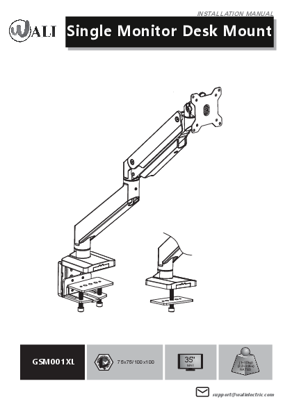
Product Overview
VESA Compatibility: 75x75/100x100 mm
Maximum Monitor Size: 35 inches
Weight Capacity: 1-15 kg (2.2-33 lbs)
Contact: support@walielectric.com
[Diagram: An illustration of the WALI GSM001XL Single Monitor Desk Mount.]
⚠️ IMPORTANT SAFETY INFORMATION
If you do not understand these directions, or if you have any doubts about the safety of the installation, please call a qualified technician. Check carefully to make sure there are no missing or defective parts. Improper installation may cause damage or serious injury. Do not use this product for any purpose that is not explicitly specified in this manual. Do not exceed weight capacity. WALI cannot be liable for damage or injury caused by improper mounting, incorrect assembly or inappropriate use.
⚠️ TIPOVER WARNING
SERIOUS OR FATAL CRUSHING INJURIES CAN OCCUR FROM TIPOVER.
TO HELP PREVENT TIPOVER:
- NEVER ALLOW CHILDREN TO CLIMB, STAND, HANG, OR PLAY ON ANY PART OF MONITOR OR STAND.
- USE TIPOVER RESTRAINT OR ANCHOR STAND TO WALL.
USE OF TIPOVER RESTRAINTS MAY ONLY REDUCE, BUT NOT ELIMINATE RISK OF TIP OVER.
SMALL PARTS - NOT FOR CHILDREN UNDER 3 YEARS. ADULT SUPERVISION IS REQUIRED.
Supplied Parts List
[Base A (x1)]
[Arm B (x1)]
[Arm C (x1)]
[VESA Plate D (x1)]
[Support Plate E (x1)]
[Bottom Grommet Plate F (x1)]
[Anti-skid Pad G (x1)]
[Decor Cover H (x1)]
[C-Clamp Brace I (x1)]
[C-Clamp J (x1)]
[Bolt K (x4)]
[Allen Key 3mm L (x1)]
[Allen Key 4mm M (x1)]
[Allen Key 6mm N (x1)]
[M4x12 Bolt M-A (x4)]
[M5x12 Bolt M-B (x4)]
[D5 Washer M-C (x4)]
Installation Steps
Step 1: Measure Mounting Surface
Measure the thickness of your mounting surface or desk.
Clamp Fit Range: 0.4" - 3.3"
Grommet Fit Range: 0.4" - 1.9"
[Diagram: A desk showing measurement indicators for clamp and grommet installation ranges.]
Step 2: Base Installation
Option A: Clamp Installation
- Connect the C-Clamp Brace [I] to the Base [A] from the bottom using 4 pcs Bolt [K] and tighten with Allen Key 4mm [M]. Tear off the protective paper to attach Anti-Skid Pad [G] to the bottom designated position of Base [A]. [Diagram: Attaching C-Clamp Brace I to Base A using Bolt K and Allen Key M, then applying Anti-skid Pad G.]
- Loosen the Bolts on the C-Clamp [J] using Allen Key 4mm [M]. Leave a 6mm gap. [Diagram: Loosening C-Clamp J bolts with Allen Key M, indicating a 6mm gap.]
- Hang the C-Clamp [J] on the C-Clamp Brace [I] to the preferred height according to your desk thickness and tighten using Allen Key 4mm [M]. Place Support Plate [E] on top of clamp bolts. This step illustrates two possible height ranges: 0.4"-2.3" and 2.0"-3.3". [Diagram: Attaching C-Clamp J to C-Clamp Brace I at different heights and placing Support Plate E.]
- Position base on desktop and tighten clamp bolts evenly using Allen Key 6mm [N]. Attach Decor Cover [H] to the back of C-Clamp Brace [I]. [Diagram: Securing the assembled base to the desk edge and attaching Decor Cover H.]
Option B: Grommet Base Installation
- Connect the Bottom Grommet Plate [F] to the Base [A] from the bottom using 4 pcs Bolt [K] and tighten with Allen Key 4mm [M]. Tear off the protective paper to attach Anti-Skid Pad [G] to the bottom designated position of Base [A]. [Diagram: Attaching Bottom Grommet Plate F to Base A using Bolt K and Allen Key M, then applying Anti-skid Pad G.]
- Remove clamp bolt from C-Clamp [J] using Allen Key 6mm [N]. Place the Base [A] onto the desk hole, and guide the Support Plate [E] through the bolt. Tighten the bolt to the base for stability using Allen Key 6mm [N]. [Diagram: Inserting Base A into a desk grommet hole, guiding Support Plate E through the bolt, and tightening with Allen Key N.]
Step 3: Connect Arm B to Base
Connect Arm [B] to the Base [A] and tighten the lower screw with Allen Key 3mm [L]. Optionally, tighten the upper screw to restrict swivel movement to +/-90°.
[Diagram: Connecting Arm B to Base A, showing swivel adjustment points and indicating +/-180° and +/-90° rotation limits.]
Step 4: Connect Arm C to Arm B
Connect Arm [C] to Arm [B] and tighten with Allen Key 3mm [L].
[Diagram: Connecting Arm C to Arm B and tightening the connection with Allen Key L.]
Step 5: Attach VESA Plate to Monitor
Step 5.1: Determine Screw Size
Hand thread screws (M4x12 or M5x12) into the threaded inserts on the back of your TV/Monitor to determine which screw diameter (M4) or (M5) to use.
[Diagram: Showing M4x12 and M5x12 screws and examples of them being hand-threaded into a monitor's VESA mounting holes.]
Step 5.2: Mount VESA Plate
Select M4x12 Bolt [M-A] or M5x12 Bolt [M-B] according to your TV/Monitor. Connect VESA Plate [D] together with D5 Washer [M-C] into the mounting holes on the back of TV/Monitor. Tighten with a screwdriver (not included).
[Diagram: Attaching VESA Plate D to a monitor back using M4x12 Bolt M-A or M5x12 Bolt M-B and D5 Washer M-C.]
Step 6: Mount Monitor to Arm
Pull the buckle and put the assembled TV/Monitor onto the Arm [C] and ensure stability.
[Diagram: Attaching the monitor with VESA plate to the arm mechanism, showing a locking action.]
Step 7: Adjust Gas Spring Tension
Press the Arm [C] on a horizontal level as shown. Adjust gas spring tension to your personal preference using Allen Key 6mm [N].
- Insert the 6mm Allen Key [N] into the adjusting hole and turn clockwise (-) to reduce gas spring tension, suitable for lighter screens.
- Insert the 6mm Allen Key [N] into the adjusting hole and turn counter-clockwise (+) to increase gas spring tension, suitable for heavier screens.
- Note: It may take numerous turns for gas spring tension adjustment.
[Diagram: Adjusting gas spring tension with Allen Key N, showing +/- directions and indicating 'For Heavier Monitors' and 'For Lighter Monitors'.]
Step 8: Adjust Tilt Tension
Adjust the tilt tension using Allen Key 6mm [N].
[Diagram: Adjusting tilt tension with Allen Key N.]
Step 9: Cable Management - Remove Cases
Screw out the bolts and take off the cable cases.
[Diagram: Removing cable covers from the monitor arm.]
Step 10: Cable Management - Route Cables
Guide the cables through the arm and put the cable cases back.
[Diagram: Routing cables through the monitor arm and reattaching the cable covers.]
Step 11: Safety - Monitor Placement
For safety, please do not extend the monitor behind the desk. This may cause instability and tip the desk over.
[Diagram: Showing incorrect (❌) and correct (✔️) monitor placement relative to the desk edge to prevent tipping.]
Step 12: Final Adjustments and Storage
Manually swivel, tilt, and rotate the monitor for the best viewing angle. Store the Allen Keys [L, M, N] in the holder of Decor Cover [H] for future convenience.
[Diagram: Showing monitor swivel, tilt, and rotation angles (+/-90°, +/-180°, +/-45°). Also shows Allen keys stored in Decor Cover H.]
Thank You
Thank you for choosing WALI!
WALI supports the technology that brings your home to life. WALI offers high quality products, professional customer service, and extensive technical support.
If you have any questions, please contact WALI:
? Phone: 1-844-SATTLER (18447288537)
✉️ Email: support@walielectric.com
? Website: www.walielectric.com
