ACCUENERGY AcuRev 2100 Smart Metering System User Manual
File info: application/pdf · 285 pages · 7.82MB
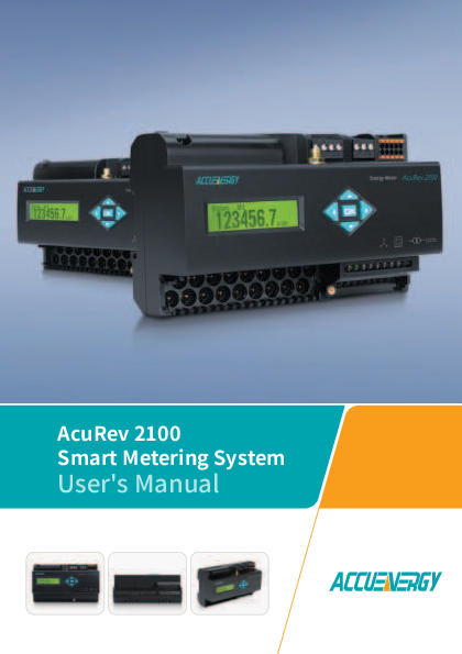
AcuRev 2100 Smart Metering System - User's Manual
Prior to maintenance and repair, the equipment must be de-energized and grounded. All maintenance work must be performed by qualified, competent accredited ...
User's Manual
Full PDF Document

If the inline viewer fails, it will open the original document in compatibility mode automatically. You can also open the file directly.
Extracted Text
AcuRev 2100 Smart Metering System User's Manual Copyright � 2020 V1.00 This manual may not be altered or reproduced in whole or in part by any means without the expressed written consent of Accuenergy. II V: 1.0 Revised: Oct 2020 www.accuenergy.com The information contained in this document is believed to be accurate at the time of publication, however, Accuenergy assumes no responsibility for any errors which may appear here and reserves the right to make changes without notice. Please ask the local representative for latest product specifications before ordering. Please read this manual carefully before installation, operation and maintenance of the AcuRev 2100 Series Power Meter. The following symbols in this manual are used to provide warning of danger or risk during the installation and operation of the meters. Electric Shock Symbol: Carries information about procedures which must be followed to reduce the risk of electric shock and danger to personal health. Safety Alert Symbol: Carries information about circumstances which if not considered may result in injury or death. Prior to maintenance and repair, the equipment must be de-energized and grounded. All maintenance work must be performed by qualified, competent accredited professionals who have received formal training and have experience with high voltage and current devices. Accuenergy shall not be responsible or liable for any damages or injuries caused by improper meter installation and/or operation. www.accuenergy.com V: 1.0 Revised: Oct 2020 1 Table of Contents Chapter 1: Introduction ........................................................................................4 1.1 Meter Overview............................................................................................................. 5 1.2 Areas of Application ..................................................................................................... 5 1.3 AcuRev 2100 Series Features ...................................................................................... 6 Chapter 2: Installation.........................................................................................10 2.1 Appearance and Dimensions....................................................................................12 2.2 Installation Methods ..................................................................................................13 2.3 Wiring ..........................................................................................................................14 2.3.1 Terminals ........................................................................................................14 2.3.2 Wiring Methods .............................................................................................16 2.3.3 Communication Port .....................................................................................19 Chapter 3: Appearance and Dimensions ..........................................................21 3.1 Display Panels and Keys ...........................................................................................22 3.2 Energy Display and Operation ..................................................................................24 3.3 Demand Display and Operation ...............................................................................26 3.4 IO Display and Operations ........................................................................................28 3.5 Real-Time Display and Key Operation......................................................................30 3.6 Power Quality Display and Key Operation ..............................................................32 3.7 Shortcut Code .............................................................................................................35 3.8 Basic Settings and Key Operation.............................................................................54 3.9 Network Settings ........................................................................................................55 3.10 Device Information and Key Operation .................................................................56 Chapter 4: Functions & Software .......................................................................57 4.1 Introduction to Acuview Software ............................................................................58 4.1.1 Connecting the AcuRev 2100 to Acuview....................................................58 4.2 General Settings..........................................................................................................61 4.2.1 CT ratio and Channel Mapping ....................................................................64 4.3 Real Time Metering ....................................................................................................66 4.4 Demand ....................................................................................................................... 67 4.5 Energy ..........................................................................................................................68 2 V: 1.0 Revised: Oct 2020 www.accuenergy.com Table of Contents 4.5.1 Time of Use (TOU)..........................................................................................69 4.6 IO Functions ................................................................................................................75 4.6.1 Digital Input ....................................................................................................75 4.6.2 Relay Output...................................................................................................77 4.6.3 Digital Output.................................................................................................79 4.7 Alarm............................................................................................................................81 4.8 System Event Log........................................................................................................83 4.9 Data Log.......................................................................................................................84 4.9.1 Reading the Data Log ....................................................................................86 4.10 Seal Button (B1) Function ........................................................................................88 4.10.1 How to use the Seal Button (B1)................................................................90 4.11 Device Information...................................................................................................90 Chapter 5: Communication ................................................................................92 5.1 MODBUS Protocol Introduction................................................................................92 5.1.1 Transmission Mode .......................................................................................92 5.1.2 Protocol...........................................................................................................92 5.1.3 CRC Check.......................................................................................................95 5.2 Modbus Communication Format .............................................................................96 5.2.1 Read Relay Output status (Function Code 01) ...........................................97 5.2.2 Read the status of DI (Function Code 02) ...................................................98 5.2.3 Read Data (Function Code 03)......................................................................99 5.2.4 Control Relay Output...................................................................................100 5.2.5 Preset/Reset Multi-Register........................................................................100 5.3 AcuRev 2100 Application Details and Parameter Address Table........................101 5.3.1 Type of Data .................................................................................................101 5.3.2 Correspondence Between Communication Value and Actual Value ....102 5.3.3 Address Table...............................................................................................103 www.accuenergy.com V: 1.0 Revised: Oct 2020 3 AcuRev 2100 Series Power Meter Chapter 1: Introduction 1.1 Meter Overview 1.2 Areas of Application 1.3 AcuRev 2100 Series Features Chapter 1: Introduction Chapter 1.0: Introduction 1.1 Meter Overview The AcuRev 2100 series meter performs real-time metering, measures energy consumption and monitors power quality for up to 18 single phase circuits (or 6 three phase circuits) in one unit. It is an advanced intelligent power meter that Accuenergy developed and manufactured for the next generation smart power distribution networks. The main features include multitenant sub metering, cyclic display, and tamper proof, which make it highly suitable for large commercial facilities, residential apartments and industrial environments. The AcuRev 2100 series has RS485, Ethernet and wireless (WIFI) communication options as well which can be easily be connected to intelligent power distribution monitoring systems. The AcuRev 2100 also supports several I/O options (e.g. Pulse Counting from water or gas meters), making it useful in energy management systems. Due to its communication capability, ease of installation and use, this product can be easily integrated into new and existing energy management systems. 1.2 Areas of Application � Multi-tenant sub metering/billing � Commercial Complex/Mall � Apartment/Condominiums � Hospitals/Public Services � Hotels/Office Buildings � Data Centers � LEED Projects � Branch circuit monitoring � Railway and Subway Systems � Energy Management Systems � Industrial & Utilities Applications WARNING: This product shall be installed in an full enclosed industrial cabinet, the access to which is strictly limited to professional personnel. www.accuenergy.com V: 1.0 Revised: Oct 2020 5 AcuRev 2100 Series Power Meter 1.3 AcuRev 2100 Series Features Multi-function Multi-Tenants AcuRev 2100 multi-function intelligent power meter utilizes powerful data acquisition and processing functions, which implements real-time metering and monitoring for up to 18 single phase circuits (or 6 three phase circuits) in one unit. It will also record system events, over/ under limit alarming and data logging functions. Innovative Display and Installation Multi-tenant energy information is cycled through on the high-resolution display. Current transformer installation is made simple with plug in connector to meter. Flexible Wiring Users can choose measuring circuits and wiring methods. Measuring circuit can be selected as 18 single phases, or 6 three phase or 6 single phase three wire. Features AcuRev 2100 features and functionality are listed in the table below. Function Energy Parameters Supported Real Energy Reactive Energy Apparent Energy Details � Combined energy total for all circuits � Real, reactive, and apparent energy for each circuit Time of Use (TOU) 4 Tariffs, 14 Schedules � Daylight Savings Time Holidays � Supports 14 Seasons, 14 Schedules, 4 Tariffs, supporting weekend and holiday settings. Supports daylight saving time and 10-year holidays with automatic switching. Accuracy Class 0.5 S 6 V: 1.0 Revised: Oct 2020 www.accuenergy.com Chapter 1: Introduction Function Demand Real Time Parameters Supported Active Power Demand Active Power Demand Max Reactive Power Demand Reactive Power Demand Max Details � Combined demand total for all circuits � Active power demand, reactive power demand, apparent power demand and current demand for each circuit. Apparent Power Demand Apparent Power Demand Max Current Demand Current Demand Max Voltage � System Line Voltage � System Phase Voltage Current � Combined average current for circuits being monitored � Current readings for each circuit being monitored Active Power Reactive Power Apparent Power Power Factor Load Characteristic � Combined power for all circuits � Active Power, Reactive Power, Apparent Power, Power Factor and Load Characteristic for each circuit being monitored Frequency � System Frequency Accuracy 0.5% 0.5% www.accuenergy.com V: 1.0 Revised: Oct 2020 7 AcuRev 2100 Series Power Meter Function Power Quality Clock Alarming Data Logging Parameters Supported THD Individual Harmonics (2~31) Current K Factor Crest Factor Voltage Unbalance Current Unbalance Voltage Telephone Interference Factor (THFF) Year/Month/Day/ Hour/Minute/Second Over/Under Limit Alarming Up to 8MB via meters onboard Up to 8GB via WEB2 communications module Details � Voltage and current THD, odd THD, even THD � Individual Harmonics (2~31), Current K-factor (KF), crest factor (CF), telephone interference factor (THFF), � Voltage and current unbalance � Real time configurable clock, � Supports NTP via WEB2 communications module � Users can select parameters and configure the set point threshold over/under. � The time and reason of an alarm event will be recorded. � Log real-time metering parameters, I/O status, and energy measurement. � Built in WEB2 communications module provides an additional 8GB of memory that can be used for logging locally on the communication module. Accuracy 1% 8 V: 1.0 Revised: Oct 2020 www.accuenergy.com Chapter 1: Introduction Function Communication I/O Parameters Supported RS485 Ethernet/WIFI 18 Digital Inputs 6 Digital Outputs 2 Relay Outputs Details � Modbus TCP, WiFi WPA, WPA2 Enterprise security protocol, HTTP/HTTPS, FTP, SMTP, NTP, SNMP, BACnet IP, MQTT � Monitors Digital Status (ON/ OFF) � Digital Counter � Energy Pulse Output � Alarm Pulse Output � Latch control relay � Alarm controlled relay Accuracy www.accuenergy.com V: 1.0 Revised: Oct 2020 9 AcuRev 2100 Series Power Meter Chapter 2: Installation 2.1 Appearance and Dimensions 2.2 Installation Methods 2.3 Wiring 2.3.1 Terminals 2.3.2 Wiring Methods 2.3.3 Communication Port Chapter 2: Installation Chapter 2.0: Installation Before Installation � The installation must be performed by qualified, competent, accredited professionals who have received formal training and have experience with high voltage and current devices. Appropriate safety wear (gloves, glasses, arc flush suit, etc.) is mandatory to ensure safe installation. � During normal meter operation, caution should be used when handling the following as high voltage may be present: Terminal Blocks, Current Transformer connection nodes, Potential Transformer connection nodes and the related circuits. All primary and secondary circuits may contain lethal current and voltage. Contact with current channels must be avoided. � The power meter and I/O modules cannot be installed on the primary side of transformers or where VA has limitations. The power meter can be only installed on the secondary side. Avoid contact with meter terminals after the completion of installation. � Do not input voltage above the rated maximum limit of the power meter and devices connected to it. Before energizing the meter, please refer to the meter's label and specifications. � Do not perform high voltage test / insulation experiment to output, input, or communication terminals. � The use of shorting blocks and fuses are recommended. � Use dry cloth to wipe the meter. � The installation method is introduced in the chapter. Please read this chapter carefully before beginning installation. Note: Failure to follow manufacturer guidelines for installation and use may compromise the safety of the meter and the user. Note: Any repair should only be performed by the manufacturer. A switch or circuit breaker should be utilized in the equipment. The switch should be placed close to the equipment and easy to reach. The switch is regarded as part of the breaking device. www.accuenergy.com V: 1.0 Revised: Oct 2020 11 AcuRev 2100 Series Power Meter 2.1 Appearance and Dimensions Dimensions Fig.2-1 AcuRev 2000 Appearance 95 mm 35.5 mm 3.74 in 1.40 in 162 mm 6.38 in 60.1 mm 2.37 in 67.1 mm 2.64 in Fig.2-2 Meter Dimensions (Meter Base, Display, External CTs) 12 V: 1.0 Revised: Oct 2020 www.accuenergy.com Chapter 2: Installation 2.2 Installation Methods Environmental Before installation, please check the environment, temperature, and humidity to ensure the AcuRev 2100 series meter is being placed where it will not be damaged. 1. Temperature AcuRev 2100 operating temperature is -25~70�C. Exceeding this temperature range will cause damage to the meter. Please note it can influence the meters life negatively if the meter operates in extremely high or extremely low temperatures. AcuRev 2100 storage temperature range is -40~85�C. 2. Humidity 5% to 95% non-condensing. 3. Location AcuRev 2100 series meter should be installed in a dry and dust free environment. Avoid exposing meter to excessive heat, radiation, and high electrical noise sources. Installation Steps This meter is DIN rail mounted, which fits 35 mm standard rails. 1. Insert the meter groove all the way into the rail, and flip the meter case as the Figure below shows, making the meter mounted onto the rail. www.accuenergy.com V: 1.0 Revised: Oct 2020 13 AcuRev 2100 Series Power Meter 2.3 Wiring 2.3.1 Terminals Meter Terminals Upper row: Voltage Input, Power Supply, Seal Button (B1), Relay Output, RS485, Digital Output, Ethernet Ports (via WEB2 module) WIFI NET1 65 NET2 66 Lower row: Current Input, Digital Input Fig. 2-6 AcuRev 2100 Terminals 14 V: 1.0 Revised: Oct 2020 www.accuenergy.com Chapter 2: Installation Power Supply AcuRev 2100 power supply is 100-415Vac, 50/60Hz or 100-300Vdc, which are universally supported. If any other power supply is required, please contact the manufacturer. The power consumption of the power meter is low during normal operation; therefore, the power supply can be either via a standalone power supply or via the measured circuit. A regulator is recommended where the voltage is not stabilized. The power supply terminal number is L/N/G. Fig. 2-7 Power Supply Wiring Power Supply wiring is AWG22~16 or 0.6~1.5mm2. A fuse or small-sized circuit breaker is mandatory for the AcuRev 2100 Power Supply. The fuse recommendation is 1A/250Vac, time delay. If a circuit breaker is utilized, it must be CE certified and comply with IEC 947 standard. An isolated transformer or EMC filter should be used in the auxiliary power supply loop if there is a power quality issue in the power supply. Voltage Input Signal 400Vac L-N, 690Vac L-L.A fuse (typical 1A/250Vac) or air circuit breaker must be used in the voltage input loop. Current Input Connection For CT Connection, the CTs are terminated and plugged directly into the meter using connectors on the CT. If the CT does not have this connector an adapter can be used to connect the CT successfully to the meter. North America International SnapOn Connector Polarity White lead is positive. Black lead is negative. Red lead is positive. White lead is negative. www.accuenergy.com V: 1.0 Revised: Oct 2020 15 AcuRev 2100 Series Power Meter Vn Connection Vn is the voltage reference point of AcuRev 2100, a low resistance to Vn connection contributes to a better measurement accuracy. Vn connection is related to the system wiring. Please refer to "Wiring Methods" for details. 2.3.2 Wiring Methods AcuRev 2100 wiring methods can be selected in system parameter settings. Inline defaults to 3-phase 4-line(3LN), load wiring can be set to single-phase (1LN), threephase four-wire (3LN), single-phase three-wire (2LN). 1. Single Phase (1LN) AcuRev 2100 V5 16 V: 1.0 Revised: Oct 2020 Fig. 2-8 Single Phase www.accuenergy.com 2. Three Phase 4 Wire (3LN) Chapter 2: Installation AcuRev 2100 V5 Fig. 2-9 3-Phase 4-Wire Table 2-1 3-Phase 4-Wire Phase C Three Phase Circuit 1 I3 Phase B I2 Phase A I1 Three Phase Circuit 2 I6 I5 I4 Three Phase Circuit 3 I9 I8 I7 Three Phase Circuit 4 I12 I11 I10 Three Phase Circuit 5 I15 I14 I13 Three Phase Circuit 6 I18 I17 I16 www.accuenergy.com V: 1.0 Revised: Oct 2020 17 AcuRev 2100 Series Power Meter 3. Single Phase 3 Wire (2LN) AcuRev 2100 V5 Fig. 2-10 Single Phase 3-Wire 18 V: 1.0 Revised: Oct 2020 www.accuenergy.com Table 2-2 Single Phase Three Wire (2 Hot Phases - 1 Neutral) Circuit Single Phase Three Wire Circuit 6 Phase A 16 Single Phase Three Wire Circuit 5 13 Single Phase Three Wire Circuit 4 10 Single Phase Three Wire Circuit 3 7 Single Phase Three Wire Circuit 2 4 Single Phase Three Wire Circuit 1 1 Chapter 2: Installation Phase B 17 14 11 8 5 2 2.3.3 Communication Port AcuRev 2100 communication utilizes RS485 port, via Modbus-RTU protocol. The wiring terminals are A, B, S (14, 13, 12), where A is positive, B is negative, and S is the shield terminal. The maximum distance of shielded twisted pair cable is 1200 m. WIFI NET1 65 NET2 66 Figure 2-11 Communication Port www.accuenergy.com V: 1.0 Revised: Oct 2020 19 AcuRev 2100 Series Power Meter If the master device does not have RS485 but RS232 port, a RS232/485 converter can be utilized. Typical RS485 network topologies include line, circle and star (wye). In order to improve communication quality, please pay attention to: 1. High-quality shielded twisted pair cable is very important, AWG22 (0.6mm2) or lower is recommended. Two cables should be different colors. 2. Pay attention to "single point earthing". It means there is only one point of the shielding connected to ground in a single communication link. 3. Every A (+) should be connected to A(+), B(-) to B(-), or it will influence the network, even damage the communication interface. 4. "T" type connection topology should be avoided. This means no new branches except from the starting point. 5. Keep communication cables away as much as possible from sources of electrical noise. When several devices are connected (daisy chain) to the same long communication line, an anti-signal reflecting resistor (typical value 1200-3000, 0.25W) is often used at the end of the circuit (the last meter of the chain) if the communication quality is distorted. 6. Use RS232/RS485 or USB/RS485 converter with optical isolated output and surge protection. 20 V: 1.0 Revised: Oct 2020 www.accuenergy.com AcuRev 2100 Series Power Meter Chapter 3: Appearance & Dimensions 3.1 Display Panels and Keys 3.2 Energy Display and Operation 3.3 Demand Display and Operation 3.4 IO Display and Operations 3.5 Real-Time Display and Key Operation 3.6 Power Quality Display and Key Operation 3.7 Shortcut Code 3.8 Basic Settings and Key Operation 3.9 Network Settings 3.10 Device Information and Key Operation AcuRev 2100 Series Power Meter Chapter 3.0: Appearance & Dimensions 3.1 Display Panels and Keys The AcuRev 2100 meter consists of one LCD screen and five keys. Refer to chapter 2 section 2.1 for more details regarding the dimensions of the LCD display. LCD Display Function Keys Fig. 3-1 AcuRev 2100 and LED Indicator Table 3-1 Function Keys Illustration Key Up Down Left Function Scroll up or increase value (Editing mode) Scroll down or decrease value (Editing mode) Move cursor to the left Right Move cursor to the right OK OK Confirm setting/value 22 V: 1.0 Revised: Oct 2020 www.accuenergy.com Chapter 3: Appearance & Dimensions Key Combination Pressing the Left and Right buttons at the same time for a second is the quick exit function. In any screen, pressing this key combination can return to the main menu screen. The basic settings and network setting screens are only available with this key combination to return back to the main menu screen. Display When first powered on the ACCUENERGY will be displayed on the LCD screen, after 2 seconds the main menu screen will appear. Settings Mode In the main menu screen, users can use the arrow keys to navigate to different options and use the OK button to enter any of the menu options. When entering either the Settings or Network Settings options users will be prompted with a password screen. The default password is 0000, if password has been changed users can use the arrow keys to enter in the required password. Table 3-2 below shows the main menu options for the AcuRev 2100 meter. Table 3-2 AcuRev 2100 Main Menu Menu Display D (Demand) INFO IO E (Energy) SET NET PQ MUL (Real-Time) M Function Demand Readings Device Information Digital Input/Output Readings Energy Readings Meter Settings Network Settings Power Quality Readings Real-Time Readings Shortcut Code www.accuenergy.com V: 1.0 Revised: Oct 2020 23 AcuRev 2100 Series Power Meter By default only the E, D, IO, MUL, and M options are displayed on main menu screen. To view the PQ, SET, NET, and INFO options press either the Right or Left arrow keys to scroll to these options. E D IO MUL M PQ SET NET INFO Fig. 3-2 Main menu screen sequence 3.2 Energy Display and Operation On the main menu screen move the cursor over to E and press OK to enter to view the energy readings for the meter. Use the Left or Right buttons to move between the different channels (1-18) as well as the in-line (meter total) energy. Press the Up and Down buttons to select the different energy readings for each channel/tenant. Users can press OK to return to the main menu screen. If TOU energy is not used, the meter will only display real-time energy readings. Table 3-3 Energy Display Parameter Apparent Energy Current Month Total Energy Current Month Tariff 1 Energy Current Month Tariff 2 Energy Current Month Tariff 3 Energy Current Month Tariff 4 Energy Prior Month Tariff 1 Energy Prior Month Tariff 2 Energy Prior Month Tariff 3 Energy Prior Month Tariff 4 Energy Reactive Energy Real-Time Energy 24 V: 1.0 Revised: Oct 2020 Screen ES MTnS MT1S MT2S MT3S MT4S UT1S UT2S UT3S UT4S EQ EP www.accuenergy.com 1. Single Phase 1 Wire (1LN) Chapter 3: Appearance & Dimensions E D IO MUL M OK Tri001 EP kWh Tri001 EP kWh M TnS M T1S M T2S Tri001 EP kWh M T3S M T4S Tri001 EP kWh U TnS U T1S U T2S Tri001 ES kVAh Tri001 EP kWh U T3S U T4S Tri001 EQ kvarh Fig. 3-3 Single Phase 1 Wire Energy Display 2. Three Phase 4 Wire (3LN) E D IO MUL M OK Tri001 EP-Sum kWh Tri001 EP kWh U T3A U T4A Tri001 EP kWh M TnB M T1B M T2B Tri001 EQ kvarh A B C Tri001 ES-Sum kVAh Tri001 EP kWh A B C Tri001 EP kWh U TnA U T1A U T2A Tri001 EP kWh M T3B M T4B Tri001 EQ-Sum kvarh Tri001 ES kVAh A B C Tri001 EP kWh M TnS M T1S M T2S Tri001 EP kWh M T3S M T4S Tri001 EP kWh U TnS U T1S U T2S Tri001 EP kWh M T3A M T4A Tri001 EP kWh M TnA M T1A M T2A Tri001 EP kWh U T3S U T4S Tri001 EP kWh U TnB U T1B U T2B Tri001 EP kWh U T3B U T4B Tri001 EP kWh M TnC M T1C M T2C Tri001 EP kWh U T3C U T4C Tri001 EP kWh U TnC U T1C U T2C Tri001 EP kWh M T3C M T4C Fig. 3-4 Three Phase 4 Wire Energy Display www.accuenergy.com V: 1.0 Revised: Oct 2020 25 AcuRev 2100 Series Power Meter 3. Single Phase 3 Wire (2LN) E D IO MUL M OK Tri001 EP-Sum kWh Tri001 EP kWh A B Tri001 EP kWh M TnS M T1S M T2S Tri001 EP kWh M T3S M T4S Tri001 EP kWh U T3A U T4A Tri001 EP kWh U TnA U T1A U T2A Tri001 EP kWh M T3A M T4A Tri001 EP kWh M TnA M T1A M T2A Tri001 EP kWh M TnB M T1B M T2B Tri001 EP kWh M T3B M T4B Tri001 EP kWh U TnB U T1B U T2B Tri001 EP kWh U T3B U T4B Tri001 ES kVAh A B Tri001 ES-Sum kVAh Fig. 3-5 Single Phase 3 Wire Energy Display Tri001 EP kWh U TnS U T1S U T2S Tri001 EP kWh U T3S U T4S Tri001 EQ-Sum kvarh Tri001 EQ kvarh A B 3.3 Demand Display and Operation On the main menu use the arrow keys to navigate to D, then press OK to view the meters demand readings. Using the Left and Right buttons to move between the different channels (118) as well as the in-line (meter total) demand. Use the Up and Down keys to view the different demand readings for each channel. Users can press the OK button to return to the main menu. Table 3-4 Demand Display Parameter Display Demand DMD Active Demand DMD-P Reactive Demand DMD-Q Apparent Demand DMD-S Current Demand DMD-I Predicted Demand Pre Maximum Demand Max For different wiring configurations, the demand data display will be different: 26 V: 1.0 Revised: Oct 2020 www.accuenergy.com Chapter 3: Appearance & Dimensions 1. Single Phase 1 Wire (1LN) E D IO MUL M OK Tri001 DMD P Q S Tri001 DMD - P Pre Max Maximum Demand Happening Time Tri001 DMD - Q Pre Max Maximum Demand Happening Time Tri001 DMD - S Pre Max Maximum Demand Happening Time Tri001 DMD - I Pre Max Maximum Demand Happening Time Fig. 3-5 Single Phase 1 Wire Demand Display Tri001 DMD - I 2. Single Phase 4 Wire (3LN) E D IO MUL M OK Tri001 DMD - Sum P Q S Tri001 DMD - P A B C Tri001 DMD - Pa Pre Max Maximum Demand Happening Time Tri001 DMD - Qb Pre Max Maximum Demand Happening Time Tri001 DMD - Qa Pre Max Maximum Demand Happening Time Tri001 DMD - Q A B C Tri001 DMD - Qc Pre Max Maximum Demand Happening Time Tri001 DMD - S A B C Tri001 DMD - Sa Pre Max Maximum Demand Happening Time Tri001 DMD - Ib Pre Max Maximum Demand Happening Time Tri001 DMD - Ia Pre Max Maximum Demand Happening Time Tri001 DMD - I Pre Max Maximum Demand Happening Time Tri001 DMD - Ic Pre Max Maximum Demand Happening Time Fig. 3-6 Single Phase 4 Wire Demand Display Tri001 DMD - Pb Pre Max Maximum Demand Happening Time Tri001 DMD - Pc Pre Max Maximum Demand Happening Time Tri001 DMD - Sb Pre Max Maximum Demand Happening Time Tri001 DMD - Sc Pre Max Maximum Demand Happening Time www.accuenergy.com V: 1.0 Revised: Oct 2020 27 AcuRev 2100 Series Power Meter 3. Single Phase 3 Wire (2LN) E D IO MUL M OK Tri001 DMD - Sum P Q S Tri001 DMD - S A B Tri001 DMD - Sa Pre Max Maximum Demand Happening Time Tri001 DMD - P A B Tri001 DMD - Qb Pre Max Maximum Demand Happening Time Tri001 DMD - Sb Pre Max Maximum Demand Happening Time Tri001 DMD - Pa Pre Max Maximum Demand Happening Time Tri001 DMD - Qa Pre Max Maximum Demand Happening Time Tri001 DMD - I A B Fig. 3-7 Single Phase 3 Wire Demand Display Tri001 DMD - Pb Pre Max Maximum Demand Happening Time Tri001 DMD - Q A B Tri001 DMD - Ia Pre Max Maximum Demand Happening Time Tri001 DMD - Ia Pre Max Maximum Demand Happening Time 3.4 IO Display and Operations On the main menu use the arrow keys to navigate to IO and then press the OK to view the IO data. Use the Up and Down buttons to view different IO readings. Users can press the OK button to return to the main menu. E D IO MUL M OK DI Status RO Status DI Pulse Input Related Fig. 3-8 IO Display 28 V: 1.0 Revised: Oct 2020 www.accuenergy.com Chapter 3: Appearance & Dimensions 1st Screen includes DI Status channels 1-10, and the second screen includes channels 11-18. DI 1 2 3 4 5 6 7 8 9 10 DI 11 12 13 14 15 16 17 18 Fig. 3-9 Digital Input Status Display indicates this channel DI status "OFF" or Pulse Input indicates DI Status "ON" 3rd Screen, RO Status, 2-Channel RO. RO Fig. 3-10 Relay Output Display indicates this channel RO status "OFF" indicates this RO Status "ON" www.accuenergy.com V: 1.0 Revised: Oct 2020 29 AcuRev 2100 Series Power Meter 4th Screen, DI pulse input number and its parameter. Pressing Left and Right to view channels 1-18. PULS CONT X X PCS X. XX YY Fig. 3-10 DI Pulse Input Display CONT X = DI Channel number PCS = Pulse Count yy = Scaled Value 3.5 Real-Time Display and Key Operation On the main menu use the arrow keys to navigate to MUL (Real-time) and press the OK button to view the real time parameter readings for the meter. Use the Left and Right buttons to move between different channels (1-18) as well as the inline parameters (meter total). Use the Up and Down buttons to scroll between the different real time parameters. Users can press the OK button to return to the main menu. Table 3-5 Real Time Data Display Parameter Total Time Active Power Reactive Power Apparent Power Real-Time Current Value Power Factor Display MUL-Sum MUL-P MUL-Q MUL-S MUL-I MUL-PF 30 V: 1.0 Revised: Oct 2020 www.accuenergy.com Parameter Load Type Phase Voltage Phase Average Voltage Line Voltage Line Voltage Average Chapter 3: Appearance & Dimensions Display MUL-Load Type MUL-Phase U Uavg MUL-Line U Ulavg For different wiring configurations, the real time data display will be different: 1. Single Phase 2-Wire (1LN) E D IO MUL M OK Tom001 MUL-P Tom001 MUL-Q Tom001 MUL-S Tom001 MUL-PF Tom001 MUL-I Tom001 MUL-Load Type Fig. 3-11 Single Phase 1 Wire Real-Time Display 2. Three Phase 4-Wire (3LN) E D IO MUL M OK Tom001 MUL-Sum P Q S Tom001 MUL-Sum PF Load Type Tom001 MUL-P A B C Tom001 MUL-Q A B C Tom001 MUL-I A B C Fig. 3-12 Three Phase 4 Wire Real-Time Display Tom001 MUL-S A B C Tom001 MUL-PF A B C www.accuenergy.com V: 1.0 Revised: Oct 2020 31 AcuRev 2100 Series Power Meter 3. Single Phase 3-Wire (2LN) E D IO MUL M OK Tom001 MUL-Sum P Q S Tom001 MUL-Sum PF Load Type Tom001 MUL-P A B Tom001 MUL-Q A B Tom001 MUL-I A B Fig. 3-13 Single Phase 3 Wire Real-Time Display 4. 4-Wire Inline E D IO MUL M OK Inline MUL-Sum P Q S Inline MUL-Sum PF Load Type Inline MUL-P A B C Inline MUL-Line U Uab Ubc Uca Inline MUL-Phase U Uavg Inline MUL-Phase U Ua Ub Uc Inline MUL-Phase U Ulavg Inline MUL-F Inline MUL-Q A B C Inline MUL-I A B C Tom001 MUL-S A B Tom001 MUL-PF A B Inline MUL-S A B C Inline MUL-PF A B C Fig. 3-14 Inline Real-Time Display 3.6 Power Quality Display and Key Operation In the second page of the main menu, use the arrow keys to navigate to PQ and press OK to view the power quality readings of the meter. Use the Left and Right buttons to move between different channels (1-18) as well as the inline values. Use the Up and Down buttons to view different power quality parameters. Users can press the OK button to return to the main menu. 32 V: 1.0 Revised: Oct 2020 www.accuenergy.com Table 3-6 Power Quality Data Display Parameter Unbalance Harmonic Distortion Total Harmonic Distortion Odd Harmonic Distortion Even Harmonic Distortion K-Factor Crest Factor Telephone Interference Factor Harmonic Ratio Chapter 3: Appearance & Dimensions Display UNBL THD SUM ODD EVEN K-Factor Crest Factor THFF HARMONIC 1. Single Phase 1-Wire (1LN) PO SET NET INFO OK User01 THD I SUM ODD EVEN User 01 K Factor User01 HARMONIC I 2nd-7th Harmonic ratio User01 HARMONIC I 26th-31th Harmonic ratio User01 HARMONIC I 20th-25th Harmonic ratio Fig. 3-15 Single Phase Power Quality User01 HARMONIC I 8th-13th Harmonic ratio User01 HARMONIC I 14th-19th Harmonic ratio www.accuenergy.com V: 1.0 Revised: Oct 2020 33 AcuRev 2100 Series Power Meter 2. Three Phase 4-Wire (3LN) PO SET NET INFO OK User01 UNBL I User01 THD Ia SUM ODD EVEN User01 THD Ib SUM ODD EVEN User01 THD Ic SUM ODD EVEN User01 K Factor A B C User01 HARNONIC Ia 26th-31st Harmonic ratio User01 HARNONIC Ia 20th-25th Harmonic ratio User01 HARNONIC Ia 14th-19th Harmonic ratio User01 HARNONIC Ia 8th-13th Harmonic ratio User01 HARNONIC Ia 2nd-7th Harmonic ratio User01 HARNONIC Ib 2nd-7th Harmonic ratio User01 HARNONIC Ib 8th-13th Harmonic ratio User01 HARNONIC Ib 14th-19th Harmonic ratio User01 HARNONIC Ib 20th-25th Harmonic ratio User01 HARNONIC Ib 26th-31st Harmonic ratio User01 HARNONIC Ic 26th-31st Harmonic ratio User01 HARNONIC Ic 20th-25th Harmonic ratio User01 HARNONIC Ic 14th-19th Harmonic ratio User01 HARNONIC Ic 8th-13th Harmonic ratio Fig. 3-16 Three Phase 4 Wire Power Quality User01 HARNONIC Ic 2nd-7th Harmonic ratio 3. Single Phase 3-Wire (2LN) PO SET NET INFO OK User01 UNBL I User01 THD Ia SUM ODD EVEN User01 THD Ib SUM ODD EVEN User01 K Factor A vavB User01 HARNONIC Ia 26th-31st Harmonic ratio User01 HARNONIC Ia 20th-25th Harmonic ratio User01 HARNONIC Ia 14th-19th Harmonic ratio User01 HARNONIC Ia 8th-13th Harmonic ratio User01 HARNONIC Ia 2nd-7th Harmonic ratio User01 HARNONIC Ib 2nd-7th Harmonic ratio User01 HARNONIC Ib 8th-13th Harmonic ratio User01 HARNONIC Ib 14th-19th Harmonic ratio User01 HARNONIC Ib 20th-25th Harmonic ratio User01 HARNONIC Ib 26th-31st Harmonic ratio Fig. 3-17 Singe Phase 3 Wire Power Quality 34 V: 1.0 Revised: Oct 2020 www.accuenergy.com Chapter 3: Appearance & Dimensions 4. Inline PO SET NET INFO OK Inline UNBL U I Inline THD Ua SUM ODD EVEN Inline THD Ub SUM ODD EVEN Inline THD Uc SUM ODD EVEN Inline THD U avg Inline HARNONIC Ua 14th-19th Harmonic ratio Inline HARNONIC Ua 8th-13th Harmonic ratio Inline HARNONIC Ua 2nd-7th Harmonic ratio Inline THFF A B C Inline Crest Factor A B C Inline HARNONIC Ua 20th-25th Harmonic ratio Inline HARNONIC Ua 26th-31st Harmonic ratio Inline HARNONIC Ub 2nd-7th Harmonic ratio Inline HARNONIC Ub 8th-13th Harmonic ratio Inline HARNONIC Ub 14th-19th Harmonic ratio Inline HARNONIC Uc 14th-19th Harmonic ratio Inline HARNONIC Uc 8th-13th Harmonic ratio Inline HARNONIC Uc 2nd-7th Harmonic ratio Inline HARNONIC Ub 26th-31st Harmonic ratio Inline HARNONIC Ub 20th-25th Harmonic ratio Inline HARNONIC Uc 20th-25th Harmonic ratio Inline HARNONIC Uc 26th-31st Harmonic ratio Fig. 3-18 Inline Power Quality 3.7 Shortcut Code The AcuRev 2100 supports a shortcut code that allows users to enter the code for a certain parameter and this parameter will be displayed on screen. Users can use this function if looking for a particular parameter rather than scrolling through the many screens in order to find it. On the main menu page use the arrow keys to navigate to M and press the OK to enter the Shortcut Key page. www.accuenergy.com V: 1.0 Revised: Oct 2020 35 AcuRev 2100 Series Power Meter E D IO MUL M OK 10101 Fig. 3-19 Shortcut Code Press the Left and Right buttons to move the cursor over to different digits. Press the Up and Down buttons to change the value of the digit. After inputting the Shortcut Code, press OK to enter the corresponding page. The Shortcut Code consists of five digits. The first digit on the left is to choose functions. The following tables provide the shortcut code to all the available parameters supported on the AcuRev 2100 meter. Table 3-7 Short Cut Code First Digit Representation Function Energy Measurement Shortcut 1 Demand Measurement 2 Digital Input Digital Output 3 Real-Time Measurement 4 Power Quality 5 36 V: 1.0 Revised: Oct 2020 www.accuenergy.com Chapter 3: Appearance & Dimensions 1. Single Phase 1-Wire (1LN): Table 3-8 Single Phase 1-Wire Shortcut Code Function User Screen Number Code 1 10101-10118 Content Real-time energy This month total energy, this 2 10201-10218 month tariff 1 energy, this month tariff 2 energy Energy (No TOU, 1-8 only Realtime Energy) 3 10301-10318 This month tariff 3 energy, this month tariff 4 energy Prior month total energy, prior 4 1-18 month tariff 1 energy, prior month tariff 2 energy Prior month tariff 3 energy, prior 5 10501-10518 month tariff 4 energy 6 10601-10618 Reactive energy 7 10701-10718 Apparent energy Real power demand, reactive power 1 20101-20118 demand, apparent power demand Real power demand prediction, 2 20201-20218 real power demand peak and happening time Demand 1-18 Reactive power demand prediction, 3 20301-20318 reactive power demand peak and happening time Apparent power demand 4 20401-20418 prediction, apparent power demand peak and happening time 5 20501-20518 Current demand Current demand prediction, current 6 20601-20618 demand peak and happening time www.accuenergy.com V: 1.0 Revised: Oct 2020 37 AcuRev 2100 Series Power Meter Digital Input DI 1 30101-30108 Digital Channel 2 30201-30208 Output 1-8 3 30301-30308 DI status RO status DI pulse input related 1 40101-40118 Real power 2 40201-40218 Reactive power Real-time 1-18 3 40301-40318 4 40401-40418 Apparent power Power factor 5 40501-40518 Load type 6 40601-40618 Current Harmonic distortion, odd 1 50101-50118 Harmonic distortion, even Harmonic distortion 2 50201-50218 Current K-factor 3 50301-50318 Harmonic of current (2-7) Power Quality 1-18 4 50401-50418 Harmonic of current (8-13) 5 50501-50518 Harmonic of current (14-19) 6 50601-50618 Harmonic of current (20-25) 7 50701-50718 Harmonic of current (26-31) 38 V: 1.0 Revised: Oct 2020 www.accuenergy.com Chapter 3: Appearance & Dimensions 2. Three Phase 4-Wire (3LN): Table 3-9 Three Phase 4-Wire Shortcut Code Function Energy (No TOU, only Realtime Energy) User 1-18 Screen Number 1 2 3 Code 12101-12118 12201-12218 12301-12318 Content Total real energy Phase A,B,C real energy This month total power-sharing, this month tariff 1 energy, this month tariff 2 energy This month tariff 3 energy, this 4 12401-12418 month tariff 4 energy Prior month total power sharing, 5 12501-12518 prior month tariff 1 energy, prior month tariff 2 energy Prior month tariff 3 energy, prior 6 12601-12618 month tariff 2 energy Phase A this month total power- sharing 7 12701-12718 Phase A this month tariff 1 energy, Phase A this month tariff 2 energy Phase A this month tariff 3 energy, 8 12801-12818 Phase A this month tariff 4 energy Phase A prior month total energy, Phase A prior month tariff 1 energy, 9 12901-12918 Phase A prior month tariff 1 energy, Phase A prior month tariff 2 energy Phase A prior month tariff 3 10 13001-13018 energy, Phase A prior month tariff 4 energy Phase B this month total energy, 11 13101-13118 Phase B this month tariff 1 energy, Phase B this month tariff 2 energy www.accuenergy.com V: 1.0 Revised: Oct 2020 39 AcuRev 2100 Series Power Meter Phase B this month tariff 3 energy, 12 13201-13218 Phase B this month tariff 4 energy Phase B prior month total energy, Phase B prior month 13 13301-13318 tariff 1 energy, Phase B prior month tariff 2 energy Phase B prior month tariff 3 14 13401-13418 energy, Phase B prior month tariff 4 energy Phase C this month total energy, 15 13501-13518 Phase C this month tariff 1 energy, Phase C this month tariff 2 energy Phase C this month tariff 3 energy, 16 13601-13618 Phase C this month tariff 4 energy Phase C prior month total energy, Phase C prior month 17 13701-13718 tariff 1 energy, Phase C prior month tariff 2 energy Phase C prior month tariff 3 18 13801-13818 energy, Phase C prior month tariff 4 energy 19 13901-13918 Total reactive energy 20 14001-14018 Phase A, B, C reactive energy 21 14101-14118 Total apparent energy 22 14201-14218 Phase A, B, C apparent energy 40 V: 1.0 Revised: Oct 2020 www.accuenergy.com Chapter 3: Appearance & Dimensions Function Demand User 1-18 Screen Number 1 Code 22101-22118 Content System active power demand, system reactive power demand, system apparent power demand 2 22201-22218 Phase A, B, C active power demand Phase A real power demand 3 22301-22318 prediction, Phase A real power demand peak and load time Phase B real power demand 4 22401-22418 prediction, Phase B real power demand peak and load time Phase C real power demand 5 22501-22518 prediction, Phase C real power demand peak and load time 6 22601-22618 Phase A, B, C reactive power demand Phase A reactive power demand 7 22701-22718 prediction, Phase A reactive power demand peak and load time Phase B reactive power demand 8 22801-22818 prediction, Phase B reactive power demand peak and load time Phase C reactive power demand 9 22901-22918 prediction, Phase C reactive power demand peak and load time Phase A, B, C apparent power 10 23001-23018 demand Phase A apparent power demand prediction, Phase A 11 23101-23118 apparent power demand peak and load time www.accuenergy.com V: 1.0 Revised: Oct 2020 41 AcuRev 2100 Series Power Meter Function User Screen Number Code Content Phase B apparent power demand 12 23201-23218 prediction, Phase B apparent power demand peak and load time Phase C apparent power demand 13 23301-23318 prediction, Phase C apparent power demand peak and load time 14 23401-23418 Phase A, B, C current demand Phase A current demand 15 23501-23518 prediction, Phase A current demand peak and load time Phase B current demand 16 23601-23618 prediction, Phase B current demand peak and load time Phase C current demand 17 23701-23718 prediction, Phase C current demand peak and load time 1 Digital Input DI Digital Channel 2 Output 1-8 3 30101-30108 30201-30208 30301-30308 DI status RO status DI pulse input related Total active power, total reactive 1 42101-42118 power, total apparent power 2 42201-42218 Total power factor, total load type Real-time 1-18 3 42301-42318 Phase A, B, C active power 4 42401-42418 Phase A, B, C reactive power 5 42501-42518 Phase A, B, C apparent power 6 42601-42618 Phase A, B, C power factor 7 42701-42718 Phase A, B, C current 42 V: 1.0 Revised: Oct 2020 www.accuenergy.com Chapter 3: Appearance & Dimensions Function Power Quality User 1-18 Screen Number 1 Code 52101-52118 2 52201-52218 3 52301-52318 4 52401-52418 5 52501-52518 6 52601-52618 7 52701-52718 8 52801-52818 9 52901-52918 10 53001-53018 11 53101-53118 12 53201-53218 13 53301-53318 14 53401-53418 Content Current unbalance Phase A harmonic distortion, odd harmonic distortion, even harmonic distortion Phase B harmonic distortion, odd harmonic distortion, even harmonic distortion Phase C harmonic distortion, odd harmonic, even harmonic distortion Current K-factor Harmonic of Phase A current (2-7) Harmonic of Phase A current (8-13) Harmonic of Phase A current (14-19) Harmonic of Phase A current (20-25) Harmonic of Phase A current (26-31) Harmonic of Phase B current (2-7) Harmonic of Phase B current (8-13) Harmonic of Phase B current (14-19) Harmonic of Phase B current (20-25) www.accuenergy.com V: 1.0 Revised: Oct 2020 43 AcuRev 2100 Series Power Meter Function User Screen Number Code Content Harmonic of Phase B current 15 53501-53518 (26-31) Harmonic of Phase C current 16 53601-53618 (2-7) Harmonic of Phase C current 17 53701-53718 (8-13) Harmonic of Phase C current 18 53801-53818 (14-19) Harmonic of Phase C current 19 53901-53918 (20-25) Harmonic of Phase C current 20 54001-54018 (26-31) 3. Single Phase 3-Wire (2LN): Table 3-10 Single Phase 3-Wire Shortcut Code Function Energy (No TOU, only Real-Time Energy) User 1-18 Screen Number 1 2 3 Code 16101-16118 16201-16218 16301-16318 Content Real-time energy Phase A, B real-time energy This month total power sharing, this month tariff 1 energy, this month tariff 2 energy This month tariff 3 energy, this 4 16401-16418 month tariff 4 energy Prior month total power-sharing, 5 16501-16518 prior month tariff 1 energy, prior month tariff 2 energy Prior month tariff 3 energy, prior 6 16601-16618 month tariff 4 energy 44 V: 1.0 Revised: Oct 2020 www.accuenergy.com Function Chapter 3: Appearance & Dimensions User Screen Number Code Content Phase A this month total energy, 7 16701-16718 Phase A this month tariff 1 energy, Phase A this month tariff 2 energy Phase A this month tariff 3 energy, 8 16801-16818 Phase A this month tariff 4 energy Phase A prior month total energy, 9 16901-16918 Phase A prior month tariff 1 energy, Phase A prior month tariff 2 energy Phase A prior month tariff 3 energy, 10 17001-17018 Phase A prior month tariff 4 energy Phase B this month total energy, 11 17101-17118 Phase B this month tariff 1 energy, Phase B this month tariff 2 energy Phase B this month tariff 3 12 17201-17218 energy, Phase B this month tariff 4 energy Phase B prior month total energy, Phase B prior month 13 17301-17318 tariff 1 energy, Phase B prior month tariff 2 energy 14 17401-17418 Phase B prior month tariff 3 energy, Phase B prior month tariff 4 energy 15 17501-17518 Total reactive energy 16 17601-17618 Phase A, B reactive energy 17 17701-17718 Total apparent energy 18 17801-17818 Phase A, B apparent energy www.accuenergy.com V: 1.0 Revised: Oct 2020 45 AcuRev 2100 Series Power Meter Function User Screen Number Code Content System active power demand, 1 26101-26118 system reactive power demand, system apparent power demand 2 26201-26218 Phase A, B active power demand Phase A real power demand 3 26301-26318 prediction, Phase A real power demand peak and load time Phase B real power demand 4 26401-26418 prediction, Phase B real power demand peak and load time 5 26501-26518 Phase A, B reactive power demand Phase A reactive power demand 6 26601-26618 prediction, Phase A reactive power demand peak and load time Demand 1-18 Phase B reactive power demand 7 26701-26718 prediction, Phase B reactive power demand peak and load time 8 26801-26818 Phase A, B apparent power demand Phase A apparent power demand 9 26901-26918 prediction, Phase A apparent power demand peak and load time Phase B apparent power demand 10 27001-27018 prediction, Phase B apparent power demand peak and load time 11 27101-27118 Phase A, B current demand Phase A current demand 12 27201-27218 prediction, Phase A current demand peak and load time Phase B current demand 13 27301-27318 prediction, Phase B current demand peak and load time 46 V: 1.0 Revised: Oct 2020 www.accuenergy.com Chapter 3: Appearance & Dimensions Function Digital Input Digital Output User DI Channel 1-8 Screen Number 1 2 3 1 2 3 Real-time 1-18 4 5 6 7 Power 1-18 1 Quality 2 3 4 5 6 7 Code 30101-30108 30201-30208 30301-30308 46101-46118 46201-46218 46301-46318 46401-46418 46501-46518 46601-46618 46701-46718 56101-56118 56201-56218 56301-56318 56401-56418 56501-56518 56601-56618 56701-56718 Content DI status RO status DI pulse input related Total active power, total reactive power, total apparent power Total power factor, total load type Phase A, B active power Phase A, B reactive power Phase A, B apparent power Phase A, B power factor Phase A, B current Current unbalance Phase A harmonic distortion, odd harmonic distortion, even harmonic distortion Phase B harmonic distortion, odd harmonic distortion, even harmonic distortion Current K-factor Harmonic of Phase A current (2-7) Harmonic of Phase A current (8-13) Harmonic of Phase A current (14-19) www.accuenergy.com V: 1.0 Revised: Oct 2020 47 AcuRev 2100 Series Power Meter Function User Screen Number Code Content Harmonic of Phase A current 8 56801-56818 (20-25) Harmonic of Phase A current 9 56901-56918 (26-31) Harmonic of Phase B current 10 57001-57018 (2-7) Harmonic of Phase B current 11 57101-57118 (8-13) Harmonic of Phase B current 12 57201-57218 (14-19) Harmonic of Phase B current 13 57301-57318 (20-25) Harmonic of Phase B current 14 57401-57418 (26-31) 48 V: 1.0 Revised: Oct 2020 www.accuenergy.com Chapter 3: Appearance & Dimensions 4. Energy Inline (Meter Total) Table 3-11 Energy Inline Shortcut Code Function Energy (No TOU, only Realtime Energy) User Inline Screen Number 1 2 3 4 5 6 7 8 9 10 11 12 Code 10100 10200 10300 10400 10500 10600 10700 10800 10900 11000 11100 11200 Content System active energy Phase A, B, C active energy System this month total energy, system this month tariff 1 energy, system this month tariff 2 energy System this month tariff 3 energy, system this month tariff 4 energy System prior month total energy, system prior month tariff 1 energy, system prior month tariff 2 energy System prior month tariff 3 energy, system prior month tariff 4 energy Phase A this month tariff 3 energy, Phase A this month tariff 1 energy, Phase A this month tariff 2 energy Phase A this month tariff 3 energy, Phase A this month tariff 4 energy Phase A prior month total energy, Phase A prior month tariff 1 energy, Phase B this month tariff 2 energy Phase A prior month tariff 3 energy, Phase A prior month tariff 4 energy Phase B this month total energy, Phase B this month tariff 1 energy, Phase B this month tariff 2 energy Phase B this month tariff 3 energy, Phase B this month tariff 4 energy www.accuenergy.com V: 1.0 Revised: Oct 2020 49 AcuRev 2100 Series Power Meter Function Demand User Screen Number 13 14 15 16 17 18 19 20 21 22 1-18 1 2 3 4 Code 11300 11400 11500 11600 11700 11800 11900 12000 12100 12200 20100 20200 20300 20400 Content Phase B prior month total energy, Phase B prior month tariff 1 energy, Phase B prior month tariff 2 energy Phase B prior month tariff 3 energy, Phase B prior month tariff 4 energy Phase C this month total energy, Phase C this month tariff 1 energy, Phase C this month tariff 2 energy Phase C this month tariff 3 energy, Phase C this month tariff 4 energy Phase C prior month total energy, Phase C prior month tariff 1 energy, Phase C prior month tariff 2 energy Phase C prior month tariff 3 energy Phase C prior month tariff 4 energy System reactive energy Phase A, B, C reactive energy System apparent energy Phase A, B, C apparent energy System active power demand, system reactive power demand, system apparent power demand Phase A, B, C active power demand Phase A real power demand prediction, Phase A real power demand peak and load time Phase B real power demand prediction, Phase B real power demand peak and load time 50 V: 1.0 Revised: Oct 2020 www.accuenergy.com Function Chapter 3: Appearance & Dimensions User Screen Number 5 6 7 8 9 10 11 12 13 14 15 Code 20500 20600 20700 20800 20900 21000 21100 21200 21300 21400 21500 Content Phase C real power demand prediction, Phase C real power demand peak and load time Phase A, B, C reactive power demand Phase A reactive power demand prediction, Phase A reactive power demand peak and load time Phase B reactive power demand prediction, Phase B reactive power demand peak and load time Phase C reactive power demand prediction, Phase C reactive power demand peak and load time Phase A, B, C apparent power demand Phase A apparent power demand prediction, Phase A apparent power demand peak and load time Phase B apparent power demand prediction, Phase B apparent power demand peak and load time Phase C apparent power demand prediction, Phase C apparent power demand peak and load time Phase A, B, C current demand Phase A current demand prediction, Phase A current demand peak and load time www.accuenergy.com V: 1.0 Revised: Oct 2020 51 AcuRev 2100 Series Power Meter Function User Screen Number 16 Code 21600 17 1 Digital Input DI Digital Channel 2 Output 1-8 3 1 21700 30101-30108 30201-30208 30301-30308 40100 2 3 4 5 Real-time Inline 6 7 8 9 10 11 12 40200 40300 40400 40500 40600 40700 40800 40900 41000 41100 41200 Content Phase B current demand prediction, Phase B current demand peak and load time Phase C current demand prediction, Phase C current demand peak and load time DI status RO status DI pulse input status System active power, system reactive power, system apparent power System power factor, system load type Phase A, B, C active power Phase A, B, C reactive power Phase A, B, C apparent power Phase A, B, C power factor Phase A, B, C current Phase A, B, C phase voltage Phase A, B, C average of phase voltage Phase A, B, C line voltage Phase A, B, C average of line voltage Voltage frequency 52 V: 1.0 Revised: Oct 2020 www.accuenergy.com Chapter 3: Appearance & Dimensions Function Power Quality User Inline Screen Number 1 2 3 4 5 6 7 8 9 10 11 12 13 14 Code 50100 50200 50300 50400 50500 50600 50700 50800 50900 51000 51100 51200 51300 51400 Content Current unbalance Phase A harmonic distortion, odd harmonic distortion, even harmonic distortion Phase B harmonic distortion, odd harmonic distortion, even harmonic distortion Phase C harmonic distortion, odd harmonic distortion, even distortion distortion Average voltage of harmonic distortion Crest factor Telephone harmonic form factor Harmonic of Phase A current (2-7) Harmonic of Phase A current (8-13) Harmonic of Phase A current (14-19) Harmonic of Phase A current (20-25) Harmonic of Phase A current (26-31) Harmonic of Phase B current (2-7) Harmonic of Phase B current (8-13) www.accuenergy.com V: 1.0 Revised: Oct 2020 53 AcuRev 2100 Series Power Meter Function User Screen Number 15 16 17 18 19 20 21 22 Code 51500 51600 51700 51800 51900 52000 52100 52200 Content Harmonic of Phase B current (14-19) Harmonic of Phase B current (20-25) Harmonic of Phase B current (26-31) Harmonic of Phase C current (2-7) Harmonic of Phase C current (8-13) Harmonic of Phase C current (14-19) Harmonic of Phase C current (20-25) Harmonic of Phase C current (26-31) 3.8 Basic Settings and Key Operation In the second page of the main menu, use the arrow keys to navigate to SET and press OK to view the meter settings. Users will be prompted by a password screen, this can be left as the default password of 0000 or if the password has been changed enter it to view the settings. Use the Left and Right arrow keys to move between settings. To change a setting use the OK button to enter edit mode, the setting will be flashing once in edit mode. To change the value of the setting press either the Up or Down buttons and press the OK button to confirm the setting. Once the setting is confirmed it will no longer be flashing. Pressing the Left and Right buttons at the same time will return the user back to the main menu. 54 V: 1.0 Revised: Oct 2020 www.accuenergy.com Chapter 3: Appearance & Dimensions PO SET NET INFO OK Password OK P01 Language P10 DI Channel Triggering Conditions P11 DI Type Selection P20 Clear Operation P21 Pulse Count is Cleared P30 User Channel Numbers Selection P31 CT Type Selection P02 Communication Address P09 Demand Period Second Cycle P12 DI Constant P19 Alarm Time P22 Backlight Off Delay P29 Connection Type Setting P32 Date and Time Settings P03 RS485 Baud Rate and Checksum P08 Demand Calculation P13 DI Unit P18 Alarm Switch P23 Backlight Brightness P28 User Enable Setting P33 Restore Factory Settings P04 Extended Serial Baud Rate and Parity bi P07 DO Pulse Output Setting P14 DI Value P17 Relay Pulse Width P24 Cycle Start Time and Duration P27 645 Address Defined P34 Password Setting P05 Energy Pulse Constant Setting P06 Pulse Width Setting P15 Relay Function P16 Relay Work P25 Reactive Calculation Method P26 Load Statute Selection Fig. 3-20 Basic Settings 3.9 Network Settings In the second page of the main menu use the arrow keys to navigate to NET and press OK to enter the NET settings. Users will be prompted by a password screen, this can be left as the default password of 0000 or if the password has been changed enter it to view the network settings. Use the Left and Right arrow keys to move between settings. To change a setting use the OK button to enter edit mode, the setting will be flashing once in edit mode. To change the value of the setting press either the Up or Down buttons and press the OK button to confirm the setting. Once the setting is confirmed it will no longer be flashing. Pressing the Left and Right buttons at the same time will return the user back to the main menu. www.accuenergy.com V: 1.0 Revised: Oct 2020 55 AcuRev 2100 Series Power Meter PO SET NET INFO OK Password OK P01 DHCP P02 IP Address P03 Submask P04 Gateway P05 DNS1 P06 DNS2 P11 WIFI IP Address P10 IP2 Address P09 Ethernet Reset Fig. 3-21 Network Settings P08 HTTPS Port P07 Modbus Port P01 DHCP represents the DHCP address allocation mode setting, MANU (static IP) and AUTO (dynamic IP); P09 Network Module Reset options: 1. No Reset 2. Reset Network Module 3. Restore Default Parameters Network settings only apply to the communications module. After network setting configuration, the communication module needs to be reset in order to confirm all changes. 3.10 Device Information and Key Operation In the second page of the main menu, use the arrow keys to navigate to INFO and then press OK to view the meters device information. Use the arrow keys to scroll between pages and press the OK button to return to the main menu. PO SET NET INFO OK Firmware Version Time & Date Model Meter Run Time Manufacturer S/N Auxiliary Power Rated Voltage Meter Constant Approval Number Frequency Temperature Range Transformer Rated Current Range Net Connect Fig. 3-22 Device Information Display 56 V: 1.0 Revised: Oct 2020 www.accuenergy.com AcuRev 2100 Series Power Meter Chapter 4: Functions and Software 4.1 Introduction to Acuview Software 4.1.1 Connecting the AcuRev 2100 to Acuview 4.2 General Settings 4.2.1 CT ratio and Channel Mapping 4.3 Real Time Metering 4.4 Demand 4.5 Energy 4.5.1 Time of Use (TOU) 4.6 IO Functions 4.6.1 Digital Input 4.6.2 Relay Output 4.6.3 Digital Output 4.7 Alarm 4.8 System Event Log 4.9 Data Log 4.9.1 Reading the Data Log 4.10 Seal Button (B1) Function 4.10.1 How to use the Seal Button (B1) 4.11 Device Information AcuRev 2100 Series Power Meter Chapter 4.0: Functions and Software 4.1 Introduction to Acuview Software The AcuRev 2100 has a wide range of measurement parameters with power quality detection, alarm and other functions. We have designed special software to use and configure the AcuRev 2100 meter. This chapter will be combined with the software interface for the functional explanation. This chapter introduces AcuRev 2100 Software (Acuview). This software can be downloaded for free from our website. (www.accuenergy.com) Figure 4-1 AcuRev 2100 Software 4.1.1 Connecting the AcuRev 2100 to Acuview Users can connect to the software either the RS485 port on the meter or by Ethernet/WIFI. When connecting to the software via RS485 user will need to use an RS485 to USB converter in order to connect. NOTE: For more information on Ethernet/WIFI communication refer to the AcuRev 2100-WEB manual. 58 V: 1.0 Revised: Oct 2020 www.accuenergy.com Chapter 4: Functions and Software RS485-USB Converter T/R+ T/R- RXD+ RXD- GND VCC WIFI NET1 65 NET2 66 Figure 4-2 AcuRev 2100 RS485-USB converter connection Two wires should be used in connecting the USB-RS485 converter to the meter: � T/R+ from the converter to 'A'(14) on the meter � T/R- from the converter to 'B'(15) on the meter The default communication settings on the AcuRev 2100 are: � Device Address: 1 � Baud Rate: 19200 � Parity: Non1 (No parity, 1 stop bit) www.accuenergy.com V: 1.0 Revised: Oct 2020 59 AcuRev 2100 Series Power Meter Steps to connect to the software: 1. Open the Acuview software, users will be prompted to enter in the connection settings. The COM port can be confirmed in the Device Manager of the computer. Click on OK. Figure 4-3 Connection Setting Configuration 2. Add device window will appear, select AcuRev 2100, select the connection created in the previous step, enter in the device address and enter in a description for the device. Click on OK. Figure 4-4 Add Device page on Acuview 60 V: 1.0 Revised: Oct 2020 www.accuenergy.com Chapter 4: Functions and Software 3. The meter will automatically connect, if it does not click on the Operation menu and click on Connect. Figure 4-5 AcuRev 2100 connected to Acuview 4.2 General Settings Users can configure the general setting of the AcuRev 2100 meter from the Acuview software, some of these settings include the CT ratio/mapping, communication, and password. To access the settings from Acuview click on the Settings tab located on the left panel of the software and select General. Users can change the settings for the AcuRev 2100 and use the Update Device button at the bottom of the page to confirm the settings. www.accuenergy.com V: 1.0 Revised: Oct 2020 61 AcuRev 2100 Series Power Meter Figure 4-6 General Settings The General Settings page is divided into the following sections. Security Change Password: Users can change the meter password using this setting. The range is 0000-9999. Communication � Address: Users can configure the Modbus address for the device, this refers to the Modbus address via RS485. The range is from 1-247, the default address is 1. � Address 2: Users can configure the Modbus TCP address for the meter, the default is 1 and the range is 1-247. 62 V: 1.0 Revised: Oct 2020 www.accuenergy.com Chapter 4: Functions and Software � Baud Rate: Users can configure the baud rate for the RS485 port, the range is 1200115200 bps. The default is 19200. � Parity: Users can configure the parity here, the default is None 1 (No parity, 1 stop bit) NOTE: Baud rate 2 and Parity 2 should not be changed from 38400 and None1, these settings are required in order for successful communication between the meter and communications module. Demand � Demand Type: There are 4 types of demand that the user can select. The default method is Sliding Window. � Fixed Window: The demand is calculated based on selecting the calculation period between 1-30min. The meter will calculate and update the demand values at the end of each calculation period. � Sliding Window: The demand is calculated by selecting the calculation period between 1-30 min. The meter will average the energy accumulated within this period of time and the demand value is updated every minute. � Thermal: The demand is calculated based on thermal response, used in thermal demand meters. This method uses a sliding window to update the demand value at the end of each calculation period. � Rolling Window: The demand is based on selecting a calculation period between 1-30 min, a sub interval(Demand Calculation Slip Time) and the demand value is updated at each sub interval. The sub interval must be a factor of the calculation period. For example, with a calculation period of 15 minutes, the sub interval can be configured as 5 minutes. VAR Calculation/VAR Convention � VAR Calculation Method: Can be either True or Generalized. � True: Uses the Budeanu Concept to calculate the True reactive power. This method generally takes the harmonic components to do the calculation instead of using the power vector triangle method. � Generalized: Uses Fryze's concept to calculate the Generalized reactive power. This method separates instantaneous current into two components, active and reactive currents. � VAR/PF Convention: Users can select the convention as either IEC or IEEE www.accuenergy.com V: 1.0 Revised: Oct 2020 63 AcuRev 2100 Series Power Meter Energy Pulse � Channel of Energy Pulse: Users can select which user/input channel energy corresponds to the Digital Output channels. � Pulse Constant: Used to represent the amount of pulses that represents 1kWh. The range is 1-60000, the default is 50000. � Pulse Width: Users can configure the pulse width, the range is 20-100ms, the default is 80ms. DI Synchronous Demand � DI Trigger Condition: Users can synchronize the Demand with the DI, and can select the condition in which to synchronize. The options are � No Trigger � Trigger by rising edge � Trigger by falling edge � Trigger by changes � DI Sync-Source: DI Synchronization source can set as DI1-DI8. Rated Voltage Rated Voltage: This rated voltage is the rating used for the Alarm setting. The default is 220V and the range is 120-600VLL. 4.2.1 CT ratio and Channel Mapping The CT ratio must be configured in the AcuRev 2100 meter in order for it to correctly read current measurements. Users can configure the CT settings in the software by clicking on User and CT under the Settings tab on the left panel of Acuview. In the CT model section users can enter in the primary rating of the CTs being used with the meter. The range is 5-2000A and the default setting is 20A. Users can also map the channel names in this section where the user name can be customized. The user names can support up to 6 characters (ASCII). Number 101-118 refers to the physical single-phase channel 1-18. 64 V: 1.0 Revised: Oct 2020 www.accuenergy.com Chapter 4: Functions and Software Number 301/201- 306/206 refers to three-phase user channels 1 to 6. The enable display section allows users to enable or disable that particular channel on the LCD display of the meter. For example, the first one username Jack01 is set as 301/201 meaning it is the first three phase circuit (using channels 1,2,3). NOTE: After any change in configuration users must click on "Update Device" in order to send and save the settings to the meter. Figure 4-7 User and Channel Mapping www.accuenergy.com V: 1.0 Revised: Oct 2020 65 AcuRev 2100 Series Power Meter 4.3 Real Time Metering The AcuRev 2100 supports real time parameters such as voltage, current and power. Voltage includes line voltage, phase voltage, current for each channel and inline (total of all circuits), power (active, reactive, apparent) and power factor for each channel and inline values. Depending on the wiring mode configured in the meter the view on Acuview will be different. The real time values can be seen on the software by clicking on Real-Time Metering under the Readings tab on the left panel of the software. The figure below shows the real time metering section when the wiring is set for 3LN. The top portion of the page displays the meter inline values, meaning the totals and averages for all circuits connected to the meter. The User section at the bottom of the page allows users to view the real time metering for each channel or circuit connected to the meter. Figure 4-8 Real Time Metering 66 V: 1.0 Revised: Oct 2020 www.accuenergy.com Chapter 4: Functions and Software 4.4 Demand The meter demand readings can be found under the Readings tab by selecting Demand. This page displays the Demand, Max Demand, Max Demand Time, Demand Prediction (update per second) of the power, reactive power, apparent power and current. The page is divided into two sections where the top part of the page shows the total demand readings for all circuits/ channels connected to the meter. The bottom half of the page is where users can select the individual channels/circuits to view the demand. AcuRev 2100 supports Demand Synchronization, where the demand is synchronized with the Digital Input. The demand cycle or the end of the sub-cycle can be output as DO. This can be configured in the general settings sections. Users can reset the demand in this section by using the Clear Demand button. www.accuenergy.com Figure 4-9 Demand Readings V: 1.0 Revised: Oct 2020 67 AcuRev 2100 Series Power Meter 4.5 Energy From the Acuview software users can view the energy readings for the meter. The top portion of the page provides the total energy consumed energy for all circuits connected to the meter. This includes the real, reactive, and apparent energy. The AcuRev 2100 also supports a TOU function where the energy can be divided into different tariff groups. The TOU provides the current energy TOU as well as the prior month TOU. The bottom portion of the energy page allows users to view the energy consumption for each individual circuit/channel. The energy value is read and write, meaning users can edit the value of the energy from this section. To edit the value of the energy click on the value of the energy parameter and enter in the new value. Users can reset the meter energy by using the Clear Energy button. Figure 4-10 Energy Readings 68 V: 1.0 Revised: Oct 2020 www.accuenergy.com Chapter 4: Functions and Software 4.5.1 Time of Use (TOU) The AcuRev 2100 supports a time-of-use function that allows users to assign up to 4 different tariffs to different time periods within the day according to their billing requirements. The meter will calculate and accumulate energy to each of the different tariffs configured based on the meters time/date and TOU settings. The TOU function allows users to view the current month usage as well as the previous months usage. The Time of use (TOU) must be configured from the Acuview software by selecting TOU under the Settings tab. Figure 4-11 TOU Settings page www.accuenergy.com V: 1.0 Revised: Oct 2020 69 AcuRev 2100 Series Power Meter TOU Settings � Season: The maximum season number is 14. Each season will operate on the TOU Schedule it is configured to. � Schedule: The maximum schedule number is 8, where this parameter determines the number of TOU schedules available for the TOU calendar setting. Each schedule can be divided up into time segments and assigned a tariff. � Segment: A segment is included in a schedule where each schedule can have up to a maximum of 14 time segments. Each segment is assigned a tariff. � Tariff: The AcuRev 2100 supports up to 4 tariffs in the TOU function. The range is 1-4 for this setting where 1 means 1 tariff and 4 means all 4 tariffs are used. 1. Sharp 2. Sharp, Peak 3. Sharp, Peak, Valley 4. Sharp, Peak, Valley, Normal � Weekend: Allows users to assign how many days are considered weekend days. The range is 1-8 for this setting. � Holiday: A maximum of 30 holidays can be programmed to the TOU calendar. If the holiday setting parameter is set as 3, the first 3 slots of the holiday schedule must be set, otherwise, it will be considered as an invalid input (TOU function will be disabled). If the weekend and public holidays are overlapped, the public holiday overrides the weekend setting, the holiday has a higher priority. � Fault Status Word: Will display a hex word if there is an error present in the TOU settings. This word should read 0 if all settings are correct. Billing Mode � Monthly Billing Mode: Users can select the monthly billing according to their billing requirement, where the billing mode can be at the end of every month or a specific time and date. The format for the time method is DD HH:MM:SS. � In this section users can enable the TOU function in the Acuvim II meter by checking the box from the software. Users also have the option to restore the TOU setting back to its default settings from this section. 70 V: 1.0 Revised: Oct 2020 www.accuenergy.com Chapter 4: Functions and Software Daylight saving time (DST): The AcuRev 2100 meter can adjust for the Daylight Savings Time. The DST can then be selected to follow one of two formats: 1. Fixed date option - If you choose a fixed date option, you set the format according to a fixed date for the DST switch. The format is Month/ Day/ Hour/ Minute/ adjusted time (in minutes). 2. Non-Fixed date option - If you choose the non-fixed option, DST will be implemented by which day of which week is selected. The format is Month/ Which Day/ Which week/ Hour/ Minute/ adjusted time (in minutes). TOU Seasons Settings Enter the start date into the TOU season table slot following format MM-DD-ID. � MM stands for month (range is from 1 to 12) � DD stands for date/day (range is from 1 to 31) � ID represents the TOU schedule to run (range is from 1-14) The dates should be organized so that they are in sequence according to the calendar year (the earlier date comes first and the later date comes last). For example, if 2 seasons are selected, the date parameters are March 31 and November 4, and TOU schedule 01, 02 will be used respectively, the first TOU season table slot shall enter 03-31 01, and the second slot shall enter 11-04 02. With this configuration the first season would be form March 31st to November 4th, and the second season would be from November 4th to March 31st. TOU Schedule Settings Similar to TOU season format, enter the start time into the TOU schedule table slot following this format HH: MM ID: � HH stands for hour (range is in 24 hour format, 0 to 24 hours) � MM stands for minutes (range is from 00 to 60 minutes) � ID stands for tariffs (available from 00 to 03). www.accuenergy.com V: 1.0 Revised: Oct 2020 71 AcuRev 2100 Series Power Meter The time should be organized according to the hour sequence. For example, if 3 segments are configured, timing parameters are 01:00, 15:30, 22:45, the order of the 3 segments should be one of the following: 01:00, 15:30, 22:45 or 15:30, 22:45, 01:00 or 22:45, 01:00, 15:30. Entering time information in a wrong sequence (for example, entering 15:30, 01:00, 22:45) is considered as an invalid operation and the TOU function will be disabled. In the figure below TOU Schedule #1 can be described as follows: � From 12AM to 11AM all energy consumed will be accumulate under the Sharp Tariff (Tariff ID 1) � From 11AM to 5PM all energy consumed will be accumulated under the Peak Tariff (Tariff ID 2) � From 5PM to 6PM all energy consumed will be accumulated under the Valley Tariff (Tariff ID 3) � From 6PM to 8PM all energy consumed will be accumulated under the Normal Tariff (Tariff ID 4) � From 8PM to 11AM all energy consumed will be accumulated under the Sharp Tariff (Tariff ID 1) Figure 4-12 TOU Schedule Configuration 72 V: 1.0 Revised: Oct 2020 www.accuenergy.com Chapter 4: Functions and Software Holidays Settings The AcuRev 2100 supports holiday configuration within its TOU function, where a maximum of 30 holidays can be programmed to the TOU calendar. Users can program the amount of holidays within the TOU calendar by entering a number from 0-30 on the holiday setting in the General section of the TOU settings. For example if the holiday setting parameter is set as 3, the first 3 slots of the holiday schedule must be set, otherwise, it will be considered as an invalid input (TOU function will be disabled). To configure the Holiday timing users must set the the holiday schedule, which uses the same format as the TOU seasons "MMDD ID". Users can select which TOU schedule to be used for the holiday. The dates of the holiday schedule do not need to be organized in sequential order (i.e. the first slot can be January 1, the second slot can be December 26 and the third slot can be December 25). Ten Year Holiday Setting Users can preset holidays for the upcoming 10 years via the meter software. Since the holiday dates change as the years go by this feature allows users to preset the dates. Select Ten Year Holiday under the Settings tab in order to view the settings. The holiday format MM-DD ID, where the ID number is the schedule number to use for that holiday. User can input all the holidays in the Make Holiday Settings (10 year) option located on the bottom of the page. Users can enter in the holiday dates, holiday code and Schedule setting number. The holiday codes are defined as follows: 0 - Holiday only occurs once 1 - Holiday occurs on the same date each year 2 - Holiday occurs on the first Sunday on or after the date entered 3 - Holiday occurs on the first Monday on or after the date entered 4 - Holiday occurs on the first Thursday on or after the date entered 5 - Holiday moved from Sunday to Monday 6 - Holiday moved from Saturday to Friday or Sunday to Monday www.accuenergy.com V: 1.0 Revised: Oct 2020 73 AcuRev 2100 Series Power Meter Figure 4-13 TOU Holiday Code Definition Once all the holidays are entered in the TOU Holiday Code definition users can click on Generate to automatically populate and load all the holidays in the 10 year holiday settings. If the current year of the meter does not fall into the Ten year Holiday setting, it remains as the current TOU settings. NOTE: The holiday schedule has the highest priority among all the schedules. The weekend schedule's priority is followed by the Holiday schedule. When the holiday schedule is not enabled, the weekend schedule has the highest priority, overriding the normal (weekday) schedule. 74 V: 1.0 Revised: Oct 2020 www.accuenergy.com Chapter 4: Functions and Software Figure 4-14 Ten Year Holiday Configuration 4.6 IO Functions AcuRev 2100 has 2 Relay Outputs (RO), 18 Digital Inputs (DI) and 6 Digital Outputs (DO). To configure the IO setting on the meter click on DI, RO and Event under the Settings tab on the left panel of Acuview. From this page users can configure the Digital Input and Relay Output settings. 4.6.1 Digital Input The AcuRev 2100 supports two Digital Input mode, Digital Status mode and Pulse Counter mode. By default the digital input mode is configured for digital status mode where the status can be either ON/OFF, this is represented by State on the Acuview software. The Digital Input is a dry contact meaning a voltage is required to change the status of the DI. When the DI detects a sufficient voltage input the status will be ON, otherwise the status will remain as OFF. www.accuenergy.com V: 1.0 Revised: Oct 2020 75 AcuRev 2100 Series Power Meter DI Ratings: � Input Style: Dry Contact � Input Current (Max): 2mA � Input Voltage Range: 15-30Vdc � Start Voltage: 12V � Stop Voltage: 10V � Pulse Frequency (Max): 100Hz, 50% Duty Cycle Users can configure the DI as Pulse Counter under the DI type section in the Acuview software. Once the mode is changed to Counter user can configure how many pulses equals one count on the meter. For example in figure 4-15 below DI1 is configured for 10 pulses to equal 1 count. Users can also configure the scaling of the DI count, for example in figure 4-15 below DI1 is configured for 1 count to equal 0.50 m3. The DI unit available to configure from Acuview are t (tonne), m3 (cubic meters), kWh (energy), RMB (Renminbi), and $ (dollar). Figure 4-15 Digital Input Settings 76 V: 1.0 Revised: Oct 2020 www.accuenergy.com Chapter 4: Functions and Software To view the DI pulse count or DI status click on DI and RO under the Readings tab on the the left panel of Acuview. Figure 4-16 DI Readings 4.6.2 Relay Output The relay output has two modes that it can operate as in the AcuRev 2100, either control or alarm mode. 1. Control Mode: Allows users to manually control relay ON/OFF. � Momentary Mode: Allows users to manually turn on relay for a certain time period. The time can be configured from 50-3000ms. 2. Alarm Mode: Users can configure the over/under alarm to trigger the relay outpt. Users can also use the system event alarm to trigger the relay output in this mode. There are 12 types of system event alarms that users can trigger the relay with. 1. Reset 2. DI Synchronization Demand 3. Command Synchronization Demand 4. Reset energy 5. Reset Device Run Time 6. Reset Battery Run Time 7. Modify System Parameters 8. Set Initial Energy 9. Modify TOU Settings 10. Modify System Clock 11. Reversed Power Direction 12. Reset DI Pulse Count www.accuenergy.com V: 1.0 Revised: Oct 2020 77 AcuRev 2100 Series Power Meter Users can configure and enable these events to trigger the relay. The over/under alarms will be explained in a later section of the manual. The relay alarm drive output time ranges can be configured on this page also, it ranges from 1~60000s (how long will it take to turn off the output by itself). Figure 4-17 Relay Output Settings 78 V: 1.0 Revised: Oct 2020 www.accuenergy.com Chapter 4: Functions and Software Users can view the status of the relay on the DI and RO page under the Readings tab on Acuview. If the relay is configured for relay control mode users can manually turn ON/OFF the relay by clicking on the Control button. If in alarm mode this function is blocked on the software. Figure 4-18 Relay Output Readings 4.6.3 Digital Output The AcuRev 2100 has 6 Digital Outputs channels where the meter will output energy pulses. The DO settings can be configured from the General Settings page on Acuview. Users can configure each channel to output pulses based on energy, either the total energy or individual circuit energy consumption. Energy pulse settings include Pulse Constant and Pulse Width. The pulse Constant's range is 1-60000, and the Pulse Width range is 20-100 ms. In practical applications, Pulse Constant and Pulse Width should be set according to the system's real power, otherwise, it will influence the system's energy accuracy. www.accuenergy.com V: 1.0 Revised: Oct 2020 79 AcuRev 2100 Series Power Meter Pulse Period = 3600000 /(Real Power x Pulse Constant) Pulse Period > Pulse Width The following equation must be fulfilled in order to ensure the energy accuracy, the unit of Real Power is kW, Pulse Width is in ms. 3600000 /(Real Power x Pulse Constant)> Pulse Width For example, if the Real Power is 35.2 kW, Pulse Width = 3600000 /(35.2 x Pulse Constant), it must meet 3600000 /(35.2 x Pulse Constant)>Pulse Width. Figure 4-19 Digital Output Settings 80 V: 1.0 Revised: Oct 2020 www.accuenergy.com Chapter 4: Functions and Software 4.7 Alarm The AcuRev 2100 supports over/under alarms where the meter can have up to 10 alarms configured. Users can configure this by clicking on Alarm under the Settings tab on Acuview. Users can alarm for either the individual circuit channels or alarm for the meter total (inline), this can be configured in the category drop down menu. The following category options are available: � Real-Time Metering (Incoming) - active power, reactive power, apparent power, frequency, voltage, current, power factor of the incoming line � Real-Time Metering (User) - active power, reactive power, apparent power, current, power factor of the individual circuits � Demand (Incoming) - active power, reactive power, apparent power, current demand and demand prediction � Demand (User) - active power, reactive power, apparent power, current demand and demand prediction of the individual circuits After the category is selected, users can then select the desired alarming parameter in the parameter drop down menu. Once configured select the setting for the alarm, this can be over (>), under(<), or equal. The setpoint value will be a percentage of the rated value and not the actual measurement value. The current rating and voltage rating refer to the rated voltage and current value of the load, which are used to generate the alarm target value. For example, suppose the voltage rating is 220V, the CT rating is 20A, and the user wants to alarm when the active power is over 3kW. Since the rated power is 4.4kW and 3kW is 68% of 4.4kW, the alarm target value is set to 68. Users have the option to set a delay for the alarms, where the alarm will trigger after the delay time has passed. The default is 0 which means there is no delay and the alarm will trigger as soon as it occurs. The delay time range is from 0-30000 ms. If the relay mode is configured for Alarm mode, users can use the over/under alarms to trigger the relay output. Users can select RO1 or RO2 from the output drop down menu. www.accuenergy.com V: 1.0 Revised: Oct 2020 81 AcuRev 2100 Series Power Meter Figure 4-20 Alarm Settings The alarms can be read in the Alarm Log under the Readings tab on Acuview. The alarm record shows the time of the alarm, the alarm parameter, the limit value exceeded or restored value, the alarm state and the alarm rule. Up to 20 alarms can be recorded, and will override from the oldest alarm entry (first in, first out). The software displays the newest alarm record number and allows users to reset the alarm log using the Clear Alarm button. 82 V: 1.0 Revised: Oct 2020 Figure 4-21 Alarm Log www.accuenergy.com Chapter 4: Functions and Software NOTE: The limit value displayed by the tool software is not the actual measurement value, but the percentage of the actual measurement value to the rated value. 4.8 System Event Log The event log captures and record significant events that occur in the AcuRev 2100 meter. The log records the time and type of system event. The following are the event types that the AcuRev 2100 supports: 1. Reset 2. DI Synchronization Demand 3. Command Synchronization Demand 4. Reset energy 5. Reset Device Run Time 6. Reset Battery Run Time 7. Modify System Parameters 8. Set Initial Energy 9. Modify TOU Settings 10. Modify System Clock 11. Reversed Power Direction 12. Reset DI Pulse Count Up to 100 records can be displayed, users can choose to display the latest 20 records or all records. The event log can be reset by using the Clear Event button. www.accuenergy.com V: 1.0 Revised: Oct 2020 83 AcuRev 2100 Series Power Meter Figure 4-22 Event Log 4.9 Data Log The AcuRev 2100 includes 8MB of memory that is used for data logging. This allows users to log data and retrieve it from the Acuview software. In order to configure the meter to data log using the internal memory select Data Log 1/Data Log 2/Data Log 3 from the Settings tab on Acuview. The AcuRev 2100 has 3 data logs, where each can be configured individually and the three logs cab be configured with different parameters. There are 114 different parameters that can be logged ranging from Real Time Metering, Energy, TOU Energy, Demand, and DI. Users can log either the incoming (inline) or individual circuit parameters. The memory size of the 3 data logs can also be set, but the total number of memory sectors of the 3 records should not be greater than 100. 84 V: 1.0 Revised: Oct 2020 www.accuenergy.com Chapter 4: Functions and Software Figure 4-23 Data Log Settings Different parameters can be set between the 3 data logs according to user requirements. For example, data log 1 can be set as basic measurement parameters (such as power), data log 2 can be set as energy parameters, and data log 3 can be set as demand parameters. www.accuenergy.com V: 1.0 Revised: Oct 2020 85 AcuRev 2100 Series Power Meter Generally, setting a data log requires setting the following: � Parameter selection - Choose one of the 8 categories, different wiring methods will be different � Select parameters � Select the relevant parameter in the left selection box � Click the Add button, the selected parameter will be added to the selected box on the right. � If you want to delete an item, select the parameter you want to delete in the selected box, and then click Delete. � In the Space Allocation section, users can view the number of registers in the record, the number of bytes that have been used in this record, and the number of remaining bytes. These areas are automatically increased according to the parameters you choose. The total number of bytes that can be used is 228. � Set the Logging Interval - Users can set the logging interval from 0-1440 minutes. When the interval is selected as 0 the data log function is disabled. � Set data log sector size - The sector size can be selected from 0-100, but the total sector size of the 3 data logs must not exceed 100. � Select the Logging Mode: � Start Logging Immediately - This mode uses a first in-first out method where once the data log is full the oldest data log entry will be overrided by the newest log entry. � Start Time - This mode allows users to configure a start time for the data log. The meter will begin logging at the time specified in this setting. Once the log is full it will start to override from the oldest entry. � Time Range - This mode allows users to configure the meter to log data during a specific time period. Users can configure the start and stop time for logging. If the meters memory is full before the stop time the meter will stop data logging. 4.9.1 Reading the Data Log The data log can be read by selecting Data Log under the Readings tab. On this page users will be able to the overview of the data which includes the first/last time stamp logged, max records, record size, and the amount of used records. 86 V: 1.0 Revised: Oct 2020 www.accuenergy.com Chapter 4: Functions and Software In the first drop down menu users can select one of the three data logs, and in the second drop down menu users can select the amount of records to read. The following options are available � Read newest 50 records � Read 1000 records � Read 64000 records � Read 1000 records (Select Time) � Read 64000 records (Select Time) Users can also set the record number to start reading the data log at. Click on Read to begin reading the data from the data log. There is an option to download the data from Acuview, users can save the data as a text, csv, or excel format file. www.accuenergy.com Figure 4-24 Reading the Data Log V: 1.0 Revised: Oct 2020 87 AcuRev 2100 Series Power Meter 4.10 Seal Button (B1) Function The AcuRev 2100 supports a sealing function that allows user to prevent tampering of the meter settings. When the meter is sealed users cannot change or modify certain settings. There are two types of sealed parameters, standard and non stand parameters. The sealed parameters include: � Energy pulse constant � Energy pulse width � DO output energy channel selection � Demand calculation method � Demand interval window � Demand sub-interval time � DI synchronous demand trigger � All user mapping relations � Wiring mode � 1-18 Channel CT Ratio � Rated voltage � DI trigger condition � Reactive power calculation method � VAR/PF protocol selection � Clear energy/demand/DI � All energy data � Restore default parameters � Non-standard seal function selection The Non Standard sealed parameters include: � RS485 Communication parameters � Network Parameters � Clear meter running time � TOU parameters � Relay Output Parameters � Clock 88 V: 1.0 Revised: Oct 2020 www.accuenergy.com Chapter 4: Functions and Software Users can select the Non Standard seal options from the Acuview software in the General Settings. Figure 4-25 Configuring the Non-Standard Seal Options www.accuenergy.com V: 1.0 Revised: Oct 2020 89 AcuRev 2100 Series Power Meter 4.10.1 How to use the Seal Button (B1) By default the AcuRev 2100 is sealed, in order to unseal the meter press B1. Users will notice that on the display screen on the settings page certain settings will have a lock-shaped symbol on the top right corner of the display. After pressing B1 the meter will be unsealed for 1 hour where the lock symbol will now show as an unlocked symbol. After the 1 hour has passed the meter will go back to being sealed. During the 1 hour when the meter is unsealed the meter can be sealed again by pressing B1. NOTE: When operating the B1 button, you must first ensure that the B1 button is in a state that allows parameter modification. 4.11 Device Information Users can view the meters information from the Acuview by clicking on Device Information under the Readings tab. This provides users with information such as device type, hardware/ software version, serial number, device clock, device run time and communications module firmware information. Figure 4-26 Device Information 90 V: 1.0 Revised: Oct 2020 www.accuenergy.com Chapter 4: Functions and Software Users can reset the meters run time from this page and also configure the meter clock. The device clock can be set manually or according to the computer time, users can click on Set Device Clock for the clock configuration to take affect. AcuRev 2100 Series Power Meter Chapter 5: Communication 5.1 MODBUS Protocol Introduction 5.1.1 Transmission Mode 5.1.2 Protocol 5.1.3 CRC Check 5.2 Modbus Communication Format 5.2.1 Read Relay Output status (Function Code 01) 5.2.2 Read the status of DI (Function Code 02) 5.2.3 Read Data (Function Code 03) 5.2.4 Control Relay Output 5.2.5 Preset/Reset Multi-Register 5.3 AcuRev 2100 Application Details and Parameter Address Table 5.3.1 Type of Data 5.3.2 Correspondence Between Communication Value and Actual Value 5.3.3 Address Table Chapter 5: Communication Chapter 5: Communication AcuRev 2100 supports the mainstream open communication protocol Modbus. The standard configuration is Modbus-RTU protocol, this manual only lists the address table under this protocol. 5.1 MODBUS Protocol Introduction AcuRev 2100 uses the MODBUS-RTU communication protocol. The MODBUS protocol defines the check code, data sequence, etc., which are necessary for specific data exchange. 5.1.1 Transmission Mode The transmission mode is a series of independent data structures within a data frame and limited rules for data transmission. The transmission mode compatible with the MODBUS-RTU protocol mode is defined below. Coding System Start bit 8-bit 1-bit Stop bit 1-bit Data bits 8-bit Error checking CRC (Cyclic Redundancy Check) Parity No parity/odd parity/even parity 5.1.2 Protocol When a data frame arrives at the terminal device, it enters the addressed device through a simple "port", the device removes the "envelope" (data header) of the data frame, reads the data, and if there is no error, it executes the data transfer. The requested task, then, adds the data it generates to the obtained "envelope" and returns the data frame to the sender. The returned response data contains the following content: the terminal slave address (Address), the executed command (Function), the requested data (Data) generated by executing the command, and a check code (Check). There will be no successful response if any error occurs. www.accuenergy.com V: 1.0 Revised: Oct 2020 93 AcuRev 2100 Series Power Meter 1. Frame Format Table 5-1 Data Frame Format Address 08-bit Function 8-bit Data N * 8-bit Check 16-bit 2. Address Field The address field is at the start of the frame. It is composed of 1 byte (8 bits), its decimal value range is 0-247. A master addresses a slave by placing the slave address in the address field of the message. When the slave sends its response, it places its own address in this address field of the response to let the master know which slave is responding. 3. Function Field When a message is sent from a master to a slave device the function code field tells the slave what kind of action to perform. Table 5-2 Function Code Code Meaning 01 Read DO status Action Obtain Digital (Relay) Output current status (ON/OFF) 02 Read DI status Obtain Digital Input current status (ON/OFF) 03 Read Data Obtain current binary value from one or more registers 05 Control DO Control Digital (Relay) Output (ON/OFF) Preset multiple 16 registers Place specific value into a series of consecutive multiple-registers 94 V: 1.0 Revised: Oct 2020 www.accuenergy.com Chapter 5: Communication 4. Data Field The Data field contains the data that terminals need to complete the request and the data that terminals respond to the request. This data may be a numerical value, address or setting. For example, Function Code tells the terminal to read one register, Data Field needs to specify reading from which register and how many registers to read. 5. Error Check Field The field allows the error check by master and slave devices. Due to electrical noise and other interferences, a group of data may be changed while transmitting from one location to the other. Error Check ensures master or slave devices do not respond to the distorted data during the transmission, which enhances system security and efficiency. Error Check uses 16bit Cyclic Redundancy Check (CRC 16). 5.1.3 CRC Check The cyclic redundancy check (CRC) field occupies two bytes and contains a 16-bit binary value. The CRC value is calculated by the transmitting device and then appended to the data frame. The receiving device recalculates the CRC value when receiving the data, and then compares it with the value in the received CRC field. If the two values are not equal, it will happen. error. During the CRC operation, first preset a 16-bit register to all 1s, and then continuously calculate the 8 bits in each byte in the data frame with the current value of the register, only 8 data per byte Bit participates in generating CRC, start bit, stop bit and possible parity bit does not affect CRC. When generating the CRC, the 8 bits of each byte is XORed with the contents of the register, and then the result is shifted to the low bit, the high bit is supplemented with "0", and the least significant bit (LSB) is shifted out and checked. If it is 1, This register is XORed with a preset fixed value (0A001H). If the lowest bit is 0, no processing is done. The above processing is repeated until 8 shift operations are performed. After the last bit (the 8th bit) is shifted, the next 8-bit byte is XORed with the current value of the register, and the other 8 above is also performed. When all the bytes in the data frame are processed, the final value generated is the CRC value. www.accuenergy.com V: 1.0 Revised: Oct 2020 95 AcuRev 2100 Series Power Meter The process of generating a CRC is: 1. Preset a 16-bit register as 0FFFFH (all 1s), which is called the CRC register. 2. Perform exclusive OR operation on the 8 bits of the first byte in the data frame and the low byte in the CRC register, and store the result back to the CRC register. 3. Shift the CRC register one bit to the right, fill the highest bit with 0, and move the lowest bit out and check. 4. If the lowest bit is 0: repeat the third step (the next shift); if the lowest bit is 1: connect the CRC register to a preset. The fixed value (0A001H) is XORed. 5. Repeat the third and fourth steps until 8 shifts. A complete eight bits are processed in this way. 6. Repeat steps 2 to 5 to process the next eight bits until all byte processing ends. 7. Swap the high and low bytes of the CRC register, the result is the CRC value. 5.2 Modbus Communication Format The examples in this section will use the format shown in Table 5-3 as much as possible (the numbers are in hexadecimal). Table 5-3 Protocol Example Address 06H Function 03H Data Start Reg Hi 00H Data Start Reg Lo 00H Data #of Regs Hi 00H Data #of Regs Lo 21H CRC16 Hi 84H CRC16 Lo 65H Addr: Slave device address Fun: Function Code Data start reg hi: Start register address, high byte Data start reg lo: Start register address, low byte Data #of reg hi: Number of registers, high byte Data #of reg lo: Number of registers, low byte CRC16 Hi: CRC high byte CRC16 Lo: CRC low byte 96 V: 1.0 Revised: Oct 2020 www.accuenergy.com Chapter 5: Communication 5.2.1 Read Relay Output status (Function Code 01) Query The master device sends a query frame to the slave device. Function Code 01 allows users to acquire the relay output status (1=ON, 0=OFF) of the slave device with the specified address. On top of the slave device address and function code, the query frame must contain the relay register starting address and the number of registers to be read. Table 5-4 depicts reading Relay 1 and Relay 2 status of the slave device with the address of 17. Table 5-4 Query Frame of Reading Relay Output Status Address 11H Function 01H Relay Start Reg Hi 00H Relay Start Reg Lo 00H Relay #of Regs Hi 00H Relay #of Regs Lo 02H CRC16 Hi BFH CRC16 Lo 5BH Response The slave device answers the master device's query. The response frame contains a slave device address, function code, data quantity and CRC check. Each relay utilizes one bit (1 = ON , 0 = OFF). Table 5-5 depicts the response frame. Table 5-5 Response frame of reading Relay Output status Address 11H Function 01H Byte Count 01H Data 02H CRC16 Hi D4H CRC16 Lo 89H Data Bytes 7 6 5 4 3 2 1 0 0 0 0 0 0 0 1 0 MSB LSB (Relay 1 = OFF, Relay 2=ON) www.accuenergy.com V: 1.0 Revised: Oct 2020 97 AcuRev 2100 Series Power Meter 5.2.2 Read the status of DI (Function Code 02) Query On top of the slave device address and function code, the query frame must contain the digital input register starting address and the number of registers to be read. DI register address starts from 0000H (DI1=0000H, DI2=0001H, DI3=0002H, DI4=0003H). Table 5-6 depicts reading DI1 to DI4 status of the slave device with the address of 17. Table 5-6 Query frame of reading DI status Address 11H Function 02H DI Start Addr Hi 00H DI Start Addr Lo 00H DI Num Hi 00H DI Num Lo 04H CRC16 Hi 7BH CRC16 Lo 59H Response The slave device answers the master device's query. The response frame contains a slave device address, function code, data quantity and CRC check. Each DI utilizes one bit (1 = ON , 0 = OFF).Table 5-7 depicts the response frame. Table 5-7 Response Frame of Reading DI1 to DI4 Status Address 11H Function 02H Byte Count 01H Data 03H CRC16 Hi E5H CRC16 Lo 49H Data Bytes 0 0 0 0 DI4 DI3 DI2 DI1 0 0 0 0 0 0 1 0 MSB LSB 98 V: 1.0 Revised: Oct 2020 www.accuenergy.com Chapter 5: Communication 5.2.3 Read Data (Function Code 03) Query This function allows users to obtain the data and system parameters collected and recorded by the device. The example in Table 5-8 is reading three basic data collected from the address 17 slave machine into line A real-time energy, line B real-time energy, and line C real-time energy (these parameters are dword data types, each parameter occupies two addresses, each address two bytes), the address of incoming line A real-time energy in AcuRev 2100 is 4500H, 4501H; incoming line B real-time energy address is 4502H, 4503H; incoming line C real-time energy address is 4504H,4505H. Table 5-8 Query of Inline A Real-time Energy, Inline B Real-time Energy, Inline C Real-time Energy Address 11H Function 03H Data Start Addr Hi 45H Data Start Addr Lo 00H Data #of Regs Hi 00H Data #of Regs Lo 06H CRC16 Hi D2H CRC16 Lo 54H Response The response frame contains slave device address, function code, data quantity and CRC check. Table 5-9 depicts Inline A real-time energy=0000000BH (1.1kWh), Inline B real-time energy= 0000000CH (1.2kWh), Inline C real-time energy=0000000D (1.3kWh). Table 5-9 Response of Inline A Real-time Energy, Inline B Real-time Energy, Inline C Real-time Energy Address Function 11H 03H Byte Count 0CH Data 1 Hi 00H Data 1 Lo 00H Data 2 Hi 00H Data 2 Lo 0BH Data 3 Hi 00H Data 3 Lo 00H Data 4 Hi 00H Data 4 Lo 0CH Data 5 Hi 11H Data 5 Lo 02H Data 6 Hi 01H Data 6 Lo 03H CRC16 Hi E5H CRC16 Lo 49H www.accuenergy.com V: 1.0 Revised: Oct 2020 99 AcuRev 2100 Series Power Meter 5.2.4 Control Relay Output (Function Code 05) Query This query frame forces the relay status to ON or OFF. Data FF00H sets the relay as ON, and data 0000H sets the relay as OFF. The relay will not be influenced by any other data input. The following is to query slave device 17 to set relay status is ON. Table 5-10 Control Relay Status Query Frame Address 11H Function 05H DO Addr Hi 00H DO Addr Lo 00H Value Hi FFH Value Lo 00H CRC16 Hi 8EH CRC16 Lo AAH Response The correct response to this request is to send back the received data after the relay status is changed. Table 5-11 Control Relay Status Response Frame Address 11H Function 05H DO Addr Hi 00H DO Addr Lo 00H Value Hi FFH Value Lo 00H CRC16 Hi 8EH CRC16 Lo AAH 5.2.5 Preset/Reset Multi-Register (Function Code 16) Query Function Code 16(10H Hex) allows the user to modify the contents of multiple registers. The example below is a request to preset the device address of 17's channel #1's real-time energy as 12345.6 kWh. AcuRev 2100 energy is raw data multiplied by 0.1 kWh, therefore, the value written into the register should be 123456, hex format is 01E240H. Channel 1's real-time energy address is 4600H and 4601H, 32 bit, a total of 4 Bytes. Table 5-12 Preset Tenant #1's Real-time Energy Address 11H Function 10H Data Start Reg Hi 46H Data Start Reg Lo 00H Data #of Regs Hi 00H Data #of Regs Lo 02H Byte Count 04H 100 V: 1.0 Revised: Oct 2020 www.accuenergy.com Value Hi 00H Value Lo 02H Value Hi E2H Chapter 5: Communication Value Lo 40H CRC16 Hi BEH CRC16 Lo B6H Response The correct response is to send back address, function code, data starting address, data bytes, CRC check after the value is changed. Table 5-13 Preset Multi-register Response Frame Address 11H Function 10H Data Start Reg Hi 46H Data Start Reg Lo 00H Data #of Regs Hi 00H Data #of Regs Lo 02H CRC16 Hi 56H CRC16 Lo 10H 5.3 AcuRev 2100 Application Details and Parameter Address Table There are several conventions of AcuRev 2100. 5.3.1 Type of Data "Bit" refers to binary bits. "Word" is a 16-bit unsigned integer, occupying a data address. Two bytes. The value range is 0~65535. "Int" is a 16-bit signed integer, occupying a data address. Two bytes. The value range is -32768~32767. "Dword" is a 32-bit unsigned integer, occupying two data addresses. The high word comes first, and the low word comes after. A total of 4 bytes. Value range 0~4294967295; Rx = high word X65536 + low word. "Float" is a single-precision floating-point number, occupying two data addresses. A total of 4 bytes. The value range is 0.0~3.402823E +38. www.accuenergy.com V: 1.0 Revised: Oct 2020 101 AcuRev 2100 Series Power Meter 5.3.2 Correspondence Between Communication Value and Actual Value The communication value of the instrument is not necessarily equal to the actual value. There is a certain conversion relationship between them. This is very important. The production of the upper-level software must make it clear which conversion relationship is used for the collected parameters, otherwise, it will lead to wrong results. Table 5-14 Correspondence Between Communication Value and Actual Value Applicable Parameters System parameter Correspondence The actual value is equal to the communication value Unit No unit Meter and battery runtime T=Rx/100 Hour Real clock, all time labels The actual value is equal to the communication value Time unit Energy E=Rx/100 kWh Power R 0~65535 (0.01 accuracy) The actual value is equal to Demand kW the communication value The actual value is equal to Frequency Hz the communication value Power factor The actual value is equal to the communication value No unit The actual value is equal to Voltage Volt the communication value Current The actual value is equal to the communication value Amp Harmonic parameters The actual value is equal to the communication value No unit Pulse count value Value=Rx/100 See specific settings 102 V: 1.0 Revised: Oct 2020 www.accuenergy.com Chapter 5: Communication 5.3.3 Address Table System Parameter Settings Address (H) Address (D) Parameters 800H 2048 RS485 Device Address 801H 2049 RS485 Modbus Communication Parity Bit Setting 802H 2050 Channel 2 Modbus Communication Parity 803H 2051 RS485 Modbus Communication Baud Rate 804H 2052 Channel 2 Modbus Communication Baud Rate 805H 2053 Password 806H 2054 Energy Pulse Constant 807H 2055 Energy Pulse Width 808H 2056 Modbus TCP Device Address 809H 2057 Reserved Range 1-247 0: Even 1:Odd 2:None2 3:None1 0: Even 1:Odd 2:None2 3:None1 1200-115200 When setting 115200, write (11520) 1200-115200 When setting 115200, write (11520) 0000-9999 1-60000 20-100ms 1-247 Default 1 Data Type Access Property word R/W 3 word R/W 3 word R/W 19200 word R/W 38400 word R/W 0000 word R/W 50000 word R/W 80 word R/W 1 word R/W www.accuenergy.com V: 1.0 Revised: Oct 2020 103 AcuRev 2100 Series Power Meter Address (H) Address (D) 80AH 2058 Parameters Demand Calculation Method Range 0: Sliding Window 1: Rolling Window 2: Fixed Window 3: Thermal 80BH 2059 Demand Interval 1-30 mins 80CH 2060 Demand Sub-Interval 1-30mins 80DH - 827H 2061 - 2087 Reserved 828H 2088 Relay Output Mode bit0~bit1 corresponds to RO1~RO2 0: Relay Control 1: Alarm RO Relay Control 829H 2089 Output Mode bit0~bit1to RO1~RO2 0: Latch 1: Momentary RO Relay Control 82AH 2090 Momentary Time 50-3000ms 82BH 2091 Alarm Enable 0:Disable 1:Enable 82CH 2092 Alarm Channel Enable 1-10 Bit0-bit9 corresponds to 1-10 1: Enable 0: Disable 82DH 2093 System Alarm Event Bit0-15 corresponds to 16 Event 1: Enable 0: Disable Default 0 15 1 0 0 80 0 0 0 Data Type Access Property word R/W word R/W word R/W word R/W word R/W word R/W word R/W word R/W word R/W 104 V: 1.0 Revised: Oct 2020 www.accuenergy.com Chapter 5: Communication Address (H) 82EH Address (D) 2094 Parameters Relay Output selection for first 8 System Alarm Events 82FH 2095 Relay Output selection for last 8 System Alarm Events 830H 2096 Relay Output Alarm time delay (the over-limit alarm does not have this function) 831H 2097 Backlight Time 832H 2098 Automatic Display if no key is pressed Screen Display 833H 2099 Time per Screen 834H 2100 Display power (demand) decimal places 835H 2101 Reactive Power Calculation Method 836H 2102 VAR/PF Convention Range 2 bytes, every 2 bits corresponds to an event 00 Relay1 01 Relay2 22 bytes, every 2 bits corresponds to an event 00: Relay1 01: Relay2 1-60000s 0-60mins Mins: 1-60 Seconds: 5-100 3-4 decimal 0: Real 1: Generalized 0: IEC 1: IEEE Default Data Type Access Property 0 word R/W 0 word R/W 60 word R/W 1 word R/W 1 word R/W 5 word R/W 3 word R/W 0 word R/W 0 word R/W www.accuenergy.com V: 1.0 Revised: Oct 2020 105 AcuRev 2100 Series Power Meter Address (H) Address (D) 837H 2103 Parameters Clear all data digits to clear all records Range Set 1 to clear Bit0: Clear current month and historical electricity Bit1: Clear demand Bit2: Clear SOE record Bit3: Clear the alarm record Bit4: Clear the incident record Bit5: Clear the meter runtime Bit6: Clear the battery runtime Bit7: Reserved Default 0 Data Type Access Property word R/W 838H - 839H 2104 - 2105 The DI pulse count value is cleared, each bit represents one DI channel 838 address bit0~bit15 corresponds to DI1~DI16 839 address bit0~ bit1corresponds to DI17~DI18 0: No Clear 1: Clear 0 word R/W 83AH - 83EH 2106 - 2110 Reserved 83FH - 841H 2111 - 2113 user01 user name user name (6 ASCII) user01 word R/W High byte: 0: The display module does not display the user 1: The display module displays the user 842H 2114 user01 Mapping Low byte 0: Disable 0x0101 word R/W 1-18: corresponding physical channel 19-24: Corresponding to three-phase users of 1-6 channels 106 V: 1.0 Revised: Oct 2020 www.accuenergy.com Chapter 5: Communication Address (H) 843H - 845H Address (D) 2115 - 2117 Parameters user02 user name 846H 2118 user02 Mapping 847H - 849H 2119 - 2121 user03 user name 84AH 2122 user03 Mapping 84BH - 84DH 2123 - 2125 user04 user name Range user name (6 ASCII) High byte: 0: The display module does not display the user 1: The display module displays the user Low byte 0: Disable 1-18: corresponding physical channel 19-24: Corresponding to three-phase users of 1-6 channels user name (6 ASCII) High byte: 0: The display module does not display the user 1: The display module displays the user Low byte 0: Disable 1-18: corresponding physical channel 19-24: Corresponding to three-phase users of 1-6 channels user name (6 ASCII) Default Data Type Access Property user02 word R/W 0x0102 word R/W user03 word R/W 0x0103 word R/W user04 word R/W www.accuenergy.com V: 1.0 Revised: Oct 2020 107 AcuRev 2100 Series Power Meter Address (H) Address (D) Parameters 84EH 2126 tuser04 Mapping 84FH - 851H 2127 - 2129 user05 user name user01 Mapping 852H 2130 relations 853H - 855H 2131 - 2133 user06 Mapping Range High byte: 0: The display module does not display the user 1: The display module displays the user Low byte 0: Disable 1-18: corresponding physical channel 19-24: Corresponding to three-phase users of 1-6 channels user name (6 ASCII) High byte: 0: The display module does not display the user 1: The display module displays the user Low byte 0: Disable 1-18: corresponding physical channel 19-24: Corresponding to three-phase users of 1-6 channels user name (6 ASCII) Default Data Type Access Property 0x0104 word R/W user05 word R/W 0x0105 Word R/W user06 Word R/W 108 V: 1.0 Revised: Oct 2020 www.accuenergy.com Chapter 5: Communication Address (H) Address (D) Parameters 856H 2134 user06 Mapping 857H - 859H 2135 - 2137 user07 user name 85AH 2138 user07 Mapping 85BH - 85DH 2139 - 2141 user08 user name Range High byte: 0: The display module does not display the user 1: The display module displays the user Low byte 0: Disable 1-18: corresponding physical channel 19-24: Corresponding to three-phase users of 1-6 channels user name (6 ASCII) High byte: 0: The display module does not display the user 1: The display module displays the user Low byte 0: Disable 1-18: corresponding physical channel 19-24: Corresponding to three-phase users of 1-6 channels user name (6 ASCII) Default Data Type Access Property 0x0106 Word R/W user07 Word R/W 0x0107 Word R/W user08 Word R/W www.accuenergy.com V: 1.0 Revised: Oct 2020 109 AcuRev 2100 Series Power Meter Address (H) Address (D) Parameters 85EH 2142 user08 Mapping 85FH - 861H 2143 - 2145 user09 user name 862H 2146 user09 Mapping 863H - 865H 2147 - 2149 user10 user name Range High byte: 0: The display module does not display the user 1: The display module displays the use Low byte 0: Disable 1-18: corresponding physical channel 19-24: Corresponding to three-phase users of 1-6 channels user name (6 ASCII) High byte: 0: The display module does not display the user 1: The display module displays the user Low byte 0: Disable 1-18: corresponding physical channel 19-24: Corresponding to three-phase users of 1-6 channels user name (6 ASCII) Default Data Type Access Property 0x0108 Word R/W user09 Word R/W 0x0109 Word R/W user10 Word R/W 110 V: 1.0 Revised: Oct 2020 www.accuenergy.com Chapter 5: Communication Address (H) Address (D) Parameters 866H 2150 user10 Mapping 867H - 869H 2151 - 2153 user11 user name 86AH 2154 user11 Mapping 86BH - 86DH 2155 - 2157 user12 user name Range High byte: 0: The display module does not display the user 1: The display module displays the user Low byte 0: Disable 1-18: corresponding physical channel 19-24: Corresponding to three-phase users of 1-6 channels user name (6 ASCII) High byte: 0: The display module does not display the user 1: The display module displays the user Low byte 0: Disable 1-18: corresponding physical channel 19-24: Corresponding to three-phase users of 1-6 channels user name (6 ASCII) Default Data Type Access Property 0x010a Word R/W user11 Word R/W 0x010b Word R/W user12 Word R/W www.accuenergy.com V: 1.0 Revised: Oct 2020 111 AcuRev 2100 Series Power Meter Address (H) Address (D) Parameters 86EH 2158 user12 Mapping 86FH - 871H 2159 - 2161 user13 user name 872H 2162 user13 Mapping 873H - 875H 2163 - 2165 user14 user name Range High byte: 0: The display module does not display the user 1: The display module displays the user Low byte 0: Disable 1-18: corresponding physical channel 19-24: Corresponding to three-phase users of 1-6 channels user name (6 ASCII) High byte: 0: The display module does not display the user 1: The display module displays the user Low byte 0: Disable 1-18: corresponding physical channel 19-24: Corresponding to three-phase users of 1-6 channels user name (6 ASCII) Default Data Type Access Property 0x010c Word R/W user13 Word R/W 0x010d Word R/W user14 Word R/W 112 V: 1.0 Revised: Oct 2020 www.accuenergy.com Chapter 5: Communication Address (H) Address (D) Parameters 876H 2166 user14 Mapping 877H - 879H 2167 - 2169 user15 user name 87AH 2170 user15 Mapping 87BH - 87DH 2171 - 2173 user16 user name Range High byte: 0: The display module does not display the user 1: The display module displays the user Low byte 0: Disable 1-18: corresponding physical channel 19-24: Corresponding to three-phase users of 1-6 channels user name (6 ASCII) High byte: 0: The display module does not display the user 1: The display module displays the user Low byte 0: Disable 1-18: corresponding physical channel 19-24: Corresponding to three-phase users of 1-6 channels user name (6 ASCII) Default Data Type Access Property 0x010e Word R/W 0x010f Word R/W 0x010f Word R/W user16 Word R/W www.accuenergy.com V: 1.0 Revised: Oct 2020 113 AcuRev 2100 Series Power Meter Address (H) Address (D) Parameters 87EH 2174 user16 Mapping 87FH - 881H 2175 - 2177 user17 user name 882H 2178 user17 Mapping 883H - 885H 2179 - 2181 user18 user name Range High byte: 0: The display module does not display the user 1: The display module displays the user Low byte 0: Disable 1-18: corresponding physical channel 19-24: Corresponding to three-phase users of 1-6 channels user name (6 ASCII) High byte: 0: The display module does not display the user 1: The display module displays the user Low byte 0: Disable 1-18: corresponding physical channel 19-24: Corresponding to three-phase users of 1-6 channels user name (6 ASCII) Default Data Type Access Property 0x0110 Word R/W user17 Word R/W 0x0111 Word R/W user18 Word R/W 114 V: 1.0 Revised: Oct 2020 www.accuenergy.com Chapter 5: Communication Address (H) Address (D) Parameters 886H 2182 user18 Mapping Range High byte: 0: The display module does not display the user 1: The display module displays the user Low byte 0: Disable 1-18: corresponding physical channel 19-24: Corresponding to three-phase users of 1-6 channels Default Data Type Access Property 0x0112 Word R/W 887H 2183 Rated voltage setting (Only relative to Alarm Setting) Default 220V 220 Word R/W 0: 1LN 1: 3LN (Three-phase four- 888H 2184 Wiring Mode wire) 0 Word R/W 2: 2LN (Single-phase three-wire) 889H 2185 Channel 1 CT Rating 5-2000 200 Word R/W 88AH 2186 Channel 2 CT Rating 5-2000 200 Word R/W 88BH 2187 Channel 3 CT Rating 5-2000 200 Word R/W 88CH 2188 Channel 4 CT Rating 5-2000 200 Word R/W 88DH 2189 Channel 5 CT Rating 5-2000 200 Word R/W www.accuenergy.com V: 1.0 Revised: Oct 2020 115 AcuRev 2100 Series Power Meter Address (H) Address (D) 88EH 2190 88FH 2191 890H 2192 891H 2193 892H 2194 893H 2195 894H 2196 895H 2197 896H 2198 897H 2199 898H 2200 899H 2201 89AH 2202 Parameters Channel 6 CT Rating Channel 7 CT Rating Channel 8 CT Rating Channel 9 CT Rating Channel 10 CT Rating Channel 11 CT Rating Channel 12 CT Rating Channel 13 CT Rating Channel 14 CT Rating Channel 15 CT Rating Channel 16 CT Rating Channel 17 CT Rating Channel 18 CT Rating Range 5-2000 5-2000 5-2000 5-2000 5-2000 5-2000 5-2000 5-2000 5-2000 5-2000 5-2000 5-2000 5-2000 Default 200 Data Type Access Property Word R/W 200 Word R/W 200 Word R/W 200 Word R/W 200 Word R/W 200 Word R/W 200 Word R/W 200 Word R/W 200 Word R/W 200 Word R/W 200 Word R/W 200 Word R/W 200 Word R/W 116 V: 1.0 Revised: Oct 2020 www.accuenergy.com Chapter 5: Communication Clock Settings Address (H) 1050H - 1051H Address (D) 4176 - 4177 Parameters Meter running time Access Property R Range YYYY/ MM/DD HH:MM:SS Data Type dword Clock Address (H) 1054H 1055H 1056H 1057H 1058H 1059H 105AH Address (D) 4180 4181 4182 4183 4184 4185 Parameters Clock: Year Clock: month Clock: Day Clock: hour Clock: minutes Clock: seconds 4186 Clock: Week Range 0-99 1-12 1-31 0-23 0-59 0-59 0-6, 0 means Sunday Data Type word word word word word word Access Property R/W R/W R/W R/W R/W R/W word R/W Basic Measurement Note: Function code reading 03 Address (H) 2000H - 2001H Address (D) 8192 - 8193 Parameters F 2002H - 2003H 8194 - 8195 Phase 1 Voltage 2004H - 2005H 8196 - 8197 Phase 2 Voltage Description Relationship Property Data Type Access Property System Frequency F=Rx Hz Float R Phase A LineNeutral Voltage U1=Rx V Float R Phase B LineNeutral Voltage U2=Rx V Float R www.accuenergy.com V: 1.0 Revised: Oct 2020 117 AcuRev 2100 Series Power Meter Address (H) 2006H - 2007H Address (D) 8198 - 8199 Parameters Phase 3 Voltage 2008H - 2009H 8200 - 8201 Average Phase Voltage 200AH - 200BH 8202 - 8203 Line Voltage 1-2 200CH - 200DH 8204 - 8205 Line Voltage 2-3 200EH - 200FH 8206 - 8207 Line Voltage 3-1 2010H - 2011H 8208 - 8209 Average Line Voltage 2012H - 2013H 8210 - 8211 Phase A inline Current 2014H - 2015H 8212 - 8213 Phase B inline Current 2016H - 2017H 8214 - 8215 Phase C inline Current Description Phase C LineNeutral Average LineNeutral Voltage Line-Line AB Voltage Line-Line BC Voltage Line-Line CA Voltage Average Line-Line Voltage Sum of the Phase A currents for all circuits on the meter Sum of the Phase B currents for all circuits on the meter Sum of the Phase C currents for all circuits on the meter Relationship Property Data Type Access Property U3=Rx V Float R Uavg=Rx V Float R U12=Rx V Float R U23=Rx V Float R U31=Rx V Float R Ulavg=Rx V Float R IL1=Rx A Float R IL2=Rx A Float R IL3=Rx A Float R 118 V: 1.0 Revised: Oct 2020 www.accuenergy.com Chapter 5: Communication Address (H) Address (D) 2018H - 2019H 8216 - 8217 Parameters Average inline Current Description Average of the Phase A, Phase B and Phase C inline currents Relationship Property Data Type Access Property ILavg=Rx A Float R 201AH 8218 Total inline Sum of Phase A, - - System Phase B, and Phase Psum=Rx kW Float R 201BH 8219 Power C inline Real Power Sum of Phase A, 201CH 8220 Total inline Phase B, and Phase - - Reactive Qsum=Rx kvar Float R C inline Reactive 201DH 8221 Power Power Sum of Phase A, 201EH 8222 Total inline Phase B, and Phase - - Apparent Ssum=Rx kVA Float R C inline Apparent 201FH 8223 Power Power 2020H - 2021H 8224 - 8225 Total inline Power Factor Average of Phase A, Phase B, and Phase C inline Power Factor PF=Rx Float R Total inline 2022H 8226 1: R System - - 2: L Load 2023H 8227 3: C Nature LC=Rx Float R 2024H 8228 Phase A Sum of Phase A real Pa_ - - inline Real power for all circuits kW Float R sum=Rx 2025H 8239 Power on the meter 2026H 8230 Phase B Sum of Phase B real Pb_ - - inline Real power for all circuits kW Float R sum=Rx 2027H 8231 Powe on the meter www.accuenergy.com V: 1.0 Revised: Oct 2020 119 AcuRev 2100 Series Power Meter Address (H) 2028H - 2029H Address (D) 8232 - 8233 Parameters Phase C inline Real Powe Description Sum of Phase C real power for all circuits on the meter Relationship Property Data Type Access Property Pc_ kW Float R sum=Rx 202AH - 202BH 8234 - 8235 Phase A inline Reactive Power Sum of Phase A reactive power for Qa_ kvar Float R all circuits on the sum=Rx meter 202CH - 202DH 8236 - 8237 Phase B inline Reactive Power Sum of Phase B reactive power for Qb_ kvar Float R all circuits on the sum=Rx meter 202EH - 202FH 8238 - 8239 Phase C inline Reactive Power Sum of Phase C reactive power for Qc_ kvar Float R all circuits on the sum=Rx meter Phase Sum of Phase A 2030H 8240 A inline apparent power for Sa_ - - kVA Float R Apparent all circuits on the sum=Rx 2031H 8241 Power meter Phase Sum of Phase B 2032H 8242 B inline apparent power for Sb_ - - kVA Float R Apparent all circuits on the sum=Rx 2033H 8243 Power meter Phase Sum of Phase C 2034H 8244 C inline apparent power for Sc_ - - kVA Float R Apparent all circuits on the sum=Rx 2035H 8245 Power meter 2036H - 2037H 8246 - 8247 Phase A inline Power Factor Average of the Phase A Power Factor for all circuits on the meter PFa=Rx Float R 120 V: 1.0 Revised: Oct 2020 www.accuenergy.com Chapter 5: Communication Address (H) 2038H - 2039H Address (D) 8248 - 8249 Parameters Phase B inline Power Factor Description Average of the Phase B Power Factor for all circuits on the meter Relationship Property Data Type Access Property PFb=Rx Float R 203AH - 203BH 8250 - 8251 Phase C inline Power Factor Average of the Phase C Power Factor for all circuits on the meter PFc=Rx Float R 203CH - 203DH 8252 - 8253 Phase A inline Load Nature Average of the Phase A Load Nature for all circuits on the meter LCa=Rx Float R 203EH - 203FH 8254 - 8255 Phase B inline Load Nature Average of the Phase B Load Nature for all circuits on the meter LCb=Rx Float R 2040H - 2041H 8256 - 8257 Phase C inline Load Nature Average of the Phase C Load Nature for all circuits on the meter LCc=Rx Float R Single-Phase data and Three-Phase / Single-Three Data 2100H - 2101H 8448 - 8449 Channel 1 Current Single Phase: Total current in circuit 1Three Phase/ Single Phase-three wire: Phase A current in circuit 1 I1=Rx A Float R www.accuenergy.com V: 1.0 Revised: Oct 2020 121 AcuRev 2100 Series Power Meter Address (H) Address (D) 2102H - 2103H 8450 - 8451 Parameters Channel 1 Real Power Description Single Phase: Total system power in circuit 1 Three Phase/Single Phasethree wire: Phase A real power in circuit 1 Relationship Property Data Type Access Property P1=Rx kW Float R Single Phase: Total reactive power 2104H 8452 Channel 1 in circuit 1 Three - - Reactive Phase/Single Phase- Q1=Rx kvar Float R 2105H 8453 Power three wire: Phase A reactive power in circuit 1 Single Phase: Total apparent power 2106H 8454 Channel 1 in circuit 1 Three - - Apparent Phase/Single Phase- S1=Rx kVA Float R 2107H 8455 Power three wire: Phase A apparent power in circuit 1 2108H - 2109H 8456 - 8457 Channel 1 Power Factor Single Phase: Total power factor in circuit 1 Three Phase/Single Phasethree wire: Phase A power factor in circuit 1 PF1=Rx Float R 210AH - 210BH 8458 - 8459 Channel 1 Load Nature Single Phase: Load nature of circuit 1Three Phase/ Single Phase-three wire: Phase A load nature of circuit 1 LC1=Rx Float R 122 V: 1.0 Revised: Oct 2020 www.accuenergy.com Chapter 5: Communication Address (H) Address (D) Parameters 210CH - 210DH 8460 - 8461 Channel 2 Current Description Single Phase: Total current in circuit 2 Three Phase/Single Phase-three wire: Phase B current in circuit 1 Relationship Property Data Type Access Property I2=Rx A Float R 210EH - 210FH 8462 - 8463 Channel 2 Real Power Single Phase: Total system power in circuit 2 Three Phase/Single Phasethree wire: Phase B real power in circuit 1 P2=Rx kW Float R Single Phase: Total reactive power 2110H 8464 Channel 2 in circuit 2 Three - - Reactive Phase/Single Phase- Q2=Rx kvar Float R 2111H 8465 Power three wire: Phase B reactive power in circuit 1 Single Phase: Total apparent power 2112H 8466 Channel 2 in circuit 2 Three - - Apparent Phase/Single Phase- S2=Rx kVA Float R 2113H 8467 Power three wire: Phase B apparent power in circuit 1 2114H - 2115H 8468 - 8469 Channel 2 Power Factor Single Phase: Total power factor in circuit 2 Three Phase/Single Phasethree wire: Phase B power factor in circuit 1 PF2=Rx Float R www.accuenergy.com V: 1.0 Revised: Oct 2020 123 AcuRev 2100 Series Power Meter Address (H) Address (D) 2116H - 2117H 8470 - 8471 Parameters Channel 2 Load Nature Description Single Phase: Load nature of circuit 2 Three Phase/Single Phase-three wire: Phase B load nature of circuit 1 Relationship Property Data Type Access Property LC2=Rx Float R 2118H - 2119H 8472 - 8473 Channel 3 Current Single Phase: Total current in circuit 3 Three Phase/Single Phase-three wire: Phase C current in circuit 1 I3=Rx A Float R 211AH - 211BH 8474 - 8475 Channel 3 Real Power Single Phase: Total power in circuit 3 Three Phase/Single Phase-three wire: Phase C power in circuit 1 P3=Rx kW Float R Single Phase: Total reactive power 211CH 8476 Channel 3 in circuit 3 Three - - Reactive Phase/Single Phase- Q3=Rx kvar Float R 211DH 8477 Power three wire: Phase C reactive power in circuit 1 Single Phase: Total apparent power 211EH 8478 Channel 3 in circuit 3 Three - - Apparent Phase/Single Phase- S3=Rx kVA Float R 211FH 8479 Power three wire: Phase C apparent power in circuit 1 124 V: 1.0 Revised: Oct 2020 www.accuenergy.com Chapter 5: Communication Address (H) Address (D) 2120H - 2121H 8480 - 8481 Parameters Channel 3 Power Factor Description Single Phase: Total power factor in circuit 3 Three Phase/Single Phasethree wire: Phase C power factor in circuit 1 Relationship Property Data Type Access Property PF3=Rx Float R 2122H - 2123H 8482 - 8483 Channel 3 Load Nature Single Phase: Load nature of circuit 3 Three Phase/Single Phase-three wire: Phase C load nature of circuit 1 LC3=Rx Float R 2124H - 2125H 8484 - 8485 Channel 4 Current Single Phase: Total current in circuit 4 Three Phase/Single Phase-three wire: Phase A current in circuit 2 I4=Rx A Float R 2126H - 2127H 8486 - 8487 Channel 4 Real Power Single Phase: Total power in circuit 4 Three Phase/Single Phase-three wire: Phase A power in circuit 2 P4=Rx kW Float R Single Phase: Total reactive power 2128H 8488 Channel 4 in circuit 4 Three - - Reactive Phase/Single Phase- Q4=Rx kvar Float R 2129H 8489 Power three wire: Phase A reactive power in circuit 2 www.accuenergy.com V: 1.0 Revised: Oct 2020 125 AcuRev 2100 Series Power Meter Address (H) Address (D) 212AH - 212BH 8490 - 8491 Parameters Channel 4 Apparent Power Description Single Phase: Total apparent power in circuit 4 Three Phase/Single Phasethree wire: Phase A apparent power in circuit 2 Relationship Property Data Type Access Property S4=Rx kVA Float R 212CH - 212DH 8492 - 8493 Channel 4 Power Factor Single Phase: Total power factor in circuit 4 Three Phase/Single Phasethree wire: Phase A power factor in circuit 2 PF4=Rx Float R 212EH - 212FH 8494 - 8495 Channel 4 Load Nature Single Phase: Load nature of circuit 4 Three Phase/Single Phase-three wire: Phase A load nature of circuit 2 LC4=Rx Float R 2130H - 2131H 8496 - 8497 Channel 5 Current Single Phase: Total current in circuit 5 Three Phase/Single Phase-three wire: Phase B current in circuit 2 I5=Rx A Float R 2132H - 2133H 8498 - 8499 Channel 5 Real Power Single Phase: Total power in circuit 5 Three Phase/Single Phase-three wire: Phase B power in circuit 2 P5=Rx kW Float R 126 V: 1.0 Revised: Oct 2020 www.accuenergy.com Chapter 5: Communication Address (H) Address (D) 2134H - 2135H 8500 - 8501 2136H - 2137H 8502 - 8503 2138H - 2139H 8504 - 8505 213AH - 213BH 8506 - 8507 213CH - 213DH 8508 - 8509 Parameters Channel 5 Reactive Power Channel 5 Apparent Power Channel 5 Power Factor Channel 5 Load Nature Channel 6 Current Description Single Phase: Total reactive power in circuit 5 Three Phase/Single Phasethree wire: Phase B reactive power in circuit 2 Single Phase: Total apparent power in circuit 5 Three Phase/Single Phasethree wire: Phase B apparent power in circuit 2 Single Phase: Total power factor in circuit 5 Three Phase/Single Phasethree wire: Phase B power factor in circuit 2 Single Phase: Load nature of circuit 5 Three Phase/Single Phase-three wire: Phase B load nature of circuit 2 Single Phase: Total current in circuit 6 Three Phase/Single Phase-three wire: Phase C current in circuit 2 Relationship Property Data Type Access Property Q5=Rx kvar Float R S5=Rx kVA Float R PF5=Rx Float R LC5=Rx Float R I6=Rx A Float R www.accuenergy.com V: 1.0 Revised: Oct 2020 127 AcuRev 2100 Series Power Meter Address (H) Address (D) 213EH - 213FH 8510 - 8511 2140H - 2141H 8512 - 8513 2142H - 2143H 8514 - 8515 2144H - 2145H 8516 - 8517 2146H - 2147H 8518 - 8519 Parameters Channel 6 Real Power Channel 6 Reactive Power Channel 6 Apparent Power Channel 6 Power Factor Channel 6 Load Nature Description Single Phase: Total power in circuit 6 Three Phase/Single Phase-three wire: Phase C power in circuit 2 Single Phase: Total reactive power in circuit 6 Three Phase/Single Phasethree wire: Phase C reactive power in circuit 2 Single Phase: Total apparent power in circuit 6 Three Phase/Single Phasethree wire: Phase C apparent power in circuit 2 Single Phase: Total power factor in circuit 6 Three Phase/Single Phasethree wire: Phase C power factor in circuit 2 Single Phase: Load nature of circuit 6 Three Phase/Single Phase-three wire: Phase C load nature of circuit 2 Relationship Property Data Type Access Property P6=Rx kW Float R Q6=Rx kvar Float R S6=Rx kVA Float R PF6=Rx Float R LC6=Rx Float R 128 V: 1.0 Revised: Oct 2020 www.accuenergy.com Chapter 5: Communication Address (H) Address (D) Parameters 2148H - 2149H 8520 - 8521 Channel 7 Current Description Single Phase: Total current in circuit 7 Three Phase/Single Phase-three wire: Phase A current in circuit 3 Relationship Property Data Type Access Property I7=Rx A Float R 214AH - 214BH 8522 - 8523 Channel 7 Real Power Single Phase: Total power in circuit 7Three Phase/ Single Phase-three wire: Phase A power in circuit 3 P7=Rx kW Float R Single Phase: Total reactive power 214CH 8524 Channel 7 in circuit 7 Three - - Reactive Phase/Single Phase- Q7=Rx kvar Float R 214DH 8525 Power three wire: Phase A reactive power in circuit 3 Single Phase: Total apparent power 214EH 8526 Channel 7 in circuit 7 Three - - Apparent Phase/Single Phase- S7=Rx kVA Float R 214FH 8527 Power three wire: Phase A apparent power in circuit 3 2150H - 2151H 8528 - 8529 Channel 7 Power Factor Single Phase: Total power factor in circuit 7 Three Phase/Single Phasethree wire: Phase A power factor in circuit 3 PF7=Rx Float R www.accuenergy.com V: 1.0 Revised: Oct 2020 129 AcuRev 2100 Series Power Meter Address (H) Address (D) 2152H - 2153H 8530 - 8531 Parameters Channel 7 Load Nature Description Single Phase: Load nature of circuit 7 Three Phase/Single Phase-three wire: Phase A load nature of circuit 3 Relationship Property Data Type Access Property LC7=Rx Float R 2154H - 2155H 8532 - 8533 Channel 8 Current Single Phase: Total current in circuit 8 Three Phase/Single Phase-three wire: Phase B current in circuit 3 I8=Rx A Float R 2156H - 2157H 8534 - 8535 Channel 8 Real Power Single Phase: Total power in circuit 8 Three Phase/Single Phase-three wire: Phase B power in circuit 3 P8=Rx kW Float R Single Phase: Total reactive power 2158H 8536 Channel 8 in circuit 8Three - - Reactive Phase/Single Phase- Q8=Rx kvar Float R 2159H 8537 Power three wire: Phase B reactive power in circuit 3 Single Phase: Total apparent power 215AH 8538 Channel 8 in circuit 8 Three - - Apparent Phase/Single Phase- S8=Rx kVA Float R 215BH 8539 Power three wire: Phase B apparent power in circuit 3 130 V: 1.0 Revised: Oct 2020 www.accuenergy.com Chapter 5: Communication Address (H) Address (D) 215CH - 215DH 8540 - 8541 Parameters Channel 8 Power Factor Description Single Phase: Total power factor in circuit 8Three Phase/Single Phasethree wire: Phase B power factor in circuit 3 Relationship Property Data Type Access Property PF8=Rx Float R 215EH - 215FH 8542 - 8543 Channel 8 Load Nature Single Phase: Load nature of circuit 8 Three Phase/Single Phase-three wire: Phase B load nature of circuit 3 LC8=Rx Float R 2160H - 2161H 8544 - 8545 Channel 9 Current Single Phase: Total current in circuit 9 Three Phase/Single Phase-three wire: Phase C current in circuit 3 I9=Rx A Float R 2162H - 2163H 8546 - 8547 Channel 9 Real Power Single Phase: Total power in circuit 9 Three Phase/Single Phase-three wire: Phase C power in circuit 3 P9=Rx kW Float R Single Phase: Total reactive power 2164H 8548 Channel 9 in circuit 9 Three - - Reactive Phase/Single Phase- Q9=Rx kvar Float R 2165H 8549 Power three wire: Phase C reactive power in circuit 3 www.accuenergy.com V: 1.0 Revised: Oct 2020 131 AcuRev 2100 Series Power Meter Address (H) Address (D) 2166H - 2167H 8550 - 8551 Parameters Channel 9 Apparent Power Description Single Phase: Total apparent power in circuit 9Three Phase/Single Phasethree wire: Phase C apparent power in circuit 3 Relationship Property Data Type Access Property S9=Rx kVA Float R 2168H - 2169H 8552 - 8553 Channel 9 Power Factor Single Phase: Total power factor in circuit 9Three Phase/Single Phasethree wire: Phase C power factor in circuit 3 PF9=Rx Float R 216AH - 216BH 8554 - 8555 Channel 9 Load Nature Single Phase: Load nature of circuit 9Three Phase/ Single Phase-three wire: Phase C load nature of circuit 3 LC9=Rx Float R 216CH - 216DH 8556 - 8557 Channel 10 Current Single Phase: Total current in circuit 10 Three Phase/Single Phase-three wire: Phase A current in circuit 4 I10=Rx A Float R Single Phase: Total power in circuit 10 216EH 8558 Channel 10 Three Phase/Single - - P10=Rx kW Float R Real Power Phase-three wire: 216FH 8559 Phase A power in circuit 4 132 V: 1.0 Revised: Oct 2020 www.accuenergy.com Chapter 5: Communication Address (H) Address (D) 2170H - 2171H 8560 - 8561 Parameters Channel 10 Reactive Power Description Single Phase: Total reactive power in circuit 10 Three Phase/Single Phasethree wire: Phase A reactive power in circuit 4 Relationship Property Data Type Access Property Q10=Rx kvar Float R Single Phase: Total apparent power 2172H 8562 Channel 10 in circuit 10 Three - - Apparent Phase/Single Phase- S10=Rx kVA Float R 2173H 8563 Power three wire: Phase A apparent power in circuit 4 2174H - 2175H 8564 - 8565 Channel 10 Power Factor Single Phase: Total power factor in circuit 10 Three Phase/Single Phasethree wire: Phase A power factor in circuit 4 PF10=Rx Float R 2176H - 2177H 8566 - 8567 Channel 10 Load Nature Single Phase: Load nature of circuit 10 Three Phase/Single Phase-three wire: Phase A load nature of circuit 4 LC10=Rx Float R 2178H - 2179H 8568 - 8569 Channel 11 Current Single Phase: Total current in circuit 11 Three Phase/Single Phase-three wire: Phase B current in circuit 4 I11=Rx A Float R www.accuenergy.com V: 1.0 Revised: Oct 2020 133 AcuRev 2100 Series Power Meter Address (H) Address (D) Parameters 217AH - 217BH 8570 - 8571 Channel 11 Real Power Description Single Phase: Total power in circuit 11 Three Phase/Single Phase-three wire: Phase B power in circuit 4 Relationship Property Data Type Access Property P11=Rx kW Float R Single Phase: Total reactive power in 217CH 8572 Channel 11 circuit 11 Three - - Reactive Phase/Single Phase- Q11=Rx kvar Float R 217DH 8573 Power three wire: Phase B reactive power in circuit 4 Single Phase: Total apparent power 217EH 8574 Channel 11 in circuit 11 Three - - Apparent Phase/Single Phase- S11=Rx kVA Float R 217FH 8575 Power three wire: Phase B apparent power in circuit 4 2180H - 2181H 8576 - 8577 Channel 11 Power Factor Single Phase: Total power factor in circuit 11 Three Phase/Single Phasethree wire: Phase B power factor in circuit 4 PF11=Rx Float R 2182H - 2183H 8578 - 8579 Channel 11 Load Nature Single Phase: Load nature of circuit 11 Three Phase/Single Phase-three wire: Phase B load nature of circuit 4 LC11=Rx Float R 134 V: 1.0 Revised: Oct 2020 www.accuenergy.com Chapter 5: Communication Address (H) Address (D) Parameters 2184H - 2185H 8580 - 8581 Channel 12 Current Description Single Phase: Total current in circuit 12 Three Phase/Single Phase-three wire: Phase C current in circuit 4 Relationship Property Data Type Access Property I12=Rx A Float R Single Phase: Total power in circuit 12 2186H 8582 Channel 12 Three Phase/Single - - P12=Rx kW Float R Real Power Phase-three wire: 2187H 8583 Phase C power in circuit 4 Single Phase: Total reactive power in 2188H 8584 Channel 12 circuit 12Three - - Reactive Phase/Single Phase- Q12=Rx kvar Float R 2189H 8585 Power three wire: Phase C reactive power in circuit 4 Single Phase: Total apparent power 218AH 8586 Channel 12 in circuit 12 Three - - Apparent Phase/Single Phase- S12=Rx kVA Float R 218BH 8587 Power three wire: Phase C apparent power in circuit 4 218CH - 218DH 8588 - 8589 Channel 12 Power Factor Single Phase: Total power factor in circuit 12 Three Phase/Single Phasethree wire: Phase C power factor in circuit 4 PF12=Rx Float R www.accuenergy.com V: 1.0 Revised: Oct 2020 135 AcuRev 2100 Series Power Meter Address (H) Address (D) 218EH - 218FH 8590 - 8591 Parameters Channel 12 Load Nature Description Single Phase: Load nature of circuit 12 Three Phase/Single Phase-three wire: Phase C load nature of circuit 4 Relationship Property Data Type Access Property LC12=Rx Float R 2190H - 2191H 8592 - 8593 Channel 13 Current Single Phase: Total current in circuit 13 Three Phase/Single Phase-three wire: Phase A current in circuit 5 I13=Rx A Float R Single Phase: Total power in circuit 13 2192H 8594 Channel 13 Three Phase/Single - - P13=Rx kW Float R Real Power Phase-three wire: -2193H 8595 Phase A power in circuit 5 Single Phase: Total reactive power in 2194H 8596 Channel 13 circuit 13 Three - - Reactive Phase/Single Phase- Q13=Rx kvar Float R 2195H 8597 Power three wire: Phase A reactive power in circuit 5 Single Phase: Total apparent power 2196H 8598 Channel 13 in circuit 13 Three - - Apparent Phase/Single Phase- S13=Rx kVA Float R 2197H 8599 Power three wire: Phase A apparent power in circuit 5 136 V: 1.0 Revised: Oct 2020 www.accuenergy.com Chapter 5: Communication Address (H) Address (D) 2198H - 2199H 8600 - 8601 Parameters Channel 13 Power Factor Description Single Phase: Total power factor in circuit 13 Three Phase/Single Phasethree wire: Phase A power factor in circuit 5 Relationship Property Data Type Access Property PF13=Rx Float R 219AH - 219BH 8602 - 8603 Channel 13 Load Nature Single Phase: Load nature of circuit 13 Three Phase/Single Phase-three wire: Phase A load nature of circuit 5 LC13=Rx Float R 219CH - 219DH 8604 - 8605 Channel 14 Current Single Phase: Total current in circuit 14 Three Phase/Single Phase-three wire: Phase B current in circuit 5 I14=Rx A Float R Single Phase: Total power in circuit 14 219EH 8606 Channel 14 Three Phase/Single - - P14=Rx kW Float R Real Power Phase-three wire: 219FH 8607 Phase B power in circuit 5 Single Phase: Total reactive power in 21A0H 8608 Channel 14 circuit 14 Three - - Reactive Phase/Single Phase- Q14=Rx kvar Float R 21A1H 8609 Power three wire: Phase B reactive power in circuit 5 www.accuenergy.com V: 1.0 Revised: Oct 2020 137 AcuRev 2100 Series Power Meter Address (H) Address (D) 21A2H - 21A3H 8610 - 8611 Parameters Channel 14 Apparent Power Description Single Phase: Total apparent power in circuit 14 Three Phase/Single Phasethree wire: Phase B apparent power in circuit 5 Relationship Property Data Type Access Property S14=Rx kVA Float R 21A4H - 21A5H 8612 - 8613 Channel 14 Power Factor Single Phase: Total power factor in circuit 14 Three Phase/Single Phasethree wire: Phase B power factor in circuit 5 PF14=Rx Float R 21A6H - 21A7H 8614 - 8615 Channel 14 Load Nature Single Phase: Load nature of circuit 14 Three Phase/Single Phase-three wire: Phase B load nature of circuit 5 LC14=Rx Float R 21A8H - 21A9H 8616 - 8617 Channel 15 Current Single Phase: Total current in circuit 15 Three Phase/Single Phase-three wire: Phase C current in circuit 5 I15=Rx A Float R Single Phase: Total power in circuit 15 21AAH 8618 Channel 15 Three Phase/Single - - P15=Rx kW Float R Real Power Phase-three wire: 21ABH 8619 Phase C power in circuit 5 138 V: 1.0 Revised: Oct 2020 www.accuenergy.com Chapter 5: Communication Address (H) Address (D) 21ACH - 21ADH 8620 - 8621 Parameters Channel 15 Reactive Power Description Single Phase: Total reactive power in circuit 15 Three Phase/Single Phasethree wire: Phase C reactive power in circuit 5 Relationship Property Data Type Access Property Q15=Rx kvar Float R Single Phase: Total apparent power 21AEH 8622 Channel 15 in circuit 15 Three - - Apparent Phase/Single Phase- S15=Rx kVA Float R 21AFH 8623 Power three wire: Phase C apparent power in circuit 5 21B0H - 21B1H 8624 - 8625 Channel 15 Power Factor Single Phase: Total power factor in circuit 15 Three Phase/Single Phasethree wire: Phase C power factor in circuit 5 PF15=Rx Float R 21B2H - 21B3H 8626 - 8627 Channel 15 Load Nature Single Phase: Load nature of circuit 15 Three Phase/Single Phase-three wire: Phase C load nature of circuit 5 LC15=Rx Float R 21B4H - 21B5H 8628 - 8629 Channel 16 Current Single Phase: Total current in circuit 16 Three Phase/Single Phase-three wire: Phase A current in circuit 6 I16=Rx A Float R www.accuenergy.com V: 1.0 Revised: Oct 2020 139 AcuRev 2100 Series Power Meter Address (H) Address (D) Parameters 21B6H - 21B7H 8630 - 8631 Channel 16 Real Power Description Single Phase: Total power in circuit 16 Three Phase/Single Phase-three wire: Phase A power in circuit 6 Relationship Property Data Type Access Property P16=Rx kW Float R Single Phase: Total reactive power in 21B8H 8632 Channel 16 circuit 16 Three - - Reactive Phase/Single Phase- Q16=Rx kvar Float R 21B9H 8633 Power three wire: Phase A reactive power in circuit 6 Single Phase: Total apparent power 21BAH 8634 Channel 16 in circuit 16 Three - - Apparent Phase/Single Phase- S16=Rx kVA Float R 21BBH 8635 Power three wire: Phase A apparent power in circuit 6 21BCH - 21BDH 8636 - 8637 Channel 16 Power Factor Single Phase: Total power factor in circuit 16 Three Phase/Single Phasethree wire: Phase A power factor in circuit 6 PF16=Rx Float R 21BEH - 21BFH 8638 - 8639 Channel 16 Load Nature Single Phase: Load nature of circuit 16Three Phase/ Single Phase-three wire: Phase A load nature of circuit 6 LC16=Rx Float R 140 V: 1.0 Revised: Oct 2020 www.accuenergy.com Chapter 5: Communication Address (H) Address (D) Parameters 21C0H - 21C1H 8640 - 8641 Channel 17 Current Description Single Phase: Total current in circuit 17 Three Phase/Single Phase-three wire: Phase B current in circuit 6 Relationship Property Data Type Access Property I17=Rx A Float R Single Phase: Total power in circuit 17 21C2H 8642 Channel 17 Three Phase/Single - - P17=Rx kW Float R Real Power Phase-three wire: 21C3H 8643 Phase B power in circuit 6 Single Phase: Total reactive power in 21C4H 8644 Channel 17 circuit 17 Three - - Reactive Phase/Single Phase- Q17=Rx kvar Float R 21C5H 8645 Power three wire: Phase B reactive power in circuit 6 Single Phase: Total apparent power 21C6H 8646 Channel 17 in circuit 17 Three - - Apparent Phase/Single Phase- S17=Rx kVA Float R 21C7H 8647 Power three wire: Phase B apparent power in circuit 6 21C8H - 21C9H 8648 - 8649 Channel 17 Power Factor Single Phase: Total power factor in circuit 17 Three Phase/Single Phasethree wire: Phase B power factor in circuit 6 PF17=Rx Float R www.accuenergy.com V: 1.0 Revised: Oct 2020 141 AcuRev 2100 Series Power Meter Address (H) Address (D) 21CAH - 21CBH 8650 - 8651 Parameters Channel 17 Load Nature Description Single Phase: Load nature of circuit 17 Three Phase/Single Phase-three wire: Phase B load nature of circuit 6 Relationship Property Data Type Access Property LC17=Rx Float R 21CCH - 21CDH 8652 - 8653 Channel 18 Current Single Phase: Total current in circuit 18 Three Phase/Single Phase-three wire: Phase C current in circuit 6 I18=Rx A Float R Single Phase: Total power in circuit 18 21CEH 8654 Channel 18 Three Phase/Single - - P18=Rx kW Float R Real Power Phase-three wire: 21CFH 8655 Phase C power in circuit 6 Single Phase: Total reactive power in 21D0H 8656 Channel 18 circuit 18 Three - - Reactive Phase/Single Phase- Q18=Rx kvar Float R 21D1H 8657 Power three wire: Phase C reactive power in circuit 6 Single Phase: Total apparent power 21D2H 8658 Channel 18 in circuit 18 Three - - Apparent Phase/Single Phase- S18=Rx kVA Float R 21D3H 8659 Power three wire: Phase C apparent power in circuit 6 142 V: 1.0 Revised: Oct 2020 www.accuenergy.com Chapter 5: Communication Address (H) Address (D) 21D4H - 21D5H 8660 - 8661 Parameters Channel 18 Power Factor Description Single Phase: Total power factor in circuit 18 Three Phase/Single Phasethree wire: Phase C power factor in circuit 6 Relationship Property Data Type Access Property PF18=Rx Float R 21D6H - 21D7H 8662 - 8663 Channel 18 Load Nature Single Phase: Load nature of circuit 18Three Phase/ Single Phase-three wire: Phase C load nature of circuit 6 LC18=Rx Float R User Total Active Power 21D8H 8664 Channel 1 for 1st three phase/ - - Three Phase Ps1=Rx kW Float R single phase three 21D9H 8665 Active wire circuit. Power User Total Reactive 21DAH 8666 Channel 1 Power for 1st three - - Three Phase Qs1=Rx kvar Float R phase/single phase 21DBH 8667 Reactive three wire circuit. Power User Total Apparent 21DCH 8668 Channel 1 Power for 1st three - - Three Phase Ss1=Rx kVA Float R phase/single phase 21DDH 8669 Apparent three wire circuit. Power 21DEH - 21DFH 8670 - 8671 User Channel 1 Three Phase Power Factor Total Power Factor for 1st three phase/ single phase three wire circuit PFs1=Rx Float R www.accuenergy.com V: 1.0 Revised: Oct 2020 143 AcuRev 2100 Series Power Meter Address (H) Address (D) 21E0H - 21E1H 8672 - 8673 Parameters User Channel 1 Three Phase Load Nature Description Total Load Nature for 1st three phase/ single phase three wire circuit Relationship Property Data Type Access Property LCs1=Rx Float R User Total Active Power 21E2H 8674 Channel 2 for 2nd three - - Three Phase Ps2=Rx kW Float R phase/single phase 21E3H 8675 Active three wire circuit. Power User Total Reactive 21E4H 8676 Channel 2 Power for 2nd three - - Three Phase Qs2=Rx kvar Float R phase/single phase 21E5H 8677 Reactive three wire circuit. Power User Total Apparent 21E6H 8678 Channel 2 Power for 2nd three - - Three Phase Ss2=Rx kVA Float R phase/single phase 21E7H 8679 Apparent three wire circuit. Power 21E8H - 21E9H 8680 - 8681 User Channel 2 Three Phase Power Factor Total Power Factor for 2nd three phase/single phase three wire circuit PFs2=Rx Float R 21EAH - 21EBH 8682 - 8683 User Channel 2 Three Phase Load Nature Total Load Nature for 2nd three phase/single phase three wire circuit LCs2=Rx Float R 144 V: 1.0 Revised: Oct 2020 www.accuenergy.com Chapter 5: Communication Address (H) 21ECH - 21EDH Address (D) 8684 - 8685 Parameters User Channel 3 Three Phase Active Power Description Total Active Power for 3rd three phase/ single phase three wire circuit. Relationship Property Data Type Access Property Ps3=Rx kW Float R User Total Reactive 21EEH 8686 Channel 3 Power for 3rd three - - Three Phase Qs3=Rx kvar Float R phase/single phase 21EFH 8687 Reactive three wire circuit. Power User Total Apparent 21F0H 8688 Channel 3 Power for 3rd three - - Three Phase Ss3=Rx kVA Float R phase/single phase 21F1H 8689 Apparent three wire circuit. Power 21F2H - 21F3H 8690 - 8691 User Channel 3 Three Phase Power Factor Total Power Factor for 3rd three phase/ single phase three wire circuit PFs3=Rx Float R 21F4H - 21F5H 8692 - 8693 User Channel 3 Three Phase Load Nature Total Load Nature for 3rd three phase/ single phase three wire circuit LCs3=Rx Float R User Total Active Power 21F6H 8694 Channel 4 for 4th three phase/ - - Three Phase Ps4=Rx kW Float R single phase three 21F7H 8695 Active wire circuit. Power www.accuenergy.com V: 1.0 Revised: Oct 2020 145 AcuRev 2100 Series Power Meter Address (H) 21F8H - 21F9H Address (D) 8696 - 8697 Parameters User Channel 4 Three Phase Reactive Power Description Total Reactive Power for 4th three phase/single phase three wire circuit. Relationship Property Data Type Access Property Qs4=Rx kvar Float R User Total Apparent 21FAH 8698 Channel 4 Power for 4th three - - Three Phase Ss4=Rx kVA Float R phase/single phase 21FBH 8699 Apparent three wire circuit. Power 21FCH - 21FDH 8700 - 8701 User Channel 4 Three Phase Power Factor Total Power Factor for 4th three phase/ single phase three wire circuit PFs4=Rx Float R 21FEH - 21FFH 8702 - 8703 User Channel 4 Three Phase Load Nature Total Load Nature for 4th three phase/ single phase three wire circuit LCs4=Rx Float R User Total Active Power 2200H 8704 Channel 5 for 5th three phase/ - - Three Phase Ps5=Rx kW Float R single phase three 2201H 8705 Active wire circuit. Power User Total Reactive 2202H 8706 Channel 5 Power for 5th three - - Three Phase Qs5=Rx kvar Float R phase/single phase 2203H 8707 Reactive three wire circuit. Power 146 V: 1.0 Revised: Oct 2020 www.accuenergy.com Chapter 5: Communication Address (H) 2204H - 2205H Address (D) 8708 - 8709 Parameters User Channel 5 Three Phase Apparent Power Description Total Apparent Power for 5th three phase/single phase three wire circuit. Relationship Property Data Type Access Property Ss5=Rx kVA Float R 2206H - 2207H 8710 - 8711 User Channel 5 Three Phase Power Factor Total Power Factor for 5th three phase/ single phase three wire circuit PFs5=Rx Float R 2208H - 2209H 8712 - 8713 User Channel 5 Three Phase Load Nature Total Load Nature for 5th three phase/ single phase three wire circuit LCs5=Rx Float R User Total Active Power 220AH 8714 Channel 6 for 6th three phase/ - - Three Phase Ps6=Rx kW Float R single phase three 220BH 8715 Active wire circuit. Power User Total Reactive 220CH 8716 Channel 6 Power for 6th three - - Three Phase Qs6=Rx kvar Float R phase/single phase 220DH 8717 Reactive three wire circuit. Power User Total Apparent 220EH 8718 Channel 6 Power for 6th three - - Three Phase Ss6=Rx kVA Float R phase/single phase 220FH 8719 Apparent three wire circuit. Power www.accuenergy.com V: 1.0 Revised: Oct 2020 147 AcuRev 2100 Series Power Meter Address (H) 2210H - 2211H Address (D) 872 - 8721 Parameters User Channel 6 Three Phase Power Factor Description Total Power Factor for 6th three phase/ single phase three wire circuit Relationship Property Data Type Access Property PFs6=Rx Float R 2212H - 2213H 8722 - 8723 User Channel 6 Three Phase Load Nature Total Load Nature for 6th three phase/ single phase three wire circuit LCs6=Rx Float R The maximum value range is 9 digits, and one decimal point is displayed Active energy Note: 0x03 Read, 16 (0x10) Write Real-time Energy - Positive Active Energy Address (H) Address (D) Parameters 2500H - 2501H 9472 - 9473 Phase A inline Import Energy Description Relationship Property Data Type Access Property Sum of all Phase A EPa_ Consumed Energy kWh Dword R/W IMP=Rx/10 for all circuits 2502H - 2503H 9474 - 9475 Phase B inline Import Energy Sum of all Phase B EPb_ Consumed Energy kWh Dword R/W IMP=Rx/10 for all circuits 2504H - 2505H 9476 - 9477 Phase C inline Import Energy Sum of all Phase C EPc_ Consumed Energy kWh Dword R/W IMP=Rx/10 for all circuits 148 V: 1.0 Revised: Oct 2020 www.accuenergy.com Chapter 5: Communication Address (H) Address (D) Parameters 2506H - 2507H 9478 - 9479 Total Inline Import Energy Description Relationship Property Data Type Access Property Sum of all EP_ Consumed Energy kWh Dword R/W IMP=Rx/10 for all circuits 18 Single Phase + 6 Three - Phase / Single Three Real - time Positive Active Energy 2508 - 2509 9480 - 9481 Single Phase: Total Import Energy Channel 1 Import Energy in circuit 1 Three Phase/Single Phase-three wire: EP1_ IMP=Rx/10 kWh Dword R/W Phase A Import Energy in circuit 1 250A - 250B 9482 - 9483 Single Phase: Total Import Energy Channel 2 Import Energy in circuit 2 Three Phase/Single Phase-three wire: EP2_ IMP=Rx/10 kWh Dword R/W Phase B Import Energy in circuit 1 250C - 250D 9484 - 9485 Single Phase: Total Import Energy Channel 3 Import Energy in circuit 3 Three Phase/Single Phase-three wire: EP3_ IMP=Rx/10 kWh Dword R/W Phase C Import Energy in circuit 1 250E - 250F 9486 - 9487 Single Phase: Total Import Energy Channel 4 Import Energy in circuit 4 Three Phase/Single Phase-three wire: EP4_ IMP=Rx/10 kWh Dword R/W Phase A Import Energy in circuit 2 www.accuenergy.com V: 1.0 Revised: Oct 2020 149 AcuRev 2100 Series Power Meter Address (H) Address (D) Parameters 2510 - 2511 9488 - 9489 Channel 5 Import Energy Description Relationship Property Single Phase: Total Import Energy in circuit 5 Three Phase/Single Phase-three wire: Phase B Import Energy in circuit 2 EP5_ IMP=Rx/10 kWh Data Type Access Property Dword R/W 2512 - 2513 9490 - 9491 Single Phase: Total Import Energy Channel 6 Import Energy in circuit 6 Three Phase/Single Phase-three wire: EP6_ IMP=Rx/10 kWh Dword R/W Phase C Import Energy in circuit 2 2514 - 2515 9492 - 9493 Single Phase: Total Import Energy Channel 7 Import Energy in circuit 7 Three Phase/Single Phase-three wire: EP7_ IMP=Rx/10 kWh Dword R/W Phase A Import Energy in circuit 3 2516 - 2517 9494 - 9495 Single Phase: Total Import Energy Channel 8 Import Energy in circuit 8Three Phase/Single Phase-three wire: EP8_ IMP=Rx/10 kWh Dword R/W Phase B Import Energy in circuit 3 150 V: 1.0 Revised: Oct 2020 www.accuenergy.com Chapter 5: Communication Address (H) Address (D) Parameters 2518 - 2519 9496 - 9497 Channel 9 Import Energy Description Relationship Property Single Phase: Total Import Energy in circuit 9 Three Phase/Single Phase-three wire: Phase C Import Energy in circuit 3 EP9_ IMP=Rx/10 kWh Data Type Access Property Dword R/W 251A - 251B 9498 - 9499 Single Phase: Total Channel 10 Import Energy Import Energy in circuit 10 Three EP10_ Phase/Single kWh Dword R/W IMP=Rx/10 Phase-three wire: Phase A Import Energy in circuit 4 251C - 251D 9500 - 9501 Single Phase: Total Channel 11 Import Energy Import Energy in circuit 11 Three Phase/Single Phase-three wire: Phase B Import EP11_ IMP=Rx/10 kWh Dword R/W Energy in circuit 4 251E - 251F 9502 - 9503 Single Phase: Total Channel 12 Import Energy Import Energy in circuit 12 Three Phase/Single Phase-three wire: Phase C Import EP12_ IMP=Rx/10 kWh Dword R/W Energy in circuit 4 www.accuenergy.com V: 1.0 Revised: Oct 2020 151 AcuRev 2100 Series Power Meter Address (H) Address (D) Parameters 2520 - 2521 9504 - 9505 Channel 13 Import Energy Description Single Phase: Total Import Energy in circuit 13 Three Phase/Single Phase-three wire: Phase B Import Energy in circuit 5 Relationship EP13_ IMP=Rx/10 Property kWh Data Type Access Property Dword R/W 2522 - 2523 9506 - 9507 Single Phase: Total Channel 14 Import Energy Import Energy in circuit 14 Three Phase/Single Phase-three wire: Phase B Import EP14_ IMP=Rx/10 kWh Dword R/W Energy in circuit 5 2514 - 2525 9508 - 9509 Single Phase: Total Channel 15 Import Energy Import Energy in circuit 15 Three Phase/Single Phase-three wire: Phase C Import EP15_ IMP=Rx/10 kWh Dword R/W Energy in circuit 5 2516 - 2527 9510 - 9511 Channel 16 Import Energy Single Phase: Total Import Energy in circuit 16 Three Phase/ Single Phasethree wire: Phase A Import Energy in circuit 6 EP16_ IMP=Rx/10 kWh Dword R/W 152 V: 1.0 Revised: Oct 2020 www.accuenergy.com Chapter 5: Communication Address (H) Address (D) Parameters 2528 - 2529 9512 - 9513 Channel 17 Import Energy Description Single Phase: Total Import Energy in circuit 17 Three Phase/ Single Phasethree wire: Phase B Import Energy in circuit 6 Relationship EP17_ IMP=Rx/10 Property kWh Data Type Access Property Dword R/W 252A - 252B 9514 - 9515 Single Phase: Total Import Channel Energy in circuit 18 Import 18 Three Phase/ Single Phase- EP18_ kWh Dword R/W IMP=Rx/10 Energy three wire: Phase C Import Energy in circuit 6 252C - 252D 9516 - 9517 Total Import User Energy for the 1st Channel EPs1_ three phase/single kWh Dword R/W 1 Import IMP=Rx/10 phase three wire Energy circuit 252E - 252F 9518 - 9519 Total Import User Energy for the 2nd Channel EPs2_ three phase/single kWh Dword R/W 2 Import IMP=Rx/10 phase three wire Energy circuit 2530 - 2531 9520 - 9521 Total Import User Energy for the 3rd Channel EPs3_ three phase/single kWh Dword R/W 3 Import IMP=Rx/10 phase three wire Energy circuit www.accuenergy.com V: 1.0 Revised: Oct 2020 153 AcuRev 2100 Series Power Meter Address (H) Address (D) Parameters 2532 - 2533 9522 - 9523 User Channel 4 Import Energy Description Total Import Energy for the 4th three phase/single phase three wire circuit Relationship EPs4_ IMP=Rx/10 Property kWh Data Type Access Property Dword R/W 2534 - 2535 9524 - 9525 Total Import User Energy for the 5th Channel EPs5_ three phase/single kWh Dword R/W 5 Import IMP=Rx/10 phase three wire Energy circuit 2536 - 2537 9526 - 9527 Total Import User Energy for the 6th Channel EPs6_ three phase/single kWh Dword R/W 6 Import IMP=Rx/10 phase three wire Energy circuit Reactive Energy Address (H) Address (D) 2B00H - 2B01H 11008 - 11009 2B02H - 2B03H 11010 - 11011 Parameters Relationship Incoming Reactive Energy Phase A Inline Import Reactive Energy Sum of all Phase A Consumed Reactive Energy for all circuits Phase B Inline Import Reactive Energy Sum of all Phase B Consumed Reactive Energy for all circuits Property kvarh kvarh Data Type Access Property Dword R/W Dword R/W 154 V: 1.0 Revised: Oct 2020 www.accuenergy.com Chapter 5: Communication Address (H) Address (D) 2B04H - 2B05H 11012 - 11013 Parameters Phase C Inline Import Reactive Energy Relationship Sum of all Phase C Consumed Reactive Energy for all circuits Property Data Type Access Property kvarh Dword R/W 2B06H - 2B07H 11014 - 11015 Total Inline Import Reactive Energy Sum of all Consumed Reactive Energy for all circuits kvarh Dword R/W 18 Channel Single - Phase and 6 Three - Phase / Single Three Reactive Energy 2B08H - 2B09H 11016 - 11017 Channel 1 Import Reactive Energy Single Phase: Total Import Reactive Energy in circuit 1 Three Phase/Single Phasethree wire: Phase A Import Reactive Energy in circuit 1 kvarh Dword R/W 2B0AH - 2B0BH 11018 - 11019 Channel 2 Import Reactive Energy Single Phase: Total Import Reactive Energy in circuit 2 Three Phase/Single Phasethree wire: Phase B Import Reactive Energy in circuit 1 kvarh Dword R/W 2B0CH - 2B0DH 11020 - 11021 Channel 3 Import Reactive Energy Single Phase: Total Import Reactive Energy in circuit 3 Three Phase/Single Phasethree wire: Phase C Import Reactive Energy in circuit 1 kvarh Dword R/W www.accuenergy.com V: 1.0 Revised: Oct 2020 155 AcuRev 2100 Series Power Meter Address (H) Address (D) 2B0EH - 2B0FH 11022 - 11023 2B10H - 2B11H 11024 - 11025 2B12H - 2B13H 11026 - 11027 2B14H - 2B15H 11028 - 11029 Parameters Channel 4 Import Reactive Energy Channel 5 Import Reactive Energy Channel 6 Import Reactive Energy Channel 7 Import Reactive Energy Relationship Single Phase: Total Import Reactive Energy in circuit 4 Three Phase/Single Phasethree wire: Phase A Import Reactive Energy in circuit 2 Single Phase: Total Import Reactive Energy in circuit 5 Three Phase/Single Phasethree wire: Phase B Import Reactive Energy in circuit 2 Single Phase: Total Import Reactive Energy in circuit 6 Three Phase/Single Phasethree wire: Phase C Import Reactive Energy in circuit 2 Single Phase: Total Import Reactive Energy in circuit 7 Three Phase/Single Phasethree wire: Phase A Import Reactive Energy in circuit 3 Property kvarh kvarh kvarh kvarh Data Type Access Property Dword R/W Dword R/W Dword R/W Dword R/W 156 V: 1.0 Revised: Oct 2020 www.accuenergy.com Chapter 5: Communication Address (H) Address (D) 2B16H - 2B17H 11030 - 11031 2B18H - 2B19H 11032 - 11033 2B1AH - 2B1BH 11034 - 11035 2B1CH - 2B1DH 11036 - 11037 Parameters Channel 8 Import Reactive Energy Channel 9 Import Reactive Energy Channel 10 Import Reactive Energy Channel 11 Import Reactive Energy Relationship Single Phase: Total Import Reactive Energy in circuit 8 Three Phase/Single Phasethree wire: Phase B Import Reactive Energy in circuit 3 Single Phase: Total Import Reactive Energy in circuit 9 Three Phase/Single Phasethree wire: Phase C Import Reactive Energy in circuit 3 Single Phase: Total Import Reactive Energy in circuit 10 Three Phase/Single Phasethree wire: Phase A Import Reactive Energy in circuit 4 Single Phase: Total Import Reactive Energy in circuit 11 Three Phase/Single Phasethree wire: Phase B Import Reactive Energy in circuit 4 Property kvarh kvarh kvarh kvarh Data Type Access Property Dword R/W Dword R/W Dword R/W Dword R/W www.accuenergy.com V: 1.0 Revised: Oct 2020 157 AcuRev 2100 Series Power Meter Address (H) Address (D) 2B1EH - 2B1FH 11038 - 11039 2B20H - 2B21H 11040 - 11041 2B22H - 2B23H 11042 - 11043 2B24H - 2B25H 11044 - 11045 Parameters Channel 12 Import Reactive Energy Channel 13 Import Reactive Energy Channel 14 Import Reactive Energy Channel 15 Import Reactive Energy Relationship Single Phase: Total Import Reactive Energy in circuit 12 Three Phase/Single Phasethree wire: Phase C Import Reactive Energy in circuit 4 Single Phase: Total Import Reactive Energy in circuit 13 Three Phase/Single Phasethree wire: Phase A Import Reactive Energy in circuit 5 Single Phase: Total Import Reactive Energy in circuit 14 Three Phase/Single Phasethree wire: Phase B Import Reactive Energy in circuit 5 Single Phase: Total Import Reactive Energy in circuit 15 Three Phase/Single Phasethree wire: Phase C Import Reactive Energy in circuit 5 Property kvarh kvarh kvarh kvarh Data Type Access Property Dword R/W Dword R/W Dword R/W Dword R/W 158 V: 1.0 Revised: Oct 2020 www.accuenergy.com Chapter 5: Communication Address (H) Address (D) Parameters Relationship 2B26H - 2B27H 11046 - 11047 Channel 16 Import Reactive Energy Single Phase: Total Import Reactive Energy in circuit 16 Three Phase/Single Phasethree wire: Phase A Import Reactive Energy in circuit 6 2B28H - 2B29H 11048 - 11049 Channel 17 Import Reactive Energy Single Phase: Total Import Reactive Energy in circuit 17 Three Phase/Single Phasethree wire: Phase B Import Reactive Energy in circuit 6 2B2AH - 2B2BH 11050 - 11051 Channel 18 Import Reactive Energy Single Phase: Total Import Reactive Energy in circuit 18 Three Phase/Single Phasethree wire: Phase C Import Reactive Energy in circuit 6 2B2CH - 2B2DH 11052 - 11053 User Channel 1 Import Reactive Energy Total Import Reactive Energy for the 1st three phase/single phase three wire circuit 2B2EH - 2B2FH 11054 - 11055 User Channel 2 Import Reactive Energy Total Import Reactive Energy for the 2nd three phase/single phase three wire circuit Property kvarh kvarh kvarh kvarh kvarh Data Type Access Property Dword R/W Dword R/W Dword R/W Dword R/W Dword R/W www.accuenergy.com V: 1.0 Revised: Oct 2020 159 AcuRev 2100 Series Power Meter Address (H) Address (D) 2B30H - 2B31H 11056 - 11057 2B32H - 2B33H 11058 - 11059 2B34H - 2B35H 11060 - 11061 2B36H - 2B37H 11062 - 11063 Parameters User Channel 3 Import Reactive Energy User Channel 4 Import Reactive Energy User Channel 5 Import Reactive Energy User Channel 6 Import Reactive Energy Relationship Total Import Reactive Energy for the 3rd three phase/single phase three wire circuit Total Import Reactive Energy for the 4th three phase/single phase three wire circuit Total Import Reactive Energy for the 5th three phase/single phase three wire circuit Total Import Reactive Energy for the 6th three phase/single phase three wire circuit Property kvarh kvarh kvarh kvarh Data Type Access Property Dword R/W Dword R/W Dword R/W Dword R/W Apparent Energy Address (H) Address (D) Parameter Description Relationship Incoming Apparent Energy Property Data Type Access Property 2B38H - 2B39H 11064 - 11065 Phase A Inline Apparent Energy Sum of all Phase A Apparent Energy for all circuits ESa_ IMP=Rx/10 kVA Dword R/W 160 V: 1.0 Revised: Oct 2020 www.accuenergy.com Chapter 5: Communication Address (H) Address (D) Parameter 2B3AH - 2B3BH 11066 - 11067 Phase B Inline Apparent Energy Description Sum of all Phase B Apparent Energy for all circuits Relationship Property Data Type Access Property ESb_ kVA Dword R/W IMP=Rx/10 Phase 2B3CH 11068 Sum of all Phase C C Inline ESc_ - - Apparent Energy kVA Dword R/W Apparent IMP=Rx/10 2B3DH 11069 for all circuits Energy Total Sum of all 2B3EH 11070 Inline Consumed ES_ - - kVA Dword R/W Apparent Apparent Energy IMP=Rx/10 2B3FH 11071 Energy for all circuits 18 Channel Single - Phase and 6 Three - Phase / Single Three Apparent Energy Single Phase: Total Apparent Channel Energy in circuit 2B40H 11072 1 1 Three Phase/ ES1_ - - kVA Dword R/W Apparent Single Phase- IMP=Rx/10 2B41H 11073 Energy three wire: Phase A Apparent Energy in circuit 1 Single Phase: Total Apparent Channel Energy in circuit 2B42H 11074 2 2 Three Phase/ ES2_ - - kVA Dword R/W Apparent Single Phase- IMP=Rx/10 2B43H 11075 Energy three wire: Phase B Apparent Energy in circuit 1 www.accuenergy.com V: 1.0 Revised: Oct 2020 161 AcuRev 2100 Series Power Meter Address (H) Address (D) Parameter 2B44H - 2B45H 11076 - 11077 Channel 3 Apparent Energy Description Single Phase: Total Apparent Energy in circuit 1 Three Phase/ Single Phasethree wire: Phase C Apparent Energy in circuit 1 Relationship Property Data Type Access Property ES3_ kVA Dword R/W IMP=Rx/10 Single Phase: Total Apparent Channel Energy in circuit 2B46H 11078 4 4 Three Phase/ ES4_ - - kVA Dword R/W Apparent Single Phase- IMP=Rx/10 2B47H 11079 Energy three wire: Phase A Apparent Energy in circuit 1 Single Phase: Total Apparent Channel Energy in circuit 2B48H 11080 5 5 Three Phase/ ES5_ - - kVA Dword R/W Apparent Single Phase- IMP=Rx/10 2B49H 11081 Energy three wire: Phase B Apparent Energy in circuit 1 Single Phase: Total Apparent Channel Energy in circuit 2B4AH 11082 6 6 Three Phase/ ES6_ - - kVA Dword R/W Apparent Single Phase- IMP=Rx/10 2B4BH 11083 Energy three wire: Phase C Apparent Energy in circuit 1 162 V: 1.0 Revised: Oct 2020 www.accuenergy.com Chapter 5: Communication Address (H) Address (D) Parameter 2B4CH - 2B4DH 11084 - 11085 Channel 7 Apparent Energy Description Single Phase: Total Apparent Energy in circuit 7 Three Phase/ Single Phasethree wire: Phase A Apparent Energy in circuit 1 Relationship Property Data Type Access Property ES7_ kVA Dword R/W IMP=Rx/10 Single Phase: Total Apparent Channel Energy in circuit 2B4EH 11086 8 8 Three Phase/ ES8_ - - kVA Dword R/W Apparent Single Phase- IMP=Rx/10 2B4FH 11087 Energy three wire: Phase B Apparent Energy in circuit 1 Single Phase: Total Apparent Channel Energy in circuit 2B50H 11088 9 9 Three Phase/ ES9_ - - kVA Dword R/W Apparent Single Phase- IMP=Rx/10 2B51H 11089 Energy three wire: Phase C Apparent Energy in circuit 1 Single Phase: Total Apparent Channel Energy in circuit 2B52H 10090 10 10 Three Phase/ ES10_ - - kVA Dword R/W Apparent Single Phase- IMP=Rx/10 2B53H 11091 Energy three wire: Phase A Apparent Energy in circuit 1 www.accuenergy.com V: 1.0 Revised: Oct 2020 163 AcuRev 2100 Series Power Meter Address (H) Address (D) Parameter 2B54H - 2B55H 11092 - 11093 Channel 11 Apparent Energy Description Single Phase: Total Apparent Energy in circuit 11 Three Phase/ Single Phasethree wire: Phase B Apparent Energy in circuit 1 Relationship Property Data Type Access Property ES11_ kVA Dword R/W IMP=Rx/10 Single Phase: Total Apparent Channel Energy in circuit 2B56H 11094 12 12 Three Phase/ ES12_ - - kVA Dword R/W Apparent Single Phase- IMP=Rx/10 2B57H 11095 Energy three wire: Phase C Apparent Energy in circuit 1 Single Phase: Total Apparent Channel Energy in circuit 2B58H 11096 13 13 Three Phase/ ES13_ - - kVA Dword R/W Apparent Single Phase- IMP=Rx/10 2B59H 11097 Energy three wire: Phase A Apparent Energy in circuit 1 Single Phase: Total Apparent Channel Energy in circuit 2B5AH 11098 14 14 Three Phase/ ES14_ - - kVA Dword R/W Apparent Single Phase- IMP=Rx/10 2B5BH 11099 Energy three wire: Phase B Apparent Energy in circuit 1 164 V: 1.0 Revised: Oct 2020 www.accuenergy.com Chapter 5: Communication Address (H) Address (D) Parameter 2B5CH - 2B5DH 11100 - 11101 Channel 15 Apparent Energy Description Single Phase: Total Apparent Energy in circuit 15 Three Phase/ Single Phasethree wire: Phase C Apparent Energy in circuit 1 Relationship Property Data Type Access Property ES15_ kVA Dword R/W IMP=Rx/10 Single Phase: Total Apparent Channel Energy in circuit 2B5EH 11102 16 16 Three Phase/ ES16_ - - kVA Dword R/W Apparent Single Phase- IMP=Rx/10 2B5FH 11103 Energy three wire: Phase A Apparent Energy in circuit 1 Single Phase: Total Apparent Channel Energy in circuit 2B60H 11104 17 17 Three Phase/ ES17_ - - kVA Dword R/W Apparent Single Phase- IMP=Rx/10 2B61H 11105 Energy three wire: Phase B Apparent Energy in circuit 1 Single Phase: Total Apparent Channel Energy in circuit 2B62H 11106 18 18 Three Phase/ ES18_ - - kVA Dword R/W Apparent Single Phase- IMP=Rx/10 2B63H 11107 Energy three wire: Phase C Apparent Energy in circuit 1 www.accuenergy.com V: 1.0 Revised: Oct 2020 165 AcuRev 2100 Series Power Meter Address (H) Address (D) Parameter 2B64H - 2B65H 11108 - 11109 User Channel 1 Apparent Energy Description Total Apparent Energy for the 1st three phase/ single phase three wire circuit Relationship Property Data Type Access Property ESs1_ kVA Dword R/W IMP=Rx/10 User Total Apparent 2B66H 11110 Channel Energy for the ESs1_ - - 2 2nd three phase/ kVA Dword R/W IMP=Rx/10 2B67H 11111 Apparent single phase Energy three wire circuit User Total Apparent 2B68H 11112 Channel Energy for the ESs1_ - - 3 3rd three phase/ kVA Dword R/W IMP=Rx/10 2B69H 11113 Apparent single phase Energy three wire circuit User Total Apparent 2B6AH 11114 Channel Energy for the ESs1_ - - 4 4th three phase/ kVA Dword R/W IMP=Rx/10 2B6BH 11115 Apparent single phase Energy three wire circuit User Total Apparent 2B6CH 11116 Channel Energy for the ESs1_ - - 5 5th three phase/ kVA Dword R/W IMP=Rx/10 2B6DH 11117 Apparent single phase Energy three wire circuit User Total Apparent 2B6EH 11118 Channel Energy for the ESs1_ - - 6 6th three phase/ kVA Dword R/W IMP=Rx/10 2B6FH 11119 Apparent single phase Energy three wire circuit Demand 166 V: 1.0 Revised: Oct 2020 www.accuenergy.com Chapter 5: Communication Address (H) Address (D) Parameters 2D00H - 2D01H 11520 - 11521 Total Inline System Power Demand 2D02H - 2D03H 11522 - 11523 Total Inline System Power Demand Prediction 2D04H - 2D05H 11524 - 11525 Total Inline Peak System Power Demand 2D06H - 2D08H 11526 - 11527 Inline Peak System Power Demand Time 2D09H - 2D0AH 11530 - 11531 Total Inline Reactive Power Demand 2D0BH - 2D0CH 11532 - 11533 Total Inline Reactive Power Demand Prediction Description Incoming Demand System Power Demand for all circuits System Power Demand Prediction for all circuits Maximum System Power Demand for all circuits Time stamp for Maximum System Power Demand Reactive Power Demand for all circuits Reactive Power Demand Prediction for all circuits Relationship Property Data Type Access Property Rx=Psum_ kW Float R DMD Rx=Psum_ Pred_ kW Float R DMD Rx=Psum_ kW Float R Max_DMD Rx= R Rx=Qsum_ kvar Float R DMD Rx=Qsum_ Pred_ kvar Float R DMD www.accuenergy.com V: 1.0 Revised: Oct 2020 167 AcuRev 2100 Series Power Meter Address (H) Address (D) Parameters 2D0DH - 2D0EH 11534 - 11535 Total Inline Peak Reactive Power Demand 2D0FH - 2D11H 11536 - 11537 Inline Peak Reactive Power Demand Time 2D12H - 2D13H 11538 - 11539 Total Inline Apparent Power Demand 2D14H - 2D15H 11540 - 11541 Total Inline Apparent Power Demand Prediction 2D16H - 2D17H 11542 - 11543 Inline Peak Apparent Power Demand 2D18H - 2D1AH 11544 - 11546 Inline Peak Apparent Power Demand Time 2D1BH - 2D1CH 11547 - 11548 Phase A Inline Current Demand Description Maximum Reactive Power Demand for all circuits Time stamp for Maximum Reactive Power Demand Apparent Power Demand for all circuits Apparent Power Demand Prediction for all circuits Maximum Apparent Power Demand for all circuits Time stamp for Maximum Apparent Power Demand Phase A Current Demand for all circuits Relationship Property Data Type Access Property Rx=Qsum_ kvar Float R Max_DMD Rx= R Rx=Ssum_ kVA Float R DMD Rx=Ssum_ Pred_ kVA Float R DMD Rx=Ssum_ kVA Float R Max_DMD Rx= R Rx=Ia_ DMD A Float R 168 V: 1.0 Revised: Oct 2020 www.accuenergy.com Chapter 5: Communication Address (H) Address (D) Parameters 2D1DH - 2D1EH 11549 - 11550 Phase A Inline Current Demand Prediction Description Phase A Current Demand Prediction for all circuits Relationship Property Data Type Access Property Rx=Ia_ Pred_ DMD A Float R 2D1FH - 2D20H 11551 - 11552 Phase A Inline Peak Current Demand Maximum Phase A Current Demand for all circuits Rx=Ia_ Max_DMD A Float R Inline Phase 2D21H 11553 Time stamp for A Peak - - Maximum Phase A Rx= R Current 2D23H 11555 Current Demand Demand Time 2D24H - 2D25H 11556 - 11557 Phase A Inline Power Demand Phase A Power Demand for all circuits Rx=Pa_ DMD kW Float R 2D26H - 2D27H 11558 - 11559 Phase A Inline Power Demand Prediction Phase A Power Demand Prediction for all circuits Rx=Pa_ Pred_ DMD kW Float R Phase A 2D28H 11560 Maximum Phase A Inline Peak Rx=Pa_ - - Peak Power Demand kW Float R Power Max_DMD 2D29H 11561 for all circuits Demand www.accuenergy.com V: 1.0 Revised: Oct 2020 169 AcuRev 2100 Series Power Meter Address (H) Address (D) Parameters 2D2AH - 2D2CH 11562 - 11564 Inline Phase A Peak Power Demand Time 2D2DH - 2D2EH 11565 - 11566 Phase A Inline Reactive Power Demand 2D2FH - 2D30H 11567 - 11568 Phase A Inline Reactive Power Demand Prediction 2D31H - 2D32H 11569 - 11570 Phase A Peak Inline Reactive Power Demand 2D33H - 2D35H 11571 - 11573 Inline Phase A Peak Reactive Power Demand Time Description Time stamp for Maximum Phase A Power Demand Phase A Reactive Power Demand for all circuits Phase A Reactive Power Demand Prediction for all circuits Maximum Phase A Reactive Power Demand for all circuits Time stamp for Maximum Phase A Reactive Power Demand Relationship Property Data Type Access Property Rx= R Rx=Qa_ DMD kvar Float R Rx=Qa_ Pred_ DMD kvar Float R Rx=Qa_ kvar Float R Max_DMD Rx= R 170 V: 1.0 Revised: Oct 2020 www.accuenergy.com Chapter 5: Communication Address (H) Address (D) Parameters 2D36H - R2D37H 11574 - 11575 Phase A Inline Apparent Power Demand 2D38H - 2D39H 11576 - 11577 Phase A Inline Apparent Power Demand Prediction 2D3AH - 2D3BH 11578 - 11579 Phase A Peak Inline Apparent Power Demand 2D3CH - 2D3EH 11580 - 11582 Inline Phase A Peak Apparent Power Demand Time 2D3FH - 2D40H 11583 - 11584 Phase B Inline Current Demand 2D41H - 2D42H 11585 - 11586 Phase B Inline Current Demand Prediction Description Phase A Apparent Power Demand for all circuits Phase A Apparent Power Demand Prediction for all circuits Maximum Phase A Apparent Demand for all circuits Time Stamp for Maximum Phase A Peak Apparent Demand Phase B Current Demand for all circuits Phase B Current Demand Prediction for all circuits Relationship Property Data Type Access Property Rx=Sa_ DMD kVA Float R Rx=Sa_ Pred_ DMD kVA Float R Rx=Sa_ kVA Float R Max_DMD Rx= R Rx=Ib_ DMD A Float R Rx=Ib_ Pred_ DMD A Float R www.accuenergy.com V: 1.0 Revised: Oct 2020 171 AcuRev 2100 Series Power Meter Address (H) Address (D) Parameters 2D43H - 2D44H 11587 - 11588 Phase B Inline Peak Current Demand Description Maximum Phase B Current Demand Relationship Property Data Type Access Property Rx=Ib_ Max_DMD A Float R Inline Phase 2D45H 11589 Time Stamp for B Peak - - Maximum Phase B Rx= R Power 2D47H 11591 Current Demand Demand Time 2D48H - 2D49H 11592 - 11593 Phase B Inline Power Demand Phase B Power Demand for all circuits Rx=Pb_ DMD kW Float R 2D4AH - 2D4BH 11594 - 11595 Phase B Inline Power Demand Prediction Phase B Inline Power Demand Prediction for all circuits Rx=Pb_ Pred_ DMD kW Float R 2D4CH - 2D4DH 11596 - 11597 Phase B Inline Peak Power Demand Maximum Phase B Power Demand for all circuits Rx=Pb_ kW Float R Max_DMD Inline Phase 2D4EH 11598 Time Stamp for B Peak - - Maximum Phase B Rx= R Power 2D50H 11600 Power Demand Demand Time 172 V: 1.0 Revised: Oct 2020 www.accuenergy.com Chapter 5: Communication Address (H) Address (D) Parameters 2D51H - 2D52H 11601 - 11602 Phase B Inline Reactive Power Demand 2D53H - 2D54H 11603 - 11604 Phase B Inline Reactive Power Demand Prediction 2D55H - 2D56H 11605 - 11606 Phase B Inline Peak Reactive Power Demand 2D57H - 2D59H 11607 - 11609 Inline Phase B Peak Reactive Power Demand Time 2D5AH - 2D5BH 11610 - 11611 Phase B Inline Apparent Power Demand Description Phase B Reactive Power Demand for all circuits Phase B Reactive Power Demand Prediction for all circuits Maximum Phase B Reactive Power Demand for all circuits Time Stamp for Maximum Phase B Reactive Power Demand Phase B Apparent Power Demand for all circuits Relationship Property Data Type Access Property Rx=Qb_ DMD kvar Float R Rx=Qb_ Pred_ DMD kvar Float R Rx=Qb_ kvar Float R Max_DMD Rx= R Rx=Sb_ DMD kVA Float R www.accuenergy.com V: 1.0 Revised: Oct 2020 173 AcuRev 2100 Series Power Meter Address (H) Address (D) Parameters 2D5CH - 2D5DH 11612 - 11613 Phase B Inline Apparent Power Demand Prediction 2D5EH - 2D5FH 11614 - 11615 Phase B Inline Apparent Peak Power Demand 2D60H - 2D62H 11616 - 11618 Inline Phase B Apparent Power Demand Time 2D63H - 2D64H 11619 - 11620 Phase C Inline Current Demand 2D65H - 2D66H 11621 - 11622 Phase C Inline Current Demand Prediction 2D67H - 2D68H 11623 - 11624 Phase C Inline Peak Current Demand Description Phase B Apparent Power Demand Prediction for all circuits Maximum Phase B Apparent Power Demand for all circuits Time Stamp for Maximum Phase B Apparent Power Demand Phase C Current Demand for all circuits Phase C Current Demand Prediction for all circuits Maximum Phase C Current Demand for all circuits Relationship Property Data Type Access Property Rx=Sb_ Pred_ DMD kVA Float R Rx=Sb_ kVA Float R Max_DMD Rx= R Rx=Ic_ DMD A Float R Rx=Ic_ Pred_ DMD A Float R Rx=Ic_ Max_DMD A Float R 174 V: 1.0 Revised: Oct 2020 www.accuenergy.com Chapter 5: Communication Address (H) Address (D) Parameters 2D69H - 2D6BH 11625 - 11627 Inline Phase C Peak Current Demand Time 2D6CH - 2D6DH 11628 - 11629 Phase C Inline Power Demand 2D6EH - 2D6FH 11630 - 11631 Phase C Inline Power Demand Prediction 2D70H - 2D71H 11632 - 11633 Phase C Inline Peak Power Demand 2D72H - 2D74H 11634 - 11636 Inline Phase C Peak Power Demand Time 2D75H - 2D76H 11637 - 11638 Phase C Inline Reactive Power Demand Description Time Stamp for Maximum Phase C Current Demand Phase C Power Demand for all circuits Phase C Power Demand Prediction for all circuits Maximum Phase C Power Demand for all circuits Time Stamp for Maximum Phase C Power Demand Phase C Reactive Power Demand for all circuits Relationship Property Data Type Access Property Rx= R Rx=Pc_ DMD kW Float R Rx=Pc_ Pred_ DMD kW Float R Rx=Pc_ kW Float R Max_DMD Rx= R Rx=Qc_ DMD kvar Float R www.accuenergy.com V: 1.0 Revised: Oct 2020 175 AcuRev 2100 Series Power Meter Address (H) Address (D) Parameters 2D77H - 2D78H 11639 - 11640 Phase C Inline Reactive Power Demand Prediction 2D79H - 2D7AH 11641 - 11642 Phase C Inline Peak Reactive Power Demand 2D7BH - 2D7DH 11643 - 11645 Inline Phase C Peak Reactive Power Demand Time 2D7EH - 2D7FH 11646 - 11647 Phase C Inline Apparent Power Demand 2D80H - 2D81H 11648 - 11649 Phase C Inline Apparent Power Demand Prediction Description Phase C Reactive Power Demand Prediction for all circuits Maximum Phase C Reactive Power Demand for all circuits Time Stamp for Maximum Phase C Reactive Power Demand Phase C Apparent Power Demand for all circuits Phase C Apparent Power Demand Prediction for all circuits Relationship Property Data Type Access Property Rx=Qc_ Pred_ DMD kvar Float R Rx=Qc_ kvar Float R Max_DMD Rx= R Rx=Sc_ DMD kVA Float R Rx=Sc_ Pred_ DMD kVA Float R 176 V: 1.0 Revised: Oct 2020 www.accuenergy.com Chapter 5: Communication Address (H) Address (D) Parameters 2D82H - 2D83H 11650 - 11651 Phase C Inline Peak Apparent Power Demand Description Maximum Phase C Apparent Power Demand for all circuits Relationship Property Data Type Access Property Rx=Sc_ kVA Float R Max_DMD Inline Phase Time Stamp for 2D84H 11652 C Peak Maximum Phase - - Apparent Rx= R C Apparent Power 2D86H 11654 Power Demand Demand Time 2D87H - 2D88H 11655 - 11656 Channel 1 Current Demand Single Phase: Current Demand for circuit 1Three Phase/Single Phase-three wire: Phase A Current Demand for circuit 1 Rx=I1_ DMD A Float R 2D89H - 2D8AH 11657 - 11658 Channel 1 Current Demand Prediction Single Phase: Current Demand Prediction for circuit 1Three Phase/Single Phase- three wire: Phase A Current Demand Prediction for circuit 1 Rx=I1_ Pred_ DMD A Float R 2D8BH - 2D8CH 11659 - 11660 Channel 1 Peak Current Demand Single Phase: Maximum Current Demand for circuit 1Three Phase/Single Phase-three wire: Maximum Phase A Current Demand for circuit 1 Rx=I1_ Max_DMD A Float R www.accuenergy.com V: 1.0 Revised: Oct 2020 177 AcuRev 2100 Series Power Meter Address (H) Address (D) Parameters 2D8DH - 2D8FH 11661 - 11663 Channel 1 Peak Current Demand Time Description Single Phase: Time Stamp for Maximum Current Demand for circuit 1Three Phase/ Single Phase-three wire: Time Stamp for Maximum Current Demand for circuit 1 Relationship Property Data Type Access Property Rx= R 2D90H - 2D91H 11664 - 11665 Channel 1 Power Demand Single Phase: Power Demand for circuit 1Three Phase/ Single Phase-three wire: Phase A Power Demand for circuit 1 Rx=P1_ DMD kW Float R 2D92H - 2D93H 11666 - 11667 Channel 1 Power Demand Prediction Single Phase: Power Demand Prediction for circuit 1Three Phase/Single Phase- three wire: Phase A Power Demand Prediction for circuit 1 Rx=P1_ Pred_ DMD kW Float R 2D94H - 2D95H 11668 - 11669 Channel 1 Peak Power Demand Single Phase: Maximum Power Demand for circuit 1Three Phase/Single Rx=P1_ kW Float R Phase-three wire: Max_DMD Maximum Phase A Power Demand for circuit 1 178 V: 1.0 Revised: Oct 2020 www.accuenergy.com Chapter 5: Communication Address (H) Address (D) Parameters Description 2D96H - 2D98H 11670 - 11672 Channel 1 Peak Power Demand Time Single Phase: Time Stamp for Maximum Power Demand of circuit 1Three Phase/ Single Phase-three wire: Time Stamp for Maximum Phase A Power Demand for circuit 1 2D99H - 2D9AH 11673 - 11674 Channel 1 Reactive Power Demand Single Phase: Reactive Power Demand of circuit 1Three Phase/Single Phase-three wire: Phase A Reactive Power Demand for circuit 1 2D9BH - 2D9CH 11675 - 11676 Channel 1 Reactive Power Demand Prediction Single Phase: Reactive Power Demand Prediction for circuit 1Three Phase/Single Phasethree wire: Phase A Reactive Power Demand Prediction for circuit 1 Relationship Property Data Type Access Property Rx= R Rx=Q1_ DMD kvar Float R Rx=Q1_ Pred_ DMD kvar Float R www.accuenergy.com V: 1.0 Revised: Oct 2020 179 AcuRev 2100 Series Power Meter Address (H) Address (D) Parameters 2D9DH - 2D9EH 11677 - 11678 Channel 1 Peak Reactive Power Demand Description Single Phase: Maximum Reactive Power Demand for circuit 1Three Phase/ Single Phase-three wire: Maximum Phase A Reactive Power Demand for circuit 1 Relationship Property Data Type Access Property Rx=Q1_ kvar Float R Max_DMD Single Phase: Time Stamp for Maximum Channel Reactive Power 1 Peak Demand for circuit 2D9FH 11679 Reactive 1Three Phase/Single - - R Power Phase-three wire: 2DA1H 11681 Demand Time Stamp for Time Phase A Reactive Power Demand for circuit 1 2DA2H - 2DA3H 11682 - 11683 Channel 1 Apparent Power Demand Single Phase: Apparent Power Demand for circuit 1Three Phase/Single Phase-three wire: Phase A Apparent Power Demand for circuit 1 Rx=S1_ DMD kVA Float R 180 V: 1.0 Revised: Oct 2020 www.accuenergy.com Chapter 5: Communication Address (H) Address (D) Parameters 2DA4H - 2DA5H 11684 - 11685 Channel 1 Apparent Power Demand Prediction Description Single Phase: Apparent Power Demand Prediction for circuit 1Three Phase/Single Phasethree wire: Phase A Apparent Power Demand Prediction for circuit 1 Relationship Property Data Type Access Property Rx=S1_ Pred_ DMD kVA Float R Single Phase: Maximum Apparent Channel Power Demand for 2DA6H 11686 1 Peak circuit 1Three Phase/ Rx=S1_ - - Apparent Single Phase-three kVA Float R Max_DMD 2DA7H 11687 Power wire: Maximum Demand Phase A Apparent Power Demand for circuit 1 Single Phase: Time Stamp for Maximum Channel Apparent Power 1 Peak Demand in circuit 2DA8H 11688 Apparent 1Three Phase/Single - - Rx= R Power Phase-three wire: 2DAAH 11690 Demand Time Stamp for Time Maximum Phase A Apparent Power Demand for circuit 1 2DABH - 2DACH 11691 - 11692 Channel 2 Current Demand Single Phase: Current Demand for circuit 2Three Phase/Single Phase-three wire: Phase B Current Demand for circuit 2 Rx=I2_ DMD A Float R www.accuenergy.com V: 1.0 Revised: Oct 2020 181 AcuRev 2100 Series Power Meter Address (H) Address (D) Parameters 2DADH - 2DAEH 11693 - 11694 Channel 2 Current Demand Prediction Description Single Phase: Current Demand Prediction for circuit 2Three Phase/Single Phase- three wire: Phase B Current Demand Prediction for circuit 2 Relationship Property Data Type Access Property Rx=I2_ Pred_ DMD A Float R 2DAFH - 2DB0H 11695 - 11696 Channel 2 Peak Current Demand Single Phase: Maximum Current Demand for circuit 2Three Phase/Single Phase-three wire: Maximum Phase B Current Demand for circuit 2 Rx=I2_ Max_DMD A Float R Single Phase: Time Stamp for Maximum Channel Current Demand for 2DB1H 11697 2 Peak circuit 2Three Phase/ - - Current Single Phase-three Rx= R 2DB3H 11699 Demand wire: Time Stamp for Time Maximum Phase B Current Demand for circuit 2 2DB4H - 2DB5H 11700 - 11701 Channel 2 Power Demand Single Phase: Power Demand for circuit 2Three Phase/ Single Phase-three wire: Phase B Power Demand for circuit 2 Rx=P2_ DMD kW Float R 182 V: 1.0 Revised: Oct 2020 www.accuenergy.com Chapter 5: Communication Address (H) Address (D) Parameters 2DB6H - 2DB7H 11702 - 11703 Channel 2 Power Demand Prediction Description Single Phase: Power Demand Prediction for circuit 2Three Phase/Single Phase- three wire: Phase B Power Demand Prediction for circuit 2 Relationship Property Data Type Access Property Rx=P2_ Pred_ DMD kW Float R 2DB8H - 2DB9H 11704 - 11705 Channel 2 Peak Power Demand Single Phase: Maximum Power Demand for circuit 2Three Phase/Single Rx=P2_ kW Float R Phase-three wire: Max_DMD Maximum Phase B Power Demand for circuit 2 Single Phase: Time Stamp for Maximum Channel Power Demand for 2DBAH 11706 2 Peak circuit 2Three Phase/ - - Power Single Phase-three Rx= R 2DBCH 11708 Demand wire: Time Stamp for Time Maximum Phase B Power Demand for circuit 2 2DBDH - 2DBEH 11709 - 11710 Channel 2 Reactive Power Demand Single Phase: Reactive Power Demand for circuit 2 Three Phase/Single Phase-three wire: Phase B Reactive Power Demand for circuit 2 Rx=Q2_ DMD kvar Float R www.accuenergy.com V: 1.0 Revised: Oct 2020 183 AcuRev 2100 Series Power Meter Address (H) Address (D) Parameters 2DBFH - 2DC0H 11711 - 11712 Channel 2 Reactive Power Demand Prediction Description Single Phase: Reactive Power Demand Prediction for circuit 2Three Phase/Single Phasethree wire: Phase B Reactive Power Demand Prediction for circuit 2 Relationship Property Data Type Access Property Rx=Q2_ Pred_ DMD kvar Float R 2DC1H - 2DC2H 11713 - 11714 Channel 2 Peak Reactive Power Demand Single Phase: Maximum Reactive Power Demand for circuit 2Three Phase/ Rx=Q2_ Single Phase-three kvar Float R Max_DMD wire: Maximum Phase B Reactive Power Demand for circuit 2 Single Phase: Time Stamp for Maximum Channel Reactive Power 2 Peak Demand for circuit 2DC3H 11715 Reactive 2Three Phase/Single - - Rx= R Power Phase-three wire: 2DC5H 11717 Demand Time Stamp for Time Maximum Phase B Reactive Power Demand for circuit 2 184 V: 1.0 Revised: Oct 2020 www.accuenergy.com Chapter 5: Communication Address (H) Address (D) Parameters 2DC6H - 2DC7H 11718 - 11719 Channel 2 Apparent Power Demand Description Single Phase: Apparent Power Demand for circuit 2Three Phase/Single Phase-three wire: Phase B Apparent Power Demand for circuit 2 Relationship Property Data Type Access Property Rx=S2_ DMD kVA Float R 2DC8H - 2DC9H 11720 - 11721 Channel 2 Apparent Power Demand Prediction Single Phase: Apparent Power Demand Prediction for circuit 2Three Phase/Single Phasethree wire: Phase B Apparent Power Demand Prediction for circuit 2 Rx=S2_ Pred_ DMD kVA Float R Single Phase: Maximum Apparent Channel Power Demand for 2DCAH 11722 2 Peak circuit 2Three Phase/ Rx=S2_ - - Apparent Single Phase-three kVA Float R Max_DMD 2DCBH 11723 Power wire: Maximum Demand Phase B Apparent Power Demand for circuit 2 www.accuenergy.com V: 1.0 Revised: Oct 2020 185 AcuRev 2100 Series Power Meter Address (H) Address (D) Parameters 2DCCH - 2DCEH 11724 - 11726 Channel 2 Peak Apparent Power Demand Time Description Single Phase: Time Stamp for Maximum Apparent Power Demand for circuit 2Three Phase/Single Phase-three wire: Time Stamp for Maximum Phase B Apparent Power Demand for circuit 2 Relationship Property Data Type Access Property Rx= R 2DCFH - 2DD0H 11727 - 11728 Channel 3 Current Demand Single Phase: Current Demand for circuit 3Three Phase/Single Phase-three wire: Phase C Current Demand for circuit 3 Rx=I3_ DMD A Float R 2DD1H - 2DD2H 11729 - 11730 Channel 3 Current Demand Prediction Single Phase: Current Demand Prediction for circuit 3Three Phase/Single Phase- three wire: Phase C Current Demand Prediction for circuit 3 Rx=I3_ Pred_ DMD A Float R 2DD3H - 2DD4H 11731 - 11732 Channel 3 Peak Current Demand Single Phase: Maximum Current Demand for circuit 3Three Phase/Single Phase-three wire: Maximum Phase C Current Demand for circuit 3 Rx=I3_ Max_DMD A Float R 186 V: 1.0 Revised: Oct 2020 www.accuenergy.com Chapter 5: Communication Address (H) Address (D) Parameters 2DD5H - 2DD7H 11733 - 11735 Channel 3 Peak Current Demand Time Description Single Phase: Time Stamp for Maximum Current Demand for circuit 3Three Phase/ Single Phase-three wire: Time Stamp for Maximum Phase C Current Demand for circuit 3 Relationship Property Data Type Access Property Rx= R 2DD8H - 2DD9H 11736 - 11737 Channel 3 Power Demand Single Phase: Power Demand for circuit 3Three Phase/ Single Phase-three wire: Phase C Power Demand for circuit 3 Rx=P3_ DMD kW Float R 2DDAH - 2DDBH 11738 - 11739 Channel 3 Power Demand Prediction Single Phase: Power Demand Prediction for circuit 3Three Phase/Single Phase- three wire: Phase C Power Demand Prediction for circuit 3 Rx=P3_ Pred_ DMD kW Float R 2DDCH - 2DDDH 11740 - 11741 Channel 3 Peak Power Demand Single Phase: Maximum Power Demand for circuit 3Three Phase/Single Rx=P3_ kW Float R Phase-three wire: Max_DMD Maximum Phase C Power Demand for circuit 3 www.accuenergy.com V: 1.0 Revised: Oct 2020 187 AcuRev 2100 Series Power Meter Address (H) Address (D) Parameters Description 2DDEH - 2DE0H 11742 - 11744 Channel 3 Peak Power Demand Time Single Phase: Time Stamp for Maximum Power Demand for circuit 3Three Phase/ Single Phase-three wire: Time Stamp for Maximum Phase C Power Demand for circuit 3 2DE1H - 2DE2H 11745 - 11746 Channel 3 Reactive Power Demand Single Phase: Reactive Power Demand for circuit 3Three Phase/Single Phase-three wire: Phase C Reactive Power Demand for circuit 3 2DE3H - 2DE4H 11747 - 11748 Channel 3 Reactive Power Demand Prediction Single Phase: Reactive Power Demand Prediction for circuit 3Three Phase/Single Phasethree wire: Phase C Reactive Power Demand Prediction for circuit 3 Relationship Property Data Type Access Property Rx= R Rx=Q3_ DMD kvar Float R Rx=Q3_ Pred_ DMD kvar Float R 188 V: 1.0 Revised: Oct 2020 www.accuenergy.com Chapter 5: Communication Address (H) Address (D) Parameters 2DE5H - 2DE6H 11749 - 11750 Channel 3 Peak Reactive Power Demand Description Single Phase: Maximum Reactive Power Demand for circuit 3Three Phase/ Single Phase-three wire: Maximum Phase C Reactive Power Demand for circuit 3 Relationship Property Data Type Access Property Rx=Q3_ kvar Float R Max_DMD Single Phase: Time Stamp for Maximum Channel Reactive Power 3 Peak Demand for circuit 2DE7H 11751 Reactive 3Three Phase/Single - - Rx= R Power Phase-three wire: 2DE9H 11753 Demand Time Stamp for Time Maximum Phase C Reactive Power Demand for circuit 3 2DEAH - 2DEBH 11754 - 11755 Channel 3 Apparent Power Demand Single Phase: Apparent Power Demand for circuit 3Three Phase/Single Phase-three wire: Phase C Apparent Power Demand for circuit 3 Rx=S3_ DMD kVA Float R www.accuenergy.com V: 1.0 Revised: Oct 2020 189 AcuRev 2100 Series Power Meter Address (H) Address (D) Parameters 2DECH - 2DEDH 11756 - 11757 Channel 3 Apparent Power Demand Prediction Description Single Phase: Apparent Power Demand Prediction for circuit 3Three Phase/Single Phasethree wire: Phase C Apparent Power Demand Prediction for circuit 3 Relationship Property Data Type Access Property Rx=S3_ Pred_ DMD kVA Float R Single Phase: Maximum Apparent Channel Power Demand for 2DEEH 11758 3 Peak circuit 3Three Phase/ Rx=S3_ - - Apparent Single Phase-three kVA Float R Max_DMD 2DEFH 11759 Power wire: Maximum Demand Phase C Apparent Power Demand for circuit 3 Single Phase: Time Stamp for Maximum Channel Apparent Power 3 Peak Demand for circuit 2DF0H 11760 Apparent 3Three Phase/Single - - Rx= R Power Phase-three wire: 2DF2H 11762 Demand Time Stamp for Time Maximum Phase C Apparent Power Demand for circuit 3 2DF3H - 2DF4H 11763 - 11764 Channel 4 Current Demand Single Phase: Current Demand for circuit 4Three Phase/Single Phase-three wire: Phase A Current Demand for circuit 2 Rx=I4_ DMD A Float R 190 V: 1.0 Revised: Oct 2020 www.accuenergy.com Chapter 5: Communication Address (H) Address (D) Parameters 2DF5H - 2DF6H 11765 - 11766 Channel 4 Current Demand Prediction Description Single Phase: Current Demand Prediction for circuit 4Three Phase/Single Phase- three wire: Phase Current Demand Prediction for circuit 2 Relationship Property Data Type Access Property Rx=I4_ Pred_ DMD A Float R 2DF7H - 2DF8H 11767 - 11768 Channel 4 Peak Current Demand Single Phase: Maximum Current Demand for circuit 4Three Phase/Single Phase-three wire: Maximum Phase A Current Demand for circuit 2 Rx=I4_ Max_DMD A Float R Single Phase: Time Stamp for Maximum Channel Current Demand for 2DF9H 11769 4 Peak circuit 4Three Phase/ - - Current Single Phase-three Rx= R 2DFBH 11771 Demand wire: Time Stamp for Time Maximum Phase A Current Demand for circuit 2 2DFCH - 2DFDH 11772 - 11773 Channel 4 Power Demand Single Phase: Power Demand for circuit 4Three Phase/ Single Phase-three wire: Phase A Power Demand for circuit 2 Rx=P4_ DMD kW Float R www.accuenergy.com V: 1.0 Revised: Oct 2020 191 AcuRev 2100 Series Power Meter Address (H) Address (D) Parameters 2DFEH - 2DFFH 11774 - 11775 Channel 4 Power Demand Prediction Description Single Phase: Power Demand Prediction for circuit 4Three Phase/Single Phase- three wire: Phase A Power Demand Prediction for circuit 2 Relationship Property Data Type Access Property Rx=P4_ Pred_ DMD kW Float R 2E00H - 2E01H 11776 - 11777 Channel 4 Peak Power Demand Single Phase: Maximum Power Demand for circuit 4Three Phase/Single Rx=P4_ kW Float R Phase-three wire: Max_DMD Maximum Phase A Power Demand for circuit 2 Single Phase: Time Stamp for Maximum Channel Power Demand for 2E02H 11778 4 Peak circuit 4Three Phase/ - - Power Single Phase-three Rx= R 2E04H 11780 Demand wire: Time Stamp for Time Maximum Phase A Power Demand for circuit 2 2E05H - 2E06H 11781 - 11782 Channel 4 Reactive Power Demand Single Phase: Reactive Power Demand for circuit 4Three Phase/Single Phase-three wire: Phase A Reactive Power Demand for circuit 2 Rx=Q4_ DMD kvar Float R 192 V: 1.0 Revised: Oct 2020 www.accuenergy.com Chapter 5: Communication Address (H) Address (D) Parameters 2E07H - 2E08H 11783 - 11784 Channel 4 Reactive Power Demand Prediction Description Single Phase: Reactive Power Demand Prediction for circuit 4Three Phase/Single Phasethree wire: Phase A Reactive Power Demand Prediction for circuit 2 Relationship Property Data Type Access Property Rx=Q4_ Pred_ DMD kvar Float R 2E09H - 2E0AH 11785 - 11786 Channel 4 Peak Reactive Power Demand Single Phase: Maximum Reactive Power Demand for circuit 4Three Phase/ Rx=Q4_ Single Phase-three kvar Float R Max_DMD wire: Maximum Phase A Reactive Power Demand for circuit 2 Single Phase: Time Stamp for Maximum Channel Reactive Power 4 Peak Demand for circuit 2E0BH 11787 Reactive 4Three Phase/Single - - Rx= R Power Phase-three wire: 2E0DH 11789 Demand Time Stamp for Time Maximum Phase A Reactive Power Demand for circuit 2 www.accuenergy.com V: 1.0 Revised: Oct 2020 193 AcuRev 2100 Series Power Meter Address (H) Address (D) Parameters 2E0EH - 2E0FH 11790 - 11791 Channel 4 Apparent Power Demand Description Single Phase: Apparent Power Demand for circuit 4Three Phase/Single Phase-three wire: Phase A Apparent Power Demand for circuit 2 Relationship Property Data Type Access Property Rx=S4_ DMD kVA Float R 2E10H - 2E11H 11792 - 11793 Channel 4 Apparent Power Demand Prediction Single Phase: Apparent Power Demand Prediction for circuit 4Three Phase/Single Phasethree wire: Phase A Apparent Power Demand Prediction for circuit 2 Rx=S4_ Pred_ DMD kVA Float R Single Phase: Maximum Apparent Channel Power Demand for 2E12H 11794 4 Peak circuit 4Three Phase/ Rx=S4_ - - Apparent Single Phase-three kVA Float R Max_DMD 2E13H 11795 Power wire: Maximum Demand Phase A Apparent Power Demand for circuit 2 194 V: 1.0 Revised: Oct 2020 www.accuenergy.com Chapter 5: Communication Address (H) Address (D) Parameters 2E14H - 2E16H 11796 - 11798 Channel 4 Peak Apparent Power Demand Time Description Single Phase: Time Stamp for Maximum Apparent Power Demand for circuit 4Three Phase/Single Phase-three wire: Time Stamp for Maximum Phase A Apparent Power Demand for circuit 2 Relationship Property Data Type Access Property Rx= R 2E17H - 2E18H 11799 - 11800 Channel 5 Current Demand Single Phase: Current Demand for circuit 5Three Phase/Single Phase-three wire: Phase B Current Demand for circuit 2 Rx=I5_ DMD A Float R 2E19H - 2E1AH 11801 - 11802 Channel 5 Current Demand Prediction Single Phase: Current Demand Prediction for circuit 5Three Phase/Single Phase- three wire: Phase B Current Demand Prediction for circuit 2 Rx=I5_ Pred_ DMD A Float R 2E1BH - 2E1CH 11803 - 11804 Channel 5 Peak Current Demand Single Phase: Maximum Current Demand for circuit 5Three Phase/Single Phase-three wire: Maximum Phase B Current Demand for circuit 2 Rx=I5_ Max_DMD A Float R www.accuenergy.com V: 1.0 Revised: Oct 2020 195 AcuRev 2100 Series Power Meter Address (H) Address (D) Parameters 2E1DH - 2E1FH 11805 - 11807 Channel 5 Peak Current Demand Time Description Single Phase: Time Stamp for Maximum Current Demand for circuit 5Three Phase/ Single Phase-three wire: Time Stamp for Maximum Phase B Current Demand for circuit 2 Relationship Property Data Type Access Property Rx= R 2E20H - 2E21H 11808 - 11809 Channel 5 Power Demand Single Phase: Power Demand for circuit 5Three Phase/ Single Phase-three wire: Phase B Power Demand for circuit 2 Rx=P5_ DMD kW Float R 2E22H - 2E23H 11810 - 11811 Channel 5 Power Demand Prediction Single Phase: Power Demand Prediction for circuit 5Three Phase/Single Phase- three wire: Phase B Power Demand Prediction for circuit 2 Rx=P5_ Pred_ DMD kW Float R 2E24H - 2E25H 11812 - 11813 Channel 5 Peak Power Demand Single Phase: Maximum Power Demand for circuit 5Three Phase/Single Rx=P5_ kW Float R Phase-three wire: Max_DMD Maximum Phase B Power Demand for circuit 2 196 V: 1.0 Revised: Oct 2020 www.accuenergy.com Chapter 5: Communication Address (H) Address (D) Parameters Description 2E26H - 2E28H 11814 - 11816 Channel 5 Peak Power Demand Time Single Phase: Time Stamp for Maximum Power Demand for circuit 5Three Phase/ Single Phase-three wire: Time Stamp for Maximum Phase B Power Demand for circuit 2 2E29H - 2E2AH 11817 - 11818 Channel 5 Reactive Power Demand Single Phase: Reactive Power Demand for circuit 5Three Phase/Single Phase-three wire: Phase B Reactive Power Demand for circuit 2 2E2BH - 2E2CH 11819 - 11820 Channel 5 Reactive Power Demand Prediction Single Phase: Reactive Power Demand Prediction for circuit 5Three Phase/Single Phasethree wire: Phase B Reactive Power Demand Prediction for circuit 2 Relationship Property Data Type Access Property Rx= R Rx=Q5_ DMD kvar Float R Rx=Q5_ Pred_ DMD kvar Float R www.accuenergy.com V: 1.0 Revised: Oct 2020 197 AcuRev 2100 Series Power Meter Address (H) Address (D) Parameters 2E2DH - 2E2EH 11821 - 11822 Channel 5 Peak Reactive Power Demand Description Single Phase: Maximum Reactive Power Demand for circuit 5Three Phase/ Single Phase-three wire: Maximum Phase B reactive Power Demand for circuit 2 Relationship Property Data Type Access Property Rx=Q5_ kvar Float R Max_DMD Single Phase: Time Stamp for Maximum Channel Reactive Power 5 Peak Demand for circuit 2E2FH 11823 Reactive 5Three Phase/Single - - Rx= R Power Phase-three wire: 2E31H 11825 Demand Time Stamp for Time Maximum Phase B Reactive Power Demand for circuit 2 2E32H - 2E33H 11826 - 11827 Channel 5 Apparent Power Demand Single Phase: Apparent Power Demand for circuit 5Three Phase/Single Phase-three wire: Phase B Apparent Power Demand for circuit 2 Rx=S5_ DMD kVA Float R 198 V: 1.0 Revised: Oct 2020 www.accuenergy.com Chapter 5: Communication Address (H) Address (D) Parameters 2E34H - 2E35H 11828 - 11829 Channel 5 Apparent Power Demand Prediction Description Single Phase: Apparent Power Demand Prediction for circuit 5Three Phase/Single Phasethree wire: Phase B Apparent Power Demand Prediction for circuit 2 Relationship Property Data Type Access Property Rx=S5_ Pred_ DMD kVA Float R Single Phase: Maximum Apparent Channel Power Demand for 2E36H 11830 5 Peak circuit 5Three Phase/ Rx=S5_ - - Apparent Single Phase-three kVA Float R Max_DMD 2E37H 11831 Power wire: Maximum Demand Phase B Apparent Power Demand for circuit 2 Single Phase: Time Stamp for Maximum Channel Apparent Power 5 Peak Demand for circuit 2E38H 11832 Apparent 5Three Phase/Single - - Rx= R Power Phase-three wire: 2E3AH 11834 Demand Time Stamp for Time Maximum Phase B Apparent Power Demand for circuit 2 2E3BH - 2E3CH 11835 - 11836 Channel 6 Current Demand Single Phase: Current Demand for circuit 6Three Phase/Single Phase-three wire: Phase C Current Demand for circuit 2 Rx=I6_ DMD A Float R www.accuenergy.com V: 1.0 Revised: Oct 2020 199 AcuRev 2100 Series Power Meter Address (H) Address (D) Parameters 2E3DH - 2E3EH 11837 - 11838 Channel 6 Current Demand Prediction Description Single Phase: Current Demand Prediction for circuit 6Three Phase/Single Phase- three wire: Phase C Current Demand Prediction for circuit 2 Relationship Property Data Type Access Property Rx=I6_ Pred_ DMD A Float R 2E3FH - 2E40H 11839 - 11840 Channel 6 Peak Current Demand Single Phase: Maximum Current Demand for circuit 6Three Phase/Single Phase-three wire: Maximum Phase C Current Demand for circuit 2 Rx=I6_ Max_DMD A Float R Single Phase: Time Stamp for Maximum Channel Current Demand for 2E41H 11841 6 Peak circuit 6Three Phase/ - - Current Single Phase-three Rx= R 2E43H 11843 Demand wire: Time Stamp for Time Maximum Phase C Current Demand for circuit 2 2E44H - 2E45H 11844 - 11845 Channel 6 Power Demand Single Phase: Power Demand for circuit 6Three Phase/ Single Phase-three wire: Phase C Power Demand for circuit 2 Rx=P6_ DMD kW Float R 200 V: 1.0 Revised: Oct 2020 www.accuenergy.com Chapter 5: Communication Address (H) Address (D) Parameters 2E46H - 2E47H 11846 - 11847 Channel 6 Power Demand Prediction Description Single Phase: Power Demand Prediction for circuit 6Three Phase/Single Phase- three wire: Phase C Power Demand Prediction for circuit 2 Relationship Property Data Type Access Property Rx=P6_ Pred_ DMD kW Float R 2E48H - 2E49H 11848 - 11849 Channel 6 Peak Power Demand Single Phase: Maximum Power Demand for circuit 6Three Phase/Single Rx=P6_ kW Float R Phase-three wire: Max_DMD Maximum Phase C Power Demand for circuit 2 Single Phase: Time Stamp for Maximum Channel Power Demand for 2E4AH 11850 6 Peak circuit 6Three Phase/ - - Power Single Phase-three Rx= R 2E4CH 11852 Demand wire: Time Stamp for Time Maximum Phase C Power Demand for circuit 2 2E4DH - 2E4EH 11853 - 11854 Channel 6 Reactive Power Demand Single Phase: Reactive Power Demand for circuit 6Three Phase/Single Phase-three wire: Phase C Reactive Power Demand for circuit 2 Rx=Q6_ DMD kvar Float R www.accuenergy.com V: 1.0 Revised: Oct 2020 201 AcuRev 2100 Series Power Meter Address (H) Address (D) Parameters 2E4FH - 2E50H 11855 - 11856 Channel 6 Reactive Power Demand Prediction Description Single Phase: Reactive Power Demand Prediction for circuit 6Three Phase/Single Phasethree wire: Phase C Reactive Power Demand Prediction for circuit 2 Relationship Property Data Type Access Property Rx=Q6_ Pred_ DMD kvar Float R 2E51H - 2E52H 11857 - 11858 Channel 6 Peak Reactive Power Demand Single Phase: Maximum Reactive Power Demand for circuit 6Three Phase/ Rx=Q6_ Single Phase-three kvar Float R Max_DMD wire: Maximum Phase C Reactive Power Demand for circuit 2 Single Phase: Time Stamp for Maximum Channel Reactive Power 6 Peak Demand for circuit 2E53H 11859 Reactive 6Three Phase/Single - - Rx= R Power Phase-three wire: 2E55H 11861 Demand Time Stamp for Time Maximum Phase C Reactive Power Demand for circuit 2 202 V: 1.0 Revised: Oct 2020 www.accuenergy.com Chapter 5: Communication Address (H) Address (D) Parameters 2E56H - 2E57H 11862 - 11863 Channel 6 Apparent Power Demand Description Single Phase: Apparent Power Demand for circuit 6Three Phase/Single Phase-three wire: Phase C Apparent Power Demand for circuit 2 Relationship Property Data Type Access Property Rx=S6_ DMD kVA Float R 2E58H - 2E59H 11864 - 11865 Channel 6 Apparent Power Demand Prediction Single Phase: Apparent Power Demand Prediction for circuit 6Three Phase/Single Phasethree wire: Phase C Apparent Power Demand Prediction for circuit 2 Rx=S6_ Pred_ DMD kVA Float R Single Phase: Maximum Apparent Channel Power Demand for 2E5AH 11866 6 Peak circuit 6Three Phase/ Rx=S6_ - - Apparent Single Phase-three kVA Float R Max_DMD 2E5BH 11867 Power wire: Maximum Demand Phase C Apparent Power Demand for circuit 2 www.accuenergy.com V: 1.0 Revised: Oct 2020 203 AcuRev 2100 Series Power Meter Address (H) Address (D) Parameters 2E5CH - 2E5EH 11868 - 11870 Channel 6 Peak Apparent Power Demand Time Description Single Phase: Time Stamp for Maximum Apparent Power Demand for circuit 6Three Phase/Single Phase-three wire: Time Stamp for Maximum Phase C Apparent Power Demand for circuit 2 Relationship Property Data Type Access Property Rx= R 2E5FH - 2E60H 11871 - 11872 Channel 7 Current Demand Single Phase: Current Demand for circuit 7Three Phase/Single Phase-three wire: Phase A Current Demand for circuit 3 Rx=I7_ DMD A Float R 2E61H - 2E62H 11873 - 11874 Channel 7 Current Demand Prediction Single Phase: Current Demand Prediction for circuit 7Three Phase/Single Phase- three wire: Phase A Current Demand Prediction for circuit 3 Rx=I7_ Pred_ DMD A Float R 2E63H - 2E64H 11875 - 11876 Channel 7 Peak Current Demand Single Phase: Maximum Current Demand for circuit 7Three Phase/Single Phase-three wire: Maximum Phase A Current Demand for circuit 3 Rx=I7_ Max_DMD A Float R 204 V: 1.0 Revised: Oct 2020 www.accuenergy.com Chapter 5: Communication Address (H) Address (D) Parameters 2E65H - 2E67H 11877 - 11879 Channel 7 Peak Current Demand Time Description Single Phase: Time Stamp for Maximum Current Demand for circuit 7Three Phase/ Single Phase-three wire: Time Stamp for Maximum Phase A Current Demand for circuit 3 Relationship Property Data Type Access Property Rx= R 2E68H - 2E69H 11880 - 11881 Channel 7 Power Demand Single Phase: Power Demand for circuit 7Three Phase/ Single Phase-three wire: Phase A Power Demand for circuit 3 Rx=P7_ DMD kW Float R 2E6AH - 2E6BH 11882 - 11883 Channel 7 Power Demand Prediction Single Phase: Power Demand Prediction for circuit 7Three Phase/Single Phase- three wire: Phase A Power Demand Prediction for circuit 3 Rx=P7_ Pred_ DMD kW Float R 2E6CH - 2E6DH 11884 - 11885 Channel 7 Peak Power Demand Single Phase: Maximum Power Demand for circuit 7Three Phase/Single Rx=P7_ kW Float R Phase-three wire: Max_DMD Maximum Phase A Power Demand for circuit 3 www.accuenergy.com V: 1.0 Revised: Oct 2020 205 AcuRev 2100 Series Power Meter Address (H) Address (D) Parameters Description 2E6EH - 2E70H 11886 - 11888 Channel 7 Peak Power Demand Time Single Phase: Time Stamp for Maximum Power Demand for circuit 7Three Phase/ Single Phase-three wire: Time Stamp for Maximum Phase A Power Demand for circuit 3 2E71H - 2E72H 11889 - 11890 Channel 7 Reactive Power Demand Single Phase: Reactive Power Demand for circuit 7Three Phase/Single Phase-three wire: Phase A Reactive Power Demand for circuit 3 2E73H - 2E74H 11891 - 11892 Channel 7 Reactive Power Demand Prediction Single Phase: Reactive Power Demand Prediction for circuit 7Three Phase/Single Phasethree wire: Phase A Reactive Power Demand Prediction for circuit 3 Relationship Property Data Type Access Property Rx= R Rx=Q7_ DMD kvar Float R Rx=Q7_ Pred_ DMD kvar Float R 206 V: 1.0 Revised: Oct 2020 www.accuenergy.com Chapter 5: Communication Address (H) Address (D) Parameters 2E75H - 2E76H 11893 - 11894 Channel 7 Peak Reactive Power Demand Description Single Phase: Maximum Reactive Power Demand for circuit 7Three Phase/ Single Phase-three wire: Maximum Phase A Reactive Power Demand for circuit 3 Relationship Property Data Type Access Property Rx=Q7_ kvar Float R Max_DMD Single Phase: Time Stamp for Maximum Channel Reactive Power 7 Peak Demand for circuit 2E77H 11895 Reactive 7Three Phase/Single - - Rx= R Power Phase-three wire: 2E79H 11897 Demand Time Stamp for Time Maximum Phase A Reactive Power Demand for circuit 3 2E7AH - 2E7BH 11898 - 11899 Channel 7 Apparent Power Demand Single Phase: Apparent Power Demand for circuit 7Three Phase/Single Phase-three wire: Phase A Apparent Power Demand for circuit 3 Rx=S7_ DMD kVA Float R www.accuenergy.com V: 1.0 Revised: Oct 2020 207 AcuRev 2100 Series Power Meter Address (H) Address (D) Parameters 2E7CH - 2E7DH 11900 - 11901 Channel 7 Apparent Power Demand Prediction Description Single Phase: Apparent Power Demand Prediction for circuit 7Three Phase/Single Phasethree wire: Phase A Apparent Power Demand Prediction for circuit 3 Relationship Property Data Type Access Property Rx=S7_ Pred_ DMD kVA Float R Single Phase: Maximum Apparent Channel Power Demand for 2E7EH 11902 7 Peak circuit 7Three Phase/ Rx=S7_ - - Apparent Single Phase-three kVA Float R Max_DMD 2E7FH 11903 Power wire: Maximum Demand Phase A Apparent Power Demand for circuit 3 Single Phase: Time Stamp for Maximum Channel Apparent Power 7 Peak Demand for circuit 2E80H 11904 Apparent 7Three Phase/Single - - Rx= R Power Phase-three wire: 2E82H 11906 Demand Time Stamp for Time Maximum Phase A Apparent Power Demand for circuit 3 2E83H - 2E84H 11907 - 11908 Channel 8 Current Demand Single Phase: Current Demand for circuit 8Three Phase/Single Phase-three wire: Phase B Current Demand for circuit 3 Rx=I8_ DMD A Float R 208 V: 1.0 Revised: Oct 2020 www.accuenergy.com Chapter 5: Communication Address (H) Address (D) Parameters 2E85H - 2E86H 11909 - 11910 Channel 8 Current Demand Prediction Description Single Phase: Current Demand Prediction for circuit 8Three Phase/Single Phase- three wire: Phase B Current Demand Prediction for circuit 3 Relationship Property Data Type Access Property Rx=I8_ Pred_ DMD A Float R 2E87H - 2E88H 11911 - 11912 Channel 8 Peak Current Demand Single Phase: Maximum Current Demand for circuit 8Three Phase/Single Phase-three wire: Maximum Phase B Current Demand for circuit 3 Rx=I8_ Max_DMD A Float R Single Phase: Time Stamp for Maximum Channel Current Demand for 2E89H 11913 8 Peak circuit 8Three Phase/ - - Current Single Phase-three Rx= R 2E8BH 11915 Demand wire: Time Stamp for Time Maximum Phase B Current Demand for circuit 3 2E8CH - 2E8DH 11916 - 11917 Channel 8 Power Demand Single Phase: Power Demand for circuit 8Three Phase/ Single Phase-three wire: Phase B Power Demand for circuit 3 Rx=P8_ DMD kW Float R www.accuenergy.com V: 1.0 Revised: Oct 2020 209 AcuRev 2100 Series Power Meter Address (H) Address (D) Parameters 2E8EH - 2E8FH 11918 - 11919 Channel 8 Power Demand Prediction Description Single Phase: Power Demand Prediction for circuit 8Three Phase/Single Phase- three wire: Phase B Power Demand Prediction for circuit 3 Relationship Property Data Type Access Property Rx=P8_ Pred_ DMD kW Float R 2E90H - 2E91H 11920 - 11921 Channel 8 Peak Power Demand Single Phase: Maximum Power Demand for circuit 8Three Phase/Single Rx=P8_ kW Float R Phase-three wire: Max_DMD Maximum Phase B Power Demand for circuit 3 Single Phase: Time Stamp for Maximum Channel Power Demand for 2E92H 11922 8 Peak circuit 8Three Phase/ - - Power Single Phase-three Rx= R 2E94H 11924 Demand wire: Time Stamp for Time Maximum Phase B Power Demand for circuit 3 2E95H - 2E96H 11925 - 11926 Channel 8 Reactive Power Demand Single Phase: Reactive Power Demand for circuit 8Three Phase/Single Phase-three wire: Phase B Reactive Power Demand for circuit 3 Rx=Q8_ DMD kvar Float R 210 V: 1.0 Revised: Oct 2020 www.accuenergy.com Chapter 5: Communication Address (H) Address (D) Parameters 2E97H - 2E98H 11927 - 11928 Channel 8 Reactive Power Demand Prediction Description Single Phase: Reactive Power Demand Prediction for circuit 8Three Phase/Single Phasethree wire: Phase B Reactive Power Demand Prediction for circuit 3 Relationship Property Data Type Access Property Rx=Q8_ Pred_ DMD kvar Float R 2E99H - 2E9AH 11929 - 11930 Channel 8 Peak Reactive Power Demand Single Phase: Maximum Reactive Power Demand for circuit 8Three Phase/ Rx=Q8_ Single Phase-three kvar Float R Max_DMD wire: Maximum Phase B Reactive Power Demand for circuit 3 Single Phase: Time Stamp for Maximum Channel Reactive Power 8 Peak Demand for circuit 2E9BH 11931 Reactive 8Three Phase/Single - - Rx= R Power Phase-three wire: 2E9DH 11933 Demand Time Stamp for Time Maximum Phase B Reactive Power Demand for circuit 3 www.accuenergy.com V: 1.0 Revised: Oct 2020 211 AcuRev 2100 Series Power Meter Address (H) Address (D) Parameters 2E9EH - 2E9FH 11934 - 11935 Channel 8 Apparent Power Demand Description Single Phase: Apparent Power Demand for circuit 8Three Phase/Single Phase-three wire: Phase B Apparent Power Demand for circuit 3 Relationship Property Data Type Access Property Rx=S8_ kVA Float R Max_DMD 2EA0H - 2EA1H 11936 - 11937 Channel 8 Apparent Power Demand Prediction Single Phase: Apparent Power Demand Prediction for circuit 8Three Phase/Single Phasethree wire: Phase B Apparent Power Demand Prediction for circuit 3 Rx=S8_ Pred_ DMD kVA Float R Single Phase: Maximum Apparent Channel Power Demand for 2EA2H 11938 8 Peak circuit 8Three Phase/ Rx=S8_ - - Apparent Single Phase-three kVA Float R Max_DMD 2EA3H 11939 Power wire: Maximum Demand Phase B Apparent Power Demand for circuit 3 212 V: 1.0 Revised: Oct 2020 www.accuenergy.com Chapter 5: Communication Address (H) Address (D) Parameters 2EA4H - 2EA6H 11940 - 11942 Channel 8 Peak Apparent Power Demand Time Description Single Phase: Time Stamp for Maximum Apparent Power Demand for circuit 8Three Phase/Single Phase-three wire: Time Stamp for Maximum Phase B Apparent Power Demand for circuit 3 Relationship Property Data Type Access Property Rx= R 2EA7H - 2EA8H 11943 - 11944 Channel 9 Current Demand Single Phase: Current Demand for circuit 9Three Phase/Single Phase-three wire: Phase C Current Demand for circuit 3 Rx=I9_ DMD A Float R 2EA9H - 2EAAH 11945 - 11946 Channel 9 Current Demand Prediction Single Phase: Current Demand Prediction for circuit 9Three Phase/Single Phase- three wire: Phase C Current Demand Prediction for circuit 3 Rx=I9_ Pred_DM A Float R 2EABH - 2EACH 11947 - 11948 Channel 9 Peak Current Demand Single Phase: Maximum Current Demand for circuit 9Three Phase/Single Phase-three wire: Maximum Phase C Current Demand for circuit 3 Rx=I9_ Max_DMD A Float R www.accuenergy.com V: 1.0 Revised: Oct 2020 213 AcuRev 2100 Series Power Meter Address (H) Address (D) Parameters 2EADH - 2EAFH 11949 - 11951 Channel 9 Peak Current Demand Time Description Single Phase: Time Stamp for Maximum Current Demand for circuit 9Three Phase/ Single Phase-three wire: Time Stamp for Maximum Phase C Current Demand for circuit 3 Relationship Property Data Type Access Property Rx= R 2EB0H - 2EB1H 11952 - 11953 Channel 9 Power Demand Single Phase: Power Demand for circuit 9Three Phase/ Single Phase-three wire: Phase C Power Demand for circuit 3 Rx=P9_ DMD kW Float R 2EB2H - 2EB3H 11954 - 11955 Channel 9 Power Demand Prediction Single Phase: Power Demand Prediction for circuit 9Three Phase/Single Phase- three wire: Phase C Power Demand Prediction for circuit 3 Rx=P9_ Pred_ DMD kW Float R 2EB4H - 2EB5H 11956 - 11957 Channel 9 Peak Power Demand Single Phase: Maximum Power Demand for circuit 9Three Phase/Single Rx=P9_ kW Float R Phase-three wire: Max_DMD Maximum Phase C Power Demand for circuit 3 214 V: 1.0 Revised: Oct 2020 www.accuenergy.com Chapter 5: Communication Address (H) Address (D) Parameters Description 2EB6H - 2EB8H 11958 - 11960 Channel 9 Peak Power Demand Time Single Phase: Time Stamp for Maximum Power Demand for circuit 9Three Phase/ Single Phase-three wire: Time Stamp for Maximum Phase C Power Demand for circuit 3 2EB9H - 2EBAH 11961 - 11962 Channel 9 Reactive Power Demand Single Phase: Reactive Power Demand for circuit 9Three Phase/Single Phase-three wire: Phase C Reactive Power Demand for circuit 3 2EBBH - 2EBCH 11963 - 11964 Channel 9 Reactive Power Demand Prediction Single Phase: Reactive Power Demand Prediction for circuit 9Three Phase/Single Phasethree wire: Phase C Reactive Power Demand Prediction for circuit 3 Relationship Property Data Type Access Property Rx= R Rx=Q9_ DMD kvar Float R Rx=Q9_ Pred_ DMD kvar Float R www.accuenergy.com V: 1.0 Revised: Oct 2020 215 AcuRev 2100 Series Power Meter Address (H) Address (D) Parameters 2EBDH - 2EBEH 11965 - 11966 Channel 9 Peak Reactive Power Demand Description Single Phase: Maximum Reactive Power Demand for circuit 9Three Phase/ Single Phase-three wire: Maximum Phase C Reactive Power Demand for circuit 3 Relationship Property Data Type Access Property Rx=Q9_ kvar Float R Max_DMD Single Phase: Time Stamp for Maximum Channel Reactive Power 9 Peak Demand for circuit 2EBFH 11967 Reactive 9Three Phase/Single - - Rx= R Power Phase-three wire: 2EC1H 11969 Demand Time Stamp for Time Maximum Phase C Reactive Power Demand for circuit 3 2EC2H - 2EC3H 11970 - 11971 Channel 9 Apparent Power Demand Single Phase: Apparent Power Demand for circuit 9Three Phase/Single Phase-three wire: Phase C Apparent Power Demand for circuit 3 Rx=S9_ DMD kVA Float R 216 V: 1.0 Revised: Oct 2020 www.accuenergy.com Chapter 5: Communication Address (H) Address (D) Parameters 2EC4H - 2EC5H 11972 - 11973 Channel 9 Apparent Power Demand Prediction Description Single Phase: Apparent Power Demand Prediction for circuit 9Three Phase/Single Phasethree wire: Phase C Apparent Power Demand Prediction for circuit 3 Relationship Property Data Type Access Property Rx=S9_ Pred_ DMD kVA Float R Single Phase: Maximum Apparent Channel Power Demand for 2EC6H 11974 9 Peak circuit 9Three Phase/ Rx=S9_ - - Apparent Single Phase-three kVA Float R Max_DMD 2EC7H 11975 Power wire: Maximum Demand Phase C Apparent Power Demand for circuit 3 Single Phase: Time Stamp for Maximum Channel Apparent Power 9 Peak Demand for circuit 2EC8H 11976 Apparent 9Three Phase/Single - - Rx= R Power Phase-three wire: 2ECAH 11978 Demand Time Stamp for Time Maximum Phase C Apparent Power Demand for circuit 3 2ECBH - 2ECCH 11979 - 11980 Channel 10 Current Demand Single Phase: Current Demand for circuit 10Three Phase/ Single Phase-three wire: Phase A Current Demand for circuit 4 Rx=I10_ DMD A Float R www.accuenergy.com V: 1.0 Revised: Oct 2020 217 AcuRev 2100 Series Power Meter Address (H) Address (D) Parameters Description 2ECDH - 2ECEH 11981 - 11982 Channel 10 Current Demand Prediction Single Phase: Current Demand Prediction for circuit 10Three Phase/Single Phasethree wire: Phase A Current Demand Prediction for circuit 4 Relationship Property Data Type Access Property Rx=I10_ Pred_DM A Float R 2ECFH - 2ED0H 11983 - 11984 Channel 10 Peak Current Demand Single Phase: Maximum Current Demand for circuit 10Three Phase/Single Phase-three wire: Maximum Phase A Current Demand for circuit 4 Rx=I10_ Max_DMD A Float R Single Phase: Time Stamp for Maximum Channel Current Demand 2ED1H 11985 10 Peak for circuit 10Three - - Current Phase/Single Phase- Rx= R 2ED3H 11987 Demand three wire: Time Time Stamp for Maximum Phase A Current Demand for circuit 4 2ED4H - 2ED5H 11988 - 11989 Channel 10 Power Demand Single Phase: Power Demand for circuit 10Three Phase/ Single Phase-three wire: Phase A Power Demand for circuit 4 Rx=P10_ DMD kW Float R 218 V: 1.0 Revised: Oct 2020 www.accuenergy.com Chapter 5: Communication Address (H) Address (D) Parameters 2ED6H - 2ED7H 11990 - 11991 Channel 10 Power Demand Prediction Description Single Phase: Power Demand Prediction for circuit 10Three Phase/Single Phasethree wire: Phase A Power Demand Prediction for circuit 4 Relationship Property Data Type Access Property Rx=P10_ Pred_ DMD kW Float R 2ED8H - 2ED9H 11992 - 11993 Channel 10 Peak Power Demand Single Phase: Maximum Power Demand for circuit 10Three Phase/Single Rx=P10_ kW Float R Phase-three wire: Max_DMD Maximum Phase A Power Demand for circuit 4 Single Phase: Time Stamp for Maximum Channel Power Demand 2EDAH 11994 10 Peak for circuit 10Three - - Power Phase/Single Phase- Rx= R 2EDCH 11996 Demand three wire: Time Time Stamp for Maximum Phase A Power Demand for circuit 4 2EDDH - 2EDEH 11997 - 11998 Channel 10 Reactive Power Demand Single Phase: Reactive Power Demand for circuit 10Three Phase/Single Rx=Q10_ kvar Float R Phase-three wire: DMD Phase A Reactive Power Demand for circuit 4 www.accuenergy.com V: 1.0 Revised: Oct 2020 219 AcuRev 2100 Series Power Meter Address (H) Address (D) Parameters 2EDFH - 2EE0H 11999 - 12000 Channel 10 Reactive Power Demand Prediction Description Single Phase: Reactive Power Demand Prediction for circuit 10Three Phase/Single Phasethree wire: Phase A Reactive Power Demand Prediction for circuit 4 Relationship Property Data Type Access Property Rx=Q10_ Pred_ kvar Float R DMD 2EE1H - 2EE2H 12001 - 12002 Channel 10 Peak Reactive Power Demand Single Phase: Maximum Reactive Power Demand for circuit 10Three Rx=Q10_ Phase/Single Phase- kvar Float R Max_DMD three wire: Maximum Phase A Reactive Power Demand for circuit 4 Single Phase: Time Stamp for Maximum Channel Reactive Power 10 Peak Demand for circuit 2EE3H 12003 Reactive 10Three Phase/ - - Rx= R Power Single Phase-three 2EE5H 12005 Demand wire: Time Stamp Time for Maximum Phase A Reactive Power Demand for circuit 4 220 V: 1.0 Revised: Oct 2020 www.accuenergy.com Chapter 5: Communication Address (H) Address (D) Parameters 2EE6H - 2EE7H 12006 - 12007 Channel 10 Apparent Power Demand Description Single Phase: Apparent Power Demand for circuit 10Three Phase/Single Phase-three wire: Phase A Apparent Power Demand for circuit 4 Relationship Property Data Type Access Property Rx=S10_ DMD kVA Float R 2EE8H - 2EE9H 12008 - 12009 Channel 10 Apparent Power Demand Prediction Single Phase: Apparent Power Demand Prediction for circuit 10Three Phase/Single Phasethree wire: Phase A Apparent Power Demand Prediction for circuit 4 Rx=S10_ Pred_ DMD kVA Float R Single Phase: Maximum Apparent Channel Power Demand 2EEAH 12010 10 Peak for circuit 10Three Rx=S10_ - - Apparent Phase/Single Phase- kVA Float R Max_DMD 2EEBH 12011 Power three wire: Maximum Demand Phase A Apparent Power Demand for circuit 4 www.accuenergy.com V: 1.0 Revised: Oct 2020 221 AcuRev 2100 Series Power Meter Address (H) Address (D) Parameters 2EECH - 2EEEH 12012 - 12014 Channel 10 Peak Apparent Power Demand Time Description Single Phase: Time Stamp for Maximum Apparent Power Demand for circuit 10Three Phase/ Single Phase-three wire: Time Stamp for Maximum Phase A Apparent Power Demand for circuit 4 Relationship Property Data Type Access Property Rx= R 2EEFH - 2EF0H 12015 - 12016 Channel 11 Current Demand Single Phase: Current Demand for circuit 11Three Phase/Single Phase-three wire: Phase B Current Demand for circuit 4 Rx=I11_ DMD A Float R 2EF1H - 2EF2H 12017 - 12018 Channel 11 Current Demand Prediction Single Phase: Current Demand Prediction for circuit 11Three Phase/Single Phasethree wire: Phase B Current Demand Prediction for circuit 4 Rx=I11_ Pred_DM A Float R 2EF3H - 2EF4H 12019 - 12020 Channel 11 Peak Current Demand Single Phase: Maximum Current Demand for circuit 11Three Phase/Single Phase-three wire: Maximum Phase B Current Demand for circuit 4 Rx=I11_ Max_DMD A Float R 222 V: 1.0 Revised: Oct 2020 www.accuenergy.com Chapter 5: Communication Address (H) Address (D) Parameters 2EF5H - 2EF7H 12021 - 12023 Channel 11 Peak Current Demand Time Description Single Phase: Time Stamp for Maximum Current Demand for circuit 11Three Phase/Single Phasethree wire: Time Stamp for Maximum Phase B Current Demand for circuit 4 Relationship Property Data Type Access Property Rx= R 2EF8H - 2EF9H 12024 - 12025 Channel 11 Power Demand Single Phase: Power Demand for circuit 11Three Phase/ Single Phase-three wire: Phase B Power Demand for circuit 4 Rx=P11_ DMD kW Float R 2EFAH - 2EFBH 12026 - 12027 Channel 11 Power Demand Prediction Single Phase: Power Demand Prediction for circuit 11Three Phase/Single Phasethree wire: Phase B Power Demand Prediction for circuit 4 Rx=P11_ Pred_ DMD kW Float R 2EFCH - 2EFDH 12028 - 12029 Channel 11 Peak Power Demand Single Phase: Maximum Power Demand for circuit 11Three Phase/Single Rx=P11_ kW Float R Phase-three wire: Max_DMD Maximum Phase B Power Demand for circuit 4 www.accuenergy.com V: 1.0 Revised: Oct 2020 223 AcuRev 2100 Series Power Meter Address (H) Address (D) Parameters Description 2EFEH - 2F00 12030 - 12032 Channel 11 Peak Power Demand Time Single Phase: Time Stamp for Maximum Power Demand for circuit 11Three Phase/Single Phasethree wire: Time Stamp for Maximum Phase B Power Demand for circuit 4 2F01H - 2F02H 12033 - 12034 Channel 11 Reactive Power Demand Single Phase: Reactive Power Demand for circuit 11Three Phase/Single Phase-three wire: Phase B Reactive Power Demand for circuit 4 2F03H - 2F04H 12035 - 12036 Channel 11 Reactive Power Demand Prediction Single Phase: Reactive Power Demand Prediction for circuit 11Three Phase/Single Phasethree wire: Phase B Reactive Power Demand Prediction for circuit 4 Relationship Property Data Type Access Property Rx= R Rx=Q11_ kvar Float R DMD Rx=Q11_ Pred_ kvar Float R DMD 224 V: 1.0 Revised: Oct 2020 www.accuenergy.com Chapter 5: Communication Address (H) Address (D) 2F05H - 2F06H 12037 - 12038 2F07H - 2F09H 12039 - 12041 2F0AH - 2F0BH 12042 - 12043 Parameters Channel 11 Peak Reactive Power Demand Channel 11 Peak Reactive Power Demand Time Channel 11 Apparent Power Demand Description Single Phase: Maximum Reactive Power Demand for circuit 11Three Phase/Single Phasethree wire: Maximum Phase B Reactive Power Demand for circuit 4 Relationship Property Data Type Access Property Rx=Q11_ kvar Float R Max_DMD Single Phase: Time Stamp for Maximum Reactive Power Demand for circuit 11Three Phase/ Rx= R Single Phase-three wire: Time Stamp for Maximum Phase B Reactive Power Demand for circuit 4 Single Phase: Apparent Power Demand for circuit 11Three Phase/Single Phase-three wire: Phase B Apparent Power Demand for circuit 4 Rx=S11_ DMD kVA Float R www.accuenergy.com V: 1.0 Revised: Oct 2020 225 AcuRev 2100 Series Power Meter Address (H) Address (D) Parameters 2F0CH - 2F0DH 12044 - 12045 Channel 11 Apparent Power Demand Prediction Description Single Phase: Apparent Power Demand Prediction for circuit 11Three Phase/Single Phasethree wire: Phase B Apparent Power Demand Prediction for circuit 4 Relationship Property Data Type Access Property Rx=S11_ Pred_ DMD kVA Float R Single Phase: Maximum Apparent Channel Power Demand 2F0EH 12046 11 Peak for circuit 11Three Rx=S11_ - - Apparent Phase/Single Phase- kVA Float R Max_DMD 2F0FH 12047 Power three wire: Maximum Demand Phase B Apparent Power Demand for circuit 4 Single Phase: Time Stamp for Maximum Channel Apparent Power 11 Peak Demand for circuit 2F10H 12048 Apparent 11Three Phase/ - - Rx= R Power Single Phase-three 2F12H 12050 Demand wire: Time Stamp Time for Maximum Phase B Apparent Power Demand for circuit 4 2F13H - 2F14H 12051 - 12052 Channel 12 Current Demand Single Phase: Current Demand for circuit 12Three Phase/ Single Phase-three wire: Phase C Current Demand for circuit 4 Rx=I12_ DMD A Float R 226 V: 1.0 Revised: Oct 2020 www.accuenergy.com Chapter 5: Communication Address (H) Address (D) Parameters Description 2F15H - 2F16H 12053 - 12054 Channel 12 Current Demand Prediction Single Phase: Current Demand Prediction for circuit 12Three Phase/Single Phasethree wire: Phase C Current Demand Prediction for circuit 4 Relationship Property Data Type Access Property Rx=I12_ Pred_DM A Float R 2F17H - 2F18H 12055 - 12056 Channel 12 Peak Current Demand Single Phase: Maximum Current Demand for circuit 12Three Phase/Single Phase-three wire: Maximum Phase C Current Demand for circuit 4 Rx=I12_ Max_DMD A Float R Single Phase: Time Stamp for Maximum Channel Current Demand 2F19H 12057 12 Peak for circuit 12Three - - Current Phase/Single Phase- Rx= R 2F1BH 12059 Demand three wire: Time Time Stamp for Maximum Phase C Current Demand for circuit 4 2F1CH - 2F1DH 12060 - 12061 Channel 12 Power Demand Single Phase: Power Demand for circuit 12Three Phase/ Single Phase-three wire: Phase C Power Demand for circuit 4 Rx=P12_ DMD kW Float R www.accuenergy.com V: 1.0 Revised: Oct 2020 227 AcuRev 2100 Series Power Meter Address (H) Address (D) Parameters 2F1EH - 2F1FH 12062 - 12063 Channel 12 Power Demand Prediction Description Single Phase: Power Demand Prediction for circuit 12Three Phase/Single Phasethree wire: Phase C Power Demand Prediction for circuit 4 Relationship Property Data Type Access Property Rx=P12_ Pred_ DMD kW Float R 2F20H - 2F21H 12064 - 12065 Channel 12 Peak Power Demand Single Phase: Maximum Power Demand for circuit 12Three Phase/Single Rx=P12_ kW Float R Phase-three wire: Max_DMD Maximum Phase C Power Demand for circuit 4 Single Phase: Time Stamp for Maximum Channel Power Demand 2F22H 12066 12 Peak for circuit 12Three - - Power Phase/Single Phase- Rx= R 2F24H 12068 Demand three wire: Time Time Stamp for Maximum Phase C Power Demand for circuit 4 2F25H - 2F26H 12069 - 12070 Channel 12 Reactive Power Demand Single Phase: Reactive Power Demand for circuit 12Three Phase/Single Rx=Q12_ kvar Float R Phase-three wire: DMD Phase C Reactive Power Demand for circuit 4 228 V: 1.0 Revised: Oct 2020 www.accuenergy.com Chapter 5: Communication Address (H) Address (D) Parameters 2F27H - 2F28H 12071 - 12072 Channel 12 Reactive Power Demand Prediction Description Single Phase: Reactive Power Demand Prediction for circuit 12Three Phase/Single Phasethree wire: Phase C Reactive Power Demand Prediction for circuit 4 Relationship Property Data Type Access Property Rx=Q12_ Pred_ kvar Float R DMD 2F29H - 2F2AH 12073 - 12074 Channel 12 Peak Reactive Power Demand Single Phase: Maximum Reactive Power Demand for circuit 12Three Rx=Q12_ Phase/Single Phase- kvar Float R Max_DMD three wire: Maximum Phase C Reactive Power Demand for circuit 4 Single Phase: Time Stamp for Maximum Channel Reactive Power 12 Peak Demand for circuit 2F2BH 12075 Reactive 12Three Phase/ - - Rx= R Power Single Phase-three 2F2DH 12077 Demand wire: Time Stamp Time for Maximum Phase C Reactive Power Demand for circuit 4 www.accuenergy.com V: 1.0 Revised: Oct 2020 229 AcuRev 2100 Series Power Meter Address (H) Address (D) Parameters 2F2EH - 2F2FH 12078 - 12079 Channel 12 Apparent Power Demand Description Single Phase: Apparent Power Demand for circuit 12Three Phase/Single Phase-three wire: Phase C Apparent Power Demand for circuit 4 Relationship Property Data Type Access Property Rx=S12_ DMD kVA Float R 2F30H - 2F31H 12080 - 12081 Channel 12 Apparent Power Demand Prediction Single Phase: Apparent Power Demand Prediction for circuit 12Three Phase/Single Phasethree wire: Phase C Apparent Power Demand Prediction for circuit 4 Rx=S12_ Pred_ DMD kVA Float R Single Phase: Maximum Apparent Channel Power Demand 2F32H 12082 12 Peak for circuit 12Three Rx=S12_ - - Apparent Phase/Single Phase- kVA Float R Max_DMD 2F33H 12083 Power three wire: Maximum Demand Phase C Apparent Power Demand for circuit 4 230 V: 1.0 Revised: Oct 2020 www.accuenergy.com Chapter 5: Communication Address (H) Address (D) Parameters 2F34H - 2F36H 12084 - 12086 Channel 12 Peak Apparent Power Demand Time Description Single Phase: Time Stamp for Maximum Apparent Power Demand for circuit 12Three Phase/ Single Phase-three wire: Time Stamp for Maximum Phase C Apparent Power Demand for circuit 4 Relationship Property Data Type Access Property Rx= R 2F37H - 2F38H 12087 - 12088 Channel 13 Current Demand Single Phase: Current Demand for circuit 13Three Phase/ Single Phase-three wire: Phase A Current Demand for circuit 5 Rx=I13_ DMD A Float R 2F39H - 2F3AH 12089 - 12090 Channel 13 Current Demand Prediction Single Phase: Current Demand Prediction for circuit 13Three Phase/Single Phasethree wire: Phase A Current Demand Prediction for circuit 5 Rx=I13_ Pred_DM A Float R 2F3BH - 2F3CH 12091 - 12092 Channel 13 Peak Current Demand Single Phase: Maximum Current Demand for circuit 13Three Phase/Single Phase-three wire: Maximum Phase A Current Demand for circuit 5 Rx=I13_ Max_DMD A Float R www.accuenergy.com V: 1.0 Revised: Oct 2020 231 AcuRev 2100 Series Power Meter Address (H) Address (D) Parameters 2F3DH - 2F3FH 12093 - 12095 Channel 13 Peak Current Demand Time Description Single Phase: Time Stamp for Maximum Current Demand for circuit 13Three Phase/Single Phasethree wire: Time Stamp for Maximum Phase A Current Demand for circuit 5 Relationship Property Data Type Access Property Rx= R 2F40H - 2F41H 12096 - 12097 Channel 13 Power Demand Single Phase: Power Demand for circuit 13Three Phase/ Single Phase-three wire: Phase A Power Demand for circuit 5 Rx=P13_ DMD kW Float R 2F42H - 2F43H 12098 - 12099 Channel 13 Power Demand Prediction Single Phase: Power Demand Prediction for circuit 13Three Phase/Single Phasethree wire: Phase A Power Demand Prediction for circuit 5 Rx=P13_ Pred_ DMD kW Float R 2F44H - 2F45H 12100 - 12101 Channel 13 Peak Power Demand Single Phase: Maximum Power Demand for circuit 13Three Phase/Single Rx=P13_ kW Float R Phase-three wire: Max_DMD Maximum Phase A Power Demand for circuit 5 232 V: 1.0 Revised: Oct 2020 www.accuenergy.com Chapter 5: Communication Address (H) Address (D) Parameters Description 2F46H - 2F48H 12102 - 12104 Channel 13 Peak Power Demand Time Single Phase: Time Stamp for Maximum Power Demand for circuit 13Three Phase/Single Phasethree wire: Time Stamp for Maximum Phase A Power Demand for circuit 5 2F49H - 2F4AH 12105 - 12106 Channel 13 Reactive Power Demand Single Phase: Reactive Power Demand for circuit 13Three Phase/Single Phase-three wire: Phase A Reactive Power Demand for circuit 5 2F4BH - 2F4CH 12107 - 10108 Channel 13 Reactive Power Demand Prediction Single Phase: Reactive Power Demand Prediction for circuit 13Three Phase/Single Phasethree wire: Phase A Reactive Power Demand Prediction for circuit 5 Relationship Property Data Type Access Property Rx= R Rx=Q13_ kvar Float R DMD Rx=Q13_ Pred_ kvar Float R DMD www.accuenergy.com V: 1.0 Revised: Oct 2020 233 AcuRev 2100 Series Power Meter Address (H) Address (D) 2F4DH - 2F4EH 12109 - 12110 2F4FH - 2F51H 12111 - 12113 2F52H - 2F53H 12114 - 12115 Parameters Channel 13 Peak Reactive Power Demand Channel 13 Peak Reactive Power Demand Time Channel 13 Apparent Power Demand Description Single Phase: Maximum Reactive Power Demand for circuit 13Three Phase/Single Phasethree wire: Maximum Phase A Reactive Power Demand for circuit 5 Relationship Property Data Type Access Property Rx=Q13_ kvar Float R Max_DMD Single Phase: Time Stamp for Maximum Reactive Power Demand for circuit 13Three Phase/ Rx= R Single Phase-three wire: Time Stamp for Maximum Phase A Reactive Power Demand for circuit 5 Single Phase: Apparent Power Demand for circuit 13Three Phase/Single Phase-three wire: Phase A Apparent Power Demand for circuit 5 Rx=S13_ DMD kVA Float R 234 V: 1.0 Revised: Oct 2020 www.accuenergy.com Chapter 5: Communication Address (H) Address (D) Parameters 2F54H - 2F55H 12116 - 12117 Channel 13 Apparent Power Demand Prediction Description Single Phase: Apparent Power Demand Prediction for circuit 13Three Phase/Single Phasethree wire: Phase A Apparent Power Demand Prediction for circuit 5 Relationship Property Data Type Access Property Rx=S13_ Pred_ DMD kVA Float R Single Phase: Maximum Apparent Channel Power Demand 2F56H 12118 13 Peak for circuit 13Three Rx=S13_ - - Apparent Phase/Single Phase- kVA Float R Max_DMD 2F57H 12119 Power three wire: Maximum Demand Phase A Apparent Power Demand for circuit 5 Single Phase: Time Stamp for Maximum Channel Apparent Power 13 Peak Demand for circuit 2F58H 12120 Apparent 13Three Phase/ - - Rx= R Power Single Phase-three 2F5AH 12122 Demand wire: Time Stamp Time for Maximum Phase A Apparent Power Demand for circuit 5 2F5BH - 2F5CH 12123 - 12124 Channel 14 Current Demand Single Phase: Current Demand for circuit 14Three Phase/Single Phase-three wire: Phase B Current Demand for circuit 5 Rx=I14_ DMD A Float R www.accuenergy.com V: 1.0 Revised: Oct 2020 235 AcuRev 2100 Series Power Meter Address (H) Address (D) Parameters Description 2F5DH - 2F5EH 12125 - 12126 Channel 14 Current Demand Prediction Single Phase: Current Demand Prediction for circuit 14Three Phase/Single Phasethree wire: Phase B Current Demand Prediction for circuit 5 Relationship Property Data Type Access Property Rx=I14_ Pred_DM A Float R 2F5FH - 2F60H 12127 - 12128 Channel 14 Peak Current Demand Single Phase: Maximum Current Demand for circuit 14Three Phase/Single Phase-three wire: Maximum Phase B Current Demand for circuit 5 Rx=I14_ Max_DMD A Float R Single Phase: Time Stamp for Maximum Channel Current Demand 2F61H 12129 14 Peak for circuit 14Three - - Current Phase/Single Phase- Rx= R 2F63H 12131 Demand three wire: Time Time Stamp for Maximum Phase B Current Demand for circuit 5 2F64H - 2F65H 12132 - 12133 Channel 14 Power Demand Single Phase: Power Demand for circuit 14Three Phase/ Single Phase-three wire: Phase B Power Demand for circuit 5 Rx=P14_ DMD kW Float R 236 V: 1.0 Revised: Oct 2020 www.accuenergy.com Chapter 5: Communication Address (H) Address (D) Parameters 2F66H - 2F67H 12134 - 12135 Channel 14 Power Demand Prediction Description Single Phase: Power Demand Prediction for circuit 14Three Phase/Single Phasethree wire: Phase B Power Demand Prediction for circuit 5 Relationship Property Data Type Access Property Rx=P14_ Pred_ DMD kW Float R 2F68H - 2F69H 12136 - 12137 Channel 14 Peak Power Demand Single Phase: Maximum Power Demand for circuit 14Three Phase/Single Rx=P14_ kW Float R Phase-three wire: Max_DMD Maximum Phase B Power Demand for circuit 5 Single Phase: Time Stamp for Maximum Channel Power Demand 2F6AH 12138 14 Peak for circuit 14Three - - Power Phase/Single Phase- Rx= R 2F6CH 12140 Demand three wire: Time Time Stamp for Maximum Phase B Power Demand for circuit 5 2F6DH - 2F6EH 12141 - 12142 Channel 14 Reactive Power Demand Single Phase: Reactive Power Demand for circuit 14Three Phase/Single Rx=Q14_ kvar Float R Phase-three wire: DMD Phase B Reactive Power Demand for circuit 5 www.accuenergy.com V: 1.0 Revised: Oct 2020 237 AcuRev 2100 Series Power Meter Address (H) Address (D) Parameters 2F6FH - 2F70H 12143 - 12144 Channel 14 Reactive Power Demand Prediction Description Single Phase: Reactive Power Demand Prediction for circuit 14Three Phase/Single Phasethree wire: Phase B Reactive Power Demand Prediction for circuit 5 Relationship Property Data Type Access Property Rx=Q14_ Pred_ kvar Float R DMD 2F71H - 2F72H 12145 - 12146 Channel 14 Peak Reactive Power Demand Single Phase: Maximum Reactive Power Demand for circuit 14Three Rx=Q14_ Phase/Single Phase- kvar Float R Max_DMD three wire: Maximum Phase B Reactive Power Demand for circuit 5 Single Phase: Time Stamp for Maximum Channel Reactive Power 14 Peak Demand for circuit 2F73H 12147 Reactive 14Three Phase/ - - Rx= R Power Single Phase-three 2F75H 12149 Demand wire: Time Stamp Time for Maximum Phase B Reactive Power Demand for circuit 5 238 V: 1.0 Revised: Oct 2020 www.accuenergy.com Chapter 5: Communication Address (H) Address (D) Parameters 2F76H - 2F77H 12150 - 12151 Channel 14 Apparent Power Demand Description Single Phase: Apparent Power Demand for circuit 14Three Phase/Single Phase-three wire: Phase B Apparent Power Demand for circuit 5 Relationship Property Data Type Access Property Rx=S14_ DMD kVA Float R 2F78H - 2F79H 12152 - 12153 Channel 14 Apparent Power Demand Prediction Single Phase: Apparent Power Demand Prediction for circuit 14Three Phase/Single Phasethree wire: Phase B Apparent Power Demand Prediction for circuit 5 Rx=S14_ Pred_ DMD kVA Float R Single Phase: Maximum Apparent Channel Power Demand 2F7AH 12154 14 Peak for circuit 14Three Rx=S14_ - - Apparent Phase/Single Phase- kVA Float R Max_DMD 2F7BH 12155 Power three wire: Maximum Demand Phase B Apparent Power Demand for circuit 5 www.accuenergy.com V: 1.0 Revised: Oct 2020 239 AcuRev 2100 Series Power Meter Address (H) Address (D) Parameters 2F7CH - 2F7EH 12156 - 12158 Channel 14 Peak Apparent Power Demand Time Description Single Phase: Time Stamp for Maximum Apparent Power Demand for circuit 14Three Phase/ Single Phase-three wire: Time Stamp for Maximum Phase B Apparent Power Demand for circuit 5 Relationship Property Data Type Access Property Rx= R 2F7FH - 2F80H 12159 - 12160 Channel 15 Current Demand Single Phase: Current Demand for circuit 15Three Phase/ Single Phase-three wire: Phase C Current Demand for circuit 5 Rx=I15_ DMD A Float R 2F81G - 2F82H 12161 - 12162 Channel 15 Current Demand Prediction Single Phase: Current Demand Prediction for circuit 15Three Phase/Single Phasethree wire: Phase C Current Demand Prediction for circuit 5 Rx=I15_ Pred_DM A Float R 2F83H - 2F84H 12163 - 12164 Channel 15 Peak Current Demand Single Phase: Maximum Current Demand for circuit 15Three Phase/Single Phase-three wire: Maximum Phase C Current Demand for circuit 5 Rx=I15_ Max_DMD A Float R 240 V: 1.0 Revised: Oct 2020 www.accuenergy.com Chapter 5: Communication Address (H) Address (D) Parameters 2F85H - 2F87H 12165 - 12167 Channel 15 Peak Current Demand Time Description Single Phase: Time Stamp for Maximum Current Demand for circuit 15Three Phase/Single Phasethree wire: Time Stamp for Maximum Phase C Current Demand for circuit 5 Relationship Property Data Type Access Property Rx= R 2F88H - 2F89H 12168 - 12169 Channel 15 Power Demand Single Phase: Power Demand for circuit 15Three Phase/ Single Phase-three wire: Phase C Power Demand for circuit 5 Rx=P15_ DMD kW Float R 2F8AH - 2F8BH 12170 - 12171 Channel 15 Power Demand Prediction Single Phase: Power Demand Prediction for circuit 15Three Phase/Single Phasethree wire: Phase C Power Demand Prediction for circuit 5 Rx=P15_ Pred_ DMD kW Float R 2F8CH - 2F8DH 12172 - 12173 Channel 15 Peak Power Demand Single Phase: Maximum Power Demand for circuit 15Three Phase/Single Rx=P15_ kW Float R Phase-three wire: Max_DMD Maximum Phase C Power Demand for circuit 5 www.accuenergy.com V: 1.0 Revised: Oct 2020 241 AcuRev 2100 Series Power Meter Address (H) Address (D) Parameters Description 2F8EH - 2F90H 12174 - 12176 Channel 15 Peak Power Demand Time Single Phase: Time Stamp for Maximum Power Demand for circuit 15Three Phase/Single Phasethree wire: Time Stamp for Maximum Phase C Power Demand for circuit 5 2F91H - 2F92H 12177 - 12178 Channel 15 Reactive Power Demand Single Phase: Reactive Power Demand for circuit 15Three Phase/Single Phase-three wire: Phase C Reactive Power Demand for circuit 5 2F93H - 2F94H 12179 - 12180 Channel 15 Reactive Power Demand Prediction Single Phase: Reactive Power Demand Prediction for circuit 15Three Phase/Single Phasethree wire: Phase C Reactive Power Demand Prediction for circuit 5 Relationship Property Data Type Access Property Rx= R Rx=Q15_ kvar Float R DMD Rx=Q15_ Pred_ kvar Float R DMD 242 V: 1.0 Revised: Oct 2020 www.accuenergy.com Chapter 5: Communication Address (H) Address (D) 2F95H - 2F96H 12181 - 12182 2F97H - 2F99H 12183 - 12185 2F9AH - 2F9BH 12186 - 12187 Parameters Channel 15 Peak Reactive Power Demand Channel 15 Peak Reactive Power Demand Time Channel 15 Apparent Power Demand Description Single Phase: Maximum Reactive Power Demand for circuit 15Three Phase/Single Phasethree wire: Maximum Phase C Reactive Power Demand for circuit 5 Relationship Property Data Type Access Property Rx=Q15_ kvar Float R Max_DMD Single Phase: Time Stamp for Maximum Reactive Power Demand for circuit 15Three Phase/ Rx= R Single Phase-three wire: Time Stamp for Maximum Phase C Reactive Power Demand for circuit 5 Single Phase: Apparent Power Demand for circuit 15Three Phase/Single Phase-three wire: Phase C Apparent Power Demand for circuit 5 Rx=S15_ DMD kVA Float R www.accuenergy.com V: 1.0 Revised: Oct 2020 243 AcuRev 2100 Series Power Meter Address (H) Address (D) Parameters 2F9CH - 2F9DH 12188 - 12189 Channel 15 Apparent Power Demand Prediction Description Single Phase: Apparent Power Demand Prediction for circuit 15Three Phase/Single Phasethree wire: Phase C Apparent Power Demand Prediction for circuit 5 Relationship Property Data Type Access Property Rx=S15_ Pred_ DMD kVA Float R Single Phase: Maximum Apparent Channel Power Demand 2F9EH 12190 15 Peak for circuit 15Three Rx=S15_ - - Apparent Phase/Single Phase- kVA Float R Max_DMD 2F9FH 12191 Power three wire: Maximum Demand Phase C Apparent Power Demand for circuit 5 Single Phase: Time Stamp for Maximum Channel Apparent Power 15 Peak Demand for circuit 2FA0H 12192 Apparent 15Three Phase/ - - Rx= R Power Single Phase-three 2FA2H 12194 Demand wire: Time Stamp Time for Maximum Phase C Apparent Power Demand for circuit 5 2FA3H - 2FA4H 12195 - 12196 Channel 16 Current Demand Single Phase: Current Demand for circuit 16Three Phase/ Single Phase-three wire: Phase A Current Demand for circuit 6 Rx=I16_ DMD A Float R 244 V: 1.0 Revised: Oct 2020 www.accuenergy.com Chapter 5: Communication Address (H) Address (D) Parameters Description 2FA5H - 2FA6H 12197 - 12198 Channel 16 Current Demand Prediction Single Phase: Current Demand Prediction for circuit 16Three Phase/Single Phasethree wire: Phase A Current Demand Prediction for circuit 6 Relationship Property Data Type Access Property Rx=I16_ Pred_DM A Float R 2FA7H - 2FA8H 12199 - 12200 Channel 16 Peak Current Demand Single Phase: Maximum Current Demand for circuit 16Three Phase/Single Phase-three wire: Maximum Phase A Current Demand for circuit 6 Rx=I16_ Max_DMD A Float R Single Phase: Time Stamp for Maximum Channel Current Demand 2FA9H 12201 16 Peak for circuit 16Three - - Current Phase/Single Phase- Rx= R 2FABH 12203 Demand three wire: Time Time Stamp for Maximum Phase A Current Demand for circuit 6 2FACH - 2FADH 12204 - 12205 Channel 16 Power Demand Single Phase: Power Demand for circuit 16Three Phase/ Single Phase-three wire: Phase A Power Demand for circuit 6 Rx=P16_ DMD kW Float R www.accuenergy.com V: 1.0 Revised: Oct 2020 245 AcuRev 2100 Series Power Meter Address (H) Address (D) Parameters 2FAEH - 2FAFH 12206 - 12207 Channel 16 Power Demand Prediction Description Single Phase: Power Demand Prediction for circuit 16Three Phase/Single Phasethree wire: Phase A Power Demand Prediction for circuit 6 Relationship Property Data Type Access Property Rx=P16_ Pred_ DMD kW Float R 2FB0H - 2FB1H 12208 - 12209 Channel 16 Peak Power Demand Single Phase: Maximum Power Demand for circuit 16Three Phase/Single Rx=P16_ kW Float R Phase-three wire: Max_DMD Maximum Phase A Power Demand for circuit 6 Single Phase: Time Stamp for Maximum Channel Power Demand 2FB2H 12210 16 Peak for circuit 16Three - - Power Phase/Single Phase- Rx= R 2FB4H 12212 Demand three wire: Time Time Stamp for Maximum Phase A Power Demand for circuit 6 2FB5H - 2FB6H 12213 - 12214 Channel 16 Reactive Power Demand Single Phase: Reactive Power Demand for circuit 16Three Phase/Single Rx=Q16_ kvar Float R Phase-three wire: DMD Phase A Reactive Power Demand for circuit 6 246 V: 1.0 Revised: Oct 2020 www.accuenergy.com Chapter 5: Communication Address (H) Address (D) Parameters 2FB7H - 2FB8H 12215 - 12216 Channel 16 Reactive Power Demand Prediction Description Single Phase: Reactive Power Demand Prediction for circuit 16Three Phase/Single Phasethree wire: Phase A Reactive Power Demand Prediction for circuit 6 Relationship Property Data Type Access Property Rx=Q16_ Pred_ kvar Float R DMD 2FB9H - 2FBAH 12217 - 12218 Channel 16 Peak Reactive Power Demand Single Phase: Maximum Reactive Power Demand for circuit 16Three Rx=Q16_ Phase/Single Phase- kvar Float R Max_DMD three wire: Maximum Phase A Reactive Power Demand for circuit 6 Single Phase: Time Stamp for Maximum Channel Reactive Power 16 Peak Demand for circuit 2FBBH 12219 Reactive 16Three Phase/ - - Rx= R Power Single Phase-three 2FBDH 12221 Demand wire: Time Stamp Time for Maximum Phase A Reactive Power Demand for circuit 6 www.accuenergy.com V: 1.0 Revised: Oct 2020 247 AcuRev 2100 Series Power Meter Address (H) Address (D) Parameters 2FBEH - 2FBFH 12222 - 12223 Channel 16 Apparent Power Demand Description Single Phase: Apparent Power Demand for circuit 16Three Phase/Single Phase-three wire: Phase A Apparent Power Demand for circuit 6 Relationship Property Data Type Access Property Rx=S16_ DMD kVA Float R 2FC0H - 2FC1H 12224 - 12225 Channel 16 Apparent Power Demand Prediction Single Phase: Apparent Power Demand Prediction for circuit 16Three Phase/Single Phasethree wire: Phase A Apparent Power Demand Prediction for circuit 6 Rx=S16_ Pred_ DMD kVA Float R Single Phase: Maximum Apparent Channel Power Demand 2FC2H 12226 16 Peak for circuit 16Three Rx=S16_ - - Apparent Phase/Single Phase- kVA Float R Max_DMD 2FC3H 12227 Power three wire: Maximum Demand Phase A Apparent Power Demand for circuit 6 248 V: 1.0 Revised: Oct 2020 www.accuenergy.com Chapter 5: Communication Address (H) Address (D) Parameters 2FC4H - 2FC6H 12228 - 12230 Channel 16 Peak Apparent Power Demand Time Description Single Phase: Time Stamp for Maximum Apparent Power Demand for circuit 16Three Phase/ Single Phase-three wire: Time Stamp for Maximum Phase A Apparent Power Demand for circuit 6 Relationship Property Data Type Access Property Rx= R 2FC7H - 2FC8H 12231 - 12232 Channel 17 Current Demand Single Phase: Current Demand for circuit 17Three Phase/Single Phase-three wire: Phase B Current Demand for circuit 6 Rx=I17_ DMD A Float R 2FC9H - 2FCAH 12233 - 12234 Channel 17 Current Demand Prediction Single Phase: Current Demand Prediction for circuit 17Three Phase/Single Phasethree wire: Phase B Current Demand Prediction for circuit 6 Rx=I17_ Pred_DM A Float R 2FCBH - 2FCCH 12235 - 12236 Channel 17 Peak Current Demand Single Phase: Maximum Current Demand for circuit 17Three Phase/Single Phase-three wire: Maximum Phase B Current Demand for circuit 6 Rx=I17_ Max_DMD A Float R www.accuenergy.com V: 1.0 Revised: Oct 2020 249 AcuRev 2100 Series Power Meter Address (H) Address (D) Parameters 2FCDH - 2FCFH 12237 - 12239 Channel 17 Peak Current Demand Time Description Single Phase: Time Stamp for Maximum Current Demand for circuit 17Three Phase/Single Phasethree wire: Time Stamp for Maximum Phase B Current Demand for circuit 6 Relationship Property Data Type Access Property Rx= R 2FD0H - 2FD1H 12240 - 12241 Channel 17 Power Demand Single Phase: Power Demand for circuit 17Three Phase/ Single Phase-three wire: Phase B Power Demand for circuit 6 Rx=P17_ DMD kW Float R 2FD2H - 2FD3H 12242 - 12243 Channel 17 Power Demand Prediction Single Phase: Power Demand Prediction for circuit 17Three Phase/Single Phasethree wire: Phase B Power Demand Prediction for circuit 6 Rx=P17_ Pred_ DMD kW Float R 2FD4H - 2FD5H 12244 - 12245 Channel 17 Peak Power Demand Single Phase: Maximum Power Demand for circuit 17Three Phase/Single Rx=P17_ kW Float R Phase-three wire: Max_DMD Maximum Phase B Power Demand for circuit 6 250 V: 1.0 Revised: Oct 2020 www.accuenergy.com Chapter 5: Communication Address (H) Address (D) Parameters Description 2FD6H - 2FD8H 12246 - 12248 Channel 17 Peak Power Demand Time Single Phase: Time Stamp for Maximum Power Demand for circuit 17Three Phase/Single Phasethree wire: Time Stamp for Maximum Phase B Power Demand for circuit 6 2FD9H - 2FDAH 12249 - 12250 Channel 17 Reactive Power Demand Single Phase: Reactive Power Demand for circuit 17Three Phase/Single Phase-three wire: Phase B Reactive Power Demand for circuit 6 2FDBH - 2FDCH 12251 - 12252 Channel 17 Reactive Power Demand Prediction Single Phase: Reactive Power Demand Prediction for circuit 17Three Phase/Single Phasethree wire: Phase B Reactive Power Demand Prediction for circuit 6 Relationship Property Data Type Access Property Rx= R Rx=Q17_ kvar Float R DMD Rx=Q17_ Pred_ kvar Float R DMD www.accuenergy.com V: 1.0 Revised: Oct 2020 251 AcuRev 2100 Series Power Meter Address (H) Address (D) 2FDDH - 2FDEH 12253 - 12254 2FDFH - 2FE1H 12255 - 12257 2FE2H - 2FE3H 12258 - 12259 Parameters Channel 17 Peak Reactive Power Demand Channel 17 Peak Reactive Power Demand Time Channel 17 Apparent Power Demand Description Single Phase: Maximum Reactive Power Demand for circuit 17Three Phase/Single Phasethree wire: Maximum Phase B Reactive Power Demand for circuit 6 Relationship Property Data Type Access Property Rx=Q17_ kvar Float R Max_DMD Single Phase: Time Stamp for Maximum Reactive Power Demand for circuit 17Three Phase/ Rx= R Single Phase-three wire: Time Stamp for Maximum Phase B Reactive Power Demand for circuit 6 Single Phase: Apparent Power Demand for circuit 17Three Phase/Single Phase-three wire: Phase B Apparent Power Demand for circuit 6 Rx=S17_ DMD kVA Float R 252 V: 1.0 Revised: Oct 2020 www.accuenergy.com Chapter 5: Communication Address (H) Address (D) Parameters 2FE4H - 2FE5H 12260 - 12261 Channel 17 Apparent Power Demand Prediction Description Single Phase: Apparent Power Demand Prediction for circuit 17Three Phase/Single Phasethree wire: Phase B Apparent Power Demand Prediction for circuit 6 Relationship Property Data Type Access Property Rx=S17_ Pred_ DMD kVA Float R Single Phase: Maximum Apparent Channel Power Demand 2FE6H 12262 17 Peak for circuit 17Three Rx=S17_ - - Apparent Phase/Single Phase- kVA Float R Max_DMD 2FE7H 12263 Power three wire: Maximum Demand Phase B Apparent Power Demand for circuit 6 Single Phase: Time Stamp for Maximum Channel Apparent Power 17 Peak Demand for circuit 2FE8H 12264 Apparent 17Three Phase/ - - Rx= R Power Single Phase-three 2FEAH 12266 Demand wire: Time Stamp Time for Maximum Phase B Apparent Power Demand for circuit 6 2FEBH - 2FECH 12267 - 12268 Channel 18 Current Demand Single Phase: Current Demand for circuit 18Three Phase/ Single Phase-three wire: Phase C Current Demand for circuit 6 Rx=I18_ DMD A Float R www.accuenergy.com V: 1.0 Revised: Oct 2020 253 AcuRev 2100 Series Power Meter Address (H) Address (D) Parameters Description 2FEDH - 2FEEH 12269 - 12270 Channel 18 Current Demand Prediction Single Phase: Current Demand Prediction for circuit 18Three Phase/Single Phasethree wire: Phase C Current Demand Prediction for circuit 6 Relationship Property Data Type Access Property Rx=I18_ Pred_DM A Float R 2FEFH - 2FF0H 12271 - 12272 Channel 18 Peak Current Demand Single Phase: Maximum Current Demand for circuit 18Three Phase/Single Phase-three wire: Maximum Phase C Current Demand for circuit 6 Rx=I18_ Max_DMD A Float R Single Phase: Time Stamp for Maximum Channel Current Demand 2FF1H 12273 18 Peak for circuit 18Three - - Current Phase/Single Phase- Rx= R 2FF3H 12275 Demand three wire: Time Time Stamp for Maximum Phase C Current Demand for circuit 6 2FF4H - 2FF5H 12276 - 12277 Channel 18 Power Demand Single Phase: Power Demand for circuit 18Three Phase/ Single Phase-three wire: Phase C Power Demand for circuit 6 Rx=P18_ DMD kW Float R 254 V: 1.0 Revised: Oct 2020 www.accuenergy.com Chapter 5: Communication Address (H) Address (D) Parameters 2FF6H - 2FF7H 12278 - 12279 Channel 18 Power Demand Prediction Description Single Phase: Power Demand Prediction for circuit 18Three Phase/Single Phasethree wire: Phase C Power Demand Prediction for circuit 6 Relationship Property Data Type Access Property Rx=P18_ Pred_ DMD kW Float R 2FF8H - 2FF9H 12280 - 12281 Channel 18 Peak Power Demand Single Phase: Maximum Power Demand for circuit 18Three Phase/Single Rx=P18_ kW Float R Phase-three wire: Max_DMD Maximum Phase C Power Demand for circuit 6 Single Phase: Time Stamp for Maximum Channel Power Demand for 2FFAH 12282 18 Peak circuit 18Three Phase/ - - Power Single Phase-three Rx= R 2FFCH 12284 Demand wire: Time Stamp for Time Maximum Phase C Power Demand for circuit 6 2FFDH - 2FFEH 12285 - 12286 Channel 18 Reactive Power Demand Single Phase: Reactive Power Demand for circuit 18Three Phase/ Single Phase-three wire: Phase C Reactive Power Demand for circuit 6 Rx=Q18_ kvar Float R DMD www.accuenergy.com V: 1.0 Revised: Oct 2020 255 AcuRev 2100 Series Power Meter Address (H) Address (D) Parameters 2FFFH - 3000H 12287 - 12288 Channel 18 Reactive Power Demand Prediction 3001H - 3002H 12289 - 12290 Channel 18 Peak Reactive Power Demand 3003H - 3005H 12291 - 12293 Channel 18 Peak Reactive Power Demand Time Description Single Phase: Reactive Power Demand Prediction for circuit 18Three Phase/Single Phasethree wire: Phase C Reactive Power Demand Prediction for circuit 6 Single Phase: Maximum Reactive Power Demand for circuit 18Three Phase/ Single Phase-three wire: Maximum Phase C Reactive Power Demand for circuit 6 Single Phase: Time Stamp for Maximum Reactive Power Demand for circuit 18Three Phase/ Single Phase-three wire: Time Stamp for Maximum Phase C Reactive Power Demand for circuit 6 Relationship Property Data Type Access Property Rx=Q18_ Pred_ kvar Float R DMD Rx=Q18_ kvar Float R Max_DMD Rx= R 256 V: 1.0 Revised: Oct 2020 www.accuenergy.com Chapter 5: Communication Address (H) Address (D) Parameters 3006H - 3007H 12294 - 12295 Channel 18 Apparent Power Demand Description Single Phase: Apparent Power Demand for circuit 18Three Phase/Single Phase-three wire: Phase C Apparent Power Demand for circuit 6 Relationship Property Data Type Access Property Rx=S18_ DMD kVA Float R 3008H - 3009H 12296 - 12297 Channel 18 Apparent Power Demand Prediction Single Phase: Apparent Power Demand Prediction for circuit 18Three Phase/Single Phasethree wire: Phase C Apparent Power Demand Prediction for circuit 6 Rx=S18_ Pred_ DMD kVA Float R Single Phase: Maximum Apparent Channel Power Demand 300AH 12298 18 Peak for circuit 18Three Rx=S18_ - - Apparent Phase/Single Phase- kVA Float R Max_DMD 300BH 12299 Power three wire: Maximum Demand Phase C Apparent Power Demand for circuit 6 www.accuenergy.com V: 1.0 Revised: Oct 2020 257 AcuRev 2100 Series Power Meter Address (H) Address (D) Parameters 300CH - 300EH 12300 - 12302 Channel 18 Peak Apparent Power Demand Time Description Single Phase: Time Stamp for Maximum Apparent Power Demand for circuit 18Three Phase/ Single Phase-three wire: Time Stamp for Maximum Phase C Apparent Power Demand for circuit 6 Relationship Property Data Type Access Property Rx= R 300FH - 3010H 12303 - 12304 User Channel 1 Total Power Demand Three Phase-four wire/Single Phasethree-wire: Total Power Demand for circuit 1 Rx=P1_ DMD kW Float R 3011H - 3012H 12305 - 12306 User Channel 1 Total Power Demand Prediction Three Phase-four wire/Single Phasethree-wire: Total Power Demand Prediction for circuit 1 Rx=P1_ Pred_ DMD kW Float R 3013H - 3014H 12307 - 12308 User Channel 1 Total Power Demand Peak Three Phase-four wire/Single Phase- Rx=P1_ three-wire: Maximum kW Float R Max_DMD Total Power Demand for circuit 1 User Three Phase-four Channel wire/Single Phase- 3015H 12309 1 Total three-wire: Time - - Rx= R Power Stamp for Maximum 3017H 12311 Demand Total Power Demand Peak Time for circuit 1 258 V: 1.0 Revised: Oct 2020 www.accuenergy.com Chapter 5: Communication Address (H) Address (D) 3018H - 3019H 12312 - 12313 Parameters User Channel 1 Total Reactive Power Demand Description Three Phase-four wire/Single Phasethree-wire: Total Reactive Power Demand for circuit 1 Relationship Property Data Type Access Property Rx=Q1_ DMD kvar Float R 301AH - 301BH 12314 - 12315 User Channel 1 Total Reactive Power Demand Prediction Three Phase-four wire/Single Phasethree-wire: Total Reactive Power Demand Prediction for circuit 1 Rx=Q1_ Pred_ DMD kvar Float R 301CH - 301DH 12316 - 12317 User Channel 1 Total Reactive Power Demand Peak Three Phase-four wire/Single Phase- Rx=Q1_ three-wire: Maximum kvar Float R Max_DMD Total Reactive Power Demand for circuit 1 User Three Phase-four Channel wire/Single Phase- 301EH 12318 1 Total three-wire: Time - - Reactive Rx= R Stamp for Maximum 3020H 12320 Power Total Reactive Power Demand Demand for circuit 1 Peak Time 3021H - 3022H 12321 - 12322 User Channel 1 Total Apparent Power Demand Three Phasefour wire/Single Phase-three-wire: Total Apparent Power Demand for circuit 1 Rx=S1_ DMD kVA Float R www.accuenergy.com V: 1.0 Revised: Oct 2020 259 AcuRev 2100 Series Power Meter Address (H) Address (D) Parameters Description 3023H - 3024H 12323 - 12324 User Channel 1 Total Apparent Power Demand Prediction Three Phasefour wire/Single Phase-three-wire: Total Apparent Power Demand Prediction for circuit 1 Relationship Property Data Type Access Property Rx=S1_ Pred_ DMD kVA Float R User Channel Three Phase-four 3025H 12325 1 Total wire/Single Phase- Rx=S1_ - - Apparent three-wire: Maximum kVA Float R Max_DMD 3026H 12326 Power Total Apparent Power Demand Demand for circuit 1 Peak User Three Phase-four Channel wire/Single Phase- 3027H 12327 1 Total three-wire: Time - - Apparent Rx= R Stamp for Maximum 3029H 12329 Power Total Apparent Power Demand Demand for circuit 1 Peak Time 302AH - 302BH 12330 - 12331 User Channel 2 Total Power Demand Three Phase-four wire/Single Phasethree-wire: Total Power Demand for circuit 2 Rx=P2_ DMD kW Float R 302CH - 302DH 12332 - 12333 User Channel 2 Total Power Demand Prediction Three Phase-four wire/Single Phasethree-wire: Total Power Demand Prediction for circuit 2 Rx=P2_ Pred_ DMD kW Float R 260 V: 1.0 Revised: Oct 2020 www.accuenergy.com Chapter 5: Communication Address (H) Address (D) 302EH - 302FH 12334 - 12335 Parameters User Channel 2 Total Power Demand Peak Description Relationship Property Data Type Access Property Three Phase-four wire/Single Phase- Rx=P2_ three-wire: Maximum kW Float R Max_DMD Total Power Demand for circuit 2 User Three Phase-four Channel wire/Single Phase- 3030H 12336 2 Total three-wire: Time - - Rx= R Power Stamp for Maximum 3032H 12338 Demand Total Power Demand Peak Time for circuit 2 3033H - 3034H 12339 - 12340 User Channel 2 Total Reactive Power Demand Three Phase-four wire/Single Phasethree-wire: Total Reactive Power Demand for circuit 2 Rx=Q2_ DMD kvar Float R 3035H - 3036H 12341 - 12342 User Channel 2 Total Reactive Power Demand Prediction Three Phase-four wire/Single Phasethree-wire: Total Reactive Power Demand Prediction for circuit 2 Rx=Q2_ Pred_ DMD kvar Float R 3037H - 3038H 12343 - 12344 User Channel 2 Total Reactive Power Demand Peak Three Phase-four wire/Single Phase- Rx=Q2_ three-wire: Maximum kvar Float R Max_DMD Total Reactive Power Demand for circuit 2 www.accuenergy.com V: 1.0 Revised: Oct 2020 261 AcuRev 2100 Series Power Meter Address (H) Address (D) Parameters 3039H - 303BH 12345 - 12347 User Channel 2 Total Reactive Power Demand Peak Time Description Three Phase-four wire/Single Phasethree-wire: Time Stamp for Maximum Total Reactive Power Demand for circuit 2 Relationship Property Data Type Access Property Rx= R 303CH - 303DH 12348 - 12349 User Channel 2 Total Apparent Power Demand Three Phasefour wire/Single Phase-three-wire: Total Apparent Power Demand for circuit 2 Rx=S2_ DMD kVA Float R 303EH - 303FH 12350 - 12351 User Channel 2 Total Apparent Power Demand Prediction Three Phasefour wire/Single Phase-three-wire: Total Apparent Power Demand Prediction for circuit 2 Rx=S2_ Pred_ DMD kVA Float R User Channel Three Phase-four 3040H 12352 2 Total wire/Single Phase- Rx=S2_ - - Apparent three-wire: Maximum kVA Float R Max_DMD 3041H 12353 Power Total Apparent Power Demand Demand for circuit 2 Peak 262 V: 1.0 Revised: Oct 2020 www.accuenergy.com Chapter 5: Communication Address (H) Address (D) Parameters Description 3042H - 3044H 12354 - 12356 User Channel 2 Total Apparent Power Demand Peak Time Three Phase-four wire/Single Phasethree-wire: Time Stamp for Maximum Total Apparent Power Demand for circuit 2 Relationship Property Data Type Access Property Rx= R 3045H - 3046H 12357 - 12358 User Channel 3 Total Power Demand Three Phase-four wire/Single Phasethree-wire: Total Power Demand for circuit 3 Rx=P3_ DMD kW Float R 3047H - 3048H 12359 - 12360 User Channel 3 Total Power Demand Prediction Three Phase-four wire/Single Phasethree-wire: Total Power Demand Prediction for circuit 3 Rx=P3_ Pred_ DMD kW Float R 3049H - 304AH 12361 - 12362 User Channel 3 Total Power Demand Peak Three Phase-four wire/Single Phase- Rx=P3_ three-wire: Maximum kW Float R Max_DMD Total Power Demand for circuit 3 User Three Phase-four Channel wire/Single Phase- 304BH 12363 3 Total three-wire: Time - - Rx= R Power Stamp for Maximum 304DH 12365 Demand Total Power Demand Peak Time for circuit 3 www.accuenergy.com V: 1.0 Revised: Oct 2020 263 AcuRev 2100 Series Power Meter Address (H) Address (D) 304EH - 304FH 12366 - 12367 Parameters User Channel 3 Total Reactive Power Demand Description Three Phase-four wire/Single Phasethree-wire: Total Reactive Power Demand for circuit 3 Relationship Property Data Type Access Property Rx=Q3_ DMD kvar Float R 3050H - 3051H 12368 - 12369 User Channel 3 Total Reactive Power Demand Prediction Three Phase-four wire/Single Phasethree-wire: Total Reactive Power Demand Prediction for circuit 3 Rx=Q3_ Pred_ DMD kvar Float R 3052H - 3053H 12370 - 12371 User Channel 3 Total Reactive Power Demand Peak Three Phase-four wire/Single Phase- Rx=Q3_ three-wire: Maximum kvar Float R Max_DMD Total Reactive Power Demand for circuit 3 User Three Phase-four Channel wire/Single Phase- 3054H 12372 3 Total three-wire: Time - - Reactive Rx= R Stamp for Maximum 3056H 12374 Power Total Reactive Power Demand Demand for circuit 3 Peak Time 3057H - 3058H 12375 - 12376 User Channel 3 Total Apparent Power Demand Three Phasefour wire/Single Phase-three-wire: Total Apparent Power Demand for circuit 3 Rx=S3_ DMD kVA Float R 264 V: 1.0 Revised: Oct 2020 www.accuenergy.com Chapter 5: Communication Address (H) Address (D) Parameters Description 3059H - 305AH 12377 - 12378 User Channel 3 Total Apparent Power Demand Prediction Three Phasefour wire/Single Phase-three-wire: Total Apparent Power Demand Prediction for circuit 3 Relationship Property Data Type Access Property Rx=S3_ Pred_ DMD kVA Float R User Channel Three Phase-four 305BH 12379 3 Total wire/Single Phase- Rx=S3_ - - Apparent three-wire: Maximum kVA Float R Max_DMD 305CH 12380 Power Total Apparent Power Demand Demand for circuit 3 Peak User Three Phase-four Channel wire/Single Phase- 305DH 12381 3 Total three-wire: Time - - Apparent Rx= R Stamp for Maximum 305FH 12383 Power Total Apparent Power Demand Demand for circuit 3 Peak Time 3060H - 3061H 12384 - 12385 User Channel 4 Total Power Demand Three Phase-four wire/Single Phasethree-wire: Total Power Demand for circuit 4 Rx=P4_ DMD kW Float R 3062H - 3063H 12386 - 12387 User Channel 4 Total Power Demand Prediction Three Phase-four wire/Single Phasethree-wire: Total Power Demand Prediction for circuit 4 Rx=P4_ Pred_ DMD kW Float R www.accuenergy.com V: 1.0 Revised: Oct 2020 265 AcuRev 2100 Series Power Meter Address (H) Address (D) 3064H - 3065H 12388 - 12389 Parameters User Channel 4 Total Power Demand Peak Description Relationship Property Data Type Access Property Three Phase-four wire/Single Phase- Rx=P4_ three-wire: Maximum kW Float R Max_DMD Total Power Demand for circuit 4 User Three Phase-four Channel wire/Single Phase- 3066H 12390 4 Total three-wire: Time - - Rx= R Power Stamp for Maximum 3068H 12392 Demand Total Power Demand Peak Time for circuit 4 3069H - 306AH 12393 - 12394 User Channel 4 Total Reactive Power Demand Three Phase-four wire/Single Phasethree-wire: Total Reactive Power Demand for circuit 4 Rx=Q4_ DMD kvar Float R 306BH - 306CH 12395 - 12396 User Channel 4 Total Reactive Power Demand Prediction Three Phase-four wire/Single Phasethree-wire: Total Reactive Power Demand Prediction for circuit 4 Rx=Q4_ Pred_ DMD kvar Float R 306DH - 306EH 12397 - 12398 User Channel 4 Total Reactive Power Demand Peak Three Phase-four wire/Single Phase- Rx=Q4_ three-wire: Maximum kvar Float R Max_DMD Total Reactive Power Demand for circuit 4 266 V: 1.0 Revised: Oct 2020 www.accuenergy.com Chapter 5: Communication Address (H) Address (D) Parameters 306FH - 3071H 12399 - 12401 User Channel 4 Total Reactive Power Demand Peak Time Description Three Phase-four wire/Single Phasethree-wire: Time Stamp for Maximum Total Reactive Power Demand for circuit 4 Relationship Property Data Type Access Property Rx= R 3072H - 3073H 12402 - 12403 User Channel 4 Total Apparent Power Demand Three Phasefour wire/Single Phase-three-wire: Total Apparent Power Demand for circuit 4 Rx=S4_ DMD kVA Float R 3074H - 3075H 12404 - 12405 User Channel 4 Total Apparent Power Demand Prediction Three Phasefour wire/Single Phase-three-wire: Total Apparent Power Demand Prediction for circuit 4 Rx=S4_ Pred_ DMD kVA Float R User Channel Three Phase-four 3076H 12406 4 Total wire/Single Phase- Rx=S4_ - - Apparent three-wire: Maximum kVA Float R Max_DMD 3077H 12407 Power Total Apparent Power Demand Demand for circuit 4 Peak www.accuenergy.com V: 1.0 Revised: Oct 2020 267 AcuRev 2100 Series Power Meter Address (H) Address (D) Parameters Description 3078H - 307AH 12408 - 12410 User Channel 4 Total Apparent Power Demand Peak Time Three Phase-four wire/Single Phasethree-wire: Time Stamp for Maximum Total Apparent Power Demand for circuit 4 Relationship Property Data Type Access Property Rx= R 307BH - 307CH 12411 - 12412 User Channel 5 Total Power Demand Three Phase-four wire/Single Phasethree-wire: Total Power Demand for circuit 5 Rx=P5_ DMD kW Float R 307DH - 307EH 12413 - 12414 User Channel 5 Total Power Demand Prediction Three Phase-four wire/Single Phasethree-wire: Total Power Demand Prediction for circuit 5 Rx=P5_ Pred_ DMD kW Float R 307FH - 3080H 12415 - 12416 User Channel 5 Total Power Demand Peak Three Phase-four wire/Single Phase- Rx=P5_ three-wire: Maximum kW Float R Max_DMD Total Power Demand for circuit 5 User Three Phase-four Channel wire/Single Phase- 3081H 12417 5 Total three-wire: Time - - Rx= R Power Stamp for Maximum 3083H 12419 Demand Total Power Demand Peak Time for circuit 5 268 V: 1.0 Revised: Oct 2020 www.accuenergy.com Chapter 5: Communication Address (H) Address (D) 3084H - 3085H 12420 - 12421 Parameters User Channel 5 Total Reactive Power Demand Description Three Phase-four wire/Single Phasethree-wire: Total Reactive Power Demand for circuit 5 Relationship Property Data Type Access Property Rx=Q5_ DMD kvar Float R 3086H - 3087H 12422 - 12423 User Channel 5 Total Reactive Power Demand Prediction Three Phase-four wire/Single Phasethree-wire: Total Reactive Power Demand Prediction for circuit 5 Rx=Q5_ Pred_ DMD kvar Float R 3088H - 3089H 12424 - 12425 User Channel 5 Total Reactive Power Demand Peak Three Phase-four wire/Single Phase- Rx=Q5_ three-wire: Maximum kvar Float R Max_DMD Total Reactive Power Demand for circuit 5 User Three Phase-four Channel wire/Single Phase- 308AH 12426 5 Total three-wire: Time - - Reactive Rx= R Stamp for Maximum 308CH 12428 Power Total Reactive Power Demand Demand for circuit 5 Peak Time 308DH - 308EH 12429 - 12430 User Channel 5 Total Apparent Power Demand Three Phasefour wire/Single Phase-three-wire: Total Apparent Power Demand for circuit 5 Rx=S5_ DMD kVA Float R www.accuenergy.com V: 1.0 Revised: Oct 2020 269 AcuRev 2100 Series Power Meter Address (H) Address (D) Parameters Description 308FH - 3090H 12431 - 12432 User Channel 5 Total Apparent Power Demand Prediction Three Phasefour wire/Single Phase-three-wire: Total Apparent Power Demand Prediction for circuit 5 Relationship Property Data Type Access Property Rx=S5_ Pred_ DMD kVA Float R User Channel Three Phase-four 3091H 12433 5 Total wire/Single Phase- Rx=S5_ - - Apparent three-wire: Maximum kVA Float R Max_DMD 3092H 12434 Power Total Apparent Power Demand Demand for circuit 5 Peak User Three Phase-four Channel wire/Single Phase- 3093H 12435 5 Total three-wire: Time - - Apparent Rx= R Stamp for Maximum 3095H 12437 Power Total Apparent Power Demand Demand for circuit 5 Peak Time 3096H - 3097H 12438 - 12439 User Channel 6 Total Power Demand Three Phase-four wire/Single Phasethree-wire: Total Power Demand for circuit 6 Rx=P6_ DMD kW Float R 3098H - 3099H 12440 - 12441 User Channel 6 Total Power Demand Prediction Three Phase-four wire/Single Phasethree-wire: Total Power Demand Prediction for circuit 6 Rx=P6_ Pred_ DMD kW Float R 270 V: 1.0 Revised: Oct 2020 www.accuenergy.com Chapter 5: Communication Address (H) Address (D) 309AH - 309BH 12442 - 12443 Parameters User Channel 6 Total Power Demand Peak Description Relationship Property Data Type Access Property Three Phase-four wire/Single Phase- Rx=P6_ three-wire: Maximum kW Float R Max_DMD Total Power Demand for circuit 6 User Three Phase-four Channel wire/Single Phase- 309CH 12444 6 Total three-wire: Time - - Rx= R Power Stamp for Maximum 309EH 12446 Demand Total Power Demand Peak Time for circuit 6 309FH - 30A0H 12447 - 12448 User Channel 6 Total Reactive Power Demand Three Phase-four wire/Single Phasethree-wire: Total Reactive Power Demand for circuit 6 Rx=Q6_ DMD kvar Float R 30A1H - 30A2H 12449 - 12450 User Channel 6 Total Reactive Power Demand Prediction Three Phase-four wire/Single Phasethree-wire: Total Reactive Power Demand Prediction for circuit 6 Rx=Q6_ Pred_ DMD kvar Float R 30A3H - 30A4H 12451 - 12452 User Channel 6 Total Reactive Power Demand Peak Three Phase-four wire/Single Phase- Rx=Q6_ three-wire: Maximum kvar Float R Max_DMD Total Reactive Power Demand for circuit 6 www.accuenergy.com V: 1.0 Revised: Oct 2020 271 AcuRev 2100 Series Power Meter Address (H) Address (D) Parameters 30A5H - 30A7H 12543 - 12455 User Channel 6 Total Reactive Power Demand Peak Time Description Three Phase-four wire/Single Phasethree-wire: Time Stamp for Maximum Total Reactive Power Demand for circuit 6 Relationship Property Data Type Access Property Rx= R 30A8H - 30A9H 12456 - 12457 User Channel 6 Total Apparent Power Demand Three Phasefour wire/Single Phase-three-wire: Total Apparent Power Demand for circuit 6 Rx=S6_ DMD kVA Float R 30AAH - 30ABH 12458 - 12459 User Channel 6 Total Apparent Power Demand Prediction Three Phasefour wire/Single Phase-three-wire: Total Apparent Power Demand Prediction for circuit 6 Rx=S6_ Pred_ DMD kVA Float R User Channel Three Phase-four 30ACH 12460 6 Total wire/Single Phase- Rx=S6_ - - Apparent three-wire: Maximum kVA Float R Max_DMD 30ADH 12461 Power Total Apparent Power Demand Demand for circuit 6 Peak 272 V: 1.0 Revised: Oct 2020 www.accuenergy.com Chapter 5: Communication Address (H) Address (D) Parameters Description 30AEH - 30B0H 12462 - 12464 User Channel 6 Total Apparent Power Demand Peak Time Three Phase-four wire/Single Phasethree-wire: Time Stamp for Maximum Total Apparent Power Demand for circuit 6 Relationship Property Data Type Access Property Rx= R Power Quality Address (H) Address (D) 3200H 3201H 12800 12801 3202H 12802 3203H 12803 3204H 12804 3205H 3206H ...... 3222H 3223H 3224H ...... 12805 12806 12834 12835 12836 Parameter Incoming Power Quality Voltage Unbalance U1 or U12 Harmonic Distortion THD-U1 U2 or U23 Harmonic Distortion THD-U2 U3 or U31 Harmonic Distortion THD-U3 Average Voltage Harmonic Distortion U1 or U12 2nd Harmonic U1 or U12 3rd Harmonic ...... U1 or U12 31st Harmonic U2 or U23 2nd Harmonic U2 or U23 3rd Harmonic ...... Range Data Type Access Property word R word R word R word R word R word R word R word R word R word R word R word R www.accuenergy.com V: 1.0 Revised: Oct 2020 273 AcuRev 2100 Series Power Meter Address (H) 3240H 3241H 3242H ...... 325EH 325FH 3260H 3261H 3262H 3263H 3264H 3265H 3266H 3267H 3268H 3269H 326AH 326BH 32A0H 32A1H Address (D) 12864 12865 12866 12894 12895 12896 12897 12898 12899 12900 12901 12902 12903 12904 12905 12906 12907 12960 12961 Parameter U2 or U23 31st Harmonic U3 or U31 2nd Harmonic U3 or U31 3rd Harmonic ...... U3 or U31 31st Harmonic Current Unbalance U1 Odd Harmonic Distortion U1 Even Harmonic Distortion U1 Crest Factor U1 Telephone Harmonic Form Factor U2 Odd Harmonic Distortion U2 Even Harmonic Distortion U2 Crest Factor U2 Telephone Harmonic Form Factor U3 Odd Harmonic Distortion U3 Even Harmonic Distortion U3 Crest Factor U3 Telephone Harmonic Form Factor Channel 1 Current Odd Harmonic Distortion Channel 1 Current Even Harmonic Distortion Range Data Type word Access Property R word R word R word R word R Word R Word R Word R Word R Word R Word R Word R Word R Word R Word R Word R Word R Word R Word R Word R 274 V: 1.0 Revised: Oct 2020 www.accuenergy.com Chapter 5: Communication Address (H) Address (D) Parameter 32A2H 12962 Channel 1 Current K Factor 32A3H 32A4H 12963 12964 Channel 2 Current Odd Harmonic Distortion Channel 2 Current Even Harmonic Distortion 32A5H 12965 Channel 2 Current K Factor 32A6H 32A7H 32A8H 32A9H 32AAH 32ABH 32ACH 32ADH 12966 12967 12968 12969 12970 12971 12972 12973 Channel 3 Current Odd Harmonic Distortion Channel 3 Current Even Harmonic Distortion Channel 3 Current K Factor Channel 4 Current Odd Harmonic Distortion Channel 4 Current Even Harmonic Distortion Channel 4 Current K Factor Channel 5 Current Odd Harmonic Distortion Channel 5 Current Even Harmonic Distortion 32AEH 12974 Channel 5 Current K Factor 32AFH 32B0H 12975 12976 Channel 6 Current Odd Harmonic Distortion Channel 6 Current Even Harmonic Distortion Range Data Type Access Property Word R Word R Word R Word R Word R Word R Word R Word R Word R Word R Word R Word R Word R Word R Word R www.accuenergy.com V: 1.0 Revised: Oct 2020 275 AcuRev 2100 Series Power Meter Address (H) 32B1H 32B2H 32B3H 32B4H 32B5H 32B6H 32B7H 32B8H 32B9H 32BAH 32BBH 32BCH 32BDH 32BEH 32BFH 32C0H Address (D) Parameter 12977 Channel 6 Current K Factor 12978 Channel 7 Current Odd Harmonic Distortion 12979 Channel 7 Current Even Harmonic Distortion 12980 Channel 7 Current K Factor 12981 Channel 8 Current Odd Harmonic Distortion 12982 Channel 8 Current Even Harmonic Distortion 12983 Channel 8 Current K Factor 12984 Channel 9 Current Odd Harmonic Distortion 12985 Channel 9 Current Even Harmonic Distortion 12986 Channel 9 Current K Factor 12987 Channel 10 Current Odd Harmonic Distortion 12988 Channel 10 Current Even Harmonic Distortion 12989 Channel 10 Current K Factor 12990 Channel 11 Current Odd Harmonic Distortion 12991 Channel 11 Current Even Harmonic Distortion 12992 Channel 11 Current K Factor Range Data Type Word Access Property R Word R Word R Word R Word R Word R Word R Word R Word R Word R Word R Word R Word R Word R Word R Word R 276 V: 1.0 Revised: Oct 2020 www.accuenergy.com Chapter 5: Communication Address (H) Address (D) Parameter Range 32C1H 12993 Channel 12 Current Odd Harmonic Distortion 32C2H 12994 Channel 12 Current Even Harmonic Distortion 32C3H 12995 Channel 12 Current K Factor 32C4H 12996 Channel 13 Current Odd Harmonic Distortion 32C5H 12997 Channel 13 Current Even Harmonic Distortion 32C6H 12998 Channel 13 Current K Factor 32C7H 12999 Channel 14 Current Odd Harmonic Distortion 32C8H 13000 Channel 14 Current Even Harmonic Distortion 32C9H 13001 Channel 14 Current K Factor 32CAH 13002 Channel 15 Current Odd Harmonic Distortion 32CBH 13003 Channel 15 Current Even Harmonic Distortion 32CCH 13004 Channel 15 Current K Factor 32CDH 13005 Channel 16 Current Odd Harmonic Distortion 32CEH 13006 Channel 16 Current Even Harmonic Distortion 32CFH 13007 Channel 16 Current K Factor 32D0H 13008 Channel 17 Current Odd Harmonic Distortion Data Type Access Property Word R Word R Word R Word R Word R Word R Word R Word R Word R Word R Word R Word R Word R Word R Word R Word R www.accuenergy.com V: 1.0 Revised: Oct 2020 277 AcuRev 2100 Series Power Meter Address (H) 32D1H 32D2H 32D3H 32D4H 32D5H 3300H 3301H ...... 331EH 331FH 333DH 333EH 335CH 335DH 337BH 337CH 339AH 339BH 33B9H Address (D) Parameter Range 13009 Channel 17 Current Even Harmonic Distortion 13010 Channel 17 Current K Factor 13011 Channel 18 Current Odd Harmonic Distortion 13012 Channel 18 Current Even Harmonic Distortion 13013 Channel 18 Current K Factor 18 Single - Phase Data 13056 Channel 1 Current THD-I1 13057 Channel 1 Current 2nd Harmonic ...... 13086 Channel 1 Current 31st Harmonic 13087 - 13117 Channel 2 Current Harmonic Data Same as Channel 1 13118 - 13148 Channel 3 Current Harmonic Data Same as Channel 1 13149 - 13179 Channel 4 Current Harmonic Data Same as Channel 1 13180 - 13210 Channel 5 Current Harmonic Data Same as Channel 1 13211 - 13241 Channel 6 Current Harmonic Data Same as Channel 1 Data Type Word Word Word Word Word word word word word word word word word word Access Property R R R R R R R R R R R R R R 278 V: 1.0 Revised: Oct 2020 www.accuenergy.com Chapter 5: Communication Address (H) 33BAH - 33D8H 33D9H - 33F7H 33F8H - 3416H 3417H - 3435H 3436H - 3454H 3455H - 3473H 3474H - 3492H 3493H - 34B1H 34B2H - 34D0H 34D1H - 34EFH Address (D) 13242 - 13272 13273 - 13303 13304 - 13334 13335 - 13365 13366 - 13396 13397 - 13427 13428 - 13458 13459 - 13489 13490 - 13520 13521 - 13551 Parameter Channel 7 Current Harmonic Data Channel 8 Current Harmonic Data Channel 9 Current Harmonic Data Channel 10 Current Harmonic Data Channel 11 Current Harmonic Data Channel 12 Current Harmonic Data Channel 13 Current Harmonic Data Channel 14 Current Harmonic Data Channel 15 Current Harmonic Data Channel 16 Current Harmonic Data Range Same as Channel 1 Same as Channel 1 Same as Channel 1 Same as Channel 1 Same as Channel 1 Same as Channel 1 Same as Channel 1 Same as Channel 1 Same as Channel 1 Same as Channel 1 Data Type word word word word word word word word word word Access Property R R R R R R R R R R www.accuenergy.com V: 1.0 Revised: Oct 2020 279 AcuRev 2100 Series Power Meter Address (H) 34F0H - 350EH 350FH 352DH 352EH 352FH 3530H 3531H 3532H 3533H Address (D) Parameter Range 13552 - 13582 Channel 17 Current Harmonic Data Same as Channel 1 13583 - 13613 Channel 18 Current Harmonic Data Same as Channel 1 Channel 1 - Channel 18 single phase 3 line data 13614 User 1 Three-Phase/Single Three Current Unbalance 13615 User 2 Three-Phase/Single Three Current Unbalance 13616 User 3 Three-Phase/Single Three Current Unbalance 13617 User 4 Three-Phase/Single Three Current Unbalance 13618 User 5 Three-Phase/Single Three Current Unbalance 13619 User 6 Three-Phase/Single Three Current Unbalance Data Type word word word word word word word word Access Property R R R R R R R R Alarm Log Address (H) Address (D) Parameter 3700 14080 Alarm status of currently read record 3701 14081 The serial number of the parameter currently being read Range 0 - 352 Data Type Access Property integer R integer R 280 V: 1.0 Revised: Oct 2020 www.accuenergy.com Chapter 5: Communication Address (H) Address (D) Parameter 3702 14082 The current reading recorded -limit or restore the parameters' values Range Data Type Access Property integer R 3703 - 3709 14083 - 14089 Occurrence time of current read record Year, month, day, hour, integer R minute, second, millisecond 370A 14090 The group number of the latest alarm record 1- 2 0 , 0 means integer R no alarm record 370B 14091 Alarm record number currently read 1- 2 0, other integer R/W values are invalid The format is 370CH 14092 First . 1 Article alarm log the same as the - - (record format with the R current reading 3715H 14101 current read) record The format is 3716H 14102 Article 2 Alarm record (the the same as the - - format is the same as the R current reading 371FH 14111 current reading record) record 3720H - 37D3H 14112 - 14291 Of 3 ~ section 20 is Article alarm records Alarm status: the high byte indicates the alarm channel number 1-10, the low byte bit0 is 1 indicates that the alarm is generated, and 0 indicates that the alarm is restored Only one alarm record can be read at a time, by reading the setting of (a current reading alarm record number) www.accuenergy.com V: 1.0 Revised: Oct 2020 281 AcuRev 2100 Series Power Meter System Event Address (H) 3800H - 3805H Address (D) 14336 - 14341 Parameter The time when the current system event record was read Range Data Type Access Property Year, month, day, word R hour, minute, second Event ID currently reading the 1-16 3806H 14342 word system event record Indicates 1-16 events The latest event record group 3807H 14343 number 1-100 , 0 means no word 3808H 14344 The record number of the currently read event 1-100 , other values word R/W are invalid Article 1 System Event Record (The format is the 6000H 24576 (The format is the same as same as the current - - R the current read system reading system 6006H 24582 event record ) event record ) Of 2 Article ~ section 100 (The format is the 6007H 24583 Article System Event Log same as the current - - R (reading system event format reading system 62BBH 25275 with the current record) event record ) 282 V: 1.0 Revised: Oct 2020 www.accuenergy.com MAKE ENERGY USAGE SMARTER Revision Date: Oct. 2020 ACCUENERGY (CANADA) INC. 2 Lansing Square, Suite 700 Toronto, ON M2J 4P8, Canada TF: 1-877-721-8908 INT: +1-416-497-4100 FAX: +1-416-497-4130 E: marketing@accuenergy.com ACCUENERGY SOUTH AFRICA (PTY) LTD Castle Walk Corporate Park, Block B, Cnr. Nossob & Swakop Street Erasmuskloof, Pretoria, 0181 South Africa TF: +27 (0) 87 802 6136