Mercia Garden Combi Summerhouse Instruction Manual
File info: application/pdf · 12 pages · 5.69MB
General Instructions - Scene7
Refer to the instructions pages for your speci˜c product code For ease of assembly use a rubber mallet to ˚t the log boards. Do NOT use a heavy hammer. Ensure to measure and check before cutting boards. It is advisable…
General Instructions - Wickes
1 4 5 3 2 P 4 Please retain product label and instructions for future reference Step 4 Fix the side of the short panel (No. 3) against the framing of the back panel (No. 2)with 3x50mm screws as shown in diagram.
Extracted Text
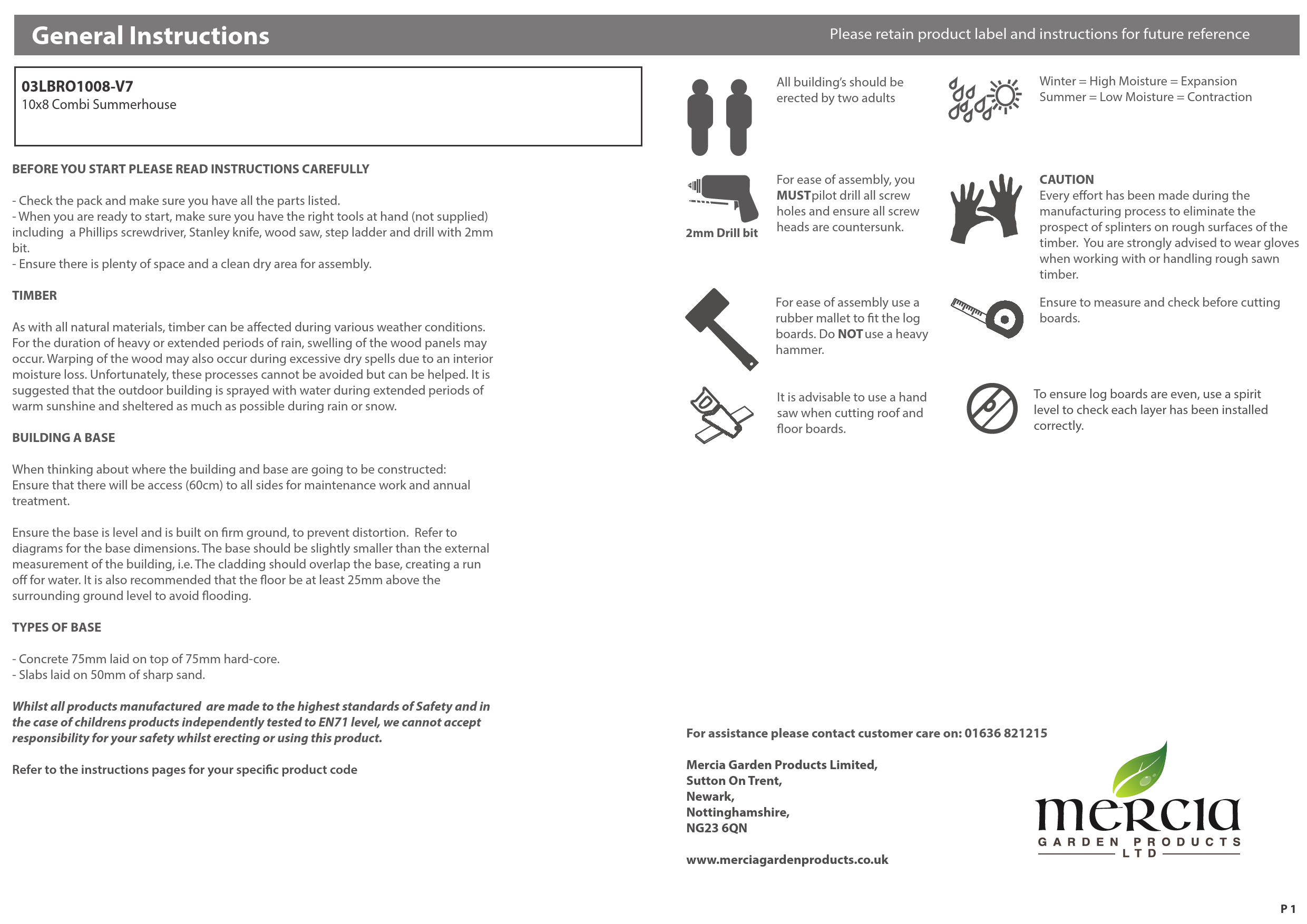
General Instructions
03LBRO1008-V7
10x8 Combi Summerhouse
BEFORE YOU START PLEASE READ INSTRUCTIONS CAREFULLY
- Check the pack and make sure you have all the parts listed. - When you are ready to start, make sure you have the right tools at hand (not supplied) including a Phillips screwdriver, Stanley knife, wood saw, step ladder and drill with 2mm bit. - Ensure there is plenty of space and a clean dry area for assembly.
TIMBER
As with all natural materials, timber can be affected during various weather conditions. For the duration of heavy or extended periods of rain, swelling of the wood panels may occur. Warping of the wood may also occur during excessive dry spells due to an interior moisture loss. Unfortunately, these processes cannot be avoided but can be helped. It is suggested that the outdoor building is sprayed with water during extended periods of warm sunshine and sheltered as much as possible during rain or snow.
BUILDING A BASE
When thinking about where the building and base are going to be constructed: Ensure that there will be access (60cm) to all sides for maintenance work and annual treatment.
Ensure the base is level and is built on firm ground, to prevent distortion. Refer to diagrams for the base dimensions. The base should be slightly smaller than the external measurement of the building, i.e. The cladding should overlap the base, creating a run off for water. It is also recommended that the floor be at least 25mm above the surrounding ground level to avoid flooding.
TYPES OF BASE
- Concrete 75mm laid on top of 75mm hard-core. - Slabs laid on 50mm of sharp sand.
Whilst all products manufactured are made to the highest standards of Safety and in the case of childrens products independently tested to EN71 level, we cannot accept responsibility for your safety whilst erecting or using this product.
Refer to the instructions pages for your specific product code

Please retain product label and instructions for future reference

All building's should be erected by two adults

Winter = High Moisture = Expansion Summer = Low Moisture = Contraction

2mm Drill bit

For ease of assembly, you MUSTpilot drill all screw holes and ensure all screw heads are countersunk.

For ease of assembly use a rubber mallet to fit the log boards. Do NOT use a heavy hammer.
It is advisable to use a hand saw when cutting roof and floor boards.

CAUTION Every effort has been made during the manufacturing process to eliminate the prospect of splinters on rough surfaces of the timber. You are strongly advised to wear gloves when working with or handling rough sawn timber.
Ensure to measure and check before cutting boards.
To ensure log boards are even, use a spirit level to check each layer has been installed correctly.

For assistance please contact customer care on: 01636 821215
Mercia Garden Products Limited, Sutton On Trent, Newark, Nottinghamshire, NG23 6QN
www.merciagardenproducts.co.uk
P 1

03LBRO1008-V7
Overall Dimensions: Width = 3114mm Depth = 2512mm Height = 2146mm
Base Dimensions: Width = 3016mm Depth = 2413mm
Before assembly please make sure you have a suitable base ready to erect your
building

MADE IN GREAT BRITAIN

1

2

3

4

5

Door Panel
AI-03LBRO1008-V7DP
6

Back Panel
AI-03LBRO1008-V7BP

Short Panel Short Window

AI-03LBRO1008-V7SPP

Panel

AI-03LBRO1008-V7SWP

Internal Panel
AI-03LBRO1008-V7INP

7

8

9

10

Floor
AI-03LBRO1008-V7F QTY x2

Roof
AI-03LBRO1008-V7R QTY x2

Storage Back Panel
AI-03LBRO1008-V7SBP

Storage Door Panel
AI-03LBRO1008-V7STD

Plain Panel
AI-03LBRO1008-V7PP

Please retain product label and instructions for future reference

11

12

13

14

15

Storage Gable Left Storage Gable Right

AI-03LBRO1008-V7SGL

AI-03LBRO1008-V7SGR

Under Roof
AI-03LBRO1008-V7UR

Veranda
AI-03LBRO1008-V7V

Small Floor
AI-03LBRO1008-V7SF

16

17

17b

18

19

Double Boarded Gable Top
AI-03LBRO1008-V7GTDB
20

Gable Top Right
AI-03LBRO1008-V7GTR

Master Door Slave Door Plain Door Storage Door
AI-03LBRO1008-V7MD AI-03LBRO1008-V7SD AI-03LBRO1008-V7SD AI-03LBRO1008-V7STD
Fixing Kit

21
Gable Top Left
AI-03LBRO1008-V7GTL

22
5xFloor Blocks - 28x28x400mm
F2828-400mm
23
Cover Trim A - 12x56x1980mm
S1256-1980mm
24
2x Cover Trim B - 12x56x2000mm
S1256-2000mm
25
Cover Trim C - 12x56x2011mm
S1256-2011mm
26
Cover Trim D - 12x56x2040mm
S1256-2040mm
27
Cover Trim E - 12x56x2070mm
S1256-2070mm
28
2x Cover Trim F - 12x56x2080mm
S1256-2080mm
29
4x Front Fascia - 12x134x1250mm
S12134-1250mm

30

31

2x Side Fascia - 12x134x1557mm
S12134-1557mm

32

Door Stop
PLY TRIANGLE

2x Door Trim - 16x60x1698mm

F1660-1698mm (rounded edge)

2x Press Lock Base-

33

28x28x95mm

F2828-95mm

34

35

Felt

36

37

Chrome Handle
PI-07-0159

Press Lock
PI-07-0162
4x Barrel Bolt
PI-07-0067

38

2x Door Handles

PI-07-0001

Fixing Kit continues on P3 P 2

Fixing kit cont..

39

Mortice Lock

PI-07-0017

Nail Bag PI-02-0352

40

12x Butt Hinge

PI-07-0066

41

Key Plate

PI-07-0017

42

4x Turn Button
PI-07-0034

Pre Assembly
Before assembling remove the transportation blocks from the bottom of each panel.

Please retain product label and instructions for future reference

*This building can be built with the shed on the LEFT hand side. Follow the same steps but be aware to position panels to the opposite side.*

70mm Screw x 10

Step 2

50mm Screw x 119

Place the 2 floor panels (No. 6) onto a firm

30mm Black Screw x 4

and level base, ensuring the base has suitable drainage & is free from

30mm Screw x 162

areas where standing water can collect.

6

10mm Screw x 8

Secure the floors together using 10x30mm screws per floor.

6

Felt Tacks x 165

10x30mm Screws

Pre drill hole

30mm screw

*This building can be built with the shed on the LEFT hand side. Follow the same steps but be aware to position panels to the opposite side.*

Step 3 Flip over the two floor boards (No. 6)

Step 1
Secure the floor (No. 6) to the Floor Blocks (No.22) and 10x30mm screws per floor.
10x30mm Screws

Place the small floor (No. 15) flush against

6

the assembled floor and fix to (No. 6)

15

Using 4x50mm screws fix the small floor in

6

place as shown in the diagram.

22

4x50mm Screws

Pre drill hole

30mm screw

Pre drill hole

50mm screw

P 3

Step 4

2 3

Fix the side of the short panel (No. 3) against the framing of the back panel (No. 2) with 3x50mm screws as shown in diagram.

Do not secure the building to the Floor until the roof is fitted.

3x50mm Screws

Pre drill hole

50mm screw

Step 5

Fix the side of the short panel (No. 3)

against the side of the short window panel

3

(No. 4) with 3x50mm screws as shown in

diagram.

Do not secure the building to the Floor until the roof is fitted.

3x50mm Screws
4

Pre drill hole

50mm screw

Please retain product label and instructions for future reference

Step 6
Fix the side of the Internal Panel (No. 5) against the framing of the Back Panel (No. 2) with 3x50mm screws as shown in diagram.
Do not secure the building to the Floor until the roof is fitted.
3x50mm Screws

Pre drill hole

50mm screw

2 5

Step 7

Place the door panel (No. 1) onto the

assembly between the Window Panel

(No. 4) and Internal Panel (No. 5). Fix with

6x70mm screws as shown in diagram

4

internally.

Do not secure the building to the Floor 1
until the roof is fitted.

6x70mm Screws

Pre drill hole

70mm screw

5
P 4

Step 8

21

Place the Gable Top Left/Right (No. 21/No. 20) upon the top of the side panel, slotting the groove of the boarding on the gable into the tongue of the side panel as shown and screw internally.

Fix with 4x50mm screws per gable top as shown in diagram.

8x50mm Screws

Pre drill hole

50mm screw

Step 9
Fix the side of the Storage Back Panel (No. 8) against the side of the Back Panel (No. 2) with 3x50mm screws as shown in diagram.
Fix with 3x50mm screws per gable top as shown in diagram.
**Be careful to ensure positions of screws do not interfere with previously placed screws**
3x50mm Screws

Pre drill hole

50mm screw

Please retain product label and instructions for future reference

Step 10
20
Fix the side of the Side Panel (No. 10) against the framing of the Storage Back Panel (No. 8) with 3x 50mm screws as shown in diagram.
Fix with 3x50mm screws per gable top as shown in diagram.
Do not secure the building to the Floor until the roof is fitted.
3x50mm Screws

Pre drill hole

50mm screw

8 10

Step 11

2

Place the Double Boarded Gable Top (No. 19) on top of the Side Panel (No. 10) slotting

8

the groove of the boarding on the gable

into the tongue of the side panel as shown.

Fix with 4x50mm screws per gable top as shown in diagram.

4x50mm Screws

Pre drill hole

50mm screw

19 10

P 5

Step 12
Place the Storage Gable Sides Left/Right (No. 11/12) against the sides of the Internal (No. 5)and Side Panel (No. 10)with the boarding facing outwards as shown.
Fix with 3x50mm screws per gable as shown in diagram.
Do not secure the building to the Floor until the roof is fitted.
6x50mm Screws

Pre drill hole

50mm screw

11

12

PPleleaasesereretataininpprorodduuccttlalabbeel laannddininstsrturucctitoionnssfoforrfufututurerererefefererenncece

Step 12b Fix the hinges (No. 40) to the Slave door & plain door (No. 17, 17b) and attach to the door frame.
36x30mm Screws

Slave Door Plain Door

17

17b

40

Frame Internal Aeriel view External

Pre drill hole

30mm screw

Step 12a
Fix the hinge (No. 40) to the frame and master door (No. 16)

Internal

18x30mm Screws

External
40

Master Door
16
Aeriel view

Pre drill hole

30mm screw

Step 12c

Fit the mortice lock (No. 39) into

the recess and fix in place with the screws

provided. Fit the key plate(No. 41) to the

opposite door using the 4X30mm screws

provided.

37

Fix door handles (No. 38) using 8x30mm screws.

Fix the Door Cover Strips (No. 31) in positionas shown then fit barrel bolts (No. 37) to top and bottom of the door strips as shown in diagram. Use 4x10mm screws per barrel bolt.

Ensure doors open and close freely.

10x30mm Screws
8x10mm Screws
Pre drill hole

The Mortice Lock is Reversible
41 39

30mm screw

10mm screw

31

31

38
P 6

Step 13
Place the Storage Door panel (No. 9) against the end of the Storage Gable Sides (No. 11/12) and fix into position internally.
Fix with 3x50mm screws per side internally as shown in diagram.
Do not secure the building to the Floor until the roof is fitted.
6x50mm Screws

Pre drill hole

50mm screw

11

9

12

Please retain product label and instructions for future reference

Step 14
Lay the Veranda (No. 14) face down, side by side and fix together with 3x70mm screws as shown in the diagram, to secure the two Verandas together.
3x70mm Screws

14

70mm screw

Pre drill hole

14

Step 13b - Fitting Door Secure the 3x hinge (No. 40) to the storage door (No. 18) and the storage door panel (No. 9). *You will need to open the door in order to fit the hinges
Do not secure the building to the Floor until the roof is fitted.
18x30mm Screws

9 18 40

Storage Door

Storage Door Panel

6

Internal

18

Aeriel view

External
40

Pre drill hole

50mm screw

Storage Door hinges fitted on the right hand side of the door which means that your door will open on the left side.

P 7

Step 15
Place the assembled Verandas (No. 14) flush to the building as shown to make sure the building is square.

Step 16a

Place the Roof Panels (No. 7) onto the top

of the building. Allign the 2 Roof Panels

7

so they sit square before fixing into postion.

Do not secure the building to the Floor until the roof is fitted.

Please retain product label and instructions for future reference

Step 16b
Fix the two Roof panels together using 50mm offset from each other as shown in the diagram.
Do not secure the building to the Floor until the roof is fitted.
8x50mm Screws

Pre drill hole

50mm screw

Step 16c

11

Screw internally with 8x50mm screws

11

securing the roof

7

panels (No. 11) x 2 to all of the panels on

the front of the building

Do not secure the building to the Floor until the roof is fitted.

*External panels not shown

7x50mm Screws

Pre drill hole

50mm screw

P 8

Step 17a
Once the Roof is aligned and secure the Floor can be fixed into postion.
Fix the building into place by screwing through the panel into the floor making sure to screw into the floor bearers.
*External panels not shown
15x50mm Screws

Pre drill hole

50mm screw

Step 17b
Continue to fix the building into place by screwing through the panel into the floor making sure to screw into the floor bearers.
*External panels not shown
11x50mm Screws

Pre drill hole

50mm screw

Please retain product label and instructions for future reference

Step 18

Place the Under Roof(No. 13) into position, making sure it is flush to the Door panel and Storage section.

Fix in place making sure to screw through

13

the Roof framing. Pre-drill holes first.

10x30mm Screws

Pre drill hole

30mm screw

P 9

Step 19 Cut the Felt (No. 34) into 3 sheets and lay onto the roof. *Ensure there is approximately 50mm of overhang around the building. Fix into place using 165x felt tacks at 100mm intervals. 165x Felt tacks Felt Length 3224mm
Felt tacks

1

2

3 4

HANDLE WITH CARE

34

3.

2.

1.

Step 20
Fix the Fascias (4x No. 29and 2x No. 30) into position as shown.
No. 30are for the front and No. 29are for the side.
Fix in place using 18x30mm screws.
18x30mm Screws

Pre drill hole

30mm screw

29 29
30

29
29 30

Please retain product label and instructions for future reference

Step 21
Fix the Cover Trims (No. 23,2x No. 24, No. 25, No.26, No.27and 2x No. 28) into position as shown.
Fix each strip into position using 3x30mm screws per trim.
24x30mm Screws

Pre drill hole

30mm screw

27 28

24 26

28

23 25
24
P 10

Step 22

To fix the lock to the Shed Door, first fix the Door Blocks (No. 33) either side of the centre framing of the Door with 4x40mm screws.

Once the Door Blocks are in place the Lock (No. 35)

can be fixed in place as shown with 4x30mm

33

screws, making sure to align the key hole of the

lock to the key hole of the door.

35

4x30mm Screws

4x40mm Screws

Pre drill hole

30mm screw

40mm screw

Step 23
Pre drill holes and then fix Chrome Handle (No. 36) using 45mm bolt as shown in diagram.
Fix Door Stop (No. 32) to bottom right of door panel at the back. Use 3x30mm screws.
2x45mm Bolt 3x30mm Screws

Pre drill hole

30mm screw

36

Please retain product label and instructions for future reference

Step 24
Attach two Turn Buttons (No. 42) to the Storage Door at the top and bottom of the door. Using black screws ensure the screws go through into the Storage Door Panel framing.
Attach two further Turn Buttons to the Slave Door at the top and bottom of the door using black screws.
These Turn Buttons help to keep your doors straight during high and low levels of moisture content in the air.
4x30mm Black Screws

Pre drill hole

30mm screw

42
Button

It is ESSENTIAL that you apply wood tre-at ment immediately after the building has
been assembled.

Please retain product label and instructions for future reference
Step 24 Enjoy your Combi-Summerhouse.

AFTER TREATMENT: score around protective
cover on glazing and carefuly peel covering back