Uni-Trend UT116A/C SMD Tester User Manual
Introduction
Thank you for purchasing our SMD tester. To use the device correctly and safely, please read this instruction manual carefully, especially the chapter on Safety Precautions. We recommend keeping the manual in an easily accessible place, preferably near the device.
Limited Warranty Conditions
Uni-Trend provides a warranty on the product's material quality and assembly for one year from the date of purchase. The warranty does not cover damage caused by accidents, negligence, misuse, modifications, contamination, or improper handling. The seller is not authorized to provide any other warranty on behalf of Uni-Trend. In case of necessary warranty repair within the warranty period, please contact your device seller.
General Information
This device is a miniature, integrated, and advanced instrument for measuring resistance, capacitance, and diode characteristics of SMD components. Additionally, it can be used for measuring LEDs, Zener diodes, and DC voltage up to 36V. This tester is an excellent device for electronics manufacturing plants. The tester complies with the 2nd category of environmental safety criteria and European Union standards. The tester's casing is made of plastic, and the working end is coated for corrosion protection. Before using the tester, please read the instructions carefully, especially the "Safety Precautions" section.
Safety Precautions
- Before using the device, check the tester's casing for damage. Do not use the device if it is damaged.
- Check the metal probes for damage.
- Do not apply more than 36V DC voltage to the measurement port.
- Do not use the tester in an atmosphere of explosive gas, vapor, or dust.
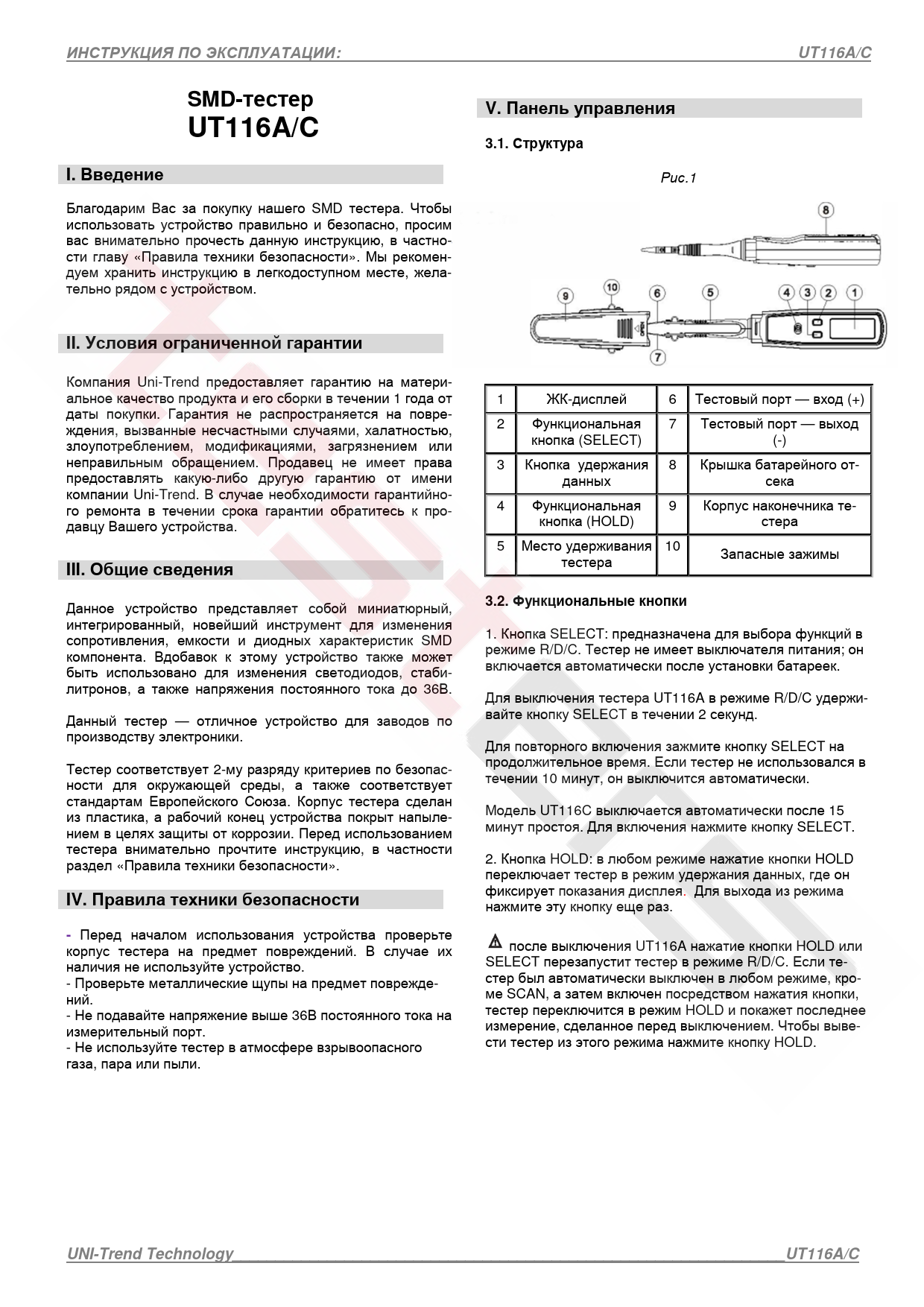
Control Panel Structure
Figure 1 shows the structure of the SMD Tester:
- 1. LCD Display
- 2. SELECT Function Button
- 3. Data Hold Button
- 4. HOLD Function Button
- 5. Tester Holding Slot
- 6. Test Port (+)
- 7. Test Port (-)
- 8. Battery Compartment Cover
- 9. Tester Tip Housing
- 10. Spare Clips
Functional Buttons
- SELECT Button: Used to select functions in R/D/C mode. The tester does not have a power switch; it turns on automatically after battery installation. To turn off the UT116A in R/D/C mode, press and hold the SELECT button for 2 seconds. To turn it back on, press and hold the SELECT button. If the tester is not used for 10 minutes, it will turn off automatically. The UT116C model turns off automatically after 15 minutes of inactivity. Press the SELECT button to turn it on.
- HOLD Button: In any mode, pressing the HOLD button switches the tester to data hold mode, where it freezes the display readings. Press the button again to exit hold mode. After the UT116A is turned off, pressing the HOLD or SELECT button will restart the tester in R/D/C mode. If the tester was automatically turned off in any mode other than SCAN, and then turned on by pressing a button, the tester will switch to HOLD mode and display the last measurement taken before shutdown. Press the HOLD button to exit this mode.
LCD Display
Figure 2 illustrates the LCD display symbols:
- 1. SCAN: Auto-detection
- 2. AUTO: Auto-range
- 3. H: Data Hold
- 4. Diode Symbol
- 5. On/Off Test Symbol
- 6. Capacitance Unit (nF, µF, mF)
- 7. Resistance Unit (Ω, kΩ, MΩ)
- 8. Voltage Unit (mV)
- 9. Low Battery Indicator
Functions
4.1. Main Functions
- Display resolution: UT116A 3000 (UT116C 6000) LCD screen.
- Automatic measurement range detection.
- Automatic component type detection (resistor, capacitor, or diode, UT116A only).
- Function selection via the SELECT button.
- Data hold.
- Power status test.
- Semiconductor test.
- LED test.
- UT116A: DC voltage measurement up to 36V.
- UT116C: Battery charge measurement.
- Overload protection.
- Overload indication - OL.
- Low battery indicator.
- Power source: 2 x 1.5V (AAA) batteries.
- Automatic power-off: The tester automatically turns off if no operations are performed for the last 10 minutes (UT116A) or 15 minutes (UT116C).
- Operating temperature and humidity: 0-40°C (32-104°F) and <80% humidity.
- Storage temperature and humidity: -10-50°C (14-122°F) and <70% humidity.
- EC: MAXDC36V, EN61326-1:2013, EN61326-2-2:2013.
- Dimensions (Length, Width, Height) and Weight: 204x33x25mm, approximately 80g.
- Use only indoors and at altitudes not exceeding 2000m above sea level.
4.2. Electrical Specifications
Operating conditions: Air temperature 18°C-28°C (64°F-82°F), relative humidity less than 75%. If the air temperature is less than 18°C or greater than 28°C, the measurement error is calculated by the formula: 0.1 x (measurement accuracy)/°C.
UT116A Specifications
| Function | Range | Resolution | Accuracy |
|---|---|---|---|
| Resistance | 300Ω | 0.1Ω | ± 1.5% + ± 5 digits |
| 3kΩ | 1Ω | ||
| 30kΩ | 10Ω | ||
| 300kΩ | 100Ω | ||
| 3MΩ | 1kΩ | ± 2.5% + ±5 digits | |
| 30MΩ | 10kΩ | ||
| Capacitance | 3nF | 1pF | ± 3% + ± 50 digits |
| 30nF | 10pF | ||
| 300nF | 100pF | ||
| 3µF | 1nF | ± 2.5% + ±5 digits | |
| 30µF | 10nF | ||
| 300µF | 100nF | ± 5% + ± 5 digits | |
| 3mF | 1µF | ||
| 30mF | 10µF | For reference only |
Semiconductor/LED
Open circuit voltage: 3.0V, current: 1mA. If the resistance of the measured components or circuit is lower than approximately 30Ω, a beep will sound (no beep if resistance is above 1000Ω, behavior is undefined between 300Ω and 100Ω).
Voltage
| Function | Range | Resolution | Accuracy |
|---|---|---|---|
| 36V DC | 0.1V | ± 1.5% + ± 5 digits |
UT116C Specifications
| Function | Range | Resolution | Accuracy |
|---|---|---|---|
| Resistance | 300Ω | 0.1Ω | ± 1.5% + ± 5 digits |
| 3kΩ | 1Ω | ||
| 30kΩ | 10Ω | ||
| 300kΩ | 100Ω | ||
| 3MΩ | 1kΩ | ± 2.5% + ±5 digits | |
| 30MΩ | 10kΩ | ||
| Capacitance | 3nF | 1pF | ± 3% + ± 50 digits |
| 30nF | 10pF | ||
| 300nF | 100pF | ||
| 3µF | 1nF | ± 2.5% + ±5 digits | |
| 30µF | 10nF | ||
| 300µF | 100nF | ± 5% + ± 5 digits | |
| 3mF | 1µF | ||
| 30mF | 10µF | For reference only |
Semiconductor/LED
Open circuit voltage: 3.0V, current: 2mA. If the resistance of the measured components or circuit is lower than approximately 30Ω, a beep will sound (no beep if resistance is above 1000Ω, behavior is undefined between 300Ω and 100Ω).
Open circuit voltage: approximately 21V. If the displayed voltage exceeds 21V, the measured semiconductor or LED will not be damaged.
Voltage
| Function | Range | Resolution | Accuracy |
|---|---|---|---|
| 36V DC | 0.1V | ± 1.5% + ± 5 digits |
Instructions for Use
5.1. Automatic Component Identification (UT116A only)
The tester turns on automatically after battery installation. Under the scale on the LCD screen, the symbols SCAN and --- will be displayed, indicating that the tester is in automatic identification mode. In this mode, the instrument will automatically determine what needs to be measured (resistance, capacitance, diode, or power status) and perform the corresponding measurement. In automatic identification mode, results will be displayed on the LCD screen when both test probes are in contact with the object being measured.
Caution: Before measuring components on a printed circuit board, ensure the board is de-energized and capacitors are discharged.
5.2. Resistance Measurement
- Use the function button to select the resistance measurement mode.
- Measurement range in automatic mode: 300.0-30-3.000MΩ (UT116A only).
- Use the SELECT button to select the automatic resistance measurement mode.
- If the range is exceeded, OL will be displayed on the LCD screen.
5.3. Capacitance Measurement
- Measurement range in automatic mode: 3.000nF-300.0uF (UT116A only).
- Use the SELECT button to select the automatic capacitance measurement mode.
5.4. Diode Measurement
To prevent damage to the tester or measured objects, the power to the object must be turned off, and capacitors discharged.
- Use the function button to select the diode measurement mode.
- Use the SELECT button to select either automatic mode or diode mode.
- Connect the tester probes to the corresponding ends of the diode.
- The silicon diode forward voltage will be displayed on the LCD screen, typically between 0.5V-0.8V.
5.5. Power Status Test
- Use the function button to select the power status test mode.
- Use the SELECT button to select either automatic mode or power status test mode. If the resistance is below 300Ω (UT116A) or 500Ω (UT116C), a beep will sound.
5.6. Semiconductor or LED Test
- Use the function button to select the semiconductor or LED test mode.
- Connect the input port and the open test post to the corresponding anode and cathode of the Zener diode or LED being measured. The direction of the anode and cathode can be controlled by rotating the probes.
- The Zener diode or LED voltage will be displayed on the LCD screen.
5.7. DC Voltage Measurement (UT116A) or Battery Voltage (UT116C)
- Use the function button to select the DCV mode.
- Connect the probes correctly.
- The measured voltage will be displayed on the LCD screen (UT116C: battery voltage under a 10mA load).
Caution: When using the battery voltage measurement mode on the UT116C, do not measure other active electrical devices besides the battery.
Maintenance and Cleaning
6.1. Low Battery
The batteries in the tester need to be replaced in the following situations:
- The battery symbol is displayed on the screen during tester operation.
- Upon turning on the tester, a beep sounds, and then the device shuts down.
- The tester continuously restarts in LED measurement mode.
Replace the batteries as follows:
- Turn off the device.
- Open the battery compartment at the bottom of the device and remove the batteries.
- Insert new 1.5V (AAA) batteries and secure the battery compartment cover.
6.2. Cleaning
- It is recommended to clean the tester using damp wipes or a mild cleaning agent.
- Do not use solvents or abrasives!
Included Accessories
- Two spare clips
- Two 1.5V (AAA) batteries
- Instruction manual
- A pair of probes.
Product images are for reference purposes only. Uni-Trend reserves the right to change product specifications without prior notice.
Uni-Trend Technology (China) Co., Ltd.
No. 6, Gong Ye Bei 1st Road, Songshan Lake National High-Tech Industrial Development Zone, Dongguan City, Guangdong Province, China
Tel: (86-769) 8572 3888
Website: www.un-trend.com
