

Specifications
- Product: MD06/MD12
- Power Supply: 12-24VDC 0.1A
- Wire AWG: 26
- Resistance: 128 ohm/km
Product Usage Instructions
Tools Needed for Installation
- Cat Ethernet Cable
- Crosshead Screwdriver
- Electric Drill
Powering On the Device
Use a 12-24VDC 0.1A power adapter to power on the device.
Installation Requirements
Ensure the device is installed near a window or door, avoiding direct sunlight, indirect sunlight through windows, or being close to light sources.
Warnings and Cautions
- Avoid touching power core, power adapter, or device with wet hands.
- Avoid damaging components and use only qualified power adapter and cord.
- Avoid hitting the device to prevent personal injuries.
- Avoid pressing down hard on the device screen.
- Do not expose the device to chemical products.
- Clean the device surface gently with a wet cloth and then dry cloth.
- If any abnormal situation occurs, power off the device and contact technical support immediately.
Installation Steps
- Main Unit Installation:
- Combine R20K/B, MD06, and MD12 with the flush-mounting bracket following the provided directions.
- Fasten devices using twelve M3x6.8 wall-mounting screws.
- Insert cables into the terminals of MD06 and MD12, connect them to the corresponding interfaces, secure the cables with rubber plugs, and fasten the pressing plate with screws.
- Flush-mounting Box Installation:
- Remove the box and make holes on marked positions using a 6mm electric drill.
- Insert plastic wall anchors into holes and lead wires through cable holes.
- Press the flush-mounting box into the square hole against thewall edges and fix it with screws.
- Simple Installation:
- Cut out a square hole on the wall with the specified dimensions.
- Fill gaps with cement or non-corrosive adhesive.
FAQ
- Q: What should I do if I encounter an uncommon sound or smell from the device?
A: Power off the device immediately and contact Akuvox Technical Team for assistance. - Q: Can I use any power adapter to power on the device?
A: It is recommended to use a 12–24VDC 0.1A power adapter to ensure proper functioning of the device.
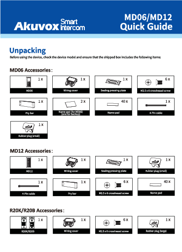
Unpacking
Before using the device, check the device model and ensure that the shipped box includes the following items:
MD06 Accessories:
MD12 Accessories: 
R20K/R20B Accessories : 

Dual-unit Device Accessories:
Triple-unit device accessories:
PRODUCT OVERVIEW
Before You Start
Tools needed (not included in shipped box)
- Cat Ethernet Cable
- Crosshead Screwdriver
- Electric Drill
Voltage and Current Specifications
It is suggested that use 12-24VDC 0.1A power adapter to power on device.
AWG Sizes and Properties Table
Please follow the properly wire data to install device:
Requirements
- Place the device away from sunlight and light sources to prevent potential damage.
- Do not place the device in the high-temperature, and humid environments or in surroundings impacted by magnetic field.
- Install the device on the flat surface securely to avoid personal injuries and property loss caused by device’s falling.
- Do not use or place the device near heating objects.
- If installing the device indoors, please keep device at least 2 meters away from light, and at least 3 meters away from window and door.

Warning!
- To ensure safety, avoid touching power core, power adapter, and device with wet hands, bending or pulling the power core, damaging any components, and use only qualified power adapter and power cord.
- Be careful that standing up on the area under the device in case of personal injuries cause by hitting the device.
Cautious
- Do not knock device with hard objects.
- Do not press down hard on the device screen.
- Do not expose device to chemical products, such as alcohol, acid liquid, disinfectants, and so on.
- To prevent the device installation from becoming loose, ensure accurate diameters and depths of screw holes. If the screw holes are too large, use glue to secure the screws.
- Use wet cloth clean device surface softly, and then wipe the surface with dry cloth for cleaning the device.
- If there is abnormal situation of the device, including uncommon sound and smell, please power off the device and contact Akuvox Technical Team immediately.
Wiring Interface
Installation
For Triple-unit Device
- Step 1: Flush-mounting Box Installation
Normal Installation

- Cut out a square hole on the wall with the dimension 212•2s5•42mm (height’width•depth).
Note: Make sure that the cables within the hole or reserve a cable tube.- Break out the round wiring holes of box.
- Insert flush-mounting box into the square hole and mark eight screw holes positions.
- Remove the box and use a 6mm electric drill to make holes on the marked position.
- Insert eight plastic wall anchors into holes.
- Lead wires go through the cable holes.
- Press the flush-mounting box into the square hole, ensuring that the edges closely against the wall.
- Use eight ST4x20 crosshead screws to fix flush-mounting box.
Note:- The flush-mounting box is not positioned higher than wall, which can be lower 0-3mm.
- The box tilt angle does exceed than 2°.

- Remove the box and use a 6mm electric drill to make holes on the marked position.
Simple Installation (with lower resistance of vandalism)
- Cut out a square hole on the wall with the dimension 212’286’42mm (height’width’depth).
Note: Make sure that the cables within the hole or reserve a cable tube.- Fill the gap between the wall and the flush-mounting box with cement or non-corrosive adhesive.
- Brush the outer surface of the gap with the same decorative materials as the surrounding walls.
- Wait for the cement to dry before proceeding to the next step.
Note: To prevent water from entering the back cover of the door phone, it is recommended to fill the gaps around with waterproof material.
- The flush-mounting box installation is done.

Main Unit Installation
- Combine R20K/B, MD06, and MD12 with the flush-mounting bracket according to the direction indicated in the drawing.
- Use twelve M3x6.8 wall-mounting screws to fasten devices.
- For easier installation, hang the device on the box/bracket using the rope.
- Press sealing ring into the corresponding groove

- Insert 4-Pin cable to terminal of MD06 and MD12.
- Make cables go through the wiring cover, connecting to the corresponding interfaces as needed (for details, refer to “Wiring Interface”).
- Fasten rubber plug (M) to R20K/B device and rubber plug (S) to MD06 andMD12 device for securing cables.
- Fasten sealing pressing plate with two M2.5×6 crosshead screws.
Fasten wiring cover with M2.Sx6 crosshead screws.
Device Mounting
Use the M4 Torx wrench to tighten the device with four M4x15 Torx head screws. Installation is completed.
For Dual-unit Device
Step 1: Flush-mounting Box Installation
Normal Installation
- Cut out a square hole on the wall with the dimension 209•1ss•4omm (height’width*depth).
Note: Make sure that the cables within the hole or reserve a cable tube.- Break out the round wiring holes of box.
- Insert flush-mounting box into the square hole and mark four screw holes positions.

- Remove the box and use a 6mm electric drill to make holes on the marked position.
- Insert four plastic wall anchors into holes.
- Lead wires go through the cable holes.
- Press the flush-mounting box into the square hole, ensuring that the edges closely against the wall.
- Use four ST4x20 crosshead screws to fix flush-mounting box.
Note:
- The flush-mounting box is not positioned higher than wall, which can be lower 0-3mm.
- The box tilt angle does exceed than 2°.
- The flush-mounting box installation is done.
Simple Installation (with lower resistance of vandalism)
- Cut out a square hole on the wall with the dimension 209*188*40mm (height*width*depth).
Note: Make sure that the cables within the hole or reserve a cable tube.- Fill the gap between the wall and the flush-mounting box with cement or non-corrosive adhesive.
- Brush the outer surface of the gap with the same decorative materials as the surrounding walls.
- Wait for the cement to dry before proceeding to the next step.
Note:
To prevent water from entering the back cover of the door phone, it is recommended to fill the gaps around with waterproof material.
The flush-mounting box installation is done.
Main Unit Installation
- Combine R20K/R20B and MD06/MD12 with the flush-mounting bracket according to the direction indicated in the drawing.
- Use eight M3x6.8 wall-mounting screws to fasten devices
- For easier installation, hang the device on the box/bracket using the rope.
- Press sealing ring into the corresponding groove.

- Insert 4-Pin cable to terminal of MD06/12.
- Make cables go through the wiring cover, connecting to the corresponding interfaces as needed (for details, refer to “Wiring Interface”).
- Fasten the rubber plug (M) to R20K/B device and rubber plug (S} to MD06/12 device for securing cables.
- Fasten sealing pressing plate and wiring cover with M2.5×6 crosshead screws.
Device Mounting
Use the Torx wrench to tighten the device with four M4x15 Torx head screws. Installation is completed.
Application Network Topology
Device Test
- Please verify the device status after installation:
Network: Check the device’s IP address and network status. Network is working properly if the IP address is obtained. If no IP address is obtained, R20X will announce “IP 0.0.0.0”.
For R20K: Press *3258* to obtain IP address.- For R20B: Long press the first Call Button for 5 seconds.
- lntercom: Press Call Button to make a call. The call configuration is correct if the call is successful.
- Access Control: Use pre-configured RF card to unlock door.
Warranty
- Akuvox warranty does not cover intentional mechanical damage or destruction caused by improper installation.
- Do not attempt to modify, alternate, maintain, or repair device by yourself. Akuvox warranty does not apply to damages caused by anyone who is not representative of Akuvox or an Akuvox authorized service provider. Please contact Akuvox Technical Team if the device need to be repaired.
Get Help
For help or more assistance, contact us at:
https://ticket.akuvox.com/
support@akuvox.com
Scan the QR code to get more videos, guides, and additional product information.
Notice Information
Information contained in this document is believed to be accurate and reliable at the time of printing. This document is subject to change without notice, any update to this document can be viewed on Akuvox’ s website: http://www.akuvox.com © Copyright 2023 Akuvox Ltd. All rights reserved.
Documents / Resources
 |
Akuvox MD06 6 Call Buttons with Name Tags [pdf] User Guide MD06 6 Call Buttons with Name Tags, MD06 6, Call Buttons with Name Tags, Buttons with Name Tags, Name Tags |
