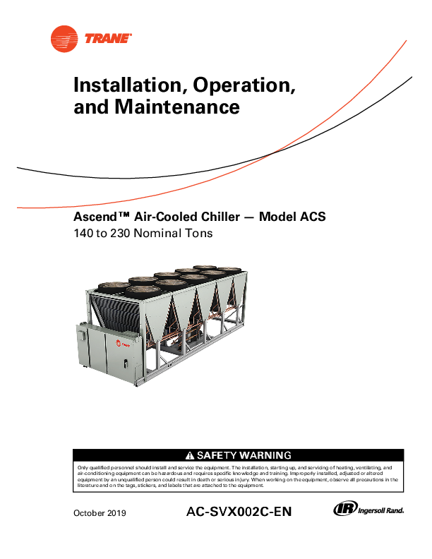
Ascend™ Air-Cooled Chiller — Model ACS

Installation, Operation, and Maintenance

The units described in this manual use R-410A refrigerant which operates at higher pressures than R-22. Use ONLY R-410A rated service equipment or components with these units. For specific handling concerns with R-410A, please contact your local Trane representative. Factory Warranty Information Compliance with the following is required to preserve

Ascend Chiller Model ACS

Ascend™ Air-cooled chillers Model ACS

AC-SVX002C-EN 10102019
Installation, Operation, and Maintenance
AscendTM Air-Cooled Chiller -- Model ACS 140 to 230 Nominal Tons

SAFETY WARNING
Only qualified personnel should install and service the equipment. The installation, starting up, and servicing of heating, ventilating, and air-conditioning equipment can be hazardous and requires specific knowledge and training. Improperly installed, adjusted or altered equipment by an unqualified person could result in death or serious injury. When working on the equipment, observe all precautions in the literature and on the tags, stickers, and labels that are attached to the equipment.

October 2019

AC-SVX002C-EN

Introduction

Read this manual thoroughly before operating or servicing this unit.

Warnings, Cautions, and Notices
Safety advisories appear throughout this manual as required. Your personal safety and the proper operation of this machine depend upon the strict observance of these precautions.

The three types of advisories are defined as follows:

WARNING

Indicates a potentially hazardous situation which, if not avoided, could result in death or serious injury.

CAUTION

Indicates a potentially hazardous situation which, if not avoided, could result in minor or moderate injury. It could also be used to alert against unsafe practices.

NOTICE

Indicates a situation that could result in equipment or property-damage only accidents.

Important Environmental Concerns
Scientific research has shown that certain man-made chemicals can affect the earth's naturally occurring stratospheric ozone layer when released to the atmosphere. In particular, several of the identified chemicals that may affect the ozone layer are refrigerants that contain Chlorine, Fluorine and Carbon (CFCs) and those containing Hydrogen, Chlorine, Fluorine and Carbon (HCFCs). Not all refrigerants containing these compounds have the same potential impact to the environment. Trane advocates the responsible handling of all refrigerants-including industry replacements for CFCs and HCFCs such as saturated or unsaturated HFCs and HCFCs.
Important Responsible Refrigerant Practices
Trane believes that responsible refrigerant practices are important to the environment, our customers, and the air conditioning industry. All technicians who handle refrigerants must be certified according to local rules. For the USA, the Federal Clean Air Act (Section 608) sets forth the requirements for handling, reclaiming, recovering and recycling of certain refrigerants and the equipment that is used in these service procedures. In addition, some states or municipalities may have additional requirements that must also be adhered to for responsible management of refrigerants. Know the applicable laws and follow them.

WARNING
Proper Field Wiring and Grounding Required!
Failure to follow code could result in death or serious injury. All field wiring MUST be performed by qualified personnel. Improperly installed and grounded field wiring poses FIRE and ELECTROCUTION hazards. To avoid these hazards, you MUST follow requirements for field wiring installation and grounding as described in NEC and your local/ state/national electrical codes.
WARNING
Personal Protective Equipment (PPE) Required!
Failure to wear proper PPE for the job being undertaken could result in death or serious injury. Technicians, in order to protect themselves from potential electrical, mechanical, and chemical hazards, MUST follow precautions in this manual and on the tags, stickers, and labels, as well as the instructions below:
· Before installing/servicing this unit, technicians MUST put on all PPE required for the work being undertaken (Examples; cut resistant gloves/sleeves, butyl gloves, safety glasses, hard hat/bump cap, fall protection, electrical PPE and arc flash clothing). ALWAYS refer to appropriate Material Safety Data Sheets (MSDS)/Safety Data Sheets (SDS) and OSHA guidelines for proper PPE.
· When working with or around hazardous chemicals, ALWAYS refer to the appropriate MSDS/SDS and OSHA/GHS (Global Harmonized System of Classification and Labelling of Chemicals) guidelines for information on allowable personal exposure levels, proper respiratory protection and handling instructions.
· If there is a risk of energized electrical contact, arc, or flash, technicians MUST put on all PPE in accordance with OSHA, NFPA 70E, or other country-specific requirements for arc flash protection, PRIOR to servicing the unit. NEVER PERFORM ANY SWITCHING, DISCONNECTING, OR VOLTAGE TESTING WITHOUT PROPER ELECTRICAL PPE AND ARC FLASH CLOTHING. ENSURE ELECTRICAL METERS AND EQUIPMENT ARE PROPERLY RATED FOR INTENDED VOLTAGE.

©2019 Ingersoll Rand

AC-SVX002C-EN

WARNING
Follow EHS Policies!
Failure to follow instructions below could result in death or serious injury.
· All Ingersoll Rand personnel must follow Ingersoll Rand Environmental, Health and Safety (EHS) policies when performing work such as hot work, electrical, fall protection, lockout/tagout, refrigerant handling, etc. All policies can be found on the BOS site. Where local regulations are more stringent than these policies, those regulations supersede these policies.
· Non-Ingersoll Rand personnel should always follow local regulations.
WARNING
R-410A Refrigerant under Higher Pressure than R-22!
Failure to use proper equipment or components as described below, could result in equipment failing and possibly exploding, which could result in death, serious injury, or equipment damage. The units described in this manual use R-410A refrigerant which operates at higher pressures than R-22. Use ONLY R-410A rated service equipment or components with these units. For specific handling concerns with R-410A, please contact your local Trane representative.
Factory Warranty Information
Compliance with the following is required to preserve the factory warranty:

Introduction
All Unit Installations Startup MUST be performed by Trane, or an authorized agent of Trane, to VALIDATE this WARRANTY. Contractor must provide a two-week startup notification to Trane (or an agent
Copyright
This document and the information in it are the property of Trane, and may not be used or reproduced in whole or in part without written permission. Trane reserves the right to revise this publication at any time, and to make changes to its content without obligation to notify any person of such revision or change.
Trademarks
All trademarks referenced in this document are the trademarks of their respective owners.
Factory Training
Factory training is available through Trane UniversityTM to help you learn more about the operation and maintenance of your equipment. To learn about available training opportunities contact Trane UniversityTM. Online: www.trane.com/traneuniversity Phone: 855-803-3563 Email: traneuniversity@trane.com
Revision History
Added model number description information that had been inadvertently deleted in previous revision.

AC-SVX002C-EN

3

Table of Contents
Model Number Information . . . . . . . . . . . . . . . . 6 Nameplates . . . . . . . . . . . . . . . . . . . . . . . . . . . . . . 6 Unit Nameplate . . . . . . . . . . . . . . . . . . . . . . . . . . 6 Model Number Coding System. . . . . . . . . 6 Compressor Nameplate . . . . . . . . . . . . . . . . . . . 6
Model Number Descriptions. . . . . . . . . . . . . . . . 7 Unit Model Number. . . . . . . . . . . . . . . . . . . . . . . 7 Compressor Information . . . . . . . . . . . . . . . . . . 8 Model Number . . . . . . . . . . . . . . . . . . . . . . . 8
General Information . . . . . . . . . . . . . . . . . . . . . . . . 9 Unit Description . . . . . . . . . . . . . . . . . . . . . . . . . . 9 General Data . . . . . . . . . . . . . . . . . . . . . . . . . . . . . 9
Pre-Installation . . . . . . . . . . . . . . . . . . . . . . . . . . . . 12 Unit Inspection . . . . . . . . . . . . . . . . . . . . . . . . . . 12 Exterior Inspection . . . . . . . . . . . . . . . . . . . 12 Inspection for Concealed Damage . . . . . . . . . . . . . . . . . . . . . . . . . . . . . 12 Repair. . . . . . . . . . . . . . . . . . . . . . . . . . . . . . . 12 Unit Storage . . . . . . . . . . . . . . . . . . . . . . . . . . . . 12 Installation Requirements . . . . . . . . . . . . . . . . 13
Dimensions and Weights . . . . . . . . . . . . . . . . . . 14 Unit Dimensions. . . . . . . . . . . . . . . . . . . . . . . . . 14 Standard Unit. . . . . . . . . . . . . . . . . . . . . . . . 14 Units with Pump Package Option . . . . . . . . . . . . . . . . . . . . . . . . . . . . . . 15 Service Clearance . . . . . . . . . . . . . . . . . . . . . . . 16 Weights. . . . . . . . . . . . . . . . . . . . . . . . . . . . . . . . . 16
Installation - Mechanical. . . . . . . . . . . . . . . . . . . 17 Location Requirements . . . . . . . . . . . . . . . . . . 17 Sound Considerations . . . . . . . . . . . . . . . . 17 Foundation . . . . . . . . . . . . . . . . . . . . . . . . . . 17 Clearances . . . . . . . . . . . . . . . . . . . . . . . . . . 17 Lifting and Moving Instructions . . . . . . . . . . . 17 Center of Gravity . . . . . . . . . . . . . . . . . . . . . . . . 19 Isolation and Sound Emission . . . . . . . . . . . . 19 Unit Isolation and Leveling. . . . . . . . . . . . 19 Elastomeric Isolators . . . . . . . . . . . . . . . . . 20 Mounting Locations, Weights, Isolators. . . . . . . . . . . . . . . . . . . . . . . . . . . . . 20

Evaporator Piping . . . . . . . . . . . . . . . . . . . . . . . 22 Evaporator Piping Components . . . . . . . 22 Evaporator Label. . . . . . . . . . . . . . . . . . . . . 24
Pressure Drop Curves . . . . . . . . . . . . . . . . . . . . 25
Pump Curves . . . . . . . . . . . . . . . . . . . . . . . . . . . . 27
Freeze Avoidance. . . . . . . . . . . . . . . . . . . . . . . . 29
Low Evaporator Refrigerant Cutout, Glycol Requirements . . . . . . . . . . . . . . . . . . . . 30
High Head Pump Package . . . . . . . . . . . . . . . . 33 Expansion Tank . . . . . . . . . . . . . . . . . . . . . . 35
Installation Electrical . . . . . . . . . . . . . . . . . . . . . . 36
General Recommendations. . . . . . . . . . . . . . . 36
Installer-Supplied Components . . . . . . . . . . . 36 Power Supply Wiring. . . . . . . . . . . . . . . . . 37 Control Power Supply . . . . . . . . . . . . . . . . 37 Heater Power Supply . . . . . . . . . . . . . . . . . 37 Water Pump Power Supply . . . . . . . . . . . 38
Interconnecting Wiring. . . . . . . . . . . . . . . . . . . 38 Chilled Water Flow (Pump) Interlock. . . . . . . . . . . . . . . . . . . . . . . . . . . . . 38 Chilled Water Pump Control . . . . . . . . . . 38 Lead/Lag Dual Pump . . . . . . . . . . . . . . . . . 38
Programmable Relays . . . . . . . . . . . . . . . . . . . 38
Relay Assignments Using Tracer TU . . . . . . 39
Low Voltage Wiring . . . . . . . . . . . . . . . . . . . . . . 40 Emergency Stop . . . . . . . . . . . . . . . . . . . . . 40 External Auto/Stop . . . . . . . . . . . . . . . . . . . 40 Ice Building Option . . . . . . . . . . . . . . . . . . 40 External Chilled/Hot Water Setpoint (ECHWS) Option . . . . . . . . . . . . . . . . . . . . . 41 External Demand Limit Setpoint (EDLS) Option . . . . . . . . . . . . . . . . . . . . . . . 41 EDLS and ECHWS Analog Input Signal Wiring . . . . . . . . . . . . . . . . . . . . . . . 42 Chilled Water Reset (CWR) . . . . . . . . . . . 42
Communications Interface . . . . . . . . . . . . . . . 43 LonTalk Interface (LCI-C) . . . . . . . . . . . . . 43 BACnet Interface (BCI-C) . . . . . . . . . . . . . . 43 Modbus Remote Terminal Unit Interface . . . . . . . . . . . . . . . . . . . . . . . . . . . . 43
Operating Principles . . . . . . . . . . . . . . . . . . . . . . . 44
General . . . . . . . . . . . . . . . . . . . . . . . . . . . . . . . . . 44

4

AC-SVX002C-EN

Table of Contents

Refrigerant Cycle . . . . . . . . . . . . . . . . . . . . . . . . 44
Oil System . . . . . . . . . . . . . . . . . . . . . . . . . . . . . . 44
Condenser and Fans . . . . . . . . . . . . . . . . . . . . . 44
Controls . . . . . . . . . . . . . . . . . . . . . . . . . . . . . . . . . . . 45
Overview . . . . . . . . . . . . . . . . . . . . . . . . . . . . . . . 45
UC800 Specifications . . . . . . . . . . . . . . . . . . . . 45 Wiring and Port Descriptions. . . . . . . . . . 45 Communication Interfaces . . . . . . . . . . . . 46 Rotary Switches . . . . . . . . . . . . . . . . . . . . . 46 LED Description and Operation. . . . . . . . 46
Tracer AdaptiView TD7 Display . . . . . . . . . . . 48 Operator Interface. . . . . . . . . . . . . . . . . . . . 48 Home Screen . . . . . . . . . . . . . . . . . . . . . . . 48 Viewing Chiller Operating Modes . . . . . . . . . . . . . . . . . . . . . . . . . . . . . . 48 Alarms . . . . . . . . . . . . . . . . . . . . . . . . . . . . . . 52 Reports . . . . . . . . . . . . . . . . . . . . . . . . . . . . . 52 Equipment Settings . . . . . . . . . . . . . . . . . . 54 Display Settings . . . . . . . . . . . . . . . . . . . . . 55 Security Settings. . . . . . . . . . . . . . . . . . . . . 57 InvisiSound Ultimate -- Noise Reduction Mode . . . . . . . . . . . . . . . . . . . . . 58
Tracer TU . . . . . . . . . . . . . . . . . . . . . . . . . . . . . . . 58
Integrated Rapid Restart. . . . . . . . . . . . . . . . . . 59
Pre-Start. . . . . . . . . . . . . . . . . . . . . . . . . . . . . . . . . . . 60
Start-up and Shutdown. . . . . . . . . . . . . . . . . . . . 61
Unit Start-up . . . . . . . . . . . . . . . . . . . . . . . . . . . . 61
Temporary Shutdown And Restart . . . . . . . . 61
Extended Shutdown Procedure . . . . . . . . . . . 61
Seasonal Unit Start-up Procedure . . . . . . . . 62
System Restart After Extended Shutdown . . . . . . . . . . . . . . . . . . . . . . . . . . . . . . 62
Sequence of Operation. . . . . . . . . . . . . . . . . . . 64 Software Operation Overview. . . . . . . . . 64 Power Up Diagram . . . . . . . . . . . . . . . . . . 64 Power Up to Starting . . . . . . . . . . . . . . . . . 65

Stopped to Starting . . . . . . . . . . . . . . . . . . 66 Normal Shutdown to Stopped or Run Inhibit . . . . . . . . . . . . . . . . . . . . . . . . . . 67
Maintenance . . . . . . . . . . . . . . . . . . . . . . . . . . . . . . 68
Recommended Maintenance . . . . . . . . . . . . . 68 Weekly . . . . . . . . . . . . . . . . . . . . . . . . . . . . . . 68 Monthly . . . . . . . . . . . . . . . . . . . . . . . . . . . . . 68 Annual . . . . . . . . . . . . . . . . . . . . . . . . . . . . . . 68
Refrigerant and Oil Charge Management . . . . . . . . . . . . . . . . . . . . . . . . . . . 69
Lubrication System . . . . . . . . . . . . . . . . . . . . . . 69 Oil Level. . . . . . . . . . . . . . . . . . . . . . . . . . . . . 69 Oil Testing. . . . . . . . . . . . . . . . . . . . . . . . . . . 69
Condenser Maintenance . . . . . . . . . . . . . . . . . 69 Condenser Coil Cleaning . . . . . . . . . . . . . 69 Repair/Replacement of Microchannel Coil . . . . . . . . . . . . . . . . . . . . . . . . . . . . . . . . . 70 Condenser Coil Corrosion Protection Inspection . . . . . . . . . . . . . . . . . . . . . . . . . . . 70
Evaporator Maintenance . . . . . . . . . . . . . . . . . 70
Water Strainer Maintenance . . . . . . . . . . . . . . 70 Units without Pump Package. . . . . . . . . . 70 Units with Pump Package . . . . . . . . . . . . . 71
Pump Package Maintenance . . . . . . . . . . . . . . 71
Diagnostics . . . . . . . . . . . . . . . . . . . . . . . . . . . . . . . . 72
General Diagnostics Information . . . . . . . . . . 72
Main Processor Diagnostics . . . . . . . . . . . . . . 72
Sensor Failure Diagnostic . . . . . . . . . . . . . . . . 79
Communication Diagnostics. . . . . . . . . . . . . . 80
Unit Wiring . . . . . . . . . . . . . . . . . . . . . . . . . . . . . . . . 84
Log and Check Sheets . . . . . . . . . . . . . . . . . . . . . 85
AscendTM Model ACS Installation Completion Check Sheet and Request for Trane Service . . . . . . . . . . . . . . . . . . . . . . . . . . . 86

AC-SVX002C-EN

5

Model Number Information
Nameplates
Unit nameplates are applied to the exterior of the control panel. A compressor nameplate is located on each compressor. When the unit arrives, compare all nameplate data with ordering, submittal, and shipping information.
Unit Nameplate
See figure below for a typical unit nameplate. The outdoor unit nameplate provides the following information:

· Unit model and size description. · Unit serial number. · Unit electrical requirements. · Operating charges of R-410A and refrigerant oil. · Unit design pressures. · Installation, operation and maintenance and service
data literature. · Drawing numbers for unit wiring diagrams

Model Number Coding System
Model numbers are composed of numbers and letters that represent features of the equipment. Shown below is a sample of typical unit model number.
ACSA 1802 EUA0 XUXA XNB2 ACAH SMEX 1TAB LXTA X1X4 XX0
Each position, or group of positions, in the model number is used to represent a feature. Unit model number digits are selected and assigned in accordance with the definitions as listed in Model Number Descriptions chapter. For example, position 08 of the unit model number above contains the letter "E" which indicates the unit voltage is 460/60/3.

Compressor Nameplate
The compressor nameplate provides the following information: · Compressor model number. · Compressor serial number. · Compressor electrical characteristics · Utilization range. · Recommended refrigerant See Model Number Descriptions chapter for compressor model and serial number descriptions.

6

AC-SVX002C-EN

Model Number Descriptions
Unit Model Number

Digit 1, 2, 3, 4 -- Unit Model
ACSA = Air-Cooled Scroll Chiller
Digit 5, 6, 7 -- Nominal Tonnage
140 = 140 Tons 160 = 160 Tons 180 = 180 Tons 200 = 200 Tons 215 = 215 Tons 230 = 230 Tons Digit 8 -- Compressor Type
2 = Scroll with Variable Volume Ratio
Digit 9-- Unit Voltage
A = 200/60/3 B = 230/60/3 E = 460/60/3 F = 575/60/3 Digit 10-- Manufacturing Location
U = Trane Commercial Systems, Pueblo, CO USA Digits 11, 12 -- Design Sequence
** = Factory assigned
Digit 13 -- Unit Sound Package
X = Standard Unit L = Superior R = Standard with Noise Reduction Request Q = Superior with Noise Reduction Request
Digit 14 -- Agency Listing
U =UL/cUL Listing C = No Agency Listing
Digit 15 -- Pressure Vessel Code
X = Not Applicable
Digit 16 -- Factory Charge
A = Refrigerant Charge R-410A B = Nitrogen Charge

Digit 17 -- Auxiliary Items
X = No Auxiliary Items
Digit 18 -- Evaporator Application
N = Standard Cooling (above 40°F) P = Low Temp Process Cooling (below 40°F) C = Ice Making
Digit 19, 20 -- Evaporator Type
B2 = Brazed Plate Heat Exchanger (Standard)
Digit 21 -- Water Connection
X = Grooved Pipe A = Grooved Pipe + Flange Adapter
Digit 22 -- Flow Switch Set Point
C = Flow Switch Setpoint 15 F = Flow Switch Setpoint 35 H = Flow Switch Setpoint 45 L = Flow Switch Setpoint 60
Digit 23 -- Insulation
A = Factory Insulation -- All Cold Parts 0.75 inch B = Evaporator-Only Insulation for High Humidity/Low Evap Temp 1.25 inch
Digit 24 -- Unit Application
X = Standard Ambient (32 to 115°F) L = Low Ambient (­20 to 115°F) H = High Ambient (32 to 130°F) W = Wide Ambient (­20 to 130°F)
Digit 25 -- Condenser Length
S = Standard
Digit 26 -- Condenser Fin Options
M = Aluminum Microchannel C = CompleteCoatTM Microchannel
Digit 27 -- Fan Type
E = EC Condenser Fan Motors

Digit 28 -- Compressor Starter
X = Across-the-Line Starter
Digit 29 -- Incoming Unit Power Line Connection 1 = Single Point Unit Power Connection
Digit 30 -- Power Line Connection Type T = Terminal Block H = Circuit Breaker with High Fault Rated Control Panel
Digit 31 -- Short Circuit Current Rating A = Default Short Circuit Rating B = High Short Circuit Rating
Digit 32 -- Electrical Accessories
X = None U = Under/Over Voltage Protection C = 15A ­ 115V Convenience Outlet B = Convenience Outlet and Under/Over Voltage Protection
Digit 33 -- Remote Communications Options X = None B =BACnet® Interface M = ModbusTM Interface L = LonTalk® Interface
Digit 34 --Hard Wire Communication
X = None A = Hard Wired Bundle -- All D = Unit Status Programmable Relay
Digit 35 -- Smart Flow Control
X = None T = Variable Primary Flow (Constant Delta T)
Digit 36 -- Structural Options
A = Standard Unit Structure
Digit 37 -- Appearance Options
X = No Appearance Options
Digit 38 -- Unit Isolation
X = None 1 = Elastomeric Isolators

AC-SVX002C-EN

7

Model Number Descriptions
Digit 39 -- Shipping Package X = No Shipping Package T = Tarp Covering Full Unit Digit 40 -- Pump Package X = No Pump Option 2 = Single Pump, High Pressure, Single VFD 4 = Dual Pump, High Pressure, Dual VFD Digit 41-- Not Used X = Selection1 Digit 42-- Not Used X = Selection1 Digit 43 -- Special Requirement 0 = None S = Special Requirement F = Ship to Final Finisher
Compressor Information
Model Number
Digit 1, 2, 3 -- Compressor Type DSH = Danfoss Digit 4, 5, 6 -- Capacity 381 = 30 tons 485 = 40 tons Digit 7 -- Agency Approval A = UL Digit 8 -- Voltage 3 = 200­230V/60Hz/3ph 4 = 460V/60Hz/3ph 7 = 575V/60Hz/3ph Digit 9, 10 -- Custom AT = Trane Pueblo AT = Trane Epinal
8

AC-SVX002C-EN

General Information

Unit Description

AscendTM Model ACS units are scroll type, air-cooled, liquid chillers, designed for installation outdoors. Each unit has two independent refrigerant circuits, with two or three compressors per circuit. The chillers are packaged with an evaporator and condenser.
Note: Each unit is a completely assembled, hermetic -compressors packaged unit that is factory-piped, wired, leak-tested, dehydrated, charged and tested for proper control operations prior to shipment. The chilled water inlet and outlet openings are covered for shipment.
The chiller features Tracer® UC800 controls to monitor the control variables that govern the operation of the

Table 1. General data (I-P)

Unit Size (tons)

Compressor Model

Quantity

Tonnage/ckt(a)

Evaporator

Water storage

Min. flow(b)

Max. flow(b)

Water connection

Condenser

Quantity of coils

Coil length

Coil height

Tube width Fins per foot

Fan

Quantity

Diameter Airflow per fan

Power per motor

Motor RPM Tip speed

General Unit Refrigerant circuits

Capacity steps

Min ambient - low/wide Min ambient - std/high
Refrig charge/ckt(a) Oil charge/ckt(a)
Pump Package (Single Pump)

#
gal gpm gpm
in
# in in in fpf
# in cfm HP rpm ft/min
# % °F °F lb gal

140
4 30+40
17.4 168 504
4
8 75 49 1 276
8 36 11337 3.0 820 7728
2 21-4371-100
-20 32 63 3.2

160
4 40+40
17.4 192 576
4
8 75 49 1 276
8 36 11334 3.0 820 7728
2 25-5075-100
-20 32 72 3.2

chiller unit. Adaptive Control logic can correct these variables, when necessary, to optimize operational efficiencies, avoid chiller shutdown, and keep producing chilled water. Each refrigerant circuit is provided with filter, sight glass, electronic expansion valve, and charging valves. The evaporator is a brazed plate heat exchanger equipped with water drain and vent connections in the water piping. The condenser is an air-cooled slit or serpentine fin coil, arranged in a transverse V layout.
General Data

180

200

215

230

6 30+30+30

6 30+30+40

6 30+40+40

6 40+40+40

17.4 216 648
4

17.4 240 720
4

17.4 258 774
4

21.6 276 828
4

10

10

12

12

75

75

75

75

49

49

49

49

1

1

1

1

276

276

276

276

10 36 11336 3.0 820 7728

10 36 11334 3.0 820 7728

12 36 11337 3.0 820 7728

12 36 11335 3.0 820 7728

2 17-33-5067-83-100
-20 32 81 4.8

2 15-30-5065-80-100
-20 32 90 4.8

2 14-32-5064-82-100
-20 32 96.8 4.8

2 17-33-5067-83-100
-20 32 103.5 4.8

AC-SVX002C-EN

9

General Information

Table 1. General data (I-P) (continued)

Unit Size (tons)

140

160

180

200

215

230

Avail Head Pressure(c) Power per motor
Pump Package (Twin Pump)

ft H20 HP

95 21.4

99 22.3

89 23.2

90 27.3

101 27.1

91 26.3

Avail Head Pressure(c) Power per motor

ft H20 HP

91 20.9

94 22.6

82 22.9

82 27.1

92 26.3

80 26.5

(a) Data shown for one circuit only. The second circuit always matches. (b) Minimum and maximum flow rates apply to constant-flow chilled water system running at AHRI conditions, without freeze inhibitors added to the water
loop. (c) Pump available head pressure is based on 44/54° evaporator water, .0001 hr-ft-°F/Btu, 95°F ambient and 0 ft. elevation.

10

AC-SVX002C-EN

General Information

Table 2. General data (SI)

Unit Size (tons) Compressor Model

140

160

180

200

215

230

Evaporator

Quantity

#

Tonnage/ckt(a)

4 30+40

4 40+40

6 30+30+30

6 30+30+40

6 30+40+40

6 40+40+40

Water storage

l

Min. flow(b)

l/s

66.0 10.6

66.0 12.1

66.0 13.6

66.0 15.1

66.0 16.3

81.8 17.4

Max. flow(b)

l/s

31.8

36.3

40.9

45.4

48.8

52.2

Water connection mm

101.6

101.6

101.6

101.6

101.6

101.6

Condenser

Quantity of coils

#

Coil length mm

8 1914

8 1914

10 1914

10 1914

12 1914

12 1914

Coil height mm

1252

1252

1252

1252

1252

1252

Tube width Fins per foot

mm (fpf)

25.4 276

25.4 276

25.4 276

25.4 276

25.4 276

25.4 276

Fan

Quantity

#

8

8

10

10

12

12

Diameter mm

914

914

914

914

914

914

Airflow per fan Power per motor
Motor RPM

m3/h kW rpm

19262 2.2 820

19257 2.2 820

19260 2.2 820

19257 2.2 820

19262 2.2 820

19258 2.2 820

Tip speed m/s

39.3

39.3

39.3

39.3

39.3

39.3

General Unit

Refrigerant circuits

#

Capacity steps

%

Min ambient - low/wide

°C

2
21-4371-100
-29

2
25-5075-100
-29

2
17-33-5067-83-100
-29

2
15-30-5065-80-100
-29

2
14-32-5064-82-100
-29

2
17-33-5067-83-100
-29

Min ambient - std/high

°C

0

0

0

0

0

0

Refrig charge/ckt(a)

kg

28.6

32.7

36.8

40.8

43.9

47.0

Oil charge/ckt(a)

l

12

12

18

18

18

18

Pump Package (Single Pump)

Avail Head Pressure(c)

kPa

Power per motor

HP

Pump Package (Twin Pump)

284 21.4

297 22.3

267 23.2

270 27.3

302 27.1

272 26.3

Avail Head Pressure(c)

kPa

Power per motor

HP

272 20.9

280 22.6

247 22.9

245 27.1

274 26.3

240 26.5

(a) Data shown for one circuit only. The second circuit always matches. (b) Minimum and maximum flow rates apply to constant-flow chilled water system running at AHRI conditions, without freeze inhibitors added to the water
loop. (c) Pump available head pressure is based on 44/54° evaporator water, .0001 hr-ft-°F/Btu, 95°F ambient and 0 ft. elevation.

AC-SVX002C-EN

11

Pre-Installation
Unit Inspection
To protect against loss due to damage incurred in transit, perform inspection immediately upon receipt of the unit.
Exterior Inspection
If the job site inspection reveals damage or material shortages, file a claim with the carrier immediately. Specify the type and extent of the damage on the bill of lading before signing. Notify the appropriate sales representative.
Important: Do not proceed with installation of a damaged unit without sales representative's approval.
· Visually inspect the complete exterior for signs of shipping damages to unit or packing material.
· Verify that the unit is properly equipped and there are no material shortages.
Note: Corrosion due to dirt, road grim, road salt, and other contaminates picked up during shipping is not the responsibility of the carrier.
Inspection for Concealed Damage
Visually inspect the components for concealed damage as soon as possible after delivery and before it is stored.
If concealed damage is discovered:
· Notify the carrier's terminal of the damage immediately by phone and by mail.
· Concealed damage must be reported within 15 days.
· Request an immediate, joint inspection of the damage with the carrier and consignee.
· Stop unpacking the unit.

· Do not remove damaged material from receiving location.
· Take photos of the damage, if possible.
· The owner must provide reasonable evidence that the damage did not occur after delivery.
Repair
Notify the appropriate sales representative before arranging unit installation or repair.
Important: Do not repair unit until the damage has been inspected by the carrier's representative.
Unit Storage
If the chiller is to be stored in ambients of 32°F or less, evaporator should be blown out to remove any liquid and refrigerant isolation valves should be closed. If the chiller is to be stored for more than one month prior to installation, observe the following precautions:
· Do not remove the protective coverings from the electrical panel.
· Store the chiller in a secure area.
· Units charged with refrigerant should not be stored where temperatures exceed 155°F.
· At least every three months, attach a gauge and manually check the pressure in the refrigerant circuit. If the refrigerant pressure is below 200 psig at 70°F (or 145 psig at 50°F), call a qualified service organization and the appropriate Trane sales office.
Note: Pressure will be approximately 20 psig if shipped with the optional nitrogen charge.

12

AC-SVX002C-EN

Pre-Installation

Installation Requirements

Type Foundation Rigging Isolation
Electrical
Water piping
Insulation Water Piping Connection Components Other Materials

Trane Supplied Trane Installed
· Circuit breakers (optional) · Unit Mounted Starter
· Flow switch · Water strainer · Insulation · High humidity insulation (opt)

Trane Supplied Field Installed
Elastomeric isolators (optional)

Field Supplied Field Installed
· Meet foundation requirements
· Safety chains · Clevis connectors · Lifting beam
· Elastomeric isolators (optional)
· Circuit breakers (optional) · Electrical connections to unit mounted starter · Wiring sizes per submittal and NEC · Terminal lugs · Ground connection(s) · BAS wiring (optional) · Control voltage wiring · Chilled water pump contactor and wiring including interlock · Option relays and wiring · Taps for thermometers and gauges · Thermometers · Water flow pressure gauges · Isolation and balancing valves in water piping · Vents and drain · Waterside pressure relief valves
· Insulation

Grooved pipe
· R-410A refrigerant (1 lb max per unit as needed)
· Dry nitrogen (20 psig max per unit as needed)

AscendTM Model ACS Installation Completion Check Sheet and Request for Trane Service (AC-ADF003*-EN) See Log and Check Sheet chapter

Chiller Start-up Commissioning

Trane, or an agent of Trane specifically authorized to perform start-up of Trane® products

AC-SVX002C-EN

13

Dimensions and Weights
Unit Dimensions
Standard Unit

J I

F C

G
D B A

H E

Dim A B C D E F G H I J K L

140

in

mm

228.9

5513

225.7

5734

48.3

1226

172.6

4383

-

-

75.6

1920

134.6

3420

189.8

4820

64.1

1628

58.9

1751

64.3

1633

64.3

1633

160

in

mm

228.9

5513

225.7

5734

48.3

1226

172.6

4383

-

-

75.6

1920

134.6

3420

189.8

4820

64.1

1628

58.9

1751

64.3

1633

64.3

1633

Unit Size

180

200

in

mm

in

mm

281.5

7151

281.5

7151

278.6

7076

278.6

7076

63.3

1609

63.3

1609

225.4

5725

225.4

5725

-

-

-

-

116.9

2970

116.9

2970

176.0

4470

176.0

4470

246.9

6270

246.9

6270

99.9

2536

99.9

2536

104.7

2689

104.7

2689

64.3

1633

64.3

1633

64.3

1633

64.3

1633

K L

215

in

mm

334.4

8495

331.4

8418

60.4

1535

189.1

4803

275.8

7006

116.9

2970

211.4

5370

307.9

7820

152.7

3878

157.5

4001

64.3

1633

64.3

1633

230

in

mm

334.4

8495.0

331.4

8418

60.4

1535

189.1

4803

275.8

7006

116.9

2970

211.4

5370

307.9

7820

152.7

3878

157.5

4001

64.3

1633

64.3

1633

14

AC-SVX002C-EN

Units with Pump Package Option

Dimensions and Weights

J I

F C

G D
B A

H E

Dim A B C D E F G H I J K L

140

in

mm

228.9

5513

225.7

5734

48.3

1226

172.6

4383

-

-

75.6

1920

134.6

3420

189.8

4820

92.4

2346

5.5

139

33.0

838

75.4

1915

160

in

mm

228.9

5513

225.7

5734

48.3

1226

172.6

4383

-

-

75.6

1920

134.6

3420

189.8

4820

92.4

2346

5.5

139

33.0

838

75.4

1915

Unit Size

180

200

in

mm

in

mm

281.5

7151

281.5

7151

278.6

7076

278.6

7076

63.3

1609

63.3

1609

225.4

5725

225.4

5725

-

-

-

-

116.9

2970

116.9

2970

176.0

4470

176.0

4470

246.9

6270

246.9

6270

104.4

2652

104.4

2652

3.3

83

3.3

83

33.0

838

33.0

838

33.0

838

33.0

838

K L

215

in

mm

334.4

8495

331.4

8418

60.4

1535

189.1

4803

275.8

7006

116.9

2970

211.4

5370

307.9

7820

157.3

3996

5.6

143

33.0

838

64.3

1633

230

in

mm

334.4

8495.0

331.4

8418

60.4

1535

189.1

4803

275.8

7006

116.9

2970

211.4

5370

307.9

7820

157.3

3996

5.6

143

33.0

838

64.3

1633

AC-SVX002C-EN

15

Dimensions and Weights

Service Clearance
Figure 1. Unit service clearance requirements
NO OBSTRUCTIONS ABOVE UNIT

Control Panel

83" (2108mm)
See note 2

40" (1016
mm)
See note 1

24" (600.1mm)

36" (914.4mm)

TOP VIEW

Notes:
1. A full 40" clearance is required in front of the control panel. Must be measured from front of panel, not end of unit base.
2. Clearance of 85" on the side of the unit is required for coil replacement. Preferred side for coil replacement is shown (left side of the unit, as facing control panel), however either side is acceptable.

Weights

Table 3. Unit weights

Unit Size (tons)

Standard Unit

Shipping

Operating

lb

kg

lb

kg

140

7754

3517

7896

3581

160

7754

3517

7896

3581

180

9434

4278

9576

4343

200

9434

4278

9576

4343

215

10376

4706

10519

4771

230

10523

4772

10700

4853

Note: Weights include factory charge of refrigerant and oil.

Options - Additional Weight

Pump Package

lb

kg

2970

1347

2970

1347

3205

1454

3205

1454

3711

1683

3711

1683

16

AC-SVX002C-EN

Installation - Mechanical
Location Requirements
Sound Considerations
· Locate the unit away from sound-sensitive areas.
· Install the optional elastomeric isolators under the unit. See Isolation and Sound Emission section.
· Chilled water piping should not be supported by chiller frame.
· Install rubber vibration isolators in all water piping.
· Use flexible electrical conduit.
· Seal all wall penetrations.
Note: Consult an acoustical engineer for critical applications.
Foundation
Provide rigid, non-warping mounting pads or a concrete foundation of sufficient strength and mass to support the applicable operating weight (i.e., including completed piping, and full operating charges of refrigerant, oil and water). See Dimensions and Weights chapter for unit operating weights. Once in place, the unit must be level within 1/4" (6.4 mm) across the length and width of the unit. The Trane Company is not responsible for equipment problems resulting from an improperly designed or constructed foundation.
Clearances
Provide enough space around the unit to allow the installation and maintenance personnel unrestricted access to all service points. See submittal drawings for the unit dimensions, to provide sufficient clearance for the opening of control panel doors and unit service. See Dimensions and Weights chapter for minimum clearances. In all cases, local codes which require additional clearances will take precedence over these recommendations.
For close spacing information, see AC-PRB001*-EN.

Lifting and Moving Instructions
WARNING
Heavy Object!
Failure to follow instructions below could result in unit dropping which could result in death or serious injury, and equipment or property-only damage. Ensure that all the lifting equipment used is properly rated for the weight of the unit being lifted. Each of the cables (chains or slings), hooks, and shackles used to lift the unit must be capable of supporting the entire weight of the unit. Lifting cables (chains or slings) may not be of the same length. Adjust as necessary for even unit lift.

WARNING
Improper Unit Lift!
Failure to properly lift unit in a LEVEL position could result in unit dropping and possibly crushing operator/technician which could result in death or serious injury, and equipment or property-only damage.
Test lift unit approximately 24 inches (61 cm) to verify proper center of gravity lift point. To avoid dropping of unit, reposition lifting point if unit is not level.

NOTICE
Equipment Damage!
Moving the chiller using a fork lift could result in equipment or property-only damage. Do not use a fork lift to move the chiller!

Important: · · ·
·

See unit nameplate and/or unit submittal for total shipping weight.
See following figures for unit lifting configuration.
See Dimensions and Weights chapter, or unit submittal, for lifting point locations.
See Center of Gravity section for more information.

AC-SVX002C-EN

17

Installation - Mechanical
Figure 2. 4­point lift configuration -- 140, 160, 180, 200 ton units

Lifting Location 3 (Lifting Location 4 located on other side of the unit)

Control Panel

Lifting Location 1 (Lifting Location 2 located on other side of the unit)

Figure 3. 6­point lift configuration -- 215, 230 ton units

Control Panel

Lifting Location 5 (Lifting Location 6 located on other side of the unit)
Lifting Location 3 (Lifting Location 4 located on other side of the unit)
Lifting Location 1 (Lifting Location 2 located on other side of the unit)

18

AC-SVX002C-EN

Center of Gravity
Figure 4. Center of gravity

Installation - Mechanical

Control Panel

CG

CG

Z

X SIDE VIEW

Y END VIEW (Non-Control Panel End)

Table 4. Center of gravity -- shipping

Unit Size

CGx

CGy

CGz

in

mm

in

mm

in

mm

Standard Unit (without Pump Package)

140

86

2184

46

1168

39

991

160

86

2184

46

1168

39

991

180

108

2743

47

1194

39

991

200

108

2743

47

1194

39

991

215

123

3124

47

1194

41

1041

230

122

3099

47

1194

41

1041

CGx

CGy

CGz

in

mm

in

mm

in

mm

Unit with Pump Package Option

107

2718

46

1168

34

864

107

2718

46

1168

34

864

132

3353

47

1194

35

889

132

3353

47

1194

35

889

154

3912

47

1194

36

914

153

3886

47

1194

36

914

Table 5. Center of gravity -- operating

Unit Size

CGx

CGy

CGz

in

mm

in

mm

in

mm

Standard Unit (without Pump Package)

140

87

2210

46

1168

39

991

160

87

2210

46

1168

39

991

180

109

2769

47

1194

39

991

200

109

2769

47

1194

39

991

215

123

3124

47

1194

41

1041

230

122

3099

46

1168

41

1041

CGx

CGy

CGz

in

mm

in

mm

in

mm

Unit with Pump Package Option

107

2718

46

1168

34

864

107

2718

46

1168

34

864

132

3353

47

1194

35

889

132

3353

47

1194

35

889

154

3912

47

1194

36

914

153

3886

47

1194

36

914

Isolation and Sound Emission
The most effective form of isolation is to locate the unit away from any sound sensitive area. Structurally transmitted sound can be reduced by elastomeric vibration eliminators. Spring isolators are not recommended. Consult an acoustical engineer in critical sound applications.
For maximum isolation effect, isolate water lines and electrical conduit. Wall sleeves and rubber isolated piping hangers can be used to reduce the sound transmitted through water piping. To reduce the sound transmitted through electrical conduit, use flexible electrical conduit.

State and local codes on sound emissions should always be considered. Since the environment in which a sound source is located affects sound pressure, unit placement must be carefully evaluated. Sound power levels for Stealth chillers are available on request.
Unit Isolation and Leveling
For additional reduction of sound and vibration, install the optional elastomeric isolators.
Construct an isolated concrete pad for the unit or provide concrete footings at the unit mounting points. Mount the unit directly to the concrete pads or footings.

AC-SVX002C-EN

19

Installation - Mechanical

Level the unit using the base rail as a reference. The unit must be level within 1/4" (6.4 mm) over the entire length and width. Use shims as necessary to level the unit.

Elastomeric Isolators

Note: See unit submittal, or tables in this section, for point weights, isolator locations and isolator selections.
1. Secure the isolators to the mounting surface using

Figure 5. Elastomeric isolator

E

F

1/2 - 13NC - 2B

the mounting slots in the isolator base plate. Do not fully tighten the isolator mounting bolts at this time.
2. Align the mounting holes in the base of the unit with the threaded positioning pins on the top of the isolators.
3. Lower the unit onto the isolators and secure the isolator to the unit with a nut.
4. Level the unit carefully. Fully tighten the isolator mounting bolts.

G 0.56 in

0.50 in

Mounting molded in neoprene

1.6D0±0.25

3A.0

2B.75

Table 6. Elastomeric isolator specifications

Isolator

Max Load (lbs)

Max Deflection
(in)

A

Brown 61

1500

0.5

3.0

Red 62

2250

0.5

3.0

Green 63

3000

0.5

3.0

0.C38

B
2.75 2.75 2.75

C
0.38 0.38 0.38

D
1.60 1.60 1.60

E
6.25 6.25 6.25

F
5.00 5.00 5.00

G
4.63 4.63 4.63

Type
RDP4-WR RDP4-WR RDP4-WR

Mounting Locations, Weights, Isolators
See figure below for mounting point location designations.

Figure 6. Mounting point locations (top view)

2

4

6

8

Control panel

1

3

5

7

Note: Quantity of isolators varies with unit. See submittal for actual number required for specific unit.

20

AC-SVX002C-EN

Point Weights

Table 7. Point weights (lb) - base unit (without pump package)

Unit

Size

1

2

3

140

1329

1170

684

160

1329

1170

684

180

1645

1365

798

200

1645

1365

798

215

1710

1562

911

230

1745

1611

942

Location

4

5

6

7

601

1410

1369

671

601

1410

1369

671

663

1832

1717

812

663

1832

1717

812

721

1934

1964

928

741

1945

1983

937

Installation - Mechanical
8 663 663 745 745 790 797

Table 8. Point weights (lb) - unit with pump package

Unit Size
140 160 180 200 215 230

1 1317 1317 1663 1663 1774 1810

2 1283 1283 1481 1481 1697 1741

3 1289 1289 1403 1403 1607 1644

Location

4

5

1336

1277

1336

1277

1351

1696

1351

1696

1486

1869

1503

1881

6 1487 1487 1897 1897 2145 2163

7 1322 1322 1548 1548 1772 1784

8 1554 1554 1742 1742 1880 1886

Isolator Selections

Table 9. Elastomeric isolator selections - base unit (without pump package)

Unit Size
140 160 180 200 215 230

1 Red 62 Red 62 Red 62 Red 62 Red 62 Red 62

2 Green 63 Green 63 Green 63 Green 63 Green 63 Green 63

3 Red 62 Red 62 Red 62 Red 62 Red 62 Red 62

Location

4

5

6

7

8

Green 63 Brown 61 Brown 61 Brown 61 Brown 61

Green 63 Brown 61 Brown 61 Brown 61 Brown 61

Green 63 Brown 61 Brown 61 Brown 61 Brown 61

Green 63 Brown 61 Brown 61 Brown 61 Brown 61

Green 63 Brown 61 Brown 61 Brown 61 Brown 61

Green 63 Brown 61 Brown 61 Brown 61 Brown 61

Table 10. Elastomeric isolator selections - unit with pump package

Unit Size
140 160 180 200 215 230

1 Red 62 Red 62 Red 62 Red 62 Red 62 Red 62

2 Green 63 Green 63 Green 63 Green 63 Green 63 Green 63

3 Red 62 Red 62 Red 62 Red 62 Red 62 Red 62

Location

4

5

Green 63 Red 62

Green 63 Red 62

Green 63 Red 62

Green 63 Red 62

Green 63 Red 62

Green 63 Red 62

6 Red 62 Red 62 Red 62 Red 62 Red 62 Red 62

7 Red 62 Red 62 Red 62 Red 62 Red 62 Red 62

8 Red 62 Red 62 Red 62 Red 62 Red 62 Red 62

AC-SVX002C-EN

21

Installation - Mechanical
Evaporator Piping
NOTICE
Proper Water Treatment Required!
The use of untreated or improperly treated water could result in scaling, erosion, corrosion, algae or slime. Use the services of a qualified water treatment specialist to determine what water treatment, if any, is required. Trane assumes no responsibility for equipment failures which result from untreated or improperly treated water, or saline or brackish water.
NOTICE
Heat Exchanger Damage!
Failure to follow instructions below could result in heat exchanger damage. If an acidic commercial flushing solution is used, bypass the EVP chiller to prevent damage .
· Evaporator water connections are grooved.
· Thoroughly flush all water piping to the unit before making the final piping connections to the unit.
· Components and layout will vary slightly, depending on the location of connections and the water source.

· A vent is provided at the chilled water inlet line to the evaporator. Additional vents at high points in the piping must be provided to bleed air from the chilled water system.
· Install necessary pressure gauges to monitor the entering and leaving chilled water pressures.
· Provide shutoff valves in lines to the gauges to isolate them from the system when they are not in use.
· Use rubber vibration eliminators to prevent vibration transmission through the water lines.
· If desired, install thermometers in the lines to monitor entering and leaving water temperatures.
· Install a balancing valve in the leaving water line to control water flow balance.
· Install shutoff valves on both the entering and leaving water lines so that the evaporator can be isolated for service.
Evaporator Piping Components
Piping components include all devices and controls used to provide proper water system operation and unit operating safety. These components and their general locations are given below.

22

AC-SVX002C-EN

Figure 7. Typical water piping components

Installation - Mechanical

4

6

7 5

3

2

8 1
B

6

3

2

5

5
UNIT

Item Description

1

Bypass Valve

2

Isolation Valve

3

Vibration Eliminator

4

Evaporator Heat Exchanger

5

Water Heaters

6

Valve for Pressure point

7

Strainer

8

Water Heater

Entering Chilled Water Piping
· Air vents (to bleed air from system). · Water pressure gauges with shutoff valves. · Vibration eliminators. · Shutoff (isolation) valves. · Thermometers (if desired). · Relief valve.
Leaving Chilled Water Piping
· Air vents (to bleed air from system). · Water pressure gauges with shutoff valves.

CUSTOMER PIPING

Item Description

Pi

Pressure Gauge

FT

Water Flow Switch

T1

Evap Water Inlet Temp Sensor

T2

Evap Water Outlet Temp Sensor

NOTE

B

Brazed plate differential pressure gauge and piping not

supplied. Must account for water head height difference when

calculating brazed plate pressure differential.

· Vibration eliminators.
· Shutoff (isolation) valves.
· Thermometers.
· Balancing valve.
Water Strainer
The water strainer is factory-installed with taps for the pressure gauges on the inlet and outlet. Install pressure gauges in order to measure differential pressure across the filter. This will help to determine when it is necessary to clean the water strainer

AC-SVX002C-EN

23

Installation - Mechanical
Evaporator Flow Switch
NOTICE
Flow Switch Damage!
Incorrect voltage application could cause damage to the flow switch. Flow switch is on a 24V circuit. Do NOT apply 120V to the flow switch.
The flow switch is factory-installed and programmed based on the operating conditions submitted with the order. The leaving evaporator temperature, fluid type and fluid concentration affect the selected flow switch. If the operating conditions on the job site change, the flow switch may need to be replaced. Contact your local Trane Sales office for more information.
The sensor head includes 3 LEDs, two yellow and one green. Wait 15 seconds after power is applied to the sensor before evaluating LEDs for flow status. When wired correctly and flow is established, only the green LED should be lit. Following are the LED indicators:
· Green ON, both yellow OFF -- Flow
· Green and outside yellow ON -- No Flow
· Center yellow ON continuously -- Miswire
Factory installed jumper wire W11 must be removed if using auxiliary contacts and/or additional proof of flow. See schematics in AC-SVE002*-EN for more details.
NOTICE
Equipment Damage!
Incorrect wiring of auxiliary contacts could cause equipment damage. See schematics for proper wiring.
If using auxiliary flow sensing, both yellow LEDs come on initially when flow is stopped. The center yellow LED will turn off after approximately 7 seconds. The LED indicators are otherwise the same as indicated above.
Indexing Flow Switch
To properly index the flow switch, the following requirements must be met:
· The dot must be at a position no greater than 90° off Index.

· The torque must be between 22 ft-lb minimum and 74 ft-lb maximum.
· A minimum distance of 5x pipe diameter must be maintained between flow switch and any bends, valves, changes in cross sections, etc.
Figure 8. Proper flow switch indexing
Top View

Flow

Index

The flow switch must have the dot in the shaded area to the left of this line for proper indexing (±90° off Index).
Evaporator Label
The brazed plate heat exchanger (BPHE) label, including barcode, is located under the insulation, in the locations shown below. Insulation backing over this area has not been removed, so it can be rolled back to access the label.

Location of Label and Barcode Roll back the insulation

24

AC-SVX002C-EN

Installation - Mechanical

Pressure Drop Curves

Note: See General Data tables for limit values for overlapping curves.

Figure 9. Pressure drop curve, standard unit (without pump package)
55

PRESSURE DROP (FT. of H20)

50

140T

45

160T

40 180T
35

200T 30

25

215T

20

230T

15

10

5

0 150 200 250 300 350 400 450 500 550 600 650 700 750 800 850
FLOW (GPM)

Figure 10. Pressure drop curve, unit with pump package

PRESSURE DROP (Ft. of H2O)

85

80 140T
75

70

160T

65

60

180T

55

50

200T

45 215T
40

35

230T

30

25

20

15

10

5

0 150 200 250 300 350 400 450 500 550 600 650 700 750 800 850

FLOW RATE (GPM)

AC-SVX002C-EN

25

Installation - Mechanical
Figure 11. Pump package available head pressure (single pump) 140

PRESSURE HEAD (Ft. of H2O)

120 100
80

140 215
160

180 200

230

60

40

20

0

0

100 200 300 400 500 600 700 800

FLOW RATE (GPM)

Figure 12. Pump package available head pressure (dual pump) 140

PRESSURE HEAD (Ft. of H2O)

120 100
80

140
160 180 200

215 230

60

40

20

0

0

100

200

300

400

500

600

700

800

FLOW RATE (GPM)

26

AC-SVX002C-EN

Pump Curves

Figure 13. Pump curve (series 4380 at 3416 rpm) -- 140 to 200 ton units

160 Head
140

Effy.(%) 80
70

Effy

120

60

Installation - Mechanical

Head (Ft. of H2O),Power (hp),NPSH(ft)

100

50

80

40

60

30

40

20

NPSH

20

Power

10

0

0

0

100

200

300

400

500

600

700

FLOW RATE (Usgpm)

Head (Ft. of H2O),Power (hp),NPSH(ft)

Figure 14. Pump curve (series 4380 at 3291 rpm) -- 215 to 230 ton units

Effy.(%)

200

90

Head

180

80

160 Effy
140
120
100
80
60
40 Power
20

70

60

50

40

30

NPSH

20

10

0

0

0

100

200

300

400

500

600

700

800

FLOW RATE (Usgpm)

AC-SVX002C-EN

27

Head (Ft. of H2O),Power (hp),NPSH(ft)

Installation - Mechanical

Figure 15. Pump curve (series 4392 at 3496 rpm) -- 140 to 200 ton units

Effy.(%)

180

80

Head

160

70

140 Effy
120

100

80

60

40

20

Power

60
50
40
30
20 NPSH
10

0

0

0

100

200

300

400

500

600

700

FLOW RATE (Usgpm)

Figure 16. Pump curve (series 4392 at 3373 rpm) -- 215 to 230 ton units

200 Head
180
160
140
120

Effy

Effy.(%) 80
70
60
50

Head (Ft. of H2O),Power (hp),NPSH(ft)

100

40

80 30

60

20

40

NPSH

Power

10

20

0

0

0

100

200

300

400

500

600

700

800

FLOW RATE (Usgpm)

28

AC-SVX002C-EN

Installation - Mechanical

Freeze Avoidance

One or more of the ambient freeze avoidance methods in the table below must be used to protect the chiller from ambient freeze damage. See RF-PRB002*-EN for more information.

Method

Protects to ambient temperature

Notes

Note: AscendTM model ACS chillers use brazed plate heat exchangers which are NOT at risk for refrigerant migration freeze. Chiller must only be protected from freeze due to low ambient conditions.

Water Pump Control

Down to 0°F

· Unit controller can start the pump when the ambient temperatures drops to prevent freezing. For this option the pump must to be controlled by the chiller unand this function must be validated.
· Heaters are factory-installed on the evaporator and water piping and will protect them from freezing.
· If dual high head pump package option is selected, the chiller MUST control the pumps.

Heaters
Freeze Inhibitor

Down to -20°F

· Freeze protection heaters are provided on all chillers as standard.
· Heaters are factory-installed on the evaporator and water piping and will protect them from freezing in ambient temperatures down to -20°F (-29°C).
Note: For units with optional pump package, heaters will protect to -4°F (-20°C) for water, -20°F (-29°C) for ethylene glycol or propylene glycol
· Install heat tape on all water piping, pumps, and other components that may be damaged if exposed to freezing temperatures. Heat tape must be designed for low ambient temperature applications. Heat tape selection should be based on the lowest expected ambient temperature.
· See NOTICE below for important information.

Varies. See Low Evaporator Refrigerant Cutout, · Glycol Requirements.

Freeze protection can be accomplished by adding sufficient glycol to protect against freezing below the lowest ambient expected.

Drain Water Circuit

Below -20°F

· Shut off the power supply to the unit and to all heaters. · Purge the water circuit. · Blow out the evaporator to ensure no liquid is left in the evaporator.

NOTICE
Equipment Damage!
Failure to follow these instructions could result in equipment damage.
All heaters have separate power from the unit. All heaters must be energized or the unit controller must control the pumps when the unit is off (unless the water circuit is drained or sufficient glycol is used). In the event of prolonged power loss, neither heaters nor unit control of the pumps will protect the evaporator from catastrophic damage. In order to provide freeze protection in the event of a power loss you MUST drain the evaporator, use sufficient freeze inhibitor in the evaporator or provide back-up power for pump.

AC-SVX002C-EN

29

Installation - Mechanical

Low Evaporator Refrigerant Cutout, Glycol Requirements
The table below shows the low evaporator temperature cutout for different glycol levels. Additional glycol beyond the recommendations will adversely effect unit performance. The unit efficiency will be reduced and the saturated evaporator temperature will be reduced. For some operating conditions this effect can be significant.

additional glycol is used, then use the actual percent glycol to establish the low refrigerant cutout setpoint.
Note: Table below is not a substitute for full unit simulation for proper prediction of unit performance for specific operating conditions. For information on specific conditions, contact Trane product support.

Table 11. Low ambient refrigerant temperature cutout (LERTC) and low water temperature cutout (LWTC) -- ethlyene glycol

Glycol Percentage
(%)

Solution Freeze Point
(°F)

Minimum Recommended
LERTC (°F)

Minimum Recommended
LWTC (°F)

Minimum Chilled Water Set Point (°F)

0

32.0

26.0

36.0

1

31.6

25.6

35.6

2

31.0

25.0

35.0

3

30.3

24.3

34.3

4

29.7

23.7

33.7

5

29.0

23.0

33.0

6

28.3

22.3

32.3

7

27.6

21.6

31.6

8

26.9

20.9

30.9

9

26.2

20.2

30.2

10

25.5

19.5

29.5

11

24.7

18.7

28.7

12

23.9

17.9

27.9

13

23.1

17.1

27.1

14

22.3

16.3

26.3

15

21.5

15.5

25.5

16

20.6

14.6

24.6

17

19.7

13.7

23.7

18

18.7

12.7

22.7

19

17.8

11.8

21.8

20

16.8

10.8

20.8

21

15.8

9.8

19.8

22

14.7

8.7

18.7

23

13.7

7.7

17.7

24

12.5

6.5

16.5

25

11.4

5.4

15.4

26

10.2

4.2

14.2

27

9.0

3.0

13.0

28

7.7

1.7

11.7

29

6.4

0.4

10.4

30

5.1

-0.9

9.1

31

3.7

-2.3

7.7

41.7 41.3 40.7 40.0 39.4 38.7 38.0 37.3 36.6 35.9 35.2 34.4 33.6 32.8 32.0 31.2 30.3 29.4 28.4 27.5 26.5 25.5 24.4 23.4 22.2 21.1 19.9 18.7 17.4 16.1 14.8 13.4

30

AC-SVX002C-EN

Installation - Mechanical

Table 11. Low ambient refrigerant temperature cutout (LERTC) and low water temperature cutout (LWTC) --ethlyene glycol (continued)

Glycol Percentage
(%)

Solution Freeze Point
(°F)

Minimum Recommended
LERTC (°F)

Minimum Recommended
LWTC (°F)

Minimum Chilled Water Set Point (°F)

32

2.3

-3.7

6.3

33

0.8

-5.2

4.8

34

-0.7

-6.7

3.3

35

-2.3

-8.3

1.7

36

-3.9

-9.9

0.1

37

-5.6

-11.6

-1.6

38

-7.3

-13.3

-3.3

39

-9.0

-15.0

-5.0

40

-10.8

-16.8

-6.8

41

-12.7

-18.7

-7.0

42

-14.6

-20.6

-7.0

43

-16.6

-21.0

-7.0

44

-18.6

-21.0

-7.0

45

-20.7

-21.0

-7.0

46

-22.9

-21.0

-7.0

47

-25.1

-21.0

-7.0

48

-27.3

-21.0

-7.0

49

-29.7

-21.0

-7.0

50

-32.1

-21.0

-7.0

51

-34.5

-21.0

-7.0

52

-37.1

-21.0

-7.0

53

-39.7

-21.0

-7.0

54

-42.3

-21.0

-7.0

55

-45.0

-21.0

-7.0

12.0 10.5 9.0 7.4 5.8 4.1 2.4 0.7 0.0 0.0 0.0 0.0 0.0 0.0 0.0 0.0 0.0 0.0 0.0 0.0 0.0 0.0 0.0 0.0

Table 12. Low ambient refrigerant temperature cutout (LERTC) and low water temperature cutout (LWTC) -- propylene glycol

Glycol Percentage
(%)

Solution Freeze Point
(°F)

Minimum Recommended
LERTC (°F)

Minimum Recommended
LWTC (°F)

Minimum Chilled Water Set Point (°F)

0

32.0

26.0

36.0

1

31.6

25.6

35.6

2

31.0

25.0

35.0

3

30.4

24.4

34.4

4

29.9

23.9

33.9

5

29.3

23.3

33.3

6

28.7

22.7

32.7

7

28.1

22.1

32.1

8

27.6

21.6

31.6

9

27.0

21.0

31.0

10

26.4

20.4

30.4

41.7 41.3 40.7 40.1 39.6 39.0 38.4 37.8 37.3 36.7 36.1

AC-SVX002C-EN

31

Installation - Mechanical

Table 12. Low ambient refrigerant temperature cutout (LERTC) and low water temperature cutout (LWTC) -- propylene glycol (continued)

Glycol Percentage
(%)

Solution Freeze Point
(°F)

Minimum Recommended
LERTC (°F)

Minimum Recommended
LWTC (°F)

Minimum Chilled Water Set Point (°F)

11

25.7

19.7

29.7

12

25.1

19.1

29.1

13

24.4

18.4

28.4

14

23.8

17.8

27.8

15

23.1

17.1

27.1

16

22.4

16.4

26.4

17

21.6

15.6

25.6

18

20.9

14.9

24.9

19

20.1

14.1

24.1

20

19.3

13.3

23.3

21

18.4

12.4

22.4

22

17.6

11.6

21.6

23

16.7

10.7

20.7

24

15.7

9.7

19.7

25

14.8

8.8

18.8

26

13.8

7.8

17.8

27

12.7

6.7

16.7

28

11.6

5.6

15.6

29

10.5

4.5

14.5

30

9.3

3.3

13.3

31

8.1

2.1

12.1

32

6.8

0.8

10.8

33

5.5

-0.5

9.5

34

4.1

-1.9

8.1

35

2.7

-3.3

6.7

36

1.3

-4.7

5.3

37

-0.3

-6.3

3.7

38

-1.8

-7.8

2.2

39

-3.5

-9.5

0.5

40

-5.2

-11.2

-1.2

41

-6.9

-12.9

-2.9

42

-8.8

-14.8

-4.8

43

-10.7

-16.7

-6.7

44

-12.6

-18.6

-7.0

45

-14.6

-20.6

-7.0

46

-16.7

-21.0

-7.0

47

-18.9

-21.0

-7.0

48

-21.1

-21.0

-7.0

49

-23.4

-21.0

-7.0

50

-25.8

-21.0

-7.0

35.4 34.8 34.1 33.5 32.8 32.1 31.3 30.6 29.8 29.0 28.1 27.3 26.4 25.4 24.5 23.5 22.4 21.3 20.2 19.0 17.8 16.5 15.2 13.8 12.4 11.0 9.4 7.9 6.2 4.5 2.8 0.9 0.0 0.0 0.0 0.0 0.0 0.0 0.0 0.0

32

AC-SVX002C-EN

Installation - Mechanical

Table 12. Low ambient refrigerant temperature cutout (LERTC) and low water temperature cutout (LWTC) -- propylene glycol (continued)

Glycol Percentage
(%)
51 52 53 54 55

Solution Freeze Point
(°F)
-28.3 -30.8 -33.4 -36.1 -38.9

Minimum Recommended
LERTC (°F)
-21.0 -21.0 -21.0 -21.0 -21.0

Minimum Recommended
LWTC (°F)
-7.0 -7.0 -7.0 -7.0 -7.0

Minimum Chilled Water Set Point (°F)
0.0 0.0 0.0 0.0 0.0

High Head Pump Package
Pump package includes: one or two high head pumps, VFD, drainage valves, shut-off valves at entering and leaving connections. See pump package unit schematic below.
Notes:
1. Water piping system shall be equipped with an expansion tank, field installed outside of pump package.
2. The pump package is single point power integrated into the chiller unit power with a separate factory wired control panel. The control of the pump is integrated into the chiller controller.
The unit controller displays evaporator pump starts and run-times. Freeze protection down to an ambient of -4°F (-20°C) for water, or -20°F (-29°C) for ethylene glycol or propylene glycol, is included. The cold parts of the pump package will also be insulated. Designed with one redundant pump, the chiller controls both pumps through a lead/lag and failure/recovery functionality. One or two variable speed drives are installed in an additional panel to control the pump.
Note: Speed command is also available for customerprovided variable flow input.

Figure 17. Pump package unit -- field water piping

3

2

Unit with Pump Package
Option

Building/

1

Process Load

A

3

2

CUSTOMER PIPING

Table 13. Pump package unit -- field water piping components

Item Description

1

Bypass Valve

2

Isolator Valve

3

Vibration Eliminator

A

Isolate unit for initial water loop cleaning

Note: Water piping system shall be equipped with an expansion tank, field installed outside of pump package.

AC-SVX002C-EN

33

Installation - Mechanical
Figure 18. Pump package unit schematic

Pump Package Scope

Insulated Water Line and Antifreeze Protection

Table 14. Pump package components

Item Description

Item Description

1

Pump -- Single or Dual

6

Water Pressure Relief Valve

2

Water Strainer

7

BPHE

3

Drain Valve

4

Valve for Pressure Point

8

Antifreeze Protection

9

Butterfly Valve

5

Expansion Tank

10

Manual Air Bleed

Item Description

T1

Evap Inlet Temp Sensor

T2

Evap Outlet Temp Sensor

FS

Flow Switch

34

AC-SVX002C-EN

Installation - Mechanical

Expansion Tank
Water piping system shall be equipped with an expansion tank, field installed outside of pump package. Expansion tank should be capable of the

thermal expansion of a loop volume equivalent to three (3) minute loop at rated flow. See volume calculation methods in ASHRAE-Handbook-Equip. 2012, section 13.5.

Table 15. Expansion tank volume selection examples (diaphragm tank type)

Example Description
Maximum Pressure
Acceptance Expansion Tanks Volume Req. 1
Acceptance volume
Tank Volume Required
Maximum Pressure
Acceptance Expansion Tanks Volume Req. 2
Acceptance volume
Tank Volume Required
Maximum Pressure
Acceptance Expansion Tanks Volume Req. 3
Acceptance volume
Tank Volume Required
Maximum Pressure
Acceptance Expansion Tanks Volume Req. 4
Acceptance volume
Tank Volume Required

Units
psi gal gal gal psi gal gal gal psi gal gal gal psi gal gal gal

140 30 26 28 33 45 22 28 28 125 17 20 22 150 17 20 21

160 30 29 36 37 45 25 28 32 125 20 20 25 150 19 20 24

Unit Size (tons)

180

200

30

30

33

37

36

49

42

46

45

45

28

31

36

36

35

39

125

125

22

24

28

28

28

31

150

150

21

24

28

28

27

30

215 30 40 49 50 45 33 36 42 125 26 36 33 150 26 28 33

230 30 42 49 53 45 36 36 45 125 28 36 36 150 27 28 35

AC-SVX002C-EN

35

Installation Electrical
General Recommendations
As you review this manual, keep in mind that:
· All field-installed wiring must conform to National Electric Code (NEC) guidelines, and any applicable state and local codes. Be sure to satisfy proper equipment grounding requirements per NEC.
· Compressor motor and unit electrical data (including motor kW, voltage utilization range, rated load amps) is listed on the chiller nameplate.
· All field-installed wiring must be checked for proper terminations, and for possible shorts or grounds.
Note: Always refer to wiring diagrams shipped with chiller or unit submittal for specific electrical schematic and connection information.
WARNING
Hazardous Voltage - Pressurized Flammable Fluid!
Failure to follow all electrical safety precautions could result in death or serious injury. Do not operate compressor without terminal box cover in place.
The motors in the compressors have strong permanent magnet motors and have the capability to generate voltage during situations when the refrigerant charge is being migrated. This potential will be present at the motor terminals and at the output of the variable speed drives in the power panel.
Before removing compressor terminal box cover for servicing, or servicing power side of control panel, CLOSE COMPRESSOR DISCHARGE SERVICE VALVE and disconnect all electric power including remote disconnects. Discharge all motor start/run capacitors. Follow lockout/tagout procedures to ensure the power cannot be inadvertently energized. Verify with an appropriate voltmeter that all capacitors have discharged.
The compressor contains hot, pressurized refrigerant. Motor terminals act as a seal against this refrigerant. Care should be taken when servicing NOT to damage or loosen motor terminals.

WARNING
Hazardous Voltage!
Failure to disconnect power before servicing could result in death or serious injury. Disconnect all electric power, including remote disconnects before servicing. Follow proper lockout/tagout procedures to ensure the power can not be inadvertently energized. Verify that no power is present with a voltmeter.
WARNING
Proper Field Wiring and Grounding Required!
Failure to follow code could result in death or serious injury. All field wiring MUST be performed by qualified personnel. Improperly installed and grounded field wiring poses FIRE and ELECTROCUTION hazards. To avoid these hazards, you MUST follow requirements for field wiring installation and grounding as described in NEC and your local/ state/national electrical codes.
NOTICE
Use Copper Conductors Only!
Failure to use copper conductors could result in equipment damage as the equipment was not designed or qualified to accept other types of conductors.
Important:
To prevent control malfunctions, do not run low voltage wiring (<30 V) in conduit with conductors carrying more than 30 volts.
Installer-Supplied Components
Customer wiring interface connections are shown in the electrical schematics and connection diagrams that are shipped with the unit. The installer must provide the following components if not ordered with the unit:
· Power supply wiring (in conduit) for all field-wired connections.
· All control (interconnecting) wiring (in conduit) for field supplied devices.
· Fused-disconnect switches or circuit breakers.

36

AC-SVX002C-EN

Power Supply Wiring
WARNING
Hazardous Voltage w/Capacitors!
Failure to follow these instructions could result in death or serious injury. Disconnect all electric power, including remote disconnects and discharge all motor start/run and AFD (Adaptive FrequencyTM Drive) capacitors before servicing. Follow proper lockout/tagout procedures to ensure the power cannot be inadvertently energized.
· For variable frequency drives or other energy storing components provided by Trane or others, refer to the appropriate manufacturer's literature for allowable waiting periods for discharge of capacitors. Verify with an appropriate voltmeter that all capacitors have discharged.
· DC bus capacitors retain hazardous voltages after input power has been disconnected. Follow proper lockout/tagout procedures to ensure the power cannot be inadvertently energized. After disconnecting input power, wait five (5) minutes for the DC capacitors to discharge, then check the voltage with a voltmeter. Make sure DC bus capacitors are discharged (0 VDC) before touching any internal components.
For additional information regarding the safe discharge of capacitors, see Adaptive FrequencyTM Drive Capacity Discharge section, and PRODSVB06*-EN.
WARNING
Proper Field Wiring and Grounding Required!
Failure to follow code could result in death or serious injury. All field wiring MUST be performed by qualified personnel. Improperly installed and grounded field wiring poses FIRE and ELECTROCUTION hazards. To avoid these hazards, you MUST follow requirements for field wiring installation and grounding as described in NEC and your local/ state/national electrical codes.
All power supply wiring must be sized and selected accordingly by the project engineer in accordance with NEC Table 310-16.
All wiring must comply with local codes and the National Electrical Code. The installing (or electrical) contractor must provide and install the system interconnecting wiring, as well as the power supply
AC-SVX002C-EN

Installation Electrical
wiring. It must be properly sized and equipped with the appropriate fused disconnect switches. The type and installation location(s) of the fused disconnects must comply with all applicable codes.
NOTICE
Use Copper Conductors Only!
Failure to use copper conductors could result in equipment damage as the equipment was not designed or qualified to accept other types of conductors.
See Dimensions and Weights chapter for location of incoming customer power locations in the control panel. Cut holes into the location indicated for the appropriately-sized power wiring conduits. The wiring is passed through these conduits and connected to the terminal blocks, or circuit breakers. The high voltage field-provided connections are made through patch plate on the right side of the main control panel. To provide proper phasing of 3-phase input, make connections as shown in field wiring diagrams and as stated on the WARNING label in the starter panel. Proper equipment ground must be provided to each ground connection in the panel (one for each customer-supplied conductor per phase). The low voltage connections are made through knockouts provided on the left side of the control panel. Additional grounds may be required for each 115 volt power supply to the unit. Green lugs are provided for 115V customer wiring.
Control Power Supply
The unit is equipped with a control power transformer. It is not necessary to provide additional control power voltage to the unit. No other loads should be connected to the control power transformer. All units are factory-connected for appropriate labeled voltages.
Heater Power Supply
The evaporator shell is insulated from ambient air and protected from freezing for temperature down to -4°F by two thermostatically-controlled immersion heaters combined with evaporator pumps activation through Tracer® UC800. Whenever the ambient temperature drops below 32°F the thermostat energizes the heaters and the Tracer UC800 activates the pumps. If ambient temperatures below -4°F are expected, contact your local Trane office.
37

Installation Electrical
NOTICE
Evaporator Damage!
Failure to follow instructions below could result in evaporator damage. A qualified technician must frequently verify power to the heat tape and confirm operation of the heat tape thermostat. Control panel main processor does not check for loss of power to the heat tape, nor does it verify thermostat operation.
NOTICE
Equipment Damage!
Failure to follow instructions below could result in evaporator damage. If evaporator is drained, heaters must be turned off to avoid damage to the heaters or heating elements. Damaged heaters could cause evaporator damage when unit is back in operation.
Water Pump Power Supply
For units without the optional pump package, provide power supply wiring with disconnect for the chilled water pump(s).
For units with the optional pump package, power is provided through a separate factory-wired control panel, integrated into the chiller unit power.
Interconnecting Wiring
Chilled Water Flow (Pump) Interlock
This chiller requires a field-supplied, control-voltage contact input through a flow proving switch (6S51) and an auxiliary contact (6K51). Connect the proving switch and auxiliary contact to terminal 2 connector J2 cards (1A11). Refer to the field wiring diagram for details.
Chilled Water Pump Control
NOTICE
Evaporator Damage!
If the microprocessor calls for a pump to start and water does not flow, the evaporator may be damaged catastrophically. It is the responsibility of the installing contractor and/or the customer to ensure that a pump will always be running when called upon by the chiller controls.
An evaporator water pump output relay's normallyopen contact closes to start the evaporator water pump when the chiller is given a signal to go into the Auto mode of operation from any source. The contact is opened to turn off the pump in the event of most machine level diagnostics to prevent the build up of pump heat.
38

The relay output is required to operate the Evaporator Water Pump (EWP) contactor. The relay's contacts are compatible with 115/240 VAC control circuits. See Programmable Relays section for rating details. Normally, the EWP relay follows the AUTO mode of the chiller. Whenever the chiller has no diagnostics and is in the AUTO mode, regardless of where the auto command is coming from, the relay is energized and the normally-open contact is closed. When the chiller exits the AUTO mode, the relay's normally-open contact is timed to open in an adjustable (using Tracer® TU service tool) 0 to 30 minutes. The nonAUTO modes, in which the pump is stopped, include Reset, Stop, External Stop, Remote Display Stop, Stopped by Tracer, Start Inhibited by Low Ambient Temp, and Ice Building complete.
Table 16. Pump relay operation

Chiller Mode Auto
Ice Building Tracer Override
Stop

Relay Operation Instant Close Instant Close Close Timed Open

Ice Complete

Instant Open

Diagnostics

Instant Open

When going from Stop to Auto, the EWP relay is energized immediately. If evaporator water flow is not established in 20 minutes (for normal transition) or 4 minutes, 15 seconds (for pump commanded ON due to an override safety), the UC800 de-energizes the EWP relay and generates a non-latching diagnostic. If flow returns (e.g. someone else is controlling the pump), the diagnostic is cleared, the EWP is re-energized, and normal control resumed.
If evaporator water flow is lost once it had been established, the EWP relay remains energized and a non-latching diagnostic is generated. If flow returns, the diagnostic is cleared and the chiller returns to normal operation.
Lead/Lag Dual Pump
The running pump is changed each time the unit is switched on.
Programmable Relays
A programmable relay concept provides for enunciation or hardwired interlocking of certain events or states of the chiller, selected from a list of likely needs, while only using four physical output relays, as shown in the field wiring diagram. The four relays are provided (generally with a Quad Relay Output LLID) as part of the Programmable Relay Option. The relay's contacts are isolated Form C (SPDT), suitable for use with 120 VAC circuits drawing up to 2.8 amps inductive,
AC-SVX002C-EN

7.2 amps resistive, or 1/3 HP and for 240 VAC circuits drawing up to 0.5 amp resistive.
The list of events/states that can be assigned to the programmable relays can be found in the following table. The relay will be energized when the event/state occurs.
Table 17. Alarm and status relay output configurations

Description

Alarm (Latching)

This output is true whenever there is any active latching shutdown diagnostic that targets the Unit, Circuit, or any of the Compressors on a circuit.

Alarm (Non-Latching)

This output is true whenever there is any active non-latching shutdown diagnostic that targets the Unit, Circuit, or any of the Compressors on a circuit.

Alarm

This output is true whenever there is any active latching or non-latching shutdown diagnostic that targets the Unit, Circuit, or any of the Compressors on a circuit.

Alarm Ckt 1

This output is true whenever there is any active latching or non-latching shutdown diagnostic that targets Circuit 1, or any of the Compressors on Circuit 1.

Alarm Ckt 2

This output is true whenever there is any active latching or non-latching shutdown diagnostic that targets Circuit 2, or any of the Compressors on Circuit 2.

Unit Limit Mode

This output is true whenever a circuit on the unit has been running in one of the limit modes continuously for the Limit Relay debounce time. A given limit or overlapping of different limits must be in effect continuously for the debounce time prior to the output becoming true. It will become false if no limits are present for the debounce time.

Compressor Running

The output is true whenever any compressor is running.

Circuit 1 Running

The output is true whenever any compressor of Circuit 1 is running.

Circuit 2 Running

The output is true whenever any compressor of Circuit 2 is running.

Ice Making
Maximum Capacity

This output is true when Ice Building status is active.
The output is true whenever the unit has reached maximum capacity continuously for the Max Capacity Relay debounce time. The output is false when the unit is not at maximum capacity continuously for the filter debounce time.

Installation Electrical

Table 17. Alarm and status relay output configurations (continued)

Description

Evaporator Water Freeze Avoidance Request

This relay output is energized any time either the Low Evaporator Water Temperature ­ Unit Off or the Low Evaporator Temperature Ckt x ­ Unit Off diagnostics are active. This relay is intended for use as an external interlock for a field engineered and provided solution to mitigate the freeze danger implied by these diagnostics. Generally, this would be used in cases where operation of the evaporator water pump is unacceptable due to the system constraints, (i.e. such as mixing unconditioned warm water with controlled supply water as provided by other parallel chillers. The relay's output can provide the method to close bypass valves so the circulation becomes local to the evap and excludes the load, or can be used to defeat the evap pump override entirely while initiating an independent source of heat / flow to the evap.

None

This selection is desirable to provide an easy way for a customer to defeat the effect of the relay, if it has already been wired. For instance, if the relay was normally programmed as an "alarm" relay, and was wired to a claxon, it may be desirable to temporarily defeat the feature without changing wiring.

Service Request (for unit compressor or water pump)

This relay will be energized when at least one Maintenance alert condition (refer to Service required message specification) occurs, as long as at least one of associated informational diagnostic(s) will be active.

Hot Water Control

The output is true if capacity control is in Hot Water Control mode (water temperature being controlled to the Active Hot Water Setpoint). The output is false in any other capacity control mode (Chilled Water Control, Ice Making, etc.)

Relay Assignments Using Tracer TU
Tracer® TU Service Tool is used to install the Programmable Relay Option package and assign any of the above list of events or status to each of the four relays provided with the option. (See Tracer® TU section of Controls chapter for more information on this service tool.) The relays to be programmed are referred to by the relay's terminal numbers on the LLID board 1A18.
The default assignments for the four available relays of the Programmable Relay option are show in the table below.

AC-SVX002C-EN

39

Installation Electrical

Table 18. Default assignments
Relay Relay 1 Terminals J2-1,2,3: Relay 2 Terminals J2-4,5,6: Relay 3 Terminals J2 - 7,8,9: Relay 4 Terminals J2 -10,11,12:

Assignment Evaporator Freeze Avoidance Request Maximum Capacity Compressor Running Latching Alarm

The eight available relays in the Lead/Lag Chiller Sequence Option are assigned with the following defaults as follows:

Table 19. Lead/lag chiller sequence option default assignments

LLID Name

LLID Software Relay Designation

Output Name

Relay 0

Status Relay 1, J2-1,2,3

Operating Status Programmable Relays Module 1
Operating Status Programmable Relays Module 2

Relay 1 Relay 2 Relay 3 Relay 4 Relay 5 Relay 6 Relay 7

Status Relay 2, J2-4,5,6 Status Relay 3, J2-7,8,9 Status Relay 4, J2-10,11,12 Status Relay 5, J2-1,2,3 Status Relay 6, J2-4,5,6 Status Relay 7, J2-7,8,9 Status Relay 8, J2-10,11,12

Default
Evaporator Water Freeze Avoidance Request Maximum Capacity Compressor Running Latching Alarm Alarm Ckt 2 Alarm Ckt 1 Alarm (Latching or Non latching) Non Latching Alarm

If any of the Alarm/Status relays are used, provide electrical power, 115 VAC with fused-disconnect to the panel and wire through the appropriate relays (terminals on 1A10). Provide wiring (switched hot, neutral, and ground connections) to the remote annunciation devices. Do not use power from the chiller's control panel transformer to power these remote devices. See the field wiring diagrams which are shipped with the unit.
Low Voltage Wiring
Emergency Stop
UC800 provides auxiliary control for a customer specified/installed latching trip out. When this customer-furnished remote contact 6S2 is provided, the chiller will run normally when the contact is closed. When the contact opens, the unit will trip on a latching diagnostic. This latched condition requires either a manual reset at the front of the control panel or a power cycle of the UC800 to clear.
Silver or gold-plated contacts are recommended. These customer-furnished contacts must be compatible with 24 VDC, 12 mA resistive load.
External Auto/Stop
If the unit requires the external Auto/Stop function, the installer must provide leads from the remote contacts 6S1.

The chiller will run normally when the contacts are closed. When either contact opens, the compressor(s), if operating, will go to the RUN:UNLOAD operating mode and cycle off. Unit operation will be inhibited. Closure of the contacts will permit the unit to return to normal operation.
Field-supplied contacts for all low voltage connections must be compatible with dry circuit 24 VDC for a 12 mA resistive load. Refer to the field diagrams that are shipped with the unit.
Ice Building Option
If Programmable Relay Option is included with Evaporator Application item `Ice', UC800 provides auxiliary control for a customer specified/installed contact closure for ice building if so configured and enabled. This output is known as the Ice Building Status Relay. The normally open contact will be closed when ice building is in progress and open when ice building has been normally terminated either through Ice Termination setpoint being reached or removal of the Ice Building command. This output is for use with the ice storage system equipment or controls (provided by others) to signal the system changes required as the chiller mode changes from "ice building" to "ice complete". When contact is provided, the chiller will run normally when the contact is open.
UC800 will accept either an isolated contact closure (External Ice Building command) or a Remote

40

AC-SVX002C-EN

Communicated input (Tracer) to initiate and command the Ice Building mode.
UC800 also provides a "Front Panel Ice Termination Setpoint", settable through Tracer® TU, and adjustable from 20 to 32°F (-6.7 to 0°C) in at least 1°F (1°C) increments.
Note: When in the ice building mode, and the evaporator entering water temperature drops below the ice termination setpoint, the chiller terminates the ice building mode and changes to the ice building complete mode.
NOTICE
Equipment Damage!
Failure to follow instructions could result in damage to system components. Freeze inhibitor must be adequate for the leaving water temperature.
Tracer® TU must also be used to enable or disable Ice Machine Control. This setting does not prevent the Tracer from commanding Ice Building mode.
Upon contact closure, the UC800 will initiate an ice building mode, in which the unit runs fully loaded at all times. Ice building shall be terminated either by opening the contact or based on the entering evaporator water temperature. UC800 will not permit the ice building mode to be reentered until the unit has been switched out of ice building mode and then switched back into ice building mode.
In ice building, all limits (freeze avoidance, evaporator, condenser, current) will be ignored. All safeties will be enforced.
If, while in ice building mode, the unit gets down to the freeze stat setting (water or refrigerant), the unit will shut down on a manually resettable diagnostic, just as in normal operation.
Connect leads to the proper terminals. Refer to the field diagrams which are shipped with the unit.
Silver or gold-plated contacts are recommended. These customer furnished contacts must be compatible with 24 VDC, 12 mA resistive load.
External Chilled/Hot Water Setpoint (ECHWS) Option
The UC800 provides inputs that accept either 4-20 mA or 2-10 VDC signals to set the external chilled/hot water setpoint (ECHWS). This is not a reset function. The input defines the setpoint. This input is primarily used with generic building automation systems (BAS).
When the unit is in cooling mode, the external water setpoint (EWS) corresponds to the chilled water setpoint.
When the unit is in heating mode, the external water setpoint (EWS) corresponds to the hot water setpoint.
AC-SVX002C-EN

Installation Electrical

The external water setpoint shall have a configurable minimum and maximum set for cooling, and another one for heating.
The setpoints may be changed from a remote location by sending either a 2-10 VDC or 4-20 mA signal that corresponds to an EWS range with a configurable minimum and maximum value.
Table 20. Setpoint/signal relationships

Input Signal

External Water Setpoint

< 1 VDC 1 VDC to 2 VDC 2 VDC to 10 VDC 10 VDC to 11 VDC > 11 VDC < 2 mA 2 mA to 4 mA
4 mA to 20 mA
20 mA to 22 mA > 22 mA

Invalid min min + (max ­ min) * (Signal ­ 2) / 8 max Invalid Invalid min min + (max ­ min) * (Signal ­ 4) / 16 max Invalid

If the ECHWS input develops an open or short, the LLID will report either a very high or very low value back to the main processor. This will generate an informational diagnostic and the unit will default to using the front Panel (TD7) Chilled Water Setpoint.
Tracer® TU Service Tool is used to set the input signal type from the factory default of 2-10 VDC to that of 4-20 mA. Tracer® TU is also used to install or remove, enable or disable, the External Chilled Water Setpoint.
External Demand Limit Setpoint (EDLS) Option
Similar to the above, the UC800 also provides for an optional External Demand Limit Setpoint that will accept either a 2­10 VDC (default) or a 4­20 mA signal. The Demand Limit Setting can also be set via the Tracer AdaptiViewTM TD7 or through digital communication with Tracer (Comm4). The arbitration of the various sources of demand limit is described in the flow charts at the end of this section. The External Demand Limit Setpoint may be changed from a remote location by hooking up the analog input signal to the 1A19 LLID terminals 5 and 6. Refer to the following paragraph on Analog Input Signal Wiring Details. The following equations apply for EDLS:
If the EDLS input develops an open or short, the LLID will report either a very high or very low value back to the man processor. This will generate an informational diagnostic and the unit will default to using the Front Panel (Tracer AdaptiViewTM TD7) Demand Limit Setpoint.

41

Installation Electrical
The Tracer® TU Service Tool must be used to set the input signal type from the factory default of 2-10 VDC to that of 420 mA current. Tracer TU must also be used to install or remove the External Demand Limit Setpoint Option for field installation, or can be used to enable or disable the feature (if installed).
Figure 19. Demand limit setpoint via 2­10 VDC signal
4

Number of allowed compressors (4 compressors unit)

3

2

1

0

0

10

20

30

40

50

60

70

80

90

100

Active Demand Limit Setpoint (%)

Figure 20. Demand limit setpoint via 4­20 mA signal

6

Number of allowed compressors (6 compressors unit)

5

4

3

2

1

0

0

10

20

30

40

50

60

70

80

90

100

Active Demand Limit Setpoint (%)

EDLS and ECHWS Analog Input Signal Wiring
Both the ECHWS and EDLS can be connected and setup as either a 2­10 VDC (factory default), 4-20 mA, or resistance input (also a form of 4­20mA) as indicated below. Depending on the type to be used, the Tracer® TU Service Tool must be used to configure the LLID and the unit controller for the proper input type that is being used. This is accomplished by a setting change on the Custom Tab of the Configuration View within Tracer® TU.
Important: For proper unit operation, BOTH the EDLS and ECHWS settings MUST be the same (210 VDC or 4-20mA), even if only one input is to be used.
When not Installed, external chilled hot water setpoint analog input, external demand limit setpoint analog input and auxiliary binary input setpoint enable will not be used (Front panel or BAS sources used, depending which one is valid).
Setpoint Source selections are: BAS/Ext/FP, Ext/FP, or Front Panel

42

When Installed, both analog I/O and binary will be used, with respect of following status:
· External chilled hot water setpoint: IF it is the highest priority and it is a valid source THEN use this external setpoint for active chilled water setpoint.
· External demand limit setpoint: IF it is the highest priority and it is a valid source THEN use this external setpoint for active demand limit setpoint.
· External auxiliary chilled hot water setpoint enable input: IF setpoint source is set to external/ Front Panel or Front Panel THEN:
­ IF input open, use the next highest priority setpoint source (see priority list below)
­ IF input closed, use the auxiliary chilled water setpoint
Priority (from highest to lowest):
· BAS communication (BACnet®, LonTalk® or ModbusTM)
· Ice Building
· External setpoints
· Front Panel setpoints
Chilled Water Reset (CWR)
UC800 resets the chilled water temperature setpoint based on either return water temperature, or outdoor air temperature. Return Reset is standard, Outdoor Reset is optional.
The following shall be selectable:
· One of three Reset types: None, Return Water Temperature Reset, Outdoor Air Temperature Reset, or Constant Return Water Temperature Reset.
· Reset Ratio setpoints: For outdoor air temperature reset there shall be both positive and negative reset ratios.
· Start Reset Setpoints.
· Maximum Reset setpints.
Variable Definitions
· CWS is the arbitrated chilled water setpoint before any reset has occurred
· CWS' is the active chilled water setpoint, includes the effect of chilled water reset
· CWR is the amount of chilled water reset (also called Degrees of Reset)
The above values are related by the equations:
CWS' = CWS + CWR
OR
CWR = CWS' -- CWS
With the chiller running and any type pf chilled water reset enabled, CWR is allowed to change at a
AC-SVX002C-EN

maximum rate of 1°F every 5 minutes until the actual CWR equals the desired CWR. When the chiller is not running, actual CWR shall be set equal to the desired CWR within one minute (no maximum rate is in effect). If Chilled Water Reset is disabled, desired CWR is 0. Additional Variable Definitions · RESET RATIO is a user adjustable gain · START RESET is a user adjustable reference · TOD is the outdoor air temperature · TWE is evaporator entering water temperature · TWL is evaporator leaving water temperature · MAXIMUM RESET is a user adjustable limit
providing the maximum amount of reset. For all types of reset, CWS' - CWS < or = Maximum Reset. The equations for each type of reset are as follows: Return CWR = RESET RATIO * + [START RESET - (TWE - TWL)] with limits: · CWR > or = 0 · CWR < or = Maximum Reset Outdoor CWR = RESET RATIO * + (START RESET - TOD) with limits: · CWR > or = 0 · CWR < or = Maximum Reset Constant Return Water Temperature Reset CWR = 100% * [Design Delta Temperature -- (TWETWL)] with limits: · CWR > or = 0 · CWR < or = Maximum Reset
Using Equations for Calculating CWR
Degrees of Reset · OUTSIDE AIR: Degrees of Reset = Reset Ratio *
(Start Reset -- TOD) · RETURN RESET: Degrees of Reset = Reset Ratio *
[Start Reset -- (TWE-TWL)] · DEGREES OF RESET = 100% * [Design Delta Temp
-- (TWE-TWL)]
Active CWS from Degrees of Reset Active CWS = Degrees of Reset + Arbitrated CWS

Installation Electrical
Note: Arbitrated CWS can either be Front Panel, BAS, or External
Reset Ratio
The Reset Ratio on the User Interface is displayed as a percentage. To use it in the above equation it must be converted to its decimal form:
Reset Ratio percent / 100 = Reset Ratio decimal
Example of converting Reset Ratio:
If the Reset Ratio displayed on the User Interface is 50% then use (50/100) = .5 in the equation.
Diagnostic
If any sensor measurement needed to perform the currently selected chilled water reset type is invalid due to loss of communication or sensor failure, the desired CWR will be set to 0. The actual CWR is subject to maximum rate limits described earlier.
Communications Interface
LonTalk Interface (LCI-C)
UC800 provides an optional LonTalk® Communication Interface (LCI-C) between the chiller and a building automation system (BAS). An LCI-C LLID shall be used to provide "gateway" functionality between a LonTalk® compatible device and the chiller. The inputs/outputs include both mandatory and optional network variables as established by the LONMARK® Functional Chiller Profile 8040.
Note: For more information see ACC-SVN100*-EN.
BACnet Interface (BCI-C)
Optional BACnet® Communication Interface for Chillers (BCI-C) is comprised of a Tracer® UC800 controller with interface software. It is a nonprogrammable communications module that allows units to communicate on a BACnet® communications network.
Note: For more information, see BAS-SVP01*-EN.
Modbus Remote Terminal Unit Interface
Modicon Communication Bus (ModbusTM) enables the chiller controller to communicate as a slave device on a ModbusTM network. Chiller setpoints, operating modes, alarms and status can be monitored and controlled by a ModbusTM master device.
Note: For more information, see BAS-SVP01*-EN.

AC-SVX002C-EN

43

Operating Principles
This section contains an overview of the operation of AscendTM Model ACS air-cooled liquid chiller equipped with microcomputer-based control system.
Note: To ensure proper diagnosis and repair, contact a qualified service organization if a problem could occur.
General
AscendTM Model ACS units are scroll compressor, dual circuit, air-cooled liquid chillers. These units are equipped with unit-mounted starter/control panels and operate with R­410A refrigerant.
The basic components are:
· Unit-mounted panel containing starter and Tracer® UC800 controller and Input/Output LLIDs
· Scroll compressors
· Brazed-plate evaporator
· Air-cooled Microchannel (MCHE) condenser with subcooler
· Electronic Expansion Valve (EXV)
· Relating interconnecting piping
Refrigerant Cycle
The refrigeration cycle of the ACS chiller is conceptually similar to other Trane air-cooled chiller products. The chiller uses a brazed plate evaporator and an air-cooled MCHE condenser. The compressors use suction gas cooled motors and an oil management system to provide almost oil-free refrigerant to the condenser and evaporator for maximum heat transfer while lubricating and sealing compressor rotors and bearings. The lubrication system helps to assure long compressor life and contributes to quiet operation.

Refrigerant condenses in the MCHE air-cooled heat exchanger. Liquid refrigerant is metered into the brazed plate evaporator using an electronic expansion valve to maximize chiller efficiency at full and part load operation.
The chiller is equipped with a unit-mounted starter and control panel. Microprocessor based unit control modules (Trane TracerTM UC800) provide accurate chilled water control and providing monitoring, protection and adaptive limit functions. The adaptive nature of the controls intelligently prevent the chiller from operating outside of its limits, or compensates for unusual operating conditions while keeping the chiller running rather than simply shutting off the chiller. If problems do occur, the UC800 controls provide diagnostic messages to help the operator in troubleshooting.
Oil System
The oil is efficiently separated inside the scroll compressor and will remain in the scroll compressor during all run cycles. Between 1-2% of the oil circulates around with the refrigerant.
See compressor section for oil level information.
Condenser and Fans
The air-cooled microchannel condenser coils use all aluminum brazed fin construction. The coil is composed of three components: the flat microchannel tube, the fins located between the microchannel tubes, and two refrigerant manifolds. Coils can be cleaned with high pressure water. (See Maintenance chapter for instructions.) The condenser coil has an integral subcooling circuit. Condensers are factory proof and leak tested at 650 psig. Direct-drive vertical-discharge airfoil condenser fans are dynamically balanced.

44

AC-SVX002C-EN

Controls
Overview
AscendTM model ACS units utilize the following control/ interface components: · Tracer® UC800 Controller · Tracer AdaptiViewTM TD7 Operator Interface
UC800 Specifications
Wiring and Port Descriptions
The following figure illustrates the UC800 controller ports, LEDs, rotary switches, and wiring terminals. The numbered list following the figure corresponds to the numbered callouts in the illustration.

AC-SVX002C-EN

45

Controls
Figure 21. UC800 wiring locations and connection ports

+

+

+

+24

VDC

LINK

MBUS

Front View

2345

6

6

7 8

1

9

0 -
Bottom View

0
-
1. Rotary Switches for setting BACnet® MAC address or MODBUS® ID.
2. LINK for BACnet® MS/TP, or MODBUS® Slave (two terminals, ±). Field wired if used.
3. LINK for BACnet® MS/TP, or MODBUS® Slave (two terminals, ±). Field wired if used.
4. Machine bus for existing machine LLIDs (IPC3 Tracer bus). IPC3 Bus: used for LonTalk® using LCIC.
46

5. Power (210 mA at 24 Vdc) and ground terminations (same bus as Item 4). Factory wired.
6. Modbus connection to AFD. 7. Marquee LED power and UC800 Status indicator
(refer to the table in "LED Description and Operation," p. 46). 8. Status LEDs for the BAS link, MBus link, and IMC link. 9. USB device Type B connection for the service tool (Tracer® TU). 10. The Ethernet connection can only be used with the Tracer® AdaptiViewTM display. 11. USB Host (not used).
Communication Interfaces
There are four connections on the UC800 that support the communication interfaces listed. Refer to the figure in "Wiring and Port Descriptions," p. 45 for the locations of each of these ports. · BACnet® MS/TP · MODBUS® Slave · LonTalk® using LCI-C (from the IPC3 bus)
Rotary Switches
There are three rotary switches on the front of the UC800 controller. Use these switches to define a threedigit address when the UC800 is installed in a BACnet® or MODBUS® system (e.g., 107, 127, etc.). Note: Valid addresses are 001 to 127 for BACnet® and
001 to 247 for MODBUS®.
LED Description and Operation
There are ten LEDs on the front of the UC800. The following figure shows the locations of each LED and the following table describes their behavior in specific instances.
AC-SVX002C-EN

Figure 22. LED locations

Marquee LED

TX

LINK MBUS IMC

RX

LINK ACT

SERVICE

Controls

Table 21. LED behavior

LED

UC800 Status

Powered. If the Marquee LED is green solid, the

UC800 is powered and no problems exist.

Low power or malfunction. If the Marquee LED

Marquee LED is red solid, the UC800 is powered but there are

problems present.

Alarm. The Marquee LED blinks red when an alarm

exists. The TX LED blinks green at the data transfer rate

when the UC800 transfers data to other devices on

LINK, MBUS, the link.

IMC

The RX LED blinks yellow at the data transfer rate

when the UC800 receives data from other devices

on the link. The LINK LED is solid green if the Ethernet link is

Ethernet Link

connected and communicating. The ACT LED blinks yellow at the data transfer rate

Service

when data flow is active on the link. The Service LED is solid green when pressed. For
qualified service technicians only. Do NOT use.

Important: Maintain at least 6 in. (16 cm) between lowvoltage (less than 30V) and high voltage circuits.

AC-SVX002C-EN

47

Controls
Tracer AdaptiView TD7 Display
Operator Interface
Information is tailored to operators, service technicians, and owners. When operating a chiller, specific information is needed on a day-to-day basis--
Figure 23. TD7 screens

setpoints, limits, diagnostic information, and reports. This information is provided through the Tracer® AdaptiViewTM TD7 display. Logically organized groups of information-- chiller modes of operation, active diagnostics, settings and reports put information conveniently at your fingertips.

Operator Display Boot Screen

Display Loading Data

Home Screen, Auto Mode

Home Screen
The home screen (see following figure) provides the most frequently needed chiller status information on "touch targets" (the entire white rectangular areas) for each chiller component. Touching any touch target displays a screen containing more chiller status information related to each component.
Figure 24. Home screen

Table 22. Home screen items (continued)

Description
Percent Speed 1A/2A
Evaporator Water flow Status
Evap Entering/Leaving Water Temp

Resolution 22.2 Flow/No Flow XX.X/XX.X

Units %
°F /°C

Viewing Chiller Operating Modes
On the Reports screen, click Chiller Operating Modes to view the current operating status of the chiller in terms of the top-level operating mode and submodes.
Note: Chiller Operating Modes screen can also be accessed from the chiller status button in the upper left corner of the screen.
Figure 25. Chiller operating modes

Table 22. Home screen items

Description

Resolution

Top Level Mode Ckt1

Top Level Mode Ckt2

Outdoor Air Temperature

XX.X

Percent Air Flow Ckt1/Ckt 2 X.X/X.X

Active Chiller Water Setpoint

XX.X

Units
°F /°C % °F /°C

48

AC-SVX002C-EN

Table 23. Operating modes -- chiller
Chiller Modes MP Resetting

Description

Controls

Stopped Local Stop Immediate Stop
Diagnostic Shutdown ­ Manual Reset Software Service Lock Run Inhibit Ice Building Is Complete
Start Inhibited by BAS Start Inhibited by External Source Start Inhibited by Local Schedule Diagnostic Shutdown ­ Auto Reset Waiting for BAS Communications Start Inhibited by Low Ambient Temp Start Inhibited by Low Ambient Temp Start Inhibited by High Ambient Temp No Evaporator Water Pumps Available
No Circuits Available Auto Waiting For Evaporator Water Flow Waiting For A Need To Cool Waiting For A Need To Heat
Power-Up Delay Inhibit: MIN:SEC
Waiting to Start
AC-SVX002C-EN

The chiller is not running either circuit, and cannot run without intervention, for instance to place chiller into the "Auto Mode" or to clear a manual reset chiller level diagnostic.
Chiller is stopped by the AdaptiView Stop button command­ cannot be remotely overridden.
Chiller is stopped by the AdaptiView Immediate Stop (by pressing the Stop then Immediate Stop buttons in succession) ­ previous shutdown was manually commanded to shutdown immediately.
The chiller is stopped by a diagnostic that requires manual intervention to reset.
Software download is in progress from TU service tool
The chiller is currently being inhibited from starting (and running), but may be allowed to start if the inhibiting or diagnostic condition is cleared.
The chiller is inhibited from running as the Ice Building process has been normally terminated on the evaporator entering temperature. The chiller will not start unless the ice building command (hardwired input or Building Automation System command) is removed or cycled.
Chiller is stopped by Tracer or other BAS system.
The chiller is inhibited from starting or running by the "external stop" hardwired input.
The chiller is inhibited from starting or running by the Local Schedule.
The entire chiller is stopped by a diagnostic that may automatically clear.
The chiller is inhibited because of lack of communication with the BAS. This is only valid 15 minutes after power up.
The chiller is inhibited based on the outdoor air temperature.This is a Chiller Level Mode when the chiller is in Chilled Water Control with Free Cooling not installed
The chiller is inhibited based on the outdoor air temperature.This is a Chiller Level Mode when the chiller is in Hot Water Control with Supplemental Heat not installed.
The chiller is inhibited based on the outdoor air temperature.This is a Chiller Level Mode when the chiller is in Hot Water Control
On multiple pump units, pump faults and/or pump lockouts have been identified on each pump, rendering the unit unable to run until the faults and/or lockouts are cleared. Depending on the pump configuration and scenario in which this submode is used, it may have a Run Inhibit or Stopped top level mode.
The entire chiller is stopped by circuit diagnostics or lockouts that may automatically clear.
The chiller is not currently running but can be expected to start at any moment given that the proper conditions and interlocks are satisfied.
The chiller will wait a user adjustable time in this mode for evaporator water flow to be established per the flow switch hardwired input.
The chiller will wait indefinitely in this mode, for an evaporator leaving water temperature higher than the Chilled Water Setpoint plus some control dead-band.
For water cooled the chiller will wait indefinitely in this mode, for a condenser leaving water temperature lower than the Hot Water Setpoint plus some control dead-band. For a reversible unit, the chiller will wait indefinitely in this mode, for an evaporator leaving water temperature lower than the Hot Water Setpoint plus some control dead-band.
On Power up, the chiller will wait for the Power-Up Delay Timer to expire. The associated customer settable delay time, provides a means to "stagger" the start ups of multiple chillers after a mains power restoration.
Generally a transient mode, this indicates the that a demand to run the chiller (cooling or heating) has been established, and the first compressor start is imminent, pursuant to sequential delays e.g. EXV pre-positioning.
49

Controls

Table 23. Operating modes -- chiller (continued)

Chiller Modes

Description

Running Maximum Capacity Capacity Control Softloading Unit is Building Ice Running -- Limit
Demand Limit
Shutting Down Evaporator Water Pump Off Delay: MIN:SEC Various Hot Water Control
Chilled Water Control
Manual Evaporator Pump Override Diagnostic Evap Pump Override Manual Compressor Control Signal Evaporator Antifreeze Heater On Local Schedule Active ­ Event X Noise Reduction Active Evaporator Water Pump X Locked Out Supplemental Heater On

At least one circuit on the chiller is currently running.
The chiller is operating at its maximum capacity.
The control is limiting the chiller loading due to capacity based softloading setpoints.
The chiller is building ice, and will terminate on the Ice Termination Setpoint based on the Entering Evap Water Temperature sensor.
At least one circuit on the chiller is currently running, but the operation of the chiller as a whole is being actively limited by the controls. The sub modes that apply to the Running top modes may also be displayed along with the following limit specific modes.
The number of compressors allowed to operate is being limited to less than the available number of compressors by either the BAS system, the front panel demand limit setpoint or the external demand limit input.
The chiller is still running but shutdown is imminent. The chiller is going through a compressor run-unload.
The Evaporator pump is executing the pump off delay timer.
These submodes may be displayed in most of the top level chiller modes.
For water cooled the chiller is controlling to the leaving condenser water temperature. For a reversible the reversing valve is in the heating position. This sub-mode is mutually exclusive with the Chilled Water Control mode.
For water cooled the chiller is controlling to the leaving evaporator water temperature. For a reversible the reversing valve is in the cooling position. This sub-mode is mutually exclusive with the Hot Water Control mode
The evaporator water pump relay is on due to a manual command.
The evaporator water pump relay is on due to a diagnostic.
Chiller capacity control is being controlled by AdaptiView.
The evaporator antifreeze heater is commanded on.
The Local Schedule is active, and has selected Event X `s values to control the chiller.
The Noise Reduction Request/Night Noise Setback feature has been activated. If the unit is running, fans will be running at low speed.
Evaporator Water Pump X has been locked out by manual override from TD7 or TechView.
At least one stage of supplemental heat is energized

Table 24. Operating modes -- circuit
Circuit Modes Stopped Diagnostic Shutdown ­ Manual Reset Front Panel Circuit Lockout
Run Inhibit Diagnostic Shutdown ­ Auto Reset No Compressors Available
Start Inhibited by Low Ambient Temp

Description
The circuit is not running, and cannot run without intervention.
The circuit has been shutdown on a latching diagnostic.
The circuit is manually locked out by the circuit lockout setting ­ the nonvolatile lockout setting is accessible through AdaptiViewTM.
The given circuit is currently being inhibited from starting (and running), but may be allowed to start if the inhibiting or diagnostic condition is cleared.
The circuit has been shutdown on a diagnostic that may clear automatically.
Based on the configured compressor staging sequence, the circuit cannot run because necessary compressors are being prevented from running.
The chiller is inhibited based on the outdoor air temperature. This is a Circuit Level Mode when the chiller is in Hot Water Control with Supplemental Heat installed.

50

AC-SVX002C-EN

Controls

Table 24. Operating modes -- circuit (continued)

Circuit Modes External Circuit Lockout

Description The respective circuit is manually locked out by External Circuit Lockout switch.

Remote Circuit Lockout

The respective circuit is manually locked out by a BAS Remote Circuit Lockout command.

Auto

The circuit is not currently running but can be expected to start at any moment given that the proper conditions are satisfied.

Calibrating EXV

This submode is displayed when the circuit EXV is performing a calibration. A calibration is only performed when the chiller is not running and never more frequently than once every 24 hours (note, this mode can occur in other nonrunning top level circuit modes) but shown here as the most likely.

Waiting to Start

The circuit is going through the necessary steps to allow the lead circuit to start.

Running Part-Load Efficiency Optimization
Running - Limit Hot Start Limit Condenser Pressure Limit Low Suction Pressure Limit High Discharge Temp Limit Compressor Involute Pressure Limit Preparing Shutdown Operational Pumpdown Shutting Down

The compressor on the given circuit is currently running.
The circuit has part-load efficiency optimization that is active. Condenser fan speed will be decreased while evaporator capacity is held constant to improve unit EER.
The circuit, and compressor are currently running, but the operation of the chiller/ compressor is being actively limited by the controls. Further information is provided by the sub-mode.* See the section below regarding criteria for annunciation of limit modes
Additional stages on a given circuit are being held off based on leaving evaporator temperature.
The circuit is being inhibited from loading due to high discharge pressure. (aka Condenser Pressure)
The circuit is being inhibited from loading due to low suction pressure.
The circuit is being inhibited from loading due to high discharge temperature.
The circuit is being inhibited from loading due to high compressor involute pressure differential.
The circuit is preparing to de-energize the compressor.
The operational pumpdown is enabled and the circuit is shutting down.
The chiller is going through the necessary steps after de-energizing the compressor.

Miscellaneous Next Defrost Allowed In: MIN:SEC
Service Pumpdown Compressor X Running Restart Time Inhibit Cprsr X: MIN:SEC
Warm-Up Cycle Waiting for Warm-Up Cycle
Defrosting Waiting for Defrost Manual Defrost Request Compressor X Locked Out

These submodes may be displayed in most of the top level circuit modes.
The circuit recently defrosted, but is not being allowed to defrost again until the timer elapses, even if other criteria for defrost have been met.
The circuit is currently performing a service pumpdown.
A specific compressor is running where X is A, B, or C.
If there is accumulated Restart Inhibit Time, it must expire before the compressor is allowed to start. X is denoted as compressor A, B, or C.
This circuit is in a warm-up cycle operating mode
This circuit is in waiting for a warm-up cycle. Has met the criteria for a warm-up cycle but is not allowed to start. The circuit is in a de-frost operational mode.
This circuit is in waiting for defrost. Has met the criteria for defrost but is not allowed to start.
User has commanded a manual defrost cycle.
Compressor X (A, B, or C) is manually locked out by its respective compressor lockout setting ­ the nonvolatile lockout setting is accessible through either the DynaView or TechView.

AC-SVX002C-EN

51

Controls

Table 24. Operating modes -- circuit (continued)

Circuit Modes Compressor Sump Heater On

Description The circuit compressor sump heaters are commanded to be energized.

Note: Mode strings may or may not include the characters in parentheses.

Alarms
Alarms can be viewed and reset using the TD7 display. Alarms are communicated to the display immediately upon detection.
Viewing the Alarms Screen
Click the Alarms button in the main menu area to view the Alarm screen.
The Alarm screen will display a table of active alarms, listed chronologically, with the most recent first. See the following figure for an example of default view. The alarm list can be sorted by other columns.
Figure 26. Alarm screen

Figure 27. Report screen

Reports
The TD7 provides the a variety of reports and allows the creation and editing of custom reports. All reports contain live data that refreshes every 2­5 seconds.
Viewing the Reports Screen
Click the Reports button in the main menu area to view the Reports screen. The Reports screen contains the following buttons to access the selected report: · Custom Report1 · Custom Report2 · Custom Report3 · Evaporator · Condenser · Compressor · About · Operating Modes · Log Sheet · ASHRAE Chiller Log

Editing a Custom Report
A custom report can be edited by adding, removing, or re-ordering data. Click Edit to access the Edit Custom Report screen.:
· Add Items: Select item to be added. Selected item will change to blue. Use arrows to scroll to additional items, and select all items to be added. Click Add to move the selected item to the box on the right side of the screen.
· Remove Items: Select item to be removed. Selected item will change to blue.Use arrows to scroll to additional items, and select all items to be removed. Click Remove to move the selected item to the box on the left side of the screen.
· Re-order Items: Select item to be moved. Selected item will change to blue. Use arrows to change the order of the item.
Touch Save to save and view the edited custom report.
Figure 28. Edit custom report screen

52

AC-SVX002C-EN

Figure 29. Report -- evaporator screen

Table 25. Report -- evaporator screen items

Description

Resolution

Active Chilled Water

Setpoint

X.X

Evaporator Entering

Water Temperature

X.X

Evaporator Leaving Water

Temperature

X.X

Evaporator Water Flow Status

Flow, No Flow

Evaporator Water Pump Override

Auto, On

Evaporator Approach

Temperature

X.X

EXV Position Percent

X.X

Evaporator Refrigerant Pressure

XXX.X

Evaporator Saturated

Rfgt Temp

X.X

Evaporator Refrigerant Liquid Level

X.XX

Units °F / °C °F / °C °F / °C Text Text °F / °C % PSIA/kPa °F / °C in/mm

Figure 30. Report -- condenser screen

AC-SVX002C-EN

Controls

Table 26. Report -- condenser screen items

Description

Resolution

Condenser Entering

Water Temperature

X.X

Condenser Leaving Water

Temperature

X.X

Condenser Water Flow Status

Flow, No Flow

Condenser Water Pump Override

Auto, On

Condenser Approach

Temperature

X.X

EXV Position Percent

X.X

Condenser Refrigerant Pressure

XXX.X

Condenser Saturated Rfgt

Temp

X.X

Differential Refrigerant Pressure

XXX.X

Outdoor Air Temperature X.X

Units F/C F/C Text Text F/C % PSIA/kPa F/C PSIA/kPa F/C

Figure 31. Report -- compressor screen

Table 27. Report -- compressor screen items

Description
Compressor Running Status Average Motor Current % RLA Compressor Starts
Compressor Running Time
Oil Loss Level Sensor Discharge Temperature
Discharge Temperature
Compressor Oil Pressure
Evaporator Refrigerant Pressure

Resolution On,Off
XX.X% XX
XX:XX Wet, Dry X.X X.X XXX.X
XXX.X

Units
Text
%RLA Text
Hr:Min Text °F / °C °F / °C PSIA/kPaA
PSIA/kPaA

53

Controls

Table 27. Report -- compressor screen items (continued)

Description

Resolution

Units

Condenser Refrigerant Pressure
Differential Refrigerant Pressure
Frequency Command

XXX.X
XXX.X XX.X

PSIA/kPaA PSIA/kPaA Hz

Equipment Settings
You can use the TD7 display to monitor and change a variety of equipment settings.
Accessing Equipment Settings
Equipment Settings are found on the left column of the Settings screen as shown in figure below. Included are the following: · Chiller Settings · Feature Settings · Chilled Water Reset · Manual Control Settings Each selection will provide access to the detailed settings submenus.
Figure 32. Settings screen

Figure 33. Equipment settings screen -- chiller settings
To change an equipment setting, click desired setting from Equipment Settings column on the Settings screen. Click the setting to be changed. The screen to input new data will be one of two types: · Button selections: When clicked to select, the
button becomes shaded, and a Save button appears at the bottom of the screen, as show below. Figure 34. Chilled water reset screen

Viewing and Changing Equipment Settings
Each button in the Equipment Settings column on the Settings screen takes you to a submenu which displays the name of a setting and its current value. See figure below. Click any button to select and change the value.
Note: A page number appears in the lower right corner of the screen. If a screen contains more than one page, up/down arrows also appear for viewing the other pages, as in figure below.

· Numeric keypad screen: For settings screen with numeric keypads (see example in figure below), enter the current value using the keypad. The new value will appear above the keypad. Keypad features:
­ When a new number is entered, the value in the New Value field is deleted and replaced with the new entry.
­ The backspace (arrow) key deletes the characters previously entered.
­ If the keypad is used to enter a setpoint that is out of range, an error dialog will appear when the Save button is selected.
­ Keypads that allow negative numbers have positive and negative number (+/-) keys.

54

AC-SVX002C-EN

Figure 35. Changed chilled water setpoint screen

Click Save to complete the change. The current value is updated in the upper left side of the screen, demonstrating that the change has been communicated to the Tracer® UC800 controller.
Table 28. Settings screen items

Description Chiller Settings

Resolution

Units

Active Chilled Water Setpoint
Active Current Limit Setpoint
Active Panel Base Load Cmd
Active Base Loading Setpoint
Active Base Loading Command
Differential to Start
Differential to Stop
Setpoint Source

± XXX.X XXX % On/Auto
XXX On/Auto XXX.X XXX.X

°F / °C
%RLA Text % Text °F / °C °F / °C

(BAS/Ext/FP, Ext/Front Panel, Front Panel)

BAS/Ext/FP

Evaporator Water Pump

Off Delay

XX

Condenser Pump Prestart

Time

XX

High Evap Water Temp Cutout

XXX.X

Evaporator Leaving Water

Temp Cutout

XX.X

Low Refrigerant Temperature Cutout

XX.X

Current Limit Softload Start Point

XXX.X

Current Limit Control Softload Time

XXXX

Text Min Min °F / °C °F / °C °F / °C % Sec

AC-SVX002C-EN

Controls

Table 28. Settings screen items (continued)

Description
Capacity Control Softload Time
Local Atmospheric Pressure
Power Up Start Delay
Feature Settings

Resolution XXXX XXX.X XXX

Units Sec psi/kPa Min

External Chilled/Hot Water Setpoint (Enable/ Disable)

External Current Limit Setpoint (Enable/Disable)

LCI-C Diagnostic Encoding (Enable/ Disable)

Chilled Water Reset (Constant, Outdoor, Return, Disable)

Disable

Return Reset Ratio

XXX

Return Start Reset

XXX.X

Return Maximum Reset

XXX.X

Outdoor Reset Ratio

XXX

Outdoor Start Reset

XXX.X

Outdoor Maximum Reset XXX.X

Mode Overrides

Evap Water Pump (Auto, On)

Auto

Cond Water Pump (Auto, On)

Auto

Text Text
Text
Text % °F / °C °F / °C % °F / °C °F / °C
Text Text

Display Settings
Display settings can be customized. The display also includes a function to clean the touch screen.
Viewing the Settings Screen
Display Settings are found on the right column of the Settings screen which includes the following: · Display Preferences · Language · Date and Time · Clean Display
Viewing and Changing Display Preferences
On the Settings screen, click Display Preferences which includes the following: · Date Format · Date Separator · Time Format

55

Controls
· Unit System · Pressure Units · Number Format Figure 36. Display preference screen
Each of the buttons shows the current value for each selection. Click any of these buttons to change. Select the option to be changed, which will be shaded.. Example in figure below shows a selection of MMDDYYY for the date format. Figure 37. Date format preference selection

· Pressure Units ­ kPaA (default if "SI" is chosen for display units) ­ kPaG ­ PSIA (default if "I-P" is chosen for display units) ­ PSIG
Number Format ­ 1000000.0 ­ 1000000,0
Viewing and Changing Language
On the Settings screen, click Language. The current setting will be shaded, as shown in figure below. To change the language, click the preferred language to select. Click Save to confirm selection.
Figure 38. Language settings

Click Save to confirm your selection and return to Display Preferences screen.
Following are the preference options available:
· Date Format ­ MMDDYYYY (default) ­ YYYYMMDD ­ DDMMYYYY
· Date Separator ­ None ­ Slash (default) ­ Hyphen
· Time Format ­ 12 hour (default) ­ 24 hour
· Units System ­ SI ­ I-P (default)
56

Viewing and Changing Date and Time
On the Settings screen, click Date and Time. The current date and time appear at the bottom of the screen. The following options are available to change on the main screen: · Month · Day · Year · Hour · Minute · AM/PM To change any settings, click the corresponding button to highligh, then use up/down arrow keys to set desired value. Repeat for any other items to be changed. When complete, click Save to confirm selection and return to Settings screen. Note: To edit field using keypad entry, click the
highlighted button a second time to access the keypad.
AC-SVX002C-EN

Figure 39. Date and time settings screen
Cleaning the Display
On the Settings screen, click Clean Display. The TD7 is disabled for 5 seconds to allow screen cleaning without response to touch. During this time, the screen is black with a number in the center that counts down the seconds. After 5 seconds, the display will return to the Settings screen. Figure 40. Cleaning the display -- countdown screen

Controls
Tracer® TU service tool is used to set an alternate PIN, or to recall a forgotten pin. When defining a PIN in Tracer® TU, enter a 4-digit PIN to correspond with the desired level of security.
To log in, click Log In button, and use the keypad to enter your pin. See figure below.
· PIN is a four-digit number, which was configured for your system with the Tracer® TU service tool.
· For security, the PIN is hidden by asterisks during entry.
Note: If an invalid PIN is entered, an error message will appear.
Click Save. User will be returned to previous screen.
Note: User will be logged out after 30 minutes of inactivity. To manually log out, see section later
Figure 41. Log in screen

Security Settings
Security settings are available to prevent unauthorized changes to the system. To access security, click Security button on the Settings screen.
Logging In
All data can be viewed without logging in. However, if security if enabled, the Tracer® AdaptiViewTM requires a four-digit security PIN log-in to make changes to any settings protected by security. This feature prevents unauthorized personnel from making changes to the system.Two levels of security are provided.
· Security Level 1: Allows users to change a limited group of secure settings. The default security PIN is 1111.
· Security Level 2: Allows users to change all secure settings. The default security PIN is 7123.

Disabling/Enabling Security
The security feature that allows a user to log in or out can be disabled or enabled. To disable security, user must be logged in: · On Settings screen, click Security button.
Note: Log in prompt will appear if user is not already logged in.
· Click Disable button, then click Save.
Figure 42. Security screen -- disable

AC-SVX002C-EN

57

Controls
To enable security: · On Settings screen, click Security button. The
Settings screen will now appear with onlyo the Security button. It will not have a Log In/Log Out buttons · Click Enable button, then click Save. The Settings screen will now appear with Log In/Log Out button, in addition to the Security button.
Logging Out
To log out, click Log Out button. A confirmation screen appears as shown below. Click Yes to confirm. Figure 43. Log out confirmation screen
InvisiSound Ultimate -- Noise Reduction Mode
When the InvisiSoundTM Ultimate option is selected (model number digit 12=3), noise reduction mode can be enabled to adjust fan speed and lower maximum sound levels. Reduced acoustic noise levels can be set for certain times, or on a schedule. The noise reduction feature can be requested by local time of day scheduling, external input or building automation system. To enable this function at the external display, access the Settings screen on the Tracer® AdaptiViewTM. See figure below. Figure 44. Noise reduction mode settings
58

· Set the Front Panel Noise Reduction Request to ON.
· Adjust the Noise Reduction Condenser Fan Speed Clamp to desired value.
­ Setting for fan speed: Percentage of 920 rpm maximum fan speed (Example: For fan speed of 700 rpm, enter a value of 76%)
­ Acceptable inputs are 60% (552 rpm) to 100% (920 rpm) in 1% increments
Tracer TU
The AdaptiViewTMTD7 operator interface allows for daily operational tasks and setpoint changes. However, to adequately service chillers, Tracer® TU service tool is required. (Non-Trane personnel, contact your local Trane office for software purchase information.) Tracer® TU adds a level of sophistication that improves service technician effectiveness and minimizes chiller downtime. This portable PC-based service-tool software supports service and maintenance tasks, and is required for software upgrades, configuration changes and major service tasks.
Tracer® TU serves as a common interface to all Trane® chillers, and will customize itself based on the properties of the chiller with which it is communicating. Thus, the service technician learns only one service interface.
The panel bus is easy to troubleshoot using LED sensor verification. Only the defective device is replaced. Tracer® TU can communicate with individual devices or groups of devices.
All chiller status, machine configuration settings, customizable limits, and up to 100 active or historic diagnostics are displayed through the service-tool software interface.
LEDs and their respective Tracer® TU indicators visually confirm the availability of each connected sensor, relay, and actuator.
Tracer® TU is designed to run on a customer's laptop, connected to the Tracer® AdaptiViewTM control panel with a USB cable. Your laptop must meet the following hardware and software requirements:
· 1 GB RAM (minimum)
· 1024 x 768 screen resolution
· CD-ROM drive
· Ethernet 10/100 LAN card
· An available USB 2.0 port
· Windows 7 Enterprise or Professional operating system (32-bit or 64-bit)
Note: Tracer® TU versions 8.6 and earlier will also support Microsoft® Windows® XP Professional operation system with Service Pack 3 (SP3) .
· Microsoft .NET Framework 4.0 or later
AC-SVX002C-EN

Notes: ·
·

Tracer® TU is designed and validated for this minimum laptop configuration. Any variation from this configuration may have different results. Therefore, support for Tracer TU is limited to only those laptops with the configuration previously specified.
For more information, see TTU-SVN01*-EN Tracer ®TU Getting Started Guide

Figure 45. Tracer TU

Controls
Integrated Rapid Restart
Chiller controls are designed and engineered for Rapid RestartTM. In the event of a power interruption, the chiller will start a compressor before the front panel display is fully powered up, eliminating the need for an uninterrupted power supply (UPS). Advanced features and functionality are built into the chillers. Bringing a chiller back online rapidly after a loss of power is critical to operations in mission critical environments, which demand the highest levels of reliability.
Under optimal conditions, it can restart in as little as 45 seconds with no need for uninterrupted power supply (UPS). An 80 percent cooling load can be achieved in less than 2.5 minutes after power restoration.

AC-SVX002C-EN

59

Pre-Start
Upon completion of installation, complete the Installation Completion Check Sheet and Request for Trane Service checklist in Log and Check Sheet chapter.

Important: Start-up must be performed by Trane or an agent of Trane specifically authorized to perform start-up and warranty of Trane products. Contractor shall provide Trane (or an agent of Trane specifically authorized to perform start-up) with notice of the scheduled start-up at least two weeks prior to the scheduled start-up.

60

AC-SVX002C-EN

Start-up and Shutdown
Important: Initial unit commissioning start-up must be performed by Trane or an agent of Trane specifically authorized to perform start-up and warranty of Trane products. Contractor shall provide Trane (or an agent of Trane specifically authorized to perform start-up) with notice of the scheduled start-up at least two weeks prior to the scheduled start-up.
Unit Start-up
NOTICE
Equipment Damage!
Failure to follow instructions could result in equipment damage. Ensure that the compressor and oil sump heaters have been operating properly for a minimum of 24 hours before starting.
If required, once the system has been operating for approximately 30 minutes and has become stabilized, complete the remaining start-up procedures, as follows:
1. Check the evaporator refrigerant pressure and the condenser refrigerant pressure under Refrigerant Report on the AdaptiViewTM TD7. The pressures are referenced to sea level (14.6960 psia).
2. Check the EXV sight glasses after sufficient time has elapsed to stabilize the chiller. The refrigerant flow past the sight glasses should be clear. Bubbles in the refrigerant indicate either low refrigerant charge or excessive pressure drop in the liquid line or a stuck open expansion valve. A restriction in the line can sometimes be identified by a noticeable temperature differential between the two sides of the restriction. Frost will often form on the line at this point. Proper refrigerant charges are shown in the General Information Section.
Important: A clear sight glass alone does not mean that the system is properly charged. Also check system subcooling, liquid level control and unit operating pressures.
If chiller is limited by any limiting conditions, contact

local Trane service organization for more information.
Temporary Shutdown And Restart
To shut the unit down for a short time, use the following procedure:
1. Press the STOP key on the AdaptiViewTM TD7. The compressors will continue to operate and an operational pumpdown cycle will be initiated.
2. UC800 pump control will turn off the pump (after a minimum 1 min. delay) when the STOP key is pressed and automatically restart the pump when the unit starts normally.
To restart the unit after a temporary shutdown, enable the chilled-water pump and press the AUTO key. The unit will start normally, provided the following conditions exist:
· The UC800 receives a call for cooling and the differential-to-start is above the setpoint.
· All system operating interlocks and safety circuits are satisfied.
Extended Shutdown Procedure
The following procedure is to be followed if the system is to be taken out of service for an extended period of time, e.g. seasonal shutdown:
1. Perform normal unit stop sequence.
2. Verify that compressor oil sump heaters are installed tightly around compressor. Energize and verify heaters are operational using a temperature probe. See table below. Install jumper across thermostat and verify current flow.
NOTICE
Heater Damage!
Failure to follow instructions below could result in damage to the heater. If the chiller evaporator or evaporator water piping is drained of water, the evaporator immersion heater must be de-energized.

AC-SVX002C-EN

61

Start-up and Shutdown

Table 29. Freeze protection heater summary

Heater

Thermostat

Jumper

Heater Description

Heaters

Evaporator

6E50­1

Evap and Water Pipe Heaters

6B52

6X1-2 to 6X1-3

Evap Entering Water

6E50­3

Evap Leaving Water

6E50­2

Pump Package (optional)

6B53

6X2-2 to 6X2-4 6X2­3 to 6x2­5

Water Pump Piping

6E51­1, 6E51­2, 6E51­3, 6E51­4, 6E51­5

Note: Not all heaters are present on all unit configurations. See schematics and component locations in AC-SVE002*-EN.`

3. Once unit is secured, perform tasks as outlined in the Maintenance chapter.
Seasonal Unit Start-up Procedure
1. PRIOR to water being pumped into system, use gauges to verify positive pressure in the evaporator and condenser. Lack of pressure could indicate a system leak. In the event that no pressure is present, contact local Trane service.
2. Close all drain valves and re-install the drain plugs in the evaporator.
3. Service the auxiliary equipment according to the start-up/maintenance instructions provided by the respective equipment manufacturers.
4. Close the vents in the evaporator chilled water circuits.
5. Open all the valves in the evaporator chilled water circuits.
6. Open all refrigerant valves or verify they are in the open condition.
7. If the evaporator was previously drained, vent and fill the evaporator and chilled water circuit. When all air is removed from the system (including each pass), install the vent plugs.
8. Check the adjustment and operation of each safety and operating control.
9. Refer to the sequence for daily unit startup for the remainder of the seasonal startup.
System Restart After Extended Shutdown
NOTICE
Equipment Damage!
Failure to follow instructions could result in equipment damage. Ensure that the compressor and oil sump heaters have been operating properly for a minimum of 24 hours before starting.
Follow the procedures below to restart the unit after
62

extended shutdown:
1. Check refrigerant pressure as noted in Seasonal Unit Start-Up procedure.
2. Verify that the liquid line service valves, oil line, compressor discharge service valves and suction service valves are open (backseated).
NOTICE
Compressor Damage!
Failure to follow instructions below could cause catastrophic damage to the compressor. Do not leave oil line shut off valve or the isolation valves closed on unit start-up.
3. Check the oil sump level. See instructions in Maintenance chapter.
4. Fill the evaporator water circuit. Vent the system while it is being filled. Open the vent on the top of the evaporator and condenser while filling and close when filling is completed.
NOTICE
Proper Water Treatment Required!
The use of untreated or improperly treated water could result in scaling, erosion, corrosion, algae or slime. Use the services of a qualified water treatment specialist to determine what water treatment, if any, is required. Trane assumes no responsibility for equipment failures which result from untreated or improperly treated water, or saline or brackish water.
5. Close the fused-disconnect switches that provides power to the chilled water pump.
6. Start the evaporator water pump and, while water is circulating, inspect all piping for leakage. Make any necessary repairs before starting the unit.
7. While the water is circulating, adjust the water flows and check the water pressure drops through the evaporator. See Evaporator Waterside Pressure Drop Curves in Installation Mechanical chapter, and water flow rates in General Data tables..
8. Verify proper operation of flow switch on the
AC-SVX002C-EN

evaporator waterbox. 9. Stop the water pump. The unit is now ready for

Start-up and Shutdown
start-up as described previously

AC-SVX002C-EN

63

Start-up and Shutdown

Sequence of Operation
This section provides basic information on chiller operation for common events. Adaptive control algorithms are used on these chillers. This section illustrates common control sequences.
Software Operation Overview
The following figure is a diagram of the five possible software states. This diagram can be thought of as a state chart, with the arrows and arrow text, depicting the transitions between states:
· The text in the circles is the internal software designations for each state.
· The shading of each software state circle corresponds to the shading on the time lines that show the chiller's state.
There are five generic states that the software can be in:
· Power Up
· Stopped
· Starting
· Running
· Stopping
Power Up

C oSnhfuirtmdoewdn
Shutting Down

Stopped
or
Run Inhibit

C omAmuatond

o

fRInehleiba

se it

Stop Com m and or Diagnostic

Boot and Self Test
A u to
or
W aiting to Start

D

Stop iagnos

Com tic

m

a

n

d

R u n n in g
or
Running Lim it

Confirmed Start
Check for Differential
to Stop

Check for Differential
to Start

Figure 46. Sequence of operation: power up

Apply Control Power

Completing Self Test (15 Seconds)
Self Test

In the following diagrams:
· The time line indicates the upper level operating mode, as it would be viewed in the Tracer® AdaptiViewTM.
· The shading color of the cylinder indicates the software state.
· Text in parentheses indicates sub-mode text as viewed in the Tracer® AdaptiViewTM.
· Text above the time line cylinder is used to illustrate inputs to the UC800. This may include user input to the Tracer® AdaptiViewTM touch screen, control inputs from sensors, or control inputs from a generic BAS.
· Boxes indicate control actions such as turning on relays, or pulsing compressor load or unload solenoids.
· Smaller cylinders under the main cylinder indicate diagnostic checks.
· Text outside a box or cylinder indicates time-based functions.
· Solid double arrows indicate fixed timers.
· Dashed double arrows indicate variable timers.
Power Up Diagram
The following diagram shows the respective TD7 AdaptiViewTM screens during a power up of the UC800 and display. This process takes 25 seconds for the UC800 and 90 seconds for the display. On all power ups, the software model always will transition through the 'Stopped' Software state independent of the last mode. If the last mode before power down was 'Auto', the transition from 'Stopped' to 'Starting' occurs, but it is not apparent to the user.

Starting Application (15 to 30 Seconds)
Starting Application

Last Mode i.e. Auto
or Stopped as Shown

64

AC-SVX002C-EN

Power Up to Starting
The following diagram shows the timing from a power up event to energizing the first compressor. The shortest allowable time would be under the following conditions:
· No motor restart inhibit time left from subsequent starts
· Evaporator Water flow occurs quickly with pump on command
Figure 47. Sequence of operation: power up to starting
Last Mode Was Auto

Start-up and Shutdown
· Power up Start Delay set to 0 minutes · Need to cool (differential to start) already exists · Oil level is detected immediately The above conditions would allow for a minimum power up to starting the first compressor time of about 45 seconds (variations may exist due to options installed). Note that it is not advisable to start a chiller "cold", the oil heaters should be in operation for a sufficient length of time prior to first start.
Call for Cooling: Differential to Start is met

Power Applied

Power Up

Run Inhibited

Enforce Power Up Boot Time Start Delay Timer (30 to 40 Sec) (adj 0 to 10 mins)

Auto (Waiting for Evaporator
Water Flow)

Auto (Waiting for a Need to Cool)

Confirm Evaporator Water Flow
(10 Second Filter)

Waiting for Differential to Start

Waiting to Start Waiting to Start

EXV stroke to Preposition

Wait for Pressure Stabilization (3 Seconds)

Start Command to Lead Cprsr*

Energize Evaporator Water Pump Relay

Pre-Position EXV of Lead Circuit*

Re-calibrate EXV (overdrive closed)

Confirm Evaporator Water Flow Within 20 minutes (10 Sec Filter)

Fan Pre-Start of Lead Circuit*

*Lead Circuit/Compressor is determined by: - Circuit Staging Option: Balanced Wear, Circuit 1 Lead, Circuit 2 Lead - Compressor Staging Option: Balanced Wear, Fixed Sequence (Follows per circuit configuration) - also influenced by lockouts, restart inhibit and diagnostics present

AC-SVX002C-EN

65

Start-up and Shutdown
Stopped to Starting
The following diagram shows the timing from a stopped mode to energizing the first compressor. The shortest allowable time would be under the following conditions: · No motor restart inhibit time left from subsequent
starts
Figure 48. Sequence of operation: stopped to starting
Chiller Set to Auto

· Evaporator Water flow occurs quickly with pump on command
· Need to cool (differential to start) already exists · The above conditions would allow a compressor to
start in about 20 seconds.
Call for Cooling: Differential to Start is met

Stopped Or Run
Inhibit

Auto (Waiting for Evaporator
Water Flow)

Auto (Waiting for a Need to Cool)

Confirm Evaporator Water Flow
(10 Second Filter)

Waiting for Differential to Start

Waiting to Start Waiting to Start

EXV stroke to Preposition

Wait for Pressure Stabilization (3 Seconds)

Start Command to Lead Compressor*

Energize Evaporator Water Pump Relay

Pre-Position EXV of Lead Circuit*

Confirm Evaporator Water Flow Within 20 minutes (10 Sec Filter)

Fan Pre-Start of Lead Circuit*

*Lead Circuit/Compressor is determined by: - Circuit Staging Option: Balanced Wear, Circuit 1 Lead, Circuit 2 Lead - Compressor Staging Option: Balanced Wear, Fixed Sequence (Follows per circuit configuration) - also influenced by lockouts, restart inhibit and diagnostics present

66

AC-SVX002C-EN

Start-up and Shutdown

Normal Shutdown to Stopped or Run Inhibit
The following diagram shows the Transition from Running through a Normal (friendly) Shutdown. The

dashed lines on the top attempt to show the final mode if stop is selected via various inputs.

Figure 49. Sequence of operation: normal shutdown to shopped or run inhibit

Local Stop Normal Shutdown Diagnostic*, Latched Normal Shutdown Diagnostic*, Non-Latched BAS Stop External Auto-Stop Local Schedule Stop

Running

Shutting Down

Shutting Down

(Operational Pumpdown) (Operational Pumpdown)

Shutting Down (Evaporator Water Pump Off Delay)

Stopped
or
Run Inhibit

Waiting for EXV to Close (0 to 10 Seconds)
Close EXV
De-Energize all NonPumpdown Compressors **

Waiting for Saturated Suction Temperature to fall to 0 Degrees F
(Less than 30 Seconds)
Confirm Pumpdown Termination. See Note***

Time out Evap Pump Off Delay (adj 0-30 minutes)
De-Energize Pumpdown Compressors

*Normal Shutdown Diagnostic:

De-Energize All Fans

- Chiller Level Diagnostic

- Circuit Level Diagnostic on only running circuit

- Compressor Level Diagnostic on only running compressor

De-Energize Evaporator Water Pump

**Pumpdown Compressor is: - One compressor on each circuit running during Operational Pumpdown

***If normal pumpdown termination does not occur within the Pumpdown Timeout

AC-SVX002C-EN

67

Maintenance
WARNING
Hazardous Voltage - Pressurized Flammable Fluid!
Failure to follow all electrical safety precautions could result in death or serious injury. Do not operate compressor without terminal box cover in place. The motors in the compressors have strong permanent magnet motors and have the capability to generate voltage during situations when the refrigerant charge is being migrated. This potential will be present at the motor terminals and at the output of the variable speed drives in the power panel. Before removing compressor terminal box cover for servicing, or servicing power side of control panel, CLOSE COMPRESSOR DISCHARGE SERVICE VALVE and disconnect all electric power including remote disconnects. Discharge all motor start/run capacitors. Follow lockout/tagout procedures to ensure the power cannot be inadvertently energized. Verify with an appropriate voltmeter that all capacitors have discharged. The compressor contains hot, pressurized refrigerant. Motor terminals act as a seal against this refrigerant. Care should be taken when servicing NOT to damage or loosen motor terminals.
WARNING
Hazardous Voltage!
Failure to disconnect power before servicing could result in death or serious injury. Disconnect all electric power, including remote disconnects before servicing. Follow proper lockout/tagout procedures to ensure the power can not be inadvertently energized. Verify that no power is present with a voltmeter.
This section describes the basic chiller preventive maintenance procedures, and recommends the intervals at which these procedures should be performed. Use of a periodic maintenance program is important to ensure the best possible performance and efficiency.
If unit does not operate properly during inspections, see Diagnostics chapter.
Recommended Maintenance
Weekly
While unit is running in stable conditions.
68

1. At AdaptiViewTM TD7 or Tracer® TU service tool, check pressure for evaporator, condenser and intermediate oil.
2. Observe liquid line sight glass on EXV. The refrigerant flow through the sight glasses should be clear. Bubbles in the refrigerant indicate either low refrigerant charge or excessive pressure drop in the liquid line. A restriction in the line can sometimes be identified by a noticeable temperature differential between the two sides of the restriction. Frost may often form on the liquid line at this point. Correct refrigerant charges are shown in the General Data Tables.
3. Inspect the entire system for unusual operation.
4. Inspect the condenser coils for dirt and debris. If the coils are dirty, see Condenser Coil Cleaning section of Maintenance chapter.
NOTICE
Coil Damage!
Use of detergents could cause damage to coils. Do not use detergents to clean coils. Use clean water only.
Monthly
1. Perform all weekly maintenance procedures.
2. Record the system subcooling.
3. Record the evaporator superheat.
Annual
1. Perform all weekly and monthly procedures.
2. Check oil level while unit is off. See Maintenance chapter.
3. Have a qualified laboratory perform a compressor oil analysis to determine system moisture content and acid level.
4. Contact a Trane service organization to leak test the chiller, to check operating and safety controls, and to inspect electrical components for deficiencies.
5. Clean all water strainers.
NOTICE
Heater Damage!
Failure to follow instructions below could result in damage to the heater. If the chiller evaporator or evaporator water piping is drained of water, the evaporator immersion heater must be de-energized.
6. Clean and repaint any areas that show signs of corrosion.
7. Clean the condenser coils. See Condenser Coil
AC-SVX002C-EN

Cleaning section of Maintenance chapter.
NOTICE
Coil Damage!
Use of detergents could cause damage to coils. Do not use detergents to clean coils. Use clean water only.

Refrigerant and Oil Charge Management
Proper oil and refrigerant charge is essential for proper unit operation, unit performance, and environmental protection. Only trained and licensed service personnel should service the chiller.
The following table lists baseline measurements for chillers running at AHRI standard operating conditions. If chiller measurements vary significantly from values listed below, problems may exist with refrigerant and oil charge levels. Contact your local Trane office.
Note: Low temperature applications units will have values that vary from the following table. Contact your local Trane office for more information.
Table 30. Typical baselines (AHRI conditions)

Measurement Evaporator Pressure

Baseline 129 psia

Evaporator Saturation Temperature Evaporator Approach EXV Position Evaporator DT Condenser Pressure Condenser Saturation Temperature Subcooling Discharge Superheat Suction Superheat Compressor RLA Compressor RLA

38°F 7°F 45% open 10°F 435 psia 121°F 15°F 70°F 11°F 95% 100%

Lubrication System
Oil Level
Oil should also be visible in the sight glass when the compressor is running. When operating, each compressor in a tandem or trio set may have a different oil level.
To check compressor oil level, refer to the label near the compressor sight glass. The compressor(s) must be

AC-SVX002C-EN

Maintenance
off. Wait three minutes. With tandem or triple compressors the oil level will equalize after shutdown. Compressor oil level should be clearly visible within the sight glass when the compressors are off
Important: If oil level is low, contact your local Trane office. Verify that ONLY Trane OIL00080 is used.
Oil Testing
NOTICE
Compressor Damage!
POE oil is hygroscopic ­ it absorbs water directly from the air. This water is nearly impossible to remove from the compressor oil and can result in compressor failures. To prevent POE oil from absorbing water, the system should not remain open for longer than necessary. When open, dry nitrogen should flow through the piping. Only new oil containers should be used for service and maintenance. Always use the smallest container size required for the job requirements. Always leave the oil container tightly sealed until time of use. Do not reuse oil that has been opened.
Use Trane Oil Testing Kit KIT06815 only for testing lubricating oil. Note that:
· The POE oil used in this product is very hygroscopic and easily absorbs and retains moisture. The acceptable moisture content is less than 100 ppm and acceptable acid level is less than 0.5 TAN.
· Refrigerant and moisture is very difficult to remove from this oil using vacuum
· Once the seal on a container of POE oil is opened, the oil must be used
Important: In the event of a compressor failure, always test the oil with an acid test kit to determine whether the compressor failure was mechanical or electrical. This information is required to determine the correct cleanup procedure.
Condenser Maintenance
Condenser Coil Cleaning
For information regarding the proper microchannel coil cleaning procedure, refer to RT-SVB83*-EN
Coil Cleaning Interval
Clean condenser coils at least once a year or more frequently if it is in a "dirty" environment. A clean condenser coil will help maintain chiller operating efficiency.
69

Maintenance
Cleaning Air Side of Coils
NOTICE
Coil Damage!
Use of coil cleaning agents on uncoated coils could cause damage to coils. Do not use coil cleaning agents to uncoated clean coils. Use clean water only.
Do not use detergents to clean the air side of coils. Use clean water only. Clean from inside out by removing end panels.
Cleaning Coated Coils
WARNING
Hazardous Chemicals!
Coil cleaning agents can be either acidic or highly alkaline and can burn severely if contact with skin or eyes occurs. Handle chemical carefully and avoid contact with skin. ALWAYS wear Personal Protective Equipment (PPE) including goggles or face shield, chemical resistant gloves, boots, apron or suit as required. For personal safety refer to the cleaning agent manufacturer's Materials Safety Data Sheet and follow all recommended safe handling practices.
Coated coils may be cleaned using traditional detergents.
Repair/Replacement of Microchannel Coil
Microchannel coils are considerably more robust in design than tube and fin condenser coils, however they are not indestructible. When damage or a leak occurs, contact your local Trane office.
Condenser Coil Corrosion Protection Inspection
Perform coil inspection each time coils are cleaned. Inspect corrosion protection at each coil refrigerant connection where the copper tube joins the aluminum manifold. If damaged or missing, wrap new Prestite Insulated tar tape (STR01506) on joint to cover area from the aluminum header body to at least 2 inches of the copper tube. Seal insulation using hand pressure. Rubber gloves are suggested when handling insulation. Note: Prestite insulated tar tape is required for all units
at each copper/aluminum connection. This requirement is NOT associated with the coated coil option.
70

Evaporator Maintenance
This chiller uses a brazed plate heat exchanger (BPHE) evaporator with factory-installed electronic flow switch (IFM efector) that is positioned in the evaporator water pipe. The evaporator inlet also includes a factoryinstalled immersion heater for freeze protection and a water strainer that must be kept in place to keep debris out of the evaporator.
Note: Strainer maintenance is critical to proper operation and reliability. Any particles larger than 1mm entering the BPHE evaporator may cause the evaporator to fail, requiring replacement.
Acceptable BPHE evaporator water flow rate is 1.2 to 3.6 gpm/ton. To maintain 54-44°F in/ out chilled water temperatures, the nominal water flow rate is 2.4 GPM/ ton.
Minimum water flow rate must be maintained to avoid laminar flow, potential evaporator freezing, scaling and poor temperature control. The microprocessor and capacity control algorithms are designed to take a 10 percent change in water flow rate per minute while maintaining a ±2°F (1.1°C) leaving water temperature control accuracy. The chiller tolerates up to 30 percent per minute water flow variation as long as the flow is equal to or greater than minimum flow requirements.
Maximum water flow is 18 feet per second. Flow rates greater than this will cause excessive erosion.
The BPHE evaporator is difficult to clean should it become plugged with debris. Indications of a plugged BPHE evaporator include "wet" suction due to lack of heat exchange, loss of superheat control, depressed discharge superheat, compressor oil dilution and/or starvation and premature compressor failure.
Water Strainer Maintenance
Units without Pump Package
An in-line strainer with a V-shaped sieve is used for units that do not have factory-installed pump package option.
Figure 50. In-line strainer, units without pump package
WATER FLOW DIRECTION
The strainer is equipped with a blow-down port. The strainer is a 16 mesh (approximately 1 mm) material.
For maximum efficiency, a differential pressure gauge installed across the inlet and outlet will indicate pressure loss due to clogging and may be used as a guide to determine when cleaning is required. The taps
AC-SVX002C-EN

for the pressure gauges are included as standard from the factory. Normally when differential pressure reaches 5-10psi, the screen must be cleaned. The strainer is equipped with a blow-down port on the cover plate. To clean open and flush out until any sediment is removed
Units with Pump Package
For units with optional pump package, the factoryinstalled water strainer is a Y-type design with a cylindrical sieve. Figure 51. Y--type strainer, units without pump package
Pump Package Maintenance
Pumps not immediately placed into service, or removed from service and stored, must be properly prepared to prevent excessive rusting.

Maintenance
· Pump port protection plates must not be removed until the pump is ready to connect to the piping.
· Rotate the shaft periodically (at least monthly) to keep rotating element free and bearings fully functional.
· For long term storage (3 months or longer), prevent internal rust buildup and possibility of freezing by performing the following steps: ­ Remove the plugs at the top and bottom of the casing. ­ If water is to be drained: · Disconnect evaporator and piping heaters. · Drain or blow out all water. ­ As an optional step, it is acceptable to rustproof or pack the casing with moisture absorbing material and cover the flanges.
When returning pumps to service : · Remove drying agent from the pump, if used. · Reinstall plugs at the top and bottom of the casing. · If water had been drained:
­ Refill water. ­ Reconnect evaporator and piping heaters .

AC-SVX002C-EN

71

Diagnostics

General Diagnostics Information
Diagnostic Name and Source: Diagnostics may be shown in the spec with a source of "xy". In this case, letter "x" can be either "1" or "2" (signifying which circuit) and letter "y" can be "A", "B" or "C" (signifying which compressor on that circuit). Some circuit diagnostics don't have `x' letter to indicate which circuit is failing. Refer to TD7 alarm display for this information.
Affects Target: Defines the "target" or what is affected by the diagnostic. Usually either the entire Chiller, or a particular Circuit or Compressor is affected by the diagnostic (the same one as the source), but in special cases functions are modified or disabled by the diagnostic. "None" implies that there is no direct affect to the chiller, sub components or functional operation.
Design Note: Functions that are affected by a diagnostic are simply reported as "chiller or circuit x" targets in Tracer TU and on the Alarms page of the AdaptiViewTM display, even though only a specific function and not the entire circuit or chiller would be effected.
Severity: Defines the severity of the above effect. Immediate means immediate shutdown of the affected portion, Normal means normal or friendly shutdown of the affected portion, Special Action means a special action or mode of operation (limp along) is invoked, but without shutdown, and Info means an Informational Note or Warning is generated. Design Note: Tracer TU does not support display of "Special Action", on its Diagnostics pages, so that if a diagnostic

has a special action defined in the table below, it will be displayed only as "Informational Warning" as long as no circuit or chiller shutdown results. If there is a shutdown and special action defined in the table, then the Tracer® TU Diagnostics Page display will indicate the shutdown type only.
Persistence: Defines whether or not the diagnostic and its effects are to be manually reset (Latched), or can be either manually or automatically reset when and if the condition returns to normal (Nonlatched).
Active Modes [Inactive Modes]: States the modes or periods of operation that the diagnostic is active in and, as necessary, those modes or periods that it is specifically "not active" in as an exception to the active modes. The inactive modes are enclosed in brackets, [ ]. Note that the modes used in this column are internal and not generally annunciated to any of the formal mode displays.
Criteria: Quantitatively defines the criteria used in generating the diagnostic and, if nonlatching, the criteria for auto reset.
Reset Level: Defines the lowest level of manual diagnostic reset command which can clear the diagnostic. The manual diagnostic reset levels in order of priority are: Local or Remote. For example, a diagnostic that has a reset level of Remote, can be reset by either a remote diagnostic reset command or by a local diagnostic reset command.
Main Processor Diagnostics

Table 31. Main process diagnostics

Diagnostic Name

Affects Target

Severity

Persistence

Active Modes [Inactive Modes]

Criteria

Reset Level

MP: Reset Has Occurred

Platform

Warning

NonLatch

The main processor has successfully come out of a

reset and built its application. A reset may have been

All

due to a power up, installing new software or configuration. This diagnostic is immediately and

Remote

automatically cleared and thus can only be seen in

the Historic Diagnostic List in Tracer TU.

MP: Invalid Configuration

N/A

N/A

Latch

All

MP has an invalid configuration based on the current software installed.

Remote

Phase Protection
Fault

Chiller

Low Suction Rfgt Pressure

Circuit

Immediate

NonLatch

Immediate

Latch

Phase protection module recognized a phase loss,

phase reversal or under/over voltage of the line

All

power. Reset automatically after module recognizes Local

good power for 30 continuous seconds.

The suction refrigerant pressure fell below the low

All

pressure cutout trip point. See the Low Suction Refrigerant Pressure Protection spec for more

Local

details.

72

AC-SVX002C-EN

Diagnostics

Table 31. Main process diagnostics (continued)

Diagnostic Name

Affects Target

Severity Persistence

Very Low Suction Pressure ­ ckt
x

Chiller

Immediate

Latch

Active Modes [Inactive Modes]
All

Criteria

Reset Level

The circuit's suction pressure dropped below (Low Pressure Cutout Setpoint (kPa absolute) * 0.5) regardless of whether or not compressors are
running on that circuit. This diagnostic was created to prevent compressor failures due to cross-binding by forcing an entire chiller shutdown. See the Very Low Suction Pressure Crossbinding Protection spec
for more details.

Local

Suction Temperature
Too High

Circuit

Immediate

Latch

The suction temperature measurement is larger than

the entering temperature by more than a threshold

value for 5 continuous minutes. The threshold value

is 4°C (7.2°F) for cooling-only units, and 20°C for

heat pumps. The entering temperature is the

evaporator entering water temperature when the

reversing valve is in the cooling direction, and the

ambient air temperature when the reversing valve is

Ckt Energized in the heating direction. There is an ignore time of 2

[Ckt Not

minutes following circuit startup. The trip criteria is

Energized] not evaluated (and time above the threshold is not

counted) until the ignore time passes.

Note: the threshold was increased to 20°C because

of Suction Line Heat Exchanged installed on High

Efficiency heatpumps CXAF. Differentiation between

units with and without SLHX will be managed in next

release (R2b). Downside of this extension to every

heatpumps is loose limit to detect that temp sensor is

failing, if unit does not have SLHX.

Local

High Discharge Temperature

Circuit

High Discharge Temperature Lockout
Compressor Fault

Circuit Cprsr

Compressor Fault Lockout

Cprsr

BAS Failed to Establish
Communication

Chiller

Immediate Immediate

NonLatch

Ckt Energized [Ckt Not
Energized]

The discharge temperature exceeded the limits for the compressor. See the Discharge Temperature Protection specification for more details

Local

Latch

5 high discharge temperature diagnostics occurred

All

over 210 minutes. See the Discharge Temperature

Protection specification for more details

Immediate Immediate
Warning and Special

NonLatch Latch
NonLatch

All

The compressor fault switch input is open.

Local

· The compressor fault switch input remained

open for more than 35 minutes. (Circuit breaker or

CMP Protection Module)

All

· Five compressor fault diagnostics have occurred Local

within the last 210 minutes.

See the Compressor Protection specification for more

details.

At power-up

The BAS was setup as "installed" and the BAS did not communicate with the Lontalk LCIC within 15
minutes after chiller controls power-up. Refer to Section on Setpoint Arbitration to determine how setpoints and operating modes may be affected. Remote Note that this diagnostic is never operational for BacNet Communication interface (BCIC) and only operational with a LonTalk Communication interface (LCIC) if so configured by the BAS or Tracer system.

AC-SVX002C-EN

73

Diagnostics

Table 31. Main process diagnostics (continued)

Diagnostic Name

Affects Target

Severity Persistence

Active Modes [Inactive Modes]

Criteria

Reset Level

BAS Communica-
tion Lost

Chiller

Special

NonLatch

The BAS was setup as "installed" at the MP and the

Lontalk LCIC lost communications with the BAS for

15 contiguous minutes after it had been established.

Refer to Section on Setpoint Arbitration to determine

how setpoints and operating modes may be affected

by the comm loss. The chiller follows the value of the

All

Tracer Default Run Command which can be

Remote

previously written by Tracer and stored nonvolatile

by the MP (either use local or shutdown). Note that

this diagnostic is never operational for BacNet

Communication interface (BCIC) and only

operational with a LonTalk Communication interface

(LCIC) if so configured by the BAS or Tracer system.

LCI-C Software Mismatch: Use
BAS Tool

Chiller

External Chilled/Hot Water Setpoint

Chiller

External Demand Limit
Setpoint

Chiller

Pumpdown Terminated By
Time

Circuit

Inverted Evaporator
Water Temperature

Chiller

Warning Warning Warning Warning
Warning/ Normal

NonLatch NonLatch NonLatch Latching

The neuron software in the LCI-C module does not

match the chiller type. Download the proper software

All

into the LCI-C neuron. To do this, use the Rover Remote

service tool, or a LonTalk® tool capable of

downloading software to a Neuron 3150®.

a. Function Not "Enabled": no diagnostics. b.

"Enabled ": Out-Of-Range Low or Hi or bad LLID, set

diagnostic, default CWS/HWS to next level of priority

All

(e.g. Front Panel SetPoint). This Warning diagnostic Remote

will automatically reset if the input returns to the

normal range.

a. Function Not "Enabled": no diagnostics. B.

"Enabled ": Out-Of-Range Low or Hi or bad LLID, set

diagnostic, default DLS to next level of priority (e.g.

All

Front Panel SetPoint). This Warning diagnostic will Remote

automatically reset if the input returns to the normal

range.

Operational/ Service
Pumpdown [All Except
Operational and Service Pumpdown]

Operational Pumpdown or Service Pumpdown procedure did not terminate normally by reaching the termination pressure within the allotted time.

Remote

NonLatch/ Latch

Not Enabled (Default): diagnostic is Non-Latching

and Warning. Enabled: diagnostic is Latching and

Normal Shutdown. The entering evaporator water

temp fell below the leaving evaporator water

Any Ckt(s) Energized [No
Ckt(s) Energized]

temperature by more than 3°F for 100°F-sec while at least one compressor was running. Diagnostic will
auto clear if the leaving water temp ­ entering water temp < 3F. It can warn of improper flow direction through the evaporator, misbound water

Remote

temperature sensors, improper sensor installation,

partially failed sensors, or other system problems.

Note that either entering or leaving water temp

sensor or the water system could be at fault.

74

AC-SVX002C-EN

Diagnostics

Table 31. Main process diagnostics (continued)

Diagnostic Name

Affects Target

Severity Persistence

Active Modes [Inactive Modes]

Criteria

Reset Level

Inverted Water Temp
(Heating)

Chiller

Warning/ Normal

NonLatch/ Latch

Not Enabled (Default): diagnostic is Non-Latching

and Warning. Enabled: diagnostic is Latching and

Unit energized Normal Shutdown. The leaving evaporator water

and all ckts'

temp fell below the entering evaporator water

reversing temperature by more than 3°F for 100°F-sec. There

valves in

is a 60 second ignore time after the condition to

heating enable the diagnostic is met. During the ignore time,

direction [Unit the temperature error is not integrated. Diagnostic

de-energized will auto clear if the entering water temp ­ leaving

or any ckt's

water temp < 3F. It can warn of improper flow

reversing valve direction through the evaporator, misbound water

in cooling temperature sensors, improper sensor installation,

direction] partially failed sensors, or other system problems.

Note that either entering or leaving water temp

sensor or the water system could be at fault.

Remote

Low Evaporator Water Temp:
Unit On

Chiller

Immediate Shutdown and Special Action

NonLatch

Any Ckt[s] Energzd [No
Ckt(s) Energzd]

The evaporator entering or leaving water temp fell below the cutout setpoint for 30° F-seconds while the
compressor was running. Automatic reset occurs when both of the temperature rises 2 °F (1.1°C) Remote
above the cutout setting for 2 minutes. This diagnostic shall not de-energize the Evaporator
Water Pump Output

Low Evaporator Water Temp (Unit Off)

Evap Pump and

Freeze

Info and

Avoidance Special Action

Request Relay

NonLatch

Either the entering or leaving evaporator water temp fell below the evaporator water temp cutout setting
for 30 °F-seconds while the Chiller is in the Stop Unit in Stop mode, or in Auto mode with no compressors running. Mode, or in Energize Freeze Avoidance Request Relay and Evap Auto Mode and Water Pump Relay until diagnostic auto resets, then
No Ckt(s) de-energize the Freeze Avoidance Request Relay and Remote Energzd [Any return to normal evap pump control. Automatic reset Ckt Energzd] occurs when both temps rise 2°F (1.1°C) above the
cutout setting for 30 minutes, or either circuit starts. This diagnostic even while active, does not prevent
operation of either circuit

Low Refrigerant Temperature

Circuit

Immediate

Latch

Circuit Energized [Service Pumpdown, Operational Pumpdown]

The suction saturated refrigerant temperature dropped below the Low Refrigerant Temperature
Cutout Setpoint for 16.67°C-seconds (30°Fseconds). See Low Refrigerant Temperature
Protection spec for more details.

Local

AC-SVX002C-EN

75

Diagnostics

Table 31. Main process diagnostics (continued)

Diagnostic Name

Affects Target

Severity Persistence

Active Modes [Inactive Modes]

Criteria

Reset Level

High Evaporator
Water Temperature

Chiller

Info and Special Action

NonLatch

Either the leaving or the entering water temperature

exceeded the high evap water temp setting (TU

service menu settable ­ default 40.5°C (105°F)) for

15 continuous seconds. The evaporator water pump

Only effective if relay will be de-energized to stop the pump, but only

either

if it is running due to one of the diagnostics listed on

1) Evaporator Water Flow

the left. The diagnostic will auto reset and the pump will return to normal control when both the entering

Overdue

and leaving falls 2.778°C (5°F) below the trip

2) Evaporator

setting. The primary purpose is to stop the

Water Flow Lost

evaporator water pump and its associated pump heat from causing excessive water-side temperatures and

Remote

3) Low Evap water-side pressures when the unit is not running

Water Temp: Unit Off,

but the evap pump is on due to either Evaporator Water Flow Overdue, Evaporator Water Flow Lost , or

diagnostic is Low Evap Water Temp ­ Unit Off diagnostics. This

active.

diagnostic will not auto clear solely due to the

4) Heating

clearing of the enabling diagnostic.

mode

*at unit installation, especially reversible units, high

evap water temp setting will need to be written. The

value should be approximately 65.5°C (150°F) for

heat pumps

High Suction Rfgt Pressure

Chiller

Immediate

NonLatch

High Pressure Cutout

Circuit

High Discharge Refrigerant Pressure

Circuit

Emergency Stop Feedback
Input

Chiller

Starts/Hours Modified - xy

Cprsr

Immediate

Latch

Immediate

Latch

Immediate

Latch

Warning

NonLatch

Evaporator Pump 1 Starts/ Hours Modified

Chiller

Warning

NonLatch

Any circuit's suction pressure has risen above 95% of

the high pressure cutout setting. The evaporator

water pump relay will be de-energized to stop the

pump regardless of why the pump is running. The

diagnostic will auto reset and the pump will return to

normal control when all circuits' suction pressures

fall below 85% of the high pressure cutout setting.

All

The primary purpose is to stop the evaporator water pump and its associated pump heat from causing

Remote

refrigerant side pressures close to the relief valve

setting when the chiller is not running, such as could

occur with Evaporator Water Flow Overdue,

Evaporator Water Flow Lost, or Low Evap Water Temp

­ Unit Off diagnostics. This condition is unlikely

unless a discharge isolation valve is installed and

closed.

The high pressure cutout switch recognized a high

All

pressure. See Condenser High Pressure Protection Local

spec for more details.

Discharge pressure exceeded the high pressure

All

cutout setpoint + 100 kPa. Likely cause: failed or incorrectly set high pressure cutout switch. Prevents Local

release of refrigerant through relief valve.

Emergency Stop input is open. See Auto Stop and

All

Immediate Stop spec

Local

A counter for a given compressor starts or hours has

been modified by TU. This diagnostic is immediately

All

and automatically cleared and thus can only be seen NA

in the historic diagnostic list.

A counter for evaporator pump 1 starts or hours has

been manually modified. This diagnostic is

All

immediately and automatically cleared and thus can NA

only be seen in the historic diagnostic list.

76

AC-SVX002C-EN

Diagnostics

Table 31. Main process diagnostics (continued)

Diagnostic Name

Affects Target

Severity Persistence

Evaporator Pump 2 Starts/ Hours Modified

Chiller

Warning

NonLatch

Active Modes [Inactive Modes]
All

Criteria

Reset Level

A counter for evaporator pump 2 starts or hours has been manually modified. This diagnostic is
immediately and automatically cleared and thus can NA only be seen in the historic diagnostic list.

Evaporator Water Flow
Lost

Chiller

Immediate and Special Action NonLatch

After the pump request was activated, water flow

was established and then lost. Special action is to

All

keep the evap pump request active in a diagnostic Remote

override mode. See Evaporator Water Flow

Protection for more details.

Evaporator Water Flow Lost Lockout
Evaporator Water Flow Too
Low
Evaporator Water Flow
Overdue
Evaporator Water Flow Lost ­ Pump 1
Evaporator Water Flow Lost ­ Pump 2
Evaporator Water Flow Overdue ­
Pump 1
Evaporator Water Flow Overdue ­
Pump 2

Chiller Chiller Chiller Chiller Chiller Chiller Chiller

Immediate

Latch

Four (4) water flow loss events occurred in a moving

All

4 day time window. Corrective action is needed to identify and eliminate the cause. See Evaporator

Local

Water Flow Protection for more details.

Immediate

Latch

Immediate and Special Action NonLatch

Warning and Special Action

NonLatch

Cooling Mode [Not Cooling
Mode]

Refrigerant side to water side heat balance indicates that water flow has dropped below allowable
manufacturer limits. See Evaporator Water Flow Estimation for more details.

Local

After the pump request was activated, the

evaporator water flow overdue wait time elapsed

All

before water flow was established. Special action is to keep the evap pump request active in a diagnostic

Remote

override mode. See Evaporator Water Flow

Protection for more details.

For dual evaporator pump configurations only.

Evaporator Water Flow Lost diagnostic occurred

All

while Pump 1 was the selected pump. Specific details Remote

of special action are described in Evaporator_Water_

Pump_Control.

Warning and Special Action

NonLatch

For dual evaporator pump configurations only.

Evaporator Water Flow Lost diagnostic occurred

All

while Pump 2 was the selected pump. Specific details Remote

of special action are described in Evaporator_Water_

Pump_Control.

Warning and Special Action

NonLatch

Warning and Special Action

NonLatch

For dual evaporator pump configurations only.

Evaporator Water Flow Overdue diagnostic occurred

All

while Pump 1 was the selected pump. Specific details Remote

of special action are described in Evaporator_Water_

Pump_Control.

For dual evaporator pump configurations only.

Evaporator Water Flow Overdue diagnostic occurred

All

while Pump 2 was the selected pump. Specific details Remote

of special action are described in Evaporator_Water_

Pump_Control.

Evaporator Pump 1 Fault

Chiller

Immediate or Warning and Special Action

NonLatch

For systems with no evaporator pump, a single

evaporator pump, or a single inverter driving dual

evaporator pumps, an immediate shutdown shall be

performed. For multiple pump systems, detection of

All

a pump fault will generally cause pump control to switch to the redundant pump. For single inverter,

Remote

dual pump configuration, switching to the redundant

pump can only happen after the fault is cleared.

Specific details of special action are described in

Evaporator_Water_Pump_Control.

AC-SVX002C-EN

77

Diagnostics

Table 31. Main process diagnostics (continued)

Diagnostic Name

Affects Target

Severity Persistence

Active Modes [Inactive Modes]

Criteria

Reset Level

Evaporator Pump 2 Fault

Chiller

Immediate or Warning and Special Action

NonLatch

For systems with no evaporator pump, a single

evaporator pump, or a single inverter driving dual

evaporator pumps, an immediate shutdown shall be

performed. For multiple pump systems, detection of

All

a pump fault will generally cause pump control to switch to the redundant pump. For single inverter,

Remote

dual pump configuration, switching to the redundant

pump can only happen after the fault is cleared.

Specific details of special action are described in

Evaporator_Water_Pump_Control.

Low Suction Superheat

Circuit

Immediate

High Compressor
Pressure Differential
Low Refrigerant Pressure Ratio

Circuit Circuit

Low Discharge Saturated
Temperature

Circuit

Immediate Normal Normal

Latch Latch Latch Latch

Ckt Energized [Ckt Not
Energized]

Measured suction superheat stays below 2.22 °C for one continuous minute in cooling mode or 3 minutes
in heating mode, with a 1 minute ignore time from the start of the circuit.
Suction Superheat = suction temp ­ sat. suction temp.

Ckt Energized [Ckt Not
Energized or Operational Pumpdown]

Compressor involute pressure differential exceeded allowable limits. See Compressor Involute Pressure
Differential Protection spec for details.

Ckt Energized [Ckt Not
Energized]

The refrigerant pressure ratio between compressors outlet and inlet of a given circuit exceeded allowable limits. See Low Refrigerant Pressure Ratio Protection
spec for details

Local Local Local

Ckt Energized [Ckt Not
Energized]

The discharge saturated temperature for the respective circuit was below 10 °C for more than 2250 °C-sec, with a 10 minutes ignore time from the start of the circuit. Integration starts after the ignore
time is completed.

Local

Loss of Charge

Circuit

Chiller Service Recommended
Evap Water Pump 1 Svc Recommended
Evap Water Pump 2 Svc Recommended
Mfr Maintenance Recommended
- xy

Chiller Chiller Chiller Cprsr

Restart Inhibit Invoked - xy

Cprsr

Immediate
Warning Warning Warning Warning Warning

Latch
Latch Latch

Ckt Energized [Ckt Not
Energized]

For Release 1.0, this feature is factory enabled for glycol applications only. The diagnostic occurs if the EXV (normal cooling mode only) is consistently and significantly more open than internal models predict
for the conditions. This would occur with lack of subcooling from the condenser, a condition that generally suggests undercharging or charge loss. Pressure sensor errors or excessive compressor capacity over the commanded capacity could also cause this diagnostic. (Adjustment is available to
mitigate nuisance tripping)

Local

Service Messages Enabled

Chiller service interval time has elapsed. Chiller service is recommended.

Remote

Service Pump service recommended as service interval hours

Messages

have elapsed.

Remote

Latch Latch NonLatch

Service Messages Enabled

Pump service recommended as service interval hours

have elapsed.

Remote

Service Messages Enabled

Compressor service recommended as service interval hours have elapsed.

Remote

When restart inhibit warning is enabled, the warning

exists when unit has been inhibited from starting and

All

is cleared when a start of a compressor is possible Remote

(Start-to-Start Timer expires)

78

AC-SVX002C-EN

Sensor Failure Diagnostic

Notes:
1. The following sensor failure diagnostics will not occur unless that input or output is required to be present by the particular configuration and installed options for the chiller.
2. Sensor diagnostics are named by the Functional Name of the input or output that

Table 32. Sensor failure diagnostics

Diagnostic Name

Affects Target

Severity

Persistence

Active Modes [Inactive Modes]

Evaporator

Entering Water

Chiller

Normal

Latch

All

Temp Sensor

Evaporator

Leaving Water

Chiller

Normal

Latch

All

Temp Sensor

Outdoor Air

Temp Sensor

Chiller

Normal

Latch

All

Discharge Pressure Transducer

Circuit

Immediate

Latch

All [Ckt/Cprsr lock out]

Suction Pressure Transducer

Circuit

Immediate

Latch

All [Ckt/Cprsr lock out]

Suction Temperature
Sensor

Circuit

Immediate

Latch

All [Ckt/Cprsr lock out]

Discharge Temperature
Sensor

Circuit

Immediate

Latch

All [Ckt/Cprsr lock out]

Liquid Line Pressure Transducer
SLHX Entering Temp Sensor

Circuit Circuit

Normal Normal

Latch Latch

All [Ckt/Cprsr lock out]
All [Ckt lock out]

Diagnostics
is no longer sending a valid value to the Main Processor, indicating a sensor failure. Some LLIDs may have more than one functional output associated with it. Refer to the unit's wiring diagrams to relate the occurrence of such sensor failure diagnostics back to the physical LLID boards that they have been assigned to (bound).

Criteria Bad Sensor or LLID. Bad Sensor or LLID Bad Sensor or LLID. Bad Sensor or LLID Bad Sensor or LLID Bad Sensor or LLID Bad Sensor or LLID Bad Sensor or LLID Bad Sensor or LLID

Reset Level Remote Remote Remote Remote Remote Remote Remote Remote Remote

AC-SVX002C-EN

79

Diagnostics

Communication Diagnostics
Notes:
1. The following communication loss diagnostics will not occur unless that input or output is required to be present by the particular configuration and installed options for the chiller.
2. Communication diagnostics (with the exception of "Programmable Annunciation Relay modules) are named by the Functional

Name of the input or output that is no longer being heard from by the Main Processor. Many LLIDs, such as the Quad Relay LLID, have more than one functional output associated with it. A comm loss with such a multiple function board, will generate multiple diagnostics. Refer to the chiller's wiring diagrams to relate the occurrence of multiple communication diagnostics back to the physical LLID boards that they have been assigned to (bound).

Table 33. Communication diagnostics

Diagnostic Name

Affects Target

Severity Persistence

Comm Loss: External Auto/
Stop

Chiller

Normal

Latch

Active Modes [Inactive Modes]

Criteria

Reset Level

Continual loss of communication between the MP and

All

the Functional ID has occurred for a 35-40 second Remote

period.

Comm Loss: Emergency
Stop

Chiller

Normal

Latch

Continual loss of communication between the MP and

All

the Functional ID has occurred for a 35-40 second Remote

period.

Comm Loss: External Ice
Building Command

Chiller

Warning

Latch

Continual loss of communication between the MP and

the Functional ID has occurred for a 35-40 second

All

period. Chiller shall revert to normal (non-ice

Remote

building) mode regardless of last state.

Comm Loss: Outdoor Air Temperature
Comm Loss: Evap Leaving Water Temp
Comm Loss: Evap Entering Water Temp
Comm Loss: Discharge Pressure Transducer
Comm Loss: Suction Pressure
Transducer

Chiller Chiller Chiller Circuit Circuit

Normal Normal Normal Immediate Immediate

Latch Latch Latch Latch Latch

Comm Loss: Ext Chilled/Hot Water Setpoint

Chiller

Warning and Special Action

Latch

Continual loss of communication between the MP and

All

the Functional ID has occurred for a 35-40 second Remote

period.

Continual loss of communication between the MP and

All

the Functional ID has occurred for a 35-40 second Remote

period.

Continual loss of communication between the MP and

All

the Functional ID has occurred for a 35-40 second Remote

period.

Continual loss of communication between the MP and

All

the Functional ID has occurred for a 35-40 second Remote

period.

Continual loss of communication between the MP and

All

the Functional ID has occurred for a 35-40 second Remote

period.

Continual loss of communication between the MP and

the Functional ID has occurred for a 35-40 second

All

period. Chiller shall discontinue use of the External Remote

Chilled/Hot Water Setpoint source and revert to the

next higher priority for setpoint arbitration

Comm Loss: Ext Demand Limit Setpoint

Chiller

Warning and Special Action

Latch

Comm Loss: Auxiliary Setpoint Command

Chiller

Warning and Special Action

Latch

Continual loss of communication between the MP and

the Functional ID has occurred for a 35-40 second

All

period. Chiller shall discontinue use of the External Remote

Demand Limit Setpoint source and revert to the next

higher priority for setpoint arbitration

Continual loss of communication between the MP and

the Functional ID has occurred for a 35-40 second

All

period. Chiller shall discontinue use of the Auxiliary Remote

Setpoint and revert to the Chilled Water Setpoint

based on setpoint arbitration

80

AC-SVX002C-EN

Diagnostics

Table 33. Communication diagnostics (continued)

Diagnostic Name

Affects Target

Severity Persistence

Active Modes [Inactive Modes]

Criteria

Reset Level

Comm Loss: High Pressure Cutout Switch

Circuit

Immediate

Latch

Continual loss of communication between the MP and

All

the Functional ID has occurred for a 35-40 second Remote

period.

Comm Loss: Evaporator Water Flow
Switch

Chiller

Immediate

Latch

Continual loss of communication between the MP and

All

the Functional ID has occurred for a 35-40 second Remote

period.

Comm Loss: Local BAS Interface

Chiller

Warning and Special Action

NonLatch

Continual loss of communication between the MP and

All

the Functional ID has occurred for a 35-40 second Remote

period. Use the last values sent from BAS.

Comm Loss: Compressor Fault Input

Cprsr

Immediate

Latch

Continual loss of communication between the MP and

All

the Functional ID has occurred for a 35-40 second Remote

period.

Comm Loss: Run Command Compressor X
Comm Loss: Fan Board 1
Relay X Comm Loss: Fan Board 2
Relay X
Comm Loss: Fan Speed
Select Board Relay X

Cprsr Circuit Circuit Circuit

Immediate Normal Normal Normal

Latch Latch Latch Latch

Continual loss of communication between the MP and

All

the Functional ID has occurred for a 35-40 second Remote

period.

Continual loss of communication between the MP and

All

the Functional ID has occurred for a 35-40 second Remote

period.

Continual loss of communication between the MP and

All

the Functional ID has occurred for a 35-40 second

period.

Continual loss of communication between the MP and

All

the Functional ID has occurred for a 35-40 second Remote

period.

Comm Loss: Condenser Fan Enable, Shared
Circuit 1&2

Circuit

Warning

Latch

Continual loss of communication between the MP and

All

the Functional ID has occurred for a 35-40 second Remote

period.

Comm Loss: Condenser Fan
Enable
Comm Loss: Fan Inverter
Speed Command
Comm Loss: Fan Inverter
Speed Command
Shared, Shared Circuit
1&2
Comm Loss: Programmable Relay Board 1
Comm Loss: Programmable Relay Board 2
Comm Loss: Evaporator Antifreeze
Heater

Circuit Circuit
Circuit Chiller Chiller Chiller

Normal Normal
Warning
Warning Warning Warning and Special Action

Latch Latch
Latch Latch Latch Latch

Continual loss of communication between the MP and

All

the Functional ID has occurred for a 35-40 second Remote

period.

Continual loss of communication between the MP and

All

the Functional ID has occurred for a 35-40 second Remote

period.

Continual loss of communication between the MP and

All

the Functional ID has occurred for a 35-40 second Remote

period.

Continual loss of communication between the MP and

All

the Functional ID has occurred for a 35-40 second Remote

period.

Continual loss of communication between the MP and

All

the Functional ID has occurred for a 35-40 second Remote

period.

Continual loss of communication between the MP and

All

the Functional ID has occurred for a 35-40 second Remote

period.

AC-SVX002C-EN

81

Diagnostics

Table 33. Communication diagnostics (continued)

Diagnostic Name

Affects Target

Comm Loss: Evaporator Water Pump 1
Relay
Comm Loss: Evaporator Water Pump 2
Relay
Comm Loss: Evaporator Pump 1 Fault
Input
Comm Loss: Evaporator Pump 2 Fault
Input

Chiller Chiller Chiller Chiller

Severity Persistence

Normal

Latch

Normal

Latch

Normal

Latch

Normal

Latch

Active Modes [Inactive Modes]

Criteria

Reset Level

Continual loss of communication between the MP and

All

the Functional ID has occurred for a 35-40 second Remote

period.

Continual loss of communication between the MP and

All

the Functional ID has occurred for a 35-40 second Remote

period.

Continual loss of communication between the MP and

All

the Functional ID has occurred for a 35-40 second Remote

period.

Continual loss of communication between the MP and

All

the Functional ID has occurred for a 35-40 second Remote

period.

Comm Loss: Evap Pump Inverter 1 Run Command
Comm Loss: Evap Pump Inverter 1 Fault
Input
Comm Loss: Evap Pump Inverter 1 Frequency Feedback
Comm Loss: Evap Pump Inverter 1
Speed

Chiller Chiller Chiller Chiller

Normal Warning Normal Normal

Latch Latch Latch Latch

Continual loss of communication between the MP and

All

the Functional ID has occurred for a 35-40 second Remote

period.

Continual loss of communication between the MP and

All

the Functional ID has occurred for a 35-40 second Remote

period.

Continual loss of communication between the MP and

All

the Functional ID has occurred for a 35-40 second Remote

period.

Continual loss of communication between the MP and

All

the Functional ID has occurred for a 35-40 second

period.

Comm Loss: Suction
Temperature

Circuit

Immediate

Latch

Continual loss of communication between the MP and

All

the Functional ID has occurred for a 35-40 second Remote

period.

Comm Loss: Electronic Expansion Valve
Comm Loss: External Noise
Reduction Request Input

Circuit Chiller

Immediate
Warning and Special Action

Latch Latch

Continual loss of communication between the MP and

All

the Functional ID has occurred for a 35-40 second Remote

period.

Continual loss of communication between the MP and

the Functional ID has occurred for a 35-40 second

All

period. External input is excluded from arbitration Remote

logic per standard arbitration rules.

Comm Loss: Energy Meter
Pulse Input

Chiller

Warning

Latch

Continual loss of communication between the MP and

All

the Functional ID has occurred for a 35-40 second Remote

period.

Comm Loss: Phase
Protection Fault Input

Chiller

Normal

Latch

Continual loss of communication between the MP and

All

the Functional ID has occurred for a 35-40 second Remote

period.

Comm Loss: Discharge
Temperature Sensor

Circuit

Immediate

Latch

Continual loss of communication between the MP and

All

the Functional ID has occurred for a 35-40 second Remote

period.

82

AC-SVX002C-EN

Diagnostics

Table 33. Communication diagnostics (continued)

Diagnostic Name
Comm Loss: Percent Capacity Output

Affects Target
Chiller

Severity Persistence

Warning

Latch

Active Modes [Inactive Modes]

Criteria

Reset Level

Continual loss of communication between the MP and

All

the Functional ID has occurred for a 35-40 second Remote

period.

Comm Loss: External Ckt
Lockout
Comm Loss: External Hot
Water Command
Comm Loss: Reversing Valve

Circuit

Special Mode

Chiller Circuit

Normal Normal

Latch Latch Latch

Continual loss of communication between the MP and

the Functional ID has occurred for a 30 second

All

period. MP will nonvolatily hold the lockout state Remote

(enabled or disabled) that was in effect at the time of

comm loss.

Continual loss of communication between the MP and

All

the Functional ID has occurred for a 35-40 second Remote

period.

Continual loss of communication between the MP and

All

the Functional ID has occurred for a 35-40 second Remote

period.

Comm Loss: Shared V Coil Isolating Valve

Circuit

Normal

Latch

Continual loss of communication between the MP and

All

the Functional ID has occurred for a 35-40 second Remote

period.

Comm Loss: Supplemental Heater Relay X
Comm Loss: Liquid Line Temperature
Comm Loss: Liquid Line Pressure
Comm Loss: Dynamic
Receiver Fill Valve
Comm Loss: Hot Gas Bypass
Valve
Comm Loss: Sump Heater

Chiller Circuit Circuit Circuit Circuit Circuit

Comm Loss: SLHX Valve
Comm Loss: SLHX Entering Temperature

Circuit Circuit

Warning Normal Normal Normal Normal Normal Normal Normal

Latch Latch Latch Latch Latch Latch Latch Latch

Continual loss of communication between the MP and

All

the Functional ID has occurred for a 35-40 second Remote

period.

Continual loss of communication between the MP and

All

the Functional ID has occurred for a 35-40 second Remote

period.

Continual loss of communication between the MP and

All

the Functional ID has occurred for a 35-40 second Remote

period.

Continual loss of communication between the MP and

All

the Functional ID has occurred for a 35-40 second Remote

period.

Continual loss of communication between the MP and

All

the Functional ID has occurred for a 35-40 second Remote

period.

Continual loss of communication between the MP and

All

the Functional ID has occurred for a 35-40 second Remote

period.

Continual loss of communication between the MP and

All

the Functional ID has occurred for a 35-40 second Remote

period.

Continual loss of communication between the MP and

All

the Functional ID has occurred for a 35-40 second Remote

period.

AC-SVX002C-EN

83

Unit Wiring

The following table provides a list of electrical schematics, field wiring diagrams and connection diagrams. Complete wiring package is documented in

AC-SVE002*-EN. A laminated wiring diagram booklet is also shipped with each unit.

Document Number Sheet 1 Sheet 2

5732-0011
5722-9367 5722-9368 5722-9369 5722-9370

Sheet 3 Sheet 4 Sheet 5 Sheet 6 Sheet 7 Sheet 8 Sheet 9 Sheet 10 Sheet 11 Sheet 12

Description

Table of Contents

Legend

Incoming Power, Circuit 1, Compressors and Transformers

Power, Circuit 2 Compressors

Controls, Compressor Fault

Schematic Wiring

Controls, Transformer and Power Supply Power, Condenser Fans

Controls, Condenser Fans

Controls, Compressor Control

Controls and Power, Pump Package

Controls, Customer Connection

Controls, Global Bus

Unit Field Wiring

Field Layout

Component Location -- Control Panel

Component Location -- Unit

84

AC-SVX002C-EN

Log and Check Sheets
The following are included for use as appropriate, for installation completion verification before Trane startup is scheduled, and for reference during the Trane start-up. Where the log or check sheet also exists outside of this publication as standalone literature, the literature order number is also listed.

· AscendTM Model ACS Installation Completion Check Sheet and Request for Trane Service (AC-ADF003*EN)
· Operator Log

AC-SVX002C-EN

85

Log and Check Sheets
AscendTM Model ACS Installation Completion Check Sheet and Request for Trane Service
Important: A copy of this completed form must be submitted to the Trane service agency that will be responsible for the start-up of the chiller. Start-up will NOT proceed unless applicable items listed in this form have been satisfactorily completed.
To:
Trane Service Office:
S.O. Number:
Serial Numbers:
Job/Project Name:
Address:
The following items are being installed and will be completed by:
Important: Start-up must be performed by Trane or an agent of Trane specifically authorized to perform start-up and warranty of Trane® products. Contractor shall provide Trane (or an agent of Trane specifically authorized to perform start-up) with notice of the scheduled start-up at least two weeks prior to the scheduled start-up.
Important: It is required that heaters are energized for a minimum of 24 hours prior to start up. Therefore, chiller should have power for this amount of time before Trane Service arrives to do start-up.
Check boxes if the task is complete or if the answer is "yes". 1. Chiller
 Installation meets foundation requirements  In place and piped.  Isolation pads or elastomeric isolators installed.  Chiller is level to within 1/4" end-to-end and
side-to-side.  Record and report any damage to the chiller. 2. Piping  Water piping flushed before making final
connections to the system

 Chilled water piping connected to:
 Evaporator
 Air handling units
 Pumps (no piping to pump required if optional pump package is installed)
 Strainer installed and cleaned at entering water connection
Note: Do NOT remove strainer mesh to clean the system.
 Verify chilled water inlet vents and chilled water outlet drains are closed or plugs installed
 Water supply connected to filling system
 Does unit have freeze inhibitor? If unit has freeze inhibitor:
 Verify type and concentration correct per unit submittal
 Calculate and record freeze point of the solution: __________
 Systems filled
 Pumps run, air bled from system
 Relief valve ventilation piping installed (if applicable)
 Flow balancing valves installed on leaving chilled water
 Gauges, thermometers, and air vents installed on both sides of evaporator
3. Wiring
 Wire size per submittal and NEC 310-16
 Unit is properly grounded
 All wiring connections are tight (not limited to field wiring - include factory wiring and connections)
 Full power available, and within utilization range
 Interconnecting wiring to control panel (as required)
 Chilled water pump connected and tested (not required if optional pump package is installed)
 Heat recovery condenser water pump (as applicable)
 115 Vac power available for service tools
 All controls installed and connected
4. Testing
 Trace gas amounts of R-410A available for leak testing, if necessary

86

AC-SVX002C-EN

5. Refrigerant on job site, if unit shipped with nitrogen charge
 Dry nitrogen available for pressure testing
6. Systems can be operated under load conditions
Important: Start-up cannot be completed without ability to fully load the unit.
7. Heaters
 Verify that the compressor oil sump heaters are installed tightly around the compressor. Energize and verify heaters are operational using a temperature probe.
 If unit was factory charged (model number digit 20 = 1), energize heaters for 24 hours prior to start up.
Important: It is required that chiller heaters are energized for a minimum of 24 hours prior to start up. Therefore, chiller should have power for this amount of time before Trane Service arrives to do start-up.
 If unit has nitrogen charge (model number digit 20 = 2), contact Trane Service for unit charging prior to start-up.
8. Owner Awareness
 Does the owner have a copy of the MSDS for refrigerant?
Note: Additional time required to properly complete the start-up and commissioning, due to any incompleteness of the installation, will be invoiced at prevailing rates.
This is to certify that the Trane® equipment has been properly and completely installed, and that the applicable items listed above have been satisfactorily completed.

Log and Check Sheets

Important: It is required that the heaters are energized for a minimum of 24 hours prior to start up. Therefore, the chiller should have power for this amount of time before Trane Service arrives to do start-up of the equipment.

Checklist completed by:
Signed:
Date:

________________________________ ________________________________ ________________________________

In accordance with your quotation and our purchase order number __________________, we will therefore require the presence of Trane service on this site, for the purpose of start-up and commissioning, by __________________ (date).
Note: Minimum two-week advance notification is required to allow scheduling of the chiller startup.
Additional Comments/Instructions:

Note: A copy of this completed from must be submitted to the Trane Service Office that will be responsible for start-up of chiller.

AC-SVX002C-EN

87

Ingersoll Rand (NYSE: IR) advances the quality of life by creating comfortable, sustainable and efficient environments. Our people and our family of brands -- including Club Car®, Ingersoll Rand®, Thermo King® and Trane® -- work together to enhance the quality and comfort of air in homes and buildings; transport and protect food and perishables; and increase industrial productivity and efficiency. We are a global business committed to a world of sustainable progress and enduring results.

ingersollrand.com

Ingersoll Rand has a policy of continuous product and product data improvements and reserves the right to change design and specifications without notice. We are committed to using environmentally conscious print practices.

AC-SVX002C-EN 10 Oct 2019
Supersedes AC-SVX002B-EN (September 2019)

©2019 Ingersoll Rand


PDFlib PDI 9.0.6 (C /Win64) PTC Arbortext Publishing Engine