OPERATION INSTRUCTIONS
File info: application/pdf · 17 pages · 9.25MB
OPERATION INSTRUCTIONS
2
Fork truck work platform 36 inch x36 inch rentals Chicago IL | Where to rent fork truck work platform 36 inch x36 inch in Skokie Illinois, Glenview, Wheeling, and Chicago IL
Full PDF Document

If the inline viewer fails, it will open the original document in compatibility mode automatically. You can also open the file directly.
Extracted Text
Table of Contents
Rev. 4/3/2020
WP, MANUAL
Vestil Manufacturing Corp.
2999 North Wayne Street, P.O. Box 507, Angola, IN 46703 Telephone: (260) 665-7586 Toll Free (800) 348-0868
Fax: (260) 665-1339 www.vestilmfg.com e-mail: info@vestil.com
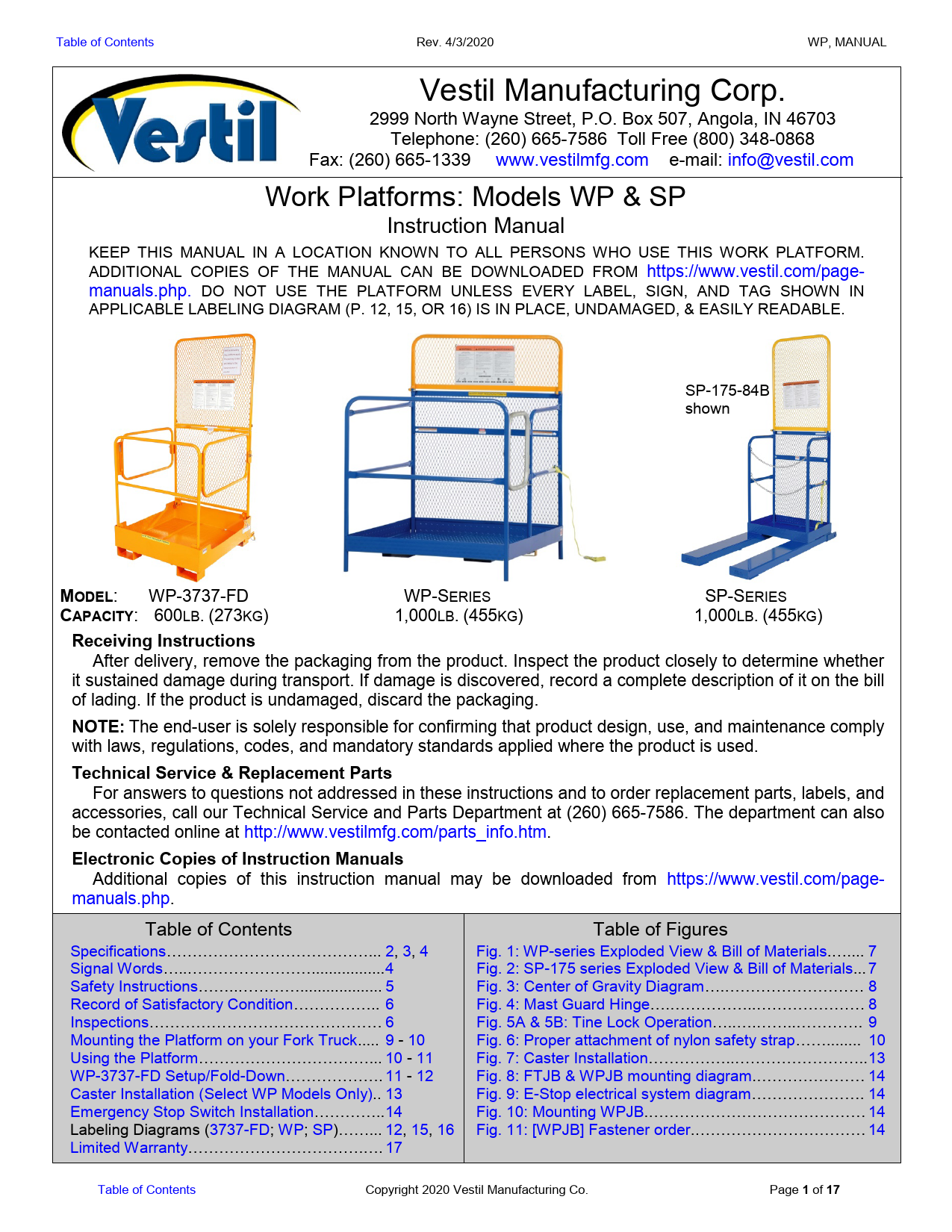
Work Platforms: Models WP & SP
Instruction Manual
KEEP THIS MANUAL IN A LOCATION KNOWN TO ALL PERSONS WHO USE THIS WORK PLATFORM.
ADDITIONAL COPIES OF THE MANUAL CAN BE DOWNLOADED FROM https://www.vestil.com/pagemanuals.php. DO NOT USE THE PLATFORM UNLESS EVERY LABEL, SIGN, AND TAG SHOWN IN
APPLICABLE LABELING DIAGRAM (P. 12, 15, OR 16) IS IN PLACE, UNDAMAGED, & EASILY READABLE.
SP-175-84B shown
MODEL: WP-3737-FD CAPACITY: 600LB. (273KG)
WP-SERIES 1,000LB. (455KG)
SP-SERIES 1,000LB. (455KG)
Receiving Instructions After delivery, remove the packaging from the product. Inspect the product closely to determine whether
it sustained damage during transport. If damage is discovered, record a complete description of it on the bill of lading. If the product is undamaged, discard the packaging.
NOTE: The end-user is solely responsible for confirming that product design, use, and maintenance comply with laws, regulations, codes, and mandatory standards applied where the product is used.
Technical Service & Replacement Parts For answers to questions not addressed in these instructions and to order replacement parts, labels, and
accessories, call our Technical Service and Parts Department at (260) 665-7586. The department can also be contacted online at http://www.vestilmfg.com/parts_info.htm.
Electronic Copies of Instruction Manuals Additional copies of this instruction manual may be downloaded from https://www.vestil.com/page-
manuals.php.
Table of Contents
Specifications.......................................... 2, 3, 4 Signal Words..............................................4 Safety Instructions....................................... 5 Record of Satisfactory Condition................. 6 Inspections............................................. 6 Mounting the Platform on your Fork Truck..... 9 - 10 Using the Platform.................................... 10 - 11 WP-3737-FD Setup/Fold-Down................... 11 - 12 Caster Installation (Select WP Models Only).. 13 Emergency Stop Switch Installation..............14 Labeling Diagrams (3737-FD; WP; SP)......... 12, 15, 16 Limited Warranty...................................... 17
Table of Figures
Fig. 1: WP-series Exploded View & Bill of Materials........ 7 Fig. 2: SP-175 series Exploded View & Bill of Materials... 7 Fig. 3: Center of Gravity Diagram............................... 8 Fig. 4: Mast Guard Hinge.......................................... 8 Fig. 5A & 5B: Tine Lock Operation.............................. 9 Fig. 6: Proper attachment of nylon safety strap.............. 10 Fig. 7: Caster Installation...........................................13 Fig. 8: FTJB & WPJB mounting diagram...................... 14 Fig. 9: E-Stop electrical system diagram...................... 14 Fig. 10: Mounting WPJB........................................... 14 Fig. 11: [WPJB] Fastener order.................................. 14
Table of Contents
Copyright 2020 Vestil Manufacturing Co.
Page 1 of 17
Table of Contents
Rev. 4/3/2020
WP, MANUAL
SPECIFICATIONS
Dimensions, center of gravity, capacity, and net weight figures for each model appear in the following diagrams and tables. Center of gravity values are broken into a horizontal component (HCG) and vertical component (VCG).
Models WP-36##
Model
A
B
C
D
E
HCG VCG Capacity Net weight
WP-3636
655/8"
60"
361/16" 333/8"
39"
15"
213/8"
1,000 lb. 454.5 kg
174 lb. (91 kg)
WP-3648
655/8"
60"
481/16" 453/8"
51"
205/8"
207/8"
1,000 lb. 454.5 kg
195 lb. (105 kg)
WP3636-84B
895/8"
84"
361/16" 333/8"
39"
141/8"
253/8"
1,000 lb. 454.5 kg
182 lb. (112 kg)
WP-3648-84B
895/8"
84"
481/16" 453/8"
51"
191/2"
243/8"
1,000 lb. 454.5 kg
202 lb. (118 kg)
WP-3636-DD
655/8"
60"
361/16" 333/8"
39"
151/8"
213/4"
1,000 lb. 454.5 kg
184 lb. (106 kg)
WP-3648-DD
655/8"
60"
481/16" 453/8"
51"
203/8"
211/8"
1,000 lb. 454.5 kg
204 lb. (112 kg)
WP3636-84B-DD
895/8"
84"
361/16" 333/8"
39"
141/8"
253/8"
1,000 lb. 454.5 kg
191 lb. (112 kg)
WP-3648-84B-DD 895/8"
84"
481/16" 453/8"
51"
193/8"
241/2"
1,000 lb. 454.5 kg
212 lb. (118 kg)
NOTE: To calculate the weight of a "fully loaded platform," find the net weight of your model in the table above. Add 1,000 pounds (455 kg) to that figure.
Table of Contents
Copyright 2020 Vestil Manufacturing Co.
Page 2 of 17
Table of Contents
SPECIFICATIONS (continued)
Models WP-4848
Rev. 4/3/2020
WP, MANUAL
NOTE: To calculate the weight of a "fully loaded platform," find the net weight of your model in the table above, and then add: 1) 1,000 pounds (455 kg) for all WP-series models except the fold-down WD-3737-FD; 2) 1,000 pounds (455 kg) for SP model platforms; or 3) 600 pounds (273 kg) for WP-3737-FD platforms.
Model
A
B
C
D
E
HCG VCG Capacity Net weight
WP-4848
655/8"
60"
481/16" 453/8"
51"
205/8"
20"
1,000 lb. 454.5 kg
237 lb. (108 kg)
WP-4848-84B
895/8"
84"
481/16" 453/8"
51"
191/2"
231/2"
1,000 lb. 454.5 kg
245 lb. (112 kg)
WP-4848-DD
655/8"
60"
481/16" 453/8"
51"
207/16" 201/4"
1,000 lb. 454.5 kg
246 lb. (112 kg)
WP-4848-84B-DD 895/8"
84"
481/16" 453/8"
51"
193/8"
235/8"
1,000 lb. 454.5 kg
254 lb. (116 kg)
NOTE: TO CALCULATE THE WEIGHT OF A "FULLY LOADED PLATFORM," FIND THE NET WEIGHT OF YOUR MODEL IN THE TABLE ABOVE AND ADD 1,000 POUNDS (455 KG).
Model
WP-CA WP-SB WP-SB-FTJB WP-SB-WPJB WP-TC WP-P-TC WP-TT36 WP-TT48 WP-AFR WP-WS WP-DL
Work platform safety options
Description 4" x 11/4" polyurethane-on-polyurethane casters: 2 swivel & 2 rigid Emergency stop button kit Emergency stop junction box � Fork truck Emergency stop junction box � Work platform Fluorescent tube caddy Fluorescent tube caddy (plastic) 36" tool tray 48" tool tray Automatically deploying ramp Caution sign with necessary mounting hardware Double chain door lock
Weight
20 lb. (9.1 kg) 7 lb. (3.2 kg) 8 lb. (3.6 kg) 5 lb. (2.3 kg) 15 lb. (6.8 kg)
13 lb. (5.9 kg) 22 lb. (10 kg) 222 lb. (100.9 kg) 3 lb. (1.4 kg) 2 lb. (0.9 kg)
Table of Contents
Copyright 2020 Vestil Manufacturing Co.
Page 3 of 17
Table of Contents
SPECIFICATIONS (continued)
Rev. 4/3/2020
WP, MANUAL
Lanyard and Safety Harness Options (see sizing chart below)
Model
WP-LH-S WP-LH-M WP-LH-L WP-LH-XL WP-LH-XXL WP-LH-XXXL
Description
Small harness Medium harness Large harness Extra large harness Extra-extra large harness Extra-extra-extra large harness
Lanyard length
6ft. (~1.83m) 6ft. (~1.83m) 6ft. (~1.83m) 6ft. (~1.83m) 6ft. (~1.83m) 6ft. (~1.83m)
Weight
10 lb. (4.5 kg) 10 lb. (4.5 kg) 10 lb. (4.5 kg) 10 lb. (4.5 kg) 10 lb. (4.5 kg) 10 lb. (4.5 kg)
Height of User
5ft 4in � 5ft 7in (163 � 170)cm 5ft 8in � 5ft 11in (173 � 180)cm
6ft � 6ft 3in (183 � 191)cm 6ft 3in and Taller 191cm and taller
34"-36" Small Small
Medium Large
38"-40" Small
Medium Medium
Large
Platform Model
WP-series except fold-down SP-series Fold-down WP-3737-FD
Waist Size of User 42"-44" 46"-48"
Medium Large
50"-54" X-Large
56"-60" XX-Large
Large X-Large XX-Large XXX-Large
Large X-Large XX-Large XXX-Large
X-Large X-Large XX-Large XXX-Large
Maximum Rated Load
1,000 lb. 1,000 lb. 600 lb.
Employers are responsible for instructing employees to use the product properly (see OSHA standard 1910.178 and 1993 letter of interpretation accessible at:
http://www.osha.gov/pls/oshaweb/owadisp.show_document?p_table=INTERPRETATIONS&p_id=21322. EVERY person who might use, inspect, or perform maintenance on this work platform must read and understand every instruction BEFOREHAND. Users should have access to the manual at all times and should review the directions whenever necessary.
SIGNAL WORDS
This manual uses SIGNAL WORDS to draw attention to uses of the product that could result in personal injuries, as well as the probable seriousness of those injuries. Other signal words call attention to uses likely to cause property damage. Signal words used in this manual appear below along with the definition of each word.
Identifies a hazardous situation which, if not avoided, WILL result in DEATH or SERIOUS INJURY. Use of this signal word is limited to the most extreme situations.
Identifies a hazardous situation which, if not avoided, COULD result in DEATH or SERIOUS INJURY.
Identifies practices likely to result in product/property damage, such as operation that might damage the platform.
Table of Contents
Copyright 2020 Vestil Manufacturing Co.
Page 4 of 17
Table of Contents
Rev. 4/3/2020
WP, MANUAL
SAFETY INSTRUCTIONS
We strive to identify all hazards associated with the use of our products. However, material handling is dangerous and no manual can address every risk. The most effective way to avoid injury is for the end-user to exercise sound judgment whenever using this product.
Electrocution might result if an occupied work platform contacts electrified wires. DO NOT contact electrified wires with any part of the platform, tools, or your body/clothing. DO NOT use the platform in an area where contact with electrified wires might occur. DO NOT use the work platform in close proximity to electrified wires or other sources of electricity.
Improper or careless operation might result in serious personal injuries or death sustained by the boom operator(s) and bystanders. � Always conform to OSHA "Powered industrial trucks" and fall protection systems rules. See 29 CFR 1910.178. � Acquire a copy of the latest revision of American National Standard ANSI/ITSDF B56.1. The Standard is freely
downloadable from the ITSF website (http://www.itsdf.org/cue/b56-standards.html). Apply all recommended and mandatory provisions regarding the use, inspection, care, and maintenance of platforms used to elevate personnel. � Contact the manufacturer of your lift truck to verify that the truck is capable of safely handling the fully loaded platform. See NOTE on p. 2. The width of your platform must be equal to or less than the width of your fork truck plus 10 inches (250mm). � DO NOT exceed the maximum occupancy ratings for each model: WP-series = 2; SP-175 = 1; WP-3737-FD = 2. � If your model allows for occupancy by 2 persons, each person must wear a safety harness and lanyard. Connect the lanyard to a distinct anchor point. Anchor points are identified on p. 10. Each person must connect to a different anchor point. DO NOT connect both harnesses to the same anchor point. � ONLY use the work platform to lift people and their tools. DO NOT exceed the capacity of the platform. � DO NOT use the work platform unless it is in SATISFACTORY CONDITION. Inspect the platform before each use by applying the INSPECTION instructions on p. 6. DO NOT use the platform unless it is in SATISFACTORY CONDITION passes every part of the inspection. � Platform occupants and fork truck operators must wear hard hats whenever this platform is used. � DO NOT use the platform if the safety chain/strap is damaged or missing. � DO NOT elevate the platform until it is securely connected to the carriage of the fork truck with the safety strap. The safety chain/strap is the primary safety mechanism. It must be used every time the work platform is used! To use the safety chain/strap properly, attach the device to the fork truck carriage as instructed in STEP 2 on p. 10. � Each work platform also includes a secondary safety feature called a tine lock that secures the platform to a tine of your fork truck. However, the lock might not fit over the heel of the tine of your fork truck. If this is the case, do not modify the tine lock. Although the platform can be used without applying the tine lock, it is strongly recommended that the platform only be mounted on forks that allow use of the tine lock. � DO NOT attempt to support a load that weighs more than the platform's capacity. The net weight, i.e. the sum of the weight of all occupants and everything else supported by the platform, cannot exceed the capacity of the platform. � DO NOT stand beneath or travel under the platform while it is elevated. � DO NOT use the gate(s), chains, mast guard, guardrails, etc. as a step. � Platform occupants must ALWAYS use personal fall protection equipment securely attached to the platform at an anchorage point. See USING THE PLATFORM diagrams on p. 10-11. Only disconnect from an anchorage point when the platform rests securely on the ground. � DO NOT use UNLESS each label is in place, undamaged and readable. See applicable LABELING DIAGRAM on p. 12, 15, or 16. � Occupant safety depends on maintaining a work platform in level, horizontal position. Only use work platforms on improved surfaces (asphalt or concrete) that are even and level. � DO NOT mount a work platform on a telehandler, aka boom lift, or rough terrain forklift, even if the handler will be used on level concrete or asphalt. � ONLY use this work platform on a safe, well-maintained lift truck in proper working order. � The forklift operator must remain in the forklift whenever the work platform is occupied. DO NOT leave the operator station of the forklift if the work platform is occupied. � Maintain uninterrupted communications between the lift truck operator and platform occupant(s) at all times. � The work platform must be equipped with an emergency stop switch whenever the platform is used in noisy areas where communication between the forklift operator and platform occupant(s) is impaired. See EMERGENCY STOP SWITCH INSTALLATION on p. 14.
Table of Contents
Copyright 2020 Vestil Manufacturing Co.
Page 5 of 17
Table of Contents
Rev. 4/3/2020
WP, MANUAL
RECORD OF SATISFACTORY CONDITION
Thoroughly document the appearance and condition of your platform before putting it into service. Photograph the platform from numerous angles. Take close range photos of all hardware connections, gates and gate hardware, guardrail welds, fork pockets, tine lock, lanyard anchor points, and safety strap (hook, strap, and welded connection to midrail). Refer to the LABELING DIAGRAM for your model on p. 12, 15, or 16. Include photographs of both sides of the warning placard (080 & 082 attached to the mast guard) and every label applied to the unit. Describe the appearance of the unit in writing. Include details about how the gate operates (the gate should automatically close). Collate all photographs and writings into a single file. The file is a record of the unit in satisfactory condition. Whenever inspections are performed, compare the results of the inspections to this record to determine if the unit is in satisfactory condition. Purely cosmetic changes, like damaged powdercoat/paint, are not changes from original condition. Persons performing inspections must have access to this file each time the unit is inspected.
INSPECTIONS
Compare the results of each inspection to the RECORD OF SATISFACTORY CONDITION. Do not use the
platform unless it is in satisfactory condition. If you are unsure whether your platform is in satisfactory condition,
contact TECHNICAL SERVICE.
Before each use inspections � Inspect the following components before each use:
1. Tine locks: Confirm normal function. Model specific tine lock information appears on p. 8.
2. Snap hook attached to the free end of the nylon safety strap: Confirm that
the spring latch automatically closes securely against the hook as shown in the diagram to the right. If the hook, nylon strap, or latch is damaged, tag the platform "Out of Service". Do not return the platform to service until a
spring latch
new safety strap is installed.
3. Gate latches: WP-3737-FD: Confirm that each gate latch functions normally. See
hook
Step 4 on p. 12; SP-175 series: Confirm chains, D-links, snap rings and D-links are
Nylon safety strap
undamaged;
WP-series: Gate(s) are spring-actuated and should automatically close when released. If a gate(s) does
not automatically close, replace the spring before resuming use of the platform.
4. Handrails: Check the rails, rail welds, and points of attachment to the platform for bending, warping, and cracking.
5. Lanyard attachment points: Check the anchorage weldment (see diagrams on p. 10) and points of attachment to the
mast guard for bending, warping, or cracking.
6. Casters (if equipped with WP-CA kit): Check the casters to confirm that each one is properly seated within the
corner handrail posts. Caster installation instructions are provided on p. 13.
7. Labels and placards: Labels and placards must be easily readable from a reasonable distance. They should be
located as shown in the applicable LABELING DIAGRAM on p. 12, 15, or 16. Contact TECHNICAL SERVICE to
order replacements.
Monthly Inspections � Inspect the following at least 1 time per month: 1. Fasteners (hardware):
Mast guard hinge - bolts, nuts, washers; Tine lock - pins, cotter pins, spring pins, and tine brackets (refer to diagrams on p. 9); Gates � chains, latches, hinges, pins, springs. 2. Casters: Look for excessive wear, bending or cracking. Do not use the casters to move the platform until all damaged casters are replaced. 3. Fork pockets: Confirm that each pocket is structurally sound, not corroded or rusted. Do not use the platform if the fork pockets are significantly worn or excessively rusted or corroded. 4. Welds: Confirm that all welds are intact. 5. Handrails, gates, & the floor of the platform: Look for damage, e.g. deformation, severe wear, breaks, etc. 6. Overall condition of platform: The unit should be clean, square and rigid, and free of rust and corrosion. Remove rust, corrosion, dirt and debris. Apply touchup paint wherever the finish is damaged as soon as damage occurs.
Table of Contents
Copyright 2020 Vestil Manufacturing Co.
Page 6 of 17
Table of Contents
Bracket locking spring pin
7 6
3
Rev. 4/3/2020
WP, MANUAL
FIG. 1: WP-series Exploded View & Bill of Materials
D-link
8 9
NOTE: D-link is used to secure the nylon safety strap to the midrail.
Tine bracket
Item No.
1
2 3 4 5 6
Description
Part No. Quantity
Weldment, frame: WP-3636 WP-3648 WP-4848 WP-3636-DD WP-3648-DD WP-4848-DD
WP tine lock assembly
14-514-118 1
14-514-119 1
14-514-120 1
14-514-095 1
14-514-096 1
14-514-097 1
14-537-007
1
Hinged gate weldment
14-514-093
1
9/16" x 2-1/4" spring
14-146-002
1
#11 hitch pin
45286
1
Pin, axle
13-112-001
1
Upper mast guard weldment
WP-3636 models:
Standard mast guard
14-514-125 1
48in. (Cal-OSHA) upper mast guard 14-514-128 1
WP-3648 models:
7
Standard mast guard
48in. (Cal-OSHA) guard
14-514-125 1 14-514-128 1
WP-4848 models: Standard mast guard 48in. (Cal-OSHA) guard
14-514-126 1 14-514-129 1
8
�" � 13 x 1-1/2" HHCS #2 zinc-plated 11209 bolt
2
9 �" � 13 zinc-plated hex nut
36110
2
10 �" - 13 x 2" HHCS zinc-plated bolt 11211
2
Nylon safety strap
08-145-028
1
Complete tine lock assembly
14-537-007
1
FIG. 2: SP-175 series Diagram & Parts List
Item no. 1 2 3
4
5 6 7
Part no. 14-112-001 45286 37-028-014 14-514-127
14-514-130 1/4in. D-link 10211 36109
Description
5/8in. x 9-1/2in. pin
1/8in. x 2-5/8in. (#11) hitch pin clip
Fork tubes Upper mast guard (standard); OR Upper mast guard (Cal-OSHA) D-link
� in. x 2in. hex head bolt
� in. � 13 UNC hex head nut
4
Quantity 2 2 2
1
4 2 2
2
1
Close-up of tine lock assembly
D-link (secures the nylon safety strap to midrail)
Nylon strap
Table of Contents
Copyright 2020 Vestil Manufacturing Co.
Page 7 of 17
Table of Contents
FIG. 3: Center of Gravity Diagram
Rev. 4/3/2020
Horizontal center of gravity (B) measured from back of mast guard
WP, MANUAL
Horizontal center of gravity (B) measured from back of mast guard
Lanyard attacMghumaaesrtndt points
Vertical center of gravity (A) calculated from bottom of platform floor
WP-series center of gravity
(C.O.G.)
Model
WP-3636 WP-3648 WP-4848 WP-4848-FF WP-3636-84B WP-3648-84B WP-4848-84B SP-175
A: Vertical center of gravity in inches (~cm)
15.9 (40.4cm) 15.4 (39.1cm) 14.5 (36.8cm) 14.5 (36.8cm) 19.9 (50.5cm) 18.9 (48.0cm) 18.0 (45.7cm) 11.4 (29.0cm)
B: Horizontal center of gravity in inches (~cm)
15.0 (38.1cm) 20.6 (52.3cm) 20.6 (52.3cm) 20.6 (52.3cm) 14.1 (35.8cm) 19.5 (49.3cm) 19.5 (49.3cm) 16.8 (42.5cm)
Model
WP-3636-DD WP-3648-DD WP-4848-DD WP-4848-DD-FF WP-3636-84B-DD WP-3648-84B-DD WP-4848-84B-DD WP-3737-FD
A: Vertical center of gravity in inches (~cm)
18.1 (46.0cm) 18.8 (47.8cm) 16.8 (42.7cm) 16.8 (42.7cm) 23.4 (59.4cm) 21.9 (55.6cm) 21.9 (55.6cm) 16.5 (41.9cm)
B: Horizontal center of gravity in inches (~cm)
13.7 (34.8cm) 17.0 (43.2cm) 18.5 (47.0cm) 18.5 (47.0cm) 12.5 (31.8cm) 17.3 (43.9cm) 17.0 (43.2cm) 18.0 (45.7cm)
FIG. 4: Mast Guard Hinge
Upper mast guard
Lower mast guard
Hex nut Bolt
Connection between top and bottom portions of mast guard.
If the mast guard is improperly fastened, it cannot adequately protect platform occupants. Therefore, make sure that hinge bolts and nuts (circled in the drawings) are tightened to 35ft�lb of torque. Retighten the connection to 35 ft�lb whenever:
1. The work platform is taken out of storage:
Raise the upper portion of the mast guard, and then Tighten the bolts and nuts. 2. The mast guard is bumped or deflected from vertical. Immediately lower the platform to the ground; then Straighten the mast guard (return it to the vertical orientation) and retighten the bolts and nuts.
Table of Contents
Copyright 2020 Vestil Manufacturing Co.
Page 8 of 17
Table of Contents
Rev. 4/3/2020
WP, MANUAL
MOUNTING THE PLATFORM ON YOUR FORK TRUCK
Each work platform has 2 mechanisms for securing it to a fork lift: 1) A tine lock; and 2) A nylon safety strap. Both safety features must be applied every time the platform is used.
Step 1: Mount the platform on your fork truck. Remove the tine retaining pins (SP-series and WP-3737-FD; see FIG. 5B) or put tine lock in unlocked position (WP-series; see FIG. 5A). Drive forward and insert the forks into the fork channels/pockets on the underside of the platform. For WP-model platforms drive forward until the tines extend through both the rear and front fork pockets. See Diagrams in FIG. 5A. Apply the tine lock(s) as shown in FIG. 5A (WP-model platforms excluding WP-3737-FD) or FIG. 5B (SP-series platforms and WP-3737-FD).
NOTE: Both the safety strap and the tine lock(s) must be used every time the work platform is used. Instructions for applying the safety strap are provided in Step 2 on p. 10.
SP-175 tine locks
Mast guard
Forklift tine
WP-3737-FD tine locks
Table of Contents
Cotter pin
Tine lock retaining pins
Copyright 2020 Vestil Manufacturing Co.
Page 9 of 17
Table of Contents
Rev. 4/3/2020
WP, MANUAL
Step 2: Fasten the nylon safety strap to the fork carriage without slack.
The nylon strap is an essential safety feature. If the forks are accidentally tilted towards the ground, the strap will not prevent the platform from sliding off of the fork lift if it is improperly connected to the platform or the fork lift. Connect the strap to the carriage of your fork truck. Wrap the strap around the carriage without slack at one of the points indicated by dotted arrows in Fig. 6 (vertical midpoint of carriage). If slack is left in the strap, the platform will be able to slide. This condition must be avoided.
FIG. 6: Proper attachment of nylon safety strap Mast
The unit is delivered with the safety strap connected to the midrail. Each time the platform is mounted on a fork lift the hook end of the nylon strap must be connected to the fork carriage.
WP-series platforms: The capacity of each platform appears on Sign 080 which is fastened to the mast guard. See LABELING DIAGRAM on p. 12 or 15. Only use the platform to lift one or two people along with necessary light tools and equipment. Maximum occupancy is two persons at a time.
The capacity of SP-series platforms is 1,000 pounds (455kg). These platforms are designed to lift only one person as well as a loaded skid placed on top of the fork tubes. This arrangement allows the platform occupant to remove items from the skid and place them on shelves, racks, etc. while remaining inside the protective guardrail. The weight of the skid supported by the fork tubes must not produce a horizontal load center more than 20 inches (~51cm) from the front of the stock platform. Contact TECHNICAL SERVICE with questions.
USING THE PLATFORM
Carriage
Fork (tine)
Proper loading (SP-series)
Fork tubes: apply 1 skid at a time.
Combined weight of skid and load must not produce load center more than 20 inches from front of work platform. (Front of platform indicated by solid line; 20in. in front of platform indicated with dashed line.)
The platform user, fork truck operator, and/or bystanders might be seriously injured or killed if this
product is used improperly.
� WP-series and SP-series products are medium-duty platforms. ONLY use with sit-down, rider, high-lift fork trucks
having a minimum load capacity of 3,000 pounds at 24" load center. Never exceed the forklift capacity.
� Review the SAFETY INSTRUCTIONS on p. 5 - 6 before each use.
� The forklift used to lift this platform must comply with Occupational Safety and Health Administration (OSHA)
standard 1910.178 "Powered industrial trucks" and US national standard ANSI/ITSDF B56.1. See 29 CFR 1910.178.
� Acquire a copy of the latest version of ANSI/ITSDF B56.1, "Safety Standard for Low Lift and High Lift Trucks". The
standard is freely downloadable from the ITSDF website (www.ITSDF.org).
� Every occupant must wear a safety
harness and lanyard properly fit for his/her weight and height.
SP platforms: The platform occupant MUST attach a lanyard to an anchor point (B).
Safety placard
Safety/carriage strap attachment point. DO NOT attach harness
here.
WP platforms: Maximum occupancy is 2
persons; only 1 person per anchoring
point (A or B).
� Do not lean against the handrails or safety
chains.
� Only use the work platform on smooth,
level, finished surfaces capable of
supporting the combined weight of the
Anchor
person(s) occupying the platform and all equipment and/or material present on the platform, the platform, and the fork lift.
Anchor point A
point B
� Avoid sudden stops and quick turns while transporting the platform.
Table of Contents
Copyright 2020 Vestil Manufacturing Co.
Page 10 of 17
Table of Contents
Rev. 4/3/2020
WP, MANUAL
(Continued from p. 10) � DO NOT drive the fork truck while the platform is occupied. Fully lower the platform and allow all platform
occupants to dismount before driving the forklift.
� Set the parking brake before lifting the platform. � Occupants must hold onto the handrail on two sides of the work platform whenever it is ascending or descending.
� If the platform is equipped with (optional) casters, DO NOT move the platform if it is occupied. Require all persons to get off of the platform AND unload the platform completely BEFORE moving it.
Before anyone occupies the work platform, confirm that the safety strap is attached to the fork carriage without slack. Perform a BEFORE EACH USE inspection. Inspection procedures are provided on p. 6. Never exit the guardrail enclosure while a work platform is elevated.
Model WP Platforms: Push open the gate(s) to enter the work platform. Release the gate once you are inside the guardrail. All gates should automatically return to the closed position. If all gates operate normally, then attach your lanyard to one of the anchor points. Anchor points are shown in the USING THE PLATFORM diagrams on p. 10. DO NOT elevate the platform until you have attached your lanyard to an anchor point.
Model SP-175: Open a gate and enter the platform. Latch both of the safety chains to their D-links. Attach your lanyard to one of the anchor points. Anchor points are identified in the diagram. The fork tubes in front of the occupant enclosure support a loaded or unloaded skid/pallet. Orient the elevated platform with the side of the platform adjacent (in front of) the loading bay.
Anchor points
Attach lanyard
Model WP-3737-FD: Enter the platform from either side. Lift the gate, pull the gate fully closed, and then press the gate down to secure the latch. See WP-3737-FD SETUP/FOLD-DOWN INSTRUCTIONS. Attach your lanyard to the lanyard anchor point which is identified in STEP 3 "Raise the front guard rail" on p. 12. Confirm that both gates are securely latched before elevating the platform.
WP-3737-FD SETUP / FOLD-DOWN INSTRUCTIONS
NOTE: Folding the platform creates pinch points. Keep feet, hands and clothing away from pinch points while folding or setting up the work platform.
Step 1: Identify the pegs (welded to the inside of the toeboard and the slots (at the bottoms of the guardrail posts) as shown below.
Step 2: Raise the mast guard.
Peg Slot
Nylon safety strap
Lift the guard to allow the pegs to fit into the slots.
Table of Contents
Copyright 2020 Vestil Manufacturing Co.
Page 11 of 17
Table of Contents
Step 3: Raise the front guard rail.
Rev. 4/3/2020
WP, MANUAL
Step 4: Close and latch the gates.
Attach lanyard to anchor
point
Pivot the rail assembly towards the front of the platform.
Secure the assembly in place with the pegs and slots.
Step 5: Secure the platform to the tines of the fork lift both tine locks and the (yellow) Nylon safety strap.
a.) Tine locks: Review MOUNTING THE PLATFORM ON YOUR FORK TRUCK, STEP 1 and Fig. 5B on p. 9. Then, remove the tine lock pins. Drive the forklift tines into the fork pockets. Reinstall the tine lock pins. Refer to Step 1 and FIG. 5A & 5B on p. 9).
b.) Nylon safety strap: Review MOUNTING THE PLATFORM ON YOUR FORK TRUCK, STEP 2 and Fig. 6 on p. 10. As delivered, a safety strap is connected to the base of the mast guard. Attach the strap to the fork carriage without slack.
Lift the gate to allow the slots to slide onto the pegs welded to the toeguard.
LABELING DIAGRAM: WP-3737-FD
Each unit should be labeled as shown in the diagram. Label content and location are subject to change so your product might not be labeled exactly as shown. Compare the diagram below to your Record of Satisfactory Condition. If there are any differences between actual labeling and this diagram, contact Technical Service.
Replace all labels that are damaged, missing, or not easily readable (e.g. faded). To order replacement labels or to inquire whether your unit is properly labeled, contact the technical service and parts department online at http://www.vestilmfg.com/parts_info.htm or by calling (260) 665-7586 and asking for the Parts Department.
Sign 082 (on back of mast guard facing forklift)
Sign 080 (facing platform)
Label 218 (on toeboard, both sides of platform)
Label 287 (on toeboard)
Label 253 (facing platform) Label 821 Label 729
Table of Contents
Copyright 2020 Vestil Manufacturing Co.
Page 12 of 17
Table of Contents
Rev. 4/3/2020
WP, MANUAL
CASTER INSTALLATION: WP-3636, WP-3648, & WP-4848
Improperly installed, utilized, or maintained casters could make the platform unsafe to use. To reduce the likelihood of serious injury: READ EACH INSTRUCTION BEFORE BEGINNING THE INSTALLATION. Inspect the casters regularly for damage and to verify that the caster stem is still inserted fully and that it is securely held inside the post. Only use the casters on flat, even, solid surfaces. DO NOT move the platform when loaded with equipment or personnel. Only move the platform by means of the casters if completely unloaded AND unoccupied. Forklift operator: DO NOT lower the platform onto the casters at a rate greater than one foot per second. Gently
lower the platform onto the casters to avoid damaging them.
1. Verify that the bottoms of all four of the handrail posts are undamaged and free of foreign material (inside the
posts).
2. Raise the work platform high enough to allow the casters to be inserted into the bottom of each of the four posts.
3. Examine each caster; verify that each has a plastic spacer, a black rubber expansion sleeve, and a knurled nut as
shown in Figure A.
4. Hold onto the 2�" tightening hub at the top of the caster rig with your hand and snug the knurled nut against the
top rubber expansion sleeve.
5. Insert the caster stem into the bottom of the post until the tightening hub is up against the bottom of the handrail
post.
6. Turn the tightening hub counterclockwise. If the hub doesn't tighten, apply side pressure to the caster while
turning the hub.
NOTE: The tightening hub must maintain contact with the bottom of the corner handrail post during tightening.
FIG. 7: Caster insertion
7. After hand-tightening the hub, pull down on the caster rig
to verify that the caster is secured in the post.
Work platform with casters installed
Corner handrail post
Handrail post
Caster stem
Knurled nut
Expansion rubber Plastic spacer
Tightening hub
Insert caster into corner post; bottom of post should rest on tightening hub
Caster rig
Table of Contents
Copyright 2020 Vestil Manufacturing Co.
Page 13 of 17
Table of Contents
Rev. 4/3/2020
WP, MANUAL
EMERGENCY STOP SWITCH INSTALLATION
The following instructions apply ONLY to LP or gasoline powered fork trucks. If the truck designated for use with work platforms is powered either by battery or diesel fuel, contact the truck manufacturer for installation directions.
Item
Description
Quantity FIG. 8: FTJB and
1 � in. - 20 x 1in.
8
WPJB mounting
2 � in. - 20 lock nut
8
diagram
3 � in. flat washer
8
4 � in. fender washer
4
5 Fork truck junction box (FTJB)
1
Coil
5
cord
6
Jumper cord
Mounting plate with bolt holes
6 Work platform junction box
1
(WPJB)
Mast guard Jumper plug
Mounting plate with bolt holes
E-stop button
Coil cord
Pigtail cord
E-stop button
#6 Work platform junction
FIG. 9: E-Switch electrical system diagram
box (WPJB)
#5 Fork truck junction box (FTJB)
Connect to positive side of
ignition coil Fork
truck
battery
Jumper cord
INSTALLING THE SWITCH
1) Attach the fork truck junction box (5) to the fork
lift. For instance, attach it to the operator roll cage as shown in FIGS. 8 & 9. Fasten the junction box (5) to the lift truck with 4 bolts, 4 flat washers, and 4 lock nuts. 2) Disconnect the wire from the ignition coil (key switch) of the lift truck. Attach the wire to 1 of the receptacle terminals inside the fork truck junction box (5). 3) Connect the appropriate wire from the (ignition) key switch to the other receptacle terminal inside the junction box (5). 4) Mount the work platform junction box (6) to the mast guard. Position the junction box as shown in Fig. 10. Fasten the WPJB to the inside surface of the mast guard. Fastener order is shown in Fig. 11.
Connect to key switch
Ignition coil terminal & key switch of lift truck. Disconnect from battery and connect to FTJB
FIG. 10: Mounting WPJB
Mount WPJB here
FIG. 11: Fastener order
WPJB mounting plate
1
4 3 2
Mast Guard
Inner surface (of mast guard)
Outside surface
USING THE SWITCH To use the switch, mount the platform on the forks of your lift truck. Apply all tine locks and safety straps. Attach the
(male) plug of the pigtail cord to the socket of the FTJB. Pull the E-stop button out/up. The switch is now ready to use. Press the button to immediately cut forklift power.
If your platform is equipped with an E-switch but you need to operate the forklift without the platform: 1) Disconnect the pigtail cord from the FTJB socket; and 2) Plug the FTJB jumper cord into the socket Connecting the jumper cord to the socket closes the ignition circuit.
Table of Contents
Copyright 2020 Vestil Manufacturing Co.
Page 14 of 17
Table of Contents
Rev. 4/3/2020
WP, MANUAL
LABELING DIAGRAMS: WP-series platforms
Each unit should be labeled as shown in the diagram. Label content and location are subject to change so your product might not be labeled exactly as shown. Compare the diagram below to your RECORD OF SATISFACTORY CONDITION. If there are any differences between actual labeling and this diagram, contact TECHNICAL SERVICE.
Replace all labels that are damaged, missing, or not easily readable (e.g. faded). To order replacement labels or to inquire whether your unit is properly labeled, contact the technical service and parts department online at http://www.vestilmfg.com/parts_info.htm or by calling (260) 665-7586 and asking for the Parts Department.
Table of Contents
Copyright 2020 Vestil Manufacturing Co.
Page 15 of 17
Table of Contents
Rev. 4/3/2020
WP, MANUAL
LABELING DIAGRAM: SP-series platforms
Each unit should be labeled as shown in the diagram. Label content and location are subject to change so your product might not be labeled exactly as shown. Compare the diagram below to your RECORD OF SATISFACTORY CONDITION. If there are any differences between actual labeling and this diagram, contact TECHNICAL SERVICE.
Replace all labels that are damaged, missing, or not easily readable (e.g. faded). To order replacement labels or to inquire whether your unit is properly labeled, contact the technical service and parts department online at http://www.vestilmfg.com/parts_info.htm or by calling (260) 665-7586 and asking for the Parts Department.
Table of Contents
Copyright 2020 Vestil Manufacturing Co.
Page 16 of 17
Table of Contents
Rev. 4/3/2020
WP, MANUAL
LIMITED WARRANTY
Vestil Manufacturing Corporation ("Vestil") warrants this product to be free of defects in material and workmanship during the warranty period. Our warranty obligation is to provide a replacement for a defective, original part covered by the warranty after we receive a proper request from the Warrantee (you) for warranty service.
Who may request service? Only a warrantee may request service. You are a warrantee if you purchased the product from Vestil or from
an authorized distributor AND Vestil has been fully paid.
Definition of "original part"? An original part is a part used to make the product as shipped to the Warrantee.
What is a "proper request"?
A request for warranty service is proper if Vestil receives: 1) a photocopy of the Customer Invoice that
displays the shipping date; AND 2) a written request for warranty service including your name and phone
number. Send requests by one of the following methods:
US Mail
Fax
Email
Vestil Manufacturing Corporation
(260) 665-1339
info@vestil.com
2999 North Wayne Street, PO Box 507
Phone
Enter "Warranty service request"
Angola, IN 46703
(260) 665-7586
in subject field.
In the written request, list the parts believed to be defective and include the address where replacements
should be delivered. After Vestil receives your request for warranty service, an authorized representative will
contact you to determine whether your claim is covered by the warranty. Before providing warranty service,
Vestil will require you to send the entire product, or just the defective part (or parts), to its facility in Angola, IN.
What is covered under the warranty? The warranty covers defects in the following original, dynamic parts: motors, hydraulic pumps, motor
controllers, and cylinders. It also covers defects in original parts that wear under normal usage conditions ("wearing parts"), such as bearings, hoses, wheels, seals, brushes, and batteries.
How long is the warranty period? The warranty period for original dynamic components is 90 days. For wearing parts, the warranty period is
90 days. Both warranty periods begin on the date Vestil ships the product to the Warrantee. If the product was purchased from an authorized distributor, the periods begin when the distributor ships the product. Vestil may, at its sole discretion, extend a warranty period for products shipped from authorized distributors by up to 30 days to account for shipping time.
If a defective part is covered by the warranty, what will Vestil do to correct the problem? Vestil will provide an appropriate replacement for any covered part. An authorized representative of Vestil
will contact you to discuss your claim.
What is not covered by the warranty? The Warrantee (you) is responsible for paying labor costs and freight costs to return the product to Vestil for
warranty service.
Events that automatically void this Limited Warranty. � Misuse; � Negligent assembly, installation, operation or repair; � Installation/use in corrosive environments; � Inadequate or improper maintenance; � Damage sustained during shipping; � Collisions or other accidents that damage the product; � Unauthorized modifications: Do not modify the product IN ANY WAY without first receiving written
authorization from Vestil.
Do any other warranties apply to the product? Vestil Manufacturing Corp. makes no other express warranties. All implied warranties are disclaimed to the
extent allowed by law. Any implied warranty not disclaimed is limited in scope to the terms of this Limited Warranty. Vestil makes no warranty or representation that this product complies with any state or local design, performance, or safety code or standard. Noncompliance with any such code or standard is not a defect in material or workmanship.
Table of Contents
Copyright 2020 Vestil Manufacturing Co.
Page 17 of 17