EMERSON SDU DC UPS B-Series Uninterruptible Power Supply User Manual
File info: application/pdf · 23 pages · 989.25KB
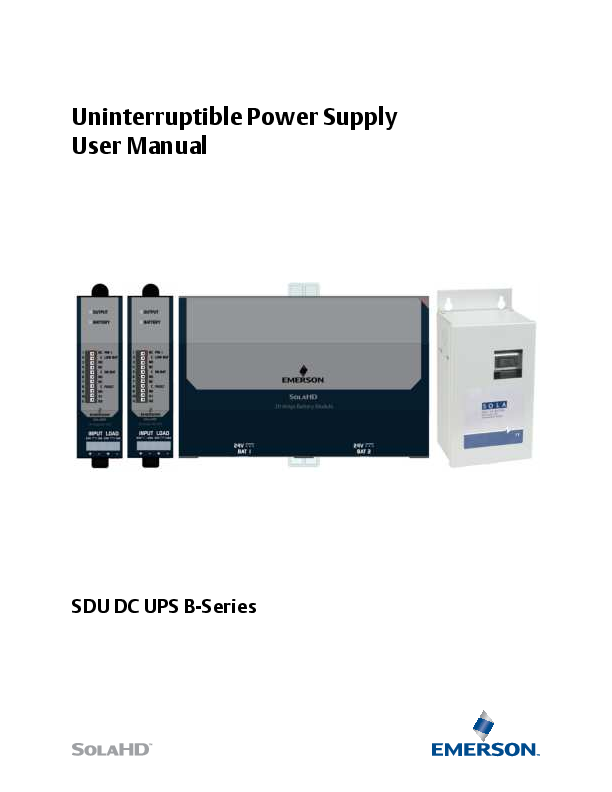
Uninterruptible Power Supply User Manual
Page: 3 Battery Options Two battery modules are available: • SDU 24-BATB: 24 V DIN rail/panel mount battery module (cable included). NOTE: Up to 4 SDU 24-BATB modules can be connected to the UPS. • SDU 24-BATEM: 24 V ex…
Full PDF Document

If the inline viewer fails, it will open the original document in compatibility mode automatically. You can also open the file directly.
Extracted Text
Uninterruptible Power Supply User Manual
SDU DC UPS B-Series

Contents

Safety Instructions.............................................. 1
Introduction ....................................................... 2
Preinstallation.................................................... 2
Receiving ........................................................... 2 What's Included ................................................2 Battery Options .................................................3 Optional Accessories .........................................3
Product Description............................................ 3
Installation ......................................................... 4 Location ............................................................4 DIN Rail Mounting .............................................4 Removing the Unit from the DIN Rail .................4 Optional Chassis Mounting ................................5 Connecting the Unit - Wiring Diagrams .............8 SDU DC UPS B-Series with SDU 24-BATB ............8 SDU DC UPS B-Series with SDU 24-BATEM .........9 Charging the Battery .........................................9
Operation......................................................... 10 Turning ON the UPS (Normal Mode) ............... 10 Turning OFF the UPS ....................................... 10 Remote ON/OFF ............................................. 10 Self-Testing..................................................... 10
LED Status ........................................................ 11
Contact Relay Truth Table................................. 12
UPS Battery ...................................................... 13 Battery Types.................................................. 13 Batteries for SDU-24 BATB .............................. 13 Batteries for SDU-24 BATEM ........................... 13
Battery Backup Times ...................................... 14 SDU 10-24B with SDU 24-BATB....................... 14 SDU 20-24B with SDU 24-BATB....................... 14 SDU 10-24B with SDU 24-BATEM.................... 14 SDU 20-24B with SDU 24-BATEM.................... 14
Specifications ................................................... 15 Power Module Specifications .......................... 15 Battery Module Specifications ........................ 17
Troubleshooting............................................... 18 Troubleshooting ............................................. 18

Storage ............................................................ 19 Extended Storage .......................................... 19
Technical Support............................................. 20
Warranty ......................................................... 20 Warranty Information..................................... 20 Product Literature .......................................... 20

Safety Instructions
PLEASE READ AND FOLLOW THESE INSTRUCTIONS! This manual contains important safety instructions that must be followed during the installation and operation of the DC UPS. Follow all warnings on the unit, in this manual and on the safety instruction sheet.

WARNING - Explosion Hazard, Risk of Electric Shock and Energy Hazard

This device receives input power from multiple sources. Disconnect the DC UPS input from the AC to DC power supply connection and the DC Battery Modules before wiring. Follow all local, National Electrical Code� (NEC�) and CEC wiring and installation codes
Wiring/Torque Specifications: Use only 90�C rated solid or stranded copper wire

Terminals

Gauge Size

Torque

Input/Output

10-14 AWG (5.3-2.1mm2) 4.4-6.5lb-inch (50-73 N-cm)

Remote On/Off Connections (1-9)

16-24 AWG (1.3-0.2mm2) N/A

Contact Terminal Connections (10-11) 16-24 AWG (1.3-0.2mm2) N/A

� Remote On/Off and Contact Terminal connections: Connect only to Class 2 or LPS circuit. � Battery Connection: Use only the SOLA cable provided with unit or SOLA type SDU 24EXTBC6

CAUTION - Risk of electric shock and personal injury
Do not remove the cover, as the unit has no user-serviceable parts inside.
GENERAL INSTALLATION SAFETY PRECAUTIONS: � This product is for indoor use only in a Pollution Degree II environment, Overvoltage
Category II system. � Device provides Double Insulation based on 100 V maximum working voltage according
to IEC61010-1. � To prevent the risk of fire or electric shock, install the DC UPS in a temperature and humidity
controlled ventilated enclosure, free of conductive contaminants, moisture, flammable liquids, gases, and corrosive substances. Do not install or operate the DC UPS in or near water. � Do not place the DC UPS under direct sunlight or close to heat-emitting sources. � To allow proper ventilation of the DC UPS, do not block or cover the top and bottom sides of the unit. Do not insert any objects into the ventilation holes or other openings of the DC UPS. Keep all vents free of dust accumulation that could restrict airflow. � Do not place the DC UPS on an unstable cart, stand, or table. Ensure that it is properly installed on the DIN rail.
Page: 1

GENERAL OPERATING SAFETY PRECAUTIONS: RATINGS:

Model Nominal Input Voltage /Current Nominal Output Voltage/ Current/Power Contact Relay Ambient

SDU 10-24B 24Vdc, 12A 24Vdc, 10A, 240W
50Vdc, 0.2A Ordinary Location: -15C to +50C

SDU 20-24B 24Vdc, 22A 24Vdc, 20A, 480W
50Vdc, 0.2A Ordinary Location: -15C to +50C

The following documents contain important safety instructions that must be followed during the installation and operation of the DC UPS. Follow all warnings mentioned in the documents.

Document
Safety Instruction Sheet � SDU 10-24B, SDU 20-24B DC Uninterruptible Power Supplies
Safety Instruction Sheet � SDU 24-BATB DC Uninterruptible Power Supply Battery Module
Safety Instruction Sheet � SDU-BATEM DC Uninterruptible Power Supply Battery Module

Part No./ Rev/ Year A272-367 Rev.0 8/2021
A272-368 Rev.0 8/2021
A272-369 Rev.0 8/2021

Introduction

Congratulations on your choice of the SDU DC B Series Uninterruptible Power System (UPS). The SDU DC is an advanced 24 Vdc UPS that combines an industry leading design, unique installation options, and a wide operational temperature range (see "Specifications").
The SDU DC is a powerful microprocessor-controlled UPS which provides protection from power interruptions and is the ideal power backup solution for your critically connected loads.

Preinstallation

Receiving Inspect the UPS upon receipt. Damage that may have occurred in transit is not covered under the warranty. If shipping damage is present, contact your local carrier and SolaHD distributor immediately.
What's Included � SDU 10-24B or SDU 20-24B � Safety Instruction Sheet � Remote On/Off Bypass Jumper

Page: 2

Battery Options Two battery modules are available:
� SDU 24-BATB: 24 V DIN rail/panel mount battery module (cable included). NOTE: Up to 4 SDU 24-BATB modules can be connected to the UPS.
� SDU 24-BATEM: 24 V external mount battery module (cable included). NOTE: Only 1 SDU 24-BATEM module can be connected to the UPS. NOTE: A combination of both modules cannot be used with the UPS.
Optional Accessories � SDU 24EXTBC6: 1ft (30.5cm) battery module cable. � SDU 24-DB9: Interface kit to convert relay contact signals to DB9 signals. � SDU-PMBRK: Chassis mounting brackets to secure the UPS to the wall, back of the panel, or enclosure.
Product Description

Figure 1

Figure 2

1. Output LED: Indicates the output status of the DC UPS. See Table 1.

2. Battery LED: Indicates the status of the battery module connected to the DC UPS. See Table 1.

3. Contact Relay Terminals: The control module incorporates dry relay contacts for remote signaling of the UPS and battery module status.

4. Remote ON/OFF Terminals (R1 and R2): Turns the unit ON/OFF.

5. DC Input/Output Screw Terminal Connections: IP20 rated input and output screw terminals.

Page: 3

Figure 3

Figure 4

6. Polarized Terminal Connections for the Battery (+ Red color; - Black color).

Installation

Location Install the power module and battery module in a protected area with adequate airflow and free of excessive dust. Do not operate the UPS outdoors.
DIN Rail Mounting 1. Tilt and place the unit onto the DIN rail. 2. Push the unit downward until it stops. 3. Push at the lower front edge to lock. Ensure that the retainer has locked.
Removing the Unit from the DIN Rail Push the button and swing the bottom out and up.

Page: 4

Figure 5

Optional Chassis Mounting
Optional chassis mounting brackets (P/N: SDU-PMBRK) are sold separately. Please refer to the installation instructions supplied with the brackets.
NOTE: If you will be shipping the UPS already mounted, we recommend using the chassis mounting brackets (P/N: SDU-PMBRK) to secure the UPS.

Figure 6

Page: 5

Figure 7

Page: 6

Figure 8

Figure 9
Page: 7

Connecting the Unit - Wiring Diagrams SDU DC UPS B-Series with SDU 24-BATB
WARNING - Risk of electric shock!
Disconnect the DC input's AC supply connection before wiring. Operate the UPS only from a properly grounded (earthed) DC supply. To reduce the risk of electric shock, do not remove the cover. For service, contact a qualified technician.
Figure 10 Connections: 1. Use the polarized cable to connect the power module to the battery module. 2. Connect the power module dc input connector to the 24 Vdc input power source. 3. Hardwire the load to the power module output terminal connector.
Page: 8

SDU DC UPS B-Series with SDU 24-BATEM
WARNING - Risk of electric shock!
Disconnect the DC input's AC supply connection before wiring. Operate the UPS only from a properly grounded (earthed) DC supply. To reduce the risk of electric shock, do not remove the cover. For service, contact a qualified technician.
Figure 11 Connections: 1. Use the polarized cable to connect the power module to the battery module. 2. Connect the power module dc input connector to the 24 Vdc input power source. 3. Hardwire the load to the power module output terminal connector. Charging the Battery
Page: 9

Operation
Turning ON the UPS (Normal Mode) 1. Ensure that the DC input supply is de-energized prior to wiring the DC UPS system. 2. Ensure that the Battery Module meets the charge schedule. 3. Ensure that the Remote ON/OFF toggle switch for R1 and R2 is open (if using Remote ON/OFF Bypass
Jumper, make sure it is disconnected). 4. Connect the DC input to the DC UPS module; connect the Battery Module to the UPS module; then,
connect the load to the UPS module. 5. Energize the DC input supply. 6. Enable the DC UPS by shorting R1 and R2 through the Remote ON/OFF toggle switch (if not using toggle
switch, insert the Remote ON/OFF Bypass Jumper). 7. This will start the UPS in Normal Mode. Note: If the DC input supply is not present, the DC UPS will enable Battery Mode. The load will be powered by the battery module until reaching cutoff voltage (21.6V). Please ensure switch is OFF or ON/OFF Bypass Jumper is removed when UPS is not in use to prevent draining of the battery.
Turning OFF the UPS 1. Disable the DC UPS by disconnecting R1 and R2 through turning off the Remote ON/OFF toggle switch (if
not using a toggle switch, remove the Remote ON/OFF Bypass Jumper). 2. De-energize the DC input supply. 3. Disconnect the DC input supply, Battery Module, and the load.
Remote ON/OFF Turns UPS output on when terminals R1 and R2 are shorted.
Figure 12 NOTE: The Remote ON/OFF is connected to the DC UPS internal signal ground and it should be isolated from the chassis ground potentials that may cause unit malfunction or damage. Isolate the Remote Sense wiring away from high current, high voltage, and high frequency components to prevent any magnetically coupled noise on the Remote ON/OFF connections.
Self-Testing The DC UPS employs an Automatic Self-Test feature. This feature checks the Battery Module's health and serves as indicator if the battery is still in good condition. The first Self-Testing will be activated 5 hours after commissioning. The subsequent Self-Testing will happen every 1 month thereafter. If the Battery Health fails the Self-Test, the Battery LED will display Solid Red.
Page: 10

LED Status

Table 1

Operating MODE

LED Signal

NORMAL (input present) BATTERY (Input loss)
NORMAL (input present) BATTERY (Input loss) BATTERY FAULT

Load Condition / Control Module Status Load Within Range (100% < Iout < 120%) Overload (125% � 150% for >4s) Power Boost
Overcurrent and Short Circuit Protection Overtemperature Protection
Battery Mode & Load Within Range Overtemperature Protection
Battery Condition Battery Full
Battery Charging / <50% Capacity
Battery Charging / >50% Capacity Battery Mode & Load Within Range
Overtemperature Protection Shorted Battery, Battery Overvoltage, reverse
polarity, end of life or no battery.

Output LED
Steady Green Green Flashing (0.25s ON : 0.25s OFF) Red Flashing (1s ON : 1s OFF)
Steady Red Green Flashing (0.5s ON: 0.5s OFF)
Steady Red
Battery LED
Steady Green Green Flashing (0.25s ON : 0.25s OFF) Green Flashing (1s ON : 1s OFF)
OFF OFF
Steady Red

Page: 11

Contact Relay Truth Table

Table 2
UPS Status
Normal mode Battery mode (30-100% SOC) Battery mode - Low Battery (20-30% SOC)
Battery fault

Low Battery

Pin 1-2

Pin 2-3

N.C.

N.O.

O

X

O

X

X

O

I

I

On Battery

Pin 4-5

Pin 5-6

N.C.

N.O.

O

X

X

O

X

O

I

I

Battery Fault

Pin 7-8

Pin 8-9

N.C.

N.O.

O

X

O

X

O

X

X

O

Legend: X � Contact close O � Contact open I - Indeterminate N.C. - Normally close N.O. - Normally open

Page: 12

UPS Battery

CAUTION
� Do not attempt to open the DC UPS or replace the batteries inside the battery module. � Call SolaHD Technical Support for further instructions. � Do not mount the DC UPS or the Battery Module in an upside-down orientation.

Battery Types
Table 3
Batteries for SDU-24 BATB Manufacturer CSB
Taiwan Yuasa Battery Co. Ltd.

Type HRL 1225W
NPX25

Rating 12 V dc, 5.0 Ah

Table 4
Batteries for SDU-24 BATEM Manufacturer CSB

Type GP1272

Rating 12 V dc, 7.2 Ah

Recharging the Battery
Locate the recharge label on the box containing the product. The label will indicate the last recharge date. Please refer to the label for the next recharge due date.
If the product is due for recharge, please follow the wiring diagram Figure 10 to recharge the SDU 24-BATB. Please allow 8 hours to fully recharge a battery.
Once the battery is recharged, please create a LOG and track the due dates to properly maintain the charge.

Page: 13

Battery Backup Times

Table 5

SDU 10-24B with SDU 24-BATB

Load 1 unit 2 units 3 units 4 units

20% (2 A) 113 247 396 531

40% (4 A) 45 114 178 233

Table 6

SDU 20-24B with SDU 24-BATB

Load 1 unit 2 units 3 units 4 units

20% (4 A) 46 116 178 237

40% (8 A) 21 50 80 113

Table 7

SDU 10-24B with SDU 24-BATEM

Load 1 unit

20% (2 A) 135

40% (4 A) 52

60% (6 A) 30 74 117 148

80% (8 A) 21 48 80 111

100% (10 A) 14 38 58 81

60% (12 A) 10 28 46 65

80% (16 A) 6 17 31 43

100% (20 A) 4 10 20 31

60% (6 A) 28

80% (8 A) 19

100% (10 A) 14

Table 8

SDU 20-24B with SDU 24-BATEM

Load 1 unit

20% (4 A) 48

40% (8 A) 17

60% (12 A) 9

80% (16 A) 6

100% (20 A) 4

NOTE: Run times are based on new, fully charged battery module at a temperature of 25�C (77�F) with purely resistive DC UPS load. Run times listed above may vary due to manufacturing variances of the individual batteries.

Page: 14

Specifications
Table 9
Power Module Specifications
Parameter
Nominal Input Voltage Efficiency (Normal Mode) -
Battery Fully Charged Efficiency (BATTERY Mode) -
Battery Fully Charged INPUT
Nominal Input Voltage Input Voltage Range OUTPUT Nominal Output Voltage
Output Voltage Range
Output Ripple(Normal Mode) Fully Charged
Rated Output Current Rated Output Power PROTECTION Input Current Protection
(Normal Mode) Peak current capability
(Normal Mode) Reverse Polarity, input voltage Reverse Polarity, battery input
Output Short Circuit Battery Over Voltage Protection
Input Protection
Back EMF Immunity, output Overtemperature Protections WEIGHT & DIMENSIONS
Net Weight H x W x D

Catalog Number

SDU 10-24B

24 V dc

SDU 20-24B

>95%

>95%

>93%

>93%

24V 22.1 � 28.6 V dc

24 V dc
Ubat range: 22.1 � 28.6 Vdc maximum Worst case: Ubat - 0.4 V DC = Uout

Uin Ripple = Uout Ripple

10 A 240W

20 A 480 A

Internally Fused 30A 32VDC
Power boost (allows for 150% of rated load) for > 4 seconds
UPS goes to battery mode UPS does not turn on
UPS shutdown, Auto-recovery Charging stops at 28V, Auto-recovery Allowable Input range is 21.6V min and 28.6V max.
or else UPS goes to Battery Mode < 35 V Max No damage, Auto-recovery
Unit shutdown, Auto-recovery
0 .88 lb. (0.4 kg) 4.88 in. x 1.37 in. x 4.80 in. (124 mm x 35 mm x 121.9 mm)

Page: 15

Table 9

Power Module Specifications

Parameter

Catalog Number

SDU 10-24B

SDU 20-24B

ENVIRONMENT Audible Noise
Operating Temperature Storage Temperature Humidity Pollution Maximum Elevation Shock Vibration

<40 dBA (1 m) distance -15�C to +50�C -40�C to +85�C
0 to 95%, non-condensing Degree 2
3000m max According to IEC60068-2-27 According to IEC60068-2-6; DNVGL-CG-0339 Section 3

GENERAL

MTBF

Life Expectancy

>1,000,000 hours; Telcordia SR-332 @ 40C
>15 yrs. 50% load at 40C >15 yrs. 100% load at 25C

INSTALLATION Power Input/Output
Terminals (Screw Type)
Battery Terminals
Relay Contact Terminals Mounting

Connector size range: 16-10 AWG (1.5-6 mm2) for solid/stranded conductors. Screw Torque: 4.4 -6.5 lb-in (50-73 N-cm)
Polarized Terminal Connections for the Battery (+Red color, - Black color)
NOTE: The maximum length of the connection between the power module and battery module is 6 ft. (1.85m).
Use connector size range: 24 � 16 AWG (0.34 � 4mm2)
Use DIN TS35/7.5 or TS35/15 rail system. Apply to both thin and thick DIN Rail (1.0 and 1.5mm), optional screw mounting set SDU-PMBRK.

SAFETY APPROVALS

cULus Listed: UL/CSA 61010-1, UL/CSA 61010-2-201

cRUus: UL Recognized Component UL/CSA 62368-1, UL/CSA 60950-1

SDU DC UPS System*

CE LVD / UKCA EE (Safety) Regulations 2016 �IEC/EN 62368-1, IEC/EN 61010-1, IEC/EN 61010-2-201 (CB Certified IEC/EN 60950-1)

CE EMC/ UKCA - EN 62040-2 Category C2, EN 55032, EN 55011, EN 55024, EN 55035, EN 61000-6-1, EN 61000-6-2, EN 61000-6-3,
EN 61000-6-4, EN 61326-1, EN61000-3-2, EN 61000-3-3, I EC/EN 61000-4 Series

*The SDU DC UPS system includes a power module (SDU 10-24B or SDU 20-24B) and a battery module (SDU 24-BATB or SDU 24-BATEM).

Page: 16

Table 10

Battery Module Specifications

Parameter

Catalog Number

SDU 24-BATB

SDU 24-BATEM

Nominal Voltage

24 V dc

Protection

Fuse: 30 A

Circuit Breaker: 24 V, 25 A

Charging Current

1.2 A

Battery Type

Sealed, maintenance-free lead acid batteries

Enclosure Type

IP20

NEMA 1

Terminal Connector Type

Polarized power pole connectors

Operating Temperature

-15�C to +50�C

Storage Temperature

-15�C to +40�C

Humidity

95%, non-condensing

Typical Recharge Time (to 90% of full capacity)

SDU 24-BATB: 6 hours for 2 battery modules; 3 hours for each additional battery module SDU 24-BATEM: 8 hours for 1 battery module

Backup Times

See Tables 5�8

Weight

11.46 lb. (5.2 kg)

16 lb. (7.26 kg)

Enclosure Dimensions

7.57 in. x 4.85 in. x 4.33 in. (192.4 mm x 123.3 mm x 110 mm)

11.50 in. x 5.57 in. x 4.57 in. (292 mm x 142 mm x 116 mm)

Mounting

Simple snap-on system for DIN rail TS35/7.5 or TS35/15 or optional
chassis mounting brackets (P/N: SDU-PMBRK)

Chassis mounting brackets (P/N: SDU-PMBRK)

Accessories

1 ft (30.5cm) polarized battery cable

6 ft (180cm) polarized battery cable

*The SDU DC UPS B-Series system includes a power module (SDU 10-24B or SDU 20-24B) and a battery module (SDU 24-BATB or SDU 24-BATEM).

Page: 17

Troubleshooting

Table 11

Troubleshooting

Problem

Probable Cause

Remote ON/OFF terminals (R1 and R2) are not short circuited.

UPS has no output
UPS cannot turn ON at Normal Mode
UPS cannot turn ON at Battery Mode

Input DC voltage is not within the acceptable range of 22.1V � 28.
6V and the battery is drained.
Load is short circuited
Other failure.
Loose input DC voltage power connection.
Input DC voltage is not within the acceptable range of 22.1V � 28. 6V.
Other failure.
Battery is Drained or not connected

Battery is not fully charged.

Backup time is too short

Battery has low capacity due to deterioration
Other failure.

Display Steady Red at Battery LED

Battery is drained
Battery is disconnected. Other battery failure.

Required Action
Insert REMOTE ON/OFF BYPASS jumper to short circuit the terminals.
Check the DC input voltage. If the input is within the range,
check the input fuse. Remove the load.
Contact Technical Support. Tighten the dc input power connection.
Adjust dc input voltage
Contact Technical Support.
Connect or recharge battery.
Recharge the UPS for at least three (3) hours.
Replace the battery
Contact Technical Support. Recharge the battery for at least
three (3) hours. Check battery connections.
Replace the battery.

SOLAHD Technical Support (USE STANDARD VERBIAGE)

For further assistance, please contact SolaHD Technical Support at 1.800.377.4384/1.847.268.6651 or by e-mail at solahd.technicalservices@emerson.com.

Page: 18

Storage
Extended Storage � Store the UPS covered and upright in a cool, dry location with the battery fully charged. � Remove the REMOTE ON/OFF Bypass Jumper (or turn remote ON/OFF Switch to OFF position). Remove any accessories in the accessory slot and disconnect any cables connected to the computer interface port to avoid unnecessary draining of the battery. � During extended storage in environments where the ambient temperature is -15�C to +30�C (+5�F to +86�F), charge the UPS battery every 4 months. � During extended storage in environments where the ambient temperature is +30�C to +45�C (+86�F to +113�F), charge the UPS battery every three (3) months.
Page: 19

The information in this manual is provided as a guide for installation, operation, and maintenance. It does not affect or exceed our obligations under the Terms and Conditions of Sale. Note that unit specifications are subject to change without notice.
Technical Support
Website: www.solahd.com Technical Support E-Mail: solahd.technicalservices@emerson.com Toll-Free: (800) 377-4384 USA: (847) 268-6651
Warranty
Warranty Information Please refer to the "Terms & Conditions of Sale" at https://www.appleton.emerson.com/documents/appletongrp-llc-terms-of-sale-policies-procedures-en-us-7444090.pdf Product Literature For additional product literature, including French and Spanish manuals, please visit www.solahd.com.
While every precaution has been taken to ensure accuracy and completeness in this manual, Appleton Grp LLC d/b/a Appleton Group assumes no responsibility, and disclaims all liability for damages resulting from use of this information or for any errors or omissions.
Page: 20

SDU DC UPS B-Series A272-374 Rev. 0 10/2021

The Emerson logo is a trademark and service mark of Emerson Electric Co. Appleton Grp LLC d/b/a Appleton Group. SolaHD is a registered trademark of Appleton Grp LLC. All other marks are the property of their respective owners. � 2021 Emerson Electric Co. All rights reserved.

United States (Headquarters) Appleton Grp LLC 9377 W. Higgins Road Rosemont, IL 60018 United States T +1 800 621 1506
Australia Sales Office Bayswater, Victoria T +61 3 9721 0348
Korea Sales Office Seoul T +82 2 3483 1555

Europe ATX SAS Espace Industriel Nord 35, rue Andr� Durouchez, CS 98017 80084 Amiens Cedex 2 France T +33 3 2254 1390
China Sales Office Shanghai T +86 21 3338 7000

Canada EGS Electrical Group Canada Ltd. 99 Union Street Elmira ON, N3B 3L7 Canada T +1 888 765 2226

Asia Pacific EGS Private Ltd. Block 4008, Ang Mo Kio Ave 10, #04-16 TechPlace 1, Singapore 569625 T +65 6556 1100

Middle East Sales Office Dammam, Saudi Arabia T +966 13 510 3702

Chile Sales Office Las Condes T +56 2928 4819

Latin America EGS Comercializadora Mexico S de RL de CV Calle 10 N�145 Piso 3 Col. San Pedro de los Pinos Del. �lvaro Obregon Ciudad de M�xico. 01180 T +52 55 5809 5049
India Sales Office Chennai T +91 44 3919 7300