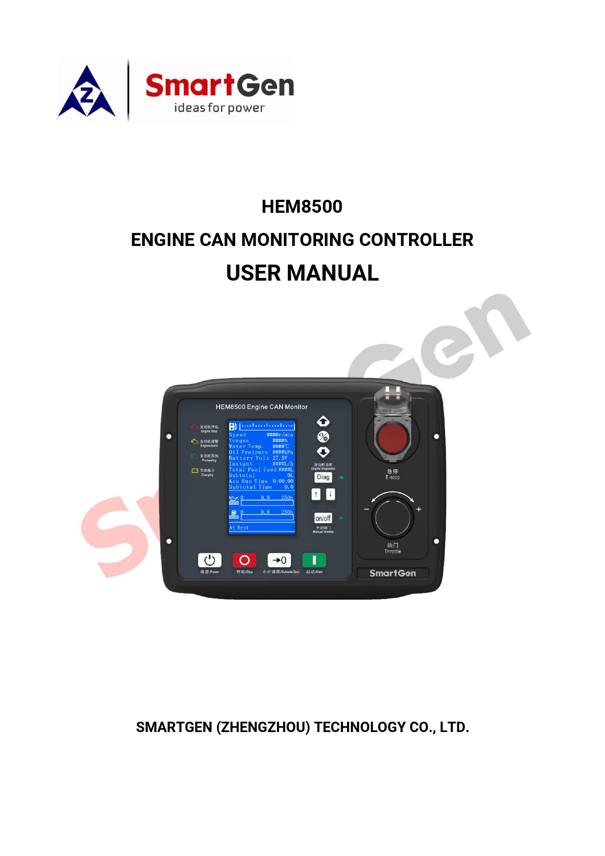
.

User

hem8500 engine can monitoring controller user manual

..................................................................... 39. 12.3 CUMMINS QSM11 .....

User Manual V1.2

SmartGen HEM8500 Engine CAN Monitoring Controller 4.3 inch LCD CANBUS interface RS485 interface. Engine CAN Monitoring Controllers.Technical Parameters: Display 4.3 inch LCD Operation Panel Silicon Rubber Programmable Interface RS485 RTC & Event Log ● CANBUS ● IP Protection Class(front panel) IP65 DC Supply DC(10~35)V Case Dimensions(mm) 247*191*71(mm) Panel Cutout(mm) 214*160(mm) Operating Temp. (-25~ 70)℃ Product Overview: HEM8500 Engine CAN Monitoring Controller is an intelligent instrument and contr

USER MANUAL

HEM8500 en-User-Manual
HEM8500 ENGINE CAN MONITORING CONTROLLER
USER MANUAL
SMARTGEN (ZHENGZHOU) TECHNOLOGY CO., LTD.

Chinese trademark
English trademark SmartGen -- make your generator smart SmartGen Technology Co., Ltd. No.28 Jinsuo Road, Zhengzhou, Henan Province, China Tel: +86-371-67988888/67981888/67992951
+86-371-67981000 (overseas) Fax: +86-371-67992952 Email: sales@smartgen.cn Web: www.smartgen.com.cn
www.smartgen.cn
All rights reserved. No part of this publication may be reproduced in any material form (including photocopying or storing in any medium by electronic means or other) without the written permission of the copyright holder. Applications for the copyright holder's written permission to reproduce any part of this publication should be addressed to SmartGen Technology at the address above. Any reference to trademarked product names used within this publication is owned by their respective companies. SmartGen Technology reserves the right to change the contents of this document without prior notice.

Date 2020-04-23
2020-10-21
2021-03-04

Table 1 Software Version

Version 1.0
1.1
1.2

Content Initial release. 1. Modify the output port name of the controller in the example of J1939 connection between the controller and engine; 2. Add the example of connection between the controller and Weichai WISE15 electric-controlled engine. Add some function descriptions.

HEM8500 Engine CAN Monitoring Controller User Manual

Page 2 of 43

Table 2 Symbol Instruction

Symbol

Instruction

NOTE CAUTION WARNING

Highlights an essential element of a procedure to ensure correctness.
Indicates a procedure or practice, which, if not strictly observed, could result in damage or destruction of equipment. Indicates a procedure or practice, which could result in injury to personnel or loss of life if not followed correctly.

HEM8500 Engine CAN Monitoring Controller User Manual

Page 3 of 43

CONTENTS
1 OVERVIEW ..................................................................................................................................................6 2 PERFORMANCE AND CHARACTERISTICS...............................................................................................7 3 SPECIFICATION .........................................................................................................................................8 4 OPERATION................................................................................................................................................9
4.1 KEY FUNCTION DESCRIPTION ........................................................................................................... 9 4.2 CONTROLLER PANEL........................................................................................................................ 10 5 LCD DISPLAY .......................................................................................................................................... 11 5.1 MAIN DISPLAY................................................................................................................................... 11 5.2 USER MENU AND PARARMETER SETTINGS ................................................................................... 14 5.3 START/STOP OPERATION................................................................................................................ 16 5.4 SPEED REGULATION OPERATION.................................................................................................... 17 5.5 ENGINE DIAGNOSIS OPERATION ..................................................................................................... 18 6 PROTECTION .......................................................................................................................................... 19 6.1 WARNINGS ........................................................................................................................................ 19 6.2 SHUTDOWN ALARMS ....................................................................................................................... 21 7 WIRING CONNECTION............................................................................................................................ 22 8 SCOPES AND DEFINITIONS OF PROGRAMMABLE PARAMETERS ..................................................... 25 8.1 CONTENTS AND SCOPES OF PARAMETER SETTING..................................................................... 25 8.2 DEFINABLE CONTENTS OF PROGRAMMABLE OUTPUT PORTS 1~2 ............................................ 29 8.3 DEFINABLE CONTENTS OF PROGRAMMABLE INPUT PORTS ....................................................... 31 8.4 4~20MA OUTPUT CONTENT LIST.................................................................................................... 33 8.5 SENSORS SELECTION ....................................................................................................................... 34 9 SENSORS SETTING................................................................................................................................. 36 10 TYPICAL APPLICATION ......................................................................................................................... 37 11 INSTALLATION ....................................................................................................................................... 38 11.1 INSTALLATION METHOD ............................................................................................................... 38 11.2 OVERALL DIMENSION AND PANEL CUTOUT ................................................................................ 38 12 CONNECTIONS OF CONTROLLER AND J1939 ENGINE....................................................................... 39 12.1 CUMMINS QSL9 .............................................................................................................................. 39 12.2 CUMMINS QSX15-CM570 .............................................................................................................. 39 12.3 CUMMINS QSM11........................................................................................................................... 40 12.4 DETROIT DIESEL DDEC III/IV .......................................................................................................... 40

HEM8500 Engine CAN Monitoring Controller User Manual

Page 4 of 43

12.5 MTU ADEC (SMART MODULE) ....................................................................................................... 41 12.6 MTU ADEC (SAM MODULE)............................................................................................................ 41 12.7 SCANIA ............................................................................................................................................ 41 12.8 WEICHAI .......................................................................................................................................... 42 13 FAULT FINDING ...................................................................................................................................... 43

HEM8500 Engine CAN Monitoring Controller User Manual

Page 5 of 43

1 OVERVIEW
HEM8500 Engine CAN Monitoring Controller is an intelligent instrument and controlling device that combined microelectronic technique, electric measurement technique, digital-analog hybrid signal processing technique, CAN communication technique, vehicle controlling technique and engine electronic control technique. It is the ideal product for engineering vehicles' CAN communication and electric device control with its high integration and powerful CAN gateway functions (can replace Murphy display totally).

HEM8500 Engine CAN Monitoring Controller User Manual

Page 6 of 43

2 PERFORMANCE AND CHARACTERISTICS
-- With 32-bit ARM microprocessor as the core, 4.3-inch LCD display, touch buttons operation and
English/Chinese language can be optional;
-- Two CANBUS ports, one is connecting with engine ECU, and the other one is standby; -- RS485 communication port enables data communication via MODBUS protocol through PC
monitoring software;
-- 4~20mA output, which can connect speed tachometer and torque indicator; -- Through CANBUS port can read real time data of the running engine, such as speed, torque, water
temperature, oil pressure, oil temperature, total fuel consumption and instant fuel consumption etc;
-- With a reset zero button for integrated panel engine, press and hold it for more than 3s to reset
subtotal time and subtotal fuel consumption;
-- With a fault diagnosis button for integrated panel engine, press it to enter into diagnostic mode, if
ECU alarms occur in this mode, users can check corresponding fault alarm information through flicker times of engine red light, and press it again to exit diagnostic mode;
-- Manual throttle switch: push button on the panel, press it after engine start to activate manual
throttle, which can accurately control engine speed;
-- Emergency stop button on the front panel, which can control engine stop; -- Users can change parameters settings, and changed parameters will be memorized into internal
FLASH storage simultaneously to avoid losing data in case of power down;
-- Real-time calendar, RTC, and running time accumulation functions; -- Diesel engine total start times display; -- 99 pieces of shutdown alarm records can be cyclically stored and records can be checked on the
site;
-- Use hard screen acrylic material to protect screen with strong wear-resistance and scratch
resistance;
-- Rubber panel and buttons with strong performance to work in high/low temperature; -- Widely power supply range (10~35) V DC, which can adapt to various starting battery voltage
environments;
-- There is rubber seal ring between shell and control panel. IP65 protective performance can be
achieved.

HEM8500 Engine CAN Monitoring Controller User Manual

Page 7 of 43

3 SPECIFICATION
Parameter Working Voltage Overall Consumption Starter relay Output ECU Power Relay Output Programmable Relay Output 1~2
4~20mA Output
Analog Sensor
Case Dimension Panel Cutout Mounting Screw Dimension Working Conditions Storage Conditions Protection Level Weight Insulation Intensity

Table 3 Technical Parameters
Details DC10. 0V to 35. 0V continuous power supply <5W (Standby mode: 3.5W) 16A DC28V power supply output 16A DC28V power supply output
7A DC28V power supply output
Range: 4~20mA Resolution: 0.01mA Accuracy: 1% Tachometer or torque indicator can be connected; Aux. Sensor 1, Aux. Sensor 2, Fuel Level Sensor Resistance Input Range: 0~6000 Resolution: 0.1 Accuracy: 1 (below 300) Aux. Sensor 3, and Aux. Sensor 4 Current Input Range: 0~20mA Resolution: 0.01mA Accuracy: 1% 247mm × 191mm × 72mm 214mm × 160mm 4 × M4 Temperature: (-25~+70)°C Humidity: (20~93)%RH Temperature: (-30~+80)°C IP65 front panel 0.90kg Apply AC2.2kV voltage between high voltage terminal and low voltage terminal. The leakage current is not more than 3mA within 1min.

HEM8500 Engine CAN Monitoring Controller User Manual

Page 8 of 43

4 OPERATION

4.1 KEY FUNCTION DESCRIPTION

Table 4 Key Function Description

Icons

Keys Stop

Description Stop the running engine; Reset shutdown alarms when engine alarms occur.

Start

Start engine in standby status.

Power Engine Diagnosis Paging Up Paging Down
Manual Throttle
Subtotal Zero Home/Set Up/Increase Down/Decrease Throttle

In standby status, press longer to turn off the power; In power off status, press longer to turn on the power. It can put the controller in diagnostic mode, and its indicator lights up; Press it again and it exits diagnostic mode, and its indicator lights off. In Diagnostic mode, if multiple ECU alarms occur, it can check the flashing status of the last alarm. In Diagnostic mode, if multiple ECU alarms occur, it can check the flashing status of the next alarm. After the engine starts, it can put the engine in manual throttle mode, its indicator lights up, and speed can be adjusted by throttle knob. Press it again and engine exits manual throttle mode, its indicator lights off, and speed cannot be adjusted at this moment. Press it for 3s and "subtotal time", "subtotal fuel consumption" and "subtotal avg. fuel consumption" become "0". In main menu page, it can enter parameter setting interface; in other pages, it can make it faster to return the main menu page. 1) Screen scroll; 2) Move up cursor and increase value in setting menu. 1) Screen scroll; 2) Move down cursor and decrease value in setting menu. In manual throttle mode, forward/backward rotate this knob to increase/decrease target speed; Press the knob and it can return to "Idle Speed".

E-Stop

Press it, start output and ECU power will be disconnected and meanwhile stop process will be executed.

HEM8500 Engine CAN Monitoring Controller User Manual

Page 9 of 43

4.2 CONTROLLER PANEL

Fig. 1 HEM8500 Front Panel Indication

Table 5 Indicator Description

Indicators

Description Engine shutdown alarm indication, when diagnostic mode is active, if ECU alarms occur, users can check corresponding fault alarm information through flicker times of this indicator. Or when E-stop button is pressed, engine stop indicator flashes quickly. (engine red light) Engine warning alarm indication, when controller detects warning alarm signals, this indicator flashes. (engine yellow light) Engine pre-heating indication, when engine preheat starts, ECU initiates corresponding preheating command. Charging indication, after charging indication input accessing to the controller, when charge, it will light off, otherwise, it will light on.

HEM8500 Engine CAN Monitoring Controller User Manual

Page 10 of 43

5 LCD DISPLAY

5.1 MAIN DISPLAY

When system power is connected (controller has no power right now), press power key

for

more than 2s, then controller starts power up, right now, after entering boot password, controller will get

into normal running interface as bellow:

Please enter boot password ***

Initial boot password is 000, which can be changed in password setting page of module setting interface.

Through

keys to choose numbers, and use

key to set next number. Press

key after three password

numbers finished to enter into the normal display interface.

Fig. 2 Start Interface
Interface display can be divided into multi pages: Main Screen display, Engine Data display, Alarm Data display, Event Log Data display, and Others information display.

HEM8500 Engine CAN Monitoring Controller User Manual

Page 11 of 43

 Main Screen includes the following contents: Table 6 Display Content Description

Main Screen Display Content

Display Content

Description

Data Sources

Engine fuel level indication Fuel level sensor data

Speed Torque Coolant Temp Oil Pressure Battery Voltage Inst. FC Accum. FC Subtotal FC Total Time Subtotal Time

800 r/min 20% 35°C
100kPa

Engine running speed Engine Torque Engine coolant temp display Engine oil pressure display

ECU data analysis ECU data analysis ECU data analysis ECU data analysis

System power supply voltage Controller gathered battery voltage 24.5V

Engine instant fuel consump. ECU data analysis 1L/h

25L Engine total fuel consump. ECU data analysis

25L Fuel used after engine start FC calculation after engine start

2:38:25 Total engine running time

Engine running time accumulation

2.3 Running time after engine start Time accum. after engine start

Oil filter running time

Run time after new oil filter changed.

At Rest

Diesel filter running time Engine status

Run time after new diesel filter changed.

Engine Page Display Content

Display

Description

Data Sources

Engine

Oil Pressure Sensor Temp Sensor

68kPa 65°C

Aux. Sensor 3

80kPa

Current type sensor

Aux. Sensor 4 Oil Temp Fuel Temp Fuel Pressure Inlet Temp Outlet Temp

80kPa 25°C Oil temp display 25°C Fuel temp display 100kPa Fuel pressure display 25°C Inlet temp display 25°C Outlet temp display

Current type sensor ECU data analysis ECU data analysis ECU data analysis ECU data analysis ECU data analysis

HEM8500 Engine CAN Monitoring Controller User Manual

Page 12 of 43

Turbo Pressure Coolant Pressure Coolant Level Subtotal Avg FC Starts

100kPa Turbo pressure display 30kPa Coolant pressure display

ECU data analysis ECU data analysis

80% Coolant level sensor display ECU data analysis

5L/h Subtotal avg. FC display

Calculated by subtotal FC & time

12 Start times display

Start times accumulation

NOTE: Different engines contain different data.
 Alarm page concludes: Display all warnings and shutdown information.

NOTE: For ECU alarms and shutdown alarms, which can display most of alarms content and SPN codes, if there is alarm information that not displayed, please check the engine manual according to SPN alarm code.

 Event log page concludes: Make records about all alarms and the real time when alarm occurs.
 Others page concludes: Time and date, software version, hardware version, input/output status.

HEM8500 Engine CAN Monitoring Controller User Manual

Page 13 of 43

5.2 USER MENU AND PARARMETER SETTINGS

Press

key and enter user menu:

 Parameter After entering the correct password (factory default password is 00318) you can enter parameter
settings interface.  Module settings  Timer settings  Engine settings  Sensor settings (flexible sensor 1~2, fuel level sensor setting, flexible sensor 3~4 (current type
sensor) settings;)  Input port settings  Output port settings  4~20mA output settings

Table 7 Parameter Setting Example (Screen 1)

>Return >Module >Timers >Engine >Sensor >Inputs >Outputs >4~20mA Output >Return >Pre-heat Delay >Cranking Time >Crank Rest Time >Safety On Time >Cooling Time >ETS Solenoid Hold >Fail to Stop Delay >Power Off Delay

Screen 1:
Use (Screen 2).

to change settings and

to enter settings

HEM8500 Engine CAN Monitoring Controller User Manual

Page 14 of 43

>Return >Module >Timers >Engine >Sensor >Inputs >Outputs >4~20mA Output >Return >Pre-heat Delay >Cranking Time >Crank Rest Time >Safety On Delay >Cooling Time >ETS Solenoid Hold >Fail to Stop Delay >Power Off Delay
>Return >Pre-heat Delay >Cranking Time >Crank Rest Time >Safety On Delay >Cooling Time >ETS Solenoid Hold >Fail to Stop Delay >Power Off Delay

Table 8 Parameter Setting Example (Screen 2) Screen 2:

Use (Screen 3).

to change settings and

to enter settings

Table 9 Parameter Setting Example (Screen 3) Screen 3:

Use (Screen 4).

to change settings and

to enter settings

00010s

HEM8500 Engine CAN Monitoring Controller User Manual

Page 15 of 43

>Return >Pre-heat Delay >Cranking Time >Crank Rest Time >Safety On Delay >Cooling Time >ETS Solenoid Hold >Fail to Stop Delay >Power Off Delay

Table 10 Parameter Setting Example (Screen 4) Screen 4:

Use

to change settings and

numbers and confirm setting data.

to move setting

00010s

NOTE: press

and it can exist parameter settings directly.

5.3 START/STOP OPERATION
a) Press start key, then engine is cranking; b) Preheat relay energizes (if configured), "Preheat Delay XX s" information will be displayed on LCD; c) After the preheat delay, Starter relay is engaged. If the engine fails to fire during this cranking
attempt then the Starter relay stop outputting; "Crank Rest Time" begins and wait for the next crank attempt; d) During the set start attempts, if engine fails to start, it will issue failed to start alarm; e) In case of successful crank attempt, the "Safety On" timer is activated. As soon as this delay is over, engine enters into normal running status; f) During the engine normal running process, when manual throttle is active, users can adjust engine speed through manual throttle knob; g) Press stop key, engine enters into stopping process; h) Engine enters "ETS Solenoid Hold". ECU power off and ETS delay timer is energized; i) After ETS delay is over, it enters into "After Stop" delay; j) Engine is placed into its standby mode after its "Waiting for Stop" delay expired.

HEM8500 Engine CAN Monitoring Controller User Manual

Page 16 of 43

5.4 SPEED REGULATION OPERATION
a) After controller normal running, press screen is showing as bellow,

key (manual throttle is active), controller's main

Speed

800 r/min

Torque

20%

Coolant Temp

35°C

Oil Pressure

100kPa

Battery Voltage

24.5V

Inst. FC

1L/h

Accum. FC

25L

Subtotal FC

25L

Total Time

2:18:25

Subtotal Time

2.3

Manual throttle is active.

Target Speed

800r/min

At Rest

Fig. 3 GOV Interface

Initial target speed value is initial throttle speed value that user-defined.

b) Target speed changes along with regulating throttle knob, then engine speed will be controlled by

the controller on the basis of target speed value. The speed resolution (throttle knob each turn of a

grid) is the setting throttle resolution, if adjusted target speed by throttle knob is over the max

pre-set throttle speed, it will be forced to be equal to the max speed value; if adjusted target speed

by throttle knob is below the pre-set minimum throttle speed, it will be forced to be equal to the

minimum speed value.

c) Press throttle knob, engine target speed value will be forced to be equal to the minimum setting

speed value.

d) Again to press

to exit manual throttle mode.

HEM8500 Engine CAN Monitoring Controller User Manual

Page 17 of 43

5.5 ENGINE DIAGNOSIS OPERATION

a) Press

key to enter into Diagnostic Mode if ECU alarms of controller occur.

b) After system enters into diagnostic mode, if the first ECU alarm is shutdown alarm, engine red light

will flash once at first; if ECU alarm is warning alarm, engine yellow light will flash once at first.

c) After alarm types were indicated, engine detailed fault information can be checked according to the

red light flash frequency, for example, red light first time flashes twice, second time flashes 3 times,

and third time flashes 5 times, then fault code (indicator) data is 235, and corresponding fault

information is low coolant level alarm.

d) If ECU fault occurs, fault information is the same failure, and then the light flashes twice.

e) If there are other ECU alarms, please repeat step b-c.

f) Again press

key to exit diagnostic mode.

g) If ECU has no alarms, press

key, both engine red light and yellow light are light off.

HEM8500 Engine CAN Monitoring Controller User Manual

Page 18 of 43

6 PROTECTION

6.1 WARNINGS

When controller detects warning alarms, it only sends warnings but not shuts down the engine, and corresponding warning alarm types are displayed on LCD. If controller detects more than one ECU alarms (if more than 5 pieces), LCD will display max 5 ECU alarms.

Table 11 Warning Alarms

No

Type

1 Battery Over Volt

2 Battery Under Volt Oil Filter Maintenance
3 Due Diesel Filter
4 Maintenance Due
5 ECU Warning

6 Low Fuel Level

7 Fuel Level Open Circuit Aux. Sensor 1~2 Open
8 Circuit

9 Aux. Sensor 1~2 High

10 Aux. Sensor 1~2 Low Aux. Sensor 3~4 Open
11 Circuit (current type) Aux. Sensor 3~4 High
12 (current type) Aux. Sensor 3~4 Low
13 (current type)
14 Input 1~5 Warning

Description When the controller detects that the battery voltage has exceeded the pre-set value, it will initiate a warning alarm When the controller detects that the battery voltage has fallen below the pre-set value, it will initiate a warning alarm When the running time is arrived at preset oil filter maintenance time, it will initiate a warning alarm. When the running time is arrived at preset filter maintenance time, it will initiate a warning alarm. When the controller received engine warning signals via J1939, it will initiate a warning alarm and fault code and name will be displayed. When the controller detects that the fuel level has fallen below the pre-set value, it will initiate a warning alarm. When the controller detects that the fuel level sensor open circuit, it will initiate a warning alarm. After sensors are enabled, when controller detects corresponding sensor is open circuit. It will initiate a warning alarm. After sensors are enabled, When the controller detects that the sensor value has exceeded the pre-set upper limit value, it will initiate a warning alarm. After sensors are enabled, When the controller detects that the sensor value has fallen below the pre-set lower limit value, it will initiate a warning alarm. After sensors are enabled, When the controller detects the sensor is open, it will issue corresponding sensor open warning signal. After sensors are enabled, When the controller detects the sensor value is above the pre-set upper limit of warning value, it will issue sensor high warning signal. After sensors are enabled, When the controller detects the sensor value is below the pre-set lower limit of warning value, it will issue sensor low warning signal. When digital input port is set as warning and the alarm is active, it will initiate a warning alarm.

HEM8500 Engine CAN Monitoring Controller User Manual

Page 19 of 43

No

Type

15 Air Filter Block

16 Low Water Level

17 Failed to Start

Description When air filter block input is active, it will initiate a warning alarm. When low water level input is active, it will initiate a warning alarm. If the number of controller start attempts exceeds pre-set start times, it will initiate a warning alarm.

HEM8500 Engine CAN Monitoring Controller User Manual

Page 20 of 43

6.2 SHUTDOWN ALARMS

When controller detects shutdown alarms, detailed alarms information will be displayed on LCD alarm page.
NOTE: For No. 1~7, when shutdown alarms occur for controller, it only displays shutdown alarm information, but not control ECU shutdown; if stop is needed please press stop button. No. 8 controls ECU shutdown.

Table 12 Shutdown Alarms

No.

Type

1 ECU Shutdown

2 ECU Comm. Failure

3 Aux. Sensor 1~2 High

4 Aux. Sensor 1~2 Low Aux. Sensor 3~4 High
5 Shutdown (current type) Aux. Sensor 3~4 Low
6 Shutdown (current type)
7 Input 1~5 Shutdown 8 Emergency Stop

Description When the controller received engine shutdown signals via J1939, it will initiate a shutdown alarm signal and fault code and name will be displayed. When the engine start up but controller didn't via J1939 receive engine shutdown signals, it will initiate a shutdown alarm signal. After sensors are enabled, when the controller detects that the sensor value has exceeded the pre-set upper limit value, it will initiate a shutdown alarm signal. After sensors are enabled, when the controller detects that the sensor 1 value has fallen below the pre-set lower limit value, it will initiate a shutdown alarm signal. After sensors are enabled, when controller detects sensor value is above the pre-set upper shutdown value, it will initiate sensor high shutdown alarm signal. After sensors are enabled, when controller detects sensor value is above the pre-set upper shutdown value, it will initiate sensor low shutdown alarm signal. When digital input port is configured as "shutdown" and after it is active, it will initiate a shutdown alarm signal. When it is active, starting output and ECU power output is disconnected.

HEM8500 Engine CAN Monitoring Controller User Manual

Page 21 of 43

7 WIRING CONNECTION

Fig. 4 Controller Back Panel

HEM8500 Engine CAN Monitoring Controller User Manual

Page 22 of 43

Table 13 Terminal Wiring Description

No.

Functions

Cable Size

Remark

A Plug Terminal (Back Panel)

1 Ground Loop

1.0mm2

ECU ground loop

2 4~20mA Output3 Aux. Input 5 4 Aux. Input 4 5 GND 6 Aux. Input 2 7 Aux. Input 3

1.0mm2 1.0mm2 1.0mm2 1.0mm2 1.0mm2 1.0mm2

4~20mA output negative Discrete input port Discrete input port GND Discrete input port Discrete input port

8 Air Filter Block Alarm Input 1.0mm2

Air filter block alarm input

9 Charging Indicator Input 1.0mm2

10 Shutdown Indicator Input 1.0mm2 (red light)

11 Warning Indicator Input 1.0mm2 (yellow light)

12 Waiting for Start Indicator 1.0mm2 Input

Diagnosis Paging Up

13

1.0mm2

Output

14 4~20mA Output+

1.0mm2

15 NC

1.0mm2

16 GND

1.0mm2

Discrete input port Discrete input port
Discrete input port
Discrete input port
Output port control 4~20mA output positive NC GND

17 NC Aux. Sensor 3 Input
18 (4~20mA) Aux. Sensor 4 Input
19 (4~20mA)
20 Aux. Input 1

1.0mm2 1.0mm2 1.0mm2 1.0mm2

NC Analog input port Analog input port Discrete input port

21 Low Water Level Warning 1.0mm2

Low water level input port

22 GND

1.0mm2

GND

23 Aux. Sensor 2 Input

1.0mm2

Analog input port

24 Diagnosis Output

1.0mm2

Output after diagnosis is active

25 Diagnosis Paging Down 1.0mm2

Diagnosis paging down output

HEM8500 Engine CAN Monitoring Controller User Manual

Page 23 of 43

No.

Functions

Output

Cable Size

Remark

26 NC 27 RS485 (B) 28 RS485 (A) 29 RS485 120 30 NC 31 32/33 Relay Output COM 32 Aux. Output 1 33 Aux. Output 2 34 Fuel Level Sensor Input 35 Aux. Sensor 1 Input B Plug Terminal (Back Panel) 1 Crank 2 CAN2 120 3 CAN2 (L) 4 CAN2 (H) 5 CAN1 120 6 Crank 7 B+ 8 B9 CAN1(L) 10 ECU Power 11 ECU Power 12 B+ 13 B14 CAN1 (H)

1.0mm2 0.5mm2 0.5mm2 0.5mm2 1.0mm2 1.0mm2 1.5mm2 1.5mm2 1.0mm2 1.0mm2
1.5mm2 0.5mm2 0.5mm2 0.5mm2 0.5mm2 1.5mm2 1.5mm2 1.5mm2 0.5mm2 1.5mm2 1.5mm2 1.5mm2 1.5mm2 0.5mm2

NC RS485 (B) RS485 (A) RS485 (SCR) NC 32/33 relay output common port Output port control, the max contact capacity is 7A Output port control, the max contact capacity is 7A Analog input port Analog input port
Connecting with starting output capacity 16A Standby CANBUS Standby CANBUS Standby CANBUS Engine J1939 CANBUS Connecting with starting output capacity 16A Working power supply DC B+ Working power supply DC BEngine J1939 CANBUS Connecting with ECU power output capacity 16A Connecting with ECU power output capacity 16A Working power supply DC B+ Working power supply DC BEngine J1939 CANBUS

HEM8500 Engine CAN Monitoring Controller User Manual

Page 24 of 43

8 SCOPES AND DEFINITIONS OF PROGRAMMABLE PARAMETERS

8.1 CONTENTS AND SCOPES OF PARAMETER SETTING

Table 14 Parameter Setting Contents and Scopes

No.

Items

Timer Settings

1 Pre-heat Delay

2 Cranking Time

3 Crank Rest Time

4 Safety On Delay 5 Cooling Time 6 ETS Solenoid Hold

7 Fail to Stop Time

Parameters
(0~3600) s (3~60) s (3~60) s (0~3600) s (0~3600) s (0~3600) s (0~3600) s

8 Power Off Delay Engine Settings

(15~150) s

1 Engine Type

(0~39)

2 SPN Alarm Version (1~3)

3 Start Attempts

(1~30) times

4 Disconnect Speed

(1~1000) r/min

5 Battery Rated Volt (0~60.0) V

Battery Over Volt

6

(0~200) %

Warn

Battery Under Volt

7

(0~200) %

Warn

8 Throttle Start Speed 0~2000 r/min

9 Throttle Max. Speed 0~3000 r/min

10 Throttle Resolution 0~100 r/min

Defaults

Description

Time of pre-powering heat plug before 0
starter is powered up.

8

Time of starter power on

The waiting time before second power up 10
when engine start fail.

10

A short of running time after engine start up.

10

Cooling time for engine before stop.

20

ECU power off time after pressing stop key.

Time from gen-set ETS solenoid hold time 0
expired to stop completely.

The delay time for power off after pressing 35
power key.

1 1 1 350 24.0 125
80 800 2500 50

Default: J1939 Engine When connected to J1939 engine, choose the corresponding type. Selection for SPN alarm version. Max. crank times. When reach this number, controller will send start failure signal. When engine speed is higher than the set value, starter will be disconnected. Provide standard judgment for battery over /under voltage. When battery volt is higher than preset volt percentage, controller will send battery voltage high warning alarm. When battery volt is lower than preset volt percentage, controller will send battery voltage low warning alarm. The minimum engine speed of throttle can be adjusted. The max engine speed of throttle can be adjusted. Resolution of the throttle knob each turn of a grid.

HEM8500 Engine CAN Monitoring Controller User Manual

Page 25 of 43

No.

Items

Parameters

SPN Alarm Mask

11

(0~65535)

Code 1

SPN Alarm Mask

12

(0~65535)

Code 2

SPN Alarm Mask

13

(0~65535)

Code 3

ECU Comm. Failure

14

(0~1)

Action

15 Alt. Config. 1 Speed (0~3000)r/min

16 Alt. Config. 2 Speed (0~3000)r/min

17 Alt. Config. 3 Speed (0~3000)r/min

18 External Crank Set

ECU 19
Address

Comm.

Module Setting

(0-1) (0-255)

1 Module Address

(1~254)

2 Language

(0~2)

3 Password

Oil Filter 1st Time 4
Maintenance

Oil

Filter

5

Maintenance Time

Diesel Filter 1st 6
Time Maintenance

Diesel

Filter

7

Maintenance Time

Boot Password 8
Setting

Boot Password 9
Enable

10 Date & Time

11 Boot Screen Enable

Fuel Level Sensor

1 Curve Type

(0~9999) (1~5000) h (1~5000) h (1~5000) h (1~5000) h (0~999) (0~1)
(0-1) (0~15)

2 Low Level Warning (0~100) %

Defaults 0 0 0 0 1500 1500 1500 0 7
1
0 00318 200 250 200 250 0 0
0 3 10

Description
It is can shield corresponding SPN alarm.
0: Warning; 1: Shutdown
Alt. configuration 1 speed associated with alt. configuration 1 of input port. Alt. configuration 2 speed associated with alt. configuration 2 of input port. Alt. configuration 3 speed associated with alt. configuration 3 of input port. 0: Disable; 1: Enable It is used for setting ECU communication address.
It is used for setting RS485 communication address. 0: Simplified Chinese 1: English 2: Traditional Chinese For entering advanced parameters setting.
First maintenance time of oil filter setting.
Oil filter's normal maintenance interval setting.
First maintenance time of filters setting.
Diesel filter's normal maintenance interval setting. Press start key and enter start password to get into controller main screen.
0: Disable; 1: Enable
Users can manually calibrate date and time. 0: Disable; 1: Enable
SGD When the value of external level sensor bellows the default value, controller will

HEM8500 Engine CAN Monitoring Controller User Manual

Page 26 of 43

No.

Items

Parameters

3 Warning Delay

(0~3600) s

Aux Sensor 1~2 1 Sensor Type

(0~3)

2 Curve Type

(0~15)

Alarm 3
Setting

Speed (0~3000) r/min

Upper Limit Shut 4
Enabled

Upper Limit Shut 5
Value

6 Stop Delay

Lower Limit Shut 7
Enabled

Lower Limit Shut 8
Value

9 Stop Delay

Upper Limit Warning 10
Enabled

Upper Limit Warning 11
Value

12 Warning Delay

Lower

Limit

13

Warning Enabled

Lower

Limit

14

Warning Value

15 Warning Delay

Aux Sensor 3~4

(0~1) (0~6000) (0~3600) s (0~1) (0~400) (0~3600) s (0~1) (0~6000) (0~3600) s (0~1) (0~4000) (0~3600) s

1 Sensor Type

(0~3)

2 Curve Type

(0~15)

3 Alarm

Speed (0~3000)

Defaults 2

Description initiate corresponding alarm. (it is always available) When the value of level sensor is below preset warning value, controller will initiate corresponding alarm.

0 0
1200
1 98 5 0 0 5 1

0: Not used 1: Pressure 2: Temp 3: Liquid Level Changed according to sensor type. Sensor types details please to see Table 20. When controller detects engine speed exceeds preset alarm speed, system starts detecting and initiating alarms. Sensor upper limit shutdown enabled setting.
Sensor upper limit shutdown value setting.
Sensor upper limit stop delay setting. Sensor lower limit shutdown enabled setting.
Sensor lower limit shutdown value setting.
Sensor lower limit stop delay setting.
Sensor upper limit warning enabled setting.

92

Sensor upper limit warning value setting.

2

Sensor upper limit warning delay setting.

0

Sensor lower limit warning enabled setting.

0

Sensor lower limit warning value setting.

2

Sensor lower limit warning delay setting.

0
0 1200

0: Not Used 1: Pressure 2: Temperature 3: Fuel Level Change according to sensor type; Refer to Table 21 for detailed sensor type list. When controller measures engine speed is

HEM8500 Engine CAN Monitoring Controller User Manual

Page 27 of 43

No.

Items

Setting

Parameters r/min

Upper Limit Shut

4

(0~1)

Enabled

Upper Limit Shut

5

(0~6000)

Value

6 Stop Delay

(0~3600) s

Lower Limit Shut

7

(0~1)

Enabled

Lower Limit Shut

8

(0~400)

Value

9 Stop Delay

(0~3600) s

Upper Limit Warning

10

(0~1)

Enabled

Upper Limit Warning

11

(0~6000)

Value

12 Warning Delay

(0~3600) s

Lower

Limit

13

(0~1)

Warning Enabled

Lower

Limit

14

(0~4000)

Warning Value

15 Warning Delay

(0~3600) s

Digital Input Ports

Digital Input Port 1

1 Content Setting

(0~50)

2 Active Type

(0~1)

Digital Input Port 2

1 Content Setting

(0~50)

2 Active Type

(0~1)

Digital Input Port 3

1 Content Setting

(0~50)

2 Active Type

(0~1)

Digital Input Port 4

1 Content Setting

(0~50)

2 Active Type

(0~1)

Digital Input Port 5

1 Content Setting

(0~50)

2 Active Type

(0~1)

Relay Outputs

Defaults
1 98 5 0 0 5

Description above preset alarm speed value, system starts to detect alarms. Setting of sensor upper limit shutdown enable. Setting of sensor upper limit shutdown value. Setting of sensor upper limit shutdown delay. Setting of sensor lower limit shutdown enable. Setting of sensor lower limit shutdown value. Setting of sensor lower limit shutdown delay.

1

Setting of sensor upper limit warning enable.

92

Setting of sensor upper limit warning value.

2

Setting of sensor upper limit warning delay.

0

Setting of sensor lower limit warning enable.

0

Setting of sensor lower limit warning value.

2

Setting of sensor lower limit warning delay.

0

Not used.

0

0: Close; 1: Open

0

Not used.

0

0: Close; 1: Open

0

Not used.

0

0: Close; 1: Open

0

Not used.

0

0: Close; 1: Open

0

Not used.

0

0: Close; 1: Open

HEM8500 Engine CAN Monitoring Controller User Manual

Page 28 of 43

No.

Items

Relay Output 1

1 Content Setting

2 Active Type

Relay Output 2

1 Content Setting

2 Active Type

4~20mA Output

1 4~20mA Output

Parameters Defaults

Description

(0~50)

0

Not used.

(0~1)

0

0: Normally Open; 1: Normally Close

(0~50)

0

Not Used

(0~1)

0

0: Normally Open; 1: Normally Close

(0~2)

0: Not Used

1

1: Custom Speed Curve

2: Custom Torque Curve

8.2 DEFINABLE CONTENTS OF PROGRAMMABLE OUTPUT PORTS 1~2

Table 15 Definable Contents of Programmable Output Ports 1~2

No.

Type

0 Not Used

1 User Configured

2 Audible Alarm 3 ECU Power Supply 4 Reserved 5 Starter Relay Output

6 Fuel Relay Output

7 ETS Output 8 Reserved 9 Reserved 10 Common Alarm 11 Common Shutdown Alarm 12 Common Warning Alarm 13 Digital Input 1 Active 14 Digital Input 2 Active 15 Digital Input 3 Active 16 Digital Input 4 Active 17 Digital Input 5 Active 18 Reserved 19 Reserved 20 Reserved 21 Crank Success Output 22 Normal Running Output 23 ECU Comm. Failure 24 Battery Under Volt Alarm

Description
See Table 16 Users-defined Functions of Programmable Output Ports Output when alarms occur. Output after controller is powered on, and disconnect at ETS. Reserved Output when controller starts up. When fuel outputs, the relay outputs; when ETS outputs, the relay stops outputting. Output when controller stops. Reserved Reserved Output when controller has warning/shutdown alarms. Output when controller has shutdown alarms. Output when controller has warning alarms. Output when programmable input port 1 is active. Output when programmable input port 2 is active. Output when programmable input port 3 is active. Output when programmable input port 4 is active. Output when programmable input port 5 is active. Reserved Reserved Reserved Output after engine crank successfully. Output after engine running normally. Shutdown alarm outputs when ECU fails to communicate. Warning alarm outputs when controller battery volt is high.

HEM8500 Engine CAN Monitoring Controller User Manual

Page 29 of 43

No. 25 26 27 28 29 30 31 32 33 34 35 36 37
38
39 40 41 42 43 44 45 46 47~50

Type Battery Over Volt Alarm Reserved Reserved Reserved Fail to Start Reserved Reserved Sensor 1 Open Warning Sensor 1 Warning Sensor 1 Shutdown Sensor 2 Open Warning Sensor 2 Warning Sensor 2 Shutdown Fuel Level Sensor Open Warning Fuel Level Sensor Warning Reserved Sensor 3 Open Warning Sensor 3 Warning Sensor 3 Shutdown Sensor 4 Open Warning Sensor 4 Warning Sensor 4 Shutdown Reserved

Description Warning alarm outputs when controller battery volt is low. Reserved Reserved Reserved Alarm outputs when controller fails to start. Reserved Reserved Warning alarm outputs when flexible sensor 1 is open circuit. Warning alarm outputs when flexible sensor 1 is high/low. Shutdown alarm outputs when flexible sensor 1 is high/low. Warning alarm outputs when flexible sensor 2 is open circuit. Warning alarm outputs when flexible sensor 2 is high/low. Shutdown alarm outputs when flexible sensor 2 is high/low.
Warning alarm outputs when fuel level sensor is open circuit.
Warning alarm outputs when fuel level is low. Reserved Output when flexible sensor 3 open circuit warning occurs. Output when flexible sensor 3 high/low warning occurs. Output when flexible sensor 3 high/low shutdown occurs. Output when flexible sensor 4 open circuit warning occurs. Output when flexible sensor 4 high/low warning occurs. Output when flexible sensor 4 high/low shutdown occurs. Reserved

Table 16 Users-defined Functions of Programmable Output Ports

No.

Item

Content

Remark

1

Function Selection

(0~50)

2

Output Type

0 Close 1 Open

3

Active Speed

0~2000r/min

4

Delay Output Time

(0~100.0) s

5

Output Time

(0~3600) s

NOTE: Active Speed, delay output time, output time settings can only be set via PC software.

HEM8500 Engine CAN Monitoring Controller User Manual

Page 30 of 43

8.3 DEFINABLE CONTENTS OF PROGRAMMABLE INPUT PORTS

Table 17 Input Port Function List

No. 0.
1.
2. 3. 4. 5. 6.
7.
8.
9.
10. 11. 12. 13. 14. 15. 16. 17. 18. 19. 20. 21.
22.
23.
24.
25~50

Type Not Used User Defined
Alarm Mute

Description
Details to Table 18 User-defined Functions of Programmable Input Ports. Through this key to mute alarms if audible alarms occurred.

Alarm Reset

Trough this key to reset alarms if shutdown alarms occurred.

Reserved Reserved Idle Mode Manual Throttle Control
Speed Raise Input
Speed Drop Input
Reserved Reserved Simulate Stop Key Simulate Start Key Reserved Reserved Reserved Emergency Stop Alarm Reserved Remote Start/Stop Reserved Reserved
Alt. Config. 1 Active
Alt. Config. 2 Active
Alt. Config. 3 Active
Reserved

Reserved Reserved When input is active, it returns to the beginning speed (idle speed). When input is active, speed can be adjusted manually. When input is active, for speed raise once (step length is throttle resolution), self-reset button can be connected. When input is active, for speed drop once (step length is throttle resolution), self-reset button can be connected. Reserved Reserved When the simulate stop key is active, it will stop. When the simulate start key is active, it will start.
When input is active, it can execute stop process.
When input is active, it will start; when inactive, it will stop.
When it is active, speed cannot be adjusted, constant for Alt. config. 1 speed. When it is active, speed cannot be adjusted, constant for Alt. config. 2 speed. When it is active, speed cannot be adjusted, constant for Alt. config. 3 speed.

HEM8500 Engine CAN Monitoring Controller User Manual

Page 31 of 43

Table 18 User-defined Functions of Programmable Input Ports

No. 1
2

Setting

Item

Active Type

3

Active Speed

Content (0~50) (0~1)
(0~2500) r/min

Remark See Input Port Function List 0: Close to activate 1: Open to activate Alarm is active when speed exceeded this threshold.

4

Active Action

(0~2)

0: Warning 1: Shutdown 2: No Action

5

Delay

(0~20.0) s

NOTE: User-defined input ports character strings can be set only via PC software.

HEM8500 Engine CAN Monitoring Controller User Manual

Page 32 of 43

8.4 4~20mA OUTPUT CONTENT LIST

Table 19 4~20mA Output Function List

No.

Type

Function Description

0

Not Used

Set mA output current of speed correspondence; externally

1

Custom Speed Curve connect tachometer if this is selected. Min. set current 4mA, max.

set current 20mA.

Set mA output current of torque correspondence; externally

2

Custom Torque Curve connect torque indicator if this is selected. Min. set current 4mA,

max. set current 20mA.

NOTE: Custom curve coordinate point can only be set by PC software. Curve is linear and set the coordinate of two points.

HEM8500 Engine CAN Monitoring Controller User Manual

Page 33 of 43

8.5 SENSORS SELECTION

Table 20 Sensor Selection List (Resistance)

No.

Type

Content

Remark

Pressure 1
Sensor

0 Not Used 1 Reserved 2 Custom Resistance Curve 3 VDO 10Bar 4 CURTIS 5 VOLVO-EC 6 DATCON 10Bar 7 SGX 8 SGD 9 SGH 10~15 Reserved

Defined resistance's range is 0~6k, default is reserved.

0 Not Used

1 Reserved

2 Custom Resistance Curve

3 VDO

4 CURTIS

5 VOLVO-EC

2

Temp Sensor

6 DATCON

Defined resistance's range is 0~6k, default is reserved.

7 SGX

8 SGD

9 SGH

10 PT100

11~15 Reserved

Fuel Level 3
Sensor

0 Not Used 1 Custom Resistance Curve 2 Reserved 3 SGD 4 SGH 5~15 Reserved

Defined resistance's range is 0~6k, default is SGD sensor.

HEM8500 Engine CAN Monitoring Controller User Manual

Page 34 of 43

No. 1 2 3

Table 21 Sensor Selection List (Current)

Type Pressure Sensor
Temp. Sensor
Fuel Level Sensor

Content 0 Not Used 1 Custom 4~20mA Curve 2~15 Reserved 0 Not Used 1 Custom 4~20mA Curve 2~15 Reserved 0 Not Used 1 Custom 4~20mA Curve 2~15 Reserved

Remark Custom current type input current range is 0-20mA; default is reserved.
Custom current type input current range is 0-20mA; default is reserved.

HEM8500 Engine CAN Monitoring Controller User Manual

Page 35 of 43

9 SENSORS SETTING
a) When reselect sensors, the sensor curve will be transferred into the standard value. For example, if temperature sensor is SGH (120°C resistor type), its sensor curve is SGH (120°C resistor type); if select the SGD (120°C resistor type), the temperature sensor curve is SGD curve.
b) When there is difference between standard sensor curves and using sensor, user can adjust it in "curve type" and input target curvilinear coordinate.
c) When input the sensor curve, X value (resistor) must be input from small to large, otherwise, mistake occurs.
d) The headmost or backmost values in the vertical coordinates can be set as same as below. e) For current type sensor, sensor curve is linear, and it only needs to set the coordinate of two points.

Item 1Pa 1kgf/cm2 1bar 1psi

Fig. 5 Oil Pressure Sensor Curve

Table 22 Normal Pressure Unit Conversion Form

N/m2 (pa) 1
9.8x10⁴ 1x10⁵ 6.89x10³

kgf/cm2 1.02x10⁵
1 1.02 7.03x10²

bar 1x10⁵
0.98 1
6.89x10²

psi 1.45x10⁴
14.2 14.5
1

HEM8500 Engine CAN Monitoring Controller User Manual

Page 36 of 43

10 TYPICAL APPLICATION

Fig. 6 HEM8500 Typical Application Diagram

HEM8500 Engine CAN Monitoring Controller User Manual

Page 37 of 43

11 INSTALLATION
11.1 INSTALLATION METHOD 1) The module is held into the panel fascia using the supplied fixing bolts. 2) Use 4 pieces of M4 screws and nuts fixed on the 4 corresponding screw holes. 3) Care should be taken not to over tighten the screws of fixing screws. 11.2 OVERALL DIMENSION AND PANEL CUTOUT

Unit: mm

Fig. 7 Overall Dimensions and Panel Cutout
HEM8500 controller can suit for wide range of battery voltage DC (10~35) V. Negative of battery must be connected with the shell of engine. The wire's diameter of battery negative and positive, which is connected to B+ and B- of controller power must be over 2.5mm2. If floating charger configured, please firstly connect output wires of charger to battery's positive and negative directly, then, connect wires from battery's positive and negative individually to controller's positive and negative input ports in order to prevent charger disturbing the controller's normal working. a) Output And Expand Relays
All outputs of controller are relay contact output type. If it needs to expand the relays, please add freewheel diode to both ends of expand relay's coils (when coils of relay have DC current) or, increase resistance-capacitance return circuit (when coils of relay have AC current), in order to prevent disturbance to controller or other's equipment. b) Withstand Voltage Test
When controller had been installed in control panel, if it needs the high voltage test, please disconnect controller's all terminal connections, in order to prevent high voltage into controller and damage it.

HEM8500 Engine CAN Monitoring Controller User Manual

Page 38 of 43

12 CONNECTIONS OF CONTROLLER AND J1939 ENGINE

If CAN 1 needs to match 120 resistance, short connect outside CAN1 (H) and CAN1 120, which is short connect B14 and B5. 12.1 CUMMINS QSL9

It is suitable for CM850 engine control module.

Table 23 50-Pin Connector

Terminals of controller ECU Power Starting Relay Output

50 pins connector 39 -

Remark Connected to starter coil directly.

Table 24 9-Pin Connector

Terminals of controller

9 pins connector

SAE J1939 shield-E

CAN(H)

SAE J1939 signal-C

CAN(L)

SAE J1939 return-D

Engine type: Cummins-CM850.

Remark CAN communication shielding line; Using impedance 120 connecting line. Using impedance 120 connecting line.

12.2 CUMMINS QSX15-CM570

It is suitable for CM570 engine control module. Engine type is QSX15 etc.

Table 25 50-Pin Connector

Terminals of controller ECU Power Starting Relay Output

50 pins connector 38 -

Remark Injection switch; Connected to starter coil directly.

Table 26 9-Pin Connector

Terminals of controller

9 pins connector

SAE J1939 shield-E

CAN(H)

SAE J1939 signal-C

CAN(L)

SAE J1939 return-D

Engine type: Cummins QSX15-CM570.

Remark CAN communication shielding line; Using impedance 120 connecting line. Using impedance 120 connecting line.

HEM8500 Engine CAN Monitoring Controller User Manual

Page 39 of 43

12.3 CUMMINS QSM11

Table 27 Engine OEM Connector

Terminals of controller OEM connector of engine

ECU Power

38

Starting Relay Output

-

-

CAN(H)

46

CAN(L)

37

Engine type: common J1939.

Remark
Connected with starter coil directly. CAN communication shielding line. Using impedance 120 connecting line. Using impedance 120 connecting line.

12.4 DETROIT DIESEL DDEC III/IV

Table 28 Engine CAN Port

Terminals of controller

CAN port of engine

Expansion 30A relay,

ECU Power

proving battery voltage for

ECU.

Starting Relay Output

-

-

CAN(H)

CAN(H)

CAN(L)

CAN(L)

Engine type: common J1939.

Remark
Connected to starter coil directly. CAN communication shielding line. Using impedance 120 connecting line. Using impedance 120 connecting line.

HEM8500 Engine CAN Monitoring Controller User Manual

Page 40 of 43

12.5 MTU ADEC (SMART MODULE)

It is suitable for MTU engine with ADEC (ECU8) and SMART module.

Table 29 ADEC (X1 Port)

Terminals of controller ECU Power Starting Relay Output

ADEC (X1 port) X1 10 X1 34

Remark X1 9 shall connect negative of battery. X1 33 shall connect negative of battery.

Table 30 SMART (X4 Port)

Terminals of controller
CAN(H) CAN(L) Engine type: mtu-ADEC.

SMART (X4 port) X4 3 X4 1 X4 2

Remark CAN communication shielding line. Using impedance 120 connecting line. Using impedance 120 connecting line.

12.6 MTU ADEC (SAM MODULE)

It is suitable for MTU engine with ADEC (ECU7) and SAM module.

Table 31 ADEC (X1 Port)

Terminals of controller ECU Power Starting Relay Output

ADEC (X1 port) X1 43 X1 37

Remark X1 28 shall connect negative of battery. X1 22 shall connect negative of battery.

Table 32 SAM (X23 Port)

Terminals of controller

SAM (X23 Port)

X23 3

CAN(H)

X23 2

CAN(L)

X23 1

Engine type: General J1939.

Remark CAN communication shielding line. Using impedance 120 connecting line. Using impedance 120 connecting line.

12.7 SCANIA

It is suitable for S6 engine control module. Engine type is DC9, DC12, and DC16.

Table 33 B1 Connector

Terminals of controller

ECU Power

3

Starting Relay Output

-

-

CAN(H)

9

CAN(L)

10

Engine type: Scania.

B1 connector

Remark
Connected to starter coil directly. CAN communication shielding line. Using impedance 120 connecting line. Using impedance 120 connecting line.

HEM8500 Engine CAN Monitoring Controller User Manual

Page 41 of 43

12.8 WEICHAI

It is suitable for Weichai BOSCH common rail electric-controlled engine.

Table 34 Engine Port

Terminals of controller

Engine port

ECU Power

1.40

Starting relay output

1.61

-

CAN(H)

1.35

CAN(L)

1.34

Engine type: GTSC1.

Remark Connected to engine ignition lock.
Using impedance 120 connecting line. Using impedance 120 connecting line.

It is suitable for Weichai WISE15 electric-controlled engine.

Table 35 Engine Port

Terminals of controller

Engine port

Remark

ECU Power

1.59

Starting relay output 1.58

CAN_SCR

-

CAN(H)

1.42

CAN(L)

1.43

Engine type: GTSC1.

Connected to engine ignition lock.
CAN communication shielding line. Using impedance 120 connecting line. Using impedance 120 connecting line.

NOTE: If there is any problem in the communication between the controller and ECU, please contact our service personnel.

HEM8500 Engine CAN Monitoring Controller User Manual

Page 42 of 43

13 FAULT FINDING

Table 36 Fault Finding

Symptoms

Possible Solutions

Check starting batteries; Controller no response with
Check controller connection wirings; power.
Check DC fuse.

Check related switch and its connections according to the

Shutdown alarm in running

information on LCD;

Check programmable inputs.

Check fuel circuit and its connections;

Fail to start

Check starting batteries; Check speed sensor and its connections;

Refer to engine manual.

Starter no response

Check starter connections; Check starting batteries.

_________________________________

HEM8500 Engine CAN Monitoring Controller User Manual

Page 43 of 43


Microsoft Word 2016 Microsoft Word 2016