Title
File info: application/pdf · 7 pages · 521.87KB
Title
Subject
Keywords
Diagnostics and Troubleshooting Syringe Pump Technical ...
TB10 Low Flow Operation and TB07 Temperature Control Jacket Setup, and D-Series Manual Section Back Pressure Regulation. a. For valve leakage, see the procedure "Valves" on page 6. Instructions for calibrating new elect…
Diagnostics and Troubleshooting Tech Bulletin - Teledyne ISCO
current D-Series manual). Current Pump. Controller. Legacy Pump. Controller. DISP button. Lighted display. Syringe Pump Technical Bulletin. Sept 2020, TB23 ...
Full PDF Document

If the inline viewer fails, it will open the original document in compatibility mode automatically. You can also open the file directly.
Extracted Text
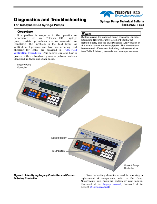
Diagnostics and Troubleshooting
For Teledyne ISCO Syringe Pumps

Syringe Pump Technical Bulletin Sept 2020, TB23

Overview
If a problem is suspected in the operation or performance of an Teledyne ISCO syringe pump, certain procedures are recommended for identifying the problem in the field. Steps for verification of pressure and flow rate accuracy, and checking for leaks, are provided in TB05 Field Verification Procedures. This bulletin explains how to proceed with troubleshooting once a problem has been identified, in these and other areas.
Legacy Pump Controller

Note
Systems using the updated pump controller (on sale beginning November 2011) are identified by the lighted display and the blue Dispense (DISP) button in the fourth row on the control panel. The two systems have several differences, including maintenance kits (see Table 1 below), manuals, and some procedures.

Lighted display DISP button

Current Pump Controller

Figure 1: Identifying Legacy Controller and Current D-Series Controller

If troubleshooting identifies a need for servicing or replacement of components, refer to the Pump Maintenance and Servicing section of your manual (Section 5 of the Legacy manual; Section 8 of the current D-Series manual).

Syringe Pump Technical Bulletin TB23

Table 1: Maintenance Kit Contents

Wrench Package:

Piston & Wiper Seals
Cylinder Cap Seal

Various wrenches for use with most com-mon part replacements.

Cyl. cap NOTE: Wrench types and sizes may vary seal between pump models.

Piston seal
Wiper seal

Package Numbers If Ordering Separately:

1000D

60-1247-093

500D

60-1247-068

260D

60-1247-067

100D

60-1247-067

65D

60-1247-130

30D

60-1249-132

Control Panel Label Depending on use, the most frequently pressed keypad buttons may eventually wear out.
Port Plug

Motor Brush Set : Inspect the top brush, which is easier to access. New brushes are 1.1 cm long. Replace both brushes before the top brush wears to a length of 0.4 cm. To access the bottom brush for replacement, remove the cover plate on the bottom of the pump. Refer to the user manual section Pump Maintenance, Troubleshooting, and Servicing for detailed instructions. Other option: replace entire motor.
Cable Ties & Mounts

Tubing Connectors

Fuses

Shear Key w/

Installation Tool - Shear key

If the pump motor fails to stop in the Shear key for 65DM

event of an over-

Installation tool

pressure situation,

the shear key may require replacement.

Shear Key Part Numbers

Installation Tool 1000D, 500HP, 260D, 65D 500D 100DM/DX 65DM 30D

60-1248-135 60-1243-607 60-1243-654 60-1243-608 60-1243-949 60-1263-131

Zero Volume Nut & Ferrule (100D/260D)

Universal Sensor Harness

69-1244-415

Maintenance Kit Part Numbers

Legacy (Older Controller):

1000D

68-1249-104

500D

68-1249-102

260D

68-1249-101

100DM/DX

68-1249-100

65D

68-1249-111

D-Series (Current Controller):

1000D

60-1247-060

500D

60-1247-072

260D

60-1247-073

100DM/DX

60-1247-074

65D

60-1247-087

65DM

60-1247-094

30D

60-1249-127

2A fuse, 117V 1A fuse, 234V

Rear Panel of Pump 411-0311-62 411-0311-51

2

Syringe Pump Technical Bulletin TB23

Troubleshooting Tables
On the following pages, Tables 2 through 5 provide basic syringe pump troubleshooting information.
Under "Additional Information" are references to relevant sections of the D-Series user manual included with your pump, as well as online documents containing detailed instructions for the solutions outlined in the tables.
Many test procedures and repairs listed here require accessing the interior of the controller or pump module. Instructions for doing so are provided in the section following the tables.

Table 2: General Troubleshooting

Symptom

Cause

Solution

Additional Information

Fluid leaking from drip pan Fluid leaking onto the worm gear Fluid leaking from where the cylinder cap meets the cylinder
Pump runs, never reaches set pressure
Pump cannot be set to desired pressure Pump will not run or refill; No error message.
Controller will not power up

Damaged pump seals
Failed cylinder cap seal Shear key broken (worm gear is turning but ball screw is not) Gross leak; Pump has no restriction
Pumping Gas
Factory specified maximum pressure exceeded, or user-set pressure limit exceeded. Software has been updated without a controller reset Universal sensor harness (limit sensor) failure. Pump B or C not connected to AC Power.. Pump cable not attached. Pump module not powered on. 5VDC unavailable to Pump A

Replace pump seals
Replace cylinder cap seal
Replace shear key Tighten fittings; Clean or replace piston seal; Add restriction/pressure downstream.
Isco pumps are designed for pumping liquids and supercritical fluids. If pumping CO2, use a dip tube and take necessary measures to ensure that the CO2 remains in a liquid state.

See sections on Fluid Leakage later in this bulletin. D-Series Manual Sections: Seal Cleaning and Replacement; Wear Ring Cleaning and Replacement
D-Series Manual Section: Overpressure Conditions
D-Series Manual Sections: Seal Cleaning and Replacement Back Pressure Regulation
D-Series Manual Sections: CO2 Cylinder Connection Package; Temperature and Pressure Controls; Technical bulletin TB08 CO2 Applications and Tech Notes For additional support, contact a Teledyne Isco Applications Specialist.

Set pump to a lower pressure.

Verify operation of the limit sensors (2 total). Connect AC Mains Power to the pump. Perform a controller reset. Refer to Technical bulletin TB09 Flash Memory Upgrade.
Verify 5VDC on controller board and on power drive CBA. (Pump A) Calibration (Legacy controller only) or fuse replacement may be necessary.

D-Series Manual Section Motor Control/Limits
D-Series Manual Section: Test Points

3

Syringe Pump Technical Bulletin TB23

Table 3: Displayed Messages

Symptom

Cause

Solution

Additional Information

FAILURE POSITION A/B/C/D The pump speed does not correctly correspond with the amount of power required to run the motor.
FAILURE PRESSURE A/B/C/D (A, B, C, D OVER PRESSURE)
Pump will not run; CYLINDER EMPTY message displayed Pump will not refill; CYLINDER FULL message displayed CYLINDER EMPTY message displayed, but piston is not at top of cylinder (cylinder not really empty) CYLINDER FULL message displayed, but piston is not at bottom of cylinder (cylinder not really full)
VALVE ERROR

Temporary software hangup
Tachometer sensor failure; A to D converter failure (Verify by using a different controller.) Older pumps may have a bad tachometer sensor or alignment. Worn motor brushes Fuse 101 blown Universal sensor harness (limit sensor) failure
Cylinder screwed too tightly into the mounting block Failed drive transistor on motor drive board Pressure has exceeded maximum range of the pump. Constant Flow Mode, models 260D, 500D, & 1000D: Pressure has exceeded that specified in the graphs shown in Section 1 of the user manual. Pump empty; Piston at top of cylinder
Pump full; Piston at bottom of cylinder
Universal sensor harness (limit sensor) failure
Cycle power. If the message reappears, repair or replace the valve package.

Hard system reset (Erases controller settings, restores to factory defaults)

D-Series Manual Section: Resetting the System

Replace or align the tach sensor. (The encoder cannot be replaced in the field.)

Replace entire motor, or just the D-Series Manual Section:

brushes.

Motor Brushes

Replace F101 4A fuse. Part #411-0312-70)

Verify operation of the limit sensors (2 total). Replace harness if either sensor fails.

D-Series Manual Section: MOTOR CONTROL/LIMITS

Using the cylinder wrench (see Table 1) to back the cylinder off and tighten it properly.

Refer to technical bulletin TB22 Care and Maintenance.

Replace motor drive board.

Set pump to a lower pressure.

Refill the pump.

Run the pump.

Verify operation of the limit sensors (2 total). Replace harness if either sensor fails.

D-Series Manual Section: MOTOR CONTROL/LIMITS

Electric Valves: Valve or valve motor failure; repair kits available. Air Valves: May be restorable w/ new seal kit.

D-Series Manual Section: Electric Valve Motor Calibration

Note Error messages can only be removed by correcting the problem and restarting the controller. If diagnostics indicate CBA component failure (other than fuses), replace the CBA.

4

Syringe Pump Technical Bulletin TB23

Table 4: Flow Rate Troubleshooting

Problem
Total volume collected < calculated, AND: � Pressure > 500psi � (Calculated Volume � Collected Volume)  Collection Time is out of specified leak rate � Flow rate > 0.25ml/min
Total volume collected < calculated AND pressure < 500psi
Total volume collected < calculated but still within specified leak rate

Cause

Solution

Additional Information

Seal leakage

Replace seals. Inspect wear ring and cylinder.

D-Series Manual Sections: Section 1.2 - Specification Tables Seal Cleaning and Replacement; Wear Ring Cleaning and Replacement

Leakage outside pump: External tubing fittings, or valves.a

Repair or replace leaking component.

Cylinder cap seal

Replace seal and tighten cylinder cap.

D-Series Manual Section: Seal Cleaning and Replacement Technical Bulletin TB05 Field Verification

Standard seals are generally more Add backpressure resistance. effective at pressures > 500psi. Use low pressure seals.

Technical Bulletin TB10 Low Flow Operation Contact Teledyne Isco's application specialists for further assistance. 402-465-2086 or 800-775-2965

Low flow applications often require special laboratory and equipment precautions.

D-Series Manual Section: Section 1.2 - Specification Tables Technical Bulletin TB10 Low Flow Operation Contact Teledyne Isco's application specialists for further assistance. 800-775-2965

Note Although minute fluctuations within the �L range at set pressure are considered normal, low flows in particular can benefit from smaller cylinder capacities, back pressure regulation, control of the ambient and fluid temperatures. For details, refer to TB10 Low Flow Operation and TB07 Temperature Control Jacket Setup, and D-Series Manual Section Back Pressure Regulation.
a. For valve leakage, see the procedure "Valves" on page 6. Instructions for calibrating new electric valve motors is provided in the D-Series user manual.

Table 5: Pressure Troubleshootinga

Symptom
Pressure reading is somewhat inaccurate when compared with an external calibrated gauge.
Pressure drifts out of calibration after it has been calibrated.

Cause Incorrect calibration Pressure transducer has drifted
Pressure transducer has failed.

Solution Calibrate the pressure transducer.

Additional Information
D-Series Manual Section: Calibration

Replace the transducer

Pressure reading is grossly inaccurate when compared with an external calibrated gauge, does not reflect large changes in pressure, and/or does not read zero when open to atmosphere.
Pump does not maintain pressure when ports are closed. (Leak check failure)
Pump sounds like it is running, but the piston does not move up the cylinder.

Pump drive board fuses F102 and F104 are open. Controller electronics are damaged.
Seal leakage
Leakage outside the pump (external tubing, fittings, or valves) Cylinder cap seal
An overpressure condition has broken the shear key.

Replace fuses. Replace pump drive board and/or pressure transducer. Repair/replace controller board.
Replace seals; Inspect wear ring and cylinder.

D-Series Manual Section: Pump Case Top Removal, Test Points
D-Series Manual Sections: Seal Cleaning and Replacement; Wear Ring Cleaning and Replacement

Repair or replace leaking component.

Replace cylinder cap seal and tighten cylinder cap.
Before replacing the shear key, ensure that the pumping system is properly installed and programmed.

D-Series Manual Section: Calibration
D-Series Manual Section: Overpressure Conditions

a. See "Incorrect or Unstable Pressure Reading" on page 6 for additional troubleshooting information.

5

Syringe Pump Technical Bulletin TB23

Incorrect or Unstable Pressure Reading
If the pressure is out of specification, has a constant reading of 0psi, or will not stabilize, check the following points.
Incorrect or Zero Pressure 1. Ensure that fuses F102 and F104 are not blown. 2. Cylinder cap screwed on too tight, or not tight enough. 3. A - D Converter failure 4. Optical sensor (limit sensor) failure 5. Damaged pressure transducer 6. Shear key broken (indication of failure to automatically stop in overpressure condition). Shear key replacement procedures are available in Section 5 of the legacy manual, and Section 8 of the current manual.
Overpressure Condition If an overpressure condition occurs, the pump will
stop running. It will either stop automatically and display an error message, or the shear key will break, in which case the motors keeps running but pressure is not developed.
This can be caused by an electrical problem, such as failure of fuse F102, or damage to the pressure transducer. Unstable Pressure
Densification inside the tubing associated with high viscosity applications can cause clogs. Ensure that temperature and other factors affecting viscosity are carefully maintained. For solutions, refer to TB17 High Temperature and High Accuracy Options.

Fluid Leakage
Although slight leakage during normal operation is expected, leakage exceeding specifications (refer to TB05 Field Verification Procedures) may signal a problem. Areas to check are listed, in order of likelihood, along with possible causes: Damaged seals
 Pump seals are a consumable item that becomes worn over time. Replace cylinder cap seal, piston seal, and wiper seal annually. Replace more often for applications involving heavy use or harsh/ abrasive substances.
 Dirt or other solids on the seal can cause leakage. If removed and rinsed with distilled water, a seal may still be usable, but reused cap seals may leak.
 The seals are easily damaged. Use great care during handling not to leave debris or fingernail imprints on the seal's surface.
 If the cylinder cap is not screwed on tight enough, the cap seal may not be able to prevent leaks.
Fittings  Problems with the fittings can cause leakage.
 Inspect all plugs, ferrules, and tubing connections for damaged surfaces and threads.
 Ensure that all fittings are properly tightened.
Surface finish  Visually inspect the inside of the cylinder for scratches by shining a flashlight down inside; the surface should have a mirror finish. Some scratches or score marks may be repaired at the factory. If the marks are very deep, however, the cylinder must be replaced.
 If the surface of the piston is damaged, the piston must be replaced.
 The piston retainer can function normally as long as there are no scratches or marks on the sealing surface.
Valves  Pumping caustic substances or fluids containing particulates can shorten the life of valve packages, usually causing leakage to occur. Options are available from Teledyne Isco for reducing or preventing damage of this nature. These options are discussed in TB04 Pumping Salt Solutions and Brines.
 Leakage may be accompanied by a VALVE ERROR message. Cycle power and see if the message reappears. If it does, repair or replace the valve package.
Valves may not be closing properly. For example, if the inlet valve opens but the outlet does not fully close, a vacuum can be created.

6

Syringe Pump Technical Bulletin TB23

The valve seals may become worn, or a valve may be impaired by thickening of viscous fluids. In electric valves, it is also possible for a motor to fail. Failure of electric valves may be further indicated by leakage from the small opening in the side of the valve body (see Figure 2).
(close-up)

Accessing Internal Components
The following information applies across many troubleshooting areas. Refer back to this section when investigating more specific issues.
DANGER
Risk of electric shock. Disconnect the electric power before servicing. Only trained service personnel may remove the case top.
Controller Case Top Removal Troubleshooting for a number of issues can be done
on the controller main circuit board. Remove the four screws holding the case top in place (two screws on each side). Lift the cover straight up and off.

Figure 2: Weep hole on electric valves
Air valve packages can often be restored. Seal kits are available for this type of valve. Kits available:

1000D 500D, 260D, 100DM/DX
65D

60-5364-168 60-5364-071 60-5364-299

Electric valves or motors can be replaced. Replacement motors require current adjustment before operation can resume. Refer to the D-Series user manual section: Electric Valve Motor Calibration.

Figure 3: Controller case top screws (2 of 4 shown)
Pump Case Top Removal Some maintenance and troubleshooting procedures
require accessing the pump module interior. Remove the four screws holding the case top in place (two screws on each side). Lift the cover straight up and off.

Figure 4: Pump case top screws (2 of 4 shown)
Teledyne ISCO P.O. Box 82531, Lincoln, Nebraska, 68501 USA Toll-free: (800) 775-2965 � Phone: (402) 464-0231 � Fax: (402) 465-3001 Teledyne ISCO is continually improving its products and reserves the right to change product specifications, replacement parts, schematics, and instructions without notice.