A Look Inside the Latest in Electronics
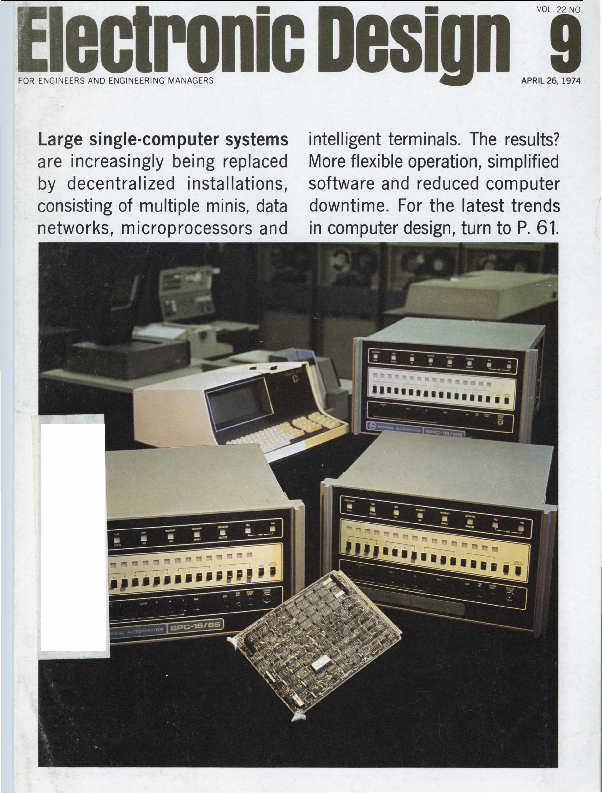
This issue of Electronic Design, dated April 26, 1974, delves into the rapidly evolving world of computer technology and electronic components. Discover how decentralized installations are replacing large single-computer systems, offering more flexible operation and simplified software. The magazine highlights key trends in microprocessors, intelligent terminals, and data networks, providing insights for engineers and engineering managers.
Featured are advancements from leading companies in the field:
- Dale Electronics introduces the EBT 156 Edgeboard, a cost-effective connector solution.
- Hewlett-Packard showcases its larger LED displays, the 5082-7750 series.
- Teledyne Relays presents its solid-state DC relay with controlled rise and fall time.
- USCC/Centralab offers MONO-GLASS encapsulated ceramic capacitors designed for high-volume insertion.
- Abbott Laboratories provides solutions for power supply size challenges with their compact converters.
- TRW Capacitors emphasizes quality and technological leadership in their component offerings.
Explore articles on microcomputer software, instrument design with microprocessors, telemetry systems, and techniques for minimizing computer errors. This publication serves as a valuable resource for professionals seeking to stay ahead in electronic design and innovation.
