File info: application/pdf · 208 pages · 108.87MB
Document preview and download links are below.
Extracted Text
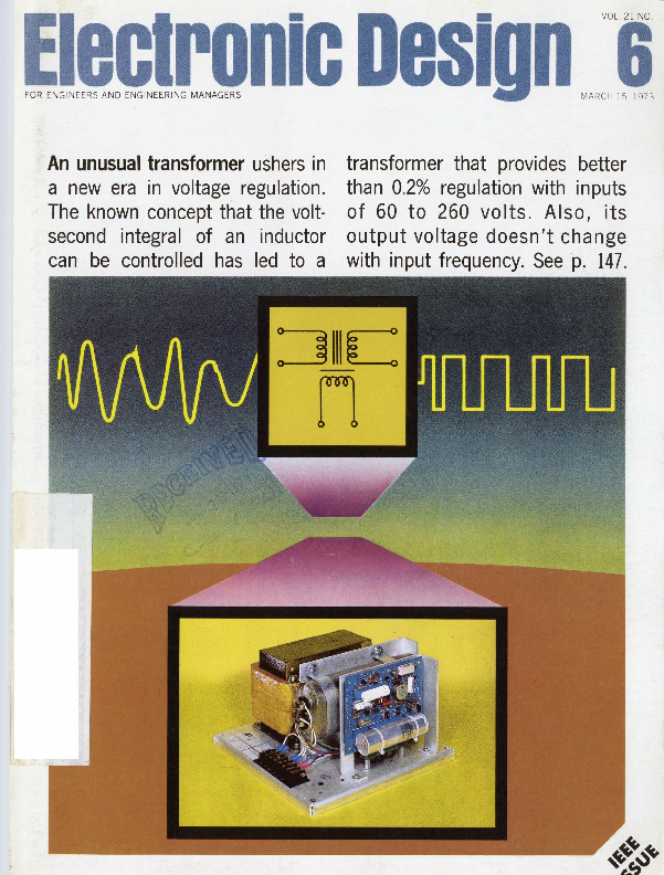
An unusual transformer ushers in
a new era in voltage regulation. The known concept that the voltsecond integral of an inductor can be controlled has led to a

transformer that provides better than 0.2% regulation with inputs of 60 to 260 volts. Also, its output voltage doesn't change with input frequency. See p. 147.

:JlllC
n

Only from Lambda the LP series
a complete line of laboratory power supplies for bench or rack mounting

All 5-year guaranteed All 1-daydelivery

LPD SERIES DUAL OUTPUT MODELS
5 3/16" x 83/s" x 10%2"
+ REGULATION: 0.01% 1 mV
RIPPLE: 500 �V RMS

MODEL

VOLTAGE
RANGE Per Output
Outputvsoine Series

3o� c

MAX. CURRENT {AMPS) AT AMBIENT OF: Per Output. Outputs in Parallel

4o� c

5o� c

60� c

PRICE

LPD-421 A-FM LPD-422A-FM LPD-423A-FM LPD-424A-FM LPD-425A-FM

0-� 20 / 0-40 0-� 40 / 0-80 0-� 60 / 0-120 0-� 120 / 0-240 0-� 250 / 0-500

1.7 / 3.4 1.0/ 2.0 0. 7 / 1.4 0.38 / 0.76 0 .13 10.26

1.5/ 3.0 0.85/ 1.7 0.6 / 1.2 0.32 / 0.64 0.12/ 0.24

1.3/ 2.6 0.7 / 1.4 0.5 / 1.0 0.26 / 0.52 0.11 / 0.22

0.9 / 1.8 0.55/ 1.1 0.4/ 0.8 0.20 / 0.40 0.10/ 0.20

$290 290 325 325 350

LP 400A SERIES SINGLE OUTPUT MODELS
5 3/16" x 43/16" x 10"
+ REGULATION: 0.01 % 1 mV
RIPPLE: 500 �V RMS

MODEL
LP-410A-FM LP-411A-FM LP-412A-FM LP�413A�FM LP-414A-FM LP-415A�FM

ADJ . VOLTAGE
RAvNoeGE
0-10 0-20 0-40 0-60 0-120 0-250

3o� c

MAX. CURRENT {AMPS) AT AMBIENT OF :

4o � c

5o� c

2 1.2 1.9 0.45 0 .20 80 mA

1.8 1.1 0.90 0.41 0.18 72 mA

1.6 1.0 0 .80 0.37 0.16 65 mA

60� c
1.4 0.8 0.60 0 .33 0.12 60 mA

PRICE
$170 155 155 155 190 210

LP 520 SERIES SINGLE OUTPUT MODELS
5 3/16" x 4 3/16" x 15 %"
+ REGULATION : 0.01 % 1 mV
RIPPLE: 500 �V RMS

MODEL
LP-520-FM LP-521-FM LP-522-FM LP-523-FM LP-524-FM

ADJ. VOLTAGE
RvAoNeGE
0-10 0-20 0-40 0-60 0-120

30 � c
5.0 3 .3 1.8 0.9 0.5

MAX. CURRENT {AMPS) AT AMBIENT OF:

4o� c

5o� c

4.7

4.3

3.0

2.6

1.6

1.4

0.8

0.7

0.45

0.4

60 � c
3.7 2.3 1.2 0 .6 0.35

PRICE
$210 210 210 215 270

LP 530 SERIES SINGLE OUTPUT MODELS
5 3/16" x 83/s" x 155/e"
+ REGULATION : 0.01 % 1 mV
RIPPLE: 500 �V RMS
�. ~-.

MODEL
LP-530-FM LP-531-FM LP-532-FM LP-533-FM LP-534-FM

ADJ . VOLTAGE
RvAoNeGE
0-10 0-20 0-40 0-60 0-120

30� c
10.0 5.7 3.0 2.4 1.2

MAX. CURRENT (AMPS) AT AMBIENT OF:

40 � c

50� c

9.0

8 .0

5.3

4.7

2 .9

2.7

2 .2

2.1

1.0

0.9

60� c
7.0 4.0 2 .3 1.8 0 .8

PRICE
$320 300 300 345 350

& L A M B D A E LE C T R o N I c S C O R P. 515 Broad Hollow Road , Mellville, N.Y. 11746 (516) 694-4200
INFORMATION RETRIEVAL NUMBER 232

MOM TALK
Multiply, Divide and Square Root

Frequency Doubling and Translation

Triangle to Sine Wave
-

-----AM Generation
-
The XR-2208 is a Monolithic Operational Multiplier. Our MOM has an independent four-quadrant multiplier, op amp and high frequency buffer on one chip that you can tie together with minimum fuss to perform a host of analog computations, signal processing and Phase-Lock Loop applications. By combining the multiplier and buffer functions, the small signal 3-db bandwidth can be extended to 8 MHz and the transconductance band-

- - - - -Whistler's MOM
width to 100 MHz. Current and voltage levels are internally regulated with good power supply rejection and excellent temperature stability. MOM has a � 4.5 V to � 16 V supply range , and in her prime 0 � to 70� she 's only $6.90 in 1OO's. Our relaxed MOM is the 2308 and sells for $4 ; our MIL MOM is $9 .25 . Well . . . why not send for an 8-page data sheet jam-packed with applications? Call and ask for MOM .

r CXAR SPEAKS YOUR LANGUAG�

EXAR INTEGRATED SYSTEMS
750 Palomar Sunnyvale, Cal ifornia 94086 (408 ) 732-7970 TWX 910�339�9233
EXAR SALES REPRESENTATIVES Alabama , Georgia, Mississippi, North Carolina, South Carolina and Tennessee: K&E Associates, Kennesaw, Georgia (404) 974-4264 Arkansas, Louisiana, Oklahoma and Texas: Evans-McDowell, Dallas, Texas (214) 238-7157 California : De Ange lo, Rothman and Co., Cul ver City (213) 398-6239 , Logan Sales Co., Redwood City (415) 369-6726 Connecllcut, Maine, Massachusetts, New Hampshire, Rhode Island and Vermont: Com-Sale, Wa ltham, Massachusetts (617) 890-0011 , Meriden, Conn. (203) 634-0179 Indiana, Kentucky and Ohio: McFadden Sales, Columbus, Ohio (614) 221-3363 Idaho, Oregon and Washington : SD � R' Products & Sales, Bellevue, Washington (206) 747-9424 Illinois and Wisconsin: Mar-Con Associates, Inc., Skokie, Illinois (312) 675-6450 Maryland, Virginia and Washington , D.C.: Rep-tron , Inc., Sliver Spring, Maryland (301) 593-4844 New Jersey (South) and Pennsylvania: Harry Nash Associates, Willow Grove, Pennsylvania (215) 657-2213 New Jersey (North) and New York : MOS Associates, Floral Park, New York (516) 694-5923 Canada: Harvard Electronic Sales, Laval, Quebec (514) 681-1400 EXAR DISTRIBUTORS California: EEP Corporalion, Culver City (213) 838� 1912, lntermark Electronics, San Carlos (415) 592-1641, San Diego (714) 279-5200, Santa Ana (714) 540-1322 Colorado: lnterm ark Electronics, Denver (303) 936-8284 Massachusetts: Gerber Electronics, Dedham (617) 329-2400 Washington : lntermark Electronics, Seattle (206) 767-3160

ELECTRONIC D ESIGN 6, March 15, 1973

INFORMATION RETRIEVAL NUMBER 2

For the really tough applications, OEM's like VIDAR choose HP.

How do you record millions of telephone calls daily, process this data, and bill millions of customers monthly without any errors? The VITEL division of VIDAR tackled this problem and solved it with their unique new telephone message metering system.
To record the raw data, VIDAR needed a magnetic tape drive with proven reliability at a competitive price. That's why VIDAR chose HP's 7970E Tape Drive. They needed the best of both worlds and knew that HP quality was the result of 33 years of experience in engineering and mass production techniques that lower costs and improve reliability.
The VITEL system records "one-shot" data at a telephone company central office to provide accurate usage

information. For instance, one system in a major metropolitan area handles 3.6 million telephones in over 100 offices. The system replaces mechanical message registers to bring a new level of accuracy to customer billing procedures.
But OEM's like VTTEL want - and need - more than rugged construction, reliable performance, and competitive pricing.
They want a broad range of data rates. Like 200,556,800 cpi NRZI, or 1600 cpi phase-encoded recording that's ANSI/ IBM compatible. And flexibility, like 7 and 9 track, multi-density, NRZI and PE; all in one read-only tape drive.
Plus OEM Specials. Like 50-Hz 230-volt operation. Or personalized labels or logos. Even different paint on

the front panel. And how about OEM discounts, and a one-page OEM agreement written in plain English.
For the full story call your local HP sales engineer or write: Hewlett-Packard, 1501 Page Mill Road, Palo Alto, California 94304; Europe: P. 0. Box 85, CH-1217 Meyrin 2, Geneva, Switzerland; Japan: Yokogawa Hewlett-Packard, 1-59-1, Yoyogi, Shibuya-ku, Tokyo, 151.
lfi HEWLETT PACKA~.~
HP sales, service and suppon in 172 cities in 65 countries.

NEWS
25 News Scope 28 One-transistor-per-bit, random-access-memory eel Is
reaching for first place in MOS memories. 29 Lab advances giving GaAs FET edge over bipolar for microwaves. 30 EFL, a new logic family for LSI, promises to ease designer's job. 34 Advances in resistor fabrication yield monolithic 10-bit DACs. 36 Kilovolt supply circuit fashioned from cheap, low-voltage parts. 40 Technology Abroad 43 Washington Report
66 IEEE '73-A special section devoted to this year's big show

TECHNOLOGY
106 Protect solid-state power rectifiers by limiting peak junction temperatures to maximum ratings. Simple formulas cover the most common overload conditions.
112 Blend ECL and TTL ICs to obtain high-frequency counter circuits. Counters up to 500 MHz can be built for systems or bench use.
120 Cascode differential pairs instead of cascading them. You'll find significant improvements in common-mode rejection ratio and common-mode input resistance.
126 Get 0.02% full-scale VCO accuracy. Here's an oscillator that uses frequency feedback to avoid the conventional integrate-compare errors.
132 Designing what the customer wants, says this manager, isn't as easy as it sounds. A high percentage of the time the goal is not fully met. Here are tips to design on target.
136 Ideas for Design: Wideband circuit fits curves with straight-line segments . . . . Ambiguous contact closures eliminated in sequential timers ... Phase-lock indicator operates with either periodic or PCM inputs ... Single-digit readout offers range of 95 dB with 0.002 % resolution . . . Resistive network converts limit detector to movable window operation.

PRODUCTS

147 Modules & Subassemblies: CV transformer holds output to 0.5% over

wide load, line, frequency changes.

156 ICs & Semiconductors: 4-bit BCD adder and arithmetic unit perform

faster with less power.

164 Microwaves & Lasers: $30 double-balanced mixer lists 1-GHz range in

miniature package.

152 Instrumentation

171 Packaging & Materials

168 Components

Departments

49 Editorial: The maiden and the editor

7 Across the Desk

182 Bulletin Board

174 Design Aids

188 Advertisers' Index

175 Application Notes

190 Product Index

176 New Literature

192 Information Retrieval Card

Cover: Photo by William E. Wilson Co., courtesy of Advanced Power, Inc.

Design by ED art director, Bill Kelly. Controfluxer symbol is

a registered trademark.

ELECTRONIC DESIGN is published biweekly by Hayden Publishing Company, Inc., 50 Essex St., Rochelle Park, N. J. 07662. James S. Mulholland, Jr., President. Printed at Brown Printing Co., Inc., Waseca, Minn. Controlled circulation postage paid at Waseca, Minn., and New York, N . Y., postage pending Rochelle Park, N . J. Copy-
right � 1973, Hayden Publishing Company, Inc. 84,392 copies this Issue.

..... INFORMATION RETRIEVAL NUMBER 3

3

One-stop TTL shopping for 74S MSI, SSI. ..

At last. Available now, all in one place. The whole mix in Schottky logicto match every high speed TTL function in demand today. Signetics broad line of 74S circuits. Plus ourcompatible82S series of enhanced MSI devices that help Schottky give you a competitive step-up in speed, in design-ease, in versatility ... and of course, in MSI complexity. And you get it where you want it, when you want it. Fast service directly from distributor stock. Signetics knocks off the waiting list tie-ups, the multi-stop shopping. After all, how can we encourage you to boost system speed by replacing TTL with Schottky equivarents, if you can't get the circuits to work with? All the parts you needwithout delays, without runarounds, without making six calls when one should do the job. Here's where Signetics makes the difference. One call does the job. Completely. SSI Schottky to cover full function range:

74SOO 74503 74S04 74505 74510 74511 74S15 74520 74564 74565 74574 745112 745113 745114 74540 745140

SSI SCHOnKY 748 nL
Quad 2-lnput NAND Gate Quad 2-lnput NAND Gate (Open Collector) Hex- Inverter Hex-Inverter (Open Collector) Triple 3-lnput NAND Gate Triple 3-lnput Positive AND Gate Triple 3-lnput Positive AND Gate (Open Collector) Dual 4-lnput NAND Gate 4-2-3-2-lnput AND/OR/INVERT Gate 4-2-3-2-lnput AND/OR/INVERT Gate Dual D-Type Edge-Triggered Flip-Flop Dual J-K Edge-Triggered Flip-Flop Dual J-K Edge-Triggered Flip-Flop Dual J-K Edge-Triggered Flip-Flop Dual 4-lnput NAND Buffer Dual 4-lnput NAND Line Driver

4

You can make the same call encompass MSI too. Signetics 74S MSI circuits offer the same volume availability as SSI, as well as the same - - - - total TTL compatibility-pin-for-pin fits with standard TTL and low-power Schottky. Ten MSI devices in stock now, with more to be announced in the next few months.
74S151 8-lnput Data Selector/Multiplexer 74S153 Dual 4-lnput-to-1-Line Selector/Multiplexer 74S157 Quad 2-Line-to-1-Line Data Selector/Multiplexer 74S158 Quad 2-Line-to-1-Line Selector/Multiplexer (Inverting) 74S174 Hex D-Type Flip-Flop w/Clear 74S175 Quad D-Type Flip-Flop w/Cle.ar *74S181 Arithmetic Logic '74S194 4-Bit Bidirectional Shift Register '74S195 4-Bit Parallel Access Shift Register 74S251 8-lnput Data Selector/Multiplexer w/tri-state 74S253 Dual 4-lnput-to-1-Line Selector/Multiplexer w/tri-state 745257 Quad 2-Line-to-1-Line Data Selector/Multiplexer
w/tri-state outputs 74$258 Quad 2-Line-to-1-Line Selector/Multiplexer
(Inverting) w/tri-state
�January-February announcement
Complementing 74S, Signetics 82S series MSI circuits offer significant advantages in sophisticated Schottky systems designs. The conventional TTL input circuit found in all Schottky logic, otherthan Signetics 82S, suffers from low input impedance.
Signetics advanced PNP structure produces significantly higher input impedance. You can drive far more devices from one output since input current is one-fifth that of standard Schottky inputs. With Signetics82S MSI you need not worry about noise when driving long lines since, in addition to 10 PNP loads, a termination resistor can be accommodated when needed without fan-out reduction.
ELECTRONIC DESIGN 6, March 15, 1973

...and now optimized 82S MSI too.

J CONVEN~IONAL 74S INPUT

IIN(0) = 2m~ A

Vee

--��

liN (1) = 501-'A

-"

ADVANCED SIGNETICS 82S INPUT

~N(OHO';./

Of course the 828 M81 line interfaces with 748 logic directly, operating in the same design environment as all 7400 circuitry but with the added advantage of direct replacement without violating fan-out rules.

82830/31/32 8-lnput Digital MulUplexer

82833/84 2-lnput, 4-Blt Digital MultlplelCer

81841142 Quad Exclusive-OR/Quad ~

t2850/.U Blnary-to-Octal/BCD-to-Dec:lmalOecoder

1RS12

Hit Parity Generator/Checker'

flll8117 2-lnput, 4-811 Digital Mulllplmlf
82870ff1 4-Blt Shift Aeglater

82882

BCD Arithmetic Unit

828M

BCD Adder

82880ftt Praeettable Decade/Binary Cot.tnt9r

15 ns 15 ns
5 ns 12 ns 17 ns 15 ns 70MHz 20 ns 20 ns
100 MHz

748/8288chottkyTTL. Just one call to one of our

distributors, reps or salesmen. And 8ignetics puts it on

�

the line. Your line.

Signetics-Schottky

811 East Arques Avenue

Sunnyvale, California 94086

High speed response requested on SchottkyTIL data, specs, applications and delivery for 748 SSI, 74S MSI and 828 MSI.

The growing line of 828 includes ultra high speed pin-for-pin replacements for the popular 8200 series M81. In addition, the82890/91100 MHz counter will replace the 74196/197, and the82870/71 70 MHz shift register will replace the 74178/179 in systems requiring improved speed performance.
The BCD arithmetic unit 82882 replaces at least six M81 packages previously needed for the same function while at the same time operating speed is improved by a factor of 3. For BCD applications that only require addition, the82883 adder will replace three M81 circuits, and double operating speed. The 82862 parity generatorI checker is unsurpassed in speed.

Name Title Company Address City Telephone

State

Zip

Signetics Corp~ ration , a subsidiary of Corning Glass Works.

!ii!IDl!liC!i

INFORMATION RETRIEVAL NUMBER 4

ELECTRONIC D ESIGN 6, March 15, 1973

5

Our Bill Shuart doesn't work
for Power/Mate.

Be works only for you... and that's the way the new Power/Mate
wants it.

Bill is .the Power/ Mate Quality Assurance Manager and he has 34 supervisors and perfectionists under him.
They also work for you . The result is unexcelled and consistent quality that we at Power/ Mate are genuinely proud of. Bill does a lot more than making sure our products are produced in accordance with his high standards of workmanship. (He wrote the book on that too.) Bill has developed a series of courses for all our employees on soldering techniques and workmanship standards. D He has developed a computer failure analysis program to
insure that our vendors also maintain the consistent high quality you should expect when you use our power supply in your product.

D He oversees the continuing MTBF studies {by computer of course) and worst case calculations on all our power supplies to insure the long life and trouble free performance you should expect.
D He has developed a thermally cycled burn-in rack in which we subject a// of our power supplies for 24 hours before shipment to insure there are no premature field failures.
D He oversees the random sampiing of all production-run power supplies. These are subject to a continuous night and day life test ... for your continued assurance of a long-lived trouble free
product. We could go on ... but we at Power/ Mate are glad he works for you. That's why we can give a five year no-holds warranty.

THE NEW-1~u~-,~1

POWER/MATE CORR
514 S. River Street, Hackensack, N. J. 07601 / Phone (201) 343-6294 TWX 71 0-990-5023

INFORMATION RETRIEVAL NUMBER 5
6

Vice President, Publisher
� Peter Coley

Editors
Editorial Offices 50 Essex St. Rochelle Park, N.J. 07662 (201) 843-0550 TWX: 710-990 5071 Cable: Haydenpubs Rochellepark
Editor-in-Chief: George Rostky
Managing Editors: Ralph Dobriner Michael Elphick
Associate Editors: Jules H. Gilder Morris Grossman Seymour T. Levine John F. Mason Stanley Runyon Edward A. Terrero Richard L. Turmail
Contributing Editor: Peter N. Budzilovich

Editorial Field Offices
East Jim McDermott, Eastern Editor P.O. Box 272 Easthampton, Mass. 01027 (413) 527-3632
West David N. Kaye, Senior Western Editor 2930 West Imperial Highway Inglewood, Calif. 90303 (213) 757-0183
Washington Heather M. David, Bureau Chief 2506 Eye St., N.W. Washington, D.C. 20037 (202) 338-3470

Editorial Production
Marjorie A. Duffy

Art
Art Director, Williatn Kelly Richard Luce Anthony J. Fischetto

Production

Manager, Dollie S. Viebig

Helen � De Polo

�

Maxine Correa! Anne Molfetas

Circulation
Manager, Nancy L. Merritt Ron Deramo

Information Retrieval
Peggy Long

Promotion
Manager, Jeffrey A. Weiner Karen Kerrigan

ELECTRONIC DESIGN 6, March 15, 1973

(across the desk)

Print what we now don't? Readers give us advice

Just finished reading your Dec. 21, 1972 editorial, "What We Don't Print-Should We?" (ED 26, p. 45 ) . It brought back some memories of my own editorial days and of pressures from some of our media reps. Taking you at your word, I'd like to jot down a few reactions to them :
First, I would regret your substituting a policy of printing the vendors' �boilerplate for your present policy of "reject it all!" But I would regret even more the possibility of your keeping your present nondiscriminating policy. Some of these vendors have some excellent engineers, whose ideas should be expressed in print. Your policy prohibits this.
Second, I do not agree at all with your policy of automatic rejection of articles on the application of proprietary products. What the hell, you would not have printed an article on how to apply Tl's first integrated circuits until other licensed firms got into production! And your editors, as bright as they are, could not possibly do as comprehensive a job on such an article as the men who conceived the product after perceiving the need!
Third, I am delighted to see that you vi.olate your own policy. Your � editorial ran on p. 45. On p. 48 Stanley Hall's excellent article on the tricks of using high-speed logic ran with his Bunker-Ramo by-line. What does Bunker-Ramo sell? Campaign buttons?
Robert J. Mi tchell President
Cramer/ Mitchell Advertising 1212 Wilshire Blvd. Los Angeles, Calif. 90017
Articles that tend to gild a cor-

porate image should not be published in your magazine, unless they are subject to editing by your staff to remove the gilding and provide useful information to designers.
R. E. Jurewicf Senior Supervisor GTE Automatic Electric Laboratories Box 17 Northlake, Ill. 60164
As to your question regarding articles pushing a particular product of a particular manufacturer, with said article prepared by said manufacturer: Judge each article strictly on its technical content. Discontinue your practice of rejecting articles touting a product available from only one manufacturer. I want to learn what is new and useful. Please do not deprive me of such information merely because particular items are available from only one manufacturer.
R. 0 . Whitaker Engineer
Rowco Engineering Co. 4719 Squire Dr. Indianapolis, Ind. 46241
Your readers here heartily support your present article-acceptance policy. Your resistance to vendor pressures is commendable.
Martin L. Bayor Project Manag er National Scientific Lab, Inc. Westgate Research Park McLean, Va. 22101
Your Dec. 21 editorial is motherhood, apple pie and ice cream. Any-
(continued on page 10)

Electronic Design welcomes the opinions of its readers on the issues raised in the magazine's editorial columns. Address letters to Managing Editor Electronic Design, 50 Essex St. Rochelle Park, N. J. 07662. Try to keep ietters under 200 words. Letters must be signed. Names will be withheld on request.

~~
THE ~, ~
LONG LINE
OFECC
THERMOTAB�& THERMOPAK~:~
TRIACS
World's leading Triac producer offers
fast delivery, electrical isolation and competitive pricing.
THERMOTAB and THERMOPAK TRIACS
(Electrically isolated tab)
� Wide current range ITIRMSI 0.8 � 16 amps
� High voltage capability VDROM 200 . 800 volts
� High surge current ratings ITSM 20 . 150 amps
� Sensitive gate triggering 191 1, 111 3, 5, 10, 25, 50 ma
All ECC triacs feature heavily glass passivated junctions for high reliability. They are available from your nearest ECC Sales Representative or Authorized Distributor.
' trademark of ECC
NEW CONDENSED CATALOG contains technical data on these and other ECC semiconductors.
To receive your copy, circle No. 246.
Ecc �
CORPORATION P. 0. Box 669 � Euless, Texas 76039
817 /267-2601

EL ECTRONIC D ESIGN 6, March 15, 1973

7

Everybodywantsyo11r components business.

Butwere doing
6 things to ea111 lt.

1Extra reliability. We build extra reliability into our components to let you build extra reliability into your systems.
We offer documented reliability from ER through industrial, from precision through general purpose.
2 Pricing you'll like. For many product styles, our quantity resistor pricing is under 5� and often less than 3�. And that's for CORNING�metal film resistors that significantly outperform other metal films (including glazed), wirewounds and carbon comps.
3 Faster delivery. Our distributors can give you off-the-shelf delivery from an inventory of over 50,000,000

components. And our "ball parks" lot of board space.

are firm, real and reliable. This lets you keep expediting and inventory levels to a minimum.

6 Sharper support. We've hand-picked the 30 most competent distributors in

4 Production savings. Our unique product configurations greatly simplify both

the country and built the industry's largest technically trained field force-then backed every-

hand insertion and automatic in- thingwith a full team of specialists

sertion operations. This saves you - to give you all the in-depth

money. And our QC is so stringent, service you want and then some.

many of our customers have to-

We too want your busi-

tally eliminated their incoming n~ss. But we're doing 6 extra

QC testing of our parts. This

things to earn it.

saves them money.

Give us a chance to prove

5 Product innovations. Like our new CORDIPTM Component Networks.

it. Write: Corning Glass Works, Electronic Products Division, Corning, New York 14830. Or call:

With up to 23 discrete resistors/ (607) 962-4444, Extension 8381.

C O R N I N G capacitors/diodes in a miniature,
pre-tested, plug-in package to

save you time, money, and a whole E L E c T R o N I c s

Resistors &Capacitors

for guys who can\ stand failures

INFORMATION RETRIEVAL NUMBER 7

ELECTRONIC DESIGN 6, March 15, 1973

9

ACROSS THE DESK

D� llw-1111, --111111
vlMa 1/1 convener thlt dellven
. . . . . lld ma111111.-..
INFORMATION RETRIEVAL NUMBER 8
10

( conti nued from page 7)
one (except for a few warped marketing managers ) who disagrees with you is a Communist or a Peeping Tom. All I'm really interested in is where you say of a product: "We'll show its advantages and limitations, its strengths and weaknesses . . . and show how it stacks up against competing technologies and products." Do a complete job on that, and all us warped marketing managers will be happy.
Stan Harris Marketing Manager-Mi crocircuits Analog Devices, Inc. Route 1 Industrial Park P.O. Box 280 Norwood, Mass. 02062
I support your present policy. Particularly annoying, I have seen articles in electronics magazines that were actual reprints of manufacturers application notes!
David Sherdell Engineer
Random Research P.O. Box 253 Tenafly, N.J. 07603
About that editorial "What We Don't Print-Should We?" I'd say yes, with some qualifications.
You say you're the top design book, right? Design engineers look to your pages for what's happening, right? Well, by the time an IC or component is popular enough to be second-sourced and thus eligible for an article in ED, it's no longer state-of-the-art. The designer can read about its benefits and features in your New Product section, true. But what he needs is design and applications information beyond the data sheet.
If the product is truly state-ofthe-art, it no doubt does something better than something else does . Why not make the author do an extensive comparison to demonstrate that fact? Perhaps you could limit such articles to one or two a month and set up an independent judging board to select the
( conti nued on page 15 )
INFORMATION RETRIEVAL NUMBER 9 ....

1. For almost unlimited mounting flexibility
2. To reduce package costs by 20%
3. To save up to 75% on interconnection costs

1. For almost unlimited mounting or terminating flexibility ... try Elco's new mix and match connector systems. Board-to-board, cable-to-board or cable-to-cable. Gives you a new order of freedom in circuit packaging. Through the use of two new Elco miniature crimp, two piece, metal-to-metal connectors that also mate with their existing termination counterparts. One of these, the new Series 8221 crimp type, mates with Series 8219 PC miniature board connectors. Both are available with 18, 30, 36, 42, 54 and 72 dual row contacts on .050" offset grid. The other, Series 8229 crimp type, mates with Series 8129 PC type connectors and provides a single row of 6. 9, 10, 12 or 15 contacts on .100" centers. All use new Vari con"" low withdrawal force contact ( 1-6 ozs. per contact pair) which provides MIL-Spec reliability MIL-C-55302 type.
2. Reduce total packaging costs by up to 20% ... with Elco's .125"x .250" Series 6064 and .1OO" x .200" Series 6307 discrete card edge connectors. Because we can supply them mounted on an Elco Variframe1" back panel - custom designed and built to your specs. With up to three levels of wire wrapping, input/output connectors and voltage and/or ground buses . For high performance . At low cost. Also available - right off your distributor's shelf and priced right - Elco Series 6007 card edge receptacles with .156" spacing .

3. Save up to 75% on interconnection costs ... with Elco's .125"x .125" Series 6327 *, .100"x .200" Series 6320*, and .125"x .250" Series 6321 * press-fit card edge connector systems. They provide the design flexibility of wire wrapping with the economy of PC wiring. Typically, you might specify 50 to 75% of your interconnections as PC wiring, including all grounds and voltage distributions. And thus cut interconnection costs by up to 75%. Interconnections are made by press-fitting the contacts of our connectors into the plated-through holes of a board. Complete the job with easy-to-change wire wrapping of the appropriate contacts. Call or write for information or samples.
Three ideas from Elco that make good connector sense. In keeping with CONNECTRONICS, Elco's Total Connector Capability.
For full details on these connectors from Elco, contact your local Elco representative or distributor, or:

Elco Corporation ,

Willow Grove, Pa. 19090,

T.

(215) 659-7000 Elco Corporation,

?~-'J (j-, ~

2200 Park Place,

_

El Segundo, Calif. 90245 ~--~

(213) 675-3311

Operations in USA, Australia , Belgium, Canada , Denmark, England, France, Germany, Israel and Japan. Sales offices throughout the world.

In Europe, Elco Beige, 77 Blancefloerlaan, Antwerp, Belgium, Tel . 03-190064. In the Far East, Elco International, TBR Building, 2-10-2 Nagata-

cho. r.hivnrl,. .. ku . Tnkvn 1M l::irin::.in T,:i.J e'\A0-,711 / t:. *P--*------P-4ndin.o

n u ..lo.h~~

lld..a.h.t.....,.......,..,.,,.___ __

Take signal sources
for example . ..
You can't see the automated testing and the other manufacturing advances that help lower the price of HP's quality signal sources. But you sure can see the versatility and extra performance you get for your money. From the simplest function generator to the most capable synthesizer, HP technology has brought the price of quality way down .

20 TTL loads. Note that price again. It's 15% lower than its nearest major competition.
Wide Range Function Generators 3310A/B deliver general-purpose waveforms with extended low-frequency response. These 0.0005 Hz to 5 MHz instruments equip you with a linear very-low-frequency ramp, in addition to sine, square, triangle and pulse waveforms. Prices are a modest $595 for the 33 lOA, and $735 for the 33 lOB that also provides free-run, single-cycle and multiple-cycle operating modes.

Brand New Function Generator 3311A shows what a performance plus you get from this technology in action. Priced at only $249, it adds sweep capability and a separate highpower pulse output to the usual sine, square and triangular wave outputs. Sweep it over any 10 to 1 span within its 0.1 Hz to 1 MHz range . The pulse output drives up to
12

ELECTRONIC D ESIGN 6, March 15, 1973

ess
Whatever your needs in signal sources, 'satisfy them with one of HP's technology-leader instruments. They're packed with more capability than ever before-and priced lower, too. For more information on the entire family of HP signal sources, contact your local HP field engineer. Or, write

Lowest Cost Frequency Synthesizers 3320A/B bring you synthesizer quality for as little as $1,900. You get 1 part in 106 frequency resolution over the entire 0.01 Hz to 13 MHz range. Also, on the 3320B, HP's thermopile control of amplitude level gives 0.01 dB level resolution. If precise amplitude setting and calibration aren't required, get the 3320A for $1,900. Or, get both frequency and amplitude precision in the 3320B for $2,550 (add $595 for full ASCII programmability). How's that for a blend of quality, performance and low price!
Top-of-the-line Automatic Synthesizers 3330A/B have a built-in "brain" that Jets you avoid tying up a computer. They're like the 3320A/B, only these can be programmed to automatically sweep their frequency spectrum (and, on the 3330B, its precision amplitude level). With the 3330B you're getting a synthesizer, a sweeper, a marker generator, a counter, a programmable attenuator, a built-in controller and a precision level generator-in other words a Jabin-a-box-for just $6,000. Or, cut that to $5,100 for the manual-amplitude-control 3330A.

Hewlett-Packard, Palo Alto, California 94304. In Europe: HPSA, P.O. Box 85, CH-1217 Meyrin 2, Geneva, Switzerland. In Japan: Yokogawa-Hewlett~Packard, 1-59-1, Yoyogi, Shibuya-Ku, Tokyo, 151.
093/43
SIGNAL SOURCES

INFORMATION RETRIEVAL NUMBER 10

ELECTRONIC DESIGN 6, March 15, 1973

13

MPLHEzS�SsEOYUBTEAOTFSETVHEERYONE ELSE.

The SP 616 bi-polar digital divider operates at frequencies in excess of 1000 MHz. One top IC supplier declares a 500 MHz; the next best only guarantees 220- and both only at room temperature. And so it goesstraight down the line.
The SP 600 series of DC to lGHz frequency dividers (with guaranteed 9perating temperature ranges of
- 55 to + 125 degrees centigrade) is
absolutely the fastest by far.
And it includes dozens of prescalers and variable ratio counters which deliver Plessey's superior performance.
Whether you're putting together complex communications, or military systems or specialized high frequency test instruments, it pays to specify Plessey.

PLESSEY SEMICONDUCTORS

1674 McGaw Avenue, Santa Ana California 92705 (714) 540-9945
r----------------------

Please send me a complete literature packet.

Now.

�

D I would like information only at this time.

D I would like to talk to your representative
personally.

Title_ _ _ _ _ _ _ _ _ _ _ _ __

Firm_ _ _ _ _ _ _ _ _ _ _ _ __

Address_ _ _ _ _ _ _ _ _ _ _ __

City_ _ _ _ __ State._ __

Phone No._ _ _ _ _ _ _ _ _ _ _ _..__

I

1

~--------------------

Minneapolis, Minnesota

Los Altos, California

(612) 835-271 7

(415) 941-4080

Fra mingham, Massachusetts Houston, Texas

(617) 879-7920

(713) 462-4077

San Diego, California (714) 295-2500

Farmingdale, New York (516) 694-7377

�
� � �

. .
�

,, �

.. �

�

IN FO RMATION RETRIEVAL NUMBER 13

14

E L ECTRON IC D ESIGN 6 , M a rch 15, 1973

ACROSS THE DESK
(continued from page 10)
"true blue" new product/applications articles.
Regis McKenna Communication Strategies 644 Emerson St. Palo Alto, Calif. 94301
The articles written by various companies are usually available from those companies. ED should reject such articles.
J. M. Gwinn, EE Federal Communications
Commission Room 722 1919 M. St., NW Washington, D.C. 20554
Your concern for literary and technical integrity expressed in your Dec. 21 editorial was appreciated. In response to your request for alternate viewpoints, I offer the following:
The larger companies can afford to circulate technical information and ballyhoo on their own products. It complements catalog and sales information and can aid product selection. In using information from these sources, we recognize that it is seldom complete.
It would be beneficial to have more detailed information on competing products, or competing technical viewpoints from smaller companies that can't afford an expensive journal. These companies are frequently founded and managed by the most creative members of the technical community, some having left the larger companies to prove their convictions regarding technology and better products.
If a person or company has come up with a state-of-the-art, one-of-its-kind product, I'd like to hear them talk about it in as much detail as possible. The higher the potential buying risk, the more data and words you need to form an impression.
J. E . Marks Proj ect Engineer Eastman Kodak Co. 2632 Oakview Dr. Rochester, N.Y. 1461.7
Referring to your editorial in ( continued on page 18)
ELECTRONIC DESIGN 6, March 15, 1973

Stacked'...with beautiful curves!

(stacked-foil construction with ultra-low impedance, ultra-low ESR, ultra-low inductance)

Revolutionary new Type 4320 COMPULYTIC� Aluminum Electrolytic Capacitors offer capacitance values to 100,000 �.F with equivalent series resistance of typically less than 0.001 ohm and
inductance of only 1 nH in a 3" x
55/a" case. This same capacitor will handle 93 amperes of ripple current at 65 C and 1 kHz.
Impedance limits at 10 kHz are as low as 0.001 ohm with typical values of only half of the specified limits.

Terminals are ideal for use with laminated-bus power distribution systems found in modern EDP equipment, where the low ESR and impedance of Compulytic capacitors help insure continued operation of logic circuits even during momentary power outages.
Sprague Type 4320 Capacitors are available in nine voltage ratings from 5 to 50 volts d-c, and are designed for operation over
the temperature range from -40
to +as c.

For complete technical data, write for Engineering Bulletin 3443 to: Technical Literature Service, Sprague Electric Co., 347Marshall St., North Adams, Mass. 01247.

SPRAGUE "
THE MARK OF RELIABILITY

THE BROAD-LINE PRODUCER OF ELECTRONIC PARTS

INFORMATION RETRIEVAL NUMBER 14
15

GPD-402 5-400 MHz, 13 dB gain, 6.0 dB N.F., +6 dBm P 0
In 1971, Avantek's low-cost GPD Series began replacing up to 15 different components with a single highly reliable unit of gain. Six models operate at frequencies from 5 to 400 MHz.

Avantek's discrete Unit Amplifier family has pro-
vided patented modular cascadability and broad-
band performance to design engineers for more
than five years. Today, 25 models are available.

20-300 MHz, 18.5 dB gain, 3.5 dB N.F., +10 dBm P 0

The introduction in 1970 of Avantek's UTO
MIC�amp� Series expanded upon the Unit
Amplifier concept by offering miniature thin film MIC modules with frequency coverage to 2 GHz. 25 standard UTO
models are currently being produced.

UT0-2011, 1-2 GHz, 7.5 dB gain, 5.0 dB N.F., -3 dBm P 0

Now, the UDP-2032 and three-model UDP-4000 Series introduce a new dimension in microwave
system design by offering cascadable "connector-
less" thin-film amplifiers for high-performance applications to 4 GHz.

UDP-4001,2-4 GHz, 5.0 dB gain, 8.5 dB N .F ., +5 dBm P 0

u-nique (u-n8k'), adj., 1. different
from all others; having no like or equal ...

U.S. Patent 3493882 covers a unique circuit design developed by Avantek engineers in the mid-1960's. This design has enabled Avantek to develop and deliver a succession of modular amplifiers, featuring flat gain cascadability, that have set the pace in solid-state amplifier miniaturization, flexibility and reliability in the
years since.

No one else offers a comparable product line. That's unique. Avantek modular units are available for applications from DC to 4 GHz. A wide selection of models allows the circuit
designer to match units to exacting gain, noise and power requirements in packages suitable for his needs. Limiter and variable gain modules are also available.

The cascadable amplifier concept, and its continuing refinement over recent years, is representative of Avantek's established technology leadership. Find out about Avantek's unique modular amplifiers by phoning your nearby field representative or contacting the factory directly. Be sure to ask for the August 1972 Component Catalog that gives a complete listing of the entire Avantek amplifier/oscillator line.

Avantek .. . years ahead today.

Avantek , Inc., 3175 Bowers Avenu e. Santa Clara . Cal i fornia 95 051. Phone (408) 249-0700. TWX 910-339-9274 Cable: AVANTEK

INFORMATION RETRIEVAL NUMBER 15

16

ELECTRON IC DESIGN 6, March 15, 1973

E
14-Bit DAC's troms95
LOW COST 14-BIT DAC's-The new ZD300 Series include ten new models that offer excellent linearity, fast settling, current and voltage outputs, bipolar and unipolar coding, slaveable reference, and two quadrant multiplication. Prices range from $85 to $179 in single quantities. FAST SETTLING Tl MES (1 us)-Settling times as fast as 1 us for current output models and 2 us for voltage output DAC's makes the ZD300 Series useful in a variety of data conversion applications. UNIPOLAR, BIPOLAR OUTPUTS- Unipolar and bipolar operation is specified at 0 to lOV, and �lOV, respectively. Current output models are rated at ~2 mA. Voltage output models also feature current output capability as well as two-quadrant multiplication-up to 100 kHz. LINEARITY 0.005o/e>-High performance units feature linearity error of only 0.005% of full scale. Moreover, the extremely low linearity temperature coefficient of only 0.0005%/�C ensures high resolution accuracy. SMALLEST 14-BIT DAC's- The ZD300 Series modular DAC's measure only 1.96 x 1. 76 x 0.40 inches high-less than 1.4 cubic inches in volume. Low profile, DIP pinning compatibility and interchangeability of models make the series highly desirable for OEM usage. APPLICATIONS- The versatility of the ZD300 Series makes them an excellent choice for use in process-control systems, automated test equipment, servo/synchro/resolver systems, and biomedical instrumentation. Multiplying capabilities further enhance their use for CRT character generation, digital modulation, and polar-to-rectangular coordinate conversion.
IZlel"te.'NC.LEADERS IN DATA CONVERSION TECHNOLOGY
CA LL or WRITE TODAY for detailed data on these and other ZELTEX Conversion and Linear products.
1000 CHALOMAR ROAD � CONCORD, CALIFORNIA 94518 � (415) 686-6660 TWX 910- 481-9477
INFORM ATION RETRIEVAL NU.. "'BER 211

' �

The IjED with a built-in resistor.

01322
16B

Now. two direct 5-volt lamp replacements offering no increase in size over o ur standard LED la mps. Beca use we've built in th e resistor, they're both directly TIL co mpa tible. Th at adds up to space savings and reduced asse mbly
costs a nd a lamp ideal fo r high density arrays. Two sizes a re available: a T-1 package (5082-4468) a nd a T-1 3/.i package (5082-4860). G et the full story
on our new Resistor LED la mps from your nea rby HP distri butor. Or write us. you'll find our IK price of 60C ha rd to resist.
INFORMATION RETRIEVAL NUMBER 212

fP HEWLETT PACKARD
Sales. service an d support in 172 cente rs in 65 cou ntries. P�to Alto. C1Morn�a 94304, Ort ces in or1n.::1pal cit�es throughout the U S
ELECTRONIC D ESIGN 6, March 15, 197 3

SURPRiSE!
SURPRIS~~!
The LED with the built-in resistor is at your nearest HP distributor.
Distribu tor Stoc king Loca tio ns:
SCHWEBER ELECTRONICS
Ho llywood. F lori da (305) 927-05 11
Elk Grove Vill age. Illi nois (3 12) 593-2740
Rockville. Maryland (30 I ) 88 1-2970
Wa lth a m. Massac huse tts (6 17) 890-8484
Rocheste r, Ne w Yo rk (7 16) 328-41 80
Westbury, New York (5 16) 334-7474
Beachwood , Ohio (2 16) 464-2970
WYLE DISTRIBUTION GROUP
Liberty Electro ni cs / Ari zona Phoeni x. Ari zo na (602) 264-4438
Libe rt y Electro ni cs El Segundo. Ca li fo rnia (2 13) 322-8 100
Elm a r Electro nics ML Vi ew. Ca li fo rnia (41 5) 96 1-36 11
Weste rn Radio Sa n Diego, Ca li fo rni a (7 14) 235-657 1
Elmar Electro nics Commerce C ity, Colo rad o (303) 287-96 11
Libe rty Electro nics / No rthwest Sea ttle, Washington (206) 763-8200
HALL-MARK ELECTRONICS
Huntsville. Ala ba ma (205) 539-069 1 Lenexa, Kansas (9 13) 888-4747
St. Lo u is. M issouri (3 14) 52 1-3800
Ra leigh, No rth Carolina (91 9) 832-4465
Okl a ho ma C ity, Oklaho ma ENte rpnse 224
Tulsa. Okla homa (9 18) 835 -8458 Austin. Texas (5 12) 454-4839 Dall as, Texas (214) 231-61J J Ho usto n. Texas (7 13) 78 1-6 100
EUROPE
Celdis Ltd. 37-39 Loverock Road , READING . Be rks, Engla nd
Tel. : READING 58 22 11 I.S.C. France
20. rue Gambe tta, 92-Bo ulogne, Fra nce Tel. : 604.52. 75
Ingenieurbiiro Dreyer 238 Schleswi g, Fle nsburger Strasse 3. G e rm a ny
Tel. : (04621) 2 3 1 2 1 EBV Elektronik
8 Mun ich 2, Auguste nstrasse 79. Ge rma ny Tel. : (08 11 ) 52 43 40 / 48
6 Fran kfurt I, My liusstrasse 54. G e rma ny Te l. : (06 11 ) 72 04 16/8
HEWLETT . PACKARD

ACROSS THE DESK
( continued from page 18 )
I am in complete agreement with your present policy. Peop1e with an engineering background can understand the efforts and ingenuity involved in the development of a new product, and are not interested in an opinionated description, probably overitemized and noninformative.
Manufacturers writing about their own products tend to emphasize the intelligence of their employes and how they solved the problems that arose during the design. This does not tell its significance or give comparisons of competitive products, which determine the decision of the buyers.
Dennis A. S errano R esearch Engin(Jer Hughes Aircraft Co. Oceanside, Calif. 9202'(
You note in your Dec. 21 editorial: "We've always insisted that every article we publish must be useful to electronics engineersn o t m e r ely int e resting." 0 .K. There's your platform . That's where the dogma should end and sound editing begin.
Vendors, too , ar e engineers; they, too, seek to benefit engineers who design with electronics, they, too, want to publish useful (not just intere s ting ) information about their products. They, in short, are with you! So why not open your editorial columns to stories that meet ELECTRONIC DESIGN'S basic objectives, irrespective of the source, irrespective of your per sonal prejudices.
You publish articles by users of products, articles by managers, articles by professors, articles by members of your staff. Why deny entree to your columns to the intelligent and articulate engineers who can be expected to know the most about a product, the people who determined that there was a need for it, who designed it and took the risks of manufacturing it and putting it on the market-and who are often supremely qualified to provide useful information about it?

If an article is timely and meets sound technical and editorial criteria, ELECTRONIC DESIGN should be unafraid to run it.
D. H. Sheingold T echnical Marketing Manager
and Editor, Analog Dialogue Analog Devices, Inc. Norwood, Mass.
Who introduced TV? BBC, Briton says
I enjoyed reading the historical accounts of electronic developments in your November, 1972, issue ("The Transistor Years," ED 24, Nov. 23, 1972, pp. 66-135 ) . It is sobering to consider the tremendous development that has taken place over the last 30 years or so, and even more so to consider what the next 30 years will produce.
On page 114 of this issue you refer to the introduction of TV sets with cathode-ray tube display in 1939. The BBC in London started the first regular broadcasts of such a system in 1936, and at the outbreak of World War II-in September, 1939-there were, I believe, 50,000 sets in use in the London area.
My own company, Pye, was deeply involved in the production of TV receivers using seven-inch and nine-inch cathode-ray tubes in those early days.
P. J. Simpson Pye Telecommunications Ltd. Elizabeth Way Cambridge, CB4 lDW, England
How to outbark a barking dog
In response to your inquiry for help in combating barking dogs ("Help! Widget Wanted to Drive the Mutts Nuts," ED 25, Dec. 7, 1972, p. 16B ) , the equipment required is available off the shelf.
It is an audio oscillator at 20 kHz, connected to a 10 or 20-W monophonic amplifier that drives a hi-fi tweeter horn. These components are available secondhand. The amplifier may be made to serve as the oscillator also by connecting the output to the input. People will not hear this but dogs will, and the dog will keep its owner awake at night until the own er gets rid of the dog.
Name Withheld on R equest

EL ECTRONIC D ESIGN 6, Ma rch 15, 1973

16C

Rugged, all sol id-state, Kurz-Kasch logic probes are designed for fast, accurate testing of logic levels in all types of integrated circuit systems. A simple readout system indicates " true" , " zero" , or " pulse" readings precisely through color-coded visual electronic readouts in the probe tip . Absence of logic levels is indicated by all readouts remaining OFF.

Applications Logic levels can be accurately tested in virtually any (DTL, TTL, RTL) IC system including desk calculators, business machines, N/C devices, computers or telephone systems. Power is derived from the unit under test allowing use in the field or in the lab.

Specifications Readout Light Red = Logic " l " Readout Light White = Logic "O" No Readout Light = " infinity"

High input impedance prevents loading of circuit under test. Size ~/' dia., 6" long, 26%" leads with pin terminals

A pulse detection feature is available on most models of logic probe. A third readout is provided to display high speed pulse trains or a single cycle pulse of less than 50 nanoseconds on the standard Model
LP-520. Overload protection to + 50, - 20 volts DC is also availabl e.

Standard Probes Logic probes are presently available in five standard models. MODEL LP-500 for use in testing 4.75-5 .0 V DC logic systems. MODEL LP-510 for testing 4.75-5.0 V DC systems ... includes overload
protection to + 50, - 20 V DC. MODEL LP-520 .. . for 4.75-5.0 V DC
logic systems .. . includes overload protection and pulse detection features. MODEL LP-530 for testing of 12-15 V DC logic systems .. .
includes overload protection to + 50, - 20 V DC. MODEL LP-540 .. .
for 12-15 V DC systems . . . includes overload protection and pulse detection features.

Add these options: G-S-M: Gating Feature (-G)- 3 Channel input for timing. Pulse indicator displays only when probe tip and gate/gates are in coincidence. Memory & Stretch (-M)- Push-pull switch for selecting stretch or latch mode. Stretch mode detects high speed pulse and displays blue " P" lamp for 200 mS. Latch mode captures high speed pulse /trains and latches blue " P" on until reset. 5 Nano-second capability (-S)- Allows detection of pulses up to 10 x faster than standard probes. Each option $10.00.
Special Probes As a routine service, Kurz-Kasch will custom design logic probes to user spec ifications. Custom designs can include: both positive and negative logic levels from 50 to 30 volts ... special pulse detection characteristics . . . floating or grounded cases .. . custom power supply requirements . .. power lead reversal protection .. . and your choice of logic crossover parameters.
Kurz-Kasch logic probes provide all the information you need to quickly and accurately evaluate all logic systems .. . and they are the most economical logic testing instruments avai lable. Standard Models range in price from $39.95 to $69.95. Write today for complete details on all standard and spec ial logic probes.
*Patent #3,525,939 applies , others pending.
� ~~1~~~~~~~lnc. 1421 S. Broadway Dayton, Ohio 45401 Telephone(513)223-8161

i6D

INFORMATION RETRIEVAL NUMBER 214

ELECTRONIC D ESIGN 6, March 15, 1973

NEW
only$J95
The TTL
Data Book

Complete specifications on industrys broadest IC line -more than 320 MSI and SSI functions.

54/74 Schottky and low-power Schottky; 54/74 high-speed, standard and low-power; Series 29000/29300; beam-lead devices; radiationtolerant circuits; MACH IV Hi-Rel procurement specification; JAN IC data and cross reference guide.

And here's a valuable design companion to the new data book.
"Designing with TTL Integrated Circuits" covers a full range of digital system applications, as well as design philosophy, economics, basic descriptions and electrical characteristics. Compr ehensive and practical, it is written for elect r onics engineers, computer designers, systems analysts and managers who want information on the best use of these devices. Written by Tl's application staff, published by McGr aw-Hill. 384 pages. $18.50.

The brand new TTL integrated circuits Data

Book for Design Engineers offers you the most

complete, up-to-date and comprehensive design

information now available. Contains data sheets

for every TI TTL product, including 140 MSI

functions, 16 memory functions and more than

100 Schottky-clamped circuits.

The 640-page, hard-bound book is indexed by

both type number and function, and ~

includes helpful cross-reference

Vt

guides and a glossary of terms.

,---------------, I TO: Texas Instruments Incorporated

I I

P. O. Box 3640, M/S 84
D The TTL Data Book. $3 .95

DDallas, Texas 75221 Designi ng with TTL Integrated Circuits. $18 .50

Enclose check or money order. Books sent postage paid in U.S.

I I I

I

I

I ~ME

I

I ADDRESS

I

I

I

I CITY

I

L--------------- I STATE

ZIP

0wJ1

TEXAS INSTRUMENTS

INCORPORATED

87235

ELECTRONIC D ESIGN 6. March 15, 1973

16E

The very quiet ones

Send for the "Quiet Ones" Kit, it's yours for the asking
� Application Book -16 pages detailing and describing Signal Generator applications!
� Data Sheets - on the Marconi "Quiet Ones"; Models 2011 , 2012, and 2013.

These are the Quiet Ones. We could have said the Quietest, but this series of low noise FM Signal Generators is unique. So how can we be quieter?
For example, our Model 2012 has less than -140 dB/Hz noise, relative to the carrier, 20KHz froni the carrier. It will test any of today's UHF mobile receivers to the limit of performance of their adjacent channel noise specifications.
Low noise Nuvistor� oscillators plus solid state circuits give negligible FM noise - less than 3Hz. Microphony is virtually undetectable; we had to specify it under shake table conditions. Precision piston attenuators go down to 0.03uV. Anc;I what's more, the signal goes down too, because we tightly control leakage and radiation.
OK - we don't have synthesizers or digital readout, but then we don't have any noise degradation from these "benefits" either!
All three generators are in stock including the very latest in this series Model 2013 which covers the 800-960 MHz range. It's ready to aid your design and test tomorrow's new mobile receivers in this band.
To really appreciate these generators and their many other. special features - stability, velvet smooth tuning, carrier detune facility - you must operate it. Call for a demonstration and specify Model 2011 (100-180 MHz), Model 2012 (400-520 MHz), or Model 2013 (800-960 MHz).

dat�� data data

m1� MARCONI INSTRUMENTS

111 CEDAR LANE 0 ENGLEWOOD, NEW JERSEY 07631

TELEPHONE : (201) !567-0607

731

SEE US AT IEEE-BOOTH 2610-16 INFORMATION RETRIEVAL NUMBER 216

SOS/CMOS
��II � ��II
HIGH-SPEED�LOW-POWER CMOS

THE I NS4000S SERI ES
INS4007S-DUAL/PAIR INVERTER INS4012S-DUAL FOUR-INPUT NAND CATE INS4013S-DUAL "D" FLIP-FLOP WITH SET/RESET I NS4027S-DUAL J-K FLIP-FLOP I NS4030S-QUAD EXCLUSIVE-OR GATE
� CMOS that has a lower power-speed product than any other logic family in existence. � CMOS that is 5 times faster than monolithic CMOS. � CMOS that is as fast as 1 TL logic, but dissipates only l I l 0,000,000th the power in
standby mode. � CMOS that is full temperature rated from -55 �c to l 25 �c . That means it's ideal for
industrial and military customers. � CMOS that offers you bipolar speed with MOS power in a single package. � CMOS that is price competitive.

QUANTITIES 100-999
INS4007S ___________ 2.65

For Further Informatian,
Call or Write : Bob HellerDept 6; University Park; 743 Alexander Rd., Princeton, N. Y. 08540 Telephone (609) 452-2222 Cable : Inselek

INS4012S ___________ 3.40 INS4013S ___________ 4.75 INS4027S ___________ 5.25 INS4030S ___________ 3.80

REGIONAL SALES OFFICES

EASTERN REGIONAL SALES OFFICE 191 SUDBURY RD.
CONCORD, MASS. 01742 (617) 369�5298

WESTERN REGIONAL SALES OFFICE 30811 MAINMAST DR. AGOURA, CALIF. 91301 (213) 889-2788

E L ECTRON IC D ESIGN 6, March 15, 1973

INFORMATION RETRIEVAL NUMBER 217

16G

How to S<t!!_~eze 60 dB of swept frequency response from 10 mW of RF drive.

It's simple. Just use the new HP 8755 Frequency Response Test Set. Its extremely high sensitivity (-50 dBm) delivers a full 60 dB dynamic measurement range from 100 MHz to 18 GHz using modern solid-state sweepers like the HP 8620.
But that's just the beginning. Its flat ( �0.5 dB) response means that you can make accurate swept measurements of insertion loss/ gain and return loss, even on frequency translation devices like mixers. And it doesn't drift with time and temperature because it's a modulated system. This high stability means

minimal recalibration. Isn't that what you need for production testing?
Yet with all of its sophistication, the system is really easy to use. It's direct reading and fu lly calibrated with pushbutton selection of operating functions. You can simultaneously display forward and return loss either as a ratio or an absolute response. Everything is designed for time-saving, error-free measurement.
You can take this lightweight, all solid-state and rugged system out into the field to test cable runs, antennas and the like. Another important and practical advantage for field use: you can operate

the detectors up to 200 feet away from the display !
There's economy too: a complete 8755 system with analyzer in an HP 182A large screen scope display, modulation unit and three detectors costs just $3200.
Ask your HP field engineer for the new brochure on the 8755L. It'll give you the complete story on why it's so much system for so little money.
HEWLETT"" PACKA~~

HP sales, service and support in 172 cities in 65 countries. For more information write: Hewle1t-Packard, 1501 Page Mill Road, Palo Alto, California 94304; Europe: P.O. Box 85, CH-1217 Meyrin 2, Geneva, Switzerland ; Japan: YHP, 1-59-1, Yoyogi , Shibuya-Ku , Tokyo, 151.

INFORMATIO N RETRIEVAL NU M BER 218

Save 37weeks
on your next microwave
amplifier designwith MICroAMPs
Send for this. Read it. You'll be convinced.

r- -------------------,
OK, convince me . Send your data and appl ications booklet on TRW MICroAMPs. Show me how input match ing can hslp my broadband design go from paper to hardware in ju st 2 weeks .

Name

Titl e

Company

Address

City

State

Zip

Clip coupon and ma il toSalesManager,TRW Semiconductors .an
Electronic Component Division ofTRW Inc., 14520 Aviation Blvd .,
Lawndale , Ca . 90260 . If you can't wait , phone : (213) 679-4561.
L--------------------~-~

TRWsEM1coNoucT0Rs

INFORMATION RETRIEVAL NUMBER 16

ELECTRONIC D ESIGN 6, March 15 , 1973

17

ACROSS THE DESK

A ctu~ I scan using RL512 array. Scan rate, 2 M Hz; Resolution, 6 mils; 4 bit AI D con version provides 16 gray levels. Ph oto is courtesy of Recognit ion Equipment, In corporated. (see No te)
ANNOUNCING THE FIRST
PAGE READER ON A CHIP
You can read a standard 81h" wide page at 16 mil res.olution with only a single RL-512 self-scanned array. With only two of the 512 element devices aligned you can improve resolution to 8 mil on paper and still read
at up to 10 MHz scan rates.
The Reticon RL-512 array offers 512 photodiodes on 1 mil centers self-scanned by on chip shift registers and
multiplex switches. The device offers high sensitivity, charge storage mode operation , scan rates from 10 KHz to 10 MHz and operation on 15V supply. Optical quality quartz window seals the 18 pin standard ceramic DIP. Other applications include OCR, facsimile, surveillance,
industrial control, size and edge monitoring, laser detection and many others.
This and other devices of 16, 64, 128, 256 elements are available from inventory.
450 E. MIDDLEFIELD ROAD MOUNTAIN VIEW, CA 94040
(415) 964-6800
INFORMATION RETRIEVAL NUMBER 17
18

( continued from page 15)
the Dec. 21 issue, I think you ought to stick by your guns and print articles on how to design with advanced products. Don't permit ED to become a "house organ" for any manufacturer.
Frank Spiro President
Frank Spiro & Associates, Inc. 38052 Euclid Ave. Willoughby, Ohio 44094
In your editorial of Dec. 21 you have touched upon a dilemma that appears to be basic to our system of information transferral via the press. The problem is that if you don't print those articles the vendors turn out, they often find their way into print another way anyhow.
Looking at it from a practical viewpoint, I think that you have to give the vendors a voice. After all, they are the experts. Who can know a specialty better than one who lives (and dies ) by it? Granted, the platform a seller must take is often one that conveniently overlooks alternate solutions. Every product has its weak points, and you can't expect a vendor to trumpet them.
One way this problem of "the whole truth" might be lessened is via some form of interaction among different experts in a particular technology. Maybe if you laid the ground rules out beforehand and invited a group of experts to present their views on a particular topic, it would prove helpful.
But why be afraid to go out on a limb about a new product that is truly unique and innovative? It could be the 709 of tomorrow.
I hope you continue your policies of objectivity. The industry needs more of it. Call a spade a spade, if it is one. We're supposed to be engineers, not Madison Avenue types! So print those articles -perhaps with "equal time" provisions where needed.
Walter G. Jung 1946 Pleasantville Rd. Forest Hill, Md. 21050
ELECTRONIC DESIGN 6, March 15, 1973

FREQUENCY SYNTHESIZER

� Full Programmability ~~N~~1

� O.Om Hz ta 2 MHz Range

� Na Switching Transients

� O.Om Hz Resolution

� Direct Digital Technique

NO MIXING OR PHASE LOCKING

� High Spectral Purity=~~~~ ~~~~1g~1~

� HJ�gh Sta y flf b~'�t

c �2
�2

X x

0
10-s; 1 0- 10;

c
0

STANDARD OPTIONAL

� Precision Attenuator 0 TO 85db IN ldb STEPS PLUS CONTINUOUS CONTROL (PROGRAMMABLE ATTENUATION OPTIONAL)
� High Output Voltage

10 VOLTS P-P, 50-0HM SOURCE IMPEDANCE

ROCKLAND SYSTEMS CORPORATION
230 W. Nyack Rd. , W. Nyack, N.Y. 10994 � (914) 623 -6666

RCICICl..Rl\ID

INFORMATION RETRIEVAL NUMBER 18

ELECTRONIC D ESIGN 6, March 15, 1973

19

Twice: Control Data Did

Control Data's reputation was built on providing computers with high throughput/dollar capabilities. That capability must be protected by assuring their customers ultrareliable computers. Therefore, when Control Data assigns a scope to a computer, that scope must be as reliable as their computer. This makes reliability equally as important a consideration as performance - In both categories, H-P's portable is a scope that meets Control Data's rigid requirements.
It Pays To Compare.
Before choosing any scope-from the smallest portable to the most sophisticated lab model - make a careful evaluation and comparison. If you need a portable, remember that HP portables with selfcontained batteries give you goanywhere capability to meet your most demanding field service requirements. A sealed case with no fan or vent holes frees you from worry about dust and moisture. For a lab system, compare the flexibility offered by the broad range of compatible plug-ins. Then call us for a hands-on demonstration of the combination that best fits your needs.
Look Into Price.
Analyze your total measurement

needs, then ask both manufacturers to submit prices. On currently available models, you'll find that HP can save you money- lots of it in most cases. Check carefully on all aspects of cost and performance. Whether you are comparing real-time systems with or without delayed sweep, or sampling units, you'll find that HP still offers a cost/performance advantage.
Check Ease-of-Use.
Compare simplicity of controls, display size and error-prevention devices. Does the scope have usefu I, time-saving features , like selectable input impedance, variable-persistance storage and simplified sampling? Check writing speed; HP's new burn-resistant storage scopes are brighter than scopes have ever been, and write at a speed up to 400 cm/�,sec . This means you no longer need to bury your head under a scope hood to view fast-risetime, low-rep rate signals.
Don't Neglect Calibration And Service.
Compare calibration time needed for each manufacturer's unit. You'll find it takes less time with an HP scope. In fact, some companies bought HP scopes because of this .one fact alone. You'II also
INFORMATION RETRIEVAL NUMBER 19

discover that HP scopes are backed by video tapes which cut the time you spend training your calibration people.
Think Twice: Like Control Data.
You owe it to yourself to make these comparisons before you choose your next scope. To help you compose the check list for the scope that meets your personal needs, send for our "No-Nonsense Guide to Oscilloscope Selection. " Or, contact your local HP field engineer for a demonstration. Think twice and check before you choose. Hewlett-Packard, Palo Alto, California 94304. In Japan: Yokogawa - Hewlett-Packard , 1-59-1, Yoyogi, Shibuya-Ku , Tokyo 151, Japan. In Europe : HPSA, P.O. Box 85 , CH-1217 Meyrin 2, Geneva, Switzerland.
Scopes Are Changing; Think Twice.
083/ 2
OSCILLOSCOPE SYSTEMS

Dlvlde-by-10 ll50 MHz Counter
OUT

'lz MC10131
11 c A 'O 14
510

Q2
'lz
MC10131 510
A
6c 'O 3
510

IN

510

Q 15

'lz MC1013!

510

B _1

Q

510

-::-

Q
'lz MCIOl31
B
'O

�== �

22

ELECTRONIC DESIGN 6, March 15, 1973

MECL and MECL 10,000 are trademarks of Motorola Inc.

offers
the logical way to go.
MECL circuitry has been providing answers to instrumentation problems for years. Now, MECL 10,000 and MECL III permit further expansion of design potentials. Standard MSI functions such as MECL 10,000 counters and the MECL III 500 MHz flipflop offer new ways of measuring rapidly increasing frequencies and data rates.

MECL designs add much more than speed. Flexibility is achieved in many ways; wire "OR"ing and multiple levels of gating yield savings in gate and package count, and complementary (OR/NOR) outputs add to further cost reduction.
Designing with MECL is no mystery. And to prove it we have prepared the MECL Instrumentation Design File - a compilation of application notes and design � tips. For your copy, write to Motorola Semiconductor Products Inc., P. 0. Box 20912, Phoenix, AZ 85036 and ask for "MECL Design File #2".

Programmable Counter Program Input= N
1) Fout=~
2) F..., = 110 MHz (typ.)

500 MHz Input Amplifier

MC1692L 470

0.1 10 500 MHz ~11-+~Nv---------d

50 ll

=

50

MB0502

75
10.01

V11 1.0 k

+5.o =

v~----v\A---~-

100 100

470

470

220 330

For speed where it counts ... count on MECL.

INFORMATION RETRIEVAL NUMBER 20

ELECTRONIC DESIGN 6, March 15, 1973

23

You don't have a core memory requirement Ampex can't meet
including speed, capacity, reliability, delivery and price

We're the world's largest producer of magnetic core memory products only because we give you what you need: speed, high density, reliability, ruggedness, temperature stability and the broadest range of core memories available. They'll out-access, out-cycle anybody's. It doesn't matter what system or what size you design, we have the memory modules to meet your requirements. We'll even specially build stacks or complete systems for you. Standard or ruggedized. Here are just a few of our proven core memory modules that will work for you anywhere. Challenge us. Contact your Ampex Computer Specialist for details about the core memory line everybody is trying to match. He's also equipped to help you with Ampex tape and disk drives.
AMPEX
AMPEX COMPUTER PRODUCTS DIVISION
13031 West Jefferson Boulevard Marina del Rey, Ca 90291 (213) 821-8933

THE NEW
AMPEX 2065.
The fastest, most compact 20-bit memory available. Access time-260 ns, cycle time-650 ns. BK words of up to 20 bits per module. Modules can be combinedto give you up to 65,536 words.
Size: only B" x 10" x 2".

THE NEW
AMPEX 9100.
A perfect selection for buffer memories. Access time-350 ns, cycle time900 ns. 1K or 2K words of up to 1B bits, or 4K words by 9 bits per circuit board. No forced-air cooling is required because TIN cores are used. Modules can be combined . Size: only 9.2" x 6.3" x 0.97".

THE NEW
AMPEX 4090.
Everything you need in a large-capacity memory. Unmatched size and speed. Access time-350 ns, cycle time-900 ns. 16K words of up to 40 bits per module. Modules can be combined to give you up to 131,072 words. Size: only 11.6" x 15" x 2".

THE AMPEX
1800.
The working man's memory for use out where the action is. Access times-230, 250 or 340 ns, cycle time600, 650 or B50 ns. BK words of up to 1B bits per module. Modules can be combined to give you up to
64K words. Size: only B" x 10" x.2".

INFORMATION RETRIEVAL NUMBER 21

24

ELECTRON IC D ESIGN 6, March 15, 1973

(news scope)
MARCH 15, 1973

Analog methods may yield denser computer memories

While most memory designers are seeing new ways to increase the density of digital memories, charge-coupled-device ( CCD ) designers are looking at the possibility of using analog memories to store digital data.
Engineers interested in analog storage include representatives of the Army Electronics Command, Texas Instruments, RCA and Westinghouse, to name a few.
According to Dr. Clarence Thornton, director of IC and semiconductor-device work for the Army Electronics Command, Fort Monmouth, N.J., more information per silicon area can be stored in the analog domain than in the digital.
In addition, he continues, analog storage reduces the amount of memory needed. If analog data is stored in the digital mode, he notes, conversion code of from five to 13 bits is used, depending on the required accuracy. Every one of these bits, he explains, requires a cell in memory. But with analog storage, the five to 13 bits of information can be stored in a single cell.
James Carnes, a member of the technical staff at RCA's David Sarnoff Research Center, Princeton, N.J., agrees with Thornton. In explaining why, Carnes notes that in a digital memory either you have charge or you don't. Thus there are only two levels for each bit, a ONE or a ZERO.
However, in an analog CCD memory, where it is possible to distinguish eight shades of gray, each memory cell can store eight levels of information. When these levels are converted into digital form, they represent three bits of digital data. Thus if the digital
information is converted to analog, stored and then reconverted back
to digital on the output, the ca-

pacity of a memory can be tripled. Alan R. Kmetz, a member of
Texas Instruments' Advanced Technology Laboratory, where CCDs are being investigated, says that there is an important tradeoff between format conversiongoing from analog to digital and back again-and cost. "Until you get fairly large register sizes," he says, "this technique will not be worthwhile."
But large registers pose another problem-that of charge transfer efficiency, Kmetz says. "If you're going to have a long register, you have to make sure that you can discriminate between eight different gray shades by the time you get out of it."
RCA's Carnes notes that if data are to be stored for longer than a second, a practical circuit for regeneration must be found. Such a circuit, he explains, will have to take a degraded signal with eight shades of gray, distinguish those shades and regenerate them.
Another problem, he points out, is that of error rate. For a computer memory, it must be very low-about one in 1015� As the number of shades of gray increases, the signal-to-noise ratio decreases and the error rate, which depends on this ratio, increases exponentially.
There is no urgent need now for analog memories, Thornton says, and thus no solutions to these problems are imminent. But in the long run, he speculates, CCD analog memories may be very useful.
Iran seeking to buy U.S. 'smart' bombs
Laser-guided bombs may be sold by the United States as part of a more than $2-billion military equipment order from Iran. The

"smart" bombs, first used in Vietnam, have not yet been sold by any foreign power.
Texas Instruments is the principal contractor for the laser-guided bombs, providing seeker units that are designed to home in on reflected radiation, which is beamed at a target by a laser transmitter. The transmitter can be operated from either the aircraft that carries the bomb or another.
Besides the bombs, the Shah of Iran has also asked for a number of RF-4 reconaissance aircraft. This is believed to be one of the first foreign orders for that system.
Other items in the deal include an unspecified number of Lockheed P-3C land-based antisubmarine warfare patrol planes, several Boeing 707 fuel tankers, two squadrons of F-4 Phantom aircraft, 202 Bell AH-lJ helicopter gunships, 234 Bell passenger lielicopters, two squadrons of Northrop F-5E fighter aircraft and a number of Lockheed C-130 cargo planes.
Iran is also seeking to buy McDonnell Douglas F-15 fighter aircraft, now being developed by the Air Force, but Air Force sources say that the U.S. orders must be filled first,
Offensive against IBM shapes up in Europe
Following the example of the European aerospace industry, which has tried multinational cooperation to meet competition from the United States, European computer makers are exploring the possibility of banding together to take on IBM, which has approxi-
mately 50 % of the market in
Europe. One such combine involves three
companies already working on ways to pool their efforts and costs: Compagnie Internationale Pour 1' Informatique of France, Siemens of West Germany and Philips of the Netherlands. Together, these three manufacture and sell business machines valued at $625-million a year.
If the fl:>ur big European computer manufacturer, Britain's International Computers, Ltd., should join the cooperative effort, $400million more would be added.

ELECTRONIC DESIGN 6. March 15. 1973

25

A main advantage in forming a giant organization like this would be its ability to provide good service to customers-a well-known strong point of IBM.
A problem, however, would be to build compatible machines. At present the major computer producers in Europe build machines that don't work together. The tentative solution in the case of medium and large machines, technicians say, would be to build computers that correspond to the IBM 370 series.
Britain's International Comput�ers hasn't decided yet whether to join its competitors on the Continent. Meanwhile it is working on an agreement with the Control Data Corp. in the U.S . to pool marketing skills.
Another computer deal is being concluded between Nixdorf of West Germany and Victor Comptometers of Chicago. The German firm has agreed to take over part of the American Company's computer operations in the United States.
Burroughs Corp. of Detroit is also said to be interested in buying or merging with a company in Europe. The American company has talked with Nixdorf and with International Computers. The plan would be either to buy Nixdorf outright or to merge with the bigger British company. The British Government, however, is said to look unfavorably on its giant computer company getting that involved with an American firm. But International Computer has had financial problems, and only recently it had a top-management shuffle. Some corrective move by it would not be unexpected.
FAA completes Phase l
of automation program
The long-awaited completion of Phase 1 of the Federal Aviation Administration's control-center automation program-a nationwide computer network that permits automatic transfer of flight data between 20 traffic-control centers -has been achieved.
Phase II, promised by 1975, will provide automatic display of radar position, aircraft identity and altitude. The hardware for Phase II has been delivered to four centers,

with installation to begin at Los Angeles this summer.
Using IBM 9020 computers, the Phase I en-route program automates the major bookkeeping functions within each center, such as the calculation of aircraft position data and their distribution to the controllers. It also turns over to the computer the processing of flight plans from users of the control system and the transfer of data to other centers or airport terminals as flights progress.
To avoid any halt in the processing of information as a result of momentary lapses in the power supply, all computers are supplied with battery packs.
Abdominal flying tested for Navy
Is the way to a pilot's brain through his abdomen? The Navy thinks it could be. If it is, the service reasons, it would relieve some of the work he now does with his eyes.
Instead of trying to watch, simultaneously the runway and the dials in the cockpit while making a landing, the pilot would "feel" certain information on his abdomen.
Indication of the plane's bank angle, its azimuth (how well it's lined up with the runway) and any deviation in desired altitude would be fed to "displays" on his abdomen in the form of electric charges or vibrations. If the plane's left wing were too low, for example, the pilot would get a series of electrical pulses or vibrations-one in the middle of a pattern to serve as a reference point, then two or more pulses running toward the left. When he corrected the roll angle, he would feel it in the reference point alone.
The idea is being tested for the Navy by Sanders Associates, Inc., of Nashua, N.H.
The electrical stimulator consists of a coaxial electrode operating at 60 V with a current of 5 mA. The inner electrode, which has a negative polarity, is 5mm in diameter. The outer electrode, with a positive polarity, has a diameter of 20 mm. Twenty of these electrodes are affixed to the pilot's skin in a counterclockwise pattern, with an elec-

trade in the middle to serve as the reference point.
The vibratory stimulator consists of a bimorph crystal for the driving mechanism. When the polarity of the voltage of the crystal is switched it alternately shrinks and expands. A wire fixed to the crystal moves back and forth, creating a vibration effect.
The crystal being used is 38 mm long and 1 mm wide, and it has a short, stiff wire attached to one end. The pattern for the vibratory crystals consists of x-y coordinates.
Although a computer is being used in the tests to simulate readings, the flight system is intended to operate without a computer. "Data will flow from the sensorwhether it be altimeter, angle of bank or azimuth-directly to the skin stimulator," according to John J. O'Hare, project manager in the Psychology Sciencies Div. of the Office of Naval Research, Arlington, Va. Funding the Navy project is the Defense Dept.'s Advanced Research Projects Agency.
'Who is it?' machine sought by Air Force
The Electronic Systems Div. of the Air Force Systems Command says it is looking for a "Who Is It?" machine.
"We need a device which can correctly and automatically grant or deny access to persons desiring admittance to a restricted area," explains Maj. Wayne K. Messner, project manager at Hanscom Air Force Base, Mass. He is assigned to the Base and Installation Security Program Office, which is responsible for developing security systems for worldwide deployment at military sites.
Since the automated personali den ti f i ca ti on system must be "spoof-proof," the Air Force wants a device that can recognize unique human features-like fingerprints, voiceprints or signatures. Additional requirements include the following: ability to process at least 4000 individuals with a secure, stored-data source ; no badge, card or other object to be carried by persons seeking entry; probability
of correct identification of 99 % or
higher and probability of false identification of 2% or lower.

26

ELECTRONIC DESIGN 6, March 15, 1973

� �
NEW UES 500 SERIES GIVES YOU HIGHER CURRENT HANDLING CAPABILITIES-
UP T050A.

It's another good reason to believe in ESP. We're continually expanding and
improving the line to help you design with more Efficiency, Speed and Power.
Packaging is now industry-standard with the 50A series in the 00-5 and the 20A
series in the 00-4. The advantage is that Unitrode provides up to twice the current
output of other devices in the same packages.
Recovery time is the fastest available in a
power rectifier-typically 15 to 25nsec In any circuit. Voltages to 150V in all four series. And
leakage is low even at high temperatures.
They're designed to operate over the full
milltary range of -65"C to +175"C and they are

radiation tolerant. ESP rectifiers are also

available in high efficiency assemblies as

center tap rectifiers, bridges and higher

current modules.

Check the table/coupon below for details

on

ESP rectifiers. They're on the

at your local Unitrode distributor.

you don't need ESP to locate him. You

can find out by simply dialing (800) 64&9200 toll

free, or in New York State (516) 294-0990 collect.

For immediate action on any specific problem,

call Sales Engineering collect at (617) 926-0404,

Uriitrode Corporation, Department 4X,

580 Pleasant Street,

Watertown, Massachusetts 02172.

UNITRDDE

Unllrode Corporallon, Dept 4X , 580 Pleasant Street. Watertown, Mass. 02172

'"''

Please send complete technical infonnatlon and prices on the following ESP Rectifiers:

........ .. ,.....- .,..,...,.,_.. ....... �11�tilift 1111��� LHklll Ma1l�1�

D.C. 511111..11

Clrrlll IH1n1

::.\ ..., .,., PIY

,r;i~,

�111111

@PIY lecnery 25'C Tl��

M11I�� llo�

�...... lll'8fillfl

L11kl11 Ml1lll1�

D.C. 511111..11

C11111t loHlll

...,.. Slrp

V11t111 @PIY loctHry

T1111 PIV C.rrut CIJ�ll

f5'C Tl�

Check Here

Check.Here

D 1N5802 50V D 1N5803 75 D 1NS81l' 100 2.SA 35A 0.875V@IA lf1A 25na D 1NS805 125 Cl IN5806 150

D INS812 50V D IN5813 75 D !N5814 100 20A D N5815 125 D IN5816 150

250A 0.900V@lOA l<lflA 35ns

D INS807 50V D INS808 75 D INS809 100 6A D 1NS810 125 D INS811 150

125A 0.875V@4A ~A 30na

a�s~11mI9I1v 50A

500A 0.15V@50A 2511A sons

NAM._~~~~~~~~~~~~~~TITL.__~~~~~~~~~~~~ COMPANY~~~~~~~~~~~~~~~~~~~~~~~~~ADDRESS,~~~~~~~~~~~~~~~~~~~~~~~~~ CITY~~~~~~~~~~~-STATE~~~~~~~P~~~~~~ TELEPHON.._~~~~~~~~~~~~~~~~~~~~~~~

See EEM Section 4800 And EBG Semiconductors Section for more complete product listing.

(news)

AT THE SOLID-STATE CIRCUITS CONFERENCE

Single-transistor cells reaching for first place in MOS memories

The handwriting is on the wall : One-transistor-per-bit, random-access memories have finally arrived. Many engineers believe that multitransistor memory cells are on the way out.
The belief was expressed by engineers interviewed at the "FET Memory" and "LSI Components" sessions of the 1973 IEEE Inter~ national Solid-State Circuits Conference in Philadelphia.
The trend toward single transistor cells, according to Leo Critchlow, chairman of the memory session, is the result of innovations in organization of the memory chips, as well as new circuit techniques and improved processing.
In a paper on "A 4096-Bit, OneTransistor-Per-Bit RAM with Internal Timing and Low Dissipation,'' Loek Boonstra, an engineer at Philips Research Laboratories, Eindhoven, the Netherlands, described a p-channel MOS RAM that has memory capacitors with only 0.055 pF. The small capacitance is desirable, he noted, to minimize the required area and achieve high density. However, he went on, it did present a problem.
The signal from a cell with such a small capacitance requires a very sensitive amplifier. A special amplifier that was sensitive enough had to be built ( Fig. a ) . In operation, the output of the first stage is tied back to its input during the precharge time, and the amplifier
Th e following editors contribut- . ed to this report: Jules H. Gilder, Michael Elphick, Jim McDermott and Ed Torrero .

~ECHARGE

PRECHARGE

-r

DECODE
T OUTPUT

DELAYED
PRE CHARGE

T

DIGIT BUS

RESTORE

DIGI T BUS

RESTORE

A sensitive ampl ifier is needed to detect data in single device cells. In (a) precharging is critical, in (b) it is not.

charges the digit bus to the switching point of the amplifier. After the digit bus has been precharged, the presence of a ONE or a ZERO in the memory cell determines whether the bus is charged or discharged.
The 4-k RAM is constructed on a 119-by-170-mil chip and has an access time of 300 ns. Using LOCOS (local oxidation of silicon) and silicon-gate technology, the new RAM is TTL-compatible on inputs and outputs.
An n-channel approach
At the same session, Robert Green, an engineer from the Mostek Corp., Carrollton, Tex., described another single-cell, 4-k RAM-an n-channel, self-aligned metal-gate device. It is under development, and the company hopes to complete fabrication by next month.
The Mostek approach to the problem of small size and high capacitance was to develop a new process. In it one plate of the storage capacitor is an enlarged diffused source region of the transis-

tor used in the cell. The other plate is a deposited polysilicon layer. Silicon nitride was chosen for the dielectric because it has twice the dielectric constant of oxide and because it is more pinhole-free than oxi'de, permitting a thinner layer of nitride to be used.
A new approach also was taken in the sense-amplifier design. "We considered the approach taken by Boonstra,'' Green explained, "but found that the new design [Fig. b] had certain advantages."
These include the fact that the digit bus can be precharged to a somewhat arbitrary voltage--an operation that does not require de current.
Another advantage is that the differential amplifier rejects power-supply voltage variations, permitting a high degree of noiseimmunity.
The Mostek RAM, Green said, will be on a 156-by-184-mil2 chip. Like the Philips device, it is expected to have an access time of 300 ns.
An experimental 8-k memory was described at the Philadelphia con-

28

ELECTRONIC DESIGN 6, March 15, 1973

ference by William K. Hoffman, an engineer with IBM's System Products Div. Laboratory, Essex Junction, Vt. In his paper,�"An 8-k-Bit, Random - Access Memory Chip Using a One-Device FET Cell," he outlined a p-channel, self-aligned, polysilicon gate device that meassures 145 by 201 mils2 � The device differs from other semiconductor memories in that it has a two-level memory hierarchy system-called a one-slot paging store-built into the chip to maximize speed.
Inversion capacitor used
Another unusual feature of the IBM RAM is that the storage capacitor consists of an inversion layer formed by polysilicon biased at - V over a thin oxide. This contrasts with the generally diffused capacitor. Power dissipation of the memory, Hoffman noted, is lowonly 22.5 mW. This was necessary to achieve the high density. But to get it, Hoffman said, "we had to sacrifice speed."
The 8-k RAM has been produced in quantity. According to Hoffman,

17-million bits were produced, and the average yield over the last 500 wafers was 4.2%. These results demonstrate, he said, that acceptable yields and productivity can be achieved with a one-device FET cell that uses an inversion-layer storage capacitor.
Two other significant IBM papers were presented by Dr. Hwa Yu of the Watson Research Center, Yorktown Heights, N.Y., and Horst H. Berger of IBM Laboratories, Boeblingen, West Germany.
Dr. Yu's paper, "An Experimental High-Density Memory Array Fabricated with Electron Beam," described an eight-bit, nchannel dynamic memory chip that occupies only 1 mil2� The basic cell is identical to that described by Hoffman, except that it is scaled down by a factor of five. This scaling decreases the power dissipation and area by a factor of 25.
The size reduction is made possible by use of electron-beam lithography instead of photolithography, which is limited by optical diffraction effects, Yu reported.
While most of the memory pa-

pers at the conference dealt with MOS memories, IBM's Berger presented one on a "High-Density, Static, Bipolar Memory" that proves the bipolar approach isn't dead yet.
The bipolar memory, Berger said, is comparable to dynamic FET memories in storage density but superior in perf~rniance and power dissipation. It uses direct minority-carrier injection, introduced last year by both IBM and . Philips, for the current supply and for coupling to the read/write Jines.
Investigations on .exploratory chips containing small arrays have verified the feasibility of this design, Berger noted. Cells have been operated at a standby power of less than 0.1 �,W, and projections indicate that a 4-k-bit chip, 160-by150 mil2 , will have an access time of about 50 ns, he said.
The area of a single cell, Berger added, is 3.1 mi12 , but this can be reduced to 1.1 mil2 by taking advantage of oxide isolation and dipopen N + diffusion. This means that a 16-k bit memory can be put on a 175-by-175 mil2 chip. ��

Lab advances giving GaAs FET edge over bipolar for microwaves

Gallium-arsenide field-effect transistors (GaAs FETs)-barely out of the laboratory-are emerging as the most likely semiconductor choice for microwave applications from about C through Ku bands.
There was general agreement on this point at a Solid-State Circuits Conference panel session, "Bipolar vs FETs for Microwaves." Recent laboratory advances in GaAs-FET technology have resulted in devices with lower noise figures, higher gains and even relatively high output powers, it was brought out.
The characteristics of these devices-and improved versions expected shortly-were regarded by the panelists as superior to those of bipolar transistors for threeterminal applications above 7 to 8 GHz. Bipolar transistors will maintain their present dominant position below 4 to 5 GHz, the panel felt, while between these frequen-

cy limits the two device types are expected to compete strongly.
A number of panelists looked for both bipolar transistors and GaAs FETs to benefit from continuing improvements in technology. Charles Liechti of Hewlett-Packard predicted that ion implantation would be applied to bipolar devices within two years, with present 1-�, emitter widths decreasing to about 0.5 �, and bipolar performance improving.
Liechti said that present bipolar devices with 1-�, emitters had a 3-dB noise figure and 6.6-dB associated gain at 4 GHz. With 0.5-�, emitters, bipolar devices will have a 4-dB noise figure and 5-dB associated gain at 8 GHz, he added.
The FET devices with the lowest noise, Liechti said, now have 1-�, gate lengths and a 3.3-dB noise figure at 10 GHz, with an associated gain of 6.6 dB . Decreasing the

gate length to 0.5 �, will lead to about the same noise figure but with the gain increased to about 12 dB, he said.
GaAs FET highlights given
Just how far the GaAs FET has come was shown in part in a paper, "Application of GaAs SchottkyGate FETs in Microwave Amplifiers," by Liechti. He described a FET fabricated with a state-of-the art 1-by-0.5-�, Schottky-barrier gate (Fig. 1). The FET ratings refl.ected the small gate construction: a maximum frequency of oscillation of 45 GHz, maximum available gain of 12 dB at 10 GHz and minimum noise figure of 3.3 dB at 10 GHz. Output power for 1-dB gain compression was 9 dBm, while associated gain was 6.6 dB .
The FET was used in a threestage X-band amplifier having an

ELECTRONIC D ESIGN 6, March 15, 1973

29

A
t
I....

2. A multiple-gate GaAs FET design yields 800 mW at 3 GHz. High-power bipolar devices require a maximum source periphery that does not degrade high-frequency characteristics. For FETs, the limiting condition on source periphery is determined more by the gate-metallization resistance. That tradeoff motivated this RCA design.

9 10 II IZ 13 FREQUENCY- GHz
1. GaAs FET with 1-� Schottky-barrier gates (above) is used in a 7.1to-8.4-GHz three-stage amplifier having a gain of 25 dB and noise figure of 6 dB. Single-stage power gain and input VSWR are shown below. The Hewlett-Packard development is expected to be commercially available within two years.
over-all gain of 25 dB and a noise figure of 6 dB. A single stage exhibited a typical power gain of 8 to 9 dB and typical VSWR of about 2 :1 over the frequency range of 8 to 12 GHz.
Another paper, "High-Power GaAs FET Amplifier- a Multigate Structure," delivered by Louis Napoli of RCA, described a relatively high-power multigate device that delivered 800 mW of output power at 4 GHz. Napoli also reported a single-gate device built at RCA

that delivered 100 mW at 7 GHz. These are the highest powers at the respective frequencies reported for GaAs FETs. And while they don't seem especially high, Napoli noted, they are significant from the standpoint of per-unit admittance.
The multigate device has eight gate bonding pads, each connected to the apex of a V-gate structure (Fig. 2) . Within the Vis the drain metallization, and external to it, the source metallization. In a single section the gate can be safely reverse-biased, with respect to the drain, by as much as 29 Va value normally associated only with bipolar devices.
Drawing on some of these developments and others, members of the panel appraised the strengths and weaknesses of each device type.
G. Bechtol of Fairchild noted that silicon bipolar transisto�rs were the result of an established technology, while the techniques involved in fabricating GaAs FETs had been developed only re-

cently. Moreover bipolar transistors have only two contacts-for the emitter and base--on the top of the chip, compared with three for the FET. The additional contact makes it harder for device manufacturers to make good contacts. Unless wire-bonding is used, the FET requires two-layer metallization, and that presents problems in production.
On the negative side, Bechtol noted that bipolars are limited in amplifier applications because of their low impedance. For higher frequencies- say, above 6 GHzbipolars will require smaller geometrics than now seem feasible with present techniques, the panelist said.
Basically agreeing with this appraisal, John Eisenberg of Watkins-J oh n son emphasized some GaAs-FET limitations for designers. For octave bandwidths, he said, the FET is very difficult to match both at the input, particularly at S-band, and at the output over the entire frequency range of operation. ��

EFL, a new logic family for LSI, promises to ease designer's job

A stiff competitive race appears to be shaping up in high-speed logic, with the development of a new LSI logic family known as emitter function logic (EFL) . The development was described at the Solid State Circuits Conference by Zdenek E. Skokan, an associate member of the technical staff at Hewlett-Packard, Palo Alto, Calif.,

who spoke at a session on "HighPerformance Logic."
Contrary to most modern logic families, which use an inverting gate to perform the basic functions, emitter function logic uses a noninverting gate. Although this approach does not entirely eliminate the need for an inverter, it does substantially reduce the num-

ber of inversions needed, said the HP engineer.
The reason for reducing inversions, he explained, is to reduce the propagation delay and power dissipation. In addition the multipleemitter structure of EFL leads to more efficient use of chip area.
The basic gate (Fig. a ) of EFL logic uses a common-base voltage

30

ELECTRONIC DESIGN 6, March 15, 1973

INFORMATION RETRIEVAL NUMBER 23

ELECTRONIC DESIGN 6, March 15, 1973

31

(Solid-State, continued)
EFL GATE
AB+C AB+O A
a

ECL GATE R2

If

somebody

else

already

ripped off

the new

A+B

Fluke

lEst and Measurement

Instruments Directory,

let us send you a

free copy.

AB+C

A~A+ii

A

B~A+B

a

AB+O

Emitter function logic mrn1m1zes the need for inverters. This results in simpler logic design as can be seen above.

amplifier, Q1 as the input stage, while a common-collector current amplifier, Q2, forms the output. Multiple emitters on the input device perform the AND function, while multiple emitters on the output device create the wired-OR functions. Where multiple input currents can occur, a clamping diode, Q3, is added to prevent saturation of the input device.
The basic ECL gate, to which the EFL gate can be compared, is shown in Fig. b. Skokan pointed out that Qu R, and R2 in the ECL gate were eliminated because there was no need to perform inversion. And Q2, which performs the OR function, and Q3, the second follower in the ECL �gate, are also not needed.
High power EFL devices can be fabricated with standard bipolar technology, while a high-density process can be used to get lower power operation and a power delay product of only 1.37 pJ.
Transistor shrunk 40%
Two other significant developments in high-speed logic were described at the same session. Dr. Vir A. Dhaka, manager of ECL development for Fairchild Semiconductor, Palo Alto, Calif., describ-
ed a process that boasts a 40 %
reduction in transistor area, com-

pared with the Isoplanar process introduced two years ago.
In his paper, "Subnanosecond ECL Gate Circuit Using Isoplanar II," Dhaka noted that the new process also reduced junction capacitance, leading to an increase in operating speed and a decrease in power dissipation. The process, according to Dhaka, uses an oxide walled-emitter structure that allows a 60% reduction in the collector-base junction area.
The first circuit built with the new technology was a dual 5/ 4 input ECL gate with current switched inputs and an emitter-follower output. It has a typical propagation delay of 650 ps for the fiveinput gate and 600 ps for the fourinput. Power dissipation is 57 mW per gate.
Another oxide-isolation technique was described by William J. Evans of Bell Telephone Laboratories, Murray Hill, N.J. Known as OXIM-for oxide isolated ioni mpl an ta ti on-the process, like other oxide-isolation techniques, reduces device size and associated capacitances. However, a further reduction in capacitance is achieved by ion-implanting the bases, emitters and buried collectors. The basic gate has been fabricated, Evans said, and the power-delay product measures 5 pJ. � �
(continued on page 3/ 4) ,

32

Simply phone your nearest Fluke sales office listed below and a copy will be sent immediately.

U.S.A. & CANADA

ALBUQUERQUE, NM, Tel. (505) 299-7658 ATLAN-

TA, GA, Tel. (404) 874-9925 BOSTON, MA, Tel.

(617) 861-8620 CHICAGO, IL, Tel. (312) 298-3600

CLEARWATER, FL, Tel. (813) 443-5854 CLEVE�

LAND, OH, Tel . (216) 267-0445 DALLAS, TX, Tel.

(214) 231-2573 DAYTON, OH, Tel. (513) 434-7500

DENVER, CO, Tel. (303) 934-5505 l>ETROIT, Ml,

Tel. (313) 892-2500 F'r. LAUDERDALE, FL, Tel.

(305) 735-7641 GLASTONBURY, CT, Tel. (203)

633-0777 GREENSBORO, NC, Tel. (919) 273-1918

HONOLULU, HI, Tel. (808) 533-6095 HOUSTON,

TX, Tel. (713) 621-0040 HUNTSVILLE, AL, Tel.

(205) 881-6220 INDIANAPOLIS, IN, Tel. (317)

244-2456 KENSINGTON, MD, Tel. (301) 881-5300

LOS ANGELES, CA, Tel. (213) 245-9404 MINNE�

APOLIS, MN, Tel. (612) 884-4336 MOBILE, AL,

Tel . (205) 342-9670

ORLANDO, FL, Tel. (305)

896-4881 PHILADELPHIA, PA, Tel. (215) 248-5050

PITTSBURGH, PA, Tel. (412) 892-2953 PLEAS�

ANTVILLE, NY, Tel. (914) 769-1811 PORTLAND,

OR, Tel. (503) 283-3287 ROCHESTER, NY, Tel.

(716) 266-1400 ST. LOUIS, MO, Tel . (314) 423-1234

SAN DIEGO, CA, Tel. (714! 565-2555 SAN FRAN�

CISCO, CA, Tel. (408) 244-1505 SCOTTSDALE,

AZ, Tel. (602) 947-7841 SEATTLE, WA, Tel. (206)

762-2310 :iNION, NJ, Tel. (201) 687-8737 WIL�

LIAMSBURG, VA, Tel. (703) 229-5108 CALGARY,

AL, Tel. (403) 261-0780 MONTREAL, P.Q., Tel.

(514) 670-1212 OTTAWA, ON, Tel. (613) 725-3354

TORONTO, ON, Tel. (416) 678-1500 VANCOUVER,

B. C., Tel. (604) 253-7136.

INTERNATIONAL
ARGENTINA, Buenos Aires, Tel. 523185 AUSTRA� LIA. Brookvale, N. S. W., Tel. 937944 AUSTRIA,
Wien , Tel. 420202 BELGIUM, Brussels , Tel. 352135 BRAZIL, Rio de Janeiro , Tel. 2647406 ,
Sao Paulo, Tel. 527806 CHILE, Santiago, Tel.
396713 COLOMBIA, Bogota, Tel. 364731 DEN� MARK, Copenhagen, Tel. 294800 ECUADOR, Quito, Tel. 526759 FINLAND, Helsinki, Tel. 717799
FRANCE, Suresnes, Tel. 7723108 GREECE, Athens, Tel. 710669 HONG KONG, Hong Kong, Tel. 227011 INDIA, Bombay, Tel. 365344 IRAN, Tehran, Tel. 628294 ISRAEL, Tel Aviv, Tel. 266181 ITALY, Roma, Tel. 3667305 JAPAN, Tokyo, Tel. 2790771 KOREA, Seoul, Tel. 241431 MALAYSIA,
P.O. Box 1197, Kola Klnabalu, East Malaysia, P.O. Box 91, Pata ling Jaya, West Malaysia MEXICO, Mexico City, Tel. 5360910 THE NETHER� LANDS, Rljswljk (Z.H.) 2100, Tel. 996360, Tllburg,
Tel. (13) 673973 NEW ZEALAND, Brookvale N.S. W. Australia 2100, Tel. 937944 NIGERIA, P. O. Box 3073, Lagos NORWAY, Oslo, Tel. 372940, PAKISTAN, P.O. Box 5323, Karachi PERU, Lima, Tel. 272078 PORTUGAL, Lisbon, Tel. 535051 SINGA� PORE, Singapore, Tel. 637944 SOUTH AFRICA,
Johannesburg, Tel. 421939 SPAIN, Madrid, Tel. 2153543 SWEDEN, Stockholm, Tel . 870345 SWITZERLAND, Zurich, Tel. 628282 TAIWANREPUBLIC OF CHINA, Taipei, Tel. 518324 THAI�
LAND, 30 Patpong Ave., Surlwong, Bangkok THE UNITED KINGDOM, Watford, WD24TT, Tel. 33066
USSR, Moscow, Tel. 2038842 URUGUAY, Cerrito 617 4� Plso, Montevideo VENEZUELA, Caracas,
Tel. 722311 WEST GERMANY, Mun ich , Tel. 184041.

Or, if more convenient, simply write us directly or circle the reader service number below.

=I =========I� FLUKE

Address John Fluke Mfg. Co., Inc., P.O. Box 7428,
~~f~~l.e, Washington

See UI et IEEE INTERCON #2503-2507
INFORMATION RETRIEVAL NUMBER 242
ELECTRONIC D ESIGN 6, March 15, 1973

Push�~ p1wn11ses.

Atmosphere. That intangible social, professional or creative influence that you have been a part of since you started your working career. We don't have to tell you how important the right working atmosphere is. Nor do we have to tell you how often it's maligned in recruitment propaganda through gross exaggeration. It's an important part of packaged promises designed to get you onto the payroll. We at Fairchild don't discount the importance of atmosphere. But, at the same time, we aren't going to make any false claims about the Fairchild atmosphere. Collectively, we are a
multi-division company comprised of thousands of highly-skilled professionals. But, individually,
we are people. And as people we react

differently to different situations. Challenge to some may be frustration to others. Some need regimentation. Others won't tolerate it. Some must lead, others cannot. Some companies can't understand this. Fairchild can. That's the Fairchild atmosphere. A place for the highlyskilled. But still a place for people. If you're interested, we would like to talk to you. Call or send us your resume. Employment Opportunities, Fairchild Semiconductor Components Group, Dept. 27, 465 National Avenue, Mountain View, California 94040. (415) 962-3401.
An Equal Opportunity F=AIRCl-411...C Employer M/ F.

A Fairchild career...more than a pretty package.

INFORMATION RETRIEVAL NUMBER 901

ELECTRONIC D ESIG 6, M arch 15, 1973

33

(Solid-State, continued)

Advances in resistor fabrication yield monolithic 10-bit DACs

Just three years ago at the International Solid-State Circuits Conference, industry experts agreed almost unanimously that technical problems-limits on the stability of resistor networks and voltage-reference elements-would make it impossible in the foreseeable future to build stable, monolithic digital-to-analog converters with resolution of greater than six to eight bits. Yet at this year's conference engineers from three different companies described complete monolithic 10-bit DACs that had been built and tested at least in prototype versions.
Each of the three manufacturers overcame the tough stability limitations. But each arrived at the goal by a different route. One manufacturer used diffused resistors for the weighting network, another used thin-film resistors, while the third employed ion-implanted resistors.
Diffusing the resistors
Diffused resistors were used throughout in a converter described by Daniel J. Dooley of Precision Monolithics, Inc., Santa Clara, Calif. The circuit incorporated all of the elements needed for a 10bit-plus-sign converter, including the voltage reference, an internally compensated high-speed output op amp. The cu.rrent switches were Schottky-clamped, and the voltage reference was generated by a temperature-compensated zener diode powered from a current source to provide adequate power-supply rejection. A buffer amplifier for the . reference voltage was provided on the chip. The buffered reference point was connected to one of the pins of the IC so that the user could select the internal reference or supply an external reference. Dooley said that in the R-2R resistor ladder and other critical portions of the circuit, untrimmed diffused resistors had been success-

Comparison of monolithic resistor technologies

Fabrication process

Nominal sheet resistance ohms/ square

Diffusion

135

Thin-film

1000

Ion Implantation

1250

Matching tolerance

Deviation (%)

10 IL 0.44 0.24

40 IL 0 .23 0.11

Mean (%) Temperature coefficient
�c 10 IL 40 IL ppm/
-0.1 0.07 + 1500
-0.1 -0.06 - 200

0.34 0.12 -0.04 0.05 + 400

(Data presented by Stellrecht and Kelson of Signetics.)

fully matched to better than 0.5 % over the circuit's operating temperature range. This, ht'! said, represented an improvement of two orders of magnitude over matchings achieved with conventional linear-IC processing. Use of current-steering logic minimized tracking errors caused by thermal gradients on the chip.
Among the key specifications cited for the new Precision Monolithics circuit were the following:
� Linearity options: 0.05 to 0.2 % max.
� FS tempco (internal reference ) : � 60 ppm/ �C max.
� FS tempco (external reference ) : � 10 ppm/� C.
� Settling time: 1.5 �,s to
0.05 % . � Output slew rate: 40 VI �,s. � Power-supply rejection:
0.015 % ( FS )/V.
Thin films on silicon
Thin-film resistors were employed in a 10-bit converter described by Walter R. Spofford Jr. of Analog Devices, Inc., Norwood, Mass. A total of 1.5-MO worth of thinfilm resistors were included on the 75-by-90-mil chip along with a reference source, 10 current-source transistors, a reference amplifier and a bipolar offset~current source slaved to the internal reference. Unlike the Precision Monolithics circuit, however, the Analog De-

vices converter did not include an output amplifier on the chip. As a result, its dissipation was loweronly 250 mW vs 300 mW.
Another interesting feature of the Analog Devices converter is its use of a forward-biased, base-emitt~r junction-instead of the more widely used zener diode-for the voltage reference element. Citing earlier work by Robert Widlar and others, Spofford said that the characteristics of forward-biased baseemitter junctions had been shown to be more predictable and repeatable than those of zeners. Analog Devices engineers found that the reference element's conformance to its theoretical temperature dependence was enhanced when the transistor's collector-base junction was reverse-biased for linear operation.
The ion-implant approach
Ion-implanted resistors were used for binary attenuation and to set internal current sources in a complete monolithic 10-bit DAC developed at Signetics Corp., Sunnyvale, Calif. The new circuit was described in a paper by Hans H. Stellrecht and Gary Kelson. The circuit included a forward-biased, base-emitte r-junction reference element, a compensation amplifier, a resistive weighting network, transistor current sources and switches, and an output summing
( continued on page 36 )

34

ELECTRONIC DESIGN 6, March 15 , 1973

This problem should take you about 17minutes to solve.

Four shapes make a perfect square.t So do five. As an engineer, you should solve this in 17 minutes.*
With P&Bs Reed;i'riggered Triacs you solve critical switching,longevity and mounting problems.
Immediately.
EBT

Controlled and isolated by a reed relay, these solid state AC switches provide a modern means for interfacing DC logic signals and ACpowered loads such as motors, relays, solenoids and lamps. Expected life exceeds 1 million operations so they are especially suited to highly repetitive applications.
Switching capabilities range from 1.7 to 20 A rms, 60 Hz depending upon type of package and mounting method. All have a 1 Form A (SPSTNO) "contact" as well as an internal
RC network that provides dv/dt suppression. All feature the inherent long life and the ability to switch high inrush loads that characterize thyristors. ECT Series. Steady-state rms current ratings (at 25 �C) range from 2 to 20 amperes depending upon the method

of mounting. Coil voltages are from 5 to 48V DC. Power requirements are 290 mW for 120V, 60 Hz operation and 450 mW for 240V, 60 Hz. .250" quick-connect terminals are standard with .187" and .205" also available. EBT Series. The solid-state "contact" is designed to carry a maximum load current of 7A rms, 60 Hz at 25 �C ambient. This series provides the convenience of octal plugin terminals and may be mounted in a socket having screw terminals. JOB Series. This fully-encapsulated, low-profile (.350" height) hybrid will switch 1.7A AC loads. It is being used in modern machine tool controls, food packaging equipment and similar applications requiring DC input and AC out-put switching. EKU Series. Rated at 7 amperes, 60

Hz at 25 � C, the EKU is housed in the versatile KU-style case and has .187" quick-connect terminals. It may be mounted direct to a chassis or in a socket having screw, solder or printed-circuit terminals. A wide variety of P&B relays and solid state time delays are housed in this same case .
For complete information, call your local P&B representative or Potter & Brumfield Division AMF Incorporated, Princeton, Indiana 47670. 812 385 5251
*Like to try your hand at solving the puzzle shown above? Ask your P&B representative for one.
0
0

Solving switch.mg problems is what we're all about.

t " Medegascar Madne11" . Copyright Behavioral Sciences, Inc.

INFORMATION RETRIEVAL NUMBER 25

A~F
Potter & Brumfield

amplifier. Designers of the Signetics con-
verter arranged, by using a binary attenuator, to make all constantcurrent bit cells identical. This allowed a symmetrical chip layout to be used, thus facilitating computerized mask-making and thereby enhancing circuit accuracy. The reference circuitry and compensation amplifier formed a feedback loop that drives the current cells. As a result, cell matching is the only critical factor affecting circuit accuracy, since the feedback signal tends to cancel absolute parameter variations. The converter's summing-node connections have been brought out to external pins, so that the circuit can be operated either in a current or voltage mode.
Following are some of the key specifications cited for the Signetics DAC:
� Linearity: 0.05 % . � FS tempco (internal reference ) : � 15 ppm/� C. � FS tempco (external reference ) : � 10 ppm/� C. � Settling time (current output ) : 200 ns to 0.05 % . � Settling time (voltage output) : 2 iLS to 0.05% .
� Output slew rate: 20 VI,�,s.
� Power-supply rejection: 0.005 %/'% .
� Power consumption: 350 mW.
Rival technologies debated
During a couple of panel discussions-and in informal meetings with the authors of the technical

papers---engineers at the conference debated the merits of the various technologies used for resistor fabrication and the design techniques for reference elements. Predictably, the Precision Monolithics, Analog Devices and Signetics engineers tended to favor the particular approaches that they had used in their own converters. However, the consensus of the uncommitted engineers, who had not yet designed high-resolution monolithic DACs seemed to Jean toward ion-implanted resistors and forward-biased, base-emitter-junction references-the Signetics approach. For example, James Solomon, manager of linear IC development with National Semiconductor, said that he was "fantastically enthusiastic" about ion implantation.
Some of the more traditional manufacturers of discrete-component converters, however, appeared to distrust the newer monolithic techniques-diffused and ion-implanted resistors. They argued that resistors made of bulk metal or thin-film metal unquestionably provided the best absolute temperature coefficients and that therefore it seemed intuitively obvious that they should also provide the most stable matching and tracking.
Proponents of diffused and ionimplanted resistors admitted that these devices offered inferior absolute tempcos, but they argued that by careful circuit design and chip layout, it was possible to make a converter's accuracy depend solely

on resistor matching. Accurate resistor matching, they said, could be achieved especially with ion implantation. It was pointed out that various masking techniquesincluding oxide, metal and photoresist--could be used for ion-implanted resistors, thus circumventing some of the limitations imposed by photolithography. Another advantage cited for ion-implanted resistors was the higher sheet resistivities obtainable, though some thin-film advocates argued that they could achieve a wider range of resistivities. It was generally agreed, however, that ion implantation offered a wider range of resistivities than straight diffusion.
Thin-film proponents also argued that they were not subject to the same layout constraints as users of diffused and ion-implanted resistors. But the latter countered by pointing out the contact problems that could occur when thin films are deposited on a monolithic substrate. Also, the advocates of diffused resistors pointed to the cost savings resulting from use of a standard process, while supporters of ion-implanted resistors claimed that their process offered great design flexibility than any other method.
So arguments were traded back and forth, but no single process emerged as a clear winner. Each appeared to have pitfalls for the unwary, but each could also yield good results for those engineers with the necessary skills and ex-
perience. '� �

Kilovolt supply circuit fashioned from cheap, low-voltage parts

For designers who need lightweight, low-cost, high-voltage supplies- or ultra-low-frequency, highvoltage pseudo sine waves- the news from the Solid-State Circuits Conference was significant. A new de-to-de transformerless circuit that produces kilovolts from a lowvoltage source was described. It uses common, inexpensive low-voltage components.
Conventional high-voltage supplies use costly elements.
36

Described in Session VIII by Dr. Richard H. Baker, head of the Laboratory for Scientific Experiments at the MIT Space Research Center, Cambridge, Mass., the new circuit is called a "Programmable Switch-er-oo Chain."
The seemingly jocular title, Baker explained, is intended to convey that the design is "a switch with surprising results." Based on an old concept, the programmable switched chain, he said, has pro-

duced, experimentally, 80 kV at 1 A.
Also unusual, Baker pointed out, is the fact that the circuit can produce a high-voltage, very-low-frequency pseudo sine wave of the order of one cycle per minute or hour-or for even longer, if desired. This type of operation is based on the fact that voltage can be switched down as well as up.
For the pseudo sine waves, the
( continued on page 38 )
ELECTRONIC DESIGN 6, March 15, 1973

For years, people thought
Teletype machines only talked to themselves.

Fact is, Teletype machines have been carrying on intelligent conversations for years with some of the fastest information movers in the world. Computers.
We've earned a good, solid name for ourselves in computer communications because our equipment is compatible with practically any computer-based system.
Our pros)uct line proves the point.
The number one standardduty data terminal in the industry is our model 33 series. And our

new wide-platen model 38 offers big system features at economy system prices.
Heavy-duty operation with minimum maintenance? Check out our model 35. And our model 37 series delivers the utmost in flexibility and vocabulary for complex data systems.
We also build equipment for paper tape systems, as well as a magnetic tape terminal for greater on-line savings. As you can see, our reputation in point-to-point communications has served us well in computer terminals. No one comes close to us in reliability, flexibility and economy.

It takes more than manufacturing facilities to build the machines Teletype Corporation offers. It also takes commitment. From people who think service is as important as sales. In terminals for computers and point-to-point communications.
That's why we invented a new name for who we are and what we make. The computercations people.

For more information about any Teletype product, write or call: TERMINAL CENTRAL; Teletype Corporation, Dept. 89F, 5555 Touhy Avenue, Skokie, Illinois 60076. Phone 312/ 982-2500
INFORMATION RETRIEVAL NUMBER 26

1�01-f ll.2ns

0

A switched chain of energy storage elements, such as batteries or capacitors, can generate high voltages or a variable high-voltage w~veform. The peak voltage output is directly proportional to the number of switched steps.

(continued from page !16) voltage output is comprised of a sequence of rising and falling discrete voltage steps (see photo).
The fundamental concept from which the programmable switching circuit is derived, Baker explains, uses a set of energy-storage elements-either batteries or capacitors-that can be switched in or but of a series circuit (see schematic).
The energy elements are connected in parallel for charging at low voltage. Once charged, they are switched in series with each other. The voltage output is then the sum of the individual voltages.
If all switches are open, Baker explained, the output is zero. If the switches are closed in a time sequence, the voltage rises in discrete steps until all energy sources are switched in.
In the prototype circuits developed to date, capacitors are used for energy storage. They are all supplied from the main low-voltage power source. The output power and voltage supplied is the sum of that of the per-stage-capacitor values.
The storage capacitors in the switching circuit are connected between the input terminals of individual, isolated semi conductor switching stages. Each switching stage is of low-power design, and it floats with reference to the system ground.
These stages are triggered by photosensitive diodes illuminated by LED pulses. This provides optical coupling that is needed for high-voltage isolation.
In experiments, Baker reported, stage voltages have ranged from

10 to 600 v.
The output switching time is adjustable from about 1000 VI �s to 10 A/�s, depending upon whether current or voltage is the prime requirement. Output switching time can be extended to as long as desired.
Each of the switching stages uses less than 10 �A of standby current, Baker noted. They can be triggered with a 0.5-�s pulse from a LED that has repetition rates from close to de to as high as 10 kHz.
Compared with supplies of equivalent output, the efficiency is high, Baker said. A voltage upconverter consisting of a 12-stage chain has an efficiency of 96% at a 50-mA load current.
Communications link sought
Of other experiments described in Session VIII, "New Devices and New Techniques," one- a Gunneffect laser-diode modulator-is being studied as a potentially important link in optical communications. That link is a high-speed pulse type of modulator.
In a paper, "Subnanosecond PCM of GaAs Lasers by Gunn-Effect Switches," Dr. H. W. Thim of Bell Telephone Laboratories, Murray Hill, N.J., described a pulsed-laser modulator assembled from a double heterojunction laser diode in series with a plated Gunn diode that has a heat sink.
The Gunn diode was operated as a bistable switch. It was initially biased in the high-current state at slightly below the Gunn threshold when laser output was a maximum. A small, positive trigger pulse

-f 2ns I-

-300mA
-200 -100 -0

Modulated laser output and the laser driving current are compared.

f 1

]

,~

I� I ...

---~--l

Pseudo-sinusoidal waveform generated by operating a programmable switching chain as a staircase generator. Voltage is switched down as well as up.
switched the current to a stable lower level, where it remained until a negative pulse reset the Gunn diode to the high-current level.
Thim explained that the onset of laser emission was delayed by 500 ps when the GaAs diode was switched to 8% below the lasing threshold. Because of this excessive delay, the minimum level of modulating current through the laser diode was held slightly above the lasing threshold.
This, Thim noted, decreased the rise time of the laser IR output to 200 ps and the fall time to 400 ps. Substantial laser modulation levels were produced by a change of only 10 % in the Gunn-diode current. � �
A complet e ISSCC 73 digest of the t echnical papers is available at $15 (IEEE m embers) $20 (nonm e mb e rs ) from H. G. Sparks, Moore School of Electrical Engineering, University of P ennsyl v ania, Philadelphia, 19104.

38

ELECTRONIC DESIGN 6, March 15, 1973

New Low Cost AM I FM Function Generator Has Built In Modulation Source

EXACT'S NEW

5MHz and the

Model 129 AM/FM Function Genera-

8 .�~� ��~� �

AM/FM generator 1 Hz to 1 .MHz. Up

tor lets you do it all

to 100% modula-

with one box. AM

() ()

tion and double

internal � or exter-

sideband sup -

nal. FM internal or

pressed carrier is

external. Simulta-

Moclel 129 AM/ FM Function Generator

provided. FM de-

neous AM-FM, sweep, single shot, tone

viation up to 500:1 around a center fre-

burst. The Model 129 contains two indepen-

quency is possible. The outputs have preci-

dent function generators. One provides the

sion attenuators, variable d-c offset and all

carrier, while the second provides AM or

the capabilities to make this the most ver-

FM modulating signals plus trig and gating

satile signal source ever offered at anywhere

signals in the pulse and burst modes. The

near the low price tag of $795. F.O.B. Hills-

two generators provide Sine, Square, Trian-

boro, Oregon. Circle the bingo number and

gle and pulse waveforms. The carrier gener-

we'll send you more information, or better

ator has a frequency range of O.lHz to

yet, call the nearest sales office listed below

and we'll rush a Model 129 over.

� Box 160 Hillsboro, Oregon

97123 Tel. (503) 648-6661

TWX 910-460-8811

electronics, inc.

EXACT

A subsidiary of Danalab. Inc .

CJ:R"r"fR An Affiliate of

Laboratories. Inc.

Albuquerque, New Mexico B7112 - Barnhill Three, Inc. - (505) 299-765B Brookfield, Wisconsin 53005 - Pivan Engineering, Inc. - (414) 7B6-1940 Chicago, Illinois 60645 - Pivan Engineering. Inc. - (312) 539-4838 Cleveland. Ohio 44126 - Carter. McCormic and Peirce, Inc. - (216) 333-5650 Dayton, Ohio 45414 - Carter. McCormic and Peirce, Inc. - (513) 278-5873 Denver. Colorado 80226 - Barnhill Three, Inc. - (303) 934-5505 Farmington. Michigan 48024 - Carter. McCormic and Peirce. Inc. - (313) 477-7700 Great Neck. N.Y. 11020 - Measurement Technology, Inc. - (516) 482-3500 Greensboro , North Carolina 27405 - BCS Associates. Inc. - (919) 273-1918 Hamden, Conn. 16518 - Pat Jenks Associates. Inc. - (203) 281-0810 Houston, Texas - Barnhill Two. Inc . - (713) 621-0040 Huntsville, Alabama - SSC Associates, Inc. - (205) 881 -6220 Indianapolis, Indiana 46260 - Pivan Engineering, Inc. - (317) 253- 1681 Kensington. Md. 20795 - Electronic Marketing Associates - (301) 744-7700 (Bait. area) Kensington, Md. 20795 - Electronic Marketing Associates - (301 ) BBl -5300 (Wash. area) King of Prussia, Pa. - Electronic Marketing Associates - (215) 265- 1600 (King of P. area) King of Prussia, Pa. - Electronic Marketing Associ ates - (215) 24B-5050 (Phila. area) Manchester. Mo : 3011 - Pivan Engineering, Inc . - (314) 227-3501

Minneapolis, Minn. 55422 - Pivan Engineering, Inc. - (612) 537-4501 Montreal. Quebec, Canada - Atlas Elec. Corp - (514) 489-8495 New Hartford, N.Y. 13413 - KLM Associates - (315) 735-8525 Newport Beach, Calif. 92660 - Feeger. Lucas, Wolfe. Inc. - (714) 540-4412 North Hollywood, Calif. 91601 - Feeger. Lucas, Wolfe, l~c . - (213) 877-5518 No. Syracuse. N.Y. 13212 - KLM Associates - (315) 45B-6214 Orlando, Florida 32803 - BCS Associates, Inc. - (305) 896-48B1 Palo Alto, California 94303 - Coherent Marketing Associates - (415) 327-2217 Pittsburgh, Pa. 15235 - Carter. Mccormic and Peirce, Inc. - (412) 824-3760 Richardson, Texas 75080 - Barnhill Two, Inc. - (214) 231-2573 Rochester. N.Y. 14600 - KLM Associates - (716) 442-0820 San Diego, Calif. 92117 - Feeger. Lucas, Wolfe, Inc . - (714) 277-0993 Scottsdale, Arizona 85251 - Barnhill Three, Inc. - (602) 947-7841 Seattle. Washington 98103 - H,ayes Technical - (206) 763-2210 Shawnee Mission, Kansas 66202 - Pivan Engineering, Inc. - (913) 772- 1030 Toronto, Ontario, Canada -Atlas Elec. Corp - (416) 781 -6174 Wakefield, Mass . 01880 - Pat Jenks Associates, Inc. - (617) 246-1590

INFORMATION RETRIEVAL NUMBER 27

l'.L ECTRON IC D ESIGN 6, March 15 , 1973

39

Dialight sees a need:
(Need: The right switch for the right price.)

� See Dialight.

For the switch buyer, choice of function and esthetics, reliability, ease of mounting, and low cost are his prime concerns. He may need a pushbutton switch for panel, sub-panel or snap-in mounting. He may need a choice of bezels with or without bprriers in black, gray, dark gray or white . He may need a legend that' s positive, negative, or hidden until energized ... one that's white when "off" and red, green, amber, blue or light yellow when "on" .. . or colored both "on" and "off." He may need a highly

reliable switch proven in thousands of installations . . . available in momentary or alternate action ... N.O., N.C. or two circuit (one N.0., one N.C.) or for low level , low voltage and current applications ... that accommodates a T-H4 bulb with midget flanged base, incandescent, in voltages from 6 to 28 V. Matching indicators with same front-of-panel appearance are also available. These are some custom needs he may face, and these switches are some off-the-shelf answers from Dialight.

Conse-rvatively speaking, Dialight
offers well over 1,879,698 switch possibilities. Dialight is a company that
looks for needs ... and develops solutions. That's how we developed the industry's broadest line of switches, in-
dicator lights and readouts. No other company offers you one-stop shop-
ping in these product areas. And no one has more experience in the visual display field. Dialight can help you do
more with switches than anyone else
because we have done more with them. Talk to the specialists at
Dialight first. You won't have to talk to anyone else.
Here are a few products in this
family: 1. Thumbwheel switchesminiature and standard sizes 2. Contactless solid state switch 3. Keyboard reed switch 4. Double pole, double throw snap action switch 5.
LED lighted momentary action switch
6. Matching indicators 7. Momen-
tary snap, nonsnap, and alternate ac-
tion switches 8. Transistorized indicator with momentary switch 9.
Incandescent or neon lighted switch.

technology abroad
A divide-by-four counter operating at 12 GHz is one of the devices developed by Plessey of England with a new process for the production of bipolar integrated circuits. Substantial improvements � in speed and performance,
The feasibility of using oversized rectangular waveguide for bandpass filters in TE01 telecommunications systems instead of circular waveguide, has been demonstrated at West Germany's Braunschweig Technical University. Only one sectoral mode transducer for the entire filter system is needed with the large rectangu-

along with low power requirements, are achieved with the new Process III, according to Plessey. Developed at the company's Allen Clark Research Center, the process is being used at the main production plant at Swindon.
CIRCLE NO. 441
Jar waveguide. The transducer can be mounted outside the housing. In contrast, circular waveguide systems require several mode transducers for each stack of channel multiplexers. These oversize waveguide filters meet the standard requirements of bandwidth, isolation, low loss and compact construction.
CIRCLE NO. 442

Please send data on your switches .

An ion-implantation system capable of generating beams with energies up to 450 keV has been installed by Philips Research Laboratories in Amsterdam. The machine has a magnetic switch that can swing the beam in five discrete directions. Each of the five channels can be connected to different instruments and sample holders. As

a result, both material processing and research can be conducted on the same machine. The dopant implantation is carried out automatically to tolerances within a
few percent. A vacuum of 3 x
10-s Torr eliminates scattering of
the :ion beam, which otherwise could cause nonuniform bombardment.
CIRCLE NO. 443

NAME

TITLE

COMPANY

ADDRESS

CITY

STATE

DIAL/GI-IT

Dialight Corporation, A North American Philips Company 60 Stewart Avenue , Broo klyn , N.Y. 11237 (212) 497-7600

INFORMATION RETRIEVAL NUMBER 28

A 15-km length of circular wavegiuide that will carry up to 300,-
ooo� simultaneous telephone con-
versations is being installed between the British Post Office Research Station at Martlesham, Suffolk, and the nearby town of Wickham Market in England. The waveguide, operating at between 32 and 110 GHz, is being tested

as part of a program of upgrading telephone communications. Researchers will obtain a 30-km test path by using frequency-changing equipment at one end of the waveguide to send signals back along it at a different frequency. The terminal equipment is supplied by GEC-Marconi Electronics.
CIRCLE NO. 444
41

washington report Heather M. David
Washington Bureau

Tariff action not likely for months
Despite White House indications that changes may be proposed soon in the tariff schedule, with possible effects on the electronics industry, no final action will be taken by the Congress for some months. The Electronic Industries Association has received hints that the Administration may remove tariff exemptions from goods manufactured in this country, assembled abroad and then returned here for further processing. The EIA estimates that the duties saved on such imports of semiconductors range from 2% to 6% of the total value of the products. If tariff protection is removed, says the EIA's president, V. J. Adduci, research development and production might also be done overseas.
The House Ways and Means Committee, which by law will have first crack at any trade legislation, is working on tax reforms right now and won't be ready to consider the tariff question for some months. The committee chairman, Wilbur D. Mills (D-Ark.), has suggested that the President impose an across-the-board 15 % surcharge on imports rather than draw up a detailed trade program that he says, would take a long time for Congress and the Administration to review and agree upon.

Defense-to-civilian conversion a toughie
A high-ranking defense research official is dashing cold water on the idea that defense technology can be converted easily to the solution of civilian problems. Dr. George Heilmeier, electronics and physical sciences chief in the Pentagon's R&D directorate, says he believes this conversion "is neither a large nor immediate possibility." The conversion time may be 10 years or longer, he estimates. "I suspect it's going to be very much like today's defense business-perhaps a bit more grotesque-because there will be new people making the old mistakes of the Defense Dept. over again."

A revised laser standard due Mar. 26
The Bureau of Radiological Health plans to revise its proposed laser safety standard as a result of protests by the Electronic Industries Association. The bureau's Division of Bioeffects is examining technical data submitted by the EIA to support the association's position that continuous wave lasers with emissions up to 5 milliwatts are acceptable for use by the general public. Laser-industry executives have told the bureau that its proposed 1-mW emission limit for general-use lasers is

.... INFORMATION RETRIEVAL NUMBER 30

43

unreasonably severe and does not take into account the no-injury record of the high-level lasers. The EIA also differs with the draft standard on aspects of high-output measurement and collateral radiation. The bureau will submit its revised standard to the Technical Electronic Products Safety Standards Committee of the Dept. of Health, Education and Welfare on Mar. 26.

Citizen's alarm system to be built
The Federal Law Enforcement Assistance Administration is planning to develop a citizen's alarm system that could be used to summon emergency police, fire or medical assistance. It could lead to mass sales of small electronic devices. The units, about the size of a pen, would signal alarm transceivers placed throughout buildings. The signal would be passed from a transceiver to a central console.
The Aerospace Corp. will award a contract for development of the system, which the law-enforcement agency has specified must include devices capable of sending encoded identification of from two to 10 digits and be capable of accommodating as few as 100 users to as many as 10,000. Older tenement structures and new middle-class apartment buildings without guard protection would get the systems first.

New cable TV policy coming
The White House's Office of Telecommunications Policy is working on a long range policy for cable TV. OTP director Clay Whitehead says that industry and government alike too often have viewed CATV as an adjunct to over-the-air broadcasting, and that its potential growth in areas of two-way communications with computer data banks has been hampered by conflicting regulations by Federal and State governments. In another telecommunications area Whitehead told the Senate Commerce Committee that the Administration is looking at the possibility of permitting open competition in the construction and operation of domestic satellite systems for aeronautical and maritime communications and high-speed data processing.

Capital Capsules: The Dept. of Health, Education and Welfare will contract soon for
a six-month study leading to recommendations on the future �of educational telecommunications. New technologies will be examined.... Senator William Proxmire (D-Wis.) has asked the Internal Revenue Service to look into pension-fund practices of aerospace contractors to determine whether the companies have been illegally holding back funds for corporate use. . . . The Air Force Office of Scientific Research has issued its annual invitation for proposals for fundamental scientific investigations, including those in the area of electronics and solid-state sciences. Information is available from AFOSR, 1400 Wilson Blvd., Arlington, Va. . . . NASA is moving forward on its space-tug program. Four companies-General Dynamics, McDonnell-Douglas, Grumman and Martin-Marietta-have received 10-month study contracts. The space tug will operate with the space shuttle, becoming the third stage of the shuttle for some missions. . . . The Navy's Antisubmarine Warfare Project office is reviewing industry ideas for its "hip pocket" program. The concept is designed to obtain low-cost solutions through new uses for existing equipment or near concepts that are ready for production.

44

ELECTRONIC D ESIGN 6, March 15, 1973

CH 1

-VOlTS/DIV
(EXT HORIZI

POWER !BATTERY!
- CH 2 VOLTS/DIV

Oscilloscope plus
Digital Plug-ins
�
7704A OSCIUOSCON mllll
Ono. OISH.AY UNIT
.�=.

Unique Solutions to Difficult Problems

Using the 7015 Universal Counter/Timer
46

Problem: Accurately measure the time between two nonadjacent pulses in a word train (displayed in upper trace).
Solution: Use the scope's delayed sweep gate to selectively control the counter's measurement interval (displaj'ed in lower trace). A time interval of 29694.55 ns is measured and displayed on the scope's CRT READOUT.

A Time Interval Counter, a Frequency Counter, a DMM, and a Delay Unit make up the 7000Series Digital Family. These plug-ins bring the accuracy and convenience of digital technology to waveform measurements. Both analog and digital information can be displayed simultaneously.
Applications unique with the new 7D15 Universal Counter/ Timer include measuring: time intervals
EL ECTRONIC DESIGN 6, March 15 , 19 73

7000 Series Digital Family

GATE e

OFF NORM 01

:..:~ Iii (ii

MODE TIMI - - CLOCK

"NODA

- �i1

~.
.. - Iii

.-. .�. �. .

IIiiii

1. . .
�-�Iii
. .-�-..... �

-�� mClllCl� ClOClDUT ...

of selected portions of complex waveforms (such as telemetry and computers); time between nonadjacent pulses; time between desired events (such as radar)-while ignoring effects of noise; frequency of burst-the arming feature permits measurement inside a burst so that burst turn on can't introduce possible error; and frequency of events -while ignoring signal ringing .
Teaming the 7015 with a scope gives you more solving power for today's complex measurements. This unique combination allows you to : (1) Display on the CRT the measured signal together with the measurement interval, or the counter Schmitt trigger signal; (2) Precondition the signal via the scope's vertical
ELECTRON IC DESIGN 6, March 15, 1973

TllllEll
mne

EVEITS STAllT TlllHH

KUllJ
fill
K�KI
ii i� i

..
ii
llT
Ill mi+i� _ __.._

DELAY TIME �EYmll

amplifier to provide input possibilities such as, 10 � V � sensitivity, Differential input, and Current probe input; and (3) Accurately Controfthe start and stop points of measurement by selective arming.
The new 7011 Digital Delay Unit with its 100 ns-to-1 s delay range in Time-Delay mode and its 10,000,000 count range in the Events-Delay mode , fulfills many measurement requirements for accurate delays.
Applications in the Time-Delay mode include measuring : accurate low jitter sweep delays; propagation delays of delay lines or delay devices; delay path equalization in networks , logic systems, cable systems, or distribution amplifiers; oscillator
INFORMATION RETRIEVAL NUMBER 33

stability; pulse width jitter, pulseto-pulse jitter; and more.
Applications in the Events-Delay mode include: disc memory skewing adjustments; computer main storage or local storage timing adjustments; lost bit identification and location on disc memory or magnetic tapes; modulation analysis on time division multiplexing (TOM) or pulse modulation (PWM) in communication and data systems; and more.
The 7013 Digital Multimeter with its unique temperature probe and 7014 525-MHz Digital Frequency Counter are two more problem solvers in TEK's digital family.
TEK's concept of integrating these digital measurement capabilities with the scope brings you many advantages over separate test units:
� measuring convenience and confidence
� easier and faster solutions to complex problems
� fewer dollars invested
� more bench working space
� signal conditioning
Add to these, the new dimension of scope-controlled measurements and you realize why we say "7000 Series ... more than just an oscilloscope."
f;or more information contact your local TEKTRONIX Field Engineer or write: Tektronix, Inc., P.O. Box 500, Beaverton , Oregon 97005 . In Europe write: Tektronix Ltd ., P.O . Box 36, St. Peter Port , Guernsey , Channel Islands .
-I � � � T E K T R O N I X� committed to technlc1I excellence
47

P-Channel JFET

N-Channel JFET

Since 1962, Siliconix has evolved FET technology and applied it to a complete line of singles, duals, arrays, and ICs. So what's new?

Economy

EpoxyFETs

Siliconix, the world's leading supplier of FETs, now brings you a full line of plastic encapsulated field-effect transistors-at economy prices as low as 32c each in 1000-unit quantities. Why be concerned over alternate sources? Call on the FET leader for quality devices at rock-bottom cost.

The Siliconix line of epoxy products includes � FETs for general purpose amplifiers � FETs for VHF/UHF amplifiers and mixers � FETs for switches, choppers, and commutators � FET pairs for differential amplifiers � FET diodes for current limiters and regulators

Use these new epoxy FETs with the same confidence you have placed in Siliconix products in the past-they are typed, manufactured, and tested specifically for the industrial and commercial markets.

A copy of our new epoxy FET cross-reference guide and full line catalog is yours for the asking. Just circle the bingo card number or call your nearest Siliconix distributor.

Write for Data

Silicanix incorporated

2201 Laurelwood Road, Santa Clara, California 95054

INFORMATION RETRIEVAL NUMBER 34

48

ELECTRONIC DESIGN 6, March 15, 1973

(editorial)

The maiden and the editor
I feel like a virgin who almost said yes. I was looking forward to the experience, but I was nervous. It started when I asked for your views in my editorial: "What We Don't Print. Should We?" It pointed out that ELECTRONIC DESIGN'S staff writes about significant new products but won't let a company tout its own products in an article. I said further that we don't accept articles on how to use a solesourced product, but that we do accept articles on how to use a product available from more than one vendor.
At first you clobbered me. In the first mail, 12 out of 14 letters urged us to change our policy. The dozen who wanted us to accept articles written by vendors about their products argued that we should open the door to such articles, carefully and judiciously-whkfh is rather interesting advice for a virgin. Almost all these letters came from people involved in public relations, advertising and marketing.
Then came the mail from engineers. In the first batch, the vote was 202 in favor of our policy and 46 against--a ratio of better than 4 to 1. Among the 46 who suggested a change, most advised that we should accept such articles only in exceptional circumstances: Products like the first op-amp IC, for example, should merit an article written by the vendor, in addition to what's written by ED's editors. That argument has lots of appeal. We'll certainly evaluate such special cases-even if they put us in the position of the girl who's only slightly virginal.
But for all other cases, we'll follow the advice of the vast majority of readers, who urged that we stick to our guns. On articles we write about new products, we'll continue to include Information Retrieval numbers to help you get applications information from vendors. We'll follow the readers who advised that vendor-written articles on solesourced products belong in vendor's application notes (which we'll describe) and in fine house organs like H ewlett-Packar d Journal, T ekscope and A nalog Dialogue. And we'll continue to insist that every article must be useful-not merely interesting.
To the many readers who wrote-and continue to write-with advice on how we can make ED even more useful, we extend our appreciation. To the vendors who P'lY us with articles on their dandy counter or zippy new IC, we'll paraphrase the maiden: "Your offer is very kind. Thank you, sir. But no thanks."

ELECTRONIC DESIGN 6, March 15, 1973

GEORGE ROSTKY Editor-in-Chief
49

If you clon't ~ee what you want,
1ust aslc.
Tracor is at work around the country and the world. Our time-and-frequency instruments are used by the U.S. Naval Observatory in Washington . Our navigation systems operate on distant oceans. And our television instrumentation is used by the country's three major networks. We're in a lot of places helping solve a lot of problems. We 're also a lot more than you see here. So, if you don't see what you want. just ask. Call (512) 926-2800. Or write us.

Tr8COr1ndustria1 instruments
6500 Tracor Lane� Aust in,Texa�s 78721 �AC 512/926-2800

INFORMATION RETRIEVAL NUMBER 35

50

ELECTRONIC DESIGN 6, March 15, 1973

Jll-t~��"1

~'--Ac

1NPuT

1�
u11f'A:

flt.f.(

TERMINAL1"+f1Jlf �

NEW, UNIQUE LOW COST BUILDING

BLOCKS WITH BUilT-IN RECTIFIER,

FILTER, REGULATOR AND OVP. ~~ mod~owerpackages, upto

~~-Direct electrical

/0

o a transformer and

?{ ountmg to a heat sink completes a

quality d.c. power supply that meets

your specific needs at the lowest

possible cost.

OTHER EXCLUSIVE FEATURES: � Regulation: Line/Load �0.075% � Logic Inhibit Function � Hermetic Transistors � Remote Sensing � Computer Grade Capacitors No need to add external compo

No bag of parts: Everything you need for In-House use is already built-in. Write for new 40-page Powertec catalogue today.

CUSTOM DESIGNS Also these new standard sub-modules are ideally suited for custom designs at low costs and fast delivery. Custom designs are standard practice at p owertec.

SUB-MODULES OUTPUT RATING CHART AND PRICES.

MODEL
22A 228 22C 220 22�

-100

*4.75V to 7.0V

5V

6V.

1.0A .875A

3.0A 2.5A

6.0A 5.2A

12.0A 10.4A

18.0A 15.SA

-200

*7.0V to 10.5V

8V

lOV

.725A .625A

2.2A 1.9A

4.4A 3.8A

8.8A 7.6A

13.2A 11.4A

-300 *10.5V to 15.75V 12V 15V .575A .500A 1.7A l.5A 3.4A 3.0A 6.8A 6.0A 10.2A 9.0A

-400 *15.75V to 22.0V 18V 20V .475A .450A l.4A l.3A 2.8A 2.6A 5.6A 5.2A 8.4A 7.8A

-500 *22.0V to 30.0V 24V 28V .425A .400A 1.2A I.IA 2.5A 2.3A 5.0A 4.7A 7.5A 7.IA

PRICES** 100 PC.
$15.00 20.00 30.00 40.00 50.00

ypical ordering information for SV, 1.0A, Model 22A-100; and 12V, 6.BA, Model 220-300, etc. *Volt.adj. range. **Consult factory tor prices at other quantities.

INFORMATION RETRIEVAL NUMBER 36

INFORMATION RETRIEVAL NUMBER 37
PHOTO CONTROLS FOR EVERY PURPOSE 303 TYPES � 3003 VARIATIONS

.000000" surface finish variation in Meller's high quality, in-stock substrates make them ideal for SOS, hybrid microcircuitry, delay lines, etc. The substrates feature high and uniform resistivity and have a scratch-free surface finished {up to ?OX magnification), obtained using a special polishing method. Both x-ray and random orientation are available. For more information, contact ADOLF MELLER CO., P.O. Box 6001, Providence, R.l. �02904. Tel : 401-331-3717.
QUAUTY
INFORMATION RETRIEVAL NUMBER 38
52

Contains latest released information on photo-electric controls developments, application survey, 61 complete
application sketches and dimensional diagrams for innumerable practical uses.
AUTOTRON , INC.
3 629 N . VERMILION ST. --=--- DANVILLE. ILL . 61832
PHONE 217 - 446-0650
INFORMATION RETRIEVAL NUMBER 39
E LECT RONIC D ESIGN 6, M arch 15, 1973

For real reliabilit1
in rolled capacitors
buy
EXPERIENCE.
El-Menco Rolled Capacitor Types: � Mylar-paper, dipped (Type MPD) � Mylar, dipped, epoxy (Type MOE) � Mylar, dipped, epoxy, flat (Type MDEF) � Mylar-paper, ceramic tube, epoxy end fill (Type MPCE) � Paper, ceramic tube, epoxy end fill (Type PCE) � Mylar, impregnated, dipped (Type MOR) � Mylar, Mylar wrap , round (Type MWR) � Mylar, Mylar wrap, flat (Type MWF) � Polypropylene, dipped (Type PPD)

The real measure of rolled capacitor reliability ultimately comes down to one critical, controlling factor: the capacitor manufacturer's experience. And you can measure E/-Menco's rolled capacitor experience in the hundreds of millions. El-Menco's experience in design - in improved testing and manufacturing techniques - in better quality and reliability through closer control of purchased materials and manufacturing methods - all combine to give you, the customer, experience in
failure-free equipment in the field.
Why settle for less than the priceless assurance of continuous, trouble-free operation?
A glance at some of the El-Menco rolled types, shown here actual size, tells you the space these compact capacitor packages can save. They are available in several dielectrics, in capacitance ranges from .001 to 1.0 mF, in voltage ratings from 50 to 2000 V, with axial or radial leads, and in operating temperatures as low as -55�C and as high as +125�C.
Write for comprehensive engineering data

I

THE ELECTRO MOTIVE MFG. co., INC.

�U�l:llll15m,�1 Willimantic, Conn. 06226

West Coast: Collins and Hyde Co. Nationwide: Arco Electronic Distributors

INFORMATION RETRIEVAL NUMBER 40

ELECTRONIC DESIGN 6, March 15, 1973

53

GR~
measure� Anr.tfiing Resistance Bridge
Enough #10 wire to reach the moon will total about 1 megohm. The GR 1666 DC Resistance Bridge will measure thatto within �0.01%, or the equivalent of�25 miles. Better yet, if a piece as short as 440 yards is removed from the translunar span, the 1666 bridge will resolve the 1-ohm difference.
Most striking about the 1666 bridge is its wide measurement range. It will measure a piece of the same size wire long enough to reach from here to Neptune, 2.7 billion miles (10 gigohms), or a 1Y2-inch piece (100 microohms), both within �2% accuracy. And that feat doesnl really tax the 1666; it has enough resolution and detector sensitivity to distinguish between 0 and 2 microohms and between oo and 500 gigohms (measured as 2 picomhos conductance).
Here, for $950, is a bridge that wi II measure contact resistance and dielectric leakage, transformer windings and insulation, diode forward and back resistance, relays open and closed ... and all with precision.
The 1666 has a fast-responding detector. The 1666 is self-contained. The 1666 has guard and Kelvin connections. The 1666 is essential if you measure resistance.
From General Radio, Concord, Mass. and, in Europe, Postfach, CH 8034 Zurich, Switzerland.

NEW YORK IN.Y.) 212 964�2722, IN.J.> 201 791-8990 � BOSTON 617 6'6.0550 DAYTON 513 29'-1500 � CHICAGO 312 992.()800 �WASHINGTON , 0. C. 3D1 9'8-7071 ATLANTA 404 '57-2'85 �DALLAS 214 234�3357 � LOS ANGELES 714 540-9830 SAN FRANCISCO 415 9'8-8233 � TORONTO 416 252-3395 � ZURICH IOU 55 24 20
GR COMPANIES� Gruon-Stadler �Time/ Data� Ttchware Computing Corp, GR ASSOCIATE� Mlcronell t Systems Inc .

INFORMATION RETRIEVAL NUMBER 41

54

ELECTRON I~ D ESIGN 6, March 15, 1973

A new concept in packaged power circuits
as convenient as theTVdinner.

IJ

The International Rectifier PACE/pakTM is the device behind this new concept.
They are power integrated circuits, made up of SCRs, diodes, triacs, etc. which give you a complete control circuit function in a single package . And like the TV dinner, they take most of the shopping and assembly times out oi the job.
But that's just the beginning of the benefits they offer.
Smaller size. PACE/paks (Passivated Assembled Circuit Elements) are electrically isolated up to 2.5 kV. There's no need for a separate isolated heatsink, so you get up to 60% reduction in space requirements.
A better designed system. With the smaller size of these power hybrid control circuits you get more design and packaging flexibility. And since you don't have to spend time designing with discrete components , you have more time to make other improvements .
One-fifth the assembly time. No more do you have to assemble five to seven devices for single and 3-phase functions . With the PACE/pak there is just one part to mount, one part to interconnect with push on or screw terminals. Your system reliability is higher, too.
Just think of the other savings you can make in testing , inspection and field servicing .

Lower inventory costs. We estimate a 7-to-1 reduction in inventory, plus savings in procurement time and costs. Standard PACE/pak circuits now cover 90% of single-phase power circuit requirements, with more in development for 3-phase applications.
They are available as standards with 25 or 42.5 Amp current ratings , in either 120 or 230 Volt RMS versions.
Find out how PACE/paks will revolutionize your designs like de motor controls, inverters, chopper drives, generator exciters, solid-state circuit breakers, battery chargers and variable de power supplies.
Call your local IR sales office for details or contact the factory: International Rectifier � 233 Kansas Street, El Segundo, CA 90245 � (213) 678-6281 � TELEX : 67-4666.
International Rectifier
IJ:\iR I . .. the innovative power people

INFORMATION RETRIEVAL NUMBER 42

EMl/RFI CONTROLLER

mi�cro�temp (m11kro temp')

A patented, positive safety thermal cutoff.

II It will interrupt a circuit .when the operating
temperature exceeds the rated temperature of the cutoff. Normally

employed as a back-up

safety protector to cut off

power to electronic cir-

cuits or components that

develop abnormal tem-

pe.rature build-up, this de-

vice is fast, reliable and

accurate to � 3�F. Ml-

CROTEMPS are UL/CSA

listed and insure product

safety. Costing as little as

7.5� each, MICROTEMPS

are available in a wide
I! range of configurations,
ratings and terminations

MICROTEMP Safety Thermal
Cutoff

to suit your individual ap-

plications. MICROTEMPS are hermetically

sealed; unaffected by vibration, shock, aging

or positioning. For specific details regarding

,your requirements, call or write:

.I l l MICRO DE\llCEScoRP. "W1..lW.l.M;W.l~~

1881 southtown Blvd.Dayton, Ohio Ph. (513) 294-0581 Telex: 28-8087

45439

INFORMATION RETRIEVAL NUMBER 44

INFORMATION RETRIEVAL NUMBER 43
56

CA

CAD

RA

CBT

stepping switches...

--::;-.~ , ~

RTM miniature

-2 pole,

RT rotary

10 or 12 position

-1, 2, &
iil=!!9=.- 4 pole

accesson� es ...

plugs, sockets and dust covers

Ill

HIGH QUALITY� LOW COST� IMMEDIATE DELIVERY
SEND FOR FREE CATALOGS
~(i&?(f tf/,j ELECTRICAL SALES CORP.
1140 Broadway, New York, New York 10001 Tel: (212) 683-0790

INFORMATION RETRIEVAL NUMBER 45
E L ECTRONIC D ESIGN 6, March 15, 1973

OUR ANGLE: LowCostD/S
and SID Modules

TYPICAL S/D MODUL!: SETS

FUNCTION

LINE-LINE

FREQUENCY

SID or R/ D

11.8V

400Hz

RID

26V

400Hz

SID or R/D

90V

SID

90V

400Hz 60Hz

TYPICAL D/S MODULE SETS

FUNCTION

LINE-LINE

FREQUENCY

DIS or D/R

11.SV

400Hz

DIR

26V

400Hz

DIS or DIR

90V

400Hz

D/S

90V

60Hz

How does a choice of 14-bit resolution, 60 or 400 Hz data frequency, high accuracy, 11.8V to 90V line-line voltages and all kinds of self-protection circuitry look from your angle?
North Atlantic's Series 780 is available now. Only 5 modules make up a complete S/D or D/S converter, and any set nests in an area less than 21 square inches.
SID specifications include 3 minutes � 0.9LSB accuracy, and continuous tracking with low velocity errors. D/S specifications include 4 minute accuracy, 1.25 VA output and 25 �.sec settling time.
Key performance specifications for both converters include 14-bit (.022�) resolution over 360�, 0-70�C 'operation and 4000 � /sec data rates; Both units are DTL and TTL compatible.
To shrink your prototype schedule, we offer an interconnecting PC board. Or, if you plan to integrate a converter directly onto your own PC cards, we can supply proven mylar artwork.
Any set of modules - $650. Order a set today. North Atlantic sales engineering representatives are located throughout the free world.

NORTH .A.TL.ANTIC industries, inc.

200 Terminal Drive, Plainview, New York 11803 Phone (516) 681-8600 California District Office : 13418 Wyandotte Street, N. Hollywood , CA 91605 ; Phone (213) 982-0442

" On display at IEEE Booth # 2119. "

INFORMATION RETRIEVAL NUMBER 46

ELECTRO NIC D ESIGN 6, March 15, 1973

57

DE~H~~sr~o~!o?Y~R!~vKES CM 4~.... , ,:"llli~�~

FASTEST SPOT RECOVERY Spot recovery times to 0.1 % in less than 2 micro seconds.
LOW RESIDUAL MAGNETISM Residuals as law as 0 .005%. Lower on your special order.

SEND FOR THE NEWCELCO YOKE GUIDE LISTING OVER 175 TYPES. FIND THE
0 NE YOKE FOR YOUR SPECIAL DISPLAY
APPLICATION.

High sensitivity yokes fpr both resonant, direct drive.
ULTRA HIGH RESOLUTION
De(~s Low astigma -
tism with a minimum spot
growth.

HI SENSITIVITY LOW Ll2 High efficiency with minimum deflection driving power.

MAGNETIC WRITING YOKES High sensitivity character yokes. Frequencies lo 30 MHz .

CONSTANTINE ENGINEERING

70 Constantine Dr., Mahwah, N.J. 07430

LOW COST TERMINAL YOKES For computer terminals, airline or stock price displays.

DIRECT VIEW STORAGE CRTS Maximum informa tion obtained by use of low driving power.

LABORATORIES COMPANY

Tel. 201-327-1123

TWX: 710-988-1018

INFORMATION RETRIEVAL NUMBER 47

NEWI MllDlilL POWER SUPPLIESI

MCD "Stak/Pak" Modular Power Supply Units can optimum-power YOUR EDP peripheral!
VERSATILITY in design and production are almost unlimited to meet your very specific needs! Stak/ Pak " building-block" modules-consist of four models, three mechanically interchangeable packages-deliver 5 to 24 volts DC/2.0 to 35.0 amp controlled output! They put the power-punch into lowest-cost-to-the-user over the life of the product.
CAPITALIZE on MCD's 15 years' knowhow in meeting Control Data� 's" inside needs." Send for the MCD Stak/Pak Modular Power Supply fact brochure.

MAGNETIC COMPONENTS

CONTROL DATA

DIVISION

7801 Computer Ave. So.� Minneapolis, Minn . 55435

L---liil

(612) 920-8600 TWX 910-576-2978

INFORMATION RETRIEVAL NUMBER 48
58

-1

"-
\

\

I

I

b
I/

I

0. c.

/

I AMP F. f~ F S

BOYT Model 2135 the newest in panel meters

SHIELDED ACCU-RING MOVEMENT
HIGH TORQUE � FAST RESPONSE
The Accu-ring shielded movement offers excellent damping characteristics - better for vibration applications. The 2135 case is made of bakelite
and glass. Size - 4" x 23/4 "

� 3 Y2" scale length

� Other case styles

� VU or AC & DC movements � No static problems

Wflce or phone for complete quota tion and specifications.
HOYT ELECTRICAL INSTRUMENT WORKS, INC.
BURTON-ROGERS COMPANY Sales Division 556 TAAPELO ROAD � BEL MO NT, MASSACHUSETTS 02179 (6 17) 489� 1520

INFORMATION RETRIEVAL NUMBER 49
ELECTRONIC D ESIGN 6, M arch 15, 1973

Singer is here to Servo you.

SERVO MOTORS.

*" Kearfott offers you a complete line to fit just about any

application . From a

diameter motor with an ac-

celeration of 150,300 rad/sec� to units such as the 7"

diameter 1 HP Servo Motor shown above.

SERVO AMPLIFIERS.
Choose from 1.4 watt output amplifiers to the new 2200 watt unit above. Only 1011 long and weighing just 7 lbs., the XA-2200 is a highly-efficient solid-state amplifier that furnishes output required by 1 HP motors.

PRECISION POWER SERVO DRIVES.
Our broad line of Servo Motors (to 1 HP) are the primary drive source for our Power Servo Drives. Typical units give you : accurate positional feedback information; low backlash; highest performance/pound.

SERVO PACKAGES.
We can give you the " tightest" job, the lowest price and meet your delivery dates. How? We make thousands of Servo components, from motors to clutches. We design and build all associated electronics, from Servo amplifiers to switching networks.

We can meet almost any Servo requirement you may have from a single source-Singer's Kearfott Division.
For nearly 30 years Kearfott has been a pacesetter in the development of small motors and their associated electronics. Today we can offer you a wider variety of Servo components than any other single supplier.
All components are built to the highest order of precision, both in concept and construction. In
ELE CTRON IC Dl:S IGN 6. March 15. 19 7�'

addition , we'll design and produce units to your special requirements.
To learn more about Kearfott Servos and capabilities, mail the coupon now, for our informationpacked 24-page brochure "Servo � Motors". We'll rush it to you. The Singer Company, Kearfott Division, 1150 McBride Avenue, Little Falls, New Jersey 07424.
SINGER
AEROSPACE&. MARINE SYSTEMS
INFORMATION RETRIEVAL NUMBER SO

I The Singer Company, Kearfott Division

I 1150 McBride Avenue Little Falls, New Jersey 07424

ED -10

I Gentlemen: I Please send me your 24-page booklet on
Servo Motors.

I

I Title_ _ _ _ _ __ _ _ _ _ __

I Company_ _ _ _ _ _ _ _ _ _~

I Address._ _ _ _ _ _ _ _ _ _ __

I City_ _ _ _ _ _ state_ _ _ zip_ _

59

If you've flown on a 747, you've enjoyed our
work.

Know that nifty entertainment system at your fingertips on the 747 and LlOl 1? Nine channels of music, the movie audio, and stewardess call, etc? In the heart of that system is a sweet little hybrid device built by The Hybrid Professionals at Integrated Microsystems Incorporated. It permits all that information to be multiplexed across one pair of wires. Saves miles of wire, lots of weight, and a significant amount of money. Please think of us on your next flight. There must be something we can hybridize for you.
We also have a line of MOS clock drivers and hybrid building blocks for modems and active filters. Write for data.
Wbp inteqrated !11icrosystems incorporated
16845 Hicks Road Los Gatos, California 95030 (408) 268-2410
INFORMATION RETRIEVAL NUMBER 161
60

A broad range of special purpose piezoelectric ceramics is offered by one of the nation's oldest and largest sources of such Items as thin discs. spheres. rings. bars. and cylinders. Available from stock or by special order to customer specifications. � Lead Zirconate � Barium Titanate � ADP Crystals
Ceramic Appllc1llon Notea end product data sheets will be nnt upon request.
&Q;~CORP.
TM' s..111 JOO Wost, Slit llkl Cltr, Utllfl 14115 � (IOI) 415-7411
INFORMATION RETRIEVAL NUMBER 162

..~ ~ ,~ ,...
RUB .. . IT'S TRANSFERRED

PERFECT REGISTRATION because you position patterns first, then rub them down.

CORRECTIONS ARE EASY because you can lift patterns with a knife and reuse them.

TOUGHER THAN STICK�ONS because the ink is underneath a hard plastic over-coat.

Try the JotDraft Sampler and convince yourself. It's an assortment of 746 patterns and pads (2X scale) for $4.50. Or write for a free sample and catalog. You ' ll be glad you did!

The DATAK Corporation

85 Highland Avenue

�

Passaic, New Jersey 07055

INFORMATION RETRIEVAL NUMBER 163
E L ECTRON IC D ESIGN 6, Ma rch 15, 1973

YOUR SHORTCUT TO FAME AND FORTUNE

Your IC designs might be great, but they're not worth a nickel until they're in saleable products.
And getting your designs to market profitably is where we can really help.
Fast, flexible, inexpensive. EECO plug-in IC packaging can cut your production costs by 40%, triple your packing density over PC boards, and cut your production cycle to just 5 weeks from the time your logic diagrams are ready.
With our wire-wrap hardware, prototypes are simpler (ask about our low-cost kits) . Production changes are made instantly. And maintenance is faster and less expensive.
Be picky. Whetheryou 'redesigning with standard IC's or LSI (with or without discretes), you can choose from the world 's finest and largest selection of plug-in hardware.
For fewer connections, higher reliability and less costly production, use our 20 planes.
For easier maintenance and

lower spares costs, use our EECOLOGIC 2 plug-in cards. For maximum density, try our newest 30 cards. They
pack up to 70 IC's on a card and over a thousand IC's in a 7"H x 9112''0 card cage.
Start selling now. Standard hardware delivery is 1-2 weeks, but we can save you even more with our automatic wiring service. Send us your logic' diagrams and in just
5 weeks we'll send you finished products. Wrapped, debugged , documented and ready to ship to your customers. Far faster and for
a great deal less than you could do it yourself. How to be an expert. We've put,every~ thing you need to know about
IC packaging into a free kit. Besides details on our hardware and software, our IC Packaging Package includes several article reprints
and design aids. To get it, just use the coupon or call (714) 54 7-5651 today.
Opportunity is knocking .

FREE: THE EECO KIT AND KABOODLE.

EECO, 1441 E. Chestnut Ave ., Santa Ana , Calif. 92705
You 're right - I've got some great IC designs. Show me how I can turn them into reliable finished products in just 5 weeks while cutting my production costs by as much as 40%. Name _ _ _ _ _ _ _ _ _ _ _ _ _ _ _ _ _ _ _ __

Company

Telephone _ _ _ _ _ _ __

Address _ _ _ _ _ _ _ _ _ _ _ _ _ _ _ _ _ _ __

City_ _ _ _ _ _ __ State _ _ _ _ _ _ _ Zip _ __

INFORMATION RETRIEVAL NUMBER 164

i:LECTRON IC D ESI GN 6, March 15 , 197 3

61

VERSATILITY RELIABILITY ECONOMY YOU GET IT ALL IN THE NEW CTS CERMIDE� THICK FILM MINI-POTENTIOMETER PACKAGE (As low as 75� each in production quantities)

CTS Series 205 high power,
mini pots offer immediate design versatility for Instrumentation miniaturization (other
applications too!) In any style you say ... singlesduals-triples - straight or
concentric tandems.

With proven CTS design features:
1 watt power rating � compact 5/a" diameter �design versatility� TCR -+-250 PPMl�C
standard (lower on request) 50 ohms- 5 megohms� U/L approved SPST switch - 3 amp 125 vac � choice of mountings and terminals.

Write or phone CTS Keene, i'nc., Paso Robles, Ca. 93446. Phone : (805) 238-0350.
INFORMATION RETRIEVAL NUMBER 165
CHANCES ARE YOU'RE PAYING MORE FOR YOUR ALPHAMERIC STRIP PRINTER RIGHT NOW

� Input US ASCII standard, character by characte r
� 15 CPS � 5 x 7 dot matrix presentation of
characters

� High character flexibility
� Single print hammer-fewer moving parts Also available: 4552/01 Signal Input Serial dot-by-dot in the matrix 4552/02 Signal Input parallel column-by-column in the matrix
� Immediate delivery from stock

r --;:aci;;dhner~;---~D-1-;-- - -~Mo-131

I 501 Winsor Drive

I Secaucus, N.J.

II Gentlemen :

�

II I am interested in receiving detailed data on your Alphameric Strip Printer

I Name

Title

I Phone I Company I Address I City

State

Zip

L--- - ------ - --- - -- - -- - ~

INFORMATION RETRIEVAL NUMBER 166

62

INFORMATION RETRIEVAL NUMBER 167
ELECTRON IC DESIGN 6, March 15, 1973

Speculation is too exP-ensive on the big boarO.

With pin counts ranging in the

the definitive capability in testing com-

hundreds, complex PC Boards are

ponents, PC Boards, modules and

already way into big economies

sub-systems. For Manufacturing,

and bigger profits. More com-

Quality Control, Incoming In-

ponents, more functions , less

spection and Performance

work and less inventory. No

Standards. Faster, complete docu-

question about it; the pay-off

mentation of faults makes it less

from the big board is hand-

expensive to rework than reorder.

some. Until it develops a a glitch.
Isolating the problem is the hook . Once found, repair is comparatively easy.But finding it, with certainty, had been cause enough to doubt the profitability of using big boards. And especially of reclaiming them. With smaller boards, it was often cheaper to throw the board away and replace it with a new unit. But as costs went up with packing densities, that choice began to resemble throwing the baby out with the bathwater.

Built around the exclusive FAIRSIWFAIRGEN software for simulation and test gener-
ation, Fairchild Systems has evolved FAIRTEST, the complete software system
which develops custom testing and fault isolation
programs just from the description of your PC
Board content, layout and wiring. The first time we actually need a physical sample of the PC Board is to final-verify the software. We have figures and adapters including load boards where needed to simulate an unusual electrical environment. The whole shooting match, from soft-

Fairchild Systems has a better way. Computer controlled ware through computer-controlled hardware and accessory

SENTRY Systems with fault isolation software can exercise your PC Boards through the complete functional test pattern with program

r---------------------------, Fairchild Systems FAIRCHILD 3500DeerCreek Road
svs�Ms """"""""'" Palo Alto. California 94302

fixtures, including maintenance support and updating services, available with cost analysis of the proposed system ... only from Fair-

directed probing. Each program is unique to your board's logic topography.And it means you can quickly,

_Please send me information on your PC Board Test System .
_Please send information on your avionic and military test capabilities.

child Systems. Ifyou manufacture systems with
large scale digital boards, or if you

automatically, economically isolate

_Call immediately.

only inventory them, Fairchild has

the malfunctioning element or ele-

a system for keeping the profit re-

ments in the PC Board and make the repairs only where they are needed. Inexpensive. Fast. Efficient. And

Title---------------Company _ _ _ _ _ _ _ _ _ _ _ _ _ __

turns from the big board at their optimum levels. We take the guesswork out of rework.

you'll keep your PC Boards in working, available inventory.with a minimum of replacement parts.
It takes a big capability to make the job this simple. And Fairchild has

Street _ _ _ _ _ _ _ _ _ _ _ _ _ _ __
City _ _ _ _ _ _ _ _ _ State _ _ _ _ __
Zip _ _ _ _ _ _ Telephone - - - - - -- ED
---------------------------~

Fairchild Systems . Fairchild
Systems Technology, a division of Fairchild Camera & Instrument Corporation.

INFORMATION RETRIEVAL NUMBER 168

ELECTRONIC D ESIGN 6, March 15, 1973

63

BA.RG.. AI.NI.
MINI-PRICES

Repeat of our

previous "best

seller." Hottest price for precision man-

ufactured mini open transformers. Bi-

fiIar wound with exciting two-color

solder pot strippable wiring. The perfect

touch for your new balun, floating

switches, inhibit drive and coupling ap-

plications. Eliminates time-consuming

core search and winding.

Low, low factory to you prices. 25� each

(lots of 500)

Guaranteed, immediate shipping within

24-hours of your order for any item in the

vast selection described below. Deliv-

ered fresh to you in convenient pack-
ages of 50. If you're a big spender, ask

for special quotes for lots of 1,000 or

more.

Catalog Number

ELECTRICAL SPECIFICATIONS

Primary ET

Cww

LL

Turn a

OCL Volt-�sec

pl

�H

Ratio � 5% �H min Min

max

max

OCR ohm a
max

PE 52104

1:1

10

1.0

1.5

0.18

.14

PE 52106

1:1

20

1.3

2.0

0.20

.17

PE 52108

1:1

35

1.6

2.5

0.20

.23

PE 52110

1:1

60

1.8

3.5

0.22

.25

PE 52112

1:1

85

2.1

4.0

0.22

.28

PE 52114

1:1

125

2.7

5.0

0 .22

.30

PE 52116

1:1

160

2 .8

6.5

0.22

.35

PE 52118

1 :1

215

2.8

8.5

0.22

.35

PE 52120

1:1

240

3.2

10.0

0.22

.37

PE 52122

1:1

290

3.6

12.0

0.22

.41

PE 52124

1:1

360

3.9

12.5

0.24

.42

PE 52126

1:1

385

4.2

12.5

0.28

.48

PE 52128

1:1

445

4.4

14.0

0.28

.50

PE 52130

1:1

515

4.9

14 .5

0.32

.54

PHYSICAL DIMENSIONS

Lead Length: Start 1.5 in. min. Finish .75 in. min.
0 .D.-0.220 max.
Helght-0.100 max. Inspection per MIL STD 105
1% AOL Level 2

Rating Range

Average Power Rating

(40 �C Rise)

250 mw

Dissipation Rating

75mw

Peak Pulse Voltage

50 volts

High Potential Test 200v rms

Insulation Res istance 10,000M!l

Pulse Engineering
Inc.

A Varian Subs idiary
Pulse Engineering, Inc.
P.O. Box 12235 �San Diego, Calif. 92112 Phone 714-279-5900 � TWX 910-335-1527

INFORMATION RETRIEVAL NUMBER 169
64

CONDUCTIVE EPOXIES
�Highly conductive pure silver systems� Flexible/ rigid bond� .001 ohm-cm . volume resistivity� Fast room or elev. temp . cure �Tensile to 3200 psi � Shear to 2700 psi � 30+ min . pot life � Cut costs - up to twice volume/unit wt. compared to other epoxies.
I OECKNIT� Technical Wire Products, Inc.
Eastern Division � 129 Dermody St. , Cranford, NJ 070 16 (201 ) 272-5500 Western Division � 427 Olive St., Santa Barbara, CA 93101 (805) 963-1867
INFORMATION RETRIEVAL NUMBER 170

QUICK-CONNECT BLOCKS

With Infinite Design Possibilities

There 's an Underwrite �rs Terminal Block for virtually any design requirement you have or can conceive.

No other line offers a wid-

er selection of blocks and variations of in-block circuitry. Any number of terminations. Wide choice of configurations. Most are UL

.. ' c c-,._'-_---'� - ~ I- I I, �1

-__, ,..

'�~,

., '�'1 0

0

recognized and CSA certified.

Blocks in kit form , too. Also

special designs and hot-stamped

coded blocks.

Request bulletin.

Underwriters

Safety Device Company

4332 N. Kedzie Ave., Chicago, Ill. 60618 � 312-583-4080

INFORMATION RETRIEVAL NUMBER 171
ELECTRONIC D ESIGN 6, March 15, 1973

The UN-new���
GUARDIAN 1220 RELAY
This versatile standard of the industry ... mount-any-way-you-please
enclosed relay has NOT been changed or "improved to death." It's a promise from your Guardian Angel. The Guardian 1220 relay still mounts 4 different ways: Through the chassis
for easy front-side assembly or disassembly. Or, through the chassis permanently with a one-piece socket mounting clip. Number three: "Snap-bracket" mount it above the chassis using the socket housing and one-piece mounting clip as a �cable connector. Four? Snap-bracket mount it above the chassis for quick connects or soldering. Also available in PC termination. Any way you mount it, it's still the good-old-reliable 1220 DPDT, 10 amp relay in a choice of AC or DC.

WANT THE SAME VERSATILITY IN MINIATURE SIZE . . . OR EVEN "MINI"?

1310 Miniature Relay: 4PDT, 5 amp in choice of plug-in or PC termination, built-in " test" lamp or " push-to-
test" options.

New 1330 "Mini" Relay: DPDT, 5 amp relay that's less than 3/4 of a. cubic inch small . . . with a small price to
match .

G U A R D IAN~n a hurry? Call your Guardian Distributor.

GUARDIAN ELECTRIC MANUFACTURING CO. 1572 West Carroll Ave., Chicago, Illinois 60607

E L ECTRON IC D ESIGN 6, M a rch 15, 1973

INFORMATION RETRIEVAL NUMBER 54

64A

Reliability is 756 little dents and one big one.

The big squeeze.
The heelpiece and frame are the backbone of our Class H relay. The slightest squiggle or shimmy out of either and the whole relay is out of whack. 756 tiny dents on the heelpiece, plus one big one on the frame, make sure this'll never happen. They're the result of planishing, a big squeeze. Planishing is an extra step we go through in forming the pieces to add strength and stability by relieving surface strain. It also makes the parts extra flat. This takes the biggest press in the industry and the biggest squeeze. Both exclusively ours.
A different kind of coil.
The heart of a relay is the coil. If ours looks different, it's because we build it around a glassfilled nylon bobbin. It costs us more, but you know how most plastic tends to chip and crack.
Also, moisture and humidity have no effect on glass-filled nylon. No effect means no malfunctions for you to worry about. No current leakage, either.
The coil is wound on the bobbin automatically. No chance of human error here.
Springs and other things.
We don't take any chances with our contact assembly, either. Our contact springs are phosphor-bronze. Others use nickel-silver. Our lab gave this stuff a thorough check, but found nickel-silver too prone to stress-corrosion. Atmospheric conditions which cause tarnish and ultimately stress corrosion have almost no effect on phosphor-bronze.
Even things like the pileup insulators (those little black rectangles ) get special attention. We precision mold them.

Other manufacturers just punch them out. It makes a lot of difference. They're stronger, for
one thing; and because they're molded, there's no chance of the insulators absorbing even a droplet of harmful moisture. Finally, they'll withstand the high temperatures that knock out punched insulators.

Two are better than one.

Our next step was to make sure our contacts give

a completed circuit every time. So we bifurcate both

the make and break springs. Each contact works independently to give you a

completed circuit every time. Contact material is

pure palladium with a

gold overlay because

no alloy works as

well.

Edge-tinned

contact springs

save you the

job of solder tinning them

~.IQQQ

later. Also, edge-tinning enables you to safely use

the same relay with sockets or mounted directly to a printed

circuit board. A simple thing, but it takes a big

chunk out of the inventory you have to stock.

Finally, superior protection.
Out of the dozens of plastics to choose from for our dust cover, we picked a durable polycarbonate. The same material used for plastic windshields and special vehicle bodies. It's strong, resists high temperatures, and is unaffected by most cleaning solvents.
Then, for extra safety, we put a disposable cap over the cover's open end. This seals out dirt and dust while preventing damage to the terminals during shipping and handling.

Etc. Etc. Etc.
There's a lot more to tell about what makes our Class H relay reliable. Now we're waiting to hear from you. GTE Automatic Electric, Industrial Sales Division, Northlake,
Illinois 60164.

(Ci i #I AUTOmATIC ELECTRIC
INFORMATION RETRIEVAL NUMBER 55

These digital panel meters are ctianging your
thinking about digital panel meters.

They all operate on 5 volts DC. A new class of DPM's.
Most of your electronic systems have lots of digital logic all over the place along with 5 volts of DC to power it. We pioneered a way to use the same 5 volts to power the DPM as well.
The first thing this means is that you don't need a separate power supplyjustforthe DPM. That saves money. It saves space. Less heat is generated. The design becomes simpler and the reliability is improved.
Then, because line-power voltage is kept away from the DP M and its inputs, internally generated noise is virtually eliminated. You get more reliable readings.
Now you can think of a DPM as a component just like any other logic component in your system.
We offer DP M's optimized for economy display applications. Like the AD2001, 3112 digits-$89*. The AD2002, a $50* 2V2 digit replacement for analog meters.

Then,for system interfacing requiring exceptionally clean digital outputs, good isolation and high noise immunity,we offer the AD2003, a3112 digit DPM with differential input CMRof80dBand normal mode rejection of 40d Bat 60Hz. All for $93*.
If you need 4V2digits, there's the AD2004 LED display DPM with an optically isolated analog section,and fully floating differential input providing CMR of 120dB at +300 volts and normal mode rejection of 60dB at 60Hz or 50Hz. This one's $189*.
BCD outputs on all. All small. All given a seven-day burn-in for added reliability. Our thinking hasn't stopped because yours hasn't either. And ourDPM's give you a lot .more to think about. Analog Devices, Inc., Norwood, Mass. 02062.
�Al I prices are the 100-piece price.
ram...ADNEAVLICOEGS

Call 617-329-4700
for everything you need to know about 5 volt DC powered DPM's.

INFORMATION RETRIEVAL NUMBER 56

64 0

ELECTRON IC D ESIGN 6, March 15, 197 3

Janice.

A nice, quiet, English Girl.
Meet her any day aiter office hours and you'll find her reading JaneAusten, writing to her mother, listening to good music or setti ng off on a long country walk .With an enormous dog for bodyguard .
But up to 5 p.m .(West CoastTime) she's yours to command.
Janice runs the Jermyn sales office in San Francisco ,and her working day is one long scamper to answer the phone, send off catalogs, or pack up parcels of urgent components, all despatched the � day she receives the order.

She can tempt you with DIP sockets, IC mounting pads, heat sinks, and all the other semiconductor hardware made by Jermyn.
And she's making a huge success of the job, for two reasons .
The famous Jermyn same-day despatch means that when you want something in a hurry,you get it.
And the equally famous .Jermyn quality means that when you get it, you won't want to change back to any other brand.
Here are a few examples, with prices and an order form ,for you to try for yourself.
We'll send a complete catalog of course.

;----

/

I I
/~

A23 _2031 y
$1.80 ~ -C:>

\

Type number

\

Quan t1'ty

\

I enclose check/money

\

order$

I I I

8 contact DIP socket A23 -2034Y
6o c

8 contact T099 socket

A23 - 2017

!Please add California sales tax \

65c

where appropriate)

16 contact pin-header

N

\

A23 - 2049 TC

ame

$l .04

Address

\

/
L_ ___ -

\ 14 contact wire-wrapping socket

_

_

_

_

A23-2041 $1.00 _

--------------~

Jermyn

712 Montgomery Street San Francisco Cali fornia 94111 Telephone (415) 362-7431 East Coast Sales Offi ce Telephone (914) 634 6151

IEEE INTERCON/ 73
A shorter, more compact show
salutes transistor

It's an old, familiar show but under new management this year, and hopes are high that the attendance curve will reverse itself and begin to show a slight rise. IEEE Intercon/ 73. Still the industry's biggest show, even though only 207 exhibitors are booked to show their wares this year, compared with 258 in 1972.
The theme is a natural: "Solid State Shapes the Future," in celebration of the 25th anniversary of the transistor. A highlight of the technical program is a panel session in which three Nobel laureates-William Shockley, John Bardeen and Walter H. Brattain, co-inventors of the transistor-will join with others in discussing "The Transistor-Yesterday, Today and Tomorrow." A banquet ceremony in the Americana will honor these three pioneers of electronics.
IEEE officials are looking for "upwards of 30,000 visitors" to the convention and exposition. This would compare with some 25,000 last year. Unlike former years, the extravaganza in the New York Coliseum is running but four days-March 27-30-not five. The major technical and business sessions will be staged in the Americana.
Fifty-eight sessions will be held in the Americana with a total of about 250 technical papers.
66

The sessions are broken up into eight major blocs and are scheduled so that sessions in the same general topic area do not conflict. The purpose is to allow an instrument design engineer, for example, to attend all "Instruments and Instrumentation" sessions in the latter half of the week. The eight general subject areas covered by the program are "Computers and Information," "Communications and Data Transmission," "SolidState Electronics," "Electro-Optical Technology," "Electro-Mechanical Technology," "Instruments and Instrumentation," "Energy Utilization and Control" and "Marketing."
The technical papers deal with nearly all aspects of today's technology. Session 23, for example, describes the latest in LSI-MOS circuits.. The four papers in the session cover such topics as n-channel MOS, CMOS/ SOS for high-speed signal processing, high-density LSI with Isoplanar MOS
ELECTRONIC D ESIGN 6, March 15, 1973

and the design and performance of MOSFET circuits that have silicon on insulating substrates.
In the instrument area, two trends are discernible. One is to digital instrumentation, which is discussed in Session 38: "Instruments for Computer-Controlled Test Systems." The other trend is toward "smart" instruments-instruments that store data, compute averages and provide summary results rather than mere raw data. This topic is covered in a paper in Session 21: "Applications for Minicomputers in Instrumentation."
The papers on computers deal more with applications than with design innovations. Session 4, "Computers in Public Systems,'' includes a paper on the legal considerations of computer use in public systems. Another discusses computer applications on an urban highway project. Papers for the designer as well as the user are found in Session 9, "Archival and Mass Memories."
EL ECTRON IC D ESIGN 6, March 15, 1973

Design trends in major engineering areas
as reflected in the technical papers Microelectronics . . . . . . . . . . . . . . . . . . 68 Communications . . . . . . . . . . . . . . . . . . 70 Consumer Electronics . . . . . . . . . . . . . . 72 Computers . . . . . . . . . . . . . . . . . . . . . . 74 Instruments . . . . . . . . . . . . . . . . . . . . . 76 Electro-Optics . . . . . . . . . . . . . . . . . . . . 77
Outstanding new products
Instrumentation . ... .. .... . . .. .. . . 80 Data Processing . . . . . . . . . . . . . . . . . . 90 ICs & Semiconductors . . . . . . . . . . . . . 94 Microwaves & Lasers . . . . . . . . . . . . . . 98 Components . .. . ........ .. ... .. . . 100 Packaging & Materials . .... .... .. . . 102 Modules & Subassemblies . .� ... . . . . . 103
67

INTERCON/ 73: THE TECHNICAL HIGHLIGHTS

Microelectronics

New processing and design tricks skyrocket the performance of LSI

Packing density, low power dissipation, high speed and low cost are the ingredients that have pushed LSI circuit performance to new heights. These improvements, the result of new processing technologies and design techniques, are described in Session 23, "LSI-MOS Circuits."
According to Robert B. Seeds and Robert L. Luce of Fairchild Semiconductor, Mountain View, Calif., the density of MOS/ LSI circuits is increasing annually by a factor of two. In their paper, "High-Density LSI With Isoplanar MOS," the authors note that IC memory circuits have increased from 64 bits to 4096 over the last six

or seven years. In the same period, they continue, electronic calculator systems have evolved from 26 separately packaged circuits to equivalent systems containing only one or two packaged circuits.
Seeds and Luce see the trend toward denser ICs continuing, and they contend that the key to higher-density devices � is the fabrication of PMOS devices, with the Isoplanar process, a technology introduced in February, 1971.
In the same session, H. E. Puckett and William W. Lattin of Motorola's Semiconductor Products Div., Phoenix, Ariz., say the future for

Coaxial and mic rostri p wideband TRAPATT amplifiers are designed for operation at 3.4 GHz. The amplifiers, descri bed in Session 48, exhibit a power gain of 6 dB
68

over at least a 10 % frequency band . The output power is 10 W peak at a dc-to-rf conversion efficiency of 20%.
ELECTRONIC D ESIGN 6. Ma rch 15, 19 73

high-density MOS/ LSI devices lies not in p-channel MOS but in n-channel.
The reason why n-channel is becoming popular, they note, is because its operating characteristics are superior to p-channel and recent improvements in proce~s control have eliminated many of the fabrication problems.
NMOS devices, Puckett and Lattin explain, are two to three times faster than PMOS. This is because NMOS operates via electron migration, while PMOS uses hole migration. The higher electron mobility also means the NMOS device is capable of higher gain, the authors po.int out.
Other advantages of NMOS, they say, include TTL compatibility both on inputs and outputs, higher density due to the inherently smaller n-channel devices and higher device stability.
As for future accomplishments with NMOS, the authors predict that by 1975 the practical chip size will be 200 mils on a side with a complexity of between 1200 and 1400 gates per chip.
But MOS technology is not the only area where LSI advances are taking place. In Session 30, "High Packing Density Bipolar Technology for Large-Scale Integration,'' J. Agraz-Guerena and others describe a new bipolar device that is similar in structure to collector-diffused isolation (CDI) devices. Known as a Guard-Ring Isolated Monolithic Integrated Circuit (GIMIC), the simple, ion-implanted bipolar structure retains the cost advantages of CDI, the authors say, while improving the breakdown voltage and parasitic capacitance, thus increasing the level of attainable integration.
The main features of the GIMIC structure, the authors explain, are a buried boron-implanted layer, which forms the intrinsic base; ionimplanted, self-isolated, n-type resistors and a 1.5-,�m, high-resistivity, p-type epitaxial layer. The structure, they continue, potentially supports a wide variety of circuit functions and is particularly suited to bipolar LSI, because it requires only five masks-including one level of metaland makes possible precise control of device parameters.
In the same session, Roy H. Mattson of the University of Arizona's Electrical Engineering Dept. in Tucson, describes semiconductor technology in the Soviet Union. He reports that the Russians have a highly sophisticated and highly developed technology. The analysis is based on 30 samples of Soviet semiconductor devices, including transistors, hybrid low-noise amplifiers, consumer hybrid analog ICs and monolithic, radiation-hardened TTL devices.
Mattson supports his analysis with information gathered on a recent trip he made to the Soviet. The Russian capability, he reports, includes substantial production of 7-nsec, emitter-
EL ECTRON IC D ESIGN 6, March 15 , 1973

26 0
24 0 ~
2z11e1 22"
~-e1rn: 200 iii~
Q. 18'"
g 160
14 0 72

PMOS-~~ ~-s~ \

~:'J

\

~

::,

~

j\NMOS

~s

74

75

76

YEAR

77

78

Industry predictions indicate that by 1975 the practical chip size for n�channel integrated circuits will be 200 mils on a side.

2750 2500

2250

!!: 2000

lj er:

17

r 1500

; 12

~ IO 750

500
2 72

73

74

71S

VEAR

The number of gates per chip is expected to grow as chips get bigger. By 1975 complexity will reach 1200 to 1400 gates.

The GIMIC bipolar device is similar to the collector-diffused isolation structure. It has the simplicity and low cost of the structure without its high capacitance.
69

coupled logic circuitry and developments aimed at realizing 2-nsec ECL devices. The only thing that is apparently limiting Soviet progress, he says, is a lack of good circuit design.
Session 48, "Microwave Solid-State Amplifiers

and Oscillators-Two or Three-Terminal Devices," describes the performance advantages of two and three-terminal devices, with power output, efficiency, gain, bandwidth and noise compared for the two designs. � �

Communications

The challenge of linking satellites to more and more ground terminals

We've come a long way since the Early Bird communications satellite went into orbit in 1965, and progress calls for innovation.
Early Bird, for example, had two access channels, while Intelsat IV, now hanging in stationary orbit over the Atlantic, has 12 transponders, each with a bandwidth of 36 MHz. How will future satellites be designed to link up with even more ground terminals?
Session 5, "Satellite Multiple Access-The Key to Effective Utilization," seeks to answer this question with papers that are "a mix between systems application and the technology required to create practical systems," according to the session organizer and chairman, Andrew M. Werth, vice president of the Digital Communication Corp. in Rockville, Md. "In this session we try to reduce theory to practice," he adds.
Leading off the session, George D. Dill of Comsat Laboratories, Clarksburg, Md., tells how to tie a number of foreign countries into one satellite with multiple-access techniques. From the standpoint of economy, he recommends a "demand-assigned multiple access network," as opposed to one with permanently assigned channels. With the demand technique, the channel is used by a terminal only when it's needed. At other times it's available for other terminals.
The next multiple-access technique to be used on the Intelsat satellite system is described by D. J. Withers and C. A. Blackwell, both of the Comsat Corp., Washington, D. C. The Intelsat satellite now in orbit uses frequency-division multiple access, the radio-frequency carriers being frequency-modulated with multichannel, frequency-division-multiplex (FDM) basebands. But, according to the authors, TDMA (time-division multiple access) would be preferable, "particularly if it were made flexible enough to provide economically the various kinds of facilities that a wide spectrum of users will require."
"In time," the authors predict, "the terrestrial
70

communications networks of many countries will be converted from the FDM/ analog techniques now in use to TDM/ digital transmission, to take advantage of the benefits that digital transmission provides."
This changeover will begin by 1980, the authors predict, with many countries converting all or much of their long-distance networks by 1990.
A paper by R. K. Kwan and R. G. Lyons of Telesat Canada describes a number of multipleaccess techniques that are planned for the Canadian Domestic Satellite Communications network, Telesat. The systems discussed are FDM / FM / FDMA, 6.-mod/ PSK/ FDMA and FDM/ PCM/ PSK/ TDMA.
The authors zero in, however, on the two major contenders_:_frequency division multiple access (FDMA) and time division multiple access (TDMA)-and their tradeoffs.
More channel capacity with TOMA
While frequency division has found wider application to date in commercial satellite systems, it could be edged out by the theoretically higher total channel capacity available with TDMA. The authors review the relative merits of both approaches.
An examination of the design of a TDMA system is offered in a paper by W. E. Coffrin of Raytheon and G. J. Goubeaud of the U.S. Army Satellite Communications Agency at Fort Monmouth, N. J.-"Time Division Multiple Access ' for the Defense Satellite Communications System."
The equipment has several unique features, the authors say: the ability to accommodate earth terminals of varying gain/ noise-temperatures, flexible frame formatting, incorporation of forward error-correction coding and fault location.
( conti n ued on pag e 72 )
ELECTRONIC DESION 6, Ma rch 15, 1973

CTI

5 Timetable to the technical sessions at lntercon '73

;o

0

3

(")

Monday, March 26

Tuesday, March 27

Wednesday, March 28

m 0

2 p.m.-4:30 p.m.

9:30 a.m.-12 noon 2 p.m .~4:30 p.m.

9:30 a.m.-12 noon 2 p.m .-4:30 p.m .

Cz i

Session 1 Progress in Solid

Session 8

Session 15

Computer Applica- Minicomputers:

Session 22 EDP as a

Session 29 The Transistor-

-�'

State Imaging

tion in the Manu- Boon or Blight-

Business

Yesterday, Today

s::
!>'

facturing Environ- A Workshop Panel

ment

Session

Opportunity

and Tomorrow

(l

;J"

.....

Session 2

Session 9

Session 16

Session 23

Session 30

_v.

Semiconductor Main Archival and Mass Video Storage;

LSI -MOS

High Packing

.....

Frame Memories Memories

Present and Future

Circuits

Density Bipolar

\0 -.!

Impact on Communi-

Technology for

w

cations, Information

Large Scale

Retrieval, and Data

Integration

Display

Session 3
Precision Marketing/Can Computers Help?

Session 10
Interior Information Transfer-An Application of Multiplexing

Session 17 Maintaining the
Competitive Edge in International Markets

Session 24 Outlook for Purchasing Components for '73

Session 31 Contra.IUtilizing Light
Sensitive Devices

Session 4 Computers in Public Systems

Session 11

Session 18

The Evolution of

Hybrid Simulation:

Large Government What is it-and How

Computing Systems Viable?

Session 25 State o.f Computing
Outside the U.S.

Session 32 Electro-
Mechanical Versus Solid
State

Session 5 Satellite Multiple Access-The Key to Effective Utilization
Session 6 Prospecting for Energy

Session 12 Communication Satellite System ApplicationsExtending Our Horizons
Session 13 Energy Storage

Session 19 Bus Organized Interconnection Techniques
Session 20 Power System Control

Session 26 Projection Display
Systems

Session 33 Matrix Displays

Session 27 Can Direct Interaction With a Computer Serve You?

Session 34 New Developments in Signal Generators

Session 7 Optical Computing

Session 14 Information Theory After 25 Years Synopsis

Session 21 Implementing Random Logic with Microprocessors

Session 28
The Philosophy
and Methodology of Technological Forecasting

Session 35 Technology
Assessment and Applications

Session 57 Industrial Application of Power
Semiconductors

Highlight Session 8 p.m. Energy Crisis
-.!

Keynote Session 8 p.m. Limits To Growth

Thursday, March 29

9:30 a.m .-12 noon 2 p.m .-4:30 p.m.

Session 36 Environmental Electroacoustics

Session 43 Numeric and Alpha-Numeric Displays for Instruments

Session 37 Electronics for the Visually Handicapped

Session 44 Engineering and Purchasing: Allies or Adversaries

Friday, March 30
9:30 a.m.-12 noon
Session 50 Advanced Microelectronic Packaging for Cost, Reliability and Field Service
Session 51 Solid State for Consumer Electronics

Session 38 Instruments for ComputerControlled Test Systems Session 39 Television
Session 40 Cybernetics and Man-Machine .Systems
Session 41 Resistor Trimming
Session 42 Surface Acoustic Wave Devices in Real Systems

Session 45 Program Generation for
Automatic Test Equipment

Session 52 Applying Computer-
Controlled Test Systems

Session 46 What Detroit Really Needs From the Electronics Industry

Session 53 Multinational
Marketing of Semiconductors by U.S. Manufacturers

Session 47

Session 54

The Significance

Automated

of Satellite

Machine Control

Telecommunications Technology

for Developing

Countries

Session 48 Microwave SolidState Amplifiers and OscillatorsTwo or Three Terminal Devices

Session 55 MIC's in Instrumentation

Session 49 Advances in Transducer Design

Session 56 Impact of New Technologies on Silicon Devices and Circuits

More on communication satellites-though less technical-is offered in Session 12. This session stresses the total system, how it is used and the economics involved, according to the session organizer and chairman, John G. Puente, director of the Technology Div. of Comsat Laboratories in Clarksburg, Md.
The first paper describes the Canadian Government's domestic satellite system, Telesat. According to the author, R. M. Lester, Telesat will handle both telephone messages and television transmission, using both analog and digital techniques. For those not already familiar with the system, Lester provides a relatively thorough description of the system's hardware.
Other papers in the session, which are more applications-oriented than the Telesat paper, describe the U.S. Navy's Fleetsat system now being built, a proposed commercial satellite for ships at sea, and a domestic educational system for the U.S. Public Broadcasting System.
Session 10, "Interior Information TransferAn Application of Multiplexing," deals with multiplexing short-haul communications, which for the most part has been left waiting in the wings while long-distance multiplexing got most of the attention, says the session organizer .and chairman, F. F. Lazarus, system project group leader at RCA in Camden, N. J.
The first paper, "The Multiplexed Communication Network Operating System," by S. B. Calo and N. J. Maxemchuk of RCA Laboratories in Princeton, N.J., describes the development of a software program for a data-communications system with a wide variety of terminal types and data rates.
The design goal was to give the network the utmost in flexibility by using a minicomputer to perform multiplex control, message switching and communication processing functions. The

programs can be used, the authors say, in a wide variety of data-communication applications.
The programs, designed to support a loopconfigured TDM network, include facilities to control the multiplex link, assemble and convert incoming characters into messages in an appropriate format and multiplex the converted messages.
The second and third papers describe applications. In the second, L. Balliet and R. Hockenberger of IBM's Federal Systems Div. in Huntsville, Ala., outline the design parameters and operating concepts of a wideband, multidrop, multiplexed data-distribution system. Developed for space-station application, the system includes one analog and one digital bus. The analog bus contains audio and video data assigned directly to FDM channels. The digital bus contains multiple asynchronous TDM/ FDM data channels operating half duplex on a command response basis. Control of the digital bus is maintained through the use of a command and� control processor.
J. I. Ohlahaber of Harris Intertype in Melborne, Fla., describes the complex job of multiplexing the electrical system in the Air Force's B-1 bomber.
And finally, a paper by R. J. Ward of IBM in Gaithersburg, Md., describes the architectural problems in designing a computer to be used as a communications system controller.
The "Role of Communications in the Development of Nations" is discussed in Session 47 by four representatives of underdeveloped nations. Carlos Braga Coelho of Brazil evaluates the impact of Intelsat on his country. Eitel Rizzoni of Teleconsult Inc. in Washington, D. C., discusses communications in general in developing nations. Other panel members include A. Bairi, a representative from the Arab nations, and Jose Alegrett, representing Venezuela. � �

Consumer Electronics

How to change bulky, discrete circuits into their micro-chip equivalents

Conversion of discrete circuits to microcircuit equivalents raises major design questions: What do you substitute for inductors, transformers and capacitive coupling elements? And how do you eliminate modulation transformers?
Solutions are considered in Session 51, "Solid State for Consumer Electronics." Robert A. Hirschfeld, president of Lithic Systems, Inc.,

Cupertino, Calif., describes the design of the first production monolithic microtransmitter to be put on the market. The rf section of the IC consists of an oscillator driving two buffer stages and an output stage. A power-supply regulator, a modulator preamplifier and a unique modulator complete the chip circuitry.
In his paper," A Monolithic Microtransmit-

72

ELECTRONIC DESIGN 6, March 15, 1973

Monolithic radio transmitter on a chip produces 100 mW at 27 MHz, sufficient for a voice-modulated range of about one mile. The first of its kind, the microtransmitter can, with the proper crystals and an external oscillator tank circuit, radiate at up to 150 MHz. The device, packaged in a 10-pin hermetic T0-5 can, requires an external oscillator tank and an antenna matching coil as well as a crystal. The microtransmitter is being produced by Lithic Systems, Inc., Cupertino, Calif.

ter," Hirschfeld points out that two external

coils are required : one for the oscillator tank

circuit and the other for matching the output of

the final rf stage to the antenna. An external

crystal is also required.

The microtransmitter-the LP 2000-can op-

erate as an amplitude-modulated or pulse-modu-

lated transmitter. It produces about 100 mW cw

or 50 mW AM at 27 MHz, although Hirschfeld

says that it .is useful to 150 MHz. With a good

antenna, he points out, the range is about one

mil~

�

The design cuts package costs, and it also

minimizes undesirable high-frequency capacitive

loading and stray coupling between stages by

limiting the package pins to 10.

Elimination of capacitive or inductive coupling

between the oscillator and the three rf stages

has been obtained, Hirschfeld says, by use of de

coupling throughout. Speeial circuit features are

required to get this de coupling.

First, Hirschfeld points out, the crystal oscil-

lator external tank circuit is connected so that

it links the collector and base of the oscillator

transistor. While the inductor provides the prop-

er impedance, it also acts as a de short between

those elements. The short produces a zero-bias

condition under which monolithic transistors still

have current gain.

The oscillator base voltage is regulated and

the emitter current fixed by a constant current

source in the emitter leg. As a result, the oscilla-

tor stage has constant dissipation, which is

unique.

A 0.7-V, peak-to-peak swing at the oscillator

ELECTRONIC DESIGN 6, March 15, 1973

output (taken at the collector) is centered on the regulated base voltage. Thus, Hirschfeld points out, the subsequent de stages may be coupled with stable de levels.
The need for a modulation transformer and modulator power amplifier is eliminated, he explains, by operation of the rf output stage from a controlled-current-regulator, which keeps the de current drain of the stage constant despite load and drive variations.
This regulator is linearly driven by AM signals. The rf buffer amplifier is similarly modulated, operating at instantaneous power consumption that is no greater than that needed to drive the output stage.
Cheaper watches sought
In another Session 51 paper, Sheffield Eaton, design engineer at the RCA Solid State Div., Somerville, N.J., considers the need for lower costs and longer battery life in electronic watch circuits. The paper, "COS/ MOS Watch Circuits," examines the tradeoffs if higher frequency crystals are used to hold down costs and dynamic CMOS is incorporated, instead of static.
Eaton points out that while present watches use 8-kHz crystals, the cost of these elements decreases as frequency goes up. But with CMOS watch circuits the power drain increases in proportion to the increase in frequency, because these circuits consume power only during switching transitions.
An 8-MHz crystal is the smallest high-frequency wristwatch crystal that can be used without excessive aging error, Eaton says. But because the upper limit at which CMOS operates .is about 2 MHz, the 8-MHz crystal is ruled out.
What appears to be a good crystal in terms of frequency, size, aging characteristics and power dissipation is an SL-cut crystal operating at 782 kHz, Eaton says.
The use of such a crystal permits power savings because dynamic CMOS circuits, instead of the static, can be used. These dynamic circuits have but one-half the number of transistors of their static-circuit equivalents. And they have less capacitance per common drain node-which means they consume substantially less power.
But, like dynamic CMOS memory counterparts, the dynamic watch circuits have a lower operating limit-in the region of 5 to 10 kHz-which prohibits their use with low-frequency, 8-kHz crystals.
However, Eaton notes, dynamic CMOS can be used to advantage in the first three divider stages of the higher-frequency crystals-stages that consume 87 % of the watch's total power.
Further reduction in power drain can be achieved with CMOS fabrication techniques,
73

Eaton points out. Resistors can be incorporated in the source lead of the p and of the n-CMOS transistors of the oscillator circuit. The use of these resistors is feasible, the author says, be-

cause the crystal presents an inductive load that tunes out the load capacitance, yet preserves sufficient gain to allow oscillation. The resistors also give a more stable oscillator, Eaton says. ��

Computers

Using processors to solve today's and tomorrow's problems

Can you name 10 unusual ways in which computers are being used to solve modern problems? Engineers who attend this year's IEEE sessions on the computer should have little difficulty fielding a question like that. For the most part, the sessions are slated more toward application than design, more toward the systems specialist than the device innovator.
Session 4, for example, organized and chaired by Robert C. Haavind, editor of Computer Decisions, is entitled "Computers in Public Systems." One speaker, Gerald M. Sturman, assistant vice president of the engineering consulting concern of Parson, Brinckerhoff, Quade & Douglas, Inc., in New York, describes how computers are being used to redesign New York's West Side Highway, built for horse and buggies and now accommodating more than 100,000 automobiles a day. At present the narrow road is restricted to automobiles, but future use would allow for the movement of commercial goods. The computer, Sturman says, is helping to analyze the environmental impact of such a new highway and its socioeconomic effect on adjacent neighborhoods, as well as the optimum design for the road itself.
"The engineer should leave the session with a better perspective for ways to use computers," Haavind says.
A significant departure from the applicationsoriented sessions, however, is Session 7, which attempts to bring the experts up to date in the theory and application of the mushrooming field of optical computing. Optical computers, a new class of ultra-high-speed, high-mass-storage data processors, have a bright future in coherent sidelooking radar systems, correlative pattern recognition and optical image deblurring. The session has been organized and is chaired by Cmdr. Robert D. Matulka of the office of Naval Research.
F. Paul Carlson of the University of Washing-
74

ton in Seattle discusses mathematical operators and E. B. Champagne of the University of Michigan, Ann Arbor speaks on the application of optical processing-mainly for sidelooking radars. The Navy is especially interested in obtaining a real-time sidelooking radar that has a synthetic aperture. The systems now in use display the radar picture on film that must be developed before it can be seen.
Computers in the factory
Session 8, "Computer Application in the Manufacturing Environment," led by Merle F. Brown of General Automation, Clifton, N.J., covers the application of a large computer used on a timeshared basis, a minicomputer and electronic calculations in manufacturing.
Stan Reece, also with General Automation, describes automated test systems for the production of electronic equipment and peripherals. Reece has had extensive background in designing test equipment for the automotive industry, specifically emission-control systems and ignition systems.
R. H. Riggans, a systems analyst with RCA's Electronic Components Div. in Harrison, N.J., tells how to use time-shared computers in a continuous-control environment. "While time-share facilities are not a substitute for on-site control computers," he says, "they can be of great assistance in reaching the objectives of full control." The advantages, Riggans points out, are that time-shared work can be started at once on a small budget and can produce results in a relatively short time. The method can then be used to help design a process-control computer system.
Memories for the designer
Another session for the designer and user is Session 9, "Archival and Mass Memories," or-
ELECTRONIC DESIGN 6, March 15, 1973

Computer-based test system built by General Automation checks magnetic tape transports for quality, accuracy and reliability. It also checks mechanical functions, such as response time, accuracy of speed and reliability.
ganized by W. J. Kubitz of the University of Illinois and chaired by Virgil Krone, also of the university.
Howard Knoebel of the University of Illinois describes a photodichroic color center memory. And the use of "Holograms for Archival Storage" is explored by A. Kozma of the Harris Electro-Optics Center, Ann Arbor, Mich.
Kozma describes a prototype of a holographic storage and retrieval system that his division built. It circumvents the need for the usual spatial page composer by computing the Fourier transform of the block of digital data to be stored and using a laser scanner to record the data on film as a dimensional hologram.
The advantage of using holograms for storage, according to Kozma, is that they offer a low-cost, compact system in which large quantities of data can be easily retrieved.
"A Review of Recently Proposed and Potential Electron Beam Mass Storage Systems and Their Applications" is presented by E. B. Mccrohan and J. A. Ridgeway of General Electric in Syracuse, N. Y.
And "ADP Data: Archival Storage Media Performance Parameters" is outlined by Gerald J. Rosenkrantz of the National Archives and Records Service, Washington, D. C.
"The Evolution of Large Government Computing Systems," discussed in Session 11, zeros in on three computer complexes. The first, a glimpse into the future, is an integrated three-dimensional at mospheric and oceanic model development described by Capt. W. S. Houston and Edward Morenoff of Ocean Data Systems in Rockville, Md.
The second, "Evolution of the Satellite Telemetry Data Processing Facility," is discussed by
ELECTRON IC D ESIGN 6, March 15, 1973

Frank A. Keipert and Richard C. Lee, both of the Goddard Space Flight Center in Greenbelt, Md. In the past 12 years, they point out, the volume of telemetry data processed at Goddard has grown from a few thousand measurements to over 200 million each day. In the process the dataprocessing facility has evolved from a manual operation through generations of equipment to the threshold of a phase in which a mass storage system with a capacity of 2 x 1012 bits will be introduced. The authors discuss the approaches considered for this massive change.
The third complex, "The Station Data Acquisition and Control System," also at Goddard, is described by John W. Kiebler. This is a multicomputer data-handling and control system now under development. The system will format spacecraft telemetry data for real-time transmission to project control centers. It will also format experimental data for transmission to the processing facilities.
What is a minicomputer?
"Minicomputers: Boom or Blight-A Workshop Panel Session," is the title of Session 15, organized and chaired by Ivan Flores of Flores Associates in Brooklyn, N. Y. He provides a working definition of what a minicomputer is and what it isn't and suggests where it should and should not be used. The purpose is to put into perspective alternative uses of minicomputers. The panel members are Peter Briggs, an independent consultant in Wayland, Mass.; Milton Collins of Minico Systems, Waltham, Mass. ; Henry Oswald of ESP, Valhalla, N. Y., and William Highleyman of Minidata Services, Parsippany, N.J.
The "State�of Computing Outside the U.S.A." is described in Session 25. Patrick J. McGovern, president of the International Data Corp. and editor of the EDP Industry Report, emphasizes the growth of the foreign computer industry and forecasts its future.
A look at computers in Japan is provided by Michio Chikugo and Jiroh Iimura of the Musashino Electronic Communication Laboratory of the Nippon Telegraph and Telephone Public Corp. They tell how several competing companies carried out cooperative development of a large software system.
Computing in the People's Republic of China is also on the program. A group of research specialists and educators who visited China last August will describe China's development of a native computer technology that is both similar to and different from that of the Western world. ����
( conti nued on page 76}
75

Instruments

Swing to the digital raises problems; 'Smart' hardware growing popular

The growing trend toward digital instruments is reflected in papers at the instrumentation sessions of the IEEE convention. The trend and the lack of interface standards have caused many problems for users of digital test equipment, notes Donald H. Williamson, an RCA engineer and a speaker at Session 38-"Instruments for Computer Controlled Test Systems."
In his paper, "Programmable Test Equipment -Considerations from a User's Viewpoint," Williamson points out that because instrument outputs are not standardized, level-shifting is invariably necessary before the instruments can be used. In addition, he continues, the different coding schemes employed by manufacturers often make it necessary to reformat the information.
Donald C. Loughry, corporate interface engineer with Hewlett-Packard, Sunnyvale, Calif., agrees with Williamson. In his paper, "Instrument Communications: A New Interface System," Loughry proposes a general-purpose interface bus system for broad application to instrumentation systems. This interface system, he says, would facilitate the communication of digital information in byte serial form over an eightbit data bus at rates of up to 1 megabyte per second. The eight-bit byte serial organization, he explains, takes into account such critical factors as cost, ability to interface with 16-bit computer words and compatibility with commonly used communication codes, such as ASCII.
Up to 15 programmable instruments could be addressed, programmed to make specific measurements and output the results directly to the desired destination, Loughry notes. And the new interface system would permit the assembly of cheaper instrumentation systems, he contends.
'Smart' instruments become popular
Another trend in test instruments-one toward "smart" instruments-can be of significant benefit to system designers, says Richard W. Van Saun, chief engineer for the John Fluke Manufacturing Co., Mountlake Terrace, Wash. Smart instruments perform not only the traditional functions of stimulus and measurement but also a wide variety of related tasks, such as storing data, computing averages and providing summary results rather than the mere raw data.
76

To perform these extra functions, a processor must be incorporated into the instrument. Marcian E. Hoff Jr., manager of applications research for the Intel Corp., Santa Clara, Calif., discusses "Applications for Microcomputers in Instrumentation" in Session 21. The session itself is entitled "Implementing Random Logic With Microprocessors." Hoff notes that digital computer chips, as w:ell as programmable calculator chips, are rap,idly finding application in electronic instrumentation for measurement and control.
There are several reasons why these chips are attractive for this type of equipment, Hoff explains. For one, the LSI processor reduces the digital computer to a component. And because it is a component, Hoff goes on, the programs are usually stored in read-only memories. As a result, the characteristics of the instrument or the system that uses these chips can be easily altered
Typifying today's advanced digital instrumentation is Textronix' TM 500 series of compatible, compact plug� in test and measurement instruments.
ELECTRONIC DESIGN 6, March 15, 1973

by changing the program. TQ.e availability of high-density, bipolar read-
only memories, as well as medium-scale digital ICs and fast rugital-to-analog converters, have led to a new instrument class, the direct digital frequency synthesizer. In Session 34-"New Developments in Signal Generators," Rodger H. Hosking, a member of the technical staff of the Rockland Systems Corp., West Nyack, N.Y., notes that this new type of instrument has created a wide range of new applications as well as special design problems.
In describing the operation of the direct digital frequency synthesizer, Hosking explains that an accumulator generates a linearity increasing

digital phase value for the sinusoid at a fixed output sample rate. The phase information is converted by a read-only memory, which contains a sine function table, into digital samples of the waveform. The samples are fed to a digital-to-analog converter, and a pure sinusoid results.
The direct digital synthesizer, Hosking says, is superior to other synthesis techniques in these ways: It has a switching speed of less than 1 �,s, easily incorporated phase control, programmability and a high degree of stability. But there are also disadvantages, Hosking notes, the most important probably being the direct synthesizer's low maximum output frequency. � �

Electro-Optics

The promise and the big hitch in fast, fast optical computing

Optical computers have a fantastic potential: They could exceed substantially the data-handling rates of the fastest digital computers, excet>t-.
Except that their speed is limited at present by relatively slow input and output devices.
"The digital computer, being primarily a serial device, is running into a data-rate limit on the order of 1_00 megabits per second," says Dr. F. Paul Carlson, associate professor at the University of Washington, Seattle, and author of a Session 7 paper on optical computing, "Generalized Optical Operators."
"At present," he continues, "the optical computer is limited by its ability to put data in and take it out at the processing rates of which it is capable. However, much progress is now being made in this area."
From recent work in photodiochroics by the Naval Research Laboratory and at the University of Illinois, Carlson concludes that write-in and read-out rates of microseconds will be feasible. If optical data arrays with 106 to 108 elements are read at these high speeds, Carlson says, the 100megabit-per-second rate can be surpassed.
The organizer and chairman of Session 7, "Optical Computers," is Commander R. D. Matulka of the Office of Naval Research, Arlington, Va. He sees optical computers as future necessities.
"Optical processing has to be reckoned with as
ELECTRONIC D ESIGN 6, March 15, 1973

an alternative to digital processing," he says. Information quantities are going up fast, and optical processing is desirable because of its inherent parallelism of operation.
Anthony Vander Lugt, director of research at the Harris Electro-Optics Center in Ann Arbor,
Holographic read-write memory, with no moving parts, has a 400,000-bit capability. Developed for NASA by the Harris Electro-Optics Center, Ann Arbor, Mich., the memory is the first step in d�evelopment of a trillion-bit computer memory for space. Lasers convert electrical data to optical signals. A photodetector array then converts the optical signals to electrical for processing.
77

Mich., agrees. "The fundamental attraction of optical processing," he says, "is that it is basically a parallel processor-that is, you process an entire frame of imagery-perhaps a million elements or more-or an entire signal at one instant."
In the actual processing, he explains, negligible time is required for optical calculations. The light goes from the input to the output plane at one foot a nanosecond.
"We're able to do this,'' Vander Lugt says, "because the entire picture is processed at one time. There's no scanning involved because the filtering operation-instead of being done in time -is done in a spatial frequency plane that exists physically."
This is in contrast with electronic filters that are in the time domain and are consequently limited.
In optical processing it's possible to have a light distribution that is a two-dimensional Fourier transform of the input to the system.
"This allows us to build a filter for a specific pattern that exists at that plane,'' Vander Lugt points out. "In essence, it allows us to do filtering operations that are not easily realizable with electronic networks."
In another session on electro-optical devicesSession 1, "Progress in Solid-State Imaging"solutions are reported for many of the early problems encountered with charge-coupled-device imaging arrays. But significant problems remain, says Dr. Michael F. Tompsett, a member of the technical staff at Bell Telephone Laboratories, Murray Hill, N.J., and senior author of a paper, "Charge-Coupled Image Sensing; State of the Art."
"One problem solved is that of image blooming," Tompsett points out.
This has been done by diffusing strips parallel to the array elements-diffused drains, Tompsett calls them.
"When the individual charge package is full from exposure to light, the excess charge bleeds off into the drain," Tompsett explains. "This essentially eliminates blooming, because it can compensate for many orders-of-magnitude increase in light intensity. The drains occupy array space, but it's a tradeoff we're happy to make."
The yield of defect-free CCD image arrays is a major problem area, Tompsett concedes.
"That's where everybody's effort is concentrating," he says.
The problem, he points out, is that the CCD arrays are very large circuits. While standard MOS memories have about 1000 elements, and some memory manufacturers are working with about 4000, Tompsett says that "our present area device is 13,000 elements and the Picture~ phone will have about 56,000." � �
78

Exclusive
Technical session order form
Please send me the following IEEE technical ses� sion preprints at $2.50 per session (average: four papers per session), plus $1 mailing charge per complete order. I understand this order will be mailed to my address within two weeks after receipt. Offer good until June 1, 1973.
(Bound volumes of complete sessions according to subject area or a complete conference record is also available upon request.) (Note: Papers bound by sessions; no individual papers available).

Session No.

Quantity

Session Quantity
No.

1

28

2

30

3

32

4

33

5

34

6

35

7

36

8

37

10

38

11

39

12

40

13

41

14

42

16

43

20

45

21

48

23

49

25

50

26

51

27

52

55

Total Sessions x $2.50

$_ __ _ __

Plus $1.00 Mailing Charge $_ _ _ _ __

Total Cost $_ __ _ __

Make check payable to IEEE and mail with this form to:
IEEE Convention Dept._ 345 E. 47 St. New York. N.Y. 10017,

DATE- - - - - - -

NAME FIRM STREET ADDRESS CITY, STATE, ZIP CODE

ELECTRONIC D ESIGN 6, M a rch 15, 1973

RESISTANCE TRIMMING ENTERS NEW

ERA WITH THE SYSTEM 25

Mafch, 1973, wi II see the first fourth generation automatic resistance trimming laser system become operational, on the production floor here at Electro Scientific Industries. We call it the System 25, and its advent will be of significance to hybrid circuit manufacturers worldwide.
For the first time high speed and high accuracy of positioning are combined in a single system. Positioning time for a typ ical move between resistors is less than 30 milliseconds, resulting in a dramatic increase in the real production rate .

For the first time a system will be available that positions the laser beam with zero drift and hysteresis, keeping it always in focus. Linear optical encoders provide better than 0.1 milli-inch positional repeatability and hysteresis over the entire 3" x 3" substrate area.
For the first time measurement range has been extended to 1000 megohms, and mid-range meas-
urement accuracy to 0.005%. For the first time an integrated ,
compact console has been designed, which permits the changeover of parts handlers in less than 15 minutes.

If you are interested in true state of the art in automatic resistance trimming-high volume production of thick films, high accuracy production of thin films , and rapid functional adjusting (in any combination)-send for the full story on the System 25.
ELECTRO SCIENTIFIC INDUSTRIES 13900 N.W. Science Park Drive Portland , Oregon 97229 Telephone: (503) 646-4141 Telex : 36-0273 '
elsli �

INFORMATION RETRIEVAL NUMBER 58

ELECTRONIC DESIGN 6, M a rch 15 , 1973

79

IEEE' 73 products

Digital readout sig gen stretches peak FM deviation

Boonton Electronics Corp., Route
287 at Smith Rd., Parsippany,
N.J. 07054. (201) 887-5110 . $2975; 8 wks.
A new entry in the FM/AM signal generator market, the 102A, is a general-purpose instrument that offers wide deviatiops at low carrier frequencies, low noise and good frequency accuracy and stability-all for $2975.
The 102A's performance can be traced to the unusual way in which Boonton Electronics generates its frequencies. The frequency range is broken up into five bands, each of whose frequencies is derived differently.
Thus the 65-to-130-MHz midband is obtained by fundamental generation with inductive tuning, the lowest band (4.3 to 37.5 MHz ) by mixing, the next upper band (32.5 to 65 MHz ) by division, and the two highest bands ( 130 to 260 MHz and 260 to 520 MHz ) by multiplication.
This hybrid design is intended to combine the advantages of the various frequency-derivation methods and at the same time minimize the disadvantages.
The 102A, though Boonton's first, is the latest of several new FM / AM signal generators-from Logimetrics, Hewlett-Packard and Singer-that have recently appear-

ed on the market. Like these earlier instruments,
the 102A is all-solid-state, provides a digital readout of frequency and offers modulation unavailable in many older signal generators. But its $2975 price puts it close to the Logimetrics' unit (at $3100 ) at the less-expensive end of the� prfoe scale.
The results of Boonton's frequency-generation approach are reflected in the unit's specifications. Frequency accuracy is listed as plus or minus the resolution plus 3 ppm over a 20-to-30-C temperature range. The resolution of the six-digit LED readout is selectable and can be set to either 100 Hz, 1 kHz or 10 kHz. And by using an external standard, a" user can further improve the accuracy.
Stability of the 102A is specified for bands 2 through 5 as a maximum drift of 20 ppm for 10 minutes after a one-hour warmup. For band 1-the lowest banddrift is stated as less than 1.5 kHz for 10 minutes after a onehour warmup.
As for spurious outputs and noise, the harmonics of the new unit are reduced to below 30 dB, the subharmonics to below 40 dB and the mixing products in band 1 to below 30 dB. These numbers are valid at settings between zero

and - 10 dB on the output vernier. Single-sideband phase noise for
bands 1 through 3 is down more than 120 dB per hertz at 20 kHz off the carrier. For bands 4 and 5, SSE phase noise is down more than 105 dB per hertz, also at 20 kHz from the carrier. SSE broadband noise is listed as typically - 130 dB/ Hz, with no minimum given.
The 102A can supply - 130 to
+ 13 dBm, or 0.07 � V to 1 V into
a 50-n load. A calibrated meter displays the output, which can be varied in 13 steps at 10 dB / step, or by a vernier with 13-dB range. Output is leveled to within � 0.5 dB across each band.
Modulation capabilities of the 102A include FM, AM and simultaneous FM and AM. Wide FM deviations are possible at low frequencies: The five ranges of calibrated deviation go up to a peak of 300 kHz on all bands.
And a true-peak-reading meter shows the setting with an accuracy of � 10 % full scale from 20 Hz to 200 kHz. However, deviation can go up to a peak of 1 MHz uncalibrated.
Total harmonic distortion at 100-kHz peak deviation ranges from 0.5 % on band 5 to 2% on bands 1 and 2.
Amplitude can be modulated up to 100 % at outputs of less than � 10 dBm and between zero and -10 dB on the output vernier. Calibrated ranges are 30 % and 50 % AM, also displayed on the peak-reading meter. Distortion (THD ) at a 1-kHz rate is less than 1% at 30 % AM and less than 2% at 70 % AM.
Other features and specs of the 102A include an internal modulation oscillator that offers five frequencies from 400 Hz to 19 kHz, a VSWR of 1.5 to 1 below 0 dBm, 50-n output impedance and power consumption of 30 W.

Booth No. 2727

Circle No. 257

80

INFORMATION RETRIEVAL NUMBER 59 ....

INSTRUMENTATION

Tiny CMOS counters rival electromechanical imports

8 3 2 8 4 0
2 8 4 2 9 2
Practical Automation, Inc., Trap Falls Rd., Shelton, Conn. 06484. (203) 929-1495. P&A: See text, 30 days.
Like Swiss watches, imported electromechanical totalizers have practically dominated the American market. But now Practical Automation of Shelton, Conn., has produced a family of electronic totalizers and preset counters that are intended to restore the balance.
The company's approach: combine CMOS circuitry with solidstate displays. This is a combination that has already started to revive the American watch industry, and may do the same for totalizers.
Thus the counter family-called Mnemocounters-is built around a proprietary � CMOS chip that can totalize up to six digits, compare two numbers and provide information to a LED display.
About the only similarity between the electronic counters and

their electromechanical counterparts is the method of mounting. Practical Automation has packaged its modules to fit the same 50-by50 mm or 50-by-100 mm panel cutout used by the majority of electromechanical devices. Or, if desired, the Mnemocounters can be stacked or clip mounted.
But though the electronic units can count faster, have longer lifetimes and are more rugged than their electromechanical counterparts, they are at present more expensive. Prices start at $85 for a four-digit preset counter with no display. However, a company spokesman points out that the price advantage is likely to erode as European inflation becomes more severe and as semiconductor component costs drop.
Among the virtues of the CMOS counters are extremely low current drain and, because they are battery-operated, high noise immunity. Quiescent current drawn by the chip is between 2 and 10 �A, and at a 3-kHz counting rate, this rises to only 100 �A. The low drain means that the usable life of the 9-V battery that powers the counter chip is roughly 2 to 2-1/2 years.
And the battery is the sole power source in those preset counter models without a LED display and with open-collector transistor .outputs. Models using electromechanical relay outputs and LED count displays have an auxiliary power supply connected to the 115-V (or 230-V), 50/60-Hz line. The auxiliary supply is used only for the LEDs and relay, and it is isolated from the counting logic.
If line power fai ls, the battery acts as an inherent memory, so that the count and display are not lost. A front-panel LED warns of low battery voltage.
Six models currently make up the Mnemocounter series:
� The 5MN-0-4-X-a 50-by-50mm, four-digit preset counter

without display. Specs include totalizing to 50 kHz ( 10 kHz max when used as a preset counter), 100-ns reset time, 2 to 40-V pulse or dry-contact input, relay or opencollector output and a LED outputswitching indicator.
� The 5MN-6-0-a 50-by-50mm, six-digit totalizer with display. Specs are similar to the 5MN-0-4-X. BCD output is optional.
� The lOMN-0-6-a 50-by-100 mm, five or six-digit counter, with no display.
� The lOMN-6-6-a 50-by-100mm preset with four, five or six digits and a display.
� The 10MN-4(Z)-4-a 50-by100-mm double preset with four digits per level.
� The 10MN-6(X)-6-a multilevel, six-digit preset that includes
4 x 64-bit CMOS RAMs in its
logical organization. The number of levels depends on memory capacity. Ten preset levels are possible with the basic unit, with expansion up to 100 levels. Only one digital switch is used to enter all preset numbers into memory.
Other specs, applicable to all models, include an operating temperature range of 0 to 70 C, a case depth of 150 mm and DTL/ TTL/CMOS-compatible inputs. Booth No. 2236 Circle No. 258
5-1/2-digit DPM
resolves 1 � V
Data Precision, Audubon Rd., Wakefield, Mass. 01880. (617) 2461600. $645 to $695.
Series 3000 is the only available 5-1/2-digit DPM. Five models in the series offer full-scale voltages from �0.l to �1000 V, giving 1� V resolution on the most sensitive units (Model 3001). Booth No. 2628 Circle No. 259

82

ELECTRONIC DESIGN 6, March 15, 1973

INSTRUMENTATION
Microwave power meter spans 0 .3 to 100 mW

If yo u don't requ ire all the electrical performance built into SMA type connectors, why pay for it? Up to 3 GHz for flexible cable assembly and even beyond 6 GHz for semi-rigid assembly, our new JCM series gives you th e same electrical performance as the far more expensive SMA types. The series includes connectors fo r both panel and PC mounting . All are interchangeable and intermateable with the standard, expensive SMA connectors. So you can use them without making any ch anges ... and without compromising required performance. There are JCM connectors to accept virtually any miniature size cable, so you don't have to stock a big variety. It's worth looking into, isn 't it? All it costs is a stamp.

E. F. JOHNSON COMPANY I Waseca, Minnesota 56093
Please check for techn ical info rmation or test samples of our new low -cost series 142 -0200-001 JCM connectors. D Please send technical h formation . D I desire test sample s. Please ca ll :ne at.
NAME
FIRM - - - - - - - - - - - - TITLE

Dept. ED-3

ZIP
C:DMPANY
INFORMATION RETRIEVAL NUMBER 61
84

H ewlett-Packard, 1501 Page Mill Rd., Palo Alto, Calif. 94304. (415) 493-1501. 8481A: $350; 435A: $550; 4 wks.
By using a silicon integrated thermocouple sensor instead of the traditional bismuth-antimony bimetal type, HP's new microwave power meter greatly reduces mismatch uncertainty and thereby gives wide-range measurements.
Thus the 435A power meter/ 8481A power sensor measures over a 55-dB dynamic range-300 nW to 100 mW-from 10 MHz to 18 GHz. The unit's SWR from 30 MHz to 12.4 GHz is less than 1.2, and from 12.4 to 18 GHz it's less than 1.3.
Features include a thermocouple burnout level of greater than 300 mW; a 1-mW, 50-MHz internal calibration signal; remote power monitoring capability; a chart, displaying calibration factor vs frequency, printed on the case of each power sensor; and auto zero -just press a button to zero the meter when rf power is removed.
Also, each sensor is computercalibrated at 17 frequencies for cal factor and the magnitude and phase of the sensor's reflection coefficient.
The thermocouple chip is bonded to a sapphire substrate that also contains rf circuitry to match the thermocouple to the coaxial input. This makes it possible to terminate the rf-input circuit for low SWR.
Booth No . 2400 Circle No. 260
ELECTRONIC DESIGN 6, March 15, 1973

Six guys-ready to rap about your transformer and
filter application problems

Got a transformer, filter or inductor problem you'd like to kick around with somebody who knows? Just pick up the phone and call the UTC Hot Line in New York. The call is on you. The rap is on us. Call and ask for:

Specialty

Bill Burt Bruce Aaron Marie Bill Schulz Yu din Gueble Beers Fu chs Totino

Audio Pulse Power Ferro Resonant Fi lters Inductors Q.C. MIL Circuits

� �

� �

� �

� �

� � � �

�� �

Chances are good that we 'll clue you in on a UTC standard unit to meet your needs, and already in stock at a nearby UTC distributor.
Or you may find that a standard UTC transformer, filter or inductor can be economically modified to solve your design problem. These guys have on-line computer terminals right at their desks to tap storage bank design data.
If neither of those will fly, you'll still be talking to someone who can tell you exactly what would be involved in a custom unit-and how to go about getting a prototype.
You don 't have an immediate problem? Fair enough. But why not send for our current catalog - 80 pages covering some 1300 standard transformers, inductors, amplifiers and filters. Free from TRWI UTC Transformers, an Operation of TRW Electronic Components, 150 Varick Street, New York, N.Y. 10013.

CALL THE UTC HOT LINE (212) 255-3500

TRWuTc TRANSFORMERS

INFORMATION RETRIEVAL NUMBER 62

E LECTRONIC D ESIGN 6, Ma rch 15 , 1973

85

INSTRUMENTAT ION
FM/AM signal generator gives 6-digit display

Marconi Instruments, 111 Cedar Lane, Englewood, N.J . 07631. (201) 567-0607. $6675; 90 days.
Model 2008/1, FM/AM signal generator offers an optional digital display of carrier frequency. The six-digit readout shows the frequency in megahertz, with automatic positioning of the decimal point. The significance of the last digit depends on the carrier range in use. The generator covers 10 kHz to 510 MHz. It can be operated in FM and AM modes or as a sweep generator. Full FM/AM capabilities can be used in the swept mode. Booth No. 2610-2616 Circle No. 261

lmmittance probe gives
swept-frequency XL

General Radio, 300 Baker Ave.,

Concord, Mass. 01742. (617) !169-

4400. $595. With the 1710-P5 immittance

probe, you can make 400-kHz to

500-MHz sweep-frequency meas-

urements of impedances from 0.5 n to 1 Mn and of admittances

from 1 �mho to 2 mho. The probe

is an accessory to the 1710 rf net-

work analyzer. The system pro-

vides the measurements as recti-

linear displays of the magnitude

and phase of the impedance or ad-

mittance vs frequency or as a polar

display of the real and imaginary

components. Bias can be applied at

the rf input for tests of semicon-

ductor devices. The probe is sup-

plied with guarded probe tips, a

100-n calibration standard, clip

terminals, component test stand,

storage case, and adaptors to BNC,

GR900 and binding-post connec-

tors. Booth No. 2324

Circle No. 262

Economical scope fulfills workhorse requirements
Ballantine Laboratories, P .O. Box 97, Boonton, N. J. 07005. (201) 335-0900. $495.
This 5-in. solid-state "workhorse" scope Model 1010A has 5mV/cm maximum sensitivity in two identical input channels and a bandwidth of de to 10 MHz. Alternate or chopped sweeps for twochannel work are automatically selected by the time-base switch, and the amplitude (to 20 V/cm) and sweep (1 �s/cm to 0.5 s/cm) range dials are calibrated. The trigger system allows the selection of a bright baseline display in the absence of an input signal. The unit weighs 15 lb and accommodates a 7000A Polaroid camera. Booth No. 2339 Circle No. 263
200-kHz, 5-digit counter costs just $239
Systron-Donner, 1 Systron Dr., Concord, Calif. 94520. ( 415) 6826161. $239; 30 days.
The Model 6202 combines two new features that permit faster and easier frequency measurements. An automatic gain control circuit eliminates the need for adjustment of input-circuit controls -the counter does this automatically. And an autoranging mode fills the display register while automatically selecting maximum frequency resolution for 1 second. A manual resolution switch also lets the operator select any one of four measurement resolutions. The standard 6202 has an external time base oscillator with accuracy of 3 parts in 107 /month. Other standard features include a 5-digit, in-plane display, leading-zero suppression and BCD output. Booth No. 2326-2331 Circle No . 264

Portable oscilloscope works 5 hr on battery
Tektronix, P. 0. Box 500, Beaverton, Ore. 97005. (503) 644-0161. $725.
The 212 portable oscilloscope is
a dual-trace, 500-kHz, 3 x 5-1/4
X 9-in. scope that weighs just 3.4 lb. Rechargeable internal batteries provide up to 5 hr of operation. The oscilloscope is double insulated to permit safer high-voltage measurements. An impact-resistant plastic housing can withstand rough handling. Integral 1-Mn probes store in specially designed compartments when not in use. The probes are color-matched to t he vertical deflection controls to avoid confusion. Trigger adjustments are combined into one rotary control. Booth No. 2526-2532, 2527-2533
Circle No . 265
Universal bridge spans wide range
Hewlett-Packard Co., 1501 Page Mill Rd., Palo Alto, Calif. 94304. (415) 493-1501. Less than $540; 90 days.
The 4265A universal bridge measures L, C and R at 1 kHz to an accuracy of 0.2% of reading.. Dissipation factor (D) and Quality factor (Q) are also measured. Results are read on a four-digit, in-line display. Inductance is measured from 0.1 �H to 1111 H and capacitance is measured from 0.1 pF to 1111 �,F, both in seven ranges. Seven ranges of resistance measurements cover from 0.1 milliohms to 1.111 Mn. Q, measured at 1 kHz for series L or parallel C, is from 1 to 10. D, for parallel L or series C, is from 0.001 to 1. Both are measured to an accuracy of 5%. Booth No . 2400 Circle No. 266

86

ELECTRONIC DESIGN 6, March 15, 1973

If you thought you couldn't afford complete measurement capability in a single instrument ...
Take a look at the
Fluke 8120A. New low price, S695
Measure volts, amps and ohms anywhere on battery or line with complete portability. Here's the digital multimeter with all-around flexibility. Precisely measure ac/ de voltage, current and resistance.
Measure in five ranges and five functions with 4V2 digit display to a resolution of 0.008% on all functions. Measure current from 10 nanoamps to 1.2 amps, volts from 10 microvolts to 1200 volts and resistance from 100 milliohms to 12 megohms.
Check the rugged overload and environmental specs on this go-anywhere meter. Look into Fluke 's guaranteed accuracy and documented 10,000 hour MTBF specs. Note the wide range of options including printer output and battery operation. Details? Call your local Fluke sales engineer or contact us directly at the address listed below.

..

--- -
,.

. ~�

,'I i l

-----

~

� I"'"''"""'""

IFLUKEI
R

For details call your lo ca l Fluke sales engineer. In the continental U. S., dial our toll free number, 800426-0361 for his name and address . Abroad and in Canada , call or write the office nearest you listed below. Fluke , P. 0 . Box 7428, Seattle, Washington 98133 . Phone (206) 774-2211 . TWX : 910-449-2850. In Europe, address Fluke Nederland (N. V.). P. 0. Box 5053 , Ti Iburg , Holl and. Phone 13-673973. Telex : 884-55237. In the U. K. address Fluke International Corp ., Garnett Close , Watford , WD2 , 4TT. Phone , Watford , 33066. Telex : 934583 . In Canada , address ACA , Ltd . 6427 Northam Dr ive, Missisauga , Ontario. Phone 416-678-1500.

"See us at IEEE. Booths 2503-2507"

INFORMATION RETRIEVAL NUMBER 63

Compare Mox

INSTRUMENTATION

to whatever resistor 4-1/2-digit DMM resolves 1.0 � V

you're using now.
Our Metal Oxide Resistors offer you:
� Small Size �Maximum Reliability
�Low Temperature Coefficient
� High Stability � High Voltage Capability
Set a comparable MOX Resistor beside the wire wound or metal film resistor you're using now. Chances are you'll find ours smaller, giving you greater design possibilities for ultra-critical applications. Our precision? As good as �0.5 per cent. With stability to' match, both on the shelf-less than 0.1 per cent drift per year-and off-as little as 1 per cent drift under full load in 2000 hours. MOX Resistors withstand extreme environmental conditions; the effects from temperature cycling are negligible; and they have voltage capabilities far in excess of wire wound and metal film resistors.
We offer you a complete MOX Series to choose from, and we keep them stocked for prompt delivery.
Mini-Mox-Miniature high voltage resistors with ratings as high as 5 KV and dissipations to 1 watt. Available with 100 ppm TCR. Compare with bulky metal film types.
Maxi-Mox-Rated at 2.5 watts and 7.5 Kv per lineal inch. Available in 1-5"
lengths in 1" increments. Approximately V2 size of film resistors with equiv-
alent ratings. Compare with metal films with inflated voltage ratings.
Divider-Mox-Single units with one or more taps. Ratios as high as 10,000:1. Input voltages to 37.5 Kv. Output voltage stability �0.5 per cent over temperature extremes. Compare design advantages with discrete resistors.
Power-Mox - High voltage, high power resistors with hollow cores for more efficient heat dissipation. Voltages to 45 Kv. Wattages to 45 watts in 70�C air ambient. Compare with voltage limited wire wound resistors.

MOX FACTS and Technical Data Sheets are available from: Victoreen Instrument Div. of VLN Corp. 10101 Woodland Avenue, Cleveland, Ohio 44104. Telephone: 216/795-8200
OMA 681

VICTOREEN Expertise in high voltage.

INFORMATION RETRIEVAL NUMBER 64
88

--

--- -

1.7777 ~

-1

-l' ��

Keithley Instruments, Inc., 28775 Aurora Rd., Cleveland, Ohio 44139. (2 16) 248-0400. $895.
The Model 171 ac/ dc DMM combines the functions of a microvoltmeter with those of a general-purpose digital multimeter. As a de voltmeter, the Model 171 covers measurements from 1 � V to 1000 V. Six FS de voltage ranges offer �0.02% accuracy. One the five ac voltage ranges, the 171 permits measurements from 40 Hz to 100 kHz, with �0.3% midband accuracy. Ac and de current ranges span seven FS decades, with an over-all sensitivity of 0.1 nA to 2 A. Resistance ranges also cover seven full-scale decades, with 0.1-n to 2000-Mn sensitivity. Booth No. 2309 Circle No. 267

Sweeper outputs 10 mW in 1 to 18 GHz band
W einschel Engineering, Box 577, Gaithersburg, Md. 20760. (901 1 948-3434. Starts at $12,675.
A minimum of 10 mW leveled rf output power in a continuous sweep across 1 to 18 GHz is provided by the 4310A solid-state multiband sweep oscillator (with the high-power option). Leveled rf output across this range with
standard plug-in rf units is + 6
dBm min. Over narrower frequency ranges, leveled outputs up to 40 mW are provided. Other notable features of the Model 4310A sweeper are all solid-state oscillator plug-in units; frequency ranges of 0.01 to 12.4 GHz, 1 to 12.4 GHz, 2 to 12.4 GHz, 0.01 to 18 GHz, 1 to 18 GHz, 2 to 18 GHz and narrower ranges as required. Booth No. 2536 Circle No. 268
ELECTRONIC DESIGN 6, March 15, 1973

Self-contained printer logs 4-1/2-digit DMMs
Practical Automation, Trap Falls Rd., Shelton, Conn. 06484. ( 203) 929-1495. $645; April.
Leading makes of 4-1 / 2-digit multimeters can be equipped with . a compact new printer to have their readings printed on 2-1 / 4 in. register-style tape. The Model DMMP-7be prints two consecutive lines for each print command. The first line (printed red) contains a three-digit index number and the measurement mode of the host instrument. The second line (printed blue) contains the measured value and measurement units. After printing a pair of lines, the paper advances one space thus setting off a block of data. The pushbutton for print command can be attached to the measuring probe to allow remote control of the printer. The maximum measurement rate is one/ s. The printer is selfcontained and is ordered according to the DMM for which it is intended. The proper pin-compatible connector is then supplied for that specific device.
Booth No. 2236 Circle No. 269
Pulse generators give constant duty cycle
Interstate Electronics Corp., 707 E. Vermont Ave., Anaheim, Calif. 92803. (714 ) 772-2811. P 25: $995; P23: $625.
P23 and P25 pulse generators feature a constant-duty-cycle (CDC ) mode that allows the operator to set a timing relationship between pulse width and period that is not affected when changing frequencies. This mode can also be used to generate square waves. Both SERIES 20 instruments operate from 1 Hz up to 50 MHz, and simultaneous positive and nega-
tive pulses up to 10 v into 50 n
loads, as well as their positive and negative complements, can be selected. The P25 has adjustable rise/ fall times down to 5 ns. Rise and fall controls are independently variable for each of the two output channels on this model. P23 is IEC's fast rise/ fall performer, offering a fixed rise time of less than 3.5 ns. Booth No. 2714 Circle No . 270
ELECTRONIC DESIGN 6, March 15, 1973

I EIEIF#
TRYIT. 73 �� ATllHal
TRUE RMS VOLTMETER
OPTIONAL dB DISPLAV
PROGRAMMABLE � SENSITIVE � WIDE BANDWIDTH

Fl?S~?c~UU TRUE RMS VOLTMETER

RESPONSE TIME
)~~~. ~ ( ~~~.
BANDWIDTH
0 .I MHz ml! 20 MHz
OtS PLAY VOLTS ~ d8m 16()0 1

MODEL 93AD
*-". " MODE ~OFF
AUTO

dBm mV FULL SCALE v dBm

10 20 30 40

300~ , . - - 1

�~=# ' 30 -

10

10 -

.- 30

" 0
. 10 � 20 INPUT .30

so 3

'-- 100 �40

60

1 ~ - L_ 300 ,50

These important features, usually extra-cost or unavailable, are standard with the 3V2 digit 93AD at its $1200 base price: � 300 �, V sensitivity usable over the full 20 MHz bandwidth. � Full remote control. � Digital and analog outputs. � Auxiliary analog meter. � Selectable bandwidth and response time.

Trythesetoo ... they're NEW:

� FM/AM Signal Generator, 4.3-520 MHz � FM/AM Modulation Meter � 1 MHz Automatic Capacitance Bridge � 18 GHz Microwattmeter � Transistor Parameter Test Set � C-V Plotter � Computer-Based Resistance Network Test System

Booth 2727

BOONTONllll ROUTE 287 AT SMITH RD. PARSIPPANY, N.J. 07054

.ELECTRONICS

TEL. : 201-887-5110 TWX: 710-986-8241

INFORMATION RETRIEVAL NUMBER 65
89

DATA PROCESS ING
CMOS data logger records with 900 mW, idles on 10 �W
tains data and track two the data complement. A digital channel input is available for logging identification data, such as time.
Depending on the choice of 8, 10 or 12-bit a/ d conversion, the units costs $1449, $1549 or $1595. A Model LPS-16R cassette reader allows the user to reformat the data into any desired form. The unit provides a "data available" strobe after each character and halts after each 63-word tape record to permit processing the record.
Booth No. 2609-2611 Circle No . 271

Datel Systems, Inc., 1020 Turnpike
St., Canton, Mass. 02021. (617)
828-6395. See text; stock.
Lightweight, compact and power-pinching are just some of the adjectives that could describe Datel's Model LPS-16 portable data-logging instrument. It weighs two pounds, occupies only 4.5 by 3.8 by 4.88 in. of space and, thanks to the use of MOS circuitry, requires 900 mW from a single 12V-dc source only when recording. Otherwise it idles at a negligible 10 �,W.
Priced at $1449 (with an 8-bit a/ d), the unit can multiplex up to 16 channels and record the converted 8, 10 or 12-bit parallel binary number plus four-bit channel address as a complete 16-bit word on its internal-incremental cassette recorder. The recorder uses Philips-style cassettes.
In incremental recording, the cassette tape moves only when information is presented, so power is conserved and no tape is wasted. The maximum tape length of 300 feet, with a packing density of 2.2 Mbits, holds 120,000 words. Thus,

for example, if one analog sample is made each hour, the unit will operate unattended for 13 years before the cassette is filled.
A recording cycle is initiated by an external pulse. Logic ZERO must be under 3 V, and a logic ONE requires 9 to 12 V. Once a cycle is initiated, 50 �,s are expended in powering up and 50 �s in recording and selecting the next channel. If desired, the unit can be operated with a four-bit parallel channel address to provide random channel selection.
Over-all system accuracy is �0.025 % of FS �1/ 2 LSB, with a temperature coefficient of �0.004 %/� C. The maximum scan rate is 5 channels per sec.-a limit imposed by the recorder speed. Each of the channels accepts 0 to 5 V (FS) or �5 V (FS) with an input impedance of 100 Mn. Also, each channel can withstand up to � 10-V overload.
Data are recorded in one-word blocks with a two-bit gap before each word. A whole-word gap is generated at the end of each 63word tape record. Track one con-

Powerful calculator drives digital devices
Monroe, 850 Central Ave., Orange, N.J. 07051. (201 ) 673-6600. $3000;
stock.
Model 1180, a computer-like calculator, accepts 512 program steps (expandable to 4096 ) . Single keystrokes solve logarithms, squareroots, trigonometric functions and hyperbolic functions. Magnetic cards provide storage for 256 steps on each side. Answers are printed at the rate of 2.5 lines/ s with five to 10 significant digits. Each of the 54 registers stores and operates with 13-digit mantissas and exponents from +99 to - 99. Program control includes branching, jumping, looping and subroutine transfers. No special programming language is needed to write the programs. Built-in I/ 0 capability permits interfacing with a wide range of peripheral devices such as the Model CK-2 mark/ sense card reader or the Model PL-2 XY digital plotter.
Booth No. 2414, 2216 Circle No. 272

90

ELECTRONIC DESIGN 6, March 15, 1973

MALLORY

MALLORY CAPACITOR COMPANY
a dlvielon of P . R. MALLORY & CO. INC. lndianapolla, Indiana 46206;

Electrical and Electronic Components � Sequence Timers � Metallurgical Products � Batteries

INFORMATION RETRIEVAL NUMBER 66

E L ECTRON IC D ESIGN 6, M a rch 15, 1973

91

Data
Conversion Products

New, Low Cost

High Performance

Modules

Plugs into a single
IC socket!

DAC371I-10-Miniature $19
� 10 bits � Current out �Complete with reference � Binary coding � 1.4" x 0.6" x 0.48"

S/H725 - Economical $29
� 0.01 % accurate � 451<S acquisition time � 100nS aperture � Complete with holding capacitor � Miniature

MUX201 - Fast

$49

� 8 channel � � 10V range � Complete and ready
to use � Built-in decoder � Min iature

All units plug into a single 16 pin DIP socket; they are TTL/DTL compatible . For extra reliability, only hermetically sealed active components are used - no plastic IC's or transistors . Many more data conversion modules are .available - A/D's, D/A's, Sample-Holds, Multiplexers, etc .. . . ask us about them .
I.,_ ~!c~~lv~u~:!~Ts~n~s~a19a?~r~2~~s!!2~ Telephone : 617-272-1522 TWX : 710-332-7584
Booth #2632, IEEE Show

Full line catalog now available ...
write for your copy.

INFORMATION RETRIEVAL NUMBER 67
92

DATA PROCESSING

Scanning system shows locations of personnel

Recognition Devices, 101 Park

Ave., New York, N. Y. 10017.

(212) MU 3-1330.

The Trakascan scanning system

locates key personnel, and displays

their whereabouts on a CRT termi-

nal by polling the ultrasonic trans-

ponder pens worn by them. At

specific time intervals, the central

processor sends a coded message,

on private wires to all ultrasonic

transmitter-receivers installed

throughout a building, or build-

ings. The pen, code-addressed by

the processor, responds with its

own coded message to the receiver

in a particular room, or area. The

transmitter-receivers then send a

coded message to the processor

which identifies the area of the

coded pen.

Both No. 26B

Circle No. 279

TV image-storage system gives remote hard copy
Alden Research Center, Westboro, Mass. 01581. (617) 366-8851. See text.
With the "Frame Grabber," System, live TV images are held in a storage tube and later printed, on demand, in 45 seconds. Alternatively, the images can be sent over dial-up voice-grade telephone lines and printed out as permanent hard copy records on a frame-by-frame basis. The system consists of either an ALDEN 400 or 600 "Push to Print" recorder interfaced to a scan converter. The scan converter converts video-rate standard TV 525-line frames into slow frames suitable for transmission over voice grade telephone lines or for direct printout by the recorder. Two systems are now available. One provides a resolution of 1300 TV lines per diameter at 50 % modulation orthagonal read right (80 characters/ line) . The other system provides 750 TV lines per diameter at 50% modulation orthagonal read right (50 characters per line). Pricing, less scan converter, ranges from $795 to $2500 depending on model and quantity.
Booth No. 2519 Circle No . 274
ELECTRONIC DESIGN 6, March 15, 1973

*Major computer and electronic manufacturers have adopted this important cost-saving Ingredient of tin plated contacts In their connector circuit applications.
Write or phone (212) 899-4422 for free condensed connector catalog plus details on how you can cut costs with
our tin plated contacts.
For the Sales Representative Nearest You, See Our Listings in EEM and VSMF Directories.

CONTINENTAL CONNECTOR CORPORATION � WOODSIDE, NEW YORK '1377

INFORMATION RETRIEVAL NUMBER 68

EL ECTRONIC D ESIGN 6, Ma rch 15, 1973

93

ICs & SEMICONDUCTORS

Fastest IC op-amp settling time,
1 �s to 0.01�lo, given by 10-MHz unit

temperature coefficient of � 15

�V /� C (vs 30 �V /� C for the

1324 ) and bias current of 200 nA

(vs 300 nA for the standard ver-

sion ) . Both op-amp types have a

common-mode range of � 12 V,

CMRR of 80 dB and PSRR of

10 �,V / V. Pricing for the new op amps in

quantities of 100 is $7.50 for the

Model 1324 and $11.50 for the

Model 1324/ 01.

Booth No. 1607

Teledyne Analog Devices

Circle No. 259 Circle No. 254

Harris Fairchild

Circle No. 255 Circle No. 256

Teledyne� Philbrick, Allied Dr. at Route 128, Dedham, Mass. 02026. ( 617 ) 329-1600. P&A: S ee below.
While integrated-circuit wideband op amps can be obtained with higher slew rates, wider bandwidths or higher gains, the Teledyne Philbrick Model 1324 offers the fastest settling time to 0.01 % of final output value. Teledyne guarantees that the 1324 op amp will achieve this settling in 1 ,�s maximum in both an inverting and noninverting mode. Operating temperatures cover the O-to-70-C range.
The 1324 also features a unitygain bandwidth, fu of 8 MHz minimum and 10 MHz typical, openJoop gain of 100,000 minimum and
slew rate of 25 V/ ,�,s minimum.
The output rating is 10 V and 10 mA minimum, while the full-power bandwidth, f P, is listed as 600 kHz typical.
Aside from the spec on settling time, many of the critical ratings for the 1324 can be exceeded by presently available op amps. Analog Devices' 505 J / K inverting op amp, for example, lists the higher slew rate of 120 VI�s typical and

higher fP (2 MHz typical ) and f t (12 MHz typical ) . And open-loop gain reaches a minimum of 250,000 (suffix K ) in the 505. However, the minimum output is 10 V and 5 mA, and settling time to 0.01 % is given as 2 �s typical.
Similarly Harris' 2525 op amp has a maximum slew rate of 80 V/ �s and full-power bandwidth, f P, of 1.2 MHz. But the 2525 has a much lower voltage gain and higher settling time.
Philbrick's rn24 comes in a T0100 package with pin-outs compatible with Fairchild's �A715 op amp. As a replacement for the 715, the 1324 offers several advantages, including higher slew rate (25 V / �s vs 10 for the 715 ) , higher f P ( typically 600 kHz vs 300 for the 715 ) and much higher openloop gain. Of course, a major advantage of the 1324 over the 715, as with the other op amps, is the significantly lower settling time.
The 1324 comes in two versions that differ in bias and offset drift specifications. The premium unit, Model 1324/ 01, offers a maximum offset of �3 mV and 30 nA (vs � 10 mV and 50 nA for the 1324) ,

Opto-isolator achieve,s 63-ns delay
Hewlett-Packard, 1501 Page Mill Rd., Palo Alto, Calif. 94304. ( 415) 493-1501. $4.60 (1000 ) ; stock.
Model 5082-4360 optically-coupled isolator uses a photo IC to provide a propagation delay of only 63 ns. It's intended for highspeed digital interface applications such as converting from parallel to serial data transmission. The device is TTL/ DTL compatible at both input ;i.nd output, yet provides de isolation of 2500 V min. It operates from a 5-V supply from 0 to 70 C. Common-mode rejection is 10 V at 10 MHz. An input current of only 5 mA will sink an eight-gate fanout (13 mA) at the output. The gallium-arsenide phosphide LED, photon-coupled to a monolithic IC photodiode detector and high-gain amplifier, achieves a 20-MHz BW. And data rates up to 20 megabits are possible. The circuit is temperature compensated. The built-in enable circuit permits strobing of several line receivers. The Model 50824360 comes in an eight-pin DIP.
Booth No . 2400 Circle No. 275

94

ELECTRONIC DESIGN 6, March 15, 1973

Rotron? In commercial blowers?

Ask Eastman Kodak. Or Ampex. Or IBM. Or Control Data. Or Digital Equipment. Or Honeywell. Or Potter Instruments. Or Univac. Or Mohawk Data Sciences.
These are a few of the dozens of companies that are major customers for Rotron 's VanguardTM-the new commercial centrifugal blower that provides a balanced combination of quality and economy. In simplex and duplex models, flows to over 600 cfm, pressures to 2" HzO . And that can be quickly and easily customized to meet highly specific customer needs.
Many of these same companies, of course, have long known Rotron for its leadership in fan products. For the completeness of its application engineering and distributor services. And for the fact that these Rotron "extras" cost no more.
Now they, and you , know this. Rotron!> is fast becoming a name in blowers, too .

J!~I

ROTRON INC. Woodstock , N. Y.12498 O 914 �679-2401 0 TWX 510-247-9033

INCORPORATED

Pacific Div .. Burbank . Cal. 91506 . 213 � 849-7871 � Rotron B .V .. Breda . Netherlands. Tel. 49550 . Tele x : 844-54074
16340

INFORMATION RETRIEVAL NUMBER 69

ELECTRONIC D ESIGN 6, March 15, 1973

95

Decision: Assume you need an alterable, non-volatile
memory in your system, what choices do you have right now? And at what true and complete cost-per-bit 7

Cores and plated wire-patchboards-diode arrays 7 Fine.

Providing you need lots of memory-and you're not concerned about

size, bulk and speed. Or power consumption. Or compatibility

with existing and future logic forms. Or the additional cost

- ta CT _ ~ts

J~

of power-fail detection circuitry, or retrieval software and reload hardware-and the like.

Semiconductor memories 7 If you go with RAMs

your bit cost per se may be lower. But you'll have to

Cost- nPr--.Dlt .I:'"''

GD �

conasniduenir ntth~erreupxttraablc.oe spt oo~feprr.osvoiudricneg.
Or power-fail detection c1rcu1try and

battery back-up. Or retrieval software and reload

hardware. Just to compensate for their inherent volatility.

If you consider ROMs-either the fixed or one-shot programmable variety-your cost-per-bit for memory alone could be even lower. Until
you start adding up all the extra peripheral costs involved in trying to overcome their inherent unalterability. Simulation systems.
Special masks and programmers. Surplus capacity for unused future options. Not to mention multiple spare parts inventories, field retrofits, obsolete stock, and spoilage due to errors.

So where do you go from there 7 Take a good look at RMMsl

M

ALTERABLE/NON-VOLATILE SEMICONDUCTOR MEMORIES

They're the only inherently non-volatile, fully electrically alterable semiconductor memories in production-now/ You can use them just
like any other hard-wired memory elements-but without having to buy and build a bunch of superfluous circuitry into your system just to protect stored data or correct program errors.

In fact, you can take Ovonic RM Ms completely out of your system-for days, weeks, years at a time-without loss of data. And you can also change, up-date and re-alter
stored information at will. Quickly, selectively and repeatedly-by simple electrical means.

Easy to apply, too. Standard packages. TTL/DTL compatible. Compatible with each other. Which means
you can mix or intermix them any way you like to create flexible, expandable memory systems to meet present and future needs-exactly/

Cost-per-bit 7 Still a bit more than RAMs or

ROMs on a straight device comparison basis.

But considering the fact that bit cost is

the only cost with RM Ms, you'll find they're

worth it I Important, too: RMM costs have

dropped dramatically in the past 18 months

and haven't reached bottom yet. So if

you start using them now, your true bit

13�

costs will be a lot less by the time

you hit volume production.

71

'72

Call or write for complete information today I

Energy Conversion Devices, Inc.
1675 WEST MAPLE ROAD � TROY, MICHIGAN 48084 TELEPHONE 3131549-7300

INFORMATION RETRIEVAL NUMBER 70
96

ICs & SEMICONDUCTORS

Silicon photovoltaic line includes arrays

.�... '. .-

.� .:..:.... :::....-.:-

\ ____~. ~ /r

\
~

.,

Plessey Semiconductors, Optoelectronics & Microwave Unit, Wood Burcote Way, Towcester, Northamptonshire, England.
A wide range of silicon photovoltaic devices are available as individual cells of various sizes and multiple integral arrays of photo-
voltaic segments. The cells have a wide spectral response (0.4 to 1.15 �,m ) covering the whole of the visible spectrum and near infrared. The peak response wavelength (0.9 �,m ) matches the emission of GaAs LEDs. A typical single cell device, termed SCI, has an active area of
0.15 x 0.08 inches. Its electrical
characteristics at 25 C and 100 mW/cm2 incident illumination are open-circuit voltage of 450 mV, short-circuit current of 1.6 mA, reverse leakage current of 1 �A,
maximum power output of 400 � W and response time of 1 �,s. Booth No . S-8 Circle No . 276

Darlington arrays on com�mon substrate
Sprague Electric, 347 Marshall St., North Adams, Mass. 01247. (413 ) 664-4411.
A series of high-current Darlington transistor arrays consist of seven silicon Darlington pairs on a common monolithic substrate. The Type ULN-2031A has 14 npn transistors connected to form the seven pairs. The Type ULN-2032A (hFE = 500 minimum ) and the Type
ULN-2033A (hFE = 50 minimum)
consist of seven npn and seven pnp transistors connected to form the seven pairs with pnp operation. All devices feature a common-emitter configuration.
Booth No. 1512-18, 1513-19 Circle No. 277
ELECTRONIC DESIGN 6, March 15, 1973

Fast-recovery rectifiers rated at 12 A

Now you can specify:
� Clean-cut, modern design Time-Tested, tough phenolic case
� Environment-Free Viewing Area

International Rectifier, .233 Kansas St., El Segundo, Calif. 90245. (213) 678-6281. 12FL100: $15; 12FT100: $17.25; 12FV100 : $19.80 (1-99); 4 wks.
Three series of 12-A, high-voltage, fast-recovery rectifiers-types 12FL/ T/V-have maximum repetitive peak reverse voltage ratings through 1000 V. Maximum reverse recovery time is 200 ns for type 12FL, 350 ns for type 12FT and 500 ns for type 12FV. All types have maximum peak one-cycle nonrecurrent surge-current rating of 150 A. Booth No. SIAC 1 and 3
Circle No. 278
FET op amp settles in 900 ns
T eledyne Philbrick, Allied Dr. at Route 128, Dedham, Mass. 02026 . (617) 329-1600. P: See below; 2 wks.
The Model 1427, a low-cost FET op amp packaged in a T0-8 can, features a 7-MHz bandwidth and
900-ns settling time to 0.01 %. For
most applications, the low initial offset voltage of � 500 � V eliminates the need for external trimming. Offset voltage drift is 50 �V/�C and the price is $19.50 ( 100-up) . The 142701 is available with 25 �V /�C maximum drift for $27 ( 100-up) . Booth No. 1607 Circle No. 279
ELECTRONIC DESIGN 6, March 15, 1973

20

30

10

/,40 \I

I \

,,

11I11

11

/////11
1 11

,,\i

11111.

'~'

RES

~///

::-'', O.C. MICROAMPE

50

' ' '

all in the new Simpson
CENTURY SERIES
PANEL INSTRUMENTS
� 1V2'', 2V2", 3V2" and 41/2" sizes. Ranges, scales
and other characteristics to meet your exact requirements.
� Variety of movements. Matching Relays, Wattmeters and Elapsed Time Meters also available.
Standards now in stock at electronic distributors everywhere. For custom specials, see your Simpson Representative . .. he's listed in the Yellow Pages.

. I NSTRUMENTS THAT ST AY AC CURATE

~-

SIMPSON ELl:CTRIC COMPANY 5200 W. Kinzie St., Chicago, Ill. 60644, Phone: (31 2) 379-1121

Export Dept: 400 W. Mad ison St., Chicago, Ill. 60606, Cable SIMELCO

IN CANADA: Bach - Simpson , Ltd ., London, Ontario

IN INDIA: Ruttonsha- Simpson Pri vate, Ltd., International House, Bombay- Agra Road, Vikh roli, Bombay

INFORMATION RETRIEVAL NUMBER 71
97

MICROWAVES & LASERS

4.5-to-5 .3 -GHz source features 'freq uency-agile' phase locking

Narda Microwave Corp., 75 Commercial, Plainview, L.l., N.Y. 11803. ( 516) 433-9000. P&A: See .below.
With the introduction of Narda's solid-state, phase-locked frequency multipliers, designers have yet another choice for remote-tuning applications requiring lownoise performance or noise improvement of a reference signal. The Narda 461-F5-001 and 502F5-002 join Engelmann's F A-AOl and A02 and California Microwave's APE 48P and 53P models -the leading automatic phaselocked sources covering the 4.5-to5.3-GHz frequency.
All three sources provide rapid automatic adjustment of the output frequency to a changing inputreference signal-hence the manufacturers' description, "frequency agile." The input reference may be a switched crystal bank or a frequency synthesizer. The source tracks a sweeping input signal or, if switched to a new input signal,

locks on to it with a specified lownoise performance.
The Narda 461-F5-001 and 502F5-002 accept input signals in the frequency range of 102 to 109 and 100 to 110.4 MHz, respectively. The sources multiply the input frequencies by 44 and 48 to deliver 4.5-to-4.8 and 4.8-to-5.3-GHz signals, respectively. Residual FM, or noise, is listed at around 55 Hz rms in any 3-kHz slot between 10 and 100 kHz away from the carrier. When the 55-Hz figure is psophometrically weighted (to obtain a more widely used characterization for the harmful effects of noise), the noise level drops to: about 40 Hz.
Locking of the input signal occurs within 100 ms and settles to produce low-noise values within 300 ms. Spurious rf-signal components are 75 dB below the output signal within the band and 50 dB out of the band. Output power is a minimum of +8 dBm for an input level range of - 3 to + 20

dBm. The Narda sources require

supplies of � 24 V de at 200 mA maximum.

Engelmann's F A-AOl and A02 sources list similar specs. Input

power level and input and output frequencies are the same. However, the ratings on output power

is 17 dBm, and weighted noise, at around 40 Hz rms, is specified in the same frequency slot out to 10 MHz (against 100 kHz for the Narda unit) from the carrier.

Moreover the F A-AOl and A02 can lock to a changing input signal in

about 10 ms, while an A15 version lists a locking time of less than 1 ms.
California Microwave, which was

the first to offer sources of this type, rates the locking time for its

APE 48P and 53P at 0.5 s. Noise is given at 80 dB in any 3-kHz slot between 50 kHz out to 1 MHz

from the carrier. The Narda sources are priced at
around $3000 for the basic unit.

Delivery is 8 to 10 weeks.

Booth No. 2426

Narda Microwave CIRCLE NO. 250

Engelmann

CI RCLE NO. 25 1

California Microwave CI RCLE NO. 252.

Miniature coax load handles 100 W
Bird Electronic Corp., 30303 Aurora Rd., Cleveland (Solon), Ohio
44139. (216) 248-1200. $125; 90
days. The Model 8071 coaxial termina-
tion, a 100-W load, weighs 1-1/4 oz and requires less than 3/4 cubic inch of space. For 50-n coaxial systems, these miniature high-power loads may be directly mounted to airframes, equipment cabinets or panels that serve as its heat sink. The VSWR is below 1.1 from de to 1000 MHz, and below 1.2 to 2000 MHz. Booth No. 2509 Circle No. 280

98

ELECTRONIC DESIGN 6, March 15, 1973

WE N
maximinimultimeter

The new 4-digit model 4444 The world's smallest 4-digit
autoranging multimeter. Maxi performance and features. Mini size and price.
You select VAC, VDC, Ohms, or DC current. The 4444 does the rest. Instant automatic ranging-starting at lOOmV with lOuV resolution. Displays four full digits including polarity. Even puts the decimal point in the right place.
Amazingly accurate + .02%, + one digit. Automatic overrange indication. Overload protection on AC and DC to lOOOV, ohms to 200V. Current circuit fused. Fullyfloating input stage positively rejects common and normal mode noise.

The heart of the rugged little 4444 is a proprietary LSI chip. And, the case is unbreakable, fireresistant polycarbonate.
Sound like a lot offeatures? The 4444 crams all of them and more into only 2.25" x 5.45" ~ 7.0". Weighs less than 21h lbs. Put it in a corner of your briefcase. And here's the best part. The 4444 is only $575 complete-including probes, leads, and extra fuses.
See the maximinimultimeter -the Model 4444-at your nearest Weston distributor. Or, call us direct (201) 243-4700. We'll send you all the information you need. Weston Instruments, Inc., 614 Freylinghuysen Ave., Newark, N.J. 07114.
We're either first or best. Or both.
WES I ON�M.1�=11J
INFORMATION RETRIEVAL NUMBER 72

COMPONENTS
Brushless de low-speed motor drives turntable
Matsushita Electric Corp. of America, Pan Am Bldg., 200 Park Ave., New York, N. Y. 10017. (212) 973-5700.
Panasonic's MPL-10 brushless, ultra-low-speed de motor can directly drive a phonograph turntable without intermediate reduction mechanisms. This greatly reduces rumble, wow and flutter. Also the hum associated with ac motors and the noise from the brushes of conventional de motors are eliminated. In addition an electronic speed-control circuit allows the motor to operate at selected speeds and the circuit's feedback tends to keep t he speed more constant (how much not given) than conventional turntable motors. B ooth No. 2718-2725 Circle No. 300
Enclosed rotary switches compete with open units
Grayhill, P .O. B ox 373, 561 Hillgrove Ave., La Grange, Ill. 605 25. (312) 354-1040. $4 .70 (unit qty); $2.35 ( 100-up); one-deck switches.
Grayhill's new Series 71 line of r otary switches compete in price with open switches and provide the protection of enclosed switches. The series offers a choice of standard 0.125 or 0.250-in. D shafts. The switches are only 0.75-in D. Only 0. 761 to 3.439 in. behind-the panel-space is needed for a one-to12 deck switch. Gold-plated contacts operate effectively at low currents. Molded-in terminals are securely anchored. B ooth No. 1713 Circle No. 301

DIP mercury-wetted reed works in any position
Magnecraft Electric, 5575 N. Lynch Ave., Chicago, Ill . 60630. (3 12) 282-5500.
Switching with 178DIP, mercury-wetted reed relays can be done in any position. This results from the elimination of the conventional mercury pool. It performs as if a completely new set of contacts were provided after each switching operation. The relay is available in either one form A or one form-B contact. Coil voltages are 5, 6, 12 or 24-V de. A choice of internal clamping diodes and eight or 14-pin models is offered for all versions. B ooth No. 1523 Circle No. 302
LED comes with built-in
p limiting resistor
LEO
Hewlett-Packard, 1501 Page Mill Rd., Palo Alto, Calif. 94304. ( 415 ) 493-1501. 5082-4860 and 50824468: 60� (1000).
T his LED series is avai lable with a built-in current-limiting resistor chip. They are no larger than standard LEDs without builtin resistors; they are TTL compatible; and they have a typical forward current of 16 mA at 5 V. Two styles are available: the 50824860 (red diffused) is 0.2-in. D (T-1 3/ 4 size), with long lead wires; t he . 5082-4468 (clear diffused) is 0.125-in. D (T-1 size). Luminous intensity typical of both lamps is 0.8 med at 5 V. Wavelength of the emitted light is 655 nm. Booth No. 2400 Circle No. 903

SEE YOUR NEAREST KEMET� DISTRIBUTOR

ARI ZONA Phoenix

Hamilton/ Avnet Electronics 602-269-1391

CALIFORNIA
Culver City Gardena
~�in~o"~i~~s
Mountain View San Diego Woodland Hills

Hamilton Electro Sales Bell Electronics Kierulff Inc. Bell Electronics
Hamilton/ Avnet Electronics Hamilton/Avnet Electronics
JACO Electronics

213�559-3311 213-321-5802 213-685-5511 415-323-9431 415-961 -7000 714-279-2421 213-887-6400

COLORADO Denver

Hamilton/ Avnet Electronics 303-534-1212

FLORIDA Hollywood Hollywood

Schweber Electronics

305-927-0511

Hamilton/ Avnet Electronics 305-925-5401

GEORGIA Atlanta

Schweber Electronics

404-449-9170

ILLINOIS Elmhurst Rosemont Schiller Park

Semiconductor Specialists 312-279-1000

Kierulff Electronics

312-678-8560

Hamilton/ Avnet Elect ronics 312-678-6310

IN DIANA
kno~fh~~

Graham Electronics Supply 31 7-634-8486 Radio Distributing Company 219-287-2911

IOWA Cedar Rapids Schweber Electronics

319-366-0774

MARYLAND
Hanover Rockville Baltimore

Hamilton/ Avnet Electronics 301-796-5000

Schweber Electronics

301-881-2970

Technico

301 -828-6416

MASSACHUSETTS

Burhngton

Hamilton/ Avnet Electronics

Lexington

Harvey/ R & 0 Electronics

Waltham

Schweber Electronics

617-273-2120 617-861-9200 617-89().8484

MICHIGAN Livonia

Hamilton/ Avnet Electronics 313-522-4700

MINNESOTA Minneapal1s
~ti.np;~roiis

Hamilton/ Avnet Electronics 612-854-4800

Semiconductor Specialists 612-866-3434

Gopher Electronics

612-645-0889

MISSOURI
Hazelwood N. Kansas City
St. LOUIS Kansas City

Hamilton / Avnet Electronics
L Comp-Kansas City, Inc. Hall-Mark Electronics
Hamilton/Avnet Electronics

314-731-1144 816-221 -2400 314-521 -3 8 0 0 913-362-3250

NEW JERSEY
Cherry Hill Clifton
Cedar Grove

Hamilton/ Avnet Electronics
Eastern Radio Hamilton/ Avnet Electronics

609-662-9337 201 -365-1150 201 -239-0800

N EW MEXICO Albuquerque K1erulff Electronics

505-247-1055

NEW YORK
'Nest bury Buffalo Syracuse
VJestbury Hauppauge

Hamilton/Avnet Electronics Summit Distributors Hamilton/ Avnet Electronics
Schweber Electronics
JACO Electronics

516-333-5800 716-884-3450 315-437-2642 516-334-7474 516-273-5500

NORTH CAROLINA Winston-Sa lem Kirkman Electronics

9lg..724-0541

OHIO
Beachwood Cleveland Dayton

Schweber Electronics
Pioneer Electronics Pioneer/ Dayton

216-464-2970 216-432-0010 513-236-9900

OKLAHOMA Tulsa

Hall-Mark Electronics

918-835-8458

PENNSYLVANIA

Huntington

Hall-Mark Electronics

Valley

215-355-7300

TEXAS Dallas
Dallas Dallas
Houston
Houston Houston

Hall-Mark Electronics
Hamilton/Avnet Electronics Solid State Electronics Hall-Mark Electronics Hamilton/Avnet Electronics Solid State Electronics

214-231-6111
214-638-2850 214-352-2601 713-781-0011 713-526-4661 713-785-5205

UTAH Salt Lake City Hamilton/Avnet Electronics 801 -262-8451

WASHINGTON

Seattle

Hamilton/Avnet Electronics 206-624-5930

�

COMPONENTS DEPARTMENT

P.O. Box 5928, Greenville. S .C. 29606 (803) 963-7421

100

ELECTRONIC DESIGN 6, March 15 , 1973

The new KEMET�cordless calculator comes in a plain white envelope.

J
..........

�------ 8!!t~!':~MCITOR S

�

IC, Ii FILM

.......

It's our little secret.

But now it can be sold.
Amaze your colleagues!
End the drudgery of mundane, manual manipulations. In seconds, you can use the speedy KEMET Microfarad Manipulator to simplify capacitor calculations.
On one side, the KEMET calculator relates capacitance, reactance, resistance, frequency and dissipation factor.
On the other, it relates ripple voltage, power dissipation, impedance and resistance.
All this for just a buck!
(And just to be sure you're getting your money's worth, we even included a sliding Centigrade/Fahrenheit converter (-l00�C. to +400 �C.), an inch/millimeter converter (.001 to 10 inches), and mm/cm /inch rulers!)
The supply is limited. Get yours today-ask your local KEMET distributor, or send coupon now!

r-------------------------,

�

~iM~~xN5E9Ta~g~~~~~NJ. 29606

Please send me

KEMET calculators@$! each, postpaid.

My check in the amount of $

* is enclosed.

Name

Title

Company

Address

City

State

Zip

Allow three weeks for delivery.

4_: L .::~t~c:.r~: ::_5i~e::s.:d~ :1: ~x:_ __ ~ ______ ...J

INFORMATION RETRIEVAL NUMBER 74

ELECTRONIC D ESIGN 6, March 15 , 1973

101

What's new in frequency control?

PACKAGING & MATERIALS
Splice and tie with this wiring kit

I I

A new series of highly miniaturized coldweld crystals having a broader frequency output is now available. The units - developed by Bulova - feature tolerances as close as 3 ppm of nominal on initial adjustment, and aging rates up to 3 pp 108 per week. In the T0-5 can, for example, with a frequency range of 500 KHz to 160 MHz, Bulova coldwelds have a tolerance of �.015% (from -55�C to +105�C, or to specs.) Aging is 1x10⁻¹/ week after 4 weeks.
CIRCLE NO. 201

Bulova's complete line of crystal fil-

ters meet all transmission specifica-

tions from 4 KHz to 150 MHz. Group

delay crystal filters offering perfect

phase linearity for optimum data

transmission are also available from

Bulova. Overshoot is kept to 40 db (13)

below the steady state value. The filters

provide distortion-free selectivity, at a

maximum speed, and have a reduced

error rate.

CIRCLE NO. 202

Panduit Corp., 17301 Ridgeland

Ave., Tinley Park, Ill. 60477. (3 12)

532-1800.

A new Panduit combination wir-

ing kit with a good selection of

both cable ties and terminal units

can help in many electrical repair

jobs. The K-205 kit contains: 100

each of three cable-tie sizes; a

selection of 350 self-insulated lock-

ing-fork terminals, in four sizes;

a selection of 250 self-insulated

butt splices; a GS2B cable-tie in-

stallation tool; and a CT-100 termi-

nal installation tool. The kit is

30 % cheaper than purchase of the

individual components.

Booth No. 1212

Circle No. 904

I
In crystal oscillators, the temperature compensated TCX0-18 offers a frequency stability of� 2 ppm over a temperature range of -55�C to + 105�C. A voltage variable capacitance diode and thermistor network maintain stability without an oven. The high stability PCOX0-5 - also by Bulova - has an aging of 5 pp 1010/day. It's a commercial, plug-in package with frequency stability of 2 pp 1010/�C over a range of 0� to +60�C, and short term stability of 11 pp 1010 per second.
CIRCLE NO. 203

The news in subminiature fork oscillators is a unit which uses less than 5 ma. The oscillator, developed by Bulova and designated the FS-11-1, takes up about 'h cu. in. of space and weighs one ounce. Their units have accuracies up to �.00053, 903 reliability for 200,000 hrs. and logic circuit compatibility.
CIRCLE NO. 204
Bulova has been making frequency control news since 1937. For information on Bulova's complete range offrequency control products, call 212-335-6000, see EEM Section 2300, or write: Bulova Watch Company, Inc., Electronics Division, 61-20 Woodside Ave., Woodside, N. Y. 11377.

102

W eckesser Co., 4444 W. Irving

Park Rd., Chioogo, Ill. 60641. (312 )

282-862 6.

Seolon nonburning screws, nuts

and cable clamps are made of

flame-retardant nylon with a U.L.

rating Type 1 and SE-0 classifica-

tion. These items are of special

interest to manufacturers who

must meet critical safety stand-

ards.

Booth No. 1320

Circle No. 305

ELECTRONIC DESIGN 6, March 15, 1973

MODULES & SUBASSEMBLIES
8-bit a/d module converts in 800 ns

Hybrid Systems, 87 Second Ave., Northwest Park, Burlington, Mass. 01803. (617) 272-1522. $595; stock to 2 wks.
Converting all eight bits in under 800 ns, the ADC-592-8 a/d converter has a maximum rate of more than a million samples per
second. Packaged in a 2 x 4 x
0.4-in. module, the unit comes complete with all references, logic and timing. For operation, only � 15 V
and + 5 V are needed. No trim-
ming or external components are needed. And the $595 price appears to be at least $200 less than similar competing units. The unit will accept input signals in three ranges
-0 to � 1 V, 0 to + 10 V and
�5 V. Selection is through simple pin connections. ADC-592-8 will operate over a 0 to 70 C temperature range, with an accuracy vs temperature of 50 ppm/�C. The coding is binary or offset binary, and is fully TTL/DTL compatible. For convenience in packaging, the unit has DIP pin spacing so that it may be plugged into a standard IC socket card. Booth No. 2632 Circle No. 306
Four-bit a/d module converts in 40 ns
Datel Systems, 1020 Turnpike St., Canton, Mass. 02021. (617) 8286395. $1250; stock.
The Model ADC-4B-25 MHz a / d converter can digitize analog inputs up to 12.5 MHz. Size of the
aluminum case is only 3 x 5 x 1
in. Input voltage range is 0 to - 2.55 V and overload can be up to �5 V FS. Booth No. 2609-2611 Circle No. 307
ELECTRONIC DESIGN 6, March 15, 1973

SEE THE LIGHT with AEL's new Alpha Numeric LED Display.
1. The only Alpha Numeric LED Display with integrated storage and drive circuits.
2. Single serial data input line simplifies your system wiring complexity. You save engineering time and wiring costs.
-3. The only 14 segment monolithic display available with superior character definition.
4. Continuous line displays are preferred by Human Factors Engineers over dots and dashes.
5. Easy to read 6 character display can be expanded to meet requirements.
..&..MERICAN ::ELECTRONIC LABORATORIES. INC. P. 0. Box 552, Lansdale, Pa. 19446 � (215) 822-2929 � TWX: 510-661-4976 � Cable: AMERLAB
INFORMATION RETRIEVAL NUMBER 76
103

No calculator at any price makes
rammi�ng an ed ing is easJ

Singer introduces the Friden*llSS

Advanced Programmable Calculator.

It makes editing as easy as Touch and Know. Because now you can insert or delete part of a program just by pushing a button . Make your change and you can proceed to the next step in the program without having to manually re-enter the program once it's interrupted. (This is where you can lose so much time with other calculators .)
Take , for example , an exponential problem. You can see how easy editing can be with the new 1155:

Example : y= aex + 5 Change to y= ae 12x + 5

Go to the nearest branch point in the program, "list" and one-step in the program to the point of change .

10 (BRANCH POINT) STOP PRINT STORE 01

10 STOP PRINT STORE 01

20 (BRANCH POINT)
SPACE
STOP
PRINT
5
+
e x
RECALL 01
x
PRINT
GO TO 20

20 SPACE STOP PRINT
m
5
+
e x
RECALL 01
x
PRINT GO TO 20

With the 1155 you can locate as many as 100 branch points at any point in the program. Branch points are not predetermined by the machine.
At the end of a program the 1155 will tell you how many program steps are left in storage.
You cannot delete a part of the program by accident. And because of the Program List function, you can always check to see if any part of a program is correct, including deletions or insertions. Just by pressing a button.
Nothing's easier. And nothing else gives you Touch and Know editing this easy for a price this reasonable : just $2595 . Not even the models that cost hundreds more.
What else does the Friden 1155 offer? Plenty.
511 program steps. 20 independent data storage registers. 13 digit numerical capacity. Two working registers, so you can work intermediate problems without tying up the storage registers. There are 12 error messages.
There 's an automatic round-off feature that reta ins the full scientific notation with a factorial range of 10�99.
And the Friden 1155 is the only calculator that can be r;)rogrammed in English. And r;)rints out in English. Great time-savers for many of your staff.
For a complete Touch and Know demonstration, call your nearest Singer Business Machines representative. He'l l prove to you that no calculator- at any price - makes programming and editing as easy as the new Friden 1155. Or write : Singer Business Machines , San Leandro, California 94577 .
INFORMATION RETRIEVAL NUMBER 77

"A Trademark ol THE SINGER CO MPANY

Touch&Know
calculators by~
SINGER

Protect solid-state power rectifiers
by limiting peak junction temperatures to maximum ratings.
Simple formulas cover the most common overload conditions.

If you would extend the life of semiconductor power-rectifier diodes and thyristors, limit the junction temperature when you design the circuit.
Most engineers worry more about the maximum current ratings. Because power rectifiers and thyristors are not usually built to withstand moderate-to-severe current overloads, the average designer relies on control devices alone for protection. And, to some extent, this tactic is successful. You can prevent catastrophic damage with fuses and circuit breakers, true. But with every overload, there is some deterioration in the life of the devices.
If the circuit design limits device junction temperatures to the maximum specified by the manufacturer, most overloads can be accommodated safely without the blowing of fuses or tripping of circuit breakers. For an SCR, the right temperatures allow the device to block current in the off-state direction during and immediately after the overload. Moreover overloads need not be limited in frequency of occurrence. The only restriction : Allow the device temperature to return to the initial value before another overload is applied. Fortunately, since the thermal storage capacity of the devices is small, a rectifier cools quickly following an overload condition.
Limiting temperatures to maximum ratings requires that the anticipated overloads be defined (in terms of duration and current magnitude) and that the peak junction temperature at the end of the overload be calculated. The peak temperature is determined by calculating the junction temperature rise caused by the load (or overload) current and adding this to the initial or ambient temperature.
Calculate junction temperature above case
The load current carried by rectifying devices usually has essentially a rectangular waveform
David Borst, Manager, Customer Engineering, International Rectifier Corp., 233 Kansas St., El Segundo, Calif. 90245.
106

ANODE CURRENT

2
'z�i'"
I 414i
-

si_ 4i ei 12i PEAK CURRENT
L7S21 2.000i 2.449i 3.4651 AMS CURRENT
I �AVERAGE ANODE CURRENT -
0

L2

ac SUPPLY o-m'Y'--1--_.

1 0 LOAD
l ~~i:E CIRCUIT USING

. _ _ - - - - - - 0 DIODES

ANODE CURRENT

1. Essentially rectangular anode-current waveforms (a) result from rectifier circuits having inductance in the ac supply and load line (b). Replacing the diodes in the circuit with SCRs only causes a shift in the anode cur-
rent waveform by an amount determined by a, the
phase retard angle (c).
(Fig. la). Some load inductance-almost always presentr-prevents the current from varying in direct proportion to the variations in output voltage. Hence each device carries a current pulse equal in magnitude to the de output of the rectifier unit. The pulse lasts one-third of a cycle (120 electrical degrees) in a three-phase bridge circuit (Fig. lb). In a double-y circuit the duration of the current pulses is the same, but the amplitude is only one-half the de output of the rectifier unit.
When the rectifying devices are SCRs and phase retard is used to control output voltage, the current waveform remains essentially the
ELECTRONIC DESIGN 6, March 15, 1973

CASE

~---i

JUNCTION

HEAT-SINK-TO-COOUNGFLUID INTERFACE
OEVICE STUD

HEAT SINK
CASE-TO-HEAT-SINK THERMAL MERFACE

2. Thermal drops from the case to cooling fluid l3re '!':5rimarily caused by case-to-heat-sink and heat-sink-to-fluid interfaces. The over-all heating results in a temperature rise that must be added to the junction-to-case temperature rise to obtain the absolute junction temperature.

same; it is shifted in time, however, by an

amount that depends on the angle of retard, a

(Fig. le).

Because of the rectangular waveform, calcu-

lating junction-temperature rise is not difficult.

The data required are the following: the on-state

(forward) voltage curve at maximum rated junc-

tion temperature, the transient thermal imped-

ance curve for times between 1 and 10 ms (the

time range for one current pulse) and the rated

thermal resistance of the device from junction

to case. If a curve of instantaneous on-state

power loss vs current is available, the calculation

can be somewhat simplified: On-state power loss

may then be read directly rather than calculated

from the voltage curve.

With these data, junction-temperature rise

above case temperature under steady load condi-

tions, t:.TJCJc� can be calculated from the formula

J = [ t:.TJ(JC)

tp : 8JC + (l-: p) Z8JC(tp) ~T� (1)

The power and time-related terms in Eq. 1 represent the following: ~T = peak on-state or

ELECTRONIC D ESIGN 6, M arch 15, 1973

= forward power loss; tp duration of one cur-
rent pulse, and 7' = period (reciprocal of supply frequency).
The impedance terms of Eq. 1 are defined as
= = follows: R 9JC thermal resistance and z 8JC(tp)
transient thermal impedance for one currentpulse duration. Both terms are from junction to case.
The first expression in Eq. 1-(tp/r)R8Jc ~,, represents the average junction-temperature rise (average power dissipated times thermal resistance). To this is added an expression for the temperature response of the junction to the final pulse of load current. This increment contains a factor for the amount of power above the average power that is dissipated during the final
pulse-(1 - .!�.) ~,,-multiplied by the tran7'
sient thermal impedance. For a more accurate version of Eq. 1, the
small heating effect of losses during the reverse and off-state (forward) periods should be included. However, these losses are only a few watts and are generally neglected. They cause only a small temperature rise of 1 or 2 C.
Include case-to-ambient temperature rise
The case-to-ambient temperature, which must be added to the junction temperature rise, represents the additional rise of the case above the cooling fluid (air, water or oil). It is calculated by multiplying the total average on-state, offstate and reverse blocking losses by the thermal resistance from case to fluid. This thermal resistance usually results from two series resistances: case to heat dissipator (or case to heat sink) and heat dissipator to cooling fluid (Fig. 2).
The thermal resistance from case to heat dissipator depends on the size of the thyristor base and presence or absence of thermal c9mpound on the mating surfaces. The thermal resistance �from heat dissipator to cooling fluid must be determined from such factors as the configuration, size and surface finish of the heat dissipator. Both resistances can be obtained from measure-
107

1.2
!:: 1.0
~ a:
le
~ 0.8 ~
S! 0.6
a:
~
ci: 0.4
la.I
i
0.2

' ~ ~

~
~

\

~

110

8 " 120 130 140 150 160 oc JUNCTION TEMPERATURE

170

!I()
40

z
j,7"

30

v.L

20

~ v /

10 9 8 7 6 5
4
3

z z
L 17" ~
L
,7.

j
2
If_

I o 1000 2000 3000 4000 5000 eooo 1000
PEAK SURGE CURRENT -A
0

3. Epitaxial SCRs may be operated above 125 C. The breakdown voltage of a 550 A average device (IR 470PA) shows a gradual reduction with temperature (a) . Observed junction-temperature rise for current surges to 7000 A are shown in b.
ments or possibly from the manufacturer of the heat diss.ipator.
The formula for the junction temperature rise above the cooling fluid temperature, ilTJ <JA� follows:

where Rscs = case-to-heat-dissipator thermal resistance, RssA = heat-dissipator-to-fluid ther-
mal resistance and PB = average power losses
during reverse blocking and forward off-state periods.
Note that the heating caused by blocking losses-neglected in Eq. 1-is included in Eq. 2
108

(P13 ). For the calculation of ilTJ <JA>. this heating
becomes significant. Finally the rms value of the current found by
the above procedures should not exceed the rma current rating of the device.

Short overload: The most common case

One of the most common overload conditions

is that of a short overload following continuous

loading. The following formula-an extension of

Eq. 2-may be used to calculate the junction

temperature rise at the end of such an overload :

ilTJ(JAl =

( -t p

.�>
.t'Tcss>

+

-
P

s

)

(RsJo + Rsos + RBsA)

+

T

(1 - tp) P T(SS) z 9JO( tp) + &T(OL) - i?T(ss�

T

J, [ ~ Zmc tOL> - (1 - t;) z 9JO(tp>

(3)

where i?Tcss> = peak steady on-state power loss (prior to overload), i?T<OL> = peak on-state power lOSS during OVerload and Z9JA(t0L) = tran-
sient thermal impedance, junction to fluid, for the overload period.
In determining the transient thermal impedance for the overload period, you can use the transient thermal impedance curve for the idealized case of a thyristor mounted on an infinite heat sink. This yields valid results when the transient thermal impedance does not exceed
90 % of the maximum value on the curve. For
longer overloads, where the 90 % condition does not prevail, use a curve for the actual heat dissipator.
Such a curve can be drawn by forming a composite of the published transient thermal impedance curves for the rectifying device and for the actual heat dissipator. Make certain to include the effect of the thermal resistance at the interface between the rectifying device and the heat dissipator.
To prevent excessive junction temperature at the end of an overload, reduce the continuous loading to allow for a possible additional temperature rise that may occur during the overload. The amount of reduction depends on the severity and duration of the overload. If a temperature rise margin, ilTJ(Ot,� is provided (when determining the steady-state current loading), the recurrent overload, i?T<OL� that can be imposed for any duration (tOL) can be found from the following equation (derived from the final term of Eq. 3) :
i?t(OL) =
J ilTJ (OL) + i?'l'(SS) [ ~ ZsJA(tOL) + (1 - ~) z 9JC(tp)

-t;p:-ZsJA(tOL) + (1 - -t;p:- ) ZsJC(tp)

(4)

ELECTRONIC DESIGN 6, March 15 , 1973

LIGHTNING ARRESTER

r
I I I I
I
I I

-, ,... ..,

II I II I II I

II I

II I

I I

I I

I I

I

L

JL _J

r ., ,... -, r -,

I I I I I I
I
I L

1'I
,,I 1
11

I I I I
: I

I I

, 1 I
I 1

I I
I I I I

I 1
_J L

I I -' L

I I I
I
I
I
I _J

TEN 550-A HOCKEY-PUK SCRs

r

-, r- -,

I
I I
I I I I I

I I

I

,,I I I

I

I I

I

11

I I

I I

I

I I

I

'-

_J L _J

PHASE A

PHASE B

PHASE C

4160-V, 3-PHASE, 60-Hz ac SUPPLY
4. A high voltage ac power control circuit for the primary of a rectifier transformer. Ten 550-A average SCRs in series comprise each string assembly. After current overloads, each string can block 4160 V.

The average current that can be carried during the overload period is calculated from the onstate voltage vs current curve. Or it's read from the appropriate on-state power loss vs current curve.
Severe overloads can be handled, too
Sometimes rectifying devices must accommodate severe overloads. In this case, operate the devices on a continuous basis well below their published continuous ratings. The penalty is particularly severe for controlled rectifiers, which usually have a maximum junction operating temperature of only 125 C.
Because of this limitation, some equipment designers permit the controlled rectifier junction temperature to exceed the maximum rated operating temperature during a severe overload. At the same time steps are taken to make sure the SCR does not lose control when voltage is applied in the off-state direction during and immediately following such an overload. Two factors make such operation feasible:
1. The repetitive peak off-state and reverse voltage impressed on an SCR during normal operating conditions is usually considerably lower than the maximum rated values for the part. These margins exist because the designer provided for transients.
2. When an SCR is supplied from a conventional 60-Hz power system, there is a time interval of about 8.3 ms between off-state voltage applications. During this time the SCR junction is cooling, and since the junction has a short thermal time constant, it cools rapidly. Its temperature will approach, and may even drop to, less than the maximum rated operating temperature.
Of course, each SCR should be tested to en-
ELECTRONIC DESIGN 6, March 15, 1973

sure that it will perform in the manner expected. Some SCRs lose their off-state blocking capability rapidly as junction temperature increases above 125 C. Conversely, epitaxial SCRs exhibit a more gradual degradation with temperature, and they have been found appropriate for this application.
The curve in Fig. 3a shows the off-state blocking performance of epitaxial Hockey-Puk SCRs rated 550 A average (860 A rms) in the range from 800 to 1300 V. A second curve, Fig. 3b, shows the observed junction temperature rise for the same devices 8.3 ms after a half-sinewave current surge. The curve is plotted for half sine waves up to 7000 A peak.
The temperature increase caused by an overload; as read from the graph, should be added to the calculated average junction temperature at the end of the overload (as calculated by Eq. 3). The peak junction temperature obtained is then used to determine the greatest off-state voltage that the SCR will block at that temperature.
Example: ac power control assembly
These principles were used in the design of a high-voltage ac power controller installed in the primary of a rectifier transformer (Fig. 4). Two SCR string assemblies connected in anti-parallel ("back-to-back") were used in each conductor to control power from a 4160-V, 60-Hz, three-phase line. Each pair of assemblies was rated to carry 233 A rms continuously at an air flow rate of 350 cubic feet per minute in a maximum ambient temperature of 75 C. The overload current rating of each assembly was 5200 A peak for 0.2 second and 7000 A peak for 0.0083 second. Following either overload, each string of SCRs in the controller was required to block 4160 A rms the next instant this voltage was applied.
The working peak reverse voltage that can be applied can be as much as 6500 V rms under high-line conditions. The string assembly consisted of 10 550-A average Hockey-Puk SCRs in series, each rated 1300 V repetitive (PRV) and off-state voltage.
Each device in Fig. 4 was tested to be sure it did not self-fire when a 1550-V, 60-Hz half sine wave was applied in the off-state direction at a junction temperature of 125 C. The aggregate repetitive off-state and PRV rating was 13,000 V-two times the maximum working value-and the aggregate nonrepetitive PRV rating was 16,000 V-2.46 times the working value. These margins provide for nonuniform distribution of blocking voltage across the 10 devices and also for line voltage transients up to 2.5 times the normal working PRV of 4160
y2 V. Tests showed that the power control-
ler gave the required control under fault conditions. ��
109

Western Digital MOS/LSI.
More Data Com devices in more applications.

Western Digital MOS/ LSI devices give the data

systems to handle virtually any data

communication systems designer more to work

transmission scheme at any rate up

with . .. that's why more of our devices are designed

to 100 kilobits per second! Both are

in! All of our MOS/ LSI circuits are programmable

programmable, with operable modes

subsystems for greater design flexibility ... saving

in synchronous, asynchronous or even

time and money on hardware, space, power,

isochronous.

system design and manufacturing. Our devices

Double your data

are fully TIL-compatible and are ideal for any

buffering with FIFO

data com application ... from terminals, computers

Our FR1502E FIFO (First-In First-Out)

and concentrators ... to modems and peripherals. buffer memory is 9 bits wide, to match your data.

A new generation of

Pay for only one device to do the job of two. Its

asynchronous receiver/transmitters

three-state data lines, master reset and status flags,

The popular TR1402A MOS/ LSI Asynchronous ability to expand with no external hardware and

Receiver/ Transmitter is the industry standard. And 1 MHz input/ output makes FIFO the most cost

a new generation is here - the TR1602A! It's effective method of data speed buffering available.

pin compatible with the TR1402A and with all of

Custom design that works

its features, and also capable of transmitting 1.5

Western Digital is ready to develop custom-

stop bits. Both devices are programmable and designed MOS/ LSI systems to your most demand-

capable of simultaneous transmission and recep - ing requirements. Our technology is backed by

tion, are double buffered and feature automatic extensive facilities, giving you fast turnaround design

start bit generation.

and development capability.

Increase your data rate with

Find out why Western Digital has more data

programmable synchronous-aSY-nchronous

communications sub-system devices, standard and

transmitter/ receiver

custom, in more applications than anyone. Contact

The Programmable Synchronous-Asynchronous us today for information on our hard-working line

Transmitter P/SAT (PT1482B) and Receiver P/ SAR of data com systems. Western Digital Corporation,

(PR1472B) are designed to increase your data rate. Up-

!If WESTERN DIGITAL

19242 Red Hill Avenue, Newport Beach, California 92663, Tel:

grade your data com

714/ 557-3550.

C D R PD RA T/D N

MOS/LSI that works. Harder.

INFORMATION RETRIEVAL NUMBER 5 2

110

ELECTRONIC D ESIGN 6, Ma rch 15, 1973

IRC TY PE
MAR3 MARS MAR6 MAR7

RESISTANCE RAN GE" (Ohms)

TEMPERATURE COEFFI CIENTS -20 ' C to + 85 ' C
(� ppm /' C)

TOLE RANCES
(� %)

20-100K 20-250K 20-SOOK 20-1 Meg

T10 = 15 T13 = 10 T16 = 5

1.00, 0.50, 0.25 , 0.10, 0.05 , 0.02 , 0.01

POWE R

DIMENSIONS IN INCHES

RATING VOLTAGE Body Length Body Diameter

@ 85 ' c
(Watts)

RATINGS (Vol ts)

(L Max.)

(D Max.)

Lead Gage (A)

1/ 20 200 1 / 10 250 1 / 8 300 1/ 4 500

.191
.281 I
.425
.650

.082 .102 .155 .195

# 26 .016 ''"' ::;: 22 .025 : 22 .025 = 22 .025

INFORMATION RETRIEVAL NUMBER 53

E L ECTRON IC D ESIGN 6, Ma rch 15, 1973

111

Blend ECL and TTL ICs to obtain
high-frequency counter circuits. Counters up to
500 MHz can be built for systems or bench use.

As the frequencies and data rates of analog and digital signals continue to increase, they become increasingly difficult to measure. One solution is to build a frequency counter that uses high-speed, emitter-coupled logic (ECL) in the front end and TTL ICs in the counter and timebase chain. If constructed properly, such a counter can measure frequencies in excess of 500 MHz.
The building blocks for the system include an eight-digit counter chain; a time-base and control circuit; a clock, or oscillator; an input amplifier and pre-scalers (Fig. 1).
The basic eight-digit counter (Fig. 2) uses TTL MSI in the counter-latch-decoder and time base, and it operates to 35 MHz. Within the timebase circuit is a controller that provides the correct sequence of operating events. Just one monostable device is used to generate the necessary pulse sequence.
Two input amplifiers offer a choice of either a
Jon Delaune, Section Manager, High�Speed Digital Sys� terns, Motorola Semiconductor Products, Phoenix, Ariz.
85008.

50-!1, 500-MHz input or a high-impedance, 150MHz input. The 500-MHz amplifier uses Micro-T switching transistors, while the 150-MHz amplifier has a FET input stage followed by a triple differential amplifier.
The basic, eight-digit counter
The basic system uses a counter, latch and seven-segment decoder, with automatic leadingzero blanking-all in a 16-pin package. The use of this MSI device for each digit permits an economical design, with reduced package count, smaller size and decreased power consumption.
To achieve the 35-MHz rate, the least-significant digit is operated in the ripple-through mode, while the seven other digits are operated synchronously. The counter-enable control on the least-significant digit gates the input from the pre-scaler according to the time-base input signal. This is done without regard to the state of the input and without introducing false counter transitions. The seven-segment LED readout (not shown) uses 7 mA per segment and has pro-

INPUTS

TIME BASE DIVIDERS

SELECTOR

TIME BASE CONTROLER

SELECTOR

MECL TO TTL TRANSLATOR

LATCH

GATE

8-DIGIT LSI COUNTER

SAMPLE RATE ADJ.

8-DIGIT LED READOUT

1. Building blocks of the 500-MHz counter include a TIL eight�digit counter chain, operating at 35 MHz; a
112

l�MHz oscillator; a time base and control circuit; and input amplifiers and prescalers.
ELECTRONIC DESIGN 6, March 15, 1973

tT1
t"' tT1
,.()
--l
0zn I
0
tT1 ~
0 z
9' ~
("l'
t:r
-�'""
-\Q
........;,i

1 .0 MHz

43�7070 404

10 �s Reset

T .B.
Resat

4

270 -::-

+5 .o v~

1 24
--Is

7

E

0 .1 ms

sec sec

4006

10

AxA 5 .1 k

3

+5 .0 v

S a
B

Sample

�FI f Cx t
5 ~; 0
Axe =

�s-y 4 001
IN

+5 .0 v

11 13

81
...~.le., 8601
5
6

14 +5 .0 v
7
-

" .....- - - - - - -- - - - - - - - i - - - + - - - + - - - - i - - - + - - - + - - - - - - + - - - - J 1 3

Ry I

9

I I ,-+-.I-t-I H)E 1=i=l =t=l::i=1

----==:JI~~ 0.1 ms

2 @7400

"1" Gate

6

04

5

Counter

Counter

Latch

Reset

' - - - - - - - - - - - - - - - - - - - - - - - - - - - - - - - - - - - - - 1 1. . . .----+-~ToAllR's

3 4
5 6

S A E 12

S AE

B
c

121So6 7 c

12

Lamp Test >--To All pin 13 of 4051 ' s

._---+----+.~ To All S's

I Er.-- E~ EP I I s A

2

12

114

ps

s

A

MC4051

1915141617' ab cde f g
To LED Resistors

Clock From Prescaler

....,

2. Schematic of the counter mother board, excluding the LED display. R, adjusts the display time by varying the pulse width of the monostable multi.

Ol23456

TIME BAS.EJ1IUU1IlJ1Jl_ __ - - - _ _

I0'41 CLOCK

.lm1TOI01

rE OFMC405I

G.A2!..1

INHIBIT COUNT GATE ON INTERVAi.

n. . _ _ _ _ _ _ _ _r IENABLEI STROBE

- -,-CO- UN-T1-NG- IN-TE_R_\ll_lU_ s� aFMC4CXlls

n- - - - - - - !COUNTER LATCH!
RESET COUNTER

R OF MOICJll1

n .;R..E;.SE�-T Tl_M.E__BA_SE_ _

R OFMC7490s

3. Control clock signals: After a count-gate pulse, the latch is strobed. The counter and time base are then reset at counts of four and five, respectively.
500-MHz Counter Specifications
Input channels: 500-MHz and 150-MHz range. Channel A-1 kHz to 500 MHz prescaled by 100. 1 kHz to 350 MHz prescaled by 10. Channel B-1 Hz to 150 MHz prescaled by 10 (200 MHz with MC10200 ) . 1 Hz to 35 MHz direct.
Sensitivity (min): 100 mV rm& sin~ waye both channels.
Impedance: Channel A-50 n.
Channel B-1 M!.1 and 30 pF. Gate times: 0.1 ms, 1 ms, 10 ms, 0.1 s, ls, and
10 s. Accuracy: � 1 digit � time base accuracy. Display: 8-digit solid state LED display includ-
ing decimal point. Display storage: holds readout between samples. Sample rate: adj ustable.
Power requirements: + 5.0 V at 1.5 A (all seg-
ments on ) .
+ 15.0 V at 20 mA.

vision for a decimal point. The time base, control section and oscillator
are shown at the top of Fig. 2. A dual NOR ECL gate, operating at + 5 V and using a 1-MHz crystal in the feedback path, forms a stable, selfstarting oscillator. ECL was chosen over TTL because of its linear operation. In addition, the ECL oscillator is more stable, starts easier and its linear bias point is not influenced by temperature.
The oscillator output swings between + 4.3 and + 3.5 V. Therefore a translation must be made to obtain the saturated TTL logic levels needed to operate the succeeding counter time base. The fast-switching pnp transistor (2N3906) following the oscillator performs the conversion. Provision is also made for an external 1-MHz oscillator if greater stability is desired.
114

The control section uses the time-base output

to generate a multiphase control clock. A three-

line to eight-line binary decoder forms the con-

trol signal format by decoding the first three

binary bits of the second time-base divider

(Fig. 2). The following sequence of events takes

place (Fig. 3) :

Suppose the number left in the counter when

the counter gate goes high is 12345678. As the
counter is disabled (E = HIGH), the control de-
= coder receives an enable signal (E LOW)

from the time-base flip-flop (MC3060). Now, the

three-to-eight decoder will begin to convert the

first three binary bits. First, the number within

the counter must be removed and stored within

the latch section of the TTL counters.

At a binary count of two, the strobe, or latch,

pulse goes HIGH and enters the number

12345678 into the latch. Latch-up occurs after

one time base clock pulse (when the pulse re-

turns to a LOW state). The stored number is also

displayed by the eight-digit, seven-segment LED.

Now the counter is free to be reset at a binary

count of four. To conclude the sequence of events,

the time-base counters are reset at a binary

count of five. On the next rising edge of the 10-�.s

time-base output, the time-base flip-flop returns

the input frequency to be counted to the counter

chain. This is done by enabling the first TTL
= counter (E LOW). At this point the control

sequence will repeat.

An additional control signal is also present, but

it does not affect the above sequence directly. Its

function is to vary the width of the latch pulse.

The display, or sample, time is adjusted via

the counter latch by varying the time constant

of the monostable multivibrator shown beneath

the oscillator. With the given RxCx. the sample

time is adjustable between 0.4 and 10 seconds. If

other times are required, Cx may be changed in

accordance with Eq. 1.

PW 0.32 RxCx [1 + (0.7/ Rx)]

(1)

PW pulse width in ns.

Rx

kD

Cx

pF.

The values of Rx may vary from 5 to 50 kn for

O-to-75-C operation and from 5 to 25 kD for - 55

to + 125 C. The range of the capacitance value

is unlimited; hence maximum pulse width is

limited only by the values of available capacitors.

The time base allows selection of gate intervals

between 100 �s and 10 s. This range can be alter-

ed by using more, or less, divide-by-ten circuits.

Note that the time base selection gates (MC7400

and MC7430) can be replaced by a one-of-eight

multiplexer.

A 220-fl series current-limiting resistor is used

between the counter outputs and each of the seg-

ments of the LED display. Dual-in-line resistor

networks are used, with either seven or eight

ELECTRONIC DESIGN 6, March 15 , 1973

m

m r

(")
-I
n0"z'

::r: 470 pF

0

m

"Cz ' i

500 MHz 0.1

son~

10

��'

~

-

50

Ill

ri
;:;

MBD

_...,,

0.01 502

\_0,
\,.)

I ' +5.0 v

::r: 470 pF

: : r o .0 1 1.0 k

5 .0 v

+5.0 v

~ 0.1 �F

:J.J:-_:04pF10.J~..4I7'0pF

T
1

T
16

I 16! -:

':"

o+5.o v

I
~c

0 1I 2

, 21c2

d314

MC1678L

470

470

MC1690L

8

11.D

+5.0 v
R1 100
100 39

* *0.1 �F

MM07000 0.1 �F

MBD502
I �I t t

t 0 +5 .0 V

330

820
+15 v

0

a~

1/2

MC10131

A

11. c

0 114

510

510

510

o

art=n10 o

a11s

1/2

MC10131

A

6.c

a�3

1/2

SlO

MC10131

B

-g�c

-a114

~o

a

510

112 MC10131

B

-=g
c

513

MBD 102

To T2L Counter
Board

330 ":"

510
-=
82 +5.Q V Q-JV\/\J �
130

510
�
510
l��

-.g; I

To Switch

l~J ll''-t-11

-T

510
! 0.1 150 MHz HiZ 15 �F _c-11 � � --1
1.0 k�
...,,

I J ":" 0.01110.01

-= 0.01

0.011

*Ferrite Beads

-=

-=

Ferrox Cube No. 56590 65/3B or equiv.

4 . Schematic of input amplifiers and prescalers. Sensitivity is 100 mV rms .

Switch Truth Table
so--.-sTT S2

11 11 [<35 MHz

>3s<150 MHz 01

0

1

>>500MHz+10 1 SOOMHz +100 1

1 0

0 1

.., �� " +5.0 v

provide maximum bandwidth. Once R1 is set for

60

500 MHz or higher, the counter will trigger at

lower frequencies. The frequency response curves

50

for the 500-MHz amplifier are shown in Fig. 5.

If this input is to be used below 10 MHz, a

Schmitt trigger stage must be used to shape the

40
. 30
...

~ ~ ~

input signal prior to the counter. The Schmitt may be added afer the second differential amplifier.
The important parameters to remember at the interface with the ECL flip-flop are the de levels

1'

and the threshold required for successful tog-

gli:r:g. Also, the VBB (threshold) supply for an

10

ac-coupled flip-flop or amplifier should tempera-

ture-track to maintain successful toggling over

0

the full temperature range.1

-10

10

20

IOO 200
FREQUENCY MHz

IOOO

5. Frequency response of 500-MHz amplifier. Operation can be extended below 10-MHz by adding a Schmitt trigger after second differential amplifier.

~....---...................,.........,......... - - - . . . -...................-.............. - - -- - - r l40

t- 130

301-----4-4-i-+-++++---+--4-4-l-+-++++--- - rl20

�~ GAIN

--

t- 110

z5,1-----4-4-1-+-++++---+--4-4-1-+-nl"l.++--+-- r lOO

t- 90(/)

201t----+--+-t-t-1-1-t1----t--+--+-t-t-t-ttflA....--tt---rSo~

I.D.,

~

roE>

~ I5�t----+--+-t-t-H-t1----t--+--t-t-H-t1--...,.~-9-t----1"" 60 ~

I

50;;;

7 ~ 101-----4-4-1-+-++++---+--t--~H-t+--+----r 4() 30

51-----t--~1-1-t-t--1---+--t-1-t-t1-1-t-nvj,____,..--r20

S t'f;fr I Y

~

10

o l:::====l::::!::�::f�!:l~==�::::t:lt:!DJlL~..1_J_ o

I

10

100

FREQUENCY MHZ

6. Sensitivity and gain curves of the 150-MHz amplifier demonstrate excellent response.

resistors per package. The eighth resistor can be used for the LED decimal point.
500-MHz stage uses ECL
The 500-MHz input amplifier (Fig. 4) uses annular switching transistors in a cascaded differential circuit. The amplifier typically exhibits 14dB gain at 500 MHz and is de-level-compatible with the ECL 500-MHz flip-flop that follows it. The ac-coupled input has an impedance of 50 fl and is protected with Schottky-diode clamps.
Input trigger sensitivity is adjusted by R1 to
116

Input stage offers high impedance
For the optional high-impedance input stage, to accept frequencies up to 200 MHz, the amplifier-pre-scaler-control section is designed with either MECL 10,100 Series or MECL 10,200 logic, dependent upon whether 150 or 200-MHz input capability is required. The control section (Fig. 4, right) determines the amplifier pre-scale.r combinations used. For instance, using the 500MHz, 50-!l input, you can select either pre-scaling by 10 or by 100. On the other hand, if you use the high-impedance input, you can select either divide-by-1 or pre-scaling by a factor of 10.
The high-impedance input section (Fig. 4, lower left) operates typically to greater than 150 MHz with a MECL 10,000 amplifier/ Schmitttrigger, counter and clock driver. If MECL 10,200 pin-compatible parts are substituted, the high-impedance input section will operate at input frequencies of greater than 200 MHz.
The amplifier consists of a FET input followed by an emitter follower, which in turn drives the MECL 10,000 amplifier/ Schmitt trigger. The output NOR gates drive a Schottky-diode clamped pnp transistor which converts the ECL signal levels to TTL levels for driving the counter chain. The curves in Fig. 6 show the excellent gainbandwidth of the amplifier.
The basic PC-board layout rules for ECL should be followed when constructing the 500MHz and 200-MHz pre-scaler1 � Two-sided boards are used, with all signal interconnects on the top or circuit side of the board (Fig. 7). The almostsolid copper layer of the back side acts as a ground plane.
Ideally, all signal interconnects should be terminated in their characteristic impedance. But if the ECL ICs are positioned near each other on a small board, no matching of interconnects is necessary.
As can be seen from Fig. 4, the pulldown re-
ELECTRONIC DESIGN 6, March 15, 1973

I
� <>
ODDD� �"
<>

PRO"EN RELIA~ILITY~
SOLID-STATE POWER INVERTERS, 1
over 260,000 logge� operational hours- !
voltage-regulate�, fr81fuency-coatrolled, ,j
for ml11tle, telemeter, ground support, I
11S�C all-sllicoa anifs avallahle now-

Ci)

I 111111111111111 lllllU II

.--.-.. ... . .._., �- �:
r ....,-... .--..� ...

...�.�

�...�~�.....t�...�:

.

.

�

�
.

:

.

---�

. --� -��..�'.�...�.

4111.1!!. . . . ."--. : �
�

7. Input amplifier and prescaler PC board. All inter� connects are on top of board (top). Almost-solid copper layer of back side acts as ground plane (center). Photo shows component layout (bottom).
sistors are returned to ground (MECL III de-
vices use 470 n and MECL 10,000 devices use 510
fl). All de control lines, and the + 5-V power supply, should be bypassed with 0.01-�F capacitors at the point where the lines leave the board. Also, the 5-V bus should be bypassed at each grouping of ECL devices with .01-�F and 470-pF capacitors. . ,.
Reference 1. MECL Systems Design Handbook (Motorola).
ELECTRONIC DESIGN 6, March 15, 1973

":}
l --~Iit " p .. ? , ~--

lnterelectronics all-silicon thyratron-like gating elements and cubic-grain toroidal magnetic components convert DC to any desired number of AC or DC outputs from 1 to 10,000 watts .
Ultra-reliable in operation (over 260,000 logged hours). no moving parts, unharmed by shorting output or reversing input polarity. High conversion efficiency (to 92%, including voltage regulation by lnterelectronics patented reflex high-efficiency magnetic amplifier circuitry.)
Light weight (to 6 watts/oz.). compact (to 8 watts/cu . in.). low ripple (to 0 .01 mv. p-p). excellent voltage regulation (to 0 .1% ). precise frequency control (to 0.2% with lnterelectronics extreme environment magnetostrictive standards or to 0.0001 % with fork or piezoelectric standards.)
Complies with MIL specs. for shock (lOOG 11 misc .). acceleration (1OOG 15 min.). vibration (1OOG 5 to 5,000 cps .). temperature (to 150 degrees C). RF noise (1-26600).
AC single and polyphase units supply sine waveform output (to 2% harmonics). will deliver up to ten times rated line current into a short circuit or actuate MIL type magnetic circuit breakers or fuses, will start gyros and motors with starting current surges up to ten timeo normal operating line current.
Now in use in major missiles, powering telemeter transmitters, radar beacons, electronic equipment. Single and polyphase units now power airborne and marine missile gyros, synchros, servos, magnetic amplifiers.
lnterelectronics-first and most experienced in the solid-state power supply field produces its own all-silicon solid-state gating elements, all high flux density magnetic components, high temperature ultra-reliable film capacitors and components, has complete facilities and know how-has designed and delivered more working KVA than any other firm!

INTERELECTRONICS CORPORATION
SSO U. S. Route IOI, Congers, N. Y.
Telephone: 914 Elmwood 8-8000
INFORMATION RETRIEVAL NUMBER 79
J 17

2.4
1.6 .8

0

I

.8

1.6 t=CLLJL-JL-;....J___.~FREaueNCY

-------------- 2.4 12.4

Now there 's no need to purchase cable and connectors sepa-

~--

rately, or generate your own assembly instructions, or do your

Times Ti-Track
Introducing the first family of matched coaxial cable assemblies with less than 8.0 degrees phase difference and 0.8 db amplitude difference at 18 GHz over a temperature range of - 56� to 85 �C.
These Ti-Track assemblies combine a new cable with a precise

own testing for VSWR or insertion . Ti-Swept assemblies are factory terminated and 100% sweep tested across the entire frequency band of 2 to 12.4 GHz. Interfaces available include type N and TNC to 12.4 GHz and type SC to 8 GHz.
Times TK

attenuation characteristic and practically no difference in phase

Introducing a brand new transmission line for interconnection to

and attenuation temperature coefficients with phase trimmable

18 GHz without moding.

connectors. The result : exceptional tracking . Available in flexible

TK interfaces are much smaller than TNC connectors (only 0.5

or semiflexible cable construction.

inch diameter O.D.) yet much more rugged than SMA connectors.

Times Ti-Swept

TK connectors can sustain a maximum coupling nut torque of 75 inch-lbs. compared to 15 inch-lbs. for an SMA.

Here's the first family of low cost, readily available flexible cable

TK assemblies are available in special configurations with fool-

assemblies manufactured to specific broadband swept perform-

proof keying . Flexible or semiflexible cable constructions are

ance specs from 2 to 12.4 GHz.

available.

Times KTNC
Here's the first TNC mateable coaxial cable assembly that operates to 18 GHz without moding .
KTNC assemblies mate with standard TNC interfaces, which means you can now update your system to 18 GHz without changing box receptacles.
KTNC assemblies are available in straight or 90�, 120� and 135� angular connector configurations and flexible and semiflexible cable constructions.
Times Hi-Strength Miniatures
These new miniature coaxial cables are three times stronger than RG-1788/ U, RG-1798/ U, and RG-1808/ U ... without any sacrifice in dimensional, electrical or environmental characteristics of MIL-C-17D.
Designated HS-1788, HS-1798, and HS-1808, these new cables eliminate the conductor breakage problems during installation and operation commonly experienced by users of this type of RG cable.
INFORMATION RETRIEVAL NUMBER 80

Please send me more information on :

Times Ti-Track D

Times Ti-Swept D

Times KTNC 0

Times TK

0

Times Hi-Strength Miniatures D

NAME_ _ _ _ _ _ _ _ _ _ _ _ _ __ _ _ __

TITLE _ _ _ _ _ _ _ _ _ _ _ _ _ _ _ _ _ _ __

COMPANY_ _ _ _ _ _ _ _ _ _ _ _ _ _ _ __

ADDRESS_ _ _ _ __ _ _ _ _ _ _ _ _ _ __

CITY_ _ _ _ _ _ _ __

gTIMES STATE_ _____ _ _
ZIP_ _ _ _ _ _ _ __
lmf!I Wire&Cable Co.
Wallingford, Connecticut 06492

Case.ode differential pairs instead of
cascading them. You'll find significant improvements in
common-mode rejection ratio and common-mode input resistance.

The common-mode input resistance and com-

mon-mode rejection ratio of a differential pair

can be improved significantly without harm to

other performance parameters. Use a cascode

configuration instead of conventional cascaded

stages. With the cascode stage, CMMRs exceed-

ing 150 dB and common-mode input resistances

up to 1011 n are possible.

.,

In the cascode stage, a differential common-

emitter input pair drives a differential common-

base output pair. The bases of the output pair

are referenced to the emitter potential of the

input pair (Fig. la). JFETs can be used instead

of bipolar transistors, or the two types can be

combined (Fig. lb) ; JFETs in the input pair

yield the highest differential-mode input resist-

ance, while bipolar inputs give the largest

CMMR.

+
0
�2
RE
+
RL
0

Use models to calculate CMRR
The differential and common-mode performance of the cascode amplifier can be determined with the use of half-circuit analysis and lowfrequency pi models for both bipolar transistors and JFETs1�2� Common-mode rejection ratio calculations include the effects of device parameter imbalance (the CMRR of a perfectly balanced amplifier with differential output is infinite).
Typical values from such an analysis (Table I) show that, in terms of differential-mode gain and input resistance and common-mode gain, the differential cascode amplifier offers performance that is equivalent to that of a conventional differential amplifier. However, the cascode stage significantly improves common-mode input resistance, an important parameter when commonmode voltage is applied to a differential amplifier :with unbalanced source resistances.
To preserve the inherently high common-mode input resistance, while minimizing the input bias current, a high-resistance bias current must be used to supply the base currents of the input pair; one method uses current sources driven from the emitters of the input pair (Fig. 2).
Richard C. Jaeger, Advisory Engineer, and George A. Hellwarth, Senior Engineer, IBM, Boca Raton , Fla. 33432
120

1. Bipolar cascode amplifier consists of a differential common-emitter input pair driving a common-base output pair (a). Or, JFETS can be used (b).
The bipolar-input cascode circuit also offers significant improvement in CMRR. But a current source with very high output resistance is necessary to maintain a high CMRR. The cascode stage (Fig. 3a) is ideal for realizing this current source and can yield two orders of magnitude improvement in output resistance compared to that of the simple transistor current source (Fig. 3b).
Also, large values of current-source output resistance can reduce the common-mode gain of the cascode amplifier. A bipolar-JFET differential cascode circuit (with a similar cascode current source) can be used to obtain an amplifier that has a CMRR in excess of 150 dB (when driven from a 1-M!l source unbalance) and a commonmode input resistance of more than 100,000 Mn.
Note that the cascode current source also makes an ideal active load to replace RLin differential cascode amplifiers. When this is done, you
ELECTRONIC DESIGN 6, March 15, 1973

+
2. Cascode amplifier must be biased from a high -impedance current source to obtain high common-mode input resistance. The input pair can act as current drivers.

can achieve single-stage gains3 exceeding one million. This is possible because the bipolarJFET cascode stage has an over-all open-circuit voltage gain of greater than 106� �
The JFET, of course, requires very low input bias current. But it has relatively large offset voltages (although JFETs with much better matches are now becoming available) 4�5� Also, the low transconductance of the JFET limits the available voltage gain with passive loaoo. l:!owever, high-gain amplifiers can be built with JFETs that have active loads and cascoded stages. The JFET-input cascode circuit offers performance that is superior to that of a circuit with bipolar input devices, except for its differential mode gain and CMRR.
How the configurations stack up
Simplified formulas for calCulating the CMRR of cascode amplifiers are given in Table 2. The formulas assume that a current source with very high output resistance is used. The open-circuit voltage-gain parameter, �,r, for the bipolar common-emitter ( or FET common-source) is used to

Table 1. Performance companson of cascode differential amplifiers

Differentialmode gain
Differential -mode input resistance
Common-mode gain
Common -mode input resistance

Bipolar differentia I
pair
-160
300 kn
10-4
500 Mn

Bipolar� bipolar cascode stage
-160
300 kn
10-5
1011 n

Bipolar-JFET cascode stage

JFET-JFET cascode stage

J FET-bipolar cascode stage

-160
300 kn
10-5
1011 n

-10
> 1011 n
10-6
>1011 n

-10
> 1011 n
10-a
> 1011 n

Common -mode
rejection ratio,
1% parameter unbalance

-106 dB

-145 dB

-150 dB

I, = lo = 100 �.A; RL = 50 kn; RE = 109 n

ELECTRONIC D ESIGN 6, March 15, 1973

-120 dB

-120 dB

10 = I, = 1 mA; RL = 5 kn; RE = 109 n

121

'Table 2. Simplified CMRR equations for cascode differential amplifiers

Bipolar-bipolar: CMRR = � Agm, 1
g m2 131 132

= + + B1: poIar-JFET: CMMR

+

A-gg,,,,

-ggm,

l
-�.2f-2

+ ( -Aggmr-o

AA ag.
L.>t>o

JFET-JFET: CMRR = ( � Ag" + Ag." + Ag,,, ) +

gn

g. .,

g,., �. "

JFET-bipolar: CMRR = � Agm gm ~ + Agu _J_ ( __!_ )

gm g, {3 2

gu }J.tJ {3,

Note: Equations assume bias-current-source output resistance (RE) is very high-subscripts 1 and 2 refer to lower and upper devices where applicable.

c
~ B + R1T v
E

BIPOLAR R�.

~

Ro

9mM

c
/3�gmR1T

�. f ' 9m Ro
8

JFET

G

Rdg

~ + Rgs

8

D
Rds /3�g1Rgs
�.1� 9f Rds

+
�-1
3. The cascode itself (a) can yield a current source with impedance 103 that of simple transistor source (b).

40 30
20
10
0 ii -10
~
z -20
1-30
-40
-so
-eo
-70 -80

-DIFFERENTIAL-MODE GAIN

""""b..

z COMMON-MODE GAIN-L

ta'

10�

101

FREQUENCY lHzl

4. Frequency response of bipolar-JFET cascode exhibits peaking in common-mode response.

122

simplify comparisons of the formulas. The CMRRs of the JFET-JFET and JFET-
bipolar cascode amplifiers suffer because of the low ,/1-r of the JFET, the low g r/ gm ratio and the difficulty in obtaining matched devices. The bipolar-bipolar cascode stage has good CMRR if well-matched, high-,8 devices are used.
The bipolar-input cascode circuits provide superior performance in terms of CMRR, and equivalent performance in terms of commonmode input resistance and common-mode gain. The bipolar-JFET cascode offers the advantage of not requiring additional biasing circuitry.
The frequency response of the differential bipolar-JFET cascode amplifier can be determined by use of the hybrid-pi, small-signal model of the bipolar transistor and a pi-model of the JFET. Such an analysis shows that a cascode stage can yield a bandwidth improvement over a conventional differential pair.
The frequency response of a bipolar-JFET cascode amplifier in the differential and common modes was simulated on a compute�r (Fig. 4). The simulation revealed a high-Q, complex pole pair in the common-mode response.
The pole pair should be considered when designing feedback amplifiers that have a differential cascode stage. Since an amplifier operating with an unbalanced or single-ended input always has a common-mode input signal, its response
ELECTRONIC D ESIGN 6, March 15, 1973

Bipolar cascode parameters

The basic differential-amplifier parameters for the bipolar cascade are defined as follows:

v, + v,

V cm �==

2

I Differential-mode gain, A. = v' v-.mv'

Y em =0
I Differential-mode input resistance= v~m l, V ern = 0
= - I Common-mode gam. v, Y em Vdm= 0
and for a balanced circuit,

I - Vve.rn

V�m= 0

Common-mode input resistance= V~m \

v. - v. I Common-mode reJ.ect1.0n rat�10 =

= l, Vdm 0 A

V ern d
Vdm = 0

+

Countdown to shipment ... 72 hours! That's
lllSTAllT
EMCOR�
MODULAR CABINETRY

Vz
will have a component resulting from excitation of the common-mode poles. � �
References: 1. Middlebrook, R. D., "Differential Amplifiers," New
York, Wiley, 1963. 2. Thornton, B. D., Searle, C. I., et al, "Multistage
'.l'ransistor Circuits," New York, Wiley, 1965, Ch. 6. 3. Lyerly, T. C., "Ultrahigh G~in Di!ect-Coupled Di.f-
'ferential Amplifier," IBM Technical Disclosure Bulletin, Vol. 14, No. 3, Au~ust, 1971.
4. National Seiniconductor Specification Sheet, FM1105A Matched Monolithic Dual-FET, September, 1971.
5. National Semiconductor Specification Sheet, LM115A Transistor Pairs, 1971. ELECTRONIC DESIGN 6, March 15, 1973

When time is of the essence ... and you need equipment enclosures "yesterday" ... it's good to know you can count on INSTANT EMCOR to ship your requirements within 3 days. That's because we stockpile 69 models of our EMCOR I and EMCOR II series of modular enclosure frames -vertical, slope front, turret, desk and counter height, instrument, low silhouette and steel work/ writing top ... ready to go on 72 hour notice.
Plus - doors, cjrawers, shelves chassis guides, panels, you name it . . . literally thousands of components and accessories to meet virtually any equipment housing need .
That's INSTANT EMCOR - the enclosures you order "off-the-shelf."
Call our hot line-3121264-7800
Ingersoll Products . 1000 W. 120th St. , Chicago, IL 60643
DIV OF BORG WARNER CORP
Ingersoll Products eonGXwARNER.
INFORMATION RETRIEVAL NUMBER 81
123

NO~ 400V& 600V DARI INGIONS FROM

I I Delco Electronics
DIVISION OF GENERAL MOTO RS CO RPORATION, KOKOMO, INOIANA

Delco's new DTS-4000 series Darlingtons with VcEO�s of 400V and 600V are triple diffused mesa units built for rugged duty. They come to you with a practical 15 Ampere rating that you can depend on all the way up to the high voltage requirements of ac motor speed controls, for instance-or the 1.5 kW switching regulator in the illustration .
And they offer new possibilities

SAFE OPERATING CURVES

15 10
.... ~ ~::>I-C
u ~ a: c.
l.O.i.l. E<-
:j 0 u 0. 1

l' :s

]'.'I :::s: ~~

�~

~ ~
~ .~ DTS-4040

J:!o,,

~-"" ..{

1\1 lX'\ -0 ~

~ 1" ~. ~

~

DTS-4045
�
Tc c; 75�c T � 7 .5ms

~~
~
~~~

SOUA RE fJ'UUES OF THE Pt:CIFIED 1-- ~E NGTH AT A REl'ETITIOH fllATE OF
4 L Sl'ERSt:COfilO

COLLECTOR -EMITTER VOLTAGE (YOhtl

�0.01

10

100

* COLLECTOR-EMITTER VOLTAGE 1'�"�1
� Reverse Bias Required

325 400
*

in circuit design where de drive conditions may have created awkward problems when using SCR's.
Our new Darlingtons can save you space and give you more design flexibility . The high energy capability of the DTS-4000 series is

TYPE

VeEO

le (Cont.)

VEBo (Max.)

VeEO(sus)

hFE @ le

tf (com . base)

Po(max .)

DTS-4040 400V

15A

20V

325V

250/3A 0.25�s

lOOW

DTS-4045 400V

15A

20V

325V

500/3A 0.25�s

lOOW

DTS-4060 600V

15A

20V

400V

250/3A 0 .25�s

lOOW

DTS-4065 600V

15A

20V

400V

500/3A 0 .25�s

lOOW

NPN-Triple diffused Darlington transistors packaged in solid copper T0-204MA (T0-3) cases.

124

ELECTRONIC D ESIGN 6, March 15, 1973

HIGH ENERGY THE KOKOMOANS.

backed by safe operating curves up to 600 volts, as shown at left. And to further aid your circuit design hFE is plotted continuously from 15mA to the maximum collector current rating of 15A.
As you expected, the new DTS4000's are in stock and ready for delivery. Contact us or your nearest Delco distributor for complete details. Ask for Application Note 52 on the switching regulator.
Now available from these distributors in production quantities:
ALA ., BIRMINGHAM � Forbes Distributing Co ., Inc. (205)�251-4104 ARIZ ., PHOENIX � Sterling Electronics (602)-258� 4531 CAL., LOS ANGELES � Kierulff Electronics, Inc. (213)-685-5511 � Radio Products Sales, Inc. (213) 748-1271 CAL., PALO ALTO� Kierulff Electronics, In c. (415)968-6292 CAL., REDWOOD CITY � Cramer/San Francisco, (415)-365-4000 CAL., SAN DIEGO � Radio Products Sales, Inc. (714)-292-5611 CAL., SAN DIEGO� Kierulff Electronics, Inc. (714)278-2112 COLO., DENVER � Cramer/Denver (303)-758�2100 CONN ., NORWALK � Harvey/Connecticut (203) 853-1515 FLA., MIAMI SPRINGS � Powell/Gulf Electronics (305) -885-8761 FLA., ORLANDO � Powell/Gulf Electronics (305) 859-1450

ILL., ROSEMONT (Chicago) � Kierulff Electronics ( 3 1 2 ) - 6 7 8 -8 5 6 0

ILL., SKOKIE (Chicago) � Bell Industries (312)282 -5400

IND., !NDIANAPOLIS � Graham Electronics Supply, Inc. (317)-634-8202

MD., BALTIMORE� Radio Electric Service Co . (301)823-0070

MASS., NEEDHAM HEIGHTS � Kierulff Electronics, Inc., (617) -449-3600

MASS., NEWTON� The Greene-Shaw Co ., Inc. (617) 9 6 9 -8 9 0 0

MICH ., FARMINGTON � Harvey-Michigan (313) -4771650

MINN ., MINNEAPOLIS � Sta rk Electronics Supply Co. (612)-332-1325

MO ., NO. KANSAS CITY� LCOMP-Kansas City, Inc. (816)-221 -2400

MO., ST. LOUIS� LCOMP-St. Louis, Inc. (314)-6475505

N.J., CLIFTON � Eastern Radio Corporation (201) 365-2600, (212)-244-8930

N.Y., BINGHAMTON � Harvey / Federal (607)-7488211

N.Y., EAST SYRACUSE � Cramer/Syracuse (315) 437-6671

N.Y., ROCHESTER � Cramer/ Rochester (716) -2750300

N.Y., WOODBURY � Harvey/New York (516)-9218700, (212) � 582-2590

OHIO , CINCINNATI � United Radio, Inc. (513) -761 4030

OHIO , CLEVELAND � Pattison Supply (216) �441 3000

OHIO, DAYTON � Kierulff Electronics (513)-2789411

PENN ., PHILADELPHIA � Almo Electronics (215)676-6000

PENN ., PITTSBURGH � RPC Electronics (412)�7823770

S.C., COLUMBIA � Dixie Radio Supply Co ., Inc. (803) -253 -5333

TEXAS, DALLAS � Adleta Electronics Co. (214)-741-

3151

.

TEXAS, FORT WORTH � Adleta Electronics Co . (817) -336-7446

TEXAS, GARLAND � Kierulff Electronics, Inc. (214) 271-2471

TEXAS, HOUSTON � Harrison Equipment Co ., Inc. (713) -224-9131

UTAH , SALT LAKE CITY � Cramer/Utah (801)-4873681
VA ., RICHMOND � Meridian Electronics, Inc., a Sterling Electronics Company (703)-353 -6648

WASH ., SEATTLE � Kierulff Electronics, Inc. (206) 763-1550

CANADA, ONT. , SCARBOROUGH � Lake Engineering Co ., Ltd. (416)-751 -5980

ALL OVERSEAS INQUIRIES:
General Motors Overseas Operations Power and Industrial Products Dept. 767 Fifth Avei&Je , New York, N .Y. 10022. Phone: (212)-486-3723

Kokomoans' Regional Headquarters.
Union, New Jersey 07083, Box 1018, Chestnut Station, (201) 687 -3770 . El Segundo , Calif. 90245, 354 Coral Circle , (213) 640-0443 . Kokomo, Ind . 46901, 700 E. Fir m in, (317) 459 2175 (Home Offi ce)

ELECTRONIC DESIGN 6, Ma rch 15, 1973

INFORMATION RETRIEVAL NUMBER 82

MAR KOf EXCELLENCE
125

Get �0.02% full-scale VCO accuracy.
Here's an oscillator that uses frequency feedback to avoid
the conventional integrate-compare errors.

Most voltage-to-frequency converters (VFCs) operate on an open-loop basis. A capacitor in an operational integrator is charged to a preset voltage, then discharged with a pulse of current. With this technique, the user can't correct for the amount of current in each discharge pulse or for changes in the firing point of the voltage comparator-both of which cause erroneous integration intervals. Errors of this type can be avoided, however, by use of a voltage-controlled oscillator (VCO) in a feed-forward loop and a frequency-to-voltage converter (FVC) circuit in the feedback loop.
Conversion accuracy depends on FVC accuracy and summing-junction accuracy, both of which are easy to control. With care, the resulting accuracy is better than �0.02 % of full scale (10 V at 10 kHz).
Begin with the loop
As shown in Fig. 1, the input voltage is compared with the de output of the FVC and the error voltage drives the VCO frequency to produce a null between these two voltages. Since the conversions of the FVC are designed to be linear, the output frequency is linear with respect to the input or command voltage.
A unijunction oscillator (Fig. 2) plus transistors Q, and Qz make up the VCO. The charg-
ing current for the timing capacitor, c., is con-
trolled by the transistors. And the op-amp output voltage can command the VCO to produce any frequency from zero to almost 13.5 kHz.
A duty-cycle measurement scheme derives the feedback or error-correction signal. Each pulse emitted by the VCO results in a fixed-amplitude, 20-�s pulse from monostable multivibrator IC2. These pulses, which constitute the output of the over-all system also form the input to the FVC block. There, each pulse causes the switching of a stable 5-mA current pulse into integrating capacitor Cs, the output of which is the corrective feedback.
R�obert Young, Engineering Supervisor, Ohio University, Dept. of Physics, Athens, Ohio 45701.
126

de FEEDBACK

FREQUENCY TO
VOLTAGE
CONVERTER

1. Feedback loop compares de analog of output frequency with commanded value to correct the VCO rate. A monostable pulse shaper ensures accurate frequencyto-voltage conversion .
Finally, the input of IC1 provides the summing junction for the frequency-command signal and the output of the FVC. Any difference between these two voltages results in an op-amp output change of correct polarity. This output then changes the VCO frequency and restores the input null condition.
With the components shown, the accuracy is
about 0.1 % of full scale. To insure FVC accu-
racy, the 5-V supply to the monostable must remain within a few millivolts of the set value.
Configuration has drawbacks
The circuit of Fig. 2 has at least two weaknesses because of large input common-mode voltages to IC,. Errors due to common-mode rejection ratio increase with increasing input voltage.
Most of the 0.1 % over-all error is attributable to
common-mode error when the input exceedS' about 10 V. Also, the presence of large commonmode signals means additional heating of the 741 chip with consequent thermal drift.
Use of a 725 IC (Fig. 3) in place of the 741 reduces the common-mode error, but the heating problem remains. However, the modified summing operation reduces the heating. In the circuit of Fig. 3, both op amps operate with near-
ELECTRONIC D ESIGN 6, March 15, 1973

zero common-mode voltages, since the inverting terminals of both are at ground potential. The FVC feedback signal is inverted by unity gain amplifier IC2, then subtracted from the de command signal at the noninverting input of IC1 to provide the error signal. And the linearity of �0.02 % full scale is achieved.
The addition of the resistor and potentiometer in the emitter circuit of current source Qs provides temperature compensation for ICa. Ordinarily the output pulse width of IC3 decreases slightly with increasing temperature, and the

VCO frequency increases to keep the feedback voltage equal to the command signal. As the temperature increases, the diode voltage drop decreases and the voltage across the resistor and potentiometer increases. This increases the current-source level with temperature, thereby raising the FVC output without an increase of VCO frequency. The resulting frequency drift is then less than 0.0001 %/� C, compared with the former 0.07 %!� C.
The conversion scale factor can be changed to accommodate almost any required frequency

r,6.8/J.F

15V

L

INPUT

IOk

0-12VDC RI

6

2

15V

510 R4

2.7k R6

280

R7

IUl'i' CR4

ClS

5IVW Z

":'

":'

C3 0.01/J.F

-15V

IOVZ

CRI

IN4154

CR2

IN4154

CR3

....

de FEEDBACK

ALL RESISTORS 5"4 lQ.07"4/Cl
UNLESS OTHERWISE NOTEO

15V
180 R22
....
R21 l.5k

vco

.... 24V

....

2.21k l"lo Rl4

IN4154 CR5

IN8287 CR6

2N3638
.0..6,_,--
R20 47

0-12 voe

C8 6 .8�.F

I Ok 1�1.

Rl9

150 OUTPUT Rl2 0-12KHZ
~
15V 300 Rt5
22pF C7

FREQUENCY-TO-VOLlllGE CONVERTER

30 RIB

2. The basic voltage-to-frequency converter uses a single IC input as the summing point. Linearity is
limited to �0.1 % of FS by the large common-mode
ELECTRONIC DESIGN 6, March 15, 1973

voltages at the op amp inputs. Capacitor C8 averages constant-current pulses to provide the frequency feed back signal.
127

CI

l:

0 .37/J.F

INPUT 0-12 v

5V I'-

R25 R24 WW
9.09k

1�1. !Ok

Rl5 4 4

150

IC 3

3

�L9601

5�/o

I 2 7

IC 3

R26 WW !500

15V0----1f--e-<

R6 !Ok

.1�1.

vco

IOOk POT

R5 !Ok
.1�1.

range. The scale factor of the feedback signal is

governed by the equation

V/F

(le) Q6 ' RR ' TMONO ,

= where T~mNo monostable pulse width.

RR

input resistor to ICz.

V/ F = conversion factor (V/ Hz).

-::-

-::-

PULSE STANDARDIZER

FREQ\�NCY-TO-VOLTAGE CONVERTER

R30

150 OUTPUT O--'Vl/\,--

0-12kHz

5�/o

24V

ql5JJ.F
Cc

R20 2 .4k
1%

R27 2 .4k
IN914

R28

500

WW

Rl9

2.Zl k

1% ISV

ISV

.,,.

~ Smo

Rl6 180 5%

Circuit operation is flexible
For operation at 100 kHz, use a 2N4948 unij unction, since the 2N4870 has reduced output at this frequency. The monostable pulse width is adjusted by the two potentiometers connected to IC3� However, the finite switching time of the
monostable degrades the accuracy to 0.3 % at
100 kHz. Both circuits can accept negative input volt-
ages after the user makes some minor modifications. For negative inputs, connect R, to pin 2 of IC1 (Fig. 2), thereby summing the input with the positive output of the FVC. Of course, pin 3 must be grounded. In Fig. 3, simply apply the input command to pin 2 of IC11 and the negative feedback voltage at pin 3 will balance the negative command signal at pin 2.
Calibration requires use of an adjustable voltage source and frequency counter. Apply 5 V de to the input terminal and adjust both wirewound potentiometers (connected to the monostable IC) to obtain a 5-kHz frequency count. Then apply 0.1 V to the input and adjust the 10-kfl amplifier trimpot for a pulse period of 0.1 s. Alternate these adjustments until both voltage-frequency conditions are met.
Put the circuit to use
The over-all frequency response can be made wide enough for speech transmission if a con-

3. Conversion accuracy exceeds �0.02% because the common -mode voltage is almost zero for both op amps . Constant-current pulses are averaged by Cc to provide the de frequency-feedback signal, which is inverted by IC2 for comparison with the command signal.
version-scale factor of 10 V/ 100 kHz is used and the value of capacitor Cc is reduced to 0.005 �,F.
A prescaler and counter device connected to the output of the VFC will provide the digital equivalent of the command signal's voltage function integral. Prescaling the VFC output avoids an overflow at the counter. A frequency counter connected to the VFC output converts the circuit to a digital voltmeter with four-digit resolution. And with use of an optical isolator or transformer between the VCO and FVC, information can be-safely sent across large voltage potentials.
A separate direct-reading frequency meter can be built using only the VFC section plus a DPM. The meter, connected across the integrating capacitor, indicates the frequency of a signal applied to pin 3 of the one-shot. � �

128

ELECTRONIC D ESIGN 6, March 15, 1973

Texas Instruments Incorporated Keyboard Products Marketing MS12-33/0E Attleboro, Mass. 02703

Name_~~~~~~~~~~~~~~~~~~-Title_~~~~~~~~~~~~~~~~~~~-

Company_~~~~~~~~~~~~~~~~~~~~~~~~~~~~~~~~~~~~~~~~

Address

City _ _ _ _ _ _ _ _ _ _State _ _ _ _ _ _ __uip _ _ _ _ _ _ __

Keyboard application: Pocket Calculator D Computer Terminal D Desk-top Calculator D Credit Card Verifier D Personal use D O t h e r - - - - - - - - - - - - - - - - - - - - - - - - - -

Application is new D or existin~ D

Approximate annual usage _ _ _ _ _ _ _......nits

Application requires: Basic lKS keyboard array D Complete 6KS keyboard assembly D

Please send additional information on: TI optoelectronic displays D TI calculator integrated circuitry D Please have a TI Sales Engineer call D
INFORMATION RETRIEVAL NUMBER 84

TEXAS INSTRUMENTS
INCORPORATED
CONTROL PRODUCTS 01\llSION . ATTLEBORO. MASSACHUSETTS 02703

AIRPAH,.

CIRCUIT PROTECTORS

Airpax magnetic protectors provide reliable, low cost circuit protection for industrial
applications and ground support military equipment. Handle action is trip-free,
making it impossible to hold the circuit

closed against a fault. Multi-pole assemblies can be furnished with a mix of ratings, delays, and internal circuit configurations. All Airpax circuit protectors shown here are UL Recognized.

TypeAPG
Type APG protectors offer a choice of actuators: toggle, thumbwheel, rocker arm, and panel seal. Two and three pole assemblies have single actuators, a unique feature which simplifies mounting. A SPDT auxiliary switch for remote signaling or alarm, rated at 5 amps, can be supplied with series trip types. Current range is 0.02 to 50 amperes. Ask for Bulletin 16 E-16.

Type APL

1'

protectors have a higher interrupting

c pacity than any other comparable protector

on the market. They are available with

extended delay times to accommodate high

inrush or motor starting currents without

tripping. The APL-RS has a single-pole, double-

th row snap switch, rated 5 amps, that is

independent of breaker contact. Operates

ONLY on electrical overload, does NOT

operate when breaker is switched by hand.

Full load current ratings from 0.02 to 100

amperes. Ask for Bulletin 2002.

Type203
Type 203 protectors combine pbeJJMi over-current protection, ON-OFF iwf~ function, snap-in front panel mounting or optional flush mounting, and plain or illuminated single-rocker actuator. Choice of case, rocker arm, and illumination color combinations. Accurate current ratings from 0.02 to 20 amperes. Ask for Bulletin 2009.

AIRPAH'"
ELECTRONICS
Cambridge Division, Cambridge, Maryland 21613 Phone (301) 228-4600

INFORMATION RETRIEVAL NUMBER 85

ELECTRONIC DESIGN 6, March 15, 1973

131

CHALLENGES TO THE ENGINEER WHO MANAGES

Designing what the customer wants, says this
manager, isn 't as easy as it sounds. A high percentage of the time
the goa l is not fully met. Here are tips to design on target.

Here's a leading question for all design engineering managers : How many of your customers really got the design they wanted last year? 75 % ? 50 % ? Less?
If the answer is anything over 50 % , I'd be surprised, because designers often don't produce the design that was requested. Why? Usually it's because they fail to do one or more of the following:
� Listen to the customer. � Design a product that is adaptable. � Describe exactly how the product design will solve the customer's problems. � Keep the design simple. � Test the product thoroughly enough to know just what its specs are. One of the toughest challenges for the engineering project manager is to detect these failures before it's too late to do anything about them. Sometimes the problem rests with the designer alone. But not always. As a guideline for both the manager and his designers, suppose we analyze those failures, with some suggested cures. Listen to the customer: A basic mistake that an engineer makes in failing to come up with the right design is that he doesn't listen carefully when someone is talking. He automatically filters what a customer or an outsider to the organization is asking for in a design and interprets it in terms of what he'd like to design instead. I � think that the ability to listen is the difference between a good salesman and a bad one, a good doctor and a bad one, or a good politician and a bad one. It's true of any profession, and it's certainly true of engineering. If the manager makes his people feel that they're an important part of the company, they'll be more willing to listen to customers whose ideas might improve the capability of the company's product, and therefore help make the organization more successful. Design a product that's adaptable: Don't overclassify a design problem. Often the engineer
David C.ooper, VP Sales and Engineering, International Rectifier, 233 Kansas, El Segundo, Calif. 90245.
132

who is designing for six different customers representing six different industries tends to customize the product for each rather than look at it as a common design problem that perhaps could be solved by a single solution. He limits the product's potential commercial success if he gears it to a very narrow portion of the industry. He should, if possible, design a general product that may cure five additional problems in the five other industries.
Describe exactly how the produ ct design will solve the customer's problems: Once the engineer has designed the product, it's important to tell what the product will do in language that the user can understand. In other words, I can write an article about a rectifier and how it's made that should appeal to my competitors, or I can write an article about a rectifier and how it's used that should appeal to my users. Designers are often guilty of becoming so enamored with the innovations that they've designed into a product that they describe it in great detail in terms of how they accomplished something. What they should do instead, of course, is describe what makes it perform better to solve somebody's problem. And that's really what the user is interested in.
K eep the design simple: Simplicity in design leads to good reliability. A sophisticated design may perform the same function even after you've simplified it. And in the long run the simplest original design is going to make the customer much happier. If the engineer doesn't do this, there's nothing much the manager can do. But he's going to be unhappy if the unnecessary sophistication :results in a need to restart the design project. It's important that the engineer understand this, especially if he wants to become a manager himself.
T est the product thoroughly: Every engineering school should have a course in logic and the design of an experiment. By thinking over what he's trying to prove, by having an experiment performed in the laboratory, the designer can save himself false starts, save the company a great deal of money and time, and can optimize his design in a minimum number of steps. In too
ELECTRONIC DESIGN 6, March 15, 1973

David Cooper
Education: BSEE, Pratt Institute
Experience: Widely recognized as an authority in pow~r control technology, and has contributed numerous technical articles and handbooks to the state of the art. Prior to joining IR he had been with the GE Jet Engineer Department for two years, working on electronic controls for jet engines, and with

GE's Tl'ansportation Div. for seven years, where he contributed to advanced development of rapid transit and locomotive system controls.
Symposia: Organized and chaired session entitled "Industrial Applications of Power Semiconductors," at 1973 IEEE Intercon; also to be held at IEEE Show in March.
Activities: Serves on the Little League Board of Directors, and the American Youth Soccer Organization Board of Directors.
Employer: Fiscal 1973 marks International Rectifier's twenty-five years of semiconductor experience. Sales in fiscal 1972 were in excess of $44-million. While the firm is best known for high power SCRs and diodes, it also produces in medium and low power levels. It is also a major manufacturer of zener diodes, reference elements, and heat exchangers for SCR assemblies.
In 1972 the company introduced a line of hybrid power modules, and the first line of semiconductor fuses to be available from a semiconductor manufacturer. The Crydom Controls Division is a major supplier of control systems, and was the first to develop a line of solid state relays and power contactors using optical (LED) isolation. IR's wholly-owned subsidiary, Rachelle Laboratories, Inc., is a basic manufacturer of pharmaceuticals, and is one of the world's leading sources of tetracycline HCl, a broad-spectrum antibiotic. Xaloy Incorporated, another subsidiary, produces bimetallic alloys.

many instances an engineer will say: "I want a temperature run on this device. I want to find out what temperature it's capable of." He decides that he's going to run the test at 125 C. He makes the run and finds that the device passes the test. What he hasn't determined is if the device will withstand more heat-150 or 175 C. Or it may fail at 125, and he runs the test at 80 or 90. And then he may run another test at 100.
What he should do is say to himself: I know that with this insulation system and this kind of device and this amount of sophistication, I can expect the device to run at this temperature. And if possible, I'm going to run a family of devices with a spread in characteristics and determine what the family will do and what the probability is that the device will run at 125 or _80 or 150.
ELECTRONIC D ESIGN 6, March 15 , 1973

From that he may decide that what the company should market is not a single product but two or three that are all made basically the same way but that are selected by tests. He has given his customer a choice of rating, depending upon what the customer has to have for his application, and he's giving the marketing department some leeway in terms of what it can go to the market with.
That's all involved in how the engineer_ designs the experiment. Once the design is past that point-unless the manager is presented with a design review and a need to re-do work that should have been done four months prior to the meeting-the die is cast. The human frailty is to believe anything in print. Once the spec sheet is written up, from then on the marketing people are going to assume that that's exactly what the device will do-no more, no less. � �
133

ONE-STOP

�-�'.,�/

SEMICONDUCTOR MODULES
Broad product line featuring her� metically sealed units designed to withstand severe environments.

o LOW-LEVEL LIMITERS. For receiver protection and CW or pulse power leveling. Frequency range from 400 MHz to 18 GHz with typical limiting threshold of +6 dBm .
o LIMITER-DETECTORS. Self protecting detectors featuring high Tss and broad bandwidth.
o STRIPLINE PIN SWITCHES. Designed for low and intermediate power switching and attenuation from 100 MHz to 12.4 GHz.
o SINGLE-ENDED MIXERS. Single diode, single RF port devices for use in broadband applications. Units operate from 2 to 18 GHz.
o COMB GENERATORS. Step recovery modules with outputs from 0.1 to 12 GHz.

AMPLIFIERS
TUNNEL DIODE AMPLIFIERS Military and space hardware in standard octave and wave guide band-
widths from 2 to 18.0 GHz. Special ,.m
frequency bands available such as ~

=; � ......'

7 to 11 GHz and 11 to 18 GHz feature noise figure as low as 7 dB with 20 to 40 dB gain . Commercial communications frequency bands are also available with noise figure as low as 4.5 dB.

o TRANSISTOR AMPLIFIERS. Featuring low noise, wide bandwidth and medium power capability. Frequency coverage is 10 MHz to 5.5 GHz in various bandwidths.

o VIDEO AMPLIFIERS. Broad line of amplifiers featuring

wide bandwidths. Ideal for use with our tunnel and Schottky diode detectors.

o LOG VIDEO AMPLIFIER DETECTORS. High performance

detector combined with our Log Video Amplifier. Excellent pulse fidelity with pulse widths of 50 �Sec and 60% duty cycle.

o MIXER PREAMPLIFIERS. Available in standard octave bandwidths from 500 MHz to 18 GHz.

o PARAMETRIC AMPLIFIERS. Low cost, uncooled, 2 dB noise figures for satellite ground stations, radar, troposcatter and telemetry applications.

GAIN EQUALIZERS
Provide amplitude equalization of frequency response for TWT's, BWO's, solid-state amplifiers and oscillators. Available in frequency ranges of 2.6 to 5.4 GHz, 4.8 to 9.6 GHz, 7 to 11 GHz, 8 to 16 GHz, and 12 to 18 GHz.

VIG DEVICES*
o TUNABLE OSCILLATORS. Avail� able in standard octave bands from 500 MHz to 5 GHz. Special units available with sweep speeds up to 250 microseconds.
o TUNABLE FILTERS. Two and four stage standard octave bandwidths from 500 MHz to 18 GHz. Multi octave bandwidths from 1 to 18 GHz.
o TUNABLE DISCRIMINATORS. Voltage-tuned frequency discrimination window movable anywhere in standard octave bands from 500 MHz to 18 GHz.
o TUNABLE HARMONIC MULTl PLIERS. Selectable outputs from 400 MHz to 12.4 GHz in a single unit.

� Manufactured by Am labs, a subsidiary of Aertech Indust ri es.

SHOPPING
SEMICONDUCTOR DIODES
Package types include metal-ceramic, glass axial and hermetically sealed stripline.
o SCHOTTKY BARRIER. Gallium Arsenide Schottky Barrier mixer diodes optimized to provide the best available noise figure for X and Ku bands. Silicon Schottky Barrier diodes for mixers, switches and detectors. o STEP RECOVERY. For use in high performance frequency multiplier appl ications. o SILICON PIN. For general RF control applications from VHF through microwave frequencies where fast switch ing speed is a primary requirement. o TUNNEL DIODES. High Rel is our specialty. Both military and space environmental diodes are available.
o DIODES FOR HYBRID CIRCUITS. Configurations for ultrason ic or thermocompression bonding are available.. Package types are LID, chip , beam lead and post.
POLAR DISCRIMINATORS
o FREQUENCY DISCRIMINATORS. Provide amplitude and frequency information from a single input. Instantaneous frequency measurement of pulsed or CW signals. Over octave bands in standard bandwidths from 500 MHz to 18 GHz. Excellent companions to Aertech TOA.
o PHASE DISCRIMINATORS. Provide relative amplitude and phase information from two signal inputs. Excellent for direction finding , radar or phase detection . Available in standard octave bandwidths from 500 MHz to 18 GHz.
MIXERS
Double balanced mixers featuring broad I. F. bandwidths, small size, high isolation and low conversion loss in standard octave bandwidths from 20 MHz to 18 GHz. Spec ial units such as 4.6 to 10.6 GHz for use with ECM first converters that must pass fast pulses with mimimum distortion are also available.
DETECTORS
Tunnel and Schottky diode detectors featuring flat response, octave bandwidths , high sensitivity and broad dynamic range are available in standard octave bandwidths from 100 MHz to 18 GHz. Crystal detectors for test or bench use are available from 10 MHz to 12.4 GHz in a single unit.
CIRCULATORS/ISOLATORS*
Coax 3-port circulators are available from 60 MHz to 18 GHz. Standard octave bandwidths are available from 1 to 18 GHz. Many special bands are also available , such as 8 to 16 GHz. Isolators are terminated through-port devices. Through-port configurations provide 20 dB isolation while 4-port configurations provide 40 dB isolation .
SUBSYSTEMS
Up and Down converters are available in multi-channel configurations. Integrated groups of components are manufactured to Customer specifications.

825 STEWART DR. � SUNNYVALE � CALIF. 94086 � (408) 732-0880 � TWX 910-339-9207

INFORMATION RETRIEVAL NUMBER 86

13 4

ELECTRONIC D ESIGN 6, March 15, 1973

A Recorder...

If all recorder requirements were the same, it wouldn 't make any difference what recording paper you used. All recording papers would be the same also.
But the recording equipment you design is unique. Its recording speed , dynamic range , resolution and other characteristics are not identical to all other recorders . So if you are going to get peak performance, you must use a recording paper which matches your unique design requirements.
is a recorder

At Fitchburg CPI we have ten different lines of coated

recording paper. With literally hundreds of standard varia-

tions to meet practically every recording requirement. We

have recording papers to meet the special requirements of

sonar, computer print out, electrocardiograph, non-destructive

test ing , industrial event recording , photo facsimilies and voice

.tf-

i
j

characteristic sonagrams.

(

If we don 't have a recording paper to exactly match the

I

characteristics of your machine, we can develop one. Our

lab facilities and R & D department are at your disposal.

Fitchburg CPI is the world 's largest manufacturer of electrosensitive recording paper. Our technical personnel will select or develop a recording paper for your machine that will record all the detail and fidelity of your recording signal.
If you build specialized recording equipment, why not allow us to advise you on the selection of electrosensitive, heat writing , pressure writing or other recording media. As a start, we would like to send you a free copy of our technical brochure " The dry electrosensitive process". It's yours for the asking .

EL ECTRON IC D ESIGN 6, March 15, 1973

rn FITCHBURG COATED PRODUCTS
Litton Box 1106, Scranton. Pa. 18501 Phone . 71 7-347-2035
INFORMATION RETRIEVAL NUMBER 87
135

(ideas for design)

Wideband circuit fits curves with straight-line segments

With this circuit, an operator can approximate a relationship between two analog quantities in terms of discrete break points connected by straight-line segments. And each break point can be set separately, so long as the slopes defined by them increase with increasing signal input.
Transistor Q, (Fig. la) acts as a voltage source for the resistor-transistor network and as a current source for load resistor R4� The bias voltages Vi. V2 and Va determine the break point values along the independent-variable axis (Fig. lb) ; the series potentiometers R,, R2, and Ra jointly determine the slope. The output equation for any given line segment is
V out = R� . (Vi n - 1.2) / REQ� where REQ is the parallel combination of resistances (R1 through R a) that are conducting at the

particular value of Vi n� The constant 1.2 in the

equation represents the base-emitter junction

voltage drops of two transistors, Q, plus any one

of transistors Q2 to Q�. Also, output voltage V out

will decrease monotonically with the input volt-

age until the limit is reached where the two are

approximately the same.

Input signals with frequencies from de to sev-

eral megahertz can be processed. The bias and

resistance control potentiometers can be panel-

mounted for operator use or made program-

mable for automatic operation. The circuit shown

handles three break points, but an arbitrary

number N can be used.

Terry Byers, Lockheed Electronics Co., Houston

Aerospace Systems, Station B-11, 16811 El Camino

Real, Houston, Tex. 77058.

CIRCLE No. 311

R4 lk

IOV RB 5k

10

R7 2k

; 9
.. 8

} 7

R6

2k

6

R5 I k

5'Y

I i I I

I

2

5 6

1st

2n: 1 3rd

BREAKPOINT

The relation between output and input voltages is a series of straight-line segments. As the
input voltage increases, each of transistors Q2
through Q. successively conducts and causes the
136

slope to increase (a). Slope is set by the parallel combination of resistors conducting at a particular value of input voltage (b). The limit on the curve
occurs when v,D ~ Vout�
ELECTRONIC DESIGN 6, March 15, 1973

We knew a lot of you would want this new V4-inch GaAsLITE display the minute we announced it. So we waited until our distributors had good stocks for your TV channel indicators, calculators, P.O.S. terminals, credit verifiers, DVM 's and the rest.
They' re there. Go get 'em.
Performance? You gotta see it to believe it. Bright. Clean. And the only word for the price is cheap!
Details? Common anode construction. Faster switching {there's less material to switch).

Wh en it's OFF, it's outa sight!

It's specifically adapted for MUXing, in case you're among the leaders in pulse actuation.
And it already has green and yellow display-mates, our MAN5 and MANS, that have the same pretty faces.
Get the data sheet from us or call your Monsanto rep .
Monsanto Commercial Products Co. Electronic Special Products 10131 Bubb Road Cupertino, California 95014 (408) 257-2140

* Distributed by : Alta Electronics, Elmar Electronics, Hammond Electronics, Kierulff Electronics , Kierulff/Schley, Liberty Electron ics , Schweber Electronics , Semiconductor Specialists, Wesco Electronics, Western Radio ; Canada: Canadian Dynamics, Ltd., Cesco Electronics , Ltd .

Monsanto

INFORMATION RETRIEVAL NUMBER 88

ELECTRONIC D ESIGN 6, March 15, 1973

137

Ambiguous contact closures eliminated in sequential timers

ANTENNA STEP MOTOR/SEQUENTIAL SWITCH
r------,

r--- ---- - -- - - - - -- - - - - - -- - - - - - - - - - - - --- - ,

I

I
1

TO RF STAGE

...V..I..------~..---____.--+-_.,.--.,. KI

!j::

DC wi;i~�..V:2....:.__;:tk----t--t-~ K 2

"

....-V~3~nc--------t---<.....,.. K 3

I

I

V4

L----- : FM RADIO ----------------------------
FFI

K4
rKS

>-----+--c_LOC__K.....c~ 1-1-12_s_N7_4_7_ 4 _ _ _ _ _ _...........,.__...., AC LINE

FOR RADIO

RB 330

R7 330

AC

IN I

R6

LINEo-.........,-0--

330

RI 330 5 V de
POWER SUPPLY

R2

R3

R4

330

330

330

1. Only one of relays K1 through K4 is enabled to tune the radio even when switch contacts INl to

IN4 do not sequence correctly. The method can be extended to any number of channels.

It's usually impossible to set the timing cams in a 24-hour sequential switch with complete accuracy. Ideally the cams should be set mechanically so that successive switch contacts are closed while previously closed contacts are simultaneously opened. But, for a 24-hour timer, an interval of as much as � 2 minutes can result during which two switches are both on or both off.
The logic circuit of Fig. 1 resolves conflicts when two switches are both on or both off simultaneously. When both are on (Fig. 2a), contact INl for channel 1 comes on while IN3 is still closed. Relay K1, enabled by FF1, goes on only after contact IN3 opens. When both switches are off (Fig. 2b), relay K 3 (channel 3) is enabled until contact INl goes on.
The logic gates derive an off-on signal that is applied to the clock lin~s of the flip-flops during the undefined time zones. Contacts of relays K 1 to K., enabled by the flip-flops, then apply the appropriate tuning voltage to the tuning capacitance diode. In all cases of possible contact ambiguity, only one relay will be enabled. The radio in Fig. 1 is switched on automatically by the timer switch via contacts on relay K 5�
T. K. Tawfig, Ph. D. In g., MIEEE, Pilegaar dsvej 11, BlovsfJrod 3450 Allerod, Denmark.
138

INl_r-
IN3~

INI _ _ __ IN 3 - - - , . ,_ _ _ _ __

CLOCK~ CLOCK - - i _ r -

QOFFFl__r-
QOF FF2 - - - - - - -
QOFFF3~

Q OF FFI QOFFF.;;..._ _ _ _ _ __
Q OF FF-3- - -..

Q OF FF4

Q OF FF4

2. Two possible cases of conflicting switch closures between channel 1 and channel 3. Both contacts are on (a) or both off (b) .

CIRCLE No. 312
ELECTRONIC D ESIGN 6, M arch 15, 1973

A CAMBION Double "QQ" Product Line

Cambion presents the great deliate.

To Go Card File
Whatever the system you're building, you should consider cards as the best design concept, if: 1. Higtily skilled technicians won't be around to
service your system in the field. 2. Modularity offers your customer a benefit. 3. Your system needs good noise immunity. 4. Your system could make use of a wide variety of
compatible printed circuit assemblies. 5. Your boss says to.

To Go Integrated Socket Array
You should opt for Integrated Socket construction as the best design concept if: 1. Servicing can be done at the component level. 2. Time to layout and construct the system is
important.
3. You want to minimize the total connections and the fabrication cost.
4. You have definite space limitations requiring the tightest packaging.
5. You and your boss have changed your minds.

Rebuttal:

Cambion helps you keep your options open . With Cambi-Cards� you can have a modular Wire-Wrap* system. With Cambion integrated arrays , you can have a mass-produced Wire-Wrap system to satisfy even the most exacting applications.
Before you get into the great debate (with your boss or the customer) let's discuss your projects. We have some typically Cambion thoughts designed to give
ypu a quality product whether you go cards or
integrated socket arrays or decide to mix the two.
At Cambion we take a Double " QQ" Approach - the

Quality stands up as the Quantity goes on. Why not give�us a ring? Cambridge Thermi6nic Corporation , 445 Concord Avenue, Cambridge, Mass. 02138, Phone : 617-491-5400. In Los Angeles, 8703 La Tijera Blvd. 90045. Phone : 213-776-0472.
�Trade mark, Gardner- Denver Company
Standardize on
C...BIO�e
The Guaranteed Digital Products

INFORMATION RETRIEVAL NUMBER 89

Phase-lock indicator operates with either periodic or PCM inputs

With the circuit of Fig. 1, a visual out-of-lock indication can be obtained for pulsed input signals that have repetition frequencies between 10 Hz and 5 MHz. The indicator lights if the leading edge of lhe clock pulse does not occur within a predetermined interval from the leading edge of the input signal.
One-shot IC , is triggered by the leading edge of the data signal and remains on for the preset interval, during which a clock pulse is expected. The R-S flip-flop, made up of gates G9 and G10, is enabled for the time interval between the leading

edges of the data pulse and the next clock pulse (Fig. 2). If the Q output of the flip-fl.op remains in the ONE state after the signal from IC , terminates, the pulse appearing at the output of G,2 enables one-shot IC2� The res ulting 0.1-s pulse output from IC, causes the "out-of-lock" indicator to light.
Han �y A. L ee Jr., Honeywell In c., A erospace Div., MI S 724-5, P.O. Box 11 568, St. P et ersburg, Fla. 33733.
CIRCLE No. 313

Cl IOOpF 5V
CLOCK INPUT

NANO GATES : 11'4 SN74HOON

30k 5V
R2
IN914 CRI

12V 12V BULB I I

14

I SN74122N

I

~- - - - - - - - - -J

IC2

1. An "out-of-lock" indication occurs when the leading edge of the clock input is delayed more

than 80 ns from the data -pulse leading edge. A 0.1 s pulse operates the indicator.

IN- PHASE LOCK WAVEFORMS

OUT-OF-PHASE LOCK WAVEFORMS

DATA INPUT CLOCK INPUT lPLL) l� SHOT OUTPUT IC I I-SHOT OUTPUT G4 I-SHOT OUTPUT GB FLIP�FLOP OUTPUT lO)
INPUT IC 2 l � SHOT OUTPUT IC2

_ _ s - - - - L _ I~

I
_ _""""I

I
Lio

_n' lI __I~

I

I

--rr-1~

I

I

U

I ~

I

I

~___,.rl

I~

I
LI

I~

�;'.,', 11 ---.....1i----O.I sec ---(~ o

2. One-shot IC, is triggered whenever the output
at Q remains a ONE after the active period of IC, .

(_b)
The R-S flip-flop is enabled by the data input waveform and disabled by the clock.

140

EL ECTRO NI C D ESIGN 6. Ma rch 15 , 1973

PTMDUALS. Apowerful addition
to the Sorensen modular line.

Nine new dual output supplies are everything you expect from Sorensen's compact PTM

line. Unmatched power density and built-in overvoltage protection on every model.

Plus a unique+ 5, - 12 volt output for MOS applications.
The PTM duals are packed with performance for OEM requirements. Like adjustable tracking accuracy to 0 .2%. Regulation of 0 .02%. Transient response of 50 �sec.

SPECIFICATIONS
Package size I: 3 5/,6 x 3 7/a x 6 112

Adjust. Range (VDC) Current Rating (A)

Model

M in.

Max. 40�C 50�C 60�C 7 1�C

PTM- 12-10 PTM-15-.8 0 PTM-5/120 1

11 11
14 14
4.75 11

13

1.0 0.9 0.7 0.4

13

1.0 0.9 0.7 0 .4

16

0.8 0.72 0.56 0.32

16

0.8 0.72 0 .56 0.32

5 .5

2.0 1.8

1.4 0.8

13

0.5 0 .45 0.35 0.2

Price� $130 $125 $135

PTM duals. First in performance, first in

Package size II: 3 5/i6 x 5 1/a x 6 112

reliability. Send for complete data. Write Sorensen Company, a unit of the Raytheon Company, 676 Island Pond Rd., Manchester, N.H. 03103. Telephone(603)668-4500. Or TWX 710-220-1339.
rorensen
JPOWER SUPPLIES

PTM- 12- 1.60 PTM- 15- 1.50 PTM-5/ 12011

11 11
14 14
4.75 11

13

1.6 1.44 1.12 0 .64

13

1.6 1.44 1.12 0 .64

16

1.5 1.35 1.05 0 .6

16

1.5 1.35 1.05 0 .6

5 .5

3.5 3.1 5 2.45 1.4

13

1.0 0 .9 0.7 0 .4

Package size Ill: 3 5/i6x 51/a x .9 112

$ 155 $150 $160

PTM-12-30 PTM-15-2.80 PTM-5/ 120111

11 11
14 14
4.75 11

13

3.0 2.7

2.1

1.2

$ 180

13

3.0 2.7

2.1

1.2

16

2.8 2.52 1.96 1.12

$175

16

2.8 2.52 1.96 1.12

5 .5

6 .0 5 .4 4.2 2.4

$185

13

1.5 1.35 1.05 0 .6

�u .SA. list.

INFORMATION RETRIEVAL NUMBER 90

ELECTRON IC DESIGN 6, March 15, 1973

14 1

Single-digit readout offers range of 95 dB with 0.002% resolution

When two quantities are compared, maximum resolution is usually needed only when the dif�ference between them approaches zero.- By representing the difference in the form �of a binary logarithm, one can use a single-digit � hexadecimal readout to indicate difference values ranging from 1 part in 216 to 1 part in 21 �
The circuit shown � uses a binary counter to implement the progression. The input signal determines the time interval during which internal clock pulses are presented to the 16-bit counter stage. A signal from the overflow -detector, G4 and G5, controls the string of EXCLUSIVE-OR gates, IC5 through IC8� These determine the proper logic mode to the priority encoders, IC9 and IC10, for the overflow or underflow condition. The same signal provides the greater-or-lessthan-reference indication for setting the polarity latching circuitry, G6 through G9�
On completion of the count, the priority encoders select the most significant bit present in t he 16-bit counter, and its binary representation is encoded to a hexadecimal display digit.
Three possible conditions may occur during the

measurement interval: 1. The scaled input equals the time base. 2. The input is too fast. 3. The input is too slow. In the first case the counter will contain all
ONEs with no overflow or all ZEROs with overflow. For the second case, with the input too fast, the gate will turn off before the counters can fill, and the most significant unfilled counter stage will represent the range of the difference. For the third condition, the counters will overflow and start filling again. The most significant filled counter stage represents the range of the difference.
Using the same basic circuit technique, we can add stages .that extend both the range and the effective resolution. The circuit can be used to measure any quantity that can be expressed in the form of a pulse train.
Barry Bronson , Development E ngineer, H ewlett-Packar d Co. , 5301 Stev ens Cre ek Blvd., Santa Clara, Calif. 95050.
:CIRCLE No. 314

11

TIME BASE AND GATE

RESET CLOCK ICI 7493
A BC D

CLOCK
A B

RESET IC2
c

RESET IC3 CLOCK
AB c

CONTROL

IC9

IC5-IC8 : 7486

\\

INPUT

FIXED OR PROGRAMMABLE

NANO GATES : 1/4 7400

INPUT SCALER

Hexadecimal display indicates difference values from one part in 2 16 to one part in 2 '. A binary count represents the numerical difference between

the input signal and a reference time base. Priority encoders determine the most significant count bit position and convert it to hexadecimal form .

142

E L ECTRONIC D ESIGN 6, Ma rch 15 , 1973

z

tor $ onlr

*7
�

lf11��t.1�NCY COUNT�ft

WaPHoriat-ohadvtaIehhr/iaSttcrtoihalrluoomunrbesaarr1a1ar

� Auto-ranging
� 5 Hz to 30 MHz range
� 10 mV input sensitivity
� 6-digit LED readout with leading zero blanking
Heath/Schlumberger does it again ... with the new SM-118A. Compare features and price against the competition. The new 11 SA provides 5 Hz to 30 MHz guaranteed range ... 2 Hz to 40 MHz typical .. . 10 mV sensitivity guaranteed over the entire range . . . 5-8 mV typical. Plus features not found on other low cost counters: Autoranging with four automatically selected ranges of 10 sec., 1 sec., 100 ms or 10 ms., plus switch-selected time base ranges of 1 sec. and 10 msec.... 1 MHz time base provides stability of 1 part in 10'/mo...plus a rear panel input to allow use of an external time base oscillator for extreme accuracy or frequency ratio measurements. Other features include 6-digit LED readout with leading zero blanking ... combination carrying handle/tilt stand ... small size and light weight ... 120/240 VAC operation.
A value? You decide. Check the details of our trial offer at right and put one to work for 30 days. We think you'll keep It.
Factory assembled & calibrated SM-118A, 7 lbs.... .. . $225.00*
Send for our FREE 1973 Electronic Instruments catalog and get complete details on this and other high performance, low cost instruments. Use the coupon to receive your FREE copy now.

world's largest buyers of electronic components. That means real purchasing power for us, lower costs for you.

And we're not a small company struggling with high overhead, but a small division of a very large company, getting the benefit of sharing some other very important (and expensive) facilities. Again, this means lower costs for us ... and for you.
Take advantage of our 30-day trial offer and prove it to yourself.
The Heath/Schlumberger 30-day trial offer. We're so sure that our products can deliver on our claim of high performance and low cost that we make this offer: try this or any other Heath/Schlumberger product in your lab for 30 days. Just send us your purchase order with the statement below typed on it.

"This order Is placed for 30-day evaluation. The equipment ordered may be returned within 30 days if, in the buyer's opinion, it is not suitable. The buyer agrees to pay transportation costs In both directions."

If, in your opinion, the product is not suitable for any reason, just return it to us within the 30-day limit and pay the shipping costs. After the 30-day limit we'll process your PO and bill you for the product. Send your PO now ... and prove it to yourself.

~---------------Heath/Schlumberger Scientific Instruments
Dept. 531-264 Benton Harbor, Michigan 49022

~:anHEmATH ;n~ -ini--�

O Please send 1973 Electronic Instruments catalog O Enclosed Is my purchase order for a 30�day trial evaluation
Name'---------------------~

T l t l e ' - - - - -- -- - - - - - - - - - - - - - -

How we can sell high performance instrumentation at low cost. Heath/Schlumberger sells direct to you, through the mail. No salesmen, no distributors. Result? Lower selling costs ... lower prices. Heath/Schlumberger is a division of the Heath Company, the world's largest manufacturer of electronic kits, one of the

Company/lnstitutio n ' - - - - - - - - - - - - - - - - Add res,,__ _ _ _ _ _ _ _ _ _ _ _ _ _ _ _ _ _ __

Clty,_ _ _ _ _ _ _ _ _ _state,_ _ _ _ _ _Z i P � - - -

�Mail order prices; FOB factory.

EK-370

~-------------------------~

INFORMATION RETRIEVAL NUMBER 91

ELECTRONIC D ESIGN 6. March 15. 197 3

143

IDEAS FOR DESIGN

Resistive network converts limit detector to movable window operation

By adding a suitable resistive network at the
input of a double-ended limit detector, you can independently set the size and position of a voltage-acceptance window. And two such detectors with their outputs tied together provide a
two-dimensional acceptance window. Signal V i" and window center voltage Ve are
applied as shown through equal-valued resistors, R1. The window-size reference voltage, V., is applied through resistors R2, which are also of equal value. Under these conditions the acceptance region (output equal to ZERO) for signal
V in is:
Ve - v. (Ri/ R2) L. V inL. Ve + v. (R1/ R 2)
Allowable limits for the input voltages are dictated by the specification for the IC and the values chosen for R1 and R 2� With a 711, each input voltage may not exceed � 5 V, and the absolute difference between inputs is limited to
5 v.
Resistors Ri and R2 must be selected to provide the necessary attenuation under worst-case conditions. The attenuation factors are:
Ve . R zl (R1 + R2) V in . R zl (R1 + R 2) V. �R, / (R1 +R2). To avoid errors caused by the offset and bias

currents of the 711, choose values for R1 and R2 so that their equivalent parallel resistance is less than 5 k!l.
Bert Pearl, Research Specialist, Lockheed Missiles and Space Co., Sunnyvale, Calif. 94088.
CIRCLE No. 315

RI

R2 OUTP\11'
RI

R2
.,,. RI

R2

L..--

0 .1,._F

.,,.Cl -6V

External voltages separately control the size and center of the voltage-acceptance window in this detector. A low (nominally zero) output indicates that the input signal level lies within the window. Other signal levels result in a high (3 V) output. Total width of the window is 2V. (R1 / R2) centered at V0 �

IFD Winner of November 9, 1972 Walter G. Jung, 1946 Pleasantville Rd., Forest Hill, Md. 21050. His idea "Wide range audio zero eras.sing detector with TTL output" has been voted the Most Valuable of Issue Award. Vote for the Best Idea in this issue by circling the number for your selection on the Information Retrieval Card at the back of this issue.

SEND US YOUR IDEAS FOR DESIGN. You may win a grand total of $1050 (cash)! Here's how. Subm it your IFD describing a new or important circuit or design technique, the clever use of a new component or test equipment , packaging tips, cost-saving ideas to our Ideas for Design editor. Ideas can only be considered for publication if they are submitted exclusively to ELECTRONIC DESIGN . You will receive $20 for each published idea, $30 more if it is voted best of issue by our readers. The best -of-issue winners become eligible for the Idea of the Year award of $1000.

ELECTRONIC DESIGN cannot assume responsibility tor circuits shown nor represent freedom from patent infringement.

144

ELECTRONIC DESIGN 6, March 15, 1973

Also mica insulators � Ready to Assemble Kits�

..-5- 0-C-K_E_T_S_,

Available from stock

HARDWARE

i
I

You can't tease

the Marco-Oak 670 series

NEW FREE CATALOG ON REQUEST
� K'E�~~:f~?.'-'1�1~~ 49 Bleecker Street � New York, N.Y. 10012 INFORMATION RETRIEVAL NUMBER 92

latching Presslite
The latch, controls the ~
sMtch.

Evaluation kits @ $25 in stock. Standard parts on 2 weeks delivery, or less! Custom parts 4 to 6 weeks delivery!

MINI/BUS The low-cost, noise attenuating,

high packaging density, power distribution system for

LR�PC boards. Ask for data. Rogers Corporation / Chandler, Arizona 85224

West: (602) 963-45B4

East: (203) 774-9605

INFORMATION RETRIEVAL NUMBER 93
ELECTRONIC D ESIGN 6, M arch 15, 1973

D 10.5 amp, 28 volt DC, 115/230 volt AC D 1 or 2 poles, single or double throw D Relampable from front of panel D Contact module U.L. Listed
Lighten your decisions contact . ..
MARCO-OAK
Subsid iary of OAK Industries Inc . P.O. Box 4011
207 S. Helena Street, Anaheim , Calif. 92803 Tel. (714) 535-6037 �TWX- 910-591-1185
INFORMATION RETRIEVAL NUMBER 94
145

The new reference point in Non-Inductive Resistors

In the search for a perfectly non-inductive axial-lead resistor Caddock has just taken a giant step forward.
We have developed and perfected a truly non-inductive resistance-only device, built in the rugged and reliable axial-lead configuration, about as inductive as a straight piece of wire the length of the resistor body.
The finished part looks just like any conventional axial-lead resistor, but that's where the resemblance ends. We took the classic non-inductive serpentine resistance pattern and literally wrapped it around a ceramic core (Patents Pending). The serpentine resistance pattern-by far the most efficient non-inductive configura-

tion-is now available in precision axial-lead film resistors without sacrificing power ratings, resistance ranges, or performance characteristics. Available in a wide range of sizes-up to 15 watts and

up to 2000 megohms, and in tolerances from 1% to .1 % .
These non-inductive resistors pay off in delivering the fastest possible settling time for critical fast response applications. Yet, because this unique design is produced in standard catalog items, costs are competitive with conventional resistors.
If you want a free evaluation sample, write to us on your company letterhead. For complete specifications, and application information, circle the Reader Service Number below.
CADDOCK �ww ELECTRONICS
3127 Chicago Ave. , Riverside, CA 92507 Tel: (714) 683-5361 �TWX : 910-332-6108

In film resistors, a new dimension

INFORMATION RETRIEVAL NUMBER 95

146

E LECT RON IC D ESIGN 6, M arch 15, 1973

(new products)

CV transformer holds output to 0.5�lo
over wide load, line, frequency changes

Advanced Power Inc., 1621 S. Sin-
clair St., Anaheim, Calif. 92806. ( 714 ) 997-0034. See text; stock to
30 days .
A new type of constant-voltage transformer, trademarked Controfluxer, keeps an output voltage constant despite wide changes in line voltage, Hne frequency and load. The device can take input voltages over a range of at least 50 to 260 V, and a frequency range that is greater than the specified 45 to 66 Hz, and still deliver rated output from zero to full load. Usually the output is 117 V or 240 V, though it can be varied.
Worst-case line and load regulation are each specified at � 0.5 % from zero to full load. Both reactive and resistive loads are acceptable. The manufacturer says that typical regulation is � 0.1 % over the entire input voltage range.
Controfluxers weigh at least 50 % less than ferroresonant regu-

lators, which are extremely frequency-sensitive. Typical weight for the AC 1000 regulator is 35 pounds; it has a 1000-VA rating at a nominal 240-V input with resistive load. The AC 250 weighs 16 pounds; it has a 250-VA rating at a nominal 240-V input with resistive load. Models are offered that have ratings varying from 250 to 2500 VA with 240-V input and with resistive load. If an inductive load is used, the VA ratings triple. The power-handling capability of the regulator depends on the input voltage. For example, the AC 250 handles only 100 VA if the input voltage is reduced to 120 V and the unit feeds a resistive load. As the input voltage is halved, the power rating drops by 60 % .
A second series of regulators, called the ACA, contains a switch for selecting a high input range or a low input range. This can reduce the power-rating dependence

upon the input voltage. The power ratings are the same on the high range and the low range.
All models can withstand large input overvoltages-a minimum of twice the rated input voltage at full rated load for at least one hour.
The efficiency of the regulators is at least 85 % at full rated load, and it can be as high as 95% under some conditions.
Recovery time is only half a cycle after either a line or load change--8.3 ms for an input frequency of 60 Hz.
The operating-temperature range is 0 to 51 C in free air under rated load. The storage-tempera-
ture range is - 30 to + 85 C. The
regulator has an open-frame type of construction.
Pricing of the AC series in 1-9 quantities varies from $176 to $556 for 250 to 2500 VA. In the same quantities, the ACA series costs $194 to $294 for 250 to 1000 VA. At the 100-quantity level, prices drop by at least 25 % .
The new regulator works on the principle that a magnetic-cored transformer has a constant voltsecond integral before the core saturates. Thus, for a perfect saturating device, if the transformer's input voltage saturates the core before the end of each half cycle, the output voltage remains constant.
There are three windings on the Controfluxer core--an input winding, an output tap or winding and a control winding. The input winding has a capacitor in series, and the control winding is tied to a voltage sensor that follows the output voltage. The capacitor acts as a sink for current during one portion of the cycle and as a source during another. When the core saturates, energy is transferred to
(continued on page 149 )

ELECTRONIC DESIGN 6, March 15, 1973

147

To get from A to D takes more than ingenuity.

It takes experience. And perhaps if we could add our experience to yours you will end up with a data converter that performs better and is less expensive.
Our qualifications? First, a team of engineers who have worked with customers to design many industrial products. Often as not the customer went to market with a system that outperformed his
148

competition and returned him a higher profit- because of our involvement.
Second, the largest line of data conversion equipment in the world - over 80 function modules and systems - and the facilities to support their continued improvement and expans10n.
We're a good partner to have when you're going from A to Dor D to A. Get acquainted by asking for our helpful A-DID-A Design Reference Guide and our complete catalog. Both

free. Analogic Corporation, Wakefield, Mass. 01880, (617) 246-0300.
A-0/0-A DESIGN REFERENCE GUIDE
Northeast, 617-235-2330 203-966-2580, 3 15-446-0220
MidAtlantic, 201-652-7055, 212-947-0379, 215-272-1444 Midwest,3 14S954100, 2 16-267-0445, 513-434-7500, 313-892-2500, 3 12-283-0713, 9 13-362-0919, 4 12-892-2953
South, 713-785-0581 8 17-268-3505, 305-8944401,
919-227-2581 , 305-773-3411 , 813-867-7820, 205-534-977 1
West,}93,.;Z44-330 1~~5-523-060 1~602-946-4215,
505-~03, 714-:l'IU-71 60, 408-.j74-5220, 206-762-7664, 503-646-6064, 503-646-3416 Canada, 6 13-836-4411 ,604-688-2619, 416-444-9111 , 514-861 -1375
ANALOG1C��

INFORMATION RETRIEVAL NUMBER 96

E L c Cl RON I C D1 s 1GN 6. Ma rc h 15 . 1973

For example: High speed, high resolution A-D converters

MODULES & SUBASSEMBLIES
( continued from page 147)
the capacitor. As the capacitor charges, the current through the input winding decreases until the core comes out of saturation. At this point the capacitor becomes the energy source and provides a voltage across the input winding.
When the line voltage changes polarity, capacitor voltage and line voltage are in phase. As line voltage increases, the volt-second sum exceeds the device's volt-second capacity, and the core again saturates. The capacitor then discharges and recharges with the opposite polarity. As the cycle is repeated, the output becomes a constant-amplitude, modified square wave regardless of inputvoltage variations.
Changes in the output due to load variation are coupled back to the control winding, where a change in current varies the voltsecond integral of the core to compensate for the load variation.
Advanced Power also offers a line of ac-to-dc converter power supplies. These have the same basic regulators plus rectifier circuitry.
CIRCLE NO. 308

Calculator keyboards are low cost
Flex K ey Corp., 18 Sargent St., Gloucester, Mass. 01930. (617) 2812040. SK: $3.50; DK: $2.75 (qty); 6 to 10 wks. ARO.
Standard features of the SK calculator keyboards include doubleshot keys, with concave surface, a toggle-cam switch for on/off and constant setting, popular key spacing and mounting dimensions. Switches in these conductive-elastomer keyboards are adhesive-bond sealed and impervious to dust and moisture. Contact grids are goldplated copper on a .062-in. PC board. One million cycles are guaranteed at 250 mW switched power. Contact bounce is 1 ms typical. Depth behind calculator case is 0.200-in. � The DK series features similar sealing and electrical specs plus pin terminals and a bezel grid to guide the fingers.
CIRCLE NO. 310

Conversion

Resolution Time Linearity

T.C.

MP2813 13 bits 75 usec �0.005% 10 ppmi�C MP2814 14 bits 80 usec �0.005% 10 ppmi�C MP2913A 13 bits 10 usec �0.005% 7 ppm/�C MP2914A 14 bits 10 usec :�:0.005% 6 ppmi�C

AN2714M 14 bits 15 usec �0.004% 7 ppmi�C

AN2715M 15 bits 17 usec �0.002% 7 ppmi�C

Here are 6 high-performance function modules summarized from our complete catalog of over 80. Send for the catalog, it's a good place to start when you're going from A to Dor D to A Then call us for technical support- we like to get involved. Analogic Corporation, Wakefield, Mass. 01880. (617) 246-0300.
ANALOGIC*�

INFORMATION RETRIEVAL NUMBER 97
ELECTRONIC D ESIGN 6, March 15, 1973

OEM power supplies cost $1.08/W
Elexon Power Systems, 3131 S.
Standard St., Santa Ana, Calif. 92705. (714) 979-4450. From $129 (1-9); stock.
OLV-120 Series are OEM regulated power supplies that cost $1.08 per watt. They provide 15 different output voltages from 4-28 V de with current ratings of 24 to 6.8 A. The new series is designed for service in computer, instrumentation and communications equipment applications. Features
of the series include: 0.01 % line and load regulation; 0.1 % ripple
and noise; remote sensing; adjustable high-ratio foldback current 1i mi ting ; and electrostaticallyshielded transformers. The openframe units are convection-cooled and will operate continuously from 0 to 55 C at rated output.
CIRCLE NO. 309

Stepper motor drive gives 6 A at 15 kHz
Comput er Equipment Corp., Vought D iv., 290 Fischer Ave., Costa Mesa, Calif. 92626. (714) 540-1024. $95 (6-10); stock to 30 days.
Model VDR-CC4D drives fourphase stepper motors in either direction at rates up to 15 kHz. Standby power dissipation is 7 W. Up to 6 A per phase are provided. Input signals are clock, run/ standby and fwd/rev (direction ) . The driver unit will interface with any logic levels, including TTL, DTL and RTL. Input power is 5-V de � 5 % and 10 to 45 V de. Also available is the VDR-CC4L which includes a variable-frequency oscillator (with input for velocity ramping), preset steps select (from 000 to 999) and external step-rate control.
CIRCLE NO. 325
' 149

MODULES & SUBASSEMBLIES
Power .supplies regulate to 0.1% with 5-mV ripple ~.:;-
Power Pac, 24 Stage St., Stamford, Conn. 06901. (203 ) 359-4377. EP-1: $19 .60 (100 ) ; EP-2: $35.60 (100 ) ; stock.
Two new series of ECONOPAC power supplies feature regulation of �0.1 %, line and load combined, and ripple of . 5 mV pk-pk. The EP-1 and EP-2 series both come in five single-output models of 5, 6, 12, 15 and 24 V de ( �5 % adjust), with currept output to 6 A. Voltage input requirements for each series is 105 to 125 V, 47 to 63 Hz. The units are convectioncooled and can be mounted in any plane. Built-in short-circuit protection, with automatic recovery, is provided. Dimensions of EP-1 are
4 x 2-5 / 8 x 4-1/ 2 in. Each of
the five EP-2 models has twice the current output of its corresponding EP-1 model. Dimensions of the
EP-2 are 4 x 5 x 5 in.
CIRCLE NO. 326

CMOS d I a converters
consume 40 mW max
Datel Systems, 1020 Turnpik e St., Canton, Mass. 02021. ( 617) 8286395. $199 to $249; stock.
These d/ a converters, the DACCM Series, consume a max of 40 mW at �12 V de to �15 V de. In contrast, d/ a converters using TTL draw approximately 750 mW at � 15 V de. The DAC-CM series is available in word lengths of 8, 10 and 12 binary bits with a choice of straight binary or offset binary coding. Voltage output is programmable and can be either unipolar (0 V to -5 V FS or 0 V to -10 V FS) or bipolar ( �5 V FS or � 10 V FS ) and can drive a 5-kn load. Over-all accuracy is specified at � 0.01 % FS with a tempco of �0.003 %/� C from 0 to 70 C. Output setting time is 25 �s to �0.025% of FS. B oo th N o. 2609-2611 Circle N o. 327
Op .amp features �20-V com�mon-mode voltage
T eledyne Philbrick, Allied Dr. at Route 128, Dedham, Mass. 02026. ( 617) 329-1600. $30 ( 100 up) ; stock.
Model 1034 operational amplifier features a � 20-V common-modevoltage capability and an output which will deliver a minimum of � 20 mA at � 20 V. Other key specs include 25-nA bias current, 1-MHz
minimum bandwidth, 6 VI�s slew
rate and 86-dB minimum CMRR.
The package for the 1034 is 1.5 x 1.5 x 0.4-in. Model 103401 fea-
tures �5 �V/�C maximum offset voltage drift.
CIRCLE NO. 328

24-V power supplies deliver up to 29 A
ACDC Electronics, Oceanside Industrial Center, Oceanside, Calif. 92054 . ( 714 ) 757-1880. HCM24N19: $245 ; HCM24N29: $315.
HCM24N19 is a 24-V, 19-A power supply. The HCM24N29 is also 24 V but with a 29-A rating. Both models carry UL recognition. They feature 0.1 % regulation and inherent protection against overload and short circuit. Provisions are made for overvoltage protection, remote sensing, remote programming and rack mounting. Like all ACDC power supplies, they carry the company's exclusive "guaranteed forever" warranty.
CIRCLE NO. 329
T0-3 amplifier
delivers 20 dBm, mm.
Optimax, P .O. Box 105, Colmar, Pa. 18915. (215) 822-1311. $75; stock.
Model AH-60 modular amplifier
provides an output power of + 20
dBm min. The unit is designed for direct insertion into microstrip circuitry and comes in a T0-3 package. It operates from 5 to 300 MHz and has a nominal gain of 9 dB at 24 V de. Noise figure of the AH-60 is 8 dB, and impedance is
50 n.
CIRCLE NO. 330

WELL WDYOU
� AN ANA AND LOG-
CAfi,TOON KIT
AND @ET OF DATA
~HC:E."15 ON ovR NC:.W~ST
MODVL-AFV
PR.ODVcTB'.

- --
I <gi:ND

--
Mf

-AN-d-fJ-IJ-'-lf-/-5~-

-

,
I

I CN\,~ON KIT, PO�'T�R/. I

I DA1"A g>HfEI PACK AND

IOF COVFW~ TH� U\;'fOF P~ZE:?.

I

: NAt-11~----

: COMPANY-----

' ADl/fi�~8'----

' -._-fi___f_ru __ I

1�1 I �~e;i')Q � � f{ElE,;~~
I 1220 COLEMAN, 13WT'A CLA2A,

1�CO<PO��TEo
CAL(1I0~8)9)!5t-0Q5,O0O

- - - -- - - - - - - -- - ........~'-'-------------'

INFORMATION RETRIEVAL NUMBER 98

150

ELECTRONIC D ESIGN 6, March 15, 1973

In 1962 VISHAY introduced the first production resistor with a TC of 1 ppm/�C---stability of 25 ppm/yr...tolerance of +0.0053 ... and a rise time of 1 nanosecond!
TODAY...10 YEARS LATER ...WITH 5 TIMES BETTER TOLERANCE AND STABILITY, VISHAY IS STILL THE WORLD'S NUMBER ONE SUPPLIER OF HIGH ACCURACY, HIGH SPEED RESISTORS

Send for these technical bulleUns:

HERMETIC SEAL SERIES
Tolerance to �0.001%
Stability to 5 ppm/yr
Circle 12
on reader
service card

S102 SERIES Tolerance to �0.005% Stability to 25 ppm/yr Circle 11
on reader
service card
63 LINCOLN HIGHWAY � MALVERN, PA. 19355 TELEPHONE (215) 644-1300 �TWX: 510-688-8944
TELEX 83-4503

��� IDEAL FOR SUB-CHASSIS

CHECKOUT, INTERLOCK

CIRCUITS AND FIELD SERVICE

e NO MOUNTING HARDWARE
Specifically destgned for solder
pin insertion into X6, %2 and
~,, PC Boards

e IMPACT AND FLAME-

RESISTANT CASE

Available in a variety of colors Screwdriver Snap-On

e GOLD PLATED CONTACTS

-Slot

Button

PUSHBUTTONS

Ideal for low level operation- (Actual Size)

500,000 cycles mi.ni.mum

Each type Momentary Action or Latch-Down

T::laRlWEYER
-r;.Jependability
INFORMATION RETRIEVAL NUMBER 100
ELECTRON IC D ESIGN 6, M arch 15, 1973

CONTROL SWITCH INC.
A SUBSIDIARY OF CUTLER-HAMMER INC.
1420 Delmar Drive � Folcroft, Pa. 19032 � (215) LU-6-7500
Representatives and Stocking Distributors Throughout the United States, Canada, and Europe
INFORMATION RETRIEVAL NUMBER 101
151

INSTRUMENTATION
20-MHz function gen gives FM to 50 kHz

Bistable storage scope offers dual tr.ace

LOWER PRICES, SAME HIGH QUALITY
Now low as
$11.85
Per digit*
Increased demand means greatly reduced prices on popular IC-compatible SSR Series readouts. Lowest-priced unit has .27011 high characters , 7-segment decoder/ driver, lamp test and automatic blanking provision . Other models in the SSR Series offer character heights of .34411 , .60011 , and .77011, plus buffer memory option. Easily mounted units have input logic
levels of o to 0.8 voe @ -1.5 mA for logic "O" and 2.5 to 5 voe @ 5 uA for
logic "1." Supply is 5 VDC �5% @ 220 to 500 mA, depending on the model. Optional bezel with polarizing filter enhances panel appearance ... holds from 1 to 10 readouts and mounts quickly with just 2 screws.
PANELM~"-
Replaceable LED snaps into attractive bezel assembly that mounts quickly with Tinnerman clip provided. Highly reliable unit Is ideal for numerous low current, solid state applications. $1.25".
Just .7311 long, unit is perfect for use on closely spaced boards. Replaceable LED plugs into holder that solders directly to PCB. Only $1.50". � 100-499 quantity
See TEC-LITE for the complete line of readouts, indicators, switches , display panels, keyboards, CRT terminals.
,., , ~'-"1 Et TEC, Incorporated; 9800 North Oracle
Road , Tucson, Arizona 85704 ; or phone
~RPORATEO
INFORMATION RETRIEVAL NUMBER 102
152

�-
Systron-Donner, Datapulse Div., 10150 W. Jefferson Blvd., Culver City, Calif. 90230. (213) 8366100. $785; 4 wks.
Model 420 is a 20-MHz function generator that offers 200 to 1 FM, 80-dB attenuation, 20-V pk-pk output, 10-V offset, and trigger and gate modes. Accuracy is better than � 2% of reading to 2 MHz, and better than � 10 % of reading to 20 MHz. Stability is better than � 0.1 % for 1 hour and better than �0.5 % for 24 hours.
CIRCLE NO. 331
Fast-Fourier analyzer handles four channels

Tektronix, Inc., P.O . Box 500, Beaverton, Ore. 9700-5. (503) 6440161. $1095; stock.
A storage oscilloscope joins the TELEQUIPMENT line. Designated the DM64, this 10-MHz bistable storage scope is dual-trace and features compactness and light weight. The DM64 offers all the advantages of a conventional scope plus the added advantages of a bistable storage CRT. Through front panel controls, the storage writing speed can be varied from 25 cm/ms to 250 cm/ms. Specs include sweep speeds from 2 s/cm to 100 ns / cm (40 ns/ cm with X5 magnifiier), X-Y measurement capability and 5% accuracy. Deflection factors extend to 1 mVI cm at full bandwidth. The ability to trigger at TV field or line rates allows those in the TV industry to obtain stable triggering on composite video signals.
CIRCLE NO. 333

Unigon Industries, Inc., 9 N. Bond St., Mount V ernon, N.Y. 10550. ( 914 ) 699-7545. $19,800; 90 days ARO.
The FFT 1024/ 2048 is real-time, fast-Fourier spectrum analyzer. The FFT 1024/ 2048 is a stand alone unit which requires no software or external computer. It analyzes four channels of 1024 real points or two channels of 2048 real points, switch selectable, with a basic realtime throughput rate of 40 kHz. Input and output is fully buffered and available in both analog and TTL-compatible form. Outputs are magnitude spectrum and FFT. Input data can be sampled at an externally-supplied rate and output can be read out synchronously or asynchronously at any desired rate. Hamming weighting is standard on all channels.
CIRCLE NO. 332

Frequency deviation measured to 1 ppm
Bulova/American Time Products, Electronics Div., 61-20 Woodside Ave., Woodside, N.Y. 11377. (212), 335-6000.
Model B-9957 measures frequency devi~tion in �ppm with 1-ppm (0.0001 % ) resolution in a I-second computation time. It also measures frequency in hertz and time interval of I to 999,999 periods in �,s, for frequencies as low as 1 Hz. The readout automatically displays deviation of the input frequency from the nominal in. �ppm, and displays sign as well. Or, readout is directly in hertz (for frequency) or �,s (for period). The instrument requires no warm-up, has integrated-circuit design and solid-state readout.
CIRCLE NO. 334
ELECTRONIC DESIGN 6, March 15, 1973

Photometers detect 10-4 foo'tcandles
Gamma Scientific, Inc., 3777 Ruffin Rd., San Diego, Calif. 92123. (714 ) 279-8034. 820: $650; 900: $275 (w / o heads); 30 days.
Gama Scientific announces a new digital photometer (Model 820) and a portable photometer (Model 900) for photometric and radiometric steady-state and integrate measurements. The UV, visible and IR spectrum detector heads are interchangeable with the photometers without recalibration. Both photometers have a 0.1-footcandle sensitivity and can detect 10-�-footcandle min. The units have absolute calibration traceable to NBS and a 0.03 % per month longterm stability. The Model 820 has a 3-1/2-digit display and operates on 115 or 230 V. The Model 900 uses a 4-in. mirrored scale and has a battery life of 40 hours.
CIRCLE NO. 335
$249 buys 1-MHz function generator

-

Hewlett-Packard Co., 1501 Page Mill Rd., Palo Alto, Calif. 94304. ( 415) 493-1501. $249; 60 days.
Sine, square, triangle and TTLcompatible pulse outputs from 0.1 Hz to 1 MHz in seven ranges are provided by the Model 3311A. The function generator provides current sinking for up to 20 TTL loads on pulse output. Pulse rise time is better than 25 ns, and amplitude is 3 V. In addition, an external voltage-controlled oscillator input is provided for phase-locked loop and swept-frequency applications. Output is 10 V pk-pk into
600 n for sine, square and triangle
waveforms. A continuously-variable attenuator adjusts output over a greater than 30-db range. Booth No. 2400 Circle No. 336
ELECTRONIC DESIGN 6, March 15, 1973

INFORMATION RETRIEVAL NUMBER 103
153

Reduce Car Maintenance
Increase Engine Performance.
Put a Mark Ten Capacitive Discharge Ignition (COi)
System On Your Car.

INSTRUMENTATION
$500 buys functional digital-IC tester

Even Detroit finally recognizes that elec-

tronic ignition systems dramatically in-

crease engine performance. Chrysler is now

putting them on their new models. The Mark

Ten COi, the original electronic ignition

system, has been giving increased perfor-

mance with lower maintenance to hundreds

of thousands of satisfied customers for

over eight years. Install a Mark Ten COi on

your car, boat or truck and eliminate 3 out

of 4 tune-ups. Increase gasoline mileage up

tp 20%. Enjoy improved engine � perfor-

mance. Or put a Mark Ten B on your car. It

was especially designed for engine;; with

' smog control devices. By reducing combus-

tion contaminants, the Mark Ten B restores

power losses caused by these devices.

Equipped with a convenient switch for

instant return to standard ignition, the Mark

Ten B is applicable to ANY 12 volt negative

ground engine. Both systems install in 10

minutes with no rewiring. Order a Mark

Ten or Mark Ten B COi today.

Mark Ten (Assembled) $44.95 ppd .

Mark.Ten IDeltaKit)

$29.95 ppd .

(K\t available in 12 volt only,

positive or negative ground.)

Mark Ten B

$59.95 ppd.

(12 volt negative ground only)

Superior Products at Sensible Prices Mfg. in U.S.A.
,------------ -1

Dept. ED
DELTA PRODUCTS, INC.
P.O. Box 1147 / Grand Junction , Colo. 81501' (303) 242-9000

Please send me free literatu re.

Enclosed is$_ _ o Ship ppd. o Ship c.o .D.

Please send :

_ Mark Ten B @ $59.95 ppd .

_ Standard Mark Ten (Assemb led ) @ $44.95 ppd.
_ 6 Volt : Neg. Ground Only

_ 12 Volt : Specify

_ Positive Ground _ Negative Ground

_ Standard Mark Ten (Oeltakit' )@

$29.95 ppd . (12 Volt Positive Or Negative Ground Only)

I Car Year_ _ Make _ _ _ _ _ __ Name _ _ _ _ _ _ _ _ _ _ __

I Add ress._ _ _ _ _ _ _ _ _ __

I City/ State

Zi p _ __

L __ _______ __J

INFORMATION RETRIEVAL NUMBER l 04
154

Electro Scientific Industries, 13900 N. W. Science Park Dr., Portland, Ore. 97229. ( 503} 646-4141. $500.
Model 1248 is an IC functional tester used for evaluating TTL, DTL and CMOS families in DIP, T0-5 and flat configurations. The instrument tests I Cs before they are mounted in circuit, determining in from one to five seconds whether or not the device inputs and outputs are correct. The unit does not require a reference IC for comparison. It is a true functional tester, yielding an absolute result. Problems of IC interrelations, as when one IC drives a number of other gates or functions, are avoided. Only one IC is tested at a time so there is no interference from associated devices as is often the case with mounted ICs.
CIRCLE NO. 337
Minicalculator offered to. kit enthusiasts
MITS, Inc., 5404 Coal A ve. S.E., Albuquerque, N. M. 87108 . ( 505 ) 265-7553. Six digits : $49.95; 12 digits : $89 .95 ; stock to 2 wks.
The kit enthusiast will be interested in this four-function minicalculator. The 1200 series pocket calculator is compact and batter y operated. An automatic display cutoff saves battery life. With alkaline cells, the unit operates about 150 hours in stand-by mode, and 50 hours in computation mode. The ca lculator performs four functions: addition, subtraction, multiplication and division, as well as a mixed multiplication-division function. The six, nine or 12-digit readout has true credit balance and additional indications show display, as well as calculation overflow.
CIRCLE NO. 338

DPM resolves 10 � V on 20-mV range
LFE Corp., 1601 Trap elo Rd., Waltham, Mass. 02154. ( 617) 8902000. $195 (20 mV) ; stock.
API Model 4352 DPM is available in a 20-mV range with 10-� V resolution. Full-scale sensitivity of 19.99 mV provides digital readout for strain gauges, pressure transducers, thermocouples and other low-level sources. Display is planar seven-segment (green). Full-option flexibility includes BCD output, read/ hold and programmable decimal points.
CIRCLE NO . 339
Snap-in module converts display to analog
~ ~,.0
~
H ewlett-Packard, 1501 Pag e Mill Rd., Palo Alto, Calif. 94304. ( 415 ) 493-1501 . 5311A: $295 ; April.
This latest snap-between module for HP's 5300 System is a d/ a converter. The 5311A provides any of three selectable analog voltage levels proportional to any three consecutive digits on the 5300A display. Most d/ a converters provide a proportional voltage with zero output at 000 and maximum at 999. The 5311A offers two additional modes; MODE: 000 display produces a mid-scale output, - 999 gives zero output, and +999 gives maximum output. This is useful for measurements that go negative ; OFFSET MODE: A 500 reading produces zero output, 000 produces half scale and 499 gives full scale. The unit also has a separate analog current output giving a 1-mA full scale for galvanometric recording. With the 5311A in the system, analog recordings may be made of any of its measurements- frequency , period, time interval, ratio, count, de volts, ac volts and ohms. Any of these may also be recorded digitally from the instrument's BCD output. Booth No. 2400 Circle No . 340
ELECTRONIC DESIGN 6, March 15, 1973

This fully loaded, high-performance DMM cost you 50% to 80% less

yet it equals or exceeds the performance of any other comparable DMM.

At $1295, Data Precision's Tri-Phasic Model 2540A1 is the best buy in the entire DMM field.
A fully loaded, high performance precision instrument, our top of the line 5V2 digit model provides a basic accuracy of � 0.001 % f.s. � 0.007% reading � 1 l.s.d. for six months, documented by full fest data and Certificate of Conformance.

Functions include: DC volts, AC volts, 2-wire and 4-wire resistance, DC/DC ratio, AC/DC ratio.
1 p.V to 1000 voe. 1 �,V to 500
VAC. 1 milliohm to 12 megohms. Autoranging, auto-polarity. Isolated BCD output. Remote triggering and remote ranging.
All of the Data Precision DMM's - the 5V2 digit 2500 Series models, and the 4Y2 digit 2400 Series models - incorporate our exclusive Tri-PhasicTM conver-

sion, lsopolarTM referencing and RatiohmicTM resistance measurement design features.
Performance equals or exceeds other laboratory-grade instruments.
But at a fraction of their cost, size, weight and price.
Data Precision Corporation Audubon Road Wakefield, MA 01880 (617) 246-1600

To arrange a demonstration phone your local sales office listed below.

AL (205) 883-2530 AZ (602) 946-7252 CA! NI (415) 321-7323 CA 1s1 (714) 540-7160
co (303) 449-5294
CT (203) 527-1245 FL 1s1 (305) 563-8056

FL!NI (305) 241-4445 GA (404) 457-7117 IL (312) 286-6824 IN (317) 253-2087 MA (617) 273-0198 MD (301) 588-7790 Ml (313) 482-1229

MN (612) 781-1611
M01w1 (913) 236-6600 M0 1�1 (314) 426-2331 NC (919) 787-5818 NJ (215) 925-8711 NM (505) 265-6471 NY!NI (315) 446-0220

NY1s1 (516) 482-3500 OH !NJ (216) 243-7430 OH 1s1 (513) 298-3033 TX !NJ (214) 234-4137 TX 1s1 (713) 461-4487 WA (206) 767-4330

~-~ATA PRECISION
...years ahead

VISIT US DURING IEEE INTERCON-BOOTH 2628

INFORMATION RETRIEVAL NUMBER 105

ELECTRONIC D ESIGN 6, Ma rch 15 , 197 3

155

ICs & SEMICONDUCTORS

4-bit BCD adder and arithmetic unit perform faster with less power

82582 Ill
7483 ADDER
7486

Signetics, 811 E. Arques Ave.,
Sunnyvale, Calif. 94086. (408 ) 739-7700. P&A: See below.
Generally it has taken several ICs to perform binary-coded-decimal ( BCD ) arithmetic with standard TTL circuits. Speeds have been limited to maximum TTL rates, and power consumption has been fixed by the number and type of devices used. But with Signetics' new 4-bit BCD arithmetic unit (the 82S82 ) and adder (the 82S83 ) -both of which are Schottkyclamped TTL circuits-the addition or subtraction of a 4-bit BCD number takes typically only 32 ns. And power and current requirements are limited to 500 mW and 95 mA for both ICs.
These ratings represent a speed improvement of as much as 4: 1, and power dissipation has been re-

duced by at least half compared with conventional TTL versions. Moreover the use of high-impedance pnp devices results in an input loading of typically 0.4 mA-or one-quarter that usually required.
The 82S82 arithmetic unit performs addition, subtraction or comparison of two 4-bit BCD words. Both the adder and the arithmetic unit perform the carry/borrow function or the carry function in the look-ahead mode with the result at output terminals
that offer ripple capability. Typical propagation delays for
the arithmetic unit from wordinput to sum-output terminals range from 29 to 32 ns ; to the carry/ borrow output, it's 22 to 29 ns. Subtraction is performed by a nines-complement circuit.
The 82S83 adder has a word-in-

156

put-to-sum-output delay of typically 29 ns, and a word-input-to-carry-output delay of typically 22 ns. Current ratings for both ICs with a logic-ZERO input are a maximum of 16 mA at 0.5 V (the logic ZERO output) and typically 800p.A at 2.7 V (the logic-ONE output) .
Either IC can be easily cascaded for the addition or subtraction of several BCD decades. For the adder, all that's required is a simple connection of the carry input from one IC to the carry output of the following IC in the system. The extension of the arithmetic unit into several decades can be augmented by the use of a fast-carry extender, like the 74182, to achieve complete look-ahead carry for higher speeds between devices.
The arithmetic unit comes in a 24-lead DIP with tentative unit costs of $11.07 (25 to 100 ) for the N82S82N version. The N82S83B adder has tentative unit costs of $7.04 (25 to 100 ) and is available in a 16-lead DIP. Delivery is from stock.
INQ UIRE DIRECT
Transistors drive gas-d ischarge displays
Dionics, 65 Rushmore St., WestbunJ, N.Y. 11590. ( 516) 997-7474.
34 to 52� (1-99 ) . A line of high-voltage, npn and
pnp transistors, designated DTN and DTP 203 through 206, can be used as gas-discharge display (anode and cathode) drivers. Continuous collector current is rated at 50 mA, with a gain of 40 or greater at 10 mA. Voltage ratings are 200 V for the DTN / DTP 203 and 125 V for the DTN / DTP 206. The transistors are available in T0-106 packages.
CIRCLE NO . 341
ELECTRONIC DESIGN 6, March 15, 1973

INFORMATION RETRIEVAL NUMBER 106

ELECTRO IC D ESIGN 6, Marc h 15, 1973

157

ICs & SEMICONDUCTORS
Phototransistor specs 100- � s recovery

European Electronic Products, 10180 W. J efferson Blvd., Culver City, Calif. 90230. (213 ) 838-1912.
The EPHlO npn Darlington phototransistor has switching speeds for reverse and forward recovery ranging from 100 to 150 �s. It has a spectral response extending from 4000 to 10,000 .A to accept daylight, tungsten and gallium-arsenide sources. The EPHlO comes mounted in a two-terminal microdisc package.
CIRCLE NO. 342

MOS-to-LED display interfacing eased
Texas Instruments Inc., P.O. Box 501 2, M / S 308, Dallas, Tex. 75222. (214) 238-3741. SN75491: $1.61; SN75492: $1.87 (100 up) .
Two interface circuits couple MOS and visible-light-emitting-diode (VLED ) displays. Designated the SN75491 and the SN75492, these MOS-to-VLED drivers are believed to be the only such res currently available. The SN75491 replaces eight transistors and 12 resistors, while the SN75492 replaces 12 transistors and 18 resistors. The 491 is a quad segment driver with 50 mA of source capability for driving the individual segments of a VLED display. The 492 is a hex digit driver and features 250 mA sink capability.
CIRCLE NO. 343

With this handy new guide, you can cross-check over 50 basic specificati<?nS against each of our 15 switch "families". In just a few minutes, you can narrow your applications down to a few possibilities...save hours of catalog search and research! Covers our Rotary Switch lines from 10A-240V to 200A-600V. Send for your free copy today.
ELECTRO SWITCH
CORP.
Weymouth, Massachusetts 02188 Telephone: 617/335/5200 TWX: 710/388/0377
INFORMATION RETRIEVAL NUMBER 107
158

SCRs in plastic have high ratings
Int ernational R ectifier, 233 Kansas St. , El S egundo, Calif. 90245 . (213) 678-6281.
Two lines of plastic Hockey-Puk power SCRs feature high l2t and surge-current ratings. Series 501p A has maximum Pt rating of 420,000 A2sec and maximum rms on-state current of 785 A. The 551p A has maximum Pt of 500,000 A2 sec and maximum rms on-state current of 865 A. Both types are available with maximum repetitive peak reverse and off-state voltage ratings from 50 to 600 V. Maximum peak one cycle, nonrepetitive surge current is 10,000 A for the 501PA and 11,000 A for the 551P A.
Booth No. SIAC 1 and 3 Ci rcle No. 344
ELECTRONIC D ESIGN 6, March 15, 1973

Two-for-One money Saver new from monsanto.

1It's A Function � Generator!!
� Frequency Range 10Hz to 1MHz � Setability and Resolution to 0.1Hz with digital display � Low Distortion-typically 0.10/o � Functions : Sine, Square and Offset Square Waves � Attenuator-3, 20db sections plus vernier to 4VRMS

~ It's A
C.. Counter!!
� Frequency Range 5Hz to 15MHz � Six gate times for resolution to 0.1 Hz
� 4 Digit LED display with memory � Input sensitivity, 50mV RMS � Crystal Controlled Time Base

It's A function
Generator/Counter!! Only $445.

United Systems Corporation, 918 Woodley Road,

Dayton, Ohio 45403 (513) 254-6251

A Subsidiary of

Monsanto

INFORMATION RETRIEVAL NUMBER 108

NEED TOP QUALITY ENCODERS? THEN, COME TO THE LEADER!
Itek manufactu res Digisec�. the line of optical shaft encoders. Digisec encoders are available from 1-1/2-inc h svnchro mount to 8-i nch through hole for on axis mounting. DIGISEC encoders range in resolution from 100 counts/revolution to 21 bits/revolutioFl-absolute and incremental models. Send for free catalog.

lntrodueln1the expensive dl1ltal multimeter tllat doesn't eost alot.
The B&K Precision Model 281. This 2Y2-digit unit is so versatile, its range
covers 99% of your measurements. And its DC accuracy is 1% . The stable 281 also gives you positive over-range and wrong-polarity indications.
It's easy to use (even for semi-skilled people).
tAon1doeoaosvy. to read across all 26 ranges, 100mV
Sl89 8& Naturally, we're enthused about our Model 281.
You will be, too, when you see our complete specs. Call your B&K distributor. Or write
Dynascan Corporation.

STANDARD-FOR THE INDUSTRY

MEASUREMENT SYSTEMS DIVISION

Christina Street , Newton, MA 02 161

�

(617)969-7300 TWX 710-335-6783

INFORMATION RETRIEVAL NUMBER 109
ELECTRON IC D ESIGN 6, March 15 , 1973

Product ol Dynascan Corporation 1801 West Belle Plaine Avenue, Chicago, Illinois 60813
INFORMATION RETRIEVAL NUMBER 110
159

ICs & SEMICONDUCTORS
Op amp has extended voltage range
T eledyne Philbrick, Allied Dr. at Route 128, Dedham, Mass. 02026. (617) 329-1600. $30 (100 up); stock.
The Model 1034 op amp offers a high common-mode-voltage range

or a high output-power-drive capability. The unit features a full � 20 V common-mode-voltage capability and an output that will deliver a minimum of � 20 mA at �20 V. Other key specs include 25-nA bias current, 1-MHz minimum bandwidth, 6-V/ �,s slew rate and 86-dB minimum CMRR. Packaging is low-profile-1.5 X 1.5 X 0.4 inches.
Booth No. 1607 Circle No. 345

Low cost FET op amp lowers bias to 1 pA

j ! 10

-~
;;; E

c
a ~

.1

z(5 a";'

.01

-50 �25 0 25 50 75 100 125
Temperature (�C)
NORMALIZED INPUT BIAS CURRENT vs. TEMPERATURE
Burr-Brown Research Corp., .International Airport Industrial Park, Tucson, Ariz. 85706. (602) 2941431. 3522J: $10.50 (small qty.); stock.
Unlike other FET op amps of comparable cost the 3522 series offers guaranteed maximum bias currents as low as 1 pA at 25 C, low noise of 1 � V pk-pk, a CMR of 90 dB and maximum offset voltages as low as 500 ,�,V, according to Burr-Brown. Input offset voltage drift from 0 to 70 C is � 50 �,V/�C for Model 3522J and � 25 �,V/�C for Models 3522K and 3522L. All models come in the T0-99 package.
CIRCLE NO. 346

S-TTL multiplexers
list 6 to 9 ns delay ,

Write
for Detailed Specifications

� CK05 and CK06 ceramic capacitors in standard 10% tolerance available in production quantities from stock.
� 5% tolerance units on request. � Both series meet or exceed the
requirements of Mil-C-11015.

BELL INDUSTRIES/"'. W. Miller Division
19070 REYES AVENUE � P.O. BOX 5825 � COMPTON, CALIFORNIA 90224
INFORMATION RETRIEVAL NUMBER 111
160

Signetics, 811 E. Arques Ave., Sunnyvale, Calif. 94086. (408). 739-7700. $4.75 (100 up).
Three 8-input digital multiplexers use Schottky-TTL to obtain higher speeds than standard TTL versions. The 82830 multiplexer, a higher speed replacement for the 9312, has typical propagation delays from 6 to 9 ns. The 82831 provides an open collector output for expansion of input terms. Typical 82831 delays are 9 to 12 ns. The 82832 is similar to the 82830 except for the effect of the inhibit input.
INQUIRE DIRECT
ELECTRONIC D ESIGN 6, March 15, 1973

Cadmium-compound photoconductors offered
Sens~r -Technology,� 21012 � Lassen St., Chatsworth, - Calif. 91311.
(213) 882-4100. The STQ series of 44 cadmium-
c om pound photoconductors are available in six subseries, as .single or dual units, packaged in modified hermetically sealed T0-5, T0-8 and T0-18 cans or in plastic. STQ photoconductors within each series use any one of three types of materials: Type A, cadmium sulfo-selenide, has a spectral peak at 570 nm. Type B, cadmium selenide, has a spectral peak at 690 nm. Type C, cadmium sulfide, has
a peak at 495 nm with only 10 %
of peak sensitivity at 570 nm. The operating temperature range for all units in the series is from - 50 to +75 C.
CIRCLE NO. 347
T0-3 power transistors vie with plastic types
Kertron, 7516 Central Industrial Dr., Riviera B each, Fla. 33404. (30."i ) 848-9606. P&A: S ee below ; stock.
The KD4044 npn silicon power transistors, packaged in a hermetically sealed steel T0-3 case, meet or exceed the characteristics of similarly priced plastic power devices. Unit costs are 30� (1000 up ) . The KD4044 lists a breakdown voltage, VC EO� exceeding 40 V, hFE at 4 V and 2 A greater than 20, and a VCE(SA'Tl at 2 A under 1.1 V.
CIRCLE NO. 348
ELECTRONIC DESIGN 6, March 15, 1973

Dual toggle flip-flop
works on -.5 to +19 V
St ewart-Warner Microcircuits, 730 E. Evelyn A ve ., Sunnyvale, Calif.
94086. (408) 245-9200. The SW-20, an IC containing
two independent flip-flops, can operate from a supply voltage in the range of - 0.5 to 19 V de. The circuits have output buffers for isolation from noise and internal steering logic for toggle action. The operating temperature range is 0 to 75 C and the maximum rating for total power applied is 1 W at 25 C and 0.5 W at 75 C.
CIRCLE NO. 349
45-W vhf transistor comes in plastic

$9.95 in 6-piece quantities.
0.1-400MHz 0.5dB insertion loss
40dB isolation EMI shielded case

N . V. Philips, P.O . Box 5 23, E indhoven, Th e N etherlands.
The 544BLY npn planar power transistor, operating from 12.5-V supplies, lists an output power of 45 W cw at 175 MHz, or 30 W ( PEP ) SSB up to 28 MHz. The 544BLY has a plastic SOT-56 envelope and four 544BLYs can be used to build a 100-W SSB transmitter.
.(IRCLE NO. 350

A breakthrough in technology and high production volume enables Mini-Circuits Laboratory to offer these new products at an unprecedented low price.
In today's tough competitive market can you afford not to use these remarkably low priced and high performance units?
Ruggedness and durability are built in the PSC2-1. Packaged within an EMI shielded metal enclosure and hermetically sealed header. This new unit uses a broadband hybrid junction and uniquely designed matched transmission line transformers.
We invite you to convince yourself. Place your order now and check our delivery, product performance and reliability.
Mini-Circuits
9.e~!~gl~~'g2rY
(212) 252-5252, lnt'I Telex 620156 A D1vi s1on Sc1 ent1fi c Components Co rp .
FR ANCE : S.C.l. E., ' 31, rue George-San d, Palaiseau 91, Fran ce. GERMANY , AU STRIA, SWI TZER LAND : Indu str ial El ect ronics GMBH , 'K luberstrasse 14, 6000 Frankf urt / Ma in, Germany 'UNITS IN STOCK
INFORMATION RETRIEVAL NUMBER 112
161

ICs & SEMICO NDUCTORS
Multiplier/ divider avoids ext components

4

X. Y .

Y. In

Eout=

In In
10

doesn't bother our
Multiplying D/A
Converters a bit.

(not even half a bit)

Over the range of -ss�c to +125�C

you maintain half bit accuracy, as well

as 11 or 12 bit resolution - a stability

which spans a full 180�C. This high

performance level of Perkin-Elmer

multiplying digital to analog converters

is based on the utilization of our pa-

tented principal of vernier transformer

windings. There is no drift or degrada-

tio,n over the life of the unit.

Each MD/A unit is encapsulated in a

rugged package containing a series of

windings switched by MOSFET IC's.

The digital logic inputs are directly

compatible with TTL and DTL devices

without level shifting or pull up

resistors .

1

These precision converters have wide

applications in synchro and servo con-

trols, interfacing digital and analog sys-

tems, for shipborne or air data compu -

ters, fire control systems and in drivers

for analog display.

Numerous applications in the ma-

chine tool and process control indus-

tries are also possiqle since the

frequency range is not limited to 400

Hz. For information on either sta ndard

Series 2000 models, or custom units

for a specific application, just write or

call: Electronic Products Department,

Industrial Products Division, The

Perkin-Elmer Corporation, Main Av-

enue, Norwalk, Connecticut 06856.

(203) 762-4786. Vernistat� AC pots,

Scott T's and other toroidal transform-

ers are specialties of ours too.

PERKIN-ELMER

INFORMATION RETRIEVAL NUMBER 113
162

Burr-Brown Research, International Airport Industrial Park, Tucson, Ariz. 85706. (602) 2941431. 4203K: $39 (1-24); stock.
The Model 4203 IC multiplier/ divider, hermetically sealed in a T0-100 package, requires no external components to deliver a
guaranteed accuracy of 1% (suf-
fix K ). In addition to division and four-quadrant multiplication, square-rooting may also be performed. The 4203 has a 1-MHz bandwidth and a slew rate of 25
VI�s. Rated output is � 10 V at � 5 mA. Output impedance is 1 n
and output noise from 10 kHz to 10 MHz is a low 3 mV rms. An operating voltage of � 12 V de to � 18 V de is required.
CIRCLE NO. 351
Unijunction ready for hybrid circuits
��~

N. V. Philips, P.O. Box 523, Eindhoven, The Netherlands.
A programmable unijunction in a miniature SOT-23 plastic package for hybrid-circuit use, the 555BRY, has a maximum gateanode voltage of 70 V and operates at a maximum junction temperature of 150 C. For case temperatures up to 85 C, the maximum de anode current is 250 mA . Maximum junction temperature is 150
c.
CIRCLE NO. 352

CONDENSER CORPORATION
Dept. ED�l 1065 West Addison Street Chicago, Illinois 60613 � (312) 327-5440
INFORMATION RETRIEVAL NUMBER 157
ELECTRONIC D ESIGN 6, March 15, 1973

Calculator chip uses singl,e battery supply

Hex/ quad D fl ip-flo ps toggle at 110 MHz

Si gnetics, 811 E. Arques Ave., Sunnyvale, Calif. 94086. ( 408) 739-7700. About $5 (100 up).
The 174 hex and 175 quad Dtype flip-flops use Schottky-TTL to obtain toggle rates to 110 MHz. The ICs have a direct clear input, and the 175 features complementary outputs. Military versions (prefix S54S) and commercial versions (prefix N74S) are available.
INQUIRE DIRECT

Cal-Tex, 3090 Alfred St., Santa Clara, Calif. 95050. ( 408) 2477660. Under $15 (prod. qty.); stock.
The CT5007, a single MOS chip operating from 5.5-to-7.5-V battery supplies, can be used in calculators having displays with up to 12 digits. Current output is from 1 to 5 mA. The chip performs the add, subtract, multiply and divide functions and contains a memory for storage of internal values or four-function constant capability. Current drain is typically 7 mA with a maximum of 10 mA. The circuit operates with an external single-phase clock, nominally 40 kHz.
CIRCLE NO. 356
Low-power ICs provide high audio gain

Wedidn-190 OP.en frame unlil we could go one beller

Micro Power Systems, 3100 Alfred St., Santa Clara, Calif. 95050. ( 408) 247-5350.
A series of IC audio amplifiers that provide high gain-typically 70 to 72 dB- draw only 600 to 900 �A from a single 1.5-V battery. Designated MPS5003H and MPS5003L, the low-power circuits feature a maximum harmonic distortion of only 2 % with a 40-�V, 1kHz input signal. They are available in 6-lead flat-packs and are said to be ideal for portable equipment such as hearing aids and radios.
CIRCLE NO. 357
ELECTRONIC D ESIGN 6, March 15, 1973

Here's the open frame power supply you've been waiting for. Built with Dynage quality to improve system retiability. Designed to give you maximum power for your dollar and simplify your design problems. Bulletin

273 tells the whole story. Write for your free copy and see how we go one better. Dynage, Inc ., 1331 Blue Hills Avenue, Bloomfield, Connecticut 06002. Telephone (203) 243-0315.

INFORMATION RETRIEVAL NUMBER 114
163

MICROWAVES & LASERS

$30 double-balanced mixer lists 1-GHz range in miniature package

9

B

.C,D,

""g ' ' '

7 6

z

0

iai:i

5

~

z
8

4 t-----1

3 t------1

2 t------1

.~ .. ,
~:~

t------1
.l. ..1 ..1 .l...1.1.ll
10

v
-- ;z_L

.l. .1 ..1 .l...1.1.ll
100
FREQUENCY - MHz

..1 .l. .1.1..1..lil
1000

Mini-Circuits Laboratory, 2913 Quentin Rd., Brooklyn, N.Y. 11229. (212 ) 252-5252. $29.95 (1-24); stock to 1 wk.
The latest entry in double-balanced mixers-Mini-Circuits Laboratory's SAM-2-offers designers an impressive combination: the widest bandwidth at the lowest price in a miniature package that needs only the same PC-board area as a standard T0-5 package.
The SAM-2 mixer operates over the 1-to-1000-MHz frequency range (local oscillator as well as rf signals ) with an i-f range of de to 1000 MHz. Conversion loss over the total frequency range is typically 7 dB, and the maximum is 9 dB (see diagram). One octave from the band edges, conversion loss drops to 6 dB typical and 6.5 dB maximum. Mid-range isolation, from LO-to-rf and LO-to-i-f, reaches a typical value of 40 dB and a minimum value of 25 dB.
Packaged in an eight-lead hermetically sealed metal case, the
SAM-2 measures 0.5 x 0.2 x 0.4
inch and requires only 0.1 square inch of PC-board space. Pins are placed on a 0.1-inch grid for board mounting.
The $29.95 price for the SAM-2

beats those of competing units. For example, Hewlett Packard's 10514C and Relcom's M6T operate over the narrower frequency range of 10 to 500 MHz-yet they cost $25 to $30 more than the SAM-2. Similarly Anzac's MAC-51 and Summit's 749 mixers, which cover the 2-to-500-MHz frequency range, cost $10 to $30 more than the Mini-Circuits unit. The smallest board area required for the competing mixers is that needed for a standard T0-5 package.
The SAM-2 exhibits a typical noise figure that is only 0.5 to 1 dB greater than its conversion
loss. It has an impedance of 50 n
for all of its ports and a localoscillator power level at 7 dBm (the level at which conversion-loss values are determined ) . The signal level for 1-dB compression is 1 dBm.
Absolute maximum ratings include total input power of 50 mW, total input current of 40 mA and a pin temperature rated for 10 s at 510 F . Operating temperatures extend from - 55 to 100 C.
The manufacturer reports that the improved characteristics of the SAM-2 result from the use of closely matched hot-carrier diodes

and rugged transmission-line

transformers. Silicone rubber is

incorporated both as an insulator

and to provide mechanical protec-

tion. The mixer carries a one-year

warranty.

Mini Circuits Laboratory CIRCLE 320

Hewlett Packard

CIRCLE NO. 321

Rel com Anzac

CIRCLE NO. 322 CIRCLE NO. 323

Summit

CIRCLE NO. 324

Sweeper generator covers 17-GHz range

Narda, 75 Commercial, Plainview, L.I., N .Y. 11803. (516 ) 433-9000.
The Model 9535 1-to-18-GHz solid-state sweeper/ signal generator provides full sweep coverage of L thru Ku frequency bands without the need for plug-ins. The generator can sweep all or any portion of its total frequency range continuously and remain leveled. Amplitude and frequency may be programmed, with the input calibrated to 1 V/ GHz-18 V yields 18 GHz. The rf power capability provides a 30-dB dynamic range for a zero to 2-V input. The signal frequency and power level can be programmed from an analog source or a BCD-type power supply. Frequency control and readout is provided by four digital selectors. Booth No. 2426 Circle N o. 358

164

ELECTRONIC DESIGN 6, March 15, 1973

Godzilla Meets The Linear Monster

Godzilla, alias Bob Widlar, is the well known king of the linear IC underworld. Teledyne, on the other hand, is known as the semiconductor and IC producer of monstrous proportions. We compete in � just about all areas of IC's. When we started out to do battle in the linear market, we came up against Godzilla's forces; the 101, 101A, 105, 107, 108, 108A, etc. Now that's a formidable line. You see, Teledyne, though big, is friendly. To oppose such a line would be contrary to our normal cordial, compatible, helpful

nature. So the only thing to do is join Godzilla's forces. After all, Teledyne can do it in a very big way.
Now, here's the line-up and we're ready to take on all comers:
101 Operational Amplifier 101A Operational Amplifier 105 Positive Voltage
Regulator 107 Operational Amplifier 108 Operational Amplifier 108A Operational Amplifier

Just to prove how friendly we really are, we'll give you absolutely free one of the above (1 only) IC's ... plus a signed picture post card of Godzilla ... if you send us a note on your company letterhead and tell us why you want one free.
Note: Bob Widlar; inventor of the 709, 101, 105, and 108; does not work for Teledyne Semiconductor. Bob Widlar does not work.
I'll drink to that!

the challenger

~~TELEDYNE SEMICONDUCTOR
1300 Terra Bella Avenue Mountain View, California 94040 (415) 968-924 1 TWX: 910-379-6494 Telex : 34-8416

E L ECTRON IC D ES IGN 6, M a rch 15, 1973

165

PICO
transformers ... small size
...big specs-

MICROWAVES & LASERS
Plug-in line reduces units needed

A/D Converters for many needs

� size variations of .25" diam. x .25" ht. to .34" diam. x .49" ht.
e MIL-T-27(PICO is QPL source)
� extreme resistance to thermal shock MIL-STD-2020, method 107(25 cycles)
e 300 Hz-250KHz
�pulse applications .05�.s to 100�.S � prim. and sec. impedances 3 to
250K ohms �power to 600 milliwatts � inductors to 80 henries � flying leads or T0-5 plug-in
construction (.1" grid available)
Send for new 36 page Pico Catalog
PICO Electronics, Inc. 316 w. FIRST STREET
MOUNT VERNON, N. Y. 10550
Telephone 914-699-5514
{All PICO Products are patented)
INFORMATION RETRIEVAL NUMBER 115
166

Wiltron, 930 E. Meadow Dr., Palo Alto, Calif. 94303. (415) 3217428. $11,635; April.
Solid-state rf plug-ins provide wide coverage to mm1mize the number of units required. The 0.5to-18 GHz range is covered by three p lug-ins : Model 6211, 19 and 29 with the 6219 covering the 2-to8 GHz range. Output powers are 13 dBm from 0.5 to 4 GHz, 7 dBm from 4-to-8 GHz and a high 10 dBm from 7.9-to-10.5 GHz. Each plug-in features frequency-response compensation for the external rf system. Booth No. 2623 and 2625
Circle No. 359
Capacitor diodes have low PC-board profile
MS! Electroni cs, 34-32 57th St., Woodside, N.Y. 11377. ( 212) 6726500. $22 (100 up) ; 2 wks.
The HA1707-17F series lowinductance (under 0.5 nR ) capacitor diodes have their ribbon leads arranged so the diode lays flat on the stripline PC board. These electronically variable capacitors have a 5 :1 capacitance ratio from 0 to 30 V with a capacitance at 4 V of 1.2 pF and a Q of 1200. The 30-V ratio for the 10-pF diodes is 7: 1 with a Q of 1000.
CIRCLE NO. 360

HIGHEST SPEED IN THEIR CLASS. ADC:900 Series. 2 Microseconds for 12 bits, 1 Microsecond for 1O bits, 800 Nanoseconds for 8 bits. Accuracy within �0.025% of full range. (ADC912). All units utilize the technique of voltage-switching successive-approximation to provide fast. accurate conversion with excellent repeatability , linearity, and monotonicity. All units are systemready, plug-in, repairable modules incorporating all of the functions necessary to perform conversions except for power supplies. No external voltage sources. amplifiers. or trimming potentiometers are required. Many options, modifications for special applications.
EXCEPTIONAL SPEED/PERFORMANCE RATIO. ADC800 Series. 10 Microseconds for 14 bits. 4 Microseconds for 12 bits. 3 Microseconds for 10 bits, 2 Microseconds for 8 bits. Accuracy within :t0 .01% of full range . (ADC814) . All units are system-ready, plug-in , repairable modules incorporating all functions necessary to perform con versions except for power supplies. Accuracy and temperature coefficient specifications include errors due to analog switches, internal teference voltage generator, comparator offset, gain error. non-linearity, calibration resolution , resistor network tracking , quantiz ing error. and power supply variations within � 5% tolerance. Accuracy-i ncluding all error sources-is within �0.01% of full range in theADC814. Many options, modifications for special applications.
GOOD SPEED AND STABILITY. ADC700 Series. 6.5 Microseconds for 12 bits, 3.5 Microseconds for 8 bits. Up to 0.025% full range accuracy and :t10 ppm /�C stability. Voltage switching attains high conversion speed without sacrificing accuracy . Series includes six repairable models. Many options, modifications for special applications. If it's stability, accuracy, speed, or all-around quality performance you need in Data Conversion . contact Phoenix Data now!
PDHAOTAE,NIIXNC. ~�Z 5o
* 3384 W Osborn Rd Phoenix, Arizona 85017 Ph. (602) 278-8528. TWX 910-951-1364 INFORMATION RETRIEVAL NUMBER 156
ELECTRONIC DESIGN 6, March 15, 1973

Now-you need only ONE reader for 150/300/600 CPS
DECITEK'S NEW
UNIVERSAL READER

Laser system� for advanced designs
Union Carbide Corp., Korad Dept., 2520 Colorado Ave., Santa Monica, Calif. 90406. (213) 829-3377.
A laser system, the Model K1300, offers multiwavelength picosecond pulses that are useful for Jab designs. The new system, a neodymium glass laser type, combines an oscillator with dual amps to produce single-mode Jocked pulses with energies of more than 1.0 joule. The pulse width is typically less than 20 picoseconds.
CIRCLE NO. 363
Parabolic reflectors from 1/4 to 2 inches

thick film hybrid
Voltage Regulators
by Solitron
' Offering advanced hybrid technology and volume production capabilityat low cost!

cuts inventory costs saves on spare parts speeds servicing simplifies your designs reduces documentation. software and training
Think of the money, time and trouble you can save by standardizing on
one, proven-reliable punched-tape
reader for all your applications. Decitek's evolutionary new "Universal Reader" reads to 300 CPS step-at-atime truly asynchronously ... to 600 CPS stop-on-character. Combines refined electromechanical design and improved electronics with all original Decitek advantages that avoid edge guides, capstans, pinch rolls, brakes, lenses . . . stepping motor/dual sprocket bi-directional drive . .. interchangeable reading of 5, 6, 7 or 8-level paper, metallized polyester or paperpolyester tapes having up to 70% transmissivity. Basic reader with or without electronics, fanfold or spooler. Call or write DECITEK, 16 Sagamore Rd., Worcester, Mass. 01605. Tel. (617) 757-4577.
J])J]]CQJTI�lrlmTIK
A DIVISION OF JAMESBURY CORP.
INFORMATION RETRIEVAL NUMBER 116
ELECTRONIC DESIGN 6, March 15, 1973

S ervometer Corp., 82 Industrial East, Clifton, N.J. 07012. (201 ) 773-0474.
Miniature parabolic reflectors for microwave and other electronic applications are offered with typical sizes of 0.25 to 2.00 inches. Inside surfaces of the reflectors are normally finished in 24 karat gold plate, but for infrared or other wavelengths, rhodium or silver may also be plated. Wall thickness is typically in the range of .015 inch.
CIRCLE NO. 364
Matched dual FETs for differential amps
N. V. Philips, P.O. Box 523, Eindhoven, Th e N etherlands.
Dual FETs in a single T0-71
package-type numbers 396BFYI A
to E-are matched n-channel silicon planar epitaxial JFETs. The new FETs feature thermal drift of less than 5 � V/� C, common mode rejection ratio greater than 100 dB and a gate-source voltage differ ence of less than 5 mV. The FETs have electrically insulated gates and a common substrate that is connected to the can.
CIRCLE NO. 365

BHN Series

BHN 0001 BHN 0002

Max. output current lA

lA

Output voltage ranga 4.8 - 8.0V 8.0V - 30V

Loud regulation , max. 0.5%

0.5 %

Output regulation , max. 0.5 %

0.5%

Max . temp . coeffici ent 0.04 % / � C 0.04 % / �C
Operating temp . range -30�C to + 100�C

Regulation voltage is selected within the specified range by a feed-back resistor.

BN Series 1 AMP SERIES REGULATORS �3% VOLTAGE TOLERANCE BN 4000 6V
4001 12V 4002 18V 4003 24V 4008 5V
BN 4100 5V �5% Voltage Tolerance 4101 6V 4102 12V 4103 18V 4104 25V
1 AMP SHUNT REGULATORS
� 3% VOLTAGE TOLERANCE BN 40 04 6V
4005 9V 4006 12V 4009 5V
Special voltages available in all types.
~i ~~~~~:rces. inc.
(914) 359-5050 TWX: 710-576-2654
Other plants: Jupiter, Fla., Riviera Beach , Fla ., San Diego, Calif.

INFORMATION RETRIEVAL NUMBER 117 167

COMPONENTS
Quad pulse Xformers fit 16-pin DIP

Eddy-current losses reduced in relays.

Linear LED array ligh'ts lines for bar graphs

Sprague Electric Co., 347 Marshall St., N. Adams, Mass. 01247. ( 413) 664-4411.
The type 23Z Multi-Comp molded, dual-inline pulse transformers operate over a 0 to 70-C temperature range. They are available in inductance values up to 1000 �H and volt-time products of 5 V-�s . These quadruple-transformer DIP modules are compatible with most logic circuitry.
CIRCLE NO. 366

North American Philips Controls, Frederick, Md. 21701. (301 ) 6635141. $2.14 ; SPDT-10A (100 up) ; 4-6 wks.
Through the use of a new spiralwrapped coil core, the eddy-current loss in the magnetic circuit of Series 13 relays have been reduced. Relays are offered in coil voltages ranging from 6 to 110 V de and 6 to 230 V ac. Contact ratings can be furnished for 5 or 10 A, 28 V de or 115 V ac resistive loads. Nominal power is 1.2 W de or 2.0 W ac, continuous duty. Electrical life is 100,000 operations minimum at rated load.
CIRCLE NO. 367

Litronix, 1900 Homest ead Rd.,
Cupertino, Calif. 95014. ( 408) 2577910. $5.10 ( 100-999) .
A LED array for continuous-line and bar-graph applications, the ARL-18, has a common cathode and an eight-diode array with 75mil lead spacing and 100-mil centers between lights. Several units can be placed end-to-end to provide a continuous line-of-light source. The output of an individual diode is 100 ft-L, and the eight-diode array requires only 16 mW of power per diode. The array stands 0.105in. high.
CIRCLE NO. 368

TAkE AGood look!
Hathaway D.l.P. Reed Relay

TElls ThE SToRy!
Hathaway Drireed Current Sensor

components

A HATHAWAY INSTRUMENTS INC. COMPANY

P. 0 . BOX 45381 � SOUTHEAST STATION. TULSA. OKLAHOMA 74145

PHONE: (918) 663-0110

TWX 910-845-2129

INFORMATION RETRIEVAL NUMBER 118 168

Hermetically sealed, with the built-in reliability of Hathaway Drireed switches, the Hathaway current sensor combines simplicity with economy. Designed for applications where indication is needed when de current exceeds a set level. 20 milliamps to 120 amps de models. Adjustable trip level. Flame resistant. It makes sense.

Send for Current Sensor Bulletin. Testing samples also available.
:H:..A.'I'::H:..A.~..A.-y-
components

A HATHAWAY INSTRUMENTS INC. COMPANY

P. 0 . BOX 45381 � SOUTHEAST STATION. TULSA. OKLAHOMA 74145

PHONE: (918) 663-0110

TWX 910-845- 2129

INFORMATION RETRIEVAL NUMBER 119
ELECTRONIC D ESIGN 6, March 15, 1973

Hybrid time-delay relay features easy mounting

For five cents, I'd start something.

specialist or general
prc-ctitioner ?

Magnecraf t Electric, 5575 N. L ynch Ave., Chicago, Ill. 60630. (312) 282-5500. S tock.
The new Class 388 hybr id timedelay relay is plug-in or surface mounted and comes with a crackproof dust cover of polycarbonate resin. In common with Magnecraft's general-purpose Class 388 relays, t he timers have t he same three-way pierced terminals. The terminals are spaced for mating a standard plug; they can accept quick-connect tabs; or t hey can accept direct soldering. F or plug-in use, chassis mounted sockets are available with quick-connect, solder, P C or screw-type terminals. The entire relay and timing network assembly is mounted on the unit's phenolic base. Internal and external arc-barrier strips, which meet UL and CSA standards, protect the terminals. B ooth No. 1523 Circle No. 369

Rrron Dept. ED�l P.O. Box 743 Skokie, Illinois 60076
Phone 312 � 327-4020
INFORMATION RETRIEVAL NUMBER 120
ELECTRONIC DESIGN 6, March 15, 1973

Gallium phosphide LEDs offered
Xciton Corp., S haker Park, 5 H emlock St., Latham, N.Y . 1211 0. (518 ) 783-7726. 87� (100-999).
A line of LE Ds, t he XC-200 and XC-300 Series, are fabricated with gallium phosphide for low power and high luminance. The XC-200 is a low-profile point source of light available in both clear and red epoxy lens. The high-profile version, t he XC-300, is a magnifying lens available in both clear and red. Luminous specifications are typically 3 millicandella for the XC-300 Series and 0.5 mill icandella for the XC-200 Series at operating currents as low as 10 mA.
CIRCLE NO. 370

me too.
Turn on with a Stackpole slide switch. Prices start at 5� for this field proven standard of the industry. Available in two sizes, Regular and the new 50% smaller Miniature Series. Fully UL and CSA approved. Rated from 1 to 1O amps @ 125 and 250 volts (Miniature Series rated at 3 amps @ 125 V). Over 23 basic . types, 7960 variations of slide and rocker switch adaptions. For complete details, send for Bulletin 78/79-100.
INFORMATION RETRIEVAL NUMBER 121
169

COMPONENTS
Infrared source/sensor drives TTL logic

I'm an illuminate Capitol Switch
.�QUALITY and
DEPENDABILITY

Sensor Technology, 21012 Lassen St., Chatsworth, Calif. 91311. (213) 882-4100.
A family of 9, 10 and 12-posi' tion matched-pair infrared source
and sensor arrays sense reflected
or incident light. Designated STI A
71-SS, ST/ A 73-SS and ST/ A74SS, each array pair consists of gallium-arsenide infrared-emitting diodes and matching infrared phototransistor sensors. Standard TTL logic operates from the 5 V, 50 mA sensor outputs without amplification. The npn phototransistors are sensitive to radiation from 0.4 to 1.2 �,m and have a response time
of 20 �,s.
CIRCLE NO. 371

We're just part of the gang ....
Top quality, dependable circuit selector push-button and lever switches �
many custom combinations
and assemblies

INFORMATION RETRIEVAL NUMBER 122
170

Circuit breaker needs key 1o operate
Square D Co., Dept. SA, Mercer Rd., L exington, Ky. 40505. (606 ) 254-641 2.
Square D's key-operated circuit breaker assures that critical circuits such as security systems, emergency lighting and clocks are not accidently (or purposely) shut off by unauthorized personnel. They are available with 15 to 30 A ratings in plug-on, bolt-on or unitmountable versions. The ON-OFF status is shown by an indicator and the trip condition is demonstrated by a highly reflective red-flag that springs into view when the breaker trips. In an emergency a 1/ 8-in. Allen wrench may be used to operate the breaker. However, a disguised keyhole gives the appearance of requiring a special key.
CIRCLE NO. 372

ALTERNATE ACTION PUSH BUTTON SWITCHES ILLUMINATED, NON-ILLUMINATED SINGLE POSITION, MULTIPLE POSITION
LEVER SWITCHES ILLUMINATED, NON-ILLUMINATED
MOMENTARY PUSH BUTTON SWITCHES ILLUMINATED, NON-ILLUMINATED SINGLE POSITION
INTERLOCKING PUSH BUTTON SWITCHES ILLUMINATED, NON-ILLUMINATED
INDICATOR LITES SINGLE POSITION, MULTIPLE POSITION
Write for our 24 page catalogue
Representatives in principal cities.
CAP.llOL SWITCHES ~ THE CAPITOL MACHINE & SWITCH CO.
87 NEWTOWN RD. DANBURY, CONN. 06810
INFORMATION RETRIEVAL NUMBER 123
ELECTRONIC D ESIGN 6, March 15 , 1973

PACKAGING & MATERIALS
Polyester Xmission line costs 1/3 that of Teflon

You're a
penny-pi~hing,
up-tight, li'I
switch with no spark.

Hutson's advanced thyristor technology has produced a new power triac series in hermetically sealed % " press fit and stud mount packages. This series features: � 60 Amps (111RMsi> � 200 V to 1000 V (VDROM) � 100 V/�sec, {dv/dt) (min) � 600 Amps (lrsM) at Tc=75�C � 0.64�C/W (R8Jc) � 42 W for 10 �sec (P6 M) � Operating temperature range
{Tc) -40 to +125�C � Center gate design for faster
qd ,turn-on, lower switching losses and improved di/dt characteristics
Call or write for
complete intonnali<m.
HUTSON INDUSTRIES
BOX 34235 � 2019 W. VALLEY VIEW, DALLAS, TEX. 75234 (214) 241�3511 TWX 910-860�5537
Distributed by:
In Canada: WEBER�SEMAD ELECTRONICS, Downs� view, Ont. 416/ 635-9880
Vice-President, European Operations:
30 Rue Pierre Semard, Verros, 91 France Tel: Paris 925-8258 � TELEX 21-311
Distributed in Europe by:
Belgium: C. N. ROOD S.A. Brussels 02-352135 � Denmark: E. V. JOHANSSEN A/S, Copenhagen (01) 0 295622 � Norway: INTELCO, Box 158, 47 2 207451, Sentrum, Oslo � Spain : BELPORT, Madrid 234.62 .62 � Sweden : ELEKTROFLEX, Sun � dyberg 08-28-9290 � Switzerland: D. LEITGEB, Dubendorf 051 85 9666 � UK, CLAUDE LYONS, LTD, Hoddeston, Hertfordshire (09924) 67161
INFORMATION RETRIEVAL NUMBER 124
EL ECTRON IC D ESI GN 6, M a rch 15 , 1973

Spectra-Strip, P.O . Box 415, Garden Grove, Calif. 92642. (714 ) 892-3361.
A polyester insulated transmission line, which is directly interchangeable with the much more expensive fluorocarbon types, is now available in many standard or custom geometries. A typical example is: eight, 32-gauge, unbalanced GSG triplets on 25/ 50 mil centers with
a characteristic impedance of 100 n
� 10 % and a propagation delay of less than 1.4 ns / ft. Spectra-Line costs approximately one-third of the equivalent in Teflon. Booth No . 1327 Circle No. 373

Southco, Industrial Hwy., Lester,

Pa. 19119. (215) LO 8-7230. .

Improve the appearance of an

industrial cabinet by concealing

screwheads, gaps and � seams with

decorative trim. Southco's new No.

98 Trimstrips harmonize with

modern cabinetry and install quick-

ly. They are made of brushed ano-

dized aluminum and come plain or

with inlays of ither walnut-grain-

ed or pebbled-black vinyl. Plastic

retainers attach beneath the screw-

heads you want to hide. Then the

Trimstrip is snapped onto the re-

tainers.
Booth No. isa

Circle No. 374

J
There's no better value than a Stackpole rotary switch. Fast delivery and quality features, but at a price you can afford. Unique design achieves a totally enclosed rotary, without sacrificing complex switching capability. Rigid construction and molded terminals produce a switch so tight it's explosion proof. Samples immediately. Production quantities in 1 to 2 weeks. Including switches with PC mounting. For details, send for Bulletin 73-103.
INFORMATION RETRIEVAL NUMBER 125
171

Dual visual recognition switches with versatility and
economythat�s yankee ingenuity.
Switchcraft's unique and highly versatile DVR Switches give you the advantage of advanced DUAL VISUAL RECOGNITION. When the pushbutton is "out," the black color band contrasts with the recognition cap; in the "in" position, only the colored recognition cap shows. It means we've made it easier to see the switch position, eliminating false indications. This kind of advanced "human engineering"-plus its low costmakes DVR ideal for applications in EDP, computer systems and peripheral equipment, sound and communications equipment, and telephone equipment. You get reliability and economy in one little package. DVR Switches in either momentary or push-lock/ push-release functions offer up to 4-C switching. Standard silver-plated, U-shaped bifurcated sliders are rated at 0.5 amp D.C., or 3 amps A.C., 125 V non-inductive load are ideal for dry circuit use. An 11 amp power module is offered with 1-C switching (depth: 1%2"), plus additional 1-C or 2-C of standard bifurcated switching (depth: 2~2") . Solder lug terminals are standard; P.C. or wire wrapping terminals are available. DVR switches mount in a single 1%{' hole and offer a variety of colors, styles, mounting hardware and legends. Only Switchcraft-and a little Yankee Ingenuity-gives you all this for so little. Contact your Switchcraft Representative or Switchcraft, 5555 N. Elston Avenue, Chicago, Illinois 60630.
INFORMATION RETRIEVAL NUMBER 126 172

PACKAGING & MATERIALS
Cable ties, permanent or reusable, hold 20 lb

SOLID STATE IF FILTERS FOR
SOLID STATE RELIABILITY

Dennison Manufacturing, 300

Howard St., Framingham, Mass.

01701. (617) 879-0511.

Both the permanent and re-

usable Secur-a-tie nylon fasteners

are 5-in. long and handle bundle

diameters to 1-3/8 in. Tensile

strength is 20 lb. The fasteners

are claimed to cost up to 50 % less

than comparable ties (neither

price nor competitor was given).

Booth No. 1229

Circle No. 375

Epoxy powder can use low preheat and curing

m11Rata
CERAMIC
I IF Fill'ERS
Whether your application includes AM and FM entertainment receivers or communications and TV receivers, Murata has a solid state ceramic IF filter that can replace those tired, wound IF cans for increased performance and reliability with reduced size and cost. 455 KHz filters, 10.7 MHz filters , 4.5 MHz filters including bandwidths for the sharpest communications receiver specifications and bandwidths to meet the " flat-top " requirements of good FM and TV are all included in this , the industry's largest, line of ceramic IF filters.
Why not add solid state reliability to your entire IF strip? Write for complete technical information today, it's yours for the asking.

Amicon Corp., 25 Hartwell A ve., Lexington, Mass. 02179. (617) 861-
9600. Novaloy one-part epoxies, de-
signed specifically for the fluidized-bed packaging process, adhere to parts preheated to temperatures as low as 120 C. Typical cure times range from 4 min at 149 C to 7 s at 219 C. Such low preheat and cure temperatures make packaging of delicate, heat-sensitive parts practical. Until now, available epoxy powders required preheat temperatures greater than 150 C. Novaloy powders are flame retardant, have desirable flow characteristics and possess an abrupt gel point. The standard color is reddish brown. Booth No. 1324-26 Circle No. 376

,,.,,Raia
MURATA CORPORATION OF AMERICA
! 2 Westchester Plaza. Elmsford, New York 10523
Telex: MURATA EMFD 137332 Phone: 914/592-9180 A Subsidiary of
Murata Mfg. Co., ltd., Japan
INFORMATION RETRIEVAL NUMBER 127
ELECTRONIC DESIGN 6, March 15, 1973

Naked DIP sockets boast easy insertion

Switch on OISE, Switch off OISE, Switch on NOISE, Switch off NOISE.

PRECISION UPSET PINS IN VOLUME ...
� It takes automatic equipment and know-how developed over many years to turn out precision pms like these at a low cost. ART WIRE has both. And when we say precision that's just what we mean. We can control the head diameter of these upset pins to� .003-the overall length
�.005-and we can give you double
upsets as close together as .025. In some cases we can even do better. What's more. ART WIRE can produce them in any workable metal or alloy. They can be formed of wire as fine as .010 dia. up to .125 dia. Send us a sample or a blueprint of your requirements and we'll be glad to quote on it. You'll find that ART WIRE'S extra know-how doesn't cost money. It saves 1tl
Write For Free Bulletin
ART WIRE & STAmPlnli EOmPAnv
116 Wing Drive Cedar Knolls. New Jersey 07927
INFORMATION RETRIEVAL NUMBER 128
EL ECTRONI C DESIGN 6, March 15, 1973

Loranger Manufacturing Corp., P.O. Box 948, Warren, Pa. 16365. (814 ) 723-8600. $1.10 (1000 up) ; 3 wks.
A new design for testing 14 through 40-lead standard DIPs and "side-brazed" packages, without carriers. The claim is that unlike zero-insertion-force sockets, the LMC No. 2748 series has contact wiping action, with durable spring quality, to maintain easy insertion and withdrawal of the DIP. The generous contact area, protected by side ribs, enable devices to be loaded regardless of bent or misaligned device leads and without fishing for entry holes, in addition to reducing electrical contact resistance. Temperature capabilities range from - 65 C to +300 C continuous operation.
CIRCLE NO. 377
Cut connector to number of contacts you need
Cin ch Connectors, 1500 Mors e A ve., Elk Grove V illage, Ill. 60007. (3 12) 439-8800.
The Dura-Con strip connector can be cut to any number of contact positions up to 120. Contacts are on 0.05-in. centers and a 6-in. strip holds 120 contacts. The connector is only 0.075-in. thick and 0.437-in. deep, when mated. It comes with factory-installed, wirelead terminations or with 1/ 2-in. pigtail leads. Contacts are goldplated and the connector insulator material is a glass-filled polyester. The contacts are rated at 3 A. Contact resistance is less than 8 mn after 2000 mating and unmating cycles.
CIRCLE NO. 378

Quiet!
Ceramag� ferrite beads provi de a simple, inexpensive means of obtaining RF decoupling, shielding and parasitic suppression without sacrificing low frequency power or signal level. Install beads by slipping one (or more) over appropriate conductor(s) for desired effect. Sizes from .020" ID - .038" OD - .050" L. Beads available with leads for PC boards. Send for samples.
INFORMATION RETRIEVAL NUMBER 129
173

design aids

� ... � --

.--

. ��~--
~ ~

.. ��~--~~ ~ .ii :�� -o..._
~--- --~ ~

Size Shown 1:4
B & K's 1519 and 1521 Deviation Test Bridges are direct-reading instruments for fast, accurate determination of the percentage deviation of impedance and phase angle difference of compacitors, inductors, and resistors. No need for expensive Standards; use your acceptable component as reference.
APPLICATIONS
� Precision capacitor, inductor, and resistor measurements
� Control instrument for automatic sorting and manufacturing systems
� Comparison measurements on motor windings, solenoids, and relay coils
� Locating tracking errors in ganged controls
�Testing � Wiring harnesses � Transformers � Passive subassemblies

Adhesive selector chart
An adhesives selector chart in the form of a folder suitable for notebook or wall mounting describes 17 nonconducting adhesives and nine electrically conductive adhesives. Many of the adhesives listed have an epoxy base, but vinyl, cyanoacrylate and silicone are represented. The Eastman 910 instant set adhesive line is included. Emerson & Cuming, Inc., Dielectric Materials Div.
CIRCLE NO. 379
Solder reference data
Rosin-core, acid-core and paste ::;olders are covered in a reference data sheet. Canfield Quality Solder.
CIRCLE NO. 380
Rectifier calculator
An engineering calculator helps the engineer select the optimum high-voltage rectifier stack for high-power industrial and communications equipment. Amperex Electronic Corp.
CIRCLE NO. 381
Heat-sink extrusions
A wall chart depicts standard heat-sink extrusions. The chart shows all dimensions of standard 3-ft. extrusions, weight per foot, and thermal resistance in �C/ W. Thermalloy.
CIRCLE NO. 382

FEATURES
� Impedance comparison to 0.01 % deviation fu II scale
� Phase angle comparison to tan 8 = 0.001 difference
�Tolerance-limit indicator lamps �Analog output for recording
and automatic control � Relay output to sorters � Interchangeable meter scales

~I~

BaK Instruments, Inc.
' '" " & ' ' "' p" ""o" 10,.rumoo"

~~/,,I\\\~~

5111 WH11MthlltHI, Clev1l1nd, 0hio441'112 / T1l1phon1 : (211)211-4100

1440 Sou11'1 51111 Coll1g1 Boulevard , An1h1lm , C1I 92806 I Te lephoM (714) 778-2� 50

Relative humidity charts
Charts show relative humidity from wet and dry bulb temperatures for 35 to 210 F and 0 to 100 C readings. Relative humidity is found on either chart by intersecting horizontal and vertical columns of figures. Horizontal columns represent dry bulb temperatures and vertical columns represent the difference between wet and dry bulb temperature readings. Webber Manufacturing Co., Inc.
CIRCLE NO. 383

INFORMATION RETRIEVAL NUMBER 130 17 4

Dependable, solid state components and circuitry. Design efficiency makes these digitals the most economical available. Rugged and reliable. No moving parts.
Custom capabilities: Video tape counter I
editor, monitoring systems, clock/timers 3, 4, or 6 digits. Record seconds in lOths, lOOths or lOOOths. Thumbwheel or patchboard programming. BCD, Relay Closure. Solid State outputs.
ES 112/ 124: 12 or 24 hr. clock .... $ 90.00 ES 300: 100 min. up / down counter .. 135.00 ES 400: 10 min . timer . . . . . . . . . . . 75 .00 ES 500: 12 hr. clock/ timer . . .. .. . 120 .00
'=1L.:J ~O: 6~n;uii~~ ::ae:t ~~; -~~~ �t~~~::~~Oe~ or patchboard programmers.
506 Main St., El Segundo. Ca. 90245 772-6176
INFORMATION RETRIEVAL NUMBER 131
INFORMATION RETRIEVAL NUMBER 132
ELECTRONIC DESIGN 6, March 15, 1973

USC GR/RGR HIGH DENSITY
WRAP/CRIMP CONNECTORS

application notes
Circuit isolation
How to use high-speed, solidstate optical isolators and their detailed operating characteristics are subjects of a six-page application note. Two types of isolators are described along with their uses in digital and analog circuits. Hewlett-Packard Co., Palo Alto, Calif.
CIRCLE NO. 384

Cut and formed leads
reduce assembly
costs.

1 of over 20,000 types of Connectors. Send today for GR/RGR Series Catalog.
U. S. COMPONENTS, INC.
Leader in advanced engineering & design
1338 Zerega Avenue, Bronx, N. Y. 10462 (212) 824-1600 TWX: 710 -593-2141 Telex: 1-2411 Cable: COMPONENTS, N.Y.C.
INFORMATION RETRIEVAL NUMBER 133

Time-delay measurements
"A High-Accuracy Technique for Swept Measurements of Time Delay at rf and Microwave Frequencies" describes a technique for the precise measurement of rf and microwave time delay that is insensitive to attenuation variations and signal-source characteristics. Rantec Div., Emerson Electric Co., Pasadena, Calif.
CIRCLE NO. 385
Holography
A brochure discusses the techniques of holography, the need for lasers in holography and the future for both in a wide range of industries. Union Carbide, Santa Monica, Calif.
CIRCLE NO. 386

INFORMATION RETRIEVAL NUMBER 134
ELECTRONIC D ESIGN 6, March 15, 1973

Phased-locked loops
The complete story of the phaselocked loop is told in a 76-page paperback entitled "Signetics Linear Phased-Locked-Loops Applications Book." The book is a companion to "Linear Specifications Handbook," which must be ordered separately. In addition to a dash of history given in the book's introduction, sections provide a short glossary and descriptions of the phase-locked-loop principle and PLL building blocks. Major sections include explanations of general loop setup and tradeoffs, PLL measurement techniques, monolithic phaselocked loops, expanding loop capability and specific applications. Signetics, 811 E . Arques Ave., Sunnyvale, Calif. 94086.

Now that's a nice twist.
Pre-shaped and trimmed resistor leads significantly reduce installation time. Alt Stackpole carbon composition resistors, 2, 1, 1h, and 114 watts are available with cut and formed leads, to your specifications. Leads are coated for easy soldering. All resistors are 1OOo/o tested. Samples available. Send for Bulletin 80-100.
INFORMATION RETRIEVAL NUMBER 135 175

NEW! (new literature)

LINISTORSTM
sensitive linear negative temperature coefficient thermistor
assemblies
..
I
Linistor assemblies will provide you with an accurate straight line resistance/temperature plot from 0�C to 100�C.
Linistors are ideal for temperature sensing and temperature compensating devices. They are now available in four standard encasements to satisfy most design applications. Write for Data Bulletin l -601.
@),stone
Thermistor Division St . Marys, Pa. 15857 Phone: 814/781-1591 INFORMATION RETRIEVAL NUMBER 136
176

model 1410

liftffr K te1ter

. -------- -- -- ��-__-_�_- ___ - :

:...,.-..::-.:::_

;...:::....:...=..._:_:

._..".. .........
?~'-!.:"'-=..-:

� .............. :::-..:.-:::=:-.-_.....: ,.,......,_....,.�IA�-
________ =__=_=_-=__=_-=_ � :-...:=----- ... ................. ............. :=::::...~ . ... """""_ ....-.-�...- I11t lie.- __ ..,. _
-� ---- __ --...-. --. - 11s.-.---� __.., 1_�_ -l_ lU..U.. _ __ �_ -,~.._ -_ -_ -_ -U -C-:_..

High-stability ovens
An illustrated data sheet lists temperature stabilities, set temperatures, cavity and case sizes and prices for standard hi gh-stability ovens. Oven Industries, Inc., Mechanicsburg, Pa.
CIRCLE NO. 390

51
SITEK
DI a converter tester
The digital-to-analog converter option for the company's Model 1420 linear-IC tester is described in a data sheet. The two-page publication contains specifications for the program board which has the capability of testing any modular or monolithic d/a converter up to 12 bits. Sitek, Inc., Sunnyvale, Calif.
CIRCLE NO. 387
Automatic testers
Technical details and application data on four automatic test systems-Model 4400 digital module tester, Model 4500 high-speed functional tester, Model 4600 PC card tester and Model 4650 PC card tester-are given in a 12-page brochure. Included are block diagrams and a selection matrix for each tester. Datatron, Inc., Santa Ana, Calif.
CIRCLE NO. 388
16-channel oscillograph
The 870 portable test oscillograph is illustrated in a four-page brochure. Included are physical and design features, specifications, including specs on galvanometers, a list of optional auxiliary equipment and a sample of the paper strip recording. Hathaway Instruments, Inc., Denver, Colo.
CIRCLE NO. 389

SC Rs
A series of 1.6 A SCRs in T0-5 cans are described in a data sheet. International Rectifier Corp., El Segundo, Calif.
CIRCLE NO. 391
Thick-film material
"Products for the ElectricalElectronic Industry," a 12-page brochure, presents a wide range of precious and base-metal materials, products and instrumentation. Engelhard Minerals & Chemicals Corp., Murray Hill, N.J.
CIRCLE NO. 392
Holography
Literature details the company's latest holographic system. Gaertner Scientific Corp., Chicago, Ill.
CIRCLE NO. 393
Lasers
A four-page brochure summarizes high-energy, high-repetitionrate, neodymium YAG laser systems. The b r o c h u r e provides performance characteristics of the company's Q-switched lasers, laser rangefinders and welding systems. International Laser Systems, Orlando, Fla.
CIRCLE NO. 394
Vacuum capacitors
A 52-page catalog lists over 160 fixed and variable vacuum capacitors with maximum values from 8 pF to 5000 pF and peak voltage ratings from 2 kV to 60 kV. ITT Jennings, San Jose, Calif.
CIRCLE NO. 395

ELECTRONIC DESIGN 6, March 15, 1973

FREE samples ... to prove stock spacers better, cost less than specials.
Why buy specials when we have 2,152 sizes and types of standard spacers in stock that are far better and less expensive than anything you can make. or buy. Anywhere.
You 'll save drafting time by adapting C.E.M . standards. You 'll get samples for protypes when you need them. You 'll eliminate tooling costs. You 'll cut inventory costs. You 'll get consistent quality - square ends. better roundness. no sharp burrs. You'll get immediate delivery. And you 'll save a pot of money.
How can you beat all that? You can't. So send for our free samples of standard C.E.M. spacers. Complete engineering specs. prices. too. (203) 774-8571
r:.'!r=lm COMPANY, INC. li:IL::ll.l.LI 336 School St. , Danielson, Ct. 06239

LIGHTED DECORATOR PUSH BUTION SWITCHES.
250,000 colorful operations per button.

These Grayhill 1/ 4 amp lighted

decorator push button switches offer

a wide selection of popular styles and

colors. Square or round, front or sub-

panel mounts. Full range of colors, single

or two-tone. Legends to order.

And that's only on the surface of

things. There's an equally imposing variety in

the circuitry available. SPST, momentary

N.0. or N.C.; SPOT, momentary or alternate

action; and DPDT, momentary or alternate action.

And every Grayhill lighted decorator push button

switch variation has a tested life expectancy of 250,000 operations.

To learn more about tlTese and other Grayhill quality

A).. products, write for our latest Engineering Catalog.
Grayhill, Inc., 565 Hillgrove Avenue, 6

La Grange, Illinois 60525.

I .11

(312) 354-1040.

'1Wy1t111

INFORMATION RETRIEVAL NUMBER 99

INFORMATION RETRIEVAL NUMBER 13 8
ELECTRON IC D ESIGN 6, March 15, 1973

The HX0002 Buffer Amplifier is a high speed , high impedance fol lower wh ich can be used as a line driver or current booster for operational amplifiers. HX0002 Buffer Ampl ifier in 8-pin T0-5 package, pin-for-pin replacement , is priced at $14 . each , in 100-piece lots, off-the-shelf delivery.
For additional prices and data sheets on HX0002 and other hig h-quality thin-film microcircuits and resistor networks, write or call collect: Yukata Tonai, (213) 722-4461 . 3500 West Jorrance Blvd .. Torrance. Ca 30509
:HALEX,INC.
INFORMATION RETR IEV A L NUMBER 139
177

MICRO�VECTORBORD� AND 0.1. P. PLUGBORDS ARE HERE!

Save time - _:;ave work - Save money

o.os"--l l--

1..................................... T:::::::::: t::::4== e � � � � � � � � � INBORD PINS TO FIT
...... ..... . :::::::::: 02s� ec O�WHOLES

�
:
:

1 m~gg;;mrnr ��~_;::~ f-
--lf--T �.=0�=�2=�=5=�"=�=�D=�I=�A=�=�. =�=�=�=�=�=� ��� ��� ��� ��� ��������m�m�i�iii�ii�i-�1

����� ����� �����
�042"

����� ����� �����
DIA.

-�����-!�����f

-�����-

� � � � �

� � � � �

� � � � �

� � � � �

WIDE SELECTION OF SIZES AND MATERIALS

MICRO�VECTDRBORD "P" .042" holes match D.1.P. leads. Epoxy glass or paper, cop. cld. also 1164" to 1/ 16" thk.
MICRO�VECTORBORD "M" .025" holes match Flat-Paks, 1/32" Epoxy glass, cop. cld. also or .007" Mylar.
NEW SOLDER-PAD D.l.P. PLUGBORDS - 3677 Series Epoxy glass, " P" pat. , 1116" thick with 44 etched plug contacts (2 side total) power, ground

busses, pads for up to 24 D.l.P.'s (14 's) . Also 21 units 16-leads D.l .P.'s, T-O's and discretes.
NEW WIRE WRAP D.l.P. PLUGBORDS - 3682 Series Similar to above but closely spaced bu s lines for higher density. Up to 48 D.l.P. 14 lead wire wrap sockets mountable or T-O's and discretes.
TERMINALS - Micro Klips, Mini-Wire-Wraps, Rd. Pins, Patch Cords. etc., available.

4l~

S end for complete literaturP

JI~(, ELECT R 0 N IC C 0., I N C.

12460 Gladstone Ave., Sylmar , California 91342

Phone ( 213) 3 6 5 . 9 6 61 � TWX ( 9.1 O) 4 9 6 . 153 9

INFORMATION RETRIEVAL NUMBER 140

FOR SMALL PC MOUNTED SEMICONDUCTOR DEVICES

We can cool 'em

@i

TO-S's

T0-3 and T0-66's

Complete line includes ex- Unique fin design (left) uses

clusive 2-piece heat sinks slanted van fins. Highly effi-

in 3 models from economy cient and lightweight. Diato high performance. Also mond-shaped cooler (right)

low cost press-on and clip- is designed for high-density

on coolers.

applications. All available in variety of finishes and fin

ALL ARE AVAILABLE

heights.

FROM YOUR LOCAL THERMALLOY DISTRIBUTOR

Thermalloy's other products include coolers for plastic packaged and
disc compression devices . Write for FREE CATALOG.
~ ~!!:~!,~,~~~.~,....""' Phone 214 -243 -4321 / TWX 910 -860 -5542

INFORMATION RETRIEVAL NUMBER 141
178

NEW LITERATURE
Wire, cable and tubing
A selection of Teflon insulated hook-up wire, PVC UL-approved hookup wire, shielding and braiding, low-temperature PVC plastic tubing, extruded Teflon tubing and American wire gauge and RG/U tables is included in a 36-page catalog. Norelcom Electronics, Inc., Farmingdale, N.Y.
CIRCLE NO. 396
Magnetic heads
A six-page brochure describes the design and manufacture of custom magnetic heads-including hotpressed, glass-bonded ferrite process-for use in audio, video, instrumentation and digital tape-recording equipment. Saki Magnetics, Santa Monica, Calif.
CIRCLE NO. 397
Telephone jackfields
Three bulletins contain technical and descriptive material on a line of prewired and connectorized jackfields. ADC Products, Inc., Communication Components Div., Minneapolis, Minn.
CIRCLE NO. 399�
Plug-in memories
A brochure describes plug-in disc memories for most minicomputers, including DEC, Honeywell, Interdata, HP, Varian and Data General. Data Disc, Inc., Sunnyvale, Calif.
CIRCLE NO. 399
ELECTRONIC DESIGN 6, March 15, 1973

Light-emitting diodes
"LED Product Selector Guide" details the company's line of light-emitting diodes, indicators, switches, opto-isolators and related readout devices. Complete specifications, curves, applications and mounting details, where appropriate, are given in the 72-page guide. Dialight Corp., Brooklyn, N.Y.
CIRCLE NO. 400
Semi replacement manual
The Semiconductor Replacement Manual contains over 30,000 OEM part numbers which can be replaced by the company's semiconductor devices. The 52-page manual includes performance characteristics, outline drawings and other pertinent parameters. Sprague Products Company, N. Adams, Mass.
CIRCLE NO. 401
Electrostatic voltmeters
Two dc-rf electrostatic voltmeters are described in an eightpage brochure. Bulletin 502 details Model LVE, with full-scale ranges from 200 V to �6000 V, and the Model KVE, with ranges from 3000 V to 140 kV. Beckman Instruments, Inc., Cedar Grove, N.J.
CIRCLE NO. 402

only from Vero
The ULTIMATE PC CARD FRAME
� Excepti onal Strength � Precision Aluminum Extrusion Guide Rails � Concealed Guide Mounting � Identification
T�Set4r1mi1pp&.S4tRa'ahnnd"gaeWrdi-d6ien0GF+uroid1ne2t 5-BlCoOcp�ktsiSoW enlaeitlchtiino5n11RCeoaaf rrGd�suiNSdoeprayLcl einGnggutfihdoser
Fastest Assembly Guides Slide Into Extrusions� Individual Variable Spaced Guides form 4 11 Available � Combine Guide Lengths for Extra Length Cards With Special Center Extrusion� Unique Extruded Connector Rails Allow Connector Mounting at any Point and Identification of Connector Position .
Vero Electronlcs Inc.
171 Bridge Road, Hauppauge, N.Y. 11787 Tel.: 516-234-0400 � TWX510-227�8890
INFORMATION RETRIEVAL NUMBER 142

Analog panel meters
Analog panel meters are described in a six-page brochure. Prices and dimensions are listed. LFE Corp., Process Control Div., Waltham, Mass.
CIRCLE NO. 403
De motors
A 300-page engineering handbook, DC Motors-Speed ControlsServo Systems, presents basic de permanent magnet motor and control theory, detailed discussions of the fractional-horsepower iron-core and moving-coil motors and generators, and extensive testing and application notes. For an introductory �period, it is available free of charge to qualified engineers writing for it on their company letterhead. Enclose $1 for postage and handling. Electro-Craft, Box 664, Hopkins, Minn. 55343.
ELECTRONIC DESIGN 6, March 15, 1973

LOW PROFILE, PLUG�IN
I I CRYSTAL OSCILLATORS

FOR DIP USE

�

The MF Model 5406 oscillator module is designed for direct insertion into DIP sockets, or can be soldered into PC boards if desired. Only 0 .3" in height when seated, it offers the advantage of allowing standard 0.5" board spacing. Any frequency from
4 MHz to 45 MHz may be specified with a stability of � 50 ppm or � 25 ppm from 0� to 65� C. Temperature
range from - 55� to + 125� C is also available. Input
voltage is 5v and the TTL output sinks 16 ma up to 10 MHz, and 20 ma above 10 MHz (10 TTL loads). Typical price, in quantities of 1through4 is $35.00. Delivery is with in four weeks, and many frequencies are available for immediate shipment. For information regarding these and other MF crystal oscillators, contact:
IPJ~F~~

118 East 25th Street, New York, NY 10010 � (212) 674-5360

INFORMATION RETRIEVAL NUMBER 143
179

NEW LITERATURE

BIG&BOL &BRIGHT!

+ Our Series 1060 Display tells it like It ments, floating decimal, and -,

is, no matter where you stand. The choice of screen colors, etc.). What's

.big 211 characters don't play games more, the price Is right. Call or write

on you - regardless of environment, us on our Series 1060. It has a lot to

application or distance. Closely say, and so do we. Industrial Elec-

spaced, easy to read bar-segments tronic Engineers, Inc., 7740 Lemona

are Individually illuminated by a vari- Ave., Van Nuys, Ca. 91405, Telephone:

ety of long life T 1~ lamps.

(213) 787:0311, TWX 910-

Replacement is made either from front or rear of the panel. The Series 1060 abounds with options; (7 or 9 seg-

l!il.

495-1707. Our European Office: 6707 Schifferstadt, Eichendorff-Allee 19, Germany, Phone: 06235-662.

INFORMATION RETRIEVAL NUMBER 144

Sockets for testing
Burn-in and electrical test sockets and carrier/ contactor systems for semiconductor devices are described in a six-page, two-color brochure. Information and specifications for insulating and contact materials are included. Instructions for estimating socket and tooling costs for custom racks are featured. K-Tech, Inc., Framingham, Mass.
CIRCLE NO. 404

--

\ t l.. l..

.i� �L

� � � � �.�. � !SIft!fl.~ n.c:L-.. ar

(.;..I.
-'!

\

I ii

.... .-. . ..... I \ \

I

\

~

9'ur���fr' i

- All sizes to fit your needs - with hardware to match and dress up your panel; electrical characteristics to fit your circuitry, ST, OT, 1-, 2-, 3-, and 4-pole; and compatible terminals. When you need switches, give us a try - we'll be waiting at (203) 772-2220.
� We used the dollar sign $ instead of the plain S because the typesetter didn't charge any more for It - and that gives us the chance to point out that we don't charge, either, for U1e many points of superiority of our switches, such as UL listings, longer useful life, and shipments from stock, to name a few.
J-B-T INSTRUMENTS, INC.
424 CHAPEL STREET � NEW HAVEN. CONNECTICUT 06508
Booth 2624 IEEE
INFORMATION RETRIEVAL NUMBER 145
180

Process controller
Features of the Model 2610 process controller are given in a twopage data sheet. Tables give operating specifications and illustrations show all relevant dimensions for control-panel layouts. Leslie Co., Parsippany, N.J.
CIRCLE NO. 405
Electronic instruments
Included in a 52-page catalog are a series of vhf counters that can provide capability to 600 MHz and a line of oscilloscopes, generators, power supplies and digital voltmeters. Digital instrumentation includes a patchable minicomputer interface system and complete digital systems for design and research. Heath/Schlumberger Scientific Instruments, Benton Harbor, Mich.
CIRCLE NO. 406
ELECTRONIC DESIGN 6, March 15, 1973

Linear circuit modules
The Linear Short Form Catalog features the company's series of economy FET microcircuit op amps. Also described are nonlinear function modules and low-cost modular power supplies. Teledyne Philbrick, Dedham, Mass.
CIRCLE NO. 407
PCM encoders
General information, system specifications and detailed descriptions of programmable pulse-codemodulator encoders are listed in a six-page illustrated folder. Spacetac Inc., Bedford, Mass.
CIRCLE NO. 408
Add-on core memory
The DMS-15 add-on core memory for use with the PDP-15 computer is described in a four-page brochure. Features, specifications and outline drawings are included. Dimensional Systems, Inc., Waltham, Mass.
CIRCLE NO. 409
Thermistors
Products Data Bulletin TB-4 describes Hi-Temp (450 C) Thermobeads. Tables on standard resistances, tolerances, resistance vs temperature curve and thermal properties are included. Special options are noted. Thermometrics Inc., Edison, N.J.
CIRCLE NO. 410
Tubing design ideas
"Tubing Design Ideas from Superior," a 20-page brochure, illustrates how manufacturers can solve their design and fabrication problems through the use of small tubing. Superior Tube Co., Norristown, Pa.
CIRCLE NO. 411
Motors
A 34-page catalog features ac and de motors from 1/2000 to 1-1/ 8 hp with specifications, dimensions and prices. Sections on electrical characteristics and data, formulas, charts and tables are included. B & B Motor & Control Corp., New York, N.Y.
CIRCLE NO. 412
ELECTRONIC DESIGN 6, March 15, 1973

Don't "daisy chain','

Don't wrap or solder terminal connections when you can do the job for 2 or 3 cents per pin . Pin Bars� are the ideal way to connect adjacent or alternate pins where common connection is desired. Available in configurations to fit square or rectangular pins, Pin Bars come in any size, any length, and provide a fast, positive method of making connections on a production basis.
FREE SAMPLE Pin Bar and brochure on request.

LEAR SIEGLER, INC/� ELECTRONIC INSTRUMENTATION DIVISION
714 N. Brookhurst St ., Anaheim, Calif. 92803, (714) 774-1010
r-----------., INFORMATION RETRIEVAL NUMBER 146

I

5 volt output I

I

OEM power I

I

supplies I

I

I

I

I

I I

1.5 amps to 100 amps

I
I

I

Rating

5V@ 1.5 Amps

5V@ 5.7 Amps

5V@ 10 Amps

5V@ 17 Amps

5V@ 25 Amps

5V@ 35 Amps

5V@ 65 Amps

5V@ 100 Amps

I

I

10 pc. Price $28.50 $57 $69.50 $105 $149 $184 $245 $315

I

I

Three series: OEM modules, high current, and compact pc card models.
0.1 % regulation. Optional overvoltage protection. Excellent stability. High
performance at lowest prices. Guaranteed forever. UL recognized.

I

I

GSA listed. Off.the-shelf delivery. Write for new catalog with over 100 standard OEM power supplies.

I

I acdc electronics inc. I I.. Oceanside Industrial Center, Oceanside, Calif. 92054. (714) 757-1880

I

------------ INFORMATION RETRIEVAL NUMBER 147

181

ERIE FREQUENCY CONTROL
The Need:
A 1.22880 MHz CRYSTAL TO MEET 100 G SHOCK AND +50 G VIBRATION

PROBLEMSOLUTION
#14

PROBLEM

The military demanded a miniature

Erie designed a special welded

1.22880 MHz crystal be designed to

mount which clamped the crystal

resist a shock of 100 G and 50 G

without restricting the free vibration

vibration guaranteed through

of the piezoelectric plate, enabling

continuous monitoring during test.

it to meet this rugged performance

while maintaining all frequency and

criteria.

resistance tolerances.

""Eiii"'"'"" CRYSTALS ... CRYSTAL FILTERS ... OSCILLATORS

r::~:,~~~'.' '""� ;,,""""'

Coou., ,,,.,.m

ERIE FREQUENCY CONTROL
453 LINCOLN ST.. CARLISLE, PA. 17013 (717) 249-2232 DIVISION OF ERIE TECHNOLOGICAL PRODUCTS . INC.

INFORMATION RETRIEVAL NUMBER 148
'
ENVIRONMENTAL CONTROL?

We've been doing it for 40 years with ...

-� - �~ ERnovoimrosn/mental
Temperature Humidity Chambers
Bench-top to walk-in.
I.... o: GJGJ

TenneyZphere
For simulation of temperature, humidity, vacuum .

Laminar-Flow Clean Stations

Multl�Range Precision Temperature Baths

Write or call for further information on any of these, or autoclaves, packaged refrigeration systems , thermal shrouds, low temperature storage chests , etc.

���
182

1090 Springfield Rd., Union, N. J. 07083 � (201) 686-7870 � (212) 962-0332 INFORMATION RETRIEVAL NUMBER 149

bulletin
board
The Peripheral Package Purchase Plan enables system houses and minicomputer manufacturers to reduce the cost of acquiring peripherals for resale. The OEM buyer may purchase devices from a single source at a discount. lomec offers six different types of electromechanical peripheralsmagnetic tape drives, minicartridge drives, large and smal;l cartridge disc drives, a complete paper tape line of readers, punches and handlers and line printers.
CIRCLE NO. 413
The Center for Communications Management, Inc., P.O. Box 324, Ramsey, N.J. 07664, has prepared an 80-page report, "Compendium: AT&T Rate Increase," that deals with the FCC's decision to increase AT&T's authorized rate of return. The 2% average upward adjustment is directed to daytime long distance and WATS lines. All current and "proposed" rates, applicable tariff reference, a cross-reference index and an analysis of the effect these increases will have on business communication's budgets are included. The report costs $19.50 per copy.
Fairchild Camera & Instrument Corp. has expanded its family of 95 k voltage and temperature compensated ECL circuits and introduced a 10 k family of voltagecompensated devices that are direct socket replacements for 10,000 series ECL circuits already on the market.
CIRCLE NO. 414
Siemens now offers the Series BPX 90, 91 and 92 silicon photodiodes and what is reported to be the first blue-sensitive photodetector, BPX 79. New too are the Series 26 linear-array GaAs LEDs and the complete range of redemission GaAsP LEDs with designations LD 30B, 40 and 50.
CIRCLE NO . 415
ELECTRONIC DESIGN 6, March 15, 1973

Nine npn high-voltage Darlington power transistors have been introduced by Texas Instruments. Six devices are offered in plastic packages-TIP150, 151 and 152 are in T0-66 plastic packages; TIP160, 161 and 162 are in T0-3 plastic packages. The TIP660, 661 and 662 are available in T0-3 metal cans.
CIRCLE NO. 416

Optl111
solid and good looi

High performance design and construetlon with a purpose-to enhance your
product's function and appearance. 52 slz'9 and plenty of options for 19 and 24 inch inslru'nents. Choose from hundreds
of two-color combinations of a durable

vinyt finish. Get information on

Price reductions

Opcoa, Inc., has announced a 30 % price reduction for its green numeric displays and lamps and red numeric displays.
CIRCLE NO. 417

Meriam, Inc., has reduced the price of its EM-D2 IBM card reader to $550 from $1280.
CIRCLE NO. 418

Price reductions to 30 % have been announced by the Dialight Corp. on its 745 series of LED readouts.
CIRCLE NO. 419
American Electronic Laboratories, Inc., has announced a unit price of $78.60 for quantities up to 3000 for its Model ASN 1221A cavity backed archimedes spiral antenna. Previous unit prices were $175 (1-24); $130 (50-99); $110 (100-249) and $95 (250-499).
CIRCLE NO. 420
Price reductions ranging up to 48 % on two phototransistor optoisolators and 45 % on an infrared LED have been announced by Litronix.
CIRCLE NO. 421
The Digital Products Div. of Fairchild Camera & Instrument Corp. has announced price decreases for the TTL versions of its Isoplanar 256-bit bipolar RAMs. Products affected are the 93410 standard 256-bit RAM reduced to $15 from $20 (100-999 ) ; the 93410A highspeed version reduced to $25.50 from $30 (100-999 ) ; and the 93410 military version reduced to $36 from $40 (100-up).
CIRCLE NO. 422
ELECTRONIC DESIGN 6, March 15, 1973

r - - - - - - - - - - - - , INFORMATION RETRIEVAL NUMBER 150

I I
I
I

triple output OEM power
supplies

I I I
I

I

I

I
1

5 volts and +15 volts: s109

I
1

I

I

I II The only triple output power supplies guaranteed forever. Standards, not long-delivery specials. Overvoltage protection built-in on 5V,
I optional on dual. 0.1 % regulation. Small and light to fit tight computer
packages. Write for new catalog with over IOO standard OEM power supplies.
I 1 1 8
IL -~!-~d,-!1-c.!-~!,-~~~-!f.-(!)-1!~-soc�...l1 INFORMATION RETRIEVAL NUMBER 151 183

quickad1

New and current products for the electronic designer presented by their manufacturers.

Thin-Trim� variable capacitors are designed to replace fixed tuning techniques. Applications include crystal oscillators, CATV amplfiers, communication and test equipment. Series 9410 has high Q's with five capacitance ranges from 1.0 � 4.5 pf to 10.0 - 50.0 pf. Johanson Manufacturing Corporation , Boon� ton, N. J. (201) 334 -2676
INFORMATION RETRIEVAL NUMBER 181

Shaft to digital converter-(encoder) -absolute output, resolver pickoff
+ display + BCD or binary data + reference + DC supplies included,
�.1 � system accuracy, adjustable
scale factor (0 to �9999), single +
multi-axis units. Price $495/axis in qty. Computer Conversion Corp., East Northport, N.Y. 11731. (516) 261�3300.
INFORMATION RETRIEVAL NUMBER 184

Design as you order modular power supplies. Complete, fully tested high efficiency power supply in a minia� ture package. Available with AC or DC inputs with up to 6 isolated and regulated DC outputs to 150 watts. No engineering charges! Arnold Magnetics, 11520 W. Jefferson Blvd., Culver City, Ca. 90230. Phone (213) 870�7014.
INFORMATION RETRIEVAL NUMBER 187

High voltage power supply modules for Photomultipliers & other tube applications are AC-line operated and fully regulated to .05%. The series (ARM) covers 200 to 2500 V at 6 W. Output is adjustable and voltage programmable. Advanced High Volt� age Co., 14532 Arminta St. , Van Nuys, Ca . 91402. (213) 997-7222 ~ Other HV supplies in EEM, Pg. 703 .
INFORMATION RETRIEVAL NUMBER 182

I I' I
filmJlll
II
Practical Relay Circuits, by Frank J. Oliver. Time -saving guide clas� sifies relays by function, presenting a rapid overview of the circuits that can solve the problem at hand . 384 pp., illus., cloth, $14.95. Circle be� low for 15�day examination copies. Hayden Book Co., New York, N.Y. 10011.
INFORMATION RETRIEVAL NUMBER 185

Cramolin contact cleaner & lubricant, dissolves oxide films caused by most corrosive atmospheres such as sulphur dioxide, etc. Effective on all metals and their alloys. Safe to use. Will not harm plastics. Free of acids. Wide operating temperature range. Tech data & test evaluation fluid sample available. Caig Laboratories, Inc ., P.O. 788, Westbury, N.Y. 11590.
INFORMATION RETRIEVAL NUMBER 188

"Super Q" magnetically-shielded chip inductor has "Q" up to 80 (typical 75 min. at 56 uH & 2.5 MHz test freq .), inductance 0.1to100,000 uH , measures only .160 x .125 x .125. Transfer-molded, all-welded con� struction, suited to automatic inser� tion. For all hybrid microelectronic ap� plications. Vanguard Electronics, 930 W. Hyde Pk., Inglewood, CA 90302 .
INFORMATION RETRIEVAL NUMBER 183

Tll-700 series multiple pair arrester assemblies - available up to 30 arresters in wire-wrap pin , coated for solder, high density package. For use in signaling, data processing, carrier and security equipment. Telecommunications Industries Inc., Copiague, N.Y. (516) 842-5000.
INFORMATION RETRIEVAL NUMBER 186

Scott-T-Transformers - Miniature size 13/ 16 x l � l /2 x 5/8, input 90 or 11.8 volts, line to line, 400 Hz, output sine and cosine, 60 secs. ac� curacy, cost $19. in quantity. Write for standard literature. Synchro to resolver & resolver to synchro. Magnetico, Inc., East Northport, N.Y. 11731. (516)�261�4502.
INFORMATION RETRIEVAL NUMBER 189

Advertiser Specs-Supply glossy photo of product and approximately 40 words which will set no more t han 10 lines of 34 characters each AFTER SUBMISSION NO COPY CH ANGES CAN B E ACCEPTED . Quick Ads cost only $300 per in-
sertion, less for frequency advertisers.

TS translator. 4�phase stepper trans� lator with acceleration provides step rates to 2500 steps/sec. Unit costs $440.00 in quantities 1�5 and is com� plete with power supplies and mount� ed line dropping resistors. Dahmen Burnett Electronics, Grenier Indus� trial Village, Londonberry, N.H. 03053.
INFORMATION RETRIEVAL NUMBER 190

5 voe power supply only $16. ea.
from stock. Model 2144 provides an isolated , regulated 5 VDC with 2 % regulation for 10% line, 0 to lA load. Equipped with built-in short circuit and fold-back current protection . 61 /8 " x 3 -3/4" x 2 " . Model 2245, � 15 \(DC tracking power supply only $34.50 ea . Melcor Electronics Corp., Farmingdale, N.Y. 516-694-5570.
INFORMATION RETRIEVAL NUMBER 193

Advanced design Overhung Genera� tor eliminates problems of alignment, bearing failure, sig noise resulting from roughness in operation, need for solid or flex couplings & freq maintenance. Superior performance. Low ripple also available. Servo-Tek Products Company, 1086 Goffle Rd ., Hawthorne, N.J. 07506. (201) 427-3100.
INFORMATION RETRIEVAL NUMBER 196

Low cost HV CRT power supplies Optimum performance at low cost in small, totally silent modules. Out� puts 10, 12, 15, 18 or 20 KV @ lOW max; inputs 24 VDC, 115 or 230 VAC; excellent specs; short-circuit and arc-proof. From $125, stock to 3 wks. Keltron Corp., 225 Crescent, Waltham, Ma. 02154. (617) 8940525.
INFORMATION RETRIEVAL NUMBER 191

400 Ideas for Design, Vol. 2, Ed ited by Frank Egan . Ready to borrow, modify, or adapt, the top recent contributions to Electron ic Desi gn's popular " Ideas for Design" column ran ge from amplifiers to switching circuits. 288 pp., illus., cloth, $11.95. Circle below for 15-day exam ination copies. Hayden Book Co., New York, N.Y. 10011.
INFORMATION RETRIEVAL NUMBER 194

Over 32,000 power supplies from the worlds largest manufacturer of quality Power Supplies. New '73 catalog covers over 32,000 D.C. Power Supplies for every application. All units are UL approved, and meet most military and commercial specs for industrial and computer uses. Power Mate Corp .-(201) 343-6294.
INFORMATION RETRIEVAL NUMBER 197

Precision piezoelectric tuning forks provide exceptional flexibility for control and signaling applications. Frequencies from 150 to 3,000 Hz and standard E.l.A. values are offered. Companion IC amplifier for t ransmitter/receiver applicat i ons also offered. Murata Corporation of America , 2 Westchester Plaza, Elmsford , N.Y. 914-592-9180.
INFORMATION RETRIEVAL NUMBER 192

The Gerber Variable Scale eliminates routine calculations, provides direct scaling of oscillograms, charts and graphs without converting for scale factors or calibration constants. Ava ilable in 10 and 20 inch models . Prices: 10 inch model , $126; 12 inch model , $196. The Gerber Scientific Instrument Company, P.O. Box 305, Hartford, Connecticut 06101.
INFORMATION RETRIEVAL NUMBER 195

Win with EC" s "DIP Series" lumped constant delay lines. Packaged in a low silhouette epoxy encapsulated 14-pin dual in-line configuration, EC' offers over 200 variations of either fixed or tapped delays, from 4 to 150 nanoseconds. Engineered Components Company, 2134 West Rosecrans Avenue, Gardena, Calif. 90249. (213) 321 -6565.
INFORMATION RETRIEVAL NUMBER 198

Electronic Design Design Data from

ELECTRONIC DESIGN'S function is:
� To aid progress in the electronics manufacturing industry by promoting good design.
� To give the electronic design engineer concepts and ideas that make his job easier and more productive.
� To provide a central source of timely electr onics infor mation.
� To promote communication among members of the electronics engineering community.
Want a subscription? ELECTRONIC DESIGN is sent free to qualified engineers and engineering managers doing design work, supervising design or setting standards in the United States and Western Europe. For a free subscription, use the application form bound in the magazine. If none is included, write to us direct for an application form.
If you do not qualify, you may take out a paid subscription for $30 a year in the U.S.A., $40 a year elsewhere. Single copies are $1.50 each.
If you change your address, send us an old mailing label a nd your new address; t here is gener.ally a postcard for this bound in the magazine. You will have to requalify to continue receiving ELECTRONIC DESIGN free.
The accuracy policy of ELECTRONIC DESIGN is:
� To make diligent efforts to ensure the accuracy of editorial matter. � To publish prompt corrections whenever inaccuracies are brought to our attention. Corrections appear in "Across the Desk." � To encourage our readers as responsible members of our business community to report to us misleading or fraudulent advertising.
� To refuse any advertisement deemed to be misleading or fraudulent.
Microfilm copies are available of complete volumes of ELECTRONIC DESIGN at $19 .00 per volume, beginning with Volume 9, 1961. Work is now ih process to complete the microfilm edition of Volumes 1-8. Reprints of individual articles may be obtained for $2.00 each, prepaid ($.50 for each additional copy of the same article) no matter how long the article. For further details and to place orders, contact the Customer Services Department, University Microfilms, 300 North Zeeb Road, Ann Arbor, Michigan 48106 telephone (313) 761-4700.
Want to contact us? If you have any comments or wish to submit a manuscript or article outline, address your correspondence to:
Editor ELECTRONIC DESIGN
50 Essex Street Rochelle Park, N.J. 07662

MAGNETIC SHIELD COSTS REDUCED

Existing tooling for nearly every type magnetic shield

reduces your costs . Or, our Magnetic Shielding Spe.

cialists will design and fabricate an AD-MU shield to

your performance requirements. Our shielding is used

off-planet in spacecraft & satellites, and world-wide in

precis ion industrial, laboratory, military & consumer

applications . Ad -Vance , the Old Firm with the New

Name, is the industry's largest, oldest and most experi �

enced independent f irm exclusively manufactu ring

magneti c shield ing. Our Engineering Department can

help you.

CIRCLE NO. 173

AD-VANCE MAGNETICS, INC.
The Magnetic Shielding Specialists 225 E. Seventh St., Rochester, Ind. 46975. (219) 223-3158.

Model SP-465 WWVB Time Synchronizer

MOOEL SP-465 WWVB Tine Synchronizer
SAl..ENT FEAT\..RES:
�:-..!::'_ __..__
��--------------

Datametrics is offering a new application bulletin SP465, entitled " Model SP-465 WWVB Time Synchro�
nizer" that illustrates how the Model SP-465 can provide an economical and direct method for dissiminating precis ion t ime and frequency information in syncli ro�
nization with NBS Radio Station WWVB. The methods illust rate how time accuracies of 1 millisecond and fre� quency synchrenization to 1 part 10" is obtainable.
The SP-465 technical bulletin is an aid for en'gineers engaged in prima ry cal ibration , as well as deriving time indexing pulses for real time data correlation with any
recording medium . For further information , contact Mr. P. Micciche, Data metrics, 127 Coolidge Hill Road , Watertown , Massachu -
setts 02172 . Telephone (617) 924-8505.

Data metrics
127 Coolidge Rd. Watertown, Mass. 02172 (617) 924-8505

CIRCLE NO. 174

"Zoom In" on Any Portion of the Spectrum During Real-Time Analysis

90307 LOw__,.tu.uTOI

Closely spaced harmonics in a frequency spectrum can be clearly separated , analyzed and displayed in real tirr.e by combining the SD307 Low

Frequency Translator with any SD301 -series Real Time Analyzer. In effect , it expands a given spec -

trum band like a zoom lens, to enable detailed examination . Resolution can be increased by as

much as 1000 to 1. The combination is especially valuable for detecting very low level pe-

....
SP!tWl,,_c11!'11U11111irS111 -
._.

riod ic signals normally buried in noise. The SD307 selects any one of four " windows": 50 Hz, 100 Hz, 500 Hz and 1 kHz , providing detailed narrowband analysis of 0 .15 Hz , 0.3 Hz , 1.5 Hz and 3 Hz, respectively. Send for data.

Spectral Dynamics Corporation

CIRCLE NO. 175

P.O. Box 671. San Diego CA 92112

186

ELECTRONIC D ESIGN 6, March 15, 1973

Manufacturers
Advertisements of booklets, bTochuTes, catalogs and data sheets. To OTdeT use ReadeT-Service CaTd.
(Advertisement J

FREE TUTORIAL ON REAL-TIME ANALYZERS

11 QUESTIONS YOU SHOULD ASK WHEN BUYING A REAL-TIME SPECTRUM ANALYZER

For application in the fields of VIBRATION--diagnose complex machinery. NOISE-identify sources. UNDERWATER-detect faint signals.

Federal 's latest Tutorial Brochure answers such mean-

ingful questions as:

Why do I need real time?

How much resolution do I really need?

Can I calibrate frequency and amplitude quickly and ac-

curately?

Do I need spectrum averaging?

How can I compare past data with new data?

How do I know I am analyzing (or averaging) valid data?

Can I interface to my computer?

CIRCLE NO. 176

FEDERAL SCIENTIFIC CORP.
An affil. of Nicolet Instrument 615 West 131st St., New York, N.Y. 10027

(212) 286-4400

EXTRUDED HEAT SINKS WALL CHART

TOR HEAT SINK EXTRUSIONS

Now available Is a 5hort form catalog that opens into

a convenient wall chart featuring 107 popular stand-

ard models of TOR '"' aluminum heat sink extrusions.

Accompanying a drawing of each model is the size of

the dissipating surface, thermal resistance and weight.

Also included are the various standard hole patterns ,

stud clearance hole options and extrusion tolerances.

The introduction of Models 1722A and 1722B Forced

Convection Heat Sinks is featured in the catalog.

Incorporating new ideas in heat sink design , units are

half the size and weight of, conventional units at a

20% to 40% cost reduction.

CIRCLE NO. 177

Heat Sink Division
PRECISION DIPBRAZE TOR, INC.
14715 Arminta Street Van Nuys, California 91402 (213) 786-6524

la.&... Pace Product/Applications Handbook FRE.E PRODUCT APPLICATIONS

.......

HANDBOOK

,,.,, ~.r. ,,.wr:
.~...1,...,.\,1..;,.,,..1..,Ir- ",~ ,,�,.m�~=:,-"=-:: ��~ ~ m�-~ t1

Assembly, Repair, Rework , and Experimentation of your

electronic assemblies and components now made

economical and reliable! This comprehensive, easy-to-

understand, and fully-illustrated 32-page handbook pro-

vides all the advanced data , techniques and the com-

plete product information you need to assure continuing

reliability and highest quality in your electronic sys�-

tems. Free and available now-Only from Pace , Inc.-

the leader in innovative Electronic Rework, Repair and

Modification Systems.

CIRCLE NO. 178

Pace, Inc.

9329 Fraser Ave., Silver Spring, Maryland 20910 301/587-1696

Electronic Design
Advertising Sales Staff Tom W. Carr Sales Manager
Rochelle Park, N.J. 07662 Robert W. Gascoigne Daniel J. Rowland 50 Essex Street (201) 843-0550 TWX : 710 -990 -5071
Philadelphia Thomas P. B11rth 50 Essex Street Rochelle Park, N. J. 07662 (201) 843 -0550
Boston 02116 Richard L. Green 20 Columbus Avenue Boston, Mass. (617) 482-7989
Chicago 60611 Thomas P. Kavooras Berry Conner, Jr. 200 East Ontario (312) 337-0588
Cleveland Thomas P. Kavooras (Chicago) (312) 337-0588 (ca II collect)
Los Angeles 90303 Stanley I. Ehrenclou Burt Underwood 2930 Imperial Highway Inglewood, Calif (213) 757 -0183
San Francisco 94022 Jerry D. Latta P.O. Box 1248 Los Altos, Calif. (415) 965-2 636
London W. 1 For United Kingdom and Holland
Brayton C. Nichols For Eastern Europe
Peter Kehr The American Magazine Group
9 Warwick Street London, W. 1, England Phone: 437 5462 Cable: Ammagnic, London 4800 Verviers, Belgium For Continental Europe Andre Jamar Rue Mallar, 1
(087) 253.85 Telex 41563 Tokyo
Haruki Hirayama Electronic Media Service 5th Floor, Lila Bldg., 4 -9 -8 Roppongi Minato-ku Phone : 402-4556 Cable:Electronicmedia, Tokyo
~---*~ - AMERICAN BUSINESS PRESS, INC.

ELECTRON IC D ESIGN 6, March 15, 1973

187

11Y8 - ALTER T-1 SERIES
�11111mS:
� These filters pnwlde guaranteed rejection of 90d8. Thelrvolume is 48.3% that of widely used 8-element conventional filters. Their height is only 12mm. � Terminating conditions are unifonn, allowing these filters to be used in a wide range of applications. These filters are fully compatible with other filters in terms of electrical characteristics. Ample consideration has been given to mechanical compatibility. � Stringent environmental tests <shock and vibration tests> assure adequate quality control levels.

TOYOCOM
TOYO COMMUNICATION
EQUIPMENT CO ,LTD

vtP'OftTDl!:PARTMENT TOYO BUii.DiNO, N0.8 �12, .JINOUU�MA~ 5Hl&l.IYA-KU, TOKVO� .J APAN CABI..!: vt~TOVCCOM�TOf<YO
~~tJ�=;:,~

INFORMATION RETRIEVAL NUMBER 158

The President's Committee on Employment of the Handicapped
Washington, D.C. 20210
188

advertiser's index
Page
ACDC Electronics, Inc............. 181, 183 Ad-Vance M agnetics, Inc. ................ 186 Addmaster Corporation .................... 189 Advanced High Voltage Co. -���-����--- 184 Aertech Industries ........... ...................134 Airpax Electronics, Cambridge
Division .................... ...................... 131 American Electronic Laboratories,
Inc. ������ ��------�-�����������������-���������������� I03 Ampex Computer Products Division 24 Analog Devices, Inc.......... ............. ..64D Analogic Corporation ............. ...148, 149 Arnold M agnetics .. ............................ 184 Art Wire & Stamping Co................... 173
Autotron, Inc. ��-���������-----------�-���-������� 52 Avantek, Inc. �����������������-�����������--����--� 16
B & K Instruments, Inc..................... 174 Bell Industries, J. W. Miller
Division ... ........ .. .......... ...... .... ......... 160 Boonton Electronics Corporation...... 89 Bourns, Inc., Trimpot Products
Division -���������������� �����-������������ ������� 31 Bulova Frequency Control Products.. I 02
CTS Corporation �������������������---- ---�-�� 62 Caddock Electronics -������������-������------146 Caig Laboratories, Inc..................... 184 Cambridge Thermionic Corporation.. 139 Capitol Machine & Switch Co., The.. 170 CELCO (Constantine Engineering
Laboratories Co.) �����--------------------- 58 CEM Company, Inc. ........................ 177 Chicago Dynamics Industries, Inc..... 191 Computer Conversions ...................... 184 Constantine Enginee ring Labs. Co.
CELCO) .......................................... 58 Continental Connector Corporation.. 93 Control Switch, Inc. .......................... 151 Coming Gl ass Works, Electronic
Products Division .......................... 8, 9 Custom Electronics, Inc........... ......... .170 Cutler-Hammer Specialty
Products Division ��-��--�--���-�����-������ 83
Dahmen Burnett Electronics ...... ...... 185 Data Precision Corporation ............155 Datak Corporation, The ���-�����-�����-�� 60 Datametrics Division, CGS
Scientific Corporation .................... 186 Decitek, Division of Jamesbury
Corp................................................. 167 Delco Electronics, Division of
General Motors Corporation.. 124, 125 Delta Products, Inc. ���----------------������� 154 Dialigbt Corporation ....................40, 41 Dormeyer Industries, Inc................... 151 Dynage, Inc. ......... ......... ...................... 163 Dynascan Corporation ����-���--�����������- 159
ECC Corporation .............................. 7 EECO .................................................. 61 ENM Company ............ ...................... 191 ES Enterprises, Inc. .......................... 174 Edo Western Corp. ����-��-�������������������� 60 Elco Corporation .............................. 11 Electro-Motive Mfg. Co., Inc., The.. 53 Electro Scientific Industries .............. 79 Electro Switch Corp......................... 158 Electrostatics, Inc. ������-������-�������������� 62 Energy Conversion Devices Inc......... 96 Engineered Components Co. ............ 185 Erie Frequency Control ..................182 Erie Technological Products, Inc..... 81 Exact Electronics, Inc....................... 39 Exar Integrated Systems �������-�-������----_ 1
Facit-Odhner, Inc. ........,................... 62 Fairchild Semiconductor
Components Group ........................ 33

Advertiser

Page

Fairchild Systems, Fairchild Systems Technology, a Division of Fairchild Camera and Instrument Corp. ����-���������--�-���-�-���- 63
Federal Scientific Corporation ........ 187 Fitchburg Coated Products,
Division of Litton Industries ........ 135 Fluke Mfg. Co., Inc., John
32, 32 Al-Al6, 87
GTE Automatic Electric..........64B, 64C General R adio Compa ny ................. . 54 Gerber Scientific Instrument Co.,
The ����-���------������-� ����-�������---------------- 185 G rayhill, Inc. --�-������---------���������--�--����� 177 Guardian Electric Manufacturing
Company ---------�--�-�������-------------------64A
Halex, Inc. -�����--���-�����------����������---------177 H athaway Instruments, Inc. .............. 168 H ayden Book Company, lnc..... 184, _185 Heath/ Schlumberger,
Scientific Instruments .................. .. 143 Hewlett-Packard
2, 12, 13, 16B, 16C, 16H, 20, 21 Hoy Electrical Instrument Works,
Inc. -����------------�-������------------------------- 58 Hutson Industries .................... ............124 Hybrid Systems Corporation ............ 92
ILC D ata Devices, Inc....................... 10 Industrial Electronic Engineers, lnc...180 Ingersoll Products, Division of
Borg Warner Corporation ... ... ...... 123
Inselek ����-��������� ���������������������-------------16G Intech, Incorporated -------------------------- 150 Integrated Microsystems, Inc. ________ __ __ 60
Interelectronics Corporation ............117 International Rectifier ���-���-��-������----- 55 Itek W ayne George Division............159
J.B.T . Instruments, Inc.______ __ _____ _________ 180
Jermyn Industries ���������------------�������-� 65 Johanson Manufacturing Corp......... 184 Johnson Company, E. F. __________ _____ __ ___ 84

Keithley Instruments, Inc. ----------------153 Keltron Corp. ...... .............................. 185 Keystone C a rbon Company................ 176 Keystone Electronics Corp. --------------145 Kurz-Kasch , Inc............... ................16D
Lambda Electronics Corp.........Cover II Lear Siegler Inc. -�-�����-----------�-�����------ 181
MF Electronics Corp. ......................179 Magnetic Components Division, _
Control Data Corporation ---------��� 58 Magnecraft Electric Company ----------192 Magnetico, Inc. --� ��-���������������-�-������----184 Mallory C apacitor Company ------------ 91 Marco-Oak, Subsidiary of
Oak Industries, Inc. -�������------------ --145 Marconi Instruments ........................ 16F Meguro Denpa Sokki K. K. ............ .. 177 Melcor Electronics Corp................... 185 Meller Co., Adolf -�����-����������������������� 52 Micro Devices Corp. --------------�-����--�� 56 Mini-Circuits Laboratory .................. 161 Molex Incorporated _______ __ ___ ____Cover III Mons~nto Electronic Special
Products �-��-����� �-���������-����---��� �--------- 13 7 Moririca Electronics, Ltd. --���� ��-���---- 174 Motorola Semiconductor Products,
Inc. -----�����������������-�-������---------------22, 23 Mur.ata Corporation of
America ��-�-� �������-�-������-����-�-----172, 185
North Atlantic Industries, Inc, _____ _____ 57

Optima, A Division of Scientific Atlanta, Inc. ------------------183

Pace, Inc. --�-��� �-�������-���������������------------187 Perkin Elmer Corporation................162

ELECTRONIC D ESIGN 6, March 15, 1973

Advertiser

Page

Phoeni x D ata, Inc............................. 166 Pico Electronics, Inc. ........................ 166 Plessey Semiconductors ............. ....... 14
Potter & Brumfield Division of AMF Incorporated ........................ 35
Power/ Ma:te Co rp ................... ..... .6, 185 Power-Tee, Inc. .................................. 51 Precision Dipbraze Tor. lnc............. 187 Pulse Engineering, Inc....................... 64

RCA Solid State Division........Cover IV Reticon ................................................ 18 RtroN Corporation ............................ 169 Rotron, Incorporated .... ........ ............ 95 Rockl and Systems Corpomtion ........ 19 Rogan Corporation ............................ 42 Rogers Corporation ................... ....... 145
Schrack Electrical Sales Corp........... 56 Semtech Co rporation .................... .... 157 Servo-Tek Products Company .......... 185 Signetics Corporation ................. ..... 4, 5 Siliconix Incorporated ...................... 48 Simpson Electric Company .............. 97 Singer Company, The, Kearfott
Division .......................................... 59 Singer Company ....................... . 104, 105 Solid State Scientific, Inc. ........... ..... 52 Solitron Devices, Inc. ........................ 167 Sorenson Company, a unit of the
Raytheon Company ...................... 141 Sprague Electric Company ................ 15 Spectral Dynamics Corporation.......... 186 Stackpole Components
Company ................169, 171 , 173, 175 Standard Condenser Corporation...... 162 Switchcraft, Inc. .... ............................ 172

TEC Incorporated ............................ 152 TRW/ IRC Fixed Resistors................ 129 TRW Semiconductors, an Electronic
Component Division of TRW, Inc. 17 TRW/ UTC Transformers, an
Operation of TRW Electronic Components ............. .... ................... 85 Tau Tron, Inc................. .. ................ 189 Technical Wire Products, Inc........... 64 Tektronix, lnc. ................ ........45 , 46, 47 Telecommunications Industries, Inc... l 84 Teledyne Semiconductor .................. 165 Teletype Corporation ................. ....... 37 Tenney Engineering, Inc................... 182 Texas Instruments Incorporated Control Products Division .... 129, 130
Texas Instruments Inc., Comp. Div... 16E Thermalloy Company .... .................. 178
Times Wire and Cable Company ................................ 118, 119
Tohoku Metal Industries, Ltd.......... .175
Toyo Communication Equipment Co. Ltd........................................... 188
Tracor, Inc. ............ ............................ 50

Underwriters Safety Device Company ........................................ 64
Union Carbide, Components Dept. ........... ...... ....................... 100, 101
United Systems Corporation ............ 159 U. S. Capacitor Corporation ............ 56 U.S. Components, Inc....................... 175 Unitrode Corporation ........................ 27

V angu ard Electronics ..................... ... 184
Vector Electronic Company, lnc..... 178 Vero Electronics, Inc. ................ ...... 179 Victoreen Instrument, Div. of
VLN Corp. .................................... 88
Vishay Resistor Products, A Division of Vishay Intertechnology, Inc..... 151

Western Digital Corporation .......... .. 110 Weston Instruments, Inc. .................. 99
Zeltex, Inc. ............................. ...... .... .16A

ELECTRONIC D ESIGN 6, March 15, 1973

[Kil�~~� IB�IB criou~ IB�OO
~~�V�rn~rnmv~o� ~@J~ffi~ u@J~ffi u~0uo@mJOovvrn~@ wofr~ ouofrrn~g@J�ffi 000~ ~�Wffi~ @QO~~~~
Serial (RS232 compatible) or parallel (buffered) Contains power supply and clock Selectible 10, 15, 30, 60 or , 120-character per second asynchronous Weighs only 8 pounds Rack mounted or self-contained case Completely interfaced just plug it in!
ADDMASTER
Addmaster Corporation
416 Junipero Serra Drive, San Gabriel, California 91776
INFORMATION RETRIEVAL NUMBER 159

If you're looking for speed,
you're looking in the right place.

Our DG-525 series

� programmable data
generators are

r--.

among the fastest � in the world: they

� '

_- ~ ' ~

operate from 1 bit per second to over 300MB/sec. They produce

serial bit streams of 32 bits per word, either NRZ or RZ. Three options

are available: remote control; synchronol!s switching between true and

complement data; synchronous switching between true and an in-

ternally stored word. Nobody builds faster, surer, more economical

digital test equipment than Tau-Tron, and there's a lot more where

the DG-525 came from. Write for spec sheets, applications folder

and catalog.

The Troubleshooters, from
Tau-Tron, Inc.
685 Lawrence Street Lowell, tvOssachusetts 01852

INFORMATION RETRIEVAL NUMBER 160
189

(product index)

Information Retrieval Service. New Products, Evaluation Samples (ES),, Design Aids (DA), Application Notes (AN), and New Literature (NL) in this issue are listed
here with page and Information Retrieval numbers. Reader requests will be promptly proc,;essed by computer and mailed to the manufacturer within three days.

Category

Page IRN

Components

circuit breaker, key

170 372

high-stability ovens

176 390

infrared arrays

170 371

LED array

168 368

LEDs

100 303

LEDs (NL)

169 370

LEDs (NL)

179 400

magnetic heads (NL) 178 397

motors (NL)

181 412

motors, phono

100 300

pulse transformers

168 366

rectifier calculator (DA) 174 381

relays

168 367

relays, reed

100 302

relays, time delay

169 369

switch , rotary

100 301

telephone jackfields

(NL)

178 398

thermistors (NL)

181 410

vacuum capacitors (NL) 176 395

Data Processing

add-on core memory

(NL)

181 409

data logger

90 272

locator, personnel

92 273

memories, plug-in (NL) 178 399

process controller (NL) 180 405

storage, image

92 274

ICs & Semiconductors

calculator chip

163 356

circuit isolation

175 384

Darlington arrays

96 277

flip-flops

161 349

IC audio amps

163 357

interface circuits

158 343

multiplier/ divider

162 352

op amp

94 275

op amp

97 279

op amp

160 345

op amp, FET

160 346

photoconductors

161 347

photovoltaic line

96 276

rectifiers

97 278

SCRs

158 344

SCRs (NL)

176 391

semiconductors (NL) 179 401

transistors

156 341

transistors

161 350

transistors, power

161 348

unijunction

162 352

Instrumentation analyzer calculator counters counters, digital d /a converter d /a converter tester
(NL)

152 332 154 338
86 264 82 259 154 340
176 387

190

Category

Page IR N

DMM

88 267

DPM

154 339

frequency deviation

counter

152 334

function generator

152 331

function generator

153 336

IC tester

154 337

immitance probe

86 262

impedance bridge

86 266

instruments (NL)

180 406

microwave sweeper

88 268

oscillograph (NL)

176 389

oscilloscope

86 263

oscilloscope

86 265

oscilloscope

152 333

panel meters, analog

(NL)

179 403

photometer

153 335

power meter (microwave) 84 260

printer

89 269

pulse generators

89 270

signal generators

80 257

signal generators

86 261

testers, automatic (NL) 176 388

voltmeters (NL)

179 402

Microwaves & Lasers

capacitor diodes

166 360

coax load

98 280

FETs, dual

167 365

frequency source

98 250

frequency source

98 251

frequency source

98 252

holography (AN)

175 386

holography (NL)

176 393

laser system

167 363

lasers (NL)

176 394

mixer, double-balanced 164 320

plug-ins

166 359

reflectors

167 364

sweeper generator

164 358

time-delay measu rements

(AN)

175 385

Modules & Subassemblies

a/ d converter

106 307

a/d converter

107 306

amplifier

150 330

d I a converter

150 327

keyboard

149 310

modules (NL)

181 407

operational amplifier 150 328

power supplies

149 309

power supplies

150 326

power supplies

150 329

stepper motor drive 149 325

transformer

147 308

Packaging & Materials

adhesive selection (DA) 174 379

cable ties

172 375

connector

173 378

Category

Page IRN

decorative strips

171 374

epoxy powder

172 376

heat-sink extrusions (DA) 174 382

nuts, screws, clamps 106 305

PCM encoders (NL)

181 408

sockets (NL)

180 404

sockets, DIP

173 377

solder data (DA)

174 380

thick-film material (NL) 176 392

transmission line

171 373

tubing (NL)

181 411

wide cable and tubing

(NL)

178 396

wiring kit

106 304

new literature

add -on core memory 181 409

d /a converter tester 176 387

high-stability ovens

176 390

holography

176 393

instruments

180 406

LEDs

179 400

lasers

176 394

magnetic heads

178 397

memories, plug-in

178 399

modules

181 407

motors

181 412

oscillograph

176 389

PCM encoders

181 408

panel meters, analog 179 403

process controller

180 405

SCRs

176 391

semiconductors

179 401

sockets

180 404

telephone jackfields

178 398

testers, automatic

176 388

thermistors

181 410

thick-film material

176 392

tubing

181 411

vacuum capacitors

176 395

voltmeters

179 402

wire cable and tubing 178 396

application notes

circuit isolation holography
time-delay measurements

175 384 175 386
175 385

design aids
adhesive selection heat-sink extrusions humidity charts rectifier calculator solder data

174 379
174 382 174 383 174 381 174 380

ELECTRONIC DESIGN 6, March 15 , 1973

Sealed Switch Module. Completely sealed and/ or RFI shielded.
Series SL (Pat. Pending) Linear Slide Switch. Up to 100 or more positions. Mounts EITHER left/right OR up/down. Single or multiple position selectors.

Miniature Add/Subtract Pushbutton units retrofit most mini-thumbwheel switch panel openings. Pat. #3,435,-
167. .... "Y

Series TSM Mini Thumb-
wheel switch mounts on 1f2" centers. Retrofits
most miniature thumb-
wh ee I switch panel openings.

No Down-Time Rotary Switch. 5-Second wafer repIace men t. Mfd. under Tabet U.S. Patent 2,956,131 & others.

Series SP Rotary Switch. Economical, flexible, compact. More options on one wafer than previously available.

CDI earns its reputation every day for Consistently High Quality, Consistently Good Delivery. Request catalog.

INFORMATION RETRIEVAL NUMBER 152

��vouR OPPORTUNITY"
WITH KNOWN DISTRIBUTOR - MANUFACTURER OF TELEPHONY EQUIPMENT SEEKING PRODUCTS TO ADD TO ITS LINE FOR NATIONAL DISTRIBUTION. ALL FACILITIES AVAILABLE FOR COMPLETE DEVELOPMENT.
in confidence reply to
INFORMATION RETRIEVAL NUMBER 902
ELECTRONIC ASSOCIATES, INC.
will be interviewing during the
IEEE SHOW
MARCH 26, 27, AND 28 from 9:00 A.M. to 8:00 P.M.
at the Hotel Americana
7th Avenue between 52nd - 53rd Sts.
to arrange an appointment, call our direct line (212) 246-3260
Mr. Jack House or Mr. Roland Hood
ELECTRONIC ASSOCIATES, INC.
WEST LONG BRANCH , NEW JERSEY 07764
An Affirmative Action Equal Opportunity Employer M /F
INFORMATION RETRIEVAL NUMBER 903
ELECTRONIC D ESIGN 6, March 15, 1973

ELECTRICAL

lclolMIPIRlcl

E2B

Life Tests:
Electrical impulse E28 counters, running at 600 counts per minute under laboratory conditions, have achieved the following-
50,000,000 counts-DC units; 15,000,000 counts-AC units.

Drive: New patented reciprocating Delrin verge.

Accuracy: Complete reliability under variable test conditions.
Figures : 6�digits, black on white .

Mounting: Base or panel mount.
Face Size: 1.72" Wx 1.19" H x 2.34" D. (Net wt. 5 oz.)
Recognition: Meets U.L. and C.S.A. standards.

Voltages: 115 V. AC; 230 V. AC ; Delivery: Most voltages avail24 V. AC ; and 24 V.DC . (4 watts) able from stock.
COVERED BY PATENT NO. 3.470.361
Write for literature. Application help available.

.l.W, &l&l!�ls~~~~!!.r PHONE: (312) 775-8400 TELEX: 25-4068

INFORMATION RETRIEVAL NUMBER 153
191

THE MOST COMPLETE LINE OF

DUAL-INLINE-PACKAGED REED RELAYS

Magnecraft is proud to announce its new DIP (dualinline-package) line of 8 and 14-pin reed relays. These new relays are designed not only to be compatible with the standard packaging developed for Integrated circuits, but to offer Magnecraft quality at a low cost. This unique design gives further savings by offering the user the optimum in automated insertion and other economical installation techniques associated with printed circuit applications.
These fantastic new epoxy molded reed relays are ideal for use in circuits where high density packaging is essential. The 5VDC IC compatible versions of these relays will operate directly from TTL or DTL circuits.
Other standard coil voltages are available from stock in 6, 12, and 24VDC as well as contact configurations in 1 form A, 2 form A, 1 form B, and 1 form C. Most versions are also offered with a choice of an internal clamping diode.
Magnec.zra.Ft"eLecTR�c coMPANv
5575 NORTH LVNCH A VE NUE� CHIC AGO . ILLINOIS 60630 � 312 � 28 2-5500 �TWX 910 221 5221

FREEi
DIP
CATALOG
This 12-page catalog offers the most complete listing of DIP reed relays in the entire industry. Including four all new position-free mercury wetted types; plus eighteen others. Specifications, dimensions, prices, and all other pertinent data necessary to specify is given.

"SEE US AT IEEE, BOOTH 1523"

INFORMATIOJ\rRETRIEVAL NUMBER 154

192

ELECTRONIC D ESIGN 6, March 15 , 1973

KONEKTCON�MAKES THIS EASY! It's the terminal wafers also available for 2 to 18

Molex system that solves the most complex circuits. Th~�ee female terminal assemblies

board-to-board, board-to-component, chas- prov!de incomparable flexibility: cable-to-

sis-to-board interconnection problems. It's board; board-to-board, parallel; board-to-

economical. Reliable. Quick. VersatG I~. IJs~s board, perpendicular; and board-to-chassis.

only four basic connectors. Unique rigid Plus a variety of options, including a 3-cir-

square wire male terminals permit stacking cuit power transistor. For technical specs

of multiple board connections to the same call (312) 969-4550. Or write: Molex Incor-

circuits. Molex vibration assembly method porated, lisle, Illinois 60532.

r _ ' stakes up to 300 terminals per minute for ��� creating components that

R10lex wave soldering. Preassembled round male

simplify circuitry

~

INFORMATION RETRIEVAL NUMBER 233

'-..../

off the old breadboard.

RCA put 1,238 devices on a 150 mil COS/MOS chip.
What are your LSI requirements ?

,

The move is toward LSI . And RCA is ready now to develop custom COS/MOS circuits to your most de-

d"!velopment of complex micropower arrays. They are backed by extensive facil i1ies to speed the process of IC de-

work to help reduce package count, cut assembly costs, and achieve excel lent cost effectiveness in your systems.

manding requirements.

sign and development.

When it comes to COS/MOS LSI,

For example, the 149 x 150 mil

These facil iti es con sist of comput- ~ome to RCA.

t iming circuit above was integrated ers for logic simulation , artwcrk digi-

Contact your local RCA Repre-

from a breadboard containing 1,238 tizer-plotter systems th at '.:dn cut turn - sentative or RCA Distributor, or write

discrete devices. Just one of many cus- around time by 33% in t -y pical circuits, RCA Solid State Division, Section

tom chips designed with RCA's unique Mann Pattern Ge1 1erator facilities to

57C-15 Box 3200, Somerville, New

silicon interconnect process to provide speed mask preparation, and Teradyne Jersey 08876.

high packaging density. RCA maintains a staff of systems
engineers who are experienced in the

Model J-283 digital IC systems which functionally evaluate complex arrays.
Put RCA 's COS/ MOS team to

lnternatio.nal : RCA , Sunbury-o n-Tham es, U. K., or Fu ji Bu ild ing, 7-4 Kasu migaseki , 3-Ch ome, Ghiyoda-Ku , Tokyo, Japan . In Canada: RCA Limited, Ste. Ann e de Bell evue 810 , Can ada.

Ren Solid State
products that make products pay off

INFORMATION RETRIEVAL NUMBER 234