File info: application/pdf · 4 pages · 993.15KB
IKO GLASS UNIVERSAL T-O UNDERLAY
Refurbishment work undertaken on existing flat roofs is likely to be reportable to Local Authority Building. Control (LABC) and it is advisable that any ...
IKO PLC, Appley Lane North, Appley Bridge, Wigan, Lancashire, WN6 9AB t: 01257 256 864 technical.uk@iko.com www.ikogroup.co.uk Page 1 of 4 Technical Data Sheet June 2017 IKO GLASS UNIVERSAL T-O UNDERLAY
IKO GLASS UNIVERSAL T-O UNDERLAY - Scene7
Extracted Text
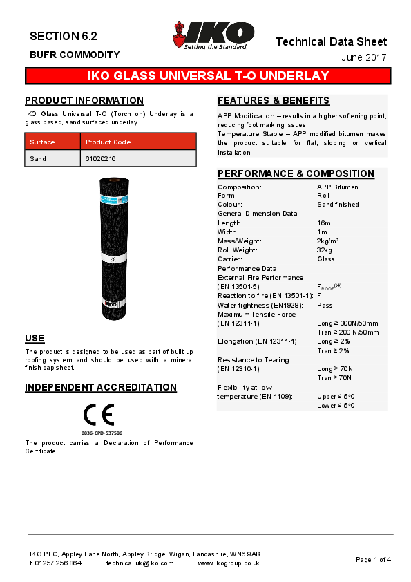
SECTION 6.2
BUFR COMMODITY

Technical Data Sheet
June 2017

IKO GLASS UNIVERSAL T-O UNDERLAY

PRODUCT INFORMATION
IKO Glass Universal T-O (Torch on) Underlay is a glass based, sand surfaced underlay.

Surface Sand

Product Code 61020216

USE
The product is designed to be used as part of built up roofing system and should be used with a mineral finish cap sheet.
INDEPENDENT ACCREDITATION

FEATURES & BENEFITS
APP Modification � results in a higher softening point, reducing foot marking issues Temperature Stable � APP modified bitumen makes the product suitable for flat, sloping or vertical installation

PERFORMANCE & COMPOSITION

Composition:

APP Bitumen

Form:

Roll

Colour:

Sand finished

General Dimension Data

Length:

16m

Width:

1m

Mass/Weight:

2kg/m�

Roll Weight:

32kg

Carrier:

Glass

Performance Data

External Fire Performance

(EN 13501-5):

FROOF(t4)

Reaction to fire (EN 13501-1): F

Water tightness (EN1928): Pass

Maximum Tensile Force

(EN 12311-1):

Long  300N/50mm

Tran  200 N/50mm

Elongation (EN 12311-1):

Long  2%

Tran  2%

Resistance to Tearing

(EN 12310-1):

Long  70N

Tran  70N

Flexibility at low

temperature (EN 1109):

Upper -5oC

Lower -5oC

0836-CPD-537586
The product carries a Declaration of Performance Certificate.

IKO PLC, Appley Lane North, Appley Bridge, Wigan, Lancashire, WN6 9AB

t: 01257 256 864

technical.uk@iko.com

www.ikogroup.co.uk

Page 1 of 4

SPECIFICATION
All construction detailing and specification should conform to UK Building Regulations.
Relevant Codes of Practice and British Standards, should also be used for guidance, in particular it is recommended that reference is made to the relevant parts of:
BS 8747:2007 Reinforced bitumen membranes for roofing � Guide to selection and specification; BS 8217:2005 Code of Practice for Reinforced Bitumen Membranes for roofing; BS 6229:2003 Code of Practice for Flat Roofs with continuously supported roof coverings; BS5250:2011 Code of Practice Control of Condensation within Buildings.
Refurbishment work undertaken on existing flat roofs is likely to be reportable to Local Authority Building Control (LABC) and it is advisable that any proposed works are discussed with the LABC prior to commencement, or that the installing contractor is a member of the Competent Roofer Scheme. www.competentroofer.co.uk
Where required by building warranty providers i.e. NHBC, LABC, etc. installers and those undertaking specifications should seek guidance from Technical Standards as issued by the provider in addition to the above.
The National Federation of Roofing Contractors (NFRC) also provides a Responsible Specification Checklist that may be useful during this stage � www.nfrc.co.uk
DESIGN CONSIDERATIONS
CONFIGURATION
The construction of the roof deck and ceiling has an important effect on the behaviour of the waterproofing material on top.
The building industry uses the terms WARM ROOF and COLD ROOF to describe the two different types.
Most roofs require insulation and current practice is for insulation to be placed above the roof deck, often referred to as a `warm roof'. No void ventilation is required with this design.
Alternative practice is to install the insulation within the voids below the roof deck. Often referred to as a `cold roof', this type of arrangement must include ventilation to the void areas to remove the risk of condensation. It is advisable that cold roof design is ventilated at the rates prescribed within the aforementioned British Standards and Approved Codes of Practice.

WARM ROOF
COLD ROOF
ASSOCIATED MATERIALS
Dependant on system arrangement, IKO offers several material solutions to cover the multiple layers of a typical built up bituminous roofing system as illustrated above. For guidance on selection of these layers, please refer to the IKO Flat & Pitched Roofing Guide available at www.ikogroup.co.uk
STRUCTURAL DECKS
It is essential that the deck is suitably fit for purpose and is structurally adequate in supporting the waterproofing system and any associated loadings. For deck selection and determining suitability, the guidance of the relevant Approved Codes of Practice should be sought.
FALLS AND DRAINAGE
To reduce the effect of water ponding on the roof finish, a minimum finished fall of 1:80 should be achieved; however designs should be to 1:60 to take into account any inaccuracies within the deck construction.
VAPOUR CONTROL
It is essential that roofing solutions include layers to control and inhibit the movement of vapour into the building fabric. For further guidance please contact IKO Technical services department.

IKO PLC, Appley Lane North, Appley Bridge, Wigan, Lancashire, WN6 9AB

t: 01257 256 864

technical.uk@iko.com

www.ikogroup.co.uk

Page 2 of 4

CONSTRUCTION
MATERIAL HANDLING
Checking: Material should be checked to ensure that they conform to the project specification. Handling: Material should be unloaded and handled with care to avoid damage. Site Storage: Material should be stored on end on a firm, clean base protected from direct sunlight.
PRIOR TO COMMENCEMENT
Application must always follow good, safe working practice.
Prior to commencing works, it is advisable to consult Health and Safety Executive Guidance documents such as HSG33 `Health and Safety in Roof Work', irrespective of levels of competence, to ensure all works are being planned and undertaken in a safe, pragmatic manner.
Torch applied materials should only be applied by those competent, conversant and capable of undertaking roofing works safely and that are experienced in the use of roofing torches and procedures.
Torch applied membranes should not be used in close proximity to combustible materials, decorative coatings and heat sensitive materials. Preparatory nailing layers must be employed when using as an underlayer onto a combustible deck material i.e. plywood, OSB3, timber planks. IKO Challenger 180 Sand is appropriate for use as a nailing layer in such instances.
PREPARATION
Before commencement of the roofing works, the roofing contractor should ensure that the surfaces to receive the new waterproofing system are sound and capable of accepting the imposed loading of the new waterproofing system and its installation. The surface to which the waterproofing membrane is to be installed must be clean, dry and fit for purpose. Existing substrates should be assessed by a competent roofer or suitably qualified professional to ascertain their suitability in relation to structural strength, falls and drainage provision.
SETTING OUT
When setting out the field area, the rolls of material should always be laid in the same direction, never cross bonded. Top layers should be arranged to achieve a staggered bond with the preceding underlayers with half width layers being used to maintain bond patterns where necessary. Sheets should be overlapped to form the required 75mm side laps and 100mm end laps. Ends laps must be staggered so that they do not occur in the same position in adjacent sheets.

Figure 1 Setting Out to Staggered Laps
BONDING
The membrane must be fully bonded by using the torch-on application method, ensuring that a constant flow of bitumen is maintained across the whole width of the roll and that a bead of bitumen (5-15mm) is exuded from all side and end laps to demonstrate a good seal has been achieved (Figure 2).
Figure 2 Side lap formation
DETAILING
All waterproofing detailing must be undertaken as seperate flashings. Upstands and skirtings � (Warm Roof)

IKO PLC, Appley Lane North, Appley Bridge, Wigan, Lancashire, WN6 9AB

t: 01257 256 864

technical.uk@iko.com

www.ikogroup.co.uk

Page 3 of 4

At all skirtings and upstands, the waterproofing should be at least 150mm above the level of the finished roof. Care must be undertaken not to bridge over any DPC or Cavity Tray positions.
Drip edge detail � (Warm Roof)

DISCLAIMER
Whilst every precaution is taken to ensure that the information given in this literature is correct and up to date it is not intended to form part of any contract or give rise to any collateral liability, which is hereby specifically excluded.
IKO reserve the right to amend and/or withdraw this document without notice.
Intending purchasers of our materials should therefore verify with the company whether any changes in our specification, application details, withdrawals or otherwise have taken place since this literature was issued.

A welted drip edge should be formed wherever drainage to an external guttering is required. A plywood former should be introduced to form the drip. In warm roof build ups an insulated hard edge, 10mm thinner than the insulation thickness, should be incorporated.
Check kerb � (Warm Roof)

Check kerbs should be constructed to form a 50mm water check to prevent water from running over the edge incorporating a welted drip detail. In warm roof build ups a timber hard edge should be incorporated.
Other typical details are available via the IKO website, or alternatively via NFRC information sheets � www.nfrc.co.uk
POST COMPLETION
To obtain the best possible life expectancy, all flat roofs should be inspected in accordance with the requirements of BS 6229 Code of Practice for Flat Roofs with continuously supported roof coverings.
DURABILITY
When installed and conditions are maintained as per IKO literature, relevant Codes of Practice and UK Building Regulations, the product will contribute to the durability stated by the respective cap sheet.

IKO PLC, Appley Lane North, Appley Bridge, Wigan, Lancashire, WN6 9AB

t: 01257 256 864

technical.uk@iko.com

www.ikogroup.co.uk

Page 4 of 4