File info: application/pdf · 76 pages · 42.09MB
Document preview and download links are below.
Extracted Text
electronics�
A McGraw-Hill W eekl y 75 Cents
March 29, 1968
ESP: FACT OR FANCY?
AUTOMATIC THIN FILMS
Report USSR leading in research, p 14
Crystals monitor deposition, p 33
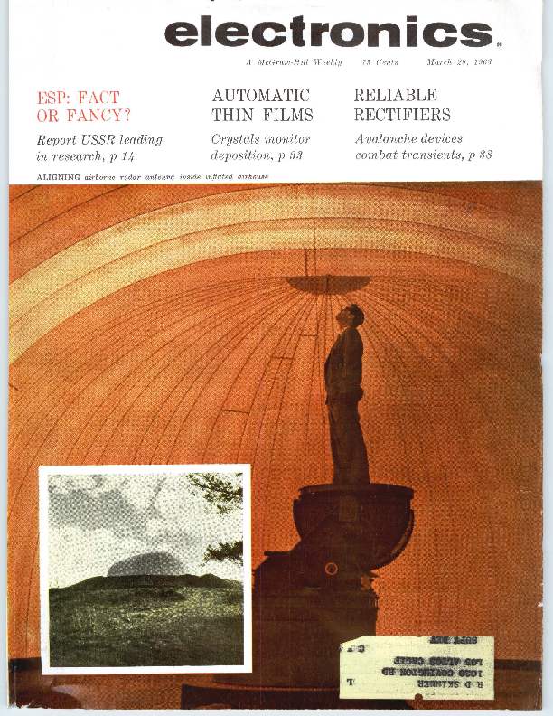
ALIGNING airborne radar antenna inside inf/,ated airhouse
RELIABLE RECTIFIERS
Avalanche devices combat transients, p 38
II I
II
Transistor TRANSFORMERS & INDUCTORS
HERMETICALLY SEALED 10 Mll-T-27A
There is no transformer even twice the size of the 0().T and Dl-T series which
has as much as I/10th the power handling ability � � �
which can equal the effi� ciency � � � or equal the response range. And none
to approach the reliability of the 00-T and 01-T units (proved to, but exceeding
MIL�T�27A grade 4).
HIP Power btlq ..........,..................up to 10 times greater Excelleat Respeua . . ..............twice as good at low end Llw Dlltlrtltl .................................................reduced 80% HIP EtllcJucy ........... up to 30% better � � � compare OCR Mllltlll'I Pnof ....... .... ... hermetically sealed to MIL-T�27A Ruged .......................... lradl 4, c111pletely metll cased Ancllere� Leads ............. will withstand 10 pound pull test Printed Clretit Use ...... <solder melting) nylon insulated leads Suited t1 Clip MHntltli ................. use Augat #6009.SA clip
00-T
01-T
DO �T
No. DO-T44 DO-T29 DO-Tl2 DO-Tl3 DO-Tl9 DO-T30 DO-T43 DO-T42 DO-T41 DO-T2 DO-T20
Pri. D.C. Ma.t Imp. in Pri.
80 CT 12 100 CT JO 120 CT 10 150 CT IO 150 CT IO 200 CT 10 300 CT 7 400 CT 7 300 CT 7 320 CT 7 400 CT 7
400 CT 8 500 CT 6
400 CT 8 500 CT 6
400 CT 8 500 CT 6
500
3
600
3
500 CT 5.5
DO-T4 DO-T14 DO-T31 DO-TlS DO-T32 DO-T21 DO-T3 'D0-T4S
DO-T16 DO-T33 DO-TS DO-T17 DO-T22 DO-T34 DO-T37 DO-TlS DO-T3S
600
3
600 CT 5 800 CT 5
640 CT 5 800 CT 5
800 CT 4 1070 CT 4
800 CT 4 1000 CT 4
900 CT 4
1000
3
1200
3
1000 CT 3.5 I250 CT 3.5
1000 CT 3.5 1330 CT 3.5
1060 CT 3.5 1330 CT 3.5
1200
2
1500 CT 3 2000 CT 3
1500 CT 3
1600 CT 3 2000 CT 3
2000 CT 3 2500 CT 3
7500 CT I 10,000 CT I
8000 CT I 10,000 CT I
...... WrltefwClllllS
1.- STOCl l1EMI
wla UTC HIP RtlllllllltY
llUElllATlLY AYAUILE frlll
YGUI Leal llltr'*
TRANSFORMERS PICTURED DO-T: Jf6Dia. x IJh"', t / IODZ.; Dl�T1JI', Dia. x )4H , 1/ t50Z.
TRANSFORMERS
Sec. Pri. Res. Pri. Res. Mw
Df.T
Imp.
DO�T Df.T Level
No.
DO � T No.
Pri. D.C. Ma.t
Sec.
Pri. Res. Pri. Res. Mw Df.T
Imp.
in Pri.
Imp.
DO�T Df.T Level
No.
32 split 40 split 3.2 4 12 16 12 16 600 3.2 4 40 split 50 split 120 split I50 split 400 split 500 split 50 60 600
3.2 12 16 3.2 4 12 16 3.2 4 600 50 60 16.000 split 20,000 split
9.8 11.5 500 Dl-T44'
IO
500
11
500
20
500
19 20 500 DI�T19
20
500
46 50 500 Dl�T43'
46
500
46 50 500 Dl-T41'
60 65 100 DI�T2
31 32 500 Dl�T20
60
100
43
500
43
500
51
500
51
500
53 53 500 DI�T21 115 110 100 Dl-T3
120
100
0 DO-T4S ' D0-T47
DO-T6 DO-T9 DO-TlO DO�T2S DO-T3S DO-Tll DO-T36 DO�Tl DO-T23 DO-T39
DO-T40
'D0-T46 DO-T7 DO-T24 DO-TSOO
8.000 CT I
1200 CT 640
100
10.000 CT I
1500 CT
9.000 CT I
9000 CT 850
100
10.000 CT I 10,000 CT
10.000
I
10.000
I
12.000
I
3.2 500 CT 600 CT
790
100
780 870 100 Dl-T9
10.000
I
1200 CT 780 870 100 Dl-TlO
12,500
1
1500 CT
10.000 CT I 12.000 CT I
1500 CT 1800 CT
780 870 100 Dl-T2S
10.000 CT I 12.000 CT I
2000 split 560 620 100 Dl-T38 ' 2400 split
10.000
I
2000 CT 780 870 100 Dl-Tll
12 .500
1
2500 CT
10.000 CT 12.000 CT
20 .ooo
30.000
I 10,000 CT I 12,000 CT .5 800 .5 1200
975 970 100 Dl-T36 830 815 50 DI-Tl
20 .000 CT 30 .000 CT 20 ,000 CT 30.000 CT
.5
800 CT 830 815 100 Dl-T23
. 5'--_.,_12~070-=-C""T~~~--~~---
.5 1000 split 800
100
. .5 1500 split
40.000 CT .25 400 split 1700
50
50.000 CT .25 500 split
100.000 CT 0
500 CT 7900
25
200.000
0
1000
8500
25
200.000 CT 0
1000 CT 8500
25
Power 00-T. Pri 28V 380-1000 cycles, sec 6.3V @ 60 ma
INDUCT RS
'DO-TSO 1.075 Hy /10 ma ..06 Hy /30 ma
10.5
(2 wdgs.) �t.018 HY /20 ma, .o!5 Hy /60 ma
2.6
DO� T2S .3 Hy /4 ma , .15 Hy 120 ma
25
12
71
500
16
3.2
71
500
4
.I Hy /4 ma, .08 Hy /10 ma
DO-T27 1.25 Hys /2 ma, .5 Hy ill ma
100
.9 Hy /2 ma, .5 Hy /6 ma
25 D 1-T2S 105 Dl-T27
3.2
105 110 100 DI�TS
DO-TS 3.5 Hys /2 ma , I Hy /5 ma
560
12
108
500
16
600
86 87 500 DI�T22
3.2
109
500
4
8000 split 195 180 100 Dl-T37' 10.000 split
DO-T26
'DO-T49 (2 wdgs.)
DO-TSH
2.5 Hys/2 ma, .9 Hy /4 ma
6 Hys/2 ma, 1.5 Hys /5 ma
2100
4.5 Hys /2 ma, 1.2 Hys/ 4 ma
f.20 Hys /l ma, 8 Hys /3 ma
5100
1�5 Hys /2 ma, 2 Hys /6 ma
1275
Drawn Hi permalloy shield and cover 20!30 db
630 DI-TS 2300 Dl-T26
Dl-TSH
12
505
100
16
3.2
505
100
4
iocMA shown is for single ended useage (under 5 % distortion- IOOMW-1 KC) � .. for
push pull, DCMA can be any balanced value taken by .SW transistors (under 5% distor-
tion - 500MW- I KC)
DO-T & 01-T units designed for transistor use only. Pats. Pend.
~Series connected; HParallel connected
- �Units newly added to series
AND
CUSTOM BUILT SPECIAL UNITS
TO YOUR SPECIFICATIONS
150 VARICK STREET, NEW YORK 13, N. Y.
PACIFIC MFG. DIVISION: 3630 EASTHAM DRIVE, CULVER CITY, CALIF.
EXPOaT DIVISIOH1 13 EAST .COth STREET, NEW YORK 16, N. Y.
CAILES1 "ARI.Al"
CIRCLE 900 ON RUDEi SOYKE CAID
W. W. MacDONALD, Editor
J. M. CARROLL, Managing Editar
SENIOR EDITORS Samuel Weber, George W. Sideris
SENIOR ASSOCIATE EDITORS Michael F. Wolff, John F. Mason
ASSOC IATE EDITORS Michael F. Tomaino , Sylvester P. Carter, William P. O'Brien, Sy Vagel, Leslie Solomon, Gearge J. Flynn, Laurence D. Shergalis, George V. Novotny, Leon H . Dulberger
ASSISTANT EDITORS Nile Lindgren, Stanley Freud, Stephen B . Gray, Roy J. Bruun, Barry A. Briskman
REGIONAL EDITORS Harold C. Hood (Pacif ic Coast, Los Angeles), Thomas Maguire (New England, Boston), Cletus M. Wiley (Midwest, Chicago)
ART DIRECTOR Howard R. Berry
ASSISTANT ART DIRECTOR John C. Wright, Jr
EDITORIAL ASSISTANTS Lorraine Rossi, Virginia T. Bastion, Lynn Emery, Ann Mella, Lorraine Werner, Alice M . O'Brien
FOREIGN NEWS BUREAU DIRECTOR, John Wilhelm;
Alyne Elias , Charles Obertance LONDON-John Shinn, Derek
Barlow, Nicholas Landon BONN-Bruce Bendow,
Richard Mikton, Silke McQueen BRUSSELS-Peter Forbath PARIS-Robert Farrell,
Arthur Erikson MILAN-Marc A. Messina MEXICO CITY-Wesley Perry, Jr RIO DE JANEIRO-Leslie Warren MOSCOW-Stewart Ramsey TOKYO-Richard Halloran,
Charles Cohen, John Yamaguchi
CIRCULATION MANAGER Hugh J. Quinn
W. W. GAREY, Publisher
March 29, 1968
electronics A McGraw-Hill Weekly 75 Cents
ENGINEER stands atop a 24-in. Dalmo-Victor Rotodrome antenna for the new and highly classified Grumman W2F-1 all-weather early-warning and intercept-control aircraft. The 140,000-cu ft airhouse surrounding the antenna is shown in the inset. It's made of 22-oz vinyl-coated plastic inflated and maintained under pressure. Entrance is through an airlock COVER
EXTRASENSORY PERCEPTION: Is Biological Radio Com-
munication Possible? Interest in ESP has been aroused by re-
ports of Soviet work. Soviets claim that ESP is a form of elec-
tromagnetic radiation
14
DISPLAYS: $200 Million a Year. That's one estimate of the present contracting in this fast-growing field. Among new systems is one that simulates a 3-D view of overflown terrain 15
LASERS NOW INDUSTRIAL TOOLS. Manufacturers demon-
strate uses in cutting and welding many kinds of materials.
Micromachining looks especially promising
16
IEEE SHOW. The parade of new products continues. Microcircuit transmitter and digital voice system are among them 18
COMPUTERS Push Toward Nanosecond Speed. Parallel processing, associative memories and laser techniques are explored at conference. Las ers a.re expected to find applications in storage 20
LOWER TARIFF BARRIERS Depend on Solution of Agricul-
tural Trade Impasse. This problem may hamper electronics
trade with Europe. But Europe is still a good market, say EIA
symposium speakers
20
BEACON for Brushfire War. Air Force has developed a new
Tacan. It weighs only 6,000 lb, is air-transportable
22
ELECTRONIC ANTENNA SCANNING Uses No Phase Shifters. Instead a line of microwave receiving antennas is switched on and off at a kilocycle or megacycle rate. Predominant frequency term in resulting modulation spectrum will depend on angle of arrival of the signal. Angular resolution is equivalent to that of other multiple-beam antennas. By W. H. Kummer, A. T. Villeneuve and F. G. Terrio, Hughes Aircraft 27
LATEST THING IN THIN FILMS: Automatic Deposition Control. Here's how to shut off the vacuum coater when you get just the right thickness of film deposited on the substrate. Put a known-frequency crystal in the vacuum chamber. The thin film will alter its frequency and produce the desired control signal. By S. J. Lins and P. E. Oberg, Univac Div., Sperry Rand 33
OVERLOAD PROTECTION Without High Power Dissipation. Fuses afford little protection for transistor regulated power supplies ana even sampling circuits are not effective working into large capacitive loads. In this modification of the currentlimiting protection method, load current actually decreases as overload increases. By K. L. Burfeindt, Norden Div., United Aircraft 36
Contents Continued
electronics
March 29, 1963 Volume 36 No . 13
Published weekly , with Electronics Buyers' Gu ide as part of the subscrip tion, by McGraw-Hill Publishing Company , Inc. Founder : James H . McGraw (1860-1948).
Title � registered U.S. Patent Office ; � copyright 1963 by McGraw-Hill Publishing Co., Inc. All rig'hts re -
served, including the right to repro duce the contents of this publication , in whole or in part.
Executive, editorial , circulation and advertising offices : McGraw-H ill Building, 330 West 42nd Street, New York 36, N. Y. Telephone Longacre 4-3000. Teletype TWX N.Y. 212 -640-4646. Cable McGrawhill, N. Y. PRINTED IN ALBANY, N. Y.; second class postage paid at Albany, N. Y.
OFFICERS OF THE PUBLICATIONS DIVISION : Shelton Fisher, President; Vice Presidents: Joseph H. Allen, Operations ; John R. Callaham, Editorial ; Ervin E. DeGraff, Circulation ; Donald C. McGraw, Jr., Advertising Sales ; Angelo R. Venezian, Marketing .
OFFICERS OF THE CORPORATION: Donald C. McGraw, President; Hugh J . Kelly, Harry L. Waddell, Executive Vice Presidents; L. Keith Goodrich , Executive Vice President and Treasurer; John J . Cooke, Vice President and Secretary.
Subscriptions are solicited only from those actively engaged in the field of the publication . Position and com pany connection must be indicated on orders. Subscription rotes: United States and Possessions, $6 .00 one year, $9.00 two years, $12.00 three years . Canada : $10.00 one year. All other countries $20.00 one year. Single copies, United States and Possessions and Canada 75� . Single copies all other countries $1.50.
THE PUBLISHER, UPON WRITTEN REQUEST FROM ANY SUBSCRIBER TO OUR NEW YORK OFFICE AGREES TO REFUND THAT PART OF THE SUBSCRIPTION PRICE APPLYING TO COPIES NOT YET MAILED.
Subscribers: Please address change of address notices, subscription orders or complaints to Fulfillment Manager, Electronics, at above address. Change of address notices should provide old as well as new address, including postal zone number if any. If possible, attach address label from rece nt issue. Allow one month for change to become effective.
Postma ster : Please send Form 3579 to Fu lfillment Manager, Electronics, 330 West 42nd Street, New York 36, New York.
������I����-�
.. .."' � 1 � C'. ~ ..,
Audited Paid Circulation
2
CONTENTS continued
CONTROLLED AVALANCHE RECTIFIERS F or More Reliab ili ty. A s ili co n contro ll ed avala n ch e recti fi er can dissipate as mu ch heat in t he r everse direction as in th e forward direction. These di odes can eas ily di ssipate h igh levels of transient energy such as a r everse current sur ge. P ower supplies using these new components save space and cost while boosting r eliability. By F . W. Gutzwiller, Gener al Electric 38
MAGNETICALLY COUPLED MULTIVIBRATOR: A Neglected
P recis ion Ci r cuit . Magnet ic multivibrat ors are well known as
power converters but can also be used as precision oscillators
and fr equ en cy divi der s. Th ey are highly stable oscillators even
below 10,000 cps .
By M. Ing en ito, General Time 42
R-M MONITOR SHOWS POWER AND VSWR. Instrument for h-f and vhf r eads tra nsmitter output power in watts a nd indicates voltag e-st a nding wave r atio independent of power level. It consists of a directional coupler, bridge and an alarm circuit for transmitter protection. By L. F . St ein, West inghouse Electric 44
DEPARTMENTS
Cr osst alk. B elieve It Or N ot
3
Comment. Civilian E lectronics. Nuclear B last
D etection
4
Elect roni cs Newsletter. Underground Antennas
T ransmit 1,200 Miles
7
Wash ington Th is Week. Looks Like Governm ent
W ill R elax Patent Rules
12
Meet ings Ahead. Conf erence on the Impact of
Microelectronics
24
Research a nd Development. Field Operational
S -Band Maser
48
Components and Mat eri als. T antalum Capacitors
Without Electrolyte
52
P roduct ion Techniques. High-Speed Production
Ch ecking of Logic W iring
56
New P r od uct s. Voltage Standard Produces A -C
in 1-Mc Steps
60
Literat ur e of t he Week
67
People and Pla nts. Filtron Expands on the W est
Coast
68
Index to Advertisers
73
Morch 29, 1963 � electronics
CROSSTALK
Believe It Or Not
MILITARY MARKET specialists now possess a guideline for military product planning as specific as any they have ever had. No longer need industry be taken unawares by sudden, unexplained cancellations of weapon system contracts, or be in doubt about the future military role in space. The uncertainties that have troubled the defense contractor for the past two years have been removed, and the way ahead is clear.
Secretary of Defense Robert McNamara has spelled out in his 161page budget presentation to the House and Senate Armed Services Committees the new military strategy of the United States, the kind of equipment needed to make the new strategy operable, and the rate at which the effort must proceed.
McNamara's detailed prediction of the course of future events, while rarely substantiated, is crystal clear as dogm:i. He has subjected all possible actions human beings might take to a cost/effectiveness analysis. Every weapon system, existing or planned, and every aspect of military strategy learned from past experience was put to the test. Any element that did not match the already-programmed theory was thrown out.
Based on this formula-which we are tacitly asked to assume the Soviets are also using-the United States and the Soviets are throwing all their efforts into stockpiling the weapon that scored highest in the cost/effectiveness studies: the ballistic missile.
The next step, according to McNamara's logic, will be a nuclear stalemate. Both sides will possess a supply of land- and submarine-based ballistic missiles adequate to deliver "a devastating retaliatory blow" even after suffering a first strike. Since neither side wants mutual destruction, nuclear war will be out of the question.
While some studies will continue on improved ICBM's and Polaris missiles, all other means of nuclear delivery are out. Cost/effectiveness studies have shown that new bombers and offensive weapons in space are impractical.
On the thin chance that the Soviets might stray from the cost/effectiveness formula and build an "impractical" weapon in space, McNamara will not cancel development of our Satellite Inspector project, although this work was recently slowed down (ELECTRONICS, p 18, Dec. 21, 1962). As for the probability of such a Soviet move, McNamara said: "There does not appear to be any logical reason for (the Soviets to place bomb-carrying satellites in orbit), since there are much more efficient ways of delivering nuclear warheads."
electronics � March 29, 1963
With the threat of nuclear war virtually eliminated by the nuclear stalemate, the emphasis-and therefore the big market-is for non-nuclear weapons. Every element of every military service offers a market for nonnuclear weapons and support equipment.
"Al though we are still a long way from achieving the non-nuclear capabilities we hope to create in Europe we are much better off in this regard than we were two years ago," McNamara said. The ultimate goal is to build conventional, non-nuclear forces mighty enough to defend Europe against an all-out Soviet attack.
A big new market exists in equipping new general purpose forces scheduled to get $19.1 billion in 1964 as opposed to the Strategic Retaliatory Forces' $7.3 billion.
Much of the new market results from the findings of a study group established by Gen. L. L. Lemnitzer for defining new requirements for meeting non-nuclear combat situations. For example, a whole new Army is being created that is literally taking to the air. Varied electronic equipment, including mobile air traffic control systems, will be needed to support the 1,600 aircraft-helicopters and fixed-wing-Army will buy in 1964. There will be new "air assault divisions, air-cavalry combat brigades, and corps aviation brigades."
The air-cavalry brigade, like the airassault division, would be equipped "with large numbers of helicopters and would perform a role much like the horse cavalry of earlier yearn. It would have large numbers of antitank weapons including missiles mounted on helicopters."
"Cost of attaining the new objective will be high-a total of $3.3 billion for Army procurement in 1964."
Opportunities to sell new kinds of equipment to create the new military force are big and varied. The budget is the largest in peacetime history$55.2 billion, not counting the cost of nuclear warheads.
But industry's planning, based on the digital-like clarity of McNamara's new strategy, should not be longrange. Industry should be prepared to
shift its efforts swiftly at any given moment.
Any evidence that the Soviets do not think precisely the way the Defense Department does would upset the entire military market structure.
The Soviets will undoubtedly play out the improbable role McNamara has created for them as long as they can. They will pretend to be as anxious for nuclear stalemate as we are, and deplore the thought of weapons in space. Back in October they tried to fool us with our own cost / effectiveness logic. Why should we accuse them of setting up missile bases in Cuba, when they could destroy the U. S. more economically with longrange missiles at home?
Secretly, the Soviets must be appalled by McNamara's logic, and his assumption that they share it. The Soviets have other reasons for putting bombs in satellites capable of reentry. The reasons are "human"-in an exploitive sense of the word-and McNamara missed them.
Although more expensive than shooting a missile straight from silo to target, the cost of weapons in space might well be worthwhile.
There is a psychological value in announcing to a nation that a fleet of nuclear warheads is passing over their cities; that at certain hours the orbiting bombs can be seen with the naked eye. The sight would be more moving than the spectacular glow of the Echo communications satellite so many Americans watched move across the sky two summers ago. It is doubtful that we would be comforted by deriding the enemy for his folly with cost/effectiveness studies hastily calculated in basements.
Such a surprise by the Soviets would be all the more impressive if at the same time they provided proof of their claim that they have a means of knocking down our ICBM's.
We are building a lop-sided defense. It is based on a limited band in the spectrum of factors that motivate the rise and fall of civilizations. By 1970 it will be too late.
But America has shaken loose from rigid theories before, and hopefully it will again.
3
Anala&
oo~�/a��
the industry's fin est dual-trace oscilloscope
the only oscilloscope on which you can make PRECISE QUANTITATIVE
MEASUREMENTS! USE AS PRECISION AC & DC VOLTMETER,
PHASE METER, TIME-INTERVAL METER.
� Superior triggering and over-all stability
� Highest sensitivity (lOO�v/cm) � Both single-ended and
differential amplifier inputs, AC or DC-coupled � No interpolation needed with direct-reading Null-Balance dials � "Instantaneous" beam finder � Delayed trigger output from 1 �sec to 50,000,000 �sec � Bandwidth from DC to 150 kc
Call or write for specifications on the 1120/700 and on the full line of Analab scopes, scope camera systems, and accessories.
Analab Instrument Corporation
Cedar Grove, New Jersey
Ana lab
Asubsidiary of THE JERROlD CORPORATION
4 CIRCLE 4 ON READER SERVICE CARD
COMMENT
Civilian Electronics
I just read the editorial, Let's Look at the Civilian Sector (p 3, Feb. 22). I'm not usually wholeheartedly enthusiastic about editorials in general, but by golly, I sure am about this one. Can't you find 52 different ways to say the same things, and keep saying it over and over again for at least a year?
When electronics slipped over the 50-percent-military mark a few years ago, I felt that something bad had happened, for the industry, through sloth and carlessness, had allowed itself to become a munitions industry, with all that implies. In the ensuing years, it seemed as if no one wanted to do anything about it except to gripe every time a budget cut (which we need badly) threatened one sacred buck in electronics procurement.
Obviously, the attack on the problem is to get away from reliance on the federal bucks-and it's a real treat to see ELECTRONICS live up to its responsibility to lead in that direction.
Please say it over and over again. It's mighty sweet music.
FRANK LEARY New York, New York
Nuclear Blast Detection
Your article, Black Box Blast Detection-Hope or Hoax?, in the Jan. 4 issue (p 62) was extremely interesting and well done.
The information contained therein does not seem to be widely propagated. I would be most interested in any sources you can refer me to for further information, as I would like to do a paper on the topic for my Y-R club.
BERNARD P . TRACEY Inglewood, California
Feature articles in ELECTRONICS include Nuclear Bomb Alarm Systems (p 53, May 8, 1959); Station Detects Underground Nuclear Blasts (p 34, Dec. 2, 1960); A-Bomb Detection Program Spurs Seismology and Instrumentation (p 28, Feb. 23, 1962); and Navy Prepares For VLF Detection of Nuclear Blasts
(p 28, Oct. l!:I, 1!162). A good source of information is
Congressional records, such as "Technical Aspects of Detection and Inspection Controls of a Nuclear Weapons Test Ban, April 19, 20, 21 and 22, 1960," Parts 1 and 2. There is also a list of reading references cited by Dr. Edward Teller in an article he wrote for the Headline Series booklet, The Future of Nuclear Tests (No. 145, 1961). Another source is the IEEE professional technical group on Nuclear Science.
Puzzle Prodigy
I solved your puzzle, nose + cone
+ upon + ocean = rescue (p 4,
March 1), but it took me more than 30 minutes. My answer is
5720 9750 8475 79035
102980 The hardest part was deciding whether 0 was equal to 7 or 8 or 9. I liked this puzzle especially since I just learned how to add.
DAVID PENFIELD (Age 5) Weston, Mass.
If Davey worked it out all by himself without any help from Daddy, then he's wasting his time with puzzles and should be starting in on Freshman Calculus 101.
Sideband Coherent Radar
Regarding my article, More Target Data With Sideband Coherent Radar (p 40, Jan. 18):
The caption of Fig. 6 (p 43) should include a reference signal of -70 dbm, rather than -112 dbm.
My original manuscript acknowledged the sponsorship of this project by National Science Foundation Grant No. G-14087, which was omitted from the article.
With these two exceptions, I thought the article was edited extremely well.
JOHN B. THEISS Applied Research Laboratory College of Engineering University of Arizona Tucson, Arizona
March 29, 1963 � electronics
Ultra-Stable
COMPENSATED ZENERS
� STABILITY BETTER THAN 20 PARTS PER MILLION
� 10 TIMES GREATER STABILITY THAN STANDARD CELLS
� 1000-HOUR DATA FURNISHED WITH EACH UNIT
N ew PS- 1200 series Ul t ra- Stable Compensated Zeners provide acc urat e refe rence under a wide
range of environmental conditions. Each uni t is backed by more tha n 1,000 hours of certified
test data. These units provide long term stabil ity from 20 to 200 part s pe r million. This is sub.
stantially better than any competiti ve zene r reference device ava ila ble.
PS-1200-1205's are ideal replacements for standard cells in precision instrument applica�
tions. Not only do these extremely small units offer long term sta bil it ies t en t imes greater than
standa rd cells, but they also give you t he added advantage of ext reme ruggedness. These devices
easi ly withstand a wide range of temperature variations, temperature cycling, and vibration, and are
complet ely insensit ive to "positioning"
TYPICAL ST ABILITY CURVE
problems usually associa t ed with standard cells. They are particularly adapt�
able to portable equipment. TRW Elec-
tronics compensated zeners can even
be shorted and operated under load
without damage .
Apply the new PS-1200 series to
lOO 200 300 400 500 600 700 800 900 1000
high precision instrument designs and othe r app lica t io ns requiring ultra-stable
HOURS IN OPERATION
reference.
1111111111111111111111111111111111111111111
Type (2) Long-Term Stabili ty
Number
(1)
PS-1200 PS�1 201 PS�l202 PS� 120 3 PS� 120 4 PS�1205
%0.023 =0.013 %0.00753 %0.0053 %0.00353 =0.0023
(200 ppm) (100 ppm) ( 75 ppm) ( 50 ppm) ( 35 ppm) ( 20 ppm)
Dynamic Impedance
Reference Voltage @ 10 mAdc and 1 mA rms
@ 10 mAdc @ 25�C
Max.@ 25�C
8.0 � 8.8V 8.0 � 8.8V 8.0 � 8.8V 8.0 � 8.8V 8.0 � 8.8V 8.0 � 8.8V
15 ohms 15 ohms 15 ohms 15 ohms 15 ohms 15 ohms
( fl l ong Term Stability
Prior to the stability test each unit has been power aged and submitt ed to various sta bilizing processes . Each unit is identified and serialized and a comple te production and te st history is kept.
The stability te st consists of 1000 hours of operation dur ing which the zener voltage is recorded at periodic intervals. Each unit is shipped with a sta bility vs. time graph giving a complete cer tified record of the actual readings.
( 2) Temperature Coefficient
"B" type un it s: ::t:0.007 V ma x. change in E, from 25 � C over ran ge of - 55 � C to + 100 - c (ave rage TC of 0.00 1% ' C)
''A" type units: � 0.01 4 V max . change in E, from 25 C over range of - 55 � C to + 100 -c (a verage TC of 0.002 %/ ' C)
NEW TECHNICAL INFORMATION
Write today on your company letterhead for new application note entitled "Ultra-Stable Reference Elements" and complete technical information on the new PS-1200 series.
Regular units: (no suff ix)
::t: 0.028 V ma x. change in E, from 25 ' C over range of - 55 ' C to + 100 �C (average TC of 0.004 %/� C)
Pacific Semiconductors, Inc.
TRW Electronics
THOMPSON R A M O W OOLDRIDGE INC.
14520 AVIATION BLVD., LAWNDALE, CALIF. � OS 9�4561 , OR 8-0561 �TWX: 213 647-5113 � Cable Address: PSISOCAL
CIRCLE 5 ON READER SERVICE CARD
Tests Transistor Beta in-the-circuit
\
TRANSISTOR TESTER- Portable, Battery Operated
� Reads Beta directly in-the-circuit (1-4, 3-12, 10-40, 30-120); no need to unsolder leads -
� Measures lco, (0-50, 0-500 /.La) & Beta out-of. circuit
� Packaged for portability in ~ of a cubic foot; weighs 12% lbs.
� Carries its own battery power supply � Price: $335; delivery immediately from stock
For a free demonstration, more information about the 2198 Transistor Tester, or the complete Sierra Quick Reference Catalog, contact your Sierra representa-
SIERRA ELECTRONIC DIV.
OF
PHILCO
tive, or write to address below:
J
Sierra Electronic Division/ 38~S Bohannon Drive/ Menlo Park 1, California
6 CIRCLE 6 ON READER SERVICE CARD
March 29, 1963 � electronics
electronics NEWSLETTER
Buried Antenna Transmits 1,200 Miles
BURIED RADIO antenna operating at reduced power has transmitted data over 1,200 miles and offers promise for military underground communications systems invulnerable to nuclear attack, according to Aerojet-General. System was developed under the direction of the Air Force Systems Command. It includes an omni-directional antenna.
Sylvania said hardened, underground radio antennas it has developed have transmitted signals 30 to 1,000 miles. The up-over-down mode was used to achieve this range, said Rolf M. Wundt of Sylvania. Waves travel from the antenna up to the ground, along the surface of the earth and down to the buried receiving antenna.
Wundt also says that it is possible to propagate radio waves "considerable distances" through the ground "in certain formations having low electrical conductivity, such as granite or rocksalt. A rock formation which initially appears capable of supporting underground communication links longer than about 40 miles, possibly up to hundreds of miles, is the deep granite basement rock which underlies all continents." Optimum frequency for such links is usually in the 10 Kc to 10 Mc range. Antennas are either vertical dipoles or monopoles or loops fitting into the drill hole, with subsurface ground nets above the antenna, preferably in contact with the water table.
tive and capacitive components. Real-world linguistic relation-
ships are plugged into Acorns with resistors, so that in the final network, associations can be deduced instantly without sequential digital scanning. Four experimental devices have been built. Acorn 2 associated 100 technical libraries and 41 subjects the libraries dealt with. Acorn 4 relates 240 nouns to 240 sentences containing them.
In five years, Guiliano says, small digital computers might profitably be equipped with micromm1aturized, high-capacity Acorn type memories. The computer might handle all input-output tasks while the Acorn carried out association retrieval functions.
New Transistor Fabrication Technique Is Unveiled
MOTOROLA'S new transistor fabrication technique, the annular process, was introduced this week as the answer to high-voltage problems associated with planar silicon devices.
According to Jack Haenichen, in-
ventor of the process, present planar devices have low breakdown voltage as a result of a phenomenon known as channeling, particularly prevalent in pnp devices. In effect, channeling is an induced polarity reversal near the surface of the transistor, resulting in high leakage current and severe instability.
The annular process overcomes this by fabricating the device with a deliberately induced channel with controlled characteristics. The channel is constrained to the vicinity of the base by diffused annular ring. Motorola is now marketing pnp silicon transistors with breakdown ratings as high as 70 v, compared to typical rating of 20 v for planar devices. Company claims these units are radiation resistant.
U.S. Firm Gets Rights To 1,000-Mc Transistors
FRENCH-DEVELOPED series of field effect transistors ranging from ultrasensitive units operating in the 1,000-Mc range to high power types will be manufactured in U.S.
First Action Photo of Shillelagh
Information Nets Make "Real-World" Associations
DAYTON, OHIO - Unusual analog electrical networks for automatic recognition of statistical word associations were described by Vincent E. Guiliano of Arthur D. Little, Inc. at the 2nd Bionics Symposium March 21. The networks, called Acorns (Associative Content Retrieval Network), associate linguistic units by linear transformations achieved with passive resis-
electronics � March 29, 1963
TANK-MOUNTED surface-to-sur face w eapon system, the Shillelagh, has passed a series of test firin gs ag ainst stationary and moving targets, r eports Ford's Aer onutronic division, prime contractor to Army. Arrow points to m issile leaving gun-launcher
7
by Atlantic Instruments and Electronics, Inc. They will be marketed under the tradename, Fieldtron.
They are rod-shaped like miniature bobbins, the ends forming the anode and cathode, with the center sections acting as the grid, as opposed to the usual planar approach. High grid impedance and low capacitance are the result. Stanislas Teszner of Paris invented the devices. French Government Telecommunications Laboratory helped with their development.
received by all receivers, but rejected by all except the addressee whose code was dialed.
Army acceptance of one of the three competing designs would eliminate the need for communications centers, switchboards, telephones, wire and cable, and a large part of the radio equipment from the division down to company level.
Red Chinese Report Transistor Progress
3 Firms Will Study
RADA System for Army
THREE ONE-YEAR study contracts were signed last Thursday for the Random Access Discrete Address (Rada) communications system. Contracts went to RCA ($1,947,600), Motorola ($1,986,350), and Martin-Marietta ($1,967,120).
Using a broadband technique, a number of users would operate simultaneously with privacy and without mutual interference. The signals, sent out at random on the broad band of frequencies, will be
HONGKONG-New developments in the study of transistors were reported at the 2nd Chinese National Conference on semi-conductors in Peking recently, according to the official New China News Agency.
Success in varying degrees was claimed in the preparation of ultrapure silicon, the extraction, synthesis and analysis of the element by chemical processes, its extraction and purification by physical processes, and in the preparation of different kinds of single crystals. Some of the 86 conference papers reported headway in growing single crystals.
U. S. Leads in Laser Research, Experts Say
NEW YORK-U. S. laser technology is way ahead of Europe's. That's the impression reported last week by B. J. McMurtry, of Sylvania. Just back from visiting several European laser research facilities he said he observed many experiments that U.S. researchers have already performed and cast aside. But the British, he added, tend to do a thorough job investigating an area that U.S. scientists leave after doing some good initial work.
McMurtry was impressed with the caliber of Soviet scientists at the Paris quantum electronics conference and the scope of the work they seemed to be engaged in, including some work "very interesting but so obscure I personally couldn't tell if they were talking about experiments they had performed or would perform."
Scientists from the Lebedev Institute in Moscow reported on traveling-wave generation in lasers,
a
Ii
I
-....
heating plasmas with lasers, an ammonia maser with disk resonator, and other topics.
_:.
Lax in Boston
BOSTON-British workers at the Services Electronic Research Lab have achieved the highest averagepower junction diode laser reported to date, according to another scientist just returned from Europe, Benjamin Lax, of MIT Lincoln Lab.
The British, he said last Thursday, put a gallium-arsenide laser between molybdenum tabs for better head transfer. They report getting an average power of 1 watt.
In answer to a query after a lecture before the Boston IEEE, Lax said his discussions with Russians at the Paris conference indicated that semiconductor laser workers at the Lebedev Institute are essentially reproducing results obtained earlier in the U.S.
In Brief ..
SOVIET SCIENTISTS have agreed to share data obtained from the Russian Mars probe.
BAD-WEATHER landing system for helicopters and VTOL aircraft has been developed by Raytheon.
CLOSED-CIRCUIT tv camera developed by Sylvania has a miniature cable-connected vidicon unit that can be used separately to view small areas.
EUROPEAN COMPUTER market is the fastest growing industrial market in the world, according to William C. Norris, president of Control Data Corp. Now $400 million, it should reach $3 billion to $5 billion annually in about 10 years, he said.
ELECTRON-BEAM welder has been set up for high-volume production of latching switches by Filtors, Inc.
DATA PROCESSOR designed to improve government's radio frequency assignment methods will be developed by HRB-Singer. Contract was awarded by U.S. Office of Emergency Planning.
AIR FORCE gave Laboratory For Electronics, Inc. $8.7-million contract for doppler navigation systems for F-105D Thunderchief.
HONEYWELL received $4-million contract for production of accelerometers for Minuteman missile.
$50 MILLION follow-on order has been placed with Melpar for high reliability circuit boards for the Minuteman missile.
STANFORD UNIVERSITY is buying over $1 million worth of 24-megawatt klystron amplifier tubes from RCA and Sperry Gyroscope. Tubes will power 2-mile-long atom smasher now being built at Stanford.
SIMPSON INSTRUMENTS bought the electric meter operations of Beckman Instruments' Helipot division.
JAPAN MAY WAIVE 20 percent commodity tax on transistor tv sets. Increased domestic sales would probably result, leading to eventual cuts in export prices.
March 29, 1963 � electronics
AND ITS KEY�INDUSTRIAl DISTRIBUTORS
~ � --==
�
P. P. S. For complete technical data write for Engineering Bulletin 74100
SPRAGUE ELECTRIC COMPANY � 35 MARSHALL STREET, NORTH ADAMS, MASS. For application engineering assistance write:
Marketing Dept., Resistor Division, Sprague Electric Co., Nashua, New Hampshire.
SPRAGUE COMPONENTS
RESISTORS CAPACITORS MAGNETIC COMPONENTS TRANSISTORS MICRO CIRCUITS
INTERFERENCE FILTERS PULSE TRANSFORMERS PIEZOELECTRIC CERAMICS PUL S~FORMING NETWORKS TOROIDAL INDUCTORS
HIGH TEMPERATURE MAGNET WIRE CERAMIC-BASE PRINTED NETWORKS PACKAGED COMPONENT ASSEMBLIES FUNCTIONAL DIGITAL CIRCUITS ELECTRIC WAVE FILTERS
electronics � March 29, 1963
SPRAGUE�
THE MARK OF RELIABILITY
'Sprague' and'@' are registered trademarks of the Sprague Electric Co.
CIRCLE 9 ON READER SERVICE CARD 9
Print top and side together at 3200/hour
Print 1500 hard-to-hold items per hour with complete uniformity change to new imprint in seconds
Identify products with inks that meet government specs
cut your identification costs with modern methods like-these
Save purchase, inventory and obsolescence costs by making your own labels exactly as needed
Color-band and/or print economically by machine - in sample lots or up to 6000/hour
Get sharp, durable imprints on extremely irregular shapes or rough surfaces
Looking for faster identification . . . imprints that meet government specs ... flexibility to meet changing requirements .. a practical way to mark prototype or sample lots? Would direct printing or making your own labels cut costs, give higher print quality? Ask Markem to analyze your identifica-
tion needs now - without obligation - and show you how and where you can save money. Frequently, a Markem in-plant identification system pays for itself in a few months. Contact the Markem Technical Representative near you, or write Markem Machine Co., Keene 5, New Hampshire.
New 12-page Catalog describes Electrical/Electronic Identification Methods and Equipment. Copy on request.
10 CIRCLE 10 ON READER SERVICE CARD
M A RK E M
TECHNICAL ASSISTANCE AND INDUSTRY-PROVEN EQUIPMENT WORLDWIDE ��� TO HELP YOUR PRODUCT SPEAK FOR ITSELF
March 29, 1963 � electronics
Fusion. Electronics and magnetics are teamed capabilities at Sperry's Electro Devices Laboratory. From
20 years' research, development and production in the two disciplines have come major advances in power supplies, high-power pulse components, focus coils and similar devices. Typical units-customized to meet the toughest specifications and reliability requirements - include pulse transformers,
SP(RRY modulators, networks, charging reactors, power controllers and regulators, and radia-
tion resistant components. Programs include work for Minuteman, Polaris, Nike-Zeus, Sergeant, Terrier, Talas and others, plus assignments from leading industrial firms. Backup facilities include the entire Sperry group. For details write Marketing Manager, DIVISIONS OF
SPERRY RAND
SPERRY ELECTRO DEVICES LABORATORY, Sperry Gyroscope Co., Great Neck, N.Y. CORPORATION
electronics � March 29, 1963
CIRCLE 11 ON READER SERVICE CARD 11
WASHINGTON THIS WEEK
LOOKS LIKE GOVERNMENT WILL RELAX PATENT RULES
TRAIL THAT the White House is hacking through the government
patent-policy jungle is marked now in a message to Congress by Jerome Wiesner, presidential science advisor. He cut a swath half-way between NASA's government ownership and the Defense Department's contractor control policies (E1..EC'l'RON1cs. p 12, Nov. 9, and p 12, April 27, 1962). Government-wide policy would emphasize relaxation of restrictions where possible. This also parallels NASA's recent efforts to give some contractors a freer hand with government-financed patentable developments.
Wiesner cites the importance of patent protection to electronics industry growth as an example of the need for relaxed regulations. Whether a contractor would get exclusive rights, he indicated, would depend on government needs, the nature of the work, the contractor's commercial background and the extent that he would work the invention in the public interest. This could entail almost a case-by-case review.
CONGRESS TO REVIEW DOD COST-CUTTING
PROCUREMENT POLICIES and cost reduction programs which
Defense Secretary McNamara says will save $3.4 billion of the $50billion defense budget gets a full-dress review this week. The Joint Economic Committee is holding th ree days of hearings on ways of eliminating government waste. Stress will be on reducing defense inventories (now $41 billion), more competitive procurement, more standardization. The committee also will hear from General Services Administration, buyer for defense and civilian agencies, and the comptroller-general.
SCIENCE AGENCY GETS NEW BOSS
AEC COMMISSIONER Leland J. Haworth will succeed Alan T.
Waterman, retiring National Science Foundation director. Haworth will oversee the expansion of NSF's role in government support of basic research and science education. The Foundation's budget has jumped from $263 million in 1962 to a requested $589 million for fiscal 1964 and is expected to go higher as more responsibility for basic research is shifted to it from the old-line government agencies.
IT'S ANTITRUST TIME IN EUROPE
SENATE ANTITRUST and Monopoly Subcommittee members
plan a European trip during Easter recess to study Common Market antitrust rules and how they may affect American business operations there. Some changes in U. S. law may be in the wind. Joint ventures between U. S. and foreign firms will be examined. So will the 45-yearold Webb-Pomerene law allowing U. S. firms to set up associations for foreign trading.
AMENDMENT TO TRADE AC'r, IS OPPOSEO
12
HUNDRED-PERCENT tariff cuts under Trade Expansion Act
provisions (U. S.-European Economic Community control of 80 percent of world trade in certain products) are now "practically a dead letter," says one top official. A proposed amendment to the trade act would let the President cut tariffs as though Britain were in EEC, but administration officials hope it dies aborning. With the touchy de GaulleBritain situation, they don't want Congress working the bill over again. Trade negotiations are already complicated by agricultural trade questions (seep 20).
Morch 29, 1963 � electronics
What kind of spectrum analysis do you do?
Rayspan Spectrum Analyzers do just about every kind. No doubt you can think of others not illustrated here that may require the unique features of Rayspan. The multiple-filter Ray� span analyzer is capable of scan rates up to 200 times a second and gives extremely high resolution. A variety of displays, from "A" scope presentation to an intensity modulation of frequency-time raster, is possible. Permanent records in real time can be made on continuous paper charts using high-speed
helix recorders. Multiple stylus recorders are also available. Perhaps Rayspan can help serve you in your particular
analysis area. Raytheon has prepared a complete brochure describing the various technical specifications and operational details of the Rayspan Spectrum Analyzers. For your copy, write: Raytheon Company, Industri-
(RAYTHEONl al Components Division, 55 Chapel
Street, Newton 58, Massachusetts.
CIRCLE 13 ON READER SERVICE CARD
SU BJECT'S
CONSOL E
D D[}:~~GRAM-
PRINTER TAPE
PUNCHER
. CONTROL CONS OLE
CONTROL CONSOLE and subject console are separated by walls. Mathematician Margar et D. Hill sits at control console
ESP: Is Biological Radio
Communication Possible?
Soviets reportedly find extrasensory perception
is high-frequency r-f
By NILO LINDGREN
Assistant Editor
BEDF ORD, MASS.-At first sight, probably one of the unlikeliest subjects for the U. S. Air Force to take seriously is extrasensory perception (ESP).
But the past year and a half, Air Force Cambridge Research Laboratories has been quietly conducting scientific experiments into ESP at its Communications Sciences Laboratory at Hanscom Field. The work at Hanscom has thus far neither proved nor disproved the existence of ESP. The investigation was started by a few individuals who felt that a pilot project would form a sound base of Air Force knowledge in this controversial area.
So far in this country no solid results-or at least nothing solidly acceptable to all parties-have been produced. But research has gone on for years at such places as Duke University and, in general, scientific interest in ESP is on the rise here and in other countries.
SOVIET WORK - The Russians, for instance, have worked for years on ESP (they call it biological ra-
14
dio communication). They now have large laboratories in Moscow, Leningrad and Omsk. The extent of the work is a closely-guarded secret.
What has been reported by our government about the Russian work reads like science fiction. Russian scientists have evidently found that ESP is a form of electromagnetic radiation on a series of wavelengths in the centimeter, millimeter and micron bands. No single wavelength carries all the information of any one message; somehow it is separated and carried on the different wavelengths.
An evjdent aim of the Soviet work is to devise methods of synthesizing and amplifying ESP messages. If this is done, ESP messages could be broadcast to entire populations as a psychological warfare weapon.
AIR FORCE STUDY-Objective of the AFCRL study-carried out by an electronics engineer, a physicist, a mathematician, psychologist and 37 unpaid subjects-is developing scientifically based methods of testing for ESP, and understanding what ESP might involve. The objective was not to prove whether ESP exists, but the results may influence AF attitudes on whether to continue ESP research.
Used in the AFCRL experiments was an electronic setup specially
designed by electronics engineer Everett F. Dagle, who along with psychologist Dr. William R. Smith initiated the project. The physicist is John Mott-Smith.
The equipment, called Veritac, incorporates a random number generator, control and subject consoles that are completely separated, and an automatic score-keeping mechanism that prevents both conscious and unconscious cheating.
The random number generator, consisting of a 10-cathode gas tube with associated driver and outputpulse switching circuits, generates numbers from 0 to 9 at a 2.5-Kc rate. One of these numbers appear on the control console when the subject presses a button on his console.
THREE F ORMS OF ESP-Three types of tests were given, for clairvoyance (ESP of objects or objective events), for precognition (perception of a future event by ESP) and for general ESP (knowing or experiencing events by other than the usual sensory means).
In the clairvoyance test, the subject pushes the generator button, then lets it go and registers his guess on the number that has come up on the control console. Data for a statistical study of the results are automatically recorded.
In the precognition test, the subject tries to guess a number that will come up on the machine when
March 29, 1963 � elect r o nics
-, I I I
_ _ _ _ _ _ ~O~R~ CONSOLE_ _J
ORGANIZATION of eq11ipment used in Air Force ex periments
he lets the button go. In the test for general ESP ca-
pabilities, a human "sender" who sits at the control console, looks at a number and tries to send it to the subject, who presumably by telepathy or clairvoyance or both, attempts to receive.
RESULTS-Each subject took 15 tests consisting of 100 trials. In all, 55,500 responses are being analyzed for the possibility of ESP. The subjects chosen were girls from Endicott Junior College.
Although the analysis is not yet complete, it indicates that the
group gave results that might be expected by chance from a normal group-a few showed above average, a few showed below average, and the bulk were gathered in the middle.
The ESP equipment has turned out to be useful for other experiments than ESP. It has produced some indices of decision-making times. Robert Fitzpatrick of Systems Development Corp., who has worked on human engineering problems for Project Dyna Soar, says Veritac is the best equipment he has seen for carrying out certain decision-making experiments.
Displays: $200 Million
SANTA MONICA-Attendance of 450-triple the anticipated number -at the Society for Information Display's first conference two weeks ago points up the interest in this rapidly growing field.
One estimate is that the field is now generating more than $200 million a year in hardware and development contracts.
HIGH-CONTRAST SCREENAmong the new devices discussed was a screen designed by Intertechnical Corp. of Los Angeles to suppress the image-contrast degrading effect of high ambient light levels on front and rear-projection devices. Using a grouping of small, plastic paraboloids (40,000 per sq ft) to trap light, the screen absorbs and diffuses roughly 98 percent of undesired light and presents a highcontrast image.
NEW DISPLAYS-White Sands missile range has developed a digital~input, pseudo 3-D display that gives an oblique look at terrain overflown by missiles and aircraft. Visual tracking is provided by two intersecting green lines that estab-
lish the X and Y coordinates of the object's position. A variable-length red line that appears to be perpendicular to the map's surface presents altitude.
Litton Industries gave details of a multicolor projector using a 70-mm perforated film continuously moving across the face of an electrostatic image-induction Printapix crt. Horizontal picture elements are handled by a sweeping electron beam and film motion takes care of the vertical elements.
MILITARY NEEDS-Air Force Col. Anthony Debons, of Hanscom Field, gave his views on display needs. While color, 3-D perspective and larger size are desirable in military displays, he said, the prime need is for translation of data into information that won't be misinterpreted. Often, a relatively simple bar-graph display coupled with map and pictorial news depiction can accomplish this.
Debons emphasized the importance of including display designers in advanced planning and initial concept stages of any complex information systems.
MT-36: THE MOST RELIABLE TRANSPORT in its price range
The Potter MT�36 Digital Mai;netic Tape Transport offers maximum reliability for computer systems requiring an economical transport. The Potter MT�36 features: � NO PROGRAM RESTRICTIONS ..�
up to 200 commands per second at 36 ips. �SOLID STATE CIRCUITRY ..� photo electric sensing minimizes the need for switches and relays. � VACUUM TROUGH GUIDES, �� provide smooth tape stops.
� cIMuPITRSOV.�E�DofPfeINr CfaHs�Rt OtLaLpEeRstCaIrRts�
and stops. � EASE OF MAINTENANCE ... drlve
electronics and fully regulated power supply are mounted on individual plug-in boards. � RAPID TAPE THREADING ... Just 15 seconds for complete threading. �BUILT IN TAPE CLEANER , , , vacuum on trough guide removes all loose oxide and dust. For full information and specif!� cations on the MT-36 Di!!ital Mag� netic Tape Transport, write today.
eleclronics � March 29, 1963
CIRCLE 1S ON READER SERVICE CARD 15
FINE CONTROL possible with lasers is demonstrnted by welding of transistor lead wires to header. Hiighcs laser makes weld in less than 1 m8ec
SAPPHIRE CRYSTAL .,\-in. thick is pierced in 1 msec at RCA Laborctt01�ies. Surface temperature is over
2,800 c
Now Lasers Are Industrial
HOLE IS PUNCHED in ~-in. steel by Raytheon's 350-joule las er
Manufacturers derrnonstrate
coherent-light cutting,
weld1"ng, rnicrorrnachining
PRACTICAL industrial tasks for pulsed ruby lasers are rapidly emerging. Cutting, drilling and welding have been demonstrated.
The fine control possible with lasers make them desirable for precision machining and, since the cutting and welding can be done in air, vacuum equipment associated with electron-beam machining is not necessary. Lasers can produce up to 1011 watts/cm' energy density.
Hard materials like diamond have been machined at GE and Hughes. RCA has developed a technique for burning off tiny amounts of various materials for spectroscopic analysis.
Hughes Aircraft predicts a bright future for lasers in the welding of incompatible materials, machining extremely hard substances and in microminiaturization applications. Hughes has put out a line of instruments for such uses. Any known material can be cut with a laser beam, Hughes says.
Pulsed ruby lasers able to punch through ~- in. steel are now off-the shelf items from such firms as Hughes Aircraft and Raytheon. Raytheon has measured the output energy of one of its lasers at 350 joules, with an efficiency of 1 percent. Radiation at Stanford estimates the output of its latest model at 500 joules.
Q SPOILING-One Hughes Laser Products model puts out a beam energy of over 4 joules. Q-spoiling, raises peak power from 50 Kw to 10 Mw.
MIRRORS MAKE DU AL LASER
GAS LASERS that can operate at visible as well as infrared beam wavelengths (0.6328 and 1.153 microns) are commercially available. In Palo Alto, Calif., Admiral an-
CONCAVE
1'~
nounced a classroom and experimental model. In Japan, Hitachi showed a lab setup. Frequency is changed by changing mirrors. Feasibility of changing a helium-
neon laser beam from ir to visible by changing mirror reflectivity was demonstrated last year by Bell Telephone Laboratories (ELECTRONICS, p 28, Aug. 17, 1962).
EMITTED
LIGHT
BASIC POSITION of mirrors in Hitachi laser
REFLECTOR at end of Admiral's laser kit can be extended to allow access to las er beam between mirrors. Laser is in housing
LASER WELD of 0.004-in.-diameter copper-constantan thermocou ple. Hughes says wires need not be stripped
Tools
Q-spoiling refers to methods of concentrating laser energy in time to achieve peak powers. An increase in peak power is obtained by the storing of the energy in the crystal.
The need for high energy, high peak power, or high average power (approaching c-w operation) is determined by the nature of t he industrial machining or welding job. Additionally, a means of focusing the laser beam is required to obtain a high power density on the surface of the material, plus time control for controlled cutting and welding.
RAISI NG P OWER - Raytheon's 350-joule laser employs a liquidnitrogen-cooled ruby 6 in. long and ~ in. in diameter. P umping energy is 32,500 joules in a four barreled head. Xenon flash-lamp firing rate is once every 5 minutes. Beam spread is one degree.
Output energy was determined by directing the laser beam into a copper block with a cone shaped opening and measuring the temperature rise of the block.
Employing Q-spoiling techniques, Raytheon has achieved a peak power of the order of 2 Mw. Two methods have been used. I n one, a spinning mirror at one end of the ruby rod permits the crystal to store energy until the mirror is in alignment briefly during the flash tube discharge, allowing a burst of coherent output. The second uses a prism at one end of the ruby with an extra piece of glass on one surface. The glass is pulled away by a piezoelectric transdu cer to increase the reflectivity of the prism and the Q in the cavity. Hughes uses a Kerr shutter.
e lectroni cs � Marc h 29, 1963
Radar Switch Tuhes
to 125kV 20mW
1OOOusec Pulse
ML-8038
O il insulated
Anode d issipation :
o il (convection) to 5 kW *
Max. de Plate Volts
125 kV
Pulse Cathode Current 17 5 amp
Pulse Power Output, to 20 Mw
ML-8040
A ir Insulated
Anode d issipation :
forced a ir cooled to 10 kW
Max . de Plate Volts
60 kV
Pulse Cathode Current 1 75 a m p
Pulse Power Output, to 10 Mw
ML-8041
Air Insulated * *
Anode dissipatio n:
water cooled to 60 kW
Max. de P late Volts
60 kV
Pulse CathodQ Current 175 amp
Pulse Power Output, to 10 Mw
� Forced-Oi l..Cooling conside r abl y increa s es this figure �* May be Operated oil insula ted (and n ot w ater-cooled) to 125 kV.
Three coaxial switch t ubes of same family. Mu:120 ...Thoriated -tungsten cathode.. . . 3 cooling/insulation options....Tubes shielded for high voltage stab i l ity, low x-radiation yield . ... All tubes aged, tested, in Machlett equipment.
Write today for complete information on ML-8038, ML-8040 and ML-8041 contained in Mechlett L aboratories' 74 page Hard Pulse Modulator Tube Brochure.
A n A ffiliate o f R a y theon Compa ny
THE MACHLETT LABORATORIES, INC.
S PR ING D ALE, CONNECT I C UT
CIRCLE 17 ON READER SERVICE CARD 17
llow from Sprague#
WIDE SELECTION OF
T0-5 Silicon
CASE
Chopper Transistors
HIGH-SPEED
DIGITAL
I
I
CO MP UTER
I I
20
COR E ME MORY
DECODER ANO SWITCH ORIVE
1
AUDIO OUTPUT LINES
MULTIPLEXED
INTERCONNECT TRANSMISSION
SWITCHES
i
' I : AUDIO
\ DRUM
I I
1--- - - --'64:..:.....j ,- - - -
1.000
:'.VIEMORY of digital-to-vo-ice co11 vcl'ter/ 11wltiplexel' is scanned in synchronism w�ith the lines. Output data from memol'y closes switches so proper audio word is sampled and fed to line
NOW IN ' VOLUME PRODUCTION
Products Parade Goes On
11 \
Specifically designed for use as low-
level choppers , Sprague Silicon Pre-
cision Alloy Transistors are inherently
stable. Every Sprague chopper tran-
sistor undergoes a rigid production
+ conditioning of 40 temperature cycles
from - 55 C to 140 C, a 200-hour
+ bakeat 140C,and a 2 -hour 125mW
operational burn-in!
2N2162 2N2165
Guaranteed 30 vol t rating . Typical fr of 20 Mc and low offset voltage make these :~~~~~~grs ideal where high voltage is
2 N2163 2 N2166
Have 15 volt ratin9 and same high frequency ~~1f6Tance an low offset voltage as
2N2164 2N2167
Highest frequency P-N- P Silicon Choppers available as standard tvoes
2N2185
E~~emely low leakage current of 1 nanoam ere at 10 volts. Has 30 volt rating
2N2274
Similar to 2N2185 but has lower inverted dynamic saturation resistance
2N2276 Low-cost version of 2N2274
2N2278
Very low offset volt age of 1.75 mV at IB =
1 mA
2N2187
Matched pair LlN2185 with !J.Vorr50�V max. from 25 C to_�85 C
2N2275
Matched pair o,t .::N2274 with !J.VOFF =
100,uV max . from 25 C to_�65 C
2N2277
MlOat~cVhedmaxp.afirromo'_l:N2252C76to_:w:l:i_th65
!J.VOFF=
C
2N227 9
Matched pair o~:2N2278 with t;.VOFF=
50�V max. from 25 C to +85 C
G~ For additional information ,
write Technical Literature Ser-
vice, Sprague Electric Co.,
3 5 Marshall Street, North
Adams, Mass., indicating the
types in which you are interested.
SPRAGUE�
THE MARK OF RELIABILITY
Microcircuit transmitter,
digital voice among
IEEE show-stoppers
NEW YORK-A 100-Mc transmitter with a self-contained antenna, on a wafer ~ -in . square and i--in. thick, was one of the continuing parade of new products at the IEEE Show this week (for reports on previously announced new products, see our March 15 special issue).
The transmitter, shown by Sylvania, required a battery and microphone to make it operational.
A true rms converter that reportedly improves the accuracy of existing a-c digital and potentiometric voltmeters by a factor of 10 or more was shown by Rotek Instruments.
High-stability three-terminal capacitors for use as laboratory standards or long time-constant measuring devices were exhibited by Electronic Associates, Inc. Ranges are 1 to 1,000 �,f and 25 to 400 v d-c.
Eitel-McCullough said that in addition to its previously reported 500-Kw pentode, it will be producing models with 1-Mw and more output at frequencies to 200 Mc.
North Electric demonstrated how its new digital-to-voice con-
verter/multiplexer gives spoken replies to digital queries.
As devised for Teleregister's Televox stock quotation system, the converter uses computer data on stocks (see diagram) to select recorded words. The subscriber makes his query over a dial phone.
A time-sharing multiplex technique enables different replies to go out simultaneously over 1,000 lines. Present vocabulary is 64 words and numbers.
Lamme Medal Winner
E. L. HARDER, manager of Westinghouse Electric's Advanced Systems Engineering and Analytical department, was named winner of the Lamme Gold Medal at the IEEE banquet last night. He was cited fo r his many achievements in machinery, controls and computC'rs
18 CIRCLE 18 ON READER SERVICE CARD
Ma rch 29, 1963 � elec tronics
DOUBLED PERFORMANCE Bandwidth and speed have
both been doubled in Mincom's Series G-100 Recorder /Reproducer. This superb all-purpose system now has a Direct response of 300 cycles to 600 kc at 120 ips. At 60 ips FM response is de to 20 kc (extended), de to 10 kc (standard). With fourteen interchangeable analog or FM tracks in one standard rack, the G-100 is now even better equipped for its job of static or dynamic testingwith Mincom's reliable simplicity. Plug-in card system record/reproduce modules and Mincom's exclusive DC tape transport reduce maintenance down time to a minimum. Write today for details and complete specifications.
m. a� . . ~m 1ncom IVISIDTI .;JcamPANv
2049 South Barrington Avenue, Los Angeles 25 425 13th Street N . W., Washington 4, D. C.
eler.tronics � March 29, 1963
CIRCLE 19 ON READER SERVICE CARD 19
Computers Push Toward Nanosecond
Parallel processing,
associative ?ne?nories,
lasers are explored
PASADENA, CALIF. - Emp�hasis at the IEEE Pacific Computer Conference March 15 and 16 was very noticeably on speed. Typical comment was that "the nation to win the aerospace race will be the nation which will first develop the nanosecond computer."
Technical program chairman Samuel Nissim said the conference's prime goal was bringing into sharper focus avenues leading most quickly to nanosecond speeds. A
device that switches in 1 nsec or less does not guarantee nanosecond computing speeds, he stated, but such a device coupled with proper organizations can do it.
Areas discussed as promising were parallel processing and associative memories. General feeling was that fiber optics and lasers are at least a generation beyond the hardware that will produce nanosecond computing. For example, the problem of actually making contact with fiber optics transmission-line material remains a knotty one. The type of laser hardware necessary to make large computer systems does not yet exist. Consensus was that the laser's first real impact on computers will be
in storage applications rather than logic.
FAST MEMORIES - Compatible with the "speed" theme was an Aeronutronic paper describing a new thin-film memory that utilizes a self-biasing operating motor to achieve multi-megacycle nondestructive readout. Speeds up to 22 Mc were reported by A. M. Renard for a prototype having 256 words and 16-bit readout. Drive current level is typically 150 ma. Anticipated for follow-on units are readout speeds to 35 Mc and write rates to 5 Mc.
Developed in association with the system is a new address decoder using majority logic and hav-
First Bread, Then Electronics
French far?ners are key
to European tariff cuts for U. S. electronics
WASHINGTON-Lowering of European tariff barriers against products of the U.S. electronics and
othe�r industries appears to depend on prior settlement of agricultural trade relations within Europe and between Europe and the U.S.
The big question is how far de Gaulle will go in his efforts to assure the French a rapidly expanding market protected by Common Market tariff walls.
Speakers at the Electronic In-
Machine Learns to Run Maze
MAZE PROBLEM is run on L annet ( Large Artificial Nerve Network) developed by Melpar for Air Force and shown last week at the bionics symposium in Dayton, Ohio (p 8, March 22)
20
dustries Association's European Markets Symposium last week showed concern that prenegotiation rules fights and an agricultural trade impasse might block final trade talks between the U.S. and the Common Market next year.
The U.S. administration hopes to use its new Trade Expansion Act powers to lower tariff (ELECTRONICS, p 28, March 8, 1963, and p 12, Sept . 21, 1962). But if the agricultural questions are not solved, it was pointed out, some of the predictions made for U.S. electronics trade with Europe may not come true.
Another problem stressed by one company official is danger of a subtle European blockade against imports from the U.S. and opposition to the setting up of American manufacturing plants within the EEC walls.
Both de Gaulle and the administration aim to cut down U.S. plant investment in Europe-President Kennedy wants to cut down on balance of payments outflow.
TRA DE PREDICTIONS-Jack N. Behrman, assistant secretary of commerce, said U.S. electronic com-
March 29, 1963 � e lec tronics
Speed
ing a propagation time of less than 10 nsec. Another Aeronutronic project is a 1,024-word, 48-bit, 109nsec read-cycle biax memory.
TUNNEL-DIODE LOGIC - M. Cooperman, of RCA, described a 300Mc tunnel-diode logic system using only tunnelling and passive devices for the 40 high-speed logic gates used. The gates, consisting of OR, AND and bistable units, reportedly are logically complete and suitable for construction of large digital computers. Asynchronous operation is achieved through d-c-powered circuits and the average delay per logic level is roughly 0.5 �.sec. Average d-c power dissipation per gate is 100 mw.
An important announcement
panies still can make more sales in Europe but competition is stiffening fast. He said U.S. exporting companies had to be "more sophisticated."
Richard H. Randall of Stanford Research Institute, said the profusion of new products can give American electronics an advantage in Europe. Most European companies are smaller and cannot support comparable R&D programs.
William M. Adams, president of Sprague International Ltd. and overseas director of Sprague Electric, said the European parts market is still open. Although Europe is catching up to the U.S. on "runof-the-mill types of components," the field is wide open to components requiring a high level of R&D, tooling and engineering cost.
William P. Bundy, deputy assistant secretary of defense, said U.S. sales of defense products abroad in the next 10 years will be double that of the last 10 years. Harold M. Landau, of Sperry Gyroscope, projected the electronics content of defense expenditures by NATO countries alone at $2.7 billion by 1972, compared with $1.4 billion last year.
electronics � March 29, 1963
During the past year and a half, Midland Manufacturing Company has developed a radically new design concept which obsoletes substantially all conventional image parameter crystal filters.
Strong words, but true nevertheless.
These new filters are designed by so-called insertion loss methods, and bear the Midland trademark ILo.
llo crystal filters, at most narrow fractional bandwidths, have nominal insertion losses of 0.5 db, compared with 3 or 4 db losses in image parameter filters. ILo filter techniques permit exact prediction of the 0-6 db passband characteristics, and extremely close approximations of square corner Chebbychev, or round, nose Butterworth functions. ILo crystal filters have near perfect symmetry about center frequency.
More. ILo filter design permits tight control over amplitude and phase characteristics. High selectivity begins at the bottom of the passband.
Shape factors of 1.5 :1 measured from 60 to X db, and ultimate attenuations
of 100 db, are realizable. Improved control of spurs is a by-product of the design
Any center frequency, and almost any fractional bandwidth, suitable for conventional crystal filters, are also suitable for an ILo filter. And prices are comparable, too.
Experimental? Not any more. Midland has built, tested, and delivered more than 35,000 ILo crystal filters before making this announcement - your guarantee of reproducibility.
Write the world's largest producer of cryst<l.IS and crystal filters.
~ ~[Q)[LfA\!NffOJ lR11l/A\~UJJrF&\~UJJ ~~ ~ffil ~(Q)lR11l [p)&\~W
3155 FIBERGLAS ROAD
�
KANSAS CITY 15, KANSAS
An electronics division ~ of Pacific Industries, Inc.
CIRCLE 21 ON READER SERVICE CARD 21
ADJUSTABLE
PRECISION POLYSTYRENE
CAPACITORS
SH E LT ER-HOUSED Ta can beacon is part of equipment developed f or E mergency Mission Support ( 482L) System. All-band antenna (ins et) and seven-section mast are shown in retracted position before erection
BEACON
For Brushfire
War
1st choice for Critical Applications
N ew Tacan 1's rugged, rnodular and can be transported by air
SOUTHERN ELECTRONICS hermeti� cally sealed precision adjustable capacitors are being used for many applications in analog computers, network tun ing circuits, differential analyzers, and sim i lar circuitry re� quiring the utmost � in accuracy and rel iability.
SEC has pioneered in the design and manufacture of hermetically sealed adjustable capacitors, and this ex�
perien ce has resulted in a .01 %
accuracy standard, and a degree of in-circuit reliability not previously ava ilable. SEC adjustable capacitors incorporate features proven to be years ahead of any comparable product now available.
GENERAL SPECIFICATIONS
Adjustment Ran ge: � l'/2%
Di el ectric Abso rption: 0.02 % Av ail able from .01 mid. to 10 mid.
Accuracy: .00"1 %
Lon g Term Stabi lity : 0.03 % Temperature Coefficient : - 100 PPM per �C Temperature Range: - 40 �F to + 140�F
~~
POLVCON
'1..M..Y.Ct.O..Nl..l
Write today for complete specifications and general catalog.
SOUTHERN
ELECTRONICS
<fiO'lftO'laUbn
150 West Cypress Ave ., Burbank , California
BEDFORD, MASS.- R uggedi zed, transportable ground beacontransponder developed here by Air F orce adds new flexibility to Tacan and updates it for today's emphasis on nonnuclear confrontations: joint Air F orce-Army operations in counter-insurgency, g ueri ll a warfare, and other closesupport missions.
Suited for fixed install ation s as we ll as Strikecom-type operations, the modular system weighs 6,000 pounds and can be assembled �in 2 hours. It is housed in an a irliftable shelter for manual or remote operation anywhere . An all-band antenna and 7-section, 35-f.t mast are a lso stored in the 9 x 7-ft shelter during shi pment. Range is 200 mil es.
The revised model of the tactical air navigation system features major innovations conceived by George Harou les, of Air Force E-lectronic System s Division . Th e system was developed and fabricated by ITT Federal Laboratories.
NEW FEATURES-Modu lar design permits bu ilt-in test features a nd quick-repair t echni ques,- plu s easy tuning to any one of 126 frequ encies in a matter of mi nu tes.
22 CIRCLE 22 ON READER SERVICE CARD
T h e new design a ls�o permits self-monitoring and is fai l-safe. If the transmitter and sw itching fail, automatic transfer to standby equipment is effected. If this cannot be done, the equipment will turn itse lf off r ather than give erroneous information.
The AN / TRN -17 bea.con-tra n sponder is equ ipped wi�th crysta ls for a ll 126 Tacan channels a nd has an a ll-band fmo (frequency multiplier-osc illator). Operation frequency is derived by m ult ip lying a crysta l freque n cy by 24 in the fmo. Output of t his stage is fed to a broaclbased 126-Mc dr iver whi ch amplifies the 2-m w signa l to a bout 2 watts.
Driver and output stage are energized only when high voltage pu lses from the modulator are p.resent. Th us the SY'stem radiates at a con stant freque n cy, pul se coded by the modulator. Driver output is fed to the fina l amplifi er, a single RCA 7651 tetrode. P eak power output measured at the spectru m filter is 1.2 Kw.
The all-band antenna operates from 962 Me to 1,213 Mc. It is a stationary vertical dipo1e about which two sets of parasitic elements rotate synch ronou sly at 900 rpm. Th is rotation mechanicall y modulates t h e beam with 15 and 135-cycle sinewaves.
The Air Force h as in R&D a solid - state be�acon - transponder that will be lighter an d still more re li ab le t h an t hi s a ll-t ube model.
March 29, 1963 � electronics
You can use these new Globe planetary gearmotors to replace units 5 to 10 times as la rge and heavy. They slash pounds of dead weight from you r design-give you up to 500 inch-pounds continuous duty or 1000 inch�pounds intermittent duty torque. Here's enough brawn to handle aircraft, missile and other h igh�quality, high -reliability jobs. Smaller gearbox shown above gives 200 in.�lbs. intermittent, 100 in .-lbs. continuous duty.
Globe's brand new planetary gearing system provides 22 ratios from 1.87:1 to 5211 :1. Stage efficiency of 90% or better has been achieved by using heavy duty precision ball bearings on every gear and on the output
shaft. Heat treated gears and hardened output shaft withstand enormous turning and bending moments. Type BO and BL gearmotors fit your application exactly, using 21 standard armature windings for 4 to 115 v.d.c. power-custom design for your application can include
speed governors, brakes, and clutches. 1 %" flange
gearmotor typically weighs llh lb.; 3" flange high� torq_ue gearmotor weighs 4 % lb. typ.
Let Globe engineers review your application early in the design stage. Prototypes furnished promptly. Write for Bulletin BPG. Globe Industries, Inc., 1784 Stanley Ave., Dayton 4, Ohio. Phone BAidwin 2-3741.
GLOBE INDUSTRIES, INC.
P REC I SIO N M I NIA T URE A.C, 6 D . C . MOTORS , A CTUATORS. t I M E R S. C L U T C H ES. B l 0 WE R S. FAN S . M 0 T 0 R I ZE D, DE V I CES
ele ctronics � Ma rch 29, 1963
CIRCLE 23 ON READER SERVICE CARD 23
HOW WE
SHR~~K
TEFLON*
MEETINGS AHEAD
BROADCAST ENGINEERING CONFERENCE,
National Association of Broadcasters; Conrad Hilton Hotel, Chicago, March 31-April 3.
RADIOISOTOPE CONFERENCE, Oak Ridge National Laboratory, et al; Gatlinburg, Tenn., April 1-3.
PROTECTIVE RELAY ENGINEERS CONFER-
ENCE, A & M College of Texas; at Texas A & M, College Station, Texas, April 8-10.
Why Gudebrod's Common Sense Approach to Lacing Problems Pays Dividends for Customers!
Some years ago motor manufacturers had a problem! They required a high temperature lacing tape that would not deteriorate during the baking process of motor manufacture and would be practical in its application.
Teflon offered the most practical solution to the problem since it provides a temperature range from -100�F to 500�F. We took teflon and flat braided it-we originated the process-but what about shrinkage? When teflon is baked it shrinks ... it would cut thru fine motor wires!
To meet this problem, we developed an exclusive pre-shrunk process for teflon. This patented process pre-shrinks teflon so that the maximum shrinkage is less than 3% after 16 hours at 425�F. We call this lacing tape PreShrunk TEMP-LACE. Motor manufacturers use it in great quantities.
Pre-shrinking teflon is but one of the many processes we have developed to meet the needs of customers. Whatever your lacing needs-nylon, glass, dacront, fungus proofing, color coding-Gudebrod's common sense approach to the problem will pay dividends for you because
1. Gudebrod lacing tape increases production! 2. Gudebrod lacing tape reduces labor costs! 3. Gudebrod lacing tape means minimal maintenance after installation! 4. Gudebrod is quality-our standards for lacing tape are more exacting than
those required for compliance with MIL-T!
Write today for our Technical Products Data Book which explains the many advantages of Gudebrod lacing tape for both civilian and military use.
�Du Pont registered trademark for its TFE-fluorocarbon fiber.
tDu Pont trade name for its pol yester fiber.
24 CIRCLE 24 ON READER SERVICE CARD
7, PENNA .
ENGINEERING ASPECTS OF MAGNETOHYDRODYNAMICS SYMPOSIUM, IEEE,
!AS, University of California; Berkeley, Calif., April 10-11.
OHIO VALLEY INSTRUMENT-AUTOMA-
TION SYMPOSIUM, ISA, et al j Cincinnati Gardens, Cincinnati, Ohio, April 16-17.
CLEVELAND ELECTRON ICS CONFERENCE,
IEEE, Case Institute, Western Reserve University, ISA; Hotel Sheraton, Cleveland, 0., April 16-18.
OPTICAL MASERS SYMPOSIUM, IEEE,
American Optical Society, Armed Services, et al; Waldorf Astoria Hotel, New York City, April 16-18.
INTERNATIONAL NONLINEAR MAGNETICS
CONFERENCE, IEEE j Shoreham Hotel, Washington, D. C., April 17-19.
SOUTHWESTERN IEEE CONFERENCE &
ELECTRONICS SHOW, IEEE (Region 5) ; Dallas Memorial Auditorium, Dallas, Texas, April 17-19.
BIO-MEDICAL ENGINEERING SYMPOSIUM,
IEEE, et al; Del Webb's Ocean House, San Diego, Calif., April 22-24.
NATIONAL E[,ECTROMAGNETIC RELAY
CONFERENCE; Oklahoma State University; OSU, Stillwater, Okla., April 23-25.
POWER INDU STRY COMPUTER CONFER-
ENCE, IEEE j Westward-Ho Hotel, Phoenix, Ariz., April 24-26.
WESTERN ELECTRONIC SHOW AND CON-
FERENCE, WEMA, IEEE; Cow Palace, San Francisco, Calif., Aug. 20-23.
ADVANGE REPORT
11\lPACT OF MICROELECTRONlCS CONFER-
ENCE, Armottr R esearch Foundation ancl ELECTHONICS 111�agaz ine; Illinois I 11sti.-
/11te of T echnology, C h �icogo. June n-
27. April 19 is deadline for submilti11g dnp licate copies of abstracts to: Gco.-ge T. Jacobi, Co-Chair11ian, l?lectronics R esearch Division, Arrnour ll esearch Fonndation, 10 1V. 85 th Street, Chicago 16 , Illinois. In addition to papers, brief reports on r ecent advances can a.lso be given in follo wing areas: changing technical and financial structure in electronic component industry; pr-oduct status (lnd fo>'ecasts; changing technic(ll (lnd jin(lncia l aspects of venclor-user 1�elat'ionship _; e<l1<cution (lnd c/wnging role of engineers; future trends; recent technical advwnces.
March 29, 1963 � electronics
NEWS FROM BELL TELEPHONE LABORATORIES
New high-purity
alloys make better
electron tubes
Ingot of high-purity nickel alloy Is removed from controlled atmosphere melting furnace. Alloy is virtually free of impurities which inhibit electron emission. The new alloying technique and the methods for making cathodes and evaluating their electron-emitting properties were developed by K. M. Olsen and H. E. Kern.
Scientists at Bell Telephone Laboratories have developed new high-purity nickel alloys which are proving highly effective in lengthening the life of advanced-design electron tubes used in the Bell System. This development meets the demand of new electronic technology for long life and high reliability in electron tubes.
One of the new alloys is now providing the outstanding performance required in the electron-emitting cathode of the traveling wave tube in the Telstar satellite.
The first step was to devise new means for the fabrication of ultra-pure nickel to eliminate those impurities harmful to cathode performance. It was then possible to add to the ultra-pure nickel the alloy constituents and activating agents desired for optimum cathode performance, and at the same time to hold the undesirable
impurities at levels below 50 parts per million. These
techniques involved purifying the nickel raw materials and melting, alloying and casting in controlled atmospheres of hydrogen and helium.
This development is an example of how metallurgical scientists work to improve communications. The new nickel alloys are now being produced by the Western Electric Cor:npany, manufacturing unit of the Bell System.
Bell Telephone Laboratories
World center of communications research and development
'Time after time
engineers specify
Johnson sockets!
Whatever the choice ��. a miniature 7-pin steatite wafer or a low-loss Kel�F socket for high power transmitting tubes ..� time and time again design and development engineers specify Johnson tube sockets! All sockets have been categorized under a socket standardization program, reducing the number of variations in. each socket type. Standardization and immediately available stock shortens delivery cycles-permiis fast selection of a Johnson socket for almost any application!
Standard: Commercial grade for general requirements. Bases are glazed porcelain or steatite. Etched aluminum shields or bayonet shells.
/11d11striaf : Superior in quality to "Standard" Grade. Glazed steatite bases, DC-200 treated. Phosphor bronze or beryllium copper contacts .0005 silver-plated. Aluminum shells and shields are iridite No. 14 treated. Fungus resistant cushion washers under contacts.
Military: Top quality to meet military requirements. Glazed L-4 steatite bases, DC-200 treated . Phosphor bronze or beryllium copper contacts heavily silver-plated. Hot tin dipped solder terminals. Brass bayonet shells .0003 nickel-plated. Aluminum shells and shields are iridite No. 14 treated. Fungus resistant cushion washers under contacts. Wafer sockets protected for 200 hour salt spray test.
00.~. !;,~ ~.~~~.~ ~.E~,~!~,~,!
KEL-F SERIES-Molded of low dielectric loss-factor Kel �F plastic-designed for use with a wide selection of high power transmitting tubes such as: 4X l 50A; 4X l 50D; 4X250B ; 4CX250B; 4X250F, 7034; 7035. Basic sockets are available in several designs-with or without screen grid by-pass capacitors, mounting saddles, or steatite chimney to direct air flow through tube cooling fins. Control grid contact "guide" is machined for greater alignment accuracy, and tapped for 6-32 machine sc rew . All contacts are low resistance silver. plated beryllium copper. Tube pin contacts are heat treated to provide positive contact ~ressure as well as extended life. Annealed sold<>ring tabs may be easily bent or formed .
BAYO N ET TYPES-Includes Medium and Heavy Duty Me� dium, Jumbo and Super Jumbo 4-pin types. For use with tubes such as : 866A or 81 lA, E.l.A. Base No. A4 -10; 872A , 211, and others with E.1.A. Base No. A4 �29; and tubes such as: 8008, 5C22, FG104 , GL146 and others with E.1. A. Ba se No. A4�18.
STEATITE WAFER TYPES-Available in 4, 5 , 6, 7, and 8 -pin standard socket t ypes, as well as Super Jumbo 4 -pin for tubes with E.1.A. Base Nos . A4 -15, A4 -16, and A4 -18. Giant 5 and 7 -pin models for tubes with E.1.A . Base Nos. A5 -19 and A7-l 7. Septa r Sockets for tubes such as the 7094 with E.1.A. Base No. E7 -2 ; and VHF Septar Sockets for tubes such as : 5894, 6524, 6252 with E.1.A. Base No. E7-20; and 826, 832 , 4D32 with E. l.A . Base No. E7 -2.
M I NIATURE TYPES-All steatite, available in Standard Wafer Type or Shield Base Type for 7-pin miniatures such as the: lRS, 155, 6CB6, etc., with E.l.A. Base No. E7 � l.
SPECIAL PURPOSE TYPES-Includes sockets for special purpose tubes such as the: 204A and 849; the 833 and 833A; 152TL; 304TL; 750TL; 1500T; 2-2000A; 5021, 705A and others.
NOTE: Detailed specifications on all Johnson tube sockets have been prepared for engineering department use in Socket Standardization Booklet 536. Should you wish a copy -please make yo ur request on company letterhea~.
26 CIRCLE 26 ON READER SERVICE CARD
Marc h 2 9 , 1963 � e lect ronics
e lectronics
A McGraw-Hill Weekly March 29, 1963
ADJUSTMENT of receiver for simultaneous scan operation
NEW ANTENNA IDEA
Scanning Without
Simultaneously-scanned multiple-beam antenna arrays use only on-off switching of the array elements plus filtering of the r-f signal from a single output channel. Angular resolution compares with that of other multiple-beam antennas of equivalent aperture
By W. H. KUMMER, A. T. VILLENEUVE, F. G. TERRIO
Antenna Dept.. Radar and Missile Electronics Laboratory Hughes Aircraft Co., Culver City, California
IN CONVENTIONAL antenna design, the major characteristics of the antenna are determined once the antenna is designed and built. Beamwidth, gain, and sidelobe levels are interrelated.
Now antenna engineers have increased antenna performance and capabilities with the addition of time as a significant parameter in design.1� ' In the past, such functions as mechanical and electric scanning used this parameter also,
but the modulation products were of such a low frequency that they were not used in a significant way. The time-varying antennas to be described use the modulation products from the output of the array in a significant way. The modulation frequencies are in the kilocycle or megacycle range.
A time-modulated array may be represented as in Fig. IA. The boxes represent the operation to be performed. In the usual array, the
box may be a feed-through device only, or a phase shifter if the array is scanned. In a time-modulated array, the box might be an on-off switch or other nonlinear device such as a multiplier.
THEORY OF OPERATION-The technique of simultaneous scan as applied to a receiving array is outlined in the following discussion, the approach to which was suggested by S. N. Vodopia of the An-
27
RADIATOR
~ ~ ~ ~'""'""
BROADSIDE
DIRECTIO~
CONSTANT PHASE LINES /'/OF INCIDENT WAVE
B OUTPUT
(A)
MJ\JlJIJwwWwv\/JIMJ\I~
I- r--t- r--+-- r-+- r--+-- r-i
(0)
(8)
(Cl
l"-r~rl1
2.irfNr
Nr IN+2lr TIME-
(E)
SWITC~l/ /!~~ RADIATOR
""'"" "" ~ ~,(
'""'" ""
~ OUTPU:~ ~ ~ - ~
SHORT
LJ~l~l~J~L
2
2
2
2
2
(F)
SIGNAL-PROCESSING antenna representation (A); linear array orientation (B); output vhase variation for broad-
side wave (C); phase-modulated received signal (D); output phase variation for wave incident at angle o (E); sche-
matic of five-element array (F), to which the 20-element a.rray is similar-Fig. 1
tenna Dept. Consider a linear array of N elements equally spaced with separation d as shown in Fig. lB.
Each element is connected to a common transmission line through an on-off switch. The elements are switched on and off sequentially so that, as one goes off, the next goes on. This process is repeated periodically.
Now suppose that a c-w wave of frequency f is incident from broadside. The wave will strike each element of the array with the same phase. Now look at the energy passing at the output of the array at point B in Fig. lA.
The array is a standing wavearray and the design is such that as the first switch goes on, a wave train at zero phase goes into the co mm o n transmission line. As switch 1 goes off at time r later and switch 2 goes on, another train goes down the line. This is essentially a continuation of the first train.
During the time r that the first switch is on, the phase <I> will have increased by wr where w is the angu-
Jar frequency; that is, the change of phase is given by
<l>=wr=2rrfr
( 1)
Finally, as the array is switched
through one sequence ( Nr) the
train at B will be a continuous wave
similar to that striking the aper-
ture. The phase of this wave will in-
crease linearly as a function of time
as shown in Fig. lC.
Next suppose that the arrival of
the energy is from the direction 0.
Now there will be a phase delay be-
tween the various portions of the
wave hitting the array. As this en-
ergy is channelled through the same
line, the phase between the end and
beginning of successive trains will
no longer be continuous but will
look like that of Fig. ID. If the
phase is shown as a function of
time, it will jump between wave
trains as indicated in Fig. IE. The
phase jump .M> will be proportional
to the time the wave requires to tra-
verse the distance l
where c
t!i.r = _ l_ c
(2)
velocity of the wave;
since c = /'A (>. free space
wavelength) in
l
/!i.T
=
-f
-
A
d sin 0
/ "A
(3)
Finally, using Eq. 1 and 3
r 6 <I> = 2 .,,. .
!!. r
=
2rrd - "-A
. sm 0
(~)
In the time required to switch the
entire array (Nr) the total phase
change is
2:d 0) + <l>r = 2rrfNr (N - 1) (
sin (.i)
As the array is switched through its next sequence and the first element is switched on again, the phase jumps to 2TT/Nr and the jump is equal to
-2rrd
{!,. <l> N =
"A (!I' - 1) sin O (6)
If the incident signal arrives from an angle ()., so that the phase
jump, M>,., plus the phase jump per
element, <lll>, equal a multiple of 27T, that is,
+ 2 7r d (/\: - l ) .
2 7r d .
A
Sm On - A- SllJ O..
= 2 n rr,
(7)
28
March 29, 1963 � electronics
then the curve can be redrawn to continue on as shown by the broken staircase in Fig. lE. This curve has an average slope given by
2 ... f+n---y2;r7;r-
(8)
and from Eq. 7 the value of On is
.
n >.
SID 0,. = Nd
(9)
Therefore, corresponding to the angle of arrival given by Eq. 9, the output signal of the array has a predominant frequency term which (Eq. 8) is given by (since rate of change of phase is angular frequency)
fn = f +
n N ,,.
(10)
n/ N-r corresponds to multiples of the fundamental frequency at which the array is switched. (The small phase jumps of (21Td/ X) sin 8,. introduce additional frequency terms beyond the frequency range of interest and will not be considered further.) For angles of arrival between the values given by Eq. 9, a number of additional frequencies exist in the output. These correspond to the sidelobes of the patterns at the various frequencies, /,.. Thus the angle of arrival corresponds to frequency in the antenna output.
NEW SCANNING TECHNIQUE
Take a line of microwave receiving antennas spaced equal distances apart, switch them on and off at a kilocycle or megacycle rate and the input to the receiver will be modulated by the switching frequency and its harmonics. The predominant frequency term will depend upon the angle of arrival of the signal. Thus a series of narrow-band filters can derive angle-of-arrival information without mechanical scanning or use of phase shifters.
To realize the capabilities of this antenna, the output frequencies must be separated and detected. This need not be done at r-f, however; any convenient frequency range can be chosen.
CHARACTERISTICS-The characteristics of this antenna (as exemplified by an array above a ground plane) are:
(1) With X/ 2 spacing, the whole half-plane is covered with overlapping beams; the numbers of beams approximately equals the number of elements. The theoretical pattern of a 20-element array is shown in Fig. 4A. In general, the peaks oc-
cur at sin 8,. = n A/Nd, where n = = number of sideband, N the num-
her of elements, X is the free space wavelength and d is the spacing of the elements.
(2) For uniform element excitation, the peak of every main beam (each at a different frequency ) corresponds to a null for all other patterns.
(3) The pattern for every frequency is the same as that for the static pattern of the same antenna electronically scanned with all the switches ON.
(4) The crossover is at 4 db between main beams.
(5) Sidelobe control is identical to that for the equivalent static array. Thus, with uniform illumination , 13-db sidelobes result.
(6) The gain of these arrays is
NIXI E TUB E
. . . . . . . . I I I sw'.~CH sw1TCH
sw1;;cH
sw1;CH
f sw1,rcH
,
,
SWITCHES and driving circuits for five-element array-Fig. 2
electronics � March 29, 1963
29
,..__ __. LOCAL OSC f�MC
f + 30-MC'
TRANSMITTER HORN
R�F IN 9375-GC :!:(tO�KC')
260-KC 1-F 6-KC
BANDWIDTH
DISPLAY RECORDER
MICROWAVE TRANSMITTER and local oscillator (top); receiver (bottom)-Fig. 3
essentially that of one element since only one radiator is ON at any one time.
EXPERIMENTAL ARRAY-For vertification of the above theory, five-element and twenty-element ex-
perimental simultaneously scanned receiving arrays were built. The arrays consist of X-band end-plate slots, each fed through an individual branch guide containing an on-off r-f switch. The branch guides are shunt-coupled at half guide-
wavelength intervals to a main feed guide that is effectively open-circuited at one end. The output is taken from the opposite end.
The coupling slots are unity-coupled to provide a matched input with only one element on at a time. Figure lF is a schematic drawing of the five-element array. The photo on page 32 shows the 20-element array.
R-F SWITCHES-For the implementation of the simultaneous scan techniques, fast-acting microwave switches are required. They must provide reasonably small insertion losses when on, and must have good switching ratios. When used in receiving antennas they need handle only low r-f powers. Semiconductor diode switches can be designed with these characteristics.
Accordingly, a switch was developed with two germanium diodes, each mounted directly across a section of X-band waveguide, and separated along the guide axis by three-fourths of a guide wavelength at 9.375 Ge. The switching times of the switches themselves have not been measured, but based on the literat ure, they are expected to be of th e order of nanoseconds. In this application, the switching times are
8 IN DEGREES
0
5� 0�
0
10�
-80
80
3
6
10 13
13 10 6
3
POWER ONE WAY IN DB
(Al
ANTENNA PATTERNS for 20-element simultaneously scanned array: calculated array factors (A), with element spacing one-half of free space wavelength, beams numbered according to sideband number, and sidelobes omitted for clarity; measured patte1"'ns at various frequencies (B through F) , with switches programmed-Fig. 4
20�
CD Cl
z
>-
<(
3::
5 wz 0 er w 3:: 0 Cl..
30�
10
40�
so�
15
70�
9o�ULL:::~iim~:::::::IlLJ
f
{B) (CARRIER FREQUENCY)
30
March 29, 1963 � electronics
limited by the external control circuit.
SWITCHING CIRCUITS-The actual switching between adjacent microwave diode switches is accomplished with a Burroughs BX 1000 beam-switching tube (see Fig. 2). This is a vacuum tube with ten targets (plates) arranged in a circle around the cathode. The tube also contains magnets, locking grids and common switching grids. Initially, an electron beam is formed to one target. A square-wave voltage applied to the common switching grids distorts the field within the tube, causing the beam to shift to the leading adjacent target; switching occurs once for each half cycle of the control waveform. Even with a distorted control waveform, this tube produces clean square pulses since it is a device with only discrete stable states and has short switching times.
Since this tube has only a 3-ma output current and the microwave switches require up to 100 ma in the ON state, a 2N1300 transistor is used with each switch as a current amplifier. In the OFF state the diodes are reverse-biased and draw only a few microamperes. This current is readily supplied by
biasing the switch with a high-impedance reverse current supply at all times. Each supply is adjusted with its own switch for optimum OFF isolation. In the ON state the low forward impedance of the diodes shunts this supply and removes it from the circuit.
A 100-Kc timing unit drives a high-voltage flip-flop circuit whose output, in turn, switches the beam switching tube. A Nixie (Burroughs No. 6844-A) numerical display tube is included to indicate which switches are on. This is driven from the output of each current amplifier by a 2N1310 transistor. With the present equipment the switches can be operated individually or in sequence, and when in sequence they are controlled with the timing unit.
TRANSMITTER AND RECEIVER -A microwave oscillator operating at X-band was used as a local oscillator. A portion of the output was shifted in frequency with a crystalcontrolled 30-Mc oscillator and a balanced up-converter to generate the transmitter power. As shown in Fig. 3 (top), a transmission cavity was used to filter unwanted frequencies from the transmitted power. The local oscillator signal
was also mixed in a balanced mixer with the signal from the receiving array. The resulting 30-Mc signal was fed to the i-f amplifiers of the receiver.
The array was switched with a repetition rate of 10 Kc; thus the bandwidth of the receiver must be less than 10 Kc, so that the various frequencies introduced by the antenna modulation may be separated. A receiver that meets this requirement is described below with the aid of Fig. 3 (bottom) .
The r-f signal out of the receiving antenna is fed into a balanced mixer. The local-oscillator signal is at X-band. The output of the mixer is then at a frequency of 30 Mc. The 30-Mc signal and sidebands are amplified in a 30-Mc radar amplifier that incorporates an age circuit controlled by the d-c from the last detector. The signal is then mixed with a crystal-controlled local oscillator. The output of the mixer is amplified with a 3-Mc i-f strip with a bandwidth of 150 Kc at the 3-db points. This signal is mixed with the signal from a local oscillator. The output of the mixer is amplified by a 250-Kc i-f amplifier. The bandwidth and channel separation are obtained by Collins mechanical filters whose bandwidth at the 60-db
so o�
0
10�
10�
10�
CD 0
~
>-
s <( 3:
w z
0
20�
<w>:
3: a0 ..
30�
10
40�
so� IS
70�
90� f tlOKC
(FIRST UPPER SIDEBAND)
(C)
CD 0
~
>-
<(
s 3:
z w
0
20�
<>:
w
3:
0 a..
30�
10
'100
so� IS
70�
90� ft20KC
(SECOND UPF'ER SIDEBAND}
(D)
CD 0
z
s ><( 3:
w
z
20�
0
<>:
w 3: a0 ..
30�
10
40�
so�
IS 70�
90� f -IOKC
(FIRST LOWER SIDEBAND}
(El
CD 0
z
>-
<(
s 3:
w z
0
20�
<>:
w
3:
0 a..
30�
10
40"
SO" IS
70�
90� f-20KC
(SECOND LOWER SIDEBAND)
ff)
electronics � March 29, 1963
31
points is 14 Kc. With the local oscillator set at 2.75 Mc, the carrier frequency and the first four sidebands may be detected with a filter. The photo on p 27 shows the receiver and filter banks.
PATTERN MEASUREMENTSThe technique for pattern measurement will be described in detail for the 20-element array. In making the pattern measurements, individual patterns of each of the 20 elements were recorded to check that all 20 elements were the same. Next, all 20 elements were turned on and a conventional or static pattern was recorded. Ideally, the antenna should have an 8.2-degree beamwidth between nulls and first sidelobes 13.2 db down. The theoretical half-power beamwidth of the experimental array was calculated to be 3.64 degrees. The measurements agree well with the theoretical values, having about the correct beamwidths and 13-db sidelobes. After completing the static measurements, the antenna was operated in the switching mode. Figure 4B shows the pattern obtained at the carrier frequency; theory predicts this pattern to be the same as the static pattern ; a compllrison of the two measured patterns shows them to be the same. The patterns exist-
ing at 10 Kc and 20 Kc above and below the carrier frequency are shown in detail in Fig. 4C through 4F. The beam pointing directions are predicted by theory to lie at 0 degree, � 4.1 degrees, �8.3 degrees. The measured angles are identical with these. The two beams to the left of the broadside beam appear higher in power level than the other three beams. This slight change in peak amplitude occurs because the gain of the receiver varies by one db as the incoming sign~l varies
from f - 20 Kc to f + 20 Kc. This
antenna has many more beams in the spectral lines not under study; to observe these, the receiver must be operated outside its design frequency band.
APPLICATION-The simultaneous scan antenna may be thought of as a multiple-beam antenna array whose beams cover the same space as that of an element in the array. The angle of arr ival information contained in the processed signal from the antenna is depicted in the frequency domain where different angles of arrival correspond to different frequencies. The switching frequency of the antenna elements determines the separation of the spectral frequencies. The switching of the elements of the antenna is
such that only one element is on a t one time; thus, the energy received per unit time is that of one element; this is in contrast to a usual array where all the elements are on at once. Hence the gain of the antenna is that of one element. However, the directivity is the same as that of a conventional array of equal aperture. Thus, in comparison to a multiple beam antenna with N beams and N outputs, the ga in of the simultaneously scanned antenna is that of one element only. H owever only one r-f output is required.
If a comparison is made between a scanning antenna a nd the simultaneous scan antenna with equal incident signals, the effective gains are about equal since the scanning antenna spends only a fraction of its time on target, while the si multaneous scan antenna integrates the incoming signal continuously.
This study was sponsored by AFCRL on contract No. AF19(604 ) -8006 and by RADC on contract No. AF30 (602 ) -2410.
REFERENCES
( 1) H . E. S hanks and R. W . Bickmore Fo ur-Dime nsio n a l E lectr o m a gn e t ic Radi a~ to r s, Can ./ Phys. Vol. 37, p 263, 1959.
( 2) H. E. Sh a nks, A N e w T ech n iq u e for E lect r o nic Scanning, IRE Trans PGAI' V ol. A P - 9, N o. 2, pp 1 62 -166, Mar. 1 96 1. '
TWENTY-ELEMENT array 32
March 29, 1963 � electron ics
THIN-FILM thickness monitor deposition control equipment. Monitor oscillator is mounted below the vacuum-coater unit cind thickness crystal is mounted within the vacuum system near the substrate
LATEST TH ING IN THIN FI LMS
Automatic Deposition Control
A known-frequency crystal is mounted in the same vacuum chamber as the substrate. Its frequency is mixed with a known standard. As deposition increases substrate thickness, the crystal also changes frequency . It then becomes an easy matter to relate beat frequency to deposited thickness
By STANLEY J. LINS and PAUL E OBERG
Univac Division of Sperry Rand Corp., St. Paul, Minnesota
DURING FABRICATION of electronic equipment, economies could be realized if a single process were able to produce and interconnect all active and passive components. Several techniques promise to satisfy these conditions. Of particular interest is the vacuum-deposited, thin-film process that presently can produce a wide variety of active and passive thin-film components.
The control of film thickness is essential to such a process. This article describes a compatible thickness monitoring instrument for the vacuum vapor-deposition process that can be included in a closed-loop control system. Since it has a nearly linear film thickness-signal output functional relationship, it is consistently accurate over its complete range. Furthermore, because of this linear behavior, it can be timedifferentiated to allow film formation rate control.
OPERATION-The principal components of the film thickness monitor are a crystal-controlled mon-
elecl!onics � March 29, 1963
itor oscillator, an adjustable frequency standard, a mixer and a frequency counter. The monitor oscillator is mounted below the vacuum-coater unit and the quartz crystal that controls oscillator frequency is inside the vacuum system near the substrate.
One face of the thin rectangular crystal is exposed to the evaporant source. During operation of the vacuum coater, the substrate and the monitor crystal simultaneously receive a similar coating of material
M EASURING THIN FILMS
As there are 254,000,000 angstroms to the inch and some thin fl lms are measured in hundreds of angstroms, determining their thickness can be a problem. The authors of this article use an approach based on superheterodyne theory in which an oscillator crystal whose frequency is changed by deposition thickness beats against a known standard frequency. The resultant beat note can be calibrated in deposition thickness
33
MONITOR crystal, mounted in same vacuum system as components being 1nade, changes fr equency with deposition thickness. Difference frequency out7mt of mix er changes as crystal thickness increases-Fig. 1
gradually increasing in thickness. The increase in thickness results in a decrease of monitor-crystal resonant frequency. Monitor oscillator output is amplified and mixed with the output of a frequency standard. Before the evaporation process begins, the
standard is adjusted to a frequency f , equal to that of the monitor crystal f ,. Thus, the output of the mixer
is a frequency equal to the difference of the two frequencies, and is initially zero. During evaporation, as the monitor crystal frequency decreases, audio difference frequency f will indicate the thin film thickness. This difference is converted to an analog signal and recorded on a moving-chart potentiometer to give a graphical record of thickness t1d cr. !1fi and the time rate of film growth (dd/dt).
CIRCUIT-The monitor oscillator is a transistor Colpitts oscillator (Fig. 1) operating as a parallelresonant circuit. Oscillator output is amplified and matched to a coaxial cable through emitter followers. This enables one control chassis to operate any one of several monitor installations from a convenient remote location.
The signal is fed through tuned amplifiers thus blocking extraneous signals from entering the mixer. The audio output of the mixer (t;.f.) is amplified, clipped and converted to an analog signal by a passive counter operating on the nearly linear initial portion of the R-C charging curve. The output operates a linear-scale meter and a recording potentiometer, both calibrated directly in units of thickness. An audio monitor enables the operator to establish an accurate zero-beat.
PIEZOELECTRIC SENSOR-An ideal thicknesssensing element for this type of monitor must provide a continuous linear relationship between change of resonant frequency and increase of thickness of the condensed parasitic film and be insensitive to the elastic moduli of the parasitic film. Thus a thickness shear mode of vibration of a quartz crystal is used.
Crystals of this type are fl.at with the planar dimensions large with respect to thickness. An alternating electric field applied in the direction of the thickness, usually by sputtered or evaporated integral electrodes, causes the faces of the crystal to slide to and fro at the frequency of the electric field but in a
34
direction normal to the potential gradient. Because the faces slide in opposite directions, a nodal pla ne exists midway between the faces. The parasitic film condensing on one face decreases crystal resonant frequency. Such a situation under static conditions is shown in Fig. 2A.
A model (Fig. 2B) suggested in 1893 by Lord Kelvin, shows qualitatively why the direction of displacement can be normal to the direction of the applied field. The quartz (SiO,) molecule comprises silicon atoms, which in the model are thought of a~
I-E=- ~
NOOAL PLAN E
~ ----=---- - -
-s, (A)
(B)
y
-
(MEC HAN ICA L
AXIS)
-Sy
(Cl
STRESS-STRAIN condition of a crystal with a deposited layer (A) and a model of the stress-strain condition (B). The preferred cuts of a raw crystal are shown in (C)Fig. 2
March 29, 1963 � electron ics
being positively charJ.!'ed bodies. and double oxygen atoms, which are considered as having a net negative charge. They are arranged hexagonally, one axis being codirectional with the nodal plane of the crystal. When an electric field is applied across the crystal (normal to the nodal plane), the atoms are displaced because of the net charge so that on either side of the nodal plane there is a resultant strain S.., and -S..,. The collective result of this behavior of all the molecules is a thickness shear.
For crystals of this type there is a possibility of mechanically or electrically coupling to other modes of oscillation. For the AT cut and BT cut there is almost zero coupling to other oscillation modes. Lack of care in mounting and beveling can cause crosscoupling to other modes. For AT and BT crystals (Fig. 2C), if the ratio of planar dimensions to thickness is greater than 20 :1, the cryf:'!tal can be mounted by the corners with a negligible stress-strain relationship. The AT cut is preferred over the BT cut for this monitor system because of higher activity. �
Once calibrated. it seems theoretically possible, using a knowledge of bulk density of any evaporant, to use the same calibration for a new evaporant. However, the same problem that makes x-ray fluorescence and colorimetric thickness determinations of evaporated thin films unreliable under certai n conditions, also makes the vibrating crystal method inaccurate under the same conditions. The problem is that evaporated thin films do not always have densities equal to bulk densities. Since thif' irn;trument is calibrated with a multiple-beam interferometer, ti.d i~ a metric thickness, not an effective or equivalent thickness.
The manner in which a thin film approaches bulk density will usually depend on the controlled conditions under which the deposition has taken place. Evaporated copper for example.' approaches to within 95 percent of bulk density at a thickne,;s of 3.000 A. while silver achieves this value at about 1.000 A.. Unless density is considered to be variable-not constant and equal to bulk density, but a function of thickness-a significant error will be introduced for some evaporants.
As shown in the table, within error the empirical ratio of pdp0, (density of the film to the density of the quartz crystal) is always equal to or less than the bulk ratio of these materials.
Special consideration mnst be given to instrument calibration when interface effects are prominent.
Choice of f will depend on the characteristics of
the installation. The resonant frequency of a crystal is inversely proportional to thickness and if a highsensitivity S is required (large frequency shift per unit thickness), it will be desirable to use a highfrequency crystal, since sensitivity increases as the square of the frequency. However, a sl ight deviation from linearity occurs between the depo,;ited maRs and the frequency shift as crystal frequen cy increases.
To keep error from this cause low, the resonant frequency of a high-frequency crystal must be taken into account, more so than for a 1-f crystal.
CRYSTAL COOLING-All quartz crystals are temperature sensitive in at least one temperature range.
electronics � March 29, 1963
TAnLE- DETEl1\1T'\ll\TT01\T OF nF,/pQ WITH CRYSTAL l\fONTTOR
EVAPOR �\NT
Frequency Shift e.f(cps) � 20
Thickn eRs (inlnrforom r, Iri c )
~d(A) �25
Sensitivi1 y
s = e.f/ ~d
(cp�/ A)
Bulk Ratio of P�f pq
Empirical Ratio of pg / PQ
G o ld l , 550 515
5 .0 � 0.3
7 . 50 6 .3 � 0. I
Cohalt 1,320 750
3.0 � 0 .3
3 .36 3.7 � 0.4
Pf'rmalloy Aluminum
1 ,650 1 , 900
1,6 10
9RO
2,300
1 , 190
2.8 � 0 .3 1.2 � 0 .2 2.7 � 0.3
3 . 25
1.02
3 .5 � 0 .4 0 .8 � 0 .3 3.4 � 0.4
DIFFEREN CE between standard and monitor f requencies for evaporation with crucible (A) ring (B) and ring with wett er - cool ed holder (C). Arrow defines evaporation period. Move ment to ri,ght indicates drop in monitor frequency af'ter evaporation while moveme11t to left giv es magnitude of thermal error~ Fig. 9
I!I I
li I
J I A ����� �����1 /
....................��~��� ................
{::;.:�.
i i-
H :���.
j I~ !~ ~-
ii
: \
;
l
... �( i
.c.. .. �(
500 1,000 1,500 2,000 2,500 FREQUENCY, IN CPS
Although a properly-mounted, high-quality AT-cut crystal has a nearly zero temperature coefficient of frequency in the 0 to 20 C range, an unprotected crystal is usually driven beyond this range by radiation and energy of vaporization emitted by the evaporant source.
The behavior of an unprotected monitor crystal in a ring source system or an electron-bombardment source system is not so neat. The effect of heating on the resonant frequency of the crystal is apparent in curve B of Fig. 3 and the heating effect from a crucible source is shown in cu rve A. For the perfect crucible source, the ratio of evaporant area to thermally-radiating area is unity. For a ring source this can vary from unity to 10, therefore, a system using a ring source for high melting point evaporants or bakeout heaters may require crystal cooling. The success of a water-cooled crystal holder in remedying such situations is apparent in curve C of Fig. 3. This thickness determination was made under exactly the same conditions as curve B, except for cooling.
Work described in this article was performed under contract with the U. S. Navy, Bureau of Ships.
REFERENCE
(1) M. S. Blois, Jr., and L. M. Rieser, Jr., J oiir Ap711ied Physics, 25, p 338, March 1954.
35
FROM VOLTAGE DOUBLER
02
R1 R4
Rs R5
R1
Vo+l2
-, Dz
Vo REG OUTPUT
PROTECTIVE device has no effect during nonnal operation up to full load current. For any overload, the loadcurrent reduces until only a fraction of the maximum current flows through the series transistor in a short-circuit condition-Fig. 1
OVERLOAD
PROTECTION
TRANSISTOR overload circuit is simple and occupies a minimum of space
THE OVERLOAD DILEMMA Short circuit and overload protection can be a serious problem in regulated transistor power supplies. As the value of the load resistor is decreased, the control amplifier causes the series power transistors to conduct more current into the load. As the load resistor value is reduced even further, a point is reached where the dissipation of the series power transistors reaches a maximum safe level. Any further increase in load current can result in destruction of the regulator. Here is a method that prevents load current from exceeding a maximum safe value
36
SERIES REGULATED power supplies may be damaged by short circuits or overloads unless protection is used. In vacuum-tube regulators, fuses are most generally used; however, with transistor regulators, fuses are not fast enough to provide the protection, nor are they desirable in military applications.
There are many popular methods of overload protection today, including sampling circuits that monitor load current. During overload conditions, the regulator tries to recover by momentarily disabling the overload circuit. This method keeps the series power transistor dissipation at a safe level during overload, but is less effective when operating into large capacitive loads. Another popular method of protection depends upon limiting the current to some constant value above full-load value. This method converts a voltage source into a constant-current source. It's major disadvantage is that for short circuits or heavy overloads, the series transistor power dissipation becomes excessive, requiring large heat sinks or additional series power transistors.
This circuit has the advantages of the currentlimiting technique without the drawback of excessive power dissipation. When the load is increased beyond ratings, the overload circuit starts to limit the voltage as does the constant-current method except that as the overload is increased even further, the load current, instead of remaining constant, begins to decrease. At short circuit, the load current i~ only a fraction of the maximum current. Power dissipation in the series pass transistors is less than their dissipation at full load. As the overload is removed, the output voltage returns to normal with little or no hysteresis.
March 29. 1963 � electronics
++UNREG INPUT FROM DOUBLER
+UN REG INPUT
D1 IN645
REG OUTPUT
Os
2N697
Q7 2N697
Os
+
2N697
RETURN
TYPI CAL regu lated power supply with O'Verloa d p rot ect ion has high effi ciency-F ig , 2
COMMON
Short circuits and overloads can destroy transistor regulators. Here is a method of protection that reduces load current to a safe value during short circuits
Without High Power Dissipation
By KARL L. BURFEINDT, Nord e n Div., United A ircraft Cor p., N orwa lk , Co nn.
Some of the features of the circuit include: low power dissipation during overload ; circuit applicability to large capacitive loads; automatic recovery and return to normal operation after overload; addition of only one transistor ; circuit can be used for high or low-voltage and high or low-current supplies; use of all npn transistors (or all pnp germanium t ransistors ) ; successful meeting of military specifications and stable performance over a wide range of ambient temperature, and high reliability. If the overload protection transistor fails, limited protection is still provided by the current limiting resistor.
OPERATION-The circuit is shown in Fig. 1. During normal operation up to full load current, the overload-protection circuit has no effect, since the voltage at the base of the series power transistor is not high enough to cause D, to conduct. As the load current increases, the drop in R, follows, causing the voltage at the base of Q. to increase until diode D , conducts. Then, the collector voltage of Q, acts as a clamp to prevent any further increase in load current. If the load resistor is decreased still further, the output voltage drops due to clamping action. However, as the output voltage starts to drop, the bias on Q, changes, causing a decrease in its collector voltage; this reduces the clamping voltage, which in turn reduces the load current. Thus, for any further overload, the load current reduces until a fraction of full load current continues to flow through the series power transistor only in a short circuit.
A 2N657 is suited for Q, due to its constant beta from transistor to transistor. To further reduce the effects of beta variations, considerable feedback is
elect ronics � March 29, 1963
used around Q,. Resistors R ,, R , and R . are chosen
t o bias the collector of Q, at six volts when a 12-volt
zener diode is used for D ,. These resistors also pro-
vide the feedback to stabilize Q,. Resistor R. is chosen
so that Q, will be biased near saturation during a
short circuit. Resistor R, is then chosen according to
R , = R. x V .!12.
The only remaining resistors are R , and R , ; R ,
cietermines the current at which the regulator goes
into overload ; it is found with the loop equation
l oLRl + V B1'2 - V o, = 6,. �. Rl = 6 + V o. - v .m/l oL,
= where the collect or-emitter voltage of Q, 6 v.
Resistor R , determines the short-circuit current.
= Its value can be found from l sc Rl + V um - Vo,
+ = + 0.7
7 X 10-� R ., .'. R ,
130 Use Rl
V V 8 ,,2 -
01 -
0.7), where 0. 7 is the nominal bottoming value for
Ql, which is about 0.5 volt above saturation for Ql.
The voltage drop across the emitter resistor of Q, is
(7 x 10-� R ,) while the transistor is bottomed. The
seven milliamperes causing this voltage drop comes
from both R . and R�.
In this equation, / 80 is only the short circuit current flowing in Q, and does not include the current
flowing from the voltage doubler, which also flows
through the short-circuited load. In practice, since
V .,, is not known accurately, especially if several
transistors are used in a Darlington connection, it is
best to experiment with R, until an optimum value
is found . If this resistor is too low, the regulator will
remain at cut off even after the short circuit has
been removed.
Figure 2 is a complete circuit for a typical regu-
lator showing how the overload circuit is connected
to the regulator.
37
MORE RELIABILITY WITH
Controlled Avalanche
High reverse dissipation capabilities of these new silicon semiconductor devices make them hundreds of times more immune to voltage transients. Application in a variety of cfrcuits significantly reduces required voltage safety factors
VOLTAGE safety factors can be significantly reduced and even eliminated in some applications using controlled avalanche silicon rectifiers. These semiconductor devices can dissipate typical circuit transients without being damaged. Their high surface stability at high voltages ensures the reliability of controlled avalanche rectifiers at normal operating voltages below avalanche. Since clipping takes place at well defined voltage levels, other circuit components are protected.
Long series strings of controlled avalanche rectifiers can be operated at high voltages without equalizing resistors, and shunting capacitors can also be eliminated in some applications. Because these diodes are unharmed by insulation high-potential and megger tests, they need not be disconnected or short circuited during such tests.
POWER DISSIPATION-The conventional silicon rectifier has made substantial contributions to electronics by its long life, small size, efficiency and low cost. However, the silicon rectifier is sensitive to overvoltage transients, in addition to some other shortcomings. One of the primary advantages of the silicon controlled avalanche rectifier is that it overcomes this fundamental limitation. Thus, controlled avalanche rectifiers permit a fuller realization of the potential of silicon in broader areas of application.
Three typical controlled avalanche rectifier diodes are shown in the photograph. Their current ratings range from 1 to 250 amperes, and their working peak reverse voltage (prv) ratings from 150 to 1,200 volts.
A conventional silicon rectifier may be permanently damaged by only a few watts of reverse power dissipation, although the same device can momentarily dissipate thousands of watts in its forward direction. This disparity exists because the reverse dissipation in a conventional silicon rectifier may occur at a localized spot at the junction surface. Conversely, losses resulting from forward current flow are uniformly distributed over the entire junction area.
A silicon controlled avalanche rectifier can dissipate about as much heat in the reverse direction as in the forward direction whether it is steady state or transient. High reverse energy dissipation in this type semiconductor occurs in the avalanche breakdown
38
region of the diode characterisic. This inherent nondestructive characteristic of the silicon rectifier diode is widely used at relatively low power and voltage levels in the zener diode.
No damage from true avalanche action results to a diode with a uniform junction if current is limited by the external circuit to the thermal capability of the diode. Hence, a rectifier diode, with uniform avalanche breakdown occurring at a voltage below that at which local dielectric surface breakdowns occur, can dissipate hundreds of times more reverse energy during transient overvoltage conditions.
By ensuring that true avalanche action occurs at voltages below the level of surface instability, there is no way that voltage across a controlled avalanche rectifier can reach levels where surface damage might occur. Such a semiconductor might be regarded as having a built-in transient voltage suppressor.
CHARACTERISTICS-In addition to conventional silicon rectifier characteristics, for a controlled avalanche rectifier to be generally useful, it should have rigidly specified maximum and minimum avalanche characterisitics. It should also be capable of steadystate operation in its avalanche region without damage and be able to dissipate momentary current surges in the avalanche region without damage (with ratings defining this capability).
An oscilloscope display of the reverse currentvoltage characteristic of a typical A27 rectifier with 800 volts peak reverse voltage rating at room temperature is shown in Fig. lA. The horizontal scale is 200 volts/cm and the vertical scale is 10 ma/cm. While it has the same sharp transition characteristic as a conventional zener diode, avalanche occurs at a much higher voltage (1,280 volts ) . The slope of the characteristic in the avalanche region, generally designated dynamic resistance, is typically 200 ohms for this 12-ampere diode. The avalanche breakdown voltage has a positive temperature coefficient, increasing about 0.1 percent per deg C of increasing junction temperature relative to the voltage at 25 deg C.
The outstanding feature of the controlled avalanche rectifier, its ability to dissipate high levels of transient energy, is defined in Fig. 2, which shows the reverse current surge curve of the A27. This graph
Ma rch 29, 1963 � electronics
Rectifiers
By F. W. GUTZWILLER
Rectifier Components Department General Electric Company Auburn, N. Y.
CONTROLLED avalanche rectifier diodes have cun�ent
'ratings of ?;, 12 and 250 amperes
illustrates the peak reverse current capability for various pulse durations under nonrecurrent conditions.
In the forward direction, the controlled avalanche rectifier behaves similarly to any high-quality conventional silicon rectifier. Load current is distributed uniformly across the entire junction at both normal and surge levels, and load current ratings are similar to conventional silicon rectifiers of identical size.
SERIES OPERATION - Operation of controlled avalanche rectifiers in series strings can have favorable effects on efficiency, reliability, space utilization and cost. Because of their ability to operate reliably in the avalanche region, series strings of controlled avalanche rectifiers require no shunting resistors to equalize reverse voltage. If total applied voltage remains less than total avalanche voltage of all diodes in series, reverse current is limited to a value well within the continuous dissipation ratings of the controlled avalanche rectifiers. Since each diode operates well within its tested voltage and power dissipation capabilities, reliable operation is assured.
With series strings of conventional silicon rectifiers, shunting capacitors are used to equalize voltage between diodes during transient conditions, such as steep rises in applied voltage or during diode commutation. However, since series strings of controlled avalanche rectifiers can dissipate substantial reverse transient power, the need for shunting capacitors as well as resistors is eliminated in some cases, depending on the commutating cycle.
These characteristics of controlled avalanche rectifiers operated in series can also be used to force peak voltage sharing among series-connected conYentional rectifiers and silicon controlled rectifiers. For example, small selected controlled avalanche rectifiers can be used in parallel with series-connected si licon controlled rectifiers to balance forward and reverse blocking voltage across each silicon controlled rectifier. This approach is more efficient than using voltage-equalizing resistors.
Small controlled avalanche rectifiers can also be used in the anode-gate circuits of silicon controlled rectifiers to protect them from excessive anode voltage. A back-to-back pair of silicon controlled recti-
electronics � March 29, 1963
(A)
( B)
(C)
. ��- j
REVERSE voltage-current trace (A) is for diode with 800-volt prv rating at room temperature . Peale 7,500-volt transient (B) produced when trans/ormer primary is switched is reduced to 2,500 volts; (C) two controlled avalanche rectifiers-Fig. 1
AVALANCHE SIMPLIFIES RECTIFIER DESIGN Silicon rectifier circuit design is complicated by the limited ability of these devices to dissipate power in the reverse direction w ithout being permanently damaged. However, the familiar mechanism of the zener diode, avalanche breakdown, causes no permanent damage. This phenomenon occurs in the reverse direction in controlled avalanche diodes, which otherwise behave like conventional silicon diodes. These semiconductor devices can simplify rectifier circuit design
39
fiers for phase control of alternating current is protected by the pair of controlled avalanche diodes in Fig. 3A. The A7 diodes are selected so that avalanche occurs below the forward and reverse voltage ratings of the silicon controlled rectifiers. Hence, any voltage exceeding the avalanche level triggers the silicon controlled rectifiers into conduction, protecting them from the effects of high-voltage line surges.
PARALLEL OPERATION-Like conventional silicon diodes, controlled avalanche rectifiers can be operated in parallel if precautions are taken to assure that forward load current is equalized. Factory matching of the forward current characteristics of the diodes or forced current sharing techniques could be used to equalize current.
Since a controlled avalanche rectifier must conduct in the reverse direction to dissipate transient circuit energy, parallel sharing of reverse current during pulse operation is necessary if the diode array is to dissipate more than the reverse pulse rating of a single diode. In controlled avalanche diodes having the same prv ratings, the avalanche characteristics are automatically matched to a considerable degree by the minimum and maximum avalanche limits of the diodes. The dynamic resistances of individual diodes in the avalanche region provide an additional mechanism of transient reverse current sharing, as does the positive temperature coefficient of the avalanche voltage.
In a single-phase bridge, diametrically opposite diode elements operate in parallel in the reverse direction. Therefore, transient reverse dissipation is also greater than that of a sing:k! diode even though the diodes are not connected directly in parallel.
TRANSIENTS - Transient voltages that damage conventional silicon rectifiers generally arise when inductive circuits are switched. When current through an inductance is abruptly interrupted, the stored energy seeks a discharge path other than the switch. Voltage increases until a current discharge path is established by arcing or fiashover or until destructive reverse current or dielectric breakdown is caused in the sil icon rectifier.
Controlled avalanche rectifier diodes can conduct momentary discharge currents in the reverse direction at the avalanche level without damage if the currents are within the diode ratings. Voltages are thereby harmlessly limited to the avalanche voltage of the rectifier diode, protecting the diode, minimizing arcing and lowering the voltage on other components.
Clipping by controlled avalanche rectifiers connected to the secondary of a step-up transformer is shown in Fig. lB and C. The vertical scale is 1,000 volts/cm and the horizontal scale is 2 millisec/ cm in both traces. With no rectifier diodes across the 1,400volt (rms ) secondary, switching voltage transients of 7,500 volts peak were encountered regularly. With two A27N diodes in series in each leg of the secondary, the transient was clipped at 2,500 volts, which is the avalanche voltage of two diodes in series. The clipping action takes place just above the repetitive circuit voltage peak of 2,000 volts, indicating the success that has been achieved in this application
40
without requiring a substantial prv safety factor. The maximum reverse dissipation limits of con-
trolled avalanche rectifiers are hundreds of times higher than those of conventional silicon rectifiers. In applications where the diodes are relatively well matched to the stiffness of the system by their forward current ratings (diode Kva rating equals transformer Kva), these diodes can often be applied using a low prv safety factor. However, a rectifier operating from stiff a-c lines without the softening influence of its own transformer may require supplemental transient suppression.
Applications guidelines have been established defining the capabilities and performance of controlled avalanche rectifiers in basic circuit configurations. To simplify the analysis and presentation, several conservative assumptions are made. Circuit interruption is assumed to be instantaneous with no contact arcing and no energy dissipated in the switch. These assumptions are conservative in that practical switches in inductive circuits do arc and seldom chop currents above a few amperes. Thus, in practice, controlled avalanche rectifiers may handle many times the calculated value of stored energy.
It has also been assumed that circuit inductance is constant (no saturation effects exist) and that the avalanche voltage has zero dynamic impedance.
INDUCTANCE IN D-C LINES-A controlled avalanche rectifier is connected in the discharge path of an inductor in Fig. 3B. This circuit is equivalent to many relay, power supply and free-wheeling rectifier circuits. When the switch is closed, current I flows from the d-c source through inductor L . When
the switch is abruptly opened at time t = 0, current
i from inductor L discharges through the controlled avalanche rectifier. The relationship among the voltages around the discharge loop is described by the equation 0 = L di/dt - nV,., where VA is avalanche voltage of each diode and n is the number of seriesconnected controlled avalanche diodes. Solving for i
i = I - (n V A/ L )t
(I)
Time T for current to reach zero (see Fig. 3C) can
= be determined by solving Eq. 1 for i 0
T = Ll/ nVA
(2)
These equations are useful in determining drop-out time of solenoids and relays. For correlation with the reverse surge current curve of the controlled avalanche diode (see Fig. 2), the triangular current waveshape in Fig. 3D can be translated into the equivalent rectangular current waveshape in Fig. 3E. Peak current I is the same in this waveshape as in Fig. 3D and has the same current-time integral I (T/2) so the time base of the rectangular current waveshape is T/2. The duration of the equivalent rectangular current waveshape can be determined from Eq. 2
T / 2 = LI / 2n VA
(3)
For nonrecurrent conditions, maximum allowable inductor current I can be obtained for design purposes directly from the reverse current surge curve (Fig. 2) for pulse duration T/2. As expected, higher discharge currents can be handled by controlled
March 29, 1963 � electronics
CURVES MEET EQUATION ! 2�52 t =K
c/)
a. :;:
<[
!:: >z--
w a: a:
::> u
w
(f)
a: w w > a:
""<[
w a. ::.: 0.1
::>
:x:.:
<[
::.:
0.01 '-------'----'---'--'---'---..___ _.__....__.__..___----'----'----'---'---1
10
100
1,000
10,DOO
PULSE DURATION IN MICROSECONDS
NONRECURRENT reverse current surge curve indicates capabilities of 12-ampere rectifier at different puls e durations-Fig. 2
INVERSE parallel pair of silicon controlled rectifiers (A) is protected from voltage transients by controlled avalanche rectifiers. Controlled avalanche rectifier (B) in discharge path of inductor has voltage (CJ across it and current ( D) through it, w hich can be translated to rectangular waveshape (E)-Fig. 8
LOAD
(A)
SWITCH OPENS
AT t =0
CONTROLLED AVALANCHE RECTIFIER
(Bl
�-~1
T 0 f--r--i 0 1--r--j 0 -1 f--
0
0
0
VOLTAGE ACROSS RECTIFIER
CURRENT THROUGH RECTIFIER
EQUIVALENT SQUARE-WAVE
CURRENT THROUGH
RECTIFIER
(0)
(E)
avalanche diodes with lower prv ratings. Two general rules can be derived from these data.
For maximum reverse current capability as well as maximum energy dissipation capability into the reverse diode characteristic, the lowest possible prv rating for each diode should be used that is consistent with recurrent circuit prv requirements. Moreover, for faster suppression of the inductive transient, higher prv ratings or a series string of diodes with higher total avalanche voltage should be used. Similar methods can be used to analyze other circuits.1
INDUCTANCE INA-CLINES-When a controlled avalanche rectifier is subjected to the discharge of an inductance connected to an a-c line, peak allowable current IL through the inductor is
h = (1.4lwKn V ..t/Vs)lla
(4)
where V s is a-c line rms voltage, cu is frequency in
radians per second, K is a constant for a diode with
a specific prv rating at a specified temperature (see
Fig. 2) , and a is a constant for a given diode type
(a is 2.52 for the A27).
A similar approach can be used for the transient
that occurs when the primary of a single-phase trans-
former feeding a rectifier is switched. The maximum
size transformer for which the magnetizing current
can be instantaneously switched into the reverse char-
electronics � March 29, 1963
acteristic of a controlled avalanche rectifier is
VAmax = (Vs/lAim) (1.4lwKnV..t/Vs) 110
(5)
where VAmax is transformer volt-ampere rating, Va is transformer rated secondary rms voltage, and m
is magnetizing current on per unit basis.
It is unlikely that a switch would abruptly inter-
rupt current in an inductive circuit without arcing.
Also, in practical circuits, distributed capacitance
and other storage and dissipative elements are pres-
ent in addition to the controlled avalanche rectifier.
Therefore, these analyses are conservative. In addi-
tion, when more than one controlled avalanche recti-
fier is in the circuit, they share the dissipation duty.
Where the reverse transient capability of con-
trolled avalanche rectifier diodes is not sufficient to
dissipate system energy, a capacitor can be used in
parallel with the diodes to increase the overall power
level of the circuit. For solving transformer switch-
ing problems, the capacitance in farads necessary to
increase the transformer rating from VA 0 (without capacitor) as determined in Eq. 5 to V A 0 (with capacitor) is
C = [2mVAc/w (nV.-t) 2] [1 - (VAo/VAc)2]
(6)
REFERENCE
(1) F. W. Gutzwiller, An Introduction to the Controlled Avalanche Slllcon Rect!fter, Application Note 200.27, Genel'al Electric Company, Auburn, N. Y.
41
NEGLECTED PRECISION CIRCUITS
MAGNETICALLY COUPLED
VOLTAGE
NETW/\\ STABILIZING
A B
LJ,r--OUTPUT
120
SUPPLY VOLTAGE
+1v2o�e5%
IN821A
r
SPIKE SUPPRESSION
C1 470pF
(100.PPS)
,.J\/V'v-+---0 UT PUT
..n..n.n...
39K
-METALLIC OR
T
SEMI-CONDUCTOR
TEMPERATURE
COMPENSATING
ELEMENT
100
(A)
>- +0.1
u z
w =>z 00
L~L~'.'! 0
Iz-w>
w Cl u
0:: w
a.. -O:_! 60
-30
0
30
60
90
TEMP IN DEG C
(B)
BAS!C magnetically coupled multivibrator is stabilized against temperature variation by nonlinear element in common emitter lead (A), stability is better than 0.1 percent over 150 C temperature range (B)-Fig. 1
MAGNETIC MULTIVIBRATORS for frequencies of 500 cps and upwards can be packaged in a one-inch cube. Lower-frequency units resemble a square tangerine in size
WHAT KEEPS FREQUENCY CONSTANT?
The basic equation relating magnetic multivibrator frequency to other circuit parameters is V= Nti.il>/ti.t where V is the voltage applied to each half of the winding, ti.ii> is the total change in flux when the core is switched from one saturated state to the other, and 6.t is the period of one half-cycle. Total flux change is also equal to twice the product of saturation flux density and corearea,sothatV=2NABsutl .M.
Core area and number of turns are fixed, hence frequency depends upon the stability of saturation flux density and the constancy of voltage applied across each half of the winding. Both these factors vary with temperature, but they are amenable to correction with thermistor-like elements as shown in Fig. 1A leading to stabilities of 1I 10 percent over 150 C temperature range, Fig. 1B
(A)
(C)
( D)
a
4
8
12
16
20
4PPLIED VOLTAGE
( B)
(E)
(F)
MULTIVIBRATOR running at 100-pps is locked to 100-kc input (A); converter linearity is better than 0.1 percent over 10 :1 range (B); highly asymmetrical oscillator runs at 1-pps (C); one-shot is triggered at 1,160 pps (D); bistable circuit is driven at 1,090-pps (E); and five-to-one frequency sweep is produced by sawtooth input to converter (F)Fig. B
42
March 29, 1963 � electronics
MULTIVIBRATORS
By MICHAEL INGENITO,
Project Engineer General Time Corp, Stamford, Conn.
These circuits are well known as power converters for changing the voltage level of d-c supplies, but they are far less familiar as precision oscillators, frequency dividers, and voltage-frequency converters
MAGNETIC MULTIVIBRATORS perform mo~t of the functions of conventional R-C timed muliivibrators, they can also outperform these conventional circuits in a number of ways. For example, a singlestage magnetic multivibrator can operate as a frequency divider with 1,000 :1 division ratio. Again, a freerunning magnetic multivibrator in the 1 to 10,000 cps range maintains a frequency stability of 1/10 percent over -65 F to 170 F without an oven.
Another example of the magnetic multivibrator's versatility is its high degree of linearity when operated as a voltage-to-frequency converter. Since operating frequency is directly related to voltage, merely sweeping the input voltage from 2 to 20 volts changes this frequency over a 10:1 range.
HIGHLY STABLE OSCILLATOR -The magnetic multivibrator fills the gap in the frequency chart for a highly stable oscillator below 10,000 cps. It can be stabilized by a technique devised by General Time Corporation, Stamford, Conn., over the space satellite temperature range -50 to 100 C, yielding frequency deviation within 0.25 percent, and meeting MIL specs.
Oscillators depending upon R-C or L-C networks for their timing are limited in their frequency stability by the performance of these timing elements. Since low-frequency L-C oscillators involve physically large coils they are rarely used below about 50 cps. Oscillators in this frequency range are usually such R-C configurations as the Wien bridge or bridged tee. However, large values of capaci-
electronics � Marth 29 , 1963
tance are difficult to stabilize over a wide temperature range, hence for R-C oscillators below about 10 cps, stability is difficult to achieve without a constant-temperature oven, or elaborate circuits. These difficulties can be overcome with a magnetic multivibrator, whose timing does not depend upon capacitance and is therefore more easily compensated.
Figure lA shows a typical circuit for a 100-cps magnetic multivibrator with a built-in stabilizing network. There are two main temperature-derived variables that the stabilizing network must compensate: changes in voltage across the magnetic winding and changes in saturation flux density of the core.
Voltage variations come from several sources. Two important ones, for example, are increasing circuit resistance with temperature, and variation of the transistor saturation voltage. The net effect of these variables, some aiding, some opposing frequency stability, is to produce a characteristic exhibiting steeply rising frequency at high temperatures. These effects are all treated as one composite variable, and the stabilizing network, operating much like a conventional thermistor, cancels them out. Performance of a compensated oscillator is illustrated by Fig. lB,
HIGH RATIO DIVIDER - The basic switching mechanism of the magnetic multivibrator is inherently better suited to synchronization than the exponential waveform of R-C timed circuits. At the instant of turning on, the slope of the R-C timing waveform is relatively shallow, hence noise and small vad-
ations in turn-on voltage produce relatively large timing errors. By contrast, the magnetic multivibrator waveforms have a steep slope, and the core saturation flux-density is precisely defined, making the circuit much less susceptible to noiseborne jitter. Figure 2A shows a 100-pps magnetic multivibrator synchronized to a 100-Kc input, giv� ing 1,000 :1 frequency division.
ANALOG CONVERTER - Since the frequency of the operation of the magnetic multivibrator is directly proportional to applied voltage, varying this voltage changes the frequency in the same ratio. In a practical oscillator, several effects contribute to nonlinearity, many of them attributable to a magnetizing current varying with frequency. Thus, compensating the converter circuit is more difficult than compensating the constant frequency version. However, Fig 2B shows a conversion characteristic that is linear to within 0.1 percent over a 10 :1 frequency range.
FURTHER CIRCUITS-'Dhe magnetic multivibrator can be designed for highly asymmetrical operation, giving a mark-to-space ratio of up to 50.1. Operation in this mode is possible at 1 pulse per second, as illustrated by Fig. 2C. One-shot action is also available with pulse�width linearly proportional to control voltage. Figure 2D shows a 1,160 pps one-shot waveform.
Another circuit whose properties have not been fully explored is the bistable version of this multivibrator. The bistable circuit's differ-entiated output waveform is shown in Fig. 2E.
43
Versatile R-F Monitor Shows Power
To achieve maximum power transfer from a transmitter to an antenna requires proper impedance matching. Here is an r-f monitor that reads actual output power in watts, indicates vswr independent of power level and provides an alarm circuit for transmitter protection, all in one compact unit
By LOUIS F. STEIN, Elec t ronics Div., Westi ngho u� e Electr ic Corp., Pi t ts burgh, P a .
PROPER operation of transmitting equipment requires knowledge of actual power output and voltage standing wave ratio (vswr). In the past, a direct method of measuring these parameters has seldom been available for transmitters operating in the 300 Kc to 3 Mc and 3 to 30 Mc ranges. Devices capable of measuring incident and reflected power on transmission lines can be realized ; however, they necessitate manual calculation of output and vswr.
To eliminate the manual process and reduce the possibility of error, a transmitter output monitor was developed that indicates actual power output in watts on a linear scale meter. Standing-wave ratio is measured by a potentiometer balancing a bridge circuit, with the shaft position of the pot indicating standing-wave ratio. As an additional feature, an alarm circuit is provided that removes the poweramplifier plate voltage when the vswr exceeds a preset limit.
VSWR-A schematic of the output monitor is shown in Fig. 1. The
broadband directional coupler is composed of T,, T., R, and R ,. The coupler samples incident and reflected voltage waves on the transmission line and develops proportional voltages at diodes D,, D ,, D . and D,. These voltages are rectified by D, and D. then operate the power meter M ,, when S, is in the POWER position. When S, is in the VSWR position, the rectified voltages are applied across a bridge to measure vswr. Meter M2 is the null indicator for the bridge and R, is the adjustable element.
Actual power is equal to the difference of incident and reflected power or the difference of the squares of the incident and reflected voltages. It is necessary, therefore, that the rectified current generated by D, and D2 be proportional to the square of the applied voltage when measuring power. To perform this squaring operation, a 60-cps sine wave, the amplitude of which is large with respect to the r-f voltage on to D, and D,, is applied to D, and D.. This 60cps voltage causes the diodes to be either at cut-off or saturation most
UP AND DOWN THE LINE
The r-f power from a radio transmitter must feed the antenna with a minimum of power reflected to the transmission line. Too high a vswr can damage a high-power amplifier tank by causing excessive circulating currents to flow. This circuit shows how much power is being reflected, indicates forward power in watts and can also disable the transmitter if vswr exceeds safe limits.
Two models of the monitor have been built. One operates between 300 and 1,500 Kc, and the second between 2 and 30 Mc
44
of the time. When the diodes are neither cut off or not saturated, rectification occurs. The portion of each cycle of the 60 cycles during which the diodes rectify, depends upon the amplitude of the r-f voltages, as does the amplitude of t he current-peaks during rectification. The average rectified current depends upon both the duration of rectification and the amplitude of current peaks during rectification and thus varies as the square of the r-f voltage. These currents a r e subtracted in M,, which deflects in proportion to the actual output power.
When switch S , is in the VSWR position, the 60-cycle voltage is removed from the diodes and rectified voltages that are directly proportional to the incident and reflected voltages on the transmission lin e, are applied across the vswr bridge. The ratio of these voltages is a single value function of vswr that increases as vswr does. Potenti ometer R, is used to null the bridge, while the potentiometer shaft pos ition indicates the ratio of the inci dent and reflected voltages on a directly calibrated scale.
Separate rectifiers are provided for the vswr alarm so that its operation will not be influenced by application of the 60-cycle squaring voltage to D, and D,. To operat e the vswr alarm, diodes D, and D , generate d-c voltages, V . and - V ,, portional to the incident and reflected voltages on the transmission line. Resistor R. is adjusted so that when the ratio of V, to V. corresponds to the maximum allowable vswr, the voltage at the base of Q, is equal to zero. If the vswr increases
March 29, 1963 � electronics
and VSWR
AUTHOR adjusts rnonitor for balance of the 60-cycle
squaring voltage
beyond this level, the voltage at the base of Q, becomes positive, and Q, conducts to operate the alarm relay. If the vswr level drops below maximum, the voltage on the base of Q, becomes negative, resulting in cutoff.
The directional coupler is fundamental to the operation of the overall circuit composed of T,, T ,, R, and R,, as shown in Fig. 1.
WATTMETER-The r-f rectifiers D, and D2 have a 60-cycle sine wave of peak amplitude V impressed upon them. Voltage V must be greater than the peak of the r-f voltage E. at full output power. Accuracy depends upon the linearity of the 60 cycle sine wave over the range of voltages limited by th<! peak amplitude of the r-f voltage E.. Sufficient accuracy for most applications is obtained by using V 2:: 2E�. Greater accuracy can be obtained with a sawtooth, rather than a sine wave. The relationships of voltage and currents at D1 are shown in Fig. 2.
The r-f is represented by its envelope. The 60-cycle voltage is applied by T, through R. and R, to the cathodes of D, and D.. Thus,
from t = 0 to t, in Fig. 2A, the
diodes are completely cut off and
no current flows. At t., the r-f volt-
age equals the reverse 60-cycle bias and the diode begins to rectify. As the 60-cycle voltage approaches zero, the diode rectifies more of the r-f current until at t,, the diodes are half-wave rectifiers. Then, as the 60 cycles become negative, it biases the diodes into conduction over part of the negative r-f half cycle, while the rectified current
electronics � March 29, 1963
TRANSMITTER output monitor for 300 to 1,500-Kc range including metering, alarm and coupler circuits-Fig. 1
45
diminishes until at t., the diodes are conducting constantly and no rectification occurs. Conduction continues until the 60 cycle is again equal to the peak r-f at t,, and the rectification process repeats. The amplitude of the rectified r-f cur-
rent increases between t, and t, to
a peak and then falls back to zero to create an envelope shaped like an isosceles triangle. The rectified current is proportional to the area
under this triangle, t.I./2.
If the r-f voltage increases to CE., the height of the current triangle will increase to CI. and the base width will increase to Ct. as in Fig. 2B. The rectified current
will increase to C2 t.I./2, the square
of the increase in E .. A current proportional to the square of E � is generated on diode D2 in the same way. These currents are subtracted in a microammeter Mi, which is calibrated in watts and reads the actual output power.
The circuit actually used (Fig. 1), requires some adjustment to allow for the variations and imperfections in components. Variations in rectification efficiency between Di and D2 are adjusted with Ru. The wattmeter is calibrated by R, and R., while keeping the rectified 60 cycle balanced so that none of it appears at the meter. These are the only adjustments made on the wattmeter to place it in operation, and they need not normally be repeated until a part is replaced.
VSWR INDICATION-Vswr is equal to the sum of the magnitudes of the incident and reflected voltages divided by their differences,
S = (E. + E.) / (E. - E .). Again,
the output of the directional cou-
pler provides the necessary data. The
indicated calculation is cumbersome and a simpler one provides corresponding information. The calculation made in the bridge circuit by
+ R, is E. / E �. If (E. E 0 ) I (E. - E 0 )
= S, then E . + E . = SE. - SE. = and E . (S - 1) E. (S + 1), = giving E ./E. CS - 1) I (S + 1).
A pointer on the pot shaft moves over a scale with a vswr of S indi-
cated as [(S - 1) / (S + 1)] M de-
grees of pot rotation where M degrees is the total pot rotation. The meter indicates a null when the pot is set so that the voltage at the divider arm is equal to E.. This indicator is independent of power level, a distinct advantage when us-
ing vswr indication for antenna tuning.
The vswr alarm has its own detectors, diodes D, and D,, (Fig. 1)
so that it is unaffected by switching of the wattmeter. The output
of the alarm circuit, v.., is applied
to the base of transistor Qi which
conducts when v.. exceeds the base
to emitter threshold voltage, about 0.7 volt for a silicon unit. The circuit that determines V" is a resistive voltage-divider composed of R.,
R. and Ria� Diode D. rectifies E.
to provide v., and D, rectifies E. to
provide -V�. Voltages V. and -V,
add across Rio + Ra and R. to pro-
duce the sum, v.. = (Rio + R.) V. -(R.) V./(R,. + R. + R0). The
alarm is set by adjusting R. so that V.. is greater than the threshold
voltage of the transistor when v.1
v. exceeds the maximum level of vswr. The magnitude of v.. is de-
pendent upon the magnitude of V,
and v. as well as the magnitude
of their ratio. Thus, V .. varies with the power level. However, the
60"' SINE WAVE
Ea
r-f EN VE LOPE
CE 0
r-f ENVELOPE
0
0
-Ea
t - -CE 0
I,
CI,
0
'-tr,-' (A)
t-
0
~
ct, (Bl
t-
DIODE curve shows cutoff portion between 0 and t, (A) and current triangle (B)-Fig. 2
46
polarity of v.. depends on v.;v..
If the threshold voltage of the transistor were zero so that the
alarm would operate with any V ,. >
0, it would function independently of the power level. In practice, the effective threshold can be reduced by biasing until the circuit operates for all output levels above 2 percent of full power and resolves a vswr of 4/1 to �0.5/1. When the equipment is used with an antenna tuner and badly mismatched loads, it is desirable to set the alarm so that it will not trip below fifty watts. � This allows adjustment of the antenna tuner at low power levels. Once the tuner is set so that the vswr at the transmitter output is below the alarm level, the power may be increased for final tuning.
CONCLUSIONS - The output monitor is compact and reliable. Only two active elements are used, a transistor and a relay as shown in Fig. 1. Variation of the transistor parameter's will not affect the setting of the alarm that depends
only upon the ratio of R. to (R. +
Rio) . There are no active elements in the wattmeter or vswr bridge. Overall stability is good with respect to temperature variations and aging.
The output monitor incorporates several improvements over conventional devices. Actual power output is indicated directly by the wattmeter. Vswr may be quickly determined at any power level by the bridge without requiring calculations; this is especially useful for antenna tuning. The bridge can be set to 1 :1 and nulled by adjusting the tuner. The vswr alarm trippoint is independent of the power level at which the transmitter is operating, affording protection at reduced power, during power level changes, and during final tuning of the transmitter or antenna tuner.
The output monitor has been used in transmitting equipment for several years. Two monitors are in use, one operates from 300-Kc to 1,500-Kc and the other from 2 to 30 Mc. Both are designed for 500-watt average, 1,000-watt peakpower operation. Experience has shown that these monitors improve the reliability and versatility of the transmitters by simplifying operating procedure.
March 29, 1963 � electronics
SMALL WONDER
your circuitry problems are getting smaller. Our family of miniature germanium transistors
is getting bigger! Now there are ���
TWO MORE
extremely low leakage ... high heat dissipation ... high frequency response
NUMBER
le Veeo @ Max le=SOma
fae typ.
hFE Vee (Sat) Vebo lc=lOOma @le= Yz A @le = IOOma
2N2826 I.SA lSV 17ke 7S� 200
l.OV
lSV
2N2827 I.SA 30V 17ke 7S-200
l.OV
20V
2Nl609 I.SA 60V 17ke 30-7S
l.OV
40V
2Nl610 I.SA 60V 17ke S0-12S
0.6V
40V
2Nl611 l.5A 40V 15ke 30-75
l.OV
20V
2Nllil2 l.5A 40V 17ke 50-125
0.6V
20V
2Nll72 l.5A 30V 17ke 30-90
0.5V
20V
Vebo @ lebo
2sv@ 2oo�a 40V@ 200 �a BOV@ 100 �a BOV@ 100 �a 60V@ 100 �a 60V@ 100 �a 40V@ 200 �a
Applications include DC to DC converters, voltage
regulators, power stage drivers, servo amplifiers and
many others. Applications assistance and complete
engineering data? Call or write our sales office. Or see your Delco Radio Distributor.
~..._LCO EPENOABILITY DIO
Division of General Motors, Kokomo, Indiana
Union, New Jersey 324 Chestnut Street MUrdock 7-3770 AREA CODE 201
Detroit, Michigan 57 Harper Avenue TRinity 3-6560 AREA CODE 313
Santa Monica, California 726 Santa Monica Blvd. UPton 0-8807 AREA CODE 213
Syracuse, New York 1054 James Street GRanite 2-2668 AREA CODE 315
Chicago, Illinois 5151 N. Harlem Ave. 775.5411 AREA CODE 312
General Sales Office: 700 E. Firmin, Kokomo, Ind., Gladstone 2-8211-Ext. 500 �Area Code 317
electronics� March 29, 1963
CIRCLE 47 ON READER SERVICE CARD 47
RESEARCH AND DEVELOPMENT
Field-Operational S-Band Maser
Traveling-wave maser shows 26 db gain at 4.2-degree K temperature
SAN FRANCISCO - Successful operation of an S-band travellingwave maser in a closed-cycle liquidhelium refrigerator has been achieved by Microwave Electronics Corp. of Palo Alto, Calif. This development establishes the feasibility of an ultra-low-noise solid-state receiver at remote antenna sites.
The maser was designed for the Jet Propulsion Lab at Cal Tech in Pasadena, Calif., for use on the 85-ft Goldstone tracking station antenna.
MEC's maser, see Fig. 1 and 2, operates at 4.2 deg K in a closedcycle A. D. Little, Inc., Cryodyne refrigerator, with a 26-db gain over a 100-Mc tuning range, and a 20-Mc instantaneous bandwidth at 3-db power points. Dynamic range is more than 100 db. The non-regenerative travelling - wave m as er achieves a noise temperature of 12 deg Kand a gain stability of 0.1 in 10 minutes.
SENSITIVITY-The maser's sensitivity, and its gain stability (less than 1 db in 12 hours, less than 0.05 db in 10 seconds) are expected to lead the way to significant radio astronomy applications similar to the Mariner II feat, according to Microwave Electronics Corp.
The maser uses a synthetic ruby crystal rod grown by Linde Crystal division of Union Carbide. Its pumping frequency is 12 to 13 Ge, with a power of 35 to 75 milliwatts; the operating magnetic field is 2,500 gauss. The input waveguide has a maximum voltage standingwave ratio of 1.5; the output, through a coaxial ca1ble, has a maximum vswr of 2.
Besides the maser amplifier, the entire receiving system includes the permanent magnet with a remotely adjustable tuning coil, an automatic
MASER INSTALLED in refrigrwator, with radiation and vacuum jackets removed. The traveling-
wave maser structure is shown at top, mounted in the liquid-helium temperature stage-Fig. 1
CLOSED CYCLE helium refrigerat01� with maser installed. The
S-band waveguide-to-coaxial adap-
ters are shown on top of unit; magnet to produce maser field is in the lower compartment-Fig. !J
noise-temperature measuring sys. tern and noise source, an ultra-stabilized 75-db-gain receiver and power supply, intermediate-frequency post-amplifiers, precision attenuators and linear detectors, an analog, digital and visual data ac-
quisition system for both signal and noise, and the closed-cycle liquid helium refrigerator with remote monitor.
Microwave Electronics Corp. has also produced a commercial version of the maser, Model 70110.
New Microwave Power Meter
VIENNA-A basic microwave power meter can be used to measure, with accuracy better than 1 percent, microwave power over a 3 to 4octave range. Claimed to operate on an entirely new principle, the system was developed by the Research Institute of Telecommunication of Budapest, Hungary.
The team, headed by Ernoe Acs, originally aimed at increasing
accuracy of microwave power measurements beyond first and second digit, using conventional methods. Generally, microwave power meters are based on the fact that microwave energy passing through a waveguide is partially converted into heat; this is used to warm up the power absorbing element, and its temperature increase is measured by observing its resistance
48
March 29, 1963 � electronics
Universal Predetection Telemetry Systems by DEFENSE ELECTRONICS, INC.
Under contract to USAF, Defense Electronics developed the art of TM predetection recording to a position of prominence within the industry. Unique single sideband frequency translation technique, developed by DEi, effectively utilizes maximum recorder bandwidths.
T~e TPRS-5 is capable of being used as a completely self-sufficient ground sta� tion facility for TM data acquisition, recording, and display. The system is capable of receiving four RF links with dual diversity and making both prede� tection and post-detection recordings simultaneously. It contains provisions for playback, demodulation, and limited data separation for quick-look purposes. The system is capable of re� cording, without adjustment, FM/ FM, PAM/ FM, PDM/FM, PCM/FM, AM or PM telemetry signals.
It features extreme flexibility in both the acquisition and the playback modes with selectable bandwidths, demodula� tors, and RF tuning heads.
� Handles all IRIG formats � Modular construction avoids obsolescence � Completely self-sufficient ground station � Most efficient bandwidth utilization � Versatile programming
TPRS-5 DEVELOPED FOR INSTALLATION AT PMR
elect ronics � March 29, 1963
Defense Electronics, Inc.
WASHINGTON-ROCKVILLE INDUSTRIAL PARK 5455 RANDOLPH ROAD, ROCKVILLE, MARYLAND
e WESTERN REGIONAL OFFICE:
14044 VENTURA BOULEVARD, SUITE 209, SHERMAN OAKS, CALIFORNIA
CIRCLE 49 ON READER SERVICE CARD 49
dache edy
Here's why
Low cost ELECTRIX Terminals teamed with our new "Crimping Genius"-an efficient, simple machine that can be operated with little or no training - is the fast, economical trouble-free way to terminate your wire lead assemblies. Ask us for complete details.
Write for :Iree cat~log
50 CIRCLE 50 ON READER SERVICE CARD
change, or by thermocouples. This principle has inherent accuracy limitations, according to Acs.
NEW PRINCIPLE-In Fig. 1, dissipating element D is close to bottom of vertical tube C (shown turned 90 deg.) open at both ends. When microwave power warms up the dissipating element, the air surrounding it also warms up and streams upwards as a result of decreased density. If the heat output is constant, a constant rate of flow results, the cold air entering at the bottom and the hot air leaving at the top; the rate of flow is solely dependent on the amount of heat developed in the dissipating element. If a plate S of cross-sectional area A is placed over the top of the tube, the air flow exerts a force P upon it.
In Fig. 2, the dissipating element D is placed in an enclosed tube; when it is heated, air flows in the direction indicated, having its highest temperature at D and decreasing gradually along the path. Accordingly, air density is lower in the left-hand ascending branch and higher in the right-hand descending branch, resulting in a flow of air. The S-S discs with the L-L levers are supported by a torsion shaft of light-gauge wire; air flow turns the torsion shaft clockwise. With a mirror attached to the swinging system at T, the angle of displacement can be accurately measured optically.
Calculations show that the angle of mirror deflection is directly proportional to the dissipated power
a= K ;,--%.; T ef>
where K is a geometric constant, g the acceleration of gravity, p the density of air, 71 the viscosity of air, C,, the specific heat of air at constant pressure, T the mean temperature in degrees K, and cf> the amount of heat per unit time.
The dissipating element is fitted with a d-c output terminal for d-c calibration and for checking accuracy. The power characteristic obtained with the meter is perfectly linear; a full-scale deflection is produced by a microwave power output of 20 milliwatts. Calibrated directional couplers or attenuators can be used for measuring higher levels of microwave power.
STANDING-WAVE RATIO Since in microwave circuits, power consumed by a particular load depends on matching between load and power source, and, if there is a mismatch, also on the length of lead connecting the load to a power source, and on the frequency, it is important to keep the standingwave ratio of the instrument at a low level. The dissipating element of the instrument is arranged in a waveguide containing a variable short. Figure 3 shows that the standing-wave ratio of the instrument is better than 1.1 for half the operating frequency range and never exceeds 1.3 over the range.
c
0
S I\
\
-.!..__ I
I
\
I
......+--
PRINCIPLE of new microwave power meter-Fig. 1
t
0 --
DISSIPATOR in closed circuit produces a net torsion on mirror at T -Fig. 2
1.3
:a;:: 1.2
(/)
> I. I
6 6.4 6.8 7.2 7.6 8 FREQUEN CY IN GC
VSWR is kept low over entire instrument frequency range-Fig. 9
Ma rch 2 9 , 1963 � electronics
� Conference on
Wednesday and Thursday June 26 and 21, 1963
11
--~-.
GROVER M. HERMANN HAl!L Campus of Illinois Institute of Technology
1 ~
Co-Sponsored by
ARMOUR RESEARCH FOUNDATION
of Illinois Institute of Technology
and ELECTRONICS
A McGraw-Hill Publication
Microelectronics is bringing about significant changes in the electronics industry. The driving forces behind these and the import of present trends will be sub;ects of discussion at the conference. At this forum government and industry leaders will discuss the financial and management, as well as technical, problems and forecasts for the new technology.
Sessions will cover the impact of microelectronics on:
The Changing Technical and Financial Structure in the Electronic Component Industry
Product Status and Forecasts The Changing Technical and Financial Aspects of the Vendor-
User Relationship Education and the Changing Role of the Engineer. Future Trends Recent Technical Advances
Papers in the above areas are by invitation. However, time has also been allotted for brief reports on recent advances. If you have made significant contributions and wish to participate in the conference, MAIL Y OUR ABSTRACTS in duplicate no later than April 19, to:
George T. /acobi, Co-Chairman Electronics Research Division Armour R esearch Foundation 10 W . 35th Street Chicago 16, Illinois
F.'.or further information on the conference, contact:
/ ames / . Hill, Conference Secretary Electronics Research Division Armour Research Foundation 10 W. 35th Street Chicago 16, Illinois
COMPONENTS AND MATERIALS
Capacitors Contain No Electrolyte
High-voltage tantalum capacitors sized to fit hybrid-circuit needs
LAST WEEK, General Instrument Corporation announced another realized hope for solid tantalum. Solid tantalum capacitors that seem more nearly compatible with tiny hybrid circuits. Small size is combined with high working voltage.
Discrete components may hold answer to voltage pro,blems faced by space microware. Use can spread to earthbound circuits carried in pocket or kept on desk.
Solid tantalum capacitors contain no electrolyte whatsoever. And company claims their new line will match performance of capacitors 10 times their size and 6 times their weight.
AMPLIFIER circuit for communications equipment uses three new solid tantalum capacitors. One is indicated by tweezers. In foreground is metallized paper capacitor equivalent
PERFORMANCE-The new nonelectrolytics are small enough, all types measure 0.065-in by 0.183-in. They weigh 0.004 oz apiece. Company says devices take test voltages up to 200 v, up to now not possible with solid electrolyte tantalum.
Discrete units are said to operate at temperatures as low as
--100 C and as high as 125 C. Initially, General Instrument's
line of Hi-VolTan capacitors are available in four values: 125 working volts, 400 to 3,000 pf; 100 working volts, also 400 to 3,000 pf; 50 working volts, 3,100 to 5,000 pf; and 25 working volts, 5,100 to 10,000 pf.
Company president, Moses Shapiro, says small tantalum units were deve}oped with GI money. He means General Instrument, not Government Issue.
Construction of tiny packages is deceptively simple. Tiny shell contains a needle-thin tantalum wire. Wire is coated with a thin film. Tantalum penta-oxide film acts as dielectric. Cathode connection is metallic.
Absence of any electrolytic eliminates possibility of ionization, company says. That is, there
NOW within reach. Solid state tantalum capacitor that combines ultra-miniaturization with high performance
is no ionic exchange that can produce chemical and physical changes during operational lifetime of the capacitor. And the inherent potential for instability is eliminated.
Capacitor was developed by team directed by Aniello DiGiacomo. He heads research and development at company's capacitor division.
PINHOLE FREE-Company says they now know how to form thin layer of tantalum penta-oxide 6,000 angstroms thin. What's more they say this layer is free from pinholes.
Up to now shorts have been caused by pinholes in such a thin layer.
Key to performance of new capacitors lies in treatment of pentaoxide layer after deposition of dielectric, according to Shapiro.
Prices of new tantalum units will be competitive with glass capacHors. Shapiro points out that his new capacitors are not intended to replace other types they also make. But his company plans
Morch 29, 1963 � electronics
The Defense Dollar:'
Who spends it.? Who gets it?
The ob-vious answer to the first question is government, of course. In the next fiscal year, over 23 billion defense dollars will be spent by the government on contracts for the goods and services of U.S. companies.
But government is not the only customer for the defense marketer. Industry itself is the other important customer. And, for many thousands of companies, industry is the more important customer.
Consider these facts. Only 100 U.S. firms-the leading defense contractors-account for three-fourths of the dollar value of all prime defense contracts. But half the dollar value of prime contracts is sub-contractedmore than $11 billion in 1961. It is
conservatively estimated that over 100,000 firms compete for the many billions of dollars of sub-contracts.
In this complex field, how can you reach both buying influences-government and industry-most efficiently? In BUSINESS WEEK, the magazine that reaches the greatest concentration of management decision-makers.
BUSINESS WEEK reaches 8,389 highlevel government subscribers every week. (Your BUSINESS WEEK District Manager will be glad to show you a list of their names.) BUSINESS WEEK also reaches management executives in every one of the top 100 companies doing defense business with the government. 36,266 subscribers-an average of 363 BUSINESS
WEEK subscribers per company!
Not only can your advertising in BUSINESS WEEK tell leading defense contractors about your capabilities, it can also promote-to all industrythe future commercial applications of your products and services to help you diversify and grow.
If you bid for the defense dollar -and want the most effectiveness for your advertising dollar-your
message belongs in �..
BUSINESS WEEK
_
BUSINESS WEEK
A McGraw-Hm MauanM
electronics � March 29, 1963
53
Acoustical Components of Superior Quality
JAPAN PIEZO supplies 80% of Japan's crystal product req uirements.
STEREO CARTRIDGE Crystal - "PIEZO" Y-130 X'TAL STEREO CARTRIDGE At 20 �C, response : 50 to I 0,000 c/s with a separation of 16.5db. 0.6V output at 50 mm /sec. Tracking force : 6 �I gm. Compliance: 1. 5 x I0-6 cm/dyne. Termination: 1M11 +150pF. Write for detailed catalog on our complete line of acoustical products including pickups, microphones, record players, phonograph motors and many associated products.
JAPAN PIEZO ELECTRIC CO., LTD.
Kami-renjaku, Mitaka, Tokyo, Japan
to push the solid tantalum units in a headstart race. They will broaden their own capacitor markets for microware equipment.
Company claims new tantalum's ��ave Q above 150 at 1,000 cycles. Leakage is low. Dielectric resista nce is greater than 150,000 megr hms at 100 voits.
Shapiro says parameters of new 11 nits are stable with respect to temperature frequency and voltage. Company invites comparison with solid electrolyte tantalum, wet tantalum, metallized paper, and high quality high-K ceramic devices of similar capacity. Graphs are available which show capacitance, dissipation factor, and leakage, under widely varying conditions of temperature, frequency and voltage.
Cryogenic Source To Meet
Superconductive Needs
DEVELOPMENTAL program to come up with a reliable sealed-system capable of maintaining temperatures near absolute zero has firmed up design of a sma~l cryogenic refrigerator that will operate maintenance-free for one to four years.
With feasibility stud ies and preliminary testing of critical components now completed, General Electric says that the new cryogenic system can be designed and in operation within two years. Refrigerator is expected to produce a continuous environment below 4 deg K, and will weigh about 50 pounds. Unit will occupy a volume less than one-tenth that of present apparatus, and occupy a volume of about 1~ cubic feet.
Systems could range from }-watt capacity needed for microelectronic devices, to several watts for superconducting magnets. Larger capacities can be applied to liquifying the gas that boils off stored missile fuels.
Cited as examples of new developments that will make use of the small, long-range operating refrigerator were cryogenic gyroscopes, superconducting magnets, cryogenic delay lines, cryotron computers, and low-noise electronic circuits such as masers, parametric amplifiers and infrared detectors.
Silicon Power Transistor Prices Are Reduced
FAR GREATER potential market for silicon power transistors now opens up.
This week Westinghouse announced price reductions ranging from 25 to 54 percent for their 6 amp 100 watt power units.
To show how the price has dropped, Westinghouse cites silicon power unit that started at $5.10 last August and is now down to less than $4.00. This compared to military unit that sold for $25 dollars.
The silicons can replace 2 or more germaniums. Hi-fi manufacturers are looking into these for their premium equipment. Westinghouse is going after market for inverters, regulated power supplies, amplifiers.
At the IEEE Show this week, Westinghouse was showing a line of 24 silicon power rectifiers at low prices.
Low Horsepower for Space
SELF-STARTING solid-state commutator was developed by Sperry F arragut. True direct-current rotor has been adapted for space applications. Uses will extend where size, weight and power consumption must be kept to minimum. Model made for NASA is 50 percent efficient at 3,000 rpm, with a torque of 0.67 oz-in.
Only limitations to variations in direct-current brushless motor design are those which exist for the transistor itself, according to company. Various designs are available for use in magnetic devices, H all devices, and light-sensors for rotor drives and positioning.
Other brushless motors have been developed which require an inversion principle or conversion unit. Not needed with this d-c servo, Sperry says.
Pin-Point Solder
WIRE, 0.005-in. diameter has hollow core filled with flux.
Engineers at Kester Solder Company say this innovation permits new standards of precision soldering for microware equipment.
54 CIRCLE 54 ON READER SERVICE CARD
March 29, 1963 � electroni cs
out of the jumble of electronics buying directories
emerges the direct-route directory: B eUleYEcRtrSo' GnUiIcDsE
63,000 electronics engineers and purchasing agents use the electronics Buyers' Guide to specify products, day after day throughout the year. It's the only directory of products they need. And that's all right with them.
There are many, many purchasing directories for the electronics market. Some of them are complicated. The electronics Buyers' Guide is simple to use. Some of them are cryptic. The electronics Buyers' Guide is clear. Some of them force the user to go all around Robin Hood's barn
to find the product he needs. The electronics Buyers' Guide, through sensible product groupings, lets the purchaser "spec-shop" for his product (your product?) quickly.
Closes May 1 The electronics Buyers' Guide closes for plates on May 1. If your electronic product is not already represented in its pages, it should be. Call your nearest electronics Buyers' Guide representative now:
Atlanta : 875�0523: M. H. Miller, R. C. Johnson I Baston: COngress 2�1160: Wm. S. Hodgkinson, 0. R. Furth / Chic110: MOhawk 4�5800 : H. Wernecke, R. M. Denmead / CIHeland: SUperior 1�7000: P. T. Fegley I Dallts: Riverside 7�9721: Frank LeBeau I Denwer: Alpine 5-2981: J. W, Patten / Houston: Riverside 8-1280: Joseph Pa1e, Jr. / Los An&eles: HUntley 2�5450: Wm. Gries I New York: LOngacre 4�3000: D. H. Miller, H. M. Shaw, George Werner I Ptlll1delp"i1: LOcust 8-4330:
W. H. Gardner, W. Boyle/ $In Francisco: OOugras 2-4600: R. C. Alcorn
electronics � March 29, 1963
SS
PRODUCTION TECHNIQUES
CHASSIS to be checked is placed on handler unit that has connector pin networks that connect chassisconnecto1� voints to checking equipment's core niemory
High-Speed Production
Checking of Logic Wiring
By JOHN A. ARNOLD General Products Division
International Business Machines Corp., Endicott, N. Y.
Presence or absence of 5,000 wires checked in 2 rninutes
56
EXTRA WIRES and absence of required wires on solid-state logic chassis is rapidly determined with magnetic-tape controlled production check-out equipment, which is basically a digital computer. Short circuits are also detected and identified. Instructions given by the tape are recorded by equipment's core-storage memory (similar to that in IBM 1401 Data Processing System).
Only two minutes are required to check 5000 wires on a logic chassis. Such chassis are used to connect basic component circuit cards (modules) into networks. To provide wide flexibility of this connecting procedure for many different circuit configurations, wiring varies greatly from chassis to chassis. This complex variety requires that numerical test instructions be provided sequentially on tape for checking equipment by an IBM 7090 DPS, programmed for that purpose.
In addition to the data processor, equipment includes a mechanical handling unit, a typewriter, a control panel and two tape drives.
PROCEDURE - Chassis to be tested is placed in a special handler
MAZE of wiring connections in chassis is connected to handler's pin networks through card receptacles underneath chassis
unit. Tape reel is placed in associated tape drive. An operator-start signal from equipment control panel causes information to be taken from tape and stored in instruction and data registers of tester's memory. Setup and execute information from tape is used to transfer chassis part number from data register to typewriter's A register. Serial-number switches on control panel transfer chassis serial number to typewriter's B register. Engineering change number is also in memory's data register.
Action signals from tape initiate typewriter operation to print part number, serial number, and engineering change number in appropriate columns. Return of typewriter carriage after this typing operation produces a start-tape signal to begin wire--connection check:
When the chassis was placed in handler, it was lowered onto contacts, or connecting pins connected into networks which are connected to checking eqiupment's memory. One pin from each network is electrically selected according to taped inst ructions using relay decoding. Stored address information selects a receptacle in a corresponding network in chassis to be electrically connected to selected pin. This connection is written into equipment's memory by a current pulse being applied to selected pin. A binary digital signal is thus stored for each
Ma�r-c lr 29. 1963 � electron ics
Who can give you stacks of stacks?.
AMPEX
Just say the word. Ampex can give you every kind of 30 and 50 mil component. Stacks, for example. We've got both word select and coin cident current types. They can provide complete memory cycle times ranging from 1to2.5 microseconds. They offer high signal-to-noise, high voltage output with low drive. And what's more, they're compact! 30 and 50 mil cores? We've got those-plenty
electronics � March 29, 1963
of them. High speed cores, low drive cores, and cores in-
between. 30 and 50 mil arrays, too. All performance
perfect. All now available! Ampex Computer Products
Co., Culver City, Calif. A division of the only
company providing recorders, tape and memory
devices for every application: Ampex Corp.,
934 Charter St, Redwood City, IAMPIEX IIYii I
Calif . Worldwide sales, service. :
.
CIRCLE 57 ON READER SERVICE CARD 57
connection to be examined. Destructive readout is then used
so that if required connections exist all memory cores contain zeros. All cores are then scanned for presence of extra bits. If existent, they indicate extra wires or shorts. All
YOU SHOULD HAVE APLANT IN ATLANTA
HERE'S WHY: Atlanta is the distribution hub of the
booming southeast and is within two hours' flight of all
major electronics centers east of California. It's the
home of Georgia Tech which graduates a constant supply of competent engineers and offers working engi�
neers opportunities for advanced study. Southern Tech�
nical Institute produces graduate technicians, and well�
trained labor comes from the several trade schools ..� Besides which, Atlanta is just a great place to live. The weather is all the Chamber of Commerce claims for it.
The schools and the recreation and cultural facilities are better than most. Let us tell you more about this exceptional town.
THREE USEFUL BROCHURES
ELECTRONICS - AMANUFACTURING OPPORTUNITY IN GEORGIA
A comprehensive study of local economic factors of special interest to electronics manufacturers of all types.
EDUCATIONAL AND TRAINING FACILITIES IN ATLANTA A detailed
account of the secondary and post-high-school educational in-
stitutions in the metropolitan area.
COST DATA ON INDUSTRIAL BUILDINGS Atlanta's building costs
are among the lo>vest in the nation. This brochure contains photographs and complete specifications of many recently con-
structed plants, together with cost information.
W e'll gladly send you any or all of these brochures without cost or obligation.
E. A. Yates, Jr., Vice President
GEORGIA POWER COMPANY
INDUSTRIAL DEVELOPMENT DIVISION
Box 4545 H
Atlanta 2, Georgia
Phone: 521-3400
A COMPLETE, CONFIDENTIAL SITE-SELECTION SERVICE FOR INDUSTRY
58 CIRCLE 58 ON READER SERVICE CARD
OVERALL checking equipment in-
cludes handler unit (in front of operator), data processor and core memory (b ehind handler unit), tape
drives and typewriter
TO SELECTION NETWORK
l--0-
BACK PANEL PIN
X ANO Y WINDINGS
SENSE WINDING
DESTRUCTIVE READOUT
checks existence of required con-
nections as indicated when ctll memory cores contain zeros. If they contain extra bits, ex tra wires or shorts are indicated
March 29, 1963 � electronics
unused receptacle pins on chassis are also scanned to determine whether they are all connected to memory through networks.
Should memory cycle produce an error on first pin, data contained in memory data register is transferred to typewriter's A register. A noerror signal restarts tape, which clears instruction and data register and new instructions for succeeding pins of net are stored.
LAPP HEAVY-DUTY ANTENNA INSULATORS
��� in all these standard sizes to save you time and money
Taped Resistors for Automatic Equipment
TAPE-FORM packaging of siliconepoxy coated precision fixed resistors has been developed by Wilrite Products. The taped units lend themselves to automatic assembly equipments. Resistors are either single-taped in the center of the unit, or double-taped at both lead ends. Available in a variety of tolerances, the taped resistors reportedly have high temperature stability and moisture resistance. Fabricated, with specially developed Wilrite formulations, in the company's "Metalloy" process, the resistor's hard crystalline carbon alloy film is deposited on a ceramic substrate. Carbon film is silicone coated and cured before applying a flame-retardant silicon-epoxy coating. Designed to replace molded carbon composition resistors in commercial applications, the taped resistors (Wilrite Type E) reportedly meet specifications of MIL-R-10509D, characteristics "B" and "D".
60 Miles in 5 Minutes
VACUUM of 1 x 10-� Torr is at-
tainable by Hallicrafters aerospace test chambe1� for pressu1�e-shock checking of electrnnic gear. It can simulate rocket altitudes of 150,000 f ee t in less than one minute and is reportedly first such chamber in Chicago area
electronics � March 29, 1963
No. 9171, without ring or shield, for most high-strength applications. Standard " P" dimensions: 12, 16, 20, 24, 30 inches.
No. 9172, with two grading rings to raise voltage at which corona starts, and to distribute voltage to reduce heating of porcelain. Standard "P" dimensions: 20, 24, 30 inches.
No. 9173, with corona ring and rain shield, preferred for vertical installations. Standard " P " dimensions: 24 and 30 inches.
~ 9,000 and 10,5.00 LBS.
~~
~p~
~ 6,000 and 7,000 LBS.
i~~
ii 3 2
,.
3z
1J.i!=i r-~f 4,000 and 5,,0..00 LBS.
~ " .~.~.
No. 43812 in porcelain (rated at 9,000 lb. average ultimate strength) or No. 43813 in steatite (10,500 lbs.), in standard "P" dimensions of 12, 14, 16, 20 inches.
No. 43810 in porcelain (rated at 6,000 lb. average ultimate strength) or No. 43811 in steatite (7,000 lbs.), in standard "P" dimensions of 10, 12, 14, 16 inches.
No. 43808 in porcelain (rated at 4,000 lb. average ultimate strength) or No. 43809 in steatite (5,000 lbs.), in standard "P" dimensions of 8, 10, 12, 14 inches.
FLASHOVER AND RADIO RATINGS
"P" Inches
WET FLASHOVER 60"' KVeff.
All except No. 9172 No. 9173
No. 9172
No. 9173
RADIO RATING KV eff.
All except No. 9172 No. 9173
No. 9172
No. 9173
8
45
21
10
54
22
12
62
23
14
70
24
16
77
24
20
88
88
25
34
24
96
96
60
27
37
34
30
108
108
108
28
40
38
Steatite Insulators will have the same Flashover but twice the Radi o Rating.
WRITE for Bulletin 301-R. Lapp Insulator Co., Inc., 203 Sumner Street, LeRoy, N. Y.
CIRCLE 59 ON READER SERVICE CARD 59
NEW PRODUCTS
Voltage Standard Produces A-C in 1 Mv Steps
Uses ratio transformer as attenuator and feedback source
INTRODUCED by Rotek Instrument Corp., 733 Concord Avenue, Cambridge 38, Massachusetts, the model 146AG5 a-c absolute voltage standard delivers between 0 and 511.110 v in 1 mv steps with a choice of seven frequencies between 45 and 5,000 cps. A switch permits � 2.5-percent variation about the center frequency in ~ -percent steps. Absolute accuracy is 0.035 percent and total harmonic distortion is 0.015 percent. As shown in the sketch, a
prec1s1on oscillator has its output amplitude controlled by a semiconductor modulator. The set point is defined by a d-c control voltage. A reference feedback voltage is derived from one of the ratio transformer secondaries for power amplifier feedback. The same feedback voltage is full-wave rectified
and compared with a temperaturecontrolled stable zener at the integrator. Integrator output is fed to the d-c control input closing the system feedback loop. The transformer is wound to present constant ohms-per-volt and supplies a stable attenuator.
CIRCLE 301, READER SERVICE CARD
Pulse-Height Analyzer Has Adjustable Window Width
ON THE MARKET from Troxler Electronic Laboratories, Inc., P.O. Box 5536, Raleigh, North Carolina, the model E-100 is a single-channel pulse-height analyzer with adjustable window width. By setting win-
IN AMPL
EMIT FOLL
UPPER DISC
TO SCALER
dow width at I-percent of range and manually sweeping over the energy spectrum, an accurate differential spectrum is obtained. By setting window width to cover all energy range �above a given limit, it can serve as an integrator for input above specified limits. The
60
device incorporates a linear amplifier with variable gain from 4 to 40, accepts negative input pulses at more than 5 million counts per minute and produces 2-v negative output when input lies between baseline and window height, has integral-differential capability to permit integral count above baseline setting, has a baseline variable from 0 to 10 v negative with 1,000 divisions, a channel width window variable from 0 to 3-percent of maximum baseline setting and the input is 0.25 to 3v negative at 1,500-ohms impedance. Output is 2v negative into 300 ohms. As shown in the sketch, negative input pulses are amplified by a linear bootstrap amplifier and fed to lower baseline discriminator. Lower differential amplifier discriminator is also window amplifier for upper discriminator. Negative output pulses are shaped by temperaturestable univibrators generating
pulses with 0.2 �sec rise time and 0.5 �sec fall time. Shaped pulses are checked for coincidence in a summing network and fed to external scaler. (302)
Comparator Relay Trips On 5-mv Differential
ANNOUNCED by Carter-Princeton, 178S Alexander St., Princeton, New Jersey, the model 2010 Ultra-Comparator universal electronic relay is a control instrument for evaluating low-level electronic signals without preamplification. It provides output relay transfer with Jess than 5mv differential input from a 5,000-ohm source. It features a floating reference supply with better than I-percent stability, dpdt isolated relay contacts and is adjustable for differential compari-
March 29, 1963 � electronics
l cl HTA aclto" J.ing 30 Mfd/60
~ 100
50
40 Ca pacilarice
20 Im peda nce
0 -55
0
+25
+85
Temperature , Degrees Centigrade
Typical stability of capacitance at low and high temperatures.
0
+ 125
From - 55 �C to +125�C, Mallory HTA alu minum electrolytics retain capa citance stability, to a degree never before possi ble in an aluminum un it.
Here's a new kind of aluminum electrolytic capacitor with performance characteristics approaching those of tantalum . Type HTA gives you long life and dependability at +125�C without voltage derating ... yet they hold capacitance at -55�C with negligible drop.
Take a close look at the HTA's temperature performance: you may find this unusual capacitor can fit spots in industrial and commercial equipment where you figured nothing but tantalum would do. Available in ratings of 8 to 300 mfd, 60 to 3 volts. Standard diameter is % inch. Case length is 1Vi6 to 1 % inches. Tubular aluminum case, with axial leads. Supplied with Mylar* sleeve if desired.
Call or write for technical data. Mallory Capacitor Company, Indianapolis 6, Indiana . .. a division of P. R. Mallory & Co. Inc.
� Du P ont trademark
MAi!ORY
CIRCLE 61 ON READER SERVICE CARD
Let's Quit Kidding
s
A sigma is a sigma ( O' ).
It's not an s nor is it a O'.
O' is an accepted abbreviation for :
molecular diameter standard deviation surface tension specific conductance Stefan-Boltzmann constant stress, normal.
If O' or any other symbols are im� portant in what you write, you need TYPIT �� Over 500 different symbols a re available.
It takes only 4 seconds to insert a
TYPIT � symbol as you type. Call
your local office machine dealer or
write to the address below for catalog
of symbols and additional information.
~ mechanical enterprises, Inc.
3127 Colvi n Street
~ ~
Alexandria 8, Virginia
CIRCLE 62 ON READER SERVICE CARD
Are you selling the
whole buying team
Tough competition demands that the electronics man be reached and sold wherever you find him: Research, Design, Productfon, and Management. Only advertising in electronics reaches all four ... the same men your salesmen call on. Put your a dvertising where it works ha1�dest .�� ��
in electronics
62
sons between plus and minus 6v. Input characteristics of differential sensing (without reference supply) are: hysteresis less than 2.5 mv from 1,000-ohm source and less than 4 mv from a 5,000-ohm source; repeatability of trip point within 0.5 mv with no temperature, source
(/')-~VV\~~
1-
a~.. ---'VV\~-+----~ z
---'VV\~.....
IOOK (31
DIF F AMP L
SIOK
SUPPLY
RELAY
or noise variations after warmup; input impedance of 10,000-ohms � 20 percent within 0.25-v of balance, 2,000-ohms � 20 percent outside of balance, input is diode protected; response time of 20 ms to a step change of 5 mv or more; and trip point change of 15 mv with source impedance change from zero to infinity. Maximum signal overload is 20 v differential from reference voltage for no performance change with long overload and response time to signal crossing trip point is unaffected by previous overload. The sketch shows operation as a current summing relay where the circuit is tripped by any 1-v or 10-,..a input.
CIRCLE 303, READER SERVICE CARD
ANALOG INPUT
OPER AMPL
TIMING
8-BIT REGISTER AND DIGITAL COMP
SAMPLE INPUT
2" -2"
REGISTER LOADED LEVEL
A-D Converter Features High-Speed Operation
MANUFACTURED by Adcom Corp., 9732 Cozeycroft Ave., Chatsworth, California, the model 208C analogto-digital converter operates at 100,000 eight bit parallel words per second with an accura<'.y of � 0.4 percent �~ least significant bit, approximately 7 ,..sec after initial
sample pulse. Analog input range is 0 to +5 v. Digital output is binary 8-bit parallel both true and false at 0 to -6 v into a 2,000-ohm nominal 200 pF maximum shunt capacitance load. Eight front-panel lamps in binary format indicate contents of parallel register. It can also supply analog input multiplexing, word and frame parity and formating equipment to specifications. BCD operation (2 decimal digits) requires a minor circuit change. To preclude possibility of false code readout, the converter uses a digital comparator that verifies that the binary word loaded into the parallel register is identical with the binary word at the converter output. Lack of agreement, caused by loading at a comparator transition, will re-load the register. A level shift on the register level line indicates that the verified 8-bit word is available for readout. (304)
A-C IN
POWER CONV
OUT
SERIES REG
OPER AMPL
SHORT Cl RCUIT PROTECT
Double-Regulated Supply Is Short-Circuit Proof
RECENTLY announced by Power Devices Inc., 8710 Darby Ave., Northridge, California, the SP-2 series of double-regulated power supplies deliver 4 to 18 v d-c at 2 amperes, 4 amperes and 8 amperes while others deliver 4 to 35 vat 2 amperes and 4 amperes. Input power is 30 to 125 v rms at 57 to 2,000 cps. Regulation is better than 0.01 percent and load regulation is 0.02 percent. Continuously variable, the supplies offer constant voltage or constant current with up to 140 w in a package 3 x 5 x 10 inches weighing 12 pounds. The units will operate continuously into a short circuit returning to normal operation without reset. Pre-regulation energy from the switch (see sketch) is fed to a series regulator that acts as a filter. Secondary regulation is by sensing output voltage changes which are fed to an operational amplifier and compared with
March 29, 1963 � electron ics
a reference voltage. Resulting error is amplified and returned to both series regulator and pre-regulator. The operational amplifier is a dual differential because a secondary amplification stage is added with a feedback loop to the primary stage. Since this amplifier uses pre-regulated energy and has a current gain of over 1 million, regulation to line or load is better than 0.01-percent line and 0.02-percent load. Short-circuit protection is provided by a feedback loop that allows the supply to act as a constant-current source. The device operates either constant voltage or current. As load impedance changes, current will remain at set value and voltage functions in compliance. Beyond a certain resistance, the supply switches to constant-voltage condition. (305)
.,.
I
.,.
~~ ~;,,;1;~~~~�� ~ ~~,_:~
-
.r"'l-. .l;'i.. 6 7'. .
%t
,,
Differential Voltmeter Has Variety of Uses
AD-YU ELECTRONICS, INC., 249 Terhune Ave., Passaic, N. J. Type 216 measures d-c potential difference between two points which are above ground potential. It may be used as a sensitive high input-impedance null detector. It can also be used to measure a-c differential voltage (vector difference of two voltages) up to 500 Mc, in conjunction with a differential probe supplied with the instrument. (306)
Miniature Programmer Has Multiple Output
GENERAL TIME CORP., 201 Summer St., Stamford, Conn. Miniature programmer, which utilizes mag-
electronics � March 29, 1963
AIR PAX
TACH-PAK ELECTRONIC TACHOMETER
ENGINE PERFORMANCE TEST Tests of engine efficiency, fuel consumption, brake horsepower, torque and vibration require an accurate determination of engine RPM. The Airpax TACH�PAK is a solid state electronic tachometer which provides readings with an accuracy of 0.25% over the range. It is simple to install, inexpensive and maintenance free. A proximity pickup is used in conjunction with a gear to supply the signal fed to the TACH�PAK. Readout may be meter, counter, scope or recorder. TACH�PAK systems are available for differential speed measurements, fluid flow indicators and controls, fabric and film stretch indicators, batching controls and numerous other commercial and industrial applications.
GENERAL SPECIFICATIONS ACCURACY ������ 0.25 % over the range. RANGES ������� 0 - 20,000 RPM in convenient steps (0 - 50, 0 - 100, etc.). SIGNAL INPUT ���� Standard units, 250 millivolts to 5 volts RMS; high sensitivity
units, 25 millivolts to 5 volts. OUTPUT ���.��� 0 - 1 ma DC into a 50 to 250 ohm load; 5 V DC into SK. POWER SUPPLY , , � 115 V AC at 50 to 400 CPS or 12 V DC � 2 V. (Hermetically
sealed type requires 28 V DC.l Power drawn is less than 1 watt.
CIRCLE 63 ON READER SERVICE CARD 63
GET THE POINT
�FOR
LESS
r~ rn~" " ' � ~ 0 �
~ 0 0'�""�~'''" � 0
"'""�"
lQ. ,J .. 0 .
��.,,....oc....., ~�....... ~
. 00 .
0
� ~ =..
: 0 0 :. .. '&
~ 0 0 . �
0 0
,� 0
CHART
L_,.
-READER-~~
TAPE READER
OPTICAL FINDER
MANUAL COMMAND PANEL
Scientific-Atlanta telemetry antenna position systems offer a unique, economical answer to the problem of following satellites, missiles, aircraft or astronomical targets with medium gain antennas. Such systems provide tracking rates of 6 degrees per second or higher and pointing errors of no more than 3 degrees. Yet, these systems are modestly priced at less than $10,000.
The two-axis antenna pedestals are "militarized" versions of standard Scientific-Atlanta antenna pattern range positioners, giving an extra margin of reliability even beyond the proven performance of these mounts. Control is provided by Scientific-Atlanta's augmented manual tracking equipment.
Features include two-axis tracking from programmed or slaved sources as well as manual control and continuous position indication; accessories such as optical finders, tape readers , chart readers, manual position command panel, and other input devices; use of solid state units for reliability and compactness (complete control/indication systems in 14" of rack space) and integration of standard Scientific-Atlanta instrumentation wherever possible throughout the system.
Rugged and reliable, these systems meet the environmental requirements of MIL-E-4158 and the RFI shielding requirement of MIL-1-26600.
We invite your request for more information. Please address Scientific-Atlanta, Inc., P.O. Box 13654, Atlanta 24, Georgia. Phone: (404) 938-2930.
SCIENTIFIC� ATLANTA, INC.
64 CIRCLE 64 ON READER SERVICE CARD
netic cores, offers multiple selection of one million outputs and programs from 0 to 10,000 sec (27.8 hr) with a resolution in steps of 0.01 sec. Selections of outputs are made by the user. Features include power consumption in the milliwatt range, magnetic core counting and storage, permanent storage without power required, and start-stop, preset and reset at any time in the program. Programmers are designed for the aerospace industry.
CIRCLE 307, READER SERVICE CARD
Timing Device
THE A. W. HAYDON co., Electronic Systems Facility, Culver City, Calif. Series E-311, an adjustable timing module in classic crystal can size with solid state output configuration, features simple and reliable standard circuits. (308)
SSB Receiver Uses Five AGC's
MANSON LABORATORIES INC., 375 Fairfield Ave., Stamford, Conn. The MARC line of receivers are available in over 150 different configurations; inclluding manually tuned 2 independent sidebanks, 3 or 6 Kc to full remote control automatic receivers capable of high speed automatic tuning to any frequency from 2 to 32 Mc. Receiving system provides over 650,000 discrete frequencies with coarsest tuning in 100 cycle steps and fine tuning in increments as small as 12.5 cps. Each frequency is stable to 1 part in 10-�/day, with stabilities to parts in 10-11 available as an optional feature. Sensitivity is better than 0.2 p..v for 10 db S/ N ratio with image and i-f rejection greater than 80 and 130 db respectively. (309)
March 29, 1963 � electronics
Literature of the Week
FILTERS Microporous Filters, 1537 Embassy St. Anaheim, Calif. A 25-page catalog compares the advantages of inline and tee type filters as well as providing important formulas and charts. CIRCLE 310, READER SERVICE CARD
PROXIMITY SWITCH Tann Controls Co., 3750 E. Outer Drive, Detroit 34, Mich. Bulletin describes a precision proximity switch for positioning, sequencing, timing, sensing, counting and automation programming applications. (311)
NICKEL-CADMIUM BATTERIES Sonotone Corp., Elmsford, N. Y., has available technical paper BA-112 on sintered-plate nickel-cadmium batteries. (312)
TINY POTENTIOMETERS Daystrom Inc., Weston Instruments & Electronics Division, 614 Frelinghuysen Ave., Newark 14," N. J., offers a technical data sheet on the 310 series Squaretrim subminiature trimming potentiometers. (313)
RESEARCH CAPABILITIES Leesona Moos Laboratories, Great Neck, N. Y., offers a brochure entitled "The Capabilities of Leesona Moos Laboratories for Fundamental and Applied Research." (314)
PO'LYESTER-FILM CAPACITORS Sprague Electric Co., 35 Marshall St., North Adams, Mass. Filmite E polyesterfilm capacitors in hermeticall ysealed tubular metal cases are described in bulletin 2140 available upon letterhead request.
PLASTIC PROCESSING Adam Spence Corp., U. S. Route 22 at Madison Ave., Union, N. J. Processing, properties and characteristics, and variety of uses of Adcor nylon are discussed in a recent bulletin. (315)
CODER AND DECODER Pastoriza Electronics, Inc., 285 Columbus Ave., Boston 16, Mass. Two catalog sheets describe companion analog-to-digital coder and digital-to-analog decoder units. (316)
PHOTOELECTRIC TAPE READERS Omnitronics, Inc., 511 N. Broad St., Philadelphia 23, Pa. Technical bulletin describes a series of low-cost uni- and bidirectional photoelectric paper-tape readers. (317)
INSTRUMENTATION EQUIPMENT RENTALS
Datacraft, Inc., 2407 W. 54th St., Los Angeles, Calif. A rental equipment master catalog for instrumentation engineers includes equipment of many manufacturers that can be combined to make up data acquisition systems. (318)
TANTALUM CAPACITORS Electra Mfg. Co., Independence, Kansas, has available an easy-to-use tantalum capacitor cross reference guide to MIL-C-26655/2B. (319)
electronics � March 29, 1963
Stable 1 KC to 500 MC noise generator measures noise figure of both vacuum-tube and transistor amplifiers, and receivers. Direct-reading, accurately-calibrated 1 to 20 db output control [with 0 to 1 db vernier) and � 0.25 db accuracy. VSWR ~ 1.2. Electronically-controlled diode current insures stability and accuracy. Long-life, low-cost noise tubes. Accommodates wide range of terminating impedances. Simple, accurate, trouble-free! Model N-1.
Call your POLARAD Field Engineer for a prompt, free demonstration I
POLARAD � .-..I ELECTRONIC INSTRUMENTS A Division of Polarad Electronics Corporation World leader in Microwave Instrumentation
34-02 O Queens Blvd., Long Island City 1, New York
------------------------------CI-RC-L-E -6-7-O-N-R-E-A-DE-R-S-E-RV-IC-E-C-A-R-D
\.-~electronics
IS EDITED
TO KEEP YOU
FULLY INFORMED
~-a :'well-rounded"
. :. engmeer
What's your present j ob in electronics? Do you work on computers? ( electronics ran 158 articles on computers between July, 1961 and June, 1962 ! ) Are you in semi. conductors? (For the same period, electronics had 99 articles, not including transistors, solid-state physics, di. odes, crystals, etc.) Are you in military electronics? ( electronics had 179 articles, not including those on air. craft, missiles, radar, etc.)
In all, electronics' 28-man editorial staff provided more than 3,000 editorial pages to keep you abreast of all the technical developments in the industry. No matter where you work today or in which job function (s), electronics will keep you fully informed. Subscribe today via the
Reader Service Card in this issue. Only 7Y2 cents a copy at the 3 year rate,
electronics
67
PEOPLE AND PLANTS
Filtron Expands on the West Coast
EXPANDED engineering, manufacturing and testing facilities, nearly double the previous size, were announced recently by William M. Lana, vice president of Filtron Co., Inc., in Culver City, Calif.
Approximately 15,000 square feet have been added adjacent to the existing building. This makes a total of 39,000 square feet devoted exclusively to the manufacture of electromagnetic interference reduction and control components and to its engineering support.
Filtron West facilities are sepa-
rated but adjacent. This planned separation is designed to assure a continuation of operation .in the event of destruction of any� of the individual facilities. Additionajzy, testing and engineering are separated from manufacturing, and therefore any danger of contamiNition of equipment being tested is eliminated.
The 39,000 square feet in the Culver City plant, plus approximately 5,000 square feet in the Mountain View, Calif., plant, where prototype production and testing will be per-
ITT Executives Named to Higher Posts
formed, gives Filtron West a total of more than 44,000 square feet of space for the manufacture of rfi components. Approximately 300 people will be employed at Filtron West, according to Lana.
Lana commented that Filtron recently supplied rfi systems engineering management for the design and installation of the entire Bmews complexes at Thule, Greenland, Alaska and England. Filtron also designed, installed and tested over 90,000 square feet of shielded buildings for the Nike-Zeus complex on Kwajalein Atoll.
Filtron manufacturing facilities are also located in Flushing, N. Y.
DCA Unit Elects Vice President
ELECTION of Robert E. Svozil as vice president of operations of International Fermont, Inc., subsidiary of Dynamics Corp. of America, is announced.
Prior to joining Fermont, Svozil was plant manager of Airborne Accessories Corp., and was associated for 18 years with Allen B. DuMont as division manager of its Technical Products division.
International Fermont, Inc., with facilities at Ramapo, N.Y., Hillburn, N.Y., and Mahwah, N.J., manufactures ground support equipment for the U.S. Government defense agencies.
William M. Duke
ELECTION by the board of directors of William M. Duke as a vice president and his appointment as group executive-U.S. Defense for International Telephone and Telegraph Corp. have been announced.
The board also elected George A. Banino as president of ITT Federal Laboratories to succeed
68
George A. Banino
Duke. Banino has served since last December as executive vice president of ITTFL and also is president of ITT Kellogg Communications Systems division, Chicago.
Duke, who had been president of ITTFL s ince February 1962, also has served as general managerdefense operations, since last December.
IBM Reorganizes Division Operations
REORGANIZATION of plant operations has been announced by IBM's General Products division, San Jose, Calif. The new alignment of functions, announced by general manager G. A. Cullen, brings together under assistant general manager Ralph M. Wagner four primarily functional production areas: manufacturing, quality control, production control and procurement. Managing these areas, respectively are W. B. Hall, R. A. Shaw, R. P. Miller and F. A. Detrick.
Walter G. Scott has been ap-
March 29, 1963 � electron ics
There's business out there.
You ' re looking at more than a horizon . It's a future, yours and America 's. Out there is Europe and Latin America and Asia and Africa. But in 1960, of all U. S. manufacturers, less than 5% saw these foreign shores for what they are worth: a 19-bill ion-dollar export market, a vast source of foreign trade.
Move in for your share. Build your business and help keep America growing. Extra production creates more jobs, helps balance the outflow of gold, and wins new friends abroad with U. S.-made products.
Even if you 've never sold overseas , you have a rare op-
portunity to start-now. Your U. S. Department of Commerce
will help with counsel by experts on what , where and how to
sell-with data on credits, payments and financing. A pack-
age of invaluable know-how is yours for the asking.
Now's the time to discover the many ways in which your
business can grow. In the lucrative export markets. In new
U.S. markets. In developing new products. In attracting new
industry to your community. Just write or phone the U. S.
Department
of
Commerce
Office
of
Field
Services
in
�
~
�,.,,_
your city, or Washington 25 , D. C. They are ready to ~
:
help you grow with America!
~ ..~
NOW'S THE TIME TO GET GROWING IN A GROWING AMERICA!
electroni c�s � M arc h 29 , 1963
pointed to the newly designated post of planning manager, with responsibilty for planning and engineering operations of the plant. Reporting directly to Scott will be W. E. Hoppes, program planning and control; E. Sanet, plant and industrial engineering; and M. N. Hall, manufacturing engineering.
The new regrouping will shorten communication Jines and provide closer coordination among various phases of plant operation. Previou sly, all plant groups reported to the assistant general manager.
Bogen Communications Elevates Kornetz
NORMAN KORNETZ has been named vice president in charge of engineering for Bogen Communications division of Lear Siegler, Inc., Paramus, N. J.
He joined Bogen in December 1960 as director of engineering.
Newell Heads Up Clevite Aerospace
JOHN NEWELL, III, has been appointed gener al manager of Clevite Corpor ation's new operating unitthe Aerospace division-in Cleveland, 0.
The new division will devote its attention to commercial develop-
ment of products and techniques useful in space exploration programs.
Formerly associated with Clevite from 1947 to 1954, Newell rejoins the corporation to head this division.
PEOPLE IN BRIEF
Karl E. Friese leaves E astern Air Devices, In c., to join IMC Ma gn etics Corp. as asst. to the president. William F. Dougherty, Jr., fo rmerly with Perkin-Elmer Corp., named to head the solar simulation dept. of Tenney Engineering, Inc. George M. Sokol advances to mgr. of computer programs at the eastern operation of Sylvania Electronic Systems. J. S. Webb promoted to head of the entire electronic components business of Thomps on Ramo Wooldridge Inc. Palmer Derby moves up to asst. g-m of Raytheon's Microwave and Power Tube div. Diehl Mfg. Co. ups Kenneth L. Trostle to mgr. of its Los Angeles facility. Benjamin Bender, ex-Instrument Systems Corp., appointed quality assurance mgr. for Alloys Unlimited, Inc. Irving Friedman, previously with Jefferson Electri c Co., now chief engineer, R&D , at Stancor Electronics, Inc. Stanley D. Haffey elevated to g-m of operations by Avco Corporation's Electronics div. Robert B. Mitchell, recently with T ele-Dynami cs, In c., n amed director of quality control of Scha evitz Engineering. John W. Olander transfers from High Voltage Engineering Corp. to its subsidiary, Electronized Chemicals Corp., as g-m. John S. Liefeld promoted to v-p of operations for the Astro Structures div. of Lear Siegler, Inc. Elmer C. Biegel, formerly with Fairchild Semiconductor Corp., appointed s upervising engineer in the circuit engineering section of Signetics Corp. George R. Lippert, v-p a nd director of Federal Mfg. and Engineering Corp., ta kes on added duties of director of engineering. Edgar G. Grant advances to product planning mgr. for Weston Instruments and Electronics div., Daystrom, Inc.
SEARCHLIGHT SECTION
(Classified Advertising)
BUSINESS OPPORTUNITIES
EQUIPMENT � USED or RESALE
DISPLAYED RATE
The advertising rate is $27.25 per inch for all advertisin g appearing on other than a contra.ct basis. Contract rates q uoted on request. AN ADV.l!:H TIS I NG I NCH is mea-sured ~ inch vertically on one column. 3 columns-30 inches-to a pa ge. E QUI PMENT WANTED or FOR SALE ADVEil � 1-'ISEMl<;;NTS a cceptable only in Displayed Strle.
UNDISPLAYED RATE
$2.70 & line, mi n imum 3 lines. To Hgure ach a.11tc pa11men t count 5 average words a.s a line. l' IlOPOSALS. $2. 70 a. line a.n in sert ion.
nox NUMBE R S count a s on e line a dd itional iu
undi splayed ads. D ISCOUNT OF 10% if full payment is macl t� in adrnn cc for four rnnsecu ti'"e inst->rtions ot' unclis ploycd ads (not including proposals).
MODERN INTER�COMM
SPECIAL 2 for ...... ... . .
For communication between 2 or more poin ts , a ll rin g, a ll ta lk. \ Vire 2� per ft. (twisted p r . ) 2 batteri es , requ~rc-d ror each telephone. $1.00 each. Sluprucnts F OB Simpson, Pa.. Write for free li st.
TELEPHONE ENGINEERING CO.
�
Simpson
Dept. E-3293
Penna.
CIRCLE 950 ON READER SERVICE CARD
RADIO RESEARCH INSTRUMENT CO.
AUTO�TRACK & TELEMETRY ANTENNA PEDESTALS 3 & 10 CM_ SCR. S84 AUTOTRACK RADARS AN TPS�lO SEARCH. AN TPS-10 HT . FINDERS. AN.FPN�J2GCA. AN APS�10 NAVIG. & WEATHER AN>APS�158 PRECISION. AN APQ�J5B PRECISION
AN.'APS�31A SEARCH. DOZENS MORE 5�1�2 MEGAWATT HIGH POWER PULSERS
RADIO RESEARCH INSTRUMENT CO.
550 Fifth Ave., New York
Jud~on 6�4691
RADAR
SYSTEMS
& COMPONENTS/
IMMEDIATE DELIVERY
CIRCLE 951 ON READER SERVICE CARD
NIMS
NATIONWIDE IMPROVED MAIL SERVICE PROGRAM
For Better Service Your Post Office
Suggests
That You Mail Early
In The Day!
70
March 29, 1963 � elect ron ics
EMPLOYMENT
tiPPORTUNITIES . w~�
elect�ronicS i
WEEKLY QUALIFICATION FORM FOR POSITIONS AVAILABLE
_!
J.
...::.
ATTENTION: ENGINEERS, SCIENTISTS, PHYSICISTS
This Qualification Form is designed to help you advance in the elec� tronics industry. It is unique and compad. Designed with the assistance of professional personnel management, it isolates specific experience in electronics and deals only in essential background information.
The advertisers listed here are seeking professional experience. Fill in the Qualiflcation Form below.
STRIC7LY CONFIDENTIAL
Your Qualiflcation form will be handled al "Strictly Confidential" by ELECTRONICS. Our proce11in�g tystem is 1uch that your form will be forwarded within 24 hours to the proper executives in the companies you select. You will be contacted at your home by the interested com ponies.
COMPANY ATOMIC PERSONNEL INC.
Philadelphia, Penna.
BRISTOL COMPANY Waterbury, Conn.
ELECTRO INTERNATIONAL INC. Annapolis, Md.
GENERAL DYNAMICS, ELECTRIC BOAT Groton, Conn.
HONEYWELL St. Petersburg, Fla .
SEE PAGE 122�
KEY#
122�
2
122�
3
123�
4
118*
5
WHAT TO DO
1. Review the po1ition1 in the advertiHmenfl. 2. Seled those for which you qualify. 3. Notice the key numbers. 4. Circle the corresponding key number below the Qualification Form. S. Fill out the form completely. P/ea1e print clearly. 6. Mail to: Classified Advertising Div., ELECTRONICS, Box 12, New
York 36, N. Y. (No charge, of course).
INTERNATIONAL BUSINESS MACHINES CORP.
72
6
Space Guidance Center
Owego, New York
ITT-INTELCOM, INC. Bailey Crossroads, Va.
72
7
*These advertisements appeared in the March 22nd issue.
�-------------------~---------------~ (cut here)
electronics WEEKLY QUALIFICATION FORM FOR POSITIONS AVAILABLE
(cut here)
(Please type or print clearly. Necessary for reproduction.)
Personal Background
Education
NAME �������������������..����.���������������.�����.
PROFESSIONAL DEGREE(S) ............................... .
HOME ADDRESS ����������.������������.����������������
MAJOR(S) ..���.�..������������������������������������
CITY �.���.�������..��.�. ZONE ...... .STAn �.�����.����.
UNIVERSITY ��.�����������������.���..���.�������������
HOME TELEPHONE ������........�......�.��.������.�.��.
DATE(S) ...��������������������������������.�����������
FIELDS OF EXPERIENCE (Please Check)
32963
D Aer..,ace
D Fire Control
D Radar
D AntlHGI
D Human Factors
0Radi..._TY
0Asw
D Circulh
D Infrared D l111trumentatle�
D Simulators D Selld State
D Co111111u11lcatleu D Comp011111fl D Co111put1r1
0ECM
0 ElectrOll Tult11 0 Engineering Writing
D Medicine
0Mlcrowave
D NavlgatlOll 0 Operation� Renarch 0 Optics
0 Packaging
D Tel11111try D Tranlferw1r1
00ther .������������
0 ................... 0 ................... 0 ...................
CATEGORY OF SPECIALIZATION
Please indicate number of months experience on proper lines.
RESEARCH (pure, fundamental, ba1lc)
Tochnlc�I 11:,.rlHc� (Months)
Su119rvllery .., ��1..,. (ll�llfU)
RESEARCH (Applied)
SYSTEMS (New Concept1)
DEVELOPMENT (Model)
������I
DESIGN (Product)
MANUFACTURINI (Product)
FIELD (Service)
SALES (Proposals & Products)
CIRCLE KEY NUMBERS OF ABOVE COMPANIES' POSITIONS THAT INTEREST YOU
1 2 3 4 5 6 7 8 9 10 11 12 13 14 15 16 17 18 19 20 21 22 23 24 25
electronics e March 29, 1963
71
Guidance Systems and Computers for
Titan Gemini Saturn
Vital contributions currently being developed at the
IBM SPACE GUIDANCE CENTER
Here's a chance to participate in early decisions. The Space Guidance Center has contributed to many accomplishments: the successful test flights of the rugged IBM computer used in the guidance system that directs the TITAN II Intercontinental Missile, the development of an advanced memory for the NASA Orbiting Astronomical Observatory, and guidance computers for GEMINI spacecraft and SATURN booster.
Circuit Logic and
Systems Development Engineers
Which of these assignments interests you? Conceiving and defining guidance and control packages including test and ground-support equipment � directing preparation of technical proposals, performing systems-error analyses, defining programming requirements � defining systems equations and techniques for solving them, analyzing subsystems performance, defining testing and design criteria � conducting technical liaison with contractors, subcontractors, and customers � conducting studies for future computer applications � or coordinating efforts of logic and circuit development engineers and packaging designers to achieve design objectives.
To assist you: A simulation facility which includes real-time integration of an analog computer, an IBM 7090 digital computer, an IBM 1620 digital computer, and an incremental computer; available for use individually or collectively. An extensive computational group will assist you in problems requiring detailed analysis. A special program ming group is available to provide programming support for specialpurpose computers and to assist in the definition of the computer in struction requirements.
Do you have a B.S. or M.S. in Engineering, Math or Physics, with experience in ... process control . . . computer applications (digital, analog, or incremental digital) ... numerical analysis, systems analysis . . . guidance, navigation , flight control ... or communications, radar? Are you interested in tackling problems for which there are no cut-anddried solutions? Do you have a mathematician's respect for rigor and proof and a physicist's understanding of the physical world?
Please write, outlining your interests, to: L. A. Laskowski, Dept. 554C5 IBM Space Guidance Center Owego, New York
IBM is an Equal Opportunity Employer
INTERNATIONAL BUSINESS MACHINES CORPORATION
72
TELECOMMUNICATION
ENGINEER
ITT-Intelcom was established in November 1962 by International Telephone and Telegraph Corporation. Its primary task for the next four years is to provide highest level technological assistance to the Defense Communications Agency in systems planning, design and systems management for the global Military Communications Satellite System program.
This is a unique organization, compose entirely of high level engineers and scientists who work exclusively on the formidable technical problems intrinsic to satellite communications. They are freed from all unproductive administrative obligati ons.
If you can meet the basic position requirements for our telecommunication engineering vacancy, we invite you to drop us a note, briefly outlining your education and background. You will receive a prompt and confidential reply within a week.
Requirements:
a) Must have the ability to prepare performance specifications far long haul multichannel telephone, telegraph and data systems (including multiplex). Knowledge of CCITT and equivalent US overall performance objectives and planning requirements important.
b) -be able lo prepare specifications and technical planning far broadband microwave links consisting of a number of hops in tandem . Alternately, specify and plan the design of long haul repeater carrier, cable or open wire links.
c) -be able to develop plans far switched networks consisting of tandem trunks. Knowledge of signaling and supervisory requirements far voice, teletype, and/or data transmission is required, together with a sound basic knowledge of switching philosophy. Some knowledge of modern circuit and store and forward switching hardware is desirable .
For more information about this or other immediate openings at our Washington, D. C. facility, write fully in confidence to Mr. H. T. Curran, Box 39-WJ, ITT-Intelcom, Inc., 5817 Columbia Pike, Bailey's Crossroads, Va. (15 min. from downtown Washington).
I!E!E INTELCOM, INC. lntematlonal Telephone and Telesraph Corporation
An Equal Opportunity Employer
March 29, 1963 � electronics
INDEX TO ADVERTISERS
Airpax Electronic�, Inc.... . . . . . . . . . . . 63
Ampex Co rporat io n
57
Anal ab Sub. of the J errold Co rp... . ...... . .
Armour Research Foundation .. . ..... 51
Ma rkem Machine Co.. .. .. ...... . ... .. 10
.:\l ecba n ical Enterprises, In c ..
62
~l id la nd Mfg, Co .....
21
l\finnesota Mining & Mfg. Co.
Mincom Division
. . . . . . . . . � . . . 19
CLASSIFIED ADVERTISING
F . J. Eberle, Business Mgr.
EMPLOYMENT OPPORTUNITIES .... 72
Bell Telephone Laboratories . .... .... . 25
Business Week
53
� D efense Electronics, Inc.... ..... ..... 49
D e lco Radio
47
� Fair chi ld Semiconductor Corp. . 74 , 3rd Cover
Georgia Power Co. . . . . . . . . . . . � . . . . . . . 5 8 Globe Indu stries In c........ . ..... . ... 23 Gudebrod Bros. Silk Co., Inc.. . . . � . . . . 24
� Japan Piezo Electric Co., Ltd.. . . . . . . . 54 Johnson Compan y, E . F.. . . . . . . . . . . . . 26
North American Philipa Co., Inc.
Electrix Div.. . .
50
� Polarad E lectron ic Instruments Div. P olarad Electronics Corpor ation .. . 67
� Potter Instrum ent Co., In c. . ......... . 15
� Radio Corporation of America . .. 4lh Cov er
� Rayth eon Compa ny
13
Scienti fl c A t la n ta, Tn c . ... . . . ... ,. . ... 64
� Sie rra Electronics Div. of Philco . .
� Southern Electronics Corp.
22
Sperry Gyroscope Co. Div. of Sperry R a nd Co r p . . . . . . . . . . . 11
Sprague E lectric Co. . .. . ... ..... .. .. 9, 18
EQUIPMENT ( U sed or Surplus New)
F or Sale . . . . . . . . . . . . . . . . . . . . . . . � . . . . . 70
INDEX TO CLASSIFIED ADVERTISERS
International Business )fachin es.
72
ITT-Intelcom, In c.
72
� Radio R esearch Instrumen t Co.
10
Telephone Engineerin g Co. .. .. .
70
�
� See advertisement in the July 25, 1962 issue of Electronics Buyers' Guide for complete line of produds or services.
� Lapp Insulator Co., Inc.. . . . . . . . . . . . . . 59
TRW Electronics Pacific Semicondutors, Inc.... . . . .. .
M ach lett Laboratories, In c .. The... . . . 17
M a ll ory a nd Co., Inc., P . R. ...... .
61
� United Transformer Co rp.... .. . . 2nd Cover
Thia Index and our Reader Service Numbers are Dub� llthed as a service. Every precaution la taken to make
them accurate, but electronics assumes no responai-
bllltlee for errors or omissions.
electronics
AUdtt Bw-eau ol Circulation
Associated BustneH Publications
Audited Paid Circulation
JAMES T. HAUPTLI
Advertising Sales Manager BEN ANELLO Market Services Manager DAVID CUNNIFF Promotion Manager
�
Electronics Buyers' Guide
R. S. QUINT General Manager
�
RICHARD J. TOMLINSON
Business Manager
electronics � March 29, 1963
ADVERTISING REPRESENTATIVES
ATLANTA (9) : Michael H. Miller, Robert C. Johnson 1375 Peachtree St. N. E., Trinity 5-0523 (a rea code 404)
BOSTON (16) : W i lliam S. Hodgkinson , Donald R. Furth McGraw-Hill Building, Copley Square, Congress 2-1160 (area code 617)
CHICAGO (11): Harvey W. Wernecke, Robert M. Denmeod 645 North Michigan Avenue, Mohawk 4-5800 (area code 312)
CLEVELAND (13): Poul T. Fegley 55 Public Square, Superior 1-7000 (area code 216)
DALLAS (1): Frank Le Beau The Vaughn Bldg., 1712 Commerce St� Riverside 7-9721 (area code 214)
DENVER (2) : John W. Patten Tower Bldg., 1700 Broadway, Alp ine 5-2981 (area code 303)
HOUSTON (25 ): Joseph C. Page, Jr. Prudential Bldg., Holcombe Blvd., Riverside B-1280 (area code 713)
LOS ANGELES (17) : Ashley P. Hartman, John G. Zisch, William C. Gries 1125 W. 6th St., Huntley 2 -5450 (area code 213)
NEW YORK (36): Donald H. Miller, Henry M. Shaw, George F. Werner 500 Fifth Avenue, L0-4-3000 (area code 212)
PHILADELPHIA (3 ): Warren H. Gardner, William J . Boyle 6 Penn Center Plaza, LOcust 8-4330 (orea code 215)
SAN FRANCISCO (11): Richard C. Alcorn 255 California Street, Douglas 2-4600 (area code 415)
LONDON Wl : Edwin S. Murphy Jr. 34 Dover St.
FRANKFURT/ Main : Matthee Herfurth 85 Westendstrasse
GENEVA: Michael R. Zeynel 2 Place du Port
TOKYO : George Olcott, 1, Kotohiracho, Shiba, Minato-ku
73
AVAILABLE THROUGH FAIRCHILD DISTRIBUTORS
MORE THM 500 SEMICONDUCTOR
FAIRCHILD'S CAPABILITY IN SPECIAL PRODUCTS OFFERS YOU DISCRETE PLANAR DEVICES INCORPORATED IN STANDARD JEDEC PACKAGES.
Off-the-shelf multiples or circuits of transistors and /or diodes available or ...
Design your own combinations, choosing from any standard Fairchild transistors and diodes,
More than 500 different known combinations.
EXAMPLES OF COMBINATIONS POSSIBLE
2N986/2N2452
See specification sheet 2N986�2N2452 Package: TO�IB photo can
FSP-24
Devices similar to 2Nll3Z
Package : TO�S (all leads isolated from header)
c,
c,
2N998
Devices similar to 2N1889 Darlington Connection
Package: TO�IB
.�'J
FSP-36
Devic es similar to FD -200 Package : TO�S (all leads isolated from header)
aE Er
a,
Ez
e,
c,
c,
2N2060
10% Beta Match Vu1- Vm= .OOSV @ lc=O.lmA, Vc,=SV
SP-8311
Devices similar to 2Nl893 Unmatched Package: TO�S
{all leads isolated from header)
1N3734
Photo Diode Package : TO�IB photo can
l"''-;aj
�i]I
*1
FSP-42
Device similar to 2Nl613 Package : gold �plated kovar tab 5 mil gold leads
Q3
FSP-51
Device similar to 2Nl889 Package : TQ.5 (all leads isolated lrom header)
FSP-1
Devices similar to 2Nl 613
Offset voltage I 00 �V max, 111= 111=300 �A lf1=h1= 0
Ez
Package : TO�S Er
aE Er
e,
a,
c,
Cz ,
FSP-15
Devices similar to 2N1613 and 2N 1132
Package: TO�S (all leads isolated from header)
! - " '�---i
�Sr c
~~-
FSP-55
Device similar to F0�200 Package: gold �plated kovar tab 2 mil gold leads
�
FSP-60
Devices similar to 2Nl613
B> 40,000 lc=50mA Vc,=SV Package: TO�S
74
March 29, 1963 � electronics
SPECIAL PRODUm IN COMBINATIONS OF ANY STANDARD FAIRCHILD PLANAR* TRANSISTORS/DIODES
IN ADDITION TO REDUCING YOUR TESTING AND ASSEMBLY COSTS, FAIRCHILD SPECIAL PRODUCTS ALSO FEATURE :
Better tracking between devices; all units share same package environment.
Identical electrical characteristics; devices
Reliability through Pl anar process and
taken from sing le wafer to insure same
fewer interconnections.
diffusion conditions.
FSP-103
LIGHT PULSER Package : T0-18 photo can
FSP-105
Active Junction . B-E
Reduced size .
81
81
' ,,
@ Az
A4
E
A,
FSP-354-1
Devices similar to 2N 1613 and FDJOO
Package : TQ.5 four-island 10-Jead header (all leads isolated from header)
Package � T0 -5 photo can
c,
c,
0 ,~~ .
FSP-128
Device similar to 2N1613
Pa ckage: T0 -51 Corning Glass non -magnetic hard glass package- platinum leads
FSP-449-1
Devices simila r to 2N2369
Package : TQ.5 (all leads isolated from header)
c,
c,
FSP-133
Device similar to 2N914 Package : T0 -51 Corning Glass non -magnetic hard glass package-platinum leads
FSP-469-1
Devices simi lar to 2N2483
Package : T0 -5 (a ll leads isolated from header)
c,
c,
FSP-155
Devices similar to F0 -100 Package : T0�5
SP-8300
Devices si mila r to 2N708 Package : T0-5 (all leads isolated from header)
c,
FSP-165
Device similar to 2N914 Package : gold -plaled kovar lab 1 mil gold leads
E,
~
c,
E,
Ea, c,
SP-8307
Devices similar to 2N99 5 Package : TQ.5 (all leads isola ted from header)
FSP-170
Devices similar to 2N709 and FD -100 Package : T0 -5
E,
E2
3 E a,
a,
c,
c,
SP-8309-SP-8310
Devices similar to 2Nl613 and 2Nl 711 Package : T0 -5 (all leads isolated from header)
FAIRCHILCl
SEMICONDUCTOR
A DIVISION OF FAIRCHILD CAM ER A AND INSTRUMENT CORPORATION
CIRCLE 901 ON READER SERVICE CARD
� Patented Fairchild Process
Achieve ultra-high switching speeds at currents up to lOOma
WITH NEW RCA SILICON PLANAR EPITAXIAL 2N2475
Now, RCA combines the latest silicon technology, including planar epitaxial structure and subminiature junctions, in the ultra-high-speed 2N2475. Check these outstanding features :
2N709. For additional technical data, write RCA Semiconductor & Materials Division, Commercial Engineering, Section CG3-3 , Somerville, N .J.
� Ultra-High Frequency Capability... Gai n-Bandwidth Product-
800 Mc typical
� High Beta At High Currents ... Min hFE of 20 at I0 = 50 ma � Low Saturation Voltage ...VCE (Sat) = 0.4 volt max.
"9 Low
Output
Capacitance
..
.
(C 0
b)
=
3 pf. max.
�
Low
Charge
Storage
Time
...
(t 8
)
= 6 nsec. max.
� Short Turn-On Time ... (t0 n) = 20 nsec. max. at I0 = 20 ma
� Short Turn-Off Time ... (t0 u) = 15 nsec. max. at I0 = 20 ma
The exceptional stability and ruggedness of the planar epitaxial structure, and its combination of outstanding performance features make the 2N2475 an excellent choice for switching
ELECTRICALCHARACTERISTICS AT 25�C
MIN. MAX.
hfe Uc = 1.0 ma, Vee = 0.3)
20
-
hFe Uc = 20 ma, Vee = 0.4) hFE Uc = 50 ma, Vee = 0.5) lcBo Nca = 5V, le = Ol Vceo (Sus) Uc = 10 ma, la = 0 Pulsed) Cob Nca = 5V, le = OJ t. Uc = la1 = I a2 = 5 mal
30 150
20
-
-
0.05
6
-
-
3.0
-
6
UNITS �a
volts pf
nsec
applications. This transistor is available for immediate de-
Ion Uc = 20 ma, la1 = la2 = 1 ma)
-
20
nsec
livery in production quantities.
loff Uc = 20 ma, la1 = la2 = 1 ma)
-
15
nsec
Call your RCA Representative today for further information on the 2N2475 , and ask him about RCA 's broad line of
hfe Uc = 20 ma, Vee = 2V, f = 100 Mel
6
-
-
Silicon Planar Epitaxial Transistors, now including the RCA
AVAILABLE THROUGH YOUR RCA DISTRIBUTOR
\�~ THE MOST TRUSTED NAME IN ELECTRONICS
RCA SEMICONDUCTOR I. MATERIALS DIVISION FIELD OFFICES .�. EAST : Newark , N. J., 744 Broad St., HU 5� 3900 � (Camden-PhilaOelphia Area) Erlton , N. J. , 605 Marl t on Pi ke, HA 8�4802 � Syracuse'; N. Y., 731 James St ., Rm . 402 , GR 4-5 591 � Baltimore , Md., EN 9� 1850 � NORTHEAST : Needham Heights 94, Mass ., 64 " A" St., HI 4-7200 � SOUTHEAST: Orlando, Fla., 1520 Edgewater Dr. , Suite ti, GA 4-4768 � EAST CENTRAL: Detroit 2, Mich., 714 New Center Bldg ., TR 5-5600 � CENTRAL : Chicago , Ill., Suite U54, Merchandise Mart Plaza, WH 4�2900 � Indianapolis 5, Ind., 2132 East 52nd St., CL 1� 1405 � Minneapolis 16, Minn ., 5805 Excelsior Blvd ., WE 9�0676 � Denver 11 , Co lorado , Conlinental Terrace Bldg., � Suite 301, 2785 N. Speer Blvd., 477�1688 � WEST : Los Angele s 22 , Calif, 6801 E. Washington Blvd ., RA 3-8361 � (Sa n Francisco Area ) Burl i ngame , Calif., 1838 El Cam ino Real, OX 7�1620 � Seattle 4, Wash ., 2250 First Ave . S., MA 2-8816 � SOUTHWEST: Dallas 7, Texas , 7905 Carpenter Fr eeway, ME 1-9720 � GOV'T: Da yto n, Ohio , 224 N. Wilkinson St., BA 6�2366 � Washington, D. C., 1725 " K " St ., N.W., FE 7�8500 � RCA INTERNATIONAL DIVISION, 30 Rockefeller Plaza , New York W, N. Y. Cable Address : RAD IOINTER, N. Y.
CIRCLE 902 ON READER SERVICE CARD