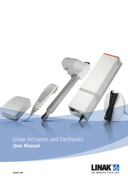
Linear Actuators and Electronics - LINAK

This User Manual does not address the end user . It is intended as a source of information for the equipment or system manufacturer only,.

linak-linear-actuators-and-electronics-user-manual-eng
Linear Actuators and Electronics
User Manual

LINAK.COM

Page 1 of 264

Contents
Preface  .  .  .  .  .  .  .  .  .  .  .  .  .  .  .  .  .  .  .  .  .  .  .  .  .  .  .  .  .  .  .  .  .  .  .  .  .  .  .  .  .  .  .  .  .  .  .  .  .  .  .  .  .  .  .  .  .  .  .  .  .  .  .  .  .  .  .  .  .  .  .  .  .  .  .  .  .  .  .  .  . 5
Valid for  .  .  .  .  .  .  .  .  .  .  .  .  .  .  .  .  .  .  .  .  .  .  .  .  .  .  .  .  .  .  .  .  .  .  .  .  .  .  .  .  .  .  .  .  .  .  .  .  .  .  .  .  .  .  .  .  .  .  .  .  .  .  .  .  .  .  .  .  .  .  .  .  .  .  .  .  .  .  .  .  . 6
Important information  .  .  .  .  .  .  .  .  .  .  .  .  .  .  .  .  .  .  .  .  .  .  .  .  .  .  .  .  .  .  .  .  .  .  .  .  .  .  .  .  .  .  .  .  .  .  .  .  .  .  .  .  .  .  .  .  .  .  .  .  .  .  .  .  .  .  .  .  . 7
Generel assembly instructions  .  .  .  .  .  .  .  .  .  .  .  .  .  .  .  .  .  .  .  .  .  .  .  .  .  .  .  .  .  .  .  .  .  .  .  .  .  .  .  .  .  .  .  .  .  .  .  .  .  .  .  .  .  .  .  .  .  .  .  .  . 11
Declaration of incorporation of partly completed machinery  .  .  .  .  .  .  .  .  .  .  .  .  .  .  .  .  .  .  .  .  .  .  .  .  .  .  .  .  .  .  .  .  .  .  . 12
1. System description  .  .  .  .  .  .  .  .  .  .  .  .  .  .  .  .  .  .  .  .  .  .  .  .  .  .  .  .  .  .  .  .  .  .  .  .  .  .  .  .  .  .  .  .  .  .  .  .  .  .  .  .  .  .  .  .  .  .  .  .  .  .  .  .  .  .  .  .  . 13 Electrostatic discharge (ESD) .  .  .  .  .  .  .  .  .  .  .  .  .  .  .  .  .  .  .  .  .  .  .  .  .  .  .  .  .  .  .  .  .  .  .  .  .  .  .  .  .  .  .  .  .  .  .  .  .  .  .  .  .  .  .  .  .  .  .  .  .  .  .  . 13 Fundamental actuator construction  .  .  .  .  .  .  .  .  .  .  .  .  .  .  .  .  .  .  .  .  .  .  .  .  .  .  .  .  .  .  .  .  .  .  .  .  .  .  .  .  .  .  .  .  .  .  .  .  .  .  .  .  .  .  .  .  .  . 14 General Warranty periods  .  .  .  .  .  .  .  .  .  .  .  .  .  .  .  .  .  .  .  .  .  .  .  .  .  .  .  .  .  .  .  .  .  .  .  .  .  .  .  .  .  .  .  .  .  .  .  .  .  .  .  .  .  .  .  .  .  .  .  .  .  .  .  .  .  . 14 IP Protection degree  .  .  .  .  .  .  .  .  .  .  .  .  .  .  .  .  .  .  .  .  .  .  .  .  .  .  .  .  .  .  .  .  .  .  .  .  .  .  .  .  .  .  .  .  .  .  .  .  .  .  .  .  .  .  .  .  .  .  .  .  .  .  .  .  .  .  .  .  .  . 15 IPX6 Washable  .  .  .  .  .  .  .  .  .  .  .  .  .  .  .  .  .  .  .  .  .  .  .  .  .  .  .  .  .  .  .  .  .  .  .  .  .  .  .  .  .  .  .  .  .  .  .  .  .  .  .  .  .  .  .  .  .  .  .  .  .  .  .  .  .  .  .  .  .  .  .  .  .  . 15 Cable Wash .  .  .  .  .  .  .  .  .  .  .  .  .  .  .  .  .  .  .  .  .  .  .  .  .  .  .  .  .  .  .  .  .  .  .  .  .  .  .  .  .  .  .  .  .  .  .  .  .  .  .  .  .  .  .  .  .  .  .  .  .  .  .  .  .  .  .  .  .  .  .  .  .  .  .  .  . 16 Maintenance  .  .  .  .  .  .  .  .  .  .  .  .  .  .  .  .  .  .  .  .  .  .  .  .  .  .  .  .  .  .  .  .  .  .  .  .  .  .  .  .  .  .  .  .  .  .  .  .  .  .  .  .  .  .  .  .  .  .  .  .  .  .  .  .  .  .  .  .  .  .  .  .  .  .  . 17 Environmental conditions  .  .  .  .  .  .  .  .  .  .  .  .  .  .  .  .  .  .  .  .  .  .  .  .  .  .  .  .  .  .  .  .  .  .  .  .  .  .  .  .  .  .  .  .  .  .  .  .  .  .  .  .  .  .  .  .  .  .  .  .  .  .  .  .  .  . 17 Insulation class  .  .  .  .  .  .  .  .  .  .  .  .  .  .  .  .  .  .  .  .  .  .  .  .  .  .  .  .  .  .  .  .  .  .  .  .  .  .  .  .  .  .  .  .  .  .  .  .  .  .  .  .  .  .  .  .  .  .  .  .  .  .  .  .  .  .  .  .  .  .  .  .  . 18 Key to symbols  .  .  .  .  .  .  .  .  .  .  .  .  .  .  .  .  .  .  .  .  .  .  .  .  .  .  .  .  .  .  .  .  .  .  .  .  .  .  .  .  .  .  .  .  .  .  .  .  .  .  .  .  .  .  .  .  .  .  .  .  .  .  .  .  .  .  .  .  .  .  .  .  .  . 18 ETL marking  .  .  .  .  .  .  .  .  .  .  .  .  .  .  .  .  .  .  .  .  .  .  .  .  .  .  .  .  .  .  .  .  .  .  .  .  .  .  .  .  .  .  .  .  .  .  .  .  .  .  .  .  .  .  .  .  .  .  .  .  .  .  .  .  .  .  .  .  .  .  .  .  .  .  .  . 19 Mounting  .  .  .  .  .  .  .  .  .  .  .  .  .  .  .  .  .  .  .  .  .  .  .  .  .  .  .  .  .  .  .  .  .  .  .  .  .  .  .  .  .  .  .  .  .  .  .  .  .  .  .  .  .  .  .  .  .  .  .  .  .  .  .  .  .  .  .  .  .  .  .  .  .  .  .  .  .  . 19 Drawings  .  .  .  .  .  .  .  .  .  .  .  .  .  .  .  .  .  .  .  .  .  .  .  .  .  .  .  .  .  .  .  .  .  .  .  .  .  .  .  .  .  .  .  .  .  .  .  .  .  .  .  .  .  .  .  .  .  .  .  .  .  .  .  .  .  .  .  .  .  .  .  .  .  .  .  .  .  . 20 Connecting the system  .  .  .  .  .  .  .  .  .  .  .  .  .  .  .  .  .  .  .  .  .  .  .  .  .  .  .  .  .  .  .  .  .  .  .  .  .  .  .  .  .  .  .  .  .  .  .  .  .  .  .  .  .  .  .  .  .  .  .  .  .  .  .  .  .  .  .  . 26 Batteries .  .  .  .  .  .  .  .  .  .  .  .  .  .  .  .  .  .  .  .  .  .  .  .  .  .  .  .  .  .  .  .  .  .  .  .  .  .  .  .  .  .  .  .  .  .  .  .  .  .  .  .  .  .  .  .  .  .  .  .  .  .  .  .  .  .  .  .  .  .  .  .  .  .  .  .  .  .  . 27
2. Information on start-up, deinstallation and operation  .  .  .  .  .  .  .  .  .  .  .  .  .  .  .  .  .  .  .  .  .  .  .  .  .  .  .  .  .  .  .  .  .  .  .  .  .  .  . 29 Troubleshooting Actuators/Lifting columns  .  .  .  .  .  .  .  .  .  .  .  .  .  .  .  .  .  .  .  .  .  .  .  .  .  .  .  .  .  .  .  .  .  .  .  .  .  .  .  .  .  .  .  .  .  .  .  .  .  .  .  .  . 30 Troubleshooting Electronics  .  .  .  .  .  .  .  .  .  .  .  .  .  .  .  .  .  .  .  .  .  .  .  .  .  .  .  .  .  .  .  .  .  .  .  .  .  .  .  .  .  .  .  .  .  .  .  .  .  .  .  .  .  .  .  .  .  .  .  .  .  .  .  . 30
3. Information on specific actuators  .  .  .  .  .  .  .  .  .  .  .  .  .  .  .  .  .  .  .  .  .  .  .  .  .  .  .  .  .  .  .  .  .  .  .  .  .  .  .  .  .  .  .  .  .  .  .  .  .  .  .  .  .  .  .  .  . 31 LA20 Inline .  .  .  .  .  .  .  .  .  .  .  .  .  .  .  .  .  .  .  .  .  .  .  .  .  .  .  .  .  .  .  .  .  .  .  .  .  .  .  .  .  .  .  .  .  .  .  .  .  .  .  .  .  .  .  .  .  .  .  .  .  .  .  .  .  .  .  .  .  .  .  .  .  .  .  .  . 31 LA23 DESKLINE®  .  .  .  .  .  .  .  .  .  .  .  .  .  .  .  .  .  .  .  .  .  .  .  .  .  .  .  .  .  .  .  .  .  .  .  .  .  .  .  .  .  .  .  .  .  .  .  .  .  .  .  .  .  .  .  .  .  .  .  .  .  .  .  .  .  .  .  .  .  .  .  . 36 LA23 MEDLINE® CARELINE® TECHLINE® .  .  .  .  .  .  .  .  .  .  .  .  .  .  .  .  .  .  .  .  .  .  .  .  .  .  .  .  .  .  .  .  .  .  .  .  .  .  .  .  .  .  .  .  .  .  .  .  .  .  .  .  .  .  . 37 LA23 IC  .  .  .  .  .  .  .  .  .  .  .  .  .  .  .  .  .  .  .  .  .  .  .  .  .  .  .  .  .  .  .  .  .  .  .  .  .  .  .  .  .  .  .  .  .  .  .  .  .  .  .  .  .  .  .  .  .  .  .  .  .  .  .  .  .  .  .  .  .  .  .  .  .  .  .  .  .  .  . 48 LA27  .  .  .  .  .  .  .  .  .  .  .  .  .  .  .  .  .  .  .  .  .  .  .  .  .  .  .  .  .  .  .  .  .  .  .  .  .  .  .  .  .  .  .  .  .  .  .  .  .  .  .  .  .  .  .  .  .  .  .  .  .  .  .  .  .  .  .  .  .  .  .  .  .  .  .  .  .  .  .  .  . 52 LA28  .  .  .  .  .  .  .  .  .  .  .  .  .  .  .  .  .  .  .  .  .  .  .  .  .  .  .  .  .  .  .  .  .  .  .  .  .  .  .  .  .  .  .  .  .  .  .  .  .  .  .  .  .  .  .  .  .  .  .  .  .  .  .  .  .  .  .  .  .  .  .  .  .  .  .  .  .  .  .  .  . 54 LA28 Compact  .  .  .  .  .  .  .  .  .  .  .  .  .  .  .  .  .  .  .  .  .  .  .  .  .  .  .  .  .  .  .  .  .  .  .  .  .  .  .  .  .  .  .  .  .  .  .  .  .  .  .  .  .  .  .  .  .  .  .  .  .  .  .  .  .  .  .  .  .  .  .  .  .  . 55 LA29  .  .  .  .  .  .  .  .  .  .  .  .  .  .  .  .  .  .  .  .  .  .  .  .  .  .  .  .  .  .  .  .  .  .  .  .  .  .  .  .  .  .  .  .  .  .  .  .  .  .  .  .  .  .  .  .  .  .  .  .  .  .  .  .  .  .  .  .  .  .  .  .  .  .  .  .  .  .  .  .  . 55 LA30  .  .  .  .  .  .  .  .  .  .  .  .  .  .  .  .  .  .  .  .  .  .  .  .  .  .  .  .  .  .  .  .  .  .  .  .  .  .  .  .  .  .  .  .  .  .  .  .  .  .  .  .  .  .  .  .  .  .  .  .  .  .  .  .  .  .  .  .  .  .  .  .  .  .  .  .  .  .  .  .  . 58 LA31  .  .  .  .  .  .  .  .  .  .  .  .  .  .  .  .  .  .  .  .  .  .  .  .  .  .  .  .  .  .  .  .  .  .  .  .  .  .  .  .  .  .  .  .  .  .  .  .  .  .  .  .  .  .  .  .  .  .  .  .  .  .  .  .  .  .  .  .  .  .  .  .  .  .  .  .  .  .  .  .  . 59 LA34  .  .  .  .  .  .  .  .  .  .  .  .  .  .  .  .  .  .  .  .  .  .  .  .  .  .  .  .  .  .  .  .  .  .  .  .  .  .  .  .  .  .  .  .  .  .  .  .  .  .  .  .  .  .  .  .  .  .  .  .  .  .  .  .  .  .  .  .  .  .  .  .  .  .  .  .  .  .  .  .  . 64 LA40 HOMELINE® .  .  .  .  .  .  .  .  .  .  .  .  .  .  .  .  .  .  .  .  .  .  .  .  .  .  .  .  .  .  .  .  .  .  .  .  .  .  .  .  .  .  .  .  .  .  .  .  .  .  .  .  .  .  .  .  .  .  .  .  .  .  .  .  .  .  .  .  .  .  .  . 66 LA40 MEDLINE® CARELINE® .  .  .  .  .  .  .  .  .  .  .  .  .  .  .  .  .  .  .  .  .  .  .  .  .  .  .  .  .  .  .  .  .  .  .  .  .  .  .  .  .  .  .  .  .  .  .  .  .  .  .  .  .  .  .  .  .  .  .  .  .  .  .  . 67 LA44 .  .  .  .  .  .  .  .  .  .  .  .  .  .  .  .  .  .  .  .  .  .  .  .  .  .  .  .  .  .  .  .  .  .  .  .  .  .  .  .  .  .  .  .  .  .  .  .  .  .  .  .  .  .  .  .  .  .  .  .  .  .  .  .  .  .  .  .  .  .  .  .  .  .  .  .  .  .  .  .  .  . 76
4. Information on specific columns  .  .  .  .  .  .  .  .  .  .  .  .  .  .  .  .  .  .  .  .  .  .  .  .  .  .  .  .  .  .  .  .  .  .  .  .  .  .  .  .  .  .  .  .  .  .  .  .  .  .  .  .  .  .  .  .  .  . 79 BL1 .  .  .  .  .  .  .  .  .  .  .  .  .  .  .  .  .  .  .  .  .  .  .  .  .  .  .  .  .  .  .  .  .  .  .  .  .  .  .  .  .  .  .  .  .  .  .  .  .  .  .  .  .  .  .  .  .  .  .  .  .  .  .  .  .  .  .  .  .  .  .  .  .  .  .  .  .  .  .  .  .  .  . 79 LC3 .  .  .  .  .  .  .  .  .  .  .  .  .  .  .  .  .  .  .  .  .  .  .  .  .  .  .  .  .  .  .  .  .  .  .  .  .  .  .  .  .  .  .  .  .  .  .  .  .  .  .  .  .  .  .  .  .  .  .  .  .  .  .  .  .  .  .  .  .  .  .  .  .  .  .  .  .  .  .  .  .  .  . 84
Page 2 of 264

5. Information on specific control boxes  .  .  .  .  .  .  .  .  .  .  .  .  .  .  .  .  .  .  .  .  .  .  .  .  .  .  .  .  .  .  .  .  .  .  .  .  .  .  .  .  .  .  .  .  .  .  .  .  .  .  .  . 103 Generel information  .  .  .  .  .  .  .  .  .  .  .  .  .  .  .  .  .  .  .  .  .  .  .  .  .  .  .  .  .  .  .  .  .  .  .  .  .  .  .  .  .  .  .  .  .  .  .  .  .  .  .  .  .  .  .  .  .  .  .  .  .  .  .  .  .  .  .  .  . 103 CA30 / CA40  .  .  .  .  .  .  .  .  .  .  .  .  .  .  .  .  .  .  .  .  .  .  .  .  .  .  .  .  .  .  .  .  .  .  .  .  .  .  .  .  .  .  .  .  .  .  .  .  .  .  .  .  .  .  .  .  .  .  .  .  .  .  .  .  .  .  .  .  .  .  .  .  .  . 104 CA63  .  .  .  .  .  .  .  .  .  .  .  .  .  .  .  .  .  .  .  .  .  .  .  .  .  .  .  .  .  .  .  .  .  .  .  .  .  .  .  .  .  .  .  .  .  .  .  .  .  .  .  .  .  .  .  .  .  .  .  .  .  .  .  .  .  .  .  .  .  .  .  .  .  .  .  .  .  .  .  . 107 CB6  .  .  .  .  .  .  .  .  .  .  .  .  .  .  .  .  .  .  .  .  .  .  .  .  .  .  .  .  .  .  .  .  .  .  .  .  .  .  .  .  .  .  .  .  .  .  .  .  .  .  .  .  .  .  .  .  .  .  .  .  .  .  .  .  .  .  .  .  .  .  .  .  .  .  .  .  .  .  .  .  . 112 CB6P2  .  .  .  .  .  .  .  .  .  .  .  .  .  .  .  .  .  .  .  .  .  .  .  .  .  .  .  .  .  .  .  .  .  .  .  .  .  .  .  .  .  .  .  .  .  .  .  .  .  .  .  .  .  .  .  .  .  .  .  .  .  .  .  .  .  .  .  .  .  .  .  .  .  .  .  .  .  .  . 113 CB7  .  .  .  .  .  .  .  .  .  .  .  .  .  .  .  .  .  .  .  .  .  .  .  .  .  .  .  .  .  .  .  .  .  .  .  .  .  .  .  .  .  .  .  .  .  .  .  .  .  .  .  .  .  .  .  .  .  .  .  .  .  .  .  .  .  .  .  .  .  .  .  .  .  .  .  .  .  .  .  .  . 113 CB8A  .  .  .  .  .  .  .  .  .  .  .  .  .  .  .  .  .  .  .  .  .  .  .  .  .  .  .  .  .  .  .  .  .  .  .  .  .  .  .  .  .  .  .  .  .  .  .  .  .  .  .  .  .  .  .  .  .  .  .  .  .  .  .  .  .  .  .  .  .  .  .  .  .  .  .  .  .  .  .  . 114 CB8-T  .  .  .  .  .  .  .  .  .  .  .  .  .  .  .  .  .  .  .  .  .  .  .  .  .  .  .  .  .  .  .  .  .  .  .  .  .  .  .  .  .  .  .  .  .  .  .  .  .  .  .  .  .  .  .  .  .  .  .  .  .  .  .  .  .  .  .  .  .  .  .  .  .  .  .  .  .  .  . 114 CB9 HOMELINE® .  .  .  .  .  .  .  .  .  .  .  .  .  .  .  .  .  .  .  .  .  .  .  .  .  .  .  .  .  .  .  .  .  .  .  .  .  .  .  .  .  .  .  .  .  .  .  .  .  .  .  .  .  .  .  .  .  .  .  .  .  .  .  .  .  .  .  .  .  .  .  . 114 CB9 CARELINE® and CB9 CARELINE® BASIC .  .  .  .  .  .  .  .  .  .  .  .  .  .  .  .  .  .  .  .  .  .  .  .  .  .  .  .  .  .  .  .  .  .  .  .  .  .  .  .  .  .  .  .  .  .  .  .  .  .  . 115 CB20  .  .  .  .  .  .  .  .  .  .  .  .  .  .  .  .  .  .  .  .  .  .  .  .  .  .  .  .  .  .  .  .  .  .  .  .  .  .  .  .  .  .  .  .  .  .  .  .  .  .  .  .  .  .  .  .  .  .  .  .  .  .  .  .  .  .  .  .  .  .  .  .  .  .  .  .  .  .  .  . 116 CBR1  .  .  .  .  .  .  .  .  .  .  .  .  .  .  .  .  .  .  .  .  .  .  .  .  .  .  .  .  .  .  .  .  .  .  .  .  .  .  .  .  .  .  .  .  .  .  .  .  .  .  .  .  .  .  .  .  .  .  .  .  .  .  .  .  .  .  .  .  .  .  .  .  .  .  .  .  .  .  .  . 116 CO53 .  .  .  .  .  .  .  .  .  .  .  .  .  .  .  .  .  .  .  .  .  .  .  .  .  .  .  .  .  .  .  .  .  .  .  .  .  .  .  .  .  .  .  .  .  .  .  .  .  .  .  .  .  .  .  .  .  .  .  .  .  .  .  .  .  .  .  .  .  .  .  .  .  .  .  .  .  .  .  . 117 CO61 .  .  .  .  .  .  .  .  .  .  .  .  .  .  .  .  .  .  .  .  .  .  .  .  .  .  .  .  .  .  .  .  .  .  .  .  .  .  .  .  .  .  .  .  .  .  .  .  .  .  .  .  .  .  .  .  .  .  .  .  .  .  .  .  .  .  .  .  .  .  .  .  .  .  .  .  .  .  .  . 123 CO65 .  .  .  .  .  .  .  .  .  .  .  .  .  .  .  .  .  .  .  .  .  .  .  .  .  .  .  .  .  .  .  .  .  .  .  .  .  .  .  .  .  .  .  .  .  .  .  .  .  .  .  .  .  .  .  .  .  .  .  .  .  .  .  .  .  .  .  .  .  .  .  .  .  .  .  .  .  .  .  . 128 CO71 .  .  .  .  .  .  .  .  .  .  .  .  .  .  .  .  .  .  .  .  .  .  .  .  .  .  .  .  .  .  .  .  .  .  .  .  .  .  .  .  .  .  .  .  .  .  .  .  .  .  .  .  .  .  .  .  .  .  .  .  .  .  .  .  .  .  .  .  .  .  .  .  .  .  .  .  .  .  .  . 133 OPS  .  .  .  .  .  .  .  .  .  .  .  .  .  .  .  .  .  .  .  .  .  .  .  .  .  .  .  .  .  .  .  .  .  .  .  .  .  .  .  .  .  .  .  .  .  .  .  .  .  .  .  .  .  .  .  .  .  .  .  .  .  .  .  .  .  .  .  .  .  .  .  .  .  .  .  .  .  .  .  . 138 PJ2  .  .  .  .  .  .  .  .  .  .  .  .  .  .  .  .  .  .  .  .  .  .  .  .  .  .  .  .  .  .  .  .  .  .  .  .  .  .  .  .  .  .  .  .  .  .  .  .  .  .  .  .  .  .  .  .  .  .  .  .  .  .  .  .  .  .  .  .  .  .  .  .  .  .  .  .  .  .  .  .  .  . 141
6. Information on specific controls  .  .  .  .  .  .  .  .  .  .  .  .  .  .  .  .  .  .  .  .  .  .  .  .  .  .  .  .  .  .  .  .  .  .  .  .  .  .  .  .  .  .  .  .  .  .  .  .  .  .  .  .  .  .  .  .  . 145 ABL .  .  .  .  .  .  .  .  .  .  .  .  .  .  .  .  .  .  .  .  .  .  .  .  .  .  .  .  .  .  .  .  .  .  .  .  .  .  .  .  .  .  .  .  .  .  .  .  .  .  .  .  .  .  .  .  .  .  .  .  .  .  .  .  .  .  .  .  .  .  .  .  .  .  .  .  .  .  .  .  .  . 145 ACC .  .  .  .  .  .  .  .  .  .  .  .  .  .  .  .  .  .  .  .  .  .  .  .  .  .  .  .  .  .  .  .  .  .  .  .  .  .  .  .  .  .  .  .  .  .  .  .  .  .  .  .  .  .  .  .  .  .  .  .  .  .  .  .  .  .  .  .  .  .  .  .  .  .  .  .  .  .  .  .  . 148 ACK  .  .  .  .  .  .  .  .  .  .  .  .  .  .  .  .  .  .  .  .  .  .  .  .  .  .  .  .  .  .  .  .  .  .  .  .  .  .  .  .  .  .  .  .  .  .  .  .  .  .  .  .  .  .  .  .  .  .  .  .  .  .  .  .  .  .  .  .  .  .  .  .  .  .  .  .  .  .  .  .  . 148 ACL . . . . . . . . . . . . . . . . . . . . . . . . . . . . . . . . . . . . . . . . . . . . . . . . . . . . . . . . . . . . . . . . . . . . . . . . . . . . . . . . . 148 ACO .  .  .  .  .  .  .  .  .  .  .  .  .  .  .  .  .  .  .  .  .  .  .  .  .  .  .  .  .  .  .  .  .  .  .  .  .  .  .  .  .  .  .  .  .  .  .  .  .  .  .  .  .  .  .  .  .  .  .  .  .  .  .  .  .  .  .  .  .  .  .  .  .  .  .  .  .  .  .  .  . 149 ACOM .  .  .  .  .  .  .  .  .  .  .  .  .  .  .  .  .  .  .  .  .  .  .  .  .  .  .  .  .  .  .  .  .  .  .  .  .  .  .  .  .  .  .  .  .  .  .  .  .  .  .  .  .  .  .  .  .  .  .  .  .  .  .  .  .  .  .  .  .  .  .  .  .  .  .  .  .  .  .  . 149 ACT  .  .  .  .  .  .  .  .  .  .  .  .  .  .  .  .  .  .  .  .  .  .  .  .  .  .  .  .  .  .  .  .  .  .  .  .  .  .  .  .  .  .  .  .  .  .  .  .  .  .  .  .  .  .  .  .  .  .  .  .  .  .  .  .  .  .  .  .  .  .  .  .  .  .  .  .  .  .  .  .  . 150 DPH Medical .  .  .  .  .  .  .  .  .  .  .  .  .  .  .  .  .  .  .  .  .  .  .  .  .  .  .  .  .  .  .  .  .  .  .  .  .  .  .  .  .  .  .  .  .  .  .  .  .  .  .  .  .  .  .  .  .  .  .  .  .  .  .  .  .  .  .  .  .  .  .  .  .  .  . 152 FPP .  .  .  .  .  .  .  .  .  .  .  .  .  .  .  .  .  .  .  .  .  .  .  .  .  .  .  .  .  .  .  .  .  .  .  .  .  .  .  .  .  .  .  .  .  .  .  .  .  .  .  .  .  .  .  .  .  .  .  .  .  .  .  .  .  .  .  .  .  .  .  .  .  .  .  .  .  .  .  .  .  . 153 FS  .  .  .  .  .  .  .  .  .  .  .  .  .  .  .  .  .  .  .  .  .  .  .  .  .  .  .  .  .  .  .  .  .  .  .  .  .  .  .  .  .  .  .  .  .  .  .  .  .  .  .  .  .  .  .  .  .  .  .  .  .  .  .  .  .  .  .  .  .  .  .  .  .  .  .  .  .  .  .  .  .  . 154 FS3  .  .  .  .  .  .  .  .  .  .  .  .  .  .  .  .  .  .  .  .  .  .  .  .  .  .  .  .  .  .  .  .  .  .  .  .  .  .  .  .  .  .  .  .  .  .  .  .  .  .  .  .  .  .  .  .  .  .  .  .  .  .  .  .  .  .  .  .  .  .  .  .  .  .  .  .  .  .  .  .  .  . 155 HB30  .  .  .  .  .  .  .  .  .  .  .  .  .  .  .  .  .  .  .  .  .  .  .  .  .  .  .  .  .  .  .  .  .  .  .  .  .  .  .  .  .  .  .  .  .  .  .  .  .  .  .  .  .  .  .  .  .  .  .  .  .  .  .  .  .  .  .  .  .  .  .  .  .  .  .  .  .  .  .  . 159 HB70  .  .  .  .  .  .  .  .  .  .  .  .  .  .  .  .  .  .  .  .  .  .  .  .  .  .  .  .  .  .  .  .  .  .  .  .  .  .  .  .  .  .  .  .  .  .  .  .  .  .  .  .  .  .  .  .  .  .  .  .  .  .  .  .  .  .  .  .  .  .  .  .  .  .  .  .  .  .  .  . 160 HB80  .  .  .  .  .  .  .  .  .  .  .  .  .  .  .  .  .  .  .  .  .  .  .  .  .  .  .  .  .  .  .  .  .  .  .  .  .  .  .  .  .  .  .  .  .  .  .  .  .  .  .  .  .  .  .  .  .  .  .  .  .  .  .  .  .  .  .  .  .  .  .  .  .  .  .  .  .  .  .  . 160 HB100  .  .  .  .  .  .  .  .  .  .  .  .  .  .  .  .  .  .  .  .  .  .  .  .  .  .  .  .  .  .  .  .  .  .  .  .  .  .  .  .  .  .  .  .  .  .  .  .  .  .  .  .  .  .  .  .  .  .  .  .  .  .  .  .  .  .  .  .  .  .  .  .  .  .  .  .  .  .  . 161 HB190  .  .  .  .  .  .  .  .  .  .  .  .  .  .  .  .  .  .  .  .  .  .  .  .  .  .  .  .  .  .  .  .  .  .  .  .  .  .  .  .  .  .  .  .  .  .  .  .  .  .  .  .  .  .  .  .  .  .  .  .  .  .  .  .  .  .  .  .  .  .  .  .  .  .  .  .  .  .  . 162 HB200  .  .  .  .  .  .  .  .  .  .  .  .  .  .  .  .  .  .  .  .  .  .  .  .  .  .  .  .  .  .  .  .  .  .  .  .  .  .  .  .  .  .  .  .  .  .  .  .  .  .  .  .  .  .  .  .  .  .  .  .  .  .  .  .  .  .  .  .  .  .  .  .  .  .  .  .  .  .  . 163 HD80 .  .  .  .  .  .  .  .  .  .  .  .  .  .  .  .  .  .  .  .  .  .  .  .  .  .  .  .  .  .  .  .  .  .  .  .  .  .  .  .  .  .  .  .  .  .  .  .  .  .  .  .  .  .  .  .  .  .  .  .  .  .  .  .  .  .  .  .  .  .  .  .  .  .  .  .  .  .  .  . 166 HD80 JUMBO .  .  .  .  .  .  .  .  .  .  .  .  .  .  .  .  .  .  .  .  .  .  .  .  .  .  .  .  .  .  .  .  .  .  .  .  .  .  .  .  .  .  .  .  .  .  .  .  .  .  .  .  .  .  .  .  .  .  .  .  .  .  .  .  .  .  .  .  .  .  .  .  .  . 167 HL70 .  .  .  .  .  .  .  .  .  .  .  .  .  .  .  .  .  .  .  .  .  .  .  .  .  .  .  .  .  .  .  .  .  .  .  .  .  .  .  .  .  .  .  .  .  .  .  .  .  .  .  .  .  .  .  .  .  .  .  .  .  .  .  .  .  .  .  .  .  .  .  .  .  .  .  .  .  .  .  .  . 167 HL80 .  .  .  .  .  .  .  .  .  .  .  .  .  .  .  .  .  .  .  .  .  .  .  .  .  .  .  .  .  .  .  .  .  .  .  .  .  .  .  .  .  .  .  .  .  .  .  .  .  .  .  .  .  .  .  .  .  .  .  .  .  .  .  .  .  .  .  .  .  .  .  .  .  .  .  .  .  .  .  .  . 168 LS  .  .  .  .  .  .  .  .  .  .  .  .  .  .  .  .  .  .  .  .  .  .  .  .  .  .  .  .  .  .  .  .  .  .  .  .  .  .  .  .  .  .  .  .  .  .  .  .  .  .  .  .  .  .  .  .  .  .  .  .  .  .  .  .  .  .  .  .  .  .  .  .  .  .  .  .  .  .  .  .  .  . 168 LSD .  .  .  .  .  .  .  .  .  .  .  .  .  .  .  .  .  .  .  .  .  .  .  .  .  .  .  .  .  .  .  .  .  .  .  .  .  .  .  .  .  .  .  .  .  .  .  .  .  .  .  .  .  .  .  .  .  .  .  .  .  .  .  .  .  .  .  .  .  .  .  .  .  .  .  .  .  .  .  .  .  . 168
7. Information on specific JUMBOTM  .  .  .  .  .  .  .  .  .  .  .  .  .  .  .  .  .  .  .  .  .  .  .  .  .  .  .  .  .  .  .  .  .  .  .  .  .  .  .  .  .  .  .  .  .  .  .  .  .  .  .  .  .  .  .  . 169 BAJ  .  .  .  .  .  .  .  .  .  .  .  .  .  .  .  .  .  .  .  .  .  .  .  .  .  .  .  .  .  .  .  .  .  .  .  .  .  .  .  .  .  .  .  .  .  .  .  .  .  .  .  .  .  .  .  .  .  .  .  .  .  .  .  .  .  .  .  .  .  .  .  .  .  .  .  .  .  .  .  .  . 169 BAJL Li-Ion .  .  .  .  .  .  .  .  .  .  .  .  .  .  .  .  .  .  .  .  .  .  .  .  .  .  .  .  .  .  .  .  .  .  .  .  .  .  .  .  .  .  .  .  .  .  .  .  .  .  .  .  .  .  .  .  .  .  .  .  .  .  .  .  .  .  .  .  .  .  .  .  .  .  .  . 169 CBJ1 / CBJ2  .  .  .  .  .  .  .  .  .  .  .  .  .  .  .  .  .  .  .  .  .  .  .  .  .  .  .  .  .  .  .  .  .  .  .  .  .  .  .  .  .  .  .  .  .  .  .  .  .  .  .  .  .  .  .  .  .  .  .  .  .  .  .  .  .  .  .  .  .  .  .  .  .  .  . 172 CBJ-Care .  .  .  .  .  .  .  .  .  .  .  .  .  .  .  .  .  .  .  .  .  .  .  .  .  .  .  .  .  .  .  .  .  .  .  .  .  .  .  .  .  .  .  .  .  .  .  .  .  .  .  .  .  .  .  .  .  .  .  .  .  .  .  .  .  .  .  .  .  .  .  .  .  .  .  .  .  . 175 CBJ-Home .  .  .  .  .  .  .  .  .  .  .  .  .  .  .  .  .  .  .  .  .  .  .  .  .  .  .  .  .  .  .  .  .  .  .  .  .  .  .  .  .  .  .  .  .  .  .  .  .  .  .  .  .  .  .  .  .  .  .  .  .  .  .  .  .  .  .  .  .  .  .  .  .  .  .  .  . 178 COBO .  .  .  .  .  .  .  .  .  .  .  .  .  .  .  .  .  .  .  .  .  .  .  .  .  .  .  .  .  .  .  .  .  .  .  .  .  .  .  .  .  .  .  .  .  .  .  .  .  .  .  .  .  .  .  .  .  .  .  .  .  .  .  .  .  .  .  .  .  .  .  .  .  .  .  .  .  .  .  . 179 CH01 2nd generation  .  .  .  .  .  .  .  .  .  .  .  .  .  .  .  .  .  .  .  .  .  .  .  .  .  .  .  .  .  .  .  .  .  .  .  .  .  .  .  .  .  .  .  .  .  .  .  .  .  .  .  .  .  .  .  .  .  .  .  .  .  .  .  .  .  .  .  . 180 CHJ2 .  .  .  .  .  .  .  .  .  .  .  .  .  .  .  .  .  .  .  .  .  .  .  .  .  .  .  .  .  .  .  .  .  .  .  .  .  .  .  .  .  .  .  .  .  .  .  .  .  .  .  .  .  .  .  .  .  .  .  .  .  .  .  .  .  .  .  .  .  .  .  .  .  .  .  .  .  .  .  .  . 180 MBJ1/2/3  .  .  .  .  .  .  .  .  .  .  .  .  .  .  .  .  .  .  .  .  .  .  .  .  .  .  .  .  .  .  .  .  .  .  .  .  .  .  .  .  .  .  .  .  .  .  .  .  .  .  .  .  .  .  .  .  .  .  .  .  .  .  .  .  .  .  .  .  .  .  .  .  .  .  .  .  . 181
Page 3 of 264

8. Information on specific accessories  .  .  .  .  .  .  .  .  .  .  .  .  .  .  .  .  .  .  .  .  .  .  .  .  .  .  .  .  .  .  .  .  .  .  .  .  .  .  .  .  .  .  .  .  .  .  .  .  .  .  .  .  .  . 182 Generel information  .  .  .  .  .  .  .  .  .  .  .  .  .  .  .  .  .  .  .  .  .  .  .  .  .  .  .  .  .  .  .  .  .  .  .  .  .  .  .  .  .  .  .  .  .  .  .  .  .  .  .  .  .  .  .  .  .  .  .  .  .  .  .  .  .  .  .  .  . 182 BA16 Lead acid .  .  .  .  .  .  .  .  .  .  .  .  .  .  .  .  .  .  .  .  .  .  .  .  .  .  .  .  .  .  .  .  .  .  .  .  .  .  .  .  .  .  .  .  .  .  .  .  .  .  .  .  .  .  .  .  .  .  .  .  .  .  .  .  .  .  .  .  .  .  .  .  . 182 BA18  .  .  .  .  .  .  .  .  .  .  .  .  .  .  .  .  .  .  .  .  .  .  .  .  .  .  .  .  .  .  .  .  .  .  .  .  .  .  .  .  .  .  .  .  .  .  .  .  .  .  .  .  .  .  .  .  .  .  .  .  .  .  .  .  .  .  .  .  .  .  .  .  .  .  .  .  .  .  .  . 184 BA19 Lead acid .  .  .  .  .  .  .  .  .  .  .  .  .  .  .  .  .  .  .  .  .  .  .  .  .  .  .  .  .  .  .  .  .  .  .  .  .  .  .  .  .  .  .  .  .  .  .  .  .  .  .  .  .  .  .  .  .  .  .  .  .  .  .  .  .  .  .  .  .  .  .  .  . 185 BA21 Li-Ion  .  .  .  .  .  .  .  .  .  .  .  .  .  .  .  .  .  .  .  .  .  .  .  .  .  .  .  .  .  .  .  .  .  .  .  .  .  .  .  .  .  .  .  .  .  .  .  .  .  .  .  .  .  .  .  .  .  .  .  .  .  .  .  .  .  .  .  .  .  .  .  .  .  .  . 187 CS16 .  .  .  .  .  .  .  .  .  .  .  .  .  .  .  .  .  .  .  .  .  .  .  .  .  .  .  .  .  .  .  .  .  .  .  .  .  .  .  .  .  .  .  .  .  .  .  .  .  .  .  .  .  .  .  .  .  .  .  .  .  .  .  .  .  .  .  .  .  .  .  .  .  .  .  .  .  .  .  .  . 191 DJB .  .  .  .  .  .  .  .  .  .  .  .  .  .  .  .  .  .  .  .  .  .  .  .  .  .  .  .  .  .  .  .  .  .  .  .  .  .  .  .  .  .  .  .  .  .  .  .  .  .  .  .  .  .  .  .  .  .  .  .  .  .  .  .  .  .  .  .  .  .  .  .  .  .  .  .  .  .  .  .  .  . 191 Massage Motor Medical .  .  .  .  .  .  .  .  .  .  .  .  .  .  .  .  .  .  .  .  .  .  .  .  .  .  .  .  .  .  .  .  .  .  .  .  .  .  .  .  .  .  .  .  .  .  .  .  .  .  .  .  .  .  .  .  .  .  .  .  .  .  .  .  .  . 192 MJB2  .  .  .  .  .  .  .  .  .  .  .  .  .  .  .  .  .  .  .  .  .  .  .  .  .  .  .  .  .  .  .  .  .  .  .  .  .  .  .  .  .  .  .  .  .  .  .  .  .  .  .  .  .  .  .  .  .  .  .  .  .  .  .  .  .  .  .  .  .  .  .  .  .  .  .  .  .  .  .  . 193 MJB5 Plus Port Repeater .  .  .  .  .  .  .  .  .  .  .  .  .  .  .  .  .  .  .  .  .  .  .  .  .  .  .  .  .  .  .  .  .  .  .  .  .  .  .  .  .  .  .  .  .  .  .  .  .  .  .  .  .  .  .  .  .  .  .  .  .  .  .  .  .  . 194 MJB5 Plus SMPS .  .  .  .  .  .  .  .  .  .  .  .  .  .  .  .  .  .  .  .  .  .  .  .  .  .  .  .  .  .  .  .  .  .  .  .  .  .  .  .  .  .  .  .  .  .  .  .  .  .  .  .  .  .  .  .  .  .  .  .  .  .  .  .  .  .  .  .  .  .  .  . 199 MJB5 Plus Gateway .  .  .  .  .  .  .  .  .  .  .  .  .  .  .  .  .  .  .  .  .  .  .  .  .  .  .  .  .  .  .  .  .  .  .  .  .  .  .  .  .  .  .  .  .  .  .  .  .  .  .  .  .  .  .  .  .  .  .  .  .  .  .  .  .  .  .  .  .  . 204 MJB5 Plus UBL (int) . . . . . . . . . . . . . . . . . . . . . . . . . . . . . . . . . . . . . . . . . . . . . . . . . . . . . . . . . . . . . . . . . . . . . 211 MJB5 Plus UBL (ext) .  .  .  .  .  .  .  .  .  .  .  .  .  .  .  .  .  .  .  .  .  .  .  .  .  .  .  .  .  .  .  .  .  .  .  .  .  .  .  .  .  .  .  .  .  .  .  .  .  .  .  .  .  .  .  .  .  .  .  .  .  .  .  .  .  .  .  .  . 217 MJB8  .  .  .  .  .  .  .  .  .  .  .  .  .  .  .  .  .  .  .  .  .  .  .  .  .  .  .  .  .  .  .  .  .  .  .  .  .  .  .  .  .  .  .  .  .  .  .  .  .  .  .  .  .  .  .  .  .  .  .  .  .  .  .  .  .  .  .  .  .  .  .  .  .  .  .  .  .  .  .  . 223 Simulator tool .  .  .  .  .  .  .  .  .  .  .  .  .  .  .  .  .  .  .  .  .  .  .  .  .  .  .  .  .  .  .  .  .  .  .  .  .  .  .  .  .  .  .  .  .  .  .  .  .  .  .  .  .  .  .  .  .  .  .  .  .  .  .  .  .  .  .  .  .  .  .  .  .  . 224 SLS  .  .  .  .  .  .  .  .  .  .  .  .  .  .  .  .  .  .  .  .  .  .  .  .  .  .  .  .  .  .  .  .  .  .  .  .  .  .  .  .  .  .  .  .  .  .  .  .  .  .  .  .  .  .  .  .  .  .  .  .  .  .  .  .  .  .  .  .  .  .  .  .  .  .  .  .  .  .  .  .  .  . 225 Under Bed Light  .  .  .  .  .  .  .  .  .  .  .  .  .  .  .  .  .  .  .  .  .  .  .  .  .  .  .  .  .  .  .  .  .  .  .  .  .  .  .  .  .  .  .  .  .  .  .  .  .  .  .  .  .  .  .  .  .  .  .  .  .  .  .  .  .  .  .  .  .  .  .  . 226 Under Bed Light 2 .  .  .  .  .  .  .  .  .  .  .  .  .  .  .  .  .  .  .  .  .  .  .  .  .  .  .  .  .  .  .  .  .  .  .  .  .  .  .  .  .  .  .  .  .  .  .  .  .  .  .  .  .  .  .  .  .  .  .  .  .  .  .  .  .  .  .  .  .  .  . 227 WET Sheet  .  .  .  .  .  .  .  .  .  .  .  .  .  .  .  .  .  .  .  .  .  .  .  .  .  .  .  .  .  .  .  .  .  .  .  .  .  .  .  .  .  .  .  .  .  .  .  .  .  .  .  .  .  .  .  .  .  .  .  .  .  .  .  .  .  .  .  .  .  .  .  .  .  .  .  . 227 QLCI2 .  .  .  .  .  .  .  .  .  .  .  .  .  .  .  .  .  .  .  .  .  .  .  .  .  .  .  .  .  .  .  .  .  .  .  .  .  .  .  .  .  .  .  .  .  .  .  .  .  .  .  .  .  .  .  .  .  .  .  .  .  .  .  .  .  .  .  .  .  .  .  .  .  .  .  .  .  .  .  . 228
9. Information on specific LIFT products .  .  .  .  .  .  .  .  .  .  .  .  .  .  .  .  .  .  .  .  .  .  .  .  .  .  .  .  .  .  .  .  .  .  .  .  .  .  .  .  .  .  .  .  .  .  .  .  .  .  .  .  . 231 Generel information  .  .  .  .  .  .  .  .  .  .  .  .  .  .  .  .  .  .  .  .  .  .  .  .  .  .  .  .  .  .  .  .  .  .  .  .  .  .  .  .  .  .  .  .  .  .  .  .  .  .  .  .  .  .  .  .  .  .  .  .  .  .  .  .  .  .  .  .  . 231 CAL40  .  .  .  .  .  .  .  .  .  .  .  .  .  .  .  .  .  .  .  .  .  .  .  .  .  .  .  .  .  .  .  .  .  .  .  .  .  .  .  .  .  .  .  .  .  .  .  .  .  .  .  .  .  .  .  .  .  .  .  .  .  .  .  .  .  .  .  .  .  .  .  .  .  .  .  .  .  .  . 231 BAL40 .  .  .  .  .  .  .  .  .  .  .  .  .  .  .  .  .  .  .  .  .  .  .  .  .  .  .  .  .  .  .  .  .  .  .  .  .  .  .  .  .  .  .  .  .  .  .  .  .  .  .  .  .  .  .  .  .  .  .  .  .  .  .  .  .  .  .  .  .  .  .  .  .  .  .  .  .  .  .  . 243 CHL40  .  .  .  .  .  .  .  .  .  .  .  .  .  .  .  .  .  .  .  .  .  .  .  .  .  .  .  .  .  .  .  .  .  .  .  .  .  .  .  .  .  .  .  .  .  .  .  .  .  .  .  .  .  .  .  .  .  .  .  .  .  .  .  .  .  .  .  .  .  .  .  .  .  .  .  .  .  .  . 245 COL50  .  .  .  .  .  .  .  .  .  .  .  .  .  .  .  .  .  .  .  .  .  .  .  .  .  .  .  .  .  .  .  .  .  .  .  .  .  .  .  .  .  .  .  .  .  .  .  .  .  .  .  .  .  .  .  .  .  .  .  .  .  .  .  .  .  .  .  .  .  .  .  .  .  .  .  .  .  .  . 246 BAL50 .  .  .  .  .  .  .  .  .  .  .  .  .  .  .  .  .  .  .  .  .  .  .  .  .  .  .  .  .  .  .  .  .  .  .  .  .  .  .  .  .  .  .  .  .  .  .  .  .  .  .  .  .  .  .  .  .  .  .  .  .  .  .  .  .  .  .  .  .  .  .  .  .  .  .  .  .  .  .  . 258 CHL50  .  .  .  .  .  .  .  .  .  .  .  .  .  .  .  .  .  .  .  .  .  .  .  .  .  .  .  .  .  .  .  .  .  .  .  .  .  .  .  .  .  .  .  .  .  .  .  .  .  .  .  .  .  .  .  .  .  .  .  .  .  .  .  .  .  .  .  .  .  .  .  .  .  .  .  .  .  .  . 260
10. Repair and disposal . . . . . . . . . . . . . . . . . . . . . . . . . . . . . . . . . . . . . . . . . . . . . . . . . . . . . . . . . . . . . . . . . . 263 Addresses  .  .  .  .  .  .  .  .  .  .  .  .  .  .  .  .  .  .  .  .  .  .  .  .  .  .  .  .  .  .  .  .  .  .  .  .  .  .  .  .  .  .  .  .  .  .  .  .  .  .  .  .  .  .  .  .  .  .  .  .  .  .  .  .  .  .  .  .  .  .  .  .  .  .  .  .  .  . 264
Page 4 of 264

Preface
Dear User, We are delighted that you have chosen a LINAK® product. LINAK systems are high-tech products based on many years of experience in the manufacture and development of actuators, electric control boxes, controls, batteries, accessories and chargers. This User Manual does not address the end user. It is intended as a source of information for the equipment or system manufacturer only, and it will tell you how to install, use and maintain your LINAK electronics. The manufacturer of the end product has the responsibility to provide a User Manual where relevant safety information from this manual is passed on to the end user. We are convinced that your LINAK system will give you many years of problem-free operation. Before our products leave the factory they undergo full function and quality testing. Should you, nevertheless, experience problems with your systems, you are always welcome to contact your local dealer. LINAK subsidiaries and some distributors situated all over the world have authorised service centres, which are always ready to help you. LINAK provides a warranty on all products. This warranty, however, is subject to correct use in accordance with the specifications, maintenance being done correctly and any repairs being carried out at a service centre, which is authorised to repair LINAK products. Changes in installation and use of LINAK systems can affect their operation and durability. The products are only be opened by authorised personnel. This User Manual has been written on the basis of the present technical knowledge. LINAK is constantly keeping the information updated and we therefore reserve the right to carry out technical modifications. LINAK A/S
Page 5 of 264

Valid for

This User Manual is valid for the following products:

Actuators:

LA20 Inline, LA23, LA23 IC, LA27, LA28, LA28 Compact, LA29, LA30, LA31, LA34, LA40, LA44

Columns:

BL1, LC3

Control boxes:

CA30, CA40, CA63, CB6, CB6P2, CB7, CB8A, CB8-T, CB9 HOMELINE®, CB9 CARELINE® and CB9 CARELINE® Basic, CB20, CBR1, CO53, CO61, CO65, CO71, OPS, PJ2

Controls:

ABL, ACC, ACK, ACL, ACO, ACOM, ACT, DPH Medical, FPP, FS, FS3, HB30, HB70, HB80, HB100, HB190, HB200, HD80, HD80 JUMBO, HL70, HL80, LS, LSD

JUMBO systems: BAJ, BAJL Li-Ion, CBJ1/2, CBJ-Care, CBJ-Home, COBO, CH01 2nd generation, CHJ2, MBJ1/2/3

Accessories:

BA16 Lead acid, BA18, BA19 Lead acid, BA21 Li-Ion, CS16, DJB, Massage Motor Medical, MJB2, MJB5 Plus, MJB8, Simulator tool, SLS, Under Bed Light, Under Bed Light 2, WET Sheet, QLCI2

LIFT:

CAL40, BAL40, CHL40, COL50, BAL50, CHL50,

Page 6 of 264

Important information
LINAK® products, within the scope of this manual, are not classified as medical electrical equipment or systems, nor do they fall within the scope of the EU Medical Device Directive/Regulation or other similar national regulations. The products are components to be built into a piece of medical electrical equipment by a manufacturer. To support the assessment and certification task of the complete medical electrical equipment or system worldwide, LINAK provides certification, on a component level, according to the IEC 60601-1, (Medical electrical equipment ­ Part 1: General requirements for basic safety and essential performance) as IEC-certificate and listed as recognised components by NRTL (Nationally Recognized Testing Laboratories).
Description of the various signs used in this manual: Warning Failure to comply with these instructions may result in accidents involving serious personal injury.
Recommendation Failing to follow these instructions can result in product damage.
Please read the following safety information carefully: It is important for everyone who is to connect, install or use the systems to have the necessary information and access to this User Manual. Please be aware that LINAK has taken precautions to ensure the safety of the actuator system. The manufacturer/OEM is responsible for the overall approval of the complete application. LINAK recommends to use the actuators in push applications rather than pull applications. LINAK actuators are not to be used for repeated dynamic push-to-pull movements. For general pull applications or repeated dynamic push-to-pull movements in the application, please contact LINAK A/S if in doubt. LINAK® actuators and electronics generally fall outside the IEC 60601-1 definition of applied parts and are not marked as such. However, assessing the risk whether actuators and electronics can unintentionally come into contact with the patient, determines that they are subject to the requirements for applied parts. All the relevant requirements and tests of the standard are carried out as part of the IEC CB-Scheme assessment.
RF transmitter / receiver properties: Some LINAK products emit RF-power by intention for communication purposes. Frequency band of transmission: 2402 MHz - 2480 MHz Type: BLUETOOTH Low Energy BLE 4.2 Modulation: GFSK Maximum Effective Radiated Power (ERP): 10 dBm
FCC and IC Statements For RF-emitting products (e.g. BLUETOOTH®, Wi-Fi) intended to be used on the North American continent, the following applies:
FCC statement NOTE: This equipment has been tested and found to comply with the limits for a Class B digital device, pursuant to part 15 of the FCC Rules. These limits are designed to provide reasonable protection against harmful interference in a residential installation. This equipment generates uses and can radiate radio frequency energy and, if not installed and used in accordance with the instructions, may cause harmful interference to radio communications. However, there is no guarantee that interference will not occur in a particular installation. If this equipment does cause harmful interference to radio or television reception, which can be determined by turning the equipment off and on, the user is encouraged to try to correct the interference by one or more of the following measures: - Reorient or relocate the receiving antenna. - Increase the separation between the equipment and receiver. - Connect the equipment into an outlet on a circuit different from that to which the receiver is connected. - Consult the dealer or an experienced radio/TV technician for help Changes or modifications not expressly approved by the party responsible for compliance could void the user's authority to operate the equipment. This device complies with Part 15 of the FCC Rules. Operation is subject to the following two conditions: (1) this device may not cause harmful interference, and (2) this device must accept any interference received, including interference that may cause undesired operation.
IC statement This device contains licence-exempt transmitter(s)/receiver(s) that comply with Innovation, Science and Economic Development Canada's licenceexempt RSS(s). Operation is subject to the following two conditions:
(1) This device may not cause interference. (2) This device must accept any interference, including interference that may cause undesired operation of the device.
L'émetteur/récepteur exempt de licence contenu dans le présent appareil est conforme aux CNR d'Innovation, Sciences et Développement économique Canada applicables aux appareils radio exempts de licence. L'exploitation est autorisée aux deux conditions suivantes :
(1) L' appareil ne doit pas produire de brouillage; (2) L' appareil doit accepter tout brouillage radioélectrique subi, même si le brouillage est susceptible d' en compromettre le fonctionnement.
Page 7 of 264

Output ratings: Nominal values: On LINAK control boxes, battery boxes and power supply marking plates, the nominal output voltage at a certain load for a certain product may be stated. Depending on product and load, this value may vary significantly due to construction. The expected output voltage may for instance vary depending on product and load within a range from approximately 20 V DC to approximately 50 V DC for a product with a nominal output voltage of 24 V DC due to the construction. When combining LINAK control boxes, battery boxes and power supplies with other LINAK components, compatibility is ensured. When combining LINAK control boxes, battery boxes or power supplies with third party products, special precautions may be taken. In this case, contact LINAK.
Classification: The equipment is not suitable for use in the presence of a flammable anesthetic mixture with air or with oxygen or nitrous oxide.
Warning Electromagnetic compatibility - general LINAK® actuator systems bear the CE marking as an attestation of compliance with the EMC Directive 2014/30/EU. The systems are designed to meet all requirements of applicable standards and have been tested to meet IEC 60601-1-2 requirements. Emission: LINAK Actuator Systems are CISPR 11, Group 1, Class B products, comply with IEC 61000-3-2, Class A and IEC 61000-3-3 unless stated otherwise in the relevant section of this document. Immunity: Test levels are according to Professional Healthcare Facility and Home Healthcare Facility Environment. Electromagnetic phenomena are evaluated on a system level, with the actuator connected to a LINAK control box and accessories. LINAK always recommends to perform verification tests on the final medical device.
Warning Electromagnetic compatibility ­ third party components Use of accessories, transducers and cables other than those specified by LINAK could result in increased electromagnetic emissions or decreased electromagnetic immunity of the actuator system and result in improper operation.
Warning Electromagnetic compatibility ­ interference with other equipment in general Use of the actuator system adjacent to or stacked with other equipment should be avoided as this could result in improper operation. If such use is necessary, the actuator system and the other equipment should be observed to verify that they are operating properly. If the user notes unusual behavior of the actuator system, in particular if such behaviour is intermittent and associated with the standing right next to mobile phones, microwaves and radio broadcast masts, this could be an indication of electromagnetic interference. If such behaviour occurs, try to move the actuator system further away from the interfering equipment.
Warning Electromagnetic compatibility ­ interference with other equipment, RF communications Portable RF communication equipment (including peripherals such as antenna cables and external antennas) should be used at a distance no closer than 30 cm (12 inches) to any part of the actuator system. This also applies to cables specified by the manufacturer. Otherwise, a performance degradation of this equipment could result.
Warning If the actuator or lifting column is used for pull in an application where personal injury can occur, the following is valid: The medical device manufacturer is responsible for the incorporation of a suitable safety arrangement, which will prevent personal injury from occurring in case of actuator failure.
Warning Note that during construction of applications, in which the actuator is to be fitted, there must be no possibility of personal injury, for example the squeezing of fingers or arms.
Warning The plastic parts in the system cannot tolerate cutting oil.
Warning Assure free space for movement of the application in both directions to avoid a blockade.
Warning The application and actuators are only to be operated by instructed personnel.
Warning In applications with spline function, the blockage by an obstacle when the application is moving inwards, the removal of the obstacle will cause the load to drop until the spindle hits the nut.
Page 8 of 264

Warning Do not turn the outer tube. Warning Do not use chemicals. Warning Inspect the actuator system regularly for damage and wear. Warning Do not expose LINAK actuator system components to high intensity ultraviolet radiation disinfection lamps. This may damage the enclosure, supporting parts and cables. Warnings LINAK® actuators and electronics are not designed for use within the following fields: · Planes and other aircrafts · Explosive environments · Nuclear power generation Warning If faults are observed, the products must be replaced. Warning A LINAK control box, actuator and accessory component must, in the final application, be placed where it is not exposed to any impact. This is to prevent damage if a passer-by accidentally hits it with an object or when cleaning the floor with a broom or a mop. On a medical bed e.g. this might be underneath the mattress support platform. If necessary to mitigate this risk, additional protection might be required. Warning Handle batteries carefully. Do not short circuit the battery.
Warning Avoid continuous battery discharge when the medical device is not in use, as this may cause lead sulphate formation, which, if left in this state for too long, will irreversibly damage the battery. Warning To avoid unintended movement, prevent foreign objects or persons from unintentionally activating a footswitch or a hand control at any time, for instance during normal use or maintenance. Warning LINAK battery packs may emit flammable gases. Do not expose the battery packs to fire or equipment that emits sparks. Moreover, do not store the battery in a closed environment or incorporate it into a closed structure of an enclosure as this may cause an explosion, fire, equipment damage, or injury. Warning Handle tools carefully and do not wear jewelery when handling batteries. A short-circuit of the battery terminals can cause burn injuries, damage or trigger explosions. Warning Only connect LINAK batteries to compatible chargers. Warning LINAK battery packs contain toxic substances. If the internal battery fluid leaks out and gets onto skin or clothing, make sure it is washed off with clean water. Moreover, if the fluid gets into the eyes, rinse them immediately with clean water and seek medical assistance. Warning Do not use or store LINAK battery packs in places where the ambient temperature exceeds 50 °C, such as inside a hot automobile, in direct sunlight, or in front of a stove or a source of intense heat. Doing so can shorten the battery life, lower its performance level, cause the battery to leak fluid, explode, cause fire, or be damaged.
Page 9 of 264

Recommendation The duty cycle printed on the actuator system label must always be respected. If exceeded, there is a risk that the actuator system is damaged. Unless otherwise specified on the label, the duty cycle is max. 10%, max. 2 min. in use followed by 18 min. not in use.
Recommendation Important information regarding lithium ion batteries Li-Ion batteries are moving in the direction of minimising the physical size and at the same time increasing the capacity. This gives a very size-effective battery but with a high concentration of energy within a small physical size. It also increases the risk of thermal runaway (see note below) due to internal short circuits. The general use of Li-ion batteries has increased and the inherent risk of thermal runaway has led to stricter rules within the transport industry, specifically air transport, with tightened restrictions placed on the quantity to be transported and handled, and on the storage of specific products moving via air. The OEMs and end users must recognise that although safe to use, there is still a very small risk of thermal runaway in a Li-Ion cell. The size of that risk could be as little as 1PPM or even less. LINAK® currently bases our Li-Ion battery design on industry proven cell types that have a proven history (e.g. electric cars). The use of well-proven cell technology reduces the risk of thermal runaway, but it does not eliminate it. LINAK has completed activities to reduce this risk and the complete battery package is UL approved. An external, internationally recognised expert has also reviewed the design to ensure that it is in accordance with the recommendations. Further to that, LINAK only uses cells from well-recognised manufacturers. When using Li-Ion batteries, LINAK recommends that the customer carries out a proper risk analysis for their application. The risk analysis must also focus on non-mounted products that can be in direct contact with flammable materials. LINAK Li-Ion batteries have no more risk of thermal runaway compared to other Li-Ion cells from well-recognised manufacturers within the market. Therefore, it is clear that LINAK cannot take responsibility for any failures that occur due to Li-Ion battery inherent failures. If any of the Li-Ion batteries built into LINAK products is found to be defective under warranty, LINAK will provide a new product to the OEM. LINAK explicitly disclaims all other remedies. LINAK shall not in any event be liable under any circumstances for any special indirect punitive incidental or consequential damages or losses arising from any incident related to the inherent risk of thermal runaway in the Li-Ion cell and any use of LINAK products. Moreover, LINAK explicitly disclaims lost profits, failure to realise expected savings, any claim against our customers by a third party, or any other commercial or economic losses of any kind, even if LINAK has been advised of the possibility of such damages or losses. Note: `Thermal runaway' is overheating of a cell and it could lead to a small fire and smoke from the cell. Transportation The lithium ion batteries must be packed and transported in accordance with applicable regulations. Always ask your local transportation provider how to handle the transportation of lithium ion batteries. Please see the general assembly instructions and the mounting section for detailed information.
Page 10 of 264

Generel assembly instructions
Please read the following safety information carefully. Ensure that all staff who are to connect, mount, or use the actuator system are in possession of the necessary information and that they have access to these assembly instructions. Persons who do not have the necessary experience or knowledge of the product/products should not use the product/products. Moreover, persons with reduced physical or mental abilities must not use the product/products, unless they are under surveillance or they have been thoroughly instructed in the use of the equipment by a person who is responsible for the safety of these persons. Moreover, children must be under surveillance to ensure that they do not play with the product.
Warnings Failure to comply with these instructions may result in accidents involving serious personal injury. · If there is visible damage on the product it should not be installed. · If the actuator system makes unusual noise or smells, switch off the mains voltage immediately. · The products must only be used in an environment that corresponds to their IP protection class. · The cleaners and disinfectants must not be highly alkaline or acidic (pH value 6-8). · Irrespectively of the load, the duty cycle stated on the product label must NOT be exceeded. · The control box must only be connected to the voltage stated on the label. · Systems not specified for pull must only be used in push applications. · Fastening screws and bolts must be tightened correctly. · Specifications on the product label must under no circumstances be exceeded. · NOT TO BE OPENED BY UNAUTHORISED PERSONS. · Only use the actuator within specified working limits. · Be aware that during the design of medical devices, the risk of personal injury (for instance squeezing of fingers or arms) must be minimised. · If irregularities are observed, the actuator must be replaced.
Failing to follow these instructions may result in actuator system damage:
· Prior to assembly/disassembly, ensure that the following points are observed: - The actuator system is not in operation. - The mains current supply is switched off and the plug has been pulled out. - Actuators are free from loads that could be released during this work.
· Prior to operating the actuator system, check the following: - Actuator system components are correctly mounted as indicated in the relevant user instructions. - The equipment can be operated in its entire intended range of movement. - Ensure that the load-supporting bolts can withstand the wear. - Ensure that the load-supporting bolts are secured safely.
· During operation: - Listen for unusual sounds and watch out for uneven movement. Stop the actuator system immediately if anything unusual is observed. - Do not sideload the actuator. - Do not step on or kick the actuator.
· When the equipment is not in use: - Switch off the mains supply or pull out the plug in order to prevent unintentional operation.
· Note: - When changing the cables on a LINAK actuator system, it is important that this is done carefully in order to protect the plugs and pins. Please ensure that the plug is in the right location and properly inserted before the cable lid is mounted.
Page 11 of 264

DECLARATION OF INCORPORATION OF PARTLY COMPLETED MACHINERY
LINAK A/S Smedevænget 8 DK - 6430 Nordborg

Herewith declares that LINAK DESKLINE® products as characterised by the following models and types:

Control Boxes Linear Actuators Lifting Columns Desk Panels Wireless Controls Accessories

CBD6S DB5, DB6, DB12, DB14, LA23, LA31 DL1A, DL2, DL4S, DL5, DL6, DL7, DL8, DL9, DL10, DL11, DL12, DL14, DL15, DL16, DL17, DL18, DL19, BASE1 DPA, DPB, DPH, DPF, DPG, DPT, DP, DP1CS HB10, HB20, RFRL BA001, BLE2LIN, DS1, DF2, Kick & Click, SLS, SMPS001, SMPS002, SMPS006

Herewith declares that LINAK HOMELINE® products as characterised by the following models and types:

Control Boxes Linear Actuators Dual Actuators Controls Wireless Controls Accessories

CBH Advanced, CBH Basic LA10, LA18, LA27, LA29, LA31 HOMELINE, LA40 HOMELINE TD3, TD4, TD5 HB10 HB10, HC05, HC10, HC20, HC30, HC40 BLE2LIN, DC CONNECTOR, LED Lightbox, LED Light Rail, Massage Motor, SMPS001, SMPS002, SMPS006

Herewith declares that LINAK MEDLINE® & CARELINE® products as characterised by the following models and types:

Control Boxes Linear Actuators Lifting Columns Controls Accessories

CA30, CA40, CA63, CB6, CB6P2, CB8, CB9, CB12, CB20, CBJ, CBJ-Care, CBJ-Home, CO53, CO61, CO65, CO71, OPS, PJ2, PJB4 LA12, LA20, LA23, LA27, LA28, LA29, LA30, LA31 MEDLINE CARELINE, LA32, LA34, LA40 MEDLINE CARELINE, LA44 BL1, LP3, LC3 ACC, ACK, ACO, ACOM, ACL, ACM, ACT, DP, DPH, FS, FS3, FPP, HB30, HB70, HB80, HB100, HB190, HB200, HD80, HL70, HL80, IRO BA16, BA18, BA19, BA21, BAJ, BAJL, CCM, CH01, CHJ2, COBO, DJB, MJB, MJB8, SMPS19, SLS, Massage Motor, QLCI2, UBL2, WET

Herewith declares that LINAK TECHLINE® products as characterised by the following models and types:

Linear Actuators Power Supply Accessories

LA12, LA14, LA23, LA25, LA30, LA33, LA35, LA36, LA37 SMPS-T160 CS16, FMB, LSD

comply with the following parts of the Machinery Directive 2006/42/EC, ANNEX I, Essential health and safety requirements relating to the design and construction of machinery:
1.5.1 Electricity supply
The relevant technical documentation is compiled in accordance with part B of Annex VII and this documentation or part hereof will be transmitted by post or electronically to a reasoned request by the national authorities.
This partly completed machinery must not be put into service until the final machinery into which it is to be incorporated has been declared in conformity with the provisions of the Machinery Directive 2006/42/EC where appropriate.

Nordborg, 2020-06-17

LINAK A/S John Kling, B.Sc.E.E. Certification and Regulatory Affairs Authorized to compile the relevant technical documentation
Page 12 of 264

1. System description:

Usage/type of applications:
LINAK® actuators, lifting columns and electronics have been developed for use in all places where a linear movement is required.
LINAK products can for example be used for: · Adjustment of beds · Patient hoists within the care and hospital sector · Adjustment of dentist chairs/gynaecological chairs · Etc.

The principles of a LINAK system are as follows:

LINAK hand control

LINAK control box

LINAK actuators or lifting columns

Attention should be paid to the following: · All detachable connections between components must be locked by the cable locking mechanism - when applicable. · All cables must be mounted in such a way that they are not trapped or exposed to tension or sharp objects when the application is moved in different
directions.
Recommendation It is recommended to have options like quick release, manual lowering or similar built into the system in case of power loss or system failure or if movement of the system is critical. After service it is recommended to test the system for correct functionality before it is put back into operation.
Electrostatic discharge (ESD)
LINAK® considers ESD to be an important issue and years of experience have shown that equipment designed to meet the levels specified in standards might be insufficient to protect electronic equipment in certain enviroments. 1. Handling and mounting electrostatic discharge sensitive devices (ESDS devices).
· Handling of sensitive components shall only take place in an ESD Protected Area (EPA) under protected and controlled conditions. · Wrist straps and/or conductive footwear (personal grounding) shall always be used when handling ESDS devices. · Sensitive devices shall be protected outside the EPA by the use of ESD protective packaging. 2. Responsibility LINAK/customer. · ESDS devices must under no circumstances, during transport, storage, handling, production or mounting in an application, be exposed to harmfull ESD. · LINAK can only guarantee the lifetime of ESDS devices if they are handled in the same way from production at LINAK A/S until they are mounted in the
manufacturer's application. It is therefore important that the ESDS devices are not removed from the ESD protected packaging before they are physically within the EPA area at the customer premises. Please refer to EN61340 for further information: EN61340-5-1, Electrostatics - Protection of electronic devices from electrostatic phenomena - General requirements EN61340-5-2, Electrostatics - Protection of electronic devices from electrostatic phenomena - User guide
Page 13 of 264

Fundamental actuator construction
General Warranty periods
These are general warranty periods. Some segments may have special warranty agreements depending on application types. Ex. TECHLINE solar applications. And some customers have Quality agreements with LINAK. These are to be handled accordantly. MEDLINE® and CARELINE®: LINAK® provides 5 years (60 months) warranty on MEDLINE and CARELINE products used in beds and medical applications. If MEDLINE® and CARELINE® products are used in other applications, they will be covered by 1½ years (18 months) warranty. Batteries are covered by a specific product warranty of 12 months. HOMELINE®: LINAK® provides 3 years (36 months) warranty on HOMELINE actuator systems used in comfort furniture. If these products are used in other applications, they will be covered by 1½ years (18 months) warranty. Batteries are covered by a specific product warranty of 12 months. DESKLINE®: LINAK® provides 5 years (60 months) warranty on all DESKLINE® products produced after 01.05.2015. Products produced before 01.05.2015 will still have a 36 months warranty. If these products are used in other applications, they will be covered by 1½ years (18 months) warranty. Batteries are covered by a specific product warranty of 12 months. TECHLINE®: LINAK® provides 1½ years (18 months) warranty on TECHLINE products. Batteries are covered by a specific product warranty of 12 months. General information: External products that are not manufactured by LINAK A/S: 12 months are added to the warranty period, for instance for transportation and stocking. Relabelling of these products only takes place, if the production date exceeds one year from the date of dispatch to the customer. If there is any doubt whether returned products are covered by the warranty, they are covered by the warranty. Please use the date of the control box or actuator as reference, if possible. Subsidiaries are allowed to offer additional warranty periods.
Page 14 of 264

IP Protection degree

The products can be cleaned as described in the following according to their IP protection stated on the product label.
The IP code specifies the protection degree provided by the enclosures. For most products, only the protection against ingress of water (second characteristic numeral) is specified, ingress of solid foreign objects or dust (first characteristic numeral) is not specified and therefore replaced by the letter X in the code.

IP protection

Cleaning instructions

IPX0

Clean with a damp cloth

IPX1

Clean with a damp cloth

IPX2

Clean with a damp cloth

IPX3

Clean with a damp cloth

IPX4

Clean with a damp cloth

IPX5

Wash with a brush and water, but not water under pressure

IPX6

Wash with a brush and water. The water can be under pressure, but the system must not be cleaned

directly with a high pressure cleaner. Max. 20 oC

IPX6 Washable according to IEC 60601-2-52 Clean by the use of wash tunnels according to IEC 60601-2-52

IPX6 Washable DURATM

Clean by the use of wash tunnels according to IEC 60601-2-52, extended washing cycle test

To avoid degreasing of the piston rod, the actuator should be retracted to minimum stroke and without load before washing.
Warning The systems must not be sprayed directly with a high pressure cleaner.

Warning Interconnecting cables must remain plugged in during cleaning to prevent water ingress.

Warning Cleaning with a steam cleaner is not permitted.

IPX6 Washable

LINAK washable products frequently undergo a fully regulated washing test. At LINAK, "IPX6 Washable" means that the products conform only to this test.

Reference:

The standard IEC 60601-2-52-2010, which includes special demands to fundamental safety and relevant functional characteristics for hospital beds. The demands for the washing process are described in the German "Maschinelle Dekontamination" from the organisation AK-BWA (Arbeitskreis Bettgestell- und Wagen-Dekotaminationsanlagen).

Description:

At LINAK, the washing test takes place in an instrument washing machine, which is fitted and programmed in such a way that it duplicates the process used in a typical hospital installation for the cleaning of beds and other medical equipment. During the test, the products are exposed to both thermal and chemical effects. To avoid degreasing of the piston rod, the actuator should be retracted to minimum stroke and without load before washing.

Preparation: As plastic materials to a larger or lesser degree change characteristics and shape with time and climatical exposure, an ageing of the products is carried out first. The conditions for ageing are 65 °C +/- 2 °C in normal dry air for 10 days followed by a minimum of 16 hours at room temperature before the washing process starts.

Procedure:

Ageing for 10 days at 65 °C. Rest for a minimum of 16 hours. The washing process proceeds in the following way: · Wash with Alkaline detergent for 2 min. with 70 °C hot water in the tank · Rinse with neutral rinsing product for 20 sec. with 65 °C hot water in the tank · Drying and cooling for 10 min. in open air at normal room temperature of approx. 20 °C · The washing process is repeated 50 times

Water:

Degree of hardness, no more than 5° dH and no demineralised water.

Detergents:

LINAK recommends the following products: · Sekumatic FDR or FRE from Ecolab · Neodisher Dekonta from Dr. Weigert · Thermosept NDR from Schülke or similar with a pH-value of 5 - 8 and in a concentration of 0.5 %

Page 15 of 264

Rinsing aids: LINAK recommends the following products: · Sekumatic FKN from Ecolab · Neodisher BP or TN from Dr. Weigert · Thermosept BSK from Schülke or similar with a pH-value of 5 - 8 and in a concentration of 0.2 %.
Demands to chemicals: · They must not contain caustic solutions · They must not change the surface structure or adhesive properties of the plastic · Must not break down grease

LINAK washing profile according to IEC 60601-2-52
°C
70.0

65.0

60.0

55.0

50.0

45.0

40.0

35.0

30.0

25.0

20.0 13:00:00

13:10:00

13:20:00

LINAK washing machine

Cable Wash
Before the washing procedure starts! In order to maintain the flexibility of the cables, it is important that the cable is placed in such a way that the cable's own weight does not strain the coil during the washing process. This can be done by placing the cable ON the bed or another form of support for the cable. Please see the examples in the picture to the right.
Page 16 of 264

Maintenance
Valid for all LINAK products · LINAK® products must be cleaned at regular intervals · Inspect for malfunction, mechanical damage, wear and cracks. Worn-out parts must be replaced · Inspection/maintenance intervals may be defined by the medical device manufacturer · LINAK products are closed units and require no internal maintenance · Only type IPX6, IPX6 Washable and IPX6 Washable DURATM are waterproof · LINAK products must be IPX6 Washable and IPX6 Washable DURATM when cleaning in wash tunnels · O-rings: When individual parts are replaced in a LINAK IPX6, IPX6 Washable or IPX6 Washable DURATM system, the O-rings must be replaced at the
same time on all parts On all products where replaceable cables or fuses have been dismounted or replaced, the O-ring must be replaced, and the O-rings and the receptacle insert must be greased with an acid-free Vaseline.
Valid for all LINAK actuators and lifting columns · Actuators/lifting columns must be inspected at attachment points, wires, piston rod, enclosure, and plugs, and it must be checked that the
actuators/lifting columns function correctly · To ensure that the pregreased inner tube remain lubricated, the actuator must only be washed when the piston rod is fully retracted
Valid for all LINAK control boxes and hand controls · Electronics must be inspected at attachment points, wires, enclosure, and plugs · Inspect the connections, cables, enclosure, and plugs, and check for correct functioning · The control box is sealed and maintenance-free

Environmental conditions

Operating, storage and transport

Operating Temperature Relative humidity Atmospheric pressure

5 °C to 40 °C 20% to 80% - non-condensing 700 to 1060 hPa (Rated to be operated at an altitude  3000 m)

Storage Temperature Relative humidity Atmospheric pressure

-10 °C to +50 °C 20% to 80% - non-condensing 700 to 1060 hPa (Rated to be stored at an altitude  3000 m)

Transport Temperature Relative humidity Atmospheric pressure

-10 °C to +50 °C 20% to 80% - non-condensing 700 to 1060 hPa (Rated to be transported at an altitude  3000 m)

If the actuator is assembled in the application and is exposed to push or pull during transportation, the actuator can be damaged. Do not drop an actuator or otherwise damage the housing during disassembly or transportation. We do not recommend to use an actuator which has been damaged.

Valid if nothing otherwise is stated under the specific products in a later section.

Page 17 of 264

Insulation class
LINAK® control boxes are available in insulation class 1 and insulation class 2.

Key to symbols
The following symbols are used on the LINAK product labels:
IEC 60417-5172: Class II equipment Product with a thermofuse
IEC 60417-5957: For indoor use only IEC 60417-5222: Safety isolating transformer, general IEC 60417-5840: Patient part of type B IEC 60417-5019: Protective earth; protective ground IEC 60417-5002: Positioning of cell ISO 7000-0434A: Caution, consult accompanying document ISO 7000-1641 Operating instructions Electronics scrap
Electronics scrap

Recycle
Recognised Component mark for Canada and the United States PSE mark
Compliance to all relevant EC directives
China Pollution control mark (also indicates recyclability) Regulatory compliance mark: The Australian Safety/EMC Regulations
Alternating current
Direct current
Reduced ETL recognised component mark for XXXXXX Canada and the United States.
X: The mark is always accompanied by a control number of 6 or 7 figures. For complete description, see ETL marking on next page.

Page 18 of 264

ETL marking

Due to space limitations, the complete ETL marking demands are not represented on the marking plates. The full ETL recognised component markings are shown here:

C/N 120690
Conforms to ANSI/AAMI Std. ES60601-1 Cert. to CSA Std. C22.2 No. 60601-1

C/N 4008004
Conforms to ANSI/AAMI Std. ES60601-1 Cert. to CSA Std. C22.2 No. 60601-1

C/N 9901916
Conforms to ANSI/AAMI Std. ES60601-1 Cert. to CSA Std. C22.2 No. 60601-1

C/N 4008005
Conforms to ANSI/AAMI Std. ES60601-1 Cert. to CSA Std. C22.2 No. 60601-1

C/N 4008003
Conforms to ANSI/AAMI Std. ES60601-1 Cert. to CSA Std. C22.2 No. 60601-1

C/N 4008623
Conforms to ANSI/AAMI Std. ES60601-1 Cert. to CSA Std. C22.2 No. 60601-1

C/N 4008838
Conforms to ANSI/AAMI Std. ES60601-1 Cert. to CSA Std. C22.2 No. 60601-1
C/N 4008671
Conforms to ANSI/AAMI Std. ES60601-1 Cert. to CSA Std. C22.2 No. 60601-1
C/N 4009507
Conforms to ANSI/AAMI Std. ES60601-1 Cert. to CSA Std. C22.2 No. 60601-1

Mounting
Actuator: Do not use any other screws for the mounting brackets than those recommended by LINAK®. If longer screws are used, they will come into contact with the inner parts of the actuator. This will result in an irregular operation or even damage the actuator.
During mounting, the actuator must always be: · Fixed to protect it against torque and bending. See Figure 2 on the next page. · Fixed so that it is restrained, but free to move on its mountings. See Figure 3 on the next page. · Fixed in brackets, which can take up the torque reaction. See Figure 3 on the next page. · Mounted at right angles so that the right angle requirement is observed. See Figure 4 on the next page. · Mounted with correct bolt dimension. · Mounted with bolts and nuts made of high quality steel grade (for example 10.8). No thread on bolts inside the back fixture or the piston rod eye. · Bolts and nuts must be protected from being able to fall out. · Inspect the actuator for damage before mounting. A damaged actuator must not be mounted. Check for instance for damaged packaging. · Do not use a too high tourque when mounting the bolts for the back fixture or the piston rod eye
Control boxes: · The mounting screws on the control box must be tightened with a maximum torque of 1 Nm · The mounting surface to which the control box is attached should have a surface evenness better than ± 0.5 mm. · Systems must not be installed/deinstalled while in operation. · Control boxes with a wet alarm must be mounted as shown on figure 5 on the next page. · Nuts and bolts must be made of steel. · Nuts and bolts must be tightened securely. · For control boxes with earth connection (Class 1), the nut must be tightened with a torque of 1 - 1.2 Nm.

Cables: It is important to remove the transport plastic bag before using the cable.

Accessories: The mounting screws on accessories must be tightened with a maximum torque of 1 Nm · The mounting surface to which the accessory is attached should have a surface evenness of more than ± 0.5 mm · Systems must not be installed/deinstalled while in operation · Nuts and bolts must be made of steel · Nuts and bolts must be tightened securely

Controls: The mounting screws on the controls must be tightened with a maximum torque of 1 Nm · The mounting surface to which the accessory is attached should have a surface evenness of more than ± 0.5 mm · Systems must not be installed/deinstalled while in operation · Nuts and bolts must be made of steel · Nuts and bolts must be tightened securely

For further instructions regarding mounting, see the data sheet for the individual product or in chapter 5, 6 or 8

in this manual.

Page 19 of 264

Drawings Figure 2
Figure 4
Figure 6 1) LA22
3) LA30 and 30S

Figure 3

Page 20 of 264

Drawings Figure 6
4) LA12

5) LA30, LA30S, LA32 and LA34 with potentiometer 6) LA30, LA30S and LA32 with optical encoder

Colour codes:

S

Black

BR Brown

R

Red

O

Orange

GU Yellow

G

Grey

BL Blue

V

Purple

GR Green

HV White

Page 21 of 264

Drawings
Figure 6 7A-B) LA28/28S/32 with CS28/28S/32 - PC-board version A and B
Version A LINAK hand control HB is connected with a telephone plug

Version B LINAK hand control HB is connected with a DIN plug

7C) LA28/28S/32 with CS28/28S/32 - PC-board version C Version C

8) LA28, LA28S, LA32 with reed-switch and LA34 with pulse system Page 22 of 264

Drawings Figure 6
9) LSD

10) LA31, LA34 with electronic pulse coder (reed-switch)

11) LA31 TECHLINE

Reed Switch

Motor

12) LA12 PLC

Black

Red

Blue + Blue -

Brown - = Runs outwards Brown + = Runs inwards

O PEN C O LLEC TO R PN P O R S W IT C H ./ N O R M A L L Y O P E N
PLC O U TPU T

P L C IN P U T

PU LSE/ P O T E N T IO M E T E R

O U T EN D SW .

REA D Y

IN E N D S W .

V IO L E T

BLU E

Y ELLO W

G REEN

ORANGE IN W A R D S
RED O U TW A RD S

+24V
BROW N
-
BLA CK

1K

1K

3K 3

10K 3K 3 10K

10K

10K

1K

1K

1K

1K

+ 10V

3K 3

3K 3

3K 3

3K 3 10K

+

-

Page 23 of 264

Drawings

Figure 6 13) Pin-connection for Mini-fit plug (valid for 13 and 14)

Mini-Fit Connector
Pin 1 Pin 2 Pin 3 Pin 4 Pin 5 Pin 6

456 123
Connector front view

654 321
PCBA Header top view

0273011 with O-ring

WITHOUT FEEDBACK LA27 Mini-fit plug cable (LA27 standard; Valid for LA27 article numbers = 27xxxxxxxxxxxx0)

CH1-4 MiniFit:

When a channel is operated UP (Motor connections)

3: Brown: + 6: Yellow: -

End-of-stroke switches

5: Orange: UP 4: Red: DOWN 2: Black: COMMON

Not Used (end of stroke = EOS)

1: No Connection

LA23/LA31/LA34/BL1/BL4 Mini-fit plug cable without Feedback

EOS Switch

Pin 1

Switch com. (GND)

Pin 2

Vbus

Pin 3

M+ (Motor/Power)

Pin 4

EOS wout

Pin 5

EOD in

Pin 6

M- (Motor/Power)

LA27 Mini-fit plug cable (Analog encoded without Hall)

without Feedback EOS Switch

Article numbers = 27xxxxxxxxxxxxB

Switch com. (GND) Vbus
M+ (Motor/Power) EOS out EOD in
M- (Motor/Power)

WITH FEEDBACK

LA23/LA31/LA34/LA44/BL1 Mini-fit plug cable

with Feedback

Hall

Pin 1

Hall GND

Pin 2

Vbus

Pin 3

M+ (Motor/Power)

Pin 4

Hall A

Pin 5

Hall B

Pin 6

M- (Motor/Power)

LA34/LA44 Mini-fit plug cable (potentiometer)

Potentiometer

Pin 1

Pot GND

Pin 2

Vbus

Pin 3

M+ (Motor/Power)

Pin 4

Pot Position

Pin 5

Pot + (3V3)

Pin 6

M- (Motor/Power)

LA27 Mini-fit plug cable
with Feedback
Hall
Hall com. (GND) Vbus
M+ (Motor/Power) EOS (analog) Hall
M- (Motor/Power)

Article numbers = 27xxxxxxxxxxxxA

BL4 Mini-fit plug cable
Reed
Reed com. (GND) Vbus
M+ (Motor/Power) NC Reed
M- (Motor/Power)
Page 24 of 264

Drawings Figure 7

Figure 8

Figure 9

Figure 10 75o

Page 25 of 264

Connecting the system
Do not connect the mains cable until all actuators and hand controls have been connected to the control box. Start by connecting the hand control to the control box. The connection in the control box is marked with "HB". Connect the different actuators to the different channels on the control box. Each channel is marked with a number (e.g. "1", "2", "3".......). Check that all plugs are well connected and firmly pushed into the connector. Due to the fact that LINAK® control boxes are designed for a high IP degree, a firm force can be required. Connect the mains cable. The actuators can now be operated by pressing a button on the hand control button.

LINAK hand control

LINAK control box

LINAK actuator or lifting column

Any non-detachable power supply cord with mains plug is considered to be the disconnecting device.
Charging is only allowed in dry environment, and the appliance inlet must be thoroughly dried before connecting to mains.
a) Actuators with plugs may only be connected to LINAK control boxes b) Actuators without plugs are connected as shown in Figures 6.1 - 6.12.

Page 26 of 264

Batteries
Lithium ion batteries
Warnings · When using Li-Ion batteries with patient lift control boxes, loss of power might happen due to the battery deep discharge protection. This will only
happen in case of continuous battery use despite warnings. In this event, there may be no warning, and the application may not be able to move when expected. · In his risk analysis, the customer must take into consideration how to assure alternative means to make movement, for instance quick release or manual lowering. · Do not open the battery housing as damaging the cell or circuitry may develop excessive heat. · If product caution is not clearly visible at low light intensity, read the product label instructions symbol. A warning must be included in the application manufacturer manual for the medical device. · The application manufacturer must test the application and ensure that intentional and unintended operations do not exceed the battery specification limits. · Defective or damaged Li-Ion batteries are not allowed for transportation. · For safety reasons, please adhere to the indicated charging and operation temperature. · In case the battery is too hot, disconnect it, evacuate the room, and wait for 2 hours before taking further steps. · Mounting instructions must be followed in order to avoid exposing batteries to water. · In general, recharging of battery must take place every 6 months. However, please note: - New Li-Ion batteries, shipped from LINAK are in a deep-sleep state, where the self-discharge is very little. - When mounted in an application, LINAK Li-Ion batteries wake up, resulting in a higher rate of discharge, depending on the application/system.
Application manufacturer must consider this idle consumption for his specific system and make precautions to avoid discharged batteries. - Contact your LINAK sales team for further information. · If batteries are to be shipped by air, they shall not be charged to more than 30%. · Disposal of the battery takes place in accordance with local regulations.
Recommendations: · Do not exceed the storage temperature as it will shorten the product life and performance. · Allow the battery to settle to room temperature before use. · Lithium ion batteries are not intended for use in outdoor applications and indoor pool environments. · If the battery is completely discharged, then recharge the battery before storage. · Always use correct LINAK® charger.
DO NOT: · Heat or burn the batteries. · Short circuit the batteries. · Expose the batteries to high impact/excessive force. · Crush or puncture the batteries. · Use batteries with signs of damage or corrosion. · Charge or store the batteries near combustible material. · Exceed IP-ratings. · Overcharge or fully discharge the batteries.
For detailed information on specific use of batteries, please see the product information in chapter 5.
Safety feature Lithium ion batteries contain several mechanisms to protect themselves from being damaged due to excessive use. In case of overheating, the device will activate a thermal protection. No power output will be available until the temperature is again within normal operating range. Overheating may occur by extensive use at high temperatures or when exceeding the duty cycle. (see product label)
Page 27 of 264

Lead acid batteries
Maintenance of batteries Prior to first use of LINAK® batteries, please make sure that they are charged at least 24 hours and if possible even longer for proper functioning and prolonging the battery lifetime.
Warnings · Please observe the following maintenance, replacement, and disposal requirements to ensure a safe and reliable operation. · The batteries are to be replaced after 4 years at the latest. Perhaps earlier, depending on the pattern of use. Frequent and high-powered discharges
reduce the battery life. For an optimum lifetime, the product must be connected to the mains voltage as often as possible. It is recommended that the batteries are to be charged for at least every 6 months - otherwise the batteries will have reduced capacity due to self-discharge. It is recommended to test the battery function at least once every year. Replacement of batteries The batteries must only be replaced by the same type of batteries or mechanical and electrical equivalent types. The batteries must be new or maintained by means of charging at least every 6 months. The batteries, which make a set, must be supplied with identical production codes. Production code mismatch may lead to a severely reduced lifetime expectancy. Before mounting, ensure that the battery set is correctly connected, compare with the drawing in the battery room and check that no connectors are loose.
Warnings · The battery compartment is hermetically separated from the electronics compartment. When replacing the batteries this separation must not be
damaged or modified as this may allow penetration of battery gas into the electronics compartment with risk of explosion. · When replacing batteries in waterproof products (IPX5 and IPX6), precautions must be taken that the sealing material (silicone ring or joint filler)
is not damaged and that it is correctly placed in the groove. Hereafter, the screws in the cover are to be fastened with approx. 1 Nm. If necessary, replacement sealing is available at LINAK. Disposal Lead acid batteries must be disposed of in the same way as car batteries. Alternatively, they may be returned to LINAK.
Warnings · The battery compartment is supplied with ventilation that ensures correct and necessary airing of the battery compartment. This airing must not be
blocked or covered as a positive pressure may occur with risk of explosion. · If the product has been exposed to mechanical overload (lost on the floor, collision/squeezing in the application or a powerful stroke), the product
must be sent to an authorised workshop for control of the hermetic separation between the battery and electronics compartment.
Page 28 of 264

2. Information on start-up, deinstallation and operation
Before installation, deinstallation, or troubleshooting: · Stop the actuator/lifting column. · Switch off the power supply or pull out the mains plug and pull out the plug to the actuator/lifting column. · Relieve the actuator/lifting column of any loads, which may be released during the work. Before start-up: · Make sure that the system has been installed as instructed in this User Manual. · The individual parts (actuator/lifting column/hand controls etc.) must be connected before the control box is connected to the mains. · Make sure that the mains voltage to be connected to the product or the system is the one stated on the label. · The equipment can be moved freely over the whole working area of the actuator/lifting column. · Check correct function after mounting. · The actuator/lifting column must not be loaded in excess of the values indicated in the specifications on the product label. · The duty cycle noted on the product label must always be observed. Otherwise there is a risk of product damage. Exceeding the duty cycle will result
in a dramatic reduction of the system lifetime. Unless specified otherwise on the product label, the duty cycle is max. 10%, max. 2 minutes in use followed by 18 minutes not in use. · The actuator/lifting column system may only be used in an environment corresponding to the IP rating of the system. LINAK products are marked with the actual IP rating on the label. · If any individual parts are suspected to be damaged, do not install the parts, but return them for inspection/service. During operation: · Check for unusual sounds and irregular movement. Stop the actuator/lifting column immediately if anything unusual is observed. · If the control box makes unusual noises or smells, switch off the mains voltage immediately and the external battery, if any. · Take care that the cables are not damaged. · Unplug the mains cable on mobile equipment before it is moved.
Page 29 of 264

Troubleshooting Actuators/Lifting columns

Symptom
No motor sound or movement of piston rod
Excessive electricity consumption Motor runs but spindle does not move Actuator cannot lift full load Motor sound but no movement of piston rod No signal from Reed or Hall switch Motor runs and quick release does not function or is noisy Piston rod will only move inwards and not outwards Motor runs too slowly or does not give full force

Possible cause - The actuator is not connnected to the control box - Blown fuse in the control box - Cable damaged
- Gear wheel or spindle damaged - Clutch is worn - Motor is damaged
- Declutching arm turns less than approx. 75 °C - Safety nut has operated - Insufficient power supply - Voltage drop in cable

Action - Connect the actuator to the control box - Fuse must be changed - Send actuator for repair - Send actuator for repair - Send actuator for repair
- Send actuator for repair
- Send actuator for repair - Send actuator for repair
- Adjust cable
- Send actuator for repair - Increase power supply - Thicker cable necessary

Troubleshooting Electronics

Symptom Power indicator does not light up

Possible cause - Not connected to mains - The fuse has blown
- Defective power cable

Power indicator lights up, but actuator does not run

- Control box defective
- Actuator plug not pushed into control box properly

Control box relays are clicking

- Actuator defective

Power indicator lights up, but actuator does not run No relay noise is heard from control box Not valid for CB20/CB6S OBF/CB16 OBF Control box completely dead on battery and no relay clicking
Actuator does not run on battery, but relay clicking can be heard
Control box okay apart from one direction on one channel

- Control box defective
- Hand control defective
- Battery completely flat - Battery defective - Actuator plug not properly pushed into control box - Actuator defective - Control box defective - Hand control defective - Control box defective

Action - Connect to mains - Replace fuse, if the system is prepared for external fuse replacement, or send the system for repair - On control boxes with exchangeable power cable, change the cable. - On control boxes with fixed cable, send it for repair - Send control box for repair
- Push actuator plug properly into control box
- Replace actuator - Defective control box - Replace the control box - Send control box for repair
- Send hand control for repair
- Charge battery - Replace battery
- Push actuator plug properly into control box
- Replace actuator - Replace control box - Send hand control for repair - Send control box for repair

Page 30 of 264

3. Information on specific actuators

1. LA20 Inline (MEDLINE® CARELINE®) Warnings

LA20 is a slim inline actuator created to cover a wide range of applications, where design, size and power are crucial. The combination of a high lifting capacity of 2,500 N with its robust but stylish, small form factor makes the LA20 the ideal solution for many of today's demanding applications.

Usage

· Duty cycle: Max. 10 %, 2 minutes continuous use followed by 18 minutes not in use

· Usage temperature: +5 ºC to +45 ºC normal operating temp.

-27 ºC to +50 ºC (according to test conditions ISO 7176-9)

· Storage temperature: -40 ºC to +70 ºC (according to ISO 7176-9)

· Compatibility:

Compatible with LINAK control boxes. Please contact LINAK

· Relative humidity: 20% to 80% - non-condensing

· Approvals:

IEC60601-1, ANSI/AAMI ES60601-1,

CAN/CSA-C22.2 No. 60601-1

In compliance with ISO 7176-8

· Atmospheric pressure: 700 to 1060 hPa

· Meters above sea level: Max. 3000 meters

· Cycles: The LA20 life cycle test has been performed with a stabilised power supply

(10% duty cycle) on a 120 mm stroke actuator at max. load for 10,000 cycles

(at ambient temperature)

· Flammability rating: UL94-V0

· Do not sideload the actuator · Only use the actuator within specified working limits · When mounting the LA20 in the application ensure that the bolts can withstand the wear and they are secured safely · Motor type G and B must only be used with their respective control box types. · Motor type B: motor which must be used with COBO, CBJC, CBJ1, CBJ2, CBJH or generally in applications that are mainly battery driven or customers'
own control box. · Motor type G: motor which must be used with CO61, CO71, CO41, CA30/40. · Instruction concerning the turning of the piston rod eye: When mounting and taking into use, it is not permitted
to make excessive turns of the piston rod eye. In cases where the eye is not positioned correctly, it is permitted to first screw the eye down to its bottom position, at a maximum torque of 2 Nm (1), and thereafter a maximum half turn outwards again (2). · If an actuator with stroke length below 50 mm is used, and the electrical endstop switch fails, be aware that the distance before reaching the mechanical endstop will be prolonged. The extra distance will be 50 mm minus the actual stroke length. This means that an actuator with 20 mm stroke length will travel an additional 30 mm before reaching the mechanical endstop if the switch fails.

Recommendations
· Do not place load on the actuator housing and do prevent impact or blows or any other form of stress to the housing · Connection bolts must be dimensioned so that they have the necessary strength and tolerance in order to obtain the minimum safety factor according
to the requirements of the authorities · Ensure that the cable lock is mounted correctly · Ensure that the cable cannot be squeezed, pulled or subjected to any other stress · Only use the actuator within the specifications · Connection bolts and brackets are to be inspected in connection with service and must be replaced if there are signs of wear · The product must always have the motor short circuited to obtain self-locking according to label value/rated value · Ensure that the duty cycles and the usage temperatures for LA20 actuators are respected · The LA20 is not suitable for use in outdoor applications where it can be exposed to sun and rain. · Do not expose the actuator to pull during transport of the application

Cable mounting A: To mount a cable

B: To remove/change a cable

Step 1: Place the cable in the actuator

Step 2:

Step 1:

Press the cable lock down into place

Place a screwdriver in the hole in

the back ficture of the actuator Page 31 of 264

Step 2: Push to remove the cable lock an remove/change the cable

Feedback specifications
E1 (Power switch) F1 (Motortype A + B) 1 Not connected 2 Not connected 3 M+ (Motor/power) 4 Not connected 5 Not connected 6 M- (Motor/power)
E1 (Power switch) F2 (Dual Hall Digital) See later page (Motortype A + B) 1 External supply: 0V 2 VCC 3 M+ (Motor/power) 4 Hall A 5 Hall B 6 M- (Motor/power)
E1 (Power switch) F7 (Hall Potentiometer) See later page (Motortype A + B) 1 External supply: 0V 2 VCC 3 M+ (Motor/power) 4 Analog feedback output 5 Not connected 6 M- (Motor/power)
E2 (Signal) F1 (Motortype G) 1 Not connected 2 VCC 3 M+ (Motor/power) 4 EOS IN 5 EOS OUT 6 M- (Motor/power)
E3 (Encoded) F3 (Motortype G) 1 External supply: 0V 2 VCC 3 M+ (Motor/power) 4 Analogue encoded (Hall-A+EOS* IN/OUT) 5 Not connected 6 M- (Motor/power)
E3 (Encoded) F3 (Dual Hall encoded) (Motortype G) 1 External supply: 0V 2 VCC 3 M+ (Motor/power) 4 Hall A/Analogue encoded (Hall-A+EOS* IN/OUT) 5 Hall B with Dual-Hall or N/C when testing without Dual Hall 6 M- (Motor/power)
Page 32 of 264

Encoded 2.65V-3.25V 2.15V-2.65V 1.65V-2.15V 1.15V-1.65V 0.65V-1.15V 0.05V-0.65V
Interval 2.65V-3.25V 2.15V-2.65V 1.65V-2.15V 1.15V-1.65V 0.65V-1.15V 0.05V-0.65V

*EOS NONE NONE OUT OUT
IN IN
Hall-A LOW HIGH LOW HIGH LOW HIGH

*EOS NONE NONE OUT OUT
IN IN

Input/output specifications: dual hall positioning

Dual Hall, Encoded (F3) is used only for LINAK A/S control boxes. Dual Hall, Digital (F2) is used for customers' own control boxes.

Dual Hall, Digital (F2) Positioning:

Item

Specification

Pin configuration

Pin 1

GND

Pin 2

VCC

Pin 3

M+

Pin 4

HALL A

Pin 5

HALL B

Pin 6

M-

VCC

4-15V

Current

Maximum 15mA @10k and 1nF load. See diagram.

Comment
Feedback circuit has to be powered 50 ms before driving, and until actuator has stopped moving

HALL A/B

TState is minimum 5ms in all states (11,10,00,01)
Duty cycle Hall A 30-70% Duty cycle Hall B 30-70%
Low level <GND+0.5V @10k and 1nF load High level >VCC-0.5V @10k and 1nF load
Driving out, the Hall B signal will go high when Hall A signal is low.
Driving in, the Hall A signal will go high when Hall B signal is low.w

Resolution

The feedback system gives 16 state shifts per spindle turn.
3 mm pitch => 0.1875 mm per shift 4 mm pitch => 0.25 mm per shift

On 100 mm stroke you will have the following number of pulses:
3 mm pitch => 533 shifts 4 mm pitch => 400 shifts

Page 33 of 264

Input/output specifications: dual Hall encoded

Item Description Pin configuration
Resolution
Connection Combination

Specification

Comment

The actuator can be equipped with two hall Only use for standard actuators, with LINAK A/S Control Boxes sensors A and B and a spindle magnet. In this for OpenBusTM. way you can have pulses from the actuator when it moves.

Pin 1

External supply: 0 V

Interval

Pin 2

VCC

2.65V-3.25V

Pin 3

M+ (motor/power)

2.15V-2.65V

Pin 4

HALL A, analogue encoded

1.65V-2.15V

(Hann-A +EOS* IN/OUT)

1.15V-1.65V

Pin 5

HALL B with dual Hall or N/C 0.65V-1.15V

when testing without dual Hall

0.05V-0.65V

Pin 6

M- (motor/power)

Hall-A LOW HIGH LOW HIGH LOW HIGH

*EOS NONE NONE OUT OUT
IN IN

The feedback system has an 8P magnet which Pulse/pause minimum 10 milli-seconds. On 100 mm stroke you

gives 16 shifts in pulses per spindle turn:

will have the following number of pulses:

2.5 mm pitch = 0.1563 mm per pulse 3.0 mm pitch = 0.1875 mm per pulse 4.0 mm pitch = 0.25 mm per pulse 5.0 mm pitch = 0.3125 mm per pulse 6.0 mm pitch = 0.375 mm per pulse
6 pins micro-fit
Only standard

2.5 mm pitch = 640 pulses 3.0 mm pitch = 533 pulses 4.0 mm pitch = 400 pulses 5.0 mm pitch = 320 pulses 6.0 mm pitch = 267 pulses
Use cables: Standard 6 wires

Page 34 of 264

Input/output specifications: Hall potentiometer feedback
The Hall potentiometer feedback is an option on the LA20. This is especially suitable for wheelchairs or other applications as the LINAK control boxes are not suitable of handling the signal.
· Hall potentiometer is close to be an absolute positioning system · Hall potentiometer is a long lasting and wear-resistant positioning system · Enables compact products to have precise positioning (potentiometer increase the product potential)

Item

Specification

Comment

Pin configuration

Pin 1

External supply: V0

Pin 2

VCC

Pin 3

M+ (motor/power)

Pin 4

Hall potentiometer

Pin 5

Not connected

Pin 6

M- (motor/power)

Actuator connector front view:

6

5

4

3

2

1

Description

The actuator can be equipped with an electronic circuit that gives a feedback signal when the actuator moves.

SIGNAL

VCC Output

Input voltage Output voltage Current consumption

VCC = 5V ­ 12 V DC
0.3V ­ 3.0V @ Load > 100k 0.3V = EOS IN 3.0V = EOS OUT Current consumption is max 20 mA @ 12V

OV (GND) Feedback circuit has to be powered 1 second before and after the motor runs and until the actuator has stopped. Cable dimension 0.32 mm3 (AWG22)
Also when actuator is not running

Combinations

The absolute positioning can be combined with potential free switches, but cannot be combined with relative positioning

Motor specification Item Pin connection
Description
Input voltage Current consumption Speed regulations

Specification

Comment

Pin 1

Pin 2

Pin 3

M+/-

Pin 4

Pin 5

Pin 6

M-/+

Outwards: Pin 3: + Pin 6: -
Inwards: Pin 3: Pin 6: +

Permanent magnet DC motor, available in 12V motor type A, 24V motor type B or 24V motor type G.

EMC noise from the motor is dealt with in LINAK A/S control boxes. If using the actuator in another application, it is up to the customer to be EMC compliant.

Motor type A +/- 10% Motor Type B +/- 10% Motor Type G +/- 10%

Motor type A, 0-1 - 1.3A depending on load Motor Type B, 0-1 - 1.3A depending on load Motor Type G, 0.1 - 1.0A depending on load

See curves for typical values

The motor can run with PWM regulation. This could be used for soft start/stop etc.

Page 35 of 264

2. LA23 (DESKLINE®)

The LA23 is a small and strong push actuator (up to 2500 N). The LA23 can be used in various applications where size is important. The LA23 is e.g. ideal for adding tiltfunction to a desk, so the table top can tilt or for adjustment in handicap kitchens.
Some of the benefits the LA23 offers you are: · Compact design · High lifting force · Exchangeable cables

Usage:

· Duty cycle:

10 %, 2 minutes continuous use followed by 18 minutes not in use

· Usage temperature: +5 °C - +40 °C normal operating temp.

-30 °C - +50 °C according to test conditions: ISO 7176-9

· Storage temperature: -45 °C to +70 °C (according to ISO 7176-9)

· Compatibility:

DESKLINE Control boxes.

SLS must be ignored Up + Down in the CBD4, when configured for LA23 and in the CBD6S with old actuators.

· Approved according to EN60335-1 with CBD6S

· Flammability rate:

Enclosure UL94-V0

· Cycles:

The LA23 Life cycle test has been performed with a stabilised power supply (10 % duty cycle) on a 200 mm stroke

actuator at max. load at 5000 cycles

Warnings
· Do not sideload the actuator. · Only use the actuator within specified working limits. · When mounting the LA23 in the application ensure that the bolts can withstand the wear and that they are secured safely. · If an actuator with stroke length below 50 mm is used, and the electrical end-stop switch fails, please be aware that the distance before reaching
the mechanical end- stop will be prolonged. The extra distance will be 50 mm minus actual stroke length. I.e. If an actuator with 20 mm stroke length is used and the switch fails, it will travel an additional 30 mm before reaching the mechanical end-stop. · Instruction concerning the turning of the piston rod eye When mounting and taking into use, it is not permitted to make excessive turns of the piston rod eye. In cases where the eye is not positioned correctly, it is permitted to first screw the eye down to its bottom position, at a maximum torque of 2 Nm (1), and thereafter a maximum half turn outwards again (2).

Recommendations: · Do not place load on the actuator housing and do prevent impact or blows, or any other form of stress to the housing. · Ensure that the cable lock is mounted correctly. · Ensure that the duty cycle and the usage temperatures for LA23 actuators is respected. · Ensure that the cable cannot be squeezed, pulled or subjected to any other stress. · The LA23 is not suitable for use in outdoor applications where it can be exposed to sun and rain.
If outdoor use cannot be avoided, it is very important that the LA23 is mounted in a position where it is well shielded. It is up to the customer to provide the shielding. Furthermore, it will be good practice to ensure that the actuator is fully retracted in the "normal" position. The reason is that there will be a vacuum inside the actuator if it is extended which over time can lead to water entering the actuator.
Page 36 of 264

The item numbers for ordering the Cable Lock are: · Item number: 0231007 (light grey) for one cable lock (1 piece). · Item number: 0231037 (black) for one cable lock (1 piece). Below you see an instruction in how to mount and remove the cable lock from LA23. a) Mount a cable lock:
Push down until the cable lock clicks into place.

b) Cable lock removal

Step 1: Insert e.g. a screwdriver at a 45 °C angle as illustrated.

Step 2: Turn the screwdriver to release the cable lock.

Note: When a cable lock has been removed, it is recommended to replace it with a new.

Step 3: Now the cable lock can be removed by hand.

3. LA23 (MEDLINE® CARELINE® TECHLINE®)

The LA23 is a small and strong push/pull actuator (up to 2,500 N). The LA23 can be used in various applications where size is important.
Some of the benefits the LA23 offers you are: · Compact design · High lifting force · Exchangeable cables

Usage: · Duty cycle: · Usage temperature:
· Storage temperature: · Compatibility: · Approvals:
· Flammability rating:

10 %, 2 minutes continuous use followed by 18 minutes not in use +5 °C - +40 °C normal operating temp. -30 °C - +50 °C according to test conditions: ISO 7176-9 -45 °C to +70 °C (according to ISO 7176-9) Compatible with LINAK control boxes. Please contact LINAK IEC60601-1, ANSI/AAMI ES60601-1, CAN/CSA 22.2 No 60601-01 LA23IC is not approved according to the above. LA23 in combination with CBD4, CBD5 & CBD6 has no approvals. Enclosure UL94-V0

Page 37 of 264

Warnings
· All IC (Integrated Controls) versions are not compliant for Medical use. · Do not sideload the actuator. · Only use the actuator within specified working limits. · Always use steel backfixture for LA23 over 1500N and for pull loads. · When mounting the LA23 in the application ensure that the bolts can withstand the wear and that they are secured safely. · The B and G 24V motors must only be used with their respective control box types.
- Motor type A: 12V - Motor type B: 24V motor which must be used with JUMBO; CBJ1/2, CBJC and CBJH or generally in applications which are mainly driven with battery - Motor type G: 24V motor which must be used with OpenBusTM control boxes; CB20, CB16, CB6S, CA30, CA40, CO61 · If an actuator with stroke length below 50 mm is used, and the electrical end-stop switch fails, please be aware that the distance before reaching the mechanical end-stop will be prolonged. The extra distance will be 50 mm minus actual stroke length. I.e. If an actuator with 20 mm stroke length is used and the switch fails, it will travel an additional 30 mm before reaching the mechanical end-stop. Please make sure that the application can withstand this in a safe way. · Instruction concerning the turning of the piston rod eye. When mounting and taking into use, it is not permitted to make excessive turns of the piston rod eye. In cases where the eye is not positioned correctly, it is permitted to first screw the eye down to its bottom position, at a maximum torque of 2 Nm (1), and thereafter a maximum half turn outwards again (2).
Recommendations
· Do not place load on the actuator housing and do prevent impact or blows, or any other form of stress to the housing. · Ensure that the cable lock is mounted correct. · Ensure that the duty cycle and the usage temperatures for LA23 actuators is respected · Ensure that the cable cannot be squeezed, pulled or subjected to any other stress. · The LA23 is not suitable for use in outdoor applications where it can be exposed to sun and rain.
If outdoor use cannot be avoided, it is very important that the LA23 is mounted in a position where it is well shielded. It is up to the customer to provide the shielding. Furthermore, it will be good practice to ensure that the actuator is fully retracted in the "normal" position. The reason is that there will be a vacuum inside the actuator if it is extended which over time can lead to water entering the actuator. · The B and G 24V motors must only be used with their respective control box types. · Not acceptable: B motor with OpenBusTM control boxes! Reason: The actuator will be too strong, it will run too fast, be noisy and only have a short lifetime. The actuator will not live up to what we promise. · Not acceptable: G motor with 24V supply! Reason: The actuator will be too weak, this means it will only run slowly, not be able to lift as much in the cold and under low current conditions. The actuator will not live up to what we promise.
The item numbers for ordering the Cable Lock are: · Item number: 0231007 (light grey) for one cable lock (1 piece). · Item number: 0231037 (black) for one cable lock (1 piece). Below you see an instruction in how to mount and remove the cable lock from LA23.
a) Mount a cable lock:
Push down until the cable lock clicks into place.

b) Cable lock removal

Step 1: Insert e.g. a screwdriver at a 45 °C angle as illustrated.

Step 2: Turn the screwdriver to release the cable lock.

Note: When a cable lock has been removed, it is recommended to replace it with a new. Page 38 of 264

Step 3: Now the cable lock can be removed by hand.

Connection diagrams:
Standard electrical end stop - no positioning 23XXXXXX00XXXXX

M+ M M_

BROWN BLUE

} 6 poles connector

Standard electrical end stop and potential free end stop - no positioning 23XXXXXX01XXXXX

M+ M M_
Common IN OUT

BROWN BLUE
RED YELLOW GREEN

} 6 poles connector

Dual Hall digital positioning 23XXXXXX02XXXXX

Dual Hall PNP positioning 23XXXXXX03XXXXX

M+ M M_

VCC +

HALL A

HALL GND

B_

BROWN BLUE
RED YELLOW GREEN BLACK

} 6 poles connector

Note: Connection colours only fit with "open-end cables. Note: If reversed driving is wanted this has to be done by using different cables.

Page 39 of 264

Hall Potentiometer feedback and potential free end stop 23XXXXXX2XXXXXX

M+ M M_
VCC + GANNADLO_G
Common IN OUT

BROWN
BLUE
WHITE VIOLET BLACK RED YELLOW GREEN

} 10 poles connector

Hall Potentiometer feedback 23XXXXXX1XXXXXX

M+ M M_
VCC + AGNNADLO_G

BROWN BLUE
WHITE VIOLET BLACK

} 10 poles connector

Hall PWM position feedback and potential free end stop 23XXXXXX4XXXXXX

M+ M M_

VCC +

PWM GND

_

Common

IN OUT

BROWN
BLUE
WHITE VIOLET BLACK RED
YELLOW GREEN

} 10 poles connector

Note: Connection colours only fit with "open-end" cables.

Page 40 of 264

Hall PWM position feedback 23XXXXXX3XXXXXX

M+ M _
VCC + PGWNDM_

BROWN BLUE
WHITE VIOLET BLACK

} 10 poles connector

Standard Integrated Control 23XXXXXX5XXXXXX
Integrated Control with Hall Potentiometer position feedback 23XXXXXX6XXXXXX
Integrated Control with Hall PWM position feedback 23XXXXXX7XXXXXX

POWER INPUT OUTPUT

INWARDS OUTWARDS ENDSTOP IN ENDSTOP OUT FEEDBACK SIGNAL GND

BROWN
BLUE
BLACK RED YELLOW GREEN VIOLET WHITE

} 10 poles connector

Drawing no.: 0239010-A

LA23 with integrated control is not approved according to IEC60601-1, ANSI/AAMI ES60601-1. Note: Connection colours only fit with "open-end" cables.
Page 41 of 264

Input/Output specifications: Motor

Item Description

Specification
Permanent magnet DC motor, available in 12 V or 24 V

Input voltage Current consumption Speed regulations Connection

12 V DC, +/- 20 % 24 V DC, +/- 10 %
12 V, 0.2 - 6 A depending on load 24 V, 0.1 - 3 A depending on load
The motor can run with PWM regulation. This could be used for soft start/stop etc.
To extend actuator: Connect Brown to positive, Connect Blue to negative To retract actuator: Connect Brown to negative, Connect Blue to positive

Comment
M
EMC noise from the motor is dealt with in LINAK A/S Control boxes. If using the actuator in another aplication it is up to the customer to be EMC compliant. Cable dimension 0.50 mm2 (AWG20) See curves for typical values
Cables: Standard 6 wires: 0237002-xxxx Absolute positioning 8 wires: 0237001-xxxx

Input/Output specifications: Potential free end stop signals (01, 2x and 4x in ordering example)

Potential free end stop signals provide a signal when the actuator has reached end stop. This signal can be utilized to provide confirmation that end stop is reached. (Not for LINAK control boxes)

Item Description
Input Voltage Output Voltage Switching capacity Connection
Combinations

Specification

Comment

The actuator can be equipped with two separate

detector switches that are activated when the actuator is fully retracted (IN) or when fully extended (OUT).

IN

The detector switches are normally open.

OUT

3 - 20 V DC

Cable dimension 0.22 mm2 (AWG24)

Same as input voltage

Max.: 50 mA 20 V DC Min.: 100 µA 3 V DC

Common: Red Actuator retracted: Yellow Actuator extended: Green

Use Cables: Standard 6 wires: 0237002 - xxxx PLC/Absolute positioning 8 wires: 0237001 - xxxx

The potential free switches can be combined with absolute feedback. But cannot be combined with "PLC/option"

Page 42 of 264

Input/ Output specifications: Dual Hall, digital positioning (02 in ordering example)

Item Description
Resolution

Specification

Comment

The actuator can be equipped with two hall sensors A Only use for standard actuators, with LINAK A/S and B and a spindle magnet. In this way you can have Control Boxes for OpenBusTM. pulses from the actuator when it moves.

The feedback system has an 8P magnet which gives Pulse/pause minimum 10 milli-seconds.

16 shifts in pulses per spindle turn:

On 100 mm stroke you will have the following

number of pulses:

3 mm pitch = 0.1875 mm per pulse

3 mm pitch = 533 pulses

5 mm pitch = 0.3125 mm per pulse

5 mm pitch = 320 pulses

6 mm pitch = 0.375 mm per pulse

6 mm pitch = 267 pulses

9 mm pitch = 0.5625 mm per pulse

9 mm pitch = 178 pulses

12 mm pitch = 0.75 mm per pulse

12 mm pitch = 133 pulses

20 mm pitch = 1.25 mm per pulse

20 mm pitch = 80 pulses

Connection Combination

See drawing for details. Tstate is minimum 5ms in all states (11.10.00.01) 6 pins mini-fit
Only standard

Use cables: Standard 6 wires: 0237003-xxxx

Page 43 of 264

Input/Output specifications: Dual Hall positioning PNP (03 in ordering example)
The Dual Hall positioning PNP is an option on LA23. This is especially suitable for wheelchairs or TECHLINE applications as the LINAK control boxes have their own option 02 for that purpose.
· Is protected against loaddump and wrong placement of wires

Input/Output specifications: Dual Hall positioning PNP

Item Description
Input voltage Output voltage

Specification
The actuator can be equipped with two hall sensors A and B and a spindle magnet. In this way you can have pulses from the actuator when it moves.

Comment

9 - 32 V DC
PNP source current: max. 12 mA. HIGH: Output = VCC-1.2 V (± 0.5 V) LOW: Output = 10K pull down tRISE < 100 us @24V LOAD: 5 m cable 1 nF//10 K tFALL < 100 us @24V LOAD: 5 m cable 1 nF//10 K tstate > 10 ms @24V LOAD: 5 m cable 1 nF//10 K

Feedback circuit has to be powered 1 second before driving and until the actuator has stopped.

Current Protection Resolution
Cable

Max. 20 mA + source current.

Also when actuator is not running.

LOAD DUMP Wire wrong placement

The feedback system has an 8P magnet which gives On 100 mm stroke you will have the following number of

16 shifts in pulses per spindle turn:

pulses:

3 mm pitch = 0.1875 mm per pulse

3 mm pitch = 533 pulses

6 mm pitch = 0.375 mm per pulse

6 mm pitch = 267 pulses

9 mm pitch = 0.5625 mm per pulse

9 mm pitch = 178 pulses

12 mm pitch = 0.75 mm per pulse

12 mm pitch = 133 pulses

20 mm pitch = 1.25 mm per pulse

20 mm pitch = 80 pulses

See drawing for details. Tstate is minimum 5 ms in all states (11.10.00.01)
Connection M+: Brown M-: Blue VCC: Red HALL A: Yellow HALL B: Green GND: BLACK Max. length 5 m.

Use cables: Standard 6 wires: 0237002-xxxx

Page 44 of 264

Input/ Output specifications: Dual Hall encoded (04 in ordering example)

Item Description Resolution
Connection Combination

Specification

Comment

The actuator can be equipped with two hall sensors Only use for standard actuators, with LINAK A/S A and B and a spindle magnet. In this way you can Control Boxes for OpenBusTM. have pulses from the actuator when it moves.

The feedback system has an 8P magnet which gives Pulse/pause minimum 10 milli-seconds.

16 shifts in pulses per spindle turn:

On 100 mm stroke you will have the following

3 mm pitch = 0.1875 mm per pulse

number of pulses:

5 mm pitch = 0.3125 mm per pulse

3 mm pitch = 533 pulses

6 mm pitch = 0.375 mm per pulse

5 mm pitch = 320 pulses

9 mm pitch = 0.5625 mm per pulse

6 mm pitch = 267 pulses

12 mm pitch = 0.75 mm per pulse

9 mm pitch = 178 pulses

20 mm pitch = 1.25 mm per pulse

12 mm pitch = 133 pulses

20 mm pitch = 80 pulses

See drawing for details.

Tstate is minimum 5ms in all states (11.10.00.01)

6 pins mini-fit

Use cables: Standard 6 wires: 0237003-xxxx

Only standard

Input/ Output specifications: Hall Potentiometer feedback (1x and 2x in ordering example).

The Hall Potentiometer feedback is a an option on LA23. This is especially suitable for wheelchairs or TECHLINE applications as the LINAK control boxes are not capable of handling the signal.
The main advantages are: · Hall potentiometer is close to being an absolute positioning system · Hall potentiometer is a long lasting and wear-resistant positioning system · Enables compact products to have precise positioning (potentiometer increases the product potential)

Input/Output specifications: Hall Potentiometer feedback

Item Description

Specification

Comment

The actuator can be equipped with an electronic circuit that gives a feedback signal when the actuator moves.

SIGNAL

Input voltage
Output voltage
Current consumption Connection Combinations

10 - 28 V DC Ripple down to 6 V acceptable Limit supply to 500 mA or 500 mA fuse in case of wrong polarisation.

Feedback circuit has to be powered 1 second before and after the motor runs and until the actuator has stopped. Cable dimension 0.5 mm2 AWG20

0 - 10 V +/- 0.5 V @ Load > 100k
0 V = Fully retracted 10 V = Fully extended

Can be configured between 0 - 10 V Example: 1 V = Fully retracted 9 V = Fully extended

Current consumption is max. 40 mA @ 12 V

Also when actuator is not running.

Supply: White Ground: Black Signal: Violet

Use Cables: PLC/Absolute positioning 8 wires 0237003-xxxx

The absolute positioning can be combined with potential free switches. But cannot be combined with relative positioning.

Page 45 of 264

Not for Medical use

Input/Output specifications: IC (Integrated Control) option

Item Description Power supply Input Voltage (VIN)
Current consumption @25ºC

Specification Same
12 V DC, ± 20 %. 24 V DC, ± 10 %. Not available with 24 / 33 V (motor type G) 12 V, 0.4 - 6 A depending on load 24 V, 0.2 - 3 A depending on load

Standby Inputs signal Outwards direction Inwards direction Output signals Signal GND
Actuator fully retracted (IN)
Actuator fully retracted (OUT)
FEEDBACK PWM Output
Hall Potentiometer feedback
FEEDBACK Single Hall
Cable

< 500 mW

> 67 % of VIN = on < 33 % of VIN = off

Used to minimize noise on the signal wires. Must be isolated from GROUND

OUT voltage when active = VINSource current max. 100 mA Voltage min = VIN - 0.5 V

OUT voltage when active = VINSource current max. 100 mA Voltage min =VIN - 0.5 V

Frequency: 75 Hz ± 5 Hz Accuracy: ± 2 % Resolution: pitch divided 16 PNP source current: max. 12 mA. PWM_HIGH: VCC ± 1 V PWM_LOW: 0.5 V ± 0.5 V

0 - 10 V +/- 0.5 V @ Load > 100 k Resolution: pitch divided 16 0 V = Fully retracted 10 V = Fully extended Output impedance = 270 

16 pulses each revolution PNP source current: max. 12 mA. PWM_HIGH: VCC ± 1 V PWM_LOW: 0.5 V ± 0.5 V

Connection

VCC:

Brown

GROUND: Blue

INWARDS: Black

OUTWARDS: Red

IN:

Yellow

OUT:

Green

Feedback: Purple

Signal GND: White

Max. length 5 m.

Comment
Cable dimension 0.5 mm2 AWG20 Recommended fuse: 12 V version = 6AT 24 V version = 3AT
< 3 K impedance = on > 30 K impedance = off < 3 K impedance = on > 30 K impedance = off
tRISE < 30 us @ LOAD:5 m cable 10 K tFALL < 30 us @ LOAD: 5 m cable 10 K
Can be configured between 0 - 10 V Example: 1 V = Fully retracted 9 V = Fully extended
Use cables: Standard 8 wires: 0237001-xxxx

Page 46 of 264

Input / Output specifications: Hall PWM positioning feedback (3x and 4x in ordering example) The Hall PWM positioning feedback is an option on LA23. This is especially suitable for wheelchairs or TECHLINE applications as the LINAK control boxes are not capable of handling the signal.
The main advantages are: · Hall potentiometer is close to being an absolute positioning system · Hall potentiometer is a long lasting and wear-resistant positioning system · PWM is more immune to noise than Hall Potentiometer feedback · Enables compact products to have precise positioning (potentiometer increases the product potential).

Input / Output specifications: Hall PWM positioning feedback

Item Description

Specification

Comment

The actuator can be equipped with an electronic circuit that gives a PWM position feedback.

Input Voltage PWM Output
Current Cable Combinations

10 - 28 V DC Ripple down to 6 V acceptable Limit supply to 500 mA or 500 mA fuse in case of wrong polarization
Frequenzy: 75 Hz ± 5 Hz Accuracy: ± 2% Resoluton: pitch divided 16
PNP source current: max. 12 mA.
PWM_HIGH: 10 V ± 1 V PWM_LOW: 0.5 V ± 0.5 V
tRISE < 30 us @ LOAD : 5 m cable 1 nF//10 K tFALL < 30 us @ LOAD : 5 m cable 1 nF//10 K

Feedback circuit has to be powered 1 second before motor runs and until the actuator has stopped. Cable dimension 0.5 mm2 AWG20

Current consumption is max. 40 mA @12 V

Also when actuator is not running

Connection VCC: White PWM: Violet GND: BLACK Max. length 5m.

Use cables: Standard 8 wires: 0237001-xxxx

The absolute positioning can be combined with potential free switches. But cannot be combined with relative positioning.

Page 47 of 264

4. LA23 IC (TECHLINE®)

The LA23 is a small and strong push/pull actuator (up to 2500N). LA23 can be used in various applications where size is important. The actuator does have build in electrical limit switches and guided nut.

Usage:

· Duty cycle: 10 %, 2 minutes continuous use followed by 18 minutes not in use

· Usage temperature: -30 °C to +55 °C (according to ISO 7176-9)

· Storage temperature: -45 °C to +70 °C (according to ISO 7176-9)

· Fire catagory:

Enclosure UL94-V0

Warnings
· All LA23 IC (Integrated Controls) versions are not compliant for Medical use. · Do not sideload the actuator. · Only use the actuator within specified working limits. · Always use steel backfixture for LA23 over 1500 N and for pull loads. · When mounting the LA23 in the application ensure that the bolts can withstand the wear and that they are secured safely. · Motor type A: 12 V motor
Motor type B: 24 V motor. · If an actuator with stroke length below 50 mm is used, and the electrical end-stop switch fails, please be aware that the distance before reaching
the mechanical end-stop will be prolonged. The extra distance will be 50 mm minus actual stroke length. I.e. If an actuator with 20 mm stroke length is used and the switch fails, it will travel an additional 30 mm before reaching the mechanical end-stop. · Instruction concerning the turning of the piston rod eye. When mounting and taking into use, it is not permitted to make excessive turns of the piston rod eye. In cases where the eye is not positioned correctly, it is permitted to first screw the eye down to its bottom position, at a maximum torque of 2 Nm (1), and thereafter a maximum half turn outwards again (2).
Recommendations
· Do not place load on the actuator housing and do prevent impact or blows, or any other form of stress to the housing. · Ensure that the cable lock is mounted correctly. · Ensure that the duty cycle and the usage temperatures for LA23 actuators is respected. · Ensure that the cable cannot be squeezed, pulled or subjected to any other stress.
The item numbers for ordering the Cable Lock are: · Item number: 0231007 (light grey) for one cable lock (1 piece). · Item number: 0231037 (black) for one cable lock (1 piece). Below you see an instruction in how to mount and remove the cable lock from LA23.
a) Mount a cable lock:
Push down until the cable lockclicks into place.

b) Cable lock removal

Step 1: Insert e.g. a screwdriver at a 45 °C angle as illustrated.

Step 2: Turn the screwdriver to release the cable lock.

Note: When a cable lock has been removed, it is recommended to replace it with a new.

Page 48 of 264

Step 3: Now the cable lock can be removed by hand.

Connection diagrams:
Standard electrical end stop - no positioning 23XXXXXX00XXXXX

M MM+_

BROWN BLUE

} 6 poles connector

Standard electrical end stop and potential free end stop - no positioning 23XXXXXX01XXXXX

M+ M M_
Common IN OUT

BROWN BLUE
RED YELLOW GREEN

} 6 poles connector

Dual Hall digital positioning 23XXXXXX02XXXXX

Dual Hall PNP positioning 23XXXXXX03XXXXX

M+ M M_

VCC +

HALL A

HALL GND

B_

BROWN BLUE
RED YELLOW GREEN BLACK

} 6 poles connector

Note: Connection colours only fit with "open-end" cables. Note: If reversed driving is wanted this has to be done by using different cables.

Page 49 of 264

Hall Potentiometer feedback and potential free end stop 23XXXXXX2XXXXXX

M MM+_
VCC + ANALOG GND _ Common IN OUT

BROWN
BLUE
WHITE VIOLET BLACK RED YELLOW GREEN

} 10 poles connector

Hall Potentiometer feedback 23XXXXXX1XXXXXX

M+ M M_
VCC + AGNNADLO_G

BROWN BLUE
WHITE VIOLET BLACK

} 10 poles connector

Hall PWM position feedback and potential free end stop 23XXXXXX4XXXXXX

M+ M M_

VCC +

PWM GND

_

Common

IN OUT

BROWN
BLUE
WHITE VIOLET BLACK RED
YELLOW GREEN

} 10 poles connector

Note: Connection colours only fit with "open-end" cables.

Page 50 of 264

Hall PWM position feedback 23XXXXXX3XXXXXX

M+ M _
VCC + PGWNDM_

BROWN BLUE
WHITE VIOLET BLACK

} 10 poles connector

Standard Integrated Control 23XXXXXX5XXXXXX
Integrated Control with Hall Potentiometer position feedback 23XXXXXX6XXXXXX
Integrated Control with Hall PWM position feedback 23XXXXXX7XXXXXX

POWER INPUT OUTPUT

INWARDS OUTWARDS ENDSTOP IN ENDSTOP OUT FEEDBACK SIGNAL GND

BROWN
BLUE
BLACK RED YELLOW GREEN VIOLET WHITE

} 10 poles connector

Drawing no.: 0239010-A

LA23 with integrated control is not approved according to IEC60601-1:2005 3rd ed., ANSI / AAMI ES60601-1:2005, 3rd edition. Note: Connection colours only fit with "open-end" cables.
Page 51 of 264

5. LA27 (MEDLINE® CARELINE® HOMELINE®)

The LA27 actuator is a powerful actuator designed for a variety of medical applications. It is developed for both push and pull applications and has a very robust construction because of the ultrasonic welded plastic housing.

Usage: · Duty cycle: 2/18; 2 minutes continuous use followed by 18 minutes not in use · Ambient temperature: +5 oC to +40 oC (the actuator must also be at this temp.) · LA27 is approved according to IEC 60601-1, ANSI/AAMI ES 60601-1 and
CAN/CSA C-22.2 No. 60601-1 · With connection to a static voltage power supply of 33V the lifetime could be
reduced to 5000 cycles (at a constant load of 6000 N).

The product is not designed for dynamic load changes (from push to pull or vice versa. If the application design requires a product with a dynamic load change capability, please contact LINAK for investigation of product feasibility or guidance.

NOTE: Re. LA27 with 6.000 N specification (274x3xxx1xxx0xZ; Z = A or B with worm shaft*) for OpenBusTM.
This combination reduces the self-lock ability because of lower friction from the worm shaft which has a rolled axle. This worm shaft is however needed because of the OpenBusTM output power.
The self-lock ability may be reduced in cases where the load curve is 6.000 N in both minimum and maximum stroke length.

*) Z as type "0" does not use the rolled worm shaft. However, type "0" is NOT compatible with the transformer used for OpenBusTM CBs.

Recommendations
· LA27 is not meant to have CB6S OBF mounted on the actuator. The CB6S OBF must be mounted separately using a bracket. · LA27 must have a minimum installation dimension of 320 mm if control box CB6 is to be mounted on the actuator. · The cable for the LA27 is not part of the actuator therefore it must be ordered separately. · Piston rod eye: The distance from the centre of the eye, to the end of the actuator. · Change between push and pull not allowed · Inspect actuator once a year, for wear and jarring sound. · We recommend using a safety nut in medical applications · Do not expose actuators without all cables fitted to water/cleaning. · No thread on bolt inside back fixture.
Note: For CB6, the current will be cut off when the total current on all channels reaches approx. 5.1 to 5.4 Amp. This means that when two LA27s, running simultaneously, are connected to a CB6, they will not be able to lift the max. load mentioned under technical specifications.
Ratchet Spline:

Quick Release gear with spline. Drawing no.: LA27QR_18

Quick Release gear without spline. Drawing no.: LA27QR_17

Mounting of the release cable:

Remove the quick release cover, and the cable mounting holes can be seen.

Mount the cable in one of the cable mounting holes / slots. (If needed both holes/slots can be used)
Page 52 of 264

Replace the Quick Release cover all the way so that it "clicks" into place.

Application requirements:
To avoid damage to the LA27 with QR, it is necessary for certain parameters to be specified in the application.
You should therefore be aware of the following facts when supplying an LA27QR to a customer.
Constant pressure on the actuator: · The QR concept is such that the actuator can pull with max.100 N. Therefore there must always be a load on the actuator when it is run inwards
to ensure correct operation. · When the QR is activated there must be a minimum load on the actuator in order to ensure that the actuator runs inwards. This load is depends on
the spindle pitch: 5 mm must have 750 N load. 6 mm must have 500 N load.
Mechanical stop in the application: · When the QR is activated the actuator will run inwards, until it blocks. Depending on the specification, the actuator will run inwards until either
the spindle nut runs against the sliding bearing or when the end plug of the inner tube runs against the spindle. · The solution is not constructed to absorb the impact that can occur when the QR is activated and the actuator is driving into endstop with a heavy
load. · Therefore there must be a mechanical stop built into the application to stop the movement 5mm before the actuator runs into endstop and blocks.
Activation of QR function: · If the QR is activated at the same time as the actuator is running, then in order for the QR parts to get into position, it may be necessary first to
run the actuator in an inward direction using the handset until the QR parts are in place.
Use of the QR function: · LA27 with QR is designed to be used as part of the back rest function on a bed. When a situation occurs where the patient in the bed has to lie
down as quickly as possible, the QR function is activated and the back rest can be lowered, when the actuator is no longer in motion the QR handle is released.
Locking plate must be mounted: · To ensure that the Bowden cables are fixed correctly the locking plate must be mounted.

Quick Release cable dimensions:

Mounting bracket instructions:

To avoid damage to the actuator when the actuator is in the "rest" position there should be no load / tension on the actuator.

· The release cable has to be provided by the customer. · The force required to operate the Quick Release is approx. 1 - 28 kg., depending on the actuator load. · When operating the Quick Release function, the Quick Release must be activated all the way down and not stopped halfway! · The Quick Release can only be ordered with 5 and 6 mm pitch.

LA27 without cable lock

LA27 with cable lock

Page 53 of 264

6. LA28 ( MEDLINE® CARELINE® HOMELINE®)

The LA28 is primarily a system actuator. The actuator is very quiet and powerful designed for use in the furniture, rehabilitation, and hospital bed line of businesses.
The actuator is also ideal for use in agricultural machinery and for a wide range of industrial applications.
Reed-switch: Reed-switch gives a number of pulses for each rotation of the motor. These pulses are used to calculate the piston rod's position as well as to control several actuators running in parallel.
Your nearest LINAK dealer can inform the number of pulses per stroke length.
Regarding Reed-switch connection, Figure 6.8 (LA28R)

Built-in end-stop circuit (CS28/CS28S) In the LA28 actuator, with built-in CS28 A-, B- or C-PCB, the actuator is switched off at the end position or when overloaded.
LA28 actuator with: · The CS28 A is standard IPX1 and is connected to a HB41 hand control with a telephone plug. · The CS28 B is standard IPX5 and is connected to a HB41 hand control with a DIN plug. CS32 B is also available in IPX6. · The CS28 C is standard IPX1 and is connected to an external contact or control. See figure 6.7.
Mechanical spline: The splines function so that the actuator can only push, not pull. During pull in the actuator, the inner tube is lifted off the thread bush, and the actuator can therefore never pull a load, only push.
Functional test of mechanical splines: When the piston rod is at the innermost position, it must be possible to pull it out manually to its full travel length and to press it in again without much resistance and without using the motor. If this is not possible, contact your nearest LINAK dealer.

Warning Do only use the actuator within specified working limits.

Usage:

· Duty cycle:

Max. 10 % or max. 2 min. continuous use followed by 18 min. not in use.

· Ambient temperatures: + 5 °C to + 40 °C

· Compatibility:

Compatible with LINAK control boxes. Please contact LINAK.

· Approvals:

IEC 60601-1, ANSI/AAMI ES60601-1 and CAN/CSA-22.2 No 60601-1

Recommendations
· LINAK control boxes are designed so that they will short-circuit the motor terminals of the actuator(s), when the actuator(s) are not running. This solution gives the actuator(s) a higher self-locking ability. If the actuator(s) are not connected to a LINAK control box, the terminals of the motor must be short-circuited to enable self-locking of the actuator.
· The maximum load in pull is 2000 N. · Min. stroke length for the LA28 with splines is 80 mm · The current supply to LINAK actuators must be cut off in case of overload and when the actuators reach end position. · Ambient operating temperature is 22 °C. · LA28 Compact cannot be used in pull applications, unless fitted with an aluminium back fixture.

Further information: Noise level: · LA28: dB(A) 45; measuring method DS/EN ISO 3743-1, actuator not loaded · LA28S: dB(A) 54; measuring method DS/EN ISO 3743-1, actuator not loaded
Material: · The piston rod eyes are "crimped" in place and cannot be unscrewed.

"Crimped" piston rod eye

Protective cap
Piston rod without eye (are not tested)

Page 54 of 264

7. LA28 Compact ( MEDLINE® CARELINE® TECHLINE®) The LA28 Compact is a small and powerful actuator designed for use in system solutions for healthcare equipment or industrial applications. Ideal applications are for example wheelchairs, treatment chairs, patient lifts or beds.
Usage: · Duty cycle: Max 10 % or max. 2 min. continuous use followed by 18 min. not in use. · Ambient temperatures: + 5 °C to + 40 °C · Compatibility: Compatible with LINAK control boxes. Please contact LINAK. · Approvals: IEC 60601-1, ANSI/AAMI ES60601-1 and CAN/CSA-22.2 No 60601-1

Recommendations
· LINAK control boxes are designed so that they will short-circuit the motor terminals of the actuator(s), when the actuator(s) are not running. This solution gives the actuator(s) a higher self-locking ability. If the actuator(s) are not connected to a LINAK control box, the terminals of the motor must be short-circuited to enable selflocking of the actuator.
· Min. stroke length for LA28 with splines is 80 mm · The current supply to LINAK actuators must be cut off in case of overload and when the actuators reach end position. · Ambient operating temperature is 22 °C. · LA28 Compact cannot be used in pull applications, unless fitted with an aluminium back fixture.

Further information: Noise level: · LA28: dB(A) 45; measuring method DS/EN ISO 3743-1, actuator not loaded · LA28S: dB(A) 54; measuring method DS/EN ISO 3743-1, actuator not loaded
Material: · The piston rod eyes are "crimped" in
place and cannot be screwed loose.
"Crimped" piston rod eye

Protective cap
Piston rod without eye (are not tested)

8. LA29 (MEDLINE® CARELINE® )

This particular LINAK® actuator is the ideal choice in medical equipment where power and speed are required, but where space is limited.
Usage: · Duty cycle: 10% or 2 minutes continuous use followed by 18 minutes not in use · Usage temperature: +5 oC to +40 oC · Storage temperature: -10 oC to 50 oC · Compatibility: Compatible with LINAK control boxes. Please contact LINAK. · Relative humidity: 20% to 80% - non-condensing · Atmospheric pressure: 700 to 1060 hPa · Height above sea level Max. 3000 meters · A CE Declaration of Conformity has been issued
Page 55 of 264

Mounting instructions:
Drawing no.: LA29005A Recommendations · The LA29 actuator must not be used in applications where the actuator is exposed to torque moment, as this will damage the actuator. · Do not use any other screws for the mounting brackets than those recommended by LINAK. If longer screws are used they will come into contact with the inner parts of the actuator. This will result in an irregular operation or even damage the actuator. Warning · If an LA29 is used in an application with repeated dynamic push/pull, it is necessary to contact LINAK A/S in order to make a correct specification of the actuator. Repeated push/pull movements cause extra strain on the actuator and can give safety considerations, the consequence being possible actuator damage. · Do not sideload the actuator. · Inspect the actuator at least once a year for war and jarring sound.
Page 56 of 264

Hall feedback Dual Hall, encoded is used only for LINAK A/S control boxes. Dual Hall, digital is used for non-LINAK A/S control boxes. Feedback specification: dual Hall, digital positioning.

Item Pin configuration
VCC

Specification

Pin 1

GND

Pin 2

VCC

Pin 3

M+

Pin 4

HALL A

Pin 5

HALL B

Pin 6

M-

4-15V

Current

Maximum 20 mA. See diagram.

Comment Connector front view:
Feedback circuit has to be powered 50ms before driving, and until actuator has stopped.

Hall A/B

tstate is minimum 5 ms in all states (11,10,00,01) Duty cycle Hall A 30-70% Duty cycle Hall B 30-70% Low level <GND+0.5V @10k and 1nF load High level >VCC-0.5V @10k and 1nF load Driving out, the Hall B signal will go high when Hall A signal is low. Driving in, the Hall A signal will go high when Hall B signal is low.w

Resolution

The feedback system gives 12 state shifts per On 100 mm stroke you will have the following number of pulses:

spindle turn.

3 mm pitch => 400 shifts

3 mm pitch => 0.25 mm per shift

4 mm pitch => 300 shifts

4 mm pitch => 0.3333 mm per shift

Page 57 of 264

9. LA30 (MEDLINE® CARELINE® TECHLINE®)

The LA30 is a powerful actuator yet small enough to fit most applications.
The actuator can be supplied with options such as built-in potentiometer for servo operation or an extra powerful motor for increased speed and strength (S-motor).
In addition to industrial and agricultural applications, the actuator is also ideal for positioning satellite dishes.
Usage: · Duty cycle: 10 %, 2 minutes continuous use followed by 18 minutes not in use · Ambient temperature: + 5 °C to + 40 °C · Storage temperature: - 40 °C to + 70 °C · Compatible with LINAK control boxes. Please contact LINAK. · Approvals: IEC 60601-1, ANSI/AAMI ES60601-1 and CAN/CSA-22.2 No 60601-1

Recommendations
LINAK control boxes are designed so that they will short-circuit the motor terminals (poles) of the actuator(s), when the actuator(s) are not running. This solution gives the actuator(s) a higher self-locking ability. If the actuator(s) are not connected to a LINAK control box the terminals of the motor must be short-circuited to achieve the self-locking ability of the actuator.
Improved self-locking ability
The H-bridge ensures that the motor is shorted when the relays are incactive. This is necessary to improve the self-locking of the actuator.

When using the LA30 with stereo jack plug be aware of the reversed direction of travel as standard.

The current supply to LINAK actuators must be cut off in case of overload when the actuators reach end position.
Various other information: Noise levels: LA30: dB(A) 50; LA30S: dB (A) 55; LA30L: dB(A) 48. Measuring method DS/EN ISO 3743-1, actuator not loaded.

LA30 Actuator with potentiometer

LA30 Actuator with reed (only possible with 24V L-motor)

Black Blue Brown Red / Yellow Green / White Blue Black Brown

+

Red / Yellow +

Green / White +

Out going In going

3.9 k Pulse

Brown Black + +

Out going In going

Please note that the voltage level og feedback signal depends on the actuator load.
Page 58 of 264

10. LA31 (MEDLINE® CARELINE®

The LA31 is a compact, quiet and powerful actuator designed for a variety of applications in the MEDLINE® & CARELINE® segment, such as hospital beds, couches and nursing home beds.
The standard LA31 actuator features known parts such as piston rod eye with slot, and comes in different variations with e.g. fast motor, hall positioning and emergency lowering. The LA31 actuator has exchangeable cables and is ideal in combination with OpenBusTM control boxes.
The LA31 actuator has an ingress protection of IPX6 and is available in version with up to 6000N in push or 4000N in pull.
Usage · Duty cycle: Max 10 % or 2 minutes continuous use followed by 18 minutes not in use · Cycles: The LA31 life cycle test has been performed with a stabilised power supply
(10 % duty cycle) on a 200 mm stroke actuator at max. load for 10,000 cycles (at ambient temperature) · Ambient temperature: + 5 °C to + 40 °C · Compatibility: Compatible with LINAK control boxes. Please contact LINAK · Approvals: IEC 60601-1, ANSI/AAMI ES60601-1 and CAN/CSA-22.2 No 60601-1

The product is not designed for dynamic load changes (from push to pull or vice versa. If the application design requires a product with a dynamic load change capability, please contact LINAK for investigation of product feasibility or guidance.

Exchangeable cables:
When using LA31 with reed feedback in combination with the following control boxes: CB8, CB14 and JUMBO control boxes, please use the cable type 10A31-X5XXXXX-XXXX-X to avoid control box damage.

Recommendations
· The release cable has to be provided by the customer. · The design of the release cable has to be as specified. · It is important to observe the max. active (the moving part of the cable) cable length of 12 mm. Do not pull more than this length otherwise the QR
will be damaged! · The force required to operate the Quick Release is approx. 5 kg. · When more than the recommended 5 kg force is used to activate the QR, more friction will be created in the internal actuator/QR mechanism.
This means that a greater load will be required to ensure successful operation. · The QR cover is supplied attached to the actuator but not mounted. · LA31 with external quick release, types I, K, L, and M can maximum pull 200 N. · The necessary release force on an actuator with 5 mm pitch is 75 kg for 6 mm pitch = 50 kg. · It is not possible to combine splines with the external quick release. · LA31 with quick release is always with brake (push). · The flexible back fixtures (05 or 06) must be standard when the LA31 is equipped with quick release. · LA31 with brake. An LA31 brake in a push application brakes actively when the actuator moves in an inward direction. The same applies to an
actuator mounted with a brake in a pull direction. It brakes in an outward direction. Under this condition the standard motor uses up to 4 Amp. and the fast motor uses up to 6 Amp. (Measured after 5 cycles at normal room temperature). Therefore if the LA31 with brake is used together with a CB7 it is important that the current cut-off limit of the control box is higher than the used Amp. i.e. not lower than 4 Amp. LA31 with brake cannot be combined with CB9/CB7 with emergency lowering. For all LA31 actuators with brake self-locking ability up to max. load it is only possible in one direction: push or pull. · The LA31 actuator must not be exposed to more than 4000 N in pull. In applications where misalignments may occur the normal back fixture can take max. 1500 N in pull whereas the flexible back fixture can take up to 4000 N in pull. The actuator must be mounted at right angles (90 oC) to it is fixing/load (max.1.5 oC deviation) · LA31 actuators with protection class IPX6 must be mounted with the screw holes mounted facing downwards. To ensure that any water remaining from cleaning / washing is not collected in the screw holes.
Correct mounting:

Not OK

OK OK

Page 59 of 264

Item Pin configuration
VCC Current

Specification

Pin 1

GND

Pin 2

VCC

Pin 3

M+

Pin 4

HALL A

Pin 5

HALL B

Pin 6

M-

4-15V

Maximum 20 mA. See diagram.

Comment Connector front view:
Feedback circuit has to be powered 50ms before driving, and until actuator has stopped.

Hall A/B

tstate is minimum 5 ms in all states (11,10,00,01) Duty cycle Hall A 30-70% Duty cycle Hall B 30-70% Low level <GND+0.5V @10k and 1nF load High level >VCC-0.5V @10k and 1nF load Driving out, the Hall B signal will go high when Hall A signal is low. Driving in, the Hall A signal will go high when Hall B signal is low.

Resolution

The feedback system gives 12 state shifts per spindle turn.
3 mm pitch => 0.25 mm per shift
4 mm pitch => 0.3333 mm per shift

On 100 mm stroke you will have the following number of pulses: 3 mm pitch => 400 shifts 4 mm pitch => 300 shifts

Page 60 of 264

Hall potentiometer Input/output specifications: absolute positioning

Item Description Input voltage Output voltage
Current consumption

Specification

Comment

The actuator can be equipped with an electronic circuit that gives an analog feedback signal when the actuator moves.

VCC = 12 - 25 VDC

Feedback circuit to be powered 1 second before motor runs, and until 1 second after the motor has stopped. Cable dimension: 2 x AWG18 and 4 x AWG26

POT OUT 0 - 5V 0 - 10V 0V = Fully retracted 10V = Fully extended

+/- 0.5V @ Load > 100K

Current consumption is max.40 mA.

Also when actuator is not running

Connection diagram:

M
+
SIGNAL

Cable connections:

Mini-Fit Connector
Pin 1 Pin 2 Pin 3 Pin 4 Pin 5 Pin 6

Definitions
N / A VCC M + POT-OUT GND M -

4 56 1 23
Connector front view

6 54 3 21
PCBA Header top view

Page 61 of 264

Mounting bracket instructions: Piston rod

Application mounting bracket

Note the recommended design for the mounting bracket hole.
· LA31 with internal quick release types A and B is not designed for use in pull. · The necessary release force on an actuator with 5mm pitch is 75 kg for 6 mm pitch = 50 kg. · LA31 with quick release is always with brake (push). · The flexible back fixtures (05 or 06) must be standard when the LA31 is equipped with quick release. · When operating the QR function of QR types A and B, the QR must be activated all the way down. Otherwise the QR will no longer function.

Mounting of the release cable: Fig 1. Removal of QR cover.

Fig. 2. QR cover removed.

Fig. 3. Replacement of QR cover.

Use only light pressure near the snap-on flanges to lift the cover.

Here the cover is removed and the cable mount- Use only a small amount of pressure to replace

ing can be seen.

the QR cover.

Max. angle of movement:

Note: To ensure operation the Quick Release must be rotated 45 oC (max.) due to tolerance/load variation. Some units may operate before 45 oC is reached. To avoid damaging the QR, it should not go above 45 oC.

Drawing no.: 031944 Page 62 of 264

Warning · The actuator must not be used in pull applications when the Quick Release is activated, as the risk of personal injury can arise. · Bowden cable must click twice, in order to be locket sufficiently. · The actuator must not be used in pull applications when the Quick Release is activated, as the risk of personal injury can arise. · Bowden cable must click twice, in order to be locket sufficiently. · Do not sideload the actuator. · Inspect the actuator minimum once a year for wear and jarring sound. · The actuator is not designed for repeated dynamic push-to-pull movement.
LA31 actuators for patient hoists are marked with a label to ensure the user is aware that it is not permitted to handle the patient hoist by pulling the actuator or otherwise expose it to side forces.
LA31 with mechanical end stop - a first failure safe option: In many applications our customers have approvals according to EN 60601-1. The typical applications can be beds, massage couches etc. In the norm, EN 60601-1, it is mentioned that the application must be first failure safe. The manufacturer is responsible for making a risk analysis in order to check this. If a risk is identified it is the manufacturer of the application who makes sure that the risk is eliminated. Normally the result of this risk analysis will state that the end stop switch in the LA31 would be questioned: Is this switch first failure safe? The answer to this will be: No, a switch cannot be first failure safe. - In practical life we have discovered only very few defect switches. Ask the customer: - What was the result of your risk analysis when you achieved the EN 60601-1 approval on your application? There are several ways that an application can be made first failure safe: · Use a mechanical stop in the application · Use of a mechanical end stop in LA31 - is a possible option. · Use an SLS (safety limit switch) in connection with the actuator. · As a special solution we can offer LA31 with mechanical end stop with the same installation dimension as a standard LA31. Contact LINAK A/S for further information if you need this solution.
Warnings To avoid damage to the actuator When the application is in the "rest" position there should be no load/tension on the actuator. If electrical end stop fails to function the actuator will continue to retract or extend until mechanical end stop is reached. The application of the customer must be able to obtain or withstand an actuator with failing electrical end stop. Minimum length of actuator reaching mechanical end stop: nominal BID - 7 mm. Maximum length of actuator reaching mechanical end stop: nominal BID + nominal SL + increase + 7 mm.
LA31 with manual lowering The purpose of the ML (Manual Lowering) is in case of a power failure, to be able to mechanically lower a patient by turning the ML part in the clockwise direction until the actuator is fully lowered.
Recommendations: · An addition of 35 mm to installation dimension compared to standard (with spline) · Only for push applications · Use spline actuators · Cannot be retro fitted
Page 63 of 264

11. LA34 (MEDLINE® CARELINE®)

LA34 is a technological state-of-the-art actuator that, due to its innovative construction can push up to 10,000 N at a speed of 5 mm/sec. and with a current consumption of approx. 7 Amp. The strong LA34 actuator is made in a low weight composite material. Its compact design, the outstanding performance and a wide range of safety options makes LA34 the right choice for a variety of medical and industrial applications. The LA34 24V actuator is approved according to IEC 60601-1, ANSI / AAMI ES60601-1, and CAN / CSA-22.2 No 60601-1.

Reed-switch: The Reed-switch gives a number of pulses for each rotation of the motor. These pulses are used to calculate the piston rod's position as well as to control several actuators running in parallel.

Your nearest LINAK dealer can inform the number of pulses per stroke length.

Options:

Regarding Reed-switch connection, see Figure 6.10.

· Mechanical spline: When using the actuator in a vertical position, the force needed to activate the mechanical spline is maximum 60 N + the

weight of the application. To reengage the spline function, a force of maximum 60 N is needed. Same installation dim. as standard actuator.

· A modified Bowden cable holder is available (as a special article), with better cable alignment and improved guidance of the cables.

· Electric spline: When using the actuator in a vertical position, the force needed to activate the electric spline is maximum 100 N + the weight of

the application. To reengage the spline function, a force of maximum 100 N is needed.

Usage: · Duty cycle: · Ambient temperature: · Compatibility: · Approvals:

2/18 ­ 2 minutes continuous use followed by 18 minutes not in use + 5 °C to + 40 °C Compatible with LINAK control boxes. Please contact LINAK IEC60601-1, ANSI / AAMI ES60601-1 and CAN / CSA-22.2 No 60601-1 for LA34 24V zinc and composite versions.

Recommendations · Power supply without current cut-off can cause serious damage to the actuator if mechanical stop is encountered or the actuator movement is
blocked in another way. · LINAK control boxes are designed so that they will short-circuit the motor terminals (poles) of the actuator(s) when the actuator(s) are not running.
This solution gives the actuator(s) a higher self-locking ability. If the actuator(s) are not connected to a LINAK control box the terminals of the motor must be short-circuited to achieve the self-locking ability of the actuator.
Warning An LA34 actuator is not designed for repeated dynamic push-to-pull movements. This cause extra strain to the actuator and can give safety considerations, the consequence being possible damage to the actuator. Therefore, if repeated dynamic push-to-pull movements are essential for the application, perform tests to validate the performance and use a steel piston rod eye (contact LINAK A/S).
LA34 actuators for patient hoists are marked with a label to ensure the user is aware that it is not permitted to handle the patient hoist by pulling the actuator or otherwise expose it to side forces.
Tests show that uneven running can occur when retracting the LA34 composite actuator with a low load below 500N. This has no impact on the safety of the actuator and is caused by internal frictions.
If the LA34 actuator is used in connection with a non-LINAK power supply the system must be equipped with current trip cut-off. Adjustment of the installation dimension N As standard the installation dimension on the LA34 actuator can be manually adjusted by +4 / -0 mm (not possible for mechanical splines). The adjustment of the installation dimension must only be made without use of tools only, or hand). It is not allowed to use tools to adjust the installation dimension of the LA34 actuator as there is a risk that the inner tube may be unscrewed. Hall The Hall principle is very similar to the Reed principle. It is a control box, which based on Hall signals, can decide whether the actuator runs out or in. Hall, however, can detect whether the actuator runs in or out. The number of pulses is like Reed. Hall and Reed are placed opposite the potentiometer on the actuator's worm wheel. Therefore, it is not suitable for use in quick release /free wheelingactuators. see figure 10.
Page 64 of 264

Potentiometer The potentiometer function is mechanically attached to the spindle and registers the number of spindle revolutions. The signal from the potentiometer is measured in Ohm, where the lowest value is measured when the actuator has been run into inward switch stop. The potentiometer is a 10 - turn and therefore it is dependent on the stroke length/spindle pitch. see figure 6.5 Mechanical spline: The splines function so that the actuator can only push, not pull. During pull in the actuator, the inner tube is lifted off the thread bush, and the actuator can therefore never pull a load, only push. See Figure 8. Functional test of mechanical splines: When the piston rod is at the innermost position, it must be possible to pull it out manually to its full travel length and to press it in again. When used in a vertical position the force needed to activate the mechanical spline is maximum 60 N + the weight of the application. To reengage the spline function, a force of maximum 60 N is needed. If this is not possible, contact your nearest LINAK dealer. Electrical splines: In the rear fixture on the actuator, a microswitch is fitted, which turns off the motor, if the actuator is exposed to pull forces. Functional test of electrical splines It is important that the actuator is correctly fixed with regard to the section on page 11. For mounting, see Figure 7. When the actuator is correctly fixed/mounted, the inward movement of the piston must stop, when the actuator is pulled or the movement is blocked, so that the back fixture is not put under undue stress/tension. Quick Release LA34 (34xxxF/H) is equipped with a function which permits operation of the actuator should the power source fail. Condition for functioning: the actuator must be loaded in push direction (LA34xxxF) or pull direction (LA34xxxsH).
Warning · If the actuator does not work as described above, the risk of injury due to squeezing can arise. Therefore, the actuator must be sent immediately for
service at the nearest, authorised LINAK workshop. · The actuator must not be used in pull applications when the Quick Release is activated, as the risk of personal injury can arise. · Do only use the actuator within specified working limits. Activation of Quick Release Pull the release handle in the direction of the piston rod eye (outwards), the harder you pull the button the quicker the actuator runs down. When releasing the button the emergency lowering stops immediately. The emergency lowering is activated as long as the load on the actuator is above 100 - 150 kg. The actuator is ready for normal use when the emergency lowering is finished. Safety device regarding functional failure of the nut (Safety nut): The LA34 has a built-in safety nut in push as standard and is available with a safety nut in pull as an option. Actuators with safety nut in push can only function when used in push applications. The safety nut comes into operation should the main nut fail. Afterwards it is only possible to drive the actuator into the innermost position. Safety nut in pull is for pull applications and works the opposite way as described above. Thereafter, the actuator will not function any more and must be sent for service. Built-in end-stop circuit In the actuators mentioned the end-stop switch is part of the actuator construction. Each time the actuator reaches end-stop position, the switch is activated and the current is cut off.
Page 65 of 264

12. LA40 (HOMELINE® )

The LA40 is a low noise and powerful actuator which is available in a 1500N, 4000N, 6000N and an 8000N version. Based on the extensive knowledge and experience from previous actuator families, LINAK has developed new gear and braking principles that improve the efficiency of the new LA40. These innovative solutions are covered by several patents.
Usage: · Duty cycle: 10 %, 2 minutes continuous use, followed by 18 minutes not in use · Usage temperature: 5 oC to 40 oC · Compatibility: CBHA220A software 30002001 version 1.08
In combination with TD4 software version 30002001, Version 1.21 · Relative humidity: 20% to 80% - non-condensing · Atmospheric pressure: 700 to 1060 hPa (3000 m) · Approvals: Will be approved according to EN60335-1

The product is not designed for dynamic load changes (from push to pull or vice versa. If the application design requires a product with a dynamic load change capability, please contact LINAK for investigation of product feasibility or guidance.
Please note that extension of the built-in dimension may reduce the safety factor.
If electrical endstop fails to function the actuator will continue to retract or extend until mechanical endstop is reached. The application of the customer must be able to obtain or withstand an actuator with failing electrical endstop. Minimum length of actuator reaching mechanical endstop: BID - 7 mm. Maximum length of actuator reaching mechanical endstop: BID + SL + 7 mm.

Recommendations
· Power supply without current cut-off can cause serious damage to the actuator if a mechanical stop is encountered or the actuator movement is blocked in another way.
· Connection bolts must be dimensioned so that they have the necessary strength and tolerance in order to obtain the minimum safety factor according to the requirements of the authorities.
· The actuator must not be subject to a side load, as this can cause bending / collapse of the actuator. The actuator must never be used as a handle. · The actuator must not be subject to off-centre loading, as this can cause bending / collapse of the actuator. · The actuator must not be subject to impact, or any form of stress to the casing. · The actuator must not be subject to overload, as this can reduce the lifetime of the actuator and in the worst case cause damage to the actuator. · The actuator must never be used in dynamic pull applications, as this can cause collapse. · Only use the actuator within the specifications. · Connection bolts and brackets are to be inspected in connection with service, and must be replaced if there are signs of wear. · Ensure that the cable lock is mounted correctly. · Ensure that the duty cycle and the usage temperatures for LA40 actuators are respected. · Ensure that the cable cannot be squeezed, pulled or subjected to any other stress. · The LA40 is not suitable for use in outdoor applications where it can be exposed to sun and rain.

Warning
· The installation of spline actuators is recommended by LINAK where possible to avoid the squeezing of body parts. · End of life issue: defective switches - endstop:
If the electrical endstop switch for outward operation fails, it may cause a prolonged actuator stroke and in addition the customer application may collapse. To avoid this, the manufacturer must take this into account when designing and making a risk analysis.
Instruction concerning the turning of the piston rod eye When mounting and taking into use, it is not permitted to turn the piston rod eye several times. In cases where the eye is not positioned correctly, the eye must be screwed to its bottom position (1) and then maximum half a turn outwards again (2).

Mounting bracket instructions To avoid damage to the actuator, it is important that the acutator drives to the application endstop position and continues to operate in the groove until it activates the electric actuator endstop.
Page 66 of 264

13. LA40 (MEDLINE® CARELINE® )

The LA40 is a low noise and powerful actuator which is available in a 1,500 N, 4,000 N, 6,000 N and an 8,000 N version.
With the LA40, LINAK offers a new durable actuator with high speed/high performance and mechanical endstop for first failure safety making it the right choice for the future market. The LA40 versions are rated up to IPX6 Washable DURATM, except for the LA40 PL version which is rated up to IPX6.
The LA40 8,000 N is available in three versions: - Standard - High Performance (HP) - Patient Lift (PL)

Usage: · Duty cycle: 10 %, 2 minutes continuous use, followed by 18 minutes not in use · Usage temperature: 5 oC to 40 oC · Storage temperature: -10 oC to 50 oC · Compatibility: Compatible with LINAK control boxes. Please contact LINAK · Relative humidity: 20% to 80% - non-condensing · Atmospheric pressure: 700 to 1,060 hPa · Height above sea level Max. 3,000 meters · Flammability rating: UL94V-2 · Approvals: IEC 60601-1, ANSI/AAMI ES60601-1, CAN/CSA-C22.2 No 60601-1
Warning
· The installation of spline actuators is recommended by LINAK where possible to avoid the squeezing of body parts. · The safety option manual lowering makes it possible to turn the inner tube down by hand in emergency cases or if electrical power is not available. · Activation of a quick release can lead to a risk of squeezing body parts. Installation of a damper may reduce this risk. · A quick release can accidentally be activated during mounting or maintenance. To avoid this, operators must be warned before service/mounting. · End of life issue: defective switches - endstop:
If the electrical endstop switch for outward operation fails, it may cause a prolonged actuator stroke and in addition the customer application may collapse. To avoid this, the manufacturer must take this into account when designing and making a risk analysis. · If electrical endstop fails to function the actuator will continue to retract or extend until mechanical endstop is reached. The application of the customer must be able to obtain or withstand an actuator with failing electrical endstop. Minimum length of actuator reaching mechanical endstop: BID - 7 mm. Maximum length of actuator reaching mechanical endstop: BID + SL + 7 mm. · If the actuator does not work as intended, there is a risk of injury. Therefore, the actuator must immediately be sent to the nearest authorised LINAK workshop for service. · The actuator is not designed for repeated dynamic push-to-pull movement.
Recommendations
· Power supply without current cut-off can cause serious damage to the actuator if a mechanical stop is encountered or the actuator movement is blocked in another way.
· Connection bolts must be dimensioned so that they have the necessary strength and tolerance in order to obtain the minimum safety factor according to the requirements of the authorities.
· The actuator must not be subject to a side load, as this can cause bending/collapse of the actuator. The actuator must never be used as a handle. · The actuator must not be subject to off-centre loading, as this can cause bending/collapse of the actuator. · The actuator must not be subject to impact, or any form of stress to the casing. · The actuator must not be subject to overload, as this can reduce the lifetime of the actuator and in the worst case cause damage to the actuator. · Only use the actuator within the specifications. · Connection bolts and brackets are to be inspected in connection with service, and must be replaced if there are signs of wear. · Ensure that the cable lock is mounted correctly. · Ensure that the duty cycle and the usage temperatures for LA40 actuators are respected. · Ensure that the cable cannot be squeezed, pulled or subjected to any other stress. · The LA40 is not suitable for use in outdoor applications where it can be exposed to sun and rain. · LA40 with mechanical endstop - a first failure safe option:
In many applications customers have approvals in accordance with EN 60601-1. The typical applications are beds, massage couches etc. The norm EN 60601-1 states that the application must be first failure safe. The manufacturer has the responsibility of carrying out a risk analysis in order to check this. If a risk is identified, the application manufacturer must ensure that this risk is eliminated. A switch cannot be first failure safe.
Page 67 of 264

Recommendations · Patient lift and stand aids:
- Long installation dimension: must always be used for patient lifts. - Do not hold the inner or outer tube while the actuator is running. There can be a risk of squeezing between the manual lowering unit and the outer tube. - Always use the ratchet spline functions for patient lifts. · LA40 8,000 N PL actuators for patient lifts are marked with a label to ensure that the user is aware that it is not allowed to pull the actuator or otherwise expose it to side forces when handling the patient lift. · If the actuator is used in dynamic push and pull, noise and extended play in axial direction may occur during lifetime due to wear and tear. · The max. pull load and guidelines for safety arrangements in accordance with the User Manual must be respected. · If the damper is activated too frequently, there is a risk of reduced damping effect. · The damper functionality is not designed to work in environments with low temperatures (below 0 °C). The actuator may become defective and/or the damping effect may be reduced. · If the load on the actuator is too low, the damper will not be activated and the actuator will work with quick-release effect only. · If the load on the actuator is too low and the QR is activated (i.e. when a caregiver uses QR for cleaning purposes), high clicking sounds may occur during the actuator lowering. This is caused by the damper functionality and does not mean any actuator or damper damage.
Instruction concerning the turning of the piston rod eye: When mounting and taking into use, it is not permitted to turn the piston rod eye several times. In cases where the eye is not positioned correctly, the eye must be screwed to its bottom position (1) and then maximum half a turn outwards again (2).
Mounting bracket instructions: To avoid damage to the actuator, it is important that the acutator drives to the application endstop position and continues to operate in the groove until it activates the electric actuator endstop.
To avoid accumulated water inside the quick release lid (see illustration to the right) it is recommended not to mount the LA40 quick release actuator with the lid in downward position.
Manual lowering: The picture to the right illustrates the manual lowering procedure. In case of a power failure, it is possible to mechanically lower a patient placed in a patient lift. When turning the manual lowering handle clockwise, the actuator can be moved fully inwards.
Page 68 of 264

Spline: · Required minimum push load 200 N on the actuator to allow inward movement (otherwise the spline can be activated) (picture 1).
· Required activation pull force during inward operation: <100 N to activate the ratchet spline to avoid squeezing situations (picture 2).
· For QR versions: Force required to manually activating spline (actuator not in operation): Static pull force = 300 - 550 N. For manual pull out (extend) of the inner tube (picture 3).

Push: 200 N (Ratchet spline for HP and PL versions)

Pull: < 100 N (Ratchet spline for HP and PL versions)

Pull: 300 - 550 N (Ratchet spline for QR versions)

Damper function: The LA40 QR can be equipped with an internal damper mechanism. The damper inside the LA40 provides a slower lowering speed, compared to the normal QR lowering speed which is faster.
When the QR is activated, with the existence of a certain amount of push load, the spindle rotation speed will engage the Damper mechanism and will start a slower lowering. The speed when the damper is activated will be load dependent and the damper is only acting as an extra friction when QR-lowering is activated.

Page 69 of 264

15.7

25

Mounting of the quick rel2exase5c.a7ble:

20

15.7

25

20

Page 70 of 264

2x 2

2x 6

Cable dimensions inside the quick release housing required to ensure correct operation.
Drawing no.: 0404016-1
Quick release mechanism in its nonactivated position. Note that the cable fixture has a maximum travel distance of 20 mm until it hits the housing wall that acts as end stop. The application design must ensure that the quick release cable cannot be pulled the full travel to end stop with excessive pull force. This is to protect the quick release unit.
Drawing no.: 0404017-1

15.7

12

7

When the cable is pulled, the quick release is activated with certainty when the cable has less than 12 mm travel distance to give.
Drawing no.: 0404016-2
At the point when the quick release is activated with certainty, the cable fixture has 7 mm travel left before it hits the end stop.

Page 71 of 264

Drawing no.: 0404017-2

Make sure that the actuator is unloaded at its fully retracted position! Open the quick release lid using a flat-head screwdriver. Push and tip to release the lock.
Run the cable through the slot of the mounting hole for the jacket collar. Pull the cable until the jacket collar is in place. If needed, support the cable jacket by holding it so that it stays in the mounting hole for the jacket collar.
Place the cylindrical cable end in the cable fixture. Repeat the procedure if two release cables are used.
If the cable is equipped with a barrel adjuster mechanism at the opposite cable end, then use it to adjust the cable to the recommended cable length. See drawing no. 0404016-1. Verify that the quick release mechanism is completely released when the cable is not pulled. Also verify that the cable can be pulled almost to the endstop.
Close the lid. Now test that the quick release is functional by pulling the cable with the actuator extracted. Approximate force required to operate the quick release: 55 N at an actuator load of 750 N 90 N at an actuator load of 4000 N
When operating the quick release function, the quick release must be activated all the way down and not stopped halfway. Page 72 of 264

Feedback specifications
E2 (Signal) 1 NC 2 COMMON EOS* 3 M+ (Motor/Power) 4 EOS IN 5 EOS OUT 6 M- (Motor/Power) *EOS equal to end of stroke
E3 (Encoded) 1 GND 2 VCC 3 M+ (Motor/Power) 4 Analogue encoded (Hall-A + EOS* IN/OUT) 5 NC 6 M- (Motor/Power) *EOS equal to end of stroke
E3 (Encoded) F3 (dual Hall encoded) 1 GND 2 VCC 3 M+ (Motor/Power) 4 Analogue encoded (Hall-A + EOS* IN/OUT) 5 Hall B 6 M- (Motor/Power) *EOS equal to end of stroke E1 (Power switch)
E1 (Power switch) 1 NC 2 NC 3 M+ (Motor/Power) 4 NC 5 NC 6 M- (Motor/Power)
E1 (Power switch) F2 (dual Hall) See next page 1 GND 2 VCC 3 M+ (Motor/Power) 4 Hall A 5 Hall B 6 M- (Motor/Power)

Analogue encoded 2.65V - 3.25V 2.15V - 2.65V 1.65V - 2.15V 1.15V - 1.65V 0.65V - 1.15V 0.05V - 0.65V

EOS NONE NONE OUT OUT IN IN

Interval 2.65V - 3.25V 2.15V - 2.65V 1.65V - 2.15V 1.15V - 1.65V 0.65V - 1.15V 0.05V - 0.65V

Hall-A LOW HIGH LOW HIGH LOW HIGH

EOS NONE NONE OUT OUT
IN IN

Page 73 of 264

Feedback specifications

Dual Hall, Encoded (F3) is used only for LINAK A/S control boxes. Dual Hall, digital (F2) is used for not LINAK A/S control boxes.

Dual Hall, digital (F2) positioning.

Item

Specification

Pin

Pin 1

configuration

Pin 2

Pin 3

Pin 4

Pin 5

Pin 6

GND VCC M+ HALL A HALL B M-

VCC Current

4 - 15V
Maximum 15 mA @10k and 1nF load. See diagram.

Comment Connector in LA40 housing:
654 321
Feedback circuit has to be powered 50 ms before driving, and until actuator has stopped moving

HALL A/B

TState is minimum 5ms in all states (11,10,00,01)

Driving out:

Duty cycle Hall A 30 - 70% Duty cycle Hall B 30 - 70%

Low level < GND + 0.5V @10k and 1nF load High level > VCC - 0.5V @10k and 1nF load

Driving out, the Hall B signal will go high when Hall A signal is low.

Driving in, the Hall A signal will go high when Hall B signal is low. Driving in:

Resolution

The feedback system gives 16 state shifts per spindle turn.
3 mm pitch => 0.1875 mm per shift 4 mm pitch => 0.25 mm per shift

On 100 mm stroke you will have the following number of pulses:
3 mm pitch => 533 shifts 4 mm pitch => 400 shifts

Page 74 of 264

Feedback specifications

E1 (power switch) F6 (potentiometer) 1 GND 2 NC 3 M+ (motor/power) 4 Potentiometer feedback 5 VCC 6 M- (motor/power)

Feedback specification VCC max. Resistor Linearity (± 2% of *maximum stroke) Precision (± 5% of *maximum stroke)

5 V 8 - 12 k ± 5.8 mm ± 14,5 mm

Calculation of maximum stroke length

Gearing

4

Spindle pitch

5 mm / rev

Total turns on potentiometer 14.5 turns

*maximum stroke

280 mm

E2 (signal) F6 (potentiometer) 1 GND (common EOS*) 2 VCC 3 M+ (Motor/Power) 4 Potentiometer feedback 5 EOS* IN/OUT 6 M- (Motor/Power) * EOS equal to end of stroke

Feedback specification LINAK A/S system Linearity (± 2% of *maximum stroke) Precision (± 5% of *maximum stroke)

± 5.8 mm ± 14,5 mm

Calculation of maximum stroke length Gearing Spindle pitch Total turns on potentiometer *maximum stroke

4 5 mm/rev 14.5 turns 280 mm

Page 75 of 264

14. LA44 (MEDLINE® CARELINE® )

The LA44 is available in powerful 10,000 N and 12,000 N versions, ensuring safe patient handling. With the LA44 actuator, LINAK offers a product, which with its wide range of safety options, low noise level, and outstanding performance is the right choice for medical applications such as patient lifts, beds, dental chairs etc.

Usage:

· Electrical spline functionality: Electrical spline; can be combined with manual lowering. The Electrical-spline switch is mounted inside LA44.

It activates on a pulling movement of the slightly moveable back fixture. When using the actuator in a vertical

position, the force needed to activate the electric spline is maximum 100 N + the weight of the application.

To reengage the spline function, a force of maximum 100 N is needed.

· Mechanical spline functionality: When using the actuator in a vertical position, the force needed to activate the mechanical spline is maximum

60 N + the weight of the application. To reengage the spline function, a force of maximum 60 N is needed.

· Duty cycle:

10 %, 2 minutes continuous use followed by 18 minutes not in use

· Usage temperature:

5 ºC to 40 ºC

· Storage temperature:

- 10 ºC to + 50 ºC

· Compatibility:

Compatible with LINAK control boxes. Please contact LINAK

· Approvals:

IEC 60601-1, ANSI/AAMI ES60601-1 and CAN/CSA 22.2 No 60601-1

Recommendations:
· The actuator is not suitable for outdoor applications · Power supply without current cut-off can cause serious damage to the actuator if a mechanical stop is encountered or the actuator movement is
blocked in another way. · If there is a risk of "pull forces" in the application, the actuator must be equipped with mechanical or electrical spline to avoid damage in pull. · If the actuator is operated without load (e.g. loose on a table) the electrical spline can activate and the actuator cannot run in an inwards direction.
Push the back fixture and the actuator can be operated again. · Connection bolts must be dimensioned so that they have the necessary strength in order to obtain the minimum safety factor according to the
requirements of the authorities. · The actuator must not be subject to a side load, as this can cause bending. It is also for this reason that the actuator should not be used as a handle,
e.g pulling a patient hoist sideways. · The actuator must not be subject to off centre loading, as this can damage the actuator. · The actuator must not be subject to impact, or any form of stress to the casing. · The actuator must not be subject to overload, as this can reduce the lifetime of the actutor and in the worst case cause damage to the actuator. · The actuator must not be used in pull applications, as this can cause collapse. · Only use the actuator within the specified working limits. · It is recommended that the actuator is serviced according to the relevant national norms for the applications in which the actuator is used. · Connection bolts and brackets are to be inspected in connection with service, and must be replaced if there are signs of wear. · The safety function: Electrical Spline, should be checked in connection with service. The function is checked by applying a straight pull, of max. 100 N,
to the back fixture. The actuator must not be able to run in an inward direction. Hereafter press the back fixture against the housing and the actuator can run in an inward direction. · The actuator should be cleaned regularly, in order to maintain a good hygiene.
LA44 actuators for patient hoists are marked with a label to ensure the user is aware that it is not permitted to handle the patient hoist by pulling the actuator or otherwise expose it to side forces.
Self-locking ability. · LINAK control boxes are designed so that they will short-circuit the motor terminals (poles) of the actuator(s), when the actuator(s) are not running.
This solution gives the actuator(s) a higher self-locking ability. If the actuator(s) are not connected to a LINAK control box, the terminals of the motor must be short-circuited to achieve the selflocking ability of the actuator.

Page 76 of 264

Manual lowering: The following pictures illustrate a) The manual lowering procedure and b) How to fit and remove the plug connection using the "Smart cable lock"
Fig. 1. Manual Lowering In case of a power failure it is possible to mechanically lower a patient placed in a patient hoist. When turning the manual lowering handle clockwise the actuator can be moved fully inwards.

Fitting the plug/smart cable lock Fig. 1

Fig. 2

Fig. 3

Step 1: The three flanges in this position indicate that the "smart cable locking" device is in the unlocked position.

Step 2: Position and press the cable plug into the socket.

Turn 90°
Step 3: Hold around the lock flanges and turn the lock either clockwise or anticlockwise.The cable is fully locked when turned 90 °C.

Feedback specifications Potentiometer

Item Description

Specification

Comment

The actuator can be equipped with a potentiometer for precise positioning.

The potentiometer is a variable resistance, the magnitude of which varies

linearly with the position of the actuator rod.

Type Input voltage Pin configuration
Combinations

ALPS RDC40, 0-10 kOhm ±30%, linearity ±1% 3.3 V recommended LA44 Mini-fit plug cable (potentiometer)
Potentiometer Pin 1 Pot GND Pin 2 Vbus Pin 3 M+ (Motor/Power) Pin 4 Pot Position Pin 5 Pot + (3V3) Pin 6 M- (Motor/Power)
The potentiometer positioning cannot be combined with LA44IC.
Page 77 of 264

Feedback specifications Hall

Item Description

Specification

Comment

The actuator can be equipped with Dual Hall that

gives a relative positioning feedback signal when the

actuator moves.

Input voltage Current

4-15V
Maximum 20 mA. See diagram.

The feedback circuit has to be powered 50 ms before driving and until the actuator has stopped moving

Pin configuration

LA44 Mini-Fit plug cable (Hall)
with feedback Hall Pin 1 Hall GND Pin 2 Vbus Pin 3 M+ (Motor/Power) Pin 4 Hall A Pin 5 Hall B Pin 6 M- (Motor/Power)

PCBA header top view

Unlocking the plug/smart cable lock

Flanges in locked position

Press here with tool

Fig. 1

Turn to open

No tap on this side

Using a tool, release the lock (must be from the side shown) by pushing the tap (through the small slot in the side of the lock).
At the same time, turn the lock 90 ºC in either direction to release the plug connection.

Page 78 of 264

4. Information on specific columns

1. BL1 (MEDLINE® CARELINE® TECHLINE®)

The BL1 is a 3-part lifting column designed to be used for example in hospital beds, nursing home beds, treatment chairs, couches and dental chairs.
The lifting column is compact and has a long stroke length. The 3-part guidance enables an overlap between the individual profiles, which ensures a high degree of stability.
The lifting column has an open spindle actuator with a chain drive inside which is practically noiseless.

Usage:

· Duty cycle:

10%, 2 minutes continuous use followed by 18 minutes

not in use

· Usage temperature: + 5 °C to + 40 °C

· Storage temperature: Max 50 °C

· Compatibility:

CB6 OBL, CB6 OBF, CB16 and CB20

· Approvals:

IEC60601-1, ANSI/AAMI ES60601-1,

CAN/CSA-22.2 No 60601-1

IEC 60601-1-6

IEC 60601-1-2

Input/output specifications: dual Hall, digital positioning
Column with Dual Hall (BL141H) are equipped with two hall sensors, A and B and a spindle magnet. In this way you can have pulses from the column when it moves. The feedback system has a 8P magnet which gives 16 shifts in pulses per spindle turn.

Hall Output: 4 mm spindle = 0,25 mm per pulse and 400 pulses per 100 mm stroke. 9 mm spindle = 0,5625 mm per pulse and 178 pulses per 100 mm stroke.

Important: The motor must always be short-circuited to obtain self-locking in accordance with the rated label value.
Page 79 of 264

Recommendations
· Please follow the important BL1 mounting guidelines. · Max. storage temperatures: +50 °C. · BL1 is for use in push applications, cable outlet from smallest profile (top) or biggest profile (bottom). See top and bottom plate dimensions. · When washing according to IPX6 parameters, it is not allowed to splash water directly onto the plastic frames between the profiles.
Direct splashing is only permitted on the aluminium profiles. Alternatively, BL1 can be mounted upside down with the largest profile at the top. In this configuration, no IP rating applies.
Warnings
· BL1 is heavy (9.8 kg) To avoid personal injury, DO NOT DROP ! · Do not adjust anything during movement, can cause personal injury ! · LINAK recommend using a safety nut in medical applications ! · A broken chain causes a drop of half the length of actual stroke. Therefore do not overload ! · The BL1 is designed for use in push applications, dynamic "Pull forces" can result in damage to the column and cause collapse of the application. · Do not loosen any screws on the BL1, this can cause collapse of the column ! · LINAK recommends making regular measurement of Class 1 protective ground conductivity in the application to avoid a disconnected grounding
cable. Worn out or defect parts must be replaced.

BL1 end plate kit without cable through: Top plate dimensions:

Bottom plate dimensions:

Page 80 of 264

BL1 end plate kit with cable through: Top plate dimensions:

Motor cable

Bottom plate dimensions:

Hand control cable

Hand control cable
Please notice the thickness of the bottom plate is 12 mm. The thickness of the bottom plate without connections is 10 mm. Bottom plate dimensions:
Motor cable
Drawing no.: 0801263-A
BL1 Mounting guidelines: · BL1 is for use in push applications, and can be mounted in both directions (smallest profile down, or up).
Note: The cable outlet can be positioned at the top (smallest profile). If the option with integrated cable is chosen, the cable outlet can also be positioned at the bottom (biggest profile). · It is very simple to mount the BL1 in the application using the 4 mounting holes in both endplates. · Use 4 self-tapping screws, in each end, for mounting to the application. Use EJOT PT type DG Ø8, screw depth must be min. 30 mm in aluminium profile. Screw torque: 15 - 17 Nm. · If the column has been loosened from the application, it is very important that the self-tapping screws are mounted in the same thread, to ensure the same strength in the thread. Therefore we recommend that the screws are loosened no more than 1 or 2 times.
Page 81 of 264

0.8

Mounting holes 0.6
Mounting holes Mounting of BL1 with cable through:
Mounting holes

Mounting holes Drain hole
Drain hole Mounting holes
Drawing no.: 0807D0r0a0w-1ing no.: 0807000-1
Mounting holes Drain hole

Mounting holes

Drain hole

Mounting holes Page 82 of 264

Drawing no.: 0807001-1

Recommendations
· The mounting plate in the application must cover the entire top plate of the BL1 and be strong enough to carry the load. · Remember to secure the cable mounted in the top of the column to the application, so that it cannot be pulled out of the column.
We recommend to use LINAK Cable: - Lock kit for BL1 with motor cable: 0808040 - Lock kit for BL1 with hand control cable through: 0808046 Use only the screws included in the kit. · For motor cable mounted at the top, use the long screw with the coarse thread. Screw torque 1.7 Nm. · For motor cable mounted at the bottom and for cable through, use the short screw with the fine thread. Screw torque 2.7 Nm. · Electro Static Discharges! There is no electrical connection through the length of the BL1 column. Therefore, to avoid ESD issues, consider external potential alignment between the top and bottom of the bed frame. To connect for further earth wiring in the application, use an appropriate ø8 mm cable shoe under one of the 8 mm screws at both the top plate and the bottom plate. · Remember to mount the blind plugs in the top plate if the motor cable is connected from the bottom plate to ensure the IPX6 protection.

When mounting more than one BL1 you need to consider the fixation: Fixed pivot point

Moveable pivot point

Example 1.

Example 2.

Fixed pivot point

Fixed pivot point

The reason why it is important only to fix one column, is that the columns will not move exactly in parallel ­ even if you have positioning such as hall. If more than one column is fixed it can lead to dangerous situations.

If you have a trend/anti-trend function in your application, you need to mount one or more BL1s with a slider. Having sliders prevents the column from bending as illustrated below.

Page 83 of 264

2. LC3 (MEDLINE® CARELINE® )

The LC3 2-stage and 3-stage set the standard for vertical lifting columns to high-end medical applications. This compact lifting column fulfils the market requirements for a solid and stable lifting column.

Usage:

· Duty cycle: 10%, 2 minutes continuous use followed by 18 minutes not in use

· Operation temperature:

+5 °C to + 40 °C

· Storage temperature:

-40 °C to + 70 °C

· Compatibility:

Compatible with LINAK control boxes.

Please contact LINAK.

· Relative humidity:

20% to 80% - non-condensing

· Atmospheric pressure:

700 to 1060 hPa

· Meters above sea level:

Max. 3000 meters

· Approvals:

IEC 60601-1

IEC 60601-1-6

ANSI/AAMI ES60601-1

CAN/CSA-C22.2 No. 60601-1

LC3 mounting guidelines LC3 is for use in push or pull applications and can be mounted in both directions ­ largest profile down or largest profile up. LC3 must be specified for specific mounting direction.
Mounting direction according to item number nomenclature.

Observe no drain holes

Top plate up IPX4

Top plate down

Observe no drain holes
IPX4
IPX6

Observe drain holes

Observe no drain holes

IPX6 is only available when LC3 is mounted with the largest profile up. IPX6 is only applicable when the LC3 column is fully retracted. Note: The cable outlet for motor connection can be positioned at the top (smallest profile) or from the side of the column.

Page 84 of 264

LC3 mounting guidelines
If you want to use the column with a high off-center load, we recommend that you install the weight in one of the 3 ways illustrated by the green symbols. It is not recommended to install the weight on the opposite side of the mechanical endstop as illustrated with the red symbol. This installation can create an uneven movement when the lifting column reaches the endstop position.

Mechanical endstop

Use 4 pcs. M10 8.8 screws, in each end, for mounting to the application. The screw depth must be min. 20 mm and max. 30 mm in aluminum profile. Screw torque: 35 Nm. LC3 3-Stage

15 mm distance to thread

Screw depth min. 20 mm

3 mm distance to thread

Mounting holes, top

Mounting holes, bottom

Page 85 of 264

Drawing no.: 1002W9005

Use 4 pcs. M10 8.8 screws, in each end, for mounting to the application. The screw depth must be min. 20 mm and max. 30 mm in aluminum profile. Screw torque: 35 Nm. LC3 2-Stage

15 mm distance to thread

Screw depth min. 20 mm

3 mm distance to thread

Mounting holes, top

Mounting holes, bottom

Drawing no.: 1002W9008
Notice that the cable plug must be mounted correctly. The cable slot must fit into the socket.
Remember to secure the cable mounted in the top of the column to the application, so that it cannot be pulled out of the column. We recommend to use LINAK Cable: · Lock kit for minifit cable: 1002W8136-A. · Lock kit for hand control cable through: 1002W8137-A
Use only the screws included in the kit. Screw torque: 2 Nm
The cables coming out of the side of the column should follow below guidelines. The internal radius should not be more than 3 times the outer dimension ­ OD - of the cable. For instance if the outer cable dimension is Ø7, the internal radius of the maximum cable bending is 21 mm.

· LC3 3-stage - protective grounding cable LC3 has potential equalization between top and bottom plate but the middle profile is not grounded.
· It is recommended to use screws with thread-lock adhesive · Screws of high quality steel 8.8 or 10.9 must be used to secure safe mounting of the LC3 to the application.
Page 86 of 264

Cable connections overview 3-stage is used as examples but variants are also applicable for 2-stage. This overview shows all possible cable connections, but please notice that some variants are upon request.

Variant

Top plate
Drawing no.:1002W9005

Side entry
Drawing no.:1002W9005

T000

Connections T001

5: Motor

Connections T100

5: Motor

Including protective grounding cable

Connections T200

5: Motor 6: Minifit through

3: Minifit through

Connections

5: Motor 6: HB through

3: HB through
Page 87 of 264

T030

Connections T040

5: Motor 6: Mains through 1
Female connection top entry, male connection side entry

3: Mains through 1 Female connection top entry, male connection side entry

Connections T101

5: Motor 6: Mains through 2
Male connection top entry, female connection side entry

3: Mains through 2 Male connection top entry, female connection side entry

Connections

5: Motor 6: Minifit through

3: Minifit through
Page 88 of 264

Including protective grounding cable

T201

Connections T031

5: Motor 6: HB through

3: HB through

Including protective grounding cable

Connections T041

5: Motor 6: Mains through 1
Female connection top entry, male connection side entry

3: Mains through 1 Female connection top entry, Including protective grounding cable male connection side entry

Connections

5: Motor 6: Mains through 2
Male connection top entry, female connection side entry

3: Mains through 2 Male connection top entry, Including protective grounding cable
female connection side entry

Page 89 of 264

T110

Connections T120

5: Motor 6: Minifit through (top) 7: Minifit through (top)

3: Minifit through (side) 4: Minifit through (side)

Connections T220

5: Motor 6: HB through 7: Minifit through

3: HB through 4: Minifit through

Connections

5: Motor 6: HB through (top) 7: HB through (top)

3: HB through (side) 4: HB through (side)

Page 90 of 264

T130

Connections T140

5: Motor 6: Mains through 1
Female connection top entry, male connection side entry 7: Minifit through

3: Mains through 1 Female connection top entry, male connection side entry
4: Minifit through

Connections T230

5: Motor 6: Mains through 2
Male connection top entry, female connection side entry 7: Minifit through

3: Mains through 2 Male connection top entry, female connection side entry
4: Minifit through

Connections

5: Motor

6: Mains through 1

3: Mains through 1

Female connection top entry,

Female connection top entry,

male connection side entry

male connection side entry

7: HB through

4: HB through
Page 91 of 264

T240

Connections S300

5: Motor 6: Mains through 2
Male connection top entry, female connection side entry 7: HB through

3: Mains through 2 Male connection top entry, female connection side entry
4: HB through

Connections S400

3: Motor supply

Connections

3: Motor supply
Page 92 of 264

S500

Connections S301
Connections S401
Connections

3: Motor supply

3: Motor supply

Including protective grounding cable

3: Motor supply

Including protective grounding cable

Page 93 of 264

S501
Connections S310

3: Motor supply

Including protective grounding cable

Connections S320

6: Minifit through

3: Motor supply 4: Minifit through

Connections

6: HB through

3: Motor supply 4: HB through

Page 94 of 264

S410

Connections S420

6: Minifit through

3: Motor supply 4: Minifit through

Connections S510

6: HB through

3: Motor supply 4: HB through

Connections

6: Minifit through

3: Motor supply 4: Minifit through

Page 95 of 264

S520

Connections S330

6: HB through

3: Motor supply 4: HB through

Connections S340

6: Mains through 1 Female connection top entry, male connection side entry

3: Motor supply 4: Mains through 1
Female connection top entry, male connection side entry

Connections

6: Mains through 2 Male connection top entry, female connection side entry

3: Motor supply 4: Mains through 2
Male connection top entry, female connection side entry

Page 96 of 264

S430

Connections S440

6: Mains through 1 Female connection top entry, male connection side entry

3: Motor supply 4: Mains through 1
Female connection top entry, male connection side entry

Connections S530

6: Mains through 2 Male connection top entry, female connection side entry

3: Motor supply 4: Mains through 2
Male connection top entry, female connection side entry

Connections

3: Motor supply

6: Mains through 1

4: Mains through 1

Female connection top entry,

Female connection top entry,

male connection side entry

male connection side entry

Page 97 of 264

S540

Connections

6: Mains through 2 Male connection top entry, female connection side entry

3: Motor supply 4: Mains through 2
Male connection top entry, female connection side entry

Mounting of a product on the side of an LC3 It is possible to mount a product on all 4 sides of the LC3 at the same time. However, it requires that the holes for mounting are placed with different distances from the top and/or bottom plate. Otherwise the mounting screws will collide.
Minimum distance from the top and bottom plate must be observed.

3-stage

2-stage

TOP

Min. 35

Max. 16

M8

Min. 45

13
SECTION A-A BOTTOM

Screws used for mounting of a product on the side of the LC3 must be 8.8.

Screw type Screw torque Nm

M8

M6

M5

M4

17

7

4

2

Page 98 of 264

General tolerance +/- 0,5 mm Drawing no.: 1002w9005

When mounting more than one LC3 you need to consider the fixation:

The reason why it is important only to fix one column, is that the columns will not move exactly in parallel ­ even if you have positioning such as hall.
If more than one column is fixed it can lead to dangerous situations.

If you do have a trend/anti-trend function in your application, you need to mount one or more of the LC3's with a slider.
Having sliders prevents the column from bending as illustrated below.

Feedback specifications: Potentiometer

Ordering code no.: 0P

Feedback specification VCC max. Potentiometer total resistance Non-linearity Hysteresis

15 V 10 k ± 20% ±2% ±2%

Calculation of output vs. SL/pitch Notice: Only one gearing available for stroke length variants up to 700 mm The output ratio of a potentiometer for a given position is defined as:

where SLposition is the actual position in millimeters on the stroke length (SL), relative to end-stop inwards. In that position, the potentiometer output is 5% of full-scale. Spindle pitch is dependent on the variant, whose value can be found in the table below:

Variant 4000 N 5000 N 6000 N

Pitch [mm/rev] 20 16 12

Example, in a system connecting a 10 V supply to potentiometer with an SL position of 400 mm and 6000 N variant, the output voltage at the given position is:

Page 99 of 264

Input/output specifications: dual Hall positioning Dual Hall digital (F3) with power switch

Item Pin configuration
VCC

Specification

Pin 1

GND

Pin 2

VCC

Pin 3

M+

Pin 4

HALL A

Pin 5

HALL B

Pin 6

M-

4-15V

Current

Maximum 15 mA @10 k and 1 nF load. See diagram.

Comment

HALL A/B

TState is minimum 5ms in all states

Signal pattern during movement:

(11,10,00,01) at a minimum mechanical load.

Tested with the above specified load.

Duty cycle Hall A 30-70% Duty cycle Hall B 30-70%

Low level <GND+0.5V @10 k and 1nF load High level >VCC-0.5V @10 k and 1nF load

Resolution

s

Number of dual Hall state shifts/spindle turn: N = 61.67 state/turn:. 4000 N: 0.324 mm per shift 5000 N: 0.260 mm per shift 6000 N: 0.195 mm per shift

Page 100 of 264

Potentiometer
Potentiometer cables: Columns with Potentiometer feedback option require specific actuator cables, both for termination through top-plate (option Txxx) and through side-entry (option Sxxx).

Table 1, connection to the motor and to the potentiometer and their colour.

E1 (power switch) F6 (potentiometer)
1 Potentiometer 0V 2 Not connected 3 M+ (motor/power) 4 Potentiometer output 5 Potentiometer VCC 6 M- (motor/power)

Colour Top plate connection
Black -
Brown Yellow Red Blue

Colour Side-entry connection
Black -
Blue Orange
Red Brown

Connection through top-plate: Columns with cable termination through top-plate (combination Txxx), require a special external cable, with part number 0965213. The cable is 1,5 m long, with open-end termination. The colours are described in the table above.

Drawing no. 0965213
Connection through side-entry: Cable termination is open-end. Please see the figure below. Please see table 1 for the connection to the motor and to the potentiometer and their colour.

Page 101 of 264

Recommendations: · Please follow the important LC3 mounting guidelines. · LC3 is for use in push or pull applications, cable outlet from smallest profile (top) or biggest profile (bottom). See top and bottom plate dimensions. · When washing according to IPX6 parameters please notice that the large profile of the LC3 column must be placed upwards (bottom up). · We recommend making a functional test of the application with all accessories connected before putting it into operation. · Regular cleaning is recommended to reduce bacteria and increase the hygiene level · Intended for indoor use only · Not intended for use in harsh environments like e.g. pool environment, marine environment and agriculture buildings with ammonia vapors.
Warnings: · Always check correct assembly after mounting and service to ensure that the cable locks are mounted. · Ensure that the cable cannot be squeezed, pulled or subjected to any other stress or damages. · LC3 is heavy (more than 10 kg). To avoid personal injury and product damage, DO NOT DROP! · Take special precautions concerning 3rd party interfacing. Please contact LINAK for further information. · Do not exceed the max. pull load specified on the label. · Do not add dynamic load when changing between pull and push. · Do not adjust anything during movement or while connected to mains, it can cause personal injury. · To avoid cable interruption and actuator defects make a proper cable installation and inspect regularly for wear,
damage and jarring sound. Defective parts must be replaced. · After service inspection, the application must be tested for correct functionality before it is put into operation,
to avoid misalignment between two columns moving in parallel. · LINAK recommend using a safety nut in medical applications! LC3 has safety nut as standard. · Do not loosen any screws on the LC3, this can cause collapse of the column! · LINAK recommends making regular measurement of Class 1 protective ground conductivity in the application to avoid
a disconnected grounding cable. If there are worn out or defect parts, the complete LC3 must be replaced. · Interconnecting cables must remain plugged in during cleaning to prevent the ingress of water. · Always retract the LC3 column fully to obtain IPX6 protection class.
Page 102 of 264

5. Information on specific control boxes
Please be aware if the control box is not visible after mounting, all information regarding limitation of use shall be marked on the end product.
Output voltage On control boxes connected to the mains the voltage of the actuator output is dependent on load, and the no-load voltage can reach 50 V. Control boxes connected to a battery can reach a voltage of 30 V during charging and no load.
For all control boxes with battery Prior to first use of LINAK batteries, please make sure that they are being charged 24 hours in order to reach proper function and prolong the lifetime of the batteries.
Warning Please observe the following maintenance, replacement, and disposal requirements to ensure a safe and reliable operation.
Maintenance of batteries The batteries are to be replaced after 4 years at the latest. Perhaps earlier, dependent on the pattern of use. Frequent and high-powered discharges reduce the battery life. For an optimum lifetime the product must be connected to the mains voltage as often as possible. It is recommended that the batteries are to be charged at least every 3rd month - otherwise will the batteries have reduced capacity due to self-discharge. It is recommended to test the battery function at least once every year.
Replacement of batteries The batteries must only be replaced by the same type of batteries or mechanical and electrical equivalent types.The batteries must be new or maintained by means of charging at least every 3rd month. The batteries, which make a set, must be supplied with identical production codes. Mismatching of production codes may lead to a severely reduced life time expectancy. Before mounting ensure that the battery set is correctly connected, compare with the drawing in the battery room, and check that no connectors are loose.
Warnings From the factory the battery room is hermatically separated from the electronics room. When replacing the batteries this separation must not be damaged or modified as this may allow penetration of battery gas into the electronics room with risk of explosion.
When replacing batteries in waterproof products (IPX5 and IPX6) precautions must be taken that the sealing material (silicone ring or joint filler) is not damaged and that it is correctly placed in the groove. Hereafter the screws in the cover are to be fastened with appox. 1 Nm. If the seal is damaged it must be replaced by a new silicone string (LINAK article no. 0008004 for a roll of 100 metres).
Disposal The batteries, which are lead-acid batteries, can be returned to LINAK or disposed in the same way as car batteries.
Warnings The battery room is supplied with ventilation that ensures correct and necessary airing of the battery room. This airing must not be blocked or covered as a positive pressure may occur with risk of explosion.
If the product has been exposed to mechanical overload (lost on the floor, collision/squeezing in the application or a powerful stroke) the product must be sent to an authorised workshop for control of the hermetic separation between the battery and electronics rooms.
Using control boxes with speed control The common way of carrying out a speed control of the actuators is by using PWM, switching the motor on/off at a high frequency. In rare cases, while switching the motor on/off, we have experienced that the coupling between the actuators and application frame and ground is too high, thus generating a slight current noise which exceeds the allowable EMC limits. The current in question is extremely low and is in no way related to any personal or patient risk.
The coupling is defined by the mechanical layout of the application, and no real guidelines can be given. Using plastic bushings or similar can improve the application.
If an application faces this issue, it can easily by solved by connecting ground of the CB box to the application frame-, through a cable with built in serial connection of a resistor and a capacitor.
The EMC test defined in IEC60601-1-2, applicable for all medical products, will show if this is an issue concerning the specific applications.
If you need more information or have any issues on this subject, please contact your LINAK A/S Sales contact.
Design criteria when using a customized CB When using a customized CB together with a LINAK actuator, the interface connection between the CB vs. Actuator as well as the purpose of the actuator (with or without feedback) must be considered.
Actuators with feedback E.g. potentiometer solutions have certain technological characteristics due to the design that might cause quality issues if used outside the specification range.
The connection interface The connection interface is not only the compatibility of the plug types used, e.g. male mini-fit to female mini-fit plug type.
It is also considering the contact transition, i.e. the cable as well as the cable connector, the connecting plug, the material surface of the plug PIN, the soldering of the PCB plug connector etc.
When however using a LINAK Actuator with feedback AND having a bad connection interface towards a Customized CB ­ LINAK only guarantees the feedback voltage to be within 500 mV (+/- 2Pa5g0e 1m0V3 )o.f 264

1. CA30/CA40 (MEDLINE® CARELINE®)

The control boxes CA30 and CA40 are developed as part of a new control box platform for the care and rehab industry.
The control boxes can be mounted separately on the application by means of unique slide-on brackets, but also on several actuator models using a specially designed actuator bracket.

Usage: · Duty cycle: 10 % - 2/18 min. on/off continuos use.
Maximum power is 120 W for 80 seconds and 60 W for 40 seconds at 25 °C
LED indicator

CA30/CA40 is equipped with a three-colour LED for indication of mains or battery operation.

Connected to MAINS

LED colour

Indication of operation

Green

On mains, not activated by hand or foot control. The system is working ok and is ready for normal operation

Yellow

On mains, not activated by hand or foot control. The system is defective and should not be operated.

Yellow

On mains, activated by hand or foot control. The system is working.

Not connected to mains but with BATTERY back-up

LED colour

Indication of operation

Orange

On battery, activated by hand or foot control. The system is working

No LED

On battery, not activated by hand or foot control. or CA30/CA40 not connected to mains

Page 104 of 264

Mounting instructions (Example CA30-CA40 with LA40) When mounting the control box onto the actuator (1) Simply slide on the bracket until you hear a clear click (2) Slide on the control box until you hear a click and the box is mounted (3)
It is recommended that the CA30/CA40 is mounted in a position that allows water to escape. Recommended torque: 0.6 Nm +/-0.1 The bracket can be mounted to the bed frame or any other application by means of one of the following mounting procedures: 1) M6 nut to be placed in bracket and fixed with M6 bolt from the rear side. 2) M5 machine screw with flat washer to be fixed through bracket with nut on the rear side. 3) Self-tapping screw to be placed through bracket and onto the frame.
Page 105 of 264

Mounting of cables and cable lock:
The control boxes CA30/CA40 have a uniquely designed cable lid. The lid also works as an integrated cable lock when closed. 1) Mount cable plugs in control box 2) Close lid until lock snaps into place (see arrows) To allow free access to the cables, the lid has a rest position when completely opened. It is possible to remove the lid by lifting it a few degrees and pulling it away from the housing under tight mounting conditions.

See illustrations: 1

Cable management: 2

Battery Operation CA30 and CA40 are only compatible with batteries with built-in charger, BA19 or BA21. EOP- electronic overload protection Remark - common/individual current measurement. As default, the current cut-off is set to 8 A per channel. The total current cut-off default setting is 8 A. If more channels run at the same time, 8 A are distributed equally.
Recommendations · Note that the common current limit on CA30-CA40 is 8 A and may cause overload on certain actuator types. · Be aware that the channel configuration has been changed compared to existing analogue control boxes. · To avoid unintended movement like trend or antitrend, LINAK recommends the application manufacturer to instruct the end user to avoid that
multiple keys are pressed simultaneously. · Push plugs fully into correct sockets and make sure that the plugs are completely inserted. · Mount the control box lid and close it until locked in place.
Warnings · Due to the half-bridge technology, pressing multiple keys simultaneously might cause an unintended trend or antitrend movement (application
environment 4).
Page 106 of 264

2. CA63 (MEDLINE® CARELINE® ) LED indicator

The LINAK control box CA63 with analogue input offers a consolidated range of unprecedented features ­ all utilising standardised technology, interfaces and compatibility.
The CA63 for LINAK actuators is intended for the control of, for example, Home Care Bed. Equipped with 200 W SMPS, excellent and well-thought-out cable management as well as multiple easy mounting options, this control box opens up a wide range of application possibilities for the provident hospital and care products manufacturer.

Features: · Duty cycle: 10 % - 2/18 min. on/off continuous use.
Maximum power is 200 W for 80 seconds and 100 W for 40 seconds at 25 °C.

Usage: · Operation temperature: · Storage temperature: · Relative humidity: · Atmospheric pressure: · Meters above sea level: · Approvals:

+5 °C to +40 °C -10 °C to +50 °C 20% to 80% - non-condensing 700 to 1060 hPa (3000 m) Max. 3000 meters IEC60601-1 edition 3.1 ANSI/AAMI ES60601-1:2005/(R) 2012 CSA CAN/CSA-C22.2 NO. 60601-1:14 IPX6 Washable in accordance with IEC60601-2-52

CA63 is equipped with a green LED for indication of mains power connected. When the CA63 is connected to mains, the LED is green. Connected only to battery, the LED is off.

Connected to MAINS

LED colour Indication of operation

Green

On mains, not activated by hand or foot control. The system is working ok and is ready for normal operation.

Yellow

On mains, not activated by hand or foot control. The system is defective and should not be operated.

Yellow

On mains, activated by hand or foot control. The system is working.

Not connected to mains but with BATTERY back-up

LED colour Indication of operation

Orange

On battery, activated by hand or foot control. The system is working.

No LED

On battery, not activated by hand or foot control. or CA63 not connected to mains.

Acoustic signal functionality: The buzzer will make a warning, when a button on the hand control is pressed, and the battery state of charge is low. The buzzer can also be activated by the control box to signal other conditions. This must be specified in the control box software.
Page 107 of 264

Mounting bracket (frame flat) - article No. 1015W1001:

Mounting bracket (frame flat) w/M4 nuts - article No. 1015W9009:

Drawing No.: 1015W4001

Drawing No.: 1015W4009

CA63 - mounted on frame: Release hook
Easy-mount bracket

Very small built-in dimension: Height: min. 80 mm (lid can be removed) Length: + 20 mm (locking system)
Service lid Integrated hinge Removable if needed

3-way cable exit

Drawing No.: 1013W4008

Page 108 of 264

Mounting instructions (Example CA63 with LA40) When mounting the control box onto the actuator (1)
Simply slide on the bracket until you hear a clear click (2)
Slide on the control box until you hear a click and the box is mounted (3)
It is recommended that the CA63 is mounted in a position that allows water to escape. Recommended torque: 0.6Nm +/-0.1 The bracket can be mounted to the bed frame or any other application by following one of the following mounting procedures: 1) M6 nut to be placed in bracket and fixed with M6 bolt from the rear side. 2) M5 machine screw with flat washer to be fixed through bracket with nut on the rear side. 3) Self-tapping screw to be placed through bracket and onto the frame.
Page 109 of 264

Mounting of cables and cable lock: CA63 has a uniquely designed cable lid. The lid also works as an integrated cable lock when closed. 1) Mount cable plugs in control box 2) Close lid until lock snaps into place (see arrows) To allow free access to the cables, the lid has a rest position when completely opened. It is possible to remove the lid by lifting it a few degrees and pulling it away from the housing under tight mounting conditions. See illustrations:
1
Cable management: 2
Page 110 of 264

Recommendations · If there is a risk that the system is overloaded and therefore shuts down thermally, LINAK recommends to use quick release actuators. These will allow
functions to be lowered manually in case of a CA63 malfunction due to misuse/abuse. · If the customer has other essential performance than "no unintended movement", he must consider this in his own risk analysis. LINAK disclaims any
liability. · If the actuator or the control cable is removed from the control box, the cable lock must be applied. To ensure movement in this case, LINAK recommends
to use quick release actuators in the application. · To avoid cables from being damaged by pulling, LINAK recommends to make safe cabling. If movement is an essential performance, LINAK recommends
to apply quick release actuators, for example, to ensure movement. · To avoid thermal protection from being activated, do not exceed load specifications. If movement is an essential performance, LINAK recommends to
apply quick release actuators, for example, to ensure movement. · Sales must request a review of the products according to current cut-off limits.
Motor cable Always use 6-wire cables. Please note that angled motor cable plugs are required for connection to the control box.
Warnings · PB31 MUST NOT BE CONNECTED DIRECTLY TO CA63 HAND CONTROL CONNECTOR (RJ45) AS THIS WILL CAUSE DAMAGE TO PB31. Can only be
programmed with PB31 by use of a special programming adaptor. · Use EPR or ensure that the user takes care not to squeeze the mains cable. · Always check correct assembly after mounting and service to ensure that the cable lock is mounted. (Connectors are usually removed during cleaning) · Always use approved chemicals with the housing as the plastic may show corrosion caused by some chemicals. As a result water may accumulate/gather
in housing. · Take special precautions concerning 3rd party interfacing. Please contact LINAK for further information. · Make a review of all product specifications before system set-up if the current cut-off limit is higher than the maximum allowed current cut-off for the
actuator. · To avoid cable interruption and actuator defects make a proper cable installation and inspect regularly for wear and damage. Defective parts must be
replaced. · After service inspection, the application must be tested for correct functionality before it is put into operation to avoid actuator plugs being mixed during
service. Operators must not be inside entrapment area. · To avoid electrical failure or system disturbance inspect regularly for wear and damage. Defective parts must be replaced. · Make a proper cable installation to avoid short-circuit cables for handset/controls. Regular inspection must be made for wear and damage. Defective
parts must be replaced. · Do not mount the actuator with the spindle facing downwards to avoid that the actuator slips off the bracket with mounted control box. The bracket can
come loose when exposed to shock or hard vibratio, for instance when passing doorsteps. Regular inspection must be made to ensure proper fixation of control box and bracket on actuator.
Page 111 of 264

3. CB6 (MEDLINE® CARELINE®)

The control box CB6 has been specially developed for use together with LA27/LA40 actuator in the care and rehab industry. The control box is designed to be mounted on the actuator LA27/LA40 as with the CB9 and LA31 system. The CB6 control box has a LED power ON indicator, detachable mains cable and strain relief for all cables. The control box CB6 communicates with the LA27/LA40 actuator by means of the built-in end stop signal switches in the actuator. Due to the signal switches the power to the motor will be cut off in the control box and not in the actuator.
Usage: · Duty cycle: 2/18; 2 minutes continuous use followed by 18 minutes not in use · CB6 is approved according to EN60601-1 / UL60601-1 · The CB6 can only be combined with LA27/LA40 and HB30 / HB70 / HL70 / HB80 and HL80.

Recommendations
· Be aware of the hand control configuration (e.g. CH1, 2, 3 should be CH1, 3, 4). · Same cables variants as for CB9 CARELINE and CB12.
Connecting the system: · Do not connect the mains cable until all actuators have been connected to the control box. · Start by connecting the hand control to the control box. The connection at the control box is marked with "HB". · Connect the different actuators to the different channels on the control box. Each channel is marked with a number (e.g. "1", "2", "3"....). · Check that all plugs are well connected and firm pushed into the connection plug. Due to the fact that LINAK control boxes are designed for a high
IP degree, a firm force can be required. · CONNECT the mains and turn on the power! · Finally, connect the battery (BA18) with special T-cable or normal battery cable depending on the specified system. · The actuators can now be operated by pushing a button on the hand control. Use only one button at a time.
If the control box is equipped with special software, an initialising process might be necessary. This process is described in the software specification.

CB6 system diagram

Attention should be paid to the following: · Control boxes must only be connected to the mains voltage specified on the label. · The control box must be connected in such a way that the cables are not trapped, exposed to tension or sharp objects, when the application is moved
in different directions.
Page 112 of 264

4. CB6P2 (MEDLINE® CARELINE®)

The CB6P2 platform is introduced to obtain a powerful and optimised solution to customers looking for existing analogue input systems. It is based on OpenBusTM technology, but to meet existing analogue systems it has an analogue input and therefore OpenBusTM accessories cannot be connected.

Combination Overview
CB6P2 is meant for use with:
LA27 std. motor with Hall (cable type `A') LA27 std. motor (cable type `B') LA31 std. / fast motor with / without Hall LA34 std. / small / fast motor with / without Hall (fast motor not max. load) LA40 std. motor with / without Hall LA44 std. / fast motor with / without Hall (fast motor not max. load) BL1 (only with 270W transformer type) with / without Hall HB7x, HL7x, HB8x, ACL

Recommendations
Battery Operation: · If the battery voltage is at `low level', a battery alarm beeps constantly when the HB/ACx is activated. (Low level means that battery charging is
necessary to maintain the best possible life time. Low level battery limit corresponds to approx. 19 V (+/- 5 %). · If the battery voltage is at `critical level' the battery alarm function shuts down all operation immediately.
Critical level limit corresponds to approx. 17.5 V (+/- 5 %). · If battery back-up is applied it only commences battery charging when it is connected to the mains. · A battery stored at 25 °C has to be recharged every 6 - 7 months. · Prior to first use of LINAK batteries, please make sure that they are charged for 24 hours in order to reach proper function and prolong the lifetime
of the batteries. · The longest lifetime is obtained when the battery is fully charged.

5. CB7 (HOMELINE®)

Compared to other LINAK control boxes the CB7 is very small and compact in design.
The CB7 is designed to slide onto an LA31 actuator for easy fitting e.g. in a recliner application where "mounting" space is limited.
The control box function is divided in two parts. The actual control box CB7, which slides onto the LA31 actuator and a separate external power supply transformer box TR6 or TR7, which can be wall mounted or placed on the floor moulding next to the mains.
The control box is only fitted with low voltage electronic components and the connection between the CB7 and transformer is via a 24 V power cable.

Page 113 of 264

6. CB8A (MEDLINE® CARELINE® TECHLINE®)

Usage: · Duty cycle: · Ambient temperatures: · Approvals:

The CB8A is a battery powered control box operating up to 3 actuators individually. One of these channels can be used either as an external emergency stop device or for battery charging.
Simple design and high quality construction make the CB8A an ideal control box choice for mains-free operation of beds, chairs, tables and many other mobile applications.
Max. 5% or 3 min. in use followed by 57 min. not in use + 5 oC to +40 oC IEC60601-1:2005 3rd edition approved ANSI/AAMI, ES60601-1:2005 3rd edition approved.

Recommendations

· Note: max. accumulated power consumption is 10 Amp.

· The measurement is individual for each channel, but if the total current consumption reaches 10 Amp, the CB cuts off the current. The CB and the

actuator are therefore protected via a common measurement.

· External Charger CH01 has to be ordered separately. By use of charger CH01 it is possible to activate the actuators when charging. However, this is

not recommended as it can damage the control box or the charger CH01.

· Battery kit BA0801 has to be ordered separately for versions M, G, H, Q, R (2 channel) and version M (3 channel).

· When using the CB8A with emergency stop button, the stop button must be released before charging batteries.

· Acoustic alarm sounds when batteries are low and recharging should be started. The alarm level corresponds to approx. 17-18 VDC.

· If the CB800XXXXN-X0 option is chosen, an external emergency stop device (NC) or short-circuiting connection must be mounted in channel 3,

before connection to allow proper function and battery charging.

CURRENT CUT-OFF (A)

Important: Individual current cut-off: The current to each actuator is monitored and when this reaches a specified value, the current

2 A (2.35 +/- 0.35 Amp)

to that actuator is cut-off.

3 A (3.00 +/- 0.35 Amp)

Values in brackets

As the actuators do not have the same current consumption the cut-off values must also be different. Therefore it must be specified which actuator is to be connected to which channel:

4 A (4.00 +/- 0.50 Amp)

show tolerances.

5 A (5.35 +/- 0.50 Amp)

6 A (5.90 +/- 0.70 Amp)

7. CB8-T (MEDLINE® CARELINE® TECHLINE®)

The CB8-T is developed for use with LINAK A/S' actuators and handsets. The control box can operate up to 2 actuators individually.
The simple compact design combined with high quality makes the control box ideal for use with beds, chairs, tables and many other applications.

Important: Individual current cut-off: The current to each actuator is monitored and when this reaches a specified value, the current to that actuator is cut-off. As the actuators do not have the same current consumption the cut-off values must also be different. Therefore it must be specified which actuator is to be connected to which channel:

CURRENT CUT-OFF (A) 2 A (2.35 +/- 0.35 Amp.) 3 A (3.00 +/- 0.35 Amp.) 4 A (4.00 +/- 0.50 Amp.)

5 A (5.35 +/- 0.50 Amp.)

6 A (5.90 +/- 0.70 Amp.)

Values in brackets show tolerances.

8. CB9 (HOMELINE®)

The CB9 has been developed for Home use. The CB9 and the LA31 can be fully integrated, which saves mounting and wiring or be installed separately.
The HOMELINE CB9 series is available as either analogue (Ax) or -processor based (Px) types.

Page 114 of 264

9. CB9 CARELINE and CB9 CARELINE Basic (MEDLINE® CARELINE®)
The CB9 CARELINE and CB9 CARELINE Basic have been developed for use together with LA31/ LA31R, LA34/LA34R* in the Care & Rehab industry. CB9 and LA31 can be fully integrated which saves mounting and wiring or be installed separately.
Exchangeable mains cables, Electronic Overload Protection (EOP), EAS, earth connection (Class 1) and exchangeable mains fuse makes CB9 a good choice for the simple hospital and care beds.
Usage: · Duty cycle: Max. 10% or 2 min. continuous use followed by 18 min. not in use · Ambient temperature: +5° to +40°C · Compatible with up to 4 actuators, type LA31 and LA34, via 4-pole DIN sockets · Compatible with BA18 · For approvals information see LINTRA/Development/Certificates · Approvals: - IEC60601-1
- ANSI/AAMI ES60601 - CSA CAN/CSA C22.2 NO. 60601-1 - PSE Japan
Recommendations LA34 fast motor is not compatible with any standard versions of CB9, due to high current consumption. For use of LA34 standard motor and small motor always use a CB9 with EAS. Additionally, actuators with reed switch are not compatible with analogue CB9s because of a conflict between the CB signal wires and the reed wires!
CB9 is equipped with a green LED for indication of mains power connected. · When the CB9 is connected to mains, the LED is green. · Connected only to battery, the LED is off.

The cables are locked in position with a locking mechanism.

The locking mechanism is shown here (not in position)

CB9 mounted on actuator, LA31.

CB9 for mounting on application. Shows the two holes used for mounting

Screw used for mounting
CB9 can be mounted and fixed together with LA31 with one screw.
Page 115 of 264

10. CB20 (MEDLINE® CARELINE®)

CB20 is a platform which offers a unique safety concept, logging off service data and it is possible to connect a variety of accessories to the control box.

The CB20 consists of 3 modules : CP20 = Control Power CU20 = Control Unit

BA20 = Battery.

For recommendations on maintenance and storage of the BA20 battery packs, please refer to chapter 5.

Usage: · Compatible with specific versions of LA23, LA31, LA34, LA40, LA43, LA44 and BL1 · Duty cycle: 10 % ~ max. 2 min. continuous use followed by 18 min. not in use · Ambient temperature: + 5 °C to + 40 °C · Approvals: IEC60601-1:2005 3rd ed., ANSI / AAMI ES60601-1:2005, 3rd edition, CAN/CSA-22.2 No 60601-1:2008 approved Please be aware: CB20 is delivered in 3 separate units - CU20 + CP20 + BA20. The units are not assembled at LINAK A/S. Microprocessor All control boxes with a microprocessor must be initialized before start-up. A description of the initialization procedure can be obtained from your LINAK dealer. If an actuator is replaced, the microprocessor always has to be initialized before use (actuators with reed/hall). If re-programmed, please ensure that the correct software is used. External battery charger If anything other than a LINAK® charger is used, it must conform to the following specifications: Charging voltage: 28.0 VDC ± 2 % Charging current: < 300 mA.
Recommendations
· Please note mains cable must be ordered separately HOT PLUGGING Removing or adding any OpenBusTM cables are not allowed when the CB is powered by mains supply! If necessary anyway follow the below procedure: 1. Remove mains and wait 5 sec. 2. Mount or dismount the required cables
If this procedure is NOT followed it may result in a damaged OpenBusTM driver circuit. The risk of a damaged circuit increases if the accessory has a high start current (in rush current). · Please note mains cable must be ordered separately. Battery running: · If battery capacity is under 50% a "bip" sound is given for 2 seconds, when a hand control key is pressed. · If the system is activated and the mains plug is pulled out, the system will stop. In the opposite case, if the system is running using battery power and the mains plug is then plugged in, the system will continue running. · The charging indicator can blink if the system operates with a high load causing the voltage to drop and because of this the batteries will start to charge. · The CB20 with battery back-up only commences battery charging when it is connected to the mains. · A running battery must be charged for at least 12 hours before use. · For recommendations on charging cycles and first use of the BA20 battery pack, please refer to chapter 5.
11. CBR1 (MEDLINE® CARELINE® HOMELINE®)
The CBR1 has been developed for use together with the RA40 Rotary actuator. The CBR1 can be installed in the same profile as the RA40 Rotary actuator thus saving mounting and wiring.
Page 116 of 264

12. CO53 (MEDLINE® CARELINE® )

The LINAK® control box CO53 is a new member of the OpenBusTM range. The control box offers a 190 Watt power supply, a small and compact design and the ability to handle multiple hand controls or other OpenBus accessories for applications with a need for more advanced features.
Features: · Duty cycle: 10% - 2/18 min. on/off continuous use

Usage:

· Operation temperature: +5 °C to +40 °C

· Storage temperature: -10 °C to +50 °C

· Relative humidity: 20% - 80% not condensing

· Atmospheric pressure: 700 to 1060 hPa

· Meters above sea level: Max. 3000 meters

· Approvals:

IEC60601-1

ANSI/AAMI ES60601-1

CSA CAN/CSA-C22.2 NO. 60601-1

Thermal Protection CO53 is thermally protected. The CO53 protects itself by shutting down. Once the thermal condition is normalised, the CO53 will recover and allow further operation.

Recommendations

NOTE - HOT PLUGGING Removing or adding any OpenBusTM cables are not allowed when the control box is powered by mains supply!
If needed anyway, follow the below procedure:
1. Remove mains and wait 5 sec. 2. Mount or dismount the required cables
If this procedure is NOT followed, it may result in a damaged OpenBus driver circuit. The risk of a damaged circuit increases if the accessory has a high start current (in rush current).

NOTE - Use of internal mains signal in software or on OpenBus Please be aware when using the internal mains signal on control boxes with SMPS that the mains signal may take up to 6 seconds before disappearing after mains has been removed.

Battery operation:

BATTERY LEVELS Battery High: > 20 V Battery Medium: 18-20 V Battery Low: < 18 V

- normal - alarm - critical

· If the battery voltage is at `Medium level', a battery alarm beeps as long as a key is activated. (Medium level means that battery charging is necessary to maintain the best possible lifetime).
· If the battery voltage is at `Low level', the battery alarm function shuts down all movement immediately. The OpenBus is still active for approx. 15 seconds. If trying to operate the system anyway, the battery could get deep drained or the actuator system could get damaged. When at low battery level (which is critical), there is a risk that the processor will incorrectly monitor the end of stroke. Crashing the actuator could be a result.
· The CO53 with battery back-up only starts battery charging when it is connected to the mains.

Page 117 of 264

LED indicator

CO53 is equipped with a green LED for indication of mains power connection and an orange LED for indication of hand or foot control activation. When the CO53 is connected to mains, the LED is green and when connected to battery, the LED is off.

Connected to MAINS

LED colour

Indication of operation

Green

On mains, not activated by hand or foot control. The system is working ok and is ready for normal operation.

Green and orange On mains, not activated by hand or foot control. The system is defective and should not be operated.

Green and orange On mains, activated by hand or foot control. The system is working.

Not connected to mains but with BATTERY back-up

LED colour

Indication of operation

Orange

On battery, activated by hand or foot control. The system is working.

No LED

On battery, not activated by hand or foot control. or CO53 not connected to mains.

Acoustic signal functionality: The buzzer will make a warning, when a button on the hand control is pressed, and the battery state of charge is low. The buzzer can also be activated by the control box to signal other conditions. This must be specified in the control box software.

Mounting bracket (frame flat) - article No. 1015W1001:

Mounting bracket (frame flat) w/M4 nuts - article No. 1015W9009:

Drawing No.: 1015W4001 Page 118 of 264

Drawing No.: 1015W4009

Screw bracket spacer - article No. 1015W1001:

Drawing No.: 1054W4001

CO53 - mounted on frame: Release hook
Easy-mount bracket

Very small built-in dimension: Height: min. 80 mm (lid can be removed) Length: + 20 mm (locking system)
Service lid Integrated hinge Removable if needed
3-way cable exit Page 119 of 264

Mounting instructions (Example CO53 with LA40) When mounting the control box onto the actuator (1)
Simply slide on the bracket until you hear a clear click (2)
Slide on the control box until you hear a click and the box is mounted (3)
It is recommended that the CO53 is mounted in a position that allows water to escape. Recommended torque: 0.6Nm +/-0.1 The bracket can be mounted to the bed frame or any other application by following one of the following mounting procedures: 1) M6 nut to be placed in bracket and fixed with M6 bolt from the rear side. 2) M5 machine screw with flat washer to be fixed through bracket with nut on the rear side. 3) Self-tapping screw to be placed through bracket and onto the frame.
Page 120 of 264

Mounting of cables and cable lock: CO53 has a uniquely designed cable lid. The lid also works as an integrated cable lock when closed. 1) Mount cable plugs in control box 2) Close lid until lock snaps into place (see arrows) To allow free access to the cables, the lid has a rest position when completely opened. It is possible to remove the lid by lifting it a few degrees and pulling it away from the housing under tight mounting conditions. See illustrations:
1
Cable management: 2
Page 121 of 264

Recommendations · To avoid unintended activation of actuators if hand control cables short-circuit, LINAK® recommends to use an OpenBusTM system (CO53). · If there is a risk that the system is overloaded and therefore shuts down thermally, LINAK recommends to use quick release actuators. These will allow
functions to be lowered manually in case of a CO53 malfunction due to misuse/abuse. · If the customer has other essential performance than "no unintended movement", he must consider this in his own risk analysis. LINAK disclaims
any liability. · If the actuator or the control cable is removed from the control box, the cable lock must be applied. To ensure movement in this case, LINAK
recommends to use quick release actuators in the application. · To avoid cables from being damaged by pulling, LINAK recommends to make safe cabling. If movement is an essential performance, LINAK
recommends to apply quick release actuators, for example, to ensure movement. · To avoid thermal protection from being activated, do not exceed load specifications. If movement is an essential performance, LINAK recommends
to apply quick release actuators, for example, to ensure movement. · Sales must request a review of the products according to current cut-off limits. · Push plugs fully into correct sockets and make sure that the plugs are completely inserted. · Mount control box lid and close lid until locked in place.
Warnings · Use EPR or ensure that the user takes care not to squeeze the mains cable. · Always check correct assembly after mounting and service to ensure that the cable lock is mounted. (Connectors are usually removed during cleaning) · Always use approved chemicals with the housing as the plastic may show corrosion caused by some chemicals. As a result water may accumulate/gather
in housing. · Take special precautions concerning 3rd party interfacing. Please contact LINAK® for further information. · Make a review of all product specifications before system set-up if the current cut-off limit is higher than the maximum allowed current cut-off for the
actuator. · To avoid cable interruption and actuator defects make a proper cable installation and inspect regularly for wear and damage. Defective parts must be
replaced. · After service inspection, the application must be tested for correct functionality before it is put into operation to avoid actuator plugs being mixed during
service. Operators must not be inside entrapment area. · To avoid electrical failure or system disturbance inspect regularly for wear and damage. Defective parts must be replaced. · Make a proper cable installation to avoid short-circuit cables for handset/controls. Regular inspection must be made for wear and damage. Defective
parts must be replaced. · Do not mount the actuator with the spindle facing downwards to avoid that the actuator slips off the bracket with mounted control box. The bracket can
come loose when exposed to shock or hard vibrations, for instance when passing doorsteps. Regular inspection must be made to ensure proper fixation of control box and bracket on actuator.
Page 122 of 264

13. CO61 (MEDLINE® CARELINE® ) LED indicator

The LINAK control box CO61 offers a consolidated range of unprecedented features ­ all utilising standardised technology, interfaces and compatibility.
The CO61 for LINAK actuators is intended for the control of, for example, hospital bed movement. Equipped with 200W SMPS, excellent and well thought-out cable management as well as multiple easy mounting options, this control box opens up a wide range of application possibilities for the provident hospital and care products manufacturer.

Features: · Duty cycle: 10 % - 2/18 min. on/off continuous use.
Maximum power is 200 W for 80 seconds and 100 W for 40 seconds at 25 °C.

Usage: · Operation temperature: · Storage temperature: · Relative humidity: · Atmospheric pressure: · Meters above sea level: · Approvals:

+5 °C to +40 °C -10 °C to +50 °C 20% to 80% - non-condensing 700 to 1060 hPa (3000 m) Max. 3000 meters IEC60601-1 edition 3.1 ANSI/AAMI ES60601-1:2005/(R) 2012 CSA CAN/CSA-C22.2 NO. 60601-1:14 PSE Japan

CO61 is equipped with a green LED for indication of mains power connected. When the CO61 is connected to mains, the LED is green. Connected only to battery, the LED is off.

Connected to MAINS

LED colour Indication of operation

Green

On mains, not activated by hand or foot control. The system is working ok and is ready for normal operation.

Yellow

On mains, not activated by hand or foot control. The system is defective and should not be operated.

Yellow

On mains, activated by hand or foot control. The system is working.

Not connected to mains but with BATTERY back-up

LED colour Indication of operation

Orange

On battery, activated by hand or foot control. The system is working.

No LED

On battery, not activated by hand or foot control. or CO61 not connected to mains.

Acoustic signal functionality: The buzzer will make a warning, when a button on the hand control is pressed, and the battery state of charge is low. The buzzer can also be activated by the control box to signal other conditions. This must be specified in the control box software.
Page 123 of 264

Mounting bracket (frame flat) - article No. 1015W1001:

Mounting bracket (frame flat) w/M4 nuts - article No. 1015W9009:

Drawing No.: 1015W4001

Drawing No.: 1015W4009

CO61 - mounted on frame: Release hook
Easy-mount bracket

Very small built-in dimension: Height: min. 80 mm (lid can be removed) Length: + 20 mm (locking system)
Service lid Integrated hinge Removable if needed
3-way cable exit

Page 124 of 264

Mounting instructions (Example CO61 with LA40) When mounting the control box onto the actuator (1)
Simply slide on the bracket until you hear a clear click (2)
Slide on the control box until you hear a click and the box is mounted (3)
It is recommended that the CO61 is mounted in a position that allows water to escape. Recommended torque: 0.6 Nm +/-0.1 The bracket can be mounted to the bed frame or any other application by following one of the following mounting procedures: 1) M6 nut to be placed in bracket and fixed with M6 bolt from the rear side. 2) M5 machine screw with flat washer to be fixed through bracket with nut on the rear side. 3) Self-tapping screw to be placed through bracket and onto the frame.
Page 125 of 264

Mounting of cables and cable lock: CO61 has a uniquely designed cable lid. The lid also works as an integrated cable lock when closed. 1) Mount cable plugs in control box 2) Close lid until lock snaps into place (see arrows) To allow free access to the cables, the lid has a rest position when completely opened. It is possible to remove the lid by lifting it a few degrees and pulling it away from the housing under tight mounting conditions. See illustrations:
1
Cable management: 2
Page 126 of 264

Recommendations · To avoid unintended activation of actuators if hand control cables short-circuit, LINAK recommends to use an OpenBusTM system (CO61). · If there is a risk that the system is overloaded and therefore shuts down thermally, LINAK recommends to use quick release actuators. These will allow
functions to be lowered manually in case of a CO61 malfunction due to misuse/abuse. · If the customer has other essential performance than "no unintended movement", he must consider this in his own risk analysis. LINAK disclaims
any liability. · If the actuator or the control cable is removed from the control box, the cable lock must be applied. To ensure movement in this case, LINAK
recommends to use quick release actuators in the application. · To avoid cables from being damaged by pulling, LINAK recommends to make safe cabling. If movement is an essential performance, LINAK
recommends to apply quick release actuators, for example, to ensure movement. · To avoid thermal protection from being acitvated, do not exceed load specifications. If movement is an essential performance, LINAK recommends
to apply quick release actuators, for example, to ensure movement. · Sales must request a review of the products according to current cut-off limits. · Push plugs fully into correct sockets and make sure that the plugs are completely inserted.. · Mount the control box lid and close it until locked in place.
Motor cable Always use 6-wire cables. Please note that angled motor cable plugs are required for connection to the control box.
Warnings · Use EPR or ensure that the user takes care not to squeeze the mains cable. · Always check correct assembly after mounting and service to ensure that the cable lock is mounted. (Connectors are usually removed during cleaning) · Always use approved chemicals with the housing as the plastic may show corrosion caused by some chemicals. As a result water may accumulate/
gather in housing. · Take special precautions concerning 3rd party interfacing. Please contact LINAK for further information. · Make a review of all product specifications before system set-up if the current cut-off limit is higher than the maximum allowed current cut-off for
the actuator. · To avoid cable interruption and actuator defects make a proper cable installation and inspect regularly for wear and damage. Defective parts must
be replaced. · After service inspection, the application must be tested for correct functionality before it is put into operation to avoid actuator plugs being mixed
during service. Operators must not be inside entrapment area. · To avoid electrical failure or system disturbance inspect regularly for wear and damage. Defective parts must be replaced. · Make a proper cable installation to avoid short-circuit cables for hand control/controls. Regular inspection must be made for wear and damage.
Defective parts must be replaced. · Do not mount the actuator with the spindle facing downwards to avoid that the actuator slips off the bracket with mounted control box. The bracket
can come loose when exposed to shock or hard vibration, for instance when passing doorsteps. Regular inspection must be made to ensure proper fixation of control box and bracket on actuator.
Page 127 of 264

14. CO65 (MEDLINE® CARELINE® )

The LINAK control box CO65 offers a consolidated range of unprecedented features ­ all utilising standardised technology, interfaces and compatibility.

Usage: · Operation temperature: · Storage temperature: · Relative humidity: · Atmospheric pressure: · Meters above sea level: · Approvals:

+5 °C to +40 °C -10 °C to +50 °C 20% to 80% - non-condensing 700 to 1060 hPa (3000 m) Max. 2000 meters IEC60601-1 edition 3.1 ANSI/AAMI ES60601-1:2005/(R) 2012 CSA CAN/CSA-C22.2 NO. 60601-1:14

LED indicator

CO65 is equipped with a green LED for indication of mains power connected. When the CO65 is connected to mains, the LED is green. Connected only to battery, the LED is off.

Connected to MAINS

LED colour Indication of operation

Green

On mains, not activated by hand or foot control. The system is working ok and is ready for normal operation.

Yellow

On mains, not activated by hand or foot control. The system is defective and should not be operated.

Yellow

On mains, activated by hand or foot control. The system is working.

Not connected to mains but with BATTERY back-up

LED colour Indication of operation

Orange

On battery, activated by hand or foot control. The system is working.

No LED

On battery, not activated by hand or foot control. or CO61 not connected to mains.

Acoustic signal functionality: The buzzer will make a warning, when a button on the hand control is pressed, and the battery state of charge is low. The buzzer can also be activated by the control box to signal other conditions. This must be specified in the control box software.
Page 128 of 264

Mounting bracket (frame flat) - article No. 1015W1001:

Mounting bracket (frame flat) w/M4 nuts - article No. 1015W9009:

Drawing No.: 1015W4001

Drawing No.: 1015W4009

CO65 - mounted on frame: Release hook
Easy-mount bracket

Very small built-in dimension: Height: min. 80 mm (lid can be removed) Length: + 20 mm (locking system)
Service lid Integrated hinge Removable if needed
3-way cable exit

Page 129 of 264

Mounting instructions (Example CO65 with LA40) When mounting the control box onto the actuator (1)
Simply slide on the bracket until you hear a clear click (2)
Slide on the control box until you hear a click and the box is mounted (3)
It is recommended that the CO65 is mounted in a position that allows water to escape. Recommended torque: 0.6 Nm +/-0.1 The bracket can be mounted to the bed frame or any other application by following one of the following mounting procedures: 1) M6 nut to be placed in bracket and fixed with M6 bolt from the rear side. 2) M5 machine screw with flat washer to be fixed through bracket with nut on the rear side. 3) Self-tapping screw to be placed through bracket and onto the frame.
Page 130 of 264

Mounting of cables and cable lock: CO65 has a uniquely designed cable lid. The lid also works as an integrated cable lock when closed. 1) Mount cable plugs in control box 2) Close lid until lock snaps into place (see arrows) To allow free access to the cables, the lid has a rest position when completely opened. It is possible to remove the lid by lifting it a few degrees and pulling it away from the housing under tight mounting conditions. See illustrations:
1
Cable management: 2
Page 131 of 264

Recommendations · To avoid unintended activation of actuators if hand control cables short-circuit, LINAK recommends to use an OpenBus system (CO65). · If there is a risk that the system is overloaded and therefore shuts down thermally, LINAK recommends to use quick release actuators. These will allow
functions to be lowered manually in case of a CO65 malfunction due to misuse/abuse. · If the customer has other essential performance than "no unintended movement", he must consider this in his own risk analysis. LINAK disclaims
any liability. · If the actuator or the control cable is removed from the control box, the cable lock must be applied. To ensure movement in this case, LINAK
recommends to use quick release actuators in the application. · To avoid cables from being damaged by pulling, LINAK recommends to make safe cabling. If movement is an essential performance, LINAK
recommends to apply quick release actuators, for example, to ensure movement. · To avoid thermal protection from being activated, do not exceed load specifications. If movement is an essential performance, LINAK recommends
to apply quick release actuators, for example, to ensure movement. · Sales must request a review of the products according to current cut-off limits. · Push plugs fully into correct sockets. Make sure that the plugs are completely inserted. · Mount control box lid and close lid until locked in place.
Motor cable Always use 6-wire cables. Please note that angled motor cable plugs are required for connection to the control box.
Warnings · Use EPR or ensure that the user takes care not to squeeze the mains cable. · Always check correct assembly after mounting and service to ensure that the cable lock is mounted. (Connectors are usually removed during cleaning) · Always use approved chemicals with the housing as the plastic may show corrosion caused by some chemicals. As a result water may accumulate/
gather in housing. · Take special precautions concerning 3rd party interfacing. Please contact LINAK for further information. · Make a review of all product specifications before system set-up if the current cut-off limit is higher than the maximum allowed current cut-off for
the actuator. · To avoid cable interruption and actuator defects make a proper cable installation and inspect regularly for wear and damage. Defective parts must
be replaced. · After service inspection, the application must be tested for correct functionality before it is put into operation to avoid actuator plugs being mixed
during service. Operators must not be inside entrapment area. · To avoid electrical failure or system disturbance inspect regularly for wear and damage. Defective parts must be replaced. · Make a proper cable installation to avoid short-circuit cables for handset/controls. Regular inspection must be made for wear and damage. Defective
parts must be replaced. · Do not mount the actuator with the spindle facing downwards to avoid that the actuator slips off the bracket with mounted control box. The bracket
can come loose when exposed to shock or hard vibratio, for instance when passing doorsteps. Regular inspection must be made to ensure proper fixation of control box and bracket on actuator.
Page 132 of 264

15. CO71 (MEDLINE® CARELINE® )

The LINAK control box CO71 offers a consolidated range of unprecedented features ­ all utilising standardised technology, interfaces and compatibility. The CO71 for LINAK actuators is intended for the control of, for example, hospital bed movement. Equipped with 350W SMPS, excellent and well thought-out cable management as well as multiple easy mounting options, this control box opens up a wide range of application possibilities for the provident hospital and care products manufacturer.
Features and Options: · Duty cycle: 10 % - 2/18 min. on/off continuous use.
Maximum power is 350 W for 80 seconds and 175 W for 40 seconds at 25 °C.

LED indicator

CO71 is equipped with a green LED for indication of mains power connected. When the CO71 is connected to mains, the LED is green. Connected only to battery, the LED is off.

Connected to MAINS

LED colour Indication of operation

Green

On mains, not activated by hand or foot control. The system is working ok and is ready for normal operation.

Yellow

On mains, not activated by hand or foot control. The system is defective and should not be operated.

Yellow

On mains, activated by hand or foot control. The system is working.

Not connected to mains but with BATTERY back-up

LED colour Indication of operation

Orange

On battery, activated by hand or foot control. The system is working.

No LED

On battery, not activated by hand or foot control. or CO71 not connected to mains.

Acoustic signal functionality: The buzzer will make a warning, when a button on the hand control is pressed, and the battery state of charge is low. The buzzer can also be activated by the control box to signal other conditions. This must be specified in the control box software.

Page 133 of 264

Mounting bracket (frame flat) - article No. 1015W1001:

Mounting bracket (frame flat) w/M4 nuts - article No. 1015W9009:

Drawing No.: 1015W4001

Drawing No.: 1015W4009

CO71 - mounted on frame: Release hook
Easy-mount bracket

Very small built-in dimension: Height: min. 80 mm (lid can be removed) Length: + 20 mm (locking system)
Service lid Integrated hinge Removable if needed
3-way cable exit

Page 134 of 264

Mounting instructions (Example CO71 with LA40) When mounting the control box onto the actuator (1)
Simply slide on the bracket until you hear a clear click (2)
Slide on the control box until you hear a click and the box is mounted (3)
It is recommended that the CO71 is mounted in a position that allows water to escape. Recommended torque: 0.6 Nm +/-0.1 The bracket can be mounted to the bed frame or any other application by following one of the following mounting procedures: 1) M6 nut to be placed in bracket and fixed with M6 bolt from the rear side. 2) M5 machine screw with flat washer to be fixed through bracket with nut on the rear side. 3) Self-tapping screw to be placed through bracket and onto the frame.
Page 135 of 264

Mounting of cables and cable lock: CO71 has a uniquely designed cable lid. The lid also works as an integrated cable lock when closed. 1) Mount cable plugs in control box 2) Close lid until lock snaps into place (see arrows) To allow free access to the cables, the lid has a rest position when completely opened. It is possible to remove the lid by lifting it a few degrees and pulling it away from the housing under tight mounting conditions. See illustrations:
1
Cable management: 2
Page 136 of 264

Recommendations · To avoid unintended activation of actuators if hand control cables short-circuit, LINAK recommends to use an OpenBusTM system (CO71). · If there is a risk that the system is overloaded and therefore shuts down thermally, LINAK recommends to use quick release actuators. These will allow
functions to be lowered manually in case of a CO71 malfunction due to misuse/abuse. · If the customer has other essential performance than "no unintended movement", he must consider this in his own risk analysis. LINAK disclaims
any liability. · If the actuator or the control cable is removed from the control box, the cable lock must be applied. To ensure movement in this case, LINAK
recommends to use quick release actuators in the application. · To avoid cables from being damaged by pulling, LINAK recommends to make safe cabling. If movement is an essential performance, LINAK
recommends to apply quick release actuators, for example, to ensure movement. · To avoid thermal protection from being activated, do not exceed load specifications. If movement is an essential performance, LINAK recommends
to apply quick release actuators, for example, to ensure movement. · Sales must request a review of the products according to current cut-off limits. · Push plugs fully into correct sockets and make sure that the plugs are completely inserted. · Mount control box lid and close lid until locked in place.
Motor cable Always use 6-wire cables. Please note that angled motor cable plugs are required for connection to the control box.
Warnings · Use EPR or ensure that the user takes care not to squeeze the mains cable. · Always check correct assembly after mounting and service to ensure that the cable lock is mounted. (Connectors are usually removed during cleaning) · Always use approved chemicals with the housing as the plastic may show corrosion caused by some chemicals. As a result water may accumulate/gather
in housing. · Take special precautions concerning 3rd party interfacing. Please contact LINAK for further information. · Make a review of all product specifications before system set-up if the current cut-off limit is higher than the maximum allowed current cut-off for the
actuator. · To avoid cable interruption and actuator defects make a proper cable installation and inspect regularly for wear and damage. Defective parts must be
replaced. · After service inspection, the application must be tested for correct functionality before it is put into operation to avoid actuator plugs being mixed during
service. Operators must not be inside entrapment area. · To avoid electrical failure or system disturbance inspect regularly for wear and damage. Defective parts must be replaced. · Make a proper cable installation to avoid short-circuit cables for hand control/controls. Regular inspection must be made for wear and damage. Defective
parts must be replaced. · Loss of mains: If the power supply is switched off for a short time (between 1 and approx. 1.5 seconds), the control box will only start up again if
a key is pressed. This is only relevant for OpenBusTM systems that run continually · Do not mount the actuator with the spindle facing downwards to avoid that the actuator slips off the bracket with mounted control box. The bracket can
come loose when exposed to shock or hard vibration, for instance when passing doorsteps. Regular inspection must be made to ensure proper fixation of control box and bracket on actuator.
Page 137 of 264

16. OPS - OpenBus Power Supply (MEDLINE® CARELINE® )
The LINAK OpenBus Power Supply (OPS) is intended to control up to three heat pads. The OPS is equipped with 120 W constant power and comes as IPX6 Washable DURATM. The OPS offers flexible system combinations and can be used as a stand-alone system or as add-on to the existing LINAK CO control box solution as CO-LinkTM.

Usage: · Duty cycle: · Operation temperature: · Storage temperature: · Relative humidity: · Atmospheric pressure: · Height above sea level: · Flammability rating: · Latex free: · Approvals:

100% +5 °C to + 40 °C -10 °C to + 50 °C 20% to 80% - non-condensing 700 to 1060 hPa Max. 3000 meters UL94 V2 Yes IEC 60601-1 ANSI/AAMI ES60601 CSA CAN/CSA-C22.2 NO. 60601 IEC 60601-1-6 IEC 60601-1-2

Mounting bracket (frame flat) - article No. 1015W1001:

Mounting bracket (frame flat) w/M4 nuts - article No. 1015W9009:

OPS - mounted on frame: Release hook

Drawing No.: 1015W4001
Very small built-in dimension: Height: min. 80 mm (lid can be removed) Length: + 20 mm (locking system)

Drawing No.: 1015W4009

Easy-mount bracket

3-way cable exit Page 138 of 264

Service lid Integrated hinge Removable if needed
Drawing No.: 1013W4008

Mounting of cables and cable lock: The OPS has a uniquely designed cable lid. The lid also works as an integrated cable lock when closed. 1) Mount cable plugs in the OPS 2) Close lid until lock snaps into place (see arrows) To allow free cable access, the lid has a rest position when completely opened. It is possible to remove the lid by lifting it a few degrees and pulling it away from the housing under tight mounting conditions. See illustrations:
1
Cable management: 2

LED indicator

The OPS is equipped with LED indication. When mains power is connected, the LED turns green. The LED turns yellow for as long as the pressure lasts.

Connected to MAINS

LED colour Indication of operation

Green

On mains The system is working ok and is ready for normal operation.

Yellow

On mains, activated by hand control The system is working.

Page 139 of 264

Recommendations · LINAK recommends safe cabling to avoid cable damage caused by pulling. · A product review as to current cut-off limits must be requested by the sales department. · Always use matching cable plug for the respective product. · Push plugs fully into correct sockets and make sure they are firmly inserted. · Mount the OPS box lid and close lid until locked in place. Heat pad cable Always use 6-wire cables. Please note that angled heat pad cable plugs are required for connection to the control box. Order no. 0965361-A (1100 mm straight cable).
Warnings · Use EPR or ensure that the user takes care not to squeeze the mains cable. · Always check correct assembly after mounting and service to ensure that the cable lock is mounted. (Connectors are usually removed during cleaning) · Take special precautions concerning 3rd party interfacing. Please contact LINAK for further information. · Make a review of all product specifications before system set-up if the OPS box current cut-off limit is higher than the maximum allowed current
heat pad cut-off. · Make a proper cable installation to avoid cable interruption and inspect regularly for wear and damage. Replace defective parts. · Make regular inspections for wear and damage to avoid electrical failure or system disturbance and replace defective parts. · Make a proper cable installation to avoid short-circuit of hand control cables. Make regular inspection for wear and damage and replace defective parts.
Page 140 of 264

17. PJ2 (MEDLINE® CARELINE®)

The LINAK Power Junction Box PJ2 offers two extra outputs for the COXX control box series. Standardised technology, interfaces and compatibility like the new COXX control boxes.

The PJ2 for LINAK actuators is intended for the control of, for instance, hospital bed and surgery tables movement.

Usage · Operating temperature: · Storage temperature: · Relative humidity: · Atmospheric pressure: · Meters above sea level: · Approvals (pending):

+5 °C to +40 °C -10 °C to +50 °C 20% to 80% - non-condensing 700 to 1060 hPa (3000 m) Max 2000 meters IEC60601-1, ANSI/AAMI ES60601-1, CSA CAN/CSA-C22.2 NO. 60601-1

Mounting brackets For mounting with LA40 (Article No.: 1015W1002)

For mounting with LA31 (Article No.: 1015W1004):

Drawing No.: 1015W4002 For mounting with LA27 (Article No.: 1015W9003):

Drawing No.: 1015W1004

Drawing No: 1015W4003 The adapter 1015W9003 includes a screw that is halfway mounted, thus everything as one part.

Screw head torx size: T15 Screw torque: 1.2 ± 0.2 Nm

Page 141 of 264

Mounting bracket (frame flat) - article No. 1015W1001:

Mounting bracket (frame flat) w/M4 nuts - article No. 1015W9009:

Drawing No.: 1015W4001

Drawing No.: 1015W1009

It is recommended that the PJ2 is mounted in a position that allows water to escape.
Recommended torque: 0.6 Nm +/- 0.1
The bracket can be mounted to the bed frame or any other application by following one of the following mounting procedures:
· M5 machine screw with flat washer to be fixed through bracket with nut on the rear side · Self-tapping screw to be placed through bracket and onto the frame

Mounted on frame

Drawing No.: 1038W4003

Page 142 of 264

Mounting instructions (Example PJ2 with LA40) When mounting the control box onto the actuator (1)
Simply slide on the bracket until you hear a clear click (2)
Slide on the control box until you hear a click and the box is mounted (3)
Cables PJ2 has a uniquely designed cable lid. The lid also works as an integrated cable lock when closed. 1) Mount cable plugs in control box 2) Close lid until lock snaps into place (see arrows) To allow free access to the cables, the lid has to be removed. It is possible to remove the lid by means of a screwdriver or similar, lifting the lid in each side and pulling it away from the housing.
Recommendations · Always use 6-wire cables for actuators · Always use 4-wire cables for PCP accessories · Please note that angled cable plugs are required for connection to the PJ2
Page 143 of 264

Recommendations · If there is a risk that the system is overloaded and therefore shuts down thermally, LINAK recommends using quick release actuators. These will allow
functions to be lowered manually in case of a PJ2 malfunction due to misuse/abuse. · If the customer has other essential performance than "no unintended movement", he must consider this in his own risk analysis. LINAK disclaims
any liability. · If the actuator or the control cable is removed from the control box, the cable lock must be applied. To ensure movement in this case, LINAK
recommends using quick release actuators in the application. · To avoid cables from being damaged by pulling, LINAK recommends making safe cabling. If movement is an essential performance, LINAK
recommends applying quick release actuators, for example, to ensure movement. · To avoid activation of thermal protection, do not exceed load specifications. If movement is an essential performance, LINAK recommends applying
quick release actuators, for example, to ensure movement. · Sales must request a review of the products according to current cut-off limits. · Push plugs fully into correct sockets and make sure that the plugs are completely inserted. · Mount control box lid and close lid until locked in place.
Warnings: · Use EPR or ensure that the user takes care not to squeeze the mains cable. · Always check correct assembly after mounting and service to ensure that the cable lock is mounted. (Connectors are usually removed during
cleaning) · Always use approved chemicals with the housing as the plastic may show corrosion caused by some chemicals. As a result water may accumulate/
gather in housing. · Take special precautions concerning 3rd party interfacing. Please contact LINAK for further information. · Make a review of all product specifications before system set-up if the current cut-off limit is higher than the maximum allowed current cut-off for
the actuator. · To avoid cable interruption and actuator defects make a proper cable installation and inspect regularly for wear and damage. Defective parts must
be replaced. · After service inspection, the application must be tested for correct functionality before it is put into operation to avoid actuator plugs being mixed
during service. Operators must not be inside entrapment area. · To avoid electrical failure or system disturbance inspect regularly for wear and damage. Defective parts must be replaced. · Make a proper cable installation to avoid short-circuit cables for handset/controls. Regular inspection must be made for wear and damage. Defective
parts must be replaced. · Do not mount the actuator with the spindle facing downwards to avoid that the actuator slips off the bracket with the mounted PJ2. The bracket can
come loose when exposed to shock or hard vibration, for instance when passing doorsteps. Regular inspection must be made to ensure proper fixation of control box and bracket on actuator. · PJ2 is ONLY to be used with PCP 2.0 control boxes.
Page 144 of 264

6. Information on specific controls

1. ABL (MEDLINE® CARELINE®)

With the small ABL print it is possible to convert analogue input to Bluetooth Low Energy. The ABL print can be used as attendant control or hand control integrated in side rails in for instance healthcare applications and offers easy access to different positioning functions.

Usage: · Operation temperature: · Storage temperature: · Compatibility:
· Relative humidity: · Atmospheric pressure: · Meters above sea level: · Approvals:

+5 °C to +40 °C -10 °C to +50 °C Compatible with LINAK Bluetooth Low Energy (BLE) control boxes. Please contact LINAK. 20% to 80% ­ non-condensing 700 to 1060 hPa Max. 3000 meters IEC60601-1 ANSI/AAMI ES60601-1 CAN/CSA-22.2 No 60601-1

This device complies with Part 15 of the FCC Rules. Operation is subject to the following two conditions: (1) this device may not cause harmful interference, and (2) this device must accept any interference received, including interference that may cause undesired operation.

Connectors on PCBA Top side

J2 Pin 10

J2
Pin 3 (input) 4 (input) 5 (input) 6 (input) 7 (input) 8 (input) 9 (input) 10 (input)
Bottom side

J1 Connection
Active when connected to pin 2 (GND)

Pin 2 Pin 1

Pin 1
Bluetooth Low Energy command (V0/V1/V2) I0/I10/I20 I1/I11/I21 I2/I12/I22 I3/I13/I23 I4/I14/I24 I5/I15/I25 I6/I16/I26 I7/I17/I27
J3 Pin 8

J3
Pin 2 (input) 3 (input) 4 (output) 5 (output) 6 (output) 7 (output)

Pin 1

Connection Active when connected to
pin 8 (GND)
Voltage between this pin and pin 1 is equal to supply voltage on J1 when
LED is active

Bluetooth Low Energy command (V0/V1/V2) I8/I18/I28 I9/I19/I29
LED1/LED11/LED21 LED2/LED12/LED22 LED3/LED13/LED23 LED4/LED14/LED24 Page 145 of 264

ABL pairing
Direct Pairing button similar to FS3BLE

Direct Pairing can also be initiated by activating pin 3 and 4 on J2 and pin 2 on J3 simultaneously. Confirm on pin 3, J2.

ABL - Commands and Pairing Function

Details

Direct Pairing Activation

To enter Direct Pairing mode.

S1 (Tactile switch next to
battery connector)

Direct Pairing Confirmation

S1 To confirm Direct Pairing (Tactile switch next to
battery connector)

OEM ID and type

Used to filter in CB whitelist

Default OR

Pin 3 (J2) +
Pin 4 (J2) +
Pin 2 (J3) Connected simultaneously to GND

OR

Pin 3 (J2)

OEM ID: 000000001
OEM type: 2000 (ABL V0) 2001 (ABL V1) 2002 (ABL V2)

Page 146 of 264

Mounting
When mounting the PCBA print in a housing be aware of the minimum recommended distance between antenna and housing ­ see drawings below. The housing material should be non-conducting due to the BLE signal. The customer is responsible for testing and ensuring the BLE performance/range of the final system.

Keep out zone (K.O) Seen from above
p out zone (K.O). Seen from above Antenna

Keep out zone (K.O) Side view
PCB Keep out zone (K.O). Side view

K.O. Vertical  3,5mm

PCB K.O. Horisontal  7,0mm
Antenna

Recommendations:
· The customer responsibility includes making a proper design of the cable strain relief inside the side rail panel. · The customer should consider the existence of vibrations when defining and specifying the housing, i.e. we recommend
the customer to carry out a vibration test on the final product. · The customer must ensure a proper IP rating/test. · The customer must ensure proper drop testing according to IEC60601-2-52. · §201.15.3.4.1. In this clause there is an additional reference to IEC60601-2-31. · The customer is responsible for correct mounting of the PCBA. Among other things, it means
- ensuring proper and safe mounting of the PCBA into for instance the side rail. - ensuring proper and correct mounting between key pad connection tails and the ABL PCBA. - ensuring proper and correct mounting of the key pad. - the customer should consider proper precautions against ESD (Electrostatic discharge). · When handling ESDS (Electrostatic Discharge Sensitive) devices ­ e.g. during transport, storage, handling, production or mounting in an application - exposure to harmful ESD must be avoided. · Consider proper creepage and clearance measures to fulfil IEC 60601. With One MOPP (One Means Of Patient Protection / Secondary side of the actuator system) · It is not recommended to dismount the membrane front cover after mounting as this may cause damage.
Wireless risks and recommendations Due to some customer concerns regarding the range of BLE, LINAK decided to set the RF sensitivity and the transmit power settings to a maximum. In addition to that, LINAK Standard BLE allows pairing all the time.
Risk 1 If a BLE hand control is to be paired with an application, this can be done without coming closer to the application, as the above-mentioned settings are at a maximum. In such a scenario, there is a risk of pairing with another application from a longer distance as opposed to the distance of the application you want to pair with. The rule is that a BLE hand control is paired with the closest BLE device that it detects, however, the BLE device is not always physically closest.
Recommendation for Risk 1 The pairing process must always be made in near proximity to the application. It must also be ensured that the pairing is done with the correct application by simply operating the application after the pairing process.
Risk 2 In case that there are more LINAK BLE applications in a building and the BLE hand controls are accidentally swapped, there is a risk of operating another BLE application if within range. This can cause unintended movement and can have severe consequences for the patients' health.
Recommendation for Risk 2 When intending to operate an application with LINAK BLE, it must be ensured that the correct BLE hand control is used. Otherwise, there is a risk of unintended movement of the application that has been paired with the BLE control.
Page 147 of 264

2. ACC (MEDLINE® CARELINE®)

The ACC (Attendant Control Compact) is fitted to advanced hospital and patient care beds for use where patient positioning must be carefully controlled by medical staff.

3. ACK (MEDLINE® CARELINE®)

With the OpenBusTM system it is possible to use ACK membrane front covers as attendant control or hand controls integrated in the bed side rails.
There are two different variants of ACK: ACK1 and ACK3. The ACK1 is a single membrane front cover, whereas the ACK3 comes with two membrane front covers, typically used on an inside side rail and an outside side rail.

Features and Options: · Straight cables: 1250 mm, 1800 mm or 2500 mm · The standard ACK colour is grey (RAL 7035)

Usage:

· Operation temperature: +5 °C to +40 °C

· Storage temperature: -10 °C to +50 °C

· Compatibility:

Compatible with LINAK control boxes.

Please contact LINAK

· Relative humidity:

20% to 80% - non-condensing

· Atmospheric pressure: 700 to 1060 hPa (3000 m)

· Meters above sea level: Max. 3000 meters

· Approvals:

IEC60601-1

ANSI/AAMI ES60601-1

CAN/CSA-22.2 No 60601-1

Generel information For LINAK standard ACKs, the following is applicable: · Adhesive for the standard ACK is 3M 7955 · For information re. suitable and unsuitable surfaces, please see 3M's
webpage · Standard recommandation for curing time is 72 hours · The customer is responsible for correct mounting on suitable surfaces

Recommendations
· The customer responsibility includes making a proper design of the cable strain relief inside the side rail panel. · The customer should consider the existence of vibrations when defining and specifying the housing, i.e. we recommend the customer to carry out a
vibration test on the final product. · The customer must ensure a proper IP rating/test · The customer must ensure proper drop testing according to IEC60601-2-52 §201.15.3.4.1. In this clause there is an additional reference to
IEC60601-2-31. · The customer is responsible for correct mounting of the PCBA. Among other things, it means
- ensuring proper and safe mounting of the PCBA into e.g. the side rail - ensuring proper and correct mounting between key pad connection tails and the ACK PCBA - ensuring proper and correct mounting of the key pad - the customer should consider proper precautions against ESD (Electrostatic discharge). · When handling ESDS (Electrostatic Discharge Sensitive) devices ­ e.g. during transport, storage, handling, production or mounting in an application - exposure to harmful ESD must be avoided. · Consider proper creepage and clearance measures to fulfil IEC 60601. With One MOPP (One Means Of Patient Protection / Secondary side of the actuator system) · It is not recommended to dismount the membrane front cover after mounting as this may cause damage.

4. ACL (MEDLINE® CARELINE®)

The ACL (Attendant Control Lock) box is a one turn button box for various applications where the patient positioning must be carefully controlled by the medical staff. The ACL disconnects all functions on hand control either by means of turn button or turn key.
The aim is to minimise the risk of unintended activation of an actuator and hereby minimising the risk of "squeezing". Due to ESF (Electronic Safety Function), the ACL / FS has to be operated using a certain technique in order to activate the switch. It is necessary to "double click" to start the system :
· Foot pressure must be applied for a short period of time, from 30 ms to 250 ms. · Then briefly lift the foot from (max. 40 ms to max. 550 ms pause), followed by a normal activation. · After an activation attempt without success, a pause of min. 1. sec. is required before a new attempt.
Page 148 of 264

5. ACO (MEDLINE® CARELINE®)

The Attendant Control OpenBusTM (ACO) is a cost optimised and compact unit with up to 21 buttons that can be used as hand control keys or lock-outs. The lock-out function can be made visable by using yellow LEDs.

Usage:

· Operation temperature: +5 °C to +40 °C

· Storage temperature: -10°C to +50 °C

· Relative humidity:

20% to 80% non-condensing

· Atmospheric pressure: 700 to 1060 hPa (3000 m)

· Flammability rating: V2

· Approvals:

IEC 60601-1

IEC 60601-1-6

ANSI/AAMI ES60601-1

CAN/CSA-C22.2 NO. 60601-1

In order to comply with the norm, the ACO must hang vertically from its hook during the washing process.

Recommendations
· Always use Locking ring and cables with O-rings. · Locking ring and cables with O-rings must be fitted to ensure IP degree. · If other front covers than standards are requested, the front cover guidelines should be consulted.
N.B. · Cables are inclusive an O-ring.

6. ACOM (MEDLINE® CARELINE®)

ACOM is the obvious control for hospital and nursing home beds where patient positioning needs careful control by medical staff. ACOM is an OpenBusTM control.

Recommendations

Usage:

· Operation temperature: +5 °C to + 40 °C

· Storage temperature: -10 °C to + 50 °C

· Relative humidity:

20% to 80% - non-condensing

· Atmospheric pressure: 700 to 1060 hPa (3000 m)

· Height above sea level: Max. 3000 meters

· Approvals:

IEC 60601-1 Edition 3.1 (2012),

IEC 60601-1-6:2010 + A1:2013

· Compatibility:

Compatible with LINAK OpenBusTM control boxes,

CO-generation

· Clean the hand control regularly to ensure good hygiene standards. · When a defective ACOM is replaced, check that the new ACOM has exactly the same specification and functionality. · Do not submerge the hand control in water. · Unless otherwise specified or agreed with LINAK, the hand control is only intended to be used for LINAK systems. · When changing hand controls for OpenBusTM systems, the power must be switched off. · It is recommended to check the hand control and cable for damage and holes caused by violent handling before washing the application or at
least once a year. · It is recommended to have a parking place for the hand control on the application where the customer ensures that the hand control does not fall off.

Warnings: · Do not sit or lie on the hand control as this can cause unintended movement of the application.

Page 149 of 264

7. ACT (MEDLINE® CARELINE®)

The Attendant Control Touch (ACT) for the hospital and care segment is a control panel with an intuitive, graphical three-level user interface:

1. Care mode for caregivers and relatives (bed operation) 2. Extended care mode for caregivers (extended bed operation, features, settings) 3. Service mode for technicians (advanced settings)

The ACT combines several operations and functionalities in one unit, thereby eliminating the need for several hand controls on the individual bed. In addition, the ACT is equipped with a large screen, giving the user a great overview of all the functions.

Software, graphics and front covers can be customised according to customer requirements. The ACT supports the LINAK OpenBusTM system offering a high level of customisation.

Usage:

· Operation temperature: +5 °C to + 40 °C

· Storage temperature: -10 °C to + 50 °C

· Relative humidity:

20% to 80% - non-condensing

· Atmospheric pressure: 700 to 1060 hPa (3000 m)

· Height above sea level: Max. 3000 meters

· Approvals:

IEC60601-1, ANSI/AAMI ES60601-1, CAN/CSA-22.2 No 60601-1

· Compatibility:

Compatible with all OpenBusTM control boxes.

Please contact LINAK.

Technical recommendations:
· Always use the cable locking mechanism and an O ring. · Prepare a system/bit overview as the unit may conflict with other OpenBusTM accessories, HBs and attendant controls. · Avoid large metal parts in the vicinity of the RFID reader (approx. 50 mm). · When designing the application, be aware of the ACT position in the application to avoid impact to the front glass. · Use a LINAK magnet or a magnet with a minimum strength of 15 mT measured at a distance of 10 mm. · Do not bend the cable more than the minimum bending radius of 10 mm when mounting the ACT in side rails or similar where the cable is repeatedly
bent. · Before first start-up, be aware not to place any magnetic devices or RFID tags in front of the company logo until the ACT goes into sleep mode to avoid
calibration disturbance. · Be aware that magnetic jewellery or magnets in general can activate care mode and lead to unintended use. LINAK recommends to use RFID tags.

Warnings:
· The application manufacturer must write an end-user manual based on the LINAK user manual which also includes relevant warnings, information on how to carry out regular inspection and a functionality description. End-users must be trained in all functions.
· Regular system inspections for wear or damage must be made. · Mains and battery power must be disconnected before servicing. · Using the magnet key cannot wake up a green system or a system running on battery. The system will wake up when activating a key and the magnet
key can then unlock the system.
Mounting instructions:
The ACT must be mounted on the bed, for example on the footboard - illustration of the fitting is shown below.
The ACT must be supported on the back of the housing when fastening it to the mounting plate and not only supported on the edge of the housing front side.

Page 150 of 264

When mounting: · LINAK recommends to use a self-tapping screw, BN84229, 50x12. · Please observe that the 1.5 [Nm] screw torque limit is not exceeded. · Please be aware that the screw holes in the ACT are only 11 mm deep. Use appropriate screws. · Please ensure that the mounting leaves space (2 mm) between the ACT and the back of the housing. This to avoid that water is trapped. The space
is only necessary where the membrane is placed on the ACT. · If upward cable exit is used, mount a ferrite core to the cable (see section "Ferrite core").
The recommended screw type is self-tapping BN84229 50 x 12. A grounding cable (article no.: 1009W7004) will be supplied together with the ACT and must be connected to the OpenBusTM system and the other end to the bed frame to decouple electrical fields. Ferrite core : If upward cable exit is used, a ferrite core needs to be added as close as possible to the ACT. Ferrite core specification: At the mentioned frequencies, the impedance must be as stated in the table:
Frequency (MHz) 10 25 100 250 Impedance () 95 156 260 270 Ferrite core graphic characteristics:
Impedance, reactance, resistance vs. frequency Page 151 of 264

8. DPH Medical (MEDLINE® CARELINE®)

The desk panel control DPH is made especially for the medical segment. It makes it possible to differentiate product design and achieve a more aesthetic control solution.
The DPH (DPH1K10-210007) works with MJB (MJB5061101-00) and is OpenBusTM compatible. The DPH (DPH1K10-210008 and DPH1K10-210009) fits directly into the analogue control box (CA30/CA40 or CA63). The MJB 000 port repeater version can be used in systems where several DPH controls are needed.

Usage: · Usage temperature: · Storage temperature: · Relative humidity: · Atmospheric pressure: · Height above sea level: · Compatibility: · Modular Junction Box:
· DPH and MJB are approved in accordance with:

+5 °C to +40 °C -10 °C to 50 °C 20% to 80% - non-condensing 700 to 1060 hPa Max. 3000 meters DPH is compatible with analogue or OpenBusTM control boxes MJB5061101-00 to be used with DPH1K10-210007 or MJB version 000 port repeater to be used with DPH1K10-210008 or DPH1K10-210009 IEC60601-1 ANSI AAMI ES60601-1, CAN/CSA-22.2 No 60601-1

Functionality DPH1K10-210007 combined with MJB5061101-00 creates the OpenBusTM codes: Up arrow: H0 Down arrow: H1
Wrong mounting is not an issue with the MJB5061101-00 and the modular jack plug of the DPH cable. The plug will only fit into the correct MJB ports. DPH1K10-210008, analogue (control box channel 1) or DPH1K10-210009, analogue (control box channel 2)

Page 152 of 264

9. FPP (MEDLINE® CARELINE®)

The FPP is for use with a variety of different bed types and is therefore compatible with control boxes that use an OpenBusTM interface.

Usage:

· Operation temperature: +5 °C to +40 °C

· Storage temperature: -10°C to +50 °C

· Relative humidity: 20% to 80% non-condensing

· Atmospheric pressure: 700 to 1060 hPa (3000 m)

· Flammability rating: V2

· Approvals:

IEC 60601-1:2005 (Edition 3)

ANSI/AAMI ES60601-1:2005

CAN/CSA-C22.2 No. 60601-1:2008

Mounting instructions:

The FPP is intended for mounting at the head end of a bed in order for the patient to be able to see and operate it with an easy push of a button. After use, it can easily be moved a short distance aside.

The FPP comes with a cable attached. The bottom part of the arm is prepared for mounting inside a bracket - fitting the diameter of the arm.

The bracket is not supplied by LINAK but must be designed and manufactured by the customer. It must fit the dimensions shown. A suggestion to a design and dimensions of the fixation parts are shown below:

Dimensions lIllustration:

Possible bracket design.

The FPP must be mounted in such a manner that it is secured against rotation. For this purpose the bracket end of the arm has 4 drilled holes - one of the 4 holes must be secured via the bracket with a slotted set screw with cone point (pointed screw).
Otherwise it may slide away from the user when operated.
Recommendations:
· The application manufacturer must ensure a proper installation of the FPP in the application which is convenient for the end user. · To ensure proper activation, the lock above the housing must be properly locked by turning it clockwise. · The application manufacturer must use the correct torque for the slotted set screw of the bracket to ensure a stable positioning of the FPP. · The application manufacturer must consider the bracket position carefully. If the FPP is mounted on a moveable part, it will move and might touch the
patient or parts of the application. If, however, mounted on a fixed part, the FPP might not be within the reach of the patient. · The end user must not apply a torque to the FPP housing of more than 8 Nm between the flexible arm and the panel. · The end user must not bend the FPP arm to a radius smaller than 105 mm. · The FPP must never be used as a handle for moving the application. · The end user must be informed that the FPP must not be used for other purposes (such as table, handle) than intended. · The end user must take care that the FPP does not touch items or persons when the application is moved.
Warnings:
· The FPP must be placed readily accessible for the patient. Never let the FPP hand out of the bed. · Never use the FPP as a handle. · Do not use sharp devices to activate buttons on the FPP. · Never use the FPP as support device. The FPP must not be used as table or notepad, nor can it be used to hang objects on.
Page 153 of 264

As illustrated in the pictures below the panel itself can be moved and angled in a number of positions. The arm can also be bent to move it closer or move it further away from the user.
The lock function Between the arm and the panel there is a lock/unlock function, (a hose type connection). It enables the user to turn the panel into a preferred position. Locking of the panel: Turn the panel to a preferred position. With one hand on the panel turn the hose clockwise with the other hand. The panel is fully locked when it cannot be turned. Unlocking of the panel: With one hand on the panel, turn the hose counterclockwise with the other hand until the panel can be moved freely.
10. FS (MEDLINE® CARELINE® TECHLINE®) The Foot Switch is a modular system, developed for use together with some of LINAK control boxes. The LINAK Foot Switch is designed for control of physiotherapeutic beds, hospital beds, dentist chairs, gynaecologist chairs, computer workstations, and working desks etc. Footswitch Consist of: FS (a pedal unit) and FSE (electronics unit), which can activate one or more actuators. The module system can max. consist of two pedal units, a FSR (right pedal), a FSL (left pedal), and one electronics box.
Features: · To be used together with the following control boxes: CB7, CB8, CB9, CB14, CB140, CBJ · Approvals: IEC60601-1, ANSI/AAMI ES60601-1 and CAN/CSA-22.2 No 60601-1
Page 154 of 264

11. FS3 (MEDLINE® CARELINE®)

FS3 Floor adaptor FS3 Bed adaptor

The LINAK® Foot Switch FS3 is an elegant control unit, allowing healthcare professionals across the sector to have both hands free when attending to patients, thus also helping to improve ergonomics. It is designed to be used in modular adjustment systems consisting of LINAK control boxes and electric LINAK IC actuators. Developed in cooperation with end users, the FS3 is specifically designed to improve and ease control of applications, such as hospital beds, treatment couches/tables and various treatment chairs. The result is a particularly user-friendly and easy-to-clean unit with an elegant and aesthetic design.

However, the FS3 is also a very robust and durable foot control available in both a single and a double version. The latter allows you to add and control more movement options, often used in more advanced applications. The FS3 is available in an analogue version as well as a digital OpenBusTM version, and for applications where trip hazards are an issue or design freedom is prioritised, the unit comes in a wireless edition too (Bluetooth® BLE).

Usage:

· Usage temperature: + 5 ºC to + 40 ºC

· Storage temperature: -10 ºC to + 50 ºC

· Relative humidity: 20% to 80% - non-condensing

· Atmospheric pressure: 700 to 1060 hPa (3000 m)

· Height above sea level: Max. 3000 meters

· Compatibility:

Compatible with LINAK analogue and OpenBusTM control boxes.

Please contact LINAK.

· Approvals:

Safety

Radio

Battery

IEC60601-1

RED

IEC 62133

ANSI/AAMI ES60601-1

FCC (US)

UL 205

CAN/CSA-22.2 No. 60601-1

IC (Canada)

UN 38.8

Telec (Japan)

Mounting of the FS3 bed model: To mount the FS3 bed model, you have to use the bolt and the nut which have already been fitted to the FS3 bed model (see picture below). Bolt and nut for mounting

7 mm

Bolt M5 x 25 Nut M5

You have to remove the nut before mounting the FS3 on the bed and after mounting the FS3 to the bed, the nut is fastened to secure that the FS3 is fixed to the bed frame.
Please note that the max. torque on the nut should be 2.0 Nm (20 kg f. cm).
When mounting the FS3 bed model, it is important to run the cable through the hole of the FS3 in order to lead the cable through (see picture below).

Location of the notch for the cable of the FS3 bed model.

Page 155 of 264

Functionality

Functionality overview analogue:

Code nos. FS3X0S1 FS3X0S2 FS3X0S3 FS3X0S4 FS3X012 FS3X013 FS3X014 FS3X021 FS3X023 FS3X024 FS3X031 FS3X032 FS3X034 FS3X041 FS3X042 FS3X043 FS3X011 FS3X022 FS3X033 FS3X044

Left pedal

+

-

N/A

N/A

N/A

N/A

N/A

N/A

N/A

N/A

1UP

1DW

1UP

1DW

1UP

1DW

2UP

2DW

2UP

2DW

2UP

2DW

3UP

3DW

3UP

3DW

3UP

3DW

4UP

4DW

4UP

4DW

4UP

4DW

1UP

1DW

2UP

2DW

3UP

3DW

4UP

4DW

Functionality overview OpenBusTM

Code nos. FS3XVS0 FS3XVS1 FS3XVS2 FS3XV00 FS3XV11 FS3XV22 FS3XV01 FS3XV10 FS3XV20

Left pedal

+

-

N/A

N/A

N/A

N/A

N/A

N/A

H0

H1

H10

H11

H20

H21

H0

H1

H10

H11

H20

H21

Single/Right pedal

+

-

1UP

1DW

2UP

2DW

3UP

3DW

4UP

4DW

2UP

2DW

3UP

3DW

4UP

4DW

1UP

1DW

3UP

3DW

4UP

4DW

1UP

1DW

2UP

2DW

4UP

4DW

1UP

1DW

2UP

2DW

3UP

3DW

1UP

1DW

2UP

2DW

3UP

3DW

4UP

4DW

Single/Right pedal

+

-

H0

H1

H10

H11

H20

H21

H2

H3

H12

H13

H22

H23

H0

H1

H10

H11

H20

H21

Page 156 of 264

Functionality overview wireless

2nd left pedal

Single right pedal

Code nos.

+

-

+

-

Key Mapping

Key 4

Key 3

Key 2

Key 1

FS34AS5

N/A

N/A

I0

I1

FS34BS5

N/A

N/A

I10

I11

FS34CS5

N/A

N/A

I20

I21

FS35A55

I2

I3

I0

I1

FS35B55

I12

I13

I10

I11

FS35C55

I22

I23

I20

I21

The same software is used in both pedal 1 and 2 setups. The single pedal is always the BLE master with software. The 2nd pedal is a standard analogue FS3 driven by a single pedal.

LED functionality: Function Enter pairing mode Locating control box

LED behaviour (FS3)
LED flashes green
LED flashes green Closer = faster flashing

Pair If more control boxes

2 long LED flashes LED flashes

LED behaviour (CB)
LED solid green
LED flashes green and yellow and buzzer is ON, same speed as FS3. The closer to the control box, the faster the flash. When the buzzer and the LEDs have the same sound and visual frequency, FS3 and CB are ready for pairing.
Buzzer and LED confirmation with 2 long flashes and 2 long buzzer sounds.
The nearest control box will increase in sound and is paired to the foot switch.

Recommendations:
· Do not pull the cable or drop the FS3 on the floor. · Do not play with the FS3. · Do not submerge the foot switch into water. · Unless otherwise specified or agreed with LINAK, the foot switch is only intended to be used for LINAK systems. · It is recommended to check the foot control for damage and holes caused by violent handling before washing the application or at least once a year. · Always perform the pairing of foot switch and control box in close proximity to the application. Also ensure that the pairing has been made with
the correct application by operating the application after ended pairing. · When intending to operate an application with LINAK Bluetooth® Low Energy, please ensure that the correct BLE foot switch is used. Otherwise, there
is a risk of unintended movement of the application that has been paired with the BLE foot switch.
Warnings:
Wireless risks and recommendations RF sensitivity and the transmitting power have been set to a maximum. In addition, LINAK standard BLE allows pairing all the time.
Risk 1 If a BLE foot switch is to be paired with an application, this can be done without being next to the application as the transmitting power settings have been set to a maximum. Under such circumstances, there is a risk of pairing with another application from the distance. As a rule, a BLE foot switch is paired with the closest detectable BLE device, however, the BLE device is not always physically closest.
Risk 1 - remedy The pairing procedure must always be made in near proximity to the application. It must also be ensured that the pairing has been made with the correct application by simply operating the application after ended pairing.
Risk 2 If a building is equipped with several LINAK BLE applications and the BLE foot switch is accidentally swapped, there is a risk of operating another BLE application if within range. This can cause unintended movement and consequently influence patients' health.
Risk 1 - remedy When intending to operate an application with LINAK BLE, it must be ensured that the correct BLE foot switch is used. Otherwise, there is a risk of unintended movement of the application that has been paired with the BLE foot switch.
Page 157 of 264

Batteries

What batteries to use The FS3 Wireless must be equipped with two AAA batteries. Due to the availability of AAA batteries, we recommend that you buy the batteries locally. If you prefer to buy from LINAK A/S, the LINAK part number is: 0063010.

How to mount batteries correctly 1. Underneath the FS3 Wireless. Remove Phillips screws and remove battery cover. 2. Place batteries correctly to ensure the electrical polarity and place battery cover again.

1.

2.

Battery replacement:
Depending on usage, the lifetime is estimated to 3-4 years.
Low battery indication When the FS3 Wireless foot switch is activated and the battery voltage = < 2.4 V and > 2.2 V, the LED will flash with 250 m/s ON/OFF 4 times and then turn off. When the battery voltage is lower than 2.2 V, the LED does not flash anymore and the battery must be replaced.

FS3 wireless pairing:

1

Open the battery cover on the back of FS3. Place

batteries and move within 2 meters of the control

box.

2

Activate Direct Pairing by pressing the button under

the battery cover for 3 seconds. Buzzer and LED are

now activated.

3

Move the foot switch within 10 cm of the control

box until the buzzer frequency changes from slow

to fast.

4

Confirm pairing by pressing the button under the

battery cover. A double confirmation beep means

that pairing is OK.

Page 158 of 264

12. HB30 (MEDLINE® CARELINE® )

The HB30 hand control is designed for better user experience and ergonomic fit for the hands of caregivers. The compact size ensures one hand operation. The HB30 is especially suitable for patient lifts and other MEDLINE® and CARELINE® applications like couches, tables and chairs for treatment and examination. The HB30 is available in an analogue version and an OpenBusTM version.

Usage: · Usage temperature: 5 °C to 40 °C · Storage temperature: -10 °C to +50 °C · Compatibility: Analogue JUMBO Systems
Analogue JUMBO systems with diode and OpenBusTM JUMBO versions All OpenBusTM control boxes CAL40, CAL40+ and COL50 · Approvals: IEC60601-1:2005 3rd edition approved, ANSI / AAMI ES60601-1:2005 3rd edition and CAN/CSA-22.2 No 60601-1:2008 The HB30 is biocompatibility tested and approved according to DS/EN ISO 10993-5:2009, biological evaluation of medical devices - part 5: Tests for in vitro cytotoxicity. It is a demand for hand-held devices for patient lifts. The HB30 has a compact design and therefore it cannot be approved according to EN IEC60601-2-52 (Application Environment 4 for care beds used in Domestic areas (or EN1970)).

How to identify the cables:

How to mount a cable:

B A

Each cable has a label for easy identification of item number and for which control box it is intended.

Step 1:

Step 2:

Mount the cable lock and fix it to the Fix the cable tab on the hand con-

slot marked in the picture.

trol's front side first.

Push in and twist a bit to fix the

tab (see picture fit A into B).

Step 3: Fix the tab on the back as well by pushing.

How to remove a cable:

Step 1: Release the cable by pushing e.g. a screwdriver into the hole on the back of the hand control. Twist and release.

Recommendations
· Please ensure that you use the right cable type to ensure the wished functionality. In case of lack of functionality of your hand control, check that the hand control cable is the right one for the intended control box or contact your local LINAK representative.
· Please note that HB3X0L0 version (analogue with diode) is not supported by the CBJC. The diode will light up at all times if used with the CBJC. · Do not submerge the hand control under water. · Unless otherwise specified or agreed with LINAK, the hand control is only intended to be used on LINAK systems. · Do not sit or lie down on the hand control. It can cause unintended movement of the application. · When changing hand controls for OpenBusTM systems, the power must be switched off. · The force of the magnet depends on the thickness and the type of the lacquering, stickers, steel thickness etc. It is the responsibility of the customer
to verify that the holding force on the application is acceptable. · For hand controls with magnets it is the responsibility of the user/operator to evaluate any possible risk caused by use of permanent magnets. · For hand controls with magnets it is recommended to have a parking place for the hand control on the application, where the customer ensures that
the hand control does not fall off.
Page 159 of 264

13. HB70 (MEDLINE® CARELINE®)

The HB70 offers simultaneous drive of multiple actuators which can be used for the memory options. The hand control HB70 can be used for both OpenBusTM and analogue systems and comes in 3 colours: black, dark grey and light grey.

Usage: · Compatible with most LINAK control boxes. · Approved according to: EN 60601-1, EN 60335-1 and UL 60601-1 as part of a LINAK actuator system
Recommendation
· It is not possible to combine HB7x with the binary based CB9..PM/PN. · The IPX6 Washable version has a special adhesive for the front covers. · The HB75xE0 used together with CB140 will give trend and anti-trend on channel 1 and 2 of the control box when using the last button row. · All front covers use the codes W0 (not Washable) and WW (Washable) Memory:
Memory: · The memory and parallel functions require the control box to have a microprocessor. · When storing a memory position on the control box, the actuators must run to the desired position and the "store" button (S) must be pushed.
Then the desired memory position button (1, 2 or 3) must be activated within 2 seconds.
14. HB80 (MEDLINE® CARELINE®) The HB80 hand control has an optimised ergonomic design shaped for the hand. The hand control is suitable for all kinds of MEDLINE and CARELINE applications such as hospital beds, patient lifts, treatment and examination couches etc. The HB80 hand control is available in versions with up to 10 or 12 activation buttons.

Usage: · Usage temperature: 5 ºC to 40 ºC · Storage temperature: -10 ºC to +50 ºC · Compatibility: Compatible with many LINAK control boxes. For further questions, please ask your local LINAK. · Approvals: IEC60601-1:2005 3rd edition, ANSI/AAMI ES60601-1:2005 3rd edition, and CAN/CSA-22.2 No 60601-1:2008.
The HB86 version has a shorter distance between the buttons and cannot be approved according to EN IEC60601-2-52 Application Environment 4 for care beds used in Domestic area (or EN1970). HB80 is designed and tested in accordance with EN60601-2-52 cl. 201.11.6.6.101 (Machine washable medical beds). The HB80 must hang vertically from it's hook during the washing process. In order to maintain the flexibility of the cables, it is important that a coiled cable is placed in such a way that the cable's own weight does not strain the coil during the washing process.

Recommendations
· Clean the hand control regularly to ensure good hygiene standards. · When a defective HB80 is replaced, check that the new HB80 has exactly the same specification and functionality. · Do not submerge the hand control under water. · Unless otherwise specified or agreed by LINAK - the hand control is only intended to be used on LINAK systems. · When changing hand controls for OpenBusTM systems, the power must be switched off. · It is recommended to check the hand control and cable for damage and holes made by violent handling before washing the application or at least
once a year. · It is recommended to have a parking place for the hand control on the application, where the customer ensures that the hand control does not fall off.
For hand controls with magnets: · If hand controls with magnet are attached to a smooth surface, a movement or twisting of the cable, for example during transport, can cause the
hand control to move and result in damage if the cable is squeezed. · The force of the magnet depends on the thickness of the lacquering, the lacquering type, stickers, steel thickness etc. It is the responsibility of the
customer to verify that the holding force on the application is acceptable. · It is the responsibility of the user/operator to evaluate any possible risk caused by use of permanent magnets.

Warnings

· Do not sit or lie on the hand control. It can cause unintended movement of the application.

· There is a risk that items with internal magnet for mounting instead of hook can disturb function of cardiac pacemaker, implantable cardioverter

defibrillators or magnetic implants!

Page 160 of 264

15. HB100 (MEDLINE® CARELINE®)

The HB100 is an intelligent hand control with the LINAK® Weighing Solution. It features a 2.4" colour display with a full navigation menu keypad, thus allowing the display to be dynamic without physically having to change the hand control. The HB100 will automatically scan the system and only show the features available to create a user-friendly experience.

The HB100 will be available with different software versions:

· HB110: The LINAK Weighing Solution. Together with the QLCI2, the

HB110 is capable of displaying the weight of a patient as well as

Usage:

setting the Out Of Bed feature.

· Operation temperature: +5 °C to + 40 °C

· Storage temperature: -10 °C to + 50 °C

· Relative humidity: 20% to 80% - non-condensing

· Atmospheric pressure: 700 to 1060 hPa

· Height above sea level: Max. 3000 meters

· Approvals:

IEC 60601-1:2005 + Amd.1:2012 (Consolidated version IEC 60601-1:2012 Ed. 3.1)

IEC 60601-1-2:2014 Ed. 4

· Compatibility:

All OpenBusTM control boxes

1

· Flammability rating: V2

A

· Latex free:

Yes

2

B

3

Replacing the cable

The cable for the HB100 can be replaced if damaged. To remove the cable, the cable lock must first be unlocke4d. This is done by moving the lock-pin

clockwise with a screwdriver or another small object, untCil a red marker shows. When inserting a new cable, the lock pin must be moved counter-

clockwise to secure a fastened cable connection.

5

6 D
7

E

8

F

A

1
B 2

3 C

Recommendations
· Keep the hand control upright when washing · Do not submerge the hand control in water

4

ConfidePnrtoiadl:uPcrotF:poerrtm-yWoaft:LEINAIGKMeAAGn/PeS3ernRGaelROrSOauUVlrSTPfaEohHceleENeeYAraCatD:mnOhQcaeUUer:Aa:RcRTte3ErLR/:3,I-DFK-E-64S3c0PaNrleoOC:dRouDTlcoByerOpM:reR:1a1:Gt0-:,e1Dr3i-0Ea4Nl:-MwA-9RVKo0lPu0hmo6nee.:a+s415m0703 8150135

mm³ 15 ; FAX

+45

74

45

80

48.

N3Dot2tSDotNbaSetoetUah.N:atOpenoCdf:d.r:aeceMdthaeoeotdAe1dcv:pedki0frpiebdtD3rodoyi,m4:evcbDeoesWypd2ne:iiges0bs9diHon1yio0gn:e8/rHsI0nun-te0es(r/-6#eiI5nrkdta-)e-r:bAiAt3kriyoa0.tAhtnTiir.ohd3Tnoph8amr5otysm. esnen-

D E

· Unless otherwise specified or agreed with LINAK, the hand control is only intended to be used for LINAK systems

· When changing hand controls for OpenBusTM systems, the power must be switched off

· It is recommended to check the hand control and cable for damage and holes caused by violent handling before washing the application or at least

once a year.

Warnings
· Do not sit or lie on the hand control. It can cause unintended movement of the application · The application manufacturer must write an end-user manual based on the LINAK user manual which also includes relevant warnings,
information on how to carry out regular inspection and a functionality description. End-users must be trained in all functions.

Page 161 of 264

16. HB190 (MEDLINE® CARELINE®)

The HB190 is an advanced hand control designed for high-end medical equipment. It contains 9.5 rows, giving the care staff 19 buttons for activation. It is equipped with 21 LEDs, providing user-friendliness due to the clear overview of the battery status, locking status and service indication.
Furthermore, the HB190 comes with an exchangeable cable and is IPX6 Washable DURATM, ensuring a long product lifetime.

Usage: · Operation temperature: · Storage temperature: · Relative humidity: · Operational atmospheric pressure: · Storage atmospheric pressure: · Operational meters above sea level: · Approvals:
· Compatibility: · Flammability rating: · Latex free:

+5 °C to + 40 °C -10 °C to + 50 °C 20% to 80% - non-condensing 800 to 1060 hPa 700 to 1060 hPa Max. 2000 meters IEC60601-1 IEC60601-1-2 All OpenBusTM control boxes UL94 V2 Yes

Recommendations
· Unless otherwise specified or agreed with LINAK, the hand control is only intended to be used for LINAK systems. · Inform the customer only to use the magnet key supplied by LINAK. · It is recommended to make a functional test of the application before setting it into operation. · Inspect the cable lock before use. If the red indicator is visible, the cable is unsecured. The detachable cables must also be locked. · In order to maintain the cable flexibility, it is important to place a coiled cable in such a way that its own weight does not strain the coil during the
washing process. · When changing hand controls for OpenBusTM systems, the power must be switched off. · Clean the hand control regularly to ensure good hygiene standards. · It is recommended to check the hand control and cable for damage and holes caused by violent handling before washing the application or at least
once a year. · Do not submerge the hand control into water. · Keep the hand control in upright position with the cable downward when washing. · Does not comply with the 10/15 rule (IEC 60601-2-52:2009 Annex BB. 3.3.3) · Be aware of the current consumption which is 28 mA. With all LEDs lit it will be 65 mA.
LED current consumption:

Red LED Yellow LED Green LED White LED

1.2 mA 1.7 mA 3.9 mA 1.3 mA

Warnings
· Do not sit or lie on the hand control. It can cause unintended movement of the bed. · If the hand control shows signs of damage, is dropped or otherwise damaged, the LEDs and backlight might be unfit to use and might show incorrect
information. · Inform the customer that after loss of mains power, the lock state is reset to the default setting. Be aware of a special setup for a magnet lock of low
power system in case of power down on mains. Also be aware that the lock is reset when running on battery or when powered down. · Inform the customer that using the magnet key cannot wake up a low-power system or a system running on battery. The system will wake up when
a key is activated. · Inform the customer that a powerful magnetic field may change the lock state. · Always use O-ring on connectors and cable locks.

Page 162 of 264

17. HB200 (MEDLINE® CARELINE®) Functionality

The HB200 Wireless is a Bluetooth Low Energy (BLE) hand control for the medical and beds segments. It is available with 3 to 5 rows and locking of individual channels by using a magnet key. One LED will function as pairing and battery indicator.

Usage: · Operation temperature: · Storage temperature: · Relative humidity: · Operation temperature: · Storage temperature: · Relative humidity: · Atmospheric pressure: · Approvals:
· Compatibility:

+5 °C to + 40 °C -10 °C to + 50 °C 20% to 80% non-condensing +5 °C to + 40 °C -10 °C to + 50 °C 20% to 80% non-condensing 700 to 1060 hPa IEC 60601-1 IEC 60601-1-6 IEC 60601-1-2 ANSI/AAMI ES60601-1 CSA CAN/CSA-C22.2 NO. 60601-1 RED 2014/53/EU FCC Part 15.249 IC RSS247 Telec MIC. All OpenBusTM BLE control boxes

Locking is possible with/without the magnet and pressing a key on the HB200.

Please note that the way to lock must be defined in the control box software.

23

2

3

As an example to lock with magnet: hold the magnet key over the marking ( ) and

01

0

1

press an odd key number (Typically the up arrow). To unlock a row use the magnet

45

4

5

key and press an even number (Typically the down arrow).

67 89

6

7

8

9

Magnet key Remember to order magnet key: Magnet key - ordering no. 0858008 (RAL 7035 light grey)
Battery The battery in the HB200 is a standard CR2032 coin cell battery. Battery lifetime With a usage of 140 sec/day, the HB200 will last approximately two years. Changing the battery To change the HB200 battery, open the battery cover on the back using a coin or a similar tool to turn the arrow counterclockwise from the locked state to the unlocked state.
Low battery indication - When the battery power level falls below 20%, the LED will flash 4 times when a key is pressed. New battery indication - When the battery has been changed, the LED will be lit for 4 seconds after the first keypress.
Battery cover: It is possible to order extra battery covers. Battery cover ordering no. SA1031W9012
Page 163 of 264

Pairing Bluetooth devices
Direct pairing Direct pairing is used for pairing a LINAK control directly to a LINAK control box that supports BLE. 1.Enter pairing mode 2.Move the hand control closer to the control box you want to pair with 3.Pair the hand control with the control box
Entering Pairing Mode

23 01 45 67 89

2

3

0

1

4

5

6

7

8

9

Place the magnet key over the Hall element ( ) and press key 1 for 3 seconds to enter the pairing mode

When in pairing mode, the control box buzzer will begin to beep, and the LED will begin to blink. The control unit LED will also begin to blink with the same frequency as the nearest control box.

In pairing mode, the light/sound frequency will increase when the HB200 gets closer to a control box. Page 164 of 264

Connecting to the control box
When the hand control LED is blinking fast and the control box gives a high frequency sound in the same speed, the devices are ready for pairing. To finalise the pairing, press Key 1 on the hand control.

23 01 45 67 89
Press key 1 to connect the hand control to the control box

Adjust your application with a LINAK wireless control

Recommendations
· Do not submerge the hand control in water. · Unless otherwise specified or agreed with LINAK, the hand control is only intended to be used for LINAK systems. · It is recommended to check the hand control for damage and holes caused by violent handling before washing the application or at least once a year. · Always perform the pairing of hand control and control box in close proximity to the application. Also ensure that the pairing has been made with
the correct application by operating the application after ended pairing. · When intending to operate an application with LINAK BLE, please ensure that the correct BLE hand control is used. Otherwise, there is a risk of
unintended movement of the application that has been paired with the BLE hand control. · When changing the battery, the battery cover must be lubricated with technical white Vaseline for easy mounting and to avoid fluids from entering
the hand control. · The string attachment hole must not be used as a magnet key placeholder. The HB200 locking mode can be activated by the magnet key both on the
front and the back of the hand control resulting in unavailable drive functions.
Warnings
Wireless risks and recommendations Due to some customer concerns regarding the range of BLE, LINAK decided to set the RF sensitivity and the transmit power settings to a maximum. In addition to that, LINAK Standard BLE allows pairing all the time.
Risk 1 If a BLE hand control is to be paired with an application, this can be done without coming closer to the application, as the above-mentioned settings are at a maximum. In such a scenario, there is a risk of pairing with another application from a longer distance as opposed to the distance of the application you want to pair with. The rule is that a BLE hand control is paired with the closest BLE device that it detects, however, the BLE device is not always physically closest.
Recommendation for Risk 1 The pairing process must always be made in near proximity to the application. It must also be ensured that the pairing is done with the correct application by simply operating the application after the pairing process.
Risk 2 In case that there are more LINAK BLE applications in a building and the BLE hand controls are accidentally swapped, there is a risk of operating another BLE application if within range. This can cause unintended movement and can have severe consequences for the patients' health.
Recommendation for Risk 2 When intending to operate an application with LINAK BLE, it must be ensured that the correct BLE hand control is used. Otherwise, there is a risk of unintended movement of the application that has been paired with the BLE hand control.
Page 165 of 264

18. HD80 (MEDLINE® CARELINE®)

The HD80 makes it possible to have two hand controls in one unit. The hand control is equipped with a magnet locking function, making it possible to have two levels of operation ­ one for the patient and relatives and one for the caregiver staff. The HD80 provides a great overview using LED indication of functions being locked or unlocked. The hand control is designed to work with OpenBusTM systems.

Usage: · Usage temperature: · Storage temperature: · Compatibility:
· Relative humidity: · Atmospheric pressure: · Height above sea level: · Approvals:
Standard HD80 - HD84C1J0550004-200120012D1C000

5 ºC to 40 ºC -10 ºC to +50 ºC Compatible with CB6 and OpenBusTM control boxes. Please contact LINAK 20% to 80% - non-condensing 700 to 1060 hPa (3000 m) Max. 3000 meters IEC60601-1, ANSI/AAMI ES60601-1 and CAN/CSA-22.2 No 60601-1

Item number J90208 This hand control can be used as a combination of a hand control and the ACO. It has two levels of operation, where the first is a patient mode with regular operations like hi/lo and trend/anti-trend. Use the magnet key to operate the next level, care mode, where it is possible to lock functions. The LEDs show which functions are locked and which are not.
Magnet key - article no. 0858008

Warning
· Do not sit or lie on the hand control. It can cause unintended movement of the bed. · Inform the customer that after loss of mains power, the lock state is reset to the default setting. Be aware of a special setup for a magnet lock of
low power system in case of power down on mains. Also be aware that the lock is reset when running on battery or when powered down. · Inform the customer that using the magnet key cannot wake up a low power system or a system running on battery. The system will wake up when
activating a key and then the magnet key can unlock the system. · Inform the customer that a powerful magnetic field may change the lock state. · Always use O-rings on connectors and cable locks. · There is a risk that items with internal magnet for mounting instead of hook can disturb function of cardiac pacemaker, implantable cardioverter
defibrillators or magnetic implants!.
Recommendations
· Inform the customer to use only the magnet key supplied by LINAK. We also recommended to make a functional test of the application before putting it into operation.
· Clean the hand control regularly to ensure good hygiene standards. · When replacing a defective HD80, check that the new HD80 has exactly the same specification and functionality. · Do not submerge the hand control under water. · Unless otherwise specified or agreed by LINAK, the hand control is only intended to be used on LINAK systems. · When changing hand controls for OpenBusTM, the power must be switched off. · It is recommended to check the hand control and cable for damage and holes made by violent handling before washing the bed or at least once a year. · In order to maintain the flexibility of the cables, it is important that a coiled cable is placed in such a way that the cable's own weight does not strain the
coil during the washing process.
For hand controls with magnets: · If hand controls with magnets are hooked on a smooth surface, a movement or twisting of the cable, for example during transport, can cause the hand
control to move and result in damage if the cable gets squeezed somewhere. · The force of the magnet depends on the thickness of the lacquering, the lacquering type, stickers, steel thickness etc. It is the responsibility of the
customer to verify that the holding force on the application is acceptable. · It is the responsibility of the user/operator to evaluate any possible risk caused by use of magnets. · It is recommended to have a parking place for the hand control on the application where the customer ensures that the hand control does not fall off.
Page 166 of 264

19. HD80 JUMBO (MEDLINE® CARELINE®)

The HD80 JUMBO is a hand control with an optimised ergonomic design and functions that are activated via dome buttons.

Usage:

· Usage temperature: 5º C to 40º C

· Storage temperature: -10º C to +50º C

· Compatibility:

Only compatible with CBJ Care

· Relative humidity: 20% to 80% - non-condensing

· Atmospheric pressure: 700 to 1060 hPa (3000 m)

· Height above sea level: Max. 3000 meters

· Flammability rating: UL94-V2

· Approvals:

IEC60601-1, ANSI/AAMI ES60601-1 and

CAN/CSA-22.2 No 60601-1

Warnings
· Do not sit or lie on the hand control. It can cause unintended movement of the application. · Always use O-ring on connectors and cable locks. · There is a risk that items with internal magnet for mounting instead of hook can disturb cardiac pacemaker functions, implantable cardioverters,
defibrillators or magnetic implants.
Recommendations
· Clean the hand control regularly to ensure good hygiene standards. · When a defective HD80 is replaced, check that the new HD80 has exactly the same specification and functionality. · Do not submerge the hand control under water. · Unless otherwise specified or agreed by LINAK, the hand control is only intended to be used on LINAK systems. · When changing hand controls for OpenBusTM, the power must be switched off. · It is recommended to check the hand control and cable for damage and holes made by violent handling before washing the bed or at least once a year. · In order to maintain the flexibility of the cables, it is important that a coiled cable is placed in such a way that the cable's own weight does not strain
the coil during the washing process.
Hand controls with magnets: · If hand controls with magnet are hooked on a smooth surface, a movement or twisting of the cable, for instance during transport, can cause the hand
control to move and result in damage, if the cable is squeezed somewhere. · The force of the magnet depends on the lacquering thickness, the lacquering type, stickers, steel thickness etc. The customer has the responsibility
to verify that the holding force on the application is acceptable. · The user/operator is responsible for evaluating any potential risk caused by the use of magnets. · It is recommended to have a parking spot for the hand control on the application where the customer ensures that the hand control does not fall off.

20. HL70 (MEDLINE® CARELINE®)

The HL70 is a hand control with integrated locking function, where a selective locking of the different functions is available by use of a special key. The HL70 is an alternative to the HB70 combined with an attendant control panel such as the ACL.

Recommendations

Usage: · Exchangeable with HB70 · Operation temperature: +5 °C to +40 °C · Storage temperature: -10 °C to +50 °C · Relative humidity: 20% to 80% - non-condensing · Atmospheric pressure: Max. 3000 meters · Compatible with many LINAK control boxes · Approvals: IEC 60601-1
IEC 60601-1-6 ANSI/AAMI ES60601-1 CSA CAN/CSA-C22.2 NO. 60601-1

· To switch between locked and unlocked position a small knob between the two push buttons has to be turned 20° by use of a special key. The key is for the use of the nursing staff only, there are two types, one is made of plastic the other metal.
· For all types: Attention should be given to ensure that the channels shown correspond to the channels available on the chosen control box. · The HL70 must hang vertically from its hook during the washing process. In order to maintain the flexibility of the cables, it is important that
a coiled cable is placed in such a way that the cable weight does not strain the coil during the washing process. Page 167 of 264

21. HL80 (MEDLINE® CARELINE®) The HL80 hand control has an optimised ergonomic design and switch activations. The HL80 is a lockable hand control, which makes it possible to lock or unlock one or several functions. It is available in several different standard versions with a variation of bed symbols for easy interaction with end-users. Usage: · Approvals: IEC60601-1, ANSI/AAMI ES60601-1 and CAN/CSA-22.2 No 60601-1
Warnings · When using the locking function on HL80 check that the hand control switches are actually locked. · Locking function on HL80 only locks the actual hand control . · Do not sit or lie on the hand control . It can cause unintended movement of the application. · Locking of a single channel at HL80 do not neccesarily prevent that channel from activation, if the same channel are covered by another hand control
button (e.g. at simultaneous drive) or another control unit. · There is a risk that items with internal magnet for mounting instead of hook can disturb function of cardiac pacemaker, implantable cardioverter
defibrillators or magnetic implants!.
Recommendations · Violent use of the key on HL80 can cause either damage to the keyhole or the key itself. · If a lock key is missing, then full control over the application could be missing. · Clean the hand control regularly to ensure good hygiene standards. · When a defective HL80 is replaced, check that the new HL80 has exactly the same specification and fuctionality. · Do not submerge the hand control under water. · Unless otherwise specified or agreed by LINAK, the hand control is only intended to be used on LINAK systems. · When changing hand controls for OpenBusTM systems, the power must be switched off. · It is recommended to check the hand control and cable for damage and holes made by violent handling before washing the application or at least
once a year. · It is recommended to have a parking place for the hand control on the application, where the customer ensures that the hand control does not
fall off. For hand controls with magnet: · If hand controls with magnet are attached to a smooth surface, a movement or twisting of the cable, for example during transport, can cause the
hand control to move and result in damage if the cable is squeezed. · The force of the magnet depends on the thickness of the lacquering, the lacquering type, stickers, steel thickness etc. It is the responsibility of the
customer to verify that the holding force on the application is acceptable. · It is the responsibility of the user/operator to evaluate any possible risk caused by use of permanent magnets.
22. LS (MEDLINE® CARELINE® TECHLINE®) There are two types of LINAK limit switches, for actuators type LA22, LA30, LA30S , LS, and LSD. The LS type gives a signal in two fixed end positions, but requires a control unit to stop the actuator when the microswitches are activated.
23. LSD (MEDLINE® CARELINE® TECHLINE®) The LSD type controls the stroke length of the actuator between two fixed end positions by cutting off the current to the motor.
Page 168 of 264

7. Information on specific JUMBOTM

1. BAJ (MEDLINE® CARELINE®)

The battery pack BAJ has been specially developed for use with the JUMBO system. They are easy to exchange through an integrated snap system, and can easily be mounted on the mounting brackets.

Usage: · BAJ is a part of the JUMBO system. It is compatible with CBJ1/CBJ2, CHJ2, CBJ Care and COBO · Duty cycle: 10 % or 2 min. continuous use then 18 min. not in use · Ambient temperatures: +5 °C to +40 °C · Storage temperature: -15 °C to +40 °C · Relative humidity: 20% to 80% - non-condensing · Atmospheric pressure: 700 to 1060 hPa · Height above sea level: Max. 3000 meters · Flammability rating: UL94-V0 · Approvals: IEC60601-1, ANSI/AAMI ES60601, CAN/CSA-22.2 No 60601-1
Charging: BAJ can be charged by · Charger CHJ2 · Control box CBJ1/2, CBJ Care, COBO · BAJ with integrated DC plug can also be charged by use of the external charger CH01
Warning Check at regular intervals that the ventilation hole is undamaged and intact. The construction of the ventilation stub permits battery gasses to get out, but it does not permit penetration of water.
2. BAJL Li-Ion (MEDLINE® CARELINE®)

The BAJL Li-Ion battery pack has been specially developed for use with the JUMBO system for patient lifts and sit to stand lifts. It is a low-weight battery with reliable and high performance.
Usage: · Compatibility: CBJ Care, COBO, CHJ2 and CH01 · Duty cycle:
BAJL003xxxxxxxx: 10 % (2/18 min.) at max. current draw 10 Amp (ambient temperature  30 ºC) 10 % (2/18 min.) at max. current draw 8 Amp or 5% (1/19 min.) at max. current draw 10 Amp (ambient temperature > 30 ºC)
BAJL004xxxxxxxx: 10 % (2/18 min.) at max. current draw 10 Amp (standard ambient temperature recommendations) · Charging: Via JUMBO wall charger CHJ2 or via JUMBO control box with integrated charger · Charging state: Maximum 30% when shipped from LINAK · Recharging during storage: Recharge the battery 6 months at the latest after production date stated on the label · Operating temperature: +5 °C to +40 °C · Charging temperature: +10 °C to +40 °C · Charging time: Type 3: 3 to 4 hours - Type 4: 6 to 8 hours · Storage temperature: -10 °C to +40 °C (+10 °C to +25 °C - recommended)
The batteries must be stored in an applicable storage room without direct sunlight. · Relative humidity: 20% to 80% - non-condensing · Atmospheric pressure: 700 to 1060 hPa (3000 m) · Height above sea level: Max. 3000 meters · Approvals: IEC60601-1:2005 3rd edition,
ANSI / AAMI ES60601-1:2005, 3rd edition, CAN / CSA-22.2 No 60601-1:2008, IEC62133 2nd edition, UL2054, 2nd edition PSE (pending) UN38.8, 6th edition (needed for transport of lithium batteries)
Page 169 of 264

Mounting Do not mount the battery upside down. Please follow the mounting instructions of the control box e.g. CBJ Care or COBO.
Standby mode When the BAJL Li-Ion is not being used for a longer period - more than a week - or when it is on stock, it enters into a standby mode to save power and protect the battery from deep discharge. · Please connect the charger for approx. 15 seconds to exit the standby mode before use. · There is no audio signal to indicate the standby mode or to indicate exit of standby mode.
After exit of the standby mode If there is still no power on, the battery needs to be charged. After charging, the hand control and/or the control box will indicate the battery capacity level again
Deep discharge protection The BAJL Li-Ion has a deep discharge protection to extend the battery lifetime. The deep discharge protection is activated when the battery is discharged. · Please connect the charger for approx. 15 seconds to exit the deep discharge mode before use. If the battery is completely discharged, the charging will be started at a very small rate to protect the battery. This small charging rate is not sufficient to turn on the light in the charger, and therefore the user may believe that the system has not yet started. Depending on the battery state, it may take several hours to get to the normal charging state. The orange light of the control box will not be turned on as the operation is analogue. It is therefore not possible to see that the charging has started, however, only at a low level.
If any of the lithium ion batteries built into LINAK products is found to be defective under warranty, LINAK will provide a new product to the OEM. LINAK explicitly disclaims all other remedies. LINAK shall not in any event be liable under any circumstances for any special indirect punitive incidental or consequential damages or losses arising from any incident related to the inherent risk of thermal runaway in the lithium ion cell and any use of LINAK products. Moreover, LINAK explicitly disclaims lost profits, failure to realise expected savings, any claim against our customer by a third party, or any other commercial or economic losses of any kind, even if LINAK has been advised of the possibility of such damages or losses.
Transportation The lithium ion batteries must be packed and transported according to applicable regulations. Always ask your local transportation provider how to handle the transportation of lithium ion batteries.
Recommendations:
· Do not exceed the storage temperature as it will shorten the lifetime and performance. · Adhere to the battery storage temperature or else the lifetime and performance will be reduced. · Allow the battery to settle to room temperature before use or charging. · Only use correct LINAK charger (CHJ2, CH01, integrated charger in JUMBO control box or COBO). · Adhere to the duty cycle or else the lifetime and performance will be reduced. · BAJL Li-Ion is intended for use in indoor applications, however not in indoor pool environments. · Recharge the battery before storage if it has been completely discharged. · Unintentional use of the emergency button, e.g. short activation and deactivation of the emergency button after operating the actuators, can lead to an
error indication of remaining battery capacity. The battery capacity will however be shown correctly approx. 20 seconds after activation of the emergency button. · The BAJL goes into sleep mode approximately 20 seconds after the CBJ Care enters into sleep mode. If the CBJ Care is reactivated within this period, it can lead to a wrong remaining battery capacity indication. The remaining battery capacity will however be shown correctly approx. 20 seconds after the reactivation of the CBJ Care.
Safety feature BAJL Li-ion contains several mechanisms to protect itself from being damaged due to excessive use. In case of overheating, the device will activate a thermal protection. No power output will be available until the temperature has returned to normal operating range. Overheating may occur by extensive use at high temperature or by exceeding the duty cycle.
Battery safety LINAK li-ion batteries for medical use are designed and manufactured to be safe through the product lifetime. LINAK has performed various tests of the batteries in normal use, abuse situations and failure situations to verify the design and production methods. These tests have not shown any unacceptable risks. The batteries are also UL-tested to have an independent organisation verify the safety of the design and to obtain a safety certificate. This means that UL regularly inspects the factory to check that standards are complied with. UL has tested in accordance with the following standards: UN38.3, 6th edition - Battery Transportation Safety IEC62133 Battery Safety UL2054, 2nd edition - Standard for Household and Commercial Batteries
Page 170 of 264

Warnings ALL LI-ION BATTERY USERS MUST READ THESE IMPORTANT BATTERY SAFETY INSTRUCTIONS AND WARNINGS BEFORE USING LI-ION BATTERIES. Failure to read and follow these safety instructions and warnings may result in fire, personal injury, and equipment damage if the batteries are charged and/or used improperly. Lithium ion batteries differ from the lead acid technology as they have a built-in deep discharge protection. · In case of continuous use despite warnings, a power loss might occur due to the battery deep discharge protection. In this event, there may be no
warning and the application may not be able to move when expected. · The combination of CBJ1 or CBJ2 with BAJL might not be able to complete a full cycle after the low battery audio signal. · The risk analysis for the final application must allow for the ensurance of alternative means to make movement, for instance quick release or manual
lowering. · Do not open, disassemble or modify the battery housing as cell or circuitry damage may develop excessive heat. · Discontinue the battery use immediately if the battery emits an unusual smell, feels hot, changes colour or shape, shows signs of damage or corrosion
or appears abnormal in any other way. · In case the battery turns hot, disconnect and remove the battery from the room. If not possible to remove the battery, then evacuate the room. · Defective or damaged lithium ion batteries or batteries that produce excessive heat or fire are not allowed for transportation. · For safety reasons, please adhere to the indicated charging, storage, and operation temperature as extreme temperatures (low or high) might
ignite the batteries and cause fire. · The mounting instructions must be followed in order to avoid exposing batteries to water. · The customer is responsible for determining that charger and host device work properly. · Recharge batteries every 6 months at a minimum. · Dispose of batteries in accordance with local regulations. DO NOT: · heat, burn or short circuit the batteries · expose the batteries to high impact · crush or puncture the batteries · charge or store the batteries near combustible material · charge the batteries without supervision · expose the batteries to water or other liquids Any of the above mentioned can cause fire or injury.
LINAK® will remedy defective Li-Ion batteries built into LINAK products in accordance with the terms stipulated in the LINAK Li-Ion battery disclaimer available on the LINAK website. LINAK explicitly disclaims all other remedies and liability.
Compatibility: Please be aware that BAJL Li-ion is not compatible with: · CBJ1, CBJ2 ­ incl. pool lift versions · COBO20
Page 171 of 264

3. CBJ1/CBJ2 (MEDLINE® CARELINE®)

The control boxes CBJ1 and CBJ2 are part of the battery driven JUMBO system. JUMBO is a modular system combining an actuator, a control box (CBJ1, CBJ2), a battery (BAJ1) and a charger (CHJ2) in a flexible solution, specially developed for patient lifts. The complete system is medically approved and contains a series of features which meet the patients need for a safe and comfortable lift, e.g. CBJ1 and CBJ2 are equipped with a soft-start/stop function, emergency lowering function etc.
CBJ1 and CBJ2 are available in a special edition that can be used in the harsh conditions in the pool environment both outdoor and indoor.

Usage:

· CBJ1/CBJ2 with internal charger: Nominal current draw max. 400 mA

Power consumption (standby) max. 2.5 W

Power consumption (charging) max. 19 W

· Duty cycle:

max. 10 % or 2 min. continuous use then 18 min. without use

· Ambient temperature:

+5 °C to +40 °C

· Storage temperature:

-10 °C to +50 °C

· Relative humidity:

20% to 80% - non-condensing

· Height above sea level:

Max. 3000 meters

· Approvals:

IEC60601-1, ANSI/AAMI ES60601, CAN/CSA-22.2 No 60601-1

· For one or two actuators (lift and leg spreader actuator)

Recommendations
· The mains cable must always be ordered separately when ordering a CBJ1, CBJ2 with an internal charger. · Use only original LINAK mains cables to ensure proper connection to internal charger. · When charging, the CBJ1, CBJ2 will not be able to operate any actuators. · By use of charger CH01 it is possible to activate the actuators when charging. However, this is not recommended as it can damage the control box
or the charger CH01. · When the CBJ1, CBJ2 with LCD display option is combined with the battery BAJ Li-Ion, the LCD display can indicate empty battery even if the
battery capacity is not low. The acoustic alarm will always be activated at low battery capacity independent of display indication.
Warning
· In order to avoid injury, the emergency-stop should be activated in (all) transport and cleaning situations. · BAJ Li-Ion batteries differ from BAJ1 lead acid as they have built-in discharge protection.
If the user continues to use the battery despite warning signals, loss of power might happen due to the battery deep discharge protection. In this event, there may be no warning and the application may not be ableto move when expected. · The combination of CBJ1 or CBJ2 with BAJL might not be able to complete a full cycle after low battery warning.

Page 172 of 264

Current cut-off for CBJ1

CBJ1

CH1

CH1

Leg spreader

CH2

Up

Down

Up

Down

Min.

Max.

Max.

Min.

Min.

Max.

Max.

Min.

Min.

Max.

CBJ1001N

6.3

8.3

5

3.3

*

*

*

*

-

-

CBJ1001H

9

11.5

7

4.7

6.3

8.8

7

4.7

-

-

CBJ1002N

6.3

8.3

5

3.3

*

*

*

*

2

2.9

CBJ1002H

9

11.5

7

4.7

6.3

8.8

7

4.7

2

2.9

CBJ1004H

5.25

6.3

3.85

2.75

5.2

7.1

5

3.3

4.7

6.2

CBJ1005N

6.3

8.3

5

3.3

*

*

*

*

4.7

6.2

CBJ1005H

9

11.5

7

4.7

6.3

8.8

7

4.7

4.7

6.2

*Current cut-off depends on motor type due to pulse width modulation.

When plugging a mono jack plug into channel 1 the current cut-off will be as the high speed table.

CBJ2
CBJ2001N CBJ2001H CBJ2002N CBJ2002H CBJ2003H CBJ2004H CBJ2005N CBJ2005H CBJ2006H CBJ2007H CBJ2008H

Current cut-off for CBJ2

CH1

Min.

Max.

7

9

9.8

11.8

7

9

9.8

11.8

4.9

5.9

4.9

5.9

7

9

9.8

11.8

9.8

11.8

9.8

11.8

9.8

11.8

Leg spreader CH2

Min.

Max.

-

-

-

-

2

2.9

2

2.9

-

-

4.7

6.2

4.7

6.2

4.7

6.2

-

-

2

2.9

4.7

6.2

The minimum and maximum values stated above refer to the tolerance range, not the adjustment range. The current cut-off tolerance is +/- 0.2 A depending on the ambient temperature (20 C)

To avoid injury, all control boxes with variable current cut-off are preset to < 4 A, unless otherwise specified.

Page 173 of 264

Adjustment instructions for the JUMBO application.

Tool For the adjustment you must use a trimming screwdriver, which can be purchased from LINAK A/S. It is also possible to use other types of trimming screwdrivers for the adjustment.
Ordinary screwdrivers cannot be used, as they will damage the potentiometer slot.
When you receive the JUMBO from LINAK A/S it is adjusted to min. current cut-off.

1.

Connect the JUMBO control box to the actuator.

2.

Load the actuator with the required load.

3.

Turn the potentiometer completely clockwise.

4.

Run the actuator in the loaded direction at the same time turn the potentiometer anticlockwise until the actuator stops.

5.

Turn the potentiometer 3 times clockwise.

6.

Check JUMBO can lift the loaded actuator.

7.

Insert the plugs article no. 0009020 (Light grey (RAL7035) or 0009019 (Dark grey (RAL7016) to ensure IP protection

Only the end with the lowered notch must be used for adjustment of the potentiometer.
Mounting the CBJ1, CBJ2
Special care should be taken when mounting the CBJ1, CBJ2. As long as the CBJ1, CBJ2 is mounted correctly then the CBJ1, CBJ2 complies to IPX5. If the CBJ1, CBJ2 is mounted incorrectly, then water will gather around the screw holes resulting in non-compliance with IPX5! CBJ1, CBJ2 with variable current cut-off: the protection plugs must always be inserted to ensure IP protection after adjustment. When using the control box with emergency stop, the stop button must be activated in cleaning situations in order to comply with IPX5. The battery pack BAJ1 must not be removed in cleaning situations, doing so could result in non-compliance with IPX5. If the CBJ1, CBJ2 is fitted with option B, D and F (DC power connector), the protection plug ex. 00918174 must always be inserted to ensure IP protection, if the port is not used. IP rating only applies when the battery is connected to the control box.
Page 174 of 264

4. CBJ-Care (MEDLINE® CARELINE®)

The control box CBJ Care is part of the JUMBO system. JUMBO is a modular system combining an actuator, control box (CBJ Care), battery (BAJ1, BAJL), wall charger (CHJ2), control box prepared for external charger by use of wall-plug charger CH01, and a hand control in a flexible solution, specially developed for patient lifts.

The complete system contains a series of features which meet the patient's need for a safe and comfortable lift.

CBJ Care is available in 3 versions, one with LEDs, one with a display and a third without display and LEDs.

It is possible to have control buttons on the front cover to have an easy control option if the hand control is missing. Furthermore it is possible to have 3 channels via a T-cable in channel 1. The 3rd channel for tilt function adds value for the patient and the caregiver.

Usage:

· CBJ Care with internal charger: Nominal current draw max. 400 mA

Power consumption (standby) max. 2.5 W

Power consumption (charging) max. 19 W

· Duty cycle:

Max. 10 % or 2 min.continuous use then 18 min. without use

· Ambient temperature:

+5° to +40°

· Storage temperature:

-10° C to +50° C

· Relative humidity:

20% to 80% - non-condensing

· Atmospheric pressure:

700 to 1060 hPa

· Approvals:

IEC60601-1, IEC60601-1-6

ANSI / AAMI ES60601-1,

CAN/CSA-22.2 No 60601-1

Instructions for uses
· Before start-up we recommend to reset the service counters ­ days and cycles until next service visit. To reset press the up and down button on the control box or the hand control for 5 seconds. An audio signal will confirm the resetting.
· When charging, the CBJ Care will not be able to operate any actuators. · It is not possible to use other battery types than BAJ1 or BAJL with the CBJ Care. · Use only original LINAK mains cables to ensure proper connection to internal charger. · The green battery indicator (100% to 50% capacity remaining) will light up during charging even though the battery is not fully charged.
It is necessary to use the "CHARGE" LED to indicate whether or not the battery is fully charged (when using internal charger). The CHARGE indicator will light up during charging and turn off when the battery is fully charged. · When resetting the CBJ Care or updating other settings than using learn mode, the CBJ Care must not be disconnected from the battery and the emergency stop must not be activated within a time span of at least 10 seconds. This is to ensure the correct storage of the new values to the memory banks of the CBJ Care.

Recommendations
Hot Plugging: Removing or adding any OpenBusTM cables is not allowed when the control box is on power via mains supply or battery! If necessary anyway, follow the below procedure:
1. Remove mains or battery and wait 5 sec. 2. Mount or dismount the required cables If this procedure is NOT followed it may result in a damaged OpenBusTM driver circuit. The risk of a damaged circuit increases if the accessory has a high start current (in rush current).
Emergency lowering/lifting: By use of BAJ1, the lifting arm can be lowered by pressing e.g. a pen in the hole or use the control buttons, if present. This is a permitted method of lowering/lifting. The emergency lowering/lifting "buttons" work as normal hand control buttons (you do not get extended functionality by using these when the battery is low). By use of BAJL, please be aware that loss of power might happen due to the battery deep discharge protection. This will only happen by continuous use of the battery despite warning.
Warnings In order to avoid injury, the emergency-stop should be activated in (all) shipping situations.
Page 175 of 264

Functionality ­ JUMBO Care with display Below you find information about what to read-out on the display version of JUMBO Care. Basically the functionality for the display version is the same as the diode version, but more information can be read out on the display.
Driving information
As long as a hand control button function is activated driving information will be shown on the display. Either lifting arm up, lifting arm down, legs in or legs out or tilt of sling. The only exception to this is when the battery is flat (stage 3 and 4 ­ see below). At that point the battery information will be shown instead.

Battery information The battery discharging will be shown in four stages:
Battery state 1: The battery is ok, no need for charging (100 - 50 %)

Battery state 2: Battery needs charging. (50 - 25 %)

Battery state 3: Battery needs charging. (Less than 25 %) Buzzer sound is provided when a button is pressed in this battery state.

Battery state 4: (BAJ1 lead acid)

The battery needs charging. At this stage some of the functionality of the lift is lost. At this battery stage, it is not possible to drive the lifting arm up or down. Furthermore, an audio signal will sound when a control button is activated (17 V or lower). The symbol will switch between the two pictures for 10 seconds. The battery symbol is shown when the box is active until power down (2 minutes after use).

Battery state 4: (BAJL li-ion)

When using CBJ Care with display together with a BAJL battery, the display will not show the "Battery state 4" symbol. The BAJL deep discharge protection overrules the "battery state 4". Consequently, the CBJ Care shuts down, and the empty battery symbol is not shown.

· The battery level is measured via voltage level. This means that it is possible to experience e.g. that the battery switches from state 1 to state 2 and back to state 1.

Charging of battery:
When the mains cable is plugged in and a control button is activated the symbol to the left is shown on the display until power down 2 minutes later. The purpose of the symbol is to tell the user that it is not possible to use the lift when it is plugged in to the mains.

Short circuit:
If there is a short circuit the control box will show the short circuit symbol with a recommendation to check the connections. The symbol will be shown until the short circuit has been repaired.

Service:

The control box will show the service symbol when it is time for service. The standard setting is after 12 months / 8000 cycles. After each power down, the first time that the service symbol is shown the control box will provide an audio sound (100 milli seconds) so that the user gets a reminder about checking the display.

The `SERVICE' text will blink 3 times, then a static service symbol will be shown (10 seconds in total). Even though it is time for service the system will still be functional and work as normal.

Page 176 of 264

Overload Channel 1 only: When overload occurs (according to the pre- defined current cut off limit) the overload symbol will be shown on the display. The `MAX' text will blink 3 times and the overload symbol will be shown for 10 seconds in total.
Service information read-out Basic service information can be read out on the display. To get the service information on the display please press the lifting arm up button (only ½ second press). The information will be shown for ½ minute or until other buttons are activated.
Total cycles done on channel 1 Total work done on channel 1 Total number of overloads (channel 1) Days since last service/Days between services If "No days" are chosen for service interval then the display will show Days since last service /-.
Recommendations for use of learn mode function: · The purpose of using learn mode function is to adjust the lift to no more than 1.5 times the max. load. The actuator will not stop exactly at the load
it has been adjusted to as the actuator uses less current when its components have been run in. When the max. current value has been registered using the learn mode function, the control box will be able to use max. current +10 %. This ensures that the lift is capable of lifting the set load, however it cannot lift more than 1.5 times of the set load. · When registering current limits, be aware to use a defined set of actuator and control box · The ambient temperature must be approx. 20 ºC · The difference between the highest and lowest load must not be more than max. 10 % · To activate the learn mode function, use the special hand control (HB7x235-00) · If an actuator or CBJ Care is exchanged, it is necessary to reset the max. load to ensure the correct cut-off value for the new system · Always use fully charged batteries for learn mode procedures · A max. cut-off value of 11 Amp can be registered (stored) · The tolerance for preset current cut-off is: +/- 1 Amp · The current cut-off value can be reset by means of the learn mode function, however this is not in accordance with EN10535
Mounting of CBJ Care
Special care should be taken when mounting the CBJ Care. As long as the the CBJ Care is mounted correctly then the CBJ Care complies to IPX4. If the CBJ Care is mounted incorrectly then water will gather around the screw holes resulting in non-compliance with IPX4! If the control box is equipped with emergency stop, the stop button must be activated in cleaning situations in order to comply with IPX4. The battery pack BAJ1 or BAJL must NOT be removed in cleaning situations, doing so could result in non-compliance with IPX4. If the CBJ Care is fitted with external charger option (DC power connector), the protection plug ex. 00918174 must always be inserted to ensure IP protection, if the port is not used. IP rating only applies when the battery is connected to the control box.
Page 177 of 264

5. CBJ-Home (MEDLINE® CARELINE®)

The CBJ-Home is a specially developed solution for patient lifts. The complete system consists of a control box and a battery enclosed in a single elegant module. The system is approved according to medical safety standards and contains a series of features ensuring a safe comfortable lift, e.g. the CBJ-Home is equipped with a soft-start function, electrical emergency lowering, emergency stop etc.

Usage: · CBJ Home with internal charger: Nominal current draw max. 280 mA
Power consumption (standby) max. 1.3 W Power consumption (charging) max. 12 W · Duty cycle: Max. 10 % or 2 min. continuous use then 18 min. without use · Ambient temperature: + 5 °C to + 40 °C · Storage temperature: - 10 °C to + 50 °C · Relative humidity: 20% to 80% - non-condensing · Atmospheric pressure: 700 to 1060 hPa · Height above sea level: Max. 3000 meters · Approvals: IEC60601-1, ANSI/AAMI ES60601

Recommendations

· If emergency stop is pressed whilst charging, the batteries will not be charged. · When charging, the CBJ Home will not be able to operate any actuators. · For recharging the batteries, use charger CH01 (charger has to be ordered separately). · Note: Always mount the CBJ Home with the channel sockets facing downwards. · The CBJ Home is not intended for use with "buffer" type actuators such as LA28. · The actuator must always be fitted with an exchangeable cable (mini-fit) socket. · Actuators on channel 1 must always be with spline. · The mains cables must always be ordered separately when ordering a CBJ with an internal charger. · Use only original LINAK mains cables to ensure proper connection to internal charger. · Always use fully charged batteries for learning mode procedures. · Only an authorised LINAK service centre should change a battery in a CBJ Home. If a CBJ Home is opened and a battery is changed by unauthorised
personnel, there may be a risk of malfunction. · When using the control box with emergency stop button, the stop button must be released before charging batteries or before the application is put
into operation. · It cannot be guaranteed that the actuator will stop exactly at the weight that is stored as the motors in the actuators will use less current when run
in. Though it will never reach the 1.5 times max. load as the norm states. · Tolerance for current cut off is: +/-10 % · The maximum cut-off value that can be registered (stored) is 8 Amp. · If an actuator or CBJ Home is exchanged it will be necessary to reset the max. load to ensure the correct cut-off value for the new system as a whole. · The registration function can only be activated by using a specially produced hand control (HB7X161-00). A standard hand control cannot activate
the function. · To operate the "Learn mode" function in External charger versions produced before February 2010 press the "R" button when "learning" (the lifting
arm actuator will operate automatically). With all other versions (and future versions with external charger) both the "R" button and the "lifting arm" button need to be pressed. · It is possible to use the "learn mode" function for channel 2: To operate the learn mode function for channel 2, press the "R" button and the "leg". spread out" button at the same time. Run actuator with load and full cycle to record maximum current during a cycle.

Warning · In order to avoid injury, the emergency stop should be activated in (all) transport situations. · When "learn mode" is used, and channel 2 is pressed instead of channel 1, the CBJ Home will learn a new current limit of nearly 0 Amp.
This will make it impossible to run the actuator with channel 2 until a new learn mode has been programmed.
Mounting information: The CBJ-Home is mounted by means of 2 screws: Type ISO4762-M6x90-8.8 ( not supplied by LINAK )
Spares information:
The cable lock kit consists of the following 3 items: · 2 x screws · 1 x blind plug for ch. 2 if not in use · Cable Lock
All the cable lock items are included when ordering the kit, article number: 0898001-B.
The mounting screws for the control box and the charger must be tightened with a maximum torque of 1 Nm. Page 178 of 264

6. COBO (MEDLINE® CARELINE®)

The COBO is an interface box specially developed for use together with the JUMBO battery pack (BAJ1/BAJ2 and BAJL Li-Ion) and the CU20 control unit. It is also possible to connect other 24V lead acid customer batteries or fixed power supply.

Safety:

The COBO has a monitoring circuit for the FET transistor. If the FET is

damaged the CU20 will go into fatal error mode. In this case the COBO is

Usage:

defective and must be replaced.

· COBO with internal charger: Nominal current draw max. 400 mA

Power consumption (standby) max. 2.5 W

Power consumption (charging) max. 19 W

· Compatibility:

LINAK Batteries BAJ1, BAJ2 (24 V, 2.9 AH) or other 26 - 28 V power sources via customer battery connection.

LINAK Lithium Ion battery (BAJL Li-Ion)

· Duty cycle:

10 % 2 minutes running and 18 minutes rest

· Operating temperature: +5 °C - +40 °C

· Storage temperature:

-10 °C - +50 °C

· Relative humidity:

20% to 80% - non-condensing

· Atmospheric pressure:

700 to 1060 hPa (3000 m)

· Height above sea level: Max. 3000 meters

· Approvals: The COBO is EMC designed and approved in accordance with IEC60601-1, ANSI/AAMI ES606011 and CAN/CSA-22.2 No 60601-1

Functionality: COBO with internal charger has a green and a yellow light.

Diode colour Functionality

Green is on

COBO is connected to mains

Yellow is on COBO is charging. The yellow LED is constantly on until batteries are fully charged.

The CU20 will shut down after 2 minutes to save power. Accessories depending on V-permanent when the system is inactive will not work. The CU20 controls whether or not activation should be allowed during charging. Please note that the CU20 SW must ensure that there is no movement during charging when using COBO with internal charger.

Guidelines regarding emergency STOP and battery state re-calibration: · The emergency stop button is not designed to be used as an on/off button. · When using the emergency stop button, the system may shortly not be ready for use:
- In normal situations waiting time for restarting the system is less than 5 seconds - In situations of shortly activating and then deactivating the emergency stop, the waiting time for battery state re-calibration can be up to 30 seconds. · If a handset key is pressed during the re-calibration period, the control box may indicate with an audio signal, that the SW measures the battery condition. The user must wait until the re-calibration is finalized to be able to operate the system again.

Mounting Special care should be taken when mounting the COBO. As long as the COBO is mounted correctly then the COBO complies to IPX5 (IPX4 with internal charger). If the COBO is mounted incorrectly then water will gather around the screw holes resulting in non-compliance with IPX5 (IPX4 with internal charger).
When using the control box with emergency stop, the stop button must be activated in cleaning situations in order to comply with IPX5.
The battery pack BAJ1 or BAJL must not be removed in cleaning situations, doing so could result in non-compliance with IPX5.
If the COBO is fitted with option EC (DC poser connector), the protection plug ex. 00918174 must always be inserted to ensure IP protection, if the port is not used.
IP rating only applies when the battery is connected to the control box.

Page 179 of 264

Recommendations
· Choose CU200XXXXX2XXXX if positioning/memory function is to be used. · It is recommended that the COBO is serviced according to the relevant national norms for the applications in which it is used, however all
electrical parts must be checked at least once a year. · The COBO should be cleaned regularly, in order to maintain good hygiene. It is not allowed to use chemicals to clean the box. · Only use COBO together with CU20. · When specifying special CU20 software, be sure to set "Operation allowed during charging" to YES, if customer batteries or fixed power supply is used.
Warnings
· Pay attention to the polarity of the customer battery cable - red is positive voltage. · In order to avoid injury, the emergency stop should be activated in (all) transport situations. · If 24V lead acid customer batteries or fixed power supply is used, the supply source must comply with "Means Of Patient Protection" and "Means
Of Operator Protection" in accordance with the Medical Safety Standard. · If 24V lead acid customer batteries or fixed power supply are used, the customer must ensure that EMC values are kept in accordance with
regulations. · The CU20 power port/channel 7 cannot be used with COBO. · Max 1 ACT can be connected to the COBO system. · The COBO is not to be used in agricultural or maritime applications or be connected directly to a vehicle battery.

7. CH01 - 2nd generation (MEDLINE® CARELINE®)
The CH01 Battery Charger gives the possibility to interchange the plug type with a simple slide-on operation.
This gives great versatility and a logistical advantage reducing stocks and costs.
Usage: · Usage temperature: +5 °C to 40 °C · Storage temperature: -10 °C to 50 °C · Relative humidity: 20% to 80% - non-condensing · Atmospheric pressure: 700 to 1060 hPa · Height above sea level: Max. 3000 meters · Power consumption: < 0.5 W · Approvals: IEC 60601-1
PSE

8. CHJ2 (MEDLINE® CARELINE®)

The charger CHJ2 has been specially designed for use as a wall-charger for the JUMBO system. The CHJ2 charger is a Switch Mode Power Supply (SMPS) version which makes charging of the batteries more efficient. BAJ1 and BAJL (standard) battery pack have a reduced charging time. Mains voltage from 100 V AC - 240 V AC (50/60 Hz) is possible on same charger. The charger indicates whether the charger is connected to the mains (green LED) or whether the battery is being charged (yellow LED). Medically approved.

Usage:

· Nominal current draw:

Max. 400 mA

· Power consumption (standby): Max. 2.5 W

· Power consumption (charging): Max. 19 W

· Ambient temperatures:

+ 5 °C to + 40 °C

· Storage temperature:

- 10 °C to + 50 °C

· Relative humidity:

20% to 80% - non-condensing

· Atmospheric pressure:

700 to 1060 hPa

· Height above sea level:

Max. 3000 meters

· Approvals:

IEC60601-1, ANSI/AAMI ES60601 and CAN / CSA-22.2 No 60601-1

Page 180 of 264

9. MBJ1/2/3 (MEDLINE® CARELINE®) Depending on of what your JUMBO system consists you need to use one of the following three mounting brackets. IP protection is only valid when the JUMBO system is mounted vertically. All three brackets include matching screws (IPX1, IPXX and IPX5 are delivered with stainless screws). The mounting screws for the control box, charger must be tightened with a maximum torque of 1 Nm.
MBJ1 For use together with CBJ1 or CBJ2 or CBJC, CHJ2 and BAJ1 or BAJ2. I. e. when combining control box, charger and battery pack MBJ1 has to be used.
MBJ2 For use together with CBJ1 or CBJ2 or CBJC, and BAJ1 or BAJ2. I. e. when combining control box and battery pack MBJ2 has to be used.
MBJ3 For use together with CHJ2 and BAJ1 or BAJ2. I. e. when combining charger and battery pack MBJ3 has to be used.
Page 181 of 264

8. Information on specific accessories
If the actuator is to be equipped with accessories, these must be specified when ordering the actuator from LINAK. There are the following possibilities: 1) TR6/TR7 External transformer If the TR6 or TR7 fixed cable connection becomes damaged the transformer must be replaced.

1. BA16 Lead acid (MEDLINE® CARELINE®)

The battery box BA16 is developed for use together with the LINAK CA and CO control box series to support power backup.
Usage: · Compatibility: Battery back-up for COxx and CAxx · Duty cycle: 10%, 2 minutes continuous use followed by 18 minutes not in use · Charging: Via integrated charger · Charging time: Approx. 6 hours · Recharging during storage:
Battery recharging no later than 6 months after production date stated on the label · Operating temperature: +5 °C to +40 °C · Storage temperature: -10 °C to +50 °C
The batteries must be stored in an applicable storage room to avoid direct sunlight · Relative humidity: 20% to 80% - non-condensing · Atmospheric pressure: 700 to 1060 hPa · Height above sea level: Max. 3000 meters · Service: Battery replacement · Approvals (pending): IEC60601-1, ANSI/AAMI ES60601-1, CAN/CSA-22.2 No. 60601-1
UL tested in accordance with UL60601-1 (pending)

LED functionality:

LED Solid yellow No LED light Flashing yellow

Indication of operation Charging (battery not ready) Fully charged (battery ready) Error during charging

Buzzer functionality: The buzzer will make a warning when a button on the hand control is pressed and the battery capacity is low. The buzzer can also be activated by an intelligent control box to signal other conditions. This must be specified in the control box software.

Page 182 of 264

Mounting instructions:
BA16 must be mounted with M4 screws due to the battery weight. Make sure the surface touching the BA16 mounting surface is flat and use all 4 screws.

The diameter of the screw cap must be maximum 8mm.

Drawing No.: 0273044-SALES

Drawing No.: 0273044-SALES

d1

M4

d2 max 8

k

4

According to ISO 2009

Cable Cable
Cable lock

Mini-fit (4 pole) with angle to Mini-fit (4 pole) straight For cable details see chapter 4.1.4/see cable configurator 0273044

SCALE : 2:1 SCALE : 2:1

Recommendations:

· Do not exceed the storage temperature as it will shorten the product life and reduce performance.

· Allow the battery to settle to room temperature before use.

· Do not exceed the duty cycle 2/18 as it will shorten the life, reduce performance, and eventually activate

overcurrent protection.

· BA16 is not intended for use in outdoor applications.

· If the battery is completely discharged, then recharge the battery before storage.

· Inspect at regular intervals that the ventilation aperture is positioned corrCerecattedlyByand is Lian Wang intact throu2g019h-0o1-0u9t its length.

Modified By Lian Wang

2019-01-09

Safety feature

· BA16 contains overcurrent protection for safety and to protect itself from being damaged due to excessive use.

· When current protection is activated, no power output will be available.

Warnings

Created By Lian Wang Modified By Lian Wang

2019-01-09 2019-01-09

· Loss of power might happen due to activation of overcurrent protection. In this event, there may be no warning and the application may not be able to move when expected.
· Defective or damaged batteries may leak acid and adequate precautions must be taken during handling and transportation. · Do not open the battery case as damage to the cell or circuitry may develop excessive heat. · It is important for users to read the guidelines in the "User Manual Linear Actuators and Electronics". · Do not short circuit the battery. · Use the specified internal charger only. · If disposed to fire, the battery may explode. · The battery box BA16 itself may not be combined with an external charger.

If product caution is not clearly visible on the final application at low light intensity, the above mentioned warnings must be integrated in the application manufacturer manual.

The application manufacturer must test the application and ensure that neither intended nor unintended use exceeds the battery specification. The application manufacturer must assure other means of movement, e.g. quick release or manual lowering in case of battery failure.

Compatibility: The BA16 has a built-in charger and is therefore not able to operate with control boxes with charger. Be aware that the BA16 is only compatible with CAxx and COxx.

BA16 safety: LINAK batteries for medical use are designed and manufactured to be safe throughout the product life. LINAK has performed various battery tests in normal use, abuse, and failure situations to verify design and production methods. These tests have not shown any unacceptable risks.

The batteries are UL-tested to verify the safety of the design and to obtain a safety certificate from an independent organisation. This means that UL regularly inspects the factory to check that standards are complied with.
Page 183 of 264

2. BA18 (MEDLINE® CARELINE®)
The BA18 is a cost-effective lead acid battery without integrated charger that can be used in combination with CO53 and with the long-established control box range, of which many are now legacy products.

Usage: · Compatibility:
· Ambient temperature: · Charging: · Charging time: · Recharging during storage: · Operating temperature: · Storage temperature: · Relative humidity: · Atmospheric pressure: · Meters above sea level: · Approvals:

CO53, CB6P2 Legacy products : CB6,CB7, CB9, CB12, CB14, CB18, CB6S NOTE: (only specific versions may be compatible) +5°to +40°C Via LINAK control box with integrated charging circuit Approx. 6 hours depending on built-in control box charger Battery recharging no later than 6 months after production date stated on the label +5 °C to +40 °C -10 °C to +50 °C 20% to 80% non-condensing 700 to 1060 hPa (3000 m) Max. 3000 meters IEC60601-1, ANSI/AAMI ES60601-1, CAN/CSA-22.2 No. 60601-1

To ensure free passage of gasses when the battery is mounted on a flat surface the back side of the battery has been supplied with venting channels see below figure.

Venting channels and membrane on BA18:

Check with regular intervals that the venting channels are unblocked.
Warnings: · The battery case is only to be opened by authorised staff as incorrect handling may compromise the IP protection. · Take care to always keep the venting channels free. Mounting plates must be rigid to prevent blocking of the venting channels. · Do not use third party chargers.
Recommendations: · Allow the battery to settle to room temperature before use. · The batteries must be stored in an applicable storage room to avoid direct sunlight.

Page 184 of 264

3. BA19 Lead acid (MEDLINE® CARELINE®)

The BA19 lead acid backup battery has been developed specifically for use with the new control boxes CA30/CA40 and CO61. It is a compact and cost-efficient battery with built-in charger and cable management.

Usage: · Compatibility: · Duty cycle: · Charging: · Charging time: · Recharging during storage: · Operating temperature: · Storage temperature:
· Relative humidity: · Atmospheric pressure: · Height above sea level: · Service: · Approvals (pending):
LED functionality: What does the LED indicate?

Battery backup for CA/CO control box platform 10%, 2 minutes continuous use followed by 18 minutes not in use Via integrated charger Approx. 6 hours Battery recharging no later than 6 months after production date stated on the label + 5 °C to + 40 °C - 5 °C to + 40 °C The batteries must be stored in an applicable storage room to avoid direct sunlight 20% to 80% - non-condensing 700 to 1060 hPa (3000 m) Max. 3000 meters Battery cells cannot be replaced as the battery cover cannot be closed properly afterwards IEC60601-1:2005 3rd edition, ANSI/AAMI ES60601-1: 2005, 3rd edition CAN/CSA-22.2 No. 60601-1:2008

LED Solid orange No LED light Flashing yellow

Indication of operation Charging (battery not ready) Fully charged (battery ready) Error during charging

Buzzer functionality: The buzzer will make a warning when a button on the hand control is pressed and the battery capacity is low.
The buzzer can also be activated by the control box to signal other conditions. This must be specified in the control box software.

Mounting instructions:

Mounting bracket (frame flat) - article no. 1015W1001:
BA19 must be mounted with attachment screw and mounting bracket (see below) due to the battery weight. Screw M4 countersunk torque 1.1 Nm +/- 0.1 Nm.

45°

dk

d

k

d

M4

dk

8.4

k

2.7

According to ISO 2009 Page 185 of 264

Recommendations: · Do not exceed the storage temperature as it will shorten the product life and reduce performance. · Allow the battery to settle to room temperature before use. · Do not exceed the duty cycle 2/18 as it will shorten the life, reduce performance, and eventually activate overcurrent protection. · BA19 is not intended for use in outdoor applications. · If the battery is completely discharged, then recharge the battery before storage. Safety feature · BA19 contains overcurrent protection for safety and to protect itself from being damaged due to excessive use. · When current protection is activated no power output will be available.
Warnings · Loss of power might happen due to activation of overcurrent protection. In this event, there may be no warning and the application may not be able
to move when expected. · Defective or damaged batteries may leak acid and adequate precautions must be taken during handling and transportation. · Do not open the battery case as damage to the cell or circuitry may develop excessive heat. · It is important for users to read the guidelines in the "User Manual Linear Actuators and Electronics". · Do not short circuit the battery. · Use the specified charger only. · If disposed to fire, the battery may explode. If product caution is not clearly visible on the final application at low light intensity, the above mentioned warnings must be integrated in the application manufacturer manual. The application manufacturer must test the application and ensure that neither intended nor unintended use exceeds the battery specification. The application manufacturer must assure other means of movement, e.g. quick release or manual lowering in case of battery failure.
Compatibility: The BA19 has a built-in charger and is therefore not able to operate with control boxes with charger. Be aware that the BA19 is compatible with CA30, CA40, CA63, CO41, CO61, CO65 and CO71.
Page 186 of 264

4. BA21 Li-Ion (MEDLINE® CARELINE®)

The BA21 Li-Ion back-up battery pack has been specially developed for use with the new control boxes COxx and CAxx, e.g. CO61 and CA40, etc. It is a low weight battery with built-in charger and high performance and safety.

Features and Options

Weight:

0.7 kg

Housing colour: Light grey (RAL 7035)

Protection class: IPX6 Washable DURATM

Packaging:

Every battery is packed individually and is fitted with

lithium caution (transportation requirement)

Classification: Internally powered

Usage: · Compatibility: · Duty cycle: · Charging: · Charging time: · Recharging during storage:
· Operating temperature: · Storage temperature:
· Relative humidity: · Atmospheric pressure: · Height above sea level: · Approvals:

Battery back-up for CO and CA control boxes 10%, 2 minutes continuous use followed by 18 minutes With integrated charger in battery Approx. 10 hours First recharge of the battery must be no later than 12 months after production date stated on the label. Hereafter the battery must be recharged at least every 12 months. +5 °C to +40 °C -10 °C to +40 °C (+10 °C to +25 °C recommended) The batteries must be stored in an applicable storage room without direct sunlight. 20% to 80% - non-condensing 700 to 1060 hPa (3000 m) Max. 3000 meters IEC60601-1, ANSI/AAMI ES60601-1, CAN/CSA-22.2 No 60601-1, IEC62133, UL2054, UN38.3 (needed for transport of lithium batteries)

LED functionality:

LED Solid yellow No LED light Flashing yellow

Indication of operation Charging Fully charged Error during charging

Buzzer functionality: The buzzer will make a warning when a button on the hand control is pressed and the battery capacity is low. The buzzer can also be activated by the control box to signal other conditions. This must be specified in the control box software.

Mounting instructions: The Battery Pack BA21 can be mounted in several ways on the bed/the application, either separately or together with the control box CO61. It is however not allowed to mount the battery in vertical position with the mounting clip pointing upwards - see illustration :

Page 187 of 264

· Disconnect the mains cable to the application at the power outlet.
· Remove the power cable from the control box by inserting a screwdriver into the locking clip marked.

· Release the control box off the application by pressing the tab on the mounting clip.

· Open the lid to the control box by releasing the locking clips.

· If you disconnect any actuator cables or hand control cables, please take note of the correct ports.

· Open the lid to the battery box by releasing the locking clips.

· Open the lid for access.

· Insert the battery connection cable supplied in the battery port. · Ensure that it is fully connected.

· Close the lid, ensuring that the locking clips engage fully when securing the lid.

· Connect the battery to the application,

· Connect the battery to the application,

· Connect the control box to the battery,

ensuring that the locking clip is fully engaged.

ensuring that the locking clip is fully engaged.

ensuring that the locking clip is fully engaged.

Page 188 of 264

· If the clips are not engaged fully, the tab will be sticking out as indicated.

· Insert the battery connection cable into the battery port in the control box. · Ensure that it is fully connected.

· Reconnect any actuator cables or hand control cables to the correct ports.

· Close the control box lid, ensuring that the locking clips fully engage.

· Reconnect the mains cable to the control box, ensuring that the locking clip engages.
· Turn on or reconnect the mains outlet.

Deep discharge protection · The BA21 Li-Ion has a deep discharge protection to protect the battery life. The deep discharge protection is activated when the battery is discharged. · Charge the battery to exit the deep discharge mode. Ensure that the battery is sufficiently charged before use.
If the battery is completely discharged, the charging will be started at a very small rate to protect the battery. In this case the yellow LED will be flashing. If the battery does not stop flashing and start charging normally within 12 hours (LED ON), the battery is defect and must be disposed according to disposal instructions.
If any and all of the lithium ion batteries built into LINAK products are found to be defective under warranty, LINAK will provide a new product to the OEM. LINAK explicitly disclaims all other remedies. LINAK shall not in any event be liable under any circumstances for any special indirect punitive incidental or consequential damages or losses arising from any incident related to the inherent risk of thermal runaway in the lithium ion cell and any use of LINAK products. Moreover, LINAK explicitly disclaims lost profits, failure to realise expected savings, any claim against our customer by a third party, or any other commercial or economic losses of any kind, even if LINAK has been advised of the possibility of such damages or losses.
Transportation The lithium ion batteries must be packed and transported according to applicable regulations. Always ask your local transportation provider how to handle the transportation of lithium ion batteries.
Recommendations:
· Charge the battery fully before first use. · Adhere to the battery storage temperature or else the lifetime and performance will be reduced. · Allow the battery to settle to room temperature before use or charging. · Adhere to the duty cycle or else the lifetime and performance will be reduced. · BA21 Li-Ion is neither intended for use in outdoor applications, pool environments nor other harsh environments. · Recharge the battery before storage if it has been completely discharged. · Unintentional use of the emergency button, for instance short activation and deactivation of the emergency button after operating the actuators, can
lead to an error indication of remaining battery capacity. The battery capacity will however be shown correctly approx. 20 seconds after activation of the emergency button. · Only charge with applicable LINAK control boxes.
Page 189 of 264

Safety feature BA21 Li-Ion contains several mechanisms to protect itself from being damaged due to excessive use. In case of overheating, the device will activate a thermal protection. No power output will be available until the temperature has returned to normal operating range. Overheating may occur by extensive use at high temperature or by exceeding the 1/19 duty cycle.
BA21 safety LINAK Li-Ion batteries for medical use are designed and manufactured to be safe through the product life. LINAK has performed various tests of the batteries in normal use, abuse and failure situations to verify the design and production methods. These tests have not shown any unacceptable risks.
The batteries are UL-tested to have an independent organisation verify the safety of the design and to obtain a safety certificate. This means that UL regularly inspects the factory to check that standards are complied with. UL has tested in accordance with the following standards: UN38.3 Battery Transportation Safety IEC62133 Battery Safety UL2054 Standard for Household and Commercial Batteries
Compatibility:
The BA21 has a built-in charger which means that it cannot operate with control boxes with charger, e.g. CB6 and similar. The BA21 is compatible with CA30, CA40, CA63, CO41, CO53, CO61, CO65 and CO71.
Warnings:
All Li-Ion battery users must read these important battery safety instructions before using Li-Ion batteries. Failure to read and follow Li-Ion safety instructions and warnings may lead to personal injury and equipment damage if the battery is charged and/or used improperly. Lithium ion batteries differ from the lead acid technology as they have a built-in deep discharge protection. · In case of continuous use despite warnings, a power loss might occur due to the battery deep discharge protection. In this event, there may be no
warning and the application may not be able to move when expected. · The application manufacturer must test the application and ensure that intentional and unintended operations do not exceed the battery specification
limits. The risk analysis for the final application must allow for the ensurance of alternative means to make movement, for instance quick release or manual lowering. · If product caution is not clearly visible at low light intensity, read the product label instructions symbol. A warning must be included in the application manufacturer's manual for the medical device. · Do not open, disassemble or modify the battery housing as cell or circuitry damage may develop excessive heat. · Discontinue the battery use immediately if the battery emits an unusual smell, feels hot, changes colour or shape, shows signs of damage or corrosion or appears abnormal in any other way. · In case the battery turns hot, disconnect and remove the battery from the room. If not possible to remove the battery, then evacuate the room. · Defective or damaged lithium ion batteries or batteries that produce excessive heat or fire are not allowed for transportation. · For safety reasons, please adhere to the indicated charging, storage, and operation temperature as extreme temperatures (low or high) might ignite the batteries and cause fire. · The mounting instructions must be followed in order to avoid exposing batteries to water. · The customer is responsible for determining that charger and host device work properly. · Recharge batteries every 12 months at a minimum. · Dispose of batteries in accordance with local regulations.
DO NOT: - heat, burn or short circuit the batteries - expose the batteries to high impact - crush or puncture the batteries - charge or store the batteries near combustible material - charge the batteries without supervision - expose the batteries to water or other liquids
Any of the above mentioned can cause fire or injury.
LINAK® will remedy defective Li-Ion batteries built into LINAK products in accordance with the terms stipulated in the LINAK Li-Ion battery disclaimer available on the LINAK website. LINAK explicitly disclaims all other remedies and liability.
Page 190 of 264

5. CS16 (TECHLINE®)

The CS16 electronic limit switch is connected between the LINAK® actuator and a non-LINAK power supply, where it cuts out the current to the actuator in end position of if an obstacle is encountered. The PCB contains a variable current limit setting and is available in different versions, depending on the actuator with which it is to be used.
The CS16 should be connected between the linear actuator and the power supply, where it will switch off the power when the actuator reaches end position or if the actuator is overloaded.

As the CS16 are open PCB's, they have to be installed in an encapsulation to prevent damage. (LINAK® offers one type of encapsulation for CS16).
Adjustment of CS16 The CS16 has a rotary potentiometer for adjusting the value of the cut-off current. To obtain the correct cut-off current, connect the CS16 and turn the potentiometer as far as it will go/anticlock wise to set the maximum cut-off current.
Then subject the actuator to the maximum load it will be exposed to in the application. At the same time turn the potentiometer clockwise, reducing the cut-off current, until the actuator stops (not in end position).
Then turn the potentiometer approx. quarter of a turn anti-clockwise and the system is ready for use. As the CS16 is a open PCB's, it have to be installed in an encapsulation to prevent damage. (LINAK® offers one type of encapsulation).

6. DJB (MEDLINE® CARELINE®)
The DIN Junction Box is designed for use where there is a need for more than 1 or 2 controls to be connected to a control box. The DIN Junction Box is constructed for connection of up to 4 controls with 8-pin DIN plugs. Furthermore, the box is constructed so that all channels for connetion are placed on the same side of the box. This gives the box a clean design and makes it easy to mount e.g. in a bed frame.

Usage: · Compatibility: · Operating temperature: · Storage temperature: · Relative humidity: · Atmospheric pressure: · Operational meters above sea level: · Latex free: · Approvals:

CB8, CB9, CB12, CBJ and OpenBusTM control boxes +5 C to +40 C -10 C to + 50 C 20% to 80% non-condensing 700 to 1060 hPa Max. 3000 meters Yes IEC 60601-1 ANSI/AAMI ES60601-1 CSA CAN/CSA-C22.2 NO. 60601-1 IEC 62366

Page 191 of 264

7. Massage Motor Medical (MEDLINE® CARELINE®)

The massage motor can be added to all kinds of couches and tables, chairs or beds for treatment and examination. It enables comfort, relaxation and tension release for patients and clients. The massage motors are directly connected to the actuator port at the control box ­ no extra wiring at the application, simple and easy mounting.

Usage: · Compatibility: · Duty cycle: · Operating temperature: · Storage temperature: · Relative humidity: · Atmospheric pressure: · Height above sea level: · Approvals:

CB6 OBMe, CB16 OBF, (CB20 pending) MJB006-0x to be used for OpenBusTM impulse drive 10 %, 30 min. max. + 5 °C to + 40 °C - 10 °C to + 50 °C 20% to 80% - non-condensing 700 to 1060 hPa (3000 m) Max. 3000 meters Medical approvals to be determined

Mounting: Massage motor on a plate

Mounting of massage motor by using brackets:

Is mounted with 4 screws

Nut

Screw Slat
Bracket Massage motor

Mounting of the screw with max. torque 2 Nm
The massage unit is mounted with 4 x M6 roundheaded machine screws with flat underside. 15 to 20 mm long + the thickness of the bracket. Torque max. 2-3 Nm. 2 brackets must be used - one on each side of the slat.

Page 192 of 264

8. MJB2 (MEDLINE® CARELINE®)

The MJB2 is a compact 2-port repeater designed for use together with analogue or OpenBusTM control boxes. It is optimised for use in systems where 1 extra port is needed for easy connection of a hand control, a foot switch or an accessory like the UBL. It is easy to integrate in a wide range of healthcare applications such as hospital beds, surgery tables, and treatment chairs.

Usage: · Usage temperature: · Storage temperature: · Compatibility: · Relative humidity: · Atmospheric pressure: · Latex free: · Approvals:

+5 °C to +40 °C -10 °C to +50 °C Connection to LINAK OpenBus and analogue control boxes 20% to 80% ­ not condensing 700 to 1060 hPa Yes IEC 60601-1 ANSI/AAMI ES60601-1 CAN/CSA-22.2 No 60601-1

Recommendations
· Always use locking mechanism and O-ring. · Unused socket(s) must be fitted with blind plug(s) to ensure the IP degree. · When mounting, a screw torque 0.8-0.9 Nm is recommended. · Hot-plugging: removing or adding any OpenBusTM cables is not allowed when the control box is powered by mains supply.
If still required, follow this procedure: 1. Remove mains and wait for 5 seconds 2. Connect or disconnect the required cables Non-observance of this procedure may lead to a damaged OpenBus driver curcuit. The risk of a damaged circuit increases, if the accessory shows a high starting current or inrush current.

Warnings
· Using a wrong type of MJB2, for instance 10 wires in an OpenBus system, can lead to unintended movement or no movement. · Using wrong screws or the wrong torque can lead to cracks in the housing. · The cable is not to be exposed to high pull force or sideway traction.

Page 193 of 264

9. MJB5 Plus Port Repeater (MEDLINE® CARELINE®)

The modular junction box MJB5 Plus is designed for use together with OpenBusTM control boxes. The MJB5 Plus makes it possible to connect multiple hand controls and attendant controls. It can even be used for charging or to connect the Under Bed Light and 3rd party products.

MJB5 Plus Port Repeater, version 000: The MJB5 Plus version 000 is used where there is a need for more ports than available in the control box. It is possible to connect multiple MJB5 Plus boxes obtaining unlimited extra connections to the control box.

Usage:

· Compatibility:

All OpenBus products

· Operation temperature:

+5 oC to +40 oC

· Storage temperature:

-10 oC to +50 oC

· Relative humidity:

20% to 80% non-condensing

· Atmospheric pressure:

700 to 1060 hPa

· Operational meters above sea level: Max. 3000 meters

· Latex free:

Yes

· Approvals:

IEC60601-1, IEC60601-1-6

ANSI/AAMI ES60601-1

CAN/CSA-22.2 No 60601-1

MJB5 Plus Port Repeater usage: Compatibility: All OpenBus products and CA control boxes.

Modular plug cable, narrow/wide alignment grooves:
Modular plug with wide alignment groove. To be used with LINAK products. Can be connected to all ports in the MJB5 Plus, both ports with narrow and wide alignment grooves.

Modular plug with narrow alignment groove. To be used with 3rd party products. Can only be connected to ports in the MJB5 Plus with narrow slit. This is to prevent 3rd party products to interfere with the OpenBusTM connections.
Page 194 of 264

Unlocking of cable locking mechanism
If a cable needs to be replaced or added, we recommend to open the cable locking mechanism as described below and demonstrated in our video on LINAK.com - MJB5 Plus section brochures and manuals.

Video guide available on www.linak.com

CLICK

CLICK

1. Insert a pin or screwdriver with 2. Pull downwards until a click sound is heard.

a diameter of 3.5 to 4 mm.

Repeat this for the other locking hole.

CLICK

Locking of cable mechanism

3. The cable mechanism is now unlocked.

Video guide available on www.linak.com

CLICK

1. Align the locking mechanism with the MJB5 Plus.

2. Press the cable locking mechanism down until you hear a click sound.

3. Slide the mechanism forward until you hear another click sound.

4. MJB5 Plus with a locked cable mechanism.

Page 195 of 264

Multi-flexible mounting bracket for MJB5 Plus - article no. 1015W1010-A

Mount the bracket on the side or the back of the MJB5 Plus. If it is necessary to dismount the MJB5 Plus from the application, we recommend to use the bracket for mounting. Use special screws type WN1423 K60x16, ordering no. 0002645. The screws must be mounted with a torque of maximum 1,0 Nm. The screw head will then be flush with the bracket.

Drawing no.: 0835012

Snap function for mounting and release of the bracket from the control box

Used for fixation of the bracket to MJB5 Plus side

Used for fixation of the bracket to MJB5 Plus back

Page 196 of 264

The bracket is very flexible for mounting but we recommend one of the following fiixations. Bracket fixation to the MJB5 Plus back: Bracket fixation to the MJB5 Plus side:
The MJB5 Plus bracket is for mounting on the CO and CB OpenBus control boxes. Mounting examples
MJB5 Plus with bracket mounted on the side. MJB5 Plus mounted on the side of the control box.
MJB5 Plus with bracket mounted on the back. MJB5 Plus mounted on the side of the control box. Page 197 of 264

Recommendations: · The MJB must be mounted on an even surface · The locking surface must be free of other material · Always use locking mechanism and O-ring · Sockets not used must be fitted with blind plugs to ensure the IP degree · HOT PLUGGING
Removing or adding any OpenBus cables are not allowed when the control box is powered by mains supply! If needed anyway follow the below procedure: 1. Remove mains and wait 5 sec. 2. Mount or dismount the required cables If this procedure is NOT followed it may result in a damaged OpenBus driver circuit. The risk of a damaged circuit increases if the accessory has a high start current (in rush current). · When using USB cable (0834000) or modular plug cable (0964399) with open end, it is up to the customer to maintain the IP degree. · Do not use 2 MJB5 Plus variants with same device ID on the OpenBusTM. This will cause conflicts and the SDT is not able to identify the different products attached. · Before the final functional test in the production, is it important that the system is re-powered. This is to make sure that all items have been detected on the OpenBus. · We recommend that the end user makes a regular test procedure, in order to prevent failures and hazardous situations on the system, e.g. squeezed cables. The MJB5 Plus is not able to detect defective 3rd party products. · LINAK only takes responsibility for LINAK products, not 3rd party products. Please pay attention to the "Patient Environment" Clause 3.79 - IEC60601-1. · There can be a risk of conflict with other OpenBus accessories, such as HB, etc. it is therefore recommended to make a system/bit overview. · When connecting 3rd party products to LINAK systems, the customer must take necessary precautions against Electrostatic Discharge (ESD). Exposure to harmful ESD must be avoided. · 3rd party products must be designed with the following isolation: Minimum 1 MOPP (creepage distance/clearance according to IEC 60601-1).
Page 198 of 264

10. MJB5 Plus SMPS (MEDLINE® CARELINE®)

The modular junction box MJB5 Plus is designed for use together with OpenBusTM control boxes.
The MJB5 Plus makes it possible to connect multiple hand controls and attendant controls. It can even be used for charging or to connect the Under Bed Light and 3rd party products.
MJB5 Plus with Switch Mode Power Supply (SMPS) 5V SMPS, version 502-010. The SMPS is to be used where there is a need for power supply near the bed. For example, to charge electronical devices.
It is also possible to connect a bedside lamp from our 3rd party supplier. This will be connected directly to the MJB5 Plus port 2 via a modular plug. The SMPS indicates with an LED on the hand control whether the power supply is switched on or off.

Usage:

· Compatibility:

All OpenBus products

· Operation temperature:

+5 oC to +40 oC

· Storage temperature:

-10 oC to + 50 oC

· Relative humidity:

20% to 80% non-condensing

· Atmospheric pressure:

700 to 1060 hPa

· Operational meters above sea level: Max. 3000 meters

· Latex free:

Yes

· Approvals:

IEC60601-1, IEC60601-1-6

ANSI/AAMI ES60601-1

CAN/CSA-22.2 No 60601-1

Standard functionality: Port 1 is to be connected to the OpenBus control box. The electronic device must be connected to PORT 2. The power on port 2 can be switched on/off via the patient control (key 1) or the attendant control (key 2), the status is indicated on the OpenBus. Switching on/off the power supply is useful, for instance when the SMPS is used together with a bedside lamp. If an error occurs, this is indicated on the OpenBus. As standard, it is switched off.
Modular plug cable, narrow/wide alignment grooves: Modular plug with wide alignment groove. To be used with LINAK products. Can be connected to all ports in the MJB5 Plus, both ports with narrow and wide alignment grooves.
Page 199 of 264

Port 2 Port 1

+5V Power supply -Pin 2 (GND) -Pin 7 (reserved) -Pin 8 (reserved) -Pin10 (output power)
OpenBusTM connection

Modular plug with narrow alignment groove. To be used with 3rd party products. Can only be connected to ports in the MJB5 Plus with narrow slit. This is to prevent 3rd party products to interfere with the OpenBusTM connections.

Unlocking of cable locking mechanism
If a cable needs to be replaced or added, we recommend to open the cable locking mechanism as described below and demonstrated in our video on LINAK.com - MJB5 Plus section brochures and manuals.

Video guide available on www.linak.com

CLICK

CLICK

1. Insert a pin or screwdriver with 2. Pull downwards until a click sound is heard.

a diameter of 3.5 to 4 mm.

Repeat this for the other locking hole.

CLICK

Locking of cable mechanism

3. The cable mechanism is now unlocked.

Video guide available on www.linak.com

CLICK

1. Align the locking mechanism with the MJB5 Plus.

2. Press the cable locking mechanism down until you hear a click sound.

3. Slide the mechanism forward until you hear another click sound.

4. MJB5 Plus with a locked cable mechanism.

Page 200 of 264

Multi-flexible mounting bracket for MJB5 Plus - article no. 1015W1010-A

Mount the bracket on the side or the back of the MJB5 Plus. If it is necessary to dismount the MJB5 Plus from the application, we recommend to use the bracket for mounting. Use special screws type WN1423 K60x16, ordering no. 0002645. The screws must be mounted with a torque of maximum 1,0 Nm. The screw head will then be flush with the bracket.

Drawing no.: 0835012

Snap function for mounting and release of the bracket from the control box

Used for fixation of the bracket to MJB5 Plus side

Used for fixation of the bracket to MJB5 Plus back

Page 201 of 264

The bracket is very flexible for mounting but we recommend one of the following fiixations. Bracket fixation to the MJB5 Plus back: Bracket fixation to the MJB5 Plus side:
The MJB5 Plus bracket is for mounting on the CO and CB OpenBus control boxes. Mounting examples
MJB5 Plus with bracket mounted on the side. MJB5 Plus mounted on the side of the control box.
MJB5 Plus with bracket mounted on the back. MJB5 Plus mounted on the side of the control box. Page 202 of 264

Recommendations:
· The MJB must be mounted on an even surface · The locking surface must be free of other material · Always use locking mechanism and O-ring · Sockets not used must be fitted with blind plugs to ensure the IP degree · HOT PLUGGING
Removing or adding any OpenBus cables are not allowed when the control box is powered by mains supply! If needed anyway follow the below procedure: 1. Remove mains and wait 5 sec. 2. Mount or dismount the required cables If this procedure is NOT followed it may result in a damaged OpenBus driver circuit. The risk of a damaged circuit increases if the accessory has a high start current (in rush current). · When using USB cable (0834000) or modular plug cable (0964399) with open end, it is up to the customer to maintain the IP degree. · Do not use 2 MJB5 Plus variants with same device ID on the OpenBusTM. This will cause conflicts and the SDT is not able to identify the different products attached. · Before the final functional test in the production, is it important that the system is re-powered. This is to make sure that all items have been detected on the OpenBus. · We recommend that the end user makes a regular test procedure, in order to prevent failures and hazardous situations on the system, e.g. squeezed cables. The MJB5 Plus is not able to detect defective 3rd party products. · LINAK only takes responsibility for LINAK products, not 3rd party products. Please pay attention to the "Patient Environment" Clause 3.79 - IEC60601-1. · There can be a risk of conflict with other OpenBus accessories, such as HB, etc. it is therefore recommended to make a system/bit overview. · When connecting 3rd party products to LINAK systems, the customer must take necessary precautions against Electrostatic Discharge (ESD). Exposure to harmful ESD must be avoided. · 3rd party products must be designed with the following isolation: Minimum 1 MOPP (creepage distance/clearance according to IEC 60601-1).

MJB5 Plus SMPS Special Recommendations:

· The USB cable 0834000 is not medically approved.

· The MJB5 Plus with SMPS is as standard defined as a 150 mA (4W ver.) type. This means that when the SMPS is delivering max. power on port 2,

the remaining power on the V permanent 40V, is maximum 50 mA. This can have influence when other accessories are connected to the system.

· When the SMPS is being used on a system with battery,

the output power will follow the power-down mode

of the control box, see table

OpenBus control box

SMPS 4W

power mode

output power

On mains

4W

On battery Power down No power

"Wake up" 2W

Page 203 of 264

11. MJB5 Plus Gateway (MEDLINE® CARELINE®)

The modular junction box MJB5 Plus is designed for use together with OpenBusTM control boxes.
The MJB5 Plus makes it possible to connect multiple hand controls and attendant controls. It can even be used for charging or to connect the Under Bed Light and 3rd party products.
MJB5 Plus with Gateway MJB5 Plus versions 504-010 & 504-020: The MJB5 Plus is a simple gateway interface which can connect switch input notifications from the hospital or nursing home infrastructure such as service/nurse call systems.
Please note that notifications are only to be used as service information and not for emergency issues.

Usage: Compatibility: Operation temperature: Storage temperature: Relative humidity: Atmospheric pressure: Operational meters above sea level: Latex free: Approvals:

All OpenBus products +5 oC to +40 oC -10 oC to + 50 oC 20% to 80% non-condensing 700 to 1060 hPa Max. 3000 meters Yes IEC60601-1, ANSI/AAMI ES60601-1, CAN/CSA-22.2 No 60601-1,

MJB Gateway usage:

Contact rating:

Maximum continuous current: 1A

Maximum switching voltage: 48VDC

Maximum switching capacity: 24VA

Contact resistance:

<100 m

Current consumption:

V bus 8V: 9 mA

V permanent 40V: 14 mA

Port 5: Relay connections

Port 5 Relay 1: Pin 1

Pin 2

NC

Pin 3

NO

Relay 2:

Pin 4

Pin 5

Pin 6

NC

NO

Port 1 OpenBusTM connection

Standard functionality:
The MJB5 Plus Gateway consists of two relays, which are connected through port 5 on the MJB5 Plus. This can be done with the special cable 0964140 (modular plug - open end) There are as standard 2 configurations, 504-010 and 504-020, see description on the next pages. Relay 1: NC (normally closed) = Pin 2 + Pin 1/NO (normally open) = Pin 2 + Pin 3 Relay 2: NC (normally closed) = Pin 5 + Pin 4/NO (normally open) = Pin 5 + Pin 6
Page 204 of 264

Relay 1 Relay 1 is NO when connected to mains and NC when no mains, this means the relay is "active", when connected to mains (closed loop). The closed loop principal is to ensure that a notification is sent if power is missing on the bed. When mains is disconnected (power is missing), the relay will go from NO to NC which will automatically result in a notification (status indicator) on the OpenBus.
Relay 1 can be activated via the patient control (Key1/Key4) or the attendant control (Key2 / Key3). When a key is activated, the relay will switch state from NO to NC for 2 seconds. After 2 seconds the relay will automatically change state from NC to NO.
The status of the relay is indicated on the OpenBus and can be used for switching on an LED.

Relay 1 OpenBus control box power mode Mains unplugged, the control box is in power-down or the OpenBus is not running (Clock/data is missing) On mains or battery at "wake up"

Notification level Notification
Bed notification\** No notification

Relay state NC\*
NC NO

Relay 2 Relay 2 is as default NC, with or without mains, (open loop).
Relay 2 can be activated via the patient control (Key 1) or the attendant control (Key 2 / Key 3).
When the relay is activated, it will switch from NC to NO for 2 seconds. After 2 seconds the relay will automatically change state from NO to NC.
The status of the relay is indicated on the OpenBusTM and can be used for switching on an LED.
By using the variant 504-020 will relay 2 be controlled by the MJB5 Plus variant 505/506 with switch input.
Notification 1 = Switch input S2 / notification 2 = Switch input S1
When using this combination, is it important to have the MJB5 Plus 505/506 connected to the system all the time. If it is not connected, the Gateway MJB5 Plus will see it as a notification and the relay will be activated. The Gateway MJB5 Plus is "scanning" the OpenBus system. every minute for a notification.

Relay 2 CB or OpenBus control box power mode Mains unplugged or the control box is in power-down On mains or battery at "wake up"

Notification level No notification Bed notification\** No notification

Relay state NC NO NC

\* When mains is unplugged or CB or the OpenBus control box is in power-down, the relay will shift to NC state and generate a notification. \** Notification generated by nurse call or bed notifications.

Page 205 of 264

Example of closed loop: 3rd party site

LINAK site

In this state no notification

Example of open loop: 3rd party site

LINAK site

In this state no notification
Modular plug cable, narrow/wide alignment grooves: Modular plug with wide alignment groove. To be used with LINAK products. Can be connected to all ports in the MJB5 Plus, both ports with narrow and wide alignment grooves.
Page 206 of 264

Modular plug with narrow alignment groove. To be used with 3rd party products. Can only be connected to ports in the MJB5 Plus with narrow slit. This is to prevent 3rd party products to interfere with the OpenBusTM connections.

Unlocking of cable locking mechanism
If a cable needs to be replaced or added, we recommend to open the cable locking mechanism as described below and demonstrated in our video on LINAK.com - MJB5 Plus section brochures and manuals.

Video guide available on www.linak.com

CLICK

CLICK

1. Insert a pin or screwdriver with 2. Pull downwards until a click sound is heard.

a diameter of 3.5 to 4 mm.

Repeat this for the other locking hole.

CLICK

Locking of cable mechanism

3. The cable mechanism is now unlocked.

Video guide available on www.linak.com

CLICK

1. Align the locking mechanism with the MJB5 Plus.

2. Press the cable locking mechanism down until you hear a click sound.

3. Slide the mechanism forward until you hear another click sound.

4. MJB5 Plus with a locked cable mechanism.

Page 207 of 264

Multi-flexible mounting bracket for MJB5 Plus - article no. 1015W1010-A

Mount the bracket on the side or the back of the MJB5 Plus. If it is necessary to dismount the MJB5 Plus from the application, we recommend to use the bracket for mounting. Use special screws type WN1423 K60x16, ordering no. 0002645. The screws must be mounted with a torque of maximum 1,0 Nm. The screw head will then be flush with the bracket.

Drawing no.: 0835012

Snap function for mounting and release of the bracket from the control box

Used for fixation of the bracket to MJB5 Plus side

Used for fixation of the bracket to MJB5 Plus back

Page 208 of 264

The bracket is very flexible for mounting but we recommend one of the following fiixations. Bracket fixation to the MJB5 Plus back: Bracket fixation to the MJB5 Plus side:
The MJB5 Plus bracket is for mounting on the CO and CB OpenBus control boxes. Mounting examples
MJB5 Plus with bracket mounted on the side. MJB5 Plus mounted on the side of the control box.
MJB5 Plus with bracket mounted on the back. MJB5 Plus mounted on the side of the control box. Page 209 of 264

Recommendations:
· The MJB must be mounted on an even surface · The locking surface must be free of other material · Always use locking mechanism and O-ring · Sockets not used must be fitted with blind plugs to ensure the IP degree · HOT PLUGGING
Removing or adding any OpenBus cables are not allowed when the control box is powered by mains supply! If needed anyway follow the below procedure: 1. Remove mains and wait 5 sec. 2. Mount or dismount the required cables If this procedure is NOT followed it may result in a damaged OpenBus driver circuit. The risk of a damaged circuit increases if the accessory has a high start current (in rush current). · When using USB cable (0834000) or modular plug cable (0964399) with open end, it is up to the customer to maintain the IP degree. · Do not use 2 MJB5 Plus variants with same device ID on the OpenBusTM. This will cause conflicts and the SDT is not able to identify the different products attached. · Before the final functional test in the production, is it important that the system is re-powered. This is to make sure that all items have been detected on the OpenBus. · We recommend that the end user makes a regular test procedure, in order to prevent failures and hazardous situations on the system, e.g. squeezed cables. The MJB5 Plus is not able to detect defective 3rd party products. · LINAK only takes responsibility for LINAK products, not 3rd party products. Please pay attention to the "Patient Environment" Clause 3.79 - IEC60601-1. · There can be a risk of conflict with other OpenBus accessories, such as HB, etc. it is therefore recommended to make a system/bit overview. · When connecting 3rd party products to LINAK systems, the customer must take necessary precautions against Electrostatic Discharge (ESD). Exposure to harmful ESD must be avoided. · 3rd party products must be designed with the following isolation: Minimum 1 MOPP (creepage distance/clearance according to IEC 60601-1).

MJB5 Plus Gateway Special Recommendations:

· If the MJB5 Plus Gateway is used as open loop, there is a risk of not sending a notification, when no mains is connected.

The MJB5 Plus Gateway will only send a notification if mains is missing, when using a closed loop (see functionality description.)

· When the Gateway is being used on a system with battery, the gateway functionality will follow the power-down mode of the control box,

see table:

OpenBus control box

Gateway

power mode

On mains

function ok

On battery Power down No function

"Wake up" Function ok

· The MJB5 Plus Gateway is not to be used as safety, it is only to be used as a guided system. · It is important to test the specified notification is working in the correct way, before sending the system to the end user.

Page 210 of 264

12. MJB5 Plus UBL (int) (MEDLINE® CARELINE®)

The modular junction box MJB5 Plus is designed for use together with OpenBusTM control boxes.
The MJB5 Plus makes it possible to connect multiple hand controls and attendant controls. It can even be used for charging or to connect the Under Bed Light and 3rd party products.

MJB5 Plus with Under Bed Light (int.) and Switch Input (S1/S2) MJB5 Plus versions 505-010 and 505-020: The MJB5 Plus is a modular junction box with 3 different options, Under Bed Light (UBL) and 2 different switch inputs, S1 and S2, which can be used for an external switch.
UBL: The MJB5 Plus with UBL gives a guiding light when the patient leaves the bed and makes it easy to find the way back to bed at night without disturbing other patients. The MJB5 Plus has an LED integrated in the MJB5 Plus housing which makes it easy to use.
External Switch (S1/S2): It is possible for the customer to connect a switch directly to the MJB5 Plus. This can be used with a customised switch or control.

Usage: Compatibility: Operation temperature: Storage temperature: Relative humidity: Atmospheric pressure: Operational meters above sea level: Latex free: Approvals:

All OpenBus products +5 oC to +40 oC -10 oC to + 50 oC 20% to 80% non-condensing 700 to 1060 hPa Max. 3000 meters Yes IEC60601-1, ANSI/AAMI ES60601-1, CAN/CSA-22.2 No 60601-1,

Port 3 Not available in version with internal UBL

Port 5 OpenBusTM connection / S1 pin 2 & 8 / S2 pin 2 & 9
Port 4 OpenBus connection / S1 pin 2 & 8 / S2 pin 2 & 9
Port 2 OpenBus connection / S1 pin 2 & 8 / S2 pin 2 & 9
Port 1 OpenBus connection

Standard functionality:
UBL: The UBL LED can be switched on and off via the patient control (Key 1) or theattendant control (Key 2). External Switch (S1/S2): The external switch is connected to S1: Pin 2 & 8/S2: Pin 2 and 9 on Port 2, Port 4 or Port 5. The Switch input functionality can be enabled/disabled via the attendant control. The enable/disable status (switch status) is indicated on the OpenBus. The switch input functionality is as standard to be used with a NO switch. When the switch is activated (NC), a notification is sent on the OpenBus (switch notification).

Page 211 of 264

Unlocking of cable locking mechanism
If a cable needs to be replaced or added, we recommend to open the cable locking mechanism as described below and demonstrated in our video on LINAK.com - MJB5 Plus section brochures and manuals.

Video guide available on www.linak.com

CLICK

CLICK

1. Insert a pin or screwdriver with 2. Pull downwards until a click sound is heard.

a diameter of 3.5 to 4 mm.

Repeat this for the other locking hole.

CLICK

Locking of cable mechanism

3. The cable mechanism is now unlocked.

Video guide available on www.linak.com

CLICK

1. Align the locking mechanism with the MJB5 Plus.

2. Press the cable locking mechanism down until you hear a click sound.

3. Slide the mechanism forward until you hear another click sound.

4. MJB5 Plus with a locked cable mechanism.

Page 212 of 264

Modular plug cable, narrow/wide alignment grooves: Modular plug with wide alignment groove. To be used with LINAK products. Can be connected to all ports in the MJB5 Plus, both ports with narrow and wide alignment grooves.
Modular plug with narrow alignment groove. To be used with 3rd party products. Can only be connected to ports in the MJB5 Plus with narrow slit. This is to prevent 3rd party products to interfere with the OpenBusTM connections. Open-end cable: 0964399: Open end cable for Under Bed Light internal and external and switch input. Length 1500 mm.
Page 213 of 264

Multi-flexible mounting bracket for MJB5 Plus - article no. 1015W1010-A

Mount the bracket on the side or the back of the MJB5 Plus. If it is necessary to dismount the MJB5 Plus from the application, we recommend to use the bracket for mounting. Use special screws type WN1423 K60x16, ordering no. 0002645. The screws must be mounted with a torque of maximum 1,0 Nm. The screw head will then be flush with the bracket.

Drawing no.: 0835012

Snap function for mounting and release of the bracket from the control box

Used for fixation of the bracket to MJB5 Plus side

Used for fixation of the bracket to MJB5 Plus back

Page 214 of 264

The bracket is very flexible for mounting but we recommend one of the following fiixations. Bracket fixation to the MJB5 Plus back: Bracket fixation to the MJB5 Plus side:
The MJB5 Plus bracket is for mounting on the CO and CB OpenBus control boxes. Mounting examples
MJB5 Plus with bracket mounted on the side. MJB5 Plus mounted on the side of the control box.
MJB5 Plus with bracket mounted on the back. MJB5 Plus mounted on the side of the control box. Page 215 of 264

Recommendations:
· The MJB must be mounted on an even surface · The locking surface must be free of other material · Always use locking mechanism and O-ring · Sockets not used must be fitted with blind plugs to ensure the IP degree · HOT PLUGGING
Removing or adding any OpenBus cables are not allowed when the control box is powered by mains supply! If needed anyway follow the below procedure: 1. Remove mains and wait 5 sec. 2. Mount or dismount the required cables If this procedure is NOT followed it may result in a damaged OpenBus driver circuit. The risk of a damaged circuit increases if the accessory has a high start current (in rush current). · When using USB cable (0834000) or modular plug cable (0964399) with open end, it is up to the customer to maintain the IP degree. · Do not use 2 MJB5 Plus variants with same device ID on the OpenBusTM. This will cause conflicts and the SDT is not able to identify the different products attached. · Before the final functional test in the production, is it important that the system is re-powered. This is to make sure that all items have been detected on the OpenBus. · We recommend that the end user makes a regular test procedure, in order to prevent failures and hazardous situations on the system, e.g. squeezed cables. The MJB5 Plus is not able to detect defective 3rd party products. · LINAK only takes responsibility for LINAK products, not 3rd party products. Please pay attention to the "Patient Environment" Clause 3.79 - IEC60601-1. · There can be a risk of conflict with other OpenBus accessories, such as HB, etc. it is therefore recommended to make a system/bit overview. · When connecting 3rd party products to LINAK systems, the customer must take necessary precautions against Electrostatic Discharge (ESD). Exposure to harmful ESD must be avoided. · 3rd party products must be designed with the following isolation: Minimum 1 MOPP (creepage distance/clearance according to IEC 60601-1).

MJB5 Plus with UBL (int.) Special Recommendations:
· When the MJB5 Plus with UBL, and switch input is being used on a system with battery, the functionality will follow the power-down mode of the control box, see table:

OpenBus control box power mode On mains On battery Power down
"Wake up"

MJB5 Plus with UBL and switch Function ok No function Function ok

Page 216 of 264

13. MJB5 Plus UBL (ext) (MEDLINE® CARELINE®)

The modular junction box MJB5 Plus is designed for use together with OpenBusTM control boxes.
The MJB5 Plus makes it possible to connect multiple hand controls and attendant controls. It can even be used for charging or to connect the Under Bed Light and 3rd party products.
MJB5 Plus with Under Bed Light (ext.) and Switch Input MJB5 Plus versions 506-010 and 506-020: The MJB5 Plus is a modular junction box with 3 different options, Under Bed Light (UBL) and two switch inputs, S1 and S2, which can be used for an external switch.
UBL: The MJB5 Plus with UBL is a simple solution to prevent fall accidents and make the patient feel safe. The UBL makes it easy to find the way back to the bed at night without disturbing other patients. The MJB5 Plus has an external LED cable (0964135) which is connected to Port 5. The external LED cable makes it more flexible to use the UBL. It can be moved from side to side of the bed or can be placed at the foot of the bed.
External Switch (S1/S2): It is possible for the customer to connect a switch directly to the MJB5 Plus. It can be used with a customised switch or control.

Usage: Compatibility: Operation temperature: Storage temperature: Relative humidity: Atmospheric pressure: Operational meters above sea level: Latex free: Approvals:

All OpenBus products +5 oC to +40 oC -10 oC to + 50 oC 20% to 80% non-condensing 700 to 1060 hPa Max. 3000 meters Yes IEC60601-1, ANSI/AAMI ES60601-1, CAN/CSA-22.2 No 60601-1,

Port 3 is not available

OpenBusTM connection / Ext. UBL cable / S1 pin pin 2 & 8 / S2 pin 2 & 9 Port 5 Port 4
OpenBus connection / S1 pin 2 & 8 / S2 pin 2 & 9
Port 2 OpenBus connection / S1 pin 2 & 8 / S2 pin 2 & 9 Port 1
OpenBus connection

Standard functionality: UBL: The UBL LED can be switched on and off via the patient control (Key1) or the attendant control (Key2). External Switch (S1/S2): The external switch is connected to S1: Pin 2 & 8/S2: Pin 2 and 9 on Port 2, Port 4 or Port 5. The switch input functionality can be enabled/disabled via the attendant control. The enable/disable status (switch status) is indicated on the OpenBus. The switch input functionality is as standard to be used with a NO switch. When the switch is activated (NC), a notification is sent on the OpenBus (switch notification).
Page 217 of 264

Unlocking of cable locking mechanism
If a cable needs to be replaced or added, we recommend to open the cable locking mechanism as described below and demonstrated in our video on LINAK.com - MJB5 Plus section brochures and manuals.

Video guide available on www.linak.com

CLICK

CLICK

1. Insert a pin or screwdriver with 2. Pull downwards until a click sound is heard.

a diameter of 3.5 to 4 mm.

Repeat this for the other locking hole.

Locking of cable mechanism

CLICK

3. The cable mechanism is now unlocked.

Video guide available on www.linak.com

CLICK

1. Align the locking mechanism with the MJB5 Plus.

2. Press the cable locking mechanism down until you hear a click sound.

3. Slide the mechanism forward until you hear another click sound.

4. MJB5 Plus with a locked cable mechanism.

Page 218 of 264

Under Bed Light cable: 0964135: Under Bed Light cable, Length 2500 mm. Please use metal screws for mounting.
Screw placement
Modular plug cable, narrow/wide alignment grooves: Modular plug with wide alignment groove. To be used with LINAK products. Can be connected to all ports in the MJB5 Plus, both ports with narrow and wide alignment grooves.
Modular plug with narrow alignment groove. To be used with 3rd party products. Can only be connected to ports in the MJB5 Plus with narrow slit. This is to prevent 3rd party products to interfere with the OpenBusTM connections. Open-end cable: 0964399: Open end cable for Under Bed Light internal and external and switch input. Length 1500 mm.
Page 219 of 264

Multi-flexible mounting bracket for MJB5 Plus - article no. 1015W1010-A

Mount the bracket on the side or the back of the MJB5 Plus. If it is necessary to dismount the MJB5 Plus from the application, we recommend to use the bracket for mounting. Use special screws type WN1423 K60x16, ordering no. 0002645. The screws must be mounted with a torque of maximum 1,0 Nm. The screw head will then be flush with the bracket.

Drawing no.: 0835012

Snap function for mounting and release of the bracket from the control box

Used for fixation of the bracket to MJB5 Plus side

Used for fixation of the bracket to MJB5 Plus back

Page 220 of 264

The bracket is very flexible for mounting but we recommend one of the following fiixations. Bracket fixation to the MJB5 Plus back: Bracket fixation to the MJB5 Plus side:
The MJB5 Plus bracket is for mounting on the CO and CB OpenBus control boxes. Mounting examples
MJB5 Plus with bracket mounted on the side. MJB5 Plus mounted on the side of the control box.
MJB5 Plus with bracket mounted on the back. MJB5 Plus mounted on the side of the control box. Page 221 of 264

Recommendations:
· The MJB must be mounted on an even surface · The locking surface must be free of other material · Always use locking mechanism and O-ring · Sockets not used must be fitted with blind plugs to ensure the IP degree · HOT PLUGGING
Removing or adding any OpenBus cables are not allowed when the control box is powered by mains supply! If needed anyway follow the below procedure: 1. Remove mains and wait 5 sec. 2. Mount or dismount the required cables If this procedure is NOT followed it may result in a damaged OpenBus driver circuit. The risk of a damaged circuit increases if the accessory has a high start current (in rush current). · When using USB cable (0834000) or modular plug cable (0964399) with open end, it is up to the customer to maintain the IP degree. · Do not use 2 MJB5 Plus variants with same device ID on the OpenBusTM. This will cause conflicts and the SDT is not able to identify the different products attached. · Before the final functional test in the production, is it important that the system is re-powered. This is to make sure that all items have been detected on the OpenBus. · We recommend that the end user makes a regular test procedure, in order to prevent failures and hazardous situations on the system, e.g. squeezed cables. The MJB5 Plus is not able to detect defective 3rd party products. · LINAK only takes responsibility for LINAK products, not 3rd party products. Please pay attention to the "Patient Environment" Clause 3.79 - IEC60601-1. · There can be a risk of conflict with other OpenBus accessories, such as HB, etc. it is therefore recommended to make a system/bit overview. · When connecting 3rd party products to LINAK systems, the customer must take necessary precautions against Electrostatic Discharge (ESD). Exposure to harmful ESD must be avoided. · 3rd party products must be designed with the following isolation: Minimum 1 MOPP (creepage distance/clearance according to IEC 60601-1).

MJB5 Plus with UBL (ext.) Special Recommendations:
· The LED end of the UBL cable (0964135) must be mounted on the bed with metal screws, in order to maintain ESD protection. · When the MJB5 Plus with UBL, switch input is being used on a system with battery, the functionality will follow the power-down
mode of the control box, see table:

OpenBus control box power mode On mains On battery Power down
"Wake up"

MJB5 Plus with UBL and switch Function ok No function Function ok

Page 222 of 264

15. MJB8 (MEDLINE® CARELINE®) The MJB8 modular junction box is a central unit in the "Intelligent Care Bed", connecting various intelligent accessories, such as the Out Of Bed and WET detection, and sending notifications via a range of optional gateways to the user (i.e. caregiver)
Recommendations · Always use locking mechanism and O-ring. · Sockets that are not used must be fitted with blind plugs (Item P/N.: 0821008) to ensure IP-degree. · When using the modular plug cable with an open end, the customer is responsible for maintaining the IP degree. · When mounting, ensure that a screw torque limit of 1 Nm is not exceeded. · 3rd party products must correspond to all requirements stated in the MJB8 Interface description for 3rd party products in order to avoid damage/
malfunction. · The Under Bed Light (Item P/N.: 0964135) must be mounted on the bed with metal screws in order to maintain ESD protection. · HOT PLUGGING
Removing or adding any OpenBusTM cables are not allowed when the control box is powered by mains supply! Follow the below procedure:
1. Remove mains and wait 5 seconds 2. Mount or dismount the required cables If this procedure is NOT followed it may result in a damaged OpenBusTM driver circuit. The risk of a damaged circuit increases if the accessory has a high start current. · Before the final functional production test, it is important that the system is repowered. This is to ensure, that all items have been detected on the OpenBusTM. · It is important to test the specified notifications in order to ensure that they work correctly before sending the system to the end user. · The MJB8 is intended for mains operation only. The user must be informed that all MJB8 sensor notifications are disabled when the system is in battery mode.
Warnings · LINAK only takes responsibility for LINAK products, not 3rd party products.
Please pay attention to the "Patient Environment" Clause 3.79 ­ EN60601-1 3rd edition. It must be subject to the Risk Analysis. It is important to inform the customer about this. · The MJB8 is not able to detect defective 3rd party products. We recommend the end user to make a regular test procedure in order to prevent hazardous situations for the user and failures to the system. · The MJB8 and the attached accessories (i.e. Out Of Bed or WET detection) are not intended as life-supporting or emergency equipment. They are only intended to support notifications for communication and comfort purposes of people in need of care.
Page 223 of 264

16. Simulator tool (MEDLINE® CARELINE® )

The Simulator Tool is a software that can be used to simulate hand control functions on OpenBusTM and analogue actuator systems. With the Simulator Tool, sequences of actuator movements can be programmed and repeated in order to test actuator systems.

USB to OpenBusTM gateway: The gateway acts as an interface between the Simulator Tool Software and the OpenBus control box. Together with the Simulator Tool Software, it can be used for test and demo purposes only. It is not allowed to use the product as a control in any commercial application. It has a USB B-input connection from the computer/laptop. As output connection it has an RJ45 jack plug for connection to the control box. The gateway is powered through the OpenBus connection to the control box. The housing has 3 LEDs on the front.
OpenBus : This LED indicator shows if connected to OpenBus system. (power indicator) : This LED indicates that USB is connected (Requires power from the OpenBus connection to work).
PRQ : This LED indicates that active power request is active.
Limitations: Note that an OpenBus system that has powered down (8 V missing) cannot be woken up by the USB to Openbus gateway! Although the USB to Openbus gateway sets a keep power bit, it might be neglected by some control boxes that will power down after a period of time. (Typically 2 minutes) For cycle testing of such systems (typically battery equipped), that powers down during the cycle, a special control box software that has been stripped for the power down feature is needed.
Warnings: · The LINAK Simulator Tool is to be used as a test tool or demo tool only. It is not allowed to use the software and accessories as a control in any
commercial application. · Potentially dangerous situations resulting from automated movement generated by the Simulator Tool Software must be considered and assessed
before starting any action. · Please note that over time the actual movement of an actuator within a fixed activation time may vary due to changed friction inside the actuator
or especially when a battery-driven system loses power. Close inspection and required adjustment is necessary to obtain the wanted movement over time and to avoid potentially dangerous situations. · The generated test report itself is not a legal proof that a system has physically moved the actuators the number of times stated and cannot be used as such. The time of activation listed in the report generated is not necessarily the same as the time of actuator movement. It just shows how long the function has been activated (equal to the time you have pressed the button on the hand control). The actuator can be in end-of-stroke position or the function can be locked and therefore the actuator itself doesn't move. It is recommended to use a physical counter or similar to verify the actual actuator movement.
Recommendations: · See to it that sufficient pauses are kept between activations, so that the duty cycle of each actuator type is respected.
Page 224 of 264

17. SLS (MEDLINE® CARELINE® TECHLINE®)
There are 2 types of SLS switches, an analogue and an OpenBusTM type.
The analogue SLS can be used as safety feature to cut off the current to the actuator. The SLS is available with 1 or 2 switches (activated by the same button). It can be placed to prevent an unintentional positioning of the various frame segments in relation to each other or simply as an external limit switch to protect the frame against the full thrust of the actuator in end position. The actuator stops immediately when the button is pressed.
The OpenBus SLS is to be used together with the OpenBus control boxes. It is available both as a passive and as an active type. It comes with 1 switch, Normally Open (NO). The standard OpenBus SLS is not to be used for safety (Signal Limit Switch).
Both types can be used as an external signal unit that gives a signal to the control box. This signal can limit or interrupt the functions on for instance a bed or can be used to start an OpenBus function.
OpenBus SLS functionality: The OpenBus SLS is normally an open switch. When the switch is activated, ID1/Hxx is set on the OpenBus. The OpenBus SLS can be ordered as an active or passive type.
The active type has power request when the switch is activated and can be used for activating a function (actuator movement).
The passive type does not have power request when the switch is activated. The passive SLS can be used as a brake buzzer switch or as part of an activation, for instance in combination with a hand control, for example HB80.

Usage: · Operating temperature: · Storage temperature: · Atmospheric pressure: · Height above sea level: · Approvals:

+5 °C to +40 °C -10 °C to +50 °C 700 to 1060 hPa Max. 3000 meters IEC 60601-1 ANSI/AAMI ES60601 CSA CAN/CSA-C22.2 NO. 60601 IEC 60601-1

Dimensions:

Page 225 of 264

Drawing no.: 0914649

The ultrasonic welded SLS is fully compatible with the SLS fitted with screws. All outer dimensions as well as the activation point are unchanged.
Cable length Safety Limit Switch

Cable length Signal Limit Switch 1

18. Under Bed Light (MEDLINE® CARELINE®)

The Under Bed Light (UBL) can be mounted under the bed to provide a discrete guiding light when the patient leaves the bed during night. With an Under Bed Light it is easy to switch the light on and off by means of a handset or controlling it automatically with the Out of Bed functionality of the MJB8.

Usage: · Operating temperature: · Storage temperature: · Atmospheric pressure: · Approvals:
· Connectivity:

+ 5 °C to + 40 °C - 10 °C to + 50 °C 700 to 1060hPa (3000 m) IEC 60601-1, ANSI/AAMI ES60601-1, CAN/CSA-22.2 No 60601-1 To be connected to MJB5 and MJB8

Recommendations · The Under Bed Light (Item P/N.: 0964135) must be mounted on the bed with metal screws in order to maintain ESD protection.

Page 226 of 264

19. Under Bed Light 2 (MEDLINE® CARELINE®)

Usage: · Operating temperature: · Storage temperature: · Relative humidity: · Atmospheric pressure: · Height above sea level: · Approvals:

+ 5 °C to + 40 °C - 10 °C to + 50 °C 20% to 80% - non-condensing 700 to 1060 hPa (3000 m) Max. 3000 meters EN62471, IEC60601-1

The Under Bed Light (UBL2) provides a powerful light with a good distribution. The UBL2 is to be used for beds within hospitals, nursing homes and in homecare. The Under Bed Light makes it easier for patients and other people in need of care to find their way at night in the dark to prevent falling accidents and to make them feel safe.

Recommendations and Precautions
· If 2 or more UBL2 products with dimming function are connected to the same application, it is recommended to have a factory reset key to be able to synchronize the dimming direction and light intensity if one of the UBL2s is replaced.
· Screw holes in application are needed for mounting. Inform the customer to use M4 Ø12 screws with Ø12 washer, when mounting the UBL2. Max. torque 2.5 Nm.
· Hot-plugging: Removing or adding any OpenBusTM cables is not allowed when the CB is powered by mains supply! If needed anyway, follow the below procedure: 1. Remove mains and wait 5 sec. 2. Mount or dismount the required cables If this procedure is NOT followed, it may result in a damaged OpenBusTM driver circuit. The risk of a damaged circuit increases if the accessory has a high start current (in rush current).
· There can be a risk of conflict with other OpenBusTM accessories, like HB, ACP, etc. when using the OpenBusTM UBL2, it is therefore recommended to make a system/bit overview.
· Always use locking mechanism and O-ring · Sockets not used must be fitted with blind plugs to ensure IP degree · The UBL2 must be mounted on a plane surface and casing must not be subject to impact or any kind of stress.

20. WET Sheet (MEDLINE® CARELINE®)
The WET Sheet is an OpenBusTM product and is a part of the WET Detection solution. The WET Detection solution consists of the WET Sheet, the MJB8 and a WET Sheet cable.
Recommendations
· The WET Sheet is a wearing part which is not covered by the standard LINAK warranty. The WET Sheet warranty is valid until the product has been put into use
· The WET Sheet is not a stand-alone article and must be included as part of an application e.g. the MJB8 · The WET Detection will not detect liquid without conductivity e.g. demineralised water · The WET Sheet is not intended for outdoor use · The WET Sheet is not a life-supporting unit · Mechanical pressure on the WET Sheet can destroy the thread and connectors · It is recommended to change the WET Sheet cable after 500 connections · The sheet and connector must be placed properly to minimise the risk of bedsore · The WET Sheet connector is not to be exposed to direct moisture etc. urine or sweat. Place the connector away
from the user e.g. on the side of the bed · To ensure the right WET Detection functionality do not use layers on top of the WET Sheet, e.g. a turning sheet · The recommended temperature for washing is 60 °C. Washing at 85 °C is acceptable, however, this will reduce
the lifetime · Tumble drying at medium heat, however, line drying is recommended · The typical number of washing cycles is up to 50, but will depend on the washing conditions · The WET Sheet should be washed before use

Page 227 of 264

21. QLCI2 (MEDLINE® CARELINE®)

The Quad Load Cell Interface 2 (QLCI2) for the hospital and care segment is a scale system accessory with weighing capabilities and Out of Bed functionality.
The housing, makes the QLCI2 easy to mount by unique slide-on brackets and has an IPX6 Washable DURATM ingress protection. The QLCI2 supports the LINAK OpenBusTM system offering a high level of customisation.

Usage

· Operation temperature: + 5 °C to + 40 °C

· Storage temperature: - 10 °C to + 50 °C

· Relative humidity:

20% to 80% - non-condensing

· Atmospheric pressure: 700 to 1060 hPa (3000 m)

· Height above sea level: Max. 3000 meters

· Approvals

IEC60601-1

ANSI/AAMI ES60601-1

CAN/CSA-22.2 No 60601-1

EN 45501 / OIML R76

EU type examination according to 2014/31/U

· Compatibility:

All OpenBus control boxes

· Flammability rating: UL V0

· Latex free:

Yes

LINAK A/S delivers the OpenBusTM system only and is not responsible for any products (i.e. products from 3rd party suppliers) other than LINAK products or the compatibility of such products with the LINAK OpenBusTM system.

Approvals An OEM application approval according to EN45501 Typically the LINAK Weighing Solution will be classified as a "non-automatic weight" system. If a LINAK Weighing Solution system is applied to a bed AND classified as such, the system MUST be "first-time" verified and sealed. The verification and sealing is typically carried out in one of two ways:

1. Verification by the Bed manufacturer himself. It prescribes that the manufacturer is certified to carry out the verification. The certification can be obtained through a Notified Body that performs auditing and approval of the procedures and the quality system in the manufacturing company. An example from Denmark: 'DS Certificering' is the only Notified Body in Denmark, certified to carry out approvals of quality systems for manufacturing and calibration of `nonautomatic weight' systems. Within Europe it is however possible to use any other Notified Body from one of the EU member states. When certified the Bed manufacturer obtains a type approval certificate to prove they are certified to manufacture and calibrate their own "nonautomatic weight" system.

2. Verification by "first-time" verification Bodies. In Denmark there are three Notified Bodies available for the verification and sealing of the application: Force Technology, Dansk Kalibreringsteknik and Trescal. Again any other Notified Body from an EU member state can be used. "First-time" verification can take place at either the manufacturer or at the destination of use.

Requirements in both situations: · The Type Approval Certificate number MUST be marked at the label on the weight unit. · The Type Approval Certificate must be issued according to and including reference to the Directive for "non-automatic weights" 2009/23/EC (new non-
modified version of 90/384/EEC).

Page 228 of 264

Mounted on frame:

Service lid Integrated hinge Removable if needed

Release hook

Easy-mount bracket
Mounting bracket (frame flat) Article No. 1015W1001:

3-way cable exit
Very small built-in dimension: Height: Min. 90 mm (lid can be removed) Length: + 20 mm (locking system)

Drawing No.: 1013W4008

Mounting bracket (frame flat) w/M4 nuts Article No. 1015W9009:

Drawing No.: 1015W4001

Drawing No.: 1015W1009

It is recommended to mount the QLCI2 in a position that allows water to escape. Recommended torque: 0.6 Nm +/-0.1 The bracket can be mounted to the bed frame or any other application by means of one of the following mounting procedures: 1) M6 nut to be placed in bracket and fixed with M6 bolt from the rear side. 2) M5 machine screw with flat washer to be fixed through bracket with nut on the rear side. 3) Self-tapping screw to be placed through bracket and onto the frame.

Warnings: · In general the load cells are not living up to 2 MOPP, which is okay as long as all other parts comply with 2 MOPP and the load cells are electrically
connected to the bed frame. This is to make the bed one electrical unit.
Page 229 of 264

Recommendations
· It is recommended to mount the load cells on the bottom frame to ensure a stable system. · Shielded load cell cables will be damaged if exposed to sharp bends. Therefore, if bended, cables should have a minimum bending radius of 60 mm. · It is not allowed to bend load cell cables repeatedly, so mount cables on non-moving parts, like the bed frame. · Load cell cables should not exceed a length of 2700 mm. · In Europe weight systems are subject to important legal restrictions. The LINAK Weighing System system will be approved in accordance with EN45501.
The used load cells must be OIML approved as well (this is not included in the LINAK approval). · Do not mount the QLCI2 directly on actuators. · Load cell cables are not to be mated more than 40 times.
Calibration and use · When calibrating, the application and components should be allowed to acclimate to ensure that they have the same temperature as the surrounding
environment. · For optimal performance the QLCI2 should be calibrated with a load similar to the in-use weight. For instance an application for lighter loads would
benefit from having the bed calibrated with a lighter calibration load than an application for heavy use. · The application will be most precise when calibrated with a load slightly above the in-use weight. · Calibrate the application on a stable base. · While performing a zero or auto-compensation and the handheld control is not placed on the application, the weight of the attendant control is not
a part of the total weight. It leads to an incorrect measurement on the scale display, when the handheld control is placed on the application. · When using auto-compensation or zeroing, do not touch the application or exert other external impacts on the application as this can result in
incorrect measurements. · Be aware that while the handheld control is not placed on the application and if its cable is pulled, it can lead to incorrect measurement on the
scale display. · When using the scale system, it is recommended to also have the bed in horizontal position.

Mounting of cables and cable lock:
The QLCI2 have a uniquely designed cable lid. The lid also works as an integrated cable lock when closed.
1. Mount load cell cable plugs in QLCI2 2. Calibrate the system 3. Mount blind plug in calibration port 4. Close lid until lock snaps into place 5. Place calibration void label
To allow free access to the cables, the lid has a rest position when completely opened. It is possible to remove the lid by lifting it a few degrees and pulling it away from the housing under tight mounting conditions.

1 Mount load cell cables 2 Calibrate the system 3 Mount blind plug

4 Close lid until it snaps 5 Place void label

Page 230 of 264

Only 1 label is required. The label can be placed anywhere along the opening of the lid on the QLCI2 box.

9. Information on specific LIFT products
1. CAL40 (MEDLINE® CARELINE®)

The control box CAL40 is part of the LIFT40 product series specially developed for patient lifts.
LIFT40 is a complete system consisting of the control box CAL40 or CAL40+, a battery BAL40 and an external charger CHL40 in a flexible solution. Combined with one or more actuators and a hand control you have a complete system for modern patient lifts.

Usage: · With internal charger:
· Duty cycle: · Operating temperature: · Storage temperature: · Relative humidity: · Atmospheric pressure: · Meters above sea level: · Approvals (pending):

Nominal current draw max. 350 mA (depending on input voltage)
Standby power of 230 VAC = 0.7 W (depending on input voltage) Improved BLE might give lower power consumption
Input voltage range: 120-240 VAC (50/60 Hz)
Power consumption (charging): max. 30 W (depending on input voltage)
Max. 10%, 2 minutes continuous use followed by 18 minutes without use +5 °C to +40 °C -10 °C to +50 °C 20% to 80% - non-condensing 700 to 1060 hPa Max. 3000 meters CAL40 EN IEC 60601-1 ANSI/AAMI ES60601-1 CAN/CSA-C22.2 NO. 60601-1 EN IEC 60601-1-2
CAL40+ IEC 60601-1 ANSI/AAMI ES60601-1CSA CAN/CSA-C22.2 NO. 60601- 1 RED (EU) FCC ID (US) IC ID (Canada) Telec (Japan) Bluetooth® qualification

Instructions for use · Default functionality ­ when charging, the LIFT40 will not be able to operate any actuators · It is only possible to use the battery BAL40 with either of the CAL40 control boxes · Use only original LINAK mains cables to ensure proper connection to internal charger

Page 231 of 264

General functionality ­ LIFT40 Remove battery: 1) Lift handle upwards to release lock 2) Grab handle, pull out and slightly to the right 3) Lift off the battery - carry in handle
Open up 1

Grab handle 2

Lift off 3

Mounting battery: 1) With open handle - position battery base over the guide track and lower it in place 2) Steer in upper part of battery 3) Press down handle to lock battery in place

Steer top in 2

Lock handle 3

Position 1 Page 232 of 264

Cable mounting and cable cover: LIFT40 control boxes have a uniquely designed cable cover which also works as an integrated cable cover when closed.

Mounting of cables and cable cover:

To close cable cover:
- mount cable plugs in control box (1) - slide cable cover directly into designated groove until locked (2)

1 2

Page 233 of 264

t 5)

3

4

To open cable cover:
- below battery (3) - insert flat head screwdriver in groove. Twist carefully and release cable lid lock (4) - pull cable cover downwards and release from grooves (5)

5
Cable routing and management: Cable management is possible on the control box backside. The wire grooves can be used for many different purposes, for instance: 1. Guide cable for sling adjustment actuator upwards 2. Guide hand control cable up and out in low or high position to right or left side of patient lift
Cable hanger: CAL40 comes with a cable hanger for parking mains cable or hand control when not in use. The cable hanger can be located on either the left or right side of the control box. Place hanger in designated grooves on the back before mounting the control box on the patient lift. When mounted, the hanger is locked in place.

Page 234 of 264

LED indicators Battery indication CAL40+
LED 1 - LED 2 - LED 3

LED state LED 1-3 constantly on LED 1-2 constantly on LED 1 constantly on LED 1 flashes slowly

Capacity Full

Buzzer -

Low Two cycles left

Single beep on key activation
Buzzing continually when voltage has dropped below threshold limit

Charging indication CAL40+
LED 1 - LED 2 - LED 3

LED state
Charging with internal charger Fully charged /ready for use On mains without battery mounted Turn off mains

For use with external charger CH01, please see CH01 usage details

Page 235 of 264

LED indicators
System status CAL40+

PRIORITY LED 4 + LED 5

LED state

States in normal

(Not listed = off)

use

Comments

Reset

Buzzer

LED 4 flashing

Buzzer in

Not ready to

0

according to BLE

Pairing BLE

Wait until ready accordance with

operate

pairing state

BLE pairing state

LED 4+5 constantly on

Emergency stop

Not ready to Release emergency

1

(only when key is

activated

operate

stop button

-

pressed)

FATAL ERROR

LED 4+5 flashing fast

No movement Reset fatal error Buzzer on key

2

Cannot operate,

(synchronous)

possible

routine

press

has to be reset

If adjustment is

LED 4+5 flashing

made with a too

slowly

Not learned/

low load, settings Learn device,

3

are not stored.

(asynchronous tog- configured correctly System must be configure correct

-

gling)

adjusted with

higher load.

4

LED 5 flashing fast

SWL active

5

LED 5 flashing

SWL confirmation

Buzzer in accordance with learn function

Overload state

kept for 10 sec.

6

LED 5 flashing slowly Overload on CH1 Momentary not

Reduce load

Beeps twice

ready to lift.

Momentary not

7

LED 4 flashing slowly Duty cycle guard

ready to lift

Wait until ready

-

Position not to be Operation is

Lower actuator. Buzzer on key

8

LED 5 constantly on

trusted

possible

End of stroke in.

press

Operation is

9

LED 4 constantly on Service needed

possible

SDT, App, HB

-

Page 236 of 264

LED indicators Battery indication CAL40 LED 3
Charging indication CAL40 LED 3 + 5

States in normal use

LED state (not listed = off)

Buzzer state (not listed = off)

High

LED constantly on

Low (needs charging)
Two cycles left

LED slowly flashing
LED slowly flashing/ synchronous/toggling +
buzzer active

Single beep at start of key activation
Constant

LED state
Charging with internal charger Fully charged /ready for use
On mains without battery mounted Turn off mains
For use with external charger CH01, please see CH01 usage details

Page 237 of 264

LED indicators
System status CAL40

PRIORITY

LED 3 + 5

0 1 2 3

LED state (not listed = off)

States in normal use

Comments

LED 5 constantly on (only when key is
pressed)

Emergency stop activated

LED 3+5 slowly flashing (asynchronous/toggling)

SWL confirmation

Not ready to operate
New current limit stored.
Ready to operate

LED slowly flashing

Overload

Momentarily not ready to lift

Reset Release emergency button
Reduce load

Buzzer
Single beep Beeps twice

LED constantly on

Momentarily not

Duty cycle guard

Wait until ready

ready to lift

No buzzer

Page 238 of 264

How to use the SWL adjustment function With LIFT40 it is possible to configure software for the use of the standard or advanced SWL function or even both if needed. When preparing the control box software, it is possible to make preparations for the use of a standard SWL hand control or the use of a customised hand control.
Safe Working Load Drive the lifting arm down and connect the special SWL adjustment hand control.
Add load to the lift corresponding to SWL for the lift type.
Press the 'R' and 'UP' buttons simultaneously and move the lifting arm up. If using the standard SWL adjustment, then it is possible to use the standard SWL adjustment function without moving the actuator a full stroke, but it must be ensured that the lifting is carried out in the area where the lift has the biggest load.
When the actuator stops running, the largest current value is registered and stored in the control box SW. When the current cutoff value is stored, the control box will provide an audio signal and a flashing LED, depending on the SW configuration.
Recommendations · Using the Safe Working Load (SWL) adjustment functionality allows easy current limit setting to help the lift comply with the ISO 10535 requirement. · The SWL adjustment functionality is recommended to use for channel 1 when adjusting the lifting actuator to fit the SWL load rating of the lift. · Based on settings from using the SWL adjustment function, the lift shall not be able to lift more than 1.5 times the maximum load.
However, the current limit setting will not stop the actuator at the exact same load as used for the SWL adjustment. This is due to the fact that an actuator uses less current when its components have been run in. · SWL adjustment: When the current limit has been registered, the control box will allow the actuator to draw the registered current plus an addition of 10%. This ensures that the lift can lift the set load, however it cannot lift more than 1.5 times of the set load. · When making new current limit settings, be aware to use a defined set of actuator and control box. To ensure that a new current limit setting is stored in the control box, either the SWL adjustment function must be active for at least 2 seconds or the actuator has to run minimum 20 mm. The actuator current consumption must be at least 2 A for minimum 2 seconds during the use of the SWL adjustment function. · Always use fully charged batteries (as a minimum more than 50% battery capacity) for SWL adjustment procedures. · CAL40+: A maximum cutoff value of 12 Amp can be registered (stored). · The ambient temperature must be approx. 20 ºC. · The difference between the highest and lowest load should exceed 10% if using the standard SWL adjustment function. · To activate the SWL adjustment function, use the special SWL adjustment hand control. · If an actuator or a control box is replaced, it is necessary to reset the maximum load to ensure the correct cutoff value for the new system. · The preset current cutoff value of a specific lift can be reset by means of the SWL adjustment function, however, this may not be in accordance with EN10535 if done with different loads than the rated load of the lift.
Page 239 of 264

Pairing BLE hand control When pairing a wireless hand control, follow this instruction:

1
How to
pair a LINAK® Wireless LIFT40

Move within two meters of the patient lift.
2

Beep Beep

Enter Direct Pairing Mode by activating key 1 and magnet for 3 seconds.
3

Release key and magnet and move closer to the LIFT40 until buzzer frequency change from slow to fast.
4

Confirm pairing by pushing key 1

 Double confirmation beep - Pairing OK

MA M9-02-875 - 2020.04

How to pair
LINAK.COM/MEDLINE-CARELINE

Page 240 of 264

LIFT40 mounting

2

UP

DOWN

3

1

3

Recommendations - positioning

LIFT40 only complies with IPX6 when the control box is mounted correctly (see illustration 1 and 2).

LIFT40 can be mounted as shown on the pictures above: · Battery upwards, cable outlets downwards · Control box lying on the right side, seen from the front · Control box placed flat on the back

(see illustration 1) (see illustration 2) (see illustration 3)

Cables and blind plugs must be inserted correctly in the control box to maintain the IP degree in washing or cleaning situations.

CAL40 ­ Mounting on Patient Lift

Mounting information: LIFT40 is mounted by means of minimum 2 screws (not supplied by LINAK). Screw type: ISO7380-1 / M5 and L = 20 mm or 25 mm Washer type: ISO7089 / M5, d1 = 5.3 mm / d2 = 10 mm / s = 1mm

Front view

The LIFT40 control box must be mounted with minimum two of the three screws possible. The mounting screws for the control box and the charger must be tightened with a maximum torque of 1 Nm. When mounting CAL40 or CAL40+ on a patient lift, please use at least two of the three dedicated mounting holes in the charger body.

Mounting holes

When mounting CAL40 or CAL40+ on a patient lift, please use at least two of the three dedicated mounting holes placed in body of charger.
Page 241 of 264

Recommendations: · The control buttons of redundant hand controls for lifting and lowering work as normal hand control buttons. · Please be aware that loss of power might occur due to the battery deep discharge protection.
This will only be the case if the battery is continually being used despite a warning. · The service counter is only active in CAL40+ when a sufficiently charged BAL40 is mounted. · When using a control box with emergency stop, the stop button must be activated in cleaning situations in order to comply with IPX6.
The battery pack BAL40 must not be removed in cleaning situations, doing so could result in non-compliance with IPX6. · If LIFT40 is fitted with a mains power connector, the protection plug must always be inserted to ensure
the IP protection, if the port is not used. · Only use original LINAK mains cables to ensure a proper connection to the internal charger. · When charging, LIFT40 will not be able to operate any actuators. · The LIFT40 DC plug is intended for charging of the BAL40 battery.
Using the DC plug for powering external equipment can lead to battery drainage or discharge. · Only use correct LINAK charger (CHL40, CH01 or integrated charger in LIFT40).
Warning · Never connect the programming box directly to the hand control port. · To avoid injury, the battery should not be mounted in transport situations. Use LINAK original packaging to store battery during transportation. · Use blind plug when cleaning/washing down to maintain the IP degree. · In order to avoid injury, the emergency stop should be activated in all transport and cleaning situations.
Page 242 of 264

2. BAL40 (MEDLINE® CARELINE® )

The BAL40 lead acid battery pack is part of the LIFT40 product series specially developed for patient lifts.

Usage:

· Compatibility:

CAL40/CAL40+/CHL40

· Duty cycle:

Max. 10% or 2 minutes continuous use followed by 18 minutes without use at a max. discharge current of 10 A

· Charging:

Via external wall charger CHL40 and CH01 or via CAL40 or CAL40+ with internal charger.

· Recharging during storage: First battery recharge must be no later than 6 months after the production date stated on the label.

Hereafter, the battery must be recharged at least every 6 months.

· Operating temperature: +5 °C to +40 °C

· Charging temperature: +5 °C to +40 °C

Charging at high ambient temperatures can impact the charging time.

· Storage temperature: -15 °C to +40 °C (+10 °C to +25 °C - recommended)

The batteries must be stored in an applicable storage room without direct sunlight.

· Relative humidity:

20% - 80% ­ non-condensing

· Atmospheric pressure 700 to 1060 hPa

· Meters above sea level: Max. 3000 meters

· Approvals:

IEC 60601-1

ANSI/AAMI ES60601-1

CSA CAN/CSA-C22.2 NO. 60601-1

IEC 60601-2

General functionality ­ LIFT40 Taking off battery: 1) Lift handle upwards to release lock 2) Grab handle, pull out and slightly to the right 3) Lift off the battery - carry in handle
Open up
1

Grab handle 2

Lift off 3

Page 243 of 264

Mounting battery: 1) With open handle (1) - position battery base over the guide track and lower it in place 2) Steer in upper part of battery 3) Press down handle to lock battery in place

Steer top in 2

Lock handle 3

Position 1
Recommendations: · Do not exceed the storage temperature as it will shorten the product life and performance. · Allow the battery to settle to room temperature before use or charging. · Only use correct LINAK charger (CHL40 or integrated charger in the CAL40 or CAL40+ control box). · Do not exceed the duty cycle as it will shorten the product life, reduce performance and eventually activate excess temperature protection. · BAL40 is intended for use in indoor applications, however not in indoor pool environments. · If the battery is completely discharged, then recharge the battery before storage. · Always use correct LINAK charger.).
Warning DO NOT: - heat, burn or short-circuit the batteries - expose the batteries to high impact - drop, crush or puncture the batteries - use batteries with signs of damage or corrosion - charge or store the batteries near combustible material - charge the batteries without supervision - overcharge or fully discharge the batteries - exceed IP ratings Any of the above mentioned can cause fire or injury.
Check at regular intervals that the ventilation hole is undamaged and intact. The construction of the ventilation hole permits battery gasses to get out, but it does not permit penetration of water.
Page 244 of 264

3. CHL40 (MEDLINE® CARELINE® )

The CHL40 charger is an important part of the LIFT40 family. It functions as a wall charger when mounted on the wall, but also as a more mobile charger simply placed horizontally on its back on any surface.

Usage:

· Usage temperature:

+5 °C to 40 °C

· Storage temperature:

-10 °C to 50 °C

· Relative humidity:

20% to 80% - non-condensing

· Atmospheric pressure:

700 to 1060 hPa

· Height above sea level:

Max. 3000 meters

· Nominal current draw:

Max. 500 mA (CH01 spec)

· Power consumption (standby): Max. 2.5 W

· Power consumption (charging): Max. 19 W

· Approvals: (pending)

IEC 60601-1

ANSI/AAMI ES60601-1

CAN/CSA-22.2 No. 60601-1

Australian deviation, Canadian deviation

LED functionality The charger indicates whether it is connected to mains (green LED) or whether the battery is being charged (orange LED).
Charger mounting/position The LIFT40 charger CHL40 can be placed for use in two different ways. It is designed for mounting flat on the wall by using minimum 2 of 3 screws in the Ø4 mm holes in the charger body. Screw types and wall plugs may vary depending on wall material. The charger can also be placed flat on a table or desk. The dedicated rubber studs on the charger back ensure that the charger stays safely at the same position during charging (see drawings).

Front View

Back View

Mounting holes

When placing CHL40 on table of shelf, 4 rubber studs on the back adds stability and friction to the charger / battery combination.

When mounting CHL40 on wall, please use minimum two of the 3 dedicated mounting holes placed in body of charger.

Studs for table placement

Mounting information CHL40 is mounted by means of minimum 2 screws (not supplied by LINAK). Screw type: The screw type depends on the wall type and has to be defined by the service technician. Washer type: ISO7089 / M5, d1 = 5.3 mm / d2 = 10 mm / s = 1mm. The CHL40 charger must be mounted with minimum two of the three screws possible. The mounting screws for the control box and the charger must be tightened with a maximum torque of 1 Nm.
To be able to comply with the IPX4 rating, the CHL40 must hang on the wall.
The charger must be disconnected from mains in cleaning situations.
Page 245 of 264

Studs for table placement

Recommendations:
· Only use original LINAK components and accessories for full compatibility. · Only use CHL40 charger for BAL40 battery charging. · The charger CHL40 is specifically designed to charge the BAL40 battery. · Special care should be taken when mounting the CHL40. · If the CHL40 is mounted correctly, the CHL40 complies to IPX4. · If the CHL40 is mounted incorrectly, water may enter the screw holes resulting in
IPX4 non-compliance and cause malfunction and hazardous situations. · In cleaning situations, the charger must be disconnected from mains.

4. COL50 (MEDLINE® CARELINE® )

The control box COL50 is a part of the LIFT50 product series specially developed for patient lifts.
LIFT50 is a complete system consisting of the control box COL50, a battery BAL50 and an external charger CHL50 in a flexible solution. Combined with one or more actuators and a hand control, you have a complete system for modern patient lifts.

Usage: · With internal charger:
· Duty cycle: · Operating temperature: · Storage temperature: · Relative humidity: · Atmospheric pressure: · Meters above sea level: · Approvals (pending):

Nominal current draw max. 350 mA (depending on input voltage)
Power consumption (standby) max. 0.5 W power (depending on input voltage)
Input voltage range: 120-240 VAC (50/60 Hz)
Power consumption (charging) max. 30 W (depending on input voltage)
Max. 10% or 2 min. continuous use followed by 18 min. without use +5 °C to +40 °C -10 °C to +50 °C 20% to 80% - non-condensing 700 to 1060 hPa Max. 3000 meters EN IEC 60601-1 ANSI/AAMI ES60601-1 CAN/CSA-C22.2 NO. 60601-1 EN IEC 60601-1-2 RED (EU) FCC ID (US) IC ID (Canada) Telec (Japan) Bluetooth® qualification

Instructions for use · Default functionality ­ when charging, the COL50 will not be able to operate any actuators. · It is not possible to use other battery types than BAL50 with the COL50. · Use only original LINAK mains cables to ensure proper connection to internal charger.

Page 246 of 264

General functionality ­ LIFT50
Battery on/off: LIFT50 has a new and ergonomic battery design.
Remove battery: 1) Use thumb and index/middle finger to push buttons on battery sides 2) Pull battery out
Mounting battery: 3) and 4) Grab battery on sides and steer battery base over steering pin, push in place

Battery handling on/off ­ COL50

1

1

2 Push
3

Steering pin 4

Please follow the mounting instructions of the control box COL50. Do not mount the battery upside down.

Page 247 of 264

Emergency stop instructions
Emergency stop activation/deactivation: The emergency stop is mounted on top of the BAL50 battery. It is readily available as the norm describes.
Operation to activate emergency stop 1) Push button on top of battery
To release emergency stop Take off battery 2) Use thumb and index/middle finger to push buttons on battery sides 3) Pull battery out
To replace the battery again 4) Grab battery on sides and steer battery base over steering pin. 5) Push in place
This will release the emergency stop.
1

2

2

3

Push
5
Steer
4

Page 248 of 264

Cable mounting and cable cover COL50 has a uniquely designed cable cover which also works as an integrated cable cover when closed.
To close cable cover 1) Mount cable plugs in control box (1) 2) Push cable cover directly over designated snaps (2)
To open cable cover 3) Insert flat head screwdriver in groove (3). Move screwdriver handle carefully towards the back of COL50. Cable lid is released 4) Pull cable cover straight out (4)

3

2

4

1

Cable routing and management Cable management is possible on the COL50 backside. The wire grooves can be used for many different purposes, for instance:
1) Guide cable for sling adjustment actuator upwards 2) Guide hand control cable up and out in low or high position to right or left side of patient lift

Page 249 of 264

LED indicators

LED 1 - LED 2 - LED 3

LED state (Not listed = off)
LED 1 - 3 constantly on

States in normal use 75 - 100% SOC

LED 1 + 2 constantly on

50 - 75% SOC

LED 1 constantly on
LED 1 left side, switches from green to yellow and flashes slowly

< 50% SOC Two cycles left, buzzer active

LED indicators

LED 1 - LED 2 - LED 3

LED state (Not listed = off)
LED 1 - 3 constantly on

States while charging 90 - 100%

LED 1 + 2 constantly on LED 3 flashes slowly
LED 1 constantly on LED 2 flashes slowly

65 - 90% 40 - 65%

LED 1 flashes slowly

0 - 40%

LED 1 + 2 + 3 flash slowly No light in LEDs

Charging stopped due to low battery temperature, high battery temperature or other error conditions
Charging stopped due to lost communication to battery

Page 250 of 264

LED indicators

PRIORITY

LED 4 + LED 5

0

LED state (Not listed = off)

States in normal use

Comments

Reset

LED 4 flashing according to BLE pairing state*

Pairing BLE

Not ready to drive Wait until ready

1

LED 4+5 constantly on

Emergency stop activated

Not ready to drive

Reactivate emergency stop

2

LED 4+5 flashing fast (synchronous)

FATAL ERROR Cannot drive, has to be reset

No movement possible

Reset fatal error routine

3

LED 4+5 flashing slowly (asynchronous toggling)

Not learned/configured correctly

Not ready to drive

Learn device, configure correct

4

LED 5 flashing slowly

OVERLOAD on CH1

Momentary not ready to LIFT

Reduce load

5

LED 4 flashing slowly

Duty cycle guard

Momentary not ready to LIFT

Wait until ready

6

LED 5 constantly on

Position not to be trusted

Drive is possible

Drive into EOS

7

LED 4 constantly on

Service needed

Drive is possible

SDT, App, HB.

Page 251 of 264

How to use Direct Pairing
1.Enter pairing mode. 2.When in pairing mode, the control box buzzer will begin to beep and the LED starts to blink. 3.Move the hand control closer to the control box with which you want to pair. 4.Pair the hand control with the control box. 5.The control unit LED will begin to blink with the same frequency as the nearest control box.
1
How to
pair a LINAK® Wireless LIFT50

Move within two meters of the patient lift.
2

Beep Beep

Enter Direct Pairing Mode by activating key 1 and magnet in 3 seconds.
3

Release key and magnet and move closer to the LIFT50 until buzzer frequency change from slow to fast.
4

Confirm pairing by pushing key 1

 Double confirmation beep - Pairing OK

How to pair
LINAK.COM/MEDLINE-CARELINE

MA M9-02-876 - 2020.10

Page 252 of 264

How to use the learn mode function With the COL50 it is possible to configure software for the use of standard or advanced learn mode function or even both if needed. When preparing the control box software, it is possible to make preparations for the use of standard learn mode hand control or the use of customised hand control.

Basic condition

Standard Learn Mode

Advanced Learn Mode

To ensure that a new current limit setting is stored in the control box, the learn mode function must be active for at least 2 seconds and the actuator current consumption must be at least 2 Amp during the use of the learn mode function.

To ensure that a new current limit setting is stored correctly in the control box, the physical actuator stroke length shall fit the specified stroke length in the SW.

Drive the lifting arm down and connect the special Drive the lifting arm down and connect the special

learn mode hand control.

learn mode hand control.

Add load to the lift corresponding to SWL for the Add load to the lift corresponding to SWL for the

lift type.

lift type.

Press the 'R' and 'UP' buttons simultaneously and Press the 'R' and 'UP' buttons simultaneously and

move the lifting arm up.

move the lifting arm up.

If using the standard learn mode, then it is possible to use the standard learn mode function without moving the actuator a full stroke, but it must be ensured that the lifting is carried out in the area where the lift has the biggest load.

For use of advanced learn mode, it is required and important to run a full stroke while registering the new current limit settings. This will cover different load requirements over the stroke length.

When the actuator stops running, the largest

When the actuator stops running, a data set of

current value is registered and stored in the control new current limits has been registered and stored

box SW.

in the control box SW.

When the current cut-off value is stored, the control box will provide an audio signal and flashing LED, depending on the SW configuration.

The data set contains pairs of values for current consumption in different stroke length sections. When the current cut-off data set is stored, the control box will provide an audio signal and flashing LED depending on the SW configuration.

Page 253 of 264

Learn Mode - recommendations · Using the Learn Mode functionality allows easy current limit setting to help the lift comply with the ISO 10535 requirement. · The Learn Mode functionality is recommended to use for channel 1 when adjusting the lifting actuator to fit the SWL load rating of the lift. · Based on settings from the Learn Mode function use, the lift shall not be able to lift more than 1.5 times the maximum load.
However, the current limit setting will not stop the actuator at the exact same load as used for the Learn Mode function. This is due to the fact that an actuator uses less current when its components have been run in. · When making new current limit settings, be aware to use a defined set of actuator and control box. · For Learn Mode, the following conditions must be fulfilled: When using Standard Learn Mode, the actuator current consumption must be at least 2 Amp and the function must either be active for at least 2 seconds or the actuator must run at least 20 mm. When using Advanced Learn Mode, the actuator stroke length must be specified in the software. Run the actuator to full stroke length to set new current limits. · Always use fully charged batteries (as a minimum more than 50% battery capacity) for Learn Mode procedures. · A maximum cut-off value of 12 Amp can be registered (stored). · The ambient temperature must be approx. 20 ºC. · The difference between the highest and lowest load should exceed 10% if using the standard Learn Mode function. · To activate the learn mode function, use the special Learn Mode hand control. · If an actuator or control box is exchanged, it is necessary to reset the maximum load to ensure the correct cut-off value for the new system. · The preset current cut-off value of a specific lift can be reset by means of the Learn Mode function, however, this may not be in accordance with EN10535 if done with different loads than the rated load of the lift. · There is a risk of false position due to the use of manual lovering/quick release and this may therefore impact the use of advanced learn mode.
Page 254 of 264

LIFT50 mounting

2

1

2

Drawing no. 1039w4000

Recommendations - positioning
LIFT50 only comply with IPX6 when the control box is mounted correctly (see illustration 1 and 2).
LIFT50 can be mounted as shown on the pictures above: · Battery upwards, cable outlets downwards (see illustration 1) · Control box lying on either side, seen from the front (see illustrations 2)
Cables and blind plugs must be inserted correctly in the control box to maintain the IP degree in washing or cleaning situations.

Mounting information: LIFT50 is mounted by means of 2 screws (not supplied by LINAK). Screw type: ISO7380-1 / M5 and L = 20 mm or 25 mm Washer type: ISO7089 / M5, d1 = 5.3 mm / d2 = 10 mm / s = 1mm
The LIFT50 control box must be mounted with two screws (se drawing). The mounting screws for the control box and the charger must be tightened with a maximum torque of 1 Nm.

Mounting holes

Page 255 of 264

Recommendations - mounting
If COL50 is mounted incorrectly, water will gather in the plug holes resulting in possible non-compliance with IPX6.
COL50 can be mounted as shown on the pictures below: 1) Batteries up, cable outlets downwards 2) COL50 lying on the side, no difference if mains cable is up or down
COL50 ­ Mounting on patient lifter

Move top position in
3

With flat head screw

4

driver - "Push, turn and

release" the lock

Mounting holes

1
Mount the steel bracket on the patient lift using the two dedicated holes

2
Mount control box (COL50) on steel bracket. Move lower position in first

Cable hanger: COL50 comes with a cable hanger for parking mains cable or hand control when not in use.
The cable hanger can be located on either the left or right side of the control box.
Place hanger in designated grooves on the back before mounting the control box on the steel bracket on the patient lift.
When mounted, the hanger is locked in place.

Page 256 of 264

Recommendations: · The control buttons of redundant hand controls for lifting and lowering work as normal hand control buttons. · The service counter is only active in COL50 when a sufficiently charged BAL50 is mounted. · When using a control box with emergency stop, the stop button must be activated in cleaning situations in order to comply with IPX6. · Only use original LINAK mains cables to ensure a proper connection to the internal charger. · When charging, LIFT50 will not be able to operate any actuators. · Only use correct LINAK charger (CHL50 or integrated charger in LIFT50). · To avoid cables from being damaged by pulling, LINAK recommends to make safe cabling. · Push mains cable fully into correct sockets and make sure that the plugs are completely inserted.
Motor cable Always use 6-wire cables. Please note that angled motor cable plugs are required for connection to the control box.
Hot Plugging Removing or adding any OpenBus cables is not allowed when the control box is on power via mains supply or battery! If necessary anyway, follow the below procedure: 1. Remove mains or battery and wait 5 sec. 2. Mount or dismount the required cables If this procedure is NOT followed, it may result in a damaged OpenBus driver circuit. The risk of a damaged circuit increases if the accessory has a high start current (in rush current).
Warnings · Always check correct assembly after mounting and service to ensure that the cable lock is mounted.
(Connectors are usually removed during cleaning) · Always use approved chemicals with the housing as the plastic may show corrosion caused by some chemicals.
As a result water may accumulate/gather in housing. · Take special precautions concerning 3rd party interfacing. Please contact LINAK for further information. · Make a review of all product specifications before system set-up if the current cut-off limit is higher
than the maximum allowed current cut-off for the actuator. · To avoid cable interruption and actuator defects make a proper cable installation and inspect regularly for wear and damage.
Defective parts must be replaced. · After service inspection, the application must be tested for correct functionality before it is put into operation to avoid
actuator plugs being mixed during service. Operators must not be inside entrapment area. · To avoid electrical failure or system disturbance inspect regularly for wear and damage. Defective parts must be replaced. · Make a proper cable installation to avoid short-circuit cables for handset/controls. Regular inspection must be made for wear and damage. Defective parts must be replaced. · To avoid injury, the battery should not be mounted in (all) transport situations. Use LINAK original packaging to store battery during transportation. · Wireless: A hand control can run an application that is out of sight.
Page 257 of 264

5. BAL50 (MEDLINE® CARELINE® )

The BAL50 Li-Ion battery pack is a part of the LIFT50 product series specially developed for patient lifts.
LIFT50 is a complete system consisting of the control box COL50, a battery BAL50 and an external charger CHL50 in a flexible solution.

Usage: · Compatibility: · Duty cycle: · Charging: · Charging state: · Recharging during storage:
· Operating temperature: · Charging temperature:
· Charging time: · Storage temperature:
· Relative humidity: · Atmospheric pressure: · Meters above sea level: · Approvals (pending):

COL50 and CHL50 Max. 10% (or 2 min. continuous use followed by 18 min. without use) at max. discharge current (10 A) Via external wall charger CHL50 or via COL50 with integrated charger Maximum 30% when shipped from LINAK First recharge of the battery must be no later than 12 months after production date stated on the label. Hereafter the battery must be recharged at least every 12 months. +5 °C to +40 °C +5 °C to +40 °C Charging at elevated temperatures can impact the charging time Approx. 5 h +10 °C to +40 °C (+10 °C to +25 °C recommended) The batteries must be stored in an applicable storage room without direct sunlight. 20% - 80% ­ non-condensing 700 to 1060 hPa Max. 3000 meters IEC 60601-1 ANSI/AAMI ES60601-1 CSA CAN/CSA-C22.2 NO. 60601-1 IEC 60601-2 IEC62133-2

Mounting Mounting of the BAL50 battery will follow the placement of the COL50 and CHL50. See user manual for further information in the respective product sections.
Deep discharge protection The BAL50 has a deep discharge protection to extend the battery life. The deep discharge protection is activated when the battery is discharged. If the battery is completely discharged, the charging will be started at a very small rate to protect the battery. Depending on the battery state, it may take several hours to get to the normal charging state. For long-term storage, remove the battery from the application and store separately.
Transportation The lithium ion batteries must be packed and transported according to applicable regulations. Always ask your local transportation provider how to handle the transportation of lithium ion batteries.

Recommendations:
· Charge the battery fully before first use. · Adhere to the battery storage temperature or else the product life and performance will be reduced. · Allow the battery to settle to room temperature before use or charging. · Only use correct LINAK® charger (CHL50 or integrated charger in COL50). · Do not exceed the duty cycle as it will shorten the product life and reduce performance. · BAL50 is intended for use in indoor applications, however not in indoor pool environments. · Recharge the battery before storage if it has been completely discharged.

Page 258 of 264

Warnings ALL LI-ION BATTERY USERS MUST READ THESE IMPORTANT BATTERY SAFETY INSTRUCTIONS AND WARNINGS BEFORE USING LI-ION BATTERIES. Failure to read and follow these safety instructions and warnings may result in fire, personal injury, and equipment damage if the batteries are charged and/or used improperly. Lithium ion batteries differ from the lead acid technology as they have a built-in deep discharge protection. · In case of continuous use despite warnings, a power loss might occur due to the battery deep discharge protection.
In this event, there may be no warning and the application may not be able to move when expected. · If product caution is not clearly visible at low light intensity, read the product label instructions symbol.
A warning must be included in the application manufacturer's manual for the medical device. · The application manufacturer must test the application and ensure that intentional and unintended operations do not exceed the battery
specification limits. The risk analysis for the final application must allow for the ensurance of alternative means to make movement, for instance quick release or manual lowering. · Do not open, disassemble or modify the battery housing as cell or circuitry damage may develop excessive heat. · Discontinue the battery use immediately if the battery emits an unusual smell, feels hot, changes colour or shape, shows signs of damage or corrosion or appears abnormal in any other way. · In case the battery turns hot, disconnect and remove the battery from the room. If not possible to remove the battery, then evacuate the room. · Defective or damaged lithium ion batteries or batteries that produce excessive heat or fire are not allowed for transportation. · For safety reasons, please adhere to the indicated charging, storage, and operation temperature as extreme temperatures (low or high) might ignite the batteries and cause fire. · The mounting instructions must be followed in order to avoid exposing batteries to water. · The customer is responsible for determining that charger and host device work properly. · Recharge batteries every 12 months at a minimum. · Dispose of batteries in accordance with local regulations.
DO NOT: - heat, burn or short circuit the batteries - expose the batteries to high impact - crush or puncture the batteries - charge or store the batteries near combustible material - charge the batteries without supervision - expose the batteries to water or other liquids - use the batteries in pool areas Any of the above mentioned can cause fire or injury.
LINAK® will remedy defective Li-Ion batteries built into LINAK products in accordance with the terms stipulated in the LINAK Li-Ion battery disclaimer available on the LINAK website. LINAK explicitly disclaims all other remedies and liability.
Page 259 of 264

6. CHL50 (MEDLINE® CARELINE® ) LED indicators

The CHL50 charger is an important part of the LIFT50 family. It functions as a wall charger when mounted on the wall, but also as a more mobile charger simply placed horizontally on its back on any surface.

Usage:

· Usage temperature:

+5 °C to 40 °C

· Storage temperature:

-10 °C to 50 °C

· Relative humidity:

20% to 80% - non-condensing

· Atmospheric pressure:

700 to 1060 hPa

· Height above sea level:

Max. 3000 meters

· Nominal current draw:

Max. 350 mA

· Power consumption (standby): < 0.5 W

· Power consumption (charging): Max. 25 W

· Approvals: (pending)

IEC 60601-1

ANSI/AAMI ES60601-1

CAN/CSA-22.2 No. 60601-1

IEC 60601-1-2

PSE

LED 1 - LED 2 - LED 3

LED state (Not listed = off)
LED 1 - 3 constantly on
LED 1 + 2 constantly on LED 3 flashes slowly
LED 1 constantly on LED 2 flashes slowly

States while charging With battery or if no battery mounted on charger: 90 - 100%
65 - 90%
40 - 65%

LED 1 flashes slowly LED 1 + 2 + 3 flash slowly
No light in LEDs

0 - 40%
Charging stopped due to low battery temperature, high battery temperature or other error
conditions
Charging stopped due to lost communication to battery

Page 260 of 264

Charger mounting When mounting CHL50 on wall, please use the two dedicated mounting holes placed in the charger body.

Front View Mounting holes

CHL50 must be mounted by means of 2 screws (not supplied by LINAK):

Screw type: Washer type:

Diameter 4 mm/style: pan head or truss head. Length and thread type depend on wall material.
Optional 4 mm washer with max. 10 mm outer diameter.

The mounting screws for the control box and the charger must be tightened with a maximum torque of 1 Nm.

When placing CHL50 on table or shelf, 4 rubber studs on the back add stability and friction to the charger/battery combination.

Side View Studs for table placement

Studs for table placement
Recommendations - mounting As long as the charger is mounted correctly, then the CHL50 complies to IPX4. If the CHL50 is mounted incorrectly, then water will gather in the plug holes resulting in possible non-compliance with IPX4.
CHL50 can be mounted as shown on the pictures: 1) Batteries up, cable outlets downwards 2) CHL50 lying on the back, no difference if mains cable is up or down 3) IPX4 only if hanging upright

Hanging on wall - Vertical

Hanging on wall - Horizontal Page 261 of 264

Laying flat on any surface

Recommendations: · The charger CHL50 is specifically designed to charge the BAL50 type battery. · Special care should be taken when mounting the CHL50. · If the CHL50 is mounted correctly, the CHL50 complies to IPX4. · If the CHL50 is mounted incorrectly, then water may enter the screw holes resulting in
IPX4 non-compliance and cause malfunction and hazardous situations. · In cleaning situations, the charger must be disconnected from mains.
Warnings · Make a proper cable installation to avoid short-circuit of cables. Regular inspection must be made for wear and damage.
Defective parts must be replaced. · Ensure that mains cable plug is fully inserted into mains socket.
Page 262 of 264

10. Repair and disposal
Repair Only an authorised LINAK® service centre should repair the LINAK actuator systems. Systems to be repaired under warranty must be sent to an authorised LINAK service centre. In order to avoid the risk of malfunction, all actuator repairs must only be carried out by an authorised LINAK Service shop or repairers, as special tools and parts must be used. If a system is opened by unauthorised personel there is a risk that it may malfunction at a later date. Disposal of LINAK systems or components LINAK systems or components may be disposed of, possibly by dividing them into different waste groups for recycling or combustion. We recommend that our product is disassembled as much as possible at the disposal and that you try to recycle it. LINAK systems or components should be disposed of in accordance with the environmental regulations applicable in the respective country.
Page 263 of 264

FACTORIES

DISTRIBUTORS

China

Denmark - International

Norway

Argentina

LINAK (Shenzhen) Actuator Systems, Ltd. LINAK International

LINAK Norge AS

NOVOTEC ARGENTINA SRL

Phone: +86 755 8610 6656

Phone: +45 73 15 15 15

Phone: +47 32 82 90 90

Phone: 011-4303-8989/8900

Phone: +86 755 8610 6990

www.linak.com

www.linak.no

Fax: 011-4032-0184

www.linak.cn

Denmark - Sales

Poland

www.novotecargentina.com

Denmark - Headquarters

LINAK DANMARK A/S

LINAK Polska

Colombia

LINAK A/S

Phone: +45 86 80 36 11

LINAK Danmark A/S (Spólka Akcyjna) MEM Ltda

Phone: +45 73 15 15 15

Fax: +45 86 82 90 51

Phone: +48 22 295 09 70 /

Phone: +[57] (1) 334-7666

Fax: +45 74 45 80 48

www.linak.dk

+48 22 295 09 71

Fax: +[57] (1) 282-1684

Fax (Sales): +45 73 15 16 13 www.linak.com

Finland LINAK OY

www.linak.pl Republic of Korea

www.mem.net.co India

Slovakia

Phone: +358 10 841 8700

LINAK Korea Ltd.

Mechatronics Control Equipments

LINAK Slovakia s.r.o.

www.linak.fi

Phone: +82 2 6231 1515

India Pvt Ltd

Phone: +421 51 7563 444 www.linak.sk

France LINAK FRANCE E.U.R.L

Fax: +82 2 6231 1516 www.linak.kr

Phone: +91-44-28558484, 85 www.mechatronicscontrol.com

Thailand

Phone: +33 (0) 2 41 36 34 34

Russia

Indonesia

LINAK APAC Ltd.

Fax: +33 (0) 2 41 36 35 00

LINAK LLC

PT. HIMALAYA EVEREST JAYA

Phone: +66 33 265 400

www.linak.fr

Phone: +7 495 780 3161

Phone: +6 221 544 8956,

www.linak.com
USA LINAK U.S. Inc. Americas Headquarters

Germany LINAK GmbH Phone: +49 6043 9655 0 Fax: +49 6043 9655 60

Fax: +7 495 687 1426 www.linak.ru
Spain LINAK Actuadores, S.L.u

+6 221 544 8965 Fax: +6 221 619 1925 Fax (Sales): +6 221 619 4658 www.hej.co.id

Phone: +1 502 253 5595

www.linak.de

Phone: +34 93 588 27 77

Iraq

Fax: +1 502 253 5596 www.linak-us.com www.linak-latinamerica.com

India LINAK A/S India Liaison Office Phone: +91 120 4531797

Fax: +34 93 588 27 85 www.linak.es
Sweden

Scan Medical Tech Phone: +964 770 470 2202
Israel

Fax: +91 120 4786428

LINAK Scandinavia AB

NetivTech LTD

www.linak.in

Phone: +46 8 732 20 00

Phone: +972 55-2266-535

SUBSIDIARIES

Ireland LINAK UK Limited (Ireland)

Fax: +46 8 732 20 50 www.linak.se

Fax: +972 2-9900-560 www.netivtech.com

Australia

Phone: +44 (0)121 544 2211

Switzerland

Kingdom of Bahrain

LINAK Australia Pty. Ltd

Fax: +44 (0)121 544 2552

LINAK AG

Mechatronics Industrial Equipments

Phone: +61 3 8796 9777

+44 (0)796 855 1606 (UK Mobile) Phone: +41 43 388 31 88

Phone: +973 17280059

Fax: +61 3 8796 9778

+35 387 634 6554

Fax: +41 43 388 31 87

Fax: +973 17910045

www.linak.com.au

(Republic of Ireland Mobile) www.linak.ch - www.fr.linak.ch

www.mechatronicsbh.com

Austria

www.linak.co.uk

www.it.linak.ch

Qatar

LINAK Repräsentanz - Österreich (Wien) Italy

Taiwan

Mechatronics Industrial Equipments

Phone: +43 (1) 890 7446

LINAK ITALIA S.r.l.

LINAK (Shenzhen) Actuator systems Ltd. Phone: +974 44581155

Fax: +43 (1) 890 744615

Phone: +39 02 48 46 33 66

Taiwan Representative office

Fax: +974 44689135

www.linak.at - www.linak.hu

Fax: +39 02 48 46 82 52

Phone: +886 2 272 90068

www.mechatronicsqatar.com

Belgium LINAK Actuator-Systems NV/SA

www.linak.it Japan

Fax: +886 2 272 90096 www.linak.tw

Russia OOO FAM

(Belgium & Luxembourg)

LINAK K.K.

Turkey

Phone: +7 812 3319333

Phone: +32 (0)9 230 01 09

Phone: 81-45-533-0802

LINAK th. hr. San. ve Tic. A..

Fax: +7 812 3271454

www.linak.be - www.fr.linak.be

Fax: 81-45-533-0803

Phone: + 90 312 4726338

www.fam-drive.ru

Brazil

www.linak.jp

LINAK Do Brasil Comércio DeAtuadores Ltda. Malaysia

Phone: +55 (11) 2832 7070

LINAK Actuators Sdn. Bhd.

Fax: +55 (11) 2832 7060

Phone: +60 4 210 6500

www.linak.com.br

Fax: +60 4 226 8901

Canada

www.linak.my

LINAK Canada Inc.

Netherlands

Fax: + 90 312 4726635 www.linak.com.tr
United Kingdom LINAK UK Limited Phone: +44 (0)121 544 2211 Fax: +44 (0)121 544 2552 www.linak.co.uk

Singapore Servo Dynamics Pte Ltd Phone: +65 6844 0288 Fax (Sales): +65 6844 0070
South Africa Industrial Specialised Applications CC Phone: +27 011 466 0346

Phone: +1 502 253 5595

LINAK Actuator-Systems B.V.

www.isaza.co.za

Fax: +1 416 255 7720 www.linak-us.com
Czech Republic LINAK C&S s.r.o. Phone: +42 058 174 1814 Fax: +42 058 170 2452

Phone: +31 76 5 42 44 40 www.linak.nl
New Zealand LINAK New Zealand Ltd Phone: +64 9580 2071 Fax: +64 9580 2072

United Arab Emirates Mechatronics Industrial Equipments LLC Phone: +971 4 267 4311 Fax: +971 4 267 4312 www.mechatronics.ae

www.linak.cz - www.linak.sk

www.linak.com.au

Copyright © LINAK 2021.02 MA-M9-02-196-BP

LINAK® accepts no responsibility for possible errors or inaccuracies in catalogues, brochures, and other material. LINAK reserves the right to change its products without prior notice. LINAK cannot guarantee product availability and reserves the right to discontinue the sale of any product. The user is responsible for determining the suitability of LINAK products for a specific application. All sales are subject to the `Standard Terms of Sale and Delivery', available on LINAK websites.

LINAK and the LINAK logotype are registered trademarks of LINAK A/S. All rights reserved.

Page 264 of 264


Adobe PDF Library 15.0 Adobe InDesign 16.1 (Windows)