BOSCH Control Air 5600 Multi-Protocol Heat Pump Controller User Manual
File info: application/pdf · 48 pages · 4.14MB
Bosch Control Air 5600 Hardware Manual revB
Download (en) (PDF 4.3 MB)
Manuals | Bosch Thermotechnology
Control Air 5600 - Hardware User Manual (PDF 4.3 MB)
Control Air 5600 | DDC Progammable Controllers | Controls | Products | Commercial
Full PDF Document

If the inline viewer fails, it will open the original document in compatibility mode automatically. You can also open the file directly.
Extracted Text
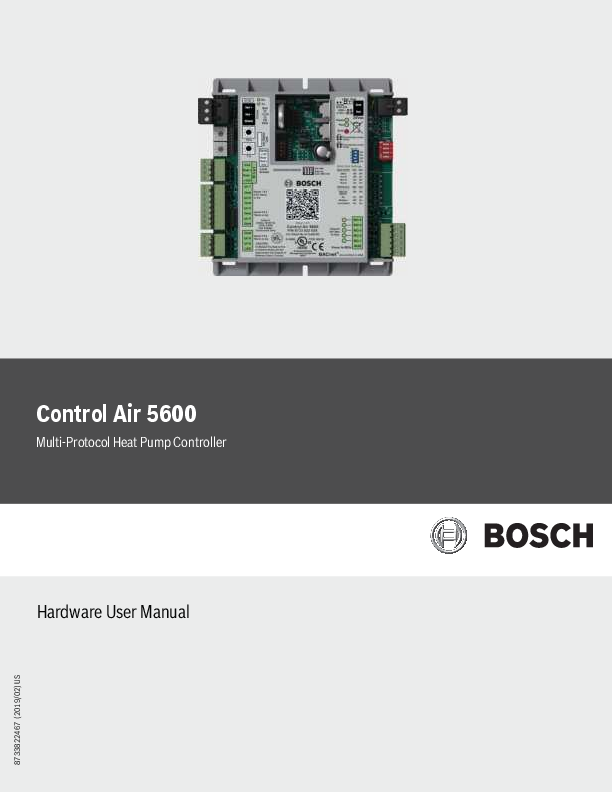
Control Air 5600
Multi-Protocol Heat Pump Controller
Hardware User Manual

8733822467 (2019/02) US

2 | Control Air 5600
Table of Contents
1 Key to Symbols and Safety Instructions 1.1 Key to Symbols 1.2 Safety Warnings
2 Control Air 5600 Specifications
3 Control Air 5600 Overview 3.1 Key Features/Benefits 3.2 Components Overview
4 Control Air 5600 Features 4.1 Network 4.2 Rotary Dials 4.3 Lon Port 4.4 Rnet port 4.5 Part Number 4.6 Inputs 4.7 Battery 4.8 Local Access 4.9 Power 4.10 DIP Switch 4.11 Outputs 4.12 IN-1 Jumper 4.13 IN-2 Jumper 4.14 Communication Jumper
5 Water to Air Systems 5.1 DDC Options 5.1.1 Air Economizer (Free Cooling) 5.1.2 Auxiliary Electric Heat 5.1.3 Boilerless Control 5.1.4 Fan Proving 5.1.5 Flow Proving (DPS) 5.1.6 Loop Water Valve Control 5.1.7 Hot Gas Reheat 5.1.8 Input Expansion Module (IEM) 5.1.9 Outside Air Damper 5.1.10 Water-Side Economizer 5.2 I/O Port Assignments And Overview 5.3 Sequence Of Operation 5.3.1 Unit Start Up 5.3.2 Temperature Source Selection 5.3.3 Setpoint Management 5.3.4 Heating/Cooling Operation 5.3.5 Unit Shutdown/Lockout 5.3.6 Options
Data subject to change

Installation & Operation Manual

4 6 Water to Water Systems

19

4 6.1 DDC Options

19

4

6.1.1 Pump control

19

6.2 I/O Port Assignments And Overview

19

5

6.3 Sequence Of Operation

21

6.3.1 Unit Start Up

21

5

6.3.2 Setpoint Management

21

6.3.3 Heating/Cooling Operation

21

5

6.3.4 Unit Shutdown/Lockout

22

6

7 ZS Combination Sensors

23

7

7.1 Available Models

24

7

7.2 Specifications

24

7

7.3 Features

25

7

7.4 Addressing Sensors

27

7

7.5 Multiple Sensors

27

7

7.6 Formatting Sensors

27

7

7.7 ZS Push/Manager Sensors

28

7

7.7.1 Navigating the Push/Manager Sensor's Screens

28

7

7.7.2 ZS Push Sensor Display

28

7

7.7.3 Make the Zone Warmer or Cooler Using a ZS Push/Manager

29

7

7.7.4 To Override the Schedule Using a ZS Push/Manager

29

7

7.7.5 To Lock the Sensor Buttons of a ZS Push/Manager

30

7

7.7.6 To Edit Displayed Values Using a ZS Push/Manager

30

7

7.8 Rnet Tags

30

7

7.8 Wiring and Mounting a ZS Sensor

33

9 8 Control Air M/M+

34

9

8.1 The Control Air M/M+ Interfaces

34

9

8.2 The Control Air M/M+ Module

34

9

8.3 Virtual Control Air M/M+ (Equipment Touch (OEM) APP)

34

9

8.4 Control Air M/M+ Specifications

35

9

8.5 Wiring

36

9

8.5.1 Recommended Wiring Scheme

36

9

8.5.2 Rnet Wiring Specifications

36

9

8.6 Connection

36

9

8.6.1 Communicate Using a Tablet Through Virtual Control

9

Air M and M+

 36

9

8.6.2 To Wire and Mount the Control Air M/M+

36

10

8.6.3 Additional Information on Connecting Control Air

16

M/M+ to a Controller

37

16

16 9 Troubleshooting

39

16

9.1 Control Air 5600

39

17

9.2 ZS Sensors

39

17

9.3 Communication LED's

40

17

02.2019 | BTC 469503102 B

Installation & Operation Manual

Table of Contents Continued

10 Physical Dimensions and Specifications

41

10.1 Control Air 5600 Controller Dimensions

41

10.2 Input Expansion Module (IEM) Features

41

10.3 Control Air M/M+ Dimensions

42

10.4 ZS Series Zone Sensor R1 Dimensions

43

10.5 Wiring Termination Specs

43

11 Electrical Schematics

44

11.1 Water to Air

44

11.2 Water to Water

45

12 Terminology

46

13 Common Abbreviations

46

14 Thermostat Signals

47

Control Air 5600 | 3

BTC 469503102 B | 02.2019

Data subject to change

4 | Control Air 5600

Installation & Operation Manual

1 Key to Symbols and Safety Instructions 1.1 Key to Symbols
Warnings
Warnings in this document are identified by a warning triangle printed against a grey background. Keywords at the start of a warning indicate the type and seriousness of the ensuing risk if measures to prevent the risk are not taken.
The following keywords are defined and can be used in this document:
 DANGER indicates a hazardous situation which, if not avoided, will result in death or serious injury.
 WARNING indicates a hazardous situation which, if not avoided, could result in death or serious injury.
 CAUTION indicates a hazardous situation which, if not avoided, could result in minor to moderate injury.
 NOTICE is used to address practices not related to personal injury.
Important information
This symbol indicates important information where there is no risk to people or property.

1.2 Safety Warnings
WARNING: FIRE, INJURY OR DEATH HAZARD  Installation and servicing of this equipment can be
hazardous due to system pressure and electrical components. Only trained and qualified personnel should install, repair, or service the equipment.
WARNING: ELECTRIC SHOCK HAZARD  Before performing service or maintenance
operations on the system, turn off main power to the unit. Electrical shock could cause personal injury or death.
CAUTION: FIRE, INJURY HAZARD  When working on equipment, always observe
precautions described in the literature, tags, and labels attached to the unit. Follow all safety codes. Wear safety glasses and work gloves. Use a quenching cloth for brazing, and place a fire extinguisher close to the work area.
WARNING: FIRE, ELECTRICAL SHOCK HAZARD  To Reduce the risk of Fire or Electric Shock, Do not interconnect the outputs of different class 2 circuits.

WARNING:
 This product can expose you to chemicals including Lead and Lead components, which are known to the State of California to cause cancer and birth defects or other reproductive harm. For more information go to www.P65Warnings.ca.gov.

Data subject to change

02.2019 | BTC 469503102 B

Installation & Operation Manual

Control Air 5600 | 5

2 Control Air 5600 Specifications
Power: 24VAC � 10%, 50-60Hz, 1.4 VA of standby power consumption (Single Class II 70VA or 100VA option available).
Physical: Rugged plastic housing protects circuitry.
Environmental Operating Range: A range of 0�F to 130�F (-17.8 �C to 54.4�C); 10% to 90% relative humidity, non-condensing.
Digital Outputs: Five(5) binary outputs - Form A relay contacts rated at 10A resistive @ 24VAC; configured as dry contact, normally open.
Universal Inputs: Six (6)universal inputs. All six inputs are configurable for pulse, 10kohm @ 77�F (25�C) thermistor, or dry contact. In addition, inputs 1 and 2 are configurable for 5Vdc.
Standard Communication: 3-pin port configurable for ARC156 (BACnet-over- ARC156) or EIA-485 communications (BACnet MS/ TP, Modbus RTU, Lon, or N2).
Ports  Rnet Port:
4-pin port for interface with remote mounted CAM (data only, no power) or ZS sensors  Local Access Ports: For local communication with a laptop computer running WebCTRL, or for communication with the CAM interface (tablet app only)
BACnet Support: Advance Application Controller (B_AAC), as defined in BACnet 135-2001 Annex L Communications Ports.
Status Indication: Visual (LED) status of network communication, run status, errors, power, and all digital outputs.
Battery: Lithium 3V coin cell battery, CR2032, provides a minimum of 10,000 hours of data retention (based on installation in condition space) during power outages.
Protection: Surge and transient protection circuitry for power and communications.
Listed By: FCC Part 15-Subpart B- Class A. Pending listings at the time of publishing this document: UL916 (PAZX), cUL C22.2 No.205-M1983 (PAZX7), CE (1997).
Weight: 0.6 Lbs. (0.27 Kg).
Overall Dimensions: (W x H x D) 5-1/16" (129mm) x 5-11/16" (144mm) x 1-1/2" (38mm) (recommended panel depth).
Mounting Hole Dimensions: Two mounting holes located center line of controller with 5-9/16" (141mm) vertical spacing.

3 Control Air 5600 Overview
The Control Air 5600 Multi-Protocol Heat Pump controller is used in most configure-to-order applications requiring integration of Direct Digital Control (DDC) systems. The controller is BACnet native but is flexible enough to integrate into existing Building Automation Systems (BAS) via a choice of the most widely used protocols including: BACnet MS/TP, N2, Modbus, and LON (requires additional hardware). The Control Air 5600 may be run either in standalone operation mode, or with the DDC network by integrating with a BAS.
The Control Air 5600 is packaged with a highly sophisticated yet easily configurable software that suits the different heat pump applications. User parameters and options relating to the physical build of the corresponding heat pump unit (e.g. number of compressors, reversing valve, etc) are usually programmed at the factory to facilitate a seamless integration in the field. However, commissioning of the controller in the field is required to ensure the setup exactly matches the requirements of the job site. User settings of the factory standard software, such as the time and test and balance set points, are usually set up during the installation and commissioning process.
When properly connected to a Bosch Water Source Heat Pump (WSHP), the Control Air 5600 controller works in tandem with the onboard Unit Protection Module (UPM) to protect the unit compressor from faults such as high/low pressure, high condensate, freeze evaporator/condenser coils, and brownouts. The controller monitors the alarm contacts of the UPM board, then decodes and broadcasts any fault conditions that may arise over a network if one is available.
3.1 Key Features/Benefits
1. Provides multi-protocol communications for seamless integration with systems running industry standard protocols such as:
a. BACnet over ARCnet
b. Johnson Controls N2
c. Modbus
d. Lon Works (additional hardware required for Lon)
2. Ruggedly built for quality and reliability
3. Stand-alone operation or networked DDC operation capable
4. Removable wiring connectors for ease of field service
5. Allows application parameters to be saved and recovered following power loss

BTC 469503102 B | 02.2019

Data subject to change

6 | Control Air 5600
3.2 Components Overview
1
2
3 4 5 6
7
8
Figure 1 Components List:
1. Network 2. Rotary Dials 3. Lon Port 4. Rnet Port 5. Part Number 6. Inputs 7. Battery 8. Local Access 9. Power 10. DIP Switch 11. Software Version 12. Outputs 13. IN-1 - Jumper 14. IN-2 - Jumper 15. Communications Jumper
Data subject to change

Installation & Operation Manual
9 10 11 12 13 14 15
02.2019 | BTC 469503102 B

Installation & Operation Manual

Control Air 5600 | 7

4 Control Air 5600 Features
4.1 Network
This block represents the communications port on the Control Air 5600. This port can be configured to communicate in two ways (RS485 or BACnet over ARC156) using the Communications Jumper. The communications wiring should be landed at the Net+, Net-, and Shield terminals, ensuring the same polarity is maintained throughout the network segment. The "BAS Port Settings" DIP switch is used to set the baud rate for the network, using the same baud rate for all controllers on the network. The LEDs (Rx and Tx) flash repeatedly when the controller is communicating with the network. This port is also used for data when connecting a Control Air M+ to the controller.
4.2 Rotary Dials
The rotary dials are used to address the Control Air 5600 so it can be uniquely identified over a network. The top dial represents the Tens digit while the bottom one represents the Ones digit. Before setting or changing the address make sure the Control Air 5600 is powered off; the controller only reads the address when the module is turned on.
4.3 Lon Port
For network integration applications involving the LonWorks network platform, the LON card will be required to enable communication over this protocol. The card is ordered separately and connects to the Lon port. Ensure that the communications jumper is in the top position (EIA- 485) and the BAS port settings are configured using the DIP switch bank (see DIP Switch)
4.4 Rnet port
The Rnet port is a four-connector block reserved mainly for wiring the ZS combo sensors to the Control Air 5600. It consists of 2 points for power (12VDC and Gnd) and 2 points for communication (Rnet + and Rnet -). This port is also used for data when connecting a Control Air M to the controller (Rnet+ and Rnet- only).
4.5 Part Number
The Control Air 5600 part number represents both the hardware and software components of the Control Air 5600, and therefore changes if the controller is ordered with a special software other than the standard (WAZ.1.01) version.
4.6 Inputs
There are 6 universal inputs on the Control Air 5600. All inputs are capable of accepting thermistor (analog), pulse or dry contact (binary) signals, but the first 2 inputs (IN-1 and IN-2) are also capable of reading 0-5VDC signals; use the corresponding jumpers to select between Therm/dry and 0-5V for these inputs. Refer to the "Ports Assignment and Overview" page for further details on configuring these inputs.
4.7 Battery
The 10-year Lithium CR2032 3V battery retains data (e.g. control programs, modified parameters, schedules, etc) for a maximum of 10,000 hours during power outages. If the Control Air 5600 experiences RAM loss (e.g. due to low voltage on the controller or high voltage on the network), it may be reset by recycling the battery power. This operation should be performed with the Control Air 5600 powered off (no 24Vac power), and resolves most of all "bad controller" issues. All previously saved parameters are retained upon power up.
BTC 469503102 B | 02.2019

4.8 Local Access The local access port is available for system startup, servicing and troubleshooting using a CAM interface (tablet app).
4.9 Power Input power for the Control Air 5600. 24Vac +/-10%, 50- 60Hz; 20VA power consumption, Single Class 2 source only, 100VA or less.
4.10 DIP Switch The BAS Port Settings DIP switch bank is used to set the appropriate network configuration when the Control Air 5600 is integrated into a Building Automation System (BAS). (See table # 2)
4.11 Outputs The Control Air 5600 has five (5) binary outputs that can each be connected to a maximum of 24Vac/26Vdc. Each output is a dry contact (Form A) rated at 1A, 24V max. Refer to the "Ports Assignment and Overview" page for further details on configuring these outputs.
4.12 IN-1 Jumper This two-position jumper is used to set the input type selection for IN-1 as follows:
 Top position is labeled W4 and configures IN-1 for dry/therm signals.
 Bottom position is labeled W5 and configures IN-1 for 0-5V signals.
The jumper is default to the bottom position (W5) for 0-5V from factory.
4.13 IN-2 Jumper This two-position jumper is used to set the input type selection for IN-2 as follows:
 Top position is labeled W6 and configures IN-2 for dry/therm signals
 Bottom position is labeled W7 and configures IN-2 for 0-5V signals.
The jumper is default to the top position (W6) for Dry/Therm from factory.
4.14 Communication Jumper This two-position jumper is used to configure the network communication mode for the Control Air 5600 as follows:
 Top position is labeled EIA-485 and configures the Control Air 5600 for RS-485 communications for BACnet MS/TP, N2, ModBus, or Lon.
 Bottom position is labeled BACnet over ARC156 and configures the Control Air 5600 for BACnet over ARC156 at 156kbps. This selection is a unique implementation of the industry standard ARCNET protocol and the jumper should only be set to this position if employing that protocol.
Data subject to change

8 | Control Air 5600

Input IN-1 AND IN-2 ALL ALL ALL Table 1

Signal Type Supported 0-5Vdc
Thermistor Dry Contact
Pulse

Baud Rate Setting

SW1

SW2

9.6KBPS

Off

Off

19.2KBPS

Off

On

38.4KBPS

On

Off

76.8KBPS

On

On

Table 2

Table 2 details the different communications settings available (this information is also on the Control Air 5600 label)

Installation & Operation Manual
Description Input impedance of the Control Air 5600 is approx. 30-kOhm
Precon type2 (10-kOhm @ 77� F/ 25�C) 3.3Vdc wetting voltage detects contact position
Pulse counting up to 10 pulses per second.

Protocol

SW3

SW4

BACnet�MS/TP

Off

Off

N2

On

Off

Modbus

Off

On

Option Card (LON)

On

On

Data subject to change

02.2019 | BTC 469503102 B

Installation & Operation Manual

Control Air 5600 | 9

5 Water to Air Systems
5.1 DDC Options
5.1.1 Air Economizer (Free Cooling)
This option utilizes an outdoor air temperature and humidity combo sensor, and a field supplied fresh air damper to provide free cooling. When there's a call for cooling, the OAT/RH sensor connected to the Control Air 5600 will monitor the outside air temperature and humidity levels and determine if the compressor should be used for cooling or if the outdoor air is ideal to condition the space with just the fan. If the air temperature and humidity is within a user-configurable range, the damper solenoid will be energized to open by the Control Air 5600, the compressor will be indexed off, and the fan is used to cool the space.
This option is only available in the cooling mode.
5.1.2 Auxiliary Electric Heat
Used to provide a single stage of electric heat by using a factory-installed electric heater option, or field-installed electric heater accessory. It may be used as a supplementary source of heating for units with mechanical heating/cooling capabilities where additional heating capacity is needed to meet/maintain space setpoint; or as the sole source of heat for straight cool units (mechanical cooling only). The configured controller output is energized to enable the heater based on unit configuration and parameter setup.
5.1.3 Boilerless Control
An option that allows a water source heat pump to be operated in heating safely when installed in a system that has no means of heating the water loop. A factory installed Entering Water Temperature (EWT) sensor (thermistor) is connected to the Control Air 5600 controller and used with this option. During a call for heating, if the EWT sensor detects a drop in water temperature below a pre-set limit (adjustable in the software), the Control Air 5600 will disengage the compressor output(s) and provide a 24VAC signal to divert unit operation from compressor heating to an alternate heat source (generally field-installed electric heat). The option is also used to proactively prevent coils from freezing.
5.1.4 Fan Proving
This option uses a factory-installed current sensor to prove fan operation prior to unit operation. The status output of the current sensor is used to establish fan operation for the unit when a proven fan call is established. If configured the Control Air 5600 disables unit compressor operation when the current in the monitored conductor drops below the rated threshold, indicating the fan is nonoperational. The current sensor output may be wired directly to the Control Air 5600, or to an Input Expansion Module (IEM) connected to the Control Air 5600 when multiple options requiring switched inputs are involved. Please consult the applications department when including this option as an engineering add-on.
5.1.5 Flow Proving (DPS)
This option employs the use of a Differential Pressure Switch (DPS) to prove water flow across a unit's water-to-refrigerant heat exchanger. If configured the software enables unit compressor operation when a pressure drop of 1.5 psi or more is detected across the water to refrigerant heat exchanger, indicating adequate water flow. This option prevents nuisance cut-outs on high head pressure or freeze protection when there are interruptions in water flow.

5.1.6 Loop Water Valve Control
This option uses a factory-installed condenser water valve to control water flow through the condenser coil. The normally closed valve includes an auxiliary end switch that is wired to the controller to determine the status of the valve. When the Control Air 5600 is configured for this option, compressor operation is disabled until valve-open status from the valve end switch is verified.
5.1.7 Hot Gas Reheat
Hot gas reheat helps actively controls humidity by reheating cooled and dehumidified air back to a neutral temperature using waste heat from the compressor. Doing this allows the unit to continue to operate and remove moisture from the space even after the sensible cooling set point has been satisfied. Hot gas reheat is well suited for conditioning outside ventilation air and for maintaining ideal humidity levels in schools, commercial buildings and even homes. A binary output on the Control Air 5600 controller is used to provide the signal for activating the reheat valve when the necessary conditions are met. Relative humidity readings may be acquired from a wall-mounted ZS combo sensor, a third-party hard wired 0-5V humidity sensor, or from RH values pushed to the Control Air 5600 over a network.
5.1.8 Input Expansion Module (IEM)
The IEM is used when multiple options that require a binary input are desired for a single application with DDC. The IEM is connected in input #5 (IN-5) of the Control Air 5600 controller and is software configured to enable a trio of preset combinations that include: Fan Status, Valve Status, Damper Status, Pump Status, Filter Status, Secondary Drain Pan Status, Differential Pressure Switch Status, and Smoke/Fire Detector Status. (see page #32 Figure# 14 for more details on the IEM).
5.1.9 Outside Air Damper
Allows the capability for pre-filtered outside air to enter the unit while in operation via a motorized, field supplied damper, based on unit occupancy, fan operation, or CO2 levels in the monitored space. A binary output on the Control Air 5600 controller is used to provide the signal for activating the damper solenoid when the necessary conditions are met. CO2 readings may be acquired from a wall-mounted ZS combo sensor, a third-party hard wired 0-5V CO2 sensor, or from CO2 values pushed to the controller over a network. A damper end switch connected to the controller may be used to verify damper status and disable compressor operation when the damper fails.
5.1.10 Water-Side Economizer
An optional package consisting of a water-to-air heat exchanger (economizer coil), a thermistor (EWT sensor), and a 3-way diverting valve. When there is a call for cooling, the EWT sensor connected to the Control Air 5600 will monitor the entering water temperature to the unit and determine if the compressor should be used for cooling or if the water temperature is low enough to cool the entering air with the economizer coil. If the entering water temperature is below a selected user-adjustable set point, the diverting valve will be indexed by the Control Air 5600 to divert the entering water through the economizer coil to cool the air stream. This DDC option can only be used for cooling operations.

BTC 469503102 B | 02.2019

Data subject to change

1 0 | Control Air 5600

Installation & Operation Manual

5.2 I/O Port Assignments And Overview

Universal Inputs

Port

Inputs Accepted

Signal Type Jumper Position

Overview

This input is selected when a dry contact (e.g. room occupancy

sensor) is required to enable the unit, and Digital Input has been

Digital Input Enable

Dry

Top(W4)

selected for Occupancy Command. Unit is placed in occupied mode

upon a contact closure at the input, and placed in unoccupied mode

10 minutes after the contacts reopen.

This input is used if RH readings are not desired from a ZS Combo

IN-1

Humidity Sensor

0-5VDC

Bottom (W5)

sensor or over a network. An example would be a duct mounted humidity sensor or third party humidity sensor with 0- 5VDC output.

CO2 Sensor

0-5VDC

Bottom (W5)

This input is used if CO2 readings are not desired from a ZS Combo sensor or over a network. An example would be a third party CO2 sensor with 0-5VDC output.

Static Pressure Sensor

0-5VDC

Bottom (W5) This input is used for applications requiring static pressure readings.

Zone Remote Sensor

Therm

Top (W6)

This input is used if zone temperature readings for controlling the unit are not desired from a ZS Combo sensor or over a network. An example would be a third party wall or duct mounted sensor. Temperature sensor must be a Type II 10kohm @ 77�F(25�C) sensor.

Outdoor Air Temperature Sensor

Therm

Top (W6)

This input is selected if outside air temperature readings are required.

Entering Water Temperature Sensor

Therm

Top (W6)

This input should be selected for applications where the entering water temperature needs to be monitored, or used to control options such as Economizer or Boilerless Electric Heat.

Mixed Air Temperature Sensor

Therm

Top (W6)

This input is selected if mixed air temperature readings are required

IN-2 This input is used if zone temperature readings for controlling the unit

Return Air Temperature Sensor

Therm

Top (W6)

are desired from a temperature probe placed in the return air duct. Temperature sensor must be a Type II 10kohm @ 77�F(25�C) type

sensor.

Digital Input Enable

This input is selected when a dry contact (e.g. room occupancy

sensor) is required to enable the unit, and Digital Input has been

Dry

Top (W6)

selected for Occupancy Command. Unit is placed in occupied mode

upon a contact closure at the input, and placed in unoccupied mode

10 minutes after the contacts reopen

Table 3

Humidity Sensor

0-5VDC

Bottom (W7)

This input is used if RH readings are not desired from a ZS Combo sensor or over a network. An example would be a duct mounted humidity sensor or third party humidity sensor with 0- 5VDC output.

Data subject to change

02.2019 | BTC 469503102 B

Installation & Operation Manual

Control Air 5600 | 11

Port IN-3*

Inputs Accepted

Universal Inputs Signal Type Jumper Position

Overview

Leaving Water Temperature Sensor

Therm

A thermistor is wired to this input from factory to monitor leaving water

temperature at the heat exchanger leaving water pipe. If the water

n/a

temperature rises above 135�F or drops below 40�F for more than 5

minutes while the unit is running, compressor operation is halted and an

alarm is generated. These temperature trip values are user adjustable.

The Unit Protection Module (UPM) is standard on all FHP heat pumps.

The alarm contacts of the UPM board are wired to the controller at

this input from factory to transmit error pulse codes to the Control Air

IN-4*

UPM Input

Pulse

n/a

5600. These alarm codes are then made available to view via a CAM/

M+ interface, ZS Pro Sensor, or over a network if one is available. Faults

include: High Pressure, Low Pressure, High Condensate, Freeze Stat,

and Brown out conditions.

Dirty Filter Switch (DFS)

Dry

Selecting this option for this input provides an alternate means of

n/a

alerting the end user of a dirty filter condition by way of a contact closure instead of fan runtime hours. An alarm is generated when

Control Air 5600 senses a contact closure at the input.

Entering Water

Temperature Sensor (Economizer Cooling &

Therm

n/a

Boilerless Electric Heat)

Differential Pressure Switch (DPS)

Dry

n/a

IN-5

Secondary Drain Pan (SDP)

Dry

n/a

Fan Status Switch (FSS)

Dry

n/a

Table 4
*Non-configurable, factory assigned I/O parameter. All I/Os must be selected/configured in the software.

This input should be the default location for an EWT sensor when the Water-Side Economizer or Boilerless Electric Heat option is selected. The temperature readings from this input are used in determining when the Economizer or Electrical Heat action is enabled and MUST be selected for the option to function properly. Default economizer EWT trip value is 55�F (user adjustable). Default Boilerless EH EWT trip value is 40� F (user adjustable).
A Differential Pressure Switch may be connected to this input to prove water flow across a unit's water- to-refrigerant heat exchanger. Heat pump operation is disabled until the DPS is closed.
This option allows a secondary condensate pan installed on the heat pump to be connected to this input to monitor condensate levels when the primary drain pan fails. When a high condensate condition for the secondary drain pan is detected an open contact status is reported at the input, and the compressors are locked out until the condition is reversed. An alarm is generated when the Control Air 5600 senses an open contact at the input.
The status output from a factory installed current sensor used to monitor fan operation may be connected to this input to provide fan status during unit operation. The unit is allowed to run only when the sensor contacts are verified as closed at the input after the fan has been indexed to run. If there's no contact closure after the fan has been commanded on, the unit is not allowed to run, and an alarm is generated after 45 seconds. If the fan fails during normal unit operation the compressors are shutdown after 20 seconds and an alarm is generated.

BTC 469503102 B | 02.2019

Data subject to change

1 2 | Control Air 5600

Installation & Operation Manual

Universal Inputs

Port

Inputs Accepted

Signal Type Jumper Position

Overview

Valve End Switch (VES)

Dry

For units with a loop valve option, the valve end switch may be

connected to this input to monitor/verify valve status during unit

operation. The factory-installed zone valve is normally-closed and

n/a

is indexed to open by the Control Air 5600 when there's a call for heating or cooling. If a contact closure is not detected at the input

after the valve is commanded on, unit operation is disabled and an

alarm is generated after a minute and a half has elapsed; this provides

adequate time for the slow acting valve to fully open.

Damper End Switch (DES)

Dry

A damper end switch may be connected at this input for units with

the outside air damper option. If connected, the unit is not allowed to

n/a

run until a contact closure is detected at the input after the damper has been indexed to open. Damper operation may be based on

occupancy, fan operation, or zone CO2 levels (default trip value is

1000ppm).

IN-5

Smoke Detector Switch (SDS)

Dry

The normally-open contacts of a field-installed smoke/fire alarm

n/a

detector or emergency shutdown switch may be wired to this input to shut the heat pump unit down during an emergency. Unit operation is

ceased 5 seconds after a contact closure is detected at the input.

Pump Status Switch (PSS)

Dry

For units with a loop pump option, the status output from a factory

installed current sensor used to monitor pump operation may be

connected to this input to provide pump status during unit operation.

The unit is allowed to run only when the sensor contacts are verified

n/a

as closed at the input after the pump has been indexed to run. If there's no contact closure after the loop pump has been commanded

on, the unit is not allowed to run, and an alarm is generated after

15 seconds. If the pump fails during normal unit operation the

compressors are shutdown after 20 seconds and an alarm is

generated.

Table 5

Mixed Air Temperature Sensor

Therm

n/a

Select this configuration parameter if a Mixed Air Temperature sensor is connected in IN-5.

Data subject to change

02.2019 | BTC 469503102 B

Installation & Operation Manual

Control Air 5600 | 13

Universal Inputs

Port

Inputs Accepted

Signal Type Jumper Position

Overview

The Input Expansion Module (see figure # 14) is used in this input when multiple options that require a binary input are required (up to 3 inputs). The combinations of these options are limited only to the seven (7) sets of three listed below

INPUT EXPANSION MODULE (IEM) COMBINATION PORT 1 (A)..........PORT 2 (B).....PORT 3 (C)

Dirty Filter Switch (DFS)

Fan Status Switch (FSS)

Valve End Switch (VES)

Smoke Detector Switch (SDS)

Fan Status

Valve End

Switch (FSS) Switch (VES)

IN-5

Dirty Filter Switch (DFS)

Fan Status Switch (FSS)

Differential Pressure Switch
(DPS)

These seven (7) sets of binary input combinations may be used with

an IEM connected to this input. The three (3) ports are labeled (A,

Smoke Detector Switch

Fan Status

Dirty Filter B, C) and must be connected correspondingly. In situations where

(SDS)

Switch (FSS) Switch (DFS) not all three inputs are used, the other inputs may be disabled in

the software, or the board may be jumpered if the option requires a

Dirty Filter Switch (DFS)

Fan Status Damper End Switch (FSS) Switch (DES)

closed contact to function properly.

Smoke Detector Switch (SDS)

Fan Status

Secondary

Switch (FSS) Drain Pan (SDP)

Dirty Filter Switch (DFS)

Fan Status Switch (FSS)

Pump Status Switch (PSS)

IN-6*

Discharge Air Temperature

Therm

n/a

Table 6
*Non-configurable, factory assigned I/O parameter. All I/Os must be selected/configured in the software.

A factory-installed thermistor mounted on the heat pump unit's blower housing (air handler section) is connected to this input for all orders requiring the factory installed DDC option. It is highly recommended that for applications requiring a more accurate representation of the supply air temperature, a duct mounted temperature probe be used instead to relocate the source of the discharge air temperature just downstream of the supply air duct. If this recommendation is followed the factory-installed thermistor may be disconnected from this input, and replaced with the leads from the duct mounted sensor.

BTC 469503102 B | 02.2019

Data subject to change

1 4 | Control Air 5600

Installation & Operation Manual

Port BO-1* BO-2*
BO3*

Inputs Accepted Fan
Reversing Valve
Compressor Stage 1

Signal Type

Universal Inputs Jumper Position

Overview

24VAC

Binary Output 1 is factory reserved for the fan command (G) and is

wired to the unit terminal block in the electrical box. The fan mode

G

may be software configured either for "continuous" mode (fan is energized continuously during occupied and night set back modes),

or configured to run in "auto" mode (fan is energized only during a call

for heating or cooling). Continuous mode is the factory default.

24VAC

Binary Output 2 is factory reserved for the reversing valve command

(O) and is wired to the valve via the unit terminal block in the

O

electrical box. For heat pump units, the output is energized during a call for cooling, and remains de-energized for heating. For straight

cool units (cooling only) where no reversing valve is installed, the

output is disabled and not used.

24VAC

Binary Output 3 is factory reserved for the compressor stage 1

command (Y1) and is connected to the UPM I board's "Y" terminal

("Y1" for dual compressor units using the UPM II board) via the unit

terminal block in the electrical box. The Y1 output is off when zone

setpoint is satisfied and within the temperature dead band (between

Y1

heating and cooling setpoints). As the zone temperature rises above the cooling setpoint and demand exceeds 30%, Y1 is enabled and PID

methods are employed to ensure the zone temperature is maintained

within 1�F of cooling setpoint. As the zone temperature drops below

the heating setpoint and demand exceeds 30%, Y1 is enabled

and PID methods are employed to ensure the zone temperature is

maintained within 1� F of heating setpoint.

Compressor Stage 2

24VAC

Y2

Economizer Cooling Control 24VAC

E

B0-4*

Fresh Air Damper (On/Off)

24VAC

D

Boilerless Control

24VAC

W

Table 7
*Non-configurable, factory assigned I/O parameter. All I/Os must be selected/configured in the software.

Binary Output 4 is factory defaulted for the compressor stage 2 command (Y2) and is connected to the second stage solenoid (Y2S) for 2-step, single compressors, or to the "Y2" terminal for dual compressor units using the UPM II board, via the unit terminal block in the electrical box. The Y2 output is off when zone setpoint is satisfied and within the temperature dead band (between heating and cooling setpoints). The Y2 output is energized after Y1 has been on for more than 7 minutes, and the heating/cooling demand exceeds 60%.
For 1 compressor 1 stage units, Binary Output 4 may be configured for one of the following options: Water-side economizer, Boilerless, or Outside Air Damper (On/Off).

Data subject to change

02.2019 | BTC 469503102 B

Installation & Operation Manual

Control Air 5600 | 15

Universal Inputs

Port

Inputs Accepted

Signal Type Jumper Position

Hot Gas Re-Heat (On/Off)

24VAC

H

Overview

Fresh Air Damper (On/Off)

24VAC

B0-5*

Heating Stage 1 (Aux Heat)

24VAC

Boilerless Control (Aux Heat)

24VAC

Economizer Cooling Control 24VAC

D

W

Binary Output 5 may be factory or field configured for one of the

following options: Hot Gas Reheat (On/Off), Single Stage Auxiliary

Electric Heat, Outside Air Damper (On/Off), Condenser Water

W

Valve, Circulating Water Pump, Economizer, or Boilerless Electric Heat.

E

Condenser Water Valve

24VAC

CV

Table 8

*Non-configurable, factory assigned I/O parameter. All I/Os must be selected/configured in the software.

BTC 469503102 B | 02.2019

Data subject to change

1 6 | Control Air 5600

Installation & Operation Manual

5.3 Sequence Of Operation
5.3.1 Unit Start Up
Program will check schedule status for either occupied or unoccupied mode to determined setpoint range. Different run conditions may determine the occupancy mode.

5.3.1.1 External Control Sources Digital input A contact closure (in IN-1 or IN-2) is used to enable unit operation. Once enabled, unit will run until set-point is satisfied, or 10 minutes has elapsed since contacts opened.

BAS A network point is used to command the unit into occupied or unoccupied mode.

Manual on The heat pump is placed in continuous run mode and will operate until setpoint is satisfied.

Override For units with ZS wall-mounted sensors or CAM interface, unit operation may be overridden into occupied mode using a push button on the sensor or CAM interface screen. Software may be configured to disallow sensor override from the space, time for override is in increments of 30 minutes, with a max of 3 hours allowed.

5.3.1.2 Internal Control Sources Local Schedule The internal scheduler uses the local time and user-defined schedule to determine occupancy.
Default schedule is:

Day of Week MON-FRI SAT SUN Table 9

Time 8:00AM - 5:00PM 7:00AM - 3:00PM 10:00AM - 1:00PM

Mode Occupied Mode Occupied Mode Occupied Mode

Unit is in unoccupied mode outside the above stated hours.

Default Occupied Schedule Set Points:  74�F Cooling setpoint (Adjustable)  70�F Heating setpoint (Adjustable)
Default Unoccupied Schedule Set Points:  90�F Cooling setpoint (Adjustable)  55�F Heating setpoint (Adjustable)

5.3.2 Temperature Source Selection
The program will check for a valid source of temperature to control the unit. The software may be configured for the following four (4) available sources: ZS sensor (default), Remote sensor, BAS Sensor/Valve or the CAM built-in sensor.
5.3.2.1 ZS Sensor The program will check for a valid 4-wire communicating ZS Sensor at the RNET port of the controller during the first 30 seconds after startup. If a valid sensor is not detected the unit will remain non operational in its default unoccupied state, an alarm is generated, and the program defaults to -60�F.
5.3.2.2 Remote Sensor The program will check for a valid 2-wire, 10Kohm@ 77�F Thermistor type sensor at IN-2 of the controller during the first 30 seconds after startup. If a valid sensor is not detected the unit will remain non operational in its default unoccupied state, an alarm is generated, and the program defaults to -60�F.
5.3.2.3 BAS Sensor The program will check for a network value pushed from the building automation system to control the unit. If no value is written to the network point the program defaults to 74�F, otherwise the last reported temperature value is used to control the unit. Refer to the Integration Points List for network points IDs.
5.3.2.4 CAM Sensor The program will check for a network value from the Control Air M module. If no value is found the program defaults to 65�F.
5.3.3 Setpoint Management
While in the Auto mode (default), the registered zone temperature will be checked against the current set point range (Default:70�F - 74�F occupied, 55�F - 90�F unoccupied). Manual offsets in the software or temperature adjustments from the ZS sensor will be taken into account when determining the actual setpoint range. Adjustment limits may be used to manage the allowed setpoint changes from the wall sensor (default limit is +/-3�F); for example, if the setpoint is increased in the space by 2�F, then the occupied setpoint range becomes 72�F -76�F, and if the setpoint is decreased in the space by -2�F, then the occupied setpoint range becomes 68�F - 72�F. Upon a transition from occupied to unoccupied mode all setpoint adjustments are removed and reset to 0�F.
The software may be configured to disable the ability to change set points in the space.

Data subject to change

02.2019 | BTC 469503102 B

Installation & Operation Manual

Control Air 5600 | 17

5.3.4 Heating/Cooling Operation
The set points are compared to the effective zone temperature from the selected source. Demand, based on a PID Algorithm, is used to determine when to energize the unit in either heating or cooling mode. The PID algorithm calculates the demand value as a percentage (%) based on the difference between the zone temperature and the Heat/Cool set points.
5.3.4.1 Supply Fan The supply fan will be started according to the schedule and is configured for continuous operation during the occupied mode (Fan On mode). The program may be configured to interlock fan operation with heating or cooling operations (Fan Auto mode). For this configuration the fan will be started if the PID demand for heating or cooling is greater than 10%, and stopped when the demand falls below 5%. After the supply fan has been started the control sequence will be enabled.
5.3.4.2 Compressors The 1st Stage of compressor operation (Heating or Cooling) is enabled at 30% PID demand, and disabled at 20% PID demand.
Once enabled the compressor will cycle to maintain the zone temperature setpoint unless commanded off by a safety condition (e.g. smoke alarm, high/low leaving water temperature, etc.) or unit option(e.g. economizer, boilerless, loop valve, etc.).
The reversing valve is indexed on during cooling and indexed off during heating.
The stage 1 compressor will have a minimum OFF time of 3 minutes, and a minimum ON time of 7 minutes.
The second stage of compressor operation (heating/cooling) is enabled at 60% PID demand, and disabled at 40% PID demand. In addition, stage 2 compressor operation is only enabled after compressor stage 1 has been running for 7 minutes.
Once enabled the compressor will cycle to maintain the zone temperature setpoint unless commanded OFF by a safety condition (e.g. Smoke alarm, high/low leaving water temperature, etc.)or unit option (e.g. economizer, boilerless, loop valve, etc.).
To prevent short-cycling, the stage 2 compressor has a minimum OFF time of 5 minutes and no minimum ON time.
There will be a 1-minute delay when transitioning between heat and cool modes. The compressor will run subject to internal safeties and controls provided by the UPM. The compressors will not run if the fan is not operational.
A networked "loop valve enable" point must be enabled to allow compressor operation. This point is defaulted "ON" from factory.
When the zone is satisfied, the PID demand percentage will begin to decrease. Once demand falls below the thresholds described (20% for stage 1, 40% for stage 2) the compressor will be disabled. In addition, compressor stage 1 will be disabled 10 seconds after compressor stage 2 is disabled.
5.3.4.3 Night Setback When this feature is enabled, the compressor will cycle as necessary to meet/maintain "unoccupied" temperature setpoints. A differential prevents the unit from cycling excessively. During unoccupied operation the fan will only cycle to maintain a heat or cool setpoint.

5.3.5 Unit Shutdown/Lockout When the unit is shutdown by a smoke alert or emergency shutdown (network point) the unit will be set as follows:
 Supply fan will be off.  Compressor(s) will be off.  HGRH valve will be de-energized.
When the unit is locked out by a stop command or system safety the unit will be set as follows:
 Supply fan will remain energized (on) unless otherwise configured.
 Compressor(s) will be off.  HGRH valve will be de-energized.
The following system safeties/conditions will result in a stop command:  Leaving water temp high condition.  Leaving water temp low condition.  UPM reset command.  Secondary drain pan (high condensate) alarm.  Smoke event alarm.  Differential pressure switch (DPS) alarm.
5.3.6 Options 5.3.6.1 Auxiliary Electric Heat Electric heat (EH) option may be factory or field installed and must be configured by the equipment integrator. Only one (1) stage of auxiliary electric heat is supported and may be configured for BO-5. Upon a call for heating with demand greater than 90%(user configurable), the EH signal will be enabled to maintain setpoint at the configured outputs as follows:
 Straight Cool Units: enable with no delay.
 Single-Stage Heat Pump Units: Enabled 5 minutes after first stage of mechanical heat if demand is still above 90%.
 Dual-Stage Heat Pump Units: Enabled 5 minutes after second stage of mechanical heat if demand is still above 90%.
5.3.6.2 Hot Gas Reheat Once the temperature setpoint has been satisfied and relative humidity is above setpoint, the unit will operate in hot-gas reheat mode to actively remove humidity from the space until the humidity setpoint has been satisfied, or there's another call for heating or cooling. Relative humidity readings may be acquired from a space ZS Combo Pro or standard wall-mounted sensor, a 0-5V humidity sensor in IN-1/N-2, or over a network; software must be configured accordingly. Humidity setpoint may be adjusted from a space ZS Pro sensor, network, or CAM/M+ interface.

BTC 469503102 B | 02.2019

Data subject to change

1 8 | Control Air 5600

Installation & Operation Manual

5.3.6.3 Boilerless Control Boilerless control (BLC) option must be configured by the equipment integrator. A factory installed entering water temperature sensor in IN-5 (IN-2 if IN-5 is unavailable) is used to enable boilerless control.
Entering water temperature values less than 40�F(user configurable) will enable boilerless control.
Compressor operation is disabled upon boilerless control signal being activated.
An Electric Heat Package must be installed for the boilerless control option. Electric heat will be enabled on output BO-5 or BO-4 for single stage units when boilerless signal is activated.
5.3.6.4 Economizer (Free Cooling) Water-side economizer option must be configured by the equipment integrator. A factory installed Entering Water Temperature (EWT) sensor in IN-5(IN-2 if IEM is present) is used to enable the economizer mode during cooling operations. Entering water temperature values below 55�F(user configurable) will enable economizer mode.
Once enabled, unit will run in economizer mode until the EWT exceeds 58�F (user configurable). A 3-way economizer valve is required for the WSE option and is connected to BO-5 or BO-4 for single stage units.
5.3.6.5 Condenser Water Valve Factory installed loop valve with Valve End Switch (VES) option must be configured by the equipment integrator. Upon a call for compressor operation the normally closed valve is indexed to open via a 24Vac signal at BO-5. If the VES is configured, compressor operation is not enabled until valve end switch is engaged (valve fully open).
Valve open status is verified via the VES within 1.5 minutes of valve enable command.
If VES contacts do not engage within the specified time, VES fail alarm is initiated. If valve opens without command from BO-5, valve in hand alarm is initiated.
Compressor operation is disabled 20 seconds after VES opens (fails) when loop valve has been indexed to open.
5.3.6.6 Dirty Filter Switch A field installed status switch is used to provide a contact closure at the configured input (IN-5 or IEM) when the filter is ready to be serviced. An alarm is generated immediately after the switch closes, and is available on a ZS Pro sensor, CAM/M+ interface, or over a network.
5.3.6.7 Smoke Detector Switch A field installed smoke detector provides a contact closure at the configured input (IN-5 or IEM) during a smoke event, and will initiate emergency shutdown procedures after 5 seconds.
When the unit is shut down by the smoke detector the unit will be set as follows:
 Supply fan will be off (user configurable)  Compressor(s) will be off.
The unit may be configured to operate the fan during a smoke event for specific safety applications; system integrator must determine the appropriate fan behavior.

5.3.6.8 Fan Status Switch The status output from a factory-installed current sensor provides a contact closure at the configured input (IN-5 or IEM) to prove fan operation.
The fan command output is disabled if a contact closure is not detected and an alarm is generated 1 minute after the unit fan is indexed on by the controller.
5.3.6.9 Differential Pressure Switch Differential Pressure Switch (DPS) option must be configured by the equipment integrator. A factory installed differential pressure switch is tied in to the controller at the configured input (IN-5 or IEM) and used to prove flow prior to unit compressor operation.
If the DPS opens during normal heating/cooling operation compressor operation is immediately ceased. If the switch remains open for more than 3 minutes an alarm is generated. Compressor operation is enabled (if a call still exists) once the switch closes, and the alarm is deactivated 5 seconds later.
5.3.6.10 Secondary Condensate Drain Pan The Secondary Drain Pan (SDP) option must be configured by the equipment integrator. A factory installed SDP is tied in to the controller at the configured input (IN-5 or IEM) and used to monitor condensate levels.
If an open contact is detected at the controller input for more than 10 seconds during normal heating/cooling operation, compressor operation is ceased and an alarm is generated.
Normal compressor operation is restored once a contact closure is reestablished at the input.
5.3.6.11 Outside Air Damper Field installed outside air damper with Damper End Switch (DES) option must be configured by the equipment integrator. Damper may be indexed to open based on:
 Occupancy: Damper opens 10 seconds after unit enters occupied mode, and closes 2 minutes after unit leaves occupied mode.
 Fan Operation: Damper opens 10 seconds after fan is de-energized and running, and closes 2 minutes after fan is de-energized and remains off.
 CO2 Levels: Damper opens if zone CO2 levels exceed 1000PPM (user configurable) and closes 2 minutes after CO2 levels fall and stay bellow trip value.
 Air Economizer: Damper opens upon a call for cooling; if the outside air temperature and humidity fall within a user configured range (default: 50� F to 60� F OAT & 40 to 50% RH OARH), compressor operation is disabled and only the fan is used to condition the space. If space setpoint is not satisfied within 7 minutes of fan only operation, compressor(s) operation is enabled to provide additional stage(s) of cooling.
When DES is configured, compressor operation is not enabled until the switch is engaged (damper fully open).
Compressor operation is disabled 20 seconds after DES fails when damper has been indexed to open.

Data subject to change

02.2019 | BTC 469503102 B

Installation & Operation Manual

Control Air 5600 | 19

6 Water to Water Systems
6.1 DDC Options
6.1.1 Pump control
This option utilizes a field installed (optional) pump to move water to and from the heat pump co-axial cable. When there is a compressor call the controller will energize B0-1, which is connected to the pump. The controller can be configured to run the pump continuously or cycle with the compressor.

6.2 I/O Port Assignments And Overview

Universal Inputs

Port

Inputs Accepted

Signal Type Jumper Position

Overview

This input is selected when a dry contact (e.g. room occupancy

sensor) is required to enable the unit, and Digital Input has been

IN-1

Digital Input Enable

Dry

Top(W4)

selected for Occupancy Command. Unit is placed in occupied mode

upon a contact closure at the input, and placed in unoccupied mode

10 minutes after the contacts reopen.

IN-2*

Load (Entering Water) Temperature Sensor

Therm

Top (W6)

This input is used to read the entering water temperature. Temperature sensor must be a stainless steel, Type II 10kohm @ 77�F(25�C) sensor, and mounted to load water pipe.

IN-3*

Leaving Water Temperature Sensor

Therm

IN-4*

UPM Input

Pulse

A thermistor is wired to this input from factory to monitor leaving

water temperature at the heat exchanger leaving water pipe. If the

n/a

water temperature rises above 135�F (65�C) or drops below 35�F (1�C) for more than 5 minutes while the unit is running, compressor

operation is halted and an alarm is generated. These temperature trip

values are user adjustable.

The Unit Protection Module (UPM) is standard on all FHP heat pumps.

The alarm contacts of the UPM board are wired to the controller at

this input from factory to transmit error pulse codes to the Control Air

n/a

5600. These alarm codes are then made available to view via a CAM/

M+ interface, or over a network if one is available. Faults include: High

Pressure, Low Pressure, High Condensate, Freeze Stat, and Brown

out conditions.

IN-5

Change Over Temperature Sensor

Therm

n/a

IN-6

Digital Input mode select

Dry

n/a

Table 10
*Non-configurable, factory assigned I/O parameter. All I/Os must be selected/configured in the software.

When the unit is operating in the Auto Changeover mode a thermistor needs to be wired to this input to monitor the air temperature in the controlled zone. The unit goes into Auto heat or Auto cool based on the change over setpoint, 65�F (18�C) and the change over deadband 3�F (2�C). These values are user adjustable.
When operating in the Digital input mode, the unit will change from heat to cool or vice versa by using the state of this input. When the input is open (Off) the unit will heat and cool when the input is closed (On).

BTC 469503102 B | 02.2019

Data subject to change

2 0 | Control Air 5600

Installation & Operation Manual

Port BO-1* BO-2* BO3*

Inputs Accepted Pump

Signal Type

Universal Inputs Jumper Position

Overview

24VAC

The unit can control a pump by using Digital Output 1 (BO-1) on controller; this feature can be enable or disabled, set to run with compressors or continuously during the commissioning process.

 If commissioned to run continuously the pump will run when

G

the unit is in occupied mode.

 If commissioned to cycle with compressors the pump will be commanded on only when the compressors are running.

The factory default is enabled to cycle with compressors.

Reversing Valve

24VAC

Compressor Stage 1

24VAC

Binary Output 2 is factory reserved for the reversing valve command

(O) and is wired to the valve via the unit terminal block in the

O

electrical box. For heat pump units, the output is energized during a call for cooling, and remains de-energized for heating. For straight

cool units (cooling only) where no reversing valve is installed, the

output is disabled and not used.

Binary Output 3 is factory reserved for the compressor stage 1

command (Y1) and is connected to the UPM I board's "Y" terminal

("Y1" for dual compressor units using the UPM II board) via the unit

terminal block in the electrical box. The Y1 output is off when the

Y1

load temperature is within the temperature dead band (between

heating and cooling setpoints). As the load temperature rises above

the cooling setpoint plus the setpoint differential, Y1 is enabled. As

the zone temperature drops below the heating setpoint minus the

setpoint differential, Y1 is enabled.

B0-4*

Compressor Stage 2

24VAC

Y2

Table 11
*Non-configurable, factory assigned I/O parameter. All I/Os must be selected/configured in the software.

Binary Output 4 is factory defaulted for the compressor stage 2 command (Y2) and is connected to the second stage solenoid (Y2S) for 2-step, single compressors, or to the "Y2" terminal for dual compressor units using the UPM II board, via the unit terminal block in the electrical box. The Y2 output is off when the load temperature is within the temperature dead band (between heating and cooling setpoints). The Y2 output is energized after Y1 has been on for more than 7 minutes, and the load temperature either is greater than the cooling setpoint plus the setpoint differenital plus a stage 2 cooling step or is lesser that the cooling setpoint minus the setpoint differential minus the stage 2 heating step. By default this step is 2, but it can be user configured.

Data subject to change

02.2019 | BTC 469503102 B

Installation & Operation Manual

Control Air 5600 | 21

6.3 Sequence Of Operation
6.3.1 Unit Start Up
Program will check schedule status for either occupied or unoccupied mode to determined setpoint range. Different run conditions may determine the occupancy mode.

6.3.1.1 External Control Sources Digital input A contact closure (in IN-1) is used to enable unit operation. Once enabled, unit will run until set-point is satisfied, or 10 minutes has elapsed since contacts opened.

BAS A network point is used to command the unit into occupied or unoccupied mode.

Manual on The heat pump is placed in continuous run mode and will operate until setpoint is satisfied.

6.3.1.2 Internal Control Sources Local Schedule The internal scheduler uses the local time and user-defined schedule to determine occupancy.
Default schedule is:

Day of Week MON-FRI SAT SUN Table 12

Time 8:00AM - 5:00PM 7:00AM - 3:00PM 10:00AM - 1:00PM

Mode Occupied Mode Occupied Mode Occupied Mode

Unit is in unoccupied mode outside the above stated hours.

Default Occupied Schedule Set Points:  54�F Cooling setpoint (Adjustable)  105�F Heating setpoint (Adjustable)
Default Unoccupied Schedule (Night Setback) Set Points:  74�F Cooling setpoint (Adjustable)  85�F Heating setpoint (Adjustable)

6.3.2 Setpoint Management
While in the Auto system mode (default), the registered load temperature will be checked against the current set point range. Manual offsets in the software will be taken into account when determining the actual setpoint range. Upon a transition from occupied to unoccupied mode all setpoint adjustments are removed and reset to 0�F.
6.3.3 Heating/Cooling Operation
The set points are compared to the effective load temperature. A simple comparator is used to determine when to energize the unit in either heating or cooling mode. If the load temperature is greater or lesser than the corresponding heat/cool threshold (setpoint + differential), a corresponding cool or heat demand is triggered.
6.3.3.1 Pump (Optional) The unit can control a pump by using Digital Output 1 (BO-1) on controller; this feature can be enable or disabled, set to run with compressors or continuously during the commissioning process.
 If commissioned to run continuously the pump will run when the unit is in occupied mode.
 If commissioned to cycle with compressors the pump will be commanded on only when the compressors are running.
The factory default is enabled to cycle with compressors.
6.3.3.2 Compressors The 1st Stage of compressor operation (Heating or Cooling) is enabled when the absolute difference between the setpoint and the load temperature exceeds the differential (default: 1F or 2C)
Once enabled the compressor will cycle to maintain the load temperature setpoint unless commanded off by a safety condition (e.g. high/low leaving water temperature, etc.).
The reversing valve is indexed on during cooling and indexed off during heating.
The second stage of compressor operation (heating/cooling) is enabled when the absolute difference between the setpoint and the load temperature exceeds the differential (default: 1F or 2C) plus a stage 2 step (default: 2). In addition, stage 2 compressor operation is only enabled after compressor stage 1 has been running for 7 minutes.
Once enabled the compressor will cycle to maintain the zone temperature setpoint unless commanded off by a safety condition (e.g. high/low leaving water temperature, etc.).

BTC 469503102 B | 02.2019

Data subject to change

2 2 | Control Air 5600
Lead - Lag Compressor operation
This feature is only available on two stage systems.
The unit will alternate the compressors by using Lead Lag control algorithm; the rotation method is user definable and can be set during the commissioning process as follows:
 Monthly  Daily  Time of Day By default the unit will change its lead compressor if the one acting as lead fails.
6.3.3.3 Night Setback When in "unoccupied" mode, the compressor will cycle as necessary to maintain the night setback load temperature at setpoint. A differential prevents the unit from cycling excessively.
6.3.4 Unit Shutdown/Lockout When the unit is locked out by a stop command or system safety the unit will be set as follows:
 Pump will remain energized.  Compressor(s) will be off.
The following system safeties/conditions will result in a stop command:  Leaving water temp high condition.  Leaving water temp low condition.  UPM reset command.

Installation & Operation Manual

Data subject to change

02.2019 | BTC 469503102 B

Installation & Operation Manual

7 ZS Combination Sensors
Supported only with Water to Air systems.

The Bosch line of intelligent zone sensors provides the function and flexibility needed to manage the conditions important to the comfo rt and productivity of the zone occupants. The ZS series are available in a variety of zone sensing combinations to address most application needs. These combinations include temperature, relative humidity, and carbon dioxide (CO2) for indoor air quality (IAQ) improvement. They are built to be flexible, allowing for easy customization of what the user/ technician sees. Designed to work with the DDC Control Air 5600, 5830, and 6120 controllers1, the ZS sensor line includes the ZS Base, ZS Slidebar, ZS Push, and ZS Manager2.

ZS Base

ZS Slidebar

ZS Push

Control Air 5600 | 23 ZS Manager

ZS-1, ZS-1H Figure 2 ZS Series Sensors

ZS-1S

ZSP-1, ZSP-1H, ZSP-1HC

ZSM-1, ZSM-1H, ZSM-1HC

Features
Part Number Temperature Humidity CO2 Neutral color Addressable / supports daisy-chaining Hidden communication port Mounts on standard 2" x 4" electrical box Occupancy status indicator Push-button occupancy override Set-point adjust Large, easy-to-read LCD Alarm indicator Fan Mode Control (ON/AUTO) System Mode Control (HEAT/COOL/AUTO/OFF) �F to �C conversion button*

Model

ZS-1

ZS-1H

ZS-1S

ZSP-1

ZSP-1H

ZSP-1HC

ZSM-1

ZSM-1H

ZSM-1HC

8733951033 8733951034 8733951035 8733951036 8733951037 8733951038 8733951039 8733951040 8733951041


Table 13
1 Previously known as FHP560, I/O Zone 583, and FLEX 6126 respectively. 2 Previously known as ZS Base, ZS Plus, ZS Pro and ZS Pro-F respectively. * Readout only.

BTC 469503102 B | 02.2019

Data subject to change

2 4 | Control Air 5600

7.1 Available Models

Sensor Model ZS-1 ZS-1H ZS-1S ZSP-1 ZSP-1H ZSP-1HC ZSM-1 ZSM-1H ZSM-1HC Table 14

Description Base Zone Temperature Sensor, no options Base Zone Temperature Sensor, with humidity Zone Temperature Sensor with override button, slidebar, occupied LED Zone Temperature Sensor, Push Button with LCD display, no options Zone Temperature Sensor, Push Button with LCD display, with humidity Zone Temperature Sensor, Push Button with LCD display, with humidity and CO2 Zone Temperature Sensor, Manager with LCD display, no options Zone Temperature Sensor, Manager with LCD display, with humidity Zone Temperature Sensor, Manager with LCD display, with humidity and CO2

7.2 Specifications
Sensing Element Temperature (On Non-Humidity Models) Temperature (On Humidity Models) Humidity
CO2
Table 15

Range -4�F to 122�F (-20� C to 50�C) 50� F to 104� F (10� C to 40� C)
10% to 90% 400 to 1250 PPM 1250 to 2000 PPM

Power Requirements Temperature Only
Temperature/CO2/ Humidity
Table 16
Power Supply A controller supplies the Rnet sensor network with 12 Vdc @ 210 mA. Additional power may be required depending on the application.
Communication 115 kbps Rnet connection between sensor(s) and controller 5 sensors max per control program (5 sensors can be daisy-chained to one controller for power averaging)
Local Access Port For connecting a laptop computer to the local equipment for maintenance and commissioning
Environmental Operating Range 32� to 122� F (0� to 50� C), 10% to 90% relative humidity, noncondensing
Mounting Dimensions Standard 2" x 4" electrical box using provided 6/ 32" x 1/2" mounting screws

Sensor Type All Models
All Models

Data subject to change

Installation & Operation Manual
Bosch Part Number 8733951033 8733951034 8733951035 8733951036 8733951037 8733951038 8733951039 8733951040 8733951041
Accuracy �0.35� F (0.2� C) �0.5� F (0.3� C)
�1.8% typical �30PPM or +/-3% of reading (greater of two)
�5% of reading plus 30 PPM
Power Required 12Vdc @ 8mA 12 Vdc @ 15 mA (idle) to 190 mA (CO2 measurement cycle)
02.2019 | BTC 469503102 B

Installation & Operation Manual
7.3 Features The ZS Series Zone Sensors are thermistor-based, communicating temperature sensors that may optionally sense humidity or CO2 . The ZS Sensors are field installed and are wired to the Rnet port of the DDC Control Air 5600, 5830, or 6120 controller1. A maximum of 5 ZS sensors may be daisy-chained and used for applications where averaging of multiple readings for temperature is required.

ZS Base

 Local access port  No user control  Available in:
-- Temperature only: ZS-1 (8733951033) -- Temperature with Humidity: ZS-1H (8733951034)

Control Air 5600 | 25

Table 17

ZS Slidebar

 Slide potentiometer for temperature setpoint adjustment to make the zone warmer or cooler


button to override the schedule and put the zone in an occupied state

 Green LED to indicate occupied state

 Local access port

 Available in: -- Temperature only: ZS-1S (8733951035)

Table 18

Slide the sensor's potentiometer up to make the zone warmer or down to make it cooler. The control program determines how much you can adjust the set point (see figure 4).

Warmer Cooler Slide
Figure 3
BTC 469503102 B | 02.2019

Data subject to change

2 6 | Control Air 5600 ZS Push
Table 19 ZS Manager
Table 20

Installation & Operation Manual

 LCD Display


button to override the schedule and put the zone in an occupied state, or force the

zone to an unoccupied state


and buttons to change any editable property, such as the temperature or humidity

set-point.

 button to cycle through information defined in the control program (see Table 11 for more info)

 Green LED to indicate occupied state

 Local access port

 Available in: -- Temperature only: ZSP-1 (8733951036) -- Temperature with Humidity: ZSP-1H (8733951037) -- Temperature with Humidity and CO2 : ZSP-1HC (8733951038)

 LCD Display


button to override the schedule and put the zone in an occupied state, or force the

zone to an unoccupied state


and buttons to change any editable property, such as the temperature or humidity

set-point.

 button to cycle through information defined in the control program (see Table 11 for more info)

 Green LED to indicate occupied state

 Local access port


button to select different system modes (Heat/Cool/Auto/Off).


button to select between two modes of fan operation (Auto/On).

 Available in:

-- Temperature only: ZSM-1 (8733951039) -- Temperature with Humidity: ZSM-1H (8733951040) -- Temperature with Humidity and CO2 : ZSM-1HC (8733951041)

Data subject to change

02.2019 | BTC 469503102 B

Installation & Operation Manual

Control Air 5600 | 27

7.4 Addressing Sensors
When multiple ZS Series Zone Sensors (up to 5 max) are connected to the DDC controller, each sensor on the Rnet must have a unique address associated with it, and the addresses have to be sequential. If the sensors are not addressed sequentially the DDC Controller reads any gaps as faulty sensors and a sensor wiring alarm is generated.
The DIP switches located at the back of the sensor (next to the Rnet connector block) may be used to set an address from 1 to 5 (the factory default address for all Bosch branded ZS Series sensors is "1").
There are four (4) DIP switches (numbered 1 through 4) used to address the ZS Series sensors. Each DIP switch has a value assigned to it for addressing the sensors as shown in the table

DIP Switch Number 1 2 3 4
Table 21

DIP Switch Value 1 2 4 8

Turn on as many DIP switches as needed so that their total value equals the required address. In the example shown in Figure 3, DIP switches #1 and #4 are ON (to the right position). Their values (1 + 8) total 9, so the sensor's address is 9.

ON 1 2 34

DIP Switch value
1 2
4 8

7.5 Multiple Sensors Multiple ZS Series Zone Sensors on an Rnet must be configured in the software (using *Control Air M or M+ interface)in order for the DDC Control Air 5600, 5830, and 6120 to function as required.
Any combination of sensing capabilities may be used (Temperature, Relative Humidity, CO2 ), and the effective temperature value used to control the unit may be configured as the minimum, maximum, or average of all the individual values.
When connecting multiple sensors for temperature averaging, the master sensor (DIP switch value 1) should be a ZS Push/ Manager, and any additional slave sensors should be ZS Base Temperature Only sensors.
7.6 Formatting Sensors Formatting a sensor clears its flash memory. To format a sensor perform one of the two options below: 1. Download the controller that the sensor is connected to with new software
using Apploader. OR
2. Perform the following steps: a. Remove the wiring connector from the sensor b. Note the current position of the DIP switches c. Set all DIP switches to the ON position d. Reattach the wiring connector to format e. After approximately 3 seconds, remove the wiring connector f. Set the DIP switches back to their original position g. Reattach the wiring connector

Figure 4

While the DIP switches may be used to address the sensor for any value from 0 to 14, the DDC Control Air 5600, 5830, and 6120 controllers ONLY recognize values from 1 to 5, and any other address will result in the sensor(s) not functioning properly.

* To be released in 2018 BTC 469503102 B | 02.2019

Data subject to change

2 8 | Control Air 5600

Installation & Operation Manual

7.7 ZS Push/Manager Sensors
The ZS Push and Manager Series Sensors can be ordered as temperature only, temperature with relative humidity, or temperature with relative humidity and CO2 . They are the most versatile of the the four sensor models, and are designed to work with the DDC Control Air 5600, 5830, and 6120 controllers. The ZS Push and Manager Series Sensor allows the user to:
 View information in the display such as zone temperature, setpoints, outside air temperature, and equipment status
 Make the zone warmer or cooler by adjusting the setpoint. By default the DDC Control Air 5600, 5830, or 6120 only allows a temperature change of 3 degrees in either direction (cooler or warmer) but this value can be changed using the Control Air M or M+ interface, CAM, or from the BAS
 Adjust humidity setpoint when unit is equipped with hot gas reheat to control relative humidity in the space
 Override the schedule to put the zone in an occupied state (in increments of 30 minutes with a maximum override time of 3 hours)
 Force the zone to an unoccupied state
 See that the zone is in an occupied state when the green LED is lit.
 Alert residents in plain text of error and fault messages that require specific actions (e.g. change filter required). See Table 13
 See that the fan is running when the fan symbol is displayed on the screen
 Set System and Fan Modes (only on ZS Manager)

7.7.1 Navigating the Push/Manager Sensor's Screens
The control program determines what screens you see, what information is in each screen, and what you can adjust. The type of sensor also determines what you see. For example, if the sensor reads temperature, humidity, and CO2 , the Home screen will cycle through the current values.

This Screen Home Set-point adjustment

Displays When The sensor has had no user interaction for 5 You press the or button.

Information

You press the button. Tap the button to cycle through various information.

Diagnostic Table 22

You hold the button for 3 seconds. Tap the button to cycle through various information to troubleshoot the system.

7.7.2 ZS Push Sensor Display

This Item F� or C�

Indicates The temperature is Fahrenheit or Celsius.

The value shown is percent relative humidity.

The value shown is outside air temperature or humidity.

Cooling

Heating

The zone's fan is running.

OCC UnOCC CO2

The fan mode is set to On.
The value(s) in the display, typically setpoints, are editable using the and buttons. If the control program specifies that the value is not editable, you will see without arrows."
The sensor is in a timed override.
The equipment is running in an energy-saving mode, or other mode defined in the control program.
An alarm condition exists. The Information screen or Diagnostic Screen will provide details on the alarm.
A maintenance condition exists. The Information screen or Diagnostic Screen will provide details on the maintenance condition.
The sensor's buttons are locked either because the control program specifies it or because a user locked them at the sensor. See Figure 6 on how to unlock.
The displayed setpoint is an occupied setpoint.
The displayed setpoint is an unoccupied setpoint.
The value shown is CO2 .

A NUMBER IN THE BOTTOM LEFT CORNER

Rnet Tag: A value in the control program that does not have an associated icon. For example, 501 represents the zone mode status.

Table 23

Data subject to change

02.2019 | BTC 469503102 B

Installation & Operation Manual

Control Air 5600 | 29

7.7.3 Make the Zone Warmer or Cooler Using a ZS Push/Manager 1. From the Home screen, press the or button to show the
Setpoint Adjustment screen. The screen shows the following: (Figure 5)
Cooling setpoint
Heating setpoint Zone temperature
Figure 5
2. Press the or button to adjust the zone temperature setpoint. The control program determines how much you can adjust the setpoint and is default to +/- 3�F. The DDC Control Air 5600, 5830, or 6120 control program allows this adjustment value to be changed either using a Control Air M or M+ interface, CAM, or from an available BAS. The maximum allowable setpoint adjustment from the space is +/- 9 �F.
3. Any setpoint adjustments made during an occupied session are cleared each time the unit transitions from occupied mode to unoccupied mode, and the setpoint adjustment remains at 0 until the next manual adjustments in the space.
4. Wait a few seconds until the display returns to the home screen before you press any other buttons

7.7.4 To Override the Schedule Using a ZS Push/Manager Timed Override to an Occupied State 1. Press the button one time to override the schedule and put
the zone in an occupied state for a length of time specified in the control program. 2. Press the button repeatedly to incrementally increase the time. The time increases in increments of 30 minutes and the maximum length of time that the override may be scheduled is 180 minutes (3 hours). 3. To cancel an override and return control to the schedule, press the
button twice. 4. Wait a few seconds until the display returns to the home screen
before you press any other buttons. During the override, the bottom of the display shows the time (minutes) remaining in the override and an hourglass to indicate the override state. (See Figure 6)
Figure 6
Force to an Occupied State 1. Press and hold the button for 3 seconds to force the zone to an
unoccupied state. 2. To cancel the force to unoccupied and return control to the
schedule, press the button again.

BTC 469503102 B | 02.2019

Data subject to change

3 0 | Control Air 5600

Installation & Operation Manual

7.7.5 To Lock the Sensor Buttons of a ZS Push/Manager
Simultaneously press and hold the 2 buttons shown below (see Figure 7) for 5 seconds to lock the sensor's buttons. The display shows a lock icon to indicate the locked state.

7.8 Rnet Tags
Rnet tags are numbers that identify types of system values, and determine how the ZS Series sensor will display those values. For example:
 The Rnet tag number 416 indicates Air Flow Setpoint. Values such as this that do not have an icon will display the Rnet tag number in the lower left corner of the sensor's display.(see Figure 8)

Figure 7
Press and hold the 2 buttons again for 5 seconds to unlock the buttons.
If you press the button slightly before the button, the sensor will go into an override state instead of locking the buttons. But, if you press the button first, the buttons will lock.

Figure 8
Next page is a list of information provided by the ZS Push/Manager Sensor when the info button is pressed.

7.7.6 To Edit Displayed Values Using a ZS Push/Manager
If the display shows a value other than a zone temperature setpoint with to the right of it, the value is editable from the sensor. An example is the screen for the zone humidity setpoint. Access this screen by pressing the info button several times (approx 7 times) until the humidity setpoint is visible (Rnet tag 406), then follow the steps below to change the value as needed (max of 95%rh, min of 20%rh):
1. Press the or button to adjust the value.
2. Wait until the display returns to the home screen before you press any other buttons.
If the control program specifies that the value is not editable, you will see without arrows.

Data subject to change

02.2019 | BTC 469503102 B

Installation & Operation Manual

Control Air 5600 | 31

Press Info Button this number of times

Information Displayed

1*

Occupied Cooling Setpoint

2

Occupied Heating Setpoint

3

Unoccupied Cooling Setpoint

4

Unoccupied Heating Setpoint

5

Effective Cooling Setpoint

6

Effective Heating Setpoint

7

Occupied Zone Humidity Setpoint

8

Outdoor Air Temperature (OAT)

9

Aux Heat Output Command

10

Effective Discharge Air Temperature (DAT)

11

Leaving Water Temperature (LWT)

12

Current Alarm Condition/Code

13

Zone Mode Status

14

Compressor Stage 1 Status

15

Compressor Stage 2 Status

16

Economizer Mode Status

Table 24
* If there's an active alarm(s) condition, pressing the info button once will first display the
alarm page(s) including the corresponding Rnet tag and a short text, before resuming the regular cycle of functions.

Rnet Tag Number
n/a n/a n/a n/a n/a n/a 406 300 1102 304 319 1300 501 1100 1101 116

Read Only


Inactive Text
Off
C1 Off C2 Off Econ Off

Active Text
On
C1 On C2 On Econ On

Alarm conditions are indicated by the bell symbol appearing on the Pro sensor display (see figure 9).

Figure 9 BTC 469503102 B | 02.2019

Data subject to change

3 2 | Control Air 5600

Installation & Operation Manual

The following is a description of the available alarm codes on the "Current Alarm Condition/Code" screen(Rnet tag 1300):

Alarm Code 0

Description System Normal - No Alarms

1

UPM code for High Pressure on circuit #1 fault

2

UPM code for Low Pressure on circuit #1 fault

3

UPM code for High Pressure on circuit #2 fault

4

UPM code for Low Pressure on circuit #2 fault

5

UPM code for Water Coil Freeze on circuit #1 fault

6

UPM code for High Condensate fault

7

UPM code for Brownout fault

8

UPM code for Air Coil Freeze on circuit #1 fault

9

UPM code for Water Coil Freeze on circuit #2 fault

10

UPM code for Air Coil Freeze on circuit #2 fault

20

FHP560 Input/Output in MANUAL lock position

30

Wired Sensor Failure for ZS Sensor, DAT Sensor, LWT Sensor, Humidity Sensor or CO2 Sensor

40

High or Low Leaving Water Temperature (LWT) Condition

50

High or Low Zone Temperature Condition

60

High or Low Discharge Air Temperature (DAT) Condition

70

Filter or Compressor Runtime Alert

80

High or Low Zone Humidity Condition

90

High Zone CO2 Condition

100 Table 25

Differential Pressure Switch (DPS) Open Condition

Data subject to change

If an alarm is generated for any of the below conditions, pressing the info button will show a Alarm Code Description short "active text" and Rnet tag:

Alarm Display Information Filter Change Status

Rnet Tag Number 1027

Active Text FILTER

Low Zone Temp Alarm

1026

Lo ZTp

High Zone CO2 Alarm

1043

HI CO2

High Zone Humidity Alarm

1044

HI RH

Low Zone Humidity Alarm

1045

Lo RH

Compressor1 Runtime Alarm

1050

C1 RT

Compressor2 Runtime Alarm
High Discharge Air Temp Alarm
Low Discharge Air Temp Alarm

1051 1028 1029

C2 RT Hi DAT Lo DAT

Manual I/O Lock Alarm

1116

IO OVRD

Wired Sensor Failure Alarm
High Leaving Water Temp Alarm Low Leaving Water Temp Alarm
High Zone Temp Alarm

1115 1113 1114 1025

SEN Conn Load H2O Load H2O
Hi ZTp

DPS Lock Alarm
UPM General High Pressure Alarm UPM General Low Pressure Alarm
UPM General Freezestat Alarm

1117 1118 1119 1120

dPS HP Fault LP Fault Frz stat

UPM Brownout BRN Alarm

1109

Brn Out

UPM Condensate COND Alarm Table 26

1108

Hi Cond

02.2019 | BTC 469503102 B

Installation & Operation Manual

Control Air 5600 | 33

7.8 Wiring and Mounting a ZS Sensor The Rnet cable is wired to the controller at the Rnet connector. The shield wire (if available) and the ground wire should be inserted into the controller's GND terminal. 1. Turn off the controller's power. 2. Pull the back plate off the ZS Sensor. You may need to turn the
setscrews in the bottom of the sensor clockwise until you can remove the back plate. 3. Pull the Rnet communication cable through the slit in the insulated backing material.(See Figure 10)
3.30 in. (84 mm)

Connect this Wire

To this Terminal

RED GREEN WHITE BLACK

+12v RnetRnet+ Gnd

Table 27 Recommended Wiring Scheme for Rnet

NOTICE:
 Allow no more than .06 inch (1.5mm) of bare communication wire contacts to avoid touching the cable's foil shield wire, or a metal surface other than the terminal block. The device may not communicate correctly otherwise (See Figure 12).

Figure 10
4. Use 2 screws to mount the back plate to the wall or outlet box. 5. Partially cut, then bend and pull off the outer jacket of the Rnet
cable(s). Do not nick the inner insulation.(See Figure 11)

Shield wire Outer jacket

.25 in. (.6 cm)

Foil shield Inner insulation

Figure 11

6. 6. Strip about.25 inch (.6 cm) of the inner insulation from each wire.
7. If wiring 1 cable to the ZS Sensor, cut the shield wire off at the outer jacket, then wrap the cable with tape at the outer jacket to cover the end of the shield wire.
8. Insert the other 4 wires into the ZS Sensor's screw terminal connector. If wiring 2 cables, insert like colored wires into each terminal.

Figure 12
9. Attach the sensor's cover and circuit board to the mounted back plate, inserting the top first.
10. Turn the setscrews one full turn counterclockwise so that the cover can not be removed.
Use the same polarity throughout the Rnet.

BTC 469503102 B | 02.2019

Data subject to change

3 4 | Control Air 5600

Installation & Operation Manual

8 Control Air M/M+
8.1 The Control Air M/M+ Interfaces
The Control Air M and M+ (M=Manager) is a Human-Machine Interface (HMI) that interfaces with the BOSCH DDC Control Air 5600, 5830, and 6120 controllers, enabling the user to view and change property values, and/or control parameters, to match a corresponding application whether it is a Water to Air or Water to Water Heat Pump. It also provides a means of accessing and modifying the controller's schedule and real time clock in applications where a system server or Building Automation System (BAS) is not available. The Control Air M is designed for applications where there is one (1) WSHP. The Control Air M+ is designed for applications where there is up to fifty (50) WSHP's (existing networks only).
The software is normally configured at the factory to match the unit configuration, however, there are cases where additional on-site changes need to be made and this screen will allow the qualified technical or commissioning agent to incorporate such changes (without having to download a different software application) via the commissioning tool. The interface is offered in two forms: as a wall mount or unit mounted Control Air M/M+module or in the form of an APP called the Equipment Touch (OEM), which can be found in the Google Play Store (Android Only).
8.2 The Control Air M/M+ Module
The Control Air M/M+ module (Figure 1) is a touchscreen device with a 4.3" color LCD display that you connect to either a Control Air 5600, 5830, or 6120 controller to view or change its property values, schedule units, view trends and alarms, and more. The unit connects to the controller via the onboard serial port. The module can be purchased by the following part numbers:
 Control Air M (8733951042)
 Control Air M+ (8733951043)
 Connecting Cable (Virtual Control Air M/M+ only) (8733908163)
The module is compatible with the following controllers: Control Air 5600, Control Air 5830, and Control Air 6120.

8.3 Virtual Control Air M/M+ (Equipment Touch (OEM) APP)
Virtual Control Air M/M+ (see Figure #2) provides the end-user an interface to a controller by way of a Android Tablet and a purchased USB-L cable (8733-927-403). The adapater; USB to micro USB (not provided by BOSCH) may be needed if USB port is not available on Android device. This adapter, not provided by Bosch, needs to be a female USB to male micro USB. Once the cables are purchased, the corresponding driver will need to be downloaded and installed before using the application. The USB or micro USB end of the cable is connected to the Android device, and the serial end is connected to the DDC controller, RS Sensor, or ZS Sensor. The Control Air M/M+ cable driver, and instructional manual are all available for free download at the Bosch Thermotechnology website.
CAUTION: FIRE, INJURY HAZARD  When working on equipment, always observe
precautions described in the literature, tags, and labels attached to the unit. Follow all safety codes. Wear safety glasses and work gloves. Use a quenching cloth for brazing, and place a fire extinguisher close to the work area.

Touch to display:
Home screen Previous screen Alarms screen

Figure 14

Figure 13 Data subject to change

Touch a button to display that screen

02.2019 | BTC 469503102 B

Installation & Operation Manual 8.4 Control Air M/M+ Specifications
Description Power Backlit LCD display Cable Communication Memory Operating Range Overall dimensions Weight Listed by
Temperature Sensor
Humidity Sensor
Table 28 Specifications

Control Air 5600 | 35
Value 24 Vac (+/-15%), 5 VA, 50-60 Hz, Class 2 4.3" resistive touchscreen color LCD discplay with backlighting WQVGA 480x272 px 6 ft. (1.8 m) cable to connect to controller's Local Access port. Rnet: 2-wire EIA-485 port for connection to the Rnet sensor network (115 kbps)
-- 16 MB Flash memory to store screen file. -- 1.5 MB RAM to store variable data and LCD data. -- 4 KB Serial EEPROM to store non-volatile configuration data.
-4� to 140�F (-20�C to 60�C), 10%-90% RH noncondensing
-- Width: 5-7/16 in. (138mm) -- Height: 4-1/16 in. (116mm) -- Depth: 1-3/8 in. (30mm)
0.54 lbs (0.24 kg) UL-916 (PAZX), CE, FCC Part 15-Subpart B-Class A
-- Range @ 95% RH: -4�F to 140�F (-20�C to 60�C) -- Range @ 20% RH: -4�F to 194�F (-20�C to 90�C) -- Accuracy @ 25�C: �0.4�C -- Accuracy over 20�C to 30�C: �0.5�C -- Accuracy over 10�C to 45�C: �1.0�C -- Accuracy over full range: �2.5�C -- Resolution: 0.01�C
-- Range: 0 to 100% RH -- Accuracy over 20 to 80% RH: �3.0% RH -- Accuracy over full range: �5.0% RH -- Resolution: 0.05 RH

BTC 469503102 B | 02.2019

Data subject to change

3 6 | Control Air 5600

Installation & Operation Manual

8.5 Wiring
The Control Air M is communicates through a Rnet connection. The Control Air M is intended for 1 HMI to 1 WSHP. It can be wired using the instructions in section 6. The Control Air M+ communicates through a BACnet MS/TP connection. The Control Air M+ is intended for 1 HMI to up to 50 WSHP's on an exisiting network.

8.5.1 Recommended Wiring Scheme

Connect this wire: Red Black White Blue Table 29 Power Wiring

To this terminal on the Control Air M: 24 VAC (R) 24 VAC (C) Rnet+ Rnet-

2-conductor wire 18 AWG for distances up to 100 feet. All transformer secondaries must be grounded. Wiring connections must be in accordance with NEC and local codes. All wiring and mounting screws must be field supplied.

8.6 Connection
8.6.1 Communicate Using a Tablet Through Virtual Control Air M and M+
In lieu of using the module to interface with the controller, a connection may be established at the local access port of the controller (or at the access port of a ZS Combo Sensor connected to the controller), to perform test and balance operations or to make changes to any device on the network.
8.6.2 To Wire and Mount the Control Air M/M+
11. Remove the backplate from the Control Air M/M+
a. Hold the Control Air M/M+ as shown in the picture below.
b. While firmly pressing the 2 tabs on top of the Control Air M/ M+, pull on the backplate with your index finger until the backplate releases from the Control Air M/M+.

8.5.2 Rnet Wiring Specifications
NOTICE:  Use the specified type of wire and cable for maximum
signal integrity.

Description
Cable
Conductor Maximum length Recommended coloring UL temperature Voltage Limited Listing Insulation Color Code
Shielding
Table 30

Value
4 conductor, unshielded, or unshielded CMP, plenum rated cable
22 AWG (7x0096) bare copper 500 feet (152 meters) Jacket: White 32�167�F (0�75�C)
300 VAC, power UL: NEC CL2P, or better Low-smoke PVC (or equivalent) Black, white, green, red
If shielded, Aluminum/Mylar shield (100% coverage) with TC drain wire

Figure 15
2. Pull the communication cable, power cable, and external thermistor wiring (if applicable) through the large hole in the center of the backplate. See figure in step 5.
3. Partially cut, then bend and pull off the outer jacket of the Rnet cable(s). Do not nick the individual wire insulation.
4. If wiring 1 cable to the Control Air M/M+, cut the shield wire off at the outer jacket, then wrap the cable with tape at the outer jacket to cover the end of the shield wire. If wiring 2 cables in a daisy-chain configuration, twist together the shield wires, then wrap the shield wires with tape.
5. Strip about 0.25 inch (0.6 cm) insulation from the end of each wire.
6. Connect wiring to the Control Air M/M+ as shown in Figure 6.

Data subject to change

Figure 16

02.2019 | BTC 469503102 B

Installation & Operation Manual

Control Air 5600 | 37

NOTICE:  Allow no more than 0.06 inch (1.5 mm) bare
communication wire to protrude. If bare communication wire contacts the cable's foil shield, shield wire, or a metal surface other than the terminal block, the device may not communicate correctly.
Figure 17
7. Attach the backplate to the wall or panel. If mounting in or on a panel: a. Drill two 3/16 inch (4.8 mm) pilot holes in the panel. b. Attach backplate using pan head 6-32 x 3/8" to l/2" long machine screws. Do not overtighten screws to prevent damage to plastic housing.
It is recommended to use Loctite 220 on screw threads if the Control Air M/M+ will be subject to vibration.
8. Attach the Control Air M/M+ to the backplate: a. Place the bottom of the Control Air M/M+ onto the backplate by aligning the 2 slots on the Control Air M/M+ with the tabs on the backplate. b. Push the Control Air M/M+ onto the backplate until the tabs at the top of the Control Air M/M+ snap onto the backplate.
9. Turn off the controller's power. 10. Connect the other end of the Rnet wiring to the controller's Rnet
port or to a zone sensor.

8.6.3 Additional Information on Connecting Control Air M/M+ to a Controller Connect the Control Air M/M+ module (or Android tablet if using Virtual Control Air M/M+) to the serial port on the DDC controller as indicated below, or to a ZS wall-mounted sensor connected to the controller (Virtual Control Air M/M+ only).
CAUTION: FIRE, INJURY, ELECTRIC SHOCK HAZARD  If the equipment is used in a manner not specified by the manufacturer, the protection provided by the equipment may be impaired.
Mounting The Control Air M/M+ must be mounted within the building interior. You can mount the Control Air M/M+:
 In a panel with the controller or on the panel door  On a wall up to 500 feet from the controller Wiring The Control Air M/M+ requires a 24 Vac power supply. It is not powered by the Rnet.
CAUTION: ELECTRIC SHOCK HAZARD  The Control Air M/M+ can st1 are a power supply wit11 the DDC controller as long as you: 1. Maintain the same polarity. 2. User the power supply only for DDC controllers.
You can also wire an external 10 kOhm, Type II thermistor to the Control Air M/M+. See External sensor resistance requirements (Table 6, page 14).

- Insert the shield wire with the ground wire into the controller's GND terminal. - Use the same polarity throughout the Rnet or MS/TP.

11. Connect power wiring to a 24 Vac power supply. 12. Turn on the controller's power.

BTC 469503102 B | 02.2019

Data subject to change

3 8 | Control Air 5600
Control Air M/M+
connector

Installation & Operation Manual
Establishing Communication Plug the USB-L cable to the USB (Bosch part number 8733-927-403) to USB micro adapter (field supplied) and then to the Android tablet and controller before launching Virtual Control Air M/M+ (Equipment Touch (OEM) app). The DDC controller must be connected to a 24 VAC source and powered on.
Not provided by Bosch
8733-927-403

Figure 18

Figure 19 Data subject to change

02.2019 | BTC 469503102 B

Installation & Operation Manual

Control Air 5600 | 39

9 Troubleshooting
9.1 Control Air 5600
Most technical issues regarding the Control Air 5600 may be resolved by following these 5 steps:
1. Ensure the jumpers located in the cut-out of the controller are set correctly: � IN-1/IN-2 jumpers are used to assign Dry/Therm or 0-5Vdc status per input and should be set accordingly � The communications selection jumper must be in the top position for all jobs, except when BACnet over ARC156 is used.
2. Ensure DIP switches are set properly to match the communication protocol (Lon, N2, Modbus, BACnet over MS/TP) and baud rates. Jobs networking over Lon must include the Lon Card (purchased separately).
3. Ensure rotary dials on a network are unique and set properly; 10's digit using top dial, 1's digit using bottom dial.

4. Ensure all wiring is secure and up to code per the wiring diagram(s) and specifications.
5. If the software becomes corrupted the controller may be reset to the last saved/archived version by performing the following: a. Remove the 24Vac power from the controller b. Pull the 3V CR2032 onboard battery from the controller c. Replace the onboard battery after approx 10 seconds d. Reconnect the unit 24Vac power

9.2 ZS Sensors
The following technical issues may be resolved as described below when using ZS sensors:

If Display Shows. Nothing

Then... The sensor has no power. Verify 24Vac power to the DDC controller and 12Vdc power to the sensor.

The sensor is not communicating with the network. Verify the following:
 Addressing setup may be incorrect. The DIP switches at the back of the sensor must be set to 1 if connecting only one sensor to the controller, or 1 through 5 in sequential order if daisy-chaining multiple sensors to the controller.
 Wiring connections may be inaccurate. Verify sensor is wired as specified under the "Wiring and Mounting" section of this document, and that all conductors are secure and continuous.
 The DDC Control Air 5600, 5830, or 6120 controllers software may be corrupted. Verify controller operating status and perform battery reset if needed (see Section 10.1 Battery Reset).
 Control program may not support ZS Series Zone Sensors. Use a Control Air M, M+ interface to verify that software version for the DDC controller.

Characters that seem out of place or jumbled
Bogus values (-999) displayed for RH and/ or CO2
Table 31

The sensor has a memory problem. Try formatting the sensor per the instructions provided in this document (see Section 8 Formatting Sensors).
The sensor hardware is not capable of reading RH and/or CO2 values. Perform the following steps to omit bogus values from the sensor screen:  If connecting sensor to the DDC controller for the very first time, ensure that the sensor is connected to
the controller R-net port then apply power (24Vac) to the controller.  Configuration to eliminate bogus values begins and is completed approximately 45 seconds later.  With sensor still connected to the controller, remove the unit 24Vac power from the controller for about 5
seconds, and then reconnect power.

BTC 469503102 B | 02.2019

Data subject to change

4 0 | Control Air 5600

Installation & Operation Manual

9.3 Communication LED's

LEDs Power
Rx Tx Run Error Table 32

Status Lights when power is being supplied to the controller. Lights when the controller receives data from the network segment; there is an Rx LED for Ports 1 and 2. Lights when the controller transits data from the network segment; there is an Rx LED for Ports 1 and 2. Lights based on controller health. Lights based on controller health.

If Run LED shows... 1 flash per second 2 flashes per second 2 flashes per second 2 flashes per second 2 flashes per second

And Error LED shows... 1 flash per second, alternating with the Run LED

Status is... The controller files are archiving. Archive is complete when Error LED stops flashing.

Off

Normal

2 flashes, alternating with Run LED

Five minute auto-restart delay after system error

3 flashes, then off

The controller has just been formatted

4 flashes, then pause

Two or more devices on this network have the same BACnet network address

2 flashes per second On

Exec halted after frequent system errors, due to:  The controller halted  Program memory corrupted  Address conflicts  One or more programs stopped

5 flashes per second On

Exec start-up aborted, Boot is running

5 flashes per second Off

Firmware transfer in progress, Boot is running

7 flashes per second 7 flashes per second, alternating with Run LED

Ten second recovery period after brownout

14 flashes per second 14 flashes per second, alternating with Run LED Brownout

On

On

Failure. Try the following solutions:  Turn the controller off, then on.  Format the controller.  Download memory to the controller.  Replace the controller.

Data subject to change

02.2019 | BTC 469503102 B

Installation & Operation Manual
10 Physical Dimensions and Specifications 10.1 Control Air 5600 Controller Dimensions

Control Air 5600 | 41

Figure 20
10.2 Input Expansion Module (IEM) Features

Figure 21
Primary Units: Inches Secondary Units: Millimeters
BTC 469503102 B | 02.2019

Data subject to change

4 2 | Control Air 5600 10.3 Control Air M/M+ Dimensions
5.440

Installation & Operation Manual

Side View - Right

Back View with Mounting Plate

4.550

4.550

5.440

Figure 22

Back View without Mounting Plate

Control Air M/M+ Module Termination Details

Back View with Mounting Plate

1.242

Mounting Plate

3.938

Side View - Left

4.799

Mounting Plate

Figure 23 Data subject to change

02.2019 | BTC 469503102 B

Installation & Operation Manual 10.4 ZS Series Zone Sensor R1 Dimensions
2.75" (same for all)
4.75" (same for all)
0.80" Figure 24
10.5 Wiring Termination Specs

Control Air 5600 | 43

Figure 25 BTC 469503102 B | 02.2019

Data subject to change

4 4 | Control Air 5600
11 Electrical Schematics 11.1 Water to Air

Figure 26 Data subject to change

ON 12 3 4

ZS-Base Maximum 4 ZS Base sensors in a daisy chain network with 1 ZS Push/Manager
24 VAC power required for Control Air M and M+. Communicates over Rnet (M) or MS/TP (M+).

ZS-Manager

ZS SERIES ZONE SENSOR: OCC OVERIDE, SETPOINT ADJUST, SPACE TEMPERATURE, HUMIDITY, CO2
MODELS:
� ZS-1 (P/N 8733951033) � ZS-1H (P/N 8733951034) � ZS-1S (P/N 8733951035) � ZSP-1 (P/N 8733951036) � ZSP-1H (P/N 8733951037) � ZSP-1HC (P/N 8733951038) � ZSM-1 (P/N 8733951039) � ZSM-1H (P/N 8733951040) � ZSM-1HC (P/N 8733951041)
The Control Air 5600 supports up to any 5 ZS sensors on its Rnet port.

ZS PUSH/MANAGER
FROM CONTROLL AIR 5600

P/N 8733908164

CONTROL AIR 5600
Local Access port on Control Air 5600, 5830, 6120 used for Control Air M/M+, Virtual Control Air M/M+, legacy product
BACview6, or Laptop PC

BT485 RXD
Net + TXD
Net Shield
78
78
Gnd Rnet + Rnet +12V

45 6

456

23 23

90 1

90 1

Rnet +

1's

10's

Comm

Rx
Tx
Batt
-+
CR 2032
Sense +12V RnetRnet+ Gnd
Local Access

IN-1 Gnd IN-2 Gnd IN-3 Gnd IN-4 Gnd

Inputs 1 & 2 0-5V, therm, or dry
Inputs 3 & 4 Therm or dry

Gnd IN-5 IN-6 LED

Inputs 5 & 6 Therm, dry, or LStat

Format Short pins
Lstat IN-5

Rnet
Gnd Hot

Power Run

24 Vac

Communications Selection
EIA-485 BACnet Over ARC156

Comm Selector DIP Switch

Error
IN-1 Thermistor/dry contact 0-5Vdc

Thermistor/dry

contact

IN-2 0-5Vdc

On

4

3

2

1

POWER RUN ERROR

BAUD RATES
9600 19.2 K 38.4 K 76.8 K

SW1
Off Off On On

SW2
Off On Off On

PROTOCOLS
BACnet MS/TP
N2 Modbus Option Card

SW3
Off
On Off On

SW4
Off
Off On On

WAZ.1.01 Control Air 5600
P/N 8733822028

DO5

Outputs 24V Max,
1A Max

DO-5

DO4

DO-4

DO3

DO-3

DO-2

DO2

DO-1

DO1

BUS

Power for D.O.'s
BACnet � �

UPM SETTINGS

LOCKOUT

4

RESET

R

ALARM

CONT

TEST

YES

2 Y PULSE NO

UNIT PROTECTION MODULE

FZ1

FZ2

OUT COM UDD

Installation & Operation Manual

02.2019 | BTC 469503102 B

Control Air M : P/N 8733951042 Control Air M+ : P/N 8733951043 Supported by new software versions WAZ.1.01 (Water to Air Zone (W2A))

Data subject to change

Figure 27 BTC 469503102 B | 02.2019

STAINLESS STEEL PROBE 10K Type II Thermistor
Mounted to Load Water Pipe
STAINLESS STEEL PROBE 10K Type II Thermistor
Mounted to Source Water Pipe
OPTIONAL SENSOR 10K Type II Thermistor Outdoor Air Temperature
Communicates over Rnet (M) or MS/TP (M+). 24 VAC power required for Control Air M and M+.

Optional - Occupancy

RLY

Override

Digital Input

TS1 TS2

TS3

Optional - Heating/Cooling

RLY

Override

Digital Input

OPEN PROTOCOL BUS LonWorks�
Network (Option Card)

OPEN PROTOCOL BUS Supported Protocols: N2 Open, BACnet/MSTP, BACnet/
ARC156, Modbus, LonWorks (Plug-in card Required)

DRY CONTACT ENABLE (OPTIONAL) IN-1 LOAD ( ENTERING) TEMP IN-2 LEAVING (SOURCE) WATER TEMP IN-3 UPM FAULT CODE IN-4
CHANGEOVER TEMP (OPTIONAL) IN-5
HEATING - COOLING IN-6 OVERRIDE (OPTIONAL)

CONTROL AIR 5600
Local Access port on Control Air 5600, 5830, 6120 used for
Control Air M/M+, Virtual Control Air M/M+, legacy product BACview6, or Laptop PC

RXD TXD

456

456

23 23

BT485 Net + Net Shield
78
78
Gnd Rnet + Rnet +12V

901

90 1

Rnet +

1's

10's

Comm

Rx
Tx
Batt
-+
CR 2032
Sense +12V RnetRnet+ Gnd
Local Access

IN-1 Gnd IN-2 Gnd IN-3 Gnd IN-4 Gnd

Inputs 1 & 2 0-5V, therm, or dry
Inputs 3 & 4 Therm or dry

Gnd IN-5 IN-6 LED

Inputs 5 & 6 Therm, dry, or LStat

Format Short
pins Lstat IN-5

Rnet
Gnd Hot

Power Run

24 Vac

Communications Selection
EIA-485 BACnet Over ARC156

Comm Selector DIP Switch

Error
IN-1 Thermistor/dry contact 0-5Vdc

Thermistor/dry contact

IN-2 0-5Vdc

On

4

3

2

1

POWER RUN ERROR

BAUD RATES SW1 SW2 PROTOCOLS SW3 SW4

9600 19.2 K 38.4 K 76.8 K

Off Off Off On On Off On On

BACnet MS/TP
N2 Modbus Option Card

Off Off
On Off Off On On On

Control Air 5600

P/N 8733822028
DO5

Outputs 24V Max,
1A Max

DO-5

DO4

DO-4

DO3

DO-3

DO-2

DO2

DO-1

DO1

BUS

Power for D.O.'s
BACnet �

ON 12 3 4

24VAC Transformer 75VA
T1
D0-5 AUX DO-4 HP - COMP STG 2 S/S DO-3 HP - COMP STG 1 S/S DO-2 HP - REVERSING VLV D0-1 PUMP S/S 24 VAC (HOT) FOR DO'S

POWER STATUS

LPC2 LPC1 Y

Y

HPC HPC

UNIT PROTECTION MODULE P/N 8733800621

FREEZE COND

C

C

DRY HOT R

R

CC

COMMON from T1

NOTE: REFER TO UNIT WIRING DIAGRAM FOR UPM BOARD INTERFACE
UPM

24V from T1

Local Display

Control Air M : P/N 8733951042 Control Air M+ : P/N 8733951043 Supported by new software versions WAZ.1.01 (Water to Air Zone (W2A)) and WWZ.1.01 (Water to Water Zone (W2W))

INPUT POWER 120 VAC

Installation & Operation Manual 11.2 Water to Water

Control Air 5600 | 45

4 6 | Control Air 5600

Installation & Operation Manual

12 Terminology
PSC - Permanent-split capacitor motor
EER - Energy Efficiency Ratio
COP - Coefficient of Performance. The COP provides a measure of performance for heat pumps that is analogous to thermal efficiency for power cycles.
ECM -Electronically Commutated Motor.
UPM - Unit Protection Module
WLHP - Water Loop Heat Pump
GLHP - Ground Loop Heat Pump
RLA - Running Load Amps
LRA - Locked Rotor Amps
FLA - Full Load Amps
NPA - Name Plate Amps
HP � Heat Pump
Suction Pressure - Pressure entering compressor
Discharge Pressure - Pressure leaving compressor
(R/A) - Return Air
Recovery - Means the collection and storage of fluorinated greenhouse gases from products, including containers, and equipment during maintenance or servicing or prior to the disposal of the products or equipment;
Recycling - Means the reuse of a recovered fluorinated greenhouse gas following a basic cleaning process;
Reclamation - Means the reprocessing of a recovered fluorinated greenhouse gas in order to match the equivalent performance of a virgin substance, taking into account its intended use;
Decommissioning - Means the final shut-down and removal from operation or usage of a product or piece of equipment containing fluorinated greenhouse gases;
Repair - Means the restoration of damaged or leaking products or equipment that contain, or whose functioning relies upon, fluorinated greenhouse gases, involving a part containing or designed to contain such gases;
Conditioned space - Space within a building provided with heated or cooled air, or both (or surfaces); and, where required, with humidification or dehumidification means, to maintain conditions for an acceptable thermal environment.

13 Common Abbreviations

Abbreviation
AFMS AC ACU AHU AI AO
AUTO AUX BAS
C CAM CHW COND COMP CW CWP DA DDC DES DFS
DI DO DPS DX EA EF EVAP EW F FM FSS HGRH HP HW IEM LP LW MA MAX MIN MINS MISC MOD NC

Description
Air Flow Measuring Station Air Conditioning
Air Conditioning Unit Air Handling Unit Analog Input Analog Output Automatic Auxiliary
Building Automation System Common (24Vac) Control Air Manager Chilled Water Condenser Compressor Condenser Water
Circulating Water Pump Discharge Air
Direct Digital Control Damper End Switch Dirty Filter Switch
Digital Input Digital Output Differential Pressure Switch Direct Expansion Exhaust Air Exhaust Fan
Evaporator Entering Water
Fahrenheit Flow Meter Fan Status Switch Hot Gas Re-Heat Heat Pump Hot Water Input Expansion Module Loop Pump Leaving Water Mixed Air Maximum Minimum
Minutes Miscellaneous
Modulating Normally Closed

Data subject to change

02.2019 | BTC 469503102 B

Installation & Operation Manual

Abbreviation
NO OA OAD OCC R RA RF RH RV SA SCR SDP SDS SECS SF SOO SP S/S STG TEMP UI UPM VAV VES VFD VLV WSE WSHP
Table 33

Description
Normally Open Outdoor Air
Outdoor Air Damper Occupancy Hot (24Vac) Return Air Return Fan
Relative Humidity Reversing Valve
Supply Air Silicon Controlled Rectifier
Secondary Drain Pan Smoke Detector Switch
Seconds Supply Fan Sequence of Operation Static Pressure Start/Stop
Stage Temperature Universal Input Unit Protection Module Variable Air Volume Valve End Switch Variable Frequency Drive
Valve Water Side Economizer Water Source Heat Pump

Control Air 5600 | 47

14 Thermostat Signals

Signal G O Y1 Y2 W H EV CV P
Table 34

Description Fan Signal Reversing Valve Signal Compressor Stage 1 Signal Compressor Stage 2 Signal Electric Heat Signal Reheat Signal Economizer Valve Signal Condenser Valve Signal Pump Signal

BTC 469503102 B | 02.2019

Data subject to change

United States Bosch Thermotechnology Corp. 65 Grove Street Watertown, MA 02472 Tel: 866-642-3198 Fax: 603-965-7581 www.boschheatingandcooling.com
8733822467 | BTC 469503102 B | 02.2019