User Manual for Aerpro models including: FP9750, Stereo Install Kit for Ford Falcon BA-BF and SY Territory
Sep 14, 2021 —
Air conditioning On or Off. Press to turn the air conditioning On/Off or vice versa. This can be changed and reversed in the setup menu.
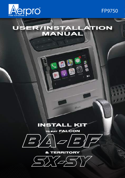
FP9750 INSTALL KIT TO SUIT FALCON BA- BF & TERRITORY SX-SY Inclusions 1 x Double DIN facia kit 1 x Built-in HVAC and steering wheel control unit 1 x Main wiring harness 1 x Universal SWC patch lead 1 x Video in/out lead 1 x Mounting kit 4 x M6 Bolts 1 x User/Install manual 2 Interface Functions Front Demister Fresh air is blown through the heater core and then ducted to and distributed over the interior surface of the vehicles windshield Rear Demister The demister clears condensation from the rear back glass 4 Interface Functions Air Circulation Mode Changes between fresh air drawn in directly from the outside of the vehicle, or recirculation where the air is drawn from inside the cabin 5 Interface Functions Mode Changes the vent positions for heating and cooling 6 Interface Functions Heating & Cooling Temperature Press up to increase temperature, press down to decrease temperature. Left hand side buttons adjust passenger side (Front & Rear). Right hand side buttons adjust drivers side (Front & Rear) temperature settings. 7 Interface Functions Air conditioning On or Off Press to turn the air conditioning On/Off or vice versa. This can be changed and reversed in the setup menu. Note: Holding down the A/C button completely turns the A/C heating and cooling system off on Dual Zone models. Fan Speed Adjustment Pressing these will turn the fan speed up and down. Note: with the A/C on and fan speed set to zero, there still will be a small amount of cold air pushed out through the vents. 8 Interface Functions Trip Computer This displays information relating to Average speed, Average fuel use, Trip time and remaining fuel in kilometres. Note: Trip button only works when not in the climate control display or settings menu. Auto Function Press to automatically control the climate control to a specified temperature. Note: This will only work on Dual Zone models. 9 Interface Functions Auto Function (Semi Auto) Press to manually control the climate control to a desired temperature. Note: This will only work on Dual Zone models. Press again to turn the climate control off. 10 Interface Functions Auto Door Lock Press to lock and unlock all doors in the vehicle Traction Control Press to turn vehicles traction control on or off Note: Only works on supported models prior to upgrade Interior Light Press to turn the vehicles factory interior light on or off 11 Menu Functions Configuration Menu Press and hold the menu button for a few seconds to display the Configuration Menu. Press menu button to enter into sub menus and again to change settings. Press the Fan UP/DOWN buttons to navigate up and down between sub menus. 12 Menu Functions Select Infoadapter settings/preferences to access (4 menus) Retained Accessory Power Controls what the headunit does after the vehicle is turned off. When Off is selected the headunit will turn off when the key is taken out of the ignition. When ON is selected the headunit will turn off when the key is taken out of the ignition and the drivers door is opened. Climate Screen Timeout Adjust the time it takes the Infoadapter screen to return to the Headunit Screen A/C Panel Brightness Adjust the brightness of the LED's on the Infoadapter Restore Factory Settings Restore all factory settings to default 13 Menu Functions Installer Menu When in the configuration menu, press and hold the fan UP/DOWN buttons at the same time to access the installer menu Air Conditioner Type Choose between a single or dual climate system. Note: Dual climate systems can run as a single zone system. Changing between single and dual zone type will change and auto correct the Invert AC Button setting. This can also be manually changed 14 Menu Functions Screen Size/ Position Allows the user to change the Infoadapter screen to fit to your headunits display Camera Connected Turns the reverse camera function On or Off if the vehicle has a factory reverse camera Invert AC Button This inverts the AC toggle. If you can still feel cold air coming out of your vents when AC is off, change this option Diagnostics Information on system 15 INSTALLATION BEFORE AFTER Tools Needed Use the following tools to make dismantling the car and the installation of the new facia easier 1. Panel Remover 2. Phillips Head Screwdriver 3. 8 mm Ratchet 4. Side Cutters 5. Small Pick 7. Electrical Tape 6. Cable Ties 2-1 Centre Console Disassembly Removing gear shift trim (Auto) Shift the gear stick down to the "D" drive position Lift the front of the panel then pull the panel up to completely remove 2-2 Side Panel Disassembly Removing side trim Undo the screw then lift up from the bottom and pull down from the top to remove the left side panel Repeat to remove the right side panel 2-3 Pocket Disassembly Removing tissue box and power socket Remove the 2 screws holding the tissue box in place Pull out the tissue box, disconnect the power harness from the socket and put the tissue box aside 2-4 Top Panel Disassembly Removing top panel trim Remove the top panel by CAREFULLY prying the edges away from the dash. Note: Age and sun damage can make this panel brittle and can break easily Remove the top panel and put it aside. Remove the screw at the top holding the factory unit in place and put aside 2-5 Headunit Removal Removing factory headunit face plate Remove the 2 x 8 mm bolts from the left side of the factory unit. Remove the 2 x 8 mm bolts from the right side of the factory unit 2-6 Headunit Removal Pull the unit away from the dash until it is loose (pic1) and unplug the 4 connectors and the antenna connector from beneath the factory unit (pic2-3). Remove the factory unit and place it on a bench. (pic1) (pic3) (pic2) 2-7 Headunit Disassembly Remove the 4 x screws from both the left and right factory brackets 2-8 Headunit Disassembly Remove the green plug and unscrew the earth strap Remove the factory unit from the plastic 2-9 Module Disassembly Removing The FOB Transceiver Module Remove the 2 screws from the transceiver, remove and put it aside 2-10 Vent Disassembly Removing The Vent From Factory Facia Remove the 3 screws holding the vent in place, remove it and put it aside 2-11 Mounting Clip Removal Remove the 4 yellow retaining clips from the factory plastics. These are to be reused on the aftermarket plastics Control Module Removal Remove 4 screws from Body Control Module (blue plastic module). Discard and use supplied 4 x M6 bolts when remounting 2-12 Changing The Dip Switch DIP switches can be changed to match the headunit and rear camera being used with this installation kit. Make these changes before installing the kit. Check the video and steering wheel control requirements for your devices. Step1. Carefully remove the back cover from the infoadapter Step2. Using a pick tool, flick the switches to the required setting Dip Switch Settings Up = On, Down = Off 1: On = Pioneer head units. Off = All other head units 2: Setting for reverse camera. On = PAL, Off = NTSC. The default setting is Off (NTSC). 3: Resets the display settings back to default. If the display settings have been manipulated in a way that it is no longer possible to make adjustments, change the DIP switch #3 from Off to On and back. This will reset the screen settings to the factory defaults. During this procedure the screen background will change to red. While the background is red, no settings can be made. 4: Not applicable 2-13 Vent Assembly Reattaching Factory Vent To New Facia Place the new plastics on a soft surface and turn it over so it is lying face down Line up the vent to the new plastics and attach it using the 3 screws taken out earlier 2-14 Vent Assembly Reattaching FOB Transceiver Module Mount the module back onto the vents Reattaching Body Control Module Mount the blue Body Control Module to the metal bracket on new plastics using the 4 M6 bolts provided and connect the lead from the FOB Transceiver Module 2-15 Body Control Module Mounting Note: Before going further, it is a good idea to check that the Body Control Module retaining bracket is fitted correctly. If the mounting bracket is the wrong way around, the body control module will not fit in the correct way... Make sure that the bracket is fitted as shown below 2-16 Mounting Aftermarket Headunit Mount the aftermarket head-unit to the mounting brackets. Leave the screws a little bit loose to allow adjustment of the screen to the desired depth. Tighten the screws 2-17 Connecting USB Pass Through & Reverse Camera Connect the USB/USB's if present. Connect the reverse camera input to the video lead and then connect it to the module. 2-18 Connecting Steering Wheel Controls Connect an Aerpro APP series (brand specific) secondary harness (sold separately) and a patch lead to the aftermarket unit. Connect to ISO plugs in main harness and connect to module NOTE: It is important to connect brand specific or correctly modified universal patch lead to module before powering up 2-19 Connecting Antenna Connect the antenna adapter and any other cables like park brake, reverse and speed pulse if available. Tape up any unused cables 2-20 OEM Reverse Sensor (Vehicle Option) Retaining the OEM reverse sensor alerts Attach the reverse sensor connector to the Aerpro AP1WAMP amplifier module (sold separately) Place the audio amplifier behind the headunit 2-21 OEM Reverse Sensor (Vehicle Option) Attaching the extension speaker Connect the 3.5mm extension jack of the Aerpro CBXS extension speaker (Sold separately) to the amplifier module input Securely mount the extension speaker in an appropriate position. You can adjust the volume of the amplifier module by turning the adjustment dial. Note: Prior to testing we suggest to set the dial to the 12 o'clock position 2-22 Main Harness Installation Plug the main harness into the vehicle. Due to the limited depth we recommend using a mechless head unit (No CD/DVD player) for this kit as some head units are too deep to fit within the space available. 2-23 Facia Kit Installation Attach the yellow retaining clips to the new plastics and place into position taking care to keep all cables out of the way 2-24 Facia Kit Installation Re-attach the four connectors to the body control module. Switch the vehicles parking lights on to test illumination of the HVAC buttons. Turn on the vehicles accessories to test steering wheel controls and audio. 2-25 Facia Kit Installation Once all of the functions have been tested, screw in the top section and bolt in the bottom section using the one screw and the 4 bolts retained earlier Replace the tissue pocket, reconnect the power socket, replace the top trim (CAREFULLY), replace the left and right side panels and screw back in. Replace the gear shift panel 2-26 Installer Notes 2-27 Technical assistance If you need assistance setting up or using your Aerpro product now or in the future, call Aerpro Support. Australia TEL: 03 8587 8888 FAX: 03 8587 8866 Mon-Fri 9am 5pm AEST Please retain this user guide for future reference. If you would like to download a digital copy of this manual, or other Aerpro manuals/software, please visit the http://aerpro.com website and click on `Firmware & Manuals" for information on where to find the manuals/software. This manual is considered correct at time of printing but is subject to change. For latest manuals and updates refer to the website. Copyright © 2017 by TDJ Australia All rights reserved. No part of this publication may be reproduced, distributed, or transmitted in any form or by any means, including photocopying, recording, copying or other electronic or mechanical methods, without the prior written permission of the author. 2-28 Wiring diagram Not included (Sold separately) Aftermarket unit Camera in Remote in Secondary Harness Video Lead SWC Patch Lead Aftermarket camera Vehicle Harness Main Harness Park brake (Green) Not Used(Grey) Amp Remote Input (Blue/White) Reverse (Purple) Speed Pulse(Pink) Factory Sub input (if Applicable) AP1AMP Reverse tone amplifier CBXS speaker 2-29 SWC Patch Harness Configuration Use 3.5mm Jack for these Head-units ALPINE Cut Green Link CLARION Cut Purple Link PIONEER No cutting required SONY No cutting required Use KEY 1, KEY 2 and GND Bullet terminals for Self Learn Head-units Use Key 1 Bullet terminal for these Head-units Philips, Nakamichi Cut Orange & Purple Wire Kenwood Cut Orange & Green Wire JVC Cut Green & Purple Link Zenec Cut all 3 wires, solder Orange and Green together as shown Self Learn Head-units No cutting required For best results or to reset the control module with a new brand, please make modifications to the patch lead first, before connecting to the steering wheel control module and before powering the module up. 2-30 SWC Patch Harness Configuration Kenwood/JVC: Some Kenwood and JVC radios have 2 steering control inputs. A 3.5mm socket (Remote IN) and Blue with Yellow trace wire. To send direct translated codes to your Kenwood/JVC radio, configure the patch lead up as Kenwood or JVC outlined in the configuration assignments and connect the Brown patch lead wire (KEY 1) used. If you would like to be able to program your steering controls configure the patch lead as Self Learn and plug the 3.5mm Jack into the Remote IN of the Kenwood/JVC, disregard the Brown wire. Pioneer : Some Pioneer models require the steering controls to be enabled they will by default OFF. These steering control settings are located in the system settings of the radio can only be accessed whilst the unit is in standby mode and the park-brake wire is connected (if applicable). Please refer to your Pioneer manual on exact methods for enabling steering controls. Sony: Recent Sony models may give you incorrect SWC button results after installing a control harness. This is due to a slight change in input codes on the newer Sony radios. To resolve this please do the following steps: - Remove the steering control harness from the vehicle. - Remove the plastic casing from the black steering control box. - Locate the very small dipswitch selector on the board - Turn dipswitch 4 OFF. - Re-assemble and test. There is also some Sony radio's that default steering controls off. If you are receiving no steering control functions at all please refer to your Sony manual on how to enable steering controls. General: Please ensure all connections to your aftermarket head unit (including patch lead modification) are completed before power is provided to the harness. Some of our control harnesses work by translating the vehicles CANBUS data and can only start this process on ignition. If you find that you are not getting any response from your steering controls on accessory (single key click) please re-test on ignition. Note: The steering controls must be working in the vehicle previously to work with our control harnesses. They will not fix a previous underlying problems. 2-31