User Guide for Honeywell models including: Series 8730, position TO, Series 760, position L, Maxon Oil Electro-mechanical Valves
Electrically actuated valves shut off oil (or other liquid) lines reliably, in less than. 1 second. • Application flexibility provided with DN10 (3/8") ...
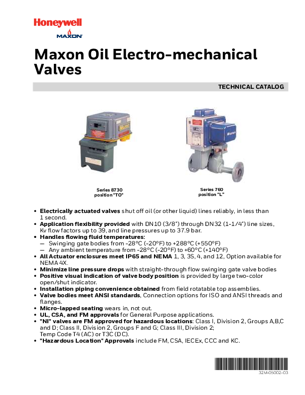
Maxon Oil Electro-mechanical Valves TECHNICAL CATALOG Series 8730 position "TO" Series 760 position "L" · Electrically actuated valves shut off oil (or other liquid) lines reliably, in less than 1 second. · Application flexibility provided with DN10 (3/8") through DN32 (1-1/4") line sizes, Kv flow factors up to 39, and line pressures up to 37.9 bar. · Handles flowing fluid temperatures: -- Swinging gate bodies from -28°C (-20°F) to +288°C (+550°F) -- Any ambient temperature from -28°C (-20°F) to +60°C (+140°F) · All Actuator enclosures meet IP65 and NEMA 1, 3, 3S, 4, and 12, Option available for NEMA 4X. · Minimize line pressure drops with straight-through flow swinging gate valve bodies · Positive visual indication of valve body position is provided by large two-color open/shut indicator. · Installation piping convenience obtained from field rotatable top assemblies. · Valve bodies meet ANSI standards, Connection options for ISO and ANSI threads and flanges. · Micro-lapped seating wears in, not out. · UL, CSA, and FM approvals for General Purpose applications. · "NI" valves are FM approved for hazardous locations: Class I, Division 2, Groups A,B,C and D; Class II, Division 2, Groups F and G; Class III, Division 2; Temp Code T4 (AC) or T3C (DC). · "Hazardous Location" Approvals include FM, CSA, IECEx, CCC and KC. 32M-05002-03 FEATURES AND BENEFITS Valves with electro-mechanical actuators Normally closed shut-off valves are used in burner system fuel supply lines on industrial boilers, furnaces, ovens, kilns, and other heating processes. All valves are designed to shut-off fuel flow, in less than one (1) second, with any interruption in the electric power supplied through your safety circuit. These valves are also used for the motorized opening or closing of pipe lines carrying gases and liquids commonly used in industrial processes. Normally closed valves VALVE BODY DESIGN DETAILS cannot be opened until the interlocking safety control circuit is proven and resulting electrical power is supplied to the shut-off valve. Motorized automatic valve actuators are used where remote access or unmanned applications are needed. NOTE: Valve motors and solenoids are protected against thermal overload. If the normal valve duty cycle is repeatedly exceeded, the thermal cutout will trip, and the motor and/or solenoid must be allowed to cool before the thermal protection will automatically reset. Seat Valve Body Assembly Disc Swinging gate valves are frequently used in normally closed oil service, and for some non-combustible gas applications. The carefully machined and micro lapped sealing surfaces promote a positive shutoff, which meets the FCI 70.2 Class VI standard. Frequent cycling of the valve shears accumulated dirt or residue from the disc/ seat interface to provide consistent and reliable sealing. The hard faced and lapped seat nut is threaded into the onepiece valve body. The free-floating, hard faced lapped,, spring loaded circular disc slides across the seat. Line pressure also assists in sealing the disc to the downstream seat. Frequent use and cycling actually helps to keep your valve clean. Since the free-floating disc is swinging across the circular seat nut on the arc created by the disc carrier, the disc rotates slightly on every cycle. This provides fresh, clean surfaces for sealing. Maxon valves have special service trim options available to meet your particular fluid service requirements. Contact your Maxon representative for details. DN15 (1/2") 8760 Threaded 32M-05002--03 2 DN25 (1") 4760 w/ Class 150 Flanges E - m - 10/20 AGENCY APPROVALS AND CERTIFICATIONS FM Approvals Table 1. Approvals and Certifications. General Purpose Valves 4730, 4760 8730, 8760 Non-Incendive/Non-Sparking Valves 4730NI, 4760NI Standards FM 7400 Markings Standards FM 3600 FM 3611 FM 3810 Markings Class I, Div 2, Groups ABCD Class II, Div 2, Groups FG Class III, Div 2 T4 (AC) T3C Ta = 60°C, T3B Ta = 65°C FM 3600 FM 3611 FM 3810 UL UL 429 Not Applicable Not Applicable CSA CSA 6.5 CSA 22.2 No. 139 IEC Approvals Not Applicable KTL Approvals Not Applicable Chinese Approvals Not Applicable Not Applicable Not Applicable Not Applicable CSA 22.2 No. 0 CSA 22.2 No. 0.4 CSA 22.2 No. 25 CSA 22.2 No. 94 CSA 22.2 No. 142 CSA 22.2 No. 213 IEC 60079-0 IEC 60079-15 IEC 60079-31 Class I, Div 2, Groups ABCD Class II, Div 2, Groups FG Class III, Div 2 T4 (AC) T3C (DC) IECEx FMG 11.0032X Ex nA nC IIC T4(AC), T3(DC) Gc Ex tc III C T135C Dc IP65 Announcement No. 2010-36 of Ministry of Employment and Labor GB 3836.1, GB 3836.8, GB 12476.1, GB 12476.5 4700NI Ex nA nC IIC T4(AC), T3(DC) Gc, Ex tD A22 IP65 T135°C Valve cycle requirements This is based on the standards that MAXON valves are approved to and the corresponding minimum number of cycles to be completed without failure as shown in the chart below. Table 2. Minimum number of cycles. Automatic Models CSA (CSA 6.5) 100.000 FM (FM 7400) 20.000 UL (UL 429) 100.000 E - m - 10/20 3 32M-05002--03 Valve Size Valve Type Body Connection Body Trim Solenoid Voltage Clutch Voltage Motor Voltage Motor Timing VOS Switch VCS Switch Enclosure Rating Terminal Block Instruction Language VALVE MODEL NUMBER DESCRIPTION Configured Model Valve Body Table 3. Valve Model Number Description Actuator 0050 8700 - A 1B - 0 B B 7 2 2 A 0 0 Valve Size 0038 -- DN10 (3/8") 0050 -- DN15 (1/2") 0075 -- DN20 (3/4") 0100 -- DN25 (1") 0125 -- DN32 (1-1/4") Valve Type 8700 -- Motor/Clutch Actuator 4700(NI) -- Motor/Solenoid Actuator 33479 -- High Temp Fluid 4700 Body Connection A -- ANSI Threaded C -- ISO Threaded E -- Nippled F -- Nippled w/150# Flanges G -- Nippled w/300# Flanges I -- Nippled w/600# Flanges Body and Trim Material Options 1B -- Iron Body with 420 SS Seat & DI Disc 1D -- Iron Body with Hardfaced Seat & Disc 2D -- Steel Body with Hardfaced Seat & Disc 2H -- HC Steel Body with Hardfaced Seat & Disc 2P -- 2D with PEEK backed Disc for lower actuation friction Solenoid Voltage 0 -- None A -- 115V 50HZ B -- 115V 60HZ C -- 230V 50HZ D -- 230V 60HZ E -- 208V 50HZ F -- 24VDC G -- 120VDC Clutch Voltage 0 -- None B -- 115V 60Hz Motor Voltage A -- 115V 50Hz B -- 115V 60Hz G -- 230V 50Hz H -- 230V 60Hz Motor Timing 7 -- 7 Second Timing VOS Switch 1 -- VOS-1 Switch 2 -- VOS-2 Switch VCS Switch 0 -- No Switch Ordered 1 -- VCS-1 Switch 2 -- VCS-2 Switch Enclosure Rating A -- NEMA 4 B -- NEMA 4X Terminal Block 00 -- None 12 -- 12 Terminal Connections 14 -- 14 Terminal Connections Instruction Language 0 -- English 6 -- Chinese 32M-05002--03 4 E - m - 10/20 VALVE BODY CAPACITIES/SPECIFICATIONS Body Material Gray Iron Cast Steel Table 4. Valve bodies. End Connections Pipe Size DN10 & DN15 Threaded DN20 DN25 DN32 Threaded & Flanged DN15 DN20 DN25 DN32 Kv Factor 2.9 8.3 10 15 39 2.9 8.3 10 15 39 Each complete valve assembly must include one of these valve bodies, regardless of ultimate series designation. Flows through the valve body and resulting pressure drops may be estimated by inserting your specific conditions into the following formula factors given for each valve body. and using Kv flow Gases: Qn = 514 Kv × (P1 - P2) × P2 n × Tf Liquids: V = (Kv) × (P1 - P2) Gf Where: G = Specific gravity (air & water = 1.0) Gf = Specific gravity @ flowing temperature °C P1 = Inlet pressure BarA P2 = Outlet pressure BarA Qn = Flow m3/hr @1 Bar and 5°C - 30°C Tf = Flowing temperature absolute (K = 273+°C) V = Flow in m3 /hr of liquid E - m - 10/20 5 32M-05002--03 VALVE BODY CAPACITIES WITH #2 OIL Tcaolsceulleactitoansv,aolvr ethfiosrgyroauprhasphpolwiciantgioanp,pursoexiemitahteerpKrvefsascutroer drop at various flows of #2 oil. Typically, pressure drop for fuel flows should not exceed 10% of inlet pressure. For preheated #5 or #6 oil, multiply the required flow rate in m3/hr by the factor given in the table at right, then select a valve based upon that equivalent flow of #2 oil and the allowable drop. Table 5. Factors for preheated #5 and #6 oil Oil Grade °C @ Inlet Factor #5 52 71 1.43 1.11 49 2.86 60 2.00 #6 82 1.25 99 1.11 104 1.05 32M-05002--03 6 E - m - 10/20 SELECTION DATA Swinging gate valves Table 6. Series Designation Body Material Top Assembly Function General Purpose Hazardous Location Sanctioned Service 1 4730; 8730 4730NI Gray Iron Special Service (Non-sanctioned) 2 4790; 8790 n/a Sanctioned Service 1 4730-S 4760; 8760 4760NI Cast Steel Special Service (Non-sanctioned) 2 4790-S; 8790-S 33479 n/a 1 Sanctioned valves are sold for fuel oils and may carry one or more sanctions (UL, FM, CGA). They are IRI approvable for liquified petroleum gases, #1 and #2 fuel oils, kerosene, JP-4 and preheated #4, #5 and #6 oils with maximum viscosity of 5000 SSU. 2 Non-sanctioned valves do not carry blanket approval/listings, and the pressure limits shown apply only for selected special service applications. An analysis of your fluid will determine the actual rating, trim, and specifics for your application. Features: · Normally closed · Electrically actuated · Swinging gate body · For shut-off service · For liquid and noncombustible gas service Temperature Limits All of these valves can handle fluid temperatures from -28°C (-20°F) to +121°C (+250°F). The Series 33479 valves are designed to handle higher fluid temperatures up to +232°C (+450°F) and even up to +288°C (+550°F) with addition (at extra charge) of special stem seals. Ambient temperature limits vary. Any valve on this page using DC voltage and all Series 8700 valves can handle ambient temperatures from -28°C (-20°F) to +52°C (125°F). The other valves on this page handle ambient temperatures from -28°C (-20°F) to +60°C (+140°F). Operation All of these electro-mechanical valves require a constant supply of electrical energy to their holding solenoids inside the top assembly actuators. Once the solenoid is energized the valve will automatically open. Any interruption of the electrical power to the valves causes an immediate trip of the valve to its normally closed position. Pipe Size (inches) Body KV Flow Factor DN10 (.375) 1 DN15 (.5) 1 2.9 DN20 (.75) 1 9.6 DN25 (1) 10 DN32 (1.25) 15 DN32 (1.25) HC 39 1 Available in 8730, 8760 & 8790 Table 7. Available Sizes and Pressure Ratings Maximum Inlet Pressure (bar) Gray Iron Bodies Cast Steel Bodies Fuel Oils Special Service Fuel Oils Liquid Propane Special Service --- --- --- 20.6 20.6 37.9 20.6 37.9 8.3 10 17.2 17.2 17.2 --- --- 8.6 --- 8.6 E - m - 10/20 7 32M-05002--03 SWINGING GATE BODY/TRIM SPECIFICATIONS Trim Specification of Maxon Swinging Gate Shut-Off Valves is two-part. The first digit before the hyphen is a number (2) identifying body material as shown in Table 8 below. The second digit after the hyphen identifies a trim utilizing the materials indicated in Table 9 below. Standard sanctioned valves incorporating a cast iron body will normally be identified by trim 1-B or 1-D. Sanctioned valves with steel body will normally be trim 2-D. Non-sanctioned services or unusual applications may require upgrading of internal trim. Contact Maxon with specific fuel analysis for price and availability. The drawings shown on the following page carry item numbers matching those in Table 9. This information is furnished for identification only, not for ordering parts. WARNING Do not attempt field repair of Maxon valve body or electro-mechanical top actuator. Any field alterations void all warranties. Table 8. Body Specifications Body Description Material ASTM Spec Body 1Cast Iron, G3000 A126 Class B Body 2Cast Steel A216-WCB Item No. Part Description 2 Hex Nut or Renewable Seat 3 Stem Bushing 4 Stem 5 Stem Spring 6 Disc Carrier 7 Disc 8 Stem O-Rings 9 Disc Spring 10 Inner Stem Thrust Ring 11 Back-up O-Rings 12 Body Gaskets 13 Stem Bushing Gasket 14 Body O-Ring 15 Stem Packing Ring 16 Packing Nut 17 Outlet Flange Table 9. Internal Trim Material Specifications. for DN10 (3/8") & DN 20 (3/4") valves Trim: -D Trim: -P Hard-Faced Steel Hard-Faced Steel For DN25 (1") & DN32 (1.25") valves Trim: -B Trim: -D Trim: -P Cast Iron with #420 Stainless Steel Seat Ring Hard-Faced Steel Hard-Faced Steel Zinc-Plated Steel Zinc-Plated Steel Zinc-Plated Steel Zinc-Plated Steel Zinc-Plated Steel #416 Stainless Steel #416 Stainless Steel #416 Stainless Steel #416 Stainless #416 Stainless Steel Steel #302 Stainless Steel #302 Stainless Steel #302 Stainless Steel #302 Stainless #302 Stainless Steel Steel Steel Steel w/PEEK Insert Steel Steel Steel w/PEEK Insert Hard-Faced Steel Hard-Faced Steel Nodular Iron Hard-Faced Steel Hard-Faced Steel Hydrin Viton Viton Viton Viton #302 Stainless Steel #302 Stainless Steel #302 Stainless Steel #302 Stainless #302 Stainless Steel Steel Teflon Teflon Teflon Teflon Teflon Teflon Teflon Teflon Teflon Teflon Soft Iron Soft Iron Soft Iron Soft Iron Soft Iron Soft Iron Soft Iron Soft Iron Soft Iron Soft Iron Viton Viton Viton Viton Viton Grafoil Grafoil --- --- --- Zinc-Plated Steel Zinc-Plated Steel --- --- --- --- --- --- --- --- 32M-05002--03 8 E - m - 10/20 SWINGING GATE BODY/TRIM SPECIFICATIONS Typical construction of DN10 (3/8") Typical construction of DN25 (1") through through DN20 (3/4") screwed body valves DN32 (1.25") screwed body valves 2-P trim disc carrier (Item No. 6) Steel Disc Carrier PEEK Insert E - m - 10/20 9 32M-05002--03 COMPONENT IDENTIFICATION General Maintenance and Spare Parts All safety devices should be tested at least monthly* and more often if deemed advisable. Periodic testing for tightness motorized shut-off valve closure is equally essential. *per NFPA 86-Appendix B-4 These Maxon valves are designed for long troublefree service. Only items shown as suggested spare parts are considered field replaceable. WARNING Do not attempt field repair of valve body, top assembly or motor drive unit. Any alterations void all warranties. To determine suggested spare parts, identify series designation and serial number from the valve's nameplate. Refer to the illustration and legend below to identify suggested spare parts. To order, specify: 1. Quantity 2. Assembly part number (if available) 3. Description 4. Electrical specification 5. Full nameplate information (from existing valve) Automatic Reset Note: Drawings are illustrative only. Actual valves may vary slightly. 4 1 2 3 1 2 Series 4700 3 Legend: 1 Nameplate 2 Solenoid 3 VOS motor limit/signal switch for normally closed valve; VCS for normally open valve 4 Printed Circuit Board (PCB) Series 8700 Nameplate (typical) (shown for listed valves; others similar) Nameplate designation does not reflect external accessory items or motor limit switch Normally closed valve designation 32M-05002--03 10 E - m - 10/20 ELECTRICAL DATA for normally closed valves General All Maxon shut-off valves are electrically actuated from a power source, normally through the flame safeguard and/ or safety control circuits. Standard valve assemblies include an internal holding solenoid or printed circuit board for 115 volt 60 hertz AC power. (Other electrical current options are available upon request.) Series 4730(NI), and 4760(NI) valves have the internal solenoid. Series 8700 valves incorporate the printed circuit board. The solenoid (or the printed circuit board) is energized whenever the valve is powered. The motor operator on automatic reset versions is powered only during the opening stroke. Switch wiring diagrams (reproduced on the next page) are part of each valve assembly, summarizing electrical data and wiring for a valve equipped with terminal block and a full complement of optional signal switches. Diagrams show valve in its normally closed (at rest) position. The indicated internal wiring is present only when the appropriate auxiliary switches are specified. Automatic reset valves always include a VOS-1 SPDT valve open motor limit switch. Good practice normally dictates that auxiliary switches in valves used for safety shut-off functions should be used for signal duty only, not to operate additional safety devices. Signal switch designations: VCS (Valve Closed Switch) is actuated at the end of the closing stroke. VCS-1 is SPDT; VCS-2 is DPDT. VOS (Valve Open Switch) is actuated at the end of the opening stroke. VOS-1 is SPDT; VOS-2 is DPDT. Switch amp ratings are shown on the schematic wiring diagrams. DO NOT EXCEED rated amperage or total load shown. Table 10. Volt Ampere (VA) Ratings: Automatic Reset Valve Size Series DN25 (1") - 4730(NI), 4760(NI), DN32 (1.25") 4790 (-S) DN25 (1") - 33479 DN32 (1.25") DN10 (3/8") 8730, 8760, 8790 (-S) DN20 (3/4") AC Operation (115 VAC, 60 Hz) Opening Holding 220 1 22 220 1 22 143 5 DC Operation (24 VDC) Opening Holding 222 24 222 24 --- --- 1 220 VA shown is for 60 hertz; if 50 hertz power, VA rating is 342 NOTE: The VA rating shown in the DC column is based on an AC motor, DC solenoid. E - m - 10/20 11 32M-05002--03 ELECTRICAL DATA for normally closed valves DN10 (3/8") through DN20 (3/4") Series 8730, 8760, and 8790 (-S) VALVE W IRING DIAGRAM SW ITCH CONTACT POSITIONS SHOWN WITH VALVE CLOSED 90 VDC CLUTCH CL UT CH RECTIFIER CIRCUIT VOS-1 M 1 2 3 VOS-2 4 5 6 VCS-1 7 8 9 VCS-2 P/N W ARNING! VALVE MUST BE WIRED AS SHOW N 10 11 12 L N SPDT SPDT SPDT SPDT AC POWER INPUT SWITCH RATINGS SPDT 125 VAC - 5 AMP MAX 250 VAC - 5 AMP MAX 125 VDC - 0.5 AMP 250 VDC - 0.25 AMP DUTY CYCLE CONTINUOUS ON OR MAX 1 CYCLE/MIN VALVE MODE VOS-1 VOS-2 1-3 4-5 4-6 FULLY SHUT INTERMEDIATE VCS-1 VCS-2 7-8 7-9 10-11 10-12 SEE NAMEPLATE FOR VOLTS, Hz, VA RATINGS FULLY OPEN DN25 (1") through DN32 (1.25") Series 4730(NI), 4760(NI), 4790, 33479 NORMALLY CLOSED VALVE VOS-2 VOS-1 VCS-1 1102216B VCS-2 M L(+) N(-) 1 2 3 4 5 6 L N SPDT DPDT SPDT 7 8 9 10 11 12 SPDT DPDT SPDT GENERAL PURPOSE AREA SPDT SPDT (HC) DPDT 125VAC 15 AMP 125VAC 10 AMP 125VAC 10 AMP 250VAC 15 AMP 125VDC 10 AMP 250VAC 10 AMP 125VDC 0.5 AMP 250VDC 3 AMP 125VDC 0.3 AMP 250VDC 0.25 AMP 250VDC 0.15 AMP DIVISION 2 AREA SPDT (HS) 125VAC 1 AMP 28VDC 5 AMP VOS-1 VOS-2 1-3 4-5 4-6 VCS-1 VCS-2 7-8 7-9 10-11 10-12 32M-05002--03 12 E - m - 10/20 DIMENSIONS (IN MM) 8700, 25300 DN10 (3/8") through DN32 (1.25") valves with swinging gate bodies Series 8730, 8760, 8790 & 8790-S (DN10, DN15 & DN20) 158 69 163 100 DN20 (3/4") Conduit Connection 281 Pipe Size 30 58 (for DN10) 81 43 (for DN15 & DN20) 74 NOTE: Series 8700 valves are available in top assembly positions "R" and "TO" only. Available Top Assembly Positions for Series 8700 "R" NOTE: 4" needed for cover removal. E - m - 10/20 13 "TO" 32M-05002--03 DIMENSIONS (IN MM) DN25 (1") & DN32 (1.25") valves with swinging gate bodies DN25 (1") & DN32 (1.25") Series 4700(NI) 72 193 D C E 190 DN25 (1") & DN32 (1.25") Series 33479 72 E 190 193 C D 414 B 39 PIPE SIZE 74 G H 417 B PIPE SIZE 39 74 G H Available Top Assembly Positions NOTE: 3" needed for terminal block cover removal. "L" "R" "TO" Valve Size Valve Series B C D E G H DN25 (1") 4730(NI), 4760(NI), 4790, DN32 (1.25") & 33479 344 193 60 89 49 105 106 "AW" 32M-05002--03 14 E - m - 10/20 AUXILIARY SIGNAL SWITCHES 4700(NI) & 33479 SERIES All Maxon valves may be equipped with internallymounted signal switch(es) to provide a "proof-of-open" or "proof-of-closure" valve position indication. throw) switch. VCS-2 is a DPDT (double-pole, doublethrow) switch. All contacts are available for external circuitry. Auxiliary signal switches indicate when valve is open or closed and are normally connected electrically into your control panel lights or warning device circuit(s). VCS (Valve Closed Switch) is actuated when valve is fully shut. It is the upper, inverted snap-switch mounted on rear of switch bracket. VCS-1 is an SPDT (single-pole, double- VOS (Valve Open Switch) is actuated when valve reaches full-open. It is the lower snap-switch mounted on front of switch bracket. VOS-1 is an SPDT switch. On automatic reset valves, its normally closed contact serves as a motor limit switch and is not available for external circuitry VOS2 is DPDT, used in lieu of VOS-1 for additional contacts. VOS (VOS-2 shown) VOS wands VOS actuator VCS actuator Valve Open VOS actuator VCS (VCS-2 shown) VCS wand VCS actuator Valve Shut E - m - 10/20 15 32M-05002--03 AUXILIARY SIGNAL SWITCHES 8700 SERIES All Maxon proof-of-open and proof-of-closure signal switches work in a similar manner; but due to different styles and types of top assembly housings, the switches appear in slightly different positions in the various types of valves. Illustrated at right are representative top housings for DN10 - DN20 Series 8700 (Fig. 1) valves. Switch locations are noted on sketch. Fig. 1. Valve Type 8700 4700/33479 Table 11. Torque Specifications Item Number Description 1 Adaptor Base Mounting Screws - 3/8"-16 x 2" UNC 2 Cover Mounting Screws - 1/4"-20 x .625" UNC 3 Nameplate Mounting Screws - #8-32 x .25" 4 Actuator Adaptor Screws - 3/8"-16 x 1.5" 5 Adaptor Base Mounting Screws - 3/8"-16 x 2" UNC 6 Nameplate Mounting Screws - #8-32 x .25" 7 Cover Mounting Screws - 1/4"-20 x .625" UNC 8 Motor Cover Mounting Screws - #10-24 x .5" 9 Actuator Adaptor Screws - 3/8"-16 x 1.5" 32M-05002--03 16 Torque 27 Nm 8 Nm 1,1 Nm 27 Nm 27 Nm 1,1 Nm 8 Nm 4,7 Nm 27 Nm E - m - 10/20 MANUFACTURER AND IMPORTER ADDRESSES Below are the addresses and contact information for the Honeywell Maxon manufacturing location and European sales office. The European sales office serves as the importer and EU manufacturer's representative under the EU New Legislative Framework (NLF). MUNCIE, INDIANA, USA MANUFACTURER 201 East 18th Street Muncie, IN 47307-0068 Tel: 765.284.3304 Fax: 765.286.8394 EUROPEAN SALES OFFICE IMPORTER BELGIUM Maxon International BVBA Luchthavenlaan 16-18 1800 Vilvoorde, Belgium Tel: 32.2.255.09.09 Fax: 32.2.251.82.41 E - m - 10/20 17 32M-05002--03 WARNING The installation, operation and maintenance instructions contain important information that must be read and followed by anyone operating or servicing this product. Do not operate or service this equipment unless the instructions have been read. IMPROPER INSTALLATION OR USE OF THIS PRODUCT COULD RESULT IN BODILY INJURY OR DEATH. Nameplate and abbreviations Consult the nameplate of your valve. This lists the maximum operating pressure, temperature limitations, voltage requirements and service conditions of your specific valve. Do not exceed nameplate ratings. Description MAXON electro-mechanical valves are electrically actuated fuel shut-off valves. The valves are designed for a fast acting return to Normally-closed and normally-open options are available. The normally-closed versions will shut off flow when de-energized and pass flow when energized. The normally-open versions will shut off flow when energized and pass flow when de-energized. Electromechanical valves are also offered in configurations that meet hazardous locations. Abbreviation or symbol M.O.P. OPENING Description Maximum operating pressure Valve opening time (for automatic valves only). Units shown in seconds. Solenoid/clutch voltage and frequency Motor voltage and frequency M TAMB Ambient temperature range TF Fluid temperature range SHUT Visual indication that valve is shut OPEN Visual indication that valve is open SPDT (HS) Single pole double throw hermetically-sealed switch(es) SPDT Single pole double throw switch(es) SPDT (HC) Single pole double throw high capacity switch(es) (used when DC motors are ordered) DPDT Double pole double throw switch(es) GENERAL PURPOSE AREA Designates components used in general purpose areas DIVISION 2 AREA Designates components used in Division 2 hazardous locations areas Valve is shut Valve is partially open VOS-1/2 VCS-1/2 Valve is full open Valve open switch(es) Valve closed switch(es); proof of closure 32M-05002--03 18 E - m - 10/20 Installation 1. A gas filter or strainer of 40 mesh (0.6 mm) or smaller is recommended in the fuel gas piping to protect the downstream safety shut-off valves. 2. Properly support and pipe the valve in the direction of the flow arrow on the valve body. Valve seats are directional. Sealing will be maintained at full rated pressures in one direction only. Sealing will be provided in reverse flow only at reduced pressures. 3. Mount valve so that open/shut window indicator will be visible to your operating personnel. The open/shut window indicator should never face downward. The valve side plates should be located in a vertical plane for best performance. Valves are usually installed in horizontal piping; however, other orientations are acceptable, subject to the above limitations. The top assemblies of all MAXON valves are field rotatable to allow installations involving conflicts with these mounting restrictions. 4. Wire the valve in accordance with all applicable local and national codes and standards. In U.S. and Canada, wiring must conform to the NEC ANSI/NFPA 70 and/or CSA C22.1, Part 1. · Supply voltages must agree with valve's nameplate voltage within -15%/+10% for proper operation. For electrical wiring schematic, see instructions or sample affixed inside valve terminal block cover. · Grounding is achieved with a grounding screw, which is located in the top assembly. · Customer connections are provided via terminal blocks located in the top assembly. · Main power wiring (120 VAC or 240 VAC) must be segregated from lower voltage 24 VDC signal wiring, when both are required. · To eliminate any potential for gas to enter the electrical wiring system, install a conduit seal fitting at the actuator conduit hub. 5. Maintain integrity of the electro-mechanical actuator enclosures by using the appropriate electrical connectors for the (2) DN20 (3/4") NPT conduit threaded connections. The electrical enclosure is NEMA 4 rated with an option for NEMA 4X. 6. All access cover plate screws should be tightened using a torque wrench in an alternate cross-corner tightening pattern to the values shown in "Torque Specifications" on page 16. 7. Verify proper installation and operation by electrically actuating the valve for 10-15 cycles prior to the first introduction of gas. 8. WARNING - Explosion hazard · Do not connect or disconnect this equipment unless power has been removed or the area is known to be non-hazardous. · Substitution of components may impair suitability for Class I, Division 2 (applies to 4700NI valves only). 9. This equipment is suitable for installation in Class I, Division 2 Groups B, C, D, and Class II Groups F and G, and Class III hazardous locations or non-hazardous locations (applies to 4700NI valves only). Auxiliary features · Non-adjustable proof of closure switch(es) with valve seal over travel interlock · Auxiliary switch for indication of full travel (open for normally-closed valves, closed for normally-open valves) Operating environment · Actuators rated for NEMA 4 or optional NEMA 4X · Ambient and fluid temperature range of -28°C (-20°F) to +60°C (140°F) for DN25 (1") & DN32 (1-1/4") valves · Ambient and fluid temperature range of -28°C (-20°F) to +52°C (125°F) for DN10 (3/8"), DN15 (1/2") & DN20 (3/4") valves E - m - 10/20 19 32M-05002--03 ACTUATOR ASSEMBLY ROTATION WARNING MAXON electro-mechanical valves should be ordered in a configuration compatible with planned piping. If valve orientation is not correct, the actuator assembly can be rotated in 90° increments around the valve body centerline axis using the procedure below. 1. Shut off all electrical power and close off upstream manual cock. 2. Remove terminal block cover plate and disconnect power lead wires. (Tag carefully for later re-assembly.) 3. Remove conduit and electrical leads. 4. Note physical position of any signal switch actuator wands on auxiliary signal switches. 5. Unscrew the two actuator bolts screwed up from the bottom to 6.5 mm. DO NOT completely remove. These bolts secure the valve body to the valve's top assembly housing. 6. Gently lift the top assembly (not more than 6 mm in height); just enough to break the seal between the valve body assembly and the rubber gasket adhering to the bottom of the top housing. WARNING Lifting too far may dislodge some small parts inside the top housing, requiring complex reassembly and retesting by trained factory personnel. 7. Remove the two actuator bolts screwed up from the bottom (were partially unscrewed in step 5). 8. Carefully rotate top assembly to the desired position in a plane parallel to the top of the valve body casting. Rotate the top housing about 30° beyond this position, and then rotate it back. Reposition the top housing back down onto the valve body casting. This should align the open/shut indicator with its window and provide proper alignment of the internal mechanism. 9. Realign holes in valve body casting with the corresponding tapped holes in the bottom of the top assembly housing. Be sure the gasket is still in place between the body and top housing. 10. Reinsert the actuator bolts up from the bottom through the body and carefully engage threads of the top assembly. Tighten securely. 11. Reconnect conduit and electrical leads, then check that signal switch wands are properly positioned and that the open/shut indicator moves freely. Failure to correct any such misalignment can result in extensive damage to the internal mechanism of your valve. 12. Energize valve and cycle several times from closed to full open position. Also electrically trip the valve in a partially opened position to prove valve operates properly. 13. Replace and secure terminal block cover plate and place valve in service. FIELD INSTALLATION OF VALVE POSITION SWITCH General · Shut off fuel supply upstream of valve, then de-ener- gize valve electrically. · Remove terminal block and access cover to provide access, being careful not to damage gaskets. · Compare with illustrations below to identify your valve type. Replacement switches · Note wand position and mounting hole location carefully, then remove 2 screws and lift existing switch. · Install replacement switch in same mounting holes on bracket and verify correct wand position. · Replace existing wiring one connection at a time, following original route and placement. Add switches · Check illustrations below. If your valve uses a switch mounting bracket as in Fig. 1 & 2, mount switches to bracket using the mounting holes appropriate for valve type and size. For high capacity valves, mount switches on the support stand. · Position bracket so VCS wand just touches top of actuator, then move downward slightly, depressing wand until switch clicks, then tighten mounting screws to hold this position. · Pin bracket by drilling 3.2 mm diameter holes 6.4 mm deep into bracket mounting pad through drive pin holes, then tap drive pin in until flush (not required for high capacity valves). · Route wires to wiring compartment as shown, then complete wiring connections and clean out metal drilling chips from previous procedure. · Cycle valve, checking switch actuation points carefully. (VCS actuates at top of stem stroke, VOS at bottom.) Simultaneously the valve body must be tested for switch continuity and seat leakage. Bend VOS switch wands slightly if necessary to insure valve is opening fully. · Replace covers, then return valve to service. 32M-05002--03 20 E - m - 10/20 MAINTENANCE INSTRUCTIONS MAXON electro-mechanical valves are endurance tested far in excess of the most stringent requirements of the various approval agencies. They are designed for long life even if frequently cycled, and to be as maintenance-free and trouble-free as possible. A valve operational test should be performed on an annual basis. If abnormal opening or closing is observed, the valve should be removed from service and your MAXON representative should be contacted. (See MAXON Technical Document 10-35.1.) Valve leak test should be performed on an annual basis to assure continued safe and reliable operation. Every MAXON valve is operationally tested and meets the requirements of FCI 70-2 Class VI Seat Leakage when in good operable condition. Zero leakage may not be obtained in the field after it has been in service. For specific recommendations on leak test procedures, see MAXON Technical Document 10-35.2. Any valve that exceeds the allowable leakage, as set forth by your local codes or insurance requirements should be removed from service and your MAXON representative should be contacted. Actuator assembly components require no field lubrication and should never be oiled. Auxiliary switches, solenoids, motors, clutches or circuit boards may be replaced in the field. WARNING Do not attempt field repair of valve body or actuator. Any alterations void all warranties and can create potentially hazardous situations. If foreign material or corrosive substances are present in the fuel line, it will be necessary to inspect the valve to make certain it is operating properly. If abnormal opening or closing is observed, the valve should be removed from service. Contact your MAXON representative for instructions. Operator should be aware of and observe characteristic opening/closing action of the valve. Should operation ever become sluggish, remove valve from service and contact MAXON for recommendations. Address inquiries to MAXON. Local worldwide offices may be located at www.maxoncorp.com. Include valve serial number and nameplate information. E - m - 10/20 21 32M-05002--03 For More Information The Honeywell Thermal Solutions family of products includes Honeywell Combustion Safety, Eclipse, Exothermics, Hauck, Kromschröder and Maxon. To learn more about our products, visit ThermalSolutions.honeywell.com or contact your Honeywell Sales Engineer. Honeywell MAXON branded products 201 E 18th Street Muncie, IN 47302 USA www.maxoncorp.com Honeywell Process Solutions Honeywell Thermal Solutions (HTS) 1250 West Sam Houston Parkway South Houston, TX 77042 ThermalSolutions.honeywell ® U.S. Registered Trademark © 2020 Honeywell International Inc. 32M-05002-03 - metric M.S. Rev.10-20 Printed in United States