HEPA 500 manual
File info: application/pdf · 12 pages · 1.11MB
HEPA 500 manual
HEPA 500 manual - PremierOne Products
PREMIERONE™ HP500 | Thos. Somerville Co.
[PDF] HEPA Air Cleaner - NET
The Whole House HEPA Filtration system does not replace the filter from the forced air heating/cooling system. Regular maintenance of this ...
Full PDF Document

If the inline viewer fails, it will open the original document in compatibility mode automatically. You can also open the file directly.
Extracted Text
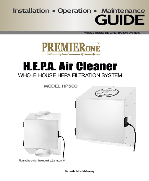
Installation � Operation � Maintenance
GUIDE
WHOLE HOUSE HEPA FILTRATION SYSTEMS
H.E.P.A. Air Cleaner
WHOLE HOUSE HEPA FILTRATION SYSTEM
MODEL HP500
Pictured here with the optional collar mount kit For residential installation only

7years
Limited Warranty
Manufacturer Warranty
You benefit from a limited 7 year warranty on the motorized impeller and a 5 year limited warranty against manufacturing defects on other components. The limited warranty covers normal usage. It does not apply to malfunctions or failures as a result of improper installation, abuse, mishandling or misapplication or any other circumstances outside the manufacturer's control or consent. Warranty from the manufacturer is for parts only, labor and shipping of the product is not covered under warranty.  Warranty doesn't cover in any way or form the replaceable Pre-Filter, Carbon Filter or HEPA Filter.
Box Content
Includes: � Whole House HP 500 � Power cord, 5 FT � Plenum seal, 7.5 FT � Screws, (16) 8 x 32 x 1/2" � Template

Table of contents
1.Getting Started
GENERAL INFORMATION
1.1 Unpacking and inspection 1.2 Technical data
2.Installation Guide
INFORMATION FOR INSTALLERS
2.1 Planning the installation 2.2 Type of installation: Return to Return 2.3 Type of installation: Stand-Alone 2.4 Installing the unit
3.Owner's Operation Guide
INFORMATION FOR THE HOMEOWNER
3.1 General Operating Information
4. Maintenance Guide
GENERAL MAINTENANCE INFORMATION
4.1 Changing filters 4.2 Cleaning unit 4.3 Auxiliary relay control module

PAGE
2 3
PAGE
4 4 5 6
PAGE
9
PAGE
10 10 11

1.1.Unpacking and inspection

PAGE 2

1.2. Technical Data

Specifications

Model HP500
Filtration Stage 1 & 2 Filtration Stage 3

Prefilter with Carbon (RPCF677) HEPA filter (RHF562)

Weight Plenum Mount Port Openings Collar Mount Port Openings Installation type Electrical Supply Power Consumption Certification Air flow data

28 lbs (12.7 kg) 16" x 3.5" (406mm x89mm) 8" (203mm) Round* Plenum,Wall* or Floor*Mounted 120 VAC @ 60 Hz 134 W CCSA US 220-300 CF.M.

* Installation requires kit No.CMK500

IMPORTANT INFORMATION The manufacturer reserves the right to modify a product, without prior notice, whether in design, color or specifications, in order to offer at all times a quality product that is highly competitive. � Please consult local authorities to find out whether the installation of electrical products requires the services of a certified technician or electrician.

Dimensions and Clearance
installation

Return Air Plenum Installation

Front View

Side View - Clearance

Back View

17" (432 mm)

Stage 1
Stage 2 Stage 3

11.587" (294.5 mm)

12" (305 mm)

22" (559 mm)

17" (432mm)

Return Air Plenum and Stand Alone Installations *
With Collar Mount Kit

Front View

Side View - Clearance

Side View

17" (432 mm)

Stage 1
Stage 2 Stage 3

11.587" (294.5 mm)

12" (305 mm)

PAGE 3

22" (559 mm)

13" (330mm)

Installation GUIDE

2. Information for the Installer

Special Consideration
For integrated system installation � Verify clearance on the ductwork to
mount the unit using the Forced Air heating/cooling system � Minimum clearance requirements for maintenance and service � Electrical power requirements � Interaction between the HEPA filter unit and other mechanical devices.

2.1 Planning the Installation
The Whole House HEPA unit is a versatile appliance with multiple installations configuration. It is recommended to take your time in planning the installation.
Several Installations are illustrated herein' for Whole House filtration applications: � Return to return integrated with the forced air
heating/cooling system. � Central draw points using dedicated duct system � Consult the manufacturer for other special applications.

Ducting Flair System
installation The Whole House HEPA Filtration system is designed to install directly onto the return air plenum of the forced air heating/cooling system. Choosing this type of installation eliminates the need to externally duct the HEPA filter unit to the plenum system. If you choose this type of installation, it is recommended that you run the fan on your forced air system continuously to maximize its cleaning ability. TIPS to installer The Whole House HEPA Filtration system does not replace the filter from the forced air heating/cooling system. Regular maintenance of this filter is necessary to permit the good operation of the forced air heating/cooling system.
Optional collar system
installation Using kit no. CMK500 the Whole House HEPA Filtration system can be converted to use 8 inch round collars for application requiring ducting. The kit includes two, 8 inch round collars, two mounting brackets for wall or floor mounting, installation guide and fasteners.

2.2 Type of Installation: Return to Return Integrated System

Ducting Flair System (Hepa Mounted on Duct)

Optional Collar System (Hepa Mounted on Wall)

Return Air Plenum

To living space
Return Air Plenum

To living space

Forced Air Heating/Cooling System

Forced Air Heating/Cooling System

INSTALLATION SHOULD BE PERFORMED BY A CERTIFIED PROFESSIONAL. Consult your HVAC product manufacturer if the usage of this product will affect the performance of your forced air heating / cooling system.
PAGE 4

Stand Alone
Attic Installation Ideal for homes without a forced air heating / cooling system. Allows for air filtration and circulation throughout the home. HEPA system must be operated continuously whenever a part or all the system is located in an unconditioned space to avoid condensation in the ductwork below freezing (0�C, 32�F).

Installation GUIDE
2.3 Types of Installation: Stand-Alone

Stand Alone
Basement Installation Ducting will usually consist of one return with grille from one side of the home, and one supply with grille at the opposite end of the home.

PAGE 5

Installation GUIDE

2.4 Installing the unit

Tools required
� Phillips #2 or Robertson #1 screwdriver
� 3/32" drill bit � Tin snips or metal shear � Power Drill
Location
Return side connections is to be installed after the last branch on the return air plenum and minimum 2 linear ft distance from furnace. A 5-ft power cord is supplied with the unit. If not available a 120VAC outlet needs to be supplied.
Note:
Refer to the Owner's Operation Guide (p.9) for details on how to remove the unit's door and filters

Step by step Installation
Steps involved in the preparation of the plenum mount system are
as followed:

Step 1: Preparing return air plenum
Find a location that satisfies both service and maintenance requirements and proceed to cut holes as illustrated below.

Step 2: Preparing ducting flairs
Remove the door and filters and proceed to cut the insulation as illustrated below.

figure 2.2a - Cut the insulation along the inside edge of both inlet and outlet ports to remove the insulation from the port openings.

figure 2.1a - Tape template to return air plenum. Cut opening with metal shears and predrill for the securing screws.

figure 2.2b -One cut permits the clean removal of the insulation piece.

figure 2.1b - Remove template. PAGE 6

figure 2.2c -The unit should look like this when the foam piece is removed.

Tips
to installer Interlocking the HEPA filtration unit with the forced air heating / cooling system is possible using an auxiliary relay. Refer to page 11 of this guide for example. Please consult local authorities to find out whether the installation of electrical products requires the services of a certified technician or electrician.

Installation GUIDE
2.4 Installing the unit (Continued)

Step 2:(Continued)

Step 2:(Continued)

Cut the four metal tabs to release the mounting flairs for the inlet and outlet ports.

figure 2.2d

figure 2.2h - Apply plenum seal tape all around both openings on the back of the unit.

figure 2.2e figure 2.2f

figure 2.2i

figure 2.2g PAGE 7

figure 2.2j- Bend tabs outward approximately 90 degrees.

Installation GUIDE

2.4 Installing the unit (Continued)

Tips
to installer It is recommended that the filtration unit have a devoted receptacle with 115V. It is not recommended to connect unit with an extension cord. If no receptacle is available please call an electrical contractor to have one installed.

Step 3: Mount Hepa

Step 3: (Continued)

MAKE SURE TO INSTALL FILTER ACCORDING TO AIR FLOW DIRECTION FOR MAXIMUM PERFORMANCE
Check for this symbol on each filters and it is located on the unit's motor plate.

figure2.3a - Align unit into place.

figure 2.3c - Install unit as usual using all supplied fastening hardware.
Step 4: Finishing Stage 1&2: Pre-Filter & Carbon

Stage 3: HEPA Filter figure 2.4a - Remove protective plastic covers from all filters and replace them in their proper location (Stage 1, 2 and 3). figure 2.3b - Unfold the ducting flairs completly to sandwich the return air plenum between the ducting flair and the filtration unit.

PAGE 8

figure 2.4b - Replace door and insert power cord into the receptacle of the filter units and the other end into wall outlet.

Owner's Operation GUIDE

Door Switch
Mode Selector
�II � I Operations
MaximumFiltration Normal Filtration

3. General Operating Information
Function
The Whole House HEPA system is comprised of a ventilator, speed selection switch, 3 stages of filtration and the cabinet enclosure system. The ventilator pulls air through the pre-filter and pushes the same air threw the impregnated carbon pad for odor control and finally the last stage of filtration is the HEPA filter which removes 99.97% of particles 0.3�m in size.
Operation Mode Options
The unit features two speeds of operation for your convenience. The speed selection switch is located on the front of the motor assembly. At lowest speed the unit will provide 220 CFM of clean air while at highest speed, the unit will provide 300 CFM of clean air. It is recommended that the unit be operated on highest speed at all times to maximize the benefits of the HEPA filtration system. If for some reason the filtration needs are not as important then one might operate the unit at low speed. An access door is provided at the front of the unit to permit access to the filters and speed selection switch. Opening the latch on the right side of the unit will permit the door to swing open. A safety door interlock switch cuts the power to the motors for your safety. If needed the door can be removed from the cabinet hinges by holding the top part of the door with one hand and gently taping on the bottom edge of the door with the other hand to release the door from its hinges.
Recommended Operation
The return plenum mount model operates in conjunction with your forced air heating/cooling system. A forced air distribution system continuously circulates the same air inside your home. The whole house HEPA filtration system operates on the principal of bypass filtration, which means that a portion of the air being returned into the furnace is filtered on each pass. Over time all the air in the home gets cleaned. It is recommended that the furnace blower be in operation whenever the filtration system is in operation. For stand-alone attic installation, the HEPA filtration system must be operated continuously whenever a part of all the system is located in an unconditionned space to avoid condensation in the ductwork below freezing (32�F ,0�C) Maintenance of the unit should be performed at regular interval to keep the benefits of the HEPA filtration unit.
PAGE 9

Maintenance

GUIDE

4. General Maintenance Information

When should I Service my Unit?
service and accessories Detailed maintenance information is located on the front decal on motor plate. PRE-FILTER AND CARBON FILTER Replace filters every 3 to 6 months or as needed. HEPA FILTER Replace filter every 1 to 3 years or as needed. Check regularly to maintain maximum performance from your HVAC system. For replacement filters, contact your local HVAC contractor.
Note
to installer IMPORTANT : ALWAYS UNPLUG UNIT BEFORE SERVICING

4.1 Changing Filters
After opening the unit's door, grasp both edges of filter and pull with equal force to slide out the filter.

4.2 Cleaning
Once a year or as needed, clean the interior of the unit (Wall and motor plates) using mild non-abrasive soap and water. It is recommended to use products that are environmentally friendly.

4.3 Troubleshooting

Troubleshooting

Suggestions

Unit does not operate Unit operates only on one speed.

� Is power cord fully inserted in the unit's connector?
� Is outlet powered? � Is door interlock switch operating? Possible loose wire inside electrical box, contact your local contractor.

Unit vibrates

Check for excessive dust builup or missing balancing weight on the impeller wheel.

4.4 Electrical Wiring Diagram

Black

Blue
M

Brown 2.5uf

Speed Selection 7.5uf
Door Interlock

L

G

N

PAGE 10

Contact
For Technical Support � Toll Free: 1-800-982-1840
Warning: Instructions listed for interlocking the filtration unit to a furnace is an example only. Actual wiring of interlock connection may vary depending on the system

Wiring the HP500 Air Cleaner
to an ICP 80% or 90 % +%Furnace
The wiring together of the HP 500 Air cleaner onto an ICP electronic fan control (EFC) board is as simple as 1-2-3. Control boards on different brands of furnaces vary but in principal are all quite similar.
Step 1: Turn-off electric power to furnace and use a 120V coil SPST N/O relay. Mount relay to a _" knockout.

PAGE 11

Step 2: Wire the HOT EAC terminal on the furnace's EFC board to one side of the 120V coil on the relay. Wire the other side of the 120V coil back to a spare common terminal on the EFC board.
Step 3: Wire 120V HOT from blower door safety switch (use a spade terminal splitter similar to Johnstone #G21-414) to one side of the open contact on the relay (red wires on L38-180). Wire from the relay to a receptacle you mount in a 2X4 handy-box on the outside of the furnace. Wire the common side of the receptacle to the common terminal on the furnace EFC board.

1-800-982-1840 www.premieroneproducts.com