File info: application/pdf · 24 pages · 1.58MB
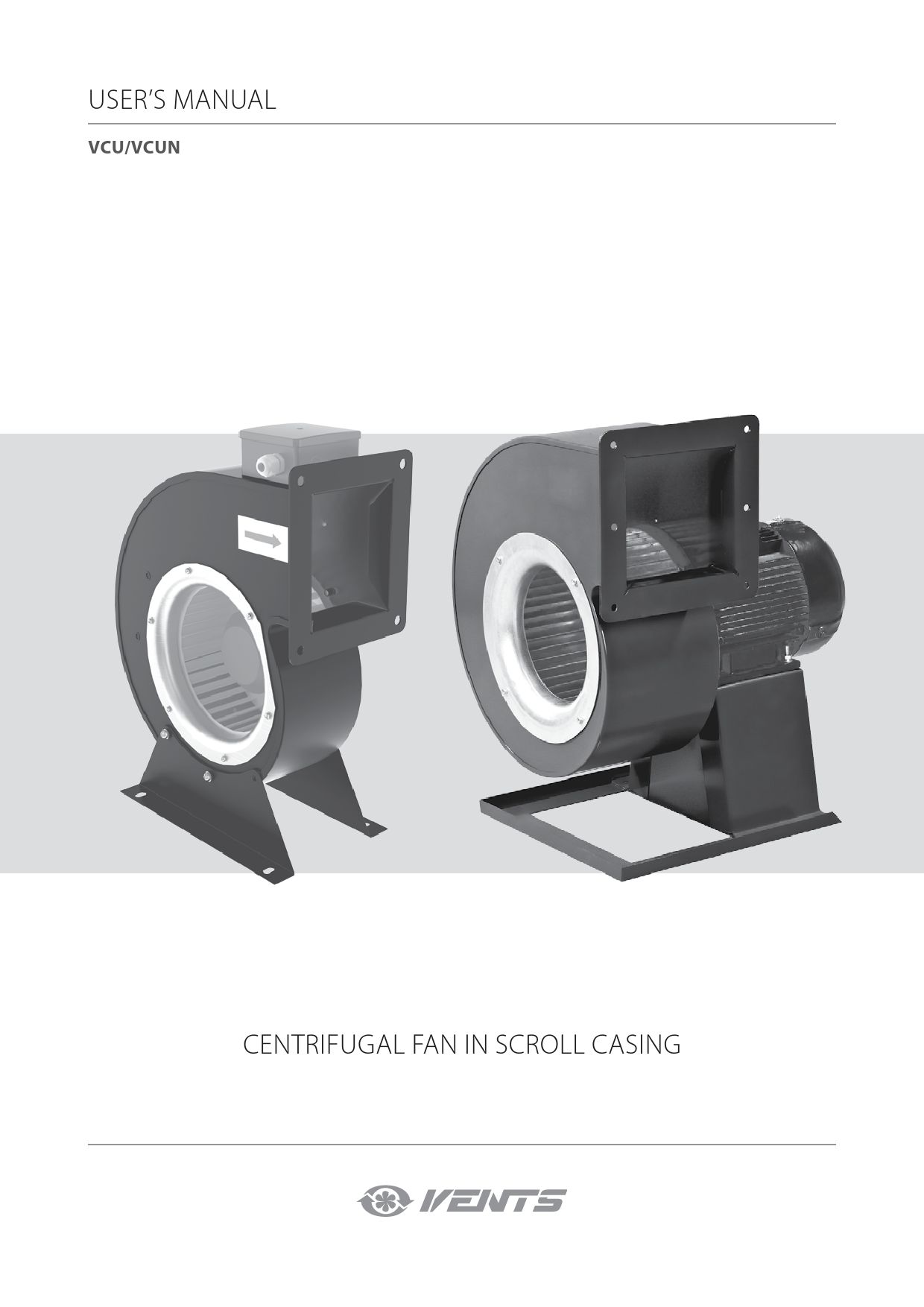
USER'S MANUAL CENTRIFUGAL FAN IN SCROLL CASING
The manual contains information about purpose, technical details, operating principle, design, and installation of the VCU/VCUN unit and all its modifications.
User’s manual
User’s manual. Vcu/vcun. Centrifugal fan in scroll casing. ... This user’s manual is a main operating document intended for technical, maintenance, and operating...
USER’S MANUAL - VENTS
2 VCU/VCUN www.ventilation-system.com This user’s manual is a main operating document intended for technical, maintenance, and operating staff.
Full PDF Document

If the inline viewer fails, it will open the original document in compatibility mode automatically. You can also open the file directly.
Extracted Text
USER'S MANUAL
VCU/VCUN
CENTRIFUGAL FAN IN SCROLL CASING

CONTENTS
Contents............................................................................................................................................................................................... 2 Safety requirements...................................................................................................................................................................... 3 Purpose................................................................................................................................................................................................. 5 Delivery set......................................................................................................................................................................................... 5 Designation key............................................................................................................................................................................... 5 Technical data................................................................................................................................................................................... 6 Design and operating principle............................................................................................................................................ 9 Installation and set-up................................................................................................................................................................ 10 Connection to power mains................................................................................................................................................... 12 Technical maintenance............................................................................................................................................................... 16 Troubles and troubleshooting............................................................................................................................................... 18 Storage and transportation regulations........................................................................................................................... 18 Manufacturer's warranty............................................................................................................................................................ 19 Certificate of acceptance........................................................................................................................................................... 20 Seller information........................................................................................................................................................................... 20 Installation certificate................................................................................................................................................................... 20 Warranty card.................................................................................................................................................................................... 20

VCU/VCUN

This user's manual is a main operating document intended for technical, maintenance, and operating staff. The manual contains information about purpose, technical details, operating principle, design, and installation of the VCU/VCUN unit and all its modifications. Technical and maintenance staff must have theoretical and practical training in the field of ventilation systems and should be able to work in accordance with workplace safety rules as well as construction norms and standards applicable in the territory of the country. The information in this user's manual is correct at the time of the document's preparation. The Company reserves the right to modify the technical characteristics, design, or configuration of its products at any time in order to incorporate the latest technological developments. No part of this publication may be reproduced, stored in a retrieval system, or transmitted, in any form or by any means in any information search system or translated into any language in any form without the prior written permission of the Company.

2

www.ventilation-system.com

SAFETY REQUIREMENTS
� Please read the user's manual carefully prior to installing and operating the unit. � All user's manual requirements as well as the provisions of all the applicable local and national
construction, electrical, and technical norms and standards must be observed when installing and operating the unit. � The warnings contained in the user's manual must be considered most seriously since they contain vital personal safety information. � Failure to follow the rules and safety precautions noted in this user's manual may result in an injury or unit damage. � After a careful reading of the manual, keep it for the entire service life of the unit. � While transferring the unit control, the user's manual must be turned over to the receiving operator.

UNIT INSTALLATION AND OPERATION SAFETY PRECAUTIONS

� Disconnect the unit from power mains prior to any installation operations.

� Unpack the unit with care.

� The unit must be grounded!
� Do not change the power cable length at your own discretion.
� Do not bend the power cable. � Avoid damaging the power
cable. � Do not put any foreign objects
on the power cable.
� Do not use damaged equipment or cables when connecting the unit to power mains.
� Do not touch the unit controls with wet hands.
� Do not carry out the installation and maintenance operations with wet hands.

� While installing the unit, follow the safety regulations specific to the use of electric tools.
� Do not lay the power cable of the unit in close proximity to heating equipment.
� Do not operate the unit outside the temperature range stated in the user's manual.
� Do not operate the unit in aggressive or explosive environments.
� Do not wash the unit with water.
� Protect the electric parts of the unit against ingress of water.

www.ventilation-system.com

3

� Do not allow children to operate the unit.
� The unit is allowed to be used by children aged from 8 years oldand above and persons with reduced physical, sensory, or mental capabilities or no experience and knowledge provided that they have been given supervision or instruction regarding safe use of the unit and understand the risks involved.
� Do not store any explosive or highly flammable substances in close proximity to the unit.
� Do not open the unit during operation.
� Do not block the air duct when the unit is switched on.
� Do not sit on the unit and avoid placing foreign objects on it.

VCU/VCUN
� Disconnect the unit from power mains prior to any technical maintenance.
� When the unit generates unusual sounds, odour, or emits smoke, disconnect it from power supply and contact the Seller.
� Do not direct the air flow produced by the unit towards open flame or ignition sources.
� In case of continuous operation of the unit, periodically check the security of mounting.
� Use the unit only for its intended purpose.

THE PRODUCT MUST BE DISPOSED SEPARATELY AT THE END OF ITS SERVICE LIFE. DO NOT DISPOSE THE UNIT AS UNSORTED DOMESTIC WASTE.

4

www.ventilation-system.com

PURPOSE
Centrifugal fans in scroll casing are designed for supply and extract ventilation of residential, public and industrial premises. The fan is constructed for floor mounting
THE UNIT SHOULD NOT BE OPERATED BY CHILDREN OR PERSONS WITH REDUCED PHYSICAL, MENTAL, OR SENSORY CAPACITIES, OR THOSE WITHOUT THE APPROPRIATE
TRAINING. THE UNIT MUST BE INSTALLED AND CONNECTED ONLY BY PROPERLY QUALIFIED
PERSONNEL AFTER THE APPROPRIATE BRIEFING. THE CHOICE OF UNIT INSTALLATION LOCATION MUST PREVENT UNAUTHORIZED
ACCESS BY UNATTENDED CHILDREN.
The unit is rated for continuous operation. Transported air must not contain any flammable or explosive mixtures, evaporation of chemicals, sticky substances, fibrous materials, coarse dust, soot and oil particles or environments favourable for the formation of hazardous substances (toxic substances, dust, pathogenic germs).

DELIVERY SET

Name Fan User's manual Mounting bracket (for the VCU models) Packing box
DESIGNATION KEY
VCUN 140�74- 0- 4 - R - 45

Quantity
1 pc. 1 pc. 1 pc. 1 pc.
Casing pitch angle 0; 45; 90; 135; 180; 225; 270; 315 Modification R: right-sided L: left-sided Number of poles 2; 4; 6; 8 Motor power [kW] Impeller dimensions [mm] Unit name VCUN: centrifugal fan with an external rotor motor

VCU 2 E 140�60

Impeller dimensions [mm]
Power mains characteristics E: single-phase power supply
Number of poles 2; 4; 6;
Unit name VCU: centrifugal impeller with a built-in impeller

www.ventilation-system.com

5

VCU/VCUN
TECHNICAL DATA
The unit is designed for indoor application at ambient temperature from -30�C up to +45�C at max. RF 80 %. The unit design is constantly being improved, so some models can slightly differ from those ones described in this manual. Ingress protection rating against access to hazardous parts and water ingress: � IPX4 for VCU models � IP54 for VCUN models.
IT IS PROHIBITED TO PERFORM TRIAL RUN AND OPERATION OF THE FAN WHICH IS NOT CONNECTED TO THE VENTILATION SYSTEM , IF THE AIR FLOW AND THE CURRENT CONSUMPTION EXCEED THE MAXIMUM VALUES FOR THE APPLICABLE FAN SIZE (FOR
DETAILS SEE THE TECHNICAL DATA ON THE STICKER BELOW) AND IN CASE OF NO MOTOR OVERHEATING PROTECTION.
STICKER HERE
Main technical data of the centrifugal fan in the scroll casing

6

www.ventilation-system.com

OVERALL DIMENSIONS AND VARIANTS OF THE VCUN FAN CASING POSITIONS

POSSIBLE VARIANTS OF THE VCUN FAN CASING POSITIONS
(View on the supply side)

Impeller rotation rightwards

Impeller rotation leftwards

R

R

L

L

R

R

R

R

L

L

L

L

R

R

L

L

Model
VCUN 140x74-0,25-4 VCUN 140x74-0,37-2 VCUN 160x74-0,55-4 VCUN 160x74-0,75-2 VCUN 180x74-0,55-4 VCUN 180x74-1,1-2 VCUN 200x93-0,55-4 VCUN 200x93-1,1-2 VCUN 225x103-1,1-4 VCUN 225x103-2,2-2 VCUN 240x114-2,2-4 VCUN 240x114-3,0-2 VCUN 250x127-1,5-6 VCUN 250x127-2,2-4 VCUN 250x127-5,5-2 VCUN 280x127-1,5-6 VCUN 280x127-2,2-4 VCUN 280x127-5,5-2

Dimensions [mm]

Mass

� D � d � d1 B H H1 H2 H3 L L1 L2 P M l G K S [kg]

140 8 10 242 323 125 92 144 309 125 95 124 220 234 18 253 80 9,3

140 8 10 242 323 125 92 144 309 125 95 124 220 234 18 253 80 9,3

160 8 10 277 373 134 106 173 356 134 104 141 220 260 17 252 90 12,7

160 8 10 277 373 134 106 173 356 134 104 141 220 260 17 252 90 13,0

180 10 10 311 414 143 120 193 365 143 114 146 270 270 22 314 90 13,5

180 10 10 311 414 143 120 193 365 143 114 146 270 270 22 314 90 14,5

200 10 10 345 436 160 134 193 380 160 129 158 270 284 24 315 90 15,2

200 10 10 345 436 160 134 193 380 160 129 158 270 284 24 315 90 16,2

225 10 12 388 507 178 151 232 432 172 141 174 275 316 27 330 100 21,2

225 10 12 388 507 178 151 232 432 172 141 174 275 316 27 330 100 24,2

240 10 12 414 568 186 161 282 461 186 156 195 275 362 27 330 125 30,5

240 10 12 414 568 186 161 282 461 186 156 195 275 362 27 330 125 31,4

250 10 12 431 594 202 168 292 473 202 166 206 300 373 27 355 125 33,0

250 10 12 431 594 202 168 292 473 202 166 206 300 373 27 355 125 32,2

250 10 12 431 614 202 168 312 517 202 166 213 300 397 27 355 140 40,0

280 10 12 483 626 225 189 292 503 231 196 243 300 410 27 355 125 35,1

280 10 12 483 626 225 189 292 503 231 196 243 300 410 27 355 125 34,2

280 10 12 483 646 225 189 312 545 231 196 243 300 427 27 355 140 42,4

www.ventilation-system.com

7

VCU/VCUN

VCUN 315x143-2,2-6 VCUN 315x143-4,0-4 VCUN 355x143-2,2-6 VCUN 355x143-4,0-4 VCUN 400x183-1,5-8 VCUN 400x183-2,2-6 VCUN 400x183-5,5-4 VCUN 450x203-3,0-8 VCUN 450x203-4,0-6 VCUN 450x203-11,0-4 VCUN 500x229-5,5-8 VCUN 500x229-7,5-6 VCUN 500x229-11,0-4

315 10 15 543 731 250 213 353 568 255 216 268 350 452 27 405 140 46,8 315 10 15 543 731 250 213 353 568 255 216 268 350 452 27 405 140 49,8 355 10 15 611 817 275 241 403 566 255 214 253 350 442 32 405 140 49,0 355 10 15 611 817 275 241 403 566 255 214 253 350 442 32 405 140 51,0 400 10 15 689 870 310 272 403 619 310 268 313 400 497 27 455 140 57,1 400 10 15 689 870 310 272 403 619 310 268 313 400 497 27 455 140 54,1 400 10 15 689 882 310 272 414 662 330 289 341 400 525 27 455 140 69,5 450 10 15 774 985 345 306 464 690 352 315 351 450 550 42 530 140 77,8 450 10 15 774 985 345 306 464 690 352 315 351 450 550 42 530 140 76,5 450 10 15 774 1005 345 306 484 722 352 315 371 450 608 42 530 178 105,0 500 11 15 860 1115 390 341 534 761 401 353 408 500 645 42 580 178 85,0 500 11 15 860 1115 390 341 534 761 401 353 408 500 645 42 580 178 86,0 500 11 15 860 1115 390 341 534 761 401 353 408 500 645 42 580 178 107,0

OVERALL DIMENSIONS AND VARIANTS OF THE VCU FAN CASING POSITIONS

POSSIBLE VARIANTS OF THE VCU FAN CASING POSITIONS (View on the supply side)

Model
VCU 2E 140x60 VCU 2E 160x62 VCU 2E 160x90 VCU 4E 180x92 VCU 4E 200x80 VCU 4E 200x102 VCU 4E 225x102 VCU 4E 250x102 VCU 4E 250x140
8

Dimensions [mm]

Mass

�D �d B

H

H1 H2

L

L1 L2

P

M [kg]

140 9 243 287 125 93 85 107 75 116 150 3,5

160 9 277 324 136 106 89 112 82 122 200 4,6

160 9 277 324 136 106 136 158 127 168 200 5,5

180 9 311 360 150 120 145 166 137 181 230 7,1

200 9 345 398 165 134 116 140 108 150 240 7,5

200 9 345 398 165 134 152 175 143 185 240 8,0

225 11 365 441 210 171 145 170 137 178 250 11,9

250 11 410 485 230 191 165 190 157 198 270 16,3

250 11 410 485 230 191 205 230 197 238 270 16,3

www.ventilation-system.com

DESIGN AND OPERATING PRINCIPLE
Casing

Motor

Terminal block

Casing

Motor

Impeller

VCU

Fixing bracket Impeller

Fixing bracket
VCUN

The VCUN fan is enclosed in a metal casing. The electric motor and the air intake ring are fixed to the casing through the flange. The impeller is fastened to the drive shaft. The fixing bracket for the fan mounting is attached to the motor bottom. The VCUN fans are available in the right- and left-hand modifications. In the first case the impeller has clockwise rotation and in the second case the impeller has counter-clockwise rotation, view on the supply side.
The VCU fan is enclosed in a metal casing. The impeller and the electric motor are bolted to the flange. The terminal box for connection to power mains is located on the top of the casing. The capacitor is enclosed in the terminal box. The fan fixation is performed with fixing brackets.

www.ventilation-system.com

9

VCU/VCUN
INSTALLATION AND SET-UP
After the fan unpacking, prior to the mounting: � Read carefully the user's manual and the mounting, start-up, operating and servicing guidelines. � Make sure that the fan impeller rotates freely. � Make sure there is no condensate on the motor. � Check the electrical resistance of insulation between the motor windings and between each winding and the motor casing. Follow the safety regulations during the make-ready procedures and fan operation.
MOUNTING STEPS FOR THE FAN VCUN � Make sure that the motor is disconnected from power supply (Fig. 1). � Bore holes and fasten the fixing bracket using the appropriate fasteners (i.e. expansion anchors). In case of need use the vibration
dampers VVCr or VVCp (specially ordered accessories), (Fig. 3). � Provide reliable grounding of the fan (Fig. 4). � Connect the air ducts to the fan. On the air intake side install the flange FVC-VCU, FVC-VCUN (specially ordered accessories) (Fig.5) or the protecting
grille RVC-VCU, RVC-VCUN (Abb. 6).MOUNTING STEPS FOR THE FAN VCU

1.

2.

S1

PE

3.

4.

5.

6.

10

www.ventilation-system.com

� Make sure that the motor is disconnected from power supply (Fig. 1). � Mark holes on the mounting surface for mounting of the fixing bracket (Fig. 2). � Bore holes and fasten the fixing bracket using the appropriate fasteners (i.e. expansion anchors). In case of need use the vibration
dampers VVCr or VVCp (specially ordered accessories), (Fig. 3). � Provide reliable grounding of the fan (Fig. 4). � Connect the air ducts to the fan. On the air intake side install the flange FVC-VCU, FVC-VCUN (specially ordered accessories) (Fig.5) or
the protecting grille RVC-VCU, RVC-VCUN (Abb. 6).

1.

2.

S1

3.

4.

5.

6.

After installing the unit, you need to make sure that the fan impeller rotates freely.

www.ventilation-system.com

11

CONNECTION TO POWER MAINS

VCU/VCUN

POWER OFF THE POWER SUPPLY PRIOR TO ANY OPERATIONS WITH THE UNIT. THE UNIT MUST BE CONNECTED TO POWER SUPPLY BY A QUALIFIED ELECTRICIAN.
THE RATED ELECTRICAL PARAMETERS OF THE UNIT ARE GIVEN ON THE MANUFACTURER'S LABEL.

ANY TAMPERING WITH THE INTERNAL CONNECTIONS IS PROHIBITED AND WILL VOID THE WARRANTY.

The VCU fan is rated for connection to single-phase alternating current 230 V/ 50 (60) Hz power supply. The VCUN fan is rated for connection to three-phase alternating current 400 V/ 50 (60) Hz power supply. The fan must be connected to power mains using durable, insulated and heat-resistant electric conductors (cables, wires). Connect the unit to power mains through the external automatic circuit breaker with a magnetic trip integrated into the fixed wiring system. The installation place of the circuit breaker must provide unhampered access to the unit for its emergency shutdown. For selection of the rated trip current of the automatic circuit breaker refer to the fan technical data table. The wire cross section is stated in the table. The actual conductor cross section selection must be based on the maximum permissible wire temperature depending in the wire type, insulation, length and installation method.

Fan model
All VCU models VCUN 140 .. VCUN 180 VCUN 200 .. VCUN 400 VCUN 450 .. VCUN 500

Minimum wire cross section [mm2] 1,5 1,5 2,5 4

12

www.ventilation-system.com

WIRING STEPS FOR THE VCUN FAN
� Make sure the power cable is disconnected from power supply (Fig. 1). � Take off the lid of the terminal box located on the motor casing (Fig. 2). � Route the power cable wires through the cable gland on the terminal box, then strip the wires for 7-8 mm (Fig. 3). � Connect the wires to the terminal box in compliance with the wiring diagram and considering the terminal marking. The three-phase
motors must be star-connected (Fig. 3 und 4). For doing that insert the wires into the metal part of the terminals against insulation stop and fix those with the screws. � Cover the terminal box with the lid (Fig. 4).

1.

2.

S1

PE

3.

4.

The air direction must match the pointer direction of the fan casing. To check the impeller direction turn the fan on for a short run. If the impeller rotation is wrong, change any two phase conductors on the motor terminals. For that change the respective wires on the terminal block in the terminal box.

www.ventilation-system.com

13

VCU/VCUN
WIRING STEPS FOR THE VCU FAN
� Make sure the power cable is disconnected from power supply (Fig. 1). � Take off the lid of the terminal box located on the motor casing (Fig. 2). � Route the power cable wires through the cable gland on the terminal box, then strip the wires for 7-8 mm (Fig. 3). � Connect the wires to the terminal box in compliance with the wiring diagram and considering the terminal marking (Fig. 3). For doing
that insert the wires into the metal part of the terminals against insulation stop and fix those with the screws. � Cover the terminal box with the lid (Fig. 4).

1.

2.

S1

3.

4.

14

www.ventilation-system.com

WIRING DIAGRAMS

1.

VCU

QF L ~230 V 50 (60) Hz N
PE

X1

L

1

2

N

3

4

QF: automatic circuit breaker (not included in the delivery set) X1: terminal block
VCU
3. with magnetic starter
and a thermal switch

L
~230 V 50 (60) Hz
N PE

KM1
S1 S2

X1

L

1

2

N

3

4

TW1

5

TW2

6

QF: automatic circuit breaker KM1: magnetic starter S1, S2: control buttons (QF, KM1, S1, S2 are not included in the delivery set) X1: terminal block

2.

VCU with thermal switch

QF L ~230 V 50 (60) Hz N PE
TW1
TW2

X1

L

1

2

N

3

4

TW1

5

TW2

6

4.

L1

~400 V

L2

50 (60) Hz L3

PE

VCUN

QF
L1 L2 L3

X1

L1

1 U1

L2

2 V1

L3

3 W1

4 U2

5 V2

6 W2

7 PE

QF: automatic circuit breaker (not included in the delivery set) X1: terminal block

Wiring example for the VCU fan with external leads of the motor overheating protection and a magnetic starter is shown in Fig. 3. The terminals TW1, TW2 are the leads of the normally closed contact of the motor overheating protection. This contact must be serial connected to the power circuit of the magnetic starter coil that starts the motor. In case of the motor overheating the contact is opened and breaks power supply to the starter coil. This way the motor is stopped.

www.ventilation-system.com

15

VCU/VCUN
TECHNICAL MAINTENANCE
Disconnect the unit from power supply prior to any maintenance operations. Make sure the rotations parts have come to a full stop. The fan maintenance includes regular cleaning of the surfaces of dust and dirt. Clean the impeller blades each 6 months. Impeller blades cleaning is as follows: � Disconnect the fan from power supply. � Provide access to the impeller blades. � VCUN models: loosen the screws and remove the air intake ring. � VCU models: loosen the screws and remove the motor-impeller block. � Clean the impeller blades using a soft dry brush or compressed air. � In case of high contaminations wet cleaning is recommended. Clean the impeller blades with a soft cloth wetted in a neutral detergent
solution. Avoid liquid dripping on the motor! After cleaning perform all the operations in the reverse order.

VCUN

1.

2.

S1

PE

1.
S1

VCU 2.

16

www.ventilation-system.com

MAINTENANCE INSTRUCTIONS
Perform regular maintenance of the fan to ensure its reliable, safe and efficient operation. General maintenance includes: � Daily maintenance � Maintenance after each 1000 operating hours � Current repair and maintenance after each 10 000 operating hours � Overhaul repair after 20 000 operating hours All the maintenance operations must be carried out according to the schedule above, no matter of the fan operating condition. Daily maintenance must be performed by a mechanician. Current repair operations and overhaul repair operations must be performed by a plumber and an electrician responsible for the equipment repair and operation.
Steps for daily maintenance of the fan: � Check the bolt tightening. � Check reliability of the earth connection � Check the fan for abnormal noise.
Steps for maintenance after each 1000 operating hours: � Fulfil all the daily maintenance operations. � Troubleshoot any faults of bolt and welded connections. � Check the clearance between the impeller and the capacitor.
Steps for current repair: � Fulfil all the above operations of the maintenance after each 1000 operating hours. � Clean the casing and the impeller.
Steps for overhaul repair: � Disconnect the air ducts from the fan. � Disassemble the fan assembled units. � Assemble the fan units using the new or repaired parts. � Check the bearing grease and perform adjustment and test running.

www.ventilation-system.com

17

VCU/VCUN

TROUBLES AND TROUBLESHOOTING

TROUBLE

POSSIBLE REASONS

TROUBLESHOOTING

The fan does not get started.

No power supply. Motor jam.

Check the electric connections and troubleshoot a connection error, if applicable.
Turn the fan off. Troubleshoot clogging of the impeller. Restart the fan.

Automatic circuit breaker Overcurrent as a result of short circuit in the

tripping during the unit

electric circuit leads to tripping of the circuit

Turn the fan off. Contact the seller of the unit..

turning on.

breaker.

Contaminated impeller.

Clean the impeller blades.

High noise, vibrations.

Loose screw connection. Resonance with a mounting construction.

Check the screw connection and tighten the screws if required.
Install the matching vibration dampers VVCr and VVCp for the fan model.

STORAGE AND TRANSPORTATION REGULATIONS
� Store the unit in the manufacturer's original packaging box in a dry closed ventilated premise with temperature range from +5�C to +40�C and relative humidity up to 70 %.
� Storage environment must not contain aggressive vapors and chemical mixtures provoking corrosion, insulation, and sealing deformation.
� Use suitable hoist machinery for handling and storage operations to prevent possible damage to the unit. � Follow the handling requirements applicable for the particular type of cargo. � The unit can be carried in the original packaging by any mode of transport provided proper protection against precipitation and
mechanical damage. The unit must be transported only in the working position. � Avoid sharp blows, scratches, or rough handling during loading and unloading. � Prior to the initial power-up after transportation at low temperatures, allow the unit to warm up at operating temperature for at least
3-4 hours.

18

www.ventilation-system.com

MANUFACTURER'S WARRANTY
The product is in compliance with EU norms and standards on low voltage guidelines and electromagnetic compatibility. We hereby declare that the product complies with the provisions of Electromagnetic Compatibility (EMC) Directive 2014/30/EU of the European Parliament and of the Council, Low Voltage Directive (LVD) 2014/35/EU of the European Parliament and of the Council and CE-marking Council Directive 93/68/EEC. This certificate is issued following test carried out on samples of the product referred to above. The manufacturer hereby warrants normal operation of the unit for 24 months after the retail sale date provided the user's observance of the transportation, storage, installation, and operation regulations. Should any malfunctions occur in the course of the unit operation through the Manufacturer's fault during the guaranteed period of operation, the user is entitled to get all the faults eliminated by the manufacturer by means of warranty repair at the factory free of charge. The warranty repair includes work specific to elimination of faults in the unit operation to ensure its intended use by the user within the guaranteed period of operation. The faults are eliminated by means of replacement or repair of the unit components or a specific part of such unit component.
The warranty repair does not include: � routine technical maintenance � unit installation/dismantling � unit setup To benefit from warranty repair, the user must provide the unit, the user's manual with the purchase date stamp, and the payment paperwork certifying the purchase. The unit model must comply with the one stated in the user's manual. Contact the Seller for warranty service.
The manufacturer's warranty does not apply to the following cases: � User's failure to submit the unit with the entire delivery package as stated in the user's manual including submission with missing
component parts previously dismounted by the user. � Mismatch of the unit model and the brand name with the information stated on the unit packaging and in the user's manual. � User's failure to ensure timely technical maintenance of the unit. � External damage to the unit casing (excluding external modifications as required for installation) and internal components caused
by the user. � Redesign or engineering changes to the unit. � Replacement and use of any assemblies, parts and components not approved by the manufacturer. � Unit misuse. � Violation of the unit installation regulations by the user. � Violation of the unit control regulations by the user. � Unit connection to power mains with a voltage different from the one stated in the user's manual. � Unit breakdown due to voltage surges in power mains. � Discretionary repair of the unit by the user. � Unit repair by any persons without the manufacturer's authorization. � Expiration of the unit warranty period. � Violation of the unit transportation regulations by the user. � Violation of the unit storage regulations by the user. � Wrongful actions against the unit committed by third parties. � Unit breakdown due to circumstances of insuperable force (fire, flood, earthquake, war, hostilities of any kind, blockades). � Missing seals if provided by the user's manual. � Failure to submit the user's manual with the unit purchase date stamp. � Missing payment paperwork certifying the unit purchase.
FOLLOWING THE REGULATIONS STIPULATED HEREIN WILL ENSURE A LONG AND TROUBLE-FREE OPERATION OF THE UNIT.
USER'S WARRANTY CLAIMS SHALL BE SUBJECT TO REVIEW ONLY UPON PRESENTATION OF THE UNIT, THE PAYMENT DOCUMENT AND THE USER'S MANUAL WITH THE PURCHASE DATE STAMP.

www.ventilation-system.com

19

CERTIFICATE OF ACCEPTANCE
Unit Type Model Serial Number Manufacture Date
Quality Inspector's Stamp

Centrifugal fan in scroll casing VCU ______________ / VCUN _______________

VCU/VCUN

SELLER INFORMATION
Seller Address Phone Number E-mail Purchase Date This is to certify acceptance of the complete unit delivery with the user's manual. The warranty terms are acknowledged and accepted.
Customer's Signature

INSTALLATION CERTIFICATE

The VCU ______________ / VCUN _______________ unit is installed pursuant to the requirements stated in the present user's manual.

Company name

Address

Phone Number

Installation Technician's Full Name

Installation Date:

Signature:

The unit has been installed in accordance with the provisions of all the applicable local and national construction, electrical and technical codes and standards. The unit operates normally as intended by the manufacturer.

Signature:

WARRANTY CARD
Unit Type Model Serial Number Manufacture Date Purchase Date Warranty Period
Seller

Centrifugal fan in scroll casing VCU ______________ / VCUN _______________

Seller's Stamp Installation Stamp
Seller's Stamp

20

www.ventilation-system.com

www.ventilation-system.com

21

VCU/VCUN

22

www.ventilation-system.com

www.ventilation-system.com

23

V16EN-09