Maxon Cinema 4D 9.0 Mocca C4D Us
Cinema 4D - 9.5 - Mocca C4D_mocca_9.5_us User Guide for Maxon Cinema 4D Software, Free Instruction Manual
User Manual: maxon Cinema 4D - 9.0 - Mocca Free User Guide for Maxon Cinema 4D Software, Manual
Open the PDF directly: View PDF ![]() .
.
Page Count: 166 [warning: Documents this large are best viewed by clicking the View PDF Link!]
- Credits & Copyrights
- EULA
- Contents
- Introduction
- 1 MOCCA Layout & Palette
- 2 Introduction to IK
- 3 MOCCA IK Tag
- 4 Bone Tool
- 5 Bone Mirror Tool
- 6 Claude Bonet Tool
- 7 Cappuccino Tool
- 8 KeyReducer Tool
- 9 TimeWarp Tool
- 10 PoseMixer Tag
- 11 P2P Library & Manager
- 12 Quaternion Tag
- 13 Motion Blending
- 14 Retarget Tag
- 15 Clothilde
- Index

MOCCA
MOCCA
Programming Team Christian Losch, Philip Losch, Richard Kurz, Tilo Kühn, Thomas Kunert,
David O’Reilly, Cathleen Poppe.
Plugin Programming Sven Behne, Wilfried Behne, Michael Breitzke, Kiril Dinev, Per-Anders Edwards,
David Farmer, Jamie Halmick, Richard Hintzenstern, Jan Eric Hoffmann,
Eduardo Olivares, Nina Ivanova, Markus Jakubietz, Eric Sommerlade,
Hendrik Steffen, Jens Uhlig, Michael Welter, Thomas Zeier.
Product Manager Marco Tillmann.
QA Manager Björn Marl.
Writers Paul Babb, Rick Barrett, Oliver Becker, Jens Bosse, Chris Broeske, Chris Debski,
Glenn Frey, Michael Giebel, Jason Goldsmith, Jörn Gollob, Sven Hauth,
Josiah Hultgren, Arndt von Königsmarck, David Link, Arno Löwecke, Aaron Matthew,
Josh Miller, Matthew ‘Mash’ O’Neill, Janine Pauke, Marcus Spranger, Luke Stacy,
Perry Stacy, Marco Tillmann, Jeff Walker, Scot Wardlaw.
SDK Docs & Support David O’Reilly, Mikael Sterner.
Layout Oliver Becker, Harald Egel, Michael Giebel, David Link, Luke Stacy, Jeff Walker.
Translation Oliver Becker, Michael Giebel, Arno Löwecke, Björn Marl, Josh Miller, Janine Pauke,
Luke Stacy, Marco Tillmann, Scot Wardlaw.
Copyright © 1989-2004 by MAXON Computer GmbH. All rights reserved.
English translation Copyright © 2004 by MAXON Computer Ltd. All rights reserved.
This manual and the accompanying software are copyright protected. No part of this document may be
translated, reproduced, stored in a retrieval system or transmitted in any form or by any means, electronic or
mechanical, for any purpose, without the express written permission of MAXON Computer.
Although every precaution has been taken in the preparation of the program and this manual, MAXON Computer
assumes no responsibility for errors or omissions. Neither is any liability assumed for damages resulting from
the use of the program or from the information contained in this manual.
This manual, as well as the software described in it, is furnished under license and may be used or copied
only in accordance with the terms of such license. The content of this manual is furnished for informational
use only, is subject to change without notice, and should not be construed as a commitment by MAXON
Computer. MAXON Computer assumes no responsibility or liability for any errors or inaccuracies that may
appear in this book.
MAXON Computer, the MAXON logo, CINEMA 4D, Hyper NURBS, and C.O.F.F.E.E. are trademarks of MAXON
Computer GmbH or MAXON Computer Inc. Acrobat, the Acrobat logo, PostScript, Acrobat Reader, Photoshop
and Illustrator are trademarks of Adobe Systems Incorporated registered in the U.S. and other countries. Apple,
AppleScript, AppleTalk, ColorSync, Mac OS, QuickTime, Macintosh and TrueType are trademarks of Apple
Computer, Inc. registered in the U.S. and other countries. QuickTime and the QuickTime logo are trademarks
used under license. Microsoft, Windows, and Windows NT are either registered trademarks or trademarks
of Microsoft Corporation in the U.S. and/or other countries. UNIX is a registered trademark only licensed
to X/Open Company Ltd. All other brand and product names mentioned in this manual are trademarks or
registered trademarks of their respective companies, and are hereby acknowledged.
MAXON Computer End User License Agreement
NOTICE TO USER
WITH THE INSTALLATION OF MOCCA (THE “SOFTWARE”) A CONTRACT IS CONCLUDED BETWEEN YOU
(“YOU” OR THE “USER”) AND MAXON COMPUTER GMBH ( THE “LICENSOR”), A COMPANY UNDER GERMAN
LAW WITH RESIDENCE IN FRIEDRICHSDORF, GERMANY.
WHEREAS BY USING AND/OR INSTALLING THE SOFTWARE YOU ACCEPT ALL THE TERMS AND CONDITIONS
OF THIS AGREEMENT. IN THE CASE OF NON-ACCEPTANCE OF THIS LICENSE YOU ARE NOT PERMITTED TO
INSTALL THE SOFTWARE.
IF YOU DO NOT ACCEPT THIS LICENSE PLEASE SEND THE SOFTWARE TOGETHER WITH ACCOMPANYING
DOCUMENTATION TO MAXON COMPUTER OR TO THE SUPPLIER WHERE YOU BOUGHT THE SOFTWARE.
1. General
Under this contract the Licensor grants to you, the User, a non-exclusive license to use the Software and its
associated documentation. The Software itself, as well as the copy of the Software or any other copy you
are authorized to make under this license, remain the property of the Licensor.
2. Use of the Software
You are authorized to copy the Software as far as the copy is necessary to use the Software. Necessary
copies are the installation of the program from the original disk to the mass storage medium of your
hardware as well as the loading of the program into RAM.
(2) Furthermore the User is entitled to make a backup copy. However only one backup copy may be made
and kept in store. This backup copy must be identied as a backup copy of the licensed Software.
(3) Further copies are not permitted; this also includes the making of a hard copy of the program code on a
printer as well as copies, in any form, of the documentation.
3. Multiple use and network operation
(1) You may use the Software on any single hardware platform, Macintosh or Windows, and must decide
on the platform (Macintosh or Windows operating system) at the time of installation of the Software. If
you change the hardware you are obliged to delete the Software from the mass storage medium of the
hardware used up to then. A simultaneous installation or use on more than one hardware system is not
permitted.
(2) The use of the licensed Software for network operation or other client server systems is prohibited if this
opens the possibility of simultaneous multiple use of the Software. In the case that you intend to use the
Software within a network or other client server system you should ensure that multiple use is not possible
by employing the necessary access security. Otherwise you will be required to pay to the Licensor a special
network license fee, the amount of which is determined by the number of Users admitted to the network.
(3) The license fee for network operation of the Software will be communicated to you by the Licensor
immediately after you have indicated the number of admitted users in writing. The correct address of the
Licensor is given in the manual and also at the end of this contract. The network use may start only after
the relevant license fee is completely paid.
4. Transfer
(1) You may not rent, lease, sublicense or lend the Software or documentation. You may, however, transfer
all your rights to use the Software to another person or legal entity provided that you transfer this
agreement, the Software, including all copies, updates or prior versions as well as all documentation to
such person or entity and that you retain no copies, including copies stored on a computer and that the
other person agrees that the terms of this agreement remain valid and that his acceptance is communicated
to the Licensor.
(2) You are obliged to carefully store the terms of the agreement. Prior to the transfer of the Software you
should inform the new user of these terms. In the case that the new user does not have the terms at hand
at the time of the transfer of the Software, he is obliged to request a second copy from the Licensor, the
cost of which is born by the new licensee.
(3) After transfer of this license to another user you no longer have a license to use the Software.
5. Updates
If the Software is an update to a previous version of the Software, you must possess a valid licence to such
previous version in order to use the update. You may continue to use the previous version of the Software
only to help the transition to and the installation of the update. After 90 days from the receipt of the
update your licence for the previous version of the Software expires and you are no longer permitted to use
the previous version of the Software, except as necessary to install the update.
6. Recompilation and changes of the Software
(1) The recompilation of the provided program code into other code forms as well as all other types
of reverse engineering of the different phases of Software production including any alterations of the
Software are strictly not allowed.
(2) The removal of the security against copy or similar safety system is only permitted if a faultless
performance of the Software is impaired or hindered by such security. The burden of proof for the fact that
the performance of the program is impaired or hindered by the security device rests with the User.
(3) Copyright notices, serial numbers or other identications of the Software may not be removed or
changed. The Software is owned by the Licensor and its structure, organization and code are the valuable
trade secrets of the Licensor. It is also protected by United States Copyright and International Treaty
provisions. Except as stated above, this agreement does not grant you any intellectual property rights on
the Software.
7. Limited warranty
(1) The parties to this agreement hereby agree that at present it is not possible to develop and produce
software in such a way that it is t for any conditions of use without problems. The Licensor warrants that
the Software will perform substantially in accordance with the documentation. The Licensor does not
warrant that the Software and the documentation comply with certain requirements and purposes of the
User or works together with other software used by the licensee. You are obliged to check the Software
and the documentation carefully immediately upon receipt and inform the Licensor in writing of apparent
defects 14 days after receipt. Latent defects have to be communicated in the same manner immediately
after their discovery. Otherwise the Software and documentation are considered to be faultless. The
defects, in particular the symptoms that occurred, are to be described in detail in as much as you are able
to do so. The warranty is granted for a period of 6 months from delivery of the Software (for the date of
which the date of the purchase according to the invoice is decisive). The Licensor is free to cure the defects
by free repair or provision of a faultless update.
(2) The Licensor and its suppliers do not and cannot warrant the performance and the results you may
obtain by using the Software or documentation. The foregoing states the sole and exclusive remedies for
the Licensor’s or its suppliers’ breach of warranty, except for the foregoing limited warranty. The Licensor
and its suppliers make no warranties, express or implied, as to noninfringement of third party rights,
merchantability, or tness for any particular purpose. In no event will the Licensor or its suppliers be liable
for any consequential, incidental or special damages, including any lost prots or lost savings, even if a
representative of the Licensor has been advised of the possibility of such damages or for any claim by any
third party.
(3) Some states or jurisdictions do not allow the exclusion or limitation of incidental, consequential or
special damages, or the exclusion of implied warranties or limitations on how long an implied warranty
may last, so the above limitations may not apply to you. In this case a special limited warranty is attached
as exhibit to this agreement, which becomes part of this agreement. To the extent permissible, any implied
warranties are limited to 6 months. This warranty gives you specic legal rights. You may have other rights
which vary from state to state or jurisdiction to jurisdiction. In the case that no special warranty is attached
to your contract please contact the Licensor for further warranty information.
The user is obliged to immediately inform the transport agent in writing of any eventual damages in transit
and has to provide the licensor with a copy of said correspondence, since all transportation is insured by
the licensor if shipment was procured by him.
8. Damage in transit
You are obliged to immediately inform the transport agent in writing of any eventual damages in transit
and you should provide the Licensor with a copy of said correspondence, since all transportation is insured
by the Licensor if shipment was procured by him.
9. Secrecy
You are obliged to take careful measures to protect the Software and its documentation, in particular the
serial number, from access by third parties. You are not permitted to duplicate or pass on the Software or
documentation. These obligations apply equally to your employees or other persons engaged by you to
operate the programs. You must pass on these obligations to such persons. You are liable for damages in all
instances where these obligations have not been met. These obligations apply equally to your employees or
other persons he entrusts to use the Software. The User will pass on these obligations to such persons. You
are liable to pay the Licensor all damages arising from failure to abide by these terms.
10. Information
In case of transfer of the Software you are obliged to inform the Licensor of the name and full address of
the transferee in writing. The address of the Licensor is stated in the manual and at the end of this contract.
11. Data Protection
For the purpose of customer registration and control of proper use of the programs the Licensor will store
personal data of the Users in accordance with the German law on Data Protection (Bundesdatenschutzg
esetz). This data may only be used for the above-mentioned purposes and will not be accessible to third
parties. Upon request of the User the Licensor will at any time inform the User of the data stored with
regard to him.
12. Other
(1) This contract includes all rights and obligations of the parties. There are no other agreements. Any
changes or alterations of this agreement have to be performed in writing with reference to this agreement
and have to be signed by both contracting parties. This also applies to the agreement on abolition of the
written form.
(2) This agreement is governed by German law. Place of jurisdiction is the competent court in Frankfurt
am Main. This agreement will not be governed by the United Nations Convention on Contracts for the
International Sale of Goods, the application of which is expressly excluded.
(3) If any part of this agreement is found void and unenforceable, it will not affect the validity of the
balance of the agreement which shall remain valid and enforceable according to its terms.
13. Termination
This agreement shall automatically terminate upon failure by you to comply with its terms despite being
given an additional period to do so. In case of termination due to the aforementioned reason, you are
obliged to return the program and all documentation to the Licensor. Furthermore, upon request of
Licensor you must submit written declaration that you are not in possession of any copy of the Software on
data storage devices or on the computer itself.
14. Information and Notices
Should you have any questions concerning this agreement or if you desire to contact MAXON Computer for
any reason and for all notications to be performed under this agreement, please write to:
MAXON Computer GmbH
Max-Planck-Str. 20
D-61381, Friedrichsdorf
Germany
or for North and South America to:
MAXON Computer, Inc.
2640 Lavery Court Suite A
Newbury Park, CA 91320
USA
or for the United Kingdom and Republic of Ireland to:
MAXON Computer Ltd
The Old School, Greeneld
Bedford MK45 5DE
United Kingdom
We will also be pleased to provide you with the address of your nearest supplier.
Contents
1 MOCCA Layout and Palette ...............................................................................5
2 Introduction to IK ..............................................................................................9
3 MOCCA IK Tag .................................................................................................. 13
Attribute manager settings ................................................................................................................. 14
Tag Properties................................................................................................................................. 14
Constraint ....................................................................................................................................... 20
Limit................................................................................................................................................ 24
Rest ................................................................................................................................................. 28
MOCCA IK Commands ......................................................................................................................... 30
Setup IK Chain ................................................................................................................................ 30
Add Anchor .................................................................................................................................... 30
Add Root Goal ................................................................................................................................ 30
Add Tip Goal................................................................................................................................... 30
Add Up Vector ................................................................................................................................ 31
Set Chain Rest Position ................................................................................................................... 31
Set Chain Rest Rotation .................................................................................................................. 31
Auto Redraw ................................................................................................................................... 31
Auto IK-Lock ................................................................................................................................... 32
4 Bone Tool .........................................................................................................35
Attribute manager settings ................................................................................................................. 36
5 Bone Mirror Tool .............................................................................................. 41
Attribute manager settings ................................................................................................................. 42
6 Claude Bonet Tool ............................................................................................47
Attribute manager settings ................................................................................................................. 48
Further usage advice ........................................................................................................................... 52
7 Cappuccino Tool...............................................................................................57
Cappuccino dialog settings ................................................................................................................. 57
8 KeyReducer Tool...............................................................................................65
9 TimeWarp Tool .................................................................................................69
10 PoseMixer Tag ................................................................................................73
Attribute manager settings ................................................................................................................. 75
11 P2P Library and Manager...............................................................................81
Pose2Pose manager settings ............................................................................................................... 82
Attribute manager settings ................................................................................................................. 84
12 Quaternion Tag...............................................................................................89
Attribute manager settings ................................................................................................................. 90
13 Motion Blending ............................................................................................95
Testing motion blending ..................................................................................................................... 95
Setup Motion Blend Tracks.................................................................................................................. 97
Show Transitions.................................................................................................................................. 99
Attribute manager settings ................................................................................................................. 99
Motion Blend Properties................................................................................................................. 99
Detail Properties ........................................................................................................................... 104
Transition Properties..................................................................................................................... 105
14 Retarget Tag ................................................................................................. 109
15 Clothilde ....................................................................................................... 115
Cloth NURBS .......................................................................................................................................115
Attribute manager settings .......................................................................................................... 120
Basic Properties ....................................................................................................................... 120
Tag Properties .......................................................................................................................... 121
Forces....................................................................................................................................... 126
Dresser ..................................................................................................................................... 131
Effects...................................................................................................................................... 139
Expert ...................................................................................................................................... 143
Collider Tag........................................................................................................................................ 147
Attribute manager settings .......................................................................................................... 147
Basic Properties.......................................................................................................................... 147
Tag Properties ............................................................................................................................ 147
Modeling Clothes .............................................................................................................................. 150
Procedures for Animation............................................................................................................. 152
Index.................................................................................................................. 157

MOCCA INTRODUCTION 1
Character animation — a constant in the world of 3D and the ultimate discipline.
MOCCA‘s initial release was the rst complete CINEMA 4D module developed
solely to address the wants and needs of character animators.
Since MOCCA‘s initial release we have been able to improve the module by
collecting and evaluating your comments, new ideas and suggestions.
This new release of MOCCA now offers you the possibility to create professional
character animation even faster and easier. A variety of new functions have been
created to assist you and even do some of the work for you!
Here is an overview of some of the most important improvements:
Motion Blending
The new motion blending process allows you to transfer animations from one
character to another. In other words, you can animate a character and use its
motion data information for another character sometime in the future. Even the
use of motion capture tools is made easier.
Hard IK
MOCCA now offers improved Hard IK functionality in addition to its extensive
Soft IK functionality. The Hard IK algorithms forgo the Soft IK “frills” and offer
much faster calcutation and response. Using the MOCCA IK tag you can select
which kind of IK you want to use and can even mix Hard IK and Soft IK in the same
character rig!
IK FK Blending
One of MOCCA‘s most powerful new features is its ability to mix IK and FK.
Animate your character as you wish using IK or FK and simply use the sliders to
easily blend IK and FK. The days of basing the method with which you animated
your character on how its rigging had been set up are over!
Motion Retrageting
You have already created several nished animations using a particular character
and now your client needs a larger character? You‘re working with motion capture
but the proportions of the recorded motion don‘t quite t your character?
Don‘t worry – Motion Retargeting can help. Simply transfer the animation of
one character‘s rigging onto another and MOCCA will take care of the scaling!
Whether your entire character‘s dimensions change or only individual proportions,
Motion Retargeting will rescale them. You just sit back and relax.
Pole Vectors
Many additional changes, new features and improvements have made their way
into MOCCA that will make your 3D life easier, such as pole vectors.
Introduction
You can easily animate any
character using MOCCA’s
powerful yet simple to
understand tools, from a comic
book superhero to a squirrel
juggling burning nuts.

1 MOCCA Layout and Palette
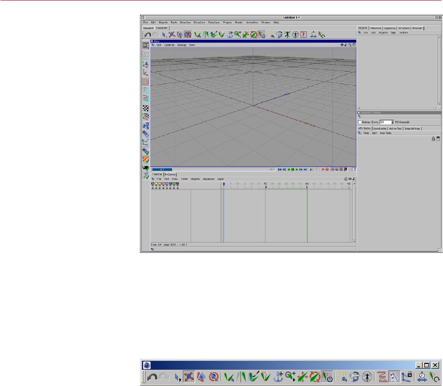
MOCCA MOCCA LAYOUT AND PALETTE 5
Reach MOCCA commands quickly and save time using the predened MOCCA layout
and MOCCA palette. The MOCCA palette is integrated automatically into the MOCCA
layout. On this palette you’ll nd commands and tools from the Plugins > MOCCA
sub-menu as well as some of the most commonly used CINEMA 4D tools: move, scale,
rotate and the selection tools.
To use the predened MOCCA layout, choose Window > Layout > Mocca.l4d. You
can, if you wish, create your own layout for MOCCA. For details on how to do this,
please see the Conguration chapter of your CINEMA 4D Reference Manual.
You can open the MOCCA palette
and integrate it anywhere in
the GUI.
If you want to open just the MOCCA palette rather than load the entire MOCCA
layout, choose Plugins > MOCCA > MOCCA Palette. The palette then appears as a
freestanding window, which you can integrate anywhere in the CINEMA 4D GUI. To
learn how to congure the GUI, please refer to the Conguration chapter of your
CINEMA 4D Reference Manual.
MOCCA
Layout
and
Palette
Although you can access
all of MOCCA’s commands
from menus, you may nd it
quicker to use the MOCCA
palette and MOCCA layout.

2 Introduction to IK
MOCCA INTRODUCTION TO IK 9
You have probably heard the term Inverse Kinematics (IK) before; it has become quite
a buzzword in the 3D world, particularly when it comes to character animation. The
main difference from the so-called Forward Kinematics (FK) is the direction in which
something is animated. Take an arm, for example.
Using FK, the arm would be animated from the shoulder downwards. This means that
you rst rotate the shoulder, then the upper arm, the lower arm, hand and nally the
ngers pointing to a specic location. The obvious disadvantage is the difculty of
trying to get the hand in a certain position in your 3D world, since any move of the
shoulder will require readjustments of all limbs that follow in the hierarchy. Having a
hand grab a cup of tea, lift it to the character’s mouth and place it back on the table
would involve a large number of rotations and adjustments, particularly because the
position and rotation of the cup and hand have to be synchronized at all times.
With Forward Kinematics (left),
each bone must be rotated in
order to move the arm. With
Inverse Kinematics (right), you
can move the hand freely and
the other bones in the arm will
move and rotate automatically
to ensure that the bones remain
connected to one another.
Inverse Kinematics helps you to
pose characters quickly.
Inverse Kinematics offers an elegant solution to this problem. As the name suggests,
the direction of the animation is inverted. This means that moving the hand will force
the other joints between hand and shoulder to reposition in order to remain in contact
with the hand. A simple expression could lock the hand to the position of the cup,
allowing you to animate just one object, the cup, instead of two.
Inverse Kinematics has been a key part of the application since CINEMA 4D XL R5.
MOCCA IK offers a completely new approach. Almost all possible movements are
handled via constraints. Imagine a constraint as a force that always tries to nd an
equilibrium with other such constraints, just like an array of magnets that levitate a
metal sphere within their common magnetic elds.
Introduction
to IK
MOCCA and Soft IK offer a
completely new approach for
animating characters. Almost all
possible movements are handled
via soft constraints. These enable
you to go beyond the world of
strict constraints.

10 INTRODUCTION TO IK MOCCA
The following example of earlier IK systems is familiar. You drag a bone target object
from one position to the next and the IK chain practically jumps into place. IK systems
that limit the freedom of rotation of each bone often create dead spaces. These,
sometimes large, spaces are created by overlapping rotation limits. The larger the
limits are for each bone, the bigger the dead zones. This can escalate to the point of
producing completely unmovable IK chains.
The new IK solution in MOCCA has been created with precisely this problem in mind.
By allowing the software to extend beyond these boundaries, it enables you to leave
behind the world of strict constraints.
How does this work?
The programming within Soft IK means that the more you stretch your constraints, the
more a dynamic counter-force will try to return the object to its initial rest position.
A basic example would be a comic character that grabs a heavy weight, which pulls
his arms and upper body to the oor. As soon as he lets go of the weights, the arms
will return to a more comfortable position, in other words, his rest position.
This animation is handled by what are called ‘tip effectors’ (control objects) that
attract the bones of a character. A lot of the work that needs to be done in character
animation involves a proper constraint setup, based on constraints for the angle
and position, which should facilitate animation later on. Just as in real life, these
constraints are soft. A constraint strength of 100% will not eliminate the other forces.
The object is still inuenced by all forces in the setup, making dead zones a thing of
the past. Careful placement and setup of these constraints will result in much more
elegant-looking animations that would otherwise be very difcult to achieve with
older IK solutions.
Some features in MOCCA might seem familiar, such as the Dynamics function in
Soft IK. However, MOCCA is not an addition to the CINEMA 4D Dynamics module
— it is an independent toolset in its own right. It has nothing to do with actual
dynamics, which are realistic simulations of physical events that give you enormous
control over all aspects of an environment. Naturally, those simulations also require
more processing power, the more realistic you want them to be. On the other hand,
MOCCA is a completely new technology, which emphasizes speed and reliability
above all else. Ultimately, it is the result that matters most.

3 MOCCA IK Tag
MOCCA MOCCA IK TAG 13
The MOCCA IK tag helps make CINEMA 4D’s standard bones more powerful. Once
the tag has been assigned you can make full use of MOCCA for optimal control over
your bones.
You can assign the MOCCA IK tag by clicking on the object with the right mouse
button in the object manager. Not only has the MOCCA IK tag’s functionality been
improved but it also offers several new visual aides in the Object manager. Hence the
look of your IK tag will be different depending on if you activate the Anchor option
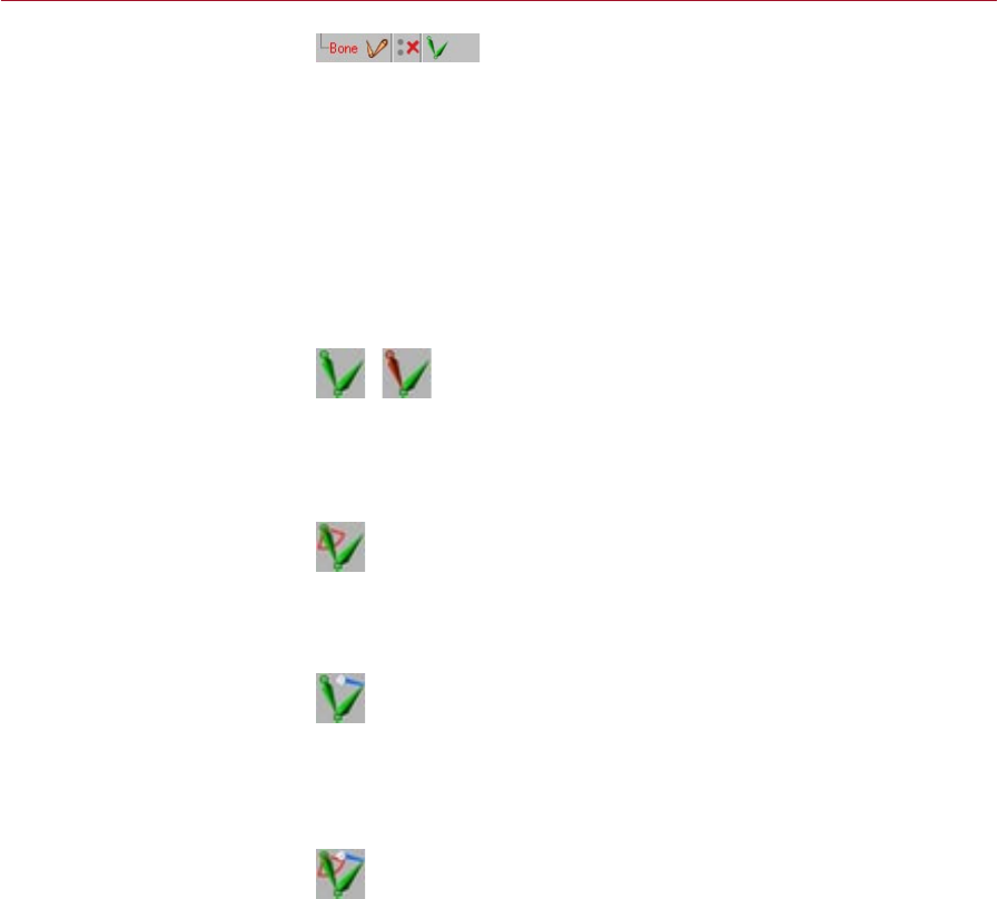
or if you add Limiters, for example. The MOCCA IK tag can look as follows:
Standard icon and with Anchor option
These are the standard icons after a MOCCA IK tag has been assigned (left) and
the icon after applying the Anchor option (right).
Once a Limiter has been applied
Once a Limiter has been applied to a bone the icon will look like this.
Once a Limiter has been adjusted
This icon will be used if the Limiter‘s values, within which the bones should move,
have been changed in the Attribute manager.
Limiters and altered values
And last but not least this is the icon that will be shown when Limiters as well as
altered values for Limiters in one MOCCA IK tag have been assigned.
MOCCA IK Tag
MOCCA IK tags add a great deal
of control to your bone setup.
In these pages you’ll nd a
description of each setting in the
MOCCA IK tag.
14 MOCCA IK TAG MOCCA
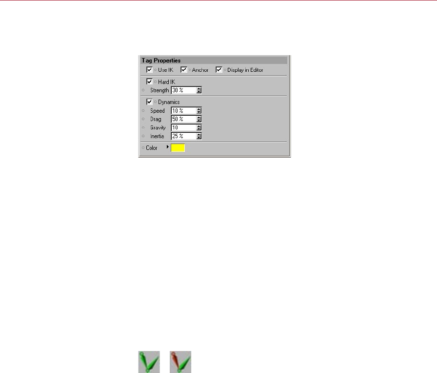
Attribute manager settings
Tag Properties
Use UK
This option activates or deactivates IK for the bone chain. The option can be found
within every MOCCA IK tag of the IK chain. Note that the entire chain is linked to this
command. Turning it off for one tag will deactivate it for the entire chain. The same
applies to turning it on again.
Anchor
An anchor is the root of any given chain. A classic anchor in a 3D character would
be the hips. Most of the time, this is the root element for the character bone setup.
Normally, you wouldn’t want the hips to jump out of place when dragging the goal
target of the left leg, thus twisting the entire character. Placing the root at a certain
point will tell the chain that the leg has to be held in place at its root, in this case
the hips.
The icon in the Object manager changes as soon as the Anchor option has been
enabled in the Object manager:
Anchor disabled (left) and
enabled (right).

MOCCA MOCCA IK TAG 15
Hard IK
This option is only available when Anchor is enabled.
This option lets you control the bone’s movement and behavior. MOCCA uses Soft IK
from the previous version by default to control bones. As the name suggests, Soft IK
is ideal for use on “soft” bones because it exhibits a certain dynamic of its own. This
makes it prefect for cartoon characters or body parts that require a softer movement.
Hard IK, on the other hand, is less dynamic in its movement but is therefore faster
and does not exhibit its own dynamics.
Strength
This option is only available when Anchor is enabled.
This parameter modies the strength with which the skeleton will be held together.
It affects all movements and a high value results in precise, but harder animation.
You’ll quickly notice how, as the strength increases, the distances between each
bone in a stretched chain become smaller. High values will take additional time to
calculate though.
Dynamics
This option is only available when Anchor is enabled.
The dynamics parameters modify the dynamic movements of the bone chain. The
dynamics settings affect an entire bone chain, whose root bone has this option
enabled. Since dynamics inuence the alignment of your chain, the effect becomes
more obvious if few constraints have been added. If you want to experiment with the
settings and get direct feedback, make sure you avoid setting constraints.
How do all these parameters interact?
There is no easy answer for this, since they affect each other. High Drag will cause
stiff joints, therefore limiting the effect of the other parameters. This makes drag an
ideal regulator for dynamics. On the other hand, Speed does not necessarily make
the movements of the chain faster. Test the different settings of the dynamics and
you’ll soon develop an intuitive understanding.
To switch dynamics on, enable the Dynamics option. You can then adjust the dynamics
of the bone chain using the following parameters.
16 MOCCA IK TAG MOCCA
Speed
This option is only available when Anchor is enabled.
Controls the speed at which the dynamic simulations are played back. The default
value of 10% initiates a slow reaction. Experiment with this setting. A small, light
character might move more quickly than a large, heavy one for example. The trunk
of an elephant would require slower movements and therefore lower values.
Drag
This option is only available when Anchor is enabled.
This parameter controls the resistance of the child bones toward the reaction to the
movements of the root bone. Imagine draining the lubricant from a joint mechanism
– the joint will become stiffer the more lubricant is removed. Similarly, the bones will
not move with the root as freely when using a higher percentage value. A word of
caution: Drag very much affects the other dynamic parameters and could seriously
dampen the whole dynamic movement.
Gravity
This option is only available when Anchor is enabled.
Gravity pulls the bones down,
in the direction of the world
system’s negative Y-axis.
This parameter denes the strength of gravity that acts upon the bones. Higher values
result in a stronger bending of the chain on the Y-axis, downwards. Here again, small
characters might require lower values than large, heavy ones.
MOCCA MOCCA IK TAG 17
Inertia
This option is only available when Anchor is enabled.
Inertia controls how much of a root bone’s movement is translated into torque for
its children. Torque is the force that causes rotation. Moving a bone chain around
will make torque affect the angle between each of the bones. Low values won’t
cause too much disruption in the chain, whereas high percentage values will jiggle
the chain more and more.
Color
This option is only available when Anchor is enabled.
Here you can set the color of the lines connecting the rst and last bones of your IK
chain as they are displayed in the viewport. The default color is yellow.
The lines connecting the rst and
last bones are displayed yellow
in the viewport by default.
IK <-> FK
One of MOCCA’s most powerful new features is the ability to seamlessly switch
between IK and FK animation. Until recently you had to base the way you animated
your character on how it’s rigging had been set up. The respective situation will
dictate whether you move a leg by positioning the foot using IK or simply rotate the
shinbone using FK. The problem we would encounter, though, is that a rig that has
been set up using IK would lose its control object associations if a single bone in the
hierarchy would be selected and rotated independent of its IK control object.
18 MOCCA IK TAG MOCCA
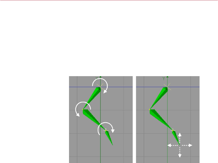
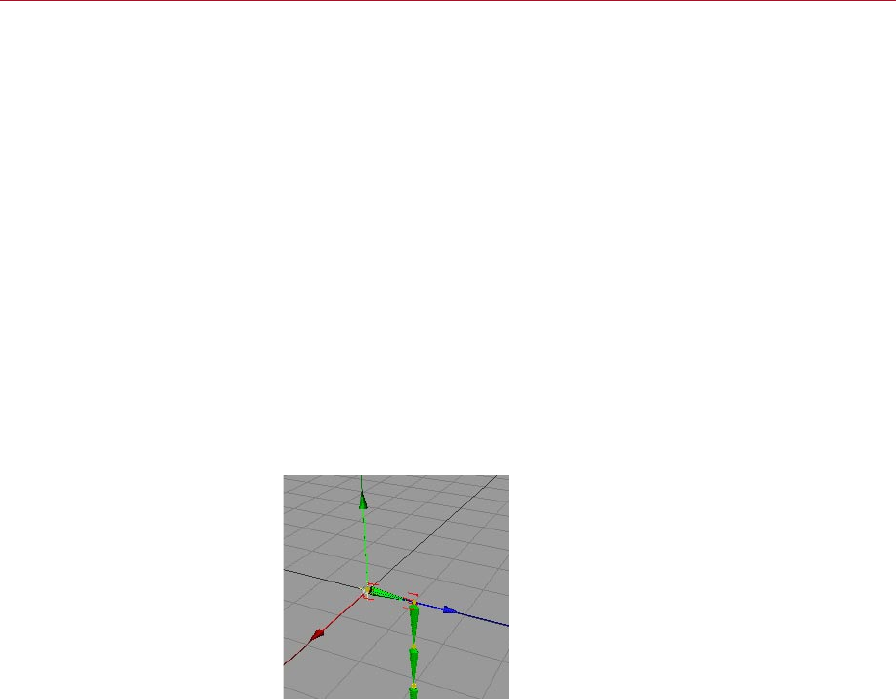
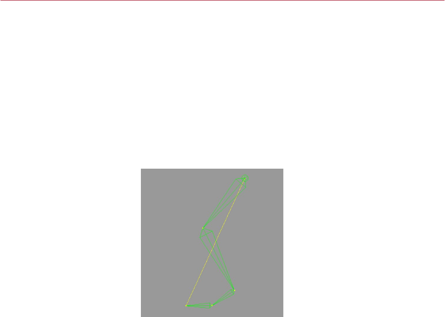
Let’s take a look at an example of this in the following images.
Three control objects assigned to
a typical bone setup for a foot.
The image shows a typical bone setup which will be controlled using IK. Three control
objects have been assigned for the foot (see blue arrows). Now the bone will be
bent to the rear.
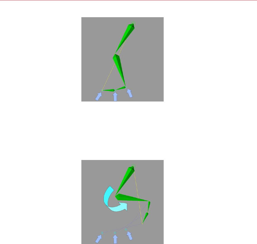
In the past one could only bend the leg by moving the control objects using IK.
If you were to bend the leg by rotating the shin bone using the rotate function, the
control objects would retain their positions and it would be practically impossible to
animate the leg further using IK (see following image).
With the shin rotated, further
animation of the leg using IK is
almost impossible.
MOCCA MOCCA IK TAG 19
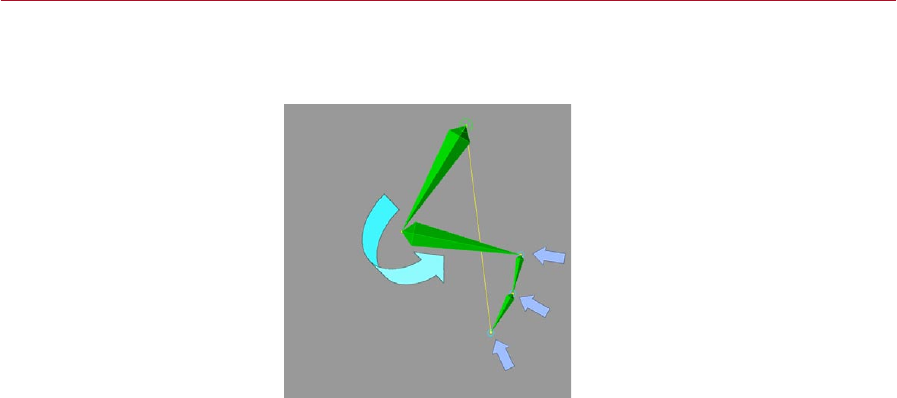
Now MOCCA lets you reach your goals any way you want. MOCCA will recognize
any control objects connected to your bones and move them with your FK rotation
(see image).
MOCCA can now move the
control objects with your FK
rotations.
Display In Editor
You can use the Display In Editor option to control the display of visual aids in the
viewport. For example, this allows you to have the connection between the rst and
last element in an IK chain displayed as a thin line. If you don’t want these visual aids
to be displayed, disable the option.

20 MOCCA IK TAG MOCCA
Constraint
The Constraint settings allow
you to control the bone chain
with other objects in the scene.
This page is shown only if Anchor is disabled on the Tag Properties page.
The Constraint settings dene the controls that force the IK chain into another form
or direction; they allow another object to be used to move the bone chain.
Here’s a more precise explanation: the goal constraint uses the origin of virtually any
object in the scene to enable you to force the IK chain towards the position of that
object, assuming that the other potential constraints in your scene do not counteract
this. Since the IK chains follow the goal constraints, the bone angles will also be
modied. Therefore this is useful for setting up different poses, since all you have to
do is move about individual goal constraint objects.
If you want the chain to point at a constraint, you will have to work with a tip effector.
In other words, a null will be placed at the end of a chain and linked to a goal constraint.
This works similarly when you use the Set Up IK Chain command.
Goal
Drag an object from the Object manager into this box. This object will then serve as a
goal constraint. You can remove an object from this box by clicking the small triangle
next to it and choosing Clear from the drop-down list that appears.
Add buttons
These buttons allow you to add a root goal or up vector.
Strength
Imagine setting the ‘muscular’ force at which the constraint pulls on the bone. If you
have used several constraints with different strengths in your scene, the ones with
the higher values will be preferred by the chain.
MOCCA MOCCA IK TAG 21
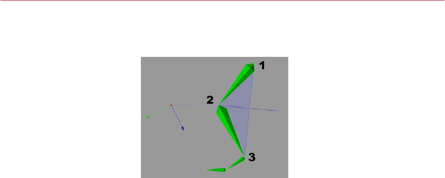
Use As Pole
You can very easily obtain control over unwanted bone rotation using the option
Use As Pole.
Pole vectors represent the planar
surface between these three
points.
Pole vectors represent a planar surface between the following three points (see
image) of a pair of bones:
1 The beginning of the rst bone.
2. The end of the rst and beginning of the second bone.
3. Around the end of the second bone.
The result is that the bones cannot be rotated independently of each other; the
rotation of the two bones is now controlled by the pole vector.
Use As Pole only has an effect when used with a root goal; the option has
no effect when used with a tip goal. This is down to the way that goals are
created — root goals are attached directly to the bone they should affect,
whereas tip goals are assigned an extra Null object.
22 MOCCA IK TAG MOCCA
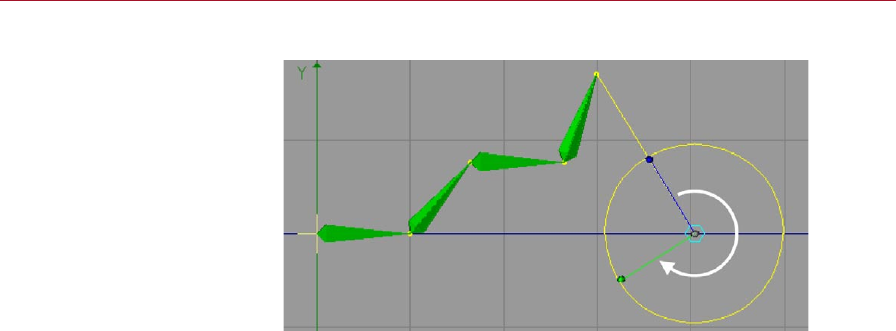
Distance
Chopsticks enable you to rotate
the chain around the value of
the Distance setting.
The behavior of the Distance setting depends on the Chop Sticks setting. If Chop
Sticks is enabled, this parameter sets the length of the chopsticks (see below). If
Chop Sticks is disabled, it denes the distance between the tip effector and tip goal
constraint within the bone chain.
Chop Sticks
This setting, when enabled, allows you to move your character as if the joints were
connected to sticks, like shadow puppets. When using chopsticks you can pivot
around a point connected to an arm, just like the wheels of a locomotive train. Set
the length of the chopsticks using Distance (see above).
Set
This button is only available when the Use IK option (on the Tag Properties tab) is
disabled. When using chopsticks the Distance parameter allows you to change the
distance from the control object to the bone. To do this, switch off the MOCCA IK,
move the control object to the desired position, click Set and switch the MOCCA IK back
on. The new value for the distance will appear in the Distance box automatically.
Up Vector
Here you can drag and drop an object from the Object manager. That object will
then be used as an Up Vector object. Delete the Up Vector by clicking on the small
triangle next to it and selecting Clear.
Up Vector constraints let you orientate the axis of a bone towards a control object.
In this case, not the position, but the angle of the bone will be modied.

MOCCA MOCCA IK TAG 23
There are cases in which the chain may have various alternative ways of conforming
to all the constraints. Take a leg, consisting of an upper and lower thigh. The upper
thigh is parented to a root bone and the lower thigh has a tip effector, which is linked
to a goal constraint. If you move the goal constraint, the chain has no clear way of
knowing how the angles behave between root and effector. On longer chains this
can sometimes cause chaotic twisting of the IK chain. Obviously you’ll quickly notice
this when the character’s skin is xed to the bones, as it will twist with the chain.
The Up Vector gives you a chance to prevent this from happening by constraining
the orientation of the bone axis to the Up Vector constraint.
Strength
This value denes the strength at which the xed axis will be pulled towards the Up
Vector constraint. A value of 0% will completely ignore the constraint. A value of
100% practically nails the axis to the constraint. A value of 50% orientates the bone
with a bit of lag, just like a magnetic compass needle adjusting towards true North
after the compass has been moved.
Axis
Here you can choose between the various axes that point towards the Up Vector. The
options are Y, -Y and X, -X. If you choose -Y, the Y-axis will point in the exactly opposite
direction of the Up Vector, since an object axis arrow always points positively.
24 MOCCA IK TAG MOCCA
Limit
Limits dene the position and
rotation spaces that your chain
may not leave. The only way for
the chain to break away from
these limits is to use strong
constraints that try to pull the
chain through the prohibited
spaces. You could say that a lot
of strength is necessary to pull
the joints beyond their limits.
This page is shown only if Anchor is disabled on the Tag Properties page.
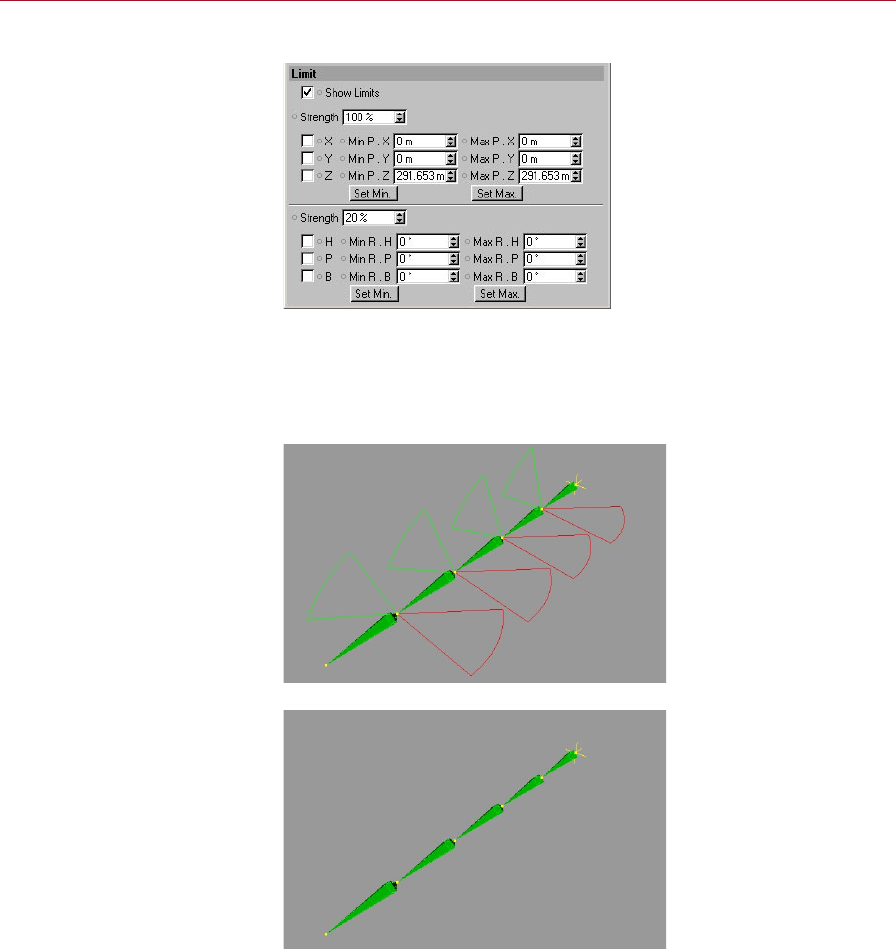
Show Limits
Enable this option to switch on the display of position and rotation limits in the
viewport.
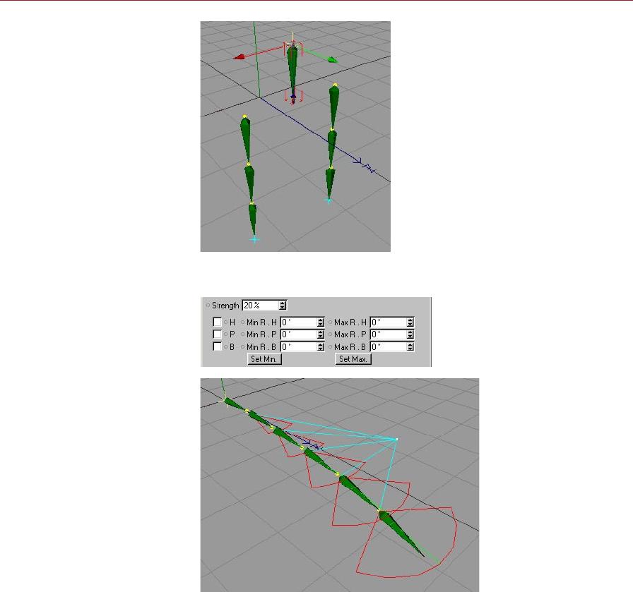
Rotation limits displayed in the
viewport (Show Limits enabled).
Show Limits disabled.
MOCCA MOCCA IK TAG 25
Strength
This denes the strength of the position (X, Y, Z) or rotation (H, P, B) limits.
Be careful about using too high a Strength value, especially for a rotation limit. If
you’re using rotation limits on all bones, the limits might start working against each
other, causing the chain to twitch wildly. Therefore only increase the rotation limit
strength a little at a time.
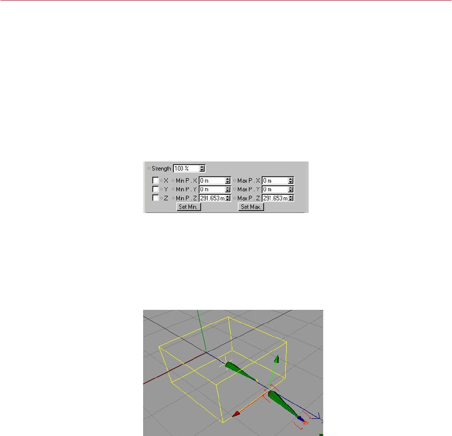
Position limit settings (X, Y, Z)
Position limits enable you to offset bones in relation to their parent bone.
This can be useful where joints fork off, such as at the hips or the shoulders.
Remember to consider the equilibrium between the position limits and the
rest position of the bone structure.
Position limits give the bones boundaries that bind them with a given strength. The
Min and Max settings enable you to dene a point, area or space that is displayed as
yellow lines in and about the bone.
If you enable the X limits, say, and set a Min value of -50 and a Max value of +50, you
will notice a yellow line extending from both sides of the bone parent. If you want
to dene an area, you will have to use an additional axis (Y or Z). Using a third axis
will create a volume in the form of a box.
The box shape represents three
position limit axes.
All forces of the Soft IK limits are not static but behave dynamically. Imagine using a
rest position that is outside the space of your dened limits. In that case, the system
will try to nd a balance between both these forces, according to the strength values
used, and position the bones somewhere between both of them.
26 MOCCA IK TAG MOCCA
Using position limits, you can
construct the chain with an
offset between the bones.
Rotation limit settings (H, P, B)
A bone chain, set up with
heading rotation limits and Up
Vectors.
This option enables you to conne the freedom of rotation of the joints in the chain.
The Min and Max entry elds next to R.H, R.P, R.B dene the rotation limits for
heading, pitch and bank. This is where you dene the angles within which the bones
can move freely. In the viewport, the limits are represented as pie sections, in red,
green and blue respectively.

MOCCA MOCCA IK TAG 27
The limits will only be active when they are enabled by checking the relevant boxes.
Otherwise the allowed movement or rotation will be unlimited.
If you want to prevent a change of heading, just enable the H limits. The default values
of 0 for Min and Max tell the bone to move 0 degrees on heading and it therefore
can only be pulled in that direction by increasing Strength.
28 MOCCA IK TAG MOCCA
Rest
Using the parameters on this
page, you can control the rest
position and rotation of each
joint to which the character will
return when the constraints are
either inactive or reduced.
This page is shown only if Anchor is disabled on the Tag Properties page.
These settings dene a rest position and rotation — a space to which the IK chain
will return when the other constraints are inactive.
Imagine a character that is pulled with great force from her original position. The
acceleration will cause her to stretch in the opposite direction of the pull. As soon
as the acceleration reduces, she will try to assume her initial pose (provided that no
other constraints prevent her from doing so). The Rest settings allow you to dene
this initial pose.
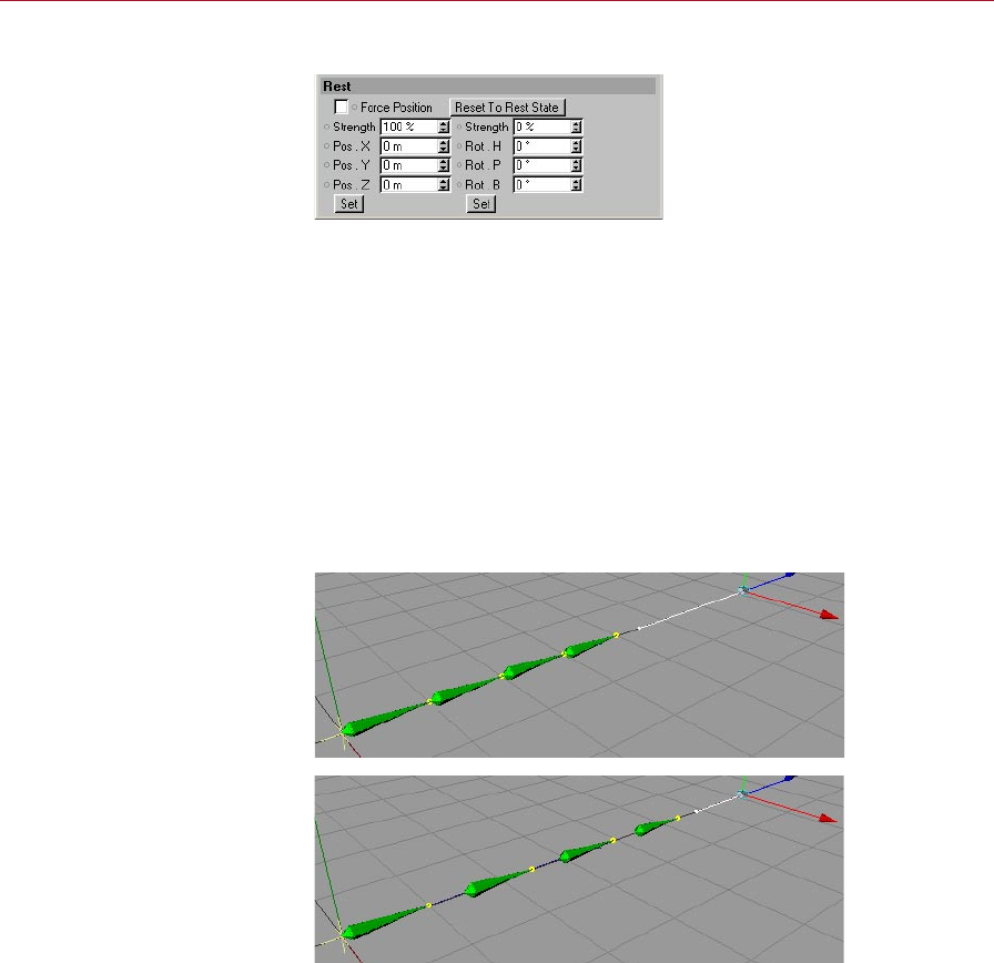
Force Position
If this option is enabled, the bones remain in contact, i.e. there will be no gaps
between the bones, even if the tip effector has not been reached.
Force Position enabled.
Although the tip effector has not
been reached, there are no gaps
between the bones.
Force Position disabled. The
bones are stretched apart as
they try to reach the tip effector.

MOCCA MOCCA IK TAG 29
Reset To Rest State
Clicking this button will cause the IK chain to return to its predened rest position
and rest rotation. Since you will probably have other active constraints in the scene
preventing this, the Use IK option will automatically be turned off at the root bone.
Strength, Pos X, Pos Y, Pos Z, Set
These values dene the initial rest position for the IK chain. You can set them by
moving the chain into the position you want and pressing Set or the Set Chain Rest
Position icon on the MOCCA palette.
The Strength setting regulates the strength at which the rest position will interact
with other forces. The higher the value, the greater the inuence of the rest position
on the character.
Strength, Rot H, Rot P, Rot B, Set
These settings dene the initial rest rotation of the IK chain when no other constraints
are active. You can set them by arranging the chain as you want and pressing Set or
the Set Chain Rest Rotation icon on the MOCCA palette.
If you have set a rest position for the arm, which also has a tip effector connected to
it, the chain will try to nd a common denominator for both forces. If you try to pull
the arm away from its rest position with a goal constraint, you will have to use more
force than if you hadn’t used rest rotation. Eliminating the goal constraint will cause
the chain to return to its rest rotation immediately. This form of constraint should be
preferred to the classical rotation limit, since it allows for more natural movements
with less strict prohibited spaces to which the chain can move.
The Strength setting controls the strength at which the rest rotation interacts with
other forces. The higher the value, the greater the inuence of the rest rotation on
the character.

30 MOCCA IK TAG MOCCA
MOCCA IK
Commands
These commands help you to
create MOCCA IK chains and
fully automate your setup.
When setting up a Soft IK chain, you’ll need to use the MOCCA IK commands. Using
these, you can add anchors, goals and more and save time with the Setup IK Chain
tool, which fully automates the Soft IK setup for simple bone chains. You’ll nd these
commands on the Plugins > MOCCA sub-menu as well as on the MOCCA palette.
Setup IK Chain
With a bone chain selected, choosing this icon from the MOCCA palette, or from the
MOCCA Plugin menu, will add a MOCCA IK tag to the root bone, with the Anchor
option enabled. The child bones will also receive a MOCCA IK tag, and a tip effector
will be added to the last bone. The effector is linked to a goal constraint parented to
the root bone of the chain. This will set up your IK chain at the press of a button.
Add Anchor
This command adds an anchor to the selected bone.
Add Root Goal
The root of an individual bone is also where its object axis is placed. This command
puts an effector at the bone’s origin. The effector is linked to a goal constraint, which
is parented to the chain’s root bone. It will automatically receive the sufx ‘Root Goal’.
Moving this goal object will give you direct control over the position of the joint.
Add Tip Goal
This command puts an effector at the tip of the bone. The effector is linked to a goal
constraint, which is parented to the chain’s root bone. It will automatically receive
the sufx ‘Tip Goal’. Moving this object gives you inuence over the direction of the
Z-axis for the respective bone.

MOCCA MOCCA IK TAG 31
Add Up Vector
By selecting this, an Up Vector will be added to the selected bone, constraining its
Y-axis orientation towards a control object placed above it. This object will adopt the
name of the bone along with the sufx ‘Up’. Adding this to the bone called ‘Upper
thigh’ for example, would result in an Up Vector control object with the name ‘Upper
thigh.Up’. If you want to constrain the X-axis of the bone, select its MOCCA IK tag
and, on the Attribute manager’s Constraint page, choose a different axis from the
Axis drop-down list.
Set Chain Rest Position
This command sets the local positions (i.e. the position relative to the immediate
parent object) of all objects in the IK chain as the rest position in the MOCCA IK tag.
The command gives you an easy way to dene rest poses. See also the description
of the Rest tab earlier in this chapter.
Set Chain Rest Rotation
This command sets the rest rotation of all bones in the IK chain that have MOCCA IK
tags. See also the description of the Rest tab earlier in this chapter.
Auto Redraw
You’ve probably noticed that a great way to test the movements of your IK chain,
especially in combination with the Dynamics function of Soft IK, is to press the Play
button (or hotkey: F8).
However, since the Soft IK chain works with soft constraints, the animation reacts to
a number of different factors. This means that the animation might not be nished
at the last frame. The joints might still come to rest slowly. To display those changes
without playing back the entire animation, you can use the Auto Redraw command
in MOCCA. Once enabled, it will constantly update the calculations, displaying the
reactions of your IK chain immediately.
When choosing this command, the dialog will enable you to set the redraw step in
milliseconds. If you have activated the MOCCA layout by choosing Window > Layout
> Mocca.l4d, you will nd the dialog already below the Object manager. Normally,
the animation will be played back in realtime; for PAL systems, that means 25 frames
per second, for NTSC it is 30. Each frame will therefore be displayed for 1/25 or 1/30
of a second before it is updated again.

32 MOCCA IK TAG MOCCA
The default value of 50 milliseconds (20 frames per second) is quite enough to make
the movements smooth. Note that each redraw costs processing power. Higher redraw
times will cost more processor time. 50 milliseconds is a good average value. Very
complex scenes may, however, require faster redraw times.
Auto IK-Lock
The Auto IK-Lock option is closely related to the ability in MOCCA to seamlessly
switch between IK and FK when you are animating. If the option is enabled, when
you animate the tag’s bone with FK, all of the bone’s control objects such as goals
and up vectors will move along with the bone automatically. If the option is disabled,
MOCCA will still rotate the bone but it will ignore the control objects.

4 Bone Tool
MOCCA BONE TOOL 35
Bone Tool
With the bone tool, you can
create and adjust bone chains
quickly and easily, using a
variety of tools.
The bone tool is the tool of choice for preparing your virtual characters
for that big Hollywood role. MOCCA was given an extra tool to let you
put together your 3D star’s skeleton quickly and intuitively and easily
position them in your scene. If you make a change to a bone, changes to
its dependent bones will be made accordingly. It has never been easier to edit bones
in CINEMA 4D.
Selecting and deselecting the bone tool
You’re probably wondering why we have a special section just for selecting a tool,
even though its so obvious. Well, this section is less about actually selecting the tool
and more about the effect that selecting this tool has, i.e. what happens to the bones
when you select this tool or switch from it to another tool.
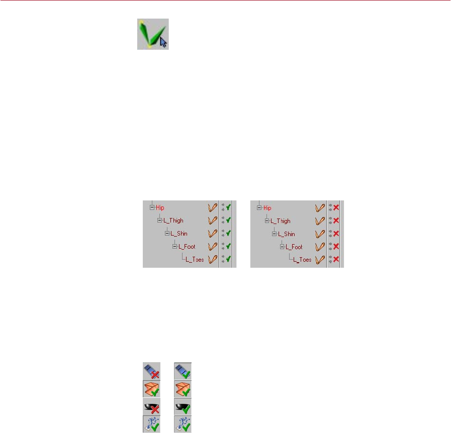
Selecting the bone tool is like beginning a phase – the bone editing phase. All bones
in the scene are deactivated when the bone tool is selected. The red check marks in
the object manager will turn from green to red.
Bones in the Object manager
before selecting the bone tool
(left) and after (right).
In addition, the bones will be reset to their initial rest position and will lose their
deformation effect on the mesh.
This effect is similar to the Reset Bones command in the Object manager.
A further effect of selecting the bone tool is that the Use Animation and Use
Expressions options on the left toolbar will be disabled. This will prevent the bones
from being affected by animation keys or expressions.
When you select the bone
tool, the Use Animation and
Use Expressions options in the
left toolbar will be disabled
automatically (left). They will
become active again (right)
as soon as you change to a
different tool.
36 BONE TOOL MOCCA
As soon as you switch from the bone tool to another tool such as rotate, the bones
will be reactivated automatically and the mesh will be inuenced by the bones once
again. The Use Animation and Use Expressions options will also be activated again.
If, before using the bone tool, you’ve edited the bones or recorded keys for them
and so on, then when you switch from the bone tool to another tool the bones will
jump back to the positions and rotations they had at the time when you selected the
bone tool. In other words, you’ll lose any position and rotation changes that you’ve
applied to the bones while the bone tool was selected.
Although selecting the bone tool can be compared to the Reset Bones command,
deselecting the bone tool is not, in turn, similar to the Fix Bones command.
The difference is that Fix Bones xes the bones to their present position and rotation
and denes this as the new initial state, whereas deselecting the bone tool does not
x the bones — it simply activates their deformation properties.
Therefore we recommend that you edit the bones using the bone tool before applying
expressions and so on. If you must make changes to the bones later using the bone
tool, before you deselect the bone tool, choose the Fix Bones command to x the
bones in their new position and rotation.
Attribute manager settings
The various tools are available
from the Attribute manager.
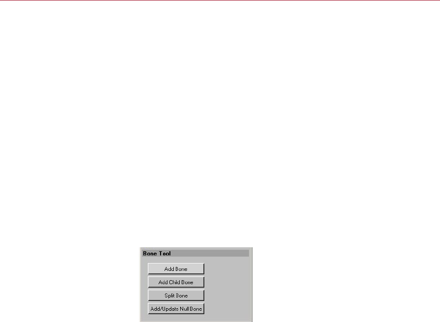
Add Bone
This command adds a bone to the scene. The bone has a default length of 100 m
and points in the direction of the Z-axis. Pressing the button twice, however, does
not add a child bone to the previous bone but another independent bone, with the
same parameters as the rst one. If you want to add a child bone, use the Add Child
Bone button instead.
Add Child Bone
Clicking this button will simply add a child bone to the chain; this is placed at the
tip of the previously created bone or child bone. It adopts the parameters of the
preceding bone, as well as its name.
MOCCA BONE TOOL 37
Continuously using this command will add a new child bone for every push of the
button, quickly creating an entire chain.
You can also add child bones by Ctrl-clicking in the viewport, in which case a new
bone is added to the chain between the tip of the last bone and the position of the
mouse pointer. If you look closely, you’ll notice a yellow dot at the origin of each
bone. These are handles. Drag them to scale and rotate the bones interactively in
the viewport.
Split Bone
This will split the bone in half. Together, the newly created bones will have the same
length as the original. The overall length of the chain therefore remains unchanged.
You can also split bones interactively in the viewport. While pressing the Shift key
simply click on the bone at the point at which you want to split it.
Use this command before setting up Soft IK, since the Setup IK Chain command will
also set the rest position of the bones. If you then split the bone, a new bone with
half the length of the original will be placed at the previous origin. The other new
bone will also be shorter but cannot reach the tip of the preceding bone, since the
old rest position has also been copied. This would lead to gaps in the IK chain.
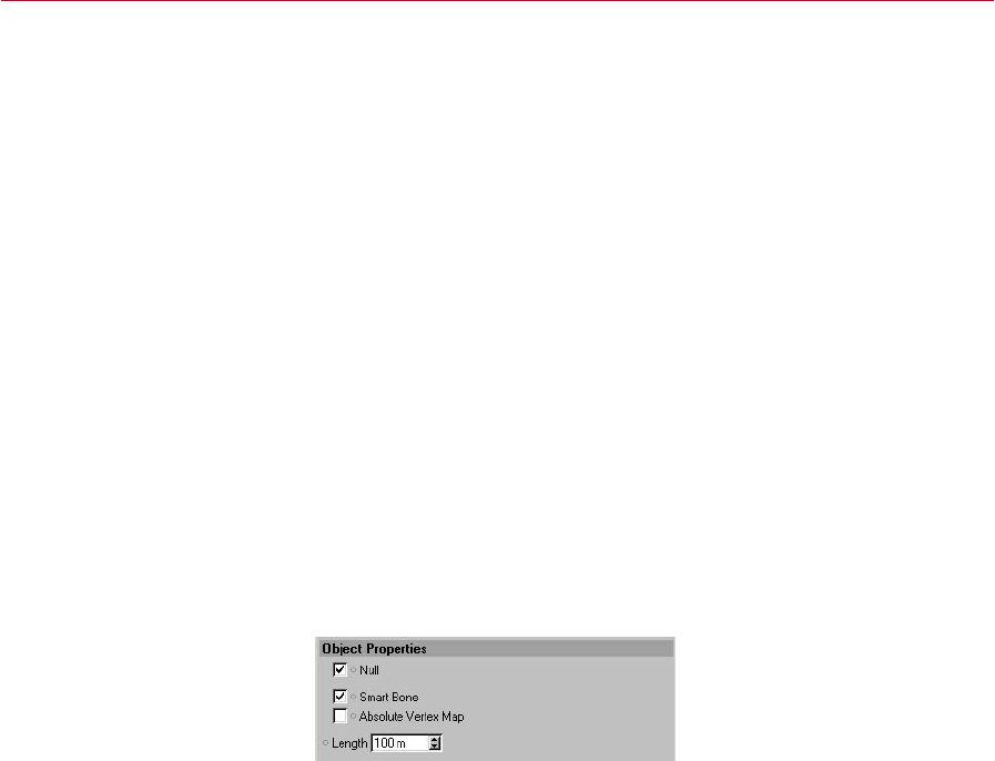
Add/Update Null Bone
A Null bone is a bone without inuence on the geometry of the object to which it
is assigned. In other words, it is a bone with a strength of 0% and a length of 0 m
— literally null.
The Attribute manager settings
for a Null bone.
Bones, just like any other object in a hierarchy, always work with the information of
their parent object, such as its limits or positions. Null bones offer the benet of not
affecting the geometry and can therefore serve as a master system.
So why not use a normal Null object instead? The answer is simple: a bone chain
does not allow other objects (such as the normal Null object) to penetrate its
hierarchy. Otherwise, the bones might no longer be xed and results would be quite
unexpected.
The Add/Update Null Bone command adopts the rotation and position of and is
placed at the origin of the selected bone. The rotation of the selected bone is cleared.
The great advantage is that you can easily set rotation limits for non-rotated bones
without having to do the math for each of them.

38 BONE TOOL MOCCA
Use this command before Setup IK Chain, since the latter will x the rest position of
the bones. If the Null bone is added later on, the following bone cannot be placed
at the tip of the shorter null bone, because it inherits the rest position. The chain
would be elongated.

5 Bone Mirror Tool

MOCCA BONE MIRROR TOOL 41
Bone Mirror
With this tool you can mirror
individual bones and entire
chains including tags, Claude
Bonet maps and much more.
The bone mirror tool is a powerful accessory that can speed up your work
with bones by mirroring not only the bones but also tags, constraints,
selections and more. To select the bone mirror tool, choose Plugins >
MOCCA > Bone Mirror or select the Bone Mirror icon from the MOCCA
palette. In both cases, this opens the Bone Mirror dialog, from where you can set up
the operation of the tool, before clicking the Mirror button to make the changes.
The bone mirror tool mirrors only the bones and the Null objects within the
setup (such as nulls for root goals), NOT geometry (meaning 3D volumes). If
you want to mirror geometry, use the Mirror tool from the Structure menu.
Since the Bone Mirror tool was developed primarily for use with Soft IK
it does not support other functions such as IK expressions or XPresso
expressions.
Before using the bone mirror
tool (left) and after (right).

42 BONE MIRROR TOOL MOCCA
Attribute manager settings
Plane
This is where you select the plane onto which the setup is mirrored. Imagine putting
half an orange onto a mirror, open side facing the mirror. The half orange suddenly
appears like a complete one. The mirror is the equivalent of the tool’s plane that you
choose from this drop-down list.
Origin
The Origin setting denes a point through which the Plane should pass, thus dening
the mirror’s position. Choose one of the following settings.
Selected
This will mirror the selected bone with the mirror plane passing through its object
axis. The rotation of the axis will be ignored, since the bone mirror tool always
mirrors parallel to the plane that you have chosen.
Parent
The setup will be mirrored according to the position of the axis of the selected
bone’s parent. Again, the rotation of the axis will be ignored, since the bone mirror
tool always mirrors parallel to the plane that you have chosen.
Top Most
In this case, the root bone sets the origin of the mirror. Here too, only the mirror
plane is of importance.
World
If you choose the World setting, the origin of the world coordinates will be used,
regardless of the rotation of origin.

MOCCA BONE MIRROR TOOL 43
Auto Find Center, Match Search
The Auto Find Center option is designed to help you mirror Claude Bonet maps, point
and polygon selections, as well as vertex maps. Imagine having built a character and
set up half of it with bones. You might also have set the range of inuence of some
of the bones with the Claude Bonet tool. Naturally, you’ll want the bone mirror tool
to copy those weights properly to the other side, too.
If you disable the Auto Find Center option, the object axis of the bone setup will be
used instead. The object axis isn’t necessarily at the center of your character’s points,
though. Enabling the option will nd the center of the points, which can create very
accurate results in symmetrical models.
The Match Search box is where you set an amount of tolerance with which the bone
mirror tool will compensate for irregularities within the model. If the bone mirror tool
does not nd exactly the same corresponding points on the other side of the setup, it
will search for them within the radius that you can set. You should experiment with
this setting. Very small values tend to produce unconvincing results.
Sufx
Here you can set a name sufx that is added to the mirrored elements. This serves for
organizational purposes, avoiding confusion between the various resulting bones.
If you are mirroring the left half of the character, you might set the sufx to ‘_R’. An
upper thigh named ‘ThighUp’ would, after mirroring, create a bone with the name
‘[ThighUp_R]’ on the right side.
Prex
This is where you can set a prex to be added in front of the mirrored bones. Taking
the previous example (see ‘Sufx’, above), setting the prex to ‘R_’ will cause the
right side of the upper thigh to be named ‘R_ThighUp’ after mirroring.
Replace ... With
These settings enable you to rename a bone while mirroring. For example, if you have
already named a left upper thigh ‘[ThighUp_L]’, it would make little sense to leave
‘_L’ in the name of the right side. Simply type _L into the Replace box and _R into the
With box. The mirrored bone will automatically be named ‘[ThighUp_R]’.
Clone Tags
You can also mirror all the tags assigned to a bone element by enabling this option.
Note that the Mirror Constraints and Mirror Inuences options are available only
when Clone Tags is enabled.

44 BONE MIRROR TOOL MOCCA
Clone Animation
If this option is enabled, the chain’s existing animation tracks are cloned.
Mirror Children
When enabled, this option will mirror the children of the selected bone, as well as any
control objects. If the option is disabled, only the selected bone will be mirrored.
Mirror Constraints
If this option is enabled, existing Restriction tags and the constraints dened in the
Attribute manager will be mirrored as well.
These restrictions are used to control which part of the body the bone may deform.
Even combined vertex maps with parented polygon models can be mirrored,
despite the fact that the vertex map is not assigned to the bone, but to the Polygon
object above it. The only necessary condition is that the Mirror Inuences option is
enabled.
Mirror Inuences
When enabled, this option will mirror all inuences a bone may have on a model.
These inuences can refer to Restriction tags assigned to point or polygon selections
as well as to vertex maps. This option is especially useful when mirroring Claude
Bonet weighting.
Mirror
Click this button to apply the Mirror tool to the selected bones.

6 Claude Bonet Tool

MOCCA CLAUDE BONET TOOL 47
Claude
Bonet Tool
The process of weighting bones is
quick and easy with this tool.
It enables you to set inuences
and assign them to bones at the
same time.
The Claude Bonet tool takes its name from the word ‘bone’ and from the
name of the leading exponent of impressionism, Claude Monet. Before
we explain what the Claude Bonet tool does, some explanation of bone
weighting is in order. Bones are deformers. In other words, bones are
objects that have no geometry themselves but are used to deform volumes (e.g.
the esh around them). Usually, a single bone won’t be enough to set up a realistic
skeleton. Instead you’ll probably use several complete chains, where each bone has
a function.
To use the bones efciently within the chain, you’ll have to assign separate parts
of the geometry to each bone, to avoid having the foot bones curl the ears of the
character, for example. This process is called ‘weighting’.
In earlier versions of CINEMA 4D, this weighting was achieved using traditional vertex
map weighting tools. Back then, you assigned weighting to points and linked them
to the bones via Restriction tags. You can still do this, but there is an easier way.
Claude Bonet makes this process far simpler by enabling you to set inuences and
assign them to bones simultaneously and, as its name suggests, you paint these
weightings onto the bone.
To select the Claude Bonet tool, choose Plugins > MOCCA > Claude Bonet or click
the Claude Bonet icon on the MOCCA palette.
The settings for the tool will then appear in the Attribute manager.
Once you have adjusted the settings as described below, just select a bone and ‘paint’
the weighting onto the bone in the viewport, using the mouse.
48 CLAUDE BONET TOOL MOCCA
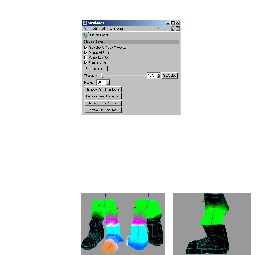
Attribute manager settings
In the Attribute manager,
you’ll nd all the commands
and options that are needed to
weight the bones.
Only Modify Visible Elements
If this option is enabled, you can paint visible elements only. Invisible elements are
ignored.
Display All Bones
When enabled, this option will display the inuences of all bones on the geometry,
in the selected chain. What you’ll see is the color display of the existing Claude Bonet
weighting range. When adjusting the weighting of a single bone, we recommend
disabling this option. Inuences might overlap near their borders, making it difcult
to judge a single bone’s weighting.
Left: the left leg has been
weighted using the Claude
Bonet tool with Display All
Bones enabled.
Right: Display All Bones
disabled.
MOCCA CLAUDE BONET TOOL 49
Paint Absolute
The links between the bones and the individual points in the mesh will be saved by
Claude Bonet as weighting information within the points themselves. Normally, if
you paint weighting with a strength of 20%, for example, each brush stroke will
add another 20% to the area. By holding down the Ctrl key while you paint, you can
erase the weights.
Paint Absolute will disable the above behavior. You’ll then paint with the absolute
Strength value only.
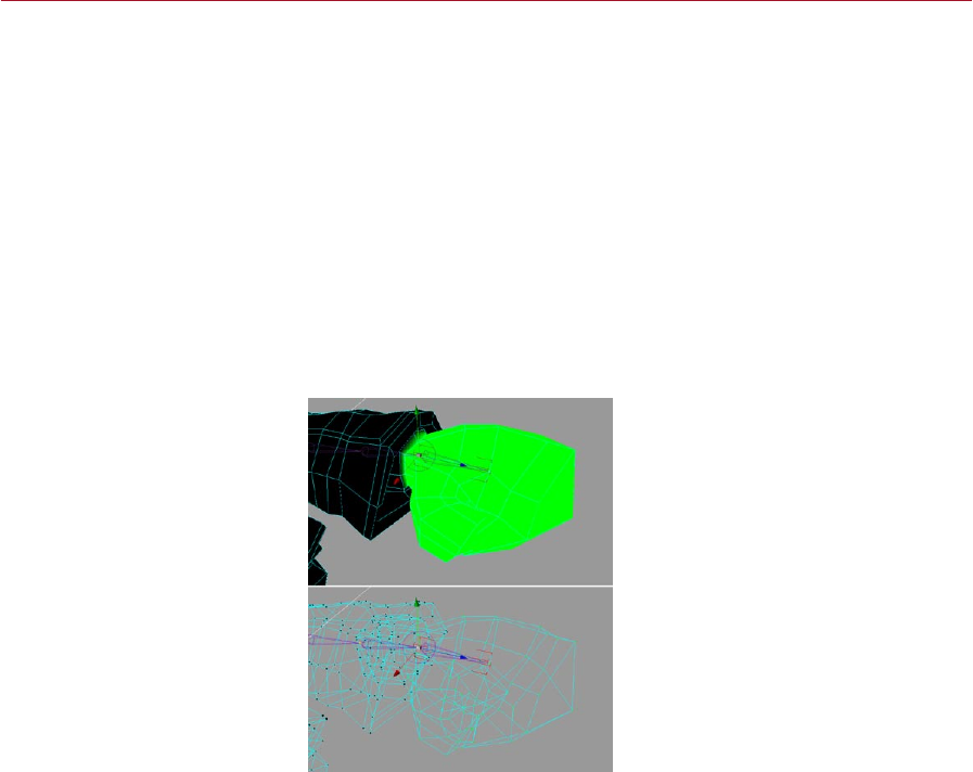
Force Shading
Normally, if you paint the weighting in, say, the Lines display mode, it can be difcult
to weight the bones by eye. At best the only weighting information you’ll see in
the viewport will be colored lines and points. To make your work easier, enable this
option. Quick Shading will then be used.
Force Shading enabled (top) and
disabled (bottom).

50 CLAUDE BONET TOOL MOCCA
Set Reference
With this command, you can
apply the same Claude Bonet
weight to multiple bones. This
helps you to quickly set the
weighting for similar bones such
as the nger bones of a hand.
It’s not absolutely necessary to assign all joints of a bone chain a separate weighting
for the mesh. Particularly in areas where a lot of bones control a small section, such
as hands, it may be easier to simply apply the same Claude Bonet weights to all
ngers. In this case, you can set a reference weight for the rst nger and reuse it
for the following ngers.
This is precisely what Set Reference is implemented for. Select a bone and click this
button. If you haven’t set any weights yet, the button will have no effect. Otherwise,
a list will pop up; choose the bone whose weighting information you want to apply
to the selected bone and click OK.
Strength
This is where you set the strength with which you paint. A value of 50%, for example,
would allow the bone to have limited inuence on the mesh. The strength is added
relatively; if you paint weighting with a strength of 20%, for example, each brush
stroke will add another 20% to the area. Enabling the Paint Absolute option turns off
this relative mode and allows you to paint with an absolute Strength value.
By holding down the Ctrl key while you paint, you can erase the weighting.
Set Value
This button sets the current weighting strength for the selected bone across the entire
area of the assigned geometry. If you select a character’s hip bone, for example,
dene a strength of 100% and click Set Value, the bone would have full inuence
over the entire geometry of the volume. This is a quick way of painting the weights
across the whole chain.
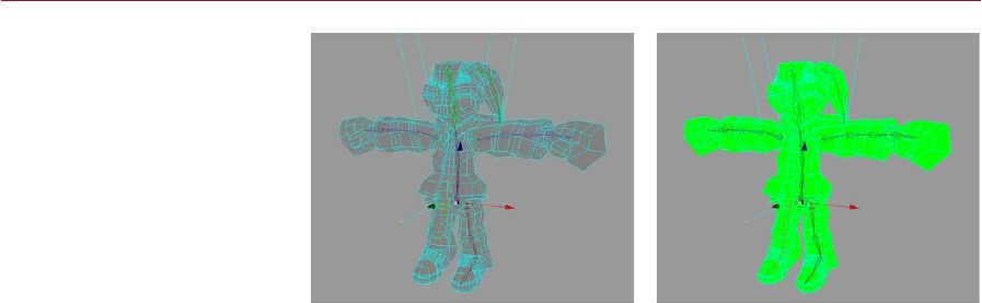
MOCCA CLAUDE BONET TOOL 51
Before using Set Value (left) and
after (right) with Strength set
to 100%.
Radius
The Radius denes the size of the brush with which you paint the weights. Experiment
with the radius.
Remove Paint (This Bone)
Erases the weighting of the selected bone. You can use this function if the weighting
is bad and you want to start again instead of reworking the bad map.
Remove Paint (Hierarchy)
Removes the weighting of the selected bone hierarchy, from the active bone down
to the last bone of the chain. If you have to completely rebuild and re-weight a
character’s arm, for example, it can make sense to keep the bones and just completely
reapply the weighting.
Remove Paint (Scene)
Removes all weighting for the entire scene. This can be useful if you discover you have
painted the character incorrectly and would rather paint it again from the beginning,
or if you want to edit the character entirely including new setups.

52 CLAUDE BONET TOOL MOCCA
Further usage advice
When weighting bones with Claude Bonet it is important to know which of the three
possible bone parameters you are working with:
1. Smart Bone disabled.
2. Smart Bone enabled, Absolute Vertex Map disabled.
3. Smart Bone enabled, Absolute Vertex Map enabled.
Each of these properties requires a different method of application of the Claude
Bonet tool because each property uses a different algorithm to deform the mesh
with the bones.
1. Smart Bones disabled
When using bones in the classic CINEMA 4D style (the Smart Bone option was rst
added in version 8.5) it is important to know that every bone will inuence EVERY
point of an object even WITHOUT application of the Claude Bonet tool. Therefore
if you forget to paint a bone with Claude Bonet and you have not assigned a vertex
map to the bone, the bone will affect the entire mesh and this can lead to unwanted
deformations. How much the bone affects the mesh will depend on the size of the
bone and how far away it is from the points.
2. Smart Bone enabled, Absolute Vertex Map disabled
Generally speaking, the same applies here as with the previously described function:
if no maps have been applied, the bones will inuence all points of an object,
THE DIFFERENCE BEING that a different algorithm is used. This algorithm affects
substantially fewer points located a greater distance from the bone. In principle,
the Smart Bone option can be added at any time to bones already weighted with
Claude Bonet.
3. Smart Bone enabled, Absolute Vertex Map enabled
As mentioned in the CINEMA 4D reference manual, if Absolute Vertex Map is enabled,
the maps alone will control the entire weighting of the bones. This has the advantage
that any points that are not referenced in the map (i.e. points not painted with Claude
Bonet) will NOT be deformed by the bones — each and every point must be accounted
for in the maps. In addition, none of the other parameters such as function or strength
can be used for bones within the hierarchy.
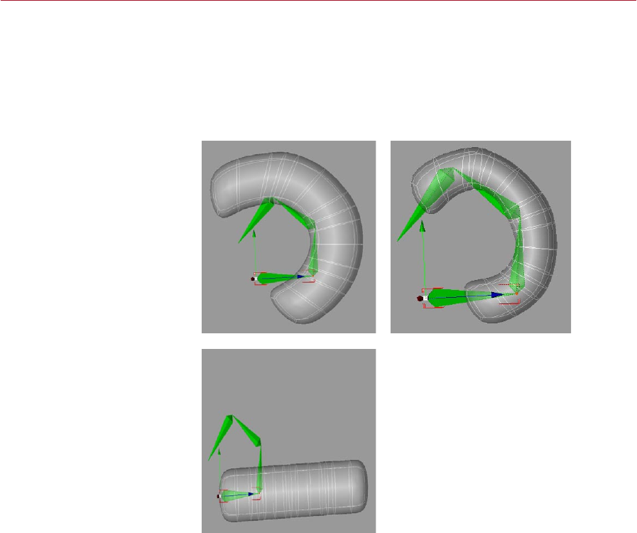
MOCCA CLAUDE BONET TOOL 53
Examples
The difference between using smart bones and normal bones becomes clear when
you take a look at the following examples. For these examples no Claude Bonet maps
were used in order to make the differences as clear as possible.
As these examples suggest, you may need a different Claude Bonet weighting when
using smart bones than you do when using normal bones.
Left: Here is an example of a
deformation of a simple mesh
without Claude Bonet and
without Smart Bone enabled
(Function set to 1/r^2).
Right: Here is an example of a
deformation of a simple mesh
without Claude Bonet and with
Smart Bones enabled (Function
set to 1/r^2) but with Absolute
Vertex Map disabled. You
can see how the Smart Bone
algorithm deforms the object in
a quite different manner to the
classic algorithm (without the
Smart Bone function).
Here is an example of a
deformation of a simple mesh
without Claude Bonet but with
Smart Bone AND Absolute
Vertex Map both enabled.
No deformation can be seen
because no maps have been
applied to the bones.
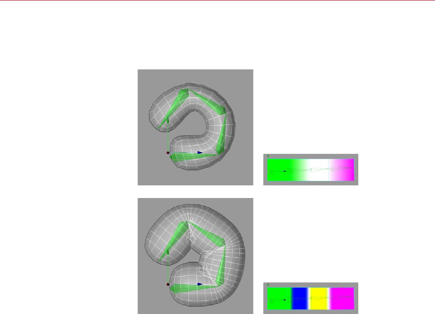
54 CLAUDE BONET TOOL MOCCA
Additional comments
The structure of the object is also very important with regard to painting maps. A
highly subdivided object will be deformed differently than an object with fewer
subdivisions.
The deformation of a cuboid
with few subdivisions in a
HyperNURBS object via four
bone objects (the polygonal
cube was subdivided three times
using the Knife Tool). Each bone
was weighted using Claude
Bonet, where the weighting
overlaps the segments (right).
The deformation of a cuboid
with a few more subdivisions
(especially at the joints) within
a HyperNURBS object via four
bones. Each bone was weighted
using Claude Bonet, where the
weighting overlaps the segments
(right). Because the object
contains more subdivisions at
the joints, the outer form will
retain its original form more
closely than will an object with
fewer subdivisions.
This does, though, require
more work when painting the
weighting onto the mesh.

7 Cappuccino Tool
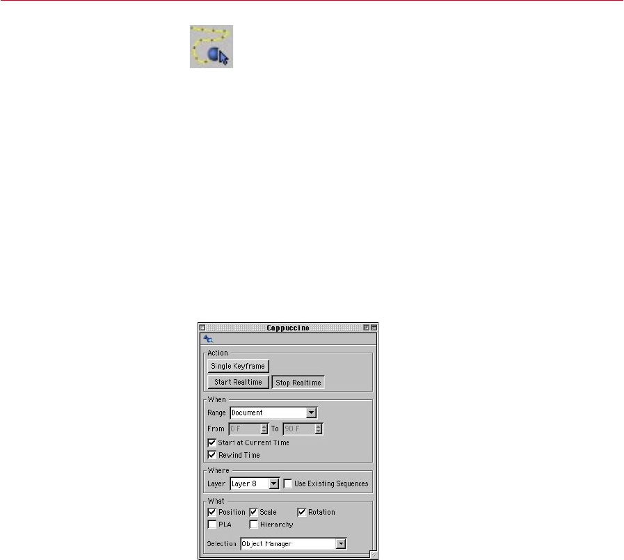
MOCCA CAPPUCCINO TOOL 57
Cappuccino
Tool
Cappuccino is MOCCA’s
integrated motion capture tool.
It enables you to create lifelike
motion for your characters,
from a head nodding in
agreement to a gecko catching
a y with its tongue.
With Cappuccino you can quickly create all kinds of realistic movements for
your 3D characters and models, simply by recording mouse movements.
Cappuccino is MOCCA’s integrated motion capture tool. Take an object,
activate the function and drag it around the viewport. All movements of your mouse
will be captured and recorded frame by frame in the object’s animation track.
Cappuccino is good for setting so-called secondary motions such as the movement of
pigtails which you really don’t want to animate manually. Furthermore, you can more
easily animate vehicles using the top view or move planes or birds across the sky.
Cappuccino produces a large amount of unnecessary keys since it sets a key at every
frame of the animation. It is generally a good idea to apply the Key Reducer after
using Cappuccino.
To select the Cappuccino tool, choose Plugins > MOCCA > Cappuccino or click the
Cappuccino icon, shown above, which you’ll nd on the MOCCA palette.
The Cappuccino dialog opens.
Cappuccino dialog settings
Capture your mouse movements
using the options and commands
in this dialog, which opens when
you choose the Cappuccino
command.

58 CAPPUCCINO TOOL MOCCA
Action pane
Here you’ll nd the buttons for recording the keyframes in different ways.
Single Keyframe
This will record keys for the selected object(s) at the current Timeline position and
according to the Where and What selections within the dialog. Simply select an object,
or objects, and click Single Keyframe.
This button describes the same functionality as the record button on the Timeline.
Having the function available directly in the Cappuccino dialog is more convenient in
case the Timeline is not visible for whatever reason. It is by all means conceivable that
one could mix automatic keyframes and manually set keyframes using Cappuccino.
Start Realtime
This button prepares MOCCA for multiple-keyframe recording. It tells MOCCA to
start recording as soon as the mouse button is pressed within the viewport and stop
when it is released again.
Look at the Timeline: when you rst press the mouse button in the viewport, the
Timeline pointer will start running and then stop abruptly when you release the button.
MOCCA will record a key for each frame of the animation. By default, in PAL mode,
this will result in 25 keys per second; in NTSC mode, 30 frames per second. Use the
KeyReducer tool to reduce the number of keyframes if necessary.
Here, ‘second’ does not represent a real-time second, i.e. the actual
time the object takes to move. This is also dependent upon the speed of
your processor and the scene’s complexity. A simple cube in an empty
environment will behave differently to a complex model of a car in a city
landscape!
It’s important to keep these factors in mind and to deactivate objects that
aren’t needed for the recording in order to free up some of your computer’s
performance if necessary. Another possibility is to work with proxy objects;
for example, in the case of animating a car, you could animate a cube in place
of the car and then transfer the animation from the cube to the car.
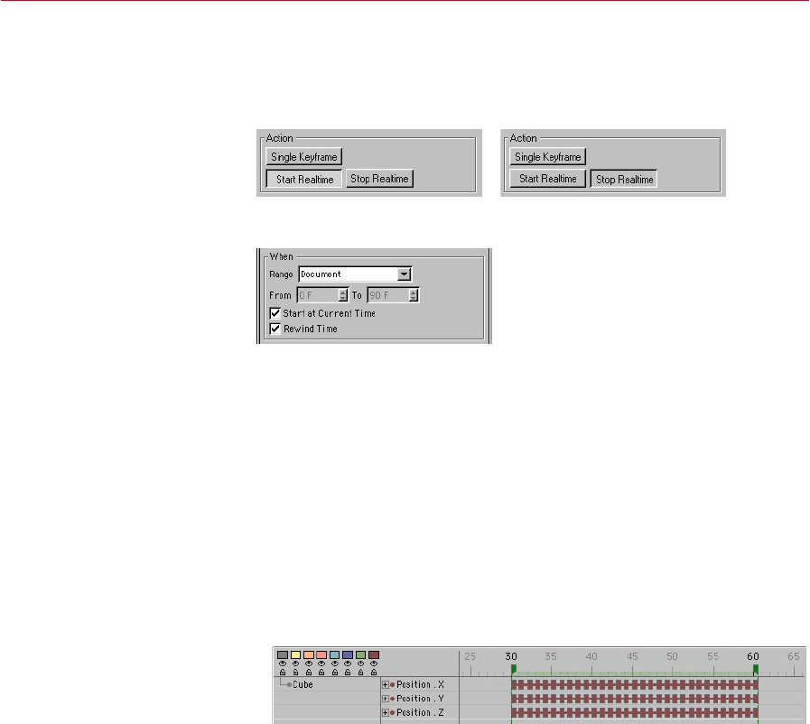
MOCCA CAPPUCCINO TOOL 59
Stop Realtime
Think of this as that ‘Quiet: Live Recording’ sign that you see in recording studios. Its
sole purpose is to indicate when the recording has nished. When you’re not recording,
this button is appears ‘pressed’. During recording, it appears ‘unpressed’.
The Stop button during the
recording (left) and after (right).
When pane
Here you can dene the time frame for the recording or choose to simply get going
without being tied down to a specic time frame.
Range, From, To
Use this drop-down list to choose one of four different settings that limit the range
of the recording.
Document
This option uses the project settings of CINEMA 4D (Edit > Project Settings), where
you can set the frame rate (frames per second) as well as he total number of frames
in the Timeline. If, say, the project settings are set to a range of 0 to 90 frames and
this option is selected, MOCCA will only record 91 frames and no more.
Preview
With Preview selected, the
preview range in the Timeline
will be used to determine the
extent of the recording.
Here, the Timeline’s preview range will be used. For example, if the preview range
markers are set to frames 25 and 50, keys will be recorded from frames 25 to 50
only. This range must be set in the Timeline rst.
Render
This option uses the frame range dened in the render settings on the Output
page.

60 CAPPUCCINO TOOL MOCCA
User
When this option is chosen, user-dened settings can be entered manually in the
Cappuccino dialog. The recording will take place between the frame numbers you
set in the From and To edit boxes.
Start At Current Time
Enabling this option will allow you to choose the starting point of your animation
interactively. The current position of the time slider will dene the frame at which
recording begins. Simply move the time slider to the frame you want to record from
and start recording.
Rewind Time
This will rewind the time slider to its initial starting point once the recording has
stopped. If you are unsatised with the results of the recording, or just want to
practice the movements, you can press the Start Realtime button once more and
overwrite the previously recorded animation, frame for frame.
When you rewind and click Start Realtime again, existing keyframes will
be overwritten, NOT deleted. For example, if you have previously captured
frames 0 – 200 of your animation and only capture frames 0 –100 the second
time around, frames 101 – 200 from the rst time will be preserved. This can
be useful if, say, you’ve recorded some animation and you’re happy with the
end of the recorded animation but you want to change the start — simply
rewind and re-record over the frames that you want to change. Be careful
not to record over the ‘good’ part as well!
Where pane
Here you can choose which objects are to be recorded. If you just want to animate
certain objects in the scene, you can assign them to a specic layer in the Timeline.
Then choose that layer here and Cappuccino will be unable to record keys if you select
an object that is not part of the chosen layer.
Keep in mind that each object you drag into the Timeline without assigning it a specic
layer will automatically be part of layer 1. If you haven’t assigned objects to any other
layer, you can just keep on working with layer 1 for your animation.
Layer
This drop-down list gives you a choice of layers, corresponding to the layer system
in the Timeline. If objects are assigned to specic layers, this option enables you to
lock or unlock object groups for recording, as described above.
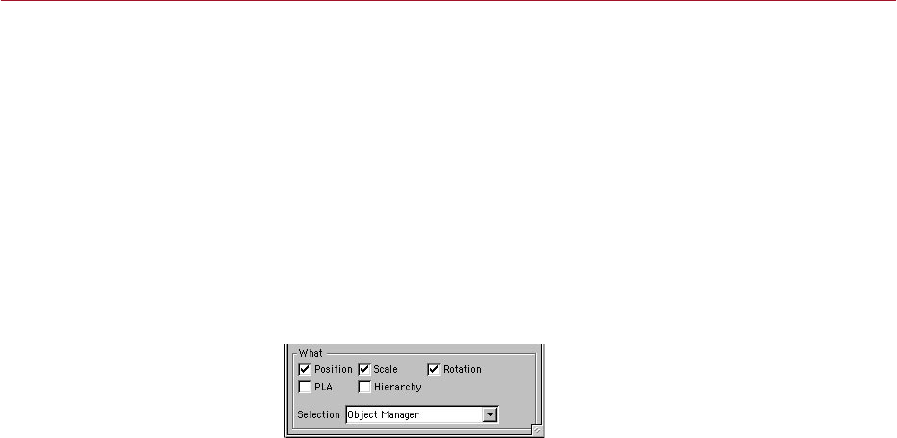
MOCCA CAPPUCCINO TOOL 61
Use Existing Sequences
If objects within a layer already have sequences, these will be used for recording
when you enable this option. This also means that keys can be written only where a
sequence is present. Disabling this option will cause MOCCA to extend the sequence
to cover the entire recording time.
Suppose you’ve dened that from one frame to another frame an object should move
from one point to another point; this object therefore already has a sequence in the
Timeline for this motion. Now you want to animate another object using Cappuccino
and you want this object to only move at the same time as the rst object. You can
either look in the Timeline to see which frames must be used or you can use the Use
Existing Sequences option to narrow down the time frame for the movement.
What pane
The only remaining factor that Cappuccino needs to know is what to record, meaning
what type of animation. Here you will nd the following options:
Position
If you want to record the changes in position of an object, enable this option. Position
tracks will be created in the Timeline.
Scale
Animating the scale can be achieved by enabling this option. Scale tracks will be
created in the Timeline for the selected object.
Rotation
If you want to record the rotation of an object over time, enable this option. Rotation
tracks will be created in the Timeline for the selected object.
PLA
Point level animation of a polygon object will be recorded with this option enabled.
PLA tracks can be created with the help of the magnet tool.
Hierarchy
In this case, not only the selected object and its predened tracks will be keyframed,
but also those of its child objects.

62 CAPPUCCINO TOOL MOCCA
Selection
This drop-down list gives you a choice of two ways of object selection.
If you want to record keys for only one object, select Object manager in this list; you
won’t be able to record keys for multi-selected objects in this mode.
If you choose Timeline, however, you can select several objects simultaneously in the
Timeline and record keys for all of them. Remember that, if the Timeline is in manual
mode, it may not show all the objects that you want to record.
Object Manager
The object that is selected in the Object manager will be used for recording.
Simultaneous recording of several objects is not possible here.
Timeline
The objects that are selected in the Timeline will be used for recording. Simultaneous
recording of multiple objects is possible. In other words, selecting one or more
separate objects in the Timeline will enable you to record the movements or
deformations for all selected objects.

8 KeyReducer Tool
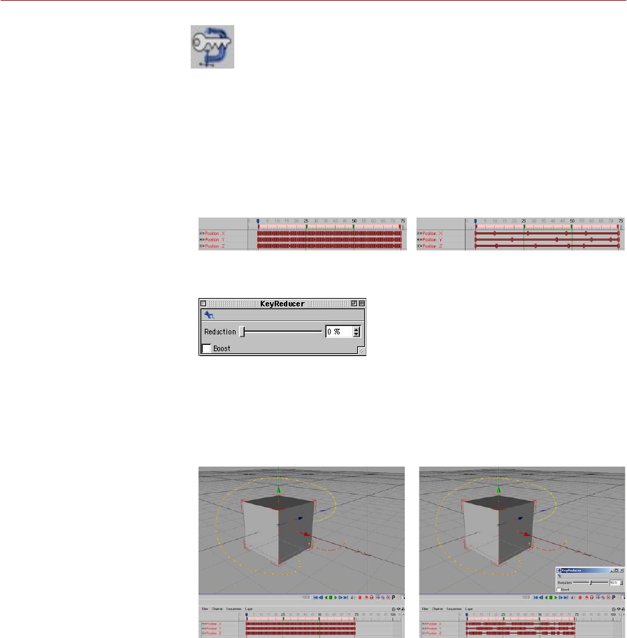
MOCCA KEYREDUCER TOOL 65
KeyReducer
Tool
Motion captured tracks
often have more keys than
are necessary, making them
difcult to edit. Using the
KeyReducer tool, you can
quickly reduce the number of
keys without losing the ones
that matter.
KeyReducer is an invaluable tool when it comes to cleaning up motion
capture tracks such as those created using MOCCA’s Cappuccino tool. Most
motion capture systems write a key per frame to ensure that all important
data is captured. However, this process usually generates many more keys
than are necessary. When you need to edit these tracks, it can be extremely difcult
to tell what events happen at what time.
In such cases, you can remove the unnecessary keys using the KeyReducer tool. It
reduces the number of keys used by the selected tracks intelligently, keeping the
important keys while removing those that are not required.
To select the KeyReducer tool, choose Plugins > MOCCA > KeyReducer or click its
icon on the MOCCA palette.
Before using the KeyReducer tool
(left) and after (right).
KeyReducer dialog settings
Reduce the number of keys
using the Reduction slider in the
KeyReducer dialog, which opens
when you select the KeyReducer
tool.
Reduction
This slider controls the strength of key reduction for the selected tracks. To test this,
use Cappuccino to capture the movements of a Cube object in the viewport. Select
the tracks in the Timeline. Now select the KeyReducer tool, drag the handle and
watch the keys disappear!
Before applying the
KeyReduction tool to the cube’s
tracks (left) and after (right).
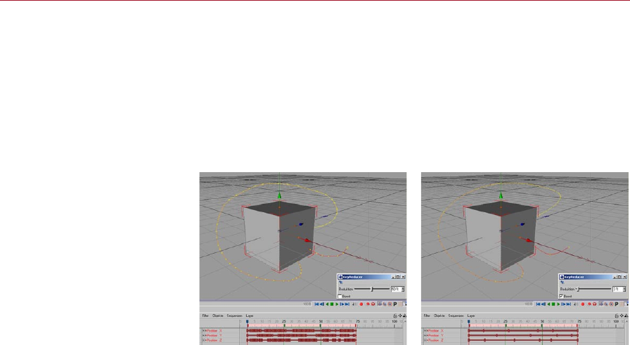
66 KEYREDUCER TOOL MOCCA
As soon as you release the slider it will jump back to 0%. If you’re not satised with the
result, simply move the slider again or select Undo (Action) from the Edit menu.
Boost
If you reduce keys without the Boost option, you’ll still notice some unnecessary keys.
These are mostly keys that fall between the ups and downs of a curve. The Boost
option eliminates these keys while still maintaining the peaks and overall shape of
the curve. Note that boosted reductions will remove the vast majority of keys within
the rst few positions of the slider.
Boost disabled (left) and enabled
(right). Boost removes many keys
while still preserving the general
shape of the curve.
The KeyReducer is especially useful when editing tracks captured using the Cappuccino
tool. This is because usually Cappuccino records many more keys than you need.
More care is needed, however, when you are using KeyReducer with motion data that
has not come from Cappuccino. Simply adjusting all tracks at once will practically
never give you your desired result. It will most likely result in your bone skeleton self-
destructing because the KeyReducer views each object independently of the other
and cannot take dependencies such as distance between bones into consideration.
Therefore you should deal with the tracks one by one.

9 TimeWarp Tool
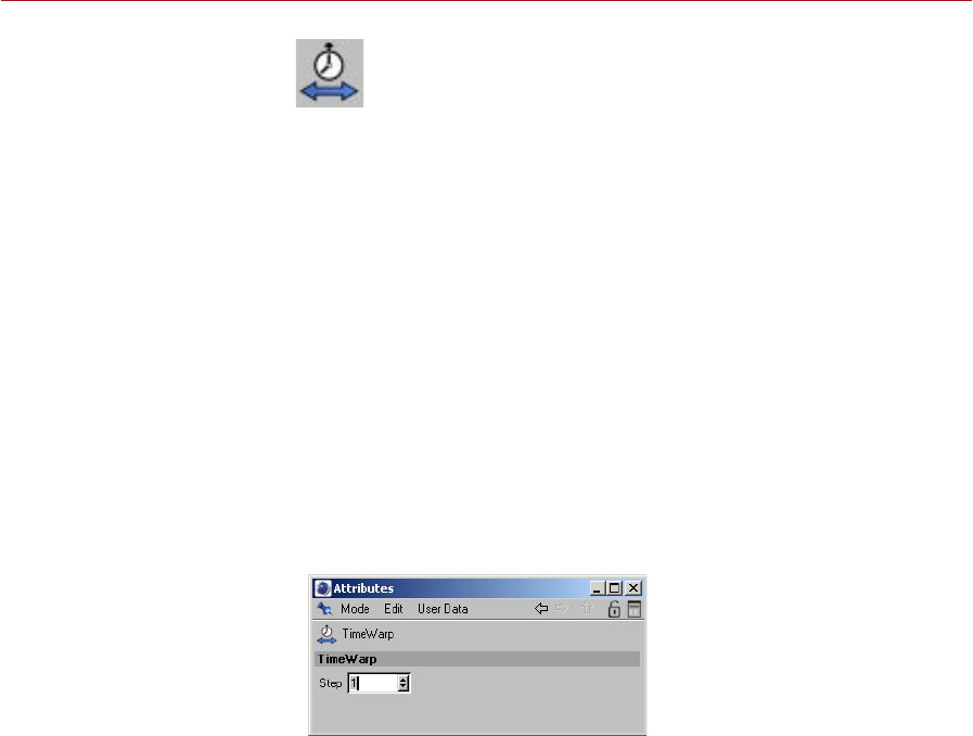
MOCCA TIMEWARP TOOL 69
TimeWarp Tool
Using this tool, you can
quickly nd a specic frame
in an animation.
TimeWarp is your personal time machine. You might nd it helpful to think
of TimeWarp as a multiple frame jog dial on your VCR when you’re skipping
through a lm scene that might be hundreds of frames long. Normally, it
is very difcult to nd a specic frame in a scene but TimeWarp will do this
for you, without you having to drag any sliders.
To use the TimeWarp tool, hold down the ‘J’ key and, in the viewport, drag left or
right to move backwards or forwards respectively in time. You can travel more slowly
through the animation by holding down Ctrl at the same time.
You can also access the TimeWarp tool from the Plugins > Mocca sub-menu or by
selecting its icon from the MOCCA palette. In this case, there is no need to hold
down the ‘J’ key — simply drag left or right in the viewport to step backwards or
forwards in time.
In addition, and most importantly, a Step setting is available in the Attribute manager.
This differentiates the TimeWarp tool from the time slider.
The TimeWarp function lets you switch between frames much faster than
you can using the Timeline. This lets you check your animation much more
quickly. Depending on the complexity of your scene you can play sequences
faster via TimeWarp than you can using the Timeline!
Attribute manager settings
The Step value determines how
far you need to drag the mouse
in order to advance or rewind
the animation by one time unit.
Step
This is where you set the relationship between length of mouse movement and time.
A higher step value means less movement of the mouse is required to reach the
desired point in time. But be careful: the higher the step value, the more difcult it
will be to stop at a specic frame.

10 PoseMixer Tag
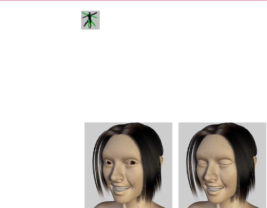
MOCCA POSEMIXER TAG 73
PoseMixer Tag
You can easily morph objects
from one shape to another
using this tool. It is especially
useful for animating a
character’s mouth, where
each mouth shape is a
separate morph pose.
The PoseMixer tag is a morphing tool. Simply put, morphing is the transition
of one form to another. The PoseMixer uses deformed duplicates of an object
to achieve this. PoseMixer works just like an audio mixer or synthesizer. The
duplicates, called poses, are like the inputs of the mixer desk. They will be
assigned to the PoseMixer tag.
All you need now is the output, i.e. the object that will be morphed by the poses;
this is called the destination object. You can use the original object that the poses
were duplicated from as the destination object.
PoseMixer is especially useful for animating faces — mouth shapes in particular. The
most important vowels can be assigned as duplicates to the PoseMixer. By mixing
all of them together, to lesser or greater degrees, you can create virtually any mouth
form and animate it. PoseMixer also works with objects, bones, splines and points.
Animated objects can also be mixed with each other.
To add a PoserMixer tag to an object, select the object and in the Object manager
choose File > Mocca Tags > PoseMixer.
A default pose for eyes open
(left) and a pose for eyes shut
(right) suitable for allowing you
to quickly control the opening
and closing of the eyes.
Here is a typical example of a PoseMixer application using a character’s head. In
the default pose (left) the character’s eyes are open. The head was then duplicated
and the eyes were manually closed using modeling tools (right). This ‘closed
eyes’ object was then assigned to the PoseMixer tag as a pose. This will allow the
character’s eyes to be opened and closed by moving the tag’s slider for the pose.
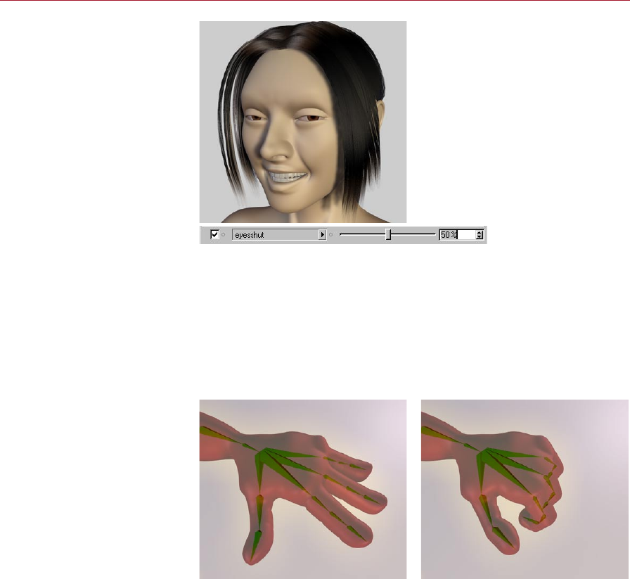
74 POSEMIXER TAG MOCCA
New in-between poses can be
generated quickly, simply by
dragging the slider.
PoseMixer offers you the advantage that you can move between poses smoothly
and new in-between poses will be generated. The eyes should only open halfway?
No problem! Simply move the slider to 50% and the eyes will be half open. With the
endless pose mixing possibilities you can create complex animation for faces in the
blink of an eye.
PoseMixer allows you to control objects, bones, splines and points. For example, you
can dene entire bone hierarchies as poses and use these to animate hand gestures
and positions.
New in-between poses can be
generated quickly, simply by
dragging the slider for the pose!
Example of PoserMixer applied to a bone hierarchy. By dening a default pose for
the hand open and a morph pose for the hand clenched into a st, you can smoothly
open and close the hand by dragging the slider for the clenched st morph pose.
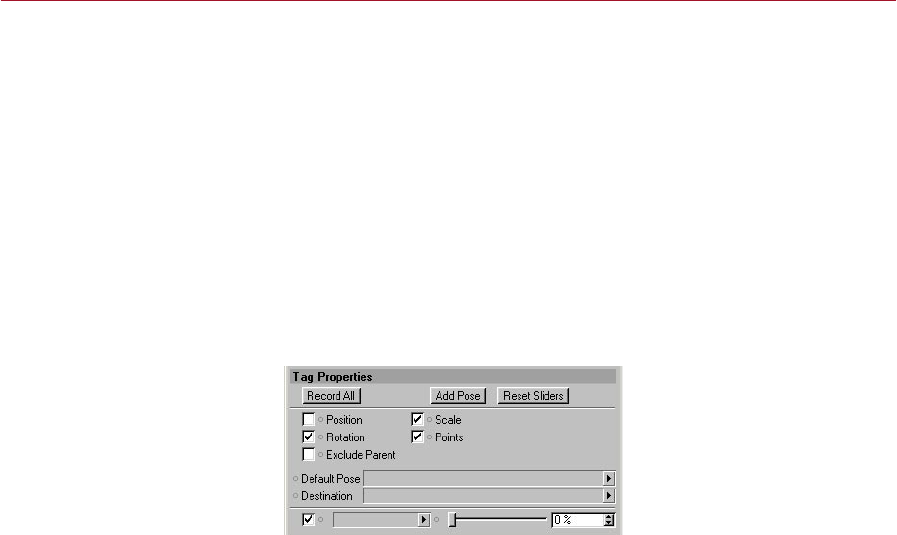
MOCCA POSEMIXER TAG 75
Note to users of previous versions of MOCCA
PoseMixer has been completely reworked for the new release of MOCCA. Contrary to
the previous version, PoseMixer is now a tag, NOT a separate object. This improves
PoseMixer’s functionality and makes it easier to work with.
When using PoseMixer to mix autonomous states you can position it to basically any
object without having to take the position of the other objects into consideration
since it is not bound by hierarchies.
For the sake of compatibility, though, the old PoseMixer object is still available in
CINEMA 4D and will be used when loading older scenes that use the object. An
automatic conversion to the PoseMixer tag is unfortunately not possible due to tag’s
new inner workings.
Attribute manager settings
Add and record poses using
these settings, which appear in
the Attribute manager when the
PoseMixer tag is selected.
Record All
This button sets keyframes at the current time for the present mix of poses. For
example, if you have mixed three different poses and use Record, PoseMixer won’t
just set a single key. Instead it records a separate key for each pose track, containing
the necessary amount of each pose for the resulting shape. Therefore Record makes it
extremely easy to build entire animations without having to worry about a multitude
of objects.
Add Pose
Add Pose will add a new mixing track, so to speak. A new box appears into which
you can drag the pose from the Object Manager. Next to the box you’ll nd a slider
which controls the strength of the pose’s inuence on the nal mix.
Reset Sliders
This button resets all the pose sliders back to 0%.

76 POSEMIXER TAG MOCCA
Position
You can prevent PoseMixer from changing the destination object’s position by
disabling this option. This is especially important for animating faces, for example,
which generally use a different object for each expression. Previous versions of MOCCA
required you to create objects each with the exact same coordinates or simulate this
with Null objects. This is no longer necessary in the new version of MOCCA.
If, however, you want PoseMixer to assign the various positions of the objects to the
destination object, enable the option.
Scale
If the objects you’ve assigned as poses are different scales, you can transfer these
differences in scale to the destination object by enabling this option.
Note here that ‘scale’ refers to the Scale values of the objects as displayed in the
Coordinate manager when the Coordinate manager’s middle drop-down list is set
to Scale. This means, for example, that the option will have no effect at all if the
pose objects are different sizes but have the same Scale values! In such cases, enable
the Points option instead if you want the differences in size to be transferred to the
destination object.
For more information on the Scale values in the Coordinate manager, please consult
your CINEMA 4D reference manual.
Rotation
Enable this option if the pose objects are at different rotations and you want these
differences in rotation to be transferred to the destination object.
Points
The Points option compares the geometry data of the objects with one another and
passes this information to the destination object. This option is necessary, for example,
for the animated faces already mentioned where the positions of the points will vary
from one pose to the next.
Exlude Parent
Sometimes it makes sense to group the pose objects together as children of a Null
object. However, this can change the object coordinates for the pose objects. In such
cases, it would make sense for PoseMixer to ignore the parent null.
That’s exactly what the Exclude Parent option is designed for. Enable the option if
you want PoseMixer to ignore the parent null.

MOCCA POSEMIXER TAG 77
Destination
You can apply the PoseMixer tag to any object in your scene; it doesn’t have to be
applied to the destination object (the object that will be morphed by the poses). The
choice is entirely up to you.
Because you have this freedom to choose which object to add the tag to, you need
to let MOCCA know which object you want to use as the destination object.
To choose the destination object, drag and drop the desired object from the Object
manager into the Destination box.
Default Pose
This is where you drag and drop the default pose, which serves as a reference for
the other poses. MOCCA needs a default pose to compare its rest state with the
deformations of the other poses and then apply whatever differences it nds to the
destination object. Therefore we recommend using a neutral position of the object
for the default pose.

11 P2P Library and Manager

MOCCA P2P LIBRARY AND MANAGER 81
P2P Library
and Manager
Collect and manage poses for
your animation with these useful
tools.
The abbreviation ‘P2P’ stands for ‘Pose to Pose’ and simply describes a
process of animation that moves from one predened pose to the next.
The P2P library serves as the archive for these poses. Before you can start
adding poses to a P2P library, you need to add a P2P Library object to the
Object manager; to do this either select Plugins > MOCCA > P2P Library or click on
the Add P2P Library Object icon on the MOCCA palette.
Now, double-clicking the P2P library icon in the Object manager will open the P2P
manager, which enables you to collect the different poses. You can also open the
P2P manager for the selected P2P library object by selecting Plugins > MOCCA >
P2P Manager.
We recommend that you dene a reference, or neutral, position of your character
as the rst object in the P2P manager. To do this, just drag and drop the character’s
name from the Object manager into the empty space in the P2P manager. After you
let go of the mouse button, a rendered thumbnail appears in the manager window
(this may take a few seconds, depending on the geometry of your object). You can
now repeat this process to add as many poses as you need to the P2P manager.
After you’ve collected all the necessary poses, drag the P2P library onto the destination
character that will be morphed by the poses (again, it is recommended that you use
a neutral pose of this character for this destination object). This works similarly to
PoseMixer and motion blending. Please note that you shouldn’t drag the library onto
the destination object beforehand; dragging the library (within an object) into the
P2P manager could lead to recursion.
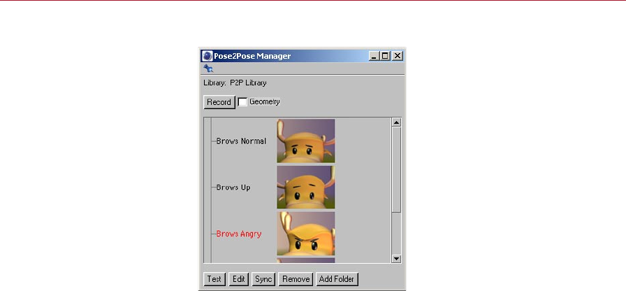
82 P2P LIBRARY AND MANAGER MOCCA
Pose2Pose manager settings
The P2P manager is where you
collect all the poses that you
want to store in the P2P library.
Record
Record will place a key for the selected pose at the current position in the Timeline.
This key will not be placed on the destination character’s track, but on the P2P library
object’s Pose track. If the P2P library object is not visible in the Timeline, you can
add it to the Timeline display by dragging its name from the Object manager to the
Timeline (note that this will create a new manual selection in the Timeline - see the
Timeline chapter in your CINEMA 4D reference manual for more details).
Geometry
If you use elements, such as deformers, that deform the actual geometry of an object,
within the P2P library, you need to select this option. Otherwise, MOCCA will not
recognize these deformations. This enables you to work with deformers, points and
even bones as elements of the pose.
Test
Test temporarily applies the selected pose in the P2P manager to the destination
object; if no pose is selected, Test is grayed out. Test enables you to quickly check
the pose, before recording it in your animation. This makes sense, especially for very
intricate poses such as a face, where the thumbnails might not be enough to check
the detail.

MOCCA P2P LIBRARY AND MANAGER 83
Edit
This command enables you to edit the poses in the P2P manager. It places a copy
of the selected pose in the scene; by default, this pose does not contain the full
geometry, only nulls as placeholders for the position of the character’s parts. Enabling
the Geometry option will copy the entire geometry instead of the nulls. At this
point you can edit the pose and then replace the original pose by clicking the Sync
button. You can also drag the updated pose back into the P2P manager to create a
new version.
Sync
Sync synchronizes poses in the P2P manager with the reference object in the scene.
Select a pose from the manager rst. Suppose that this pose was a bit stiff and you
wanted to modify it in the viewport. Edit the pose while having the pose selected both
in the P2P manager and in the Object manager and then click on Sync. The selected
pose in the P2P manager will be overwritten with the modied version. Afterwards,
you can use the modied pose just like any other.
Remove
Clicking this button will delete the selected pose or folder from the P2P manager’s
list.
Add Folder
Click this button to add a folder inside the P2P manager’s window, into which you
can drag objects (poses) from within the P2P manager or directly from the Object
manager.
The folder will be named ‘Libn’, by default, where ‘n’ is a number that increases as you
add folders. Naturally, you can always rename a folder by double-clicking its name,
typing the new name into the dialog that opens and clicking OK.

84 P2P LIBRARY AND MANAGER MOCCA
Attribute manager settings
Key Properties
Set the parameters for each key
on a Pose track in this dialog.
When you select a key on the Pose track of a P2P library object, you will see the
following Key Properties in the Attribute manager.
Name
Here you can rename the pose, making it easier to document and organize your
animation. Note that the naming of the pose in the P2P manager and the key in the
Attribute manager do not have to match, nor will this break the link. Name is designed
to make organization more exible.
Time
This gives the current time of the selected key in the Pose track. To change this, you can
either enter a number or simply drag the key along the Pose track in the Timeline.
Link
This is the name of the pose to which the key is assigned. If you want a different pose
to replace this one at the current time, select that pose and click Record in the P2P
manager to overwrite the old pose and key in the Timeline.
Bias
Bias modies the transition between the selected key and the next key on the Pose
track. A bias of 0% creates a linear interpolation between both keys. A lower or higher
value will create a sloped curve between the selected key and the next key. To see the
shape of the curve, click on the boxed ‘+’ icon next to the Pose track in the Timeline.
This will open the pose curve display.
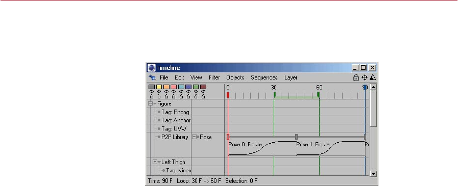
MOCCA P2P LIBRARY AND MANAGER 85
EasyEase
EasyEase will create an S-shaped curve for smooth in and out transition of the
animation.
EasyEase creates a smooth in
and out transition.
Smooth
When you loop a Pose track within a Timeline sequence, copies of the sequence will be
placed one behind the other in the Timeline. This could lead to hard breaks between
each sequence. Enabling the Smooth function will smooth out this transition and is
similar to the Soft setting of the sequence interpolation.

12 Quaternion Tag
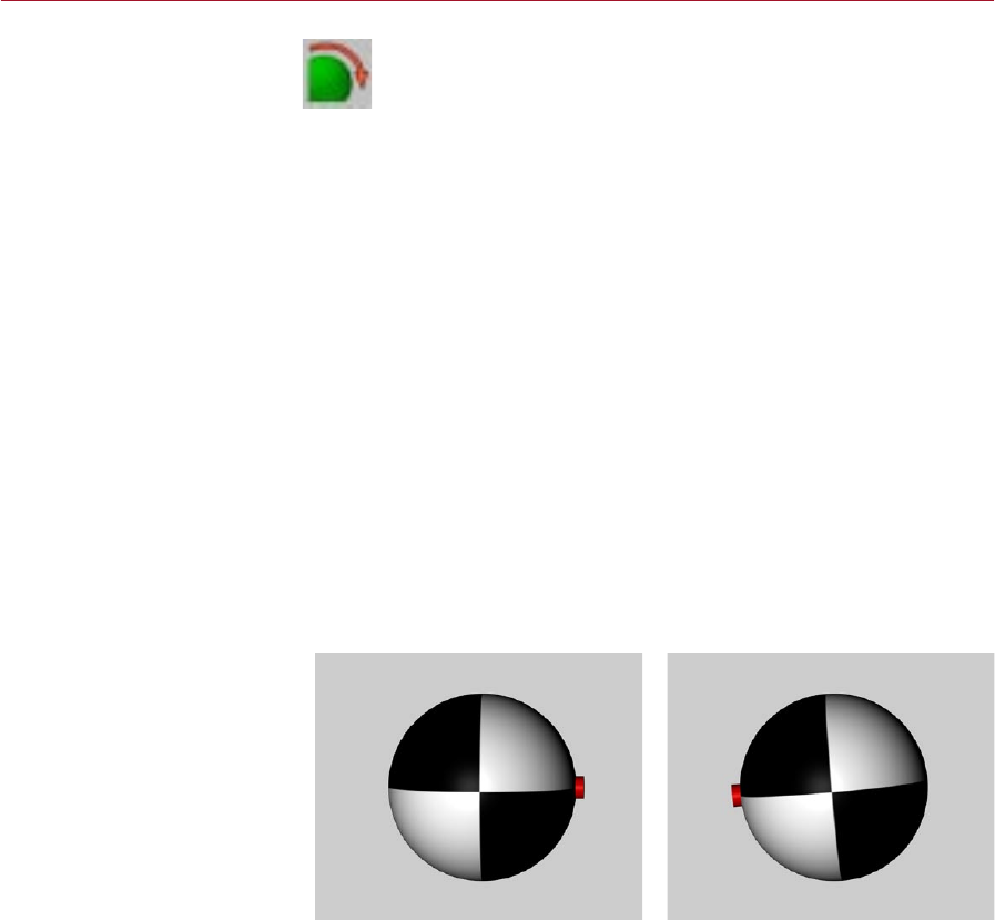
MOCCA QUATERNION TAG 89
Quaternion Tag
The dreaded problem of gimbal
lock becomes a thing of the past
when you use this powerful tag.
Surely you have already heard of the dreaded ‘gimbal lock’ in connection
with character animation. Or worse, you already have experience of it.
Now Quaternion has stepped up to the plate!
CINEMA 4D uses Euler angles by default to interpolate the rotation of bones.
The individual components of the Eular angles are interpolated independently of one
another. For example, the value midway between HPB (0,0,0) and HPB (60,60,60)
would be HPB (30,30,30).
The path from (0,0,0) over (30,30,30) to (60,60,60) is not exactly the shortest. You can
test this in the viewport yourself. What we want is the shortest possible interpolation,
which any user would attempt to do manually.
This is where quaternions come in; quaternion interpolation achieves a much shorter,
smoother interpolation between the keyframes and manages to avoid the problem
of gimbal lock. The quaternion path in the example will lead from 0,0,0 to 60,60,60
via 35.104, 22.83, 25.104.
You are probably wondering why a Quaternion tag isn’t simply applied to all bones!
Easy – every advantage also has a disadvantage, and here the Quaternion tag is no
exception. As long as a rotation is not altered by more than 180 degrees, Quaternion
can work its magic. But anything beyond 180 degrees will cause problems because,
as already mentioned, Quaternion will strive to nd the shortest path.
Let’s take an example: Suppose you want to rotate an object around an axis by more
than 180 degrees.
The rotation of the object at the
start of the animation (left) and
at the end (right).
To do this you’d record a key at frame 0 with the object in its starting rotation,;move
the time slider to the frame; rotate the object as desired and record another key. The
rotation of the object at the start and end of the animation is shown in the images
above.
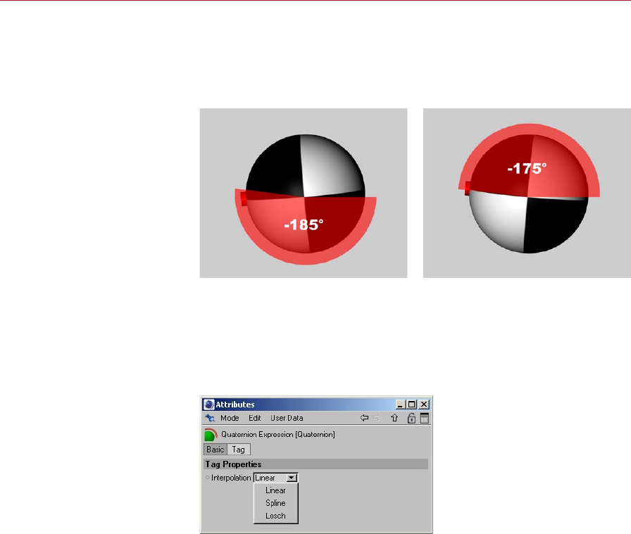
90 QUATERNION TAG MOCCA
So far so good. Now let’s take a look at what happens to the path taken by the
rotation animation if it is interpolated in the traditional way, i.e. using Euler angles.
Suppose you have keyframed the object to rotate around P by –185°. The object will
rotate, from the point of view of the camera, through 185 degrees clockwise (see
left image below).
Interpolation with Euler
angles (left) and quaternion
interpolation (right).
Now let’s look at the way Quaternion behaves. As you know, this method of
interpolation searches for the shortest possible path. The shortest path, though, is not
(from the point of view of the observer) clockwise 185 degrees but counterclockwise
175 degrees. See the right image above.
Attribute manager settings
Interpolation
You can choose from three types of interpolation for the quaternion: Linear, Spline
and Losch. The differences between the algorithms are demonstrated in the following
example: A sphere should rotate from H,P,B (0,0,0) to H,P,B (45,35,-20) over a period
of 50 frames. A red marker was placed onto the sphere to clarify the path taken by
the rotation.
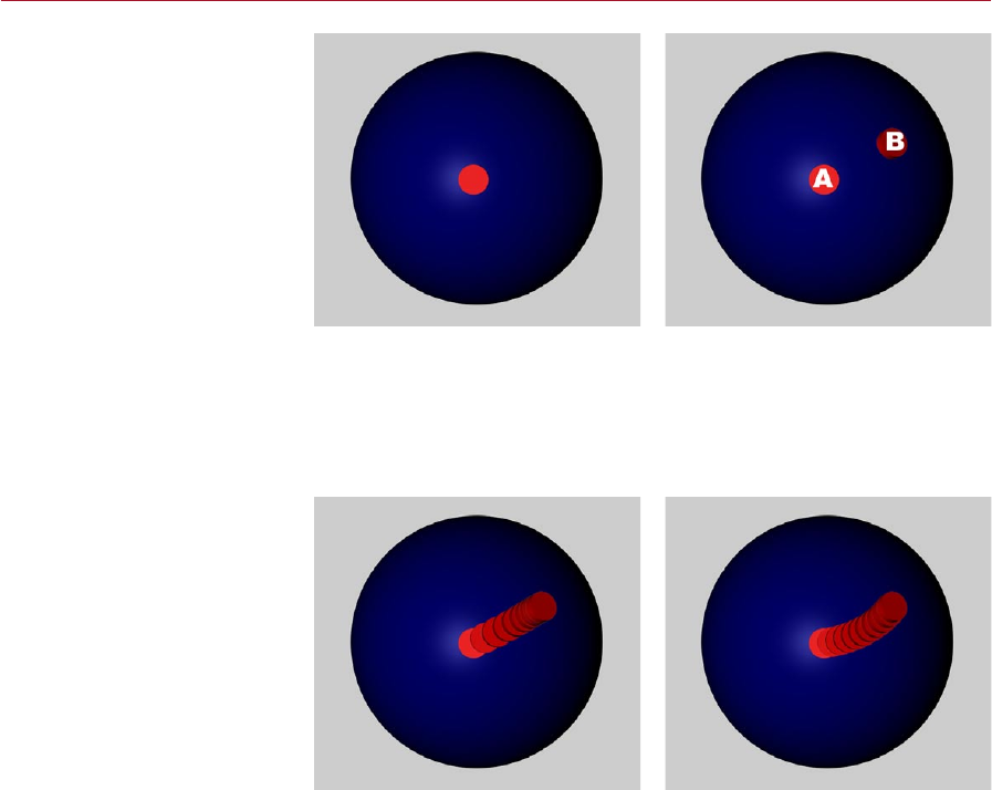
MOCCA QUATERNION TAG 91
The sphere prior to animation
(left) and there sphere’s start
and end angles for the rotation
animation (right).
In the images above, the left image shows the sphere with the red marker prior to
animation. The right image shows the start and end angles — ‘A’ and ‘B’ respectively
— for the sphere’s rotation.
The following pictures demonstrate the paths taken by the sphere, where the distance
between each red marker corresponds to ve frames.
Interpolation with Euler
angles (left) and quaternion
interpolation (right).
The left image above shows the path taken by the sphere if it doesn’t have a
Quaternion tag; notice how the red markers are bunched up near the end — this
is a result of the H,P and B values operating completely independently of one
another.
The Quaternion (linear) interpolation (right image above) looks very different. Here
the gap between each red counter is equal and the path is a smooth, even curve.
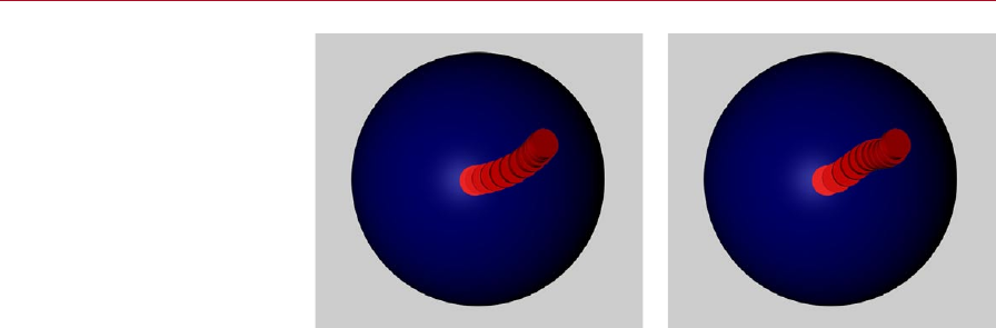
92 QUATERNION TAG MOCCA
The two other types of
quaternion interpolation (right).
The images above show the path taken by the sphere with the two other types of
interpolation.
So when should you use Quaternion tags?
When you are working with characters it makes sense to use Quaternion tags for
all joints that probably won’t be rotated by more than 180 degrees around any axis
between two keyframes. So typically, these are joints that in real life cannot be rotated
through more than 180 degrees such as the knee.

13 Motion Blending

MOCCA MOTION BLENDING 95
Motion blending is the successor to the MoMix object from previous versions
of MOCCA. Because Motion Blend is not an object but a Timeline function,
it is much more exible than the old MoMix object it has replaced.
Motion Blend lets you animate various movements of a character independently
of one another. Later, you can set them up sequentially and let MOCCA calculate
the transitions between them. This can be compared to working with a non-linear
editing system.
Suppose you want to animate a character that goes from a walk into a handstand into
a cartwheel. In previous versions of CINEMA 4D before MOCCA was available, you’d
have had to do the transitions between the three motions in one of two ways: either
by hand, which would require a great deal of effort, or by using Motion Sequencing,
which would still require considerable effort.
With this latest version of MOCCA, you can blend motions in the ick of a wrist. You
can animate the various motions (walking, doing a handstand, doing a cartwheel...)
separately — even as different scene les if you wish — and use motion blending to
mix them together.
Maybe you’re using motion capture data? No problem. Because MOCCA supports
FBX you have access to Kaydara’s popular exchange format – practically an industry
standard.
Whether manually animated or animated via motion capture, you can acquire a
database of movements and simply mix them together whenever you need them
using Motion Blend.
In connection with the Retarget feature you can transfer movements created for one
character to a completely different character — even if they are different sizes and
have completely different builds such as athletic and obese.
Testing motion blending
Step 1
Create two motions or load two motion capture les (BVH or FBX, for example).
Create a Null object and make the motions children of the Null. In the Object
manager, keep clicking the Null‘s top visibility dot until it turns red, in order to hide
the Null in the viewport. Now set the Null’s bottom visibilty dot to red in order to
hide the null in the renderer.
Using a Null object in this way allows you to build up a library of motions that you
can dip in to as and when you need them.
Motion Blending
MOCCA’s advanced motion
blending allows you to easily
combine multiple separate
motions into one smooth,
continuous action.
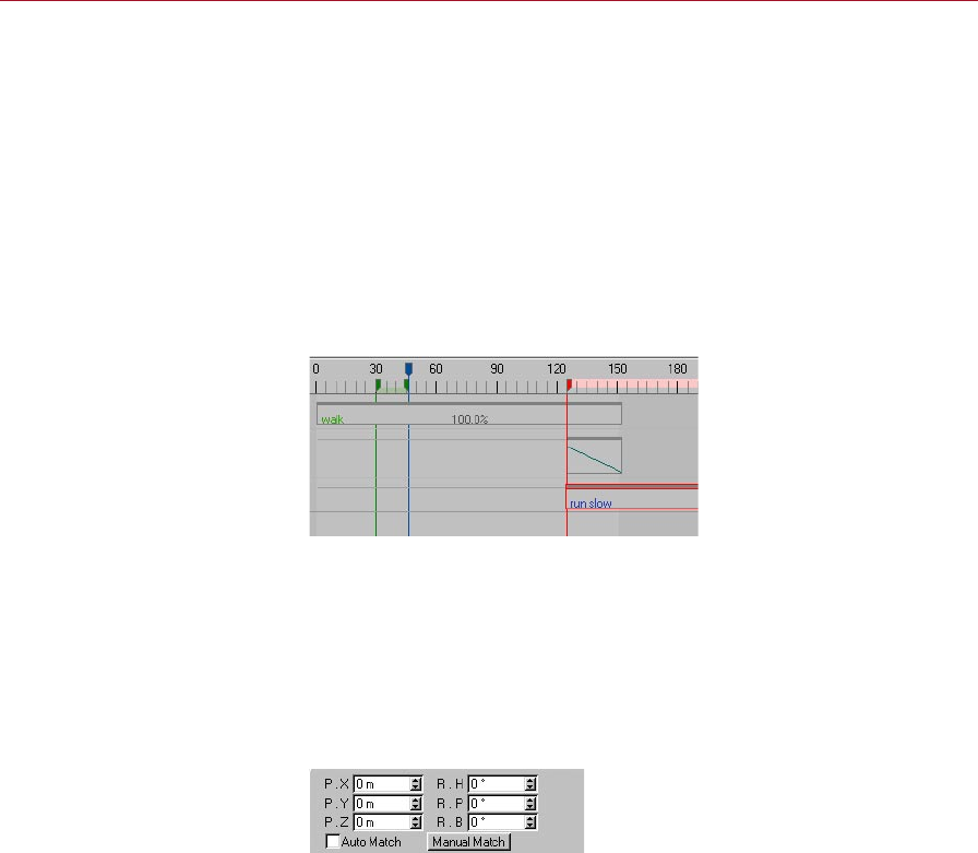
96 MOTION BLENDING MOCCA
Step 2
Add a destination object without animation if you don’t already have one (ideally its
bone hierarchy should match that of the motions).
Step 3
Select the destination object and choose Plugins > MOCCA > Setup Motion Blend
Tracks. Three new tracks will be created in the Timeline: two for motion and one for
the transition.
Step 4
Add a sequence to each track. For each motion sequence, drag and drop the motion
you want to assign to the sequence into the Motion box in the Attribute manager.
A linear curve will be assigned
to the transition sequence
automatically.
The transition sequence will be assigned a linear curve automatically.
Step 5
This basically completes the Motion Blend setup. You will probably notice, though,
that your character will stutter a bit at the transition between the two motions. This
is because the motions don’t match 100% at the seam. You can adjust the global
position and rotation data of the objects using the Attribute manager settings for
the motion sequences.
You can adjust the position and
rotation using the Attribute
manager settings for the
sequences.
Tip
Move the timeslider to approximately the middle of the transition sequence. This
will make it easier to adjust the coordinates.
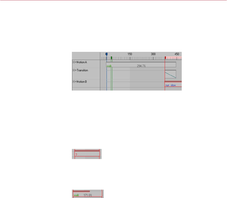
MOCCA MOTION BLENDING 97
Setup Motion Blend Tracks
This command, which is on the Plugins > MOCCA sub-menu, creates the tracks that
are necessary for motion blending. In general, you should select the top-most object
in the destination’s hierarchy before calling the command.
The command will assign three empty tracks to the selected object: Motion A,
Transition and Motion B.
These tracks are created
automatically when you choose
Setup Motion Blend Tracks.
Add a sequence to each of these tracks. The reason why the sequences are not created
automatically is that by manually creating them yourself you can directly set them to
the required positions and lengths.
To create a sequence, right-click (Windows) or Command-click (Mac OS) on the track
and choose New Sequence. Use the dialog that opens to set the sequence to the
desired position.
Initially, the motion sequences will display a question mark; this indicates that a
motion is not yet assigned to the sequence.
A question mark indicates that a
motion is not assigned.
The dark gray bar at the top of the sequence shows the length of the original
animation. The following example illustrates a repeated motion. This lengthens the
sequence but you can still tell how long the original animation is without repeats
via the dark gray bar.
A repeated motion.
Motion A
This is where you dene the rst motion that will be transferred to your character.
This motion will be blended into a second motion: Motion B.
Transition
The transition sequence allows you to dene when and how the two motions should
be mixed.
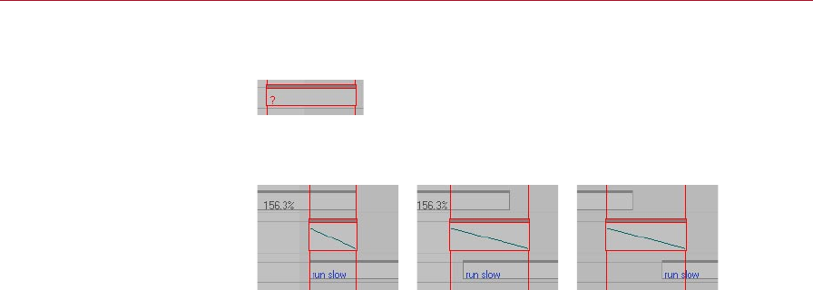
98 MOTION BLENDING MOCCA
If the transition currently makes no sense, MOCCA will display a question mark on
the sequence.
A question mark indicates that
the transition makes no sense.
You can set up the transition sequence in many different ways. The most popular
methods are:
The most popular set-ups for the
transition sequence.
Motion B
This is where you dene the second motion that will be transferred to your character.
The rst motion, Motion A, will blend into this second motion.
In the Timeline, the usual convention when two sequences overlap is that the
top-most one will overwrite the other one. With motion blending, however,
it’s the other way around: in overlapping areas the bottom motion sequence
will overwrite the top motion sequence (unless, of course, you’ve used the
transition sequence to control the mixing between the motions).
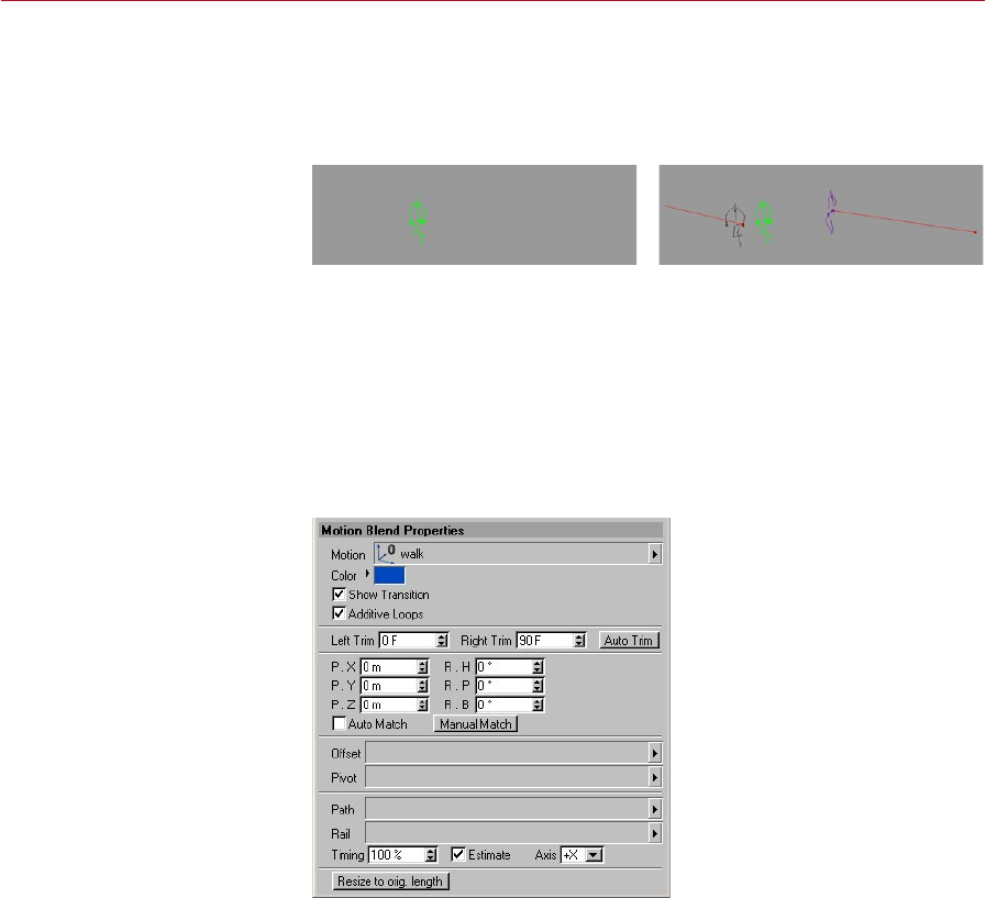
MOCCA MOTION BLENDING 99
Show Transitions
You’ll nd this command on the Plugins > MOCCA sub-menu. It controls whether
transitions are displayed in the viewport. You call also switch off transitions locally
using the Attribute manager settings for the sequences.
Show Transitions disabled (left)
and enabled (right).
Transitions displayed in the viewport should act as a guide to help you set and
ne-tune the motion sequences, i.e. how a motion starts and how it ends. These
will appear as ghosts that point out the starting and ending position of the bone
structure. If you nd the ghosts annoying, or if you’re done using them, disable the
option to switch them off.
Attribute manager settings
Motion Blend Properties
The Attribute manager settings
on the Motion Blend Properties
tab of a selected motion
sequence.
Motion
Into this box drag and drop the object that contains the motion you want to assign
to the motion sequence.
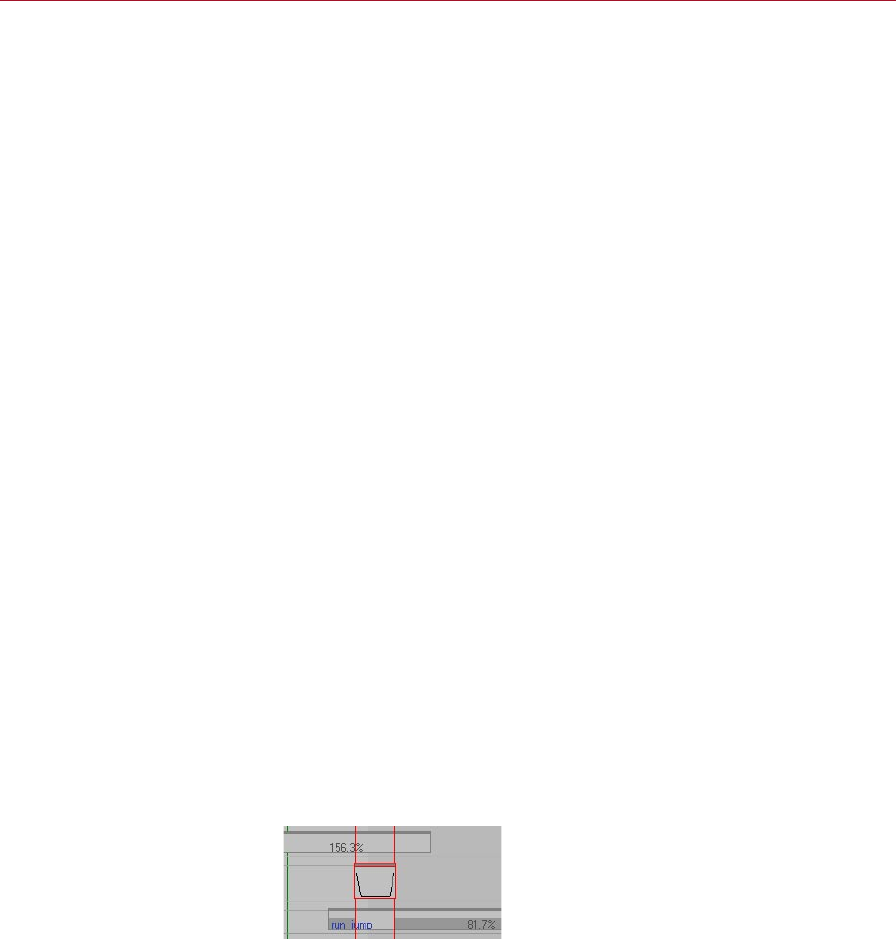
100 MOTION BLENDING MOCCA
Color
The Color option lets you change the color of the transition displayed in the viewport
and the text color of the sequence in the Timeline.
Show Transition
Here you can choose whether the transition should be displayed for the motion. You
can also switch transitions on or off globally using the Show Transitions command
on the Plugins > MOCCA submenu.
Additive Loops
If this option is enabled and loops have been set in the Sequence Properties, MOCCA
will not only repeat the motion, it will “add” the loops together to form a continuous
animation.
For example, suppose that your character has a motion in which she takes four steps
forwards and you want to loop this motion so that she keeps on moving forward
many steps instead of just four.
The problem with a normal — i.e. non-additive — loop here is that when the
character has reached the fourth step and the loop kicks in, her position will jump
all the way back to where she was for her very rst step. She’d keep walking four
steps forwards and then jump all the way back to the start before walking the same
four steps again.
Not so with additive loops. After making her fourth step, the next loop will carry her
forward another four steps instead of putting her back to square one.
Left Trim, Right Trim, Auto Trim
Trimming is a kind of mask mode for motion blending.
Suppose you have two motions. In one of the motions the character is walking and in
the other motion the character is running and every now and then does a jump.
Now you want to create a motion in which the character walks, does a jump and
then carries on walking again. So you need to pluck out a jump from the Run-Jump
motion and blend it with the walk motion. You can do this by making off everything
in the Run-Jump motion except the jump you want. See the image below.
Trimming allows you to mask out
parts of a motion (the areas with
a thick, dark gray bar).

MOCCA MOTION BLENDING 101
The Auto Trim feature will mask off all parts of the motion except the part that ts
the transition sequence. The masked parts are indicated by a thick dark gray bar that
sits on the bottom of the sequence.
Left Trim and Right Trim allow you to manually adjust which parts of the motion
are masked.
Position, Rotation
These values allow you to
smooth the transition.
Here you can adjust the position and rotation data for the motion sequence in order
to smooth the transition.
Auto Match
In order to blend two motions, the end of the rst motion needs to match (more or
less!) the start of the second motion.
Naturally, it would be difcult to match the end of a walk animation with the beginning
of an animation in which the character is sitting down at a table eating dinner! It would
be very difcult to nd motions in these two animations that are very similar.
Matching a walking animation to a running animation would, on the other hand, be
within the realms of possibility. Even so, chances are with such a blend the transition
will not be completely smooth. Chances are that the character will slide across the
oor slightly, rather like he‘s skating on ice.
In order to avoid this, the motions must be placed in such a manner as to achieve a
transition that is as seamless as possible — the keyframe at the moment the motions
are most similar must be found. Of course, this can take quite some time if done
manually. So why not let MOCCA do the work for you?
If Auto Match is enabled, MOCCA will search for matching movements in the two
motions and will try to nd the most appropriate time in the animation to transition
them. The Auto Match option works closely with the Treeview, which you’ll nd on
the sequence’s Detail Properties tab in the Attribute manager.
The Treeview allows you to specify which object Auto Match should concentrate
on. For example, you’ll usually get a better match if you instruct Auto Match via the
Treeview to match up the motions based on the position of one of the feet. MOCCA
will then search for a frame where the foot in the rst motion and the foot in the
second motion are almost in the exact same position.
See also ‘Treeview’, later in this chapter.

102 MOTION BLENDING MOCCA
Manual Match
Previously in this chapter we’ve seen that you can adjust the transition from Motion A
to Motion B by using the position and rotation values or by using Auto Match. Manual
Match is a combination of these two methods: when you click on the button it will
automatically set the position and rotation values to what MOCCA thinks is the best
place for the transition, and you can then manually ne-tune these values using the
position and rotation settings.
Offset
The offset allows you to specify the start of a path animation. The easiest way to
do this is via a Null object that is placed at the position where the animation should
start. Drag and drop the Null object into this box.
Pivot
You can control orientation via an additional object using Pivot. In general, use a
Null object as the pivot and place the null in such a way that you can easily control
the rotation during the animation by rotating the null.
Path
Here you can dene a Spline object as a path along which the animation should
move.
Rail
In addition to dening a path along which a character should move (see above),
you can also use a rail (a spline with two paths) to control several directions. This is
useful when the character should not simply move over a surface but should also
move up and down.
A good example here is a character walking up and down a hill. One path denes the
horizontal motion and the other denes the vertical motion.
Timing
The Timing allows you to set the speed of the character’s steps or the distance between
each step. If the character appears to slide across the oor, increase or decrease the
value as necessary.
The effect of the Timing value largely depends on whether the Estimate option is
enabled.

MOCCA MOTION BLENDING 103
In principle, a Timing value of 100% corresponds to the exact timing of the motion
from the start of the path to the end of path. If you set Timing to a value greater
than 100% and Estimate is disabled, the character will travel all the way to the end
of the path and when it gets there it will move on the spot for a while. With a value
less than 100%, the character won’t reach the end of the path.
If Estimate is enabled, a Timing value of 100% will correspond to the estimated step
distance. See also ‘Estimate’.
Estimate
If a path has been dened along which the character should move, MOCCA won’t
automatically recognize how much distance there should be between each step.
If this option is enabled, MOCCA will estimate the ideal distance for a step based on
the length of the path.
If the option is disabled, the Timing value will have a different meaning; with a Timing
value of 100%, the character will move from the start of the path to the end of the
path exactly over the length of the animation.
See also ‘Timing’.
Axis
This denes which object axis should be moved tangentially along the path. For
example, if a character’s +Z axis should point in the direction in which the character
is running, Axis should be set to +Z. With a setting of -Z, the character would run
backwards.
Resize To Orig. Length
When adding a new sequence, the New Sequence dialog allows you to set the length
and position of the sequence. However, at this stage you may not know how long
the motion is that you will be assigning to the sequence.
If, after assigning the motion to the sequence, you click the Reset To Orig. Length
button, MOCCA will set the length of the sequence to the same length as the original
motion.
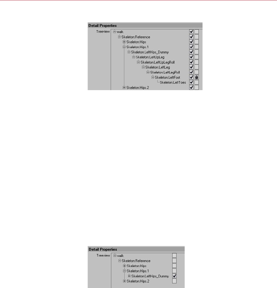
104 MOTION BLENDING MOCCA
Detail Properties
The padlock icon denes
which part of the character
the Auto Match option should
concentrate on.
Padlock icons
If the Auto Match option on the Motion Blending page is enabled, you can use the
Treeview to choose which parts of the character Auto Match should concentrate on
(called ‘weighting’) when searching for the most appropriate time in the animation
to blend between the motions.
For each object that you want Auto Match to concentrate on, click the object’s right-
most checkbox. A padlock icon will appear in each of these check boxes to indicate
that the object is ‘locked’ to Auto Match. To unlock a checkbox, click it again.
See also the ‘Auto Match’ entry described earlier in this chapter.
Check marks
In addition to being able to weight certain bones using the padlock icons, you can
exclude bones, which tells MOCCA which bones, if any, to ignore when transferring
the motion. All bones without a check mark will be ignored.
For example, suppose you have two animations and you want to take the head
movement only from one of the animations and transfer it to your character. You
can exclude all other bones in the Treeview (click the top-most check mark to switch
off all the check marks) and place a check next to the bones you will need — in this
case, the head.
Here, MOCCA will transfer the
motion of LeftHips_Dummy
because it has a check mark.
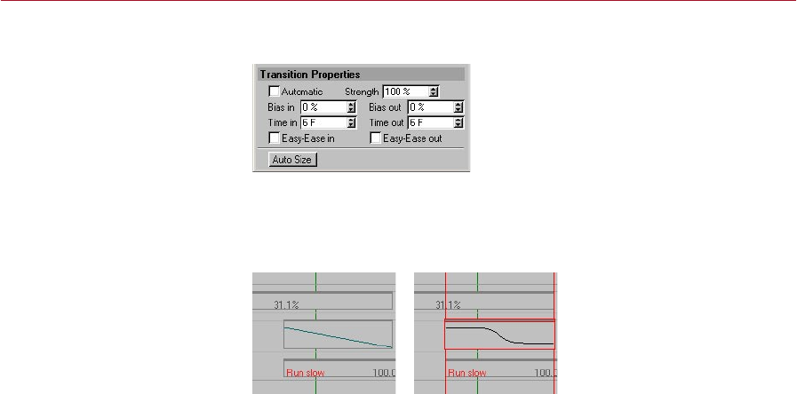
MOCCA MOTION BLENDING 105
Transition Properties
Automatic, Bias In, Bias Out, ...
The Automatic option activates a linear transition. This is represented in the Timeline
as a line in the transition sequence — see the left image below.
If Automatic is enabled, the
transition will be linear (left).
For non-linear transitions, such
as the right example, disable the
Automatic option.
If you disable the Automatic option you will have access to further settings that allow
you to change the shape of the transition curve.
You’ll nd details on the following options in your CINEMA 4D reference manual:
- Strength
- Bias In, Bias Out
- Time In, Time Out
- Easy-Ease In, Easy-Ease Out
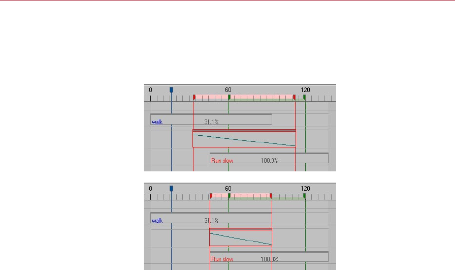
106 MOTION BLENDING MOCCA
Auto Size
The Auto Size button resizes the transition sequence to neatly cover the overlap
between the Motion A and Motion B sequences. The length of the transition sequence
will then automatically run from the beginning of the second motion to the end of
the rst motion.
Before using Auto Size.
After using Auto Size.

14 Retarget Tag
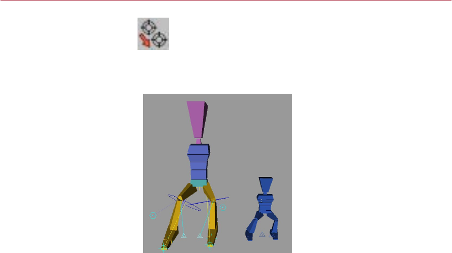
MOCCA RETARGET TAG 109
The Retarget Tag lets you assign animation data from one character to
another even if the characters‘ proportions don’t match!
You‘ve just animate a dwarf for your client and your client has changed
her mind and wants a giant to be animated instead? No problem. Simply assign the
dwarf’s animation to the giant! MOCCA does the re-proportioning for you thanks
to the Retarget tag.
Even though the dwarf on the
right is much smaller than the
giant, using the Retarget tag you
can tranfer the motion from one
character to the other.
To add a Retarget tag to the selected object(s), in the Object manager, choose
File > MOCCA Tags > Retarget.
You need three things to operate motion retargeting:
1. An animated object to act as the source.
2. A target object that has not yet been animated to which the animation will be
transferred.
3. A copy of the non-animated object that denes a neutral state for the character
(a type of starting position, often with the arms stretched out in a T-pose).
Retarget Tag
With this powerful tag you can
easily tranfer motion from one
character to another.

110 RETARGET TAG MOCCA
Attribute manager settings
Source
Drag and drop the object whose motion you want to transfer (the source object)
into this box.
Target
Into this box drag and drop the object that should receive the motion (the target
object). Only the highest object in the hierarchy must be dragged into this box — its
child objects will be included in the transfer automatically.
Neutral
Into this box drag and drop the object that denes the neutral state.
Use Hierarchy Instead Of Names
This option, which is enabled by default, makes the Retarget Expression compare the
hierarchical structure the of reference objects (source, target and neutral) including
their children.
Objects that are in the same position in the hierarchies — such as the direct child of
the top-most object in the hierarchy — will be assigned to one another and compared.
This is assuming that the source, target and neutral reference objects all have the
same hierarchical structure. For example, the hip bone must be in the same position
in the hierarchy for all three reference objects.

MOCCA RETARGET TAG 111
If the option is disabled, the Retarget Expression will orient itself according to the
names used in the hierarchy. This is useful when there are differences in the hierarchy
between the source object and the target object. One example of this would be when
transferring the animination of a character that has a tail to a character that doesn‘t
have a tail. Because a tail does not exist in the character that is receiving the transferred
motion, the tail motion data will be ignored. For this type of transfer to work, it is
essential that you use a naming convention consistently for the characters involved
in the transfer. In time, every animator develops his or her own routine for naming
conventions and can make good use of these in order to marry bone hierarchies,
simply by using the naming convention!

15 Clothilde
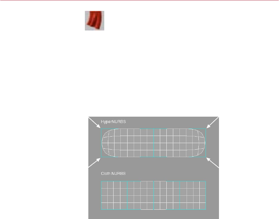
MOCCA CLOTHILDE 115
Cloth NURBS
Cloth must be applied to a
polygon object. Further more,
how the polygon object is
subdivided will play an important
part in how well the cloth
will animate when used with
Clothilde.
Cloth must be applied to a polygon object. For realistic cloth, cloth objects
should ideally have as high a polygon count as possible. This will give the
cloth engine more points to simulate cloth with and will lead to higher quality
results. However, high polygon counts can result in slow editor playback.
One way of avoiding this is to only have high polygon counts at render time which
can be achieved with CINEMA 4D’s HyperNURBS or Cloth NURBS. With either of
these tools, a polygonal mesh can be subdivided to create a smooth looking surface
at render time. However, when using HyperNURBS with a cloth object, there can be
unexpected results because the subdivided object does not always meet the control
cage’s points. This can cause the cloth to intersect with the colliding objects when the
cloth is subdivided. Cloth NURBS will always meet the points on the polygonal cage
that it is subdividing. The reason this is needed for cloth to be simulated correctly
is for the simple fact that cloth collides very close to its colliding surface. Just using
HyperNURBS would allow for the character, or colliding surface, to penetrate the
subdivided cloth.
The arrowheads show which
areas could lead to intersection
problems when using
HyperNURBS to subdivide the
cloth.
In the above image, the arrowheads show the areas where HyperNURBS would cause
intersection problems during a simulation. This is caused by the HyperNURBS object
only interpolating, and not meeting, the polygonal cage’s points.
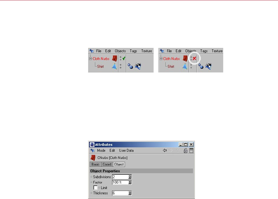
116 CLOTHILDE MOCCA
The functionality of the Cloth NURBS object is the same as the HyperNURBS object.
Place the cloth object as a child of the Cloth NURBS object and the cloth will be
smoothed or more accurately subdivided. To disable the Cloth NURBS object just click
the green check mark next to the object in the Object manager so it becomes a red ‘X’.
This completely disables the Cloth NURBS object from smoothing its child object.
Click the green check mark to
disable the Cloth NURBS.
This does not mean that Cloth NURBS and Hyper NURBS can’t be used together.
Cloth NURBS ensures that the subdivided high-resolution mesh meets the points of
the cloth object. Placing the Cloth NURBS object as a child of the Hyper NURBS object
can then smooth this even further.
A current limitation of the Cloth NURBS object is that it does not support
multiple materials or multiple UVW tags.
Attrubute manager settings
Subdivisions
This eld is very similar to the Subdivision settings located in the HyperNURBS
object. A value of 1 will subdivide each polygon of the child object into four smaller
polygons, a value of 2 will subdivide each polygon of the child object into sixteen
smaller polygons and so on. The subdivision value will control how smooth the cloth
object appears to be. The higher the number, the slower the playback will be during
the cloth simulation, but the nicer the results.
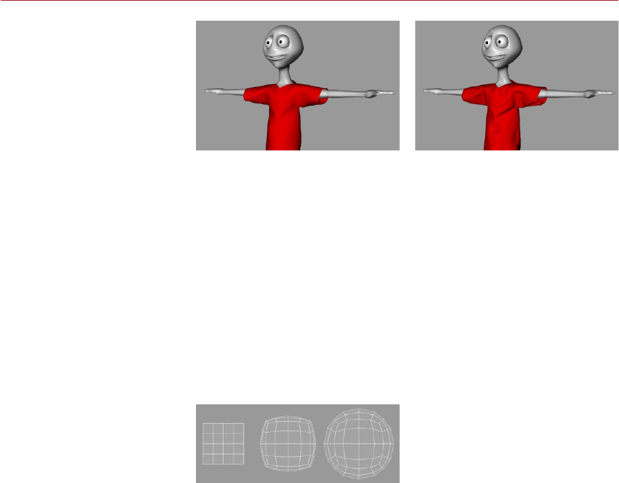
MOCCA CLOTHILDE 117
The original cage object (left)
and the cage smoothed with
Subdivisions set to 2.
The images above show the original polygonal cage that has the Cloth Tag applied to
it (left) and the same polygonal cage with a Cloth NURBS object applied to it using
a Subdivision value of 2. The wrinkles and bulges of the cloth become more dened
as the subdivision increases.
Due to the nature of the Cloth NURBS algorithm, wrinkles in the surface
become more apparent as the subdivision increases. This can be used to
simulate cloth wrinkles. However, if this is not the desired result, use a
Cloth NURBS with a very low subdivision value inside of a HyperNURBS
object; this can produce the same results without the wrinkles.
Factor
This setting will interpolate the surface normals of the polygonal cage, or more
accurately the cloth object. A value of 0% means that the subdivided surface will not
interpolate the surface normals. A value of 100% will interpolate the surface normals
when subdividing the surface.
Factor set to 0% (left), 50%
(center) and 100% (right).
Above is an example of how the surface normals are interpolated as the Factor value
is increased on the same object.
Limit
At many times during a cloth simulation, two points may approach each other whose
corresponding surface normals are adjacent to each other. At this point the Cloth
NURBS will interpolate its subdivided surface through the control cage or cloth object.
The Limit option will prevent this from happening. Take the given situation:
- With the Limit option disabled the subdivided surface will pass through the control
cage.
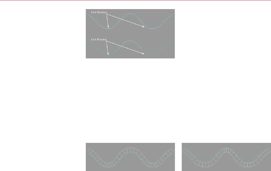
118 CLOTHILDE MOCCA
Limit disabled (top) and enabled
(bottom).
- With the Limit option enabled the subdivided surface will not pass through the
control cage’s surface. The direction of the surface normals for the polygonal cage
will determine if the Cloth NURBS is passing through the geometry.
Thickness
This is another property that separates Cloth NURBS from the HyperNURBS object.
By increasing the Thickness setting, the Cloth NURBS object will generate a form of
extrusion to make the cloth look thick. The thickness of the subdivided surface will be
determined by the direction of the surface normals for the control cage. This allows
for the control cage to be modeled without thickness resulting in fewer polygons
that need to be calculated during the cloth simulation.
Before reversing the normals
(left) and after (right).
- The left image above shows the Cloth NURBS surface when using a Thickness value
of 20. Also notice that the normals are facing up the Y-axis, which is dening the
direction of the thickness.
- The right image above shows another Cloth NURBS surface using the Thickness
setting. As opposed to the other image, this one has the surface normals
reversed.
MOCCA CLOTHILDE 119
Cloth Tag
The Cloth tag identies an object
as a cloth object.
In order to identify an object as a cloth object, its rst requirement is that it is
a polygon object. Using the Make Editable command will convert a primitive
into a polygon object allowing for it to inherit cloth attributes. This next part
of the process is done by applying a Cloth tag to a polygon object.
To add a Cloth tag to an object:
- Select the object and in the Object manager, choose File > Clothilde Tags >
Cloth.
The object now has cloth-like properties.
The cloth tag icon in the Object Manager is dynamic in the sense that it will change its
appearance based on different settings made in the tag itself. For example, the icon
for the tag will change once the simulation has been cached. This clearly identies
what’s going on with the cloth at any time. Here is a rundown of the different states
of the icons:
Initial State
This is the initial state of the Cloth tag icon. This indicates that cloth is ready to be
simulated. After a garment has been draped to a character and an Initial State has
been dened, the icon will revert to this blue curtain showing that the object is ready
for simulation.
Dress State
When the icon is displayed as above, the cloth object or garment is in a dress state.
This means that the cloth object will only be allowed to drape to a character or be
relaxed from real world forces.
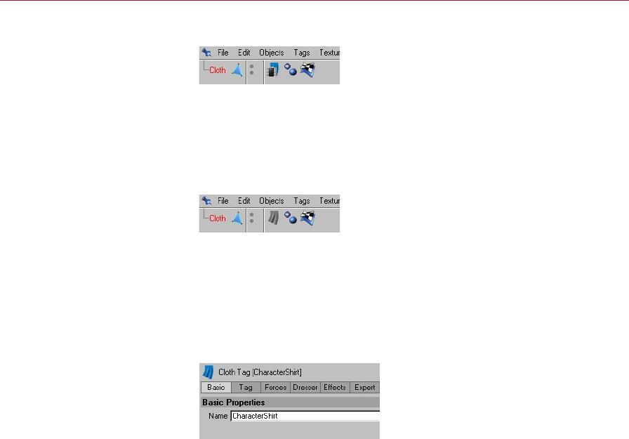
120 CLOTHILDE MOCCA
Cached State
After a simulation has been cached, or the calculations have been stored in RAM, the
icon will look as shown above. When the icon is in this state only the cached solution
will be played back. This icon will also appear when the Cache Mode option on the
Tag Properties page is enabled.
Engine Disabled State
The icon of the tag will also change its appearance when the Cloth Engine option
in the Tag Properties tab is disabled. The gray cloth icon represents that the Cloth
Engine option has been disabled.
Attribute manager settings
Basic Properties
Basic
The only property found on this tab is the name of the tag. This setting defaults to
‘Cloth’, but it can be changed manually for project organization purposes.
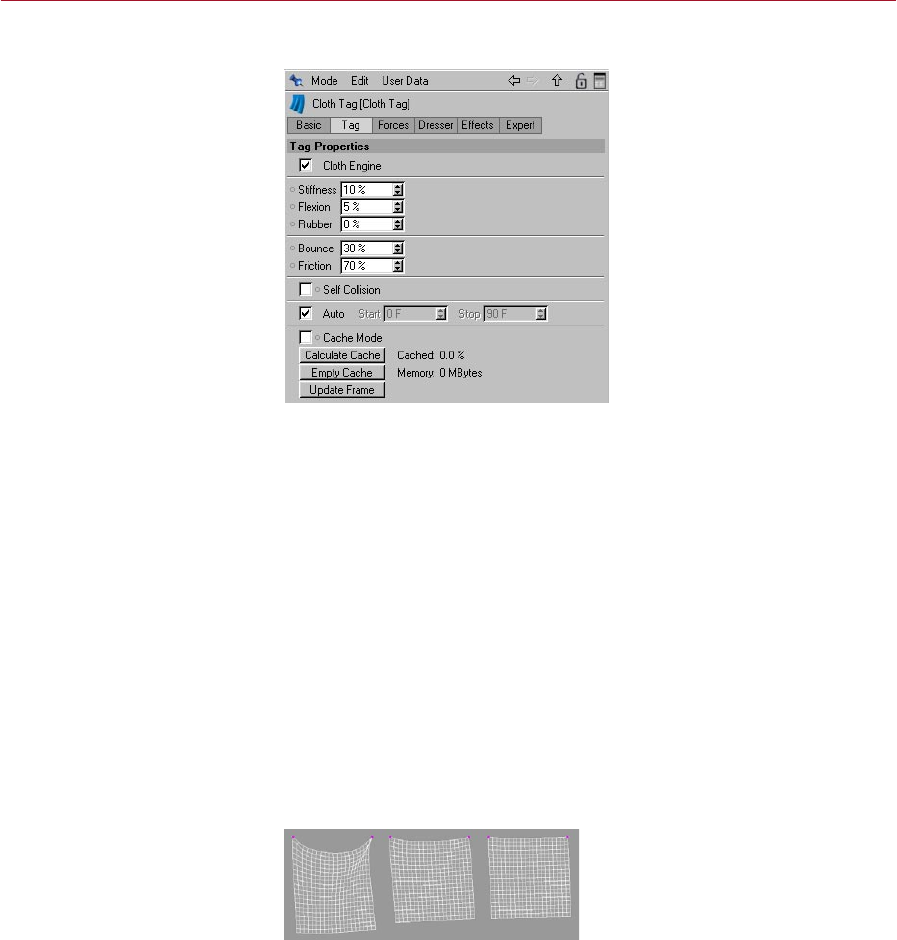
MOCCA CLOTHILDE 121
Tag Properties
The settings found on this tab affect the actual structure of the control cage. This also
provides functions that handle the stored calculations of the cloth simulation.
Cloth Engine
This option turns the cloth simulation on and off. With a checkmark placed in the
checkbox for this eld, the cloth engine is live. This turns on the engine, allowing for
solutions to be solved for the cloth object.
At many points when applying clothes to an entire character, certain pieces of cloth
don’t need to be simulated and can slow down the performance. For example: A jacket
is being added to a character’s wardrobe. Now, during the simulation it will need to
collide against the shirt during the draping process. The pants wouldn’t need to be
a part of this simulation, so its Cloth Engine option could be disabled.
Stiffness
This parameter controls the overall stiffness of the cloth object. As this value is
increased the internal springs will exert more control over the points of the geometry,
giving the cloth a more rigid look.
Stiffness set to 10% (left), 30%
(center) and 100% (right).
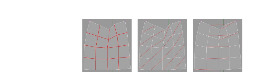
122 CLOTHILDE MOCCA
Springs work much in the same way as those found in Soft Body Dynamics:
Structural springs (left), shear
springs (center) and exion
springs (right).
Structural
This will connect each point of the cloth object to its neighboring point with an
imaginary spring. These points must share a common polygonal edge for a spring
to be created. These springs are essentially the topology of the geometry that is
being used.
Shear
This will also create imaginary springs based on the geometry that is being used.
These springs will connect the points in a way that allows the cloth polygons to
fold in any direction. Without this stabilization, the four-sided polygons could
collapse.
Flexion
As much as the name describes, these springs are created to allow the control cage
to ex. This will create a spring that will start from a single point on one polygon
and will connect to another point on another polygon, as long as that polygon is
not a direct neighbor of the originating polygon. In other words, for any given point
the spring will skip the rst contiguous point and go on to the next. The percentage
value will determine the strength at which the points on the cloth will be able to
ex or bend. A high percentage value will not allow the cloth to bend as easily;
whereas, a low percentage value will allow for the cloth to bend quite easily.
Rubber
This parameter controls the amount of stretching that the cloth object will be able to
do. The default value of 0% will not allow for the cloth to stretch; whereas, a value
of 100% will allow the cloth to be stretched. This parameter can also be controlled
through a vertex map by using the respective eld on the Effects tab.

MOCCA CLOTHILDE 123
Rubber set to 0% (left), 50%
(center) and 85% (right).
The image above shows three identical cloth objects with the exclusion that the
Rubber setting has been altered. The higher that this value is, the more that the
cloth objects can stretch.
Bounce
This parameter controls the amount of bounce for the cloth object. This value is taken
into account during a collision with a Collider object. The higher this value the more
bounce will occur from the cloth object when colliding with an object. So, a very high
value will cause the cloth to bounce away from the collision object. This value will also
look at the Bounce value found in the Collider tag for the collision object.
Providing real world examples here will aid in understanding how this parameter
affects cloth collisions. With a leather jacket, for example, this would create a high
amount of bounce due to its sturdy, heavy surface. A woolen sweater, however, would
create very little bounce because of its soft, airy surface.
Friction
This parameter is also only taken into account when the cloth object collides with a
collision object. This controls how much friction is produced when the cloth hits a
collision object. The lower this value is, the less friction that will be generated for the
cloth object when a collision occurs. So with a low value in this eld, the easier it is
for the cloth to glide across the colliding object. Like the Bounce parameter, this will
take the value of the Friction parameter located in the Collider tag of the collision
object into account.
To prove an example of this, look at two given shirt fabrics: A cotton tank top and a
silk shirt. The cotton tank top would produce a lot of friction due to the material and
its tight t to the character. Now the silk shirt would produce almost zero friction on
the character surface due to its smooth surface.
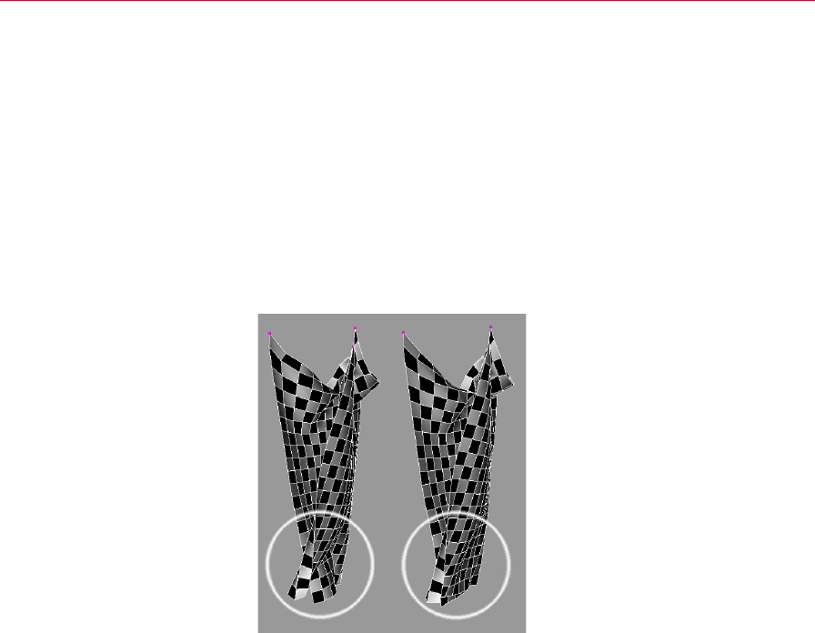
124 CLOTHILDE MOCCA
Self Collision
This option will allow for the cloth object to collide against its own points. This
prevents the cloth from penetrating its own surface when the simulation is being
played. Due to the amount of calculations that the solver must perform when this
option is enabled, it may cause the playback in the viewport to slow down. When
extreme forces are applied to the cloth object, intersection may still occur due to
these extreme forces. Using Self Repulsion (Forces tab) in addition to, or instead of,
will help with avoiding intersecting cloth.
Auto, Start, Stop
With the Auto option is enabled, the cloth engine will be linked to the maximum length
of the current scene. In the Project Settings dialog, for example, if the Maximum frame
is set to 150, the cloth engine will calculate for the entire 150 frames.
Self Collision enabled (left) and
disabled (right).
When the Auto checkbox is disabled, the Start and Stop eld will become active. This
allows for the length of time at which the cloth engine will calculate for.
Cache Mode
When this mode is enabled, the cloth engine will look at the stored calculations of
the simulation. This allows for fast playback of the animation without having waiting
on the engine to solve for the cloth.

MOCCA CLOTHILDE 125
Calculate Cache
This is the function that will create the stored calculations for the cloth engine to
read. After being executed, the engine will begin playing through the animation as
it stores the calculations into memory. After the calculation is nished, Cache Mode
will be automatically enabled and will begin reading the cached solution.
You can observe the percentage of the scene that has been calculated for through the
static text display in the Attribute manager. This is located right next to the Calculate
Cache button. The amount of memory that the cached solution takes up can also be
observed in this same area.
In order to use Scene Motion Blur, the cloth object must be cached for the
motion blur to be calculated and rendered correctly. A cached solution must
also be present in order to render the cloth object(s) using CINEMA 4D Net
Render.
Empty Cache
This deletes the stored calculations from memory. After emptying the cache, the
cloth will return to its Initial State.
Update Frame
Many times after a simulation has been cached, there are a few frames that need
settings to be adjusted in order to get the cloth to react or collide correctly. After
having cached a solution for the cloth simulation and nding some of these errors,
the settings within the Cloth tag can be adjusted and re-simulated. After those
settings have been adjusted properly, the Update Frame command will update only
the current scene frame for the cached solution.
To adjust and re-simulate the cloth settings just disable the Cache Mode checkbox so
the cloth engine will look at the tag and not the cached solution.
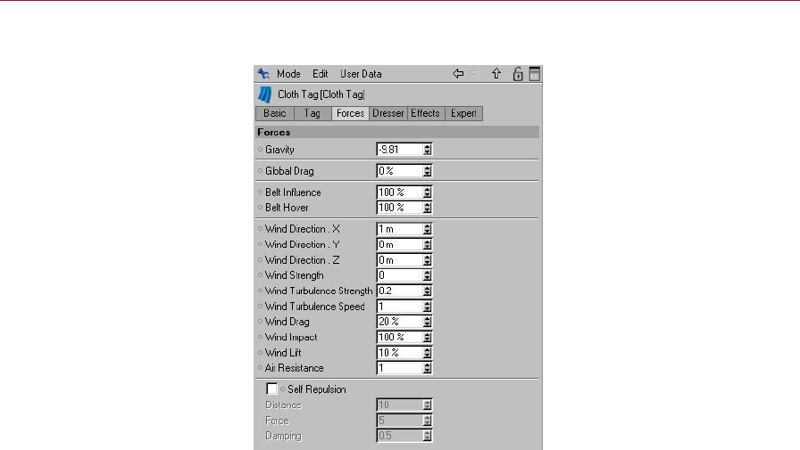
126 CLOTHILDE MOCCA
Forces
Gravity
Gravity is a force that pulls the cloth object in a certain direction. The Gravity parameter
will always be calculated for the Y-axis and will have an effect on the cloth object
on that axis. If the number in this eld is negative, Gravity will be calculated down
the Y-Axis. If it’s positive it will be calculated up the Y-axis. This value will default to
–9.81, which is Gravity’s actual force in the real world (-9.81 m/sec^2 to be exact!).
By lowering this value, this will increase the amount of force that Gravity will exert
on the cloth object in the –Y direction.
Global Drag
Much like that of the Wind Drag parameter, but this parameter deals with the energy
loss of the cloth object on a global basis. Meaning that this will control the dampening
(energy loss) for all parameters of the cloth object not just the wind.
This can become very handy in situations where there is any extreme motion performed
by a character or object and the cloth needs to stabilize for those few frames. This
parameter can be animated; increasing the value to 100% during these frames of
animation can stabilize the cloth at these moments of intense motion.
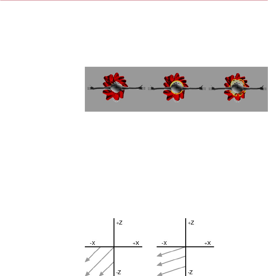
MOCCA CLOTHILDE 127
Belt Inuence
This percentage value will determine how much inuence the Belt object has on the
cloth object. A value of 0% will not allow for the Belt object to inuence the cloth
object at all, whereas a value of 100% will have complete inuence on the cloth object.
The area of Inuence can be controlled through a vertex map using the corresponding
section on the Effects page.
Belt Hover
Belt Hover set to 0% (left), 100%
(center) and 200% (right).
This value controls how far or how close the cloth object will be to the Belt object.
When the cloth points sample to the deformed geometry, they have an initial distance
that represents the Hover value at 100%. This means that if the value is decreased
to 50%, the cloth points will be half the distance from their initial state. A value of
200% will be twice the distance from the points’ initial state.
Wind Direction settings
These parameters dene the direction of the wind. You can enter positive or negative
values. For example, you can set Wind Direction X to a negative or positive value to
make the wind blow along the –X or X-axis respectively.
When dealing with wind blowing along two or three axes at the same time, a vector
will be calculated between the directions. With the given direction of –1 m / 0 m /
-1 m a vector will be created at a 45-degree angle in the negative XZ quadrant (see
left image below).
Wind Direction set to
–1 m / 0 m / -1 m (left)
and –50 m / 0 m / -1 m
(right).
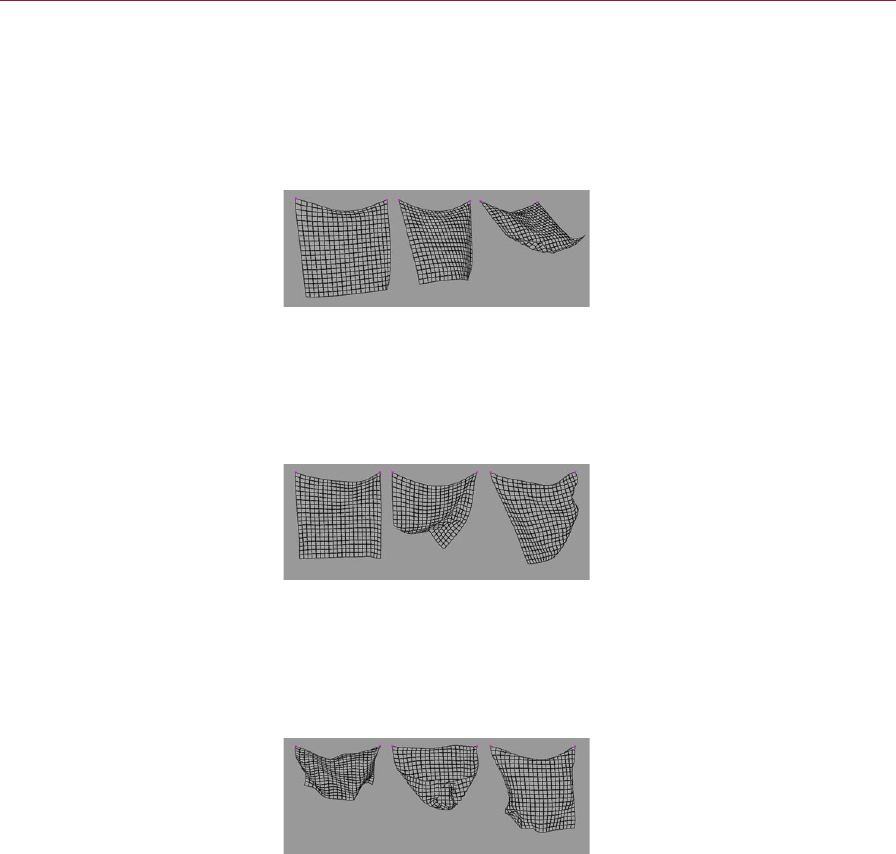
128 CLOTHILDE MOCCA
In order to adjust this 45-degree angle that is created from the direction of –1 m /
0 m / -1 m, entering a value after the positive / negative coefcient will do just this.
With the given direction of –50 m / 0 m / -1 m, the wind direction would deviate that
45-degree angle closer to the X-axis (see right image above). This would make the
direction almost perpendicular to the Z-axis
Wind Strength
Wind Strength set to 0.5 (left),
1 (center) and 2 (right).
The Wind Strength parameter controls the strength of the wind. The higher this value
the more the wind will appear to affect the cloth. The other wind parameters are
multiplied from this value, so a value of 0 in this eld will not exert any wind forces
on the cloth object.
Wind Turbulence Strength
Wind Turbulence Strength set to
1 (left), 5 (center) and 10 (right).
Real world wind blows in bursts. At some points it can be intense and at other points
very weak. The Wind Turbulence Strength parameter controls this variation. With the
value set to 0 the wind will have no variation, by increasing this value the wind will
begin to vary the strength of the bursts.
Wind Turbulence Speed
Wind Turbulence Speed set to 1
(left), 5 (center) and 10 (right).
This parameter works in connection with the Wind Turbulence Strength parameter.
Since the strength parameter controls the variation in bursts, this parameter controls
the speed at which those bursts take place. The higher this value the faster the wind
will pulsate.
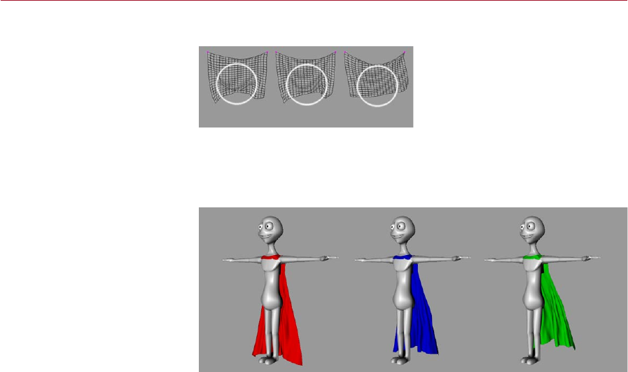
MOCCA CLOTHILDE 129
Wind Drag
Wind Drag set to 0% (left),
50% (center) and 100% (right).
When wind is affecting the cloth object, this parameter controls the damping, or the
energy loss of the cloth as it reacts to the wind.
Wind Impact
Wind Impact set to 0% (left),
50% (center) and 100% (right).
Any surface that deals with wind, such as cloth, will have a different tolerance at
which a wind force will hit that surface. The Wind Impact parameter controls just
this. A value of 100% will determine that a wind force will hit the cloth object’s entire
surface. A value of 0% will not allow for the wind force to hit the cloth’s surface.
Wind Lift
Lighter cloth materials or fabrics are lifted very easily by wind forces, while heavier
fabrics, much like leather, are not lifted as easily by the wind. A value of 100% will
allow for the cloth to be lifted very easily by the wind. A value of 0% will not be
lifted by the wind.
Air Resistance
As a piece of cloth travels through the air it will encounter a type of wind force, even
if the wind is not blowing. The Air Resistance parameter will simulate this pseudo
wind force. A high Air Resistance value will make the cloth appear as if it is moving
through water. A low value for this parameter will make the cloth appear as though
it is moving through air.
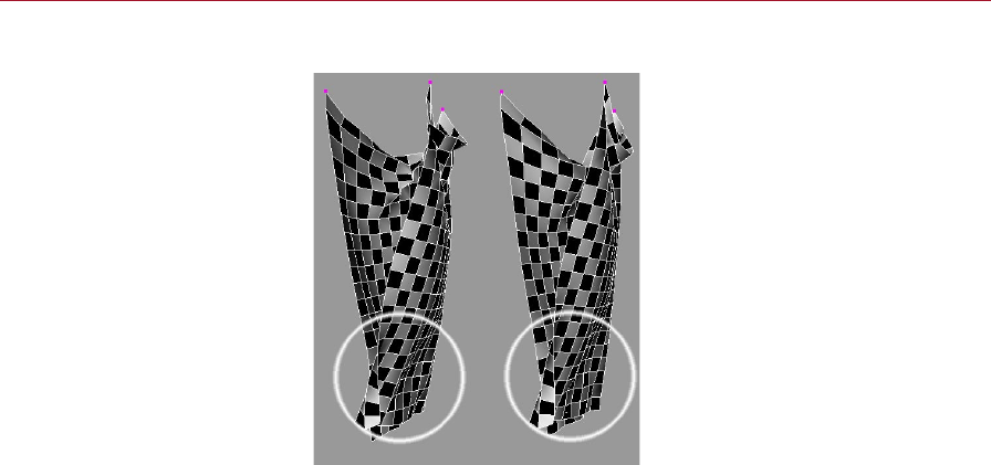
130 CLOTHILDE MOCCA
Self Repulsion
Self Repulsion (left) and
Self Collision (right).
Using this option together with, or instead of, the Self Collision option can speed
up and improve the cloth simulation. This will allow for the cloth points to repel one
another, which can aid in situations where extreme forces or motions cause the cloth
points to intersect with its surface.
Distance
This determines the distance at which the cloth points will begin to repel one another.
The default value of 10 will begin repelling the cloth points when any one point comes
within 10 units of another cloth point.
Force
Once a cloth point meets the dened Distance when approaching another cloth point,
the Force parameter will specify the speed with which the cloth points repel each
other. The higher the number the faster the points will repel each other.
Damping
Damping is in essence the amount of energy loss from some sort of external force.
In this case, this parameter is the amount of energy loss or gain depending on the
value, after the Force is produced from the repulsion. A value of 0.5 will begin slowing
down the Force parameter. A value of 2 will double the speed (energy gain) of the
Force parameter.
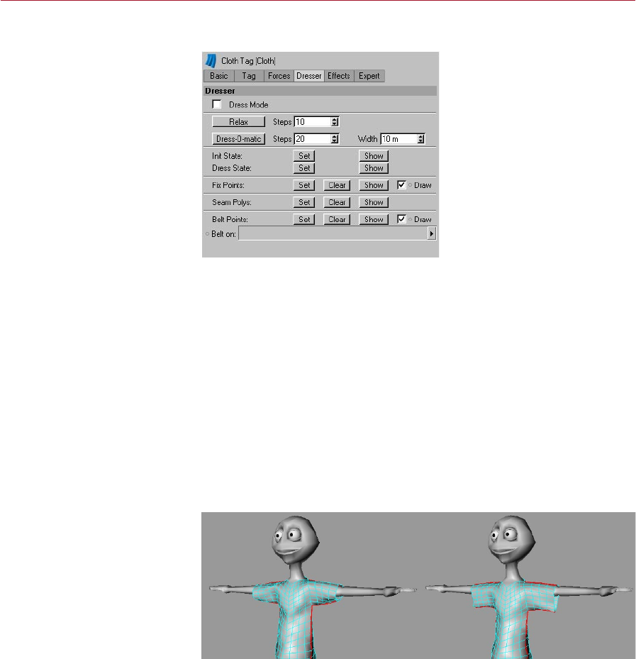
MOCCA CLOTHILDE 131
Dresser
Dress Mode
Once a garment has been assigned its dress state (the original polygonal model) this
mode will become active. While in this mode, the Cloth tag will display all seams that
have been created with a yellow cross-stitch for the affected polygons. The Cloth tag
will change its icon in the Object manager when this mode is active.
Relax
This command is similar to the Dress-O-Matic function, with the exception that it
takes all Forces tab parameters into consideration. When using the Dress-O-Matic
button to drape the cloth onto the colliding character, the properties that dene the
cloth are taken into account and not forces like Gravity. The Relax button will allow
the user to apply real world forces such as Gravity and Wind during the dressing
state to the cloth object. An Initial State for the garment must be established before
running this command.
Before using Relax (left) and
after (right).
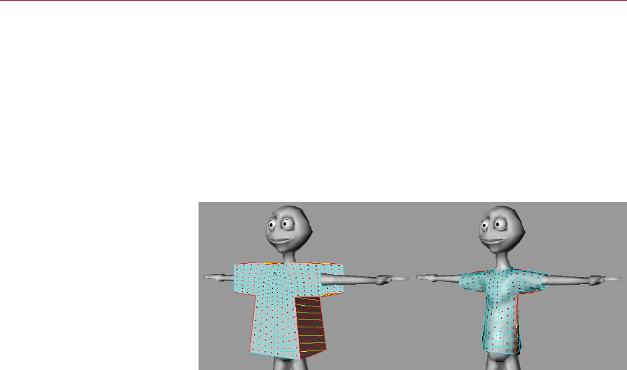
132 CLOTHILDE MOCCA
At any time during the draping simulation pressing the Esc key will stop the
simulation in its current state. This means that if the garment is at a desired
shape, but the simulation still has more Steps to calculate for, the simulation
can be cancelled without having to wait for the simulation to play out.
Steps
This determines the number of times that the cloth engine will sample as it applies
gravity and wind forces onto the garment. The higher that this number is, the longer
the forces will affect the cloth object for.
Dress-O-Matic
Before using Dress-O-Matic (left)
and after (right).
This is the command that actually drapes the garment onto the character. When this
command is executed, the cloth engine will shrink the seam to the dened Width
setting. As the cloth engine shrinks the seam of the garment to that width, all points
of the garment will drape with the seam. How the points move with the seam as it is
draped will be determined by parameters such as Stiffness, Flexion and Rubber. This
can also be stopped at any time by hitting the Esc key.
Steps
This eld determines the number of times that the cloth engine will sample as it drapes
the garment onto the character. The higher the number, the longer it will take the cloth
engine to calculate the simulation, but the smoother the cloth garment will be.
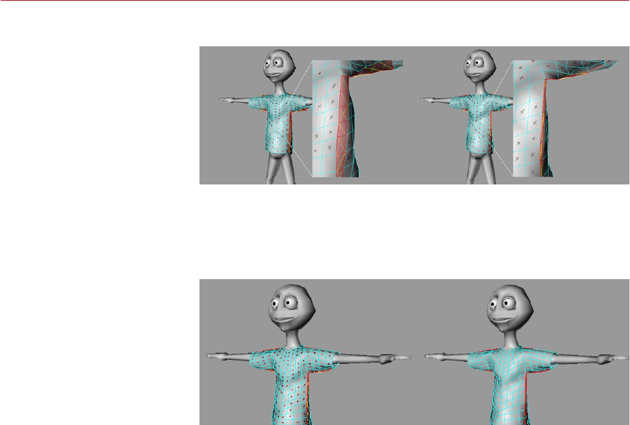
MOCCA CLOTHILDE 133
Width
Width set to 10 m (left) and
3 m (right).
This value determines the goal distance that the polygons of the seam will rest at.
With a value of 10 m, the cloth engine will shrink the seam so that the polygons are
10 m in size.
Set Initial State
Before using Set Initial State
(left) and after (right).
After the cloth garment has been dressed on the character using this command, the
cloth engine will now use this current state of the cloth as its starting pose. After
using this command, Dress Mode will be automatically disabled allowing for the
cloth simulation to run.
Show Initial State
If at any point during the simulation an error is encountered, or the simulation just
needs to be restarted, using this command will return the cloth object to its initial
state, which was dened by the Set Initial State command.
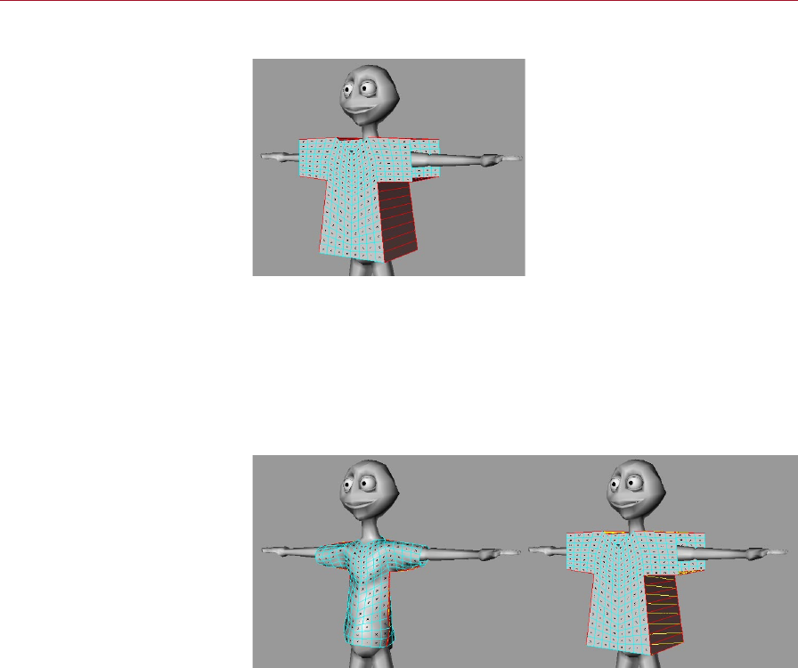
134 CLOTHILDE MOCCA
Set Dress State
In Dress Mode each polygon will
have a black ‘X’ on its surface.
After modeling the clothes, using the Set Dress State command will determine the
model’s original shape. Once this original state is specied, the cloth engine can
then drape the garment onto the colliding character when told to do so. Using this
function will automatically enable Dress Mode. This can easily be identied in the
viewport as each polygon will have a black ‘X’ on its surface. These will be removed
once an initial state has been dened.
Show Dress State
Before using Show Dress State
(left) and after (right).
If the garment has already been draped onto the character and the outcome is not
the desired result, using this function will return the garment to its original dress
shape. This will allow for parameters to be adjusted and then the garment can be
draped back onto the character.
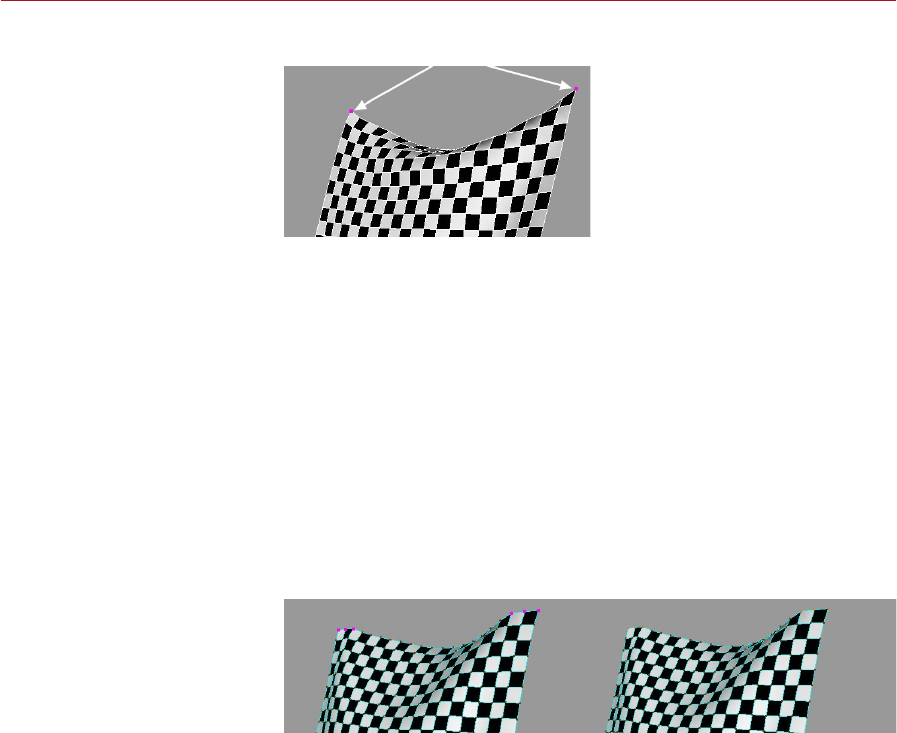
MOCCA CLOTHILDE 135
Set Fix Points
This points indicated by the
arrows have been xed using the
Set Fix Points command.
In reality, cloth objects such as curtains are usually pinned using a curtain rod. The
Set Fix command does essentially the same thing: it will x the selected points at
their current position, allowing for the cloth to be pinned in place. To x points just
select the desired points of the cloth object with a selection tool and execute the
Set Fix Points command.
Clear Fix Points
Much like the other Clear buttons, executing this function will remove any points
that have been previously xed for the cloth object.
Show Fix Points
Using this command will show the selection of points that the cloth object is being
xed from.
Draw Fix Points
Draw Fix Points enabled (left)
and disabled (right).
Enabling this option will highlight the xed points in the viewport. This will clearly
identify any points that have been xed for the cloth with large purple dots. Disabling
the option will remove those xed points from the view of the viewport.
Use xed points whenever possible. This will improve playback and
performance because the cloth engine can simulate the cloth object from
these xed points.
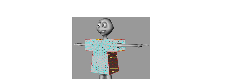
136 CLOTHILDE MOCCA
Set Seam Polys
Seams are displayed bright
yellow when their polygons are
selected.
Most clothes are stitched together using seams. This cloth engine uses that same
approach. As the tutorial will show, garments are created with a front and back plane
that are connected together. The connection of these two planes of geometry will be
considered as the seam. To dene a seam, select all of the polygons that connect the
front and back planes and use the Set Seam command. This will be visually identied
in the viewport with yellow cross-stitches for the selected polygons. If the Seam is
identied before a dress state is dened for a garment, the garment’s current state
will be stored as the Dress State. The Dress Mode checkbox will be enabled as well
after hitting the Set Seam Polys.
Clear Seam
Using this function will clear any polygons that have been previously set as the
seam.
Show Seam
This displays the selection of polygons that dene the seam for the garment.
Before dening the seam of the garment, select the polygons for both the
front and back planes and use the Subdivide command to increase the
resolution of the garment. The seam will be identied by the point order
of the garment, so setting the seam before increasing the subdivision
would cause the seam to break because point orders would change after
subdividing.
Belt On
The object that is dened in this box will be the cloth’s Belt object. When an object
is specied in this box, cloth points that are set for the belt will be able to move with
that deforming surface.

MOCCA CLOTHILDE 137
Belt Points
You can choose which points will
be attached to the Belt object.
When a Belt object is specied, any selected point can be attached to the deformed
character model. The Set Belt Points will dene what points will be attached to the
deformed mesh.
About Belting
Let’s think about what an actual belt does for real-world clothing before moving on.
When pants are belted, they stay attached to the person no matter where he moves.
With a digital character the principle is the same but the bones deform the actual
geometry to simulate movement, so attaching the cloth to the character needs to be
handled a little differently than just xing the points. Fixing the points will just keep
the points in a single xed position. What belting does is attach specied points to a
specied deformed polygon object. This allows for the cloth to stay attached to the
deformed points of the character at a denable distance.
This can be used for more than just a belt on a character. Buttons on a shirt are a
further example of what can be done using belting. But, being that most shirts have
multiple buttons, the object that will serve as the buttons will need to be connected
into one object. Another time this may come in handy is to go from a T-pose of a
character to its start pose of the animation. If the animation starts the character off
in an extreme pose, belting all points of the garments to the character’s geometry will
aid in getting the garments into position for the extreme pose. After the garments
have been properly simulated into position, dening this position as its Initial State
in the Dresser tab will allow the simulation to start from this position or state.
Set Belt Points
When this command is executed the current selected points of the cloth object will
be set as the belted points.
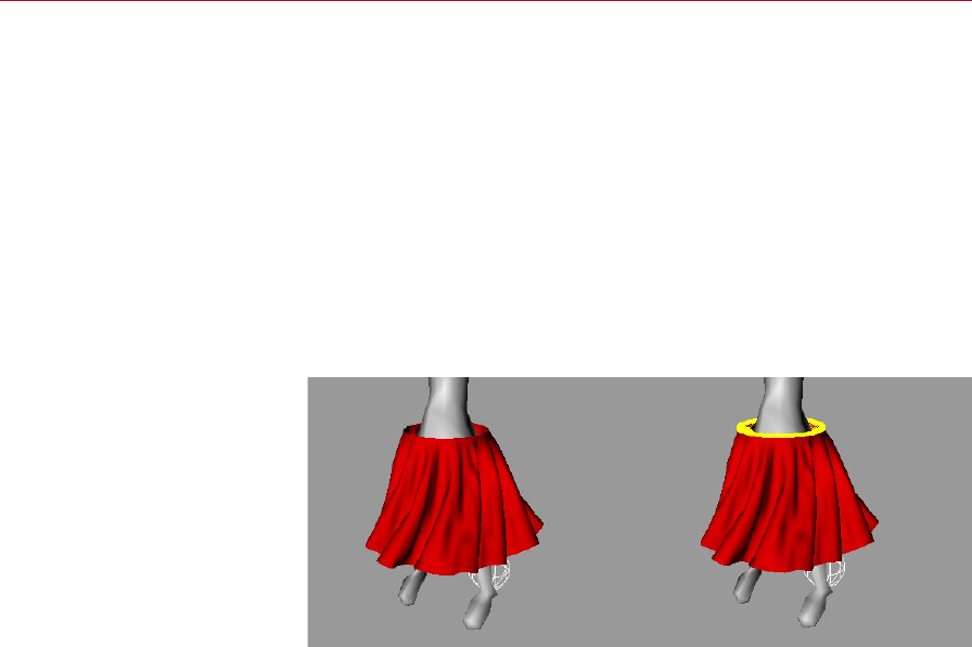
138 CLOTHILDE MOCCA
Clear Belt Points
This will remove any points that have been assigned to the belt object.
Show Belt Points
This will reselect any of the points that have been assigned to the Belt object. If
this command is executed while in any other mode than points, CINEMA 4D will
automatically switch over to Points mode.
Draw Belt Points
Enabling this checkbox will display every point that is belted as a yellow dot. A line
or sample will be drawn from this point to a relatively close area on the deforming
object. This is represented as a yellow line in the viewport. Disabling the option will
remove the display in the viewport.
Draw Belt Points disabled (left)
and enabled (right).
When the points of a cloth object are belted to a deformed object, a sample is sent
out from each of the belted points within a reasonable area on the deformed surface.
These samples can be adjusted using parameters that are found within the Forces
tab: Belt Inuence and Belt Hover.
Animating Belt Objects
The Belt On text box on the Dresser tab has the ability to be animated, meaning
that multiple Belt objects can be used to inuence the same piece of cloth. The
problem with this is that the belted points that are dened with the ‘Set’ button
can’t be animated; however, vertex maps can be animated to achieve this same type
of effect.
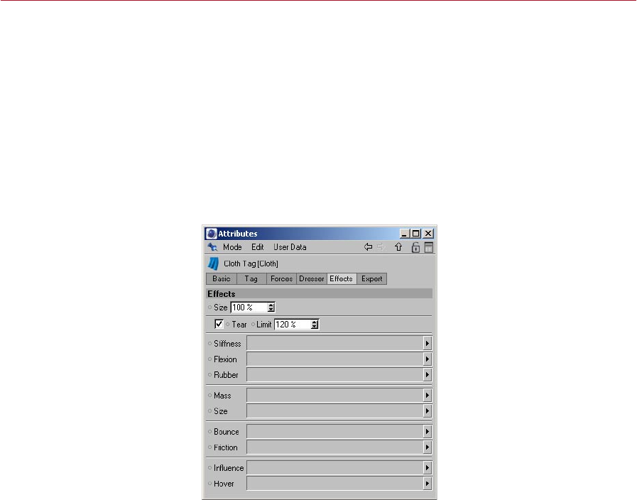
MOCCA CLOTHILDE 139
To do this you will rst need to belt all points that will be inuenced by any Belt
object. Using the Live Selection or new Brush tool, paint the points that need to be
inuenced by the rst Belt object with 100% weight. Another vertex map will need
to be created for the points that will be inuenced to the second Belt object. Drag
and drop the rst vertex map into the Inuence text box on the Effects tab and set
a keyframe for this tex box using the gray dot.
Record a keyframe when the change between the two Belt objects occurs by Ctrl-
clicking on the gray dot next to the Belt text box. At this same frame, you need to
switch from the rst vertex map to the second one by dragging and dropping it into
the text box. Ctrl-click the gray dot to create a keyframe for this change.
Effects
Here vertex maps can be dened and used to control what areas are affected by
what parameters. For example: Often, when belting points to a deformed object,
the points don’t need to be completely inuenced by that object. Painting a vertex
map that shows where the cloth object should be inuenced can be dened in the
Inuence box on this page.
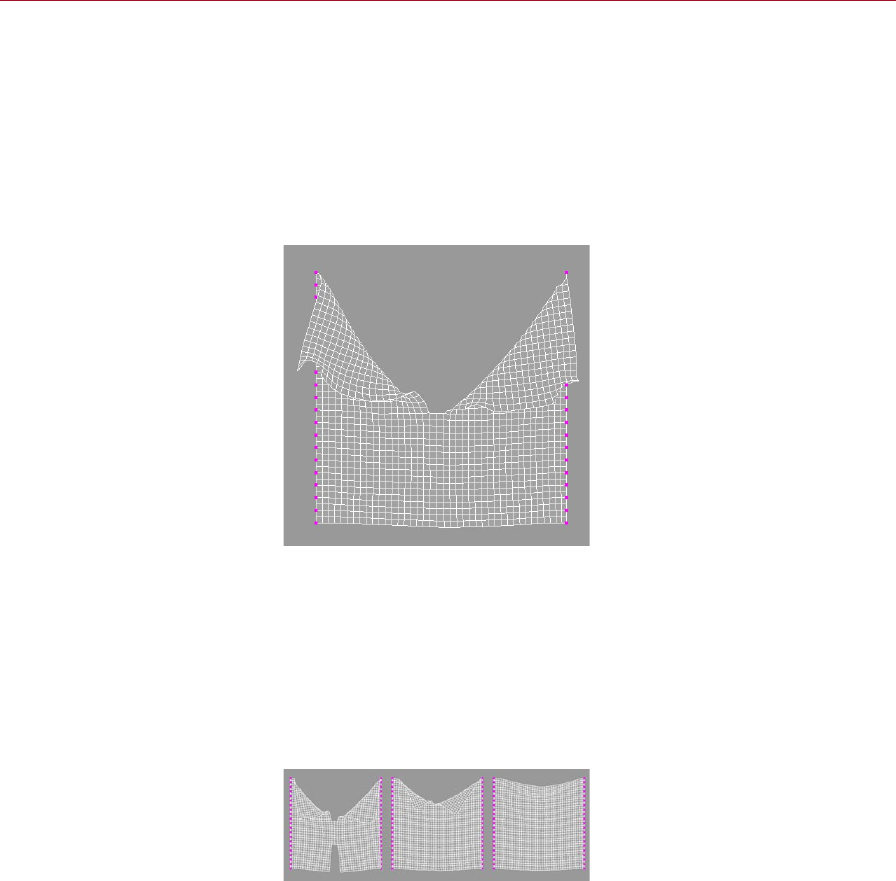
140 CLOTHILDE MOCCA
Size
This value controls the shrinking or growth of the cloth object. This is especially useful
during the dressing stage of the clothes. A value of 100% will let the cloth remain
at its current size meaning that no shrinking or enlarging is taking place. A value of
50%, however, will shrink the cloth garment to half of its original size. A value of
200% will enlarge the cloth to twice that of its original size. This value works together
with a vertex map dened in the Size box.
Tear
Tear enabled.
With this option enabled the cloth engine will allow for tearing to take place during
the simulation. But in order for this tearing to work, the cloth object must be a child
of the Cloth NURBS object. In other words, the Cloth NURBS is the actual surface
that will be torn, not the original cloth object. A tear is determined by the Stiffness
of the cloth object. The lower the amount of Stiffness the easier it is for the cloth
to be torn, with the exception that a maximum limit must be dened at which the
tear will occur.
Limit
Limit set to 110% (left), 120%
(center) and 130% (right)
This is the maximum length that the structural springs of the cloth object can endure
before a tear occurs. A Limit of 150% means that once the springs go beyond 1.5 times
the initial length, determined by the Initial State of the cloth, the cloth will be torn.

MOCCA CLOTHILDE 141
Tearing can also be controlled even further with vertex maps. As stated previously,
tearing is based on the stiffness of the cloth; so using a vertex map in the Stiffness
setting on the Effects tab will give you ultimate control over cloth tears.
Stiffness
The vertex map that is specied in this box will control how the Stiffness setting
affects the cloth. This is for any given point: The stiffness setting is set to 40% and
the vertex map that is being used is a gradient going from 100% to 0%. The points
that have been painted with 100% weight will be the points that have 40% stiffness
and the points that have 50% weight will have 20% stiffness.
Flexion
The vertex map dened in this box will control where and how the Flexion springs
affect the cloth object. With a Flexion value of 50%, all points that have 100% weight
will have a Flexion value of 50%, whereas points that have 50% weight will have a
Flexion value of 25%.
Rubber
This box allows for a vertex map to dene where and how the cloth will stretch. With
a Rubber value of 50%, any point that has 100% weight will stretch by 50%, where
a point with 50% weight will be able to only stretch by 25%.
Mass
Different areas on a piece of fabric can have different mass values. Depending on if
the garment has a pocket, a collar, a zipper, and so on those areas will carry more
mass due to the extra amount of cloth involved. Specifying a vertex map in this eld
will allow for adding extra mass to those areas. With a Mass value of 2, a point that
has been painted with 50% weight will now have a Mass value of 1.
Size
This will probably be most commonly used during the dressing state to t the clothes to
the character. Using a vertex map in this box will allow for certain areas on a garment
to be shrunk or enlarged, tailoring the clothes to the character. As mentioned in the
entry for the Size percentage setting at the top of the tab, a value of 100% is the
original size of the object. With that, an area that has 50% weight painted in the
vertex map will shrink to half the size of the original object.
A vertex map can only have a maximum value of 100%, so in order to enlarge an area
the Size percentage value would need to be increased to a value greater than 100%.
With a Size value of 200% an area with 50% weight will now be the original size of
the object. An area with a weight value of 75% will now have a Size value of 150%.

142 CLOTHILDE MOCCA
Without a vertex map for Size
(left) and with (right).
In this image, the shirt on the left side has no vertex map assigned in the Size box.
The shirt on the right side of the image is using a vertex map to control the Size of
the garment.
Bounce
A vertex map can be dened within this box to control the areas that bounce during
a collision. With the given value of 50% in the Bounce box, a point with 100% weight
will have 50% bounce, whereas a point with a 50% weight will have 25% bounce.
Friction
Certain areas of a garment may have a lot of friction with its colliding surface, primarily
in the collar and shoulder areas of a shirt, for example. But that’s not to say that one
Friction value will be able to achieve this. Painting these areas using a vertex map can
specify what areas are stickier than others. A point weight value of 0% will have no
friction, whereas a point weight value of 100% will have complete friction.
Inuence
This box controls the amount of inuence the Belt object has over the cloth object.
Any points with a weight value of 100% will be completely inuenced by the Belt
object. A value of 0% will not be inuenced at all by the Belt object.
Hover
With the example of a real belt inuencing a pair of pants, areas of the pants around
the sides of the character’s hips would be a lot closer to the belt, whereas areas around
the crotch would be allowed a little more freedom. Using a vertex map in this box
would allow for painting the areas on the sides of the pants closer to the Belt object,
and giving a little extra room in the crotch area.
Remember that a distance is dened from the Belt object to the set points of the
cloth object. The Belt Hover parameter on the Forces tab controls that distance. With
a Belt Hover value of 100%, painting the areas around the crotch with 100% weight
will leave that area at its current distance to the Belt object. Painting the sides of
the pants with 50% weight would half this distance, bringing that area closer to the
Belt object.
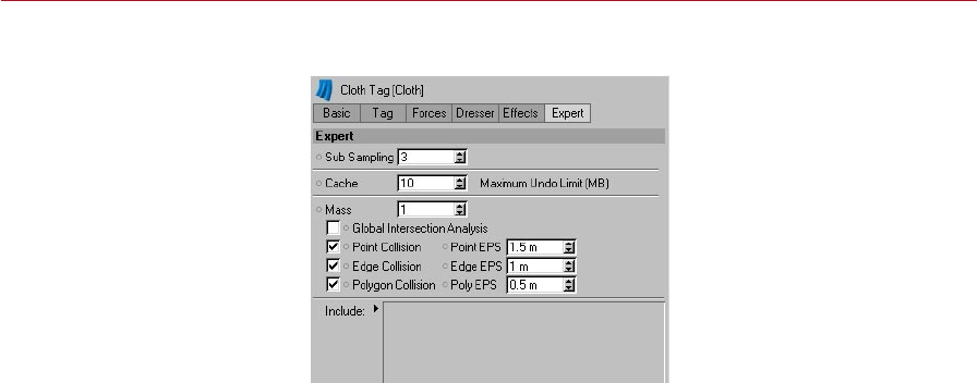
MOCCA CLOTHILDE 143
Expert
These settings control how the cloth engine solves for solutions during the cloth
simulation. Here you’ll nd settings such as the sub sampling and mass values that
need to be solved for the cloth object. All settings found within the Cloth tag will be
calculated from these settings.
Sub Sampling
This setting determines the amount of depth that the cloth simulation may undergo
while nding solutions for the cloth object. Many things like collisions and real world
forces can affect the cloth objects at fractions of a second. CINEMA 4D will play back
the animation in frames, but the cloth engine may need to calculate the simulation
between these frames. The Sub Sampling value will determine how many times the
cloth engine will calculate for the simulation in between each frame. The higher the
number, the more accurate that the simulation will be, but this will begin slowing
down the speed at which the cloth is simulated and played back.
Cache
This value corresponds to amount of RAM in megabytes being used for the Undo
buffer. Once the simulation has been cached, the tag is then stored in memory. When
any parameter is changed, a copy of this tag must be copied to the Undo buffer in
order to perform undo actions. Changing a lot of these parameters can very quickly
begin eating up memory. With the default limit of 10 MB, any cached solution less
than 10 MB will work as expected. If the cached solution exceeds 10 MB in size, the
tag will not be copied to the Undo buffer preventing an out of memory error.
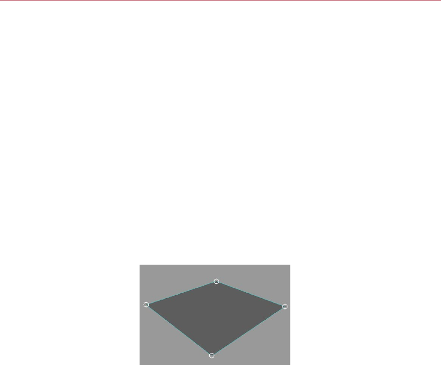
144 CLOTHILDE MOCCA
Mass
This setting denes how heavy the cloth will be. The heavier a cloth object is, the
less that impact forces such as gravity, wind, and collisions will have on it. How the
mass is spread across the cloth object can be better dened using a vertex map on
the Effects page.
Point Collision
With this option enabled, the cloth engine will calculate collisions for every point in
any cloth object’s geometry. This means that once any point that belongs to the cloth
object hits another surface, it will not be allowed to pass through that surface.
About collision settings
Cloth is usually colliding against some kind of surface. Whether it’s a shirt colliding
against a character’s body, or a tablecloth colliding against a table, cloth for the
most part will be colliding with some kind of object. The cloth engine will be
calculating for these numerous factors whenever the cloth is being simulated. How
the cloth engine calculates the collision for the geometry can be specied manually
by placing a checkmark next to the corresponding polygonal geometry types. By
default, Point, Edge, and Polygon will be enabled, but any of these geometry types
can be disabled.
Point EPS
The higher the EPS value, the
farther apart the cloth points
will collide against the collider
object’s points.
The EPS stands for epsilon. Think of this setting as an imaginary eld that surrounds
each point of the cloth object. The higher the EPS value, the farther apart the cloth
points will collide against the collider object’s points. If points begin falling through
the collider object, the Point EPS setting needs to be increased.
Edge Collision
With this option enabled, the cloth engine will calculate collisions for every edge in
any cloth object’s geometry. This means that once any edge that belongs to the cloth
object hits another surface, it will not be allowed to pass through that surface.
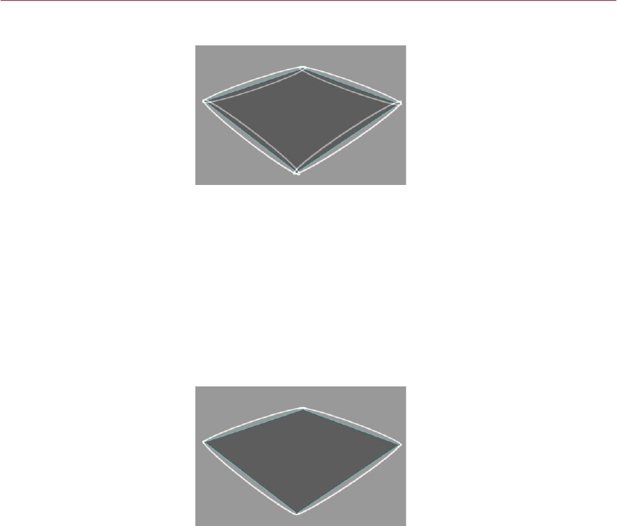
MOCCA CLOTHILDE 145
Edge EPS
The higher the EPS value, the
farther apart the cloth points
will collide against the collider
object’s edges.
Think of this setting as an imaginary eld that surrounds each edge for both cloth
and collider objects. The higher the EPS value, the farther apart the cloth edges will
collide against the collider object’s edges. If edges begin falling through the collider
object, the Edge EPS setting will need to be increased.
Poly Collision
With this option enabled, the cloth engine will calculate collisions for every polygon
in any cloth object’s geometry. This means that once any polygon that belongs to
the cloth object hits another surface, it will not be allowed to pass through that
surface.
Poly EPS
The higher the EPS value, the
farther apart the cloth points
will collide against the collider
object’s polygons.
Think of this setting as an imaginary eld that surrounds each polygon for both cloth
and collider objects. The higher the EPS value, the farther apart the cloth polygons
will collide against the collider object’s polygons. If polygons begin falling through
the collider object, the Poly EPS setting will need to be increased.

146 CLOTHILDE MOCCA
Global Intersection Analysis
During animation, either intentionally or by accident, an area such as the armpit of a
bipedal character can trap the cloth object. This can cause some cloth engines to come
to a complete halt being that the engine cannot nd a solution. Global Intersection
Analysis (GIA) will nd the best possible solution that will allow the cloth engine to
continue its simulation.
Include
Any objects that are placed within this box will be the objects included in the
calculations. In many situations there may be multiple pieces of cloth or multiple
collision objects that are located in the scene. This box will allow you to individually
dene what pieces of cloth or collision objects will be a part of the calculation for the
Cloth tag. If this box is left blank with no objects in it, all cloth objects and collision
will be taken into account.
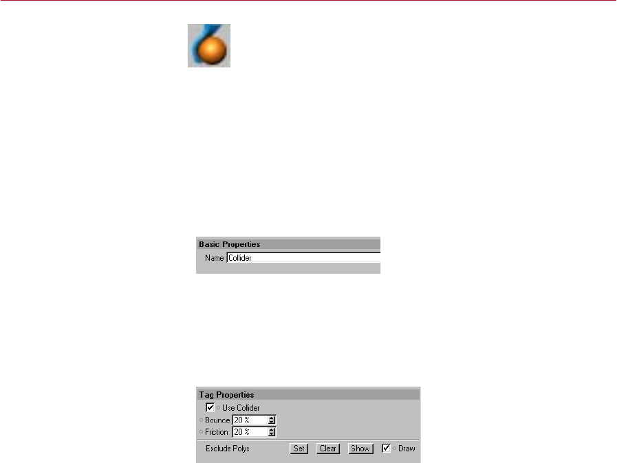
MOCCA CLOTHILDE 147
Collider Tag
The Cloth tag identies an object
as a cloth object.
Specifying what object will collide with the cloth objects is done in the
same way as dening a cloth object: by adding a Collider tag to the desired
object.
To add a Collider tag to an object:
- Select the object and in the Object manager, choose File > Clothilde Tags >
Collider.
The Collider tag will be applied to the selected object that can now collide with any
cloth object.
Attribute manager settings
Basic Properties
Name
The only parameter on this tab is the Name of the Collider tag. It will always default
to ‘Collider’ unless otherwise specied.
Tag Properties
This is the tab that contains all the properties that will control how the collision object
interacts with the cloth objects.
Use Collider
By having this enabled, the object that has the Collider tag applied to it will be able
to collide with any cloth object in the scene. Having this disabled will not allow any
cloth objects to collide against the collision object.

148 CLOTHILDE MOCCA
Bounce
This setting is also found in the Tag Properties tab of the Cloth tag. Keep in mind
that these two elds found in both tags work together. For example, a nylon piece
of cloth will always have the same Bounce value. If this piece of nylon collides against
two objects, one being a piece of cloth and the other being concrete, the Bounce
value for the nylon will remain the same; however, the two objects have completely
different Bounce values. The concrete will not allow much, if any, bounce for the
nylon, whereas the cloth that the nylon collides against will produce a lot of bounce
for the nylon.
Friction
This setting is also found in the Tag Properties tab of the Cloth tag. Keep in mind that
these two elds found in both tags work together. The surface that a cloth object
collides against can have a different Friction value. For example, a nylon piece of cloth
will always have the same Friction value. If this piece of nylon collides against two
objects, one being a rock and the other being a block of ice, the Friction value for the
nylon will remain the same; however, the two objects have completely different friction
values. The block of ice will produce almost no friction, whereas the rock will produce
a fair amount of friction for the nylon as it collides against the rock’s surface.
Exclude Polys
This will exclude any specied polygons of the collision object from being calculated
in the collision. In many cases when a shirt is being draped onto a character, only
the chest and arms of the character need to be included in the collision. With that,
the polygons that form the head and legs could be excluded to speed up calculation
times.
Set
Using this function will set any selected polygons of the collision object as excluded
polygons.
Clear
This will remove any excluded polygons for the collision object.
Show
At some point, different polygons may be deselected or new ones may be selected
for the collision object. Using the Show function will display the selection of polygons
that have been excluded for the collision object. This easily shows what polygons are
being excluded, overwriting the current selection.
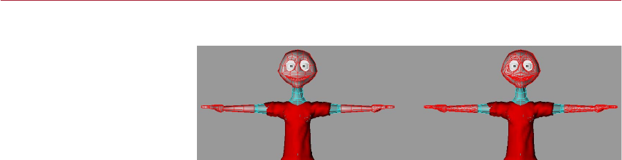
MOCCA CLOTHILDE 149
Draw
Draw disabled (left) and enabled
(right).
With this enabled, all excluded polygons of the collision object will be displayed in
the viewport with red edges. Internally, the collision object is always calculated in
triangles, so the displayed excluded polygons will be triangulated. Disabling the Draw
option will remove the display of the excluded polygons in the viewport.
The excluded polys will be drawn in their non-deformed state. The exclusion
will still use the deformed polygons, but the Draw option will only draw them
at their original modeled position.
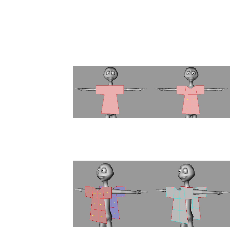
150 CLOTHILDE MOCCA
Modeling
Clothes
In these pages you’ll nd advice
on how best to model garments
for use with Clothilde.
The rst part of modeling a garment starts with creating a Polygon object (Objects >
Polygon Object). This object will allow you to create polygons anywhere in the scene.
Remember that the cloth engine will handle the draping and simulation process. All
that needs to be created is the geometry for the cloth engine to drape. So a rough
box model of the garment is all that is needed.
Use the Create Polygon Tool (Structure > Create Polygon) to create this box model
of the garment. Being that CINEMA 4D now supports n-gons, quickly draw out the
front plane of the garment. Using the Knife tool, distribute cuts evenly throughout the
garment, trying to keep as many quadrangles as possible in preference to triangles.
Before using the Knife tool to
cut the garment (left) and after
(right). Create quadrangles in
preference to triangles.
After the front plane of the garment is modeled, make sure all of the polygons are
selected and use the Clone function. This will mirror the geometry to create the back
plane of the garment. Usually, using a Clone value of 1 and 180-degree rotation
around the Y-axis works for this situation. Select the edges where the garment will
need to be seamed together. Remember to exclude the edges where the garment
will t around the character: collar, sleeves, and bottom of the shirt.
Select the edges where the
garment will need to be seamed
together. Remember to exclude
the edges where the garment
will t around the character:
collar, sleeves, and bottom of
the shirt.
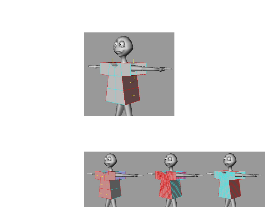
MOCCA CLOTHILDE 151
Now the seams need to be created between these two planes. Use the Stitch and Sew
tool to create the geometry for the seams. Holding the Shift modier for this tool will
add geometry as opposed to merging the edges, which is needed for the seams.
Use CINEMA 4D’s Stitch And Sew
tool to create the seams.
Keep the polygons of the front and back planes selected. It is at this point that you
will want to subdivide the garment (Functions > Subdivide). A value of 3 subdivisions
will usually sufce. Invert the selection so that the geometry of the seam is selected
(Selection > Invert).
Subdivide the polygons.
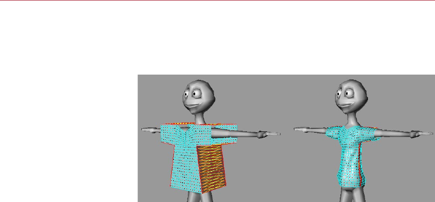
152 CLOTHILDE MOCCA
At this point, a Cloth tag can be applied to the garment to drape the geometry onto
the character. Using the functions on the Dresser tab, such as Set Seam Polys and
Dress-O-Matic, will perform this draping process. Prior to doing this you will also
want to apply a Collider tag on the geometry of the character; otherwise, the cloth
engine will not know what to drape the geometry onto.
Before using the functions on
the Dresser tab to drape the
garment onto the character (left)
and after (right).
Keep in mind that Clothilde is as much a modeling tool as it is an animation
tool. At any point in time the Cloth tag can be deleted and the cloth can be
treated as regular geometry. Even deleting the Cloth tag and modeling areas
like collars at a later time is still possible. Then just re-apply a Cloth tag to the
new model and start the simulation from there.
Procedures for Animation
As the screen shots show, it’s best to drape a garment while a character is in the
T-pose. But an animation never has a character start in the T-pose. The trick here is
to animate the character from the T-pose at a negative frame, usually –10 but this
depends on the extremity of the start pose.
On the Tag Properties tab of the Cloth tag, you can disable the Auto option and
manually specify from Frame –10 to Frame 0. Once the simulation gets to Frame 0
you can dene that as the new Initial State and the simulation will be able to start
calculating the garment from that state.
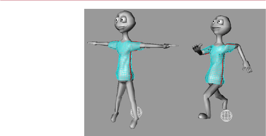
MOCCA CLOTHILDE 153
It’s best to drape a garment
while the character is in the
T-pose (left). Naturally, you’ll
want to start the animation
from a different pose (right).
The trick here is to record the
T- pose before frame 0, such as
at frame -10.
Remember that if the starting pose is really extreme, you can belt all the points of
the garment during the simulation. Once the cloth object is in place, you can remove
the belted points and set the Initial State of the garment.

Index

A
Add
anchor to bone 30
bone with bone tool 36
child bone 36
pose 75
pose to library 81
root goal 30
tip goal to bone 30
up vector to bone 31
Additive Loops 100
Air Resistance 129
Anchor 14
add to bone 30
Animating Clothes 152
Auto Find Center 43
Auto IK-Lock 32
Auto Match 101
Auto Redraw 31
Auto Size 106
Auto Trim 100
B
Belting 137
Belt Hover 127
Belt Inuence 127
Bone
adding child 36
adding with bone tool 36
add anchor 30
add root goal 30
add tip goal 30
add up vector 31
null, add with bone tool 37
null, update with bone tool 37
split with bone tool 37
tool 36
weight, removing 51
weighting 47
Bone Mirror tool 41
Boost 66
Bounce 123, 142, 148
C
Cache 143
Cache Mode 124
Calculate Cache 125
Cappuccino Tool 57
Chain
IK, setting up 30
limit position of 25
Child
bone, adding 36
Children
of bones, mirroring 44
Chopsticks 22
Claude Bonet
tool 47
Clear Belt Points 138
Clear Seam 136
Clone
tags 43
Clothilde
introduction 115
Cloth NURBS 115
Cloth Tag 119
Collider Tag 147
Collision Detection 144
Constraint
goal 20
mirror 44
strength 20
up vector 22
D
Display All Bones 48
Drag 16
Draw 149
Draw Belt Points 138
Dress-O-Matic 132
Dresser 131
Dress Mode 131
Dynamics 15
E
Edge EPS 145
Empty Cache 125
Estimate 103
Exclude Polys 148
Expert settings 143
F
Find
keyframes 69
Fix Points 135
Flexion 141
Force Position 28
Force Shading 49
Forward kinematics 9
Frames
nding easily 69
Friction 123, 142, 148
G
Global Drag 126
Global Intersection Analysis 146
Goal
add root to bone 30
add tip to bone 30
Goal constraint 20
Gravity 126
H
Hard IK 15
Hover 142
I
IK <-> FK 17
IK Chain
setting up 30
Inertia 17
Inuence 142
Initial State 133
Introduction 1
Inverse kinematics 9
K
Keyframes
nding easily 69
recording in realtime 58
KeyReducer Tool 65
Kinematics
forward 9
inverse 9
L
Layout
conguration 5
MOCCA 5
Left Trim 100
Library
of poses 81
P2P 81
M
Manager
P2P 81
Manual Match 102
Mass 141, 144
Match Search 43
INDEX 157
MOCCA

Mirror
children of bone 44
constraint 44
Mixing
poses 73
Mocca.l4d 5
MOCCA IK Tag 13
MOCCA Layout 5
MOCCA Palette 5
Modeling Clothes 150
Motion A 97
Motion B 98
Motion Blending 95
Multiple use iii
N
Network operation iii
Null
bone 37
O
Object
up vector 22
Only Modify Visible Elements 48
P
P2P Manager 81
Painting
bone weights 47
Palette
MOCCA 5
Pivot 102
Point EPS 144
Poly EPS 145
Pose
add 75
library 81
mixing 73
recording 75
record key 82
PoseMixer
tag 73
Position
limit of in MOCCA IK chain 25
rest state 29
Q
Quaternion Tag 89
R
Rail 102
Realtime
keyframe recording 58
Record
key for selected pose 82
poses 75
Reduction 65
Relax 131
Remove
bone weight 51
Reset
chain to rest state 29
Resize To Orig. Length 103
Rest rotation
set for bone chain 31
Rest State
position 29
reset chain to 29
rotation 29, 31
Retarget Tag 109
Rewind Time 60
Right Trim 100
Rotation
limit of in MOCCA IK chain 26
rest state 29
Rubber 122, 141
S
Seam Polys 136
Secrecy v
Self Collision 124
Self Repulsion 130
Setup IK chain 30
Setup Motion Blend Tracks 97
Set Belt Points 137
Set Chain Rest Position 31
Set Chain Rest Rotation 31
Set Dress State 134
Set Fix Points 135
Set Initial State 133
Set Reference 50
Set Seam Polys 136
Show Belt Points 138
Show Dress State 134
Show Initial State 133
Show Seam 136
Show Transition 100
Show Transitions 99
Soft IK 5
Split
bone with bone tool 37
Start At Current Time 60
Start Realtime 58
Stiffness 141
Stop Realtime 59
Strength
of constraints 20
of limits in MOCCA IK chain 25
Sub Sampling 143
T
Tear 140
TimeWarp
tool 69
Tip effector 10
Tool
bone 36
Claude Bonet 47
PoseMixer 73
TimeWarp 69
Transfer iv
Transition 97
U
Update
null bone with bone tool 37
Update Frame 125
Up Vector 22
add to bone 31
Use As Pole 21
Use Collider 147
Use Existing Sequences 61
Use UK 14
W
Weight
bones, removing 51
Weighting
bones 47
Wind 127
MOCCA
158 INDEX
