Maxon Cinema 4D 9.5 Sketch And Toon C4D Us
Cinema 4D - 9.0 - Sketch and Toon C4D_sketch_9.0_us Free User Guide for Maxon Cinema 4D Software, Manual
User Manual: maxon Cinema 4D - 9.5 - Sketch and Toon Free User Guide for Maxon Cinema 4D Software, Manual
Open the PDF directly: View PDF ![]() .
.
Page Count: 188 [warning: Documents this large are best viewed by clicking the View PDF Link!]
- Credits & Copyrights
- EULA
- Contents
- Introduction
- 1 Overview
- 2 QuickStart
- 3 Sketch and Toon Post Effect
- 4 Sketch Material
- Changing the preview
- Material editor settings
- Main
- Strokes
- Adjustment
- Distort
- Color, Thickness, Opacity
- Distance modifier
- Along Stroke modifier
- Position modifier
- Total Length modifier
- Scale modifier
- Facing Angle modifier
- Illumination modifier
- Join Angle modifier
- Texture modifier
- Screen Angle modifier
- From Surface modifier
- Vertex Map modifier
- From Line modifier
- Texture Map modifier
- Coffee modifier
- Screen Texture modifier
- Noise modifier
- Common modifier settings
- Render
- Clone
- Animate
- Assignment
- Blend modes
- 5 Sketch Shaders
- 6 Sketch Style Tag
- 7 Sketch Render Tag
- 8 Illustrator Export
- 9 Sketch and Toon Preferences
- 10 Frequently Asked Questions
- Index

Sketch and Toon
Sketch and Toon
Programming Team Christian Losch, Philip Losch, Richard Kurz, Tilo Kühn, Thomas Kunert,
David O’Reilly, Cathleen Poppe.
Plugin Programming Sven Behne, Wilfried Behne, Michael Breitzke, Kiril Dinev, Per-Anders Edwards,
David Farmer, Jamie Halmick, Richard Hintzenstern, Jan Eric Hoffmann,
Eduardo Olivares, Nina Ivanova, Markus Jakubietz, Eric Sommerlade,
Hendrik Steffen, Jens Uhlig, Michael Welter, Thomas Zeier.
Product Manager Marco Tillmann.
QA Manager Björn Marl.
Writers Paul Babb, Rick Barrett, Oliver Becker, Jens Bosse, Chris Broeske, Chris Debski,
Glenn Frey, Michael Giebel, Jason Goldsmith, Jörn Gollob, Sven Hauth,
Josiah Hultgren, Arndt von Königsmarck, David Link, Arno Löwecke, Aaron Matthew,
Josh Miller, Matthew ‘Mash’ O’Neill, Janine Pauke, Marcus Spranger, Luke Stacy,
Perry Stacy, Marco Tillmann, Jeff Walker, Scot Wardlaw.
SDK Docs & Support David O’Reilly, Mikael Sterner.
Layout Oliver Becker, Harald Egel, Michael Giebel, David Link, Luke Stacy, Jeff Walker.
Translation Oliver Becker, Michael Giebel, Arno Löwecke, Björn Marl, Josh Miller, Janine Pauke,
Luke Stacy, Marco Tillmann, Scot Wardlaw.
Copyright © 1989-2004 by MAXON Computer GmbH. All rights reserved.
English translation Copyright © 2004 by MAXON Computer Ltd. All rights reserved.
This manual and the accompanying software are copyright protected. No part of this document may be
translated, reproduced, stored in a retrieval system or transmitted in any form or by any means, electronic or
mechanical, for any purpose, without the express written permission of MAXON Computer.
Although every precaution has been taken in the preparation of the program and this manual, MAXON Computer
assumes no responsibility for errors or omissions. Neither is any liability assumed for damages resulting from
the use of the program or from the information contained in this manual.
This manual, as well as the software described in it, is furnished under license and may be used or copied
only in accordance with the terms of such license. The content of this manual is furnished for informational
use only, is subject to change without notice, and should not be construed as a commitment by MAXON
Computer. MAXON Computer assumes no responsibility or liability for any errors or inaccuracies that may
appear in this book.
MAXON Computer, the MAXON logo, CINEMA 4D, Hyper NURBS, and C.O.F.F.E.E. are trademarks of MAXON
Computer GmbH or MAXON Computer Inc. Acrobat, the Acrobat logo, PostScript, Acrobat Reader, Photoshop
and Illustrator are trademarks of Adobe Systems Incorporated registered in the U.S. and other countries. Apple,
AppleScript, AppleTalk, ColorSync, Mac OS, QuickTime, Macintosh and TrueType are trademarks of Apple
Computer, Inc. registered in the U.S. and other countries. QuickTime and the QuickTime logo are trademarks
used under license. Microsoft, Windows, and Windows NT are either registered trademarks or trademarks
of Microsoft Corporation in the U.S. and/or other countries. UNIX is a registered trademark only licensed
to X/Open Company Ltd. All other brand and product names mentioned in this manual are trademarks or
registered trademarks of their respective companies, and are hereby acknowledged.
MAXON Computer End User License Agreement
NOTICE TO USER
WITH THE INSTALLATION OF SKETCH AND TOON (THE “SOFTWARE”) A CONTRACT IS CONCLUDED BETWEEN
YOU (“YOU” OR THE “USER”) AND MAXON COMPUTER GMBH ( THE “LICENSOR”), A COMPANY UNDER
GERMAN LAW WITH RESIDENCE IN FRIEDRICHSDORF, GERMANY.
WHEREAS BY USING AND/OR INSTALLING THE SOFTWARE YOU ACCEPT ALL THE TERMS AND CONDITIONS
OF THIS AGREEMENT. IN THE CASE OF NON-ACCEPTANCE OF THIS LICENSE YOU ARE NOT PERMITTED TO
INSTALL THE SOFTWARE.
IF YOU DO NOT ACCEPT THIS LICENSE PLEASE SEND THE SOFTWARE TOGETHER WITH ACCOMPANYING
DOCUMENTATION TO MAXON COMPUTER OR TO THE SUPPLIER WHERE YOU BOUGHT THE SOFTWARE.
1. General
Under this contract the Licensor grants to you, the User, a non-exclusive license to use the Software and its
associated documentation. The Software itself, as well as the copy of the Software or any other copy you
are authorized to make under this license, remain the property of the Licensor.
2. Use of the Software
You are authorized to copy the Software as far as the copy is necessary to use the Software. Necessary
copies are the installation of the program from the original disk to the mass storage medium of your
hardware as well as the loading of the program into RAM.
(2) Furthermore the User is entitled to make a backup copy. However only one backup copy may be made
and kept in store. This backup copy must be identied as a backup copy of the licensed Software.
(3) Further copies are not permitted; this also includes the making of a hard copy of the program code on a
printer as well as copies, in any form, of the documentation.
3. Multiple use and network operation
(1) You may use the Software on any single hardware platform, Macintosh or Windows, and must decide
on the platform (Macintosh or Windows operating system) at the time of installation of the Software. If
you change the hardware you are obliged to delete the Software from the mass storage medium of the
hardware used up to then. A simultaneous installation or use on more than one hardware system is not
permitted.
(2) The use of the licensed Software for network operation or other client server systems is prohibited if this
opens the possibility of simultaneous multiple use of the Software. In the case that you intend to use the
Software within a network or other client server system you should ensure that multiple use is not possible
by employing the necessary access security. Otherwise you will be required to pay to the Licensor a special
network license fee, the amount of which is determined by the number of Users admitted to the network.
(3) The license fee for network operation of the Software will be communicated to you by the Licensor
immediately after you have indicated the number of admitted users in writing. The correct address of the
Licensor is given in the manual and also at the end of this contract. The network use may start only after
the relevant license fee is completely paid.
4. Transfer
(1) You may not rent, lease, sublicense or lend the Software or documentation. You may, however, transfer
all your rights to use the Software to another person or legal entity provided that you transfer this
agreement, the Software, including all copies, updates or prior versions as well as all documentation to
such person or entity and that you retain no copies, including copies stored on a computer and that the
other person agrees that the terms of this agreement remain valid and that his acceptance is communicated
to the Licensor.
(2) You are obliged to carefully store the terms of the agreement. Prior to the transfer of the Software you
should inform the new user of these terms. In the case that the new user does not have the terms at hand
at the time of the transfer of the Software, he is obliged to request a second copy from the Licensor, the
cost of which is born by the new licensee.
(3) After transfer of this license to another user you no longer have a license to use the Software.
5. Updates
If the Software is an update to a previous version of the Software, you must possess a valid licence to such
previous version in order to use the update. You may continue to use the previous version of the Software
only to help the transition to and the installation of the update. After 90 days from the receipt of the
update your licence for the previous version of the Software expires and you are no longer permitted to use
the previous version of the Software, except as necessary to install the update.
6. Recompilation and changes of the Software
(1) The recompilation of the provided program code into other code forms as well as all other types
of reverse engineering of the different phases of Software production including any alterations of the
Software are strictly not allowed.
(2) The removal of the security against copy or similar safety system is only permitted if a faultless
performance of the Software is impaired or hindered by such security. The burden of proof for the fact that
the performance of the program is impaired or hindered by the security device rests with the User.
(3) Copyright notices, serial numbers or other identications of the Software may not be removed or
changed. The Software is owned by the Licensor and its structure, organization and code are the valuable
trade secrets of the Licensor. It is also protected by United States Copyright and International Treaty
provisions. Except as stated above, this agreement does not grant you any intellectual property rights on
the Software.
7. Limited warranty
(1) The parties to this agreement hereby agree that at present it is not possible to develop and produce
software in such a way that it is t for any conditions of use without problems. The Licensor warrants that
the Software will perform substantially in accordance with the documentation. The Licensor does not
warrant that the Software and the documentation comply with certain requirements and purposes of the
User or works together with other software used by the licensee. You are obliged to check the Software
and the documentation carefully immediately upon receipt and inform the Licensor in writing of apparent
defects 14 days after receipt. Latent defects have to be communicated in the same manner immediately
after their discovery. Otherwise the Software and documentation are considered to be faultless. The
defects, in particular the symptoms that occurred, are to be described in detail in as much as you are able
to do so. The warranty is granted for a period of 6 months from delivery of the Software (for the date of
which the date of the purchase according to the invoice is decisive). The Licensor is free to cure the defects
by free repair or provision of a faultless update.
(2) The Licensor and its suppliers do not and cannot warrant the performance and the results you may
obtain by using the Software or documentation. The foregoing states the sole and exclusive remedies for
the Licensor’s or its suppliers’ breach of warranty, except for the foregoing limited warranty. The Licensor
and its suppliers make no warranties, express or implied, as to noninfringement of third party rights,
merchantability, or tness for any particular purpose. In no event will the Licensor or its suppliers be liable
for any consequential, incidental or special damages, including any lost prots or lost savings, even if a
representative of the Licensor has been advised of the possibility of such damages or for any claim by any
third party.
(3) Some states or jurisdictions do not allow the exclusion or limitation of incidental, consequential or
special damages, or the exclusion of implied warranties or limitations on how long an implied warranty
may last, so the above limitations may not apply to you. In this case a special limited warranty is attached
as exhibit to this agreement, which becomes part of this agreement. To the extent permissible, any implied
warranties are limited to 6 months. This warranty gives you specic legal rights. You may have other rights
which vary from state to state or jurisdiction to jurisdiction. In the case that no special warranty is attached
to your contract please contact the Licensor for further warranty information.
The user is obliged to immediately inform the transport agent in writing of any eventual damages in transit
and has to provide the licensor with a copy of said correspondence, since all transportation is insured by
the licensor if shipment was procured by him.
8. Damage in transit
You are obliged to immediately inform the transport agent in writing of any eventual damages in transit
and you should provide the Licensor with a copy of said correspondence, since all transportation is insured
by the Licensor if shipment was procured by him.
9. Secrecy
You are obliged to take careful measures to protect the Software and its documentation, in particular the
serial number, from access by third parties. You are not permitted to duplicate or pass on the Software or
documentation. These obligations apply equally to your employees or other persons engaged by you to
operate the programs. You must pass on these obligations to such persons. You are liable for damages in all
instances where these obligations have not been met. These obligations apply equally to your employees or
other persons he entrusts to use the Software. The User will pass on these obligations to such persons. You
are liable to pay the Licensor all damages arising from failure to abide by these terms.
10. Information
In case of transfer of the Software you are obliged to inform the Licensor of the name and full address of
the transferee in writing. The address of the Licensor is stated in the manual and at the end of this contract.
11. Data Protection
For the purpose of customer registration and control of proper use of the programs the Licensor will store
personal data of the Users in accordance with the German law on Data Protection (Bundesdatenschutzg
esetz). This data may only be used for the above-mentioned purposes and will not be accessible to third
parties. Upon request of the User the Licensor will at any time inform the User of the data stored with
regard to him.
12. Other
(1) This contract includes all rights and obligations of the parties. There are no other agreements. Any
changes or alterations of this agreement have to be performed in writing with reference to this agreement
and have to be signed by both contracting parties. This also applies to the agreement on abolition of the
written form.
(2) This agreement is governed by German law. Place of jurisdiction is the competent court in Frankfurt
am Main. This agreement will not be governed by the United Nations Convention on Contracts for the
International Sale of Goods, the application of which is expressly excluded.
(3) If any part of this agreement is found void and unenforceable, it will not affect the validity of the
balance of the agreement which shall remain valid and enforceable according to its terms.
13. Termination
This agreement shall automatically terminate upon failure by you to comply with its terms despite being
given an additional period to do so. In case of termination due to the aforementioned reason, you are
obliged to return the program and all documentation to the Licensor. Furthermore, upon request of
Licensor you must submit written declaration that you are not in possession of any copy of the Software on
data storage devices or on the computer itself.
14. Information and Notices
Should you have any questions concerning this agreement or if you desire to contact MAXON Computer for
any reason and for all notications to be performed under this agreement, please write to:
MAXON Computer GmbH
Max-Planck-Str. 20
D-61381, Friedrichsdorf
Germany
or for North and South America to:
MAXON Computer, Inc.
2640 Lavery Court Suite A
Newbury Park, CA 91320
USA
or for the United Kingdom and Republic of Ireland to:
MAXON Computer Ltd
The Old School, Greeneld
Bedford MK45 5DE
United Kingdom
We will also be pleased to provide you with the address of your nearest supplier.
Contents
Introduction ..........................................................................................................1
How to use this manual......................................................................................................................... 2
Registration ........................................................................................................................................... 2
Installation............................................................................................................................................. 2
Training.................................................................................................................................................. 2
Web Resources ...................................................................................................................................... 2
Technical Support .................................................................................................................................. 2
1 Overview ............................................................................................................5
2 QuickStart ........................................................................................................ 11
Adding the Sketch and Toon post effect ............................................................................................. 11
Adjusting the line ................................................................................................................................ 12
What does the post effect do?............................................................................................................ 13
Controlling post effect shading........................................................................................................... 14
Using the Sketch shaders..................................................................................................................... 16
Different styles for different objects ................................................................................................... 17
Control Levels ...................................................................................................................................... 19
Where now? ........................................................................................................................................ 20
3 Sketch and Toon Post Effect ............................................................................23
Effects tab settings.............................................................................................................................. 24
Main..................................................................................................................................................... 24
Lines..................................................................................................................................................... 24
Render ................................................................................................................................................. 28
Multi-Pass ............................................................................................................................................ 31
Shading................................................................................................................................................ 32
Editor Display....................................................................................................................................... 36
Line types ............................................................................................................................................ 38
Outline, Folds, Overlaps.................................................................................................................. 39
Angle .............................................................................................................................................. 42
Border............................................................................................................................................. 43
Material .......................................................................................................................................... 43
Edges .............................................................................................................................................. 44
Intersections ................................................................................................................................... 45
Triangulation................................................................................................................................... 46
Motion ............................................................................................................................................ 46
Contour........................................................................................................................................... 48
Isoparms ......................................................................................................................................... 51
Splines ............................................................................................................................................ 52
Particles .......................................................................................................................................... 52
4 Sketch Material ................................................................................................57
Changing the preview .................................................................................................................... 58
Material editor settings ....................................................................................................................... 59
Main................................................................................................................................................ 59
Strokes ............................................................................................................................................ 60
Adjustment ..................................................................................................................................... 67
Distort............................................................................................................................................. 70
Color, Thickness, Opacity................................................................................................................ 73
Distance modier ...................................................................................................................... 74
Along Stroke modier................................................................................................................ 75
Position modier ....................................................................................................................... 76
Total Length modier ................................................................................................................ 77
Scale modier ............................................................................................................................ 78
Facing Angle modier................................................................................................................ 79
Illumination modier ................................................................................................................. 80
Join Angle modier.................................................................................................................... 82
Texture modier ........................................................................................................................ 83
Screen Angle modier ............................................................................................................... 89
From Surface modier ............................................................................................................... 90
Vertex Map modier.................................................................................................................. 91
From Line modier .................................................................................................................... 92
Texture Map modier ................................................................................................................ 93
Coffee modier.......................................................................................................................... 94
Screen Texture modier............................................................................................................. 98
Noise modier ........................................................................................................................... 99
Common modier settings...................................................................................................... 102
Render .......................................................................................................................................... 104
Clone..............................................................................................................................................110
Animate .........................................................................................................................................115
Assignment....................................................................................................................................118
Blend modes..................................................................................................................................119
5 Sketch Shaders............................................................................................... 125
Creating a Sketch shader............................................................................................................ 126
Using other shaders ................................................................................................................... 127
Antialiasing tip ........................................................................................................................... 127
Art Shader .................................................................................................................................... 128
Cel Shader..................................................................................................................................... 130
Hatch Shader ................................................................................................................................ 134
Spots Shader................................................................................................................................. 143
6 Sketch Style Tag ............................................................................................. 149
Attribute manager settings ............................................................................................................... 149
Main.............................................................................................................................................. 149
Lines...............................................................................................................................................151
Shading..........................................................................................................................................151
Selections ..................................................................................................................................... 152
Maps ............................................................................................................................................. 152
7 Sketch Render Tag.......................................................................................... 155
Attribute manager settings .......................................................................................................... 156
8 Illustrator Export............................................................................................ 161
Illustrator Export Preferences ............................................................................................................ 161
9 Sketch and Toon Preferences......................................................................... 165
Sketch and Toon ................................................................................................................................ 165
Defaults ............................................................................................................................................. 166
10 Frequently Asked Questions ........................................................................169
Index.................................................................................................................. 177
INTRODUCTION • 1
Images © 2003 by Holger Schömann.
Welcome to Sketch and Toon, the CINEMA 4D module for non-photorealistic (NPR) rendering.
Quite simply, Sketch and Toon is the most powerful NPR software money can buy. Sketch and Toon
delivers a huge toolset that allows you to achieve an unlimited number of different looks. This
module doesn’t just add lines to your work, it adds style.
Now, a huge tool set normally sets alarm bells ringing for many prospective users. Lots of features
typically spells out COMPLICATED, but not in this case! Sketch and Toon has been specically
designed to cater for all users. It features three different control levels for fast, simple and
streamlined workow. User presets such as hatched lines give you instant results, while those
looking for more control will love the huge variety of options on offer. And even better, once you’ve
created your own style you can save it as a preset to use again and again.
Being a completely integrated module, Sketch and Toon works with virtually all CINEMA 4D
features. Combining lines with features such as radiosity gives you even more scope for individual
looks. It’s not just lines either. Sketch and Toon comes complete with a powerful shading system.
Your 3D objects can be lled in with colored or textured styles, for a full toon or tech experience.
“OK, so it makes very nice stills. What about us animators?” Well, naturally you can apply Sketch
and Toon to your current animations to give them a toon feel. But here’s something really special:
you can animate lines being drawn. This means that you can literally have your scenes drawn from
scratch in front of your bewildered viewers’ eyes!
As an artist, you of course know better than anyone that a picture says more than a thousand
words. Well, Sketch and Toon can make the same scene look different more than a thousand times.
Be prepared to play into the small hours of the morning, because this module’s really going to bring
out the “what if?” part in you!
Introduction
2 • INTRODUCTION
How to use this manual
To learn how to use Sketch and Toon, we recommend you proceed as follows:
- For a quick impression of what you can do with Sketch and Toon, see Chapter 1, “Overview.”
- To get up and running with Sketch and Toon, see Chapter 2, “QuickStart.”
- To move on to the more advanced features, work through the video tutorials located on the CD.
These tutorials are your primary learning tool. They are the easiest way to learn the software.
- When you’re not sure what a function does, look it up in this manual.
- If you run into problems, be sure to check out Chapter 10, “Frequently Asked Questions.”
Registration
Registering your purchase is extremely important. The serial number included with your package is
temporary and it will expire three months after installation.
To receive your nal serial number, you must register. So please ll in and return the registration
form at the earliest opportunity. Registering will also entitle you to technical support via telephone,
fax and email. And by checking the appropriate box on the registration form, MAXON will keep you
informed of the latest product information and updates.
You can also register online at register.maxon.net.
Installation
To install Sketch and Toon, run the installation program and follow the on-screen installation
instructions.
Training
Training is available for Sketch and Toon and other MAXON products. For details, please contact
MAXON or your local MAXON distributor.
Web Resources
Thousands of resources are available on the web, including online tutorials, discussion lists,
textures, models, galleries and information on 3D books. You’ll nd links to a rich selection of these
sites at maxon.net, MAXON’s homepage. Another website to bookmark is plugincafe.com. Here
you will nd dozens of useful plugins, both free and commercial. For plugin developers, there are
resources, including the SDK, tutorials and a free support forum.
Technical Support
Your local MAXON distributor will be delighted to assist you with your technical queries. You are
also welcome to contact MAXON directly. Please note that you will be entitled to technical support
provided you have registered your purchase.

1 Overview
OVERVIEW • 5
Sketch and Toon is a non-photorealistic (NPR) renderer that fully integrates into CINEMA 4D.
Essentially its job is to simplify 3D scenes and represent edges with lines to give an illustrative feel
to the nal result.
NPR software generally has two main areas: lines and shading. With Sketch and Toon, lines are
added to 3D objects using CINEMA 4D’s post effects functionality. Shading is taken care of by
CINEMA 4D’s material system with powerful additions such as the new Sketch shaders that help you
to achieve popular styles such as Manga and cross-hatching.
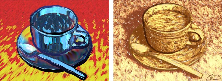
Superior Blend
Compare this powerful CINEMA 4D module with any other NPR tool on the market and you’ll come
to the conclusion that Sketch and Toon is in a class of its own. It has virtually all features of the
other NPR tools rolled into one. And then some!
But it’s not just this superior feature set that makes Sketch and Toon stand out from the crowd: its
integration with CINEMA 4D is outstanding. You can combine all of Sketch and Toon’s features with
practically any other feature found in CINEMA 4D and its modules, including radiosity, caustics,
shaders, splines and particles. This gives you ultimate exibility when illustrating your ideas. With
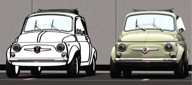
Sketch and Toon, there’s a million and one ways to present even the simplest object.
Same objects, but two completely different results. Images © 2003 by Artur Bala.
1 Overview
6 • CHAPTER 1
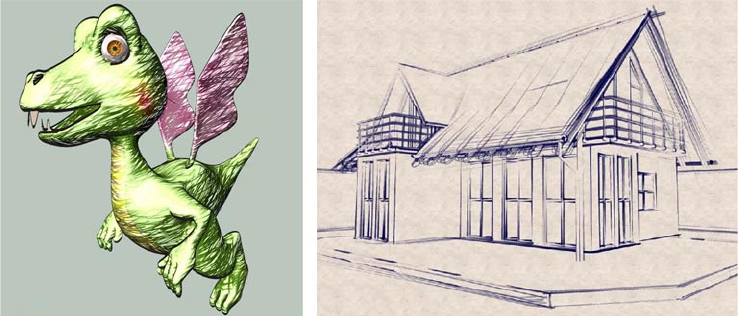
2B or not 2B?
Images © 2003 by Samir Kharchi.
With Sketch and Toon, any style is possible, including sketch. Now you can delight your clients with
sketches of the your project that look as hand-drawn as you want them to.
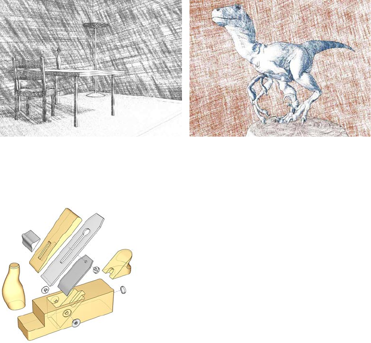
Technical support
Image © 2003 by Artur Bala.
Sketch and Toon supports all areas of NPR rendering including technical style. You have tremendous
control on exactly where lines are drawn.
OVERVIEW • 7
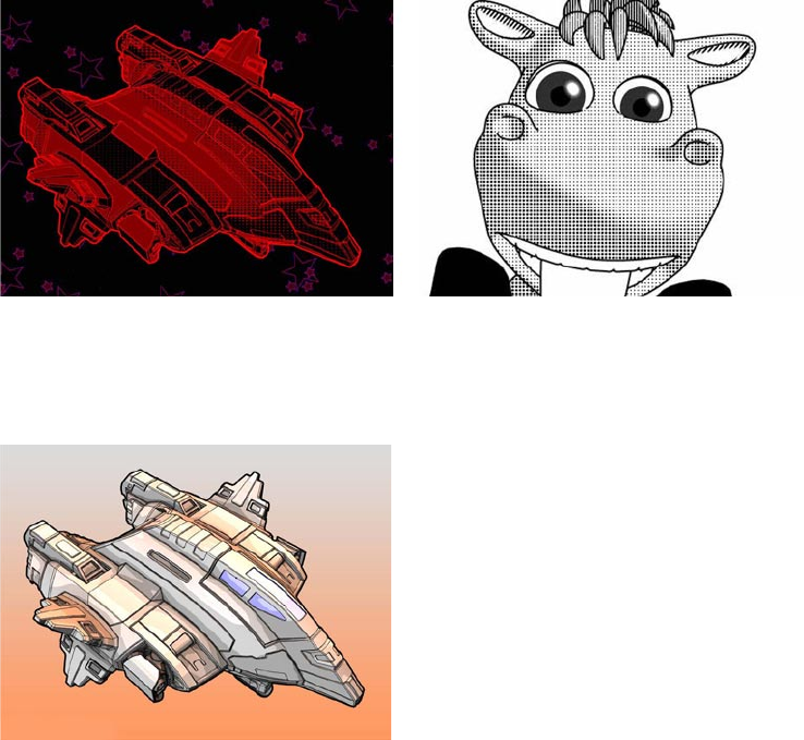
Spot the difference
Spaceship © 2003 by Michael Welter, character © 2003 by Toshihide Miyata.
The halftone dots look is more popular the ever. You’ll be pleased to know that Sketch and Toon
boasts a powerful spots shader that is ideal for these effects, and more.
Manga juice
Image © 2003 by Michael Welter.
Sketch and Toon includes a new cel shader that provides color control of backfaces for Manga-style
shading and much more!
8 • CHAPTER 1
Pick ‘n’ mix
Image © 2003 by Toshio Fuji.
Sketch and Toon’s tight integration with CINEMA 4D allows you to choose which objects are
“sketched” and which objects CINEMA 4D should still take care of.
Where next?
We recommend you read Chapter 2 next, “QuickStart”, which will show you how to get started
with Sketch and Toon.

2 QuickStart
QUICKSTART • 11
Can’t wait to get started with Sketch and Toon? Then you’ve come to the right chapter. In these
pages, you’ll learn the basics of how to use Sketch and Toon, and, most importantly of all,
where to nd the main controls and what they do in general terms.
Adding the Sketch and Toon post effect
All it takes to add the Sketch and Toon effect to your scene is a single menu pick. First you’ll need
an object.
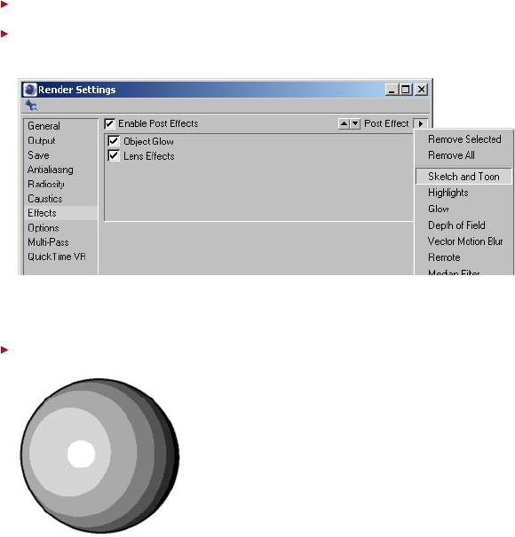
Create a sphere.
Choose Render > Render Settings and on the Effects tab, click the Post Effect button and
choose Sketch and Toon to add the Sketch and Toon post effect.
Look in the Material manager and you’ll notice a material has been added also. More about this
material later...
Render the scene.
Congratulations! You’re just rendered your rst Sketch and Toon effect. The sphere has a black
outline and its shading has been simplied into bands.
2 QuickStart
12 • CHAPTER 2
Adjusting the line
The material that is added automatically when you add the post effect is called the Sketch material.
This controls the look of the lines, such as their color and thickness. In a nutshell, the Sketch material
is the material used by the post effect to draw the lines.
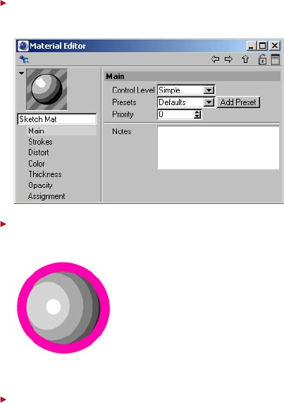
In the Material manager, double-click the Sketch material’s thumbnail to display its settings
in the Material editor.
On the Color tab, choose a new color for the line such as shocking pink. On the Thickness
tab, set the Thickness value to 20. Render the scene.
The sphere’s lines are now much thicker and use the new color.
The pink is truly shocking... On the Color tab, set the color back to black and on the Thickness
tab, set the Thickness back to 2. Rename the material to “black” using the text box below
the thumbnail.
QUICKSTART • 13
What does the post effect do?
The Sketch and Toon post effect is the main control center for the effect. Among other things, it
controls the post effect shading for objects and which Sketch materials are used by the effect. To
see this in action, you’ll need to create a second Sketch material.
In the Material manager, choose File > Sketch Material to create a new Sketch material. In the
Material editor, change the material’s thickness to 1 and color to red. Rename the material
to “red.”
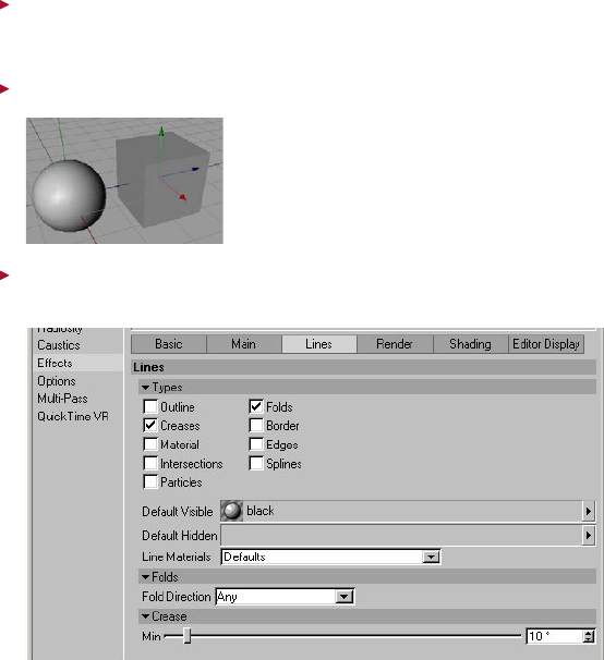
Add a cube to the scene and move it next to the sphere in the viewport.
On the Render Settings > Effects tab, ensure the Sketch and Toon post effect is selected
and click its Lines tab if it isn’t already selected.
The Default Visible and Default Hidden boxes on this tab control which materials the post effect
uses for visible lines and hidden lines respectively. You can see that the “black” Sketch material is
being used for visible lines. Currently the Default Hidden box is blank, which means hidden lines
are not drawn.
14 • CHAPTER 2
Drag and drop the red material’s thumbnail from the Material manager into the Default
Hidden box. Render the scene.
The red material is now used for the hidden lines in the scene (i.e. the lines that in real life would be
hidden behind surfaces). If you were now to drag and drop the red material into the Default Visible
box, the red material would be used for both visible and hidden lines. So among other things, the
post effect controls which Sketch materials are used by the scene for visible and hidden lines.
Before going on to the next step, take a close look at roughly how many brightness bands the
sphere has. You’ll be changing this next up.
Controlling post effect shading
As mentioned earlier, the post effect also controls the post effect shading. You’ll nd these controls
on the effect’s Shading tab.
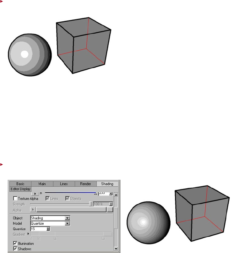
In the render settings, on the Sketch and Toon post effect’s Shading tab, set Quantize to 15
and render the scene.
The Quantize value controls the number of brightness bands for the object (like the old CINEMA 4D
cel renderer). The sphere now has many more bands.
QUICKSTART • 15
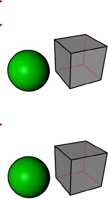
In the Material manager, choose File > New Material to create a new standard CINEMA 4D
material. Double-click the new material to display its settings in the Material editor. On the
Color tab, set the color to green. Rename the material to “green.”
Apply the green material to the sphere and render the scene.
Sketch and Toon lets you shade the objects using standard CINEMA 4D materials. The post effect
quantizes the result of the CINEMA 4D rendering. If you wanted a solid color, you could simply
set Quantize to 1.
In the render settings, on the Sketch and Toon post effect’s Shading tab, set the Object
drop-down list to Off and render the scene.
Setting Object to Off switches off the post effect shading for objects so that it doesn’t affect
the CINEMA 4D’s rendering of surfaces. Likewise you could set Background to Off to switch off
the post effect’s white background and use the background rendered by CINEMA 4D instead.
16 • CHAPTER 2
Using the Sketch shaders
Sketch and Toon includes four powerful channel shaders: Art, Cel, Hatch and Spots. These enable
you to create an endless variety of effects. You can use these shaders in any material channel which
accepts a texture, but in general they work best in the Luminance channel.
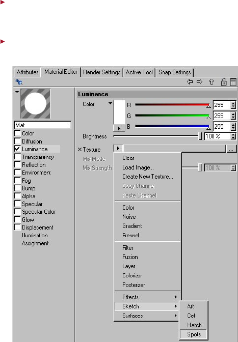
In the Material manager, choose File > New Material to create a new material. Double-click
the new material to display its settings in the Material editor. Disable all material channels
except Luminance. Rename the material to “spots.”
On the Luminance tab, click the Texture triangle button and choose Sketch > Spots to load
the Spots shader into the Luminance channel.
QUICKSTART • 17
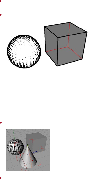
Click on the Spots preview below the Texture triangle button to access the settings for the
Spots shader. Set the Scale value to 30%.
Apply the Spots material to the sphere. Render the scene.
The Spots shader is ideal for a halftone dots effect. Note how the spots shrink the brighter the
surface is to give a fantastic impression of light to dark shading.
Different styles for different objects
What if you want an object to use different settings to those in the post effect? For example,
what if you want one object to use a different colored line? This is where the Sketch Style tag
comes in. It’s for objects that should use different settings to the scene-wide settings in the
post effect.
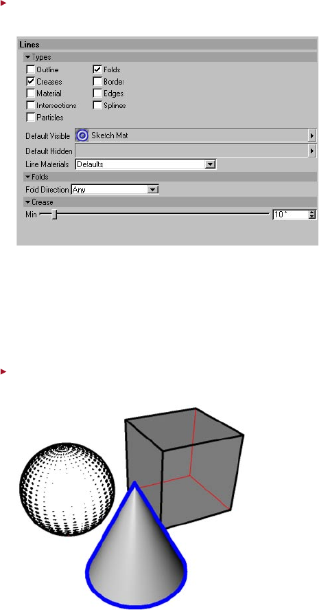
Add a cone to the scene and move it in front of the sphere and cube.
Ensure the cone is selected and in the Object manager, choose File > Sketch Tags > Sketch
Style.
You’ll see a Sketch Style tag appear to the right of the cone in the Object manager. Also, note that
a new Sketch material has been created automatically (called “Sketch Mat”).
18 • CHAPTER 2
In the Object manager, double-click the cone’s Sketch Style tag to display the tag’s settings
in the Attribute manager.
The Sketch Style tag has many similar settings to the post effect. It overrides the settings in the
post effect for the object. In other words, the object will use the tag’s settings instead of those
in the post effect.
On the Lines tab, you’ll notice the new Sketch material has already been assigned to the tag. As
with the post effect, you can control which Sketch materials are used by dragging and dropping
the materials into the Default Visible and Default Hidden boxes.
Edit the new Sketch material as follows: change its name to “blue”, give it a blue color, and
change its thickness to 6. Render the scene.
QUICKSTART • 19
Select the cube and in the Object manager, choose File > Sketch Tags > Sketch Render.
The Sketch Render tag has a few useful render options such as the ability to switch off lines for
the object.
Double-click the cube’s Sketch Render tag to display the tag’s settings in the Attribute
manager. Disable the tag’s Allow Lines and Allow Shading options, and render the scene.
The post effect is now switched off for the cube.
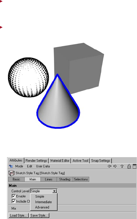
Control Levels
Sketch and Toon’s control level system is useful for hiding away the advanced controls while you
are learning the software or while you are creating a basic effect where you simply don’t need
so many controls.
You’ll find the Control Level setting on the Main tab of the Sketch and Toon post effect, Sketch
material and Sketch and Toon Style tag. Setting the Control Level in one place changes the level
for them all.
20 • CHAPTER 2
Where now?
This completes the QuickStart. You now know where the main controls are and what they do in
general. To recap:
- The Sketch material controls the look of the lines.
- The Sketch and Toon post effect is where you’ll nd the general scene-wide controls, such as
which Sketch materials are used for visible and hidden lines.
- The Sketch Style tag is where you can set an individual style for an object to override the post
effect’s style.
- The Sketch shaders are loaded as a channel shader and are best used in the Luminance
channel.
Why not take a short break then head on to the video tutorials supplied on the CD?

3 Sketch and Toon Post Effect
SKETCH AND TOON POST EFFECT • 23
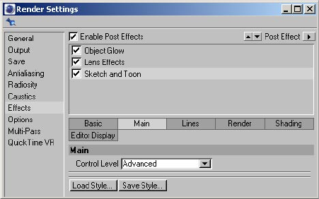
The Sketch and Toon post effect is the main control center and line rendering engine used to create
your non-photorealistic (NPR) render. This is where you’ll nd the settings for the line render, post-
rendered shading, multi-pass, editor display and scene-wide line styles. The Sketch and Toon post
effect is to be found on the Render Settings > Effects tab. See your CINEMA 4D reference manual
for general details on using the Effects tab.
To add the Sketch and Toon post effect:
- In the CINEMA 4D render settings, on the Effects tab, click the Post Effect button and choose
Sketch and Toon from the menu that appears. A new Sketch material will be created and assigned
to the post effect if this option is enabled in the Sketch and Toon preferences.
Alternatively, Sketch and Toon has a number of automatic setup options that enable you to speed
up creating your NPR scene. These settings can be found in the Sketch and Toon main preferences
located in the Sketch and Toon section of the CINEMA 4D preferences.
To add the Sketch and Toon post effect using the automatic setup:
Do one of the following:
- In the Material manager, choose File > Sketch Material to create a new Sketch material. The
Sketch and Toon post effect will be added automatically and the newly created material added.
- Select an object in the Object manager, choose File > Sketch Tags > Sketch Style. A Sketch Style
tag will be added to the object. The Sketch and Toon post effect will be added automatically and
a new Sketch material created and assigned.
3 Sketch and Toon Post Effect
24 • CHAPTER 3
Effects tab settings
Some of the following settings are available only when the Control Level is set to Intermediate
or Advanced. Look up “Control Levels” in the index.
Main
Control Level
Look up “Control Levels” in the index.
Load Style, Save Style
You’ll nd various presets in the Sketch folder within CINEMA 4D’s Library folder.
These commands enable you to load and save styles. A style is a drawing or painting style, such as
thick chalky lines or leaky pen lines, as dened by the Sketch and Toon post effect and the Sketch
materials it uses.
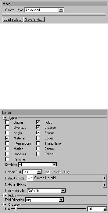
Lines
The Lines tab controls which line types (outline, intersections, polygon edges, etc.) are created and
which Sketch materials are used to render them.
SKETCH AND TOON POST EFFECT • 25
About lines and layers
To understand how lines work with settings such as Combine (see below), it can be helpful to think
about each line type created being given its own layer (internally this is exactly what happens).
When Sketch and Toon creates lines for an object, a new layer is created and the line types inserted.
If Combine is enabled, all line types that can be merged are placed onto the same layer. If Combine
is disabled, each line type is placed onto its own layer.
This means each object produces one or more layers (from each Sketch Style tag and the post
effect). The layer priority (i.e. the order in which the layers are rendered) is dened by the tag order,
post effect and material priority (dened on the Sketch material’s Main tab), then during rendering
the Z-depth is used, followed by the layer priority for all lines of approximately similar Z-depth (lines
closest to the camera are drawn on top).
Types
For details on each line type, look up “line types” in the index.
The options in the top part of the Lines tab control which line types are created. For example,
enable the Outline option to create outlines. Some options have extra settings which will appear in
the bottom part of the dialog when the option is enabled.
Combine
The following line types will always be created on their own layer: Motion, Particle, Spline,
Isoparm, Material alpha map lines.
The Combine mode enables you to merge line types in the following ways.
None
Each line type is created separately and rendered individually on its own layer. If more than one
line type produces the same line when using effects such as transparency or patterns, you may
notice unwanted results where the lines overlap. An example would be enabling Creases and
Angle, which may create lines for the same polygon edges. When strokes are enabled in the
Sketch material, the strokes will be limited to lines of the same type.
All
All line types that use the same Sketch material will be combined on a single layer. This helps to
prevent overlapping (see “None” above). When strokes are enabled in the Sketch material, all line
types in this layer are available for the strokes to draw along.
Exclusive
The line types are merged so that only lines which do not overlap between multiple types are
created.
Inclusive
The enabled line types are merged to create lines that only exist in more than one line type; this is
the opposite effect to Exclusive mode.
26 • CHAPTER 3
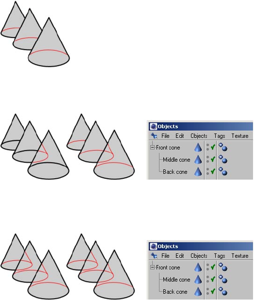
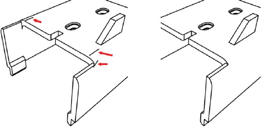
Hidden Cull, Self-Culling
To switch off hidden lines, set Hidden Cull to Self and clear the Default Hidden box or local
Hidden box.
These settings control which lines are visible and which are hidden. The Hidden Cull mode sets
which objects in the scene are used to nd out if a line is hidden. In the following examples, the
visible lines are black, the hidden lines are red.
Self
In Self mode, only the object which created the line is used to nd out if the line is hidden.
Children
Children mode with Self-Culling disabled (left) and enabled (center).
Children mode uses the parent and its children to nd out if a line is hidden.
Hierarchy
Hierarchy mode with Self-Culling disabled (left) and enabled (center) — in this case, there is no difference with
the option enabled or disabled.
Hierarchy mode nds the top-most parent and then uses the parent and all its children to nd
out if a line is hidden.
SKETCH AND TOON POST EFFECT • 27
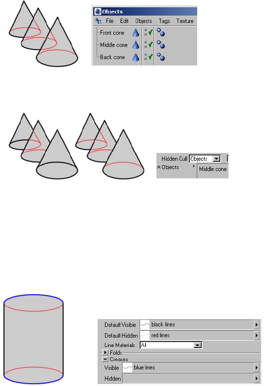
Scene
In this mode, the line is checked against all objects in the scene to nd out if it is hidden.
Objects
This mode uses the objects in the Objects box to nd out if a line is hidden.
Default Visible, Default Hidden, Line Materials
Use the Default Visible and Default Hidden boxes to specify which Sketch material to use for visible
lines and which to use for hidden lines (drag and drop the materials from the Material manager into
the boxes). Leaving a box blank means those lines won’t be rendered.
These are the default materials and they are used for all line types except those with their own
materials specied in their Visible and Hidden boxes (to display the Visible and Hidden boxes, set
Line Materials to Both).
To display the Visible and Hidden boxes for each enabled line type, set Line Materials to Both.
28 • CHAPTER 3
Each box has a triangle button to its right which you can click to access the following commands:
Clear empties the box. In other words, it unassigns the Sketch material.
Show In Manager activates the Material manager and scrolls it if necessary to display the Sketch
material.
Select Element selects the Sketch material in the Material manager and displays its settings in
the Attribute manager.
Render
The Render tab is home to general controls for Sketch and Toon’s rendering, such as the strength of
line antialiasing and the global thickness of lines.
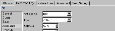
Line AA
Antialiasing removes jagged edges from the rendered image by creating a soft transition
between the lines and their surrounding pixels. For general details on antialiasing, see your
CINEMA 4D reference manual.
The Line AA setting controls the strength of antialiasing Sketch and Toon applies to the lines.
Increase the value for smoother lines, but keep in mind the lines will take longer to render the
higher you set the value. For best results, set Line AA to Best and ensure CINEMA 4D’s Filter is
switched on (on the Render Settings > Antialiasing tab, set Antialiasing to Geometry or Best).
SKETCH AND TOON POST EFFECT • 29
How CINEMA 4D’s antialiasing affects the lines
There are two parts to CINEMA 4D’s antialiasing: the Antialiasing mode (None, Geometry, Best) and
the Filter option, which are both specied on the Render Settings > Antialiasing tab.
Antialiasing
If your scene needs to use CINEMA 4D’s Best mode for antialiasing, you can sometimes
reduce render times by setting Line AA to Off. The Sketch and Toon lines will then be
antialiased by the CINEMA 4D renderer only.
The Antialiasing mode generally has no effect on the lines. It only affects the lines if Line AA is set
to Off, Antialiasing is set to Best and the Post Render option is disabled. Geometry mode doesn’t
affect the lines because it smooths geometry edges only and the lines are not geometry.
Filter
The second part of CINEMA 4D’s antialiasing is the Filter option, which applies a lter over the
whole image during rendering (provided Antialiasing is set to Geometry or Best; the Filter is
switched off automatically when Antialiasing is set to None).
The Filter does affect the lines (because the lines are part of the image) and helps to smooth
them. The one exception is if the Post Render option is enabled, in which case the lter will have
no effect on the lines because the lines will then be rendered after everything else, including
after all post effects and after the lter has been applied.
Post Render
The antialiasing quality is not as high with the Post Render option enabled, because then
CINEMA 4D’s antialiasing lter will not affect the lines (see “How CINEMA 4D’s antialiasing
affects the lines” above).
Enabling this option does two things: First, it makes Sketch and Toon render after all other post
effects, enabling you to apply lines over effects such as glow. Second, it allows you to access the
multi-pass settings for the Sketch and Toon effect — loop up “Multi-Pass” in the index.
Rendering with the post renderer can be quicker, but the quality is not as high. Also, the post
renderer does not use multiple CPUs, so if you are using a multi-processor computer, this may
cancel out any speed-up.
Background Blend
If this option is enabled, the Sketch and Toon lines will blend with anything behind them, not just
other Sketch and Toon lines.
30 • CHAPTER 3
Mode, Objects
You can also control which objects Sketch and Toon renders using the Sketch Render tag and
Sketch Style tag.
Here you can choose which objects are rendered by Sketch and Toon. All objects are rendered by
default with Mode set to Exclude and the Objects box empty. To include or exclude specic objects,
set Mode to Include or Exclude and drag and drop the objects into the Objects box.
Thickness Scale
This is a global scale setting for line thickness. A value of 100% leaves the lines unchanged. Increase
the value to make all lines in the scene thicker or decrease it for thinner lines.
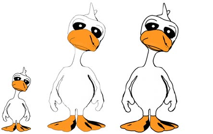
Resolution Independent settings
From left to right: original duck, larger render of the duck with Resolution Independent disabled (center) and
enabled (right).
These settings are for resolution-independent output. They automatically scale pixel-based
parameters such as Thickness to ensure the image looks the same at the new resolution, only larger
or smaller.
Resolution Independent
Enable this option to switch on the Resolution Independent settings.
Base Resolution, Base Width, Base Height, As Editor, As Render Settings
If the width to height proportion of the render is different to that of the base resolution,
Sketch and Toon uses the best match by taking the dimension which changes the least.
The base resolution tells Sketch and Toon the resolution on which the pixel values are based. You
can choose a custom resolution (Base Resolution set to Custom) or the resolution dened in the
render settings on the Output tab (Base Resolution set to Render Settings).
SKETCH AND TOON POST EFFECT • 31
For example, suppose you’ve set the line Thickness to 10 pixels and the image is 400 by 300 pixels
when you render in the viewport and 800 by 600 pixels when you render to the Picture viewer. If
Base Resolution is set to Render Settings, the lines will be ve pixels thick in the viewport and ten
pixels thick in the Picture viewer.
To set the base resolution in Custom mode, do one of the following:
- Enter the width and height into the Base Width and Base Height boxes.
- Click the As Editor button to use the viewport’s current resolution.
- Click the Render Settings button to use the current resolution dened on the Render Settings >
Output tab.
Camera Near, Camera Far, Custom Far
Sketch and Toon ignores any objects closer to the camera than the Near value or, if the Custom Far
option is enabled, any objects further away from the camera than the Camera Far value. Suppose
the scene has many objects in the distance that are only a few pixels tall when rendered. Creating
lines for these objects would probably be a waste of render time because the lines would be so
small. In such cases, use the Camera Far value to ignore the objects.
The Camera Near value also changes the near plane clipping, so moving this away from the camera
will clip the lines. Usually this isn’t desired. However, if you are using strokes and the Clip To Screen
option is disabled, lines that go near or behind the camera can have massive projections up to
millions of pixels. Moving the near plane away from the camera can reduce this.
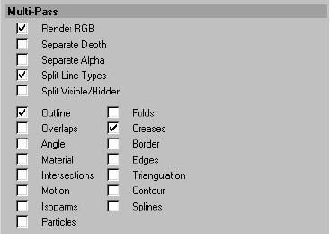
Multi-Pass
For details on multi-pass rendering, see your CINEMA 4D reference manual.
Using the options on this tab, you can render the Sketch and Toon effect in passes. Note that this
tab is hidden usually. To access it, enable the Post Render option on the post effect’s Render tab.
32 • CHAPTER 3
To multi-pass render the Sketch and Toon effect:
- On the post effect’s Render tab, ensure the Post Render option is enabled.
- On the post effect’s Multi-Pass tab, enable the passes you want to include.
- On CINEMA 4D’s Render Settings > Multi-Pass tab, click the Channels button and choose Post
Effects from the menu that appears. Render to the Picture Viewer.
Render RGB
To include a pass for the complete image, enable this option and on CINEMA 4D’s Render Settings
> Multi-Pass tab, click the Channels button and choose RGBA Image from the menu that appears.
Separate Depth, Separate Alpha
Enable these options to include a depth pass and alpha pass for just the lines.
Split Line Types, Outline, Folds, Overlaps...
You can also split the line types into separate passes. To do this, enable the Split Line Types option
and enable the option for each line type that you want to include as a separate pass.
Split Visible/Hidden
This gives you separate passes for visible and hidden lines.
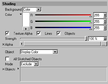
Shading
The Sketch and Toon post effect has a number of shading options which you can set on the
Shading tab. It is like applying a post effect in itself, but is included with the main post effect for
convenience. It is an extension of using CINEMA 4D’s old Cel Renderer.
SKETCH AND TOON POST EFFECT • 33
Background, Texture Alpha, Lines, Objects, Strength, Alpha
1 2 3 4
1 Background texture; 2 Background texture and the same texture used for the alpha texture with Lines
enabled; 3 With Objects enabled; 4 With Lines and Objects enabled.
The Background drop-down list lets you switch off the color for the background or pick a color or
texture for the background. The Texture Alpha option gives the effect of the lines or shading being
absorbed by the background, like ink soaking into paper.
You can choose whether the lines or shading or both are absorbed by the background using the
Lines and Objects options. The Strength value controls the strength of absorption, i.e. how much of
the texture shows through. A value of 0% means no absorption, a value of 100% means maximum
absorption. Alpha is the image to use.
Object
This controls the post effect shading for the objects.
Off
Off mode switches off the post effect shading so that it doesn’t affect the CINEMA 4D rendering.
This is generally the mode to use if you are using the Sketch shaders such as the Hatch shader.
Display Color
The object’s Display Color setting is in the Attribute manager, on the object’s Basic
Properties tab.
This mode uses the object’s Display Color setting, even if the object has materials. It will render as
a solid color as it is shown in the viewport.
Custom Color
Pick a custom color for the objects using the color chooser.
Texture
Shades the objects using a texture. The texture is placed over the whole screen image like a
background.
Background
Shades the objects using the same shading as the background (i.e. this mode uses the
background’s settings in the top part of the tab).
34 • CHAPTER 3
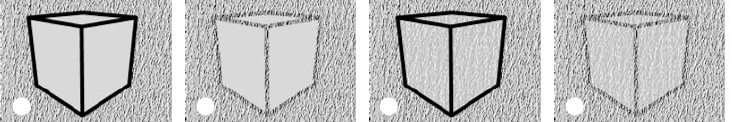
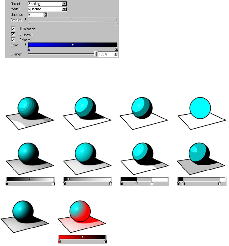
Shading
This is an extension of the old CINEMA 4D Cel renderer. It quantizes the illumination based on a
set number of brightness levels (Model set to Quantize) or gradient (Model set to Gradient).
With both models, enable the Illumination option to ignore the scene’s lighting and light all
surfaces with 100% brightness instead, and disable the Shadows option to switch off shadows.
Quantize = 5 Quantize = 2 Shadows disabled Illumination disabled
Set Model to Gradient to control the shading using a gradient
Without Colorize With Colorize
SKETCH AND TOON POST EFFECT • 35
The Quantize model controls the number of brightness levels allowed by the post effect. The
Gradient model does the same as Quantize except it uses a gradient to control which brightness
values are allowed. The Colorize option enables you to colorize the shading using a color gradient
— the Strength value controls the strength of the effect.
All Sketched Objects, Mode, Objects
Disable the All Sketched Objects option to shade all objects in the scene, not just those with lines.
To include or exclude specic objects from the post effect shading, set Mode to Include or Exclude
and drag and drop the objects into the Objects box.
36 • CHAPTER 3
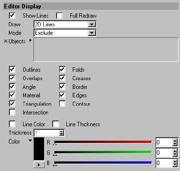
Editor Display
Why wait for a render to see the lines? On this tab you can switch on the display of lines in the
viewport.
Show Lines
Enable the Show Lines option to display lines in the viewport.
Full Redraw
This option gives you realtime refresh of the lines in the viewport. The lines will then update
constantly — try extruding some polygons with Full Redraw enabled and you’ll see how useful this
feature is.
If you disable the option, the lines will disappear while you are carry out actions such as moving
objects and will reappear as soon as the action is complete. This helps to minimize viewport
slowdown when working with complex scenes.
SKETCH AND TOON POST EFFECT • 37
Draw
2D Lines 3D Lines
Sketch and Toon offers two types of viewport display line: 2D lines and 3D lines. 2D lines are drawn
at onto the viewport, 3D lines are drawn within the 3D scene.
2D lines are the best option overall because they are crisper and more accurate than 3D lines. Also,
although both line types generate hidden lines as well as visible lines, you won’t see hidden 3D lines
in Quick Shading mode or higher because they will be blocked from view by the surfaces in front of
them! 3D lines are, however, faster to draw than 2D lines and slow down the viewport less.
Mode, Objects
To include or exclude specic objects for viewport lines, set Mode to Include or Exclude and drag
and drop the objects into the Objects box. Or set Mode to Active Only to draw lines for the active
objects only. Otherwise lines will be displayed for all objects.
Outlines, Folders, Overlaps, ...
Enable the option for each line type you want displayed in the viewport.
Line Color, Line Thickness
If these options are enabled, you can specify a custom color and thickness in pixels for the lines in
the viewport using the color chooser and Thickness box. Otherwise the color and thickness dened
in the Sketch material is used.
38 • CHAPTER 3
Line types
Only enable the line types that are actually needed. Enabling each type adds to the time it
takes to create the lines.
Sketch and Toon offers over a dozen line types. In these pages, you’ll nd a description for each line
type and its settings on the Lines tab if it has any. In general, Folds, Creases and Border are all you
need for a basic toon.
About line ownership
The object that creates a line “owns” it. The lines are placed onto a layer that is linked to the object
that created them. This can affect things such as outlines — although an outline may look like it
goes around multiple objects, internally each object owns its own section of the outline, so if you
try and apply a stroke to the outline, it can only go around lines in the same layer, which also means
for each object.
Cleaning up with the Sketch Style tag
For general details on using the Sketch Style tag, see Chapter 6, “Sketch Style Tag.”
The Sketch Style tag gives you a quick and easy way to remove unwanted lines.
The Sketch Style tag has a Lines selection box that gives you an easy way to remove unwanted lines.
Select the polygons or edges in the problem areas or, if it’s easier the other way around, select
all polygons or edges which are not causing the problem. Create a Selection tag for the selection
(Selection > Set Selection). You can create several Selection tags if you wish.
Drag and drop the Selection tag or tags into the Sketch Style tag’s Lines box (Selections tab). Set
Mode to Exclude or Include depending on whether you selected the problem areas or trouble-free
areas. Render, and the unwanted lines should be gone.
SKETCH AND TOON POST EFFECT • 39
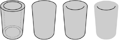
Outline, Folds, Overlaps
For these lines to appear correctly, the mesh must be complete and joined and the surface
normals must point in the correct direction.
A quick way to get an outline around objects is to enable the Folds line type and set no culling
(assign the same Sketch material to both visible and hidden lines), then set that material’s Clip
Render mode to Outside Geometry (Render tab).
(Original) Outline Folds Overlaps
These three line types — outline, folds and overlaps — are collectively known as the silhouette-
based lines. They appear at each polygon edge where the polygon on one side faces towards the
camera (frontface) and the polygon on the other side faces away from the camera (backface).
Folds are the most important silhouette-based lines. A fold is a polygon edge between a
frontface polygon and a backface polygon.
Outline generally gives you just the outline of the mesh. It is the same as Folds except that it
ignores edges which overlap the mesh.
Overlaps is the opposite of Outline. Overlaps are silhouette-based lines which overlap the mesh.
Sometimes you may notice small unwanted overlaps. You can often remove these quickly using
the Filter Strokes option in the Sketch material on the Strokes tab.
40 • CHAPTER 3
Lines tab settings
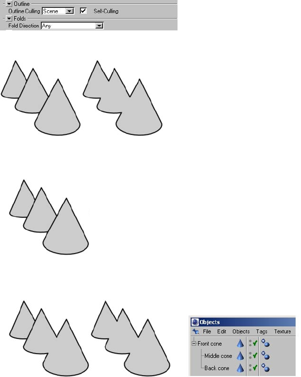
Outline Culling, Self-Culling (Outline only)
The Outline Culling mode controls which objects will combine their outlines if they overlap.
Self
Outlines are not combined between overlapping objects, but look up “Self Culling” in the index.
Children, Hierarchy
Children mode (left) and Hierarchy mode (center). In Children mode, the back cone has a separate outline
because it isn’t a child of the middle cone.
Children mode combines overlapping outlines for the parent and its children. Hierarchy mode
looks for the top-most parent and then checks all children of that parent.
SKETCH AND TOON POST EFFECT • 41
Scene
The overlapping outlines of different objects are combined.
Objects
Sketch and Toon combines the outline of each object in the Objects box with the outline of any
other object it overlaps.
Self-Culling
Original single object (left), Scene mode with Self-Culling disabled (center) and Self-Culling enabled (right).
If the Self-Culling option is enabled, each object will combine its own (Self) overlapping outlines.
The same applies if Outline Culling is set to Self.
42 • CHAPTER 3
Fold Direction (Folds only)
The Fold Direction setting denes which types of folds are created: all folds (Any), folds in the
direction of front to back, or folds in the direction of back to front. The Fold Direction can be useful
if you notice many unwanted lines forming creases. Generally the Fold Direction should be set to
Any, otherwise it reduces the number of lines created, which can result in gaps.
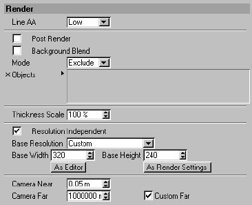
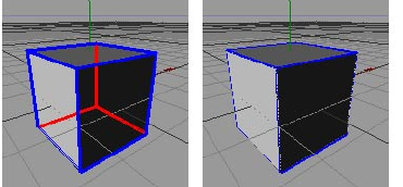
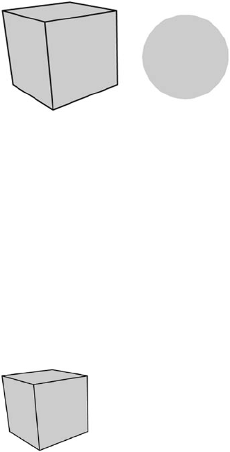
Creases
For these lines to appear correctly, the mesh must be complete and joined and the surface
normals must point in the correct direction.
The sphere has no creases because its edges are smoothed by a Phong tag. The cube, on the other hand, has no
Phong shading over its edges (angle limit less than 90˚), so each edge results in a crease line.
A crease is any edge not smoothed by a Phong tag (either because the edge has been broken using
the Break Phong Shading command on the Structure menu or because the angle between the
edge’s polygons exceeds the angle limit in the Phong tag’s settings).
Lines tab settings
Min
The Min setting helps to prevent creases from appearing in at parts of the mesh. Each crease is
only created if the angle between its polygons is greater than or equal to the Min value.
Angle
For these lines to appear correctly, the mesh must be complete and joined and the surface
normals must point in the correct direction.
Because the polygons for each edge are 90° apart in a cube, an angle line is created for each edge with the
default Min and Max values of 85° and 95° respectively.
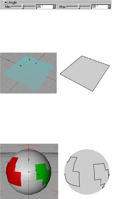
SKETCH AND TOON POST EFFECT • 43
Sketch and Toon checks each edge for the angle between its polygons. If the angle is within the Min
to Max range, an angle line is created for that edge.
Lines tab settings
Min, Max
The Min and Max values dene the range within which angle lines are created.
Border
A border is any edge with only one polygon attached to it, such as the outer edges of a Plane
object. Borders can also be the outer edges of polygon selections; use a Sketch Style tag to specify
which polygon selection tags to use (drag and drop the Selection tag or tags into the Border box on
the Sketch Style tag’s Selections tab).
Material
Material lines are the polygon edges around materials restricted to polygon selections or the edges
around alpha maps (note that “hard” alphas work best).
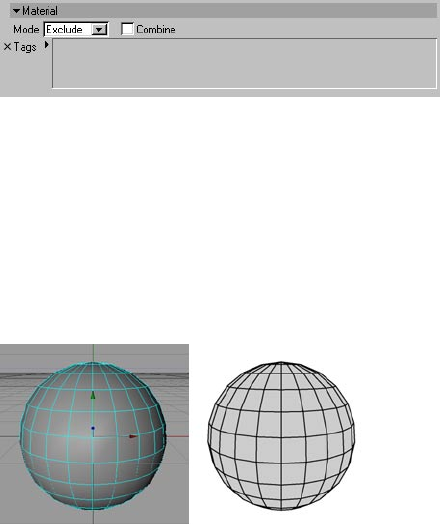
44 • CHAPTER 3
Lines tab settings
These settings are available in the Sketch Style tag only.
Mode, Tags
The Mode denes whether to include or exclude Texture tags for edges around alpha maps or
materials. Drag and drop the Texture tags into the Tags box.
Combine
If the Combine option is enabled, Sketch and Toon will combine the outline for any overlapping
alpha maps.
Edges
With Edges, lines are generated for each polygon edge unless edge selections are set on the
Selections tab of the Sketch Style tag, in which case lines are generated for the selected edges only.
SKETCH AND TOON POST EFFECT • 45
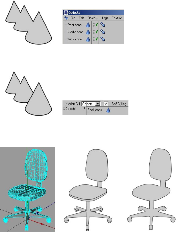
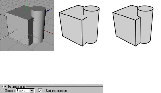
Intersections
If an object doesn’t have intersecting polygons, ensure the Self-intersection option is disabled,
otherwise Sketch and Toon will waste time checking if the polygons intersect.
A cube and cylinder... Without intersections With intersections
These are lines where polygons intersect each other.
Lines tab settings
Objects
This mode denes which objects are used to nd out if there are intersections.
Self
This mode only produces intersection lines where an object intersects itself.
Children, Hierarchy
Children mode checks the parent for intersections with its children. Hierarchy mode looks for the
top-most parent and then checks for intersections with any children of that parent.
Scene
This creates intersections where any object in the scene intersects any other object.
Objects
Sketch and Toon checks the objects in the Objects box for intersection with any other objects in
the scene.
Self-intersection
Enable this option to switch on lines for where an object intersects itself.
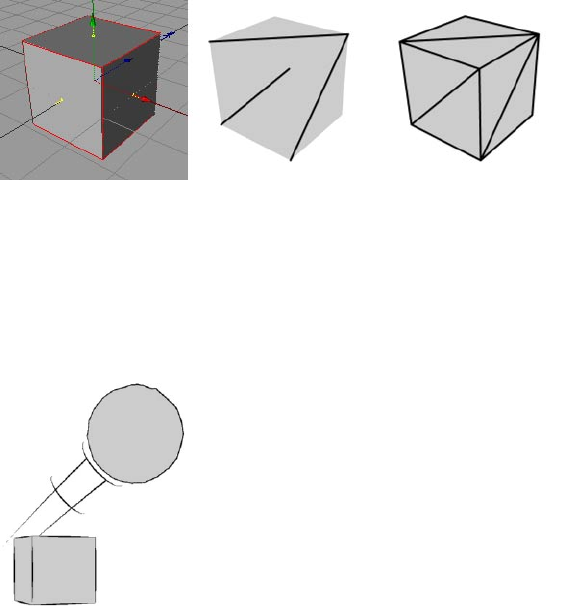
46 • CHAPTER 3
Triangulation
A cube... With Triangulation With Triangulation & Edges
This creates a triangulation line for each quadrangle.
Motion
Motion lines do not work with CINEMA 4D Net.
Render the animation to the Picture viewer to see the motion lines. They cannot be rendered
in the viewport because the previously rendered frames are needed.
These settings create motion lines when an object or polygon selection moves faster than a
threshold value. Restricting motion lines to a polygon selection is useful for producing motion lines
from arms, legs and so on.
SKETCH AND TOON POST EFFECT • 47
Lines tab settings
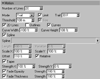
Number Of Lines
The number of motion lines to create.
Mode, Limit, Trail, Bias
Velocity mode creates motion lines based on the object’s current velocity — the greater the
velocity, the longer the lines. The lines will only appear if the object is travelling at least as fast
as the Threshold velocity. Enable the Bias option if you want the lines to be zero length at the
Threshold velocity, otherwise they will already have some length at the Threshold velocity.
Trail mode creates motion lines based on the object’s path. To limit the trail to recent frames
only, enable the Limit option and set Trail to the desired number of frames.
Threshold
The minimum speed at which motion lines will be generated.
2D Lines
These are lines drawn away from the object or polygon selection based on a 2D projection.
Outlines
Creates from the line types enabled in the Sketch Style tag or the post effect.
Curves
Enable the Curves option to creates curves along the motion. Use the Curve Width and Curve Height
settings to adjust the width and height of the curves.
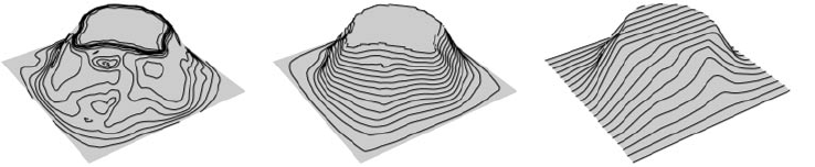
48 • CHAPTER 3
Spline
Uses a spline object (the Spline LINK control). The spline is used from the XY plane with the
dimensions of the Spline object (the object matrix is not used).
Length, Scale X, Scale Y
Length is the scale for the velocity. Scale X and Scale Y scale the motion lines.
Offset, Relative
The Offset is the size of the gap between the object or polygon selection and the motion lines.
Enable the Relative option to make the offset a percentage of the object’s size on screen — this is
useful for objects moving towards or away from the camera.
Taper, Strength X, Strength Y
Squash or stretch the motion lines as they get further away from the object or polygon selection. The
Strength boxes control the strength of tapering in the X and Y directions.
Fade Opacity, Fade Thickness
Thin out and fade the lines as they get further away from the object or polygon selection.
Contour
Angle mode Position mode UVW mode
Contour lines help to show the shape of an object. They are especially useful when used with a thick
marker style pen such as for the racing car below. There are three modes for contour lines.
Angle mode creates lines of equal angle from the surface normal to a given axis.
Position mode creates lines of equal position along an axis, like a map’s altitude lines.
UVW mode uses the object’s UVW coordinates to create lines in the U or V direction.
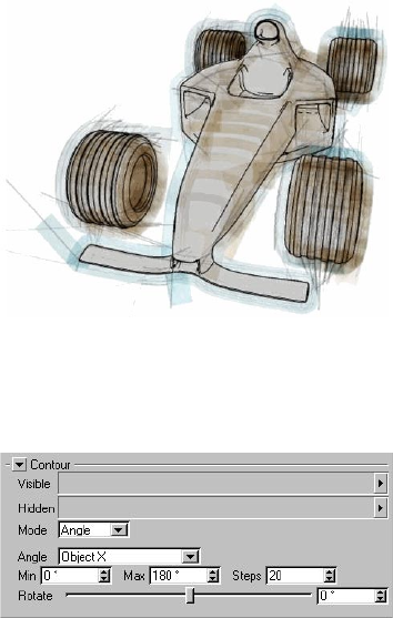
SKETCH AND TOON POST EFFECT • 49
Try using Contour lines with a marker-style pen.
Lines tab settings
Angle mode
Angle
The Angle setting denes which axis is used. You can choose the X, Y or Z-axis of the object or
world coordinate system, or the view’s (i.e. camera’s) X, Y or Z-axis.
Min, Max
These dene the range of angles over which the contour lines will be created. 0° means planar to
the axis chosen (see “Angle” above).
Steps
This is the number of contour lines to create.
Rotate
This rotates the axis on which the contour lines are based.
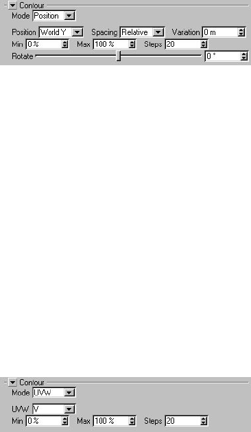
50 • CHAPTER 3
Position mode
Position
In Position mode you can choose the axis along which the contours are created. You can choose the
X, Y or Z-axis of the object or world coordinate system, or the view’s (i.e. camera’s) X, Y or Z-axis.
Spacing, Variation, Min, Max, Steps, Offset
The Spacing mode gives you two ways to control the distance between contour lines: Relative mode
and Absolute mode.
Relative mode sets the number of contour lines to create (Steps) and how far along the object
they start and end (Min and Max).
Absolute mode sets the distance between each contour line (Step). The Offset value enables you
to adjust where the contour lines start along the object.
Use the Variation value to vary the size of the gap between contour lines. The default value of 0
means no variation and the lines will be equal distances apart.
Rotate
This rotates the axis along which the contour lines are created.
UVW mode
If the object has multiple UVW tags, you can specify which of these should be used via the Sketch
Style tag (drag and drop the UVW tags to be used into the Contour UVW box on the Sketch Style
tag’s Selections tab).
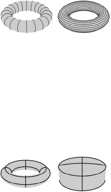
SKETCH AND TOON POST EFFECT • 51
UVW
U V
This is which coordinate to use: U or V.
Min, Max
The Min and Max values dene how far along the object the lines start (Min) and end (Max).
Steps
This is the number of contour lines to create.
Isoparms
Culling may not be accurate with isoparms. This is because culling uses the object’s real
geometry, and isoparms do not always t their geometry exactly. Hence the polygons may cull
the isoparms slightly.
When using HyperNURBS, you can get a similar result to isoparms using an edge selection.
This avoids the problems that can occur with isoparms. For a tip on how to do this, see the
HyperNURBS entries in Chapter 10, “Frequently Asked Questions”.
Isoparms for a Torus and Oil Tank object.
These are isoparm lines for objects which use them, such as primitives and NURBS objects. Note
that these do not work with parent deformers. Also, they do not work with some generator objects
such as the Array object and the Instance object.
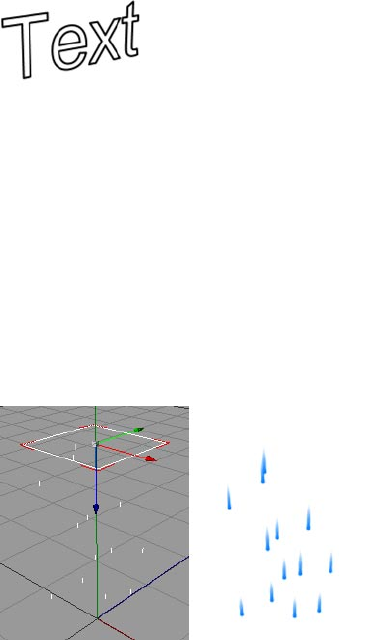
52 • CHAPTER 3
Splines
These are lines for spline objects. You can use any type of spline, including text splines and freeform
splines. However, they do not work with parent deformers. Nor do they work inside generator
objects such as the Array object, Instance object and Symmetry object. As a special case, they will
work inside a HyperNURBS object because the HyperNURBS does not affect the spline itself.
Note that a spline segment itself denes a stroke — the direction of the stroke and the line normal
(used by the From Line modier) is taken from the direction of the spline. Enabling strokes has no
effect on splines because the spline lines are already strokes.
Particles
Particle lines do not work with CINEMA 4D Net.
Render the animation to the Picture viewer to see the particle lines. They are not rendered in
the viewport because the previously rendered frames are needed.
These are lines for particles. They work for particles generated using the Thinking Particle’s module
or CINEMA 4D’s standard particle system. As with the spline line type, enabling strokes has no
effect because each particle line for a particle is already created as a stroke.
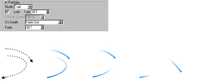
SKETCH AND TOON POST EFFECT • 53
Lines tab settings
Mode, Limit, Trail, Velocity Scale
From left to right: the ight paths of two particles; Trail mode with Limited disabled to give the entire trail; Trail
mode with Limited enabled to give only the most recent part of the trail; Velocity mode to produce a straight line
from each particle’s current position — the length of the line depends on the particle’s current velocity.
There are two modes for controlling the length of the particle lines.
Velocity mode creates a straight line from each particle’s current position. The line is as long
as the particle would travel in one second provided Velocity Scale is set to 100%. Use a higher
Velocity Scale value to lengthen the lines or a lower value to shorten them. The line points in the
particle’s current direction.
Trail mode creates lines for the trail (i.e. ight paths already travelled) of the particles. The Limit
and Trail settings limit the length of each line to the most recent part of the trail. For example, to
draw the trail travelled by the particles over the past ten frames, enable Limit and set Trail to 10 F.
On Death, Fade
The On Death setting controls what happens to a line when its particle dies.
Keep Stroke, Remove Stroke
With these modes, each line remains or disappears respectively when its particle dies.
Run Out
When each particle dies, its line gets shorter and shorter until it eventually disappears, like a train
“disappearing” into a tunnel.
Fade Out
Each line fades out gradually after its particle dies. The Fade value denes how long the line takes
to fade out.

4 Sketch Material
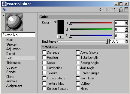
SKETCH MATERIAL • 57
Sketch and Toon’s lines may each have their own material, the Sketch material. As with standard
CINEMA 4D materials, the Sketch material has dozens of properties you can set on various tabs in
the Material editor or Attribute manager. By combining these properties, you can create almost any
look for the lines, from gritty chalk to a thick marker to advanced brush effects.
To create a Sketch material:
The rst Sketch material you create is assigned automatically as the default visible material in
the Sketch and Toon post effect. In other words, by default all objects will use the rst Sketch
material you create for their visible lines.
- In the Material manager, choose File > Sketch Material. If the Sketch and Toon post effect has not
yet been added, it will be added automatically provided this option is enabled in the Sketch and
Toon preferences.
Sketch and Toon also has a number of automatic setup options to help you work faster. You’ll nd
these settings in the Sketch and Toon main preferences, in the Sketch and Toon section of the
CINEMA 4D preferences.
4 Sketch Material
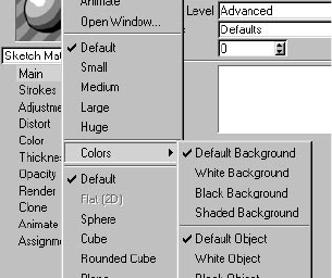
58 • CHAPTER 4
To add the Sketch material using the automatic setup:
Do one of the following:
- In the CINEMA 4D render settings, on the Effects tab, click the Post Effect button and choose
Sketch and Toon from the menu that appears. A new Sketch material will be created and assigned
to the post effect if this option is enabled in the Sketch and Toon preferences.
- Select an object in the Object manager, choose File > Sketch Tags > Sketch Style. A Sketch Style
tag will be added to the object. If the Sketch and Toon post effect has not yet been added, it will
be added automatically.
To assign the Sketch material globally to objects:
- Drag and drop the material into the Default Visible or Default Hidden box in the Sketch and Toon
post effect.
To assign the Sketch material to a specic object:
Do one of the following:
- Drag and drop the material onto the object in the Object manager or viewport. A Sketch Style tag
will be created with the material assigned.
- Drag and drop the object into the Sketch material’s Assignments box (Assignment tab).
- Add a Sketch Style tag to the object and drag and drop the material into the Default Visible or
Default Hidden box on the tag’s Lines tab.
Changing the preview
The Sketch material uses all the standard preview options from CINEMA 4D, plus some new ones for
Sketch and Toon itself. To access these settings, right-click (Windows) or Command-click (Mac OS)
the preview. The Shaded Background and Shaded Object settings use the post effect shading for
the background or object.
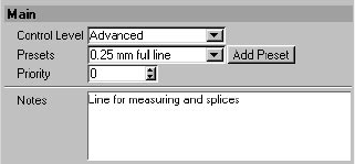
SKETCH MATERIAL • 59
Material editor settings
Some of the following settings are available only when the Control Level is set to Intermediate
or Advanced. Look up “Control Level” in the index.
You’ll nd various Sketch material presets in the Sketch folder within CINEMA 4D’s Library
folder. Load these using the Material manager’s File > Load Materials command.
Main
Control Level
Look up “Control Levels” in the index.
Presets, Add Preset
Presets is a list of all Sketch materials including the presets. Add Presets is just a shortcut to
duplication — it creates a copy of the active Sketch material.
Priority
Look up “Self-Blend” in the index.
Notes
The Notes box is a place for entering notes about the material.
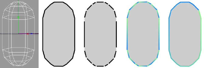
60 • CHAPTER 4
Strokes
Only enable strokes if you really need them. Strokes slow down rendering, use more memory
than normal lines, and generally are more prone to animation problems than normal lines.
1 2 3 4 5
When Sketch and Toon creates lines for an object, the lines are initially made up of unconnected
line segments. You can see the line segments for the capsule above clearly in Figure 3, where a gap
has been placed between each line segment for illustrative purposes.
The Enable option on the Strokes tab controls whether Sketch and Toon tries to connect line
segments together to form strokes. The advantage of strokes is that you can apply effects such as
a gradient over the stroke as a whole. Figure 4 shows what happens when a gradient is applied to
unconnected line segments — the gradient is applied to each individual segment instead of to the
outline as a whole. Contrast this with Figure 5, where strokes have been enabled.
In general, enable strokes when you want to apply an effect over multiple line segments; otherwise,
leave strokes disabled.
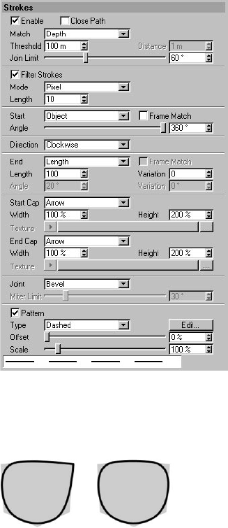
SKETCH MATERIAL • 61
Enable
This switches on strokes.
Close Path
Close Path disabled (left) and enabled (right) for a cube’s distorted outline.
If Close Path is enabled, Sketch and Toon will try to join the start and end of the stroke.
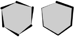
62 • CHAPTER 4
Match, Threshold, Distance
Although the lines generated by Sketch and Toon come from a 3D scene, the lines themselves are
only 2D because they are drawn at onto the screen. This means you can get line segments that
overlap on the screen and could be connected that are actually from different depths of the scene.
These settings tell Sketch and Toon how to deal with such line segments. You can set Match to the
following modes.
Flat
This mode ignores the Z-depth and treats all lines as purely 2D; this essentially attens the image
and lets line segments be connected together even if they are at different depths in the scene.
Nearest
The Nearest mode connects to the line that is the minimum Z-depth away. Note that this doesn’t
always produce the desired results. Sometimes if you have lots of very small lines close to one
another, the nearest connection may not be the best one! If strokes start breaking up, try using
Depth mode instead, and if that doesn’t help, try Flat, which allows all possible connections.
Keep in mind that when strokes break up, it is usually a sign that there are problems with the mesh;
for example, perhaps the mesh contains non-planar polygons — these are best avoided when using
Sketch and Toon. Use clean simple mesh for best results.
Depth
In Depth mode, you can specify the maximum difference in Z-depth to allow for connections.
World
This matches the Z in world coordinates. This is good for contour lines where you want line
segments from the same contour to connect.
Join Limit
Low Join Limit value (left) and high Join Limit value (right).
This is one of the most important settings on the Strokes tab. It prevents neighboring line segments
from being joined together if the angle between them exceeds the Join Limit value. This helps
to prevent very long strokes and speeds up the calculation of strokes by limiting the number of
possible connections.
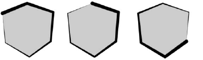
SKETCH MATERIAL • 63
Filter Strokes, Mode, Length
You can also lter strokes using the Total Length modier for Thickness in the Sketch material.
When strokes are generated, a small number of lines are often “left over” and form very small
strokes or no strokes at all. These tend to look like artefacts or “blobs.” Enable the Filter Strokes
option to remove these unwanted lines. There are three modes for the strokes lter. Overlap is
the best one and is especially good at removing overlaps and small strokes. However, it is also the
slowest mode.
Pixel
The Pixel mode lters all strokes below the Length value (in pixels). However, the problem with this
mode is that if you zoom the objects or scale them, the lter removes more or less because the pixel
size of the stroke has changed.
Object
This mode also lters strokes below the Length value. The difference is that in this mode the
Length is specied as a percentage of the object’s screen bounds maximum, i.e. its width or height,
whichever is greater. This enables you to move or zoom objects without the effect changing.
Overlap
Overlap is an intelligent mode. First it looks for overlapping strokes. When it nds them, it lters
the shorter stroke if it is shorter than the Length value and within the Distance value of the longer
stroke, where a Length value of 100% and a Distance value of 100% correspond to the longer
stroke’s length and Thickness value (Thickness tab).
Start, Angle
Various starting positions for the stroke using the Start and Angle settings.
These settings inuence the starting position of strokes. Note that the starting point is only a guide
for Sketch and Toon. Sketch and Toon will try to start here, but the stroke may start from an earlier
point if it can do so. You can set Start to the following modes.
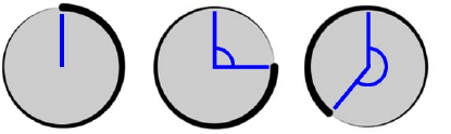
64 • CHAPTER 4
Screen, Object
From left to right: Angle set to 0°, 90° and 220°.
Sketch and Toon will try to start drawing the strokes from the angle you specify, where 0° means
from the center of the screen or object upwards (left sphere above).
Random
This starts each stroke from an available line segment chosen at random.
Mesh
In Mesh mode, the stroke starts with the “oldest” available edge (i.e. the one with the lowest
index number in the Structure manager).
Left, Right, Top, Bottom
Each stroke starts with the line segment closest to the left, right, top or bottom edge that is still
available.
Outer, Inner
The Inner and Outer modes start the stroke with the rst available line segment closest to or
furthest away from the object’s center.
Frame Match
This feature does not work with CINEMA 4D Net.
Stylized strokes may lead to problems when animated. This is because the lines and their possible
connections change from frame to frame, causing various “jumping” and “popping” effects. The
Frame Match options are designed to help overcome these issues. They attempt to match up the
strokes generated for the current frame with the strokes from the previous frame. For best results,
avoid major changes from frame to frame.
Direction
This sets the direction in which Sketch and Toon tries to draw the stroke: clockwise, anti-clockwise,
left, right, up or down. If a stroke isn’t possible in this direction, Sketch and Toon will try to draw
the stroke in the opposite direction instead. Sketch and Toon also checks the opposite direction
once the end of a stroke has been reached and extends the stroke in this direction if it can.
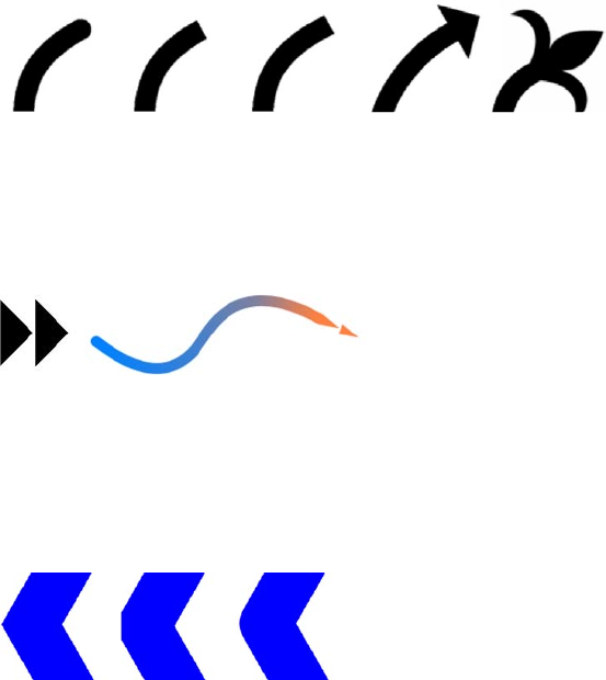
SKETCH MATERIAL • 65
End, Length, Angle, Variation
These settings control when Sketch and Toon ends a stroke. If End is set to Off, Sketch and Toon will
create each stroke until it cannot continue anyway (i.e. until it runs out of suitable connections).
The other modes — Length, Angle and Joint — end the stroke once it is longer than a set length
(dened in pixels); when the angle to the next line segment is greater than a set angle; or when
the stroke meets two or more line segments and has a choice of which path to take. The Variation
settings vary the set length and angle per stroke as a percentage.
Start Cap, End Cap, Width, Height, Texture
Round Flat Square Arrow Custom
These setting control the shape of the cap at the start and end of each line. You can choose from
shapes such as Flat or Arrow or you can load an image and use it as a custom shape (set Start Cap
or End Cap to Custom and use the Texture button to load the image).
The Width and Height settings specify the width and height for arrow caps or custom caps. Keep in
mind caps take longer to render the larger they are.
Image used as a custom cap (left) and the cap applied to the end of a stroke with Width set to 800% and Height
set to 100% (right). Note how the cap adopts the stroke’s properties such as color and thickness — the cap
effectively becomes part of the stroke.
The image for a custom cap should show the cap pointing to the right (see the double-arrow
example above). Solid parts of the cap should be black, transparent parts white. Values between
black and white represent semi-transparency.
Joint
Miter Bevel Round
Choose the shape of the joints: Miter, Bevel or Round.
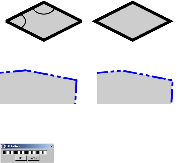
66 • CHAPTER 4
About Miter Joints
Miter joints take longer to render than Bevel joints and Round joints. However, you can optimize
their rendering speed using the Miter Limit value. The optimum setting is the smallest angle of
any joint.
53.2˚
126.8˚
Increase the value for faster rendering but avoid setting it higher than the smallest angle or some
or all of the joints will be rendered blunt instead of sharp (left diamond).
Pattern
A pattern with strokes disabled (left) and enabled (right). Enabling strokes allows the pattern to be continuous
over multiple line segments.
The Pattern settings give a pattern to the lines such as dashes or dots. These patterns are mostly
useful for technical illustrations. If you want the pattern to be continuous over multiple line
segments, ensure that strokes are enabled. You can choose from various preset patterns or, to
dene a custom pattern, click the Edit button and use the Edit Pattern dialog (click or drag over bars
to turn black bars to white and vice versa).
In the Edit Pattern dialog, click or drag over
bars to invert their color.
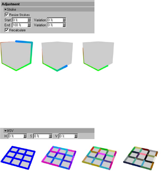
SKETCH MATERIAL • 67
Adjustment
The Adjustment tab enables you to make various adjustments to the lines. For example, you can
offset the lines from the geometry, rotate them in 3D space and add overshoots.
Stroke
Original stroke (left), resized with Recalculate enabled (center) and resized with Recalculate disabled (right). For
the center and right cube, Start and End were set to 40% and 80% respectively.
To shorten the lines, enable the Resize Strokes option and set the Start and End values to where the
lines should start and end as a percentage of their original length. Use the Variation values to vary
the start and end for each line. Enable the Recalculate option to t the stroke’s properties such as
color and thickness to the start and end of the stroke.
HSV
From left to right: original lines and HSV values all set to 20%, 50% and 100%.
The HSV settings vary the color of each stroke (or line segment if strokes are disabled) based on
a percentage variation of the original color. You can enter a separate percentage for hue (H),
saturation (S) and value (V). 0% means no variation, 100% means maximum variation.
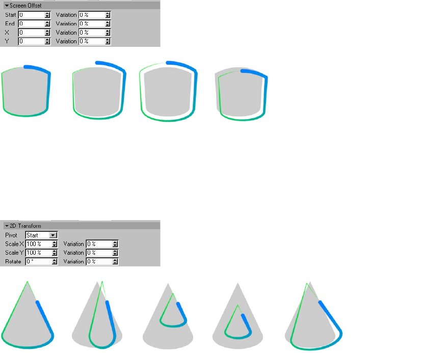
68 • CHAPTER 4
Screen Offset
From left to right: original stroke, with Start offset, with Start and End offset,
with positive X and Y offset.
The Start and End settings offset the line based on the direction of the normals at the start and end
of the line (center oil tanks). You can also offset the stroke using the X and Y boxes, which dene
how many pixels to offset the stroke in the computer screen’s X and Y directions (right oil tank). The
Variation boxes vary the offset per stroke. 0% means no variation, 100% means maximum variation.
2D Transform
1 2 3 4 5
1 Original stroke; 2 Stroke with Scale X; 3 & 4 Scaled stroke with Start pivot (3) and Center pivot (4); 5 Rotate
value set to 10°.
The 2D Transform settings scale and rotate the lines in the two dimensions of the computer screen.
The Pivot setting denes the center of rotation and scaling: Start and End for the start or end of the
line, Center for the center of the line, or Object for the center of the object. The Variation boxes vary
the scale and rotation per line. 0% means no variation, 100% means maximum variation.
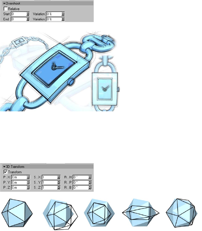
SKETCH MATERIAL • 69
Overshoot
Use Overshoot to add extensions to lines. Image © 2003 by Artur Bala.
The Overshoot settings add straight extensions to the lines. The Start and End boxes dene the
length of the overshoots at the start and end of the line, either as a percentage of the line’s
length (Relative enabled) or in pixels (Relative disabled). The Variation boxes vary the length of the
overshoots per stroke. 0% means no variation, 100% means maximum variation.
3D Transform
1 2 3 4 5
1 Original; 2 Movement with P.X and P.Y; 3 Movement with P.Z (i.e. towards or away from the camera); 4 Scale
with S.X and S.Y; 5 Rotation with R.H and R.P.
These settings change the position (P), scale (S) and rotation (R) of the lines in three dimensions.
The Transform option switches the transformation on or off.
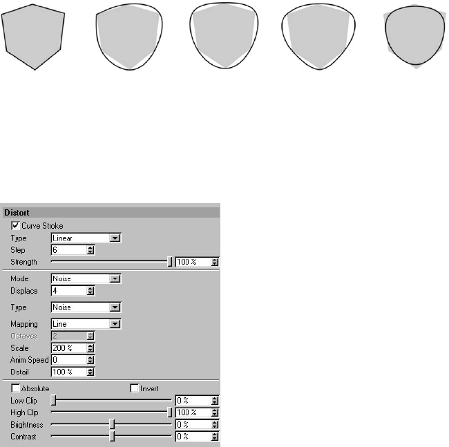
70 • CHAPTER 4
Distort
1 2 3 4 5
1 Original stroke; 2 Type set to Cubic and Close disabled on the Strokes tab; 3 Type set to Cubic and Close
enabled on the Strokes tab; 4 Type set to Akima; 5 Type set to B-Spline.
The Distort settings enable you to add imperfections to the lines such as curves and wobbles. They
are also useful for smoothing out strokes created by low poly objects.
You can optionally specify a vertex map to control which lines are distorted and by how much. To
do this, assign a Sketch Style tag to the object if it doesn’t have one already and set the map on the
tag’s Maps tab (drag and drop the tag into the Distort Map box).
Curve Stroke, Type, Step, Strength
Enable the Curve Stroke option to curve the strokes. Choose the shape of the curve from the Type
drop-down list: Linear, Cubic, Akima, B-Spline or Bezier. These are the same types that are available
for CINEMA 4D’s spline objects. The Strength value denes the strength of the curve effect. 0%
means no curve, 100% means the full effect.
The Step value is the number of pixels between each step in the curve. Decrease the value for a
smoother curve, but keep in mind it will take longer to render.
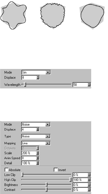
SKETCH MATERIAL • 71
Mode
From left to right: Mode set to Sin, Noise and Spline.
The Mode settings add distortions to the lines. Choose from four modes: None (switches distortions
off), Sin, Noise or Spline.
Sin
Sin mode distorts the lines based on a sine wave (left cube above). The Wavelength and Displace
settings dene the wavelength and amplitude respectively of the sine wave, in pixels.
Noise
The Noise settings are ideal for adding a natural look to the lines such as wobbles. They work in
the same way as the noise settings for the Noise modier except they modify the path of the lines
instead of the color, thickness or opacity. For details, look up “Noise modier” in the index.
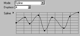
72 • CHAPTER 4
Spline
For details on using spline graphs, see your CINEMA 4D reference manual.
The Spline mode distorts the lines using a spline graph. The Displace value is the strength of the
distortion.
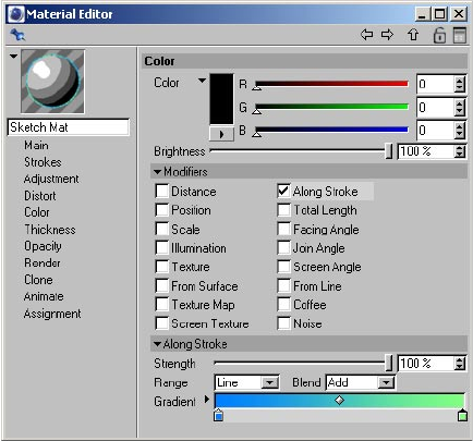
SKETCH MATERIAL • 73
Color, Thickness, Opacity
These three tabs give you complete control over the color, thickness and opacity of lines. They
enable you to create any type of line effect, from simple lines that fade out to complex brush
effects. Each tab works in a similar way:
- Set the general color, thickness and opacity using the Color, Thickness and Opacity settings at the
top of the tabs.
- Modify the color, thickness and opacity using the modier options. To switch on a modier,
enable its option. You’ll see its settings appear in the bottom part of the tab, where you can
adjust them.
With a few exceptions, each tab has the same modier options. For example, the Along Stroke
modier is present on all three tabs. You’ll nd a description of each modier in the following pages.
Link To Thickness (Opacity tab only)
The Opacity tab has a Link To Thickness option which enables you to use the same modier settings
for thickness and opacity. Instead of setting the modiers on both tabs, set them on the Thickness
tab only and enable the Link To Thickness option on the Opacity tab.
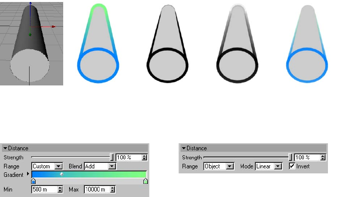
74 • CHAPTER 4
Distance modier
(Original) Color Thickness Opacity All three
The Distance modier modies the color, thickness or opacity based on distance from the camera.
Material editor settings
Color tab. Thickness and Opacity tabs.
Range, Min, Max
The Range setting denes the range over which the color, thickness or opacity is modied.
Object
This range is from the part of the object nearest the camera to the part furthest away.
Camera
This uses the camera’s Front Blur End and Rear Blur End values (Depth tab) when you enable
them. If the options are disabled then Sketch and Toon will use the Target Distance in place of
Rear Blur End and the Camera in place of Front Blur End.
Custom
When you select the Custom range, you’ll see the Min and Max boxes appear. These dene the
start and end of the range as distances from the camera.
Other settings
Look up “Common modier settings” in the index.
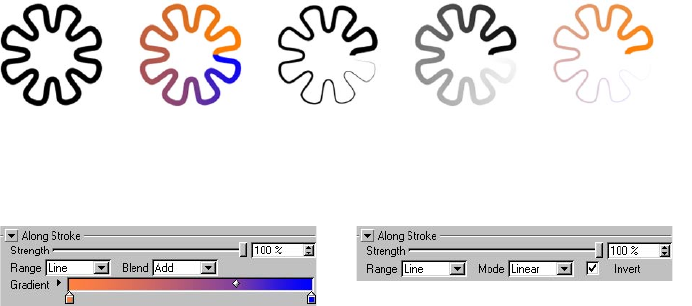
SKETCH MATERIAL • 75
Along Stroke modier
(Original) Color Thickness Opacity All three
The Along Stroke modier modies the color, thickness or opacity based on position along the stroke.
Material editor settings
Color tab. Thickness and Opacity tabs.
Range
The Range setting is the range over which the color, thickness or opacity is modied.
Line
This range is from the start to end of each stroke (or line segment if strokes are disabled).
Custom
The Custom mode lets you specify the start and end of the range (Min and Max) along the stroke
in pixels and the number of times the range is looped (Loop).
Other settings
Look up “Common modier settings” in the index.
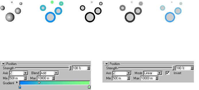
76 • CHAPTER 4
Position modier
1 2 3 4 5
(Original) Color Thickness Opacity All three
The Position modier modies the color, thickness or opacity based on the object’s position along
the camera’s X, Y or Z-axis.
Material editor settings
Color tab. Thickness and Opacity tabs.
Axis, Min, Max
The Axis is which camera axis to use. The Min and Max values dene range over which the
parameter is modied. For example, if Axis is set to Z and Min and Max are set to 500 m and
1000 m respectively, the range is from 500 m to 1000 m along the camera’s Z-axis.
Other settings
Look up “Common modier settings” in the index.
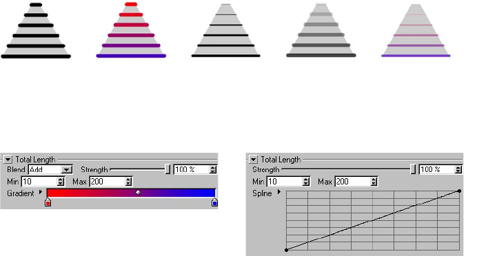
SKETCH MATERIAL • 77
Total Length modier
(Original) Color Thickness Opacity All three
The Total Length modier modiers the color, thickness or opacity based on the length of each
stroke (or line segment if strokes are disabled).
Material editor settings
Color tab. Thickness and Opacity tabs.
Min, Max
These dene the minimum and maximum line length in pixels over which the parameter is modied.
Other settings
Look up “Common modier settings” in the index.
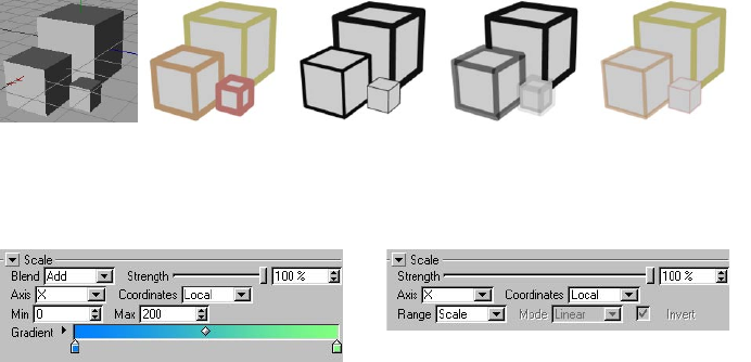
78 • CHAPTER 4
Scale modier
This modier is based on the scale — not the size — of the objects!
(Original) Color Thickness Opacity All three
The Scale modier modies the color, thickness or opacity based on the object’s scale along an axis.
Material editor settings
Color tab. Thickness and Opacity tabs.
Axis, Coordinates
The Axis setting is which axis to use: X, Y or Z. The Coordinates setting lets you choose whether this
axis is an object axis (Local) or world axis (World). For example, if you set Axis to Y and Coordinates
to Local, the lines will be modied based on the scale of the object’s Y-axis.
Range (Thickness and Opacity tabs only), Min, Max
A custom range is always used on the Color tab. Set the range using the Min and Max boxes
— see below.
This is the range of scales over which the parameter is modied. If Range is set to Scale, the range is
from a scale of 0 to 1. To dene your own range, set Range to Custom and enter the minimum and
maximum scale into the Min and Max boxes.
Other settings
Look up “Common modier settings” in the index.
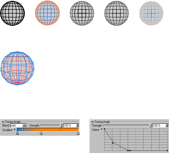
SKETCH MATERIAL • 79
Facing Angle modier
(Original) Color Thickness Opacity All three
The Facing Angle modier modies the color, thickness or opacity based on the direction in which
the lines are facing relative to the camera. Hidden lines are also affected if shown.
Blue visible lines and red hidden
lines via the Facing Angle modier.
Material editor settings
Look up “Common modier settings” in the index.
Color tab. Thickness and Opacity tabs.
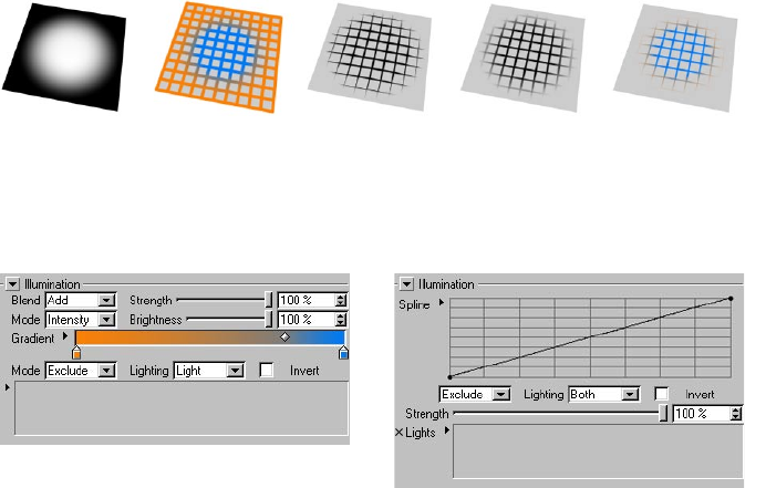
80 • CHAPTER 4
Illumination modier
This modier works best with spotlights.
(Original lighting) Color Thickness Opacity All three
The Illumination modier modies the color, thickness or opacity based on the illumination falling
onto the line.
Material editor settings
Color tab. Thickness and Opacity tabs.
Mode, Brightness (Color tab)
On the Color tab you can use the modier in two modes: Intensity and Color.
Intensity mode
This mode ignores the gradient and gives you grayscale lines whose brightness depends on the
intensity of light falling onto the line. Use the Brightness value to darken or brighten the effect.
Color mode
The Color mode uses the gradient’s colors. See the example above.
Mode, Lights box
Here you can choose which lights are used for the illumination. All lights in the scene are used by
default. To include or exclude specic lights, set Mode to Include or Exclude and drag and drop the
lights into the Lights box.
Lighting
Use Lighting to choose whether the lighting, shadows or both are used to modify the parameter.
SKETCH MATERIAL • 81
Invert
This inverts the modier’s effect.
Other settings
Look up “Common modier settings” in the index.
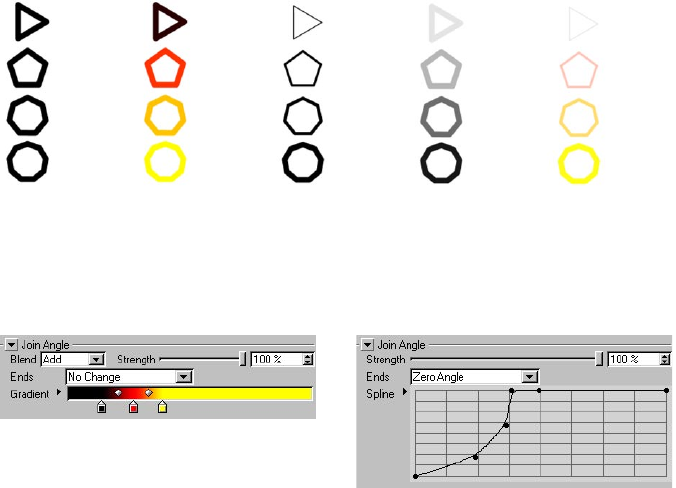
82 • CHAPTER 4
Join Angle modier
This modier works with strokes only.
(Original) Color Thickness Opacity All three
The Join Angle modier modies the color, thickness or opacity based on the angle of the joints in
the stroke.
Material editor settings
Color tab. Thickness and Opacity tabs.
Ends
The Ends mode controls what happens at the ends of the stroke.
No Change
The very start and end of the stroke use the parameter’s full value. For example, if you are using the
Join Angle modier on the Thickness tab and Thickness is set to 12 pixels, the start and end of the
stroke will be 12 pixels thick.
Minimum Angle, Maximum Angle, Zero Angle
Depending on which of these modes you select, the ends are treated as if they are joints of the
minimum or maximum angle or of zero angle.
Other settings
Look up “Common modier settings” in the index.
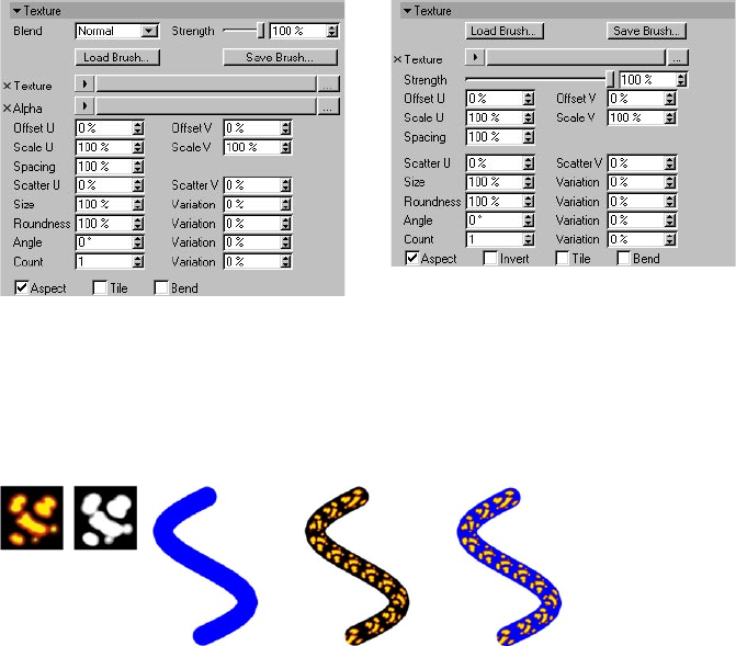
SKETCH MATERIAL • 83
Texture modier
This modier is available on the Color and Opacity tabs only.
With the exception of the Coffee modier, this is the most powerful modier in Sketch and Toon.
It offers considerable control over the rendering of the lines and enables you to create countless
brush effects.
Material editor settings
Color tab. Opacity tab.
Load Brush, Save Brush
You’ll nd various presets in the Sketch folder within CINEMA 4D’s Library folder.
These buttons enable you to load and save the Texture settings for brush-style presets.
Texture, Alpha
Texture & alpha Original line Texture Texture & Alpha
Here you can choose the main texture and apply an alpha to it. The alpha is available on the Color
tab only. Use a normal image for the alpha, not an alpha channel.
Offset U, Offset V, Scale U, Scale V
These values offset and scale the texturing in the U and V directions.
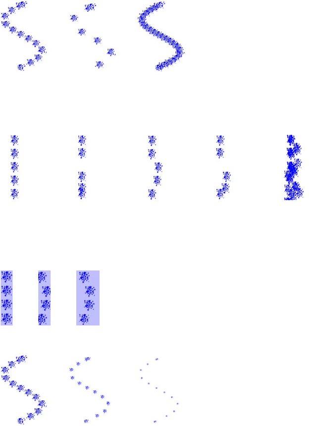
84 • CHAPTER 4
Spacing
From left to right: Spacing set to 100%, 200% and 50%.
The default Spacing value of 100% places one texture tile directly after another. Use a higher or
lower value to move the tiles apart or overlap them.
Scatter U, Scatter V, Count
Original Scatter U Scatter V Scatter U & V Count = 8
The Scatter values scatter the tiles in the U and V directions. 0% means no variation, 100% means
maximum variation. To mix in extra tiles, increase the Count value. For example, change the Count
value from 1 to 3 for three times as many tiles.
Parts of the texture that are not on the line will be cut off. See the middle line below.
Size
From left to right: Size set to 100%, 50% and 25%.
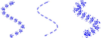
SKETCH MATERIAL • 85
The Size controls the scale of the tiles. The Variation value lets you vary the size of each tile from 0%
(no variation) to 100% (maximum variation).
Roundness
From left to right: Roundness set to 100%, 35% and 200%.
The Roundness value squashes (less than 100%) or stretches (greater than 100%) the tiles in the
line’s U direction. The Variation value varies the roundness of each tile from 0% (no variation) to
100% (maximum variation).
Angle
This value rotates each tile. The Variation value varies the angle of each tile from 0% (no variation)
to 100% (maximum variation).
Count
See “Scatter U, Scatter V, Count.”
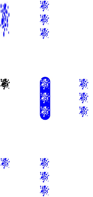
86 • CHAPTER 4
Aspect
Aspect disabled (left) and enabled (right).
If the Aspect option is disabled, the texture tile is stretched to t the whole line. Enable the option
to use the texture’s width to height ratio instead.
Invert (Opacity tab only)
The texture (left) and Invert disabled (center) and enabled (right).
Enable the Invert option to invert the texture’s effect. Transparent parts become opaque and vice
versa.
Tile
Tile disabled (left) and enabled (right).
To tile the texture, enable the Tile option and ensure the Aspect option is disabled.
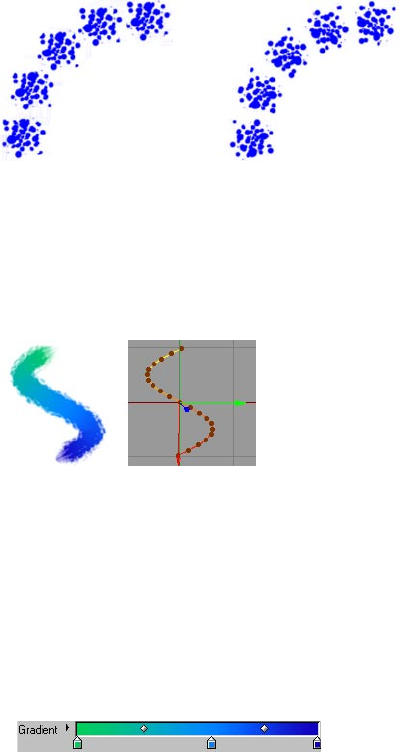
SKETCH MATERIAL • 87
Bend
Bend disabled (left) and enabled (right).
Enable the Bend option if you want the tiles rotate to follow the direction of the line.
Other settings
Look up “Common modier settings” in the index.
Making a brush with the Texture modier
Figure 1.
- Start a new scene and draw a spline similar to the one above.
- In the Material manager, choose File > Sketch Material.
- In the render settings, on the Effects tab, select the Sketch material and on its Lines tab, enable
the Splines option.
- In the Material manager, double-click the Sketch material to display its settings in the Material
editor.
- On the Thickness tab, set Thickness to, say, 30 pixels. On the Color tab, enable the Along Stroke
option and dene a gradient.
Figure 2.
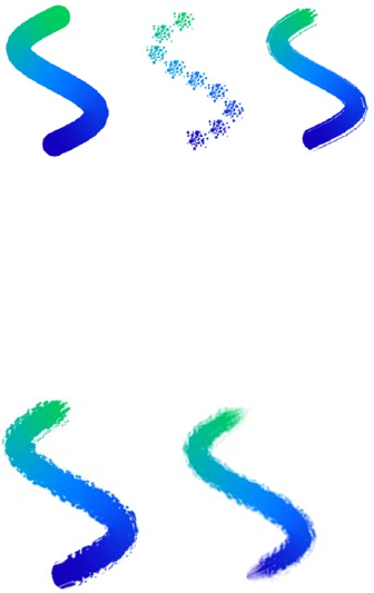
88 • CHAPTER 4
- Render to check the progress of the line (Figure 3, left line).
Figure 3.
- On the Opacity tab, enable the Texture option and in the Texture settings that appear, click the
Texture triangle and choose Load Image. Use the dialog that opens to load the chalk_chunky.jpg
texture from CINEMA 4D’s library/pattern location.
- Set Spacing to 8% to form a continuous line of tiles (Figure 3, right line).
- The stroke looks too uniform. For a more natural effect, set the Variation value for Size to 20%
and the Variation value for Angle to 10%. This varies the size and direction of the tiles (Figure 4,
left line).
Figure 4.
For nishing touches, try fading out the thickness and opacity at the ends of the stroke using the
Along Stroke modier on the Thickness and Opacity tabs (Figure 4, right line).
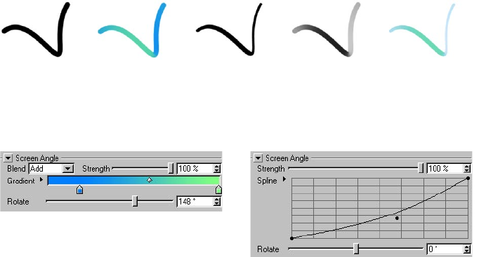
SKETCH MATERIAL • 89
Screen Angle modier
(Original) Color Thickness Opacity All three
The Screen Angle modier modies the color, thickness or opacity based on the line’s direction on
the computer screen.
Material editor settings
Color tab. Thickness and Opacity tabs.
Rotate
The Rotate setting lets you rotate the modier’s effect.
Other settings
Look up “Common modier settings” in the index.
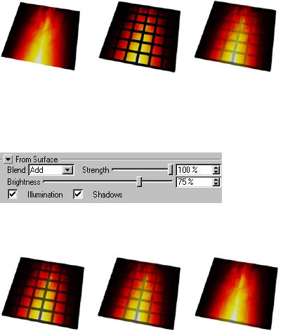
90 • CHAPTER 4
From Surface modier
This modier is available on the Color tab only.
(Original) Normal lines From Surface enabled
The From Surface modier modies the color of the line based on the color of the surface.
Material editor settings
Color tab.
Brightness
33% 66% 100%
This controls the brightness of the lines as a percentage of the color sampled from the surface. In
other words, the higher you set this value, the brighter the lines and the more they blend in with
the image.
Illumination, Shadows
These options control whether illumination and shadows are included when the surface is sampled.
Other settings
Look up “Common modier settings” in the index.
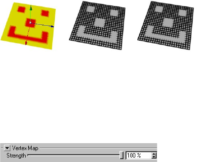
SKETCH MATERIAL • 91
Vertex Map modier
This modier is available on the Thickness and Opacity tabs only.
(Original map) Thickness Opacity
The Vertex Map modier modies the thickness or opacity based on a vertex map. To choose which
vertex map is used, assign a Sketch Style tag to the object if it doesn’t have one already and set the
map on the tag’s Maps tab (drag and drop the tag into the Thickness Map or Opacity Map box).
Material editor settings
Look up “Common modier settings” in the index.
Thickness and Opacity tabs.
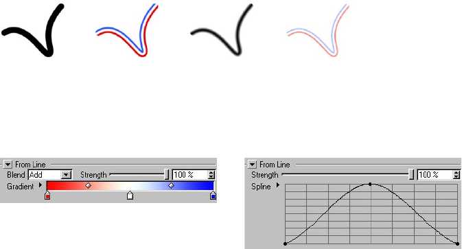
92 • CHAPTER 4
From Line modier
This modier is available on the Color and Opacity tabs only.
(Original) Color Opacity Color + Opacity
The From Line modier modies the color or opacity based on distance from the line’s edge.
Material editor settings
Look up “Common modier settings” in the index.
Color tab. Opacity tab.
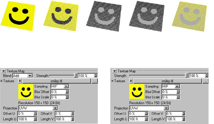
SKETCH MATERIAL • 93
Texture Map modier
The object must have a Texture tag with a material assigned for this modier to have an effect.
(The texture) Color Thickness Opacity All three
The Texture Map modier modies the color, thickness or opacity based on a texture map.
Material editor settings
Color tab. Thickness and Opacity tabs
Texture
This is the texture used to modify the lines.
Projection
For details on projection types, see your CINEMA 4D reference manual.
This is the projection to use for the texture map, such as UVW, Flat or Spherical.
Offset U, Offset V, Length U, Length V
These values offset and scale the texture in the U and V directions.
Other settings
Look up “Common modier settings” in the index.
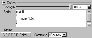
94 • CHAPTER 4
Coffee modier
For details on the COFFEE programming language, visit www.plugincafe.com.
When using the Coffee modier on the Thickness tab, the returned value can scale the
thickness down but not up. The main parameter thickness is the maximum; all returned values
are clipped to the 0 to 1 range.
The Coffee modier enables you to create virtually any medium or style, from a simple pencil to a
complex brush, using the powerful COFFEE programming language.
Material editor settings
Script, C.O.F.F.E.E. Editor
Enter a COFFEE script into the Script box or click the C.O.F.F.E.E. Editor button and enter the script
into CINEMA 4D’s COFFEE script editor.
Command
This acts as a quick reference to look up the names of the commands. It has no other purpose. It
does not insert commands.
Other settings
Look up “Common modier settings” in the index.
The COFFEE commands
sPosition [Real]
Position along a line in pixels (screen space).
sNormalisedP [Real]
Normalised position along a line (0 to 1).
ToLine [Real]
Distance to the line from the current render point (which is within the line’s thickness). Values range
from - Thickness to 0 to Thickness.
SKETCH MATERIAL • 95
Thickness [Real]
The line’s thickness as set on the Thickness tab.
StrokeLength [Real]
The total length of the stroke being rendered.
ScnPnt [Vector]
The render point in screen space (with Z).
LineOff [Real]
The offset (0 to 1) along the line segment being rendered.
wPnt [Vector]
The world coordinates for the point being rendered.
Time [Real]
Current document time in seconds.
Frame [Real]
Current frame.
FPS [Long]
Frames per second.
LineStart [Vector]
The screen space coordinates for the start of the line (LineOff = 0 at the LineStart, 1 at LineEnd).
LineEnd [Vector]
Screen space for line segment’s end point.
JoinAngleA [Real]
Join angle to the line segment at LineStart (if available, or 0.0).
JoinAngleB [Real]
Join angle (0 to 2*pi) to the line segment at LineEnd.
LineNormal [Vector]
The line normal in screen space (2D, Z=0).
EdgeNormal [Vector]
The normal from the edge that created the original line segment.
96 • CHAPTER 4
LinePosA [Real]
The line segment’s position along the stroke in pixels (A means LineStart, B LineEnd).
LinePosB [Real]
The position along the stroke in screen space for the line segment being rendered.
PntA [Long]
The index number of the object point or spline point that created the start of the line segment (or
-1 if not available).
PntB [Long]
The point index that created the LineEnd (or -1).
PolyA [Long]
The polygon index that created the line segment (or -1 if not available, like a spline).
PolyB [Long]
The polygon index that shared the edge (or -1 if not available).
RayBits [Long]
This passes in the raybits from the CINEMA 4D render. See the CINEMA 4D SDK.
CosC [Real]
The angle between the ray and normal on the surface.
Normal [Vector]
The normal from the surface (if PolyHit is not 0, which says it hit an object).
BumpNormal [Vector]
Bumped surface normal.
Dist [Real]
Distance to the point hit on the surface (if one was hit).
PolyHit [Long]
Really only useful to know if an object was hit by a ray, which means the value is not 0.
RayPos [Vector]
World position for the ray’s starting point.
SKETCH MATERIAL • 97
RayDirn [Vector]
Direction of the ray (the ray is from CINEMA 4D).
SurfPnt [Vector]
The world coordinates for the point hit (if one was hit).
RendLeft [Real]
The render image left pixel.
RendTop [Real]
Render top pixel (left, top usually 0, but not always, e.g render region).
RendRight [Real]
Right pixel (width = right-left+1).
RendBottom [Real]
Bottom pixel (height = bottom - top +1).
ObjLeft [Real]
Object’s left screen bounds pixel. This is for the object that the line came from. This is not
necessarily the object hit by the CINEMA 4D ray.
ObjTop [Real]
Object’s top screen bounds pixel.
ObjRight [Real]
Object’s right screen bounds pixel.
ObjBottom [Real]
Object’s bottom screen bounds pixel.
Color [Vector]
The color set in the Color tab (Color parameter only).
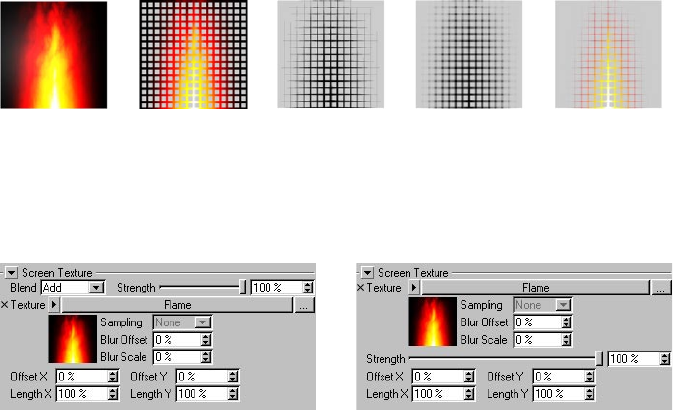
98 • CHAPTER 4
Screen Texture modier
(The texture) Color Thickness Opacity All three
The Screen Texture modier modies the color, thickness or opacity based on a texture map placed
over the entire rendered image (the screen). If the object covers only part of the screen, it will
receive only part of the texture.
Material editor settings
Color tab. Thickness and Opacity tabs.
Texture
Here you can choose the screen texture.
Offset X, Offset Y, Length X, Length Y
These values offset and scale the texture on the screen.
Other settings
Look up “Common modier settings” in the index.
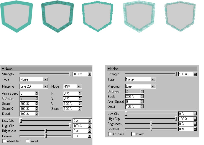
SKETCH MATERIAL • 99
Noise modier
(Original) Color Thickness Opacity All three
The Noise modier modies the color, thickness or opacity based on a noise pattern.
Material editor settings
Color tab. Thickness and Opacity tabs.
Type
Choose from 30 types of noise such as Blistered Turbulence, Dents and Wavy Turbulence. These are
the same types that are available for CINEMA 4D’s Noise shader — see your CINEMA 4D reference
manual for details.
Mapping
The Mapping drop-down list controls which coordinates are used to generate the noise. This can
affect how the noise looks, how it changes as the object or camera moves and whether the noise is
continuous over line segments if strokes are disabled.
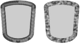
100 • CHAPTER 4
Line, Line 1D, Line 2D
Strokes disabled (left) and enabled (right).
The position along the line is used. Avoid using this type if strokes are disabled, otherwise poor
results are likely (see left cylinder above).
Screen
The noise is calculated in the space of the screen. The noise will change is the object’s position on
the screen changes.
Object
The noise is calculated in object space and remains the same regardless of object and camera
moves.
World
The noise is calculated in world coordinates. The noise remains the same if you move the camera
but changes if you move the object.
Mode, RGB, HSV (Color tab only)
The Mode setting denes whether the noise uses the RGB color system or the HSV color system to
modify the color. The three boxes below the Mode setting dene how strongly the noise affects
each color component (R,G and B or H, S and V depending on the mode).
Anim Speed
The rate at which the noise animates, in cycles per second.
Octaves
The octaves of detail in the noise.
Scale, Scale X, Scale Y
The Scale value is the global size of the noise, the Scale X and Scale Y values are the relative scale of
the noise in the X and Y directions.
SKETCH MATERIAL • 101
Detail
Used for antialiasing. In general, leave the value set to the default of 100% but if the line texture
ickers when you animate, try increasing the value. Or if you are rendering a high-res still and you
want crisp detail, set the value lower.
Low Clip, High Clip
The Low Clip value controls the bottom clipping value of the noise; all values below Low Clip will
be clipped to zero. The High Clip value controls the top clipping value of the noise; all values above
High Clip will be clipped to 100%.
Brightness, Contrast
These settings control the overall brightness and contrast of the noise. Values above zero increase
brightness or contrast, values below zero decrease brightness or contrast.
Absolute
If this option is enabled, the noise is absolute, causing it to fold about its midpoint.
Invert
Enable the Invert option to invert the noise.
Other settings
Look up “Common modier settings” in the index.
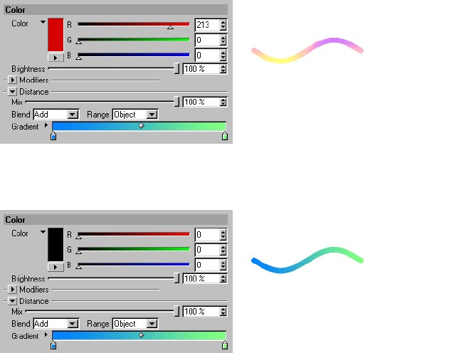
102 • CHAPTER 4
Common modier settings
These settings are present for most or all modiers. For example, each modier has a Strength
setting.
Strength
This is the strength of the modier’s effect, from 0% (no effect) to 100% (full effect).
Gradient, Blend (Color tab only)
For details on the blend modes, look up “blend modes” in the index.
For details on using gradients, see your CINEMA 4D reference manual.
The Blend setting denes which blend mode is used to mix the gradient with the main color: Add,
Subtract or Multiply. If you want the result to be the same color as the gradient, set the main color
to black and the Blend mode to Add.
With Color set to black and Mode set to Add, the gradient’s colors are applied directly to the line.
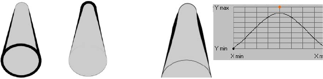
SKETCH MATERIAL • 103
Mode, Invert, Spline Graph (Thickness and Opacity tabs only)
For details on using spline graphs, see your CINEMA 4D reference manual.
For some modiers, such as Facing Angle, there is no choice of mode and a spline graph is
always used.
Linear mode for the Distance modier on the
Thickness tab, with Invert enabled (left) and
disabled (right).
Spline mode for the Distance modier on the Thickness
tab. Here the graph species how the thickness varies
depending on distance from the camera.
The Mode controls how the thickness or opacity is modied over the range. Linear mode fades out
the thickness or opacity gradually — the Invert option inverts the direction of the fade.
If instead you set Mode to Spline, you’ll see a spline graph appear. The graph denes the variation
in thickness or opacity over the range. The X-axis represents the range, the Y-axis represents the
thickness or opacity.
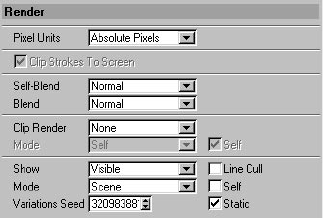
104 • CHAPTER 4
Render
Here you’ll nd the Sketch material’s rendering controls, such as the options for render culling.
Pixel Units
In the Sketch material there are numerous settings which take pixels as their units. The Pixel Units
value denes what is meant by a pixel.
Absolute Pixels
This is real pixels, i.e. 1 unit refers to 1 pixel in the image.
Relative Pixels
These values are all scaled relative to the object’s bounds. This means that 1 pixel thickness may
change based on the object’s size; this is the screen size of the object, so moving the camera away
from the object gives the same results as scaling the object. What matters is the size of the object
rendered onto the screen.
World Space
The pixels are transformed from the world space, so a “pixel” is smaller the further away it is from
the camera.
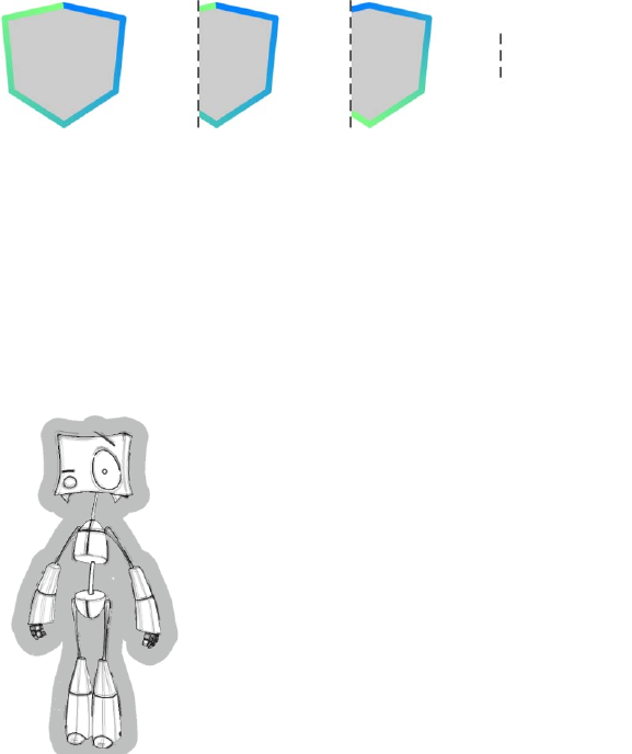
SKETCH MATERIAL • 105
Clip Strokes To Screen
= screen’s edge
(Original) Disabled Enabled
This controls how the lines are clipped if part of the object is off-screen. If the option is disabled,
the properties are chopped off at the screen’s edge. If the option is enabled, the properties are
redrawn to t the on-screen part of the stroke.
Self-Blend, Blend
For details on the blend modes, look up “blend modes” in the index.
Sometimes it’s useful to render the same line multiple times with different materials. For example,
the character below has two outlines: a thin black outline and a thick gray one. To assign multiple
Sketch materials to the same object, simply add a Sketch Style tag for each material.
Image ©2003 by Christian Rambow.
The Self-Blend and Blend settings dene the blending mode for lines on the same object (Self-
Blend) and lines from different objects (Blend).
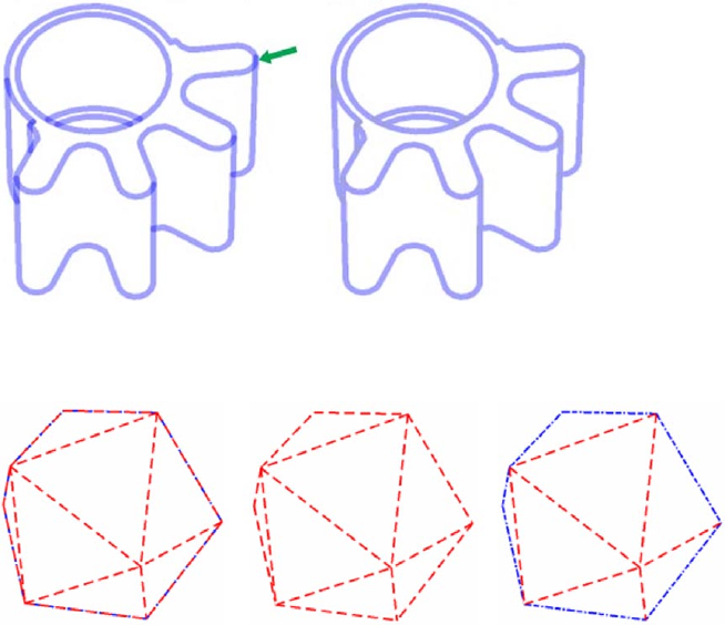
106 • CHAPTER 4
Example 1 - Solving opacity overlaps
To avoid opacity overlaps, set Self-Blend to Average.
Example 2 - Solving overlapping patterns
Two line types have been enabled for this object: Crease and Outline. Both have a different
pattern. Initially you can’t see much of a pattern around the outline (left object) because the two
lines overlap and so any gaps in one are lled by the pattern from the other line.
To remedy, rst set Self Blend to Overwrite (center object). This removes the overlap, but now the
blue line has been overwritten because of the drawing order (see “The drawing order” below).
This is easily resolved by setting the blue line’s Priority value in the Sketch material (Main tab)
higher, to give the desired result (right object).
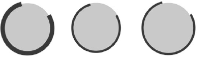
SKETCH MATERIAL • 107
The drawing order
Suppose you’ve drawn two outlines for the same object, a thin red outline and a thick black one.
How does Sketch and Toon know which line you want on top of the other?
Sketch and Toon follows a drawing order for the lines:
- If the lines are at different depths from the camera, the one closest to the camera is drawn on
top.
- If the lines are the same depth from the camera but are generated by different Sketch Style tags,
the materials are drawn according to the order of their tags in the Object manager — the left-
most tag’s material is drawn on top.
- If the lines are the same distance from the camera and are generated by the same Sketch Style
tag, the materials are drawn in order of their priority on the Basic Properties tab — the one with
the highest Priority value is drawn on top.
Clip Render, Mode
None Inside Geometry Outside Geometry
This setting lets you clip off parts of the line that are inside or outside the geometry.
The Mode setting controls how an object’s clipping is affected by other objects in the scene. Enable
the Self option if objects should clip their own lines as well.
Self
Clipping is not affected by other objects. The object’s lines are clipped to its own geometry only.
Children, Hierarchy, Scene
In Children mode, the lines are clipped to the object’s own geometry (if Self is enabled) and to
the geometry of its children (Children). Hierarchy mode nds the top-most parent and then uses
the parent and all its children to clip.
Object
This lets you choose which objects are used to clip the lines of other objects — drag and drop the
objects into the Objects box. To make each object clip its own lines as well, enable the Self option.
108 • CHAPTER 4
Render Culling (Show, Line Cull, Mode, Self, Objects)
These settings are for advanced use only. They are designed for supporting alpha maps during
rendering to allow lines to show through alphas.
Sketch and Toon has two stages of culling: hidden culling and render culling.
Hidden culling takes place while the lines are being generated and its purpose is to separate the
lines into visible lines and hidden lines. This is controlled by the Hidden Cull mode and Self-Culling
option in the post effect and Sketch Style tag (Lines tab). The Hidden Cull mode sets which objects
are used to check if a line is hidden. For more information on hidden culling, look up “hidden lines,
culling” in the index.
Render culling takes place at render time and is controlled by the Show, Line Cull, Mode, Self and
Objects settings. If a line’s rendering pixel is hidden by an object that was not used in nding if that
line was hidden or visible during hidden culling, it will use these settings to decide if it should render.
Show
If you set this to Visible or Hidden, Sketch and Toon will only render line pixels that are visible or
hidden respectively based on the Mode settings. The default setting is visible (normally you only
want to see line pixels that are not hidden by other objects).
Mode, Self
As with the other clipping and culling modes, this sets which objects in the scene are used to
nd out if this pixel is visible or hidden. The default is Scene, which means all other objects in the
scene are checked. With the default settings, only pixels that are not hidden by other objects are
rendered. The Self option is disabled by default. If you enable it, the object which generated the
line will also be checked to see if it hides the line.
Line Cull
This changes how the render culling works. It has two methods.
Method 1 (option disabled) - this simply checks the pixel itself that is rendering. This is faster than
method 2 but can result in the “line thinning” artefact where lines that are partly hidden along
their thickness are culled (because it is per pixel).
Method 2 (option enabled) - this checks the line itself. It is slower than method 1 because it
needs to send out extra rays from the line to check if the line point closest to the rendering pixel
should be culled.
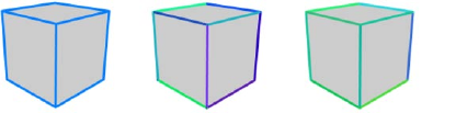
SKETCH MATERIAL • 109
Variations Seed, Static
From left to right: original cube; cube with 30% HSV color variation set on the Adjustment tab; the same settings
as the center cube except with a different Variations Seed value.
The Sketch material has many variation parameters. For example, the H, S and V values on the
Adjustment tab enable you to randomize the color of each line. Suppose you don’t like the
particular colors Sketch and Toon has chosen, what then?
Change the Variations Seed value and Sketch and Toon will create a new random look. Changing
this value is like “throwing the dice again” for all variation values. Keep changing it until you’re
satised with the result. Disable the Static option if you are rendering an animation and you want a
different variation to be generated for each frame.
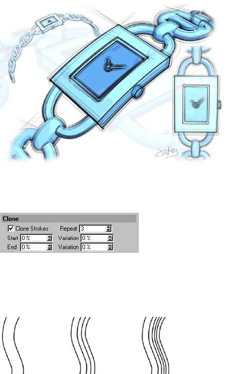
110 • CHAPTER 4
Clone
Image ©2003 by Artur Bala.
Cloning is the key to eye-pleasing sketch effects such as for the watch above where multiple faint
lines are offset from the geometry.
Clone Strokes
Enable the Clone Strokes option to switch on cloning.
Repeat
From left to right: Repeat set to 1, 3, and 5.
This is the number of clones per line. Keep in mind that the more clones you use, the longer it takes
Sketch and Toon to render the lines.
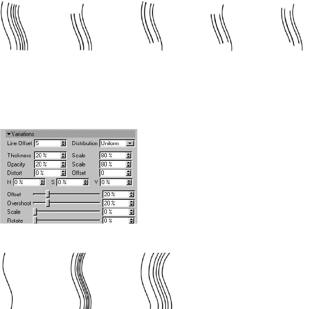
SKETCH MATERIAL • 111
Start, End, Variation
(Original) Start = 20% End = 20% Start & End = 20% With variation
Use the Start and End values to make the clones shorter than the original lines. They dene where
the clone should start and end as a percentage of the original line’s length. The Variation values let
you vary the start and end for each clone.
Variations
Line Offset, Distribution
From left to right: Offset set to 0, 25, and 50.
The Line Offset controls how far apart the clones are from the original line. The value denes the
maximum distance in pixels between the original line and the furthest clone. Note that if the value
is set to 0, the clones will be in the same position as the original line and may not be visible (see left
line, above).
The Distribution value denes which type of random pattern is used to space out the clones:
Uniform or Gaussian.
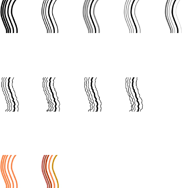
112 • CHAPTER 4
Thickness, Opacity, Scale
(Original) Scale (Thick.) = 50% Scale (Opac.) = 50% Both Scales = 50% With Variation
The Scale settings dene the global thickness and opacity of the clones as a percentage of the
original line’s thickness and opacity. You can vary the thickness and opacity of each clone using the
Thickness and Opacity boxes. 0% means no variation, 100% means maximum variation.
Distort, Offset
(Original) Distort = 100% Low Distort Offset High Distort Offset
These values vary any distortion effects applied to the original line (Distort tab) for each clone. The
Distort value denes the amount by which the strength of the distort may vary (increase the value
for more variation per clone) while the Offset offsets the position of the distortion’s coordinates.
H, S, V
Original With HSV variation
By default, each clone is the same color as the original line. To make each clone a random color
instead, enter the percentage variation for the H, S and V values into the appropriate box. 0%
means no variation, 100% means maximum variation.
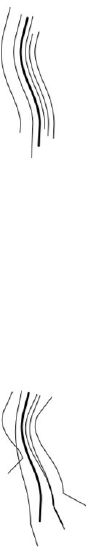
SKETCH MATERIAL • 113
Offset, Overshoot, Rotate
These values modify the original stroke’s offset, overshoot and rotation values (dened on
the Adjustment tab) for each clone. Keep in mind that if the original stroke has no adjustment
properties, then changing these variation values will have no effect (100% variation of nothing
results in nothing).
0% means no variation, 100% means maximum variation. The picture above demonstrates
Overshoot set to 100% (the original line is the thick one; note how the overshoots for the clones are
longer or shorter than the original line’s overshoots).
Scale
The Scale value randomizes the scale of each clone. 0% means no variation, 100% means maximum
variation.
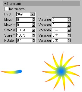
114 • CHAPTER 4
Transform
Original line (left) and ten clones with Incremental
enabled and Rotate X set to 33° (right).
These settings let you move, scale and rotate the clones. The Move values dene the number of
pixels to move the lines in the computer screen’s X and Y directions. The Pivot setting denes the
center of rotation: the start, end or center of the original line (Start, End or Center) or the center of
the object (Object). The Variation boxes let you vary the transformation per stroke. 0% means no
variation, 100% means maximum variation.
Enable the Incremental option to transform each clone based on the previous clone’s position, scale
and rotation. See the ower example above.
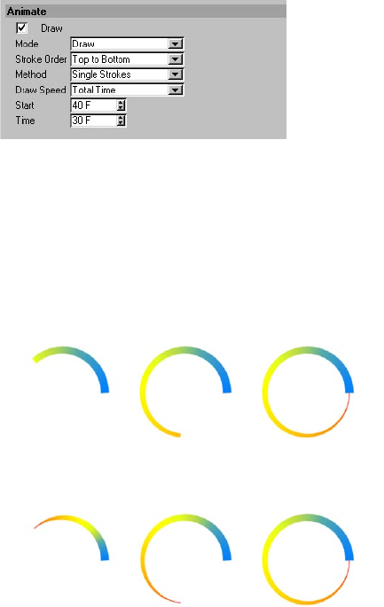
SKETCH MATERIAL • 115
Animate
Imagine you’re looking over an artist’s shoulder while he or she sketches. Soon the sketch starts to
take shape. This is the type of pleasing effect you can create using the parameters on the Animate
tab. In general, use these settings with static scenes only — neither the camera nor the objects
in the scene should move during the animation. If they do move, there’s no telling what might
happen. Suppose someone were to wobble your sketch pad while you were drawing...
Draw
Enable the Draw option to activate the Animate settings.
Mode
The Mode setting controls how Sketch and Toon animates the lines. The following examples show,
from left to right, the animation one third the way through, two thirds the way through, and all the
way through.
Draw
The Draw mode draws each line gradually.
Length
This is the same as Draw mode except parameters such as thickness and color grow with the line.
116 • CHAPTER 4
Opacity
The Opacity mode fades in the lines gradually.
Thickness
The lines start off thin and thicken out over time to reach their full thickness.
Build
Unlike Opacity mode, which fades in lines gradually, Build mode makes the lines appear suddenly.
One frame the line isn’t there, the next it’s completely drawn.
Stroke Order, Method
Choose whether Sketch and Toon should draw the strokes all at the same time (All Strokes) or
one after the other (Single Strokes). In the case of Single Strokes, the Stroke Order controls which
strokes are drawn rst.
Draw Speed
The Draw Speed controls how quickly Sketch and Toon draws the lines.
Pixels
This mode lets you set the drawing speed in pixels per second (Speed) and when Sketch and Toon
should start to draw (Start).
Stroke Time
Tells Sketch and Toon when to start drawing (Start) and how long to take to draw each stroke
(Time).
SKETCH MATERIAL • 117
Completion
Unlike the other modes, the Complete mode requires you to record keys. The Complete value
denes how complete the drawing is. For example, to record a simple animation from frames 0
to 90, record a key at frame 0 with Complete set to 0%, and record another key at frame 90 with
Complete set to 100%.
Total Time
In this mode, you can specify when the drawing should start (Start) and how long it should take
to complete (Time).
End Frame
The End Frame mode is the simplest mode of all. It tells Sketch and Toon when to start drawing
(Start) and when to be nished by (End).
Animation End
Sketch and Toon will complete the drawing by the end of the animation. The Start value denes
when the drawing should start.
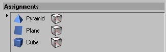
118 • CHAPTER 4
Assignment
Here you can quickly assign a Sketch material to specic objects. Drag and drop the objects into the
Assignments box. A Sketch Style tag will be created automatically for each of these objects with the
material assigned.
To remove the material assignment from an object, select the object’s name in the box and press
the Delete or Backspace key. The Sketch Style tag will be deleted automatically and the object’s
name will be cleared from the box.
SKETCH MATERIAL • 119
Blend modes
Sketch and Toon boasts a healthy selection of blend modes. There are various places where you can
choose a blend mode, such as on the Sketch material’s Render tab where you can control how lines
should be blended together.
Average
The result is the average of the background pixel and the blend pixel.
Normal
The background pixel is completely covered by the blend pixel if the strength of blending is 100%.
Multiply
This mode multiples the background pixel by the blend pixel. Unless the blend pixel is white, the
result will be darker than the background pixel.
Screen
This is the opposite of the Multiply blend mode. The background pixel and blend pixel are both
inverted, multiplied and then inverted again. This mode generally gives a result brighter than the
background.
Darken
The background and blend pixel are compared and the result is whichever is darker.
Lighten
This is the same as darken except the result is whichever pixel is lighter.
Difference
The background and blend pixels are subtracted from each other.
Negative
The Negative mode is the same as Difference mode except colors between white and black become
brighter instead of darker.
Exclusion
This mode is the same as Difference mode except that it creates a softer effect.
Overlay
A combination of Screen and Multiply mode, depending on the background color.
120 • CHAPTER 4
Hard Light
This mode works like Multiply mode and Screen mode at the same time. 50% brightness is neutral
(nothing happens). Lighter values act like Screen, darker values act like Multiply.
Soft Light
This is a combination of the Burn and Dodge modes. The Dodge mode is used for blend pixels
greater than 50% brightness, the Burn mode is used for values below 50%.
Dodge, Burn
The brightness value of the blend pixel is used to brighten (Dodge) or darken (Burn) the background
pixel.
Reect
Similar to Dodge mode but the result is not as bright in some cases.
Glow
The color of the background pixel and blend pixel are swapped. The result is similar to Hard Light
mode.
Freeze
The background pixel and blend pixel are inverted and the result inverted again.
Heat
Like Freeze mode but the background pixel and blend pixel are swapped.
Add
One of the simplest blend modes: the background pixel and blend pixel are added together.
Subtract
The background pixel and blend pixel are added together then white is subtracted (result =
background color + blend color - 256).
Stamp
A blend pixel that is 50% bright doesn’t change the background pixel; brighter or darker blend
pixels produce a darker or brighter result respectively.
Xor
The background pixel and blend pixel are combined with a logical XOR.
Hue, Saturation, Luminance
In these modes, the result is the hue, saturation or luminosity of the blend pixel applied to the
background pixel.
SKETCH MATERIAL • 121
Red, Green, Blue
The result is the red, green or blue color channel from the blend pixel and the two other color
channels from the background pixel. For example, Green mode gives you the green color channel
from the blend pixel and the red and blue color channels from the background pixel.
Overwrite
This is mostly useful for technical illustrations using patterns. It ignores any opacity (which is used
to do the pattern) from behind it and overwrites the opacity so that you can always see the pattern.
Levr
The value of the blend pixel is used to apply contrast to the background pixel.

5 Sketch Shaders
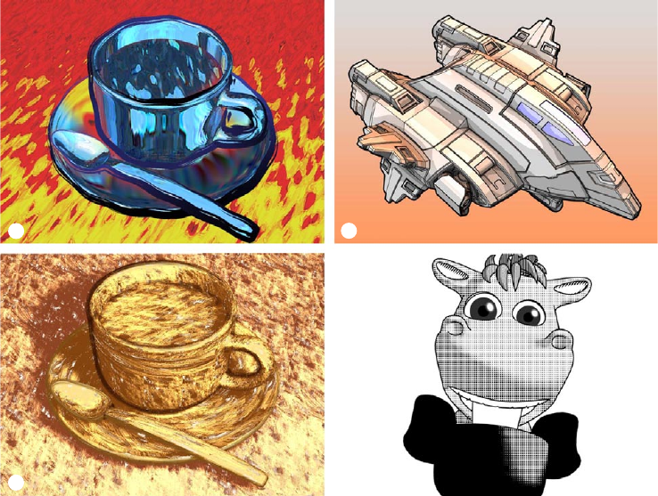
SKETCH SHADERS • 125
1 2
3 4
1 Art shader; 2 Cel shader; 3 Hatch shader; 4 Spots shader. Images © 2003 by Artur Bala (1 & 3),
Michael Welter (2), and Toshihide Miyata (4).
You’ll nd various shader presets in the Sketch folder within CINEMA 4D’s Library folder. Load
these using the Material manager’s File > Load Materials command.
Sketch and Toon includes four powerful channel shaders to color your scenes: Art, Cel, Hatch and
Spots. In these pages, you’ll nd details on each shader.
The Art shader uses a sphere to dene the illumination and shading of an object. Unique shading
is possible by varying the surface and coloring of the sphere. This shader can transform ordinary
renders into abstract masterpieces.
The Cel shader replicates the unique shading of styles such as Manga and Anime with quantized
color shading. Custom gradients make it easy to dene the look you desire.
5 Sketch Shaders
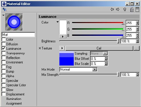
126 • CHAPTER 5
The Hatch shader creates custom hatch shading on your 3D objects based on any texture you
choose. Three levels of shading and coloring combine to create colorful and artistic renders with a
stunning hand-drawn look to them.
With the Spots shader, the spots (or any other image you desire to use) shrink depending on surface
brightness to mimic the halftone appearance of low resolution print images.
Creating a Sketch shader
The Sketch shaders are channel shaders. You can load them into any material channel which accepts
a texture, but generally they work best in the Luminance channel with all other channels such as
Specular disabled.
Keep the following in mind: The Sketch shaders are rendered by CINEMA 4D, not by the post effect.
The post effect has some shading options which will affect the CINEMA 4D rendering including the
result of the Sketch shaders unless you switch off the options.
To create a Sketch shader:
- In the Material manager, choose File > New Material to create a new material.
- Double-click the material’s thumbnail to display its settings in the Material editor (or access the
settings using the Attribute manager if you prefer).
- In general, ensure all material channels are disabled except Luminance.
- On the Luminance tab, click the Texture triangle button and choose which Sketch shader you
want to use (Art, Cel, Hatch or Spots) from the Sketch menu.
- You’ll see the shader’s name appear to the right of the Texture triangle button. Click the shader’s
name or its preview to display its settings.
SKETCH SHADERS • 127
To switch off post effect shading:
- On the Render Settings > Effects > Sketch and Toon > Shading tab, set Object to Off.
- If you want to switch off the post effect’s background color (a white background by default), set
Background to Off.
Using other shaders
Sketch and Toon allows you to shade the object using any standard shader, not just the Sketch
shaders. As with the Sketch shaders, switch off the post effect shading options unless you want
them to affect the rendering. For more details, see the previous section: “Creating a Sketch shader.”
Antialiasing tip
The Art shader, Hatch shader and Spots shader each use a texture to shade the objects. For
example, the Hatch shader uses a picture of a stroke or block of strokes to draw hatches onto the
objects. Naturally you’ll want these texture strokes to look smooth and antialiased when rendered,
which would usually mean setting CINEMA 4D’s Antialiasing mode on the Render Settings >
Antialiasing tab to Best.
A tip to speed up rendering is to set the Antialiasing mode to Geometry instead of Best and blur the
texture slightly using the texture’s Blur Offset and Blur Scaling values. Although CINEMA 4D won’t
antialias textures in Geometry mode, this blurring will produce smooth strokes that look antialiased,
and the rendering will be much faster. Ideal for when you are using thousands of hatched lines.
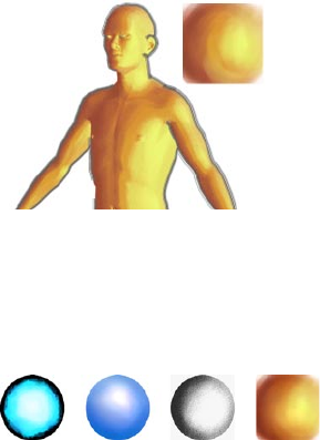
128 • CHAPTER 5
Art Shader
The Art shader is possibly the most fun you’ll ever have coloring your illustrations. Instead of using
lights and complex texture mapping for your scene, you provide the shader with a picture of a
shaded sphere textured and “lit” the way you want the objects in the scene to be textured and “lit”.
Sketch and Toon will then apply this style to the scene’s objects.
Creating the shaded sphere
The rst step when using the Art shader is to create the shaded sphere. Why not paint it from
scratch in your favorite painting software such as BodyPaint 3D (www.bodypaint3d.com). Or
perhaps render a sphere in CINEMA 4D and run a few lters over it in an image editor?
No lights required!
When using the Art Shader, lights are not required.
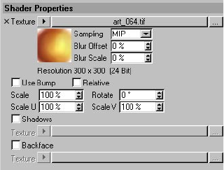
SKETCH SHADERS • 129
Material editor / Attribute manager settings
The Art shader works best with curved surfaces because the effect is controlled by the
direction of the surface normals.
Texture
This is the texture to use. It should be a picture of a shaded sphere with the texturing and lighting
drawn onto it that you want applied to the objects in the scene.
Use Bump
To apply a bump map to the shader, enable this option and set up the bump mapping on the
Material’s Bump tab as you would for a normal material.
Relative
Enable this option to vary the look slightly for each object. This can help to achieve a more natural
look, since in a real scene the lighting normally depends on the object’s position relative to the light
source. However, note that the sphere texture must be stretched over the edges of the objects to
achieve the effect and this may lead to artefacts.
Scale, Scale U, Scale V
These values scale the texture. This if mostly useful for controlling how much of the image is used,
or for correcting gaps in the texture.
Rotate
The Rotate option rotates the texture about its center.
Shadows, Backface
Generally you won’t need to use these. They enable you to use additional images for shadow
regions and backfaces (surfaces which face away from the camera).
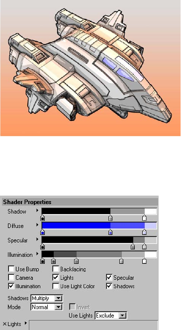
130 • CHAPTER 5
Cel Shader
Image © 2003 by Michael Welter.
The Cel shader is for cartoon-style shading, such as Manga-style or Anime-style.
Material editor / Attribute manager settings
Diffuse, Backfacing
The Diffuse gradient controls the diffuse color of the objects, from areas in total darkness (left end
of gradient) to areas which are fully lit (right end of gradient).
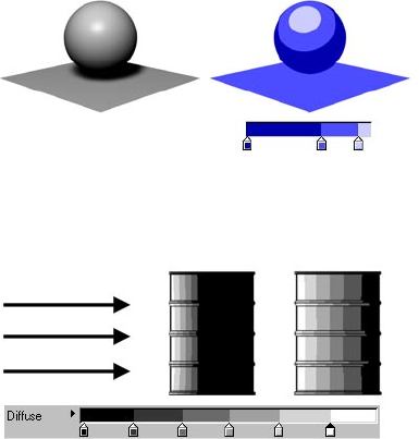
SKETCH SHADERS • 131
The Diffuse gradient controls the diffuse color of objects.
Backfacing
Direction of light
Backfacing
disabled
Backfacing
enabled
Two oil drums, both lit from the left. Enable Backfacing if you want the gradient to span frontfaces and
backfaces, not just frontfaces.
Usually the Diffuse gradient controls the color of all frontfaces (i.e. faces which point towards the
light), but backfaces simply take the “darkest” color (i.e. the color at the left edge of the gradient).
If instead you want the gradient to fully control the color of frontfaces and backfaces, enable the
Backfacing option. The left edge of the gradient then corresponds to surfaces facing directly away
from the light, the right edge corresponds to surfaces facing directly towards the light. Among
other things, Backfacing gives you a quick way to create rim light effects.
Use Bump
To apply a bump map to the shader, enable this option and dene the bump mapping on the
material’s Bump tab as you would for a normal material.
Camera
Enable the Camera option to use the camera as a light source.
Lights, Illlumination, Use Light Color, Use Lights, Lights box
To use the lights in the scene as light sources, enable the Lights option. To use the illumination of
each light (not just its direction), enable the Illumination option.
By default, all lights in the scene will be used as light sources when Lights is enabled. To include or
exclude specic lights, set Use Lights to Include or Exclude and drag and drop the lights into the
Lights box.
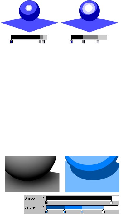
132 • CHAPTER 5
Usually the color of the objects is controlled by the Diffuse gradient. To color the objects using the
color of the lights instead, enable the Use Light Color option. The Diffuse gradient then controls the
brightness values for the objects.
Specular
If you want the lights to generate specular highlights, enable this option. The Specular gradient
controls the color, width, height and falloff of the highlights, from areas of no specular (left end of
gradient) to areas of full specular (right end of gradient).
Shadows, Mode, Invert
See “Cel shader shadows” below.
Cel shader shadows
To include shadows, enable the Shadows option and set the Shadows to Multiply, Color or Light
Shadow.
Multiply
When Shadows is set to Multiply, you have a choice of four modes: Normal, Hue, Saturation or Value.
Normal mode
Shadow under a sphere.
In Normal mode, the Shadow gradient affects the brightness of shadows, from areas of full
shadow (left end of gradient) to areas of no shadow (right end of gradient). Note that the color
of the shadows is restricted to the colors dened by the Diffuse gradient.
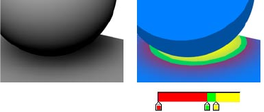
SKETCH SHADERS • 133
Hue mode, Saturation mode, Value mode
These three modes enable you to adjust the hue, saturation or value (H, S, V) based on the
shadow. They take either the hue, saturation or value of the resulting Cel shader color and
multiply it by the shadow. The Invert option swaps the multiply so the shadow either moves the
H, S or V down or up.
Color
If Shadows is set to Color, the Shadow gradient inuences the color of shadows.
Light Shadow
If this option is enabled, the shadow will use the color dened on the light object’s Shadow tab in
the Attribute manager.
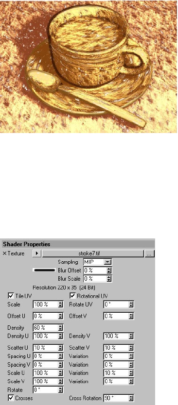
134 • CHAPTER 5
Hatch Shader
Image © 2003 by Artur Bala.
The Hatch shader is Sketch and Toon’s most advanced shader. It places a picture of a stroke (or any
other picture you want it to use) multiple times onto the object to create a hatched lines effect. The
Hatch shader’s settings give you full control over how these strokes are placed, making it possible
for you to create any type of hatched lines effect.
Material editor / Attribute manager settings
Shader Properties
This tab controls how the strokes are placed and how they overlap.
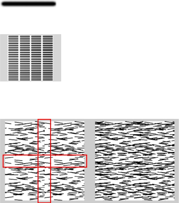
SKETCH SHADERS • 135
Texture
In general, use an image of a stroke or strokes as the texture.
This is the texture to use as the stroke. You can use a grayscale or a color image (color information
in the texture is ignored; the color of the hatches is dened on the shader’s Color tab).
The texture on a plane with full density of 100%, no overlap (Spacing 0%) and no Scatter or other variations.
To speed up rendering, consider using a block of strokes instead of a single stroke as the texture.
This enables you to use a larger texture tile (Scale values), which means faster rendering.
Tile UV
When tiling textures using the Tile X and Tile Y settings in the Texture tag, you’ll probably notice seams (left,
marked in red). Enabling the Tile UV option helps to remove the seams (right).
Sketch and Toon offers many ways to speed up the rendering of lines. One way is to tile the hatched
lines using the Tile settings in the Texture tag (the more tiles you use, the faster the lines are
rendered). Enable the Tile UV option to help remove seams from the edges of the tiles (it works by
wrapping the lines over the tile edges).
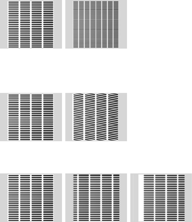
136 • CHAPTER 5
Rotational UV
Sometimes you may notice seams even with Tile UV enabled. This is when the Rotational UV option
can help. It rotates the hatch UV map around four times to ensure the strokes overlap all sides.
Scale
Scale = 100% Scale = 50%
This controls the scale of the stroke texture. A smaller texture means more strokes over the UVs,
which in turn means longer render times. For smaller strokes, instead of lowering the Scale value,
consider tiling the strokes using the tiling settings in the Texture tag. See “Tile UV” above.
Rotate UV
Rotate UV = 0% Rotate UV = 10%
Rotates the rendering UVs so the whole thing rotates.
Offset U, Offset V
From left to right: no UV offset; Offset U set to 10% and Tile UV enabled; Offset U set to 10%
and Tile UV disabled.
These settings offset the rendering on the UVs. Enable Tile UV to prevent a gap in the tiling.
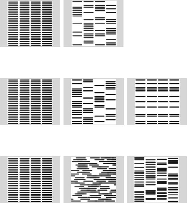
SKETCH SHADERS • 137
Density
Density = 100% Density = 10%
This is the overall stroke density, i.e the number of strokes generated.
Density U, Density V
Density U & V = 100% Density U = 50% Density V = 50%
These dene the stroke density in the U and V directions.
Scatter U, Scatter V
No Scatter Scatter U = 20% Scatter V = 10%
Scatter the strokes in the U and V directions randomly.
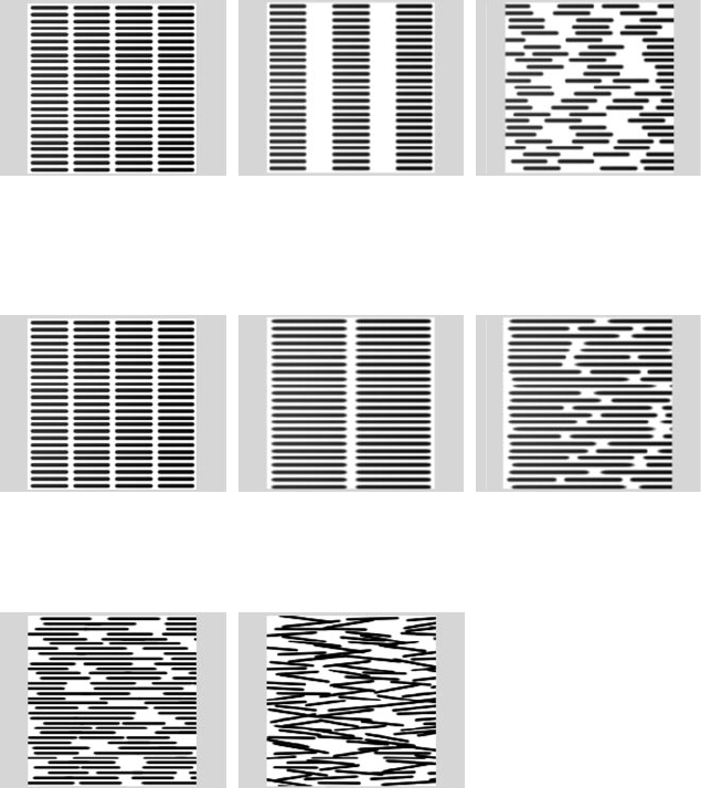
138 • CHAPTER 5
Spacing U, Spacing V, Variation
No Spacing Spacing U = 50% Spacing U = 50%, Var. = 100%
Space the stokes. Values above 100% create gaps between the tiles, values less than 100% overlap
them.
Scale U, Scale V, Variation
Scale U = 100% Scale U = 200% Scale U = 200%, Var. = 50%
Scale the strokes in the U or V direction.
Rotate
Rotate = 0% Rotate = 10%
Rotates each stroke by a random amount up to the set angle value.
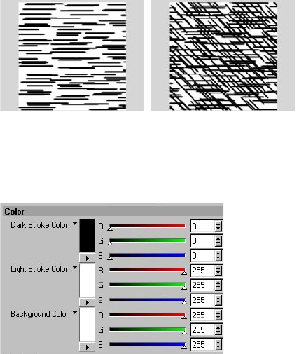
SKETCH SHADERS • 139
Crosses, Cross Rotation
Crosses disabled (left) and enabled with Cross Rotation set to 45˚ (right) .
If Crosses is enabled, a second pass of strokes will be rendered over the rst strokes and rotated as
a whole by the Cross Rotation value. This is used to create cross-hatching.
Color
Dark Stroke Color, Light Stroke Color
Here you can choose the color of the strokes. The Hatch shader can draw two types of stroke: dark
strokes and light strokes. Dark strokes are faded by light and are the main type. Light stokes, which
are disabled by default on the Illumination tab, are the opposite and fade out in areas where there
is no illumination.
Background Color
Denes the background color of the surface.
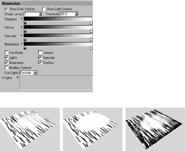
140 • CHAPTER 5
Illumination
The Illumination tab controls how the illumination affects the rendering of the strokes.
High Threshold value Low Threshold value With higher Shade Levels value
Show Dark Strokes, Show Light Strokes
Enable these options to switch on dark stokes and light strokes.
Shade Levels
In general, the higher you set this value, the more strokes you get in dark areas and the less faded
the hatching looks. It works by overlaying layers of strokes (the Shade Levels value denes the
number of layers), where each layer is more and more affected by the illumination.
Threshold
The Threshold controls how quickly the strokes fade out. See the examples above.
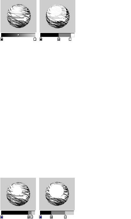
SKETCH SHADERS • 141
Diffuse
If Lights is enabled, the Diffuse gradient controls the brightness value of the hatches, from areas in
total darkness (left end of gradient) to areas which are fully lit (right end of gradient).
Use Bump
To apply a bump map to the shader, enable this option and dene the bump mapping on the
material’s Bump tab as you would for a normal material.
Camera
Enable the Camera option to use the camera as a light source.
Lights, Illumination, Use Lights, Lights box
To use the lights in the scene as light sources, enable the Lights option. To use the illumination
of each light (not just its direction), enable the Illumination option — the Illumination gradient
remaps the illumination from no illumination (left end of gradient) to full illumination (right end of
gradient).
By default, all lights in the scene will be used as light sources when Lights is enabled. To include or
exclude specic lights, set Use Lights to Include or Exclude and drag and drop the lights into the
Lights box.
Specular
If you want the lights to generate specular highlights, enable this option. The Specular gradient
controls the color, width, height and falloff of the highlights, from areas of no specular (left end of
gradient) to areas of full specular (right end of gradient).
142 • CHAPTER 5
Shadow
Enable the Shadows option to take shadows into account. The Shadow gradient affects the
brightness of shadows, from areas of full shadow (left end of gradient) to areas of no shadow (right
end of gradient).
Modies Contrast
This makes the Hatch shader work in a similar way to the Spots shader. The strokes will have their
contrast adjusted to give the impression of larger or smaller strokes depending on the brightness of
the illumination.
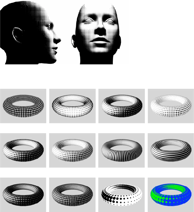
SKETCH SHADERS • 143
Spots Shader
Image © 2003 by Christian Rambow.
This shader helps you to mimic the halftone appearance of low resolution print images. It generates
larger or smaller spots depending on the brightness of the surface illumination.
Circle Circle with Camera Circle with Lights Diamond
Checker Square Lines U Lines V
Grid Custom texture Circle with Invert With color
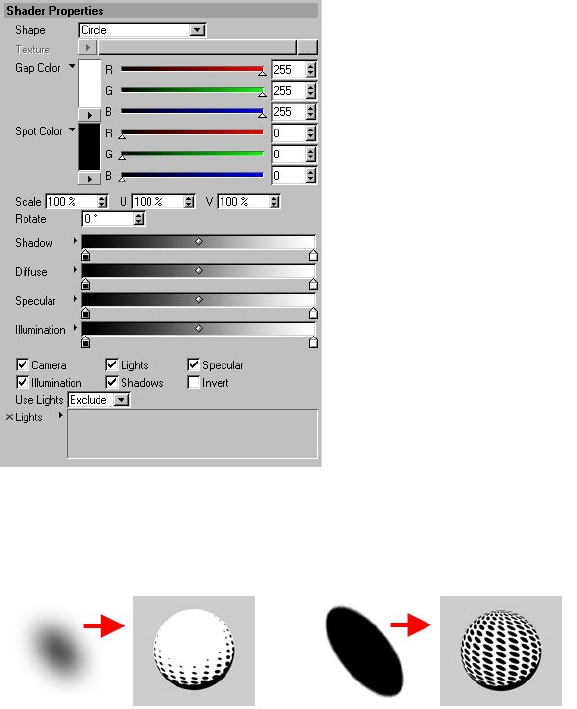
144 • CHAPTER 5
Material editor / Attribute manager settings
Shape, Texture
The Shape setting lets you choose which pattern is repeated over the surface. You can choose from
predened shapes, such as Circle, Square and Diamond, or you can load a custom texture as the
shape (set Shape to Texture and use the Texture triangle button to load the image).
Two custom textures (left of each arrow) and the result of using them as spot textures (right of each arrow).
When using a custom texture, keep the following in mind: The Spots shader makes the spots
smaller or larger by adjusting the contrast of the texture. For best results, the custom texture should
have a smooth transition from black to white as its outline (left spot above). If the transition is
sudden (right spot above), the spots won’t shrink or grow gradually.
Gap Color, Spot Color
These are the colors for the spots and the areas between the spots.
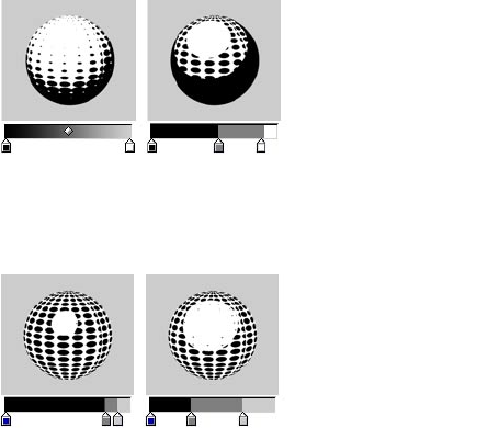
SKETCH SHADERS • 145
Scale, Scale U, Scale V
The Scale controls the global scale of the spots, Scale U and Scale V are the scale of the spots in the
U and V directions.
Rotate
This rotates the placement of the spots on the UVs.
Shadow
Enable the Shadows option to take shadows into account. The Shadow gradient affects the
brightness of shadows, from areas of full shadow (left end of gradient) to areas of no shadow (right
end of gradient)
Diffuse
The Diffuse gradient controls the brightness value of the hatches, from areas of full shadow (left
end of gradient) to areas of no shadow (right end of gradient).
Specular
If you want the lights to generate specular highlights, enable this option. The Specular gradient
controls the color, width, height and falloff of the highlights, from areas of no specular (left end of
gradient) to areas of full specular (right end of gradient).
Camera
Enable the Camera option to use the camera as a light source.
Lights, Illlumination, Use Light Color, Use Lights, Lights box
To use the lights in the scene as light sources, enable the Lights option. To use the illumination of
each light (not just its direction), enable the Illumination option.

146 • CHAPTER 5
By default, all lights in the scene will be used as light sources when Lights is enabled. To include or
exclude specic lights, set Use Lights to Include or Exclude and drag and drop the lights into the
Lights box.
Usually the color of the objects is controlled by the Diffuse gradient. To color the objects using the
color of the lights instead, enable the Use Light Color option. The Diffuse gradient then controls the
brightness values for the objects.
Invert
Invert option disabled (left) and enabled (right).
The Invert option reverses the shrinking behavior of the spots. They will then shrink as the surface
gets darker, instead of as it gets brighter.

6 Sketch Style Tag
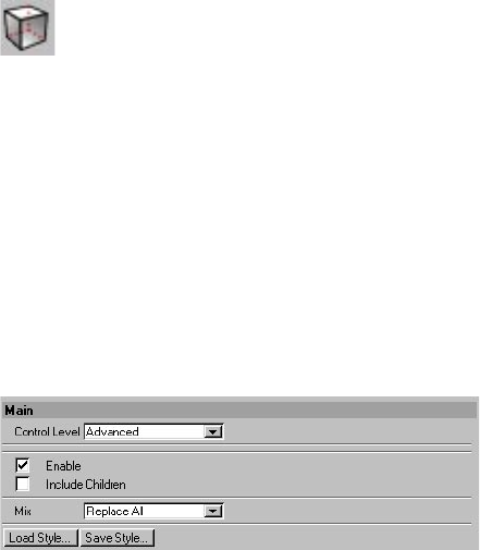
SKETCH STYLE TAG • 149
The Sketch Style tag is where you can set an individual style for an object to override the post
effect’s style. The other main use for the tag is to specify a selection. For example, here you can
restrict the edge line type to an edge selection.
To assign a Sketch Style tag to the selected object:
In the Object manager, choose File > Sketch Tags > Sketch Style.
Attribute manager settings
Some of the following settings are available only when the Control Level is set to Intermediate
or Advanced. See “Control Levels” in the index.
Main
Control Level
Look up “Control Levels” in the index.
Enable
Switches the tag on or off.
Include Children
Enable the Include Children option if you want the tag to control child objects as well.
6 Sketch Style Tag
150 • CHAPTER 6
Mix
The Mix mode controls how the tag is used in combination with other Sketch Style tags and the
Sketch and Toon post effect.
Replace All
The tag replaces the lines and shading of any parent tags and the Sketch and Toon post effect. In
other words, parent tags and the settings in the Sketch and Toon post effect are ignored.
Replace Lines
The tag replaces the lines but not the shading of parent tags (provided their Include Children option
is enabled) and the Sketch and Toon post effect.
Add
This mode adds the tag’s settings to the settings of parent tags (provided their Include option is
enabled) and the Sketch and Toon post effect.
Use
This allows you to use the tag’s settings for lines enabled in the post effect. This works with the
post effect only, not with parent tags. Note that you need to enable the line type in the tag also.
For example, suppose you have Edges enabled in the post effect. You then have a Sketch Style tag
on an object and want to use an edge selection for that object. You need to enable the Edge line
type in the Sketch Style tag, then simply set the edge selection and set Mix to Use. This will then use
the settings from the post effect and the selections from the tag.
Now suppose you have Contour enabled in the post effect. You set up how the contour looks, but
then you want to change which material is used on one object. You add a Sketch Style tag, set it to
Use, then enable the Contour line type in the Sketch Style tag. This will then tell Sketch and Toon
to use the material set in the Sketch Style tag (if it has one) — no settings for the line types in the
Sketch Style tag will be shown when in Use (because they are not used!).
Use will take the material from the tag (if the line type is enabled and the material is set), either the
material for the type or the default. Use will then also take any maps/selections from the tag.
Load Style, Save Style
You’ll nd various presets in the Sketch folder within CINEMA 4D’s Library folder.
These commands enable you to load and save styles. A style is a drawing or painting style, such as
thick chalky lines or leaky pen lines, as dened by the Sketch and Toon post effect and the Sketch
materials it uses.
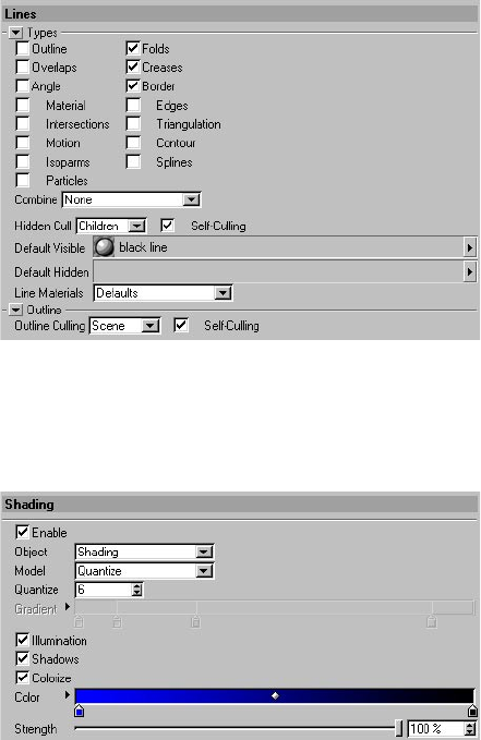
SKETCH STYLE TAG • 151
Lines
These settings control which line types and Sketch materials are used by the tag. They work in the
same way as the settings of the same name in the Sketch and Toon post effect (see Chapter 3,
“Sketch and Toon Post Effect”).
Shading
This tab denes the post effect shading for the object.
Enable
Switches on the tag’s post effect shading.
Other settings
The other settings dene the shading for the object and work in the same way as the object shading
settings in the post effect (see Chapter 3, “Sketch and Toon Post Effect”).
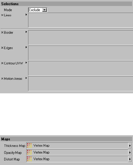
152 • CHAPTER 6
Selections
The Selections tab is where you specify any selections used by the tag or post effect. For example,
here you can specify which UVW tags should be used for UVW lines. You’ll nd more details on how
to use the various selections in Chapter 3, “Sketch and Toon Post Effect.”
Maps
Sketch and Toon enables you to modify the thickness, opacity and distortion of lines based on
vertex maps. Drag and drop the desired vertex maps into the appropriate boxes. For details on how
to use these maps, see Chapter 3, “Sketch and Toon Post Effect.”

7 Sketch Render Tag
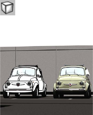
SKETCH RENDER TAG • 155
The Sketch Render tag has two main uses. First, you can use it to switch off post effect lines or post
effect shading or both for the object. This is useful for mixing CINEMA 4D rendered objects with
“sketched” objects. Second, the tag has optional extra controls for culling.
Use the Sketch Render tag to mix sketched
and non-sketched objects. Image © 2003 by
Toshio Fuji.
To assign a Sketch Render tag to the selected object:
In the Object manager, choose File > Sketch Tags > Sketch Render.
7 Sketch Render Tag
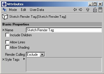
156 • CHAPTER 7
Attribute manager settings
Name
Here you can change the tag’s name.
Include Children
Enable the Include Children option if you want the tag to affect child objects also.
Allow Lines, Allow Shading
Disable these options to switch off post effect lines and post effect shading for the object.
Render Culling, Style Tags
For details on how Sketch and Toon decides which lines are hidden and which are visible, look
up “culling, hidden lines” in the index.
Generally you won’t need to use this mode. It is designed for exceptional culling cases, such as
when you need to see lines through an alpha map. It is much like the culling options in the Sketch
material on the Render tab, except the tag gives you an easy way to set the culling for a single
object and then per Sketch Style tag (good for not culling facial lines against, say, hair).
For the object that has the Sketch Render tag:
- Exclude mode excludes ALL lines from the Sketch Style tags in the Style Tags box from being
culled by this object.
- Forced mode forces the Sketch Style tags in the box to be culled by the object that has the tag,
even if this object is behind the tags’ lines.
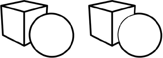
SKETCH RENDER TAG • 157
Normal culling (left) and forced culling for the cube. Note how the sphere’s outline is culled where it overlaps the
cube, but remains where it overlaps the sphere.

8 Illustrator Export
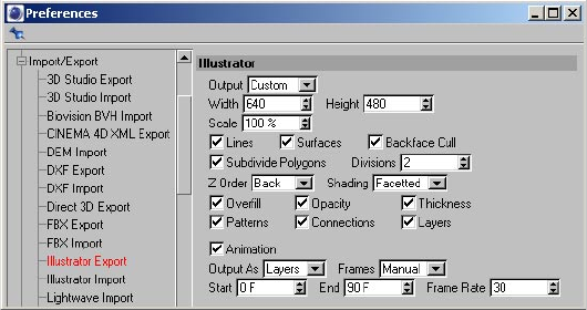
ILLUSTRATOR EXPORT • 161
Sketch and Toon includes a vector exporter to the Adobe Illustrator format (version 3). Please keep
in mind this is designed only for exporting the basic lines and strokes and simple texturing.
To export the scene to Adobe Illustrator:
- Set the Illustrator Export options as desired (see “Illustrator Export preferences”).
- Choose File > Export > Illustrator.
Illustrator Export Preferences
You’ll nd these settings in CINEMA 4D’s preferences dialog (Edit > Preferences), on the Illustrator
Export tab. Note that the Illustrator Import tab is not part of Sketch and Toon!
Output
This is the output resolution. You can choose the editor resolution, renderer resolution or a custom
resolution (enter the custom resolution into the Width and Height boxes).
Scale
This scales the line thickness for the vector export.
Lines, Surfaces
Enable these option to export lines and surfaces.
Backface Cull
Enable this option to prevent backfaces from being exported. Otherwise backfaces will be included
in the export.
8 Illustrator Export
162 • CHAPTER 8
Subdivide Polygons, Divisions
This option is useful for improving the “textured” look of the surfaces. It works by subdividing the
polygons on export. The Divisions value denes the number of subdivisions.
Z Order
The ordering for the polygons/objects for export.
Shading
Denes how the polygons are exported. Facetted mode will sample the center texture color for each
polygon. Object mode uses the object’s display color as dened on the object’s Basic Properties tab
in the Attribute manager. Uniform mode uses the color of the object’s rst material.
Overll
Enable the Overll option to reduce gaps in the vector export between polygons.
Opacity, Thickness, Patterns
Enable these options to export the line opacity, thickness and patterns.
Connections
Enable this option to allow export of strokes (i.e. connected line segments). If the option is
disabled, the strokes will be exported as individual line segments.
Layers
This option attens the polygons/lines so that if you then export an animation to layers it can
easily be exported to SWF with each layer as a frame.
Disable the Layers option to atten the export (the animation will then only have frames as layers).
Animation, Output As, Frames, Start, End, Frame Rate
Enable the Animation option to export animation. The Output As setting controls whether the
animation is saved as multiple les or as multiple layers. Set Frames to All to export all frames in
the animation, to Render to export the frames specied on the Render Settings > Output tab, or
to Manual and enter a custom start frame, end frame and frame rate into the Start, End and Frame
Rate boxes.

9 Sketch and Toon Preferences
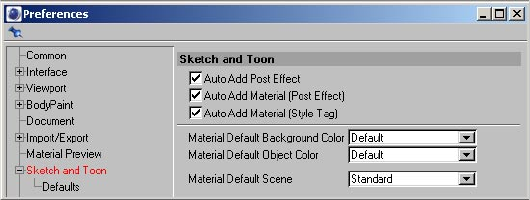
SKETCH AND TOON PREFERENCES • 165
For details on the Illustrator Export preferences, see Chapter 8, “Illustrator Export.”
The preferences enable you to streamline your workow in Sketch and Toon. For example, if you
tend to switch on Strokes each time you create a Sketch material, save time by enabling Strokes in
the preferences. Stokes will then be enabled by default.
In the preferences you’ll also nd the default settings for the Sketch material’s preview. If you want
the preview to display, say, a torus by default instead of a sphere, simply select the new shape. Last
but no least, the preferences dialog is also home to some auto options. For example, there’s an
option to automatically add a new Sketch material each time you add a Sketch Style tag. These auto
options usually help, but depending on how you like to work, they may become annoying at times.
Disable them if that’s the case.
To access the Sketch and Toon preferences:
Choose Edit > Preferences and in the preferences dialog that appears, click on Sketch and Toon or
Defaults just below it.
Preferences settings
Sketch and Toon
Auto Add Post Effect
Adds the Sketch and Toon post effect automatically when you add a Sketch material, and assigns
the material to the post effect as the default visible material.
Auto Add Material (Post Effect), Auto Add Material (Style Tag)
These options add a Sketch material automatically when you add the Sketch and Toon post effect or a
Sketch Style tag. The material will be assigned to the post effect or tag as its default visible material.
9 Sketch and Toon Preferences
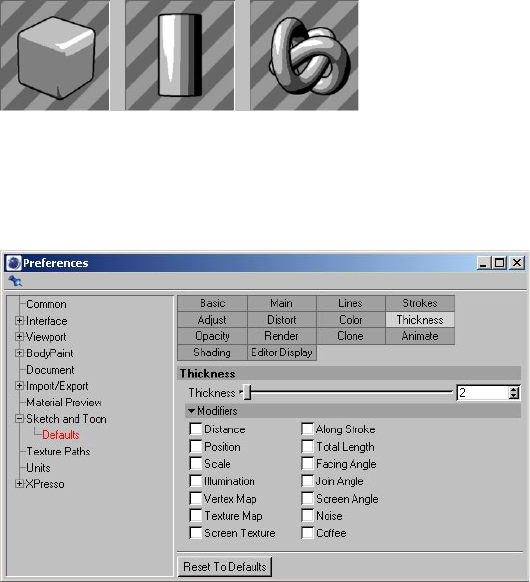
166 • CHAPTER 9
Material Default Background Color, Material Default Object Color
These settings control the default background and object color of the Sketch material’s preview. Set
them to Default to use CINEMA 4D’s standard settings for material previews. (Note that the object
color will be quantized, i.e. you’ll see bands of color appear for the object’s shading instead of a
smooth transition).
Material Default Scene
Here you can choose which scene is used to generate the preview, such as a scene containing a
rounded cube, cylinder or knot. Choose Standard to use the default scene dened on CINEMA 4D’s
Preferences > Material Preview tab.
Defaults
This tab denes the default values for the Sketch and Toon post effect, Sketch material and Sketch
Style tag. For example, if you set the Sketch material’s Thickness to 5, new Sketch materials will use
a Thickness value of 5 by default.

10 Frequently Asked Questions
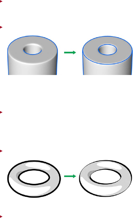
FREQUENTLY ASKED QUESTIONS • 169
In these pages, you’ll nd answers to commonly asked questions about Sketch and Toon.
Which viewport projection modes are supported by Sketch and Toon?
Not all projections are supported. The following are rejected by Sketch and Toon: Military, Frog,
Bird, Gentleman.
How can I add lines to rounded edges on a HyperNURBS object?
Select the edges on the low-res mesh where you want lines to be added. Create a Selection tag to
store the selection (Selection > Set Selection). Assign a Sketch Style tag to the object if it doesn’t
have one already, and on its Lines tag, enable Edges. On the Selections tab, drag and drop the
Selection tag into the Edges box.
I’m having problems with isoparms for a HyperNURBS object.
Isoparms come with a number of limitations. For example, culling may not be accurate. With
HyperNURBS, the best solution is not to use the Isoparm line type. Instead use Edge lines and
create a selection for ALL the edges on the low-res mesh, then follow the same producure as for
the HyperNURBs rounded edges tip above.
What can I do to spruce up outlines?
Use the Screen Angle modier on the Thickness tab.
I want to create some marker pen lines, which line type should I use?
Contour lines are useful for blocking in marker pen lines. Look up “contour” in the index.
10 Frequently Asked Questions
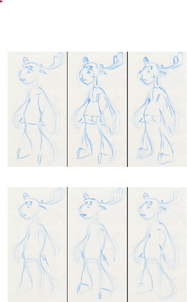
170 • CHAPTER 10
I need help with my cartoon characters and have two questions for you: One, how can I
smooth out lines? Two, which line types should I be using?
Here’s a tip for getting some extra lines in your sketch effects using the Angle modier, and
smoothing out the strokes to prevent that STRAIGHT sketch line style, especially on low poly
objects. Check out these comparison images with and without HyperNURBS.
Without HyperNURBS
Folds Folds and Angles Folds, Angles and Curves
With HyperNURBS
Folds Folds and Angles Folds, Angles and Curves

FREQUENTLY ASKED QUESTIONS • 171
The left moose in both gures was created with Fold lines only. This is the most commonly used
line type for a hard-drawn style. It produces an okay effect, but for a rough sketch the lines are
a little too accurate in their placement; an artist may have some other quick strokes to represent
volume and structure for instance.
This is where the Angle line type comes in handy. To create the extra lines for the center moose,
Angle lines were switched on with Min and Max set to 31˚ and 50˚ respectively (note that the
model has a Phong angle of 60˚). For the center moose without HyperNURBS, you can clearly see
the effect in the extra detail for the mouth and hooves, and the volume or structure of the moose
being represented in the chest and stomach areas. The effect is more subtle for the HyperNURBS
moose because the model has been subdivided so the angles in many areas that were detected in
the low-res may no longer t in the specied range.
Last but not least is the addition of curves, which are to be found on the Sketch material’s Distort
tab. For the right moose in both gures, the Curve Stroke option was enabled and Type was set to
B-Spline (this type allows for extremely smooth owing lines rather then straight angular lines).
You can clearly see how the strokes for his stomach, armpit and muzzle are curved and smooth
rather than straight and angular. In the case of the right moose with HyperNURBS, you can see
that because of the smooth, simpler curves, settings such as overshoot used in this line’s material
may shoot out in different directions as with the armpit and nostril.
Using curved strokes, especially on a low-res mesh, can help eliminate that low-res feel but allow
for sketchier lines then would be found on a smooth high-res mesh. This combination of a low-res
mesh, angles, and curved strokes set to B-spline can help to produce a more natural — yet at the
same time rougher — sketch effect!
Some controls are missing!
Sketch and Toon has a Control Level system which hides away the advanced controls. This is useful
for while you are learning the simpler controls or for when all you need is a basic effect. To see the
missing controls, you need to switch the Control Level to Intermediate or Advanced. You’ll find
the Control Level setting on the Main tab of the Sketch and Toon post effect, Sketch material and
Sketch and Toon Style tag. Setting the Control Level in one place changes the level for them all.
How can I speed up the antialiasing?
If you are using the Hatch shader or Spots shader with CINEMA 4D’s Best Antialiasing (to ensure
the texture is antialiased...), switch the Antialiasing mode to Geometry and blur the hatch or spots
texture using Blur Scale and Blur Offset.
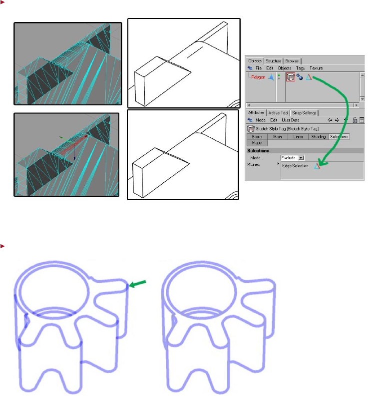
172 • CHAPTER 10
How can I get rid of unwanted lines?
Select the edges or polygons for the problem area and exclude them from line generation using
the Sketch Style tag’s Lines box (Maps tab) and Exclude mode.
How can I get rid of opacity overlaps?
On the Sketch material’s Render tab, set Self-Blend to Average. Try the Overwrite mode also. (Which
mode is best usually depends on the texturing of the line).
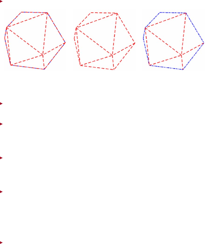
FREQUENTLY ASKED QUESTIONS • 173
I have two patterns which overlap in places, how do I get rid of the overlaps?
On the Sketch material’s Render tab, set Self-Blend to Overwrite. If one of the patterns disappears
completely (center object), it has been overwritten by Sketch and Toon’s drawing order — to resolve,
set the “missing” material’s Priority value (Sketch material, Main tab) higher.
I’m having problems with a perfect sphere.
Convert the sphere to polygons. There are many limitations with perfect spheres!
I don’t like the random look Sketch and Toon has picked.
If the variations (such as clone, adjustment...) are not as you would like, adjust the Variations
Seed on the Sketch material’s Render tab. Disable the Static option if you wish these to change
per frame.
Gaps are appearing in the lines. Why?
Check the polygons in the gap area. Although Sketch and Toon does its best to work with non-
planar polygons, it is sometimes better to split them into triangles that give the correct surface
you intend.
I’m getting “thin” lines in the rendered image.
Use the Hidden Culling by setting it to either Scene or Children and so on. The fewer objects it has
to cull against the better (e.g. Scene is slowest).
Another cause of thin lines can be objects too close together; try moving them apart slightly. An
example might be a belt around a waist, or ring on a nger. If the objects are very close, then the
lines may cull.
Where are the presets for shaders, styles and so on?
You’ll nd various presets in the Sketch folder within CINEMA 4D’s Library folder.

Index
INDEX • 177
Symbols
2D lines 37
2D Transform 67
3D lines 37
3D Transform 68
A
Add Preset 58
All Sketched Objects 35
Along Stroke modier 74
angle 42
animation
of lines 114
antialiasing
and CINEMA 4D 29
for lines 29
tips 169
Art shader
introduction 126
B
Backfacing 128
Background Blend 29
Base Resolution 30
Blend 104
blend modes 118
border 43
brushes
creating 82
C
Camera Near 31
caps 64
Cel shader
introduction 128
CINEMA 4D Net
Motion limitation 46, 63
Particles limitation 52
Clip Render 106
Clip Strokes To Screen 104
Close Path 60
Coffee modier 93
color 72
Combine 25
Common modier settings 101
contour 48
Control Level 58
Control Levels 19
Creases 42
cross-hatching 132
Cross Rotation 137
culling
hidden lines 26
Render Culling 107
Curve Stroke 69
D
dark strokes 137
Default Hidden 13, 27
Default Visible 13, 27
Distance modier 73
drawing order 106
Draw Speed 115
E
edges 44
edge selections 150
F
Facing Angle modier 78
Filter Strokes 62
folds 39
Frame Match 63
From Line modier 91
From Surface modier 89
Full Redraw 36
G
gaps in lines 171
H
hatching 132
Hatch shader
introduction 132
Hidden Cull 26
hidden lines
culling 26
I
Illumination modier 79
intersection
self 45
intersections 45
isoparms 51
J
Joint 64
Join Angle 81
Join Limit 61
L
layers 25
light strokes 137
lines
and layers 25
angle 42
border 43
caps 64
contour 48
creases 42
edges 44
folds 39
gaps 171
intersections 45
in viewport 36
isoparms 51
line types 25, 38
material 43
motion 46
outline 39
overlaps 39
ownership 38
patterned 65
splines 52
triangulation 46
Line AA 28
Line Materials 27
line ownership 38
line types 38
Link To Thickness 72
Luminance 16
M
marker pen 167, 168
Match 61
material 43
Miter joints 64
modiers
Along Stroke 74
Coffee modier 93
common settings 101
Distance 73
Facing Angle modier 78
From Line modier 91
From Surface modier 89
Illumination modier 79
178 • INDEX
Join Angle 81, 82
Noise modier 98
Position modier 75
Scale modier 77
Screen Angle modier 88
Screen Texture modier 97
Texture Map modier 92
Total Length modier 76
Vertex Map modier 90
Motion 46
Multi-Pass
tab 31
multi-pass
and Post Render 29
multi-pass rendering 32
Multiple use iii
N
Network operation iii
Noise 70
Noise modier 98
NPR 5
O
opacity 72
opacity overlaps 105
outline 39
Outline Culling 40
overlapping patterns 105
overlaps 39
Overshoot 68, 112
P
Pattern 65
patterns 65
overlapping 105
polygon selections 150
Position modier 75
Post Render 29
Priority 58
Q
Quantize 14, 34
R
Render Culling 107, 154
Render RGB 32
Resolution Independent 30
Rotational UV 134
S
Scale modier 77
Screen Angle
tip 167
Screen Angle modier 88
Screen Offset 67
Screen Texture modier 97
Secrecy v
Self-Blend 104
Self-Culling 26
Self-intersection 45
Separate Alpha 32
Separate Depth 32
shading
Quantize 14
Show Lines 36
Sketch and Toon Post Effect
adding 23
automatic setup 23
Editor Display tab 36
Effects tab 24
Lines tab 24
Main tab 24
Multi-Pass tab 31
post effect shading 32
Render tab 28
Shading tab 32
Sketch and Toon post effect
introduction 11
Sketch material
Adjustment tab 66
Animate tab 114
assigning 57, 117
Assignment tab 117
automatic setup 57
Clone tab 109
Color tab 72
creating 56
Distort tab 69
Main tab 58
Opacity tab 72
preview 57
Render tab 103
Strokes tab 59
Thickness tab 72
Sketch shader
creating 124
Sketch shaders
introduction 16
Sketch Style Tag
introduction 17
Sketch Style tag
assigning 147
Lines tab 149
Maps tab 150
Selections tab 150
Shading tab 149
Sketch material
introduction 12
splines 52
spline graph 101
Split Line Types 32
Split Visible/Hidden 32
Spots shader 124
introduction 16, 141
Static 108
strokes
introduction 59
Stroke Order 115
T
Texture Alpha 33
Texture Map modier 92
Texture modier 82
thickness 72
Tile UV 133
toolbars. See also icon palettes
Total Length modier 76
Transfer iv
triangulation 46
V
Variations Seed 108
vertex maps 150
Vertex Map modier 90
