Contents
- 1. Users Manual
- 2. user manual Dr3900
- 3. user manual DR6000
- 4. user manual TU5200 EPA
- 5. user manual TU5200 ISO
user manual TU5200 EPA
DOC022.53.80488
TU5200
09/2014, Edition 1
User Manual
EPA MANUAL
BETA DRAFT
EPA MANUAL
BETA DRAFT

Table of Contents
Specifications..............................................................................................................3
General information..................................................................................................4
Safety information........................................................................................................4
Use of hazard information....................................................................................4
Precautionary labels.............................................................................................5
Class 2 laser product............................................................................................5
RFID module........................................................................................................6
Safety information for RFID modules............................................................6
FCC conformance for RFID........................................................................... 7
Certification ........................................................................................................... 7
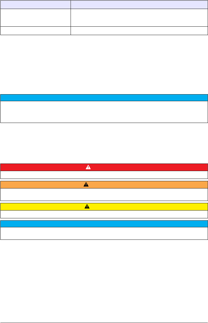
Product overview.........................................................................................................8
Product components....................................................................................................8
Installation.....................................................................................................................9
Installation guidelines..................................................................................................9
Electrical installation....................................................................................................9
Connect to external devices (optional).................................................................9
Connect to power...............................................................................................10
User interface and navigation............................................................................10
Display description..................................................................................................... 10
Startup........................................................................................................................... 12
Set the date and time................................................................................................. 12
Operation.....................................................................................................................12
Configuration.............................................................................................................12
Configure the instrument settings.......................................................................12
Add an operator ID.............................................................................................13
Configure the measurement settings.................................................................. 13
Configure the Link2SC settings..........................................................................13
Measurement.............................................................................................................14
Safely use a sample vial.....................................................................................14
Prepare the sample............................................................................................14
Put the vial into the instrument...........................................................................15
Do a measurement.............................................................................................16
Make or change a sample ID......................................................................16
Import a sample ID list................................................................................. 17
Use the RFID scanner (optional)...............................................................................17
Calibration .................................................................................................................. 17
Prepare for a verification or calibration...............................................................18
Do a verification..................................................................................................18
Do a calibration................................................................................................... 18
Data management.....................................................................................................19
Configure the data log........................................................................................19
Maintenance...............................................................................................................19
Clean spills................................................................................................................20
Clean the instrument.................................................................................................. 20
Clean the vial.............................................................................................................20
1
EPA MANUAL
BETA DRAFT

Clean the vial compartment.......................................................................................20
Troubleshooting.......................................................................................................20
Read the diagnostics information..............................................................................22
Replacement parts and accessories...............................................................22
Table of Contents
2
EPA MANUAL
BETA DRAFT

Specifications
Specifications are subject to change without notice.
Specification Details
Dimensions (W x D x H) 41 x 28 x 12.5 cm (16 x 11 x 7.7 in.)
Weight 2.37 kg (5.23 lb)
Enclosure rating IP20
Protection class III (for the instrument and the external power supply)
Pollution degree/installation category 2, II
Power connector via external power
supply
Input: 100–240 V, 50/60 Hz
Output: 15 VDC, 2A
Altitude 2500 to 3100 m (8202 to 10,171 ft) maximum
Relative humidity 5 to 95% at different temperatures, non-condensing
Operating temperature 10 to 40 °C (50 to 104 °F)
Storage temperature –30 to 60 °C (–22 to 140 °F)
Measurement method 90-degree nephelometry, 360 degrees around the axis of the incident light
beam
Display 17.8 mm (7 in.) color touch screen
Regulatory compliance USEPA
Laser Class 2 laser product: contains a non-user serviceable laser
Optical light source 650 nm, maximum 1.0 mW
Measurement modes NTU, FNU, TE/F, FTU, EBC, mNTU or mFNU
Range 0 to 700 NTU
Stray light <0.010 NTU
Accuracy +/- 2 % of reading plus 0.01 NTU from 0 to 40 NTU1
+/- 10 % of reading from 40 to 700 NTU 1
Linearity Better than 1 % 0 to 40 NTU on formazin at 25 °C (77 °F). Allows for
accurate calibration at 20 NTU
Repeatability ± 1% of the reading or ± 0.01 NTU, whichever value is more
Signal average time Off, 5 to 90 seconds (default=30 seconds)
Detection limit 0.0003 NTU
Calibration options StablCal®: at 20 NTU from 0 to 40 NTU; at 20 NTU and 600 NTU for full
range
User prepared formazin, SDVB, kaolin or EBC via factory-defined or
custom curves
Verification options StablCal®, formazin (0.1 to 40 NTU), Hach solid verification standards
Verification (Link2SC) Verification of the measurement value to compare values to a online
instrument via Link2SC.
English 3
EPA MANUAL
BETA DRAFT
Specification Details
Certifications CE compliant; US FDA accession number: 1420493-xxx. This product
complies with IEC/EN 60825-1 and to 21 CFR 1040.10 in accordance with
Laser Notice No. 50.
Warranty US: 1 year
1This is based on formazin primary standard.
General information
In no event will the manufacturer be liable for direct, indirect, special, incidental or consequential
damages resulting from any defect or omission in this manual. The manufacturer reserves the right to
make changes in this manual and the products it describes at any time, without notice or obligation.
Revised editions are found on the manufacturer’s website.
Safety information
N O T I C E
The manufacturer is not responsible for any damages due to misapplication or misuse of this product including,
without limitation, direct, incidental and consequential damages, and disclaims such damages to the full extent
permitted under applicable law. The user is solely responsible to identify critical application risks and install
appropriate mechanisms to protect processes during a possible equipment malfunction.
Please read this entire manual before unpacking, setting up or operating this equipment. Pay
attention to all danger and caution statements. Failure to do so could result in serious injury to the
operator or damage to the equipment.
Make sure that the protection provided by this equipment is not impaired. Do not use or install this
equipment in any manner other than that specified in this manual.
Use of hazard information
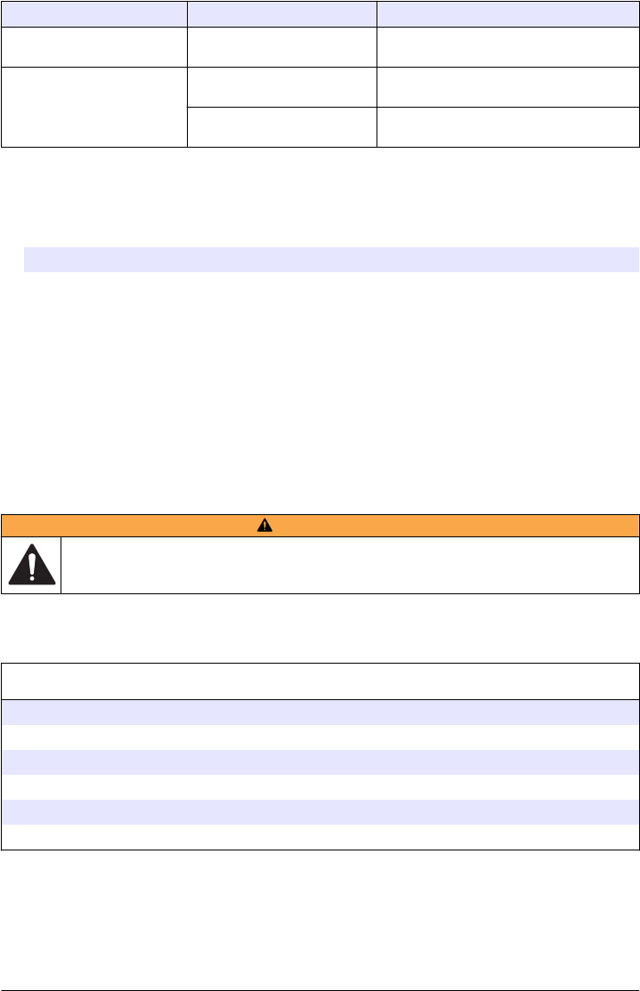
D A N G E R
Indicates a potentially or imminently hazardous situation which, if not avoided, will result in death or serious injury.
WARNING
Indicates a potentially or imminently hazardous situation which, if not avoided, could result in death or serious
injury.
CAUTION
Indicates a potentially hazardous situation that may result in minor or moderate injury.
N O T I C E
Indicates a situation which, if not avoided, may cause damage to the instrument. Information that requires special
emphasis.
4 English
EPA MANUAL
BETA DRAFT
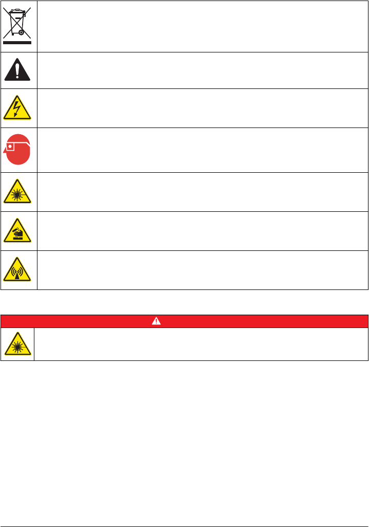
Precautionary labels
Read all labels and tags attached to the instrument. Personal injury or damage to the instrument
could occur if not observed. A symbol on the instrument is referenced in the manual with a
precautionary statement.
Electrical equipment marked with this symbol may not be disposed of in European domestic or public
disposal systems. Return old or end-of-life equipment to the manufacturer for disposal at no charge to
the user.
This symbol, if noted on the instrument, references the instruction manual for operation and/or safety
information.
This symbol indicates that a risk of electrical shock and/or electrocution exists.
This symbol indicates the need for protective eye wear.
This symbol indicates a laser device is used in the equipment.
This symbol identifies a risk of chemical harm and indicates that only individuals qualified and trained
to work with chemicals should handle chemicals or perform maintenance on chemical delivery
systems associated with the equipment.
This symbol indicates radio waves.
Class 2 laser product
D A N G E R
Personal injury hazard. Never remove covers from the instrument. This is a laser-based instrument and
the user risks injury if exposed to the laser.
English 5
EPA MANUAL
BETA DRAFT
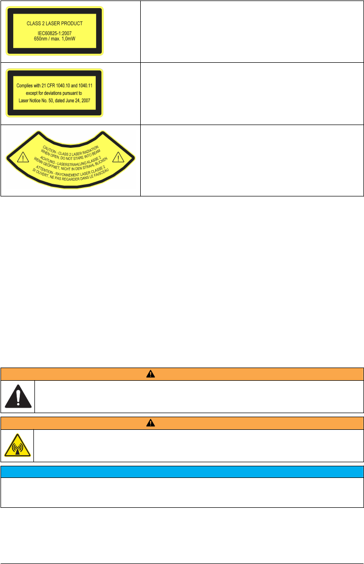
Class 2 laser product, IEC60825-1:2007, 650nm/max. 1,0 mW
Location: Rear of the instrument.
Conforms to U.S. regulations 21 CFR 1040.10 and 1040.11 in
accordance with Laser Notice No. 50.
Location: Rear of the instrument.
Caution—Class 2 laser radiation when the lid is open. Do not look
into the laser beam.
Location: Top of the vial compartment.
This instrument is a Class 2 Laser product. There is only visible laser radiation when the instrument
is defective and when the instrument lid is open. This product complies with EN 61010-1, "Safety
Requirements for Electrical Equipment for Measurement, Control and Laboratory Use" and with
IEC/EN 60825-1, "Safety of Laser Products" and with 21 CFR 1040.10 in accordance with Laser
Notice No. 50. Refer to the labels on the instrument that supply laser information.
RFID module
An optional RFID module is available for this instrument. RFID technology is a radio application.
Radio applications are subject to national conditions of authorization. The use of the sensor is
currently permitted in the following countries: EU. The manufacturer advises that the use of the
sensor outside of the above-mentioned regions may contravene national laws. The manufacturer
reserves the right also to obtain authorization in other countries. In case of doubt, contact the
manufacturer.
The sensor contains an RFID module to receive and transmit information and data. The RFID
module operates with a frequency of 13.56 MHz.
Safety information for RFID modules
WARNING
Multiple hazards. Do not disassemble the instrument for maintenance. If the internal components must
be cleaned or repaired, contact the manufacturer.
WARNING
Electromagnetic radiation hazard. Do not use the instrument in dangerous environments.
N O T I C E
This instrument is sensitive to electromagnetic and electromechanical interference. These interferences can have
an effect on the analysis performance of this instrument. Do not put this instrument near equipment that can
cause interference.
Obey the safety information that follows to operate the instrument in accordance with local, regional
and national requirements.
6 English
EPA MANUAL
BETA DRAFT

• Do not operate the instrument in hospitals and comparable establishments or near medical
equipment, such as pace makers or hearing aids.
•Do not operate the instrument near highly flammable substances, such as fuels, highly flammable
chemicals and explosives.
• Do not operate the instrument near combustible gases, vapors or dust.
• Keep the instrument away from strong vibration or shock.
• The instrument can cause interference in immediate proximity to televisions, radios and
computers.
• The warranty does not cover improper use or wear.
FCC conformance for RFID
This instrument may contain a registered radio frequency identification device (RFID). Refer to FCC
conformance for RFID for the Federal Communications Commission (FCC) registration information.
Table 1 Registration information
Parameter Value
FCC identification number (FCC ID) YUH-QR15HL
IC 9278A-QR15HL
Frequency 13.56 MHz
Certification
Canadian Radio Interference-Causing Equipment Regulation, IECS-003, Class A:
Supporting test records reside with the manufacturer.
This Class A digital apparatus meets all requirements of the Canadian Interference-Causing
Equipment Regulations.
Cet appareil numérique de classe A répond à toutes les exigences de la réglementation canadienne
sur les équipements provoquant des interférences.
FCC Part 15, Class "A" Limits
Supporting test records reside with the manufacturer. The device complies with Part 15 of the FCC
Rules. Operation is subject to the following conditions:
1. The equipment may not cause harmful interference.
2. The equipment must accept any interference received, including interference that may cause
undesired operation.
Changes or modifications to this equipment not expressly approved by the party responsible for
compliance could void the user's authority to operate the equipment. This equipment has been tested
and found to comply with the limits for a Class A digital device, pursuant to Part 15 of the FCC rules.
These limits are designed to provide reasonable protection against harmful interference when the
equipment is operated in a commercial environment. This equipment generates, uses and can
radiate radio frequency energy and, if not installed and used in accordance with the instruction
manual, may cause harmful interference to radio communications. Operation of this equipment in a
residential area is likely to cause harmful interference, in which case the user will be required to
correct the interference at their expense. The following techniques can be used to reduce
interference problems:
1. Disconnect the equipment from its power source to verify that it is or is not the source of the
interference.
2. If the equipment is connected to the same outlet as the device experiencing interference, connect
the equipment to a different outlet.
3. Move the equipment away from the device receiving the interference.
4. Reposition the receiving antenna for the device receiving the interference.
5. Try combinations of the above.
English 7
EPA MANUAL
BETA DRAFT
Product overview
D A N G E R
Chemical exposure hazard. Obey laboratory safety procedures and wear all of the personal protective
equipment appropriate to the chemicals that are handled. Refer to the current safety data sheets
(MSDS/SDS) for safety protocols.
The TU5200 turbidimeter measures low turbidity primarily in drinking water applications. This
laboratory instrument is factory calibrated and measures scattered light at an angle of 90 degrees,
360 degrees around the axis of the incident light beam. Use the touch screen to operate the
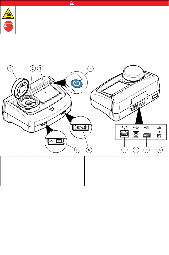
instrument. Refer to Figure 1.
Figure 1 Product overview
1 Lid 6 USB port type A
2 Vial compartment 7 USB port type B
3 Display screen 8 Ethernet port
4 Power button 9 RFID scanner (optional)
5 Power connection 10 USB port type A
Product components
Make sure that all components have been received. Refer to Figure 2. If any items are missing or
damaged, contact the manufacturer or a sales representative immediately.
8 English
EPA MANUAL
BETA DRAFT
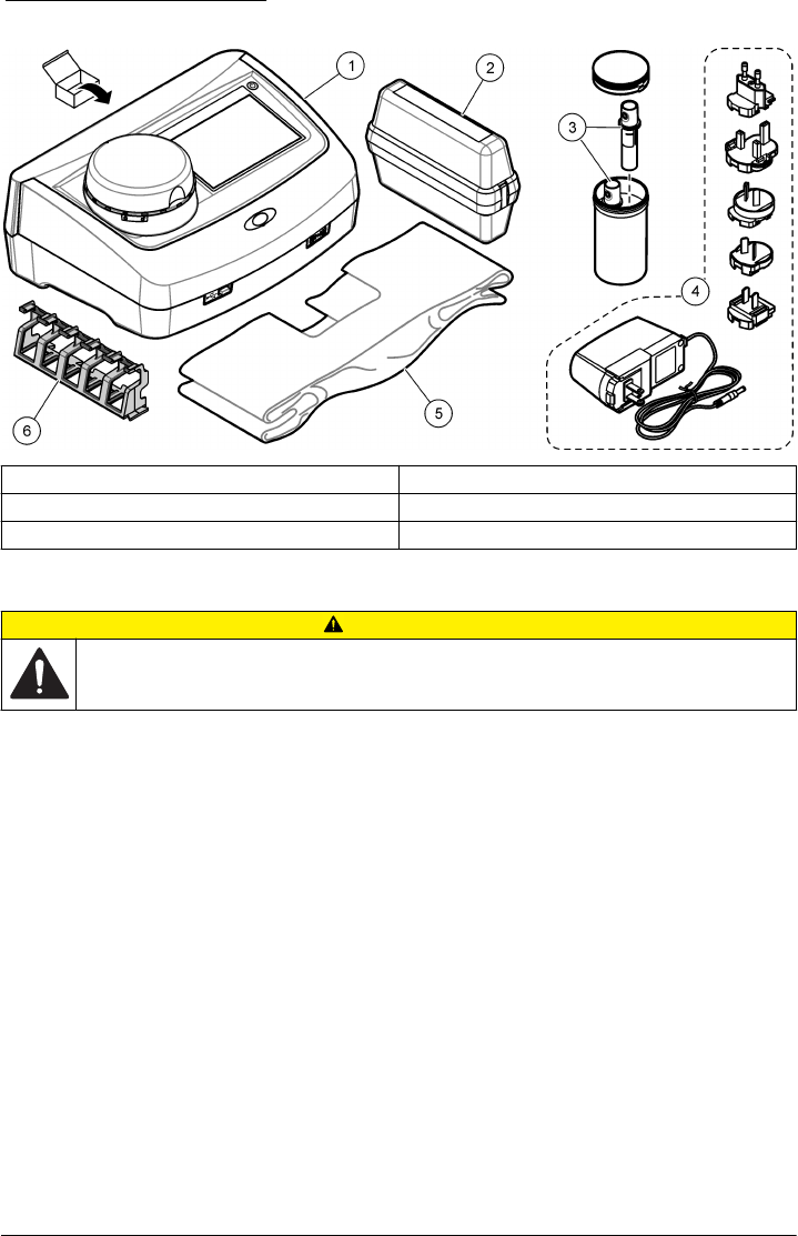
Figure 2 Product components
1 Turbidimeter 4 Power supply with adapters
2 StablCal® calibration set 5 Dust cover
3 Sample vials 6 Vial stand
Installation
CAUTION
Multiple hazards. Only qualified personnel must conduct the tasks described in this section of the
document.
This instrument is rated for an altitude of 2000 m (6562 ft) maximum. Use of this instrument at an
altitude higher than 2000 m can slightly increase the potential for the insulation to breakdown, which
can result in an electric shock hazard. The manufacturer recommends that users with concerns
contact technical support.
Installation guidelines
Install the instrument:
•On a level surface
• In a clean, dry, well ventilated, temperature controlled location
• In a location with minimum vibrations that has no direct exposure to sunlight
• In a location where there is sufficient clearance around it to make connections and to do
maintenance tasks
• In a location where the power button and power cord are visible and easily accessible
Electrical installation
Connect to external devices (optional)
The instrument has three USB ports and one ethernet port. Refer to Figure 1 on page 8. Refer to the
optional external device documentation for more information.
• USB port—Connect to a printer, scanner, USB flash drive or a flow-through module.
• Ethernet port—Connect to an external PC or a communications network.
English 9
EPA MANUAL
BETA DRAFT
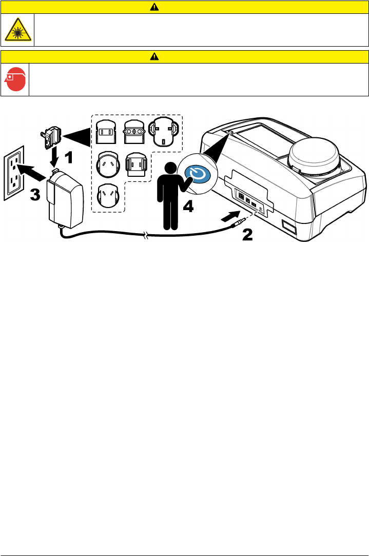
Connect to power
CAUTION
Personal injury hazard. Never remove covers from the instrument. This is a laser-based instrument and
the user risks injury if exposed to the laser.
CAUTION
Personal injury hazard. Do not look into the vial compartment when the instrument power is set to on.
Refer to the illustrated steps that follow to connect power to the instrument and start the instrument.
User interface and navigation
Display description
Refer to Figure 3 for the home screen description. Refer to Table 2 for the icon description. Do not
use writing tips of pens or pencils or other sharp objects to make selections on the screen. Only use
a clean, dry finger tip to navigate the functions of the touch screen.
10 English
EPA MANUAL
BETA DRAFT
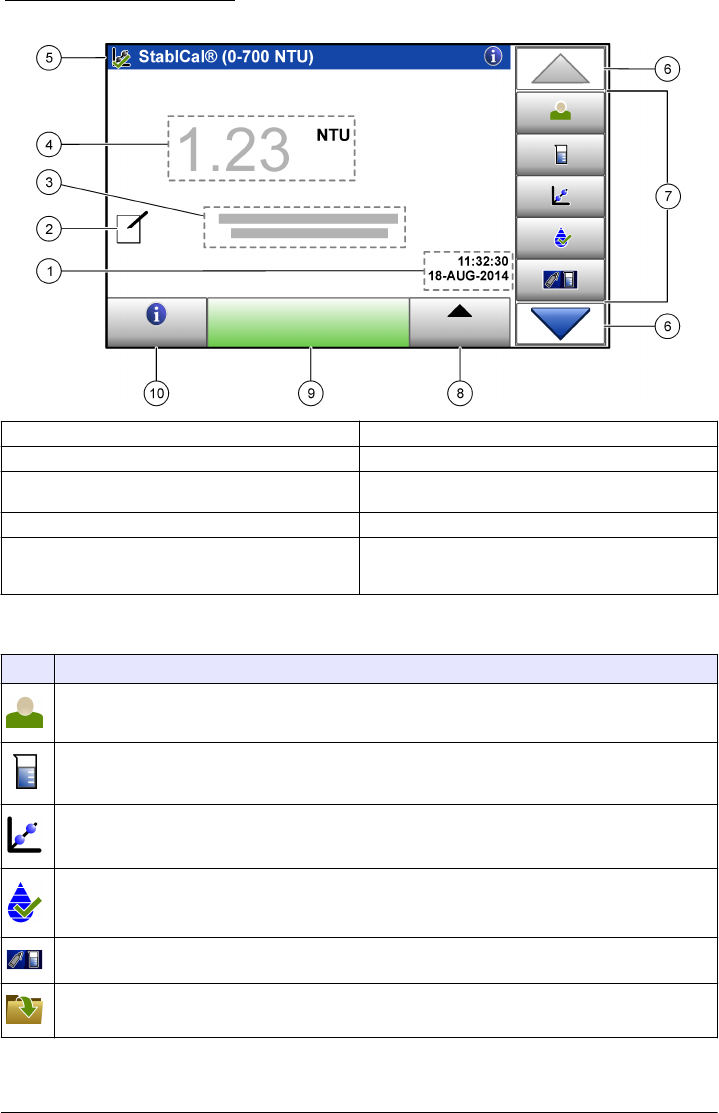
Figure 3 Main reading screen
1 Time and date 6 UP/DOWN navigation arrows
2 Comments17 Menu icons
3 Message display 8 Options (contextual: send data, compare log, setup,
import, edit) icon
4 Value and unit 9 Read icon (contextual: read, options, select, delete)
5 Heading bar (contextual: shows the currently-
selected screen, active laser icon and active
security icon)
10 Information icon (contextual: information or back
icon)
1Enter comments with an alphanumeric or a qwerty keyboard.
Table 2 Icon description
Icon Description
Goes to the login screen to log a user in or out of the system.
Adds, changes, deletes or imports a sample ID.
Starts a calibration procedure.
Starts a verification procedure.
Compares the sample measurement values between the online and laboratory turbidimeters.
Shows, compares and verifies information about measurements, verifications, and calibration data.
English 11
EPA MANUAL
BETA DRAFT
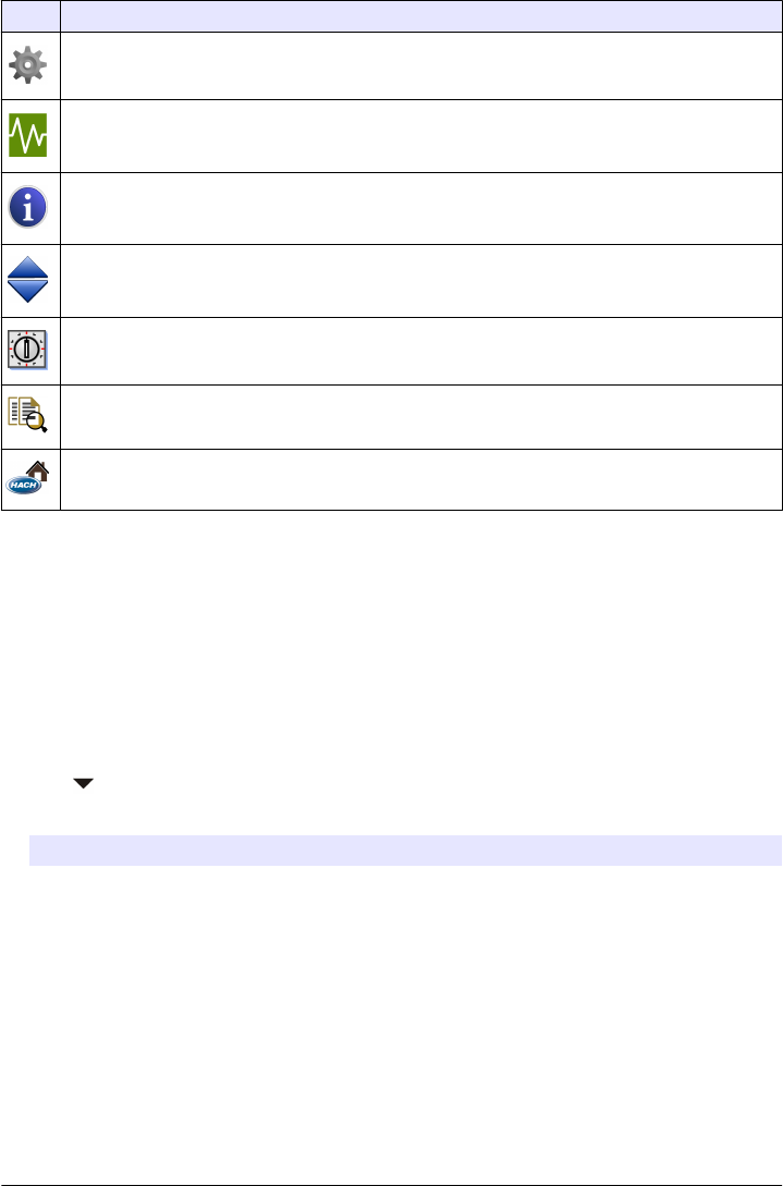
Table 2 Icon description (continued)
Icon Description
Configures the instrument settings.
Shows instrument-specific data about the instrument: firmware information, instrument backup,
instrument updates, signaling information and factory service data.
Shows help and more information. If there is more information about a task or an instrument function,
then the information icon shows on the display.
Shows information about the instrument: the firmware version, updates for the instrument, storage and
product restore information, signals, and factory service information.
Enters timed alerts.
Shows the user manual for the instrument and other uploaded documents in the PDF viewer.
Goes to the manufacturer's website for news and downloadable information, if a network connection is
configured.
Startup
Set the date and time
After the power is set to on, follow the prompts on the display to set the date and time.
Operation
Configuration
Configure the instrument settings
1. Push > Setup.
2. Select an option.
Option Description
Location Enters the name of the location of the instrument.
Date & Time Sets the date format, the time format, and the date and time.
Security Sets the security and levels of security for menu options and instrument functions.
Enter a password to enable security, then select the security settings from the
Security List.
Sound Settings Enables or disables all or some alerts to on or off. To set alerts, select from the list
of options, then set the alert volume from one to 10.
Network &
Peripherals
Shows the connection status of a printer, network, controller, PC or USB memory.
To configure a connected peripheral, push Setup.
Power Management Enables or disables the sleep timer and the power-off timer. Sleep timer options:
OFF, 30 minutes, 1, 2 or 12 hours (default: 1 hour). Power-off timer options: OFF, 2,
6, 12 or 24 hours (default: 12 hours).
12 English
EPA MANUAL
BETA DRAFT

Add an operator ID
1. Push Login>Options.
2. Select an option.
Option Description
New Adds a unique operator ID.
Edit Changes an existing operator ID and assigns a security level to an operator ID.
Delete Removes an existing operator ID.
Initialize RFID
tag
Enables an operator ID tag (optional) to be initialized. Refer to Use the RFID scanner
(optional) on page 17. Select an existing operator ID, then put the operator ID tag in
front of the RFID scanner. The screen shows the when RFID tag is activated.
To overwrite an operator ID tag and assign it to a different operator, follow the instructions
on the display.
3. Push Save or Cancel.
Configure the measurement settings
1. At the main reading screen, push Options>Reading Setup.
2. Select an option.
Option Description
Reading Sets the reading mode to single (default) or continuous. Sets the signal averaging time
to on (5 to 15 seconds) or off for a single reading. Sets the signal averaging time to on
(5 to 90 seconds) or off for a continuous reading.
Unit Selects the measurement units that are shown on the display and in the data log.
Options: NTU, FNU, TE/F, FTU, EBC, mNTU or mFNU (default: NTU )
Data Log Setup Sets the automatic storage settings, comments and automatic send to on or off. Sets
the data format storage to CSV or XML (default). Sets the print format to quick print or
detailed print (GLP) (default).
Resolution Selects the number of decimal places shown in a calculation result. Options:
0.001 (default) or 0.0001.
Bubble Reject Sets the bubble reject to on (default) or off. When it is set to on, an algorithm is used to
remove the influence of bubbles in the sample.
Close lid to start
reading
Sets the instrument to on (default) or off to immediately start a reading when a vial is in
the vial compartment and the lid is closed.
Configure the Link2SC settings
Link2SC is a secure networking method for the data exchange between the online and laboratory
turbidimeters. Refer to the online turbidimeter documentation to create a new job or select the job list
to send to the laboratory turbidimeter. Use the RFID option, a LAN connection or an SD memory card
for the data exchange. Refer to the Link2SC documentation on the manufacturer's website for a
detailed description of the Link2SC procedure.
1. Push LINK2SC>Compare.
2. Select an option.
Option Description
LINK2SC Setup Sets the acceptance range by value 1 to 50% (default: 10%) in NTU 0.001 to 100.0 NTU.
English 13
EPA MANUAL
BETA DRAFT
Option Description
Compare log Shows the data log from the online turbidimeter to compare results with the laboratory
turbidimeter. Shows the data log management options: send data to a job list, view data as
a graph, remove data and send data to a connected USB flash drive, PC or printer.
Send data Sends the data log to a connected USB flash drive, PC or printer.
Measurement
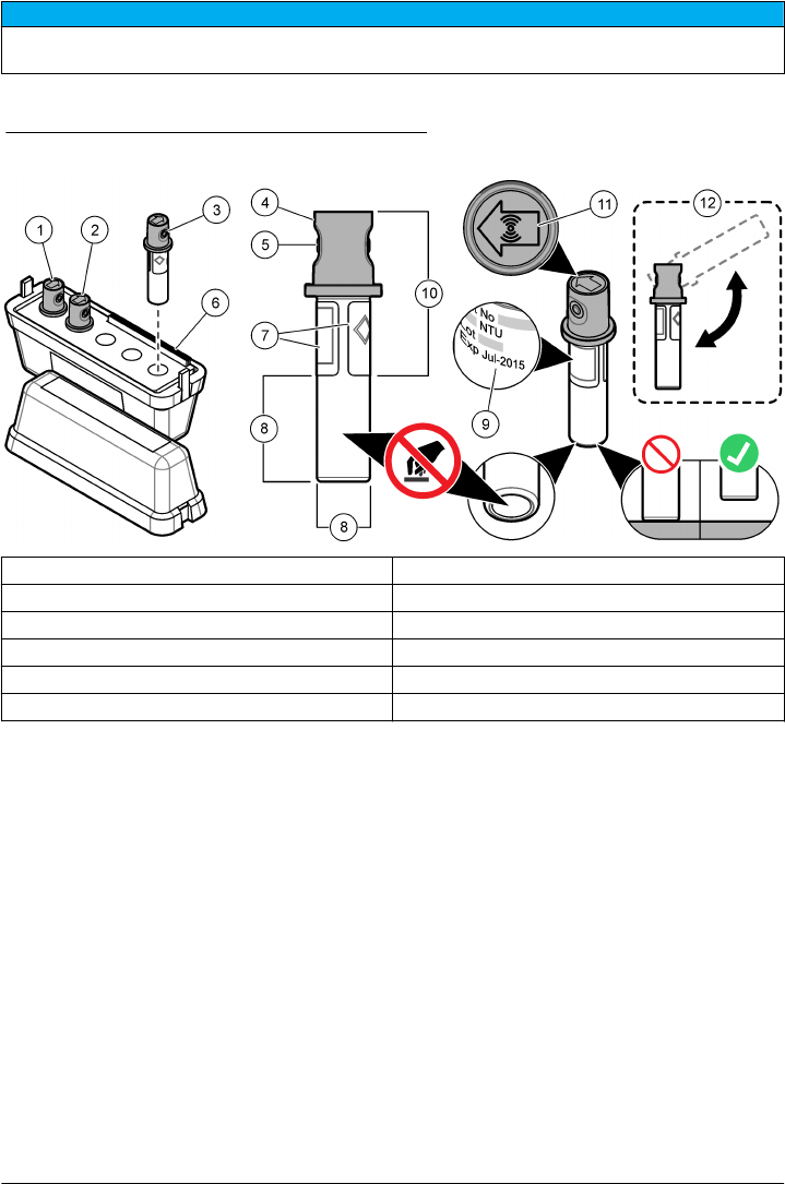
Safely use a sample vial
N O T I C E
Do not to touch or scratch the glass of the sample vial. Contamination or scratches on the glass can cause
measurement errors.
The measurement surface must stay clean and have no scratches. Use a no-lint cloth to remove dirt,
fingerprints or particles from the glass. Refer to Figure 4 to identify where to safely handle the sample
vial. Always keep the sample vials in the vial stand to reduce contamination on the bottom of the
measurement surface. Replace the sample vial when it has several scratches.
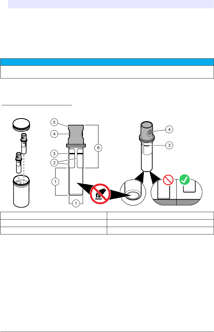
Figure 4 Sample vial overview
1 Measurement surface—Do not touch. 4 Holder for fingers (2x)
2 Label 5 Removable cap
3 Minimum fill level mark 6 Safe to touch area
Prepare the sample
Make sure to keep the vial clean to prevent contamination. Refer to Safely use a sample vial
on page 14. Refer to the illustrated steps that follow to prepare the sample vial for measurement.
Items to collect:
• Vial wiper
• No-lint cloth
• Sample vial (supplied)
• Vial stand (supplied)
14 English
EPA MANUAL
BETA DRAFT
Put the vial into the instrument
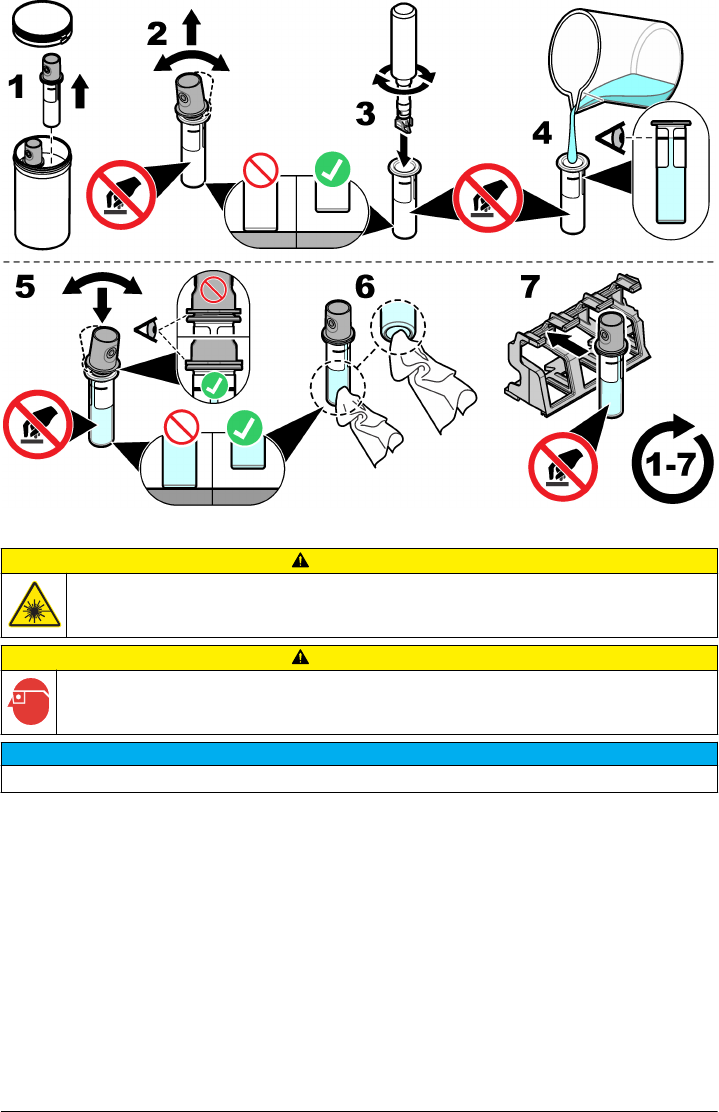
CAUTION
Personal injury hazard. Never remove covers from the instrument. This is a laser-based instrument and
the user risks injury if exposed to the laser.
CAUTION
Personal injury hazard. Do not look into the vial compartment when the instrument power is set to on.
N O T I C E
Make sure that no water or particles fall into the vial compartment.
After a sample is prepared, make sure that the vial is clean and ready for measurement. Refer to the
illustrated steps that follow to safely put a vial into the vial compartment.
English 15
EPA MANUAL
BETA DRAFT
Do a measurement
Only do the steps that follow if there is a sample vial in the vial compartment and the instrument lid
closed. Refer to Put the vial into the instrument on page 15.
1. The measurement starts automatically when the lid is closed. If not, push Read to start the
measurement or select a sample ID to measure. Refer to Make or change a sample ID
on page 16.
2. Do not open the lid until the measurement is complete. When the laser is in use, the heading bar
shows a yellow light in the right corner.
3. Read the display for the measurement status.
4. IThe measurement is complete when a dialogue box shows "Data Stored" (if the instrument is in
"auto-store" mode).
5. Select an option.
Option Description
Send data Sends data to a connected USB flash drive or PC, push Options>Send Data.
Reading Log Shows the log of measurements saved on the instrument.
Reading Setup Changes the reading mode options. Refer to Configure the measurement settings
on page 13.
Make or change a sample ID
Do the steps that follow to add, change, import or remove a sample ID.
1. Push Sample ID.
2. Enter a unique name for the sample ID.
3. As an optional step, select each applicable box to add labeling identification (date/time stamp,
numbering and colors).
4. When the sample ID is created, select the sample ID and push Options.
Option Description
Add Makes a new sample ID.
Delete Removes a sample ID.
Edit Changes the name and labeling identifications (date/time stamps, numbering or
coloring) of an existing sample ID.
Import Sample ID list Imports a sample ID list (or lists) from a connected USB flash drive or PC to the
instrument. Refer to Import a sample ID list on page 17.
16 English
EPA MANUAL
BETA DRAFT
Import a sample ID list
Make a sample ID list to import to the instrument via USB flash drive.
1. On an external device, open a spreadsheet program.
2. Make three columns that identify the sequential sample ID number, the sample ID name and the
sampling date (optional). Make sure that all headings and comment lines must start with "#".
3. Make a folder called "SampleID", then save that folder to a USB flash drive.
4. Select the sample list and "Save As" as a .CSV or .TXT file in the SampleID folder.
5. Connect the USB flash drive to the instrument.
6. On the instrument, push Sample ID>Options>Import Sample ID list.
7. All .CSV and .TXT files show in the SampleID folder.
8. Push Done to send the selected sample ID list to the instrument.
9. Select the correct sample ID list, then push OK.
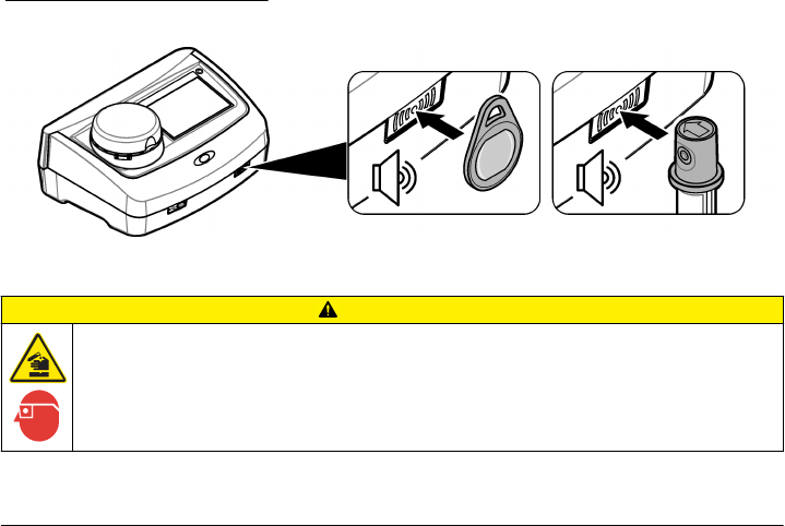
Use the RFID scanner (optional)
An RFID tag is attached in an operator ID tag or in a vial cap. An RFID tag stores and wirelessly
transmits data with radio waves about an operator or a standard. Use the steps that follow to use the
RFID scanner.
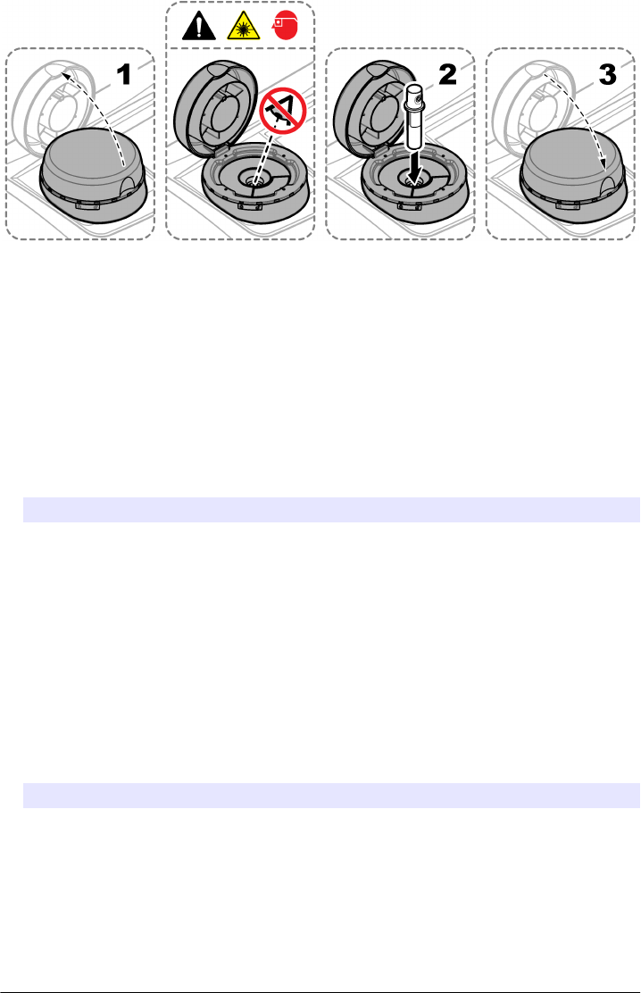
1. Put the operator ID tag or vial in front of the RFID scanner. Refer to Figure 5. Make sure that the
direction of the arrow (on top of the vial cap) is correctly oriented.
2. Wait for the sound alert to show that the scan is successful.
3. When an operator ID tag is scanned, the instrument logs the operator in the system and receives
information associated with that operator.
4. When a calibration or verification vial is scanned, the instrument receives the value, the lot
number, the expiration date and the Certificate of Analysis information from that vial.
5. For changes to the operator ID, refer to Add an operator ID on page 13.
6. To do a verification, refer to Do a verification on page 18.
7. To do a calibration, refer to Do a calibration on page 18.
Figure 5 Use the RFID scanner
Calibration
CAUTION
Chemical exposure hazard. Obey laboratory safety procedures and wear all of the personal protective
equipment appropriate to the chemicals that are handled. Refer to the current safety data sheets
(MSDS/SDS) for safety protocols.
English 17
EPA MANUAL
BETA DRAFT
Prepare for a verification or calibration
N O T I C E
Do not to touch or scratch the glass of the sample vial. Contamination or scratches on the glass can cause
measurement errors.
The measurement surface must stay clean and have no scratches. Use a no-lint cloth to remove dirt,
fingerprints or particles from the glass. Refer to Figure 6 to identify where to safely handle the vial.
Figure 6 Calibration and verification vial overview
1 Calibration solution, 600 NTU 7 Label
2 Calibration solution, 20 NTU 8 Measurement surface—Do not touch.
3 Verification solution, 10NTU 9 Expiration date
4 Non-removable crimp cap110 Safe to touch area
5 Holder for fingers (2x) 11 RFID tag (optional)
6 Certificate of analysis 12 Calibration preparation2
1The non-removable crimp cap comes with or without RFID.
2Gently invert to mix the standard. Do not make air bubbles.
Do a verification
1. Clean the vial. Refer to Safely use a sample vial on page 14.
2. For vials with an RFID tag, scan the vial in front of the RFID scanner. Refer to Use the RFID
scanner (optional) on page 17.
3. Push Verification and follow the instructions on the display.
4. Put the vial in the vial compartment. Refer to Put the vial into the instrument on page 15.
5. Push Read to start the verification.
6. Wait until the procedure is complete, then open the lid to remove the vial. The procedure is
complete when the value and range shows on the display.
7. Read the display for the verification information.
The message display shows whether the verification procedure passed or failed.
Do a calibration
When the instrument is used for EPA regulatory reporting, calibrations must be completed according
to EPA guidance documents and methodologies. Contact local authorities for compliance
regulations.
18 English
EPA MANUAL
BETA DRAFT
The instrument is factory calibrated. Do calibration procedures as necessary. Do the steps that follow
to do a full range calibration procedure.
1. Clean the vial, then carefully invert the vial. Do not cause air bubbles. Refer to Prepare for a
verification or calibration on page 18.
2. For vials with an RFID tag, scan the vial in front of the RFID scanner. Refer to Use the RFID
scanner (optional) on page 17.
3. Push Calibration and follow the instructions on the display.
4. Put the vial in the vial compartment. Refer to Put the vial into the instrument on page 15.
5. Push Read to start the calibration.
6. Wait until the procedure is complete, then open the lid to remove the vial. The procedure is
complete when the value and range shows on the display.
7. Remove the first calibration vial, then do steps 1 to 5 again for the second calibration vial.
8. Read the display for the calibration information.
9. Push Store to complete the calibration and keep the results.
Data management
Configure the data log
The data log keeps all saved comments and readings from measurements, calibrations and
verifications. Use the steps that follow to select, manage and store data.
1. Push Data Log and select a data log to show.
2. Select an option.
Option Description
Filter Sets the data filtering to on or off. If on, select and arrange data by time interval or operator ID.
View details Shows information about a selected data log. Push the comments icon to enter any necessary
information.
Options Shows the current options (contextual). View Graph—See data as a graph, set control limits to
on or off (0.800 = upper control limit or 0.200 = lower control limit). Add data—Select a sample
ID to add to the graph. Curve style(???WHAT IS THE PROPER NOUN???)—Selects the
curve style as crosses, rectangular dots or a line. Delete—Removes selected data from the
data log. Send data—Sends selected data to a connected USB flash drive or PC.
Maintenance
CAUTION
Multiple hazards. Only qualified personnel must conduct the tasks described in this section of the
document.
CAUTION
Chemical exposure hazard. Obey laboratory safety procedures and wear all of the personal protective
equipment appropriate to the chemicals that are handled. Refer to the current safety data sheets
(MSDS/SDS) for safety protocols.
CAUTION
Personal injury hazard. Never remove covers from the instrument. This is a laser-based instrument and
the user risks injury if exposed to the laser.
English 19
EPA MANUAL
BETA DRAFT
N O T I C E
Do not disassemble the instrument for maintenance. If the internal components must be cleaned or repaired,
contact the manufacturer.
Clean spills
CAUTION
Chemical exposure hazard. Dispose of chemicals and wastes in accordance with local, regional and
national regulations.
1. Obey all facility safety protocols for spill control.
2. Discard the waste according to applicable regulations.
Clean the instrument
Clean the exterior of the instrument with a moist cloth, and then wipe the instrument dry.
Clean the vial
Use a vial wiper to clean the interior of the vial. Refer to Safely use a sample vial on page 14 to clean
the exterior of the vial.
Clean the vial compartment
D A N G E R
Electrocution hazard. Remove power from the instrument before this procedure is started.
Periodically clean the vial compartment to manually remove dust with a bellow, air duster, brush or
vial compartment wiper. Make sure that the tool to clean the vial compartment has a soft surface and
does not damage the instrument. Make sure to remove power to the instrument before the cleaning
starts.
Troubleshooting
Problem Possible cause Solution
The self-check stopped or the
instrument does not operate.
A hardware error. Set the instrument to off, then to on again. If
necessary, contact technical support.
The instrument lid is open. Close the lid, then start the self-check again.
The vial compartment is dirty. Refer to Clean the vial compartment
on page 20. If necessary, contact technical
support.
The optical light source is not
stable.
Contact technical support.
An "over measuring range"
message shows.
The instrument is only single
calibrated at 40 NTU and the
sample is between 40 to
700 NTU
???WHAT IS THE SOLUTION???
The range of the sample is over
the measuring range of the
instrument
???WHAT IS THE SOLUTION???
20 English
EPA MANUAL
BETA DRAFT

Problem Possible cause Solution
The standard value is too high. The wrong standard is in the
vial compartment.
Check the calibration standard and Do a
calibration on page 18.
There are bubbles in the
standard.
???WHAT IS THE SOLUTION???
There is dirt in the vial
compartment.
Clean the vial compartment on page 20.
The standard value is too low. The wrong standard is in the
vial compartment.
Check the calibration standard. Invert the
standard and Do a calibration on page 18.
???WHAT IS THE
PROBLEM???
The standard value is out of
range.
Put the standards in ascending order. Invert
the standard, then Do a calibration
on page 18.
A "verification failure" message
shows.
The verification failed. •Do a verification on page 18 again.
•Do a calibration on page 18.
• If the verification and calibration
procedures do not work, then restore the
factory settings. Refer to Read the
diagnostics information on page 22.
The measurement values
between the online and
benchtop turbidimeters do not
match.
There is dirt or condensation on
the sample vial.
Refer to Safely use a sample vial on page 14
to remove dirt and condensation.
The service time expired. Set the bubble elimination to on. Refer to
Configure the measurement settings
on page 13.
There is an error with the online
turbidimeter.
Refer to the documentation for the online
turbidimeter.
The instrument update fails. The USB memory is not
connected.
Connect the USB flash drive. Make sure that
the file system "FAT32" is installed on the
USB memory. Set the power to off, then to
on again. Connect the USB flash drive, then
start the update procedure again.
The instrument update file or
script is corrupt or missing.
Remove the USB memory files, then
download the files again. Connect the USB
memory to the instrument, then do the
update procedure again.
The copy from the USB memory
failed.
Remove large files that use too much space.
Do the update procedure again.
Delete the file from the USB memory.
Download the file again to the USB memory.
Connect the USB memory to the instrument
and start the update procedure again.
There is not enough memory to
update the instrument.
Contact technical support.
A user cannot login. The password is wrong. Enter the correct password. If necessary,
contact technical support.
A "No valid data found"
message shows.
No sample ID found on the USB
memory or shared network
drive.
???WHAT IS THE SOLUTION???
???WHAT IS THE
PROBLEM???
The sampling date, sample ID
or the date format is wrong or
cannot be read.
Refer to Import a sample ID list on page 17.
Make sure that the date is entered correctly.
English 21
EPA MANUAL
BETA DRAFT
Problem Possible cause Solution
Selected documents do not
show on the display.
The document is not a PDF file. Make sure that the document is a PDF file.
The network connection does
not show.
There is no connection to the
DHCP server.
Contact the network administrator. If
necessary, contact technical support.
The connection was not
correctly configured.
Make sure that the settings are correctly
entered.
Read the diagnostics information
1. Push Diagnostics.
2. Select an option.
Option Description
Instrument Information Shows specific information such as the instrument name, serial number,
instrument version, location and MAC address.
Signals Shows the signals for the lid, vial, turbidity, condensation, and fouling. If a USB
flash drive or PC is connected to the instrument, send data.
Instrument Backup Sets the instrument backup settings to store or restore.
Instrument Update Connect the USB memory into a USB port and push OK to start the instrument
update.
Service Time Shows the last service date and the next service date.
Factory Service Only used by authorized factory service personnel.
Replacement parts and accessories
WARNING
Personal injury hazard. Use of non-approved parts may cause personal injury, damage to the
instrument or equipment malfunction. The replacement parts in this section are approved by the
manufacturer.
Note: Product and Article numbers may vary for some selling regions. Contact the appropriate distributor or refer to
the company website for contact information.
Replacement parts
Description Item no.
Dust cover LZV947
Power supply, 100–240 V, 50/60 Hz LZV798
StablCal calibration set (20 NTU cal, 600 NTU cal, 10 NTU ver) with RFID LZY835
StablCal calibration set (20 NTU cal, 600 NTU cal, 10 NTU ver) with no RFID LZY898
Sample vials with protective caps (2x) LZV946
Vial stand LZV952
22 English
EPA MANUAL
BETA DRAFT

Accessories
Description Item no.
Micro fiber cloth (for vial cleaning) LZY945
Secondary standards, <–0.1 NTU LZY901
Secondary standards, 1 to 4 NTU LZY902
Vial wiper for manual cleaning LZY903
Vial compartment wiper for manual cleaning LZY910
English 23
EPA MANUAL
BETA DRAFT

24 English
EPA MANUAL
BETA DRAFT
EPA MANUAL
BETA DRAFT

HACH COMPANY World Headquarters
P.O. Box 389, Loveland, CO 80539-0389 U.S.A.
Tel. (970) 669-3050
(800) 227-4224 (U.S.A. only)
Fax (970) 669-2932
orders@hach.com
www.hach.com
HACH LANGE GMBH
Willstätterstraße 11
D-40549 Düsseldorf, Germany
Tel. +49 (0) 2 11 52 88-320
Fax +49 (0) 2 11 52 88-210
info@hach-lange.de
www.hach-lange.de
HACH LANGE Sàrl
6, route de Compois
1222 Vésenaz
SWITZERLAND
Tel. +41 22 594 6400
Fax +41 22 594 6499
© Hach Company/Hach Lange GmbH, 2014.
All rights reserved. Printed in U.S.A.
EPA MANUAL
BETA DRAFT