Mitsubishi Bnpb2203d MELDASMAGIC64 CONNECTION MANUAL User Ab25794e 8899 4345 81b7 Fa0ac8a9c1ab
User Manual: mitsubishi bnpb2203d Mitsubishi Electronics Blood Glucose Meter BNP-B2203D User Guide |
Open the PDF directly: View PDF ![]() .
.
Page Count: 122 [warning: Documents this large are best viewed by clicking the View PDF Link!]
- Cover
- Introduction
- Precautions for Safety
- CONTENTS
- 1. Outline
- 2. Configuration
- 3. Installation
- 4. NC Card (HR621/HR623/FCU6-HR655) Connection
- 5. Base I/O Unit (FCU6-DX2**/3**/4**) Connection
- 5.1 Base I/O Unit Outline
- 5.2 Base I/O Connection System Drawing
- 5.3 Base I/O Unit Part Names
- 5.4 Base I/O Unit Connector Pin Assignment
- 5.5 Base I/O Unit Input/Output Specifications
- 5.5.1 Rotary Switch (CS1 and CS2) Settings
- 5.5.2 RIO1 Terminator
- 5.5.3 CF31, CF32 Input Circuit
- 5.5.4 CF33, CF34 Output Circuit
- 5.5.5 Specifications of ADD ON PCB Connected to CR31
- 5.5.6 Connection of Base I/O Unit Power Supply
- 5.5.7 Examples of DI/DO Connection
- 5.5.8 Connection of Servo Drive Unit
- 5.5.9 Connection of Spindle Encoder
- 5.5.10 Connection of Sensor Signal (skip)
- 6. Relay Card (HR682) Connection
- 7. Remote I/O Unit Connection (FCUA-DX1**)
- 7.1 Outline of Remote I/O Unit
- 7.2 Names of Each Remote I/O Unit Section
- 7.3 Connection of Remote I/O Power
- 7.4 Outline of Digital Signal Input Circuit
- 7.5 Outline of Digital Signal Output Circuit
- 7.6 Outline of Analog Signal Output Circuit
- 7.7 Outline of Analog Signal Input Circuit
- 7.8 Connection of FCUA-DX10*/13*/14* Unit and Machine Contr
- 7.9 Connection of FCUA-DX11* Unit and Machine Control Signa
- 7.10 Connection of FCUA-DX12* Unit and Machine Control Sign
- 7.11 Connection of FCUA-DX13* Unit and Handle
- 7.12 Outline of FCUA-DX13* Unit Pulse Input Circuit
- 7.13 Connection of FCUA-DX14* Unit and Analog Input/Output
- 7.14 Setting of Channel No. when Using Multiple Remote I/O
- 7.15 Remote I/O Unit Input/Output Signal Cables
- Appendix 1 Outline Drawings
- Appendix 1.1 ISA NC Card Outline Drawing (HR621)
- Appendix 1.2 ISA NC Card Outline Drawing (HR623)
- Appendix 1.3 PCI NC Card Outline Drawing (FCU6-HR655)
- Appendix 1.4 Base I/O Unit Outline Drawing
- Appendix 1.5 Relay Card (independent installation) Outline
- Appendix 1.6 Base I/O Unit + Relay Card (add-on) Outline Dr
- Appendix 1.7 Remote I/O Unit Outline Drawing
- Appendix 1.8 Manual Pulse Generator (HD60) Outline Drawing
- Appendix 1.9 Spindle Encoder (OSE-1024-3-15-68) Outline Dra
- Appendix 1.10 Grounding Plate and Clamp Fitting Outline Dra
- Appendix 2 Cable Manufacturing Drawings
- Appendix 3 Parts for EMC Measures
- Revision History
- Back cover

CNC
CONNECTION MANUAL
BNP-B2203D(ENG)
64
i
MELDASMAGIC is a registered trademark of Mitsubishi Electric Corporation.
Microsoft and MS-DOS are registered trademarks of Microsoft Corporation U.S.A.
Windows is a registered trademark of Microsoft Corporation U.S.A.
IBM is a registered trademark of International Business Machines Corporation U.S.A.
Other company and product names are trademarks or registered trademarks of the
respective companies.

ii
Introduction
This manual is the MELDASMAGIC64 Connection Manual.
MELDASMAGIC64 installation and connection methods are explained centered on the NC Card.
Refer to the materials below for explanations concerning functions.
MELDASMAGIC64 Setup Instruction Manual................................................................................ BNP-B2191
MELDASMAGIC64 Maintenance Manual ...................................................................................... BNP-B2207
MELDAS AC Servo and Spindle MDS-A/B Series Specifications Manual..................................... BNP-B3759
MELDAS AC Servo and Spindle MDS-C1 Series Specifications Manual...................................... BNP-C3000
MELDAS AC Servo and Spindle MDS-CH Series Specifications Manual ..................................... BNP-C3016
MELDAS AC Servo MDS-B-SVJ2 Series Specification Manual.................................................... BNP-B3937
MELDAS AC Servo MDS-B-SPJ2 Series Specification Manual.................................................... BNP-B2164
General items
(1) Read this manual carefully before using MELDASMAGIC64. Please have a full understanding of
product functions and performance, and use this product correctly.
(2) All efforts possible have been made to describe any special handling in this manual. Items not
described in this manual must be interpreted as "Not Possible".
(3) When the details described in this instruction manual change, the sub-No. of the cover page instruction
manual No. (*, A, B) will be changed.
(4) The details described in this manual may change without notice. Mitsubishi may not be held responsible
for errors in the contents described.
About MELDASMAGIC64
(1) MELDASMAGIC64 includes the ISA NC Card compatible with the ISA bus, and the PCI NC Card
compatible with the PCI bus. Either card can be selected. The user can structure a custom-made NC
unit by inserting the NC Card supplied from Mitsubishi into the selected personal computer's expansion
slot (ISA bus or PCI bus).
ISA NC Card PCI NC Card
HR621
HR623
FCU6-HR655
NC Card
(ISA bus specifications) (PCI bus specifications)
(2) The NC Card supplied by Mitsubishi realizes the equivalent environmental resistance (ambient
temperature, noise resistance and vibration resistance) as conventional NC units. However, some
environmental resistance equivalent to conventional NC units is not always guaranteed regarding
personal computers presumed to be normally used in an office. Therefore, when selecting a personal
computer, study this manual well and select an appropriate model responding to the required uses and
applications. When required, execute the appropriate countermeasures.
iii
(3) Take care to the working environment when using MELDASMAGIC64.
Working environment
PCI NC Card ISA NC Card
Applicable personal
computer IBM PC/AT or compatible machine
Compatible OS
• Windows 98SE
• Windows 2000
• Windows XP
• Windows 95
• Windows 98
• Windows 98SE
• Windows NT Workstation 4.0
CPU
• For Windows 95
Pentium 100MHz or faster (Pentium 150MHz or faster recommended)
• For Windows 98, Windows 98SE, Windows NT Workstation 4.0
Pentium 200MHz or faster (Pentium 233MHz or faster recommended)
• For Windows 2000, Windows XP
Pentium 300MHz or faster
Memory
• For Windows 95, Windows 98
16MB or larger (24MB or larger recommended)
• For Windows 98SE, Windows NT Workstation 4.0
24MB or larger (32MB or larger recommended)
• For Windows 2000
64MB or larger (128MB or larger recommended)
• For Windows XP
128MB or larger
Hard disk 20MB or more open space recommended
Floppy disk One 3.5-type 1.44MB drive
Expansion slot PCI bus (PCI bus Standards 2.0 or
higher) ISA bus
+3.3V (*1) 0.2A or more
+5.0V 2.5A or more
Electric
characteristics +12.0V 0.7A or more 0.5A or more
Power drop characteristics Time for +5.0V power voltage to drop from +4.5V to +4.0V when the
power is turned OFF takes 1ms or more.
(*1) When using the PCI NC Card, always use a personal computer that supplies +3.3V power to the PCI
bus.
(4) Heat radiation-countermeasures for personal computer
A rise in the personal computer's internal temperature could cause NC Card damage or malfunction.
Select a personal computer with a fan for circulating the heat in the personal computer, or a personal
computer to which a fan can be mounted.
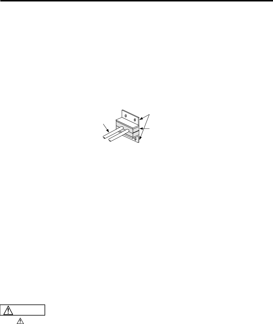
(5) Personal computer vibration
If the expansion slot on the personal computer vibrates greatly, a connector connection fault could occur
and result in incorrect operations. Select a personal computer with a fitting for fixing the NC Card, or a
personal computer that can be fixed.
<Fixing example>
iv
Precautions for Safety
Always read the specifications issued by the machine maker, this manual, related manuals
and enclosed documents before starting installation, operation, programming, maintenance
or inspection to ensure correct usage. Thoroughly understand the basics, safety information
and precautions of this numerical controller before using the unit.
This manual ranks the safety precautions into "DANGER", "WARNING" and "CAUTION".
DANGER When there is a great risk that the user could be subject to
fatalities or serious injuries if handling is mistaken.
WARNING When the user could be subject to fatalities or serious injuries
if handling is mistaken.
CAUTION When the user could be subject to injuries or when physical
damage
Note that even if the items is ranked as " CAUTION", incorrect handling could lead to
serious results. Important information is described in all cases, so please observe the items.
DANGER
Not applicable in this manual.
1. Items related to prevention of electric shocks
WARNING
Do not open the front cover while the power is ON or during operation. Failure to observe this could result
in electric shocks.
Do not operate the device with the front cover removed. The high voltage terminals and charged sections
will be exposed, and could result in electric shocks.
Do not remove the front cover even when the power is OFF except for wiring work or periodic
inspections. The controller and servo drive unit are charged internally and could result in electric shocks.
Always wait at least 15 minutes after turning the power OFF and check the voltage with a tester, etc.,
before starting wiring work or inspections. Failure to observe this could result in electric shocks.
Ground the 200V Series input controller, servo drive unit and servomotor with Class C or higher
protective grounding, and the 400V Series input with Class D or higher protective grounding.
All wiring work and inspections must be carried out by a qualified electrician.
Wire the controller, servo drive unit and servomotor after installation. Failure to observe this could result
in electric shocks.
Do not operate the switches with wet hands, as this may lead to electric shocks.
Do not damage, apply excessive stress, place heavy things on or sandwich the cables, as this may lead
to electric shocks.
v
2. Items related to prevention of fires
CAUTION
Install the controller, servo drive unit, servomotor and regenerative resistor on non-combustible material.
Installation directly on or near combustible materials could result in fires.
If trouble occurs in the servo drive unit, shut off the power at the servo drive unit's input power side. Fires
could result if large current continues to flow.
When using the regenerative resistor, shut off the power with an error signal. The regenerative resistor
could abnormally overheat and cause fires due to a regenerative transistor fault, etc.
Incorrect wiring or connections could damage the device.
3. Items related to prevention of damage
CAUTION
Do not apply voltages other than those indicated in the Controller Connection Manual or Specifications
Manual for Servo Drive Unit. Failure to observe this could lead to rupture, or damage, etc.
Do not mistake the terminal connections. Failure to observe this could lead to rupture, or damage, etc.
Do not mistake the polarity (+, –). Failure to observe this could lead to rupture, or damage, etc.
Persons wearing medical devices, such as pacemakers, must not be near this unit. The medical device
could be affected by electromagnetic waves.
The servo drive unit fins, regenerative resistor and servomotor, etc., will be hot during operation and for a
while after operation is stopped. Touching these sections could result in burns.
vi
4. General Precautions
Always observe the following precautions. Incorrect handling could result in faults, injuries, or electric shocks,
etc.
(1) Transportation and installation
CAUTION
Correctly transport the product according to its weight.
Use servomotor's suspension bolts only to transport the servomotor.
Do not use suspension bolts of the servomotor on the machine to transport the machine.
Do not stack products above the indicated limit.
Do not hold cables, shaft or detector when transporting the servomotor.
Do not suspend or hold the controller or servo drive unit by the connected wires or cables when transporting.
Do not hold the front cover when transporting the controller or servo drive unit. The device could drop.
When installing, always observe the installation direction and install on a place which can withstand the
weight.
Do not get on the product, or place heavy objects on it.
Provide the specified distance between the controller, servo drive unit and inner surface of the control
panel and between other devices.
Do not install or operate a controller, servo drive unit or servomotor that is damaged or that has missing
parts.
Take care not to cut hands on the heat radiating fins or metal edges.
Do not block the intake/outtake ports of the servomotor with cooling fan.
Do not allow conductive foreign matter such as screws or metal chips or combustible foreign matter such
as oil enter the controller, servo drive unit or servomotor.
The controller, servo drive unit and servomotor are precision devices so do not drop or apply strong
impacts on them.
Do not install the controller operation board where it may be subject to cutting oil.
vii
(2) Wiring
CAUTION
Correctly wire this product. Failure to do so could result in servomotor runaway, etc.
Do not install a phase advancing capacitor, surge absorber or radio noise filter on the output side of the
servo drive unit.
Correctly connect the output side (terminals U, V, W). The servomotor will not operate if incorrectly
connected.
Do not directly connect a commercial power supply to the servomotor. Failure to observe this could lead
to faults.
When using an inductive load such as relays, always connect a diode in parallel to the load as a noise
measure.
When using a capacitive load such as a lamp, always connect a protective resistor serially to the load to
suppress rush currents.
Do not mistake the direction of the surge absorption diode installed on the DC relay for the control output
signal. The signal will not be output due to fault and the protective circuit, such as emergency stop, will be
disabled.
Do not connect or disconnect the connection cables between each unit while the power is ON.
Securely tighten the cable connector fixing screw or fixing mechanism. Insufficient fixing could result in
dislocation during operation.
Always treat the shield cables indicated in this manual with grounding measures such as cable clamps.
Separate the signal wire from the drive line/power line when wiring.
Use wires and cables having a wire diameter, heat resistance level and bending capacity that match the
system.
Ground the device according to the requirements of the country where the device is to be used.
Wire the heat radiating fins and wires so that they do no contact.
(3) Adjustments
CAUTION
Check and adjust each parameter before staring operation. Unpredictable operations could occur depending
on the machine.
Do not make marked adjustments or changes as the operation could become unstable.
viii
(4) Usage methods
CAUTION
Install an external emergency stop circuit so that the operation can be stopped and the power turns OFF
immediately. A contactor, etc., must be used in addition to the shutoff function in the controller.
Turn OFF the power immediately if any smoke, abnormal noise or odor is generated from the controller,
servo drive unit or servomotor.
Only a qualified technician may disassemble or repair this product.
Do not modify this product.
Use a noise filter, etc., to reduce the effect of electromagnetic disturbances. Electronic devices used near
the servo drive unit could be affected by the electromagnetic disturbances.
Use the controller, servo drive unit, servomotor and regenerative resistor in the designated combination.
Failure to observe this could result in fires or faults.
The brakes (magnetic brakes) assembled in the servomotor are used for holding, and must not be used
for normal braking.
There may be cases when the magnetic brakes cannot hold the state because of the life or machine
structure (when ball screw and servomotor are coupled via a timing belt, etc.). Install a stopping device on
the machine side so that safety can be ensured.
After maintenance or inspection, always carry out a trial operation before starting actual operation.
Do not move the machine's movable range during automatic operation. Do not place hands, feet or face
near the spindle during rotation.
Use the power (input voltage, input frequency, tolerable instantaneous power failure time) under the power
specification conditions given in the Specifications.
Turn the NC Card's power ON before turning the base I/O unit's power ON.
If the base I/O unit's power is turned ON first, the current will be led to the NC Card from the connection
cable. This will prevent the personal computer or the cards in the personal computer from starting up
properly.
(5) Measures during a fault
CAUTION
If a hazardous situation could arise during a power failure or product fault, use the servomotor with
magnetic brakes or provide an external brake mechanism for holding purposes.
Use a double circuit structure for the magnetic brake's operation circuit so that the brakes will activate
even when the external emergency stop signal is issued.
If an alarm occurs, remove the cause, and secure surrounding safety before resetting the alarm and
restarting operation.
The machine could suddenly restart when power is restored after an instantaneous power failure. Do not
near the machine in this case. (Design the machine so that operator safety can be ensured even if the
machine restarts.)
ix
(6) Maintenance, inspection and part replacement
CAUTION
The electrolytic capacitor's capacity will drop due to deterioration. To prevent secondary damage due to
capacitor's faults, Mitsubishi recommends replacing the electrolytic capacitor after approx. five years
when used in a general environment. Contact the Service Center or Service Station for replacements.
Do not perform a megger test (insulation resistance measurement) during inspection.
Save the machining programs, tool data and parameters with an input/output device before replacing the
battery.
Do not short-circuit, charge, overheat, incinerate or disassemble the battery.
The hard disk unit has a service life, and must be replaced when the life is reached.
Always back up the customer's data stored on the hard disk unit. The customer's data stored on the hard
disk unit cannot be guaranteed.
(7) Disposal
CAUTION
Handle this product as general industrial waste. Note that some of the MDS Series products use alternate
Freon. These corresponding models must not be handled as general industrial waste and must always be
returned to the Service Center or Service Station. (Corresponding models have heat radiating fins on the
back of the unit.)
Do not disassemble the controller, servo drive unit or servomotor parts.
Collect and dispose of the spent batteries according to local laws.
(8) General precautions
CAUTION
To explain the details, drawings given in this instruction manual, etc., may show the unit with the cover or
safety partition removed. When operating the product, always install the cover or partitions at their original
position, and operate as indicated in the instruction manual, etc.
x
CONTENTS
1. Outline.................................................................................................................................. 1
2. Configuration ...................................................................................................................... 2
2.1 System Configuration..................................................................................................... 2
2.2 List of Configuration Units .............................................................................................. 3
3. Installation........................................................................................................................... 5
3.1 General Specifications ................................................................................................... 5
3.2 General System Diagram............................................................................................... 6
3.3 Installation...................................................................................................................... 8
3.3.1 Installation Direction and Spacing........................................................................... 8
3.3.2 Prevention of Foreign Matter Entry......................................................................... 9
3.3.3 Heat Radiation Countermeasures .......................................................................... 10
3.3.4 Noise Countermeasures......................................................................................... 12
4. NC Card Connection........................................................................................................... 15
4.1 NC Card Connection System Diagram........................................................................... 15
4.2 NC Card Part Names ..................................................................................................... 16
4.2.1 Names of HR621 Card Parts.................................................................................. 16
4.2.2 Names of HR623 Card Parts.................................................................................. 17
4.2.3 Names of FCU6-HR655 Unit Parts......................................................................... 18
4.3 Control Unit Connector Pin Assignment ......................................................................... 19
4.4 ISA NC Card Mounting................................................................................................... 23
4.4.1 Before Mounting the ISA NC Card.......................................................................... 23
4.4.2 ISA NC Card Mounting Procedure.......................................................................... 24
4.5 PCI NC Card Mounting................................................................................................... 27
4.5.1 Before Mounting the PCI NC Card ......................................................................... 27
4.5.2 PCI NC Card Mounting Procedure ......................................................................... 28
5. Base I/O Unit Connection................................................................................................... 31
5.1 Base I/O Unit Outline ..................................................................................................... 31
5.2 Base I/O Connection System Drawing ........................................................................... 32
5.3 Base I/O Unit Part Names.............................................................................................. 33
5.4 Base I/O Unit Connector Pin Assignment....................................................................... 35
5.5 Base I/O Unit Input/Output Specifications ...................................................................... 38
5.5.1 Rotary Switch Settings ........................................................................................... 38
5.5.2 RIO1 Terminator..................................................................................................... 38
5.5.3 CF31, CF32 Input Circuit........................................................................................ 39
5.5.4 CF33, CF34 Output Circuit..................................................................................... 39
5.5.5 Specifications of ADD ON PCB Connected to CR31.............................................. 39
5.5.6 Connection of Base I/O Unit Power Supply............................................................ 40
5.5.7 Examples of DI/DO Connection.............................................................................. 41
5.5.8 Connection of Servo Drive Unit .............................................................................. 42
5.5.9 Connection of Spindle Encoder .............................................................................. 42
5.5.10 Connection of Sensor Signal................................................................................ 43
6. Relay Card Connection....................................................................................................... 44
6.1 Relay Card Outline......................................................................................................... 44
6.2 Relay Card Connection System Diagram....................................................................... 44
6.3 Relay Card Part Names ................................................................................................. 45
6.4 Relay Card Connector Pin Assignment .......................................................................... 46
6.5 Relay Card Input/Output Specifications.......................................................................... 48
6.5.1 Relay Card Power Connection ............................................................................... 48
6.5.2 Emergency Stop Connection.................................................................................. 48
6.5.3 Connection of Spindle Encoder .............................................................................. 49
6.5.4 Manual Pulse Generator Connection ..................................................................... 49
6.5.5 RS-232C Device Connection.................................................................................. 49
6.6 Installation on the Base I/O Unit..................................................................................... 50
xi
7. Remote I/O Unit Connection .............................................................................................. 51
7.1 Outline of Remote I/O Unit ............................................................................................. 51
7.2 Names of Each Remote I/O Unit Section ....................................................................... 52
7.3 Connection of Remote I/O Power................................................................................... 53
7.4 Outline of Digital Signal Input Circuit.............................................................................. 54
7.5 Outline of Digital Signal Output Circuit ........................................................................... 56
7.6 Outline of Analog Signal Output Circuit .......................................................................... 57
7.7 Outline of Analog Signal Input Circuit............................................................................. 58
7.8 Connection of FCUA-DX10*/13*/14* Unit and Machine Control Signal.......................... 59
7.9 Connection of FCUA-DX11* Unit and Machine Control Signal....................................... 61
7.10 Connection of FCUA-DX12* Unit and Machine Control Signal..................................... 63
7.11 Connection of FCUA-DX13* Unit and Handle .............................................................. 65
7.12 Outline of FCUA-DX13* Unit Pulse Input Circuit .......................................................... 66
7.13 Connection of FCUA-DX14* Unit and Analog Input/Output Signal ............................... 67
7.14 Setting of Channel No. when Using Multiple Remote I/O Units.................................... 68
7.15 Remote I/O Unit Input/Output Signal Cables................................................................ 70
Appendix 1 Outline Drawings ................................................................................................ 71
Appendix 1.1 ISA NC Card Outline Drawing (HR621) ....................................................... 71
Appendix 1.2 ISA NC Card Outline Drawing (HR623) ....................................................... 71
Appendix 1.3 PCI NC Card Outline Drawing (FCU6-HR655) ............................................ 72
Appendix 1.4 Base I/O Unit Outline Drawing..................................................................... 73
Appendix 1.5 Relay Card (independent installation) Outline Drawing ............................... 74
Appendix 1.6 Base I/O Unit + Relay Card (add-on) Outline Drawing................................. 75
Appendix 1.7 Remote I/O Unit Outline Drawing................................................................. 76
Appendix 1.8 Manual Pulse Generator (HD60) Outline Drawing....................................... 77
Appendix 1.9 Spindle Encoder (OSE-1024-3-15-68) Outline Drawing............................... 78
Appendix 1.10 Grounding Plate and Clamp Fitting Outline Drawings.................................. 79
Appendix 2 Cable Manufacturing Drawings ......................................................................... 80
Appendix 2.1 SH21 cable (Servo drive unit)...................................................................... 82
Appendix 2.2 SH41 cable (Remote I/O unit)...................................................................... 83
Appendix 2.3 R031 cable (Analog signal input/output) ...................................................... 84
Appendix 2.4 R041 cable (Manual pulse generator).......................................................... 85
Appendix 2.5 R042 cable (Manual pulse generator).......................................................... 86
Appendix 2.6 R211 cable (Remote I/O unit) ..................................................................... 87
Appendix 2.7 R220 cable (+24VDC input)......................................................................... 88
Appendix 2.8 R300 cable (Machine input/output).............................................................. 89
Appendix 2.9 R301 cable (Machine input/output).............................................................. 90
Appendix 2.10 F010 cable (NC Card).................................................................................. 91
Appendix 2.11 F011 cable (NC Card).................................................................................. 92
Appendix 2.12 F020 cable (Manual pulse generator) ........................................................ 93
Appendix 2.13 F021 cable (Manual pulse generator) ........................................................ 94
Appendix 2.14 F022 cable (Manual pulse generator) ........................................................ 95
Appendix 2.15 F040 cable (Spindle encoder)...................................................................... 96
Appendix 2.16 F041 cable (Spindle encoder)...................................................................... 97
Appendix 2.17 F070 cable (+24VDC input) ......................................................................... 98
Appendix 2.18 F390 cable (RS232C) .................................................................................. 99
Appendix 2.19 ENC-SP1 cable (Spindle drive unit) ........................................................... 100
Appendix 2.20 Table of Connector Sets ............................................................................. 101
Appendix 3 Parts for EMC Measures..................................................................................... 102
Appendix 3.1 Shield Clamp Fitting..................................................................................... 102
Appendix 3.2 Ferrite Core.................................................................................................. 103
Appendix 3.3 Surge Protector............................................................................................ 104
Appendix 3.4 Selection of Stabilized Power Supply........................................................... 107

1. Outline
1
1. Outline
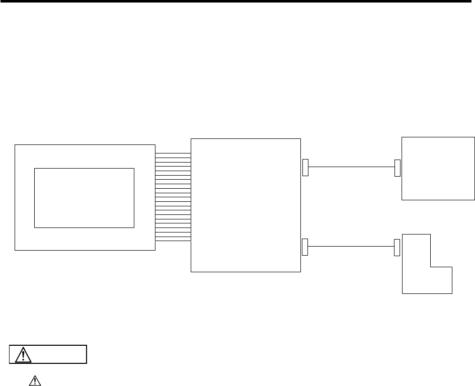
This manual explains MELDASMAGIC64 installation and connection methods centered on the NC
Card.
By installing this NC Card in a personal computer expansion slot (ISA bus or PCI bus), and connecting
a servo drive unit, servomotor, etc., a custom-made NC unit can be constructed.
This manual assumes that all functions are added, but the actually delivered device may not have all
functions.
Refer to the following documents for explanations on the functions.
MELDASMAGIC64 Setup Instruction Manual........................................................................ BNP-B2191
MELDASMAGIC64 Maintenance Manual .............................................................................. BNP-B2207
MELDAS AC Servo and Spindle MDS-A/B Series Specifications Manual ............................ BNP-B3759
MELDAS AC Servo and Spindle MDS-C1 Series Specifications Manual.............................. BNP-C3000
MELDAS AC Servo and Spindle MDS-CH Series Specifications Manual............................. BNP-C3016
MELDAS AC Servo MDS-B-SVJ2 Series Specification Manual............................................ BNP-B3937
MELDAS AC Servo MDS-B-SPJ2 Series Specification Manual............................................ BNP-B2164
2. Configuration
2.1 System Configuration
2
2. Configuration
2.1 System Configuration
Base I/O unit
(FCU6-DX2**, 3**, 4**)
#1 #2 #3
MDS-B-V1/V2
MDS-C1-V1/V2
MDS-B-SVJ2
MDS-B-SP
MDS-B-SPJ2
MR-J2-CT
NC CARD
NC CARD
ISA NC Card HR621/HR623
PCI NC Card FCU6-HR655
Relay card
(HR682)
External power
(24VDC supply)
Externalpower
(24VDC supply)
F010 cable F070 cable
(R220 cable)
SH21 cable
R300/R301
cable
SH41 cable
(R211 cable)
F011 cable
F070 cable
(R220 cable)
F070 cable
(R220 cable) F020/F021/F022
cable
Floppy disk drive
Manual pulse generator
Keyboard
Mouse
Servo drive unit/
spindle drive unit
Remote I/O unit
Servomotor/spindle motor
Machine electric cabinet
External emergency
stop switch
RS-232C device
(Note) Only the DC code (X ON/OFF)
method handshake is possible
Desktop personal computer
or
Panel computer
Prepared by machine tool manufacturer
Prepared by machine tool manufacturer

2. Configuration
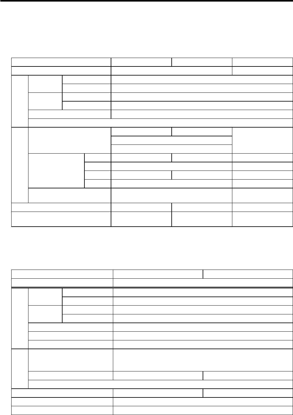
2.2 List of Configuration Units
3
2.2 List of Configuration Units
1. NC Card
Type Configuration elements Details
HR621 NC Card installed in an ISA bus personal computer HR621 CPU PCB
HR623 NC Card installed in an ISA bus personal computer HR623 CPU PCB
HR183 CPU PCB FCU6-HR655 NC Card installed in an PCI bus personal computer HR655 I/F PCB
2. I/O unit (1)
Type Configuration
elements Details
HR682 HR682 HANDLE, ENC, RS-232C,
emergency stop switch input I/F
RS-232C uses only the DC code (X
ON/OFF) method handshake.
With metal spacers. Add-on to FCU6-DX2**
possible.
HR325 FCU6-DX210 DI (sink/source)/DO (sink) = 48/48
With servo, RIO, SKIP, ENC I/F Aluminum die cast
HR325
RX323-1
FCU6-DX310 DI (sink/source)/DO (sink) = 80/64
With servo, RIO, SKIP, ENC I/F
Aluminum die cast
Base PCB: DI (sink/source)/DO (sink) = 48/48
Add-on PCB: DI (sink/source)/DO (sink) = 32/16
HR325
RX323
FCU6-DX320 DI (sink/source)/DO (sink) = 80/64
With servo, RIO, SKIP, ENC I/F
Analog output 1 point Aluminum die cast
Base PCB: DI (sink/source)/DO (sink) = 48/48
Add-on PCB: DI (sink/source)/DO (sink) = 32/16
Analog output 1 point
HR325
RX331
FCU6-DX330 DI (sink/source)/DO (sink) = 48/48
With servo, RIO, SKIP, ENC I/F
Manual pulse 2ch Aluminum die cast
Base PCB: DI (sink/source)/DO (sink) = 48/48
Add-on PCB: Manual pulse generator 2ch
HR325
RX341
FCU6-DX340 DI (sink/source)/DO (sink) = 48/48
With servo, RIO, SKIP, ENC I/F
Analog input 4 points, analog output
1 point Aluminum die cast
Base PCB: DI (sink/source)/DO (sink) = 48/48
Add-on PCB: Analog input 4 points,
analog output 1 point
HR327 FCU6-DX220 DI (sink/source)/DO (sink) = 64/64
With servo, RIO, SKIP, ENC I/F Aluminum die cast
HR327
RX323-1
FCU6-DX410 DI (sink/source)/DO (sink) = 96/80
With servo, RIO, SKIP, ENC I/F
Aluminum die cast
Base PCB: DI (sink/source)/DO (sink) = 64/64
Add-on PCB: DI (sink/source)/DO (sink) = 32/16
HR327
RX323
FCU6-DX420 DI (sink/source)/DO (sink) = 96/80
With servo, RIO, SKIP, ENC I/F
Analog output 1 point Aluminum die cast
Base PCB: DI (sink/source)/DO (sink) = 64/64
Add-on PCB: DI (sink/source)/DO (sink) = 32/16
Analog output 1 point
HR327
RX331
FCU6-DX430 DI (sink/source)/DO (sink) = 64/64
With servo, RIO, SKIP, ENC I/F
Manual pulse 2ch Aluminum die cast
Base PCB: DI (sink/source)/DO (sink) = 64/64
Add-on PCB: Manual pulse generator 2ch
HR327
RX341
FCU6-DX440 DI (sink/source)/DO (sink) = 64/64
With servo, RIO, SKIP, ENC I/F
Analog input 4 points, analog output
1 point Aluminum die cast
Base PCB: DI (sink/source)/DO (sink) = 64/64
Add-on PCB: Analog input 4 points,
analog output 1 point
HR335 FCU6-DX211 DI (sink/source)/DO (source) = 48/48
With servo, RIO, SKIP, ENC I/F Aluminum die cast
HR335
RX324-1
FCU6-DX311 DI (sink/source)/DO (source) = 80/64
With servo, RIO, SKIP, ENC I/F
Aluminum die cast
Base PCB: DI (sink/source)/DO (source) = 48/48
Add-on PCB: DI (sink/source)/DO (source) =
32/16
HR335
RX324
FCU6-DX321 DI (sink/source)/DO (source) = 80/64
With servo, RIO, SKIP, ENC I/F
Analog output 1 point Aluminum die cast
Base PCB: DI (sink/source)/DO (source) = 48/48
Add-on PCB: DI (sink/source)/DO (source) =
32/16 Analog output 1 point
HR335
RX331
FCU6-DX331 DI (sink/source)/DO (source) = 48/48
With servo, RIO, SKIP, ENC I/F
Manual pulse 2ch Aluminum die cast
Base PCB: DI (sink/source)/DO (source) = 48/48
Add-on PCB: Manual pulse generator 2ch
HR335
RX341
FCU6-DX341 DI (sink/source)/DO (source) = 48/48
With servo, RIO, SKIP, ENC I/F
Analog input 4 points, analog output
1 point Aluminum die cast
Base PCB: DI (sink/source)/DO (source) = 48/48
Add-on PCB: Analog input 4 points,
analog output 1 point
HR337 FCU6-DX221 DI (sink/source)/DO (source) = 64/64
With servo, RIO, SKIP, ENC I/F Aluminum die cast
HR337
RX324-1
FCU6-DX411 DI (sink/source)/DO (source) = 96/80
With servo, RIO, SKIP, ENC I/F
Aluminum die cast
Base PCB: DI (sink/source)/DO (source) = 64/64
Add-on PCB: DI (sink/source)/DO (source) =
32/16
HR337
RX324
FCU6-DX421 DI (sink/source)/DO (source) = 96/80
With servo, RIO, SKIP, ENC I/F
Analog output 1 point Aluminum die cast
Base PCB: DI (sink/source)/DO (source) = 64/64
Add-on PCB: DI (sink/source)/DO (source) =
32/16 Analog output 1 point
HR337
RX331
FCU6-DX431 DI (sink/source)/DO (source) = 64/64
With servo, RIO, SKIP, ENC I/F
Manual pulse 2ch Aluminum die cast
Base PCB: DI (sink/source)/DO (source) = 64/64
Add-on PCB: Manual pulse generator 2ch
HR337
RX341
FCU6-DX441 DI (sink/source)/DO (source) = 64/64
With servo, RIO, SKIP, ENC I/F
Analog input 4 points, analog output
1 point Aluminum die cast
Base PCB: DI (sink/source)/DO (source) = 64/64
Add-on PCB: Analog input 4 points,
analog output 1 point

2. Configuration
2.2 List of Configuration Units
4
2. I/O unit (2)
Type Configuration
elements Details
RX323-1 DI (sink/source)/DO (sink)=32/16 RX323-1 Add-on PCB
RX323 DI (sink/source)/DO (sink)=32/16
Analog output 1 point RX323 Add-on PCB
RX324-1 DI (sink/source)/DO
(source)=32/16 RX324-1 Add-on PCB
RX324 DI (sink/source)/DO
(source)=32/16
Analog output 1 point
RX324 Add-on PCB
RX331 Manual pulse generator 2ch RX331 Add-on PCB
RX341 Analog input 4 points,
Analog output 1 point RX341 Add-on PCB
FCUA-DX100 DI (sink/source)/DO (sink)=32/32 RX311 Base PCB: DI (sink/source)/DO (sink)=32/32
Case
RX311 Base PCB: DI
(
sink/source
)
/DO
(
sink
)
=32/32
RX321-1 Add-on PCB: DI
(
sink/source
)
/ DO
(
sink
)
=32/16
FCUA-DX110 DI (sink/source)/DO (sink)=64/48
Case
RX311 Base PCB: DI
(
sink/source
)
/DO
(
sink
)
=32/32
RX321 Add-on PCB: DI (sink/source)/ DO (sink)=32/16
Analo
g
out
p
ut 1
p
oint
FCUA-DX120 DI (sink/source)/DO (sink)=64/48
Analog output 1 point
Case
RX311 Base PCB: DI
(
sink/source
)
/DO
(
sink
)
=32/32
RX331 Add-on PCB: Manual
p
ulse
g
enerator 2ch
FCUA-DX130 DI (sink/source)/DO (sink)=32/32
Manual pulse 2ch
Case
RX311 Base PCB: DI
(
sink/source
)
/DO
(
sink
)
=32/32
RX341 Add-on PCB: Analog input 4 points,
analo
g
out
p
ut 1
p
oint
FCUA-DX140 DI (sink/source)/DO (sink)=32/32
Analog input 4 points,
Analog output 1 point
Case
RX312 Base PCB: DI
(
sink/source
)
/DO
(
source
)
=32/32FCUA-DX101 DI (sink/source)/
DO (source)=32/32 Case
RX312 Base PCB: DI
(
sink/source
)
/DO
(
source
)
=32/32
RX322-1 Add-on PCB: DI
(
sink/source
)
/ DO
(
source
)
=32/16
FCUA-DX111 DI (sink/source)/
DO (source)=64/48
Case
RX312 Base PCB: DI
(
sink/source
)
/DO
(
source
)
=32/32
RX322 Add-on PCB: DI (sink/source)/ DO (source)=32/16
Analo
g
out
p
ut 1
p
oint
FCUA-DX121 DI (sink/source)/
DO (source)=64/48
Analog output 1 point
Case
RX312 Base PCB: DI
(
sink/source
)
/DO
(
source
)
=32/32
RX331 Add-on PCB: Manual
p
ulse
g
enerator 2ch
FCUA-DX131 DI (sink/source)/
DO (source)=32/32
Manual pulse 2ch Case
RX312 Base PCB: DI
(
sink/source
)
/DO
(
source
)
=32/32
RX341 Add-on PCB: Analog input 4 points,
analo
g
out
p
ut 1
p
oint
FCUA-DX141 DI (sink/source)/
DO (source)=32/32
Analog input 4 points,
Analog output 1 point Case
3. Peripheral devices
Type Configuration
elements Details
HD60C Manual pulse generator Without MELDAS logo
HD60C-1 Manual pulse generator With MELDAS logo
Grounding plate D Grounding plate D set
Grounding plate E Grounding plate E set
4. Operation unit options
Type Configuration
elements Details
FCU6-HR211 I/O branch plate HR211 card
FCU6-HR251 IC card interface HR251 card
3. Installation
3.1 General Specifications
5
3. Installation
3.1 General Specifications
NC Card peripheral environment conditions
Type name HR621/HR623 FCU6-HR655 HR682
Unit name NC Card Relay card
During operation 0~55°C
Ambient
temperature During storage -20~60°C
During operation 40~75% RH (with no dew condensation)
Ambient
humidity During storage 40~75% RH (with no dew condensation)
Working atmosphere No corrosive gas or dust
General
specifications
– 3.3VDC ± 5%
5VDC ± 2%
Power voltage
12VDC ± 2%
24VDC ± 5%
Ripple ± 5% (P-P)
3.3V – 0.2A (max) –
5V 2.5A (max) –
12V 0.5A (max) 0.7A (max) –
Current
consumption
24V – 0.5A (max)
Power specifications
Power drop characteristics Personal computer 5V: 4.5V
→4.0V is 1ms or more (*1) –
Heating value 19W 22W 12W
Unit size 248.9×107.6×20 (mm) 174.63×106.68×21
(mm) 115×156×30 (mm) (*2)
(*1) If these characteristics are not satisfied, the NC Card cannot back up the absolute position information of
the machine position when the power is turned OFF.
(*2) Excluding spacers
Environmental conditions in electric cabinet
Type name FCU6-DX210, FCU6-DX211 FCU6-DX220, FCU6-DX221
Unit name Base I/O unit
During operation 0~55°C
Ambient
temperature During storage -20~60°C
During operation 45~75% RH (with no dew condensation)
Ambient
humidity During storage 45~80% RH (with no dew condensation)
Vibration resistance 4.9m/s2 or less (during operation)
Shock resistance 29.4m/s2 or less (during operation)
General specifications
Working atmosphere No corrosive gas or dust
Power voltage
24VDC ± 5%
Ripple ± 5% (P-P)
Current consumption 5V 1A (max), 24V 3.6A (max) (*3) 5V 1A (max), 24V 4.8A (max) (*3)
Power
specifications
Heating value 90W (*3) 110W (*3)
Mass 2.0kg
Unit size 220×168×35 (mm)
(*3) When all DO points are ON
3. Installation
3.2 General System Diagram
6
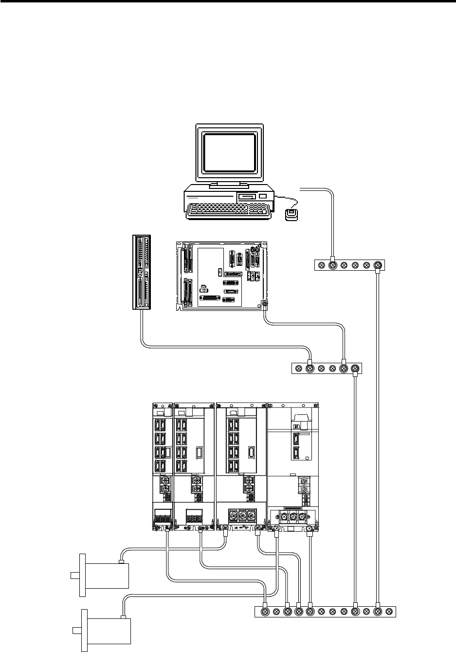
3.2 General System Diagram
SH41
(FCUA-R211)
Transformer
200VAC: 100VAC
No-fuse breaker (NFB)
3-phase 200V-230VAC
Noise
filter
No-fuse braker
(NFB)
No-fuse
braker
(NFB)
Display unit
Keyboard
Pointing device
Personal computer main unit
Cable clamp
Machine control relay/contact
To the next
remote
I/O unit
Machine
electric
cabinet
1st spindle
encoder
Sensor
contact,
max. 8 points
2nd spindle encoder
Manual pulse generator
(max. 3 channels)
Emergency stop switch
(for expansion)
:
Machine tool manufacturer
-prepared parts
(Note) Only the DC code (X ON/OFF) method
handshake is possible for the RS-232C.
+24VDC
Note) The remote I/O unit can be extended up to six stations.
Note that when an add-on PCB is mounted (DX3**, DX4**),
the remote I/O unit can be extended up to 5 stations.
MC
MC
ON
MC
RST
OFF
FG
FG
RIO
CF10 CF31
CF32
CF33
CF34
ENC1
SKIP
SV1 SV2 RIO1 RIO2
FG
Base I/O unit
FCU6-DX2**
(DX3**)
(DX4**)
SH41(FCUA-R211)
24VDC
Remote I/O unit
FCUA-DX1**
DCIN RIO1 RIO2
R
R
F040/F041
R301 DI
DI
DO
DO
R301
R301
R301
SH21
SH21
24VDC DCIN
CF61
CF10
CF61
F070
(FCUA-R220)
24VDC
24VDC
F010
F011
DCIN EMG1
NC Card
Relay card
F040/F041
ENC#2
HANDLE F020/F021/F022
RS232C
HR682
HR621/HR623/
FCU6-HR655
F070
(FCUA-R220)
F070
(FCUA-R220)
F070
(FCUA-R220)
NC servo/spindle drive unit
MDS-B-V1/V2
MDS-B-SVJ2
MDS-B-SP
MDS-B-SPJ2
MDS-C1-V1/V2
Auxiliary
axis
MR-J2-CT
Terminator
R-TM
F390
RS-232C device
Terminator
R-TM
(Note)
The power voltage depends
on the personal computer
specifications.
Stabilized
power supply
Separate the signal wire from the drive line/power line when wiring.
CAUTION

3. Installation
3.2 General System Diagram
7
Example of connection when using V1/V2 in the drive section
CN1A CN1B
CN2
SM
PG
U
V
W
E
SM
PG
CN1A CN1B
CN2 RSTE
CN4
P
N
R0
S0
MC1
P
N
R0
S0
B-AL
MC
CN4
U
V
W
E
RST
Connection to base I/O unit
SV1 and SV2
Note (1)
SH21 cable
Servo drive unit
MDS-B/C1 Series Note (2)
SH21 cable
Servo drive unit
MDS-B/C1 Series
Terminator
A-TM
Battery
unit
MDS-A-BT-4(4 axes)
MDS-A-BT-2(2 axes)
Power
supply unit
AC servomotor AC servomotor
Motor end detector Motor end detector
SH21 cable
(Note) (1) Drive section connections differ according to the configuration of the servo drive unit and
motor used.
(2) When connecting the spindle drive unit, set the axis No. to the value after the last servo
axis.
(3) Connect the last axis (the axis to be connected to the battery unit) to the power supply unit.
(4) When using a terminator, connect to the last axis.
(5) Always wire the control unit's signal wire away from the drive section's drive lines/power
lines.
Separate the signal wire from the drive line/power line when wiring.
CAUTION

3. Installation
3.3 Installation
8
3.3 Installation
3.3.1 Installation Direction and Spacing
Each unit is installed in a sealed structure electric cabinet as a principle. Observe the following points
when installing into the electric cabinet.
(1) Install each unit vertically, so that it is visible from the front.
(2) Consider the heat radiation and wiring of each unit. Refer to the following drawing, and secure
space for ventilation.
(3) Install the personal computer main unit paying particular attention to the specification conditions of
the selected personal computer.
MI TSUB IS HI MI TSUB IS HI
RI02
RI01
DCIN
0 0
CF31 C F32
CF34CF33
CF10 SV2
SV1
SKIP ENC1
CR31
EM G1
HANDLE
RS232C
ENC#2
CF61
EMG2
DCIN
Relay card Base I/O unit
Remote I/O unit Servo drive unit
Spindle drive unit
30mm or more
10mm
or more
10mm
or more
10mm or more
10mm
or more
10mm or more 150mm or more
(heat radiation and
wiring space)
15mm or more
(wiring space)
15mm or more
(wiring space)
Top
Bottom
100mm or more
(heat radiation space)
(Note) The relay card can be added on to the base I/O unit. Refer to "6.6 Installation to the Base I/O
Unit" for the installation method when adding on.
Always observe the direction of installation.
CAUTION
3. Installation
3.3 Installation
9
3.3.2 Prevention of Foreign Matter Entry
(1) The inside of each unit is densely mounted, and is sensitive to dust, etc. Always design a sealed
structure electric cabinet, and execute the following measures.
Carry out dust-proofing and oil-proofing measures such as sealing the cable inlets with packing.
Be particularly careful that outside air does not enter the electric cabinet through heat radiation
holes, etc.
Seal all gaps.
Securely install the door packing.
Always install packing around any back cover (when present).
Oil can easily accumulate in screw holes on top of the electric cabinet and penetrate into the
electric cabinet. Therefore, carry out special countermeasures such as using oil-proof packing.
Cable Metal fittings
Packing
Cable inlet (example)
(2) After installing each unit, avoid any tool machining in the area surrounding those units. Cutting
chips, etc., may adhere to electronic parts and cause a failure.
(3) Design the electric cabinet so the internal temperature will rise no more than 10°C (target value
5°C or less) over the ambient temperature, and will stay within the temperature conditions of the
personal computer, NC Card, etc. (Refer to "3.3.3 Heat Radiation Countermeasures" for details.)
Use a panel cooler when required.
(4) The personal computer display unit may not operate normally due to external magnetic fields.
Separate magnetism producing sources (transformers, fans, magnetic switches, solenoid relays,
magnet stands, magnetic workpieces, power lines flowing a large current, etc.) from the display
unit by 200mm or more.
Note that the magnetism produced by these magnetism producing sources differs individually, and
will also differ according to the installation direction, etc. Therefore, the display unit may not
operate properly even when separated by 200mm or more from these sources. When determining
the layout of magnetism producing sources, also consider the direction, etc., of the magnetism
produced, and finally confirm by actual operation of the machine.
Make sure that conductive foreign matter (screws, metal pieces, etc.) and flammable
foreign matter (oil, etc.) does not enter inside any unit.
CAUTION
3. Installation
3.3 Installation
10
3.3.3 Heat Radiation Countermeasures
In normal NC units, the electric cabinet thermal design is so the electric cabinet ambient temperature is
a 0 to 45°C usage condition, and the electric cabinet internal temperature rise is 10°C. However, these
conditions do not necessarily apply in MELDASMAGIC64.
This is because the operation of all Mitsubishi-supplied units, including the NC Card, is guaranteed up
to 55°C, but the operation of the personal computer is not necessarily guaranteed up to 55°C.
Thus, the electric cabinet ambient temperature must first be determined as shown below.
(1) Determine the electric cabinet ambient temperature Ta.
Ex. 0 to 35°C
(2) Determine the internal temperature rise ∆T.
Ex. 5°C
(3) Select a personal computer.
When Ta max. = 35°C and ∆T = 5°C, the personal computer must have a guaranteed operating
temperature of 40°C or more (45°C or more for a margin of safety).
(4) In this example, the average temperature in the electric cabinet will be 40°C or less according to
(1) and (2).
(Note) 1. When heat accumulates in upper areas, etc., of the unit, circulate the air inside the electric
cabinet using a circulation fan.
2. Use an electric cabinet cooler when required.
Use an electric cabinet cooler type that does not take outside air into the electric cabinet.
3. If the personal computer's heat builds up in the personal computer, circulate the air in the
personal computer with a fan.
Back fan
Front fan
NC card
3. Installation
3.3 Installation
11
Please refer to following method for heat radiation countermeasures method.
<Hypothetical conditions>
(1) Electric cabinet ambient temperature : Ta
(2) Internal temperature rise value : ∆Td
(The value for the conventional NC is 10°C, but this temperature must be set to 10°C or
less (target value 5°C) for the MELDASMAGIC64.)
(3) Average temperature in electric cabinet : Ta+ ∆Td
<Supplement>
(1) Refer to "3.1 General Specifications" for the
heat generated by each unit.
(2) Enclosed electric cabinet (thin steel plate)
cooling capacity calculation equation
W1 = U × A × ∆Td
U : 6W/m
2 × °C
with internal circulation fan
4W/m2 × °C
without internal circulation fan
A : Effective heat radiation area (m2)
(Area where heat can be radiated from
electric cabinet)
<Caution>
When calculating the effective heat
radiation area, do not include the parts that
contact other objects.
(3) Points of caution for heat radiation
countermeasures when designing mounting
state
* Consider convection in electric cabinet
(eliminate heat spots)
* Collect hot air at suction port in heat
exchanger panel.
(4) Evaluation standards for internal
temperature rise distribution data
∆Tm (average value) ≤ ∆Td
∆Tm max (maximum value) ≤ (∆Td + 5) °C
R (inconsistency ∆Tm max - ∆Tm min) ≤ 6°C
(Evaluate existence of heat spots)
∆Tm: Internal temperature rise
measurement value
Mounting example and introduction to temperature (∆T) measurement locations (reference)
: Temperature rise measurement
points (example)
Relay panel, etc. Internal
air flow
Heat exchanger
Air outlet
Air inlet
External
air flow
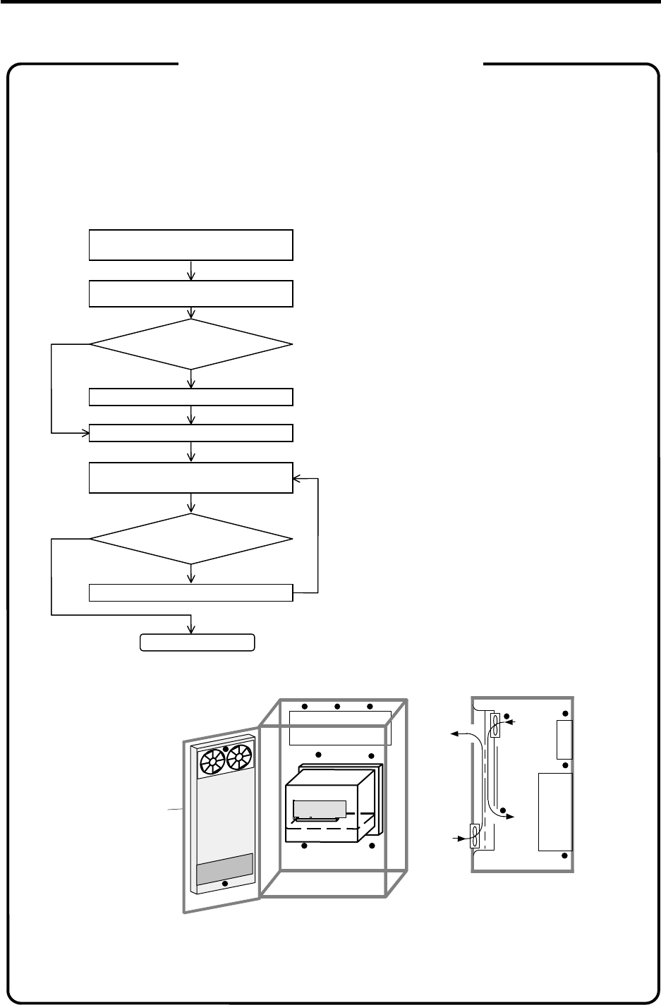
Procedures for heat design and verification
Calculate total heat generation of
each mounted unit (W)
Comparison of W and W1
W≤W1
Collection of internal temperature rise
distribution data
Mounting design
Improvements
Completion
Selection of heat exchanger
Evaluation
W
>
W1
∆
T
m
≤
∆
Td
∆
T
m
>
∆
Td
Calculate electric cabinet’s
cooling capacity (W1)
Example of heat radiation countermeasures
3. Installation
3.3 Installation
12
3.3.4 Noise Countermeasures
(1) Connection of frame ground (FG)
The frame should basically be grounded at one earth point. When relaying through the grounding
plate in the middle of the connection route, separate the desktop personal computer/panel
personal computer from the remote I/O unit, and the base I/O unit from the servo drive unit/spindle
drive unit, etc.
The NC Card FG is connected to the personal computer electric cabinet with card installation metal
fittings.
0 0
EMG1
HANDLE
RS232C ENC#2
CF61
EMG2
DCIN
HR682
Remote
I/O unit
Desktop personal computer/
panel personal computer
Servo drive unit/spindle drive unit, etc.
Main ground
Base I/O unit
Note 1
Spindle motor
Note 1
Note 3
Note 2
Note 2
Servomotor
Note 1: This is not required when directly connecting to the main ground.
Note 2: Connect the motor's grounding cable to the servo drive unit and spindle drive unit.
Note 3: A spacer is used when mounting the HR682 card on the base I/O unit, but when not mounting on the base
I/O unit, connect the card to the main ground using the FG terminal.
3. Installation
3.3 Installation
13
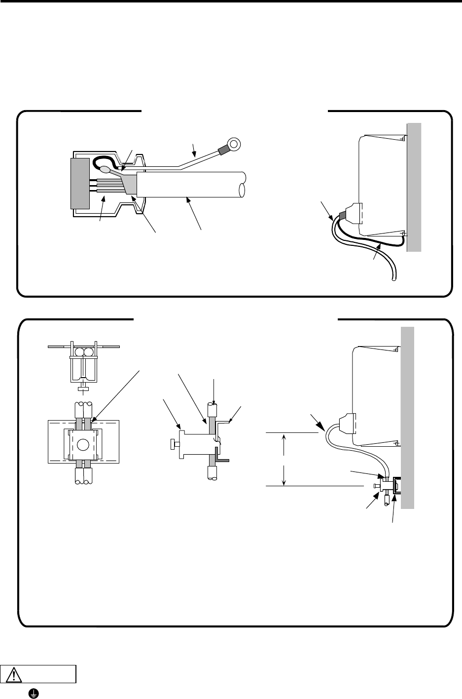
(2) Shield clamping of cables
The shield of the shield cable connected to the base I/O unit, servo drive unit and spindle drive unit
must be connected to the grounding plate to stabilize operation while preventing malfunctioning due to
noise.
The shield can be connected to the grounding plate with lead wires or clamp fittings. Refer to the
following drawings to treat the shield cable.
Example of lead wire treatment
Grounding
cable
Unit
Cable Unit
When soldering the grounding cable to the shield, if the soldered
section is close to the shield, the signal wire's sheath could melt
by the soldering heat resulting in a short-circuit.
Solder at a place 10 to 20mm away from the mesh section.
Caution Cable
Shield
Soldering
Signal wire
Grounding cable
Shield
Clamp fitting
Cable
Cable
Grounding plate Unit
Shield
Less than 0.8m
Clamp
fitting Grounding
plate
When manufacturing the clamp fittings and grounding plate, refer to "Appendix 1.10 Grounding Plate
and Clamp Fitting Outline Drawings". These can also be ordered from Mitsubishi.
Execute ground treatment by cable clamps, etc., for the shielded cable indicated in this
instruction manual.
Example of connection with clamp fitting
(1) Peel part of the cable sheath and expose
the shield as shown in the drawing.
Press the exposed part against the grounding
plate with the cable clamp fittings.
(2) If the cable is thin, clamp several together
in a bunch.
(3) Use adequate force when tightening the cable
so that the wire material is not damaged.
(4) Connect each grounding plate together and
ground them at one point.
CAUTION
Example of connection with lead wire
3. Installation
3.3 Installation
14
Cables which require shield clamp with a connector cases are shown following table.
<Shield clamp method>
Fold the wire material shield over the sheath, and wrap copper foil tape over it. Connect the wrapped
copper foil tape to the connector case GND plate.
Treatment of cable ends
Unit name Connector
name Connection destination Connection origin Connection
destination
NC Card
(HR621/HR623/
FCU6-HR655)
CF10
CF61
Base I/O unit
Relay card
(NC Card) Not required
(NC Card) Not required
Not required
Not required
Base I/O unit
(FCU6-DX2∗∗, 3∗∗,
4
∗∗)
CF10
SV1
SV2
ENC1
SKIP
PI01
PI02
NC Card
Servo drive unit
Servo drive unit
Spindle encoder
Skip
Remote I/O unit
Remote I/O unit
(Base I/O unit) Not required
(Base I/O unit) Required
(Base I/O unit) Required
(Base I/O unit) Required
(Base I/O unit) Required
(Base I/O unit) Required
(Base I/O unit) Required
Not required
Not required
Not required
Not required
Not required
Not required
Not required
Relay card
(HR682) CF61
ENC#2
HANDLE
RS232C
NC Card
Spindle encoder
Manual pulse generator
RS-232C (I/O device)
(Note)
(Relay card) Not required
(Relay card) Required
(Relay card) Required
(Relay card) Required
Not required
Not required
Not required
Not required
(Note) RS-232C uses only the DC code (X ON/OFF) method handshake.
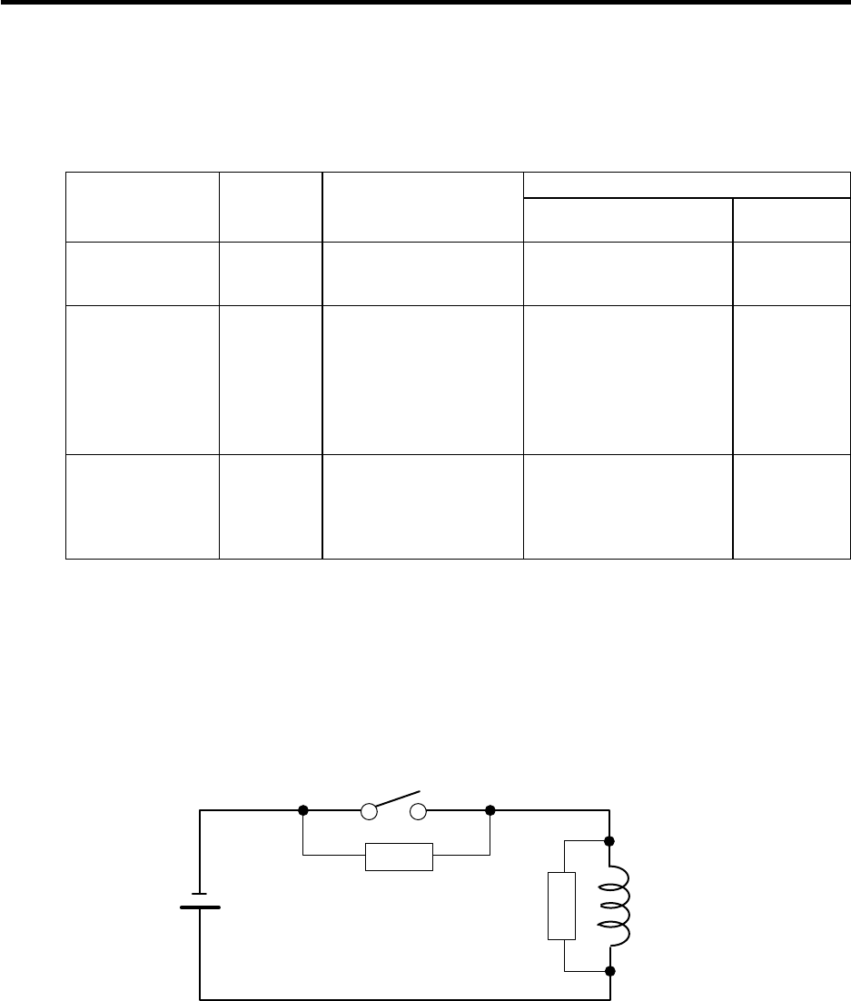
(3) Connecting Spark Killers
Connect a spark killer on the coil or relay contact in parallel for noise countermeasures.
Use spark killers which are 0.033~0.1µF, 10~120Ω.
Coil
Contact
E
SK
SK
4. NC Card (HR621/HR623/FCU6-HR655) Connection
4.1 NC Card Connection System Diagram
15
4. NC Card (HR621/HR623/FCU6-HR655) Connection
4.1 NC Card Connection System Diagram
The NC Card is connected to the personal computer with the expansion slot (ISA bus or PCI bus). The
base I/O unit and relay card are connected with a cable.
CF10
Base I/O unit
(FCU6-DX2**/3**/4**)
CF10
CF61
CF61
Personal computer NC Card
(HR621/HR623/
FCU6-HR655)
F010 cable
F011 cable
Relay card
(HR682)
Expansion slot
(ISA bus/PCI bus)
Turn the NC Card's power ON before turning the base I/O unit's power ON.
If the base I/O unit's power is turned ON first, the current will be led to the NC Card from
the connection cable. This will prevent the personal computer or the cards in the
personal computer from starting up properly.
CAUTION
4. NC Card (HR621/HR623/FCU6-HR655) Connection
4.2 NC Card Part Names
16
4.2 NC Card Part Names
4.2.1 Names of HR621 Card Parts
CF61CF10
NCLED
BAT CIO
DPADR IOPADR
IRQ
ISABUS ISABUS
ISP
TEST
CF62
CF61CF10
RWDG
SEMG
S.O.DIMM2 S.O.DIMM1
(8)
(9) (3)
(15)
(10)
(11)
(12)
(2)
(1)
(14)
(5)
(13)
(6)
(4)
(7)
List of connectors
No. Name Function details
(1) CF61 This is used in the connection with the relay card (HR682). An F011 cable is connected.
(2) CF10 This is used in the connection with the base I/O unit (DX2**, 3**, 4**). An F010 cable is connected.
(3) ISABUS This is connected to the personal computer expansion slot (ISA bus).
(4) BAT This is a battery holder. A Toshiba battery CR2450 is installed.
(5) CIO This is a connector for expansion.
(6) ISP Not used.
(7) TEST Not used.
(8) CF62 Not used.
(9) S.O. DIMM1, 2 This is the MAGIC 64 memory module connector. Do not remove the memory module.
List of rotary switches
No. Name Function details
(10) DPADR This is used in the address assignment setting of the personal computer expansion region.
(11) IOPADR This is used in the address assignment setting of the personal computer I/O port region.
(12) IRQ This is used in the level setting of the interrupt request signal to the personal computer CPU.
(Note) Refer to "4.4 ISA NC Card Mounting" for details on setting rotary switches.
LED list
No. Name Function details
(13) NCLED
This is the 7-segment LED for the NC status display. This LED changes when at startup, during
alarms, etc.
(14) SEMG
This is the chip LED for the NC system
emergency stop display. When lit (red) : System in emergency stop.
When not lit : Normal
(15) RWDG
This is the chip LED for the remote
communication watchdog display. When lit (red) : Watchdog alarm.
When not lit : Normal
Do not apply voltages on the connector other than those indicated in this manual. Doing
so may lead to destruction or damage.
Incorrect connections may damage the devices, so connect the cables to the specified
connectors.
Do not connect or disconnect the connection cables between each unit while the power
is ON.
Do not connect or disconnect any PCB while the power is ON.
CAUTION
4. NC Card (HR621/HR623/FCU6-HR655) Connection
4.2 NC Card Part Names
17
4.2.2 Names of HR623 Card Parts
CF61CF10
BAT NCLD1 CIO
DPADRIOPADRIRQ
ISABUS ISABUS
ISP
TEST
CF61CF10
WDER
SEMG
5VSALM
3VSALM
3VALM
(3)
(15)
(10)
(11)
(12)
(2)
(1)
(14)
(5)
(13)
(6) (4)
(7)
(16)(17)(18)
List of connectors
No. Name Function details
(1) CF61 This is used in the connection with the relay card (HR682). An F011 cable is connected.
(2) CF10 This is used in the connection with the base I/O unit (DX2**, 3**, 4**). An F010 cable is connected.
(3) ISABUS This is connected to the personal computer expansion slot (ISA bus).
(4) BAT This is a battery holder. A Toshiba battery CR2450 is installed.
(5) CIO This is a connector for expansion.
(6) ISP Not used.
(7) TEST Not used.
List of rotary switches
No. Name Function details
(10) DPADR This is used in the address assignment setting of the personal computer expansion region.
(11) IOPADR This is used in the address assignment setting of the personal computer I/O port region.
(12) IRQ This is used in the level setting of the interrupt request signal to the personal computer CPU.
(Note) Refer to "4.4 ISA NC Card Mounting" for details on setting rotary switches.
LED list
No. Name Function details
(13) NCLD1
This is the 7-segment LED for the NC status display. This LED changes when at startup, during
alarms, etc.
(14) SEMG
This is the chip LED for the NC system
emergency stop display. When lit (red) : System in emergency stop.
When not lit : Normal
(15) WDER
This is the chip LED for the remote
communication watchdog display. When lit (red) : Watchdog alarm.
When not lit : Normal
(16) 5VSALM
This is the chip LED for the circuit power
5VDC low alarm display. When lit (red) : 5VDC low
When not lit : Normal
(17) 3VSALM
This is the chip LED for the circuit power
3VDC low alarm display. When lit (red) : 3VDC low
When not lit : Normal
(18) 3VALM
This is the chip LED for the circuit power
3VDC low alarm display. When lit (red) : 3VDC low
When not lit : Normal
Do not apply voltages on the connector other than those indicated in this manual. Doing
so may lead to destruction or damage.
Incorrect connections may damage the devices, so connect the cables to the specified
connectors.
Do not connect or disconnect the connection cables between each unit while the power
is ON.
Do not connect or disconnect any PCB while the power is ON.
CAUTION
4. NC Card (HR621/HR623/FCU6-HR655) Connection
4.2 NC Card Part Names
18
4.2.3 Names of FCU6-HR655 Unit Parts
CF61CF10
BAT
NCLD
ISP
TEST
CF61
CF10
WDER
SEMG
5VSALM
3VSALM
3VALM
PCIBUS
BAT
CF62
CF63
SW1
PCIBUS
(9)
(3)
(10)
(7)
(2)
(1)
(11)(12)(13)(14)(15)(16)
(5)
(6)
(4)
(8
)
BAT
List of connectors
No. Name Function details
(1) CF61 This is used in the connection with the relay card (HR682). An F011 cable is connected.
(2) CF10 This is used in the connection with the base I/O unit (DX2**, 3**, 4**). An F010 cable is connected.
(3) PCIBUS This is connected to the personal computer expansion slot (PCI bus).
(4) BAT This is a battery holder. A Toshiba battery CR2032 is installed.
(5) CF62 This is used to input AC FAIL from an external source. (Note 1)
(6) CF63 This is used to supply power from an external source. (Note 1)
(7) TEST Not used.
(8) ISP Not used.
(Note 1) When multiple FCU6-HR655 cards are inserted, the power supplied from the personal computer or panel computer
may be insufficient. Supply the power from an external source to CF63 in this case. Input a FAIL signal to CF62 when
using an external power supply.
List of switches
No. Name Function details
(9) CDNO This is used to set the PCI NC Card's station No.
(10) SW1
This sets the power supply method. Set "L" when supplying from the PCI bus, and set "M" when
supplying power to CF63 from an external power supply.
(Note 2) Refer to "4.5 PCI NC Card Mounting" for details on setting rotary switches.
LED list
No. Name Function details
(11) SEMG
This is the chip LED for the NC system
emergency stop display. When lit (red) : System in emergency stop.
When not lit : Normal
(12) WDER
This is the chip LED for the remote
communication watchdog display. When lit (red) : Watchdog alarm.
When not lit : Normal
(13) 5VSALM
This is the chip LED for the circuit power
5VDC low alarm display. When lit (red) : 5VDC low
When not lit : Normal
(14) 3VSALM
This is the chip LED for the circuit power
3VDC low alarm display. When lit (red) : 3VDC low
When not lit : Normal
(15) 3VALM
This is the chip LED for the circuit power
3VDC low alarm display. When lit (red) : 3VDC low
When not lit : Normal
(16) NCLD
This is the 7-segment LED for the NC status display. This LED changes when at startup, during
alarms, etc.
Do not apply voltages on the connector other than those indicated in this manual. Doing
so may lead to destruction or damage.
Incorrect connections may damage the devices, so connect the cables to the specified
connectors.
Do not connect or disconnect the connection cables between each unit while the power
is ON.
Do not connect or disconnect any PCB while the power is ON.
CAUTION
4. NC Card (HR621/HR623/FCU6-HR655) Connection
4.3 NC Card Connector Pin Assignment
19
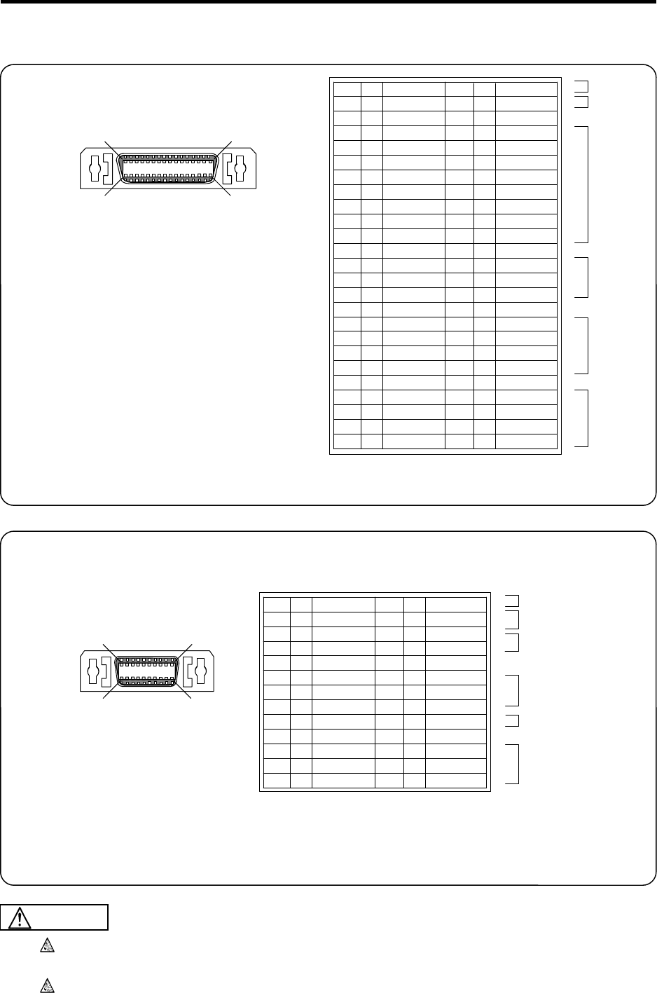
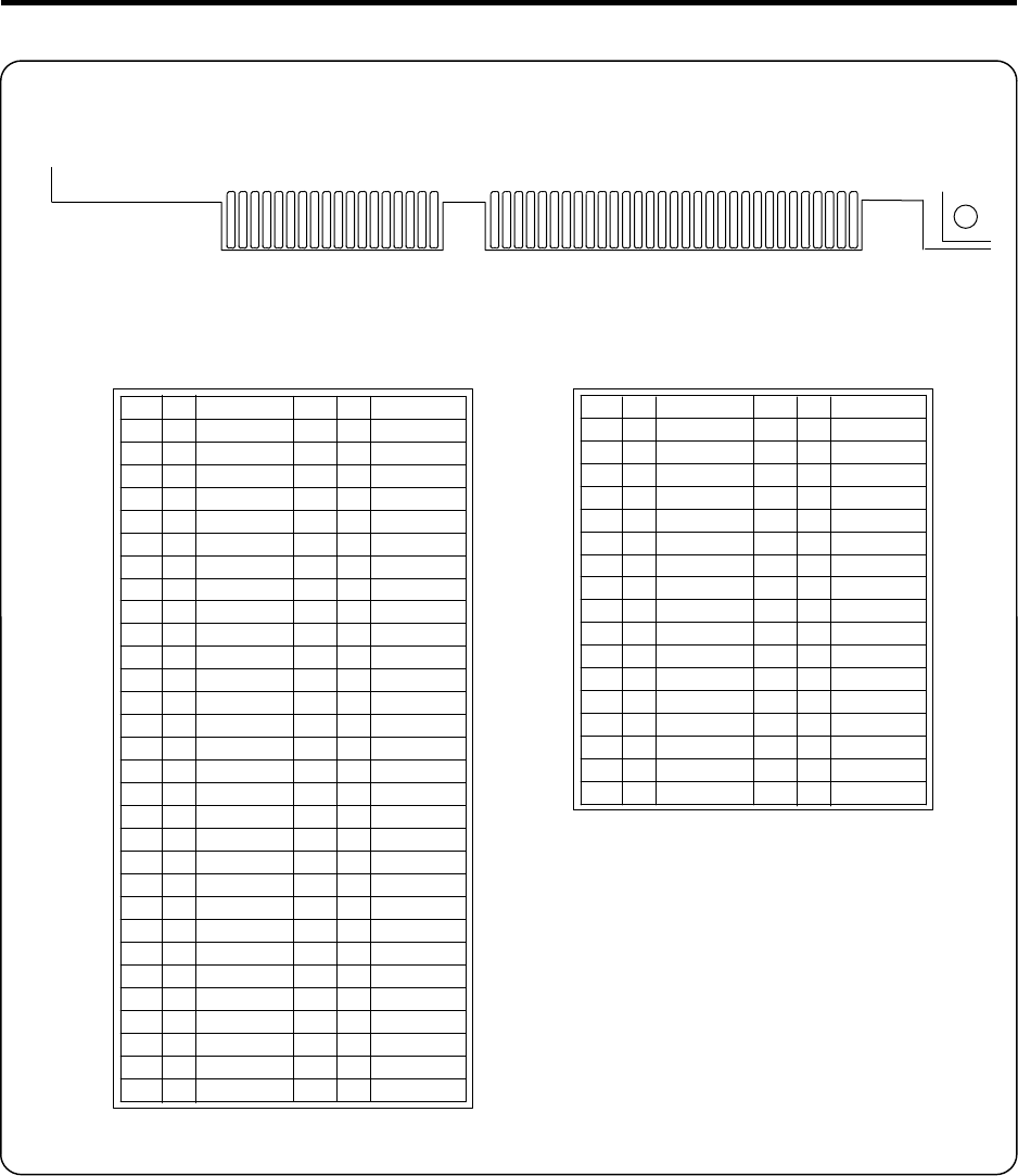
4.3 NC Card Connector Pin Assignment
Base I/O unit
CF10
1
25
50 26
<Cable side connector type>
Plug: 10150-6000EL
Shell: 10350-3210-000
Recommended manufacturer: Sumitomo 3M
Relay card
CF61
1
13
26 14
RS-232C
HANDLE
ENC#2
RS-232C
LED (for debugging)
Emergency stop
TD0
LED1
LED3
EMGIN
GND
HA1A
HA2A
HA3A
DR0
GND
EN2A
EN2B
EN2Z
1
2
3
4
5
6
7
8
9
10
11
12
13
14
15
16
17
18
19
20
21
22
23
24
25
26
O
O
O
I
I
I
I
O
I
I
I
I
O
O
I
I
I
I
I
I
I
I
RD0
LED2
EMGOUT*
EMGIN*
GND
HA1B
HA2B
HA3B
DC0
GND
EN2A*
EN2B*
EN2Z*
<Cable side connector type>
Plug: 10126-6000EL
Shell: 10326-3210-000
Recommended manufacturer: Sumitomo 3M
Do not apply voltages other than those indicated in this manual on the connector. Doing
so may lead to destruction or damage.
Incorrect connections may damage the devices, so connect the cables to the specified
connectors.
TXRX1*
TXRX2*
GND
SKIP1*
SKIP2*
SKIP3*
SKIP4*
SKIP5*
SKIP6*
SKIP7*
SKIP8*
GND
ENC1A*
ENC1B*
ENC1Z*
GND
SVTXD2*
SVALM2*
SVRXD2*
SVEMG2*
GND
SVTXD1*
SVALM1*
SVRXD1*
SVEMG1*
TXRX1
TXRX2
GND
SKIP1
SKIP2
SKIP3
SKIP4
SKIP5
SKIP6
SKIP7
SKIP8
GND
ENC1A
ENC1B
ENC1Z
GND
SVTXD2
SVALM2
SVRXD2
SVEMG2
GND
SVTXD1
SVALM1
SVRXD1
SVEMG1
1
2
3
4
5
6
7
8
9
10
11
12
13
14
15
16
17
18
19
20
21
22
23
24
25
26
27
28
29
30
31
32
33
34
35
36
37
38
39
40
41
42
43
44
45
46
47
48
49
50
I/O
I/O
I
I
I
I
I
I
I
I
I
I
I
O
I
I
O
O
I
I
O
I/O
I/O
I
I
I
I
I
I
I
I
I
I
I
O
I
I
O
O
I
I
O
RIO1
RIO2
SKIP
ENC1
SV2
SV1
CAUTION
(Note) I/O in the table is from the viewpoint of the
NC Card.
(Note) I/O in the table is from the viewpoint of the
NC Card.
4. NC Card (HR621/HR623/FCU6-HR655) Connection
4.3 NC Card Connector Pin Assignment
20
ISA bus (NC Card side)
GND
RSTDRV
+5V
IRQ9
NC
NC
NC
NC
+12V
GND
NC
NC
IOW*
IOR*
NC
NC
NC
NC
NC
NC
IRQ7
NC
IRQ5
NC
NC
NC
NC
BALE
+5V
NC
GND
NC
SD7
SD6
SD5
SD4
SD3
SD2
SD1
SD0
IOCHRDY
AEN*
NC
NC
NC
SA16
SA15
SA14
SA13
SA12
SA11
SA10
SA9
SA8
SA7
SA6
SA5
SA4
SA3
SA2
SA1
SA0
1A
2A
3A
4A
5A
6A
7A
8A
9A
10A
11A
12A
13A
14A
15A
16A
17A
18A
19A
20A
21A
22A
23A
24A
25A
26A
27A
28A
29A
30A
31A
I/O
I/O
I/O
I/O
I/O
I/O
I/O
I/O
O
I
I
I
I
I
I
I
I
I
I
I
I
I
I
I
I
I
I
I
O
I
I
O
O
I
MEMCS16*
NC
IRQ10
NC
NC
NC
NC
NC
NC
NC
NC
NC
NC
NC
NC
+5V
NC
GND
SBHE*
LA23
LA22
LA21
LA20
LA19
LA18
LA17
MEMR*
MEMW*
SD8
SD9
SD10
SD11
SD12
SD13
SD14
SD15
1C
2C
3C
4C
5C
6C
7C
8C
9C
10C
11C
12C
13C
14C
15C
16C
17C
18C
I
I
I
I
I
I
I
I
I
I
I/O
I/O
I/O
I/O
I/O
I/O
I/O
I/O
O
O
1B
2B
3B
4B
5B
6B
7B
8B
9B
10B
11B
12B
13B
14B
15B
16B
17B
18B
19B
20B
21B
22B
23B
24B
25B
26B
27B
28B
29B
30B
31B
1D
2D
3D
4D
5D
6D
7D
8D
9D
10D
11D
12D
13D
14D
15D
16D
17D
18D
1A
(1B)
31A
(31B)
18C
(18D)
1C
(1D)
* Pin Nos. inside the ( ) are rear side pin Nos.
(Note) I/O in the table is from the viewpoint of the
NC Card.
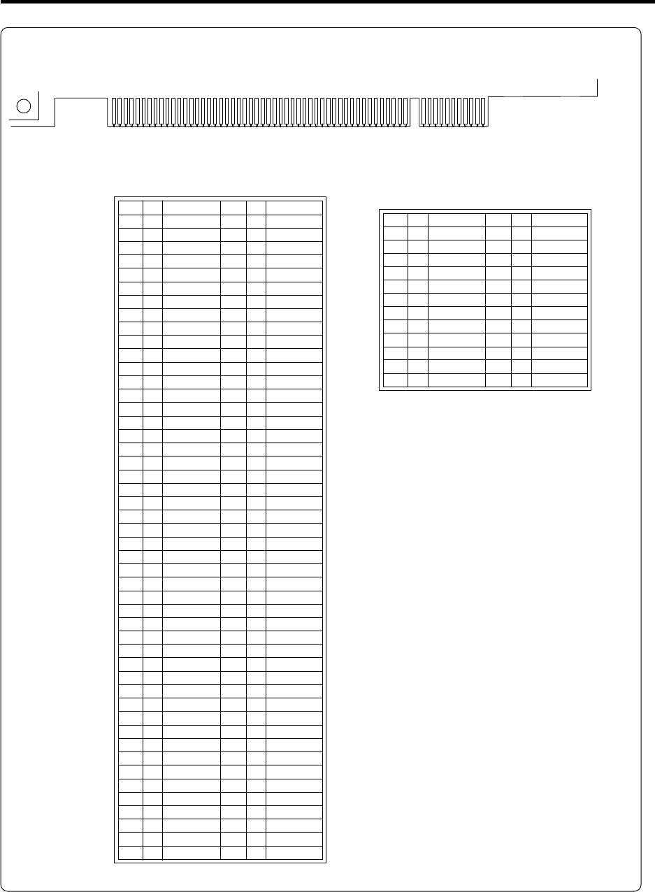
4. NC Card (HR621/HR623/FCU6-HR655) Connection
4.3 NC Card Connector Pin Assignment
21
N.C.
TCK
GND
TDO
5V
5V
N.C.
N.C.
PRSNT1*
N.C.
PRSNT2*
GND
GND
N.C.
GND
PCLK
GND
N.C.
N.C.
AD31
AD29
GND
AD27
AD25
+3.3V
C/BE3*
AD23
GND
AD21
AD19
+3.3V
AD17
C/BE2*
GND
IRDY*
+3.3V
DEVSEL*
GND
LOCK*
PERR*
+3.3V
SERR*
+3.3V
C/BE1*
AD14
GND
AD12
AD10
GND
TRST*
12V
TMS
TDI
+5V
INTA*
N.C.
+5V
N.C.
⎯
N.C.
GND
GMD
N.C.
RST*
⎯
N.C.
GND
N.C.
AD30
+3.3V
AD28
AD26
GND
AD24
IDSEL
+3.3V
AD22
AD20
GND
AD18
AD16
+3.3V
FRAME*
GND
TRDY*
GND
STOP*
+3.3V
N.C.
N.C.
GND
PAR
AD15
+3.3V
AD13
AD11
GND
AD9
1A
2A
3A
4A
5A
6A
7A
8A
9A
10A
11A
12A
13A
14A
15A
16A
17A
18A
19A
20A
21A
22A
23A
24A
25A
26A
27A
28A
29A
30A
31A
32A
33A
34A
35A
36A
37A
38A
39A
40A
41A
42A
43A
44A
45A
46A
47A
48A
49A
I
I
I
O
I
I/O
I/O
I/O
I/O
I
I/O
I/O
I/O
I/O
I
O
O
I/O
I/O
I/O
I/O
I/O
I
O
O
O
I
I/O
I/O
I/O
I/O
I
I/O
I/O
I/O
I/O
I
I
O
I
O
O
I
I/O
I/O
I/O
PCI bus (NC Card side)
62B
(62A)
52B
(52A)
49B
(49A)
1B
(1A)
AD8
AD7
+3.3V
AD5
AD3
GND
AD1
N.C.
N.C.
+5V
+5V
C/BE0
+3.3V
AD6
AD4
GND
AD2
Ad0
N.C.
N.C.
+5V
+5V
50A
51A
52A
53A
54A
55A
56A
57A
58A
59A
60A
61A
62A
I
I/O
I/O
I/O
I/O
I/O
I/O
I/O
I/O
I/O
1B
2B
3B
4B
5B
6B
7B
8B
9B
10B
11B
12B
13B
14B
15B
16B
17B
18B
19B
20B
21B
22B
23B
24B
25B
26B
27B
28B
29B
30B
31B
32B
33B
34B
35B
36B
37B
38B
39B
40B
41B
42B
43B
44B
45B
46B
47B
48B
49B
50B
51B
52B
53B
54B
55B
56B
57B
58B
59B
60B
61B
62B
(Note 1)
* Pin Nos. inside the ( ) are rear side pin Nos.
10A and 16A are for +5V (for I/O).
Connector key
Connector key Connector key
Connector key
(Note 2) I/O in the table is from the
viewpoint of the NC Card.
4. NC Card (HR621/HR623/FCU6-HR655) Connection
4.3 NC Card Connector Pin Assignment
22
AC FAIL
CF62
21
AC FAIL*
GND
1
2
I
61
External power supply
CF63
+5V
+5V
GND
GND
+12V
GND
1
2
3
4
5
6
(Note) I/O in the table is from the viewpoint of the NC Card.
(Note) I/O in the table is from the viewpoint of the NC Card.
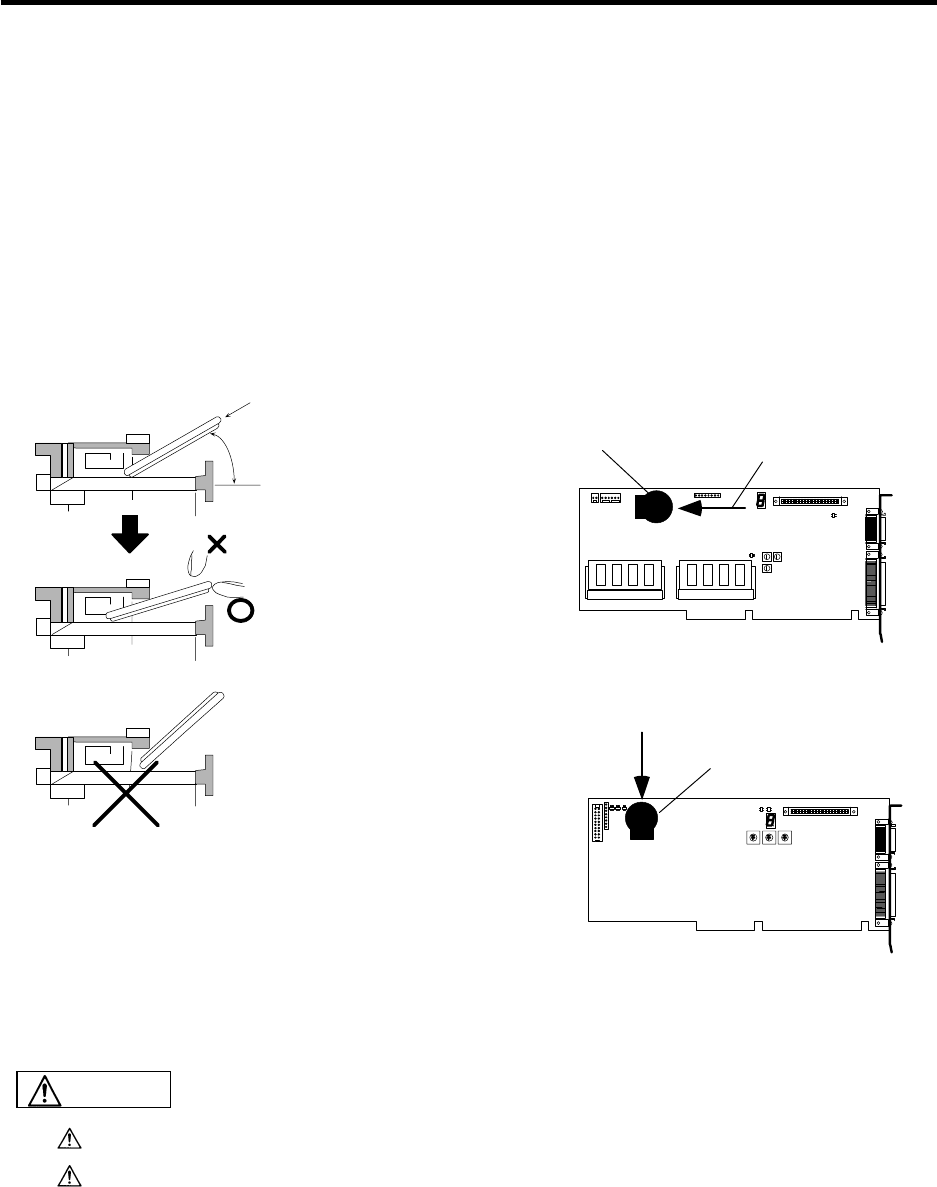
4. NC Card (HR621/HR623/FCU6-HR655) Connection
4.4 ISA NC Card Mounting
23
4.4 ISA NC Card Mounting
4.4.1 Before Mounting the ISA NC Card
(1) Before mounting the ISA NC Card, confirm that the control section items below are present.
HR621/623 card (ISA bus-compatible NC Card): 1 pc.
FCU6-DX2**, DX3** or DX4** unit
(Base I/O unit: with aluminum die cast): 1 pc.
HR682 card (relay card: L-shaped PCB, with metal spacers): 1 pc.
CR2450 (Toshiba button battery): 1 pc.
F010 cable (half-pitch 50-pole shielded cable): 1 pc.
F011 cable (half-pitch 26-pole shielded cable): 1 pc.
(2) Insert a battery to the ISA NC Card as shown below.
45° Insert at a 45° angle.
The positive (+) polarity side
should face up.
Press in horizontally.
The insertion should complete
smoothly.
Do not press in from above.
A reverse insertion prevention
function is attached so the battery
can only be inserted with the proper
polarity in the holder.
Battery holder
Battery holder
Insert in the direction
of the arrow.
Insert in the direction
of the arrow.
+
-
ISA NC Card (HR621)
20
ISA NC Card (HR623)
Do not short-circuit, charge, overheat, incinerate or disassemble the battery.
Dispose of the spent battery according to local laws.
CAUTION

4. NC Card (HR621/HR623/FCU6-HR655) Connection
4.4 ISA NC Card Mounting
24
4.4.2 ISA NC Card Mounting Procedure
Install the software and mount the NC Card following the Setup Instruction Manual (BNP-B2191).
The software will not be installed correctly if the software installation and NC Card mounting procedure
are mistaken.
Mount the NC Card onto the personal computer with the following procedures.
(1) Set the DPADR, IOPADR and IRQ rotary switches according to the personal computer memory
region, I/O port region and interrupt request signals designated when installing the software.
(Note) Before touching the NC Card, touch an exposed metal section of the personal computer to
discharge any static electricity.
Pay attention not to touch the NC Card, personal computer chip or circuit.
DPADR IOPADR IRQ
DPADR IOPADR IRQ
Location of ISA NC Card (HR621) rotary switches
Location of ISA NC Card (HR623) rotary switches
Roles of each rotary switch
DPADR : This is used in the address setting of the personal computer expansion region.
IOPADR : This is used in the address setting of the personal computer I/O port region.
IRQ : This is used in the level setting of the interrupt request signal to the personal computer CPU.
DPADR setting IOPADR setting IRQ setting
Switch Expansion region Switch I/O port region Switch Interrupt
request signal
0 h0D_8000~h0D_FFFF 0 h0120-h0123 0 None
1 h0D_0000~h0D_7FFF 1 h0140-h0143 1 IRQ5
2 h0C_8000~h0C_FFFF 2 h0160-h0163 2 IRQ7
3 h0C_0000~h0C_7FFF 3 h0180-h0183 4 IRQ9
4 RESERVED 4 h01A0-h01A3 8 IRQ10
5 RESERVED 5 h01C0-h01C3
6 RESERVED 6 h01E0-h01E3
7 RESERVED 7 h0200-h0203
8 RESERVED 8 h0220-h0223
9 RESERVED 9 h0240-h0243
A RESERVED A h0260-h0263
B RESERVED B h0280-h0283
C RESERVED C h02A0-h02A3
D RESERVED D h02C0-h02C3
E RESERVED E h02E0-h02E3
F RESERVED F h0300-h0303
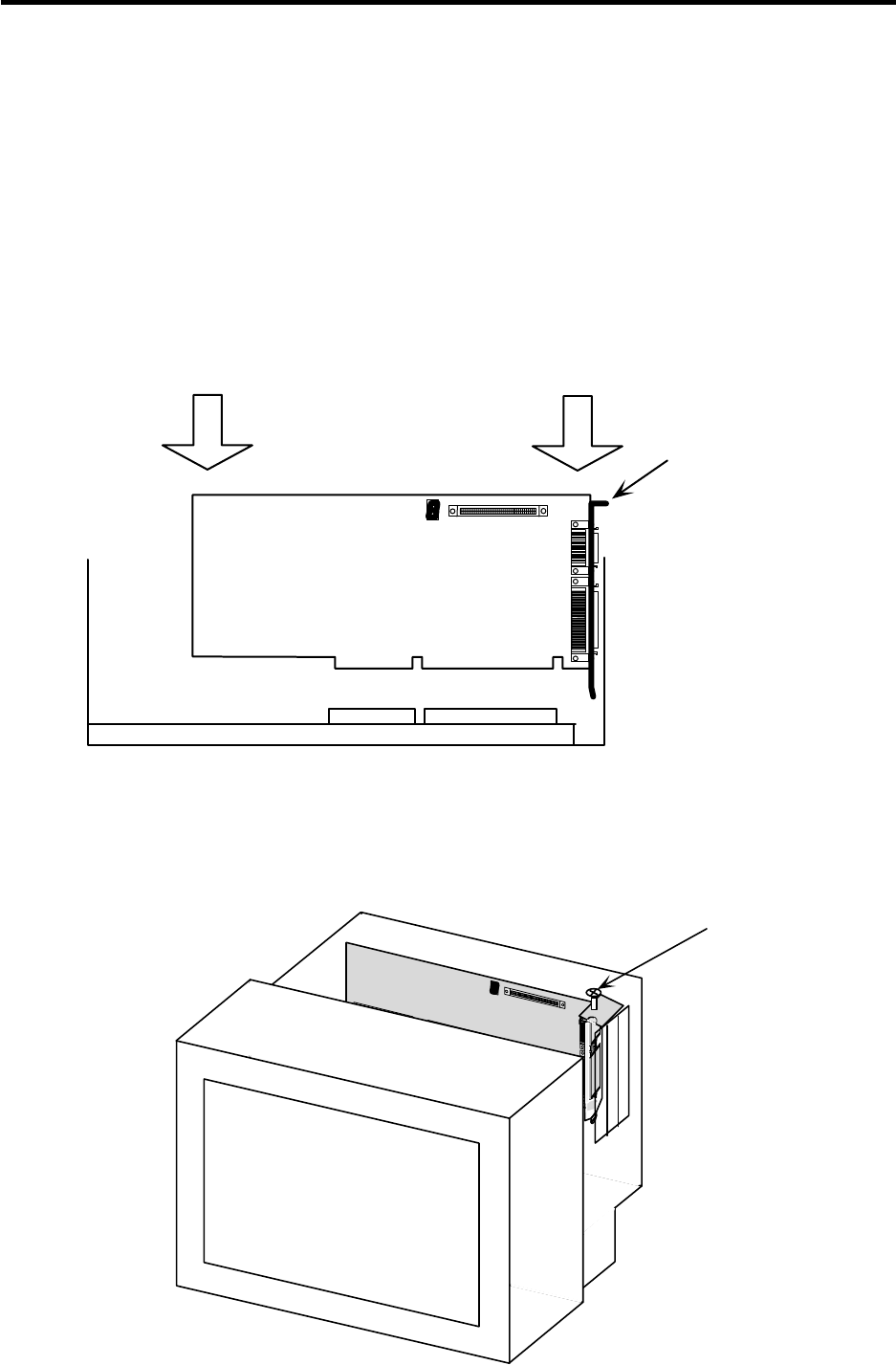
4. NC Card (HR621/HR623/FCU6-HR655) Connection
4.4 ISA NC Card Mounting
25
(2) Following the instructions in the personal computer manual, remove the personal computer cover.
(Note) Follow the precautions instructed in the personal computer manual. Confirm that the
personal computer power is OFF, and that the power cable is disconnected.
(3) After confirming that there is a vacant ISA bus slot, remove the slot cover of the selected ISA bus
slot.
(Note) Do not misplace the slot cover screw as it is used to fix the ISA NC Card onto the personal
computer.
(4) Holding the card installation metal fittings and the ends of the ISA NC Card, so as to push in the
NC Card upper end, insert the card all the way into the personal computer ISA bus slot.
(Note) The ISA BUS slot insertion orientation is predetermined. Insert the card so that the card
mounting fitting comes to the slot cover position.
Press in
ISA NC Card
Press in
Personal computer ISA bus slot
Card mounting
fitting
(5) Using the fixing screw of the slot cover removed in mounting step 3, fix the ISA NC Card to the
personal computer.
(Note) Securely tighten the screw.
Screw
NC Card

4. NC Card (HR621/HR623/FCU6-HR655) Connection
4.4 ISA NC Card Mounting
26
(6) Following the instructions in the personal computer manual, install the personal computer cover
removed in mounting step 2.
(7) Reconnect the personal computer power cables.
(Note) Do not turn the personal computer ON yet.
(8) Connect the two relay cables (F010 and F011) to the two connectors (CF10 and CF61) on the card
installation metal fitting section of the ISA NC Card.
(Note) Connect the F010 cable to the CF10 connector, and the F011 cable to the CF61 connector.
(9) Connect the F010 and F011 cables to the base I/O unit and relay card.
(Note) Connect the F010 cable to the CF10 connector on the base I/O unit, and the F011 cable to
the CF61 connector on the relay card.
This completes the ISA NC Card (HR621/623) mounting.
(10) Install the MELDASMAGIC64 software into the personal computer while the ISA NC Card is
mounted.
(Note) Install the software and mount the NC Card following the Setup Instruction Manual
(BNP-B2191).
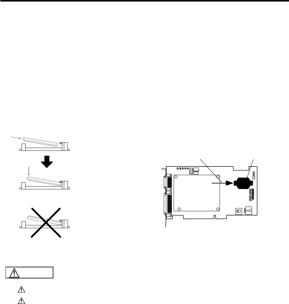
4. NC Card (HR621/HR623/FCU6-HR655) Connection
4.5 PCI NC Card Mounting
27
4.5 PCI NC Card Mounting
4.5.1 Before Mounting the PCI NC Card
(1) Before mounting the PCI NC Card, confirm that the control section items below are present.
FCU6-HR655 unit (PCI bus-compatible NC Card): 1 pc.
FCU6-DX2**, DX3** or DX4** unit
(Base I/O unit: with aluminum die cast): 1 pc.
HR682 card (relay card: L-shaped PCB, with metal spacers): 1 pc.
CR2032 (Toshiba button battery): 1 pc.
F010 cable (half-pitch 50-pole shielded cable): 1 pc.
F011 cable (half-pitch 26-pole shielded cable): 1 pc.
(2) Insert a battery to the PCI NC Card as shown below.
+
-
+
-
+
-
PCI NC Card (HR183+655)
BAT BA T
Battery holder
Insert in the direction
of the arrow.
Insert with the + polarity
facing upward, and
catch with the hook.
Press in vertically.
Check the battery's
polarity indicated on
the holder's metal
section before inserting.
Do not short-circuit, charge, overheat, incinerate or disassemble the battery.
Dispose of the spent battery according to local laws.
CAUTION
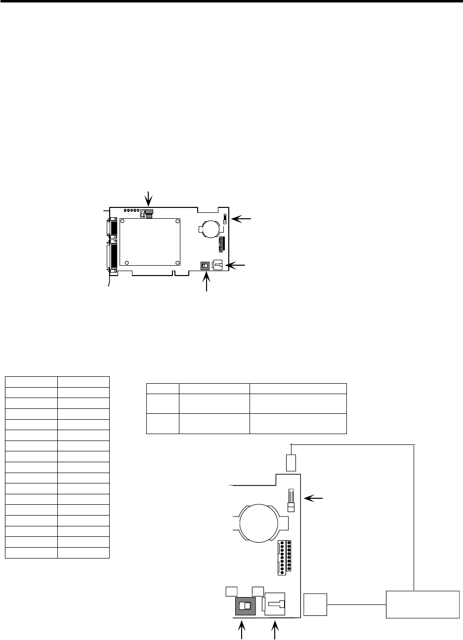
4. NC Card (HR621/HR623/FCU6-HR655) Connection
4.5 PCI NC Card Mounting
28
4.5.2 PCI NC Card Mounting Procedure
Install the software and mount the NC Card following the Setup Instruction Manual (BNP-B2191).
The software will not be installed correctly if the software installation and NC Card mounting procedure
are mistaken.
Mount the NC Card onto the personal computer with the following procedures.
(1) Set the rotary switch CDNO and slide switch SW1.
(Note) Before touching the NC Card, touch an exposed metal section of the personal computer to
discharge any static electricity.
Pay attention not to touch the NC Card, personal computer chip or circuit.
BAT
BAT
CDNO
SW1
CF63
CF62
Location of PCI NC Card (FCU6-HR655) switches
Roles of each switch
CDNO (rotary switch): Use to set the PCI NC Card's station No.
SW1 (slide switch): Use to set the PCI NC Card's power supply (internal/external).
BAT
BAT
SW1 CF63
CF62
M
LStabilized
power supply
+12V/+5V
AC FAIL
The default setting is "0".
The default setting is "L".
Connect a stabilized power supply to the CF62 and CF63 connectors
when using an external power supply.
CDNO setting
Switch Card
0 1st card
1 2nd card
2 3rd card
3 4th card
4 5th card
5 6th card
6 7th card
7 8th card
8 9th card
9 10th card
A 11th card
B 12th card
C 13th card
D 14th card
E 15th card
F 16th card
SW1 setting
Switch Supply method Details
L Internal supply
+5V/+12V is supplied by
PCI bus.
M External supply +5V/+12V is supplied by
stabilized power supply.

4. NC Card (HR621/HR623/FCU6-HR655) Connection
4.5 PCI NC Card Mounting
29
(2) Following the instructions in the personal computer manual, remove the personal computer cover.
(Note) Follow the precautions instructed in the personal computer manual. Confirm that the
personal computer power is OFF, and that the power cable is disconnected.
(3) After confirming that there is a vacant PCI bus slot, remove the slot cover of the selected PCI bus
slot.
(Note) Do not misplace the slot cover screw as it is used to fix the PCI NC Card onto the personal
computer.
(4) Holding the card installation metal fittings and the ends of the PCI NC Card, so as to push in the
NC Card upper end, insert the card all the way into the personal computer PCI bus slot.
(Note) There is a set orientation for inserting the PCI NC Card into the PCI bus slot. Insert the card
so that the card installation fitting comes to the slot cover's position.
Card mounting
fitting
Press in
PCI NC Card
Press in
Personal computer PCI bus slot
(5) Using the fixing screw of the slot cover removed in mounting step 3, fix the PCI NC Card to the
personal computer.
(Note) Securely tighten the screw.
Screw
NC Card

4. NC Card (HR621/HR623/FCU6-HR655) Connection
4.5 PCI NC Card Mounting
30
(6) Following the instructions in the personal computer manual, install the personal computer cover
removed in mounting step 2.
(7) Reconnect the personal computer power cables.
(Note) Do not turn the personal computer ON yet.
(8) Connect the two relay cables (F010 and F011) to the two connectors (CF10 and CF61) on the card
installation metal fitting section of the PCI NC Card.
(Note) Connect the F010 cable to the CF10 connector, and the F011 cable to the CF61 connector.
(9) Connect the F010 and F011 cables to the base I/O unit and relay card.
(Note) Connect the F010 cable to the CF10 connector on the base I/O unit, and the F011 cable to
the CF61 connector on the relay card.
This completes the PCI NC Card (FCU6-HR655) mounting.
(10) Install the MELDASMAGIC64 software into the personal computer while the PCI NC Card is
mounted.
(Note) Do not change the personal computer's station No. or the power supply method while
installing the software.
Install the software and mount the NC Card following the Setup Instruction Manual
(BNP-B2191).

5. Base I/O Unit (FCU6-DX2**/3**/4**) Connection
5.1 Base I/O Unit Outline
31
5. Base I/O Unit (FCU6-DX2**/3**/4**) Connection
5.1 Base I/O Unit Outline
The base I/O unit is used in the connection of the machine input/output (DI/DO), servo drive unit,
spindle encoder, skip and remote I/O unit. There must be one base I/O unit for each NC Card.
Depending on the base I/O unit type, connection is possible with analog input, analog output and a
manual pulse generator.
The following shows a list of base I/O units and add-on PCBs.
Name Type No. of machine input/
output points Other interfaces
FCU6-DX210 DI (sink/source)/DO (sink)=48/48
FCU6-DX211 DI (sink/source)/DO (source)=48/48
FCU6-DX220 DI (sink/source)/DO (sink)=64/64
Base I/O
unit
FCU6-DX221 DI (sink/source)/DO (source)=64/64
SV1, SV2, ENC1, SKIP, RIO1, RIO2,
CR31 (for add-on PCB)
FCU6-DX310 DI (sink/source)/DO (sink)=80/64
FCU6-DX311 DI (sink/source)/DO (source)=80/64
FCU6-DX410 DI (sink/source)/DO (sink)=96/80
FCU6-DX411 DI (sink/source)/DO (source)=96/80
SV1, SV2, ENC1, SKIP, RIO1, RIO2
Add-on PCB: RX323-1
(DO is sink type)
: RX324-1
(DO is source type)
FCU6-DX320 DI (sink/source)/DO (sink)=80/64
FCU6-DX321 DI (sink/source)/DO (source)=80/64
FCU6-DX420 DI (sink/source)/DO (sink)=96/80
FCU6-DX421 DI (sink/source)/DO (source)=96/80
SV1, SV2, ENC1, SKIP, RIO1, RIO2,
Analog output 1 point
Add-on PCB: RX323
(DO is sink type)
: RX324
(DO is source type)
FCU6-DX330 DI (sink/source)/DO (sink)=48/48
FCU6-DX331 DI (sink/source)/DO (source)=48/48
FCU6-DX430 DI (sink/source)/DO (sink)=64/64
FCU6-DX431 DI (sink/source)/DO (source)=64/64
SV1, SV2, ENC1, SKIP, RIO1, RIO2,
HANDLE2ch
Add-on PCB: RX331
FCU6-DX340 DI (sink/source)/DO (sink)=48/48
FCU6-DX341 DI (sink/source)/DO (source)=48/48
FCU6-DX440 DI (sink/source)/DO (sink)=64/64
FCU6-DX441 DI (sink/source)/DO (source)=64/64
SV1, SV2, ENC1, SKIP, RIO1, RIO2,
Analog input 4 points, analog output
1 point
Add-on PCB: RX341
RX323-1 DI (sink/source)/DO (sink)=32/16 None
RX323 DI (sink/source)/DO (sink)=32/16 Analog output 1 point
RX324-1 DI (sink/source)/DO (source)=32/16 None
RX324 DI (sink/source)/DO (source)=32/16 Analog output 1 point
RX331 None HANDLE2ch
Add-on
PCB
RX341 None Analog input 4 points, analog output
1 point
(Note) Refer to "7. Remote I/O Unit Connection" for add-on PCB connections.

5. Base I/O Unit Connection
5.2 Base I/O Connection System Drawing
32
5.2 Base I/O Connection System Drawing
CF10 SV1
SV2
ENC1
SKIP
RIO1
RIO2
CF31
CF32
CF33
CF34
CR31
DCIN
>
01
CF10
SW1 SW 2
Servo drive unit
(spindle and NC servo axis)
Servo drive unit
(auxiliary axes)
Encoder 1ch
(1st spindle encoder)
Sensor signal (skip)
Remote I/O unit, part system 1
DI (machine input)
DI (machine input)
DO (machine output)
DO (machine output)
Add-on PCB
NC card F010 cable SH21 cable
Base I/O unit
SH21 cable
F040 cable
SH41 (FCUA-R211) cable
SH41 (FCUA-R211) cable
R301 cable
R301 cable
R301 cable
R301 cable
Enclosed cable
F070 (FCUA-R220) cable External power (24VDC)
Remote I/O unit, part system 2
(future expansion)
>
(Note) Refer to "7. Remote I/O Unit Connection" for add-on PCB connections.
Turn the NC Card's power ON before turning the base I/O unit's power ON.
If the base I/O unit's power is turned ON first, the current will be led to the NC Card from
the connection cable. This will prevent the personal computer or the cards in the
personal computer from starting up properly.
CAUTION
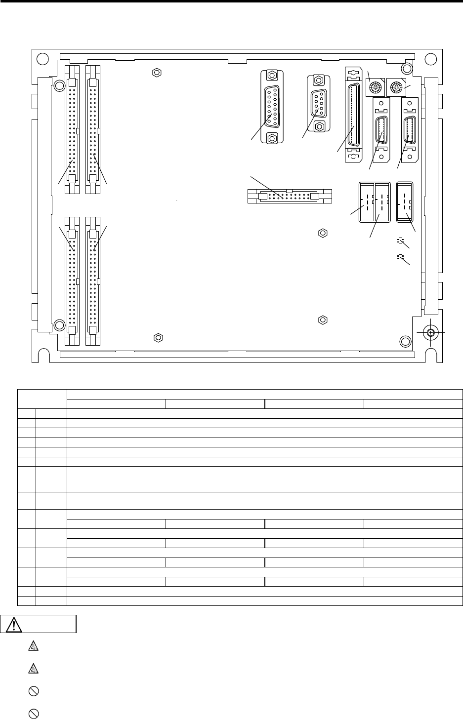
5. Base I/O Unit Connection
5.3 Base I/O Unit Part Names
33
5.3 Base I/O Unit Part Names
CS1:オンボードRIO第1局局番設定ロータリスイッチ
CS2:オンボードRIO第2局局番設定ロータリスイッチ
RI02 RI01DCIN
0
1
2
3
5
7
9
A
B
C
D
E
F
4
6
0
1
2
3
5
7
9
A
B
C
D
E
F
4
6
CF31 CF32
CF34CF33
CF10 SV2 SV1
SKIP
ENC1
88
CR31
CS2 CS1
24IN
RAL1
5OUT
RAL2
(1)
(2)
(3)
(4)
(5)
(6)
(7)
(8) (9)
(10) (11)
(12)
(13)
(14)
(15)
(16)
(17)
List of connectors
Unit name
FCU6-DX210 FCU6-DX211 FCU6-DX220 FCU6-DX221
No. Name Function
(1) CF10 This is used in the connection with the NC Card. An F010 cable is connected.
(2) SV1 This is connected to the servo drive unit 1st part system (for spindles and NC servo axes).
(3) SV2 This is connected to the servo drive unit 2nd part system (for auxiliary axes).
(4) ENC1 This is connected to the encoder 1st channel (1st spindle encoder).
(5) SKIP This is the sensor signal (skip) input connection. Up to eight points can be used.
(6) RIO1
This is connected to the remote I/O unit 1st part system. The max. No. of occupied stations is eight. Because two stations are
occupied in the base I/O unit, the remaining six occupied stations can be used. Note that when an add-on PCB is used, the
remaining five occupied stations can be used.
(7) RIO2
This is connected to the remote I/O unit 2nd part system. The max. No. of occupied stations is eight. Eight occupied stations can
be used. For future expansion.
This is used in the connection of the station No. (normally station No. 0) machine input signal set by the CS1 rotary switch.
(8) CF31 DI: 32 (sink/source) DI: 32 (sink/source) DI: 32 (sink/source) DI: 32 (sink/source)
This is used in the connection of the station No. (normally station No. 1) machine input signal set by the CS2 rotary switch.
(9) CF32 DI: 16 (sink/source) DI: 16 (sink/source) DI: 32 (sink/source) DI: 32 (sink/source)
This is used in the connection of the station No. (normally station No. 0) machine output signal set by the CS1 rotary switch.
(10) CF33 DO: 32 (sink type) DO: 32 (source type) DO: 32 (sink type) DO: 32 (source type)
This is used in the connection of the station No. (normally station No. 1) machine output signal set by the CS2 rotary switch.
(11) CF34 DO: 16 (sink type) DO: 16 (source type) DO: 32 (sink type) DO: 32 (source type)
(12) CR31 This is a connector for an add-on PCB. It cannot be used unless using an add-on PCB.
(13) DCIN 24VDC must be supplied by external power. Refer to "3.1 General Specifications" for power specifications.
Do not apply voltages on the connector other than those indicated in this manual. Doing
so may lead to destruction or damage.
Incorrect connections may damage the devices, so connect the cables to the specified
connectors.
Do not connect or disconnect the connection cables between each unit while the power
is ON.
Do not connect or disconnect any PCB while the power is ON.
CAUTION
5. Base I/O Unit Connection
5.3 Base I/O Unit Part Names
34
List of rotary switches
No. Name Function
(14) CS1 This is used in the station No. setting of the CF31 and CF33 machine input/output signals.
(15) CS2 This is used in the station No. setting of the CF32 and CF34 machine input/output signals.
Device assignment
Rotary switch
setting value Station
No. DI DO
0 0 X00~X1F Y00~Y1F
1 1 X20~X3F Y20~Y3F
2 2 X40~X5F Y40~Y5F
3 3 X60~X7F Y60~Y7F
4 4 X80~X9F Y80~Y9F
5 5 XA0~XBF YA0~YBF
6 6 XC0~XDF YC0~YDF
7 7 XE0~XFF YE0~YFF
8~F Cannot be used
LED list
No. Name Function
24IN This is the LED for the 24VDC input display. When lit (green) : 24VDC being supplied.
When not lit : 24VDC supply OFF.
(16)
RAL1 This is the LED for the onboard remote I/O 1st station
(CS1 setting station No.) communication alarm display. When lit (red) : Communication alarm.
When not lit : Normal
5OUT This is the LED for the circuit power 5VDC output
display. When lit (green) : Outputting 5VDC.
When not lit : 5VDC output OFF.
(17)
RAL2 This is the LED for the onboard remote I/O 2nd station
(CS2 setting station No.) communication alarm display. When lit (red) : Communication alarm.
When not lit : Normal
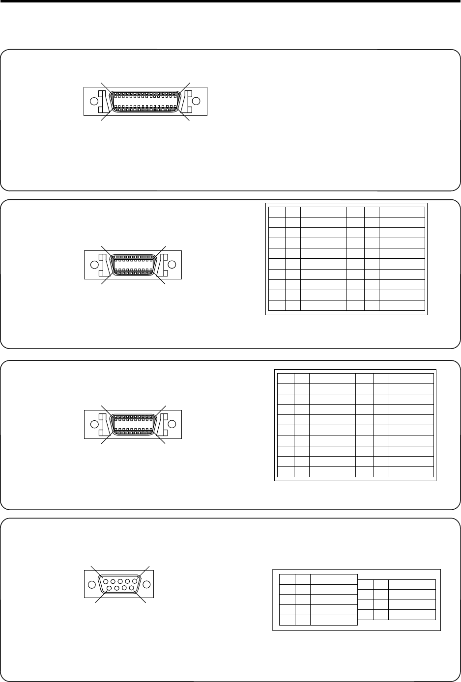
5. Base I/O Unit Connection
5.4 Base I/O Unit Connector Pin Assignment
35
5.4 Base I/O Unit Connector Pin Assignment
NC Card
CF10
<Cable side connector type>
Plug : 10150-6000EL
Shell : 10350-3210-000
Recommended manufacturer: Sumitomo 3M
Servo drive unit
SV1
1
10
1120
<Cable side connector type>
Plug : 10120-6000EL
Shell : 10320-3210-000
Recommended manufacturer: Sumitomo 3M
Servo drive unit
SV2
1
10
1120
<Cable side connector type>
Plug : 10120-6000EL
Shell : 10320-3210-000
Recommended manufacturer: Sumitomo 3M
Spindle encoder
ENC1
1
5
69
<Cable side connector type>
Connector : CDE-9PF
Contact : CD-PC-111
Case : HDE-CTH
Recommended manufacturer: Hirose Electric
1
25
50 26
Connector pin assignment:
Refer to "4.3 NC Card Connector Pin
Assignment" (Base I/O unit: CF10).
GND
SVTXD1
SVALM1
SVRXD1
GND
SVEMG1
+5V
GND
SVTXD1*
SVALM1*
SVRXD1*
GND
SVEMG1*
1
2
3
4
5
6
7
8
9
10
11
12
13
14
15
16
17
18
19
20
O
I
I
O
O
O
I
I
O
GND
SVTXD2
SVALM2
SVRXD2
GND
SVEMG2
+5V
GND
SVTXD2*
SVALM2*
SVRXD2*
GND
SVEMG2*
1
2
3
4
5
6
7
8
9
10
11
12
13
14
15
16
17
18
19
20
O
I
I
O
O
O
I
I
O
ENC1A
ENC1B
ENC1Z
GND
GND
1
2
3
4
5
I
I
I
ENC1A*
ENC1B*
ENC1Z*
+5V
6
7
8
9
I
I
I
O
(Note) I/O in the table is from the viewpoint of
the base I/O unit.
(Note) I/O in the table is from the viewpoint of
the base I/O unit.
(Note) I/O in the table is from the viewpoint of
the base I/O unit.
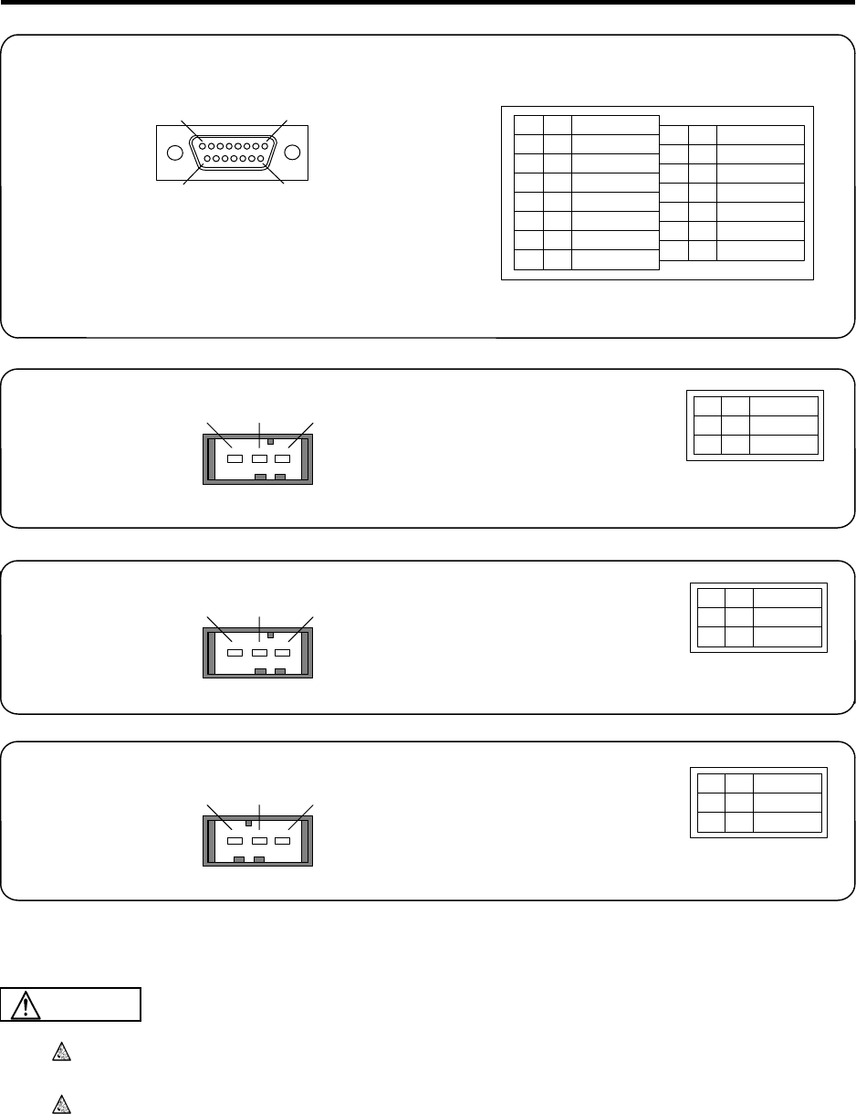
5. Base I/O Unit Connection
5.4 Base I/O Unit Connector Pin Assignment
36
Sensor signal
SKIP
1
8
9
15
<Cable side connector type>
Connector : CDA-15P
Contact : CD-PC-111
Case : HDA-CTH
Recommended manufacturer: Hirose Electric
Remote I/O unit
RIO1
Remote I/O unit
RIO2
+24VDC input
DCIN
Do not apply voltages other than those indicated in this manual on the connector. Doing
so may lead to destruction or damage.
Incorrect connections may damage the devices, so connect the cables to the specified
connectors.
GND
SKIP IN1
SKIP IN3
SKIP IN5
SKIP IN7
GND
1
2
3
4
5
6
7
8
I
I
I
I
GND
SKIP IN2
SKIP IN4
SKIP IN6
SKIP IN8
GND
9
10
11
12
13
14
15
I
I
I
I
I/O
I/O
TXRX1
TXRX1*
GND
1
2
3
12 3
12 3I/O
I/O
TXRX2
TXRX2*
GND
1
2
3
I+24V
GND
FG
1
2
3
123
(Note) I/O in the table is from the viewpoint of
the base I/O unit.
<Cable side connector type>
Connector : 1-178288-3
Contact : 1-175218-5
Recommended manufacturer: Tyco Electronics AMP
<Cable side connector type>
Connector : 1-178288-3
Contact : 1-175218-5
Recommended manufacturer: Tyco Electronics AMP
<Cable side connector type>
Connector : 2-178288-3
Contact : 1-175218-5
Recommended manufacturer: Tyco Electronics AMP
(Note) I/O in the table is from the viewpoint of
the base I/O unit.
(Note) I/O in the table is from the viewpoint of
the base I/O unit.
(Note) I/O in the table is from the viewpoint of
the base I/O unit.
CAUTION
5. Base I/O Unit Connection
5.4 Base I/O Unit Connector Pin Assignment
37
DI/DO
CF31, 32, 33, 34
A
X10
X11
X12
X13
X14
X15
X16
X17
X18
X19
X1A
X1B
X1C
X1D
X1E
X1F
COM
GND
GND
B
X0
X1
X2
X3
X4
X5
X6
X7
X8
X9
XA
XB
XC
XD
XE
XF
COM
+24V
+24V
20
19
18
17
16
15
14
13
12
11
10
9
8
7
6
5
4
3
2
1
I
I
I
I
I
I
I
I
I
I
I
I
I
I
I
I
I
I
I
20
19
18
17
16
15
14
13
12
11
10
9
8
7
6
5
4
3
2
1
I
I
I
I
I
I
I
I
I
I
I
I
I
I
I
I
I
20
19
18
17
16
15
14
13
12
11
10
9
8
7
6
5
4
3
2
1
I
I
I
I
I
I
I
I
I
I
I
I
I
I
I
I
I
I
I
20
19
18
17
16
15
14
13
12
11
10
9
8
7
6
5
4
3
2
1
I
I
I
I
I
I
I
I
I
I
I
I
I
I
I
I
I
CF31 CF32
B
Y0
Y1
Y2
Y3
Y4
Y5
Y6
Y7
Y8
Y9
YA
YB
YC
YD
YE
YF
+24V
+24V
20
19
18
17
16
15
14
13
12
11
10
9
8
7
6
5
4
3
2
1
O
O
O
O
O
O
O
O
O
O
O
O
O
O
O
O
I
I
20
19
18
17
16
15
14
13
12
11
10
9
8
7
6
5
4
3
2
1
CF33
O
O
O
O
O
O
O
O
O
O
O
O
O
O
O
O
I
I
20
19
18
17
16
15
14
13
12
11
10
9
8
7
6
5
4
3
2
1
O
O
O
O
O
O
O
O
O
O
O
O
O
O
O
O
I
I
20
19
18
17
16
15
14
13
12
11
10
9
8
7
6
5
4
3
2
1
CF34
O
O
O
O
O
O
O
O
O
O
O
O
O
O
O
O
I
I
B
X20
X21
X22
X23
X24
X25
X26
X27
X28
X29
X2A
X2B
X2C
X2D
X2E
X2F
COM
+24V
+24V
A
(X30)
(X31)
(X32)
(X33)
(X34)
(X35)
(X36)
(X37)
(X38)
(X39)
(X3A)
(X3B)
(X3C)
(X3D)
(X3E)
(X3F)
COM
GND
GND
A
Y10
Y11
Y12
Y13
Y14
Y15
Y16
Y17
Y18
Y19
Y1A
Y1B
Y1C
Y1D
Y1E
Y1F
GND
GND
B
Y20
Y21
Y22
Y23
Y24
Y25
Y26
Y27
Y28
Y29
Y2A
Y2B
Y2C
Y2D
Y2E
Y2F
+24V
+24V
A
(Y30)
(Y31)
(Y32)
(Y33)
(Y34)
(Y35)
(Y36)
(Y37)
(Y38)
(Y39)
(Y3A)
(Y3B)
(Y3C)
(Y3D)
(Y3E)
(Y3F)
GND
GND
The values in parentheses are used
only for DX220 and DX221.
The values in parentheses are used
only for DX220 and DX221.
A1A20
B20 B1
(Note) I/O in the table is from the viewpoint of
the base I/O unit.
<Cable side connector type>
Connector : 7940-6500SC
Recommended manufacturer: Sumitomo 3M
5. Base I/O Unit Connection
5.5 Base I/O Unit Input/Output Specifications
38
5.5 Base I/O Unit Input/Output Specifications
5.5.1 Rotary Switch (CS1 and CS2) Settings
Normal settings
CS1 0
CS2 1
The base I/O unit No. of occupied stations is two (when an add-on PCB is not used).
(Note) Also refer to "7.14 Setting of Channel No. When Using Multiple Remote I/O Units" for rotary
switch (CS1 and CS2) settings of the base I/O unit.
Relation between rotary switches and DI/DO connectors
CS1 DI: CF31, DO: CF33
CS2 DI: CF32, DO: CF34
Relation between rotary switches and device assignments
Device assignment
Setting
value Station
No. DI DO
No. of I/O
points (max)
0 0 X00~X1F Y00~Y1F 32 points
1 1 X20~X3F Y20~Y3F 32 points
2 2 X40~X5F Y40~Y5F 32 points
3 3 X60~X7F Y60~Y7F 32 points
4 4 X80~X9F Y80~Y9F 32 points
5 5 XA0~XBF YA0~YBF 32 points
6 6 XC0~XDF YC0~YDF 32 points
7 7 XE0~XFF YE0~YFF 32 points
8~F Cannot be used
Station No. settings of add-on PCBs
When using an add-on PCB, set the station No. using the rotary switch on the add-on PCB. This
rotary switch corresponds to connectors CR21 and CR22 of the add-on PCB.
The setting values, station Nos. and device assignments are as shown in the table above.
(Note) Refer to "5.1 Base I/O Unit Outline" for types of add-on PCBs.
One station is occupied when using RX331 (manual pulse generator) and RX341 (analog
input/output) also.
5.5.2 RIO1 Terminator
Connect a terminator to the final end of the remote I/O unit connected to the RIO1.
When not using any remote I/O unit, connect a terminator to the base I/O unit RIO1.
Terminator type: R-TM
Recommended manufacturer: Tyco Electronics AMP
AMP
D-3
X
5. Base I/O Unit Connection
5.5 Base I/O Unit Input/Output Specifications
39
5.5.3 CF31, CF32 Input Circuit
Refer to "7.4 Outline of Digital Signal Input Circuit" for the base I/O unit CF31 and CF32 input circuits.
1 Unit name FCU6-DX210 FCU6-DX211 FCU6-DX220 FCU6-DX221
2 Card name HR325 HR335 HR327 HR337
3 Input type Sink/source Sink/source Sink/source Sink/source
4 COM pin connection +24V/GND +24V/GND +24V/GND +24V/GND
5 No. of input points 48 points 48 points 64 points 64 points
6 Pin used for input X00~X2F X00~X2F X00~X3F X00~X3F
5.5.4 CF33, CF34 Output Circuit
Refer to "7.5 Outline of Digital Signal Output Circuit" for the base I/O unit CF33 and CF34 output
circuits.
1 Unit name FCU6-DX210 FCU6-DX211 FCU6-DX220 FCU6-DX221
2 Card name HR325 HR335 HR327 HR337
3 Output type Sink type Source type Sink type Source type
4 Output current 60mA/point 60mA/point 60mA/point 60mA/point
5 No. of output points 48 points 48 points 64 points 64 points
6 Pin used for output Y00~Y2F Y00~Y2F Y00~Y3F Y00~Y3F
5.5.5 Specifications of ADD ON PCB Connected to CR31
Refer to "7. Remote I/O Unit Connection" for add-on PCB specifications. One add-on PCB can be
installed on the base I/O unit, and it occupies one station. Reference items are as in the following table.
Name Reference item Reference connector name
1 RX323-1 7.9 Connection of FCUA-DX11* unit and
machine control signal FCUA-DX110: DI-R, DO-R
2 RX323 7.10 Connection of FCUA-DX12* unit and
machine control signal FCUA-DX120: DI-R, DO-R
3 RX324-1 7.9 Connection of FCUA-DX11* unit and
machine control signal FCUA-DX111: DI-R, DO-R
4 RX324 7.10 Connection of FCUA-DX12* unit and
machine control signal FCUA-DX121: DI-R, DO-R
5 RX331 7.11 Connection of FCUA-DX13* unit and
handle FCUA-DX13*: HANDLE
6 RX341 7.13 Connection of FCUA-DX14* unit and
analog input/output signal FCUA-DX14*: AIO
Refer to "7.6 Outline of Analog Signal Output Circuit" for the analog output specifications.
Refer to "7.7 Outline of Analog Signal Input Circuit" for the analog input specifications.
5. Base I/O Unit Connection
5.5 Base I/O Unit Input/Output Specifications
40
5.5.6 Connection of Base I/O Unit Power Supply
Supply the +24V power to the base I/O unit from the DCIN connector.
Stabilized power
Base I/O unit
(Prepare separately.)
+24V
GND
NC
+24V
GND
FG
DCIN
(Note) A +24V power supply must be input for both the sink type and source type.
Do not apply voltages other than those indicated in this manual on the connector. Doing
so may lead to destruction or damage.
Incorrect connections may damage the devices, so connect the cables to the specified
connectors.
CAUTION
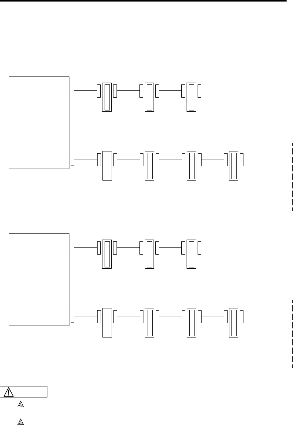
5. Base I/O Unit Connection
5.5 Base I/O Unit Input/Output Specifications
41
5.5.7 Examples of DI/DO Connection
There are two types of MELDASMAGIC64 DI/DO; the base I/O unit and remote I/O unit. Normally, one
base I/O unit is used, a remote I/O unit is connected to RIO1 or RIO2 (for future expansion), and the No.
of I/O points is configured in combination with the user specifications.
Refer to "7. Remote I/O Unit Connection" for information about remote I/O units.
<Connection example 1> When not using an add-on PCB
Base I/O unit
FCU6-DX2**
RIO1
RIO2
SH41(FCUA-R211)
cable
SH41(FCUA-R211)
cable
Remote I/O unit: FCUA-DX11*/12*/13*/14*×3 units
No. of occupied
stations: 2
(dependent on RIO1)
Maximum configuration
No. of occupied
stations: 2 No. of occupied
stations: 2 No. of occupied
stations: 2
Total No. of occupied stations (RIO1): Base I/O unit (2 stations) + 3 remote I/O units
(2 stations + 2 stations + 2 stations) = 8 stations
(For future expansion)
Maximum
configuration
Remote I/O unit: FCUA-DX11*/12*/13*/14*×4 units
No. of occupied
stations: 2 No. of occupied
stations: 2 No. of occupied
stations: 2 No. of occupied
stations: 2
Total No. of occupied stations (RIO2): Remote I/O unit (2 stations + 2 stations
+ 2 stations + 2 stations) = 8 stations
<Connection example 2> When using an add-on PCB
Base I/O unit
FCU6-DX3**/4**
RIO1
RIO2
SH41(FCUA-R211)
cable
SH41(FCUA-R211)
cable
Remote I/O unit: FCUA-DX10*×1 unit + Remote I/O unit: FCUA-DX11*/12*/13*/14*
No. of occupied
stations: 3
(dependent on RIO1)
Maximum configuration
No. of occupied
stations: 1 No. of occupied
stations: 2 No. of occupied
stations: 2
Total No. of occupied stations (RIO1): Base I/O unit (3 stations) + remote I/O unit
(1 station + 2 stations + 2 stations) = 8 stations
(For future expansion)
Maximum
configuration
Remote I/O unit: FCUA-DX11*/12*/13*/14*×4 units
No. of occupied
stations: 2 No. of occupied
stations: 2 No. of occupied
stations: 2 No. of occupied
stations: 2
Total No. of occupied stations (RIO2): Remote I/O unit (2 stations + 2 stations
+ 2 stations + 2 stations) = 8 stations
×2 units
Do not apply voltages other than those indicated in this manual on the connector. Doing
so may lead to destruction or damage.
Incorrect connections may damage the devices, so connect the cables to the specified
connectors.
CAUTION
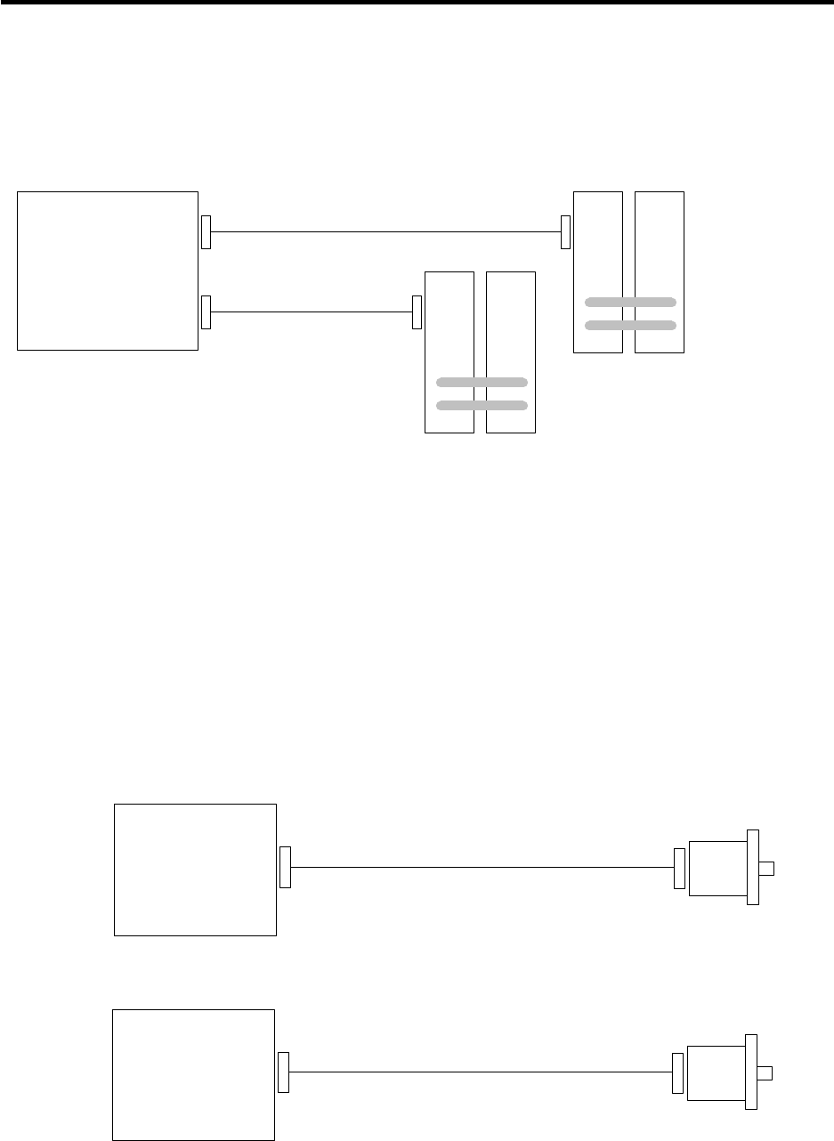
5. Base I/O Unit Connection
5.5 Base I/O Unit Input/Output Specifications
42
5.5.8 Connection of Servo Drive Unit
Connect the servo drive unit to the base I/O unit SV1 (for spindles and NC servo axes) and SV2 (for
peripheral axes).
Base I/O unit
SV1
SV2 CN1A
CN1A
Servo drive unit
SH21 cable
SH21 cable (Spindles and
NC servo axes)
(For auxiliary axes)
Servo drive unit
Refer to "MELDAS AC Servo and Spindle MDS-A/B Series Specifications Manual (BNP-B3759)
MDS-C1 Series Specifications Manual (BNP-C3000)" for servo drive unit details.
<Related sections>
Cable manufacturing drawing: “Appendix 2.1 SH21 cable”
Connector pin assignment: “5.4 Base I/O unit connector pin assignment” - servo drive unit (SV1, SV2)
5.5.9 Connection of Spindle Encoder
Connect the spindle encoder to ENC1 on the base I/O unit. When connecting two channels, connect
the second channel to ENC#2 on the relay card (HR682).
Base I/O unit
F040/F041 cable
ENC1
Relay card
F040/F041 cable
ENC#2
1st spindle encoder
(Channel 1)
(Channel 2)
2nd spindle encoder
<Related sections>
Outline drawing: Appendix 1
Cable manufacturing drawing: “Appendix 2.15 F040 cable”, “Appendix 2.16 F041 cable”
Connector pin assignment: “5.4 Base I/O unit connector pin assignment” - encoder (ENC1)
“6.4 Relay card connector pin assignment” - encoder (ENC#2)
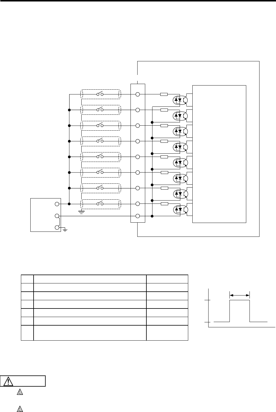
5. Base I/O Unit Connection
5.5 Base I/O Unit Input/Output Specifications
43
5.5.10 Connection of Sensor Signal (skip)
Connect the sensor signal (skip) to SKIP on the base I/O unit. The sensor signal is used for processing
the high-speed signals. Always shield the cable.
(1) Sensor signal (skip) cable
Base I/O unit
Stabilized power
2.2kΩ
2.2kΩ
2.2kΩ
2.2kΩ
2.2kΩ
2.2kΩ
2.2kΩ
2.2kΩ
2
10
3
11
5
13
6
14
1,8,9,15
+24V
GND
FG
FG
SKIP IN1
SKIP IN2
SKIP IN3
SKIP IN4
SKIP IN5
SKIP IN6
SKIP IN7
SKIP IN8
Control circuit
SKIP
(2) Input conditions
Use the input signal within the following condition range.
1 Input voltage when external contact is ON 25.2V or more
2 Input current when external contact is ON 9mA or more
3 Input voltage when external contact is OFF 4V or less
4 Input current when external contact is OFF 1mA or less
5 Input signal hold time (Ton) 2ms or more
6 Internal response time 0.08ms or less
7 Machine side contact capacity +30V or more,
16mA or more
<Related section>
Connector pin assignment: “5.4 Base I/O unit connector pin assignment” – sensor signal
(SKIP)
Do not apply voltages other than those indicated in this manual on the connector. Doing
so may lead to destruction or damage.
Incorrect connections may damage the devices, so connect the cables to the specified
connectors.
Ton
+24V
GND t
>
_
Ton 2ms
CAUTION
6. Relay Card (HR682) Connection
6.1 Relay Card Outline
44
6. Relay Card (HR682) Connection
6.1 Relay Card Outline
The relay card is used in the connection of the spindle encoder, manual pulse generator, RS-232C and
external emergency stop.
There must be one relay card for each NC Card.
Name Type No. of machine input/
output points Other interfaces
Relay
card HR682 No DI/DO EMG, ENC#2, HANDLE 3ch and
RS-232C.
With metal spacers. Add-On to
FCU6-DX2** possible.
RS-232C uses only the DC code
(X ON/OFF) method handshake.
6.2 Relay Card Connection System Diagram
CF61 ENC#2
HANDLE
RS232C
EMG1
DCIN
CF61
NC Card F011 cable
Relay card
Encoder 2ch (2nd spindle encoder)
Manual pulse generator 3ch
RS-232C 1ch
Emergency stop switch
External power (24VDC)
F040 cable
F020 cable
F070 cable
F070 cable
F390 cable
(Note) RS-232C uses only the DC code (X ON/OFF) method handshake.
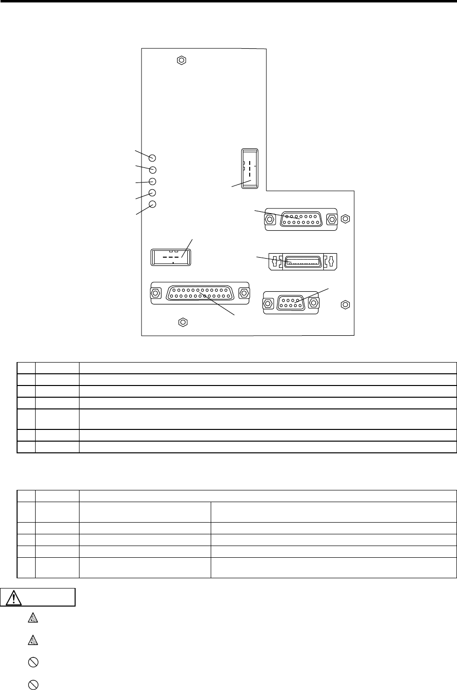
6. Relay Card (HR682) Connection
6.3 Relay Card Part Names
45
6.3 Relay Card Part Names
EMG1
HANDLE
RS232C
ENC#2
CF61
DCIN
EMG LED2 5VON
LED3 LED1
(1)
(2)
(3)
(4)
(5)
(6)
(7)
(8)
(9)
(10)
(11)
Relay card
List of connectors
No. Name Function details
(1) CF61 This is used in the connection with the NC Card. An F011 cable is connected.
(2) ENC#2 This is connected to the encoder 2nd channel (2nd spindle encoder).
(3) HANDLE This is connected to the manual pulse generator. Up to 3 channels can be connected.
(4) RS232C
This is connected to the RS-232C. One channel can be connected. Note that only the DC code (X ON/OFF)
method handshake is possible.
(5) EMG1 This is connected to the external emergency stop switch.
(6) DCIN 24VDC is supplied by external power. Refer to "3.1 General Specifications" for power specifications.
LED list
No. Name Function details
(7) 5VON
This is the LED for the circuit power
5VDC output display. When lit (green): Outputting 5VDC. When not lit: 5VDC output OFF.
(8) LED1 Not in use
(9) LED2 Not in use
(10) LED3 Not in use
(11) EMG This is the LED for the NC system
emergency stop display. When lit (red): System in emergency stop When not lit: Normal
Do not apply voltages on the connector other than those indicated in this manual. Doing
so may lead to destruction or damage.
Incorrect connections may damage the devices, so connect the cables to the specified
connectors.
Do not connect or disconnect the connection cables between each unit while the power
is ON.
Do not connect or disconnect any PCB while the power is ON.
CAUTION
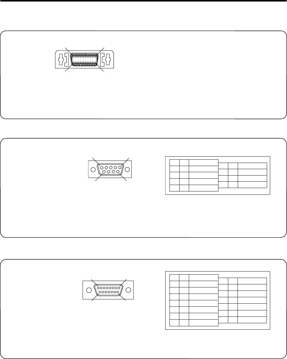
6. Relay Card (HR682) Connection
6.4 Relay Card Connector Pin Assignment
46
6.4 Relay Card Connector Pin Assignment
NC Card
CF61
<Cable side connector type>
Plug : 10126-6000EL
Shell : 10326-3210-000
Recommended manufacturer: Sumitomo 3M
Spindle encoder
ENC#2
<Cable side connector type>
Connector : CDE-9PF
Contact : CD-PC-111
Case : HDE-CTH
Recommended manufacturer: Hirose Electric
Manual pulse generator
HANDLE
<Cable side connector type>
Connector : CDA-15P
Contact : CD-PC-111
Case : HDA-CTH
Recommended manufacturer: Hirose Electric
1
13
26 14
Connector pin assignment: Refer to "4.3 NC
Card connector pin assignment" (Relay
card: CF61).
1
5
69
ENC2A
ENC2B
ENC2Z
GND
GND
1
2
3
4
5
I
I
I
ENC2A*
ENC2B*
ENC2Z*
+5V
6
7
8
9
I
I
I
O
1
8
9
15
HA1A
HA1B
HA2A
HA2B
HA3A
HA3B
1
2
3
4
5
6
7
8
I
I
I
I
I
I
GND
+12V
GND
+12V
GND
+12V
9
10
11
12
13
14
15
(Note) I/O in the table is from the viewpoint of
the rela
y
card.
(Note) I/O in the table is from the viewpoint of
the rela
y
card.
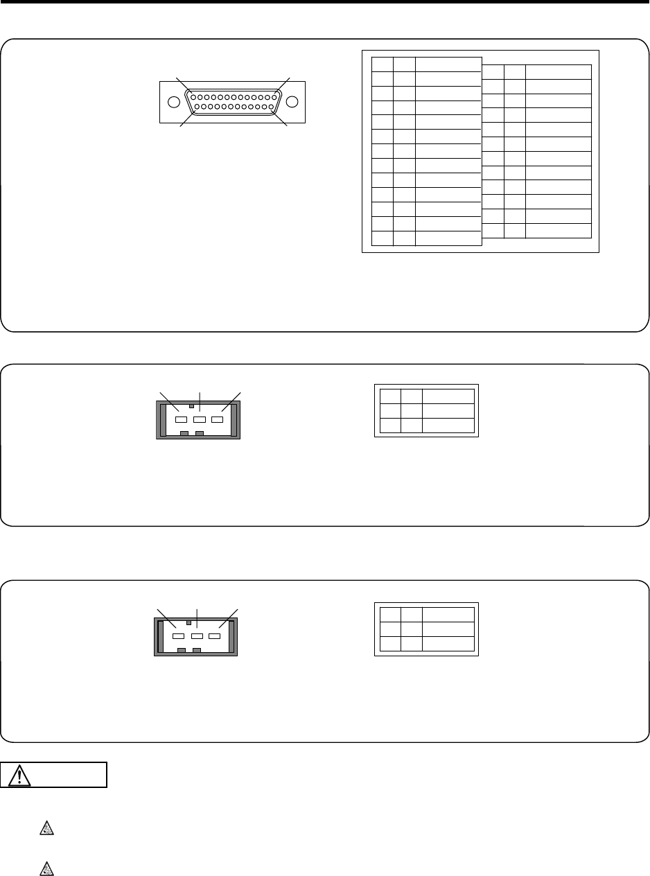
6. Relay Card (HR682) Connection
6.4 Relay Card Connector Pin Assignment
47
RS-232C device
RS232C
<Cable side connector type>
Connector : CDA-25P
Contact : CD-PC-111
Case : HDA-CTH
Recommended manufacturer:
Hirose Electric
+24VDC input
DCIN
<Cable side connector type>
Connector : 2-178288-3
Contact : 1-175218-5
Recommended manufacturer: Tyco Electronics AMP
Emergency stop
EMG1
<Cable side connector type>
Connector : 2-178288-3
Contact : 1-175218-5
Recommended maker: Tyco Electronics AMP
Do not apply voltages other than those indicated in this manual on the connector. Doing
so may lead to destruction or damage.
Incorrect connections may damage the devices, so connect the cables to the specified
connectors.
1
13
14
25
FG
TD
RD
DR
GND
1
2
3
4
5
6
7
8
9
10
11
12
13
O
I
O
DC
14
15
16
17
18
19
20
21
22
23
24
25
I
123+24V
GND
FG
1
2
3
123IEMG
GND
FG
1
2
3
(Note) I/O in the table is from the viewpoint of the relay card.
This connector shows the minimum required pin assignment
for the RS-232C interface. Refer to "Appendix 2.18 F390
Cable" for details on manufacturing the cable.
(Note) I/O in the table is from the viewpoint of
the rela
y
card.
(Note) I/O in the table is from the viewpoint of
the rela
y
card.
CAUTION
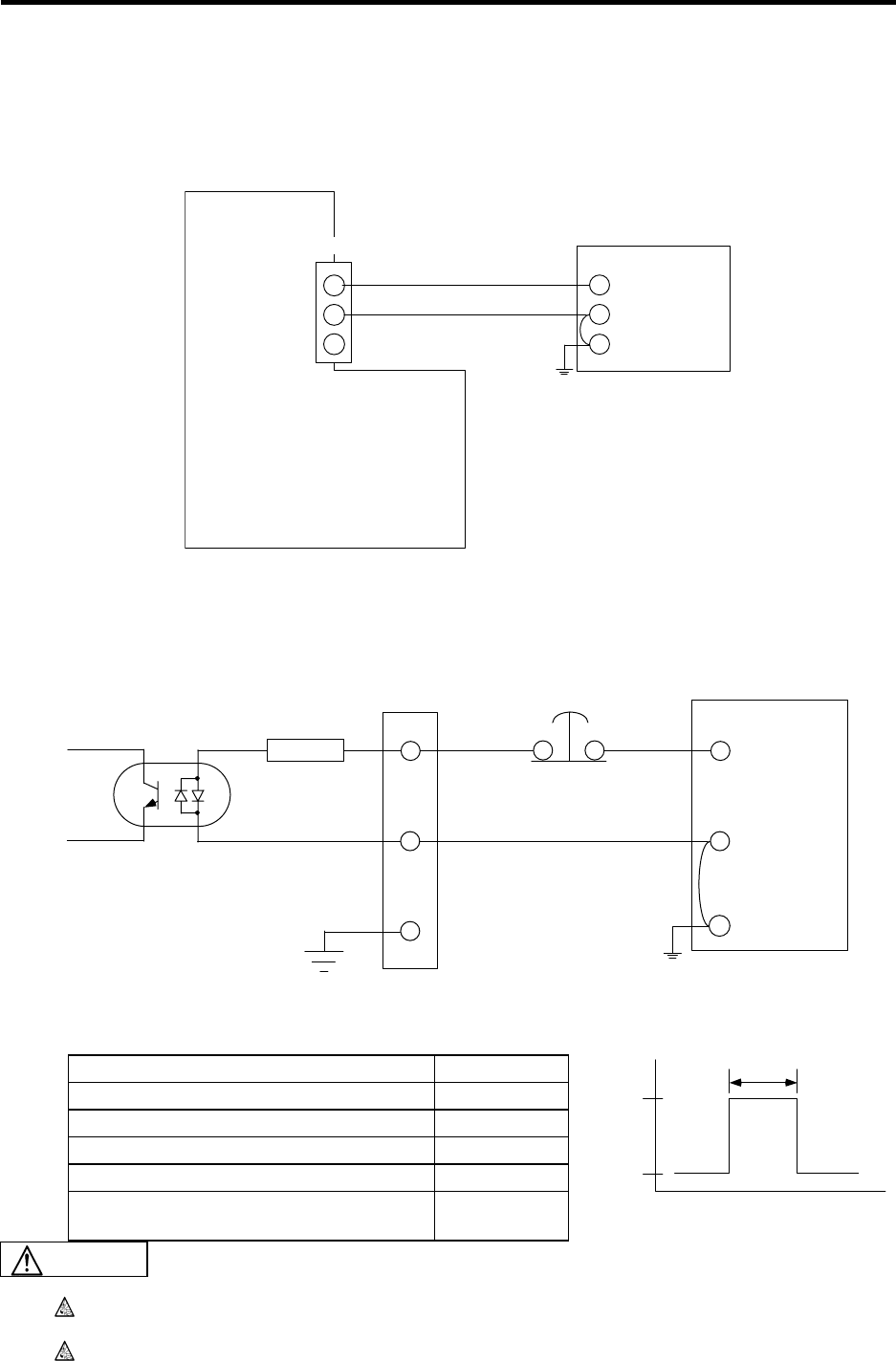
6. Relay Card (HR682) Connection
6.5 Relay Card Input/Output Specifications
48
6.5 Relay Card Input/Output Specifications
6.5.1 Relay Card Power Connection
Supply the external power (24VDC) input by the DCIN connector.
Relay card
Stabilized power supply
(Prepare separately)
24VDC
GND
FG
24VDC
GND
NC
DCIN
6.5.2 Emergency Stop Connection
The emergency stop input is connected to the EMG1 connector.
R
2.2kΩ
FG
24VDC
GND
FG
1
2
3
EMG1 Emergency stop switchStabilized power supply
(Prepare separately)
Input conditions
Input voltage when external contact is ON 18V or more
Input current when external contact is ON 9mA or more
Input voltage when external contact is OFF 4V or more
Input current when external contact is OFF 1mA or more
Input signal hold time (Tson) 40ms or more
Machine side contact capacity +30V or more,
16mA or more
Do not apply voltages other than those indicated in this manual on the connector. Doing
so may lead to destruction or damage.
Incorrect connections may damage the devices, so connect the cables to the specified
connectors.
Tson
+24V
GND t
Tson 40ms
>
_
CAUTION
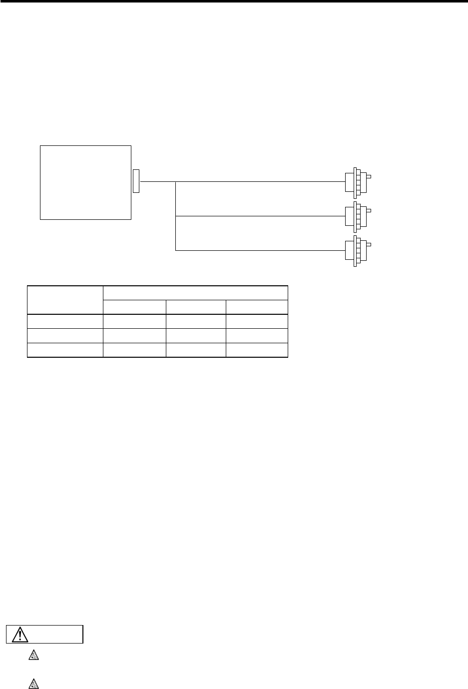
6. Relay Card (HR682) Connection
6.5 Relay Card Input/Output Specifications
49
6.5.3 Connection of Spindle Encoder
Refer to "5.5.9 Connection of Spindle Encoder" for details.
6.5.4 Manual Pulse Generator Connection
Connect the manual pulse generator to the relay card HANDLE connector. The manual pulse generator
can be connected to a max. of three channels.
HANDLE
Relay card
F020/F021/F022 cable (Channel 1)
F021/F022 cable
F022 cable
(Channel 2)
(Channel 3)
Manual pulse generator connection cables
Channel
Cable name 1 2 3
F020 cable
F021 cable
F022 cable
: Connection possible
<Related sections>
Outline drawing: "Appendix 1.8 Manual Pulse Generator (HD60) Outline Drawing"
Cable manufacturing drawing: "Appendix 2.12 F020 Cable", "Appendix 2.13 F021 Cable" and
"Appendix 2.14 F022 Cable"
Connector pin assignment: "6.4 Relay Card Connector Pin Assignment"
- Manual Pulse Generator (HANDLE)
6.5.5 RS-232C Device Connection
Connect the RS-232C device to the RS-232C connector on the relay card using an F390 cable.
The pin assignment for the RS-232C connector differs from a commercially-available RS-232C cable.
Refer to the following related sections for details on manufacturing the cable.
Note that only the DC code (X ON/OFF) method handshake is possible.
<Related sections>
Cable manufacturing drawing: "Appendix 2.18 F390 Cable"
Connector pin assignment: "6.4 Relay Card Connector Pin Assignment"
- RS-232C Device (RS232C)
Do not apply voltages other than those indicated in this manual on the connector. Doing
so may lead to destruction or damage.
Incorrect connections may damage the devices, so connect the cables to the specified
connectors.
CAUTION
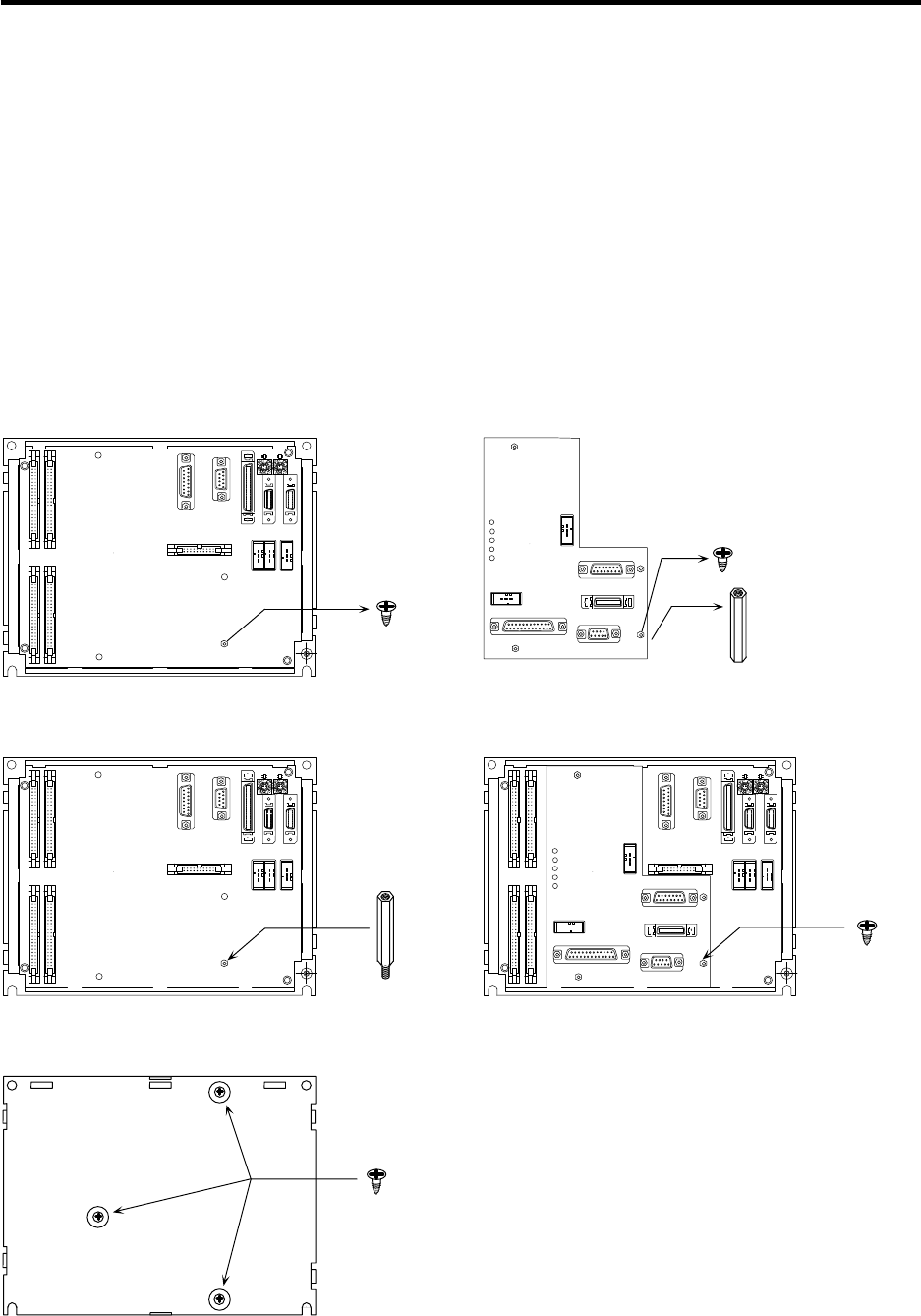
6. Relay Card (HR682) Connection
6.6 Installation on the Base I/O Unit
50
6.6 Installation on the Base I/O Unit
A relay card (HR682) can be added on to the base I/O unit. When adding on, install the card using the
following procedure.
Adding on is only possible with the FCU6-DX2** base I/O unit.
Note that adding on is not possible with the FCU6-DX3** and 4**.
1. Remove screw 1 from the base I/O unit. (Fig. 1)
2. Remove screw 2 of the relay card and spacer 1 (screw holes at both ends are female). (Fig. 2)
3. Install the attached spacer 2 (screw holes on one side are male) to the hole of screw 1 that was
removed from the base I/O unit. (Fig. 3)
4. Mount the relay card on the base I/O unit, and fix with screw 1 that was removed in step 1. (Fig. 4)
5. Turn the unit over, and fix the screws at the three holes to the three spacer locations. (Fig. 5)
This completes the installation of the relay card to the base I/O unit.
0 0
CF31CF32
CF34CF33
0 0
CF31CF32
CF34CF33
0 0
CF31CF32
CF34CF33
Remove screw 1. Remove screw 2
and spacer 1.
Fig. 1
Install spacer 2.
Install screw 1.
Turn the unit over,
and fix the screws
at the three locations.
Fig. 2
Fig. 3 Fig. 4
Fig. 5

7. Remote I/O Unit Connection (FCUA-DX1**)
7.1 Outline of Remote I/O Unit
51
7. Remote I/O Unit Connection (FCUA-DX1**)
7.1 Outline of Remote I/O Unit
The eight types of signals that can be input/output from the remote I/O unit (FCUA-DX1**) are shown
below according to the type and No. of contacts. Use with serial link connections (MC link B) to the NC
Card.
When the remote I/O unit is connected with serial links, multiple units can be used as long as the total
No. of occupied stations (channels) is within 8 channels. (Refer to "7.14 Setting of Channel No. When
Using Multiple Remote I/O Units" for station No. setting details.)
Unit name Machine control signals that can be input/output No. of occupied
serial link channels
FCUA-DX100 Digital input signal (DI) : 32 points (photo coupler insulation) sink/source type
Digital output signal (DO) : 32 points (non-insulation) sink type 1
FCUA-DX101 Digital input signal (DI) : 32 points (photo coupler insulation) sink/source type
Digital output signal (DO) : 32 points (non-insulation) source type 1
FCUA-DX110 Digital input signal (DI) : 64 points (photo coupler insulation) sink/source type
Digital output signal (DO) : 48 points (non-insulation) sink type 2
FCUA-DX111 Digital input signal (DI) : 64 points (photo coupler insulation) sink/source type
Digital output signal (DO) : 48 points (non-insulation) source type 2
FCUA-DX120 Digital input signal (DI) : 64 points (photo coupler insulation) sink/source type
Digital output signal (DO) : 48 points (non-insulation) sink type
Analog output (AO) : 1 point 2
FCUA-DX121 Digital input signal (DI) : 64 points (photo coupler insulation) sink/source type
Digital output signal (DO) : 48 points (non-insulation) source type
Analog output (AO) : 1 point 2
FCUA-DX130 Digital input signal (DI) : 32 points (photo coupler insulation) sink/source type
Digital output signal (DO) : 32 points (non-insulation) sink type
Handle input : 2 channels 2
FCUA-DX131 Digital input signal (DI) : 32 points (photo coupler insulation) sink/source type
Digital output signal (DO) : 32 points (non-insulation) source type
Handle input : 2 channels 2
FCUA-DX140
Digital input signal (DI) : 32 points (photo coupler insulation) sink/source type
Digital output signal (DO) : 32 points (non-insulation) sink type
Analog input (AI) : 4 points
Analog output (AO) : 1 point
2
FCUA-DX141
Digital input signal (DI) : 32 points (photo coupler insulation) sink/source type
Digital output signal (DO) : 32 points (non-insulation) source type
Analog input (AI) : 4 points
Analog output (AO) : 1 point
2
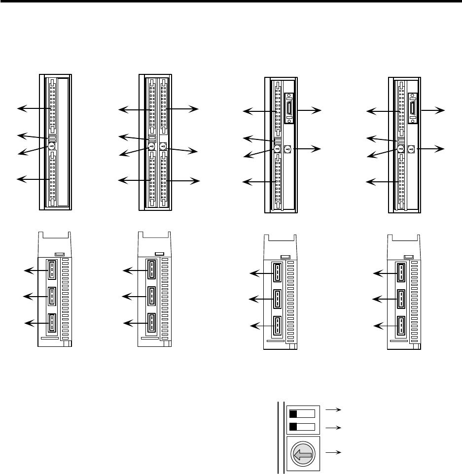
7. Remote I/O Unit Connection (FCUA-DX1**)
7.2 Names of Each Remote I/O Unit Section
52
7.2 Names of Each Remote I/O Unit Section
FCUA-DX10* FCUA-DX11*/FCUA-DX12* FCUA-DX13* FCUA-DX14*
(1)
(2)
(3)
(4)
(8)
(3)
(9)
(10)
(3)
(11)
(3)
Front view Front view Front view Front view
(Front)
(Front)
(Front)(Front)
Bottom
view Bottom
view Bottom
view Bottom
view
(Rear)
(Rear)
(Rear)(Rear)
(1)
(2)
(3)
(4)
(1)
(2)
(3)
(4)
(1)
(2)
(3)
(4)
(5)
(6)
(7)
(5)
(6)
(7)
(5)
(6)
(7)
(5)
(6)
(7)
1
4
2
5
67
A
D
9
B
F
E
0
C
8
3
Enlar
g
ed drawin
g
of DS and CS
DS
CS
Not used
Selection of channel No.
For changeover of transfer speed.
Normally set to left side.
(1) DI-L (machine input signal connector)
(2) DS (transfer speed changeover switch)
(3) CS (channel No. changeover switch)
(4) DO-L (machine output signal connector)
(5) RIO1 (serial connection connector #1)
(6) RIO2 (serial connection connector #2)
(7) DCIN (+24VDC power input connector)
(8) DI-R (machine input signal connector)
(9) DO-R (machine output signal connector)
(10) HANDLE (manual pulse generator signal
input connector)
(11) AIO (analog signal input/output connector)
(Note) Baud rate changeover
Left side : 2.8Mbps
Right side : 1.4Mbps
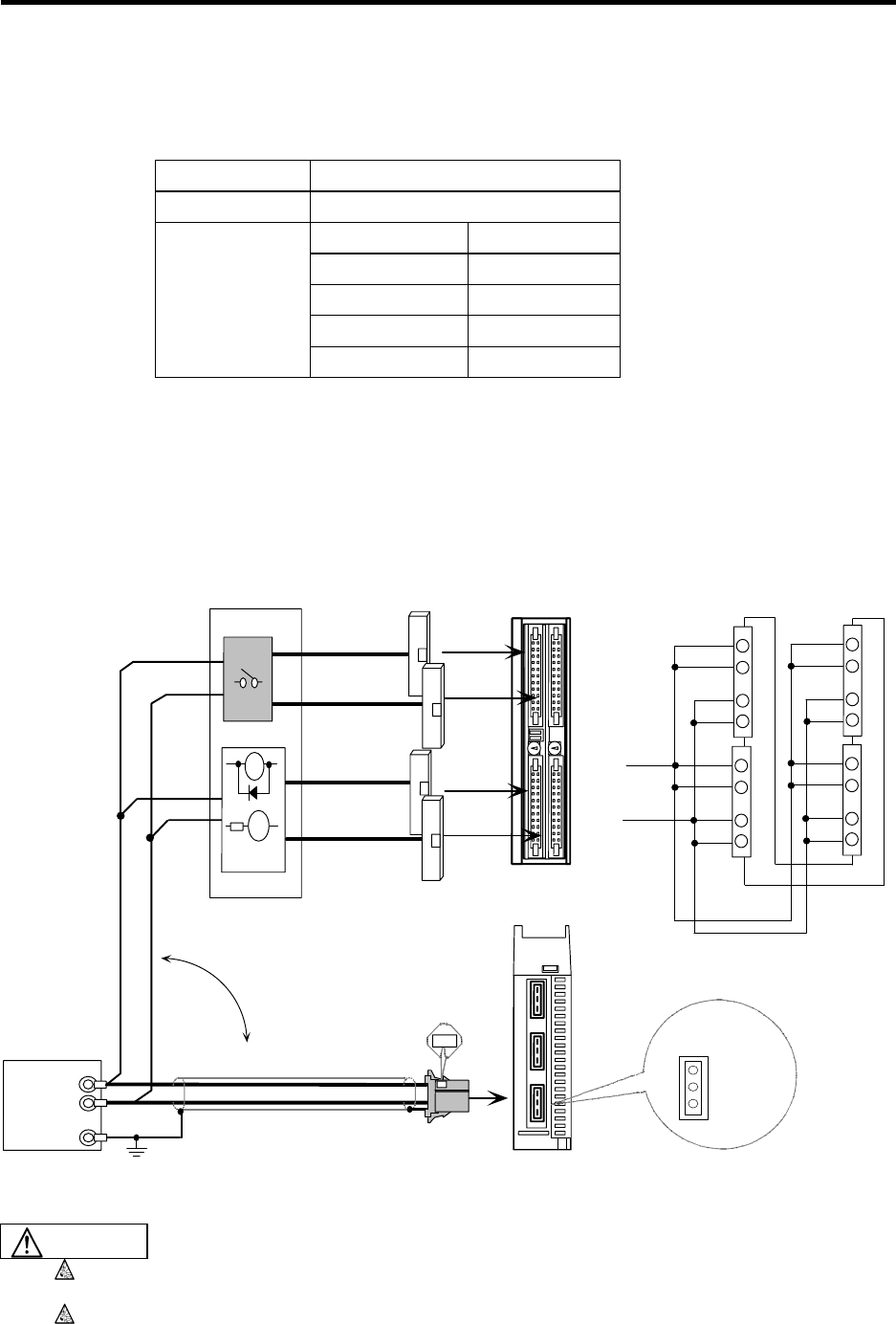
7. Remote I/O Unit Connection (FCUA-DX1**)
7.3 Connection of Remote I/O Power
53
7.3 Connection of Remote I/O Power
+24VDC is required to run the remote I/O unit. Prepare a stabilized power supply that satisfies the
following conditions.
Output voltage +24V ±5%
Ripple ±5% (P-P)
FCUA-DX10* 2.4A or more
FCUA-DX11* 3.8A or more
FCUA-DX12* 3.8A or more
FCUA-DX13* 3.4A or more
Max. output
current
FCUA-DX14* 3.4A or more
The +24VDC power for the control circuit is supplied from the connector DCIN on the bottom of the unit
or from connectors DI-L, DI-R, DO-L or DO-R on the front. When supplying from the front connector,
supply to all corresponding pins.
When manufacturing the R300 cable, use the single-end connector CN300 (optional, with one end),
and when manufacturing the R301 cable, use the connector set CS301 (optional, with two ends).
<Connection outline>
DCIN
FG
0V
1
2
3
DO-L DO-R
+24VDC
FG
0V
B1
B2
A1
A2
B1
B2
A1
A2
B1
B2
A1
A2
B1
B2
A1
A2
DI-L DI-R
DO-R
DO-L
0V
RA
PL
YY
Machine control panel,
electric cabinet, etc.
R300 cable
or R301
cable
Remote I/O unit
DI-L DI-R
+24VDC
+24VDC
Front
(Front)
Supply to either method
R220 cable Base
Stabilized power
(prepare separately)
(Rear)
Do not apply voltages other than those indicated in this manual on the connector. Doing
so may lead to destruction or damage.
Incorrect connections could damage the device, so always connect the cable to the
designated connector.
CAUTION
7. Remote I/O Unit Connection (FCUA-DX1**)
7.4 Outline of Digital Signal Input Circuit
54
7.4 Outline of Digital Signal Input Circuit
The input circuit can be selected from sink type or source type in card units.
Input circuit
2.2k
Control
circuit
2.2k
2.2k
2.2k
2.2k
COM
0V
+24VDC
(Machine side)
A3,B3
0V
0V
0V
0V
Sink type
DI-R/DI-L
2.2k
2.2k
2.2k
2.2k
2.2k
COM
0V
(Machine side)
A3,B3
Source type
DI-R/DI-L
Control
circuit
+24VDC
+24VDC
+24VDC
+24VDC
+24VDC
7. Remote I/O Unit Connection (FCUA-DX1**)
7.4 Outline of Digital Signal Input Circuit
55
Input conditions
The input signals must be used within the following condition ranges.
Sink type
Input voltage at external contact ON 6V or less
Input current at external contact ON 9mA or more
Input voltage at external contact OFF 20V or more, 25.2V or less
Input current at external contact OFF 2mA or less
Tolerable chattering time (T1) 3ms or less
Input signal hold time (T2) 40ms or more
Input circuit operation delay time (T3, T4) 3ms ≤ T3 T4 ≤ 16ms
Machine side contact capacity +30V or more, 16mA or more
Source type
Input voltage at external contact ON 18V or more, 25.2V or less
Input current at external contact ON 9mA or more
Input voltage at external contact OFF 4V or less
Input current at external contact OFF 2mA or less
Tolerable chattering time (T1) 3ms or less
Input signal hold time (T2) 40ms or more
Input circuit operation delay time (T3, T4) 3ms ≤ T3 T4 ≤ 16ms
Machine side contact capacity +30V or more, 16mA or more
T2
T1 T1
T3 T4
T2
T1 T1
T3 T4
Sink type Source type
7. Remote I/O Unit Connection (FCUA-DX1**)
7.5 Outline of Digital Signal Output Circuit
56
7.5 Outline of Digital Signal Output Circuit
The digital signal output circuit uses a sink type (DX1*0) or source type (DX1*1). Use within the
specification ranges shown below.
Output circuit
+24VDC
RA
RPL
Source type (DX1*1)
R
(Machine side)
Control
circuit
Sink type (DX1*0)
RA
PL
DO-R/DO-L
DO-R/DO-L
+24VDC
Control
circuit
(Machine side)
Output conditions
Insulation method Non-insulation
Rated load voltage +24VDC
Max. output current 60mA/1 point (fixed value)
Output delay time 40µs
(Note) An output voltage of more than 60mA per point cannot be flowed.
When using an inductive load such as a relay, always connect a diode in parallel to the
load.
When using a capacity load such as a ramp, always connect a protective resistor serially
to the load to suppress rush currents.
* When using an inductive load such as a relay, always connect a diode (voltage
resistance 100V or more, 100mA or more) in parallel to the load.
* When using a capacity load such as a ramp, always connect a protective resistor
(R=150 ) serially to the load to suppress rush currents. (Make sure that the
current is less than the above tolerable current including the momentary current.)
<CAUTION>
CAUTION
7. Remote I/O Unit Connection (FCUA-DX1**)
7.6 Outline of Analog Signal Output Circuit
57
Output voltage 0V~±10V (±5%)
Resolution
(polarity included) 12 bit (±10V × n/4096) (n = 20 to 211)
Load conditions 10k load resistance
Output impedance 220
7.6 Outline of Analog Signal Output Circuit
The analog signal output circuit can be used only for the FCUA-DX120/DX121/DX140/DX141.
Output circuit
DAC
R
220R
AO
AO*
Output conditions
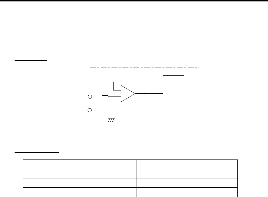
7. Remote I/O Unit Connection (FCUA-DX1**)
7.7 Outline of Analog Signal Input Circuit
58
7.7 Outline of Analog Signal Input Circuit
The analog signal output circuit can be used only for the FCUA-DX140/DX141.
Input circuit
ADC
150
AI
AI*
Input conditions
Max. input voltage rating ±15V
Resolution (polarity included) 12 bit (±10V × n/2048) (n = 20 to 211)
Precision Within ±25mV
AD input sampling time (conversion delay) 14.2ms (AI0)/42.6ms (AI1~3)
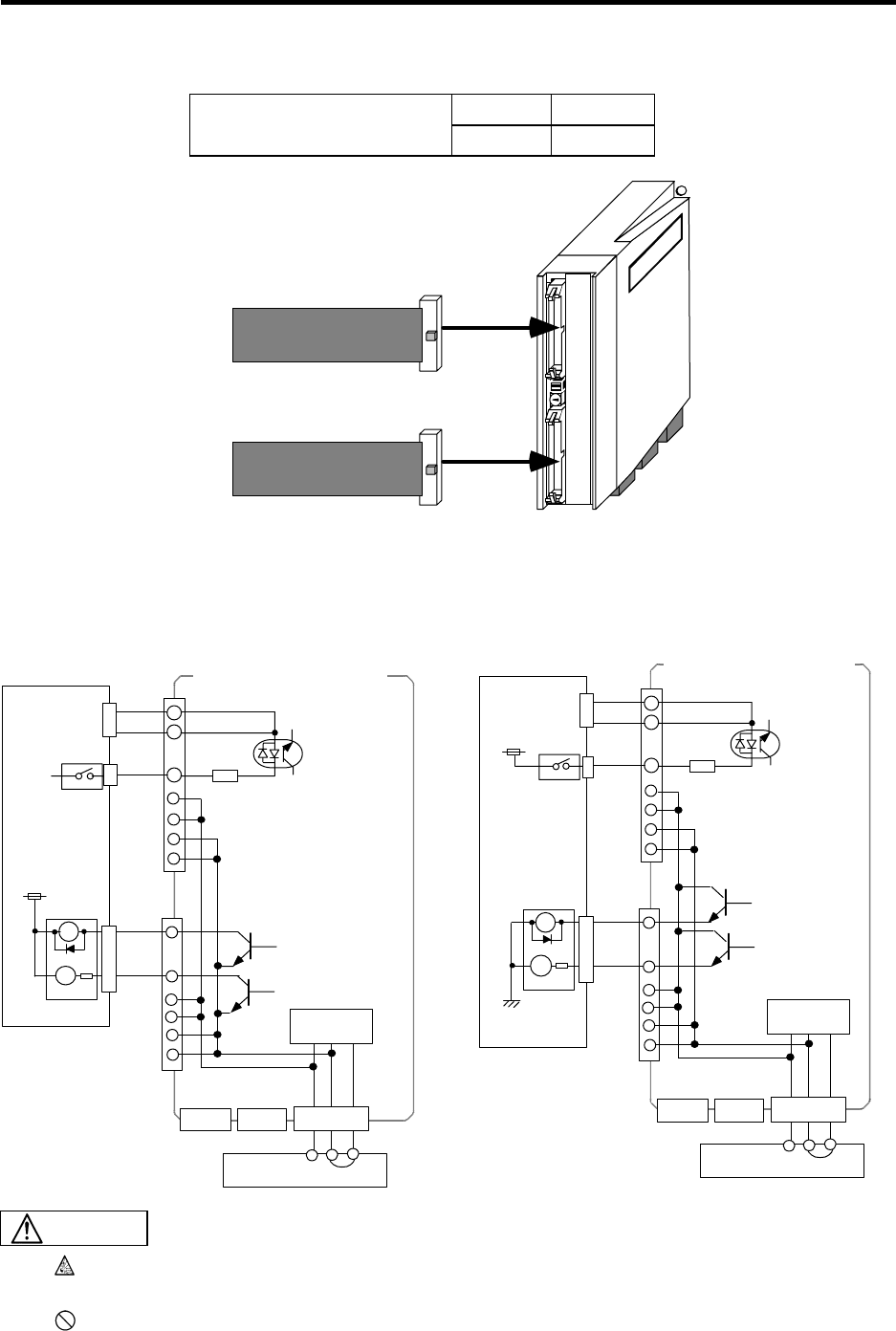
7. Remote I/O Unit Connection (FCUA-DX1**)
7.8 Connection of FCUA-DX10*/13*/14* Unit and Machine Control Signal
59
7.8 Connection of FCUA-DX10*/13*/14* Unit and Machine Control Signal
Input Output
Type of machine input/output
signal and No. of points 32 points 32 points
DCIN
RIO2
RIO1
R300 cable/
R301 cable
Machine signal DI-L
DO-L
FCUA-DX10*
or
FCUA-DX13*
or
FCUA-DX14*
R300 cable/
R301 cable
Machine signal
The single-end connector CN300 (optional, with one end) includes the DI-L and DO-L connectors. The
connector set CS301 (optional) includes the DI-L and DO-L connectors, and two connectors for
connection with the terminal block ∗.
∗ IDEC IZUMI Corporation I/O terminal BX1F-T40
<Outline of connection>
RIO1 RIO2
B3
A1
12
Input circuit
sink type
Input circuit
source type
Stabilized power
A3
Output circuit
source type
Stabilized power
Machine
control panel
COM
DI-L
DO-L
2.2k
DCIN
A2
B1
B2
A1
A2
0V
+24VDC
3
B1
B2
Output circuit
sink type
RA
PL
+24VDC
0V+24VDC FG
Machine
control panel
RIO1 RIO2
B3
A1
12
A3 COM
DI-L
DO-L
2.2k
DCIN
A2
B1
B2
A1
A2
0V
+24VDC
3
B1
B2
0V+24VDC FG
0V
RA
PL
Control
circuit
FCUA-DX101/131/141
FCUA-DX100/130/140
Control
circuit
Incorrect connections could damage the device, so always connect the cable to the
designated connector.
Do not connect or disconnect the connection cables between each unit while the power
is ON.
CAUTION
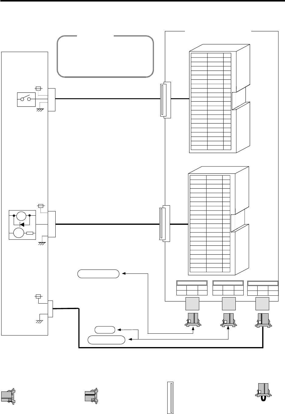
7. Remote I/O Unit Connection (FCUA-DX1**)
7.8 Connection of FCUA-DX10*/13*/14* Unit and Machine Control Signal
60
<Signal assignment table>
DO-L
B
B
Y00
Y01
Y02
Y03
Y04
Y05
Y06
Y07
Y08
Y09
Y0A
Y0B
Y0C
Y0D
Y0E
Y0F
+24V
+24V
A
A
Y10
Y11
Y12
Y13
Y14
Y15
Y16
Y17
Y18
Y19
Y1A
Y1B
Y1C
Y1D
Y1E
Y1F
0V
0V
20
19
18
17
16
15
14
13
12
11
10
9
8
7
6
5
4
3
2
1
Remote I/O unit
Base I/O unit
R-TM
Machine side
control panel, etc.
0V
PL
RA
0V
+24VDC
0V
RI02
2
13
LG
DCIN
+24V
123
FG0V
RI01
123
LG
AMP
D-3
X
AMP
D-3
Y
AMP
D-3
DI-L
TXRXTXRX*TXRXTXRX*
B
B
X00
X01
X02
X03
X04
X05
X06
X07
X08
X09
X0A
X0B
X0C
X0D
X0E
X0F
COM
+24V
+24V
A
A
X10
X11
X12
X13
X14
X15
X16
X17
X18
X19
X1A
X1B
X1C
X1D
X1E
X1F
COM
0V
0V
20
19
18
17
16
15
14
13
12
11
10
9
8
7
6
5
4
3
2
1
DO-L
X
DI-L
DO-L
When using more than two remote
I/O units, the signal assignments will
change. Refer to the "PLC Interface
Manual (BNP-B2211)" for details.
+24VDC
+24VDC
<Adaptive connection>
AMP
D-3
Terminator (R-TM)
Manufacturer:
Tyco Electronics AMP
DCIN (CN220) RIO1/RIO2 (CN211)
Manufacturer:
Sumitomo 3M
Crimp type connector:
7940-6500SC
DI-L/DO-L(CN300)
X
Connector: 2-178288-3
Contact : 1-175218-5
Manufacturer:
Tyco Electronics AMP
Connector: 1-178288-3
Contact : 1-175218-2
Manufacturer:
Tyco Electronics AMP
<CAUTION> FCUA-DX10*/13*/14*
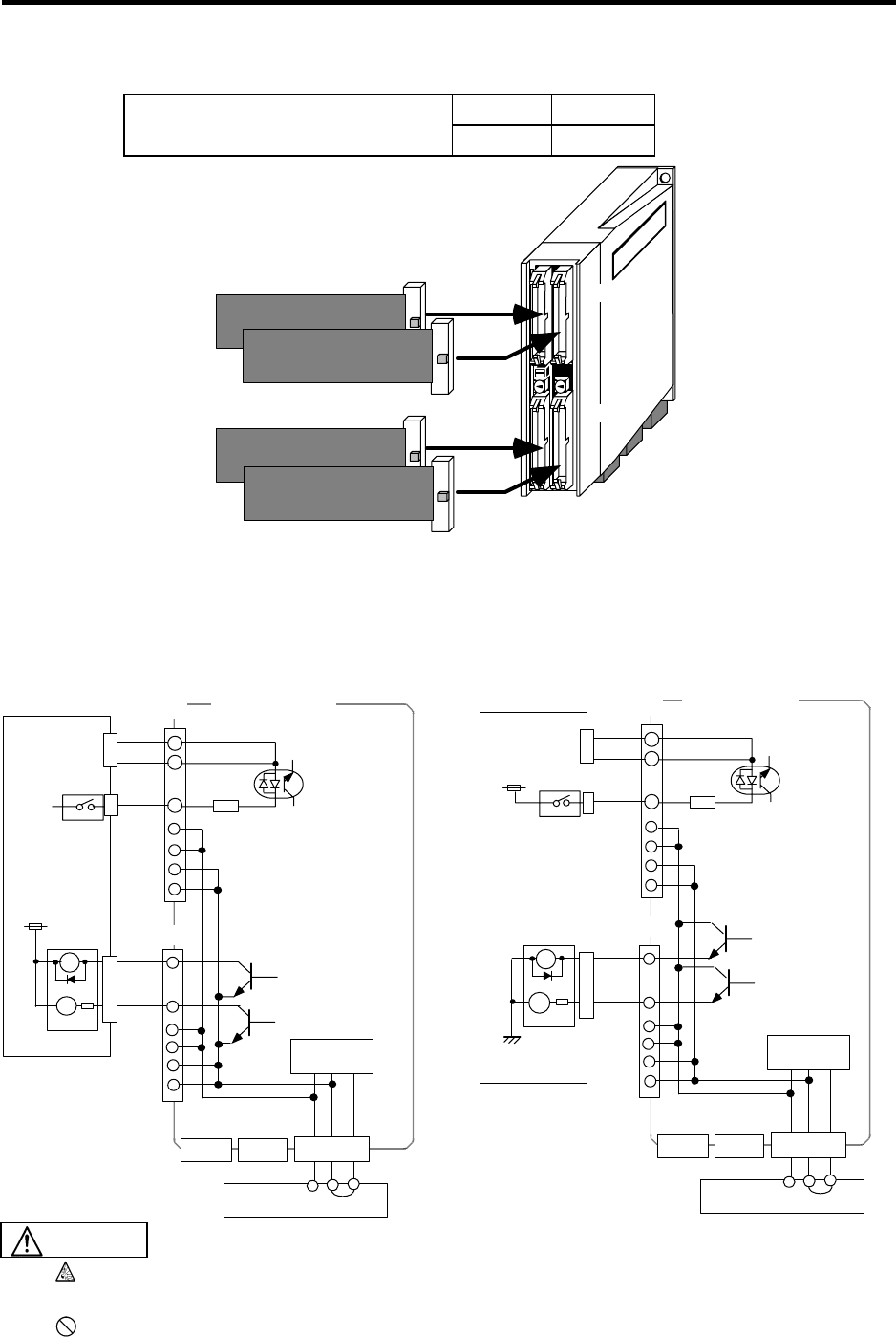
7. Remote I/O Unit Connection
7.9 Connection of FCUA-DX11* Unit and Machine Control Signal
61
7.9 Connection of FCUA-DX11* Unit and Machine Control Signal
Input Output
Type of machine input/output signal
and No. of points 64 points 48 points
FCUA-DX11*
DCIN
RIO2
Machine signal
RIO1
DI-L
DO-L
R300 cable/
R301 cable
R300 cable/
R301 cable
Machine signal
DI-R
DO-R
The single-end connector CN300 (optional, with one end) includes the DI-L (DI-R) and DO-L (DO-R)
connectors. The connector set CS301 (optional) includes the DI-L (DI-R) and DO-L (DO-R) connectors,
and two connectors for connection with the terminal block ∗.
∗ IDEC IZUMI Corporation I/O terminal BX1F-T40
<Outline of connection>
RIO1 RIO2
B3
A1
12
A3 COM
2.2kΩ
DCIN
A2
B1
B2
A1
A2
0V
+24VDC
3
B1
B2
RA
PL
+24VDC
0V+24VDC FG
RIO1 RIO2
B3
A1
12
A3 COM
2.2kΩ
DCIN
A2
B1
B2
A1
A2
0V
+24VDC
3
B1
B2
0V+24VDC FG
0V
RA
PL
Input circuit
sink type
Stabilized power
Control
circuit
Output circuit
sink type
Machine
control panel
Input circuit
source type
Stabilized power
Control
circuit
Output circuit
source type
Machine
control panel
FCUA-DX110 FCUA-DX111
DI-L/R
DO-L/R
DI-L/R
DO-L/R
Incorrect connections could damage the device, so always connect the cable to the
designated connector.
Do not connect or disconnect the connection cables between each unit while the power
is ON.
CAUTION
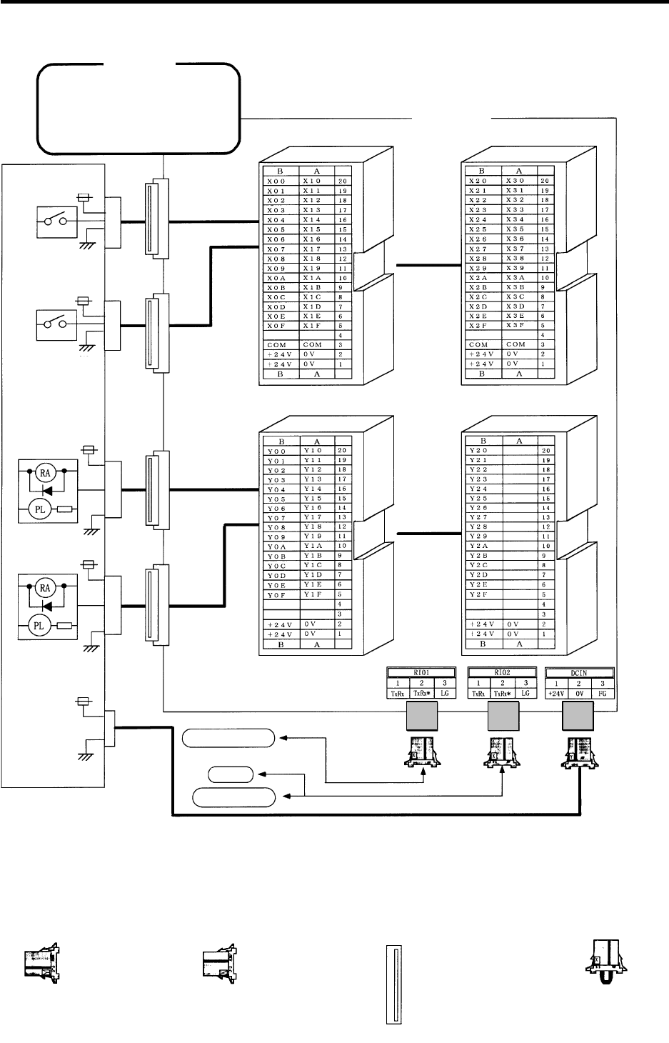
7. Remote I/O Unit Connection
7.9 Connection of FCUA-DX11* Unit and Machine Control Signal
62
<Signal assignment table>
When using two or more remote
I/O units, the signal allocation will
differ. Refer to the "PLC interface
manual" for details.
<CAUTION>
Remote I/O unit
+24VDC
+24VDC
+24VDC
+24VDC
Base I/O unit
Machine side
control panel, etc.
+24VDC
0V
DI-L
DI-R
DI-L DI-R
FCUA-DX11*
DO-L DO-R
0V
DO-L
DO-R
0V
0V
0V R-TM
<Adaptive connector>
DCIN (CN220) RIO1/RIO2 (CN211) DI-L/DO-L (CN300) Terminator (R-TM)
Crimp type connector:
7940-6500SC
Manufacturer:
Sumitomo 3M
Manufacturer:
Tyco Electronics AMP
Connector : 1-178288-3
Contact : 1-175218-2
Manufacturer :
Tyco Electronics AMP
Connector : 2-178288-3
Contact : 1-175218-5
Manufacturer :
Tyco Electronics AMP
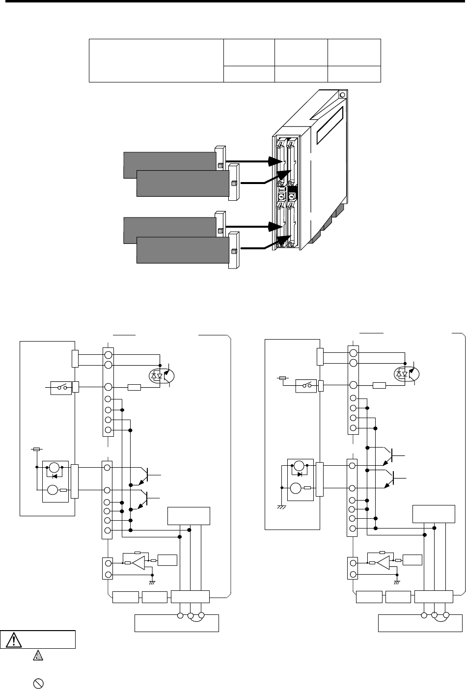
7. Remote I/O Unit Connection
7.10 Connection of FCUA-DX12* Unit and Machine Control Signal
63
7.10 Connection of FCUA-DX12* Unit and Machine Control Signal
Input Output
Analog
output
Type of machine input/output
signal and No. of points 64 points 48 points 1 point
FCUA-DX12*
DCIN
RIO2
Machine signal
Machine signal
RIO1
DI-L
DO-L
R300 cable/
R301 cable
R300 cable/
R301 cable DO-R
DI-R
The single-end connector CN300 (optional, with one end) includes the DI-L (DI-R) and DO-L (DO-R) connectors.
The connector set CS301 (optional) includes the DI-L (DI-R) and DO-L (DO-R) connectors, and two connectors for
connection with the terminal block ∗.
∗ IDEC IZUMI Corporation I/O terminal BX1F-T40
<Outline of connection>
B3
A1
A3 COM
2.2kΩ
A2
B1
B2
A1
A2
0V
+24VDC
B1
B2
RA
PL
+24VDC
B3
A1
A3 COM
2.2kΩ
A2
B1
B2
A1
A2
0V
+24VDC
B1
B2
0V
RA
PL
DO-R
A4
B4Analog out
DAC
R
220
Ω
R
RIO1 RIO2
12
DCIN
3
0V+24VDC FG
DO-R
A4
B4
DAC
R
220
Ω
R
RIO1 RIO2
12
DCIN
3
0V+24VDC FG
Input circuit
sink type
Stabilized power
Control
circuit
Output circuit
sink type
Machine
control panel
Analog out
Input circuit
source type
Stabilized power
Control
circuit
Output circuit
source type
Machine
control panel
FCUA-DX120 FCUA-DX121
DI-L/R
DO-L/R
DI-L/R
DO-L/R
Incorrect connections could damage the device, so always connect the cable to the
designated connector.
Do not connect or disconnect the connection cables between each unit while the power
is ON.
CAUTION
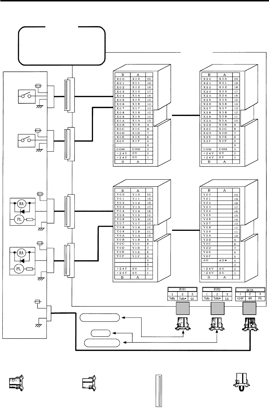
7. Remote I/O Unit Connection
7.10 Connection of FCUA-DX12* Unit and Machine Control Signal
64
<Signal assignment table>
When using two or more remote I/O
units, the signal allocation will differ.
Refer to the "PLC interface manual"
for details.
+24VDC
+24VDC
+24VDC
+24VDC
+24VDC
Remote I/O unit
Base I/O unit
<CAUTION>
0V
DI-L
DI-R
DI-L DI-R
FCUA-DX12*
DO-L DO-R
0V
DO-L
DO-R
0V
0V
0V R-TM
Machine side
control panel, etc.
<Adaptive connector>
DCIN (CN220) RIO1/RIO2 (CN211) DI-L/DO-L (CN300) Terminator (R-TM)
Crimp type connector:
7940-6500SC
Manufacturer:
Sumitomo 3M
Manufacturer:
Tyco Electronics AMP
Connector : 1-178288-3
Contact : 1-175218-2
Manufacturer :
Tyco Electronics AMP
Connector : 2-178288-3
Contact : 1-175218-5
Manufacturer :
Tyco Electronics AMP
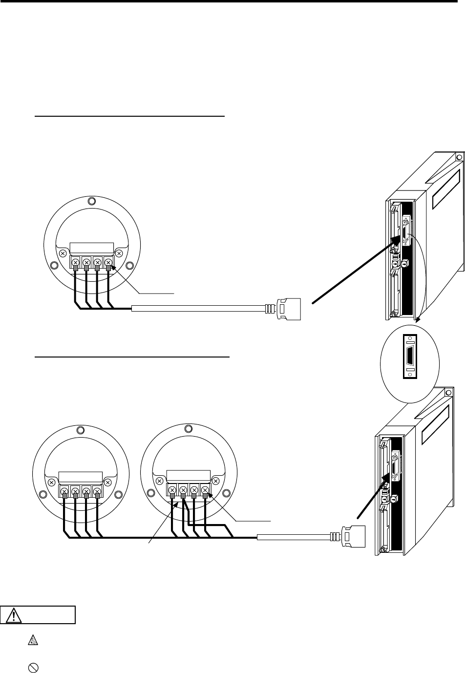
7. Remote I/O Unit Connection
7.11 Connection of FCUA-DX13* Unit and Handle
65
7.11 Connection of FCUA-DX13* Unit and Handle
To connect the manual pulse generator, the R041 or R042 cable is connected to "HANDLE". Up to two
manual pulse generators can be connected. When manufacturing the R041 or R042 cable, use the
connector set CS000 (optional, with two ends). (Refer to Appendix 2.4 R041 Cable, and Appendix 2.5
R042 Cable for cable details.)
HANDLE
FCUA-DX13*
Manual pulse generator
FCUA-HD60
Rear view
4-M3
NO.1
R041 cable
To Connect one manual pulse generator
To connect two manual pulse generators
Manual pulse generator
FCUA-HD60
Rear view
12V A0V B
4-M3
SEL*
NO.1
NO.2
HANDLE
FCUA-DX13*
1
10
11
20
Pin No.
R042 cable
12V A0V B
12V A0V B
When connecting the second manual pulse generator, connect the SEL* signal to the No. 1's 0V.
Incorrect connections could damage the device, so always connect the cable to the
designated connector.
Do not connect or disconnect the connection cables between each unit while the power
is ON.
CAUTION
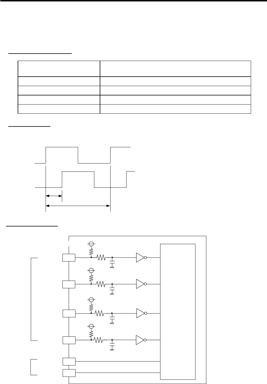
7. Remote I/O Unit Connection
7.12 Outline of FCUA-DX13* Unit Pulse Input Circuit
66
7.12 Outline of FCUA-DX13* Unit Pulse Input Circuit
When connecting a device (pulse generator) other than the manual pulse generator to the
FCUA-DX13* unit, use within the following specifications.
Input/output conditions
Input pulse signal format 2 signals of A-phase and B-phase potential difference 90
degrees (Refer to waveform below)
Input voltage H level 3.5V or more, L level 1.0V or less
Max. frequency of input pulse 100kHz
Output voltage 12V ± 10%
Max. output current 300mA
Input waveform
The difference of the input waveform potential must be ± 45 degrees or less.
A(B) phase
B(A) phase
e
T
Input/output circuit
+12V 6
10V
470Ω
220Ω4700pF
3
470Ω
220Ω4700pF
13
470Ω
220Ω4700pF
4
470Ω
220Ω4700pF
14
HA2
HB2
HA1
HB1
FCUA-DX13*
+5V
+5V
+5V
+5V
Input
Output
HC14 phase
or equivalent
Control
circuit
Connector pin No.
The R041-3M (for one unit) and R042-3M (for two units) are available for the handle cables.
e: Rising edge potential difference of A-phase
or B-phase
T: A or B-phase cycle (min. 10µs)
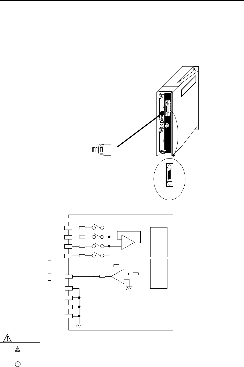
7. Remote I/O Unit Connection
7.13 Connection of FCUA-DX14* Unit and Analog Input/Output Signal
67
7.13 Connection of FCUA-DX14* Unit and Analog Input/Output Signal
For the analog input/output signal, the R031 cable is connected to "AIO". Up to four input points and
one output point of the analog input/output signal can be connected. When manufacturing the R031,
use the connector set CS000 (optional, with two ends). (Refer to the Appendix 2.3. R031 cable.)
DAC
220ΩR
R
150Ω
ADC
AI0
AI1
AI2
AI3
AO
FCUA-DX14*
150Ω
150Ω
150Ω
2
12
3
13
1
11
5
15
7
GND
GND
GND
GND
AIO
FCUA-DX14
1
10
11
20
R031 cable
Pin No.
Input/output circuit
Input
Output
Connector pin No.
Incorrect connections could damage the device, so always connect the cable to the
designated connector.
Do not connect or disconnect the connection cables between each unit while the power
is ON.
CAUTION
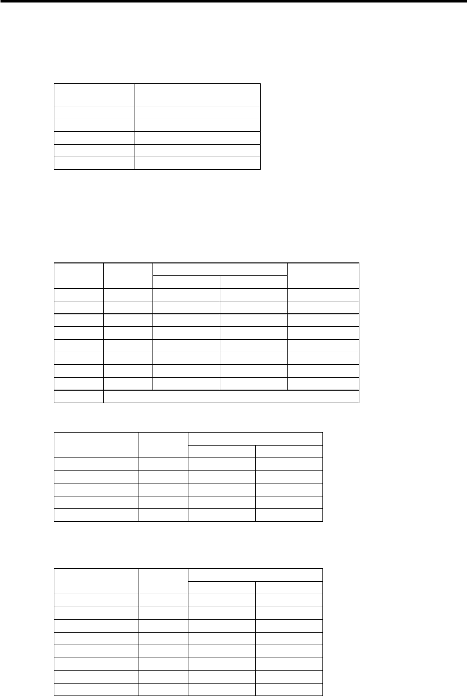
7. Remote I/O Unit Connection
7.14 Setting of Channel No. when Using Multiple Remote I/O Units
68
7.14 Setting of Channel No. when Using Multiple Remote I/O Units
When the remote I/O unit is connected with serial links (MC link B), multiple units can be used as long
as the total No. of occupied channels is within 8 channels.
Unit name No. of occupied serial
link channels
FCUA-DX10* 1
FCUA-DX11* 2
FCUA-DX12* 2
FCUA-DX13* 2
FCUA-DX14* 2
When using multiple remote I/O units, a characteristic station No. must be set for each unit. The
FCUA-DX10* unit has one station No. setting switch, and FCUA-DX11*, DX12*, DX13* and DX14*
units have two switches. Each of these switches must be set to a characteristic station No.
The device address in each unit is determined according to the station No. Use the station No. setting
switch to set the device address.
Relation between rotary switches and device assignments
Device assignment
Setting
value Station
No. DI DO
No. of I/O
points (max)
0 0 X00~X1F Y00~Y1F 32 points
1 1 X20~X3F Y20~Y3F 32 points
2 2 X40~X5F Y40~Y5F 32 points
3 3 X60~X7F Y60~Y7F 32 points
4 4 X80~X9F Y80~Y9F 32 points
5 5 XA0~XBF YA0~YBF 32 points
6 6 XC0~XDF YC0~YDF 32 points
7 7 XE0~XFF YE0~YFF 32 points
8~F Cannot be used
<Device assignment example 1>
Device assignment
Rotary switch
setting value Station
No. DI DO
0 0 X00~X1F Y00~Y1F
1 1 X20~X3F Y20~Y3F
2 2 X40~X5F Y40~Y5F
3 3 X60~X7F Y60~Y7F
4 4 X80~X9F Y80~Y9F
(Note) Refer to the next page for a configuration example.
<Device assignment example 2>
Device assignment
Rotary switch
setting value Station
No. DI DO
0 0 X00~X1F Y00~Y1F
1 1 X20~X3F Y20~Y3F
2 2 X40~X5F Y40~Y5F
3 3 X60~X7F Y60~Y7F
4 4 X80~X9F Y80~Y9F
5 5 XA0~XBF YA0~YBF
6 6 XC0~XDF YC0~YDF
7 7 XE0~XFF YE0~YFF
(Note) Refer to the next page for a configuration example.
7. Remote I/O Unit Connection
7.14 Setting of Channel No. when Using Multiple Remote I/O Units
69
Configuration for <Device assignment example 1> on the previous page
FCUA-DX10* unit
4
FCUA-DX11* unit
or
FCUA-DX12* unit
3
Total No. of occupied cannels: 5
+
2
0
1
FCU6-DX22* unit
+
CS1CS2
No. of occupied channels: 2 No. of occupied channels: 1 No. of occupied channels: 2
Configuration for <Device assignment example 2> on the previous page
0 1 2 3 4 5 6 7
+++
No. of occupied
channels: 2
FCUA-DX11* unit or FCUA-DX12* unit: 3 units
Total No. of occupied channels: 8
(Max. configuration)
FCU6-DX21* unit
No. of occupied
channels: 2
No. of occupied
channels: 2
No. of occupied
channels: 2
(Note) In MELDASMAGIC64, the base I/O unit normally occupies station Nos. 0 and 1.
Both of the examples above are configuration examples when connected to RIO1 (Part
system 1) connectors.
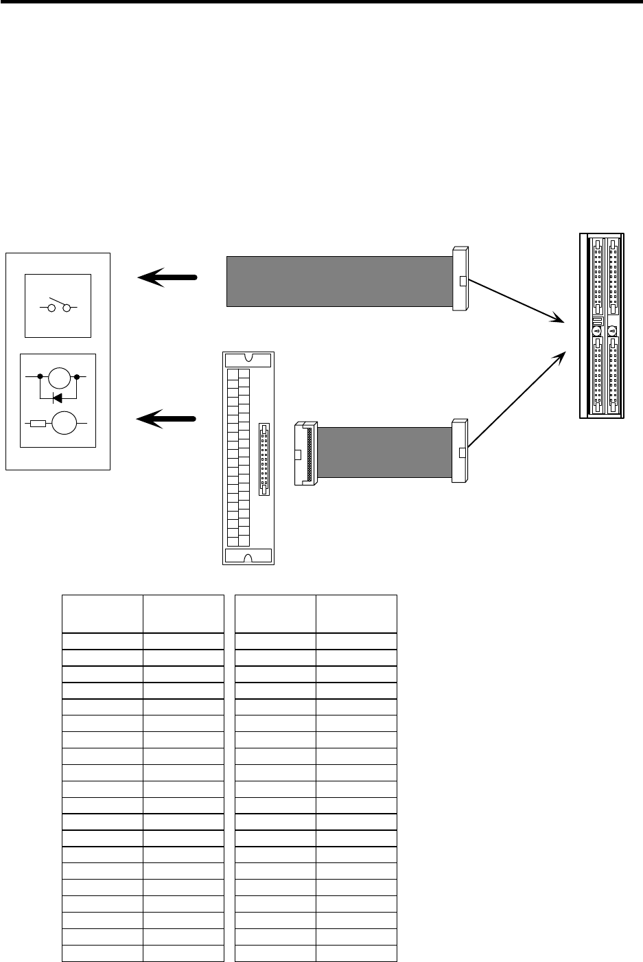
7. Remote I/O Unit Connection
7.15 Remote I/O Unit Input/Output Signal Cables
70
7.15 Remote I/O Unit Input/Output Signal Cables
There are two types of remote I/O unit digital input/output signal cables; the R300 and R301. The R300
cable has one end cut off. The R301 cable is a cable for connecting to the terminal block ∗.
R300-3M and R301-3M are available
If a cable longer than 3m is required, use the connector set CN300 or CS301.
The R041-3M (for one unit) and R042-3M (for two units) are available for the handle cables.
For the analog input/output cable, the R031 cable must be manufactured by the user.
∗ IDEC IZUMI Corporation I/O terminal BX1F-T40A
Machine control panel,
power distribution
panel, etc.
RA
PL R301 cable
IDEC
BX1F-T40A
R300 cable
19 35135791113 15 17 2123 25 2729 31 33 37 39
2468
10 12 14 16 18 20 2224 26 28 30 3432 3638 40
Connector pin correspondence table
Terminal
block
BX1F DX1**
2 B1
4 B2
6 B3
8 B4
10 B5
12 B6
14 B7
16 B8
18 B9
20 B10
22 B11
24 B12
26 B13
28 B14
30 B15
32 B16
34 B17
36 B18
38 B19
40 B20
Terminal
block
BX1F DX1**
1 A1
3 A2
5 A3
7 A4
9 A5
11 A6
13 A7
15 A8
17 A9
19 A10
21 A11
23 A12
25 A13
27 A14
29 A15
31 A16
33 A17
35 A18
37 A19
39 A20
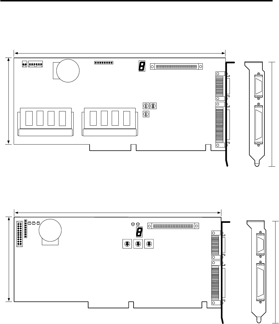
Appendix 1 Outline Drawings
Appendix 1.1 ISA NC Card Outline Drawing (HR621)
71
Appendix 1 Outline Drawings
Appendix 1.1 ISA NC Card Outline Drawing (HR621)
NCLED
BAT CIO
DPADR IOPADR
IRQ
ISABUS ISABUS
CF61CF10
CF61CF10
248.9
100
120
Appendix 1.2 ISA NC Card Outline Drawing (HR623)
CF61CF10
ISABUS ISABUS
NCLD1 CIO
DPADRIOPADRIRQ
BAT
CF10 CF61
248.9
100
120
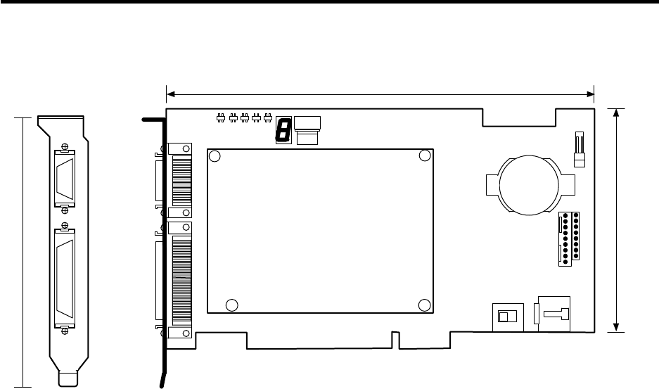
Appendix 1 Outline Drawings
Appendix 1.3 PCI NC Card Outline Drawing (FCU6-HR655)
72
Appendix 1.3 PCI NC Card Outline Drawing (FCU6-HR655)
CF61
CF10
NCLD
CDNO
ISP
TEST
CF61
CF10
PCIBUS
CF62
CF63
SW1
PCIBUS
BAT
106.71
120
174.63
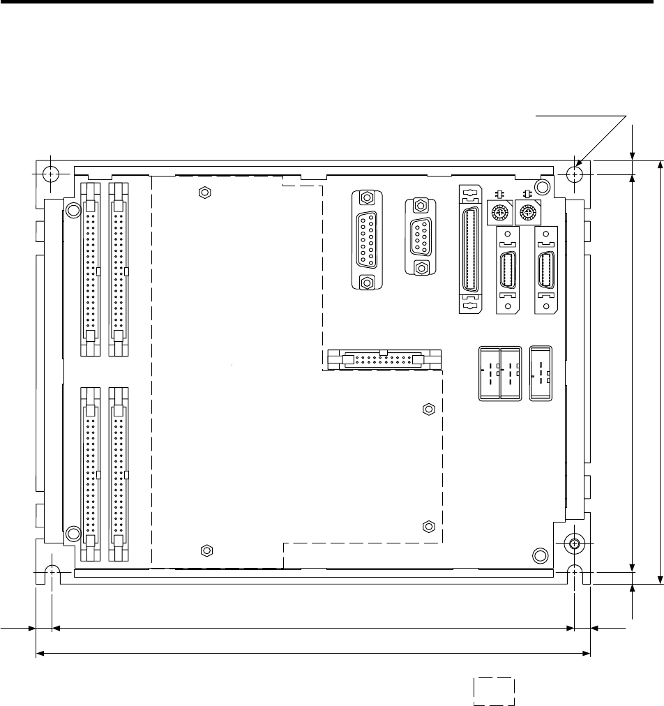
Appendix 1 Outline Drawings
Appendix 1.4 Base I/O Unit Outline Drawing
73
Appendix 1.4 Base I/O Unit Outline Drawing
1
2
3
66 156
168
5
7
9
B
C
D
E
F
4
6
1
2
3
5
7
9
B
C
D
E
F
4
6
88
A
A
ENC1
0 0
CF31 CF32
CF34CF33
CF10 SV2 SV1
SKIP
RIO2 RIO1DCIN
66
220
208
CR31
4-M5 screw hole
Add-on PCB
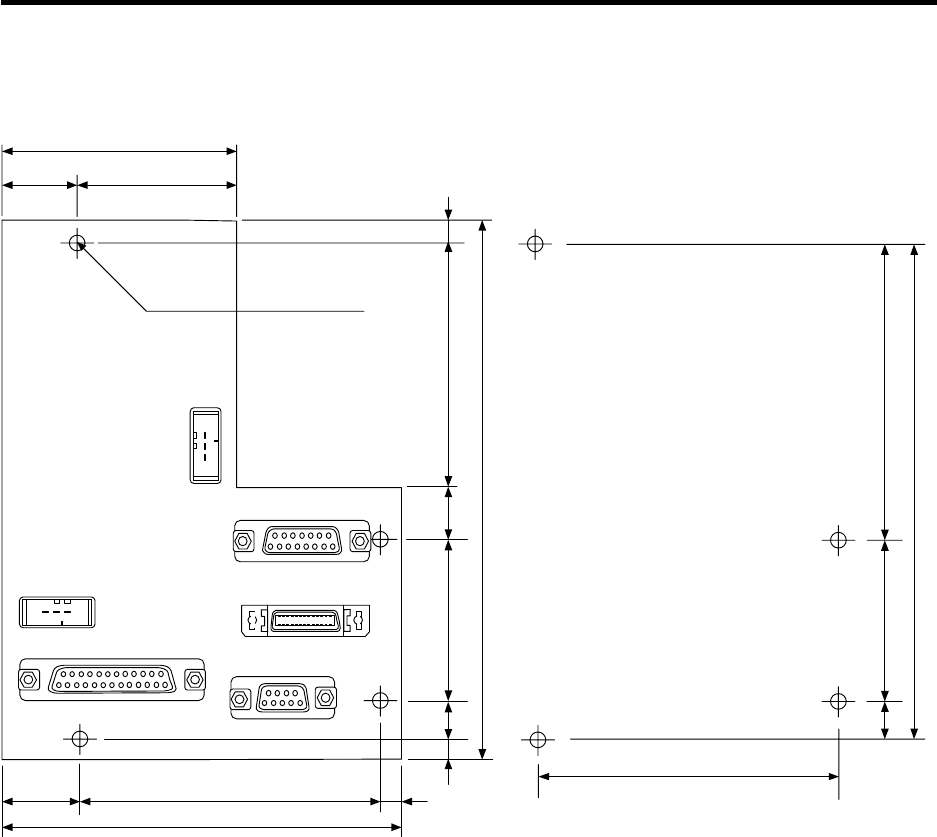
Appendix 1 Outline Drawings
Appendix 1.5 Relay Card (independent installation) Outline Drawing
74
Appendix 1.5 Relay Card (independent installation) Outline Drawing
4-M3 screw hole
70
19 51
19 91
115
5
EMG1
HANDLE
RS232C ENC#2
CF61
DCIN
5
73174610
156
5
904610
146
91
Spacer
Screw diameter: M3×0.5
Outline diameter: Ø8 or less
Length: 6mm or more
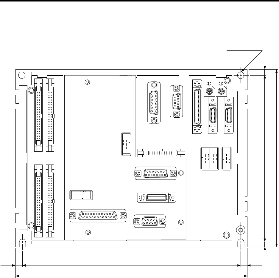
Appendix 1 Outline Drawings
Appendix 1.6 Base I/O Unit + Relay Card (add-on) Outline Drawing
75
Appendix 1.6 Base I/O Unit + Relay Card (add-on) Outline Drawing
0 0
66
220
208
4-M5 screw hole
1
2
3
5
7
9
B
C
D
E
F
4
6
1
2
3
5
7
9
B
C
D
E
F
4
6
88
A
A
ENC1
CF31 CF32
CF34CF33
CF10 SV2 SV1
SKIP
RIO2RIO1DCIN
CR31
EMG1
HANDLE
RS232C ENC#2
CF61
DCIN
66 156
168
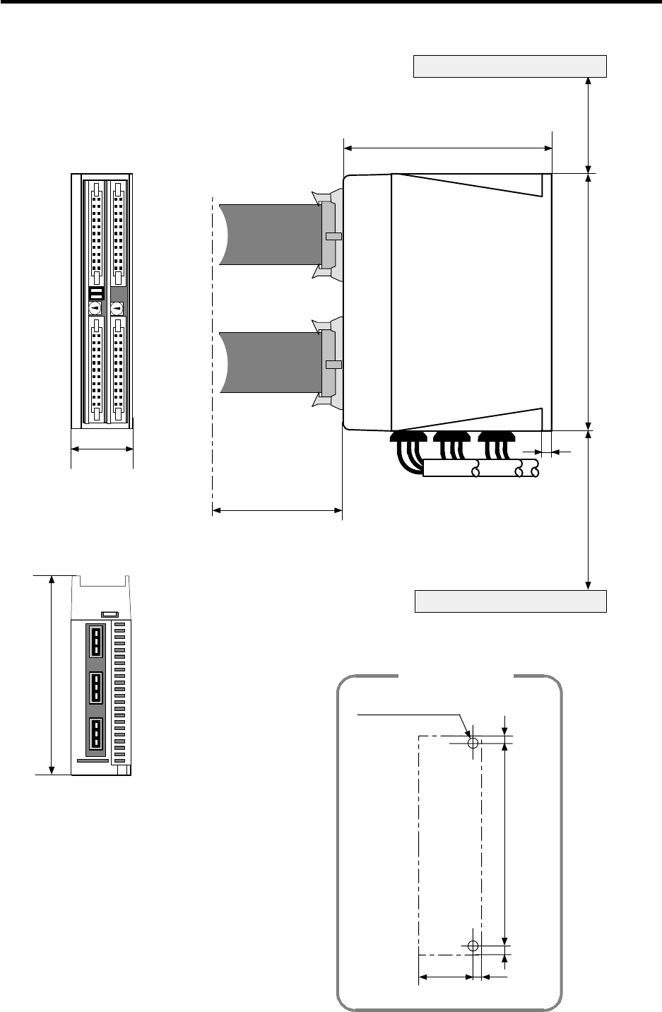
Appendix 1 Outline Drawings
Appendix 1.7 Remote I/O Unit Outline Drawing
76
Appendix 1.7 Remote I/O Unit Outline Drawing
40
2-M5-0.8 screw
634
70
6
135
Wiring allowance
DX
168
135
15666
150 100
Heat dissipation
allowance
Heat dissipation,
wiring allowance
Bottom
Top
Installation hole
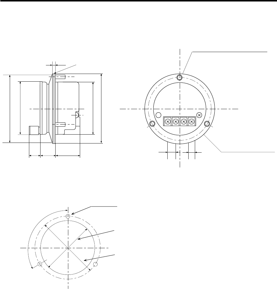
Appendix 1 Outline Drawings
Appendix 1.8 Manual Pulse Generator (HD60) Outline Drawing
77
Appendix 1.8 Manual Pulse Generator (HD60) Outline Drawing
Panel cut drawing
3 - Ø4.8 hole
Ø62 +2
0
Ø72 ± 0.2
Uniform
3-M4 stud bolts L10
8.89 7.60
12V0V A B
Rubber shield t2.0
3.6
16 24 27 ± 0.5
+12V 0V A B
Installation other than
M3 x 6 not possible
Ø77 ± 0.5
120°
(Trisection)
Ø80 ± 1
Ø60 ± 0.5
Ø60 ± 0.5
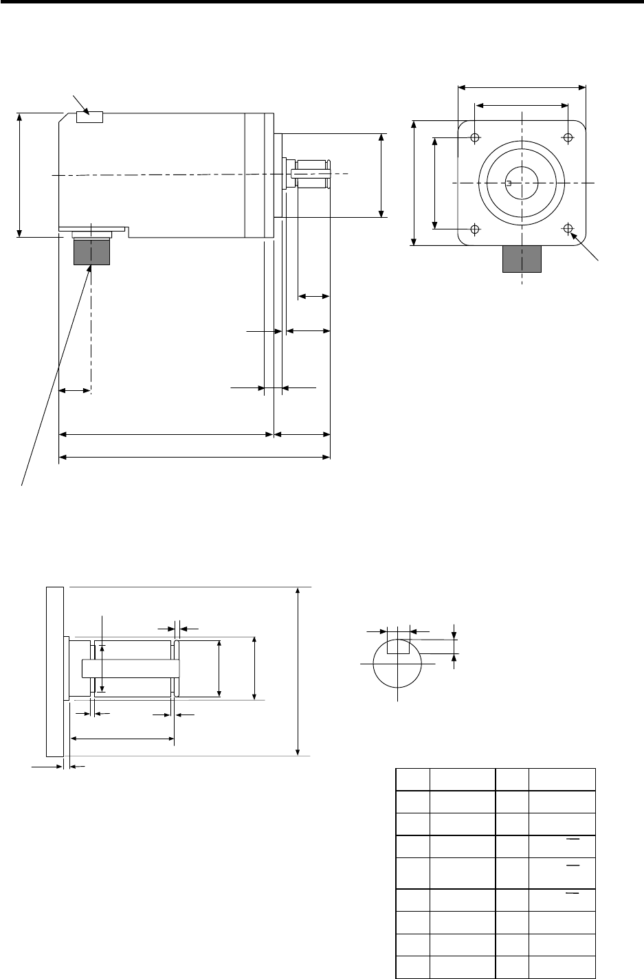
Appendix 1 Outline Drawings
Appendix 1.9 Spindle Encoder (OSE-1024-3-15-68) Outline Drawing
78
Appendix 1.9 Spindle Encoder (OSE-1024-3-15-68) Outline Drawing
4 - Ø5.4 hole
The effective depth of the key way is 21mm
Cross-section BB
Enlarged view of key
56
68
68
56
Ø14.3 0
-0.11
Ø16
Ø50
Ø15 -0.006
-0.017
-0.009
-0.025
3+0.1
0
1.15
+0.14
01.15+0.14
0
2
26
2
5-0.012
-0.042
-0.009
-0.025
19.5
102
135
53
33
228
20
Ø68
Ø50
Detector (1024P/rev)
Caution plate
Encoder side
Applicable cable side
: 97F3102E20-29P (or equivalent)
: MS3106A20-29S
A 1chA K 0V
B2chZ L
C3chB M
D N 1chA
ECase
grounding P 2chZ
F R 3chB
G S
H+5V T
J
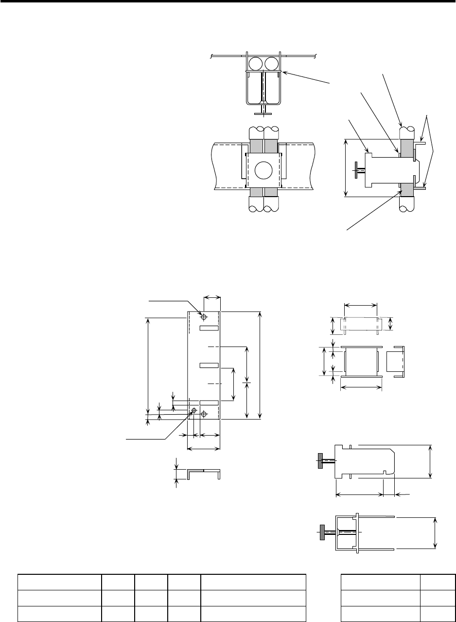
Appendix 1 Outline Drawings
Appendix 1.10 Grounding Plate and Clamp Fitting Outline Drawings
79
Appendix 1.10 Grounding Plate and Clamp Fitting Outline Drawings
The shield wire generally only needs to be
grounded to the connector's case frame.
However, the effect can be improved by
directly grounding to the grounding plate as
shown on the right.
Install the grounding plate near each unit.
Peel part of the cable sheath as shown on
the right to expose the shield sheath. Press
that section against the grounding plate
with the clamp fitting. Note that if the cable
is thin, several can be clamped together.
Install the grounding plate directly onto the
cabinet or connect a grounding wire so that
sufficient frame grounding is achieved.
If the AERSBAN-SET, containing the
grounding plate and clamp fitting, is
required, please contact Mitsubishi.
• Outline drawing
11
35
622
35
a
c
24 0
-0.2
17.5
6
3
7b ± 0.3
Grounding plate
outline drawing 2-Ø5 hole
Installation hole
Note 1 M4 screw
Note 1) Screw hole for wiring to cabinet's grounding plate
Note 2) The grounding plate thickness is 1.6mm
a b c Enclosed fittings L
AERSBAN-DSET 100 86 30 Two clamp fittings A Clamp fitting A 70
AERSBAN-ESET 70 56 – One clamp fitting B Clamp fitting B 45
(Note) a, b and c in the table are symbols in the outline drawing of (Note) L in the table is a
the grounding plate. symbol in the
outline drawing
of the clamp
metal fittings.
MAX L 10
30
+0.3
0
Clamp metal fitting outline drawing
24
Cable
Grounding
plate
Shield sheath
Clamp fitting
(Fitting A,B)
Clamp section drawing
Presser
40
Presser outline drawing
29
3
3
+0.3
0
20
0
-0.2
24
7
12
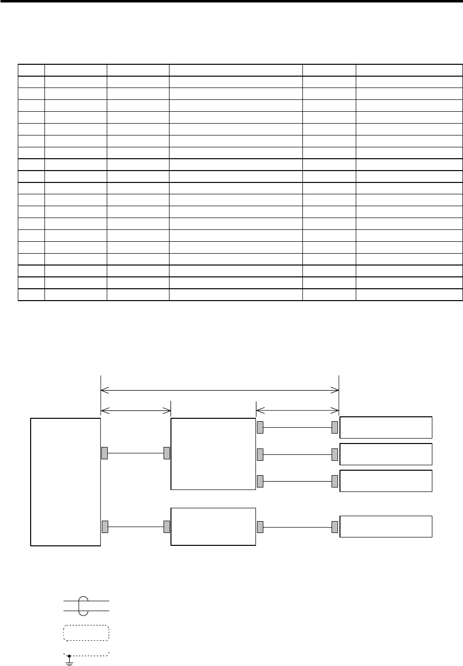
Appendix 2 Cable Manufacturing Drawings
80
Appendix 2 Cable Manufacturing Drawings
Cable type name table
No. Appendix No. Cable type Application Max. length Remarks
1 Appendix 2.1 SH21 cable Servo drive unit * 30m
2 Appendix 2.2 SH41 cable Remote I/O * 50m
3 Appendix 2.3 R031 cable Analog input/output 30m
4 Appendix 2.4 R041 cable Manual pulse generator: 1ch 50m
5 Appendix 2.5 R042 cable Manual pulse generator: 2ch 50m
6 Appendix 2.6 R211 cable Remote I/O * 50m
7 Appendix 2.7 R220 cable DC +24V input, emergency stop 30m
8 Appendix 2.8 R300 cable DI/DO: Single-end connector 50m
9 Appendix 2.9 R301 cable DI/DO: Double-end connector 50m
10 Appendix 2.10 F010 cable I/O interface: Base I/O unit 20m
11 Appendix 2.11 F011 cable I/O interface: Relay card 15m
12 Appendix 2.12 F020 cable Manual pulse generator: 1ch 50m
13 Appendix 2.13 F021 cable Manual pulse generator: 2ch 50m
14 Appendix 2.14 F022 cable Manual pulse generator: 3ch 50m
15 Appendix 2.15 F040 cable Spindle encoder: Straight * 50m
16 Appendix 2.16 F041 cable Spindle encoder: Right angle * 50m
17 Appendix 2.17 F070 cable DC +24V input, emergency stop 30m
18 Appendix 2.18 F390 cable RS232C: 1ch 15m
19 Appendix 2.19 ENC-SP1 cable Spindle drive unit 50m
* For the cables marked with * in the Max. length column:
The cable length (L1) is the length from the NC Card to the base I/O unit and relay card. The cable
length (L2) is the length from the base I/O unit and relay card to each unit. Keep the total cable length
(L1 + L2) within the maximum cable length.
SV1
SV2
RIO1
RIO2
ENC1
F010
L2
L1
SH21
SH41
(R211)
F040/041
F011 ENC#2 F040/041
NC card
Relay card
Servo drive unit
Spindle encoder
Spindle encoder
Base I/O unit
Remote I/O unit
Maximum cable length
Symbols for writing cable manufacturing drawing
The following symbols are used in the cable manufacturing drawing.
1. indicates twist.
2. indicates the shield sheath.
3. indicates shield clamping to the ground plate.
4. In the cable manufacturing drawings, the partner of the twisted pair cable is given a priority, so the pin Nos. of the
connectors at both end are not necessary in number of order.
5. Equivalent parts can be used for the connector, contact and wire material.
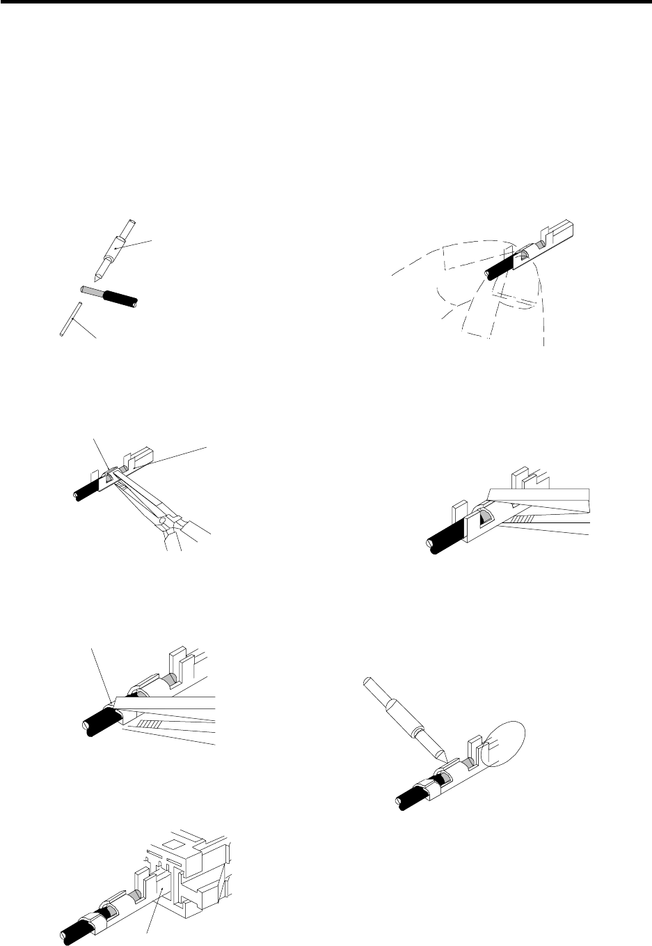
Appendix 2 Cable Manufacturing Drawings
81
As a rule, the cables used with this product are not available from Mitsubishi, excluding the cables
connected between the Mitsubishi devices. Thus, manufacture the required cables using the cable
manufacturing drawings on the following pages as a reference. Note that the cable-compatible
connectors are available from Mitsubishi as the cable set (Appendix 2.20).
If crimp tools are not available when manufacturing the power supply cable (F070, R220) and RIO
communication cable (SH41, R211), the cables can be manufactured by soldering a wire and
connector as shown in the following procedure.
1. Carry out preparatory soldering.
(Remove 3.5mm of the sheath.)
Soldering iron
Wire
Solder
3. Lightly press down one side of
the wire barrel using radio pliers.
Wire barrel This is a barrier to prevent
mis-insertion. Do not bend.
Radio pliers
5. Firmly press down the sheath
keeps in the same manner
as the wire barrel.
Sheath keep
7. Lastly, insert the soldered contact
into the housing.
Pay attention to the
insertion direction.
Contact
Soldering iron
Contact section
Be careful that the solder does
not flow into the contact section.
2. Insert the wire into the contact.
Hold the sheath keep.
4. Firmly press down the other side of the
wire barrel.
(Press firmly enough that the wire will
not come out when pulled lightly.)
6. Apply the soldering iron, and melt
the preparatory solder inside.
Better results will be achieved if an
additional, small amount of solder is
applied then.
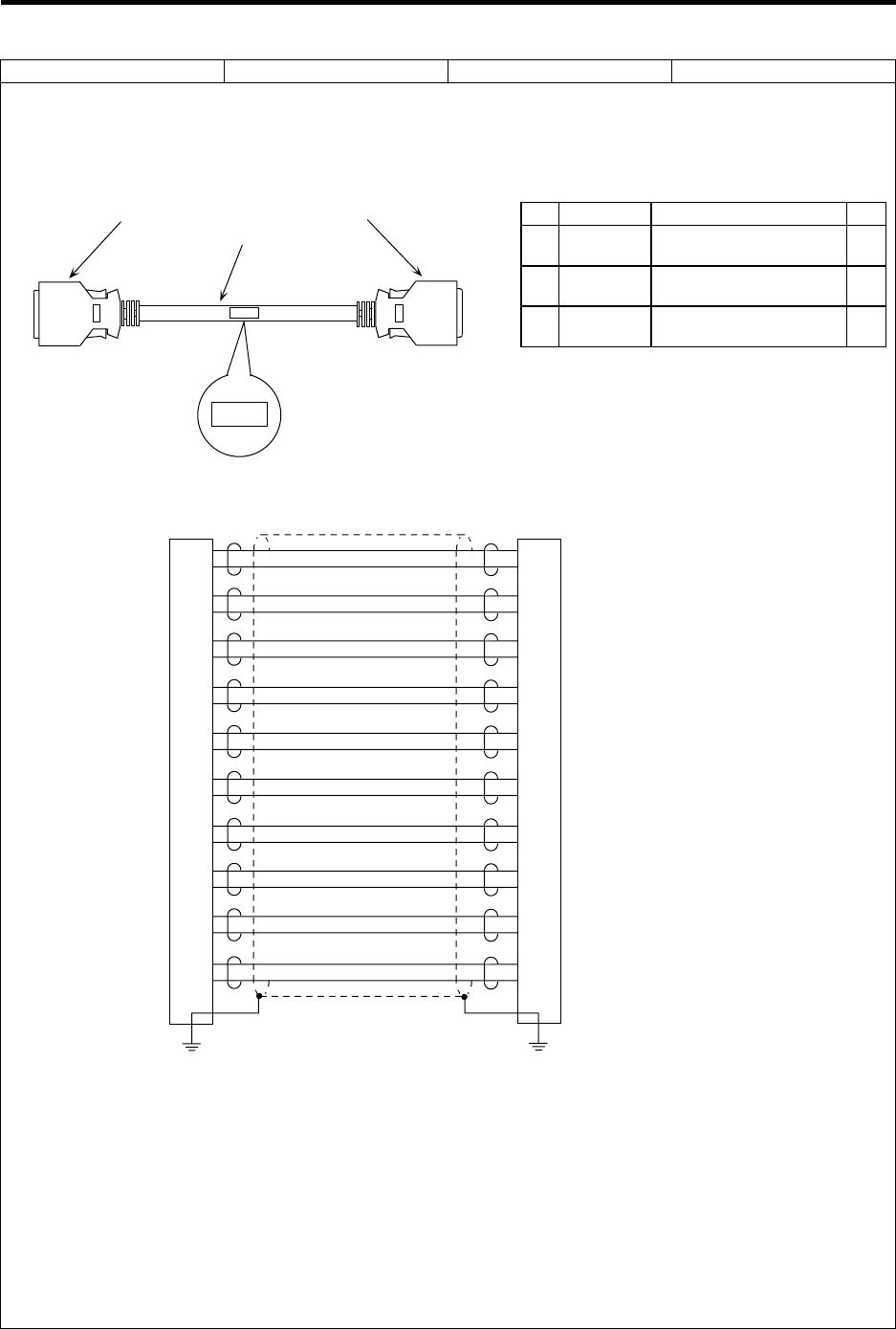
Appendix 2 Cable Manufacturing Drawings
2.1 SH21 Cable (Servo drive unit)
82
Cable type name: SH21 cable Appendix 2.1
Application: Base I/O unit – Servo drive unit connection
Servo drive unit – Servo drive unit connection, etc.
Assembly drawing
(1)(2) (1)(2)
(3)
SH21
SH21
Connection diagram
1
11
2
12
3
13
4
14
5
15
6
16
7
17
8
18
9
19
10
20
FG FG
1
11
2
12
3
13
4
14
5
15
6
16
7
17
8
18
9
19
10
20
Maximum cable length: 30m
Case frame Case frame
Manufacturing precautions
(1) The wire material shall be a shielded, 10-pair stranded cable equivalent to UL20276 Standard
AWG28 (0.08mm2).
(2) The parts used shall be Mitsubishi recommended parts. Equivalent parts may be used
providing they are compatible with the specifications.
(3) Attach the nameplate with protective cover stamped with the cable name in the position
designated in the assembly drawing.
(4) Fold the wire material shield over the sheath, and wrap copper foil tape over it. Connect the
copper foil tape wrapped around the sheath to a connector GND plate.
(5) Part No. 1 (plug) and part No. 2 (shell) are solderless types. If soldering types are required,
use parts equivalent to 10120-3000VE for the plug and 10320-52FO-008 for the shell (both
parts manufactured by Sumitomo 3M).
List of parts used
No. Part name Recommended part type Qty
1 Plug Sumitomo 3M
10120-6000EL 2
2 Shell Sumitomo 3M
10320-3210-000 2
3Wire
material Toyokuni Electric Cable
UL20276 AWG28 × 10P (1)
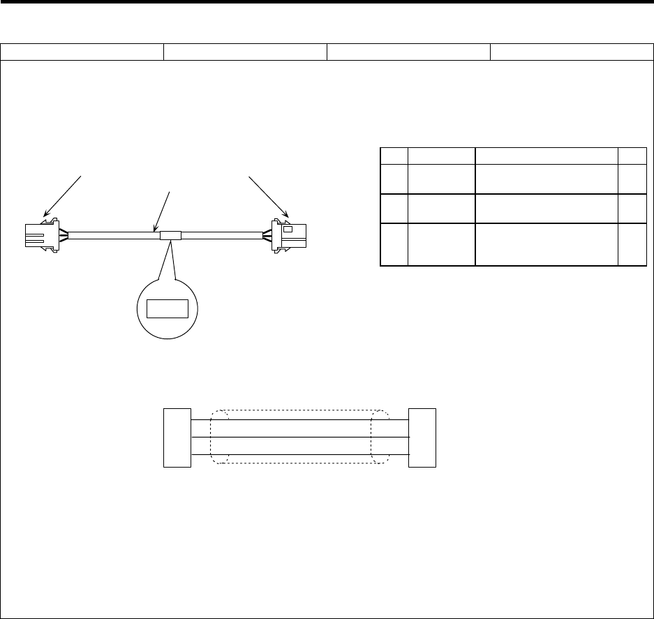
Appendix 2 Cable Manufacturing Drawings
2.2 SH41 Cable (Remote I/O unit)
83
Cable type name: SH41 cable Appendix 2.2
Application: Base I/O unit – Remote I/O unit connection
Remote I/O unit – Remote I/O unit connection
Assembly drawing
X
(1)(2) (1)(2)
(3)
SH41
SH41
Connection diagram
TXRX
TXRX*
GND
1
2
3
1
2
3
TXRX
TXRX*
GND
Maximum cable length: 50m
Manufacturing precautions
(1) The wire material shall be a shielded, 3-core cable equivalent to AWG22 (0.3mm2).
(2) The parts used shall be Mitsubishi recommended parts. Equivalent parts may be used
providing they are compatible with the specifications.
(3) Attach the nameplate with protective cover stamped with the cable name in the position
designated in the assembly drawing.
(4) Protect both ends of the wire with an insulating bush.
List of parts used
No. Part name Recommended part type Qty
1 Connector Tyco Electronics AMP
1-178288-3 2
2 Contact Tyco Electronics AMP
1-175218-2 6
3Wire
material
Takeuchi Densen
MVVS 3C × 0.3mm2
(MIC 3C × 0.3 mm2) (1)
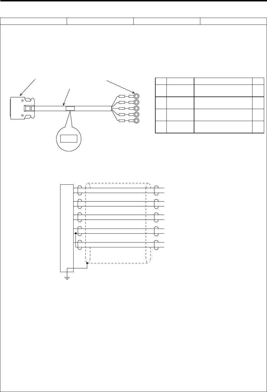
Appendix 2 Cable Manufacturing Drawings
2.3 R031 Cable (Analog signal input/output)
84
Cable type name: R031 cable Appendix 2.3
Application: Analog signal input/output
Assembly drawing
(1)(2) (4)
(3)
R031
R031
Remote I/O unit side Analog input/output signal
Connection diagram
2
1
12
11
3
5
13
15
7
FG
AI0
GND
AI1
GND
AI2
GND
AI3
GND
AO
GND
Remote I/O unit side Analog input/output signal
Maximum cable length: 30m
Case frame
Manufacturing precautions
(1) The wire material shall be a shielded, 6-pair stranded cable equivalent to UL1061-2464
Standard AWG22 (0.3mm2).
(2) The parts used shall be Mitsubishi recommended parts. Equivalent parts may be used
providing they are compatible with the specifications.
(3) Attach the nameplate with protective cover stamped with the cable name in the position
designated in the assembly drawing.
(4) Fold the wire material shield on the remote I/O unit side over the sheath, and wrap copper foil
tape over it. Connect the copper foil tape wrapped around the sheath to a connector GND
plate.
(5) Stamp the name of each signal on the crimp terminal side mark tube and install.
(6) Insulate the crimp terminals of unused signal wires with vinyl tape, etc.
(7) Part 1 (plug) is usually used for wire material of AWG 24 (0.2mm2) or less in the catalog
specifications, but AWG 22 (0.3mm2) can also be used.
Option (compatible connector set)
FCUA-CS000
(Note that this is only compatible with the
remote I/O unit side.)
List of parts used
No. Part name Recommended part type Qty
1 Plug Sumitomo 3M
10120-3000VE 1
2 Shell Sumitomo 3M
10320-52F0-008 1
3Wire
material UL1061-2464
AWG22 × 6P (1)
4Crimp
terminal J.S.T. Mfg
V1.25-4 10
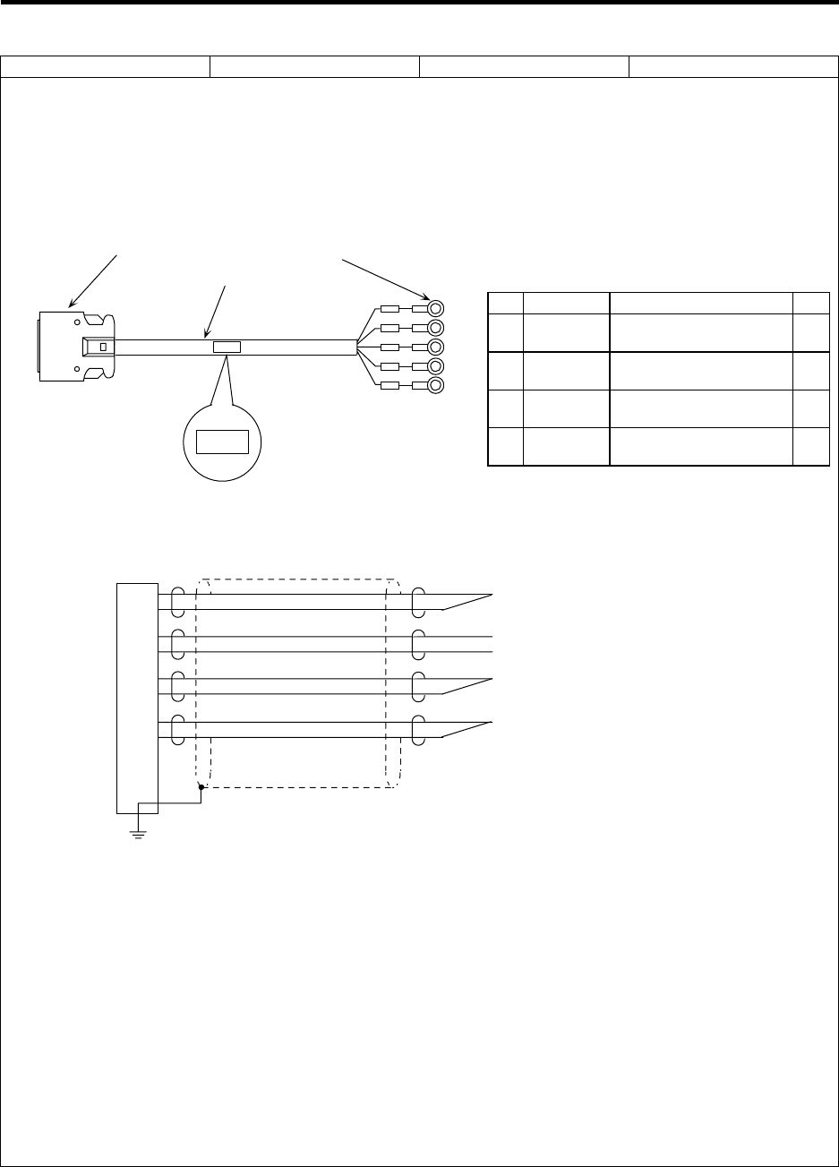
Appendix 2 Cable Manufacturing Drawings
2.4 R041 Cable (Manual pulse generator)
85
Cable type name: R041 cable Appendix 2.4
Application: Remote I/O unit – Manual pulse generator connection
(when one manual pulse generator is connected)
Assembly drawing
(1)(2) (4)
(3)
R041
R041
Remote I/O unit side Manual pulse generator side
Connection diagram
1
11
4
14
5
15
6
16
FG
GND
HA1
HB1
GND
+12V
Case frame
Remote I/O unit side Manual pulse generator side
Maximum cable length: 30m
Manufacturing precautions
(1) The wire material shall be a shielded, 6-pair stranded cable equivalent to UL1061-2464
Standard AWG22 (0.3mm2).
(2) The parts used shall be Mitsubishi recommended parts. Equivalent parts may be used
providing they are compatible with the specifications.
(3) Attach the nameplate with protective cover stamped with the cable name in the position
designated in the assembly drawing.
(4) Fold the wire material shield on the remote I/O unit side over the sheath, and wrap copper foil
tape over it. Connect the copper foil tape wrapped around the sheath to a connector GND
plate.
(5) Stamp the name of each signal on the crimp terminal side mark tube and install.
(6) Part 1 (plug) is usually used for wire material of AWG 24 (0.2mm2) or less in the catalog
specifications, but AWG 22 (0.3mm2) can also be used.
Option (compatible connector set)
FCUA-CS000
(Note that this is only compatible with the
remote I/O unit side.)
List of parts used
No. Part name Recommended part type Qty
1 Plug Sumitomo 3M
10120-3000VE 1
2 Shell Sumitomo 3M
10320-52F0-008 1
3Wire
material UL1061-2464
AWG22 × 6P (1)
4Crimp
terminal J.S.T. Mfg
V1.25-4 5
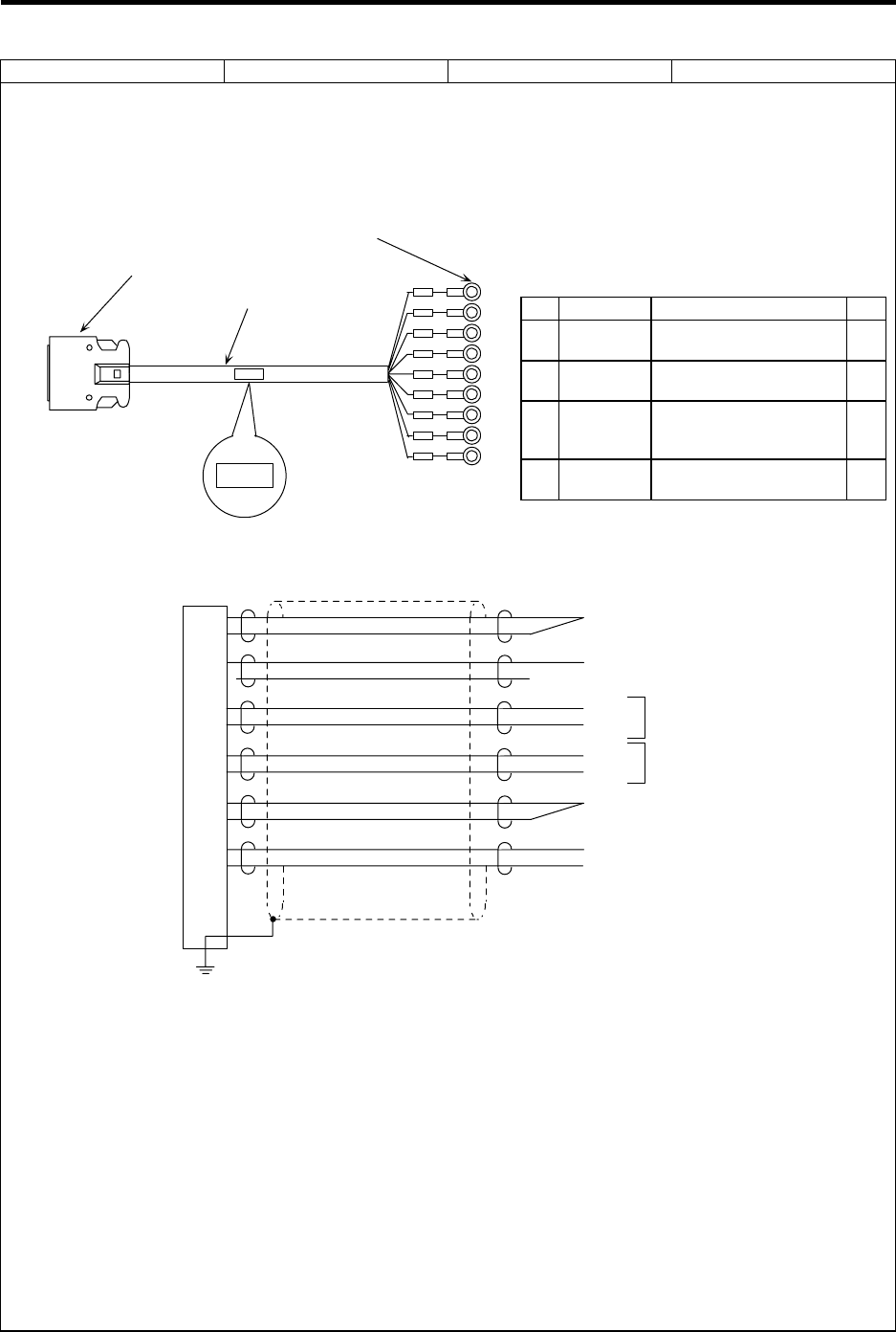
Appendix 2 Cable Manufacturing Drawings
2.5 R042 Cable (Manual pulse generator)
86
Cable type name: R042 cable Appendix 2.5
Application: Remote I/O unit – Manual pulse generator connection
(when two manual pulse generator is connected)
Assembly drawing
(1)(2)
(4)
(3)
R042
R042
Remote I/O unit side
Manual pulse generator side
Connection diagram
1
11
2
3
13
4
14
5
15
6
16
FG
GND
SEL*
HA2
HB2
HA1
HB1
GND
+12V
Case frame
Remote I/O unit side Manual pulse generator side
Maximum cable length: 30m
Channel 2
Channel 1
(When using channel 2, connect the SEL* signal to the GND.)
Manufacturing precautions
(1) The wire material shall be a shielded, 6-pair stranded cable equivalent to UL1061-2464
Standard AWG22 (0.3mm2).
(2) The parts used shall be Mitsubishi recommended parts. Equivalent parts may be used
providing they are compatible with the specifications.
(3) Attach the nameplate with protective cover stamped with the cable name in the position
designated in the assembly drawing.
(4) Fold the wire material shield on the remote I/O unit side over the sheath, and wrap copper foil
tape over it. Connect the copper foil tape wrapped around the sheath to a connector GND
plate.
(5) Stamp the name of each signal on the crimp terminal side mark tube and install.
(6) Part 1 (plug) is usually used for wire material of AWG 24 (0.2mm2) or less in the catalog
specifications, but AWG 22 (0.3mm2) can also be used.
Option (compatible connector set)
FCUA-CS000
(Note that this is only compatible with the
remote I/O unit side.)
List of parts used
No. Part name Recommended part type Qty
1 Plug Sumitomo 3M
10120-3000VE 1
2 Shell Sumitomo 3M
10320-52F0-008 1
3Wire
material
Wire material
UL1061-2464
AWG22 × 6P (1)
4Crimp
terminal J.S.T. Mfg
V1.25-4 9
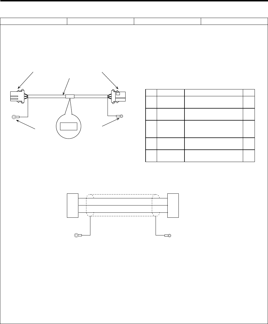
Appendix 2 Cable Manufacturing Drawings
2.6 R211 Cable (Remote I/O unit)
87
Cable type name: R211 cable Appendix 2.6
Application: Base I/O unit – Remote I/O unit connection
Remote I/O unit – Remote I/O unit connection
Assembly drawing
X
(1)(2) (1)(2)
(3)
R211
R211
(5) (4)
Connection diagram
TXRX
TXRX*
GND
1
2
3
1
2
3
TXRX
TXRX*
GND
Maximum cable length: 50m
FG FG
Manufacturing precautions
(1) The wire material shall be a shielded, 3-core cable equivalent to AWG20 (0.5mm2).
(2) The parts used shall be Mitsubishi recommended parts. Equivalent parts may be used
providing they are compatible with the specifications.
(3) Attach the nameplate with protective cover stamped with the cable name in the position
designated in the assembly drawing.
(4) Protect both ends of the wire with an insulating bush.
(5) Connect the crimp terminal attached to the shield to the frame ground of the base I/O unit or
remote I/O unit.
Note that for noise resistance improvement, in some cases only one end is connected, both
ends are connected or neither end is connected.
Option (compatible connector set)
FCUA-CN211
(Note that there is a single-end connector
and contact, with no crimp terminal.)
List of parts used
No. Part name Recommended part type Qty
1 Connector Tyco Electronics AMP
1-178288-3 2
2Contact Tyco Electronics AMP
1-175218-2 6
3Wire
material
Takeuchi Densen
MVVS 3C × 0.5 mm2
(MIC 3C × 0.5 mm2) (1)
4Crimp
terminal J.S.T. Mfg
V1.25-3 1
5Crimp
terminal J.S.T. Mfg
V1.25-5 1
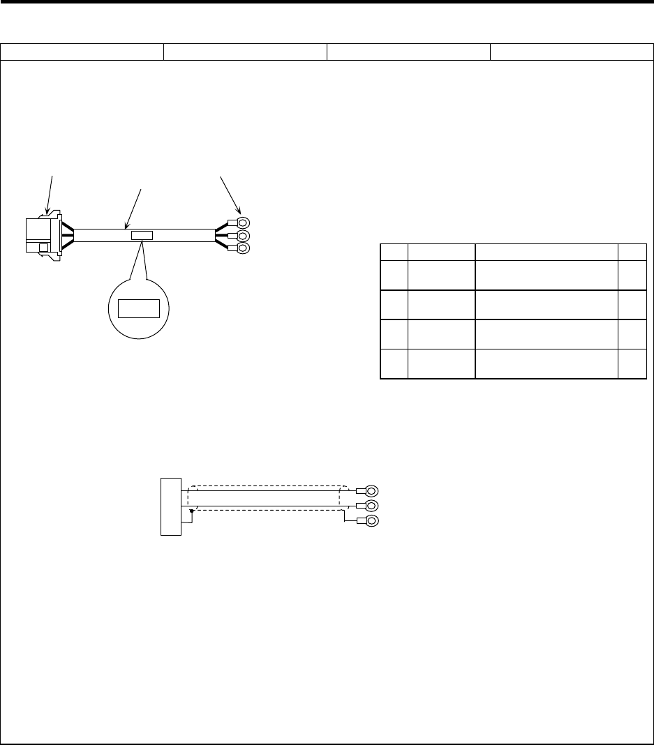
Appendix 2 Cable Manufacturing Drawings
2.7 R220 Cable (+24VDC input)
88
Cable type name: R220 cable Appendix 2.7
Application: +24V supply to the base I/O unit, relay card and remote I/O unit
Input of emergency stop signal to the relay card
Assembly drawing
Y
(1)(2) (4)
(3)
R220
R220
Connection diagram
+24V
GND
FG
1
2
3
+24V
GND
FG
Maximum cable length: 30m
Manufacturing precautions
(1) The wire material shall be a shielded, 1-pair stranded cable equivalent to AWG18 (0.75mm2).
If the cable length exceeds 15m, select wire material equivalent to AWG16.
(2) The parts used shall be Mitsubishi recommended parts. Equivalent parts may be used
providing they are compatible with the specifications.
(3) Attach the nameplate with protective cover stamped with the cable name in the position
designated in the assembly drawing.
(4) Stamp the name of each signal on the crimp terminal side mark tube and install.
(5) Protect both ends of the wire with an insulating bush.
(6) Use shield processing wire material equivalent to AWG18 (0.75mm2).
Option (compatible connector set)
FCUA-CN220
(Note that this is only compatible with the
base I/O unit, relay card and remote I/O unit
side connectors.)
List of parts used
No. Part name Recommended part type Qty
1 Connector Tyco Electronics AMP
1-178288-3 1
2 Contact Tyco Electronics AMP
2-175218-5 3
3Wire
material DDK
JPVV-SB 1P × 0.5 mm2 (1)
4Crimp
terminal J.S.T. Mfg
V1.25-3 3
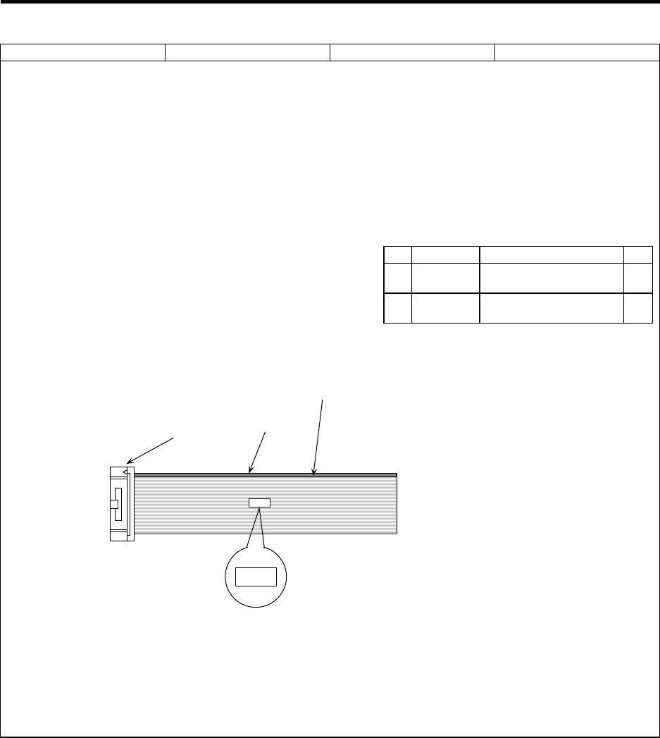
Appendix 2 Cable Manufacturing Drawings
2.8 R300 Cable (Machine input/output)
89
Cable type name: R300 cable Appendix 2.8
Application: Base I/O unit and remote I/O unit
– Machine electric cabinet connection
Assembly drawing
(2)
R300
R300
(1)
Base I/O unit and
remote I/O unit side
The No.1 pin cable is colored.
Maximum cable length: 50m
Machine electric cabinet side
Manufacturing precautions
(1) The parts used shall be Mitsubishi recommended parts. Equivalent parts may be used
providing they are compatible with the specifications.
(2) Attach the nameplate with protective cover stamped with the cable name in the position
designated in the assembly drawing.
Option (compatible connector set)
FCUA-CN300
(Note that this is only compatible with the
base I/O unit and remote I/O unit side
connectors.)
List of parts used
No. Part name Recommended part type Qty
1 Connector Sumitomo 3M
7940-6500SC 1
2Wire
material Oki Electric Cable
B40-S (1)
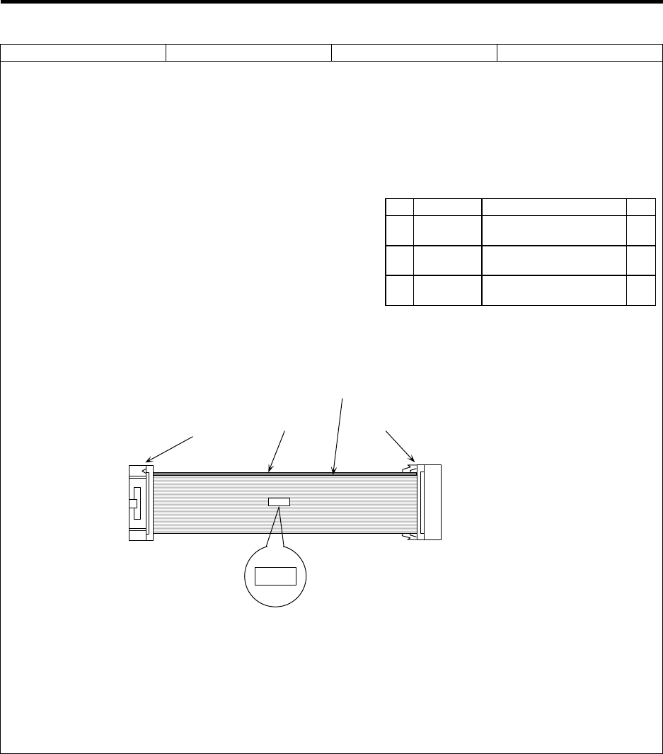
Appendix 2 Cable Manufacturing Drawings
2.9 R301 Cable (Machine input/output)
90
Cable type name: R301 cable Appendix 2.9
Application: Base I/O unit and remote I/O unit
– Recommended terminal block
Assembly drawing
(2)
R301
R301
(1) (1)(3)
Base I/O unit and
remote I/O unit side
The No.1 pin cable is colored.
Maximum cable length: 50m
Recommended terminal block side
Manufacturing precautions
(1) The parts used shall be Mitsubishi recommended parts. Equivalent parts may be used
providing they are compatible with the specifications.
(2) Attach the nameplate with protective cover stamped with the cable name in the position
designated in the assembly drawing.
(3) The recommended terminal block is the IDEC IZUMI I/O terminal BX1F-T40.
Option (compatible connector set)
FCUA-CS301
List of parts used
No. Part name Recommended part type Qty
1 Connector Sumitomo 3M
7940-6500SC 2
2Wire
material Oki Electric Cable
B40-S (1)
3 Strain relief Sumitomo 3M
3448-7940 1
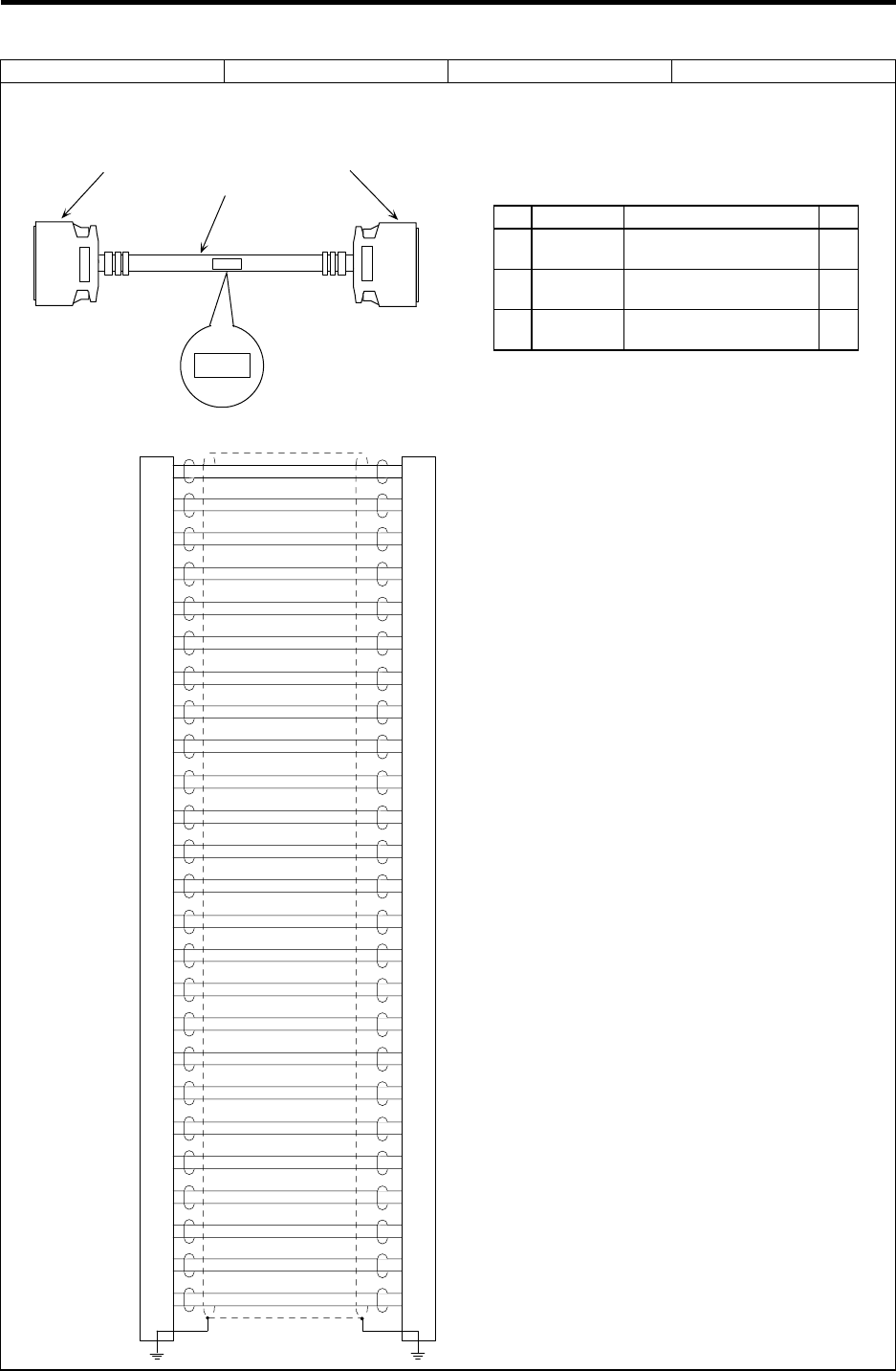
Appendix 2 Cable Manufacturing Drawings
2.10 F010 Cable (NC Card)
91
Cable type name: F010 cable Appendix 2.10
Application: NC Card – Base I/O unit connection
Assembly drawing
(1)(2) (1)(2)
(3)
F010
F010
Connection diagram
TXRX1
TXRX1*
TXRX2
TXRX2*
GND
GND
SKIP1
SKIP1*
SKIP2
SKIP2*
SKIP3
SKIP3*
SKIP4
SKIP4*
SKIP5
SKIP5*
SKIP6
SKIP6*
SKIP7
SKIP7*
SKIP8
SKIP8*
GND
GND
ENC1A
ENC1A*
ENC1B
ENC1B*
ENC1Z
ENC1Z*
GND
GND
SVTXD2
SVTXD2*
SVALM2
SVALM2*
SVRXD2
SVRXD2*
SVEMG2
SVEMG2*
GND
GND
SVTXD1
SVTXD1*
SVALM1
SVALM1*
SVRXD1
SVRXD1*
SVEMG1
SVEMG1*
1
26
2
27
3
28
4
29
5
30
6
31
7
32
8
33
9
34
10
35
11
36
12
37
13
38
14
39
15
40
16
41
17
42
18
43
19
44
20
45
21
46
22
47
23
48
24
49
25
50
1
26
2
27
3
28
4
29
5
30
6
31
7
32
8
33
9
34
10
35
11
36
12
37
13
38
14
39
15
40
16
41
17
42
18
43
19
44
20
45
21
46
22
47
23
48
24
49
25
50
FG FG
Maximum cable length: 20m
Case frame Case frame
List of parts used
No. Part name Recommended part type Qty
1 Plug Sumitomo 3M
10150-6000EL 2
2 Shell Sumitomo 3M
10350-321-000 2
3Wire
material Toyokuni Electric Cable
UL20276 AWG28 × 25P (1)
Manufacturing precautions
(1) The wire material shall be a shielded,
25-pair stranded cable equivalent to
UL20276 Standard AWG28
(0.08mm2).
(2) The parts used shall be Mitsubishi
recommended parts. Equivalent parts
may be used providing they are
compatible with the specifications.
(3) Attach the nameplate with protective
cover stamped with the cable name in
the position designated in the
assembly drawing.
(4) Fold the wire material shield over the
sheath, and wrap copper foil tape ove
r
it. Connect the copper foil tape
wrapped around the sheath to a
connector GND plate.
(5) Part No. 1 (plug) and part No. 2 (shell)
are solderless types. If soldering types
are required, use parts equivalent to
10150-3000VE for the plug and
10350-52FO-008 for the shell (both
parts manufactured by Sumitomo 3M).
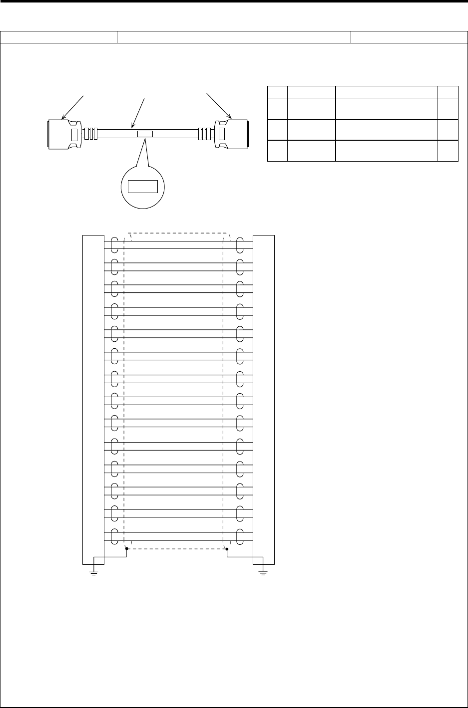
Appendix 2 Cable Manufacturing Drawings
2.11 F011 Cable (NC Card)
92
Cable type name: F011 cable Appendix 2.11
Application: NC Card – Relay card connection
Assembly drawing
(1)(2) (1)(2)
(3)
F011
F011
Connection diagram
TD0
RD0
LED1
LED2
LED3
EMGOUT*
EMGIN
EMGIN*
GND
GND
HA1A
HA1B
HA2A
HA2B
HA3A
HA3B
DR0
DC0
GND
GND
EN2A
EN2A*
EN2B
EN2B*
EN2Z
EN2Z*
1
14
2
15
3
16
4
17
5
18
6
19
7
20
8
21
9
22
10
23
11
24
12
25
13
26
FG FG
1
14
2
15
3
16
4
17
5
18
6
19
7
20
8
21
9
22
10
23
11
24
12
25
13
26
Case frame Case frame
Maximum cable length: 15m
Manufacturing precautions
(1) The wire material shall be a shielded, 15-pair stranded cable equivalent to UL20276 Standard
AWG28 (0.08mm2).
(2) The parts used shall be Mitsubishi recommended parts. Equivalent parts may be used
providing they are compatible with the specifications.
(3) Attach the nameplate with protective cover stamped with the cable name in the position
designated in the assembly drawing.
(4) Fold the wire material shield over the sheath, and wrap copper foil tape over it. Connect the
copper foil tape wrapped around the sheath to a connector GND plate.
(5) Part No. 1 (plug) and part No. 2 (shell) are solderless types. If soldering types are required,
use parts equivalent to 10126-3000VE for the plug and 10326-52FO-008 for the shell (both
parts manufactured by Sumitomo 3M).
List of parts used
No. Part name Recommended part type Qty
1 Plug Sumitomo 3M
10126-6000EL 2
2 Shell Sumitomo 3M
10326-3210-000 2
3Wire
material Toyokuni Electric Cable
UL20276 AWG28 × 15P (1)
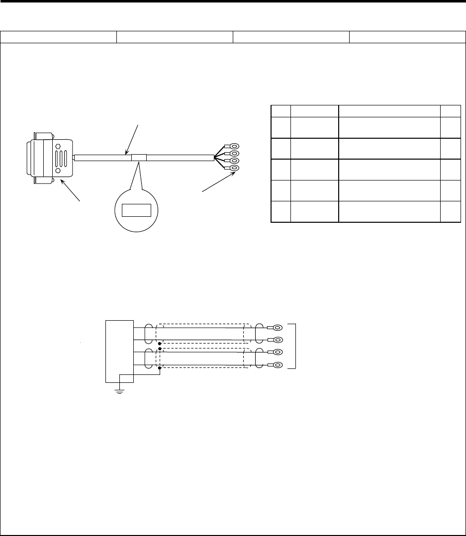
Appendix 2 Cable Manufacturing Drawings
2.12 F020 Cable (Manual pulse generator)
93
Cable type name: F020 cable Appendix 2.12
Application: Relay card – Manual pulse generator connection
(when one manual pulse generator is connected)
Assembly drawing
(1)(2)(3)
(4)
(5)
F020
F020
Relay card side
Manual pulse generator side
Connection diagram
1
2
10
9
1HA
1HB
+12V
GND
1ch
FG
Relay card side Manual pulse generator side
Maximum cable length: 50m
Case frame
Manufacturing precautions
(1) The wire material shall be a shielded, 2-pair stranded cable equivalent to AWG22 (0.3mm2).
(2) The parts used shall be Mitsubishi recommended parts. Equivalent parts may be used
providing they are compatible with the specifications.
(3) Attach the nameplate with protective cover stamped with the cable name in the position
designated in the assembly drawing.
(4) Fold the wire material shield on the relay card side over the sheath, and wrap copper foil tape
over it. Connect the copper foil tape wrapped around the sheath to a connector GND plate.
(5) Stamp the name of each signal on the crimp terminal side mark tube and install.
List of parts used
No. Part name Recommended part type Qty
1 Connector Hirose Electric
CDA-15P 1
2 Contact Hirose Electric
CD-PC-111 4
3Connector
case Hirose Electric
HAD-CTH 1
4Wire
material Sumitomo Electric
B-22 (19) U × 2SJ-1 × 9 (2)
5Crimp
terminal J.S.T. Mfg
V1.25-3 4
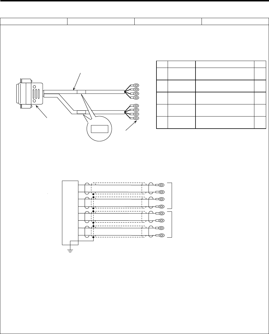
Appendix 2 Cable Manufacturing Drawings
2.13 F021 Cable (Manual pulse generator)
94
Cable type name: F021 cable Appendix 2.13
Application: Relay card – Manual pulse generator connection
(when two manual pulse generators are connected)
Assembly drawing
(1)(2)(3)
(4)
(5)
F021
F021
F021
Relay card side Manual pulse generator side
Connection diagram
1
2
10
9
3
4
12
11
1HA
1HB
+12V
GND
2HA
2HB
+12V
GND
1ch
2ch
Relay card side Manual pulse generator side
Maximum cable length: 50m
Case frame
FG
Manufacturing precautions
(1) The wire material shall be a shielded, 4-pair stranded cable equivalent to AWG22 (0.3mm2).
(2) The parts used shall be Mitsubishi recommended parts. Equivalent parts may be used
providing they are compatible with the specifications.
(3) Attach the nameplate with protective cover stamped with the cable name in the position
designated in the assembly drawing.
(4) Fold the wire material shield on the relay card side over the sheath, and wrap copper foil tape
over it. Connect the copper foil tape wrapped around the sheath to a connector GND plate.
(5) Stamp the name of each signal on the crimp terminal side mark tube and install.
List of parts used
No. Part name Recommended part type Qty
1 Connector Hirose Electric
CDA-15P 1
2 Contact Hirose Electric
CD-PC-111 8
3Connector
case Hirose Electric
HAD-CTH 1
4Wire
material Sumitomo Electric
B-22 (19) U × 2SJ-1 × 9 (4)
5Crimp
terminal J.S.T. Mfg
V1.25-3 8
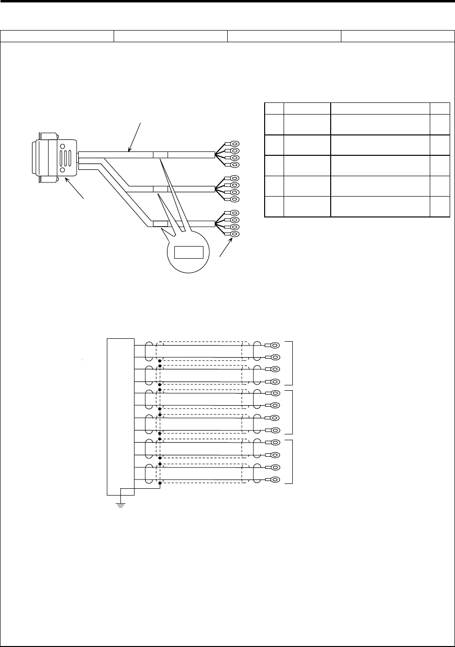
Appendix 2 Cable Manufacturing Drawings
2.14 F022 Cable (Manual pulse generator)
95
Cable type name: F022 cable Appendix 2.14
Application: Relay card – Manual pulse generator connection
(when three manual pulse generators are connected)
Assembly drawing
(1)(2)(3)
(4)
(5)
F022
F022
F022
Relay card side Manual pulse generator side
F022
Connection diagram
1
2
10
9
3
4
12
11
5
6
14
13
1HA
1HB
+12V
GND
2HA
2HB
+12V
GND
3HA
3HB
+12V
GND
1ch
Relay card side Manual pulse generator side
2ch
Maximum cable length: 50m
3ch
Case frame
FG
Manufacturing precautions
(1) The wire material shall be a shielded, 6-pair stranded cable equivalent to AWG22 (0.3mm2).
(2) The parts used shall be Mitsubishi recommended parts. Equivalent parts may be used
providing they are compatible with the specifications.
(3) Attach the nameplate with protective cover stamped with the cable name in the position
designated in the assembly drawing.
(4) Fold the wire material shield on the relay card side over the sheath, and wrap copper foil tape
over it. Connect the copper foil tape wrapped around the sheath to a connector GND plate.
(5) Stamp the name of each signal on the crimp terminal side mark tube and install.
List of parts used
No. Part name Recommended part type Qty
1 Connector Hirose Electric
CDA-15P 1
2 Contact Hirose Electric
CD-PC-111 12
3Connector
case Hirose Electric
HAD-CTH 1
4Wire
material Sumitomo Electric
B-22 (19) U × 2SJ-1 × 9 (6)
5Crimp
terminal J.S.T. Mfg
V1.25-3 12
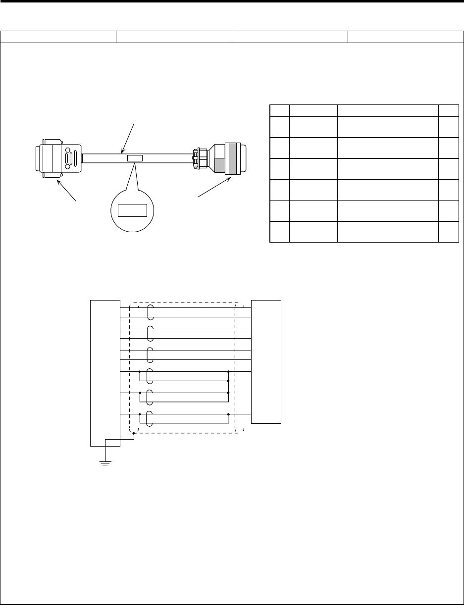
Appendix 2 Cable Manufacturing Drawings
2.15 F040 Cable (Spindle encoder)
96
Cable type name: F040 cable Appendix 2.15
Application: Base I/O unit – Spindle encoder (straight) connection
Relay card – Spindle encoder (straight) connection
Assembly drawing
(1)(2)(3)
(4)
(5)(6)
F040
F040
Base I/O unit and
relay card side Spindle encoder (straight) side
Connection diagram
ENC1A (ENC2A)
ENC1A*(ENC2A*)
ENC1B (ENC2B)
ENC1B*(ENC2B*)
ENC1Z (ENC2Z)
ENC1Z*(ENC2Z*)
GND
GND
+5V
1
6
2
7
3
8
4
5
9
A
N
C
R
B
P
K
H
FG
Base I/O unit and
relay card side Spindle encoder side (straight)
Maximum cable length: 50m
Case frame
(Note) Signal names in parentheses
are equivalent to the channel
2 signal names.
Manufacturing precautions
(1) The wire material shall be a shielded, 6-pair stranded cable equivalent to AWG24 (0.2mm2).
(2) The parts used shall be Mitsubishi recommended parts. Equivalent parts may be used
providing they are compatible with the specifications.
(3) Attach the nameplate with protective cover stamped with the cable name in the position
designated in the assembly drawing.
(4) Fold the wire material shield on the base I/O unit and relay card side over the sheath, and
wrap copper foil tape over it.
Connect the wound copper foil tape to the connector's GND plate.
List of parts used
No. Part name Recommended part type Qty
1 Connector Hirose Electric
CDE-9PF 1
2 Contact Hirose Electric
CD-PC-111 9
3Connector
case Hirose Electric
HDE-CTH 1
4Wire
material Bando Electric Wire
DPVVSB 6P × 0.2 mm2 (1)
5 Connector ITT Canon
MS3106B20-29S 1
6Cable
clamp ITT Canon
MS3057-12A 1
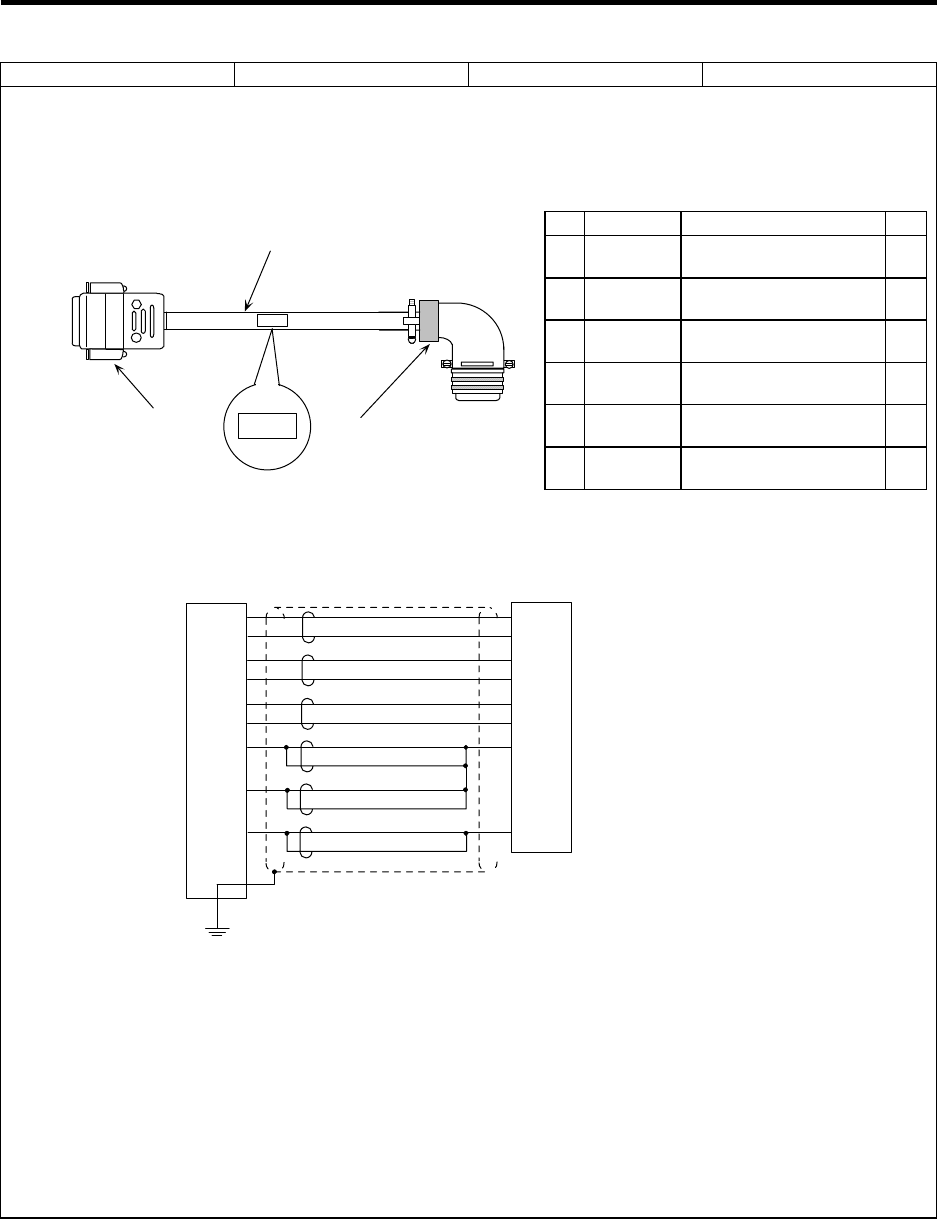
Appendix 2 Cable Manufacturing Drawings
2.16 F041 Cable (Spindle encoder)
97
Cable type name: F041 cable Appendix 2.16
Application: Base I/O unit – Spindle encoder (right angle) connection
Relay card – Spindle encoder (right angle) connection
Assembly drawing
(1)(2)(3)
(4)
(5)(6)
F041
F041
Base I/O unit and
relay card side Spindle encoder
(right angle) side
Connection diagram
ENC1A (ENC2A)
ENC1A*(ENC2A*)
ENC1B (ENC2B)
ENC1B*(ENC2B*)
ENC1Z (ENC2Z)
ENC1Z*(ENC2Z*)
GND
GND
+5V
1
6
2
7
3
8
4
5
9
A
N
C
R
B
P
K
H
Base I/O unit,
Relay card side Spindle encoder side (right angle)
Maximum cable length: 50m
Case frame
(Note) Signal names in parentheses
are equivalent to the channel
2 signal names.
FG
Manufacturing precautions
(1) The wire material shall be a shielded, 6-pair stranded cable equivalent to AWG24 (0.2mm2).
(2) The parts used shall be Mitsubishi recommended parts. Equivalent parts may be used
providing they are compatible with the specifications.
(3) Attach the nameplate with protective cover stamped with the cable name in the position
designated in the assembly drawing.
(4) Fold the wire material shield on the base I/O unit and relay card side over the sheath, and
wrap copper foil tape over it.
Connect the wound copper foil tape to the connector's GND plate.
List of parts used
No. Part name Recommended part type Qty
1 Connector Hirose Electric
CDE-9PF 1
2 Contact Hirose Electric
CD-PC-111 9
3Connector
case Hirose Electric
HDE-CTH 1
4Wire
material Bando Electric Wire
DPVVSB 6P × 0.2 mm2 (1)
5 Connector ITT Canon
MS3108B20-29S 1
6Cable
clamp ITT Canon
MS3057-12A 1
Appendix 2 Cable Manufacturing Drawings
2.17 F070 Cable (+24VDC input)
98
Cable type name: F070 cable Appendix 2.17
Application: +24V supply to the base I/O unit, relay card and remote I/O unit
Input of emergency stop signal to the relay card
Assembly drawing
Y
(1)(2) (4)
(3)
F070
F070
Connection diagram
+24V
GND
1
2
3
+24V
GND
Maximum cable length: 30m
Manufacturing precautions
(1) The wire material shall be a shielded, 1-pair stranded cable equivalent to AWG18 (0.75mm2).
If the cable length exceeds 15m, select wire material equivalent to AWG16.
(2) The parts used shall be Mitsubishi recommended parts. Equivalent parts may be used
providing they are compatible with the specifications.
(3) Attach the nameplate with protective cover stamped with the cable name in the position
designated in the assembly drawing.
(4) Stamp the name of each signal on the crimp terminal side mark tube and install.
(5) Protect both ends of the wire with an insulating bush.
(6) Use shield processing wire material equivalent to AWG18 (0.75mm2).
Option (compatible connector set)
FCUA-CN220
(Note that this is only compatible with the
base I/O unit, relay card and remote I/O unit
side connectors.)
List of parts used
No. Part name Recommended part type Qty
1 Connector Tyco Electronics AMP
1-178288-3 1
2 Contact Tyco Electronics AMP
2-175218-5 2
3Wire
material Sumitomo Electric
B-18 (19) U × 2SJ-1 × 9 (1)
4Crimp
terminal J.S.T. Mfg
V1.25-3 2
Appendix 2 Cable Manufacturing Drawings
2.18 F390 Cable (RS232C)
99
Cable type name: F390 cable Appendix 2.18
Application: Relay card – RS-232C device connection (cross cable)
Assembly drawing
(1)(2)(3)
(4)
F390
F390 (1)(2)(3)
Relay card side
Connector name: RS232C RS-232C device side
Connector name: CH1
Connection diagram
2
3
4
5
6
20
7
3
2
4
5
6
20
7
FG
RS232C
SD
RD
ER
DR
GND
CH1
Manufacturing precautions
(1) The wire material shall be a shielded, 6-pair stranded cable equivalent to AWG24 (0.2mm2).
(2) The parts used shall be Mitsubishi recommended parts. Equivalent parts may be used
providing they are compatible with the specifications.
(3) Attach the nameplate with protective cover stamped with the cable name in the position
designated in the assembly drawing.
(4) Fold the wire material shield on the base I/O unit and relay card side over the sheath, and
wrap copper foil tape over it.
Connect the wound copper foil tape to the connector's GND plate.
List of parts used
No. Part name Recommended part type Qty
1 Connector Hirose Electric
CDB-25P 2
2 Contact Hirose Electric
CD-PC-111 14
3Connector
case Hirose Electric
HDB-CTH 2
4Wire
material Bando Electric Wire
DPVVSB 6P × 0.2 mm2 (1)
Appendix 2 Cable Manufacturing Drawings
2.19 ENC-SP1 Cable (Spindle drive unit)
100
Cable type name: ENC-SP1 cable Appendix 2.19
Application: Base I/O unit – Spindle drive unit connection
Relay card – Spindle drive unit connection
Assembly drawing
(1)(2)(3)
(4)
(5)(6)
ENC-SP1
ENC-SP1
Base I/O unit and
relay card side Spindle drive unit side
Connection diagram
ENC1A (ENC2A)
ENC1A*(ENC2A*)
ENC1B (ENC2B)
ENC1B*(ENC2B*)
ENC1Z (ENC2Z)
ENC1Z*(ENC2Z*)
GND
GND
+5V
1
6
2
7
3
8
4
5
9
2
12
3
13
4
14
1
5
FG
Base I/O unit,
Relay card side Spindle drive unit side
Maximum cable length: 50m
Case frame
(Note) Signal names in parentheses
are equivalent to the channel
2 signal names.
Manufacturing precautions
(1) The wire material shall be a shielded, 6-pair stranded cable equivalent to AWG24 (0.2mm2).
(2) The parts used shall be Mitsubishi recommended parts. Equivalent parts may be used
providing they are compatible with the specifications.
(3) Attach the nameplate with protective cover stamped with the cable name in the position
designated in the assembly drawing.
(4) Fold the wire material shield on the base I/O unit and relay card side over the sheath, and
wrap copper foil tape over it.
Connect the wound cooper foil tape to the connector's GND plate.
(5) Part No. 5 (plug) and part No. 6 (shell) are solderless types. If soldering types are required,
use parts equivalent to 10120-3000VE for the plug and 10320-52FO-008 for the shell (both
parts manufactured by Sumitomo 3M).
(6) Do not connect a +5V power supply.
List of parts used
No. Part name Recommended part type Qty
1 Connector Hirose Electric
CDE-9PF 1
2 Contact Hirose Electric
CD-PC-111 8
3Connector
case Hirose Electric
HDE-CTH 1
4Wire
material Bando Electric Wire
DPVVSB 6P × 0.2 mm2 (1)
5 Plug Sumitomo 3M
10120-6000EL 1
6 Shell Sumitomo 3M
10320-3210-000 1
Appendix 2 Cable Manufacturing Drawings
Appendix 2.20 Table of Connector Sets
101
Appendix 2.20 Table of Connector Sets
Connector
type Application Packing details
FCUA-CS000
Double-ended:
Base I/O unit – Servo drive unit
Servo drive unit – Servo drive unit
Single-ended (* side):
Remote I/O unit ( * ) – Analog input/output
Remote I/O unit ( * ) – Manual pulse generator
Base I/O unit – Spindle drive unit ( * )
Relay card – Spindle drive unit ( * )
Plug (Sumitomo 3M)
10120-3000VE × 2pcs.
3M 3M
Shell (Sumitomo 3M)
10320-52F0-008 × 2pcs.
FCUA-CS301 Remote I/O unit – terminal block
Base I/O unit – terminal block
Connector (Sumitomo 3M)
7940-6500SC × 4pcs.
Strain relief
(Sumitomo 3M)
3448-7940 × 2pcs.
FCUA-CN211 Base I/O unit - remote I/O unit
Remote I/O unit - remote I/O unit
Connector
(Tyco Electronics AMP)
1-178288-3 × 1pc.
X
Gold contact
(Tyco Electronics AMP)
1-175218-2 × 3pcs.
FCUA-CN220 24VDC power input
External emergency stop input
Connector
(Tyco Electronics AMP)
2-178288-3 × 1pc.
Y
Tin contact
(Tyco Electronics AMP)
1-175218-5 × 3pcs.
FCUA-CN300 Base I/O unit – Machine electric cabinet
Remote I/O unit – Machine electric cabinet
Connector (Sumitomo 3M)
7940-6500SC × 2pcs.
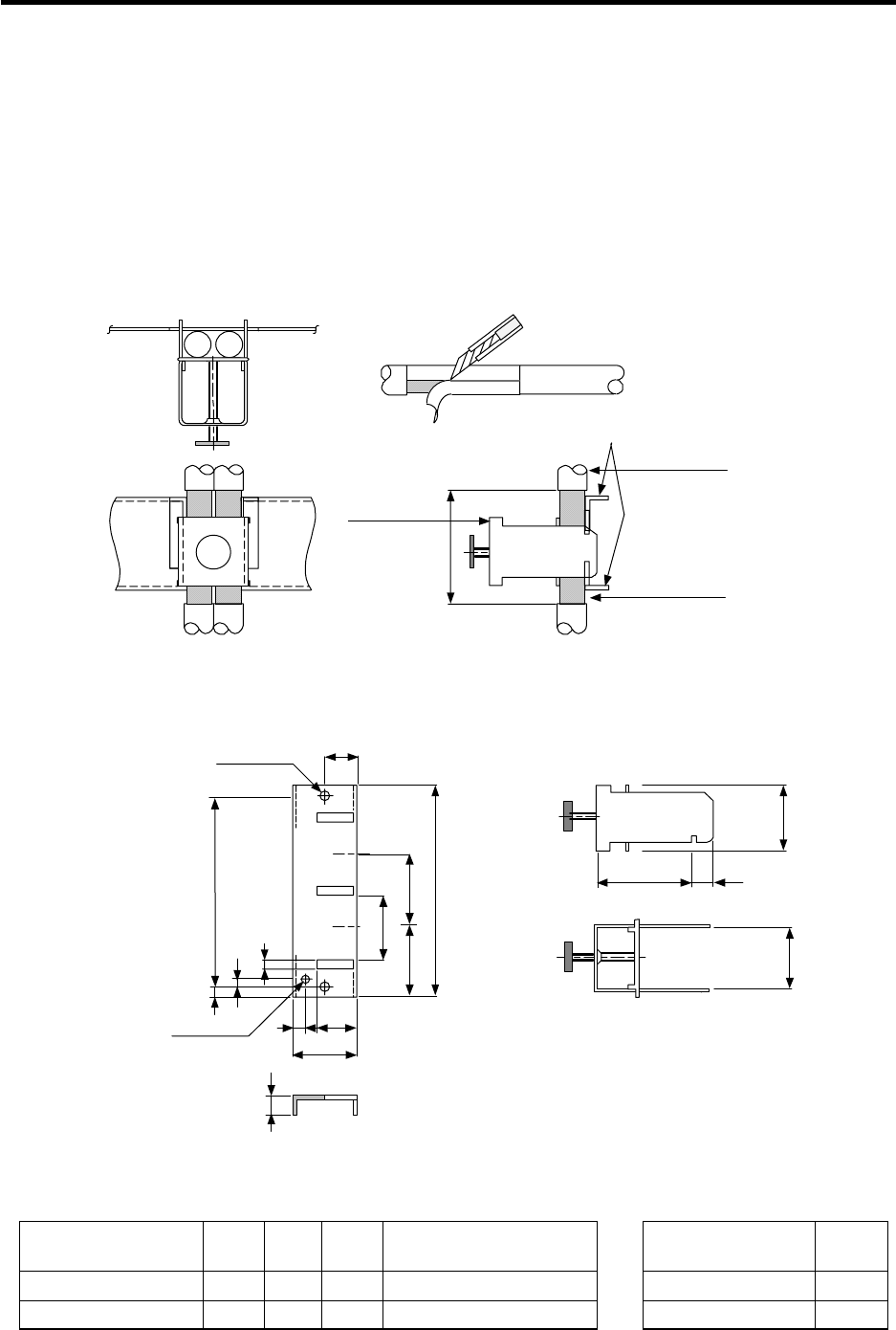
Appendix 3 Parts for EMC Measures
Appendix 3.1 Shield Clamp Fitting
102
Appendix 3 Parts for EMC Measures
Appendix 3.1 Shield Clamp Fitting
The effect can be increased by directly connecting the cable's shield sheath to the grounding plate.
Install the grounding plate near the outlet (within 10cm) of each panel, and press against the grounding
plate with the clamp fitting. If the cables are thin, several can be bundled and clamped together.
To provide sufficient frame grounding, install the grounding plate directly on the cabinet or connect with
a grounding wire.
If the AERSBAN-SET, containing the grounding plate and clamp fitting, is required, please contact
Mitsubishi.
40
Peel the cable sheath
at the clamp section
Cable
Clamp fitting
(Fitting A, B)
Grounding plate
Shield sheath
Cable
Clamp section drawing
Outline drawing
MAX L 10
24
Unit: mm
Clamp fitting
Grounding plate
M4 screw
35
622
17.5
2-φ5 hole
Installation hole
Note 1
11
35
A
C
24 0
-0.2
6
3
7B±0.3
30
+0.3
0
Note 1) Screw hole for wiring to cabinet’s grounding plate
Note 2) The grounding plate thickness is 1.6mm
A
(mm) B
(mm) C
(mm) Enclosed fitting L (mm)
AERSBAN-DSET 100 86 30 Two clamp fittings A Clamp fitting A 70
AERSBAN-ESET 70 56 – One clamp fitting B Clamp fitting B 45
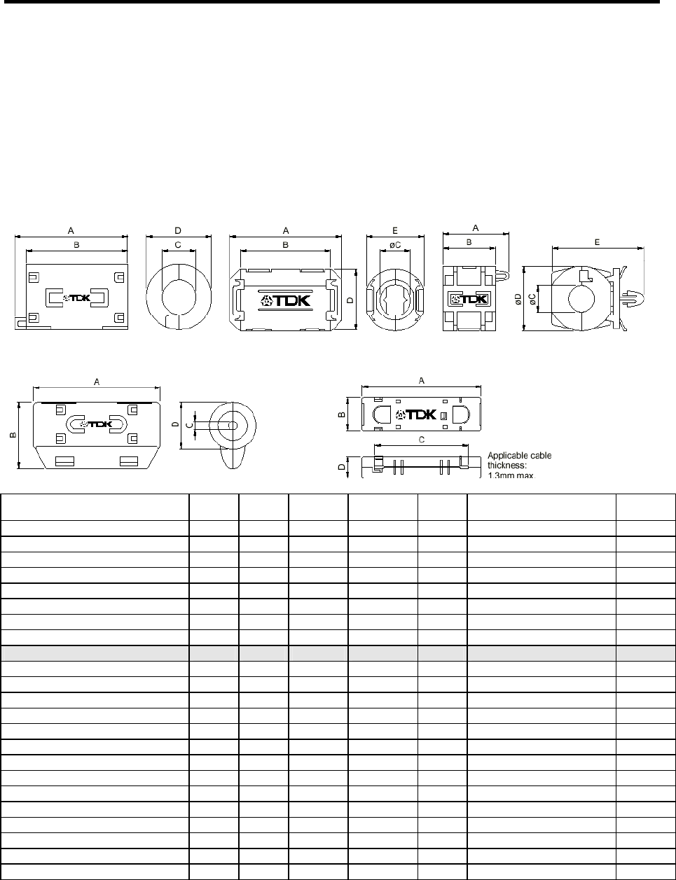
Appendix 3 Parts for EMC Measures
Appendix 3.2 Ferrite Core
103
Appendix 3.2 Ferrite Core
The ferrite core is mounted integrally with the plastic case.
This can be installed with one touch without cutting the interface cable or power supply cable.
This ferrite core is effective against common mode noise, allowing measures against noise without
affecting the quality of the signal.
Recommended ferrite core: TDK ZCAT Series
ZCAT3035-1330 (-BK)
Part name A (mm) B (mm) øC (mm) øD (mm) E (mm) Applicable cable outer
diameter (mm) Weight
(g)
ZCAT1518-0730-M(-BK)*1 22±1 18±1 7±1 15±1 – 7max. 6
ZCAT1518-0730(BK)*2 22±1 18±1 7±1 15±1 – 7max. 6
ZCAT2017-0930-M(-BK) 21±1 17±1 9±1 20±1 – 9max. 11
ZCAT2032-0930-M(-BK)*1 36±1 32±1 9±1 19.5±1 – 9max. 22
ZCAT2032-0930(-BK)*2 36±1 32±1 9±1 19.5±1 – 9max. 22
ZCAT2132-1130-M(-BK)*1 36±1 32±1 11±1 20.5±1 – 11max. 22
ZCAT2132-1130(-BK)*2 36±1 32±1 11±1 20.5±1 – 11max. 22
ZCAT3035-1330-M(-BK)*1 39±1 34±1 13±1 30±1 – 13max. 63
ZCAT3035-1330(-BK)*2 39±1 34±1 13±1 30±1 – 13max. 63
ZCAT1525-0430AP-M(-BK) 25±1 20±1 4±1 15±1 11.5±1 2.5 to 4(USB) 7
ZCAT1325-0530A-M(-BK)*1 25±1 20±1 5±1 12.8±1 11.2±1 3 to 5(USB) 7
ZCAT1325-0530A(-BK) 25±1 20±1 5±1 12.8±1 11.2±1 3 to 5(USB) 7
ZCAT1730-0730A-M(-BK) 30±1 23±1 7±1 16.5±1 15±1 4 to 7(USB/IEEE1394) 12
ZCAT2035-0930A-M(-BK)*1 35±1 28±1 9±1 19.5±1 17.4±1 6 to 9 22
ZCAT2035-0930A(-BK) 35±1 28±1 9±1 19.5±1 17.4±1 6 to 9 22
ZCAT2235-1030A-M(-BK) 35±1 28±1 10±1 21.5±1 20±1 8 to 10 27
ZCAT2436-1330A-M(-BK) 36±1 29±1 13±1 23.5±1 22±1 10 to 13 29
ZCAT2017-0930B-M(-BK) 21±1 17±1 9±1 20±1 28.5±1 9max. 12
ZCAT2749-0430C-M(-BK) 49±1 27±1 4.5±1 19.5±1 – 4.5max. 26
ZCAT4625-3430D(-BK) 45.5±1 24.5±1 34±1 12±1 – For 26 core flat cable 32
ZCAT4625-3430DT(-BK)*3 45.5±1 24.5±1 34±1 13±1 – For 26 core flat cable 32
ZCAT6819-5230D(-BK) 67.5±1 18.5±1 52±1 16±1 – For 40 core flat cable 58
ZCAT6819-5230DT(-BK)*3 67.5±1 18.5±1 52±1 17±1 – For 40 core flat cable 58
• ZCAT-C type and ZCAT-D type
*1 The M stamp is attached.
*2 A fixing band is attached at shipment.
*3 Double sided tape type. (Double sided tape is attached at shipment)
• ZCAT-B type: Cabinet fixing type installation hole ø4.8 to 4.9mm, plate thickness 0.5 to 2mm
• ZCAT-AP and ZCAT-C type: Structure that prevents easy opening after case is closed.
ZCAT type ZCAT-A, ZCAT-AP type ZCAT-B type
ZCAT-C type ZCAT-D type
Appendix 3 Parts for EMC Measures
Appendix 3.3 Surge Protector
104
Appendix 3.3 Surge Protector
(1) Surge protector
Make sure that surge does not directly enter the AC line of the general-purpose stabilized power
supply (prepared by customer) supplied to the control unit and DIO. The following product or
equivalent is recommended for the surge protector.
1) Part name : RAV-781BYZ-2
Manufacturer : Okaya Electric Industries
Circuit
voltage
50/60Hz Vrms
Max.
tolerable
circuit
voltage
Clamp
voltage
V±10%
Surge
resistance
level
8/20µs
Surge
withstand
voltage
1.2/50µs
Static
capacity
Operating
temperature
range
250V 3ø 300V 783V 2500A 20kV 75pF –20 to +70°C
28.5±1
5.5±1
11±1
28±1 200± 0
30
41±1
UL-1015 AWG16
4.5±0.5
(1) Black (2) Black (3) Black
Unit: mm
* Refer to the manufacturer's catalog for detailed characteristics, outline and connection
methods of the surge protector.
Outline drawing Circuit drawing
Appendix 3 Parts for EMC Measures
Appendix 3.3 Surge Protector
105
2) Part name : RAV-781BXZ-4
Manufacturer : Okaya Electric Industries
Circuit
voltage
50/60Hz Vrms
Max.
tolerable
circuit
voltage
Clamp
voltage
V±10%
Surge
resistance
level
8/20µs
Surge
withstand
voltage
1.2/50µs
Static
capacity
Operating
temperature
range
250V 3ø 300V 700V 2500A 2kV 75pF –20 to +70°C
Green
Unit: mm
41±1
UL-1015 AWG16
(1) (2) (3)
28.5±1
5.5±1
11±1
28±1 200± 30
0
4.5±0.5
Black Black Black
* Refer to the manufacturer's catalog for detailed characteristics, outline and connection methods of
the surge protector.
Outline drawing Circuit drawing
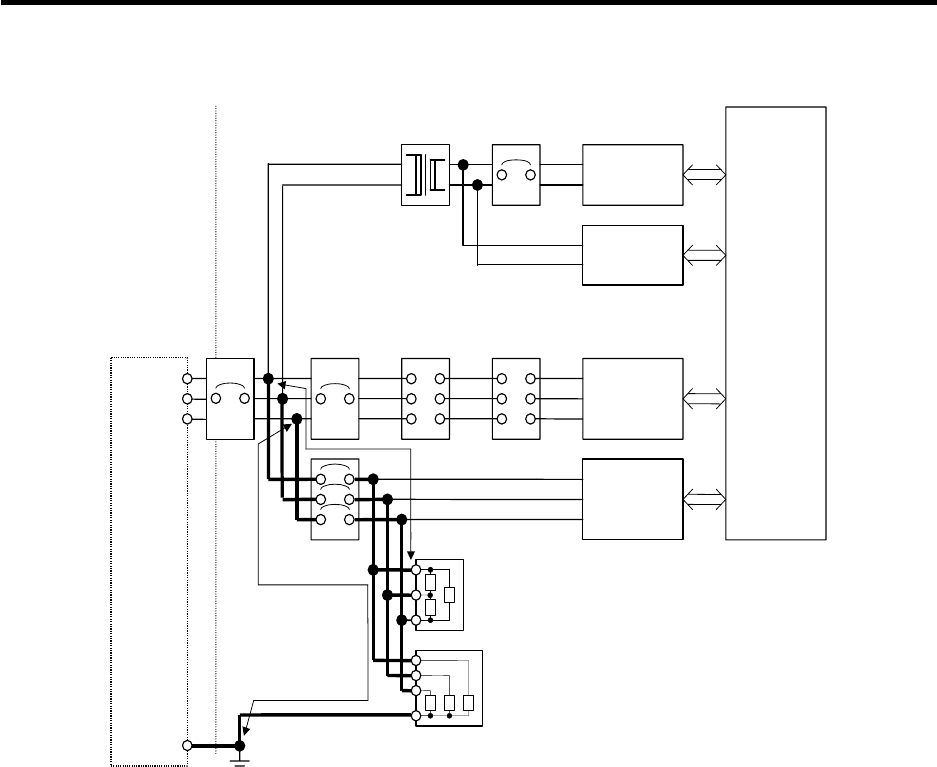
Appendix 3 Parts for EMC Measures
Appendix 3.3 Surge Protector
106
(2) Surge protector installation example
B
A
NC control
section
Control panel
(Relay panel,
etc.)
Surge protector (1)
Other device
Power supply
for panel, etc.
NC drive
section
Other device
Power supply
for panel, etc.
Earth leakage
breaker for
panel
Input
200/
230VAC
No-fuse
breaker
No-fuse
breaker MC Reactor
Transformer
Circuit
protector
Grounding Grounding plate
From power
supply
Surge protector (2)
Surge protector installation method
<Caution>
(1) Thick wires will enhance the lighting surge absorption effect, so keep the wire as thick and short as
possible.
-Wire material-
Wire diameter: 2mm2 or more
Wire length: Connection length (A) to surge protector (1) is 2m or less.
Connection length (B) to surge protector (2) is 2m or less.
(2) When carrying out an insulation voltage resistance test with an overvoltage (100VAC, 1500VAC)
applied on the power supply line, remove the serge protector (2) since it will function under the
applied voltage.
(3) A short-circuit accident will occur if a surge exceeding the tolerance is applied on the surge
protector. Thus, always insert a circuit protector to protect the power supply line.
The current does not flow constantly to surge protectors (1) and (2), so the circuit protector can
also be used for the other devices.

Appendix 3 Parts for EMC Measures
Appendix 3.4 Selection of Stabilized Power supply
107
Appendix 3.4 Selection of Stabilized Power Supply
Consider the following characteristics when selecting the stabilized power supply. (prepared by
customer)
Use a power supply that complies with CE Marking or that follows the standards given below.
Stabilized power supply selection items
Item Conditions
Voltage fluctuation ±5% ±5% or less of 24VDC output
Ripple noise Max. 120mV ±5% or less of 24VDC output
Output
fluctuation Spike noise Max. 500mV
Output current — Refer to this manual
Output holding time Min. 20ms Instantaneous off time
Standards
Safety Standards : UL1950, CSA C22.2 No. 234 approved, IEC950 compliant
Noise Terminal Voltage : FCC Class A, VCCI-1 Class
High Harmonics Current Restrictions : IEC1000-3-2

Revision History
Date of revision Manual No. Revision details
Feb. 1998 BNP-B2203* First edition created.
Sept. 1999 BNP-B2203A
Oct. 2003 BNP-B2203D
• Design of the cover and the back cover were changed.
• MODEL, MODEL CODE, and Manual No. were added on the back cover.
• PCI bus specifications (FCU6-HR655) card added.
• Miswrite is corrected

Notice
Every effort has been made to keep up with software and hardware revisions in the
contents described in this manual. However, please understand that in some
unavoidable cases simultaneous revision is not possible.
Please contact a Mitsubishi business office with any questions or comments regarding
the use of this product.
Duplication Prohibited
This instruction manual may not be reproduced in any form, in part or in whole, without
written permission from Mitsubishi Electric Corporation.
© 1997-2003 MITSUBISHI ELECTRIC CORPORATION
ALL RIGHTS RESERVED

BNP-B2203D(ENG)
MAGIC64
008-096
(0310)MEE
Specifications subject to change without notice.
Printed in Japan on recycled paper.
MITSUBISHI ELEC
T
R
IC CO
R
PO
R
A
T
ION
HEAD OFFICE : MITSUBISHI DENKI BLDG., 2-2-3, MARUNOUCHI, CHIYODA-KU, TOKYO 100-8310, JAPAN
MODEL
Manual No.
MODEL
CODE
