nextbike NXTBFVM2 Boardcomputer with card reader User Manual 150129 Manual Boardcomputer Final
nextbike GmbH Boardcomputer with card reader 150129 Manual Boardcomputer Final
nextbike >
User Manual

Nextbike GmbH
Nextbike
Boardcomputer
Instruction Manual
13.01.2015

1
Readmefirst
o Before using the device, please read the entire manual and all safety instructions
to ensure safe and proper use.
o The descriptions in this manual is based on the default settings of the device.
o The images and screenshots used in this manual may differ from the actual
product.
o The contents of this manual may differ from the product, or from software
provided, software versions are individually created based on the requirements of
the particular bicycle rental system.
o Formatting and delivery of this manual is based on nextbike operating systems.
o Functions of this boardcomputer may be different from those provided with the
bicycles - functions vary by region or hardware specifications.
o Please keep this manual for future reference.
Copyright © 2014 nextbike GmbH
This manual is protected under international copyright laws.
No part of this manual may be reproduced, distributed,
translated, or transmitted in any form or by any means,
electronic or mechanical, including photocopying, recording,
or storing in any information storage and retrieval system,
without the prior written permission of nextbike GmbH.
2
Table of contents
1.
Summary .............................................................................................................................................................. 3
2.
Applications ......................................................................................................................................................... 3
3.
Hardware Description .......................................................................................................................................... 3
4.
Functional Description ......................................................................................................................................... 8
5.
Specification ....................................................................................................................................................... 10
6.
Usage ................................................................................................................................................................. 10
7.
GPS Usage .......................................................................................................................................................... 12
8.
Cautions ............................................................................................................................................................. 12
9.
FCC Statement ................................................................................................................................................... 13
3
1. Summary
The nextbike on-boardcomputer is integrated into the nextbike smart bike. This on-
boardcomputer enables the customers to rent and return smart bikes directly through its
interface via Smart Card and mobile number including PIN code, automating the release
and lock process for all registered customers. Customers without Smart Cards or
personal log in information also have the choice to activate the rental via App or phone
call to the IVR-service hotline.
Furthermore, the system is connected to the nextbike Office Software via existing
GSM/GPRS network and GPS satellites, which permits locating and monitoring bicycle
in real time on kiosk terminals, App or calling the IVR-service hotline.
2. Applications
o Bicycle rental/return
o Bicycle tracking
3. Hardware Description
3.1 Nextbike’s components:
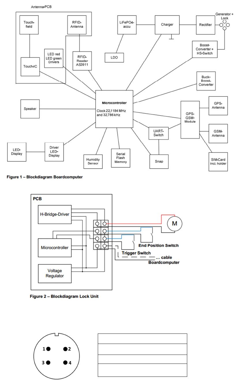
On the bike a boardcomputer (above the rear wheel) and a lock unit (at the front) is
mounted, which are connected by a 2-pin cable. The lock unit contains a motor for
locking a bar and two switches for detecting an inserted bar and the motor end position.
Apart from that, the boardcomputer is connected to the generator parallel to the two
lamps of the bicycle.
The lock unit FVML is encapsulated in a plastic housing board. The built-in components
and connections are clearly in Figure 2.
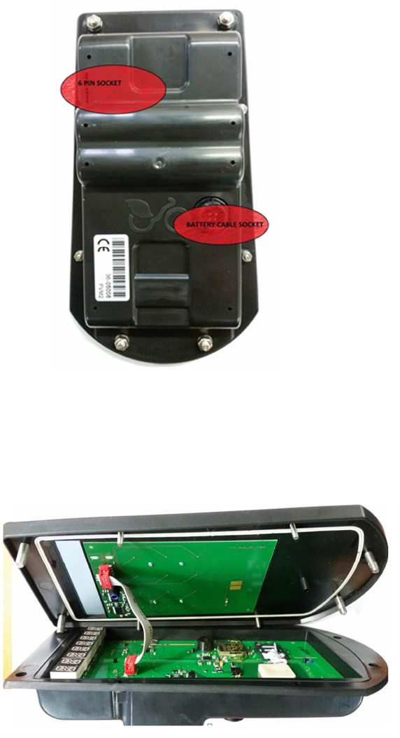
The boardcomputer FVM2 consists of two PCBs (base PCB and antenna PCB) that are
connected by an 8 pin ribbon cable and inserted into a housing. The structure is shown
in Figure 1. On the bottom side of the housing a 4-pin connector is screwed, which is
soldered to the base PCB. So the generator and the lock unit can be connected.
Besides boardcomputer includes the following main components:
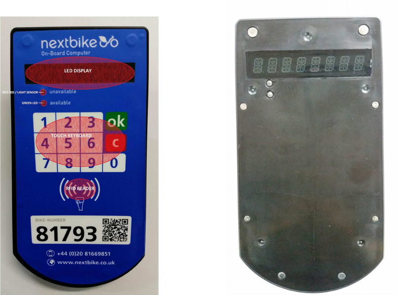
o A 10-number keyboard to wake up the system and to enter information (codes, ID
o numbers and pins)
o A RFID-Reader to wake up the system and to read customer cards
o A display and LEDs to show status, lock codes and other information
o A speaker for key feedback and alert tones
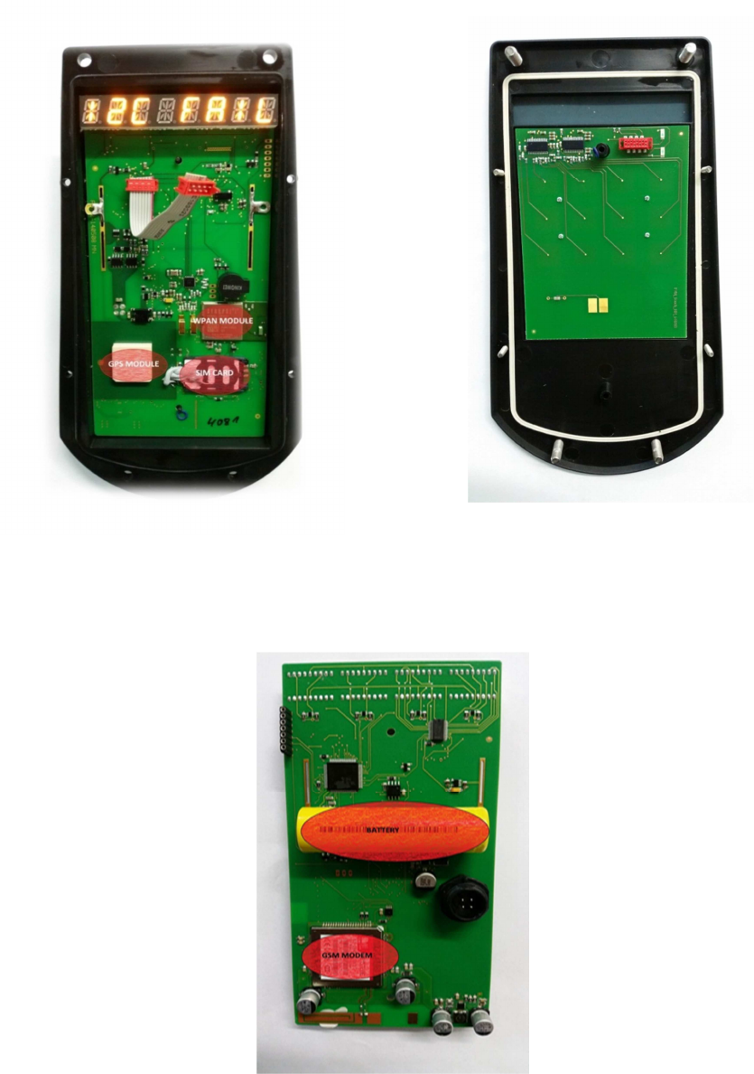
o A GSM module for communication with central server
o A WPAN-module (Synapse SM200) for local data exchange with the terminal
4
o A boost converter and a high side switch for supplying the lock unit
o A power supply unit including battery
o A Microcontroller with serial data flash memory
o The system is supplied by an on-board battery that is charged by the bicycle
generator.
Cautions:
A. Are developed with particular focus on vandalism and weather resistance
(temperature range between 14 °F and 122 °F).
B. Are developed for energy efficiency. As a standard the boardcomputer rests in
sleep modus. With activating the unit via numeric key-pad the unit wakes up for 8
seconds if no other activity is recognized. The boardcomputer is designed to
operate without any recharging for several weeks. One ride per week of 15-30
minutes will be sufficient to recharge the battery to 100%.
C. The units are fixed in the upper cover of the back wheel.
D. The electric components are covered by a waterproof glued acrylic box.
E. Please maintain a minimum distance of 20 cm from the antenna.
3.2 Design
Front Face
5
Rear Face
Interior
6
Interior Front Face Interior Top Face
Interior Bottom Face
7
3.3 Block Diagramm
Cable Connector Female – WEiPU - SP1711/S4 ( IP Rating IP 68)
1. GND
2. +12V
3. GND
4. V-D
8
4. Functional Description
4.1 Powermanagement
The boardcomputer mostly lingers in the sleep mode to reduce power consumption. The
LED display is completely off during this time and the status LEDs indicate status
cyclically by flashing.
Waking up the system can happen from following wake up sources:
o Push a button
o Apply a RFID-Card
o Ride the bike
o Connect a fast charger
o Timer interrupt for central server via GSM-Call the boardcomputer from terminal via
WPAN
In operating mode control and display elements, acoustic feedback and communication
are active.
Depending on the Battery charge level the boardcomputer switch to a power saving
mode. In this case, the system status is not indicated by the flashing LEDs. In addition,
the device cannot wake up.
Charging the batteries during riding the bicycle is controlled by the µC. The charge
current depends on the speed of the bicycle, the Battery charge level and the ambient
light.
By connecting a fast charger (5V maximum voltage, current maximum 4A), the battery
can be charged completely within about 20 minutes. During that the current charge
status [%] is displayed
.
4.2 Control and display
In idle mode red or green LED blinking indicates, if the bike is available for a rental or
not. Pushing a button or placing a customer card wakes up the system.
After pushing a button, the customer is prompted to enter either the current lock code or
phone number and pin.
Entering the lock code directly leads to an opening of the lock. This happens if the
customer has just temporarily parked the bike or the rent it another way (eg. mobile
phone).
By entering the phone number and pin, a client can authenticate similar to placing a
customer card. This leads either to a query via WPAN, in internal memory or via GSM.
Thus, the lock is only opened after appropriate approval by the central server or the
successful check in the internal memory.
9
If the user authenticates himself as a service employee, an appropriate message is
displayed and a connection between boardcomputer and central server is established
for exchanging data. For example, a new lock code can be transmitted.
After every key press a short acoustic feedback sounds, after each RFID authentication
a long one.
After 1st key operation a message is displayed in the default language. Thereafter, a
user specific language can be used.
4.3 Communication via GSM
4.3.1. Frequency band and access to the medium
The communication between boardcomputer and central server is running via GSM-
band.
The boardcomputer initiates a TCP connection to the central server, which is afterwards
used for shipping messages in both directions.
4.3.2. Communication sequence
Prior to establishing the communication the modem needs to be initialized. This is done
via AT commands. After initiation of communication by the boardcomputer, the server is
always the master. It sends requests, commands and data to the boardcomputer. The
communication is terminated by the server or a timeout.
4.4. Communication via WPAN
Unlike the communication via GSM local communication can also be initiated from the
terminal. For this, the boardcomputer listens every 3 seconds on the bus. Accordingly,
the terminal must send a burst for more than 3 seconds.
After establishing the connection, the two communication paths are identical.
4.4.1. Encryption
The data transfer is encrypted by AES128.
4.5. Position recognition via GPS
After switching on the GSM modem, GPS position is queried. The transfer of the
determined coordinates is initiated by the central server.
4.6. Data memory
In the data memory of the boardcomputer customer data are stored. So after
authentication in a very short time can be determined, whether the user is
allowed to borrow the bike. Additionally an individual user language can be stored.

10
If the user cannot be found in the internal database, a request is sent to the central
server. With a positive response, the bike can be released.
If data memory shall not be used, it just stays empty. Thus all data is automatically
requested at the central server.
5. Specification
Content BC specification
Dimensions 222 mm x 119 mm x 44 mm
Weight 500 g
Network GSM/GPRS/UMTS
Band 850/900/1800/1900Mhz
GPS Sensitivity -159dBm
GPS Accuracy 5 m
Charging V 5 V
Charging A 2.1 A
Battery
Chargeable
3.2V 1100
mAh Li
-
ion
battery
Standby Approx. 960 hours
Storage Temp. -40 °F to 140 °F
Operation Temp. 1.4 °F to 131 °F
Humidity 5%-95% non-condensing
6. Usage
6.1 All components are already installed.
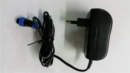
6.2 The battery charger is provided as a set.
Content Charger specification
Model No.: FPPS 5-10W
PRI 100-240 V/AC 60/50 Hz, 350 mA
SEC 5V/DC, 2100 mA, 10.5VA
11
6.3 Charger
6.3.1 Charging
The battery level is displayed on the LCD and the charging process is completed when
the display shows “99 PROZ.” If the battery level is not displayed within 10 seconds,
unplug the charger and try again after 60 seconds.
6.3.2 On-bike Charging
The charging cable is connected directly to the front dynamo hub of the smart bike and
charges automatically while the bike is underway.
CAUTIONS:
A. The Li-ion battery contains harmful chemicals and may burst. Please don’t take care
not use excessive force while handling the battery to prevent puncturing. Please
keep the battery off fire.
B. Please charge the battery in time to guarantee the highest performance.
6.3.3 Rental*
There are two options utilizing the boardcomputer for bike rentals.
1. Via Smart Card:
o Holding the customer card onto the card reader on the boardcomputer.
o The boardcomputer sends a signal to the smart lock, releasing the lock.
o The boardcomputer displays “Rented.”
2. Via mobile number and PIN code:
o Pressing the a button to activate the boardcomputer.
o Entering mobile number and PIN code.
o The boardcomputer sends a signal to the smart lock, releasing the lock.
o The boardcomputer displays “Rented.”
12
6.4 Returning*
Corresponding to the rental options, there are two options utilizing the boardcomputer
for returning the bike.
1. Via Smart Card:
o Holding the customer card onto the card reader on the boardcomputer.
o The boardcomputer sends a signal to the smart lock.
o The customer locks the bike by removing the cable from the holder at the basket
and insert it into the left side of the bike fork.
o A signal confirms successful return.
o The boardcomputer displays “Successful Return.”
2. Via mobile number and PIN code:
o Pressing the “OK-Button” to activate the boardcomputer.
o Entering mobile number and PIN code.
o Pressing the “OK-Button” for returning the bike.
o The boardcomputer sends a signal to the smart lock, releasing the lock.
o The boardcomputer displays “Successful Return.”
*The rental and return are also possible via App, boardcomputer, kiosk terminal or by
calling the IVR-service hotline. In addition, the rental and return procedures are
individually programmed per bike scheme and may differ from the described process.
7. GPS Usage
o The GPS location can be displayed in the nextbike Office Software.
o Please log in to user account to locate the location of bikes on nextbike’s online
location map.
o The GPS settings are programed automatically and can’t be changed by users.
8. Cautions
o Please comply with the instruction to maximize the unit life.
o Keep the unit interior dry. Any liquid, i.e. rain, may destroy or damage the inside
circuitry.
o Don’t expose the unit to temperatures outside aforementioned temperature range.
o Please handle the unit with care. Excessive vibration or shaking might damage the
unit.
o Clean the unit with a clean cloth, don’t use any chemicals or detergent.
o Don’t disassemble or refit unit.
o Please use charger provided by manufacturer only. Using other chargers might
resolve in damaging the unit.
13
9. FCC Statement
This device complies with Part 15 of the FCC Rules. Operation is subject to the
following two conditions: (1) this device may not cause harmful interference, and (2) this
device must accept any interference received, including interference that may cause
undesired operation.