Users Manual

User manual
of
MD-1562 Digital Cordless Module
For ooma Inc. (FCC ID: XFT-TELOMD15)
Version 1.0.1
Issue date: 2009/07/14

Page:
2
of
19
Contents
1. Introduction........................................................................................................................................... 3
1.1 Product overview _ Features summary....................................................................................... 3
2. Digital Cordless Module (MD-1562) description................................................................................. 4
2.1 Chipset platform.......................................................................................................................... 4
2.2 Numbering system ...................................................................................................................... 4
2.3 Typical application...................................................................................................................... 5
3. Functionality ......................................................................................................................................... 7
4. Technical specifications........................................................................................................................ 8
4.1 Absolute operation ratings .......................................................................................................... 8
4.2 Baseband specification................................................................................................................ 9
4.3 Radio part (RF) specification.................................................................................................... 10
5. Connection diagram .............................................................................................................................11
6. Software implementation .................................................................................................................... 13
6.1 Examples flow for implementation of API for initial start ....................................................... 13
6.2 Application note (UART for Command signalling) ................................................................. 15
7. Safety information............................................................................................................................... 17
Page: 3 of 19
1. Introduction
This document provides an overview of the functionalities supported by the Digital Cordless
Module (MD-1562) with Vega-1 based DECT processor.
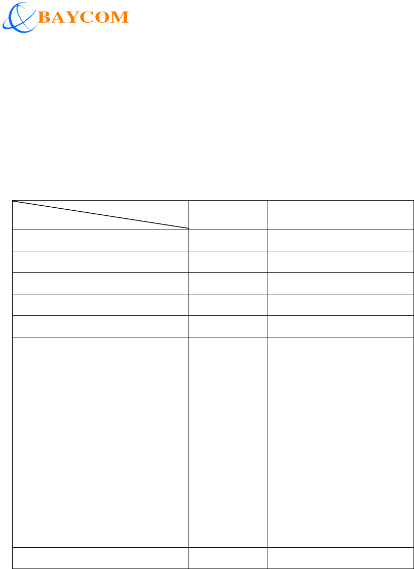
1.1 Product overview _ Features summary
The table below provided a brief summary of the key features supported by the
MD-1562_CLxx series.
P
latform
Features
MD-1562 Remark
Application (DECT/DECT 6.0) Base
Physical dimension (mm) 5*33*50
Pin count 32 pins
Wideband audio codec G.722
Audio channel (for Base) 4
Key features supported:
- GAP Compliant
- Audio streaming
- Remote access for Interactive
data application
- API command set supported
for GUI control
- Remote software upgradeable
Yes
Page: 4 of 19
2. Digital Cordless Module (MD-1562) description
2.1 Chipset platform
The MD-1562 DECT module is based on a highly integrated chipset for DECT and DECT
VoIP application.
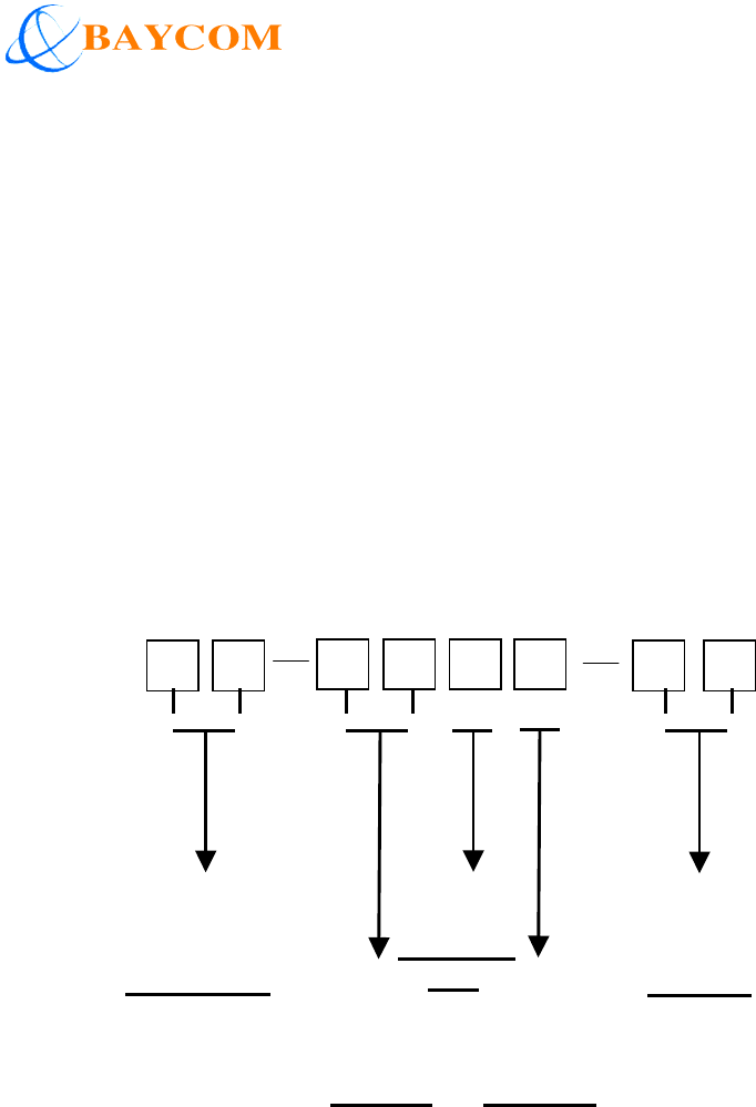
2.2 Numbering system
The customer model number system below provides basic information of model number
assignment for customer to place the order; a label shows the model number would be labeled on each
module delivered!
Code 5: “1” is reserved for Baycom’s standard platform
Example: MD-1562
Customer
code
(
((
(5)
))
)
Serial No.
(
((
(6)
))
)
Reserved
Platform
(
((
(3~4)
))
)
Product Cat.
(
((
(1~2)
))
)

Page: 5 of 19
2.3 Typical application
2.3.1 For base:
The cordless base using the MD-1562 contains a base band section & a RF section. The
antenna(s) will be located outside the module PCB area. To compose a base, the module will
need the additionally hardware interface to support line interface、power supply、handset
charger interface...

Page: 6 of 19
2.3.2 For data application:
The MD-1562 for data application can be executed as a MD-1562 base, combined with
one co-processor, which then by the control of the module able to send data back and forth
using the up to 32 Kbits/s air interface.
It is possible to establish a data link from up to five handsets to one base and routing the
data via the UART interface. However, the UART interface has a limited transmission speed up
to 115.2Kb/s baud rate. If more data connections are active at the same time and exceeding the
capacity of the serial bus, the bandwidth of the bus is shared equally between the data
connections.
For the base with MD-1562, it is possible to send data from one handset to another. It is
possible to send Low Speed (6.4Kbits/s) data between two handsets in an intercom through the
base unit.

Page: 7 of 19
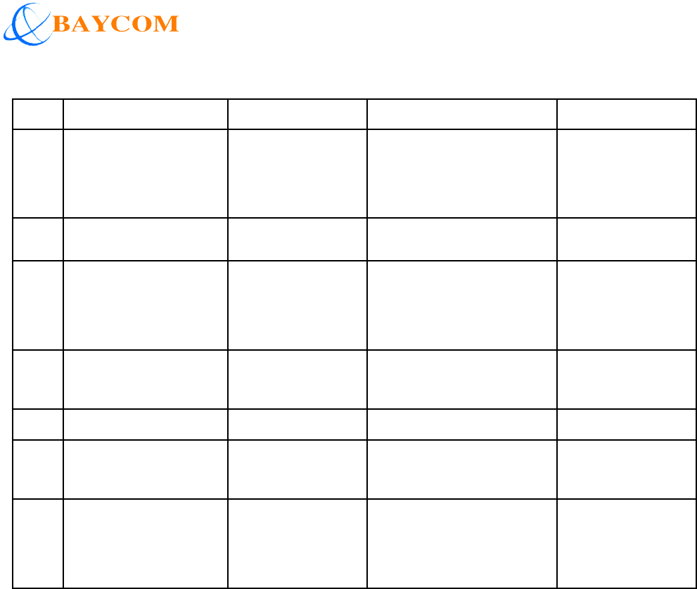
3. Functionality
The following tables list all the functionalities which the MD-1562 can support:
Functionality Support Remark
Standard Base audio control feature:Call handling
Incoming/outgoing call Yes Both DTMF and Pulse dial
Intercom Yes Between handsets via the base
Conference call Yes Between 2 handsets and external line
Call forwarding Yes Transfer call between handsets
Call back Yes If no reply on call forward
Page call Yes Base to pages all handsets (Handset
locator)
Caller ID
Call waiting at external line during
intercom Yes Indication of incoming call during
conversation.
Call waiting at external line during
another external call. Yes
Indication of incoming call during
conversation. Requires the support from
operator and the base application.
Caller ID reception Yes Supports ETSI (FSK & DTMF) CLIP
Message waiting reception/Voice mail
Yes
Protocol
Registration Yes Auto registration in Base
Handsets per base station Yes 5~9 handsets subject to the selection of
the platform
Data call Yes 32 Kbits/s on the air-interface (one slot)
Dual slot diversity Yes 32 Kbits/s voice
Broadcast from base to handset Yes

Page: 8 of 19
4. Technical specifications
4.1 Absolute operation ratings
Description Conditions Min Max Units
Supply Voltage for Baseband Vsup1 FP mode 3.0 3.6 V
Supply Voltage for RF Vsup2 FP mode 2.7 3.6 V
Supply Voltage for RF VPA FP mode 1.8 3.8 V
Max total current into VDDIOs 90 mA
Max current into I/O pins 4 mA
Max voltage on digital input pins GND-0.3
VDDIO+0.3
V
Storage temperature -30 +80 °C
ESD voltage according to human body
model
4K V

Page: 9 of 19
4.2 Baseband specification
No Item Baseband Specification Comment
1 X’tal Oscillator 13.824 MHz
+/- 20ppm
2 Serial Interface UART Compatible with
16450/16550 standard
(1,200〜921,600 Kbits/s)
Recommended
3 SPI Interface SPI Interface for external
processor or PC
Optional
4 EEPROM Module From 8Kbit to 64 Kbit
external EEPROM
TBC
5 Analog front
end/Audio
BS_Application Interface for line I/F,CLIP,
Ring detection
Optional with
platform
selection
6 Analog front
end/Audio
HS_Application Interface for Microphone,
Earpiece, Headset
7 PCM Interface GPIO 6/7/8/9
8a Power
Consumption
(stand by mode)
BS_Application
DECT
Tyep: 55 mA
Max: 60 mA
Average
8b Power
Consumption
(talk mode)
BS_Application
DECT
Type: 75 mA
Max: 100 mA
Average
Page: 10 of 19
4.3 Radio part (RF) specification
No Item Radio Part Specification Comment
1
Receive Sensitivity DECT Minimum: -89dBm
Typically: -91dBm
Maximum: -93dBm
@ BER = 0.001
2
Receive IIP DECT -21dBm to -19dBm
3
Transmit Power
(NTP)
DECT Minimum: 20dBm
Typically: 23dBm
Maximum: 25.5dBm
Approx. 200mW
4
TDMA(time division
multiple access)
DECT 12 time slot pr. carrier
5
Signaling Bit-rate DECT 1,152 Kbits/sec
6
Modulation DECT GFSK Bandwidth 20dB
< 1,728MHz
7
Antenna Diversity
supported
DECT Control signals are
available from the
module
Antenna switch
has to be added
externally
Page: 11 of 19
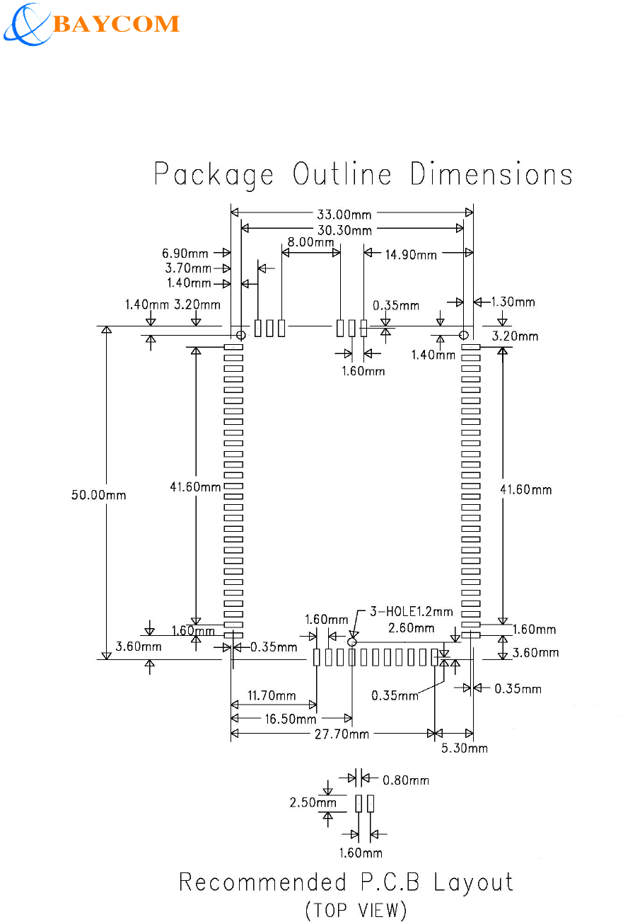
5. Connection diagram
5.1 Dimension
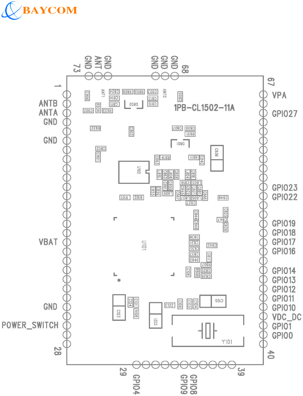
Page: 12 of 19
5.2 Pin assignment
Page: 13 of 19
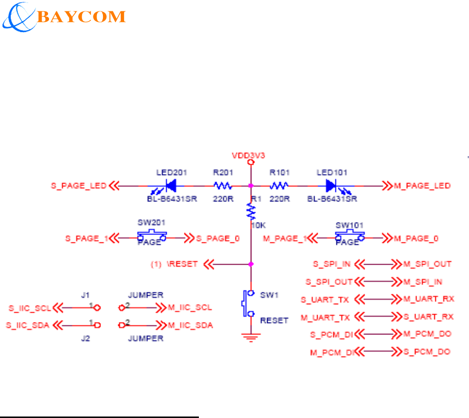
6. Application
6.1 Examples for implementation with hardware peripheral on mother board
For module application with SPI:
a. “S_SPI_IN” is “DI_SPI”, to be connected to the “SPI Data Out” on Host uP
b. “S_SPI_OUT” is “DO_SPI”, to be connected to the “SPI Data In” on Host uP
c. Opposed pin out connection for Transmit vs. Receive is required
Page: 14 of 19
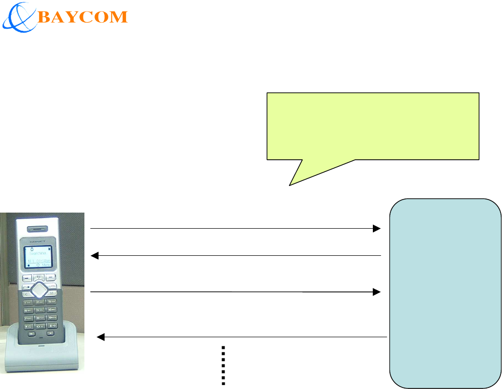
6.2 Examples flow for implementation of API for initial start
Host
uP
DCM:
Resent cycle time of Cmd22/23
is 4
seconds.
Cmd 22: 1016xxxx…
Event 23: 20170400xxxxxx
Cmd 23: 101700 (Query PC’ time)
Figure 2 _ Example for implementation of API for initialization
Event 22: 20160100
Page: 15 of 19
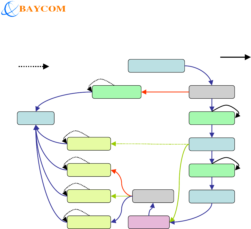
6.3 Example for software implementation
Response Cmd
Cmd25
Error
Event 17: 021101xx
Refused
Event 20: 02140400.…09
Error
Event 20: 021403xx.…
Missed
Event 20: 02140400….08
Finished
Event 20: 02140200.…07
Off-Hook for out going call
Cmd 15: 010f0bchange 1205 (P2P)
Response Event
Event 26: 021b0313.…
On Hook
Cmd 19: 011302….
Response Event
Event 26: 021b010f
Ringing
Event 17: 02110400….04
Response Cmd
Cmd 25: 0119051100.…04
Inprogress
Event 17: 02110400.…05
Response Cmd
Cmd 25: 0119051100.…05
Resent until receive
Response Cmd25, or
Timeout (3 times)
Resent until
receive
Response Cmd25,
…. Call ID
Figure 3 Example for Implementation of
API _ P2P Out going call

Page: 16 of 19
6.4 Application note (UART for Command signaling)
Block Function
The enhanced serial (UART) interface is basically compatible with the industry-standard 16450/16550
UARTs.
The following features are supported:
Even, odd, fixed ‘1’, fixed ‘0’ or no parity generation and detection
One or two stop bit generation
Character size 5/6/7 or 8 bits
Programmable standard baud rates, e.g. 4.8, 9.6, 19.2, 38.4, 57.6 and 115.2, 230.4, 460.8 and
921.6 kbps (for the highest baud rate restrictions on system clock settings apply)
Automatic line error checking: stop bit failure (framing), RX overrun, parity error, break
Received characters will be stored together with detected line errors in RX FIFO
Transmit interrupt generated when TX FIFO (i.e. TX hold register) empty
Receive interrupt generated on one of the following events
Receive line status (framing error, RX overrun, parity error)
Receive data available (receive hold register full or pre-programmed level in RX FIFO reached)
Noted: The default of UART functions are defined below:
- No parity generation and detection
- One stop bit generation
- 8 bit characters size
- Baud rates: 115,200 bps

Page: 17 of 19
7. Safety information
The equipment has been tested and found to comply with the limits for a Class B Digital Device,
pursuant to part 15 of the FCC Rules. These limits are designed to provide reasonable protection
against harmful interference in a residential installation. This equipment generate, uses and can radiate
radio frequency energy and, if not installed and used in accordance with the instruction, may cause
harmful interference to radio communication. However, there is no grantee that interference will not
occur in a particular installation. If this equipment dose causes harmful interference to radio or
television reception, which can be determined by turning the equipment off and on, the user is
encouraged to try to correct the interference by one or more of the following measures:
-- Reorient or relocate the receiving antenna.
-- Increase the separation between the equipment and receiver.
-- Connect the equipment into an outlet on a circuit different from that to
which the receiver is connected.
-- Consult the dealer or an experienced radio/TV technician for help.
This device complies with Part 15 of the FCC Rules. Operation is subject to the following two
conditions: (1) this device may not cause harmful interference, and (2) this device must accept any
interference received, including interference that may cause undesired operation.
The changes or modifications not expressly approved by the party responsible for compliance could
void the user’s authority to operate the equipment.
To comply with the FCC RF exposure compliance requirements, this device and its antenna must not
be co-located or operating to conjunction with any other antenna or transmitter.

Page: 18 of 19
To OEM installer:
1. FCC ID label on the final system must be labeled with "Contains FCC ID: XFT-TELOMD15" or
"Contains transmitter module FCC ID: XFT-TELOMD15 ".
2. In the user manual, final system integrator must be ensured that there is no instruction provided in
the user manual to install or remove the transmitter module.
3. Transmitter module must be installed and used in strict accordance with the manufacturer is
instructions as described in the user documentation that comes with the product. This device complies
with the following radio frequency and safety standards.
The user manual of the final host system must contain the following statements:
USA-Federal Communication Commission (FCC)
This equipment has been tested and found to comply with the limits for a Class B Digital Device,
pursuant to part 15 of the FCC Rules. These limits are designed to provide reasonable protection
against harmful interference in a residential installation. This equipment generates, uses and can radiate
radio frequency energy and, if not installed and used in accordance with the instruction, may cause
harmful interference to radio communication. However, there is no grantee that interference will not
occur in a particular installation. If this equipment dose cause harmful interference to radio or
television reception, which can be determined by turning the equipment off and on, the user is
encouraged to try to correct the interference by one or more of the following measures:
-- Reorient or relocate the receiving antenna.
-- Increase the separation between the equipment and receiver.
-- Connect the equipment into an outlet on a circuit different from that to which the receiver is
connected.
-- Consult the dealer or an experienced radio/TV technician for help.

Page: 19 of 19
This device complies with Part 15 of the FCC Rules. Operation is subject to the following two
conditions: (1) this device may not cause harmful interference, and (2) this device must accept any
interference received, including interference that may cause undesired operation.
The changes or modifications not expressly approved by the party responsible for compliance could
void the user’s authority to operate the equipment.
To comply with the FCC RF exposure compliance requirements, this device and its antenna must not
be co-located or operating to conjunction with any other antenna or transmitter.