orativo Lanix de C V LX220N ADSL2+/VDSL2 User Manual
Corporativo Lanix S.A. de C.V. ADSL2+/VDSL2
User Manual

LX220N
User Manual
Contents
1 Safety Precautions
.............................................................................
1
2 Overview
.........................................................................................
2
2.1
Packing List ......................................................................................... 2
2.2
Application .......................................................................................... 2
2.3
Features .............................................................................................. 3
2.4
Standards Compatibility and Compliance ............................................ 4
3 Hardware Description and Installation
....................................................
5
3.1
LEDs and Interfaces ............................................................................ 5
3.2
Hardware Installation ........................................................................... 8
4 PC Network Configuration and Login
....................................................
10
4.1
PC Network Configuration ................................................................. 10
4.2
Logging in to the DSL Router ............................................................ 11
5 Web-based Management
...................................................................
12
5.1
Setup ................................................................................................ 12
5.1.1
Wizard .................................................................................... 13
5.1.2
Internet Setup ......................................................................... 12
5.1.3
Wireless .................................................................................. 16
5.1.4
Local Network ......................................................................... 20
5.1.5
Local IPv6 Network ................................................................. 24
5.1.6
Time and Date ........................................................................ 26
5.1.7
Logout .................................................................................... 27
5.2
Advanced .......................................................................................... 28
5.2.1
Advanced Wireless ................................................................. 28
5.2.2
ALG ........................................................................................ 35
5.2.3
Port Forwarding ...................................................................... 35
5.2.4
DMZ ....................................................................................... 37
5.2.5
SAMBA ................................................................................... 37
5.2.6
Parental Control ...................................................................... 39
5.2.7
Filtering Options...................................................................... 42
5.2.8
QoS Configuration .................................................................. 58
5.2.9
Anti-Attack Settings ................................................................ 50
5.2.10
DNS .................................................................................. 64
5.2.11
Dynamic DNS .................................................................... 52
5.2.12
Network Tools .................................................................... 54
LX220N User Manual
ii
5.2.13
Routing .............................................................................. 64
5.2.14
Schedules ......................................................................... 83
5.2.15
NAT ................................................................................... 70
5.2.16
DLNA ................................................................................ 71
5.2.17
IP Tunnel ........................................................................... 71
5.2.18
Logout ............................................................................... 76
5.3
Management ..................................................................................... 77
5.3.1
Global IPv6 ............................................................................. 90
5.3.2
System Management .............................................................. 77
5.3.3
Firmware Update .................................................................... 79
5.3.4
Access Controls ...................................................................... 80
5.3.5
Diagnosis ................................................................................ 85
5.3.6
Log Configuration ................................................................... 87
5.4
Status ................................................................................................ 87
5.4.1
Device Info ............................................................................. 88
5.4.2
Wireless Clients ...................................................................... 89
5.4.3
DHCP Clients.......................................................................... 89
5.4.4 IPv6 Status ............................................................................ 90
5.4.5
Logs ....................................................................................... 90
5.4.6
Statistics ................................................................................. 91
5.4.7
Route Info ............................................................................... 93
5.5
Help .................................................................................................. 93
6 Trouble Shooting
............................................................................
94
7 FCC Statement
..............................................................................
94

LX220N User Manual
1 Safety Precautions
Take the following instructions to prevent the device from risks and damage
caused by fire or electric power.
Use the type of power marked in the volume label.
Use the power adapter in the product package.
Pay attention to the power load of the outlet or prolonged lines. An
overburden power outlet or damaged lines or plugs may cause electric
shock or fire accidents. Check the power cords regularly. If you find any
damage, replace it at once.
Proper space left for heat dissipation is necessary to avoid damage
caused by overheating to the device. The long and thin holes on the device
are designed for heat dissipation to ensure that the device works normally.
Do not cover these heat dissipation holes.
Do not put this device close to a heat source or under a high temperature
occurs. Keep the device away from direct sunshine.
Do not put this device close to an overdamp or watery place. Do not spill
fluid on this device.
Do not connect this device to a PC or electronic product unless instructed
by our customer engineer or your broadband provider. Wrong connection
may cause power or fire risk.
Do not place this device on an unstable surface or support.

LX220N User Manual
2
2 Overview
The LX220N DSL Router integrates wireless LAN and USB service into one unit.
It is designed to provide a simple and cost-effective DSL Internet connection for a
private Ethernet and 802.11g/802.11b/802.11n wireless network. The Router
combines high-speed DSL Internet connection, IP routing for the LAN, and
wireless connectivity in one package.
The Router is easy to install and use. The Router connects to an Ethernet LAN or
computers via standard Ethernet ports. The DSL connection is made using
ordinary telephone line with standard connectors. Multiple workstations can be
networked and connected to the Internet by a single Wide Area Network (WAN)
interface and single global IP address. The advanced security enhancements,
packet filtering and port redirection, can help protect your network from
potentially devastating intrusions by malicious agents from outside your network.
Network and Router management is done through the web-based management
interface accessed through the local Ethernet using any web browser. You may
also enable remote management to enable configuration of the Router via the
WAN interface.
2.1 Packing List
1 x LX220N
1 x external splitter
1 x power adapter
2 x telephone cables (RJ-11, more than 1.8m)
1 x Ethernet cable (RJ-45, more than 1.8m)
1 x USB cable (USB, more than 1m)
1 x user manual
1 x quality guarantee card
1 x certificate of quality
2.2 Application
Home gateway
Wireless LAN

LX220N User Manual
3
SOHOs
Small enterprises
Higher data rate broadband sharing
Audio and video streaming and transfer
PC file and application sharing
Network and online gaming
USB storage
2.3 Features
User-friendly GUI for web configuration
Compatible with all standard Internet applications
Industry standard and interoperable xDSL interface
Simple web-based status page displays a snapshot of system
configuration, and links to the configuration pages
Downloadable flash software updates
Support for up to 8 permanent virtual circuits (PVC)
Support for up to 8 PPPoE sessions
Support RIP v1 & RIP v2
WLAN with high-speed data transfer rates, compatible with IEEE
802.11b/g/n
IP routing and bridging
Asynchronous transfer mode (ATM) , PTM (Packet Transfer mode), and
digital subscriber line (DSL) support
Point-to-point protocol (PPP)
Network/port address translation (NAT/PAT)
Quality of service (QoS)
Wireless LAN security: WPA, 802.1x, RADIUS client
Universal plug-and-play(UPnP)
Web filtering
Management and control
Web-based management (WBM)
Command line interface (CLI)
TR-069 WAN management protocol
Remote update
System statistics and monitoring

LX220N User Manual
4
DSL router is targeted at the following platforms: DSL modems, wireless
access points and bridge.
Multicast listener discovery (MLD)
Digital living network alliance (DLNA)
Synergy advanced multipurpose bus arbiter (SAMBA)
Internet group management protocol (IGMP)
Application layer gateway (ALG)
2.4 Standards Compatibility and Compliance
Support application level gateway (ALG)
ITU G.992.1 (G.dmt)
ITU G.992.2 (G.lite)
ITU G.994.1 (G.hs)
ITU G.992.3 (ADSL2)
ITU G.992.5 (ADSL2+)
ITU G.993.1 (VDSL)
ITU G993.2 (VDSL2)
ANSI T1.413 Issue 2
IEEE 802.3
IEEE 802.3u
IEEE 802.11b
IEEE 802.11g
IEEE 802.11n
LX220N User Manual
3 Hardware Description and Installation
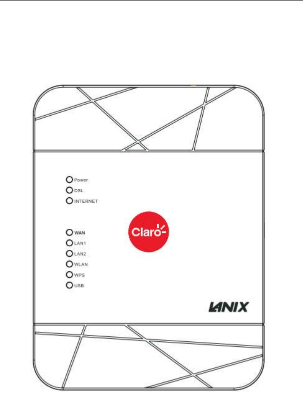
3.1 LEDs and Interfaces
Front Panel

LX220N User Manual
6
Figure 1 Front panel
The following table describes the indicators on the front panel.
Indicator
Color
Status
Description
Power
Green
On The device is powered on.
Off The device is powered off.
Red On Self-test fails, or failure occurs, or the device is
starting.
DSL Green
On DSL link is established.
Slow
Blink The DSL line is attempting to detect signals.
Fast Blink
Signals have been detected, and the DSL line is
attempting to establish link.
Internet Green
On Physical layer connection and IP connection is
established in routing mode.
Blink IP connection is established, and messages are
being transmitted.
Off IP connection or physical layer link is not
established.
Red
On IP connection fails.
WAN Green
On WAN link is established.
Blink Data is being transmitted through a WAN
interface.
Off WAN link is not established.
LAN 1/2 Green
On Ethernet link is established.
Blink Data is being transmitted through a LAN
interface.
Off Ethernet link is not established.
WLAN Green
On WLAN is enabled.
Blink Data is being transmitted by the wireless
module.
Off WLAN is disabled.
WPS Green
On Negotiation is successful under Wi-Fi protected
setup.
Blink Negotiation is in progress under Wi-Fi protected
LX220N User Manual
7
Indicator
Color
Status
Description
Setup.
Off Wi-Fi protected setup is disabled.
USB Green
On A USB flash disk is connected.
Blink Data is being transmitted.
Off No USB connection.
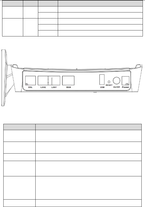
Rear Panel
Figure 2 Rear panel
The following table describes the interface of the device.
Interface/Button
Description
DSL RJ-11 interface connecting to a telephone set through a
telephone cable
LAN1/2 Ethernet RJ-45 interfaces connecting to the Ethernet
interfaces of computers or Ethernet devices
WAN Ethernet RJ-45 interfaces connecting to the WAN interfaces.
USB
USB port, for connecting a 3G network card or other USB
storage devices.
Reset
Reset to the factory defaults. To restore factory defaults, keep
the device powered on and push a paper clip into the hole.
Press down the button for more than 5 seconds and then
release.
ON/OFF Push to power on/off the device.
LX220N User Manual
8
Interface/Button
Description
Power
Interface connecting to the power adapter. The power
adapter output is: 12V DC, 1500mA
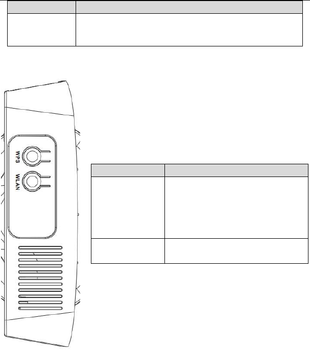
Side Panel
Interface/Button
Description
WPS
This button is used for enabling
WPS PBC mode. If WPS is enabled,
press this button, and then the
wireless router starts to accept the
negotiation of PBC mode.
WLAN WLAN switch, for enabling or
disabling the WLAN function.
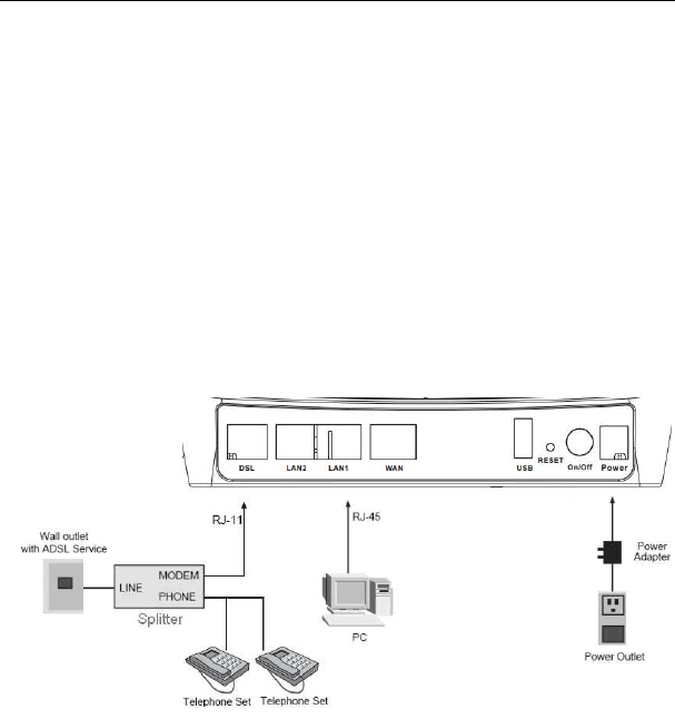
3.2 Hardware Installation
Step 1 Connect the DSL port of the device and the Modem port of the splitter
with a telephone cable. Connect the phone to the Phone port of the
splitter through a telephone cable. Connect the incoming line to the
Line port of the splitter.
The splitter has three ports:
LX220N User Manual
9
Line: Connect to a wall phone port (RJ-11 jack).
Modem: Connect to the DSL port of the device.
Phone: Connect to a telephone set.
Step 2 Connect a LAN port of the device to the network card of the PC
through an Ethernet cable (MDI/MDIX).
Note:
Use twisted-pair cables to connect the device to a Hub or switch.
Step 3 Plug one end of the power adapter to the wall outlet and the other end
to the Power port of the device.
Connection 1: Figure 3 displays the application diagram for the connection of
the device, PC, splitter and telephone sets, when no telephone set is placed
before the splitter.
Figure 3 Connection diagram (without telephone sets before the splitter)
As illustrated in the following figure, the splitter is installed close to the device.
Installing a telephone directly before the splitter may lead to failure of connection
between the device and the central office, or failure of Internet access, or slow
connection speed. If you really need to add a telephone set before the splitter,
you must add a microfilter before a telephone set. Do not connect several
telephones before the splitter or connect several telephones with the microfilter.
LX220N User Manual
4 PC Network Configuration and Login
4.1 PC Network Configuration
Each network interface on the PC should either be configured with a statically
defined IP address and DNS address, or be instructed to automatically obtain an
IP address using the network DHCP server. DSL router provides a DHCP server
on its LAN and it is recommended to configure your LAN to automatically obtain
its IP address and DNS server IP address.
The configuration principle is identical but should be carried out differently on
each operating system.
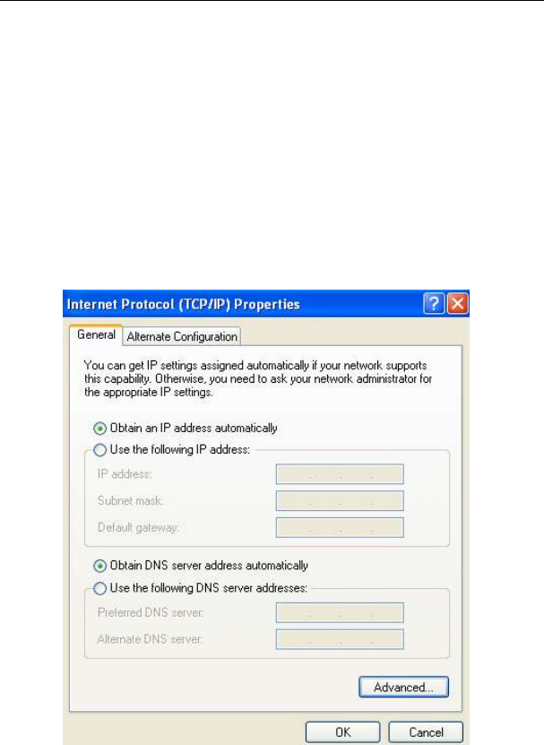
The following displays the TCP/IP Properties dialog box on Windows XP.
Figure 4 PC Network Configuration

LX220N User Manual
11
TCP/IP configuration steps for Windows XP are as follows:
Step 1 Choose Start > Control Panel > Network Connections.
Right-click the Ethernet connection icon and choose Properties.
On the General tab, select the Internet Protocol (TCP/IP) component and
click Properties. The Internet Protocol (TCP/IP) Properties window
appears.
Select the Obtain an IP address automatically radio button.
Select the Obtain DNS server address automatically radio button.
Click OK to save the settings.
4.2 Logging in to the DSL Router
To log in to the DSL router, do as follows.
Step 1 Open a Web browser on your computer.
Step 2 Enter http://192.168.1.1 (default IP address of the DSL router) in the
address bar. The login page appears.
Step 3 Enter the user name and the password. The default username and
password of the super user are admin and c1@r0. The username and
password of the common user are Usuario and c1@r0. It is recommended
to change these default values after logging in to the DSL router for the first
time.
Step 4 Click Login to log in to the Web page.
Figure 5 Logging in to the DSL Router
After logging in to the DSL router as a super user, you can query, configure, and
modify all the settings, and diagnose the system.

LX220N User Manual
5 Web-based Management
This chapter describes how to use Web-based management of the DSL router,
which allows you to configure and control all of DSL router features and system
parameters in a user-friendly GUI.
5.1 Setup
In the main interface, click Setup tab to enter the Setup menu as shown in the
following figure. The submenus are Wizard, Internet Setup, Wireless, Local
Network, Local IPv6 Network, Time and Date and Logout.
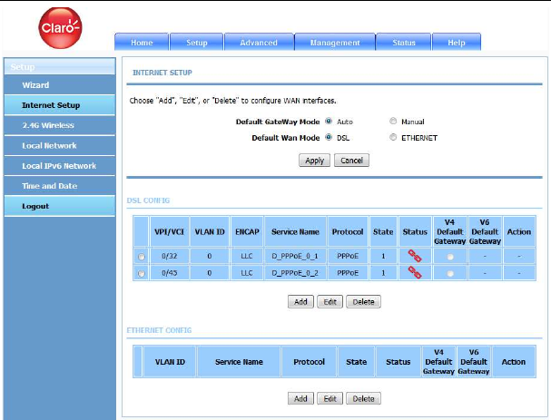
5.1.1
Internet Setup
Choose Setup > Internet Setup. The page shown in the following figure appears.
In this page, you can configure the WAN interface of the device.
LX220N User Manual
13
Click Add in “INTERNET SETUP”. The page shown in the following figure
appears.
LX220N User Manual
14
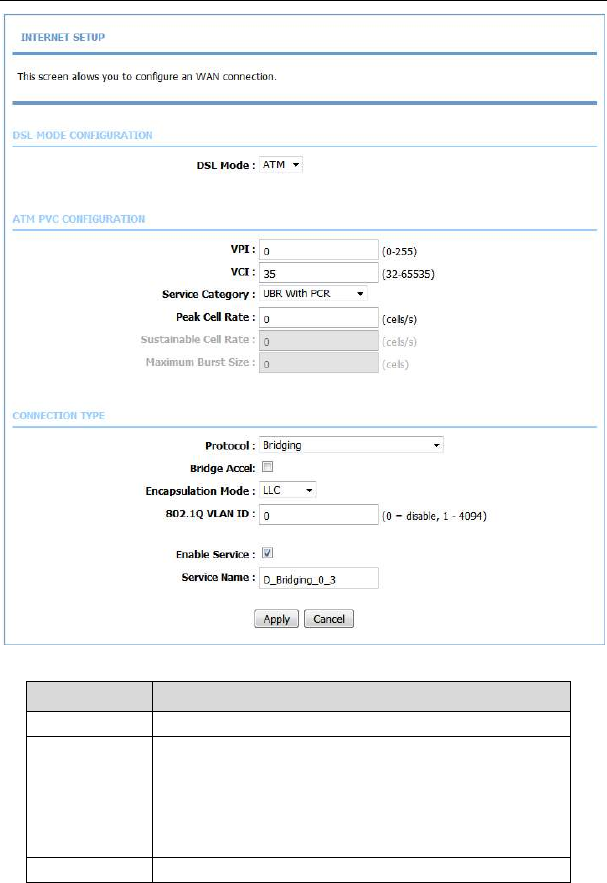
The following table describes the parameters in this page.
Field Description
DSL Mode You can select ATM or PTM.
PVC Settings
VPI: The virtual path between two points in an ATM
network, and its valid value is from 0 to 255.
VCI: The virtual channel between two points in an ATM
network, ranging from 32 to 65535 (0 to 31 is reserved
for local management of ATM traffic).
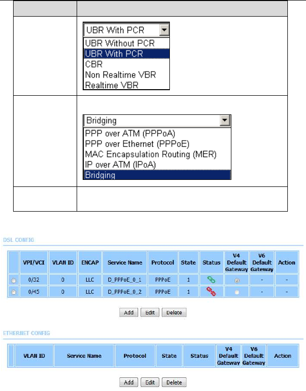
Service You can select from the drop-down list.
LX220N User Manual
15
Field Description
Category
Protocol
You can select from the drop-down list.
Encapsulation
Mode
Select the method of encapsulation provided by your
ISP. You can select LLC or VCMUX.
Click Apply, the page shown in the following figure appears.
To manage the existing WAN connections, select a connection from the list, and
then click Edit or Delete.
LX220N User Manual
16
5.1.2
Wireless
This section describes the wireless LAN and basic configuration. A wireless LAN
can be as simple as two computers with wireless LAN cards communicating in a
pear-to-pear network or as complex as a number of computers with wireless LAN
cards communicating through access points which bridge network traffic to wired
LAN.
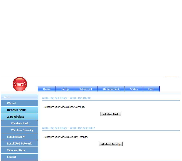
Choose Setup > Wireless. The Wireless page shown in the following figure
appears.
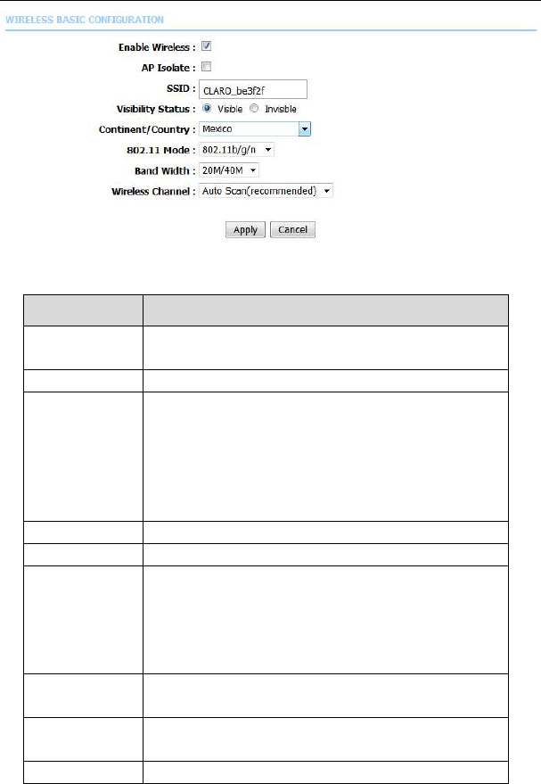
5.1.2.1 Wireless Basic
In the Wireless page, click Wireless Basic. The page shown in the following
figure appears. In this page, you can configure the parameters of wireless LAN
clients that may connect to the device.
LX220N User Manual
17
The following table describes the parameters in this page.
Field Description
Enable
Wireless
Select this to turn Wi-Fi on.
AP Isolate Select this to turn AP isolation on.
Wireless
Network Name
(SSID)
The Wireless Network Name is a unique name that
identifies a network. All devices on a network must
share the same wireless network name in order to
communicate on the network. If you decide to change
the wireless network name from the default setting,
enter your new wireless network name in this field.
Visibility Status
You can select Visible or Invisible.
Country Select the country from the drop-down list.
802.11 Mode
Select the appropriate 802.11 mode based on the
wireless clients in your network. The drop-down menu
options are 802.11b only, 802.11g only, 802.11n
only, Mixed 802.11b/g, Mixed 802.11n/g and Mixed
802.11b/g/n.
Band Width Select the appropriate band as 20M, 40M Plus, or 40M
Minus from the pull-down menu.
Wireless
Channel
Select the wireless channel from the pull-down menu.
It is different for different country.
Transmission Select the transmission rate for the network. The rate
LX220N User Manual
18
Field Description
Rate of data transmission should be set depending on the
speed of your wireless network. You can select from a
range of transmission speeds, or you can select Auto
to have the Router automatically use the fastest
possible data rate and enable the Auto-Fallback
feature. Auto-Fallback will negotiate the best possible
connection speed between the Router and a wireless
client. The default is Auto.
Click Apply to save the settings.
5.1.2.2 Wireless Security
In the Wireless page, click Wireless Security. The page shown in the following
figure appears. Wireless security is vital to your network to protect the wireless
communication among wireless stations, access points and wired network.
Note:
Enable Wireless before configuring the wireless security settings in this page.
Refer to 5.1.2.1 Wireless Basic.
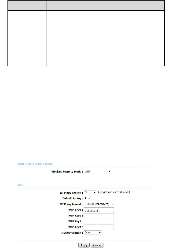
When the Security Mode is set as WEP, the following figure appears.
LX220N User Manual
19
The following table describes the parameters of this page.
Field Description
WEP Key Length Choose the WEP key length. You can choose 64-bit
or 128-bit.
Default Tx Key Choose the index of WEP Key. You can choose Key
1, 2, 3 or 4.
WEP Key Format
When 64-bit key length is selected, you can
choose ASCII (5 characters) or HEX (10
characters).
When 128-bit key length is selected, you can
choose ASCII (13 characters) or HEX (26
characters).
WEP Key 1/2/3/4
The Encryption keys are used to encrypt the data.
Both the modem and wireless stations must use the
same encryption key for data transmission. The
default key 1 is 1111111111.
Authentication Choose an authentication mode.
Click Apply to save the settings.
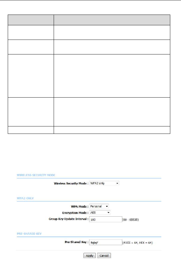
When the Security Mode is set as WPA2 only or WPA/WPA2 Mixed, the
following figure appears.

LX220N User Manual
20
The following table describes the parameters in this page.
Field Description
Wireless
Security Mode
Configure the wireless encryption mode. You can
choose None, WEP, WPA2 Only or WPA /WPA2
Mixed.
Wired equivalent privacy (WEP) encrypts data
frames before transmitting over the wireless network.
WPA2 is a subset of the IEEE802.11i security
specification draft.
WPA/WPA2 Mixed is the collection of WPA and
WPA2 encryption modes. The wireless client
establishes the connection between the modem
through WPA or WPA2.
Key differences between WPA and WEP are user
authentication and improved data encryption.
WPA Mode
Select Personal, and then enter the pre-shared
key in the Pre-Shared Key field.
Select Enterprise, and then enter the port, IP
address, and password of the Radius server. You need
to enter the password provided by the Radius server
when the wireless client connects the modem.
If the encryption is set to WEP, the modem uses 802.1
X authentication, which is Radius authentication.
Encryption
Mode
When WPA /WPA2 Mixed is selected, you can select
WPA encryption as AES, TKIP or Both.
Group Key
Update Interval
When WPA encryption is applied, messages sent are
encrypted with a password. For higher security, WPA
password is updated periodically. This value is the
update interval of the WPA password.
5.1.3
Local Network
You can configure the LAN IP address according to the actual application. The
preset IP address is 192.168.1.1. You can use the default settings and DHCP
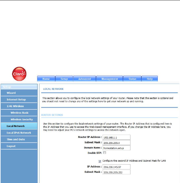
LX220N User Manual
21
service to manage the IP settings for the private network. The IP address of the
device is the base address used for DHCP. To use the device for DHCP on your
LAN, the IP address pool used for DHCP must be compatible with the IP address
of the device. The IP address available in the DHCP IP address pool changes
automatically if you change the IP address of the device.
You can also enable the secondary LAN IP address. The two LAN IP addresses
must be in different networks.
Choose Setup > Local Network. The Local Network page shown in the
following figure appears.
By default, Enable DHCP Server is selected for the Ethernet LAN interface of
the device. DHCP service supplies IP settings to workstations configured to
automatically obtain IP settings from a PC connected to the device through the
Ethernet port. When the device is used for DHCP, it becomes the default gateway
for DHCP clients connected to it. If you change the IP address of the device, you
must also change the range of IP addresses in the pool used for DHCP on the
LAN. The IP address pool can contain up to 253 IP addresses.
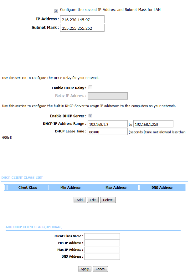
LX220N User Manual
22
This page is used to configure the DHCP Server and DHCP Relay Settings. The
HCP Lease Time is at least 600 seconds and without upper limit; -1 means
unrestricted lease time.
Click Apply to save the settings.
The DHCP Client Class List section is shown as below.
Click Add, the page shown in the following figure appears.
LX220N User Manual
23
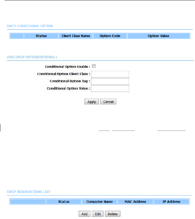
The DHCP Cond Option section is shown as below. Here you can specify the
reply message (option 240~245) the modem sends to the client. After DHCP
CLIENT CLASS is configured, you can configure DHCP COND OPTION.
Click Add to add DHCP option as shown in the following figure.
Only when this function is enabled, the modem returns the content below to the
client.
The Cond Option Client Class is the client class name of DHCP Cond Option.
The Cond Option Tag is a part of the value in the message sent by the modem
to the client. It is between 240 and 245.
The Cond Option Value is a value in the message sent by the modem to the
client. This value can be specified at random.
After setting, click Apply to save the settings.
In the Local Network page, you can assign IP addresses on the LAN to specific
individual computers based on their MAC addresses.
Click Add to add static DHCP (optional). The page shown in the following figure
appears.
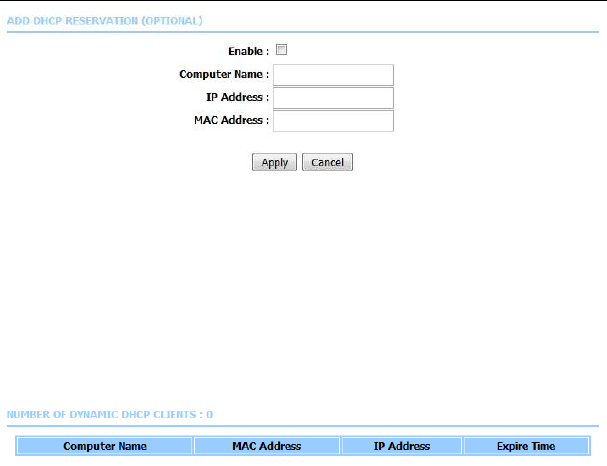
LX220N User Manual
24
Select Enable to reserve the IP address for the designated PC with the
configured MAC address. The Computer Name helps you to recognize the PC
with the MAC address, for example, Father’s Laptop. Click Apply to save the
settings.
After the DHCP reservation is saved, the DHCP reservations list displays the
configuration.
The NUMBER OF DYNAMIC DHCP CLIENTS page shows the current DHCP
clients (PC or Laptop) connected to the device and the detailed information of the
connected computer(s).
5.1.4
Local IPv6 Network
You can configure the LAN IPv6 address according to the actual application. The
preset IPv6 address is fe80::1. You can use the default settings and DHCPv6
service to manage the IPv6 settings for the private network. The IPv6 address of
the device is the base address used for DHCPv6. To use the device for DHCPv6
on your LAN, the IPv6 address pool used for DHCPv6 must be compatible with
the IPv6 address of the device. The IPv6 address available in the DHCP IPv6
address pool changes automatically if you change the IPv6 address of the
device.
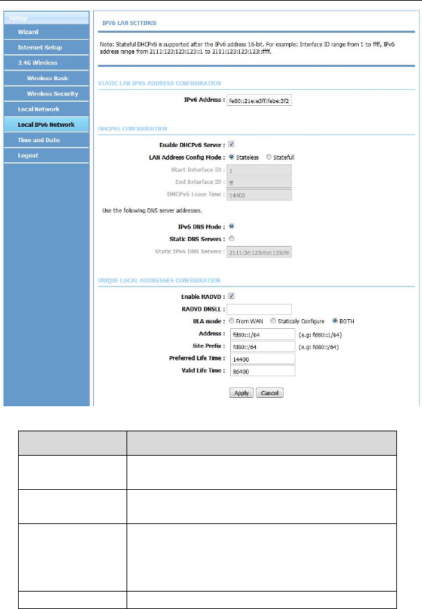
Choose Setup > Local IPv6 Network. The page shown in the following figure
appears. In this page, you can configure a static LAN IPv6 address, enable or
disable DHCPv6 server and RADVD, and configure site prefix.
LX220N User Manual
25
The following table describes the parameters in this page.
Field Description
IPv6 Interface
Address
The IPv6 address of link local gateway on the LAN
side.
Enable DHCPv6
Server
Choose to enable DHCPv6 server.
LAN address
config mode
Choose an IPv6 address mode. Stateless refers to
stateless address auto-configuration (SLAAC)
mode, and Stateful refers to dynamic host
configuration protocol (DHCP) mode.
Start/ End IPv6 address pool range.

LX220N User Manual
26
Field Description
Interface ID
DHCPv6 Lease
Time
IPv6 lease time.
Get DNS Servers
from WAN
You can choose to get the IPv6 DNS server address
from the WAN side.
Static DNS
Servers
You can manually set the IPv6 DNS server address.
Static IPv6 DNS
Servers
Input an IPv6 DNS server address.
Enable RADVD
The router advertisement daemon (RADVD) is run
by Linux or BSD systems acting as IPv6 routers. It
sends router advertisement messages, specified by
RFC2461, to a local Ethernet LAN periodically and
when requested by a node sending a router
solicitation message. These messages are required
for IPv6 stateless auto-configuration.
Auto get prefix
from WAN
You can choose to get an IPv6 prefix from the WAN
automatically.
WAN interface
You can choose to get an IPv6 prefix from the
selected WAN connection.
Static You can choose to specify an IPv6 prefix.
Site Prefix Input an IPv6 prefix.
After finishing setting, click the Apply button to apply the settings.
5.1.5
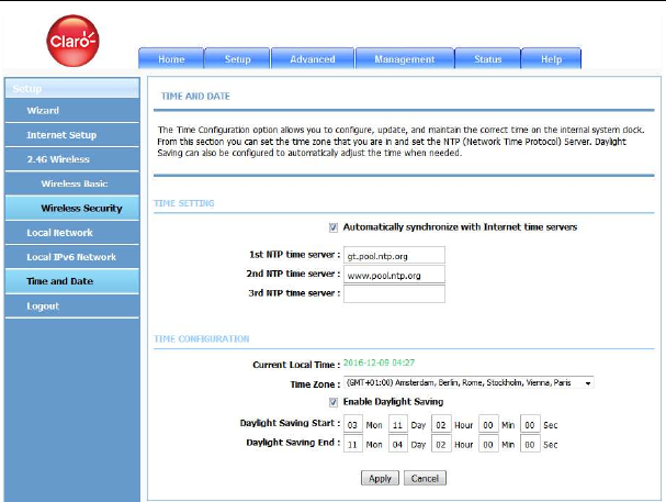
Time and Date
Choose Setup > Time and Date. The page shown in the following figure
appears.
LX220N User Manual
27
In the Time and Date page, you can configure, update, and maintain the correct
time on the internal system clock. You can set the time zone that you are in and
the network time protocol (NTP) server. You can also configure daylight saving to
automatically adjust the time when needed.
Select Automatically synchronize with Internet time servers.
Select the specific time server and the time zone from the corresponding
drop-down lists.
Select Automatically adjust clock for daylight saving changes if necessary.
Set the daylight as you want.
Click Apply to save the settings.
5.1.6
Logout
Choose Setup > Logout. The page shown in the following figure appears. In this
page, you can log out of the configuration page.
LX220N User Manual
28
5.2 Advanced
This section includes advanced features for network management, security and
administrative tools to manage the device. You can view status and other
information used to examine performance and troubleshoot.
In the main interface, click Advanced tab to enter the Advanced menu as shown
in the following figure. The submenus are 2.4G Advanced Wireless, ALG, Port
Forwarding, DMZ, SAMBA, Parental Control, Filtering Options, QoS
Configuration, Anti-Attack Settings, DNS, Dynamic DNS, Network Tools,
Routing, Schedules, NAT, DLNA, IP Tunnel and Logout.
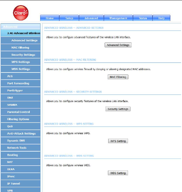
5.2.1
Advanced Wireless
It is suggested not to change the defaults, as incorrect settings may reduce the
performance of your wireless radio. The default settings provide the best wireless
radio performance in most environments.
Choose Advanced > Advanced Wireless. The page shown in the following
figure appears.
LX220N User Manual
29
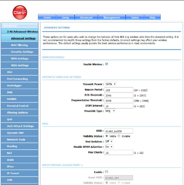
5.2.1.1 Advanced Settings
Select Advanced Settings. The page shown in the following figure appears.
LX220N User Manual
30
Wireless Network Name (SSID): The Wireless Network Name is a unique name
that identifies a network. All devices on a network must share the same wireless
network name in order to communicate on the network. If you decide to change
the wireless network name from the default setting, enter your new wireless
network name in this field.
These settings are only for more technically advanced users who have sufficient
knowledge about wireless LAN. Do not change these settings unless you know
the effect of changes on the device.
Click Apply to save the settings.
LX220N User Manual
31
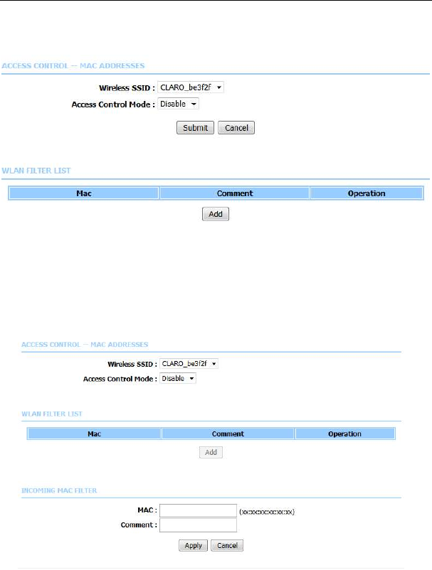
5.2.1.2 MAC Filtering
Select MAC Filtering. The page shown in the following figure appears.
MAC address access control permits access to this route from hosts with MAC
addresses contained in the WLAN Filter List.
Choose a wireless SSID, select an access control mode, and then click Add to
add a MAC Address as shown in the following figure. Click Apply to finish. After
adding a filter, you can edit or delete it.
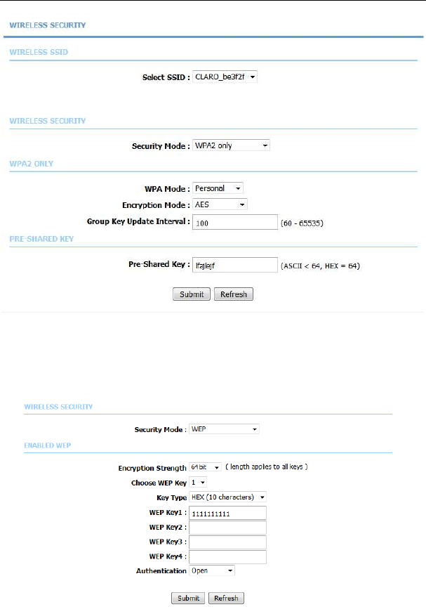
5.2.1.3 Security Settings
Select Security Settings. The VAP Configuration page appears.
LX220N User Manual
32
Select the SSID that you want to configure from the drop-down list. Select the
encryption type from the Work Mode drop-down list. You can select None, WEP,
WPA2 Only or WPA/WPA2 Mixed. The default mode is None.
If you select WEP, the page shown in the following figure appears.
LX220N User Manual
33
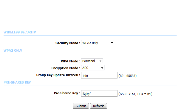
If you select WPA2 Only or WPA/WPA2 Mixed, the page shown in the following
figure appears.
Click Submit to save the settings. For detailed configuration, you may refer to
5.1.2.2 Wireless Security.
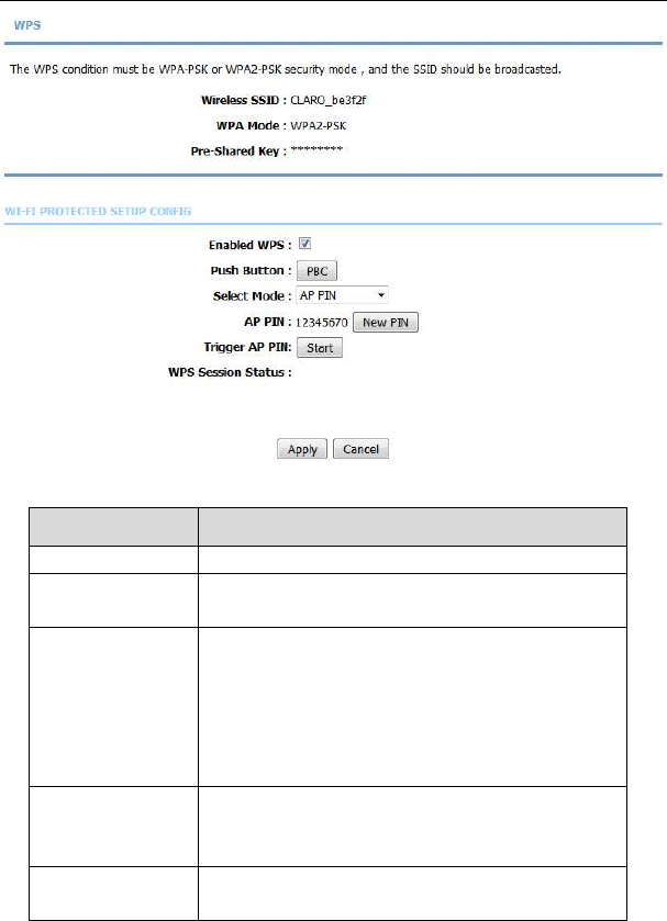
5.2.1.4 WPS Settings
Select WPS Settings. This page is used to config WPS settings.
Note:
To configure WPS, the WLAN security mode must be WPA-PSK or
WPA2-PSK mode.
LX220N User Manual
34
The following table describes the parameters of this page.
Field Description
Wireless SSID Select one SSID of the CPE.
Enabled WPS Choose to enable WPS function to set the following
parameters.
PBC
In this way, the router generates PIN. Click this
button, the router will generate a PIN, and
meanwhile press the WPS button on the wireless
client. The wireless client automatically establishes
connection with the router under encryption mode
without inputting the key.
PIN
In this way, the wireless client generates PIN. Enter
PIN of the wireless client in the Input Station PIN
field, and then click PIN to establish the connection.
WPS Session
Status
Display the session status.
LX220N User Manual
35
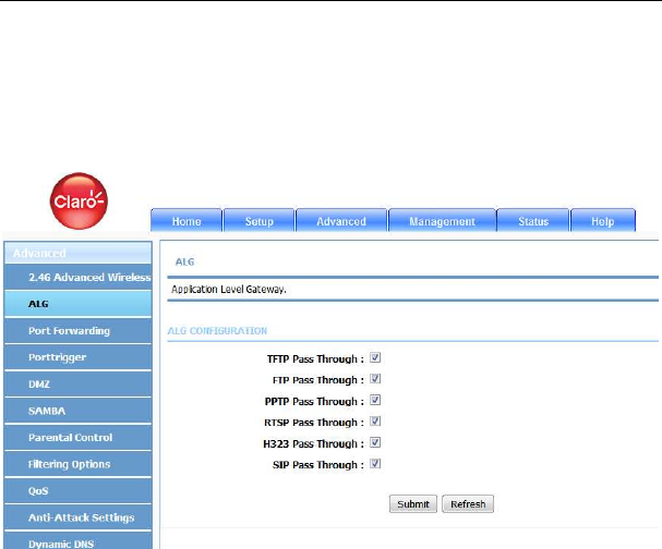
5.2.2
ALG
Choose Advanced > ALG. The page shown in the following figure appears. In
this page, you can enable passthrough of TFTP, FTP, PPTP, RTSP, L2TP, H323,
SIP and IPSEC.
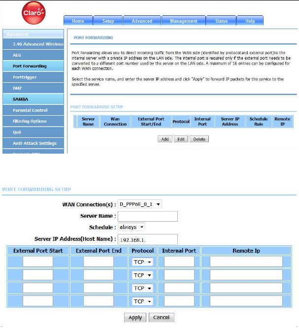
5.2.3
Port Forwarding
This function is used to open ports in your device and redirect data through those
ports to a single PC on your network (WAN-to-LAN traffic). It allows remote users
to access services on your LAN, such as FTP for file transfers or SMTP and
POP3 for e-mail. The device accepts remote requests for these services at your
global IP address. It uses the specified TCP or UDP protocol and port number,
and redirects these requests to the server on your LAN with the LAN IP address
you specify. Note that the specified private IP address must be within the
available range of the subnet where the device is in.
Choose Advanced > Port Forwarding. The page shown in the following figure
appears.
LX220N User Manual
36
Click Add to add a virtual server.
enter a name in the Server Name field.
Enter an IP address in the Server IP Address field to appoint the corresponding
PC to receive forwarded packets.
Click Apply to save the settings. The page shown in the following figure appears.
A virtual server is added.
LX220N User Manual
37
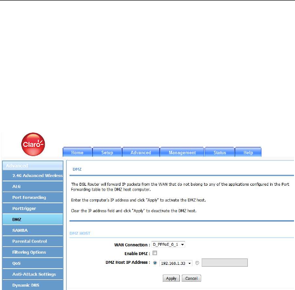
5.2.4
DMZ
Since some applications are not compatible with NAT, the device supports the
use of a DMZ IP address for a single host on the LAN. This IP address is not
protected by NAT and it is visible to agents on the Internet with the correct type of
software. Note that any client PC in the DMZ is exposed to various types of
security risks. If you use the DMZ, take measures (such as client-based virus
protection) to protect the remaining client PCs on your LAN from possible
contamination through DMZ.
Choose Advanced > DMZ. The page shown in the following figure appears.
Choose to enable DMZ, input a DMZ host ip address or Select a IP from list, and
click then Apply to save the settings.
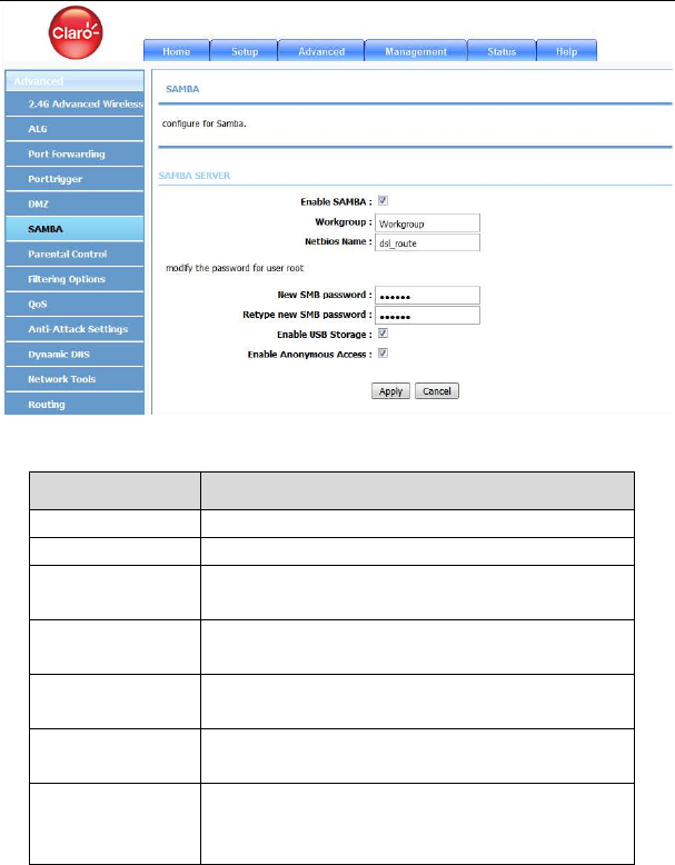
5.2.5
SAMBA
Select Advanced > SAMBA. The page shown in the following figure appears.
LX220N User Manual
38
The following table describes the parameters of this page.
Field Description
Enable SAMBA Select the check box to enable the samba service
Workgroup Enter the name of your local area network (LAN).
Netbios Name Enter your netbios name which is an identifier used
by netbios services running on a computer.
New SMB
password
Enter your samba password for user root.
Retype new SMB
password
Reconfirm your samba password here.
Enable USB
Storage
Select the check box to support USB storage.
Enable
Anonymous
Access
Select the check box to allow anonymous users
access.
LX220N User Manual
39
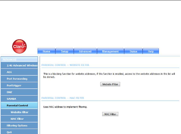
5.2.6
Parental Control
Choose Advanced > Parental Control. The Parent Control page shown in the
following figure appears.
This page provides two useful tools for restricting the Internet access. Website
Filter allows you to quickly create a list of all websites that you wish to stop users
from accessing. MAC Filter allows you to control when clients or PCs connected
to the device are allowed to access the Internet.
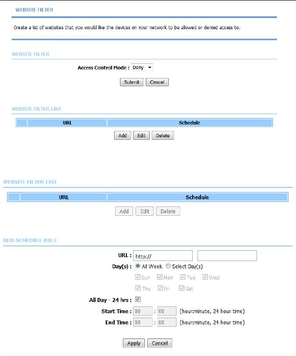
5.2.6.1 Website Filter
In the Parental Control page, click Website Filter. The page shown in the
following figure appears.
LX220N User Manual
40
Click Add. The page shown in the following figure appears.
Enter the website in the URL field. Select the Schedule from the drop-down list,
or select Manual Schedule and select the corresponding time and days.
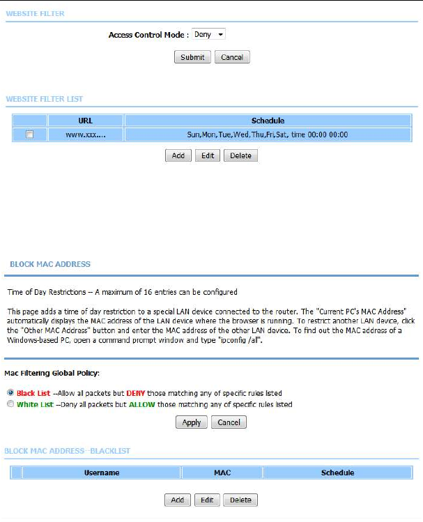
Click Apply to add the website to the WEBSITE FILTER table. The page shown
in the following figure appears.
LX220N User Manual
41
5.2.6.2 MAC Filter
In the Parental Control page, click MAC Filter. The page shown in the following
figure appears.
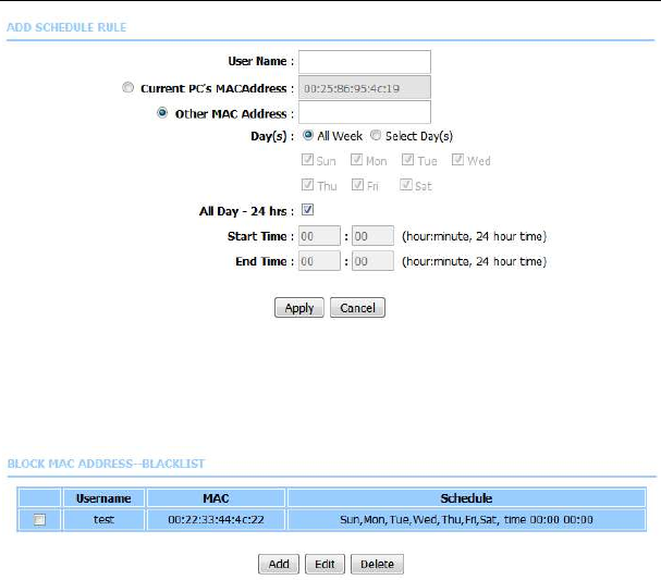
Choose BLACK_LIST or WHITE_LIST, and then click Add. The page shown in
the following figure appears.
LX220N User Manual
42
Enter the use name and MAC address and select the corresponding time and
days. Click Apply to add the MAC address to the BLOCK MAC ADDRESS
Table. The page shown in the following figure appears.
5.2.7
Filtering Options
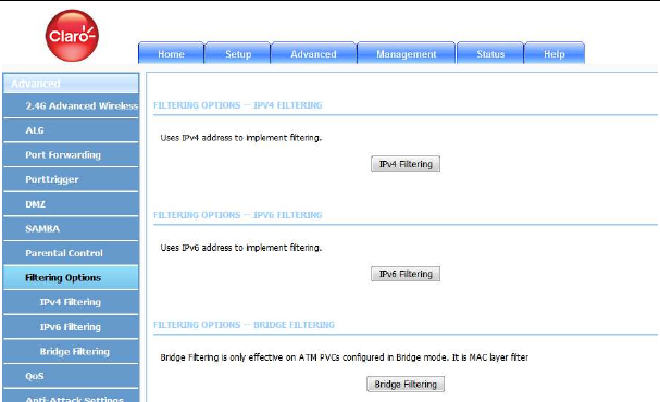
Choose Advanced > Filtering Options. The Filtering Options page shown in
the following figure appears.
LX220N User Manual
43
5.2.7.1 IPv4 Filtering
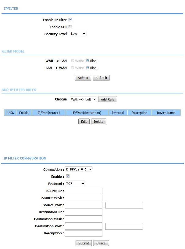
In the Filtering Options page, click IPv4 Filtering. The page shown in the
following figure appears. In this page, you may configure IPv4 firewall function.
Note:
The settings are applicable only when IP filter is enabled.
LX220N User Manual
44
Select a security level, choose a filter direction, and then click Add a rule to
display the following figure.
The following table describes the parameters of this page.
LX220N User Manual
45
Field Description
Connection Choose an IPv4 WAN connection.
Enable Tick in the box to enable a filter rule.
Protocol Choose a protocol corresponding to the rule. You
may choose TCP, UDP, ICMP or TCP/UDP.
Source/ Destination
IP
Original/ destination IP address.
Source/ Destination
Mask
Original/ destination mask.
Source/Destination
Port
Original/ end port, which is the original port range.
Description You can describe this IPv4 filter rule.
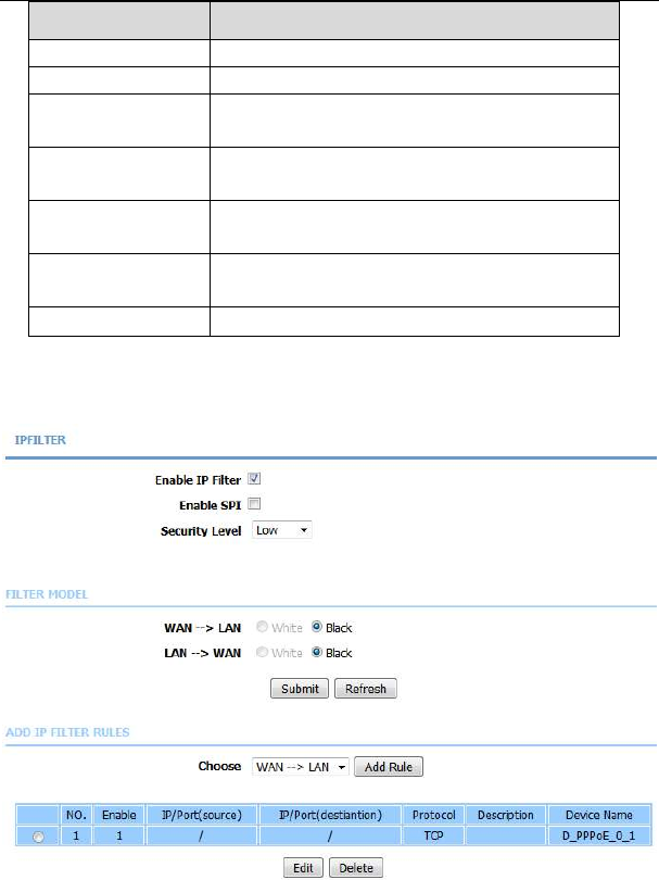
After setting the parameters, click Submit. The page shown in the following
figure appears. You can also click Edit or Delete to manage the rule.
LX220N User Manual
46
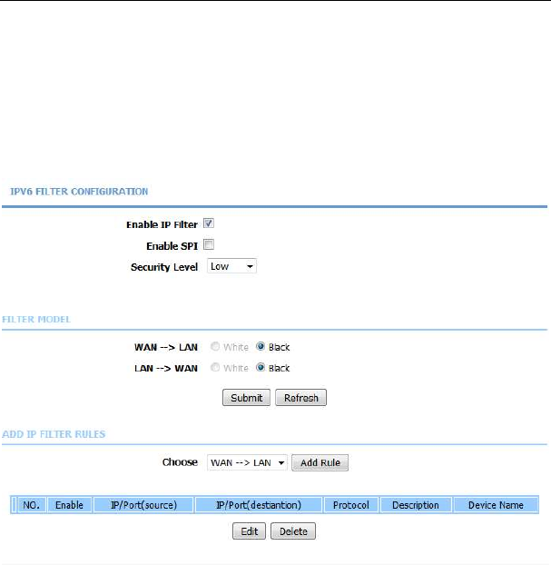
5.2.7.2 IPv6 Filtering
In the Filtering Options page, click IPv6 Filtering. The page shown in the
following figure appears. In this page, you may configure IPv6 firewall function.
Note:
The settings are applicable only when the firewall is enabled.
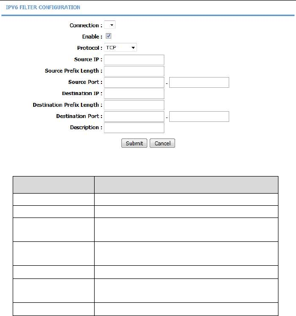
Select a security level, choose a filter direction, and then click Add a rule to
display the following figure.
LX220N User Manual
47
The following table describes the parameters of this page.
Field Description
Connection Choose an IPv6 WAN connection.
Enable Tick in the box to enable a firewall rule.
Protocol Choose a protocol corresponding to the rule. You
may choose TCP, UDP, ICMPv6 or TCP/UDP.
Source/ Destination
IP
Original/ destination IP address
Source prefix length
Original/ destination mask
Source/Destination
Port
Original/ end port, which is the original port range
Description You can describe this IPv6 filter rule.
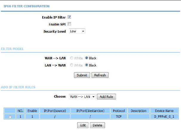
After setting the parameters, click Submit. The page shown in the following
figure appears. You can also click Edit or Delete to manage the rule.
LX220N User Manual
48
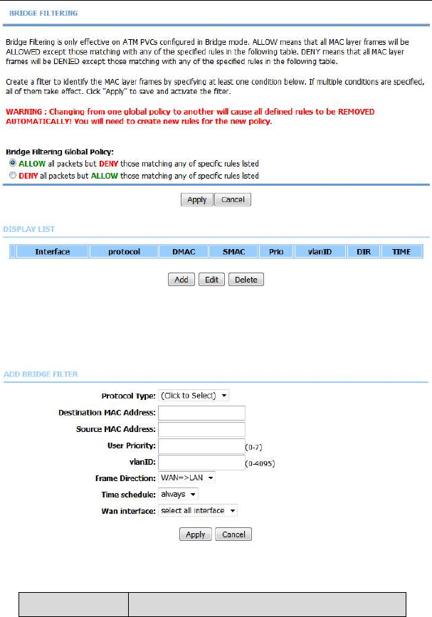
5.2.7.3 Bridge Filtering
In the Filtering Options page, click Bridge Filtering. The page shown in the
following figure appears. This page is used to configure bridge parameters. In
this page, you can change the settings or view some information of the bridge
and its attached ports.
LX220N User Manual
49
As instructed in the page, choose a bridge filtering global policy as ALLOW or
DENY, and then Click Add to add a bridge filter. The page shown in the following
figure appears.
The following table describes the parameters of this page.
Field Description

LX220N User Manual
50
Field Description
Protocol Type
Choose a third-layer protocol type for bridge filtering
from the drop-down list. You may choose PPPoE,
IPv4, IPv6, AppleTalk, IPX or NetBEUI.
Destination MAC
Address
The MAC address of sendee of the message
Source MAC
Address
The MAC address of sender of the message
User priority Vlan priority.
VlanID Vlan ID of a message。
Frame Direction Choose the sending direction as WAN to LAN or
LAN to WAN.
Time schedule Choose the filtering strategy as always or never.
Wan interface Set an effective interface for the bridge filtering rule.
Click Apply to save the settings.
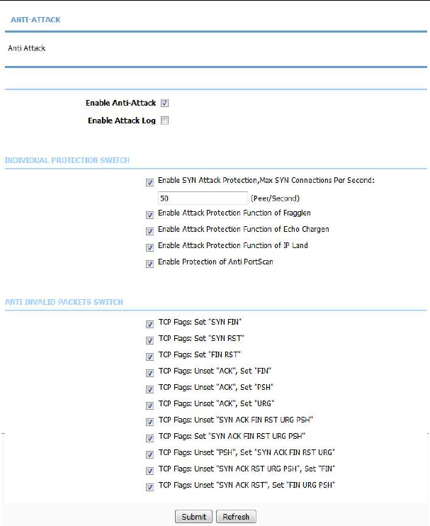
5.2.8
Anti-Attack Settings
Choose Advanced > Anti-Attack Settings. The Anti-Attack Configuration
page shown in the following figure appears.
LX220N User Manual
51
A denial-of-service (DoS) attack is characterized by an explicit attempt by
attackers to prevent legitimate users of a service from using that service.
Port scan protection is designed to block attempts to discover vulnerable ports or
services that might be exploited in an attack from the WAN.
Click Submit to save the settings.
LX220N User Manual
52
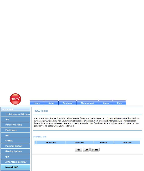
5.2.9
Dynamic DNS
The device supports dynamic domain name service (DDNS). The dynamic DNS
service allows a dynamic public IP address to be associated with a static host
name in any of the many domains, and allows access to a specified host from
various locations on the Internet. Click a hyperlinked URL in the form of
hostname.dyndns.org and allow remote access to a host. Many ISPs assign
public IP addresses using DHCP, so locating a specific host on the LAN using the
standard DNS is difficult. For example, if you are running a public web server or
VPN server on your LAN, DDNS ensures that the host can be located from the
Internet even if the public IP address changes. DDNS requires that an account
be set up with one of the supported DDNS service providers (DyndDNS.org,
3322.org and freedns.afraid.org).
Choose Advanced > Dynamic DNS. The page shown in the following figure
appears.
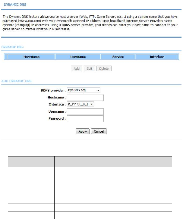
Click Add to add dynamic DNS. The page shown in the following figure appears.
LX220N User Manual
53
The following table describes the parameters of this page.
Field Description
DDNS provider
Select one of the DDNS registration organizations
from the down-list drop. Available servers include
DynDns.org, 3322.org and freedns.afraid.org.
Host Name Enter the host name that you registered with your
DDNS service provider.
Username Enter the user name for your DDNS account.
Password Enter the password for your DDNS account.
Click Apply to save the settings.
LX220N User Manual
54
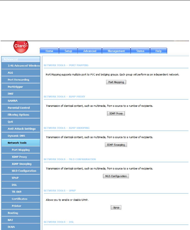
5.2.10
Network Tools
Choose Advanced > Network Tools. The page shown in the following figure
appears.
(Network Tools-1)
LX220N User Manual
55
(Network Tools-2)
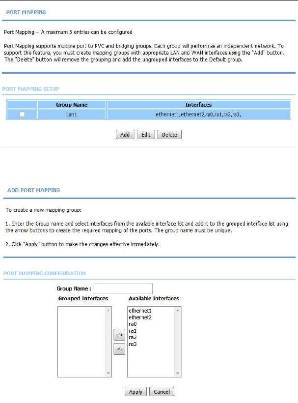
5.2.10.1 Port Mapping
Choose Advanced > Network Tools and click Port Mapping. The page shown
in the following figure appears. In this page, you can bind the WAN interface and
the LAN interface to the same group.
LX220N User Manual
56
Click Add to add port mapping. The page shown in the following figure appears.
The procedure for creating a mapping group is as follows:

LX220N User Manual
57
Step 1 Enter the group name.
Step 2 Select interfaces from the Available Interface list and click the <-
arrow button to add them to the grouped interface list, in order to
create the required mapping of the ports. The group name must be
unique.
Step 3 Click Apply to save the settings.
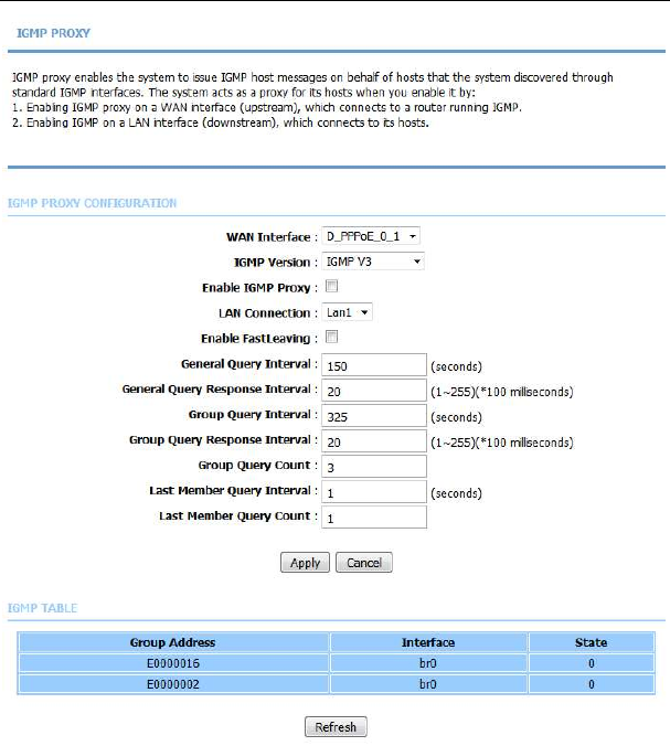
5.2.10.2 IGMP Proxy
Choose Advanced > Network Tools and click IGMP Proxy. The page shown in
the following figure appears.
LX220N User Manual
58
IGMP proxy enables the system to issue IGMP host messages on behalf of hosts
that the system discovered through standard IGMP interfaces. The system acts
as a proxy for its hosts after you enable it.
Click Apply to save the settings.
LX220N User Manual
59
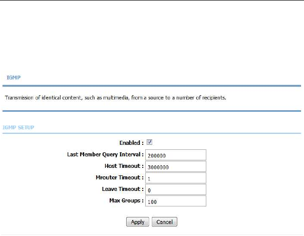
5.2.10.3 IGMP Snooping
Choose Advanced > Network Tools and click IGMP Snooping. The page
shown in the following figure appears. When IGMP Snooping is enabled, the
multicast data transmits through the specific LAN port which has received the
request report.
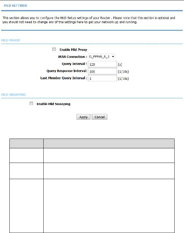
5.2.10.4 MLD Configuration
Choose Advanced > Network Tools and click MLD Configuration. The page
shown in the following figure appears. This section allows you to configure the
MLD setup settings of your router.
LX220N User Manual
60
The following table describes the parameters of this page.
Field Description
Enable Mld
Proxy
You can choose to enable MLD proxy.
WAN
Connection
Choose an IPv6 WAN connection.
Enable MLD
Snooping
Multicast Listener Discovery Snooping (MLD Snooping) is
an IPv6 multicast constraining mechanism that runs on
Layer 2 devices to manage and control IPv6 multicast
groups. By analyzing received MLD messages, a Layer 2
device running MLD Snooping establishes mappings
between ports and multicast MAC addresses and
forwards IPv6 multicast data based on these mappings.
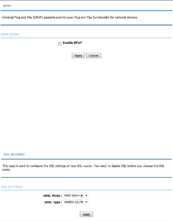
5.2.10.5 UPnP
Choose Advanced > Network Tools and click UPnP. The page shown in the
following figure appears.
LX220N User Manual
61
In this page, you can configure universal plug and play (UPnP). The system acts
as a daemon after you enable UPnP.
UPnP is used for popular audio visual software. It allows automatic discovery of
your device in the network. If you are concerned about UPnP security, you can
disable it. Block ICMP ping should be enabled so that the device does not
respond to malicious Internet requests.
Click Apply to save the settings.
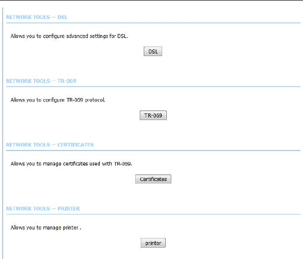
5.2.10.6 DSL
Choose Advanced > Network Tools and click DSL. The page shown in the
following figure appears.
In this page, you can select a DSL mode. Normally, you can keep this factory
default setting. The device negotiates the modulation mode with DSLAM.
LX220N User Manual
62
Click Apply to save the settings.
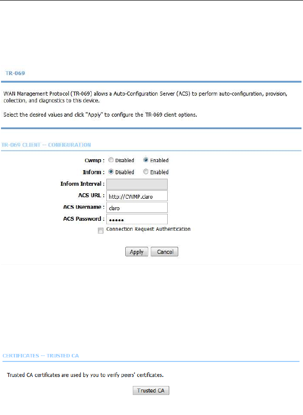
5.2.10.7 TR-069
Choose Advanced > Network Tools and click TR069. The page shown in the
following figure appears. In this page, you can configure the TR069 CPE.
Click Apply to save settings.
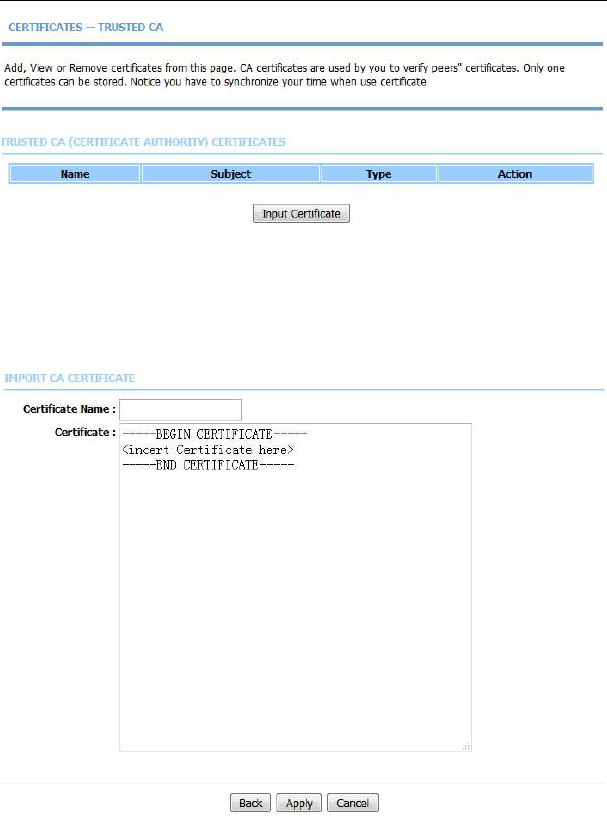
5.2.10.8 Certificates
Choose Advanced > Network Tools and click Certificates. The Certificates
page shown in the following figure appears.
Click Trusted CA button to import a certificate.
LX220N User Manual
63
Note:
You can input a certificate after deleting the existing certificate.
LX220N User Manual
64
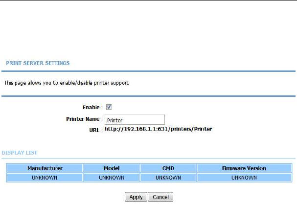
5.2.10.9 Printer
Choose Advanced > Network Tools and click Printer. The Printer page shown
in the following figure appears. In this page, you can enable/disable printer
support.
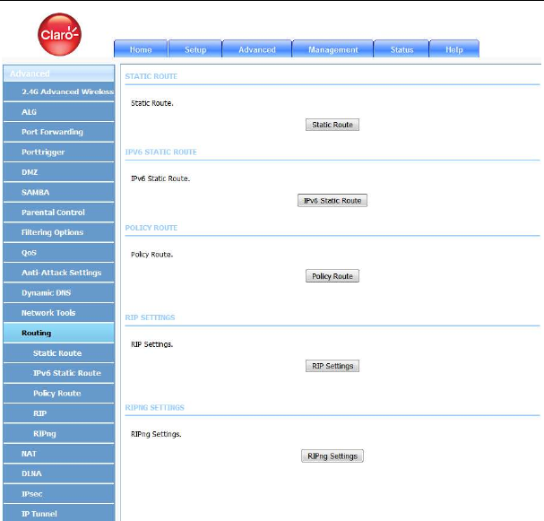
5.2.11
Routing
Choose Advanced > Routing. The page shown in the following figure appears.
LX220N User Manual
65
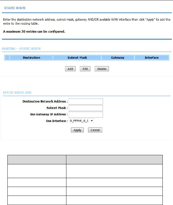
5.2.11.1 Static Routing
Choose Advanced > Routing and click Static Routing. The page shown in the
following figure appears. This page is used to configure the routing information.
In this page, you can add or delete IP routes.
LX220N User Manual
66
Click Add to add a static route. The page shown in the following figure appears.
The following table describes the parameters of this page.
Field Description
Destination Network
Address
The destination IP address of the router.
Subnet Mask The subnet mask of the destination IP
address.
Use Interface The interface name of the router output port.
Use Gateway IP Address The gateway IP address of the router.
Click Apply to save the settings.
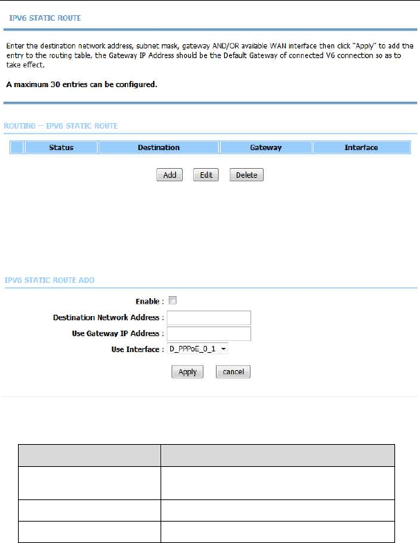
5.2.11.2 IPv6 Static Route
Choose Advanced > Routing and click IPv6 Static Route. The page shown in
the following figure appears.
LX220N User Manual
67
Click Add to add an IPv6 static route. The page shown in the following figure
appears.
The following table describes the parameters of this page.
Field Description
Destination Network
Address
The destination IP address of the static
route.
Use Gateway IP Address The gateway IP address of the static route.
Use Interface The interface name of the static route.
LX220N User Manual
68
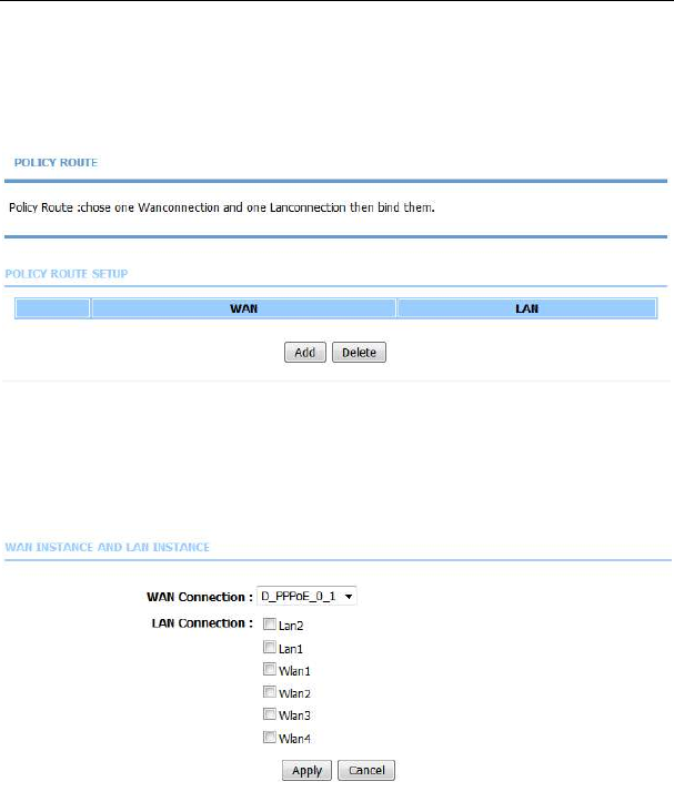
5.2.11.3 Policy Route
Choose Advanced > Routing and click Policy Route. The page shown in the
following figure appears. The policy route binds one WAN connection and one
LAN interface.
Click Add, and the page shown in the following figure appears. Choose one WAN
connection and at lease one LAN connection to bind together, and then click
Apply.
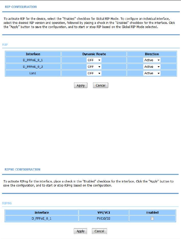
5.2.11.4 RIP
Choose Advanced > Routing and click RIP. The page shown in the following
figure appears. This page is used to select the interfaces on your device that use
RIP and the version of the protocol used.
LX220N User Manual
69
If you are using this device as a RIP-enabled device to communicate with others
using the routing information protocol, enable RIP and click Apply to save the
settings.
5.2.11.5 RIPng
Choose Advanced > Routing and click RIPng. The page shown in the following
figure appears. You can enable or disable dynamic routing of an IPv6 interface
after establishing an IPv6 PVC connection.
LX220N User Manual
70
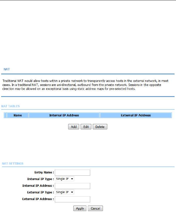
5.2.12
NAT
Choose Advanced > NAT. The page shown in the following figure appears.
Traditional NAT would allow hosts within a private network to transparently
access hosts in the external network, in most cases. In a traditional NAT,
sessions are unidirectional, outbound from the private network. Sessions in the
opposite direction may be allowed on an exceptional basis using static address
maps for pre-selected hosts
Click Add to set a NAT set in the following page. For IP type, you can choose
single IP or IP range. Click Apply to save and enable the setting.
LX220N User Manual
71
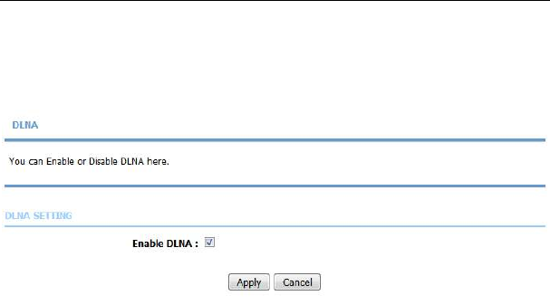
5.2.13
DLNA
Choose Advanced > DLNA. The page shown in the following figure appears. In
this page, you can choose to enable DLNA, and then click Apply.
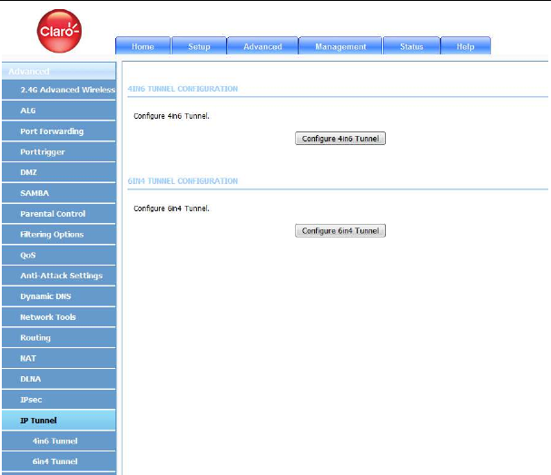
5.2.14
IP Tunnel
Choose Advanced > IP Tunnel. The page shown in the following figure appears.
LX220N User Manual
72
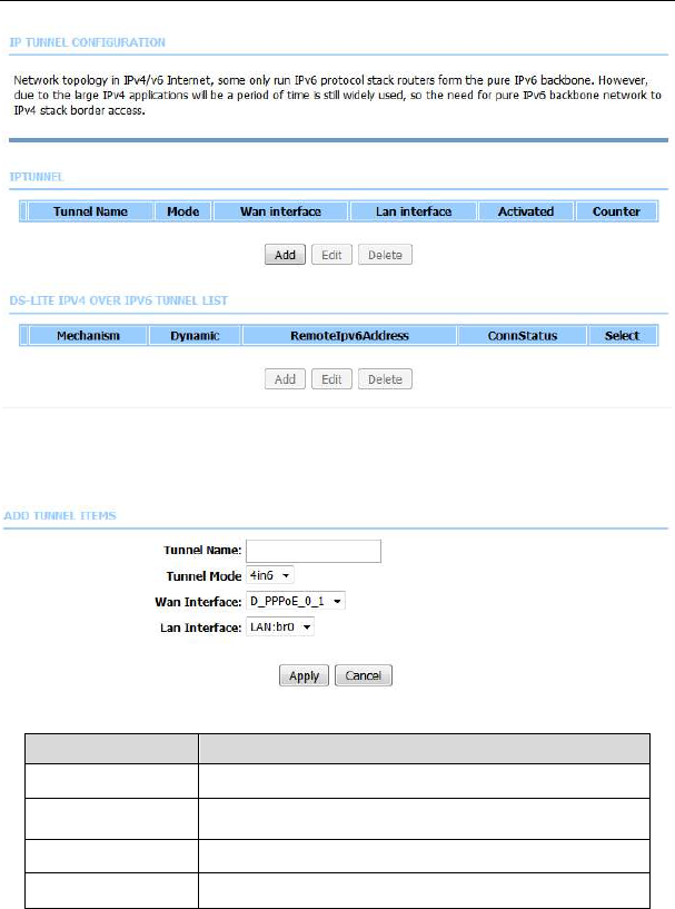
5.2.14.1 4in6 Tunnel
Choose Advanced > IP Tunnel and then click 4in6 Tunnel. The page shown in
the following figure appears. In this page, you can configure IPv4 penetration
through IPv6 network. When only IPv6 access is provided by your ISP, you can
access the Internet via IPv4 and IPv6.
LX220N User Manual
73
Click Add below the table IPTUNNEL to add tunnel items. The page shown in the
following figure appears.
The following table describes the parameters of this page.
Field Description
Tunnel Name Set a tunnel name.
Tunnel Mode Select the tunnel mode as 4 in6 or 6in4.
Wan Interface Choose a WAN interface used for the tunnel.
Lan Interface Choose a LAN interface used for the tunnel.
Click Apply to enable the settings.
LX220N User Manual
74
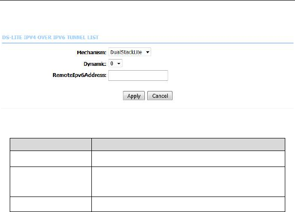
Click Add below the table DS-Lite IPv4 over IPv6 Tunnel List to add a DS-Lite
item, which is a 4in6 tunnel. The page shown in the following figure appears.
The following table describes the parameters of this page.
Field Description
Mechanism The tunnel type is DS-Lite, which is 4in6 tunnel.
Dynamic Set the obtaining mode of remote IPv6 addresses.
You can select 0 or 1.
RemoteIPv6Address
Set the remote end IPv6 address of the tunnel.
Click Apply to enable the settings.
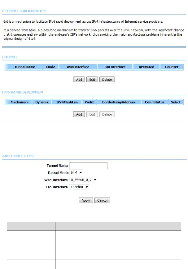
5.2.14.2 6in4 Tunnel
Choose Advanced > IP Tunnel and then click 6in4 Tunnel. The page shown in
the following figure appears. In this page, you can configure IPv6 penetration
through IPv4 network. When only IPv4 access is provided by your ISP, you can
access the Internet via IPv4 and IPv6.
LX220N User Manual
75
Click Add below the table IPTUNNEL to add tunnel items. The page shown in the
following figure appears.
The following table describes the parameters of this page.
Field Description
Tunnel Name Set a tunnel name.
Tunnel Mode Select the tunnel mode as 4 in6 or 6in4.
Wan Interface Choose a WAN interface used for the tunnel.
Lan Interface Choose a LAN interface used for the tunnel.
LX220N User Manual
76
Click Apply to enable the settings.
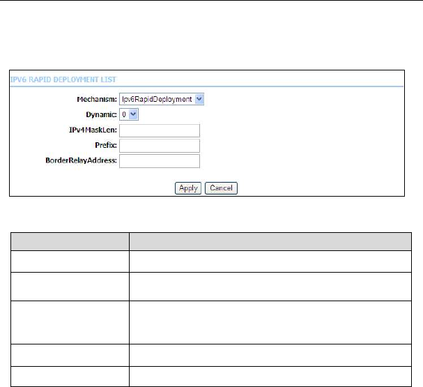
Click Add below the table IPv6 Rapid Deployment to add a 6RD item, which is a
6in4 tunnel. The page shown in the following figure appears.
The following table describes the parameters of this page.
Field Description
Mechanism The tunnel type is 6RD, which is a 6in4 tunnel.
Dynamic Set the obtaining mode of Border Relay Address.
IPv4MaskLen Set the subnet mask digits of the IPv4 address of the
local WAN interface.
Prefix Set the IPv6 prefix of the 6RD tunnel.
BorderRelayAddress
Set the Border Relay IPv4 address at the remote end.
Click Apply to enable the settings.
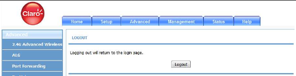
5.2.15
Logout
Choose Advanced > Logout. The page shown in the following figure appears. In
this page, you can log out of the configuration page.
LX220N User Manual
77
5.3 Management
In the main interface, click Management tab to enter the Management menu as
shown in the following figure. The submenus are Global IPv6, System
Management, Firmware Update, Access Controls, Diagnosis, Log
Configuration and Logout.
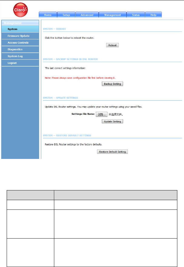
5.3.1
System Management
Choose Management > System Management. The page shown in the following
figure appears.
LX220N User Manual
78
In this page, you can reboot device, back up the current settings to a file, update
settings from the file saved previously and restore the factory defaults.
The buttons in this page are described as follows.
Field Description
Reboot Click this button to reboot the device.
Backup Setting Click this button to save the settings to the local hard
drive. Select a location on your computer to back up
the file. You can name the configuration file.
Update setting Click Browse to select the configuration file of device
and then click Update Settings to begin updating the
device configuration.
LX220N User Manual
79
Restore Default
Setting
Click this button to reset the device to default settings.
Note:
Do not turn off your device or press the Reset button while an operation in this
page is in progress.
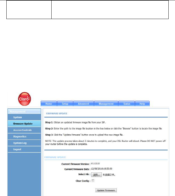
5.3.2
Firmware Update
Choose Management > Firmware Update. The page shown in the following
figure appears. In this page, you can upgrade the firmware of the device.
To update the firmware, take the following steps.
Step 1 Click Browse…to locate the file.
Step 2 Select Clear Config to clear the current configuration and restore the
default.
Step 3 Click Update Firmware to copy the file.
The device loads the file and reboots automatically.
Note:
LX220N User Manual
80
Do not turn off your device or press the Reset button while an operation in this
page is in progress.
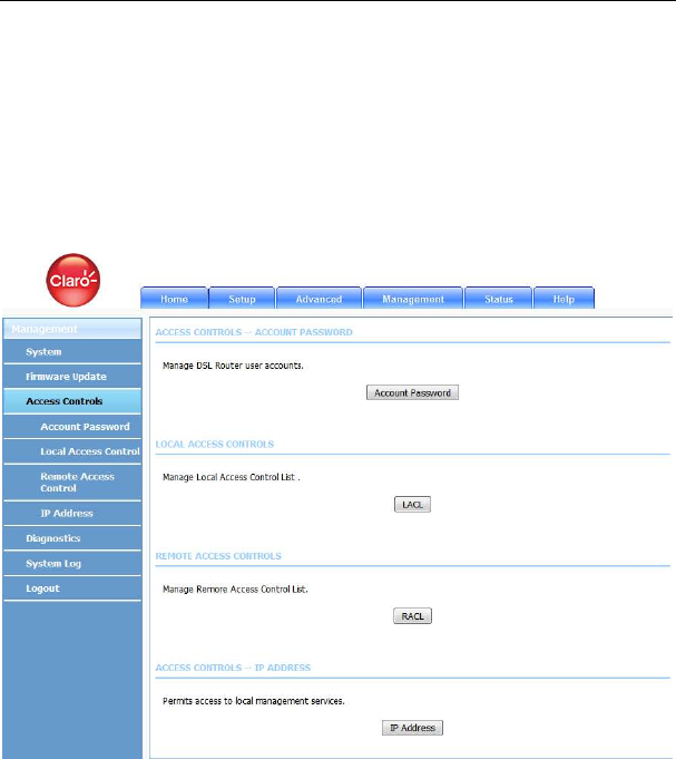
5.3.3
Access Controls
Choose Management > Access Controls. The Access Controls page shown
in the following figure appears. The page contains User Management, Local
Access Control, Remote Access Control and IP Address.
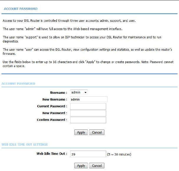
5.3.3.1 Account Password
In the Access Controls page, click Account Password. The page shown in the
following figure appears. In this page, you can change the password of the user
and set time for automatic logout.
LX220N User Manual
81
You should change the default password to secure your network. Ensure that you
remember the new password or write it down and keep it in a safe and separate
location for future reference. If you forget the password, you need to reset the
device to the factory default settings and all configuration settings of the device
are lost.
Select the Username from the drop-down list. You can select admin
(subject to different
models)
or Usuario.
Enter the current and new passwords and confirm the new password to change
the password. Click Apply to apply the settings.
Web Idle Time Out is the idle duration of user interfaces. After this duration, you
need to login to the router again for operation.
LX220N User Manual
82
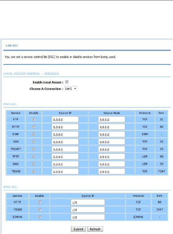
5.3.3.2 Local Access Control
Under the Access Controls menu, click Local Access Control. The page
shown in the following figure appears. This page allows you to enable or disable
LAN management services. For example, if the Telnet service is enabled on port
23, the remote host can access the router by Telnet through port 23.
LX220N User Manual
83
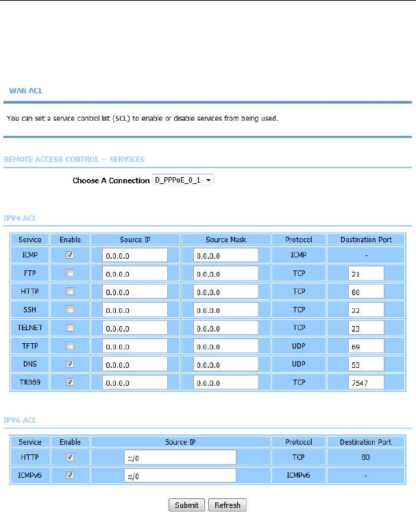
5.3.3.3 Remote Access Control
Under the Access Controls menu, click Remote Access Control. The page
shown in the following figure appears. This page allows you to enable or disable
WAN management services. You may refer to 5.3.3.2 Local Access Control.
5.3.3.4 IP Address
In the Access Controls page, click IP Address. The page shown in the following
figure appears.
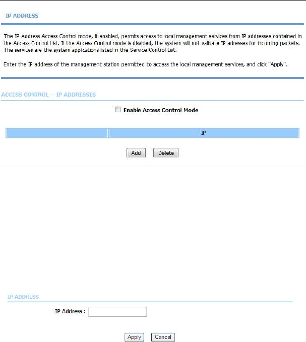
LX220N User Manual
84
In this page, you can configure the IP address for access control list (ACL). If ACL
is enabled, only devices with the specified IP addresses can access the device.
Note:
If you enable the ACL, ensure that IP address of the host is in the ACL list.
To add an IP address to the IP list, click Add. The page shown in the following
figure appears.
Click Apply to apply the settings, and then choose Enable Access Control
Mode to enable ACL.
LX220N User Manual
85
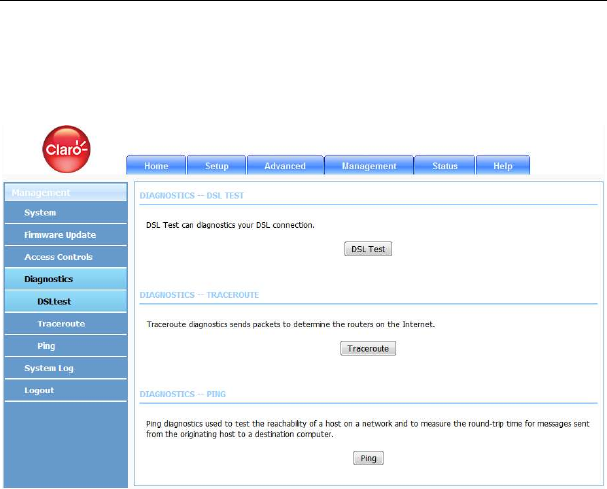
5.3.4
Diagnosis
Choose Management > Diagnosis. The Diagnosis page shown in the following
figure appears. The page contains DSL Test and Traceroute.
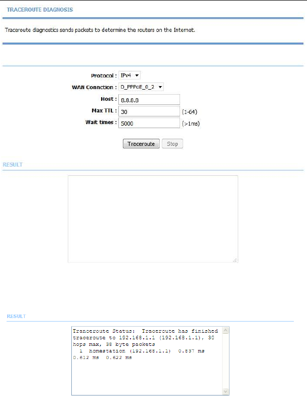
5.3.4.1 Traceroute
In the Diagnosis page, click Traceroute. The page shown in the following figure
appears. In this page, you can determine the routers on the Internet by sending
packets.
LX220N User Manual
86
Click Traceroute to begin diagnosis. After finish, the page shown in the following
figure appears.
LX220N User Manual
87
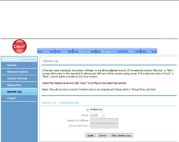
5.3.5
System Log
Choose Management > Log Configuration. The System Log page shown in
the following figure appears.
This page displays event log data in the chronological manner. You can read the
event log from the local host or send it to a system log server. In this page, you
can enable or disable the system log function.
To log the events, take the following steps.
Step 1 Select Enable Log check box.
Step 2 Select the display mode from the Mode drop-down list.
Step 3 Enter the Server IP Address and Server UDP Port if the Mode is set
to Both or Remote.
Step 4 Click Apply to apply the settings.
Step 5 Click View System Log to view the detail information of system log.
5.4 Status
In the main interface, click Status tab to enter the Status menu as shown in the
following figure. The submenus are Device Info, Wireless Clients, DHCP
LX220N User Manual
88
Clients, LAN Clients, Monitor, Stream Rate, Logs, Statistics, Route Info and
Logout. You can view the system information and monitor performance.
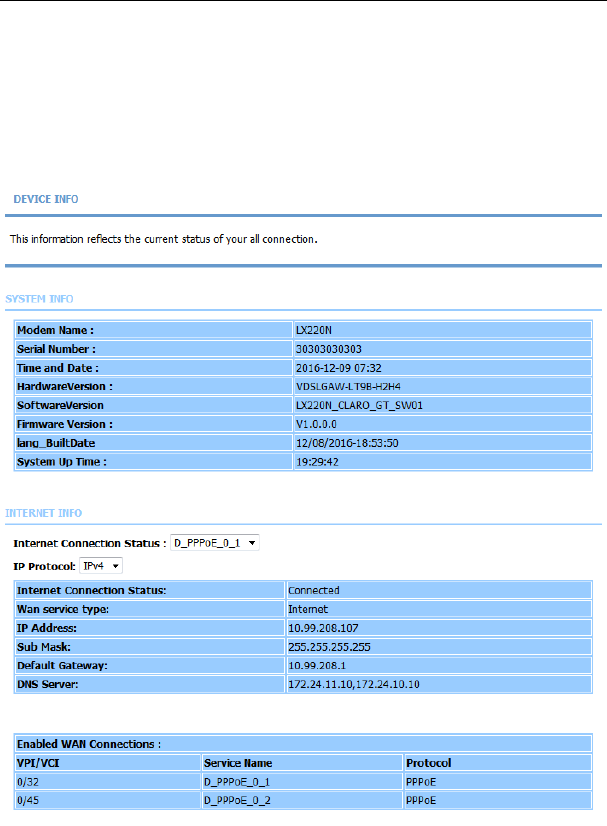
5.4.1
Device Info
Choose Status > Device Info. The page shown in the following figure appears.
LX220N User Manual
89
The page displays the summary of the device status. It includes the information
of firmware version, upstream rate, downstream rate, uptime and Internet
configuration (both wireless and Ethernet statuses).
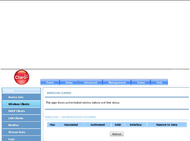
5.4.2
Wireless Clients
Choose Status > Wireless Clients. The page shown in the following figure
appears. The page displays authenticated wireless stations and their statuses.
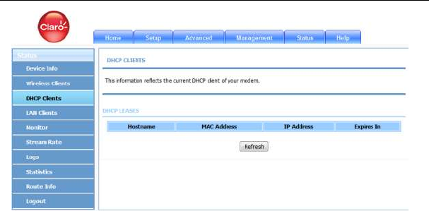
5.4.3
DHCP Clients
Choose Status > DHCP Clients. The page shown in the following figure appears.
This page displays all client devices that obtain IP addresses from the device.
You can view the host name, IP address, MAC address and time expired(s).
LX220N User Manual
90
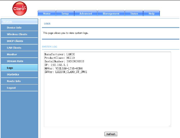
5.4.4
Logs
Choose Status > Logs. The page shown in the following figure appears. This
page lists the system log. Click Refresh to refresh the system log shown in the
table.
LX220N User Manual
91
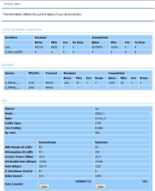
5.4.5
Statistics
Choose Status > Statistics. The page shown in the following figure appears.
This page displays the statistics of the network and data transfer. This
information helps technicians to identify if the device is functioning properly. The
information does not affect the function of the device.
LX220N User Manual
92
LX220N User Manual
93
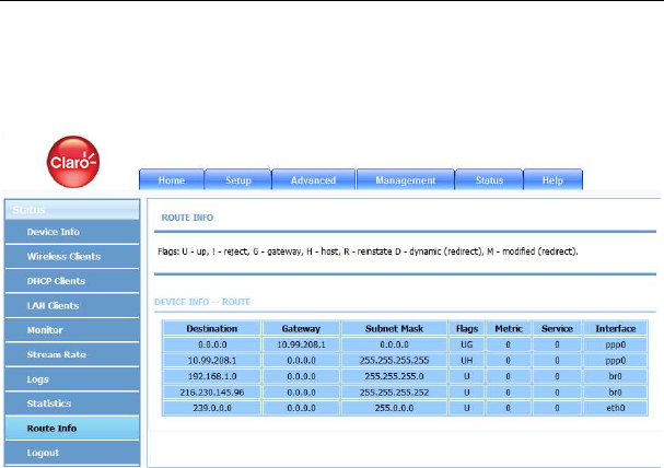
5.4.6
Route Info
Choose Status > Route Info. The page shown in the following figure appears.
The table shows a list of destination routes commonly accessed by the network.
5.5 Help
In the main interface, click Help tab to enter the Help menu as shown in the
following figure. This section provides detailed configuration information for the
device. Click a wanted link to view corresponding information.

LX220N User Manual
6 Trouble Shooting
Question Answer
Why are all the
indicators off?
Check the connection between the power
adapter and the power socket.
Check whether the power switch is turned on.
Why the LAN indicator
is off?
Check the following:
The connection between the device and your
PC, hub or switch
The running status of the computer, hub, or
switch
Why is the DSL
indicator not on?
Check the connection between the DSL port of the
device and the wall jack.
Why Internet access
fails while the ADSL
indicator is on?
Check whether the VPI, VCI, user name and
password are correctly entered.
Why I fail to access the
web configuration page
of the DSL router?
Choose Start > Run from the desktop, and ping
192.168.1.1 (IP address of the DSL router). If the
DSL router is not reachable, check the type of the
network cable, the connection between the DSL
router and the PC, and the TCP/IP configuration of
the PC.
How to load the default
settings after incorrect
configuration?
To restore the factory default settings, turn on the
device, and press the reset button for about 3
seconds, and then release it. The default IP
address and the subnet mask of the DSL router are
192.168.1.1 and 255.255.255.0, respectively.
Administrator username/password: 1234/1234
(subject to different models)
.
Common username/password: user/user.
ISP technician username/password:
support/support.

LX220N User Manual
95
7. FCC Statement
This equipment has been tested and found to comply with the limits for a Class B
digital device, pursuant to part 15 of the FCC Rules. These limits are designed to
provide reasonable protection against harmful interference in a residential
installation. This equipment generates, uses and can radiate radio frequency
energy and, if not installed and used in accordance with the instructions, may cause
harmful interference to radio communications. However, there is no guarantee that
interference will not occur in a particular installation. If this equipment does cause
harmful interference to radio or television reception, which can be determined by
turning the equipment off and on, the user is encouraged to try to correct the
interference by one or more of the following measures:
—Reorient or relocate the receiving antenna.
—Increase the separation between the equipment and receiver.
—Connect the equipment into an outlet on a circuit different from that to which the
receiver is connected.
—Consult the dealer or an experienced radio/TV technician for help.
FCC Radiation Exposure Statement
This device complies with FCC radiation exposure limits set forth for an
uncontrolled environment and it also complies with Part 15 of the FCC RF Rules.
This equipment must be installed and operated in accordance with provided
instructions and the antenna(s) used for this transmitter must be installed to provide
a separation distance of at least 20 cm from all persons and must not be co-located
or operating in conjunction with any other antenna or transmitter. End-users and
installers must be provide with antenna installation instructions and consider
removing the no-collocation statement.
This device complies with Part 15 of the FCC Rules. Operation is subject to the

LX220N User Manual
96
following two conditions: (1) this device may not cause harmful interference, and
(2) this device must accept any interference received, including interference that
may cause undesired operation.
Caution!
Any changes or modifications not expressly approved by the party responsible for
compliance could void the user's authority to operate the equipment.
FCC - PART 68
This equipment complies with Part 68 of the FCC rules and the requirements
adopted by the ACTA. On the bottom of this equipment is a label that contains,
among other information, a product identifier in the format US: S90DL01ALX220N.
If requested, this number must be provided to the telephone company.
This equipment uses the following USOC jacks: RJ-11, RJ-45, USB Jack, Power
Jack
REN (RINGER EQUIVALENT NUMBERS) STATEMENT
Notice: The Ringer Equivalence Number (REN: 0.1A) assigned to each terminal
device provides an indication of the maximum number of terminals allowed to be
connected to a telephone interface. The termination on an interface may consist of
any combination of devices subject only to the requirement that the sum of the
Ringer Equivalence Numbers of all the devices does not exceed 5.
ATTACHMENT LIMITATIONS STATEMENT
Notice: This equipment meets telecommunications network protective, operational
and safety requirements as prescribed in the appropriate Terminal Equipment
Technical Requirements document(s). This is confirmed by marking the equipment

LX220N User Manual
97
with the Industry Canada certification number. The Department does not guarantee
the equipment will operate to the user's satisfaction.
Before installing this equipment, users should ensure that it is permissible to be
connected to the facilities of the local telecommunications company. The equipment
must also be installed using an acceptable method of connection. The customer
should be aware that compliance with the above conditions may not prevent
degradation of service in some situations.
Repairs to certified equipment should be coordinated by a representative
designated by the supplier. Any repairs or alterations made by the user to this
equipment, or equipment malfunctions, may give the telecommunications company
cause to request the user to disconnect the equipment.
Users should ensure for their own protection that the electrical ground connections
of the power utility, telephone lines and internal metallic water pipe system, if
present, are connected together.
This precaution may be particularly important in rural areas. Caution: Users should
not attempt to make such connections themselves, but should contact the
appropriate electric inspection authority, or electrician, as appropriate