scemtec Transponder Technology SIH-2100 RFID Hand Held Reader User Manual manual
scemtec Transponder Technology GmbH RFID Hand Held Reader manual
Contents
- 1. manual
- 2. user manual
manual

Annex No.5
Page 1 of 24
Manual
SIH-2100

Manual and Specification
SIH-2100 0.4
Project name Version
SIH-2100 0.4
Build date Author Last change Author
16.07.08
Jürgen Kalbitzer 21.01.08 Michael Radermacher
Last print: No. of pages
21/01/09 23
Path:
P:\SIH-2100\DOC\Spezifikationen\SIH-2100_Manual-0.4_21012009.odt
Document-Number
0000.000.000
Project manager Development manager Director
© scemtec Transponder Technology GmbH · Gewerbeparkstr. 20 · D-51580 Reichshof

Manual and Specification
SIH-2100
1 Contents
1 CONTENTS..............................................................................................................................................2
2 GENERAL.................................................................................................................................................3
2.1 S
YSTEM
D
ESCRIPTION
...................................................................................................................................4
2.2 S
UPPORTED
T
RANSPONDER
T
YPES
.................................................................................................................4
2.3 R
EADING
/ W
RITING
TAG
S
............................................................................................................................4
3 INTERFACE AND ELECTRICAL CHARACTERISTICS.........................................................................5
3.1 K
EYPAD
....................................................................................................................................................5
3.2 D
ISPLAY
.....................................................................................................................................................5
3.3 USB .......................................................................................................................................................5
3.4 B
LUETOOTH
................................................................................................................................................5
3.5 P
OWER
S
UPPLY
...........................................................................................................................................6
3.6 R
ECHARGEABLE
-
BATTERIES
.............................................................................................................................6
3.7 P
OWER
C
ONSUMPTION
.................................................................................................................................6
3.8 HF O
UTPUT
...............................................................................................................................................7
3.9 A
NTENNA
..................................................................................................................................................7
3.10 A
PPLICATION
M
EMORY
...................................................................................................................................7
4 SOFTWARE FUNCTION..........................................................................................................................8
4.1 B
LUETOOTH
................................................................................................................................................8
4.2 USB........................................................................................................................................................8
4.3 C
OLLECT
M
ODE
...........................................................................................................................................8
4.3.1 Function...............................................................................................................................................9
4.3.2 Display content:...................................................................................................................................9
4.3.3 Settings for Collect Mode..................................................................................................................10
4.4 R
EAD
M
ODE
................................................................................................................................................10
4.4.1 Function.............................................................................................................................................10
4.4.2 Display content:.................................................................................................................................10
4.4.3 Settings for Read Mode:....................................................................................................................10
4.5 D
ATA
T
RANSMISSION
P
ROTOCOL
......................................................................................................................11
4.5.1 Supported Functions.........................................................................................................................11
4.5.2 SIH-2100 specific functions..............................................................................................................13
4.5.3 Buzzer signals...................................................................................................................................17
4.5.4 Display features.................................................................................................................................18
4.6 E
RROR
M
ESSAGES
......................................................................................................................................18
5 DIMENSIONS.........................................................................................................................................19
6 CONFORMITY........................................................................................................................................20
6.1 CE - C
ONFORMITY
.......................................................................................................................................20
6.2 FCC – C
ONFORMITY
: I
NFORMATION
FOR
USA..................................................................................................20
6.3 RSS – C
ONFORMITY
: I
NFORMATION
FOR
CANADA..........................................................................................21
6.4 B
LUETOOTH
: D
ECLARATION
OF
C
ONFORMITY
FOR
BLUETOOTH
-
INTERFACE
..................................................................21
7 DATASHEET..........................................................................................................................................22
8 RELATED DOCUMENTS.......................................................................................................................23
9 DOCUMENT HISTORY..........................................................................................................................23
Document no. 0000.000.000 Version: 0.4 Page 2 of 23

Manual and Specification
SIH-2100
2 General
As this technology is based on radio frequency, one must exercise the following op-
erational and mounting instructions to achieve best operation:
Metal affects radio signals. Normally the antenna has to be as far away as
possible from any metal object and it’s damping influence on the magnetic
field. Only this leads to the best distribution of the magnetic field in the read-
ing range. Very important as well is not to have “short circuits”, in the vicinity
of the antenna, damping the magnetic field. A “short circuit” is any metal near
the antenna, building a “metallic ring”, so that currents introduced by the RF-
field can flow, destroying the energy needed for the tag to operate.
Care must be exercised to reduce or eliminate unwanted signals (so called
interference or noise) from external sources. The reading range may be re-
duced by following noise sources:
portable two way radio
cellular phones
switching power supplies
computer monitors
frequency converters (e.g. motor control systems)
The read range is depending upon
performance of the reader
size of the antenna
size of the tag (the bigger the better)
orientation of the tag antenna plane to the reader antenna plane
quality of the tag
matching of reader antenna size and tag (-antenna) size
environmental, electrical noise
If influence of metal can not be fully avoided a tuning of the antenna is re-
quired and will improve reading range
Document no. 0000.000.000 Version: 0.4 Page 3 of 23

Manual and Specification
SIH-2100
Important notice:
Scemtec reserves the right to make changes to the product described in this
specification without notice.
This product is not developed to be used in safety-critical applications and
therefore must not be used in such applications.
2.1 System Description
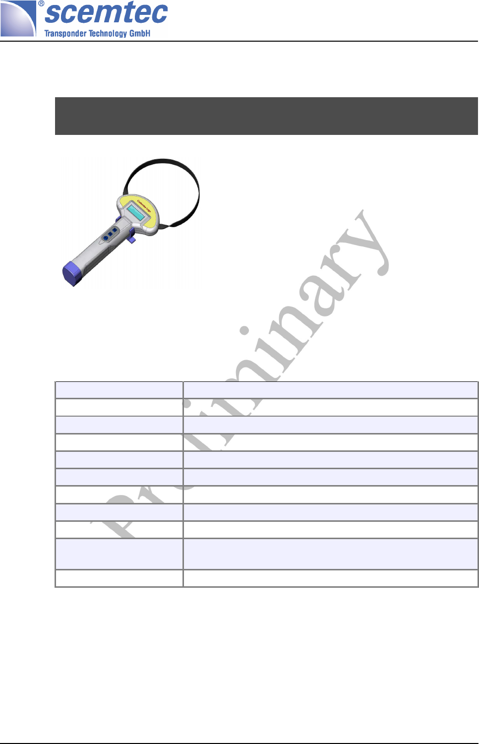
This manual describes the electronic-parts of the SIH-2100 HHR 13.56 MHz Reader
System. This Hand-Held-Reader “HHR” electronics are designed as a multi-tag
System to read and write information stored on transponders (tags). A USB 2.0 full
speed compatible interface and a Blue-tooth interface-port is available as well.
2.2 Supported Transponder Types
The reader-electronic is compatible with standards ISO/IEC 15693- 2 and
ISO18000-3 "A."
2.3 Reading / Writing TAGs
Several tags in the field can be read or written simultaneously (anti-collision). The
duration of the reading/writing process depends on the number of tags in the field.
Generally, there is no max. number of tags that are permitted in the field at the
same time.
Other operating-modes see respective software manual.
Document no. 0000.000.000 Version: 0.4 Page 4 of 23

Manual and Specification
SIH-2100
3 Interface and Electrical Characteristics
3.1 Keypad
The reader is fitted with a keypad with the following buttons:
Power
Mode
Read
3.2 Display
3 Line with 16 Characters and optional back light
Dimensions
Width 50 mm
Hight 16 mm
3.3 USB
USB 2.0 full speed compatible interface via an USB-Type B connector :
USB 2.0 full speed compatible interface
Pin 1 NC
Pin 2 D -
Pin 3 D +
Pin 4 GND
3.4 Bluetooth
Bluetooth
Class Bluetooth Class 2
Bluetooth Specification 2.0 compatible
RF output typ. 0dBm (Class 2)
Rx sensitivity typ. –80dBm
Document no. 0000.000.000 Version: 0.4 Page 5 of 23

Manual and Specification
SIH-2100
Bluetooth
Antenna Integrated chip antenna
Integrated profiles SPP
Supported modes: Slave mode
3.5 Power Supply
Power supply over Loading-connector
Input-Voltage:U-load 12 Volt DC ± 5%
minimal supply-
current @ U-load
500 mA @ 12 Volt DC
3.6 Rechargeable-batteries
The reader has a integrated battery-pack of 6 NiMH rechargeable-batteries in the
size of Mignon AA of 2500mAh capacity.
3.7 Power Consumption
Power consumption @7.5V Supply Voltage
Read/Write Tag
without data transmission to host
without LCD back light
Typ 540 mA
Data Transmission to Host
with RFID function
without LCD back light
Typ 550 mA
Full operation
with Bluetooth
with Back light
Typ 565 mA
Data Transmission to Host only Typ 270 mA
IDLE Mode Typ 105 mA
Offline Typ < 1mA
Document no. 0000.000.000 Version: 0.4 Page 6 of 23

Manual and Specification
SIH-2100
3.8 HF Output
HF Output
Operating frequency 13,56 MHz
Min. Rf Output Power 500 mW @ 50 Ohm
(depends on the actual battery-capacity)
Modulation 20% / 100% ASK
3.9 Antenna
The reader fit out with an antenna of approx. 210 mm diameter.
3.10 Application Memory
For storing Application specific data 1MBit of non-volatile memory can be used.
Document no. 0000.000.000 Version: 0.4 Page 7 of 23

Manual and Specification
SIH-2100
4 Software Function
The standard firmware SIH-2xxx hand-held device is designed to give the user a
simple possibility to scan tags as well as using all the extend functionality of this
readers.
Therefore one of the 3 Modes can be used:
Interface Mode: Using the scemtec's stx/etx protocol the reader will execute
all supported stx/etx commands like “Get Inventory”, “Read Tag”, “Write Tag”,
“Print Message on the Display” etc. The data collected in collect mode can
transferred to a host and cleared via stx/etc commands.
Collect Mode: Read Tags and store the content in the internal memory.
Read Mode: Read Tags and show the contents on the display.
The Default Mode can be set with STX/ETX Command. After pressing the Power
Button, the HHR starts up in the Default Mode.
The Modes can also changed with the Mode Button.
4.1 Bluetooth
The HHR can be connected to a PC by evaluation the blue-tooth workspace and
connecting to the service serial interface or comport.
Once the connection is established data can transferred from/to HHR.
4.2 USB
Connecting the device to a PC a virtual comport is available.
The Interface can be used to configure the HHR as well as transferring data from
the HHR to the Host.
4.3 Collect Mode
In this mode it's possible to collect transponder data and store it in the non volatile
memory of the reader.
Each reading will create a dataset.
The content of the dataset can be configured and the data can be transferred to the
host via the USB-interface or Bluetooth.
Document no. 0000.000.000 Version: 0.4 Page 8 of 23
Manual and Specification
SIH-2100
4.3.1 Function
If the Default Mode is set to Collect Mode, the HHR starts up in Collect Mode after
pressing the Power Button.
Now it's ready to collect data.
Pressing the Read Button starts the reading of Transponders. If no Transponders
are read for “Read Off Time” the HHR switch off the reading unit. Pressing the Read
Button again will start a new reading.
The HHR will switch off after the “Reader IDLE Time” if no Transponder are read or
Button pressed.
4.3.2 Display content:
1....0: Tag Content
nnn: Number of Tags in field
mmmm: Number of stored Datasets
A: Battery state.
C: Collect Mode selected.
No. [Time Stamp] [Tag ID] [Data 0] ... [Data n]
1 6 byte
2 6 byte
...
N 6 byte
No.
Reflects the number of the memory position.
Time Stamp
This Field is optional.
Time Stamp of reading time.
Format: ssmmhhddMMyy
s: seconds 1 byte
m: minutes 1 byte
h: hours 1 byte
d: day 1 byte
M: month 1 byte
y: year 1 byte
Tag ID
Data
Document no. 0000.000.000 Version: 0.4 Page 9 of 23
1234567890123456
nnn/mmmm
AC

Manual and Specification
SIH-2100
4.3.3 Settings for Collect Mode
These settings can be modified with the STX/ETX function 1055 (page 16).
1. Time Stamp: Yes /No
If this option is set, a time stamp will be stored with each dataset
2. Store Tag data: Yes/No
3. Tag content: first byte
First byte to be read and stored.
4. Tag content: number of bytes
Number of bytes to be read.
On a value of 0 no page will be read.
If the settings are changed, all data in the memory will be cleared.
4.4 Read Mode
In this mode it's possible to read transponder data. The contents will shown on dis-
play.
4.4.1 Function
If the Default Mode is set to Read Mode, the HHR starts up in Read Mode after
pressing the Power Button.
Pressing the Read Button starts the reading of Transponders. The content of the
first read Transponder is displayed.
After reading the HHR switch off the reading unit. Pressing the Read Button again
will start a new reading.
The HHR will switch off after the “Reader IDLE Time” if no Transponder are read or
Button pressed.
4.4.2 Display content:
1....0: Tag Content
nnnn: Number of Transponders in the field
A: Battery state.
R: Read Mode selected.
4.4.3 Settings for Read Mode:
These Settings can be modified with the STX/ETX function 1053 (page 15).
1. Displayed data: Tag-ID or Tag data.
2. Start and length of tag data.
Document no. 0000.000.000 Version: 0.4 Page 10 of 23
1234567890123456
nnnn
AR

Manual and Specification
SIH-2100
4.5 Data Transmission Protocol
4.5.1 Supported Functions
Function
number
Description See docu-
ment
1000 Reset Request [STXETX]
1001 Request Version Number [STXETX]
1002 Interface Test [STXETX]
1003 Change Baud rate [STXETX]
100A Request Supported Transponder Types [STXETX]
1010 Request System Setting [STXETX]
1011 Edit System Setting [STXETX]
102E Get Local Device Name [STXETX]
102F Set Local Device Name [STXETX]
200A Get System Time (Read Realtime Clock) [STXETX]
200B Set System Time (Write Realtime Clock) [STXETX]
200F Activate Buzzer
2010 Set LCD Text (Low Level) [STXETX]
2012 Set LCD Text (High Level) 4.5.4
F003 Switch off Device [STXETX]
ISO 15693
1C30 Request Setting [STXETX]
1C31 Edit Setting [STXETX]
4C10 Read Single Block [STXETX]
4C12 Read Multiple Blocks [STXETX]
4C16 Get System Information [STXETX]
4C18 Get Security Status [STXETX]
5C10 Write Single Block [STXETX]
5C12 Write Multiple Blocks [STXETX]
5C16 Write AFI [STXETX]
5C17 Write DSFID [STXETX]
6C10 Single Anticollision Round [STXETX]
6C12 Select [STXETX]
6C14 Lock Block [STXETX]
6C16 Lock AFI [STXETX]
Document no. 0000.000.000 Version: 0.4 Page 11 of 23

Manual and Specification
SIH-2100
Function
number
Description See docu-
ment
6C17 Lock DSFID [STXETX]
6C18 Stay Quiet [STXETX]
6C1A Reset To Ready [STXETX]
6C1E Custom Read Command [STXETX]
6C1F Custom Read Command [STXETX]
6C20 Create Inventory [STXETX]
6C21 Get Inventory [STXETX]
4C20 Advanced Read Single Block [STXETX]
4C2A Looped Address Scan [STXETX]
5C20 Advanced Write Single Block [STXETX]
6C22 Get ID Range from Inventory [STXETX]
6C23 Realtime Inventory [STXETX]
6C24 Create/Get Inventory [STXETX]
6C26 Advanced Lock Single Block [STXETX]
EPC/UID
1A32 Request Setting [STXETX]
1A33 Edit Setting [STXETX]
1A34 Get ID Mask [STXETX]
1A35 Set ID Mask [STXETX]
5A80 Write Block [STXETX]
6A80 Single Round [STXETX]
6A84 Destroy [STXETX]
5A90 Write Block [STXETX]
6A90 Single Round [STXETX]
6A94 Destroy [STXETX]
4AA8 Looped Read [STXETX]
5AA0 Write User Data [STXETX]
5AA1 Write Destroy Code [STXETX]
6AA0 Create Inventory [STXETX]
6AA1 Get Inventory [STXETX]
6AA2 Get ID Range from Inventory [STXETX]
6AA3 Realtime Inventory [STXETX]
6AA4 Create/Get Inventory [STXETX]
4AB8 Looped Read [STXETX]
Document no. 0000.000.000 Version: 0.4 Page 12 of 23

Manual and Specification
SIH-2100
Function
number
Description See docu-
ment
5AB0 Write User Data [STXETX]
5AB1 Write Destroy Code [STXETX]
6AB0 Create Inventory [STXETX]
6AB1 Get Inventory [STXETX]
6AB2 Get ID Range from Inventory [STXETX]
6AB3 Realtime Inventory [STXETX]
6AB4 Create/Get Inventory [STXETX]
4.5.2 SIH-2100 specific functions
Function
number
Description See page
1050 Request Handheld Settings 13
1051 Edit Handheld Settings 14
1052 Request Read Mode Configuration 14
1053 Edit Read Mode Configuration 15
1054 Request Collect Mode Configuration 15
1055 Edit Collect Mode Configuration 16
1058 Clear Buffer 16
1059 Get Entry Count 16
105A Read Entry 17
1050: Request Handheld Settings
Using a key/value combination, this function allows access to several handheld mode set-
tings. Numeric values are unsigned 16bit hex values; switch values are „0000“ for „false“
or „0001“ for „true“.
Host to RF System Request
STX "1050" <kk>
ETX {c}
Request Parameters
kKey (see below).
Document no. 0000.000.000 Version: 0.4 Page 13 of 23
Manual and Specification
SIH-2100
RF System to Host Response
ACK
STX "1050" <vvvv>
ETX {c}
Response Data
vValue.
Key Alias N/S Def. Description
00 n 0001 Default start-up mode. (1: Collect Mode, 2: Read
Mode)
01 n 000A Read timeout (seconds).
02 n 00F0 Power timeout (seconds).
1051: Edit Handheld Settings
This function is used to change system constants. See „Edit Handheld Settings“ („1050“)
for further information.
Host to RF System Request
STX "1051" <kk> <vvvv>
ETX {c}
Request Parameters
kKey.
vValue.
RF System to Host Response
ACK
STX "1051"
ETX {c}
Response Data
-None.
1052: Request Read Mode Configuration
Requests the current Read mode configuration.
Host to RF System Request
STX "1052"
ETX {c}
Request Parameters
-None.
RF System to Host Response
ACK
STX "1052" <m> [ <bb> <ll> ]
ETX {c}
Document no. 0000.000.000 Version: 0.4 Page 14 of 23

Manual and Specification
SIH-2100
Response Data
mMode:
'i': Transponder-ID will be displayed.
'a': Transponder data will be displayed as null-terminated string.
'h': Transponder data will be displayed as hex values.
bFirst Byte of transponder data.
lLength of transponder data (in bytes).
1053: Edit Read Mode Configuration
This function is used to configure the Read mode.
Host to RF System Request
STX "1053" <m> [ <bb> <ll> ]
ETX {c}
Request Parameters
mMode:
'i': Transponder-ID will be displayed.
'a': Transponder data will be displayed as null-terminated string.
'h': Transponder data will be displayed as hex values.
bFirst Byte of transponder data.
lLength of transponder data (in bytes).
RF System to Host Response
ACK
STX "1053"
ETX {c}
Response Data
-None.
1054: Request Collect Mode Configuration
Requests the current Collect mode configuration.
Host to RF System Request
STX "1054"
ETX {c}
Request Parameters
-None.
RF System to Host Response
ACK
STX "1054" <ff> [ <bb> <ll> ]
ETX {c}
Response Data
fBinary coded fields:
01: Store Transponder ID.
02: Store Timestamp.
Document no. 0000.000.000 Version: 0.4 Page 15 of 23

Manual and Specification
SIH-2100
04: Store Transponder data.
bFirst byte of transponder data
lLength of transponder data (in bytes)
1055: Edit Collect Mode Configuration
This function is used to configure the Collect mode. This will clear the transponder buffer.
Host to RF System Request
STX "1055" <ff> [ <bb> <ll> ]
ETX {c}
Request Parameters
fBinary coded fields:
01: Store Transponder ID.
02: Store Timestamp.
04: Store Transponder data.
bFirst byte of transponder data
lLength of transponder data (in bytes)
RF System to Host Response
ACK
STX "1055"
ETX {c}
Response Data
-None.
1058: Clear Buffer
This function clears the transponder buffer. All stored information will be erased.
Host to RF System Request
STX "1058"
ETX {c}
Request Parameters
-None.
RF System to Host Response
ACK
STX "1058"
ETX {c}
Response Data
-None.
1059: Get Entry Count
This function returns the number of stored entries in the transponder buffer.
Document no. 0000.000.000 Version: 0.4 Page 16 of 23

Manual and Specification
SIH-2100
Host to RF System Request
STX "1059"
ETX {c}
Request Parameters
-None.
RF System to Host Response
ACK
STX "1059" <cccc> <ssss>
ETX {c}
Response Data
cCurrent inventory size.
sMaximum inventory size (depends on configuration).
105A: Read Entry
Host to RF System Request
STX "105A" <iiii>
ETX {c}
Request Parameters
-None.
RF System to Host Response
ACK
STX "105A" <ff> <iiiiiiiiiiiiiiii> [ <ss> <mm> <hh> <DD> <MM>
<YY> ] [ <dd...> ]
ETX {c}
Response Data
fBinary coded fields:
01: Store Transponder ID.
02: Store Timestamp.
04: Store Transponder data.
iTag ID in reverse byte order.
sTimestamp (seconds).
mTimestamp (minutes).
hTimestamp (hours).
DTimestamp (day of month).
MTimestamp (month).
YTimestamp (year).
dTag Data
4.5.3 Buzzer signals
With this command the buzzer is going to be switched on for the defined time and
then switched off for the defined time. The same process can be repeated automat-
ically as defined in the command.
Document no. 0000.000.000 Version: 0.4 Page 17 of 23

Manual and Specification
SIH-2100
Each buzzer signal is defined as:
Buzzer on time [x100ms], buzzer off time [y100ms], number of repeats [z]
With x = 1...10, y = 1...10, z = 0...10
4.5.4 Display features
Any alphanumeric information with a maximum length of 255 characters can be sent
to the display of the reader. By pressing the mode button the information has to be
acknowledged by the user. Information with more characters than available on the
display will be shifted slowly and in an auto repeat mode until user acknowledge-
ment.
For setting the display text see function 2011 in the stx/etx protocol description.
If the text exceeds the display size it will be shifted.
Only Western characters are possible.
4.6 Error Messages
see also (1), scemtec STX/ETX Protocol Version 4.00 or above
Document no. 0000.000.000 Version: 0.4 Page 18 of 23
Manual and Specification
SIH-2100
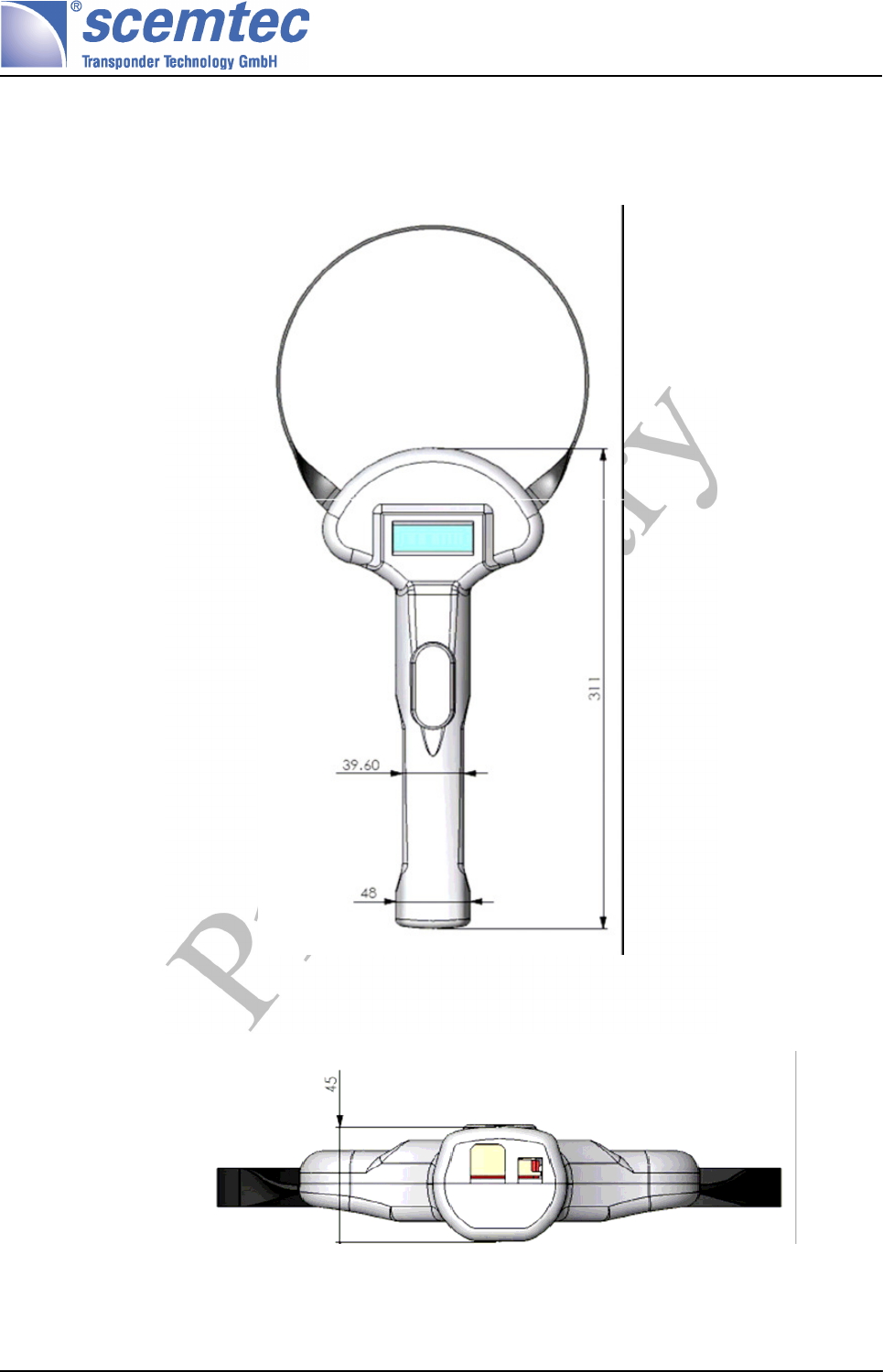
5 Dimensions
Document no. 0000.000.000 Version: 0.4 Page 19 of 23
Manual and Specification
SIH-2100
6.3 RSS – Conformity: Information for CANADA
Operation is subject to the following two conditions:
(1) this device may not cause interference, and
(2) this device must accept any interference, including interference that
may cause undesired operation of the device.
Usually this is followed by the following RSS caution:
Any changes or modifications not expressly approved by the party
responsible for compliance could void the user's authority to operate this
equipment
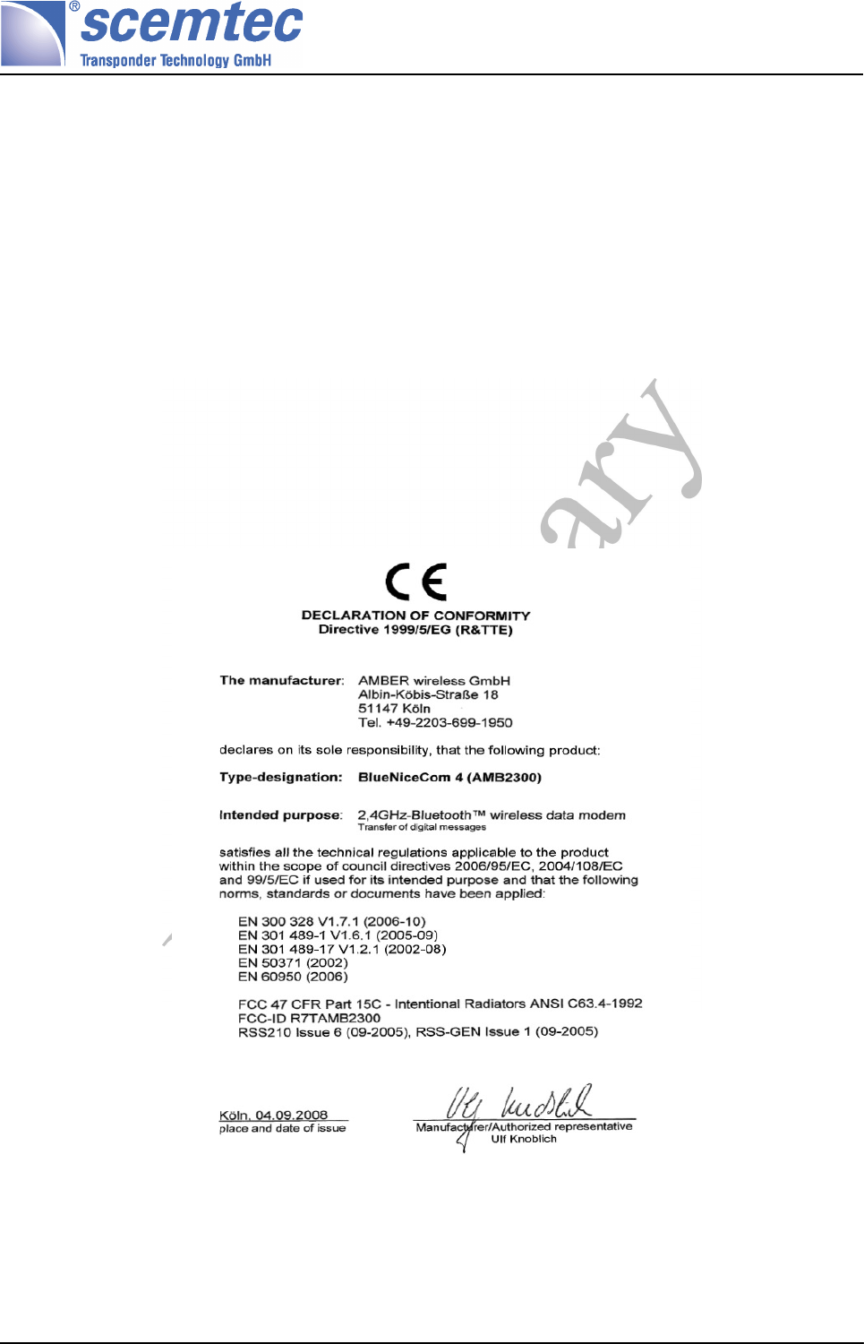
6.4 Bluetooth: Declaration of Conformity for bluetooth-interface
Document no. 0000.000.000 Version: 0.4 Page 21 of 23
Manual and Specification
SIH-2100
7 Datasheet
Hand-Held-Reader SIH-2100
13,56 MHz Hand-Held
RFID Multi Protocol Hand-Held Reader
SIH-2100
Multi standard hand-held reader
Contactless reading of 13,56 MHz Transponder
ISO-15693, ISO18000-3 "A."
Bluetooth and USB Interface
CE
Technical Data:
Dimensions: (l x h ) (453x45) mm
Display: LCD display (3 x 16 characters), option: back light
Push-buttons: 3 keys
Transmit frequency: 13,56 MHz
Antenna: diameter 215mm
Output Power 500mW @ 50Ohm
Transponders: ISO 15693, ISO18000-3 "A."
Operation distances: t.b.d
Interface: Bluetooth Class2, USB
Power supply: Integrated battery and charging unit
External power supply
Operating temperature: 0-50°C
Order Information
SIH-2100 Order-No.:
Document no. 0000.000.000 Version: 0.4 Page 22 of 23

Manual and Specification
SIH-2100
8 Related Documents
[STXETX]
STX/ETX Protocol description
Scemtec's STX/ETX Protocol description is distributed with every Reader on
the product CD
9 Document History
Version Date Changed by Description
0.1 16.07.2008 Kalbitzer Initial Version
0.2 19.11.2008 Pauls STX/ETX-Functions added
0.3 15.01.2009 Kalbitzer Data sheet corrected
Capacity of batteries is now 2500mAh
0.4 21.01.2009 Radermacher Conformity-Information added for USA/CA/BT
Document no. 0000.000.000 Version: 0.4 Page 23 of 23