scemtec Transponder Technology SIL2125 RFID Reader User Manual Annex No
scemtec Transponder Technology GmbH RFID Reader Annex No
UserManual.wiki
>
scemtec Transponder Technology
>
SIL2125 User Manual
Functional Description - User Manual
Navigation menu
Upload a User Manual
Namespaces
Wiki Guide
HTML
PDF
Info
Views
User Manual
Discussion / Help
Navigation
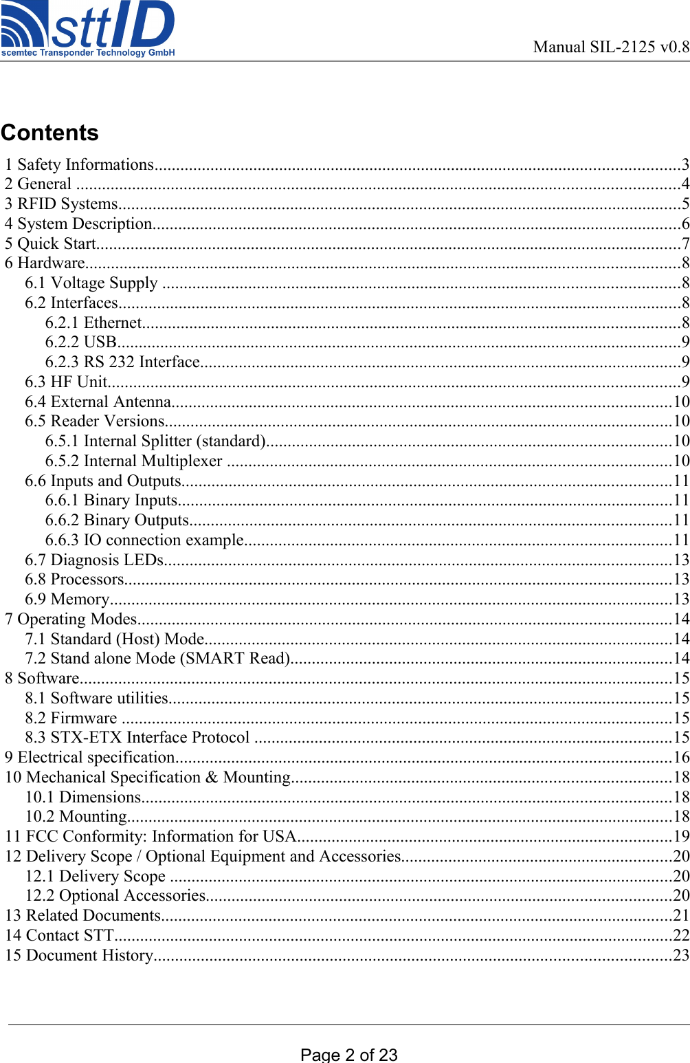
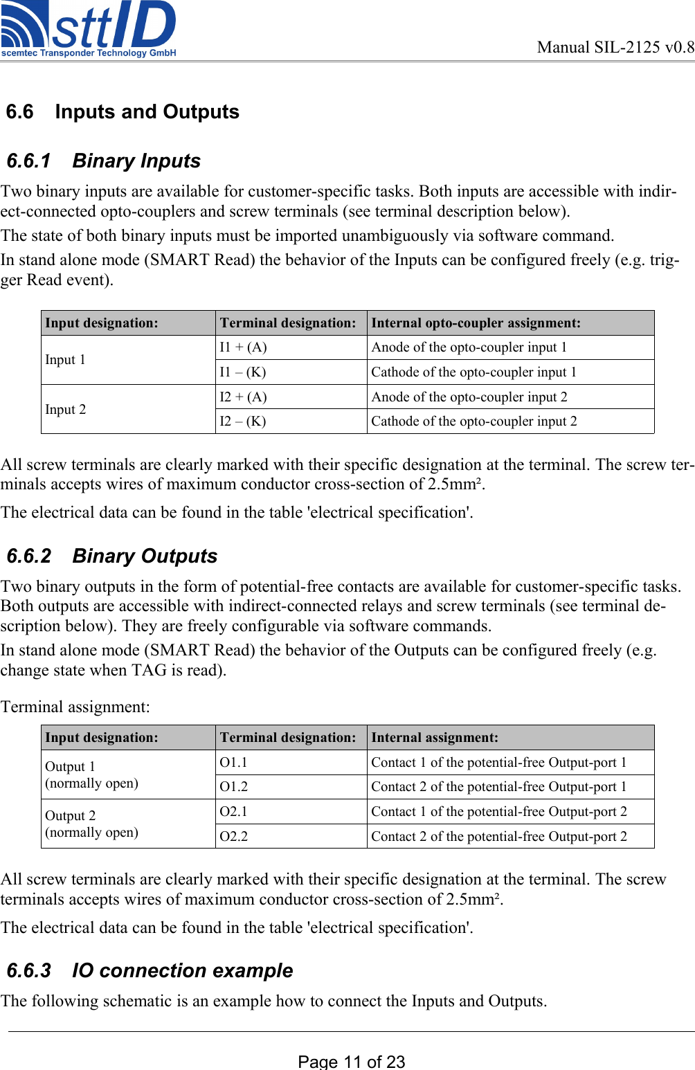
![Manual SIL-2125 v0.8 5 Quick StartFirst Connect the Reader as shown below:As example you can use the STT antenna “SAT-A40-LR-O-13MHz” [400.4020].Now you can use a Software like “Uni - Demo” to control the Reader. For more details please refer to “Quick Start Guide read”. This Guide is available for download on www.stt-rfid.com.Page 7 of 23figure 1: Reader connection example](https://usermanual.wiki/scemtec-Transponder-Technology/SIL2125/User-Guide-2474015-Page-8.png)
![Manual SIL-2125 v0.8 6.2.2 USBThe Reader is equipped with a USB 2.0 full speed (12 Mbits/sec) port. The connection is made via a standard USB-B connector.Supported profiles CDC-ACM (virtual COM-Port), HID (Keyboard emulation) Appropriate drivers for Windows are available for download on www.stt-rfid.com. 6.2.3 RS 232 InterfaceThe Reader is equipped with a RS232 interface. The connection is made via a standard 9 pin D-Sub connector . Terminal designation: SUB-D Connector Pin Terminal FunctionTxD 2 Transmit DataRxD 3 Receive DataGND 5 Ground The data transfer rate is adjustable via STX-ETX commands.Configuration 8 Data Bits, 1 Stop Bit, no Parity, no flow control Supported Data Rates [baud] 1200, 2400, 4800, 9600 (default), 19200, 38400 57600, 115200, 230400 In addition to the primary RS232 Interface described above, the Reader provides a secondary RS 232 Interface, intended to be used in stand alone mode as interface for connecting auxillary equipment (e.g. additional RFID reader, bar code scanner, …). The connection to the secondary RS232 ist also made via the 9 pin SUB D connector. Please contact STT for further Information regarding usage of the second RS232 in your application.Terminal designation: SUB-D Connector Pin Terminal FunctionTxD2 8 Transmit Data Secondary RS232RxD2 7 Receive Data Secondary RS232GND 5 Ground Special Adapters cables for connecting external devices to the secondary RS232 are available from STT. 6.3 HF UnitThe carrier frequency of 13.56 MHz is generated in the HF unit. The final stage generates an output of typical 10 watt on nominal ZF = 50 Ohm.Page 9 of 23](https://usermanual.wiki/scemtec-Transponder-Technology/SIL2125/User-Guide-2474015-Page-10.png)